OPERATING MANUAL Parts manuals available online at www.generacmobile.com 31651 ORG 06/15 01520 SELF-PRIME DIESEL TRASH PUMP MTP4000SZ • MTP6000SZ

Welcome message from author
This document is posted to help you gain knowledge. Please leave a comment to let me know what you think about it! Share it to your friends and learn new things together.
Transcript
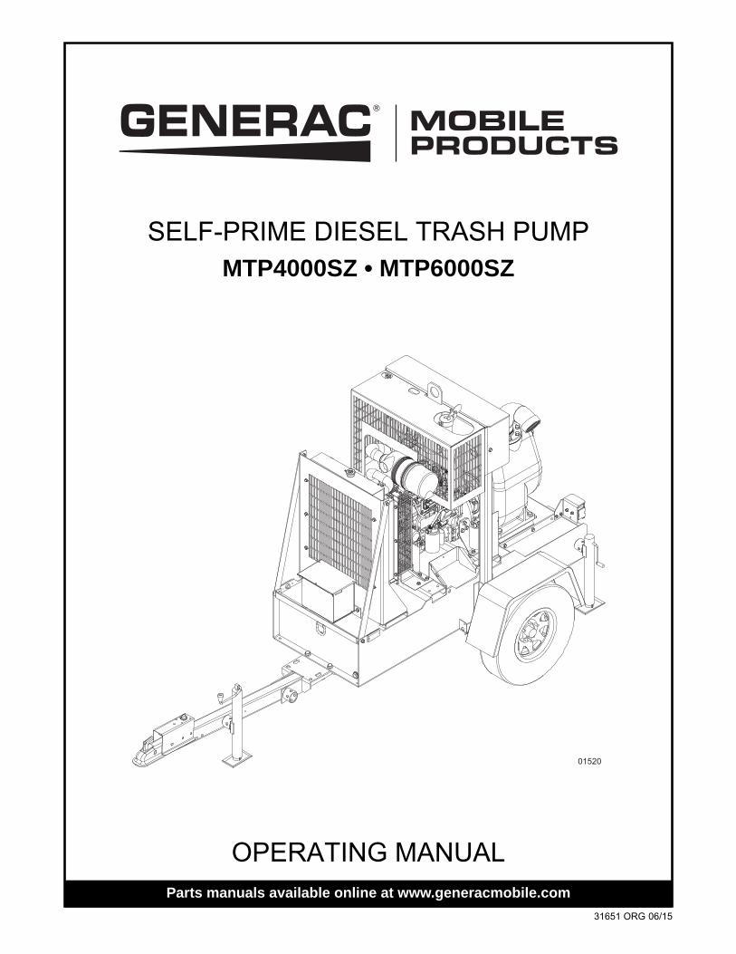
OPERATING MANUALParts manuals available online at www.generacmobile.com
01520
SELF-PRIME DIESEL TRASH PUMPMTP4000SZ • MTP6000SZ
31651 ORG 06/15
WARNINGCALIFORNIA PROPOSITION 65 WARNING: Diesel engine exhaust and some of its
constituents are known to the state of California to cause cancer, birth defects, and other reproductive harm.
WARNINGCALIFORNIA PROPOSITION 65 WARNING: This product contains or emits chemicals known to the state of California to cause cancer, birth defects, and other reproductive
harm.
ii
Introduction
This manual provides information and procedures to safely operate and maintain the Generac Mobile Products unit. For your own safety and protection from physical injury, carefully read, understand, and observe the safety instructions described in this manual. Keep a copy of this manual with the unit at all times. Additional copies are available from Generac Mobile Products, or can be found at www.generacmobile.com.The information contained in this manual was based on machines in production at the time of publication. Generac Mobile Products reserves the right to change any portion of this information without notice.
Read all of the manuals included with the unit. Each manual details specific information regarding items such as setup, use and service requirements. An engine operator’s manual provides detailed operation and maintenance procedures for the engine. Additional copies of the engine operator’s manual are available from the engine manufacturer.
DO NOT MODIFY or use this equipment for any application other than for which it was designed.
Generac Mobile Products recommends that a trained and licensed professional perform all electrical wiring and testing functions. Any wiring should be in compliance with the National Electrical Code (NEC), state and local regulations and Occupational Safety and Health Association (OSHA) guidelines.
GENERAC MOBILE PRODUCTS LLC215 Power Drive • Berlin, WI 54923
U.S.A.Phone: 920-361-4442FAX: 920-361-4416
Toll Free: 1-800-926-9768www.generacmobile.com
For technical or parts QUESTIONS, please contact the Generac Mobile Products Customer Support or Technical Support team at 1-800-926-9768. Please have your serial number available.
To ORDER SERVICE PARTS, please contact the dealer from which you purchased the unit, or call Generac Mobile Products to locate a dealer in your area.
Engine Make:__________________________________________Engine Serial Number:___________________________________Engine Model Number: __________________________________Pump Make:___________________________________________Pump Model Number: ___________________________________Pump Serial Number: ___________________________________Unit Model Number:_____________________________________Unit Serial Number: _____________________________________
iii

This Page Intentionally Left Blank
iv
Table of Contents
Introduction............................................................................................................................ iiiSection 1 - Safety
Safety Notes ....................................................................................................................................... 1Operating Safety................................................................................................................................. 1Engine Safety .................................................................................................................................... 2Pump Safety ....................................................................................................................................... 2Service Safety .................................................................................................................................... 3Towing Safety..................................................................................................................................... 3Reporting Trailer Safety Defects ........................................................................................................ 4Safety Symbol Summary ................................................................................................................... 5
Section 2 - General InformationSpecifications ..................................................................................................................................... 7
Unit Dimensions .................................................................................................................... 8Unit Serial Number Locations............................................................................................................ 9Component Locations...................................................................................................................... 10Lowering the Trailer Tongue............................................................................................................ 12Digital Controller .............................................................................................................................. 13
Automatic Operation............................................................................................................ 14Throttle Control .................................................................................................................... 14Service Timers..................................................................................................................... 14CANplus Messenger Telemetry Option ............................................................................... 14Button Lock.......................................................................................................................... 14
Control Panel Operation ................................................................................................................... 15Throttle Control................................................................................................................................. 15Ramp Throttle (Speed Control Switch)............................................................................................. 15Automatic Start/Stop Operation........................................................................................................ 16
Start and Stop Events.......................................................................................................... 16Maintain Functions .............................................................................................................. 17Dead Band........................................................................................................................... 17
CANplus Display.............................................................................................................................. 18Analog Gauge Pages ....................................................................................................................... 18Digital Gauge Pages........................................................................................................................ 19Single Analog Gauge........................................................................................................................ 19Analog Transducer/Switch Gauge.................................................................................................... 19Digital Transducer Gauge................................................................................................................. 19Active Alarms.................................................................................................................................... 19Alarm List.......................................................................................................................................... 20Configuration .................................................................................................................................... 20Configuration Menu .......................................................................................................................... 20Display Menu.................................................................................................................................... 21
Units Menu .......................................................................................................................... 21Language Menu................................................................................................................... 22Button Beep......................................................................................................................... 22Gauges Menu ...................................................................................................................... 22Max RPM............................................................................................................................. 22Max Speed .......................................................................................................................... 22Quad Adjust......................................................................................................................... 22Voltmeter ............................................................................................................................. 22Service Timers..................................................................................................................... 22
System Menu.................................................................................................................................... 23Demo ................................................................................................................................... 23Restore Defaults.................................................................................................................. 23Com Viewer ......................................................................................................................... 24
v
J1939 Viewer....................................................................................................................... 24Engine Config ...................................................................................................................... 24J1939 Settings..................................................................................................................... 25Engine Source ..................................................................................................................... 25Display CAN Add................................................................................................................. 25Alarm Filter .......................................................................................................................... 25SPN Version ........................................................................................................................ 25Speed Source...................................................................................................................... 25PIN Settings......................................................................................................................... 25PIN Entry ............................................................................................................................. 25PIN Change ......................................................................................................................... 26About ................................................................................................................................... 26
Autostart Menu ................................................................................................................................. 27Mode.................................................................................................................................... 27Function............................................................................................................................... 27Throttling Menu.................................................................................................................... 27Idle RPM.............................................................................................................................. 27Intermediate RPM................................................................................................................ 27Run RPM ............................................................................................................................. 27Ramp Up/Down ................................................................................................................... 28Servo ................................................................................................................................... 28Transducer .......................................................................................................................... 28Starter.................................................................................................................................. 29
Settings Menu................................................................................................................................... 29Governor.............................................................................................................................. 29CP750 CAN Add.................................................................................................................. 29Calibrate RPM ..................................................................................................................... 30Aux Output........................................................................................................................... 30Alarm Settings ..................................................................................................................... 30
Telemetry Menu................................................................................................................................ 30Telem J1939 Address.......................................................................................................... 30Modbus Address.................................................................................................................. 30Status .................................................................................................................................. 31
Db Viewer ......................................................................................................................................... 31Preferred Screen Store..................................................................................................................... 31Pop-Up Messages and Alerts........................................................................................................... 31
Service Required ................................................................................................................. 31Data Communications Failure ............................................................................................. 31Data Not Available............................................................................................................... 32
Adjusting Lighting and Contrast........................................................................................................ 32Indicators .......................................................................................................................................... 32
Auto Standby LED (Green).................................................................................................. 32Preheat LED (Amber) .......................................................................................................... 32Engine Stop LED (Red) ....................................................................................................... 32Warning LED (Amber) ......................................................................................................... 32
Data Parameters Monitored ............................................................................................................. 33Welding on Equipment with Electronic Controls............................................................................... 35
Section 3 - OperationPump Set Up .................................................................................................................................... 37
Pipe Submergences ........................................................................................................... 38Pump Pre-use Checkpoints.............................................................................................................. 39Prestart Checklist ............................................................................................................................. 40Starting the Unit................................................................................................................................ 41Torsional Vibration............................................................................................................................ 43Liquid Temperature and Overheating............................................................................................... 43Pump Vacuum Check....................................................................................................................... 44
vi
Bearing Temperature Check ............................................................................................................ 44Shutting Down The Unit.................................................................................................................... 44Emergency Stop Switch ................................................................................................................... 44Automatic Shutdown......................................................................................................................... 44Towing the Unit................................................................................................................................. 45Lifting the Unit................................................................................................................................... 45
Section 4 - MaintenanceDaily Walk Around Inspection........................................................................................................... 47General Maintenance ....................................................................................................................... 48
Basic Maintenance Schedule ............................................................................................. 48Checking the Engine Oil ...................................................................................................... 49Checking the Pump Sight Level Gauges............................................................................. 49Changing the Engine Oil...................................................................................................... 49Changing the Oil Filter ......................................................................................................... 50
Jack Maintenance............................................................................................................................. 50Side-Wind Models ............................................................................................................... 50Top-Wind Models ................................................................................................................ 50
Trailer Wheel Bearing Lubrication .................................................................................................... 50Resetting the Digital Controller......................................................................................................... 51
Adjusting the Service Timers............................................................................................... 51Servicing The Pump ......................................................................................................................... 51
Bearing and Shaft Assembly ............................................................................................... 54Bearing Frame Assembly .................................................................................................... 54Rotating Assembly............................................................................................................... 56Impeller Lockscrew Torque Values .................................................................................... 57Impeller Installation.............................................................................................................. 57
Storage ............................................................................................................................................. 58Extended Storage Preparation ............................................................................................ 58
Winter Storage.................................................................................................................................. 59Restart Preparation ............................................................................................................. 59
Section 5 - TroubleshootingPump Troubleshooting ..................................................................................................................... 61Engine Fault Shutdown Troubleshooting.......................................................................................... 62Control System Troubleshooting ...................................................................................................... 63Diagnostic Trouble Codes (DTS)...................................................................................................... 63
SPN Codes.......................................................................................................................... 63Typical SPN Codes ............................................................................................................ 63FMI Codes ........................................................................................................................... 64FMI Codes .......................................................................................................................... 64
Section 6 - Wiring DiagramsDC Wiring Diagram........................................................................................................................... 65Trailer Lights Wiring Diagram .......................................................................................................... 66
Section 7 - Options & AccessoriesRemote/Auto Starting ....................................................................................................................... 67
Service Log ............................................................................................................................ 69
vii

This Page Intentionally Left Blank
viii
Section 1 - Safety
SAFETY NOTESThis is the safety alert symbol. It is used to alert you to potential personal injury hazards. Obey all safety messages that follow this symbol to avoid possible injury or death.
This manual contains DANGERS, WARNINGS, CAUTIONS, NOTICES and NOTES which must be followed to prevent the possibility of improper service, damage to the equipment, personal injury or death. The following formatting options will apply when calling the readers attention to the DANGERS, WARN-INGS, CAUTIONS, NOTICES and NOTES.
DANGERINDICATES A HAZARDOUS SITUATION WHICH, IF NOT AVOIDED, WILL RESULT IN
DEATH OR SERIOUS INJURY.
WARNINGIndicates a hazardous situation which, if not avoided, could result in death or serious
injury.
CAUTIONIndicates a hazardous situation which, if not avoided, could result in minor or moderate injury.
Indicates a hazardous situation which, if not avoided, could result in property or equipment damage.
Note: Notes contain additional information important to a procedure and will be found within the regular text body of this manual.
OPERATING SAFETYBefore using the unit be sure you read and understand all of the instructions. This equipment was designed for specific applications; DO NOT modify or use this equipment for any application other than which it was designed for. Equipment operated improperly or by untrained personnel can be dangerous. Read the operating instructions and familiarize yourself with the location and proper use of all instruments and controls. Inexperienced operators should receive instruction from someone familiar with the equipment before being allowed to operate or set up the generator. The following points should be practiced at all times:
• The area immediately surrounding the unit should be dry, clean, and free of debris.
• Position and operate unit on a firm, level surface.
• NEVER start a unit in need of repair.
• NEVER modify the unit or use it in a manner other than for what it was designed.
• DO NOT start the unit if any panels or guards are loose or missing.
• Turn the Key switch to the OFF position when servicing or troubleshooting.
• Use hearing protection if you will be near an operating unit for an extended period of time.
• Keep clear of pump suction and discharge openings while engine is running.
• Keep all body parts, loose clothing and any other obstructions away from moving parts.
• NEVER operate a unit while tired, distracted, or under the influence of drugs or alcohol.
31651 ORG MTP4000-6000SZ Operating Manual 1
Safety
ENGINE SAFETYInternal combustion engines present special hazards during operation and fueling. Failure to follow the safety guidelines described below could result in severe injury or death. Read and follow all safety warnings described in the engine operator's manual. A copy of this manual was supplied with the unit when it was shipped from the factory.
• DO NOT run engine indoors or in an area with poor ventilation. Engine exhaust contains carbon monoxide, a deadly, odorless and colorless gas which, if inhaled, can cause nausea, fainting, or death. Only use this unit outside and away from windows, doors, and ventilation equipment.
• DO NOT smoke around unit. Ensure that no combustible materials are left on or near unit, as FIRE or EXPLOSION may result.
• DO NOT touch or lean against hot exhaust pipes or engine block.
• DO NOT clean air filter with gasoline or other types of low flash point solvents.
• DO NOT remove engine coolant cap while engine is hot.
• DO NOT operate the unit without a functional exhaust system.
• Prolonged exposure to sound levels in excess of 85 dB(A) can cause permanent hearing loss. Wear hearing protection when working around a running engine.
• Keep hands, feet and loose clothing away from moving parts on the generator and engine.
• Keep area around exhaust pipes and air ducts free of debris to reduce the chance of an accidental fire.
• Batteries contain sulfuric acid which can cause severe injury or death. Sulfuric acid can cause eye damage, burn flesh or eat holes in clothing. Protective eye wear and clothing are necessary when working on or around the battery. Always disconnect the negative (-) battery cable from the corresponding terminal before performing any service on the engine or other components.
PUMP SAFETYCentrifugal pumps are designed for specific applications and may not be suited for other uses without loss of performance or potential damage to equipment/personnel. If there is any doubt about suitability for a specific purpose, contact Generac Mobile Products for assistance. Follow the safety guidelines described below to prevent hazardous situations which could result in severe injury or death.
• The pump is designed to handle mild industrial corrosives, residues, and slurries containing some large entrained solids. Do not attempt to pump volatile, corrosive, or flammable materials that may damage the pump or endanger personnel as a result of pump failure.
• After the pump has been positioned, make certain that the pump and all hose/piping connections are tight, properly supported and secure before operation.
• DO NOT operate the pump without the guards in place over the rotating parts. Exposed rotating parts can catch clothing, fingers, or tools, causing severe injury.
• DO NOT remove plates, covers, gauges, pipe plugs, or fittings from an overheated pump. Vapor pressure within the pump can cause parts being disengaged to be ejected with great force. Allow the pump to cool before servicing.
• DO NOT operate the pump against a closed discharge valve for long periods of time. If operated against a closed discharge valve, pump components will deteriorate, and the liquid could come to a boil, build pressure, and cause the pump casing to rupture or explode.
• Remove suction and discharge hoses/piping from pump prior to moving. Use lifting and moving equipment with adequate capacity and in good repair.
• NEVER exceed the maximum permissible operating pressure of the pump as shown on the pump performance curve.
• NEVER wash the unit with a high pressure hose or with any kind of power washer.
2 MTP4000-6000SZ Operating Manual 31651 ORG
Safety
• NEVER wash the engine block or fuel tank with a power washer or steam cleaner. Water may collect in the pump control panel or other electrical parts, causing damage.
• If equipment is stored more than 12 months, some of the components or lubricants may have exceeded their maximum shelf life. These must be inspected and replaced as necessary prior to pump operation to ensure proper pump performance.
SERVICE SAFETYAll service work must be performed by qualified personnel who are familiar with the equipment. Only a qualified electrician should troubleshoot or repair electrical problems occurring in this equipment. Follow the safety guidelines described below to prevent hazardous situations which could result in severe injury or death.
• Before servicing the unit, make sure the Key switch is turned to OFF and the negative terminal on the battery is disconnected. NEVER perform even routine service (oil/filter changes, cleaning, etc.) unless all electrical components are shut down.
• NEVER service electrical components if clothing or skin is wet. If the unit is stored outside, check the engine for any moisture and dry the unit before use.
• NEVER open the radiator cap or oil drain plug while the engine is running or before the engine has cooled down. Pressurized coolant and hot engine oil can cause severe burns. Allow the engine and pump to cool completely before attempting any service work.
• Check the temperature before opening any pump covers, plates or plugs. Allow the pump to cool if overheated.
• Before servicing the pump end, close the suction and discharge valves. Vent the pump slowly and cautiously. Drain the pump completely.
• NEVER attempt to modify the engine, pump or related components.
• Replace all guards and safety devices immediately after servicing.
• Replace all missing and hard to read labels. Labels provide important operating instructions and warn of dangers and hazards.
• Make sure slings, chains, hooks, ramps, jacks, and other types of lifting devices are attached securely and have enough weight-bearing capacity to lift or hold the equipment safely. Always remain aware of the position of other people around you when lifting the equipment.
TOWING SAFETYTowing a trailer requires care. Both the trailer and vehicle must be in good condition and securely fastened to each other to reduce the possibility of an accident. Also, some states require that large trailers be registered and licensed. Contact your local Department of Transportation office to check on license requirements for your particular unit.
• Check that the hitch and coupling on the towing vehicle are rated equal to, or greater than, the trailer's Gross Vehicle Weight Rating (GVWR).
• Check tires on trailer for tread wear, inflation, and condition.
• NEVER tow trailer using defective parts. Inspect the hitch and coupling for wear or damage.
• Make sure the trailer hitch and the coupling are compatible. Make sure the coupling is securely fastened to the vehicle.
• Connect safety chains in a crossing pattern under the tongue and ATTACH THE BREAKAWAY CABLE TO THE REAR BUMPER OF THE TOWING VEHICLE. Do not attach the cable to the trailer hitch.
• Make sure directional and brake lights on the trailer are connected and working properly.
31651 ORG MTP4000-6000SZ Operating Manual 3
Safety
• Check that lug nuts holding wheels are tight and that none are missing.
• Maximum recommended speed for highway towing is 45 mph (72 km/h). Recommended off-road towing speed is not to exceed 10 mph (16 km/h) or less, depending on terrain.
Before towing the trailer, check that the weight of the trailer is evenly distributed. A large angle between the trailer and tow vehicle will cause more weight to be carried by the trailer axle, which could cause premature wear on the tires and axle and cause potentially unsafe operating conditions.
The trailer is equipped with surge brakes. Check the operation of the brakes by braking the vehicle at a slow speed before entering traffic. Both the trailer and the vehicle should brake smoothly. If the trailer seems to be pushing, check the level in the brake fluid reservoir.
When towing, maintain extra space between vehicles and avoid soft shoulders, curbs and sudden lane changes. If you have not pulled a trailer before, practice turning, stopping and backing up in an area away from heavy traffic.
A film of grease on the coupler will extend coupler life and eliminate squeaking. Wipe the coupler clean and apply fresh grease each time the trailer is towed.
REPORTING TRAILER SAFETY DEFECTSIf you believe your trailer has a defect which could cause a crash or could cause injury or death, you should immediately inform the National Highway Traffic Safety Administration (NHTSA) in addition to notifying Generac Mobile Products.
If NHTSA receives similar complaints, it may open an investigation; and if it finds that a safety defect exists in a group of vehicles, it may order a recall and remedy campaign. However, NHTSA cannot become involved in an individual problem between you, your dealer, or Generac Mobile Products.
To contact NHTSA, you may either call the Auto Safety Hotline toll-free at 1-888-327-4236 (TTY:1-800-424-9153), go to http://www.safercar.gov; or write to:
AdministratorNHTSA1200 New Jersey Avenue S.E.Washington, DC 20590
You can also obtain other information about motor vehicle safety from http://www.safercar.gov.
4 MTP4000-6000SZ Operating Manual 31651 ORG
Safety
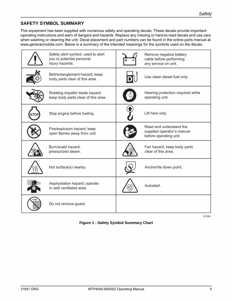
SAFETY SYMBOL SUMMARYThis equipment has been supplied with numerous safety and operating decals. These decals provide important operating instructions and warn of dangers and hazards. Replace any missing or hard-to-read decals and use care when washing or cleaning the unit. Decal placement and part numbers can be found in the online parts manual at www.generacmobile.com. Below is a summary of the intended meanings for the symbols used on the decals.
Figure 1 - Safety Symbol Summary Chart
Read and understand the supplied operator’s manual before operating unit.
Fan hazard; keep body partsclear of this area.
Anchor/tie down point.
Autostart.
Burn/scald hazard;pressurized steam.
Do not remove guard.
Hot surface(s) nearby.
Lift here only.
Safety alert symbol; used to alertyou to potential personal injury hazards.
Hearing protection required whileoperating unit.
Belt/entanglement hazard; keep body parts clear of this area.
Rotating impeller blade hazard; keep body parts clear of this area.
Stop engine before fueling.
Fire/explosion hazard; keep open flames away from unit.
Asphyxiation hazard; operate in well ventilated area.
Remove negative battery cable before performing any service on unit.
Use clean diesel fuel only.
01264
31651 ORG MTP4000-6000SZ Operating Manual 5

Safety
This Page Intentionally Left Blank
6 MTP4000-6000SZ Operating Manual 31651 ORG
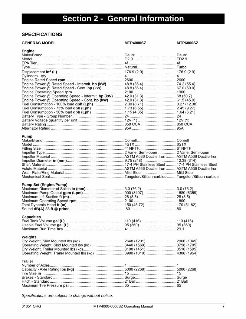
Section 2 - General Information
SPECIFICATIONSGENERAC MODEL MTP4000SZ MTP6000SZ
EngineMake/Brand.............................................................................Deutz.......................................DeutzModel ......................................................................................D2.9.........................................TD2.9 EPA Tier ..................................................................................4f .............................................4fType ........................................................................................Natural.....................................TurboDisplacement in3 (L) ...............................................................176.9 (2.9) ...............................176.9 (2.9)Cylinders - qty .........................................................................4 ..............................................4Engine Rated Speed rpm ......................................................2600 ........................................2600Engine Power @ Rated Speed - Intermit. hp (kW) ................48.8 (36.4) ...............................74.2 (55.4)Engine Power @ Rated Speed - Cont. hp (kW) .....................48.8 (36.4) ...............................67.0 (50.0)Engine Operating Speed rpm .................................................2100 ........................................1900Engine Power @ Operating Speed - Intermit. hp (kW) ..........42.0 (31.3) ...............................68 (50.7)Engine Power @ Operating Speed - Cont. hp (kW) ...............42.0 (31.3) ...............................61.5 (45.9)Fuel Consumption - 100% load gph (Lph) ............................2.30 (8.71)...............................3.27 (12.38) Fuel Consumption - 75% load gph (Lph) ...............................1.73 (6.55)...............................2.45 (9.27)Fuel Consumption - 50% load gph (Lph) ...............................1.15 (4.35)...............................1.64 (6.21)Battery Type - Group Number .................................................24 ............................................24Battery Voltage (quantity per unit)...........................................12V (1) ....................................12V (1)Battery Rating .........................................................................850 CCA..................................850 CCAAlternator Rating .....................................................................95A..........................................95A
PumpMake/Brand.............................................................................Cornell .....................................CornellModel ......................................................................................4STX .......................................6STXFitting Size ..............................................................................4" NPTF...................................6" NPTFImpeller Type...........................................................................2 Vane, Semi-open..................2 Vane, Semi-openImpeller Material .....................................................................ASTM A536 Ductile Iron ..........ASTM A536 Ductile IronImpeller Diameter in (mm)......................................................9.75 (248)................................12.38 (314)Shaft Material ..........................................................................17-4 PH Stainless Steel ..........17-4 PH Stainless SteelVolute Material ........................................................................ASTM A536 Ductile Iron ..........ASTM A536 Ductile IronWear Plate/Ring Material ........................................................Mild Steel ................................Mild SteelMechanical Seal......................................................................Tungsten/Silicon-carbide.........Tungsten/Silicon-carbide
Pump Set (Engine/Pump)Maximum Diameter of Solids in (mm) ...................................3.0 (76.2) .................................3.0 (76.2)Maximum Pump Output gpm (Lpm).......................................900 (3407)...............................1680 (6359)Maximum Lift Suction ft (m)....................................................28 (8.5) ....................................28 (8.5)Maximum Operating Speed rpm ...........................................2100 ........................................1800Total Dynamic Head ft (m) .....................................................150 (45.72)..............................170 (51.82)Sound dB(A) 23 ft @ prime ................................................... 80 ...........................................80
CapacitiesFuel Tank Volume gal (L) .......................................................110 (416) .................................110 (416)Usable Fuel Volume gal (L) ...................................................95 (360)...................................95 (360)Maximum Run Time hrs .........................................................41 ............................................29.1
WeightsDry Weight, Skid Mounted lbs (kg)..........................................2648 (1201).............................2966 (1345) Operating Weight, Skid Mounted lbs (kg) ..............................3440 (1560).............................3758 (1705)Dry Weight, Trailer Mounted lbs (kg).......................................3198 (1451).............................3516 (1595)Operating Weight, Trailer Mounted lbs (kg) ...........................3990 (1810).............................4308 (1954)
TrailerNumber of Axles......................................................................1 ..............................................1Capacity - Axle Rating lbs (kg) ..............................................5000 (2268).............................5000 (2268)Tire Size in .............................................................................15 ............................................15Brakes - Standard ...................................................................Surge.......................................SurgeHitch - Standard ......................................................................2" Ball ......................................2" BallMaximum Tire Pressure psi ...................................................65 ............................................65
Specifications are subject to change without notice.
31651 ORG MTP4000-6000SZ Operating Manual 7
General Information
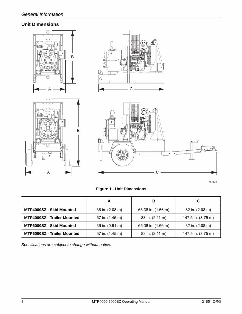
Unit Dimensions
Figure 1 - Unit Dimensions
Specifications are subject to change without notice.
A B C
MTP4000SZ - Skid Mounted 36 in. (2.08 m) 65.38 in. (1.66 m) 82 in. (2.08 m)
MTP4000SZ - Trailer Mounted 57 in. (1.45 m) 83 in. (2.11 m) 147.5 in. (3.75 m)
MTP6000SZ - Skid Mounted 36 in. (0.91 m) 65.38 in. (1.66 m) 82 in. (2.08 m)
MTP6000SZ - Trailer Mounted 57 in. (1.45 m) 83 in. (2.11 m) 147.5 in. (3.75 m)
A C
B
A
B
01521
C
8 MTP4000-6000SZ Operating Manual 31651 ORG
General Information
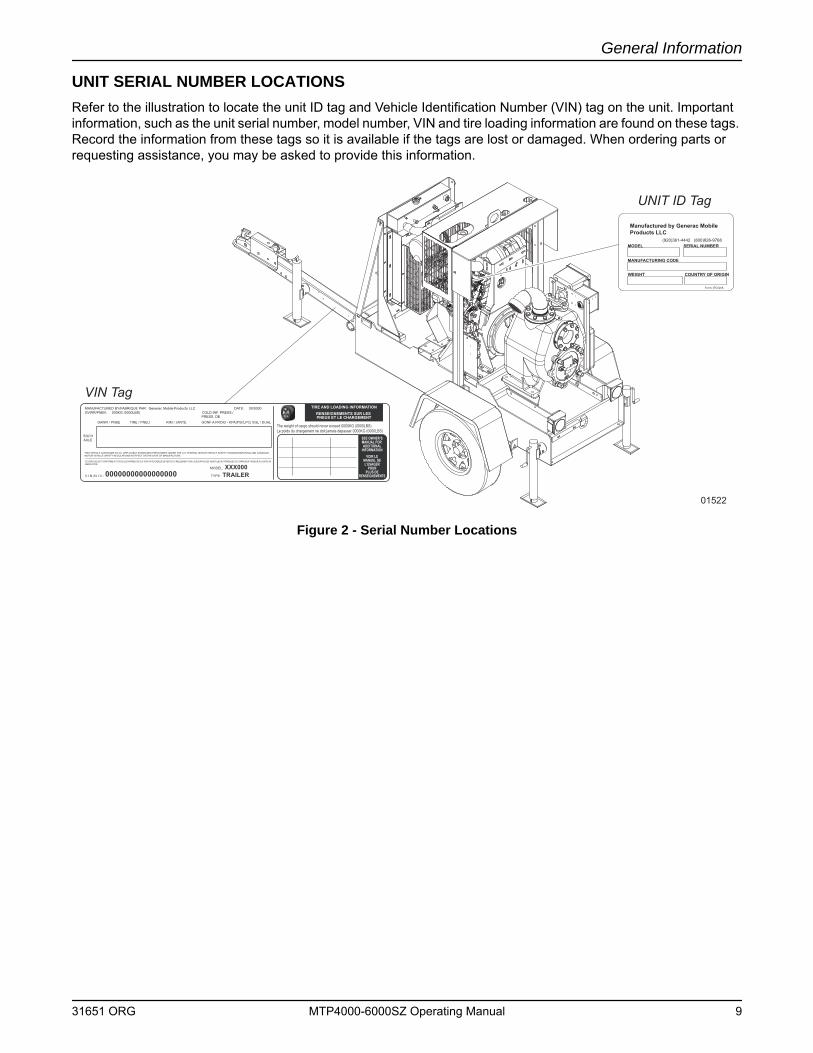
UNIT SERIAL NUMBER LOCATIONSRefer to the illustration to locate the unit ID tag and Vehicle Identification Number (VIN) tag on the unit. Important information, such as the unit serial number, model number, VIN and tire loading information are found on these tags. Record the information from these tags so it is available if the tags are lost or damaged. When ordering parts or requesting assistance, you may be asked to provide this information.
Figure 2 - Serial Number Locations
VIN Tag
UNIT ID Tag
TIRE AND LOADING INFORMATIONRENSEIGNEMENTS SUR LES PNEUS ET LE CHARGEMENT
SEE OWNER’SMANUAL FOR ADDITIONAL
INFORMATIONVOIR LE
MANUEL DEL’USAGER
POURPLUS DE
RENSEIGNEMENTS
MANUFACTURED BY/FABRIQUE PAR: Generac Mobile Products LLC DATE: 00/0000GVWR/PNBV: 000KG (0000LBS) COLD INF. PRESS./ PRESS. DE
V.I.N./N.I.V.:
00000000000000000
TYPE:
TRAILER
MODEL:
XXX000
GAWR / PNBE TIRE / PNEU RIM / JANTE GONF A FROID - KPA(PSI/LPC) SGL / DUAL
EACHAXLE
THIS VEHICLE CONFORMS TO ALL APPLICABLE STANDARDS PRESCRIBED UNDER THE U.S. FEDERAL MOTOR VEHICLE SAFETY STANDARDS(FMVSS) AND CANADIAN MOTOR VEHICLE SAFETY REGULATIONS IN EFFECT ON THE DATE OF MANUFACTURE.
CE VEHICULE EST CONFORME A TOUTES LES NORMES QUI LUI SONT APPLICABLES EN VERTU DU REGLEMENT SUR LA SECURITE DES VEHICULES AUTOMOBILES DU CANADA EN VIGUEUR A LA DATE SA FABRICATION.
The weight of cargo should never exceed 0000KG (0000LBS)Le poids du chargement ne doit jamais depasser 0000KG (0000LBS)
01522
Manufactured by Generac MobileProducts LLC
(920)361-4442 (800)926-9768MODEL
WEIGHT COUNTRY OF ORIGIN
SERIAL NUMBER
MANUFACTURING CODE
Form: SFC626A
31651 ORG MTP4000-6000SZ Operating Manual 9
General Information
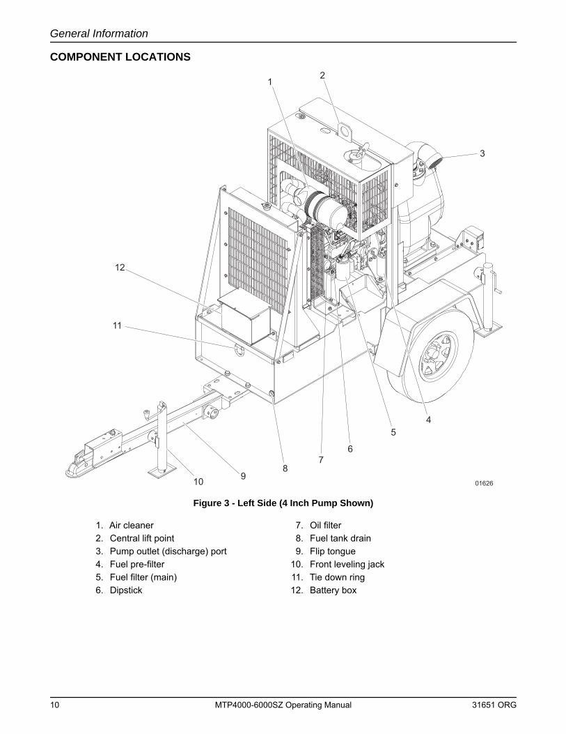
COMPONENT LOCATIONS
Figure 3 - Left Side (4 Inch Pump Shown)
1. Air cleaner 7. Oil filter2. Central lift point 8. Fuel tank drain3. Pump outlet (discharge) port 9. Flip tongue4. Fuel pre-filter 10. Front leveling jack5. Fuel filter (main) 11. Tie down ring6. Dipstick 12. Battery box
01626
12
3
54
6
89
7
10
11
12
10 MTP4000-6000SZ Operating Manual 31651 ORG
General Information
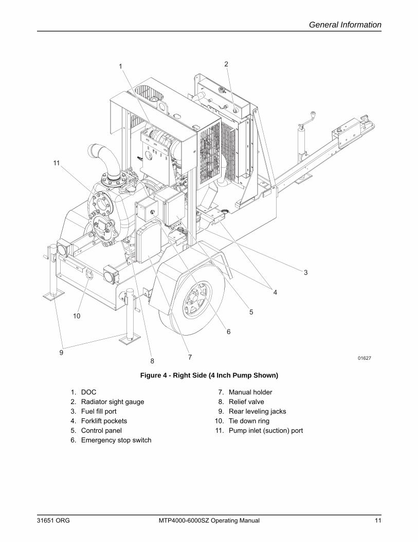
Figure 4 - Right Side (4 Inch Pump Shown)
1. DOC 7. Manual holder2. Radiator sight gauge 8. Relief valve3. Fuel fill port 9. Rear leveling jacks4. Forklift pockets 10. Tie down ring5. Control panel 11. Pump inlet (suction) port6. Emergency stop switch
01627
1 2
3
4
5
6
789
10
11
31651 ORG MTP4000-6000SZ Operating Manual 11
General Information
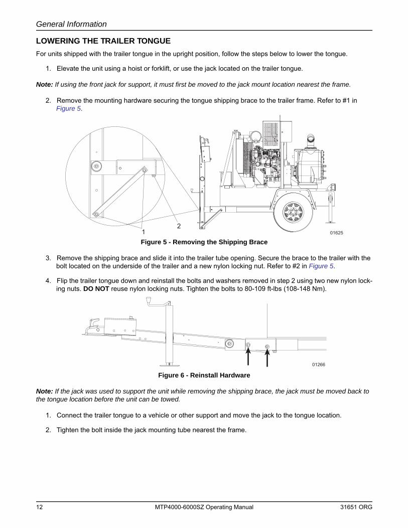
LOWERING THE TRAILER TONGUEFor units shipped with the trailer tongue in the upright position, follow the steps below to lower the tongue.
1. Elevate the unit using a hoist or forklift, or use the jack located on the trailer tongue.
Note: If using the front jack for support, it must first be moved to the jack mount location nearest the frame.
2. Remove the mounting hardware securing the tongue shipping brace to the trailer frame. Refer to #1 in Figure 5.
Figure 5 - Removing the Shipping Brace
3. Remove the shipping brace and slide it into the trailer tube opening. Secure the brace to the trailer with the bolt located on the underside of the trailer and a new nylon locking nut. Refer to #2 in Figure 5.
4. Flip the trailer tongue down and reinstall the bolts and washers removed in step 2 using two new nylon lock-ing nuts. DO NOT reuse nylon locking nuts. Tighten the bolts to 80-109 ft-lbs (108-148 Nm).
Figure 6 - Reinstall Hardware
Note: If the jack was used to support the unit while removing the shipping brace, the jack must be moved back to the tongue location before the unit can be towed.
1. Connect the trailer tongue to a vehicle or other support and move the jack to the tongue location.
2. Tighten the bolt inside the jack mounting tube nearest the frame.
12
01625
01266
12 MTP4000-6000SZ Operating Manual 31651 ORG
General Information
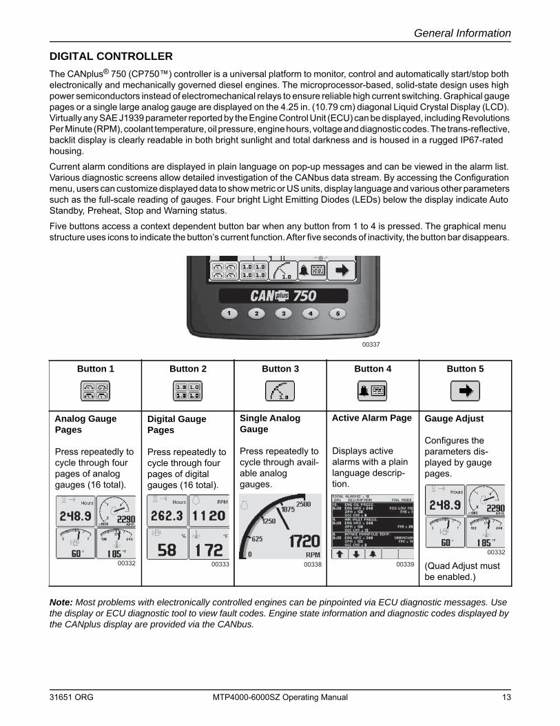
DIGITAL CONTROLLERThe CANplus® 750 (CP750™) controller is a universal platform to monitor, control and automatically start/stop both electronically and mechanically governed diesel engines. The microprocessor-based, solid-state design uses high power semiconductors instead of electromechanical relays to ensure reliable high current switching. Graphical gauge pages or a single large analog gauge are displayed on the 4.25 in. (10.79 cm) diagonal Liquid Crystal Display (LCD). Virtually any SAE J1939 parameter reported by the Engine Control Unit (ECU) can be displayed, including Revolutions Per Minute (RPM), coolant temperature, oil pressure, engine hours, voltage and diagnostic codes. The trans-reflective, backlit display is clearly readable in both bright sunlight and total darkness and is housed in a rugged IP67-rated housing.
Current alarm conditions are displayed in plain language on pop-up messages and can be viewed in the alarm list. Various diagnostic screens allow detailed investigation of the CANbus data stream. By accessing the Configuration menu, users can customize displayed data to show metric or US units, display language and various other parameters such as the full-scale reading of gauges. Four bright Light Emitting Diodes (LEDs) below the display indicate Auto Standby, Preheat, Stop and Warning status.
Five buttons access a context dependent button bar when any button from 1 to 4 is pressed. The graphical menu structure uses icons to indicate the button’s current function. After five seconds of inactivity, the button bar disappears.
Note: Most problems with electronically controlled engines can be pinpointed via ECU diagnostic messages. Use the display or ECU diagnostic tool to view fault codes. Engine state information and diagnostic codes displayed by the CANplus display are provided via the CANbus.
Button 1 Button 2 Button 3 Button 4 Button 5
Analog Gauge Pages
Press repeatedly to cycle through four pages of analog gauges (16 total).
Digital Gauge Pages
Press repeatedly to cycle through four pages of digital gauges (16 total).
Single Analog Gauge
Press repeatedly to cycle through avail-able analog gauges.
Active Alarm Page
Displays active alarms with a plain language descrip-tion.
Gauge Adjust
Configures the parameters dis-played by gauge pages.
(Quad Adjust must be enabled.)
00337
00332 00333 00338 00339
00332
31651 ORG MTP4000-6000SZ Operating Manual 13
General Information
Automatic OperationThe CP750™ panel features advanced automatic start/stop controls which can meet almost any requirement. Two switch inputs and a transducer input support a number of control scenarios. Single switch mode allows reliable operation with a single switch. Dual switch operation allows greater hysteresis when needed.
The transducer input supports simple start/stop operation by level or pressure and maintenance modes with speed modification.
• Programmable high and low set points control start/stop operation.
• Level maintenance modes monitor the operating point and adjust the engine speed to match the targeted set point with configurable aggressiveness.
• Dual switch inputs can be combined with the transducer input for redundant safety to protect against transducer sensor clog or failure.
Throttle ControlThe standard ramp throttle uses a momentary rocker switch to adjust the integral throttle control. All throttle commands are sent directly to the engine using CANbus throttle control.
Service TimersThe CP750™ display provides 16 service timers to alert the operator of needed maintenance. The time interval for each timer can be adjusted in 10 hour increments. A pop-up message is displayed after the display self test if a timer has expired, alerting the user that service is required. The message is displayed on each power up until the elapsed timer is disabled or reset.
CANplus Messenger Telemetry OptionThe optional CANplus Messenger system provides a variety of features to protect and support the equipment investment. Remote monitoring can alert maintenance requirements, operational problems, improper operation and location with geo-fence alert. The web-browser interface allows monitoring an entire fleet of equipment in a central location. Contact Generac Mobile Products for more information.
Button LockThe controller’s five buttons can be locked so the operator does not accidentally change settings or access another display mode. Button Lock is enabled by pressing and holding buttons 1 and 5 simultaneously for one second. Repeating this operation restores normal button operation.
14 MTP4000-6000SZ Operating Manual 31651 ORG
General Information
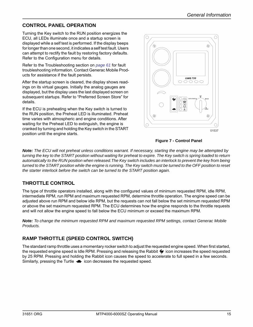
CONTROL PANEL OPERATIONTurning the Key switch to the RUN position energizes the ECU, all LEDs illuminate once and a startup screen is displayed while a self test is performed. If the display beeps for longer than one second, it indicates a self test fault. Users can attempt to rectify the fault by restoring factory defaults. Refer to the Configuration menu for details.
Refer to the Troubleshooting section on page 61 for fault troubleshooting information. Contact Generac Mobile Prod-ucts for assistance if the fault persists.
After the startup screen is cleared, the display shows read-ings on its virtual gauges. Initially the analog gauges are displayed, but the display uses the last displayed screen on subsequent startups. Refer to “Preferred Screen Store” for details.
If the ECU is preheating when the Key switch is turned to the RUN position, the Preheat LED is illuminated. Preheat time varies with atmospheric and engine conditions. After waiting for the Preheat LED to extinguish, the engine is cranked by turning and holding the Key switch in the START position until the engine starts.
Figure 7 - Control Panel
Note: The ECU will not preheat unless conditions warrant. If necessary, starting the engine may be attempted by turning the key to the START position without waiting for preheat to expire. The Key switch is spring loaded to return automatically to the RUN position when released.The Key switch includes an interlock to prevent the key from being turned to the START position while the engine is running. The Key switch must be turned to the OFF position to reset the starter interlock before the switch can be turned to the START position again.
THROTTLE CONTROLThe type of throttle operators installed, along with the configured values of minimum requested RPM, idle RPM, intermediate RPM, run RPM and maximum requested RPM, determine throttle operation. The engine speed can be adjusted above run RPM and below idle RPM, but the requests can not fall below the set minimum requested RPM or above the set maximum requested RPM. The ECU determines how the engine responds to the throttle requests and will not allow the engine speed to fall below the ECU minimum or exceed the maximum RPM.
Note: To change the minimum requested RPM and maximum requested RPM settings, contact Generac Mobile Products.
RAMP THROTTLE (SPEED CONTROL SWITCH)The standard ramp throttle uses a momentary rocker switch to adjust the requested engine speed. When first started, the requested engine speed is Idle RPM. Pressing and releasing the Rabbit icon increases the speed requested by 25 RPM. Pressing and holding the Rabbit icon causes the speed to accelerate to full speed in a few seconds. Similarly, pressing the Turtle icon decreases the requested speed.
750750®
OFF
AUTO START RUN
START
AUTOSTANDBY
01537
31651 ORG MTP4000-6000SZ Operating Manual 15
General Information
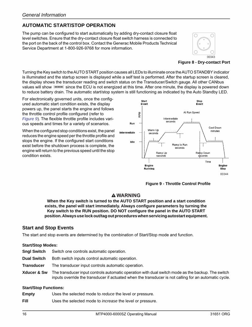
AUTOMATIC START/STOP OPERATIONThe pump can be configured to start automatically by adding dry-contact closure float level switches. Ensure that the dry-contact closure float switch harness is connected to the port on the back of the control box. Contact the Generac Mobile Products Technical Service Department at 1-800-926-9768 for more information.
Figure 8 - Dry-contact Port
Turning the Key switch to the AUTO START position causes all LEDs to illuminate once the AUTO STANDBY indicator is illuminated and the startup screen is displayed while a self test is performed. After the startup screen is cleared, the display shows the transducer reading and switch status on the Transducer/Switch gauge. All other CANbus values will show since the ECU is not energized at this time. After one minute, the display is powered down to reduce battery drain. The automatic start/stop system is still functioning as indicated by the Auto Standby LED.
For electronically governed units, once the config-ured automatic start condition exists, the display powers up, the panel starts the engine and follows the throttle control profile configured (refer to Figure 9). The flexible throttle profile includes vari-ous speeds and times for a variety of scenarios.
When the configured stop conditions exist, the panel reduces the engine speed per the throttle profile and stops the engine. If the configured start conditions exist before the shutdown process is complete, the engine will return to the previous speed until the stop condition exists.
Figure 9 - Throttle Control Profile
WARNINGWhen the Key switch is turned to the AUTO START position and a start condition
exists, the panel will start immediately. Always configure parameters by turning the Key switch to the RUN position. DO NOT configure the panel in the AUTO START
position. Always use lock out/tag out procedures when servicing autostart equipment.
Start and Stop EventsThe start and stop events are determined by the combination of Start/Stop mode and function.
Start/Stop Modes:Sngl Switch Switch one controls automatic operation.
Dual Switch Both switch inputs control automatic operation.
Transducer The transducer input controls automatic operation.
Xducer & Sw The transducer input controls automatic operation with dual switch mode as the backup. The switch inputs override the transducer if actuated when the transducer is not calling for an automatic cycle.
Start/Stop Functions:Empty Uses the selected mode to reduce the level or pressure.
Fill Uses the selected mode to increase the level or pressure.
00343
00344
16 MTP4000-6000SZ Operating Manual 31651 ORG
General Information
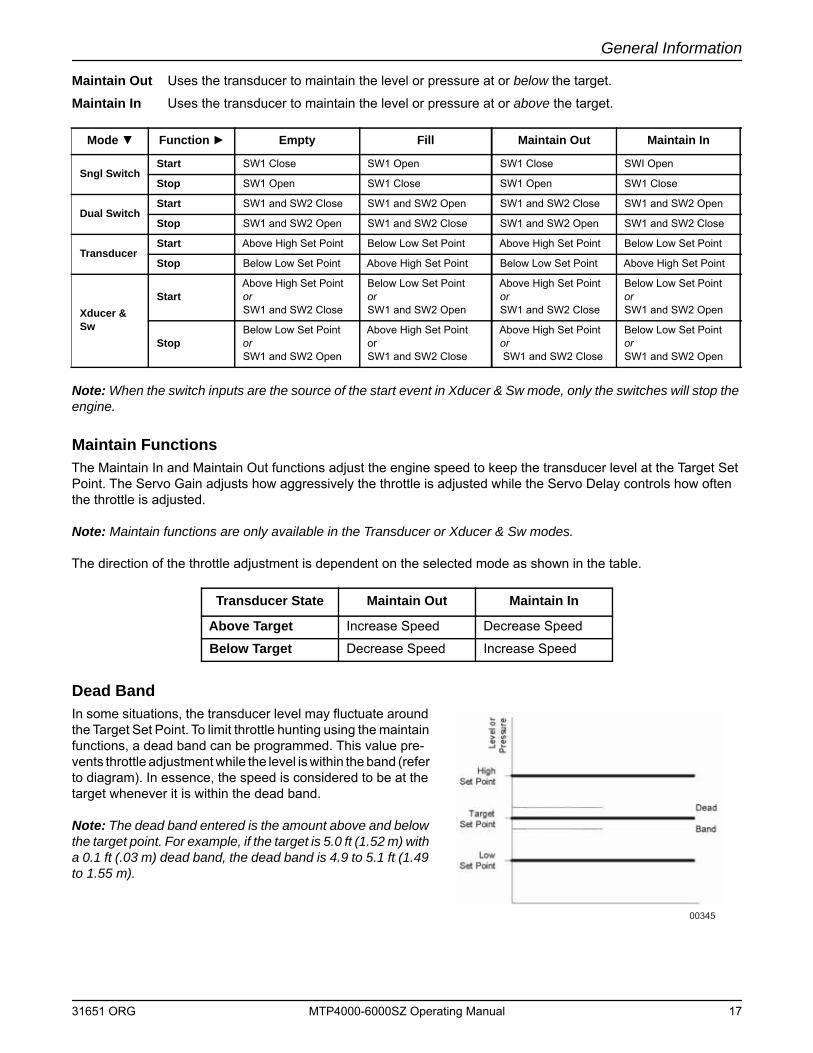
Maintain Out Uses the transducer to maintain the level or pressure at or below the target.
Maintain In Uses the transducer to maintain the level or pressure at or above the target.
Note: When the switch inputs are the source of the start event in Xducer & Sw mode, only the switches will stop the engine.
Maintain FunctionsThe Maintain In and Maintain Out functions adjust the engine speed to keep the transducer level at the Target Set Point. The Servo Gain adjusts how aggressively the throttle is adjusted while the Servo Delay controls how often the throttle is adjusted.
Note: Maintain functions are only available in the Transducer or Xducer & Sw modes.
The direction of the throttle adjustment is dependent on the selected mode as shown in the table.
Dead BandIn some situations, the transducer level may fluctuate around the Target Set Point. To limit throttle hunting using the maintain functions, a dead band can be programmed. This value pre-vents throttle adjustment while the level is within the band (refer to diagram). In essence, the speed is considered to be at the target whenever it is within the dead band.
Note: The dead band entered is the amount above and below the target point. For example, if the target is 5.0 ft (1.52 m) with a 0.1 ft (.03 m) dead band, the dead band is 4.9 to 5.1 ft (1.49 to 1.55 m).
Mode ▼ Function ► Empty Fill Maintain Out Maintain In
Sngl SwitchStart SW1 Close SW1 Open SW1 Close SWI Open
Stop SW1 Open SW1 Close SW1 Open SW1 Close
Dual SwitchStart SW1 and SW2 Close SW1 and SW2 Open SW1 and SW2 Close SW1 and SW2 Open
Stop SW1 and SW2 Open SW1 and SW2 Close SW1 and SW2 Open SW1 and SW2 Close
TransducerStart Above High Set Point Below Low Set Point Above High Set Point Below Low Set Point
Stop Below Low Set Point Above High Set Point Below Low Set Point Above High Set Point
Xducer & Sw
StartAbove High Set Point or SW1 and SW2 Close
Below Low Set Point or SW1 and SW2 Open
Above High Set Point or SW1 and SW2 Close
Below Low Set Point or SW1 and SW2 Open
StopBelow Low Set Point or SW1 and SW2 Open
Above High Set Point orSW1 and SW2 Close
Above High Set Point or SW1 and SW2 Close
Below Low Set Point orSW1 and SW2 Open
Transducer State Maintain Out Maintain In
Above Target Increase Speed Decrease Speed
Below Target Decrease Speed Increase Speed
00345
31651 ORG MTP4000-6000SZ Operating Manual 17
General Information
CANPLUS DISPLAYSoft buttons simplify the user interface by displaying a button bar above the buttons when any of the first four buttons (buttons 1 to 4), starting from the left) are pressed. Icons on the button bar change to represent the current function of each button. The button bar disappears after five seconds if no further buttons are pressed.
Note: Different software versions may have slightly different displays.
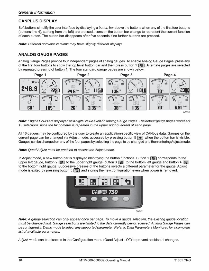
ANALOG GAUGE PAGESAnalog Gauge Pages provide four independent pages of analog gauges. To enable Analog Gauge Pages, press any of the first four buttons to show the top level button bar and then press button 1 . Alternate pages are selected by repeated pressing of button 1. The four standard gauge pages are shown below.
Note: Engine Hours are displayed as a digital value even on Analog Gauge Pages. The default gauge pages represent 13 selections since the tachometer is repeated in the upper right quadrant of each page.
All 16 gauges may be configured by the user to create an application-specific view of CANbus data. Gauges on the current page can be changed via Adjust mode, accessed by pressing button 5 when the button bar is visible. Gauges can be changed on any of the four pages by selecting the page to be changed and then entering Adjust mode.
Note: Quad Adjust must be enabled to access the Adjust mode.
In Adjust mode, a new button bar is displayed identifying the button functions. Button 1 corresponds to the upper left gauge, button 2 to the upper right gauge, button 3 to the bottom left gauge and button 4 to the bottom right gauge. Successive presses of the buttons selects a different parameter for the gauge. Adjust mode is exited by pressing button 5 and storing the new configuration even when power is removed.
Note: A gauge selection can only appear once per page. To move a gauge selection, the existing gauge location must be changed first. Gauge selections are limited to the data currently being received. Analog Gauge Pages can be configured in Demo mode to select any supported parameter. Refer to Data Parameters Monitored for a complete list of available parameters.
Adjust mode can be disabled in the Configuration menu (Quad Adjust - Off) to prevent accidental changes.
Page 1 Page 2 Page 3 Page 4
00331
00342
18 MTP4000-6000SZ Operating Manual 31651 ORG
General Information
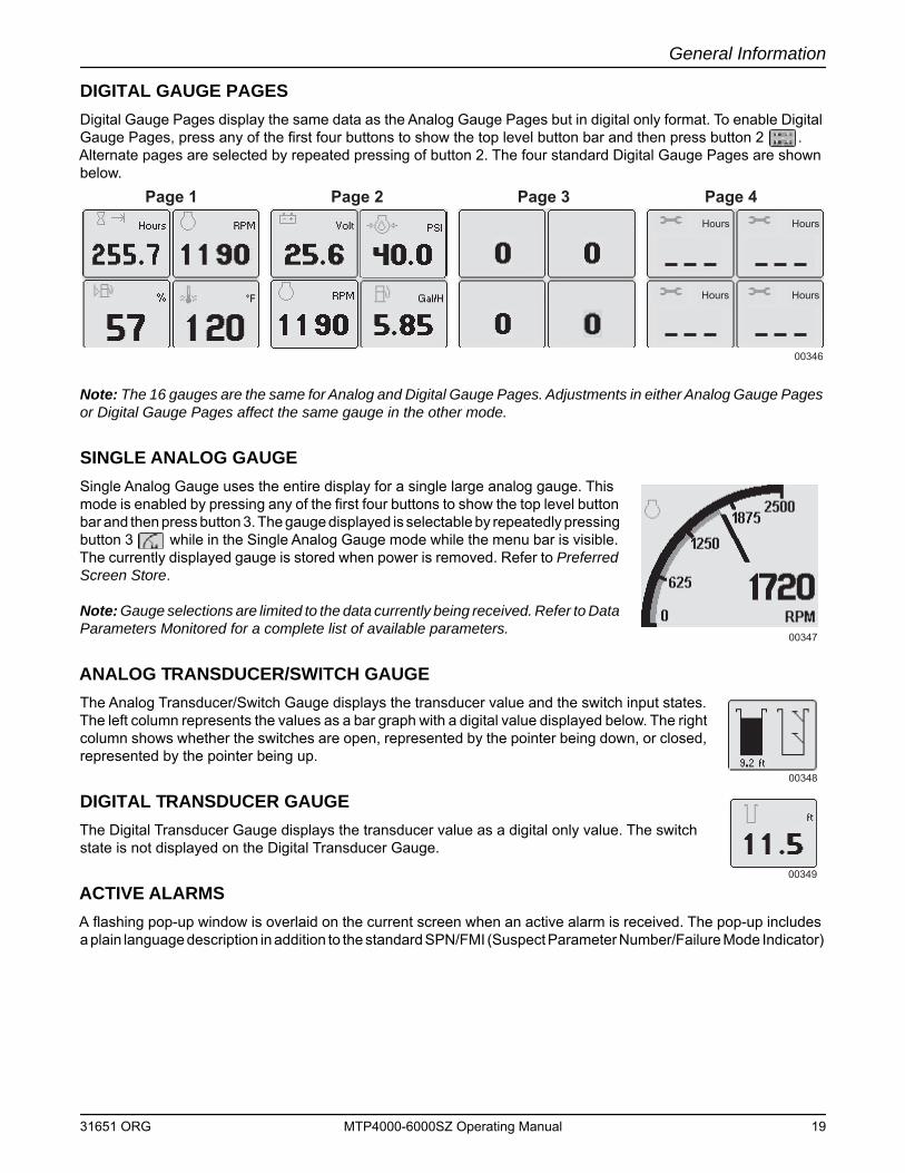
DIGITAL GAUGE PAGESDigital Gauge Pages display the same data as the Analog Gauge Pages but in digital only format. To enable Digital Gauge Pages, press any of the first four buttons to show the top level button bar and then press button 2 . Alternate pages are selected by repeated pressing of button 2. The four standard Digital Gauge Pages are shown below.
Note: The 16 gauges are the same for Analog and Digital Gauge Pages. Adjustments in either Analog Gauge Pages or Digital Gauge Pages affect the same gauge in the other mode.
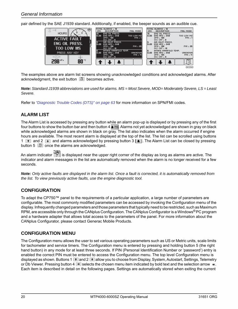
SINGLE ANALOG GAUGESingle Analog Gauge uses the entire display for a single large analog gauge. This mode is enabled by pressing any of the first four buttons to show the top level button bar and then press button 3. The gauge displayed is selectable by repeatedly pressing button 3 while in the Single Analog Gauge mode while the menu bar is visible. The currently displayed gauge is stored when power is removed. Refer to Preferred Screen Store.
Note: Gauge selections are limited to the data currently being received. Refer to Data Parameters Monitored for a complete list of available parameters.
ANALOG TRANSDUCER/SWITCH GAUGEThe Analog Transducer/Switch Gauge displays the transducer value and the switch input states. The left column represents the values as a bar graph with a digital value displayed below. The right column shows whether the switches are open, represented by the pointer being down, or closed, represented by the pointer being up.
DIGITAL TRANSDUCER GAUGEThe Digital Transducer Gauge displays the transducer value as a digital only value. The switch state is not displayed on the Digital Transducer Gauge.
ACTIVE ALARMSA flashing pop-up window is overlaid on the current screen when an active alarm is received. The pop-up includes a plain language description in addition to the standard SPN/FMI (Suspect Parameter Number/Failure Mode Indicator)
Page 1 Page 2 Page 3 Page 4
00346
Hours Hours
Hours Hours
00347
00348
00349
31651 ORG MTP4000-6000SZ Operating Manual 19
General Information
pair defined by the SAE J1939 standard. Additionally, if enabled, the beeper sounds as an audible cue.
The examples above are alarm list screens showing unacknowledged conditions and acknowledged alarms. After acknowledgment, the exit button becomes active.
Note: Standard J1939 abbreviations are used for alarms. MS = Most Severe, MOD= Moderately Severe, LS = Least Severe.
Refer to “Diagnostic Trouble Codes (DTS)” on page 63 for more information on SPN/FMI codes.
ALARM LISTThe Alarm List is accessed by pressing any button while an alarm pop-up is displayed or by pressing any of the first four buttons to show the button bar and then button 4 . Alarms not yet acknowledged are shown in gray on black while acknowledged alarms are shown in black on gray. The list also indicates when the alarm occurred if engine hours are available. The most recent alarm is displayed at the top of the list. The list can be scrolled using buttons 1 and 2 and alarms acknowledged by pressing button 3 . The Alarm List can be closed by pressing button 5 once the alarms are acknowledged.
An alarm indicator is displayed near the upper right corner of the display as long as alarms are active. The indicator and alarm messages in the list are automatically removed when the alarm is no longer received for a few seconds.
Note: Only active faults are displayed in the alarm list. Once a fault is corrected, it is automatically removed from the list. To view previously active faults, use the engine diagnostic tool.
CONFIGURATIONTo adapt the CP750™ panel to the requirements of a particular application, a large number of parameters are configurable. The most commonly modified parameters can be accessed by invoking the Configuration menu of the display. Infrequently changed parameters and those parameters that typically need to be restricted, such as Maximum RPM, are accessible only through the CANplus Configuration. The CANplus Configurator is a Windows® PC program and a hardware adapter that allows total access to the parameters of the panel. For more information about the CANplus Configurator, please contact Generac Mobile Products.
CONFIGURATION MENUThe Configuration menu allows the user to set various operating parameters such as US or Metric units, scale limits for tachometer and service timers. The Configuration menu is entered by pressing and holding button 5 (the right hand button) in any mode for at least three seconds. If PIN (Personal Identification Number or ‘password’) entry is enabled the correct PIN must be entered to access the Configuration menu. The top level Configuration menu is displayed as shown. Buttons 1 and 2 allow you to choose from Display, System, Autostart, Settings, Telemetry or Db Viewer. Pressing button 4 selects the chosen menu item indicated by bold text and the selection arrow . Each item is described in detail on the following pages. Settings are automatically stored when exiting the current
00350
20 MTP4000-6000SZ Operating Manual 31651 ORG
General Information
menu even when power is removed.
Note: Most configuration changes take affect immediately. Some, such as Idle RPM, take effect on the next power up.
DISPLAY MENUThe Display menu allows the user to configure items affecting how information is displayed.
Units MenuThis menu allows the user to set the units used for speed, distance, pressure, volume and temperature independently. Button 4 cycles through the available values for the selected item.
Speed MPH (miles per hour); km/h (kilometers per hour); Knts (knots)
Distance Miles; km (kilometers); NM (nautical miles)
Pressure PSI (pounds per square inch); bar (barometric units); kPa (kilopas cals)
Volume Gal (US gallons); IGal (Imperial gallons); Liters
Temperature °F (Fahrenheit); °C (Celsius)
The top level Configuration menu and its six choices.
00351
Service Timers
00352
00353
31651 ORG MTP4000-6000SZ Operating Manual 21
General Information
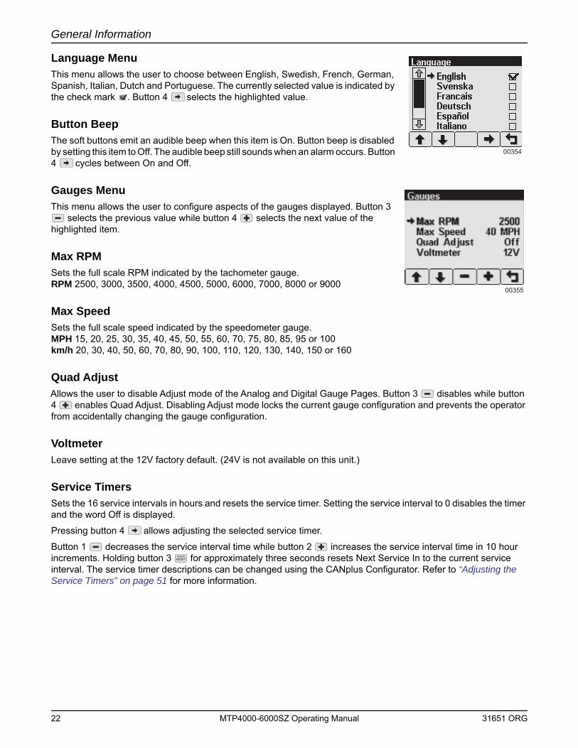
Language MenuThis menu allows the user to choose between English, Swedish, French, German, Spanish, Italian, Dutch and Portuguese. The currently selected value is indicated by the check mark . Button 4 selects the highlighted value.
Button BeepThe soft buttons emit an audible beep when this item is On. Button beep is disabled by setting this item to Off. The audible beep still sounds when an alarm occurs. Button 4 cycles between On and Off.
Gauges MenuThis menu allows the user to configure aspects of the gauges displayed. Button 3
selects the previous value while button 4 selects the next value of the highlighted item.
Max RPMSets the full scale RPM indicated by the tachometer gauge.RPM 2500, 3000, 3500, 4000, 4500, 5000, 6000, 7000, 8000 or 9000
Max SpeedSets the full scale speed indicated by the speedometer gauge.MPH 15, 20, 25, 30, 35, 40, 45, 50, 55, 60, 70, 75, 80, 85, 95 or 100km/h 20, 30, 40, 50, 60, 70, 80, 90, 100, 110, 120, 130, 140, 150 or 160
Quad AdjustAllows the user to disable Adjust mode of the Analog and Digital Gauge Pages. Button 3 disables while button 4 enables Quad Adjust. Disabling Adjust mode locks the current gauge configuration and prevents the operator from accidentally changing the gauge configuration.
VoltmeterLeave setting at the 12V factory default. (24V is not available on this unit.)
Service TimersSets the 16 service intervals in hours and resets the service timer. Setting the service interval to 0 disables the timer and the word Off is displayed.
Pressing button 4 allows adjusting the selected service timer.
Button 1 decreases the service interval time while button 2 increases the service interval time in 10 hour increments. Holding button 3 for approximately three seconds resets Next Service In to the current service interval. The service timer descriptions can be changed using the CANplus Configurator. Refer to “Adjusting the Service Timers” on page 51 for more information.
00354
00355
HOLDRESET
22 MTP4000-6000SZ Operating Manual 31651 ORG
General Information
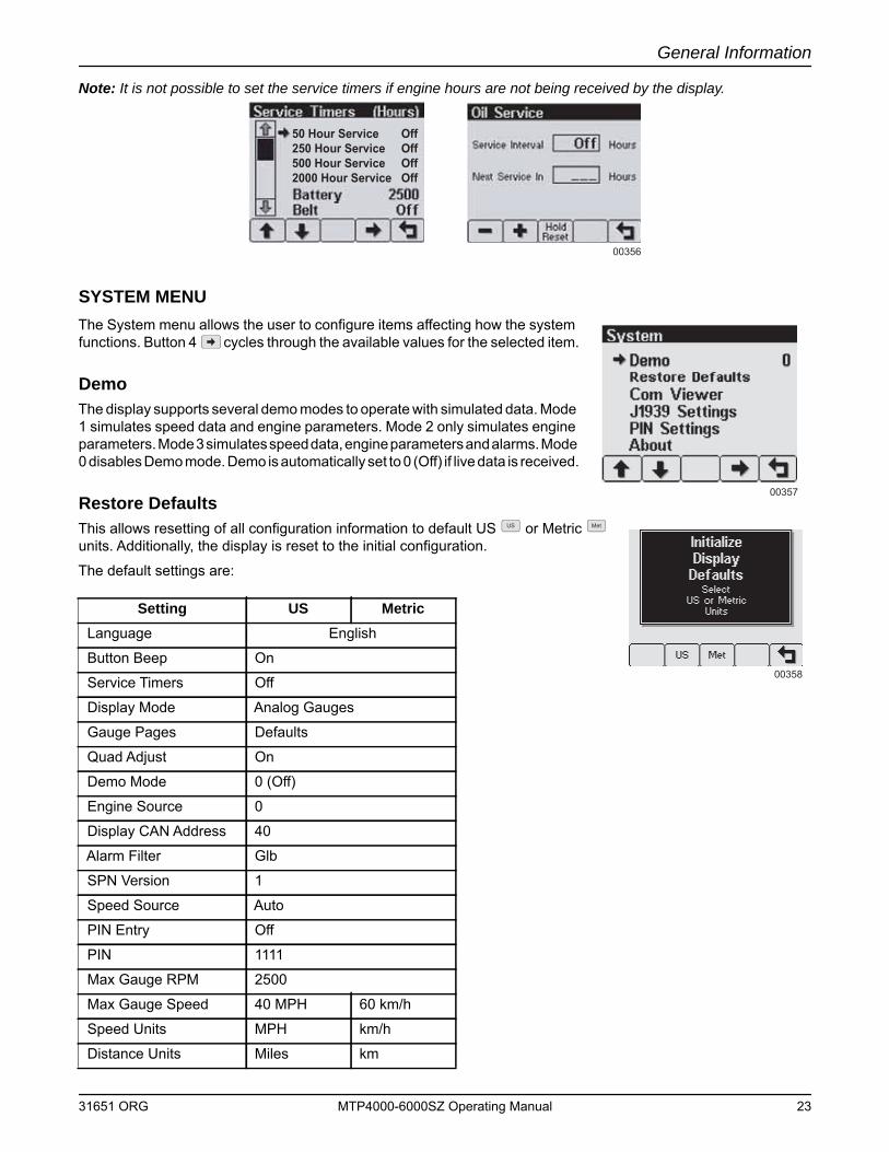
Note: It is not possible to set the service timers if engine hours are not being received by the display.
SYSTEM MENUThe System menu allows the user to configure items affecting how the system functions. Button 4 cycles through the available values for the selected item.
DemoThe display supports several demo modes to operate with simulated data. Mode 1 simulates speed data and engine parameters. Mode 2 only simulates engine parameters. Mode 3 simulates speed data, engine parameters and alarms. Mode 0 disables Demo mode. Demo is automatically set to 0 (Off) if live data is received.
Restore DefaultsThis allows resetting of all configuration information to default US or Metric units. Additionally, the display is reset to the initial configuration.
The default settings are:
Setting US MetricLanguage English
Button Beep On
Service Timers Off
Display Mode Analog Gauges
Gauge Pages Defaults
Quad Adjust On
Demo Mode 0 (Off)
Engine Source 0
Display CAN Address 40
Alarm Filter Glb
SPN Version 1
Speed Source Auto
PIN Entry Off
PIN 1111
Max Gauge RPM 2500
Max Gauge Speed 40 MPH 60 km/h
Speed Units MPH km/h
Distance Units Miles km
00356
50 Hour Service Off250 Hour Service Off500 Hour Service Off2000 Hour Service Off
00357
00358
US Met
31651 ORG MTP4000-6000SZ Operating Manual 23
General Information
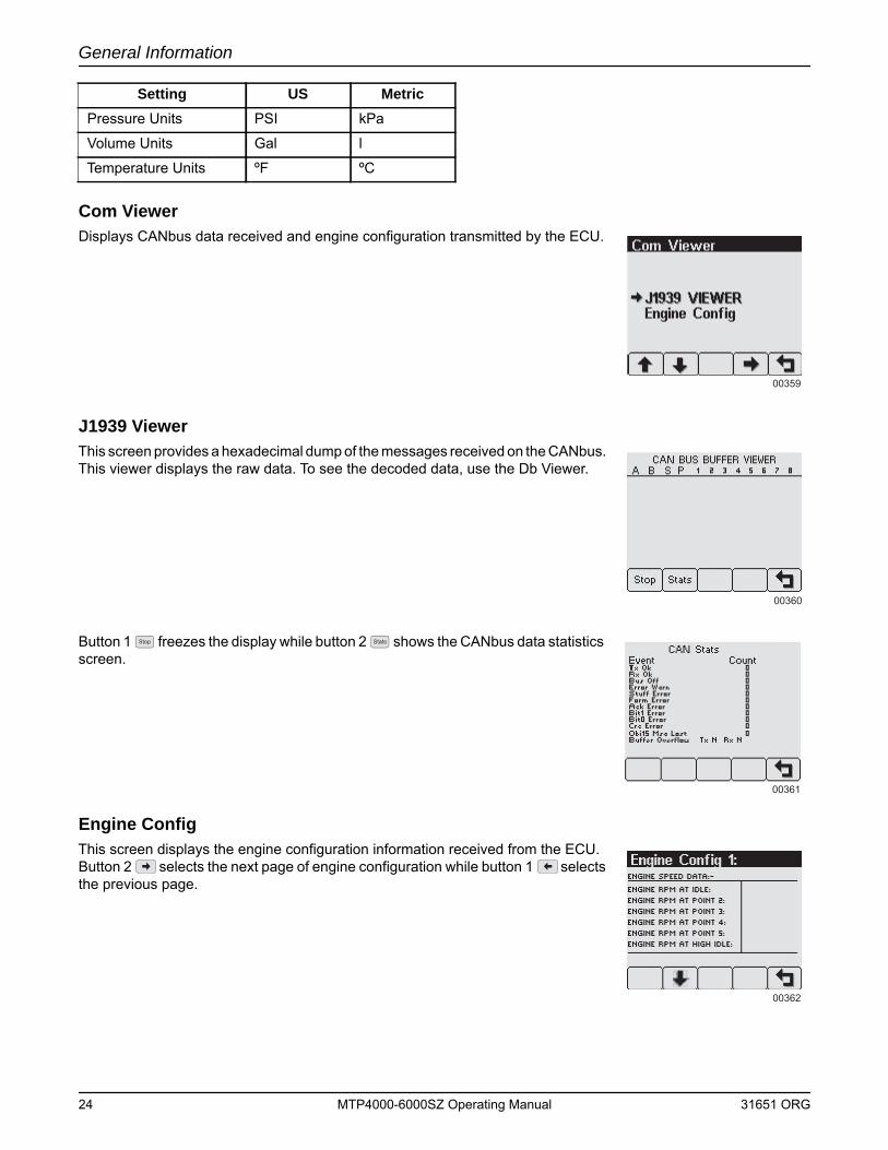
Com ViewerDisplays CANbus data received and engine configuration transmitted by the ECU.
J1939 ViewerThis screen provides a hexadecimal dump of the messages received on the CANbus. This viewer displays the raw data. To see the decoded data, use the Db Viewer.
Button 1 freezes the display while button 2 shows the CANbus data statistics screen.
Engine ConfigThis screen displays the engine configuration information received from the ECU. Button 2 selects the next page of engine configuration while button 1 selects the previous page.
Pressure Units PSI kPa
Volume Units Gal l
Temperature Units ºF ºC
Setting US Metric
00359
00360
00361
Stop Stats
00362
24 MTP4000-6000SZ Operating Manual 31651 ORG
General Information
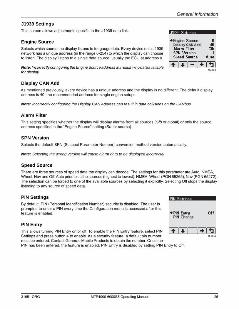
J1939 SettingsThis screen allows adjustments specific to the J1939 data link.
Engine SourceSelects which source the display listens to for gauge data. Every device on a J1939 network has a unique address (in the range 0-254) to which the display can choose to listen. The display listens to a single data source; usually the ECU at address 0.
Note: Incorrectly configuring the Engine Source address will result in no data available for display.
Display CAN AddAs mentioned previously, every device has a unique address and the display is no different. The default display address is 40, the recommended address for single engine setups.
Note: Incorrectly configuring the Display CAN Address can result in data collisions on the CANbus.
Alarm FilterThis setting specifies whether the display will display alarms from all sources (Glb or global) or only the source address specified in the “Engine Source” setting (Src or source).
SPN VersionSelects the default SPN (Suspect Parameter Number) conversion method version automatically.
Note: Selecting the wrong version will cause alarm data to be displayed incorrectly.
Speed SourceThere are three sources of speed data the display can decode. The settings for this parameter are Auto, NMEA, Wheel, Nav and Off. Auto prioritizes the sources (highest to lowest); NMEA, Wheel (PGN 65265), Nav (PGN 65272). The selection can be forced to one of the available sources by selecting it explicitly. Selecting Off stops the display listening to any source of speed data.
PIN SettingsBy default, PIN (Personal Identification Number) security is disabled. The user is prompted to enter a PIN every time the Configuration menu is accessed after this feature is enabled.
PIN EntryThis allows turning PIN Entry on or off. To enable the PIN Entry feature, select PIN Settings and press button 4 to enable. As a security feature, a default pin number must be entered. Contact Generac Mobile Products to obtain the number. Once the PIN has been entered, the feature is enabled. PIN Entry is disabled by setting PIN Entry to Off.
00363
Display CAN Add
00364
31651 ORG MTP4000-6000SZ Operating Manual 25
General Information
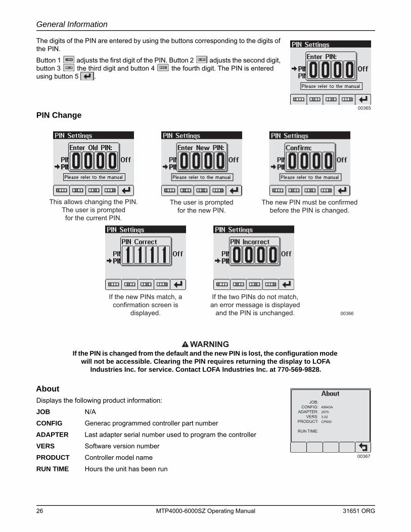
The digits of the PIN are entered by using the buttons corresponding to the digits of the PIN.
Button 1 adjusts the first digit of the PIN. Button 2 adjusts the second digit, button 3 the third digit and button 4 the fourth digit. The PIN is entered using button 5 .
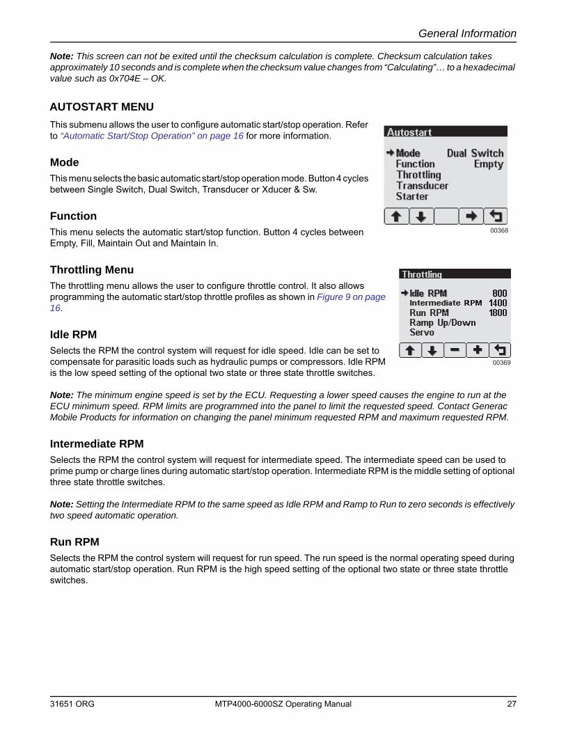
PIN Change
WARNINGIf the PIN is changed from the default and the new PIN is lost, the configuration mode
will not be accessible. Clearing the PIN requires returning the display to LOFA Industries Inc. for service. Contact LOFA Industries Inc. at 770-569-9828.
AboutDisplays the following product information:
JOB N/A
CONFIG Generac programmed controller part number
ADAPTER Last adapter serial number used to program the controller
VERS Software version number
PRODUCT Controller model name
RUN TIME Hours the unit has been run
00365
This allows changing the PIN.The user is promptedfor the current PIN.
The user is promptedfor the new PIN.
The new PIN must be confirmedbefore the PIN is changed.
If the new PINs match, aconfirmation screen is
displayed.
If the two PINs do not match,an error message is displayed
and the PIN is unchanged. 00366
JOB:CONFIG:
ADAPTER:VERS:
PRODUCT:
RUN TIME:
49943A25753.02CP600
00367
26 MTP4000-6000SZ Operating Manual 31651 ORG
General Information
Note: This screen can not be exited until the checksum calculation is complete. Checksum calculation takes approximately 10 seconds and is complete when the checksum value changes from “Calculating”… to a hexadecimal value such as 0x704E – OK.
AUTOSTART MENUThis submenu allows the user to configure automatic start/stop operation. Refer to “Automatic Start/Stop Operation” on page 16 for more information.
ModeThis menu selects the basic automatic start/stop operation mode. Button 4 cycles between Single Switch, Dual Switch, Transducer or Xducer & Sw.
FunctionThis menu selects the automatic start/stop function. Button 4 cycles between Empty, Fill, Maintain Out and Maintain In.
Throttling MenuThe throttling menu allows the user to configure throttle control. It also allows programming the automatic start/stop throttle profiles as shown in Figure 9 on page 16.
Idle RPMSelects the RPM the control system will request for idle speed. Idle can be set to compensate for parasitic loads such as hydraulic pumps or compressors. Idle RPM is the low speed setting of the optional two state or three state throttle switches.
Note: The minimum engine speed is set by the ECU. Requesting a lower speed causes the engine to run at the ECU minimum speed. RPM limits are programmed into the panel to limit the requested speed. Contact Generac Mobile Products for information on changing the panel minimum requested RPM and maximum requested RPM.
Intermediate RPMSelects the RPM the control system will request for intermediate speed. The intermediate speed can be used to prime pump or charge lines during automatic start/stop operation. Intermediate RPM is the middle setting of optional three state throttle switches.
Note: Setting the Intermediate RPM to the same speed as Idle RPM and Ramp to Run to zero seconds is effectively two speed automatic operation.
Run RPMSelects the RPM the control system will request for run speed. The run speed is the normal operating speed during automatic start/stop operation. Run RPM is the high speed setting of the optional two state or three state throttle switches.
00368
00369
31651 ORG MTP4000-6000SZ Operating Manual 27
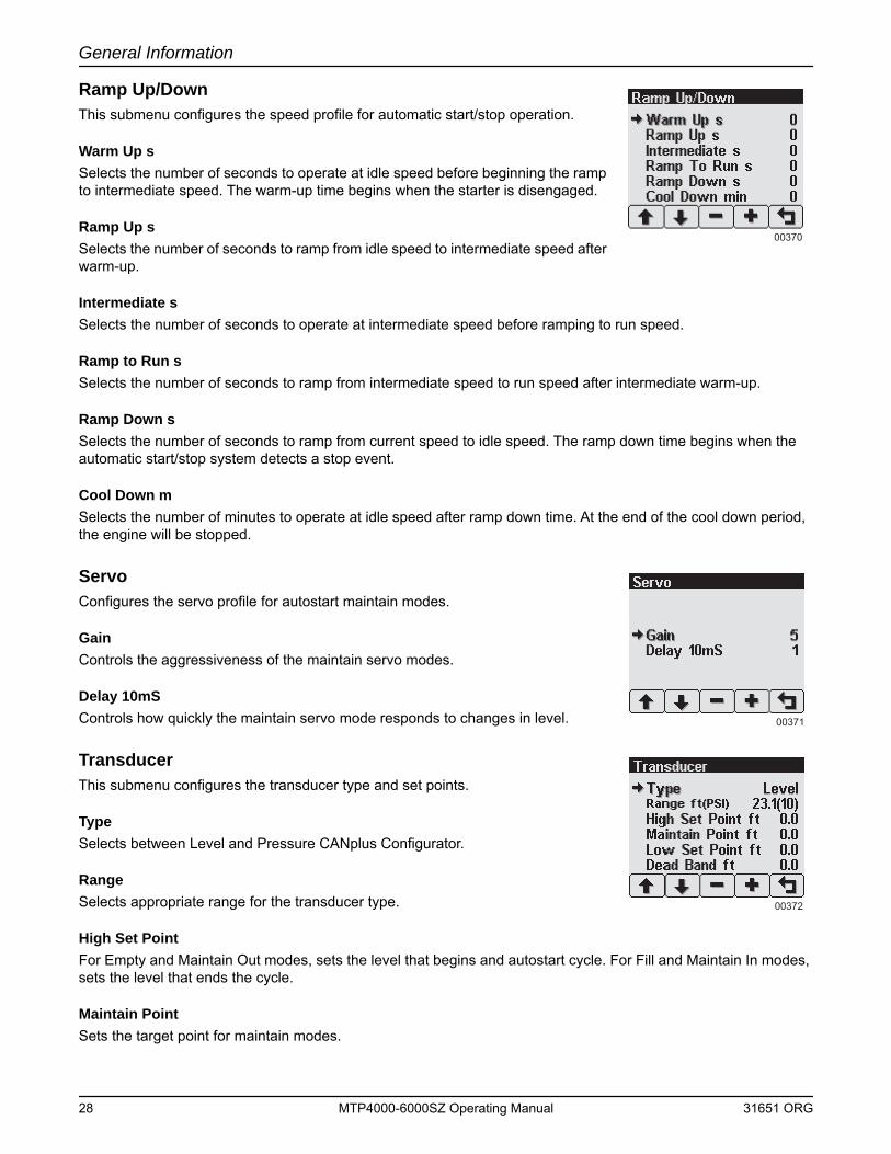
General Information
Ramp Up/DownThis submenu configures the speed profile for automatic start/stop operation.
Warm Up sSelects the number of seconds to operate at idle speed before beginning the ramp to intermediate speed. The warm-up time begins when the starter is disengaged.
Ramp Up sSelects the number of seconds to ramp from idle speed to intermediate speed after warm-up.
Intermediate sSelects the number of seconds to operate at intermediate speed before ramping to run speed.
Ramp to Run sSelects the number of seconds to ramp from intermediate speed to run speed after intermediate warm-up.
Ramp Down sSelects the number of seconds to ramp from current speed to idle speed. The ramp down time begins when the automatic start/stop system detects a stop event.
Cool Down mSelects the number of minutes to operate at idle speed after ramp down time. At the end of the cool down period, the engine will be stopped.
ServoConfigures the servo profile for autostart maintain modes.
GainControls the aggressiveness of the maintain servo modes.
Delay 10mSControls how quickly the maintain servo mode responds to changes in level.
TransducerThis submenu configures the transducer type and set points.
TypeSelects between Level and Pressure CANplus Configurator.
RangeSelects appropriate range for the transducer type.
High Set PointFor Empty and Maintain Out modes, sets the level that begins and autostart cycle. For Fill and Maintain In modes, sets the level that ends the cycle.
Maintain PointSets the target point for maintain modes.
00370
00371
00372
28 MTP4000-6000SZ Operating Manual 31651 ORG
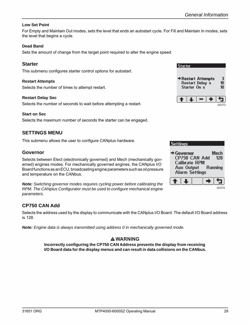
General Information
Low Set PointFor Empty and Maintain Out modes, sets the level that ends an autostart cycle. For Fill and Maintain In modes, sets the level that begins a cycle.
Dead BandSets the amount of change from the target point required to alter the engine speed.
StarterThis submenu configures starter control options for autostart.
Restart AttemptsSelects the number of times to attempt restart.
Restart Delay SecSelects the number of seconds to wait before attempting a restart.
Start on SecSelects the maximum number of seconds the starter can be engaged.
SETTINGS MENUThis submenu allows the user to configure CANplus hardware.
GovernorSelects between Elect (electronically governed) and Mech (mechanically gov-erned) engines modes. For mechanically governed engines, the CANplus I/O Board functions as an ECU, broadcasting engine parameters such as oil pressure and temperature on the CANbus.
Note: Switching governor modes requires cycling power before calibrating the RPM. The CANplus Configurator must be used to configure mechanical engine parameters.
CP750 CAN AddSelects the address used by the display to communicate with the CANplus I/O Board. The default I/O Board address is 128.
Note: Engine data is always transmitted using address 0 in mechanically governed mode.
WARNINGIncorrectly configuring the CP750 CAN Address prevents the display from receiving I/O Board data for the display menus and can result in data collisions on the CANbus.
00373
00374
31651 ORG MTP4000-6000SZ Operating Manual 29
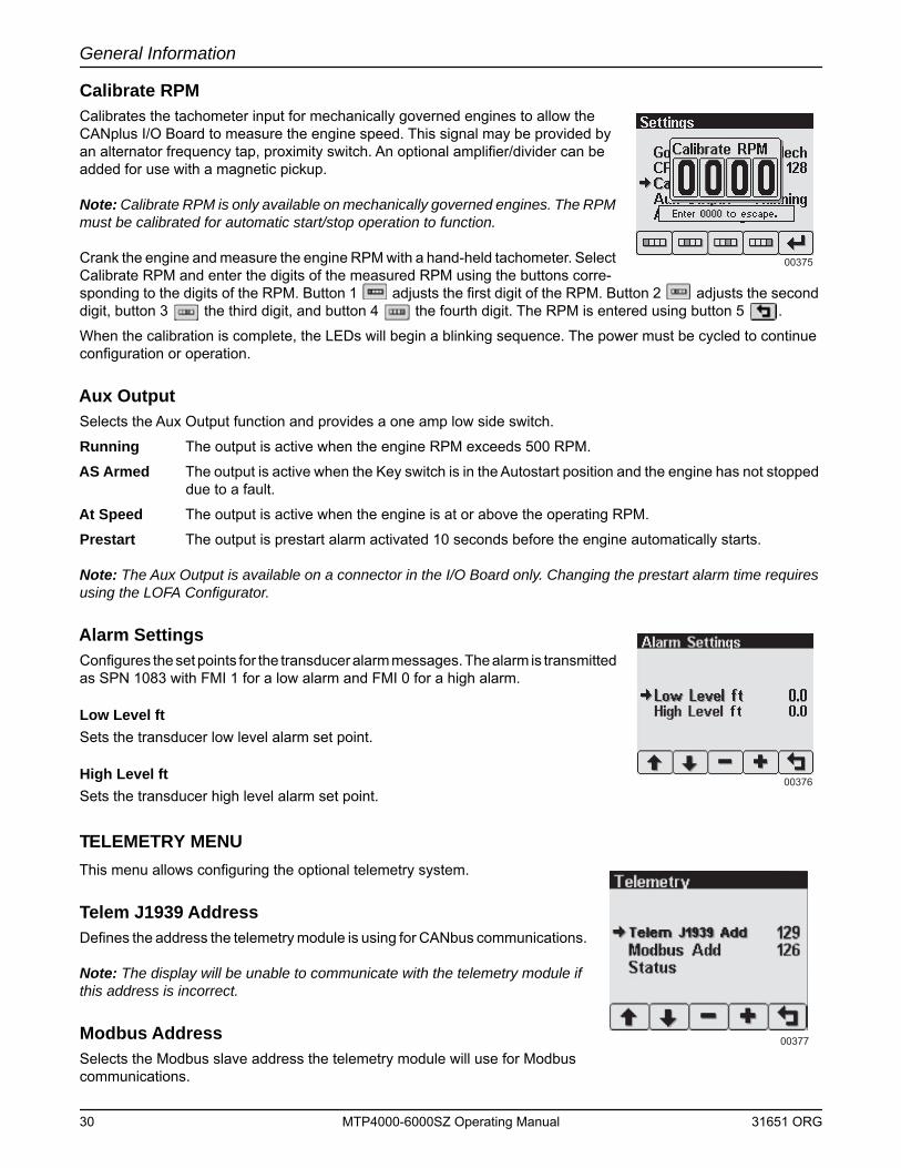
General Information
Calibrate RPMCalibrates the tachometer input for mechanically governed engines to allow the CANplus I/O Board to measure the engine speed. This signal may be provided by an alternator frequency tap, proximity switch. An optional amplifier/divider can be added for use with a magnetic pickup.
Note: Calibrate RPM is only available on mechanically governed engines. The RPM must be calibrated for automatic start/stop operation to function.
Crank the engine and measure the engine RPM with a hand-held tachometer. Select Calibrate RPM and enter the digits of the measured RPM using the buttons corre-sponding to the digits of the RPM. Button 1 adjusts the first digit of the RPM. Button 2 adjusts the second digit, button 3 the third digit, and button 4 the fourth digit. The RPM is entered using button 5 .
When the calibration is complete, the LEDs will begin a blinking sequence. The power must be cycled to continue configuration or operation.
Aux OutputSelects the Aux Output function and provides a one amp low side switch.
Running The output is active when the engine RPM exceeds 500 RPM.
AS Armed The output is active when the Key switch is in the Autostart position and the engine has not stopped due to a fault.
At Speed The output is active when the engine is at or above the operating RPM.
Prestart The output is prestart alarm activated 10 seconds before the engine automatically starts.
Note: The Aux Output is available on a connector in the I/O Board only. Changing the prestart alarm time requires using the LOFA Configurator.
Alarm SettingsConfigures the set points for the transducer alarm messages. The alarm is transmitted as SPN 1083 with FMI 1 for a low alarm and FMI 0 for a high alarm.
Low Level ftSets the transducer low level alarm set point.
High Level ftSets the transducer high level alarm set point.
TELEMETRY MENUThis menu allows configuring the optional telemetry system.
Telem J1939 AddressDefines the address the telemetry module is using for CANbus communications.
Note: The display will be unable to communicate with the telemetry module if this address is incorrect.
Modbus AddressSelects the Modbus slave address the telemetry module will use for Modbus communications.
00375
00376
00377
30 MTP4000-6000SZ Operating Manual 31651 ORG
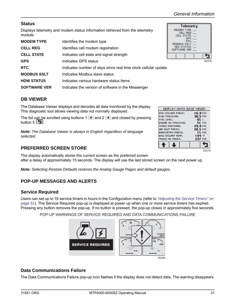
General Information
StatusDisplays telemetry and modem status information retrieved from the telemetry module:
MODEM TYPE Identifies the modem type
CELL REG Identifies cell modem registration
CELL STATE Indicates cell state and signal strength
GPS Indicates GPS status
RTC Indicates number of days since real time clock cellular update
MODBUS SSLT Indicates Modbus slave status
HDW STATUS Indicates various hardware status items
SOFTWARE VER Indicates the version of software in the Messenger
DB VIEWERThe Database Viewer displays and decodes all data monitored by the display. This diagnostic tool allows viewing data not normally displayed.
The list can be scrolled using buttons 1 and 2 and closed by pressing button 5 .
Note: The Database Viewer is always in English regardless of language selected.
PREFERRED SCREEN STOREThe display automatically stores the current screen as the preferred screen after a delay of approximately 15 seconds. The display will use the last stored screen on the next power up.
Note: Selecting Restore Defaults restores the Analog Gauge Pages and default gauges.
POP-UP MESSAGES AND ALERTS
Service RequiredUsers can set up to 16 service timers in hours in the Configuration menu (refer to “Adjusting the Service Timers” on page 51). The Service Required pop-up is displayed at power up when one or more service timers has expired. Pressing any button removes the pop-up. If no button is pressed, the pop-up closes in approximately five seconds.
Data Communications FailureThe Data Communications Failure pop-up icon flashes if the display does not detect data. The warning disappears
00378
00379
00380
POP-UP WARNINGS OF SERVICE REQUIRED AND DATA COMMUNICATIONS FAILURE
31651 ORG MTP4000-6000SZ Operating Manual 31
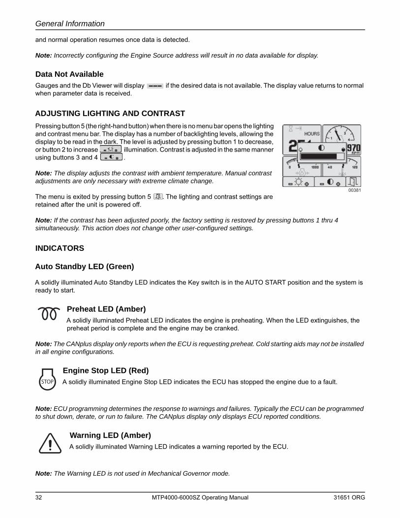
General Information
and normal operation resumes once data is detected.
Note: Incorrectly configuring the Engine Source address will result in no data available for display.
Data Not AvailableGauges and the Db Viewer will display if the desired data is not available. The display value returns to normal when parameter data is received.
ADJUSTING LIGHTING AND CONTRASTPressing button 5 (the right-hand button) when there is no menu bar opens the lighting and contrast menu bar. The display has a number of backlighting levels, allowing the display to be read in the dark. The level is adjusted by pressing button 1 to decrease, or button 2 to increase illumination. Contrast is adjusted in the same manner using buttons 3 and 4 .
Note: The display adjusts the contrast with ambient temperature. Manual contrast adjustments are only necessary with extreme climate change.
The menu is exited by pressing button 5 . The lighting and contrast settings are retained after the unit is powered off.
Note: If the contrast has been adjusted poorly, the factory setting is restored by pressing buttons 1 thru 4 simultaneously. This action does not change other user-configured settings.
INDICATORS
Auto Standby LED (Green)
A solidly illuminated Auto Standby LED indicates the Key switch is in the AUTO START position and the system is ready to start.
Preheat LED (Amber)A solidly illuminated Preheat LED indicates the engine is preheating. When the LED extinguishes, the preheat period is complete and the engine may be cranked.
Note: The CANplus display only reports when the ECU is requesting preheat. Cold starting aids may not be installed in all engine configurations.
Engine Stop LED (Red)A solidly illuminated Engine Stop LED indicates the ECU has stopped the engine due to a fault.
Note: ECU programming determines the response to warnings and failures. Typically the ECU can be programmed to shut down, derate, or run to failure. The CANplus display only displays ECU reported conditions.
Warning LED (Amber)A solidly illuminated Warning LED indicates a warning reported by the ECU.
Note: The Warning LED is not used in Mechanical Governor mode.
00381
STOP
32 MTP4000-6000SZ Operating Manual 31651 ORG
General Information
DATA PARAMETERS MONITOREDThis table lists the engine and transmission parameters that are monitored via the CANbus. The parameters can be displayed by the user-configurable gauge pages or the single analog gauge. DB is an abbreviation for the internal database which stores all data transmitted from the engine/transmission. The complete database can be accessed on the display via the Db Viewer in the Configuration menu.
Icon Parameter Gauge Pages Single Gauge Database
Electrical Potential
Battery Voltage, Switched
Net Battery Current
Alternator Voltage
Alternator Current
Fuel (L, Gal, lGal) or (L/h, Gal/h lGal/h) or (km/L, MPG or lMPG)
Fuel Level
Fuel Rate
Fuel Temperature
Instantaneous Fuel Economy
Trip Fuel Economy
Trip Fuel
Trip Fuel Rate
Total Fuel Used
Fuel Leakage 1
Fuel Leakage 2
Distance (km, Miles or Nmiles)
Distance Remaining
Trip Distance
Total Vehicle Distance
Pressure (kPa, PSI or bar)
Fuel Pressure
Barometer Pressure
Auxiliary Pressure 1
Turbo Pressure
Air Inlet Pressure
Air Filter Differential Pressure
Injector Metering Rail 1 Pressure
Injector Metering Rail 2 Pressure
Engine Coolant Pressure
31651 ORG MTP4000-6000SZ Operating Manual 33
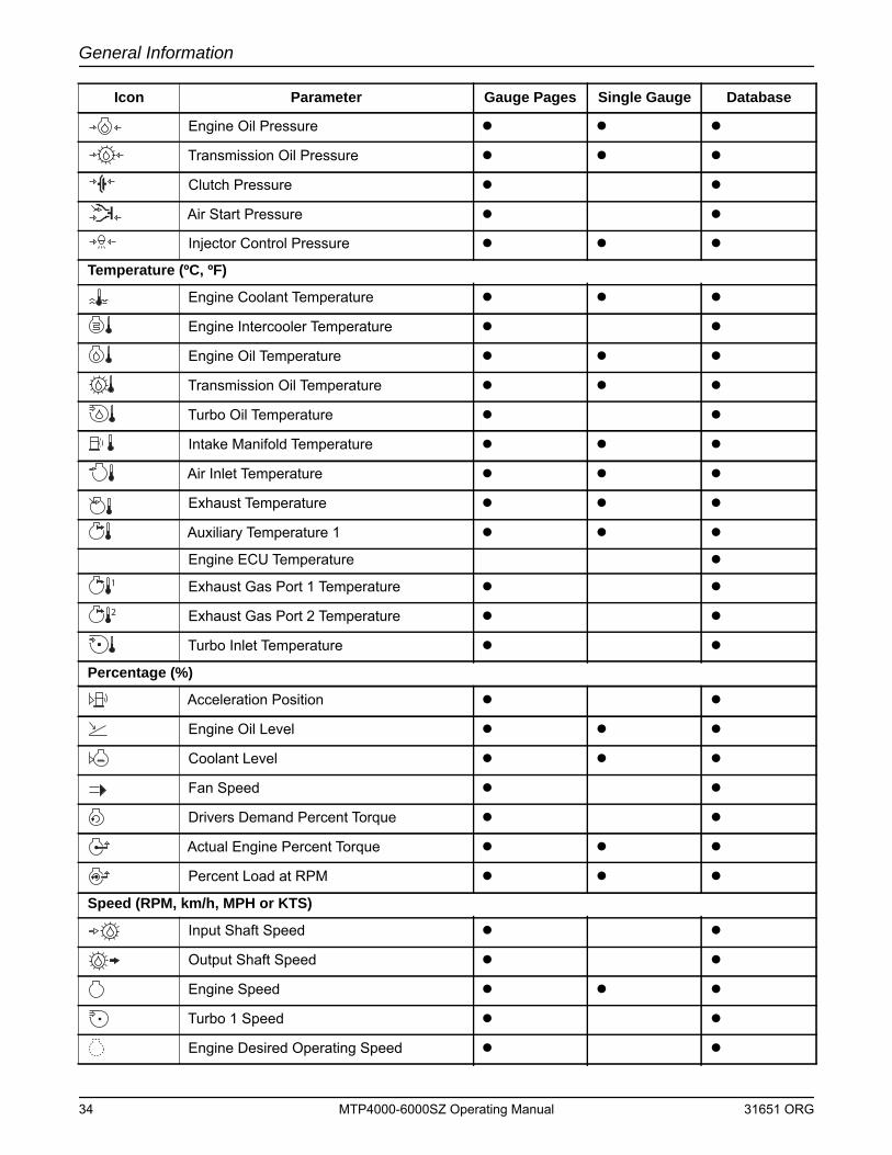
General Information
Engine Oil Pressure
Transmission Oil Pressure
Clutch Pressure
Air Start Pressure
Injector Control Pressure
Temperature (ºC, ºF)
Engine Coolant Temperature
Engine Intercooler Temperature
Engine Oil Temperature
Transmission Oil Temperature
Turbo Oil Temperature
Intake Manifold Temperature
Air Inlet Temperature
Exhaust Temperature
Auxiliary Temperature 1
Engine ECU Temperature
Exhaust Gas Port 1 Temperature
Exhaust Gas Port 2 Temperature
Turbo Inlet Temperature
Percentage (%)
Acceleration Position
Engine Oil Level
Coolant Level
Fan Speed
Drivers Demand Percent Torque
Actual Engine Percent Torque
Percent Load at RPM
Speed (RPM, km/h, MPH or KTS)
Input Shaft Speed
Output Shaft Speed
Engine Speed
Turbo 1 Speed
Engine Desired Operating Speed
Icon Parameter Gauge Pages Single Gauge Database
34 MTP4000-6000SZ Operating Manual 31651 ORG
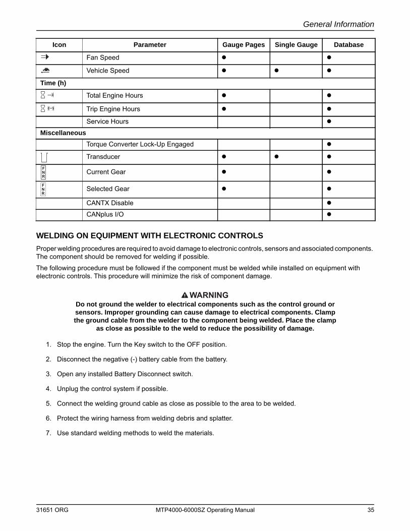
General Information
WELDING ON EQUIPMENT WITH ELECTRONIC CONTROLSProper welding procedures are required to avoid damage to electronic controls, sensors and associated components. The component should be removed for welding if possible.
The following procedure must be followed if the component must be welded while installed on equipment with electronic controls. This procedure will minimize the risk of component damage.
WARNINGDo not ground the welder to electrical components such as the control ground or sensors. Improper grounding can cause damage to electrical components. Clamp the ground cable from the welder to the component being welded. Place the clamp
as close as possible to the weld to reduce the possibility of damage.
1. Stop the engine. Turn the Key switch to the OFF position.
2. Disconnect the negative (-) battery cable from the battery.
3. Open any installed Battery Disconnect switch.
4. Unplug the control system if possible.
5. Connect the welding ground cable as close as possible to the area to be welded.
6. Protect the wiring harness from welding debris and splatter.
7. Use standard welding methods to weld the materials.
Fan Speed
Vehicle Speed
Time (h)
Total Engine Hours
Trip Engine Hours
Service Hours
MiscellaneousTorque Converter Lock-Up Engaged
Transducer
Current Gear
Selected Gear
CANTX Disable
CANplus I/O
Icon Parameter Gauge Pages Single Gauge Database
31651 ORG MTP4000-6000SZ Operating Manual 35

General Information
This Page Intentionally Left Blank
36 MTP4000-6000SZ Operating Manual 31651 ORG
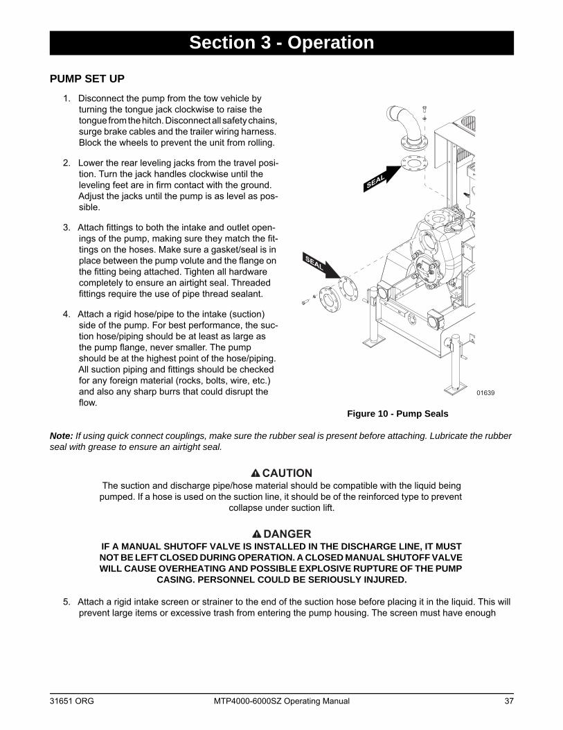
Section 3 - Operation
PUMP SET UP1. Disconnect the pump from the tow vehicle by
turning the tongue jack clockwise to raise the tongue from the hitch. Disconnect all safety chains, surge brake cables and the trailer wiring harness. Block the wheels to prevent the unit from rolling.
2. Lower the rear leveling jacks from the travel posi-tion. Turn the jack handles clockwise until the leveling feet are in firm contact with the ground. Adjust the jacks until the pump is as level as pos-sible.
3. Attach fittings to both the intake and outlet open-ings of the pump, making sure they match the fit-tings on the hoses. Make sure a gasket/seal is in place between the pump volute and the flange on the fitting being attached. Tighten all hardware completely to ensure an airtight seal. Threaded fittings require the use of pipe thread sealant.
4. Attach a rigid hose/pipe to the intake (suction) side of the pump. For best performance, the suc-tion hose/piping should be at least as large as the pump flange, never smaller. The pump should be at the highest point of the hose/piping. All suction piping and fittings should be checked for any foreign material (rocks, bolts, wire, etc.) and also any sharp burrs that could disrupt the flow.
Figure 10 - Pump Seals
Note: If using quick connect couplings, make sure the rubber seal is present before attaching. Lubricate the rubber seal with grease to ensure an airtight seal.
CAUTIONThe suction and discharge pipe/hose material should be compatible with the liquid being
pumped. If a hose is used on the suction line, it should be of the reinforced type to prevent collapse under suction lift.
DANGERIF A MANUAL SHUTOFF VALVE IS INSTALLED IN THE DISCHARGE LINE, IT MUST NOT BE LEFT CLOSED DURING OPERATION. A CLOSED MANUAL SHUTOFF VALVE WILL CAUSE OVERHEATING AND POSSIBLE EXPLOSIVE RUPTURE OF THE PUMP
CASING. PERSONNEL COULD BE SERIOUSLY INJURED.
5. Attach a rigid intake screen or strainer to the end of the suction hose before placing it in the liquid. This will prevent large items or excessive trash from entering the pump housing. The screen must have enough
SEAL
SEAL
01639
31651 ORG MTP4000-6000SZ Operating Manual 37
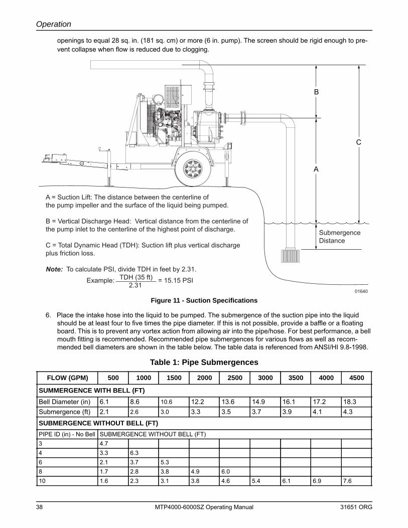
Operation
openings to equal 28 sq. in. (181 sq. cm) or more (6 in. pump). The screen should be rigid enough to pre-vent collapse when flow is reduced due to clogging.
Figure 11 - Suction Specifications
6. Place the intake hose into the liquid to be pumped. The submergence of the suction pipe into the liquid should be at least four to five times the pipe diameter. If this is not possible, provide a baffle or a floating board. This is to prevent any vortex action from allowing air into the pipe/hose. For best performance, a bell mouth fitting is recommended. Recommended pipe submergences for various flows as well as recom-mended bell diameters are shown in the table below. The table data is referenced from ANSI/HI 9.8-1998.
Table 1: Pipe Submergences
FLOW (GPM) 500 1000 1500 2000 2500 3000 3500 4000 4500
SUMMERGENCE WITH BELL (FT)Bell Diameter (in) 6.1 8.6 10.6 12.2 13.6 14.9 16.1 17.2 18.3Submergence (ft) 2.1 2.6 3.0 3.3 3.5 3.7 3.9 4.1 4.3
SUBMERGENCE WITHOUT BELL (FT)PIPE ID (in) - No Bell SUBMERGENCE WITHOUT BELL (FT)3 4.74 3.3 6.36 2.1 3.7 5.38 1.7 2.8 3.8 4.9 6.010 1.6 2.3 3.1 3.8 4.6 5.4 6.1 6.9 7.6
A = Suction Lift: The distance between the centerline ofthe pump impeller and the surface of the liquid being pumped.
B = Vertical Discharge Head: Vertical distance from the centerline of the pump inlet to the centerline of the highest point of discharge.
C = Total Dynamic Head (TDH): Suction lift plus vertical discharge plus friction loss.
Note: To calculate PSI, divide TDH in feet by 2.31. TDH (35 ft) 2.31
Example: = 15.15 PSI
A
C
B
SubmergenceDistance
01640
38 MTP4000-6000SZ Operating Manual 31651 ORG
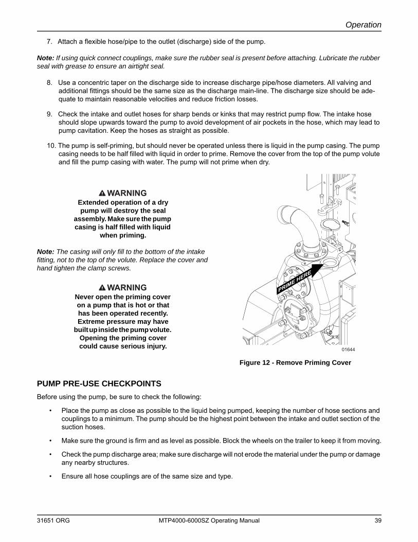
Operation
7. Attach a flexible hose/pipe to the outlet (discharge) side of the pump.
Note: If using quick connect couplings, make sure the rubber seal is present before attaching. Lubricate the rubber seal with grease to ensure an airtight seal.
8. Use a concentric taper on the discharge side to increase discharge pipe/hose diameters. All valving and additional fittings should be the same size as the discharge main-line. The discharge size should be ade-quate to maintain reasonable velocities and reduce friction losses.
9. Check the intake and outlet hoses for sharp bends or kinks that may restrict pump flow. The intake hose should slope upwards toward the pump to avoid development of air pockets in the hose, which may lead to pump cavitation. Keep the hoses as straight as possible.
10. The pump is self-priming, but should never be operated unless there is liquid in the pump casing. The pump casing needs to be half filled with liquid in order to prime. Remove the cover from the top of the pump volute and fill the pump casing with water. The pump will not prime when dry.
WARNINGExtended operation of a dry pump will destroy the seal
assembly. Make sure the pump casing is half filled with liquid
when priming.
Note: The casing will only fill to the bottom of the intake fitting, not to the top of the volute. Replace the cover and hand tighten the clamp screws.
WARNINGNever open the priming cover on a pump that is hot or that has been operated recently. Extreme pressure may have
built up inside the pump volute. Opening the priming cover could cause serious injury.
Figure 12 - Remove Priming Cover
PUMP PRE-USE CHECKPOINTS Before using the pump, be sure to check the following:
• Place the pump as close as possible to the liquid being pumped, keeping the number of hose sections and couplings to a minimum. The pump should be the highest point between the intake and outlet section of the suction hoses.
• Make sure the ground is firm and as level as possible. Block the wheels on the trailer to keep it from moving.
• Check the pump discharge area; make sure discharge will not erode the material under the pump or damage any nearby structures.
• Ensure all hose couplings are of the same size and type.
PRIME HERE
01644
31651 ORG MTP4000-6000SZ Operating Manual 39
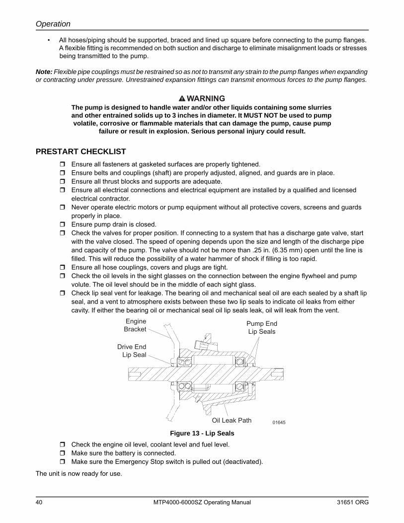
Operation
• All hoses/piping should be supported, braced and lined up square before connecting to the pump flanges. A flexible fitting is recommended on both suction and discharge to eliminate misalignment loads or stresses being transmitted to the pump.
Note: Flexible pipe couplings must be restrained so as not to transmit any strain to the pump flanges when expanding or contracting under pressure. Unrestrained expansion fittings can transmit enormous forces to the pump flanges.
WARNINGThe pump is designed to handle water and/or other liquids containing some slurries and other entrained solids up to 3 inches in diameter. It MUST NOT be used to pump volatile, corrosive or flammable materials that can damage the pump, cause pump
failure or result in explosion. Serious personal injury could result.
PRESTART CHECKLIST Ensure all fasteners at gasketed surfaces are properly tightened. Ensure belts and couplings (shaft) are properly adjusted, aligned, and guards are in place. Ensure all thrust blocks and supports are adequate. Ensure all electrical connections and electrical equipment are installed by a qualified and licensed
electrical contractor. Never operate electric motors or pump equipment without all protective covers, screens and guards
properly in place. Ensure pump drain is closed. Check the valves for proper position. If connecting to a system that has a discharge gate valve, start
with the valve closed. The speed of opening depends upon the size and length of the discharge pipe and capacity of the pump. The valve should not be more than .25 in. (6.35 mm) open until the line is filled. This will reduce the possibility of a water hammer of shock if filling is too rapid.
Ensure all hose couplings, covers and plugs are tight. Check the oil levels in the sight glasses on the connection between the engine flywheel and pump
volute. The oil level should be in the middle of each sight glass. Check lip seal vent for leakage. The bearing oil and mechanical seal oil are each sealed by a shaft lip
seal, and a vent to atmosphere exists between these two lip seals to indicate oil leaks from either cavity. If either the bearing oil or mechanical seal oil lip seals leak, oil will leak from the vent.
Figure 13 - Lip Seals Check the engine oil level, coolant level and fuel level. Make sure the battery is connected. Make sure the Emergency Stop switch is pulled out (deactivated).
The unit is now ready for use.
Drive EndLip Seal
EngineBracket
Oil Leak Path
Pump EndLip Seals
01645
40 MTP4000-6000SZ Operating Manual 31651 ORG
Operation
STARTING THE UNIT1. Turn the Key switch to the right RUN position. A startup screen will appear. After the startup screen is cleared,
the display will show readings on its virtual gauges. Once the gauges appear, crank the engine by turning and holding the Key switch in the START position until the engine starts. Refer to page 15 for details.
2. Allow the engine to run until it reaches a constant speed. Once it is running smoothly, the engine speed can be adjusted with the Speed Control switch ( / ), located to the left of the Key switch on the control panel.
a. Press and release the Rabbit icon to increase the speed.
b. Press and hold the Rabbit icon to accelerate to full speed in a few seconds.
c. Press and release the Turtle icon to decrease engine speed. (Press and hold for continuous deceleration.)
3. The pump should self prime and begin to discharge liquid within minutes. The pump may not prime immedi-ately because the suction line must first fill with liquid. If the pump fails to prime within five minutes, stop it and check the suction line for leaks.
4. Use the Speed Control switch ( / ) to adjust the pump flow. Several factors can influence pump output:
• The temperature, viscosity, and amount of entrapped solids in the liquid being moved.
• The length, diameter, and number of bends of the intake and outlet hoses.
• The total suction height (lift) of the pump.
• The altitude above sea level where the pump is operating.
WARNINGNever adjust the pump flow by attaching a valve to the intake or outlet side of the pump. Restricting the flow in this way can cause the pump to overheat, creating
extreme pressure inside the pump volute. Explosion of the pump volute and serious personal injury may result.
5. As the pump operates, avoid sucking an air/liquid mixture into the intake side of the pump as this may cause the pump to cavitate, causing damage to the pump impeller. The intake hose must be kept 4-5 times the hose diameter (4-5 x 6 in. = 24-30 in. [4-5 x 15 cm = 61-76 cm]) below the surface of the liquid being pumped.
CAUTIONDo not exceed the maximum recommended operating pressure for the pump.
31651 ORG MTP4000-6000SZ Operating Manual 41
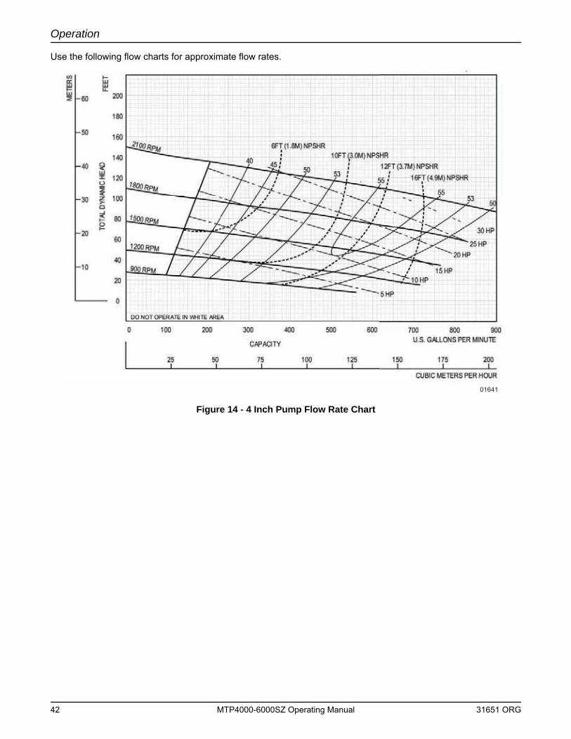
Operation
Use the following flow charts for approximate flow rates.
Figure 14 - 4 Inch Pump Flow Rate Chart
01641
42 MTP4000-6000SZ Operating Manual 31651 ORG
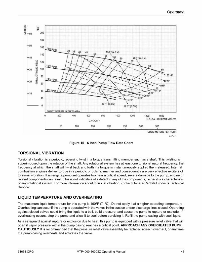
Operation
Figure 15 - 6 Inch Pump Flow Rate Chart
TORSIONAL VIBRATIONTorsional vibration is a periodic, reversing twist in a torque transmitting member such as a shaft. This twisting is superimposed upon the rotation of the shaft. Any rotational system has at least one torsional natural frequency, the frequency at which the shaft will twist back and forth if a torque is instantaneously applied then released. Internal combustion engines deliver torque in a periodic or pulsing manner and consequently are very effective exciters of torsional vibration. If an engine/pump set operates too near a critical speed, severe damage to the pump, engine or related components can result. This is not indicative of a defect in any of the components; rather it is a characteristic of any rotational system. For more information about torsional vibration, contact Generac Mobile Products Technical Service.
LIQUID TEMPERATURE AND OVERHEATINGThe maximum liquid temperature for this pump is 160ºF (71ºC). Do not apply it at a higher operating temperature. Overheating can occur if the pump is operated with the valves in the suction and/or discharge lines closed. Operating against closed valves could bring the liquid to a boil, build pressure, and cause the pump to rupture or explode. If overheating occurs, stop the pump and allow it to cool before servicing it. Refill the pump casing with cool liquid.
As a safeguard against rupture or explosion due to heat, this pump is equipped with a pressure relief valve that will open if vapor pressure within the pump casing reaches a critical point. APPROACH ANY OVERHEATED PUMP CAUTIOUSLY. It is recommended that the pressure relief valve assembly be replaced at each overhaul, or any time the pump casing overheats and activates the valve.
01642
31651 ORG MTP4000-6000SZ Operating Manual 43
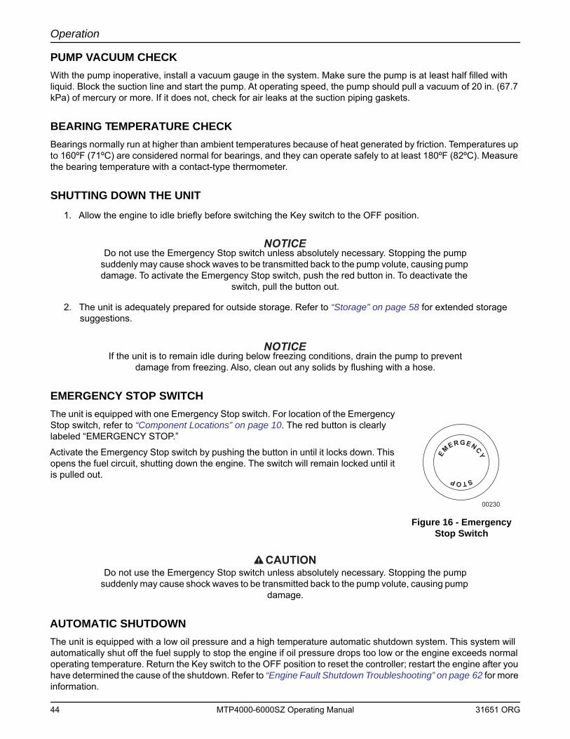
Operation
PUMP VACUUM CHECKWith the pump inoperative, install a vacuum gauge in the system. Make sure the pump is at least half filled with liquid. Block the suction line and start the pump. At operating speed, the pump should pull a vacuum of 20 in. (67.7 kPa) of mercury or more. If it does not, check for air leaks at the suction piping gaskets.
BEARING TEMPERATURE CHECKBearings normally run at higher than ambient temperatures because of heat generated by friction. Temperatures up to 160ºF (71ºC) are considered normal for bearings, and they can operate safely to at least 180ºF (82ºC). Measure the bearing temperature with a contact-type thermometer.
SHUTTING DOWN THE UNIT1. Allow the engine to idle briefly before switching the Key switch to the OFF position.
Do not use the Emergency Stop switch unless absolutely necessary. Stopping the pump suddenly may cause shock waves to be transmitted back to the pump volute, causing pump damage. To activate the Emergency Stop switch, push the red button in. To deactivate the
switch, pull the button out.
2. The unit is adequately prepared for outside storage. Refer to “Storage” on page 58 for extended storage suggestions.
If the unit is to remain idle during below freezing conditions, drain the pump to prevent damage from freezing. Also, clean out any solids by flushing with a hose.
EMERGENCY STOP SWITCHThe unit is equipped with one Emergency Stop switch. For location of the Emergency Stop switch, refer to “Component Locations” on page 10. The red button is clearly labeled “EMERGENCY STOP.”
Activate the Emergency Stop switch by pushing the button in until it locks down. This opens the fuel circuit, shutting down the engine. The switch will remain locked until it is pulled out.
Figure 16 - Emergency Stop Switch
CAUTIONDo not use the Emergency Stop switch unless absolutely necessary. Stopping the pump
suddenly may cause shock waves to be transmitted back to the pump volute, causing pump damage.
AUTOMATIC SHUTDOWNThe unit is equipped with a low oil pressure and a high temperature automatic shutdown system. This system will automatically shut off the fuel supply to stop the engine if oil pressure drops too low or the engine exceeds normal operating temperature. Return the Key switch to the OFF position to reset the controller; restart the engine after you have determined the cause of the shutdown. Refer to “Engine Fault Shutdown Troubleshooting” on page 62 for more information.
STOP
EMERGENCY
00230
44 MTP4000-6000SZ Operating Manual 31651 ORG
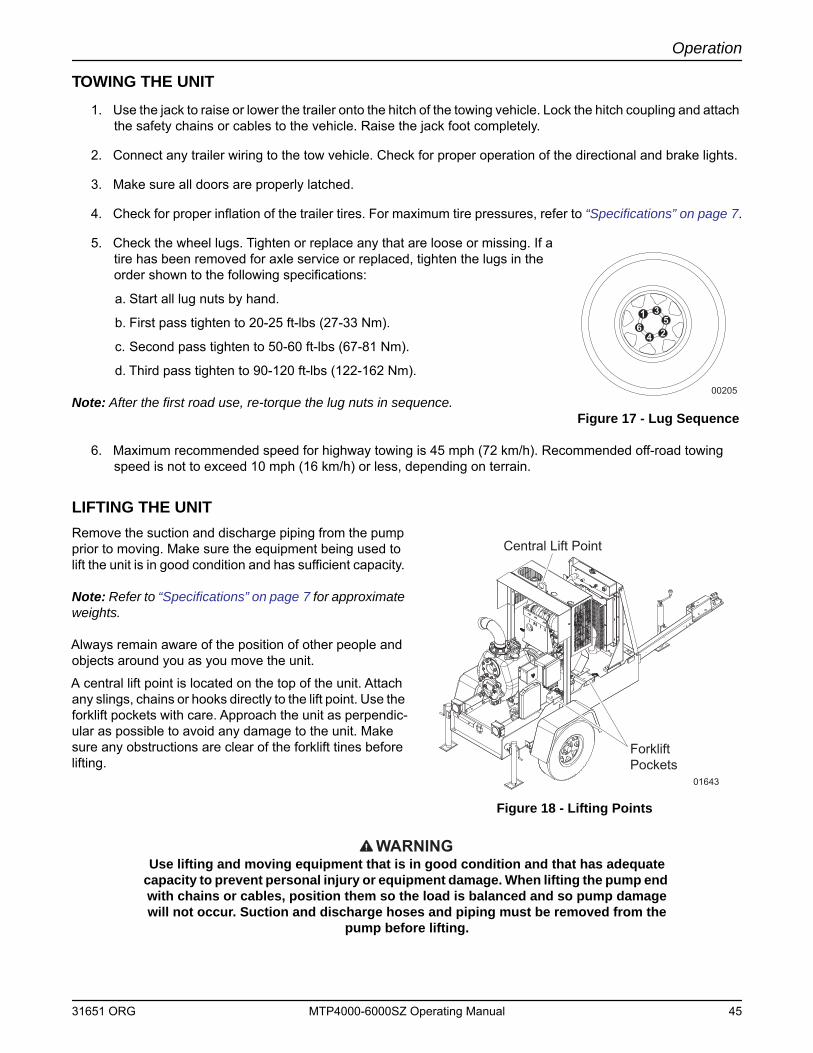
Operation
TOWING THE UNIT1. Use the jack to raise or lower the trailer onto the hitch of the towing vehicle. Lock the hitch coupling and attach
the safety chains or cables to the vehicle. Raise the jack foot completely.
2. Connect any trailer wiring to the tow vehicle. Check for proper operation of the directional and brake lights.
3. Make sure all doors are properly latched.
4. Check for proper inflation of the trailer tires. For maximum tire pressures, refer to “Specifications” on page 7.
5. Check the wheel lugs. Tighten or replace any that are loose or missing. If a tire has been removed for axle service or replaced, tighten the lugs in the order shown to the following specifications:
a. Start all lug nuts by hand.
b. First pass tighten to 20-25 ft-lbs (27-33 Nm).
c. Second pass tighten to 50-60 ft-lbs (67-81 Nm).
d. Third pass tighten to 90-120 ft-lbs (122-162 Nm).
Note: After the first road use, re-torque the lug nuts in sequence.Figure 17 - Lug Sequence
6. Maximum recommended speed for highway towing is 45 mph (72 km/h). Recommended off-road towing speed is not to exceed 10 mph (16 km/h) or less, depending on terrain.
LIFTING THE UNITRemove the suction and discharge piping from the pump prior to moving. Make sure the equipment being used to lift the unit is in good condition and has sufficient capacity.
Note: Refer to “Specifications” on page 7 for approximate weights.
Always remain aware of the position of other people and objects around you as you move the unit.
A central lift point is located on the top of the unit. Attach any slings, chains or hooks directly to the lift point. Use the forklift pockets with care. Approach the unit as perpendic-ular as possible to avoid any damage to the unit. Make sure any obstructions are clear of the forklift tines before lifting.
Figure 18 - Lifting Points
WARNINGUse lifting and moving equipment that is in good condition and that has adequate
capacity to prevent personal injury or equipment damage. When lifting the pump end with chains or cables, position them so the load is balanced and so pump damage will not occur. Suction and discharge hoses and piping must be removed from the
pump before lifting.
1
2
3
4
56
00205
Central Lift Point
ForkliftPockets
01643
31651 ORG MTP4000-6000SZ Operating Manual 45

Operation
This Page Intentionally Left Blank
46 MTP4000-6000SZ Operating Manual 31651 ORG
Section 4 - Maintenance
Normal maintenance service and replacement of parts are the responsibility of the owner/operator and, as such, are not considered defects in materials or workmanship within the terms of the warranty.
Poorly maintained equipment can become a safety hazard. In order for the equipment to operate safely and properly over a long period of time, periodic maintenance and occasional repairs are necessary. NEVER perform even routine service (oil/filter changes, cleaning, etc.) unless the Key switch is turned to OFF and the negative (-) cable on the battery is disconnected. Attach a “DO NOT START” sign to the control panel. This will notify everyone that the unit is being serviced and will reduce the chance of someone inadvertently trying to start the unit. Make sure engine and pump components are adequately cooled before attempting any service or maintenance work.
For detailed engine maintenance procedures, refer to the engine operator’s manual, which was supplied with the unit when it was shipped from the factory.
WARNINGBefore attempting to service the unit, read this manual carefully. Also review all tags and labels/decals provided on the equipment. Operating and maintenance personnel
should have a good understanding of all aspects of this unit and the pumping conditions. Failure of operating personnel to be familiar with all aspects of pump
operation outlined in this manual could contribute to equipment damage, bodily injury or possible death.
Before servicing:
1. Verify that the Key switch is turned to OFF and the negative (-) cable on the battery is disconnected.
2. If the pump or components are hot, allow adequate cooling prior to servicing the unit.
3. Close the suction and discharge valves.
4. Vent the pump slowly and drain completely.
CAUTIONDo not allow compressed air to pressurize the pump or vent-off compressed air through the
pump, as this may damage the pump and cause serious personal injury.
WARNINGIf this unit is used to handle any hazardous materials that can cause injury or illness, take precautions by wearing approved protective clothing and use appropriate safety
equipment.
When servicing the unit, use only components provided by the OEM or Generac Mobile Products. Any use of non-authorized parts could result in sub-standard performance, damage to equipment and possible injury to personnel. Use of unauthorized parts will also void the warranty.
Refer to the troubleshooting section on page 61 to help diagnose operational or performance problems. Only disassemble the unit components required to remedy the problem condition. Select a clean suitable location for any required maintenance, and note that all work must be performed by qualified personnel.
DAILY WALK AROUND INSPECTIONLook for conditions that could hinder performance or safety, such as (but not limited to) oil/coolant/fuel leakage, blocked vents, loose/missing hardware and electrical connections.
Visually inspect the engine fan belt for cracks, fraying, stretching and that the belt is properly seated in pulley grooves. Replace the belt according to the manufacturer’s recommendations.
31651 ORG MTP4000-6000SZ Operating Manual 47
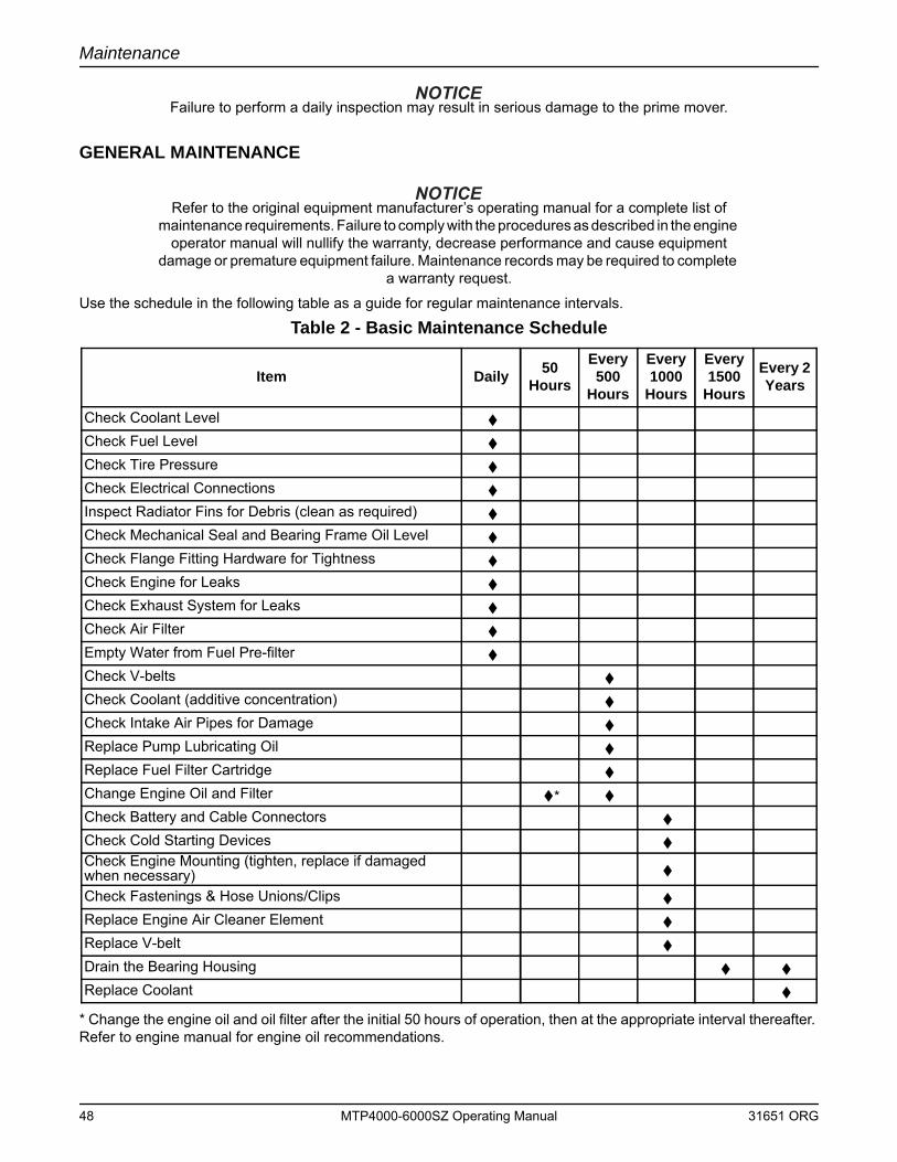
Maintenance
Failure to perform a daily inspection may result in serious damage to the prime mover.
GENERAL MAINTENANCE
Refer to the original equipment manufacturer’s operating manual for a complete list of maintenance requirements. Failure to comply with the procedures as described in the engine
operator manual will nullify the warranty, decrease performance and cause equipment damage or premature equipment failure. Maintenance records may be required to complete
a warranty request.
Use the schedule in the following table as a guide for regular maintenance intervals.
* Change the engine oil and oil filter after the initial 50 hours of operation, then at the appropriate interval thereafter. Refer to engine manual for engine oil recommendations.
Table 2 - Basic Maintenance Schedule
Item Daily 50 Hours
Every 500
Hours
Every 1000
Hours
Every 1500
Hours
Every 2 Years
Check Coolant Level
Check Fuel Level
Check Tire Pressure
Check Electrical Connections
Inspect Radiator Fins for Debris (clean as required)
Check Mechanical Seal and Bearing Frame Oil Level
Check Flange Fitting Hardware for Tightness
Check Engine for Leaks
Check Exhaust System for Leaks
Check Air Filter
Empty Water from Fuel Pre-filter
Check V-belts
Check Coolant (additive concentration)
Check Intake Air Pipes for Damage
Replace Pump Lubricating Oil
Replace Fuel Filter Cartridge
Change Engine Oil and Filter *
Check Battery and Cable Connectors
Check Cold Starting Devices Check Engine Mounting (tighten, replace if damaged when necessary)
Check Fastenings & Hose Unions/Clips
Replace Engine Air Cleaner Element
Replace V-belt
Drain the Bearing Housing
Replace Coolant
48 MTP4000-6000SZ Operating Manual 31651 ORG
Maintenance
Checking the Engine OilLow engine oil and overfilling lead to engine damage. The oil level may only be checked with the engine in a horizontal position and switched off. If the engine is warm, switch off the engine and check the oil level after five minutes. If the engine is cold, you can check it immediately.
WARNINGBe careful of hot lubricating oil. Scalding can occur. Do not pull out the dipstick while
the engine is running.
1. Pull out the dipstick and wipe off with a lint-free, clean cloth.
2. Insert the dipstick into the engine again as far as it will go.
3. Pull out the dipstick again and read the oil level. The oil level must always be between the MIN and MAX marks. Top up to the MAX mark if necessary.
Checking the Pump Sight Level GaugesCheck that oil is visible in the sight glass for the mechanical seal and bearing frame. (It is recommended that the sight glasses be checked daily.) If no oil is visible, oil will need to be added.
Adding Oil:
1. Shut down the unit.
2. Remove the air breather in the bearing frame and add oil until halfway up the sight glass (gauge).
3. Remove the air breather in the mechanical seal and add oil until halfway up the sight glass (gauge).
Note: Be careful to keep dirt and moisture out when adding oil. DO NOT OVERFILL.
Draining Oil:
1. Shut down the unit.
2. Place a suitable containers under the mechanical seal and bearing frame drain plugs.
3. Remove the mechanical seal and bearing frame drain plugs.
4. Drain the oil completely.
5. Reinstall the seal and bearing drain plugs.
6. Follow the instructions above for adding oil.
Changing the Engine Oil
1. Warm up the engine (oil temperature greater than 176°F [80°C]).
2. Ensure the engine is in a level position.
3. Turn the engine off.
4. Place a collecting receptacle underneath the oil drain tube located on the side of the unit.
5. Open the drain valve and drain the oil into the receptacle.
6. After the oil has drained completely, close the drain valve.
31651 ORG MTP4000-6000SZ Operating Manual 49
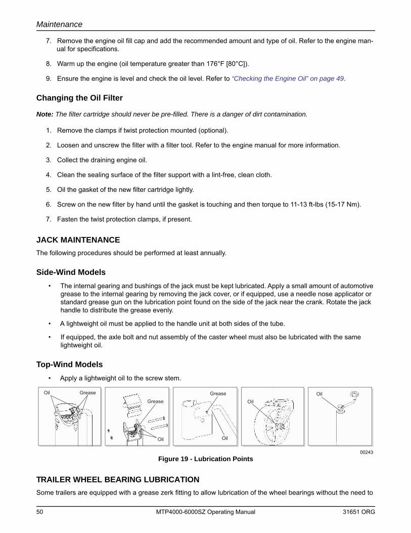
Maintenance
7. Remove the engine oil fill cap and add the recommended amount and type of oil. Refer to the engine man-ual for specifications.
8. Warm up the engine (oil temperature greater than 176°F [80°C]).
9. Ensure the engine is level and check the oil level. Refer to “Checking the Engine Oil” on page 49.
Changing the Oil Filter
Note: The filter cartridge should never be pre-filled. There is a danger of dirt contamination.
1. Remove the clamps if twist protection mounted (optional).
2. Loosen and unscrew the filter with a filter tool. Refer to the engine manual for more information.
3. Collect the draining engine oil.
4. Clean the sealing surface of the filter support with a lint-free, clean cloth.
5. Oil the gasket of the new filter cartridge lightly.
6. Screw on the new filter by hand until the gasket is touching and then torque to 11-13 ft-lbs (15-17 Nm).
7. Fasten the twist protection clamps, if present.
JACK MAINTENANCEThe following procedures should be performed at least annually.
Side-Wind Models• The internal gearing and bushings of the jack must be kept lubricated. Apply a small amount of automotive
grease to the internal gearing by removing the jack cover, or if equipped, use a needle nose applicator or standard grease gun on the lubrication point found on the side of the jack near the crank. Rotate the jack handle to distribute the grease evenly.
• A lightweight oil must be applied to the handle unit at both sides of the tube.
• If equipped, the axle bolt and nut assembly of the caster wheel must also be lubricated with the same lightweight oil.
Top-Wind Models• Apply a lightweight oil to the screw stem.
Figure 19 - Lubrication Points
TRAILER WHEEL BEARING LUBRICATIONSome trailers are equipped with a grease zerk fitting to allow lubrication of the wheel bearings without the need to
Oil Grease
GreaseGrease
Oil Oil
OilOil
00243
50 MTP4000-6000SZ Operating Manual 31651 ORG
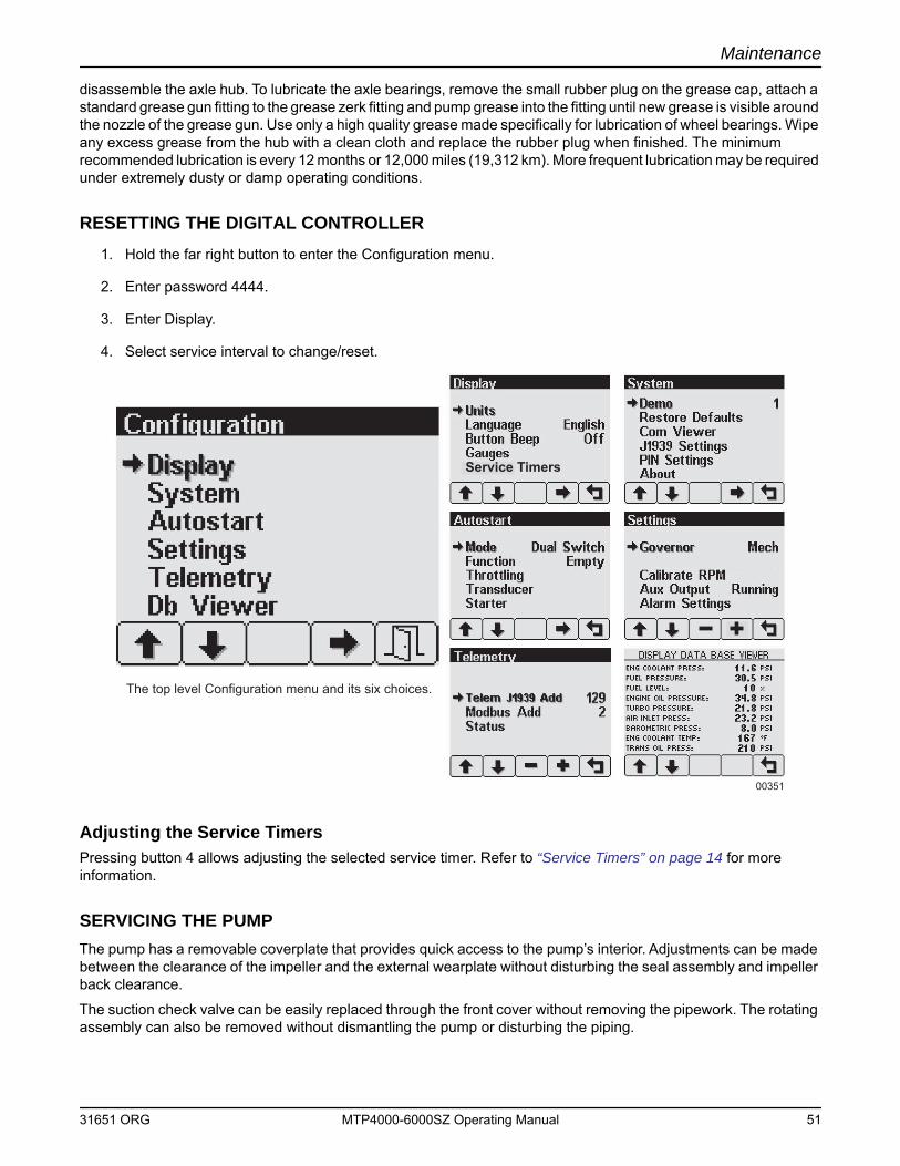
Maintenance
disassemble the axle hub. To lubricate the axle bearings, remove the small rubber plug on the grease cap, attach a standard grease gun fitting to the grease zerk fitting and pump grease into the fitting until new grease is visible around the nozzle of the grease gun. Use only a high quality grease made specifically for lubrication of wheel bearings. Wipe any excess grease from the hub with a clean cloth and replace the rubber plug when finished. The minimum recommended lubrication is every 12 months or 12,000 miles (19,312 km). More frequent lubrication may be required under extremely dusty or damp operating conditions.
RESETTING THE DIGITAL CONTROLLER1. Hold the far right button to enter the Configuration menu.
2. Enter password 4444.
3. Enter Display.
4. Select service interval to change/reset.
Adjusting the Service TimersPressing button 4 allows adjusting the selected service timer. Refer to “Service Timers” on page 14 for more information.
SERVICING THE PUMPThe pump has a removable coverplate that provides quick access to the pump’s interior. Adjustments can be made between the clearance of the impeller and the external wearplate without disturbing the seal assembly and impeller back clearance.
The suction check valve can be easily replaced through the front cover without removing the pipework. The rotating assembly can also be removed without dismantling the pump or disturbing the piping.
The top level Configuration menu and its six choices.
00351
Service Timers
31651 ORG MTP4000-6000SZ Operating Manual 51
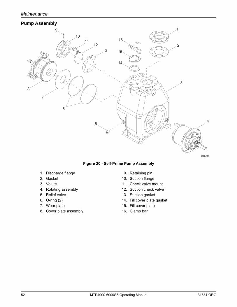
Maintenance
Pump Assembly
Figure 20 - Self-Prime Pump Assembly
1. Discharge flange 9. Retaining pin2. Gasket 10. Suction flange3. Volute 11. Check valve mount4. Rotating assembly 12. Suction check valve5. Relief valve 13. Suction gasket6. O-ring (2) 14. Fill cover plate gasket7. Wear plate 15. Fill cover plate8. Cover plate assembly 16. Clamp bar
01650
15
16
14
3
4
1
2
5
6
7
8
109
1112
13
52 MTP4000-6000SZ Operating Manual 31651 ORG
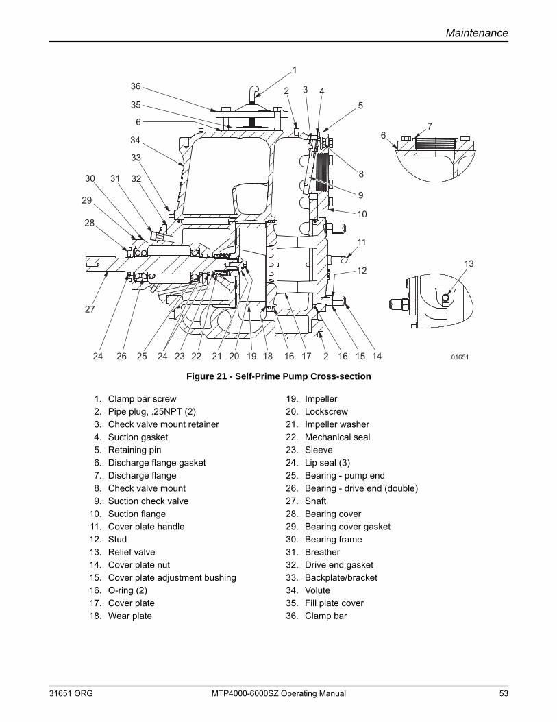
Maintenance
Figure 21 - Self-Prime Pump Cross-section
1. Clamp bar screw 19. Impeller2. Pipe plug, .25NPT (2) 20. Lockscrew3. Check valve mount retainer 21. Impeller washer4. Suction gasket 22. Mechanical seal5. Retaining pin 23. Sleeve6. Discharge flange gasket 24. Lip seal (3)7. Discharge flange 25. Bearing - pump end8. Check valve mount 26. Bearing - drive end (double)9. Suction check valve 27. Shaft
10. Suction flange 28. Bearing cover11. Cover plate handle 29. Bearing cover gasket 12. Stud 30. Bearing frame13. Relief valve 31. Breather14. Cover plate nut 32. Drive end gasket 15. Cover plate adjustment bushing 33. Backplate/bracket16. O-ring (2) 34. Volute17. Cover plate 35. Fill plate cover18. Wear plate 36. Clamp bar
1
2 3 45
8
9
67
10
11
1213
1415162171618192021222324252624
27
28
29
30 31 32
33
34
35
6
36
01651
31651 ORG MTP4000-6000SZ Operating Manual 53
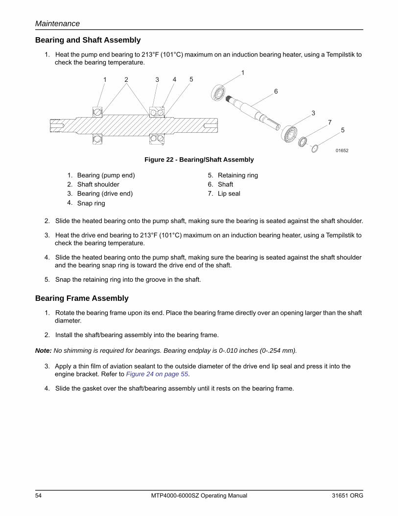
Maintenance
Bearing and Shaft Assembly
1. Heat the pump end bearing to 213°F (101°C) maximum on an induction bearing heater, using a Tempilstik to check the bearing temperature.
Figure 22 - Bearing/Shaft Assembly
2. Slide the heated bearing onto the pump shaft, making sure the bearing is seated against the shaft shoulder.
3. Heat the drive end bearing to 213°F (101°C) maximum on an induction bearing heater, using a Tempilstik to check the bearing temperature.
4. Slide the heated bearing onto the pump shaft, making sure the bearing is seated against the shaft shoulder and the bearing snap ring is toward the drive end of the shaft.
5. Snap the retaining ring into the groove in the shaft.
Bearing Frame Assembly
1. Rotate the bearing frame upon its end. Place the bearing frame directly over an opening larger than the shaft diameter.
2. Install the shaft/bearing assembly into the bearing frame.
Note: No shimming is required for bearings. Bearing endplay is 0-.010 inches (0-.254 mm).
3. Apply a thin film of aviation sealant to the outside diameter of the drive end lip seal and press it into the engine bracket. Refer to Figure 24 on page 55.
4. Slide the gasket over the shaft/bearing assembly until it rests on the bearing frame.
1. Bearing (pump end) 5. Retaining ring2. Shaft shoulder 6. Shaft3. Bearing (drive end) 7. Lip seal4. Snap ring
1 3 4 51
6
37
5
01652
2
54 MTP4000-6000SZ Operating Manual 31651 ORG
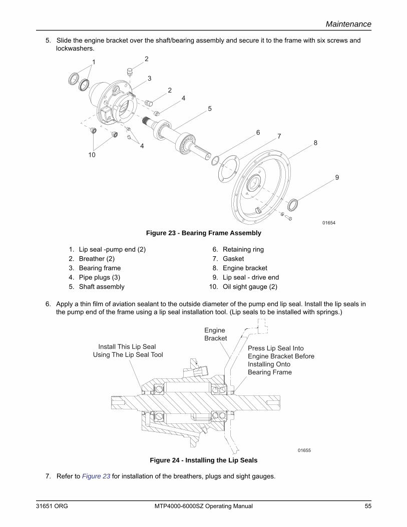
Maintenance
5. Slide the engine bracket over the shaft/bearing assembly and secure it to the frame with six screws and lockwashers.
Figure 23 - Bearing Frame Assembly
6. Apply a thin film of aviation sealant to the outside diameter of the pump end lip seal. Install the lip seals in the pump end of the frame using a lip seal installation tool. (Lip seals to be installed with springs.)
Figure 24 - Installing the Lip Seals
7. Refer to Figure 23 for installation of the breathers, plugs and sight gauges.
1. Lip seal -pump end (2) 6. Retaining ring2. Breather (2) 7. Gasket3. Bearing frame 8. Engine bracket4. Pipe plugs (3) 9. Lip seal - drive end5. Shaft assembly 10. Oil sight gauge (2)
1 2
3
24
5
6 78
9
410
01654
Press Lip Seal IntoEngine Bracket BeforeInstalling OntoBearing Frame
Install This Lip Seal Using The Lip Seal Tool
Engine Bracket
01655
31651 ORG MTP4000-6000SZ Operating Manual 55
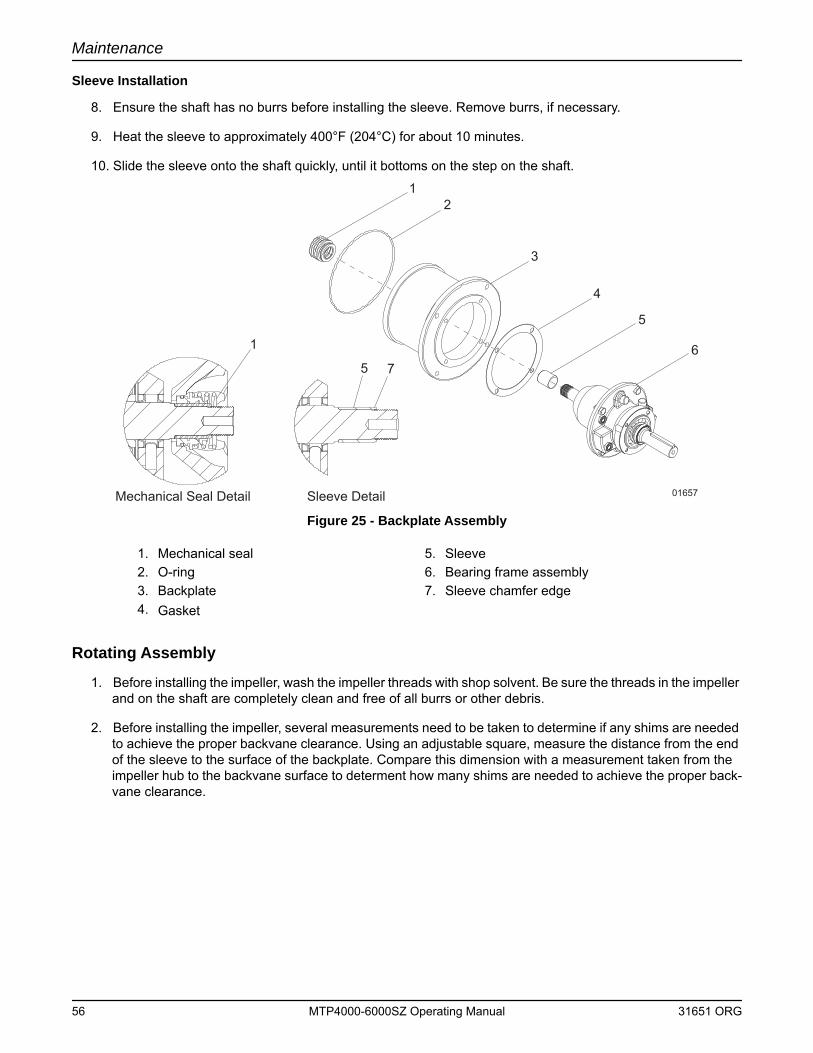
Maintenance
Sleeve Installation
8. Ensure the shaft has no burrs before installing the sleeve. Remove burrs, if necessary.
9. Heat the sleeve to approximately 400°F (204°C) for about 10 minutes.
10. Slide the sleeve onto the shaft quickly, until it bottoms on the step on the shaft.
Figure 25 - Backplate Assembly
Rotating Assembly
1. Before installing the impeller, wash the impeller threads with shop solvent. Be sure the threads in the impeller and on the shaft are completely clean and free of all burrs or other debris.
2. Before installing the impeller, several measurements need to be taken to determine if any shims are needed to achieve the proper backvane clearance. Using an adjustable square, measure the distance from the end of the sleeve to the surface of the backplate. Compare this dimension with a measurement taken from the impeller hub to the backvane surface to determent how many shims are needed to achieve the proper back-vane clearance.
1. Mechanical seal 5. Sleeve2. O-ring 6. Bearing frame assembly3. Backplate 7. Sleeve chamfer edge4. Gasket
1
1
2
3
4
5
56
7
Mechanical Seal Detail Sleeve Detail 01657
56 MTP4000-6000SZ Operating Manual 31651 ORG
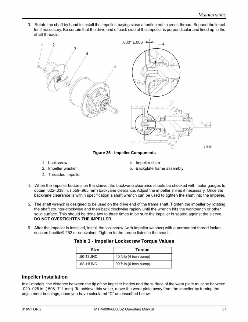
Maintenance
3. Rotate the shaft by hand to install the impeller, paying close attention not to cross-thread. Support the impel-ler if necessary. Be certain that the drive end of back side of the impeller is perpendicular and lined up to the shaft threads.
Figure 26 - Impeller Components
4. When the impeller bottoms on the sleeve, the backvane clearance should be checked with feeler gauges to obtain .022-.038 in. (.558-.965 mm) backvane clearance. Adjust the impeller shims if necessary. Once the backvane clearance is within specification a shaft wrench can be used to tighten the shaft into the impeller.
5. The shaft wrench is designed to be used on the drive end of the frame shaft. Tighten the impeller by rotating the shaft counter-clockwise and then back clockwise rapidly until the wrench hits the workbench or other solid surface. This should be done two to three times to be sure the impeller is seated against the sleeve. DO NOT OVERTIGHTEN THE IMPELLER.
6. After the impeller is installed, install the lockscrew (with impeller washer) with a permanent thread locker, such as Loctite® 262 or equivalent. Tighten to the torque listed in the chart.
Impeller InstallationIn all models, the distance between the tip of the impeller blades and the surface of the wear plate must be between .020-.028 in. (.508-.711 mm). To achieve this value, move the wear plate away from the impeller by turning the adjustment bushings, once you have calculated “C” as described below.
1. Lockscrew 4. Impeller shim2. Impeller washer 5. Backplate frame assembly3. Threaded impeller
Table 3 - Impeller Lockscrew Torque ValuesSize Torque
.50-13UNC 40 ft-lb (4 inch pump)
.62-11UNC 90 ft-lb (6 inch pump)
1 23
4
4
5
.030" ±.008
01658
31651 ORG MTP4000-6000SZ Operating Manual 57
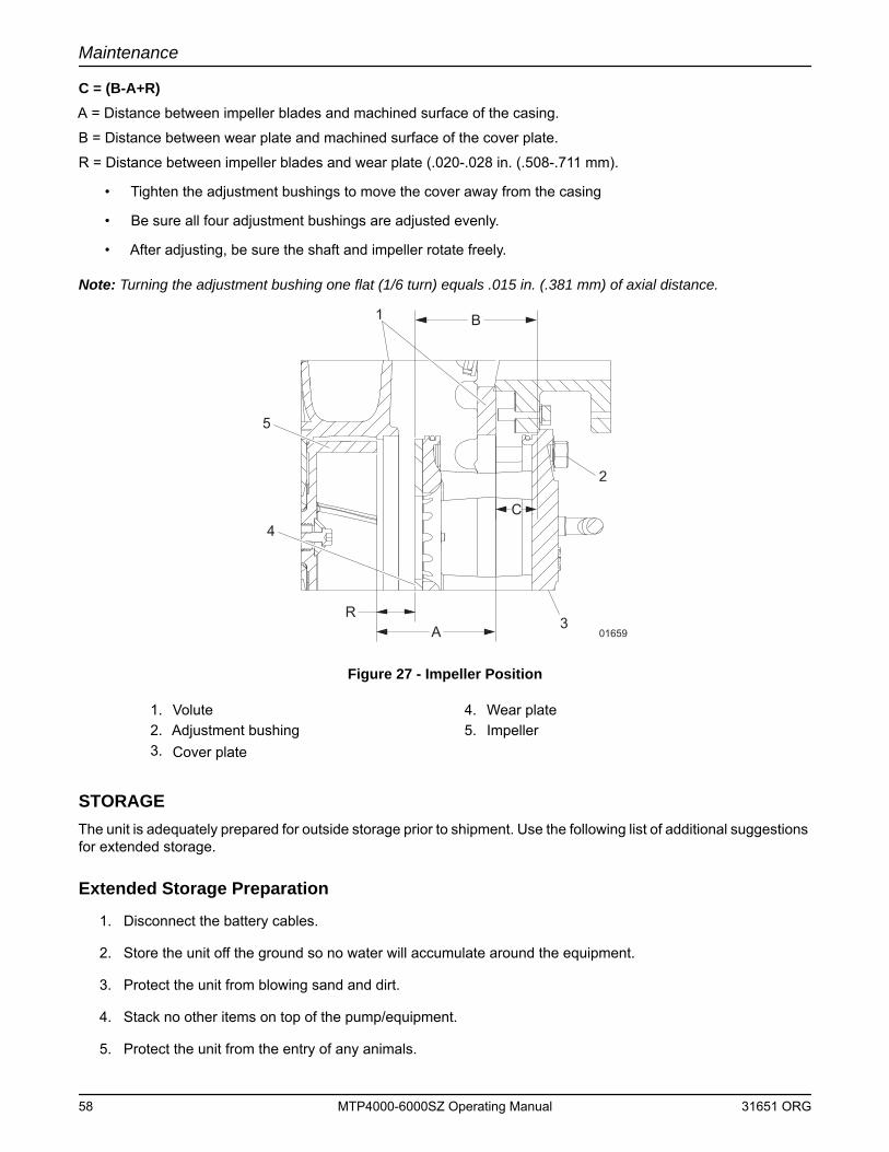
Maintenance
C = (B-A+R)A = Distance between impeller blades and machined surface of the casing.
B = Distance between wear plate and machined surface of the cover plate.
R = Distance between impeller blades and wear plate (.020-.028 in. (.508-.711 mm).
• Tighten the adjustment bushings to move the cover away from the casing
• Be sure all four adjustment bushings are adjusted evenly.
• After adjusting, be sure the shaft and impeller rotate freely.
Note: Turning the adjustment bushing one flat (1/6 turn) equals .015 in. (.381 mm) of axial distance.
Figure 27 - Impeller Position
STORAGEThe unit is adequately prepared for outside storage prior to shipment. Use the following list of additional suggestions for extended storage.
Extended Storage Preparation
1. Disconnect the battery cables.
2. Store the unit off the ground so no water will accumulate around the equipment.
3. Protect the unit from blowing sand and dirt.
4. Stack no other items on top of the pump/equipment.
5. Protect the unit from the entry of any animals.
1. Volute 4. Wear plate2. Adjustment bushing 5. Impeller3. Cover plate
B
C
AR
1
2
3
4
5
01659
58 MTP4000-6000SZ Operating Manual 31651 ORG
Maintenance
6. Periodically rotate shaft to lubricate bearings and protect bearings from brinelling.
7. Protect unit with approved drying agents (Silica Gel).
8. Ensure all bare metal areas are coated with a rust preventative.
9. Inspect unit every four weeks and replace drying agents (Silica Gel) as required, or a minimum of every six months.
10. Keep an inspection record showing dates of inspection with any maintenance performed and condition of drying agents (Silica Gel).
11. Before use ensure that all rust protection has been removed. Also, remove any foreign material that may have accumulated during storage.
12. Before use remove all drying agents (Silica Gel).
13. Drain all water from the main pump piping, including the suction line and discharge line. Remove the volute drain plug and vent plug to empty the pump casing.
14. Verify correct oil level in the engine and seal oil reservoir. Add oil as necessary.
15. Add grease to the main pump bearing frame fittings. Three to six strokes at each fitting with a hand grease gun should be sufficient.
16. Jog the main pump motor for 10 to 15 seconds. Replace all plugs removed for draining.
WINTER STORAGEOccasional motor starts once every month are recommended. Run the unit until it reaches operating temperature. This will help to replace and maintain a lubricating film on the bearings and operating parts.
Restart PreparationIn installations where winter shutdown and storage is the normal situation, it is recommended that lubricating oil and seal barrier oil be drained and replaced to correct levels before the beginning of each new season.
• Add fresh grease to the main bearing frame and vacuum pump pedestal fittings.
• Check all gasketed flanges, especially those on the suction side of the pump, for bolt tightness to eliminate the effect of air leaks on the priming time.
31651 ORG MTP4000-6000SZ Operating Manual 59

Maintenance
This Page Intentionally Left Blank
60 MTP4000-6000SZ Operating Manual 31651 ORG
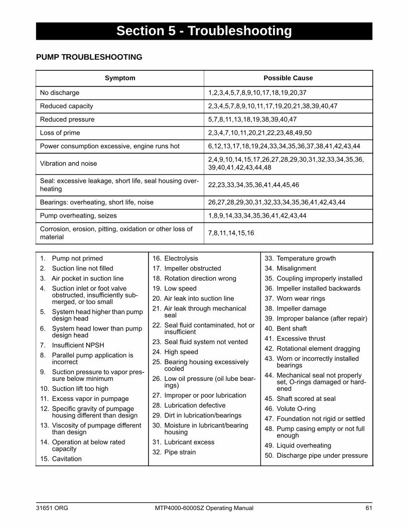
Section 5 - Troubleshooting
PUMP TROUBLESHOOTING
Symptom Possible Cause
No discharge 1,2,3,4,5,7,8,9,10,17,18,19,20,37
Reduced capacity 2,3,4,5,7,8,9,10,11,17,19,20,21,38,39,40,47
Reduced pressure 5,7,8,11,13,18,19,38,39,40,47
Loss of prime 2,3,4,7,10,11,20,21,22,23,48,49,50
Power consumption excessive, engine runs hot 6,12,13,17,18,19,24,33,34,35,36,37,38,41,42,43,44
Vibration and noise 2,4,9,10,14,15,17,26,27,28,29,30,31,32,33,34,35,36, 39,40,41,42,43,44,48
Seal: excessive leakage, short life, seal housing over-heating 22,23,33,34,35,36,41,44,45,46
Bearings: overheating, short life, noise 26,27,28,29,30,31,32,33,34,35,36,41,42,43,44
Pump overheating, seizes 1,8,9,14,33,34,35,36,41,42,43,44
Corrosion, erosion, pitting, oxidation or other loss of material 7,8,11,14,15,16
1. Pump not primed2. Suction line not filled3. Air pocket in suction line4. Suction inlet or foot valve
obstructed, insufficiently sub-merged, or too small
5. System head higher than pump design head
6. System head lower than pump design head
7. Insufficient NPSH8. Parallel pump application is
incorrect9. Suction pressure to vapor pres-
sure below minimum10. Suction lift too high11. Excess vapor in pumpage12. Specific gravity of pumpage
housing different than design13. Viscosity of pumpage different
than design14. Operation at below rated
capacity15. Cavitation
16. Electrolysis17. Impeller obstructed18. Rotation direction wrong19. Low speed20. Air leak into suction line21. Air leak through mechanical
seal22. Seal fluid contaminated, hot or
insufficient23. Seal fluid system not vented24. High speed25. Bearing housing excessively
cooled26. Low oil pressure (oil lube bear-
ings)27. Improper or poor lubrication28. Lubrication defective29. Dirt in lubrication/bearings30. Moisture in lubricant/bearing
housing31. Lubricant excess32. Pipe strain
33. Temperature growth34. Misalignment35. Coupling improperly installed36. Impeller installed backwards37. Worn wear rings38. Impeller damage39. Improper balance (after repair)40. Bent shaft41. Excessive thrust42. Rotational element dragging43. Worn or incorrectly installed
bearings44. Mechanical seal not properly
set, O-rings damaged or hard-ened
45. Shaft scored at seal46. Volute O-ring47. Foundation not rigid or settled48. Pump casing empty or not full
enough49. Liquid overheating50. Discharge pipe under pressure
31651 ORG MTP4000-6000SZ Operating Manual 61
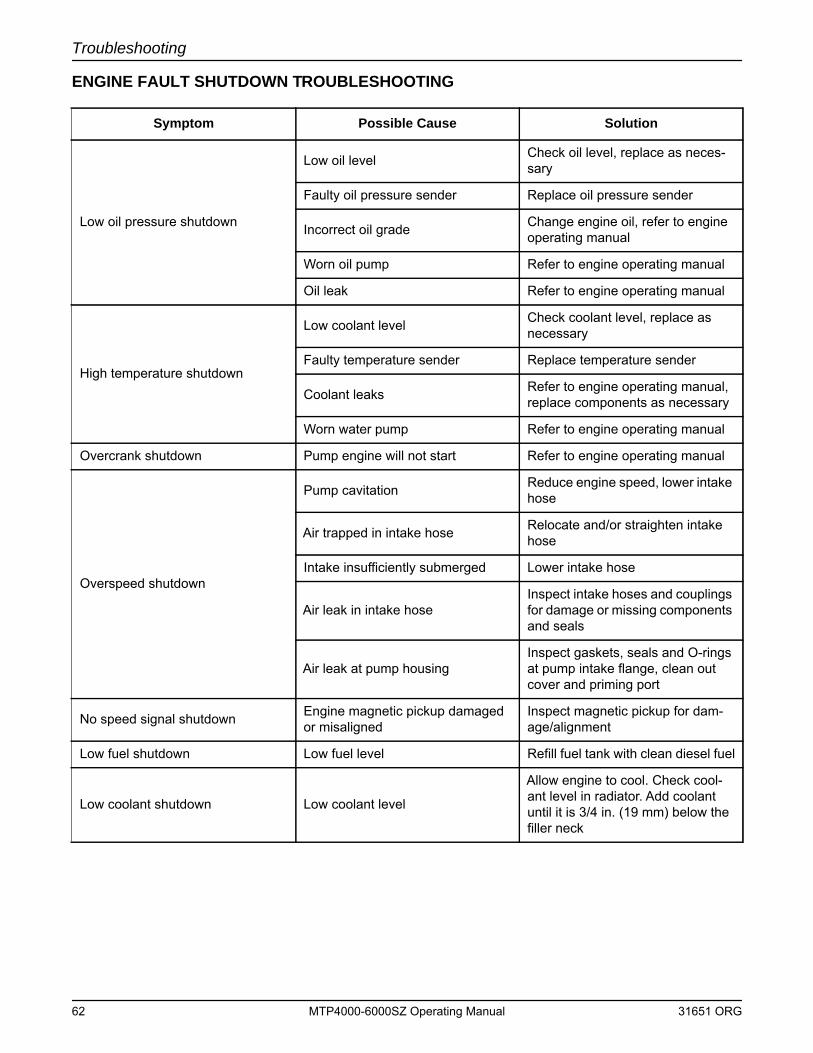
Troubleshooting
ENGINE FAULT SHUTDOWN TROUBLESHOOTING
Symptom Possible Cause Solution
Low oil pressure shutdown
Low oil level Check oil level, replace as neces-sary
Faulty oil pressure sender Replace oil pressure sender
Incorrect oil grade Change engine oil, refer to engine operating manual
Worn oil pump Refer to engine operating manual
Oil leak Refer to engine operating manual
High temperature shutdown
Low coolant level Check coolant level, replace as necessary
Faulty temperature sender Replace temperature sender
Coolant leaks Refer to engine operating manual, replace components as necessary
Worn water pump Refer to engine operating manual
Overcrank shutdown Pump engine will not start Refer to engine operating manual
Overspeed shutdown
Pump cavitation Reduce engine speed, lower intake hose
Air trapped in intake hose Relocate and/or straighten intake hose
Intake insufficiently submerged Lower intake hose
Air leak in intake hoseInspect intake hoses and couplings for damage or missing components and seals
Air leak at pump housingInspect gaskets, seals and O-rings at pump intake flange, clean out cover and priming port
No speed signal shutdown Engine magnetic pickup damaged or misaligned
Inspect magnetic pickup for dam-age/alignment
Low fuel shutdown Low fuel level Refill fuel tank with clean diesel fuel
Low coolant shutdown Low coolant level
Allow engine to cool. Check cool-ant level in radiator. Add coolant until it is 3/4 in. (19 mm) below the filler neck
62 MTP4000-6000SZ Operating Manual 31651 ORG
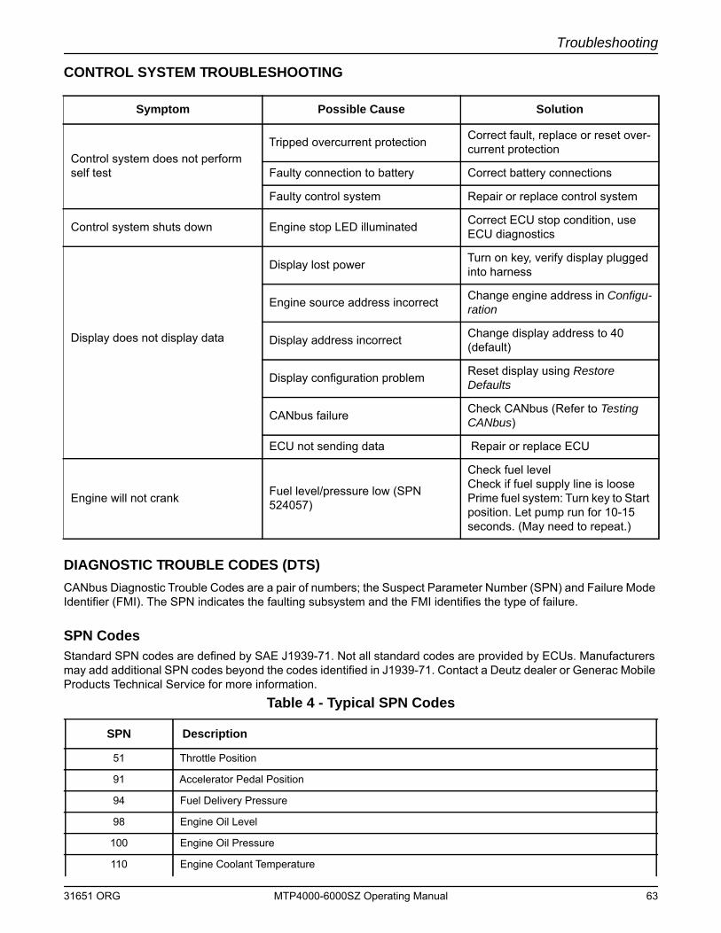
Troubleshooting
CONTROL SYSTEM TROUBLESHOOTING
DIAGNOSTIC TROUBLE CODES (DTS)CANbus Diagnostic Trouble Codes are a pair of numbers; the Suspect Parameter Number (SPN) and Failure Mode Identifier (FMI). The SPN indicates the faulting subsystem and the FMI identifies the type of failure.
SPN CodesStandard SPN codes are defined by SAE J1939-71. Not all standard codes are provided by ECUs. Manufacturers may add additional SPN codes beyond the codes identified in J1939-71. Contact a Deutz dealer or Generac Mobile Products Technical Service for more information.
Symptom Possible Cause Solution
Control system does not perform self test
Tripped overcurrent protection Correct fault, replace or reset over-current protection
Faulty connection to battery Correct battery connections
Faulty control system Repair or replace control system
Control system shuts down Engine stop LED illuminated Correct ECU stop condition, use ECU diagnostics
Display does not display data
Display lost power Turn on key, verify display plugged into harness
Engine source address incorrect Change engine address in Configu-ration
Display address incorrect Change display address to 40 (default)
Display configuration problem Reset display using Restore Defaults
CANbus failure Check CANbus (Refer to Testing CANbus)
ECU not sending data Repair or replace ECU
Engine will not crank Fuel level/pressure low (SPN 524057)
Check fuel levelCheck if fuel supply line is loosePrime fuel system: Turn key to Start position. Let pump run for 10-15 seconds. (May need to repeat.)
Table 4 - Typical SPN Codes
SPN Description
51 Throttle Position
91 Accelerator Pedal Position
94 Fuel Delivery Pressure
98 Engine Oil Level
100 Engine Oil Pressure
110 Engine Coolant Temperature
31651 ORG MTP4000-6000SZ Operating Manual 63
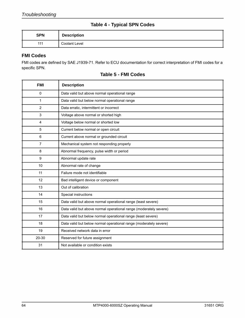
Troubleshooting
FMI CodesFMI codes are defined by SAE J1939-71. Refer to ECU documentation for correct interpretation of FMI codes for a specific SPN.
111 Coolant Level
Table 5 - FMI Codes
FMI Description
0 Data valid but above normal operational range
1 Data valid but below normal operational range
2 Data erratic, intermittent or incorrect
3 Voltage above normal or shorted high
4 Voltage below normal or shorted low
5 Current below normal or open circuit
6 Current above normal or grounded circuit
7 Mechanical system not responding properly
8 Abnormal frequency, pulse width or period
9 Abnormal update rate
10 Abnormal rate of change
11 Failure mode not identifiable
12 Bad intelligent device or component
13 Out of calibration
14 Special instructions
15 Data valid but above normal operational range (least severe)
16 Data valid but above normal operational range (moderately severe)
17 Data valid but below normal operational range (least severe)
18 Data valid but below normal operational range (moderately severe)
19 Received network data in error
20-30 Reserved for future assignment
31 Not available or condition exists
Table 4 - Typical SPN Codes
SPN Description
64 MTP4000-6000SZ Operating Manual 31651 ORG
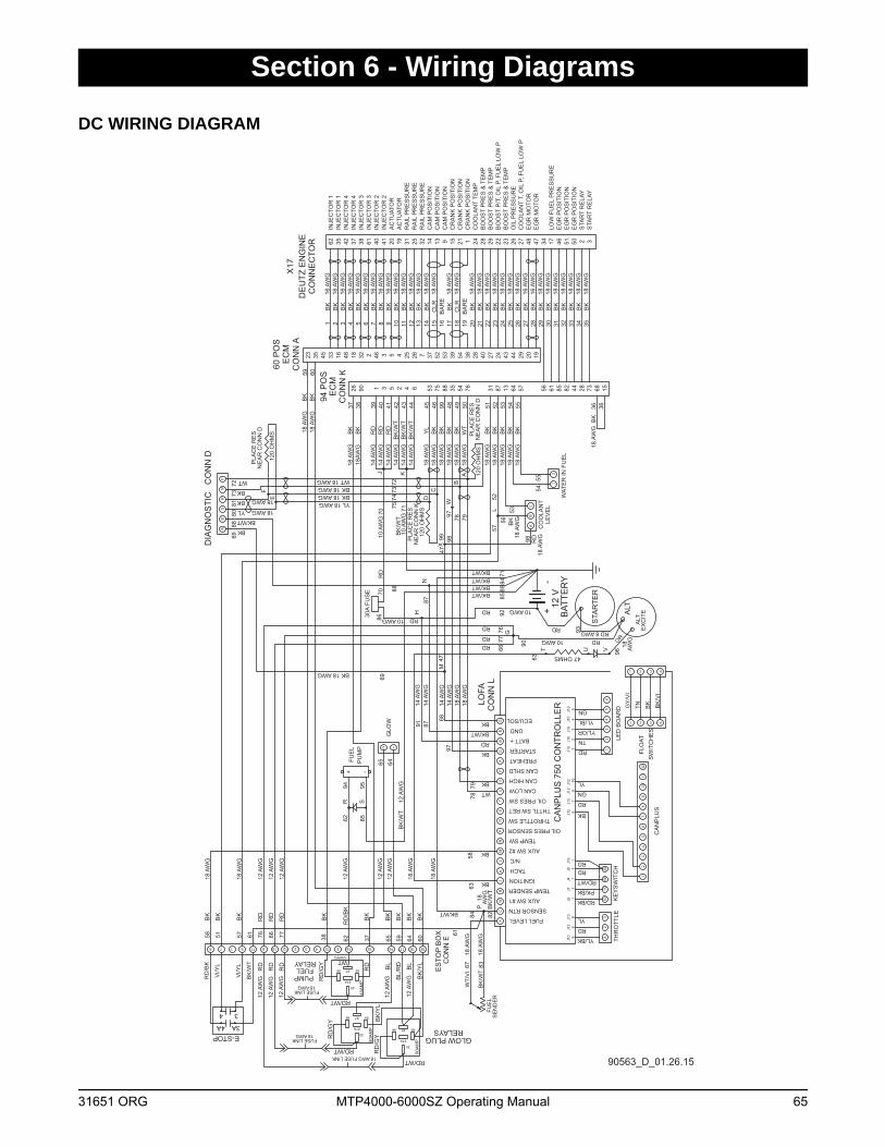
Section 6 - Wiring Diagrams
DC WIRING DIAGRAM
GE
DB
XW
RS
TU
VC
FH
JK
LM
NP
A
12 V
-+ BAT
TER
Y
12
34
56
1211
109
87
5030
5815
12
34
56
82
3
J16
11
11
86
J10
87
910
12
34
5J1
2J1
2J1
2J1
29
J12
J10
J7J4
J5J1
0J1
0J1
0J1
0J1
0J6
1
FUE
L
4231
431 2
CA
NP
LUS
750
CO
NTR
OLL
ER
SE
ND
ER
ALT
EX
CIT
E
7 91 19174321210 188 166 151451311
CO
NN
EE
STO
P B
OX
86 87 85
87A
4A 3A
34
18 AWG FUSE LINK
E-STOP30
86 87 85
87A
FUSE LINK3018 AWG
AB
GH
MF
12
BC
12
86 87 85
87A
30
A
18 AWGFUSE LINK
62 35 42 37 38 61 40 41 20 19 31 25 32 14 13 9 15 21 1 24 28 29 22 23 26 27 48 47 34 17 46 51 50 2 3
33 16 48 18 32 2 46 3 5 4 25 26 7 37 52 53 39 54 38 28 40 27 24 43 44 29 20 1935 4523
56 61 85 82 44 28 7326 90 1 3 5 2 4 6 53 75 88 35 54 76 87 13 64 57 68 15
DE
UTZ
EN
GIN
EC
ON
NE
CTO
R
INJE
CTO
R 1
INJE
CTO
R 1
INJE
CTO
R 4
INJE
CTO
R 4
INJE
CTO
R 3
INJE
CTO
R 3
INJE
CTO
R 2
INJE
CTO
R 2
AC
TUAT
OR
AC
TUAT
OR
RA
IL P
RE
SS
UR
ER
AIL
PR
ES
SU
RE
RA
IL P
RE
SS
UR
EC
AM
PO
SIT
ION
CA
M P
OS
ITIO
NC
AM
PO
SIT
ION
CR
AN
K P
OS
ITIO
NC
RA
NK
PO
SIT
ION
CR
AN
K P
OS
ITIO
NC
OO
LAN
T TE
MP
BO
OS
T P
RE
S &
TE
MP
BO
OS
T P
RE
S &
TE
MP
BO
OS
T P
/T, O
IL P
, FU
EL
LOW
PB
OO
ST
PR
ES
& T
EM
PO
IL P
RE
SS
UR
EC
OO
LAN
T T,
OIL
P, F
UE
L LO
W P
EG
R M
OTO
RE
GR
MO
TOR
LOW
FU
EL
PR
ES
SU
RE
EG
R P
OS
ITIO
NE
GR
PO
SIT
ION
EG
R P
OS
ITIO
NS
TAR
T R
ELA
YS
TAR
T R
ELA
Y
CO
NN
KE
CM
EC
M
BK
16 A
WG
16 A
WG
16 A
WG
16 A
WG
16 A
WG
16 A
WG
16 A
WG
16 A
WG
16 A
WG
16 A
WG
16 A
WG
16 A
WG
18 A
WG
18 A
WG
18 A
WG
18 A
WG
18 A
WG
18 A
WG
18 A
WG
18 A
WG
18 A
WG
18 A
WG
18 A
WG
18 A
WG
18 A
WG
18 A
WG
18 A
WG
18 A
WG
18 A
WG
18 A
WG
18 A
WG
18 A
WG
18 A
WG
THR
OTT
LELE
D B
OA
RD
CA
NP
LUS
KE
YS
WIT
CH
RD
BK
BK/WT
BK
RD/BK
PK/BK
RD/WT
RDRD
BK
RD
GN
YL
RD
TN
YL/OR
YL/BL
GN
YL
RD
YL/BK
FLO
AT
GY
/VI
TN BK BK
/VI
BK
BK/WT
WT/
VI
ALT
18 A
WG
18AW
G
14 A
WG
14 A
WG
18 A
WG
18 A
WG
18 A
WG
18 A
WG
18 A
WG
18 A
WG
18 A
WG
18 A
WG
18 A
WG
18 A
WG
14 A
WG
14 A
WG
14 A
WG
14 A
WG
10 A
WG
10 A
WG
30A
FUS
E
BK
BK
RD
RD
RD
BK
/WT
BK
/WT
BK
/WT
YL
BK
BK
BK
BK
WT
BK
BK
BK
BK
ECU/SOL
GND
BATT +
STARTER
CAN SHLD
CAN HIGH
CAN LOW
PREHEAT
OIL PRES SW
THTTL SW RET
THROTTLE SW
OIL PRES SENSOR
TEMP SW
AUX SW #2
N/C
TACH
IGNITION
TEMP SENDER
AUX SW #1
SENSOR RTN
FUEL LEVEL
GLOW PLUG
BK
/YL
BL
RD
RELAYS
RD/WT
PUMP
RELAY
RD/WT
RD
BL/
RDFUEL
RD
/GY
SW
ITC
HE
S
DIA
GN
OS
TIC
C
ON
N D 12
0 O
HM
S
120
OH
MS
3118
AW
GB
K
WAT
ER
IN F
UE
L
CO
OLA
NT
LEV
EL
BK
18 A
WG
GLO
W
FUE
LP
UM
P
X17
BK
BK
BK
BK
BK
BK
BK
BK
BK
BK
BK
BK
BK
BK
CLR
BA
RE
CLR
BA
RE
BK
BK
BK
BK
BK
BK
BK
BK
BK
BK
BK
BK
BK
BK
BK
BK
1 2 3 4 5 6 7 8 9 10 11 12 13 14 1715 16 18 19 20 21 22 23 24 25 26 27 28 29 30 31 32 33 34 353637 38 39 40 41 42 43 44 45 4846 99 49 50 51 52 53 54 55
37385158
56
57
59B
K18
AW
G60
BK
18 A
WG
CO
NN
LLO
FA
9768
61 62 59 6064
63
65 64
67
47
69
69
63
53
5455
36
62
70 7172
7374
75
78 79
7273
8180
AB
CDE
F
G
J K
L57
52
M
N
5878
7912
0 O
HM
S
H
PLA
CE
RE
SN
EA
R C
ON
N D
PLA
CE
RE
SN
EA
R C
ON
N K
PLA
CE
RE
SN
EA
R C
ON
N D
P
8283
84B
K/W
T
BK
/WT
61
85
BK
/WT
RD
/BK
85
12 A
WG
12 A
WG
8471
76 77
7677
7086
87
88
87
88
89
90
91
92
STA
RTE
R
93
CO
NN
A
60 P
OS
94 P
OS
W
14 A
WG
14 A
WG
14 A
WG
12 A
WG
12 A
WG
47 OHMS
RD
BK
/WT
RD/WT
BL
RD
12 A
WG
12 A
WG
12 A
WG
12 A
WG
12 A
WG
66 65
66
12 A
WG
RD
RD
RD
R S
94 95
U VT 96OR
RD 8 AWGRD
RD
RD
BK/WTBK/WTBK/WTBK/WT
BK/WT
RD
BK
BK
BK
BK
BK
BK
BK
BK
BK
BK
/WT
BK
BK
WT
YL 18 AWGBK 18 AWGBK 18 AWGWT 18 AWG
YL 18 AWG
18 AWGBK
BK
WT
18 A
WG
18 A
WG
12 A
WG
12 A
WG
18 A
WG
18 A
WG
18 A
WG
18 A
WG
18 AWG
14 A
WG
18 A
WG
18 A
WG
+ -
18 AWG10 AWG
10 AWG
RD
RDRD
10 AWG
BK 18 AWG
BK
BK
18 A
WG
98 RD
18 A
WG98
VI/Y
L
VI/Y
L
RD
/BK
RD
/GY
RD
RD
/GY B
K/Y
L
WT
80A
MP
80A
MP
40A
MP
12AWG
X97
4799
90563_D_01.26.15
31651 ORG MTP4000-6000SZ Operating Manual 65
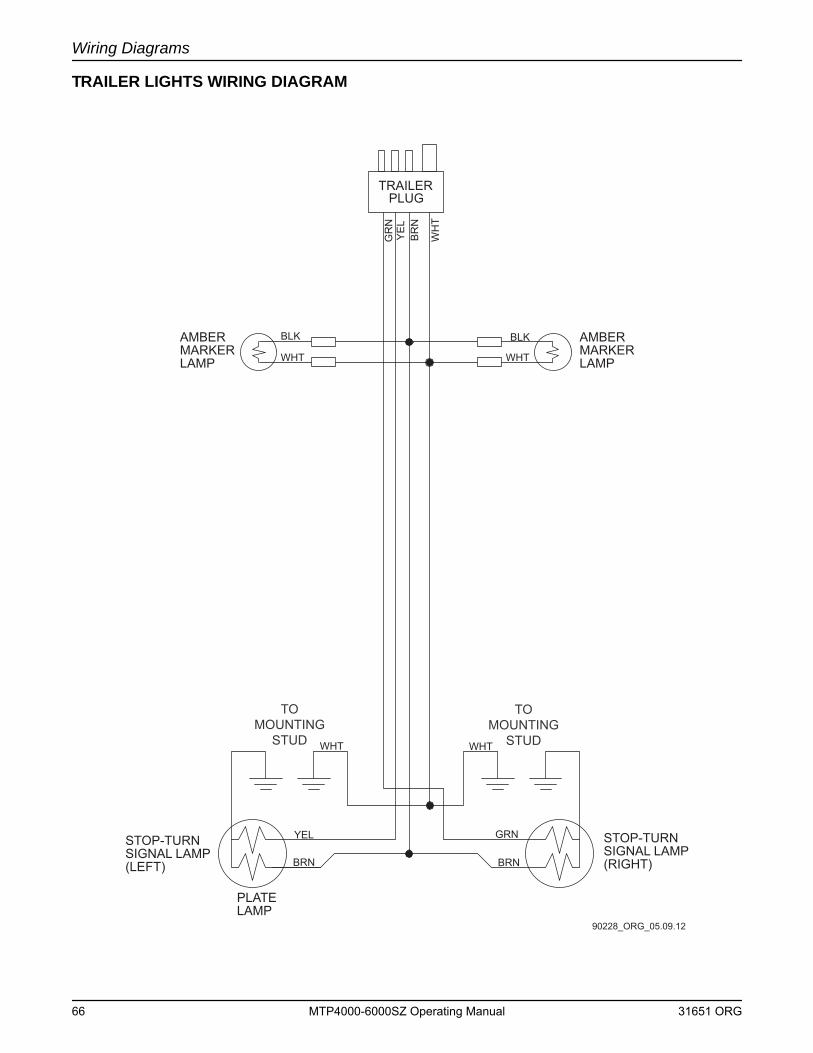
Wiring Diagrams
TRAILER LIGHTS WIRING DIAGRAM
90228_ORG_05.09.12
BLK
WHT
BLK
WHT
WH
T
BR
NY
EL
GR
N
TRAILERPLUG
AMBERMARKERLAMP
AMBERMARKERLAMP
STOP-TURNSIGNAL LAMP(RIGHT)
STOP-TURNSIGNAL LAMP(LEFT)
PLATELAMP
WHT WHT
GRN
BRN
YEL
BRN
TOMOUNTING
STUD
TOMOUNTING
STUD
66 MTP4000-6000SZ Operating Manual 31651 ORG
Section 7 - Options & Accessories
REMOTE/AUTO STARTING The unit can be configured to start automatically by adding dry-contact closure float level switches. Contact the Generac Mobile Products Technical Service Department at 1-800-926-9768 for more information on this option.
31651 ORG MTP4000-6000SZ Operating Manual 67
Options & Accessories
This Page Intentionally Left Blank
68 MTP4000-6000SZ Operating Manual 31651 ORG
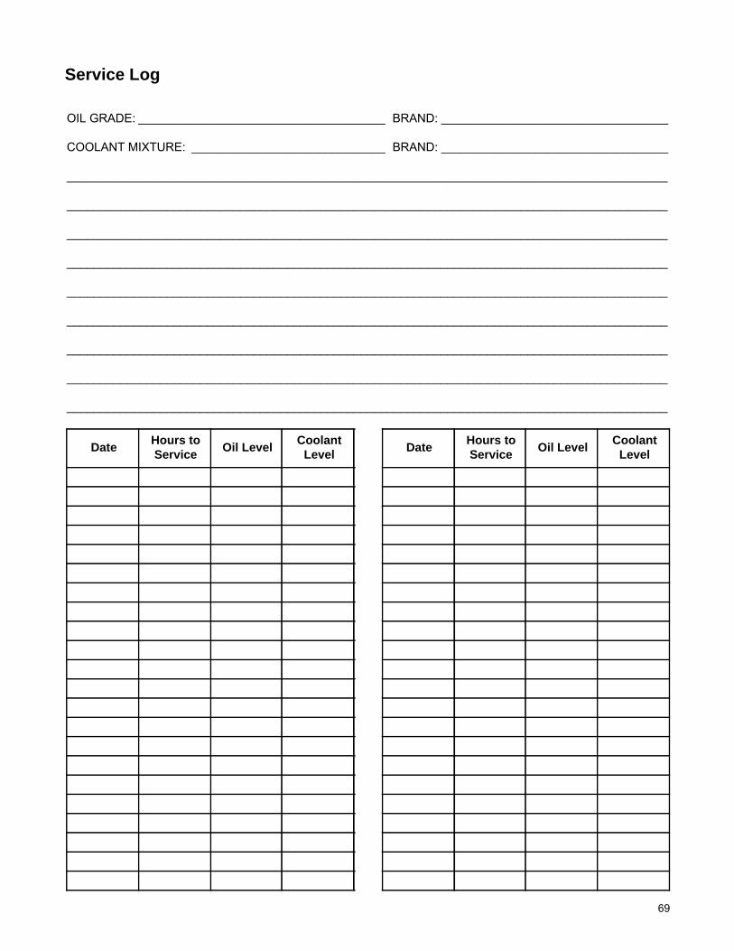
OIL GRADE: _____________________________________ BRAND: __________________________________
COOLANT MIXTURE: _____________________________ BRAND: __________________________________
__________________________________________________________________________________________
__________________________________________________________________________________________
__________________________________________________________________________________________
__________________________________________________________________________________________
__________________________________________________________________________________________
__________________________________________________________________________________________
__________________________________________________________________________________________
__________________________________________________________________________________________
__________________________________________________________________________________________
Date Hours to Service Oil Level Coolant
Level Date Hours toService Oil Level Coolant
Level
Service Log
69

___________________________________________________________________________
___________________________________________________________________________
___________________________________________________________________________
___________________________________________________________________________
___________________________________________________________________________
___________________________________________________________________________
___________________________________________________________________________
___________________________________________________________________________
___________________________________________________________________________
___________________________________________________________________________
___________________________________________________________________________
___________________________________________________________________________
___________________________________________________________________________
___________________________________________________________________________
___________________________________________________________________________
___________________________________________________________________________
___________________________________________________________________________
___________________________________________________________________________
___________________________________________________________________________
___________________________________________________________________________
___________________________________________________________________________
___________________________________________________________________________
___________________________________________________________________________
___________________________________________________________________________
___________________________________________________________________________
___________________________________________________________________________
___________________________________________________________________________
___________________________________________________________________________
Notes
70


Related Documents