V4 | 10/03/2021 EN Operating Manual IO-Link Master EtherNet/IP and Modbus/TCP

Welcome message from author
This document is posted to help you gain knowledge. Please leave a comment to let me know what you think about it! Share it to your friends and learn new things together.
Transcript

V4 |
10/0
3/20
21
EN
Operating Manual
IO-Link MasterEtherNet/IP and Modbus/TCP
Table of contents Baumer
ii Operating Manual EtherNet/IP and Modbus/TCP | V4
Table of contents1 About this document................................................................................................................................... 8
1.1 Purpose ................................................................................................................................................ 8
1.2 Installation and configuration overview................................................................................................. 9
2 Hardware Installation .................................................................................................................................. 10
2.1 BIOLM L-EIP Hardware Installation...................................................................................................... 102.1.1 Setting the rotary switch.......................................................................................................... 102.1.2 Connecting to the network ...................................................................................................... 122.1.3 Connecting the power ............................................................................................................. 132.1.4 Mounting ................................................................................................................................. 16
2.2 BIOLM DR-EIP Hardware Installation................................................................................................... 172.2.1 Connecting to the network ...................................................................................................... 172.2.2 Connecting the power ............................................................................................................. 182.2.3 Mounting ................................................................................................................................. 19
3 Configuring the Network Information........................................................................................................ 20
3.1 Network Configuration Overview .......................................................................................................... 20
3.2 Using the Web Interface to Program the Network ................................................................................ 21
4 Connecting Devices .................................................................................................................................... 22
4.1 Overview............................................................................................................................................... 22
4.2 BIOLM L-EIP IO-Link Ports................................................................................................................... 23
4.3 BIOLM IO-Link and DIO Ports .............................................................................................................. 254.3.1 Tips when Connecting Devices to the BIOLM ........................................................................ 264.3.2 Connecting IO-Link Devices ................................................................................................... 274.3.3 Connecting Digital Input Devices to IO-Link Ports .................................................................. 274.3.4 Connecting DIO Devices to IO-Link Ports............................................................................... 284.3.5 Connecting Devices to the Digital IO Ports............................................................................. 28
4.3.5.1 Connecting to DI................................................................................................. 294.3.5.2 Connecting to DIO.............................................................................................. 30
4.4 BIOLM DR-EIP IO-Link Ports ............................................................................................................... 31
5 IO-Link Port Configuration ......................................................................................................................... 33
5.1 Preparing for Port Configuration ........................................................................................................... 33
5.2 IO-Link Configuration Page .................................................................................................................. 355.2.1 Editing IO-Link Port Settings................................................................................................... 355.2.2 IO-Link Settings Parameters................................................................................................... 36
5.3 Ethernet/IP Settings Configuration Page.............................................................................................. 405.3.1 Editing EtherNet/IP Settings ................................................................................................... 405.3.2 EtherNet/IP Settings Parameters............................................................................................ 41
5.4 Modbus/TCP Settings Configuration Page........................................................................................... 485.4.1 Editing Modbus/TCP Settings ................................................................................................. 485.4.2 Modbus/TCP Settings Parameters ......................................................................................... 49
5.5 OPC UA Settings Configuration Page .................................................................................................. 525.5.1 Edit OPC UA Settings ............................................................................................................. 525.5.2 OPC UA Settings Parameters................................................................................................. 52
Baumer Table of contents
EtherNet/IP and Modbus/TCP | V4 Operating Manual iii
6 Loading and Managing IODD Files ............................................................................................................ 53
6.1 IO-Link Device Description Files Page ................................................................................................. 536.1.1 Preparing IODD Files to Upload ............................................................................................. 546.1.2 Uploading IODD Zip Files ....................................................................................................... 546.1.3 Uploading xml Files or Supporting Files ................................................................................. 556.1.4 Viewing and Saving IODD Files.............................................................................................. 556.1.5 Deleting IODD Files ................................................................................................................ 55
6.2 IO-Link Device Configuration Summary Page ...................................................................................... 56
7 Configuring IO-Link Devices ...................................................................................................................... 57
7.1 Port Pages Overview............................................................................................................................ 57
7.2 Editing Parameters – IO-Link Device – Port Table ............................................................................... 58
7.3 Resetting IO-Link Device Parameters to Factory Defaults ................................................................... 58
7.4 Editing Parameters – IO-Link Device ISDU Interface – Port ................................................................ 587.4.1 Overview ................................................................................................................................. 597.4.2 How to Use the Interface ........................................................................................................ 59
8 Utilizing BIOLM Features ............................................................................................................................ 60
8.1 Setting User Accounts and Passwords................................................................................................. 61
8.2 Data Storage......................................................................................................................................... 628.2.1 Uploading Data Storage to the BIOLM ................................................................................... 628.2.2 Downloading Data Storage to the IO-Link Device .................................................................. 638.2.3 Automatic Device Configuration.............................................................................................. 638.2.4 Automatic Device Configuration Backup................................................................................. 64
8.3 Device Validation .................................................................................................................................. 64
8.4 Data Validation ..................................................................................................................................... 65
8.5 BIOLM Configuration Files.................................................................................................................... 658.5.1 Saving Configuration Files (Web Interface) ............................................................................ 658.5.2 Loading Configuration Files (Web Interface) .......................................................................... 65
8.6 Configuring Miscellaneous Settings...................................................................................................... 668.6.1 Using the Menu Bar Hover Shows Submenu Option.............................................................. 668.6.2 Enable PDO Write From Attached Devices Port Page ........................................................... 678.6.3 IO-Link Test Event Generator ................................................................................................. 68
8.7 Clearing Settings .................................................................................................................................. 69
9 Using the diagnostic pages........................................................................................................................ 70
9.1 IO-Link Port Diagnostics ....................................................................................................................... 70
9.2 Digital I/O Diagnostics (BIOLM)............................................................................................................ 73
9.3 EtherNet/IP Diagnostics........................................................................................................................ 74
9.4 Modbus/TCP Diagnostics ..................................................................................................................... 78
9.5 OPC UA Diagnostics Page ................................................................................................................... 80
10 EtherNet/IP Interface ................................................................................................................................... 81
10.1 Introduction ........................................................................................................................................... 8110.1.1 Functionality Summary ........................................................................................................... 8110.1.2 Data Type Definitions.............................................................................................................. 8210.1.3 Terms and Definitions ............................................................................................................. 83
Table of contents Baumer
iv Operating Manual EtherNet/IP and Modbus/TCP | V4
10.2 Data Transfer Methods ......................................................................................................................... 8410.2.1 Receive Process Data Methods.............................................................................................. 84
10.2.1.1 Polling-PLC Requests Data................................................................................ 8410.2.1.2 Write-to-Tag/File-BIOLM Writes Data Directly Into PLC Memory ...................... 8410.2.1.3 Class 1 Connection (Input Only)-PLC and BIOLM Utilize an I/O Connection .... 84
10.2.2 Transmit Process Data Methods............................................................................................. 8510.2.2.1 PLC-Writes ......................................................................................................... 8510.2.2.2 Read-from-Tag/File-BIOLM Reads Data from PLC Memory.............................. 8510.2.2.3 Class 1 Connection (Input and Output)-PLC and BIOLM Utilize an I/O Con-
nection................................................................................................................85
11 Functionality Descriptions ......................................................................................................................... 86
11.1 Process Data Block Descriptions.......................................................................................................... 8611.1.1 Input Process Data Block Description..................................................................................... 86
11.1.1.1 Input Process Data Block-8 Bit Data Format...................................................... 8711.1.1.2 Input Process Data Block-16 Bit Data Format.................................................... 8811.1.1.3 Input Process Data Block-32 Bit Data Format.................................................... 88
11.1.2 Output Process Data Block Description.................................................................................. 8811.1.2.1 Output Process Data Block-8 Bit (SINT) Data Format ....................................... 8911.1.2.2 Output Process Data Block-16 Bit (INT) Data Format........................................ 9011.1.2.3 Output Process Data Block-32 Bit (DINT) Data Format ..................................... 91
11.2 Event Handling ..................................................................................................................................... 9211.2.1 Clear Event After Hold Time Process ..................................................................................... 9311.2.2 Clear Event in PDO Block Process......................................................................................... 9411.2.3 Clear Event Code in PDO Block and Clear Event After Hold Time Process-PDO Block First 9511.2.4 Clear Event Code in PDO Block and Clear Event After Hold Time Process-Hold Time Ex-
pires ........................................................................................................................................96
11.3 ISDU Handling ...................................................................................................................................... 9711.3.1 ISDU Request/Response Structure ........................................................................................ 97
11.3.1.1 Single ISDU Command Request........................................................................ 9811.3.1.2 Multiple ISDU Command Structure .................................................................... 99
11.3.2 ISDU Request Message Format-From PLC to BIOLM ...........................................................10111.3.2.1 Standard ISDU Request Command Format....................................................... 10111.3.2.2 Integer (16-Bit Word) ISDU Request Command Format.................................... 102
11.3.3 ISDU Response Message Format ..........................................................................................10311.3.3.1 Standard ISDU Response Command Format .................................................... 10311.3.3.2 Integer (16-Bit Word) ISDU Response Command Format ................................. 105
11.3.4 ISDU Blocking and Non-Blocking Methods.............................................................................10611.3.4.1 Single Command Blocking ................................................................................. 10611.3.4.2 Multiple Command Blocking............................................................................... 10711.3.4.3 Single Command Non-Blocking ......................................................................... 10811.3.4.4 Multiple Command Non-Blocking ....................................................................... 109
12 EtherNet/IP CIP Object Definitions ............................................................................................................110
12.1 IO-Link Port Information Object Definition (71 hex) .............................................................................. 11012.1.1 Class Attributes.......................................................................................................................11012.1.2 Instance Attributes ..................................................................................................................11112.1.3 Common Services...................................................................................................................11112.1.4 Instance Attribute Definitions ..................................................................................................112
12.1.4.1 Attribute 1-Vendor Name.................................................................................... 11212.1.4.2 Attribute 2-Vendor Text ...................................................................................... 112

Baumer Table of contents
EtherNet/IP and Modbus/TCP | V4 Operating Manual v
12.1.4.3 Attribute 3-Product Name................................................................................... 11212.1.4.4 Attribute 4-Product ID......................................................................................... 11212.1.4.5 Attribute 5-Product Text ..................................................................................... 11212.1.4.6 Attribute 6-Serial Number................................................................................... 11212.1.4.7 Attribute 7-Hardware Revision ........................................................................... 11312.1.4.8 Attribute 8-Firmware Revision ............................................................................ 11312.1.4.9 Attribute 9-Device PDI Length............................................................................ 11312.1.4.10 Attribute 10-Device PDO Length ........................................................................ 11312.1.4.11 Attribute 11-PDI Data Block Length ................................................................... 11312.1.4.12 Attribute 12-PDO Data Block Length.................................................................. 11312.1.4.13 Attribute 13-Input Assembly PDI Offset.............................................................. 11312.1.4.14 Attribute 14-Input Assembly PDO Offset............................................................ 11412.1.4.15 Attribute 15-Output Assembly PDO Offset ......................................................... 11412.1.4.16 Attribute 16-Control Flags .................................................................................. 114
12.2 PDI (Process Data Input) Transfer Object Definition (72 hex).............................................................. 11512.2.1 Class Attributes.......................................................................................................................11512.2.2 Instance Attributes ..................................................................................................................11512.2.3 Common Services...................................................................................................................11512.2.4 Instance Attribute Definitions – Attribute 1 to 4-PDI Data Blocks ...........................................115
12.3 PDO (Process Data Output) Transfer Object Definition (73 hex) ......................................................... 11612.3.1 Class Attributes.......................................................................................................................11612.3.2 Instance Attributes ..................................................................................................................11612.3.3 Common Services...................................................................................................................11612.3.4 Instance Attribute Definitions – Attribute 1 to 4-PDO Data Blocks..........................................117
12.4 ISDU Read/Write Object Definition (74 hex)....................................................................................... 11712.4.1 Class Attributes.....................................................................................................................11712.4.2 Instance Attributes ................................................................................................................11712.4.3 Common Services.................................................................................................................11812.4.4 Object Specific Services .......................................................................................................11812.4.5 Instance Attribute Definitions ................................................................................................118
12.4.5.1 Attribute 1-ISDU Read/Write Response (Non-Blocking only)............................. 11812.4.5.2 Attribute 2-ISDU Read/Write Request (Non-blocking only)................................ 118
12.5 Identity Object (01 hex, 1 instance) ...................................................................................................... 11912.5.1 Class Attributes.....................................................................................................................11912.5.2 Instance Attributes ................................................................................................................11912.5.3 Status Word ..........................................................................................................................12012.5.4 Common Services.................................................................................................................121
12.6 Message Router Object (02 hex)........................................................................................................ 12112.6.1 Class Attributes.....................................................................................................................12112.6.2 Instance Attributes ................................................................................................................12112.6.3 Common Services.................................................................................................................122
12.7 Connection Manager Object (06 hex)................................................................................................. 12212.7.1 Class Attributes Object (06 hex) ...........................................................................................12212.7.2 Instance Attributes (02 hex) ..................................................................................................12212.7.3 Common Services Object (06 hex) .......................................................................................123
12.8 Port Object (F4 hex-1 instance).......................................................................................................... 12312.8.1 Class Attributes.....................................................................................................................12312.8.2 Instance Attributes ................................................................................................................12412.8.3 Common Services.................................................................................................................124
Table of contents Baumer
vi Operating Manual EtherNet/IP and Modbus/TCP | V4
12.9 TCP Object (F5 hex-1 instance) ......................................................................................................... 12512.9.1 Class Attributes.....................................................................................................................12512.9.2 Instance Attributes ................................................................................................................12612.9.3 Common Services.................................................................................................................127
12.10 Ethernet Link Object (F6 hex-1 instance) ........................................................................................... 12812.10.1 Class Attributes....................................................................................................................12812.10.2 Instance Attributes ...............................................................................................................12812.10.3 Common Services................................................................................................................129
12.11 PCCC Object (67 hex-1 instance) ...................................................................................................... 12912.11.1 Instances..............................................................................................................................12912.11.2 Common Services................................................................................................................12912.11.3 Message Structure Execute_PCCC: Request Message......................................................12912.11.4 Message Structure Execute_PCCC: Response Message...................................................13012.11.5 Supported PCCC Command Types.....................................................................................130
12.12 Assembly Object (For Class 1 Interface) ............................................................................................ 13012.12.1 Class Attributes....................................................................................................................13012.12.2 Instance Definitions..............................................................................................................13112.12.3 Instance Attributes ...............................................................................................................13212.12.4 Common Services................................................................................................................13212.12.5 Instance Attribute Definitions: Attribute 3-Request/Write Data ............................................13212.12.6 Instance Attribute Definitions: Attribute 4-Data Length ........................................................13212.12.7 Overview of Assembly Interface...........................................................................................13312.12.8 Grouping of Assembly Instances .........................................................................................134
13 SLC/PLC-5/MicroLogix Interface................................................................................................................136
13.1 Requirements ....................................................................................................................................... 136
13.2 PLC-5 and SLC 5/05 PLC Requirements ............................................................................................. 13713.2.1 SLC 5/05 .................................................................................................................................13713.2.2 PLC-5......................................................................................................................................137
13.3 PLC-5 and SLC Messages ................................................................................................................... 138
13.4 Process Data (PDI and PDO) Access via PCCC Messages ................................................................ 141
14 EDS Files ......................................................................................................................................................143
14.1 Overview............................................................................................................................................... 143
14.2 Downloading the Files .......................................................................................................................... 143
14.3 Configuring RSLinx............................................................................................................................... 143
14.4 Adding EDS Files to Rockwell Software ............................................................................................... 144
15 Modbus/TCP Interface.................................................................................................................................145
15.1 Modbus Function Codes..................................................................................................................... 145
15.2 Modbus Address Definitions ................................................................................................................. 146
15.3 Multiple Port Process Data (PDI/PDO) Access via Modbus/TCP......................................................... 148
16 Troubleshooting and Technical Support ..................................................................................................151
16.1 Troubleshooting .................................................................................................................................... 151
16.2 BIOLM LEDs......................................................................................................................................... 15216.2.1 BIOLM L-EIP LEDs ................................................................................................................15216.2.2 BIOLM DR-EIP LEDs.............................................................................................................154

Baumer Table of contents
EtherNet/IP and Modbus/TCP | V4 Operating Manual vii
16.3 Using Log Files ..................................................................................................................................... 15516.3.1 View a Log File ......................................................................................................................15516.3.2 Export a Log File....................................................................................................................15516.3.3 Clear a Log File......................................................................................................................156

1 | About this document Baumer
8 Operating Manual EtherNet/IP and Modbus/TCP | V4
1 About this document
1.1 Purpose
This document provides installation, configuration, and embedded web interface information forthe Baumer IO-Link Master (BIOLM). In addition, it includes detailed information about Ether-Net/IP and Modbus/TCP.
The web interface provides a platform so that you can easily configure, review diagnosticpages, and access advanced features, such as the ability to:
n Upload the latest BIOLM images or applicationsn Set up user accounts with different user levels and passwordsn Load IODD files and configure IO-Link device parametersn Implement manual or automatic data storage (upload or download)n Implement device and/or data validation
Manufacturer:Baumer Electric AGCH-8501 FrauenfeldPhone +41 (0)52 728 1122Fax +41 (0)52 728 1144
Baumer About this document | 1
EtherNet/IP and Modbus/TCP | V4 Operating Manual 9
1.2 Installation and configuration overviewThe BIOLM installation includes the following procedures:Instruction:
a) Connect the power and Ethernet cable (Hardware Installation [} 10]).b) Configure the IP address using the embedded web interface.
BIOLM L-EIP (BIOLM L-EIP Hardware Installation [} 10]): If desired you can use the rotaryswitch to set the IP address.
c) Configure BIOLM device features such as passwords or miscellaneous settings.d) If necessary, upload the latest images to support the latest features (Updating Images and
Applications).e) Connect the IO-Link and digital I/O devices (Connecting Devices [} 22]).f) Use the web interface to configure the Modbus/TCP and OPC UA settings following:
1. BIOLM ports for your environment using the web interface (IO-Link Port Configuration[} 33]).- IO-Link settings, such as the Port Mode, which by default is set to IO-Link but dependingon the device, you may need to set it to Digital In or Digital Out.- EtherNet/IP settings- Modbus/TCP settings- OPC UA settings (on select models)2. If necessary, configure the dedicated digital I/O ports on the BIOLM (Dedicated Digital I/OPort Configuration (BIOLM)).3. If desired, upload the appropriate IODD files for your IO-Link devices (Loading and Man-aging IODD Files [} 53]) to simplify IO-Link device configuration.4. If desired, implement BIOLM features or options (Utilizing BIOLM Features [} 60]), suchas:- Data storage, automatic or manual – upload or download- Device validation- Data validation- BIOLM configuration files (save and load)
g) Use the Diagnostic pages to monitor or troubleshoot your devices.h) Connect to a PLC and configure the PLC or HMI/SCADA (depending on your protocol).
1. EtherNet/IP configuration is discussed in detail in the following chapters:- EtherNet/IP Interface [} 81] provides a functionality summary, data type definitions, termsand definition, and data transfer methods.- Functionality Descriptions [} 86] (for EtherNet/IP and Modbus/TCP) details process datablock descriptions, event handling, and ISDU handling.- EtherNet/IP CIP Object Definitions [} 110] discusses the vendor specific CIP definitions.- If applicable, use ControlLogix Family – Example PLC Programs to get your PLCs operat-ing quicker.- If applicable, use SLC/PLC-5/MicroLogix Interface [} 136] to get your PLCs operatingquicker.- EDS Files [} 143], which provides procedures on how to add EDS files to RSLinx for nor-mal BIOLM to PLC communications.2. Modbus/TCP: connect PLCs or HMI/ SCADA devices, which is discussed in detail inthese two supporting sections:- Functionality Descriptions [} 86] details process data block descriptions, event handling,and ISDU handling.- Modbus/TCP Interface [} 145] discusses Modbus Function codes, address definition andmultiple port process data (PDI/PDO).
2 | Hardware Installation Baumer
10 Operating Manual EtherNet/IP and Modbus/TCP | V4
2 Hardware InstallationUse the appropriate hardware installation for your BIOLM model:
n BIOLM L-EIP Hardware Installation [} 10]n BIOLM DR-EIP Hardware Installation [} 17]
Refer to Connecting Devices [} 22] for information about connecting IO-Link or digital devicesto the ports after you program the network information using the next chapter.
2.1 BIOLM L-EIP Hardware Installation
Use the following subsections to install the hardware and verify operation:n Setting the rotary switch [} 10]n Connecting to the network [} 12]n Connecting the power [} 13]n Mounting [} 16]
Refer to BIOLM L-EIP IO-Link Ports [} 23] for information about connecting IO-Link or digitaldevices to the ports after you program the network information using the next chapter.
2.1.1 Setting the rotary switch
You can use the rotary switches under the configuration window on the BIOLM to set the lower3-digits (8 bits) of the static IP address.
INFOOptionally, you can leave the rotary switch set to the default and use the web interface to setthe network address.
If the rotary switches are set to a non-default position, the upper 9-digits (24 bits) of the IP ad-dress are then taken from the static network address. The switches only take effect during star-tup, but the current position is always shown on Help | SUPPORT page.
Using the rotary switches to set the IP address may be useful in the following situations:n A permanent method to assign IP addresses while setting machines for a special application
where a PC or laptop is not available.n A temporary method to assign IP addresses to several BIOLMs so that they do not have du-
plicate addresses to make setting the IP addresses using software easier. After using theweb page to change the IP address, reset the rotary switches back to 000.
n An emergency method to return the BIOLM back to factory defaults, so that software can beused to program the appropriate IP address, and then return the switches back to 000.
NOTICEIf you set the network address using the rotary switches, the Rotary Switch setting overrides thenetwork settings in the web interface when the BIOLM is initially powered on or after cycling thepower.

Baumer Hardware Installation | 2
EtherNet/IP and Modbus/TCP | V4 Operating Manual 11
Switch Setting Node Address000(Default setting)
Use the network configuration stored in the flash. The default network con-figuration values are:
n IP address: 192.168.0.250n Subnet mask: 255.255.255.0n IP gateway: 0.0.0.0
After completing the hardware installation, you can set the network addressusing the web interface (Configuring the Network Information [} 20]).
001 - 254 This is the last three digits in the IP address. This uses the first three num-bers from the configured static address, which defaults to 192.168.1.xxx.
If software is used to change the IP address to another range before settingthe rotary switches, the BIOLM uses that IP address range. For example, ifthe BIOLM is set to 10.0.0.250 and the first rotary switch is set to 2, theIP address would be 10.0.0.200.
255 - 887 Reserved.
888 Reset to factory defaults. If the BIOLM is set to 888 and the IP address ischanged using other methods, the IP address is returned to the default IPaddress if the BIOLM is rebooted or power cycled.
889 - 997 Use the network configuration values stored in the flash (reserved).
998 Setting the rotary switches to 998 configures the BIOLM to use DHCP ad-dressing.
999 Use the default IP address. If the BIOLM is set to 999 and the IP address ischanged using other methods, the IP address is returned to the default IPaddress if the BIOLM is rebooted or power cycled.
Use the following steps if you want to change the default rotary switch settings:Instruction:
a) Gently pop open the window using a small flathead screwdriver.b) Gently swing open the switch window from the top to the bottom, allowing it to pivot on the
hinge on the bottom of the window.c) Turn each dial to the appropriate position using a small flathead screwdriver.
ü The default setting is 000 as shown below.ü The arrow points to the switch location. 0 is located at the 9:00 position. Turn the dial
clockwise to the appropriate setting.
d) Close the window and make sure that it snaps shut tightly.
NOTICEFailure to close the configuration window properly may compromise IP67 integrity.
2 | Hardware Installation Baumer
12 Operating Manual EtherNet/IP and Modbus/TCP | V4
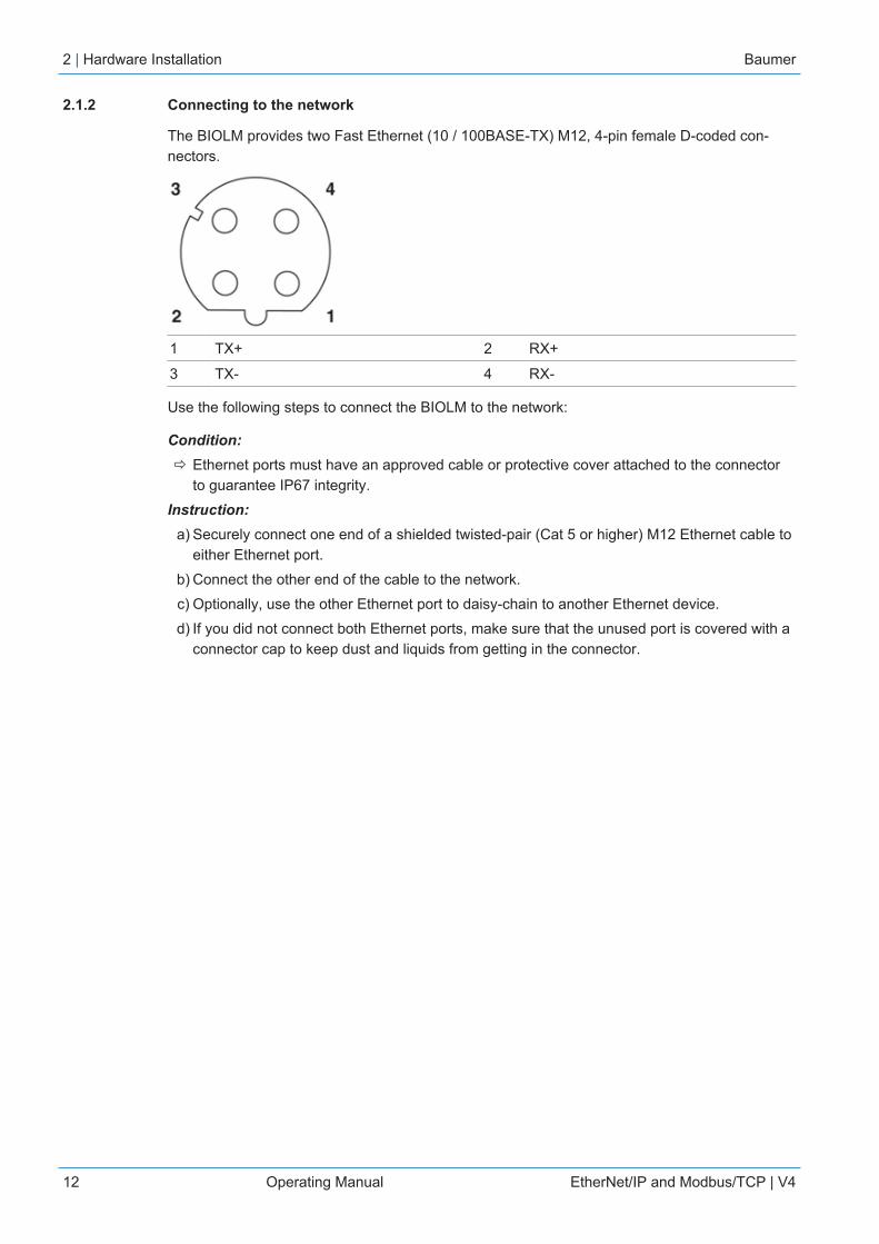
2.1.2 Connecting to the network
The BIOLM provides two Fast Ethernet (10 / 100BASE-TX) M12, 4-pin female D-coded con-nectors.
1 TX+ 2 RX+
3 TX- 4 RX-
Use the following steps to connect the BIOLM to the network:
Condition:ð Ethernet ports must have an approved cable or protective cover attached to the connector
to guarantee IP67 integrity.Instruction:
a) Securely connect one end of a shielded twisted-pair (Cat 5 or higher) M12 Ethernet cable toeither Ethernet port.
b) Connect the other end of the cable to the network.c) Optionally, use the other Ethernet port to daisy-chain to another Ethernet device.d) If you did not connect both Ethernet ports, make sure that the unused port is covered with a
connector cap to keep dust and liquids from getting in the connector.

Baumer Hardware Installation | 2
EtherNet/IP and Modbus/TCP | V4 Operating Manual 13
2.1.3 Connecting the power
NOTICEPower connectors must have an approved cable attached to the port guarantee to IP67 compli-ance.
The BIOLM L-EIP provides M12 (5-poles) L-coded input and output power connectors. Use a24 VDC power supply capable of the total output current required.
PinPower Input(Male)
Power Output or ActuatorPower (Female) Description
1 US+ US+ or +V IO-Link Master’s system electronics andIO-Link devices
2 UA- UA- or 0 V Actuator supply
3 US- US- or 0 V IO-Link Master’s system electronics andIO-Link devices
4 UA+ UA+ or +V Actuator supply
5 FE
2 | Hardware Installation Baumer
14 Operating Manual EtherNet/IP and Modbus/TCP | V4
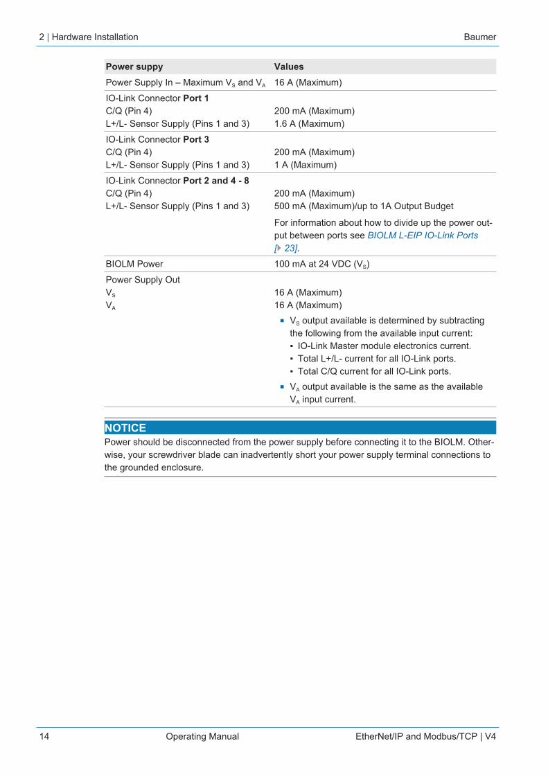
Power suppy ValuesPower Supply In – Maximum VS and VA 16 A (Maximum)
IO-Link Connector Port 1 C/Q (Pin 4) L+/L- Sensor Supply (Pins 1 and 3)
200 mA (Maximum)1.6 A (Maximum)
IO-Link Connector Port 3 C/Q (Pin 4) L+/L- Sensor Supply (Pins 1 and 3)
200 mA (Maximum)1 A (Maximum)
IO-Link Connector Port 2 and 4 - 8 C/Q (Pin 4) L+/L- Sensor Supply (Pins 1 and 3)
200 mA (Maximum)500 mA (Maximum)/up to 1A Output Budget
For information about how to divide up the power out-put between ports see BIOLM L-EIP IO-Link Ports[} 23].
BIOLM Power 100 mA at 24 VDC (VS)
Power Supply OutVS
VA
16 A (Maximum)16 A (Maximum)
n VS output available is determined by subtractingthe following from the available input current:▪ IO-Link Master module electronics current.▪ Total L+/L- current for all IO-Link ports.▪ Total C/Q current for all IO-Link ports.
n VA output available is the same as the availableVA input current.
NOTICEPower should be disconnected from the power supply before connecting it to the BIOLM. Other-wise, your screwdriver blade can inadvertently short your power supply terminal connections tothe grounded enclosure.
Baumer Hardware Installation | 2
EtherNet/IP and Modbus/TCP | V4 Operating Manual 15
To connect the BIOLM to a power supply use the following procedure:Instruction:
a) Securely attach the power cable between the male power connector (PWR In) and thepower supply.
b) Either attach a power cable between the female power connector and another device towhich you want to provide power or securely attach a connector cap to prevent dust or li-quids from getting into the connector.
c) Apply the power and verify that the following LEDs are lit indicating that you are ready to at-tach your IO-Link or digital I/O devices.1. The US LED lights.2. The ETH LED lights on the connected port.3. The MOD and NET LEDs are lit.4. The IO-Link LEDs flash (if no IO-Link device attached) or are lit if an IO-Link device is at-tached.It takes approximately 25 seconds after power up for the IO-Link Master to be ready for op-eration.5. The MOD LED is solid green, the IO-Link Master is ready for operation.
If the LEDs indicate that you are ready to go to the next installation step:n Program the IP address using the web interface. For configuring the network information
see Configuring the Network Information [} 20].n If using the rotary switches to set the IP address, then you are ready to attach devices (see
Connecting Devices [} 22]).
If the LEDs do not meet the above conditions go to BIOLM L-EIP LEDs [} 152].

2 | Hardware Installation Baumer
16 Operating Manual EtherNet/IP and Modbus/TCP | V4
2.1.4 Mounting
You can mount the BIOLM on a mounting panel or a machine. Use the following procedure tomount the BIOLM:Instruction:
a) Verify that the mounting surface is level (flat) to prevent mechanical stress to the BIOLM.b) Attach the BIOLM to the surface with two 6mm screws and washers, torque down to 8 Nm.
Baumer Hardware Installation | 2
EtherNet/IP and Modbus/TCP | V4 Operating Manual 17
2.2 BIOLM DR-EIP Hardware Installation
NOTICEThe BIOLM DR-EIP must be installed in a suitable fire, electrical, mechanical enclosure.
Use the following information to install the hardware for the BIOLM DR-EIP:n Connecting to the network [} 17]n Connecting the power [} 18]n Mounting [} 19]
Depending on your preference you can connect the BIOLM DR-EIP using several methods:n First mount the BIOLM DR-EIP and connect the power with it attached to the DIN rail.n Remove the connector with a small flat screwdriver, connect the power, and insert the con-
nector into the receptacle.
Refer to BIOLM DR-EIP IO-Link Ports [} 31] for information about connecting IO-Link or digitaldevices to the ports after you program the network information using the next chapter.
2.2.1 Connecting to the network
The BIOLM provides two Fast Ethernet (10/100BASE-TX) standard RJ45 connectors.
1 TX+ 2 TX-
3 RX+ 6 RX-
Use the following steps to connect the BIOLM to the network:Instruction:
a) Securely connect one end of the RJ45 Ethernet cable to either Ethernet port.b) Connect the other end to the network.c) Optionally, use the other Ethernet port to daisy-chain to another Ethernet device.
2 | Hardware Installation Baumer
18 Operating Manual EtherNet/IP and Modbus/TCP | V4
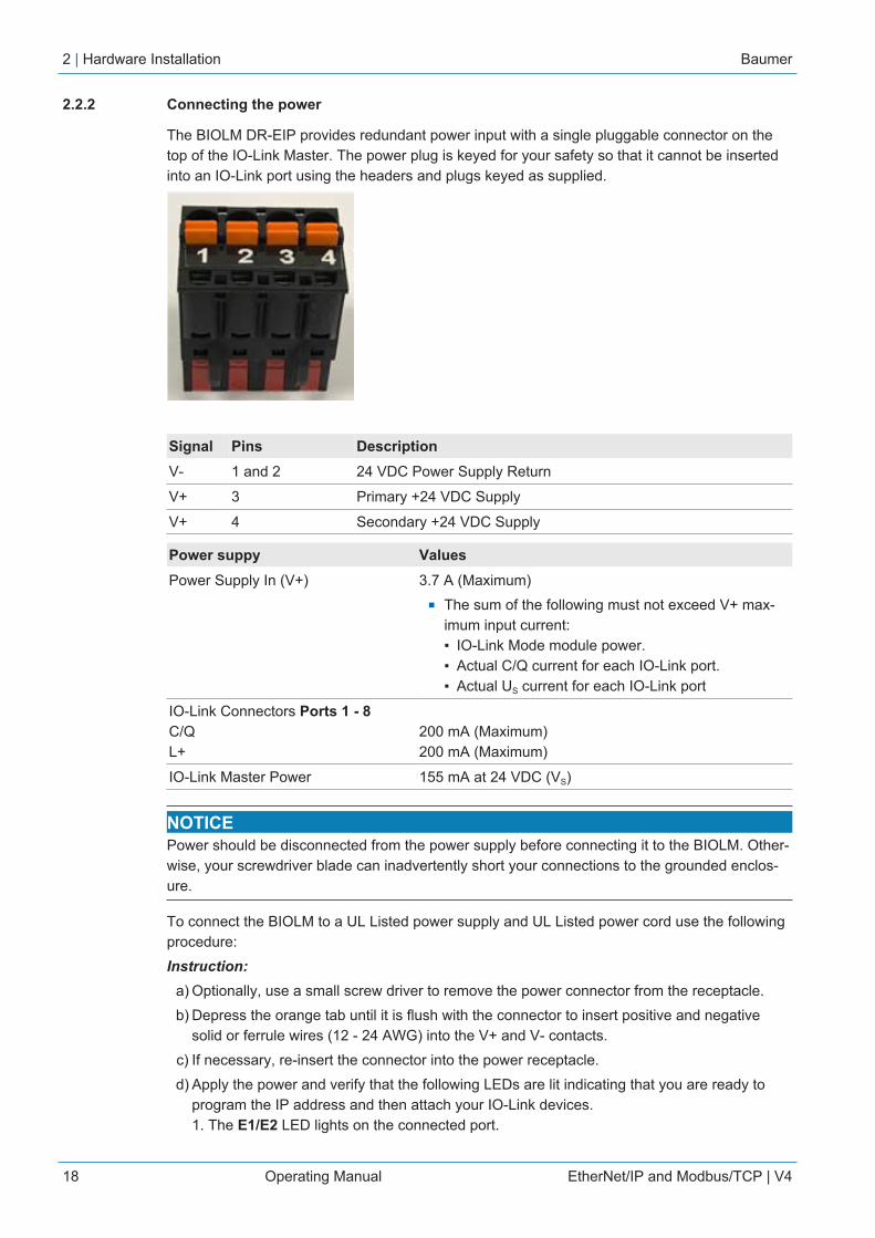
2.2.2 Connecting the power
The BIOLM DR-EIP provides redundant power input with a single pluggable connector on thetop of the IO-Link Master. The power plug is keyed for your safety so that it cannot be insertedinto an IO-Link port using the headers and plugs keyed as supplied.
Signal Pins DescriptionV- 1 and 2 24 VDC Power Supply Return
V+ 3 Primary +24 VDC Supply
V+ 4 Secondary +24 VDC Supply
Power suppy ValuesPower Supply In (V+) 3.7 A (Maximum)
n The sum of the following must not exceed V+ max-imum input current:▪ IO-Link Mode module power.▪ Actual C/Q current for each IO-Link port.▪ Actual US current for each IO-Link port
IO-Link Connectors Ports 1 - 8 C/QL+
200 mA (Maximum)200 mA (Maximum)
IO-Link Master Power 155 mA at 24 VDC (VS)
NOTICEPower should be disconnected from the power supply before connecting it to the BIOLM. Other-wise, your screwdriver blade can inadvertently short your connections to the grounded enclos-ure.
To connect the BIOLM to a UL Listed power supply and UL Listed power cord use the followingprocedure:Instruction:
a) Optionally, use a small screw driver to remove the power connector from the receptacle.b) Depress the orange tab until it is flush with the connector to insert positive and negative
solid or ferrule wires (12 - 24 AWG) into the V+ and V- contacts.c) If necessary, re-insert the connector into the power receptacle.d) Apply the power and verify that the following LEDs are lit indicating that you are ready to
program the IP address and then attach your IO-Link devices.1. The E1/E2 LED lights on the connected port.
Baumer Hardware Installation | 2
EtherNet/IP and Modbus/TCP | V4 Operating Manual 19
2. The MOD and NET LEDs are lit.3. The IO-Link LEDs flash (if no IO-Link device attached) or are lit if an IO-Link device is at-tached.4. The MOD LED is solid green, the IO-Link Master is ready for operation.
If the LEDs indicate that you are ready to go to the next installation step. Refer to Configuringthe Network Information [} 20] to configure the network information.
If the LEDs do not meet the above conditions, you can refer to BIOLM DR-EIP LEDs [} 154] inthe Troubleshooting and Technical Support [} 151] for more information.
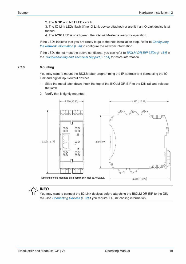
2.2.3 Mounting
You may want to mount the BIOLM after programming the IP address and connecting the IO-Link and digital input/output devices.
1. Slide the metal latch down, hook the top of the BIOLM DR-EIP to the DIN rail and releasethe latch.
2. Verify that is tightly mounted.
INFOYou may want to connect the IO-Link devices before attaching the BIOLM DR-EIP to the DINrail. Use Connecting Devices [} 22] if you require IO-Link cabling information.
3 | Configuring the Network Information Baumer
20 Operating Manual EtherNet/IP and Modbus/TCP | V4
3 Configuring the Network InformationThe following topics are discussed in this chapter:
n Network Configuration Overview [} 20]n Using the Web Interface to Program the Network [} 21]
3.1 Network Configuration Overview
If you used the rotary switch (applicable models) to set the IP address (Hardware Installation[} 10]), may want to configure the upper 9 digits (24 bits) of the IP address using the embeddedweb interface.
NOTICEIf you set the network address using the rotary switches, the Rotary Switch setting overrides thenetwork settings in the web interface when the BIOLM is initially powered on or after cycling thepower.
You can use one of the following method to configure the IP address:n Web interface (Using the Web Interface to Program the Network [} 21]):
▪ The BIOLM default IP address is: 192.168.0.250 and the Subnet Mask is:255.255.255.0.You may want to use the Advanced | Network page, if you need to configure the follow-ing:- Host name- DNS servers- Syslog Server IP/Host name- Syslog Port- SSH Server Enable

Baumer Configuring the Network Information | 3
EtherNet/IP and Modbus/TCP | V4 Operating Manual 21
3.2 Using the Web Interface to Program the Network
This subsection discusses using the web interface to configure the IP address. The default IPaddress is 192.168.0.250 and the Subnet Mask is: 255.255.255.0.
INFOThe rotary switch settings (applicable models) override the lower 3 digits (8 bits) of static IP ad-dress configured on the Configuration | Network page. The default rotary switch setting usesthe settings configured in the flash. Optionally, you can use the web interface to configure theupper 9 digits (24 bits) and the rotary switch to configure the lower 3 digits (8 bits) of the staticIP address. You can also refer to Hardware Installation [} 10] for additional information.
You may need to change your host system IP address so that it can communicate with theBIOLM default IP address: 192.168.0.250. The BIOLM is shipped from the factory with theAdmin account enabled without a password. You can configure the Admin, Operator, and Userpasswords.Instruction:
a) Open your browser and enter the IP address of the BIOLM to open the BIOLM web inter-face.
b) Click Configuration | NETWORK.c) Click the EDIT button.d) Click the CONTINUE button.e) Optionally, enter a host name to identify this BIOLM.f) Select the IP type, Static or DHCP.
If using a static IP address, enter the static IP address, subnet mask and IP gateway ad-dress.If using DNS:- Enter the DNS primary server IP address.- Optionally, enter the DNS secondary server IP address.
g) If desired, enter the NTP server IP or host name.h) If you want the BIOLM to send syslog messages to a syslog server:
Enter the syslog server's IP address (or host name if using DNS).Enter the syslog server's port number (default is 514).
i) If you want to enable the SSH server, click Enable.j) Click SAVE to save the changes.k) If the BIOLM does not redirect you to the new page, open a session using the new IP ad-
dress.The BIOLM does not need to be rebooted.
You should verify that you have the latest software installed on the BIOLM and if necessary, up-date the software. Refer to Updating Images and Applications for information about locating thelatest files and uploading the software.
After verifying that you have the latest software, you are ready to configure the BIOLM portcharacteristics.
4 | Connecting Devices Baumer
22 Operating Manual EtherNet/IP and Modbus/TCP | V4
4 Connecting DevicesThis chapter discusses connecting devices to the BIOLM. Use the appropriate discussion foryour BIOLM model:
n Overview [} 22]n BIOLM L-EIP IO-Link Ports [} 23]n BIOLM IO-Link and DIO Ports [} 25]n BIOLM DR-EIP IO-Link Ports [} 31]
4.1 Overview
The C/Q pin for the IO-Link ports in SIO mode for all models:n DI: Sinking input
The DI pin on the IO-Link ports for all models is a sinking input.n DO: PNP/NPN (push/pull) output
INFOBIOLM Only – with two dedicated DIO ports:
a) The extra DI is the same as the DI on the IO-Link ports – sinking input.b) The extra DIO is as follows:
DI: Sinking inputDO: PNP output
The following table provides definitions of the terminology used above:
Term DefinitionPNP output Is an output that can source current. That is; the (+) side of the device is connec-
ted to the output and the (-) side of the device is connected to (-) of the supply.The device is powered when the output LED is on.
NPN output Is and output that sinks current. That is: the (-) of the device is connected to theoutput and the (+) side of the device is connected to (+) side of the supply. Thedevice is powered when the output LED is off.
Sinking input Sinks current into the IO-Link Master so a positive voltage will cause the input toturn on.
NOTICE! Using NPN with inputs is not correct as NPN described an outputsituation – however some vendors describe their inputs as accepting a cer-tain type of sensor output – so in this case a sinking input will accept a PNPoutput sensor.

Baumer Connecting Devices | 4
EtherNet/IP and Modbus/TCP | V4 Operating Manual 23
4.2 BIOLM L-EIP IO-Link Ports
The BIOLM L-EIP provides eight IO-Link ports with M12, 5-pin female/A coded connectors.Each port has robust over-current protection and short circuit protection on its L+/L- power out-put and C/Q IO-Link signal. The pin-out for each IO-Link port is per the IO-Link standard and isprovided in the following table:
This table provides signal information for the IO-Link connectors.
Pin Signal Description1 L+ IO-Link device power supply (+24 V)
2 DI Digital input
3 L- IO-Link device power supply (0 V)
4 C/Q Communication signal, which supports SDCI (IO-Link) or SIO (standardinput / output) digital I/O
5 FE Functional Earth (electronics wiring)
The standard SDCI (IO-Link) transmission rates are supported:n COM1 at 4.8 Kbpsn COM2 at 38.4 Kbpsn COM3 at 230.4 Kbps
There are active over-current limiter electronics for each port in the BIOLM L-EIP that detectsthe overload/short-circuit condition within a few milliseconds and shuts off the output power toprotect the port and the devices connected to it. The port’s power output self-recovers and re-stores to normal immediately after the overload or short-circuit condition is removed.
The over-current limiter circuit for L+/L- pins is separate circuits than the over-current limiter cir-cuit for the C/Q output pin. When a port is affected by overload/short-circuit condition, it doesnot affect the operation of the other ports. All other ports will continue to operate normallywithout any glitch or interruption. The current output capacity, cutoff current, and power sharing/budgeting for L+/L- and C/Q signal for the ports on the BIOLM L-EIP are as follows.

4 | Connecting Devices Baumer
24 Operating Manual EtherNet/IP and Modbus/TCP | V4
L+/L- C/QPort Output Cur-
rent Capa-city (max.)
OverloadCutoff Cur-rent
Short-Cir-cuit Protec-tion
Output Cur-rent Capa-city (max.)
OverloadCutoff Cur-rent
Short-Cir-cuit Protec-tion
Port 1: Independent over-current limiter circuits/IC forL+/L- and C/Q pins
1.6 A 1.65 A Yes 200 mA 400 mA Yes
Port 3: Independent over-current limiter circuits/IC forL+/L- and C/Q pins
1 A 1.05 A Yes 200 mA 400 mA Yes
Ports 2 and 4 (Pair)Ports 5 and 7 (Pair)Ports 6 and 8 (Pair)
500 mA /port pair
(1 A outputpowerbudget perport pair)
1.05 A /port pair
Yes 200 mA I /port
400 mA I /port
Yes
There’s one independent over-current limiter that protects L+/L- pins on each pair of ports, for example: Port 2and 4.This allows you to do power budgeting on pair of ports that allows flexibility in the application. The combinedoverload cutoff current on a pair of ports is 1.05 A for the L+/L- pins.As long as the cutoff current of 1.05 A is not exceeded, the current output could be budgeted between a pair ofports such as, Port 2 and 4 any way you want.For example, Port 2 output can be at 900 mA and Port 4 output can be at 100 mA. Or, Port 2 could be left openand Port 4 output can be at 1 A.
I Each port’s C/Q pin has its own independent over-current limiter circuit and are not com-bined. The current output of C/Q pin for each port is also independently controlled and can-not be budgeted with other ports.
Use the following procedure to attach IO-Link or digital input/output devices to the ports:Instruction:
a) Securely attach the IO-link cable between the IO-Link or digital input/output device and theIO-Link port.NOTICE! Make sure that you tighten the cables properly to maintain IP67 integrity.
b) If necessary, securely attach a connector cap to prevent dust or liquids from getting into anyunused ports. Connector caps were shipped with the BIOLM.NOTICE! IO-Link ports must have an approved cable or protective cover attached tothe port to guarantee IP67 compliance.
c) If necessary, configure IO-Link port parameters using the Configuration | IO-Link Settingspage to configure the port mode.
Result:ü If an IO-Link device is attached to the port, the IO-Link LED should now be lit green and the
device is receiving power.ü If a digital input or output device is attached to the IO-Link port, after the port is configured
for digital input or output on the IO-Link Settings page, the IO-Link LED does not light butwhen an event occurs:Digital input causes the DI LED to flash.Digital output causes the IO-Link LED to flash.
Baumer Connecting Devices | 4
EtherNet/IP and Modbus/TCP | V4 Operating Manual 25
You can refer to the help system or IO-Link Port Configuration [} 33] for configuration informa-tion.
4.3 BIOLM IO-Link and DIO Ports
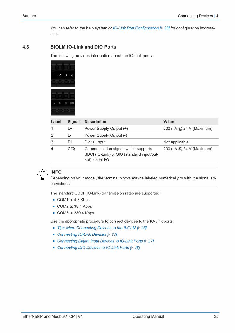
The following provides information about the IO-Link ports:
Label Signal Description Value1 L+ Power Supply Output (+) 200 mA @ 24 V (Maximum)
2 L- Power Supply Output (-)
3 DI Digital Input Not applicable.
4 C/Q Communication signal, which supportsSDCI (IO-Link) or SIO (standard input/out-put) digital I/O
200 mA @ 24 V (Maximum)
INFODepending on your model, the terminal blocks maybe labeled numerically or with the signal ab-breviations.
The standard SDCI (IO-Link) transmission rates are supported:n COM1 at 4.8 Kbpsn COM2 at 38.4 Kbpsn COM3 at 230.4 Kbps
Use the appropriate procedure to connect devices to the IO-Link ports:n Tips when Connecting Devices to the BIOLM [} 26]n Connecting IO-Link Devices [} 27]n Connecting Digital Input Devices to IO-Link Ports [} 27]n Connecting DIO Devices to IO-Link Ports [} 28]
4 | Connecting Devices Baumer
26 Operating Manual EtherNet/IP and Modbus/TCP | V4
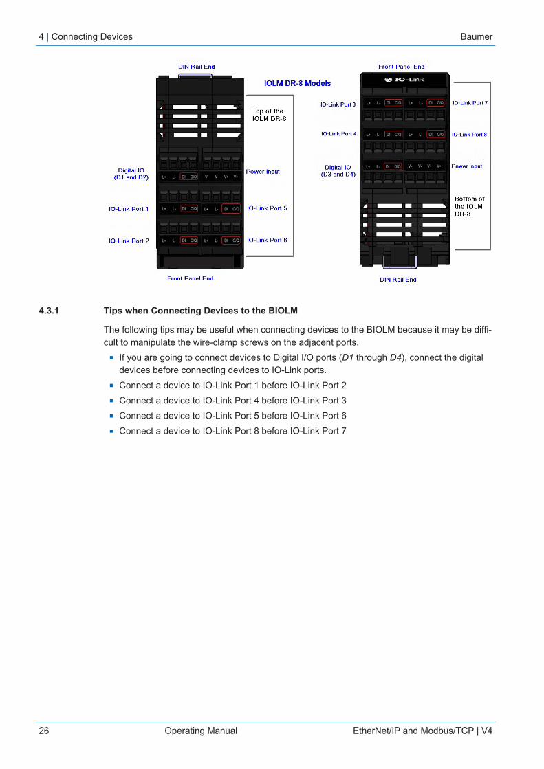
4.3.1 Tips when Connecting Devices to the BIOLM
The following tips may be useful when connecting devices to the BIOLM because it may be diffi-cult to manipulate the wire-clamp screws on the adjacent ports.
n If you are going to connect devices to Digital I/O ports (D1 through D4), connect the digitaldevices before connecting devices to IO-Link ports.
n Connect a device to IO-Link Port 1 before IO-Link Port 2n Connect a device to IO-Link Port 4 before IO-Link Port 3n Connect a device to IO-Link Port 5 before IO-Link Port 6n Connect a device to IO-Link Port 8 before IO-Link Port 7
Baumer Connecting Devices | 4
EtherNet/IP and Modbus/TCP | V4 Operating Manual 27
4.3.2 Connecting IO-Link Devices
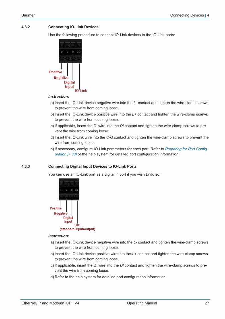
Use the following procedure to connect IO-Link devices to the IO-Link ports:
Instruction:a) Insert the IO-Link device negative wire into the L- contact and tighten the wire-clamp screws
to prevent the wire from coming loose.b) Insert the IO-Link device positive wire into the L+ contact and tighten the wire-clamp screws
to prevent the wire from coming loose.c) If applicable, insert the DI wire into the DI contact and tighten the wire-clamp screws to pre-
vent the wire from coming loose.d) Insert the IO-Link wire into the C/Q contact and tighten the wire-clamp screws to prevent the
wire from coming loose.e) If necessary, configure IO-Link parameters for each port. Refer to Preparing for Port Config-
uration [} 33] or the help system for detailed port configuration information.
4.3.3 Connecting Digital Input Devices to IO-Link Ports
You can use an IO-Link port as a digital in port if you wish to do so:
Instruction:a) Insert the IO-Link device negative wire into the L- contact and tighten the wire-clamp screws
to prevent the wire from coming loose.b) Insert the IO-Link device positive wire into the L+ contact and tighten the wire-clamp screws
to prevent the wire from coming loose.c) If applicable, insert the DI wire into the DI contact and tighten the wire-clamp screws to pre-
vent the wire from coming loose.d) Refer to the help system for detailed port configuration information.
4 | Connecting Devices Baumer
28 Operating Manual EtherNet/IP and Modbus/TCP | V4
4.3.4 Connecting DIO Devices to IO-Link Ports
You can use an IO-Link port to connect and operate a digital input or output device:Instruction:
a) Insert the IO-Link device negative wire into the L- contact and tighten the wire-clamp screwsto prevent the wire from coming loose.
b) Insert the IO-Link device positive wire into the L+ contact and tighten the wire-clamp screwsto prevent the wire from coming loose.
c) If applicable, insert the DI or DO wire into the C/Q contact and tighten the wire-clampscrews to prevent the wire from coming loose.
d) Refer to the help system for detailed port configuration information.
4.3.5 Connecting Devices to the Digital IO Ports
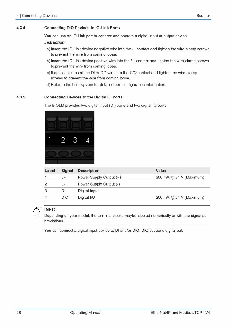
The BIOLM provides two digital input (DI) ports and two digital IO ports.
Label Signal Description Value1 L+ Power Supply Output (+) 200 mA @ 24 V (Maximum)
2 L- Power Supply Output (-)
3 DI Digital Input
4 DIO Digital I/O 200 mA @ 24 V (Maximum)
INFODepending on your model, the terminal blocks maybe labeled numerically or with the signal ab-breviations.
You can connect a digital input device to DI and/or DIO. DIO supports digital out.
Baumer Connecting Devices | 4
EtherNet/IP and Modbus/TCP | V4 Operating Manual 29
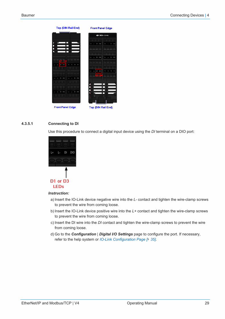
4.3.5.1 Connecting to DI
Use this procedure to connect a digital input device using the DI terminal on a DIO port:
Instruction:a) Insert the IO-Link device negative wire into the L- contact and tighten the wire-clamp screws
to prevent the wire from coming loose.b) Insert the IO-Link device positive wire into the L+ contact and tighten the wire-clamp screws
to prevent the wire from coming loose.c) Insert the DI wire into the DI contact and tighten the wire-clamp screws to prevent the wire
from coming loose.d) Go to the Configuration | Digital I/O Settings page to configure the port. If necessary,
refer to the help system or IO-Link Configuration Page [} 35].

4 | Connecting Devices Baumer
30 Operating Manual EtherNet/IP and Modbus/TCP | V4
4.3.5.2 Connecting to DIO
Instruction:a) Insert the IO-Link device negative wire into the L- contact and tighten the wire-clamp screws
to prevent the wire from coming loose.b) Insert the IO-Link device positive wire into the L+ contact and tighten the wire-clamp screws
to prevent the wire from coming loose.c) Insert the DI wire into the DIO contact and tighten the wire-clamp screws to prevent the wire
from coming loose.d) Go to the Configuration | Digital I/O Settings page to configure the port. If necessary,
refer to the help system or Dedicated Digital I/O Port Configuration (BIOLM).
Baumer Connecting Devices | 4
EtherNet/IP and Modbus/TCP | V4 Operating Manual 31
4.4 BIOLM DR-EIP IO-Link Ports
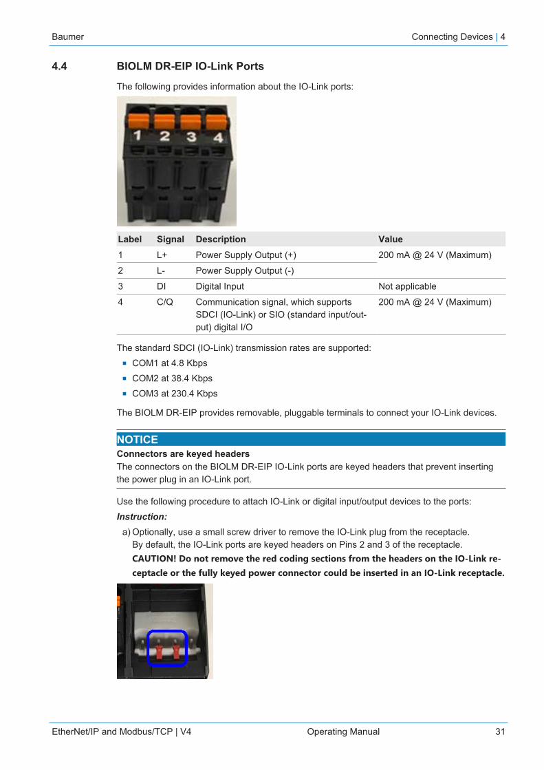
The following provides information about the IO-Link ports:
Label Signal Description Value1 L+ Power Supply Output (+) 200 mA @ 24 V (Maximum)
2 L- Power Supply Output (-)
3 DI Digital Input Not applicable
4 C/Q Communication signal, which supportsSDCI (IO-Link) or SIO (standard input/out-put) digital I/O
200 mA @ 24 V (Maximum)
The standard SDCI (IO-Link) transmission rates are supported:n COM1 at 4.8 Kbpsn COM2 at 38.4 Kbpsn COM3 at 230.4 Kbps
The BIOLM DR-EIP provides removable, pluggable terminals to connect your IO-Link devices.
NOTICEConnectors are keyed headersThe connectors on the BIOLM DR-EIP IO-Link ports are keyed headers that prevent insertingthe power plug in an IO-Link port.
Use the following procedure to attach IO-Link or digital input/output devices to the ports:Instruction:
a) Optionally, use a small screw driver to remove the IO-Link plug from the receptacle.By default, the IO-Link ports are keyed headers on Pins 2 and 3 of the receptacle.CAUTION! Do not remove the red coding sections from the headers on the IO-Link re-ceptacle or the fully keyed power connector could be inserted in an IO-Link receptacle.
4 | Connecting Devices Baumer
32 Operating Manual EtherNet/IP and Modbus/TCP | V4
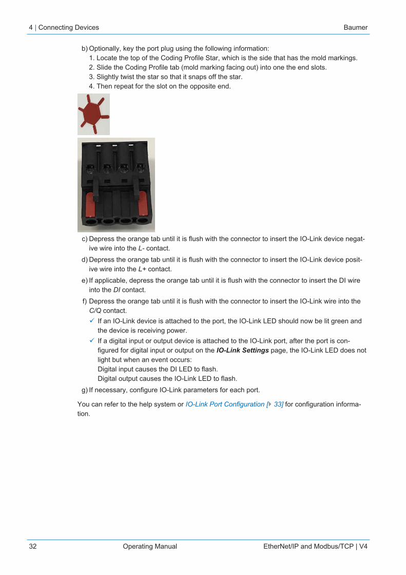
b) Optionally, key the port plug using the following information:1. Locate the top of the Coding Profile Star, which is the side that has the mold markings.2. Slide the Coding Profile tab (mold marking facing out) into one the end slots.3. Slightly twist the star so that it snaps off the star.4. Then repeat for the slot on the opposite end.
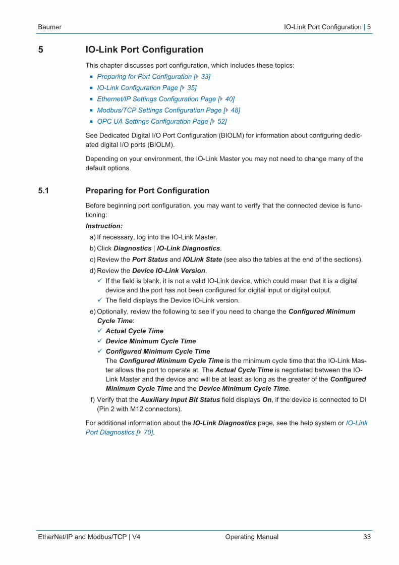
c) Depress the orange tab until it is flush with the connector to insert the IO-Link device negat-ive wire into the L- contact.
d) Depress the orange tab until it is flush with the connector to insert the IO-Link device posit-ive wire into the L+ contact.
e) If applicable, depress the orange tab until it is flush with the connector to insert the DI wireinto the DI contact.
f) Depress the orange tab until it is flush with the connector to insert the IO-Link wire into theC/Q contact.ü If an IO-Link device is attached to the port, the IO-Link LED should now be lit green and
the device is receiving power.ü If a digital input or output device is attached to the IO-Link port, after the port is con-
figured for digital input or output on the IO-Link Settings page, the IO-Link LED does notlight but when an event occurs:Digital input causes the DI LED to flash.Digital output causes the IO-Link LED to flash.
g) If necessary, configure IO-Link parameters for each port.
You can refer to the help system or IO-Link Port Configuration [} 33] for configuration informa-tion.
Baumer IO-Link Port Configuration | 5
EtherNet/IP and Modbus/TCP | V4 Operating Manual 33
5 IO-Link Port ConfigurationThis chapter discusses port configuration, which includes these topics:
n Preparing for Port Configuration [} 33]n IO-Link Configuration Page [} 35]n Ethernet/IP Settings Configuration Page [} 40]n Modbus/TCP Settings Configuration Page [} 48]n OPC UA Settings Configuration Page [} 52]
See Dedicated Digital I/O Port Configuration (BIOLM) for information about configuring dedic-ated digital I/O ports (BIOLM).
Depending on your environment, the IO-Link Master you may not need to change many of thedefault options.
5.1 Preparing for Port Configuration
Before beginning port configuration, you may want to verify that the connected device is func-tioning:Instruction:
a) If necessary, log into the IO-Link Master.b) Click Diagnostics | IO-Link Diagnostics.c) Review the Port Status and IOLink State (see also the tables at the end of the sections).d) Review the Device IO-Link Version.
ü If the field is blank, it is not a valid IO-Link device, which could mean that it is a digitaldevice and the port has not been configured for digital input or digital output.
ü The field displays the Device IO-Link version.e) Optionally, review the following to see if you need to change the Configured Minimum
Cycle Time:ü Actual Cycle Timeü Device Minimum Cycle Timeü Configured Minimum Cycle Time
The Configured Minimum Cycle Time is the minimum cycle time that the IO-Link Mas-ter allows the port to operate at. The Actual Cycle Time is negotiated between the IO-Link Master and the device and will be at least as long as the greater of the ConfiguredMinimum Cycle Time and the Device Minimum Cycle Time.
f) Verify that the Auxiliary Input Bit Status field displays On, if the device is connected to DI(Pin 2 with M12 connectors).
For additional information about the IO-Link Diagnostics page, see the help system or IO-LinkPort Diagnostics [} 70].

5 | IO-Link Port Configuration Baumer
34 Operating Manual EtherNet/IP and Modbus/TCP | V4
Port Status
Operational, PDI Valid An IO-Link device is operating on the port that has received validPDI data.
Operational An IO-Link device is operating on the port that has not receivedvalid PDI data.
Inactive One of the following conditions exists:n A valid IO-Link device is not connected to the port.n A digital input or output device is connected to the port but the
configured Port Mode is not correct.
IOLink Status
Operate Port is functioning correctly in IO-Link mode but has not receivedvalid PDI data.This may also display during a data storage upload or download.
Init The port is attempting initialization.
Reset One of the following conditions exists:n The Port Mode configuration is set to Reset.n The Port Mode configuration is set to DigitalIn or DigitalOut.
DS: Wrong Sensor Hardware failure (IO-Link LED also flashes red) because there isData Storage on this port, which does not reflect the attacheddevice.
DV: Wrong Sensor Hardware failure (IO-Link LED also flashes red) because DeviceValidation is configured for this port and the wrong device is at-tached.
DS: Wrong Size Hardware failure (IO-Link LED also flashes red) because the sizeof the configuration on the device does not match the size of theconfiguration stored on the port.
Comm Lost Temporary state after a device is disconnected and before the portis re-initialized.
Pre-operate Temporary status displayed when the device:n Is starting up after connection or power-up.n Uploading or downloading automatic data storage.
INFOIf a digital input or output device is connected to an IO-Link port, there is no valid data until theport is set to the correct Port Mode.

Baumer IO-Link Port Configuration | 5
EtherNet/IP and Modbus/TCP | V4 Operating Manual 35
5.2 IO-Link Configuration Page
You can use the Configuration | IO-Link Settings page to configure IO-Link port settings.When the IO-Link device is attached to a port, it begins operating without requiring any configur-ation. The BIOLM and attached IO-Link device automatically negotiate the Minimum CycleTime. If required by an application, you can set a specific Minimum Cycle Time.
This subsection discusses:n Editing IO-Link Port Settings [} 35]n IO-Link Settings Parameters [} 36]
INFOData Storage, Device Validation, and Data Validation are discussed in Utilizing BIOLM Features[} 60].
5.2.1 Editing IO-Link Port Settings
You can use this procedure to configure IO-Link settings for each IO-Link port.
If an IO-Link device is attached to the port, no configuration is required for operation. If a digitalinput or output device is attached, it is necessary to change the Port Mode.Instruction:
a) If necessary, open the IO-Link Master web interface with your web browser using the IP ad-dress.
b) Click Configuration | IO-Link Settings.c) Click the EDIT button for the port or ports that you want to configure.
You can click each EDIT button and open all ports to quickly configure port parameters.d) Make appropriate selections for the device that you connected to that port.
ü Make sure you select the DigitalIn option for a digital input device and the DigitalOut op-tion for a digital output device for the Port Mode.
ü The BIOLM negotiates the Minimum Cycle Time so it is not necessary to set a cycletime unless you need a specific cycle time.
ü You can use the help system if you require definitions or values for the options or refer toIO-Link Settings Parameters [} 36].NOTICE! Do not enable Automatic Download and then attempt device configura-tion as Automatic Download changes the settings back to what is stored on theBIOLM.
e) Click the SAVE button for each port.f) Return to the IO-Link Diagnostics page to verify that your changes have taken affect.
INFOPort 6 now indicates that it is functioning as a valid digital input device and the friendly portnames are displaying.
5 | IO-Link Port Configuration Baumer
36 Operating Manual EtherNet/IP and Modbus/TCP | V4
5.2.2 IO-Link Settings Parameters
The Configuration | IO-Link Settings page supports the following options:
IO-LINK Settings PagePort Name User defined port or device description:
n Standard ASCII charactersn Max length = 80 characters
Port Mode Default: IO-Link
Selected IO-Link port mode. Valid settings are:n Reset: Select to disable a port or to reset/restart an IO-Link
port.n IO-Link: Select to connect and operate an IO-Link device on
the port.n Digital In: Select if a DI device is attached to the port.n Digital Out: Select if a DO device is attached to the port.
Invert SIODefault: False
If enabled and the Port Mode is Digital In or Digital Out, this op-tion inverts the SIO value.
n False: Disabled – Do not invert SIOn True: Enabled – Invert SIO
This option does not affect the Auxiliary Input.
Invert Auxiliary Input If this option is enabled, the Auxiliary bit is inverted.
Default Digital OutputDefault: Off
If the Port Mode is Digital Out, defines the default digital outputvalue that is used at startup and when there is no active PDO con-troller.
n Off: Low voltage – 0n On: High voltage – 24 V
Minimum Cycle TimeDefault: 4
The minimum, or fastest, cycle time at which the IO-Link devicemay operate. The valid range is 4 - 538 ms.
You can leave the Minimum Cycle Time set to the default valueand the IO-Link Master negotiates with the IO-Link device for itsminimum cycle time. The IO-Link Diagnostics page displays theActual Cycle Time, which is the negotiated cycle time.
Auxiliary Input SettlingTime(0 - 10000)
The auxiliary input settling time that remains constant before thatinput is considered/accepted.
Auxiliary Input Hold Time (0 - 10000)
This is how long the IO-Link Master keeps the input at its presentvalue. For example, if the IO-Link Master detects the input to go tohigh, and the hold time is X milliseconds, then the IO-Link Masterreports the input as high for X milliseconds, even though the inputitself may have ceased. If X is zero, then you get the behavior cur-rently in the field.
SIO Input Settling Time (0 - 10000)
The SIO input settling time that remains constant before that inputis considered/accepted.
SIO Input Hold Time (0 - 10000)
This is how long the IO-Link Master keeps the input at its presentvalue. For example, if the IO-Link Master detects the input to go tohigh, and the hold time is X milliseconds, then the IO-Link Master
Baumer IO-Link Port Configuration | 5
EtherNet/IP and Modbus/TCP | V4 Operating Manual 37
IO-LINK Settings Pagereports the input as high for X milliseconds, even though the inputitself may have ceased. If X is zero, then you get the behavior cur-rently in the field.
Data Storage ConfigStorage Contents Indicates that the data storage for the port is empty or displays the
Vendor ID and Product ID of the data stored on that port.
Automatic Data StorageUpload EnableDefault: Off
When this option is initially set to On, the BIOLM saves the datastorage parameters (if the data storage is empty) from the IO-Linkdevice to the BIOLM.
Automatic upload occurs when the Automatic Upload Enable op-tion is set to On and one of these conditions exists:
n There is no upload data stored on the gateway and the IO-Linkdevice is connected to the port.
n The IO-Link device has the DS_upload bit on (generally be-cause you have changed the configuration via Teach buttonsor web page).
When a port contains data storage for an IO-Link device and if youattach a device whose Vendor and Device ID do not match, theIO-Link LED on the BIOLM flashes red to indicate a wrong deviceis attached. In addition, the IO-Link Diagnostics page displays DS:Wrong Sensor in the IOLink State field.
Not all device parameters are sent to data storage, this is determ-ined by the IO-Link device manufacturer.
Automatic Data StorageDownload EnableDefault: Off
The data storage parameters on the BIOLM are downloaded tothe connected IO-Link device if:
n The Automatic Download option is enabled.n The data stored on the BIOLM port contains the same
Vendor ID and Product ID as the IO-Link device connected tothe port.
n Data storage parameters are also downloaded to the IO-Linkdevice if configuration changes are made on the device caus-ing the DS_upload bit to turn on and automatic upload is notenabled.
n The IO-Link device requests an upload and the AutomaticUpload Enable option is set to Off.
If you change configuration parameters on the IO-Link device andwant the parameters to remain loaded on the IO-Link device, youmust disable the Automatic Download option because otherwisethe BIOLM will reload the data storage on the port down to the IO-Link device.
Data Storage Manual Ops The Manual Data Storage Ops option provides the followingfunctionality, if data storage is supported by the IO-Link device:
n CLEAR: This clears any stored data for an IO-Link device onthis port.
n UPLOAD: This uploads and stores the IO-Link device config-uration on the BIOLM.

5 | IO-Link Port Configuration Baumer
38 Operating Manual EtherNet/IP and Modbus/TCP | V4
IO-LINK Settings Pagen DOWNLOAD: This downloads the stored IO-Link device con-
figuration from the BIOLM to the IO-Link device attached tothis port if the Vendor ID and Device ID match.
Validation ConfigDevice Validation ModeDefault: None
Device Validation Mode provides these options:n None: This disables Device Validation Mode.n Compatible: Permits a compatible IO-Link device (same
Vendor ID and Device ID) to function on the correspondingport.
n Identical: Only permits an IO-Link device to function on thecorresponding port as defined in the following fields:▪ Vendor ID▪ Device ID▪ Serial Number
NOTICE! Connecting an IO-Link device that is different thanthe configured with Data Validation enabled will generate aDV: wrong sensor error.
Vendor ID(0 - 65535)
This is required if you select a Device Validation Mode other thanNone.
The Vendor ID can be manually entered in this field or click theGET ATTACHED button and the IO-Link Master populates theVendor ID in this field.
Device ID(0 - 16777215)
This is required if you select a Device Validation Mode other thanNone.
The Device ID can be manually entered in this field or click theGET ATTACHED button and the IO-Link Master populates theDevice ID in this field.
Serial Num This is required if you select Identical for the Device ValidationMode.
The Serial Number can be manually entered in this field or clickthe GET ATTACHED button and the IO-Link Master populates theserial number in this field.
Data Validation ModeDefault: None
There are three Data Validation Modes:n None: No data validation is performed on the port.n Loose: The slave device's PDI/PDO lengths must be less than
or equal to the user-configured values.n Strict: The slave device's PDI/PDO lengths must be the same
as the user-configured values.
PDI Length(0 - 32)
This is input length of the PDI data field.
This is required if you select a Data Validation Mode other thanNone.
The PDI Length can be manually entered in this field or click theGET ATTACHED button and the IO-Link Master populates thePDI length in this field.

Baumer IO-Link Port Configuration | 5
EtherNet/IP and Modbus/TCP | V4 Operating Manual 39
IO-LINK Settings PagePDO Length(0 - 32)
This is input length of the PDO data field.
This is required if you select a Data Validation Mode other thanNone.
The PDO Length can be manually entered in this field or click theGET ATTACHED button and the IO-Link Master populates thePDO length in this field
GET ATTACHED(Button)
After opening a port for editing, you can click the GET AT-TACHED button to automatically populate the following fields withdata from the IO-Link device:
n Vendor IDn Device IDn Serial Numn PDI Lengthn PDO Length

5 | IO-Link Port Configuration Baumer
40 Operating Manual EtherNet/IP and Modbus/TCP | V4
5.3 Ethernet/IP Settings Configuration Page
Use the EtherNet/IP Settings page to configure EtherNet/IP options.
You may want to refer to the following sections for additional information:
n EtherNet/IP Interface [} 81] provides a functionality summary, data type definitions, termsand conditions, and data transfer methods.
n Functionality Descriptions [} 86] discusses process data block descriptions, event hand-ling, and ISDU handling.
n EtherNet/IP CIP Object Definitions [} 110], which explains vendor specific CIP object defini-tions.
n ControlLogix Family – Example PLC Programs, which provides is intended to provide basicworking functionality.
n SLC/PLC-5/MicroLogix Interface [} 136] lists requirements and discusses PLC-5 and SLCmessages, and PDI and PDO access via PCCC messages.
n EDS Files [} 143] provides installation instructions to add the EDS files to RSLinx.
This subsection includes the following topics:n Editing EtherNet/IP Settings [} 40]n EtherNet/IP Settings Parameters [} 41]
INFOThe IO-Link Master may work out of the box for ControlLogix PLCs.
5.3.1 Editing EtherNet/IP Settings
You can use this procedure to configure EtherNet/IP characteristics for each port:Instruction:
a) If necessary, open the IO-Link Master web interface with your web browser using the IP ad-dress.
b) Click Configuration | EtherNet/IP.c) Click the EDIT button for each port that you want to configure.
You can click each EDIT button and open all ports to quickly configure port parameters.d) Make appropriate selections for the device that is connected to the port.
ü You can use the help system if you require definitions or values for the options or refer toEtherNet/IP Settings Parameters [} 41] in the next subsection.
e) Scroll to the top of the page and click the SAVE button.Result:ü Make sure that the port now displays the EDIT button.

Baumer IO-Link Port Configuration | 5
EtherNet/IP and Modbus/TCP | V4 Operating Manual 41
5.3.2 EtherNet/IP Settings Parameters
The Configuration | EtherNet/IP Settings page supports the following options.
EtherNet/IP Settings PageISDU Data SettingsISDU Response Timeout Default = 20 seconds
The time that the IO-Link Master’s EtherNet/IP interface waits for aresponse to an ISDU request.
The timeout needs to set long enough to allow all commandswithin the ISDU request to be processed.
Valid range: 1 - 10,000 seconds
Process Data SettingsPDI Data Block Size(To PLC)Default: 36-bytes
The configurable PDI data block length. Supported optionallengths are:
n 4-bytes (header only)n 8-bytes (4 bytes data)n 10-bytes (6 bytes data)n 16-bytes (12 bytes data)n 20-bytes (16 bytes data)n 24-bytes (20 bytes data)n 36-bytes (32 bytes data)
PDI Data Block Format(To PLC)Default: Word-16
Data format of PDI data block to be transferred to the PLC(s) inClass 1 and/or Write-to-Tag/File PDI Transfer Modes. Supportedformats are:
n Byte-8 (8-bit or SINT)n Word-16 (16-bit or INT)n Dword-32 (32-bit or DINT)
The Data Block Format is independent of the PDI Data Byte-SwapMethod.This setting is not used for the SLC, PLC-5 and MicroLogix PLCswhich are always Word-16.
PDI Data Byte-SwapMethodDefault: Work (16-bit) byteswap
If enabled, the IO-Link Master swaps the data bytes in word(2 byte) format or dword (4 byte) format.
Supported values are:n No byte-swap – data passed through as receivedn Word (16-bit) byte-swap – data is byte-swapped in word
formatn Dword (32-bit) byte-swap – data is byte-swapped in dword
formatn Reverse byte order – data passed through after being re-
versed
NOTICE! The byte swapping must be set correctly in order toconvert from IO-Link (big-endian byte order), to EtherNet/IP(little-endian byte order).

5 | IO-Link Port Configuration Baumer
42 Operating Manual EtherNet/IP and Modbus/TCP | V4
EtherNet/IP Settings PageInclude Digital I/O in PDIData BlockDefault: False(BIOLM, Only)
If enabled, the IO-Link Master includes the current digital I/Opins D1 to D4 status in the PDI data block header.
n False – Do not include the digital I/O pins statusn True (enable check box) – Include the digital I/O pins status in
PDI data block header
Does not affect the Auxiliary Input.
PDO Data Block Size(From PLC) Default: 32-bytes
The configurable PDO data block length. Supported optionallengths are:
Event code not included:n 4-bytes = all datan 8-bytes = all datan 10-bytes = all datan 16-bytes = all datan 20-bytes = all datan 24-bytes = all datan 32-bytes = all datan 34-bytes = 32 bytes data, 2 pad bytesn 36-bytes = 32 bytes data, 4 pad bytes
Event code included – PDO Data Format = Byte8:n 4-bytes = 2 byte event code, 2 data bytesn 8-bytes = 2 byte event code, 6 data bytesn 10-bytes = 2 byte event code, 8 data bytesn 16-bytes = 2 byte event code, 14 data bytesn 20-bytes = 2 byte event code, 18 data bytesn 24-bytes = 2 byte event code, 22 data bytesn 32-bytes = 2 byte event code, 30 data bytesn 34-bytes = 2 byte event code, 32 data bytesn 36-bytes = 2 byte event code, 32 data bytes, 2 byte pad
Event code included – PDO Data Format = word (16-bit):n 4-bytes = event code word, data wordn 8-bytes = event code word, 3 data wordsn 10-bytes = event code word, 4 data wordsn 16-bytes = event code word, 7 data wordsn 20-bytes = event code word, 9 data wordsn 24-bytes = event code word, 11 data wordsn 32-bytes = event code word, 15 data wordsn 34-bytes = event code word, 16 data wordsn 36-bytes = event code word, 16 data words, pad word
Event code included – PDO Data Format = dword (32-bit):n 4-bytes = event code dwordn 8-bytes = event code dword, data dword
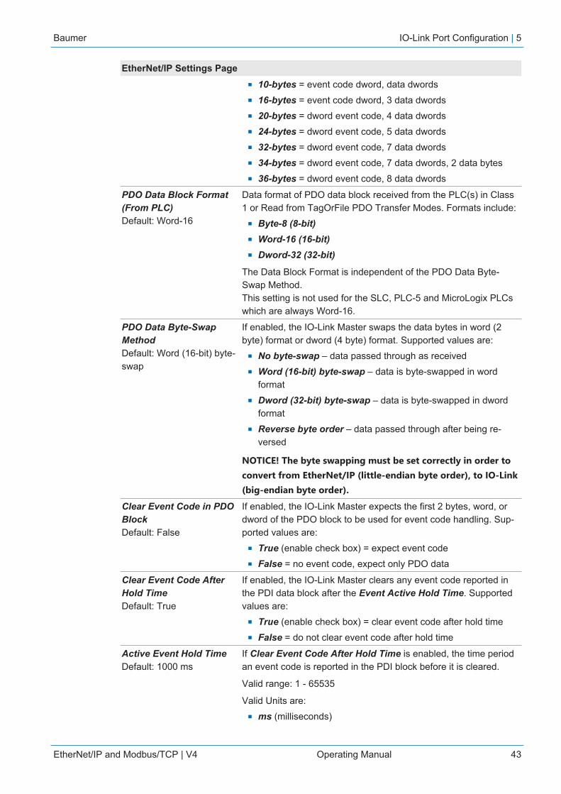
Baumer IO-Link Port Configuration | 5
EtherNet/IP and Modbus/TCP | V4 Operating Manual 43
EtherNet/IP Settings Pagen 10-bytes = event code dword, data dwordsn 16-bytes = event code dword, 3 data dwordsn 20-bytes = dword event code, 4 data dwordsn 24-bytes = dword event code, 5 data dwordsn 32-bytes = dword event code, 7 data dwordsn 34-bytes = dword event code, 7 data dwords, 2 data bytesn 36-bytes = dword event code, 8 data dwords
PDO Data Block Format(From PLC) Default: Word-16
Data format of PDO data block received from the PLC(s) in Class1 or Read from TagOrFile PDO Transfer Modes. Formats include:
n Byte-8 (8-bit)n Word-16 (16-bit)n Dword-32 (32-bit)
The Data Block Format is independent of the PDO Data Byte-Swap Method.This setting is not used for the SLC, PLC-5 and MicroLogix PLCswhich are always Word-16.
PDO Data Byte-SwapMethodDefault: Word (16-bit) byte-swap
If enabled, the IO-Link Master swaps the data bytes in word (2byte) format or dword (4 byte) format. Supported values are:
n No byte-swap – data passed through as receivedn Word (16-bit) byte-swap – data is byte-swapped in word
formatn Dword (32-bit) byte-swap – data is byte-swapped in dword
formatn Reverse byte order – data passed through after being re-
versed
NOTICE! The byte swapping must be set correctly in order toconvert from EtherNet/IP (little-endian byte order), to IO-Link(big-endian byte order).
Clear Event Code in PDOBlockDefault: False
If enabled, the IO-Link Master expects the first 2 bytes, word, ordword of the PDO block to be used for event code handling. Sup-ported values are:
n True (enable check box) = expect event coden False = no event code, expect only PDO data
Clear Event Code AfterHold TimeDefault: True
If enabled, the IO-Link Master clears any event code reported inthe PDI data block after the Event Active Hold Time. Supportedvalues are:
n True (enable check box) = clear event code after hold timen False = do not clear event code after hold time
Active Event Hold TimeDefault: 1000 ms
If Clear Event Code After Hold Time is enabled, the time periodan event code is reported in the PDI block before it is cleared.
Valid range: 1 - 65535
Valid Units are:n ms (milliseconds)
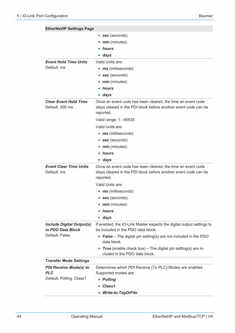
5 | IO-Link Port Configuration Baumer
44 Operating Manual EtherNet/IP and Modbus/TCP | V4
EtherNet/IP Settings Pagen sec (seconds)n min (minutes)n hoursn days
Event Hold Time UnitsDefault: ms
Valid Units are:n ms (milliseconds)n sec (seconds)n min (minutes)n hoursn days
Clear Event Hold TimeDefault: 500 ms
Once an event code has been cleared, the time an event codestays cleared in the PDI block before another event code can bereported.
Valid range: 1 - 65535
Valid Units are:n ms (milliseconds)n sec (seconds)n min (minutes)n hoursn days
Event Clear Time UnitsDefault: ms
Once an event code has been cleared, the time an event codestays cleared in the PDI block before another event code can bereported.
Valid Units are:n ms (milliseconds)n sec (seconds)n min (minutes)n hoursn days
Include Digital Output(s)in PDO Data BlockDefault: False
If enabled, the IO-Link Master expects the digital output settings tobe included in the PDO data block.
n False – The digital pin setting(s) are not included in the PDOdata block.
n True (enable check box) – The digital pin setting(s) are in-cluded in the PDO data block.
Transfer Mode SettingsPDI Receive Mode(s) toPLCDefault: Polling, Class1
Determines which PDI Receive (To PLC) Modes are enabled.Supported modes are:
n Pollingn Class1n Write-to-TagOrFile
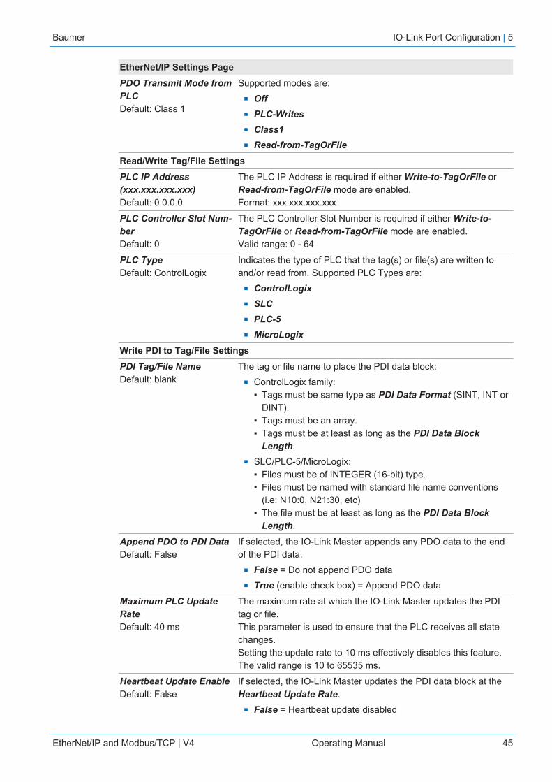
Baumer IO-Link Port Configuration | 5
EtherNet/IP and Modbus/TCP | V4 Operating Manual 45
EtherNet/IP Settings PagePDO Transmit Mode fromPLCDefault: Class 1
Supported modes are:n Offn PLC-Writesn Class1n Read-from-TagOrFile
Read/Write Tag/File SettingsPLC IP Address(xxx.xxx.xxx.xxx)Default: 0.0.0.0
The PLC IP Address is required if either Write-to-TagOrFile orRead-from-TagOrFile mode are enabled.Format: xxx.xxx.xxx.xxx
PLC Controller Slot Num-berDefault: 0
The PLC Controller Slot Number is required if either Write-to-TagOrFile or Read-from-TagOrFile mode are enabled.Valid range: 0 - 64
PLC TypeDefault: ControlLogix
Indicates the type of PLC that the tag(s) or file(s) are written toand/or read from. Supported PLC Types are:
n ControlLogixn SLCn PLC-5n MicroLogix
Write PDI to Tag/File SettingsPDI Tag/File NameDefault: blank
The tag or file name to place the PDI data block:n ControlLogix family:
▪ Tags must be same type as PDI Data Format (SINT, INT orDINT).
▪ Tags must be an array.▪ Tags must be at least as long as the PDI Data Block
Length.n SLC/PLC-5/MicroLogix:
▪ Files must be of INTEGER (16-bit) type.▪ Files must be named with standard file name conventions
(i.e: N10:0, N21:30, etc)▪ The file must be at least as long as the PDI Data Block
Length.
Append PDO to PDI DataDefault: False
If selected, the IO-Link Master appends any PDO data to the endof the PDI data.
n False = Do not append PDO datan True (enable check box) = Append PDO data
Maximum PLC UpdateRateDefault: 40 ms
The maximum rate at which the IO-Link Master updates the PDItag or file.This parameter is used to ensure that the PLC receives all statechanges.Setting the update rate to 10 ms effectively disables this feature.The valid range is 10 to 65535 ms.
Heartbeat Update EnableDefault: False
If selected, the IO-Link Master updates the PDI data block at theHeartbeat Update Rate.
n False = Heartbeat update disabled
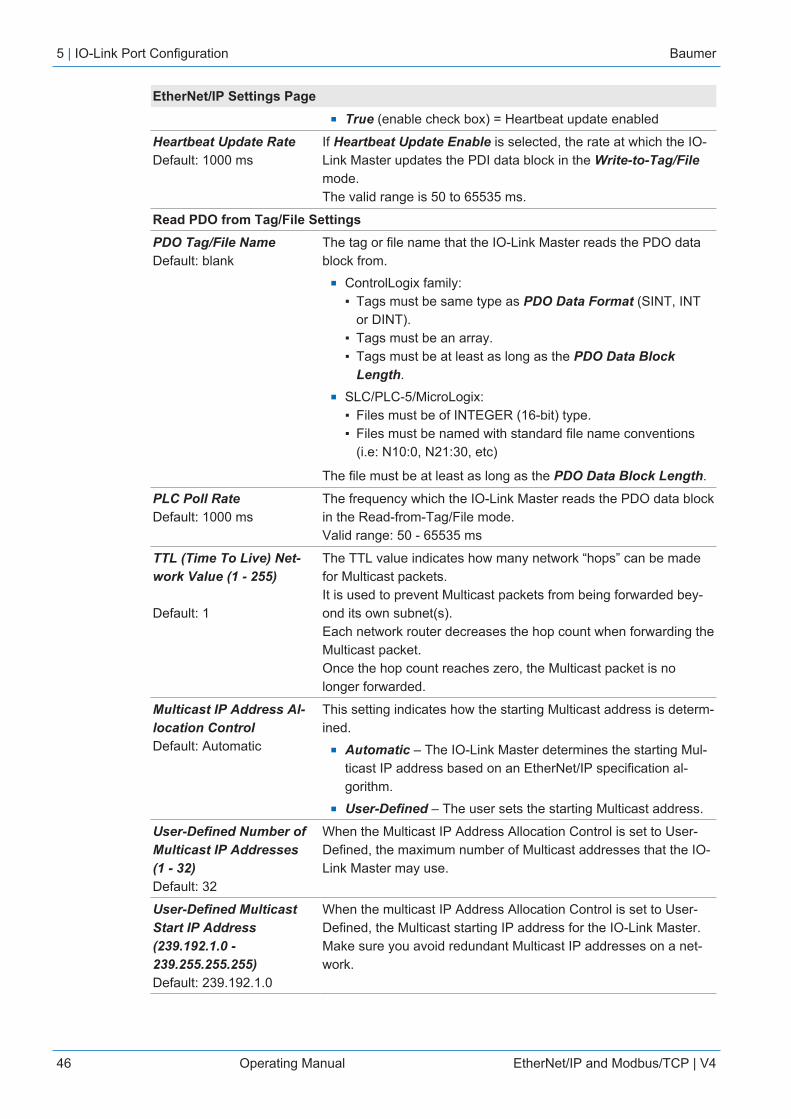
5 | IO-Link Port Configuration Baumer
46 Operating Manual EtherNet/IP and Modbus/TCP | V4
EtherNet/IP Settings Pagen True (enable check box) = Heartbeat update enabled
Heartbeat Update RateDefault: 1000 ms
If Heartbeat Update Enable is selected, the rate at which the IO-Link Master updates the PDI data block in the Write-to-Tag/Filemode.The valid range is 50 to 65535 ms.
Read PDO from Tag/File SettingsPDO Tag/File NameDefault: blank
The tag or file name that the IO-Link Master reads the PDO datablock from.
n ControlLogix family:▪ Tags must be same type as PDO Data Format (SINT, INT
or DINT).▪ Tags must be an array.▪ Tags must be at least as long as the PDO Data Block
Length.n SLC/PLC-5/MicroLogix:
▪ Files must be of INTEGER (16-bit) type.▪ Files must be named with standard file name conventions
(i.e: N10:0, N21:30, etc)
The file must be at least as long as the PDO Data Block Length.
PLC Poll RateDefault: 1000 ms
The frequency which the IO-Link Master reads the PDO data blockin the Read-from-Tag/File mode.Valid range: 50 - 65535 ms
TTL (Time To Live) Net-work Value (1 - 255)
Default: 1
The TTL value indicates how many network “hops” can be madefor Multicast packets.It is used to prevent Multicast packets from being forwarded bey-ond its own subnet(s).Each network router decreases the hop count when forwarding theMulticast packet.Once the hop count reaches zero, the Multicast packet is nolonger forwarded.
Multicast IP Address Al-location ControlDefault: Automatic
This setting indicates how the starting Multicast address is determ-ined.
n Automatic – The IO-Link Master determines the starting Mul-ticast IP address based on an EtherNet/IP specification al-gorithm.
n User-Defined – The user sets the starting Multicast address.
User-Defined Number ofMulticast IP Addresses(1 - 32)Default: 32
When the Multicast IP Address Allocation Control is set to User-Defined, the maximum number of Multicast addresses that the IO-Link Master may use.
User-Defined MulticastStart IP Address(239.192.1.0 -239.255.255.255)Default: 239.192.1.0
When the multicast IP Address Allocation Control is set to User-Defined, the Multicast starting IP address for the IO-Link Master.Make sure you avoid redundant Multicast IP addresses on a net-work.

Baumer IO-Link Port Configuration | 5
EtherNet/IP and Modbus/TCP | V4 Operating Manual 47
EtherNet/IP Settings PageSession EncapsulationTimeout (0 = disable;1 - 3600 sec)(0 - 3600)Default = 120
Defines the inactivity period before an established sessionbetween a controller, such as a PLC, and the BIOLM will time out.If such a timeout occurs, the current session is closed and a newsession must be established before communications can resumebetween the controller and the BIOLM.
5 | IO-Link Port Configuration Baumer
48 Operating Manual EtherNet/IP and Modbus/TCP | V4
5.4 Modbus/TCP Settings Configuration Page
You can use the Configuration | Modbus/TCP Settings page to configure Modbus/TCP withthe IO-Link Master. Additional Modbus information is available in the following chapters:
n Functionality Descriptions [} 86]n Modbus/TCP Interface [} 145]
This subsection includes these topics:n Editing Modbus/TCP Settings [} 48]n Modbus/TCP Settings Parameters [} 49]
INFOModbus is disabled by default. To use Modbus, click the EDIT button and select Enable.
5.4.1 Editing Modbus/TCP SettingsInstruction:
a) If necessary, open the IO-Link Master web interface with your web browser using the IP ad-dress.
b) Click Configuration | Modbus/TCP.c) Click the EDIT button for the port that you want to configure.
You can click each EDIT button and open all ports to quickly configure port parameters.d) Make appropriate selections for the IO-Link device that you will connect to that port. You
can use the help system if you require definitions or values for the options or Modbus/TCPSettings Parameters [} 49].
e) Scroll to the top of the page and click the SAVE button.Result:ü Make sure that the port now displays the EDIT button.ü If it displays the SAVE and CANCEL buttons, that means that one of the parameters con-
tains an incorrect value. If necessary, scroll down the page, make the needed corrections,and click SAVE.

Baumer IO-Link Port Configuration | 5
EtherNet/IP and Modbus/TCP | V4 Operating Manual 49
5.4.2 Modbus/TCP Settings Parameters
The following table provides detailed information about the Modbus/TCP Settings page.
Modbus/TCP Settings PageISDU Response Timeout Default = 20 seconds
The time that the IO-Link Master’s Modbus/TCP interface waits fora response to an ISDU request. The timeout needs to set longenough to allow all commands within the ISDU request to be pro-cessed.
Valid range: 1 - 10,000 seconds
Process Data SettingsPDI Data Block SizeDefault: 36-bytes
The configurable PDI data block length. Optional lengths are:n 4-bytes (header only)n 8-bytes (4 bytes data)n 16-bytes (12 bytes data)n 24-bytes (20 bytes data)n 36-bytes (32 bytes data)
PDI Byte-Swap MethodDefault: No byte-swap
If enabled, the IO-Link Master swaps the data bytes in word(2 byte) format or dword (4 byte) format. Options include:
n No byte-swap – data passed through as receivedn Word (16-bit) byte-swap – data is byte-swapped in word
formatn Dword (32-bit) byte-swap – data is byte-swapped in dword
formatn Reverse registers – data passed through after being re-
versed
Because both IO-Link and Modbus/TCP use big-endian byte or-dering, byte swapping typically is not required for word and dworddata. Byte swapping is most commonly required when receiving byte (8-bit) data and it is desired to place the first data byte in the leastsignificant byte position of the holding register. For these cases,word (16 bit) byte-swap is typically used.
Include Digital I/O in PDIData BlockDefault: False
If enabled, the IO-Link Master includes the current digital I/O pinsD1 to D4 status in the PDI data block header.
n False – Do not include the digital I/O pins statusn True (enable check box) – Include the digital I/O pins status in
PDI data block header
Does not affect the Auxiliary Input.
PDO Data Block Size(From PLC) Default: 32-bytes
The configurable PDO data block length. Optional lengths are:
Event code not included:n 4-bytes = 2 data wordsn 8-bytes = 4 data wordsn 16-bytes = 8 data wordsn 24-bytes = 12 data wordsn 32-bytes = 16 data words
5 | IO-Link Port Configuration Baumer
50 Operating Manual EtherNet/IP and Modbus/TCP | V4
Modbus/TCP Settings Pagen 34-bytes = 16 data words, 1 pad word
Event code included:n 4-bytes = event code word, 1 data wordn 8-bytes = event code word, 3 data wordsn 16-bytes = event code word, 7 data wordsn 24-bytes = event code word, 11 data wordsn 32-bytes = event code word, 15 data wordsn 34-bytes = event code word, 16 data words
PDO Byte-Swap MethodDefault: No byte-swap
If enabled, the IO-Link Master swaps the data bytes in word(2 byte) format or dword (4 byte) format. Options include:
n No byte-swap – data passed through as receivedn Word (16-bit) byte-swap – data is byte-swapped in word
formatn Dword (32-bit) byte-swap – data is byte-swapped in dword
formatn Reverse registers – data passed through after being re-
versed
Because both IO-Link and Modbus/TCP use big-endian byte or-dering, byte swapping typically is not required for word and dworddata. Byte swapping is most commonly required when sending byte (8-bit) data to the IO-Link device and it is desired to send the leastsignificant byte of the holding register first. For these cases, word(16 bit) byte-swap is typically used.
Append PDO to PDI DataDefault: False
If selected, the IO-Link Master appends any PDO data to the endof the PDI data.
n False = Do not append PDO datan True (enable check box) = Append PDO data
Clear Event Code in PDOBlockDefault: False
If enabled, the IO-Link Master expects the first word of the PDOblock to be used for event code handling.
Values are:n True (enable check box) = expect event coden False = no event code, expect only PDO data
Clear Event Code AfterHold TimeDefault: True
If enabled, the IO-Link Master clears any event code reported inthe PDI data block after the Event Active Hold Time.
Values are:n True (enable check box) = clear event code after hold timen False = do not clear event code after hold time
Active Event Hold TimeDefault: 1000 ms
If Clear Event Code After Hold Time is enabled, the time periodan event code is reported in the PDI block before it is cleared.
Valid range: 1 - 65535
Valid Units are:n ms (milliseconds)

Baumer IO-Link Port Configuration | 5
EtherNet/IP and Modbus/TCP | V4 Operating Manual 51
Modbus/TCP Settings Pagen sec (seconds)n min (minutes)n hoursn days
Event Hold Time Units Valid Units are:n ms (milliseconds)n sec (seconds)n min (minutes)n hoursn days
Clear Event Hold TimeDefault: 500 ms
Once an event code has been cleared, the time an event codestays cleared in the PDI block before another event code can bereported.
Valid range: 1 - 65535
Valid Units are:n ms (milliseconds)n sec (seconds)n min (minutes)n hoursn days
Event Clear Time Units Valid Units are:n ms (milliseconds)n sec (seconds)n min (minutes)n hoursn days
Include Digital Output(s)in PDO Data BlockDefault: False
If enabled, the IO-Link Master expects the digital output settings tobe included in the PDO data block.
n False – The digital pin setting(s) are not included in the PDOdata block
n True (enable check box) – The digital pin setting(s) are in-cluded in the PDO data block
Transfer Mode SettingsSlave Mode Device IDDefault: 1
The Modbus Device ID used to access this IO-Link port.Range: 1 - 247
PDI Receive Mode(s)Default: Slave
Determines which PDI Receive (To PLC) Modes are enabled.
The selectable mode is Slave.
NOTICE! Not selecting slave mode disables Modbus/TCP ac-cess to the PDI data block.
PDO Transmit ModeDefault: Slave
Selectable modes are:n Disabledn Slave

5 | IO-Link Port Configuration Baumer
52 Operating Manual EtherNet/IP and Modbus/TCP | V4
5.5 OPC UA Settings Configuration Page
Use the Configure | OPC UA Settings page to configure OPC UA with the BIOLM.
This subsection includes these topics:n Edit OPC UA Settings [} 52]n OPC UA Settings Parameters [} 52]
INFOOPC UA is disabled by default.
5.5.1 Edit OPC UA Settings
You can use this procedure to edit OPC UA settings:Instruction:
a) If necessary, open the IO-Link Master web interface with your web browser using the IP ad-dress.
b) Click Configuration | OPC UA.c) Click the EDIT button.d) Make the appropriate selections for your environment. You can use the help system if you
require definitions or values for the options or OPC UA Settings Parameters [} 52].e) Click the SAVE button.
5.5.2 OPC UA Settings Parameters
The following table provides information about the OPC UA Setting page:
Option OPC UA Configuration DescriptionsOPC UA Port CONFIGAllow OPC UA clients to write PDOdataDefault = disable
Determines whether OPC UA clients are allowed to writePDO data to the IO-Link devices.
OPC UA CONFIGURATIONOPC UA Server EnableDefault = disable
This option controls whether or not the OPC UA serverruns on the IO-Link Master.
Work-around for faulty OPC UA cli-ents that require unique browse-namesDefault = disable
Enables an alternative set of browsenames where eachnode's browsename is unique. Normally onlybrowsepaths are required to be unique.
Allow OPC UA clients to writeISDU dataDefault = disable
Determines whether OPC UA clients are allowed to writeISDU data to the IO-Link devices.
Baumer Loading and Managing IODD Files | 6
EtherNet/IP and Modbus/TCP | V4 Operating Manual 53
6 Loading and Managing IODD FilesThere are several Attached Devices pages that support IO-Link Device Description (IODD) filemanagement.
n IO-Link Device Description Files Page [} 53] – load IODD files from the IO-Link devicemanufacturer onto the BIOLM.
n IO-Link Device Configuration Summary Page [} 56] – verify the correct files were loadedfor each IO-Link device or use the page to retrieve information about the baud rate, SIOmode, and device number.
n The Port pages are discussed in Configuring IO-Link Devices [} 57].
6.1 IO-Link Device Description Files Page
INFOYou will need to download the appropriate IODD files from your IO-Link device manufacturer.
Use the IO-Link Device Description Files page to update (upload) and delete IO-Link DeviceDescription (IODD) files associated with this BIOLM. In addition, you can review the IODD xmlfile by clicking the IODD FILENAME in the table after loading the IODD file.
The BIOLM provides 15790K of space to store IODD files. The BIOLM includes the followingdefault IODD files, which cannot be deleted:
n IODD-StandardDefinitions1.0.1.xmln IODD-StandardUnitDefinitions1.0.1.xmln IODD-StandardDefinitions1.1.xmln IODD-StandardUnitDefinitions1.1.xml
You can use the Configuration | Save/Load feature to backup your IODD files. You can savethe configuration file from an BIOLM that has IODD files installed and then load that configura-tion file to another BIOLM to quickly load the IODD files.
6 | Loading and Managing IODD Files Baumer
54 Operating Manual EtherNet/IP and Modbus/TCP | V4
6.1.1 Preparing IODD Files to Upload
After downloading the IODD files for the IO-Link device from the IO-Link sensor or actuatormanufacturer, you may need to unzip the file and locate the appropriate xml file for the device.
n Some IODD zip files contain the xml files and supporting image files for a single product.This type of zip file can be immediately loaded onto the BIOLM.
n Some IODD zip files contain the files for multiple products. If you upload this type of IODDzip file, the BIOLM loads the first xml file and the associated image files, which may or maynot correspond to the IO-Link device connected to the port. If you need to zip the appropri-ate files, the following information may be useful:▪ Unzip the package and locate the xml file needed for your IO-Link device.▪ Open the xml file and search for the productID, which identifies the IO-Link device.▪ Zip the xml file along with the supporting images. There are several ways to locate the
supporting images:- Locate the appropriate images using the xml file.- Load only the xml file and the BIOLM notifies you what files are missing. Use the UP-DATE feature to upload the missing images.- Zip the xml with all of the images and the BIOLM ignores (and not upload) any unusedfiles and notifies which files did not upload.
INFOImage files are not required for IO-Link device configuration.
Use the appropriate discussion for your IODD files:n Uploading IODD Zip Files [} 54]n Uploading xml Files or Supporting Files [} 55]
6.1.2 Uploading IODD Zip Files
You can use the following procedure to upload IODD zip files:Instruction:
a) Click Attached Devices and IODD FILES.b) Click the UPLOAD FILE button.c) Click the CHOOSE FILE button and browse to the file location.d) Highlight the zip file, click Open and then the UPLOAD button.e) If necessary, click OK.
Only images referenced in the xml file load to the BIOLM and the remaining files are ig-nored.
f) If desired, you can view the xml file by clicking the IODD FILENAME in the table.g) Click the hyperlink at the top of the page if you want to view the xml file in your browser.h) Optionally, verify that the correct xml file was loaded using the Summary page (IO-Link
Device Configuration Summary Page [} 56]).

Baumer Loading and Managing IODD Files | 6
EtherNet/IP and Modbus/TCP | V4 Operating Manual 55
6.1.3 Uploading xml Files or Supporting Files
You can use the following procedure to upload xml, or supporting image files:Instruction:
a) Click Attached Devices and IODD FILES.b) Click the UPLOAD FILE button.c) Click the CHOOSE FILE button and browse to the file location.d) Highlight the xml or image file and click Open.
NOTICE! The xml file must be loaded before the BIOLM will load the associated imagefiles.
e) Click the UPLOAD button.ü The BIOLM notifies you what files are missing. The missing files do not affect the opera-
tion of the IODD Port page but the product image and logo for the IO-Link device com-pany do not display.
f) Optionally, use the following steps to load image files:1. Select the row in the table that contains the xml file by clicking the check box.2. Click the UPLOAD FILE button.3. Click the Choose File button and browse to the file location.4. Highlight the file and click Open.5. Click the UPLOAD button.6. Optionally, verify that the correct xml file was loaded using the Summary page (IO-LinkDevice Configuration Summary Page [} 56]).
6.1.4 Viewing and Saving IODD Files
Use the following procedure to view the contents of an IODD file:Instruction:
a) If necessary, click Attached Devices and IODD Files.b) Click the IODD FILENAME in the table that you want to review. A pop up window displays
the contents of the IODD file.c) Optionally, click the file name hyperlink at the top of the window to view the formatted file or
if you want to save a copy of the file to another location.
6.1.5 Deleting IODD Files
Use the following procedure to delete an IODD file set from the BIOLM:Instruction:
a) If necessary, click Attached Devices and IODD Files.b) Check the corresponding row of the IODD file that you want to delete.c) Click the DELETE SELECTED button.d) Click CONTINUE to the Delete files? message.

6 | Loading and Managing IODD Files Baumer
56 Operating Manual EtherNet/IP and Modbus/TCP | V4
6.2 IO-Link Device Configuration Summary Page
The IO-Link Device Configuration Summary page provides basic device configuration (deviceprofile) information for ports with valid IO-Link devices attached. The Configuration Summarypage retrieves information that resides on the IO-Link device from the manufacturer.
A file name displayed in the IODD Name field for a port indicates that a valid IODD file is associ-ated with that device. If the field is empty, that indicates that a valid IODD file has not beenloaded.
You can review complete IODD file information on a port by port basis by clicking the MOREbutton next to the port in question or by clicking the PORT menu selection in the navigationalbar.
Use the following steps to access the IO-Link Device Configuration Summary page.Instruction:
a) Click Attached Devices.b) Click SUMMARY.
ü The Configuration Summary page takes several minutes to completely load as eachdevice is queried.
c) Click the MORE button or the corresponding Port (in the navigational bar) to configure theIO-Link device parameters for a specific device. See Configuring IO-Link Devices [} 57] formore information.

Baumer Configuring IO-Link Devices | 7
EtherNet/IP and Modbus/TCP | V4 Operating Manual 57
7 Configuring IO-Link DevicesThis chapter discusses using the Attached Devices | Port pages to change IO-Link deviceparameters.
INFOOptionally, you can use traditional methods such as: PLC interfaces or HMI/SCADAs, depend-ing on your protocol to configure the IO-Link devices.
7.1 Port Pages Overview
You can use the Attached Devices | Port page for a port to review and easily edit the IO-Linkdevice configuration or view Process Data.
The Port page provides two IO-Link device configuration methods:n IO-Link Device Port table (GUI), which depends on the appropriate IODD file loaded from
the IO-Link device manufacturer onto the BIOLM. To use the IO-Link Device Port table forconfiguring IO-Link devices, refer to the following subsections:▪ Editing Parameters – IO-Link Device – Port Table [} 58]▪ Resetting IO-Link Device Parameters to Factory Defaults [} 58]
n IO-Link Device ISDU Interface – Port, which can be used with or without IODD filesloaded. Refer to the following information to use the IO-Link Device ISDU Interface – Portmethod:▪ The IO-Link Device Operator Manual from the device manufacturer is needed to use the
IO-Link Device ISDU Interface since ISDU block index and ISDU sub-index numbers arerequired.
▪ Editing Parameters – IO-Link Device ISDU Interface – Port [} 58]
The IO-Link Device Port table provides detailed information about the indexes and sub-in-dexes. Not all indexes have sub-indexes.
n If the IODD file follows IO-Link specifications, an asterisk next to RW means that parameteris not included in Data Storage.
n If a Sub-index has an asterisk next to it in the GUI, that means that sub-index is not sub-in-dexable. This may be useful information when using the IO-Link Device ISDU Interface orprogramming your PLC.

7 | Configuring IO-Link Devices Baumer
58 Operating Manual EtherNet/IP and Modbus/TCP | V4
7.2 Editing Parameters – IO-Link Device – Port Table
Use the following procedure to edit IO-Link device parameters using the IO-Link Device Porttable.
INFOYou may want to verify that the Automatic Download Enable for Data Storage option on theConfiguration | IO-Link Settings page is NOT set to On as this can cause unreliable resultson the corresponding port.
Instruction:a) If you have not done so, load the IODD file from the IO-Link device manufacturer (Loading
and Managing IODD Files [} 53]).b) Access the appropriate Port page by clicking Attached Devices and then the Port number
that you want to configure.c) Click the EDIT button after all of the device information is populated in the table.d) Scroll down the table and make appropriate parameter changes for your environment.
An IODD file may not contain all IO-Link device settings depending on the IO-Link devicemanufacturer. If you need to change a parameter that is not displayed in the IO-Link Device– Port table, you can refer to the IO-Link Device Operators Manual and use the IO-LinkDevice ISDU Interface to change the settings.You may need to scroll to the right in the table to view applicable parameter values if theparameter is not selectable in a drop list.
e) Click the SAVE button after editing the parameters.
7.3 Resetting IO-Link Device Parameters to Factory Defaults
In the event you want to reset the IO-Link device to factory default, typically the IODD fileprovides the ability from the IO-Link device manufacturer. Use the following example to reset anIO-Link device.Instruction:
a) Click the COMMAND button and locate the Restore Factory button.b) Click the Restore Factory or Load Factory Settings button.
The name of the button is determined by the IO-Link device manufacturer.c) Click OK when the Refresh message appears.
7.4 Editing Parameters – IO-Link Device ISDU Interface – Port
The IO-Link Device ISDU Interface follows these guidelines:n If necessary, convert hexadecimal ISDU index numbers to decimal, you must enter the
decimal value for the ISDU Block Index and ISDU Sub-index numbers.n You must enter the hexadecimal value for the IO-Link device parameters.
If the appropriate IODD files has been loaded, you can use the IO-Link Device – Port table todetermine the index numbers and acceptable values for each parameter.
An IODD file may not contain every IO-Link device setting depending on the IO-Link devicemanufacturer. If you need to change a parameter that is not displayed in the IO-Link Device –Port table, you can refer to the IO-Link Device Operators Manual.
Baumer Configuring IO-Link Devices | 7
EtherNet/IP and Modbus/TCP | V4 Operating Manual 59
If an IODD file has not been loaded for an IO-Link device, you can use the IO-Link Device Oper-ator's Manual to determine the ISDU indexes.
7.4.1 Overview
The following provides some basic information about the command usage and responses whenusing the ISDU Interface:
n You must enter the decimal value for the ISDU Block Index and ISDU Sub-index.n The GET button retrieves the parameter value in hex from the IO-Link device. You may
want to retrieve values to determine the data length.n The SET button sends the value to the IO-Link device.n After successfully changing a parameter, the IO-Link Master responds with a command ex-
ecuted notification.n The message other failure (write) means that the IO-Link device defines the entry as an in-
valid setting.n The message other failure (read) indicates that the IO-Link device cannot read the spe-
cified ISDU Block Index and Sub-index.
7.4.2 How to Use the Interface
Use the following procedure to edit parameters using the IO-Link Device ISDU Interface –Port.
INFOYou may want to verify that the Automatic Download Enable for Data Storage option on theConfiguration | IO-Link Settings page is NOT set to On as this can cause unreliable resultson the corresponding port.
Instruction:a) Click the + next to the IO-Link Device ISDU Interface to open the interface.b) Enter the ISDU Block Index number (decimal) that you want to edit.c) If applicable, enter the ISDU Sub-index (decimal).d) Edit the parameter (hex) and click the SET button.e) Verify that a command executed message returns.f) If the IODD file is loaded, optionally click REFRESH to verify your changes.

8 | Utilizing BIOLM Features Baumer
60 Operating Manual EtherNet/IP and Modbus/TCP | V4
8 Utilizing BIOLM FeaturesThis chapter discusses using the following features:
n Setting User Accounts and Passwords [} 61]n Data Storage [} 62], which provides automatic and manual data storage to upload or
download IO-Link v1.1 device parametersn Device Validation [} 64], which supports identical or compatible device validation to dedic-
ate a port or ports to specific IO-Link devicesn Data Validation [} 65], which supports strict or loose data validation to verify data integrityn BIOLM Configuration Files [} 65] , that supports a method to back up configuration files or
load the same configuration to multiple BIOLM unitsn Configuring Miscellaneous Settings [} 66], which provides the following options:
▪ Using the Menu Bar Hover Shows Submenu Option [} 66]▪ Enable PDO Write From Attached Devices Port Page [} 67]▪ IO-Link Test Event Generator [} 68]
n Clearing Settings [} 69], which allows you to reset the BIOLM to factory default values
Baumer Utilizing BIOLM Features | 8
EtherNet/IP and Modbus/TCP | V4 Operating Manual 61
8.1 Setting User Accounts and Passwords
The BIOLM is shipped from the factory without passwords. See the following table if you want tosee how permissions are granted:
Page Admin Operator UserLog-in Yes Yes Yes
Home Yes Yes Yes
Diagnostics – All Yes Yes Yes
Configuration – IO-Link Settings Yes Yes View-only
Configuration – Digital I/O Settings (Applicable mod-els)
Yes Yes View-only
Configuration – EtherNet/IP Settings Yes Yes View-only
Configuration – Modbus/TCP Yes Yes View-only
Configuration – OPC UA Yes Yes View-only
Configuration – Network Yes View-only No
Configuration – Misc Yes Yes Yes
Configuration – Load/Save Yes Yes View-only
Configuration – Clear Settings Yes No No
Advanced – Software Yes No No
Advanced – Accounts Yes No No
Advanced – Log Files Yes Yes Yes
Advanced – Licenses Yes Yes Yes
Attached Devices – IO-Link Device Description Files Yes Yes View-only
Attached Devices – IO-Link Device ConfigurationSummary
Yes Yes View-only
Attached Devices – IO-Link Device – Port Yes Yes View-only
You can use this procedure to set up passwords for the BIOLM:Instruction:
a) Open your browser and enter the BIOLM IP address.b) Click Advanced | ACCOUNTS.c) Click the ADMIN check box.d) If applicable, enter the old password in the Old Password text box.e) Enter the new password in the New Password text box.f) Re-enter the password in the Confirm Password text box.g) Optionally, click the Operator check box, enter a new password, and re-enter the password
in the Confirm Password text box.h) Optionally, click the User check box, enter the new password, and re-enter the password in
the Confirm Password text box.i) Click Apply.j) Close the new window that displays a Password saved banner.k) Click the Log out button on the top navigation bar.l) Re-open the web interface by selecting the appropriate user type in the drop list and enter-
ing the password.
8 | Utilizing BIOLM Features Baumer
62 Operating Manual EtherNet/IP and Modbus/TCP | V4
8.2 Data Storage
Data storage is typically supported by IO-Link v1.1 devices. Data storage means that you canupload parameters from an IO-Link device to the BIOLM and/or download parameters from theBIOLM to the IO-Link device. This feature can be used to:
n Quickly and easily replace a defective IO-Link devicen Configure multiple IO-Link devices with the same parameters as fast as it takes to connect
and disconnect the IO-Link device
To determine whether an IO-Link (v1.1) device supports data storage, you can check one of thefollowing:
n IO-Link Diagnostics page – check the Data Storage Capable field to see if it displays Yes.n IO-Link Configuration page – check to see if UPLOAD and DOWNLOAD buttons display
under the Data Storage Manual Ops group. If only a Clear button displays, the device onthe port does not support data storage.
8.2.1 Uploading Data Storage to the BIOLM
The IO-Link device manufacturer determines which parameters are saved for data storage. Re-member, the IO-Link device should be configured before enabling data storage unless you areusing data storage to back up the default device configuration.
There are two methods to upload Data Storage using the Configuration | IO-Link page:n Automatic Enable Upload – If a port is set to On for this option, the BIOLM saves the data
storage parameters (if the data storage is empty) from the IO-Link device to the BIOLM.When this option is enabled and another IO-Link device (different Vendor ID and Device ID),the IO-Link Diagnostics page displays a DS: Wrong Sensor in the IOLink State field andthe IO-Link port LED flashes red, indicating a hardware fault.Automatic upload occurs when the Automatic Upload Enable option is set to On and oneof these conditions exists:▪ There is no upload data stored on the gateway and the IO-Link device is connected to the
port.▪ The IO-Link device has the DS upload bit on; generally because you have changed the
configuration through Teach buttons or the web interface.Not all device parameters are sent to data storage. The IO-Link device manufacturer de-termines what parameters are sent to data storage.
n Data Storage Manual Ops: UPLOAD – Selecting the UPLOAD button saves the data stor-age from the IO-Link device to the BIOLM. The contents of the data storage does notchange unless it is uploaded again or cleared. Another IO-Link device with a differentVendor ID and Device ID can be attached to the port without causing a hardware fault.

Baumer Utilizing BIOLM Features | 8
EtherNet/IP and Modbus/TCP | V4 Operating Manual 63
8.2.2 Downloading Data Storage to the IO-Link Device
There are two methods to download Data Storage using the Configuration | IO-Link Devicepage:
n Automatic Download Enable – An automatic download occurs when the AutomaticDownload Enable option is set to On and one of these conditions exists:▪ The original IO-Link device is disconnected and an IO-Link device who's configuration
data differs from the stored configuration data.▪ The IO-Link device requests an upload and the Automatic Upload Enable option is set to
Off.▪ NOTICE! Do not enable both Automatic Upload and Download at the same time, the
results are not reliable among IO-Link device manufacturers.n Data Storage Manual Ops: DOWNLOAD – Selecting the DOWNLOAD button downloads
the data storage from the that port to the IO-Link device.n If an IO-Link device with a different Vendor ID and Device ID is attached to the port and
a manual download is attempted, the BIOLM issues a hardware fault.
8.2.3 Automatic Device Configuration
Use the following steps to use an BIOLM port to configure multiple IO-Link devices with thesame configuration parameters.Instruction:
a) If necessary, configure the IO-Link device as required for the environment.b) Click Configuration | IO-Link.c) Click the EDIT button for the port for which you want to store the data on the BIOLM.d) Click the UPLOAD button.e) Click the CONTINUE button to the Continue to upload the data storage on IO-Link Mas-
ter port [number] message.f) Click the OK button to the Data storage upload successful on Port [number] message.g) Set the Automatic Download Enable option to On.h) Click SAVE.i) Click Diagnostics | IO-Link.j) Replace the IO-Link device on that port with the IO-Link device for which you want con-
figured automatically.k) Verify that the IO-Link device displays operational Port Status and the appropriate IO-Link
State.l) Repeat the 2 previous steps for as many device as you want to configure.
8 | Utilizing BIOLM Features Baumer
64 Operating Manual EtherNet/IP and Modbus/TCP | V4
8.2.4 Automatic Device Configuration Backup
The following procedure shows how to utilize data storage to automatically backup an IO-Linkdevice configuration.
Remember, if you adjust parameters using Teach buttons those values may or not may be up-dated in the data storage, which depends on the IO-Link device manufacturer. If you are un-sure, you can always use the manual UPLOAD feature to capture the latest settings.Instruction:
a) Click Configuration | IO-Link.b) Click the EDIT button for the port for which you want to store the data on the BIOLM.c) Select On in the drop list for Automatic Data Storage Upload Enable.d) Click SAVE.
Result:ü When the Configuration | IO-Link page is refreshed, the Storage Contents field displays
the Vendor ID and Device ID. In addition, the IO-Link Diagnostics page displays Upload-Only in the Automatic Data Storage Configuration field.
8.3 Device Validation
Device validation is supported by many IO-Link devices. Device Validation Mode provides theseoptions:
n None – this disables Device Validation Mode.n Compatible – permits a compatible IO-Link device (same Vendor ID and Device ID) to func-
tion on the corresponding port.n Identical – only permits an IO-Link device (same Vendor ID, Device ID, and serial number)
to function on the corresponding port.
Use this procedure to configure device validation:Instruction:
a) Click Configuration | IO-Link Settings.b) Click the EDIT button.c) Select Compatible or Identical for the Device Validation mode.
Identical Device Validation requires a device serial number to operate.d) Click the GET ATTACHED button or manually complete the Vendor ID, Device, ID, and
serial number.If the device does not have a serial number, you should not select Identical because theBIOLM requires a serial number to identify a specific device.
e) Click the SAVE button. If the wrong or incompatible device is connected to the port, the IO-Link port LED flashes red and no IO-Link activity occurs on the port until the issue is re-solved.
Baumer Utilizing BIOLM Features | 8
EtherNet/IP and Modbus/TCP | V4 Operating Manual 65
8.4 Data Validation
You can use this procedure to configure data validation.Instruction:
a) Click Configuration | IO-Link Settings.b) Click the EDIT button on the port you want to configure for data validation.c) Select Loose or Strict to enable data validation.
- Loose – the slave device's PDI/PDO lengths must be less than or equal to the user-con-figured values.- Strict – the slave device's PDI/PDO lengths must be the same as the user-configured val-ues.
d) Click the GET ATTACHED button or manually enter the PDI and PDO length.e) Click the SAVE button.
If data validation fails, the IO-Link port LED flashes red and the IO-Link Diagnostics page dis-plays an error.
8.5 BIOLM Configuration Files
You can use the web interface to save or load BIOLM configuration files.
Use one of the following procedures to save or load configuration files:n Saving Configuration Files (Web Interface) [} 65]n Loading Configuration Files (Web Interface) [} 65]
8.5.1 Saving Configuration Files (Web Interface)
Use this procedure to save configuration files for the BIOLM. The configuration files includes allport settings, network settings, and encrypted passwords:Instruction:
a) Click Configuration | Load/Save.b) Click the SAVE button.c) Click the Save as option and browse to the location that you want to store the configuration
file.
8.5.2 Loading Configuration Files (Web Interface)
Use this procedure to load a configuration file onto the BIOLM:Instruction:
a) Click Configuration | Load/Save.b) Click the Browse button and locate the configuration file (.dcz extension).c) Click the LOAD button.d) Click the OK button to close the Configuration Uploaded message that notifies you of
what configuration parameters loaded.

8 | Utilizing BIOLM Features Baumer
66 Operating Manual EtherNet/IP and Modbus/TCP | V4
8.6 Configuring Miscellaneous Settings
The Miscellaneous Settings page includes the following options:n Menu Bar Hover Shows Submenu:
This option displays sub-menus for a category when you hover over the category name. Forexample, if you hover over Advanced, the SOFTWARE, ACCOUNTS, LOG FILES, and LI-CENSES sub-menus display. You can click any sub-menu and avoid opening the defaultmenu for a category.
n Enable PDO Write From Attached Devices Port Page: When enabled, it allows you to write PDO data to IO-Link slaves from the AttachedDevices | Port page in the web user interface. See Enable PDO Write From AttachedDevices Port Page [} 67] for more information.NOTICE! The PDO write will not allow writes if the BIOLM has a PLC connection. Thisshould never be enabled in a production environment.
n LED Flash:You can force the IO-Link port LEDs on the BIOLM into a flashing tracker pattern that allowsyou to easily identify a particular unit.▪ Click the ON button to enable the LED tracker feature on the BIOLM. The LEDs remain
flashing until you disable the LED tracker feature.
Click the OFF button to disable the LED tracker.
8.6.1 Using the Menu Bar Hover Shows Submenu Option
Use this procedure to enable the Menu Bar Hover Shows Submenu option. If you enable thisfeature it displays the sub-menus for a category when you hover over the category name.
For example, if you hover over Advanced, the SOFTWARE, ACCOUNTS, LOG FILES, and LI-CENSES sub-menus display. You can click any sub-menu and avoid opening the default menufor a category.Instruction:
a) Click Configuration | MISC.b) Click the EDIT button.c) Click Enable next to the Menu Bar Hover Shows Submenu option.d) Click SAVE.

Baumer Utilizing BIOLM Features | 8
EtherNet/IP and Modbus/TCP | V4 Operating Manual 67
8.6.2 Enable PDO Write From Attached Devices Port Page
The purpose of this feature is for a non-production type of demonstration of the BIOLM. You canenable this feature to get familiar with IO-Link or if you are commissioning a system and want tobe able to test / get familiar with devices. It allows you to interact with a PDO device that doesnot have a PLC connection.
You must have set and signed into the IO-Link Master using an admin password.
NOTICEThe PDO write will not allow writes if the BIOLM has a PLC connection. This should never beenabled in a production environment.
Use this procedure to enable PDO write from the Attached Devices | Port page:Instruction:
a) If necessary, log into the BIOLM using the Administrator account.b) Click Configuration | MISC.c) Click the EDIT button.d) Click Enable next to the Enable PDO Write From Attached Devices Port Page option.e) Click the SAVE button.f) If this will not cause an unstable environment, click the CONTINUE button.

8 | Utilizing BIOLM Features Baumer
68 Operating Manual EtherNet/IP and Modbus/TCP | V4
8.6.3 IO-Link Test Event Generator
You can use the IO-Link Test Event Generator to send messages to an BIOLM port. The gen-erated events are displayed in the Diagnostics | IO-Link Settings page under the Last Eventsfield and the syslog. This can test a port to verify that it is functioning correctly through.Instruction:
a) Click Configuration | Misc.b) Expand the IO-Link Test Event Generator.c) Select the port and type of event that you want to test.
Use the table at the end of this section to determine what type of event you want to gener-ate.
d) Click Diagnostics and scroll down to Last Events.
IO-Link Test Event Generator DescriptionsPort The port number to which you want to send an event.
Mode This is the first item in the event generated:n Single: generates Single in the event.n Coming: generates Active in the event.n Going: generates Cleared in the event.
Type This is the second item in the event generated:n Message: generates Message in the event.n Warning: generates Warning in the event.n Error: generates Error in the event.
Instance This is the level in which the event is generated. This is not displayed in the gen-erated event:
n unknownn physicaln datalinkn applayern application
Source This is the source in which the event is generated. This is the third item in thegenerated event:
n local:simulation generated from the BIOLM, which displays as Local in the event.
n remote:simulation of an IO-Link device event, which displays as Device in the gener-ated event.
PDI This indicates whether to send valid or invalid PDI, which is not displayed in thegenerated event:
n validn invalid
Code This is the fourth and fifth items in the generated event:n 0x0000: generates a s_pdu_check eventn 0x0001: generates a s_pdu_flow eventn 0x0002: generates a m_pdu_check event

Baumer Utilizing BIOLM Features | 8
EtherNet/IP and Modbus/TCP | V4 Operating Manual 69
IO-Link Test Event Generator Descriptionsn 0x0003: generates a s_pdu_illegal eventn 0x0004: generates a m_pdu_illegal eventn 0x0005: generates a s_pdu_buffer eventn 0x0006: generates a s_pdu_inkr eventn 0x0007: generates an s_pd_len eventn 0x0008: generates an s_no_pdin eventn 0x0009: generates an s_no_pdout eventn 0x000a: generates an s_channel eventn 0x000b: generates an m_event eventn 0x000c: generates an a_message eventn 0x000d: generates an a_warning eventn 0x000e: generates an a_device eventn 0x000f: generates an a_parameter eventn 0x0010: generates a devicelost eventn 0x0011, 13 - 17: generates an unknown eventn 0x0012: generates a s_desina event
8.7 Clearing Settings
You can return the BIOLM to factory default values and can choose whether you want to restorethese default values:
n Uploaded IODD filesn IO-Link data storagen Hostname, network settings (DHCP/Static, static IP address, static network mask, and static
IP gateway)
Use the following procedure to restore factory default values on the BIOLM:Instruction:
a) Click Configuration | Clear Settings.b) Click the OK button to the Done Configuration Cleared message.
9 | Using the diagnostic pages Baumer
70 Operating Manual EtherNet/IP and Modbus/TCP | V4
9 Using the diagnostic pagesis chapter provides information about the following Diagnostics pages:
n IO-Link Port Diagnostics [} 70]n Digital I/O Diagnostics (BIOLM) [} 73]n EtherNet/IP Diagnostics [} 74]n Modbus/TCP Diagnostics [} 78]n OPC UA Diagnostics Page [} 80]
9.1 IO-Link Port Diagnostics
Use the IO-Link Diagnostics page to determine the status of the IO-Link configuration.
The following table provides information about the IO-Link Diagnostics page:
IO-Link DiagnosticsPort Name This is an optional friendly port name, which can be configured in
the Configuration | IO-Link page.
Port Mode Displays the active device mode:n Reset = The port is configured to disable all functionality.n IO-Link = The port is configured to IO-Link mode.n Digital In = The port is configured to operate as a digital input.n Digital Out = The port is configured to operate as a digital out-
put.
Port Status Displays the port status:n Inactive = The port is in active state. Typically, this indicates
that the device is either not attached or not detected.n Initializing = The port is in the process of initializing.n Operational = The port is operational and, if in IO-Link mode,
communications to the IO-Link device has been established.n PDI Valid = The PDI data is now valid.n Fault = The port has detected a fault and is unable to re-es-
tablish communications.
IO-Link State n Operate – Port is functioning correctly in IO-Link mode buthas not received valid PDI data. This may also display duringa data storage upload or download.
n Init – The port is attempting initialization.n Reset – One of the following conditions exists:
▪ The Port Mode configuration is set to Reset.▪ The Port Mode configuration is set to DigitalIn or Di-
gitalOut.n DS – Wrong Sensor – Hardware failure (IO-Link LED also
flashes red) because there is Data Storage on this port, whichdoes not reflect the attached device.
n DV – Wrong Sensor – Hardware failure (IO-Link LED alsoflashes red) because Device Validation is configured for thisport and the wrong device is attached.

Baumer Using the diagnostic pages | 9
EtherNet/IP and Modbus/TCP | V4 Operating Manual 71
IO-Link Diagnosticsn DS – Wrong Size – Hardware failure (IO-Link LED also
flashes red) because the size of the configuration on thedevice does not match the size of the configuration stored onthe port.
n Comm Lost – Temporary state after a device is disconnectedand before the port is re-initialized.
n Pre-operate – Temporary status displayed when the device:▪ Is starting up after connection or power-up.▪ Uploading or downloading automatic data storage.
Device Vendor Name Displays the Device Vendor Name as stored in ISDU Index 16.
Device Product Name Displays the device product name as stored in ISDU Index 18.
Device Serial Number Displays the device serial number as stored in ISDU Index 21.
Device Hardware Version Displays the device hardware version as stored in ISDU Index 22.
Device Firmware Version Displays the device firmware version as stored in ISDU Index 23.
Device IO-Link Version The supported device IO-Link version as stored in ISDU Index 0.
Actual Cycle Time This is the actual, or current, cycle time of the IO-Link connectionto the device.
Device Minimum CycleTime
This is the minimum, or fastest, cycle time supported by the con-nected IO-Link device.
Configured MinimumCycle Time
Configured in the Configuration | IO-Link page, this is the min-imum cycle time the IO-Link Master will allow the port to operateat. The Actual Cycle Time, which is negotiated between the IO-Link Master and the device, will be at least as long as the greaterof the Configured Minimum Cycle Time and the Device Min-imum Cycle Time.
Data Storage Capable Displays whether the IO-Link device on a port supports the datastorage feature. Not all IO-Link devices support the data storagefeature.
Automatic Data StorageConfiguration
Displays whether a port is configured to automatically upload datafrom the IO-Link device or download data from the BIOLM to theIO-Link device. Disabled displays if automatic upload or downloadare not enabled.
Auxiliary Input (AI) BitStatus
The current status of the auxiliary bit as received on DI (Pin 2 onthe L-EIP) of the IO-Link port.
Device PDI Data Length The supported Device PDI Data Length, in bytes, as stored inISDU Index 0.
PDI Data Valid Current status of PDI data as received from the IO-Link device.
Last Rx PDI Data(MS Byte First)
The last Rx PDI data as received from the IO-Link device.
PDO Lock Enable If enabled on the Configuration | IO-Link Settings page, an in-dustrial protocol application (PROFINET IO, EtherNet/IP, or Mod-bus TCP) can lock the write access to the PDO value so that thePDO value cannot be changed by other protocols (including OPCUA or the Web interface). Such a lock is released when the PLCto IO-Link Master network link disconnects.

9 | Using the diagnostic pages Baumer
72 Operating Manual EtherNet/IP and Modbus/TCP | V4
IO-Link DiagnosticsPDO Locked Indicates whether or not one of the industrial protocol applications
has locked the write access to the PDO value.
Device PDO Data Length The supported Device PDO Data Length, in bytes, as stored inISDU Index 0.
PDO Data Valid Status of PDO data being received from controller(s).
Last Tx PDO Data(MS Byte First)
The last Tx PDO data.
Time Since Initialization The time since the last port initialization.
Process Data Errors The number of process data errors the port received.
Process Data Retries The number of process data retries the port performed.
Total Events The total number of events that were received on this port.
First Events Up to the first, or oldest, three events that were received on thisport.
Last Events Up to the last, or most recent, three events that were received onthis port.
ISDU StatisticsISDU Read Cmd Attempts The number of read ISDU command attempts.
ISDU Read Cmd Errors The number of read ISDU command errors.
ISDU Write Cmd Attempts The number of write ISDU command attempts.
ISDU Write Cmd Errors The number of write ISDU command errors.

Baumer Using the diagnostic pages | 9
EtherNet/IP and Modbus/TCP | V4 Operating Manual 73
9.2 Digital I/O Diagnostics (BIOLM)
The Digital I/O Diagnostics page may be useful when trying to troubleshoot port issues relatedto configuration.
The following table provides information about the Digital I/O Diagnostics page.
Digital I/O DiagnosticsMode Displays the current configured operating mode of the digital I/O
pin:n Offn Digital-Inputn Digital-Output (Pins D2 and D4 only)
Invert I/O Displays the current configured Invert I/O setting:n True (Invert I/O)n False (Do not invert I/O)
Input Setting Time (ms) Displays the current configured input settling time.
Status Displays the current status of the digital I/O pin:n On (high voltage)n Off (low voltage)
Status Changes Displays the number of times that the status of the digital I/O pinhas changed.
9 | Using the diagnostic pages Baumer
74 Operating Manual EtherNet/IP and Modbus/TCP | V4
9.3 EtherNet/IP Diagnostics
The EtherNet/IP Diagnostics page may be useful when trying to troubleshoot EtherNet/IPcommunications and port issues related to EtherNet/IP configuration.
The following table provides information about the EtherNet/IP Diagnostics page:
EtherNet/IP DiagnosticsActive Session Count The number of active Ethernet/IP sessions. A session can:
n Support both Class 1 I/O and Class 3 Messagesn Can be initiated by either the PLC or the IO-Link Mastern Can be terminated by either the PLC or the IO-Link Master
Active Connections The current number of active connections (both Class 1 and 3).
Total Connections Estab-lished
The total number of connections that have been established.
Connection Timeouts The number of connections that have closed due to timing out.
Connections Closed The number connections that have closed due to a standard pro-cesses.
Class 3 Messages/Re-sponses Received
The number of Class 3 messages and responses received fromthe PLC or PLCs.
Broadcast Messages Re-ceived
The number of broadcast messages received from PLC or PLCs.
Class 3 Messages/Re-sponses Transmitted
The number of Class 3 messages and responses sent to the PLCor PLCs.
Class 1 Output Updates(From PLC)
The number of Class 1 output data updates received from the PLCor PLCs.
Class 1 Output DataChanges (From PLC)
The number of changes in Class 1 output data received from thePLC.
Class 1 Input Data Up-dates (To PLC)
The number of Class 1 input data updates sent to the PLC orPLCs.
Client Object Requests The number of Class 3 requests to the IO-Link Master vendor spe-cific objects.
Good Responses fromPLC
The number of good responses from messages sent to PLC orPLCs.
Bad Responses from PLC Displays the number of bad responses from messages sent to thePLC or PLCs. Bad responses are typically returned for such errorsas:
n Incorrect tag or file namesn Incorrect tag or file data typesn Incorrect tag or file data sizesn PLC is overloaded and cannot handle the amount of Ethernet
trafficn PLC malfunction
No Responses from PLC Displays the number of no responses from messages sent to thePLC or PLCs. No responses are typically returned for such errorsas:
n Incorrect IP address
Baumer Using the diagnostic pages | 9
EtherNet/IP and Modbus/TCP | V4 Operating Manual 75
EtherNet/IP Diagnosticsn Incorrect PLC configurationn PLC malfunctionn PLC is overloaded and cannot handle the amount of Ethernet
traffic
Invalid Network Paths Displays the number of network path errors on messages sent tothe PLC or PLCs. These are typically caused by incorrect IP ad-dress settings.
Pending Request LimitReached
Displays the number of pending request limit errors. These errorsoccur when the PLC is sending a continuous stream of messagesto the IO-Link Master faster than the IO-Link Master can processthem.
Unexpected Events Displays the number of unexpected event errors. Unexpectedevent errors occur when the IO-Link Master receives an unexpec-ted message from the PLC such as an unexpected response orunknown message.
Unsupported CIP ClassErrors
Displays the number of unsupported CIP class errors.These errors occur when a message that attempts to access aninvalid class is received by the IO-Link Master.
Unsupported CIP In-stance Errors
Displays the number of unsupported CIP instance errors.These errors occur when a message that attempts to access aninvalid instance is received by the IO-Link Master.
Unsupported CIP ServiceErrors
Displays the number of unsupported CIP service errors. These er-rors occur when a message that attempts to access an invalid ser-vice is sent to the IO-Link Master.
Unsupported CIP Attrib-ute Errors
Displays the number of unsupported CIP request attribute errors.These errors occur when a message that attempts to access aninvalid attribute is sent to the IO-Link Master.
Unsupported File Errors Displays the number of messages from SLC/PLC-5/MicroLogixPLCs that attempt to access an unsupported file address.
System Resource Errors Displays the number of system resource errors. These errors in-dicate a system error on the IO-Link Master such as operatingsystem errors or full message queues. These errors typically occurwhen the PLC or PLCs are sending messages to the IO-Link Mas-ter faster than the IO-Link Master can process them.
First Error String Text description of the first error that occurred.
Last Error String Text description of the last error that occurred.
EtherNet/IP Port Specific DiagnosticsConfiguration Errors Displays the number of improper configuration errors. These er-
rors occur when the IO-Link Master receives a message that can-not be performed due to an invalid configuration.
Invalid Data Errors Displays the number of invalid message data errors. These errorsoccur when the IO-Link Master receives a message that cannot beperformed due to invalid data.
Active PDO Controller(s) Lists the controller interface(s) type, (Class 1 or Class 3), and IPaddress that are controlling the PDO data.
9 | Using the diagnostic pages Baumer
76 Operating Manual EtherNet/IP and Modbus/TCP | V4
EtherNet/IP DiagnosticsPDO Writes to Offline orRead-Only Ports
Displays the number of PDO write messages that were droppeddue to any of the following:
n The port is configured in IO-Link mode:▪ There is no device connected to the port.▪ The IO-Link device is off-line.▪ The IO-Link device does not support PDO data.
n The PDO Transmit Mode (To PLC) is disabled.n The port is configured in Digital Input mode.
Undeliverable PDI Up-dates (To PLC)
Displays the number of PDI update messages that could not bedelivered to the PLC in the Write-to-Tag/File method. Undeliver-able updates may result when:
n The IO-Link Master cannot complete an Ethernet connectionto the PLC.
n The PDI data is changing faster than the Maximum PLC Up-date Rate.
ISDU Request Msgs FromPLC(s)
Displays the number of ISDU request messages received from thePLC(s) or other controllers. These request messages may containone or multiple ISDU commands.
ISDU Invalid Requests Displays the number of ISDU requests received over EtherNet/IPwith one or more invalid commands.
ISDU Requests When PortOffline
Displays the number of ISDU requests received over EtherNet/IPwhen the IO-Link port was offline. This can occur when:
n The IO-Link port is initializing, such as after start-up.n There is no IO-Link device attached to the port.n The IO-Link device is not responding.n Communication to the IO-Link device has been lost.
Valid ISDU ResponsesFrom Port
Displays the number of valid ISDU response messages returnedfrom the IO-Link port interface and available to the PLC(s). The re-sponse messages contain results to the ISDU command(s) re-ceived in the request message.
ISDU Response Timeouts Displays the number of ISDU requests that did not receive a re-sponse within the configured ISDU Response Timeout.
Unexpected ISDU Re-sponses
Displays the number of unexpected ISDU responses.Unexpected responses may occur when an ISDU response is re-ceived after the ISDU request has timed out. This typically re-quires setting the ISDU Response Timeout to a longer value.
ISDU Read Commands Displays the number of ISDU read commands received over Eth-erNet/IP.
Maximum ISDU RequestMsg Response Time
Displays the maximum time period required to process all com-mands within an ISDU request message. The response is notavailable until all ISDU command(s) contained in the request havebeen processed.
Average ISDU RequestMsg Response Time
Displays the average time period required to process the ISDU re-quest message(s). The response is not available until all ISDUcommand(s) contained in the request have been processed.
Baumer Using the diagnostic pages | 9
EtherNet/IP and Modbus/TCP | V4 Operating Manual 77
EtherNet/IP DiagnosticsMinimum ISDU RequestMsg Response Time
Displays the minimum time period required to process all com-mands within an ISDU request message. The response is notavailable until all ISDU command(s) contained in the request havebeen processed.
ISDU Write Commands Displays the number of ISDU write commands received over Eth-erNet/IP.
ISDU NOP Commands Displays the number of ISDU NOP (no operation) commands re-ceived over EtherNet/IP.

9 | Using the diagnostic pages Baumer
78 Operating Manual EtherNet/IP and Modbus/TCP | V4
9.4 Modbus/TCP Diagnostics
The Modbus/TCP Diagnostics page may be useful when trying to troubleshoot Modbus/TCPcommunications or port issues related to Modbus/TCP configuration.
The following table provides information about the Modbus/TCP Diagnostics page:
Modbus/TCP DiagnosticsActive Connections Displays the current number of active Modbus/TCP connections.
Messages Received fromMasters
Displays the number of Modbus messages received from Modbus/TCP Masters.
Responses Sent to Mas-ters
Displays the number of Modbus responses sent to Modbus/TCPMasters.
Broadcasts Received Displays the number of broadcast Modbus/TCP messages re-ceived.
Invalid Message LengthErrors
Displays the number of Modbus messages received with incorrectlength fields.
Invalid Message Data Er-rors
Displays the number of invalid message data errors. These errorsoccur when the IO-Link Master receives a message that cannot beperformed due to invalid data.
Invalid Message AddressErrors
Displays the number of invalid message address errors. These er-rors occur when the IO-Link Master receives a message that can-not be performed due to an invalid address.
Unknown Device ID Er-rors
Displays the number of unknown device ID errors. These errorsoccur when the IO-Link Master receives a message that is ad-dressed to a device ID other than the configured Slave ModeDevice ID.
Invalid Protocol Type Er-rors
Displays the number of invalid message protocol type errors.These errors occur when the IO-Link Master receives a Modbus/TCP message that specifies a non-Modbus protocol.
Unsupported FunctionCode Errors
Displays the number of invalid Modbus function code errors.These errors occur when the IO-Link Master receives a messagethat cannot be performed due to an unsupported Modbus functioncode.
Configuration Errors Displays the number of improper configuration errors. These er-rors occur when the IO-Link Master receives a message that can-not be performed due to an invalid configuration.
No Available ConnectionErrors
Displays the number of Modbus/TCP connection attempts thatwere rejected due to no available connections. This occurs whenthe number of Modbus/TCP connections has reached the limit.
System Resource Errors Displays the number of system resource errors. These errors in-dicate a system error on the IO-Link such as operating system er-rors or full message queues. These errors typically occur when thePLC(s) are sending messages to the IO-Link Master faster thanthe IO-Link Master can process them.
First Error String Text description of the first error that occurred.
Last Error String Text description of the last error that occurred.
Modbus/TCP Port Specific Diagnostics

Baumer Using the diagnostic pages | 9
EtherNet/IP and Modbus/TCP | V4 Operating Manual 79
Modbus/TCP DiagnosticsActive PDO Controller(s) Lists IP addresses that are controlling the PDO data.
PDO Writes to Offline orRead-Only Ports
Displays the number of PDO write messages that were droppeddue to any of the following:
n The port is configured in IO-Link mode:▪ There is no device connected to the port.▪ The IO-Link device is off-line.▪ The IO-Link device does not support PDO data.
n The PDO Transmit Mode (To PLC) is disabled.n The port is configured in Digital Input mode.
ISDU Request Msgs FromPLC(s)
Displays the number of ISDU request messages received from thePLC(s) or other controllers. These request messages may containone or multiple ISDU commands.
ISDU Invalid Requests Displays the number of ISDU requests received over Modbus/TCPwith one or more invalid commands.
ISDU Requests When PortOffline
Displays the number of ISDU requests received over Modbus/TCPwhen the IO-Link port was offline. This can occur when:
n The IO-Link port is initializing, such as after start-up.n There is no IO-Link device attached to the port.n The IO-Link device is not responding.n Communication to the IO-Link device has been lost.
Valid ISDU ResponsesFrom Port
Displays the number of valid ISDU response messages returnedfrom the IO-Link port interface and available to the PLC(s). The re-sponse messages contain results to the ISDU command(s) re-ceived in the request message.
ISDU Response Timeouts Displays the number of ISDU requests that did not receive a re-sponse within the configured ISDU Response Timeout.
Unexpected ISDU Re-sponses
Displays the number of unexpected ISDU responses. Unexpectedresponses may occur when an ISDU response is received afterthe ISDU request has timed out. This typically requires setting theISDU Response Timeout to a longer value.
Maximum ISDU RequestMsg Response Time
Displays the maximum time period required to process all com-mands within an ISDU request message. The response is notavailable until all ISDU command(s) contained in the request havebeen processed.
Average ISDU RequestMsg Response Time
Displays the average time period required to process the ISDU re-quest message(s). The response is not available until all ISDUcommand(s) contained in the request have been processed.
Minimum ISDU RequestMsg Response Time
Displays the minimum time period required to process all com-mands within an ISDU request message. The response is notavailable until all ISDU command(s) contained in the request havebeen processed.
ISDU Read Commands Displays the number of ISDU read commands received over Mod-bus/TCP.
ISDU Write Commands Displays the number of ISDU write commands received over Mod-bus/TCP.
9 | Using the diagnostic pages Baumer
80 Operating Manual EtherNet/IP and Modbus/TCP | V4
Modbus/TCP DiagnosticsISDU NOP Commands Displays the number of ISDU NOP (no operation) commands re-
ceived over Modbus/TCP.
9.5 OPC UA Diagnostics Page
The OPC UA Diagnostics page displays status for OPC UA:n Whether the OPC UA feature is enabled or disabledn Number of TCP connections
Baumer EtherNet/IP Interface | 10
EtherNet/IP and Modbus/TCP | V4 Operating Manual 81
10 EtherNet/IP Interface
10.1 Introduction
This section is intended to describe the EtherNet/IP interface provided by the BIOLM.
These interfaces provide the ability to retrieve port and device status information, input and out-put process data and access to IO-Link device ISDU (SPDU) data blocks.
INFOIndexed Service Data Unit (ISDU) is sometimes referred to as Service Protocol Data Unit(SPDU). See ISDU Handling [} 97] for more information.
10.1.1 Functionality Summary
The EtherNet/IP interface consists of:n Input Process Data blocks that include:
▪ Port communication status▪ PDI valid status▪ Auxiliary Input status of IO-Link connector (Pin 2 on the L-EIP)
The active event code (zero if no active event)
The input process data received from the port. This may be:IO-Link mode: IO-Link device input process dataI/O Input mode: Input bit statusI/O Output mode: Output bit status (configurable option)
n Output Process Data blocks that include:▪ The active event code to clear ((configurable option)▪ The output process data to be sent to the port. This may be:
IO-Link mode: IO-Link device output process dataI/O Output mode: Output bit status
n ISDU (ISDU) interface:▪ Provides single and nested batch read/write capabilities▪ Requires use of MSG instructions▪ Provides both blocking and non-blocking message capabilities
Blocking message responses are not returned until all the ISDU command(s) have com-pleted.Non-blocking messages return immediately. The PLC must then request the ISDU com-mand(s) response status until a valid response is returned.
n Web based configuration and diagnostic pages:▪ IO-Link interface configuration and diagnostics▪ EtherNet/IP interface configuration and diagnostics
n EtherNet/IP interface support for ControlLogix, SLC, MicroLogix, and PLC-5 PLC families.n Modbus/TCP slave interface.n Example PLC programs to aid the PLC programmer.

10 | EtherNet/IP Interface Baumer
82 Operating Manual EtherNet/IP and Modbus/TCP | V4
10.1.2 Data Type Definitions
The following data type definitions apply:
Data Type DefinitionsBOOL Boolean; TRUE if = 1; False if = 0
USINT Unsigned Short Integer (8 bit)
CHAR Character (8 bit)
SINT Short Integer (8 bit)
UINT Unsigned Integer (16 bit)
INT Signed Integer (16 bit)
UDINT Unsigned Double Integer (32 bit)
DINT Signed Double Integer (32 bit)
STRING Character String (1 byte per character)
BYTE Bit String (8 bit)
WORD Bit String (16 bits)
DWORD Bit String (32 bits)
Baumer EtherNet/IP Interface | 10
EtherNet/IP and Modbus/TCP | V4 Operating Manual 83
10.1.3 Terms and Definitions
Class 1 Otherwise called implicit messaging, is a method of communicationbetween EtherNet/IP controllers and devices that:
n Uses Ethernet UDP messages.n Is cyclic in nature. Input and/or output data is exchanged between the
controllers and devices at regular time intervals.
Class 3 Otherwise called explicit messaging, is a method of communicationbetween EtherNet/IP controllers and devices that:
n Uses Ethernet TCP/IP messages.n By itself is not cyclic in nature. The controller and devices must send in-
dividual messages to each other.
EtherNet/IP An Ethernet based industrial communication protocol utilized to communic-ate between controllers, often times PLCS, and devices.
Ethernet TCP/IP Standard Ethernet communications protocol utilizing socket communicationinterfaces that guarantees delivery to the intended device.
Ethernet UDP/IP Standard Ethernet communications protocol utilizing socket communicationinterfaces that does not guarantee delivery. The data may or may get tothe intended device.
BIOLM IO-Link gateway that provides communication between IO-Link devices andEthernet protocols such as EtherNet/IP and Modbus/TCP.
Multicast Multicast addressing involves Ethernet devices sending messages to eachother using a multicast address. Multicast addressing:
n Uses a specified IP address range designated for multicast communica-tion.
n Allows either one or multiple devices to receive the same messages.
Point-to-Point Point-to-Point, otherwise called unicast, addressing involves Ethernetdevices sending messages directly to each other using their own IP ad-dresses. Messages are sent to only one device.
PDI data(Process Data In-put)
Process data received from an IO-Link device or I/O interface that can beprovided to external controllers such as PLCs, HMIs, SCADA, and OPC UAServers.
PDO data(Process DataOutput)
Process data received from external controllers such as PLCs, HMIs,SCADA, and OPC Servers and sent to an IO-Link device or I/O interface.IO-Link devices may or may not support PDO data.
ISDU Indexed Service Data Unit. Otherwise called ISDU, refers to the ServiceData units on IO-Link devices that are used for information, status and con-figuration settings.
Class 1 Otherwise called implicit messaging, is a method of communicationbetween EtherNet/IP controllers and devices that:
n Uses Ethernet UDP messages.n Is cyclic in nature. Input and/or output data is exchanged between the
controllers and devices at regular time intervals.
10 | EtherNet/IP Interface Baumer
84 Operating Manual EtherNet/IP and Modbus/TCP | V4
10.2 Data Transfer Methods
The BIOLM provides a selection of process data transfer methods and a number of options tocustomize the process data handling.
n Receive Process Data Methods [} 84]n Transmit Process Data Methods [} 85]
10.2.1 Receive Process Data Methods
The BIOLM supports the following receive process data methods:
10.2.1.1 Polling-PLC Requests Data
Also called Slave-Mode for some industrial protocols, the polling method requires the controllerto request data from the BIOLM via messages. The BIOLM does not respond until it receives arequest for data.
10.2.1.2 Write-to-Tag/File-BIOLM Writes Data Directly Into PLC Memory
Also called Master-Mode for some industrial protocols, the Write-to-Tag/File method requiresthe BIOLM to send messages that write data directly into a tag or file on the PLC. The BIOLMsends changed data to the PLC immediately and, optionally, can be configured to also send“heartbeat” update messages at a regular time interval.
10.2.1.3 Class 1 Connection (Input Only)-PLC and BIOLM Utilize an I/O Connection
Also called I/O Mode for some industrial protocols, the Class 1 connection method requires theBIOLM and PLC to connect to each via an I/O connection. For EtherNet/IP, a connection overUDP must first be created. Once the connection is established, the BIOLM continually sends in-put data to the PLC at a PLC configurable rate.
Baumer EtherNet/IP Interface | 10
EtherNet/IP and Modbus/TCP | V4 Operating Manual 85
10.2.2 Transmit Process Data Methods
The BIOLM supports the following transmit process data methods:
10.2.2.1 PLC-Writes
Also called Slave-Mode for some industrial protocols, the PLC-Writes method requires the PLCto send data to the BIOLM via write messages.
10.2.2.2 Read-from-Tag/File-BIOLM Reads Data from PLC Memory
Also called Master-Mode for some industrial protocols, the Read-from-Tag/File method requiresthe BIOLM to read data from a tag or file on the PLC. In this method, the BIOLM requests datafrom the PLC at configurable time intervals.
10.2.2.3 Class 1 Connection (Input and Output)-PLC and BIOLM Utilize an I/O Connection
Also called I/O Mode for some industrial protocols, the Class 1 connection method requires theBIOLM and PLC to connect to each via an I/O connection. For EtherNet/IP, a connection overUDP must first be created. Once the connection is established, the PLC and BIOLM continuallyexchange data at a configurable rate.
11 | Functionality Descriptions Baumer
86 Operating Manual EtherNet/IP and Modbus/TCP | V4
11 Functionality DescriptionsThis chapter discusses the following for Modbus/TCP:
n Process Data Block Descriptions [} 86]n Event Handling [} 92]n ISDU Handling [} 97]
11.1 Process Data Block Descriptions
This subsection discusses the following:n Input Process Data Block Description [} 86]n Output Process Data Block Description [} 88]
11.1.1 Input Process Data Block Description
The Input Process Data Block format is dependent on the configured PDI Data Format. The fol-lowing tables describe the Input Process Data Block in the possible formats.
ParameterName Data Type DescriptionPort Status BYTE The status of the IO-Link device.
Bit 0 (0x01):0 = IO-Link port communication initialization process is inactive.1 = IO-Link port communication initialization process is active.
Bit 1 (0x02):0 = IO-Link port communication is not operational.1 = IO-Link port communication is operational.
Bit 2 (0x04):0 = IO-Link input process data is not valid.1 = IO-Link input process data is valid.
Bit 3 (0x08):0= No fault detected.1= Fault detected.
n A minor communication fault is indicated by the Operationalstatus bit being set to 1. A minor communication fault resultsfrom:▪ A temporary loss of communication to the IO-Link device.▪ A recoverable BIOLM software or hardware fault.
n A major communication fault is indicated by the Operational bitbeing set to 0:▪ An unrecoverable loss of communication to the IO-Link
device.▪ An unrecoverable BIOLM software or hardware fault.
Bits 4 - 7: Reserved (0)
Auxiliary I/O BYTE The auxiliary bit on the IO-Link port is:

Baumer Functionality Descriptions | 11
EtherNet/IP and Modbus/TCP | V4 Operating Manual 87
ParameterName Data Type Description
n Pin 2 on the BIOLM L-EIP
n DI (labeled as 3 on the device) on the BIOLM DR-EIP
Bit 0 (0x01): The status of the auxiliary bit.0 = off1 = on
Bits 1 - 3: Reserved (0)If Include Digital I/O in PDI Data Block is disabled:Bits 4 - 7: Reserved (0)
Event Code INT 16-bit event code received from the IO-Link device.
PDI DataDefaultLength =32 bytes
Array of up to32 BYTEs
The PDI data as received from the IO-Link device. May containfrom 0 to 32 bytes of PDI data. The definition of the PDI data isdevice dependent.Length is configurable using the web page interface.
11.1.1.1 Input Process Data Block-8 Bit Data Format
The following table provides detailed information about the Input Process Data Block-8 Bit dataformat.
Byte Bit 7 / Bit 00 Port Status
1 Auxiliary I/O
2 Event Code LSB
3 Event Code MSB
4 PDI Data Byte 0
5 PDI Data Byte 1
.. ..
.. ..
N+3 PDI Data Byte (N-1)

11 | Functionality Descriptions Baumer
88 Operating Manual EtherNet/IP and Modbus/TCP | V4
11.1.1.2 Input Process Data Block-16 Bit Data Format
The following table provides detailed information about the Input Process Data Block-16 dataformat.
Word Bit 15 / Bit 8 Bit 7 / Bit 00 Port Status Auxiliary I/O
1 Event Code
2 PDI Data Word 0
3 PDI Data Word 1
.. ..
.. ..
N+1 PDI Data Word (N-1)
11.1.1.3 Input Process Data Block-32 Bit Data Format
The following table provides detailed information about the Input Process Data Block-32 Bit dataformat.
Long Word Bit 31 / Bit 24 Bit 23 / Bit 16 Bit 15 / Bit 00 Port Status Auxiliary I/O Event Code
2 PDI Data Long Word 0
3 PDI Data Long Word 1
.. ..
N PDI Data Long Word (N-1)
11.1.2 Output Process Data Block Description
The contents of the Output Process Data Block are configurable.
Parameter Name Data DescriptionClear Event Code in PDO Block(Configurable option)Default: Not included
INT If included, allows clearing of 16-bitevent code received in the PDI datablock via the PDU data block.
Include Digital Output(s) in PDOData BlockDefault: Not included
INT If included, allows setting the DigitalOutput Pins D2 and D4.
PDO DataDefault Length = 32 bytes
Array of up to32 BYTEs
The PDO data written to the IO-Linkdevice. May contain from 0 to 32bytes of PDO data. The definition andlength of the PDO data is device de-pendent. Length is configurable via web pageinterface.
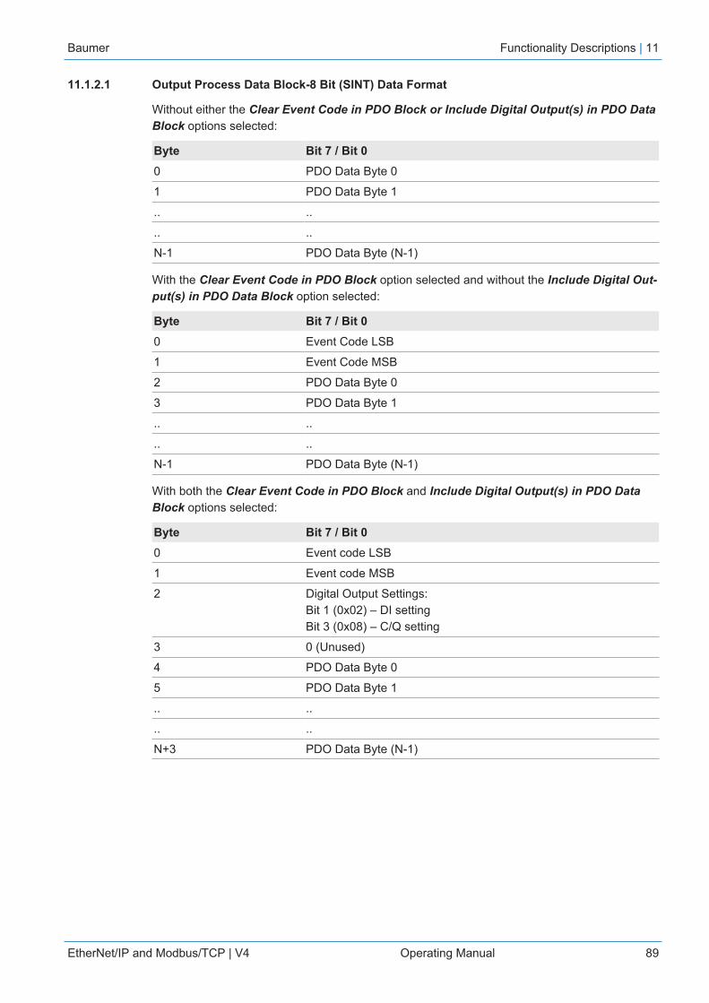
Baumer Functionality Descriptions | 11
EtherNet/IP and Modbus/TCP | V4 Operating Manual 89
11.1.2.1 Output Process Data Block-8 Bit (SINT) Data Format
Without either the Clear Event Code in PDO Block or Include Digital Output(s) in PDO DataBlock options selected:
Byte Bit 7 / Bit 00 PDO Data Byte 0
1 PDO Data Byte 1
.. ..
.. ..
N-1 PDO Data Byte (N-1)
With the Clear Event Code in PDO Block option selected and without the Include Digital Out-put(s) in PDO Data Block option selected:
Byte Bit 7 / Bit 00 Event Code LSB
1 Event Code MSB
2 PDO Data Byte 0
3 PDO Data Byte 1
.. ..
.. ..
N-1 PDO Data Byte (N-1)
With both the Clear Event Code in PDO Block and Include Digital Output(s) in PDO DataBlock options selected:
Byte Bit 7 / Bit 00 Event code LSB
1 Event code MSB
2 Digital Output Settings:Bit 1 (0x02) – DI settingBit 3 (0x08) – C/Q setting
3 0 (Unused)
4 PDO Data Byte 0
5 PDO Data Byte 1
.. ..
.. ..
N+3 PDO Data Byte (N-1)
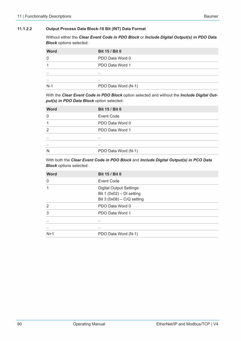
11 | Functionality Descriptions Baumer
90 Operating Manual EtherNet/IP and Modbus/TCP | V4
11.1.2.2 Output Process Data Block-16 Bit (INT) Data Format
Without either the Clear Event Code in PDO Block or Include Digital Output(s) in PDO DataBlock options selected:
Word Bit 15 / Bit 00 PDO Data Word 0
1 PDO Data Word 1
.. ..
.. ..
N-1 PDO Data Word (N-1)
With the Clear Event Code in PDO Block option selected and without the Include Digital Out-put(s) in PDO Data Block option selected:
Word Bit 15 / Bit 00 Event Code
1 PDO Data Word 0
2 PDO Data Word 1
.. ..
.. ..
N PDO Data Word (N-1)
With both the Clear Event Code in PDO Block and Include Digital Output(s) in PCO DataBlock options selected:
Word Bit 15 / Bit 00 Event Code
1 Digital Output Settings:Bit 1 (0x02) – DI settingBit 3 (0x08) – C/Q setting
2 PDO Data Word 0
3 PDO Data Word 1
.. ..
.. ..
N+1 PDO Data Word (N-1)
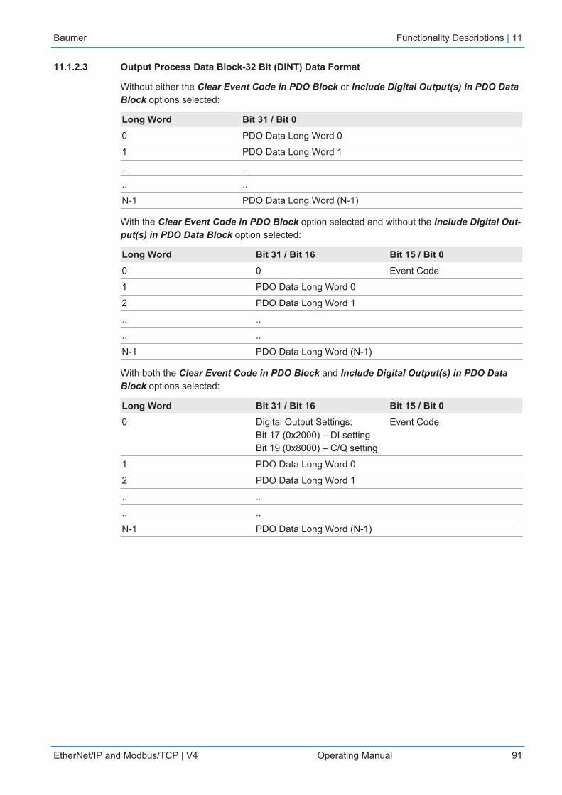
Baumer Functionality Descriptions | 11
EtherNet/IP and Modbus/TCP | V4 Operating Manual 91
11.1.2.3 Output Process Data Block-32 Bit (DINT) Data Format
Without either the Clear Event Code in PDO Block or Include Digital Output(s) in PDO DataBlock options selected:
Long Word Bit 31 / Bit 00 PDO Data Long Word 0
1 PDO Data Long Word 1
.. ..
.. ..
N-1 PDO Data Long Word (N-1)
With the Clear Event Code in PDO Block option selected and without the Include Digital Out-put(s) in PDO Data Block option selected:
Long Word Bit 31 / Bit 16 Bit 15 / Bit 00 0 Event Code
1 PDO Data Long Word 0
2 PDO Data Long Word 1
.. ..
.. ..
N-1 PDO Data Long Word (N-1)
With both the Clear Event Code in PDO Block and Include Digital Output(s) in PDO DataBlock options selected:
Long Word Bit 31 / Bit 16 Bit 15 / Bit 00 Digital Output Settings:
Bit 17 (0x2000) – DI settingBit 19 (0x8000) – C/Q setting
Event Code
1 PDO Data Long Word 0
2 PDO Data Long Word 1
.. ..
.. ..
N-1 PDO Data Long Word (N-1)

11 | Functionality Descriptions Baumer
92 Operating Manual EtherNet/IP and Modbus/TCP | V4
11.2 Event Handling
The BIOLM event handling is designed to provide real-time updates of event codes received dir-ectly from the IO-Link device. The IO-Link event code:
n Is included in the second 16-bit word of the Input Process Data (PDI) block.▪ An active event is indicated by a non-zero value.▪ Inactive or no event is indicated by a zero value.
n Two methods are provided to clear an event:▪ Enable the Clear Event After Hold Time option.
The BIOLM keeps, or holds, the active event code in the PDI block until the configuredActive Event Hold Time has passed.The BIOLM then clears the event code in the PDI block and waits until the Clear EventHold Time has passed before including another event code in the PDI block.
▪ Enable the Clear Event In PDO Block option.The BIOLM monitors the PDO block received from the PLC.The BIOLM expects the first entry of the PDO block to indicate an event code to becleared.If there is an active event code in the PDI block and the PDO block both contain the sameevent code, the event code is cleared in the PDI block.The BIOLM then clears event code in the PDI block and waits until the Clear Event HoldTime has passed before including another event code in the PDI block.
n The two methods can be used separately or together to control clearing of events.
The next subsections illustrate the event clearing process for the various event configurations.
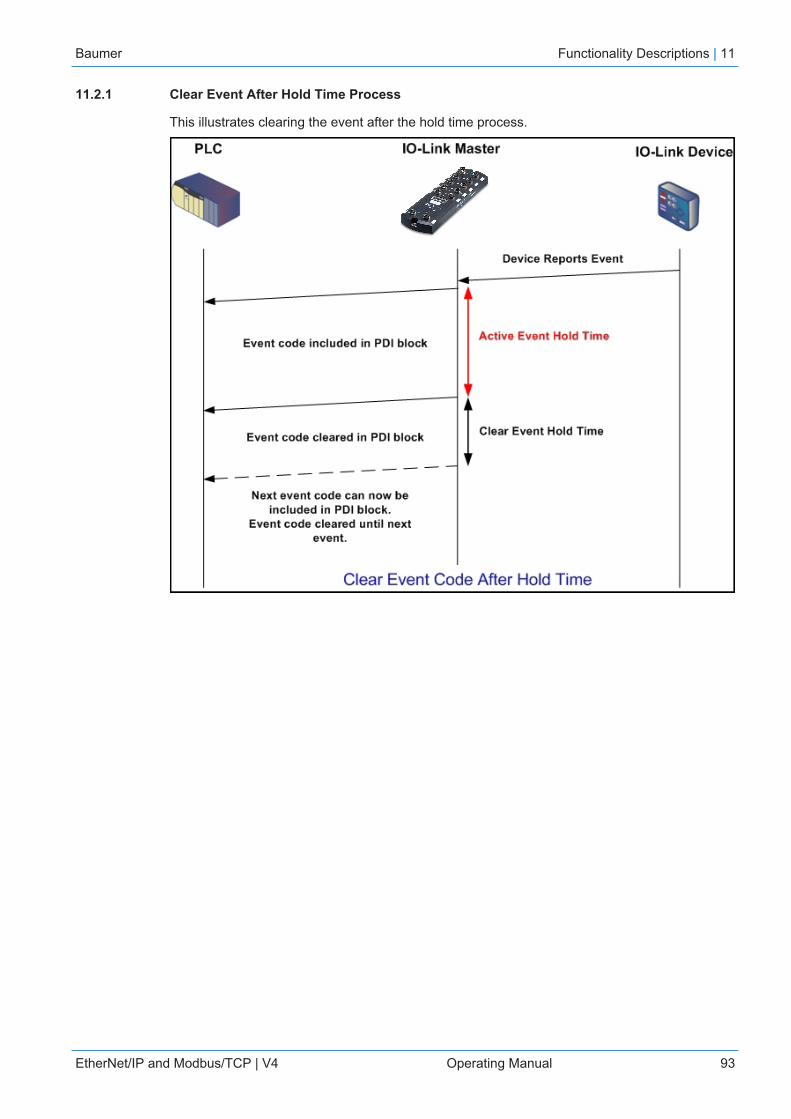
Baumer Functionality Descriptions | 11
EtherNet/IP and Modbus/TCP | V4 Operating Manual 93
11.2.1 Clear Event After Hold Time Process
This illustrates clearing the event after the hold time process.

11 | Functionality Descriptions Baumer
94 Operating Manual EtherNet/IP and Modbus/TCP | V4
11.2.2 Clear Event in PDO Block Process
This illustrates clearing the event in the PDO block process.

Baumer Functionality Descriptions | 11
EtherNet/IP and Modbus/TCP | V4 Operating Manual 95
11.2.3 Clear Event Code in PDO Block and Clear Event After Hold Time Process-PDO BlockFirst
This illustrates clearing the event code in the PDO block and clearing the event after the holdtime process with the PDO block first.
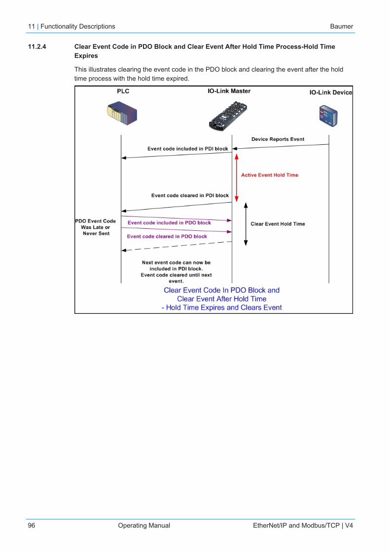
11 | Functionality Descriptions Baumer
96 Operating Manual EtherNet/IP and Modbus/TCP | V4
11.2.4 Clear Event Code in PDO Block and Clear Event After Hold Time Process-Hold TimeExpires
This illustrates clearing the event code in the PDO block and clearing the event after the holdtime process with the hold time expired.
Baumer Functionality Descriptions | 11
EtherNet/IP and Modbus/TCP | V4 Operating Manual 97
11.3 ISDU Handling
The BIOLM provides a very flexible ISDU interface that is used by all supported industrial proto-cols. The ISDU interface contains the following:
n An ISDU request may contain one or multiple individual ISDU read and/or write commands.n Individual ISDU command based byte swapping capabilities.n Variable sized command structures to allow access to wide range of ISDU block sizes.n A single ISDU request may contain as many ISDU read and/or write commands as allowed
by the industrial protocol payload. For example, if an industrial protocol provides up to 500byte read/write payloads, then an ISDU request may contain multiple commands of variouslengths that can total up to 500 bytes in length.
n For the ControlLogix family of EtherNet/IP PLCs, both blocking and non-blocking ISDU re-quest methods are provided.▪ The BIOLM implements blocking ISDU requests by not responding to an ISDU request
message until all commands have been processed.▪ The BIOLM implements non-blocking ISDU requests by:
Responding to an ISDU request message immediately after receiving and verifying theISDU request.Requiring the PLC to monitor the ISDU request status with read messages. The BIOLMwill not return a completed status until all of the ISDU commands have been processed.
11.3.1 ISDU Request/Response Structure
ISDU requests may contain a single command or multiple, nested commands. This subsectiondiscusses the following:
n Single ISDU Command Request [} 98]n Multiple ISDU Command Structure [} 99]

11 | Functionality Descriptions Baumer
98 Operating Manual EtherNet/IP and Modbus/TCP | V4
11.3.1.1 Single ISDU Command Request
This illustrates a single ISDU command request.

Baumer Functionality Descriptions | 11
EtherNet/IP and Modbus/TCP | V4 Operating Manual 99
11.3.1.2 Multiple ISDU Command Structure
ISDU requests with multiple commands may consist of commands of the same data size orcommands with different data sizes. The following are two examples of multiple ISDU com-mands.
n ISDU commands of same data sizen ISDU commands of different data sizes
Multiple Command ISDU Request/Response of Same Data Area Length

11 | Functionality Descriptions Baumer
100 Operating Manual EtherNet/IP and Modbus/TCP | V4
Multiple Command ISDU Request/Response of Different Data Lengths

Baumer Functionality Descriptions | 11
EtherNet/IP and Modbus/TCP | V4 Operating Manual 101
11.3.2 ISDU Request Message Format-From PLC to BIOLM
Write and read ISDU commands have the same message data format. Each ISDU request mes-sage is comprised of one or more commands. The command(s) can consist of either a series ofnested commands or a single read command.
INFOA list of nested ISDU commands is terminated with either a control field of 0, (single/last opera-tion), or the end of the message data.
11.3.2.1 Standard ISDU Request Command Format
This table displays a standard ISDU request command format with ControlLogix PLCs.
Name Data Type Parameter DescriptionsByte Swapping USINT Bits 0 - 3:
0 = No byte swapping.1 = 16-bit (INT) byte swapping of ISDU data.2 = 32-bit (DINT) byte swapping of ISDU data.
Bits 4 - 7:Set to zero. Unused.
RdWrControl-Type
USINT Provides the control and type of ISDU command.
Bits 0 - 3, Type Field:0 = NOP (No operation)1 = Read operation2 = Write operation3 = Read/Write “OR”4 = Read/Write “AND”
Bits 4 - 7, Control Field:0 = Single/Last Operation (length can vary from to 1 to232)1 = Nested batch command – fixed 4 byte data area2 = Nested batch command – fixed 8 byte data area3 = Nested batch command – fixed 16 byte data area4 = Nested batch command – fixed 32 byte data area5 = Nested batch command – fixed 64 byte data area6 = Nested batch command – fixed 128 byte data area7 = Nested batch command – fixed 232 byte data area
Index UINT The parameter address of the data object in the IO-Linkdevice.
Subindex UINT The data element address of a structured parameter ofthe data object in the IO-Link device.
Datalength UINT Length of data to read or write.
For nested batch commands, the data length can varyfrom 1 to the fixed data area size.
Data Array of USINTs,UINTs, or UD-INTs.
Size of array is determined by the Control field in RdWr-ControlType.
Data is valid only for write commands.

11 | Functionality Descriptions Baumer
102 Operating Manual EtherNet/IP and Modbus/TCP | V4
11.3.2.2 Integer (16-Bit Word) ISDU Request Command Format
This table shows an integer (16 bit word) ISDU request command format with a SLC, MicroLo-gix, PLC-5, or Modbus/TCP.
Name Data Type Parameter DescriptionsByte Swapping /RdWrControl-Type
UINT Provides the control, type and byte swapping of ISDUcommand.
Bits 0 - 3, Type Field:0 = NOP (No operation)1 = Read operation2 = Write operation3 = Read/Write “OR”4 = Read/Write “AND”
Bits 4 - 7, Control Field:0 = Single/Last Operation (length can vary from to 1 to232)1 = Nested batch command – fixed 4 byte data area2 = Nested batch command – fixed 8 byte data area3 = Nested batch command – fixed 16 byte data area4 = Nested batch command – fixed 32 byte data area5 = Nested batch command – fixed 64 byte data area6 = Nested batch command – fixed 128 byte data area7 = Nested batch command – fixed 232 byte data area
Bits 8 - 11:0 = No byte swapping.1 = 16-bit (INT) byte swapping of ISDU data.2 = 32-bit (DINT) byte swapping of ISDU data.
Bits 12 - 15:Set to zero. Unused.
Index UINT The parameter address of the data object in the IO-Linkdevice.
Subindex UINT The data element address of a structured parameter ofthe data object in the IO-Link device.
Datalength UINT Length of data to read or write.
For nested batch commands, the data length can varyfrom 1 to the fixed data area size.
Data Array of USINTs,UINTs, or UD-INTs.
Size of array is determined by the Control field in RdWr-ControlType.
Data is valid only for write commands.

Baumer Functionality Descriptions | 11
EtherNet/IP and Modbus/TCP | V4 Operating Manual 103
11.3.3 ISDU Response Message Format
The ISDU responses have the same data format as requests with the only exception being thereturned command status. Each ISDU response message is comprised of one or more re-sponses to the single and/or nested command(s) received in the request.
11.3.3.1 Standard ISDU Response Command Format
The following table show the standard ISDU response command format with ControlLogixPLCs.
Name Data Type Parameter DescriptionsStatus USINT Indicates the byte alignment and status of the command
response.
Byte swapping, Bits 0 - 3:0 = No byte swapping.1 = 16-bit (INT) byte swapping of TX/RX ISDU data.2 = 32-bit (DINT) byte swapping of TX/RX ISDU data.
Status, Bits 4 - 7:0 = NOP (No operation)1 = In process (Only valid for non-blocking requests)2 = Success3 = Failure: IO-Link device rejected the request.4 = Timed out: IO-Link device did not respond
RdWrControl-Type
USINT Provides the control and type of ISDU request.
Bits 0 - 3, Type Field:0 = NOP (No operation)1 = Read operation2 = Write operation3 = Read/Write “OR”4 = Read/Write “AND”
Bits 4 - 7, Control Field:0 = Single/Last Operation (length can vary from to 1 to232)1 = Nested batch command – fixed 4 byte data area2 = Nested batch command – fixed 8 byte data area3 = Nested batch command – fixed 16 byte data area4 = Nested batch command – fixed 32 byte data area5 = Nested batch command – fixed 64 byte data area6 = Nested batch command – fixed 128 byte data area7 = Nested batch command – fixed 232 byte data area
Index UINT The parameter address of the data object in the IO-Linkdevice.
Subindex UINT The data element address of a structured parameter ofthe data object in the IO-Link device.
Datalength UINT Length of data that was read or written.
For nested batch commands, the data length can varyfrom 1 to fixed data area size.
11 | Functionality Descriptions Baumer
104 Operating Manual EtherNet/IP and Modbus/TCP | V4
Name Data Type Parameter DescriptionsData Array of USINTs,
UINTs, or UD-INTs.
Data required for read commands. Optionally can returnthe data of a write command.
The size of the array is determined by the Control field inthe RdWrControlType.
Data field not required for single NOP commands.
Baumer Functionality Descriptions | 11
EtherNet/IP and Modbus/TCP | V4 Operating Manual 105
11.3.3.2 Integer (16-Bit Word) ISDU Response Command Format
The following table shows an integer (16-bit word) ISDU response command format with SLC,MicroLogix, PLC-5, or Modbus/TCP.
Name Data Type Parameter DescriptionsStatus, Byte-Swapping, Rd-WrControlType
UINT Indicates the control, type, byte swapping and status ofthe ISDU command.
Bits 0 - 3, Type Field:0 = NOP (No operation)1 = Read operation2 = Write operation3 = Read/Write “OR”4 = Read/Write “AND”
Bits 4 - 7, Control Field:0 = Single/Last Operation (length can vary from to 1 to232)1 = Nested batch command – fixed 4 byte data area2 = Nested batch command – fixed 8 byte data area3 = Nested batch command – fixed 16 byte data area4 = Nested batch command – fixed 32 byte data area5 = Nested batch command – fixed 64 byte data area6 = Nested batch command – fixed 128 byte data area7 = Nested batch command – fixed 232 byte data area
Byte swapping, Bits 8 - 11:0 = No byte swapping.1 = 16-bit (INT) byte swapping of TX/RX ISDU data.2 = 32-bit (DINT) byte swapping of TX/RX ISDU data.
Status, Bits 12 - 15:0 = NOP (No operation)1 = In process (Only valid for non-blocking requests)2 = Success3 = Failure: IO-Link device rejected the request.4 = Timed out: IO-Link device did not respond
Index UINT The parameter address of the data object in the IO-Linkdevice.
Subindex UINT The data element address of a structured parameter ofthe data object in the IO-Link device.
Datalength UINT Length of data that was read or written.
For nested batch commands, the data length can varyfrom 1 to fixed data area size.
Data Array of USINTs,UINTs, or UDINTs
Data returned for read commands. Contains the data ofa write command.
The size of the array is determined by the Control field inRdWrControlType.
Data field not required for single NOP commands.

11 | Functionality Descriptions Baumer
106 Operating Manual EtherNet/IP and Modbus/TCP | V4
11.3.4 ISDU Blocking and Non-Blocking Methods
The BIOLM supports both blocking and non-blocking ISDU requests. The following diagramsdemonstrate how each mode works.
11.3.4.1 Single Command Blocking
The following illustrates the single command blocking method.

Baumer Functionality Descriptions | 11
EtherNet/IP and Modbus/TCP | V4 Operating Manual 107
11.3.4.2 Multiple Command Blocking
This illustrates the multiple command blocking method.

11 | Functionality Descriptions Baumer
108 Operating Manual EtherNet/IP and Modbus/TCP | V4
11.3.4.3 Single Command Non-Blocking
This illustrates the single command non-blocking method.

Baumer Functionality Descriptions | 11
EtherNet/IP and Modbus/TCP | V4 Operating Manual 109
11.3.4.4 Multiple Command Non-Blocking
This illustrates the multiple command non-blocking method.
12 | EtherNet/IP CIP Object Definitions Baumer
110 Operating Manual EtherNet/IP and Modbus/TCP | V4
12 EtherNet/IP CIP Object DefinitionsThe following are the vendor specific CIP Object definitions as supported in the BIOLM:
n IO-Link Port Information Object Definition (71 hex) [} 110]n PDI (Process Data Input) Transfer Object Definition (72 hex) [} 115]n PDO (Process Data Output) Transfer Object Definition (73 hex) [} 116]n ISDU Read/Write Object Definition (74 hex) [} 117]
The following are standard CIP Object Definitions that are supported in the BIOLM:n Identity Object (01 hex, 1 instance) [} 119]n Message Router Object (02 hex) [} 121]n Connection Manager Object (06 hex) [} 122]n Port Object (F4 hex-1 instance) [} 123]n TCP Object (F5 hex-1 instance) [} 125]n Ethernet Link Object (F6 hex-1 instance) [} 128]n PCCC Object (67 hex-1 instance) [} 129]
12.1 IO-Link Port Information Object Definition (71 hex)
The IO-Link Device Information object defines the attributes by which the PLC can requeststandard device information stored in the IO-Link device’s ISDU blocks.
12.1.1 Class Attributes
The following table shows the class attributes for IO-Link port information object definition(71 hex).
Attribute ID Name Data Type Data Value(s) Access Rule1 Revision UINT 1 Get
2 Max Instance UINT 8 Get
3 Num Instances UINT 8 I GetI Instance number determines the IO-Link port.
Baumer EtherNet/IP CIP Object Definitions | 12
EtherNet/IP and Modbus/TCP | V4 Operating Manual 111
12.1.2 Instance Attributes
The following table shows the instance attributes for IO-Link port information object definition(71 hex).
Attribute ID Name Data Type Data Value(s) Access Rule1 Vendor Name Array of 64 SINTs 0-255 Get
2 Vendor Text Array of 64 SINTs 0-255 Get
3 Product Name Array of 64 SINTs 0-255 Get
4 Product Id Array of 64 SINTs 0-255 Get
5 Product Text Array of 64 SINTs 0-255 Get
6 Serial Number Array of 16 SINTs 0-255 Get
7 Hardware Revision Array of 64 SINTs 0-255 Get
8 Firmware Revision Array of 64 SINTs 0-255 Get
9 Device PDI Length INT 0-32 Get
10 Device PDO Length INT 0-32 Get
11 PDI Block Length INT 4-36 Get
12 PDO Block Length INT 0-36 Get
13 Input AssemblyPDI Offset
INT 0-108 (8-bit format)0-54(16-bit format)0-27 (32-bit format)
Get
14 Input AssemblyPDO Offset
INT 16-246 (8-bit format)8-123(16-bit format)4-62 (32-bit format)
Get
15 Output AssemblyPDO Offset
INT 0-102 (8-bit format)0-51 (16-bit format)0-26 (32-bit format)
Get
16 Control Flags INT Bit settings Get
12.1.3 Common Services
The following table shows the common services for IO-Link port information object definition (71hex).
Service Code Implemented in Class Implemented in Instance Service Name01 hex Yes Yes Get_Attributes_All
0E hex Yes Yes Get_Attribute_Single
12 | EtherNet/IP CIP Object Definitions Baumer
112 Operating Manual EtherNet/IP and Modbus/TCP | V4
12.1.4 Instance Attribute Definitions
These attributes provide access to the standard ISDU information blocks on the IO-Linkdevices. These ISDUs are read at IO-Link device initialization time and then provided once theIO-Link device is operational.
12.1.4.1 Attribute 1-Vendor Name
Data Attribute 1 – Vendor Name Description64 ASCIIcharacters
Requested from ISDU block index 16, contains the Vendor Name description ofthe IO-Link device.
12.1.4.2 Attribute 2-Vendor Text
Data Attribute 2 – Vendor Text Description64 ASCIIcharacters
Requested from ISDU block index 17, contains the Vendor Text description ofthe IO-Link device.
12.1.4.3 Attribute 3-Product Name
Data Attribute 3 – Product Name Description64 ASCIIcharacters
Requested from ISDU block index 18, contains the Product Name description ofthe IO-Link device.
12.1.4.4 Attribute 4-Product ID
Data Attribute 4 – Product ID Description64 ASCIIcharacters
Requested from ISDU block index 19, contains the Product ID description of theIO-Link device.
12.1.4.5 Attribute 5-Product Text
Data Attribute 5 – Product Text Description64 ASCIIcharacters
Requested from ISDU block index 20, contains the Product Text description ofthe IO-Link device.
12.1.4.6 Attribute 6-Serial Number
Data Attribute 6 – Serial Number Description16 ASCIIcharacters
Requested from ISDU block index 21, contains the Vendor Specific Serial Num-ber of the IO-Link device.
Baumer EtherNet/IP CIP Object Definitions | 12
EtherNet/IP and Modbus/TCP | V4 Operating Manual 113
12.1.4.7 Attribute 7-Hardware Revision
Data Attribute 7 – Hardware Revision Description64 ASCIIcharacters
Requested from ISDU block index 22, contains the Hardware Revision of the IO-Link device.
12.1.4.8 Attribute 8-Firmware Revision
Data Attribute 8 – Firmware Revision Description64 ASCIIcharacters
Requested from ISDU block index 23, contains the Firmware Revision of the IO-Link device.
12.1.4.9 Attribute 9-Device PDI Length
Data Attribute 9 – Device PDI Length DescriptionINT (0-32) Requested from ISDU block index 0, sub-index 5. Contains the number of PDI
data bytes provided by the IO-Link device.
12.1.4.10 Attribute 10-Device PDO Length
Data Attribute 10 – Device PDO Length DescriptionINT Requested from ISDU block index 0, sub-index 6. Contains the number of PDO
data bytes required by the IO-Link device.
12.1.4.11 Attribute 11-PDI Data Block Length
Data Attribute 11 – PDI Data Block Length DescriptionINT The configured PDI block length in units based on the configurable PDI data
format (8-bit, 16-bit, 32-bit). This contains the PDI block header, (port status,auxiliary bit, event code) status and the PDI data.
12.1.4.12 Attribute 12-PDO Data Block Length
Data Attribute 12 – PDO Data Block Length DescriptionINT The configured PDO data block length in units based on the configurable PDO
data format (8-bit, 16-bit, 32-bit). Depending on the configuration, this may in-clude both the returned event code and the PDO data.
12.1.4.13 Attribute 13-Input Assembly PDI Offset
Data Attribute 13 – Input Assembly PDI Offset DescriptionINT Based from the start of the first Input Assembly instance, the PDI data block’s
offset for the corresponding port’s PDI data block.This index is based on the configurable PDI data format (8-bit, 16-bit, 32-bit). Touse this offset effectively, it is recommended to set BIOLM PDI and PDO data aswell as the Class 1 I/O connection all to the same data format.

12 | EtherNet/IP CIP Object Definitions Baumer
114 Operating Manual EtherNet/IP and Modbus/TCP | V4
12.1.4.14 Attribute 14-Input Assembly PDO Offset
Data Attribute 14 – Input Assembly PDO Offset DescriptionINT Based from the start of the first Input Assembly instance, the PDO data block’s
offset for the corresponding port’s PDO data block.This index is based on the configurable PDO data format (8-bit, 16-bit, 32-bit). Touse this offset effectively, it is recommended to set BIOLM PDI and PDO data aswell as the Class 1 I/O connection all to the same data format.
12.1.4.15 Attribute 15-Output Assembly PDO Offset
Data Attribute 15 – Output Assembly PDO Offset DescriptionINT Based from the start of the first Output Assembly instance, the PDO data block’s
offset for the corresponding port’s PDO data block.This index is based on the configurable PDO data format (8-bit, 16-bit, 32-bit). Touse this offset effectively, it is recommended to set BIOLM PDI and PDO data aswell as the Class 1 I/O connection all to the same data format.
12.1.4.16 Attribute 16-Control Flags
Data Attribute 16 – Control Flags DescriptionINT(bit-mappedword)
n Bit 0 (01h):▪ 1 = Indicates that the event code to clear is expected in the PDO block▪ 0 = Indicates that the event code to clear is not expected in the PDO block
n Bit 1 (02h):▪ 1 = Indicates that the IO-Link device is SIO mode capable▪ 0 = Indicates that the IO-Link device is not SIO mode capable
n Bits 2 (04h)▪ 1 = Indicates that Class 1 Rx (receive PDI block) is enabled▪ 0 = Indicates that Class 1 Rx (receive PDI block) is disabled
n Bit 3 (08h):▪ 1 = Indicates that Class 1 Tx (transmit PDO) is enabled▪ 0 = Indicates that Class 1 Tx (transmit PDO) is disabled
n Bit 4 (10h):▪ 1 = Indicates that the digital output settings for DI and C/Q are expected in
the PDO block▪ 0 = Indicates that the digital output settings for DI and C/Q are not expec-
ted in the PDO blockn Bit 5 -15: Reserved

Baumer EtherNet/IP CIP Object Definitions | 12
EtherNet/IP and Modbus/TCP | V4 Operating Manual 115
12.2 PDI (Process Data Input) Transfer Object Definition (72 hex)
The PDI Transfer object defines the attributes by which the PLC can request the PDI data blockfrom the BIOLM.
12.2.1 Class Attributes
The following table displays Class Attributes for the PDI Transfer Object Definition (72 hex).
Attribute ID Name Data Type Data Value(s) Access Rule1 Revision UINT 1 Get
2 Max Instance UINT 1 Get
3 Num Instances UINT 1 Get
12.2.2 Instance Attributes
The following table displays Instance Attributes for the PDI Transfer Object Definition (72 hex).
Attribute ID Name Data Type Length Data ValuesAccessRule
1 Port 1 PDI data block Array of BYTEs 4-36 bytes 0-255 Get
2 Port 2 PDI data block Array of BYTEs 4-36 bytes 0-255 Get
3 Port 3 PDI data block Array of BYTEs 4-36 bytes 0-255 Get
4 Port 4 PDI data block Array of BYTEs 4-36 bytes 0-255 Get
5 Port 5 PDI data block Array of BYTEs 4-36 bytes 0-255 Get
6 Port 6 PDI data block Array of BYTEs 4-36 bytes 0-255 Get
7 Port 7 PDI data block Array of BYTEs 4-36 bytes 0-255 Get
8 Port 8 PDI data block Array of BYTEs 4-36 bytes 0-255 Get
12.2.3 Common Services
The following table shows Common Services for the PDI Transfer Object Definition (72 hex).
Service Code Implemented in Class Implemented in Instance Service Name01 hex Yes Yes Get_Attributes_All
0E hex Yes Yes Get_Attribute_Single
12.2.4 Instance Attribute Definitions – Attribute 1 to 4-PDI Data Blocks
These attributes provide access to the PDI data blocks:n Get Attribute Single requests return the PDI data block for a specific port.n Get Attribute All requests return all PDI data blocks from the BIOLM.
All PDI data is returned in the configured PDI format (8-bit, 16-bit or 32-bit). Refer to PDI (Pro-cess Data Input) Transfer Object Definition (72 hex) [} 115] for a detailed explanation of the PDIdata block.

12 | EtherNet/IP CIP Object Definitions Baumer
116 Operating Manual EtherNet/IP and Modbus/TCP | V4
12.3 PDO (Process Data Output) Transfer Object Definition (73 hex)
The PDO Transfer object defines the attributes by which the PLC can:n Request the PDO data block from the BIOLM.n Write PDO data block to the BIOLM.
12.3.1 Class Attributes
The following table displays the Class Attributes for the PDO Transfer Object Definition (73hex).
Attribute ID Name Data Type Data Value(s) Access Rule1 Revision UINT 1 Get
2 Max Instance UINT 1 Get
3 Num Instances UINT 1 Get
12.3.2 Instance Attributes
The following table displays the Instance Attributes for the PDO Transfer Object Definition (73hex).
Attribute ID Name Data Type Length Data ValuesAccessRule
1 Port 1 PDO data block Array of BYTEs 0-36 bytes 0-255 Get/Set
2 Port 2 PDO data block Array of BYTEs 0-36 bytes 0-255 Get/Set
3 Port 3 PDO data block Array of BYTEs 0-36 bytes 0-255 Get/Set
4 Port 4 PDO data block Array of BYTEs 0-36 bytes 0-255 Get/Set
5 Port 5 PDO data block Array of BYTEs 0-36 bytes 0-255 Get/Set
6 Port 6 PDO data block Array of BYTEs 0-36 bytes 0-255 Get/Set
7 Port 7 PDO data block Array of BYTEs 0-36 bytes 0-255 Get/Set
8 Port 8 PDO data block Array of BYTEs 0-36 bytes 0-255 Get/Set
12.3.3 Common Services
The following table displays the Common Services for the PDO Transfer Object Definition (73hex).
Service Code Implemented in Class Implemented in Instance Service Name01 hex Yes Yes Get_Attributes_All
0E hex Yes Yes Get_Attribute_Single
10 hex No Yes Set_Attribute_Single
02 hex No Yes Set_Attribute_All
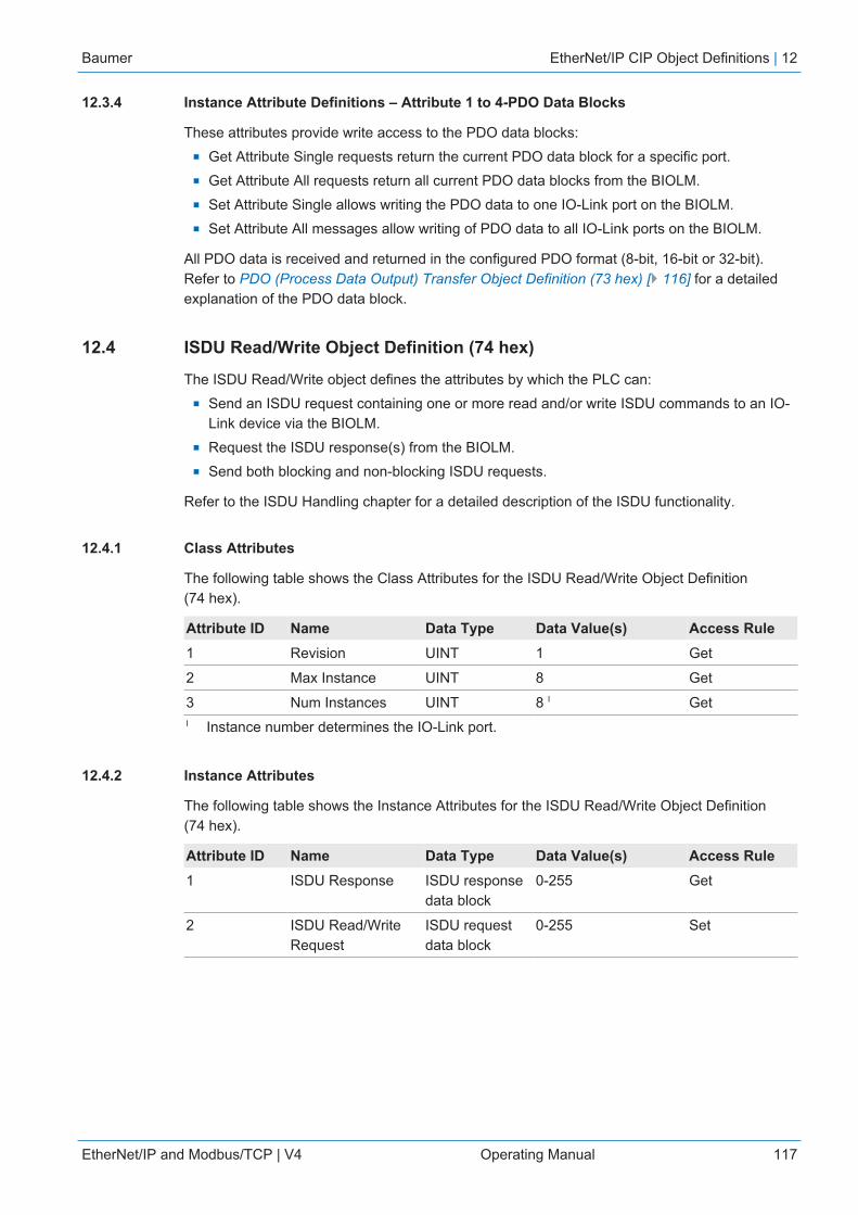
Baumer EtherNet/IP CIP Object Definitions | 12
EtherNet/IP and Modbus/TCP | V4 Operating Manual 117
12.3.4 Instance Attribute Definitions – Attribute 1 to 4-PDO Data Blocks
These attributes provide write access to the PDO data blocks:n Get Attribute Single requests return the current PDO data block for a specific port.n Get Attribute All requests return all current PDO data blocks from the BIOLM.n Set Attribute Single allows writing the PDO data to one IO-Link port on the BIOLM.n Set Attribute All messages allow writing of PDO data to all IO-Link ports on the BIOLM.
All PDO data is received and returned in the configured PDO format (8-bit, 16-bit or 32-bit).Refer to PDO (Process Data Output) Transfer Object Definition (73 hex) [} 116] for a detailedexplanation of the PDO data block.
12.4 ISDU Read/Write Object Definition (74 hex)
The ISDU Read/Write object defines the attributes by which the PLC can:n Send an ISDU request containing one or more read and/or write ISDU commands to an IO-
Link device via the BIOLM.n Request the ISDU response(s) from the BIOLM.n Send both blocking and non-blocking ISDU requests.
Refer to the ISDU Handling chapter for a detailed description of the ISDU functionality.
12.4.1 Class Attributes
The following table shows the Class Attributes for the ISDU Read/Write Object Definition(74 hex).
Attribute ID Name Data Type Data Value(s) Access Rule1 Revision UINT 1 Get
2 Max Instance UINT 8 Get
3 Num Instances UINT 8 I GetI Instance number determines the IO-Link port.
12.4.2 Instance Attributes
The following table shows the Instance Attributes for the ISDU Read/Write Object Definition(74 hex).
Attribute ID Name Data Type Data Value(s) Access Rule1 ISDU Response ISDU response
data block0-255 Get
2 ISDU Read/WriteRequest
ISDU requestdata block
0-255 Set

12 | EtherNet/IP CIP Object Definitions Baumer
118 Operating Manual EtherNet/IP and Modbus/TCP | V4
12.4.3 Common Services
The following table shows the Common Services for the ISDU Read/Write Object Definition(74 hex):
Service Code Implemented in Class Implemented in Instance Service Name01 hex Yes No Get_Attributes_All
0E hex Yes Yes Get_Attribute_Single
10 hex No Yes Set_Attribute_Single
02 hex No No Set_Attribute_All
12.4.4 Object Specific Services
The following table shows the Object Specific Services for the ISDU Read/Write Object Defini-tion (74 hex).
Service Code Implemented in Class Implemented in Instance Service Name4B hex No Yes Blocking ISDU Re-
quest
The Blocking ISDU Request service allows one message instruction to both send an ISDU re-quest and receive the response. Using this service causes the message to be active for severalseconds.
12.4.5 Instance Attribute Definitions
The following attributes provide access to the ISDU blocks on the IO-Link devices.
12.4.5.1 Attribute 1-ISDU Read/Write Response (Non-Blocking only)
Get Attribute Single messages returns the ISDU response for a specific port through theBIOLM. The response may need to be read multiple times until a response of Success, Failure,or Timed Out has been received.
12.4.5.2 Attribute 2-ISDU Read/Write Request (Non-blocking only)
Set Attribute Single messages can send read/write type ISDU requests to the IO-Link devicesvia the BIOLM. The ISDU request message need be sent only once for each ISDU read/writerequest.

Baumer EtherNet/IP CIP Object Definitions | 12
EtherNet/IP and Modbus/TCP | V4 Operating Manual 119
12.5 Identity Object (01 hex, 1 instance)
12.5.1 Class Attributes
This table shows the Class Attributes for the Identity Object (01 hex, 1 Instance).
Attribute ID Name Data Type Data Value(s) Access Rule1 Revision UINT 1 Get
2 Max Class UINT 1 Get
3 Max Instance UINT 1 Get
6 Maximum NumberClass Attribute
UINT 7 Get
7 Maximum NumberInstance Attributes
UINT 7 Get
12.5.2 Instance Attributes
This table shows the Instance Attributes for the Identity Object (01 hex, 1 Instance).
Attribute ID Name Data Type Data Value(s) Access Rule1 Vendor ID UINT 468
(Baumer)Get
2 Device Type UINT 2B hex(Generic Device)
Get
3 Product Code UINT As defined by Baumer Get
4 Revision (Product orSoftware release)
Structure of:Major RevisionMinor Revision
USINTUSINT
1 to 1271 to 255
Get
5 Status WORD See Below Get
6 Serial Number UDINT 1-FFFFFFFF hex Get
7 Product Name
Structure of:Name LengthName String
USINTSTRING
Length of stringSee below
GetGet

12 | EtherNet/IP CIP Object Definitions Baumer
120 Operating Manual EtherNet/IP and Modbus/TCP | V4
12.5.3 Status Word
Refer to Page 52 of Volume 3.5 of the CIP Common Specification.
The following applies to the Identity Object status word for the BIOLM.
Status Word Bit Setting Description0 0 Ownership Flag. Does not apply to the BIOLM.
1 0 Reserved.
2 0 BIOLM is operating on the default configuration.
1 The BIOLM has a configuration other than the default config-uration.
3 0 Reserved.
4-7 0101 (0x50) Indicates that there is a major fault (either Bit 10 or Bit 11 isset).
0100 (0x40) Indicates the stored configuration is invalid.
0011 (0x30) Indicates the system is operational and there are no I/O(Class 1) connections.
0110 (0x60) Indicates the system is operational and there is at least oneactive I/O (Class 1) connection.
0000 Indicates the system is not operational. It may be in any ofthe following states:
n System startup.n Configuration in process.n Idle.n Critical (major) fault.
8 0 No recoverable minor fault. No error history entry reportedwithin the last ten seconds.
1 Recoverable minor fault. The BIOLM has reported an errorwithin the last ten seconds and a major fault has not been de-tected.
9 1 Unrecoverable minor fault. Does not apply to the BIOLM.
10 0 No recoverable major fault.
1 A major recoverable fault exists. This is a fault that theBIOLM may be able to recover from by a system reset. If thesystem does not recover automatically, a system reset mes-sage or a power cycle of the BIOLM may be required.
11 0 No major unrecoverable fault.
1 A major unrecoverable fault has occurred in the BIOLM. If themajor fault is not corrected with a system reset or a powercycle, refer to the User Guide or call Baumer support.
12-15 0 Reserved
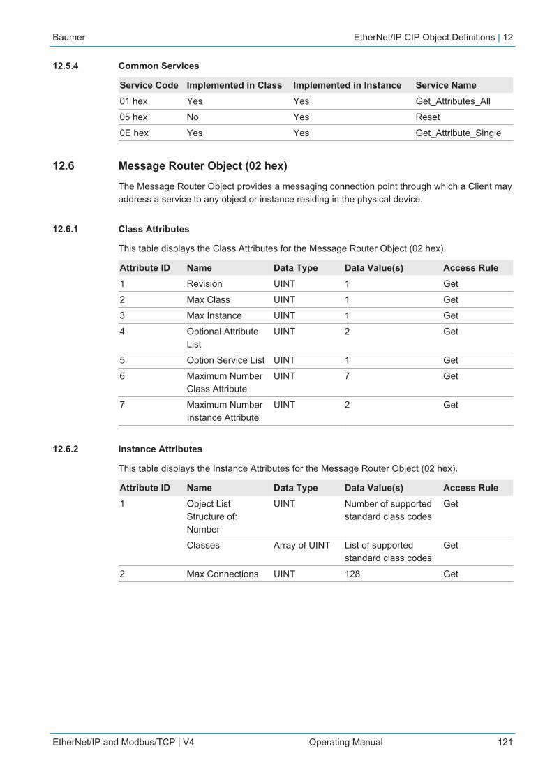
Baumer EtherNet/IP CIP Object Definitions | 12
EtherNet/IP and Modbus/TCP | V4 Operating Manual 121
12.5.4 Common Services
Service Code Implemented in Class Implemented in Instance Service Name01 hex Yes Yes Get_Attributes_All
05 hex No Yes Reset
0E hex Yes Yes Get_Attribute_Single
12.6 Message Router Object (02 hex)
The Message Router Object provides a messaging connection point through which a Client mayaddress a service to any object or instance residing in the physical device.
12.6.1 Class Attributes
This table displays the Class Attributes for the Message Router Object (02 hex).
Attribute ID Name Data Type Data Value(s) Access Rule1 Revision UINT 1 Get
2 Max Class UINT 1 Get
3 Max Instance UINT 1 Get
4 Optional AttributeList
UINT 2 Get
5 Option Service List UINT 1 Get
6 Maximum NumberClass Attribute
UINT 7 Get
7 Maximum NumberInstance Attribute
UINT 2 Get
12.6.2 Instance Attributes
This table displays the Instance Attributes for the Message Router Object (02 hex).
Attribute ID Name Data Type Data Value(s) Access Rule1 Object List
Structure of: Number
UINT Number of supportedstandard class codes
Get
Classes Array of UINT List of supportedstandard class codes
Get
2 Max Connections UINT 128 Get
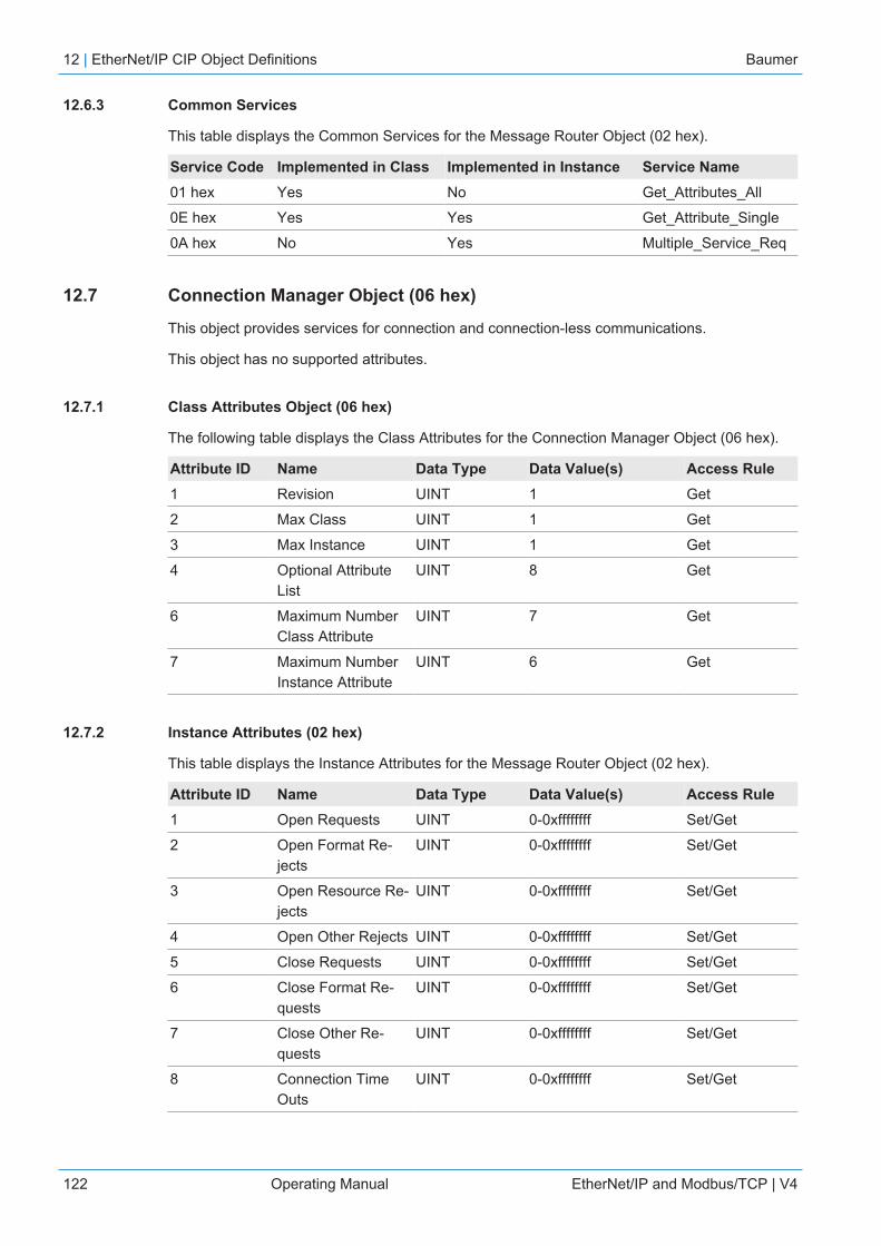
12 | EtherNet/IP CIP Object Definitions Baumer
122 Operating Manual EtherNet/IP and Modbus/TCP | V4
12.6.3 Common Services
This table displays the Common Services for the Message Router Object (02 hex).
Service Code Implemented in Class Implemented in Instance Service Name01 hex Yes No Get_Attributes_All
0E hex Yes Yes Get_Attribute_Single
0A hex No Yes Multiple_Service_Req
12.7 Connection Manager Object (06 hex)
This object provides services for connection and connection-less communications.
This object has no supported attributes.
12.7.1 Class Attributes Object (06 hex)
The following table displays the Class Attributes for the Connection Manager Object (06 hex).
Attribute ID Name Data Type Data Value(s) Access Rule1 Revision UINT 1 Get
2 Max Class UINT 1 Get
3 Max Instance UINT 1 Get
4 Optional AttributeList
UINT 8 Get
6 Maximum NumberClass Attribute
UINT 7 Get
7 Maximum NumberInstance Attribute
UINT 6 Get
12.7.2 Instance Attributes (02 hex)
This table displays the Instance Attributes for the Message Router Object (02 hex).
Attribute ID Name Data Type Data Value(s) Access Rule1 Open Requests UINT 0-0xffffffff Set/Get
2 Open Format Re-jects
UINT 0-0xffffffff Set/Get
3 Open Resource Re-jects
UINT 0-0xffffffff Set/Get
4 Open Other Rejects UINT 0-0xffffffff Set/Get
5 Close Requests UINT 0-0xffffffff Set/Get
6 Close Format Re-quests
UINT 0-0xffffffff Set/Get
7 Close Other Re-quests
UINT 0-0xffffffff Set/Get
8 Connection TimeOuts
UINT 0-0xffffffff Set/Get

Baumer EtherNet/IP CIP Object Definitions | 12
EtherNet/IP and Modbus/TCP | V4 Operating Manual 123
12.7.3 Common Services Object (06 hex)
Service Code Implemented in Class Implemented in Instance Service Name01 hex Yes Yes Get_Attributes_All
02 hex No Yes Set_Attribute_ALL
0E hex Yes Yes Get_Attribute_Single
10 hex No Yes Set_Attribute_Single
4E hex N/A N/A Forward_Close
52 hex N/A N/A Unconnected_Send
54 hex N/A N/A Forward_Open
5A hex N/A N/A Get_Connec-tion_Owner
5B hex N/A N/A Large_Forward_Open
12.8 Port Object (F4 hex-1 instance)
The Port Object enumerates the CIP ports present on the BIOLM.
12.8.1 Class Attributes
This table illustrates the Class Attributes for the Port Object (F4 hex - 1 Instance)
AttributeID Name Data Type Data Value(s)
AccessRule
1 Revision UINT 1 Get
2 Max Instance UINT 1 Get
3 Num Instances UINT 1 Get
6 Maximum Number ClassAttributes
UINT 9 Get
7 Maximum Number In-stance Attributes
UINT 7 Get
8 Entry Port UINT 1 Get
9 All Ports Array ofUINT
[0] = 0[1] = 0[2] = 1 (Vendor Specific)[3] = 1 (Backplane)[4] = TCP_IP_PORT_TYPE (4)[5] = TCP_IP_PORT_NUMBER (2)
Get

12 | EtherNet/IP CIP Object Definitions Baumer
124 Operating Manual EtherNet/IP and Modbus/TCP | V4
12.8.2 Instance Attributes
This table illustrates the Instance Attributes for the Port Object (F4 hex - 1 Instance).
Attribute ID Name Data Type Data Value(s) Access Rule1 Port Type UINT 1 Get
2 Port Number UINT 1 Get
3 Port ObjectStructure of:16 bit word count in pathPath
UINTArray of UINT
2[0] = 6420 hex[1] = 0124 hex
GetGet
4 Port Name Structure of:String LengthPort Name
USINT Array of USINT
10“Backplane”
GetGet
7 Node Address USINT[2] 0x10, 0x00 Get
This table illustrates the Instance Attributes for the Port Object (F4 hex - 2 Instance).
Attribute ID Name Data Type Data Value(s) Access Rule1 Port Type UINT 4 (TCP/IP) Get
2 Port Number UINT 2 (TCP/IP) Get
3 Port ObjectStructure of:16 bit word count in pathPath
UINTArray of UINT
2[0] = F520 hex[1] = 0124 hex
GetGet
4 Port Name Structure of:String LengthPort Name
USINT Array of USINT
17“Ethernet/IP Port”
GetGet
7 Node Address USINT[2] 0x10, 0x00 Get
12.8.3 Common Services
This table illustrates the Common Services for the Port Object (F4 hex - 1 Instance).
Service Code Implemented in Class Implemented in Instance Service Name01 hex Yes Yes Get_Attributes_All
0E hex Yes Yes Get_Attribute_Single

Baumer EtherNet/IP CIP Object Definitions | 12
EtherNet/IP and Modbus/TCP | V4 Operating Manual 125
12.9 TCP Object (F5 hex-1 instance)
The TCP/IP Interface Object provides the mechanism to retrieve the TCP/IP attributes for theBIOLM.
12.9.1 Class Attributes
This table shows the Class Attributes for the TCP Object (F5 hex - I Instance).
Attribute ID Name Data Type Data Value Access Rule1 Revision UINT 1 Get
2 Max Instance UINT 1 Get
3 Num Instances UINT 1 Get
4 Optional Attribute List UINT 4 Get
6 Maximum Number ClassAttribute
UINT 7 Get
7 Maximum Number In-stance Attribute
UINT 9 Get
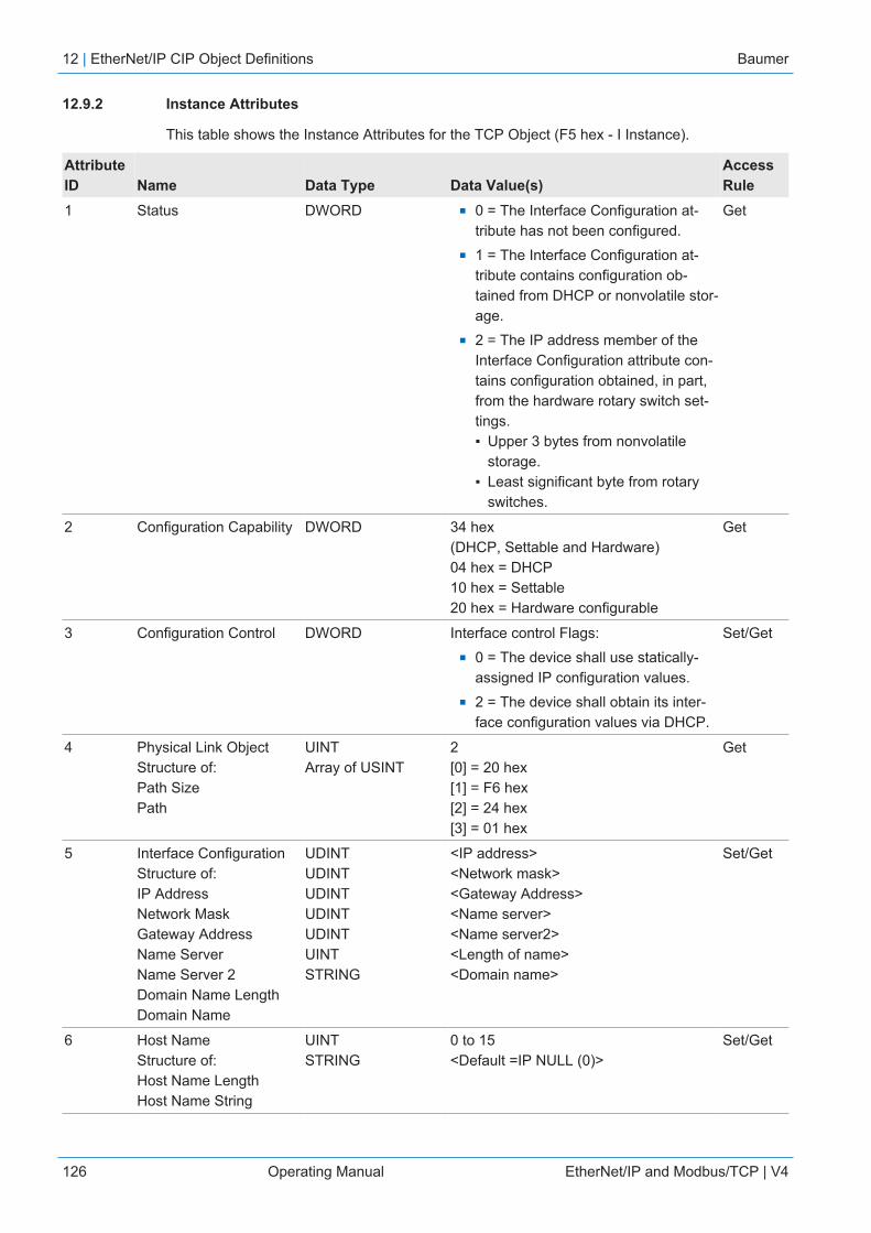
12 | EtherNet/IP CIP Object Definitions Baumer
126 Operating Manual EtherNet/IP and Modbus/TCP | V4
12.9.2 Instance Attributes
This table shows the Instance Attributes for the TCP Object (F5 hex - I Instance).
AttributeID Name Data Type Data Value(s)
AccessRule
1 Status DWORD n 0 = The Interface Configuration at-tribute has not been configured.
n 1 = The Interface Configuration at-tribute contains configuration ob-tained from DHCP or nonvolatile stor-age.
n 2 = The IP address member of theInterface Configuration attribute con-tains configuration obtained, in part,from the hardware rotary switch set-tings.▪ Upper 3 bytes from nonvolatile
storage.▪ Least significant byte from rotary
switches.
Get
2 Configuration Capability DWORD 34 hex(DHCP, Settable and Hardware)04 hex = DHCP 10 hex = Settable 20 hex = Hardware configurable
Get
3 Configuration Control DWORD Interface control Flags:n 0 = The device shall use statically-
assigned IP configuration values.n 2 = The device shall obtain its inter-
face configuration values via DHCP.
Set/Get
4 Physical Link ObjectStructure of: Path Size Path
UINTArray of USINT
2[0] = 20 hex[1] = F6 hex[2] = 24 hex [3] = 01 hex
Get
5 Interface Configuration Structure of:IP AddressNetwork MaskGateway AddressName ServerName Server 2Domain Name LengthDomain Name
UDINTUDINTUDINTUDINTUDINTUINTSTRING
<IP address><Network mask><Gateway Address><Name server><Name server2><Length of name><Domain name>
Set/Get
6 Host NameStructure of: Host Name Length Host Name String
UINT STRING
0 to 15 <Default =IP NULL (0)>
Set/Get

Baumer EtherNet/IP CIP Object Definitions | 12
EtherNet/IP and Modbus/TCP | V4 Operating Manual 127
AttributeID Name Data Type Data Value(s)
AccessRule
8 TTL (Time-to-Live) valuefor IP multicast packets.
USINT 1 to 255<Default = 1>
Set/Get
9 IP Multicast AddressConfiguration
Struct of:USINT - Alloc ControlUSINT - Reserved UINT - Num Mcast UDINT - Start McastAddress
Alloc Control: 0 = Default Algorithm1 = Configuration Num Mcast: 1 to 32Start Mcast Address:239.192.1.0 to239.255.255.255
Set/Get
12.9.3 Common Services
This table shows the Common Services for the TCP Object (F5 hex - I Instance).
Service Code Implemented in Class Implemented in Instance Service Name01 hex Yes Yes Get_Attributes_All
02 hex No Yes Set_Attribute_All
0E hex Yes Yes Get_Attribute_Single
10 hex No Yes Set_Attribute_Single

12 | EtherNet/IP CIP Object Definitions Baumer
128 Operating Manual EtherNet/IP and Modbus/TCP | V4
12.10 Ethernet Link Object (F6 hex-1 instance)
The Ethernet Link Object maintains link-specific counters and status information for the Ethernetcommunications interface on the BIOLM.
12.10.1 Class Attributes
This table displays the Class Attributes for the Ethernet Link Object (F6 hex - 1 Instance).
Attribute ID Name Data Type Data Value(s) Access Rule1 Revision UINT 3 Get
2 Max Instance UINT 1 Get
3 Num Instances UINT 1 Get
4 Optional AttributeList
UINT 4 Get
6 Maximum NumberClass Attributes
UINT 7 Get
7 Maximum NumberInstance Attributes
UINT 1 Get
12.10.2 Instance Attributes
This table displays the Instance Attributes for the Ethernet Link Object (F6 hex - 1 Instance).
AttributeID Name Data Type Data Value(s)
AccessRule
1 Interface speed(Current operationalspeed)
UDINT 10 = 10 Mbit100 = 100 Mbit
Get
2 Interface Flags(Current operationalstatus)
DWORD Bit 0 = link status(0=inactive) (1=active) Bit 1=Half/Full Duplex (0=half duplex) (2=full duplex) Bits 2-4: 00 = negotiation in progress01 = negotiation failed02 = negotiation failed speed OK03 = negotiation success
Get
3 Physical Address Array of 6 USINT MAC Address Get
7 Interface Type USINT 2 = Twisted Pair Get
8 Interface State USINT 1 = Interface is enabled and operational Get
9 Admin State USINT 1 = Interface enabled Get
10 Interface Label USINT16Array of USINT
Length = 1 to 64 ASCII characters <Default = IP address in“xxx.xxx.xxx.xxx” format>
Get
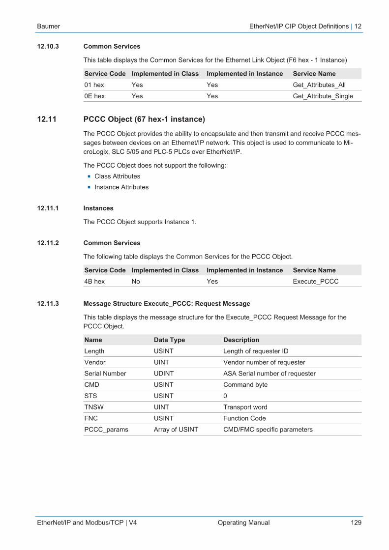
Baumer EtherNet/IP CIP Object Definitions | 12
EtherNet/IP and Modbus/TCP | V4 Operating Manual 129
12.10.3 Common Services
This table displays the Common Services for the Ethernet Link Object (F6 hex - 1 Instance)
Service Code Implemented in Class Implemented in Instance Service Name01 hex Yes Yes Get_Attributes_All
0E hex Yes Yes Get_Attribute_Single
12.11 PCCC Object (67 hex-1 instance)
The PCCC Object provides the ability to encapsulate and then transmit and receive PCCC mes-sages between devices on an Ethernet/IP network. This object is used to communicate to Mi-croLogix, SLC 5/05 and PLC-5 PLCs over EtherNet/IP.
The PCCC Object does not support the following:n Class Attributesn Instance Attributes
12.11.1 Instances
The PCCC Object supports Instance 1.
12.11.2 Common Services
The following table displays the Common Services for the PCCC Object.
Service Code Implemented in Class Implemented in Instance Service Name4B hex No Yes Execute_PCCC
12.11.3 Message Structure Execute_PCCC: Request Message
This table displays the message structure for the Execute_PCCC Request Message for thePCCC Object.
Name Data Type DescriptionLength USINT Length of requester ID
Vendor UINT Vendor number of requester
Serial Number UDINT ASA Serial number of requester
CMD USINT Command byte
STS USINT 0
TNSW UINT Transport word
FNC USINT Function Code
PCCC_params Array of USINT CMD/FMC specific parameters
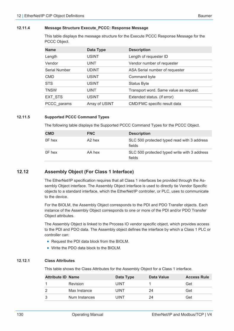
12 | EtherNet/IP CIP Object Definitions Baumer
130 Operating Manual EtherNet/IP and Modbus/TCP | V4
12.11.4 Message Structure Execute_PCCC: Response Message
This table displays the message structure for the Execute PCCC Response Message for thePCCC Object.
Name Data Type DescriptionLength USINT Length of requester ID
Vendor UINT Vendor number of requester
Serial Number UDINT ASA Serial number of requester
CMD USINT Command byte
STS USINT Status Byte
TNSW UINT Transport word. Same value as request.
EXT_STS USINT Extended status. (If error)
PCCC_params Array of USINT CMD/FMC specific result data
12.11.5 Supported PCCC Command Types
The following table displays the Supported PCCC Command Types for the PCCC Object.
CMD FNC Description0F hex A2 hex SLC 500 protected typed read with 3 address
fields
0F hex AA hex SLC 500 protected typed write with 3 addressfields
12.12 Assembly Object (For Class 1 Interface)
The EtherNet/IP specification requires that all Class 1 interfaces be provided through the As-sembly Object interface. The Assembly Object interface is used to directly tie Vendor Specificobjects to a standard interface, which the EtherNet/IP controller, or PLC, uses to communicateto the device.
For the BIOLM, the Assembly Object corresponds to the PDI and PDO Transfer objects. Eachinstance of the Assembly Object corresponds to one or more of the PDI and/or PDO TransferObject attributes.
The Assembly Object is linked to the Process IO vendor specific object, which provides accessto the PDI and PDO data. The Assembly object defines the interface by which a Class 1 PLC orcontroller can:
n Request the PDI data block from the BIOLM.n Write the PDO data block to the BIOLM.
12.12.1 Class Attributes
This table shows the Class Attributes for the Assembly Object for a Class 1 interface.
Attribute ID Name Data Type Data Value Access Rule1 Revision UINT 1 Get
2 Max Instance UINT 24 Get
3 Num Instances UINT 24 Get

Baumer EtherNet/IP CIP Object Definitions | 12
EtherNet/IP and Modbus/TCP | V4 Operating Manual 131
12.12.2 Instance Definitions
This table shows the Instance Definitions for the Assembly Object for a Class 1 interface for the8-port models.
AssemblyInstanceNumber Description Data Type
DataValues
AccessRule
101 PDI data blocks from Ports 1 to 8.PDO data blocks from ports 1-81
BYTE Array Valid read lengths: 1-576
0-255 Get
102 PDI data blocks from Ports 2 to 8.PDO data blocks from Ports 1-8
BYTE ArrayValid read lengths: 1-540
0-255 Get
103 PDI data blocks from Ports 3 to 8.PDO data blocks from Ports 1-8
BYTE ArrayValid read lengths: 1-504
0-255 Get
104 PDI data blocks from Port 4-8. PDO data blocks from Ports 1-8
BYTE Array Valid read lengths: 1-468
0-255 Get
105 PDI data blocks from Ports 5-8 PDO data blocks from Ports 1-8
BYTE Array Valid read lengths: 0-432
0-255 Get
106 PDI data blocks from Ports 6 to 8. PDO data blocks from Ports 1-8
BYTE Array Valid read lengths: 0-396
0-255 Get
107 PDI data blocks from Ports 7 to 8. PDO data blocks from Ports 1-8
BYTE Array Valid read lengths: 0-360
0-255 Get
108 PDI data blocks from Port 8. PDO data blocks from Ports 1-8
BYTE Array Valid read lengths: 0-324
0-255 Get
109 PDO data blocks from Ports 1-8 BYTE Array Valid read lengths: 0-288
0-255 Get
110 PDO data blocks from Ports 2-8 BYTE Array Valid read lengths: 0-252
0-255 Get
111 PDO data blocks from Ports 3-8 BYTE Array Valid read lengths: 0-216
0-255 Get
112 PDO data blocks from Port 4-8 BYTE Array Valid read lengths: 0-180
0-255 Get
113 PDO data blocks from Ports 5-8 BYTE Array Valid read lengths: 0-144
0-255 Get
114 PDO data blocks from Ports 6-8 BYTE Array Valid read lengths: 0-108
0-255 Get
115 PDO data blocks from Ports 7-8 BYTE Array Valid read lengths: 0-72
0-255 Get
116 PDO data blocks from Port 8 BYTE Array Valid read lengths: 0-36
0-255 Get
117 PDO data blocks to Ports 1-8 BYTE ArrayValid read lengths: 0-288
0-255 Set
118 PDO data blocks to Ports 2-8 BYTE ArrayValid read lengths: 0-252
0-255 Set
119 PDO data blocks to Ports 3-8 BYTE ArrayValid read lengths: 0-216
0-255 Set
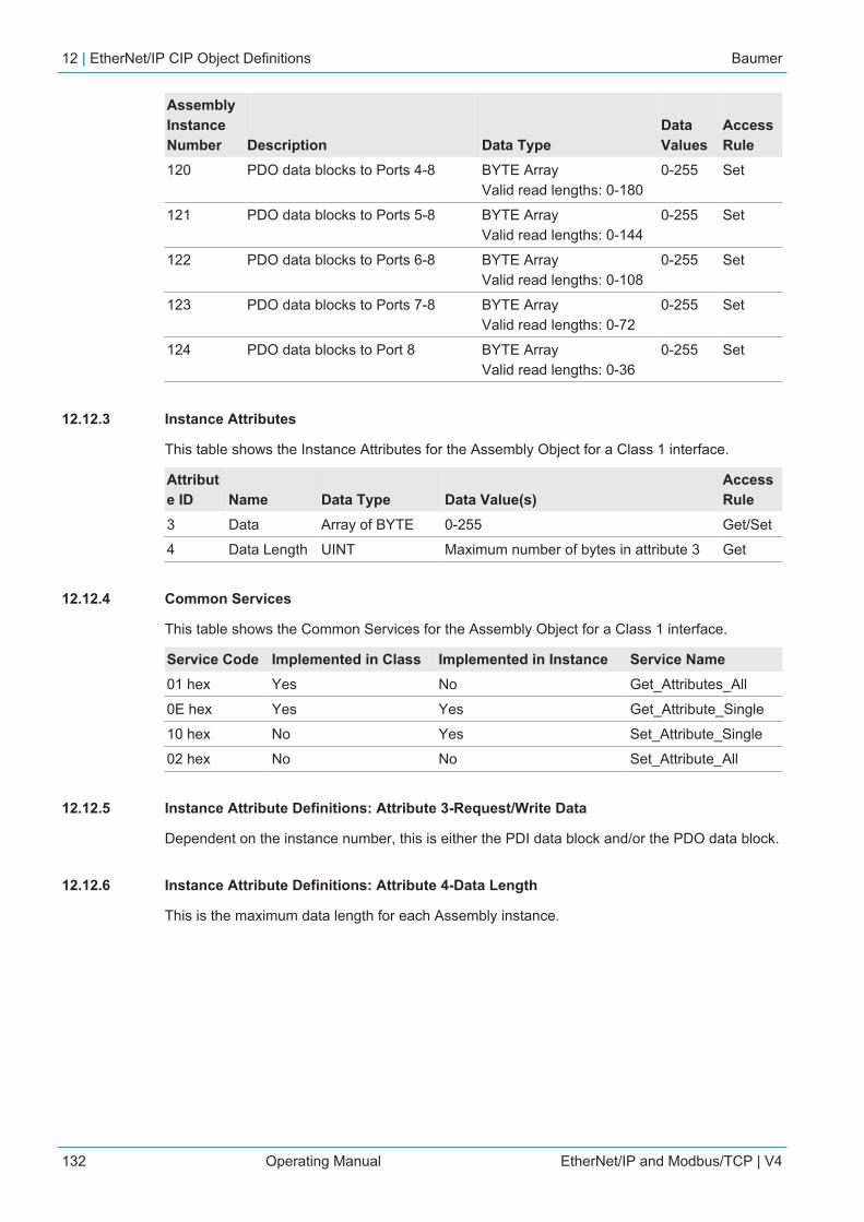
12 | EtherNet/IP CIP Object Definitions Baumer
132 Operating Manual EtherNet/IP and Modbus/TCP | V4
AssemblyInstanceNumber Description Data Type
DataValues
AccessRule
120 PDO data blocks to Ports 4-8 BYTE ArrayValid read lengths: 0-180
0-255 Set
121 PDO data blocks to Ports 5-8 BYTE ArrayValid read lengths: 0-144
0-255 Set
122 PDO data blocks to Ports 6-8 BYTE ArrayValid read lengths: 0-108
0-255 Set
123 PDO data blocks to Ports 7-8 BYTE ArrayValid read lengths: 0-72
0-255 Set
124 PDO data blocks to Port 8 BYTE ArrayValid read lengths: 0-36
0-255 Set
12.12.3 Instance Attributes
This table shows the Instance Attributes for the Assembly Object for a Class 1 interface.
Attribute ID Name Data Type Data Value(s)
AccessRule
3 Data Array of BYTE 0-255 Get/Set
4 Data Length UINT Maximum number of bytes in attribute 3 Get
12.12.4 Common Services
This table shows the Common Services for the Assembly Object for a Class 1 interface.
Service Code Implemented in Class Implemented in Instance Service Name01 hex Yes No Get_Attributes_All
0E hex Yes Yes Get_Attribute_Single
10 hex No Yes Set_Attribute_Single
02 hex No No Set_Attribute_All
12.12.5 Instance Attribute Definitions: Attribute 3-Request/Write Data
Dependent on the instance number, this is either the PDI data block and/or the PDO data block.
12.12.6 Instance Attribute Definitions: Attribute 4-Data Length
This is the maximum data length for each Assembly instance.

Baumer EtherNet/IP CIP Object Definitions | 12
EtherNet/IP and Modbus/TCP | V4 Operating Manual 133
12.12.7 Overview of Assembly Interface
The Assembly interface is designed to:n Provide access to all Input and Output assemblies.n Maximize flexibility for the PLC programmer.n Minimize required PLC and IO-Link communication bandwidth.n Be as easy to use as possible.
The following diagram illustrates the Assembly instances for an BIOLM.

12 | EtherNet/IP CIP Object Definitions Baumer
134 Operating Manual EtherNet/IP and Modbus/TCP | V4
12.12.8 Grouping of Assembly Instances
In order to minimize the number of required I/O connections, the input and output assembly in-stances are organized as follows. The Input Assembly instances are grouped into one continu-ous array with no gaps between the instances. The same is also true for Output Assembly In-stances.
Assembly Controller Access
AssemblyInstanceNumber
Controller Port 1Access
Controller Port 2Access
Controller Port 3Access
Controller Port 8Access
Read(Input)
Write(Output)
Read(Input)
Write(Output)
Read(Input)
Write(Output)
Read(Input)
Write(Output)
Read (In-put) Pro-cess DataInput
101(Port 1)
X
102(Port 2)
X X
103(Port 3)
X X X
104(Port 4)
X X X
105(Port 5)
X X X
106(Port 6)
X X X
107(Port 7)
X X X
108(Port 8)
X X X X
Read (In-put) Pro-cess DataOutput
109(Port 1)
X X X X
110(Port 2)
X X X X
111(Port 3)
X X X X
112(Port 4)
X X X X
113(Port 5)
X X X X
114(Port 6)
X X X X
115(Port 7)
X X X X
116(Port 8)

Baumer EtherNet/IP CIP Object Definitions | 12
EtherNet/IP and Modbus/TCP | V4 Operating Manual 135
AssemblyInstanceNumber
Controller Port 1Access
Controller Port 2Access
Controller Port 3Access
Controller Port 8Access
Read(Input)
Write(Output)
Read(Input)
Write(Output)
Read(Input)
Write(Output)
Read(Input)
Write(Output)
Write(Output)ProcessData Out-put
117(Port 1)
118(Port 2)
X X
119(Port 3)
X X X
120(Port 4)
X X X
121(Port 5)
X X X
122(Port 6)
X X X
123(Port 7)
X X X
124(Port 8)
X X X X
Where:n All accessible data can be read (input) and written (output) from one I/O connection.n Controller Read (Input) access:
▪ One or more input instances may be read with one I/O connection. (i.e. If addressing theinstance 101, all input instances for both PDI and PDO data, 101 to 116 (for 8-port mod-els), may be read in one connection.)
▪ The length of the Read (Input) connection can range from 1 to the total length for all inputinstances.
▪ Multiple controllers can read access to the Input Assembly instances at one time.n Controller Write (Output) access:
▪ Only output instances may be written.▪ One or more output instances may be written to with one connection.▪ The length of the Write (Output) connection must be equal to the total length of the output
instance(s).▪ Only one controller may have write access to an output instance.
INFOIn order to receive all PDI and PDO data in one Class 1 connection, it may be necessary to de-crease the size of one or more PDI and/or PDO blocks via the embedded EtherNet/IP configur-ation web page.
13 | SLC/PLC-5/MicroLogix Interface Baumer
136 Operating Manual EtherNet/IP and Modbus/TCP | V4
13 SLC/PLC-5/MicroLogix InterfaceThe BIOLM provides support for the SLC, PLC-5 and MicroLogix PLCs. The following featuresare supported:
n Rx PDI data, both Polling and Write-to-File modes.n Tx PDO data, both PLC-Writes and Read-From-File modes.n PCCC based messages transferred by means of the PCCC CIP object, including:
▪ SLC Typed Read Message▪ SLC Typed Write Message▪ PLC-5 Typed Read Message (Logical ASCII address format)▪ PLC-5 Typed Write Message (Logical ASCII address format)
n Receive, transmit and statistics data.n Standard PLC-5/SLC file naming conventions.n Controlled message rate to the PLC when operating in the Write-to-File receive method.
This is accomplished by setting the Maximum PLC Update Rate.
The primary differences between the PLC-5/SLC interface and the ControlLogix interfaces are:n Since the PLC-5 and SLC PLCs operate on a file memory system, the PLC-5/SLC interface
provides Write-to-File and Read-from-File communication methods in place of Write-to-Tagand Read-from-Tag communication methods. The Write-to-File methods operate in a verysimilar manner to the Write-to-Tag method available for the ControlLogix family of PLCs.
n Polling is performed through the PLC-5/SLC specific messages instead of accessing theSerial Port Data Transfer object.
n When configuring the BIOLM to operate in Write-to-File or Read-from-File, enter the filename starting with an N (i.e. N10:0).
INFOWhile ControlLogix PLCs support the SLC and PLC-5 messages, using those messages onControlLogix PLCs is not recommended due to data size and performance considerations.
13.1 Requirements
Your PLC-5/SLC/MicroLogix PLC must support:n MultipHopn ControlLogix devicesn EtherNet/IP
The following tables list PLCs that support EtherNet/IP and the required firmware version foreach PLC.
INFOOlder versions of the PLC firmware may or may not provide EtherNet/IP functionality. You mustverify that an older version of the PLC firmware provides EtherNet/IP functionality before youcan use it with BIOLM.
Baumer SLC/PLC-5/MicroLogix Interface | 13
EtherNet/IP and Modbus/TCP | V4 Operating Manual 137
13.2 PLC-5 and SLC 5/05 PLC Requirements
The following PLCs support Ethernet/IP.
13.2.1 SLC 5/05
Models Catalog Numbers Required Firmware Version for Ethernet/IPSLC 5/05 1747-L551
1747-L5521747-L553
Series A: FRN 5 or later Series C: FRN 3 or later
Reference: SLC 500 Instruction Set, Appendix A Firmware History, Rockwell Publication 1747-RM001D-EN-P.
13.2.2 PLC-5
Models Catalog Numbers Required Firmware Version for Ethernet/IPEthernet PLC-5 1785-L20E
1785-L40E1785-L80E
Base Ethernet/IP functionality:n Series C: Revision N and latern Series D: Revision E and latern Series E: Revision D and later
Full Ethernet/IP Compliance:n Series C: Revision R and latern Series D: Revision H and latern Series E: Revision G and later
Enhanced PLC-5 Attached to Ether-net Module
1785-L11B 1785-L20B 1785-L30B 1785-L40B 1785-L40L 1785-L60B 1785-L60L 1785-L80B
Series B: Revision N.1 or later Series C: Revision N or later Series D: Revision E or later Series E: Revision D or later
ControlNet PLC-5 Attached to Ether-net Module
1785-L20C15 1785-L40C15 1785-L60C15 1785-L80C15
Series C: Revision N or later Series D: Revision E or later Series E: Revision D or later All revisions
Ethernet Module 1785-Enet Series B:n Base Ethernet/IP functionality: All Revisionsn Full Ethernet/IP Compliance: Revision D and
later
References:n Enhanced & Ethernet PLC-5 Series and Enhancement History, Rockwell Publication
G19099n ControlNet Processor Phase, Series, and Enhancement History, Rockwell Publication
G19102n PLC-5 Programmable Controllers System Selection Guide, Rockwell Publication 1785-
SG001A-EN-P

13 | SLC/PLC-5/MicroLogix Interface Baumer
138 Operating Manual EtherNet/IP and Modbus/TCP | V4
n Ethernet Interface Module Series B, Revision D Product Release Notes, Rockwell Publica-tion 1785-RN191E-EN-P
INFOOlder versions of firmware may or may not provide Ethernet/IP functionality.
13.3 PLC-5 and SLC Messages
The following PCCC messages are supported for the PLC-5 and SLC 5/05 PLCs.
Message TypePCCCMessage ID Maximum Message Size Maximum Serial Packet Size
SLC TypedRead
162 CLX: 242 SINTs (121 INTs)SLC: 206 SINTs (103 INTs)PLC-5: 240 SINTs (120 INTs)
CLX: 238 SINTs (119 INTs)SLC: 202 SINTs (101 INTs)PLC-5: 236 SINTs (118 INTs)
SLC TypedWrite
170 CLX: 220 SINTs (110 INTs)SLC: 206 SINTs (103 INTs)PLC-5: 238 SINTs (119 INTs)
216 SINTs (108 INTs)SLC: 202 SINTs (101 INTs)PLC-5: 234 SINTs (117 INTs)
PLC-5 TypedRead
104 CLX: 234 SINTs (117 INTs)SLC: 252 SINTs (126 INTs)PLC-5: 238 SINTs (119 INTs)
230 SINTs (115 INTs)SLC: 248 SINTs (124 INTs)PLC-5: 234 SINTs (117 INTs)
PLC-5 TypedWrite
103 CLX: 226 SINTs (113 INTs)SLC: 226 SINTs (113 INTs)PLC-5: 224 SINTs (112 INTs)
CLX: 222 SINTs (111 INTs)SLC: 222 SINTs (111 INTs)PLC-5: 220 SINTs (110 INTs)
The Receive Port Information is provided in one continuous file. The following file addresses areused to retrieve the various parameters.
IO-Link Port 1 IO-Link Port 2 IO-Link Port 3 IO-Link Port 4 Access LengthPDI Data Block N10:0 N20:0 N30:0 N40:0 Read-Only Configurable
per port (seebelow for de-tails).
Receive PDOData Block
N11:0 N21:0 N31:0 N41:0 Read-Only Configurableper port (seebelow for de-tails).
Transmit PDOData Block
N12:0 N22:0 N32:0 N42:0 Write-Only Configurableper port (seebelow for de-tails).
Receive ISDUResponse
N13:0 N23:0 N33:0 N43:0 Read-Only 4 INTs to MaxMsg Size
Transmit ISDURequest
N14:0 N24:0 N34:0 N44:0 Write-Only 4 INTs to MaxMsg Size
Port Information Block (Continuous Block) 464 Bytes(232 INTs)
Vendor Name N15:0 N25:0 N35:0 N45:0 Read 64 Chars(32 INTs)

Baumer SLC/PLC-5/MicroLogix Interface | 13
EtherNet/IP and Modbus/TCP | V4 Operating Manual 139
IO-Link Port 1 IO-Link Port 2 IO-Link Port 3 IO-Link Port 4 Access LengthVendor Text N15:32 N25:32 N35:32 N45:32 Read 64 Chars
(32 INTs)
Product Name N15:64 N25:64 N35:64 N45:64 Read 64 Chars(32 INTs)
Product ID N15:96 N25:96 N35:96 N45:96 Read 64 Chars(32 INTs)
Product Text N15:128 N25:128 N35:128 N45:128 Read 64 Chars(32 INTs)
Serial Number N15:160 N25:160 N35:160 N45:160 Read 16 Chars(8 INTs)
Hardware Re-vision
N15:168 N25:168 N35:168 N45:168 Read 64 Chars(32 INTs)
Firmware Revi-sion
N15:200 N25:200 N35:200 N45:200 Read 64 Chars(32 INTs)
This table provides information for 8-port models.
IO-Link Port 5 IO-Link Port 6 IO-Link Port 7 IO-Link Port 8 Access LengthPDI Data Block N50:0 N60:0 N70:0 N80:0 Read-Only Configurable
per port (seebelow for de-tails).
Receive PDOData Block
N51:0 N61:0 N71:0 N81:0 Read-Only Configurableper port (seebelow for de-tails).
Transmit PDOData Block
N52:0 N62:0 N72:0 N82:0 Write-Only Configurableper port (seebelow for de-tails).
Receive ISDUResponse
N53:0 N63:0 N73:0 N83:0 Read-Only 4 INTs to MaxMsg Size
Transmit ISDURequest
N54:0 N64:0 N74:0 N84:0 Write-Only 4 INTs to MaxMsg Size
Port Information Block (Continuous Block) 464 Bytes(232 INTs)
Vendor Name N55:0 N65:0 N75:0 N85:0 Read 64 Chars(32 INTs)
Vendor Text N55:32 N65:32 N75:32 N85:32 Read 64 Chars(32 INTs)
Product Name N55:64 N65:64 N75:64 N85:64 Read 64 Chars(32 INTs)
Product ID N55:96 N65:96 N75:96 N85:96 Read 64 Chars(32 INTs)
Product Text N55:128 N65:128 N75:128 N85:128 Read 64 Chars(32 INTs)
13 | SLC/PLC-5/MicroLogix Interface Baumer
140 Operating Manual EtherNet/IP and Modbus/TCP | V4
IO-Link Port 5 IO-Link Port 6 IO-Link Port 7 IO-Link Port 8 Access LengthSerial Number N55:160 N65:160 N75:160 N85:160 Read 16 Chars
(8 INTs)
Hardware Re-vision
N55:168 N65:168 N75:168 N85:168 Read 64 Chars(32 INTs)
Firmware Revi-sion
N55:200 N65:200 N75:200 N85:200 Read 64 Chars(32 INTs)

Baumer SLC/PLC-5/MicroLogix Interface | 13
EtherNet/IP and Modbus/TCP | V4 Operating Manual 141
13.4 Process Data (PDI and PDO) Access via PCCC Messages
The process data has been grouped together in order to minimize the number of PCCC mes-sages required to interface to the BIOLM. The PDI and PDO data for multiple ports can be re-ceived or transmitted by one message.
FileNumber
Controller Port 1Access
Controller Port 2Access
Controller Port 3Access
Controller Port 4Access
Read(Input)
Write(Output)
Read(Input)
Write(Output)
Read(Input)
Write(Output)
Read(Input)
Write(Output)
Read (In-put) Pro-cess DataInput
N10:0(Port 1)
X
N20:0(Port 2)
X X
N30:0(Port 3)
X X X
N40:0(Port 4)
X X X X
N50:0(Port 5)
X X X X
N60:0(Port 6)
X X X X
N70:0(Port 7)
X X X X
N80:0(Port 8)
X X X X
Read (In-put) Pro-cess DataOutput
N11:0(Port 1)
X
N21:0(Port 2)
X X
N31:0(Port 3)
X X X
N41:0(Port 4)
X X X X
N51:0(Port 5)
X X X X
N61:0(Port 6)
X X X X
N71:0(Port 7)
X X X X
N81:0(Port 8)
X X X X
Write(Output)ProcessData Out-put
N12:0(Port 1)
X
N22:0(Port 2)
X X

13 | SLC/PLC-5/MicroLogix Interface Baumer
142 Operating Manual EtherNet/IP and Modbus/TCP | V4
FileNumber
Controller Port 1Access
Controller Port 2Access
Controller Port 3Access
Controller Port 4Access
Read(Input)
Write(Output)
Read(Input)
Write(Output)
Read(Input)
Write(Output)
Read(Input)
Write(Output)
N32:0(Port 3)
N42:0(Port 4)
N52:0(Port 5)
X X X X
N62:0(Port 6)
X X X X
N72:0(Port 7)
X X X X
N82:0(Port 8)
X X X X
PCCC Read/Write Access where:n All PDI data can be read with one PCCC read message.n All PDO data can be read with one PCCC read message.n All PDO data can be written with one PCCC write message.n Controller Read access:
▪ The PDI data from one or more ports may be read with one message. (That is, if address-ing Port 1, N10:0, ports one to four may be read in one message.)
▪ The PDO data from one or more ports may be read with one message. (That is, if ad-dressing Port 1, N11:0, ports one to four may be read in one message.)
▪ Partial PDI and PDO data reads are allowed.▪ The length of the Read message can range from 1 to the total, configured PDI or PDO
length for all ports starting at the addressed port.n Controller Write (Output) access:
▪ Only PDO data may be written.▪ The PDO data for one or more ports may be written with one message.▪ Partial PDO data writes are not allowed.▪ The length of the Write message must be equal to the total of the configured PDO lengths
for all ports to be written. The one exception is that the data length of the last port to bewritten must be equal to or greater than the device PDO length for that port.

Baumer EDS Files | 14
EtherNet/IP and Modbus/TCP | V4 Operating Manual 143
14 EDS FilesThis chapter discusses the following topics:
n Downloading the Files [} 143]n Configuring RSLinx [} 143]n Adding EDS Files to Rockwell Software [} 144]
INFOThe AOI files and documentation (bundled with the files) can be downloaded from the Baumerweb site.
14.1 Overview
You do not need to add the BIOLM to Rockwell software for normal BIOLM-to-PLC communica-tions. However, you can easily add the BIOLM and its associated Electronic Data Sheet (EDS)files to Rockwell software.
The files named BIOLM_*.ico are icon files and files named BIOLM_dd_NNNN-x.xx.eds areODVA electronic data sheet files where:
n dd is the model namen NNNN is the product ID numbern x.xx is the version number
14.2 Downloading the Files
You can download the EDS files provided for the BIOLM from the Baumer web site.
14.3 Configuring RSLinx
You can use these steps to add the BIOLM to RSLinx.Instruction:
a) Open RSLinx.b) If there is not an EtherNet/IP driver configured, use these steps:
1. Under Communications, select Configure Drivers.2. Under Available Drivers, select EtherNet/IP Driver.3. Select Add New.4. Use the default driver name or type your own driver name and click OK to continue.
c) Select the adapter of the network card used to communicate with the BIOLM and click OK.d) Select RSWho to verify that RSLinx can communicate with the BIOLM.
INFOA yellow question mark appears by the BIOLM(s) in the RSWho window when the associatedEDS file(s) are not installed.

14 | EDS Files Baumer
144 Operating Manual EtherNet/IP and Modbus/TCP | V4
14.4 Adding EDS Files to Rockwell Software
You can use this procedure to add the EDS files to Rockwell software.Instruction:
a) Open the EDS Hardware Installation Tool. (Select Start |All Programs | Rockwell Soft-ware | RSLinx Tools.)
b) Click Add.c) Click Register a directory of EDS files.d) Browse to the Baumer/EtherNetIP directory and click Next to continue.e) Verify that there is a green check beside each EDS file name and select Next to continue.f) Click Finish to exit.
If RSLinx does not display the device after adding BIOLM and the EDS files to RSLinx, performthe following procedure:Instruction:
a) Select File | Exit and Shutdown to exit and shutdown RSLinx.b) Remove the following files from your hard drive:
\Program Files\Rockwell Software\RSCOMMON\Harmony.hrc\Program Files\Rockwell Software\RSCOMMON\Harmony.rsh
c) Restart RSLinx. The BIOLM or BIOLMs should now appear with the associated icon oricons.
Baumer Modbus/TCP Interface | 15
EtherNet/IP and Modbus/TCP | V4 Operating Manual 145
15 Modbus/TCP InterfaceThe BIOLM provides a slave-mode Modbus/TCP interface that provides:
n Read access to the Process Data Input (PDI) and Process Data Output (PDO) data blocksfor each IO-Link port
n Write access to the PDO data block for each IO-Link portn Write access to send ISDU requests to each IO-Link portn Read access to ISDU responses from each IO-Link portn Read access to the Port Information Block for each IO-Link port
The Modbus interface is disabled by default. To enable Modbus/TCP:Instruction:
a) Click Configuration | Modbus/TCP.b) Click the EDIT button in the Modbus/TCP Configuration table.c) Select enable in the Modbus Enable drop box.d) Click the SAVE button.
Refer to Functionality Descriptions [} 86] for detailed information about process data block de-scriptions, event handing, and ISDU handling:
n Input Process Data Block-8 Bit Data Format [} 87]n Input Process Data Block-16 Bit Data Format [} 88]n Input Process Data Block-32 Bit Data Format [} 88]n Output Process Data Block-8 Bit (SINT) Data Format [} 89]n Output Process Data Block-16 Bit (INT) Data Format [} 90]n Output Process Data Block-32 Bit (DINT) Data Format [} 91]n Event Handling [} 92]n ISDU Handling [} 97]
15.1 Modbus Function Codes
This table shows the supported Modbus function codes:
Message Type Function Code Maximum Message SizeRead Holding Registers 3 250 Bytes (125 Words)
Write Single Register 6 2 bytes (1 Word)
Write Multiple Registers 16 (10 hex) 246 Bytes (123 Words)
Read/Write Holding Registers 23 (17 hex) Write: 242 bytes (121 Words)Read: 246 bytes (123 Words)

15 | Modbus/TCP Interface Baumer
146 Operating Manual EtherNet/IP and Modbus/TCP | V4
15.2 Modbus Address Definitions
The address definitions for the Modbus/TCP interface are shown in the following tables:
IO-Link Port 1 IO-Link Port 2 IO-Link Port 3 IO-Link Port 4 Access LengthMultiple PortPDI DataBlock(s)
999 (Base 0)1000 (Base 1)
1999 (Base 0)2000 (Base 1)
2999 (Base 0)3000 (Base 1)
3999 (Base 0)4000 (Base 1)
Read-Only Configurableper port(s)
Port SpecificPDI Data Block
1000 (Base 0) 1001 (Base 1)
2000 (Base 0) 2001 (Base 1)
3000 (Base 0) 3001 (Base 1)
4000 (Base 0) 4001 (Base 1)
Read-Only Configurableper port
Multiple PortPDO DataBlock(s)
1049 (Base 0)1050 (Base 1)
2049 (Base 0)2050 (Base 1)
3049 (Base 0)3050 (Base 1)
4049 (Base 0)4050 (Base 1)
Read/Write Configurableper port(s)
Port SpecificPDO DataBlock
1050 (Base 0)1051 (Base 1)
2050 (Base 0)2051 (Base 1)
3050 (Base 0)3051 (Base 1)
4050 (Base 0)4051 (Base 1)
Read/Write Configurableper port
ReceiveISDU Re-sponse
1100 (Base 0)1101 (Base 1)
2100 (Base 0)2101 (Base 1)
3100 (Base 0)3101 (Base 1)
4100 (Base 0)4101 (Base 1)
Read-Only 4 to 125 Words
Transmit ISDURequest
1300 (Base 0)1301 (Base 1)
2300 (Base 0)2301 (Base 1)
3300 (Base 0)3301 (Base 1)
4300 (Base 0)4301 (Base 1)
Write-Only 4 to 123 Words
Port Information Block (Continuous Block) 232 Words
Vendor Name 1500 (Base 0)1501 (Base 1)
2500 (Base 0)2501 (Base 1)
3500 (Base 0)3501 (Base 1)
4500 (Base 0)4501 (Base 1)
Read-Only 64 Chars32 Words
Vendor Text 1532 (Base 0)1533 (Base 1)
2532 (Base 0)2533 (Base 1)
3532 (Base 0)3533 (Base 1)
4532 (Base 0)4533 (Base 1)
Read-Only 64 Chars32 Words
Product Name 1564 (Base 0)1565 (Base 1)
2564 (Base 0)2565 (Base 1)
3564 (Base 0)3565 (Base 1)
4564 (Base 0)4565 (Base 1)
Read-Only 64 Chars32 Words
Product Id 1596 (Base 0)1597 (Base 1)
2596 (Base 0)2597 (Base 1)
3596 (Base 0)3597 (Base 1)
4596 (Base 0)4597 (Base 1)
Read-Only 64 Chars32 Words
Product Text 1628 (Base 0)1629 (Base 1)
2628 (Base 0)2629 (Base 1)
3628 (Base 0)3629 (Base 1)
3628 (Base 0)3629 (Base 1)
Read-Only 64 Chars32 Words
Serial Number 1660 (Base 0)1661 (Base 1)
2660 (Base 0)2661 (Base 1)
3660 (Base 0)3661 (Base 1)
4660 (Base 0)4661 (Base 1)
Read-Only 16 Chars8 Words
Hardware Re-vision
1668 (Base 0)1669 (Base 1)
2668 (Base 0)2669 (Base 1)
3668 (Base 0)3669 (Base 1)
4668 (Base 0)4669 (Base 1)
Read-Only 64 Chars32 Words
Firmware Revi-sion
1700 (Base 0)1701 (Base 1)
2700 (Base 0)2701 (Base 1)
3700 (Base 0)3701 (Base 1)
4700 (Base 0)4701 (Base 1)
Read-Only 64 Chars32 Words
Device PDILength
1732 (Base 0)1733 (Base 1)
2732 (Base 0)2733 (Base 1)
3732 (Base 0)3733 (Base 1)
4732 (Base 0)4733 (Base 1)
Read-Only 1 Word
Device PDOLength
1733 (Base 0)1734 (Base 1)
2733 (Base 0)2734 (Base 1)
3733 (Base 0)3734 (Base 1)
4733 (Base 0)4734 (Base 1)
Read-Only 1 Word

Baumer Modbus/TCP Interface | 15
EtherNet/IP and Modbus/TCP | V4 Operating Manual 147
IO-Link Port 5 IO-Link Port 6 IO-Link Port 7 IO-Link Port 8 Access LengthMultiple PortPDI DataBlock(s)
4999 (Base 0)5000 (Base 1)
5999 (Base 0)6000 (Base 1)
6999 (Base 0)7000 (Base 1)
7999 (Base 0)8000 (Base 1)
Read- Only Configurableper port(s)
Port SpecificPDI Data Block
5000 (Base 0)5001 (Base 1)
6000 (Base 0)6001 (Base 1)
7000 (Base 0)7001 (Base 1)
8000 (Base 0)8001 (Base 1)
Read- Only Configurableper port
Multiple PortPDO DataBlock(s)
5049 (Base 0)5050 (Base 1)
6049 (Base 0)6050 (Base 1)
7049 (Base 0)7050 (Base 1)
8049 (Base 0)8050 (Base 1)
Read/Write Configurableper port(s)
Port SpecificPDO DataBlock
5050 (Base 0)5051 (Base 1)
6050 (Base 0)6051 (Base 1)
7050 (Base 0)7051 (Base 1)
8050 (Base 0)8051 (Base 1)
Read/Write Configurableper port
ReceiveISDU Re-sponse
5100 (Base 0)5101 (Base 1)
6100 (Base 0)6101 (Base 1)
7100 (Base 0)7101 (Base 1)
8100 (Base 0)8101 (Base 1)
Read- Only 4 to 125 Words
Transmit ISDURequest
5300 (Base 0)5301 (Base 1)
6300 (Base 0)6301 (Base 1)
7300 (Base 0)7301 (Base 1)
8300 (Base 0)8301 (Base 1)
Write-Only 4 to 123 Words
Port Information Block (Continuous Block) 232 Words
Vendor Name 5500 (Base 0)5501 (Base 1)
6500 (Base 0)6501 (Base 1)
7500 (Base 0)7501 (Base 1)
8500 (Base 0)8501 (Base 1)
Read-Only 64 Chars32 Words
Vendor Text 5532 (Base 0)5533 (Base 1)
6532 (Base 0)6533 (Base 1)
7532 (Base 0)7533 (Base 1)
8532 (Base 0)8533 (Base 1)
Read-Only 64 Chars32 Words
Product Name 5564 (Base 0)5565 (Base 1)
6564 (Base 0)6565 (Base 1)
7564 (Base 0)7565 (Base 1)
8564 (Base 0)8565 (Base 1)
Read-Only 64 Chars32 Words
Product Id 5596 (Base 0)5597 (Base 1)
6596 (Base 0)6597 (Base 1)
7596 (Base 0)7597 (Base 1)
8596 (Base 0)8597 (Base 1)
Read-Only 64 Chars32 Words
Product Text 5628 (Base 0)5629 (Base 1)
6628 (Base 0)6629 (Base 1)
7628 (Base 0)7629 (Base 1)
8628 (Base 0)8629 (Base 1)
Read-Only 64 Chars32 Words
Serial Number 5660 (Base 0)5661 (Base 1)
6660 (Base 0)6661 (Base 1)
7660 (Base 0)7661 (Base 1)
8660 (Base 0)8661 (Base 1)
Read-Only 16 Chars8 Words
Hardware Re-vision
5668 (Base 0)5669 (Base 1)
6668 (Base 0)6669 (Base 1)
7668 (Base 0)7669 (Base 1)
8668 (Base 0)8669 (Base 1)
Read-Only 64 Chars32 Words
Firmware Revi-sion
5700 (Base 0)5701 (Base 1)
6700 (Base 0)6701 (Base 1)
7700 (Base 0)7701 (Base 1)
8700 (Base 0)8701 (Base 1)
Read-Only 64 Chars32 Words
Device PDILength
5732 (Base 0)5733 (Base 1)
6732 (Base 0)6733 (Base 1)
7732 (Base 0)7733 (Base 1)
8732 (Base 0)8733 (Base 1)
Read-Only 1 Word
Device PDOLength
5733 (Base 0)5734 (Base 1)
6733 (Base 0)6734 (Base 1)
7733 (Base 0)7734 (Base 1)
8733 (Base 0)8734 (Base 1)
Read-Only 1 Word

15 | Modbus/TCP Interface Baumer
148 Operating Manual EtherNet/IP and Modbus/TCP | V4
15.3 Multiple Port Process Data (PDI/PDO) Access via Modbus/TCP
The process data has been grouped together in order to minimize the number of Modbus mes-sages required to interface to the IO-Link master. The PDI and PDO data for multiple ports canbe received or transmitted by one message.
ModbusHoldingRegisterAddress(Base 1)
Controller Port 1Access
Controller Port 2Access
Controller Port 3Access
Controller Port 4Access
Read(Input)
Write(Output)
Read(Input)
Write(Output)
Read(Input)
Write(Output)
Read(Input)
Write(Output)
Read (In-put) Pro-cess DataInput
1000(Port 1)
X
2000(Port 2)
X X
3000(Port 3)
X X X
4000(Port 4)
X X X X
Read (In-put) Pro-cess DataOutput
1050(Port 1)
X
2050(Port 2)
X X
3050(Port 3)
X X X
4050(Port 4)
X X X X
Write(Output)ProcessData Out-put
1050(Port 1)
X
2050(Port 2)
X X
3050(Port 3)
X X X
4050(Port 4)
X X X X

Baumer Modbus/TCP Interface | 15
EtherNet/IP and Modbus/TCP | V4 Operating Manual 149
ModbusHoldingRegisterAddress(Base 1)
Controller Port 5Access
Controller Port 6Access
Controller Port 7Access
Controller Port 8Access
Read(Input)
Write(Output)
Read(Input)
Write(Output)
Read(Input)
Write(Output)
Read(Input)
Write(Output)
Read (In-put) Pro-cess DataInput
5000(Port 5)
X
6000(Port 6)
X X
7000(Port 7)
X X X
8000(Port 8)
X X X X
Read (In-put) Pro-cess DataOutput
5050(Port 5)
X
6050(Port 6)
X X
7050(Port 7)
X X X
8050(Port 8)
X X X X
Write(Output)ProcessData Out-put
5050(Port 5)
X
6050(Port 6)
X X
7050(Port 7)
X X X
8050(Port 8)
X X X X
To receive and transmit process data for eight ports, it may be necessary to adjust the size ofthe PDI/PDO data blocks.
Modbus Read/Write Access where:n All PDI data can be read with one Modbus Read Holding Registers message.n All PDO data can be read with one Modbus Read Holding Registers read message.n All PDO data can be written with one Modbus Write Holding Registers message.n Controller Read access:
▪ The PDI data from one or more ports may be read with one message. (i.e.: If addressingport 1, at address 1000, ports one to four may be read in one message.)
▪ The PDO data from one or more ports may be read with one message. (i.e.: If addressingport 1, at address 1050, ports one to four may be read in one message.)
▪ Partial PDI and PDO data reads are allowed.▪ The length of the Read message can range from 1 to the total, configured PDI or PDO
length for all ports starting at the addressed port.n Controller Write (Output) access:
▪ Only PDO data may be written.
15 | Modbus/TCP Interface Baumer
150 Operating Manual EtherNet/IP and Modbus/TCP | V4
▪ The PDO data for one or more ports may be written with one Write Holding Registersmessage.
▪ Partial PDO data writes are not allowed.▪ The length of the Write message must be equal to the total of the configured PDO lengths
for all ports to be written. The one exception is that the data length of the last port to bewritten must be equal to or greater than the device PDO length for that port.

Baumer Troubleshooting and Technical Support | 16
EtherNet/IP and Modbus/TCP | V4 Operating Manual 151
16 Troubleshooting and Technical SupportThis chapter provides the following information:
n Troubleshooting [} 151]n BIOLM LEDs [} 152]n Using Log Files [} 155]
16.1 Troubleshooting
Before contacting Technical Support, you may want to try the following:n Check to make sure LEDs are not reporting an issue using BIOLM LEDs [} 152].n Verify that the network IP address, subnet mask, and gateway are correct and appropriate
for the network. Make sure that the IP address programmed into the IO-Link Mastermatches the unique reserved IP configured address assigned by the system administrator.▪ If using DHCP, the host system needs to provide the subnet mask. The gateway is op-
tional and is not required for a purely local network.▪ Remember that if the rotary switches on the BIOLM L-EIP are set to a non-default posi-
tion, the rotary switches override the lower 3 digits (8 bits) of the static IP address con-figured in the Network page.
▪ Verify that the Ethernet hub and any other network devices between the system and theIO-Link Master are powered up and operating.
n Verify that you are using the correct types of cables on the correct connectors and that allcables are connected securely.
n Disconnect and re-connect the IO-Link device, or optionally, use the Configuration | IO-Link page to Reset the port, and then set the Port Mode back to IOLink.
n Reboot or power cycle the BIOLM. Use the Advanced | Software page to reboot theBIOLM.
n Verify that the Port Mode matches the device, for example: IO-Link, Digital In, Digital Out,or Reset (port is disabled).
n If you are receiving an error that indicates a hardware fault, check the Configuration | IO-Link page for the port experiencing the fault.▪ Check the settings for the Automatic Upload Enable and Automatic Download Enable
options. If the Vendor ID or Device ID of the attached device does not match, a hardwarefault is generated.
▪ Make sure if the port contains data storage that the Vendor ID and Device ID match thedevice attached to the port. If it does not, CLEAR the data storage or move the device toanother port.
▪ Check the Device Validation and Data Validation settings. If the attached device does notmeet these settings, a hardware fault is issued.
n Open the IO-Link Master web interface and review the following pages to see if you can loc-ate a problem:▪ IO-Link Diagnostics▪ Digital I/O Diagnostics (BIOLM)▪ EtherNet/IP Diagnostics▪ Modbus/TCP Diagnostics▪ OPC UA Diagnostics
n If you have a spare IO-Link Master, try replacing the IO-Link Master.
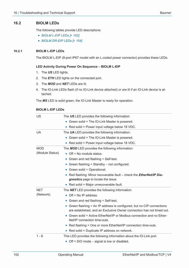
16 | Troubleshooting and Technical Support Baumer
152 Operating Manual EtherNet/IP and Modbus/TCP | V4
16.2 BIOLM LEDs
The following tables provide LED descriptions:n BIOLM L-EIP LEDs [} 152]n BIOLM DR-EIP LEDs [} 154]
16.2.1 BIOLM L-EIP LEDs
The BIOLM L-EIP (8-port IP67 model with an L-coded power connector) provides these LEDs.
LED Activity During Power On Sequence – BIOLM L-EIP
1. The US LED lights.
2. The ETH LED lights on the connected port.
3. The MOD and NET LEDs are lit.
4. The IO-Link LEDs flash (if no IO-Link device attached) or are lit if an IO-Link device is at-tached.
The MS LED is solid green, the IO-Link Master is ready for operation.
BIOLM L-EIP LEDs
US The US LED provides the following information:n Green solid = The IO-Link Master is powered.n Red solid = Power input voltage below 18 VDC.
UA The UA LED provides the following information:n Green solid = The IO-Link Master is powered.n Red solid = Power input voltage below 18 VDC.
MOD(Module Status)
The MOD LED provides the following information:n Off = No module status.n Green and red flashing = Self-test.n Green flashing = Standby – not configured.n Green solid = Operational.n Red flashing: Minor recoverable fault – check the EtherNet/IP Dia-
gnostics page to locate the issuen Red solid = Major unrecoverable fault.
NET(Network)
The NET LED provides the following information:n Off = No IP address.n Green and red flashing = Self-test.n Green flashing = An IP address is configured, but no CIP connections
are established, and an Exclusive Owner connection has not timed out.n Green solid = Active EtherNet/IP or Modbus connection and no Ether-
Net/IP connection time-outs.n Red flashing = One or more EtherNet/IP connection time-outs.n Red solid = Duplicate IP address on network.
1 - 8 This LED provides the following information about the IO-Link port.n Off = SIO mode – signal is low or disabled.

Baumer Troubleshooting and Technical Support | 16
EtherNet/IP and Modbus/TCP | V4 Operating Manual 153
n Yellow = SIO mode – signal is high.n Red flashing = Hardware fault – make sure that configured IO-Link set-
tings on the port do not conflict with the device that is attached:▪ Automatic Upload and/or Download is enabled and it is not the
same device.▪ Device Validation Mode is enabled and it is not the correct device.▪ Data Validation Mode is enabled but there is an error.
n Red solid = PDI of the attached IO-Link device is invalidGreen solid =An IO-Link device is connected and communicating.
n Green flashing = Searching for IO-Link devices.
Port 1 - 4DI
The DI LED indicates digital input on DI (Pin 2).n Off = DI signal is low or disconnected.n Yellow = DI signal is high.
ETH1ETH2
The ETH LEDs provide the following information:n Green solid = Linkn Green flashing = Activity
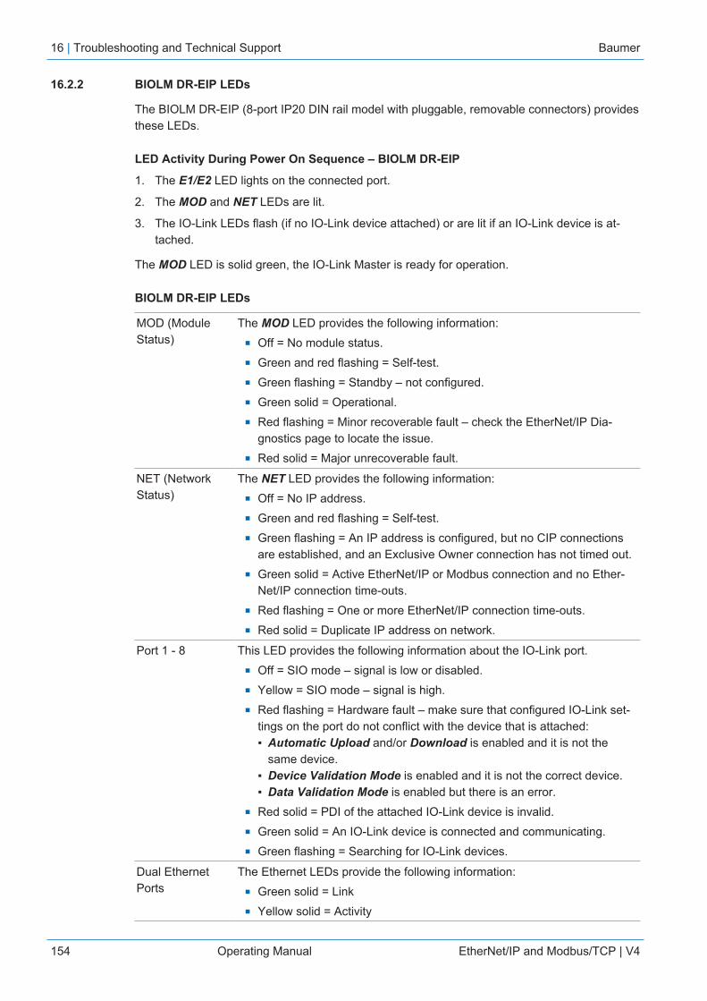
16 | Troubleshooting and Technical Support Baumer
154 Operating Manual EtherNet/IP and Modbus/TCP | V4
16.2.2 BIOLM DR-EIP LEDs
The BIOLM DR-EIP (8-port IP20 DIN rail model with pluggable, removable connectors) providesthese LEDs.
LED Activity During Power On Sequence – BIOLM DR-EIP
1. The E1/E2 LED lights on the connected port.
2. The MOD and NET LEDs are lit.
3. The IO-Link LEDs flash (if no IO-Link device attached) or are lit if an IO-Link device is at-tached.
The MOD LED is solid green, the IO-Link Master is ready for operation.
BIOLM DR-EIP LEDs
MOD (ModuleStatus)
The MOD LED provides the following information:n Off = No module status.n Green and red flashing = Self-test.n Green flashing = Standby – not configured.n Green solid = Operational.n Red flashing = Minor recoverable fault – check the EtherNet/IP Dia-
gnostics page to locate the issue.n Red solid = Major unrecoverable fault.
NET (NetworkStatus)
The NET LED provides the following information:n Off = No IP address.n Green and red flashing = Self-test.n Green flashing = An IP address is configured, but no CIP connections
are established, and an Exclusive Owner connection has not timed out.n Green solid = Active EtherNet/IP or Modbus connection and no Ether-
Net/IP connection time-outs.n Red flashing = One or more EtherNet/IP connection time-outs.n Red solid = Duplicate IP address on network.
Port 1 - 8 This LED provides the following information about the IO-Link port.n Off = SIO mode – signal is low or disabled.n Yellow = SIO mode – signal is high.n Red flashing = Hardware fault – make sure that configured IO-Link set-
tings on the port do not conflict with the device that is attached:▪ Automatic Upload and/or Download is enabled and it is not the
same device.▪ Device Validation Mode is enabled and it is not the correct device.▪ Data Validation Mode is enabled but there is an error.
n Red solid = PDI of the attached IO-Link device is invalid.n Green solid = An IO-Link device is connected and communicating.n Green flashing = Searching for IO-Link devices.
Dual EthernetPorts
The Ethernet LEDs provide the following information:n Green solid = Linkn Yellow solid = Activity

Baumer Troubleshooting and Technical Support | 16
EtherNet/IP and Modbus/TCP | V4 Operating Manual 155
16.3 Using Log Files
INFOTypically, log files are intended to be used by Technical Support in the event there is a problem.
The IO-Link Master provides four different log files that you can view, export, or clear:n Syslog (system log) displays line-by-line activity records.n dmesg displays Linux kernel messages.n top displays which programs are using most of the memory and CPU.n ps displays the running programsn All log files start up automatically during the startup cycle. Each log file has a size limit of
100 KB.
You can use the following procedures to:n View a Log File [} 155]n Clear a Log File [} 156]n Export a Log File [} 155]
16.3.1 View a Log File
Use this procedure to view a log file:Instruction:
a) Open your browser and enter the IP address of the IO-Link Master.b) Click Advanced and then LOG FILES.c) Select the log file type from the drop-list.d) Optionally, click the REFRESH button to get the latest information.e) Optionally, export the log file (Export a Log File [} 155]).
16.3.2 Export a Log File
Use the following procedure to export a log file:Instruction:
a) Open your browser and enter the IP address of the IO-Link Master.b) Click Advanced and then LOG FILES.c) Select the log file type from the drop-list.d) Click the EXPORT button.e) Click the Save button drop-list and click Save to save it to your user folder or Save as to
browse to or create a new folder in which to place the log file.f) Depending on your browser, you may need to close the pop-up window.
16 | Troubleshooting and Technical Support Baumer
156 Operating Manual EtherNet/IP and Modbus/TCP | V4
16.3.3 Clear a Log File
Use this procedure to clear a log file:Instruction:
a) Open your browser and enter the IP address of the IO-Link Master.b) Click Advanced and then LOG FILES.c) Optionally, export the log file (Export a Log File).d) Select the log file type from the drop-list.e) Click the CLEAR button.
Result:ü The log file automatically starts logging the latest information.


Baumer Worldwide
BelgiumBaumer SA/NVBE-2260 WesterloPhone +32 14 57 462 0
BrazilBaumer do Brasil LtdaBR-13208-120 Jundiaí, São PauloPhone +55 11 4523-5120
CanadaBaumer Inc.CA-Burlington, ON L7M 4B9Phone +1 905 335 8444
ChinaBaumer (China) Co., Ltd.CN-201612 ShanghaiPhone +86 2167687095
Germany / AustriaBaumer GmbHDE-61169 FriedbergPhone +49 6031 6007 0
PolandBaumer Sp.z.o.o.PL-92-333 ŁódźPhone +48 42 676 7330
SpainBaumer Automación Ibérica S.LES-08021 BarcelonaPhone +34 932547864
South KoreaBaumer (Korea) Co., Ltd.KR-03923 SeoulPhone +82-2-6351-9909
DenmarkBaumer A/SDK-8210 Aarhus V.Phone +45 8931 7611
IndiaBaumer India Private Ltd.IN-411038 PunePhone +91 20 66292400
VenezuelaBaumer BAVE, SAVE-1070 CaracasPhone +58 2122569336
SwedenBaumer A/SSE-56133 HuskvarnaPhone +46 36139430
United KingdomBaumer Ltd.GB-Watchfield, Swindon, SN6 8TZPhone +44 1793783839
FranceBaumer SASFR-74250 FillingesPhone +33 450392466
ItalyBaumer Italia S.r.l.IT-20090 Assago MIPhone +39 0245706065
SingaporeBaumer (Singapore) Pte. Ltd.SG-339412 SingaporePhone +65 6396 4131
Switzerland (Headquarter)Baumer Electric AGCH-8501 FrauenfeldPhone +41 52 728 11 22
USABaumer Ltd.US-Southington, CT 06489Phone +1 800 937 9336
www.baumer.com/worldwide
Related Documents