Operating Manual Axio Vert.A1 Inverted Microscope

Welcome message from author
This document is posted to help you gain knowledge. Please leave a comment to let me know what you think about it! Share it to your friends and learn new things together.
Transcript
Operatin
g M
anual
Axio
Vert.A
1
Inverted M
icroscope

Carl Zeiss Copyright / Trademarks Axio Vert.A1
2 431030-7044-001 01/2012
Knowledge of this manual is required for the operation of the instrument. So, please make yourself familiar with the contents of this manual and pay special attention to the hints concerning the safe operation of the instrument.
We reserve the right to make changes to accommodate technical progress. This manual is not covered by an update service.
© Unless expressly authorized, the dissemination and duplication of this document, as well as the utilization and communication of its contents are not permitted. Violations will result in payment of damages.
All rights reserved in the event of the grant of a patent or the registration of a utility model.
All the names of firms or products mentioned in this Operating Manual may be trademarks or registered trademarks. Other products are mentioned for information only. Such mention neither constitutes endorsement nor recommendation of those products.
Carl Zeiss MicroImaging GmbH is not liable for the performance or use of those products.
Issued by: Carl Zeiss MicroImaging GmbH Postfach 4041, D - 37030 Göttingen, Germany Telephone: +49 (0) 551 5060 660 Fax: +49 (0) 551 5060 464 E-mail: [email protected] www.zeiss.de
SAP No.: 431030-7044-001
Date of issue: Version 8 - January 13, 2012
Axio Vert.A1 Table of Contents / List of Figures Carl Zeiss
01/2012 431030-7044-001 3
TABLE OF CONTENTS
Page
1 INTRODUCTION ................................................................................................... 8
1.1 Notes on Instrument Safety .......................................................................................... 8
1.2 Nameplate and Warning Labels Attached to the Microscope and to Components ................................................................................................................ 11
1.3 Notes on Warranty ...................................................................................................... 13
1.4 Types of Stands (General Views) ................................................................................ 14
2 INSTRUMENT DESCRIPTION .............................................................................. 15
2.1 Name, Intended Use .................................................................................................... 15
2.2 Instrument Description and Main Features ................................................................ 16
2.3 System Overview ........................................................................................................ 18 2.3.1 Stands for Biomed Applications ...................................................................................... 18 2.3.2 Stand for Material Applications ....................................................................................... 21
2.4 Technical Specifications .............................................................................................. 23
2.5 Operation and Functional Elements on the Microscope ........................................... 26 2.5.1 Axio Vert.A1 Stand for Transmitted Light ........................................................................ 26 2.5.2 Axio Vert.A1 FL Stand for Reflected Light and Transmitted Light Fluorescence .................. 28 2.5.3 Axio Vert.A1 FL-LED Stand for Transmitted Light and Reflected Light LED Fluorescence .... 30 2.5.4 Axio Vert.A1 MAT Stand for Reflected Light (Material) .................................................... 32
2.6 Operation and Functional Elements of Optional Components ................................. 34 2.6.1 Phototube and Intermediate Phototube .......................................................................... 34 2.6.2 Microscope Stages ......................................................................................................... 36 2.6.3 Condensers .................................................................................................................... 37 2.6.4 Objective Nosepiece with Objectives ............................................................................... 38 2.6.5 Filter Slider and Slider for Aperture and Luminous Light Diaphragms for the
Axio Vert.A1 MAT and Axio Vert.A1 FL Stands ................................................................ 39 2.6.6 Filter Slider Mounted on the Carrier for Transmitted Light Illumination ............................. 39
3 PUTTING THE INSTRUMENT INTO OPERATION ................................................ 40
3.1 Mounting Standard Components ............................................................................... 40 3.1.1 Microscope Unpacking and Setup ................................................................................... 40 3.1.2 Attaching the Binocular (Photo)Tube ............................................................................... 41 3.1.3 Inserting Eyepieces or an Auxiliary Microscope or a Diopter ............................................. 42 3.1.4 Inserting an Eyepiece Reticle ........................................................................................... 42 3.1.5 Screwing Objectives in Place ........................................................................................... 43 3.1.6 Attaching Microscope Stages .......................................................................................... 44 3.1.7 Inserting, Rotating and Shifting a Condenser................................................................... 47 3.1.8 Inserting Stop Sliders into Condensers 0.3 or 0.4 for Sliders ............................................. 48 3.1.9 Equipping the Reflector Turret ........................................................................................ 49 3.1.10 Attaching Transmitted Light Illumination ......................................................................... 50
Carl Zeiss Copyright / Trademarks Axio Vert.A1
4 431030-7044-001 01/2012
3.1.11 Attaching Illuminators for Reflected Light ....................................................................... 52 3.1.12 Adjusting the HAL 100 Illuminator .................................................................................. 58 3.1.13 Changing the HAL 100 Halogen Lamp ............................................................................ 59
3.2 Connecting the Microscope to the Power Supply System, Switching the Microscope on and Setting It up ................................................................................ 60
3.3 Mounting Optional Components ............................................................................... 61 3.3.1 Changing Diaphragms in the Condenser with Modulator Disk ......................................... 61 3.3.2 Changing Diaphragms in Sliders ..................................................................................... 63 3.3.3 Changing the Filter Set in the FL P&C Reflector Module.................................................. 64 3.3.4 Changing the Beam Splitter in the FL P&C Reflector Module ........................................... 65 3.3.5 Changing the Beam-Splitting Mirror in the Intermediate Phototube ................................. 67 3.3.6 Mounting the Aqua Stop ............................................................................................... 68 3.3.7 Changing LED Modules in the Axio Vert.A1 FL-LED Stand ............................................... 69 3.3.8 Mounting the Carrier for Transmitted Light Illumination onto the
Axio Vert.A1 MAT Stand ................................................................................................ 70
4 OPERATION ....................................................................................................... 71
4.1 Use of LD Objectives ................................................................................................... 71
4.2 Use of Korr Objectives ................................................................................................ 71
4.3 Use of Immersion Objectives ...................................................................................... 72
4.4 Possible Condenser, Objective and Diffusion Disk Combinations ............................ 72
4.5 Use of Objectives ........................................................................................................ 73
4.6 ECO Power-Saving Function ....................................................................................... 73
4.7 Height Stop for the Focusing Drive ............................................................................ 74
4.8 Operating Functions on the Axio Vert.A1 FL-LED Stand ........................................... 74
4.9 Light Manager Function on the Axio Vert.A1 MAT Stand ........................................ 75
4.10 USB Interface on the Axio Vert.A1 MAT Stand ......................................................... 75
4.11 Illumination and Contrast Techniques in Transmitted Light ..................................... 76 4.11.1 Transmitted Light Bright Field ......................................................................................... 76 4.11.2 Transmitted Light Phase Contrast ................................................................................... 77 4.11.3 Transmitted Light VAREL Contrast .................................................................................. 79 4.11.4 Transmitted Light Differential Interference Contrast (DIC) ................................................ 80 4.11.5 Transmitted Light PlasDIC ............................................................................................... 82 4.11.6 Transmitted Light iHMC ................................................................................................. 83 4.11.7 Transmitted Light Polarization Contrast ......................................................................... 86
4.12 Illumination and Contrast Techniques in Reflected Light ......................................... 87 4.12.1 Reflected Light Bright Field ............................................................................................. 87 4.12.2 Reflected Light Dark Field ............................................................................................... 89 4.12.3 Reflected Light DIC ........................................................................................................ 90 4.12.4 Reflected Light Polarization ............................................................................................ 92 4.12.5 Reflected Light Fluorescence .......................................................................................... 94
4.13 Micromanipulators ...................................................................................................... 96
Axio Vert.A1 Table of Contents / List of Figures Carl Zeiss
01/2012 431030-7044-001 5
5 CARE, MAINTENANCE, TROUBLESHOOTING AND SERVICE ............................ 97
5.1 Care .............................................................................................................................. 97
5.2 Maintenance ................................................................................................................ 98 5.2.1 Performing Checks ......................................................................................................... 98 5.2.2 Replacing Fuses on the Microscope ................................................................................. 98
5.3 Service .......................................................................................................................... 99
6 ANNEX ............................................................................................................. 100
6.1 List of Abbreviations ................................................................................................. 100
6.2 Keyword Index .......................................................................................................... 101
6.3 Property Rights .......................................................................................................... 105
LIST OF FIGURES
Fig. 1-1 Nameplate on the Axio Vert.A1 FL Stand and Warning Labels on the LED Illuminator for Transmitted Light ............................................................................................................. 11
Fig. 1-2 Warning Labels on the Axio Vert.A1 FL-LED Stand ............................................................. 12 Fig. 1-3 Warning Labels on the VIS-LED (423053-9030-000) .......................................................... 12 Fig. 2-1 Axio Vert.A1 System Overview (Biomed Stands), Page 1 ..................................................... 18 Fig. 2-2 Axio Vert.A1 System Overview (Biomed Stands), Page 2 ..................................................... 19 Fig. 2-3 Axio Vert.A1 System Overview (Biomed Stands), Page 3 ..................................................... 20 Fig. 2-4 Axio Vert.A1 System Overview (Material Stand), Page 1 ..................................................... 21 Fig. 2-5 Axio Vert.A1 System Overview (Material Stand), Page 2 ..................................................... 22 Fig. 2-6 Axio Vert.A1 .................................................................................................................... 27 Fig. 2-7 Axio Vert.A1 FL ................................................................................................................ 29 Fig. 2-8 Axio Vert.A1 FL-LED ......................................................................................................... 31 Fig. 2-9 Axio Vert.A1 MAT ............................................................................................................ 33 Fig. 2-10 Binocular Phototube 45°/23 and Binocular Phototube, Left, 45°/23 .................................... 34 Fig. 2-11 Intermediate Phototube, Left, with Exchangeable Mirror .................................................... 34 Fig. 2-12 Adjusting the Viewing Height on the Binocular Tube ......................................................... 35 Fig. 2-13 Binocular Ergophototube 30°-60°/23 ................................................................................ 35 Fig. 2-14 Mechanical Stage 130x85 R with Mounting Frame ............................................................ 36 Fig. 2-15 Specimen Stage 232x230 and Object guide M 130x85 mm .............................................. 36 Fig. 2-16 Mechanical Stage 40x40 for Reflected Light with Stage Insert ............................................ 36 Fig. 2-17 LD Condensers 0.3 and 0.4 for Sliders ............................................................................... 37 Fig. 2-18 LD Condenser 0.4 for H Ph PlasDIC DIC iHMC with Insertable Polarizer Slider DL,
Rotatable 90 Degrees ....................................................................................................... 37 Fig. 2-19 LD Condenser 0.55 for H Ph PlasDIC DIC .......................................................................... 38 Fig. 2-20 Five-Position Objective Nosepiece ...................................................................................... 38 Fig. 2-21 Reflected Light Filter Slider and Slider for Aperture and Luminous Field Diaphragms ........... 39 Fig. 2-22 Transmitted Light Filter Slider ............................................................................................ 39

Carl Zeiss Copyright / Trademarks Axio Vert.A1
6 431030-7044-001 01/2012
Fig. 3-1 Unpacking and Setup ........................................................................................................ 41 Fig. 3-2 Attaching the Binocular Tube ............................................................................................ 41 Fig. 3-3 Inserting Eyepieces ............................................................................................................ 42 Fig. 3-4 Inserting an Eyepiece Reticle .............................................................................................. 42 Fig. 3-5 Screwing Objectives in Place .............................................................................................. 43 Fig. 3-6 Mounting the Mechanical Stage (Shown without Tube) ...................................................... 44 Fig. 3-7 Mounting the Specimen Stage ........................................................................................... 44 Fig. 3-8 Underside of the Scanning Stage ....................................................................................... 45 Fig. 3-9 Upper Side of the Scanning Stage ...................................................................................... 45 Fig. 3-10 Terminals on the Underside of the Scanning Stage ............................................................. 46 Fig. 3-11 Inserting the Condenser .................................................................................................... 47 Fig. 3-12 Equipping the Reflector Turret ........................................................................................... 49 Fig. 3-13 Attaching the HAL Illuminator ........................................................................................... 50 Fig. 3-14 Changing the Halogen Lamp for Transmitted Light ............................................................ 51 Fig. 3-15 Attaching the LED Illuminator ............................................................................................ 52 Fig. 3-16 Attaching the HBO 50 Illuminator or the HBO 100 Illuminator ............................................ 53 Fig. 3-17 Adjusting HBO 50 ............................................................................................................. 54 Fig. 3-18 Adjusting HBO 100 ........................................................................................................... 55 Fig. 3-19 Attaching the VIS-LED Illuminator ...................................................................................... 56 Fig. 3-20 Adjusting the VIS-LED Attachment Illuminator .................................................................... 56 Fig. 3-21 Attaching the HAL 100 Illuminator ..................................................................................... 57 Fig. 3-22 Adjusting the HAL 100 Illuminator ..................................................................................... 58 Fig. 3-23 Changing the Halogen Lamp ............................................................................................. 59 Fig. 3-24 Connecting and Switching on the Microscope.................................................................... 60 Fig. 3-25 Installing Diaphragms in the Modulator Disk of the Condenser ........................................... 61 Fig. 3-26 Inserting and Changing Diaphragms in the Slider ............................................................... 63 Fig. 3-27 Orienting the Slit Diaphragm in the Slider as a Function of the Position to the
Microscope Axis ................................................................................................................ 63 Fig. 3-28 Changing a Filter Set in the FL P&C Reflector Module ........................................................ 64 Fig. 3-29 Installing Filters and Beam Splitters .................................................................................... 65 Fig. 3-30 Opening the Reflector Module ........................................................................................... 65 Fig. 3-31 Changing the Beam Splitter ............................................................................................... 66 Fig. 3-32 Identification Features of the Beam Splitter ........................................................................ 66 Fig. 3-33 Changing the Beam-Splitting Mirror in the Intermediate Phototube .................................... 67 Fig. 3-34 Mounting the Aqua Stop ................................................................................................... 68 Fig. 3-35 Changing the LED Module in the Axio Vert.A1 FL-LED Stand .............................................. 69 Fig. 3-36 Mounting the Carrier for Transmitted Light Illumination ..................................................... 70 Fig. 3-37 Working with LD Objectives ............................................................................................... 71 Fig. 4-1 Height Stop of the Focusing Drive ...................................................................................... 74 Fig. 4-2 Setting Bright Field ............................................................................................................ 76 Fig. 4-3 Setting Phase Contrast ...................................................................................................... 77 Fig. 4-4 Centering the Phase Ring Diaphragm (Bright in the Condenser) to the Phase Ring
(Dark in the Objective) ....................................................................................................... 77 Fig. 4-5 Setting VAREL Contrast ..................................................................................................... 79 Fig. 4-6 VAREL Contrast for Microtiter Plates .................................................................................. 79 Fig. 4-7 VAREL Contrast Pupil Images ............................................................................................. 80
Axio Vert.A1 Table of Contents / List of Figures Carl Zeiss
01/2012 431030-7044-001 7
Fig. 4-8 Setting DIC ....................................................................................................................... 81 Fig. 4-9 Setting Relief Orientation on the iHMC ............................................................................. 83 Fig. 4-10 Centering Screws ............................................................................................................. 84 Fig. 4-11 Aligning of the Objective Zone Plate and the iHM Diaphragm ............................................ 85 Fig. 4-12 Setting Bright Field ........................................................................................................... 86 Fig. 4-13 Setting the Polarization ..................................................................................................... 86 Fig. 4-14 Setting Bright Field ........................................................................................................... 88 Fig. 4-15 Setting DIC/C-DIC ............................................................................................................. 90 Fig. 4-16 Setting the Polarization ..................................................................................................... 93 Fig. 4-17 Setting Fluorescence ......................................................................................................... 95 Fig. 4-18 Screw-on Options for Micromanipulators .......................................................................... 96 Fig. 5-1 Replacing Fuses ................................................................................................................ 98
NOTE
The figures integrated into the text bear numbers and captions. "Fig. 2-8", for instance, means the figure in Section 2 identified by consecutive number 8. Details discussed in the text are marked with a reference slash and a location number. In running text, "eyepiece tube (Fig. 2–8/4)" means that the eyepiece tube is marked by location number 4 in Fig. 8 of Section 2.
Please refer to the Annex for an explanation of the abbreviations used.

INTRODUCTION Carl Zeiss Notes on Instrument Safety Axio Vert.A1
8 431030-7044-001 01/2012
1 INTRODUCTION
1.1 Notes on Instrument Safety
Axio Vert.A1 microscopes have been designed, produced and tested in compliance with the DIN EN 61010-1 (IEC 61010-1) and IEC 61010-2-101 standards governing safety requirements for electrical equipment for measurement, control and laboratory use.
The instruments meet the requirements of Directive 98/79/EC (In Vitro Diagnostic Medical Devices) and are marked with the CE label.
This Operating Manual contains information and warnings that need to be observed by the user.
The following warning and caution symbols are used in this Operating Manual:
WARNING This symbol indicates a hazard that may arise to the user.
WARNING Hot Surface
WARNING LED Risk Group 1 under IEC 62471: LED radiation is emitted. Do not look into the LED beam. It may be dangerous for your eyes.
WARNING UV radiation leakage
IMPORTANT Pull the power plug before opening the device.
CAUTION This symbol indicates a hazard that may arise to the instrument or device system.
NOTE This symbol marks a note to which special attention needs to be paid.
Be sure to use Axio Vert.A1 inverted microscopes and their original accessories only for the microscoping techniques described in this Operating Manual.
INTRODUCTION Axio Vert.A1 Notes on Instrument Safety Carl Zeiss
01/2012 431030-7044-001 9
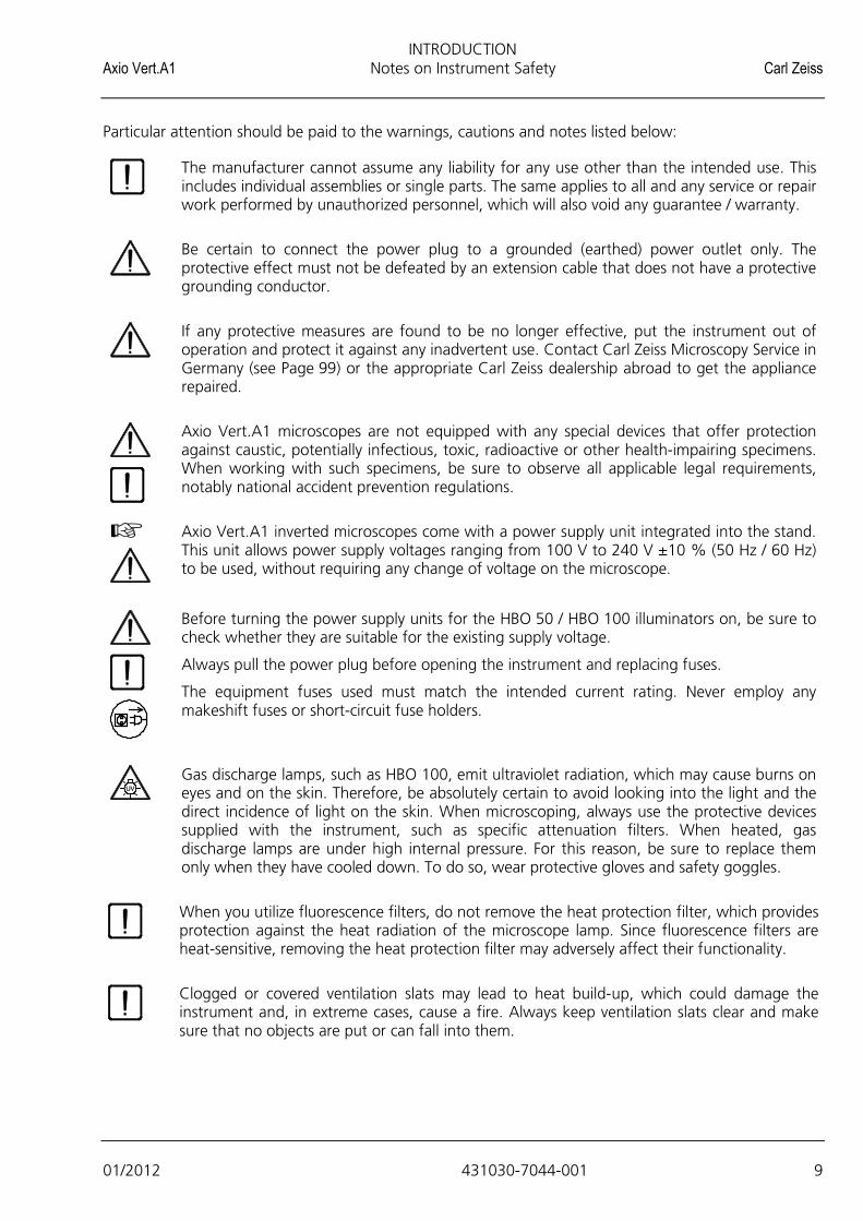
Particular attention should be paid to the warnings, cautions and notes listed below:
The manufacturer cannot assume any liability for any use other than the intended use. This includes individual assemblies or single parts. The same applies to all and any service or repair work performed by unauthorized personnel, which will also void any guarantee / warranty.
Be certain to connect the power plug to a grounded (earthed) power outlet only. The protective effect must not be defeated by an extension cable that does not have a protective grounding conductor.
If any protective measures are found to be no longer effective, put the instrument out of operation and protect it against any inadvertent use. Contact Carl Zeiss Microscopy Service in Germany (see Page 99) or the appropriate Carl Zeiss dealership abroad to get the appliance repaired.
Axio Vert.A1 microscopes are not equipped with any special devices that offer protection against caustic, potentially infectious, toxic, radioactive or other health-impairing specimens. When working with such specimens, be sure to observe all applicable legal requirements, notably national accident prevention regulations.
Axio Vert.A1 inverted microscopes come with a power supply unit integrated into the stand. This unit allows power supply voltages ranging from 100 V to 240 V ±10 % (50 Hz / 60 Hz) to be used, without requiring any change of voltage on the microscope.
Before turning the power supply units for the HBO 50 / HBO 100 illuminators on, be sure to check whether they are suitable for the existing supply voltage.
Always pull the power plug before opening the instrument and replacing fuses.
The equipment fuses used must match the intended current rating. Never employ any makeshift fuses or short-circuit fuse holders.
Gas discharge lamps, such as HBO 100, emit ultraviolet radiation, which may cause burns on eyes and on the skin. Therefore, be absolutely certain to avoid looking into the light and the direct incidence of light on the skin. When microscoping, always use the protective devices supplied with the instrument, such as specific attenuation filters. When heated, gas discharge lamps are under high internal pressure. For this reason, be sure to replace them only when they have cooled down. To do so, wear protective gloves and safety goggles.
When you utilize fluorescence filters, do not remove the heat protection filter, which provides protection against the heat radiation of the microscope lamp. Since fluorescence filters are heat-sensitive, removing the heat protection filter may adversely affect their functionality.
Clogged or covered ventilation slats may lead to heat build-up, which could damage the instrument and, in extreme cases, cause a fire. Always keep ventilation slats clear and make sure that no objects are put or can fall into them.
INTRODUCTION Carl Zeiss Notes on Instrument Safety Axio Vert.A1
10 431030-7044-001 01/2012
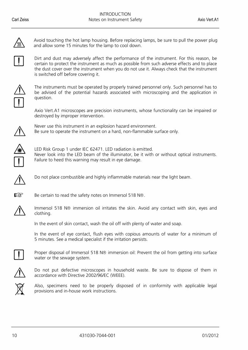
Avoid touching the hot lamp housing. Before replacing lamps, be sure to pull the power plug and allow some 15 minutes for the lamp to cool down.
Dirt and dust may adversely affect the performance of the instrument. For this reason, be certain to protect the instrument as much as possible from such adverse effects and to place the dust cover over the instrument when you do not use it. Always check that the instrument is switched off before covering it.
The instruments must be operated by properly trained personnel only. Such personnel has to be advised of the potential hazards associated with microscoping and the application in question.
Axio Vert.A1 microscopes are precision instruments, whose functionality can be impaired or destroyed by improper intervention.
Never use this instrument in an explosion hazard environment. Be sure to operate the instrument on a hard, non-flammable surface only.
LED Risk Group 1 under IEC 62471. LED radiation is emitted. Never look into the LED beam of the illuminator, be it with or without optical instruments. Failure to heed this warning may result in eye damage.
Do not place combustible and highly inflammable materials near the light beam.
Be certain to read the safety notes on Immersol 518 N.
Immersol 518 N immersion oil irritates the skin. Avoid any contact with skin, eyes and clothing.
In the event of skin contact, wash the oil off with plenty of water and soap.
In the event of eye contact, flush eyes with copious amounts of water for a minimum of 5 minutes. See a medical specialist if the irritation persists.
Proper disposal of Immersol 518 N immersion oil: Prevent the oil from getting into surface water or the sewage system.
Do not put defective microscopes in household waste. Be sure to dispose of them in accordance with Directive 2002/96/EC (WEEE).
Also, specimens need to be properly disposed of in conformity with applicable legal provisions and in-house work instructions.
INTRODUCTION Axio Vert.A1 Nameplate and Warning Labels Attached to the Microscope and to Components Carl Zeiss
01/2012 431030-7044-001 11
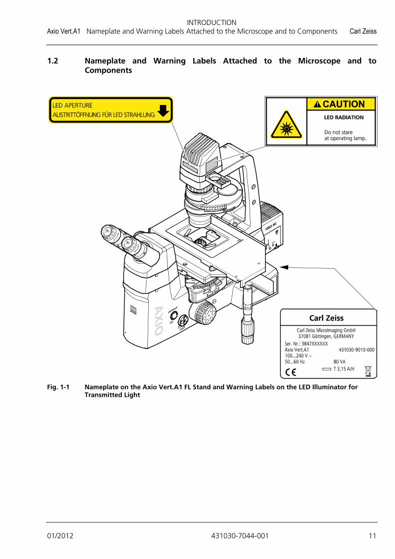
1.2 Nameplate and Warning Labels Attached to the Microscope and to Components
Fig. 1-1 Nameplate on the Axio Vert.A1 FL Stand and Warning Labels on the LED Illuminator for
Transmitted Light

INTRODUCTION Carl Zeiss Nameplate and Warning Labels Attached to the Microscope and to Components Axio Vert.A1
12 431030-7044-001 01/2012
Fig. 1-2 Warning Labels on the Axio Vert.A1 FL-LED Stand
Fig. 1-3 Warning Labels on the VIS-LED (423053-9030-000)

INTRODUCTION Axio Vert.A1 Notes on Warranty Carl Zeiss
01/2012 431030-7044-001 13
1.3 Notes on Warranty
The manufacturer of the instrument warrants the device to be free from defects in materials and workmanship at the time of its delivery. Any defect must be reported without delay, and every effort is to be made to minimize damage. If such a defect is reported, the manufacturer of the instrument is obligated to correct the defect, at his option, by repairing the instrument or delivering an instrument that is free of defects. No warranty will be provided in the event of defects caused by natural wear and tear (in particular, defective consumables) and improper operation.
The manufacturer of the instrument will not be liable for any damage attributable to operation errors, negligence or tampering with the instrument. This is especially true for damage caused by the removal or replacement of components or the use of accessories made by other manufacturers. Acts of this kind will void all and any warranty.
With the exception of the activities listed in this Operating Manual, no maintenance and repair work may be performed on the microscopes. Repairs may only be carried out by Zeiss Customer Service or by personnel specially authorized by it. Should the instrument malfunction, please contact Carl Zeiss Microscopy Service in Germany first (see Page 99) or get in touch with your Carl Zeiss dealer abroad.

INTRODUCTION Carl Zeiss Types of Stands (General Views) Axio Vert.A1
14 431030-7044-001 01/2012
1.4 Types of Stands (General Views)

INSTRUMENT DESCRIPTION Axio Vert.A1 Name, Intended Use Carl Zeiss
01/2012 431030-7044-001 15
2 INSTRUMENT DESCRIPTION
2.1 Name, Intended Use
Manufacturer’s product name: Axio Vert.A1 Inverted Transmitted Light Microscope Axio Vert.A1 microscopes take the following place within the inverted transmitted light microscope family:
Laboratory Microscopes Research Microscopes
− Primo Vert
− Axio Vert.A1
− Axio Observer.A1 / .D1 / .Z1
Axio Vert.A1 microscopes are standardized light microscopes of inverted design (inverted microscopes) for universal use.
The three BioMed stands (A1, A1 FL-LED and A1 FL) have been designed for the performance of biological and medical analyses of plant and animal cells and/or tissue samples, as well as for samples taken from the human body. Examples of observation and culture vessels: Culture bottles, Petri dishes and microtiter plates.
The microscopes are typically used
− for medical examinations in laboratories, hospitals and medical practices,
− in science and research (colleges, universities),
− for industrial applications (pharmacology, food technology),
− for the examination of blood and tissue samples from the human body.
The material stand (MAT) is employed in all the fields of research-related and industrial microscopy. Thanks to its virtually unrestricted specimen space, this stand permits an unlimited use of conventional specimens. In other words, it facilitates the examination of large specimens, workpieces, etc.
When it comes to the examination of materials, the microscopes are typically used in
− metallographic labs,
− the motor vehicle industry,
− microsystems engineering,
− geoscience institutes and
− the exploration industry.
INSTRUMENT DESCRIPTION Carl Zeiss Instrument Description and Main Features Axio Vert.A1
16 431030-7044-001 01/2012
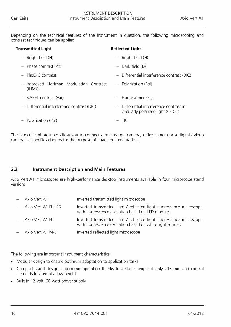
Depending on the technical features of the instrument in question, the following microscoping and contrast techniques can be applied:
Transmitted Light Reflected Light
− Bright field (H) − Bright field (H)
− Phase contrast (Ph) − Dark field (D)
− PlasDIC contrast − Differential interference contrast (DIC)
− Improved Hoffman Modulation Contrast (iHMC)
− Polarization (Pol)
− VAREL contrast (var) − Fluorescence (FL)
− Differential interference contrast (DIC) − Differential interference contrast in circularly polarized light (C-DIC)
− Polarization (Pol) − TIC
The binocular phototubes allow you to connect a microscope camera, reflex camera or a digital / video camera via specific adapters for the purpose of image documentation.
2.2 Instrument Description and Main Features
Axio Vert.A1 microscopes are high-performance desktop instruments available in four microscope stand versions.
− Axio Vert.A1 Inverted transmitted light microscope
− Axio Vert.A1 FL-LED Inverted transmitted light / reflected light fluorescence microscope, with fluorescence excitation based on LED modules
− Axio Vert.A1 FL Inverted transmitted light / reflected light fluorescence microscope, with fluorescence excitation based on white light sources
− Axio Vert.A1 MAT Inverted reflected light microscope
The following are important instrument characteristics:
• Modular design to ensure optimum adaptation to application tasks
• Compact stand design, ergonomic operation thanks to a stage height of only 215 mm and control elements located at a low height
• Built-in 12-volt, 60-watt power supply

INSTRUMENT DESCRIPTION Axio Vert.A1 Instrument Description and Main Features Carl Zeiss
01/2012 431030-7044-001 17
• Infinitely variable light intensity
• True height and image rendition
• Field of view: 23 mm
• Exchangeable condensers for contrast sliders or with built-in modular disk, 0.55, 0.4 or 0.3 numerical apertures
• VAREL (variable relief contrast) with continuous transition from oblique bright field to one-sided dark field, contrasting of microtiter plate cavities up to the edge
• PlasDIC for relief-like rendition, notably of thick objects, with variable contrasting from oblique bright field to one-sided dark field; contrasting of microtiter plate cavities up to the edge
• Ph - the classical phase contrast according to Zernicke
• iHMC for relief-like rendition with variable contrasting; contrasting of microtiter plate cavities up to the edge
• DIC - differential interference contrast
• Reflected light fluorescence contrast as an alternative to or simultaneous with transmitted light contrasts
• It is possible to adapt reflected light fluorescence to the application task concerned by changing the fluorescence filter combination (reflector module FL).
• Flexible use of the stage thanks to an attachable object guide
• Use of different mounting frames or inserts for various types of culture vessels
• Optional mechanical stage or scanning stage
• Standardized customer interfaces for objectives, eyepieces, illuminators, condensers and tubes
• Photo / video port on the phototube and intermediate phototube for reflex cameras, compact digital cameras, digital cameras, such as AxioCam and video cameras
• Viewing height adjustment
• Additional intermediate phototube
• Reflected light dark field channel for all objectives (Applies to Axio Vert.A1 MAT only.)
• Coded objective nosepiece (Applies to Axio Vert.A1 MAT only.)
• Light manager function (Applies to Axio Vert.A1 MAT only.)
• USB interface to Axio Vision Software (Applies to Axio Vert.A1 MAT only.)
INSTRUMENT DESCRIPTION Carl Zeiss System Overview Axio Vert.A1
18 431030-7044-001 01/2012
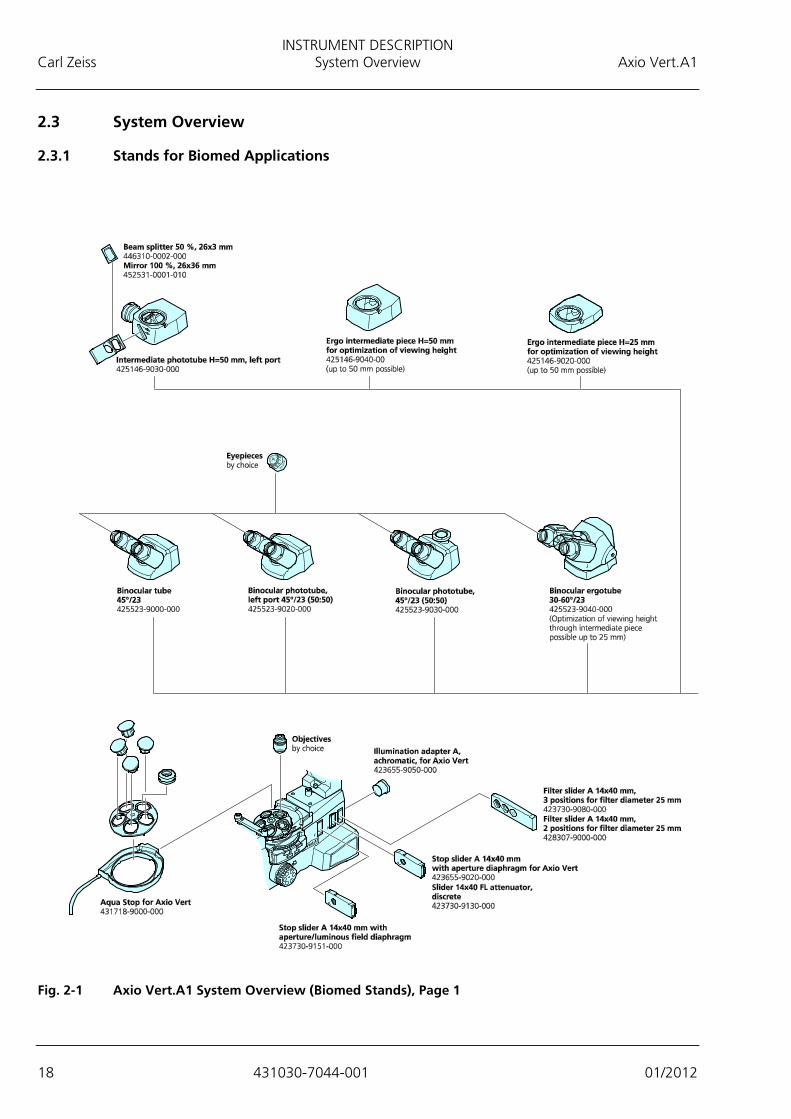
2.3 System Overview
2.3.1 Stands for Biomed Applications
Fig. 2-1 Axio Vert.A1 System Overview (Biomed Stands), Page 1

INSTRUMENT DESCRIPTION Axio Vert.A1 System Overview Carl Zeiss
01/2012 431030-7044-001 19
Fig. 2-2 Axio Vert.A1 System Overview (Biomed Stands), Page 2

INSTRUMENT DESCRIPTION Carl Zeiss System Overview Axio Vert.A1
20 431030-7044-001 01/2012
Fig. 2-3 Axio Vert.A1 System Overview (Biomed Stands), Page 3

INSTRUMENT DESCRIPTION Axio Vert.A1 System Overview Carl Zeiss
01/2012 431030-7044-001 21
2.3.2 Stand for Material Applications
Fig. 2-4 Axio Vert.A1 System Overview (Material Stand), Page 1

INSTRUMENT DESCRIPTION Carl Zeiss System Overview Axio Vert.A1
22 431030-7044-001 01/2012
Fig. 2-5 Axio Vert.A1 System Overview (Material Stand), Page 2

INSTRUMENT DESCRIPTION Axio Vert.A1 Technical Specifications Carl Zeiss
01/2012 431030-7044-001 23
2.4 Technical Specifications
Dimensions
Dimensions (Width x Depth x Height) Axio Vert.A1 ....................................................................................... 235 mm* x 560 mm x 560 mm Axio Vert.A1 FL or A1 FL-LED ........................................................... 235 mm* x 560 mm*** x 560 mm Axio Vert.A1 MAT ......................................................................... 220 mm** x 560 mm*** x 355 mm * Equipped with fixed stage without object guide ** Without mechanical stage; with 40 mm x 40 mm mechanical stage: Width: 295 mm *** Depth: 560 mm, without external (reflected light) illuminators The above measurements are maximum dimensions, which include space for cable and connector outlets. The depth was measured at an interpupillary distance of 62 mm, with binocular parts lowered. Transmitted light LED illumination results in the height of transmitted light stands being reduced by 29 mm.
Weight****
Axio Vert.A1 Stand ................................................................................................................ 10.5 kg Axio Vert.A1 FL-LED Stand ...................................................................................................... 12.3 kg Axio Vert.A1 FL Stand ............................................................................................................ 11.7 kg Axio Vert.A1 MAT Stand ........................................................................................................ 10.3 kg **** Actual weight of the stand without any attachments, such as stages, tubes, etc.
Ambient Conditions
Shipping (in Packaging): Permissible ambient temperature ............................................................................... -40 °C to +70 °C
Storage: Permissible ambient temperature ................................................................................ +5 °C to +40 °C Maximum permissible humidity (without condensation) ................................................. 75 % at 35 °C
Operation: Permissible ambient temperature ................................................................................ +5 °C to +35 °C Maximum permissible humidity (without condensation) ............................................... 75 % at +35 °C Maximum altitude for use ...................................................................................................... 2,000 m Atmospheric pressure ......................................................................................... 800 hPa to 1,060 hPa Pollution degree ............................................................................................................................... 2
Operating Specifications
Operating environment ................................................................................................... Enclosed spaces Safety class .............................................................................................................................................I Degree of protection ....................................................................................................................... IP 20 Electrical safety ..................................................................As specified in DIN EN 61010-1 (IEC 61010-1),
taking into account CSA and UL regulations Overvoltage category ............................................................................................................................. II Radio interference suppression .......................................................... As specified in EN 55011 for Class B Noise immunity ....................................................................................... As specified in DIN EN 61326-1 AC line voltage range ................................................................................. 100 VAC to 240 VAC ±10 % Line frequency .................................................................................................................. 50 Hz to 60 Hz Maximum power consumption of internal power supply unit ......................................................... 80 VA

INSTRUMENT DESCRIPTION Carl Zeiss Technical Specifications Axio Vert.A1
24 431030-7044-001 01/2012
Power Supply Unit for HBO 100 Operating environment ................................................................................................... Enclosed spaces Safety class ............................................................................................................................................ I Degree of protection ....................................................................................................................... IP 20 Line voltage ........................................................................................................... 100 VAC ... 240 VAC Line frequency.................................................................................................................... 50 Hz / 60 Hz Power consumption when operated with HBO 100 ...................................................................... 155 VA Power Supply Unit for HBO 50
Operating environment ............................................................................................... Enclosed spaces Safety class ........................................................................................................................................ I Degree of protection ................................................................................................................... IP 20 AC line voltage range ....................................................................................... 100 VAC ... 240 VAC Line frequency ............................................................................................................... 50 Hz / 60 Hz Maximum power consumption when operated with HBO 50 ..................................................... 90 VA
Power Supply Unit for HAL 100
Line voltage ......................................................... 100 VAC to 127 VAC, 200 VAC to 240 VAC ±10 % ................................................................................................. No line voltage change-over required. Line frequency ............................................................................................................... 50 Hz / 60 Hz Maximum power consumption when operated with HAL 100 .................................................. 280 VA
Axio Vert.A1 Fluorescence Reflected Light LED Illumination
Reflected light fluorescence illumination via exchangeable LED modules Selectable wavelengths ........................ 365 nm, 385 nm, 420 nm, 445 nm, 455 nm, 470 nm, 505 nm,
530 nm, 590 nm, 615 nm, 625 nm .................................................................................................. or neutral white (540 nm to 580 nm) LED classification .................................................... LED risk group 1 according to DIN EN 62471:2009
Axio Vert.A1 Transmitted Light LED Illumination
Wavelength ................................................................................. 400 nm to 700 nm, peak at 460 nm LED classification .................................................... LED risk group 1 according to DIN EN 62471:2009
Fuses According to IEC 127
Axio Vert.A1 microscope stand ................................................................. T 3.15 A/H, 5 mm x 20 mm Power supply unit for HBO 50 ................................................................................................. T 1.6 A Power supply unit for HBO 100 .................................................................. T 2.0 A/H, 5 mm x 20 mm Power supply unit for HAL 100 ................................................................... T 5.0 A/H, 5 mm x 20 mm

INSTRUMENT DESCRIPTION Axio Vert.A1 Technical Specifications Carl Zeiss
01/2012 431030-7044-001 25
Light Sources
Halogen illuminator (transmitted light) Maximum power consumption .................................................................................................. 37 W Light source adjustability .............................................................. Infinitely adjustable, ≤ 1.5 V to 12 V
LED illuminator (transmitted light) Maximum power consumption .................................................................................................... 3 W Light source adjustability .............................................................. Infinitely adjustable, ≤ 1.5 V to 12 V
HAL 100 halogen illuminator (reflected light) with external power supply unit Maximum power consumption of external power supply unit .................................................... 100 W Light source adjustability via external power supply unit .................................................................................................. Infinitely adjustable from 0 V to 12 V
HXP 120 C illuminator Line voltage ..................................................................................................... 100 V to 240 V ±10 % Maximum power consumption ............................................................................................... 210 VA
Mercury vapor lamp for fluorescence Maximum power consumption of power supply unit for HBO 50 ................................................ 90 VA Maximum power consumption of power supply unit for HBO 100 ............................................ 155 VA
VIS-LED (reflected light) LED classification ..................................................... LED risk group 1 according to DIN EN 62471:2009 Wavelength ................................................................................. 400 nm to 700 nm, peak at 460 nm Power supply ..................................................................Via microscope or external power supply unit Voltage .................................................................................................................... 0 VDC to 12 VDC Maximum power consumption ................................................................................................... 20 W
Optomechanical Specifications
Stand with objective focusing Coarse focus ........................................................................................................... 4 mm per rotation Fine focus ............................................................................................................ 0.4 mm per rotation Total focusing range ................................................................................................................13 mm
Objectives...................................................................................... Set of ICS objectives with M27 thread Change of objectives ....................................................................... Manual, via a five-position nosepiece Eyepieces .......................................................................................................... Plug-in diameter: 30 mm
.............................................................................................. Use of eyepieces up to field number 23 P&C reflector turret ............................................................................................ Capable of holding four
................................................................................................. freely loadable P&C reflector modules Change of reflector ..................................................................................................................... Manual LED modules .......................................................... Four positions freely loadable on Axio Vert.A1 FL-LED
INSTRUMENT DESCRIPTION Carl Zeiss Operation and Functional Elements on the Microscope Axio Vert.A1
26 431030-7044-001 01/2012
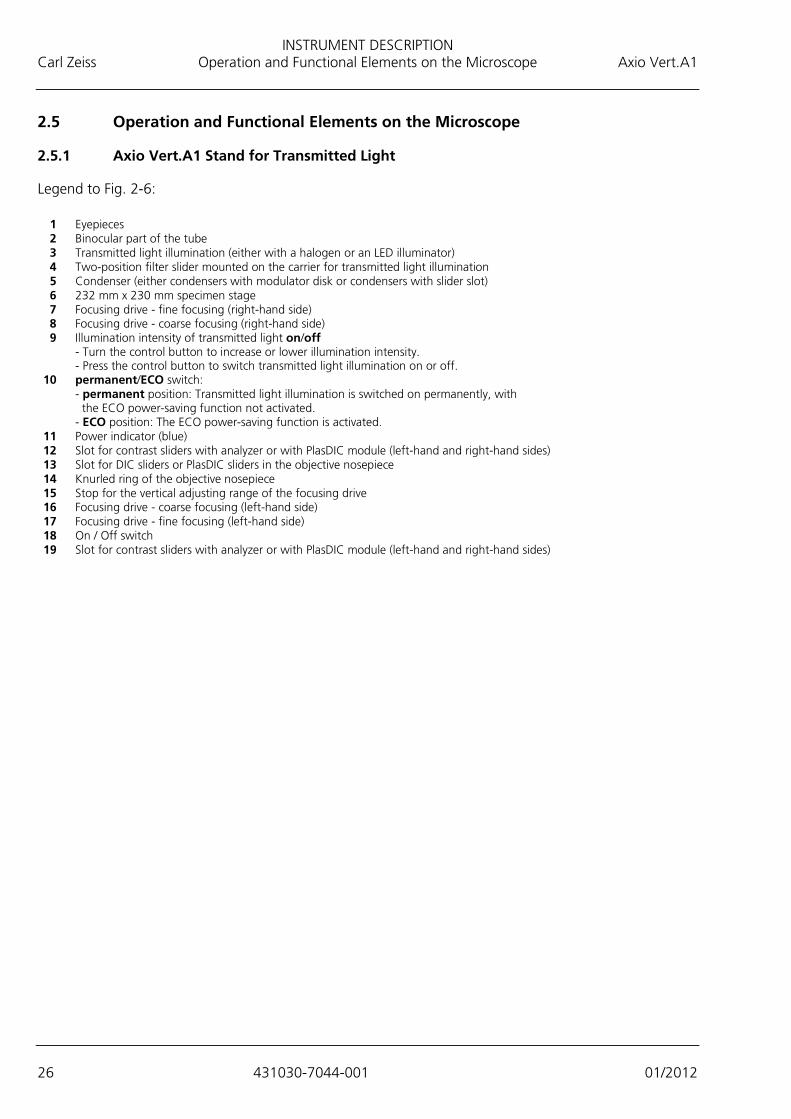
2.5 Operation and Functional Elements on the Microscope
2.5.1 Axio Vert.A1 Stand for Transmitted Light
Legend to Fig. 2-6:
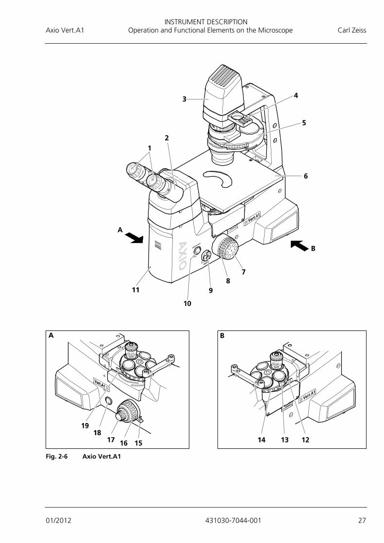
1 Eyepieces 2 Binocular part of the tube 3 Transmitted light illumination (either with a halogen or an LED illuminator) 4 Two-position filter slider mounted on the carrier for transmitted light illumination 5 Condenser (either condensers with modulator disk or condensers with slider slot) 6 232 mm x 230 mm specimen stage 7 Focusing drive - fine focusing (right-hand side) 8 Focusing drive - coarse focusing (right-hand side) 9 Illumination intensity of transmitted light on/off - Turn the control button to increase or lower illumination intensity. - Press the control button to switch transmitted light illumination on or off. 10 permanent/ECO switch: - permanent position: Transmitted light illumination is switched on permanently, with the ECO power-saving function not activated. - ECO position: The ECO power-saving function is activated. 11 Power indicator (blue) 12 Slot for contrast sliders with analyzer or with PlasDIC module (left-hand and right-hand sides) 13 Slot for DIC sliders or PlasDIC sliders in the objective nosepiece 14 Knurled ring of the objective nosepiece 15 Stop for the vertical adjusting range of the focusing drive 16 Focusing drive - coarse focusing (left-hand side) 17 Focusing drive - fine focusing (left-hand side) 18 On / Off switch 19 Slot for contrast sliders with analyzer or with PlasDIC module (left-hand and right-hand sides)
INSTRUMENT DESCRIPTION Axio Vert.A1 Operation and Functional Elements on the Microscope Carl Zeiss
01/2012 431030-7044-001 27
Fig. 2-6 Axio Vert.A1
INSTRUMENT DESCRIPTION Carl Zeiss Operation and Functional Elements on the Microscope Axio Vert.A1
28 431030-7044-001 01/2012
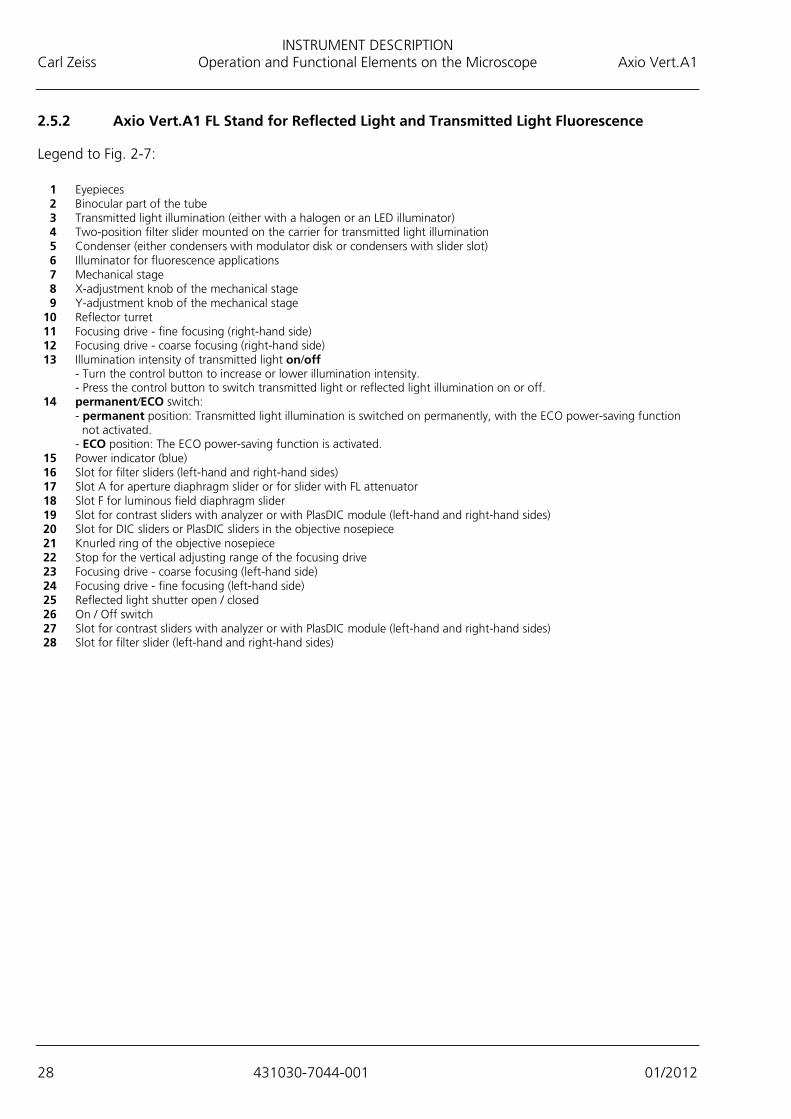
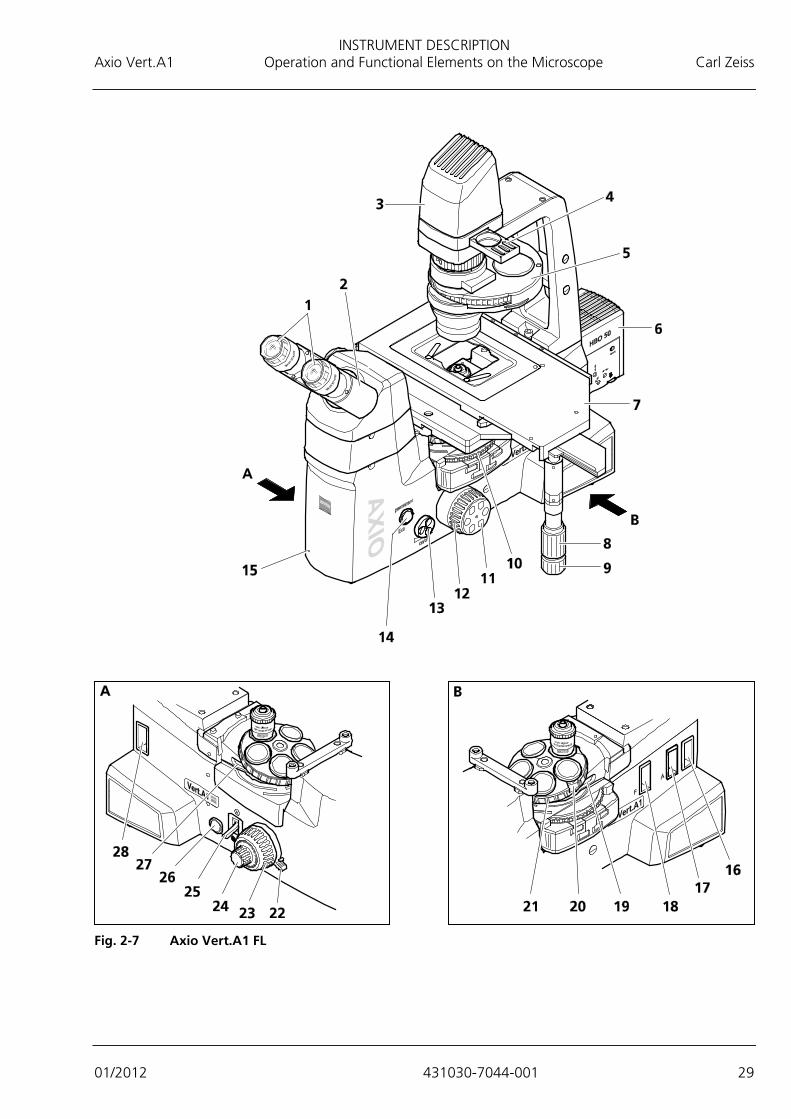
2.5.2 Axio Vert.A1 FL Stand for Reflected Light and Transmitted Light Fluorescence
Legend to Fig. 2-7:
1 Eyepieces 2 Binocular part of the tube 3 Transmitted light illumination (either with a halogen or an LED illuminator) 4 Two-position filter slider mounted on the carrier for transmitted light illumination 5 Condenser (either condensers with modulator disk or condensers with slider slot) 6 Illuminator for fluorescence applications 7 Mechanical stage 8 X-adjustment knob of the mechanical stage 9 Y-adjustment knob of the mechanical stage 10 Reflector turret 11 Focusing drive - fine focusing (right-hand side) 12 Focusing drive - coarse focusing (right-hand side) 13 Illumination intensity of transmitted light on/off - Turn the control button to increase or lower illumination intensity. - Press the control button to switch transmitted light or reflected light illumination on or off. 14 permanent/ECO switch: - permanent position: Transmitted light illumination is switched on permanently, with the ECO power-saving function not activated. - ECO position: The ECO power-saving function is activated. 15 Power indicator (blue) 16 Slot for filter sliders (left-hand and right-hand sides) 17 Slot A for aperture diaphragm slider or for slider with FL attenuator 18 Slot F for luminous field diaphragm slider 19 Slot for contrast sliders with analyzer or with PlasDIC module (left-hand and right-hand sides) 20 Slot for DIC sliders or PlasDIC sliders in the objective nosepiece 21 Knurled ring of the objective nosepiece 22 Stop for the vertical adjusting range of the focusing drive 23 Focusing drive - coarse focusing (left-hand side) 24 Focusing drive - fine focusing (left-hand side) 25 Reflected light shutter open / closed 26 On / Off switch 27 Slot for contrast sliders with analyzer or with PlasDIC module (left-hand and right-hand sides) 28 Slot for filter slider (left-hand and right-hand sides)
INSTRUMENT DESCRIPTION Axio Vert.A1 Operation and Functional Elements on the Microscope Carl Zeiss
01/2012 431030-7044-001 29
Fig. 2-7 Axio Vert.A1 FL
INSTRUMENT DESCRIPTION Carl Zeiss Operation and Functional Elements on the Microscope Axio Vert.A1
30 431030-7044-001 01/2012
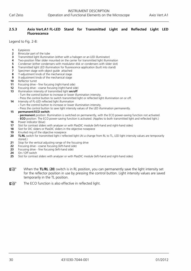
2.5.3 Axio Vert.A1 FL-LED Stand for Transmitted Light and Reflected Light LED Fluorescence
Legend to Fig. 2-8:
1 Eyepieces 2 Binocular part of the tube 3 Transmitted light illumination (either with a halogen or an LED illuminator) 4 Two-position filter slider mounted on the carrier for transmitted light illumination 5 Condenser (either condensers with modulator disk or condensers with slider slot) 6 Transmitted light LED illumination for fluorescence application (built into stand) 7 Specimen stage with object guide attached 8 Y-adjustment knob of the mechanical stage 9 X-adjustment knob of the mechanical stage 10 Reflector turret 11 Focusing drive - fine focusing (right-hand side) 12 Focusing drive - coarse focusing (right-hand side) 13 Illumination intensity of transmitted light on/off - Turn the control button to increase or lower illumination intensity. - Press the control button to switch transmitted light or reflected light illumination on or off. 14 Intensity of FL-LED reflected light illumination - Turn the control button to increase or lower illumination intensity. - Press the control button to save light intensity values of the LED illumination permanently. 15 permanent/ECO switch: - permanent position: Illumination is switched on permanently, with the ECO power-saving function not activated. - ECO position: The ECO power-saving function is activated. (Applies to both transmitted light and reflected light.) 16 Power indicator (blue) 17 Slot for contrast sliders with analyzer or with PlasDIC module (left-hand and right-hand sides) 18 Slot for DIC sliders or PlasDIC sliders in the objective nosepiece 19 Knurled ring of the objective nosepiece 20 TL/RL switch for transmitted light / reflected light (At a change from RL to TL, LED light intensity values are temporarily stored.) 21 Stop for the vertical adjusting range of the focusing drive 22 Focusing drive - coarse focusing (left-hand side) 23 Focusing drive - fine focusing (left-hand side) 24 On / Off switch 25 Slot for contrast sliders with analyzer or with PlasDIC module (left-hand and right-hand sides)
When the TL/RL (20) switch is in RL position, you can permanently save the light intensity set for the reflector position in use by pressing the control button. Light intensity values are saved temporarily in the TL position.
The ECO function is also effective in reflected light.

INSTRUMENT DESCRIPTION Axio Vert.A1 Operation and Functional Elements on the Microscope Carl Zeiss
01/2012 431030-7044-001 31
Fig. 2-8 Axio Vert.A1 FL-LED

INSTRUMENT DESCRIPTION Carl Zeiss Operation and Functional Elements on the Microscope Axio Vert.A1
32 431030-7044-001 01/2012
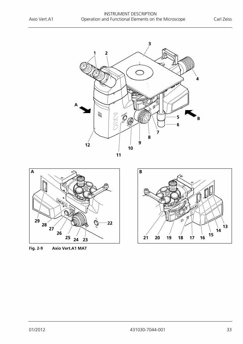
2.5.4 Axio Vert.A1 MAT Stand for Reflected Light (Material)
Legend to Fig. 2-9:
1 Eyepieces 2 Binocular part of the tube 3 40 mm x 40 mm mechanical stage for reflected light 4 Reflected light illumination (either VIS-LED or HAL 100) 5 Y-adjustment knob of the mechanical stage 6 X-adjustment knob of the mechanical stage 7 Reflector turret 8 Focusing drive - fine focusing (right-hand side) 9 Focusing drive - coarse focusing (right-hand side) 10 Intensity of reflected light illumination on/off (or for transmitted light illumination if installed) - Turn the control button to increase or lower illumination intensity. - Press the control button to switch transmitted light or reflected light illumination on or off. 11 permanent/ECO switch: - permanent position: Transmitted light illumination is switched on permanently, with the ECO power-saving function not activated. - ECO position: The ECO power-saving function is activated. 12 Power indicator (blue) 13 Slot for filter sliders (left-hand and right-hand sides) 14 Slot A for aperture diaphragm slider 15 Slot for polarization slider A , rotatable 90 degrees 16 Slot F for luminous field diaphragm slider 17 LM Set button 18 USB port 19 Slot for TIC, C-DIC sliders 20 Slot for DIC sliders in the objective nosepiece 21 Knurled ring of the objective nosepiece 22 TL/RL switch for transmitted light / reflected light (if optional transmitted light illumination is installed) 23 Stop for the vertical adjusting range of the focusing drive 24 Focusing drive - coarse focusing (left-hand side) 25 Focusing drive - fine focusing (left-hand side) 26 Diffusion disk for reflected light 27 On / Off switch 28 Slot for analyzer slider, rotatable 90 degrees (left-hand and right-hand sides) 29 Slot for filter sliders (left-hand and right-hand sides)
If the optional transmitted light illumination is mounted, turning the on/off control button will adjust illumination intensity for reflected light or transmitted light, depending on the type of illumination that has been activated via the TL/RL switch.
INSTRUMENT DESCRIPTION Axio Vert.A1 Operation and Functional Elements on the Microscope Carl Zeiss
01/2012 431030-7044-001 33
Fig. 2-9 Axio Vert.A1 MAT
INSTRUMENT DESCRIPTION Carl Zeiss Operation and Functional Elements of Optional Components Axio Vert.A1
34 431030-7044-001 01/2012
2.6 Operation and Functional Elements of Optional Components
2.6.1 Phototube and Intermediate Phototube
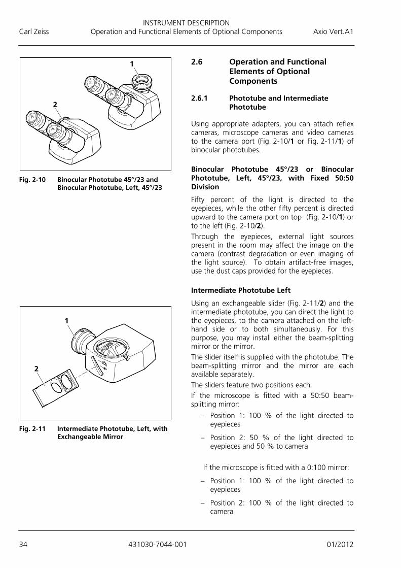
Using appropriate adapters, you can attach reflex cameras, microscope cameras and video cameras to the camera port (Fig. 2-10/1 or Fig. 2-11/1) of binocular phototubes. Binocular Phototube 45°/23 or Binocular Phototube, Left, 45°/23, with Fixed 50:50 Division
Fifty percent of the light is directed to the eyepieces, while the other fifty percent is directed upward to the camera port on top (Fig. 2-10/1) or to the left (Fig. 2-10/2). Through the eyepieces, external light sources present in the room may affect the image on the camera (contrast degradation or even imaging of the light source). To obtain artifact-free images, use the dust caps provided for the eyepieces. Intermediate Phototube Left
Using an exchangeable slider (Fig. 2-11/2) and the intermediate phototube, you can direct the light to the eyepieces, to the camera attached on the left-hand side or to both simultaneously. For this purpose, you may install either the beam-splitting mirror or the mirror. The slider itself is supplied with the phototube. The beam-splitting mirror and the mirror are each available separately. The sliders feature two positions each. If the microscope is fitted with a 50:50 beam-splitting mirror:
− Position 1: 100 % of the light directed to eyepieces
− Position 2: 50 % of the light directed to eyepieces and 50 % to camera
If the microscope is fitted with a 0:100 mirror:
− Position 1: 100 % of the light directed to eyepieces
− Position 2: 100 % of the light directed to camera
Fig. 2-10 Binocular Phototube 45°/23 and
Binocular Phototube, Left, 45°/23
Fig. 2-11 Intermediate Phototube, Left, with
Exchangeable Mirror
INSTRUMENT DESCRIPTION Axio Vert.A1 Operation and Functional Elements of Optional Components Carl Zeiss
01/2012 431030-7044-001 35
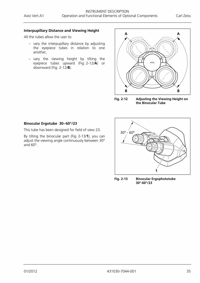
Interpupillary Distance and Viewing Height
All the tubes allow the user to
− vary the interpupillary distance by adjusting the eyepiece tubes in relation to one another,
− vary the viewing height by tilting the eyepiece tubes upward (Fig. 2-12/A) or downward (Fig. 2-12/B).
Binocular Ergotube 30--60°/23
This tube has been designed for field of view 23.
By tilting the binocular part (Fig. 2-13/1), you can adjust the viewing angle continuously between 30° and 60°.
Fig. 2-12 Adjusting the Viewing Height on
the Binocular Tube
Fig. 2-13 Binocular Ergophototube
30°-60°/23

INSTRUMENT DESCRIPTION Carl Zeiss Operation and Functional Elements of Optional Components Axio Vert.A1
36 431030-7044-001 01/2012
2.6.2 Microscope Stages
Mechanical Stage 130x85 R/L with Short Coaxial Drive
− Mechanical stage (Fig. 2-14/1) designed to hold and position specimens in mounting frame K (Fig. 2-14/4)
− To insert the mounting frame, put the mounting frame corner marked with a red dot into the recess of the mechanical stage. Press the frame diagonally onto the springs and downward into the recess. In so doing, make sure that the mounting frame is correctly seated.
− Drive knobs for X (Fig. 2-14/2) and Y adjustment (Fig. 2-14/3)
− The mechanical stage with coaxial drive can be fitted on the right-hand or left-hand side of the stand.
Specimen Stage 232x230 to Which an M 130x85 mm Object Guide Can Be Attached
− Specimen stage (Fig. 2-15/5) designed to hold and position specimens for transmitted light and reflected light
− With the object guide (Fig. 2-15/2) attached, this stage is capable of holding specimens in mounting frame Flex M (Fig. 2-15/1) and mounting frame inserts for Petri dishes or object slides and chambers, as well as accommodating mounting frame M from the current product line.
− Coaxial drive (Fig. 2-15/3) designed to position the mounting frame in XY
− To attach the object guide to the right-hand or left-hand side of the stage, set the guide onto the stage from below and secure it firmly in place with the screws supplied (Fig. 2-15/4).
Mechanical Stage 40x40 for Reflected Light
− Mechanical stage (Fig. 2-16/1) designed to hold and position reflected light specimens, equipped with coaxial drive (Fig. 2-16/2) for XY adjustment
− The mechanical stage with coaxial drive can be fitted on the right-hand or left-hand side of the stand.
− Suitable for use with d = 115 mm stage inserts (Fig. 2-16/3).
Fig. 2-14 Mechanical Stage 130x85 R with
Mounting Frame
Fig. 2-15 Specimen Stage 232x230 and
Object guide M 130x85 mm
Fig. 2-16 Mechanical Stage 40x40 for
Reflected Light with Stage Insert

INSTRUMENT DESCRIPTION Axio Vert.A1 Operation and Functional Elements of Optional Components Carl Zeiss
01/2012 431030-7044-001 37
2.6.3 Condensers
To allow a quick condenser change, all the condensers come with a special connection plate for bayonet mounting.
The condenser can be rotated in its mount in 90-degree steps (after the bayonet mount has been loosened and subsequently tightened). (See Section 3.1.7.)
LD Condensers 0.3 and 0.4 for Sliders
− Condenser equipped with an adjustable aperture diaphragm (Fig. 2-17/4) for sliders with fixed phase stop Ph1/0.3 (Fig. 2-17/1) or Ph1/0.4; slider Ph/PlasDIC, H, Ph/PlasDIC (Fig. 2-17/2) or slider Ph/PlasDIC, H, Var (Fig. 2-17/3)
− The sliders can be inserted from the right or left (or from the front or the back).
− The center position of the slider is provided with a neutral density or attenuation filter to guard against glare.
− Depending on the type of slider employed, the condenser can be utilized for the bright field, phase contrast, PlasDIC or VAREL methods.
For optical reasons, the Ph/PlasDIC, H, Var slider is suitable for condenser 0.4 only.
LD Condenser 0.4 H Ph PlasDIC DIC iHMC
− Condenser with an adjustable aperture diaphragm (Fig. 2-18/1) for the bright field position (position 1 of the modulator disk, while the aperture diaphragm is completely open for all the other positions of the modulator disk)
− Five-position modulator disk (Fig. 2-18/3) and slot for polarizer slider (Fig. 2-18/2)
− Depending on the phase stops or slit diaphragms or the condenser modules employed, the condenser can be utilized for the bright field, phase contrast, DIC, PlasDIC or iHMC methods.
− Spaces for stickers (Fig. 2-18/4) showing the designations of the slit diaphragms, phase stops or condenser modules installed
Fig. 2-17 LD Condensers 0.3 and 0.4 for
Sliders
Fig. 2-18 LD Condenser 0.4 for
H Ph PlasDIC DIC iHMC with Insertable Polarizer Slider DL, Rotatable 90 Degrees
INSTRUMENT DESCRIPTION Carl Zeiss Operation and Functional Elements of Optional Components Axio Vert.A1
38 431030-7044-001 01/2012
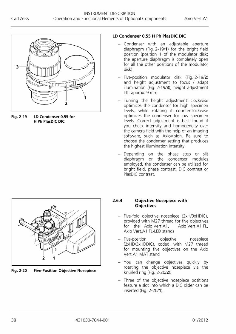
LD Condenser 0.55 H Ph PlasDIC DIC
− Condenser with an adjustable aperture diaphragm (Fig. 2-19/1) for the bright field position (position 1 of the modulator disk; the aperture diaphragm is completely open for all the other positions of the modulator disk)
− Five-position modulator disk (Fig. 2-19/2) and height adjustment to focus / adapt illumination (Fig. 2-19/3); height adjustment lift: approx. 9 mm
− Turning the height adjustment clockwise optimizes the condenser for high specimen levels, while rotating it counterclockwise optimizes the condenser for low specimen levels. Correct adjustment is best found if you check intensity and homogeneity over the camera field with the help of an imaging software, such as AxioVision. Be sure to choose the condenser setting that produces the highest illumination intensity.
− Depending on the phase stop or slit diaphragm or the condenser modules employed, the condenser can be utilized for bright field, phase contrast, DIC contrast or PlasDIC contrast.
2.6.4 Objective Nosepiece with
Objectives
− Five-fold objective nosepiece (2xH/3xHDIC), provided with M27 thread for five objectives for the Axio Vert.A1, Axio Vert.A1 FL, Axio Vert.A1 FL-LED stands
− Five-position objective nosepiece (2xHD/3xHDDIC), coded, with M27 thread for mounting five objectives on the Axio Vert.A1 MAT stand
− You can change objectives quickly by rotating the objective nosepiece via the knurled ring (Fig. 2-20/2).
− Three of the objective nosepiece positions feature a slot into which a DIC slider can be inserted (Fig. 2-20/1).
Fig. 2-19 LD Condenser 0.55 for
H Ph PlasDIC DIC
Fig. 2-20 Five-Position Objective Nosepiece

INSTRUMENT DESCRIPTION Axio Vert.A1 Operation and Functional Elements of Optional Components Carl Zeiss
01/2012 431030-7044-001 39
2.6.5 Filter Slider and Slider for Aperture and Luminous Light Diaphragms for the Axio Vert.A1 MAT and Axio Vert.A1 FL Stands
− Reflected light filter slider with three positions for d=25 mm filters (neutral density and color filters, white balance filter). A two-position filter is available as an option.
− Insert and operate the filter slider from the right (Fig. 2-21/1). To this end, remove the covers from the insertion slot.
− Aperture diaphragm slider A, equipped with a setting wheel (Fig. 2-21/2) to open or close the diaphragm, can be inserted from the right. The FL attenuator may also be inserted here for fluorescence applications.
− The luminous field slider for slot F, equipped with a setting wheel (Fig. 2-21/3) to open or close the diaphragm, can be inserted from the right.
2.6.6 Filter Slider Mounted on the Carrier for Transmitted Light Illumination
− Alternately usable two-position transmitted light filter slider (Fig. 2-22/2) for d=32 mm filters (neutral density and conversion filters or shutter plate) fixed-mounted in the carrier (Fig. 2-22/1)
− If an LED illuminator is used, the shutter plate can be inserted into a filter position and pushed into the light path to block the light path. Residual light could interfere with fluorescence viewing.
When used with transmitted light LED illumination, the conversion filter creates the usual daylight impression during the microscoping process. Without that filter, the image may appear slightly bluish on occasion. Do not employ the conversion filter when transmitted light HAL illumination is installed, as the heat generated by the HAL might damage the filter.
Fig. 2-21 Reflected Light Filter Slider and
Slider for Aperture and Luminous Field Diaphragms
Fig. 2-22 Transmitted Light Filter Slider

PUTTING THE INSTRUMENT INTO OPERATION Carl Zeiss Mounting Standard Components Axio Vert.A1
40 431030-7044-001 01/2012
3 PUTTING THE INSTRUMENT INTO OPERATION
The Axio Vert.A1 can be set up, changed over and put into operation by the customers themselves. If the customers so request, Zeiss Customer Service will be happy to set up or change over the microscope for a charge. Our services include the following:
− Set up the microscope, install and adjust all its components (to the extent not yet done at the manufacturer's plant).
− Effect cable connections and carry out the power supply connection.
− Provide training on how to operate the microscope.
Please heed the following suggestions if you wish to set up the microscope yourself or move it to another place:
Be certain to read the Notes on Instrument Safety (see Section 1) carefully before you set up the microscope and put it into operation.
3.1 Mounting Standard Components
3.1.1 Microscope Unpacking and Setup
The various Axio Vert.A1 models, including their accessories, are delivered in industry standard packaging.
• Open the packaging.
• Take out the carton box containing the accessories.
• Grasp the grip openings and pull the polyethylene packaging containing the microscope stand out of the carton box and set it down on the side.
• Remove the upper half of the packaging.
• Take the microscope stand out of the second half of the packaging. To do so, grasp the back of the transmitted illumination carrier and the front of the stand. If no optional carrier for transmitted light illumination is attached, the Axio Vert.A1 MAT stand for material applications comes with a carrying handle fitted to its back.
• Check the shipment against the delivery note to ensure that the shipment is complete.
It may be a good idea to keep the shipping container for any possible longer-term storage or a return of the unit to the manufacturer. Otherwise, dispose of the packaging properly.

PUTTING THE INSTRUMENT INTO OPERATION Axio Vert.A1 Mounting Standard Components Carl Zeiss
01/2012 431030-7044-001 41
• Place the microscope stand (Fig. 3-1/3) on a non-vibrating, even, hard and non-flammable worktop.
• Remove the plastic cover.
• Remove the protective caps (Fig. 3-1/1 and 4).
The filter slider (Fig. 3-1/2) is fixed-mounted, while appropriate filter glasses (green filter, attenuation filter, conversion filter) are not yet inserted during transport.
3.1.2 Attaching the Binocular
(Photo)Tube
All the binocular tubes listed in the system overview can be attached to the stand as described below.
The microscope comes with a factory-mounted 50-mm ergo intermediate piece, to which another 50-mm or 25-mm ergo intermediate piece may be added. If the ergotube is employed, only ergo intermediate pieces of up to 25 mm should be used, however. The utilization of the 50-mm extension would require optical compromises. For the installation, follow the same procedure as for the installation of the tube.
To mount or change the tube, proceed as follows:
• Use ball-headed screwdriver SW 3 to loosen the Allen screw (Fig. 3-2/3) on the ergo intermediate piece. If necessary, hold the tube to be changed and remove it toward the front.
• Remove the dust cap from the tube to be mounted (Fig. 3-2/2) and from the ergo intermediate piece, as applicable.
• Insert the binocular tube (Fig. 3-2/1) with the dovetail ring into the tube port (Fig. 3-2/4) of the ergo intermediate piece, align it with the ergo intermediate piece and retighten the Allen screw (Fig. 3-2/3), using the ball-headed screwdriver.
Fig. 3-1 Unpacking and Setup
Fig. 3-2 Attaching the Binocular Tube
PUTTING THE INSTRUMENT INTO OPERATION Carl Zeiss Mounting Standard Components Axio Vert.A1
42 431030-7044-001 01/2012
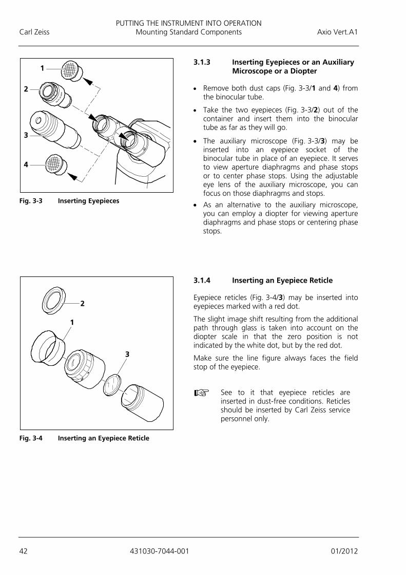
3.1.3 Inserting Eyepieces or an Auxiliary Microscope or a Diopter
• Remove both dust caps (Fig. 3-3/1 and 4) from the binocular tube.
• Take the two eyepieces (Fig. 3-3/2) out of the container and insert them into the binocular tube as far as they will go.
• The auxiliary microscope (Fig. 3-3/3) may be inserted into an eyepiece socket of the binocular tube in place of an eyepiece. It serves to view aperture diaphragms and phase stops or to center phase stops. Using the adjustable eye lens of the auxiliary microscope, you can focus on those diaphragms and stops.
• As an alternative to the auxiliary microscope, you can employ a diopter for viewing aperture diaphragms and phase stops or centering phase stops.
3.1.4 Inserting an Eyepiece Reticle
Eyepiece reticles (Fig. 3-4/3) may be inserted into eyepieces marked with a red dot.
The slight image shift resulting from the additional path through glass is taken into account on the diopter scale in that the zero position is not indicated by the white dot, but by the red dot.
Make sure the line figure always faces the field stop of the eyepiece.
See to it that eyepiece reticles are inserted in dust-free conditions. Reticles should be inserted by Carl Zeiss service personnel only.
Fig. 3-3 Inserting Eyepieces
Fig. 3-4 Inserting an Eyepiece Reticle

PUTTING THE INSTRUMENT INTO OPERATION Axio Vert.A1 Mounting Standard Components Carl Zeiss
01/2012 431030-7044-001 43
Compensating for Eyesight Differences (e.g., through the Use of Eyepiece Reticles)
For the correct use of an eyepiece reticle, two focusable eyepieces are required to ensure that differences in the observer's eyesight can be offset.
• Use the eyepiece adjustment features to lock focus on the eyepiece reticle or, if no eyepiece reticle is in place, on the edge of the field of view.
• With the eyepiece adjusted in this way, use the focusing drive to lock focus on the microscopic image of the specimen put on.
• Then use the adjustment features of the second adjustable eyepiece to lock focus on the microscopic image for the second eye. In so doing, be sure to leave the setting of the focusing drive on the microscope stand unchanged.
3.1.5 Screwing Objectives in Place
• Remove as many dust caps (Fig. 3-5/2) as there are objectives.
• Take the objectives (Fig. 3-5/1) out of the container and screw them into the objective nosepiece by ascending magnification factors. In so doing, make sure the objective is correctly and safely fitted.
Once the objectives have been screwed in, you can attach the optional aqua stop, provided that the stop has been ordered. See Section 3.3.5.
Fig. 3-5 Screwing Objectives in Place
PUTTING THE INSTRUMENT INTO OPERATION Carl Zeiss Mounting Standard Components Axio Vert.A1
44 431030-7044-001 01/2012
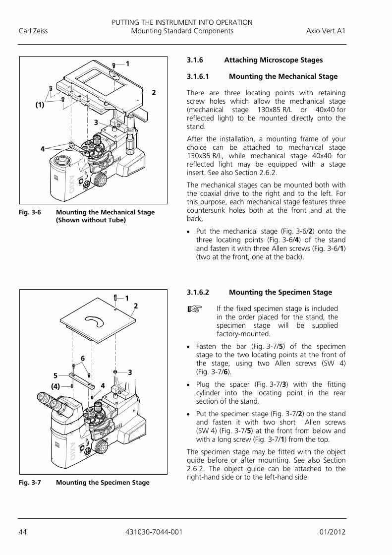
3.1.6 Attaching Microscope Stages
3.1.6.1 Mounting the Mechanical Stage
There are three locating points with retaining screw holes which allow the mechanical stage (mechanical stage 130x85 R/L or 40x40 for reflected light) to be mounted directly onto the stand.
After the installation, a mounting frame of your choice can be attached to mechanical stage 130x85 R/L, while mechanical stage 40x40 for reflected light may be equipped with a stage insert. See also Section 2.6.2.
The mechanical stages can be mounted both with the coaxial drive to the right and to the left. For this purpose, each mechanical stage features three countersunk holes both at the front and at the back.
• Put the mechanical stage (Fig. 3-6/2) onto the three locating points (Fig. 3-6/4) of the stand and fasten it with three Allen screws (Fig. 3-6/1) (two at the front, one at the back).
3.1.6.2 Mounting the Specimen Stage
If the fixed specimen stage is included in the order placed for the stand, the specimen stage will be supplied factory-mounted.
• Fasten the bar (Fig. 3-7/5) of the specimen stage to the two locating points at the front of the stage, using two Allen screws (SW 4) (Fig. 3-7/6).
• Plug the spacer (Fig. 3-7/3) with the fitting cylinder into the locating point in the rear section of the stand.
• Put the specimen stage (Fig. 3-7/2) on the stand and fasten it with two short Allen screws (SW 4) (Fig. 3-7/5) at the front from below and with a long screw (Fig. 3-7/1) from the top.
The specimen stage may be fitted with the object guide before or after mounting. See also Section 2.6.2. The object guide can be attached to the right-hand side or to the left-hand side.
Fig. 3-6 Mounting the Mechanical Stage
(Shown without Tube)
Fig. 3-7 Mounting the Specimen Stage

PUTTING THE INSTRUMENT INTO OPERATION Axio Vert.A1 Mounting Standard Components Carl Zeiss
01/2012 431030-7044-001 45
3.1.6.3 Mounting the Scanning Stage
To mount scanning stage 130x85 motP; CAN, follow the same procedure as for the mechanical stage.
In addition, heed the suggestions below when mounting the scanning stage.
• After mounting the stage on the stand, screw out the transport lock pin (Fig. 3-8/1) located on the underside of the stage.
Be sure to screw the transport lock pin in again whenever you transport the stage.
The traversing ranges of the scanning stage in X and Y directions may be restricted in the following way if necessary:
X direction
• In order to change the right or left stop for the X direction, loosen the relevant stop screw (Fig. 3-8/2) on the underside of the stage, move the screw into the desired position and retighten it.
Y direction
• In order to change the front or rear stop for the Y direction, first turn out the screws (Fig. 3-9/1) of the covers on the upper side of the stage and remove the covers (Fig. 3-9/2).
• Then loosen the stop screws (Fig. 3-9/3), move the screws in the desired position and retighten them.
• Next, screw the covers back on again.
Fig. 3-8 Underside of the Scanning Stage
Fig. 3-9 Upper Side of the Scanning Stage
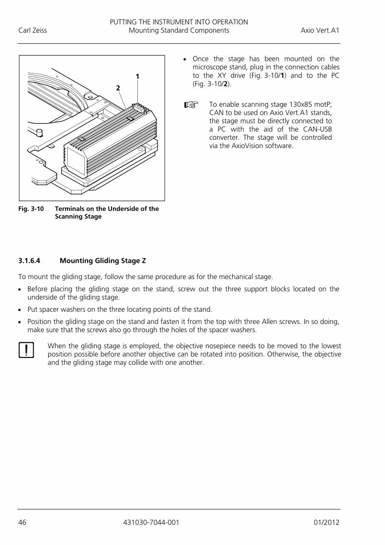
PUTTING THE INSTRUMENT INTO OPERATION Carl Zeiss Mounting Standard Components Axio Vert.A1
46 431030-7044-001 01/2012
• Once the stage has been mounted on the microscope stand, plug in the connection cables to the XY drive (Fig. 3-10/1) and to the PC (Fig. 3-10/2).
To enable scanning stage 130x85 motP;
CAN to be used on Axio Vert.A1 stands, the stage must be directly connected to a PC with the aid of the CAN-USB converter. The stage will be controlled via the AxioVision software.
3.1.6.4 Mounting Gliding Stage Z
To mount the gliding stage, follow the same procedure as for the mechanical stage.
• Before placing the gliding stage on the stand, screw out the three support blocks located on the underside of the gliding stage.
• Put spacer washers on the three locating points of the stand.
• Position the gliding stage on the stand and fasten it from the top with three Allen screws. In so doing, make sure that the screws also go through the holes of the spacer washers.
When the gliding stage is employed, the objective nosepiece needs to be moved to the lowest position possible before another objective can be rotated into position. Otherwise, the objective and the gliding stage may collide with one another.
Fig. 3-10 Terminals on the Underside of the
Scanning Stage
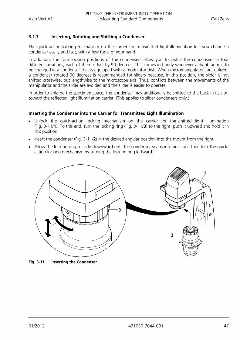
PUTTING THE INSTRUMENT INTO OPERATION Axio Vert.A1 Mounting Standard Components Carl Zeiss
01/2012 431030-7044-001 47
3.1.7 Inserting, Rotating and Shifting a Condenser
The quick-action locking mechanism on the carrier for transmitted light illumination lets you change a condenser easily and fast, with a few turns of your hand.
In addition, the four locking positions of the condensers allow you to install the condensers in four different positions, each of them offset by 90 degrees. This comes in handy whenever a diaphragm is to be changed in a condenser that is equipped with a modulator disk. When micromanipulators are utilized, a condenser rotated 90 degrees is recommended for sliders because, in this position, the slider is not shifted crosswise, but lengthwise to the microscope axis. Thus, conflicts between the movements of the manipulator and the slider are avoided and the slider is easier to operate.
In order to enlarge the specimen space, the condenser may additionally be shifted to the back in its slot, toward the reflected light illumination carrier. (This applies to slider condensers only.)
Inserting the Condenser into the Carrier for Transmitted Light Illumination
• Unlock the quick-action locking mechanism on the carrier for transmitted light illumination (Fig. 3-11/1). To this end, turn the locking ring (Fig. 3-11/3) to the right, push it upward and hold it in this position.
• Insert the condenser (Fig. 3-11/2) in the desired angular position into the mount from the right.
• Allow the locking ring to slide downward until the condenser snaps into position. Then lock the quick-action locking mechanism by turning the locking ring leftward.
Fig. 3-11 Inserting the Condenser
PUTTING THE INSTRUMENT INTO OPERATION Carl Zeiss Mounting Standard Components Axio Vert.A1
48 431030-7044-001 01/2012
Rotating the Condenser in the Transmitted Light Illumination Carrier 90 Degrees
• Hold the condenser, so that it cannot move. Rotate the locking ring rightward and push it upward.
• Turn the condenser 90 degrees in the slot until it snaps into place.
• Allow the locking ring to slide downward, and turn it leftward.
3.1.8 Inserting Stop Sliders into Condensers 0.3 or 0.4 for Sliders
• Pull the dust protection slider out of the slider slot.
• Move the required slider into the condenser from the right or left and wait until it has snapped into the desired position. (The center position corresponds to bright field and is provided with neutral-density filters for light attenuation.) See also Section 2.6.3.
The text on the slider must be legible in upright characters, and the stops inserted must
match the condenser / objective combination.
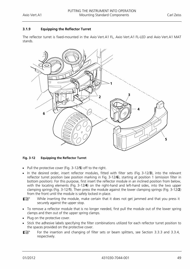
PUTTING THE INSTRUMENT INTO OPERATION Axio Vert.A1 Mounting Standard Components Carl Zeiss
01/2012 431030-7044-001 49
3.1.9 Equipping the Reflector Turret
The reflector turret is fixed-mounted in the Axio Vert.A1 FL, Axio Vert.A1 FL-LED and Axio Vert.A1 MAT stands.
Fig. 3-12 Equipping the Reflector Turret
• Pull the protective cover (Fig. 3-12/5) off to the right.
• In the desired order, insert reflector modules, fitted with filter sets (Fig. 3-12/3), into the relevant reflector turret position (see position marking in Fig. 3-12/6), starting at position 1 (emission filter in bottom position). For this purpose, first insert the reflector module in an inclined position from below, with the locating elements (Fig. 3-12/4) on the right-hand and left-hand sides, into the two upper clamping springs (Fig. 3-12/1). Then press the module against the lower clamping springs (Fig. 3-12/2) from the front until the module is safely locked in place.
While inserting the module, make certain that it does not get jammed and that you press it securely against the upper stop.
• To remove a reflector module that is no longer needed, first pull the module out of the lower spring clamps and then out of the upper spring clamps.
• Plug on the protective cover. • Stick the adhesive labels specifying the filter combinations utilized for each reflector turret position to
the spaces provided on the protective cover.
For the insertion and changing of filter sets or beam splitters, see Section 3.3.3 and 3.3.4, respectively.

PUTTING THE INSTRUMENT INTO OPERATION Carl Zeiss Mounting Standard Components Axio Vert.A1
50 431030-7044-001 01/2012
3.1.10 Attaching Transmitted Light Illumination
At your option, you can use either the LED illuminator or the HAL illuminator for transmitted light illumination.
3.1.10.1 Attaching the HAL Illuminator
The HAL illuminator is equipped with a separately exchangeable halogen lamp, which is supplied individually packed and needs to be inserted into the HAL illuminator when the illuminator is attached to the microscope.
• Insert the illuminator base with its contact pins into the slot (Fig. 3-13/6) of the carrier, as far as it will go.
• Use the screw (Fig. 3-13/7) to fasten the illuminator base in place.
• Take the halogen lamp (Fig. 3-13/2) out of the packaging box and insert it into the mount (Fig. 3-13/3). In so doing, make sure that the tip of the mount engages in the centering notch of the carrier plate (see arrow in Fig. 3-13) of the halogen lamp.
CAUTION Do not touch the bulb with your bare hands. If required, clean the bulb with pure alcohol before you switch it on for the first time in order to prevent dirt from burning into the glass.
• Plug the illuminator cap (Fig. 3-13/1) onto the illuminator base (Fig. 3-13/4). For proper alignment, slide the notch in the cap onto the alignment stud (Fig. 3-13/5).
Last Checking Step: Insert the three-pin plug of the transmitted light illuminator into the connector socket located at the back of the stand (or into the jacks marked TL on the Axio Vert.A1 MAT) and switch the halogen lamp on.
Fig. 3-13 Attaching the HAL Illuminator
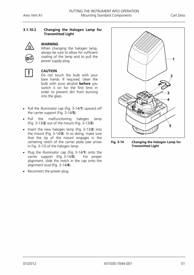
PUTTING THE INSTRUMENT INTO OPERATION Axio Vert.A1 Mounting Standard Components Carl Zeiss
01/2012 431030-7044-001 51
3.1.10.2 Changing the Halogen Lamp for Transmitted Light
WARNING When changing the halogen lamp, always be sure to allow for sufficient cooling of the lamp and to pull the power supply plug.
CAUTION Do not touch the bulb with your bare hands. If required, clean the bulb with pure alcohol before you switch it on for the first time in order to prevent dirt from burning into the glass.
• Pull the illuminator cap (Fig. 3-14/1) upward off the carrier support (Fig. 3-14/5).
• Pull the malfunctioning halogen lamp (Fig. 3-13/2) out of the mount (Fig. 3-13/3).
• Insert the new halogen lamp (Fig. 3-13/2) into the mount (Fig. 3-14/3). In so doing, make sure that the tip of the mount engages in the centering notch of the carrier plate (see arrow in Fig. 3-13) of the halogen lamp.
• Plug the illuminator cap (Fig. 3-14/1) onto the carrier support (Fig. 3-14/5). For proper alignment, slide the notch in the cap onto the alignment stud (Fig. 3-14/4).
• Reconnect the power plug.
Fig. 3-14 Changing the Halogen Lamp for
Transmitted Light

PUTTING THE INSTRUMENT INTO OPERATION Carl Zeiss Mounting Standard Components Axio Vert.A1
52 431030-7044-001 01/2012
3.1.10.3 Attaching the LED Illuminator
Attach the LED illuminator as a complete assembly and replace it as a complete assembly when its service life has ended.
• Insert the illuminator (Fig. 3-15/1) with its contact pins into the slot (Fig. 3-15/2) on the carrier, as far as it will go.
• Fasten the illuminator to the carrier with two screws (Fig. 3-15/4).
Be sure to screw the illuminator on firmly for a long service life.
If you employ the LED illuminator for transmitted light illumination, you should place the conversion filter in the slider (Fig. 3-15/3) of the carrier for reflected light. This will create the usual daylight impression during the microscoping process. Without that filter, the image may appear slightly bluish on occasion.
In order to avoid veiling glare during FL viewing, be sure to fit the supplied shutter plate in the second position of the slider in the carrier to block the light path temporarily.
Last Checking Step: Insert the three-pin plug of the transmitted light illuminator into the connector socket located at the back of the stand (or into the jacks marked TL on the Axio Vert.A1 MAT) and switch the halogen lamp on.
3.1.11 Attaching Illuminators for Reflected Light
The Axio Vert.A1 FL-LED stand comes with a fixed-mounted reflected light LED fluorescence illumination provided with four mounts for LED modules, which may be utilized at the user's option. The LED modules are interchangeable. They can be put together and installed individually by the user. See Section 3.3.7.
At the back, the Axio Vert.A1 FL and the Axio Vert.A1 MAT feature a port for the installation of reflected light illuminators. The various stands allow such illuminators as the HBO 50, HBO 100 or HXP 120C to be used for reflected light fluorescence and the VIS-LED attachment lamp or the HAL 100 illuminator to be utilized for material applications.
Fig. 3-15 Attaching the LED Illuminator
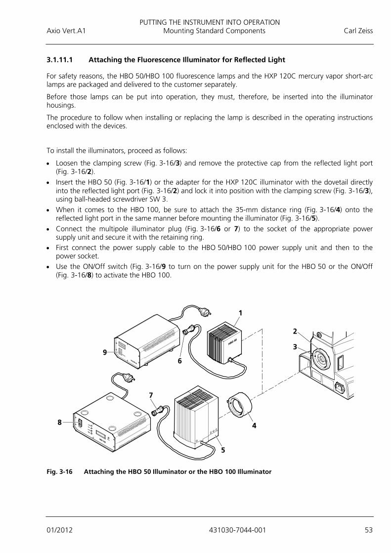
PUTTING THE INSTRUMENT INTO OPERATION Axio Vert.A1 Mounting Standard Components Carl Zeiss
01/2012 431030-7044-001 53
3.1.11.1 Attaching the Fluorescence Illuminator for Reflected Light
For safety reasons, the HBO 50/HBO 100 fluorescence lamps and the HXP 120C mercury vapor short-arc lamps are packaged and delivered to the customer separately.
Before those lamps can be put into operation, they must, therefore, be inserted into the illuminator housings.
The procedure to follow when installing or replacing the lamp is described in the operating instructions enclosed with the devices.
To install the illuminators, proceed as follows:
• Loosen the clamping screw (Fig. 3-16/3) and remove the protective cap from the reflected light port (Fig. 3-16/2).
• Insert the HBO 50 (Fig. 3-16/1) or the adapter for the HXP 120C illuminator with the dovetail directly into the reflected light port (Fig. 3-16/2) and lock it into position with the clamping screw (Fig. 3-16/3), using ball-headed screwdriver SW 3.
• When it comes to the HBO 100, be sure to attach the 35-mm distance ring (Fig. 3-16/4) onto the reflected light port in the same manner before mounting the illuminator (Fig. 3-16/5).
• Connect the multipole illuminator plug (Fig. 3-16/6 or 7) to the socket of the appropriate power supply unit and secure it with the retaining ring.
• First connect the power supply cable to the HBO 50/HBO 100 power supply unit and then to the power socket.
• Use the ON/Off switch (Fig. 3-16/9 to turn on the power supply unit for the HBO 50 or the ON/Off (Fig. 3-16/8) to activate the HBO 100.
Fig. 3-16 Attaching the HBO 50 Illuminator or the HBO 100 Illuminator
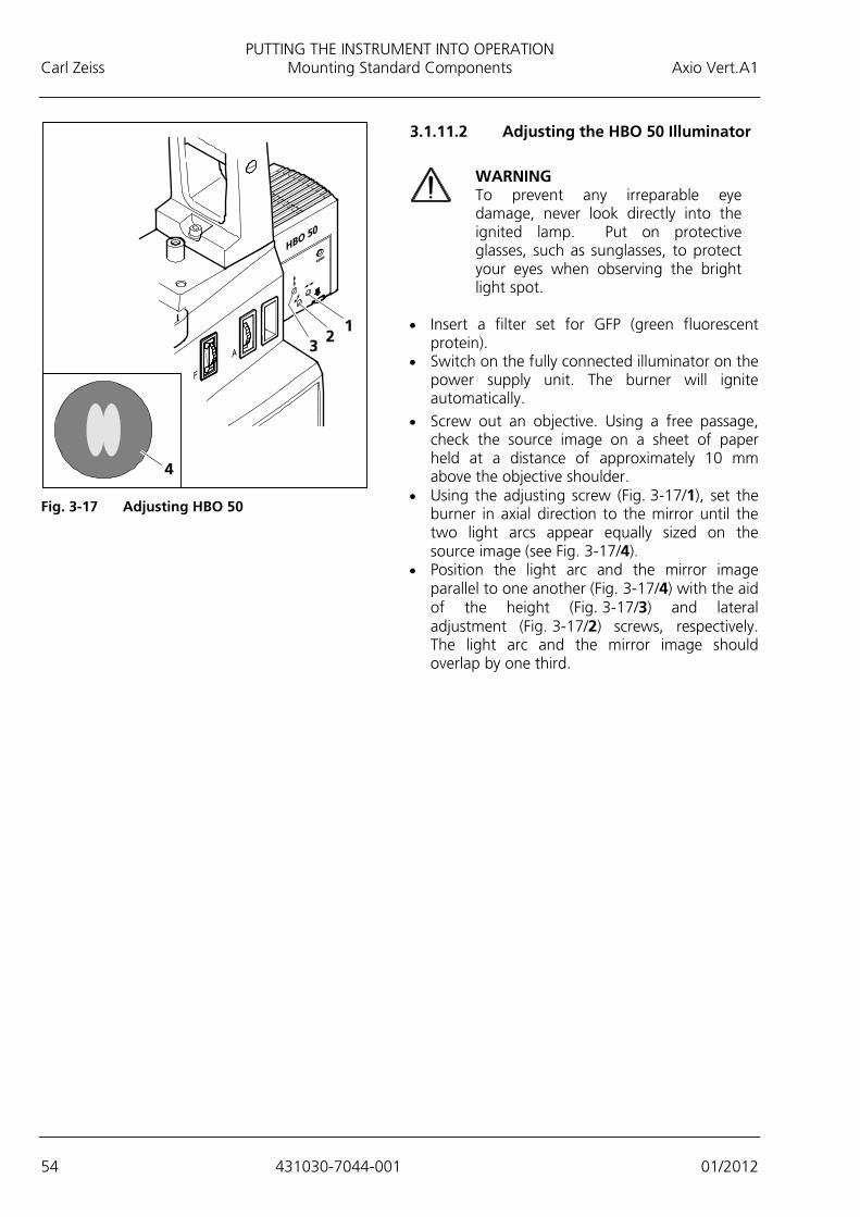
PUTTING THE INSTRUMENT INTO OPERATION Carl Zeiss Mounting Standard Components Axio Vert.A1
54 431030-7044-001 01/2012
3.1.11.2 Adjusting the HBO 50 Illuminator
WARNING To prevent any irreparable eye damage, never look directly into the ignited lamp. Put on protective glasses, such as sunglasses, to protect your eyes when observing the bright light spot.
• Insert a filter set for GFP (green fluorescent protein).
• Switch on the fully connected illuminator on the power supply unit. The burner will ignite automatically.
• Screw out an objective. Using a free passage, check the source image on a sheet of paper held at a distance of approximately 10 mm above the objective shoulder.
• Using the adjusting screw (Fig. 3-17/1), set the burner in axial direction to the mirror until the two light arcs appear equally sized on the source image (see Fig. 3-17/4).
• Position the light arc and the mirror image parallel to one another (Fig. 3-17/4) with the aid of the height (Fig. 3-17/3) and lateral adjustment (Fig. 3-17/2) screws, respectively. The light arc and the mirror image should overlap by one third.
Fig. 3-17 Adjusting HBO 50
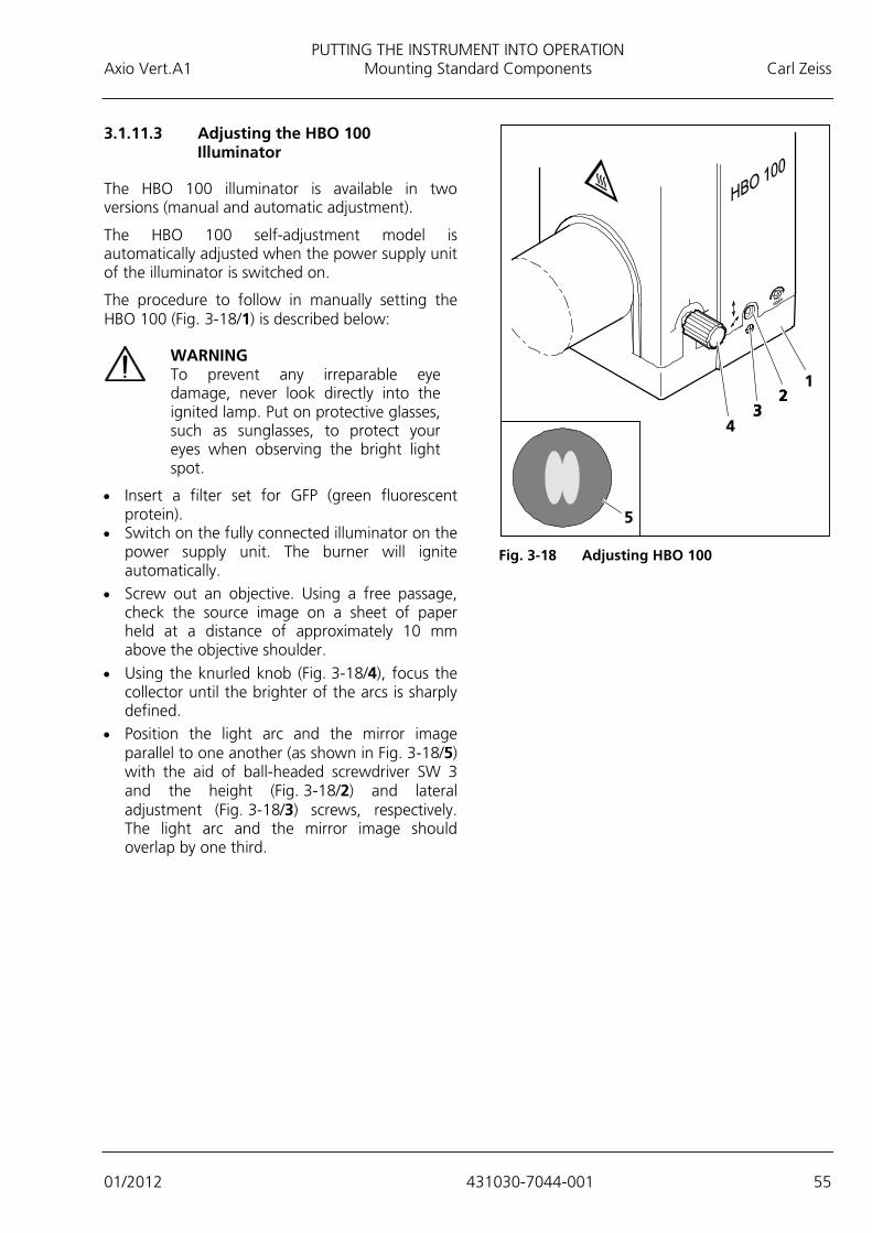
PUTTING THE INSTRUMENT INTO OPERATION Axio Vert.A1 Mounting Standard Components Carl Zeiss
01/2012 431030-7044-001 55
3.1.11.3 Adjusting the HBO 100 Illuminator
The HBO 100 illuminator is available in two versions (manual and automatic adjustment).
The HBO 100 self-adjustment model is automatically adjusted when the power supply unit of the illuminator is switched on.
The procedure to follow in manually setting the HBO 100 (Fig. 3-18/1) is described below:
WARNING To prevent any irreparable eye damage, never look directly into the ignited lamp. Put on protective glasses, such as sunglasses, to protect your eyes when observing the bright light spot.
• Insert a filter set for GFP (green fluorescent protein).
• Switch on the fully connected illuminator on the power supply unit. The burner will ignite automatically.
• Screw out an objective. Using a free passage, check the source image on a sheet of paper held at a distance of approximately 10 mm above the objective shoulder.
• Using the knurled knob (Fig. 3-18/4), focus the collector until the brighter of the arcs is sharply defined.
• Position the light arc and the mirror image parallel to one another (as shown in Fig. 3-18/5) with the aid of ball-headed screwdriver SW 3 and the height (Fig. 3-18/2) and lateral adjustment (Fig. 3-18/3) screws, respectively. The light arc and the mirror image should overlap by one third.
Fig. 3-18 Adjusting HBO 100

PUTTING THE INSTRUMENT INTO OPERATION Carl Zeiss Mounting Standard Components Axio Vert.A1
56 431030-7044-001 01/2012
3.1.11.4 Installing the VIS-LED Attachment Lamp
WARNING Avoid looking directly into the LED light.
WARNING Always make sure that the VIS-LED attachment lamp is switched off when mounting it onto or dismounting it from the reflected light port.
• Loosen the clamping screw (Fig. 3-19/2) on the
reflected light port (Fig. 3-19/1) and remove the cap.
• Insert the attachment lamp (Fig. 3-19/4) with the dovetail ring into the port (Fig. 3-19/1). Use ball-headed screwdriver SW 3 and the locking screw (Fig. 3-19/2) to lock the illuminator firmly into position.
• Insert the three-pin illuminator plug (Fig. 3-19/3) into the lower socket (Fig. 3-19/5) for reflected light (RL) at the back of the instrument.
• Put the TL/RL switch (Fig. 2-9/22) into the position for reflected light (RL).
Adjusting the VIS-LED Attachment Illuminator
• Switch on the attachment lamp via the operational microscope. (See Section 1.1.)
• Switch off the diffusion disk (Fig. 2-9/26) and remove the filter from the light path.
• Use the ≤ 40x objective to focus on a free area of the specimen.
• Remove the eyepiece. Use the adjusting screws (Fig. 3-20/1 and 2) to center the image of the illuminator in the pupil image.
• Use the focusing screw (Fig. 3-20/3) to ensure an optimized, even illumination of the pupil image.
• Switch the diffusion disk on again and insert the filter.
Fig. 3-19 Attaching the VIS-LED Illuminator
Fig. 3-20 Adjusting the VIS-LED Attachment
Illuminator

PUTTING THE INSTRUMENT INTO OPERATION Axio Vert.A1 Mounting Standard Components Carl Zeiss
01/2012 431030-7044-001 57
3.1.11.5 Attaching the HAL 100 Illuminator
Before using the halogen lamp, be sure to remove the replacement tool for the halogen lamp from the housing, as the tool might otherwise get damaged by the heat generated. (See Section 3.1.13.)
The halogen lamp can only be operated with the external power supply unit.
• Loosen the clamping screw (Fig. 3-21/2) on the reflected light port (Fig. 3-21/1) and remove the cap.
• Insert the illuminator housing (Fig. 3-21/3) with the dovetail ring into the port (Fig. 3-21/1). Use ball-headed screwdriver SW 3 and the locking screw (Fig. 3-21/2) to fix the illuminator firmly into position.
• Insert the plug of the HAL 100 (Fig. 3-21/5) into the RL socket at the back of the external power supply unit (Fig. 3-21/4).
Fig. 3-21 Attaching the HAL 100 Illuminator

PUTTING THE INSTRUMENT INTO OPERATION Carl Zeiss Mounting Standard Components Axio Vert.A1
58 431030-7044-001 01/2012
3.1.12 Adjusting the HAL 100 Illuminator
Coarse Adjustment
• Loosen the clamping screw (Fig. 3-21/2) and then detach the operational halogen illuminator (Fig. 3-22/4) from the microscope stand.
• Switch on the microscope. (See Section 1.1.)
• Aim the light beam at a projection surface (wall) that is at least 3 m away.
In so doing, be sure not to look into the light exit of the illuminator.
• Use ball-headed screwdriver SW 3 to set the adjusting screw (Fig. 3-22/1) until both lamp filament images are shown on the projection surface as sharply defined as possible.
• Use the adjusting screws (Fig. 3-22/2 and 3) to align the lamp filaments and their mirror image in such a way to each other that the mirror image fills up the spaces of the lamp filaments (Fig. 3-22/5).
Fine Adjustment
• Reattach the microscope lamp to the microscope stand and fix it into position, using the clamping screw.
• Switch off the diffusion disk (Fig. 2-9/26) and remove the filter from the light path.
• Use the ≤ 20x objective to focus on a mirror that has been put on and then go to a clean area of the specimen.
• Remove the eyepiece. Use the adjusting screws (Fig. 3-22/2 and 3) to center the lamp filaments and their mirror image in the pupil image.
• Optimize the overlapping, using the adjusting screw (Fig. 3-22/1).
• Switch on the diffusion disk and reactivate the filter.
Fig. 3-22 Adjusting the HAL 100 Illuminator

PUTTING THE INSTRUMENT INTO OPERATION Axio Vert.A1 Mounting Standard Components Carl Zeiss
01/2012 431030-7044-001 59
3.1.13 Changing the HAL 100 Halogen Lamp
WARNING Hot surface!
You need not remove the lamp housing from the stand to change the halogen lamp. Do not store the replacement tool (Fig. 3-23/7) provided for the halogen lamp inside the lamp housing while the lamp is in operation. The replacement lamp (Fig. 3-23/8) may remain inside the lamp housing in the plugged-on position.
• Switch off the microscope, remove the plug (Fig. 3-21/3) from the socket (Fig. 3-21/5 - reflected light), and allow the lamp to cool off for approximately 15 minutes.
• Press down the unlocking button (Fig. 3-23/3) of the HAL 100 (Fig. 3-23/1) halogen illuminator, pull out the illuminator drawer completely (Fig. 3-23/2) and set it down separately.
• Press down the two spring levers (Fig. 3-23/5) and pull the old halogen lamp (Fig. 3-23/6) out upward.
• Press down the two spring levers, insert the new lamp into the lamp base (Fig. 3-23/4) and release the spring levers. Be sure to always use the replacement tool (Fig. 3-23/7) for holding / touching the halogen lamp, as traces of grease may impair the service life of the halogen lamp. If required, clean the bulb with pure alcohol before you switch the lamp on for the first time in order to prevent dirt from burning into the glass.
• Briefly press down the spring levers again to center the lamp.
• Slide the illuminator drawer back in again until it is locked into position.
• Switch the diffusion disk on again and insert the filter.
Fig. 3-23 Changing the Halogen Lamp

PUTTING THE INSTRUMENT INTO OPERATION Carl Zeiss Connecting the Microscope to the Power Supply System, Switching … Axio Vert.A1
60 431030-7044-001 01/2012
3.2 Connecting the Microscope to the Power Supply System, Switching the Microscope on and Setting It up
• Plug the power supply cable (Fig. 3-24/3) into the socket at the back of the microscope and connect the microscope to the power supply system.
• Switch the microscope on, using the ON / OFF switch (Fig. 3-24/2) located on the left-hand side of the instrument.
The blue light (Fig. 3-24/1) of the power indicator signals that the microscope is ready for operation.
• Check and, if necessary, replace the two G-fuse links in the event of a malfunction. (See Section 5.2.2).
• If required, use the separate power supply unit to switch on the fluorescence illuminator (e.g., HBO 50 or HBO 100 or HXP 120C) on the Axio Vert.A1 FL stand or the halogen illuminator (HAL 100) on the Axio Vert.A1 MAT. (See Section 3.1.11.1).
Fig. 3-24 Connecting and Switching on the Microscope
• If the microscope is equipped for transmitted light and reflected light, put the TL/RL switch into the desired position.
• Set the desired brightness on the illumination control.
• Whenever the microscope is used for a short period at a time only, the ECO power-saving function may be employed. See Section 4.6.
• Set the height stop for the focusing drive to prevent specimens from getting damaged by the focusing drive. See Section 4.7.
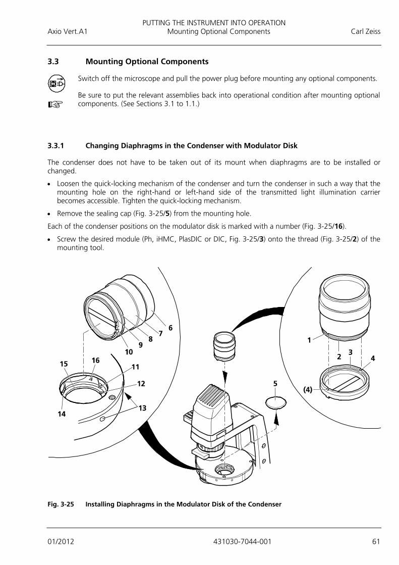
PUTTING THE INSTRUMENT INTO OPERATION Axio Vert.A1 Mounting Optional Components Carl Zeiss
01/2012 431030-7044-001 61
3.3 Mounting Optional Components
Switch off the microscope and pull the power plug before mounting any optional components.
Be sure to put the relevant assemblies back into operational condition after mounting optional components. (See Sections 3.1 to 1.1.)
3.3.1 Changing Diaphragms in the Condenser with Modulator Disk
The condenser does not have to be taken out of its mount when diaphragms are to be installed or changed.
• Loosen the quick-locking mechanism of the condenser and turn the condenser in such a way that the mounting hole on the right-hand or left-hand side of the transmitted light illumination carrier becomes accessible. Tighten the quick-locking mechanism.
• Remove the sealing cap (Fig. 3-25/5) from the mounting hole.
Each of the condenser positions on the modulator disk is marked with a number (Fig. 3-25/16).
• Screw the desired module (Ph, iHMC, PlasDIC or DIC, Fig. 3-25/3) onto the thread (Fig. 3-25/2) of the mounting tool.
Fig. 3-25 Installing Diaphragms in the Modulator Disk of the Condenser

PUTTING THE INSTRUMENT INTO OPERATION Carl Zeiss Mounting Optional Components Axio Vert.A1
62 431030-7044-001 01/2012
• Lock the cams (Fig. 3-25/1) on the underside of the mounting tool into the recesses (Fig. 3-25/4) of the contrast module.
• Insert the contrast module into the desired modulator disk position, using the gripping component (Fig. 3-25/6) of the mounting tool.
• The two centering screws (Fig. 3-25/11) may first have to be turned back slightly, as appropriate. These screws are accessible from the outside through holes (Fig. 3-25/13).
• During insertion tilt the equipped mounting tool and push the chamfer (Fig. 3-25/8) of the contrast module mount against the aluminium-colored pressure piece (Fig. 3-25/14). At the same time (in the case of DIC or PlasDIC) align coarsely cam (Fig. 3-25/10) and recess (Fig. 3-25/12).
The slit diaphragm and the DIC prism are automatically centered via the hole (Fig. 3-25/15) and the shoulder (Fig. 3-25/9).
• For the DIC prism and the PlasDIC diaphragm, rotate the alignment unit (Fig. 3-25/7) of the mounting tool to allow the cam (Fig. 3-25/10) to engage into the recess (Fig. 3-25/12).
• Hold the alignment unit (Fig. 3-25/7) and turn the mounting tool (Fig. 3-25/6) out of the contrast module.
• Remove the mounting tool and reinsert the sealing cap into the mounting hole.
• Turn the condenser into the desired working position.
When aligning Ph diaphragms and iHMC modules, you may first want to precenter the diaphragm in relation to the hole diameter on the upper side, based on your own visual judgment, before employing the auxiliary microscope to perform the exact centering when the contrast module is in the light path.
After the diaphragm change, attach identification labels to the front of the condenser.
The alignment of the iHMC module is described in Section 4.11.6.
To remove contrast modules from the modulator disk, follow the same approach, but proceed in reverse order.
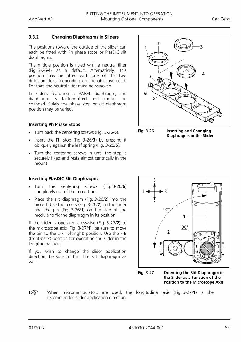
PUTTING THE INSTRUMENT INTO OPERATION Axio Vert.A1 Mounting Optional Components Carl Zeiss
01/2012 431030-7044-001 63
3.3.2 Changing Diaphragms in Sliders
The positions toward the outside of the slider can each be fitted with Ph phase stops or PlasDIC slit diaphragms.
The middle position is fitted with a neutral filter (Fig. 3-26/4) as a default. Alternatively, this position may be fitted with one of the two diffusion disks, depending on the objective used. For that, the neutral filter must be removed.
In sliders featuring a VAREL diaphragm, the diaphragm is factory-fitted and cannot be changed. Solely the phase stop or slit diaphragm position may be varied.
Inserting Ph Phase Stops
• Turn back the centering screws (Fig. 3-26/6).
• Insert the Ph stop (Fig. 3-26/3) by pressing it obliquely against the leaf spring (Fig. 3-26/5).
• Turn the centering screws in until the stop is securely fixed and rests almost centrically in the mount.
Inserting PlasDIC Slit Diaphragms
• Turn the centering screws (Fig. 3-26/6) completely out of the mount hole.
• Place the slit diaphragm (Fig. 3-26/2) into the mount. Use the recess (Fig. 3-26/7) on the slider and the pin (Fig. 3-26/1) on the side of the module to fix the diaphragm in its position.
If the slider is operated crosswise (Fig. 3-27/2) to the microscope axis (Fig. 3-27/1), be sure to move the pin to the L-R (left-right) position. Use the F-B (front-back) position for operating the slider in the longitudinal axis.
If you wish to change the slider application direction, be sure to turn the slit diaphragm as well.
When micromanipulators are used, the longitudinal axis (Fig. 3-27/1) is the recommended slider application direction.
Fig. 3-26 Inserting and Changing
Diaphragms in the Slider
Fig. 3-27 Orienting the Slit Diaphragm in
the Slider as a Function of the Position to the Microscope Axis

PUTTING THE INSTRUMENT INTO OPERATION Carl Zeiss Mounting Optional Components Axio Vert.A1
64 431030-7044-001 01/2012
3.3.3 Changing the Filter Set in the FL P&C Reflector Module
The customer can put together and install the filter sets for the FL P&C reflector module individually. Appropriate filter sets or even completely assembled FL P&C reflector modules can be ordered from Carl Zeiss.
• Take the FL P&C (Fig. 3-28/3) reflector module out of the reflector turret and set it down. (See also Section 3.1.9.)
• Use the mounting plate (Fig. 3-28/6) from the tool kit to screw out the retaining ring (Fig. 3-28/1).
• Turn over the reflector module to let the filter (Fig. 3-28/2 or 5) fall out onto a soft surface.
• Insert the barrier filter (emission filter) as shown in (Fig. 3-28/2) and the excitation filter as shown in (Fig. 3-28/5), and then secure them with the retaining rings (Fig. 3-28/1).
Both the barrier filter and the excitation filter may carry their designation and an arrow on the circumference. The arrow, which must always point inwards, indicates the direction in which the filter in question is to be installed into the reflector module. (See arrows in Fig. 3-28.)
With a view to minimizing the image shift in multifluorescence images, the barrier filter may be provided with another marking, i.e., a marking that indicates the position of the wedge angle.
When installing the barrier filter into the reflector modules used, be sure to align that marking to the orientation groove (Fig. 3-28/4). This ensures that the wedge angle of the barrier filter will be in the same defined position in the reflector module in use, thus compensating, among modules, for and/or minimizing what is actually a very small image shift anyway in the Zeiss filter sets utilized.
Fig. 3-28 Changing a Filter Set in the FL P&C
Reflector Module
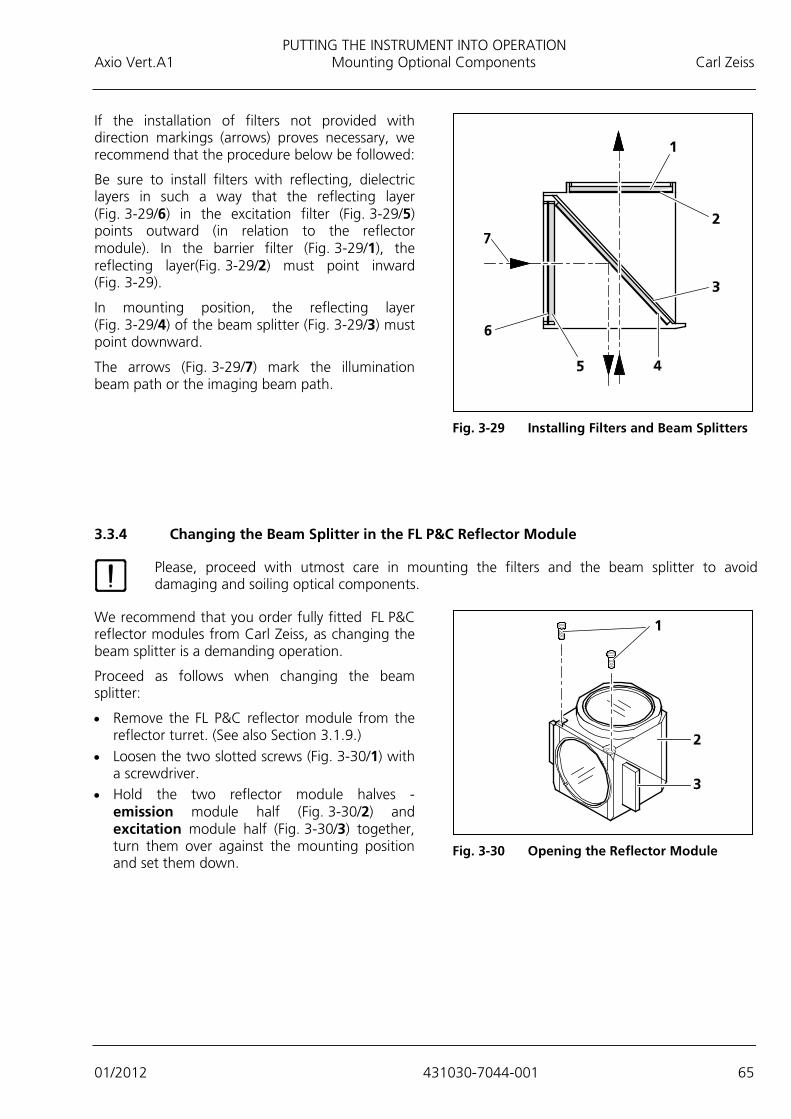
PUTTING THE INSTRUMENT INTO OPERATION Axio Vert.A1 Mounting Optional Components Carl Zeiss
01/2012 431030-7044-001 65
If the installation of filters not provided with direction markings (arrows) proves necessary, we recommend that the procedure below be followed:
Be sure to install filters with reflecting, dielectric layers in such a way that the reflecting layer (Fig. 3-29/6) in the excitation filter (Fig. 3-29/5) points outward (in relation to the reflector module). In the barrier filter (Fig. 3-29/1), the reflecting layer(Fig. 3-29/2) must point inward (Fig. 3-29).
In mounting position, the reflecting layer (Fig. 3-29/4) of the beam splitter (Fig. 3-29/3) must point downward.
The arrows (Fig. 3-29/7) mark the illumination beam path or the imaging beam path.
3.3.4 Changing the Beam Splitter in the FL P&C Reflector Module
Please, proceed with utmost care in mounting the filters and the beam splitter to avoid damaging and soiling optical components.
We recommend that you order fully fitted FL P&C reflector modules from Carl Zeiss, as changing the beam splitter is a demanding operation.
Proceed as follows when changing the beam splitter:
• Remove the FL P&C reflector module from the reflector turret. (See also Section 3.1.9.)
• Loosen the two slotted screws (Fig. 3-30/1) with a screwdriver.
• Hold the two reflector module halves - emission module half (Fig. 3-30/2) and excitation module half (Fig. 3-30/3) together, turn them over against the mounting position and set them down.
Fig. 3-29 Installing Filters and Beam Splitters
Fig. 3-30 Opening the Reflector Module

PUTTING THE INSTRUMENT INTO OPERATION Carl Zeiss Mounting Optional Components Axio Vert.A1
66 431030-7044-001 01/2012
• Tilt the excitation module half (Fig. 3-31/1), which is now on top, upward and lift it out of the retaining elements (Fig. 3-31/5b) of the lower emission module half (Fig. 3-31/4).
• Take the beam splitter (Fig. 3-31/2) and the spring frame (Fig. 3-31/3) out of the lower module half.
• Remove the old beam splitter and carefully put the new one on the spring frame (Fig. 3-31/3), with the reflecting side facing upward. Then place the two parts together into the lower module half. Make sure that the tongue of the frame sits in the relevant recess of the lower module half.
The reflecting (coated) side (Fig. 3-32/3) of the beam splitter is provided with a beveled edge (Fig. 3-32/1) or corner (Fig. 3-32/2).
• Place the excitation module half (Fig. 3-31/1)
on the emission module half (Fig. 3-31/4). The retaining elements (Fig. 3-31/5b) and the eyes (Fig. 3-31/5a) must engage. Hold the two halves together and turn them over, so that they are in the mounting position again.
• Reinsert and tighten the slotted screws.
• Then attach the sticker, identifying the filter combination, to the side of the module.
Fig. 3-31 Changing the Beam Splitter
Fig. 3-32 Identification Features of the Beam
Splitter

PUTTING THE INSTRUMENT INTO OPERATION Axio Vert.A1 Mounting Optional Components Carl Zeiss
01/2012 431030-7044-001 67
3.3.5 Changing the Beam-Splitting Mirror in the Intermediate Phototube
• Put the existing slider (Fig. 3-33/1) of the intermediate phototube on a desk.
• Use the SW 2 wrench to loosen the screw, remove the cover (Fig. 3-33/2) and the spring (Fig. 3-33/3).
• Take out the existing beam-splitting mirror (Fig. 3-33/4). Then insert the desired beam-splitting mirror (with the coated surface downward).
• Put on the spring, so that the gib of the spring engages into the existing groove and the bent edge of the short sides around the mirror.
• Put on the cover and fasten it with the screw. In so doing, make sure that the opening sits on the screw hole of the slider.
Fig. 3-33 Changing the Beam-Splitting
Mirror in the Intermediate Phototube
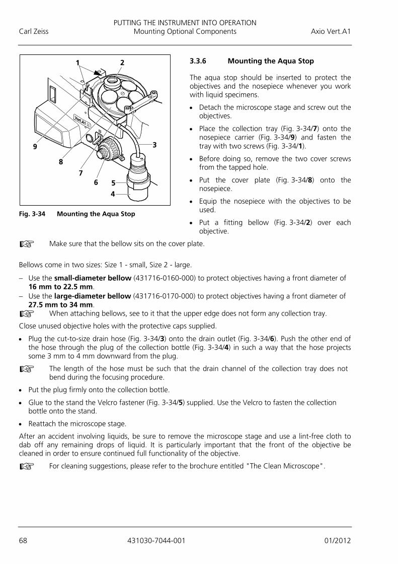
PUTTING THE INSTRUMENT INTO OPERATION Carl Zeiss Mounting Optional Components Axio Vert.A1
68 431030-7044-001 01/2012
3.3.6 Mounting the Aqua Stop
The aqua stop should be inserted to protect the objectives and the nosepiece whenever you work with liquid specimens.
• Detach the microscope stage and screw out the objectives.
• Place the collection tray (Fig. 3-34/7) onto the nosepiece carrier (Fig. 3-34/9) and fasten the tray with two screws (Fig. 3-34/1).
• Before doing so, remove the two cover screws from the tapped hole.
• Put the cover plate (Fig. 3-34/8) onto the nosepiece.
• Equip the nosepiece with the objectives to be used.
• Put a fitting bellow (Fig. 3-34/2) over each objective.
Make sure that the bellow sits on the cover plate.
Bellows come in two sizes: Size 1 - small, Size 2 - large.
− Use the small-diameter bellow (431716-0160-000) to protect objectives having a front diameter of 16 mm to 22.5 mm.
− Use the large-diameter bellow (431716-0170-000) to protect objectives having a front diameter of 27.5 mm to 34 mm.
When attaching bellows, see to it that the upper edge does not form any collection tray.
Close unused objective holes with the protective caps supplied.
• Plug the cut-to-size drain hose (Fig. 3-34/3) onto the drain outlet (Fig. 3-34/6). Push the other end of the hose through the plug of the collection bottle (Fig. 3-34/4) in such a way that the hose projects some 3 mm to 4 mm downward from the plug.
The length of the hose must be such that the drain channel of the collection tray does not bend during the focusing procedure.
• Put the plug firmly onto the collection bottle.
• Glue to the stand the Velcro fastener (Fig. 3-34/5) supplied. Use the Velcro to fasten the collection bottle onto the stand.
• Reattach the microscope stage.
After an accident involving liquids, be sure to remove the microscope stage and use a lint-free cloth to dab off any remaining drops of liquid. It is particularly important that the front of the objective be cleaned in order to ensure continued full functionality of the objective.
For cleaning suggestions, please refer to the brochure entitled "The Clean Microscope".
Fig. 3-34 Mounting the Aqua Stop

PUTTING THE INSTRUMENT INTO OPERATION Axio Vert.A1 Mounting Optional Components Carl Zeiss
01/2012 431030-7044-001 69
3.3.7 Changing LED Modules in the Axio Vert.A1 FL-LED Stand
As soon as the cover is removed from the stand, the power supply to the LED modules is disconnected and the modules stop lighting (interlock protection).
• Turn off the microscope and pull the power cable from the microscope.
• Use ball-headed screwdriver SW 3 to loosen the three screws (Fig. 3-35/1) on the protective cover (Fig. 3-35/2). Take off the cover.
• Press the locking lever on the plug and pull out of the socket the plug (Fig. 3-35/3) of the LED module (Fig. 3-35/5) to be changed. Push the clamping strap (Fig. 3-35/4) of the module mount outward and pull out the LED module.
• Slide the LED module to be employed into the LED mount as far as it will go. The clamping strap will lock the LED module firmly in its groove.
• Insert the plug of the LED module into the corresponding socket until it snaps into position.
• Attach the cover and secure it with the three screws.
• The positions of the LED modules are marked with numbers.
• Make sure that the reflector turret is fitted with filter sets which are suitable for the LED modules used. Reflector turret positions, too, are numbered for that purpose. The LED and the matching filter set need to sit in positions with identical numbers.
Fig. 3-35 Changing the LED Module in the Axio Vert.A1 FL-LED Stand

PUTTING THE INSTRUMENT INTO OPERATION Carl Zeiss Mounting Optional Components Axio Vert.A1
70 431030-7044-001 01/2012
3.3.8 Mounting the Carrier for Transmitted Light Illumination onto the Axio Vert.A1 MAT Stand
If the Axio Vert.A1 MAT stand is to be retrofitted with the optional transmitted light illumination, the carrier for transmitted light illumination must be mounted by the user. If this stand is ordered with transmitted light illumination, the stand will be delivered with the carrier already mounted by the manufacturer. Proceed as follows if you mount the carrier yourself: • Use ball-headed screwdriver SW 5 to remove the two screws (Fig. 3-36/2) on the carrying handle
(Fig. 3-36/3) and then take off the carrying handle. • Remove the cover screw (Fig. 3-36/5) from the tapped hole. • Take the carrier (Fig. 3-36/1) out of the packaging. • Turn out the three Phillips screws (Fig. 3-36/7) of the cover at the back of the carrier (Fig. 3-36/8) and
remove the cover from the carrier. • Set the carrier onto the stand (Fig. 3-36/4) and loosely attach it with the three screws (Fig. 3-36/6 and
9) and washers, using the special screwdriver supplied. • Insert the three-pin plug (Fig. 3-36/10) of the transmitted light illuminator into the upper socket (TL) at
the back of the stand. • Mount both the condenser and the illuminator for the alignment of the carrier for transmitted light
illumination. Align the cone of light centrally to the objective, based on your own visual judgment. Now, tighten the screws firmly.
• Attach the cover to the back of the carrier and loosely fasten it with the three screws.
Fig. 3-36 Mounting the Carrier for Transmitted Light Illumination

OPERATION Axio Vert.A1 Use of LD Objectives Carl Zeiss
01/2012 431030-7044-001 71
4 OPERATION
4.1 Use of LD Objectives
In tests performed with inverted microscopes, vessels are usually employed whose bottom thickness differs considerably from the common cover slip thickness of 0.17 mm.
Normally, the working distances (a) of low-magnification objectives easily bridge such distances.
− A-Plan 5x / 0.12 a = 10.9 mm (in air) or − A-Plan 5x / 0.25 a = 5.3 mm (in air)
When it comes to the medium magnification range, however, those working distances shrink to values around or below 1 mm in most cases. Those objectives can than no longer be utilized for greater bottom thicknesses.
This deficiency can be overcome with special LD (long-distance) objectives. They feature a relatively long working distance as well as the usual 45-mm parfocal length of all the other objectives.
Plug the appropriate cover slip cap (Fig. 3-37/1) onto the objective to adapt LD A-Plan objectives to thin bottoms or cover slips.
4.2 Use of Korr Objectives
For an excellent image, the correct cover slip thickness is important.
It is for this reason that Korr objectives can be adjusted to cover slips of different thicknesses through a correction mount. To this end, select an area of the specimen and determine the position of the correction mount where image sharpness and image contrast are best. (It will always be necessary to readjust sharpness.)
CAUTION
Make sure that the specimen plane is not more than 2.5 mm above the surface of the stage to prevent the LD Korr objective from hitting the underside of the stage. Specimens on a 1-mm thick vessel bottom can be focused if the vessel is moved by the object guide and the mounting frame. In this condition, it is possible to rotate through all the objectives on the specimen stage without collision.
Fig. 3-37 Working with LD Objectives
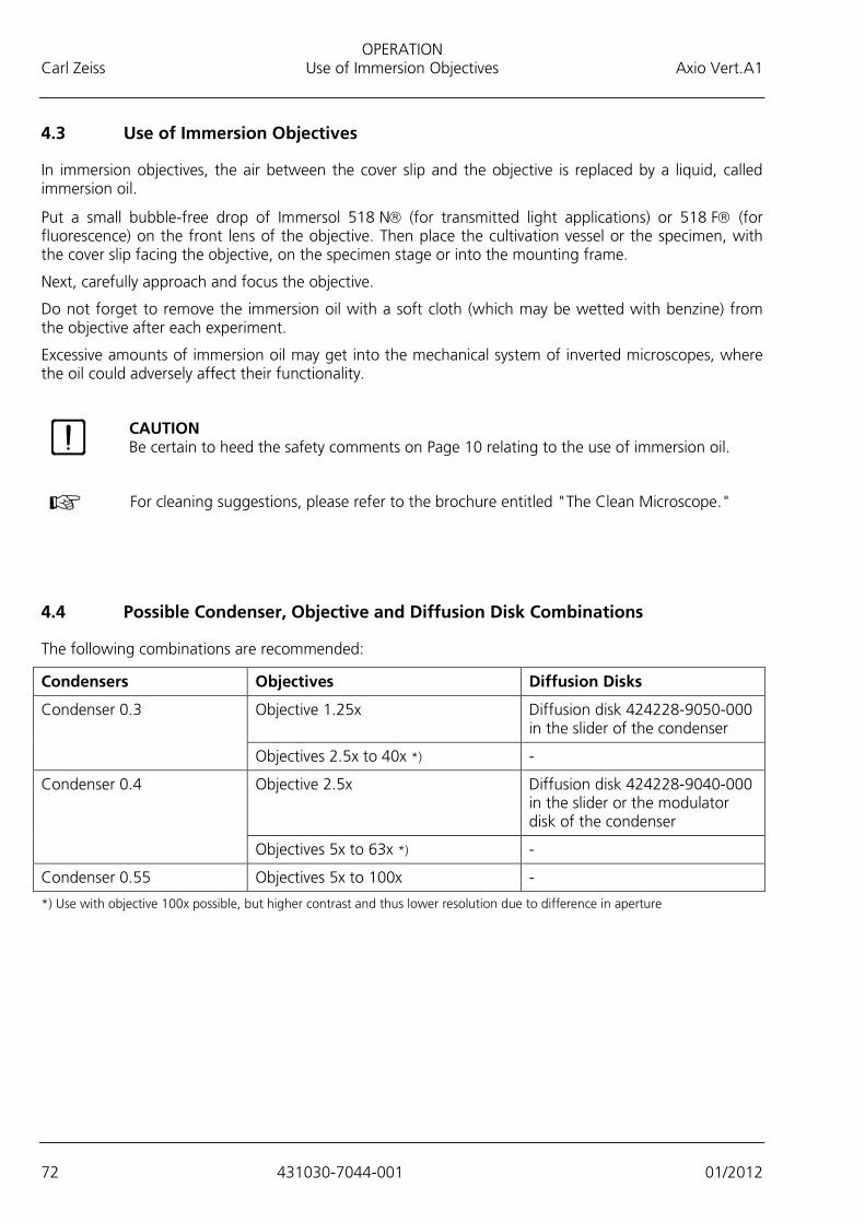
OPERATION Carl Zeiss Use of Immersion Objectives Axio Vert.A1
72 431030-7044-001 01/2012
4.3 Use of Immersion Objectives
In immersion objectives, the air between the cover slip and the objective is replaced by a liquid, called immersion oil.
Put a small bubble-free drop of Immersol 518 N (for transmitted light applications) or 518 F (for fluorescence) on the front lens of the objective. Then place the cultivation vessel or the specimen, with the cover slip facing the objective, on the specimen stage or into the mounting frame.
Next, carefully approach and focus the objective.
Do not forget to remove the immersion oil with a soft cloth (which may be wetted with benzine) from the objective after each experiment.
Excessive amounts of immersion oil may get into the mechanical system of inverted microscopes, where the oil could adversely affect their functionality.
For cleaning suggestions, please refer to the brochure entitled "The Clean Microscope."
4.4 Possible Condenser, Objective and Diffusion Disk Combinations
The following combinations are recommended:
Condensers Objectives Diffusion Disks
Condenser 0.3 Objective 1.25x Diffusion disk 424228-9050-000 in the slider of the condenser
Objectives 2.5x to 40x *) -
Condenser 0.4 Objective 2.5x Diffusion disk 424228-9040-000 in the slider or the modulator disk of the condenser
Objectives 5x to 63x *) -
Condenser 0.55 Objectives 5x to 100x -
*) Use with objective 100x possible, but higher contrast and thus lower resolution due to difference in aperture
CAUTION Be certain to heed the safety comments on Page 10 relating to the use of immersion oil.
OPERATION Axio Vert.A1 Use of Objectives Carl Zeiss
01/2012 431030-7044-001 73
4.5 Use of Objectives
Objectives for Bright Field and PlasDIC
− EC Plan-Neofluar 1.25x − EC Plan-Neofluar 2.5x − A-Plan 2.5x − A-Plan 5x − LD A-Plan 10x to 63x (also suitable for phase contrast if available as Ph objective) − LD Plan-Neofluar Korr 20x, 40x, 63x (also suitable for phase contrast if available as Ph objective)
When Ph objectives are utilized for PlasDIC, imaging quality is slightly diminished.
Objectives for the VAREL, Phase Contrast, DIC or iHMC Contrast Techniques
In order for the objectives to be used for these contrast techniques, the objectives must be expressly approved for them. (See identifier on the objective.)
4.6 ECO Power-Saving Function
The ECO function should be used for short-time microscope use. This will save energy and extend the service life of the transmitted light illumination (halogen lamp).
Activating the Power-Saving Function
• Put the permanent/ECO (Fig. 2-8/15) switch into the ECO position.
The illumination will automatically shut off after approximately 15 minutes of operation and go into the stand-by mode.
• You can terminate the power-saving function by pressing the On/off control button (Fig. 2-8/13), so that the illumination gets switched on again.
• If the On/off control button is actuated during the operation of the microscope, the power-saving function will be activated immediately, with the illumination turned off. Pressing the On/off button once more will switch the illumination on again.
Deactivating the Power-Saving Function (Normal Operating Mode)
• Put the permanent/ECO switch into the permanent position.
The illumination will stay switched on permanently. You can turn the illumination on and off by pressing the On/off control button.

OPERATION Carl Zeiss Height Stop for the Focusing Drive Axio Vert.A1
74 431030-7044-001 01/2012
4.7 Height Stop for the Focusing Drive
The purpose of the height stop for the focusing drive is to limit the uppermost position of the focusing drive, so as to protect the specimen against damage or from being lifted out during the focusing process.
• Turn the clamping lever of the stop (Fig. 4-1/1) upward against the pin.
• Use the focusing drive to move the stage into the desired position.
• Then clamp the stop again by pressing the clamping lever downward.
4.8 Operating Functions on the Axio Vert.A1 FL-LED Stand
TL/RL Switch in RL Position:
You can set reflected light LED brightness by rotating the illumination intensity control button (Fig. 2-8/14).
To permanently save the LED brightness set for the reflector turret position in use, press the control button (Fig. 2-8/14).
You can switch the LED on and off with on/off (Fig. 2-8/13).
TL/RL Switch in TL Position:
LED brightness values are only saved temporarily.
ECO Function:
The ECO function is also effective in reflected light.
Fig. 4-1 Height Stop of the Focusing Drive
OPERATION Axio Vert.A1 Light Manager Function on the Axio Vert.A1 MAT Stand Carl Zeiss
01/2012 431030-7044-001 75
4.9 Light Manager Function on the Axio Vert.A1 MAT Stand
The light manager function can be employed both in reflected light (using the VIS-LED attachment lamp) and transmitted light (using the HAL illuminator or the LED illuminator for transmitted light, provided the optional carrier for transmitted light illumination is installed).
When the HAL 100 is used in reflected light, the light manager is not active, as the HAL 100 is powered by an external power supply unit.
The light manager performs the following functions:
− When the LM Set button is pressed, the current brightness value of the objective used is permanently saved. In other words, the last value stored via the LM Set button will be set again even when you switch the microscope off and turn it on again later.
− Separate values are saved for reflected light and transmitted light.
− The TL/RL switch is in the RL position for reflected light: A brightness value will be saved for every nosepiece position.
− The TL/RL switch is in the TL position for transmitted light: A brightness value will be saved for every nosepiece position.
− Dazzle protect function during objective changes.
The lamp voltage is factory-set to 3 V for every objective position.
4.10 USB Interface on the Axio Vert.A1 MAT Stand
The following functions can be used when you connect a PC via the USB interface and install the AxioVision and ZEN (blue edition) software on your PC.
− Read nosepiece position (positions 1 to 5 of the coded nosepiece).
− Set brightness.
− Turn light manager, including dazzle protection, on and off.
− Recognize reflected light and transmitted light
Requirements:
− MTB 1.8.1.6 (AxioVision)
− MTB 2.0.0.12 (ZEN (blue edition))

OPERATION Carl Zeiss Illumination and Contrast Techniques in Transmitted Light Axio Vert.A1
76 431030-7044-001 01/2012
4.11 Illumination and Contrast Techniques in Transmitted Light
Every Axio Vert.A1 stand version allows the user to apply the transmitted light methods described below (Axio Vert.A1 MAT with optional transmitted light illumination only).
4.11.1 Transmitted Light Bright Field
Requirements
− The microscope must have properly been put into operation, as described in Section 3.
− The microscope must be switched on.
Setting Bright Field
• Check the position of the TL/RL switch and shift it to the TL position if necessary.
• Move the center position on the slider (Fig. 4-2/2) of the condenser or the position for bright field on the condenser with modulator disk into the light path.
• Place the specimen on the specimen stage and use the focusing drive to lock focus at low magnification (e.g., objective 10x, yellow ring).
• Use the lever (Fig. 4-2/3) or the setting wheel to close the aperture diaphragm until optimum contrast is obtained.
The aperture diaphragm is not meant to adjust image brightness (loss of image quality).
• If required, adjust illumination intensity by turning the on/off control button or inserting the
attenuation filter into the filter slider (Fig. 4-2/1) and moving it into the light path.
Use of a conversion filter and a shutter plate is recommended when you employ the LED lamp for transmitted light illumination. To this end, insert the conversion filter and the shutter plate into the positions of the filter slider.
When used with transmitted light LED illumination, the conversion filter creates the usual
daylight impression during the microscoping process. Without that filter, the image may appear slightly bluish on occasion. Do not employ the conversion filter when transmitted light HAL illumination is installed, as HAL might damage the filter as a result of the heat generated.
In order to avoid veiling glare during FL viewing, be sure to fit the supplied shutter plate in the second position of the slider in the carrier to block the light path temporarily.
The bright field position of sliders for condensers is fitted with a neutral-density filter to ensure that, in the event of a contrast change, brightness is adjusted to phase contrast, for instance.
Fig. 4-2 Setting Bright Field
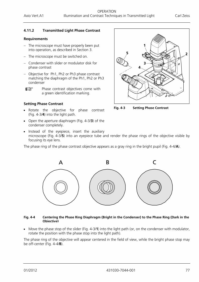
OPERATION Axio Vert.A1 Illumination and Contrast Techniques in Transmitted Light Carl Zeiss
01/2012 431030-7044-001 77
4.11.2 Transmitted Light Phase Contrast
Requirements
− The microscope must have properly been put into operation, as described in Section 3.
− The microscope must be switched on.
− Condenser with slider or modulator disk for phase contrast
− Objective for Ph1, Ph2 or Ph3 phase contrast matching the diaphragm of the Ph1, Ph2 or Ph3 condenser
Phase contrast objectives come with a green identification marking.
Setting Phase Contrast
• Rotate the objective for phase contrast (Fig. 4-3/4) into the light path.
• Open the aperture diaphragm (Fig. 4-3/3) of the condenser completely.
• Instead of the eyepiece, insert the auxiliary microscope (Fig. 4-3/5) into an eyepiece tube and render the phase rings of the objective visible by focusing its eye lens.
The phase ring of the phase contrast objective appears as a gray ring in the bright pupil (Fig. 4-4/A).
• Move the phase stop of the slider (Fig. 4-3/1) into the light path (or, on the condenser with modulator,
rotate the position with the phase stop into the light path).
The phase ring of the objective will appear centered in the field of view, while the bright phase stop may be off-center (Fig. 4-4/B).
Fig. 4-3 Setting Phase Contrast
Fig. 4-4 Centering the Phase Ring Diaphragm (Bright in the Condenser) to the Phase Ring (Dark in the
Objective)
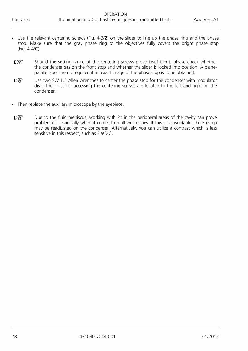
OPERATION Carl Zeiss Illumination and Contrast Techniques in Transmitted Light Axio Vert.A1
78 431030-7044-001 01/2012
• Use the relevant centering screws (Fig. 4-3/2) on the slider to line up the phase ring and the phase stop. Make sure that the gray phase ring of the objectives fully covers the bright phase stop (Fig. 4-4/C).
Should the setting range of the centering screws prove insufficient, please check whether
the condenser sits on the front stop and whether the slider is locked into position. A plane-parallel specimen is required if an exact image of the phase stop is to be obtained.
Use two SW 1.5 Allen wrenches to center the phase stop for the condenser with modulator disk. The holes for accessing the centering screws are located to the left and right on the condenser.
• Then replace the auxiliary microscope by the eyepiece.
Due to the fluid meniscus, working with Ph in the peripheral areas of the cavity can prove
problematic, especially when it comes to multiwell dishes. If this is unavoidable, the Ph stop may be readjusted on the condenser. Alternatively, you can utilize a contrast which is less sensitive in this respect, such as PlasDIC.

OPERATION Axio Vert.A1 Illumination and Contrast Techniques in Transmitted Light Carl Zeiss
01/2012 431030-7044-001 79
4.11.3 Transmitted Light VAREL Contrast
VAREL (variable relief contrast) delivers relief-like images of specimens and can be used as an alternative to phase contrast. VAREL may also be employed for curved surfaces, e.g., 96-microtiter plates, which cannot be contrasted with phase contrast, as it is impossible to set a ring overlap.
Requirements
− The microscope must have properly been put into operation, as described in Section 3.
− The microscope must be switched on. − Condenser with slider for VAREL contrast − Objective for VAREL contrast Setting VAREL Contrast
• Rotate the objective for VAREL contrast into the light path.
• Open the aperture diaphragm (Fig. 4-5/4) on the condenser (Fig. 4-5/5) completely.
• Using a fitting mounting frame, insert the specimen into the retaining clips (Fig. 4-5/3) of the object guide.
• Move the VAREL position of the Ph/PlasDIC, H, VAR slider (Fig. 4-5/2) into the light path until the notch for the currently selected specimen magnification has been found. There are three different notches for VAREL.
• The contrast desired can be adjusted via the setscrew (Fig. 4-5/1).
You may insert the var slider in two different orientations. As a result, different relief
impressions for the various magnifications are produced, depending on the orientation chosen. Even when the condenser is turned 90 degrees, it is possible to adapt the orientation of the relief impression.
Microtiter plates: To ensure excellent contrasting, insert the var slider on the edge of the cavity in such a way that the facing VAREL ring comes into operation. The right or left VAREL ring may be used in the middle of the cavity.
Specimen field with the corresponding pupil image of the VAREL diaphragm (diaphragm appears rotated 180 degrees)
Fig. 4-6 VAREL Contrast for Microtiter Plates
Fig. 4-5 Setting VAREL Contrast

OPERATION Carl Zeiss Illumination and Contrast Techniques in Transmitted Light Axio Vert.A1
80 431030-7044-001 01/2012
Fig. 4-7 VAREL Contrast Pupil Images
4.11.4 Transmitted Light Differential Interference Contrast (DIC)
The transmitted light DIC technique permits a high-contrast, plastic imaging of transparent specimen details. The light linearly polarized by a polarizer is split into two partial beams in a birefringent prism. These beams pass through two neighboring areas of the specimen at a close distance and experience path differences there due to differences in refractive index and specimen thickness. The two partial beams are subsequently merged in a second birefringent prism and end up with the same vibration direction after passing through the analyzer. Consequently, the two partial beams can interfere with one another in the intermediate image, with the path differences resulting in different gray values (intensities).
Requirements
− The microscope must have properly been put into operation, as described in Section 3.
− The microscope must be switched on.
− Condenser 0.4 with modulator disk and built-in DIC I/0.4 or DIC II/0.4 condenser module or condenser 0.55 with modulator disk and built-in DIC I/0.55, DIC II/0.55 or DIC III/0.55 condenser module (Each condenser module comes with a built-in polarizer.)
− Objectives for DIC contrast
− DIC slider matching the objectives used
− D P&C analyzer module in the reflector turret or three-position contrast slider (10 mm x 29 mm) with built-in analyzer for the contrast slider
− Specimen vessel with glass bottom
Moving the VAREL illumination all the way to a position outside of the pupil corresponds to unilateral DF illumination.
Moving the VAREL illumination between the Ph and VAREL rings of the objective corresponds to oblique HF illumination.
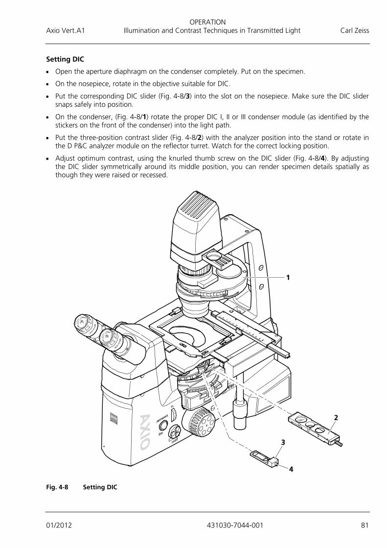
OPERATION Axio Vert.A1 Illumination and Contrast Techniques in Transmitted Light Carl Zeiss
01/2012 431030-7044-001 81
Setting DIC
• Open the aperture diaphragm on the condenser completely. Put on the specimen.
• On the nosepiece, rotate in the objective suitable for DIC.
• Put the corresponding DIC slider (Fig. 4-8/3) into the slot on the nosepiece. Make sure the DIC slider snaps safely into position.
• On the condenser, (Fig. 4-8/1) rotate the proper DIC I, II or III condenser module (as identified by the stickers on the front of the condenser) into the light path.
• Put the three-position contrast slider (Fig. 4-8/2) with the analyzer position into the stand or rotate in the D P&C analyzer module on the reflector turret. Watch for the correct locking position.
• Adjust optimum contrast, using the knurled thumb screw on the DIC slider (Fig. 4-8/4). By adjusting the DIC slider symmetrically around its middle position, you can render specimen details spatially as though they were raised or recessed.
Fig. 4-8 Setting DIC
OPERATION Carl Zeiss Illumination and Contrast Techniques in Transmitted Light Axio Vert.A1
82 431030-7044-001 01/2012
4.11.5 Transmitted Light PlasDIC
PlasDIC, an innovative interference contrast, delivers relief-like images and is to be used for thicker specimens, in particular.
The contrast is variably adjustable. The cavities of microtiter plates can be contrasted right to the edge. Cultivation vessels are not required, but are equally suitable.
Requirements
− The microscope must have properly been put into operation, as described in Section 3.
− The microscope must be switched on.
− Condenser with slider for PlasDIC or condenser 0.4 or 0.55 with modulator disk and built-in slit diaphragm for PlasDIC
− PlasDIC slider, dependent on the objective used, for the corresponding objective position in the nosepiece or three-position contrast slider (10 mm x 29 mm) with built-in LD A-Plan 10x-63x PlasDIC module for the contrast slider (suitable for LD A-Plan 10x to 63x objectives)
− D P&C analyzer module in the reflector turret or three-position contrast slider with built-in analyzer for the contrast slider (one of the two required if a PlasDIC slider is used)
− Objective for PlasDIC (e.g., LD A-Plan 10x, 20x, 32x, 40x or 63x)
Setting PlasDIC
• Open the aperture diaphragm on the condenser completely. Put on the specimen.
• Rotate in the PlasDIC diaphragm on the condenser (Fig. 4-8/1) with modulator disk (or move the PlasDIC position of the slider on the condenser into the light path). Brightness may have to be increased, as appropriate, when you change from bright field to PlasDIC.
• When employing a PlasDIC slider, rotate the D P&C analyzer module of the reflector turret into the light path or move the three-position contrast slider with the analyzer position (Fig. 4-8/2) into the slot under the nosepiece. If you use the PlasDIC module with the three-position contrast slider, no analyzer will be required.
• Rotate in the objective for PlasDIC. The following are suitable objectives: LD A-Plan 10x, 20x, 32x, 40x or 63x, LD Plan-Neofluar Korr 20x, 40x or 63x.
• On the nosepiece, place the PlasDIC slider (Fig. 4-8/4) into the DIC slot of the objective used or move the PlasDIC module, sitting in the slider, into the light path.
• Set the contrast via the knurled thumb screw of the PlasDIC slider (Fig. 4-8/5) or of the PlasDIC module. Structures may be shown in relief or in pseudo dark field images. Relief imaging delivers the best contrast.
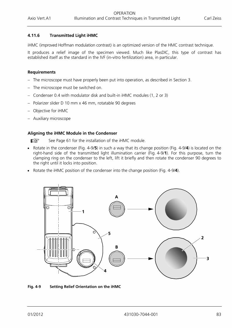
OPERATION Axio Vert.A1 Illumination and Contrast Techniques in Transmitted Light Carl Zeiss
01/2012 431030-7044-001 83
4.11.6 Transmitted Light iHMC
iHMC (improved Hoffman modulation contrast) is an optimized version of the HMC contrast technique.
It produces a relief image of the specimen viewed. Much like PlasDIC, this type of contrast has established itself as the standard in the IVF (in-vitro fertilization) area, in particular.
Requirements
− The microscope must have properly been put into operation, as described in Section 3.
− The microscope must be switched on.
− Condenser 0.4 with modulator disk and built-in iHMC modules (1, 2 or 3)
− Polarizer slider D 10 mm x 46 mm, rotatable 90 degrees
− Objective for iHMC
− Auxiliary microscope
Aligning the iHMC Module in the Condenser
• Rotate in the condenser (Fig. 4-9/5) in such a way that its change position (Fig. 4-9/4) is located on the right-hand side of the transmitted light illumination carrier (Fig. 4-9/1). For this purpose, turn the clamping ring on the condenser to the left, lift it briefly and then rotate the condenser 90 degrees to the right until it locks into position.
• Rotate the iHMC position of the condenser into the change position (Fig. 4-9/4).
Fig. 4-9 Setting Relief Orientation on the iHMC
See Page 61 for the installation of the iHMC module.

OPERATION Carl Zeiss Illumination and Contrast Techniques in Transmitted Light Axio Vert.A1
84 431030-7044-001 01/2012
• If necessary, use the two centering keys to precenter the iHMC module in the mount, based on your visual judgment. The two holes for accessing the centering screws (Fig. 4-10/1) are located under the change position.
You can individually position the diaphragm of the iHMC module in the mount, according to the desired orientation of the relief impression (Fig. 4-9/2) in the field of view (Fig. 4-9/3). For that, see Examples A and B in Fig. 4-9.
The concrete approach selected may, of course, deviate from the examples provided. (The position shown can be altered by as much as 45 degrees.) Whenever iHMC is meant to be employed for several magnifications, it makes sense to proceed in a similar way to position the diaphragms of the iHMC modules, as the relief impression will then have the same orientation in all magnifications.
• Turn the condenser back to its initial orientation until it snaps into position and rotate the clamping ring to the right for locking.
Fig. 4-10 Centering Screws
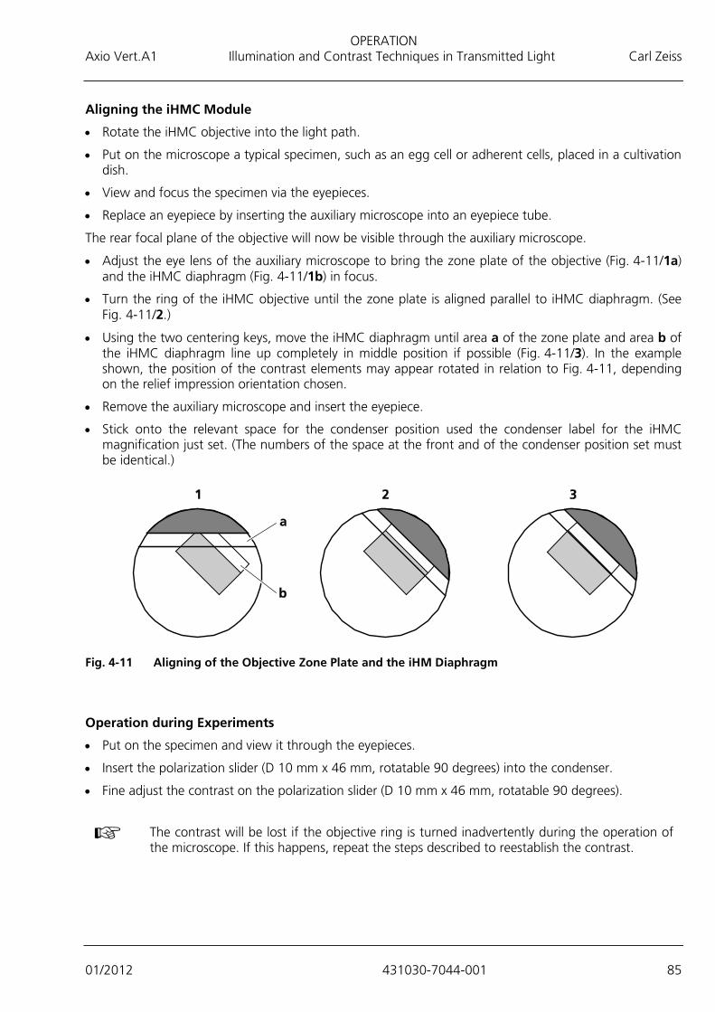
OPERATION Axio Vert.A1 Illumination and Contrast Techniques in Transmitted Light Carl Zeiss
01/2012 431030-7044-001 85
Aligning the iHMC Module
• Rotate the iHMC objective into the light path.
• Put on the microscope a typical specimen, such as an egg cell or adherent cells, placed in a cultivation dish.
• View and focus the specimen via the eyepieces.
• Replace an eyepiece by inserting the auxiliary microscope into an eyepiece tube.
The rear focal plane of the objective will now be visible through the auxiliary microscope.
• Adjust the eye lens of the auxiliary microscope to bring the zone plate of the objective (Fig. 4-11/1a) and the iHMC diaphragm (Fig. 4-11/1b) in focus.
• Turn the ring of the iHMC objective until the zone plate is aligned parallel to iHMC diaphragm. (See Fig. 4-11/2.)
• Using the two centering keys, move the iHMC diaphragm until area a of the zone plate and area b of the iHMC diaphragm line up completely in middle position if possible (Fig. 4-11/3). In the example shown, the position of the contrast elements may appear rotated in relation to Fig. 4-11, depending on the relief impression orientation chosen.
• Remove the auxiliary microscope and insert the eyepiece.
• Stick onto the relevant space for the condenser position used the condenser label for the iHMC magnification just set. (The numbers of the space at the front and of the condenser position set must be identical.)
Fig. 4-11 Aligning of the Objective Zone Plate and the iHM Diaphragm
Operation during Experiments
• Put on the specimen and view it through the eyepieces.
• Insert the polarization slider (D 10 mm x 46 mm, rotatable 90 degrees) into the condenser.
• Fine adjust the contrast on the polarization slider (D 10 mm x 46 mm, rotatable 90 degrees).
The contrast will be lost if the objective ring is turned inadvertently during the operation of the microscope. If this happens, repeat the steps described to reestablish the contrast.

OPERATION Carl Zeiss Illumination and Contrast Techniques in Transmitted Light Axio Vert.A1
86 431030-7044-001 01/2012
4.11.7 Transmitted Light Polarization Contrast
The technique of viewing transparent objects between crossed polarization filters is employed in geology and mineralogy, in particular. Increasingly, it is also used for plastic, glass, technical films, etc.
With this technique, optical anisotropies (e.g., tensions) are rendered visible, which would otherwise go undetected with reflected or transmitted light methods.
Setting the Polarization on the Axio Vert.A1 MAT, Using Polarizer DL and Analyzer Slider A 12x35 mm, Rotatable 90 Degrees
• Set up the microscope for bright field in transmitted light.
• Slide polarizer DL (Fig. 4-12/1) on the condenser (Fig. 4-12/2) in the light path.
• Insert the analyzer slider (Fig. 4-13/2) (a P&C analyzer module in the reflector turret may be used as an alternative) into the slot (Fig. 4-13/1) under the nosepiece. The analyzer can be rotated 90 degrees.
• Use the analyzer turning lever (Fig. 4-13/4) to cross the vibration direction of the analyzer and polarizer (dark position).
• The analyzer slider may be inserted both from the left-hand and right-hand sides.
For the purpose of color-contrasting
anisotropic materials, compensator Lambda or compensator Lambda Pol sub. ±10° (Fig. 4-16/3) may be used. To do so, place the compensator on the analyzer.
The typical approach would be first to bring in crossed position the polarizer and analyzer, without the specimen being in the light path, and to put on the specimen only when the field of view has reached maximum darkness.
Polarizer DL may only be used together with condenser 0.4 with modulator disk 424228-
9010-000.
Fig. 4-12 Setting Bright Field
Fig. 4-13 Setting the Polarization

OPERATION Axio Vert.A1 Illumination and Contrast Techniques in Reflected Light Carl Zeiss
01/2012 431030-7044-001 87
4.12 Illumination and Contrast Techniques in Reflected Light
4.12.1 Reflected Light Bright Field
Reflected light bright field microscopy is the simplest and most common optical microscopy technique designed to examine opaque specimens or objects, such as polished material faces or wafers.
The light coming from and concentrated by the reflected light illuminator is reflected on a neutral-colored beam splitter and subsequently passes through the objective, which focuses the beams on the surface of the specimen (also known as condenser function). The objective collects the light reflected off the object and, together with the tube lens, generates the microscopic intermediate image, which can subsequently be observed visually or documented objectively.
Requirements
− The microscope must have properly been put into operation, as described in Section 3.
− The microscope must be switched on.
− VIS-LED or HAL 100 reflected light illumination
Setting Bright Field
• Place the specimen on the specimen stage (Fig. 4-14/1) and focus at weak magnification, e.g., using the EC Epiplan 10x objective and the focusing drive (Fig. 4-14/3). Set the position for bright field on the reflector turret (Fig. 4-14/2).
• Close the luminous field diaphragm (Fig. 4-14/7) until its edge becomes visible in the field of view. Use ball-headed screwdriver SW 3 to center the luminous field diaphragm to the edge of the field of view.
• Close the aperture diaphragm (Fig. 4-14/6) slightly. Remove the eyepiece.
• Use the centering screws to center the aperture diaphragm.
• Use the adjustment wheel to set the size of the aperture diaphragm for specimens with medium-level contrast properties to approximately two thirds to four fifths of the objective exit pupil diameter. Reinsert the eyepiece.
The aperture diaphragm is not meant to adjust image brightness.
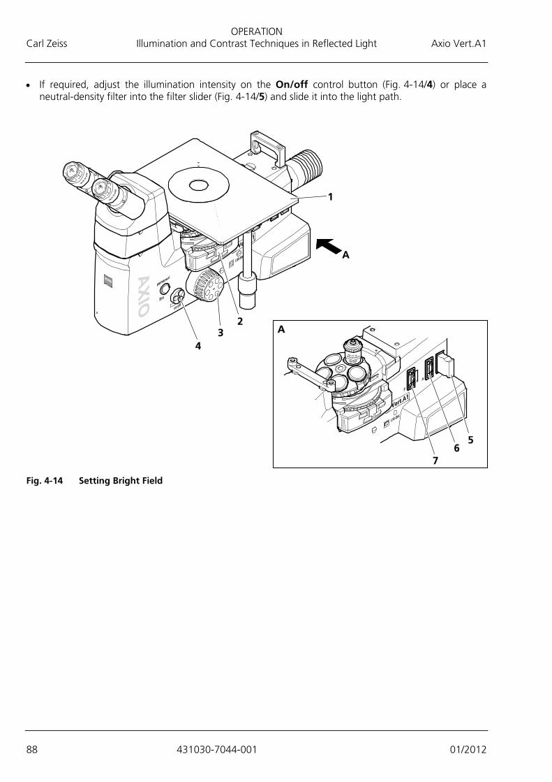
OPERATION Carl Zeiss Illumination and Contrast Techniques in Reflected Light Axio Vert.A1
88 431030-7044-001 01/2012
• If required, adjust the illumination intensity on the On/off control button (Fig. 4-14/4) or place a neutral-density filter into the filter slider (Fig. 4-14/5) and slide it into the light path.
Fig. 4-14 Setting Bright Field

OPERATION Axio Vert.A1 Illumination and Contrast Techniques in Reflected Light Carl Zeiss
01/2012 431030-7044-001 89
4.12.2 Reflected Light Dark Field
The reflected light dark field technique is used when not entirely reflecting surfaces with differences in reflectivity (ideal bright field objects) are examined, but scratches, cracks and pores exist - in short, when there are deviations from plane surfaces. All the light-scattering details will light up brightly in the dark field, while reflecting plane surfaces will remain dark.
Requirements
− The microscope must have properly been put into operation, as described in Section 3.
− The microscope must be switched on.
− VIS-LED or HAL 100 reflected light illumination
− Objectives for dark field (designation: HD)
− P&C dark field module
Setting Dark Field
• Rotate in the dark field objective on the nosepiece.
• Open the luminous field and aperture diaphragms completely and switch off or remove the neutral-density filter, as appropriate.
• Put on the specimen and focus.

OPERATION Carl Zeiss Illumination and Contrast Techniques in Reflected Light Axio Vert.A1
90 431030-7044-001 01/2012
4.12.3 Reflected Light DIC
The reflected light DIC or reflected light C-DIC technique (DIC = differential interference contrast; C-DIC = differential interference contrast in circularly polarized light) allows a high-contrast imaging of phase objects, i.e., objects which, unlike amplitude objects, only change the phase of the light.
Requirements
− The microscope must have properly been put into operation, as described in Section 3.
− The microscope must be switched on.
− VIS-LED or HAL 100 reflected light illumination
− Objectives for DIC or polarization (designation: DIC or Pol)
− DIC slider (matching the objective concerned; name of objective, magnification and aperture are engraved on the upper side of the slider) or C-DIC slider
− For DIC: DIC P&C or DIC Rot I P&C reflector module
− For C-DIC: C-DIC/TIC reflector module
Setting DIC
• Set up the microscope for reflected light bright field, as described in Section 4.12.1. Open the luminous field diaphragm until the edge of the diaphragm just about disappears from the field of view to avoid reflections.
• On the reflector turret, rotate the DIC P&C reflector module into the light path. To create color contrasts, the DIC Rot I P&C reflector module should be used, as it offers advantages in the presence of big path differences (> 1λ).
• On the nosepiece, rotate in the objective position with DIC.
• Put the DIC slider (Fig. 4-15/2) into the slot of the nosepiece.
• Put on the specimen and focus until the structure of interest is visible with maximum contrast.
• You can optimize the contrast with the knurled thumb screw located on the DIC slider.
Fig. 4-15 Setting DIC/C-DIC

OPERATION Axio Vert.A1 Illumination and Contrast Techniques in Reflected Light Carl Zeiss
01/2012 431030-7044-001 91
Setting C-DIC
• Set the microscope up for reflected light bright field.
• Rotate the C-DIC P&C reflector module into the light path.
• Insert C-DIC slider 6x20 (Fig. 4-15/1) into the slot.
• Put on the specimen, focus and turn the adjustment wheel on C-DIC slider 6x20, so that the structure of interest is visible with maximum contrast.
• You can create additional contrast effects by turning the adjustment wheel on the C-DIC slider.
Additional Comment
When using the differential interference contrast or the differential interference contrast in circularly polarized light, the contrast develops through a pseudo-relief in the specimen. When it comes to linear structures, the contrast depends, therefore, on whether those structures are oriented in "light-shadow" direction (very little contrast) or vertically to it (maximum contrast).
When you employ C-DIC slider 6x20, you can align the structures vertically to the "light-shadow" direction and thus set maximum contrast by turning the adjustment wheel of the C-DIC slider.
OPERATION Carl Zeiss Illumination and Contrast Techniques in Reflected Light Axio Vert.A1
92 431030-7044-001 01/2012
4.12.4 Reflected Light Polarization
Reflected light polarization is another contrasting option for polished faces of ore minerals, coal, ceramic products, certain metals and metal alloys, as those often exhibit a different reflection behavior in linearly polarized light, depending on the orientation of the crystals or object details.
The polarizer polarizes the illumination light linearly and transmits it, via the objective, onto the specimen surface, where it is reflected. There, the light rays experience structure-related path differences or polarization optical rotations, which present themselves as different gray values when passing the analyzer.
Requirements
− The microscope must have properly been put into operation, as described in Section 3.
− The microscope must be switched on.
− VIS-LED or HAL 100 reflected light illumination
− Objectives for polarization (designation: Pol)
− DIC P&C reflector module in the reflector turret; or Pol P&C reflector module plus analyzer slider A 12x35 mm, rotatable 90 degrees, with compensator Lambda; or analyzer slider A 12x35 mm, rotatable 90 degrees, with compensator Lambda plus polarizer slider A 6x30 mm
Setting Polarization with the DIC P&C Reflector Module
• Set up the microscope, as described in Section 4.12.1, for bright field in reflected light. If the DIC slider is still in place, remove it, as appropriate.
• Rotate in the DIC P&C reflector module on the reflector turret.
The analyzer and polarizer are fixed in crossed position in the DIC P&C reflector module.

OPERATION Axio Vert.A1 Illumination and Contrast Techniques in Reflected Light Carl Zeiss
01/2012 431030-7044-001 93
Setting Polarization with the Pol P&C Reflector Module and Analyzer Slider A 12x35 mm, Rotatable 90 Degrees
• Set up the microscope for bright field in reflected light.
• Rotate in the Pol P&C reflector module on the reflector turret.
• Insert the analyzer slider (Fig. 4-16/2) into the slot (Fig. 4-16/1) under the reflector turret. The analyzer can be rotated 90 degrees.
• Use the analyzer turning lever to cross the vibration direction of the analyzer and polarizer (Fig. 4-16/4) (dark position).
• The analyzer slider may be inserted both from the left-hand and right-hand sides.
For the purpose of color-contrasting anisotropic materials, compensator Lambda Pol sub. ±10° (Fig. 4-16/3) may be used in addition to compensator Lambda. To do so, place the compensator on the analyzer.
Setting Polarization with Analyzer Slider A 12x35 mm, Rotatable 90 Degrees, and Polarizer Slider A 6x30 mm
• Set up the microscope for reflected light bright field.
• Insert the analyzer slider into the opening under the reflector turret. The analyzer can be rotated 90 degrees.
• Insert the polarizer slider into the opening beside the luminous field diaphragm. The polarizer can be rotated 90 degrees.
• Cross the vibration direction of the analyzer and polarizer.
Fig. 4-16 Setting the Polarization

OPERATION Carl Zeiss Illumination and Contrast Techniques in Reflected Light Axio Vert.A1
94 431030-7044-001 01/2012
4.12.5 Reflected Light Fluorescence
The reflected light fluorescence method allows fluorescent substances to be presented in a high-contrast manner and in typical fluorescence colors. In a reflected light fluorescence microscope, the light produced by a high-performance illuminator reaches the excitation filter through a heat protection filter. The filtered short-wavelength excitation radiation is reflected by a dichroic beam splitter and then focused on the specimen via the objective. The specimen absorbs the short-wavelength radiation and subsequently emits fluorescence radiation of a longer wavelength (Stoke's Law), which is picked up as an image by the objective and transmitted by the dichroic beam splitter. The rays eventually pass through a barrier filter, which allows only the long-wavelength radiation emitted by the specimen to go through.
The excitation and barrier filters need to be very accurately matched spectrally and are located in an FL P&C reflector module, together with the corresponding dichroic beam splitter.
Requirements
− Stand Axio Vert.A1 FL or Axio Vert.A1 with HBO / HXP illuminator
or
− Axio Vert.A1 FL-LED stand with LED modules mounted
− The microscope must have been properly put into operation and switched on, as described in Section 3.
− Bright field objectives
− FL P&C reflector module in the reflector turret
− Illuminators for fluorescence (HBO 50, HBO 100, Colibri 2, HXP 120 C)
− Prior to their use, the HBO 50 or HBO 100 illuminators need to be adjusted and warmed up for about 15 minutes, as described in Section 3.1.11.2 and 3.1.11.3, respectively.
− HAL illuminator or LED illuminator for transmitted light illumination
Setting Fluorescence
• Select the area of the specimen in transmitted light bright field or phase contrast. To this end, switch the reflector turret (Fig. 4-17/4) to free passage and set the position for bright field or phase contrast on the condenser (Fig. 4-17/2).
• Use the power supply unit (Fig. 4-17/7) to turn on the fluorescence illumination, e.g., the HBO 50 illuminator (Fig. 4-17/3).
• Use the reflected light shutter (Fig. 2-7/25) to keep the light path temporarily blocked.
• Once you have selected the area of the specimen, use the on/off function (Fig. 4-17/5 and 6) to switch off the transmitted light illumination (Fig. 4-17/1).
When you employ the Axio Vert.A1 FL-LED stand, the TL/RL switch (Fig. 2-8/20) lets you shift directly between transmitted light and reflected light.
• Using the reflector turret (Fig. 4-17/4), rotate in the desired filter set and unblock the light path with the reflected light shutter (Fig. 2-7/25).
• Close the luminous field diaphragm (Fig. 4-17/10) until it is visible in the image. Using the centering screws, move the diaphragm into the center position and open it all the way to the edge of the field of view.
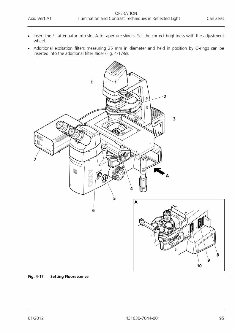
OPERATION Axio Vert.A1 Illumination and Contrast Techniques in Reflected Light Carl Zeiss
01/2012 431030-7044-001 95
• Insert the FL attenuator into slot A for aperture sliders. Set the correct brightness with the adjustment wheel.
• Additional excitation filters measuring 25 mm in diameter and held in position by O-rings can be inserted into the additional filter slider (Fig. 4-17/8).
Fig. 4-17 Setting Fluorescence
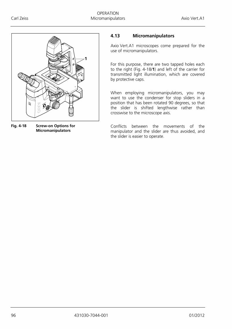
OPERATION Carl Zeiss Micromanipulators Axio Vert.A1
96 431030-7044-001 01/2012
4.13 Micromanipulators
Axio Vert.A1 microscopes come prepared for the use of micromanipulators.
For this purpose, there are two tapped holes each to the right (Fig. 4-18/1) and left of the carrier for transmitted light illumination, which are covered by protective caps.
When employing micromanipulators, you may want to use the condenser for stop sliders in a position that has been rotated 90 degrees, so that the slider is shifted lengthwise rather than crosswise to the microscope axis.
Conflicts between the movements of the manipulator and the slider are thus avoided, and the slider is easier to operate.
Fig. 4-18 Screw-on Options for
Micromanipulators

CARE, MAINTENANCE, TROUBLESHOOTING AND SERVICE Axio Vert.A1 Care Carl Zeiss
01/2012 431030-7044-001 97
5 CARE, MAINTENANCE, TROUBLESHOOTING AND SERVICE
5.1 Care
Microscope care is limited to the following:
• Place the dust cover over the microscope after each use.
• Do not set up the microscope in a moist room.
• Put dust caps on open tubes.
• Remove dust and loose dirt particles on visible optical surfaces with a brush, a blower brush, cotton swabs, optical cleaning paper or cotton cloths.
• Remove water-soluble dirt (coffee, cola, etc.) by breathing on it and wiping it off with a dust-free cotton cloth or a moistened cloth. A mild detergent may be added to the water.
• Remove stubborn oily or greasy dirt (immersion oils, finger prints), using cotton swabs or a dust-free cotton cloth and optical cleaning mixture L. This cleaning mixture is made from 90 volume percent of benzine and 10 volume percent of isopropanol (IPA). The ingredients are also known under the following synonyms: Benzine: Ligroin, petroleum ether Isopropanol: 2-propanol, dimethyl carbinol, 2-hydroxypropane
Before cleaning, switch off the microscope and pull the power plug.
Clean the optical surface, using a circular motion from the middle outward to the edge of the surface. In so doing, apply light pressure on the optical surface.
Heed the following suggestions when using the Axio Vert.A1 in regions with a hot and humid climate:
• Keep the microscope in bright, dry and well-ventilated rooms, where humidity is less than 65 %. Store particularly susceptible components and accessories, such as objectives and eyepieces, in drying cabinets.
• If you store the microscope in closed containers for a prolonged period, place fungicide-soaked cloths in the containers to prevent mold growth.
Precision mechanical and optical instruments are always prone to mold growth if
− relative humidity exceeds 75 % for more than three days at temperatures between +15 °C and +35 °C,
− they are set up in dark rooms without air movement and
− there are dust deposits and finger prints on optical surfaces.
The instruments are not equipped with any special devices that offer protection against caustic, potentially infectious, toxic, radioactive or other health-impairing samples. When working with such specimens, be sure to observe all applicable legal requirements, notably national accident prevention regulations.
− Remove contaminations on the instrument in accordance with the applicable accident prevention regulations.
− Be sure to switch the microscope off after each use and place the protective cover over the instrument to protect it from dust and moisture.
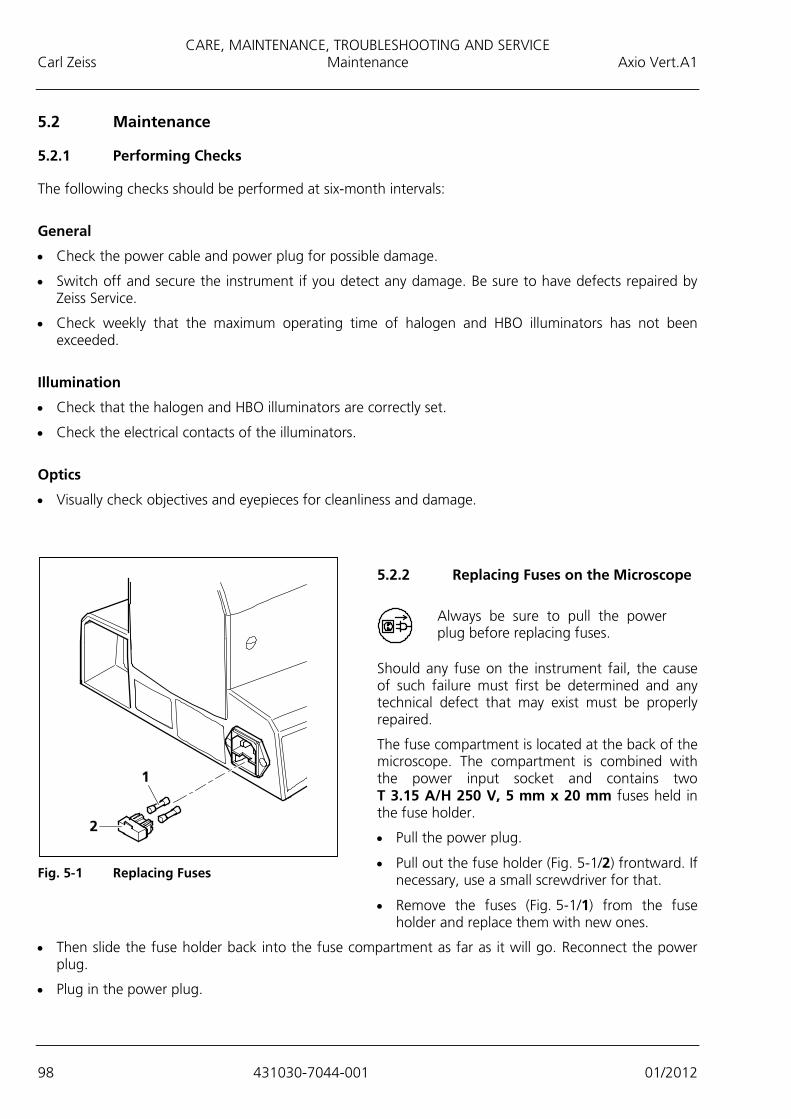
CARE, MAINTENANCE, TROUBLESHOOTING AND SERVICE Carl Zeiss Maintenance Axio Vert.A1
98 431030-7044-001 01/2012
5.2 Maintenance
5.2.1 Performing Checks
The following checks should be performed at six-month intervals:
General
• Check the power cable and power plug for possible damage.
• Switch off and secure the instrument if you detect any damage. Be sure to have defects repaired by Zeiss Service.
• Check weekly that the maximum operating time of halogen and HBO illuminators has not been exceeded.
Illumination
• Check that the halogen and HBO illuminators are correctly set.
• Check the electrical contacts of the illuminators.
Optics
• Visually check objectives and eyepieces for cleanliness and damage.
5.2.2 Replacing Fuses on the Microscope
Always be sure to pull the power plug before replacing fuses.
Should any fuse on the instrument fail, the cause of such failure must first be determined and any technical defect that may exist must be properly repaired.
The fuse compartment is located at the back of the microscope. The compartment is combined with the power input socket and contains two T 3.15 A/H 250 V, 5 mm x 20 mm fuses held in the fuse holder.
• Pull the power plug.
• Pull out the fuse holder (Fig. 5-1/2) frontward. If necessary, use a small screwdriver for that.
• Remove the fuses (Fig. 5-1/1) from the fuse holder and replace them with new ones.
• Then slide the fuse holder back into the fuse compartment as far as it will go. Reconnect the power plug.
• Plug in the power plug.
Fig. 5-1 Replacing Fuses
CARE, MAINTENANCE, TROUBLESHOOTING AND SERVICE Axio Vert.A1 Service Carl Zeiss
01/2012 431030-7044-001 99
5.3 Service
Be sure to have all the repairs of optical parts or motion elements located inside the instrument, as well as work on the power supply performed by customer service or specially authorized personnel only. In order to ensure that your microscope stays optimally adjusted and operates smoothly for a longer period of time, we recommend that you sign a service / maintenance contract with Carl Zeiss.
Whenever you require service, contact your regional dealer or Carl Zeiss MicroImaging GmbH Postfach 4041, D - 37030 Göttingen, Germany Telephone: +49 (0) 551 5060 660 Fax: +49 (0) 551 5060 464 E-mail: [email protected] www.zeiss.de
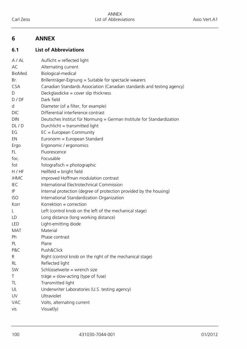
ANNEX Carl Zeiss List of Abbreviations Axio Vert.A1
100 431030-7044-001 01/2012
6 ANNEX
6.1 List of Abbreviations
A / AL Auflicht = reflected light AC Alternating current BioMed. Biological-medical Br. Brillenträger-Eignung = Suitable for spectacle wearers CSA Canadian Standards Association (Canadian standards and testing agency) D Deckglasdicke = cover slip thickness D / DF Dark field d Diameter (of a filter, for example) DIC Differential interference contrast DIN Deutsches Institut für Normung = German Institute for Standardization DL / D Durchlicht = transmitted light EG EC = European Community EN Euronorm = European Standard Ergo Ergonomic / ergonomics FL Fluorescence foc. Focusable fot fotografisch = photographic H / HF Hellfeld = bright field iHMC improved Hoffman modulation contrast IEC International Electrotechnical Commission IP Internal protection (degree of protection provided by the housing) ISO International Standardization Organization Korr Korrektion = correction L Left (control knob on the left of the mechanical stage) LD Long distance (long working distance) LED Light-emitting diode MAT Material Ph Phase contrast PL Plane P&C Push&Click R Right (control knob on the right of the mechanical stage) RL Reflected light SW Schlüsselweite = wrench size T träge = slow-acting (type of fuse) TL Transmitted light UL Underwriter Laboratories (U.S. testing agency) UV Ultraviolet VAC Volts, alternating current vis Visual(ly)
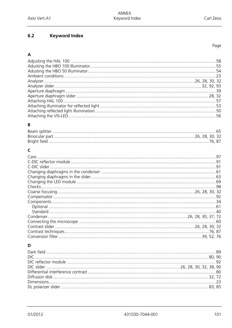
ANNEX Axio Vert.A1 Keyword Index Carl Zeiss
01/2012 431030-7044-001 101
6.2 Keyword Index
Page
A Adjusting the HAL 100 ....................................................................................................................... 58 Adusting the HBO 100 Illuminator ....................................................................................................... 55 Adusting the HBO 50 Illuminator ......................................................................................................... 54 Ambient conditions ............................................................................................................................ 23 Analyzer ............................................................................................................................26, 28, 30, 32 Analyzer slider ........................................................................................................................ 32, 92, 93 Aperture diaphragm ........................................................................................................................... 39 Aperture diaphragm slider ............................................................................................................ 28, 32 Attaching HAL 100 ............................................................................................................................. 57 Attaching illuminator for reflected light ............................................................................................... 53 Attaching reflected light illumination ................................................................................................... 50 Attaching the VIS-LED ......................................................................................................................... 56
B Beam splitter ...................................................................................................................................... 65 Binocular part ....................................................................................................................26, 28, 30, 32 Bright field ................................................................................................................................... 76, 87
C Care ................................................................................................................................................... 97 C-DIC reflector module ....................................................................................................................... 91 C-DIC slider ........................................................................................................................................ 91 Changing diaphragms in the condenser .............................................................................................. 61 Changing diaphragms in the slider ...................................................................................................... 63 Changing the LED module .................................................................................................................. 69 Checks ............................................................................................................................................... 98 Coarse focusing .................................................................................................................26, 28, 30, 32 Compensator ..................................................................................................................................... 92 Components ...................................................................................................................................... 34
Optional ......................................................................................................................................... 61 Standard ......................................................................................................................................... 40
Condenser................................................................................................................... 26, 28, 30, 37, 72 Connecting the microscope ................................................................................................................ 60 Contrast slider ...................................................................................................................26, 28, 30, 32 Contrast techniques ...................................................................................................................... 76, 87 Conversion filter ..................................................................................................................... 39, 52, 76
D Dark field ........................................................................................................................................... 89 DIC .............................................................................................................................................. 80, 90 DIC reflector module .......................................................................................................................... 92 DIC slider .............................................................................................................. 26, 28, 30, 32, 38, 90 Differential interference contrast ......................................................................................................... 80 Diffusion disk ............................................................................................................................... 32, 72 Dimensions ......................................................................................................................................... 23 DL polarizer slider ......................................................................................................................... 83, 85

ANNEX Carl Zeiss Keyword Index Axio Vert.A1
102 431030-7044-001 01/2012
E ECO ............................................................................................................................ 26, 28, 30, 32, 73 Equipping the reflector turret ...............................................................................................................49 Ergotube .............................................................................................................................................35 Eye deficiency .....................................................................................................................................43 Eyepiece reticle....................................................................................................................................42 Eyepieces .................................................................................................................... 26, 28, 30, 32, 42
F Filter set ..............................................................................................................................................64 Filter slider ........................................................................................................................ 26, 28, 30, 32 Filter slider reflected light .....................................................................................................................39 Filter slider transmitted light .................................................................................................................39 Fine focusing ..................................................................................................................... 26, 28, 30, 32 FL reflector module .............................................................................................................................64 Fluorescence .......................................................................................................................................94 Focusing drive ................................................................................................................... 26, 28, 30, 32
G Gliding stage Z ....................................................................................................................................46
H HAL illuminator ...................................................................................................................................50 Halogen lamp ............................................................................................................................... 51, 59 Height stop ................................................................................................................. 26, 28, 30, 32, 74
I iHMC ............................................................................................................................................ 83, 85 Illumination intensity ......................................................................................................... 26, 28, 30, 32 Illumination method ...................................................................................................................... 76, 87 Immersion objective ............................................................................................................................72 Inserting a condenser ..........................................................................................................................47 Inserting stop sliders ............................................................................................................................48 Instrument description ................................................................................................................... 15, 16 Instrument safety ................................................................................................................................. 8 Intended use .......................................................................................................................................15 Intermediate phototube .......................................................................................................................34 Intermediate tube ................................................................................................................................34 Interpupillary distance..........................................................................................................................35 Introduction ......................................................................................................................................... 8
K Korr objective ......................................................................................................................................71
L LED illuminator ....................................................................................................................................52 Light manager function .......................................................................................................................75 Light sources .......................................................................................................................................25 LM set ................................................................................................................................................32 Luminous field diaphragm slider .................................................................................................... 28, 32 Luminous light diaphragm ...................................................................................................................39

ANNEX Axio Vert.A1 Keyword Index Carl Zeiss
01/2012 431030-7044-001 103
M Main feature ...................................................................................................................................... 16 Maintenance ...................................................................................................................................... 98 Mechanical stage ...............................................................................................................28, 32, 36, 44 Micromanipulators .............................................................................................................................. 96 Microscope stage ......................................................................................................... 26, 28, 32, 36, 44 Modulator disk ....................................................................................................................... 37, 38, 61 Mounting frame ................................................................................................................................. 36 Mounting the Aqua Stop .................................................................................................................... 68 Mounting the carrier for transmitted light illumination ......................................................................... 70
N Name ................................................................................................................................................. 15 Notes on warranty .............................................................................................................................. 13
O Objective ...................................................................................................................................... 72, 73 Objective nosepiece ..................................................................................................... 26, 28, 30, 32, 38 On / Off switch ..................................................................................................................26, 28, 30, 32 Operating data ................................................................................................................................... 23 Operation ........................................................................................................................................... 71 Operation and functional elements .............................................................................. 26, 28, 30, 32, 34 Optomechanical data .......................................................................................................................... 25
P Permanent / ECO toggle switch ..................................................................................................... 30, 73 Phase contrast .................................................................................................................................... 77 Phototube .......................................................................................................................................... 34 PlasDIC ............................................................................................................................................... 82 PlasDIC module .................................................................................................................26, 28, 30, 32 PlasDIC slider .....................................................................................................................26, 28, 30, 32 Pol reflector module ........................................................................................................................... 92 Polarization ........................................................................................................................................ 92 Polarizer slider A ..................................................................................................................... 32, 92, 93 Polarizer slider DL ............................................................................................................................... 37 Power indicator .................................................................................................................26, 28, 30, 32 Power-saving function ........................................................................................................................ 73 Property rights .................................................................................................................................. 105 Putting the instrument into operation .................................................................................................. 40 Putting the microscope into operation ................................................................................................. 40
R Reflected light ........................................................................................... 28, 30, 32, 87, 89, 90, 92, 94 Reflected light illumination for fluorescence applications ...................................................................... 28 Reflected light LED illumination for fluorescence applications ............................................................... 30 Reflected light shutter ......................................................................................................................... 28 Reflected-light illumination ........................................................................................................... 32, 52 Reflector module ................................................................................................................................ 90 Reflector turret ....................................................................................................................... 28, 30, 32 Replacing Fuses .................................................................................................................................. 98 Reticle ................................................................................................................................................ 42
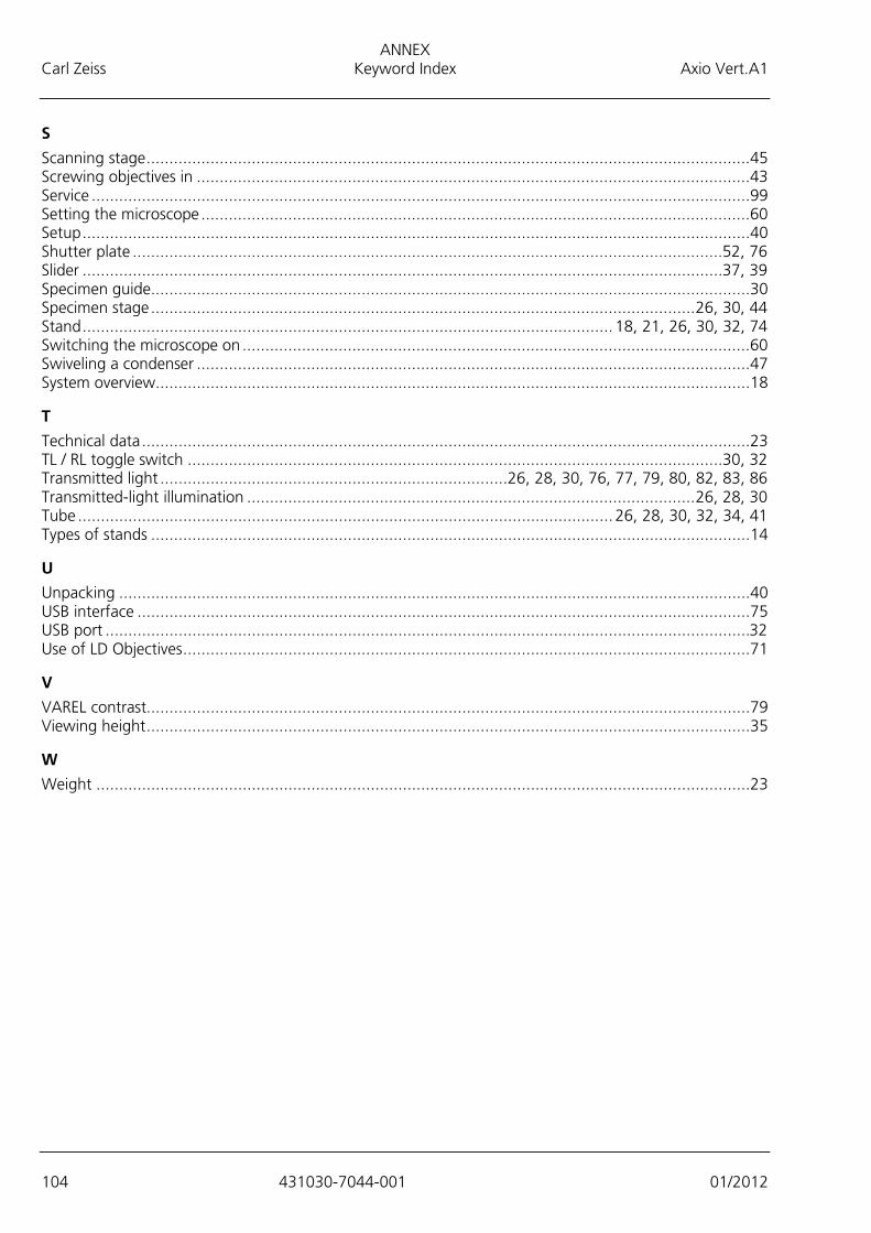
ANNEX Carl Zeiss Keyword Index Axio Vert.A1
104 431030-7044-001 01/2012
S Scanning stage ....................................................................................................................................45 Screwing objectives in .........................................................................................................................43 Service ................................................................................................................................................99 Setting the microscope ........................................................................................................................60 Setup ..................................................................................................................................................40 Shutter plate ................................................................................................................................. 52, 76 Slider ............................................................................................................................................ 37, 39 Specimen guide ...................................................................................................................................30 Specimen stage ....................................................................................................................... 26, 30, 44 Stand .................................................................................................................... 18, 21, 26, 30, 32, 74 Switching the microscope on ...............................................................................................................60 Swiveling a condenser .........................................................................................................................47 System overview ..................................................................................................................................18
T Technical data .....................................................................................................................................23 TL / RL toggle switch ..................................................................................................................... 30, 32 Transmitted light ............................................................................ 26, 28, 30, 76, 77, 79, 80, 82, 83, 86 Transmitted-light illumination .................................................................................................. 26, 28, 30 Tube ..................................................................................................................... 26, 28, 30, 32, 34, 41 Types of stands ...................................................................................................................................14
U Unpacking ..........................................................................................................................................40 USB interface ......................................................................................................................................75 USB port .............................................................................................................................................32 Use of LD Objectives ............................................................................................................................71
V VAREL contrast....................................................................................................................................79 Viewing height ....................................................................................................................................35
W Weight ...............................................................................................................................................23

ANNEX Axio Vert.A1 Property Rights Carl Zeiss
01/2012 431030-7044-001 105
6.3 Property Rights
The instruments, components or processes described in this manual are protected by the following patents:
− See the label attached to the microscope stand.

Related Documents


