SPEC.732118.019 RE Agreed: FSUE “VNIIFTRI” OS VSI “VNIIFTRI” Operating Manual Explosion-proof Infrared Projector Relion-TKV-300-N-IK Relion-TKV-300-A-IK Relion-TKV-300-M-IK 2017

Welcome message from author
This document is posted to help you gain knowledge. Please leave a comment to let me know what you think about it! Share it to your friends and learn new things together.
Transcript
SPEC.732118.019 RE
Agreed:
FSUE “VNIIFTRI”
OS VSI “VNIIFTRI”
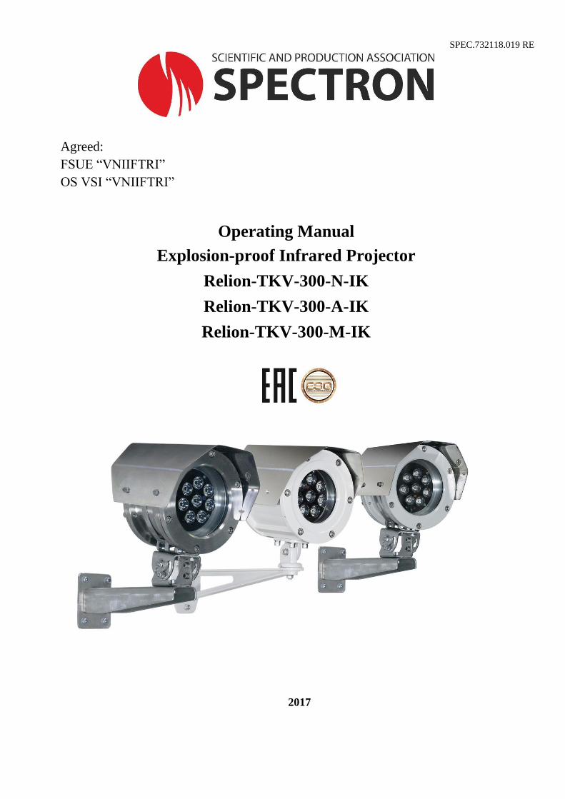
Operating Manual
Explosion-proof Infrared Projector
Relion-TKV-300-N-IK
Relion-TKV-300-A-IK
Relion-TKV-300-M-IK
2017
2
Contents
1. DESCRIPTION ................................................................................................................................. 3
2. TYPICAL FEATURES ..................................................................................................................... 3
3. TECHNICAL FEATURES ............................................................................................................... 4
4. USAGE INFORMATION ................................................................................................................. 5
4.1 DESIGN AND FUNCTION ...................................................................................................... 5
4.2 FACTORS AFFECTING VISIBILITY ..................................................................................... 6
5. ASSEMBLY OF IR-PROJECTOR ................................................................................................... 6
5.1 INSTALLATION OF IR-PROJECTOR ................................................................................... 6
5.2 PROJECTOR ASSEMBLY PROCEDURE .............................................................................. 7
5.3 ELECTRICL INSTALLATION ................................................................................................ 8
6. TROUBLESHOOTING .................................................................................................................... 9
7. TECHNICAL MAINTENANCE ...................................................................................................... 9
8. REPAIR AND RETURN OF THE DEVICE .................................................................................... 9
9. MANUFACTURER’S WARRANTY .............................................................................................. 9
10. TRANSPORTATION AND STORAGE .................................................................................... 10
11. ORDERING INFORMATION .................................................................................................... 10
3
ATTENTION!
Read closely the Operating manual prior to IR-projector installation and connection.
Dark light from IR-emitting diodes! To avoid eye injury, it is not recommended to directly look at
energized IR-projector.
1. DESCRIPTION
Relion-TKV-300-M/N/A-IK is infrared projector (hereinafter - IR projector) in explosion-proof
enclosure. High-power IR-projector is designed to arrange 24-hour CCTV and technological video control
system at no or insufficient illumination in explosion-hazard areas of industrial and infrastructural facilities.
Relion-TKV-300-M-IK IR-projector features the body that is made from galvanized steel with polymer
powder coating, Relion-TKV-300-N-IK body is made from 12KH18N10T stainless steel, Relion-TKV-300-
A-IK body is made from - aluminum alloy.
The projector is produced in compliance with requirements to ex-proof equipment of group I and
subgroups IIA, IIB, IIC as per TR CU 012/2011, GOST 30852.13 (MEK 60079-14) and complies with
explosion-proof marking:
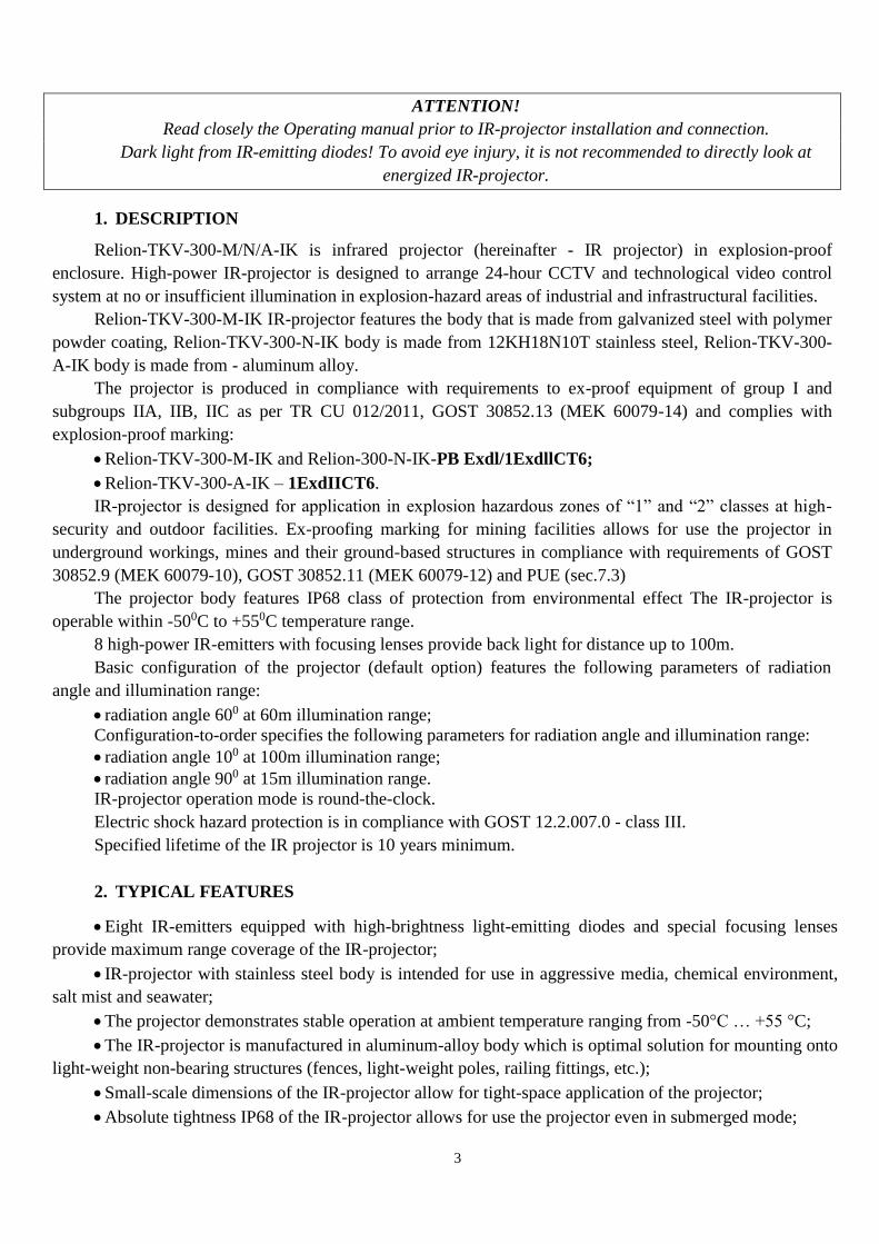
Relion-TKV-300-M-IK and Relion-300-N-IK-PB Exdl/1ExdllCT6;
Relion-TKV-300-A-IK – 1ExdIICT6.
IR-projector is designed for application in explosion hazardous zones of “1” and “2” classes at high-
security and outdoor facilities. Ex-proofing marking for mining facilities allows for use the projector in
underground workings, mines and their ground-based structures in compliance with requirements of GOST
30852.9 (MEK 60079-10), GOST 30852.11 (MEK 60079-12) and PUE (sec.7.3)
The projector body features IP68 class of protection from environmental effect The IR-projector is
operable within -500C to +550C temperature range.
8 high-power IR-emitters with focusing lenses provide back light for distance up to 100m.
Basic configuration of the projector (default option) features the following parameters of radiation
angle and illumination range:
radiation angle 600 at 60m illumination range;
Configuration-to-order specifies the following parameters for radiation angle and illumination range:
radiation angle 100 at 100m illumination range;
radiation angle 900 at 15m illumination range.
IR-projector operation mode is round-the-clock.
Electric shock hazard protection is in compliance with GOST 12.2.007.0 - class III.
Specified lifetime of the IR projector is 10 years minimum.
2. TYPICAL FEATURES
Eight IR-emitters equipped with high-brightness light-emitting diodes and special focusing lenses
provide maximum range coverage of the IR-projector;
IR-projector with stainless steel body is intended for use in aggressive media, chemical environment,
salt mist and seawater;
The projector demonstrates stable operation at ambient temperature ranging from -50°C … +55 °C;
The IR-projector is manufactured in aluminum-alloy body which is optimal solution for mounting onto
light-weight non-bearing structures (fences, light-weight poles, railing fittings, etc.);
Small-scale dimensions of the IR-projector allow for tight-space application of the projector;
Absolute tightness IP68 of the IR-projector allows for use the projector even in submerged mode;

4
Explosion-proof design of the body shall comply with global standard requirements;
Use of the mounting rack shall ensure the projector targeting;
Warranty period is 3 years.
3. TECHNICAL FEATURES
Table 1
Features Value
Ex-proofing marking
Relion-TKV-300-
M/N-IK
РВExdI/1ExdIIC
T6
Relion-TKV-300-A-
IK 1ExdIICT6
Radiation angle and illumination range
of basic configuration, m radiation angle 600 60
Radiation angle and illumination range are
provided optionally by separate order, m
radiation angle 100 100
radiation angle 900 15
Cover protection class, IP 68
Radiating wave length, nm 850
Switch on/off threshold, lx 3
Power voltage, V 12÷36 DC
Consumed current, A max 0,5
Power consumption, W 6
Weight, kg max
TKV-300-M-IK 4,8
TKV-300-N-IK 5,4
TKV-300-A-IK 2,7
Temperature range, 0C - 50 ÷ +55
Specified lifetime for the IR-projector is 10 years
minimum.
Operation mode is round-the-clock.
Overall dimensions of the IR-projector are specified in Fig.1.
Fig. 1 - Overall dimensions. TKV-300-M/N-IK – leftward, TKV-300-A-IK – rightward.

5
4. USAGE INFORMATION
4.1 DESIGN AND FUNCTION
The IR-projector features sealed cover. The board with 8 high-power IR-emitters with focusing lenses
and photo-relay designed for automatic switching-on of the emitters when the outdoor lighting decreases to 3
lx minimum is located at the front of the projector behind the shock-resistant glass. Earthing bolt and two
threaded openings M20x1,5 for cable-gland installation are located on the back cover of the IR-projector
from the outside. Cable glands ensure tight connection for circular section cables with outer diameter or
wrapping insulation (for armored cable) diameter from 8 to 10 mm. It is recommended to use stainless-steel
cable glands for IR-projector in stainless-steel body. It is recommended to use cable glands made from
galvanized low-carbon steel for IR-projector in the body made from galvanized low-carbon steel.
Switching board with terminal boxes used for power cable connection is located on the back cover of
the IR-projector from the inside. Loop power supply for board with IR-emitters is connected to the switching
board.
Silica gel is placed into IR-projector body for moisture absorption.
IR-projectors Relion-TKV-300-M-IK and Relion-TKV-300-N-IK feature the same dimensions and
differ by the body material only. The projectors are fixed on mounting and positioning device by two fixing
clamps made from stainless-steel.
Design features of the IR-projector Relion-TKV-300-A-IK. Base of the mounting and positioning
device is fastened on the projector body by four bolts M6.
Overall dimensions of Relion-TKV-300-A-IK differ from dimensions of Relion-TKV-300-M-IK and
Relion-TKV-300-N-IK.
Fig.2 Appearance of the IR-projector Relion-TKV-300-A-IK
1 - cable glands; 2 - shield; 3 - back cover; 4 - shock-resistant glass;
5 - earthing bolt; 6 - front panel; 8 - hold-down bolt of mounting and positioning device; 9 - mounting
and positioning device.

6
Fig.3 Appearance of the IR-projector Relion-TKV-300-N-IK
1 - cable glands; 2 - shield; 3 - back cover; 4 - shock-resistant glass;
5 - earthing bolt; 6 - front panel; 7 - fixing clamps; 8 - hold-down bolt of mounting and positioning
device; 9 - mounting and positioning device.
4.2 FACTORS AFFECTING VISIBILITY
Such environmental contaminants as dust, dirt or any filming agents reduce illumination range of the
IR- projector as time passes. Routine cleaning of the IR-projector glass is required in the course of operation.
5. ASSEMBLY OF IR-PROJECTOR
ATTENTION!
Do not open IR-projectors in the explosion hazardous environment when power supply is on.
IR-projector shall be connected in compliance with connection diagram specified in the present Operating
Manual. If connection diagrams differ from the recommended connection pattern and are not approved by
the manufacturer, the warranty period shall be terminated and this may result in IR-projector failure.
Installation and connection of the IR-projector shall be performed by authorized personnel only.
5.1 INSTALLATION OF IR-PROJECTOR
IR-projector shall be positioned in such manner that to provide the most effective illumination of the
area subject to CCTV. The following factors shall be taken into consideration:
Installation and targeting of IR-projector shall be performed with due regard to illumination range and
radiation angle.
IR-projector accessibility provision to perform routine maintenance.
The IR-projector shall be targeted descending on a subject at minimum 10-200 angle to horizon
(fig.4). Such installation shall prevent moisture accumulation on the projector glass.

7
Fig.4 - Installation of IR-projector relatively horizon
5.2 PROJECTOR ASSEMBLY PROCEDURE
Onsite assembly of the projector shall be performed in compliance with approved design of the system
whereat the projector is used.
Prior to assembly it is required to perform visual inspection of the IR-projector with due regard to:
no damages of the body and shock-resisting glass.
availability of cable-gland sealing materials and no damages.
availability of all fixing accessories required (screws, nuts, washers) in compliance with the site
design.
no damages of the terminal box.
no damages of earthing devices.
For installation and connection of the IR-projector it is required to perform the following operations:
Undo the bolt (8) fig. 2, 3 and take off the bracket of mounting and positioning device.
Determine operational location and fix the bracket of mounting and positioning device (9) fig.2 and 3.
Undo retention screws of the projector back cover (3). Switching board is located on the inside of the
back cover (fig.5). Carefully take off the cover from the projector body so not to damage power supply loop
of the board with IR- emitters connected to the switching board. Disconnect terminal of the power supply
loop designed for board with IR-emitters.
Use cable glands (1) to connect power cables to the projector switching board observing polarity and
in compliance with connection diagram, fig.6;
Put silica gel into the IR-projector body;
Connect power supply loop of the board with IR -emitters;
Allocate the back cover into the body and screw up retention screws;
Connect earth wire to earthing bolt (5), fig. 2 and 3
Mount the projector onto the mounting and positioning device (9), point the projector at controlled
zone and bolt it (8), fig.2 and 3;
Connect earth wire to earthing bolt (5), fig. 2 and 3
8
Switch on power supply. If the outdoor lighting is less than 3lx IR-emitters are switched on
automatically.
5.3 ELECTRICL INSTALLATION
Requirements to wires and cables.
At electrical installation of the IR-projector armored or unarmored cables with at least 0,75mm2 cross-
section shall be used. Cable cross-sections are selected according to the power supply in the line and cable line
length.
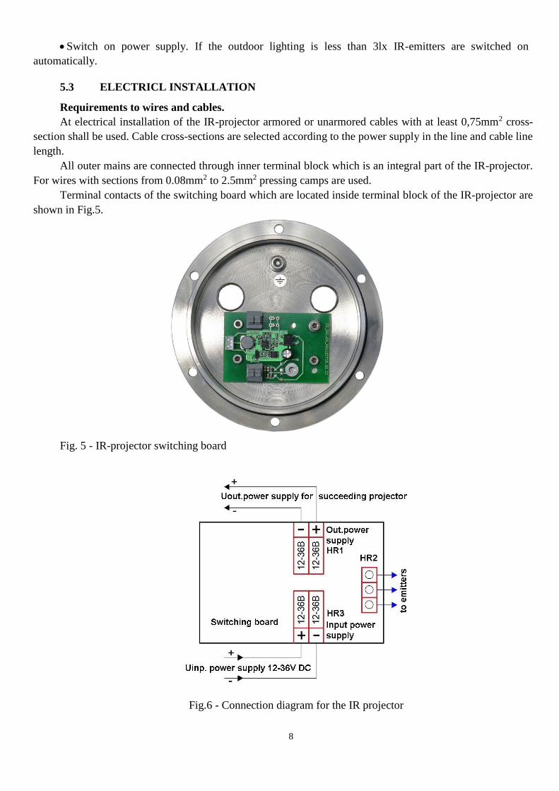
All outer mains are connected through inner terminal block which is an integral part of the IR-projector.
For wires with sections from 0.08mm2 to 2.5mm2 pressing camps are used.
Terminal contacts of the switching board which are located inside terminal block of the IR-projector are
shown in Fig.5.
Fig. 5 - IR-projector switching board
Fig.6 - Connection diagram for the IR projector

9
When installing armored cable assembly operations shall be performed in the
following sequence:
Remove cable insulation to the length of 140mm.
Remove armor to the length of 100mm.
Remove the inner insulation up to 50mm.
Install the connection cable into the cable gland in compliance with the connection diagram, fig.8
In the case of piping connection, the piping coupling shall be screwed directly on the nozzle with G1/2
or G3/4 thread, fig. 8.
Water resistance
During assembly ensure tightness at installation of cable glands and back cover to prevent the IR-
projector from moisture penetration. Water resistance is an important parameter that ensures stable
performance of the system in the process of operation.
ATTENTION!
Installation company shall be responsible for IR-projector tightness in the process of assembly.
6. TROUBLESHOOTING
ATTENTION!
The IR-projector does not contain any elements subject to repair by the Customer.
Troubleshooting of the IR-projector shall be performed in the following sequence:
Make sure there is no dirt on the IR-projector glass. Wash the glass with wet flannel in case of dirt.
Check the power supply to the IR-projector.
7. TECHNICAL MAINTENANCE
Inspection window of the IR-projector shall be maintained clean, for this purpose cleaning shall be
performed progressively as dirt accumulation takes place, cleaning shall be performed with brush or wet
flannel.
Technical maintenance intervals are determined by technical regulations approved by technical
manager of organization.
8. REPAIR AND RETURN OF THE DEVICE
If any defects or failures occur the Customer solely issues a failure certificate with description of the
defect. The IR-projector with passport and failure certificate shall be returned to the manufacturer.
The IR-projector shall be properly packed for transportation. Package information is specified in
section 10 of “Transportation and storage”. In case of return please dispatch the product to the address: 2D
Lenin Str., Beryozovsky, the Sverdlovsk Oblast, 623700, Russia, tel.: (343)379-07-95.
9. MANUFACTURER’S WARRANTY
Specified lifetime for the IR-projector is 10 years minimum.
Warranty period - 12 months from the date of commissioning.
After 24 months of service supplementary warranty period shall be issued via service WARRANTY
EXTENSION at http://spectron-ops.ru/.
Warranty repairs in compliance with GOST R 52350.19 or IR-projector replacement shall be performed
by the manufacturer only if the Customer follows all transportation, storage and operation requirements.
10
Manufacturer shall not accept any claims when the warranty period expires, if passport for the projector
is not provided or if Operating Manual is not followed.
10. TRANSPORTATION AND STORAGE
Packed IR-projector shall be stored under condition 4 as per GOST 15150.
For transportation the IR-projector shall be packed in the factory package or suitable box, wrapped in
air-bubbled film, foam core or other shock absorbent material. If several items are packed in one box, spacers
shall be located between them.
It is allowed to transport the projector at any distance by any transport. Protection of the transport
package from precipitation shall be provided for the period of transportation.
During loading and off-loading and during transportation the IR-projector shall not be exposed to
shocks or atmospheric precipitation. During transportation the box with the IR-projector shall be placed in
such a manner that to prevent uncontrolled relocation.
11. ORDERING INFORMATION
The scope of IR-projector supply includes:
IR-projector .......................................................................................................... 1 pc.;
mounting and positioning device.......................................................................... 1 pc.;
fixing clamp for models TKV-300-M-IK and TKV-300-N-IK ........................... 1 pc.;
Silica gel ............................................................................................................... 1 pc.;
label SPEC.732118.019 ET .................................................................................. 1 pc.;
passport SPEC.732118.019 PS ............................................................................. 1 pc.;
sun shield (not included in the scope of supply; supplied in separate order)........ 1 pc.;
cable gland (not included in the scope of supply; supplied in separate order)….. 2 pcs.
At the time of order please specify:
1. Model of IR-projector:
– “TKV-300-N-IK” - ex-proof IR-projector Relion (ReliON), body material - stainless steel
12KH18N10T;
– “TKV-300-M-IK” - ex-proof IR- projector Relion (ReliON), body material - galvanized low-carbon
steel St10-20 with powder coating;
– “TKV-300-A-IK” - ex-proof IR-projector Relion (ReliON), body material - aluminum alloy with
powder coating.
2. Radiation angle (illumination range)
– Basic configuration: radiation angle 600 at 60m illumination range;
– Configuration-to-order: radiation angle 100 at 100m illumination range;
– Configuration-to-order: radiation angle 900 at 15m illumination range.
3. Sun shield - not included in the scope of supply supplied in separate order.
4. Cable glands - not included in the scope of supply; supplied in separate order:
– cable glands for “TKV-300-N-IK” are made from 12KH18N10T stainless steel;
– cable glands for “TKV-300-M-IK” and “TKV-300-A-IK” are made from St10-20 galvanized steel.

11
Table 2
Nomenclature
Description 12KH18N10T
stainless steel
St10-20
galvanized steel
SHT-1/2-N SHT-1/2-M Nozzle for piping connection with G1/2 thread
KV-12-N KV-12-M
Cable glands for installation with armored cable with the armor
diameter up to 12mm or metal hose with internal diameter
D=10mm
ZG-N ZG-M End plug М20х1,5
SHT-3/4-N SHT-3/4-M Nozzle for piping connection with G 3/4 thread
KV-15-N KV-15-M Cable gland for installation with cable in metal hose with internal
diameter D=15mm
KV-18-N KV-18-M Cable gland for installation with cable in metal hose with internal
diameter D=18mm
KV-20-N KV-20-M Cable gland for installation with cable in metal hose with internal
diameter D=20mm
SHT1/2 KV12 ZG SHT3/4 KV15
Fig.7 - Cable gland kit
Fig.8 - Different input devices
1 - body foundation; 2 - inner cable isolation; 3 - sealing ring; 4 - washer; 5 - lock nut; 6 - nozzle; 7 -
nut; 8 - cable armor or metal hose; 9 - pipe coupling (not included in the supply package); 10 - plug; 11 -
cone; 12 - ring.

12
MANUFACTURER’S ADDRESS
2D Lenin St., the Sverdlovsk Oblast, 623700, Russia, tel. (343)379-07-95.
[email protected], www.spectron-ops.ru
Related Documents