Operating manual - part no.: M21201WUGB Date of operating manual: 19.01.2015 Version of operating manual: 005 Operating manual EN Ultrasonic DIN rail generator SONIC DIGITAL HS Versions MD / MFD MULTI PURPOSE

Welcome message from author
This document is posted to help you gain knowledge. Please leave a comment to let me know what you think about it! Share it to your friends and learn new things together.
Transcript
Operating manual - part no.: M21201WUGB Date of operating manual: 19.01.2015 Version of operating manual: 005
Operating manual EN Ultrasonic DIN rail generator SONIC DIGITAL HS Versions MD / MFD
MULTI PURPOSE
All rights reserved. This documentation is protected by copyright. WEBER Ultrasonics reserves all rights not expressly granted. This documentation may not be duplicated, distributed or made pub-licly available in any other way without prior written consent or in legally permitted cases.
We reserve the right to make changes without giving prior notice. The original document was published in German (the official language of the manufacturer). All translations are copies of the original document.
Copyright 2015 by WEBER Ultrasonics, Karlsbad-Ittersbach (D)
Production, sales and service:
WEBER Ultrasonics GmbH Phone: +49 (0)72 48 / 92 07-0 Im Hinteracker 7 Fax: +49 (0)72 48 / 92 07-11 76307 Karlsbad-Ittersbach [email protected] Germany www.weber-ultrasonics.de
I
Table of contents 1 Introduction .................................................................................................................................... 1
1.1 About WEBER Ultrasonics ......................................................................................................... 1 Success through customer-oriented ultrasonic solutions ..................................................... 1
1.2 About the device ........................................................................................................................ 2 1.3 Purpose of the ultrasonic welding generator .............................................................................. 2 1.4 Validity of the operating manual ................................................................................................. 3
1.4.1 Type HS MD/MFD ................................................................................................................ 3
1.5 About this document .................................................................................................................. 5 1.5.1 Purpose ................................................................................................................................ 5 1.5.2 Target groups ....................................................................................................................... 5 1.5.3 General structure .................................................................................................................. 5 1.5.4 Abbreviations used ............................................................................................................... 6 1.5.5 Signal words used ................................................................................................................ 6 1.5.6 Pictograms and safety instructions ....................................................................................... 6
2 Safety .............................................................................................................................................. 7
2.1 Personnel requirements ............................................................................................................. 7 2.2 Operating conditions .................................................................................................................. 8 2.3 Safety concept of the manufacturer ........................................................................................... 8
2.3.1 Conversions or modifications ................................................................................................ 8
2.4 Responsibilities of the operator .................................................................................................. 9 2.5 Responsibilities of operating personnel ................................................................................... 10 2.6 Environmental protection and emissions ................................................................................. 11
3 Warranty ....................................................................................................................................... 12
3.1 Exclusion of warranty ............................................................................................................... 12
4 EU Declaration of Conformity .................................................................................................... 13
5 Generator description ................................................................................................................. 14
5.1 Housing .................................................................................................................................... 15 5.1.1 Housing of the HS MD / MFD ............................................................................................. 15
5.2 Connectors ............................................................................................................................... 16 5.2.1 Model HS MD / MFD ........................................................................................................... 16 5.2.2 PIN assignment, mains connection .................................................................................... 17 5.2.3 PIN assignment, converter connection ............................................................................... 17 5.2.4 Assignment of the 15-pole interface socket ........................................................................ 18 5.2.5 PIN assignment, hardware tooling interface ....................................................................... 21 5.2.6 RS-485 Interface (optional) ................................................................................................. 23
6 Installation and connection ........................................................................................................ 24
6.1 Installation ................................................................................................................................ 25 6.2 Installation with angled adapter ................................................................................................ 26 6.3 Mains connection ..................................................................................................................... 27
6.3.1 Supply ratings ..................................................................................................................... 27 6.3.2 Cable quality and cable routing .......................................................................................... 27
7 Operation ....................................................................................................................................... 28
7.1 Control and display elements ................................................................................................... 28 7.1.1 Generator HS MD / MFD .................................................................................................... 28
7.2 Switching on ............................................................................................................................. 29 7.3 Switching off ............................................................................................................................. 30 7.4 Setting up, programming and controlling the ultrasonic generator ........................................... 30
II
8 Specifications .............................................................................................................................. 31
8.1 Generator HS MD /MFD ........................................................................................................... 31 8.1.1 Rating plate ......................................................................................................................... 31
9 Troubleshooting .......................................................................................................................... 32
9.1 Resetting malfunctions ............................................................................................................. 32 9.2 Eliminating malfunctions .......................................................................................................... 32
10 Quality assurance ........................................................................................................................ 36
11 General maintenance instructions ............................................................................................. 37
11.1 Safety ....................................................................................................................................... 37 11.2 Care and maintenance ............................................................................................................. 37 11.3 Maintenance and inspection list ............................................................................................... 38 11.4 Maintenance ............................................................................................................................. 39 11.5 Repair work .............................................................................................................................. 39
12 Life cycle ...................................................................................................................................... 40
12.1 Transport .................................................................................................................................. 40 12.1.1 Safety .................................................................................................................................. 40 12.1.2 Packaging ........................................................................................................................... 40
12.2 Positioning and installing .......................................................................................................... 41 12.2.1 Unpacking and cleaning ..................................................................................................... 41 12.2.2 Checking the delivery for completeness ............................................................................. 41 12.2.3 Place of installation ............................................................................................................. 42 12.2.4 Installing and assembling ................................................................................................... 43
12.3 Supply and installation ............................................................................................................. 44 12.3.1 Mains connections .............................................................................................................. 44 12.3.2 Ultrasound supply ............................................................................................................... 44 12.3.3 Control cables ..................................................................................................................... 44
12.4 Commissioning ......................................................................................................................... 44 12.5 Temporary non-use .................................................................................................................. 45 12.6 Decommissioning ..................................................................................................................... 45 12.7 Disposal ................................................................................................................................... 46
12.7.1 Dismantling ......................................................................................................................... 46
SERVICE ....................................................................................................................................................... 47

SONIC DIGITAL HS MD/MFD Introduction
1
1 Introduction
This chapter provides information on the manufacturer, the equipment and these operating manual.
1.1 About WEBER Ultrasonics
Success through customer-oriented ultrasonic solutions
The WEBER Ultrasonics brand sets new standards in the development and manu-facture of high-quality ultrasonic components. The company was founded in 1998 by Dieter Weber and stands for innovation, high quality and customer proximity. Thanks to our innovative portfolio of high-grade products for ultrasonic cleaning, ul-trasonic welding and special applications, we have become one of the world's tech-nological leaders in the space of just a few years.
We offer our customers new technical solutions that make economic sense. With our products and services, as well as our knowledge and experience, we create competitive advantages for you that can help you achieve market success.
Made by WEBER Ultrasonics – quality you should never go without.
Fig. 1: WEBER Ultrasonics in Karlsbad-Ittersbach, Germany
Introduction SONIC DIGITAL HS MD/MFD
2
1.2 About the device
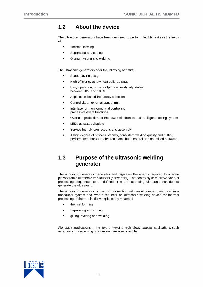
The ultrasonic generators have been designed to perform flexible tasks in the fields of:
Thermal forming
Separating and cutting
Gluing, riveting and welding
The ultrasonic generators offer the following benefits:
Space-saving design
High efficiency at low heat build-up rates
Easy operation, power output steplessly adjustable between 50% and 100%
Application-based frequency selection
Control via an external control unit
Interface for monitoring and controlling process-relevant functions
Overload protection for the power electronics and intelligent cooling system
LEDs as status displays
Service-friendly connections and assembly
A high degree of process stability, consistent welding quality and cutting performance thanks to electronic amplitude control and optimised software.
1.3 Purpose of the ultrasonic welding generator
The ultrasonic generator generates and regulates the energy required to operate piezoceramic ultrasonic transducers (converters). The control system allows various processing sequences to be defined. The corresponding ultrasonic transducers generate the ultrasound.
The ultrasonic generator is used in connection with an ultrasonic transducer in a transducer system and, where required, an ultrasonic welding device for thermal processing of thermoplastic workpieces by means of
thermal forming
Separating and cutting
gluing, riveting and welding
Alongside applications in the field of welding technology, special applications such as screening, dispersing or atomising are also possible.
SONIC DIGITAL HS MD/MFD Introduction
3
NOTE
§
Only those transducer systems and ultrasonic welding devices intended for this use in terms of their frequency, power output and dimensions may be operated on the generator.
The operator bears sole responsibility for any damage caused by not using the equipment in accordance with its intended use!
WEBER Ultrasonics accepts no liability for material damage and bodily injury caused by improper use of the equipment.
1.4 Validity of the operating manual
NOTE
§ This operating manual refers exclusively to the specific product(s) with which it was supplied.
No claims of any kind with regard to other products purchased may be derived from it or its contents.
These operating instructions are valid for
Type HS MD/MFD
1.4.1 Type HS MD/MFD
The Sonic Digital HS MD is an ultrasonic generator for device-specific piezoelectric ultrasonic transducers.
Suitable for DIN rail installation
Supply voltage 230 V AC +/- 10%
Switching power supply and integrated mains filter
Microcontroller control
Electronic amplitude control
Matched to the transducer-based welding frequency
Intelligent fan control
Protection against short-circuit, no-load operation and overload
Control via an external control unit with graphical display
Interface for control and monitoring
LED status display
All connectors pluggable
Introduction SONIC DIGITAL HS MD/MFD
4
With the following power outputs:
400 to 2000 Watt
With the following options:
20, 30, 35, 36 and 40 kHz
Standard software (MD) or SONIC FULL DIGITAL software, welding version (MFD)

SONIC DIGITAL HS MD/MFD Introduction
5
1.5 About this document
1.5.1 Purpose
This operating manual provides a basic introduction to the design, method of func-tioning and intended operation of the equipment supplied. You can also find im-portant notes on safe handling and proper maintenance.
In the interests of its customers, WEBER Ultrasonics continually develops and re-fines its equipment. For this reason, WEBER Ultrasonics reserves the right to make technical modifications without prior notice that may deviate from the information stated in this operating manual.
1.5.2 Target groups
This operating manual is aimed at:
Assembly staff
Operating staff
Maintenance staff
NOTE
§
Read the safety instructions and the entire operating manual before assembling and commissioning the equipment!
Please store the operating manual in a place where it is accessible to all users at any time.
The operating manual must be complete and kept in a perfectly read-able state at all times.
1.5.3 General structure
The instructions comprise:
Objective
Prerequisites, if applicable
1. Step 1
2. Step 2
3. Further steps
Interim result, if applicable.
4. Further steps
Result of steps performed
Instructions
Introduction SONIC DIGITAL HS MD/MFD
6
1.5.4 Abbreviations used
HF = high frequency, operating frequency of the generator
HF connection = transducer connection, transducer system connection
US = ultrasound/ultrasonic
1.5.5 Signal words used
Immediate danger of serious injury or death.
Potentially dangerous situation with the risk of serious injury or death.
Potential risk resulting in minor injuries.
Risk of material damage to equipment and products, as well as harm to the environment.
Important information, failure to comply results in loss of warranty or guarantee.
Additional information to aid understanding.
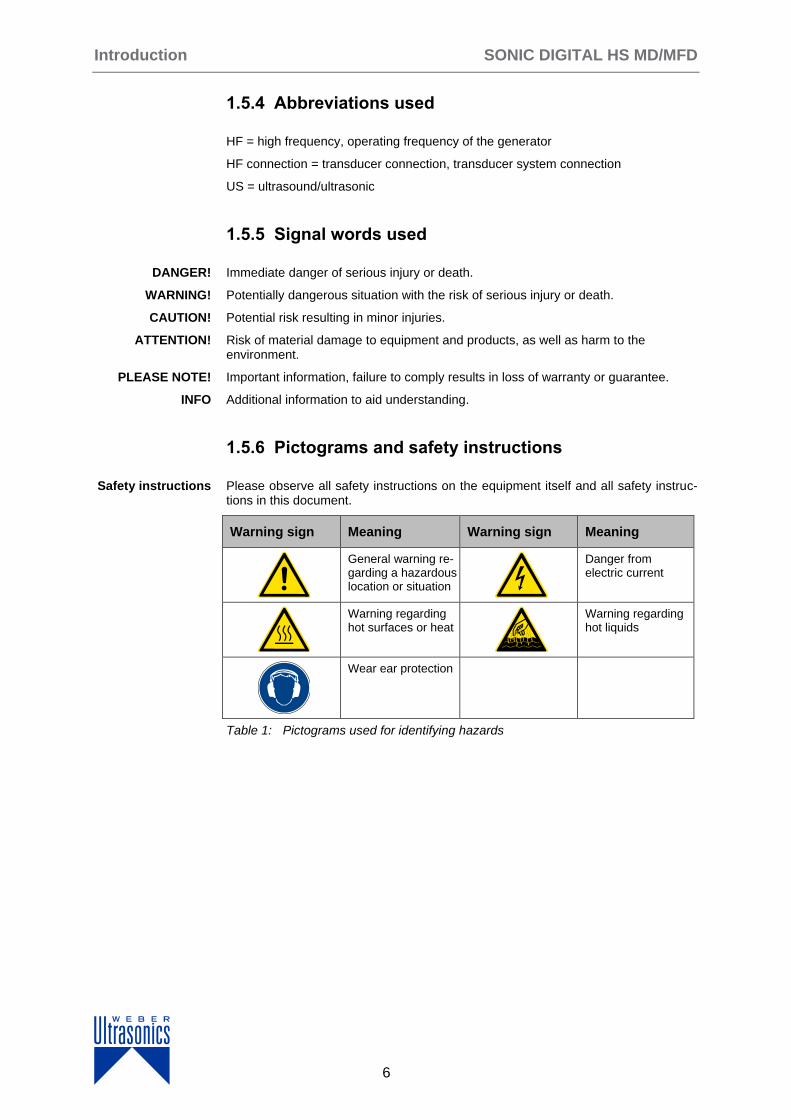
1.5.6 Pictograms and safety instructions
Please observe all safety instructions on the equipment itself and all safety instruc-tions in this document.
Warning sign Meaning Warning sign Meaning
General warning re-garding a hazardous location or situation
Danger from electric current
Warning regarding hot surfaces or heat
Warning regarding hot liquids
Wear ear protection
Table 1: Pictograms used for identifying hazards
DANGER!
WARNING!
CAUTION!
ATTENTION!
PLEASE NOTE!
INFO
Safety instructions

SONIC DIGITAL HS MD/MFD Safety
7
2 Safety
This chapter provides information on the safe assembly, commissioning and opera-tion of the equipment. It also includes information on the intended use and condi-tions of use.
2.1 Personnel requirements
NOTE
§ Prior to using and commissioning the unit, these operating instructions must be read and understood.
Trained and instructed fitters for installation of the ultrasonic generator in large-scale systems: Installation personnel carry out all installations and adjustments to the con-trol according to the parameters of the large-scale system as described in these op-erating instructions.
Personnel trained to operate the ultrasonic generator at the end user: operating personnel are responsible for correct operation of the unit.
Trained and instructed maintenance personnel at the end user: installation person-nel carry out all installations and adjustments to the control during setting up opera-tions, troubleshooting and fault clearance as well as maintenance as described in these operating instructions.
Specially trained employees of WEBER Ultrasonics.
NOTE
§ Only authorised specialists may
open the ultrasonic generator
and change components or control factory settings.
DANGER!
The sonotrodes activated by the ultrasonic generators can exceed a sound level of 75 dB(A) at full load. There is a risk of hearing loss.
In this case, the operator must ensure that personnel wear hearing protection.
Installation personnel
Operating personnel
Maintenance personnel
Service personnel
Personal protective equipment
Safety SONIC DIGITAL HS MD/MFD
8
2.2 Operating conditions
All ultrasonic welding units are designed for indoor use in a closed and dry hall.
2.3 Safety concept of the manufacturer
The unit has been designed and built based on a risk analysis and in accordance with applicable harmonised EU directives, standards and further technical specifica-tions. The unit is state of the art and offers the highest level of safety and reliable operation.
NOTE
§ Observe the warnings attached to the ultrasonic generator!
Prior to assembly/disassembly of the ultrasonic generator or changing a fuse, de-energise or disconnect the ultrasonic generator and switch off the ultrasonic supply.
2.3.1 Conversions or modifications
NOTE
§
Any modifications of the generator are prohibited!
The mechanical and electrical behaviour of the generator can be im-paired by additions or modifications of any type.
No modifications or additions to the mechanical, electrical/electronic components, safety components and changes to the programming are permitted without the express written permission of the manufac-turer.
SONIC DIGITAL HS MD/MFD Safety
9
2.4 Responsibilities of the operator
The unit can only be used safely when all necessary measures are taken. It is the duty of the operator to plan these measures and monitor their implementation.
The operator is responsible for the assignment, qualification and duties of operating personnel.
The operator is responsible for:
Selection of the site of installation
Personnel safety measures
Selection of suitable workpieces in particular with regard to possible chemi-cal processes, associated explosion and fire hazards, toxic vapours and appropriate protective measures (e.g. extraction, respiratory protection)
Choosing ultrasonic frequencies
Choosing the equipment: generators etc. with regard to power output, frequency and material
Programming of processing sequences appropriate to the workpiece
Workflow
The customer must have the necessary knowledge of specific operations and their potential hazards.
The customer is responsible for ensuring accident-free operation and fast first-aid assistance in the event of an emergency.
The power supply must comply with protection class I. The relevant DIN EN/VDE regulations or country-specific regulations must be observed.
The operator is responsible for the coordination and provision of
maintenance.
The respective regulations and technical rules must be observed.
Operating personnel
Operating instructions
Accident prevention and first aid
Electrical connection
Care, maintenance and repair

Safety SONIC DIGITAL HS MD/MFD
10
2.5 Responsibilities of operating personnel
The safety of operating personnel and other persons as well as trouble-free opera-tion depends mainly on the correct actions of operating and maintenance personnel. Personnel are obliged to:
Read and observe the general occupational health and safety regulations and accident prevention regulations before starting work.
Read and observe in full the manufacturer’s documentation as well as the safety information, checks and procedures.
Always avoid any working methods that could affect health and safety.
Use the ultrasonic generator only for the intended purpose.
Use personal protective equipment and devices (safety shoes, hearing pro-tection, safety goggles, protective gloves and cotton clothing) when working on ultrasonic welding units.
Stay within the workplaces for which they are responsible.
Refrain from consuming alcohol, taking drugs, medication and other agents liable to affect reactions and cause disorientation.
Inform the operator about necessary maintenance routines or repairs.
Immediately report faults or irregularities that occur during operation to the person in charge and have them rectified.
SONIC DIGITAL HS MD/MFD Safety
11
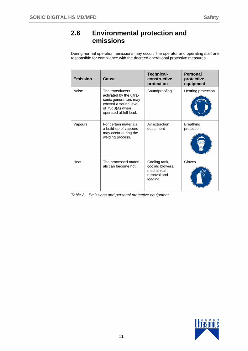
2.6 Environmental protection and emissions
During normal operation, emissions may occur. The operator and operating staff are responsible for compliance with the decreed operational protective measures.
Emission Cause Technical- constructive protection
Personal protective equipment
Noise The transducers activated by the ultra- sonic genera-tors may exceed a sound level of 75dB(A) when operated at full load.
Soundproofing Hearing protection
Vapours For certain materials, a build-up of vapours may occur during the welding process.
Air extraction equipment
Breathing protection
Heat The processed materi-als can become hot.
Cooling tank, cooling blowers, mechanical removal and loading
Gloves
Table 2: Emissions and personal protective equipment

Warranty SONIC DIGITAL HS MD/MFD
12
3 Warranty
The period and scope of the warranty are defined in the terms of delivery as part of the general terms and conditions (valid at the time of purchase) or in the sales con-tract / order confirmation, should any special agreements have been made.
3.1 Exclusion of warranty
NOTE
§
The following cases are not covered by warranty:
damage caused by improper operation,
use of the equipment other than the purpose for which it was designed,
improper alterations or modifications made without prior authorisation from the manufacturer,
damage caused by extreme influences such as jolts, falls, moisture and dirt,
inadequately qualified operating staff,
failure to comply with the applicable safety and accident pre-vention regulations,
damage resulting from modifications made to the operating instructions,
damage resulting from unauthorised access to areas only accessible to administrators (service staff of WEBER Ultrasonics).

SONIC DIGITAL HS MD/MFD EU declaration of conformity
13
4 EU Declaration of Conformity
in the sense of EU Directive 2014/35/EU "Low Voltage Directive" dated February 26, 2014.
We hereby declare that the electrical equipment described below complies with the provisions of the above-mentioned EU Directive in its design and construction and in the configuration in which we placed it on the market. However, this declaration will become null and void if any alterations are made to the equipment without our express approval.
Manufacturer
WEBER Ultrasonics Im Hinteracker 7 76307 Karlsbad-Ittersbach Germany
Product Ultrasonic generators
Type HS MD / MFD
Authorised person for documentation
Ralf Seidl
Conformity with other directives:
2014/30/EU of February 26, 2014 EMC guideline
Applied harmonised standards:
EN 61010-1:2010 Safety requirements for electrical equipment for measurement, control and laboratory use Part 1: General requirements
EN 61000-6-2:2005 Electromagnetic compatibility (EMC) Part 6-2: Generic standards – Immunity for industrial environments
EN 61000-6-4:2011-09 Electromagnetic compatibility (EMC) Part 6-4: Generic standards – Emission standard for industrial environments
Date of CE award 12
The test reports are stored by WEBER Ultrasonics for ten years.
Location 76307 Karlsbad-Ittersbach, Germany
Date 30.10.2012
Name and function of signatory
Markus Weber CEO / Technical Director
Description SONIC DIGITAL HS MD/MFD
14
5 Generator description
This chapter provides information on the design and functional principle of the generator, as well as general technical information.
Depending on its intended use, an ultrasonic system comprises at least one genera-tor, an accompanying ultrasonic transducer, supply cables and the ultrasonic tool.
The device generates a steady-frequency electrical voltage and controls the electri-cal energy required to operate piezoceramic ultrasonic transducers (converters).
The corresponding transducers generate the ultrasonic waves.
The intensity, frequency, duration and amplitude can all be controlled.
The oscillation amplitude can also be matched to the intended application through the use of boosters.
NOTE
§
Only those transducer systems and ultrasonic welding devices intended for this use in terms of their frequency, power output and dimensions may be operated on the generator.
The operator bears sole responsibility for any damage caused by not using the equipment in accordance with its intended use.
WEBER Ultrasonics accepts no liability for material damage and bodily injury caused by unlawful use of the equipment.
Type description
Type HS MD/MFD
Please refer to chapter 8 "Specifications"
SONIC DIGITAL HS MD/MFD Description
15
5.1 Housing
5.1.1 Housing of the HS MD / MFD
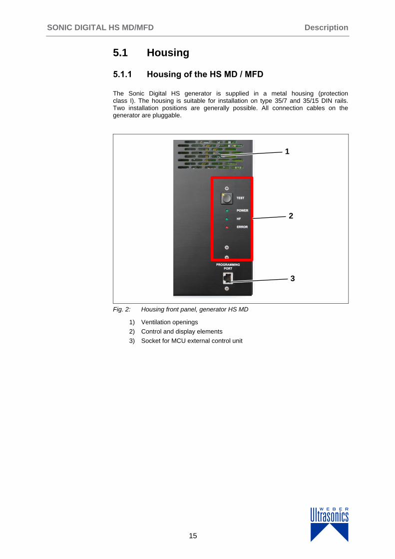
The Sonic Digital HS generator is supplied in a metal housing (protection class I). The housing is suitable for installation on type 35/7 and 35/15 DIN rails. Two installation positions are generally possible. All connection cables on the generator are pluggable.
Fig. 2: Housing front panel, generator HS MD
1) Ventilation openings
2) Control and display elements
3) Socket for MCU external control unit
1
1
3
2
Description SONIC DIGITAL HS MD/MFD
16
5.2 Connectors
5.2.1 Model HS MD / MFD
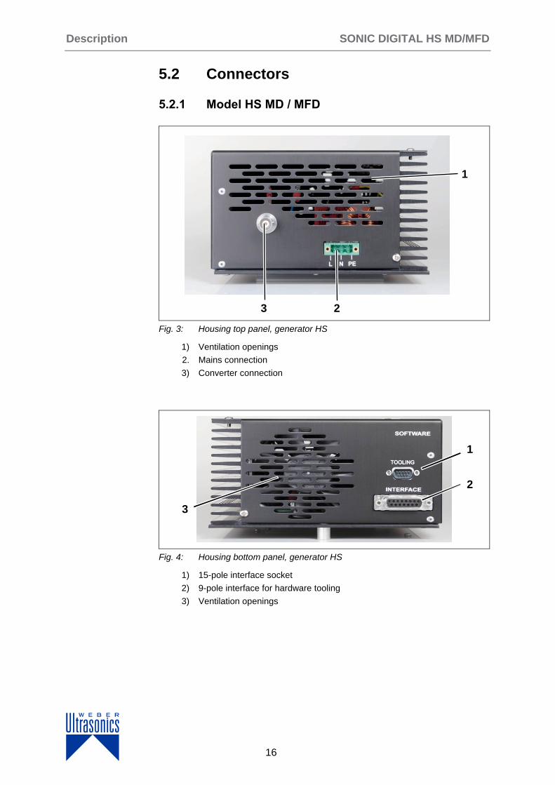
Fig. 3: Housing top panel, generator HS
1) Ventilation openings
2. Mains connection
3) Converter connection
Fig. 4: Housing bottom panel, generator HS
1) 15-pole interface socket
2) 9-pole interface for hardware tooling
3) Ventilation openings
1
23
6
1
2
3
SONIC DIGITAL HS MD/MFD Description
17
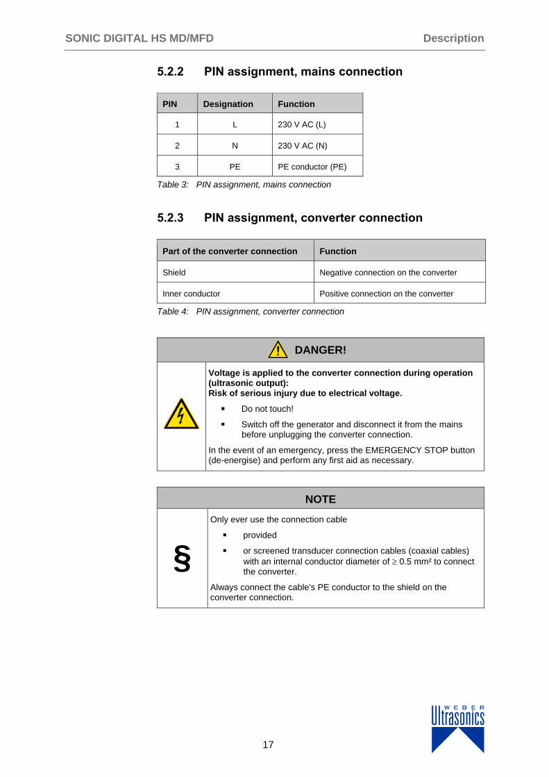
5.2.2 PIN assignment, mains connection
PIN Designation Function
1 L 230 V AC (L)
2 N 230 V AC (N)
3 PE PE conductor (PE)
Table 3: PIN assignment, mains connection
5.2.3 PIN assignment, converter connection
Part of the converter connection Function
Shield Negative connection on the converter
Inner conductor Positive connection on the converter
Table 4: PIN assignment, converter connection
DANGER!
Voltage is applied to the converter connection during operation (ultrasonic output): Risk of serious injury due to electrical voltage.
Do not touch!
Switch off the generator and disconnect it from the mains before unplugging the converter connection.
In the event of an emergency, press the EMERGENCY STOP button (de-energise) and perform any first aid as necessary.
NOTE
§
Only ever use the connection cable
provided
or screened transducer connection cables (coaxial cables)
with an internal conductor diameter of 0.5 mm² to connect the converter.
Always connect the cable's PE conductor to the shield on the converter connection.

Description SONIC DIGITAL HS MD/MFD
18
5.2.4 Assignment of the 15-pole interface socket
Fig. 5: PIN assignment, interface socket (DSUB)
PIN Signal name Function
1 +15 VOLT OUT 15 Volt for external use
2 POUT Output 0 - 10 Volt = output power 0 - 100%
3 P-EXT.-IN Input 5 – 10 Volt for power control
4 GND Common reference point = earth (GND)
5/9 HF-DA-ERROR Relay root (common) for HF-DA and ERROR
6 HF-DA Relay output HF-DA
7 ERROR Relay output ERROR
8 D+ RS485 option: non-inverting input D+ (with Software 6.xx)
9/5 HF-DA-ERROR Relay root (shared) for HF-DA and ERROR
10 D- RS485 option: inverting input D- (with Software 6.xx)
11 <> Nominal Open collector output for nominal value
12 FAN-ON Control output = 12 Volt when fan is running
13 FS-24V Remote control input (10 - 24 Volt)
14 FS-GND Remote control input (to GND)
15 GND Common reference point = earth (GND)
Table 5: Interface socket PIN assignment
NOTE
§ Always use a shielded control line!
The metal frame of the interface socket, with its locking elements, is connected to the generator's earth (GND). When using the supplied D-SUB connector with metal-lic casing and shielding terminal, the cable is connected to earth (GND) on the gen-erator side when the shielding of the control cable is connected to the shielding ter-minal.
8 1
15
6
9
SONIC DIGITAL HS MD/MFD Description
19
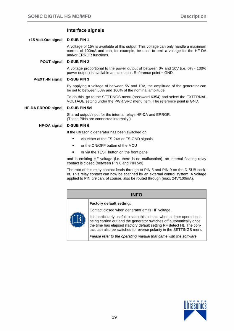
Interface signals
D-SUB PIN 1
A voltage of 15V is available at this output. This voltage can only handle a maximum current of 100mA and can, for example, be used to emit a voltage for the HF-DA and/or ERROR functions.
D-SUB PIN 2
A voltage proportional to the power output of between 0V and 10V (i.e. 0% - 100% power output) is available at this output. Reference point = GND.
D-SUB PIN 3
By applying a voltage of between 5V and 10V, the amplitude of the generator can be set to between 50% and 100% of the nominal amplitude.
To do this, go to the SETTINGS menu (password 6354) and select the EXTERNAL VOLTAGE setting under the PWR.SRC menu item. The reference point is GND.
D-SUB PIN 5/9
Shared output/input for the internal relays HF-DA and ERROR. (These PINs are connected internally.)
D-SUB PIN 6
If the ultrasonic generator has been switched on
via either of the FS-24V or FS-GND signals
or the ON/OFF button of the MCU
or via the TEST button on the front panel
and is emitting HF voltage (i.e. there is no malfunction), an internal floating relay contact is closed (between PIN 6 and PIN 5/9).
The root of this relay contact leads through to PIN 5 and PIN 9 on the D-SUB sock-et. This relay contact can now be scanned by an external control system. A voltage applied to PIN 5/9 can, of course, also be routed through (max. 24V/100mA).
INFO
Factory default setting:
Contact closed when generator emits HF voltage.
It is particularly useful to scan this contact when a timer operation is being carried out and the generator switches off automatically once the time has elapsed (factory default setting RF detect H). The con-tact can also be switched to reverse polarity in the SETTINGS menu.
Please refer to the operating manual that came with the software
+15 Volt-Out signal
POUT signal
P-EXT.-IN signal
HF-DA ERROR signal
HF-DA signal
Description SONIC DIGITAL HS MD/MFD
20
D-SUB PIN 7
This is the output of an internal relay (root to PIN 5/9). This relay reports generator malfunctions. This means that if the generator is switched on and the power output does not correspond to the set level for whatever reason, this relay will be activated.
INFO
Factory default setting:
Closed in the event of a malfunction.
The polarity can be changed via the I/O POLARITIES menu item in the SETTINGS menu (ERROR DETECT). An external voltage connected to HF-DA ERROR can, of course, also be routed through here (max. 24V / 100mA).
Please refer to the operating manual provided with the software
DSUB PIN 8
Non-inverting input for RS485 communication.
DSUB PIN 10
Inverting input for RS485 communication.
D-SUB PIN 11
Open collector output:
Signal HIGH When limit values are activated: the generator operates outside the limit values.
Signal LOW When limit values are activated: the generator operates within the limit values.
D-SUB PIN 12
When the internal fan controlled by the intelligent fan control system is running, a voltage of 12V is available at this output. The voltage is for monitoring the function of this fan.
D-SUB PIN 13
Switching on the generator (ultrasound ON) by applying a voltage of 10V - 24V between PIN 13 and GND (PIN 4 or PIN 15).
D-SUB PIN 14
Switching on the generator (ultrasound ON) with a relay contact or switch by connecting PIN 14 of the D-SUB socket to GND (PIN 4 or PIN 15).
D-SUB PIN 4, 15
The GND signal is available at the two PINs of the D-SUB socket. GND is the common reference point for all input/output signals.
NOTE
§ For control purposes,
always use GND (PIN 4 or 15)!
Otherwise, malfunctions will occur.
ERROR signal
Signal D+
Signal D-
Signal <> Nominal
FAN-ON signal
FS-24 V signal
FS-GND signal
GND signal
SONIC DIGITAL HS MD/MFD Description
21
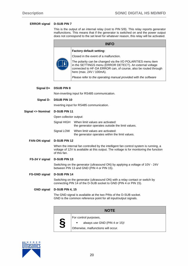
5.2.5 PIN assignment, hardware tooling interface
Fig. 6: PIN assignment, hardware tooling interface
PIN Signal name Function
1 Bit 0 Input with valence 1 or 20
2 Bit 2 Input with valence 4 or 22
3 GND Common reference point = earth (GND)
4 NC Not assigned! Do not connect anything!
5 NC Not assigned! Do not connect anything!
6 Bit 1 Input with valence 2 or 21
7 Bit 3 Input with valence 8 or 23
8 NC Not assigned! Do not connect anything!
9 NC Not assigned! Do not connect anything!
Table 6: PIN assignment, hardware tooling interface
4 1
9 5
Description SONIC DIGITAL HS MD/MFD
22
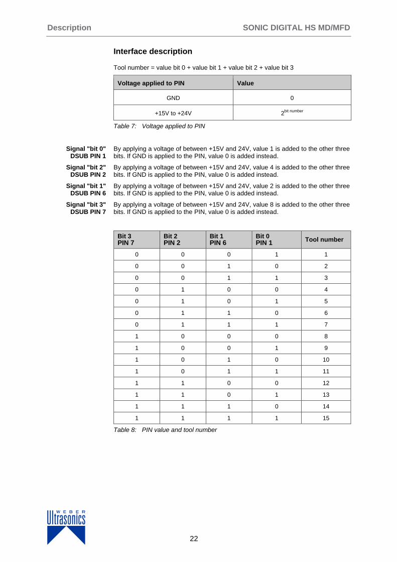
Interface description
Tool number = value bit 0 + value bit 1 + value bit 2 + value bit 3
Voltage applied to PIN Value
GND 0
+15V to +24V 2bit number
Table 7: Voltage applied to PIN
By applying a voltage of between +15V and 24V, value 1 is added to the other three bits. If GND is applied to the PIN, value 0 is added instead.
By applying a voltage of between +15V and 24V, value 4 is added to the other three bits. If GND is applied to the PIN, value 0 is added instead.
By applying a voltage of between +15V and 24V, value 2 is added to the other three bits. If GND is applied to the PIN, value 0 is added instead.
By applying a voltage of between +15V and 24V, value 8 is added to the other three bits. If GND is applied to the PIN, value 0 is added instead.
Bit 3 PIN 7
Bit 2 PIN 2
Bit 1 PIN 6
Bit 0 PIN 1
Tool number
0 0 0 1 1
0 0 1 0 2
0 0 1 1 3
0 1 0 0 4
0 1 0 1 5
0 1 1 0 6
0 1 1 1 7
1 0 0 0 8
1 0 0 1 9
1 0 1 0 10
1 0 1 1 11
1 1 0 0 12
1 1 0 1 13
1 1 1 0 14
1 1 1 1 15
Table 8: PIN value and tool number
Signal "bit 0" DSUB PIN 1
Signal "bit 2" DSUB PIN 2
Signal "bit 1" DSUB PIN 6
Signal "bit 3" DSUB PIN 7

SONIC DIGITAL HS MD/MFD Description
23
5.2.6 RS-485 Interface (optional)
Fig. 7: PIN assignment RS-485 interface socket (D-SUB)
Software versions 10.xx include a separate interface for the RS485 connection.
In software version 6.xx the interface is realised via the 15-pole D-SUB plug.
PIN Signalname Funktion
2 GND Common reference point = earth (GND)
4 TRD+ Data line +
9 TRD- Data line -
Table 9: PIN assignment RS-485 interface
NOTE
§ Always use a shielded control line!
Pin 4 Pin 2
Pin 9
Installation and connection SONIC DIGITAL HS MD/MFD
24
6 Installation and connection
Use the delivery note or packaging slip to check that the delivery is complete.
If anything is missing, please contact WEBER Ultrasonics without delay.
Please also report any transport damage immediately to the delivery company. It is vital to request written confirmation of the damage from the delivery company in these cases.
If the nature of the damage is such that it is not possible to operate the devices safely, they must not be put into operation.
INFO
The generator can get very hot during operation.
If the generator cannot dissipate this heat sufficiently, it will issue an error message after a short time, indicating that the temperature is too high.
Avoid temperatures above 40°C at the installation location.
NOTE
§ The distance between two generators positioned next to one another must be at least 50 mm.
The distance between two generators positioned above one another must be at least 50 mm.
Only then is a sufficient supply of cooling air guaranteed.
Checking the delivery for completeness
SONIC DIGITAL HS MD/MFD Installation and connection
25
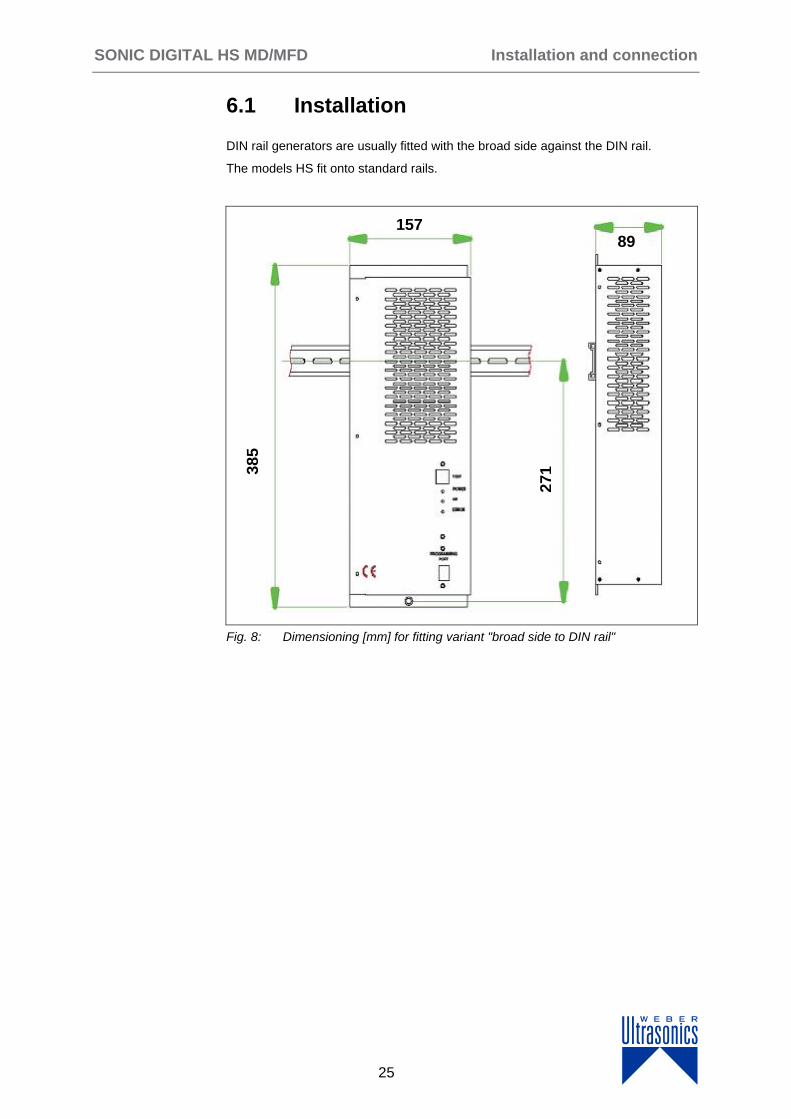
6.1 Installation
DIN rail generators are usually fitted with the broad side against the DIN rail.
The models HS fit onto standard rails.
Fig. 8: Dimensioning [mm] for fitting variant "broad side to DIN rail"
1579 89
271
385
Installation and connection SONIC DIGITAL HS MD/MFD
26
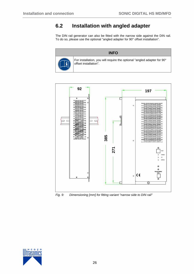
6.2 Installation with angled adapter
The DIN rail generator can also be fitted with the narrow side against the DIN rail. To do so, please use the optional "angled adapter for 90° offset installation".
INFO
For installation, you will require the optional "angled adapter for 90° offset installation".
Fig. 9: Dimensioning [mm] for fitting variant "narrow side to DIN rail"
1
2
3
4
5
7
6
271
385
197
92
SONIC DIGITAL HS MD/MFD Installation and connection
27
6.3 Mains connection
Notes on the electrical installation
The generators must be connected to the mains via a disconnecting device, which itself should be located in the vicinity of the equipment and labelled as the discon-necting device for said equipment.
The rating of the disconnecting device is derived from the electrical parameters stated under "Specifications" or from the data on the rating plate.
NOTE
§ When using
external circuit breakers as back-up fuses,
we recommend the use of
tripping characteristic K.
6.3.1 Supply ratings
The mains voltage and frequency must match the nominal values stated in the manual (or on the rating plate).
6.3.2 Cable quality and cable routing
Always use shielded cables for control or monitoring purposes.
The shielding should be connected to the generator's earth on one side of the generator.
Avoid laying control cables in the direct vicinity of current-carrying components or cables.
Shorten any mains cables that are too long to the necessary length. Rolling up cables can lead to a risk of overheating.
INFO
All connections of the signal and control lines are galvanically connected to the generator.

Operation SONIC DIGITAL HS MD/MFD
28
7 Operation
This chapter includes notes on operation. Available functions vary depending on the software.
Please refer to the operating manual that came with the software.
7.1 Control and display elements
7.1.1 Generator HS MD / MFD
Fig. 10: Housing front panel, generator HS MD / MFD
1) TEST button
2) Green LED POWER display (mains voltage)
3) Green LED HF display (high frequency)
4) Red LED ERROR display (fault)
5) Socket for external control unit
Press the TEST button = switches on the generator for testing purposes (function: PUSH)
Lights up green when the generator is being correctly supplied with mains voltage.
Lights up green when the generator is supplying high frequency (HF) voltage.
Lights up red when an error has occurred.
1
23
5
TEST button
LED POWER
LED HF
LED ERROR
SONIC DIGITAL MG Serie Reinigen Operation
29
7.2 Switching on
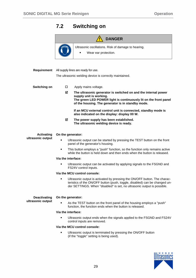
DANGER
Ultrasonic oscillations. Risk of damage to hearing.
Wear ear protection.
All supply lines are ready for use.
The ultrasonic welding device is correctly maintained.
Apply mains voltage.
The ultrasonic generator is switched on and the internal power supply unit is working. The green LED POWER light is continuously lit on the front panel of the housing. The generator is in standby mode. If an MCU external control unit is connected, standby mode is also indicated on the display: display 00 W.
The power supply has been established. The ultrasonic welding device is ready.
On the generator:
Ultrasonic output can be started by pressing the TEST button on the front panel of the generator's housing.
This button employs a "push" function, so the function only remains active while the button is held down and then ends when the button is released.
Via the interface:
Ultrasonic output can be activated by applying signals to the FSGND and FS24V control inputs.
Via the MCU control console:
Ultrasonic output is activated by pressing the ON/OFF button. The charac-teristics of the ON/OFF button (push, toggle, disabled) can be changed un-der SETTINGS. When "disabled" is set, no ultrasonic output is possible.
On the generator:
As the TEST button on the front panel of the housing employs a "push" function, the function ends when the button is released.
Via the interface:
Ultrasonic output ends when the signals applied to the FSGND and FS24V control inputs are removed.
Via the MCU control console:
Ultrasonic output is terminated by pressing the ON/OFF button (if the "toggle" setting is being used).
Requirement
Switching on
Activating ultrasonic output
Deactivating ultrasonic output
Operation SONIC DIGITAL HS MD/MFD
30
7.3 Switching off
Disconnect the generator from the mains voltage.
The generator is de-energized. The green LED POWER display goes out.
7.4 Setting up, programming and controlling the ultrasonic generator
You will need:
an external control unit and the corresponding software
Version MFD: MCU software version MU 1.01 or higher
Version MD: gleicher Softwarestand bei MCU und Generator
INFO
You can find further details on the menus and settings in the operating manual that came with the software.
Switching off

SONIC DIGITAL MG Serie Reinigen Technische Daten
31
8 Specifications
8.1 Generator HS MD /MFD
Data area Frequency
HS 400 MD/MFD 30 kHz 35 kHz 36 kHz 40 kHz
HS 600 MD/MFD 20kHz
HS 800 MD/MFD 20kHz 30 kHz 35 kHz 36 kHz 40 kHz
HS 1000 MD/MFD 20kHz
HS 1200 MD/MFD 30 kHz 35 kHz 36 kHz 40 kHz
HS 1500 MD/MFD 20kHz
HS 2000 MD/MFD 20kHz
Operating voltage 230V +/- 10%
Power consumption 1.9 A 2.9 A 3.8 A 4.8A 5.7 A 7.2 A 9.6 A
Effective power output
400 W 440 VA
600 W 660 VA
800 W 880 VA
1,000 W 1,100 VA
1,200 W 1,320 VA
1,500 W 1,650 VA
2,000 W 2,200 VA
Maximum output 400 W 600 W 800 W 1,000 W 1,200W 1,500 W 2,000W
Fuse protection HS1000: MT 10 A E 250V
HS2000: F 16 A E 250V
All other models F 10 A H 250V
3-pole Phoenix socket mains connection
230 V
Housing dimensions
H x W x D 385 x 157 x 89 mm
Weight 4.0 kg
Temperature range for generator modules
0°C to +40°C
Protection class IP 20, IEC 60 529, EN 60 525
Interface functions
Remote control
These functions are general features of all generators.
Analogue input for controlling the pow-er output 5V - 10V
Floating error relay
Analogue power indicator 0V - 10V
Table 10: Specifications for generator HS MD / MFD
8.1.1 Rating plate
The rating plate is located on the front of the generator.

Troubleshooting SONIC DIGITAL HS MD/MFD
32
9 Troubleshooting
This chapter provides notes and information on actions that can be taken to eliminate errors and malfunctions.
9.1 Resetting malfunctions
Disconnect the supply voltage.
Re-establish the supply voltage.
The generator's control system performs a reset. The factory default settings are then active.
9.2 Eliminating malfunctions
The POWER display remains unlit
No supply voltage.
Check and, if necessary, re-establish the voltage.
Check and, if necessary, repair the back-up fuses.
Supply voltage is present. Generator is defective.
Send in the generator for repairs.
ERROR display lights up
Generator malfunction.
Connect the external MCU control unit and read out the errors.
Reaction based on the diagnosis
No RF detected,
Aprotection active,
E-search,
Templimit reached.
Please refer to the operating manual provided with the software.
Reset
Cause 1
Resolution
Cause 2
Resolution
Cause
Resolution
SONIC DIGITAL HS MD/MFD Troubleshooting
33
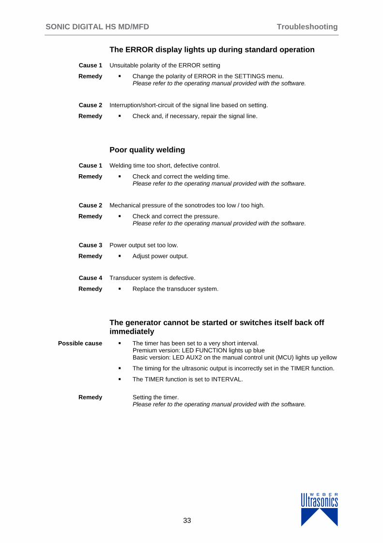
The ERROR display lights up during standard operation
Unsuitable polarity of the ERROR setting
Change the polarity of ERROR in the SETTINGS menu. Please refer to the operating manual provided with the software.
Interruption/short-circuit of the signal line based on setting.
Check and, if necessary, repair the signal line.
Poor quality welding
Welding time too short, defective control.
Check and correct the welding time. Please refer to the operating manual provided with the software.
Mechanical pressure of the sonotrodes too low / too high.
Check and correct the pressure. Please refer to the operating manual provided with the software.
Power output set too low.
Adjust power output.
Transducer system is defective.
Replace the transducer system.
The generator cannot be started or switches itself back off immediately
The timer has been set to a very short interval. Premium version: LED FUNCTION lights up blue Basic version: LED AUX2 on the manual control unit (MCU) lights up yellow
The timing for the ultrasonic output is incorrectly set in the TIMER function.
The TIMER function is set to INTERVAL.
Setting the timer. Please refer to the operating manual provided with the software.
Cause 1
Remedy
Cause 2
Remedy
Cause 1
Remedy
Cause 2
Remedy
Cause 3
Remedy
Cause 4
Remedy
Possible cause
Remedy
Troubleshooting SONIC DIGITAL HS MD/MFD
34
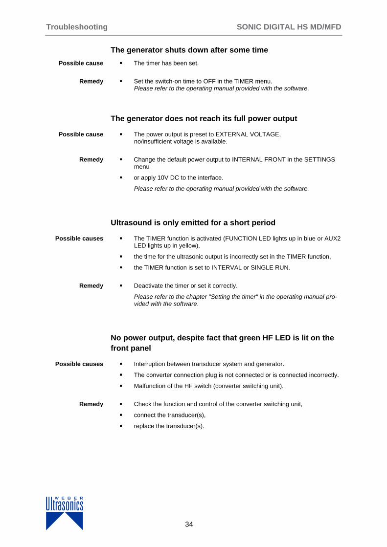
The generator shuts down after some time
The timer has been set.
Set the switch-on time to OFF in the TIMER menu. Please refer to the operating manual provided with the software.
The generator does not reach its full power output
The power output is preset to EXTERNAL VOLTAGE, no/insufficient voltage is available.
Change the default power output to INTERNAL FRONT in the SETTINGS menu
or apply 10V DC to the interface.
Please refer to the operating manual provided with the software.
Ultrasound is only emitted for a short period
The TIMER function is activated (FUNCTION LED lights up in blue or AUX2 LED lights up in yellow),
the time for the ultrasonic output is incorrectly set in the TIMER function,
the TIMER function is set to INTERVAL or SINGLE RUN.
Deactivate the timer or set it correctly.
Please refer to the chapter "Setting the timer" in the operating manual pro-vided with the software.
No power output, despite fact that green HF LED is lit on the
front panel
Interruption between transducer system and generator.
The converter connection plug is not connected or is connected incorrectly.
Malfunction of the HF switch (converter switching unit).
Check the function and control of the converter switching unit,
connect the transducer(s),
replace the transducer(s).
Possible cause
Remedy
Possible cause
Remedy
Possible causes
Remedy
Possible causes
Remedy
SONIC DIGITAL HS MD/MFD Troubleshooting
35
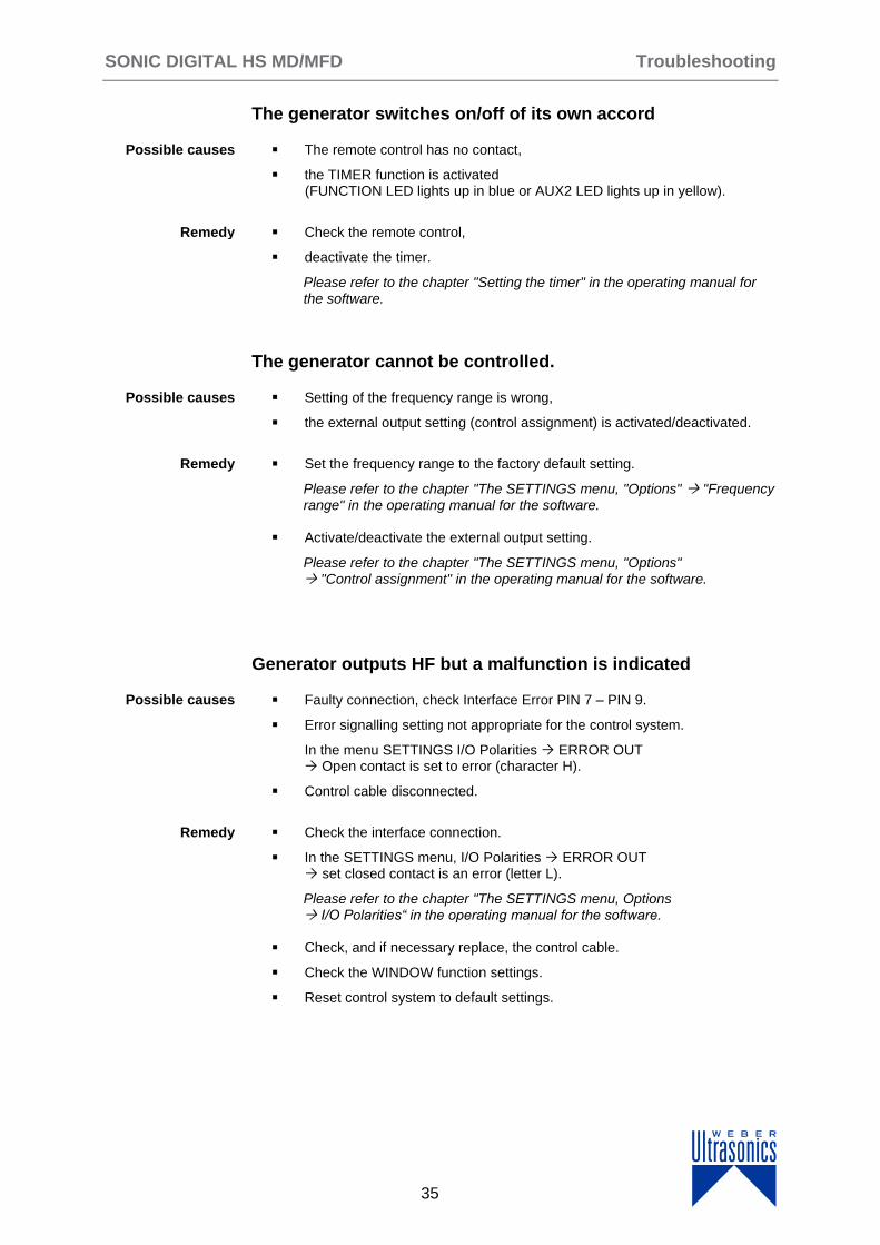
The generator switches on/off of its own accord
The remote control has no contact,
the TIMER function is activated (FUNCTION LED lights up in blue or AUX2 LED lights up in yellow).
Check the remote control,
deactivate the timer.
Please refer to the chapter "Setting the timer" in the operating manual for the software.
The generator cannot be controlled.
Setting of the frequency range is wrong,
the external output setting (control assignment) is activated/deactivated.
Set the frequency range to the factory default setting.
Please refer to the chapter "The SETTINGS menu, "Options" "Frequency range" in the operating manual for the software.
Activate/deactivate the external output setting.
Please refer to the chapter "The SETTINGS menu, "Options" "Control assignment" in the operating manual for the software.
Generator outputs HF but a malfunction is indicated
Faulty connection, check Interface Error PIN 7 – PIN 9.
Error signalling setting not appropriate for the control system.
In the menu SETTINGS I/O Polarities ERROR OUT Open contact is set to error (character H).
Control cable disconnected.
Check the interface connection.
In the SETTINGS menu, I/O Polarities ERROR OUT set closed contact is an error (letter L).
Please refer to the chapter "The SETTINGS menu, Options I/O Polarities“ in the operating manual for the software.
Check, and if necessary replace, the control cable.
Check the WINDOW function settings.
Reset control system to default settings.
Possible causes
Remedy
Possible causes
Remedy
Possible causes
Remedy
Quality assurance SONIC DIGITAL HS MD/MFD
36
10 Quality assurance
The following factors are key for quality assurance:
proper and intended use
staff behaviour focused on quality assurance
This includes:
equipping and setting up devices properly
only allowing trained and authorised staff to alter parameters
regularly maintaining equipment
The operator bears responsibility for ensuring that the complete system is in proper working order, as well as for organising and executing quality checks and quality assurance measures.
When processing an order in line with the operator's specifications, always remove and check workpieces.
The process accuracy should be checked at regular intervals.
General
Operator quality assurance
Process accuracy

SONIC DIGITAL HS MD/MFD Maintenance instructions
37
11 General maintenance instructions
11.1 Safety
DANGER
Risk to life from electric current!
Any contact with live wires or components presents a risk to life!
Before cleaning the equipment:
switch off all equipment.
Before replacing fuses:
disconnect all equipment from the power supply.
11.2 Care and maintenance
The ultrasonic generators do not require any special maintenance or care.
NOTE
§ Do not use any aggressive cleaning agents.
Do not use ultrasound to clean the generator.
Remove dust and dirt regularly using a damp cloth.
Maintenance instructions SONIC DIGITAL HS MD/MFD
38
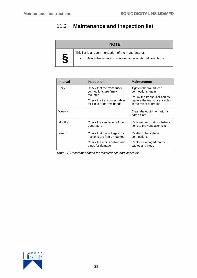
11.3 Maintenance and inspection list
NOTE
§ This list is a recommendation of the manufacturer.
Adapt the list in accordance with operational conditions.
Interval Inspection Maintenance
Daily Check that the transducer connections are firmly mounted
Check the transducer cables for kinks or narrow bends
Tighten the transducer connections again
Re-lay the transducer cables, replace the transducer cables in the event of breaks
Weekly Clean the equipment with a damp cloth
Monthly Check the ventilation of the generators
Remove dust, dirt or obstruc-tions to the ventilation slits
Yearly Check that the voltage con-nections are firmly mounted
Check the mains cables and plugs for damage
Reattach the voltage connections
Replace damaged mains cables and plugs
Table 11: Recommendation for maintenance and inspection
SONIC DIGITAL HS MD/MFD Maintenance instructions
39
11.4 Maintenance
DANGER
Risk to life from electric current!
Any contact with live wires or components presents a risk to life!.
Before replacing fuses:
disconnect all equipment from the power supply.
1. Disconnect the generator housing from the power supply.
2. Loosen the housing screws.
3. Open the device.
4. Disconnect the connection cables to the cover of the housing, if necessary.
5. Defective fuses must only be replaced by fuses of the specified type and nominal current.
6. Reestablish all connections and close the housing.
7. Properly tighten all screws again.
8. Connect the generator housing to the power supply.
The generator is ready for use.
11.5 Repair work
When sending in the equipment for inspection or repair work, please provide the fol-lowing information:
type of error,
surrounding circumstances,
suspected cause of the error,
any unusual events preceding the error.

Lifecycle SONIC DIGITAL HS MD/MFD
40
12 Life cycle
This chapter contains information relating to the individual life cycles from transport to dis-posal.
12.1 Transport
12.1.1 Safety
For transport and installation of the ultrasonic unit, the pertinent safety regu-
lations must be observed. Careful handling can prevent accidents.
The following must be observed for transport:
Disconnect the ultrasonic unit from all supply lines.
Pack the ultrasonic unit in such a way that it is protected against shocks.
Transport the ultrasonic unit in such a way that it is protected against fall-ing, mechanical pressure and shocks.
The ultrasonic unit must be transported and handled with care.
12.1.2 Packaging
The chosen transport route plays a part in determining the type of packaging used. Unless otherwise contractually agreed, the packaging material complies with Di-rective 94/62/EC on packaging and packaging waste. For overseas shipping, the equipment is corrosion-protected using a suitable casing. Wooden packaging com-plies with the guidelines of the German Federal Association for Wood Packaging, Pallets and Export Packaging (HPE)
NOTE
§ The symbols on the packaging and applicable regulations must be observed.
SONIC DIGITAL HS MD/MFD Lifecycle
41
12.2 Positioning and installing
12.2.1 Unpacking and cleaning
Unpack the unit with care! If the packaging is not opened in a correct manner, com-ponents can be damaged and the function of the ultrasonic unit impaired or the unit rendered unusable.
The following points must be observed during unpacking and cleaning:
take care when removing ultrasonic equipment from its packaging,
only use suitable auxiliary means,
avoid extended periods of outdoor storage, as environmental influences can soil and potentially even damage the ultrasonic equipment. The correct functioning of the system is then no longer ensured,
do not use compressed air to clean the system.
12.2.2 Checking the delivery for completeness
Use the delivery note or packaging slip to check that delivery is complete. If any-thing is missing, please contact WEBER Ultrasonics as soon as possible.
In the event of transport damage, it is vital to request written confirmation of the damage from the transport company.
NOTE
§ A sketch or photo of the damage would be very helpful and facilitate understanding.
Lifecycle SONIC DIGITAL HS MD/MFD
42
12.2.3 Place of installation
All ultrasonic equipment is designed for indoor use in a closed and dry building.
When positioning the equipment, select a location which ensures that it is protected from:
moisture,
water and steam,
aggressive vapours and chemically contaminated ambient air,
alkaline environments,
direct sunlight (UV light) and heat (maximum ambient temperature 40°C),
cold (minimum ambient temperature 0°C),
dust.
NOTE
When setting up and installing the ultrasonic generator, please en-sure that the following conditions are met:
sufficient cool air circulation.
SONIC DIGITAL HS MD/MFD Lifecycle
43
12.2.4 Installing and assembling
When positioning and installing the generators, please ensure that the following conditions are met:
Sufficient air circulation
The air inlets are located on the underside of the housing
Installation of the generator in a vertical positon with the front fan facing downwards
Installation of the generator in a horizontal position with the the cooling profile pointing upwards
The following must be observed for installation and assembly:
only suitable, instructed and expressly authorised persons may carry out the work,
for installation or integration of the ultrasonic generator into a total system, the data in the installation drawing must be observed.
1. Install the individual ultrasonic generators/components in line with the installation plan.
2. When fitting third party components, the manufacturer's instructions must be observed.
3. Make sure that all screwed joints and connections are properly and firmly fastened.
The ultrasonic generator is fitted.
NOTE
When assembling the equipment, please make sure you check the components for completeness (for example, vibration-absorbing and protective padding provided by the manufacturer should be inserted in the clamps again).
All isolating and contact points (HF cables, mains cables, control cables) must be checked and, if necessary, tightened. Cables should never be kinked.
Procedure

Lifecycle SONIC DIGITAL HS MD/MFD
44
12.3 Supply and installation
The following must be observed for installation:
only suitable, instructed and expressly authorised persons may carry out the work,
secure all potential hazard areas, even if they only represent a hazard for a short time,
for installation or integration of the ultrasonic generator into a total system, the data in the installation drawing must be observed.
12.3.1 Mains connections
All mains connections at the place of installation must comply with the applicable standards, directives and guidelines.
12.3.2 Ultrasound supply
All ultrasound connections at the place of installation must comply with the applica-ble standards, directives and guidelines. Please comply with an ultrasound connec-tion plan if it represents an agreed part of the shipment.
12.3.3 Control cables
All control cables at the place of installion must comply with the applicable stand-ards, directives and guidelines. If a wiring diagram for the control system is included in the scope of delivery, observe it.
12.4 Commissioning
The following must be carried out for commissioning:
check installation,
check all ultrasonic units/components,
check the energy supply,
switch on the complete system/ultrasonic welding units.
SONIC DIGITAL HS MD/MFD Lifecycle
45
12.5 Temporary non-use
For temporary non-use of the ultrasonic generator, it must be ensured that the ambient conditions for storage are appropriate.
Procedures to be carried out prior to temporary non-use/storage:
switch off the ultrasonic generator,
switch off the power supply,
clean and service all system components,
protect all system components against corrosion.
NOTE
Following a period of temporary decommissioning, the equipment must be recommissioned.
12.6 Decommissioning
Procedures to be carried out prior to decommissioning:
switch off the ultrasonic generator,
switch off the power supply and disconnect correctly,
switch off the ultrasonic supply and disconnect correctly,
clean and service all system components,
protect all system components against corrosion.
Lifecycle SONIC DIGITAL HS MD/MFD
46
12.7 Disposal
12.7.1 Dismantling
The ultrasonic equipment may only be dismantled by specially trained and author-ised staff, who must operate in compliance with national laws, regulations and safe-ty provisions.
ATTENTION!
Dispose of system components in accordance with the national regulations.
Information can be obtained from the responsible authorities and specialist companies.
Should you have any questions regarding disposal of components, please contact WEBER Ultrasonics!

47
SERVICE
Spare parts
Spare parts and accessories can only be supplied if the serial number of the device is specified.
Service hotline
Should you still have any questions after having carefully read the operating instructions, call our service hotline.
Please have the following information to hand to help us answer your questions quickly:
Device type and serial number (You find the serial number on the generator's front panel and base plate. It can also be called up in the graphical display under Info.)
Our service hotline number:
+49 (0) 7248/ 92 07-0
Related Documents