OPERATING MANUAL Asphalt paver wheeled F80W Hatz 4812217933

Welcome message from author
This document is posted to help you gain knowledge. Please leave a comment to let me know what you think about it! Share it to your friends and learn new things together.
Transcript
F80W
, Hat
z
www.dynapac.com
OPE
RATI
NG
MAN
UAL
OPERATING MANUALAsphalt paver wheeledF80WHatz
4812217933
Poznámka: Laminace lesklá 1+1 (oboustranná), horizontální a vertikální ořez dle ořezových značek, 2x big - 205 mm vnější a 210 mm vnitřní od okraje čistého formátu, dodávka obálek v přeloženém a baleném stavu po jednotlivých typech.


F80WAsphalt paver, wheeled
Hatz
Operating Manual
Edition 01/2020 ENFrom Serial No. 4510232
Original Operating Manual


Gov
ernm
ent T
estin
g La
bora
tory
of M
achi
nes
J.S.
C.
Třan
ovsk
ého
622/
1116
3 04
Pra
ha 6
–Řep
y
GN
URÄLK
RESTÄTIM
ROF
NOK
GElanigir
Oenihcsa
mtmase
GD
YNAP
AC G
mbH
Amm
erla
ende
r Str
asse
193
Wir
D-2
6203
War
denb
urg
erkl
ären
hie
rmit
in a
llein
iger
Ver
antw
ortu
ng, d
ass
das
Prod
ukt
Stra
ssen
fert
iger
e
mannenihcsaM
F80W
Tie
r 4F
pytnenihcsaM
.rN-negrah
C )NIP( redo -neireS
2006
/42
2014
/30
2000
/14
alle
n zu
treffe
nden
Bes
timm
unge
n de
r fol
gend
en R
icht
linie
n (g
gf. i
n de
r ge
ltend
en n
ovel
lierte
n Fa
ssun
g) u
nd d
en R
echt
svor
schr
iften
der
M
itglie
dsta
aten
ent
spric
ht
sdradnatS etreisinomrah etdna
wegnA Inst
allie
rte N
etto
leis
tung
Mot
or (k
W)
)A(Bd legepsgnutsiellahcS renesseme
G)A(Bd legepsgnutsiellahcS retreitnara
G
:tätimrofn oK red gnulietrueB ruz nerhafreV
Anha
ng V
I
Beau
ftrag
te b
enan
nte
Stel
le fü
r Lär
m-R
icht
linie
200
0/14
/EG
Thor
sten
Bod
e,nosreP red dnu srelletsrE sed noitisoP dnu e
maN
dnu gnulletsrE ruz egarfnA nehcildröheb netednürgeb renie ieb eidregana
M lareneG
Vorla
ge d
es e
ntsp
rech
ende
n Ab
schn
itts
der t
echn
isch
en U
nter
lage
n be
rech
tigt i
st
srelletsrE sed tfirhcsretnU
War
denb
urg
19.0
9.20
18gnulletsrE red
mutaD dnu tr
O02
88.6
0E EEN
500-
1:20
06+A
1:20
09EN
500-
6:20
06+A
1:20
08
6,3
102
104
EC D
ECLA
RAT
ION
OF
CO
NFO
RM
ITY
Tran
slat
ion
Indi
vidu
al m
achi
ne
We
decl
are
unde
r our
sol
e re
spon
sibi
lity
that
the
prod
uct
Mac
hine
nam
e
Mac
hine
type
Seria
l or b
atch
(PIN
) No.
com
plie
s w
ith a
ll th
e re
leva
nt p
rovi
sion
s of
the
follo
win
g di
rect
ives
, as
am
ende
d, a
nd th
e co
rresp
ondi
ng n
atio
nal r
egul
atio
ns
Har
mon
ized
sta
ndar
ds a
pplie
d
Net
inst
alle
d po
wer
[kW
]M
easu
red
soun
d po
wer
leve
l dB(
A)G
uara
ntee
d so
und
pow
er le
vel d
B(A)
Con
form
ity a
sses
smen
t pro
cedu
re fo
llow
ed:
Anne
x V
Nam
e an
d ad
dres
s of
the
notif
ied
body
invo
lved
for d
irect
ive
2000
/14/
EC
Nam
e an
d po
sitio
n of
issu
er a
nd th
e pe
rson
auth
oris
ed to
com
pile
and
tran
smit,
in re
spon
se to
a re
ason
ed
requ
est b
y th
e na
tiona
l aut
horit
ies,
rele
vant
par
t of t
he te
chni
cal f
ile
Sign
atur
e of
issu
er
Plac
e an
d da
te o
f iss
ue

1F80W
D451020
Congratulations to purchasing a new DYNAPAC machine. This modern machine is characterised by simple operation and easy mainte-nance. In order to avoid faults due to improper operation and maintenance, we request that you read this Operating Manual with great care and keep them for later reference.
With kind regards,
Dynapac GmbH | Ammerlaender Str. 93 | 26203 Wardenburg – Germany
% +49 4407 972-0 | www.dynapac.com
This Operating Manual consists of:
I. Specification manual II. Operating manual III. Maintenance manual
The purpose of this Operator’s Manual is to familiarize operators with safe operation of the machine and provide them information for maintenance. Therefore it is necessary to pass this manual to operators and ensure that it will be read by them carefully before the road roller is used.
DYNAPAC assumes no responsibility in cases when the machine is operated incorrectly or is used incorrectly in operating modes, which may result in an injury or death, damage to the machine or property or environmental pollution.
Adherence to maintenance instructions increases the reliability and lifetime of the machinery and reduces repair costs and down time.
In order to ensure smooth operation of the DYNAPAC compaction equipment, use only original spare parts supplied by DYNAPAC for repairs.
The operating instructions must always be kept available on the machine in an appropriate place.

2 F80W
Preface
Information, specifications, and recommended operation and maintenance instructions contained in this publication are basic and final information at the time of the printing of this publication. Printer’s errors, technical modifications, and modifications of figures are reserved. All dimensions and weights are approximate and, therefore, not binding.
DYNAPAC reserves the right to perform modifications at any time with no obligation to inform the machine user. If you identify any differences between the machine operated by you and the information contained in this publication, contact your local dealer.
Reproduction or copying of any kind is prohibited without the written permission of DYNAPAC
3F80W
D409002A
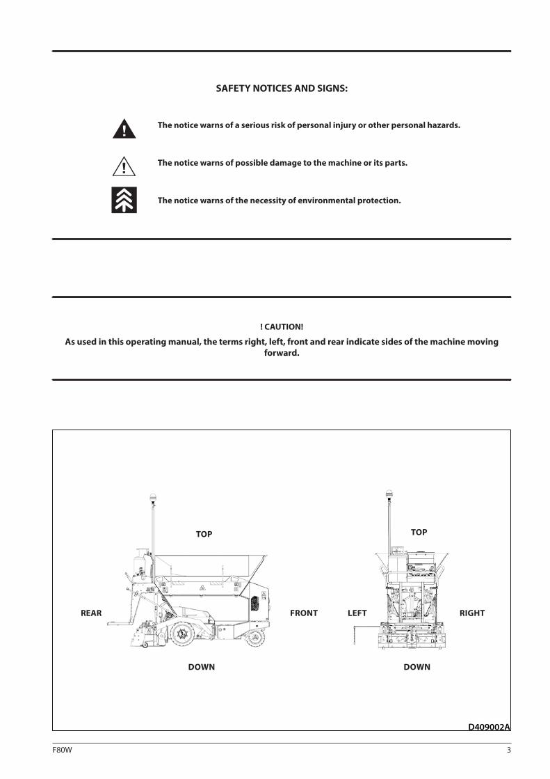
SAFETY NOTICES AND SIGNS:
The notice warns of a serious risk of personal injury or other personal hazards.
The notice warns of possible damage to the machine or its parts.
The notice warns of the necessity of environmental protection.
! CAUTION!
As used in this operating manual, the terms right, left, front and rear indicate sides of the machine moving forward.
REAR
TOP
DOWN
FRONT LEFT RIGHT
DOWN
TOP
4 F80W
Contents
Contents ...........................................................................................................................................................4
1 SPECIFICATION MANUAL ......................................................................................................................9
1.1 Basic data ..............................................................................................................................................10
1.2 Dimensional drawing of the machine .................................................................................................12
1.3 Technical data .......................................................................................................................................14
1.3.1 Specification table .................................................................................................................................................................................................14
1.3.2 Machine gradeability and lateral static stability .........................................................................................................................................16
1.4 Optional equipment .............................................................................................................................18
1.4.1 Table of optional equipment .............................................................................................................................................................................18
1.4.2 Mechanical screed extension ............................................................................................................................................................................19
1.4.3 Dual wheels ..............................................................................................................................................................................................................21
1.4.4 Front wheel scraper ..............................................................................................................................................................................................22
1.4.5 Material hopper extension .................................................................................................................................................................................23
1.4.6 Additional lighting ................................................................................................................................................................................................24
1.4.7 Screed copying system ........................................................................................................................................................................................25
2 OPERATING MANUAL ..........................................................................................................................29
2.1 Main safety precautions .......................................................................................................................30
2.1.1 Obligations before putting into operation ...................................................................................................................................................30
2.1.2 Assurance of safety precautions by the owner ...........................................................................................................................................30
2.1.3 Requirements for qualified personnel ...........................................................................................................................................................31
2.1.4 Machine operator's obligations ........................................................................................................................................................................32
2.1.5 Screed operators' obligations ...........................................................................................................................................................................33
2.1.6 Driver's stand and screed operator stand during machine operation ...............................................................................................34
2.1.7 Dangerous zone and safe distance .................................................................................................................................................................35
2.1.8 Machine operation at unclear working areas ..............................................................................................................................................38
2.1.9 Manual signals .......................................................................................................................................................................................................38
2.1.10 Safety notices and symbols used on the machine ....................................................................................................................................42
2.1.11 Personal protective equipment ........................................................................................................................................................................45
2.1.12 General safety precautions .................................................................................................................................................................................46
2.1.13 Safety precautions during machine operation ...........................................................................................................................................46
2.1.14 Safety and fire precautions during the use of gas bottles ......................................................................................................................47
2.1.15 Safety precautions for the use of portable fire extinguisher .................................................................................................................48
2.1.16 Safety and fire precautions during welding on the machine ................................................................................................................48
2.1.17 Safety precautions for electrical and electronic equipment of the machine ..................................................................................49
2.1.18 Prohibited activities ..............................................................................................................................................................................................50
2.2 Preservation and storage .....................................................................................................................52
2.2.1 Storage places and storage conditions ..........................................................................................................................................................52
2.2.2 Preservation and storage of the machine for 1–2 months .....................................................................................................................53
2.2.3 Preservation and storage of the machine for a period over 2 months...............................................................................................54
2.2.4 Removing chemical preservatives and putting the machine into operation ..................................................................................55
5F80W
OPERATING MANUAL
2.3 Machine disposal ..................................................................................................................................57
2.3.1 Machine disposal after its service life .............................................................................................................................................................57
2.4 Machine description .............................................................................................................................58
2.4.1 Description of main parts of the machine and screed .............................................................................................................................59
2.4.2 Main dashboard .....................................................................................................................................................................................................62
2.4.3 Display .......................................................................................................................................................................................................................66
2.4.4 Foot switch ...............................................................................................................................................................................................................68
2.5 Operation of the machine ....................................................................................................................70
2.5.1 Turning ON/OFF the battery disconnecter ...................................................................................................................................................70
2.5.2 Basic equipment of the machine .....................................................................................................................................................................71
2.5.3 Machine footboard................................................................................................................................................................................................74
2.5.4 Deposition boxes and safety covers on the machine ...............................................................................................................................75
2.5.5 Mounting of screed reduction plates .............................................................................................................................................................77
2.5.6 Beacon .......................................................................................................................................................................................................................79
2.5.7 Driver's stand ...........................................................................................................................................................................................................80
2.5.8 Starting the engine ...............................................................................................................................................................................................81
2.5.9 Starting the engine using starting leads from external power supply ..............................................................................................82
2.5.10 Travel and reversing of the machine...............................................................................................................................................................83
2.5.11 Stopping the machine and engine..................................................................................................................................................................85
2.5.12 Machine parking ....................................................................................................................................................................................................86
2.5.13 Front wheel ..............................................................................................................................................................................................................87
2.5.14 Using and setting the paving direction indicator ......................................................................................................................................88
2.5.15 Hopper .......................................................................................................................................................................................................................89
2.5.16 Material outlet .........................................................................................................................................................................................................90
2.5.17 Conveyor ...................................................................................................................................................................................................................91
2.5.18 Conveyor limit switch ...........................................................................................................................................................................................92
2.5.19 Augers ........................................................................................................................................................................................................................93
2.6 Operation of the screed .......................................................................................................................94
2.6.1 Lifting and lowering the screed ........................................................................................................................................................................94
2.6.2 Screed lock ...............................................................................................................................................................................................................95
2.6.3 Setting the paving width ....................................................................................................................................................................................96
2.6.4 Setting the paving thickness .............................................................................................................................................................................98
2.6.5 Setting the roadway profile ...............................................................................................................................................................................99
2.6.6 Setting the end gates ........................................................................................................................................................................................ 100
2.6.7 Screed vibration (optional equipment) ...................................................................................................................................................... 101
2.6.8 Screed gas heating ............................................................................................................................................................................................. 102
2.6.9 Loading material to the machine .................................................................................................................................................................. 108
2.6.10 Start of paving...................................................................................................................................................................................................... 109
2.6.11 End of paving ....................................................................................................................................................................................................... 110
2.7 Machine transport ..............................................................................................................................111
2.7.1 Preparation of the machine for transport .................................................................................................................................................. 111
2.7.2 Loading the machine using a ramp ............................................................................................................................................................. 112
2.7.3 Loading the machine with a crane ............................................................................................................................................................... 113
2.7.4 Machine transport .............................................................................................................................................................................................. 114
2.7.5 Preparation of the machine for operation after transportation ........................................................................................................ 114
2.8 Special conditions to use the machine .............................................................................................115
2.8.1 Towing the machine .......................................................................................................................................................................................... 115
2.8.2 Climatic conditions ............................................................................................................................................................................................ 116
2.8.3 Operation of the machine in dusty environment ................................................................................................................................... 116

6 F80W
Contents
3 MAINTENANCE MANUAL ..................................................................................................................119
3.1 Safety and other measures during maintenance of the machine ..................................................121
3.1.1 Safety precautions during machine maintenance ................................................................................................................................. 121
3.1.2 Safety and fire precautions during replacement of operating fluids ............................................................................................... 122
3.1.3 Environmental and hygienic principles ...................................................................................................................................................... 123
3.1.3.1 Hygienic principles ............................................................................................................................................................................................. 123
3.1.3.2 Environmental principles ................................................................................................................................................................................. 123
3.2 Specification of operating fluids .......................................................................................................124
3.2.1 Engine oil ............................................................................................................................................................................................................... 124
3.2.2 Fuel ........................................................................................................................................................................................................................... 124
3.2.3 Hydraulic oil .......................................................................................................................................................................................................... 125
3.2.4 Anti-adherent solution ..................................................................................................................................................................................... 125
3.2.5 Liquid gas............................................................................................................................................................................................................... 126
3.2.6 Lubricating grease .............................................................................................................................................................................................. 126
3.3 Table of fluid quantities .....................................................................................................................127
3.3.1 Overview of fluids quantities and overview of symbols specified in maintenance plans ....................................................... 127
3.4 Lubrication and maintenance chart ..................................................................................................128
3.5 Lubrication and service plan .............................................................................................................130
3.5.1 Maintenance plan ............................................................................................................................................................................................... 130
3.6 Lubrication and maintenance operations ........................................................................................131
Every 10 hours at the beginning of work (daily) ..............................................................................132
3.6.1 Fuel level check .................................................................................................................................................................................................... 132
3.6.2 Engine oil check .................................................................................................................................................................................................. 133
3.6.3 Hydraulic oil check in the hydraulic tank ................................................................................................................................................... 134
3.6.4 Driver's stand cleaning...................................................................................................................................................................................... 135
3.6.5 Cleaning the hopper, outlets and conveyor .............................................................................................................................................. 136
3.6.6 Auger cleaning ..................................................................................................................................................................................................... 137
3.6.7 Test of burner ignition, flame position adjustment and spark plug maintenance ..................................................................... 138
3.6.8 Gas equipment tightness check .................................................................................................................................................................... 142
Every 10 hours at the end of work (daily) .........................................................................................143
3.6.9 Fuel level check .................................................................................................................................................................................................... 143
3.6.10 Cleaning the hopper, outlets and conveyor .............................................................................................................................................. 144
3.6.11 Auger cleaning ..................................................................................................................................................................................................... 145
Every 50 hours (week) ........................................................................................................................146
3.6.12 Cleaning the water separator ......................................................................................................................................................................... 146
3.6.13 Machine lubrication ........................................................................................................................................................................................... 147

7F80W
OPERATING MANUAL
Every 100 hours of operation (monthly) ...........................................................................................150
3.6.14 Fuel system tightness check ........................................................................................................................................................................... 150
3.6.15 Rear wheel fastening check ............................................................................................................................................................................ 151
3.6.16 Conveyor chain tensioning ............................................................................................................................................................................. 152
Every 250 hours of operation (every 3 months) ...............................................................................153
3.6.17 Engine oil replacement ..................................................................................................................................................................................... 153
3.6.18 Engine air intake check ..................................................................................................................................................................................... 154
3.6.19 Engine accelerator cable tension check ..................................................................................................................................................... 155
3.6.20 Hydraulic oil cooler cleaning .......................................................................................................................................................................... 156
3.6.21 Hydraulic circuit tightness check .................................................................................................................................................................. 157
3.6.22 Battery check ........................................................................................................................................................................................................ 158
3.6.23 Checking the conveyor drive chain tension .............................................................................................................................................. 160
Every 500 hours of operation (every 6 months) ...............................................................................161
3.6.24 Fuel filter replacement ...................................................................................................................................................................................... 161
3.6.25 Air filter replacement ......................................................................................................................................................................................... 163
3.6.26 Front and rear wheel condition check ........................................................................................................................................................ 164
Every 1000 hours (yearly) ..................................................................................................................165
3.6.27 Engine oil filter cleaning ................................................................................................................................................................................... 165
3.6.28 Hydraulic oil and hydraulic oil filter replacement ................................................................................................................................... 167
3.6.29 Gas line hose replacement .............................................................................................................................................................................. 169
Maintenance as required ...................................................................................................................170
3.6.30 Battery replacement .......................................................................................................................................................................................... 170
3.6.31 Charging of the battery .................................................................................................................................................................................... 171
3.6.32 Screw connections tightness check ............................................................................................................................................................. 172
3.7 Troubleshooting .................................................................................................................................175
3.7.1 Troubleshooting .................................................................................................................................................................................................. 175
3.7.2 Troubleshooting engine faults when indicator lamps are lit on the display ................................................................................. 175
3.7.3 Troubleshooting the hydraulic system ....................................................................................................................................................... 175
3.7.4 Troubleshooting the electrical system ........................................................................................................................................................ 176
3.7.5 Troubleshooting of screed heating when active error indicator lamp is lit and an error code is shown on the display .....176
3.7.6 List of error codes displayed on the display .............................................................................................................................................. 177
3.8 Appendices .........................................................................................................................................180
3.8.1 Machine wiring diagram .................................................................................................................................................................................. 180
3.8.2 Machine hydraulic system diagram ............................................................................................................................................................. 186
3.8.2.1 Measuring points of the hydraulic circuit .................................................................................................................................................. 188
3.8.3 Screed gas heating system diagram ............................................................................................................................................................ 189
3.8.4 Table of spare parts for regular maintenance ........................................................................................................................................... 190
3.8.5 Content of the filter set after 500 hours (4812088533) ......................................................................................................................... 190
3.8.6 Content of the filter set after 1000 hours (4812088534) ...................................................................................................................... 190
3.8.7 Table of optional equipment .......................................................................................................................................................................... 191

8 F80W

9F80W
SPECIFICATION MANUAL
1 SPECIFICATION MANUAL
F80W(Hatz)
10 F80W
AMMERLAENDER STR. 93D-26203 WARDENBURGGERMANY
9
10
3
1
2
511
D3487
4
6
8
7
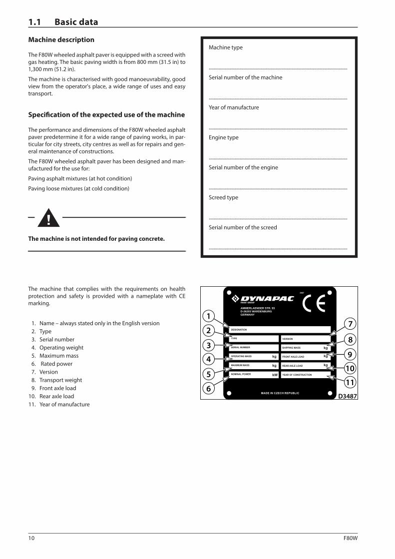
The machine that complies with the requirements on health protection and safety is provided with a nameplate with CE marking.
1. Name – always stated only in the English version 2. Type 3. Serial number 4. Operating weight 5. Maximum mass 6. Rated power 7. Version 8. Transport weight 9. Front axle load 10. Rear axle load 11. Year of manufacture
Machine type
................................................................................................................
Serial number of the machine
................................................................................................................
Year of manufacture
................................................................................................................
Engine type
................................................................................................................
Serial number of the engine
................................................................................................................
Screed type
................................................................................................................
Serial number of the screed
................................................................................................................
Machine description
The F80W wheeled asphalt paver is equipped with a screed with gas heating. The basic paving width is from 800 mm (31.5 in) to 1,300 mm (51.2 in).
The machine is characterised with good manoeuvrability, good view from the operator's place, a wide range of uses and easy transport.
Specification of the expected use of the machine
The performance and dimensions of the F80W wheeled asphalt paver predetermine it for a wide range of paving works, in par-ticular for city streets, city centres as well as for repairs and gen-eral maintenance of constructions.
The F80W wheeled asphalt paver has been designed and man-ufactured for the use for:
Paving asphalt mixtures (at hot condition)
Paving loose mixtures (at cold condition)
The machine is not intended for paving concrete.
1.1 Basic data
11F80W
D451023
D451024
D451025
SPECIFICATION MANUAL
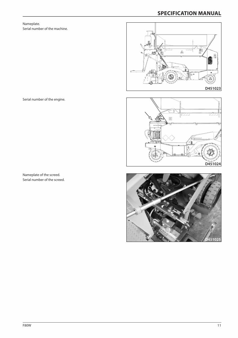
Nameplate.Serial number of the machine.
Nameplate of the screed.Serial number of the screed.
Serial number of the engine.
12 F80W
W1
W2W
W3 W4
B
L
L1
H
H1
D451170A
A
L2
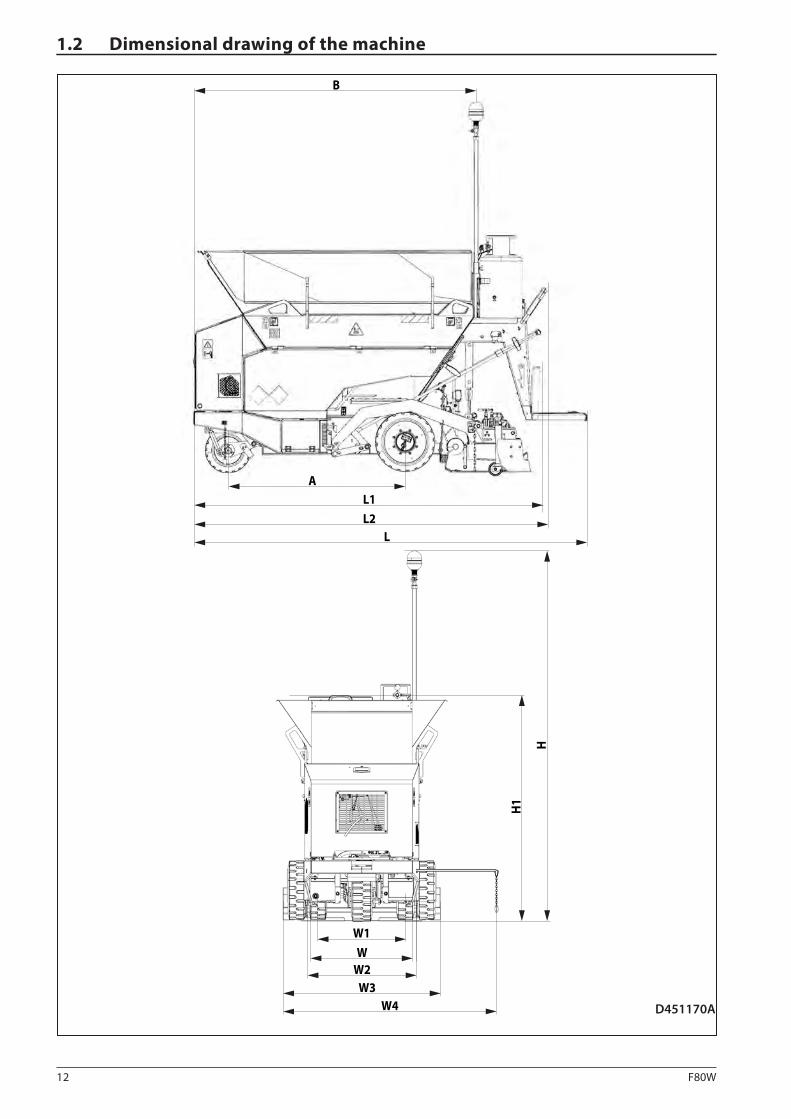
1.2 Dimensional drawing of the machine

13F80W
SPECIFICATION MANUAL
A B H H1 L L1
mm 1280 2070 2680 1598 2865 2526
in 50,4 81,5 105,5 62,9 112,8 99,4
L2 W W1 W2 W3 W4
mm 2550 765 640 800 1150 1699
in 100,4 30,1 25,2 31,5 45,3 66,9
14 F80W
1.3 Technical data
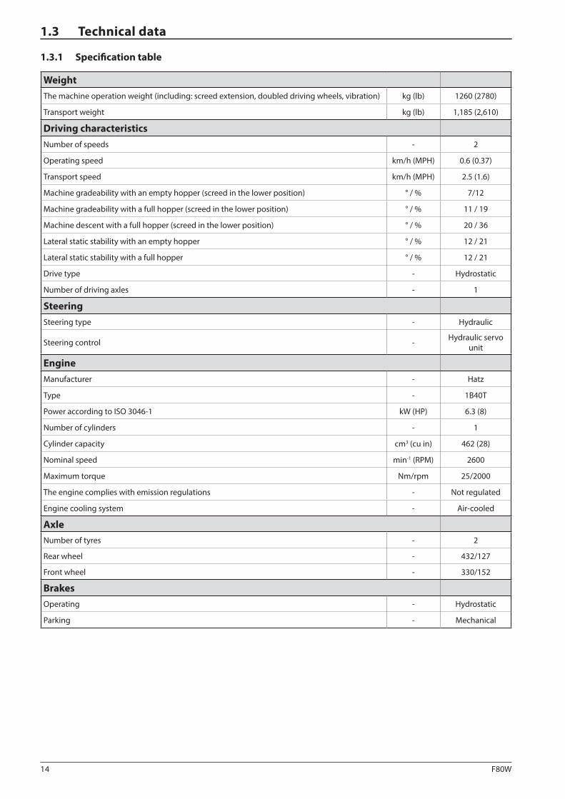
1.3.1 Specification table
WeightThe machine operation weight (including: screed extension, doubled driving wheels, vibration) kg (lb) 1260 (2780)
Transport weight kg (lb) 1,185 (2,610)
Driving characteristicsNumber of speeds - 2
Operating speed km/h (MPH) 0.6 (0.37)
Transport speed km/h (MPH) 2.5 (1.6)
Machine gradeability with an empty hopper (screed in the lower position) ° / % 7/12
Machine gradeability with a full hopper (screed in the lower position) ° / % 11 / 19
Machine descent with a full hopper (screed in the lower position) ° / % 20 / 36
Lateral static stability with an empty hopper ° / % 12 / 21
Lateral static stability with a full hopper ° / % 12 / 21
Drive type - Hydrostatic
Number of driving axles - 1
SteeringSteering type - Hydraulic
Steering control - Hydraulic servo unit
EngineManufacturer - Hatz
Type - 1B40T
Power according to ISO 3046-1 kW (HP) 6.3 (8)
Number of cylinders - 1
Cylinder capacity cm3 (cu in) 462 (28)
Nominal speed min-1 (RPM) 2600
Maximum torque Nm/rpm 25/2000
The engine complies with emission regulations - Not regulated
Engine cooling system - Air-cooled
AxleNumber of tyres - 2
Rear wheel - 432/127
Front wheel - 330/152
BrakesOperating - Hydrostatic
Parking - Mechanical
15F80W
SPECIFICATION MANUAL
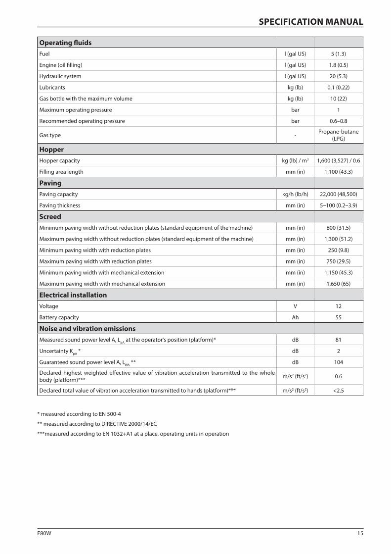
Operating fluidsFuel l (gal US) 5 (1.3)
Engine (oil filling) l (gal US) 1.8 (0.5)
Hydraulic system l (gal US) 20 (5.3)
Lubricants kg (lb) 0.1 (0.22)
Gas bottle with the maximum volume kg (lb) 10 (22)
Maximum operating pressure bar 1
Recommended operating pressure bar 0.6–0.8
Gas type - Propane-butane (LPG)
HopperHopper capacity kg (lb) / m3 1,600 (3,527) / 0.6
Filling area length mm (in) 1,100 (43.3)
PavingPaving capacity kg/h (lb/h) 22,000 (48,500)
Paving thickness mm (in) 5–100 (0.2–3.9)
ScreedMinimum paving width without reduction plates (standard equipment of the machine) mm (in) 800 (31.5)
Maximum paving width without reduction plates (standard equipment of the machine) mm (in) 1,300 (51.2)
Minimum paving width with reduction plates mm (in) 250 (9.8)
Maximum paving width with reduction plates mm (in) 750 (29.5)
Minimum paving width with mechanical extension mm (in) 1,150 (45.3)
Maximum paving width with mechanical extension mm (in) 1,650 (65)
Electrical installationVoltage V 12
Battery capacity Ah 55
Noise and vibration emissionsMeasured sound power level A, LpA at the operator's position (platform)* dB 81
Uncertainty KpA * dB 2
Guaranteed sound power level A, LWA ** dB 104
Declared highest weighted effective value of vibration acceleration transmitted to the whole body (platform)*** m/s2 (ft/s2) 0.6
Declared total value of vibration acceleration transmitted to hands (platform)*** m/s2 (ft/s2) <2.5
* measured according to EN 500-4
** measured according to DIRECTIVE 2000/14/EC
***measured according to EN 1032+A1 at a place, operating units in operation
16 F80W
α = 11° (19%)
D451172
D451174
α = 12° (21%)
D451173
α = 20° (36%)
α = 7° (12%)
D451171
1.3. Technical data
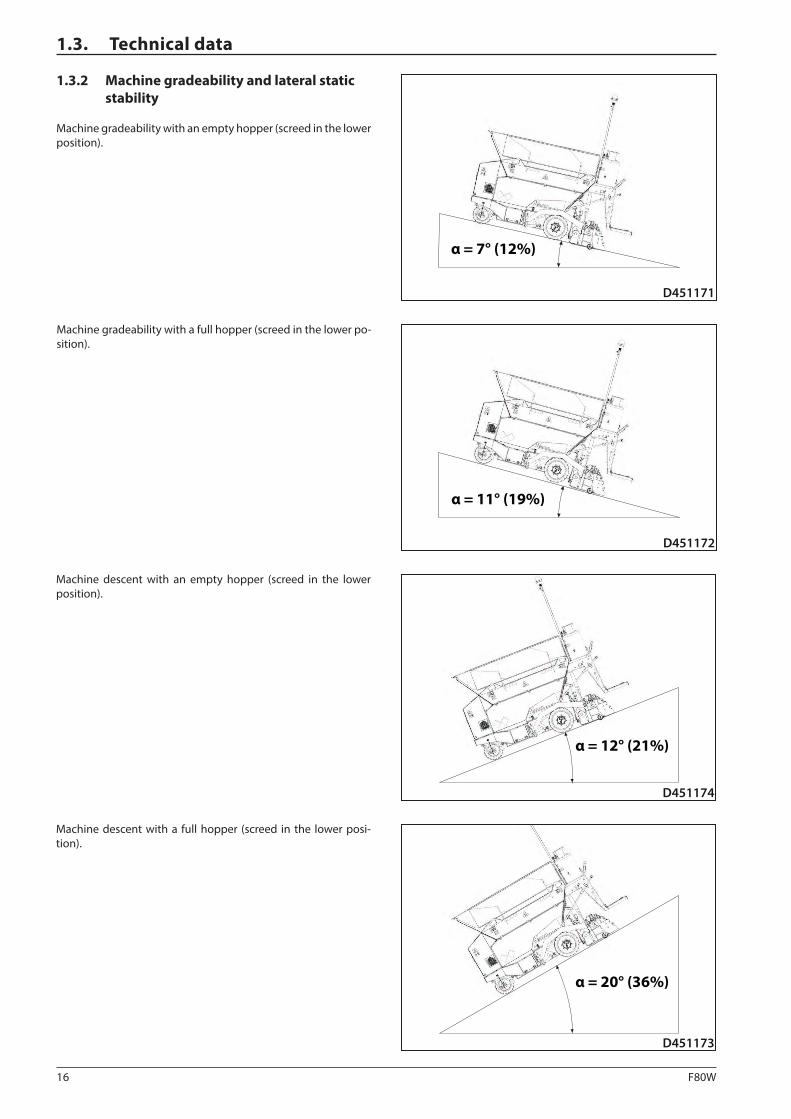
Machine gradeability with a full hopper (screed in the lower po-sition).
Machine descent with an empty hopper (screed in the lower position).
Machine descent with a full hopper (screed in the lower posi-tion).
1.3.2 Machine gradeability and lateral static stability
Machine gradeability with an empty hopper (screed in the lower position).

17F80W
D451175
α = 12° (21%)
SPECIFICATION MANUAL
Lateral static stability with an empty and full hopper.

18 F80W
1.4.1 Table of optional equipment
Chapter Optional equipment Order number
1.4.2 Mechanical screed extension 4812061017
1.4.3 Dual wheels 4812061018
1.4.4 Front wheel scraper 4812061021
1.4.5 Material hopper extension 4812061019
1.4.6 Additional lighting 4812061020
1.4.7 Screed copying system 4812335000
1.4 Optional equipment
19F80W
451814
34
451815
21
SPECIFICATION MANUAL
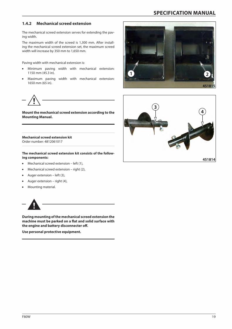
1.4.2 Mechanical screed extension
The mechanical screed extension serves for extending the pav-ing width.
The maximum width of the screed is 1,300 mm. After install-ing the mechanical screed extension set, the maximum screed width will increase by 350 mm to 1,650 mm.
Paving width with mechanical extension is:
• Minimum paving width with mechanical extension: 1150 mm (45.3 in).
• Maximum paving width with mechanical extension: 1650 mm (65 in).
Mount the mechanical screed extension according to the Mounting Manual.
Mechanical screed extension kit Order number: 4812061017
The mechanical screed extension kit consists of the follow-ing components:
• Mechanical screed extension – left (1),
• Mechanical screed extension – right (2),
• Auger extension – left (3),
• Auger extension – right (4),
• Mounting material.
During mounting of the mechanical screed extension the machine must be parked on a flat and solid surface with the engine and battery disconnecter off.
Use personal protective equipment.
20 F80W
43
44
51
52
451091A
2
3
451090A
1.4 Optional equipment
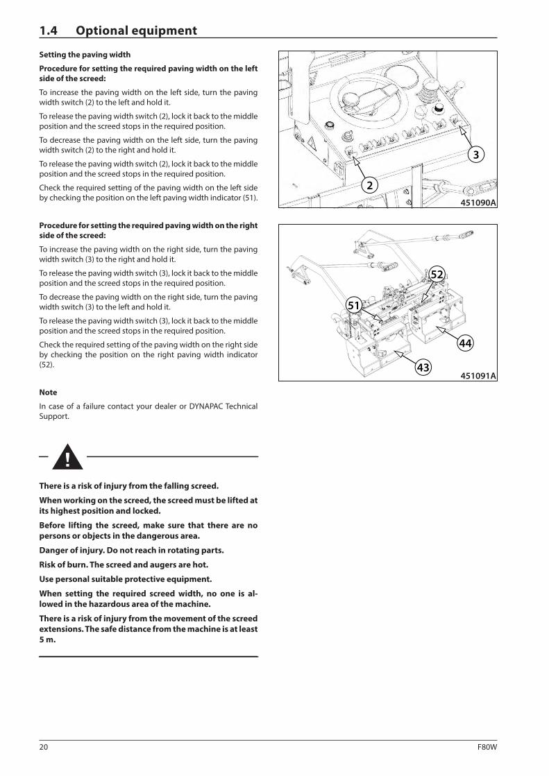
Setting the paving width
Procedure for setting the required paving width on the left side of the screed:
To increase the paving width on the left side, turn the paving width switch (2) to the left and hold it.
To release the paving width switch (2), lock it back to the middle position and the screed stops in the required position.
To decrease the paving width on the left side, turn the paving width switch (2) to the right and hold it.
To release the paving width switch (2), lock it back to the middle position and the screed stops in the required position.
Check the required setting of the paving width on the left side by checking the position on the left paving width indicator (51).
Procedure for setting the required paving width on the right side of the screed:
To increase the paving width on the right side, turn the paving width switch (3) to the right and hold it.
To release the paving width switch (3), lock it back to the middle position and the screed stops in the required position.
To decrease the paving width on the right side, turn the paving width switch (3) to the left and hold it.
To release the paving width switch (3), lock it back to the middle position and the screed stops in the required position.
Check the required setting of the paving width on the right side by checking the position on the right paving width indicator (52).
Note
In case of a failure contact your dealer or DYNAPAC Technical Support.
There is a risk of injury from the falling screed.
When working on the screed, the screed must be lifted at its highest position and locked.
Before lifting the screed, make sure that there are no persons or objects in the dangerous area.
Danger of injury. Do not reach in rotating parts.
Risk of burn. The screed and augers are hot.
Use personal suitable protective equipment.
When setting the required screed width, no one is al-lowed in the hazardous area of the machine.
There is a risk of injury from the movement of the screed extensions. The safe distance from the machine is at least 5 m.
21F80W
1
2
451816
3
451017A
SPECIFICATION MANUAL
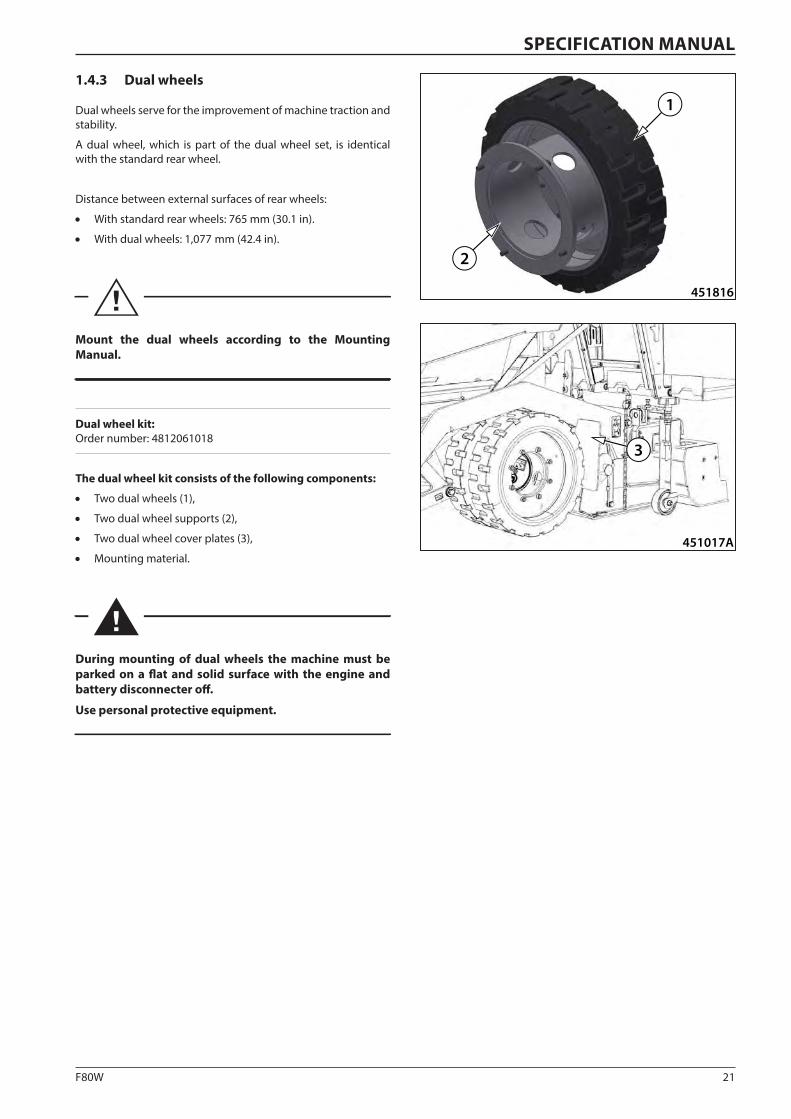
1.4.3 Dual wheels
Dual wheels serve for the improvement of machine traction and stability.
A dual wheel, which is part of the dual wheel set, is identical with the standard rear wheel.
Distance between external surfaces of rear wheels:
• With standard rear wheels: 765 mm (30.1 in).
• With dual wheels: 1,077 mm (42.4 in).
Mount the dual wheels according to the Mounting Manual.
Dual wheel kit: Order number: 4812061018
The dual wheel kit consists of the following components:
• Two dual wheels (1),
• Two dual wheel supports (2),
• Two dual wheel cover plates (3),
• Mounting material.
During mounting of dual wheels the machine must be parked on a flat and solid surface with the engine and battery disconnecter off.
Use personal protective equipment.
22 F80W
451817
12
1.4 Optional equipment
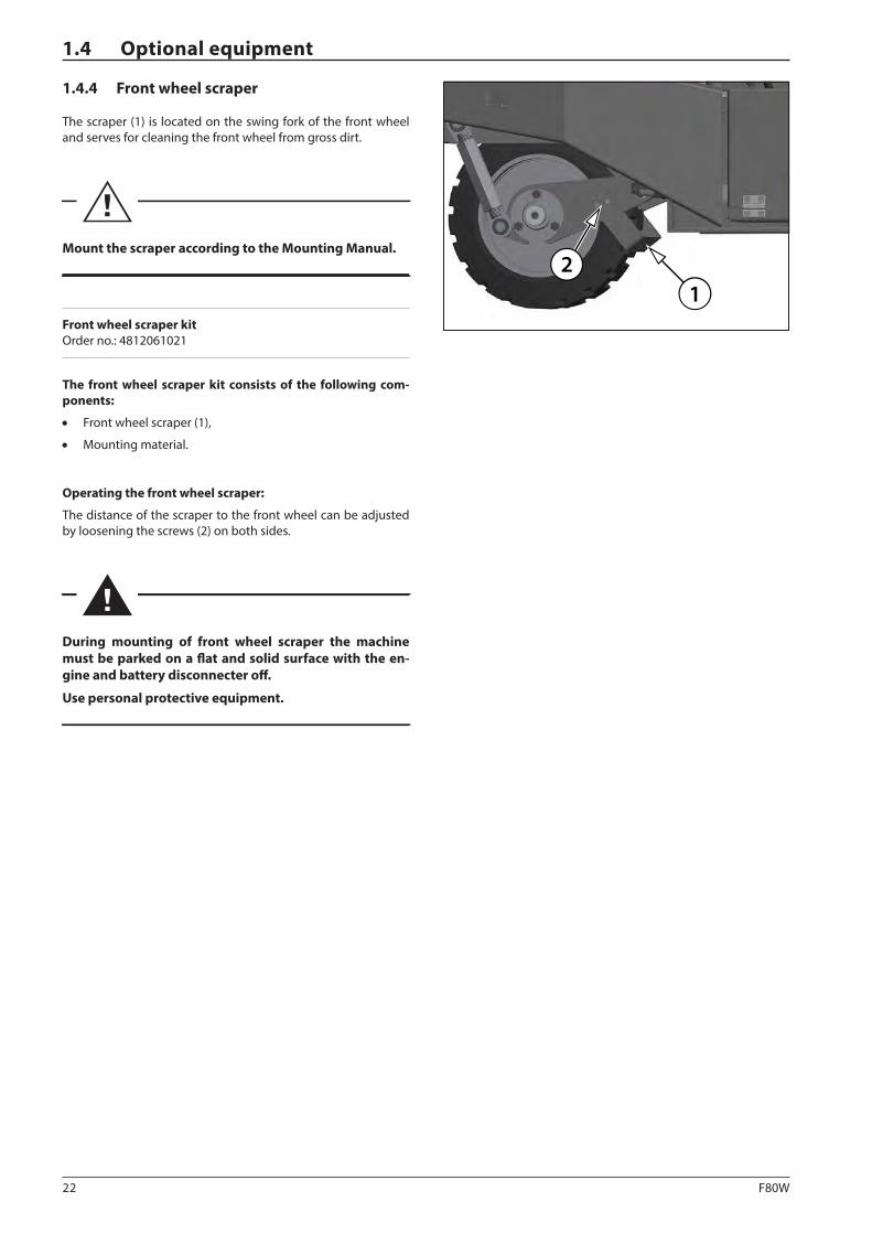
1.4.4 Front wheel scraper
The scraper (1) is located on the swing fork of the front wheel and serves for cleaning the front wheel from gross dirt.
Mount the scraper according to the Mounting Manual.
Front wheel scraper kit Order no.: 4812061021
The front wheel scraper kit consists of the following com-ponents:
• Front wheel scraper (1),
• Mounting material.
Operating the front wheel scraper:
The distance of the scraper to the front wheel can be adjusted by loosening the screws (2) on both sides.
During mounting of front wheel scraper the machine must be parked on a flat and solid surface with the en-gine and battery disconnecter off.
Use personal protective equipment.
23F80W
D451818A
12
3
SPECIFICATION MANUAL
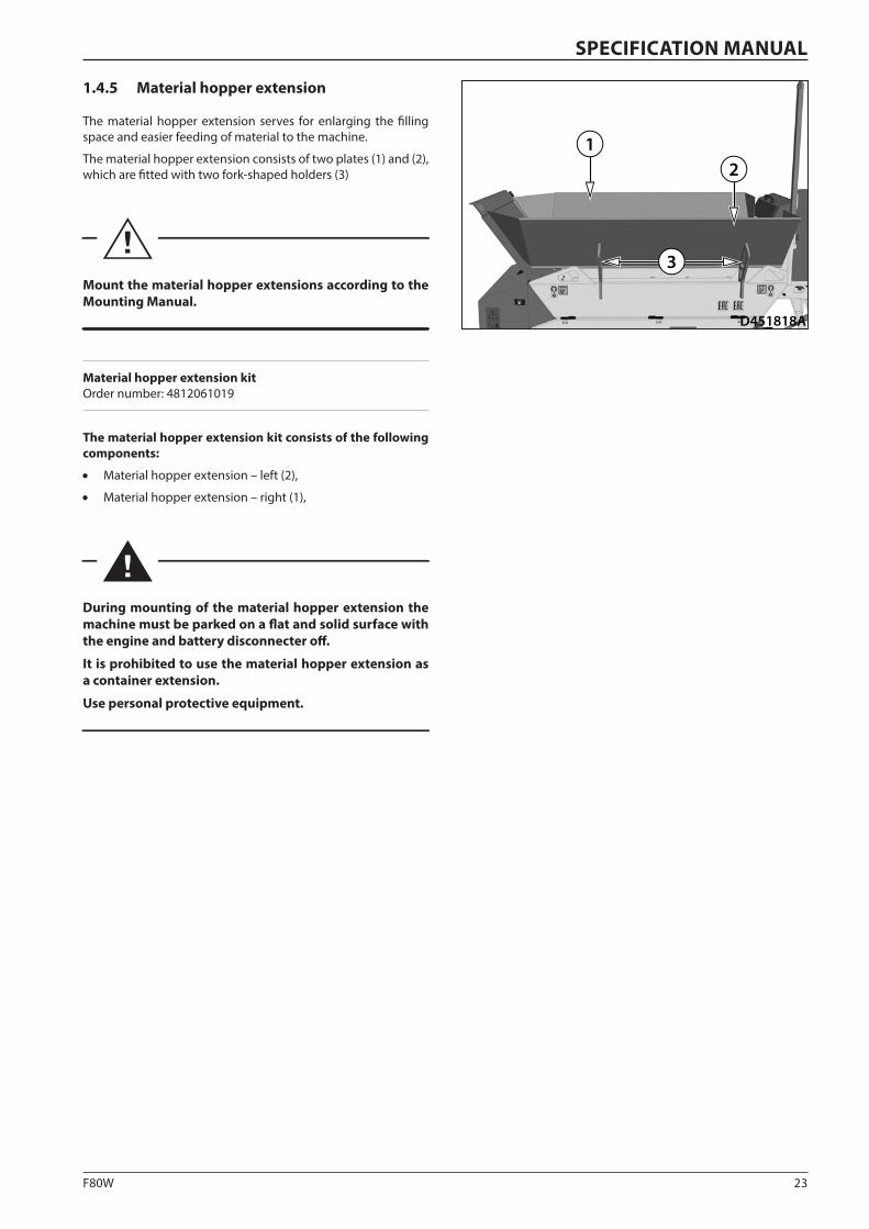
1.4.5 Material hopper extension
The material hopper extension serves for enlarging the filling space and easier feeding of material to the machine.
The material hopper extension consists of two plates (1) and (2), which are fitted with two fork-shaped holders (3)
Mount the material hopper extensions according to the Mounting Manual.
Material hopper extension kit Order number: 4812061019
The material hopper extension kit consists of the following components:
• Material hopper extension – left (2),
• Material hopper extension – right (1),
During mounting of the material hopper extension the machine must be parked on a flat and solid surface with the engine and battery disconnecter off.
It is prohibited to use the material hopper extension as a container extension.
Use personal protective equipment.
24 F80W
1
D451819
1.4 Optional equipment
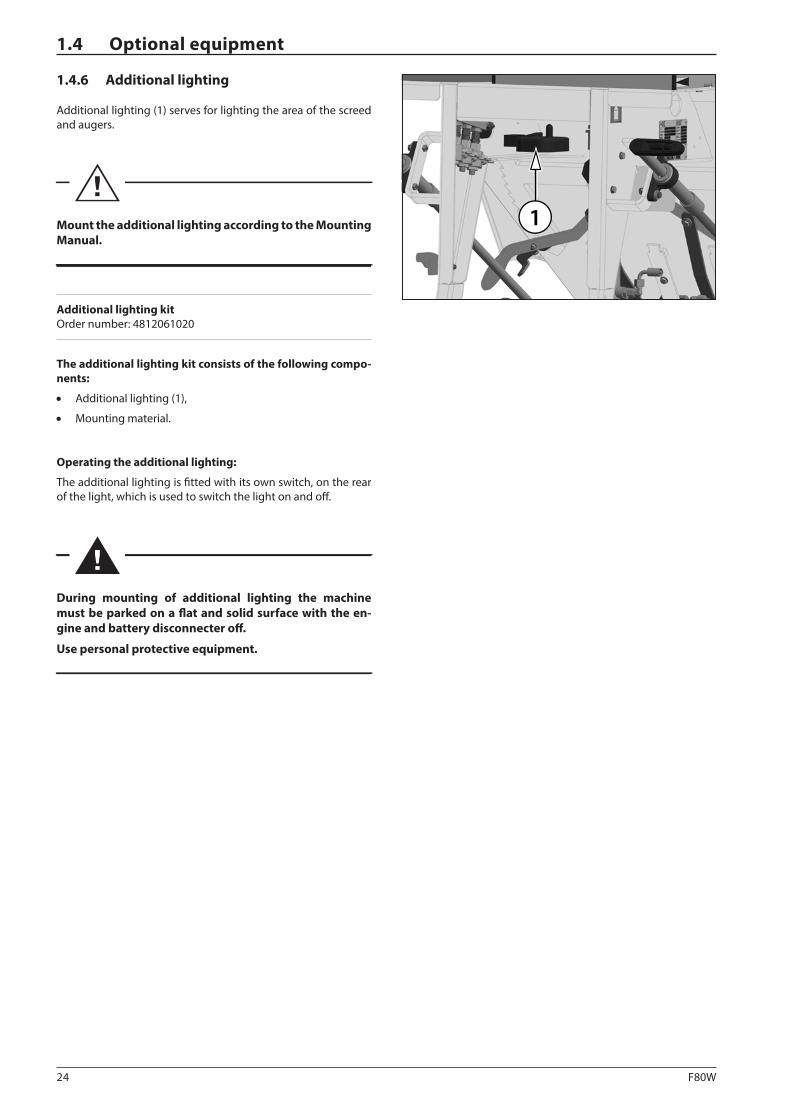
1.4.6 Additional lighting
Additional lighting (1) serves for lighting the area of the screed and augers.
Mount the additional lighting according to the Mounting Manual.
Additional lighting kit Order number: 4812061020
The additional lighting kit consists of the following compo-nents:
• Additional lighting (1),
• Mounting material.
Operating the additional lighting:
The additional lighting is fitted with its own switch, on the rear of the light, which is used to switch the light on and off.
During mounting of additional lighting the machine must be parked on a flat and solid surface with the en-gine and battery disconnecter off.
Use personal protective equipment.
25F80W
K451009
2 2
SPECIFICATION MANUAL
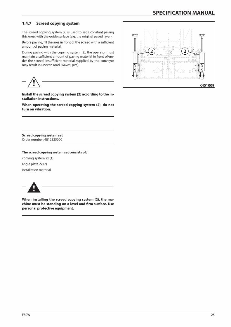
1.4.7 Screed copying system
The screed copying system (2) is used to set a constant paving thickness with the guide surface (e.g. the original paved layer).
Before paving, fill the area in front of the screed with a sufficient amount of paving material.
During paving with the copying system (2), the operator must maintain a sufficient amount of paving material in front of/un-der the screed. Insufficient material supplied by the conveyor may result in uneven road (waves, pits).
Install the screed copying system (2) according to the in-stallation instructions.
When operating the screed copying system (2), do not turn on vibration.
Screed copying system set Order number: 4812335000
The screed copying system set consists of:
copying system 2x (1)
angle plate 2x (2)
installation material.
When installing the screed copying system (2), the ma-chine must be standing on a level and firm surface. Use personal protective equipment.

26 F80W
Notes

27F80W
SPECIFICATION MANUAL
Notes

28 F80W

29F80W
OPERATING MANUAL
2 OPERATING MANUAL
F80W(Hatz)
30 F80W
2.1.2 Assurance of safety precautions by the owner
He must ensure that the machine is operated only under con-ditions and only for purposes it is technically capable for ac-cording to conditions set by the manufacturer and respective standards.
He must ensure that the machine is used only in such a way and at such workplaces where there is no dangerous vibration trans-mission and damage to nearby buildings or property possible.
He must ensure a regular inspection of operation and techni-cal conditions, regular maintenance of the machine in intervals specified in this Operating Manual. If the technical condition of the machine does not meet requirements to such an extent that it endangers safety of operation, persons and property, or damages and impairs the environment, the machine must be put out of service until the defects are removed.
He must specify who is allowed to carry out operation, mainte-nance and repairs of the machine as well as what activities can be carried out during the operation, maintenance and repair of the machine.
He must ensure that periodic safety tests are carried out in time. Every person who drives the machine, performs maintenance and service of the machine must be familiarised with instruc-tions stipulated in this Operating Manual.
He must ensure that the machine is equipped with a fire extin-guisher and it is checked on regular basis.
He must ensure that the machine is equipped with a first aid kit at the place defined for it according to respective national regulations.
He must ensure that the Operating Manual and the service book are kept in the machine at a specified place to be available to the driver all the time.
He must ensure continuous supervision by an appointed per-son during machine operation on public roads, and give instruc-tions to ensure health protection and work safety.
He must ensure that hazardous materials, e.g. fuels, oils, cool-ants, will be removed from leakage points depending on their nature so as to avoid their adverse impact on the environment, safety of operation and human health.
He must ensure and hand over to respective authorised workers any and all information for the safe use of electric installations and electronic equipment of the machine, always in compliance with respective national regulations.
He must ensure and hand over to respective authorised work-ers any and all information for the safe use and handling of gas bottles if they form part of the equipment, during the operation of the machine, always in compliance with respective national regulations.
2.1.1 Obligations before putting into operation
Before starting working with the machine, the machine opera-tor and the machine operator shall read this Operating Manual and make themselves familiar with the operation of the ma-chine, its control or operation and maintenance.
The machine user is liable to issue instructions for drivers and maintenance workers that include requirements for safety of operation when the machine is used. He must make machine operators familiar with these instructions.
The machine provider must specify a technological procedure that includes a working process for the specific job that specifies among others:
• measures for works under extraordinary conditions, works within protection zones, extreme slopes,
• precautions for any natural disaster hazards,
• requirements for the performance of works while observing principles of safety at work according to respective valid na-tional regulations,
• technical and organizational measures to provide for safety of employees, workplaces and surroundings.
The machine provider must make machine operators provably familiar with the technological procedure.
The machine user shall know exact routes of gas lines, potable water lines, pipelines, sewerage, electric and telephone lines, both aerial and ground, and inform about other potential ob-stacles. These routes must be properly set out and marked by respective authorities according to national regulations before starting any works with the machine.
The minimum safety distance according to respective national regulations must be kept from the overhead electric lines. There is a danger of high voltage electrical shock.
Any damage to the utility lines must be immediately reported to their provider, and at the same time measures must be taken to prevent unauthorized persons from entering the dangerous area.
2.1 Main safety precautions
31F80W
OPERATING MANUAL
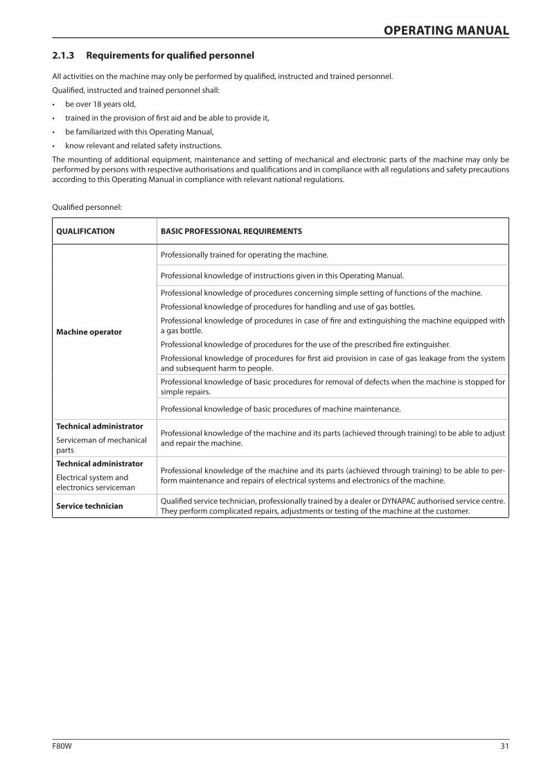
2.1.3 Requirements for qualified personnel
All activities on the machine may only be performed by qualified, instructed and trained personnel.
Qualified, instructed and trained personnel shall:
• be over 18 years old,
• trained in the provision of first aid and be able to provide it,
• be familiarized with this Operating Manual,
• know relevant and related safety instructions.
The mounting of additional equipment, maintenance and setting of mechanical and electronic parts of the machine may only be performed by persons with respective authorisations and qualifications and in compliance with all regulations and safety precautions according to this Operating Manual in compliance with relevant national regulations.
Qualified personnel:
QUALIFICATION BASIC PROFESSIONAL REQUIREMENTS
Machine operator
Professionally trained for operating the machine.
Professional knowledge of instructions given in this Operating Manual.
Professional knowledge of procedures concerning simple setting of functions of the machine.
Professional knowledge of procedures for handling and use of gas bottles.
Professional knowledge of procedures in case of fire and extinguishing the machine equipped with a gas bottle.
Professional knowledge of procedures for the use of the prescribed fire extinguisher.
Professional knowledge of procedures for first aid provision in case of gas leakage from the system and subsequent harm to people.
Professional knowledge of basic procedures for removal of defects when the machine is stopped for simple repairs.
Professional knowledge of basic procedures of machine maintenance.
Technical administrator
Serviceman of mechanical parts
Professional knowledge of the machine and its parts (achieved through training) to be able to adjust and repair the machine.
Technical administrator
Electrical system and electronics serviceman
Professional knowledge of the machine and its parts (achieved through training) to be able to per-form maintenance and repairs of electrical systems and electronics of the machine.
Service technician Qualified service technician, professionally trained by a dealer or DYNAPAC authorised service centre. They perform complicated repairs, adjustments or testing of the machine at the customer.
32 F80W
2.1 Main safety precautions
2.1.4 Machine operator's obligations
Before starting operation of the machine, the driver is obliged to get familiar with instructions stated in the documentation supplied together with the machine, especially with safety pre-cautions, and strictly observe the instructions. The same also applies to personnel assigned to maintain, adjust and repair the machine.
The driver must not drive the machine if he does not under-stand any part of the manuals. Contact your local dealer or the machine manufacturer.
The driver must not drive the machine unless he is fully familiar-ized with all functions and working and operating elements and knows exactly how to operate the machine.
The driver is obliged to follow the safety and operation signs placed on the machine and keep them legible.
The machine operator shall know exact routes of gas lines, po-table water lines, pipelines, sewerage, electric and telephone lines, both aerial and ground, and information about other po-tential obstacles.
The machine driver must always maintain a safe three-point contact with the tilting platform and the handle.
When finding out any health hazard, life hazard to persons, haz-ard to property, failures, during hardware accidents, or when finding symptoms of such hazards during operation, the driver must stop his/her work and secure the machine against unde-sired starting, communicate this to a person accountable, and, to a possible extent, notify all the persons exposed to such haz-ard.
Before starting operation of the machine, the driver is obliged to get familiar with records and operational deviations found dur-ing the previous work shift, which are recorded in the service book delivered with the machine.
Before starting the work, the driver is obliged to inspect the machine and its accessories and to check control elements and communication and safety equipment for functioning accord-ing to the manual. When he finds defects that might endanger the safety of work and is not able to repair it, then he must not put the machine into operation and must report the defect to a responsible worker.
Before starting any operation, the driver must check that a first aid kit with prescribed contents is available, as well as a fire ex-tinguisher, and find out about the possibilities of rescuing, avail-ability of medical assistance and fire brigade.
If the driver finds a defect during operation of the machine, he must park the machine at a safe place and remove the defect.
During operation, the driver must observe operation of the ma-chine and record any detected defects into the service book.
The driver must maintain a service book, which is intended for records of the acceptance and handover of the machine carried out between drivers, for defects and repairs done during opera-tion and for keeping files of serious events during the work shift.
Before the engine is put into operation, the controls must be in zero positions and no persons are allowed to stay in the danger zone of the machine.
Always before starting the engine, the driver is obliged to notify others by means of a sound signal each time the machine is put into operation.
Before putting the machine into operation, the driver must check the brakes and steering for functioning.
After a warning alarm, the operator may put the machine into operation only when all workers have left the endangered area and are at a safe distance from the machine. In case of workplac-es with unclear arranged, the machine can be put into operation only after expiration of the period of time needed for people to leave the dangerous area and after assuring inspection and connection between an appointed worker and the machine op-erator. During operation of the machine, it is necessary to follow safety instructions and not to carry out any activity that might endanger the work safety. The driver must be fully engaged in steering the machine.
The driver must comply with the technological procedure of works or instructions of a responsible worker.
When driving the machine within the workplace, the driver must adapt the driving speed to terrain conditions, the work performed and weather conditions. Watch continuously the clearance to avoid collision with any obstruction.
If the driver finishes or interrupts machine operation and leaves the machine, he must carry out safety measures against unau-thorized use of the machine and undesired start up. He must take the key out from the ignition box, lock the main dashboard of the machine or the cabin of the machine and other lockable parts of the machine and disconnect the wiring by means of a disconnecter.
When the operation is finished, the driver must park the ma-chine in a suitable area (on a flat, solid surface) so as not to en-danger stability of the machine; the machine must not interfere with traffic roads, must not be exposed to falling objects, e.g. rocks, and must be protected against any other natural disaster, e.g. floods and landslides.
When parking the machine on roads, measures according to na-tional road traffic regulations shall be taken. The machine must be marked properly.
After the work with the machine is finished, it is necessary to record all defects, damages and repairs of the machine into the service book. When drivers take turns, the driver is obliged to report any identified facts to the following driver.
The driver must use personal protective equipment, work clothes, work shoes, a warning vest, a protective helmet, hear-ing protection and a dust protection mask.
During maintenance of the machine, lubrication and replace-ment of operating fluids, hands must be protected with protec-tive gloves and eyes with safety glasses or a safety shield.
The driver must carry out the machine maintenance in compli-ance with instructions specified in this Operating manual.
The driver must equip the machine with accessories and equip-ment as prescribed.
The driver must keep the driver’s stand, foot rests and walkways clean.
The driver must keep the machine clean, free of oil contami-nants and inflammable materials.
33F80W
OPERATING MANUAL
2.1.5 Screed operators' obligations
Before starting operation of the machine, screed operators are obliged to get familiar with instructions stated in the documen-tation supplied together with the machine, especially with safe-ty precautions, and strictly observe the instructions. The same also applies to personnel assigned to maintain, adjust and re-pair the machine.
The operator must not operate the screed if he does not un-derstand any part of the Operating manuals. Contact your local dealer or the machine manufacturer.
The operator must not operate the screed unless he is fully fa-miliarized with all functions, working and operating elements and knows exactly how to operate the machine.
The screed operator is obliged to follow the safety and opera-tion signs placed on the machine and keep them legible.
Before starting the work, the screed operators must get familiar with the workplace environment, i.e. with obstructions, slopes, utility line system, distribution lines of gas, potable water, pipe-lines, sewerage, electrical and telephone lines, both aerial and ground, and information about other potential obstacles.
If a screed operator finds out a hazard to health, danger to life of people, property or failures during a breakdown of the tech-nical equipment, and/or if he finds out indications of the above mentioned during operation, he must interrupt the work and in cooperation with the driver secure the machine against unwant-ed start up, inform a responsible worker on the above mentioned and if possible notify all people involved who might be endan-gered.
Before starting operation of the machine, the screed operators are obliged to get familiar with records and operational devia-tions found during the previous work shift.
Before starting the work, the screed operator is obliged to in-spect the machine and accessories, and to check control ele-ments and communication and safety equipment for function-ing according to the manual. When he finds a defect that might endanger the safety of work and is not able to repair it, then he must not put the machine into operation and must report the defect to a responsible worker.
If the driver or the screed operator finds a defect during opera-tion of the machine, he must park the machine in a safe area and remove the defect.
During operation of the machine, the screed operator must fol-low safety instructions and must not carry out any activity that might endanger the safety of work; the screed operator must be fully engaged in the operation of the screed.
The screed operator is obliged to comply with technological procedures of works or instructions of a responsible worker.
After finishing the work with the machine, all of the defects, damages to the machine and any repairs made must be record-ed in the service book. When screed operators take turns, one screed operator is obliged to report any identified facts to the other screed operator.
The screed operators must use personal protective equipment, work clothes, work boots, a warning vest, a protective helmet, an ear protection and a dust protection mask.
During maintenance of the machine, lubrication and replace-ment of operating fluids, hands must be protected with protec-tive gloves and eyes with safety glasses or a safety shield.
The operator must carry out the machine maintenance in com-pliance with instructions specified in the Operating manual.
The screed operator is obliged to equip the machine with acces-sories and equipment as prescribed.
The screed operator is obliged to keep the driver’s stand, foot rests and walkways clean.
The screed operator must keep the machine clean, free of oil contaminants and inflammable materials.
34 F80W
D451026A
1
2.1 Main safety precautions
2.1.6 Driver's stand and screed operator stand during machine operation
These requirements during operation of the machine are considered binding with regard to the safety of people. Firstly, the machine operator and the screed operators must observe the below-given requirements during ma-chine operation.
DYNAPAC assumes no responsibility in cases when the machine is operated incorrectly or is used incorrectly in operating modes which may result in an injury or death, damage to the machine or property.
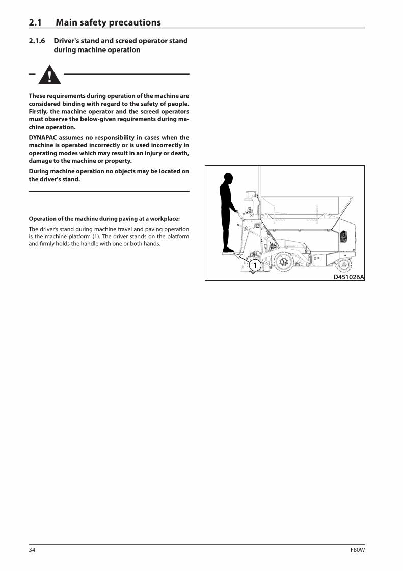
During machine operation no objects may be located on the driver's stand.
Operation of the machine during paving at a workplace:
The driver’s stand during machine travel and paving operation is the machine platform (1). The driver stands on the platform and firmly holds the handle with one or both hands.
35F80W
D451028
1
OPERATING MANUAL
2.1.7 Dangerous zone and safe distance
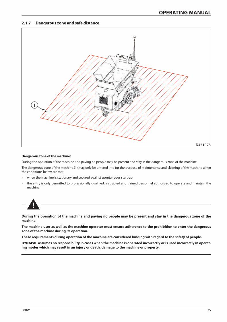
Dangerous zone of the machine:
During the operation of the machine and paving no people may be present and stay in the dangerous zone of the machine.
The dangerous zone of the machine (1) may only be entered into for the purpose of maintenance and cleaning of the machine when the conditions below are met:
• when the machine is stationary and secured against spontaneous start-up,
• the entry is only permitted to professionally qualified, instructed and trained personnel authorised to operate and maintain the machine.
During the operation of the machine and paving no people may be present and stay in the dangerous zone of the machine.
The machine user as well as the machine operator must ensure adherence to the prohibition to enter the dangerous zone of the machine during its operation.
These requirements during operation of the machine are considered binding with regard to the safety of people.
DYNAPAC assumes no responsibility in cases when the machine is operated incorrectly or is used incorrectly in operat-ing modes which may result in an injury or death, damage to the machine or property.
36 F80W
D451029
2.1 Main safety precautions
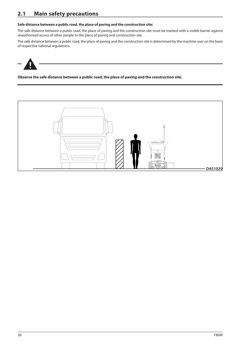
Safe distance between a public road, the place of paving and the construction site:
The safe distance between a public road, the place of paving and the construction site must be marked with a visible barrier against unauthorised access of other people to the place of paving and construction site.
The safe distance between a public road, the place of paving and the construction site is determined by the machine user on the basis of respective national regulations.
Observe the safe distance between a public road, the place of paving and the construction site.
37F80W
D451030
5 m 5 m
D451031
5 m
5 m
OPERATING MANUAL
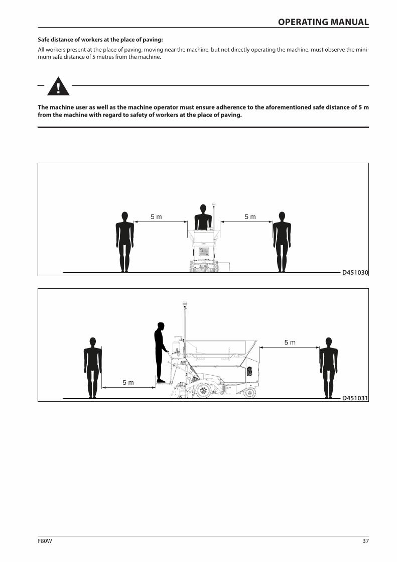
Safe distance of workers at the place of paving:
All workers present at the place of paving, moving near the machine, but not directly operating the machine, must observe the mini-mum safe distance of 5 metres from the machine.
The machine user as well as the machine operator must ensure adherence to the aforementioned safe distance of 5 m from the machine with regard to safety of workers at the place of paving.
38 F80W
2.1 Main safety precautions
2.1.8 Machine operation at unclear working areas
The machine operator may not operate the machine if he does not have a sufficient overview of the workplace and potential obstacles are not clearly visible. In such cases, a different efficient form of connection between the appointed worker and the machine operator must be ensured.
Before putting the machine into operation the machine operator must be informed by the machine user about potential obstacles, e.g. distribution lines of gas, potable water, pipelines, sewerage, electrical and telephone lines, both aerial and ground ones. These routes must be properly set out and marked by respective authorities according to national regulations before starting the operation of the machine.
To ensure connection between the appointed worker and the machine operator, we recommend using hand signals.
2.1.9 Manual signals
The machine operator may not operate the machine if he does not have a sufficient overview of the workplace and potential obstacles are not clearly visible. In such cases, a different efficient form of connection between the appointed worker and the machine operator must be ensured. To ensure connection between the appointed worker and the machine operator, we recommend using hand signals.
Hand signals for the machine operator may only be given by persons who:
• are trained for these purposes,
• have proven participation in such training,
• can furnish a certificate of such activity to the user.
When using hand signals, the following principles must be adhered to:
• signals between the appointed worker and the machine operator, given by hand, can only be used in cases when environmental conditions enable visual contact,
• the machine operator must be trained in the used signals before putting the machine into operation,
• during the operation of the machine only a limited number of signals must be used to avoid any misunderstanding between the appointed worker and the machine operator.

39F80W
0031
STOP
0032!
0040
0041
OPERATING MANUAL
Stop
Watch out
Turn off the engine
EXAMPLES OF HAND SIGNALS:
Start the engine
40 F80W
0033!
0034
0036
0035
2.1 Main safety precautions
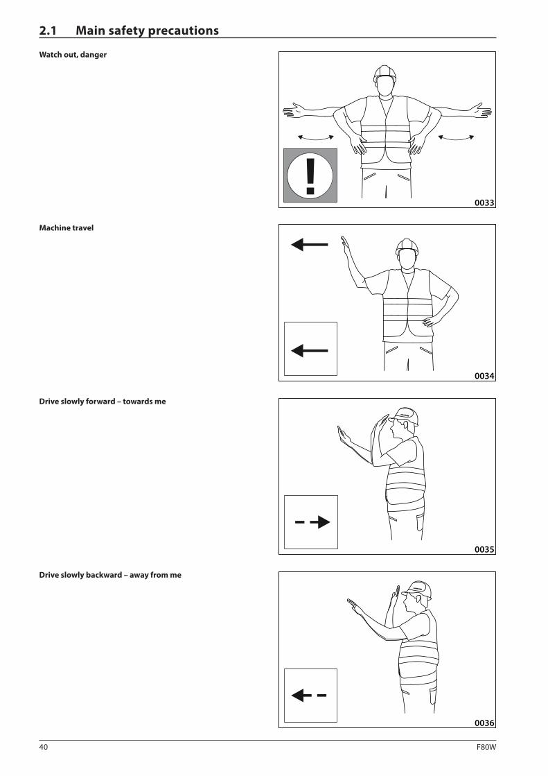
Watch out, danger
Machine travel
Drive slowly backward – away from me
Drive slowly forward – towards me
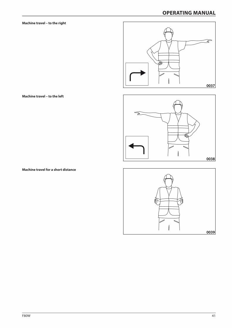
41F80W
0039
0037
0038
OPERATING MANUAL
Machine travel for a short distance
Machine travel – to the right
Machine travel – to the left
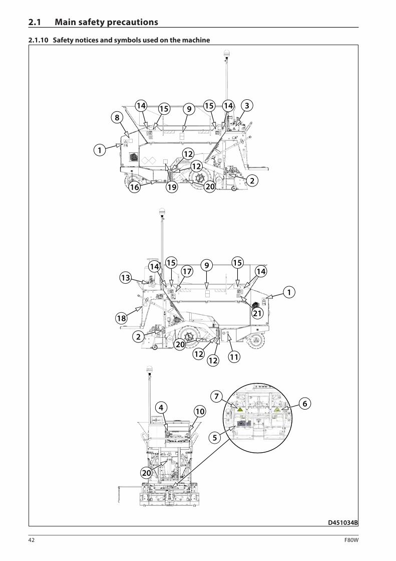
42 F80W
D451034B
2
314 15 9 15 14
20
12
16 19
1314 15 9 15
17 14
1
202
18
20
4 10
5
76
1212 11
1
8
12
21
2.1 Main safety precautions
2.1.10 Safety notices and symbols used on the machine
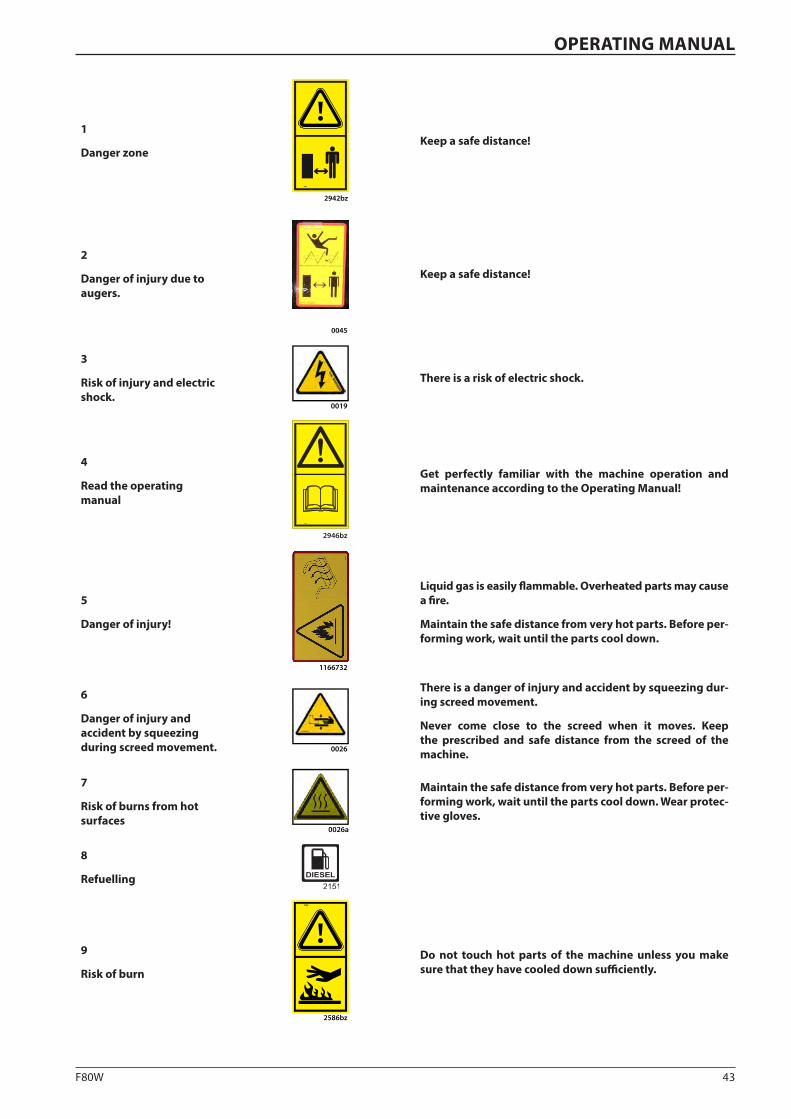
43F80W
OPERATING MANUAL
1
Danger zone
2942bz2939
Keep a safe distance!
2
Danger of injury due to augers.
0045
Keep a safe distance!
3
Risk of injury and electric shock.
0019
There is a risk of electric shock.
4
Read the operating manual
2946bz
Get perfectly familiar with the machine operation and maintenance according to the Operating Manual!
5
Danger of injury!
1166732
Liquid gas is easily flammable. Overheated parts may cause a fire.
Maintain the safe distance from very hot parts. Before per-forming work, wait until the parts cool down.
6
Danger of injury and accident by squeezing during screed movement. 0026
There is a danger of injury and accident by squeezing dur-ing screed movement.
Never come close to the screed when it moves. Keep the prescribed and safe distance from the screed of the machine.
7
Risk of burns from hot surfaces
0026a
Maintain the safe distance from very hot parts. Before per-forming work, wait until the parts cool down. Wear protec-tive gloves.
8
Refuelling
9
Risk of burn
2586
2586bz
Do not touch hot parts of the machine unless you make sure that they have cooled down sufficiently.
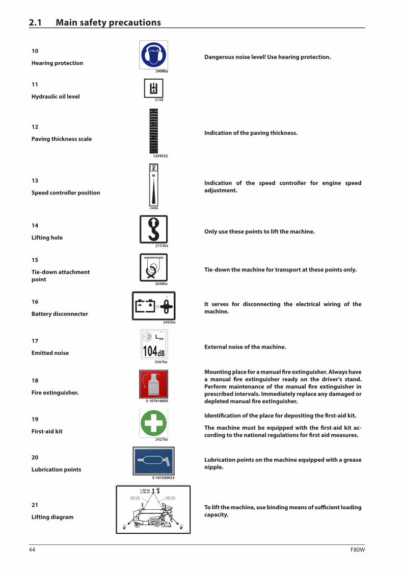
44 F80W
2.1 Main safety precautions
10
Hearing protection2408bz
Dangerous noise level! Use hearing protection.
11
Hydraulic oil level2158
12
Paving thickness scale
1259532
Indication of the paving thickness.
13
Speed controller position
2406
Indication of the speed controller for engine speed adjustment.
14
Lifting hole 2153bz
Only use these points to lift the machine.
15
Tie-down attachment point
3048bz
Tie-down the machine for transport at these points only.
16
Battery disconnecter2493bz
O
I
It serves for disconnecting the electrical wiring of the machine.
17
Emitted noise 3567bz
dB
WAL3567
104 External noise of the machine.
18
Fire extinguisher.5-107016005
Mounting place for a manual fire extinguisher. Always have a manual fire extinguisher ready on the driver's stand. Perform maintenance of the manual fire extinguisher in prescribed intervals. Immediately replace any damaged or depleted manual fire extinguisher.
19
First-aid kit2427bz
Identification of the place for depositing the first-aid kit.
The machine must be equipped with the first-aid kit ac-cording to the national regulations for first aid measures.
20
Lubrication points5-101030023
Lubrication points on the machine equipped with a grease nipple.
21
Lifting diagram
4011
1 300 kg(2 866 lb)
Lmin = 2 m(Lmin = 4,3 ft)
Lmin = 2 m(Lmin = 4,3 ft)
To lift the machine, use binding means of sufficient loading capacity.

45F80W
OPERATING MANUAL
2.1.11 Personal protective equipment
The machine operator, technical administrators, service technicians and workers present at the workplace must use personal protec-tive equipment during operation and maintenance of the machine:
1.
0001
Wear work clothes (antistatic protective clothes).
2.
0008
Wear work shoes (antistatic protective shoes).
3.
0030
Wear a warning vest.
4.
0007
Use a protective helmet.
5.
0002
Use hearing protection.
6.
0004
Use a dust protection mask (with a filter against organic gases and vapours, type A, AX).
7.
0005
Use safety glasses or a safety shield.
8.
0003
Use protective gloves (suitable for low temperatures).
46 F80W
2.1 Main safety precautions
2.1.12 General safety precautions
Always use personal protective equipment such as work clothes, work shoes, a warning vest, a protective helmet, hearing protec-tion and if necessary also a dust protection mask, safety glasses or a safety shield and protective gloves.
Keep away from the moving parts of the machine. Loose clothes, jewellery, watches, long hair and other free or hanging objects can be trapped in moving parts of the machine.
Get on and off the machine only at places with stairs and rail-ing. When getting on/off the machine, you have to have both hands free. Do not use controllers, hoses or other parts of the machines as handles.
Soiled or slippery stairs, ladders, handles, galleries or platform can cause a fall. Ensure these surfaces are clean.
If it is impossible to use parts intended for getting on/off the machine for doing so, use an external platform which meets the valid safety requirements according to respective national reg-ulations.
It is prohibited to get on/off the moving machine.
It is prohibited to jump down of the machine.
Keep the safety and operating plates situated on the machine clean. All safety and operating plates must be visible. Replace damaged plates with new ones.
Before starting to work, check all parts of the machine, covers and safety elements for proper mounting.
Before starting to work, tidy all loose objects which are not a part of the machine.
Unauthorised persons are prohibited to get on the machine.
The machine operator must not leave the driver's stand during travel of the machine.
Before starting to work:
• check the fire extinguisher,
• check all safety devices on the machine for proper opera-tion,
• check performance of all tasks of the regular maintenance,
• remove all dirt from the machine,
• check the whole machine and all additional equipment for correct operation and functioning,
• check the control elements and brakes for correct function-ing,
• if you detect any problem during inspection before starting to work, inform the machine user.
It is prohibited to operate the machine if any defects are found, if the machine is incapable of operation and if all safety conditions for machine operation have not been met.
2.1.13 Safety precautions during machine operation
Before using the machine or its equipment, make sure that no-body is present in the dangerous zone of the machine.
Sound the horn.
Observe warnings, safety messages and signals indicated by the machine.
Remember that operating fluids of the machine are flammable. When using them, proceed according to instructions described in this Operating Manual or according to the instructions for use on the product package. Store the containers at a cool, well-ven-tilated place, inaccessible to unauthorised persons. Dispose of containers according to respective national regulations. Never use operating fluids near smouldering or burning materials, open fire or sparks.
Do not operate the engine of the machine in closed spaces with-out ventilation capable of exhausting harmful exhaust gases.
Be especially careful, do not place your head, body and/or arms near belts, rotating blades or fans.
The machine must never be used for towing other machinery.
When driving the machine on public roads observe the road traffic routes according to the valid national regulations.
It is prohibited to operate the machine on the slope with in-clination and side static stability higher than stated in this Operating Manual.
47F80W
OPERATING MANUAL
2.1.14 Safety and fire precautions during the use of gas bottles
The machine user must ensure and hand over to respective au-thorised workers any and all information for the safe use and handling of gas bottles if they form part of the equipment dur-ing the operation of the machine always in compliance with re-spective national regulations.
The machine operator and appointed workers must be regularly trained in terms of the use, handling and storage of gas bottles according to valid national regulations.
Safety during the use of gas bottles
Bottles can only be handled, transported and stored by workers over 18 year old, physically fit, authorised for the given activity and provably trained and tested in a written form according to respective national regulations.
Gas bottles must be stored in an area intended for that purpose and secured against falling.
Manufacturers or importers of gas bottles shall issue a material safety data sheet to the given product according to respective national regulations.
Material safety data sheet
Material safety data sheets may give information about:
• gas/gas mixture identification and manufacturer or importer
• product specification and its composition
• potential hazards
• first aid measures
• firefighting measures
• gas leakage measures
• instructions for handling and storage
• instructions about personal protective equipment
• physical and chemical properties
• toxicity and ecological information
• instructions for disposal
• transport instructions
Safety fire precautions during the use of gas bottles
During the operation of the machine equipped with a gas bot-tle, the machine must also be equipped with a prescribed fire extinguisher according to respective national regulations. This also applies to storage of gas bottles.
Prescribed fire extinguishers must be placed and maintained in the proper condition and regularly checked according to re-spective national regulations.
Stop the gas leakage.
In case of gas leakage, inform relevant national author-ities.
Propane-butane (LPG) is an extremely flammable substance and any leakage causes a high risk of fire or explosion!
Propane-butane (LPG) is heavier than air and may accumulate in lower situated places – danger of fire!
Gas inhalation may cause headache, weakness, confusion, dizziness and nausea. It causes frostbites in the liquid state in contact with skin!
Avoid contact with skin. Wear suitable protective clothing!
Wear protective gloves resistant to oil substances comply-ing with EN374!
Wear safety goggles!
In case of excess of vapour concentration limits in air, use a suitable breathing mask. Recommended: organic fume and vapour filter (type A, AX)!
No smoking at work.
Provide adequate area ventilation!
Always require a material safety data sheet to the delivered gas bottle. Before mounting the gas bottle on the machine, read and check that the gas bottle meets all conditions for putting the machine into operation.
The machine must be equipped with a fire extinguisher. Have the fire extinguisher ready on the driver's stand at a place intended for this purpose.
When the machine is operated in underground garages or other underground areas, observe the national safety regu-lations regarding space ventilation.
First aid instructions
General
Loosen tight clothes of the injured and keep him/her warm and still. If unconscious, place in recovery position and get medi-cal attention immediately. If they are unconscious and do not breathe, ensure passability of air passages. In case of cardiac arrest, provide heart massage and get medical attention. If un-conscious and breathing, place in recovery position and get medical attention immediately.
Inhalation
Move the exposed person out to fresh air and do not leave them unattended. Keep them warm and still. Get medical attention.
Skin contact
In case of occurrence of frostbites, get medical attention. Use clean gauze to treat frostbites. Do not use any ointments and powders!
Eye contact
Immediately flush eyes with plenty of water, occasionally lifting the upper and lower eyelids. Check for and remove any contact lenses. Continue rinsing for at least 20 minutes. Get medical at-tention.
48 F80W
2.1 Main safety precautions
2.1.16 Safety and fire precautions during welding on the machine
The machine user shall ensure that all welding works on the ma-chine are only performed by qualified and professionally trained personnel with regard to work safety during welding in compli-ance with respective national regulations.
Safety risks during welding:
• risk of electric shock
• risk of burning
• risk of injury by splashing of metal and fragments of slag
• risk of action of harmful substances during welding
• risk of radiation during welding.
Before any welding works, the gas bottle must be re-moved from the machine.
When performing electrical arc welding on the machine, disconnect all electrical equipment and electrical instal-lations of the machine.
When performing electrical arc welding the welding ma-chine and the machine on which welding is performed must be properly grounded.
Any welding works on the machine can only be per-formed by qualified and professionally trained person-nel with the valid authorisation for welding.
Observe work safety during welding in compliance with respective national regulations and ensure fire safety measures before any welding on the machine.
2.1.15 Safety precautions for the use of portable fire extinguisher
A portable fire extinguisher must comply with requirements of EN 3-7+A1.
The machine user must ensure and hand over to the appointed workers any information on the use and handling of portable fire extinguishers.
A portable fire extinguisher is compulsory machine equipment.
Recommended portable fire extinguisher (according to EN 500–1+A1/ para. D.3.10):
• powder fire extinguisher, Class B and C with the capacity of 6 kg.
• Fire rating 13A – 113B – C
A portable fire extinguisher does not form part of delivery of the machine. Equip the machine with a portable fire extinguisher according to the national regulations and mount it to the desig-nated place at the driver's stand.
Regularly review how to operate the portable fire extinguisher. Operating instructions for the fire extinguisher are given on the fire extinguisher.
Replace the fire extinguisher after use and shortly before the maintenance interval elapses or its work life.
Maintenance intervals and fire extinguisher expiration date are defined by national regulations.
Start extinguish using a fire extinguisher just at the centre of the fire. The total extinguishing time (period of powder release) is only a few seconds.
Inspection of portable fire extinguisher
Check the contents of the portable fire extinguisher. If the con-tent does not comply with specification, replace the fire extin-guisher for another one with the correct content.
Check the validity of the portable fire extinguisher. In case of expiry of its validity, replace the fire extinguisher for a new one.
Check that the fire extinguisher is not damaged. In case of dam-age, replace the fire extinguisher for a new one.
Check that a seal of the portable fire extinguisher is undamaged. In case of damaged or missing seal, replace the fire extinguisher for a new one.
A portable fire extinguisher does not form part of deliv-ery of the machine. Equip the machine with a portable fire extinguisher according to the national regulations and mount it to the designated place on the machine.
It is prohibited to operate the machine without a porta-ble fire extinguisher.
Regularly review how to operate the portable fire extin-guisher. Operating instructions for the fire extinguisher are given on the fire extinguisher.
Perform regular maintenance and testing of fire extin-guishers according to national regulations.
49F80W
OPERATING MANUAL
2.1.17 Safety precautions for electrical and electronic equipment of the machine
• The machine is equipped with electrical wiring, components and electronic equipment, the operation of which can be in-terfered by external sources of electromagnetic radiation.
• This equipment is safe if operated in compliance with in-structions given in this Operating Manual or other docu-mentation supplied with the machine.
Please observe the following safety instructions concerning electrical and electronic equipment of the machine:
• Check the delivered goods for any damage immediately af-ter delivery,
• Do not use damaged parts and instruments,
• Damaged electrical wiring and sockets represent a high safety risk and must not be used,
• In such cases, contact your local dealer or DYNAPAC. They will provide you with new undamaged parts.
Before installation and operation of instruments, make yourself familiar with and carefully read entire Operat-ing Manual to these devices.
If you do not understand any part of the supplied Op-erating Manual or the instructions are unclear to you, contact your local dealer or DYNAPAC before putting the machine into operation.
In order to ensure smooth operation of DYNAPAC ma-chinery, use only original spare parts supplied by DYNA-PAC for repairs.
DYNAPAC does not assume any liability for addition-ally mounted equipment which is not authorised by DYNAPAC.
DYNAPAC assumes no responsibility in cases when the machine is operated incorrectly by not adhering to the instructions given in this Operating Manual, which may result in an injury or death, damage to the machine, property or environment.
Safety precautions
Electrical installations and wiring must be connected properly and according to data given in this Operating Manual.
Entire electrical wiring and connection components must be have adequate current rating within the meaning of valid regu-lations and they must meet requirements of respective national regulations.
All devices are only intended for industrial use and tested ac-cordingly.
Observe all instructions for control and installation of electrical and electronic equipment according to this Operating Manual.
Observe the correct polarity of connectors.
Ensure adherence to the prescribed supply voltage.
Check electrical wiring and connections of individual parts reg-ularly with regard to trouble-free operation of the machine.
The machine is equipped with fuses, which protect electrical and electronic equipment of the machine from short circuit.
Observe prescribed values of individual fuses according to this Operating Manual or other documentation supplied with the machine.
Electrical and electronic equipment of the machine is not in-tended for operation in explosive environments.
Before starting works on electrical and electronic equipment of the machine when removing defects, always disconnect elec-trical wiring of the machine and instruments from the battery using a disconnecter. Failure to adhere to these instructions ex-poses you to a danger of injury of the machine operator and danger of damage to electrical and electronic parts of the ma-chine.
It is prohibited to interfere in any manner with electrical and electronic parts of the machine. Special repairs can only be performed by an authorised service centre.
It is prohibited to use free connectors to connect other devices.
50 F80W
2.1 Main safety precautions
2.1.18 Prohibited activities
This chapter deals with main prohibited activities during opera-tion, work, repairs and maintenance of the machine.
Guarantee and warranty claims cannot be applied in the fol-lowing cases:
• faulty operation of the machine,
• insufficient or incorrectly performed maintenance of the machine,
• use of incorrect operating fluids,
• use and operation of the machine for other purposes than the ones stated in this Operating Manual.
Failure to observe these prohibited activities may affect potential assessment of a claim and further continuation of warranty claims and warranty for the machine, which has been issued by the manufacturer - DYNAPAC.
DYNAPAC does not assume any liability for addition-ally mounted equipment which is not authorised by DYNAPAC.
DYNAPAC assumes no responsibility in cases when the machine is operated incorrectly by not adhering to the instructions given in this Operating Manual, which may result in an injury or death, damage to the machine or property.
Prohibited activities during machine control:
• The machine operator must not operate the machine with-out personal protective equipment.
• The machine operator must not leave the operator stand during operation of the machine.
• The machine operator may not operate the machine if he does not have a sufficient overview of the workplace and potential obstacles are not clearly visible. In such cases, a different efficient form of connection between the ap-pointed worker and the machine operator must be ensured. To ensure connection between the appointed worker and the machine operator, we recommend using hand signals.
• The driver must not operate the machine under reduced vis-ibility or at night unless the machine’s working area and the workplace are illuminated sufficiently.
• The machine operator must not use the machine after drink-ing alcoholic beverages and/or using drugs.
• The machine operator must not operate the machine in a different way than stated in this Operating Manual.
• The machine operator must not transport other people on the machine, except for people appointed by the machine user.
• The machine operator must not operate the machine in the protective zone of electrical grid and transformer stations without observing respective national regulations.
• The machine operator must not cross electric cables if they are not properly protected against mechanical damage.
• The machine operator must not leave the machine or move away from the machine without taking measures to prevent its operation or spontaneous movement according to this Operating Manual.

51F80W
OPERATING MANUAL
Prohibited activities during machine operation:
• Operating the machine without personal protective equip-ment.
• Operating the machine if any defects are found, if the ma-chine is not serviceable and if all safety conditions for ma-chine operation are met.
• Operating the machine if its operation endangers safety of people, its technical condition and property.
• Operate the machine if any safety devices, e.g. an emergen-cy brake of the machine, are dismounted or damaged.
• Operating the machine when any of the operating fluid lev-els is low.
• Operating the machine with leaking oil, fuel, coolant or oth-er operating fluid.
• Operating the machine on the slope with inclination and side static stability higher than stated in this Operating Manual.
• Operating the machine in explosive environment.
• Starting the engine in a different way than stated in this Oper-ating Manual.
• Use the machine emergency brake function to stop the engine during machine operation when there is no danger threatening people or the machine.
• Transporting and storing tools and other objects at the driv-er's place.
• Transporting and storing objects at places inside the ma-chine which are not intended as deposition boxes.
• Transporting and storing cloths soaked with flammable sub-stances and flammable liquids in/on the machine.
• Using diesel instead of an anti-adhesion solution to ensure non-adherent surface of the hopper area.
Prohibited activities during repairs and maintenance of the machine:
• Performing maintenance, cleaning and repairs without per-sonal protective equipment.
• Performing maintenance, cleaning or repairs with the ma-chine not secured against spontaneous movement or acci-dental start, and if a person can come in contact with mov-ing parts of the machine.
• Failing to observe prescribed machine maintenance inter-vals.
• Failing to observe or omitting instructions at repairs and maintenance of the machine stated in this Operating Man-ual.
• Repairing or maintaining the engine in a different way than according to prescribed tasks in this Operating Manual; spe-cial repairs can only be performed by an authorised service centre.
• Disabling safety, protective or locking systems or altering their parameters.
• Removing impurities by high-pressure cleaners.
• Removing impurities during machine operation.
• Touching moving parts of the machine with the human body or items and tools held in hands.
• Smoking or handling an open flame when checking and pumping fuels, replacing or refilling operating fluids, lubri-cating the machine, inspecting and refilling the battery.
• Only an authorized service centre can interfere in any man-ner with electrical and electronic parts and cable harnesses, the machine is equipped with and carry out special repairs.
• Using free connectors to connect other devices.
• Performing any modifications on the machine without the prior written consent of the manufacturer DYNAPAC.
• Performing maintenance and repairs of the machine using non-original parts.
52 F80W
2.2.1 Storage places and storage conditions
The machine can be stored under a shelter or in an open-air space. The machine can be stored in closed unheated areas or in closed air-conditioned areas as well.
Before the machine is stored, it must be checked and its preserv-ative treatment must be verified.
The stored machine must be placed horizontally on a flat and solid surface,
If the machine is equipped with tyres, it must be stored hori-zontally on supports so that the clearance between the bearing surface and tyres is not less than 80 mm (3.15 in).
Access holes, fuel fill holes, exhaust pipes and other holes, through which atmospheric precipitations can penetrate in internal cavities of parts of the individual components the ma-chine, must be sealed hermetically with plugs, stoppers, caps, using waterproof adhesive tape and/or other special means.
Controls must be adjusted in such positions, in which there is no danger that the machine starts operating.
If the machine is equipped with a safety cover of the dashboard, this cover must be secured to prevent the machine from oper-ating.
If the machine is equipped with a cab, the cab must be locked to prevent the machine from operating.
The key must not be in the ignition box of the machine and the battery disconnecter must be in the position “OFF”.
Terminals of the battery must be disconnected. The electrolyte level must correspond to recommendations of the manufactur-er.
If the machine is stored for a time interval longer than 2 months, the batteries must be removed from the machine and stored in special areas.
Operating fluids of the machine must be refilled up to the levels specified in this Operating Manual.
A machine stored for a time interval longer than 2 months must be checked regularly according to the following instructions:
- every 6 months in mild climatic conditions,
- every 3 months in tropical, cold, arctic and seaside conditions.
Each of the machines, on which the preservative treatment was carried out, must be provided with instructions for removing the preservatives.
Instructions for removing the preservatives must specify proce-dures to remove the preservatives and procedures to reinstall the dismantled parts of the machine. Besides, a list of tools, in-struments and devices must be specified, which are required for performing the working procedures.
The working procedures must contain safety precau-tions in accordance with relevant national regulations.
2.2 Preservation and storage
53F80W
OPERATING MANUAL
2.2.2 Preservation and storage of the machine for 1–2 months
Before storing the machine, clean and wash the whole machine.
Before putting the machine out of operation, start the machine to warm operating fluids up to the operating temperature. Then refill the operating fluids up to the levels specified in this Oper-ating Manual.
Before preserving and storing, clean the machine from coarse impurities and wash.
Wash the machine only in areas with intercepting traps to intercept the contaminated water and detergents.
Park the machine on a flat solid surface in a safe area when there is no danger of damage to the machine by a natural disaster, e.g. landslides, floods and fire.
The following tasks must be performed first on the machine:
• stop the machine and turn off the engine
• turn off the battery disconnecter
• the machine hopper must be closed and locked
• the machine screed must be placed horizontally on a flat and solid surface
• the protective roof of the machine must be locked in the highest working position or adjusted in the lowest working position
• protective covers of the individual instruments and machine covers must be locked
• if the machine is equipped with a gas bottle, the gas bottle must be removed from the machine and stored in a special area.
Then it is recommended to perform the following tasks:
• repair damaged paintwork,
• service lubrication points according to instructions stated in the manual,
• check the pressure in tyres if the machine is equipped with wheels; protect the tyres from direct sunlight,
• check that the water tanks are drained if they are on the ma-chine,
• check that the coolant has the desired antifreeze properties,
• check the batteries for charging and recharge them if re-quired according to instructions of the manufacturer
• apply chemical preservatives on chromium-plated surfaces of piston-rods,
• we recommend you to protect the machine from corrosion by spraying a chemical preservative, particularly in areas where corrosion can occur.
If you treat the machine as above described, it is not necessary to prepare the machine in a special manner before it is put into operation again.
It is only necessary to wash the machine to remove applied chemical preservatives.
Wash the machine only in areas with intercepting traps to intercept the contaminated water and detergents.
54 F80W
2.2 Preservation and storage
2.2.3 Preservation and storage of the machine for a period over 2 months
Before storing the machine, clean and wash the whole machine.
Before putting the machine out of operation, start the machine to warm operating fluids up to the operating temperatures. Then refill the operating fluids up to the levels specified in this Operating Manual.
Before preserving and storing, clean the machine from coarse impurities and wash.
Wash the machine only in areas with intercepting traps to intercept the contaminated water and detergents.
Park the machine on a flat solid surface in a safe area when there is no danger of damage to the machine by a natural disaster, e.g. landslides, floods and fire.
The following tasks must be performed first on the machine:
• the machine hopper must be closed and locked,
• the machine screed must be put horizontally on a flat and solid surface,
• protective covers of the individual instruments and machine covers must be locked,
• the protective roof of the machine must be adjusted in the lowest working position,
• if the machine is equipped with a gas bottle, the gas bottle must be removed from the machine and stored in a special area.
Then it is recommended to perform the following tasks:
• repair damaged paintwork,
• service lubrication points according to instructions stated in the manual,
• check the pressure in tyres if the machine is equipped with wheels; protect the tyres from direct sunlight,
• check that the water tanks are drained if they are on the ma-chine,
• check that the coolant has the desired antifreeze properties,
• remove the batteries from the machine; recharge them ac-cording to instructions of the manufacturer and store them in special areas,
• apply chemical preservatives on chromium-plated surfaces of piston-rods,
• we recommend you to protect the machine from corrosion by applying a chemical preservative, particularly in areas where corrosion can occur,
• protect all rubber parts of the machine with chemical pre-servatives,
• seal the holes, through which atmospheric precipitations can penetrate in internal cavities of parts of the individual components of the machine,
• Protect the head lamps and side rear-view mirrors with chemical preservatives,
• protect other elements of the external electrical installation using a special spray,
• preserve the engine according to instructions of the manu-facturer of the engine and mark visibly that the machine has been preserved.
Never start the engine of the machine during storage!
A machine stored for a time interval longer than 2 months must be regularly inspected according to the following instructions, every 6 months in mild climatic conditions, every 3 months in tropical, cold, arctic and seaside conditions.
In order to protect components of a machine stored for a time interval longer than 2 months, during the regu-lar inspections remove the chemical preservatives and put the machine into operation to rebuild the oil film in various hydraulic and mechanical parts of the machine. If you want to keep storing the machine in the long term, complete the preservation and storage procedure for the time interval longer than 2 months.
55F80W
OPERATING MANUAL
2.2.4 Removing chemical preservatives and putting the machine into operation
Each of the machines, on which the preservative treatment was carried out, must be provided with instructions for removing the preservatives.
Instructions for removing the preservatives must specify proce-dures to remove the preservatives and procedures to reinstall the dismantled parts of the machine. Besides, a list of tools, in-struments and devices must be specified, which are required for performing the working procedures.
Always follow the working instructions for removing the chemical preservatives and procedures for reinstalling the dismantled machine parts. Observe safety precau-tions stated in the instructions for removing the chem-ical preservatives.
After the preservation and storage of the machine for more than 2 months, carry out the following tasks:
• unlock the machine hopper,
• unlock the protective covers of the individual instruments and covers of the machine,
• adjust the roof of the machine to the highest working po-sition,
• if the machine is equipped with a gas bottle, mount the gas bottle on the machine.
Then it is recommended to perform the following tasks:
• service lubrication points according to instructions stated in the manual,
• check the tyres for pressure if the machine is equipped with wheels,
• check that the coolant has the desired antifreeze properties,
• mount the batteries on the machine; recharge them accord-ing to instructions of the manufacturer,
• clean the chromium-plated surface of piston rods from chemical preservatives,
• remove protective components of the hole seals, through which atmospheric precipitations can penetrate in internal cavities of parts of the individual components of the ma-chine,
• remove protective components from headlamps and exteri-or mirrors of the machine,
• check parts of the electrical installation,
• remove chemical preservatives and protective elements of the engine according to instructions of the manufacturer of the engine.
• Remove all the chemical preservatives from the machine by washing.
Wash the machine only in areas with intercepting traps to intercept the contaminated water and detergents.
After the preservation and storage of the machine for a time interval longer than 2 months, before the ma-chine is put into operation, it is necessary to replace all filter and air elements according to instructions stated in this Operating Manual.

56 F80W
57F80W
OPERATING MANUAL
2.3.1 Machine disposal after its service life
When disposing of the machine after its lifetime expires, the machine owner must observe relevant national waste disposal regulations and environment protection regulations.
Therefore we recommend you in such cases to always contact businesses specialising professionally in waste disposal.
DYNAPAC does not assume any liability in cases when the machine after its lifetime expires is disposed of in an improper way, which may result in damage to the prop-erty or environment.
2.3 Machine disposal
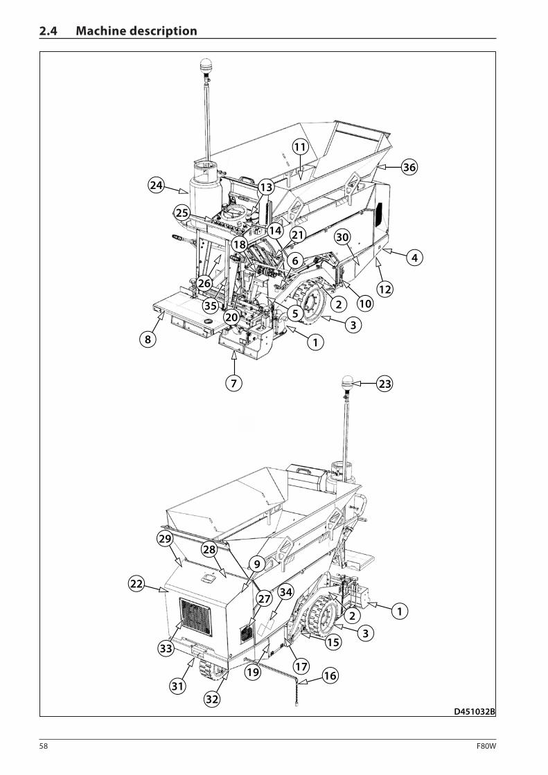
58 F80W
D451032B
26
24
25
35
23
1
5
8
9
27 34
10
11
12
17
18
19
20
2928
3231
33
22
7
3
4
13
21
6
14
15
16
3
2
2
30
1
36
2.4 Machine description

59F80W
OPERATING MANUAL
2.4.1 Description of main parts of the machine and screed
1. Augers
2. Screed tow arm
3. Travel wheels
4. Machine frame
5. Belt conveyors
6. Screed lock
7. Screed
8. Tilting platform
9. Engine
10. Laying height indicator
11. Hopper
12. Exhaust
13. Main dashboard (Chapter 2.4.2)
14. Steering wheel
15. Tow point
16. Paving direction indicator
17. Battery disconnecter
18. Conveyor hydraulic motor
19. Battery
20. Screed linear hydraulic motor
21. Material outlet
22. Hydraulic pumps
23. Beacon
24. Gas bottle
25. Fuse box
26. Warning horn
27. Air filter
28. Fuel tank
29. Bonnet
30. Hydraulic tank
31. Lug for towing the machine
32. Conveyor tensioner
33. Combined cooler
34. Storage space for the first aid kit
35. Mounting place for a manual fire extinguisher.
36. Hopper extension
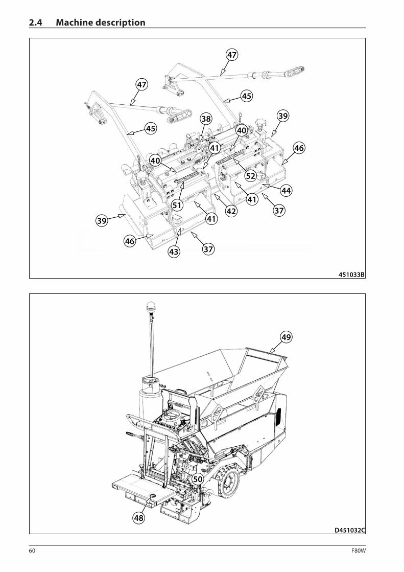
60 F80W
451033B
41
4142
41
37
37
47
47
45
45
46
43
44
38 39
40
40
46
39
51
52
D451032C
48
49
50
2.4 Machine description

61F80W
OPERATING MANUAL
37. Roadway profile bottom plates
38. Crown adjustment
39. Screed end gate
40. Screed vibrators
41. Gas components
42. Main screed
43. Left screed extension
44. Right screed extension
45. Screed tow arm
46. Mechanical extension
47. Paving thickness controller
48. Foot switch
49. Hopper cover
50. Conveyor limit switch
51. Left indicator of paving width setting
52. Right indicator of paving width setting
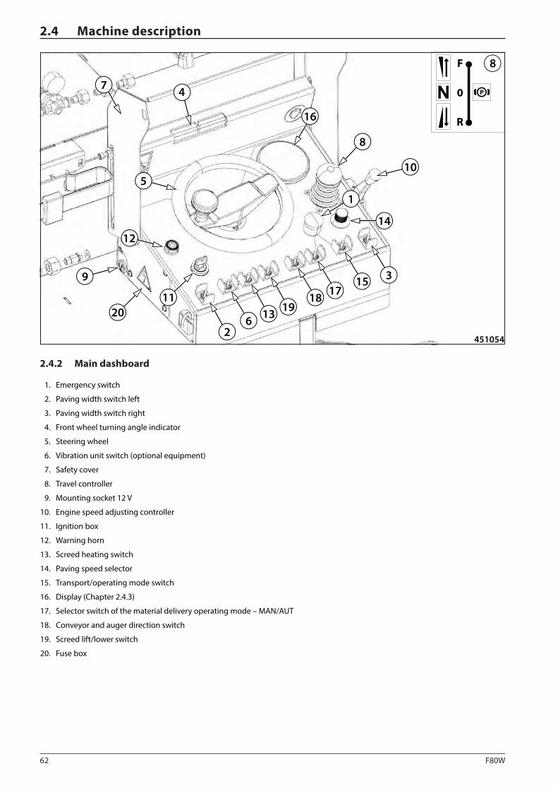
62 F80W
451054
47
5
12
9
2011
26 13 19
18 1715 3
14
10
8
16
1
P0
R
F 8
2.4 Machine description
2.4.2 Main dashboard
1. Emergency switch
2. Paving width switch left
3. Paving width switch right
4. Front wheel turning angle indicator
5. Steering wheel
6. Vibration unit switch (optional equipment)
7. Safety cover
8. Travel controller
9. Mounting socket 12 V
10. Engine speed adjusting controller
11. Ignition box
12. Warning horn
13. Screed heating switch
14. Paving speed selector
15. Transport/operating mode switch
16. Display (Chapter 2.4.3)
17. Selector switch of the material delivery operating mode – MAN/AUT
18. Conveyor and auger direction switch
19. Screed lift/lower switch
20. Fuse box

63F80W
OPERATING MANUAL
Emergency switch (1)
Press the button to enable the machine emergency brake, which is indicated by lighting up the brake, emergency stop and charging indicator lamps on the display.
The machine stops moving and the engine stalls!
Paving width switch – left (2)
It serves for increasing/decreasing the paving width on the left side.
• Left – the left part of the screed is extended.
• Middle – neutral position.
• Right – the left part of the screed is retracted.
Paving width switch – right (3)
It serves for increasing/decreasing the paving width on the right side.
• Right – the right part of the screed is extended.
• Middle – neutral position.
• Left – the right part of the screed is retracted.
Front wheel turning angle indicator (4)
It shows the turning angle of the front wheel to the left or right.
Steering wheel (5)
Vibration unit switch (6) (optional equipment)
It serves for turning on the vibration.
• Upper position – the vibration unit on
• Lower position – the vibration unit off
The vibration unit is only active in the operating mode when ma-chine travels forward.
Safety cover (7)
Protection against vandalism and unauthorized use of the ma-chine.
Travel controller (8)
The travel controller is used for braking the machine and setting the direction and speed of travel. The travel control is fitted with an arresting ring, which must be pulled up before the control is moved.
Travel controller positions:
N – Neutral – the machine is braked, idle engine speed set up
F – Forward travel
R – Reverse travel
That the machine is braked is signalled on the dashboard.
Mounting socket 12 V (9)
It is used for connecting a beacon, a mounting lamp or other equipment (12 V).
Engine speed adjusting controller (10)
The accelerator controller regulates the engine speed.
• Position up: standard speed (1,100 rpm)
• Position down: maximum speed (2,600 rpm)
To operate the machine, set the speed at maximum.
Ignition box (11)
Switch with three positions:
• Position “0” (with arresting): engine OFF.
- No electrical devices are powered.
• Position “1” (with arresting):
- All electrical devices are powered.
• Intermediate position: Engine pre-heating
• Position “2” (without arresting): Starting up of the engine
Warning horn (12)

64 F80W
2.4 Machine description
Screed heating switch (13)
It is used for turning on the screed gas heating.
• Upper position – turned ON
• Lower position – turned OFF
Paving speed selector (14)
Active only in the operating mode. The maximum speed in the operating mode is 0.6 km/h (0.37 MPH).
Transport/operating mode switch (15)
• Transport mode ("rabbit")
- The material feed function to augers, vibration and screed lowering functions cannot be activated.
- The maximum travel speed forward and backward is 2.5 km/h (1.55 MPH).
• Operating mode ("turtle")
- The material feed function to augers, vibration and screed lowering functions can be activated.
- The maximum travel speed forward is 0.6 km/h (0.37 MPH).
- The machine backward travel function cannot be acti-vated in the operating mode.
Selector switch of the material delivery operating mode – MAN/AUT (17)
• AUT – automatic mode of material delivery
- the machine moves in the operating mode.
• MAN – manual mode of material delivery
- turn over the conveyor direction switch (18) to the lower position (opposite the machine travel).
Conveyor and auger direction switch (18)
It serves for the operation of the material conveyor and augers. The function is only active in the operating mode.
• Upper position – reversing
• Central position – no material distribution
• Lower position – material distribution active
Screed lift/lower switch (19)
Toggle switch with 3 positions:
• Position up (without arresting): lifts the screed.
- Set the travel controller to the neutral position.
- Set the maximum engine speed.
• Central position (with arresting): screed lock; the screed will stay in its current position.
• Position down (with arresting): lowers the screed and the floating function.
- Floating position – active only during travel of the ma-chine in the operating mode.
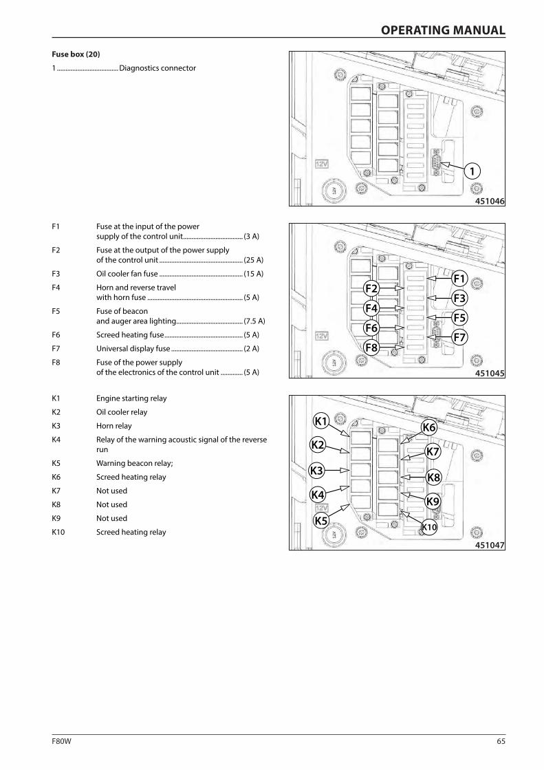
65F80W
451045
F1
F3
F5
F7
F2
F6
F8
F4
451046
1
451047
K8K3
K4
K5
K2
K1
K7
K6
K9
K10
OPERATING MANUAL
Fuse box (20)
1 .................................... Diagnostics connector
F1 Fuse at the input of the power supply of the control unit ................................... (3 A)
F2 Fuse at the output of the power supply of the control unit ................................................. (25 A)
F3 Oil cooler fan fuse ................................................. (15 A)
F4 Horn and reverse travel with horn fuse ........................................................ (5 A)
F5 Fuse of beacon and auger area lighting ....................................... (7.5 A)
F6 Screed heating fuse .............................................. (5 A)
F7 Universal display fuse .......................................... (2 A)
F8 Fuse of the power supply of the electronics of the control unit ............. (5 A)
K1 Engine starting relay
K2 Oil cooler relay
K3 Horn relay
K4 Relay of the warning acoustic signal of the reverse run
K5 Warning beacon relay;
K6 Screed heating relay
K7 Not used
K8 Not used
K9 Not used
K10 Screed heating relay
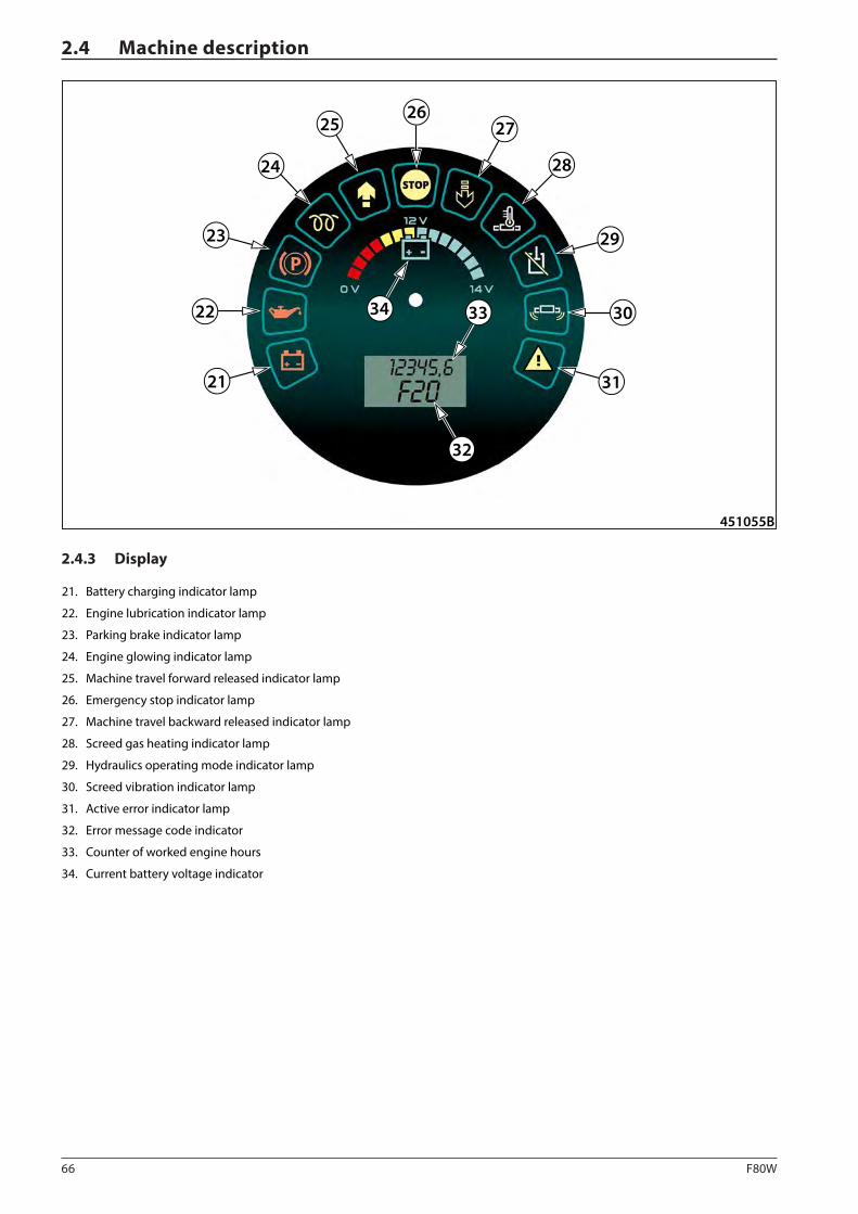
66 F80W
451055B
26
24
23
21
22
2725
28
29
30
31
32
3334
2.4 Machine description
2.4.3 Display
21. Battery charging indicator lamp
22. Engine lubrication indicator lamp
23. Parking brake indicator lamp
24. Engine glowing indicator lamp
25. Machine travel forward released indicator lamp
26. Emergency stop indicator lamp
27. Machine travel backward released indicator lamp
28. Screed gas heating indicator lamp
29. Hydraulics operating mode indicator lamp
30. Screed vibration indicator lamp
31. Active error indicator lamp
32. Error message code indicator
33. Counter of worked engine hours
34. Current battery voltage indicator

67F80W
OPERATING MANUAL
Battery charging indicator lamp (21)
It indicates that the battery charging function is in order. After the key in the ignition box (11) is switched over to the position “I”, the indicator lamp must light up and it must go off after the start-up.
Engine lubrication indicator lamp (22)
The indicator lamp indicates an engine lubrication failure.
Oil pressure too low.
Parking brake indicator lamp (23)
The lighting indicator lamp indicates that the parking brake was enabled.
Engine glowing indicator lamp (24)
It indicates the engine warming up before the cold start.
Machine travel forward released indicator lamp (25)
The indicator lamp indicates that the machine can travel forward.
Emergency stop indicator lamp (26)
It indicates an active function of the emergency brake.
Machine travel backward released indica-tor lamp (27)
The indicator lamp signals that the machine can travel back-ward.
Screed gas heating indicator lamp (28)
It indicates an active function of the screed gas heating.
Hydraulics operating mode indicator lamp (29)
It indicates blocking of material delivery, the vibration function and screed lowering.
Screed vibration indicator lamp (30)
It indicates that the vibration function is active.
Active error indicator lamp (31)
If the indicator lamp is lit, remove the failure displayed on the display or contact your dealer or an DYNAPAC authorised ser-vice centre.
Error code indicator (32)
Counter of worked engine hours (33)
It shows the total time, during which the machine has been in operation.
Battery voltage indicator (34)
It shows a battery voltage value:
Green – the battery is OK
Yellow – low battery voltage
Red – battery voltage too low
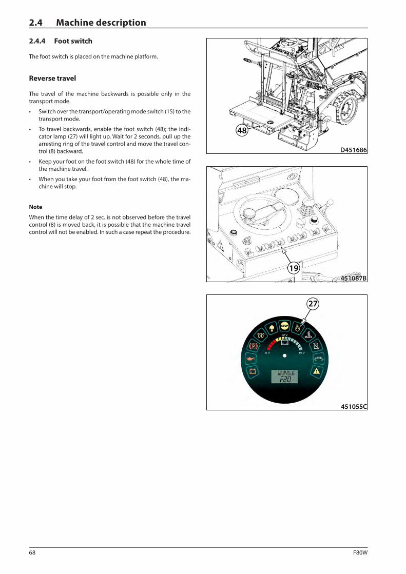
68 F80W
D451686
48
19451087B
27
451055C
2.4 Machine description
2.4.4 Foot switch
The foot switch is placed on the machine platform.
Reverse travel
The travel of the machine backwards is possible only in the transport mode.
• Switch over the transport/operating mode switch (15) to the transport mode.
• To travel backwards, enable the foot switch (48); the indi-cator lamp (27) will light up. Wait for 2 seconds, pull up the arresting ring of the travel control and move the travel con-trol (8) backward.
• Keep your foot on the foot switch (48) for the whole time of the machine travel.
• When you take your foot from the foot switch (48), the ma-chine will stop.
Note
When the time delay of 2 sec. is not observed before the travel control (8) is moved back, it is possible that the machine travel control will not be enabled. In such a case repeat the procedure.
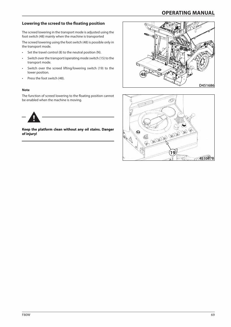
69F80W
19451087B
D451686
48
OPERATING MANUAL
Lowering the screed to the floating position
The screed lowering in the transport mode is adjusted using the foot switch (48) mainly when the machine is transported
The screed lowering using the foot switch (48) is possible only in the transport mode.
• Set the travel control (8) to the neutral position (N).
• Switch over the transport/operating mode switch (15) to the transport mode.
• Switch over the screed lifting/lowering switch (19) to the lower position.
• Press the foot switch (48).
Note
The function of screed lowering to the floating position cannot be enabled when the machine is moving.
Keep the platform clean without any oil stains. Danger of injury!
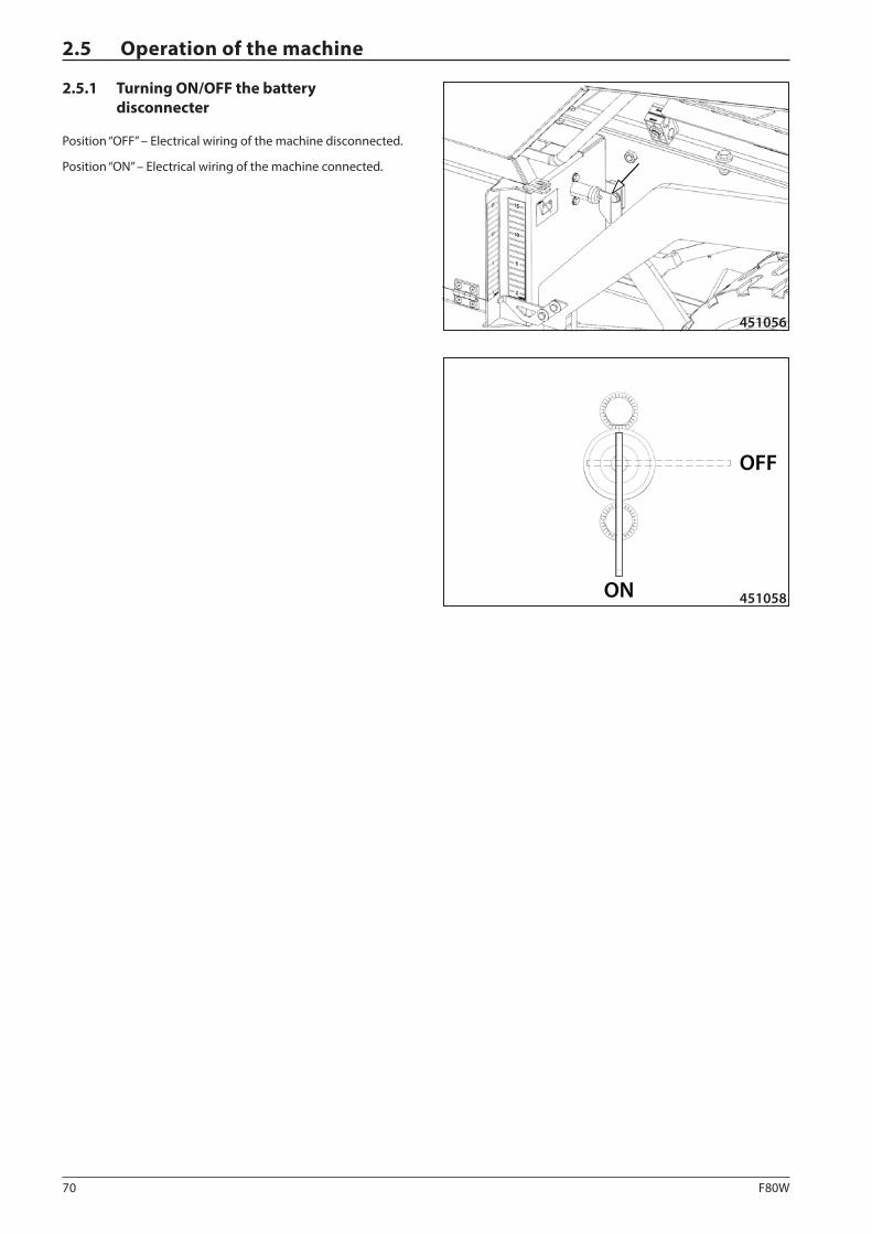
70 F80W
451056
ON
OFF
451058
2.5.1 Turning ON/OFF the battery disconnecter
Position “OFF” – Electrical wiring of the machine disconnected.
Position “ON” – Electrical wiring of the machine connected.
2.5 Operation of the machine
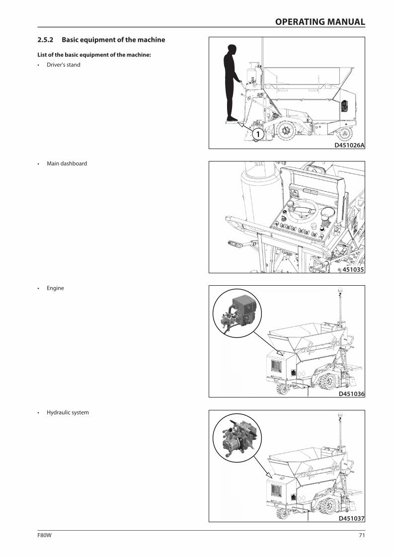
71F80W
D451026A
1
451035
D451036
D451037
OPERATING MANUAL
2.5.2 Basic equipment of the machine
List of the basic equipment of the machine:
• Driver's stand
• Main dashboard
• Engine
• Hydraulic system
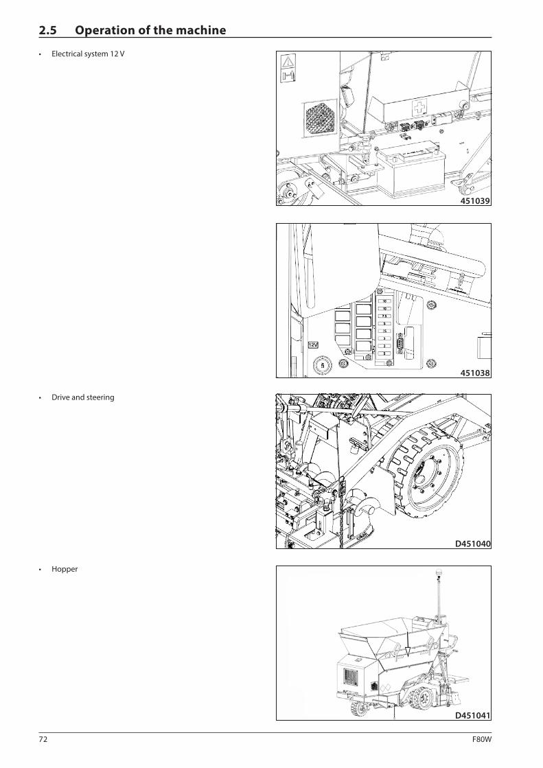
72 F80W
451039
451038
D451040
D451041
2.5 Operation of the machine
• Electrical system 12 V
• Drive and steering
• Hopper
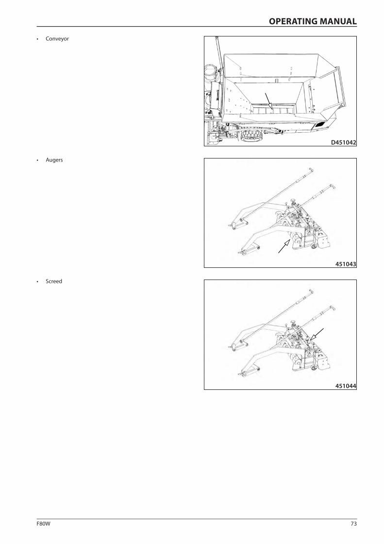
73F80W
451043
451044
D451042
OPERATING MANUAL
• Augers
• Screed
• Conveyor
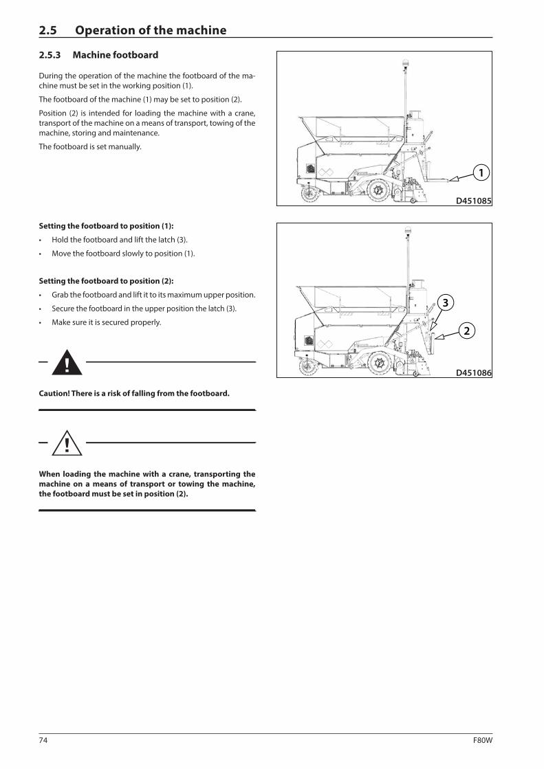
74 F80W
D451085
1
2
3
D451086
2.5 Operation of the machine
2.5.3 Machine footboard
During the operation of the machine the footboard of the ma-chine must be set in the working position (1).
The footboard of the machine (1) may be set to position (2).
Position (2) is intended for loading the machine with a crane, transport of the machine on a means of transport, towing of the machine, storing and maintenance.
The footboard is set manually.
Setting the footboard to position (1):
• Hold the footboard and lift the latch (3).
• Move the footboard slowly to position (1).
Setting the footboard to position (2):
• Grab the footboard and lift it to its maximum upper position.
• Secure the footboard in the upper position the latch (3).
• Make sure it is secured properly.
Caution! There is a risk of falling from the footboard.
When loading the machine with a crane, transporting the machine on a means of transport or towing the machine, the footboard must be set in position (2).
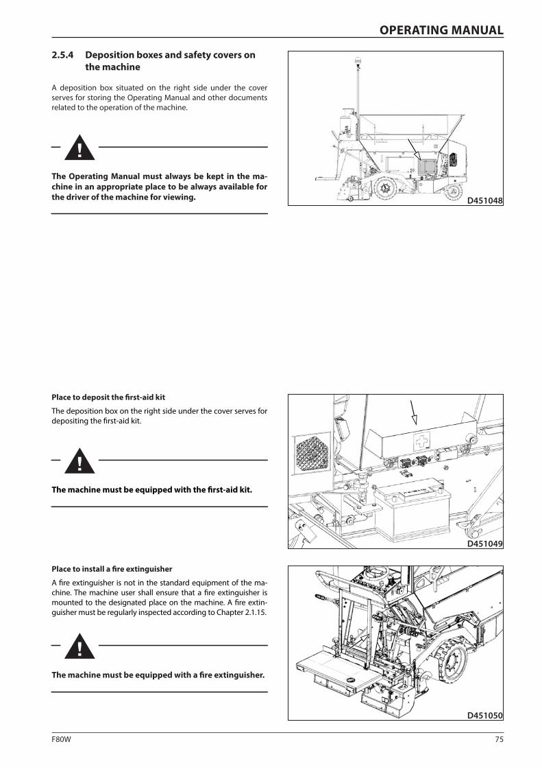
75F80W
D451048
D451049
D451050
OPERATING MANUAL
2.5.4 Deposition boxes and safety covers on the machine
A deposition box situated on the right side under the cover serves for storing the Operating Manual and other documents related to the operation of the machine.
The Operating Manual must always be kept in the ma-chine in an appropriate place to be always available for the driver of the machine for viewing.
Place to deposit the first-aid kit
The deposition box on the right side under the cover serves for depositing the first-aid kit.
The machine must be equipped with the first-aid kit.
Place to install a fire extinguisher
A fire extinguisher is not in the standard equipment of the ma-chine. The machine user shall ensure that a fire extinguisher is mounted to the designated place on the machine. A fire extin-guisher must be regularly inspected according to Chapter 2.1.15.
The machine must be equipped with a fire extinguisher.

76 F80W
451051
451052
2.5 Operation of the machine
Safety cover on the machine
The machine is equipped with a safety cover of the main dash-board. This safety cover is mounted on the machine to protect the equipment from damage or unauthorised use.
When the machine is put out of operation or left unat-tended, the safety cover of the main dashboard must al-ways be locked.
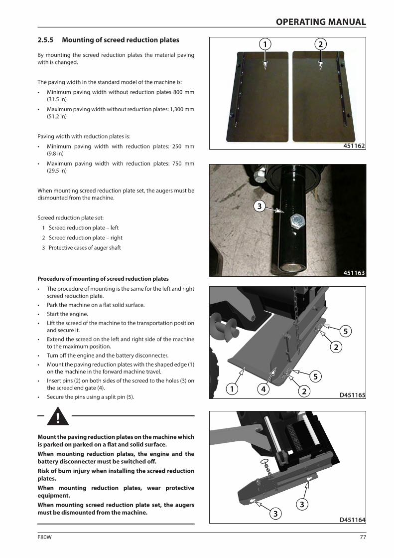
77F80W
21
451162
451163
3
D4511643
3
D4511651 4
5
5
2
2
OPERATING MANUAL
2.5.5 Mounting of screed reduction plates
By mounting the screed reduction plates the material paving with is changed.
The paving width in the standard model of the machine is:
• Minimum paving width without reduction plates 800 mm (31.5 in)
• Maximum paving width without reduction plates: 1,300 mm (51.2 in)
Paving width with reduction plates is:
• Minimum paving width with reduction plates: 250 mm (9.8 in)
• Maximum paving width with reduction plates: 750 mm (29.5 in)
When mounting screed reduction plate set, the augers must be dismounted from the machine.
Screed reduction plate set:
1 Screed reduction plate – left
2 Screed reduction plate – right
3 Protective cases of auger shaft
Procedure of mounting of screed reduction plates
• The procedure of mounting is the same for the left and right screed reduction plate.
• Park the machine on a flat solid surface.
• Start the engine.
• Lift the screed of the machine to the transportation position and secure it.
• Extend the screed on the left and right side of the machine to the maximum position.
• Turn off the engine and the battery disconnecter.
• Mount the paving reduction plates with the shaped edge (1) on the machine in the forward machine travel.
• Insert pins (2) on both sides of the screed to the holes (3) on the screed end gate (4).
• Secure the pins using a split pin (5).
Mount the paving reduction plates on the machine which is parked on parked on a flat and solid surface.When mounting reduction plates, the engine and the battery disconnecter must be switched off.Risk of burn injury when installing the screed reduction plates.When mounting reduction plates, wear protective equipment.When mounting screed reduction plate set, the augers must be dismounted from the machine.
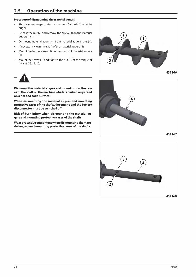
78 F80W
31
2
451166
13
2
4
451167
35
2
451168
2.5 Operation of the machine
Procedure of dismounting the material augers
• The dismounting procedure is the same for the left and right auger.
• Release the nut (2) and remove the screw (3) on the material augers (1) .
• Dismount material augers (1) from material auger shafts (4).
• If necessary, clean the shaft of the material augers (4).
• Mount protective cases (5) on the shafts of material augers (4)
• Mount the screw (3) and tighten the nut (2) at the torque of 48 Nm (35.4 lbft).
Dismount the material augers and mount protective cas-es of the shaft on the machine which is parked on parked on a flat and solid surface.
When dismounting the material augers and mounting protective cases of the shafts, the engine and the battery disconnector must be switched off.
Risk of burn injury when dismounting the material au-gers and mounting protective cases of the shafts.
Wear protective equipment when dismounting the mate-rial augers and mounting protective cases of the shafts.
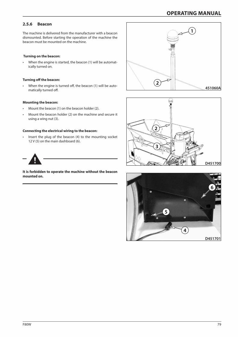
79F80W
451060A
1
2
D451700
2
3
D451701
4
5
6
OPERATING MANUAL
2.5.6 Beacon
The machine is delivered from the manufacturer with a beacon dismounted. Before starting the operation of the machine the beacon must be mounted on the machine.
Turning on the beacon:
• When the engine is started, the beacon (1) will be automat-ically turned on.
Turning off the beacon:
• When the engine is turned off, the beacon (1) will be auto-matically turned off.
Mounting the beacon:
• Mount the beacon (1) on the beacon holder (2).
• Mount the beacon holder (2) on the machine and secure it using a wing nut (3).
Connecting the electrical wiring to the beacon:
• Insert the plug of the beacon (4) to the mounting socket 12 V (5) on the main dashboard (6).
It is forbidden to operate the machine without the beacon mounted on.
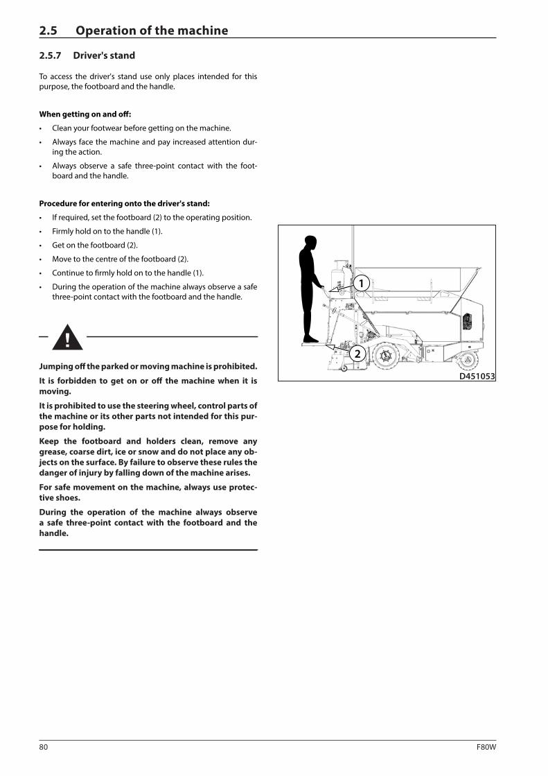
80 F80W
D451053
2
1
2.5 Operation of the machine
2.5.7 Driver's stand
To access the driver's stand use only places intended for this purpose, the footboard and the handle.
When getting on and off:
• Clean your footwear before getting on the machine.
• Always face the machine and pay increased attention dur-ing the action.
• Always observe a safe three-point contact with the foot-board and the handle.
Procedure for entering onto the driver's stand:
• If required, set the footboard (2) to the operating position.
• Firmly hold on to the handle (1).
• Get on the footboard (2).
• Move to the centre of the footboard (2).
• Continue to firmly hold on to the handle (1).
• During the operation of the machine always observe a safe three-point contact with the footboard and the handle.
Jumping off the parked or moving machine is prohibited.
It is forbidden to get on or off the machine when it is moving.
It is prohibited to use the steering wheel, control parts of the machine or its other parts not intended for this pur-pose for holding.
Keep the footboard and holders clean, remove any grease, coarse dirt, ice or snow and do not place any ob-jects on the surface. By failure to observe these rules the danger of injury by falling down of the machine arises.
For safe movement on the machine, always use protec-tive shoes.
During the operation of the machine always observe a safe three-point contact with the footboard and the handle.
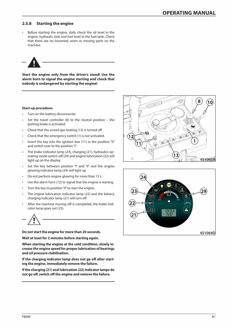
81F80W
121
451063A13
11
8 10
23
21
22
29
24
451064D
OPERATING MANUAL
2.5.8 Starting the engine
• Before starting the engine, daily check the oil level in the engine, hydraulic tank and fuel level in the fuel tank. Check that there are no loosened, worn or missing parts on the machine.
Start the engine only from the driver’s stand! Use the alarm horn to signal the engine starting and check that nobody is endangered by starting the engine!
Start-up procedure:
• Turn on the battery disconnecter.
• Set the travel controller (8) to the neutral position – the parking brake is activated.
• Check that the screed gas heating (13) is turned off.
• Check that the emergency switch (1) is not activated.
• Insert the key into the ignition box (11) in the position “0” and switch over to the position “I”.
• The brake indicator lamp (23), charging (21), hydraulics op-erating mode switch-off (29) and engine lubrication (22) will light up on the display.
• Set the key between position “I” and “II” and the engine glowing indicator lamp (24) will light up.
• Do not perform engine glowing for more than 15 s.
• Use the alarm horn (12) to signal that the engine is starting.
• Turn the key to position “II” to start the engine.
• The engine lubrication indicator lamp (22) and the battery charging indicator lamp (21) will turn off.
• After the machine moving-off is completed, the brake indi-cator lamp goes out (23).
Do not start the engine for more than 20 seconds.
Wait at least for 2 minutes before starting again.
When starting the engine at the cold condition, slowly in-crease the engine speed for proper lubrication of bearings and oil pressure stabilisation.
If the charging indicator lamp does not go off after start-ing the engine, immediately remove the failure.
If the charging (21) and lubrication (22) indicator lamps do not go off, switch off the engine and remove the failure.
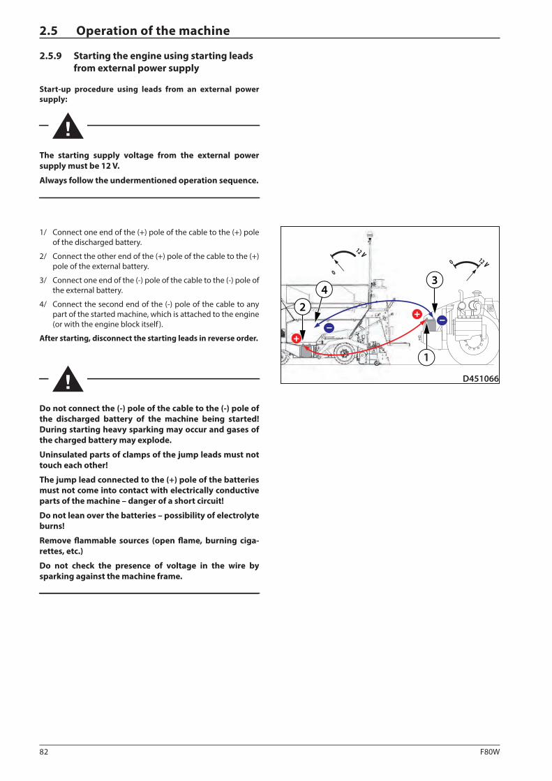
82 F80W
3
–+
+ –
0 v12
D451066
0
v12
3
24
1
2.5 Operation of the machine
2.5.9 Starting the engine using starting leads from external power supply
Start-up procedure using leads from an external power supply:
The starting supply voltage from the external power supply must be 12 V.
Always follow the undermentioned operation sequence.
1/ Connect one end of the (+) pole of the cable to the (+) pole of the discharged battery.
2/ Connect the other end of the (+) pole of the cable to the (+) pole of the external battery.
3/ Connect one end of the (-) pole of the cable to the (-) pole of the external battery.
4/ Connect the second end of the (-) pole of the cable to any part of the started machine, which is attached to the engine (or with the engine block itself ).
After starting, disconnect the starting leads in reverse order.
Do not connect the (-) pole of the cable to the (-) pole of the discharged battery of the machine being started! During starting heavy sparking may occur and gases of the charged battery may explode.
Uninsulated parts of clamps of the jump leads must not touch each other!
The jump lead connected to the (+) pole of the batteries must not come into contact with electrically conductive parts of the machine – danger of a short circuit!
Do not lean over the batteries – possibility of electrolyte burns!
Remove flammable sources (open flame, burning ciga-rettes, etc.)
Do not check the presence of voltage in the wire by sparking against the machine frame.
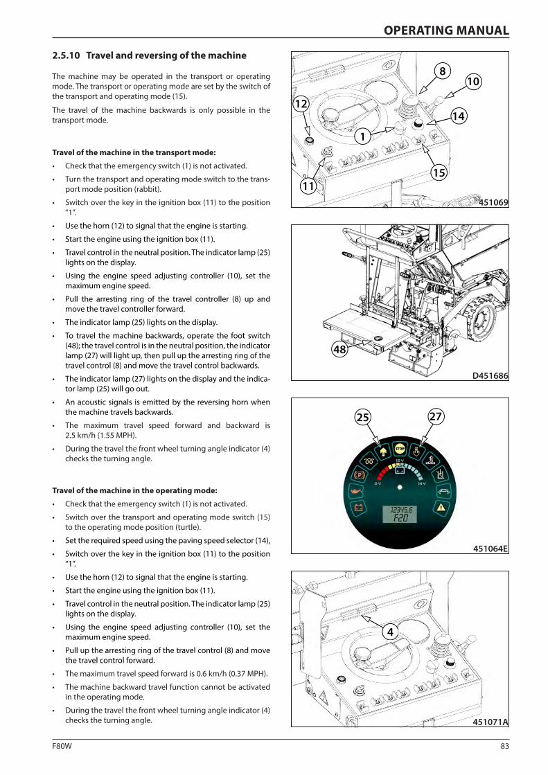
83F80W
8
14
10
451069
1
1511
12
D451686
48
25 27
451064E
4
451071A
OPERATING MANUAL
2.5.10 Travel and reversing of the machine
The machine may be operated in the transport or operating mode. The transport or operating mode are set by the switch of the transport and operating mode (15).
The travel of the machine backwards is only possible in the transport mode.
Travel of the machine in the transport mode:
• Check that the emergency switch (1) is not activated.
• Turn the transport and operating mode switch to the trans-port mode position (rabbit).
• Switch over the key in the ignition box (11) to the position “1”.
• Use the horn (12) to signal that the engine is starting.
• Start the engine using the ignition box (11).
• Travel control in the neutral position. The indicator lamp (25) lights on the display.
• Using the engine speed adjusting controller (10), set the maximum engine speed.
• Pull the arresting ring of the travel controller (8) up and move the travel controller forward.
• The indicator lamp (25) lights on the display.
• To travel the machine backwards, operate the foot switch (48); the travel control is in the neutral position, the indicator lamp (27) will light up, then pull up the arresting ring of the travel control (8) and move the travel control backwards.
• The indicator lamp (27) lights on the display and the indica-tor lamp (25) will go out.
• An acoustic signals is emitted by the reversing horn when the machine travels backwards.
• The maximum travel speed forward and backward is 2.5 km/h (1.55 MPH).
• During the travel the front wheel turning angle indicator (4) checks the turning angle.
Travel of the machine in the operating mode:
• Check that the emergency switch (1) is not activated.
• Switch over the transport and operating mode switch (15) to the operating mode position (turtle).
• Set the required speed using the paving speed selector (14),
• Switch over the key in the ignition box (11) to the position “1”.
• Use the horn (12) to signal that the engine is starting.
• Start the engine using the ignition box (11).
• Travel control in the neutral position. The indicator lamp (25) lights on the display.
• Using the engine speed adjusting controller (10), set the maximum engine speed.
• Pull up the arresting ring of the travel control (8) and move the travel control forward.
• The maximum travel speed forward is 0.6 km/h (0.37 MPH).
• The machine backward travel function cannot be activated in the operating mode.
• During the travel the front wheel turning angle indicator (4) checks the turning angle.
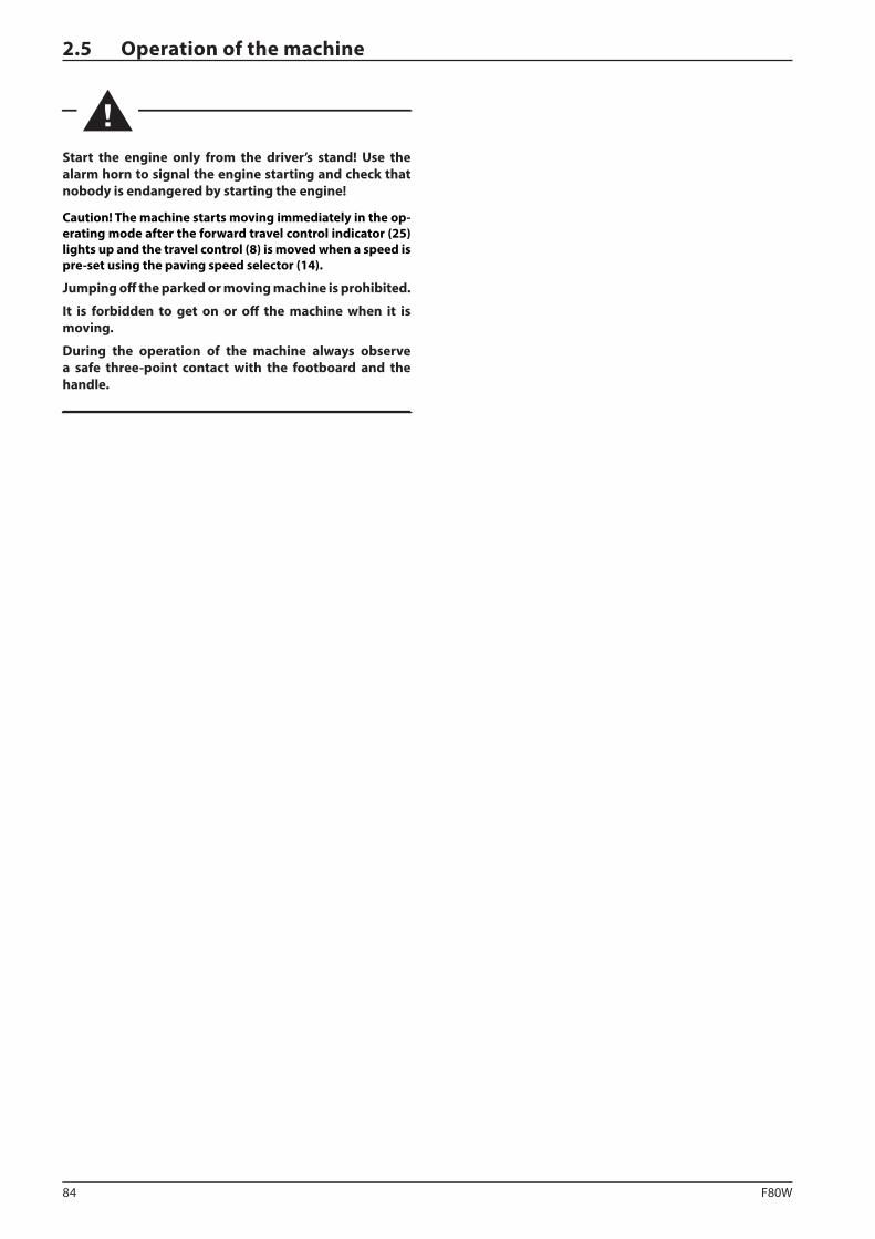
84 F80W
2.5 Operation of the machine
Start the engine only from the driver’s stand! Use the alarm horn to signal the engine starting and check that nobody is endangered by starting the engine!
Caution! The machine starts moving immediately in the op-erating mode after the forward travel control indicator (25) lights up and the travel control (8) is moved when a speed is pre-set using the paving speed selector (14).
Jumping off the parked or moving machine is prohibited.
It is forbidden to get on or off the machine when it is moving.
During the operation of the machine always observe a safe three-point contact with the footboard and the handle.
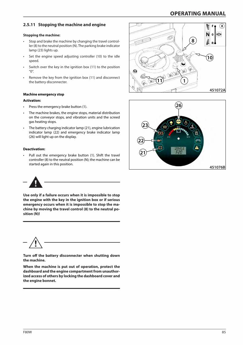
85F80W
8
10
11
P0
R
F 8
451072A
1
21
22
451076B
26
23
OPERATING MANUAL
2.5.11 Stopping the machine and engine
Stopping the machine:
• Stop and brake the machine by changing the travel control-ler (8) to the neutral position (N). The parking brake indicator lamp (23) lights up.
• Set the engine speed adjusting controller (10) to the idle speed.
• Switch over the key in the ignition box (11) to the position “0“.
• Remove the key from the ignition box (11) and disconnect the battery disconnecter.
Machine emergency stop
Activation:
• Press the emergency brake button (1).
• The machine brakes, the engine stops, material distribution on the conveyor stops, and vibration units and the screed gas heating stops.
• The battery charging indicator lamp (21), engine lubrication indicator lamp (22) and emergency brake indicator lamp (26) will light up on the display.
Deactivation:
• Pull out the emergency brake button (1). Shift the travel controller (8) to the neutral position (N); the machine can be started again in this position.
Use only if a failure occurs when it is impossible to stop the engine with the key in the ignition box or if serious emergency occurs when it is impossible to stop the ma-chine by moving the travel control (8) to the neutral po-sition (N)!
Turn off the battery disconnecter when shutting down the machine.
When the machine is put out of operation, protect the dashboard and the engine compartment from unauthor-ized access of others by locking the dashboard cover and the engine bonnet.
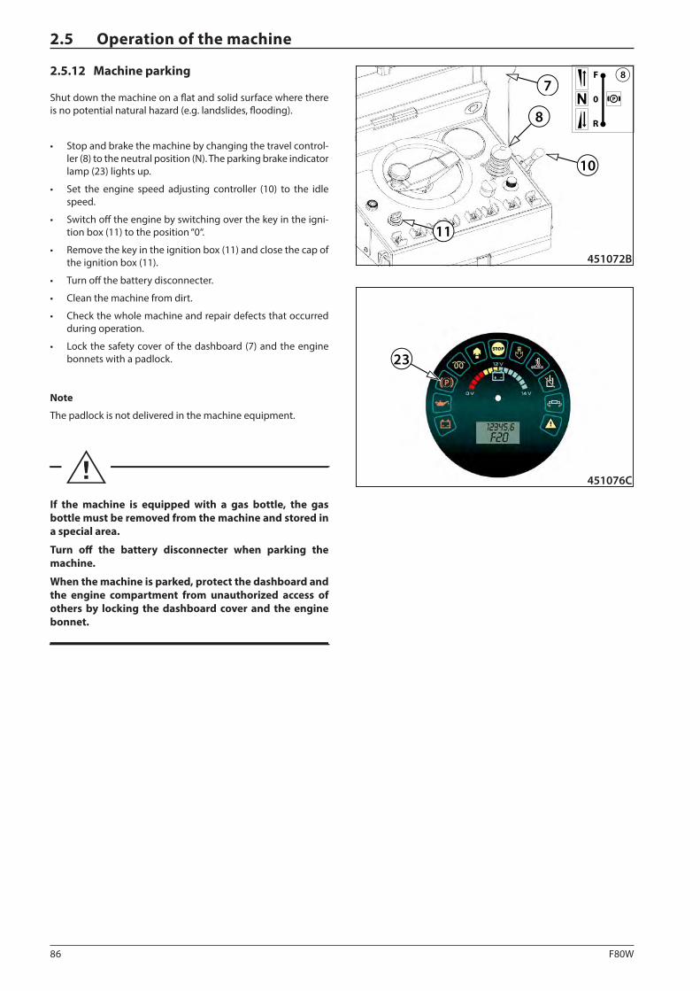
86 F80W
8
10
11
P0
R
F 8
451072B
7
451076C
23
2.5 Operation of the machine
2.5.12 Machine parking
Shut down the machine on a flat and solid surface where there is no potential natural hazard (e.g. landslides, flooding).
• Stop and brake the machine by changing the travel control-ler (8) to the neutral position (N). The parking brake indicator lamp (23) lights up.
• Set the engine speed adjusting controller (10) to the idle speed.
• Switch off the engine by switching over the key in the igni-tion box (11) to the position “0“.
• Remove the key in the ignition box (11) and close the cap of the ignition box (11).
• Turn off the battery disconnecter.
• Clean the machine from dirt.
• Check the whole machine and repair defects that occurred during operation.
• Lock the safety cover of the dashboard (7) and the engine bonnets with a padlock.
Note
The padlock is not delivered in the machine equipment.
If the machine is equipped with a gas bottle, the gas bottle must be removed from the machine and stored in a special area.
Turn off the battery disconnecter when parking the machine.
When the machine is parked, protect the dashboard and the engine compartment from unauthorized access of others by locking the dashboard cover and the engine bonnet.
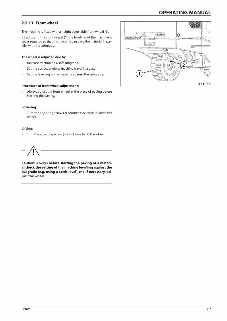
87F80W
1
2
451068
OPERATING MANUAL
2.5.13 Front wheel
The machine is fitted with a height adjustable front wheel (1).
By adjusting this front wheel (1) the levelling of the machine is set as required so that the machine can pave the material in par-allel with the subgrade.
The wheel is adjusted due to:
• Increase traction on a soft subgrade.
• Set the correct angle of machine travel in a gap.
• Set the levelling of the machine against the subgrade.
Procedure of front wheel adjustment:
• Always adjust the front wheel at the place of paving before starting the paving.
Lowering:
• Turn the adjusting screw (2) counter-clockwise to lower the wheel.
Lifting:
• Turn the adjusting screw (2) clockwise to lift the wheel.
Caution! Always before starting the paving of a materi-al check the setting of the machine levelling against the subgrade (e.g. using a spirit level) and if necessary, ad-just the wheel.
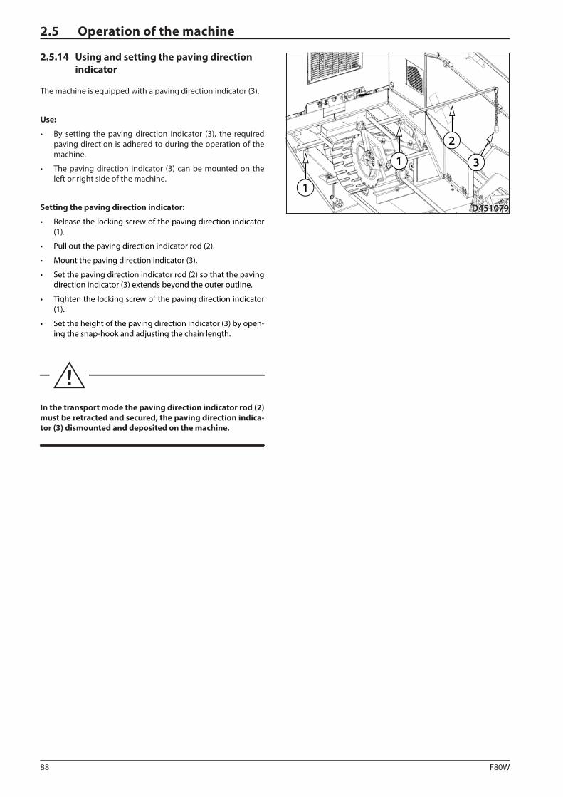
88 F80W
1
1
2
3
D451079
2.5 Operation of the machine
2.5.14 Using and setting the paving direction indicator
The machine is equipped with a paving direction indicator (3).
Use:
• By setting the paving direction indicator (3), the required paving direction is adhered to during the operation of the machine.
• The paving direction indicator (3) can be mounted on the left or right side of the machine.
Setting the paving direction indicator:
• Release the locking screw of the paving direction indicator (1).
• Pull out the paving direction indicator rod (2).
• Mount the paving direction indicator (3).
• Set the paving direction indicator rod (2) so that the paving direction indicator (3) extends beyond the outer outline.
• Tighten the locking screw of the paving direction indicator (1).
• Set the height of the paving direction indicator (3) by open-ing the snap-hook and adjusting the chain length.
In the transport mode the paving direction indicator rod (2) must be retracted and secured, the paving direction indica-tor (3) dismounted and deposited on the machine.
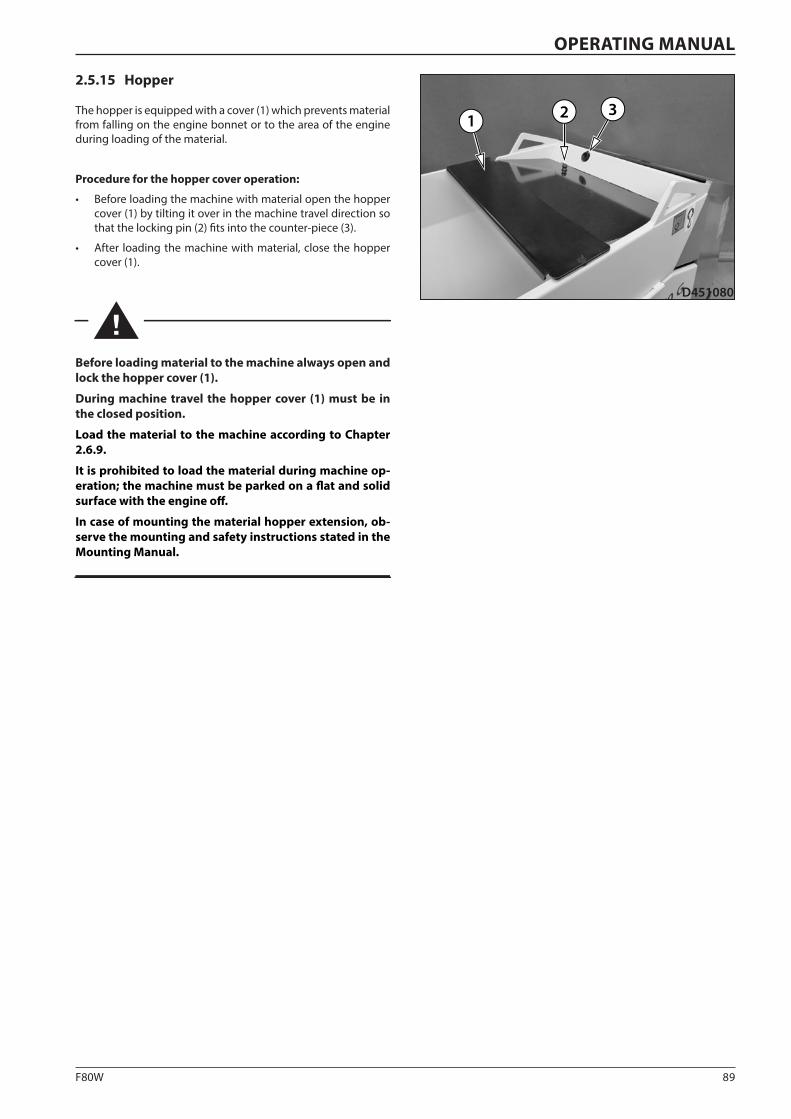
89F80W
1 2 3
D451080
OPERATING MANUAL
2.5.15 Hopper
The hopper is equipped with a cover (1) which prevents material from falling on the engine bonnet or to the area of the engine during loading of the material.
Procedure for the hopper cover operation:
• Before loading the machine with material open the hopper cover (1) by tilting it over in the machine travel direction so that the locking pin (2) fits into the counter-piece (3).
• After loading the machine with material, close the hopper cover (1).
Before loading material to the machine always open and lock the hopper cover (1).
During machine travel the hopper cover (1) must be in the closed position.
Load the material to the machine according to Chapter 2.6.9.
It is prohibited to load the material during machine op-eration; the machine must be parked on a flat and solid surface with the engine off.
In case of mounting the material hopper extension, ob-serve the mounting and safety instructions stated in the Mounting Manual.
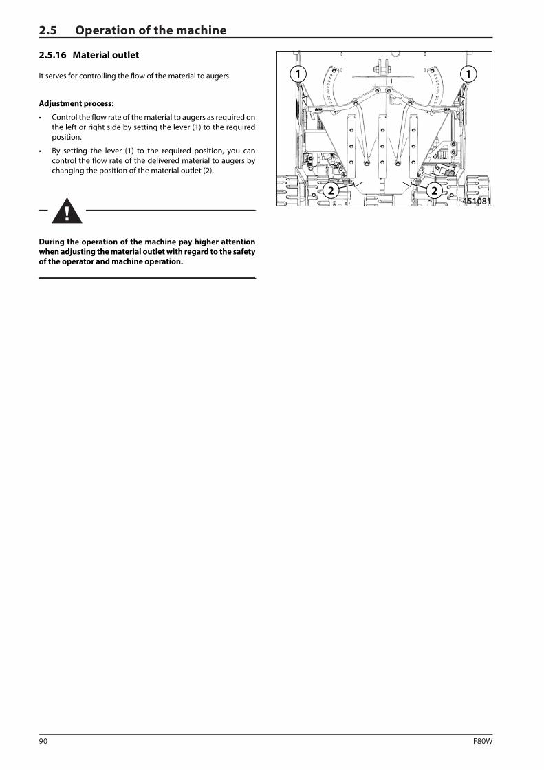
90 F80W
1 1
2 2451081
2.5 Operation of the machine
2.5.16 Material outlet
It serves for controlling the flow of the material to augers.
Adjustment process:
• Control the flow rate of the material to augers as required on the left or right side by setting the lever (1) to the required position.
• By setting the lever (1) to the required position, you can control the flow rate of the delivered material to augers by changing the position of the material outlet (2).
During the operation of the machine pay higher attention when adjusting the material outlet with regard to the safety of the operator and machine operation.
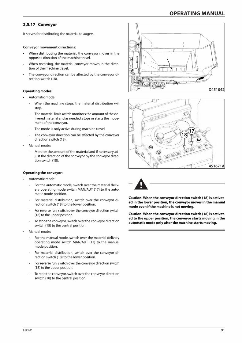
91F80W
451671A
1718
D451042
OPERATING MANUAL
2.5.17 Conveyor
It serves for distributing the material to augers.
Conveyor movement directions:
• When distributing the material, the conveyor moves in the opposite direction of the machine travel.
• When reversing, the material conveyor moves in the direc-tion of the machine travel.
• The conveyor direction can be affected by the conveyor di-rection switch (18).
Operating modes:
• Automatic mode:
- When the machine stops, the material distribution will stop.
- The material limit switch monitors the amount of the de-livered material and as needed, stops or starts the move-ment of the conveyor.
- The mode is only active during machine travel.
- The conveyor direction can be affected by the conveyor direction switch (18).
• Manual mode:
- Monitor the amount of the material and if necessary ad-just the direction of the conveyor by the conveyor direc-tion switch (18).
Operating the conveyor:
• Automatic mode:
- For the automatic mode, switch over the material deliv-ery operating mode switch MAN/AUT (17) to the auto-matic mode position.
- For material distribution, switch over the conveyor di-rection switch (18) to the lower position.
- For reverse run, switch over the conveyor direction switch (18) to the upper position.
- To stop the conveyor, switch over the conveyor direction switch (18) to the central position.
• Manual mode:
- For the manual mode, switch over the material delivery operating mode switch MAN/AUT (17) to the manual mode position.
- For material distribution, switch over the conveyor di-rection switch (18) to the lower position.
- For reverse run, switch over the conveyor direction switch (18) to the upper position.
- To stop the conveyor, switch over the conveyor direction switch (18) to the central position.
Caution! When the conveyor direction switch (18) is activat-ed in the lower position, the conveyor moves in the manual mode even if the machine is not moving.
Caution! When the conveyor direction switch (18) is activat-ed to the upper position, the conveyor starts moving in the automatic mode only after the machine starts moving.
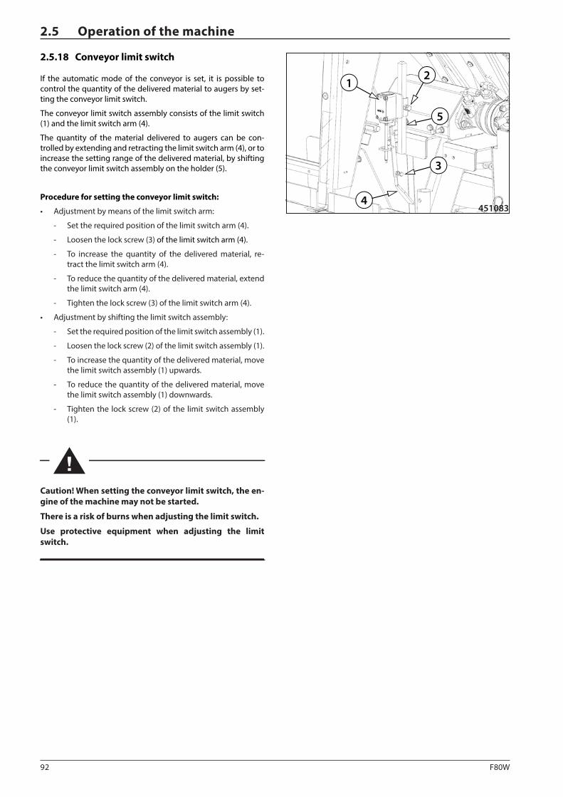
92 F80W
12
3
4451083
5
2.5 Operation of the machine
2.5.18 Conveyor limit switch
If the automatic mode of the conveyor is set, it is possible to control the quantity of the delivered material to augers by set-ting the conveyor limit switch.
The conveyor limit switch assembly consists of the limit switch (1) and the limit switch arm (4).
The quantity of the material delivered to augers can be con-trolled by extending and retracting the limit switch arm (4), or to increase the setting range of the delivered material, by shifting the conveyor limit switch assembly on the holder (5).
Procedure for setting the conveyor limit switch:
• Adjustment by means of the limit switch arm:
- Set the required position of the limit switch arm (4).
- Loosen the lock screw (3) of the limit switch arm (4).
- To increase the quantity of the delivered material, re-tract the limit switch arm (4).
- To reduce the quantity of the delivered material, extend the limit switch arm (4).
- Tighten the lock screw (3) of the limit switch arm (4).
• Adjustment by shifting the limit switch assembly:
- Set the required position of the limit switch assembly (1).
- Loosen the lock screw (2) of the limit switch assembly (1).
- To increase the quantity of the delivered material, move the limit switch assembly (1) upwards.
- To reduce the quantity of the delivered material, move the limit switch assembly (1) downwards.
- Tighten the lock screw (2) of the limit switch assembly (1).
Caution! When setting the conveyor limit switch, the en-gine of the machine may not be started.
There is a risk of burns when adjusting the limit switch.
Use protective equipment when adjusting the limit switch.
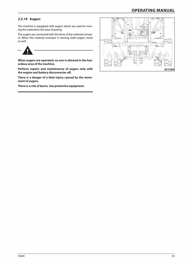
93F80W
451084
OPERATING MANUAL
2.5.19 Augers
The machine is equipped with augers which are used for mov-ing the material to the area of paving.
The augers are connected with the drive of the material convey-or. When the material conveyor is moving, both augers move as well.
When augers are operated, no one is allowed in the haz-ardous area of the machine.
Perform repairs and maintenance of augers only with the engine and battery disconnecter off.
There is a danger of a fatal injury caused by the move-ment of augers.
There is a risk of burns. Use protective equipment.
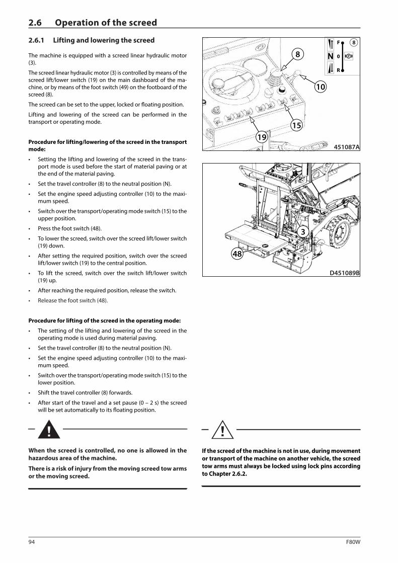
94 F80W
1915
8
451087A
P0
R
F 8
10
D451089B
3
48
2.6 Operation of the screed
2.6.1 Lifting and lowering the screed
The machine is equipped with a screed linear hydraulic motor (3).
The screed linear hydraulic motor (3) is controlled by means of the screed lift/lower switch (19) on the main dashboard of the ma-chine, or by means of the foot switch (49) on the footboard of the screed (8).
The screed can be set to the upper, locked or floating position.
Lifting and lowering of the screed can be performed in the transport or operating mode.
Procedure for lifting/lowering of the screed in the transport mode:
• Setting the lifting and lowering of the screed in the trans-port mode is used before the start of material paving or at the end of the material paving.
• Set the travel controller (8) to the neutral position (N).
• Set the engine speed adjusting controller (10) to the maxi-mum speed.
• Switch over the transport/operating mode switch (15) to the upper position.
• Press the foot switch (48).
• To lower the screed, switch over the screed lift/lower switch (19) down.
• After setting the required position, switch over the screed lift/lower switch (19) to the central position.
• To lift the screed, switch over the switch lift/lower switch (19) up.
• After reaching the required position, release the switch.
• Release the foot switch (48).
Procedure for lifting of the screed in the operating mode:
• The setting of the lifting and lowering of the screed in the operating mode is used during material paving.
• Set the travel controller (8) to the neutral position (N).
• Set the engine speed adjusting controller (10) to the maxi-mum speed.
• Switch over the transport/operating mode switch (15) to the lower position.
• Shift the travel controller (8) forwards.
• After start of the travel and a set pause (0 – 2 s) the screed will be set automatically to its floating position.
When the screed is controlled, no one is allowed in the hazardous area of the machine.
There is a risk of injury from the moving screed tow arms or the moving screed.
If the screed of the machine is not in use, during movement or transport of the machine on another vehicle, the screed tow arms must always be locked using lock pins according to Chapter 2.6.2.
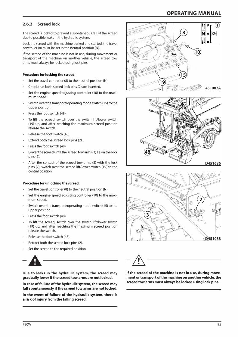
95F80W
D451088
2
3
1915
8
451087A
P0
R
F 8
10
D451686
48
OPERATING MANUAL
2.6.2 Screed lock
The screed is locked to prevent a spontaneous fall of the screed due to possible leaks in the hydraulic system.
Lock the screed with the machine parked and started, the travel controller (8) must be set in the neutral position (N).
If the screed of the machine is not in use, during movement or transport of the machine on another vehicle, the screed tow arms must always be locked using lock pins.
Procedure for locking the screed:
• Set the travel controller (8) to the neutral position (N).
• Check that both screed lock pins (2) are inserted.
• Set the engine speed adjusting controller (10) to the maxi-mum speed.
• Switch over the transport/operating mode switch (15) to the upper position.
• Press the foot switch (48).
• To lift the screed, switch over the switch lift/lower switch (19) up, and after reaching the maximum screed position release the switch.
• Release the foot switch (48).
• Extend both the screed lock pins (2).
• Press the foot switch (48).
• Lower the screed until the screed tow arms (3) lie on the lock pins (2).
• After the contact of the screed tow arms (3) with the lock pins (2), switch over the screed lift/lower switch (19) to the central position.
Procedure for unlocking the screed:
• Set the travel controller (8) to the neutral position (N).
• Set the engine speed adjusting controller (10) to the maxi-mum speed.
• Switch over the transport/operating mode switch (15) to the upper position.
• Press the foot switch (48).
• To lift the screed, switch over the switch lift/lower switch (19) up, and after reaching the maximum screed position release the switch.
• Release the foot switch (48).
• Retract both the screed lock pins (2).
• Set the screed to the required position.
Due to leaks in the hydraulic system, the screed may gradually lower if the screed tow arms are not locked.
In case of failure of the hydraulic system, the screed may fall spontaneously if the screed tow arms are not locked.
In the event of failure of the hydraulic system, there is a risk of injury from the falling screed.
If the screed of the machine is not in use, during move-ment or transport of the machine on another vehicle, the screed tow arms must always be locked using lock pins.
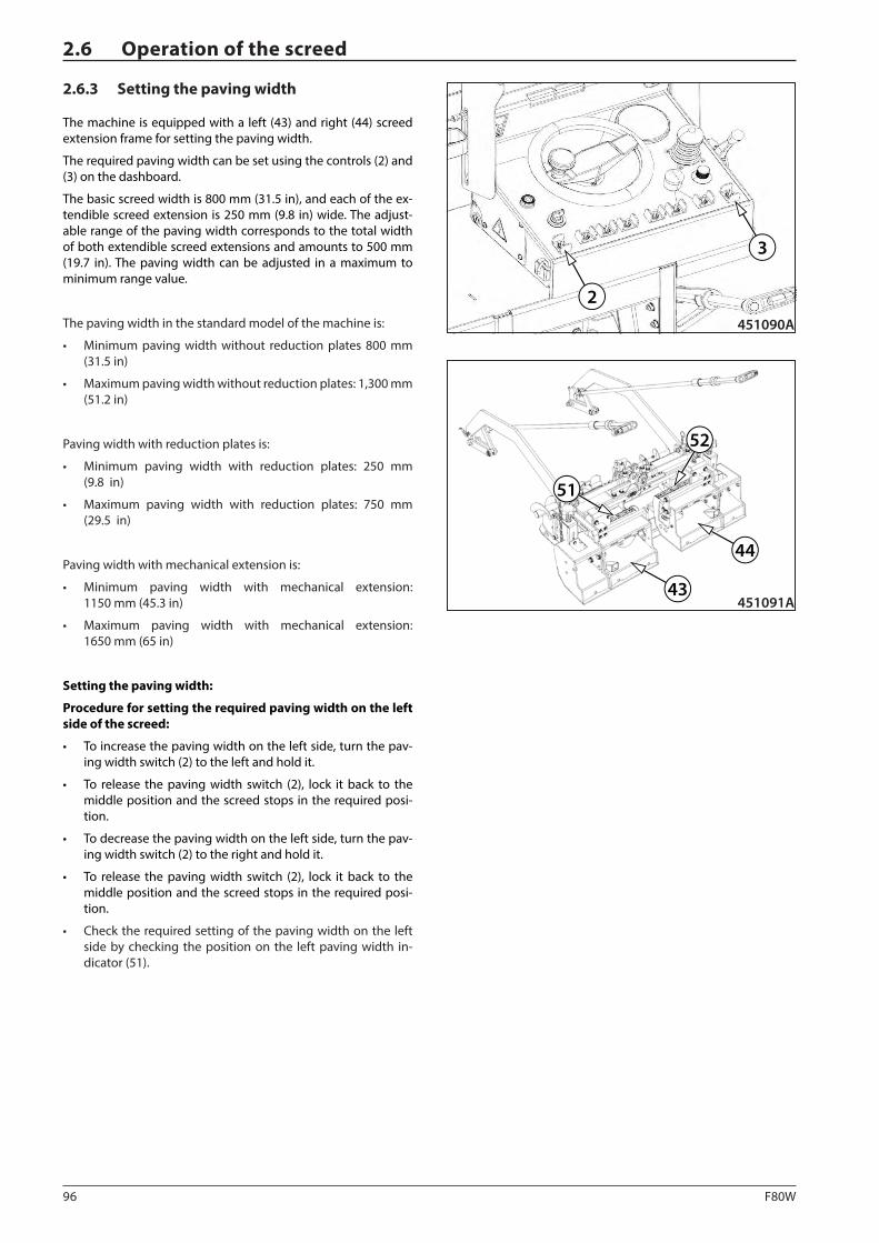
96 F80W
2
3
451090A
43
44
51
52
451091A
2.6 Operation of the screed
2.6.3 Setting the paving width
The machine is equipped with a left (43) and right (44) screed extension frame for setting the paving width.
The required paving width can be set using the controls (2) and (3) on the dashboard.
The basic screed width is 800 mm (31.5 in), and each of the ex-tendible screed extension is 250 mm (9.8 in) wide. The adjust-able range of the paving width corresponds to the total width of both extendible screed extensions and amounts to 500 mm (19.7 in). The paving width can be adjusted in a maximum to minimum range value.
The paving width in the standard model of the machine is:
• Minimum paving width without reduction plates 800 mm (31.5 in)
• Maximum paving width without reduction plates: 1,300 mm (51.2 in)
Paving width with reduction plates is:
• Minimum paving width with reduction plates: 250 mm (9.8 in)
• Maximum paving width with reduction plates: 750 mm (29.5 in)
Paving width with mechanical extension is:
• Minimum paving width with mechanical extension: 1150 mm (45.3 in)
• Maximum paving width with mechanical extension: 1650 mm (65 in)
Setting the paving width:
Procedure for setting the required paving width on the left side of the screed:
• To increase the paving width on the left side, turn the pav-ing width switch (2) to the left and hold it.
• To release the paving width switch (2), lock it back to the middle position and the screed stops in the required posi-tion.
• To decrease the paving width on the left side, turn the pav-ing width switch (2) to the right and hold it.
• To release the paving width switch (2), lock it back to the middle position and the screed stops in the required posi-tion.
• Check the required setting of the paving width on the left side by checking the position on the left paving width in-dicator (51).
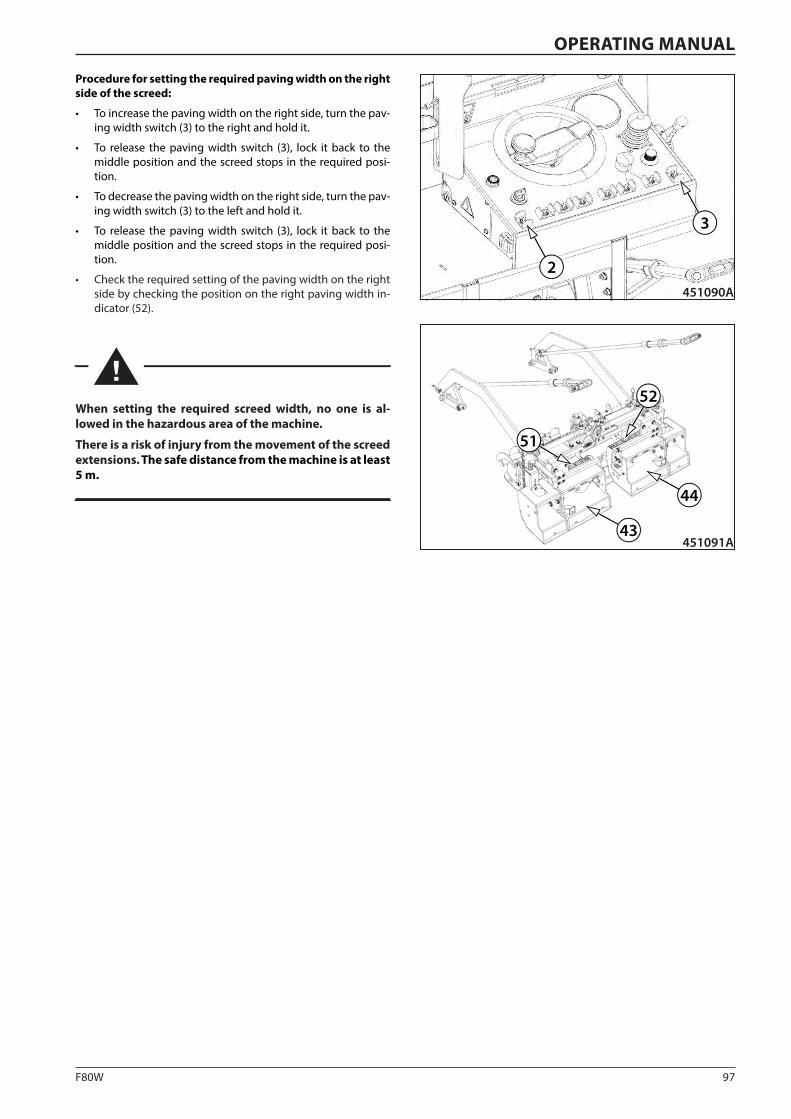
97F80W
2
3
451090A
43
44
51
52
451091A
OPERATING MANUAL
Procedure for setting the required paving width on the right side of the screed:
• To increase the paving width on the right side, turn the pav-ing width switch (3) to the right and hold it.
• To release the paving width switch (3), lock it back to the middle position and the screed stops in the required posi-tion.
• To decrease the paving width on the right side, turn the pav-ing width switch (3) to the left and hold it.
• To release the paving width switch (3), lock it back to the middle position and the screed stops in the required posi-tion.
• Check the required setting of the paving width on the right side by checking the position on the right paving width in-dicator (52).
When setting the required screed width, no one is al-lowed in the hazardous area of the machine.
There is a risk of injury from the movement of the screed extensions. The safe distance from the machine is at least 5 m.
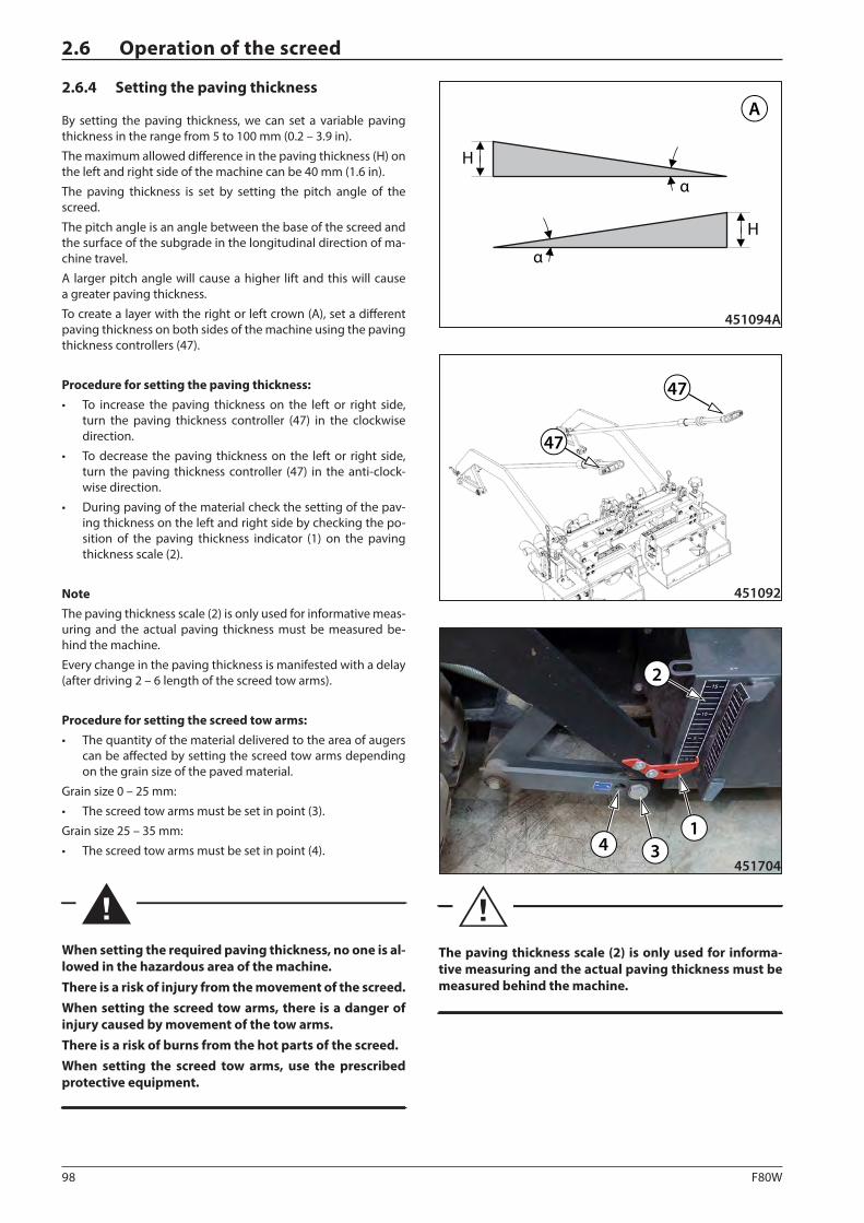
98 F80W
47
47
451092
451094A
A
H
α
α
H
4 31
2
451704
2.6 Operation of the screed
2.6.4 Setting the paving thickness
By setting the paving thickness, we can set a variable paving thickness in the range from 5 to 100 mm (0.2 – 3.9 in).
The maximum allowed difference in the paving thickness (H) on the left and right side of the machine can be 40 mm (1.6 in).
The paving thickness is set by setting the pitch angle of the screed.
The pitch angle is an angle between the base of the screed and the surface of the subgrade in the longitudinal direction of ma-chine travel.
A larger pitch angle will cause a higher lift and this will cause a greater paving thickness.
To create a layer with the right or left crown (A), set a different paving thickness on both sides of the machine using the paving thickness controllers (47).
Procedure for setting the paving thickness: • To increase the paving thickness on the left or right side,
turn the paving thickness controller (47) in the clockwise direction.
• To decrease the paving thickness on the left or right side, turn the paving thickness controller (47) in the anti-clock-wise direction.
• During paving of the material check the setting of the pav-ing thickness on the left and right side by checking the po-sition of the paving thickness indicator (1) on the paving thickness scale (2).
NoteThe paving thickness scale (2) is only used for informative meas-uring and the actual paving thickness must be measured be-hind the machine.
Every change in the paving thickness is manifested with a delay (after driving 2 – 6 length of the screed tow arms).
Procedure for setting the screed tow arms: • The quantity of the material delivered to the area of augers
can be affected by setting the screed tow arms depending on the grain size of the paved material.
Grain size 0 – 25 mm:
• The screed tow arms must be set in point (3).
Grain size 25 – 35 mm:
• The screed tow arms must be set in point (4).
When setting the required paving thickness, no one is al-lowed in the hazardous area of the machine.There is a risk of injury from the movement of the screed.When setting the screed tow arms, there is a danger of injury caused by movement of the tow arms.There is a risk of burns from the hot parts of the screed.When setting the screed tow arms, use the prescribed protective equipment.
The paving thickness scale (2) is only used for informa-tive measuring and the actual paving thickness must be measured behind the machine.
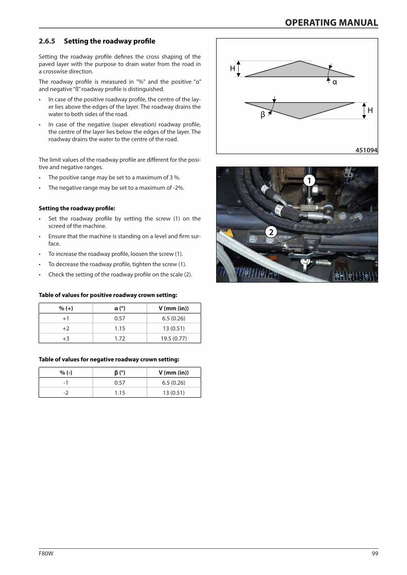
99F80W
451094
α
β
H
H
D451350
1
2
OPERATING MANUAL
2.6.5 Setting the roadway profile
Setting the roadway profile defines the cross shaping of the paved layer with the purpose to drain water from the road in a crosswise direction.
The roadway profile is measured in "%" and the positive “α” and negative “ß” roadway profile is distinguished.
• In case of the positive roadway profile, the centre of the lay-er lies above the edges of the layer. The roadway drains the water to both sides of the road.
• In case of the negative (super elevation) roadway profile, the centre of the layer lies below the edges of the layer. The roadway drains the water to the centre of the road.
The limit values of the roadway profile are different for the posi-tive and negative ranges.
• The positive range may be set to a maximum of 3 %.
• The negative range may be set to a maximum of -2%.
Setting the roadway profile:
• Set the roadway profile by setting the screw (1) on the screed of the machine.
• Ensure that the machine is standing on a level and firm sur-face.
• To increase the roadway profile, loosen the screw (1).
• To decrease the roadway profile, tighten the screw (1).
• Check the setting of the roadway profile on the scale (2).
Table of values for positive roadway crown setting:
% (+) α (°) V (mm (in))
+1 0.57 6.5 (0.26)
+2 1.15 13 (0.51)
+3 1.72 19.5 (0.77)
Table of values for negative roadway crown setting:
% (-) β (°) V (mm (in))
-1 0.57 6.5 (0.26)
-2 1.15 13 (0.51)
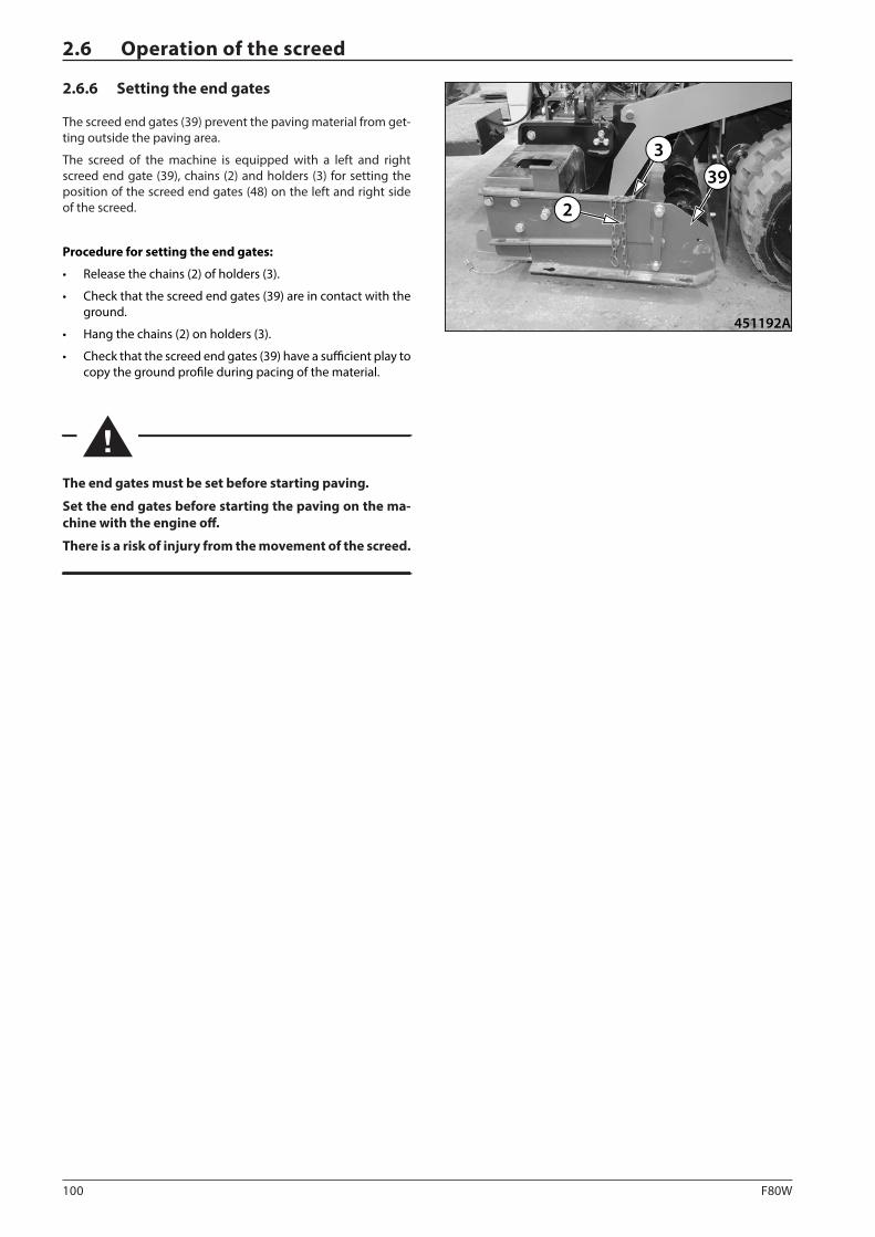
100 F80W
451192A
393
2
2.6 Operation of the screed
2.6.6 Setting the end gates
The screed end gates (39) prevent the paving material from get-ting outside the paving area.
The screed of the machine is equipped with a left and right screed end gate (39), chains (2) and holders (3) for setting the position of the screed end gates (48) on the left and right side of the screed.
Procedure for setting the end gates:
• Release the chains (2) of holders (3).
• Check that the screed end gates (39) are in contact with the ground.
• Hang the chains (2) on holders (3).
• Check that the screed end gates (39) have a sufficient play to copy the ground profile during pacing of the material.
The end gates must be set before starting paving.
Set the end gates before starting the paving on the ma-chine with the engine off.
There is a risk of injury from the movement of the screed.
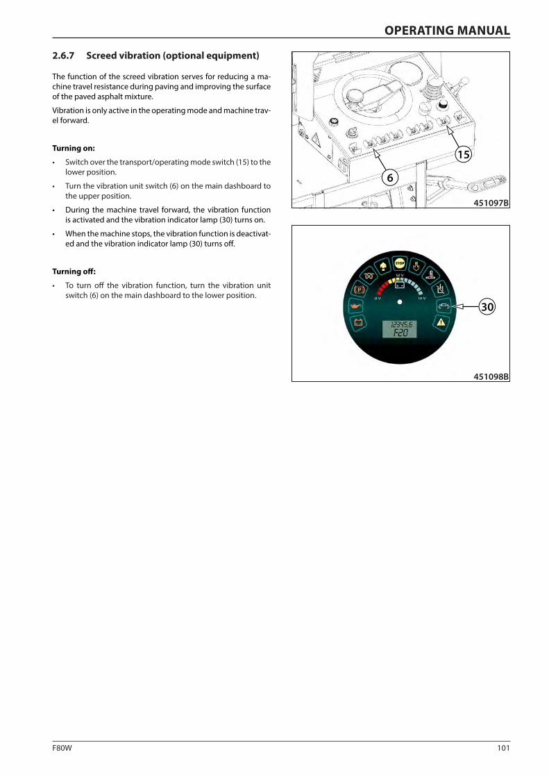
101F80W
6
451097B
15
30
451098B
OPERATING MANUAL
2.6.7 Screed vibration (optional equipment)
The function of the screed vibration serves for reducing a ma-chine travel resistance during paving and improving the surface of the paved asphalt mixture.
Vibration is only active in the operating mode and machine trav-el forward.
Turning on:
• Switch over the transport/operating mode switch (15) to the lower position.
• Turn the vibration unit switch (6) on the main dashboard to the upper position.
• During the machine travel forward, the vibration function is activated and the vibration indicator lamp (30) turns on.
• When the machine stops, the vibration function is deactivat-ed and the vibration indicator lamp (30) turns off.
Turning off:
• To turn off the vibration function, turn the vibration unit switch (6) on the main dashboard to the lower position.
102 F80W
2.6 Operation of the screed
2.6.8 Screed gas heating
To heat the screed with gas, liquefied propane-butane (LPG) can only be used.
The maximum gas bottle volume which may be placed on the machine is 10 kg (22 lb).
It is prohibited to use natural gas for screed heating.
The screed heating system is designed for a maximum operat-ing pressure of 1 bar with a total gas consumption of 10 kg/h (22 lb/h).
The recommended operating pressure for screed gas heating is from 0.6 bar to 0.8 bar, the gas consumption of a burner is ap-prox. 200 g/h (0.44 lb/g).
Propane-butane (LPG) is an extremely flammable substance and any leakage causes a high risk of fire or explosion!
Propane-butane (LPG) is heavier than air and may accumu-late in lower places – danger of fire or explosion!!
Do not smoke during machine operation. There is a risk of explosion or fire. Liquid gas can easily ignite.
The machine must be equipped with a fire extinguisher. Have the fire extinguisher ready on the driver's stand at a place intended for this purpose.
Caution! Risk of explosion, if the screed gas heating is oper-ated incorrectly, or safety and fire instructions for using and handling gas bottled are not adhered to.
Operate the screed heating system always according to the operating manual delivered with the machine.
Adhere to the national regulations in the country where the machine is operated. Familiarize yourself with these regula-tions and observe them.
It is prohibited to use natural gas for screed heating.
Operate the machine only with the liquefied propane-bu-tane (LPG). Propane-butane (LPG) is an odourless liquefied gas.
In some countries, in which the machine is operated, gas manufacturers odorize odourless gasses due to safety rea-sons (by adding aromatic substances), so that a leak can be identified easily.
In such cases pay higher attention to a potential gas leak during operation of the machine, which is manifested by an odour, and close the gas inlet.
In case of gas leakage, in some cases it is impossible to rely on the gas odour as a sign of gas leak from the system.
During the operation of the machine visually check that the gas system is undamaged.
Regularly check the gas system according to the mainte-nance plan given in this manual, especially hoses, valves and other components.
Always require a material safety data sheet to the delivered gas bottle. Before mounting the gas bottle on the machine, read and check that the gas bottle meets all conditions for putting the machine into operation.
Risk of burns! The screed may reach the temperature of up to 130°C.
Stop the gas leakage.
In case of gas leakage, inform relevant national author-ities.
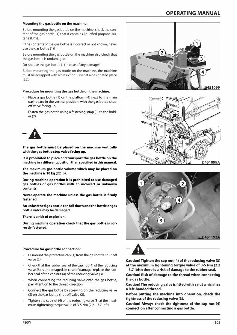
103F80W
1
23
4
D451099
35
D451099A
D451193A
21
3
4
OPERATING MANUAL
Mounting the gas bottle on the machine:
Before mounting the gas bottle on the machine, check the con-tent of the gas bottle (1) that it contains liquefied propane-bu-tane (LPG).
If the contents of the gas bottle is incorrect or not known, never use the gas bottle (1)!
Before mounting the gas bottle on the machine also check that the gas bottle is undamaged.
Do not use the gas bottle (1) in case of any damage!
Before mounting the gas bottle on the machine, the machine must be equipped with a fire extinguisher at a designated place (35).
Procedure for mounting the gas bottle on the machine:
• Place a gas bottle (1) on the platform (4) next to the main dashboard in the vertical position, with the gas bottle shut-off valve facing up.
• Fasten the gas bottle using a fastening strap (3) to the hold-er (2).
The gas bottle must be placed on the machine vertically with the gas bottle stop valve facing up.
It is prohibited to place and transport the gas bottle on the machine in a different position than specified in this manual.
The maximum gas bottle volume which may be placed on the machine is 10 kg (22 lb).
During machine operation it is prohibited to use damaged gas bottles or gas bottles with an incorrect or unknown contents.
Never operate the machine unless the gas bottle is firmly fastened.
An unfastened gas bottle can fall down and the bottle or gas bottle valve may be damaged.
There is a risk of explosion.
During machine operation check that the gas bottle is cor-rectly fastened.
Procedure for gas bottle connection:
• Dismount the protective cap (1) from the gas bottle shut-off valve (2).
• Check that the rubber seal of the cap nut (4) of the reducing valve (3) is undamaged. In case of damage, replace the rub-ber seal of the cap nut (4) of the reducing valve (3).
• When connecting the reducing valve onto the gas bottle, pay attention to the thread direction.
• Connect the gas bottle by screwing on the reducing valve (3) on the gas bottle shut-off valve (2).
• Tighten the cap nut (4) of the reducing valve (3) at the maxi-mum tightening torque value of 3-5 Nm (2.2 – 3.7 lbft).
Caution! Tighten the cap nut (4) of the reducing valve (3) at the maximum tightening torque value of 3-5 Nm (2.2 – 3.7 lbft); there is a risk of damage to the rubber seal.Caution! Risk of damage to the thread when connecting the gas bottle.Caution! The reducing valve is fitted with a nut which has a left-handed thread.Before putting the machine into operation, check the tightness of the reducing valve (3).Caution! Always check the tightness of the cap nut (4) connection after connecting a gas bottle.
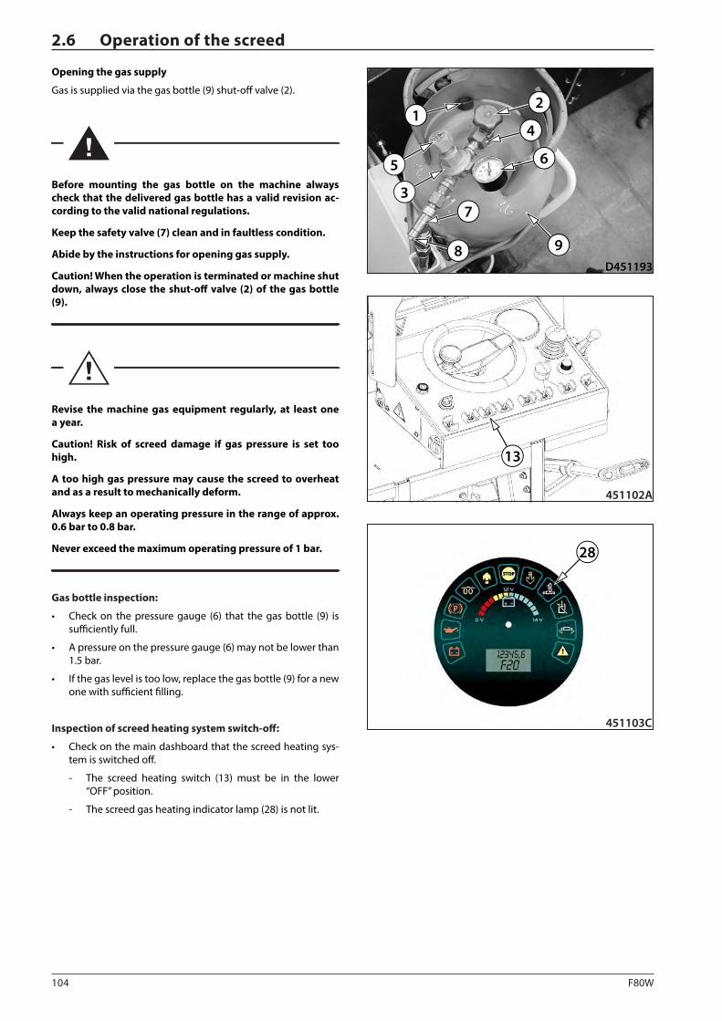
104 F80W
D451193
6
7
8
3
5
2
4
9
1
13
451102A
28
451103C
2.6 Operation of the screed
Opening the gas supply
Gas is supplied via the gas bottle (9) shut-off valve (2).
Before mounting the gas bottle on the machine always check that the delivered gas bottle has a valid revision ac-cording to the valid national regulations.
Keep the safety valve (7) clean and in faultless condition.
Abide by the instructions for opening gas supply.
Caution! When the operation is terminated or machine shut down, always close the shut-off valve (2) of the gas bottle (9).
Revise the machine gas equipment regularly, at least one a year.
Caution! Risk of screed damage if gas pressure is set too high.
A too high gas pressure may cause the screed to overheat and as a result to mechanically deform.
Always keep an operating pressure in the range of approx. 0.6 bar to 0.8 bar.
Never exceed the maximum operating pressure of 1 bar.
Gas bottle inspection:
• Check on the pressure gauge (6) that the gas bottle (9) is sufficiently full.
• A pressure on the pressure gauge (6) may not be lower than 1.5 bar.
• If the gas level is too low, replace the gas bottle (9) for a new one with sufficient filling.
Inspection of screed heating system switch-off:
• Check on the main dashboard that the screed heating sys-tem is switched off.
- The screed heating switch (13) must be in the lower “OFF” position.
- The screed gas heating indicator lamp (28) is not lit.
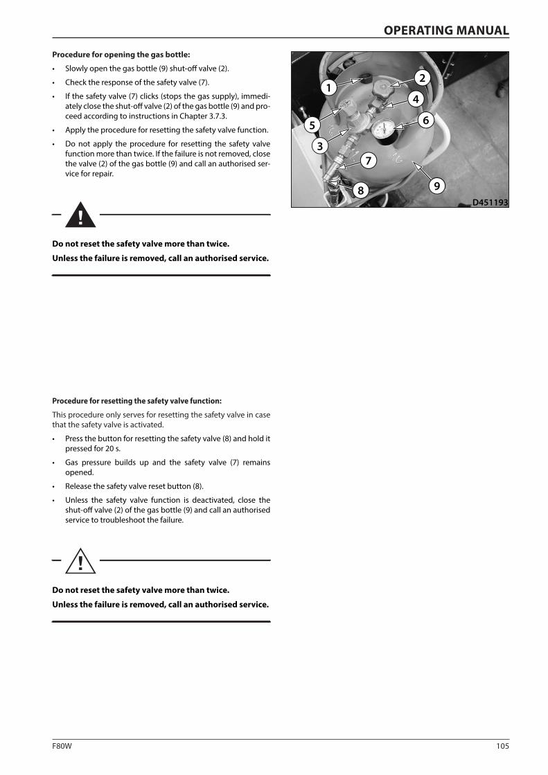
105F80W
D451193
6
7
8
3
5
2
4
9
1
OPERATING MANUAL
Procedure for opening the gas bottle:
• Slowly open the gas bottle (9) shut-off valve (2).
• Check the response of the safety valve (7).
• If the safety valve (7) clicks (stops the gas supply), immedi-ately close the shut-off valve (2) of the gas bottle (9) and pro-ceed according to instructions in Chapter 3.7.3.
• Apply the procedure for resetting the safety valve function.
• Do not apply the procedure for resetting the safety valve function more than twice. If the failure is not removed, close the valve (2) of the gas bottle (9) and call an authorised ser-vice for repair.
Do not reset the safety valve more than twice.
Unless the failure is removed, call an authorised service.
Procedure for resetting the safety valve function:
This procedure only serves for resetting the safety valve in case that the safety valve is activated.
• Press the button for resetting the safety valve (8) and hold it pressed for 20 s.
• Gas pressure builds up and the safety valve (7) remains opened.
• Release the safety valve reset button (8).
• Unless the safety valve function is deactivated, close the shut-off valve (2) of the gas bottle (9) and call an authorised service to troubleshoot the failure.
Do not reset the safety valve more than twice.
Unless the failure is removed, call an authorised service.
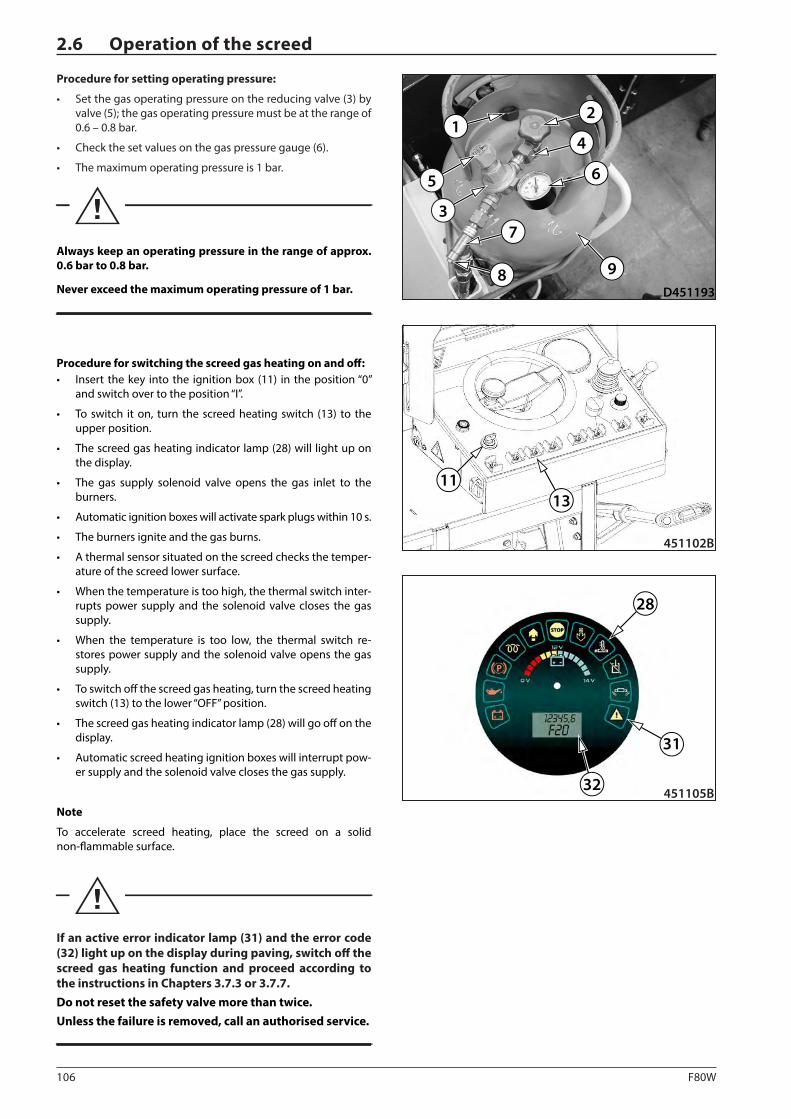
106 F80W
13
451102B
11
28
451105B
31
32
D451193
6
7
8
3
5
2
4
9
1
2.6 Operation of the screed
Procedure for setting operating pressure:
• Set the gas operating pressure on the reducing valve (3) by valve (5); the gas operating pressure must be at the range of 0.6 – 0.8 bar.
• Check the set values on the gas pressure gauge (6).
• The maximum operating pressure is 1 bar.
Always keep an operating pressure in the range of approx. 0.6 bar to 0.8 bar.
Never exceed the maximum operating pressure of 1 bar.
Procedure for switching the screed gas heating on and off: • Insert the key into the ignition box (11) in the position “0”
and switch over to the position “I”.
• To switch it on, turn the screed heating switch (13) to the upper position.
• The screed gas heating indicator lamp (28) will light up on the display.
• The gas supply solenoid valve opens the gas inlet to the burners.
• Automatic ignition boxes will activate spark plugs within 10 s.
• The burners ignite and the gas burns.
• A thermal sensor situated on the screed checks the temper-ature of the screed lower surface.
• When the temperature is too high, the thermal switch inter-rupts power supply and the solenoid valve closes the gas supply.
• When the temperature is too low, the thermal switch re-stores power supply and the solenoid valve opens the gas supply.
• To switch off the screed gas heating, turn the screed heating switch (13) to the lower “OFF” position.
• The screed gas heating indicator lamp (28) will go off on the display.
• Automatic screed heating ignition boxes will interrupt pow-er supply and the solenoid valve closes the gas supply.
Note
To accelerate screed heating, place the screed on a solid non-flammable surface.
If an active error indicator lamp (31) and the error code (32) light up on the display during paving, switch off the screed gas heating function and proceed according to the instructions in Chapters 3.7.3 or 3.7.7.Do not reset the safety valve more than twice.Unless the failure is removed, call an authorised service.
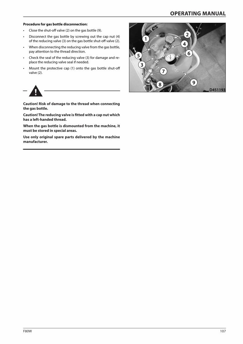
107F80W
D451193
6
7
8
3
5
2
4
9
1
OPERATING MANUAL
Procedure for gas bottle disconnection:
• Close the shut-off valve (2) on the gas bottle (9).
• Disconnect the gas bottle by screwing out the cap nut (4) of the reducing valve (3) on the gas bottle shut-off valve (2).
• When disconnecting the reducing valve from the gas bottle, pay attention to the thread direction.
• Check the seal of the reducing valve (3) for damage and re-place the reducing valve seal if needed.
• Mount the protective cap (1) onto the gas bottle shut-off valve (2).
Caution! Risk of damage to the thread when connecting the gas bottle.
Caution! The reducing valve is fitted with a cap nut which has a left-handed thread.
When the gas bottle is dismounted from the machine, it must be stored in special areas.
Use only original spare parts delivered by the machine manufacturer.
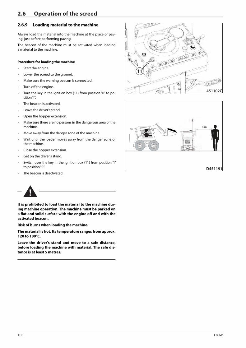
108 F80W
D451191
5 m
451102C
11
2.6 Operation of the screed
2.6.9 Loading material to the machine
Always load the material into the machine at the place of pav-ing, just before performing paving.
The beacon of the machine must be activated when loading a material to the machine.
Procedure for loading the machine
• Start the engine.
• Lower the screed to the ground.
• Make sure the warning beacon is connected.
• Turn off the engine.
• Turn the key in the ignition box (11) from position “0” to po-sition “I”.
• The beacon is activated.
• Leave the driver’s stand.
• Open the hopper extension.
• Make sure there are no persons in the dangerous area of the machine.
• Move away from the danger zone of the machine.
• Wait until the loader moves away from the danger zone of the machine.
• Close the hopper extension.
• Get on the driver's stand.
• Switch over the key in the ignition box (11) from position “I” to position “0“.
• The beacon is deactivated.
It is prohibited to load the material to the machine dur-ing machine operation. The machine must be parked on a flat and solid surface with the engine off and with the activated beacon.
Risk of burns when loading the machine.
The material is hot. Its temperature ranges from approx. 120 to 180°C.
Leave the driver's stand and move to a safe distance, before loading the machine with material. The safe dis-tance is at least 5 metres.
109F80W
OPERATING MANUAL
2.6.10 Start of paving
Before paving complete the following tasks:
• As needed:
- Adjust the front wheel.
- Set the paving direction indicator.
- Pre-set the conveyor limit switch.
- Pre-set material outlet.
• Check that the warning beacon is connected.
• Set the footboard into the working position.
• Load the material to the machine.
• Start the engine.
• Set the paving width and thickness.
• Set the required roadway profile.
• Lower the screed to the floating position.
• Set screed end gates.
• Open gas supply.
• Turn on screed gas heating and preheat the screed.
• Get on the driver's stand.
• Put the machine into operation and pave the material.
Caution! Travel speed during paving may have negative in-fluence on the paving result.
No one is allowed in the hazardous area of the machine dur-ing paving.
110 F80W
2.6 Operation of the screed
2.6.11 End of paving
Complete the following tasks before the end of paving:
• Stop the machine as needed.
• Activate the parking brake.
• Turn off the screed gas heating.
• Place the screed into a safe position, as needed, to avoid potential spontaneous fall of the screed.
- Lower the screed to the ground.
- Lock the screed.
• Turn off the engine.
• Leave the driver’s stand.
• Set the footboard into the transportation position.
• As needed, set the paving direction indicator to the trans-portation position.
• As needed, turn off the battery disconnecter.
After the end of paving the machine must be shut-down on a flat solid surface.
If the machine is not subsequently operated, park the machine.
If the machine is parked, the gas bottle must be removed from the machine and stored in a special area.
Turn off the battery disconnecter when parking the machine.
When the machine is parked, protect the dashboard and the engine compartment from unauthorized access of others by locking the dashboard cover and the engine bonnet.
111F80W
OPERATING MANUAL2.7 Machine transport
2.7.1 Preparation of the machine for transport
Each country has its own national transport regulations.
• Familiarize yourself with these regulations and observe them.
• When transporting the machine between two countries, ob-serve the stricter national transport regulations.
• When transporting the machine, always remove the gas bot-tle from the machine.
• Transport the gas bottle according to the valid national reg-ulations.
Procedure for preparation of the machine for transport:
• Check that there is no material in the hopper.
• Check that the hopper cover is closed.
• Start the engine.
• Set the minimum paving width on the screed.
• Lock the screed.
• Stop the engine.
• Closed the gas supply.
• Check that the gas supply is closed.
• Disconnect the gas bottle.
• Remove the gas bottle from the machine.
• Before loading using a crane lift the footboard.
• Check that there are no loose objects on the machine.
Familiarise yourself and observe the national transport regulations.
When transporting the machine, always remove the gas bottle from the machine.
Transport the gas bottle according to the valid national regulations.
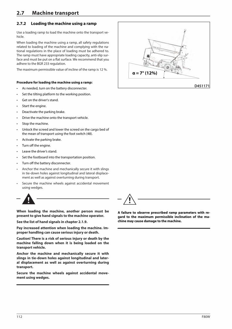
112 F80W
α = 7° (12%)
D451171
2.7 Machine transport
2.7.2 Loading the machine using a ramp
Use a loading ramp to load the machine onto the transport ve-hicle.
When loading the machine using a ramp, all safety regulations related to loading of the machine and complying with the na-tional regulations in the place of loading must be adhered to. The ramp must have appropriate loading capacity, anti-slip sur-face and must be put on a flat surface. We recommend that you adhere to the BGR 233 regulation.
The maximum permissible value of incline of the ramp is 12 %.
Procedure for loading the machine using a ramp:
• As needed, turn on the battery disconnecter.
• Set the tilting platform to the working position.
• Get on the driver's stand.
• Start the engine.
• Deactivate the parking brake.
• Drive the machine onto the transport vehicle.
• Stop the machine.
• Unlock the screed and lower the screed on the cargo bed of the mean of transport using the foot switch (48).
• Activate the parking brake.
• Turn off the engine.
• Leave the driver’s stand.
• Set the footboard into the transportation position.
• Turn off the battery disconnecter.
• Anchor the machine and mechanically secure it with slings in tie-down holes against longitudinal and lateral displace-ment as well as against overturning during transport.
• Secure the machine wheels against accidental movement using wedges.
When loading the machine, another person must be present to give hand signals to the machine operator.
See the list of hand signals in chapter 2.1.9.
Pay increased attention when loading the machine. Im-proper handling can cause serious injury or death.
Caution! There is a risk of serious injury or death by the machine falling down when it is being loaded on the transport vehicle.
Anchor the machine and mechanically secure it with slings in tie-down holes against longitudinal and later-al displacement as well as against overturning during transport.
Secure the machine wheels against accidental move-ment using wedges.
A failure to observe prescribed ramp parameters with re-gard to the maximum permissible inclination of the ma-chine may cause damage to the machine.
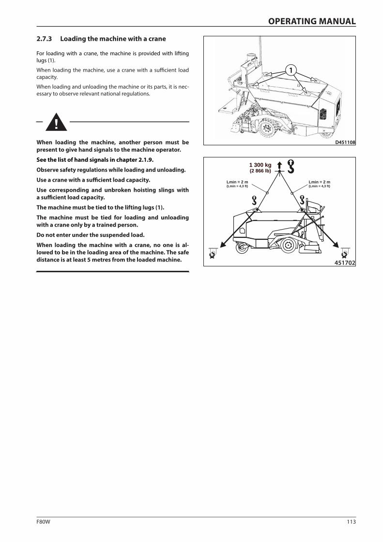
113F80W
D451108
1
1 300 kg(2 866 lb)
Lmin = 2 m(Lmin = 4,3 ft)
Lmin = 2 m(Lmin = 4,3 ft)
451702
OPERATING MANUAL
2.7.3 Loading the machine with a crane
For loading with a crane, the machine is provided with lifting lugs (1).
When loading the machine, use a crane with a sufficient load capacity.
When loading and unloading the machine or its parts, it is nec-essary to observe relevant national regulations.
When loading the machine, another person must be present to give hand signals to the machine operator.
See the list of hand signals in chapter 2.1.9.
Observe safety regulations while loading and unloading.
Use a crane with a sufficient load capacity.
Use corresponding and unbroken hoisting slings with a sufficient load capacity.
The machine must be tied to the lifting lugs (1).
The machine must be tied for loading and unloading with a crane only by a trained person.
Do not enter under the suspended load.
When loading the machine with a crane, no one is al-lowed to be in the loading area of the machine. The safe distance is at least 5 metres from the loaded machine.

114 F80W
D451109
D4512013 32 2
1 1
2.7 Machine transport
2.7.4 Machine transport
• The machine can move on its own within the work site.
When driving, observe the safety measures applicable to the working site.
• The machine should be transported on a vehicle on public roads.
When transporting the machine on a vehicle, observe regulations applicable to the given territory.
When transporting the machine on a vehicle, the gas bottle must be removed from the machine.
A warning label must be placed on the transport vehicle, informing of the transport of a gas bottle according to the national regulations.
When loading and unloading, the vehicle transporting the machine must be braked and mechanically protected against accidental movement using wedges.
The machine on the vehicle must be properly anchored and mechanically secured with the slings in tie-down holes against longitudinal and lateral displacement as well as against overturning. The machine wheels must be secured against accidental movement using wedges.
2.7.5 Preparation of the machine for operation after transportation
Procedure for preparation:
• Make sure a gas bottle is installed.
• Connect the gas bottle.
• Restore the gas supply.
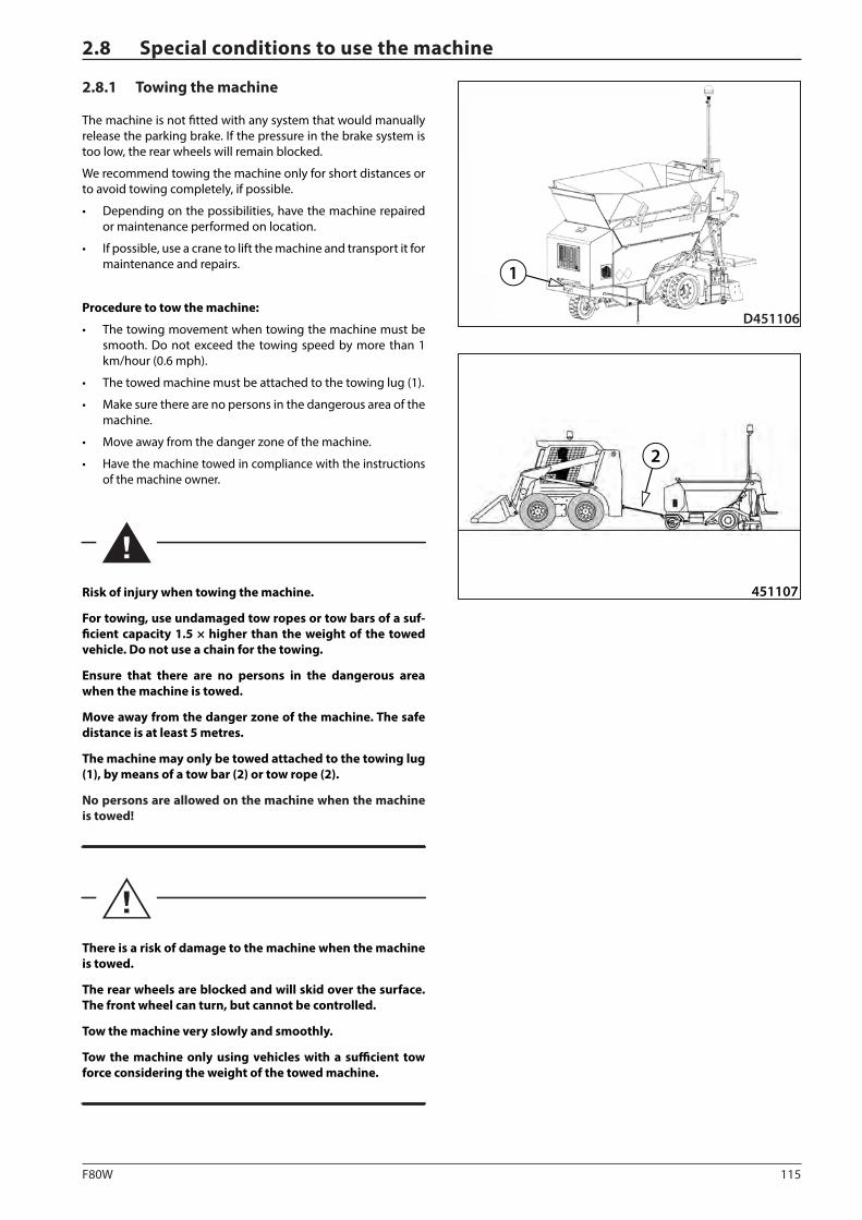
115F80W
D451106
1
451107
2
2.8.1 Towing the machine
The machine is not fitted with any system that would manually release the parking brake. If the pressure in the brake system is too low, the rear wheels will remain blocked.
We recommend towing the machine only for short distances or to avoid towing completely, if possible.
• Depending on the possibilities, have the machine repaired or maintenance performed on location.
• If possible, use a crane to lift the machine and transport it for maintenance and repairs.
Procedure to tow the machine:
• The towing movement when towing the machine must be smooth. Do not exceed the towing speed by more than 1 km/hour (0.6 mph).
• The towed machine must be attached to the towing lug (1).
• Make sure there are no persons in the dangerous area of the machine.
• Move away from the danger zone of the machine.
• Have the machine towed in compliance with the instructions of the machine owner.
Risk of injury when towing the machine.
For towing, use undamaged tow ropes or tow bars of a suf-ficient capacity 1.5 × higher than the weight of the towed vehicle. Do not use a chain for the towing.
Ensure that there are no persons in the dangerous area when the machine is towed.
Move away from the danger zone of the machine. The safe distance is at least 5 metres.
The machine may only be towed attached to the towing lug (1), by means of a tow bar (2) or tow rope (2).
No persons are allowed on the machine when the machine is towed!
There is a risk of damage to the machine when the machine is towed.
The rear wheels are blocked and will skid over the surface. The front wheel can turn, but cannot be controlled.
Tow the machine very slowly and smoothly.
Tow the machine only using vehicles with a sufficient tow force considering the weight of the towed machine.
2.8 Special conditions to use the machine
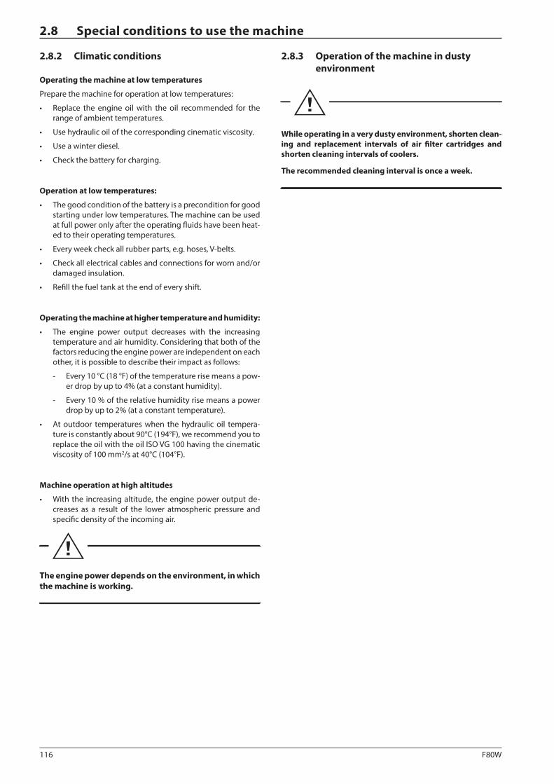
116 F80W
2.8 Special conditions to use the machine
2.8.2 Climatic conditions
Operating the machine at low temperatures
Prepare the machine for operation at low temperatures:
• Replace the engine oil with the oil recommended for the range of ambient temperatures.
• Use hydraulic oil of the corresponding cinematic viscosity.
• Use a winter diesel.
• Check the battery for charging.
Operation at low temperatures:
• The good condition of the battery is a precondition for good starting under low temperatures. The machine can be used at full power only after the operating fluids have been heat-ed to their operating temperatures.
• Every week check all rubber parts, e.g. hoses, V-belts.
• Check all electrical cables and connections for worn and/or damaged insulation.
• Refill the fuel tank at the end of every shift.
Operating the machine at higher temperature and humidity:
• The engine power output decreases with the increasing temperature and air humidity. Considering that both of the factors reducing the engine power are independent on each other, it is possible to describe their impact as follows:
- Every 10 °C (18 °F) of the temperature rise means a pow-er drop by up to 4% (at a constant humidity).
- Every 10 % of the relative humidity rise means a power drop by up to 2% (at a constant temperature).
• At outdoor temperatures when the hydraulic oil tempera-ture is constantly about 90°C (194°F), we recommend you to replace the oil with the oil ISO VG 100 having the cinematic viscosity of 100 mm2/s at 40°C (104°F).
Machine operation at high altitudes
• With the increasing altitude, the engine power output de-creases as a result of the lower atmospheric pressure and specific density of the incoming air.
The engine power depends on the environment, in which the machine is working.
2.8.3 Operation of the machine in dusty environment
While operating in a very dusty environment, shorten clean-ing and replacement intervals of air filter cartridges and shorten cleaning intervals of coolers.
The recommended cleaning interval is once a week.

117F80W
OPERATING MANUAL
Notes

118 F80W

119F80W
MAINTENANCE MANUAL
3 MAINTENANCE MANUAL
F80W(Hatz)

120 F80W
121F80W
3.1.1 Safety precautions during machine maintenance
Lubrication, maintenance and adjustment process shall be per-formed:
• by professionally qualified and trained personnel,
• according to intervals given in the Operating Manual,
• in compliance with safety warnings given in the Operating Manual,
• on the machine standing on a flat and solid surface and se-cured against movement with wedge blocks, always with the engine off, the key removed from the ignition box and the battery disconnecter disconnected,
• with the "Machine repair" tag attached to the steering wheel (the tag is supplied with the machine accessories),
2775
2775bz
• on cold machine parts,
• there is a danger of burning after operating fluids warm up during certain tasks of inspection or maintenance of the ma-chine,
• after the machine, lubrication points and maintenance plac-es have been cleaned,
• using suitable, undamaged tools,
• by replacing parts with new original parts according to the spare parts catalogue,
• with sufficient lighting of the entire machine during re-duced visibility and at night,
• reinstall all removed covers and safety elements after the work is completed,
• re-tighten bolted connections according to the specified tightening torques.
When using a steam cleaning machine, use protective clothes and safety glasses or a face shield and a protective helmet.
Hot steam can cause serious injuries.
Spilt fuel on a hot surface or electric parts can cause fire. Fire can consequently cause serious injuries.
Never place your head, body and arms under the parts of the machine which are not firmly fixed to the machine or secured against spontaneous fall.
If you need to perform repair or maintenance in areas which are not accessible from the ground, use ladder or a platform with stairs which comply with respective national regulations to reach the working area. Unless any platform with stairs or a lad-der are available, use only handles and foot plates the machine is equipped with. By failure to observe these rules you expose yourself to the danger of injury by falling down of the machine.
Do not use petrol, diesel oil, thinners or other flammable liquids to clean parts of the machine. Use approved commercial sol-vents which are non-flammable and non-toxic.
3.1 Safety and other measures during maintenance of the machine
After the adjustment or maintenance is completed, check all safety devices for proper operation!
122 F80W
3.1 Safety and other measures during maintenance of the machine
3.1.2 Safety and fire precautions during replacement of operating fluids
Considering the fire danger, the flammable liquids and gas-es used on the machine are divided into the following hazard classes:
• hazard class I – propane-butane (LPG)
• hazard class II – diesel fuel
• hazard class IV – mineral oils, lubricating greases
The oil change area must be located so that it does not interfere with any explosion or fire hazard area.
It must be identified by the tables and marks with “No smoking” signs and signs prohibiting the use of naked fire.
The handling area must be dimensioned so that it can catch a volume of flammable liquid equal to the capacity of the big-gest, transport container.
It must be equipped with portable fire extinguishers.
To handle the oil, diesel and other operating fluids use such ves-sels such as metal barrels, jerrycans or sheet-metal cans.
The transport containers must be properly closed during stor-age.
Containers must only be provided with one hole, always stored with the hole up and secured so that their content cannot flow out and drip off.
Containers must be marked by non-removable texts stating the contents and flammability classes.
123F80W
MAINTENANCE MANUAL
3.1.3 Environmental and hygienic principles
3.1.3.1 Hygienic principles
When operating and maintaining the machines, the user and appointed workers shall observe general principles of health protection related to these issues according to respective na-tional regulations.
Operating fluids of the machine, battery fluids and paints in-cluding thinners are harmful to health.
Workers coming into contact with the above products during operation or maintenance of the machine are obliged to follow general principles of health protection and comply with safety and hygienic manuals by manufacturers of the products.
In particular we draw your attention to the following:
• Protect your eyes and skin while working with the batteries.
• Protect your skin when working with operating fluids and paints.
Always store operating fluids and cleaning and preserva-tive agents in their original, properly labelled packages.
These materials are not allowed to be stored in unla-belled bottles or in any other containers considering the likelihood of confusion.
Possible confusion with foodstuffs or beverages is very dangerous.
If by accident the skin, eyes or mucous membrane is stained or if you breathe in vapours, apply immediately the principles of the first aid and immediately seek med-ical first aid.
During operation of the machine always use protective equipment stated in this Operating Manual.
3.1.3.2 Environmental principles
Some parts of the machine and operating fluids become haz-ardous wastes with dangerous properties for the environment after they are put out of operation.
This category includes in particular the following:
• organic and synthetic lubricating materials, oil or fuels,
• coolants,
• battery fluids and batteries,
• tyre fillings,
• all dismounted filters and filter elements,
• any used and discarded hydraulic and fuel hoses, rub-ber-metal elements and other parts of the machine contam-inated with the above mentioned products.
• cleaning and preservative agents.
When operating and storing the machine, the user shall observe general principles of environmental protection related to these issues according to respective national regulations.
Contaminated parts of the machine and operating fluids must be handled according to respective national regu-lations after they are put out of operation.
DYNAPAC does not assume any liability in cases when contaminated parts and operating fluids are disposed of in an improper way, which may result in damage to the environment.
124 F80W
3.2.1 Engine oil2412
Engine oil has been specified as per its performance classifica-tion and viscosity classification.
Performance classification according to
API (AMERICAN PETROLEUM INSTITUTE)
ACEA (ASSOTIATION DES CONSTRUCTEUERS EUROPPÉENS DE AUTOMOBILE)
Viscosity classification
To determine the SAE (Society of Automotive Engineers) viscos-ity class, the ambient temperature and type of operation where the machine is used are decisive.
Use of permissible oils according to API: CF / CH-4 or better quality.
Use of permissible oils according to ACEA: B3 / E4 or better quality.
SAE 15W-40 year-round.
Note
Exceeding the lower temperature limit does not result in dam-age to the engine; it can only cause some starting difficulties.
It is convenient to use universal multi-range oils to avoid oil changes due to ambient temperature.
For easy starts at the temperatures below 0°C (32°F), the engine manufacturer recommends SAE 10W-30 oil.
Exceeding the upper temperature limit, considering the reduced lubricating capabilities of the oil must not last for long.
3.2 Specification of operating fluids
3.2.2 Fuel
Diesel oil is used as fuel for the engine:
• EN 590
• BS 2869 A1 / A2
• ASTM D 975-09a 1-D, 2-D
At ambient temperatures below 0°C (32°F), use winter diesel fuel.
Mixing diesel with special additives is forbidden.
Mixing diesel with petrol is forbidden.
125F80W
MAINTENANCE MANUAL
3.2.3 Hydraulic oil2158
For the hydraulic system of the machine, it is necessary to use only high-quality hydraulic oil grades according to ISO 6743/HV (equal to DIN 51524 part 3 HVLP).
Fill the Machines normally with hydraulic oil that has cinematic viscosity of 46 mm2/s at 40°C (104°F) ISO VG 46. This oil is the most suitable for use in the widest range of ambient temper-atures.
Synthetic hydraulic oil
The hydraulic system can be filled with synthetic oil, which if leakages occur will be degraded completely by micro-organ-isms present in water and soil.
Always consult with the oil manufacturer or dealer any switching from mineral oil to synthetic or mixing oils of various brands!
3.2.4 Anti-adherent solutionAMN411
The anti-adhesive liquid is a non-adhesive additive.
It serves for cleaning the hopper, conveyor, augers and parts of the machine which are in contact with the paved asphalt ma-terial.
Use an environmentally-friendly anti-adherent solution accord-ing to the applicable national regulations.
To create the anti-adherent solution, mix a non-sticking agent with water according to the instructions of the non-sticking agent manufacturer.
Dosage
The anti-adherent solution dosage may vary depending on the operating conditions:
For standard mixtures, 1 part of anti-adherent solution in 30 parts of water. (1:30)
For modified mixtures, 1 part of anti adherent solution in 5 parts of water. (1:5)
Note
There is no vessel for an anti-adherent solution on the machine.
To apply the anti-adherent solution on individual parts of the machine, use a hand pump for spraying liquids.
It is prohibited to use diesel oil instead of an anti-adher-ent solution.
126 F80W
3.2 Specification of operating fluids
3.2.6 Lubricating grease0787
To lubricate the machine you must use a plastic grease contain-ing lithium according to:
ISO 6743/9 CCEB 2
DIN 51 502 KP2K-30
3.2.5 Liquid gas
The machine is equipped with a gas heating system that uses liquid gas as fuel.
• Propane-butane (LPG)
Propane-butane (LPG) is an extremely flammable substance and any leakage causes a high risk of fire or explosion!
Propane-butane (LPG) is heavier than air and may accumu-late in lower places – danger of fire or explosion!
Gas inhalation may cause headache, weakness, confusion, dizziness and nausea. It causes frostbites in the liquid state in contact with skin!
Avoid contact with skin. Wear suitable protective clothing!
Wear protective gloves resistant to oil substances comply-ing with EN374!
Wear safety goggles!
In case of excess of vapour concentration limits in air, use a suitable breathing mask. Recommended: organic fume and vapour filter (type A, AX)!
No smoking at work.
Provide adequate area ventilation!
Always require a material safety data sheet to the delivered gas bottle. Before mounting the gas bottle on the machine, read and check that the gas bottle meets all conditions for putting the machine into operation.
The machine must be equipped with a fire extinguisher. Have the fire extinguisher ready on the driver's stand at a place intended for this purpose.
When the machine is operated in underground garages or other underground areas, observe the national safety regu-lations regarding space ventilation.
Stop the gas leakage.In case of gas leakage, inform relevant national authorities.
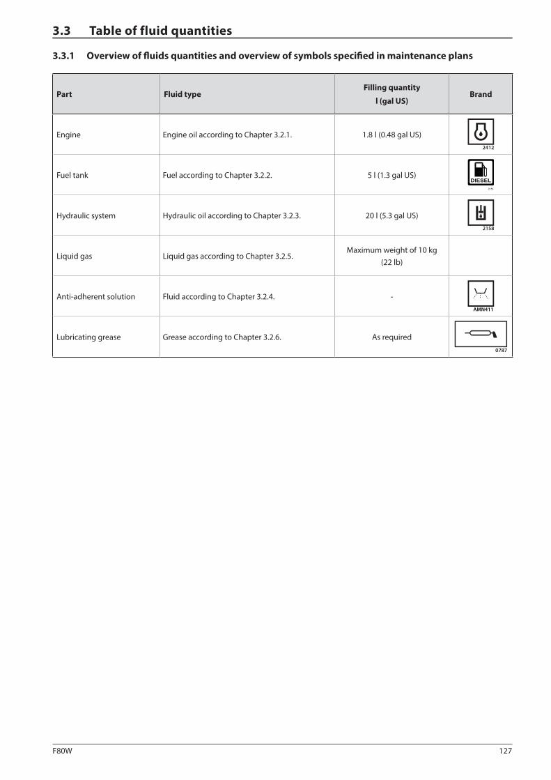
127F80W
3.3 Table of fluid quantities
3.3.1 Overview of fluids quantities and overview of symbols specified in maintenance plans
Part Fluid typeFilling quantity
l (gal US)Brand
Engine Engine oil according to Chapter 3.2.1. 1.8 l (0.48 gal US)2412
Fuel tank Fuel according to Chapter 3.2.2. 5 l (1.3 gal US)
Hydraulic system Hydraulic oil according to Chapter 3.2.3. 20 l (5.3 gal US)2158
Liquid gas Liquid gas according to Chapter 3.2.5.Maximum weight of 10 kg
(22 lb)
Anti-adherent solution Fluid according to Chapter 3.2.4. -AMN411
Lubricating grease Grease according to Chapter 3.2.6. As required0787

128 F80W
3.4 Lubrication and maintenance chart
Every 10 hours at the beginning of work (daily)
3.6.1 Fuel level check
3.6.2 Engine oil level check
3.6.3 Hydraulic tank oil level check
3.6.4 Driver's stand cleaning
3.6.5 Cleaning the hopper, outlets and conveyor
3.6.6 Cleaning the augers
3.6.7 Test of burner ignition, flame position adjustment and spark plug maintenance
3.6.8 Gas equipment tightness check
Every 10 hours at the end of work (daily)
3.6.9 Fuel level check
3.6.10 Cleaning the conveyor
3.6.11 Cleaning the augers
Every 50 hours (weekly)
3.6.12 Clearing the water separator
3.6.13 Machine lubrication
After 50 hours of operation
3.6.17 Engine oil replacement
Every 100 hours of operation (monthly)
3.6.14 Fuel system tightness check
3.6.15 Rear wheel fastening check
3.6.16 Conveyor chain tension
Every 250 hours of operation (every 3 months)
3.6.17 Engine oil replacement
3.6.18 Engine air intake check
3.6.19 Engine accelerator cable tension check
3.6.20 Hydraulic oil cooler cleaning
3.6.21 Hydraulic circuit tightness check
3.6.22 Battery inspection
3.6.23 Checking the conveyor drive chain tension

129F80W
MAINTENANCE MANUAL
Every 500 hours of operation (every 6 months)
3.6.24 Fuel filter replacement
3.6.25 Air filter replacement
3.6.26 Front and rear wheel condition check
After 500 hours of operation
3.6.28 Hydraulic oil and hydraulic oil filter replacement**
Every 1000 hours (yearly)
3.6.27 Engine oil filter cleaning
3.6.28 Hydraulic oil and hydraulic oil filter replacement**
3.6.29 Gas line hose replacement
Maintenance as required
3.6.30 Battery replacement
3.6.31 Charging of the battery
3.6.32 Screw connections tightness check
* First after 50 engine hours.
** First after 500 engine hours.
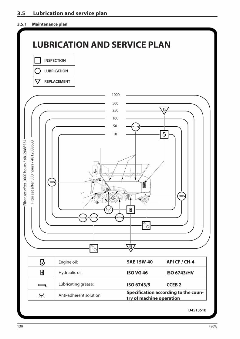
130 F80W
ISO VG 46 ISO 6743/HV
SAE 15W-40 API CF / CH-4
ISO 6743/9 CCEB 2
250
50
10
1000
100
500
D451351B
Sada
�ltr
ů 50
0 h
/ 4-7
6022
4
Sada
�ltr
ů100
0 h
/ 4-7
6022
5
3.5 Lubrication and service plan
3.5.1 Maintenance plan
LUBRICATION AND SERVICE PLANINSPECTION
LUBRICATION
REPLACEMENT
Filte
r set
aft
er 1
000
hour
s / 4
8120
8853
4
Engine oil:
Filte
r set
aft
er 5
00 h
ours
/ 48
1208
8533
Hydraulic oil:
Lubricating grease:
Anti-adherent solution:Specification according to the coun-try of machine operation
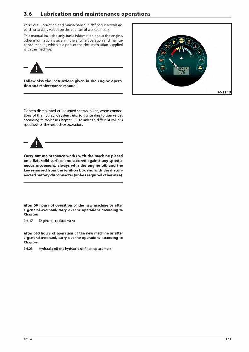
131F80W
451110
3.6 Lubrication and maintenance operations
Carry out lubrication and maintenance in defined intervals ac-cording to daily values on the counter of worked hours.
This manual includes only basic information about the engine, other information is given in the engine operation and mainte-nance manual, which is a part of the documentation supplied with the machine.
Follow also the instructions given in the engine opera-tion and maintenance manual!
Tighten dismounted or loosened screws, plugs, worm connec-tions of the hydraulic system, etc. to tightening torque values according to tables in Chapter 3.6.32 unless a different value is specified for the respective operation.
Carry out maintenance works with the machine placed on a flat, solid surface and secured against any sponta-neous movement, always with the engine off, and the key removed from the ignition box and with the discon-nected battery disconnecter (unless required otherwise).
After 50 hours of operation of the new machine or after a general overhaul, carry out the operations according to Chapter:
3.6.17 Engine oil replacement
After 500 hours of operation of the new machine or after a general overhaul, carry out the operations according to Chapter:
3.6.28 Hydraulic oil and hydraulic oil filter replacement
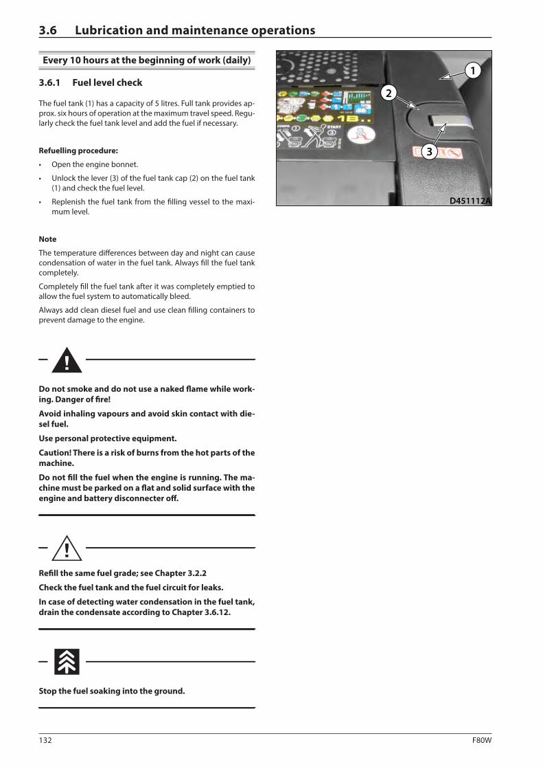
132 F80W
D451112A
1
3
2
3.6 Lubrication and maintenance operations
Every 10 hours at the beginning of work (daily)
3.6.1 Fuel level check
The fuel tank (1) has a capacity of 5 litres. Full tank provides ap-prox. six hours of operation at the maximum travel speed. Regu-larly check the fuel tank level and add the fuel if necessary.
Refuelling procedure:
• Open the engine bonnet.
• Unlock the lever (3) of the fuel tank cap (2) on the fuel tank (1) and check the fuel level.
• Replenish the fuel tank from the filling vessel to the maxi-mum level.
Note
The temperature differences between day and night can cause condensation of water in the fuel tank. Always fill the fuel tank completely.
Completely fill the fuel tank after it was completely emptied to allow the fuel system to automatically bleed.
Always add clean diesel fuel and use clean filling containers to prevent damage to the engine.
Do not smoke and do not use a naked flame while work-ing. Danger of fire!
Avoid inhaling vapours and avoid skin contact with die-sel fuel.
Use personal protective equipment.
Caution! There is a risk of burns from the hot parts of the machine.
Do not fill the fuel when the engine is running. The ma-chine must be parked on a flat and solid surface with the engine and battery disconnecter off.
Refill the same fuel grade; see Chapter 3.2.2
Check the fuel tank and the fuel circuit for leaks.
In case of detecting water condensation in the fuel tank, drain the condensate according to Chapter 3.6.12.
Stop the fuel soaking into the ground.
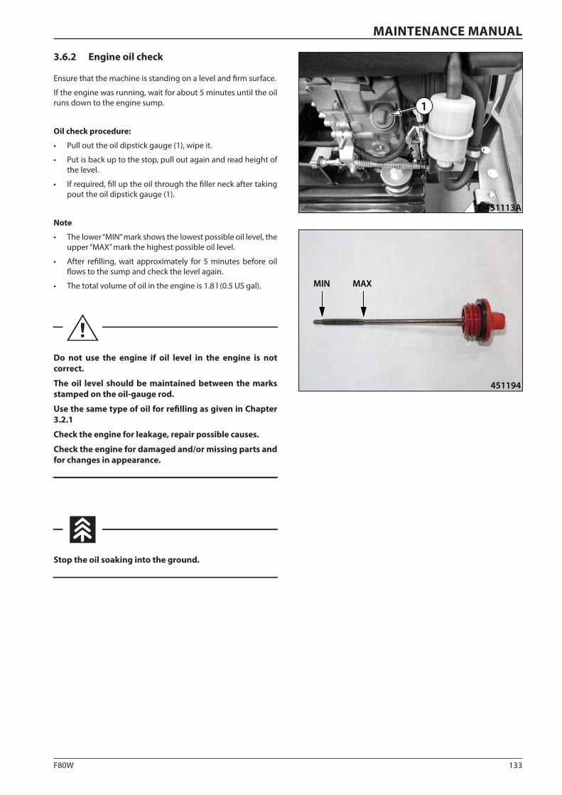
133F80W
D451113A
1
451194
MIN MAX
MAINTENANCE MANUAL
3.6.2 Engine oil check
Ensure that the machine is standing on a level and firm surface.
If the engine was running, wait for about 5 minutes until the oil runs down to the engine sump.
Oil check procedure:
• Pull out the oil dipstick gauge (1), wipe it.
• Put is back up to the stop, pull out again and read height of the level.
• If required, fill up the oil through the filler neck after taking pout the oil dipstick gauge (1).
Note
• The lower “MIN” mark shows the lowest possible oil level, the upper “MAX” mark the highest possible oil level.
• After refilling, wait approximately for 5 minutes before oil flows to the sump and check the level again.
• The total volume of oil in the engine is 1.8 l (0.5 US gal).
Do not use the engine if oil level in the engine is not correct.
The oil level should be maintained between the marks stamped on the oil-gauge rod.
Use the same type of oil for refilling as given in Chapter 3.2.1
Check the engine for leakage, repair possible causes.
Check the engine for damaged and/or missing parts and for changes in appearance.
Stop the oil soaking into the ground.
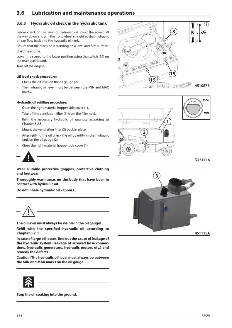
134 F80W
451115A
3
D451116
1
MAX
MIN
2
1915
8
451087B
P0
R
F 8
3.6 Lubrication and maintenance operations
3.6.3 Hydraulic oil check in the hydraulic tank
Before checking the level of hydraulic oil, lower the screed all the way down and aim the front wheel straight so that hydraulic oil can flow back into the hydraulic oil tank.
Ensure that the machine is standing on a level and firm surface.
Start the engine.
Lower the screed to the lower position using the switch (19) on the main dashboard.
Turn off the engine.
Oil level check procedure:• Check the oil level on the oil gauge (2).
• The hydraulic oil level must be between the MIN and MAX marks.
Hydraulic oil refilling procedure:• Open the right material hopper side cover (1).
• Take off the ventilation filter (3) from the filler neck.
• Refill the necessary hydraulic oil quantity according to Chapter 3.2.3.
• Mount the ventilation filter (3) back in place.
• After refilling the oil check the oil quantity in the hydraulic tank on the oil gauge (2).
• Close the right material hopper side cover (1).
Wear suitable protective goggles, protective clothing and footwear.
Thoroughly wash areas on the body that have been in contact with hydraulic oil.
Do not inhale hydraulic oil vapours.
The oil level must always be visible in the oil gauge!Refill with the specified hydraulic oil according to Chapter 3.2.3In case of large oil losses, find out the cause of leakage of the hydraulic system (leakage of screwed hose connec-tions, hydraulic generators, hydraulic motors etc.) and remedy the defects.Caution! The hydraulic oil level must always be between the MIN and MAX marks on the oil gauge.
Stop the oil soaking into the ground.
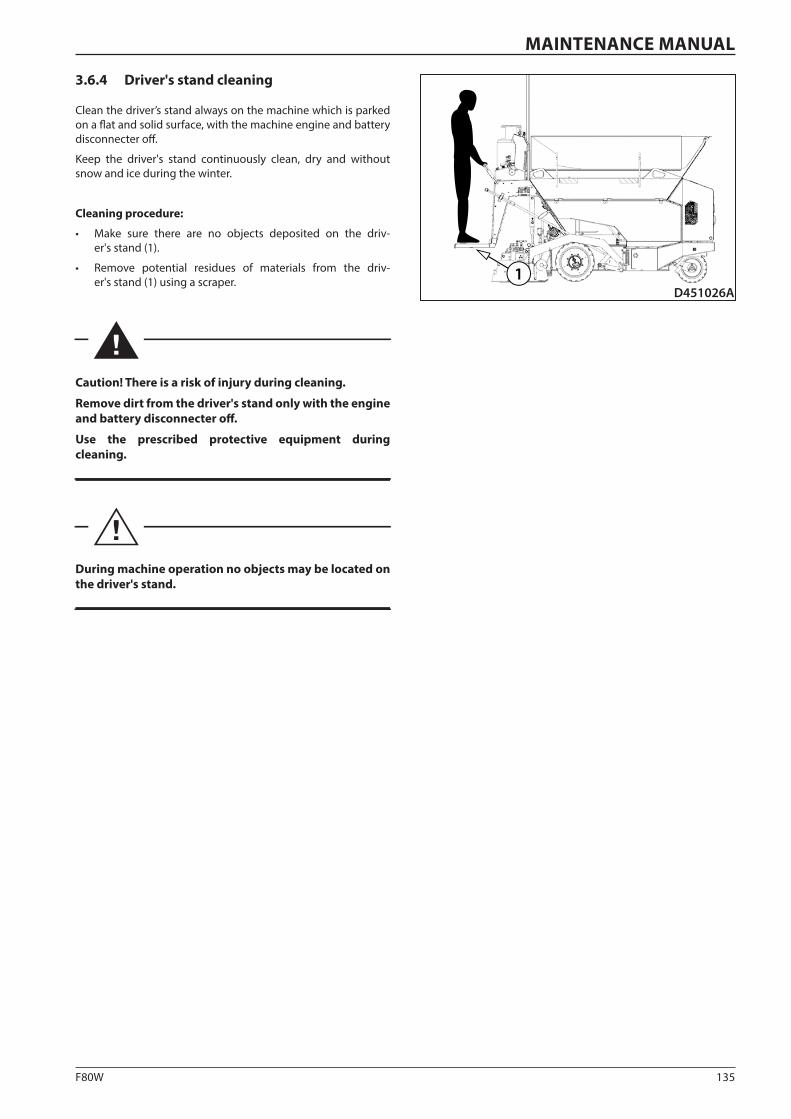
135F80W
D451026A1
MAINTENANCE MANUAL
3.6.4 Driver's stand cleaning
Clean the driver’s stand always on the machine which is parked on a flat and solid surface, with the machine engine and battery disconnecter off.
Keep the driver's stand continuously clean, dry and without snow and ice during the winter.
Cleaning procedure:
• Make sure there are no objects deposited on the driv-er's stand (1).
• Remove potential residues of materials from the driv-er's stand (1) using a scraper.
Caution! There is a risk of injury during cleaning.
Remove dirt from the driver's stand only with the engine and battery disconnecter off.
Use the prescribed protective equipment during cleaning.
During machine operation no objects may be located on the driver's stand.

136 F80W
451117
3
2
1
1817
451082A
3.6 Lubrication and maintenance operations
3.6.5 Cleaning the hopper, outlets and conveyor
Before applying the anti-adherent solution remove gross dirt from the conveyor, material outlets and the hopper of the ma-chine.
Clean the driver’s stand always on the machine which is parked on a flat and solid surface, with the machine engine and battery disconnecter off.
Cleaning procedure:
• Make sure the material hopper (1) is empty.
• Apply the anti-adherent solution on the material hopper (1), material outlets (2) and conveyor (3).
• Use a scraper to remove material residues from the material hopper walls (1).
• Use a scraper to remove material residues from the material outlets (2).
• Use a scraper to remove material residues from the convey-or (3).
• Start the engine.
• Activate the function of conveyor start by shifting the op-erating mode controller (17) to the lower position and the controller (18) on the main dashboard to remove dirt from the hopper area.
• After removing dirt from the hopper area disable the switch (18) and the operating mode switch (17) functions.
• Turn off the engine and disconnect the battery disconnect-er.
• Apply the anti-adherent solution on the material hopper (1), material outlets (2) and conveyor (3).
Caution! There is a risk of injury during cleaning.
Remove dirt from the hopper area using a scraper only with the engine and battery disconnecter off.
Use the prescribed protective equipment during cleaning.
Use the prescribed anti-adherent solution according to Chapter 3.2.4.
It is prohibited to use diesel oil instead of an anti-adher-ent solution.
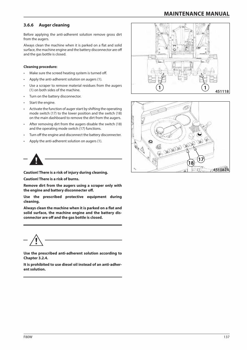
137F80W
1 1451118
1817
451082A
MAINTENANCE MANUAL
3.6.6 Auger cleaning
Before applying the anti-adherent solution remove gross dirt from the augers.
Always clean the machine when it is parked on a flat and solid surface, the machine engine and the battery disconnector are off and the gas bottle is closed.
Cleaning procedure:
• Make sure the screed heating system is turned off.
• Apply the anti-adherent solution on augers (1).
• Use a scraper to remove material residues from the augers (1) on both sides of the machine.
• Turn on the battery disconnector.
• Start the engine.
• Activate the function of auger start by shifting the operating mode switch (17) to the lower position and the switch (18) on the main dashboard to remove the dirt from the augers.
• After removing dirt from the augers disable the switch (18) and the operating mode switch (17) functions.
• Turn off the engine and disconnect the battery disconnecter.
• Apply the anti-adherent solution on augers (1).
Caution! There is a risk of injury during cleaning.
Caution! There is a risk of burns.
Remove dirt from the augers using a scraper only with the engine and battery disconnecter off.
Use the prescribed protective equipment during cleaning.
Always clean the machine when it is parked on a flat and solid surface, the machine engine and the battery dis-connector are off and the gas bottle is closed.
Use the prescribed anti-adherent solution according to Chapter 3.2.4.
It is prohibited to use diesel oil instead of an anti-adher-ent solution.
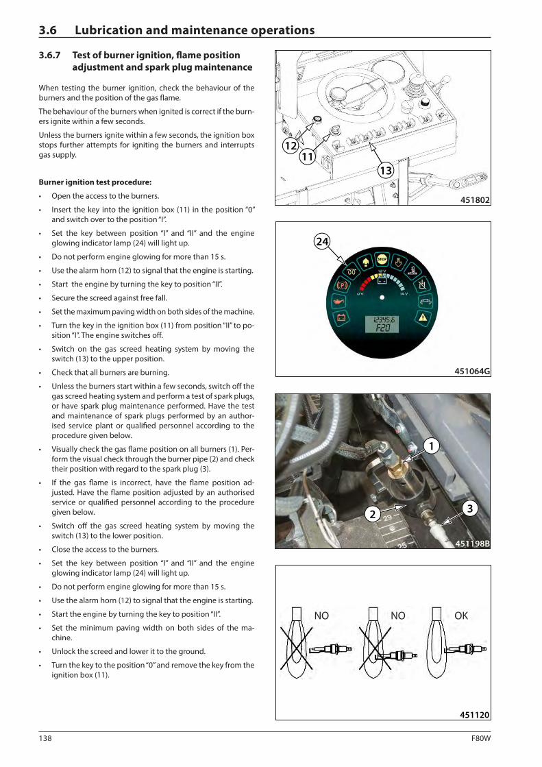
138 F80W
451120
451802
1112
13
451198B
1
32
24
451064G
3.6 Lubrication and maintenance operations
3.6.7 Test of burner ignition, flame position adjustment and spark plug maintenance
When testing the burner ignition, check the behaviour of the burners and the position of the gas flame.
The behaviour of the burners when ignited is correct if the burn-ers ignite within a few seconds.
Unless the burners ignite within a few seconds, the ignition box stops further attempts for igniting the burners and interrupts gas supply.
Burner ignition test procedure:
• Open the access to the burners.
• Insert the key into the ignition box (11) in the position “0” and switch over to the position “I”.
• Set the key between position “I” and “II” and the engine glowing indicator lamp (24) will light up.
• Do not perform engine glowing for more than 15 s.
• Use the alarm horn (12) to signal that the engine is starting.
• Start the engine by turning the key to position “II”.
• Secure the screed against free fall.
• Set the maximum paving width on both sides of the machine.
• Turn the key in the ignition box (11) from position “II” to po-sition “I”. The engine switches off.
• Switch on the gas screed heating system by moving the switch (13) to the upper position.
• Check that all burners are burning.
• Unless the burners start within a few seconds, switch off the gas screed heating system and perform a test of spark plugs, or have spark plug maintenance performed. Have the test and maintenance of spark plugs performed by an author-ised service plant or qualified personnel according to the procedure given below.
• Visually check the gas flame position on all burners (1). Per-form the visual check through the burner pipe (2) and check their position with regard to the spark plug (3).
• If the gas flame is incorrect, have the flame position ad-justed. Have the flame position adjusted by an authorised service or qualified personnel according to the procedure given below.
• Switch off the gas screed heating system by moving the switch (13) to the lower position.
• Close the access to the burners.
• Set the key between position “I” and “II” and the engine glowing indicator lamp (24) will light up.
• Do not perform engine glowing for more than 15 s.
• Use the alarm horn (12) to signal that the engine is starting.
• Start the engine by turning the key to position “II”.
• Set the minimum paving width on both sides of the ma-chine.
• Unlock the screed and lower it to the ground.
• Turn the key to the position “0” and remove the key from the ignition box (11).
NO NO OK
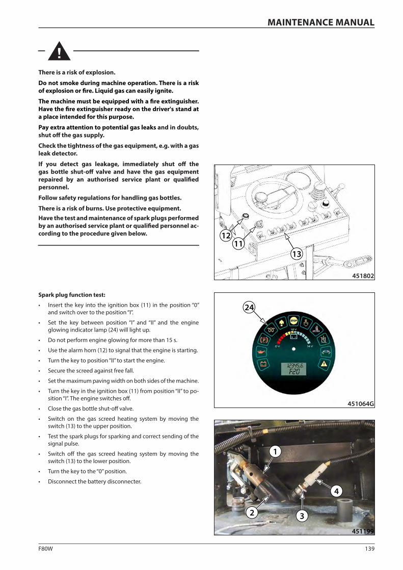
139F80W
451199
1
2 3
4
451802
1112
13
24
451064G
MAINTENANCE MANUAL
There is a risk of explosion.
Do not smoke during machine operation. There is a risk of explosion or fire. Liquid gas can easily ignite.
The machine must be equipped with a fire extinguisher. Have the fire extinguisher ready on the driver's stand at a place intended for this purpose.
Pay extra attention to potential gas leaks and in doubts, shut off the gas supply.
Check the tightness of the gas equipment, e.g. with a gas leak detector.
If you detect gas leakage, immediately shut off the gas bottle shut-off valve and have the gas equipment repaired by an authorised service plant or qualified personnel.
Follow safety regulations for handling gas bottles.
There is a risk of burns. Use protective equipment.Have the test and maintenance of spark plugs performed by an authorised service plant or qualified personnel ac-cording to the procedure given below.
Spark plug function test:
• Insert the key into the ignition box (11) in the position “0” and switch over to the position “I”.
• Set the key between position “I” and “II” and the engine glowing indicator lamp (24) will light up.
• Do not perform engine glowing for more than 15 s.
• Use the alarm horn (12) to signal that the engine is starting.
• Turn the key to position “II” to start the engine.
• Secure the screed against free fall.
• Set the maximum paving width on both sides of the machine.
• Turn the key in the ignition box (11) from position “II” to po-sition “I”. The engine switches off.
• Close the gas bottle shut-off valve.
• Switch on the gas screed heating system by moving the switch (13) to the upper position.
• Test the spark plugs for sparking and correct sending of the signal pulse.
• Switch off the gas screed heating system by moving the switch (13) to the lower position.
• Turn the key to the “0” position.
• Disconnect the battery disconnecter.
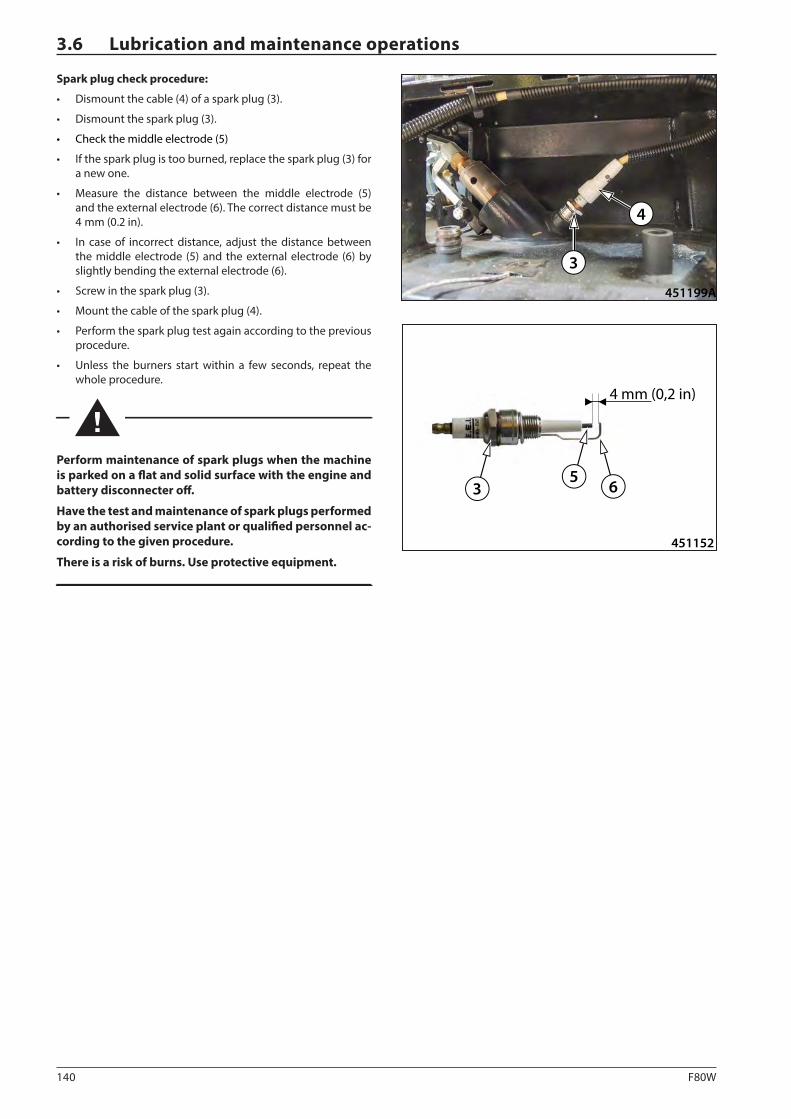
140 F80W
65
3
4 mm (0,2 in)
451152
451199A
3
4
3.6 Lubrication and maintenance operations
Spark plug check procedure:
• Dismount the cable (4) of a spark plug (3).
• Dismount the spark plug (3).
• Check the middle electrode (5)
• If the spark plug is too burned, replace the spark plug (3) for a new one.
• Measure the distance between the middle electrode (5) and the external electrode (6). The correct distance must be 4 mm (0.2 in).
• In case of incorrect distance, adjust the distance between the middle electrode (5) and the external electrode (6) by slightly bending the external electrode (6).
• Screw in the spark plug (3).
• Mount the cable of the spark plug (4).
• Perform the spark plug test again according to the previous procedure.
• Unless the burners start within a few seconds, repeat the whole procedure.
Perform maintenance of spark plugs when the machine is parked on a flat and solid surface with the engine and battery disconnecter off.
Have the test and maintenance of spark plugs performed by an authorised service plant or qualified personnel ac-cording to the given procedure.
There is a risk of burns. Use protective equipment.
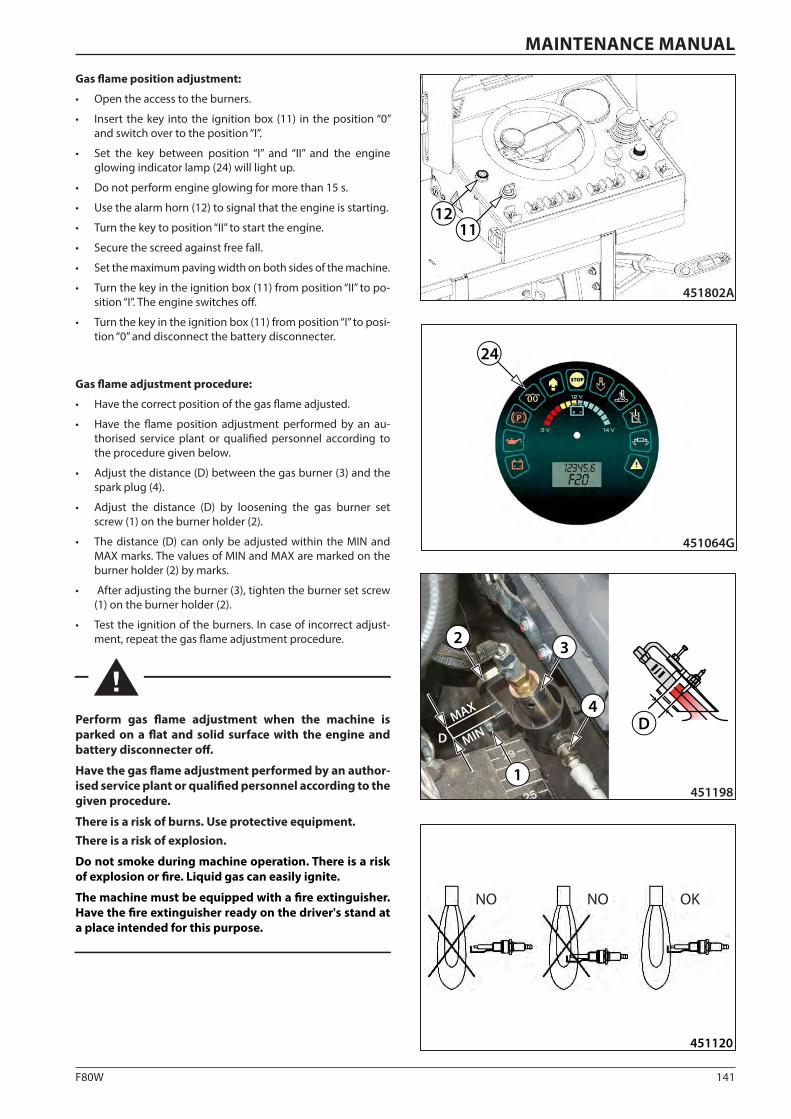
141F80W
451120
24
451064G
451802A
1112
D MINMAX
1
2 3
4D
451198
MAINTENANCE MANUAL
Gas flame position adjustment:
• Open the access to the burners.
• Insert the key into the ignition box (11) in the position “0” and switch over to the position “I”.
• Set the key between position “I” and “II” and the engine glowing indicator lamp (24) will light up.
• Do not perform engine glowing for more than 15 s.
• Use the alarm horn (12) to signal that the engine is starting.
• Turn the key to position “II” to start the engine.
• Secure the screed against free fall.
• Set the maximum paving width on both sides of the machine.
• Turn the key in the ignition box (11) from position “II” to po-sition “I”. The engine switches off.
• Turn the key in the ignition box (11) from position “I” to posi-tion “0” and disconnect the battery disconnecter.
Gas flame adjustment procedure:
• Have the correct position of the gas flame adjusted.
• Have the flame position adjustment performed by an au-thorised service plant or qualified personnel according to the procedure given below.
• Adjust the distance (D) between the gas burner (3) and the spark plug (4).
• Adjust the distance (D) by loosening the gas burner set screw (1) on the burner holder (2).
• The distance (D) can only be adjusted within the MIN and MAX marks. The values of MIN and MAX are marked on the burner holder (2) by marks.
• After adjusting the burner (3), tighten the burner set screw (1) on the burner holder (2).
• Test the ignition of the burners. In case of incorrect adjust-ment, repeat the gas flame adjustment procedure.
Perform gas flame adjustment when the machine is parked on a flat and solid surface with the engine and battery disconnecter off.
Have the gas flame adjustment performed by an author-ised service plant or qualified personnel according to the given procedure.
There is a risk of burns. Use protective equipment.There is a risk of explosion.
Do not smoke during machine operation. There is a risk of explosion or fire. Liquid gas can easily ignite.
The machine must be equipped with a fire extinguisher. Have the fire extinguisher ready on the driver's stand at a place intended for this purpose.
NO NO OK
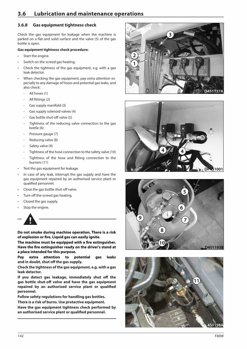
142 F80W
D451137A
1
2
3
D451193B
5
8
9 7
6
10
451198A
11
DP451001
4 4
3.6 Lubrication and maintenance operations
3.6.8 Gas equipment tightness check
Check the gas equipment for leakage when the machine is parked on a flat and solid surface and the valve (5) of the gas bottle is open.
Gas equipment tightness check procedure:
• Start the engine.
• Switch on the screed gas heating.
• Check the tightness of the gas equipment, e.g. with a gas leak detector.
• When checking the gas equipment, pay extra attention es-pecially to any damage of hoses and potential gas leaks, and also check:
- All hoses (1)
- All fittings (2)
- Gas supply manifold (3)
- Gas supply solenoid valves (4)
- Gas bottle shut-off valve (5)
- Tightness of the reducing valve connection to the gas bottle (6)
- Pressure gauge (7)
- Reducing valve (8)
- Safety valve (9)
- Tightness of the hose connection to the safety valve (10)
- Tightness of the hose and fitting connection to the burners (11)
• Test the gas equipment for leakage.
• In case of any leak, interrupt the gas supply and have the gas equipment repaired by an authorised service plant or qualified personnel.
• Close the gas bottle shut-off valve.
• Turn off the screed gas heating.
• Closed the gas supply.
• Stop the engine.
Do not smoke during machine operation. There is a risk of explosion or fire. Liquid gas can easily ignite.The machine must be equipped with a fire extinguisher. Have the fire extinguisher ready on the driver's stand at a place intended for this purpose.Pay extra attention to potential gas leaks and in doubt, shut off the gas supply. Check the tightness of the gas equipment, e.g. with a gas leak detector.If you detect gas leakage, immediately shut off the gas bottle shut-off valve and have the gas equipment repaired by an authorised service plant or qualified personnel.Follow safety regulations for handling gas bottles. There is a risk of burns. Use protective equipment.Have the gas equipment tightness check performed by an authorised service plant or qualified personnel.
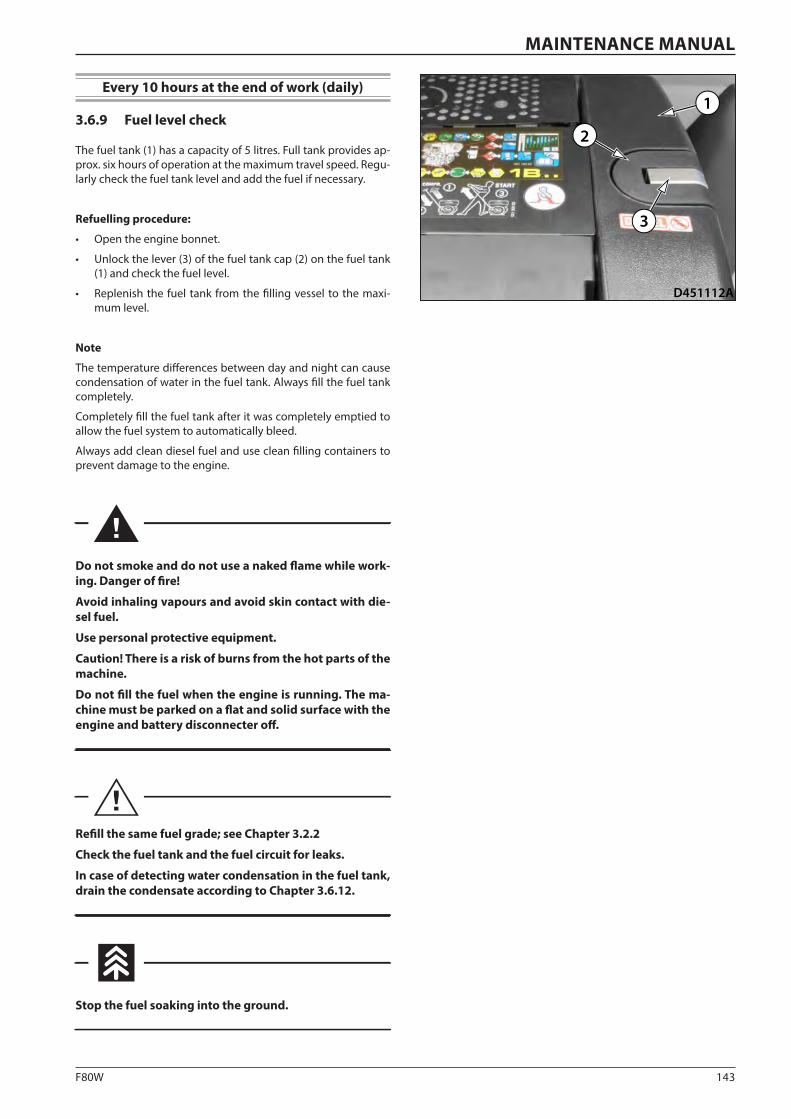
143F80W
D451112A
1
3
2
MAINTENANCE MANUAL
Every 10 hours at the end of work (daily)
3.6.9 Fuel level check
The fuel tank (1) has a capacity of 5 litres. Full tank provides ap-prox. six hours of operation at the maximum travel speed. Regu-larly check the fuel tank level and add the fuel if necessary.
Refuelling procedure:
• Open the engine bonnet.
• Unlock the lever (3) of the fuel tank cap (2) on the fuel tank (1) and check the fuel level.
• Replenish the fuel tank from the filling vessel to the maxi-mum level.
Note
The temperature differences between day and night can cause condensation of water in the fuel tank. Always fill the fuel tank completely.
Completely fill the fuel tank after it was completely emptied to allow the fuel system to automatically bleed.
Always add clean diesel fuel and use clean filling containers to prevent damage to the engine.
Do not smoke and do not use a naked flame while work-ing. Danger of fire!
Avoid inhaling vapours and avoid skin contact with die-sel fuel.
Use personal protective equipment.
Caution! There is a risk of burns from the hot parts of the machine.
Do not fill the fuel when the engine is running. The ma-chine must be parked on a flat and solid surface with the engine and battery disconnecter off.
Refill the same fuel grade; see Chapter 3.2.2
Check the fuel tank and the fuel circuit for leaks.
In case of detecting water condensation in the fuel tank, drain the condensate according to Chapter 3.6.12.
Stop the fuel soaking into the ground.
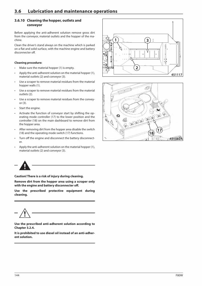
144 F80W
451117
3
2
1
1817
451082A
3.6 Lubrication and maintenance operations
3.6.10 Cleaning the hopper, outlets and conveyor
Before applying the anti-adherent solution remove gross dirt from the conveyor, material outlets and the hopper of the ma-chine.
Clean the driver’s stand always on the machine which is parked on a flat and solid surface, with the machine engine and battery disconnecter off.
Cleaning procedure:
• Make sure the material hopper (1) is empty.
• Apply the anti-adherent solution on the material hopper (1), material outlets (2) and conveyor (3).
• Use a scraper to remove material residues from the material hopper walls (1).
• Use a scraper to remove material residues from the material outlets (2).
• Use a scraper to remove material residues from the convey-or (3).
• Start the engine.
• Activate the function of conveyor start by shifting the op-erating mode controller (17) to the lower position and the controller (18) on the main dashboard to remove dirt from the hopper area.
• After removing dirt from the hopper area disable the switch (18) and the operating mode switch (17) functions.
• Turn off the engine and disconnect the battery disconnect-er.
• Apply the anti-adherent solution on the material hopper (1), material outlets (2) and conveyor (3).
Caution! There is a risk of injury during cleaning.
Remove dirt from the hopper area using a scraper only with the engine and battery disconnecter off.
Use the prescribed protective equipment during cleaning.
Use the prescribed anti-adherent solution according to Chapter 3.2.4.
It is prohibited to use diesel oil instead of an anti-adher-ent solution.
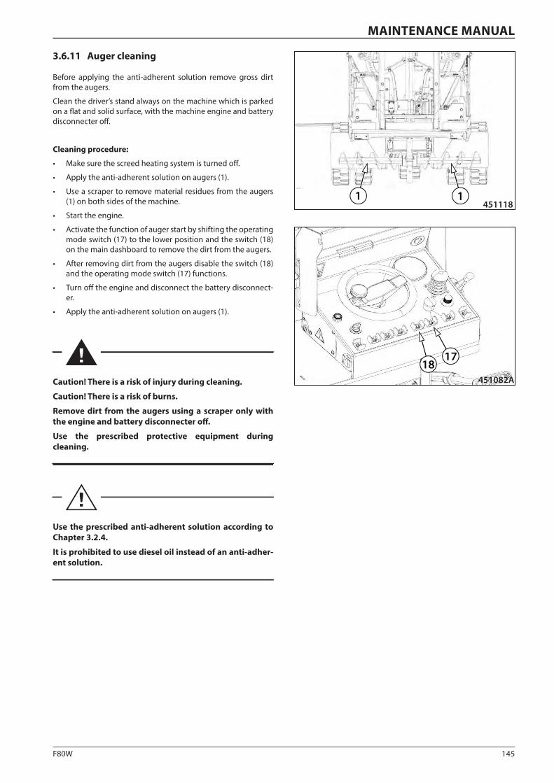
145F80W
1 1451118
1817
451082A
MAINTENANCE MANUAL
3.6.11 Auger cleaning
Before applying the anti-adherent solution remove gross dirt from the augers.
Clean the driver’s stand always on the machine which is parked on a flat and solid surface, with the machine engine and battery disconnecter off.
Cleaning procedure:
• Make sure the screed heating system is turned off.
• Apply the anti-adherent solution on augers (1).
• Use a scraper to remove material residues from the augers (1) on both sides of the machine.
• Start the engine.
• Activate the function of auger start by shifting the operating mode switch (17) to the lower position and the switch (18) on the main dashboard to remove the dirt from the augers.
• After removing dirt from the augers disable the switch (18) and the operating mode switch (17) functions.
• Turn off the engine and disconnect the battery disconnect-er.
• Apply the anti-adherent solution on augers (1).
Caution! There is a risk of injury during cleaning.
Caution! There is a risk of burns.
Remove dirt from the augers using a scraper only with the engine and battery disconnecter off.
Use the prescribed protective equipment during cleaning.
Use the prescribed anti-adherent solution according to Chapter 3.2.4.
It is prohibited to use diesel oil instead of an anti-adher-ent solution.
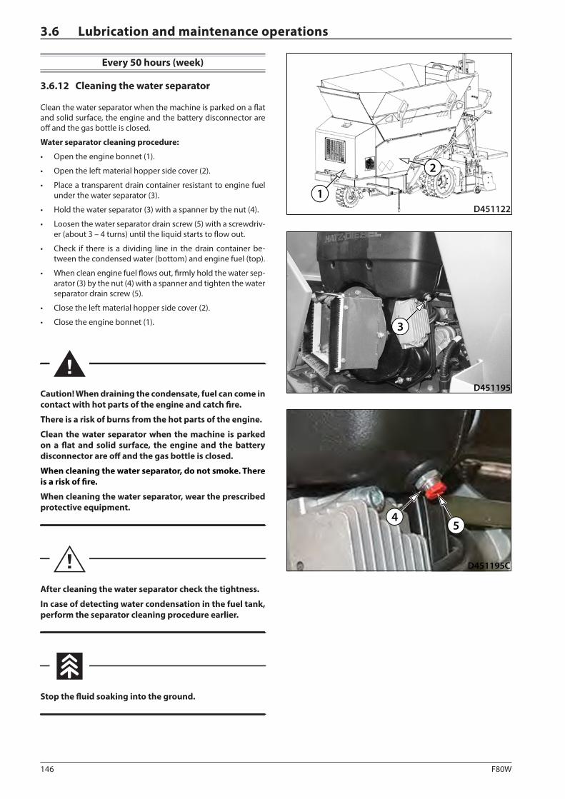
146 F80W
D451195
3
D451122
2
1
D451195C
45
3.6 Lubrication and maintenance operations
Every 50 hours (week)
3.6.12 Cleaning the water separator
Clean the water separator when the machine is parked on a flat and solid surface, the engine and the battery disconnector are off and the gas bottle is closed.
Water separator cleaning procedure:
• Open the engine bonnet (1).
• Open the left material hopper side cover (2).
• Place a transparent drain container resistant to engine fuel under the water separator (3).
• Hold the water separator (3) with a spanner by the nut (4).
• Loosen the water separator drain screw (5) with a screwdriv-er (about 3 – 4 turns) until the liquid starts to flow out.
• Check if there is a dividing line in the drain container be-tween the condensed water (bottom) and engine fuel (top).
• When clean engine fuel flows out, firmly hold the water sep-arator (3) by the nut (4) with a spanner and tighten the water separator drain screw (5).
• Close the left material hopper side cover (2).
• Close the engine bonnet (1).
Caution! When draining the condensate, fuel can come in contact with hot parts of the engine and catch fire.
There is a risk of burns from the hot parts of the engine.
Clean the water separator when the machine is parked on a flat and solid surface, the engine and the battery disconnector are off and the gas bottle is closed.
When cleaning the water separator, do not smoke. There is a risk of fire.
When cleaning the water separator, wear the prescribed protective equipment.
After cleaning the water separator check the tightness.
In case of detecting water condensation in the fuel tank, perform the separator cleaning procedure earlier.
Stop the fluid soaking into the ground.
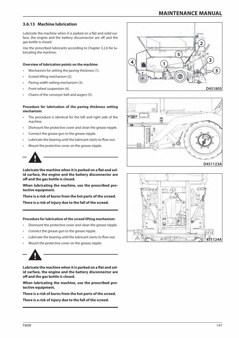
147F80W
D451123A
451124A
1
2
34
3
5
D451805
MAINTENANCE MANUAL
3.6.13 Machine lubrication
Lubricate the machine when it is parked on a flat and solid sur-face, the engine and the battery disconnector are off and the gas bottle is closed.
Use the prescribed lubricants according to Chapter 3.2.6 for lu-bricating the machine.
Overview of lubrication points on the machine:
• Mechanism for setting the paving thickness (1).
• Screed lifting mechanism (2).
• Paving width setting mechanism (3).
• Front wheel suspension (4).
• Chains of the conveyor belt and augers (5).
Procedure for lubrication of the paving thickness setting mechanism:
• The procedure is identical for the left and right side of the machine.
• Dismount the protective cover and clean the grease nipple.
• Connect the grease gun to the grease nipple.
• Lubricate the bearing until the lubricant starts to flow out.
• Mount the protective cover on the grease nipple.
Lubricate the machine when it is parked on a flat and sol-id surface, the engine and the battery disconnector are off and the gas bottle is closed.
When lubricating the machine, use the prescribed pro-tective equipment.
There is a risk of burns from the hot parts of the screed.
There is a risk of injury due to the fall of the screed.
Procedure for lubrication of the screed lifting mechanism:
• Dismount the protective cover and clean the grease nipple.
• Connect the grease gun to the grease nipple.
• Lubricate the bearing until the lubricant starts to flow out.
• Mount the protective cover on the grease nipple.
Lubricate the machine when it is parked on a flat and sol-id surface, the engine and the battery disconnector are off and the gas bottle is closed.
When lubricating the machine, use the prescribed pro-tective equipment.
There is a risk of burns from the hot parts of the screed.
There is a risk of injury due to the fall of the screed.
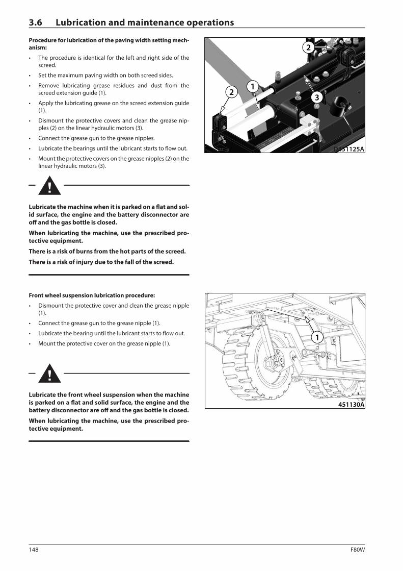
148 F80W
1
D451125A
2
2
3
451130A
1
3.6 Lubrication and maintenance operations
Procedure for lubrication of the paving width setting mech-anism:
• The procedure is identical for the left and right side of the screed.
• Set the maximum paving width on both screed sides.
• Remove lubricating grease residues and dust from the screed extension guide (1).
• Apply the lubricating grease on the screed extension guide (1).
• Dismount the protective covers and clean the grease nip-ples (2) on the linear hydraulic motors (3).
• Connect the grease gun to the grease nipples.
• Lubricate the bearings until the lubricant starts to flow out.
• Mount the protective covers on the grease nipples (2) on the linear hydraulic motors (3).
Lubricate the machine when it is parked on a flat and sol-id surface, the engine and the battery disconnector are off and the gas bottle is closed.
When lubricating the machine, use the prescribed pro-tective equipment.
There is a risk of burns from the hot parts of the screed.
There is a risk of injury due to the fall of the screed.
Front wheel suspension lubrication procedure:
• Dismount the protective cover and clean the grease nipple (1).
• Connect the grease gun to the grease nipple (1).
• Lubricate the bearing until the lubricant starts to flow out.
• Mount the protective cover on the grease nipple (1).
Lubricate the front wheel suspension when the machine is parked on a flat and solid surface, the engine and the battery disconnector are off and the gas bottle is closed.
When lubricating the machine, use the prescribed pro-tective equipment.
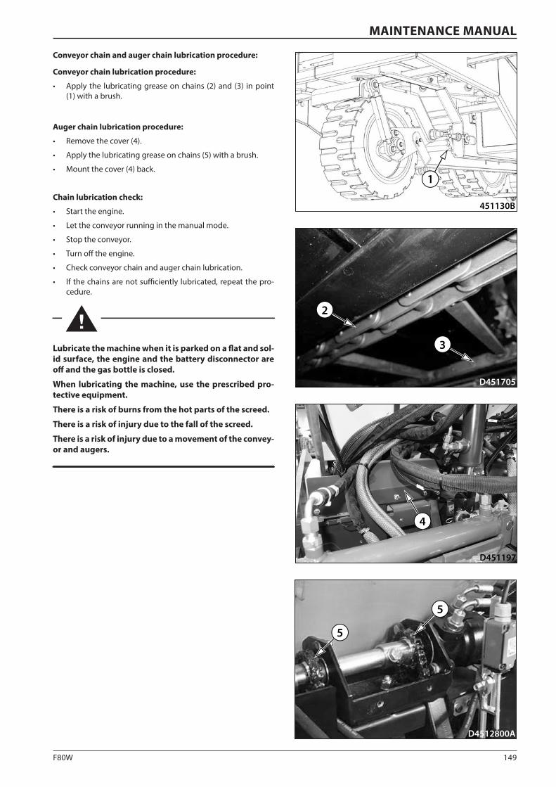
149F80W
451130B
1
D4512800A
5
5
D451197
4
3
2
D451705
MAINTENANCE MANUAL
Conveyor chain and auger chain lubrication procedure:
Conveyor chain lubrication procedure:
• Apply the lubricating grease on chains (2) and (3) in point (1) with a brush.
Auger chain lubrication procedure:
• Remove the cover (4).
• Apply the lubricating grease on chains (5) with a brush.
• Mount the cover (4) back.
Chain lubrication check:
• Start the engine.
• Let the conveyor running in the manual mode.
• Stop the conveyor.
• Turn off the engine.
• Check conveyor chain and auger chain lubrication.
• If the chains are not sufficiently lubricated, repeat the pro-cedure.
Lubricate the machine when it is parked on a flat and sol-id surface, the engine and the battery disconnector are off and the gas bottle is closed.
When lubricating the machine, use the prescribed pro-tective equipment.
There is a risk of burns from the hot parts of the screed.
There is a risk of injury due to the fall of the screed.
There is a risk of injury due to a movement of the convey-or and augers.
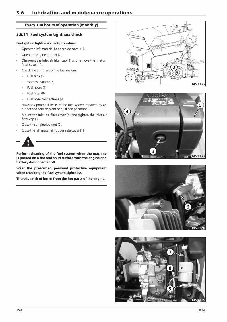
150 F80W
D451122
2
1
D4511273
45
D451128
6
D451129
9
8
7
3.6 Lubrication and maintenance operations
Every 100 hours of operation (monthly)
3.6.14 Fuel system tightness check
Fuel system tightness check procedure:
• Open the left material hopper side cover (1).
• Open the engine bonnet (2).
• Dismount the inlet air filter cap (3) and remove the inlet air filter cover (4).
• Check the tightness of the fuel system:
- Fuel tank (5)
- Water separator (6)
- Fuel hoses (7)
- Fuel filter (8)
- Fuel hose connections (9)
• Have any potential leaks of the fuel system repaired by an authorised service plant or qualified personnel.
• Mount the inlet air filter cover (4) and tighten the inlet air filter cap (3).
• Close the engine bonnet (2).
• Close the left material hopper side cover (1).
Perform cleaning of the fuel system when the machine is parked on a flat and solid surface with the engine and battery disconnecter off.
Wear the prescribed personal protective equipment when checking the fuel system tightness.
There is a risk of burns from the hot parts of the engine.
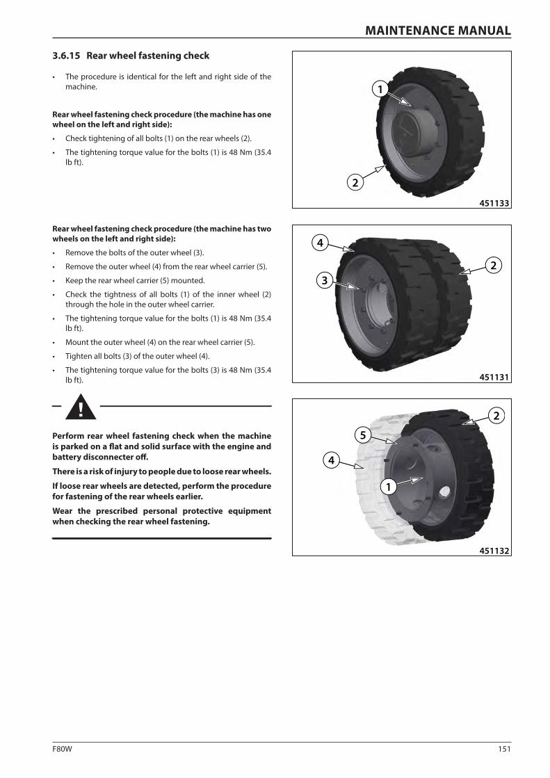
151F80W
451131
3
4
2
451132
5
4
2
1
451133
1
2
MAINTENANCE MANUAL
3.6.15 Rear wheel fastening check
• The procedure is identical for the left and right side of the machine.
Rear wheel fastening check procedure (the machine has one wheel on the left and right side):
• Check tightening of all bolts (1) on the rear wheels (2).
• The tightening torque value for the bolts (1) is 48 Nm (35.4 lb ft).
Rear wheel fastening check procedure (the machine has two wheels on the left and right side):
• Remove the bolts of the outer wheel (3).
• Remove the outer wheel (4) from the rear wheel carrier (5).
• Keep the rear wheel carrier (5) mounted.
• Check the tightness of all bolts (1) of the inner wheel (2) through the hole in the outer wheel carrier.
• The tightening torque value for the bolts (1) is 48 Nm (35.4 lb ft).
• Mount the outer wheel (4) on the rear wheel carrier (5).
• Tighten all bolts (3) of the outer wheel (4).
• The tightening torque value for the bolts (3) is 48 Nm (35.4 lb ft).
Perform rear wheel fastening check when the machine is parked on a flat and solid surface with the engine and battery disconnecter off.
There is a risk of injury to people due to loose rear wheels.
If loose rear wheels are detected, perform the procedure for fastening of the rear wheels earlier.
Wear the prescribed personal protective equipment when checking the rear wheel fastening.
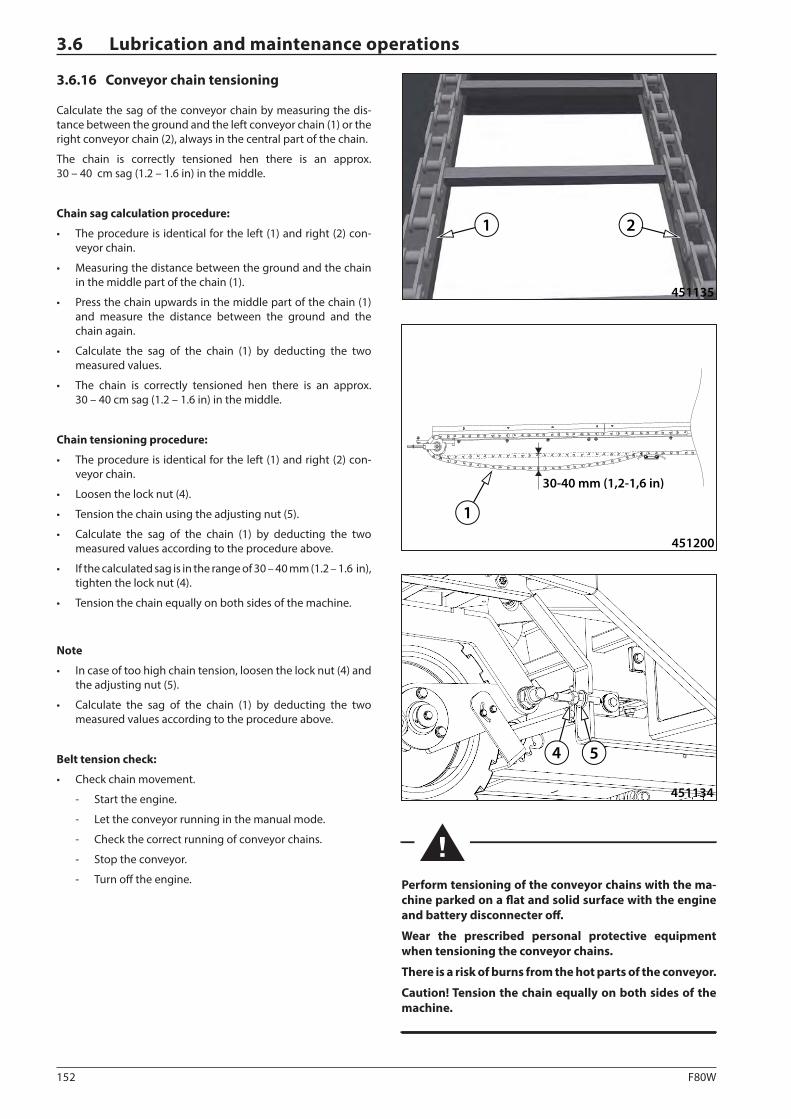
152 F80W
451134
4 5
451135
1 2
30-40 mm (1,2-1,6 in)
451200
1
3.6 Lubrication and maintenance operations
3.6.16 Conveyor chain tensioning
Calculate the sag of the conveyor chain by measuring the dis-tance between the ground and the left conveyor chain (1) or the right conveyor chain (2), always in the central part of the chain.
The chain is correctly tensioned hen there is an approx. 30 – 40 cm sag (1.2 – 1.6 in) in the middle.
Chain sag calculation procedure:
• The procedure is identical for the left (1) and right (2) con-veyor chain.
• Measuring the distance between the ground and the chain in the middle part of the chain (1).
• Press the chain upwards in the middle part of the chain (1) and measure the distance between the ground and the chain again.
• Calculate the sag of the chain (1) by deducting the two measured values.
• The chain is correctly tensioned hen there is an approx. 30 – 40 cm sag (1.2 – 1.6 in) in the middle.
Chain tensioning procedure:
• The procedure is identical for the left (1) and right (2) con-veyor chain.
• Loosen the lock nut (4).
• Tension the chain using the adjusting nut (5).
• Calculate the sag of the chain (1) by deducting the two measured values according to the procedure above.
• If the calculated sag is in the range of 30 – 40 mm (1.2 – 1.6 in), tighten the lock nut (4).
• Tension the chain equally on both sides of the machine.
Note
• In case of too high chain tension, loosen the lock nut (4) and the adjusting nut (5).
• Calculate the sag of the chain (1) by deducting the two measured values according to the procedure above.
Belt tension check:
• Check chain movement.
- Start the engine.
- Let the conveyor running in the manual mode.
- Check the correct running of conveyor chains.
- Stop the conveyor.
- Turn off the engine. Perform tensioning of the conveyor chains with the ma-chine parked on a flat and solid surface with the engine and battery disconnecter off.
Wear the prescribed personal protective equipment when tensioning the conveyor chains.
There is a risk of burns from the hot parts of the conveyor.
Caution! Tension the chain equally on both sides of the machine.
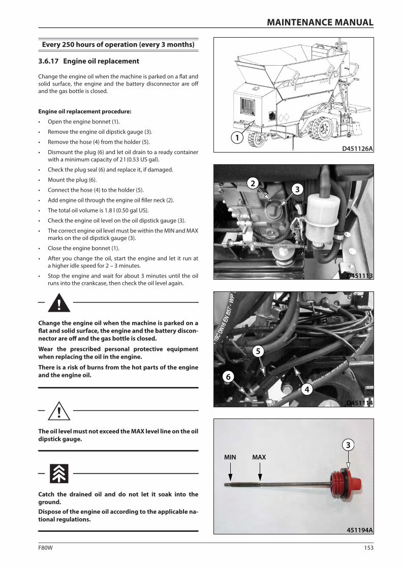
153F80W
D451113
32
D451114
6
5
4
D451126A1
451194A
MIN MAX
3
MAINTENANCE MANUAL
Every 250 hours of operation (every 3 months)
3.6.17 Engine oil replacement
Change the engine oil when the machine is parked on a flat and solid surface, the engine and the battery disconnector are off and the gas bottle is closed.
Engine oil replacement procedure:
• Open the engine bonnet (1).
• Remove the engine oil dipstick gauge (3).
• Remove the hose (4) from the holder (5).
• Dismount the plug (6) and let oil drain to a ready container with a minimum capacity of 2 l (0.53 US gal).
• Check the plug seal (6) and replace it, if damaged.
• Mount the plug (6).
• Connect the hose (4) to the holder (5).
• Add engine oil through the engine oil filler neck (2).
• The total oil volume is 1.8 l (0.50 gal US).
• Check the engine oil level on the oil dipstick gauge (3).
• The correct engine oil level must be within the MIN and MAX marks on the oil dipstick gauge (3).
• Close the engine bonnet (1).
• After you change the oil, start the engine and let it run at a higher idle speed for 2 – 3 minutes.
• Stop the engine and wait for about 3 minutes until the oil runs into the crankcase, then check the oil level again.
Change the engine oil when the machine is parked on a flat and solid surface, the engine and the battery discon-nector are off and the gas bottle is closed.
Wear the prescribed personal protective equipment when replacing the oil in the engine.
There is a risk of burns from the hot parts of the engine and the engine oil.
The oil level must not exceed the MAX level line on the oil dipstick gauge.
Catch the drained oil and do not let it soak into the ground.Dispose of the engine oil according to the applicable na-tional regulations.
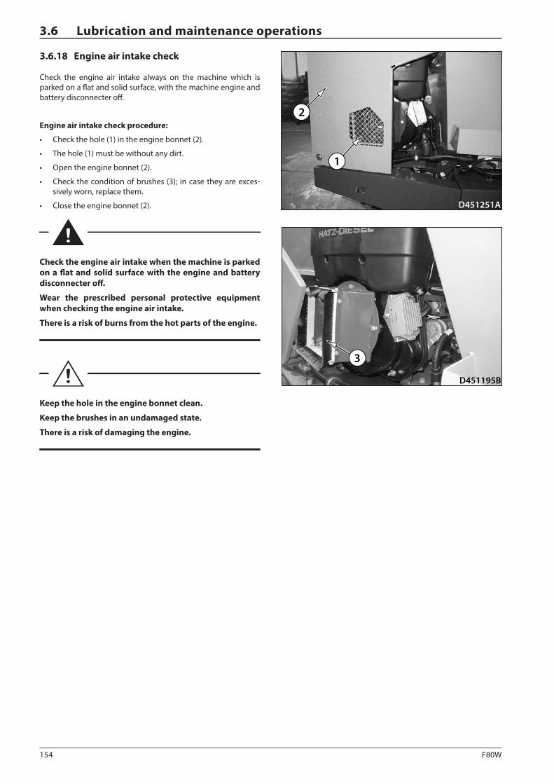
154 F80W
D451251A
1
2
D451195B
3
3.6 Lubrication and maintenance operations
3.6.18 Engine air intake check
Check the engine air intake always on the machine which is parked on a flat and solid surface, with the machine engine and battery disconnecter off.
Engine air intake check procedure:
• Check the hole (1) in the engine bonnet (2).
• The hole (1) must be without any dirt.
• Open the engine bonnet (2).
• Check the condition of brushes (3); in case they are exces-sively worn, replace them.
• Close the engine bonnet (2).
Check the engine air intake when the machine is parked on a flat and solid surface with the engine and battery disconnecter off.
Wear the prescribed personal protective equipment when checking the engine air intake.
There is a risk of burns from the hot parts of the engine.
Keep the hole in the engine bonnet clean.
Keep the brushes in an undamaged state.
There is a risk of damaging the engine.
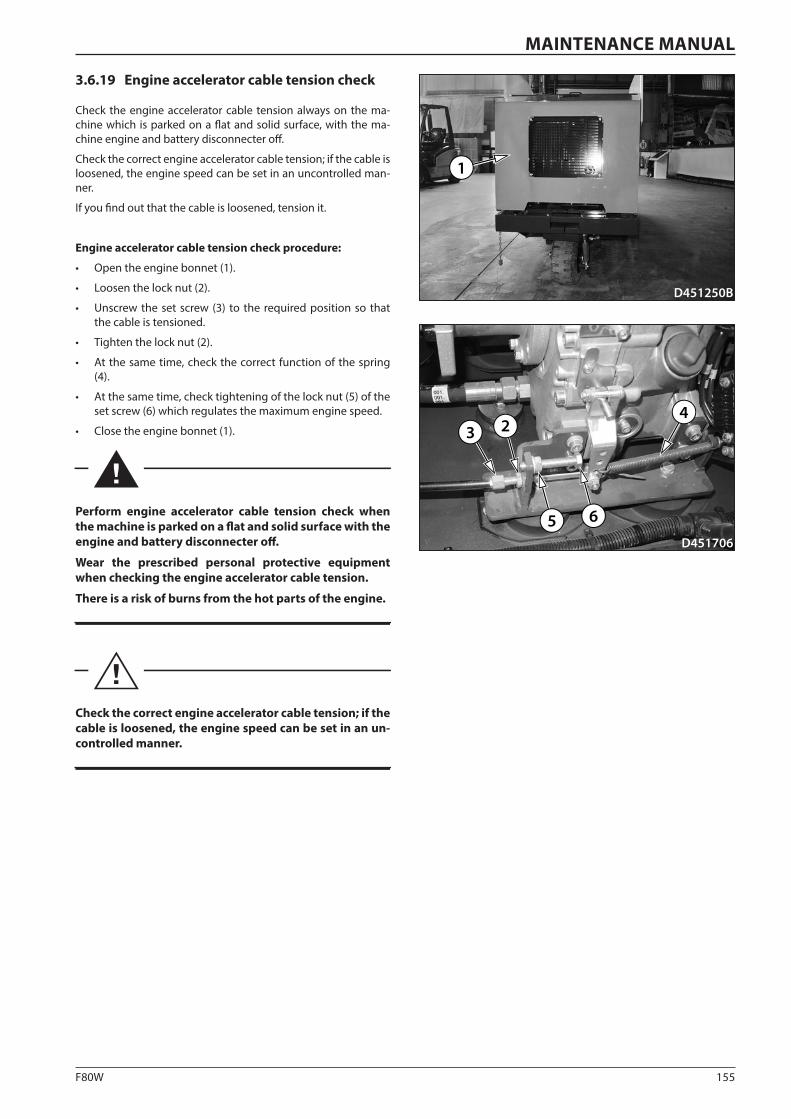
155F80W
2
D451706
34
5 6
D451250B
1
MAINTENANCE MANUAL
3.6.19 Engine accelerator cable tension check
Check the engine accelerator cable tension always on the ma-chine which is parked on a flat and solid surface, with the ma-chine engine and battery disconnecter off.
Check the correct engine accelerator cable tension; if the cable is loosened, the engine speed can be set in an uncontrolled man-ner.
If you find out that the cable is loosened, tension it.
Engine accelerator cable tension check procedure:
• Open the engine bonnet (1).
• Loosen the lock nut (2).
• Unscrew the set screw (3) to the required position so that the cable is tensioned.
• Tighten the lock nut (2).
• At the same time, check the correct function of the spring (4).
• At the same time, check tightening of the lock nut (5) of the set screw (6) which regulates the maximum engine speed.
• Close the engine bonnet (1).
Perform engine accelerator cable tension check when the machine is parked on a flat and solid surface with the engine and battery disconnecter off.
Wear the prescribed personal protective equipment when checking the engine accelerator cable tension.
There is a risk of burns from the hot parts of the engine.
Check the correct engine accelerator cable tension; if the cable is loosened, the engine speed can be set in an un-controlled manner.
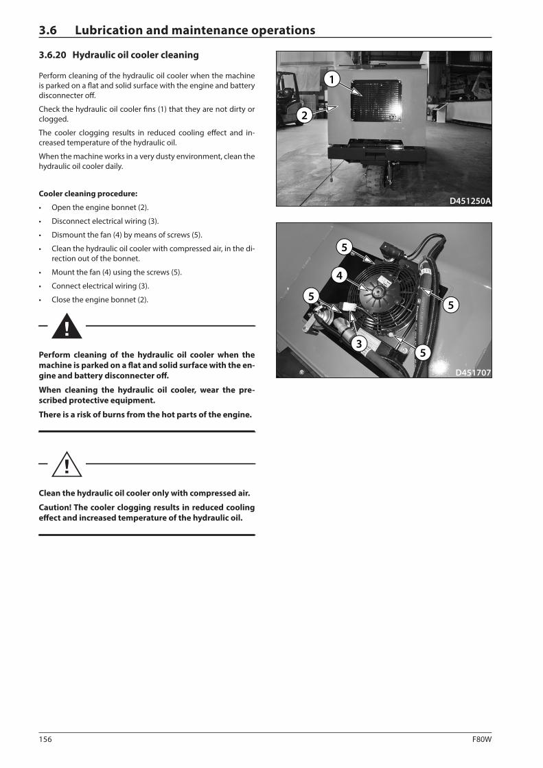
156 F80W
D451250A
2
1
D451707
35
55
5
4
3.6 Lubrication and maintenance operations
3.6.20 Hydraulic oil cooler cleaning
Perform cleaning of the hydraulic oil cooler when the machine is parked on a flat and solid surface with the engine and battery disconnecter off.
Check the hydraulic oil cooler fins (1) that they are not dirty or clogged.
The cooler clogging results in reduced cooling effect and in-creased temperature of the hydraulic oil.
When the machine works in a very dusty environment, clean the hydraulic oil cooler daily.
Cooler cleaning procedure:
• Open the engine bonnet (2).
• Disconnect electrical wiring (3).
• Dismount the fan (4) by means of screws (5).
• Clean the hydraulic oil cooler with compressed air, in the di-rection out of the bonnet.
• Mount the fan (4) using the screws (5).
• Connect electrical wiring (3).
• Close the engine bonnet (2).
Perform cleaning of the hydraulic oil cooler when the machine is parked on a flat and solid surface with the en-gine and battery disconnecter off.
When cleaning the hydraulic oil cooler, wear the pre-scribed protective equipment.
There is a risk of burns from the hot parts of the engine.
Clean the hydraulic oil cooler only with compressed air.
Caution! The cooler clogging results in reduced cooling effect and increased temperature of the hydraulic oil.
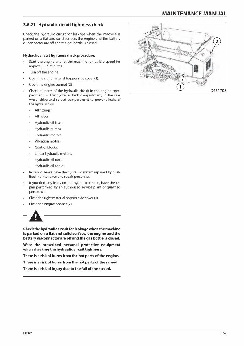
157F80W
D4517081
2
MAINTENANCE MANUAL
3.6.21 Hydraulic circuit tightness check
Check the hydraulic circuit for leakage when the machine is parked on a flat and solid surface, the engine and the battery disconnector are off and the gas bottle is closed.
Hydraulic circuit tightness check procedure:
• Start the engine and let the machine run at idle speed for approx. 3 – 5 minutes.
• Turn off the engine.
• Open the right material hopper side cover (1).
• Open the engine bonnet (2).
• Check all parts of the hydraulic circuit in the engine com-partment, in the hydraulic tank compartment, in the rear wheel drive and screed compartment to prevent leaks of the hydraulic oil.
- All fittings.
- All hoses.
- Hydraulic oil filter.
- Hydraulic pumps.
- Hydraulic motors.
- Vibration motors.
- Control blocks.
- Linear hydraulic motors.
- Hydraulic oil tank.
- Hydraulic oil cooler.
• In case of leaks, have the hydraulic system repaired by qual-ified maintenance and repair personnel.
• If you find any leaks on the hydraulic circuit:, have the re-pair performed by an authorised service plant or qualified personnel.
• Close the right material hopper side cover (1).
• Close the engine bonnet (2).
Check the hydraulic circuit for leakage when the machine is parked on a flat and solid surface, the engine and the battery disconnector are off and the gas bottle is closed.
Wear the prescribed personal protective equipment when checking the hydraulic circuit tightness.
There is a risk of burns from the hot parts of the engine.
There is a risk of burns from the hot parts of the screed.
There is a risk of injury due to the fall of the screed.
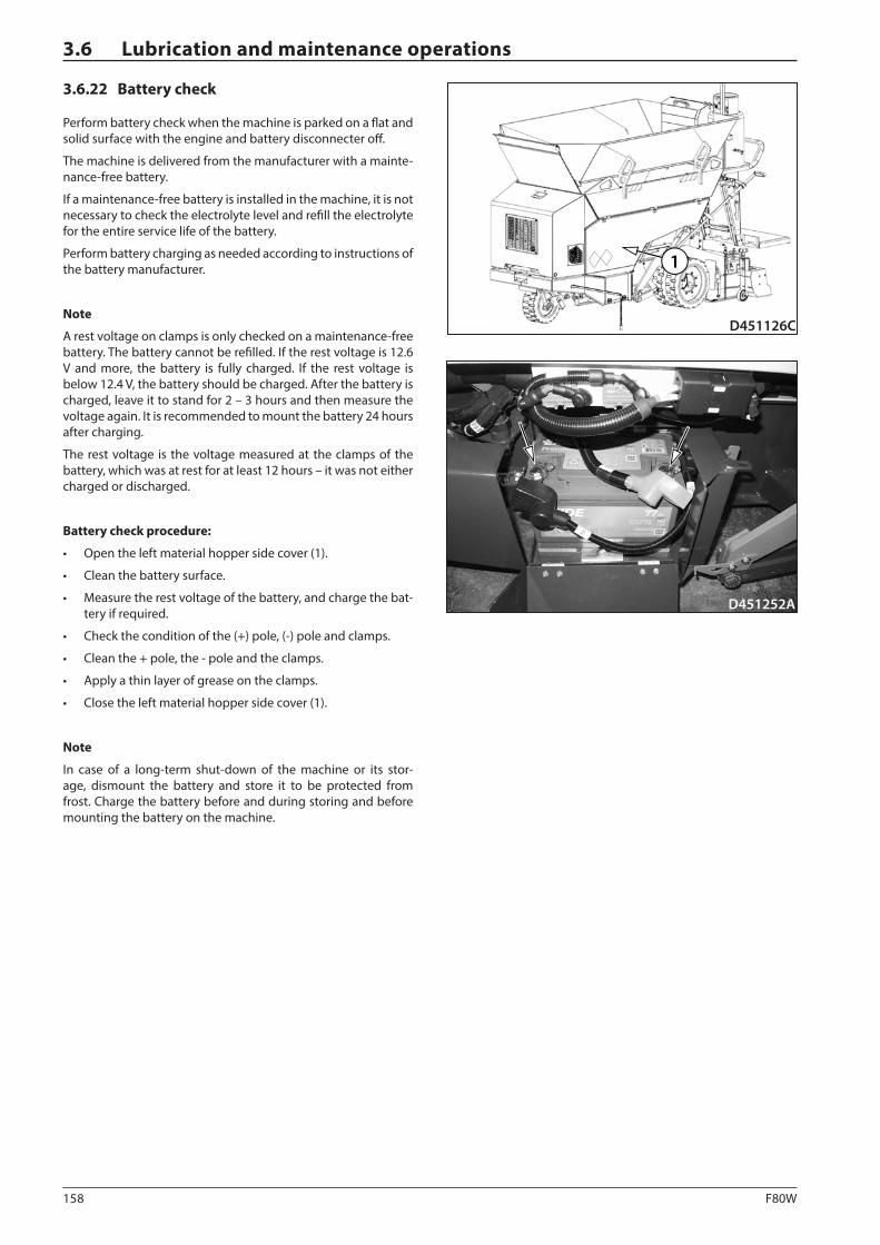
158 F80W
D451252A
D451126C
1
3.6 Lubrication and maintenance operations
3.6.22 Battery check
Perform battery check when the machine is parked on a flat and solid surface with the engine and battery disconnecter off.
The machine is delivered from the manufacturer with a mainte-nance-free battery.
If a maintenance-free battery is installed in the machine, it is not necessary to check the electrolyte level and refill the electrolyte for the entire service life of the battery.
Perform battery charging as needed according to instructions of the battery manufacturer.
Note
A rest voltage on clamps is only checked on a maintenance-free battery. The battery cannot be refilled. If the rest voltage is 12.6 V and more, the battery is fully charged. If the rest voltage is below 12.4 V, the battery should be charged. After the battery is charged, leave it to stand for 2 – 3 hours and then measure the voltage again. It is recommended to mount the battery 24 hours after charging.
The rest voltage is the voltage measured at the clamps of the battery, which was at rest for at least 12 hours – it was not either charged or discharged.
Battery check procedure:
• Open the left material hopper side cover (1).
• Clean the battery surface.
• Measure the rest voltage of the battery, and charge the bat-tery if required.
• Check the condition of the (+) pole, (-) pole and clamps.
• Clean the + pole, the - pole and the clamps.
• Apply a thin layer of grease on the clamps.
• Close the left material hopper side cover (1).
Note
In case of a long-term shut-down of the machine or its stor-age, dismount the battery and store it to be protected from frost. Charge the battery before and during storing and before mounting the battery on the machine.
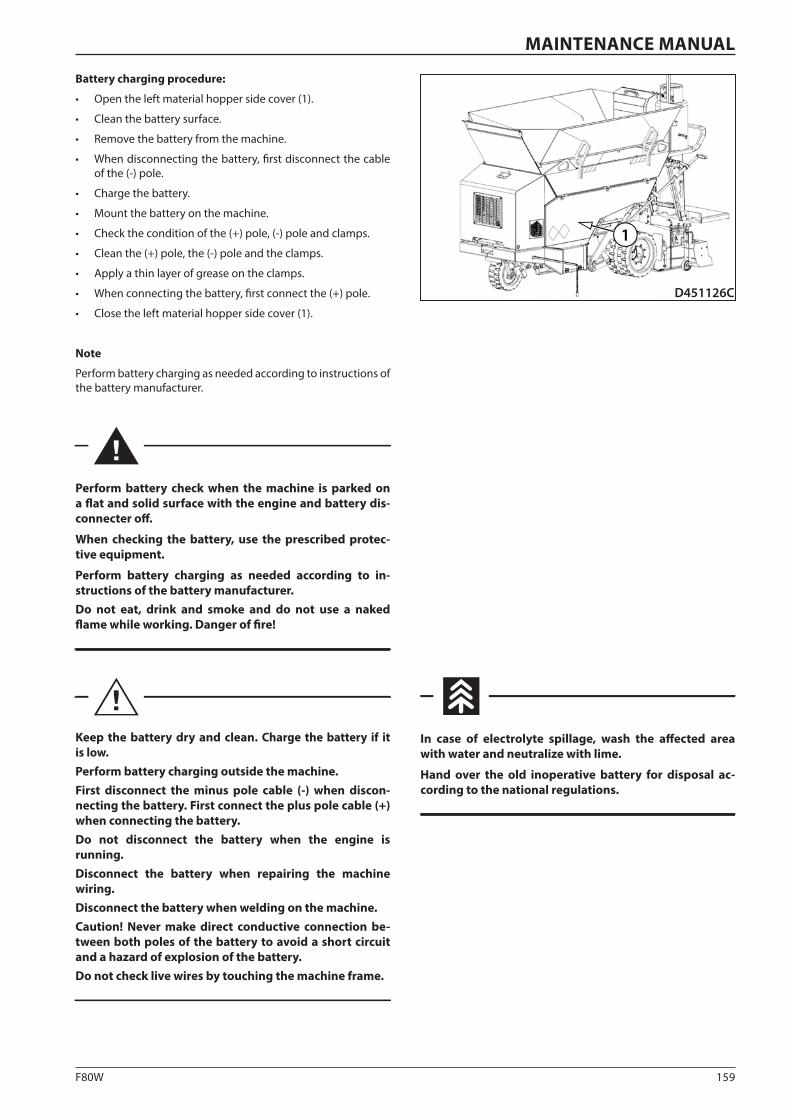
159F80W
D451126C
1
MAINTENANCE MANUAL
Battery charging procedure:
• Open the left material hopper side cover (1).
• Clean the battery surface.
• Remove the battery from the machine.
• When disconnecting the battery, first disconnect the cable of the (-) pole.
• Charge the battery.
• Mount the battery on the machine.
• Check the condition of the (+) pole, (-) pole and clamps.
• Clean the (+) pole, the (-) pole and the clamps.
• Apply a thin layer of grease on the clamps.
• When connecting the battery, first connect the (+) pole.
• Close the left material hopper side cover (1).
Note
Perform battery charging as needed according to instructions of the battery manufacturer.
Perform battery check when the machine is parked on a flat and solid surface with the engine and battery dis-connecter off.
When checking the battery, use the prescribed protec-tive equipment.
Perform battery charging as needed according to in-structions of the battery manufacturer.Do not eat, drink and smoke and do not use a naked flame while working. Danger of fire!
Keep the battery dry and clean. Charge the battery if it is low.Perform battery charging outside the machine.First disconnect the minus pole cable (-) when discon-necting the battery. First connect the plus pole cable (+) when connecting the battery.Do not disconnect the battery when the engine is running.Disconnect the battery when repairing the machine wiring.Disconnect the battery when welding on the machine.Caution! Never make direct conductive connection be-tween both poles of the battery to avoid a short circuit and a hazard of explosion of the battery.Do not check live wires by touching the machine frame.
In case of electrolyte spillage, wash the affected area with water and neutralize with lime.
Hand over the old inoperative battery for disposal ac-cording to the national regulations.
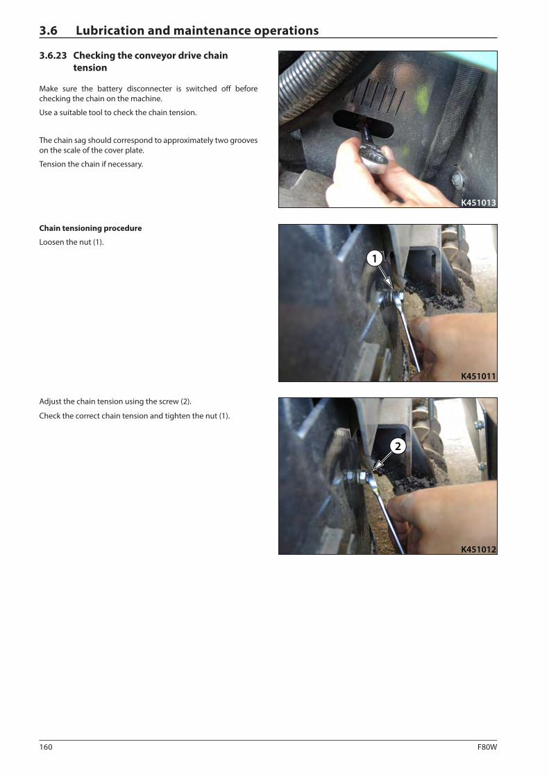
160 F80W
K451011
1
K451012
2
K451013
3.6 Lubrication and maintenance operations
3.6.23 Checking the conveyor drive chain tension
Make sure the battery disconnecter is switched off before checking the chain on the machine.
Use a suitable tool to check the chain tension.
The chain sag should correspond to approximately two grooves on the scale of the cover plate.
Tension the chain if necessary.
Chain tensioning procedure
Loosen the nut (1).
Adjust the chain tension using the screw (2).
Check the correct chain tension and tighten the nut (1).
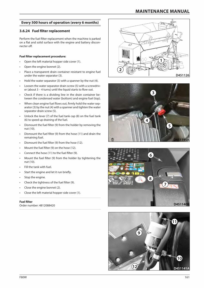
161F80W
D451141A
11
10
9
12
D451126
1
2
D451140B
6
78
D451195A
45
3
MAINTENANCE MANUAL
Every 500 hours of operation (every 6 months)
3.6.24 Fuel filter replacement
Perform the fuel filter replacement when the machine is parked on a flat and solid surface with the engine and battery discon-necter off.
Fuel filter replacement procedure:
• Open the left material hopper side cover (1).
• Open the engine bonnet (2).
• Place a transparent drain container resistant to engine fuel under the water separator (3).
• Hold the water separator (3) with a spanner by the nut (4).
• Loosen the water separator drain screw (5) with a screwdriv-er (about 3 – 4 turns) until the liquid starts to flow out.
• Check if there is a dividing line in the drain container be-tween the condensed water (bottom) and engine fuel (top).
• When clean engine fuel flows out, firmly hold the water sep-arator (3) by the nut (4) with a spanner and tighten the water separator drain screw (5).
• Unlock the lever (7) of the fuel tank cap (8) on the fuel tank (6) to speed up draining of the fuel.
• Dismount the fuel filter (9) from the holder by removing the nut (10).
• Dismount the fuel filter (9) from the hose (11) and drain the remaining fuel.
• Dismount the fuel filter (9) from the hose (12).
• Mount the fuel filter (9) on the hose (12).
• Connect the hose (11) to the fuel filter (9).
• Mount the fuel filter (9) from the holder by tightening the nut (10).
• Fill the tank with fuel.
• Start the engine and let it run briefly.
• Stop the engine.
• Check the tightness of the fuel filter (9).
• Close the engine bonnet (2).
• Close the left material hopper side cover (1).
Fuel filter Order number: 4812088420
162 F80W
3.6 Lubrication and maintenance operations
Replace the fuel filter when the machine is parked on a flat and solid surface, the engine and the battery discon-nector are off and the gas bottle is closed.
Do not smoke and do not use a naked flame while work-ing. Danger of fire!
Avoid inhaling vapours and avoid skin contact with die-sel fuel.
Use personal protective equipment.
Caution! There is a risk of burns from the hot parts of the machine.
Do not refuel when the engine is running; the machine must be parked on a flat and solid surface, the engine and the battery disconnector must be off and the gas bottle closed.
Caution! When draining the condensate, fuel can come in contact with hot parts of the engine and catch fire.
There is a risk of burns from the hot parts of the engine.
Refill the same fuel grade; see Chapter 3.2.2.
Check the fuel tank and the fuel circuit for leaks.
In case of detecting water condensation in the fuel tank, drain the condensate according to Chapter 3.6.12.
When loosening the drain screw, firmly hold the water separator using a spanner. There is a risk of damage by the water separator.
Catch the drained fuel and do not let it soak into the ground.
Stop the fluid soaking into the ground.
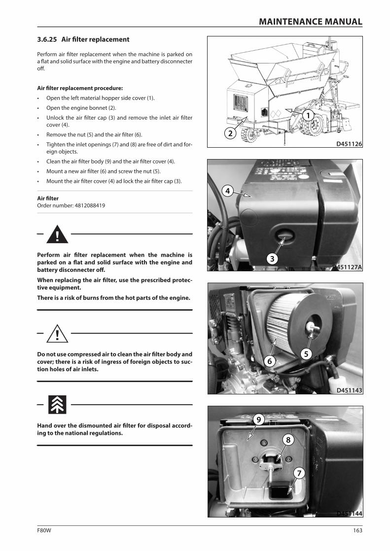
163F80W
D451143
65
D451144
9
8
7
D451126
1
2
D451127A3
4
MAINTENANCE MANUAL
3.6.25 Air filter replacement
Perform air filter replacement when the machine is parked on a flat and solid surface with the engine and battery disconnecter off.
Air filter replacement procedure:
• Open the left material hopper side cover (1).
• Open the engine bonnet (2).
• Unlock the air filter cap (3) and remove the inlet air filter cover (4).
• Remove the nut (5) and the air filter (6).
• Tighten the inlet openings (7) and (8) are free of dirt and for-eign objects.
• Clean the air filter body (9) and the air filter cover (4).
• Mount a new air filter (6) and screw the nut (5).
• Mount the air filter cover (4) ad lock the air filter cap (3).
Air filter Order number: 4812088419
Perform air filter replacement when the machine is parked on a flat and solid surface with the engine and battery disconnecter off.
When replacing the air filter, use the prescribed protec-tive equipment.
There is a risk of burns from the hot parts of the engine.
Do not use compressed air to clean the air filter body and cover; there is a risk of ingress of foreign objects to suc-tion holes of air inlets.
Hand over the dismounted air filter for disposal accord-ing to the national regulations.
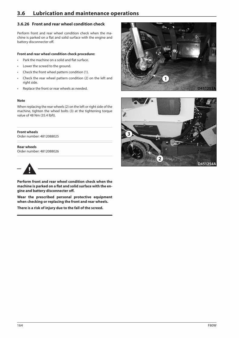
164 F80W
D451254A2
3
D451253A
1
3.6 Lubrication and maintenance operations
3.6.26 Front and rear wheel condition check
Perform front and rear wheel condition check when the ma-chine is parked on a flat and solid surface with the engine and battery disconnecter off.
Front and rear wheel condition check procedure:
• Park the machine on a solid and flat surface.
• Lower the screed to the ground.
• Check the front wheel pattern condition (1).
• Check the rear wheel pattern condition (2) on the left and right side.
• Replace the front or rear wheels as needed.
Note
When replacing the rear wheels (2) on the left or right side of the machine, tighten the wheel bolts (3) at the tightening torque value of 48 Nm (35.4 lbft).
Front wheels Order number: 4812088025
Rear wheels Order number: 4812088026
Perform front and rear wheel condition check when the machine is parked on a flat and solid surface with the en-gine and battery disconnecter off.
Wear the prescribed personal protective equipment when checking or replacing the front and rear wheels.
There is a risk of injury due to the fall of the screed.
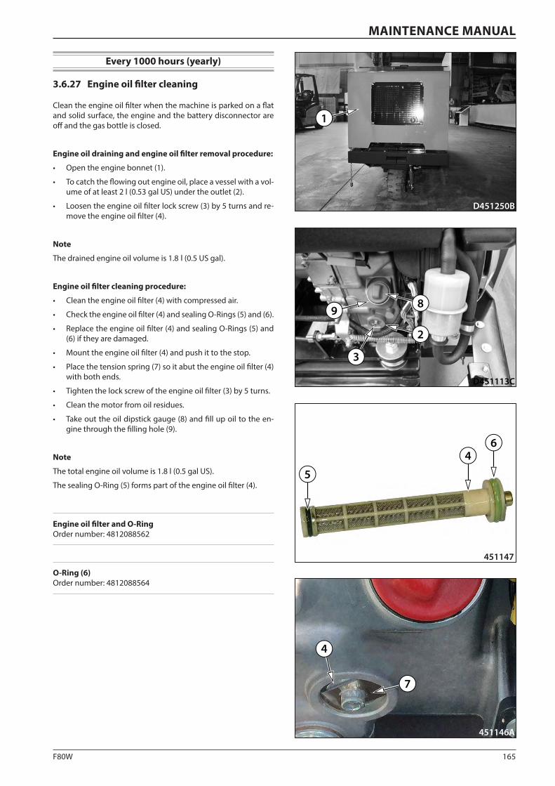
165F80W
D451113C
2
8
3
9
451147
64
5
D451250B
1
451146A
7
4
MAINTENANCE MANUAL
Every 1000 hours (yearly)
3.6.27 Engine oil filter cleaning
Clean the engine oil filter when the machine is parked on a flat and solid surface, the engine and the battery disconnector are off and the gas bottle is closed.
Engine oil draining and engine oil filter removal procedure:
• Open the engine bonnet (1).
• To catch the flowing out engine oil, place a vessel with a vol-ume of at least 2 l (0.53 gal US) under the outlet (2).
• Loosen the engine oil filter lock screw (3) by 5 turns and re-move the engine oil filter (4).
Note
The drained engine oil volume is 1.8 l (0.5 US gal).
Engine oil filter cleaning procedure:
• Clean the engine oil filter (4) with compressed air.
• Check the engine oil filter (4) and sealing O-Rings (5) and (6).
• Replace the engine oil filter (4) and sealing O-Rings (5) and (6) if they are damaged.
• Mount the engine oil filter (4) and push it to the stop.
• Place the tension spring (7) so it abut the engine oil filter (4) with both ends.
• Tighten the lock screw of the engine oil filter (3) by 5 turns.
• Clean the motor from oil residues.
• Take out the oil dipstick gauge (8) and fill up oil to the en-gine through the filling hole (9).
Note
The total engine oil volume is 1.8 l (0.5 gal US).
The sealing O-Ring (5) forms part of the engine oil filter (4).
Engine oil filter and O-Ring Order number: 4812088562
O-Ring (6) Order number: 4812088564
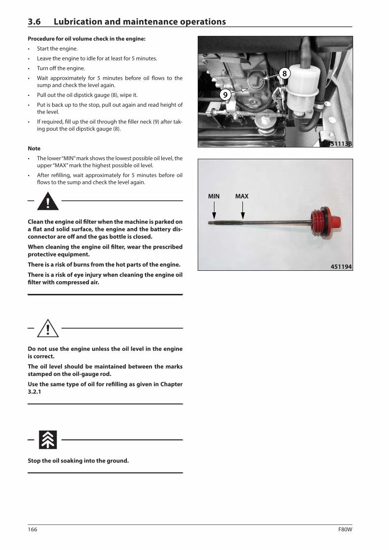
166 F80W
D451113B
8
9
451194
MIN MAX
3.6 Lubrication and maintenance operations
Procedure for oil volume check in the engine:
• Start the engine.
• Leave the engine to idle for at least for 5 minutes.
• Turn off the engine.
• Wait approximately for 5 minutes before oil flows to the sump and check the level again.
• Pull out the oil dipstick gauge (8), wipe it.
• Put is back up to the stop, pull out again and read height of the level.
• If required, fill up the oil through the filler neck (9) after tak-ing pout the oil dipstick gauge (8).
Note
• The lower “MIN” mark shows the lowest possible oil level, the upper “MAX” mark the highest possible oil level.
• After refilling, wait approximately for 5 minutes before oil flows to the sump and check the level again.
Clean the engine oil filter when the machine is parked on a flat and solid surface, the engine and the battery dis-connector are off and the gas bottle is closed.
When cleaning the engine oil filter, wear the prescribed protective equipment.
There is a risk of burns from the hot parts of the engine.
There is a risk of eye injury when cleaning the engine oil filter with compressed air.
Do not use the engine unless the oil level in the engine is correct.
The oil level should be maintained between the marks stamped on the oil-gauge rod.
Use the same type of oil for refilling as given in Chapter 3.2.1
Stop the oil soaking into the ground.
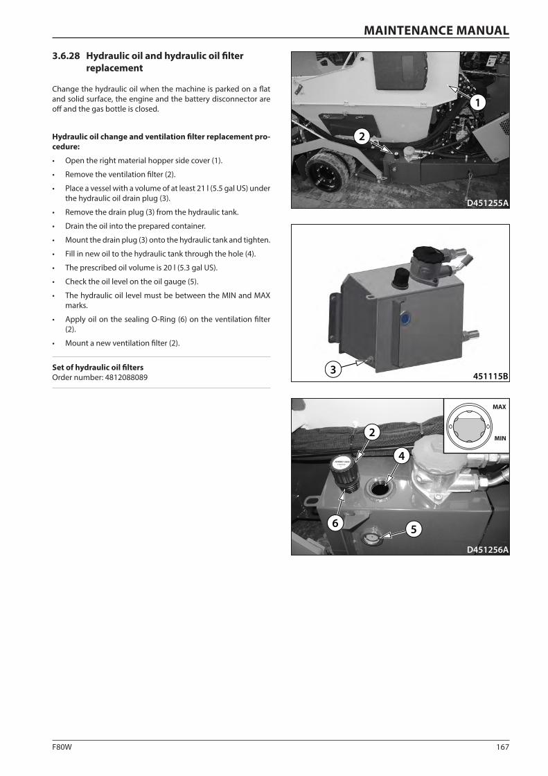
167F80W
D451256A
2
4
6
MAX
MIN
5
D451255A
2
1
451115B3
MAINTENANCE MANUAL
3.6.28 Hydraulic oil and hydraulic oil filter replacement
Change the hydraulic oil when the machine is parked on a flat and solid surface, the engine and the battery disconnector are off and the gas bottle is closed.
Hydraulic oil change and ventilation filter replacement pro-cedure:
• Open the right material hopper side cover (1).
• Remove the ventilation filter (2).
• Place a vessel with a volume of at least 21 l (5.5 gal US) under the hydraulic oil drain plug (3).
• Remove the drain plug (3) from the hydraulic tank.
• Drain the oil into the prepared container.
• Mount the drain plug (3) onto the hydraulic tank and tighten.
• Fill in new oil to the hydraulic tank through the hole (4).
• The prescribed oil volume is 20 l (5.3 gal US).
• Check the oil level on the oil gauge (5).
• The hydraulic oil level must be between the MIN and MAX marks.
• Apply oil on the sealing O-Ring (6) on the ventilation filter (2).
• Mount a new ventilation filter (2).
Set of hydraulic oil filters Order number: 4812088089
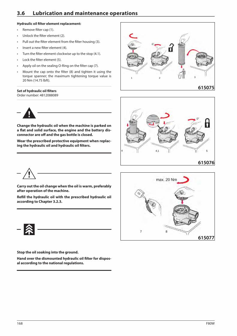
168 F80W
615075
21 3
615076
4 51,4
61507787
3.6 Lubrication and maintenance operations
Hydraulic oil filter element replacement:
• Remove filter cap (1).
• Unlock the filter element (2).
• Pull out the filter element from the filter housing (3).
• Insert a new filter element (4).
• Turn the filter element clockwise up to the stop (4.1).
• Lock the filter element (5).
• Apply oil on the sealing O-Ring on the filter cap (7).
• Mount the cap onto the filter (8) and tighten it using the torque spanner; the maximum tightening torque value is 20 Nm (14.75 lbft).
Set of hydraulic oil filters Order number: 4812088089
Change the hydraulic oil when the machine is parked on a flat and solid surface, the engine and the battery dis-connector are off and the gas bottle is closed.
Wear the prescribed protective equipment when replac-ing the hydraulic oil and hydraulic oil filters.
Carry out the oil change when the oil is warm, preferably after operation of the machine.
Refill the hydraulic oil with the prescribed hydraulic oil according to Chapter 3.2.3.
Stop the oil soaking into the ground.
Hand over the dismounted hydraulic oil filter for dispos-al according to the national regulations.
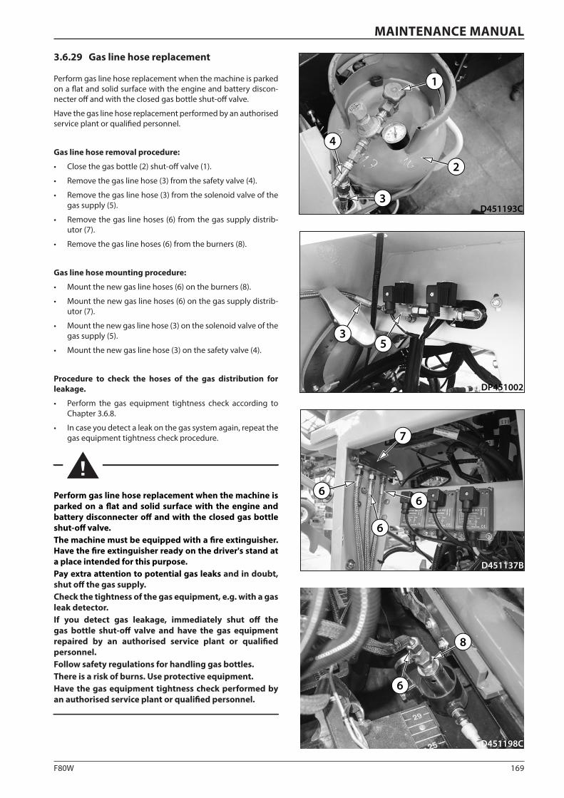
169F80W
D451137B
6
7
6
6
D451193C
1
4
2
3
D451198C
8
6
DP451002
35
MAINTENANCE MANUAL
3.6.29 Gas line hose replacement
Perform gas line hose replacement when the machine is parked on a flat and solid surface with the engine and battery discon-necter off and with the closed gas bottle shut-off valve.
Have the gas line hose replacement performed by an authorised service plant or qualified personnel.
Gas line hose removal procedure:
• Close the gas bottle (2) shut-off valve (1).
• Remove the gas line hose (3) from the safety valve (4).
• Remove the gas line hose (3) from the solenoid valve of the gas supply (5).
• Remove the gas line hoses (6) from the gas supply distrib-utor (7).
• Remove the gas line hoses (6) from the burners (8).
Gas line hose mounting procedure:
• Mount the new gas line hoses (6) on the burners (8).
• Mount the new gas line hoses (6) on the gas supply distrib-utor (7).
• Mount the new gas line hose (3) on the solenoid valve of the gas supply (5).
• Mount the new gas line hose (3) on the safety valve (4).
Procedure to check the hoses of the gas distribution for leakage.
• Perform the gas equipment tightness check according to Chapter 3.6.8.
• In case you detect a leak on the gas system again, repeat the gas equipment tightness check procedure.
Perform gas line hose replacement when the machine is parked on a flat and solid surface with the engine and battery disconnecter off and with the closed gas bottle shut-off valve.The machine must be equipped with a fire extinguisher. Have the fire extinguisher ready on the driver's stand at a place intended for this purpose.Pay extra attention to potential gas leaks and in doubt, shut off the gas supply. Check the tightness of the gas equipment, e.g. with a gas leak detector.If you detect gas leakage, immediately shut off the gas bottle shut-off valve and have the gas equipment repaired by an authorised service plant or qualified personnel.Follow safety regulations for handling gas bottles. There is a risk of burns. Use protective equipment.Have the gas equipment tightness check performed by an authorised service plant or qualified personnel.
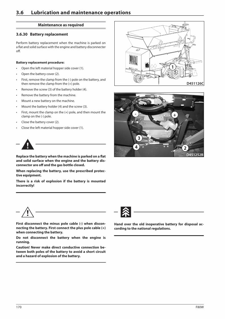
170 F80W
D451126C
1
D451252B
- +
24
3
3.6 Lubrication and maintenance operations
Maintenance as required
3.6.30 Battery replacement
Perform battery replacement when the machine is parked on a flat and solid surface with the engine and battery disconnecter off.
Battery replacement procedure:
• Open the left material hopper side cover (1).
• Open the battery cover (2).
• First, remove the clamp from the (-) pole on the battery, and then remove the clamp from the (+) pole.
• Remove the screw (3) of the battery holder (4).
• Remove the battery from the machine.
• Mount a new battery on the machine.
• Mount the battery holder (4) and the screw (3).
• First, mount the clamp on the (+) pole, and then mount the clamp on the (-) pole.
• Close the battery cover (2).
• Close the left material hopper side cover (1).
Replace the battery when the machine is parked on a flat and solid surface when the engine and the battery dis-connector are off and the gas bottle closed.
When replacing the battery, use the prescribed protec-tive equipment.
There is a risk of explosion if the battery is mounted incorrectly!
First disconnect the minus pole cable (-) when discon-necting the battery. First connect the plus pole cable (+) when connecting the battery.Do not disconnect the battery when the engine is running.Caution! Never make direct conductive connection be-tween both poles of the battery to avoid a short circuit and a hazard of explosion of the battery.
Hand over the old inoperative battery for disposal ac-cording to the national regulations.
171F80W
MAINTENANCE MANUAL
3.6.31 Charging of the battery
• Only use chargers with an appropriate rated voltage. Check that the charger is strong enough to charge the battery not too strong to charge with excessive current.
• Read and observe the operating manual of the charger ma-nufacturer.
• Check that the ventilation holes in the battery cover are not dirty or clogged and that gases can escape freely.
• Connect the positive terminal (+) of the battery to the posi-tive terminal of the charger.
• Connect the negative terminal (-) of the battery to the nega-tive terminal of the charger.
• Turn on the charger only after connecting the battery.
• Charge the battery with current corresponding to one tenth of the battery capacity.
• After charging, first turn off the charger and then disconnect the cables from the battery.
• The battery is fully charged, if:
- electric current and voltage remain constant in the case of voltage-controlled chargers,
- the charging voltage in the case of current-controlled chargers does not increase within two hours, the auto-matic charger turns off or switches to maintaining char-ge.
Use rubber gloves and eye protection devices when handling the battery.Use suitable clothing to protect your skin against con-tact with the electrolyte.After eye contact with the battery electrolyte, immedia-tely flush the affected eye thoroughly with running wa-ter for several minutes. Then seek medical advice.After ingestion of the electrolyte drink large quantities of milk, water or suspension of magnesium hydroxide in water.In case of skin contact with electrolyte, remove your clothing and shoes, wash the affected skin immediately with soap and water or with solution of water and soda. Then seek medical advice.Do not eat, drink and smoke while working!After completing the work, wash your hands and face thoroughly with water and soap!Do not check that a wire is live by touching the machine frame.
When working with the battery always follow instruc-tions of the battery manufacturer!Never charge a frozen battery or battery with a tempera-ture above 45 °C.Stop charging if the battery is hot or leaking acid.Check that the ventilation holes in the battery cover are not dirty or clogged and that gases can escape freely. If the ventilation holes are clogged, gases can accumulate inside the battery and irreversibly damage it.Never make direct conductive connection between both poles of the battery to avoid a short circuit and a risk of explosion of the battery.
Do not turn the battery upside down, the electrolyte can flow out.If the electrolyte is spilled, wash the affected area with water and neutralize with lime. Hand over the old inoperative battery for disposal.
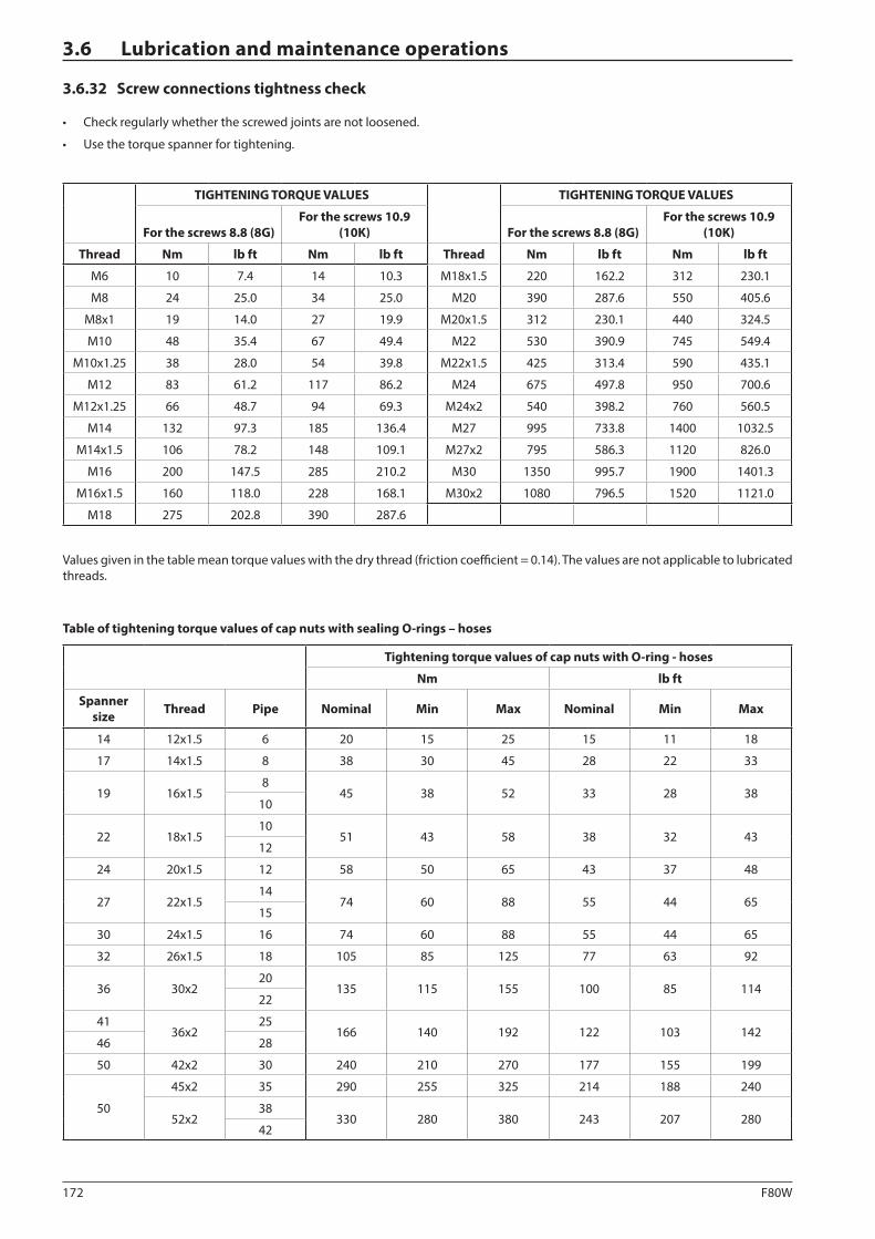
172 F80W
3.6 Lubrication and maintenance operations
3.6.32 Screw connections tightness check
• Check regularly whether the screwed joints are not loosened.
• Use the torque spanner for tightening.
TIGHTENING TORQUE VALUES TIGHTENING TORQUE VALUES
For the screws 8.8 (8G)For the screws 10.9
(10K) For the screws 8.8 (8G)For the screws 10.9
(10K)
Thread Nm lb ft Nm lb ft Thread Nm lb ft Nm lb ft
M6 10 7.4 14 10.3 M18x1.5 220 162.2 312 230.1
M8 24 25.0 34 25.0 M20 390 287.6 550 405.6
M8x1 19 14.0 27 19.9 M20x1.5 312 230.1 440 324.5
M10 48 35.4 67 49.4 M22 530 390.9 745 549.4
M10x1.25 38 28.0 54 39.8 M22x1.5 425 313.4 590 435.1
M12 83 61.2 117 86.2 M24 675 497.8 950 700.6
M12x1.25 66 48.7 94 69.3 M24x2 540 398.2 760 560.5
M14 132 97.3 185 136.4 M27 995 733.8 1400 1032.5
M14x1.5 106 78.2 148 109.1 M27x2 795 586.3 1120 826.0
M16 200 147.5 285 210.2 M30 1350 995.7 1900 1401.3
M16x1.5 160 118.0 228 168.1 M30x2 1080 796.5 1520 1121.0
M18 275 202.8 390 287.6
Values given in the table mean torque values with the dry thread (friction coefficient = 0.14). The values are not applicable to lubricated threads.
Table of tightening torque values of cap nuts with sealing O-rings – hoses
Tightening torque values of cap nuts with O-ring - hoses
Nm lb ft
Spanner size Thread Pipe Nominal Min Max Nominal Min Max
14 12x1.5 6 20 15 25 15 11 18
17 14x1.5 8 38 30 45 28 22 33
19 16x1.58
45 38 52 33 28 3810
22 18x1.510
51 43 58 38 32 4312
24 20x1.5 12 58 50 65 43 37 48
27 22x1.514
74 60 88 55 44 6515
30 24x1.5 16 74 60 88 55 44 65
32 26x1.5 18 105 85 125 77 63 92
36 30x220
135 115 155 100 85 11422
4136x2
25166 140 192 122 103 142
46 28
50 42x2 30 240 210 270 177 155 199
50
45x2 35 290 255 325 214 188 240
52x238
330 280 380 243 207 28042
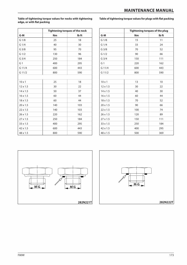
173F80W
M-GM-G
282N221T
M-G
282N222T
MAINTENANCE MANUAL
Table of tightening torque values for necks with tightening edge, or with flat packing
Tightening torques of the neck
G-M Nm lb ft
G 1/8 25 18
G 1/4 40 30
G 3/8 95 70
G 1/2 130 96
G 3/4 250 184
G 1 400 295
G 11/4 600 443
G 11/2 800 590
10 x 1 25 18
12 x 1.5 30 22
14 x 1.5 50 37
16 x 1.5 60 44
18 x 1.5 60 44
20 x 1.5 140 103
22 x 1.5 140 103
26 x 1.5 220 162
27 x 1.5 250 184
33 x 1.5 400 295
42 x 1.5 600 443
48 x 1.5 800 590
Table of tightening torque values for plugs with flat packing
Tightening torques of the plug
G-M Nm lb ft
G 1/8 15 11
G 1/4 33 24
G 3/8 70 52
G 1/2 90 66
G 3/4 150 111
G 1 220 162
G 11/4 600 443
G 11/2 800 590
10 x 1 13 10
12 x 1.5 30 22
14 x 1.5 40 30
16 x 1.5 60 44
18 x 1.5 70 52
20 x 1.5 90 66
22 x 1.5 100 74
26 x 1.5 120 89
27 x 1.5 150 111
33 x 1.5 250 184
42 x 1.5 400 295
48 x 1.5 500 369

174 F80W
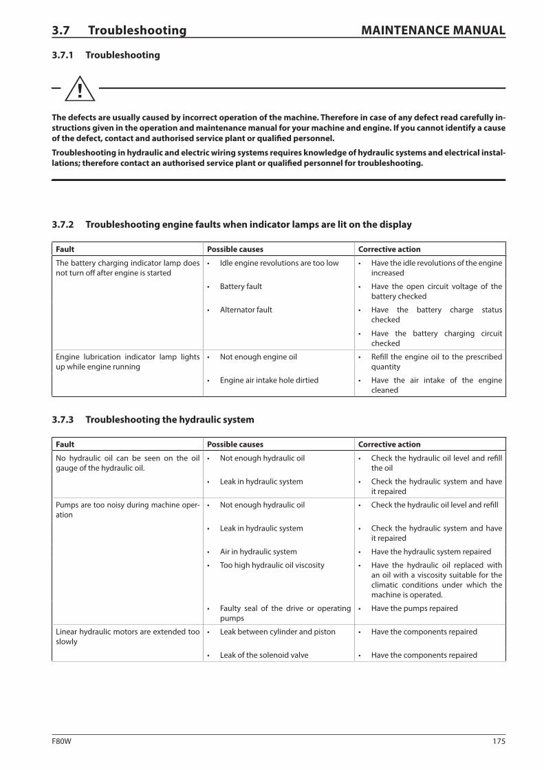
175F80W
MAINTENANCE MANUAL3.7 Troubleshooting
3.7.1 Troubleshooting
The defects are usually caused by incorrect operation of the machine. Therefore in case of any defect read carefully in-structions given in the operation and maintenance manual for your machine and engine. If you cannot identify a cause of the defect, contact and authorised service plant or qualified personnel.
Troubleshooting in hydraulic and electric wiring systems requires knowledge of hydraulic systems and electrical instal-lations; therefore contact an authorised service plant or qualified personnel for troubleshooting.
3.7.2 Troubleshooting engine faults when indicator lamps are lit on the display
Fault Possible causes Corrective action
The battery charging indicator lamp does not turn off after engine is started
• Idle engine revolutions are too low • Have the idle revolutions of the engine increased
• Battery fault • Have the open circuit voltage of the battery checked
• Alternator fault • Have the battery charge status checked
• Have the battery charging circuit checked
Engine lubrication indicator lamp lights up while engine running
• Not enough engine oil • Refill the engine oil to the prescribed quantity
• Engine air intake hole dirtied • Have the air intake of the engine cleaned
3.7.3 Troubleshooting the hydraulic system
Fault Possible causes Corrective action
No hydraulic oil can be seen on the oil gauge of the hydraulic oil.
• Not enough hydraulic oil • Check the hydraulic oil level and refill the oil
• Leak in hydraulic system • Check the hydraulic system and have it repaired
Pumps are too noisy during machine oper-ation
• Not enough hydraulic oil • Check the hydraulic oil level and refill
• Leak in hydraulic system • Check the hydraulic system and have it repaired
• Air in hydraulic system • Have the hydraulic system repaired
• Too high hydraulic oil viscosity • Have the hydraulic oil replaced with an oil with a viscosity suitable for the climatic conditions under which the machine is operated.
• Faulty seal of the drive or operating pumps
• Have the pumps repaired
Linear hydraulic motors are extended too slowly
• Leak between cylinder and piston • Have the components repaired
• Leak of the solenoid valve • Have the components repaired
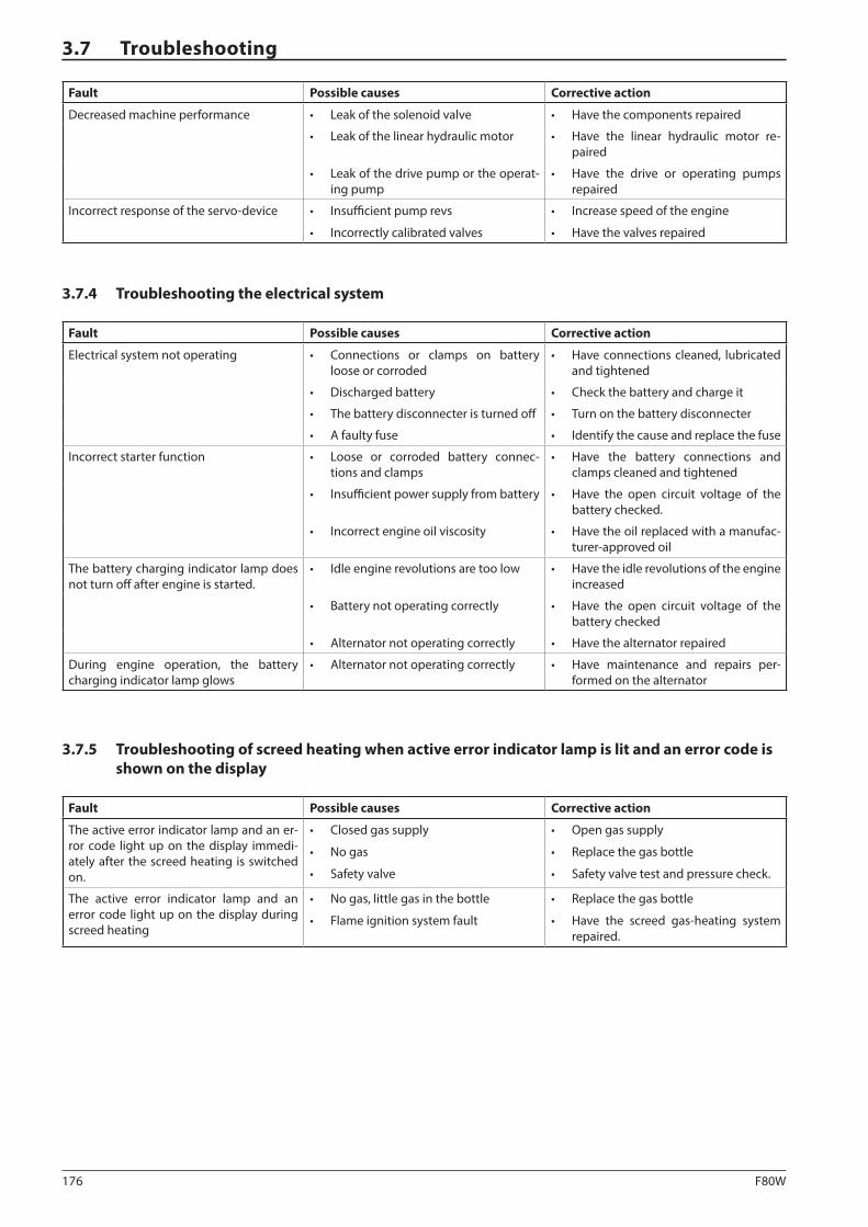
176 F80W
3.7 Troubleshooting
Fault Possible causes Corrective action
Decreased machine performance • Leak of the solenoid valve • Have the components repaired
• Leak of the linear hydraulic motor • Have the linear hydraulic motor re-paired
• Leak of the drive pump or the operat-ing pump
• Have the drive or operating pumps repaired
Incorrect response of the servo-device • Insufficient pump revs
• Incorrectly calibrated valves
• Increase speed of the engine
• Have the valves repaired
3.7.4 Troubleshooting the electrical system
Fault Possible causes Corrective action
Electrical system not operating • Connections or clamps on battery loose or corroded
• Have connections cleaned, lubricated and tightened
• Discharged battery • Check the battery and charge it
• The battery disconnecter is turned off • Turn on the battery disconnecter
• A faulty fuse • Identify the cause and replace the fuse
Incorrect starter function • Loose or corroded battery connec-tions and clamps
• Have the battery connections and clamps cleaned and tightened
• Insufficient power supply from battery • Have the open circuit voltage of the battery checked.
• Incorrect engine oil viscosity • Have the oil replaced with a manufac-turer-approved oil
The battery charging indicator lamp does not turn off after engine is started.
• Idle engine revolutions are too low • Have the idle revolutions of the engine increased
• Battery not operating correctly • Have the open circuit voltage of the battery checked
• Alternator not operating correctly • Have the alternator repaired
During engine operation, the battery charging indicator lamp glows
• Alternator not operating correctly • Have maintenance and repairs per-formed on the alternator
3.7.5 Troubleshooting of screed heating when active error indicator lamp is lit and an error code is shown on the display
Fault Possible causes Corrective action
The active error indicator lamp and an er-ror code light up on the display immedi-ately after the screed heating is switched on.
• Closed gas supply
• No gas
• Safety valve
• Open gas supply
• Replace the gas bottle
• Safety valve test and pressure check.
The active error indicator lamp and an error code light up on the display during screed heating
• No gas, little gas in the bottle
• Flame ignition system fault
• Replace the gas bottle
• Have the screed gas-heating system repaired.
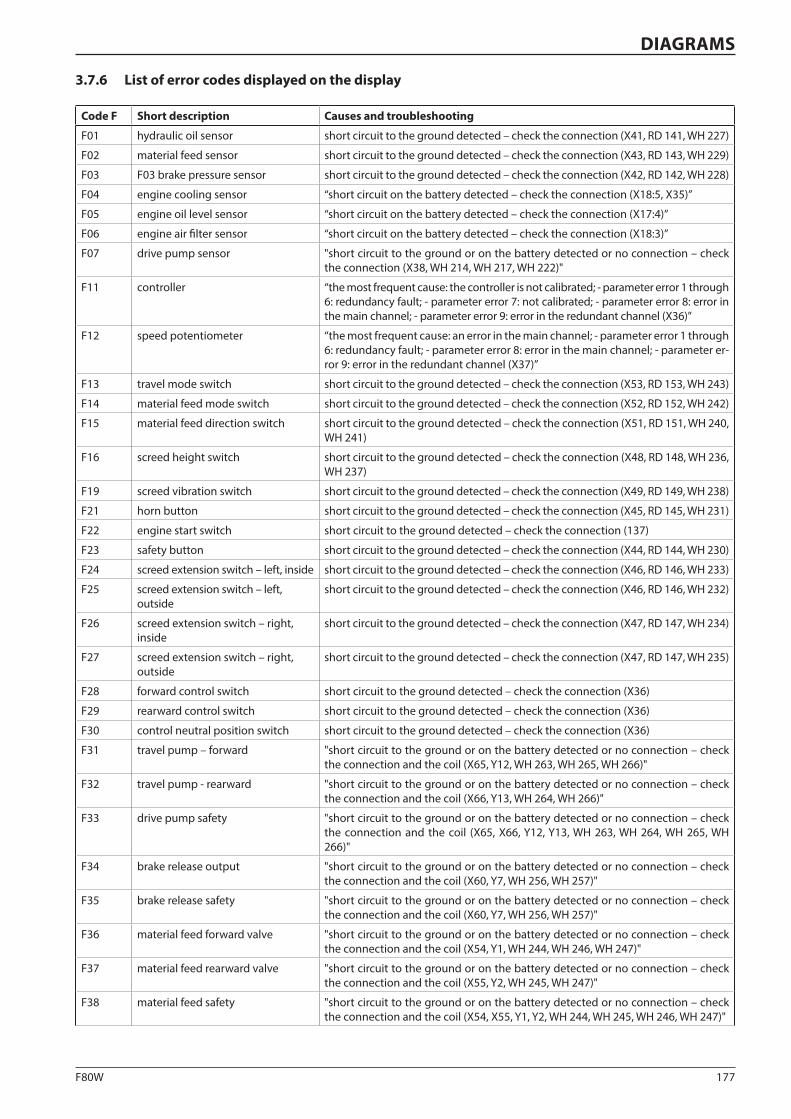
177F80W
DIAGRAMS
3.7.6 List of error codes displayed on the display
Code F Short description Causes and troubleshooting
F01 hydraulic oil sensor short circuit to the ground detected – check the connection (X41, RD 141, WH 227)
F02 material feed sensor short circuit to the ground detected – check the connection (X43, RD 143, WH 229)
F03 F03 brake pressure sensor short circuit to the ground detected – check the connection (X42, RD 142, WH 228)
F04 engine cooling sensor “short circuit on the battery detected – check the connection (X18:5, X35)”
F05 engine oil level sensor “short circuit on the battery detected – check the connection (X17:4)”
F06 engine air filter sensor “short circuit on the battery detected – check the connection (X18:3)”
F07 drive pump sensor "short circuit to the ground or on the battery detected or no connection – check the connection (X38, WH 214, WH 217, WH 222)"
F11 controller “the most frequent cause: the controller is not calibrated; - parameter error 1 through 6: redundancy fault; - parameter error 7: not calibrated; - parameter error 8: error in the main channel; - parameter error 9: error in the redundant channel (X36)”
F12 speed potentiometer “the most frequent cause: an error in the main channel; - parameter error 1 through 6: redundancy fault; - parameter error 8: error in the main channel; - parameter er-ror 9: error in the redundant channel (X37)”
F13 travel mode switch short circuit to the ground detected – check the connection (X53, RD 153, WH 243)
F14 material feed mode switch short circuit to the ground detected – check the connection (X52, RD 152, WH 242)
F15 material feed direction switch short circuit to the ground detected – check the connection (X51, RD 151, WH 240, WH 241)
F16 screed height switch short circuit to the ground detected – check the connection (X48, RD 148, WH 236, WH 237)
F19 screed vibration switch short circuit to the ground detected – check the connection (X49, RD 149, WH 238)
F21 horn button short circuit to the ground detected – check the connection (X45, RD 145, WH 231)
F22 engine start switch short circuit to the ground detected – check the connection (137)
F23 safety button short circuit to the ground detected – check the connection (X44, RD 144, WH 230)
F24 screed extension switch – left, inside short circuit to the ground detected – check the connection (X46, RD 146, WH 233)
F25 screed extension switch – left, outside
short circuit to the ground detected – check the connection (X46, RD 146, WH 232)
F26 screed extension switch – right, inside
short circuit to the ground detected – check the connection (X47, RD 147, WH 234)
F27 screed extension switch – right, outside
short circuit to the ground detected – check the connection (X47, RD 147, WH 235)
F28 forward control switch short circuit to the ground detected – check the connection (X36)
F29 rearward control switch short circuit to the ground detected – check the connection (X36)
F30 control neutral position switch short circuit to the ground detected – check the connection (X36)
F31 travel pump – forward "short circuit to the ground or on the battery detected or no connection – check the connection and the coil (X65, Y12, WH 263, WH 265, WH 266)"
F32 travel pump - rearward "short circuit to the ground or on the battery detected or no connection – check the connection and the coil (X66, Y13, WH 264, WH 266)"
F33 drive pump safety "short circuit to the ground or on the battery detected or no connection – check the connection and the coil (X65, X66, Y12, Y13, WH 263, WH 264, WH 265, WH 266)"
F34 brake release output "short circuit to the ground or on the battery detected or no connection – check the connection and the coil (X60, Y7, WH 256, WH 257)"
F35 brake release safety "short circuit to the ground or on the battery detected or no connection – check the connection and the coil (X60, Y7, WH 256, WH 257)"
F36 material feed forward valve "short circuit to the ground or on the battery detected or no connection – check the connection and the coil (X54, Y1, WH 244, WH 246, WH 247)"
F37 material feed rearward valve "short circuit to the ground or on the battery detected or no connection – check the connection and the coil (X55, Y2, WH 245, WH 247)"
F38 material feed safety "short circuit to the ground or on the battery detected or no connection – check the connection and the coil (X54, X55, Y1, Y2, WH 244, WH 245, WH 246, WH 247)"
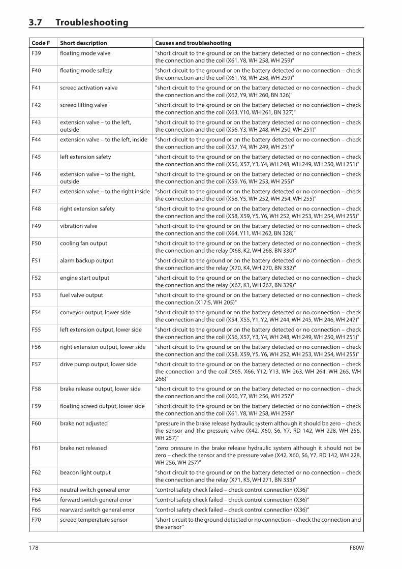
178 F80W
3.7 Troubleshooting
Code F Short description Causes and troubleshooting
F39 floating mode valve "short circuit to the ground or on the battery detected or no connection – check the connection and the coil (X61, Y8, WH 258, WH 259)"
F40 floating mode safety "short circuit to the ground or on the battery detected or no connection – check the connection and the coil (X61, Y8, WH 258, WH 259)"
F41 screed activation valve "short circuit to the ground or on the battery detected or no connection – check the connection and the coil (X62, Y9, WH 260, BN 326)"
F42 screed lifting valve "short circuit to the ground or on the battery detected or no connection – check the connection and the coil (X63, Y10, WH 261, BN 327)"
F43 extension valve – to the left, outside
"short circuit to the ground or on the battery detected or no connection – check the connection and the coil (X56, Y3, WH 248, WH 250, WH 251)"
F44 extension valve – to the left, inside "short circuit to the ground or on the battery detected or no connection – check the connection and the coil (X57, Y4, WH 249, WH 251)"
F45 left extension safety "short circuit to the ground or on the battery detected or no connection – check the connection and the coil (X56, X57, Y3, Y4, WH 248, WH 249, WH 250, WH 251)"
F46 extension valve – to the right, outside
"short circuit to the ground or on the battery detected or no connection – check the connection and the coil (X59, Y6, WH 253, WH 255)"
F47 extension valve – to the right inside "short circuit to the ground or on the battery detected or no connection – check the connection and the coil (X58, Y5, WH 252, WH 254, WH 255)"
F48 right extension safety "short circuit to the ground or on the battery detected or no connection – check the connection and the coil (X58, X59, Y5, Y6, WH 252, WH 253, WH 254, WH 255)"
F49 vibration valve "short circuit to the ground or on the battery detected or no connection – check the connection and the coil (X64, Y11, WH 262, BN 328)"
F50 cooling fan output "short circuit to the ground or on the battery detected or no connection – check the connection and the relay (X68, K2, WH 268, BN 330)"
F51 alarm backup output "short circuit to the ground or on the battery detected or no connection – check the connection and the relay (X70, K4, WH 270, BN 332)"
F52 engine start output "short circuit to the ground or on the battery detected or no connection – check the connection and the relay (X67, K1, WH 267, BN 329)"
F53 fuel valve output "short circuit to the ground or on the battery detected or no connection – check the connection (X17:5, WH 205)"
F54 conveyor output, lower side "short circuit to the ground or on the battery detected or no connection – check the connection and the coil (X54, X55, Y1, Y2, WH 244, WH 245, WH 246, WH 247)"
F55 left extension output, lower side "short circuit to the ground or on the battery detected or no connection – check the connection and the coil (X56, X57, Y3, Y4, WH 248, WH 249, WH 250, WH 251)"
F56 right extension output, lower side "short circuit to the ground or on the battery detected or no connection – check the connection and the coil (X58, X59, Y5, Y6, WH 252, WH 253, WH 254, WH 255)"
F57 drive pump output, lower side "short circuit to the ground or on the battery detected or no connection – check the connection and the coil (X65, X66, Y12, Y13, WH 263, WH 264, WH 265, WH 266)"
F58 brake release output, lower side "short circuit to the ground or on the battery detected or no connection – check the connection and the coil (X60, Y7, WH 256, WH 257)"
F59 floating screed output, lower side "short circuit to the ground or on the battery detected or no connection – check the connection and the coil (X61, Y8, WH 258, WH 259)"
F60 brake not adjusted "pressure in the brake release hydraulic system although it should be zero – check the sensor and the pressure valve (X42, X60, S6, Y7, RD 142, WH 228, WH 256, WH 257)"
F61 brake not released "zero pressure in the brake release hydraulic system although it should not be zero – check the sensor and the pressure valve (X42, X60, S6, Y7, RD 142, WH 228, WH 256, WH 257)”
F62 beacon light output "short circuit to the ground or on the battery detected or no connection – check the connection and the relay (X71, K5, WH 271, BN 333)"
F63 neutral switch general error “control safety check failed – check control connection (X36)”
F64 forward switch general error “control safety check failed – check control connection (X36)”
F65 rearward switch general error “control safety check failed – check control connection (X36)”
F70 screed temperature sensor “short circuit to the ground detected or no connection – check the connection and the sensor”
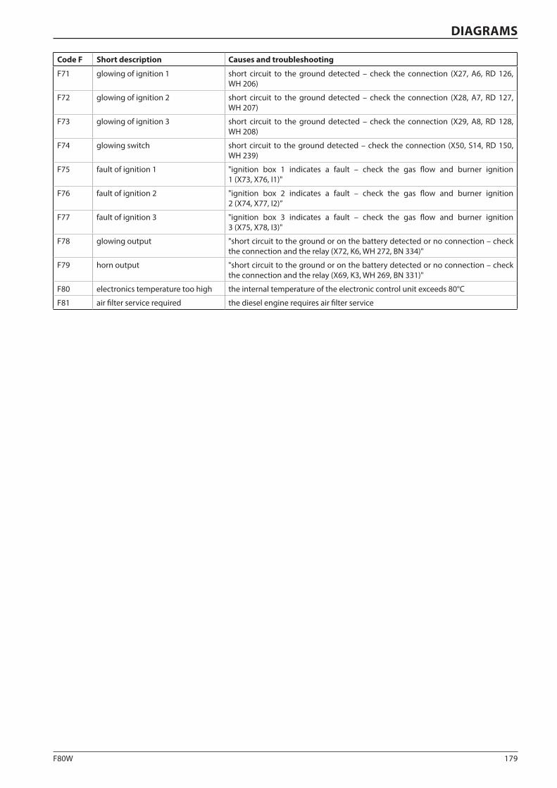
179F80W
DIAGRAMS
Code F Short description Causes and troubleshooting
F71 glowing of ignition 1 short circuit to the ground detected – check the connection (X27, A6, RD 126, WH 206)
F72 glowing of ignition 2 short circuit to the ground detected – check the connection (X28, A7, RD 127, WH 207)
F73 glowing of ignition 3 short circuit to the ground detected – check the connection (X29, A8, RD 128, WH 208)
F74 glowing switch short circuit to the ground detected – check the connection (X50, S14, RD 150, WH 239)
F75 fault of ignition 1 "ignition box 1 indicates a fault – check the gas flow and burner ignition 1 (X73, X76, I1)"
F76 fault of ignition 2 "ignition box 2 indicates a fault – check the gas flow and burner ignition 2 (X74, X77, I2)”
F77 fault of ignition 3 "ignition box 3 indicates a fault – check the gas flow and burner ignition 3 (X75, X78, I3)"
F78 glowing output "short circuit to the ground or on the battery detected or no connection – check the connection and the relay (X72, K6, WH 272, BN 334)"
F79 horn output "short circuit to the ground or on the battery detected or no connection – check the connection and the relay (X69, K3, WH 269, BN 331)"
F80 electronics temperature too high the internal temperature of the electronic control unit exceeds 80°C
F81 air filter service required the diesel engine requires air filter service

180 F80W
A1 Diesel engine
A2 Control unit Bodas RC
A3 Display
A4 Drive lever
A5 Diagnostic socket
A6 Screed gas heating controller 1 (left)
A7 Screed gas heating controller 2 (middle)
A8 Screed gas heating controller 3 (right)
F1 - F8 Fuses
F9 Main fuse
F10 Starter fuse
G1 Battery
H1 Warning beacon
H2 Auger lighting
I1 Burner ignition (left)
I2 Burner ignition (middle)
I3 Burner ignition (right)
K1 - K6 Relay
K10 Relay
M1 Oil cooling fan
P1 Horn
P2 Reverse beeper
R1 Speed control POT wiper
R2 Pump angle POT wiper
R3 - R6 Resistor
S1 Disconnector
S2 Emergency brake button
S3 Ignition switch
S5 Oil temperature switch
S6 Brake pressure switch
S7 Feed switch
S8 Foot switch
S9 Horn button
S10 Paving width switch left
S11 Paving width switch right
S12 Screed lift/lower switch
S13 Vibration switch
S14 Screed heating switch
S15 Conveyor direction switch
S16 Mode selector
S17 Transport/operating mode switch
S18 Screed temperature switch
Y1 Conveyor/auger right
Y2 Conveyor/auger reverse
Y3 Screed extension left ejection
Y4 Screed extension left retraction
Y5 Screed extension right retraction
Y6 Screed extension right ejection
Y7 Brake release
Y8 Screed floating position
Y9 Screed release
Y10 Screed lift
Y11 Screed vibration
Y12 Drive pump forward
Y13 Drive pump back ward
Y14 Solenoid of the gas shut-off valve
Y15 Solenoid of the gas shut-off valve
3.8 Appendices3.8 Appendices
3.8.1 Machine wiring diagram
Legend:

181F80W
1 2 3 4 5
12V 77AhM
T
X18: 5
X17: 3
X8: B+
X17: 2
X17: 6
X17: 4
X17: 5
X18: 6
X3:
30A
30A
3087
87a
85 86 30
15/5
4
5817 1950a
X17: 1
A2
BOD
AS R
C28-
14/3
0
X34:54
154
X34:78
178
X34:85
185
X34: 7
107
X34: 6
106
X34:79
179
X34:89
189
X34:90
190
X34:80
180
X34:28
128
X34:84
184
X34:75
175
X34:86
186
X5:
1
3A
X12: 1
X34:24
124
X7: 8
X34:23
123
X7: 7
X34:22
122
X7: 6
X35:46
246
X7: 5
X35:33
233
X7: 4
X35:20
220
X7: 3
X35: 7
207
X7: 2
X35: 2
202
X7: 1 X34:20
120X34:37
137X35:22
222X35:38
238X34:33
133
X34:58
158
X34:36
136
X35:14
214
X34:42
142X34:36
136X35:34
234X35:47
247X35:12
212X35:25
225
X35:24
224
X34:43
143
X35:39
239
X35:51
251
X35:37
237X35:48
248X34:35
135
X4:
1
X35:28
228
X34:14
114
X6: 14
X34:73
173
X34:12
112
X34:93
193
X7: 12
X34:48
148
X35:23
223
X34:59
159
D
E
F
21
21
21
21 3
21 3
2
31
2
31
G1
A1
F9
F10
K1
S3
F1S5
S6
S7
S8
S9
S2
S16
S13
S14
S10
S11
S12
S15
Y1
Y2
Y3
Y4
Y5
Y6
Y7
Y8
S1
37156_1en
Screed up
Screed �oat
Screed extension right out
Screed extension right in
Screed extension left out
Screed extension left in
Conveyor/auger reverse
Conveyor/auger feed forward
Enginer oil pressure
Engine speed pulse
Engine temp.
Gas ignition 1
Gas ignition 2
Gas ignition 3
Fuel valve
MAINTENANCE MANUAL

182 F80W
A1 Diesel engine
A2 Control unit Bodas RC
A3 Display
A4 Drive lever
A5 Diagnostic socket
A6 Screed gas heating controller 1 (left)
A7 Screed gas heating controller 2 (middle)
A8 Screed gas heating controller 3 (right)
F1 - F8 Fuses
F9 Main fuse
F10 Starter fuse
G1 Battery
H1 Warning beacon
H2 Auger lighting
I1 Burner ignition (left)
I2 Burner ignition (middle)
I3 Burner ignition (right)
K1 - K6 Relay
K10 Relay
M1 Oil cooling fan
P1 Horn
P2 Reverse beeper
R1 Speed control POT wiper
R2 Pump angle POT wiper
R3 - R6 Resistor
S1 Disconnector
S2 Emergency brake button
S3 Ignition switch
S5 Oil temperature switch
S6 Brake pressure switch
S7 Feed switch
S8 Foot switch
S9 Horn button
S10 Paving width switch left
S11 Paving width switch right
S12 Screed lift/lower switch
S13 Vibration switch
S14 Screed heating switch
S15 Conveyor direction switch
S16 Mode selector
S17 Transport/operating mode switch
S18 Screed temperature switch
Y1 Conveyor/auger right
Y2 Conveyor/auger reverse
Y3 Screed extension left ejection
Y4 Screed extension left retraction
Y5 Screed extension right retraction
Y6 Screed extension right ejection
Y7 Brake release
Y8 Screed floating position
Y9 Screed release
Y10 Screed lift
Y11 Screed vibration
Y12 Drive pump forward
Y13 Drive pump back ward
Y14 Solenoid of the gas shut-off valve
Y15 Solenoid of the gas shut-off valve
3.8 Appendices
Machine wiring diagram
Legend:
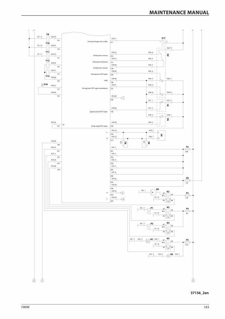
183F80W
1 2 3 4 5
X34:75
152
X34:75
176
X34:75
151
X7: 9
X7: 10
X7: 11
X34:53
153
X34:77
177
X34:83
183
X35:11
211
X36: 9
X36: 7
X36:12X36:14
X36:13
X36: 5
X36: 6
X36: 2
X36: 3
X36: 8X35:52
252X34:57
157X34:44
144
X34:64
164
X35:31
231
X34:46
146
X37: 2
X37: 1 X37: 3
X38: 2
X38: 3 X38: 1
X34:66
166
X35:26
226
X35:55
255
X39: 2
X39: 7
120
120
25A
X35: 1
201X35: 3
203
X35: 4
204
X35: 5
205
X35: 6
206
5A
X35:45
245X35:58
258
15AX7: 13
3087
87a
85 86
MX6: 1
3087
87a
85 865A
X6: 2
X7: 14
3087
87a
85 86
X6: 3
X7: 15
X35:41
241
X34: 3
103
X35:43
243
X34:49
149
7.5A
3087
87a
85 86
X7: 16
X23: 1X23: 2X6: 4
X24: 1X24: 2X6: 5
AB
X34:94
194
C
X35:53
253X35:54
254
G
H
X35:40
240I
5V
21
X34:21
121
X34:45
145
X35:15
215
X35:16
216
H
L
H
L
H
L
A4
R1R2
R4R3
A5
F2
F8
F3K2M1
K3 F4P1
K4P2
F5K5H1
H2
S17
Y9
Y10
Y11
Y12
Y13
S18
Conveyor/auger auto mode
Driving lever reverse
Driving lever forward
Driving lever neutral
Driving lever POT wiper
Driving lever POT wiper redundancy
GND
Speed control POT wiper
Pump angle POT wiper
37156_2en
MAINTENANCE MANUAL

184 F80W
A1 Diesel engine
A2 Control unit Bodas RC
A3 Display
A4 Drive lever
A5 Diagnostic socket
A6 Screed gas heating controller 1 (left)
A7 Screed gas heating controller 2 (middle)
A8 Screed gas heating controller 3 (right)
F1 - F8 Fuses
F9 Main fuse
F10 Starter fuse
G1 Battery
H1 Warning beacon
H2 Auger lighting
I1 Burner ignition (left)
I2 Burner ignition (middle)
I3 Burner ignition (right)
K1 - K6 Relay
K10 Relay
M1 Oil cooling fan
P1 Horn
P2 Reverse beeper
R1 Speed control POT wiper
R2 Pump angle POT wiper
R3 - R6 Resistor
S1 Disconnector
S2 Emergency brake button
S3 Ignition switch
S5 Oil temperature switch
S6 Brake pressure switch
S7 Feed switch
S8 Foot switch
S9 Horn button
S10 Paving width switch left
S11 Paving width switch right
S12 Screed lift/lower switch
S13 Vibration switch
S14 Screed heating switch
S15 Conveyor direction switch
S16 Mode selector
S17 Transport/operating mode switch
S18 Screed temperature switch
Y1 Conveyor/auger right
Y2 Conveyor/auger reverse
Y3 Screed extension left ejection
Y4 Screed extension left retraction
Y5 Screed extension right retraction
Y6 Screed extension right ejection
Y7 Brake release
Y8 Screed floating position
Y9 Screed release
Y10 Screed lift
Y11 Screed vibration
Y12 Drive pump forward
Y13 Drive pump back ward
Y14 Solenoid of the gas shut-off valve
Y15 Solenoid of the gas shut-off valve
3.8 Appendices
Machine wiring diagram
Legend:
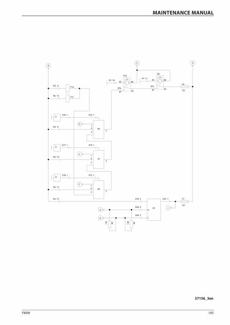
185F80W
A
F6
5A
BC
X7: 17X7: 18
Y14
Y15
X6: 6
X6: 15
A63
X6: 8D
A73
X6: 10E
A83
X6: 12F
I1X73: 1X76: 1
I2X74: 1X77: 1
I3X75: 1X78: 1
F7
2AA3
X33: 1X33: 5
X40: 6
X40: 7
R6120
R5120
G
H
X6: 13
I
K6
3087
87a
8685
K10
3087
87a
8685
14
2
14
2
14
2
H
L
37156_3en
MAINTENANCE MANUAL

186 F80W
1 Travel pump
2 Operating pump
3 Left travel motor
4 Right travel motor
5 Suction return filter
6 Hydraulic oil cooler
7 Hydraulic system block
8 Augers
9 Screed lifting/lowering hydraulic cylinder
10 Left paving width hydraulic cylinder
11 Right paving width hydraulic cylinder
12 Control unit
13 Steering
A.1 *Vibration unit right
A.2 *Vibration unit left
3.8 Appendices
3.8.2 Machine hydraulic system diagram
Legend:
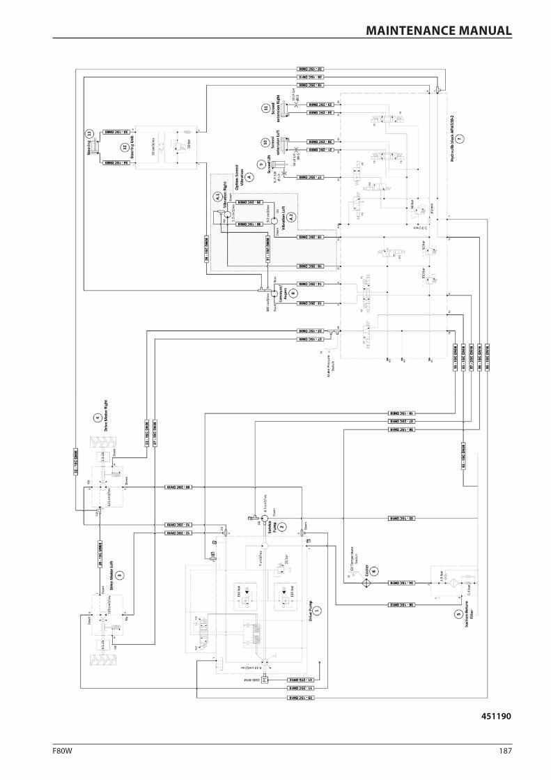
187F80W
451190
MAINTENANCE MANUAL
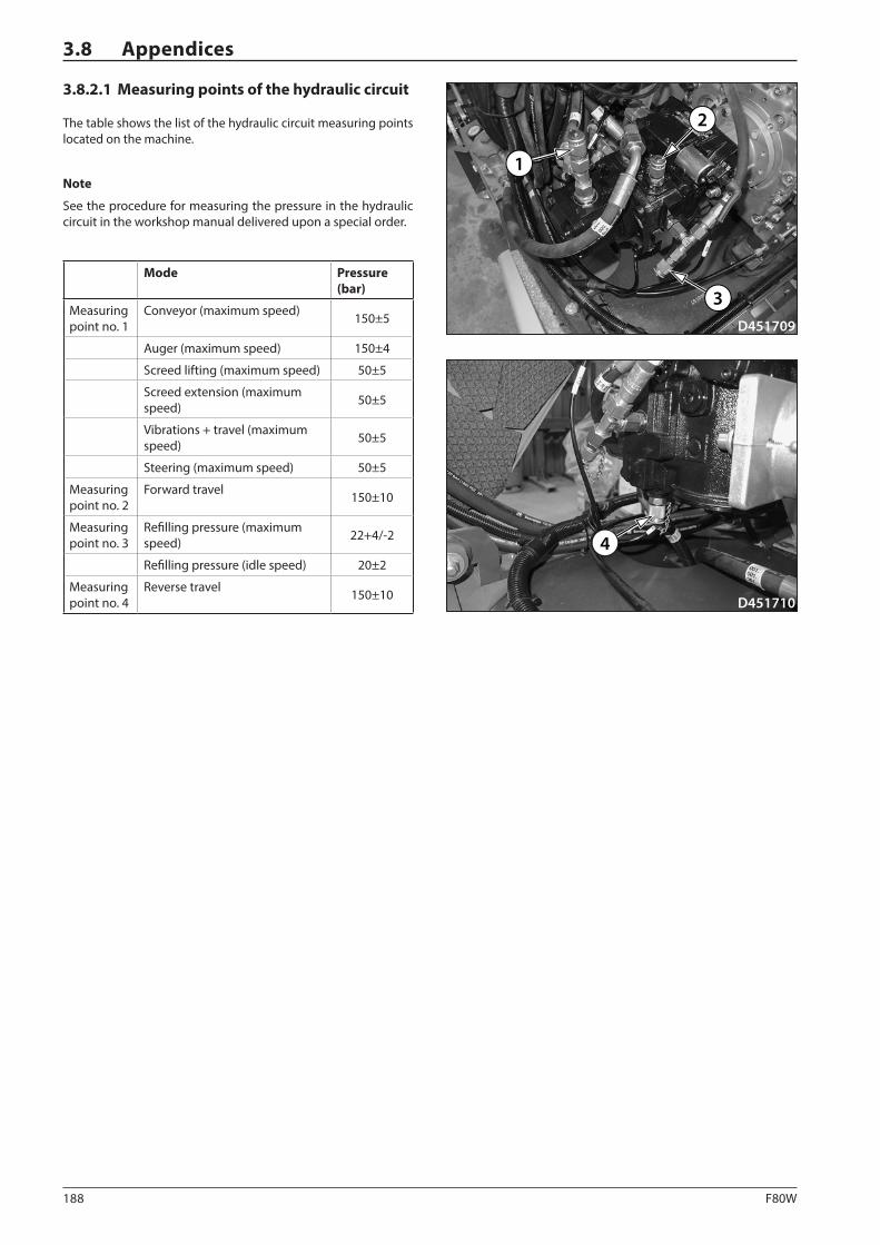
188 F80W
D451709
1
2
3
D451710
4
3.8 Appendices
3.8.2.1 Measuring points of the hydraulic circuit
The table shows the list of the hydraulic circuit measuring points located on the machine.
Note
See the procedure for measuring the pressure in the hydraulic circuit in the workshop manual delivered upon a special order.
Mode Pressure (bar)
Measuring point no. 1
Conveyor (maximum speed) 150±5
Auger (maximum speed) 150±4
Screed lifting (maximum speed) 50±5
Screed extension (maximum speed) 50±5
Vibrations + travel (maximum speed) 50±5
Steering (maximum speed) 50±5
Measuring point no. 2
Forward travel 150±10
Measuring point no. 3
Refilling pressure (maximum speed) 22+4/-2
Refilling pressure (idle speed) 20±2
Measuring point no. 4
Reverse travel 150±10
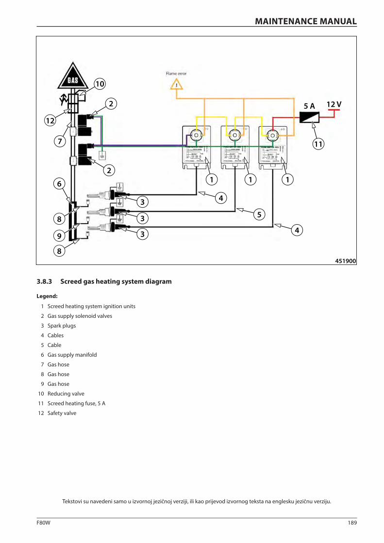
189F80W
451900
1 1 1
11
5 A 12 V
2
2
10
12
3
3
3
4
5
4
6
7
8
9
8
1 Screed heating system ignition units
2 Gas supply solenoid valves
3 Spark plugs
4 Cables
5 Cable
6 Gas supply manifold
7 Gas hose
8 Gas hose
9 Gas hose
10 Reducing valve
11 Screed heating fuse, 5 A
12 Safety valve
Tekstovi su navedeni samo u izvornoj jezičnoj verziji, ili kao prijevod izvornog teksta na englesku jezičnu verziju.
MAINTENANCE MANUAL
3.8.3 Screed gas heating system diagram
Legend:
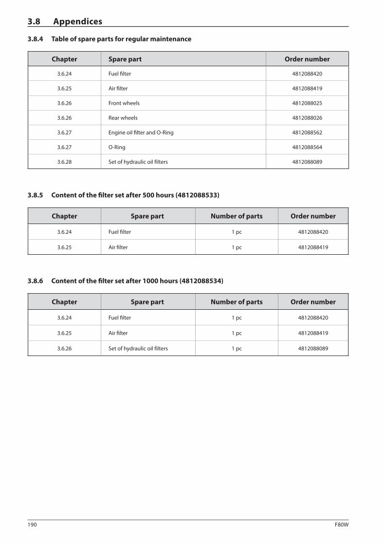
190 F80W
3.8 Appendices
3.8.4 Table of spare parts for regular maintenance
Chapter Spare part Order number
3.6.24 Fuel filter 4812088420
3.6.25 Air filter 4812088419
3.6.26 Front wheels 4812088025
3.6.26 Rear wheels 4812088026
3.6.27 Engine oil filter and O-Ring 4812088562
3.6.27 O-Ring 4812088564
3.6.28 Set of hydraulic oil filters 4812088089
3.8.5 Content of the filter set after 500 hours (4812088533)
Chapter Spare part Number of parts Order number
3.6.24 Fuel filter 1 pc 4812088420
3.6.25 Air filter 1 pc 4812088419
3.8.6 Content of the filter set after 1000 hours (4812088534)
Chapter Spare part Number of parts Order number
3.6.24 Fuel filter 1 pc 4812088420
3.6.25 Air filter 1 pc 4812088419
3.6.26 Set of hydraulic oil filters 1 pc 4812088089

191F80W
MAINTENANCE MANUAL
3.8.7 Table of optional equipment
Chapter Optional equipment Order number
1.4.2 Mechanical screed extension 4812061017
1.4.3 Dual wheels 4812061018
1.4.4 Front wheel scraper 4812061021
1.4.5 Material hopper extension 4812061019
1.4.6 Additional lighting 4812061020

192 F80W
3.8 Appendices
Notes


F80W
, Hat
z
www.dynapac.com
NÁV
OD
K O
BSLU
ZE
NÁVOD K OBSLUZEAsfaltový finišér kolovýF80WHatz
4812217931
Poznámka: Laminace lesklá 1+1 (oboustranná), horizontální a vertikální ořez dle ořezových značek, 2x big - 205 mm vnější a 210 mm vnitřní od okraje čistého formátu, dodávka obálek v přeloženém a baleném stavu po jednotlivých typech.
Related Documents


