Operating Manual motrona GmbH, Zeppelinstraße 16, DE - 78244 Gottmadingen, Tel. +49 (0) 7731 9332-0, Fax +49 (0) 7731 9332-30, [email protected], www.motrona.de Signal converter FU210 / IV210 / ZU210 Frequency (FU210) Analog (current / voltage) Serial (RS232 / RS485) Pulse counter (ZU210) SSI absolute value (IV210) Product features: Multifunctional unit with several operating modes for incremental encoders or SSI absolute encoders For incremental encoders: Operating modes as frequency converter or position transducer (pulse counter) Universal incremental inputs (HTL/TTL/RS422) for NPN/PNP/NAMUR encoders and sensors Functions such as linkages (eg. A+B), scaling, filters, start-up bridging, … Input frequencies up to 1 MHz For SSI absolute encoders: Master or Slave operation with clock frequencies up to 1 MHz For single turn and multi turn encoders with SSI formats from 10 … 32 Bit Functions such as bit suppression, round-loop function, scaling, … 16 bit analog output, configurable for voltage or current operation RS232/RS485-interface for configuration and serial readout Extremely short conversion times Linearization with 24 control points Auxiliary voltage output 5 and 24VDC for encoder supply Numerous connection options via 6 control inputs and 6 control outputs Compact rail housing to EN60715 Easy parameterization via user interface OS 6.0 (Freeware)

Welcome message from author
This document is posted to help you gain knowledge. Please leave a comment to let me know what you think about it! Share it to your friends and learn new things together.
Transcript
Operating Manual
motrona GmbH, Zeppelinstraße 16, DE - 78244 Gottmadingen, Tel. +49 (0) 7731 9332-0, Fax +49 (0) 7731 9332-30, [email protected], www.motrona.de
Signal converter FU210 / IV210 / ZU210
Frequency (FU210)
Analog (current / voltage)
Serial (RS232 / RS485) Pulse counter (ZU210)
SSI absolute value (IV210)
Product features:
Multifunctional unit with several operating modes for incremental encoders or SSI absolute encoders
For incremental encoders:
Operating modes as frequency converter or position transducer (pulse counter)
Universal incremental inputs (HTL/TTL/RS422) for NPN/PNP/NAMUR encoders and sensors
Functions such as linkages (eg. A+B), scaling, filters, start-up bridging, …
Input frequencies up to 1 MHz
For SSI absolute encoders:
Master or Slave operation with clock frequencies up to 1 MHz
For single turn and multi turn encoders with SSI formats from 10 … 32 Bit
Functions such as bit suppression, round-loop function, scaling, …
16 bit analog output, configurable for voltage or current operation
RS232/RS485-interface for configuration and serial readout
Extremely short conversion times
Linearization with 24 control points
Auxiliary voltage output 5 and 24VDC for encoder supply
Numerous connection options via 6 control inputs and 6 control outputs
Compact rail housing to EN60715
Easy parameterization via user interface OS 6.0 (Freeware)
ZU210_02a_oi_e .docx / Nov-19 page 2 / 63
Die deutsche Beschreibung ist verfügbar unter: https://www.motrona.com/fileadmin/files/bedienungsanleitungen/ZU210_d.pdf
The English description is available at: https://www.motrona.com/fileadmin/files/bedienungsanleitungen/ZU210_e.pdf
La description en français est disponible sur: https://www.motrona.com/fileadmin/files/bedienungsanleitungen/ZU210_f.pdf
https://www.motrona.com/en/support/software.html
Version: Description:
ZU210_01a_oi/tgo/April 19 First Version
Zu210_01b/mbo/August 19 New added: chapter “Compatibility Hint”
ZU210_02a_oi/tgo/November 19 Extension of QR-code and of new filter functions at Mode Frequency
Legal notices::
All contents included in this manual are protected by the terms of use and copyrights of motrona
GmbH. Any reproduction, modification, usage or publication in other electronic and printed media
as well as in the internet requires prior written authorization by motrona GmbH.
ZU210_02a_oi_e .docx / Nov-19 page 3 / 63
Table of Contents Safety Instructions and Responsibility .......................................................................... 5
General Safety Instructions ............................................................................................................. 5
Use according to the intended purpose .......................................................................................... 5
Installation ....................................................................................................................................... 6
Cleaning, Maintenance and Service Notes..................................................................................... 6
Compatibility Hint ........................................................................................................ 7
Introduction .................................................................................................................. 8
Operating Mode ............................................................................................................................... 8
Function diagram ............................................................................................................................. 8
Power – LED / Error messages ........................................................................................................ 9
Electrical Connections ................................................................................................ 10
DC Power Supply (X1) .................................................................................................................... 10
Hilfsspannungs-Ausgang (X2) ....................................................................................................... 10
Incremental encoder input (X2) ..................................................................................................... 11
Absolute encoder input (X2) .......................................................................................................... 13
Control Inputs (X5) ......................................................................................................................... 15
Analog output (X4) ......................................................................................................................... 16
Serial interface (X3) ....................................................................................................................... 17
Control outputs (X6) ....................................................................................................................... 18
Parameter / Overview-Menu Structure ....................................................................... 19
General Menu ................................................................................................................................ 21
Mode Frequency ............................................................................................................................ 23
Mode Counter ................................................................................................................................ 28
Mode SSI........................................................................................................................................ 29
Preselection Values ....................................................................................................................... 31
Preselection 1 Menu ...................................................................................................................... 32
Preselection 2 Menu ...................................................................................................................... 35
Preselection 3 Menu ...................................................................................................................... 36
Preselection 4 Menu ...................................................................................................................... 37
Preselection 5 Menu ...................................................................................................................... 38
Preselection 6 Menu ...................................................................................................................... 39
Serial Menu ................................................................................................................................... 40
Analog Menu ................................................................................................................................. 42
Command Menu ............................................................................................................................. 43
Linearization Menu ........................................................................................................................ 45
Appendix .................................................................................................................... 46
Data readout via serial interface ................................................................................................... 46
Modbus RTU Interface ................................................................................................................... 47
Parameter setting .............................................................................................................................. 47
Read Holding Registers and Write Multiple Registers .................................................................... 48
Read Coils and Write Single Coil ...................................................................................................... 49
Diagnose ............................................................................................................................................ 50
Parameter / serial codes................................................................................................................ 51
Linearization ................................................................................................................................... 56
Reading SSI-Value ......................................................................................................................... 58

ZU210_02a_oi_e .docx / Nov-19 page 4 / 63
Internal processing and calculation of SSI data ........................................................................... 59
Dimensions .................................................................................................................................... 62
Technical Specifications: ............................................................................................................... 63
ZU210_02a_oi_e .docx / Nov-19 page 5 / 63
Safety Instructions and Responsibility
General Safety Instructions This operation manual is a significant component of the unit and includes important rules and hints
about the installation, function and usage. Non-observance can result in damage and/or impairment
of the functions to the unit or the machine or even in injury to persons using the equipment!
Please read the following instructions carefully before operating the device and observe all safety
and warning instructions! Keep the manual for later use.
A pertinent qualification of the respective staff is a fundamental requirement in order to use these
manual. The unit must be installed, connected and put into operation by a qualified electrician.
Liability exclusion: The manufacturer is not liable for personal injury and/or damage to property and
for consequential damage, due to incorrect handling, installation and operation. Further claims, due
to errors in the operation manual as well as misinterpretations are excluded from liability.
In addition the manufacturer reserves the right to modify the hardware, software or operation
manual at any time and without prior notice. Therefore, there might be minor differences between
the unit and the descriptions in operation manual.
The raiser respectively positioner is exclusively responsible for the safety of the system and
equipment where the unit will be integrated.
During installation or maintenance all general and also all country- and application-specific safety
rules and standards must be observed.
If the device is used in processes, where a failure or faulty operation could damage the system or
injure persons, appropriate precautions to avoid such consequences must be taken.
Use according to the intended purpose The unit is intended exclusively for use in industrial machines, constructions and systems. Non-
conforming usage does not correspond to the provisions and lies within the sole responsibility of the
user. The manufacturer is not liable for damages which have arisen through unsuitable and improper
use.
Please note that device may only be installed in proper form and used in a technically perfect
condition (in accordance to the Technical Specifications). The device is not suitable for operation in
explosion-proof areas or areas which are excluded by the EN 61010-1 standard.

ZU210_02a_oi_e .docx / Nov-19 page 6 / 63
Installation The device is only allowed to be installed and operated within the permissible temperature range.
Please ensure an adequate ventilation and avoid all direct contact between the device and hot or
aggressive gases and liquids.
Before installation or maintenance, the unit must be disconnected from all voltage-sources. Further
it must be ensured that no danger can arise by touching the disconnected voltage-sources.
Devices which are supplied by AC-voltages must be connected exclusively by switches, respectively
circuit-breakers with the low voltage network. The switch or circuit-breaker must be placed as near
as possible to the device and further indicated as separator.
Incoming as well as outgoing wires and wires for extra low voltages (ELV) must be separated from
dangerous electrical cables (SELV circuits) by using a double resp. increased isolation.
All selected wires and isolations must be conform to the provided voltage- and temperature-ranges.
Further all country- and application-specific standards, which are relevant for structure, form and
quality of the wires, must be ensured. Indications about the permissible wire cross-sections for
wiring are described in the Technical Specifications.
Before first start-up it must be ensured that all connections and wires are firmly seated and secured
in the screw terminals. All (inclusively unused) terminals must be fastened by turning the relevant
screws clockwise up to the stop.
Overvoltages at the connections must be limited to values in accordance to the overvoltage category
II.
For placement, wiring, environmental conditions as well as shielding and earthing/grounding of the
supply lines the general standards of industrial automation industry and the specific shielding
instructions of the manufacturer are valid. Please find all respective hints and rules on
https://www.motrona.com/en/support --> “[General EMC Rules for Wiring, Screening and Earthing]”.
Cleaning, Maintenance and Service Notes To clean the front of the unit please use only a slightly damp (not wet!), soft cloth. For the rear no
cleaning is necessary. For an unscheduled, individual cleaning of the rear the maintenance staff or
assembler is self-responsible.
During normal operation no maintenance is necessary. In case of unexpected problems, failures or
malfunctions the device must be shipped for back to the manufacturer for checking, adjustment and
reparation (if necessary). Unauthorized opening and repairing can have negative effects or failures to
the protection-measures of the unit.
ZU210_02a_oi_e .docx / Nov-19 page 7 / 63
Compatibility Hint
This product is a successor model of the thousand fold proven converter type
ZU252 / FU252 / IV251.
This converter is able to replace functionally the previous model; however some minor differences
have to be observed with regard to the parameter settings.
The main differences between this product and the respective predecessor model are listed below.
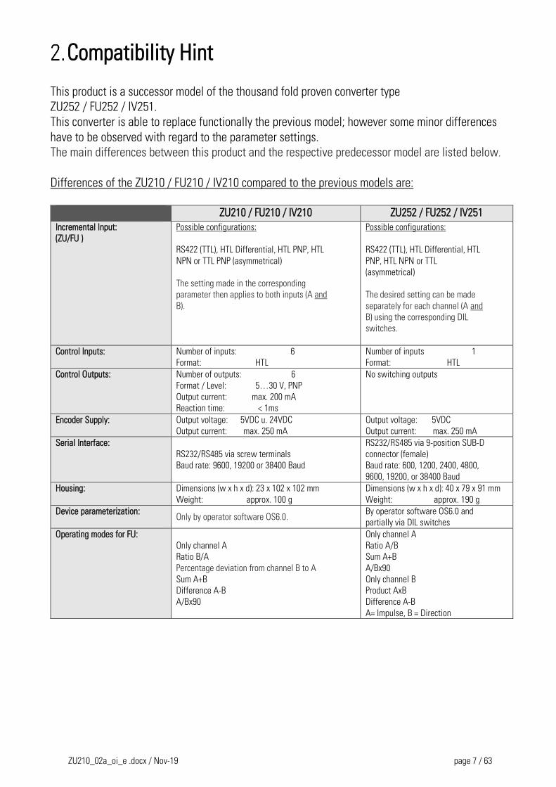
Differences of the ZU210 / FU210 / IV210 compared to the previous models are:
ZU210 / FU210 / IV210 ZU252 / FU252 / IV251
Incremental Input:
(ZU/FU )
Possible configurations:
RS422 (TTL), HTL Differential, HTL PNP, HTL
NPN or TTL PNP (asymmetrical)
The setting made in the corresponding
parameter then applies to both inputs (A and
B).
Possible configurations:
RS422 (TTL), HTL Differential, HTL
PNP, HTL NPN or TTL
(asymmetrical)
The desired setting can be made
separately for each channel (A and
B) using the corresponding DIL
switches.
Control Inputs: Number of inputs: 6
Format: HTL
Number of inputs 1
Format: HTL
Control Outputs: Number of outputs: 6
Format / Level: 5…30 V, PNP
Output current: max. 200 mA
Reaction time: < 1ms
No switching outputs
Encoder Supply: Output voltage: 5VDC u. 24VDC
Output current: max. 250 mA
Output voltage: 5VDC
Output current: max. 250 mA
Serial Interface:
RS232/RS485 via screw terminals
Baud rate: 9600, 19200 or 38400 Baud
RS232/RS485 via 9-position SUB-D
connector (female)
Baud rate: 600, 1200, 2400, 4800,
9600, 19200, or 38400 Baud
Housing: Dimensions (w x h x d): 23 x 102 x 102 mm
Weight: approx. 100 g
Dimensions (w x h x d): 40 x 79 x 91 mm
Weight: approx. 190 g Device parameterization:
Only by operator software OS6.0. By operator software OS6.0 and
partially via DIL switches
Operating modes for FU:
Only channel A
Ratio B/A
Percentage deviation from channel B to A
Sum A+B
Difference A-B
A/Bx90
Only channel A
Ratio A/B
Sum A+B
A/Bx90
Only channel B
Product AxB
Difference A-B
A= Impulse, B = Direction
ZU210_02a_oi_e .docx / Nov-19 page 8 / 63
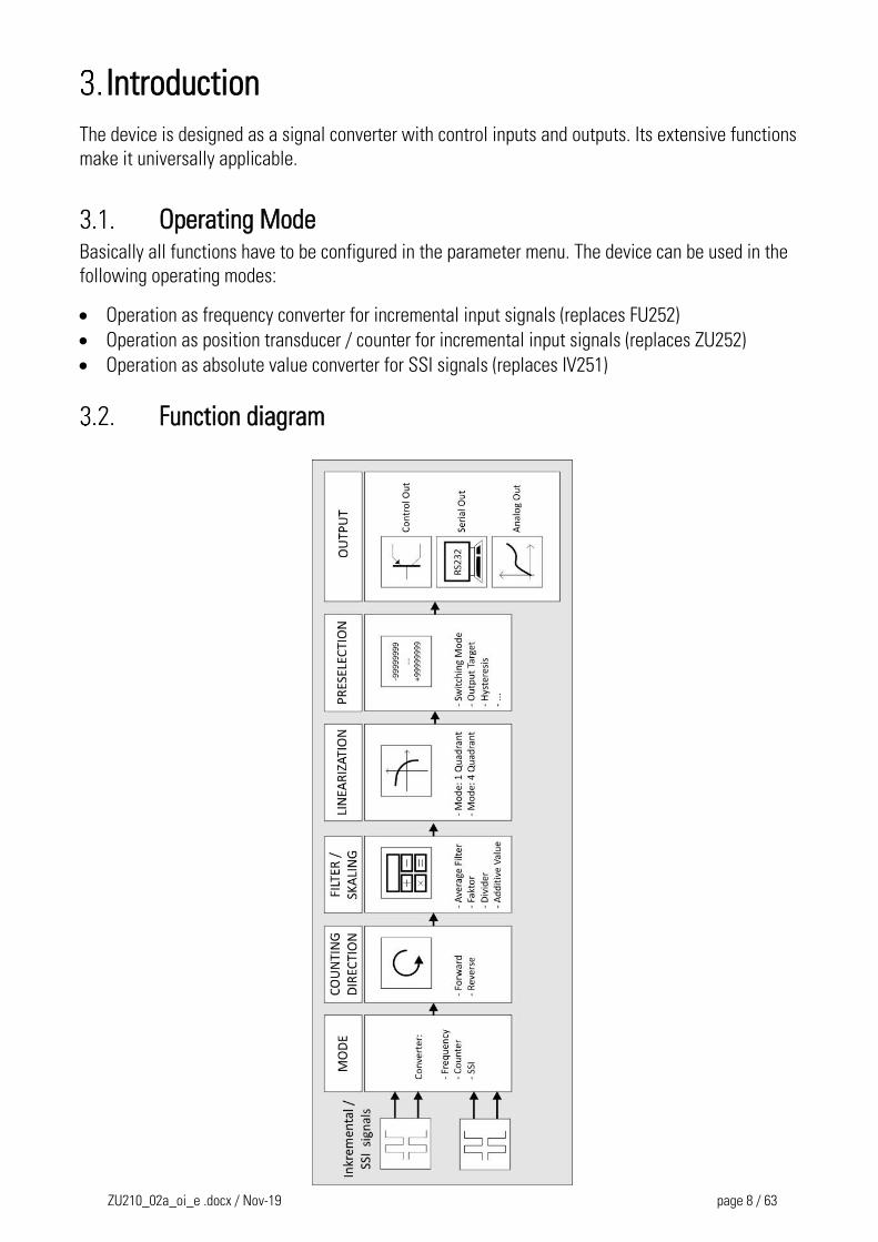
Introduction
The device is designed as a signal converter with control inputs and outputs. Its extensive functions
make it universally applicable.
Operating Mode Basically all functions have to be configured in the parameter menu. The device can be used in the
following operating modes:
Operation as frequency converter for incremental input signals (replaces FU252)
Operation as position transducer / counter for incremental input signals (replaces ZU252)
Operation as absolute value converter for SSI signals (replaces IV251)
Function diagram
ZU210_02a_oi_e .docx / Nov-19 page 9 / 63
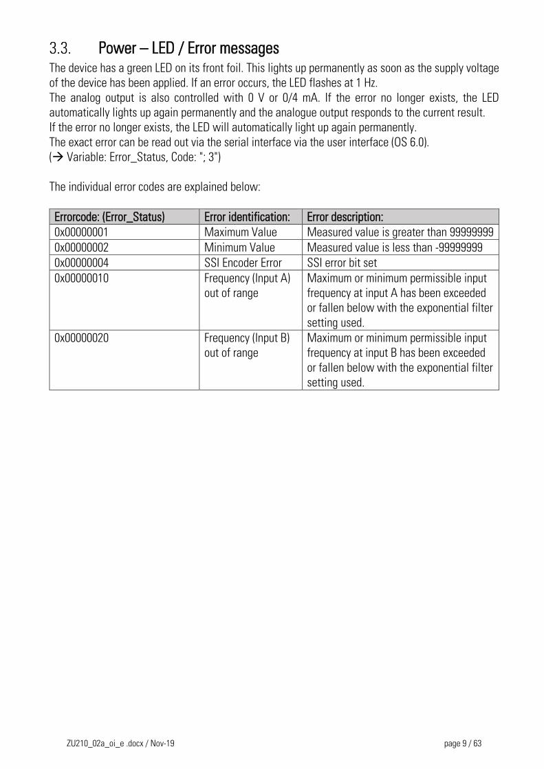
Power – LED / Error messages The device has a green LED on its front foil. This lights up permanently as soon as the supply voltage
of the device has been applied. If an error occurs, the LED flashes at 1 Hz.
The analog output is also controlled with 0 V or 0/4 mA. If the error no longer exists, the LED
automatically lights up again permanently and the analogue output responds to the current result.
If the error no longer exists, the LED will automatically light up again permanently.
The exact error can be read out via the serial interface via the user interface (OS 6.0).
( Variable: Error_Status, Code: "; 3")
The individual error codes are explained below:
Errorcode: (Error_Status) Error identification: Error description:
0x00000001 Maximum Value Measured value is greater than 99999999
0x00000002 Minimum Value Measured value is less than -99999999
0x00000004 SSI Encoder Error SSI error bit set
0x00000010 Frequency (Input A)
out of range
Maximum or minimum permissible input
frequency at input A has been exceeded
or fallen below with the exponential filter
setting used.
0x00000020 Frequency (Input B)
out of range
Maximum or minimum permissible input
frequency at input B has been exceeded
or fallen below with the exponential filter
setting used.
ZU210_02a_oi_e .docx / Nov-19 page 10 / 63
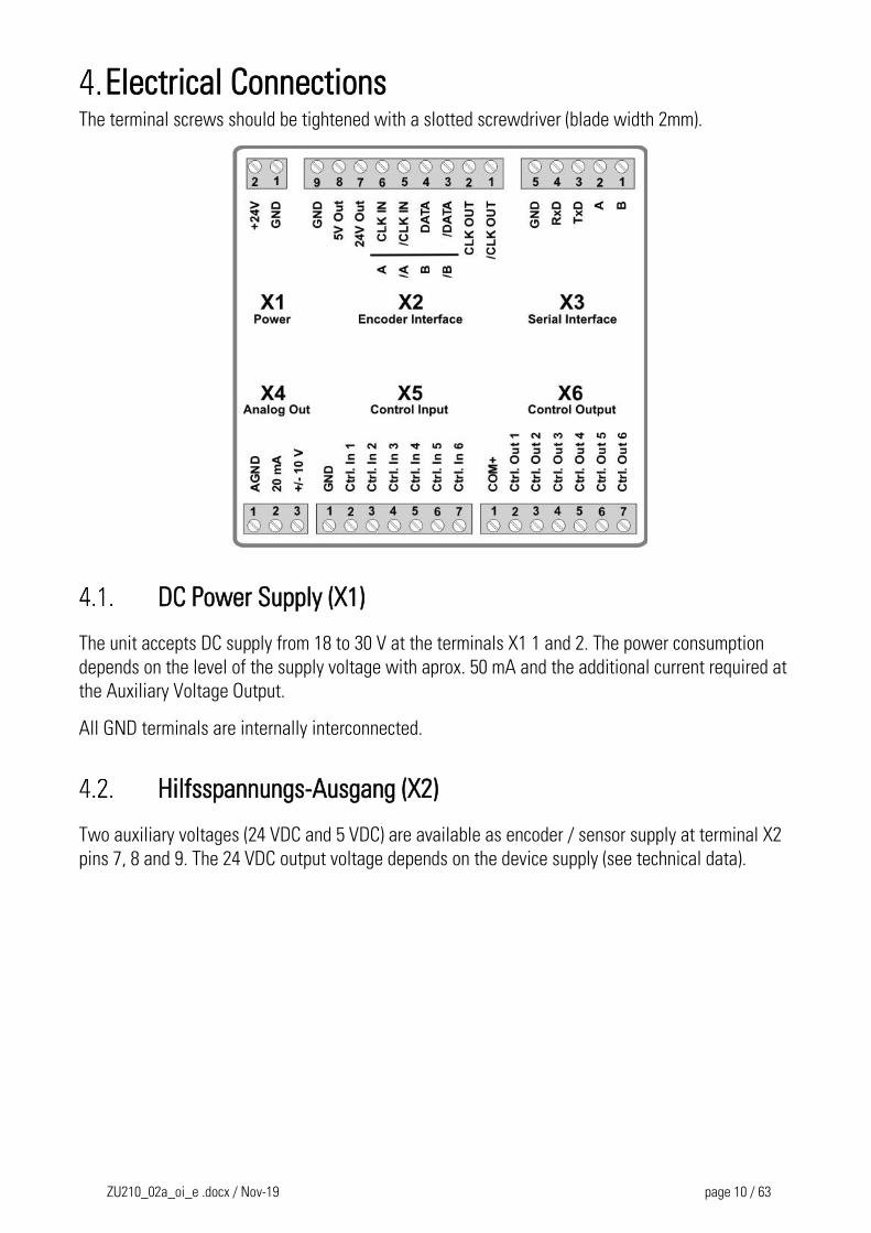
Electrical Connections The terminal screws should be tightened with a slotted screwdriver (blade width 2mm).
DC Power Supply (X1)
The unit accepts DC supply from 18 to 30 V at the terminals X1 1 and 2. The power consumption
depends on the level of the supply voltage with aprox. 50 mA and the additional current required at
the Auxiliary Voltage Output.
All GND terminals are internally interconnected.
Hilfsspannungs-Ausgang (X2)
Two auxiliary voltages (24 VDC and 5 VDC) are available as encoder / sensor supply at terminal X2
pins 7, 8 and 9. The 24 VDC output voltage depends on the device supply (see technical data).
ZU210_02a_oi_e .docx / Nov-19 page 11 / 63
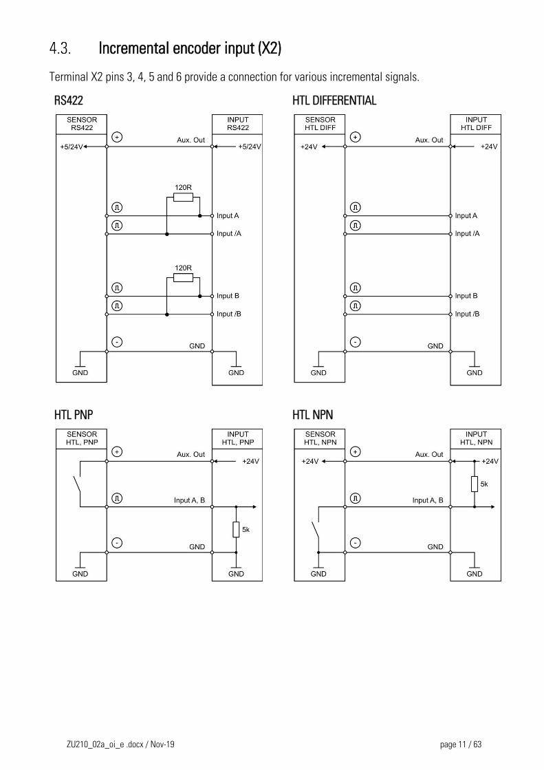
Incremental encoder input (X2)
Terminal X2 pins 3, 4, 5 and 6 provide a connection for various incremental signals.
RS422 HTL DIFFERENTIAL
HTL PNP
HTL NPN
ZU210_02a_oi_e .docx / Nov-19 page 12 / 63
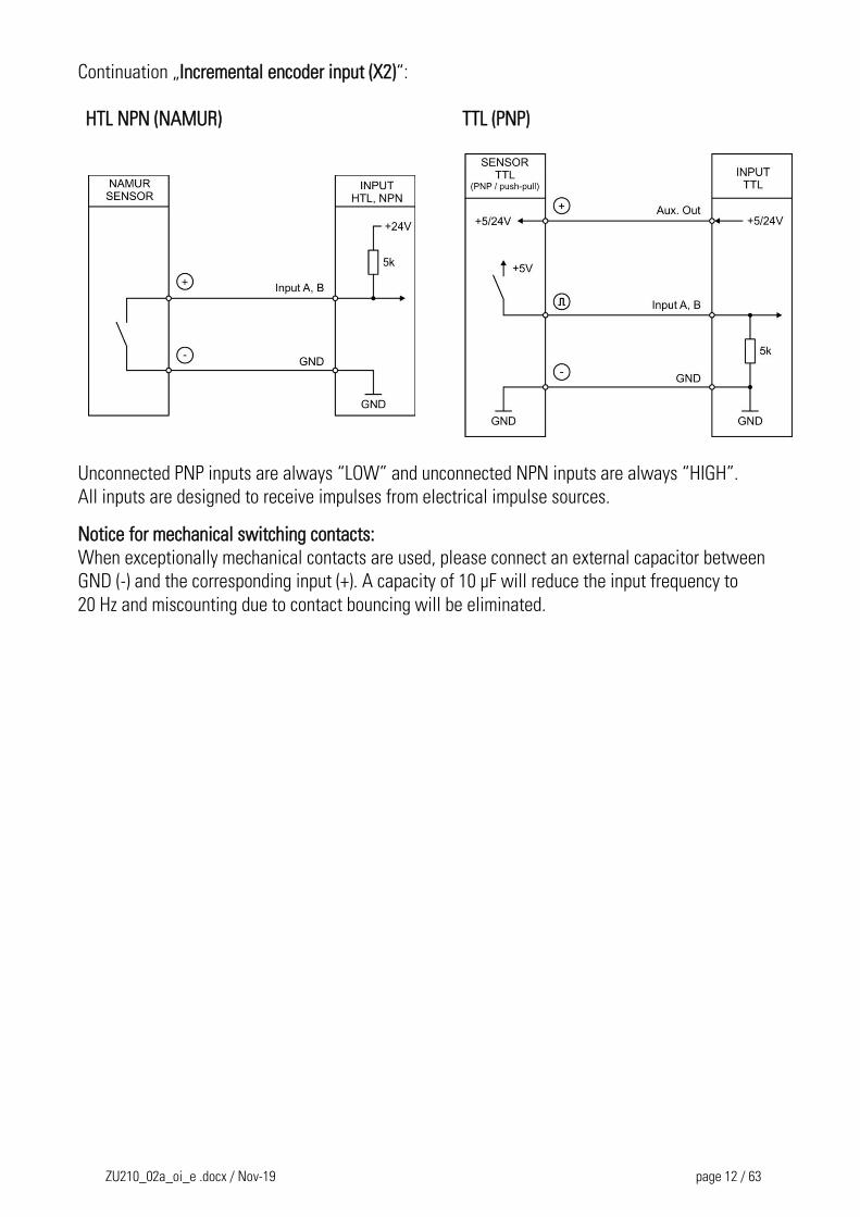
Continuation „Incremental encoder input (X2)“:
HTL NPN (NAMUR)
TTL (PNP)
Unconnected PNP inputs are always “LOW” and unconnected NPN inputs are always “HIGH”.
All inputs are designed to receive impulses from electrical impulse sources.
Notice for mechanical switching contacts:
When exceptionally mechanical contacts are used, please connect an external capacitor between
GND (-) and the corresponding input (+). A capacity of 10 µF will reduce the input frequency to
20 Hz and miscounting due to contact bouncing will be eliminated.
ZU210_02a_oi_e .docx / Nov-19 page 13 / 63
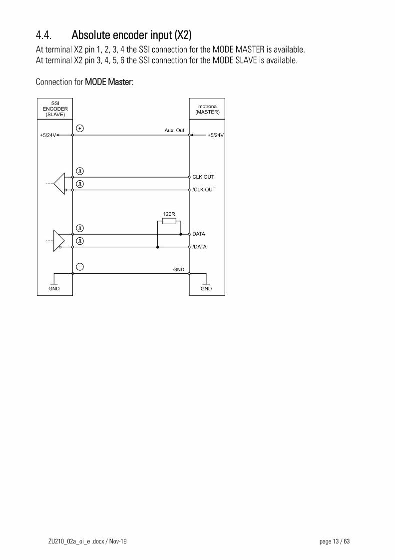
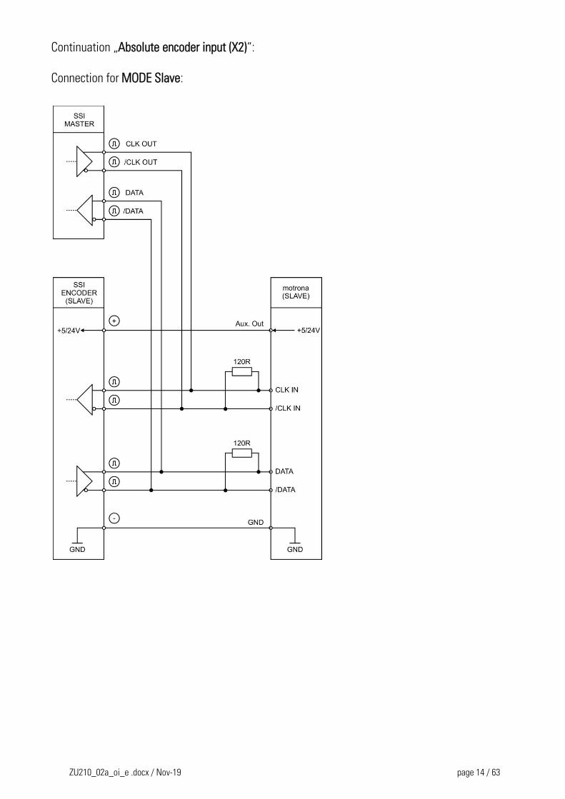
Absolute encoder input (X2) At terminal X2 pin 1, 2, 3, 4 the SSI connection for the MODE MASTER is available.
At terminal X2 pin 3, 4, 5, 6 the SSI connection for the MODE SLAVE is available.
Connection for MODE Master:
ZU210_02a_oi_e .docx / Nov-19 page 14 / 63
Continuation „Absolute encoder input (X2)“:
Connection for MODE Slave:
ZU210_02a_oi_e .docx / Nov-19 page 15 / 63
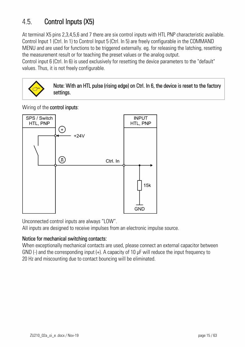
Control Inputs (X5)
At terminal X5 pins 2,3,4,5,6 and 7 there are six control inputs with HTL PNP characteristic available.
Control Input 1 (Ctrl. In 1) to Control Input 5 (Ctrl. In 5) are freely configurable in the COMMAND
MENU and are used for functions to be triggered externally. eg. for releasing the latching, resetting
the measurement result or for teaching the preset values or the analog output.
Control input 6 (Ctrl. In 6) is used exclusively for resetting the device parameters to the "default"
values. Thus, it is not freely configurable.
Note: With an HTL pulse (rising edge) on Ctrl. In 6, the device is reset to the factory
settings.
Wiring of the control inputs:
Unconnected control inputs are always “LOW”.
All inputs are designed to receive impulses from an electronic impulse source.
Notice for mechanical switching contacts:
When exceptionally mechanical contacts are used, please connect an external capacitor between
GND (-) and the corresponding input (+). A capacity of 10 µF will reduce the input frequency to
20 Hz and miscounting due to contact bouncing will be eliminated.
ZU210_02a_oi_e .docx / Nov-19 page 16 / 63
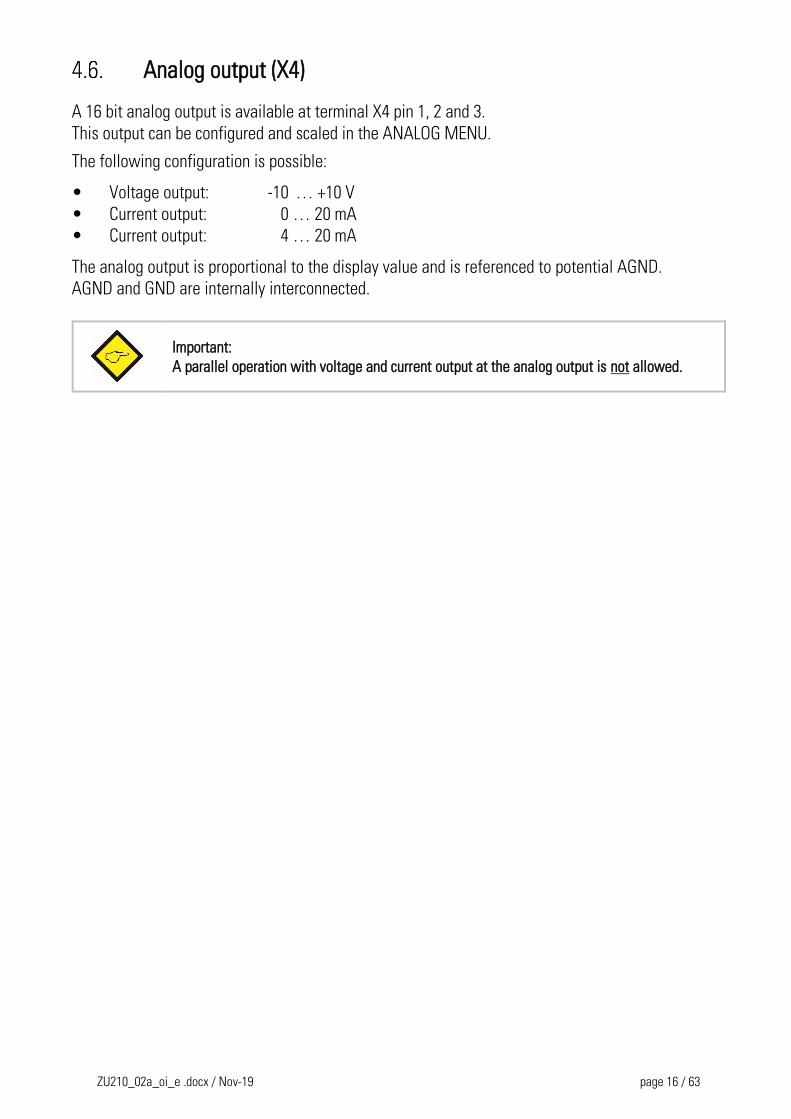
Analog output (X4)
A 16 bit analog output is available at terminal X4 pin 1, 2 and 3.
This output can be configured and scaled in the ANALOG MENU.
The following configuration is possible:
• Voltage output: -10 … +10 V
• Current output: 0 … 20 mA
• Current output: 4 … 20 mA
The analog output is proportional to the display value and is referenced to potential AGND.
AGND and GND are internally interconnected.
Important:
A parallel operation with voltage and current output at the analog output is not allowed.
ZU210_02a_oi_e .docx / Nov-19 page 17 / 63
Serial interface (X3)
A serial interface (RS232 or RS485) is available at terminal X3.
This interface can be configured in the SERIAL MENU.
The serial interface RS232 or RS485 can be used:
for easy setup and commissioning of the units
to modify settings and parameters during operation
to read out internal states and actual measuring values by PC or PLC
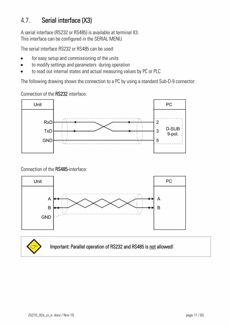
The following drawing shows the connection to a PC by using a standard Sub-D-9 connector:
Connection of the RS232 interface:
Connection of the RS485-interface:
Important: Parallel operation of RS232 and RS485 is not allowed!
ZU210_02a_oi_e .docx / Nov-19 page 18 / 63
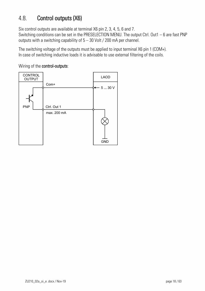
Control outputs (X6)
Six control outputs are available at terminal X6 pin 2, 3, 4, 5, 6 and 7.
Switching conditions can be set in the PRESELECTION MENU. The output Ctrl. Out1 – 6 are fast PNP
outputs with a switching capability of 5 – 30 Volt / 200 mA per channel.
The switching voltage of the outputs must be applied to input terminal X6 pin 1 (COM+).
In case of switching inductive loads it is advisable to use external filtering of the coils.
Wiring of the control-outputs:
ZU210_02a_oi_e .docx / Nov-19 page 19 / 63
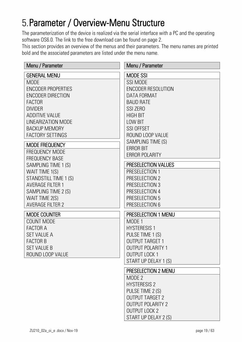
Parameter / Overview-Menu Structure The parameterization of the device is realized via the serial interface with a PC and the operating
software OS6.0. The link to the free download can be found on page 2.
This section provides an overview of the menus and their parameters. The menu names are printed
bold and the associated parameters are listed under the menu name.
Menu / Parameter
GENERAL MENU
MODE
ENCODER PROPERTIES
ENCODER DIRECTION
FACTOR
DIVIDER
ADDITIVE VALUE
LINEARIZATION MODE
BACKUP MEMORY
FACTORY SETTINGS
MODE FREQUENCY
FREQUENCY MODE
FREQUENCY BASE
SAMPLING TIME 1 (S)
WAIT TIME 1(S)
STANDSTILL TIME 1 (S)
AVERAGE FILTER 1
SAMPLING TIME 2 (S)
WAIT TIME 2(S)
AVERAGE FILTER 2
MODE COUNTER
COUNT MODE
FACTOR A
SET VALUE A
FACTOR B
SET VALUE B
ROUND LOOP VALUE
Menu / Parameter
MODE SSI
SSI MODE
ENCODER RESOLUTION
DATA FORMAT
BAUD RATE
SSI ZERO
HIGH BIT
LOW BIT
SSI OFFSET
ROUND LOOP VALUE
SAMPLING TIME (S)
ERROR BIT
ERROR POLARITY
PRESELECTION VALUES
PRESELECTION 1
PRESELECTION 2
PRESELECTION 3
PRESELECTION 4
PRESELECTION 5
PRESELECTION 6
PRESELECTION 1 MENU
MODE 1
HYSTERESIS 1
PULSE TIME 1 (S)
OUTPUT TARGET 1
OUTPUT POLARITY 1
OUTPUT LOCK 1
START UP DELAY 1 (S)
PRESELECTION 2 MENU
MODE 2
HYSTERESIS 2
PULSE TIME 2 (S)
OUTPUT TARGET 2
OUTPUT POLARITY 2
OUTPUT LOCK 2
START UP DELAY 2 (S)
ZU210_02a_oi_e .docx / Nov-19 page 20 / 63
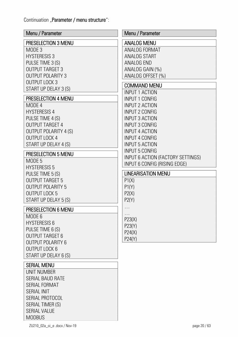
Continuation „Parameter / menu structure“:
Menu / Parameter
PRESELECTION 3 MENU
MODE 3
HYSTERESIS 3
PULSE TIME 3 (S)
OUTPUT TARGET 3
OUTPUT POLARITY 3
OUTPUT LOCK 3
START UP DELAY 3 (S)
PRESELECTION 4 MENU
MODE 4
HYSTERESIS 4
PULSE TIME 4 (S)
OUTPUT TARGET 4
OUTPUT POLARITY 4 (S)
OUTPUT LOCK 4
START UP DELAY 4 (S)
PRESELECTION 5 MENU
MODE 5
HYSTERESIS 5
PULSE TIME 5 (S)
OUTPUT TARGET 5
OUTPUT POLARITY 5
OUTPUT LOCK 5
START UP DELAY 5 (S)
PRESELECTION 6 MENU
MODE 6
HYSTERESIS 6
PULSE TIME 6 (S)
OUTPUT TARGET 6
OUTPUT POLARITY 6
OUTPUT LOCK 6
START UP DELAY 6 (S)
SERIAL MENU
UNIT NUMBER
SERIAL BAUD RATE
SERIAL FORMAT
SERIAL INIT
SERIAL PROTOCOL
SERIAL TIMER (S)
SERIAL VALUE
MODBUS
Menu / Parameter
ANALOG MENU
ANALOG FORMAT
ANALOG START
ANALOG END
ANALOG GAIN (%)
ANALOG OFFSET (%)
COMMAND MENU
INPUT 1 ACTION
INPUT 1 CONFIG
INPUT 2 ACTION INPUT 2 CONFIG INPUT 3 ACTION INPUT 3 CONFIG
INPUT 4 ACTION INPUT 4 CONFIG
INPUT 5 ACTION INPUT 5 CONFIG
INPUT 6 ACTION (FACTORY SETTINGS) INPUT 6 CONFIG (RISING EDGE)
LINEARISATION MENU
P1(X)
P1(Y)
P2(X)
P2(Y)
…
…
P23(X)
P23(Y)
P24(X)
P24(Y)
ZU210_02a_oi_e .docx / Nov-19 page 21 / 63
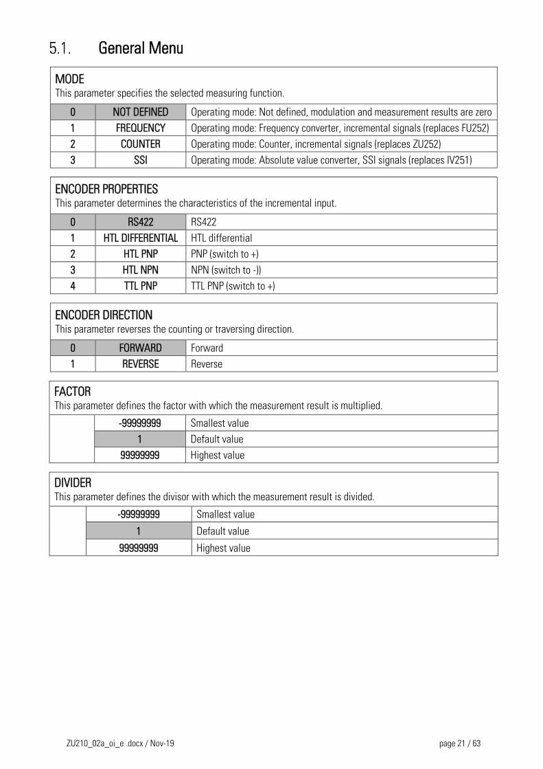
General Menu
MODE This parameter specifies the selected measuring function.
0 NOT DEFINED Operating mode: Not defined, modulation and measurement results are zero
1 FREQUENCY Operating mode: Frequency converter, incremental signals (replaces FU252)
2 COUNTER Operating mode: Counter, incremental signals (replaces ZU252)
3 SSI Operating mode: Absolute value converter, SSI signals (replaces IV251)
ENCODER PROPERTIES This parameter determines the characteristics of the incremental input.
0 RS422 RS422
1 HTL DIFFERENTIAL HTL differential
2 HTL PNP PNP (switch to +)
3 HTL NPN NPN (switch to -))
4 TTL PNP TTL PNP (switch to +)
ENCODER DIRECTION This parameter reverses the counting or traversing direction.
0 FORWARD Forward
1 REVERSE Reverse
FACTOR This parameter defines the factor with which the measurement result is multiplied.
-99999999 Smallest value
1 Default value
99999999 Highest value
DIVIDER This parameter defines the divisor with which the measurement result is divided.
-99999999 Smallest value
1 Default value
99999999 Highest value
ZU210_02a_oi_e .docx / Nov-19 page 22 / 63
Continuation „General Menu“:
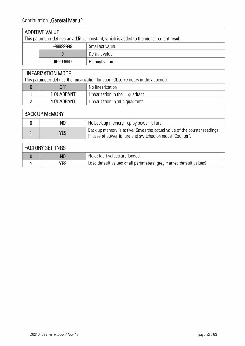
ADDITIVE VALUE This parameter defines an additive constant, which is added to the measurement result.
-99999999 Smallest value
0 Default value
99999999 Highest value
LINEARIZATION MODE This parameter defines the linearization function. Observe notes in the appendix!
0 OFF No linearization
1 1 QUADRANT Linearization in the 1. quadrant
2 4 QUADRANT Linearization in all 4 quadrants
BACK UP MEMORY
0 NO No back up memory –up by power failure
1 YES Back up memory is active. Saves the actual value of the counter readings
in case of power failure and switched on mode "Counter".
FACTORY SETTINGS
0 NO No default values are loaded
1 YES Load default values of all parameters (grey marked default values)
ZU210_02a_oi_e .docx / Nov-19 page 23 / 63
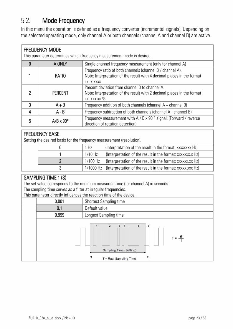
Mode Frequency In this menu the operation is defined as a frequency converter (incremental signals). Depending on
the selected operating mode, only channel A or both channels (channel A and channel B) are active.
FREQUENCY MODE This parameter determines which frequency measurement mode is desired.
0 A ONLY Single-channel frequency measurement (only for channel A)
1 RATIO
Frequency ratio of both channels (channel B / channel A).
Note: Interpretation of the result with 4 decimal places in the format
+/- x.xxxx
2 PERCENT
Percent deviation from channel B to channel A.
Note: Interpretation of the result with 2 decimal places in the format
+/- xxx.xx %
3 A + B Frequency addition of both channels (channel A + channel B)
4 A - B Frequency subtraction of both channels (channel A - channel B)
5 A/B x 90° Frequency measurement with A / B x 90 ° signal. (Forward / reverse
direction of rotation detection)
FREQUENCY BASE Setting the desired basis for the frequency measurement (resolution).
0 1 Hz (Interpretation of the result in the format: xxxxxxxx Hz)
1 1/10 Hz (Interpretation of the result in the format: xxxxxxx.x Hz)
2 1/100 Hz (Interpretation of the result in the format: xxxxxx.xx Hz)
3 1/1000 Hz (Interpretation of the result in the format: xxxxx.xxx Hz)
SAMPLING TIME 1 (S) The set value corresponds to the minimum measuring time (for channel A) in seconds.
The sampling time serves as a filter at irregular frequencies.
This parameter directly influences the reaction time of the device.
0,001 Shortest Sampling time
0,1 Default value
9,999 Longest Sampling time
ZU210_02a_oi_e .docx / Nov-19 page 24 / 63
Continuation „Mode Frequency“:
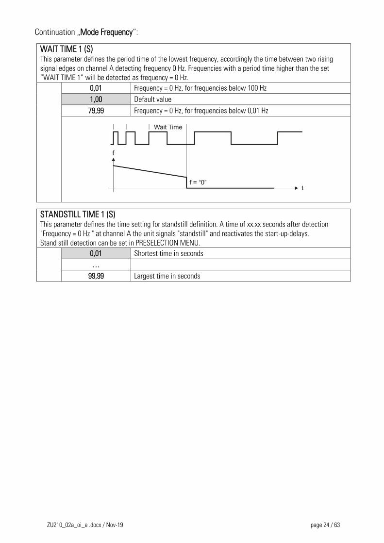
WAIT TIME 1 (S) This parameter defines the period time of the lowest frequency, accordingly the time between two rising
signal edges on channel A detecting frequency 0 Hz. Frequencies with a period time higher than the set
“WAIT TIME 1” will be detected as frequency = 0 Hz.
0,01 Frequency = 0 Hz, for frequencies below 100 Hz
1,00 Default value
79,99 Frequency = 0 Hz, for frequencies below 0,01 Hz
STANDSTILL TIME 1 (S) This parameter defines the time setting for standstill definition. A time of xx.xx seconds after detection
"Frequency = 0 Hz " at channel A the unit signals "standstill" and reactivates the start-up-delays.
Stand still detection can be set in PRESELECTION MENU.
0,01 Shortest time in seconds
…
99,99 Largest time in seconds
ZU210_02a_oi_e .docx / Nov-19 page 25 / 63
Continuation „Mode Frequency“:
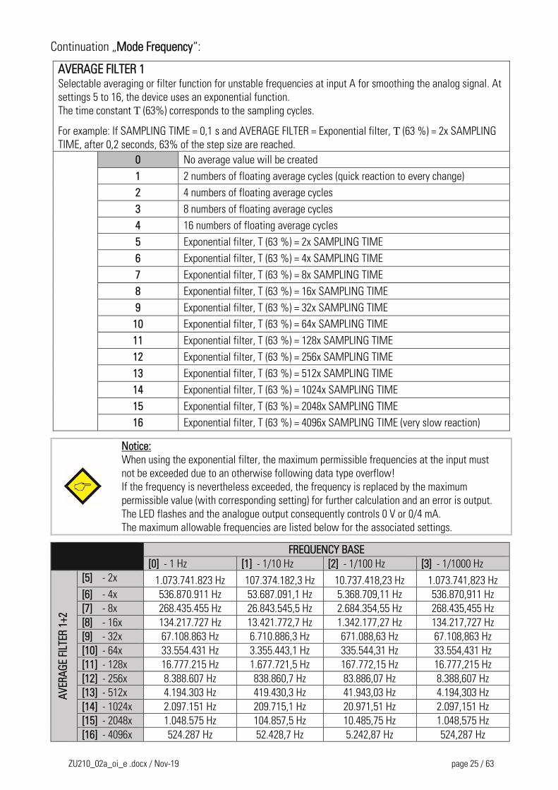
AVERAGE FILTER 1 Selectable averaging or filter function for unstable frequencies at input A for smoothing the analog signal. At
settings 5 to 16, the device uses an exponential function.
The time constant T (63%) corresponds to the sampling cycles.
For example: If SAMPLING TIME = 0,1 s and AVERAGE FILTER = Exponential filter, T (63 %) = 2x SAMPLING
TIME, after 0,2 seconds, 63% of the step size are reached.
0 No average value will be created
1 2 numbers of floating average cycles (quick reaction to every change)
2 4 numbers of floating average cycles
3 8 numbers of floating average cycles
4 16 numbers of floating average cycles
5 Exponential filter, T (63 %) = 2x SAMPLING TIME
6 Exponential filter, T (63 %) = 4x SAMPLING TIME
7 Exponential filter, T (63 %) = 8x SAMPLING TIME
8 Exponential filter, T (63 %) = 16x SAMPLING TIME
9 Exponential filter, T (63 %) = 32x SAMPLING TIME
10 Exponential filter, T (63 %) = 64x SAMPLING TIME
11 Exponential filter, T (63 %) = 128x SAMPLING TIME
12 Exponential filter, T (63 %) = 256x SAMPLING TIME
13 Exponential filter, T (63 %) = 512x SAMPLING TIME
14 Exponential filter, T (63 %) = 1024x SAMPLING TIME
15 Exponential filter, T (63 %) = 2048x SAMPLING TIME
16 Exponential filter, T (63 %) = 4096x SAMPLING TIME (very slow reaction)
Notice:
When using the exponential filter, the maximum permissible frequencies at the input must
not be exceeded due to an otherwise following data type overflow!
If the frequency is nevertheless exceeded, the frequency is replaced by the maximum
permissible value (with corresponding setting) for further calculation and an error is output.
The LED flashes and the analogue output consequently controls 0 V or 0/4 mA.
The maximum allowable frequencies are listed below for the associated settings.
FREQUENCY BASE
[0] - 1 Hz [1] - 1/10 Hz [2] - 1/100 Hz [3] - 1/1000 Hz
AV
ERA
GE
FILT
ER 1
+2
[5] - 2x 1.073.741.823 Hz 107.374.182,3 Hz 10.737.418,23 Hz 1.073.741,823 Hz
[6] - 4x 536.870.911 Hz 53.687.091,1 Hz 5.368.709,11 Hz 536.870,911 Hz
[7] - 8x 268.435.455 Hz 26.843.545,5 Hz 2.684.354,55 Hz 268.435,455 Hz
[8] - 16x 134.217.727 Hz 13.421.772,7 Hz 1.342.177,27 Hz 134.217,727 Hz
[9] - 32x 67.108.863 Hz 6.710.886,3 Hz 671.088,63 Hz 67.108,863 Hz
[10] - 64x 33.554.431 Hz 3.355.443,1 Hz 335.544,31 Hz 33.554,431 Hz
[11] - 128x 16.777.215 Hz 1.677.721,5 Hz 167.772,15 Hz 16.777,215 Hz
[12] - 256x 8.388.607 Hz 838.860,7 Hz 83.886,07 Hz 8.388,607 Hz
[13] - 512x 4.194.303 Hz 419.430,3 Hz 41.943,03 Hz 4.194,303 Hz
[14] - 1024x 2.097.151 Hz 209.715,1 Hz 20.971,51 Hz 2.097,151 Hz
[15] - 2048x 1.048.575 Hz 104.857,5 Hz 10.485,75 Hz 1.048,575 Hz
[16] - 4096x 524.287 Hz 52.428,7 Hz 5.242,87 Hz 524,287 Hz
ZU210_02a_oi_e .docx / Nov-19 page 26 / 63
Continuation „Mode Frequency“:
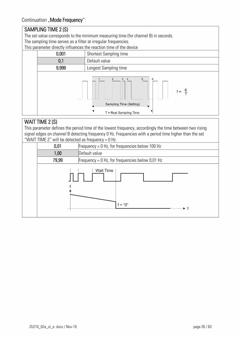
SAMPLING TIME 2 (S) The set value corresponds to the minimum measuring time (for channel B) in seconds.
The sampling time serves as a filter at irregular frequencies.
This parameter directly influences the reaction time of the device 0,001 Shortest Sampling time
0,1 Default value
9,999 Longest Sampling time
WAIT TIME 2 (S) This parameter defines the period time of the lowest frequency, accordingly the time between two rising
signal edges on channel B detecting frequency 0 Hz. Frequencies with a period time higher than the set
“WAIT TIME 2” will be detected as frequency = 0 Hz.
0,01 Frequency = 0 Hz, for frequencies below 100 Hz
1,00 Default value
79,99 Frequency = 0 Hz, for frequencies below 0,01 Hz
ZU210_02a_oi_e .docx / Nov-19 page 27 / 63
Continuation „Mode Frequency“:
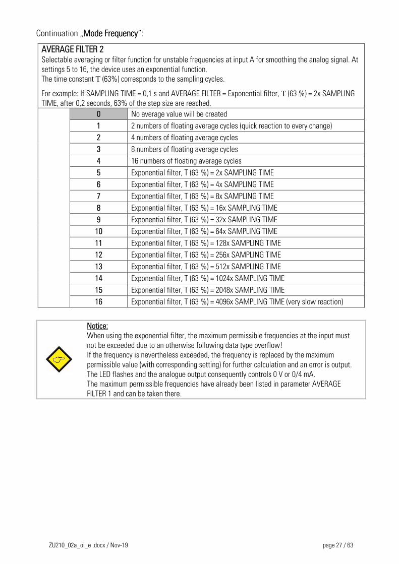
AVERAGE FILTER 2 Selectable averaging or filter function for unstable frequencies at input A for smoothing the analog signal. At
settings 5 to 16, the device uses an exponential function.
The time constant T (63%) corresponds to the sampling cycles.
For example: If SAMPLING TIME = 0,1 s and AVERAGE FILTER = Exponential filter, T (63 %) = 2x SAMPLING
TIME, after 0,2 seconds, 63% of the step size are reached.
0 No average value will be created
1 2 numbers of floating average cycles (quick reaction to every change)
2 4 numbers of floating average cycles
3 8 numbers of floating average cycles
4 16 numbers of floating average cycles
5 Exponential filter, T (63 %) = 2x SAMPLING TIME
6 Exponential filter, T (63 %) = 4x SAMPLING TIME
7 Exponential filter, T (63 %) = 8x SAMPLING TIME
8 Exponential filter, T (63 %) = 16x SAMPLING TIME
9 Exponential filter, T (63 %) = 32x SAMPLING TIME
10 Exponential filter, T (63 %) = 64x SAMPLING TIME
11 Exponential filter, T (63 %) = 128x SAMPLING TIME
12 Exponential filter, T (63 %) = 256x SAMPLING TIME
13 Exponential filter, T (63 %) = 512x SAMPLING TIME
14 Exponential filter, T (63 %) = 1024x SAMPLING TIME
15 Exponential filter, T (63 %) = 2048x SAMPLING TIME
16 Exponential filter, T (63 %) = 4096x SAMPLING TIME (very slow reaction)
Notice:
When using the exponential filter, the maximum permissible frequencies at the input must
not be exceeded due to an otherwise following data type overflow!
If the frequency is nevertheless exceeded, the frequency is replaced by the maximum
permissible value (with corresponding setting) for further calculation and an error is output.
The LED flashes and the analogue output consequently controls 0 V or 0/4 mA.
The maximum permissible frequencies have already been listed in parameter AVERAGE
FILTER 1 and can be taken there.
ZU210_02a_oi_e .docx / Nov-19 page 28 / 63
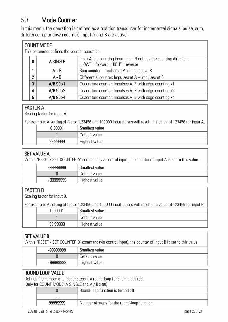
Mode Counter In this menu, the operation is defined as a position transducer for incremental signals (pulse, sum,
difference, up or down counter). Input A and B are active.
COUNT MODE This parameter defines the counter operation.
0 A SINGLE
Input A is a counting input. Input B defines the counting direction:
„LOW“ = forward „HIGH“ = reverse
1 A + B Sum counter: Impulses at A + Impulses at B
2 A - B Differential counter: Impulses at A – impulses at B
3 A/B 90 x1 Quadrature counter: Impulses A, B with edge counting x1
4 A/B 90 x2 Quadrature counter: Impulses A, B with edge counting x2
5 A/B 90 x4 Quadrature counter: Impulses A, B with edge counting x4
FACTOR A Scaling factor for input A.
For example: A setting of factor 1.23456 and 100000 input pulses will result in a value of 123456 for input A.
0,00001 Smallest value
1 Default value
99,99999 Highest value
SET VALUE A With a "RESET / SET COUNTER A" command (via control input), the counter of input A is set to this value.
-99999999 Smallest value
0 Default value
+99999999 Highest value
FACTOR B Scaling factor for input B.
For example: A setting of factor 1.23456 and 100000 input pulses will result in a value of 123456 for input B.
0,00001 Smallest value
1 Default value
99,99999 Highest value
SET VALUE B With a "RESET / SET COUNTER B" command (via control input), the counter of input B is set to this value.
-99999999 Smallest value
0 Default value
+99999999 Highest value
ROUND LOOP VALUE Defines the number of encoder steps if a round-loop function is desired.
(Only for COUNT MODE: A SINGLE and A / B x 90)
0 Round-loop function is turned off.
…
99999999 Number of steps for the round-loop function.
ZU210_02a_oi_e .docx / Nov-19 page 29 / 63
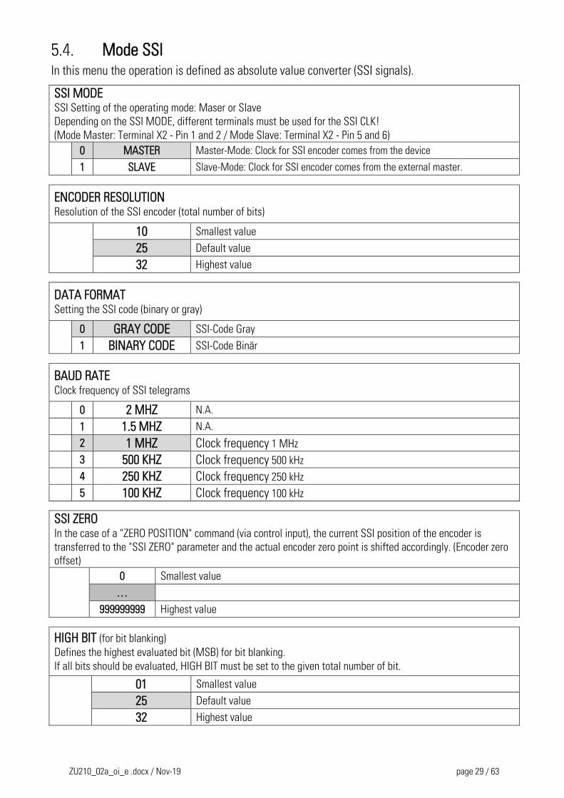
Mode SSI In this menu the operation is defined as absolute value converter (SSI signals).
SSI MODE SSI Setting of the operating mode: Maser or Slave
Depending on the SSI MODE, different terminals must be used for the SSI CLK!
(Mode Master: Terminal X2 - Pin 1 and 2 / Mode Slave: Terminal X2 - Pin 5 and 6)
0 MASTER Master-Mode: Clock for SSI encoder comes from the device
1 SLAVE Slave-Mode: Clock for SSI encoder comes from the external master.
ENCODER RESOLUTION Resolution of the SSI encoder (total number of bits)
10 Smallest value
25 Default value
32 Highest value
DATA FORMAT Setting the SSI code (binary or gray)
0 GRAY CODE SSI-Code Gray
1 BINARY CODE SSI-Code Binär
BAUD RATE Clock frequency of SSI telegrams
0 2 MHZ N.A.
1 1.5 MHZ N.A.
2 1 MHZ Clock frequency 1 MHz
3 500 KHZ Clock frequency 500 kHz
4 250 KHZ Clock frequency 250 kHz
5 100 KHZ Clock frequency 100 kHz
SSI ZERO In the case of a "ZERO POSITION" command (via control input), the current SSI position of the encoder is
transferred to the "SSI ZERO" parameter and the actual encoder zero point is shifted accordingly. (Encoder zero
offset)
0 Smallest value
…
999999999 Highest value
HIGH BIT (for bit blanking) Defines the highest evaluated bit (MSB) for bit blanking.
If all bits should be evaluated, HIGH BIT must be set to the given total number of bit.
01 Smallest value
25 Default value
32 Highest value
ZU210_02a_oi_e .docx / Nov-19 page 30 / 63
Continuation „Mode SSI“:
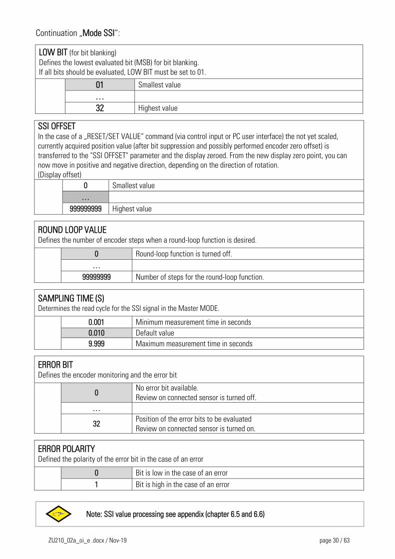
LOW BIT (for bit blanking) Defines the lowest evaluated bit (MSB) for bit blanking.
If all bits should be evaluated, LOW BIT must be set to 01.
01 Smallest value
…
32 Highest value
SSI OFFSET In the case of a „RESET/SET VALUE“ command (via control input or PC user interface) the not yet scaled,
currently acquired position value (after bit suppression and possibly performed encoder zero offset) is
transferred to the "SSI OFFSET" parameter and the display zeroed. From the new display zero point, you can
now move in positive and negative direction, depending on the direction of rotation.
(Display offset)
0 Smallest value
…
999999999 Highest value
ROUND LOOP VALUE Defines the number of encoder steps when a round-loop function is desired.
0 Round-loop function is turned off.
…
99999999 Number of steps for the round-loop function.
SAMPLING TIME (S) Determines the read cycle for the SSI signal in the Master MODE.
0.001 Minimum measurement time in seconds
0.010 Default value
9.999 Maximum measurement time in seconds
ERROR BIT Defines the encoder monitoring and the error bit
0
No error bit available.
Review on connected sensor is turned off.
…
32 Position of the error bits to be evaluated
Review on connected sensor is turned on.
ERROR POLARITY Defined the polarity of the error bit in the case of an error
0 Bit is low in the case of an error
1 Bit is high in the case of an error
Note: SSI value processing see appendix (chapter 6.5 and 6.6)
ZU210_02a_oi_e .docx / Nov-19 page 31 / 63
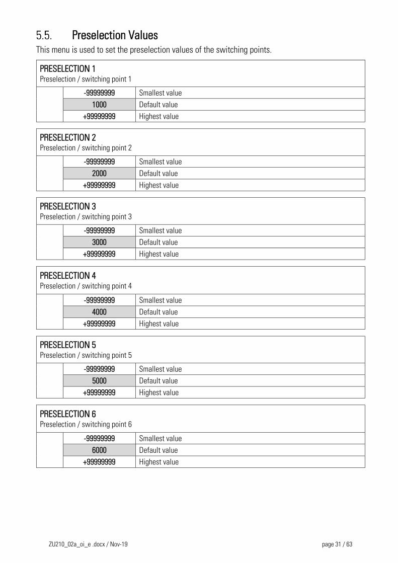
Preselection Values This menu is used to set the preselection values of the switching points.
PRESELECTION 1
Preselection / switching point 1
-99999999 Smallest value
1000 Default value
+99999999 Highest value
PRESELECTION 2
Preselection / switching point 2
-99999999 Smallest value
2000 Default value
+99999999 Highest value
PRESELECTION 3
Preselection / switching point 3
-99999999 Smallest value
3000 Default value
+99999999 Highest value
PRESELECTION 4
Preselection / switching point 4
-99999999 Smallest value
4000 Default value
+99999999 Highest value
PRESELECTION 5
Preselection / switching point 5
-99999999 Smallest value
5000 Default value
+99999999 Highest value
PRESELECTION 6
Preselection / switching point 6
-99999999 Smallest value
6000 Default value
+99999999 Highest value
ZU210_02a_oi_e .docx / Nov-19 page 32 / 63
Preselection 1 Menu
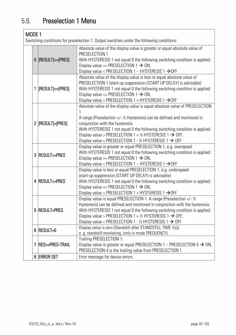
MODE 1 Switching conditions for preselection 1. Output switches under the following conditions:
0 |RESULT|>=|PRES|
Absolute value of the display value is greater or equal absolute value of
PRESELECTION 1
With HYSTERESIS 1 not equal 0 the following switching condition is applied:
Display value >= PRESELECTION 1 ON,
Display value < PRESELECTION 1 – HYSTERESIS 1 OFF
1 |RESULT|<=|PRES|
Absolute value of the display value is less or equal absolute value of
PRESELECTION 1 (start-up suppression (START UP DELAY) is advisable)
With HYSTERESIS 1 not equal 0 the following switching condition is applied:
Display value <= PRESELECTION 1 ON,
Display value > PRESELECTION 1 + HYSTERESIS 1 OFF
2 |RESULT|=|PRES|
Absolute value of the display value is equal absolute value of PRESELECTION
1
A range (Preselection +/- ½ Hysteresis) can be defined and monitored in
conjunction with the hysteresis.
With HYSTERESIS 1 not equal 0 the following switching condition is applied:
Display value > PRESELECTION 1 + ½ HYSTERESIS 1 OFF,
Display value < PRESELECTION 1 - ½ HYSTERESIS 1 OFF
3 RESULT>=PRES
Display value is greater or equal PRESELECTION 1, e.g. overspeed
With HYSTERESIS 1 not equal 0 the following switching condition is applied:
Display value >= PRESELECTION 1 ON,
Display value < PRESELECTION 1 – HYSTERESIS 1 OFF
4 RESULT<=PRES
Display value is less or equal PRESELECTION 1, e.g. underspeed
(start-up suppression (START UP DELAY) is advisable)
With HYSTERESIS 1 not equal 0 the following switching condition is applied:
Display value <= PRESELECTION 1 ON,
Display value > PRESELECTION 1 + HYSTERESIS 1 OFF
5 RESULT=PRES
Display value is equal PRESELECTION 1. A range (Preselection +/- ½
Hysteresis) can be defined and monitored in conjunction with the hysteresis.
With HYSTERESIS 1 not equal 0 the following switching condition is applied:
Display value > PRESELECTION 1 + ½ HYSTERESIS 1 OFF,
Display value < PRESELECTION 1 - ½ HYSTERESIS 1 OFF
6 RESULT=0 Display value is zero (Standstill after STANDSTILL TIME 1(s)),
e. g. standstill monitoring, (only in mode FREQUENCY).
7 RES>=PRES-TRAIL
Trailing PRESELECTION 1:
Display value is greater or equal PRESELECTION 1 – PRESELECTION 4 ON,
PRESELECTION 4 is the trailing value from PRESELECTION 1
8 ERROR SET Error message for device errors.
ZU210_02a_oi_e .docx / Nov-19 page 33 / 63
Continuation „Preselection 1 Menu“:
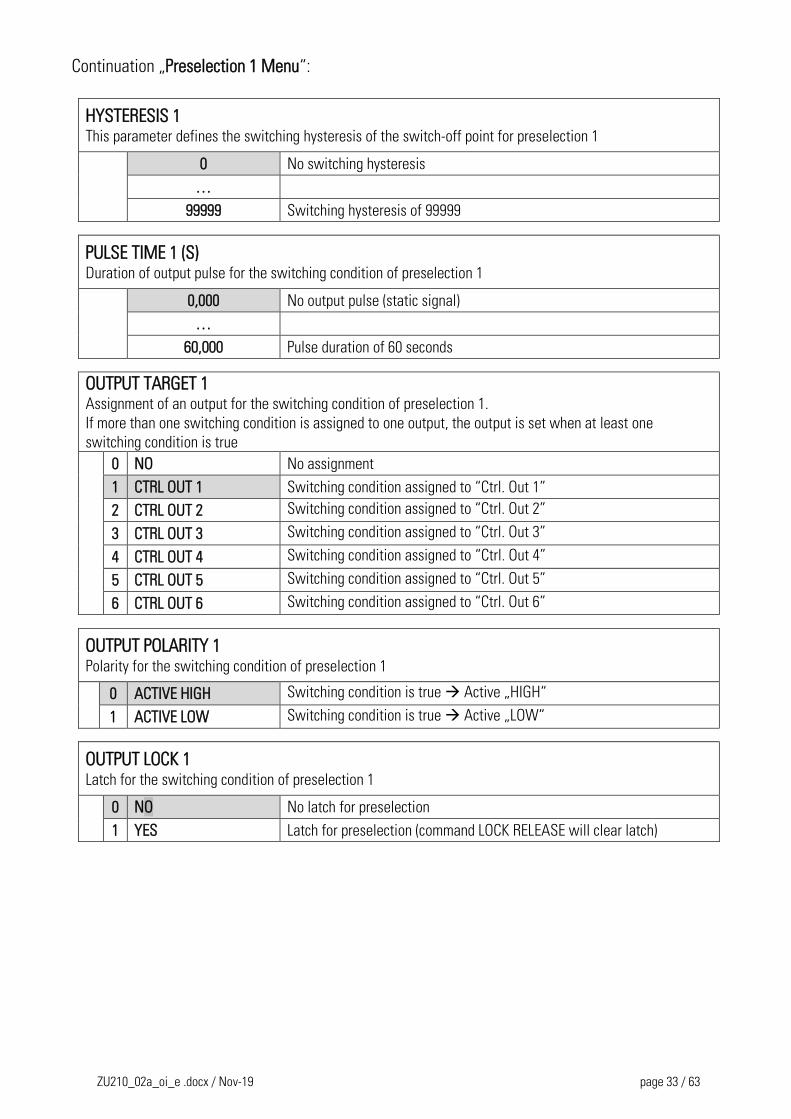
HYSTERESIS 1 This parameter defines the switching hysteresis of the switch-off point for preselection 1
0 No switching hysteresis
…
99999 Switching hysteresis of 99999
PULSE TIME 1 (S) Duration of output pulse for the switching condition of preselection 1
0,000 No output pulse (static signal)
…
60,000 Pulse duration of 60 seconds
OUTPUT TARGET 1 Assignment of an output for the switching condition of preselection 1.
If more than one switching condition is assigned to one output, the output is set when at least one
switching condition is true 0 NO No assignment
1 CTRL OUT 1 Switching condition assigned to “Ctrl. Out 1”
2 CTRL OUT 2 Switching condition assigned to “Ctrl. Out 2”
3 CTRL OUT 3 Switching condition assigned to “Ctrl. Out 3”
4 CTRL OUT 4 Switching condition assigned to “Ctrl. Out 4”
5 CTRL OUT 5 Switching condition assigned to “Ctrl. Out 5”
6 CTRL OUT 6 Switching condition assigned to “Ctrl. Out 6”
OUTPUT POLARITY 1 Polarity for the switching condition of preselection 1
0 ACTIVE HIGH Switching condition is true Active „HIGH“
1 ACTIVE LOW Switching condition is true Active „LOW“
OUTPUT LOCK 1 Latch for the switching condition of preselection 1
0 NO No latch for preselection
1 YES Latch for preselection (command LOCK RELEASE will clear latch)
ZU210_02a_oi_e .docx / Nov-19 page 34 / 63
Continuation „Preselection 1 Menu“:
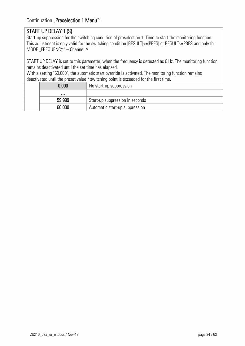
START UP DELAY 1 (S) Start-up suppression for the switching condition of preselection 1. Time to start the monitoring function.
This adjustment is only valid for the switching condition |RESULT|<=|PRES| or RESULT<=PRES and only for
MODE „FREQUENCY“ – Channel A.
START UP DELAY is set to this parameter, when the frequency is detected as 0 Hz. The monitoring function
remains deactivated until the set time has elapsed.
With a setting "60.000", the automatic start override is activated. The monitoring function remains
deactivated until the preset value / switching point is exceeded for the first time.
0.000 No start-up suppression
…
59.999 Start-up suppression in seconds
60.000 Automatic start-up suppression
ZU210_02a_oi_e .docx / Nov-19 page 35 / 63
Preselection 2 Menu
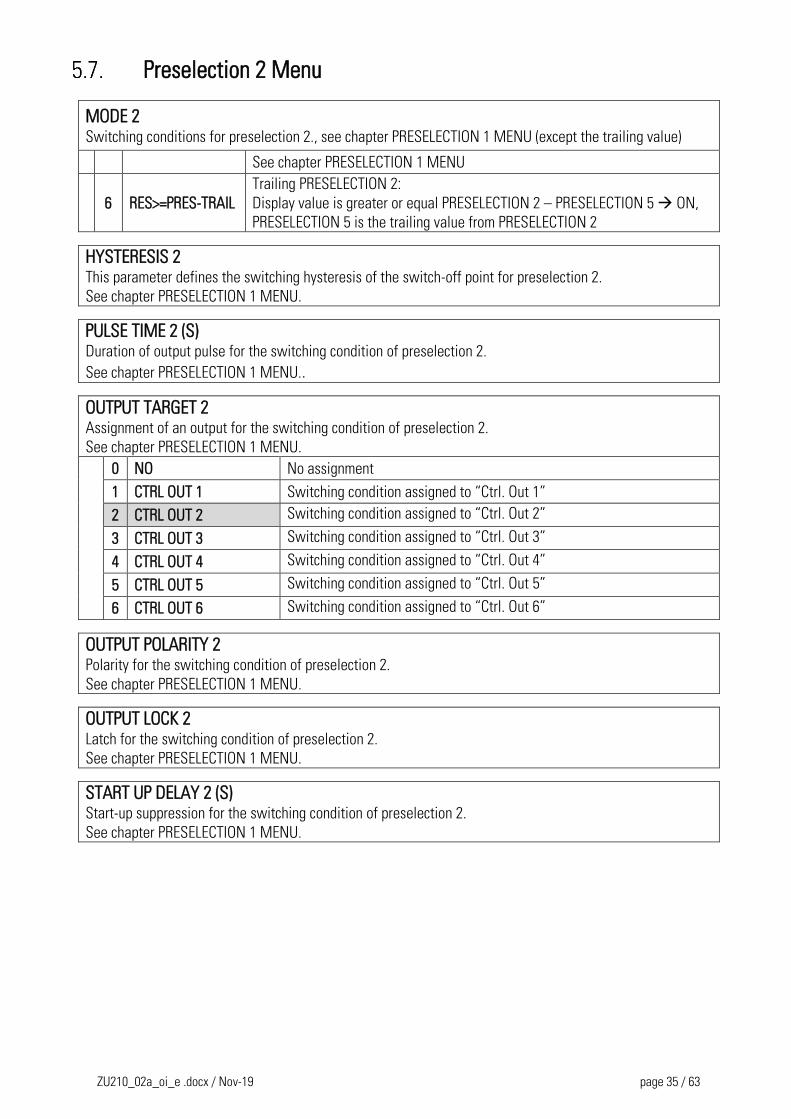
MODE 2 Switching conditions for preselection 2., see chapter PRESELECTION 1 MENU (except the trailing value)
See chapter PRESELECTION 1 MENU
6 RES>=PRES-TRAIL
Trailing PRESELECTION 2:
Display value is greater or equal PRESELECTION 2 – PRESELECTION 5 ON,
PRESELECTION 5 is the trailing value from PRESELECTION 2
HYSTERESIS 2 This parameter defines the switching hysteresis of the switch-off point for preselection 2.
See chapter PRESELECTION 1 MENU.
PULSE TIME 2 (S) Duration of output pulse for the switching condition of preselection 2.
See chapter PRESELECTION 1 MENU..
OUTPUT TARGET 2 Assignment of an output for the switching condition of preselection 2.
See chapter PRESELECTION 1 MENU.
0 NO No assignment
1 CTRL OUT 1 Switching condition assigned to “Ctrl. Out 1”
2 CTRL OUT 2 Switching condition assigned to “Ctrl. Out 2”
3 CTRL OUT 3 Switching condition assigned to “Ctrl. Out 3”
4 CTRL OUT 4 Switching condition assigned to “Ctrl. Out 4”
5 CTRL OUT 5 Switching condition assigned to “Ctrl. Out 5”
6 CTRL OUT 6 Switching condition assigned to “Ctrl. Out 6”
OUTPUT POLARITY 2 Polarity for the switching condition of preselection 2.
See chapter PRESELECTION 1 MENU.
OUTPUT LOCK 2 Latch for the switching condition of preselection 2.
See chapter PRESELECTION 1 MENU.
START UP DELAY 2 (S) Start-up suppression for the switching condition of preselection 2.
See chapter PRESELECTION 1 MENU.

ZU210_02a_oi_e .docx / Nov-19 page 36 / 63
Preselection 3 Menu
MODE 3 Switching conditions for preselection 3. see chapter PRESELECTION 1 MENU (except the trailing value).
See chapter PRESELECTION 1 MENU
6 RES>=PRES-TRAIL
Trailing PRESELECTION 3:
Display value is greater or equal PRESELECTION 3 – PRESELECTION 6 ON,
PRESELECTION 6 is the trailing value from PRESELECTION 3
HYSTERESIS 3 This parameter defines the switching hysteresis of the switch-off point for preselection 3.
See chapter PRESELECTION 1 MENU.
PULSE TIME 3 (S) Duration of output pulse for the switching condition of preselection 3.
See chapter PRESELECTION 1 MENU.
OUTPUT TARGET 3 Assignment of an output for the switching condition of preselection 3.
See chapter PRESELECTION 1 MENU.
0 NO No assignment
1 CTRL OUT 1 Switching condition assigned to “Ctrl. Out 1”
2 CTRL OUT 2 Switching condition assigned to “Ctrl. Out 2”
3 CTRL OUT 3 Switching condition assigned to “Ctrl. Out 3”
4 CTRL OUT 4 Switching condition assigned to “Ctrl. Out 4”
5 CTRL OUT 5 Switching condition assigned to “Ctrl. Out 5”
6 CTRL OUT 6 Switching condition assigned to “Ctrl. Out 6”
OUTPUT POLARITY 3 Polarity for the switching condition of preselection 3.
See chapter PRESELECTION 1 MENU.
OUTPUT LOCK 3 Latch for the switching condition of preselection 3.
See chapter PRESELECTION 1 MENU.
START UP DELAY 3 (S) Start-up suppression for the switching condition of preselection 3.
See chapter PRESELECTION 1 MENU.
ZU210_02a_oi_e .docx / Nov-19 page 37 / 63
Preselection 4 Menu
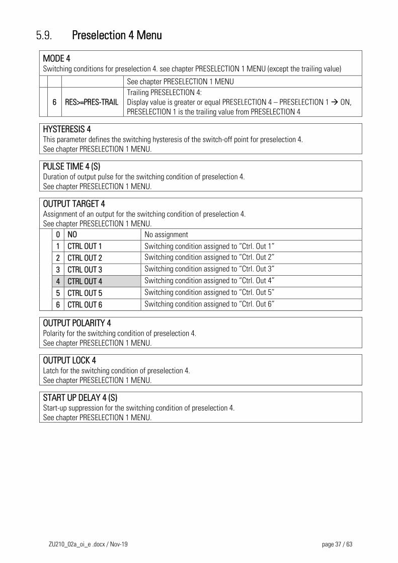
MODE 4 Switching conditions for preselection 4. see chapter PRESELECTION 1 MENU (except the trailing value)
See chapter PRESELECTION 1 MENU
6 RES>=PRES-TRAIL
Trailing PRESELECTION 4:
Display value is greater or equal PRESELECTION 4 – PRESELECTION 1 ON,
PRESELECTION 1 is the trailing value from PRESELECTION 4
HYSTERESIS 4 This parameter defines the switching hysteresis of the switch-off point for preselection 4.
See chapter PRESELECTION 1 MENU.
PULSE TIME 4 (S) Duration of output pulse for the switching condition of preselection 4.
See chapter PRESELECTION 1 MENU.
OUTPUT TARGET 4 Assignment of an output for the switching condition of preselection 4.
See chapter PRESELECTION 1 MENU.
0 NO No assignment
1 CTRL OUT 1 Switching condition assigned to “Ctrl. Out 1”
2 CTRL OUT 2 Switching condition assigned to “Ctrl. Out 2”
3 CTRL OUT 3 Switching condition assigned to “Ctrl. Out 3”
4 CTRL OUT 4 Switching condition assigned to “Ctrl. Out 4”
5 CTRL OUT 5 Switching condition assigned to “Ctrl. Out 5”
6 CTRL OUT 6 Switching condition assigned to “Ctrl. Out 6”
OUTPUT POLARITY 4 Polarity for the switching condition of preselection 4.
See chapter PRESELECTION 1 MENU.
OUTPUT LOCK 4 Latch for the switching condition of preselection 4.
See chapter PRESELECTION 1 MENU.
START UP DELAY 4 (S) Start-up suppression for the switching condition of preselection 4.
See chapter PRESELECTION 1 MENU.

ZU210_02a_oi_e .docx / Nov-19 page 38 / 63
Preselection 5 Menu
MODE 5 Switching conditions for preselection 5. see chapter PRESELECTION 1 MENU (except the trailing value)
See chapter PRESELECTION 1 MENU
6 RES>=PRES-TRAIL
Trailing PRESELECTION 5:
Display value is greater or equal PRESELECTION 5 – PRESELECTION 2 ON,
PRESELECTION 2 is the trailing value from PRESELECTION 5
HYSTERESIS 5 This parameter defines the switching hysteresis of the switch-off point for preselection 5.
See chapter PRESELECTION 1 MENU.
PULSE TIME 5 (S) Duration of output pulse for the switching condition of preselection 5.
See chapter PRESELECTION 1 MENU.
OUTPUT TARGET 5 Assignment of an output for the switching condition of preselection 5.
See chapter PRESELECTION 1 MENU.
0 NO No assignment
1 CTRL OUT 1 Switching condition assigned to “Ctrl. Out 1”
2 CTRL OUT 2 Switching condition assigned to “Ctrl. Out 2”
3 CTRL OUT 3 Switching condition assigned to “Ctrl. Out 3”
4 CTRL OUT 4 Switching condition assigned to “Ctrl. Out 4”
5 CTRL OUT 5 Switching condition assigned to “Ctrl. Out 5”
6 CTRL OUT 6 Switching condition assigned to “Ctrl. Out 6”
OUTPUT POLARITY 5 Polarity for the switching condition of preselection 5.
See chapter PRESELECTION 1 MENU.
OUTPUT LOCK 5 Latch for the switching condition of preselection 5.
See chapter PRESELECTION 1 MENU.
START UP DELAY 5 (S) Start-up suppression for the switching condition of preselection 5.
See chapter PRESELECTION 1 MENU.
ZU210_02a_oi_e .docx / Nov-19 page 39 / 63
Preselection 6 Menu
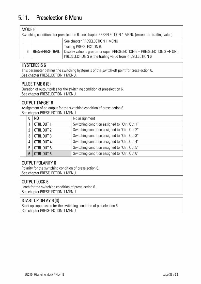
MODE 6 Switching conditions for preselection 6. see chapter PRESELECTION 1 MENU (except the trailing value)
See chapter PRESELECTION 1 MENU
6 RES>=PRES-TRAIL
Trailing PRESELECTION 6:
Display value is greater or equal PRESELECTION 6 – PRESELECTION 3 ON,
PRESELECTION 3 is the trailing value from PRESELECTION 6
HYSTERESIS 6 This parameter defines the switching hysteresis of the switch-off point for preselection 6.
See chapter PRESELECTION 1 MENU.
PULSE TIME 6 (S) Duration of output pulse for the switching condition of preselection 6.
See chapter PRESELECTION 1 MENU.
OUTPUT TARGET 6 Assignment of an output for the switching condition of preselection 6.
See chapter PRESELECTION 1 MENU.
0 NO No assignment
1 CTRL OUT 1 Switching condition assigned to “Ctrl. Out 1”
2 CTRL OUT 2 Switching condition assigned to “Ctrl. Out 2”
3 CTRL OUT 3 Switching condition assigned to “Ctrl. Out 3”
4 CTRL OUT 4 Switching condition assigned to “Ctrl. Out 4”
5 CTRL OUT 5 Switching condition assigned to “Ctrl. Out 5”
6 CTRL OUT 6 Switching condition assigned to “Ctrl. Out 6”
OUTPUT POLARITY 6 Polarity for the switching condition of preselection 6.
See chapter PRESELECTION 1 MENU.
OUTPUT LOCK 6 Latch for the switching condition of preselection 6.
See chapter PRESELECTION 1 MENU.
START UP DELAY 6 (S) Start-up suppression for the switching condition of preselection 6.
See chapter PRESELECTION 1 MENU.
ZU210_02a_oi_e .docx / Nov-19 page 40 / 63
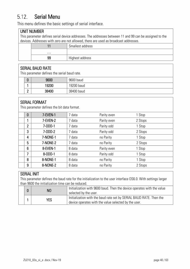
Serial Menu This menu defines the basic settings of serial interface.
UNIT NUMBER This parameter defines serial device addresses. The addresses between 11 and 99 can be assigned to the
devices. Addresses with zero are not allowed, there are used as broadcast addresses.
11 Smallest address
…
99 Highest address
SERIAL BAUD RATE This parameter defines the serial baud rate.
0 9600 9600 baud
1 19200 19200 baud
2 38400 38400 baud
SERIAL FORMAT This parameter defines the bit data format.
0 7-EVEN-1 7 data Parity even 1 Stop
1 7-EVEN-2 7 data Parity even 2 Stops
2 7-ODD-1 7 data Parity odd 1 Stop
3 7-ODD-2 7 data Parity odd 2 Stops
4 7-NONE-1 7 data no Parity 1 Stop
5 7-NONE-2 7 data no Parity 2 Stops
6 8-EVEN-1 8 data Parity even 1 Stop
7 8-ODD-1 8 data Parity odd 1 Stop
8 8-NONE-1 8 data no Parity 1 Stop
9 8-NONE-2 8 data no Parity 2 Stops
SERIAL INIT This parameter defines the baud rate for the initialization to the user interface OS6.0. With settings larger
than 9600 the initialization time can be reduced.
0 NO
Initialization with 9600 baud. Then the device operates with the value
selected by the user.
1 YES Initialization with the baud rate set by SERIAL BAUD RATE. Then the
device operates with the value selected by the user.
ZU210_02a_oi_e .docx / Nov-19 page 41 / 63
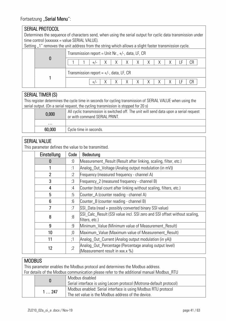
Fortsetzung „Serial Menu“:
SERIAL PROTOCOL Determines the sequence of characters send, when using the serial output for cyclic data transmission under
time control (xxxxxxx = value SERIAL VALUE).
Setting „1“ removes the unit address from the string which allows a slight faster transmission cycle.
0 Transmission report = Unit Nr., +/-, data, LF, CR
1 1 +/- X X X X X X X LF CR
1 Transmission report = +/-, data, LF, CR
+/- X X X X X X X LF CR
SERIAL TIMER (S) This register determines the cycle time in seconds for cycling transmission of SERIAL VALUE when using the
serial output. (On a serial request, the cycling transmission is stopped for 20 s)
0,000
All cyclic transmission is switched off. The unit will send data upon a serial request
or with command SERIAL PRINT.
…
60,000 Cycle time in seconds.
SERIAL VALUE This parameter defines the value to be transmitted.
Einstellung Code Bedeutung
0 :0 Measurement_Result (Result after linking, scaling, filter, etc.)
1 :1 Analog_Out_Voltage (Analog output modulation (in mV))
2 :2 Frequency (measured frequency - channel A)
3 :3 Frequency_2 (measured frequency - channel B)
4 :4 Counter (total count after linking without scaling, filters, etc.)
5 :5 Counter_A (counter reading - channel A)
6 :6 Counter_B (counter reading - channel B)
7 :7 SSI_Data (read + possibly converted binary SSI value)
8 :8 SSI_Calc_Result (SSI value incl. SSI zero and SSI offset without scaling,
filters, etc.)
9 :9 Minimum_Value (Minimum value of Measurement_Result)
10 ;0 Maximum_Value (Maximum value of Measurement_Result)
11 ;1 Analog_Out_Current (Analog output modulation (in yA))
12 ;2 Analog_Out_Percentage (Percentage analog output level)
(Measurement result in xxx.x %)
MODBUS This parameter enables the Modbus protocol and determines the Modbus address.
For details of the Modbus communication please refer to the additional manual Modbus_RTU
0
Modbus disabled
Serial interface is using Lecom protocol (Motrona-default protocol)
1 … 247 Modbus enabled: Serial interface is using Modbus RTU protocol
The set value is the Modbus address of the device.
ZU210_02a_oi_e .docx / Nov-19 page 42 / 63
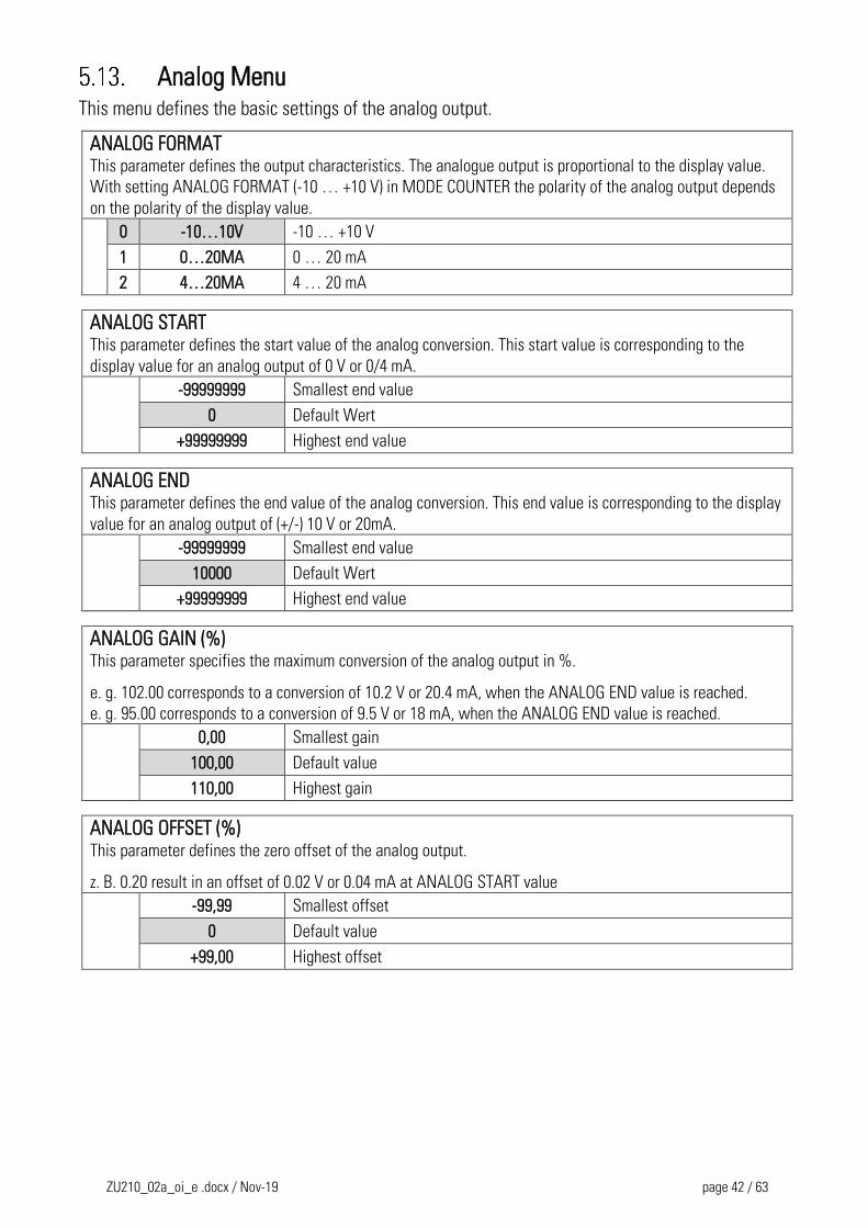
Analog Menu This menu defines the basic settings of the analog output.
ANALOG FORMAT This parameter defines the output characteristics. The analogue output is proportional to the display value.
With setting ANALOG FORMAT (-10 … +10 V) in MODE COUNTER the polarity of the analog output depends
on the polarity of the display value.
0 -10…10V -10 … +10 V
1 0…20MA 0 … 20 mA
2 4…20MA 4 … 20 mA
ANALOG START This parameter defines the start value of the analog conversion. This start value is corresponding to the
display value for an analog output of 0 V or 0/4 mA. -99999999 Smallest end value
0 Default Wert
+99999999 Highest end value
ANALOG END This parameter defines the end value of the analog conversion. This end value is corresponding to the display
value for an analog output of (+/-) 10 V or 20mA.
-99999999 Smallest end value
10000 Default Wert
+99999999 Highest end value
ANALOG GAIN (%) This parameter specifies the maximum conversion of the analog output in %.
e. g. 102.00 corresponds to a conversion of 10.2 V or 20.4 mA, when the ANALOG END value is reached.
e. g. 95.00 corresponds to a conversion of 9.5 V or 18 mA, when the ANALOG END value is reached.
0,00 Smallest gain
100,00 Default value
110,00 Highest gain
ANALOG OFFSET (%) This parameter defines the zero offset of the analog output.
z. B. 0.20 result in an offset of 0.02 V or 0.04 mA at ANALOG START value
-99,99 Smallest offset
0 Default value
+99,00 Highest offset
ZU210_02a_oi_e .docx / Nov-19 page 43 / 63
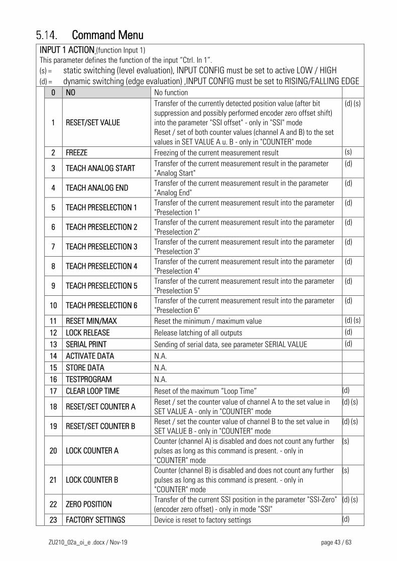
Command Menu
INPUT 1 ACTION (function Input 1)
This parameter defines the function of the input “Ctrl. In 1”.
(s) = static switching (level evaluation), INPUT CONFIG must be set to active LOW / HIGH
(d) = dynamic switching (edge evaluation) ,INPUT CONFIG must be set to RISING/FALLING EDGE 0 NO No function
1 RESET/SET VALUE
Transfer of the currently detected position value (after bit
suppression and possibly performed encoder zero offset shift)
into the parameter "SSI offset" - only in "SSI" mode
Reset / set of both counter values (channel A and B) to the set
values in SET VALUE A u. B - only in "COUNTER" mode
(d) (s)
2 FREEZE Freezing of the current measurement result (s)
3 TEACH ANALOG START Transfer of the current measurement result in the parameter
"Analog Start"
(d)
4 TEACH ANALOG END Transfer of the current measurement result in the parameter
"Analog End"
(d)
5 TEACH PRESELECTION 1 Transfer of the current measurement result into the parameter
"Preselection 1"
(d)
6 TEACH PRESELECTION 2 Transfer of the current measurement result into the parameter
"Preselection 2"
(d)
7 TEACH PRESELECTION 3 Transfer of the current measurement result into the parameter
"Preselection 3"
(d)
8 TEACH PRESELECTION 4 Transfer of the current measurement result into the parameter
"Preselection 4"
(d)
9 TEACH PRESELECTION 5 Transfer of the current measurement result into the parameter
"Preselection 5"
(d)
10 TEACH PRESELECTION 6 Transfer of the current measurement result into the parameter
"Preselection 6"
(d)
11 RESET MIN/MAX Reset the minimum / maximum value (d) (s)
12 LOCK RELEASE Release latching of all outputs (d)
13 SERIAL PRINT Sending of serial data, see parameter SERIAL VALUE (d)
14 ACTIVATE DATA N.A.
15 STORE DATA N.A.
16 TESTPROGRAM N.A.
17 CLEAR LOOP TIME Reset of the maximum “Loop Time” (d)
18 RESET/SET COUNTER A Reset / set the counter value of channel A to the set value in
SET VALUE A - only in "COUNTER" mode
(d) (s)
19 RESET/SET COUNTER B Reset / set the counter value of channel B to the set value in
SET VALUE B - only in "COUNTER" mode
(d) (s)
20 LOCK COUNTER A
Counter (channel A) is disabled and does not count any further
pulses as long as this command is present. - only in
"COUNTER" mode
(s)
21 LOCK COUNTER B
Counter (channel B) is disabled and does not count any further
pulses as long as this command is present. - only in
"COUNTER" mode
(s)
22 ZERO POSITION Transfer of the current SSI position in the parameter "SSI-Zero"
(encoder zero offset) - only in mode "SSI"
(d) (s)
23 FACTORY SETTINGS Device is reset to factory settings (d)
ZU210_02a_oi_e .docx / Nov-19 page 44 / 63
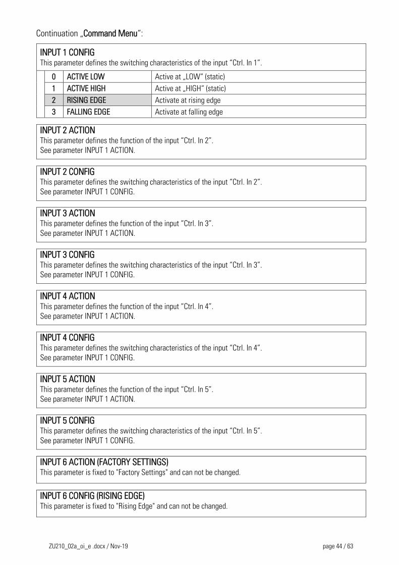
Continuation „Command Menu“:
INPUT 1 CONFIG This parameter defines the switching characteristics of the input “Ctrl. In 1”.
0 ACTIVE LOW Active at „LOW“ (static)
1 ACTIVE HIGH Active at „HIGH“ (static)
2 RISING EDGE Activate at rising edge
3 FALLING EDGE Activate at falling edge
INPUT 2 ACTION
This parameter defines the function of the input “Ctrl. In 2”.
See parameter INPUT 1 ACTION.
INPUT 2 CONFIG
This parameter defines the switching characteristics of the input “Ctrl. In 2”.
See parameter INPUT 1 CONFIG.
INPUT 3 ACTION
This parameter defines the function of the input “Ctrl. In 3”.
See parameter INPUT 1 ACTION.
INPUT 3 CONFIG
This parameter defines the switching characteristics of the input “Ctrl. In 3”.
See parameter INPUT 1 CONFIG.
INPUT 4 ACTION
This parameter defines the function of the input “Ctrl. In 4”.
See parameter INPUT 1 ACTION.
INPUT 4 CONFIG
This parameter defines the switching characteristics of the input “Ctrl. In 4”.
See parameter INPUT 1 CONFIG.
INPUT 5 ACTION
This parameter defines the function of the input “Ctrl. In 5”.
See parameter INPUT 1 ACTION.
INPUT 5 CONFIG
This parameter defines the switching characteristics of the input “Ctrl. In 5”.
See parameter INPUT 1 CONFIG.
INPUT 6 ACTION (FACTORY SETTINGS) This parameter is fixed to "Factory Settings" and can not be changed.
INPUT 6 CONFIG (RISING EDGE) This parameter is fixed to "Rising Edge" and can not be changed.
ZU210_02a_oi_e .docx / Nov-19 page 45 / 63
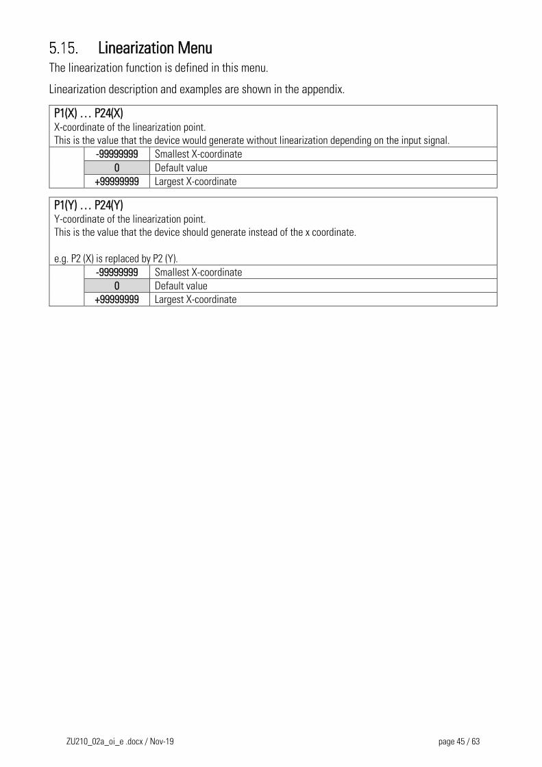
Linearization Menu The linearization function is defined in this menu.
Linearization description and examples are shown in the appendix.
P1(X) … P24(X) X-coordinate of the linearization point.
This is the value that the device would generate without linearization depending on the input signal.
-99999999 Smallest X-coordinate
0 Default value
+99999999 Largest X-coordinate
P1(Y) … P24(Y) Y-coordinate of the linearization point.
This is the value that the device should generate instead of the x coordinate.
e.g. P2 (X) is replaced by P2 (Y).
-99999999 Smallest X-coordinate
0 Default value
+99999999 Largest X-coordinate
ZU210_02a_oi_e .docx / Nov-19 page 46 / 63
Appendix
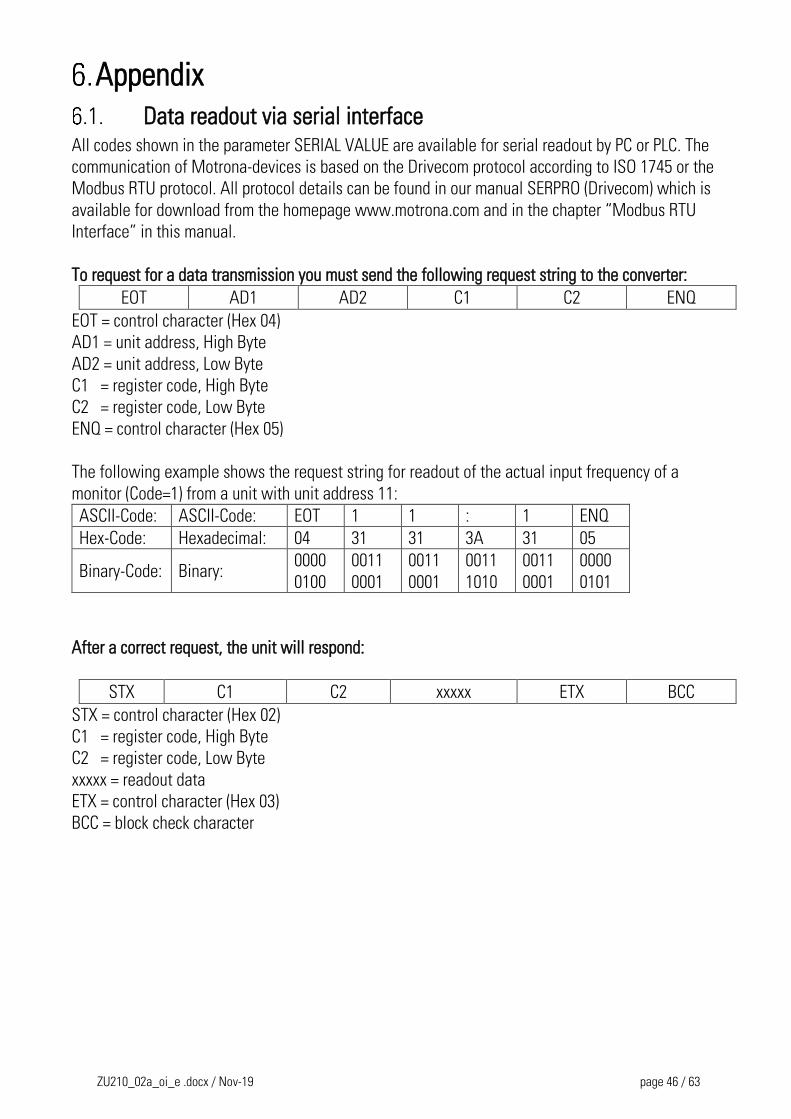
Data readout via serial interface All codes shown in the parameter SERIAL VALUE are available for serial readout by PC or PLC. The
communication of Motrona-devices is based on the Drivecom protocol according to ISO 1745 or the
Modbus RTU protocol. All protocol details can be found in our manual SERPRO (Drivecom) which is
available for download from the homepage www.motrona.com and in the chapter “Modbus RTU
Interface” in this manual.
To request for a data transmission you must send the following request string to the converter:
EOT AD1 AD2 C1 C2 ENQ
EOT = control character (Hex 04)
AD1 = unit address, High Byte
AD2 = unit address, Low Byte
C1 = register code, High Byte
C2 = register code, Low Byte
ENQ = control character (Hex 05)
The following example shows the request string for readout of the actual input frequency of a
monitor (Code=1) from a unit with unit address 11:
ASCII-Code: ASCII-Code: EOT 1 1 : 1 ENQ
Hex-Code: Hexadecimal: 04 31 31 3A 31 05
Binary-Code: Binary: 0000
0100
0011
0001
0011
0001
0011
1010
0011
0001
0000
0101
After a correct request, the unit will respond:
STX C1 C2 xxxxx ETX BCC
STX = control character (Hex 02)
C1 = register code, High Byte
C2 = register code, Low Byte
xxxxx = readout data
ETX = control character (Hex 03)
BCC = block check character
ZU210_02a_oi_e .docx / Nov-19 page 47 / 63
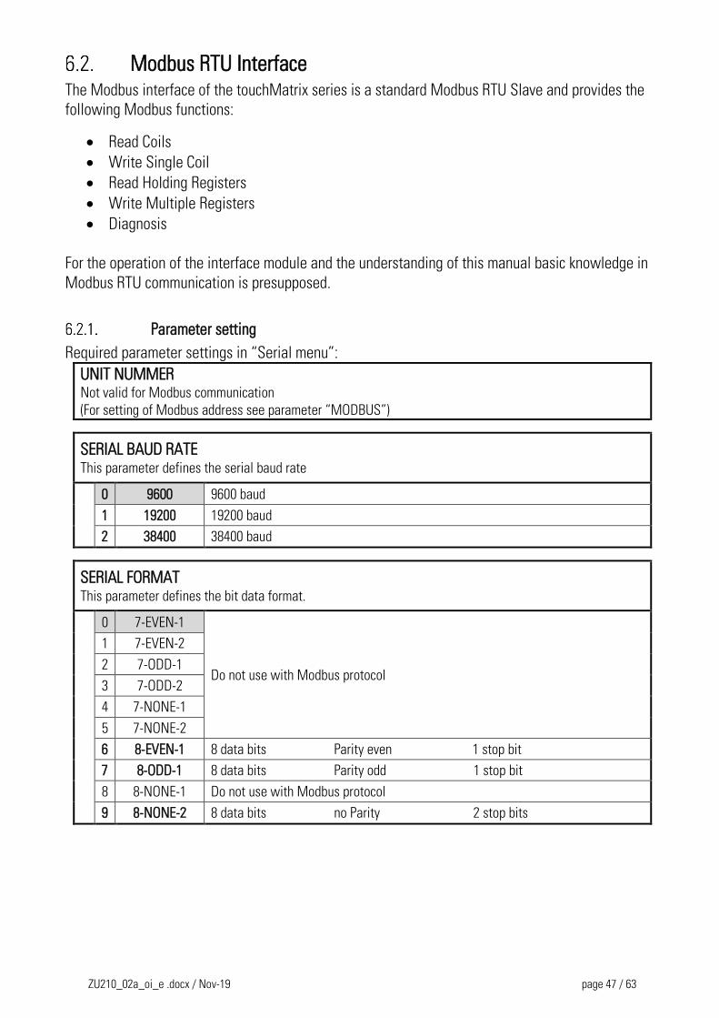
Modbus RTU Interface The Modbus interface of the touchMatrix series is a standard Modbus RTU Slave and provides the
following Modbus functions:
Read Coils
Write Single Coil
Read Holding Registers
Write Multiple Registers
Diagnosis
For the operation of the interface module and the understanding of this manual basic knowledge in
Modbus RTU communication is presupposed.
Parameter setting
Required parameter settings in “Serial menu”:
UNIT NUMMER Not valid for Modbus communication
(For setting of Modbus address see parameter “MODBUS”)
SERIAL BAUD RATE This parameter defines the serial baud rate
0 9600 9600 baud
1 19200 19200 baud
2 38400 38400 baud
SERIAL FORMAT This parameter defines the bit data format.
0 7-EVEN-1
Do not use with Modbus protocol
1 7-EVEN-2
2 7-ODD-1
3 7-ODD-2
4 7-NONE-1
5 7-NONE-2
6 8-EVEN-1 8 data bits Parity even 1 stop bit
7 8-ODD-1 8 data bits Parity odd 1 stop bit
8 8-NONE-1 Do not use with Modbus protocol
9 8-NONE-2 8 data bits no Parity 2 stop bits
ZU210_02a_oi_e .docx / Nov-19 page 48 / 63
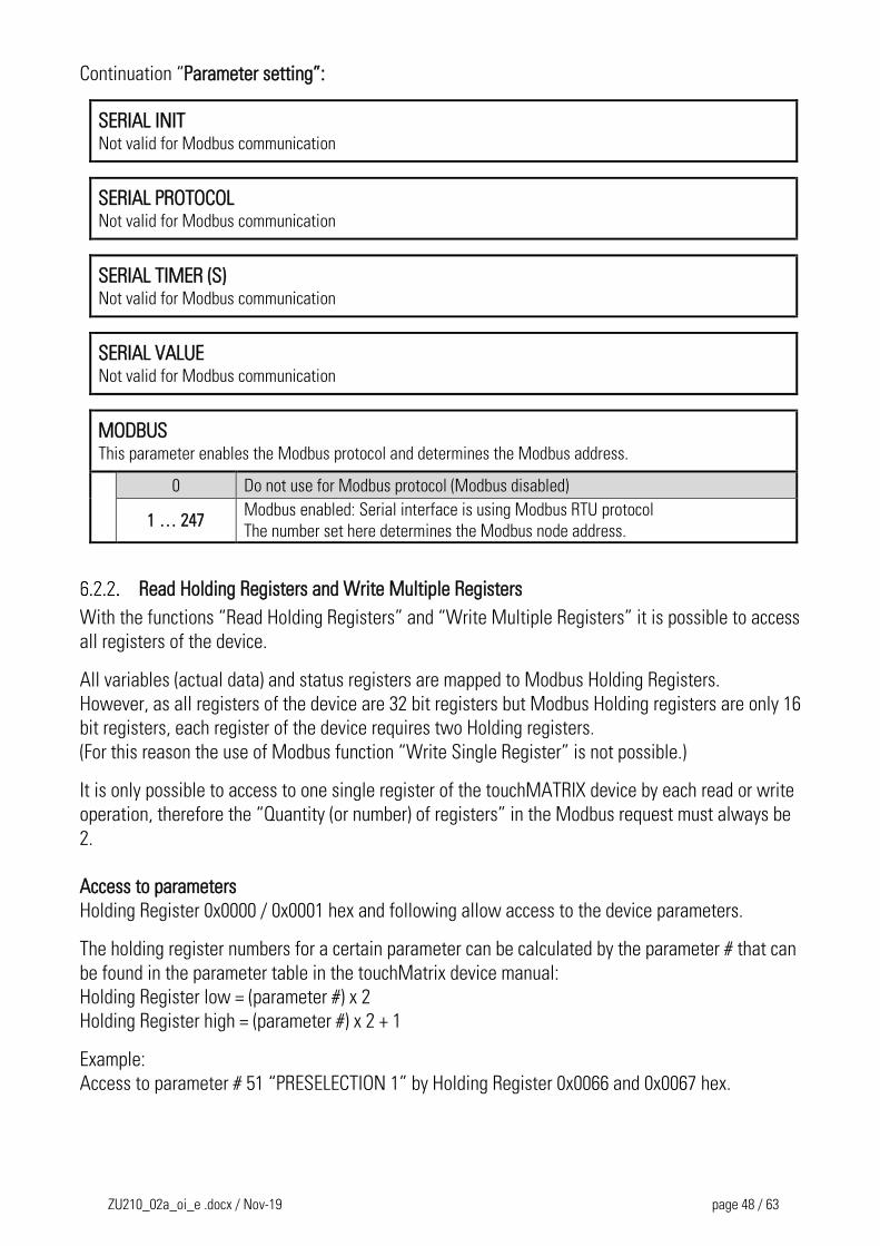
Continuation “Parameter setting”:
SERIAL INIT Not valid for Modbus communication
SERIAL PROTOCOL Not valid for Modbus communication
SERIAL TIMER (S) Not valid for Modbus communication
SERIAL VALUE Not valid for Modbus communication
MODBUS This parameter enables the Modbus protocol and determines the Modbus address.
0 Do not use for Modbus protocol (Modbus disabled)
1 … 247 Modbus enabled: Serial interface is using Modbus RTU protocol
The number set here determines the Modbus node address.
Read Holding Registers and Write Multiple Registers
With the functions “Read Holding Registers” and “Write Multiple Registers” it is possible to access
all registers of the device.
All variables (actual data) and status registers are mapped to Modbus Holding Registers.
However, as all registers of the device are 32 bit registers but Modbus Holding registers are only 16
bit registers, each register of the device requires two Holding registers.
(For this reason the use of Modbus function “Write Single Register” is not possible.)
It is only possible to access to one single register of the touchMATRIX device by each read or write
operation, therefore the “Quantity (or number) of registers” in the Modbus request must always be
2.
Access to parameters
Holding Register 0x0000 / 0x0001 hex and following allow access to the device parameters.
The holding register numbers for a certain parameter can be calculated by the parameter # that can
be found in the parameter table in the touchMatrix device manual:
Holding Register low = (parameter #) x 2
Holding Register high = (parameter #) x 2 + 1
Example:
Access to parameter # 51 “PRESELECTION 1” by Holding Register 0x0066 and 0x0067 hex.
ZU210_02a_oi_e .docx / Nov-19 page 49 / 63
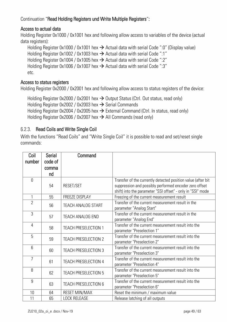
Continuation “Read Holding Registers und Write Multiple Registers”:
Access to actual data
Holding Register 0x1000 / 0x1001 hex and following allow access to variables of the device (actual
data registers):
Holding Register 0x1000 / 0x1001 hex Actual data with serial Code “:0” (Display value)
Holding Register 0x1002 / 0x1003 hex Actual data with serial Code “:1”
Holding Register 0x1004 / 0x1005 hex Actual data with serial Code “:2”
Holding Register 0x1006 / 0x1007 hex Actual data with serial Code “:3”
etc.
Access to status registers
Holding Register 0x2000 / 0x2001 hex and following allow access to status registers of the device:
Holding Register 0x2000 / 0x2001 hex Output Status (Ctrl. Out status, read only)
Holding Register 0x2002 / 0x2003 hex Serial Commands
Holding Register 0x2004 / 0x2005 hex External Command (Ctrl. In status, read only)
Holding Register 0x2006 / 0x2007 hex All Commands (read only)
Read Coils and Write Single Coil
With the functions “Read Coils” and “Write Single Coil” it is possible to read and set/reset single
commands:
Coil
number
Serial
code of
comma
nd
Command
0
54 RESET/SET
Transfer of the currently detected position value (after bit
suppression and possibly performed encoder zero offset
shift) into the parameter "SSI offset" - only in "SSI" mode
1 55 FREEZE DISPLAY Freezing of the current measurement result
2 56 TEACH ANALOG START
Transfer of the current measurement result in the
parameter "Analog Start"
3 57 TEACH ANALOG END
Transfer of the current measurement result in the
parameter "Analog End"
4 58 TEACH PRESELECTION 1
Transfer of the current measurement result into the
parameter "Preselection 1"
5 59 TEACH PRESELECTION 2
Transfer of the current measurement result into the
parameter "Preselection 2"
6 60 TEACH PRESELECTION 3
Transfer of the current measurement result into the
parameter "Preselection 3"
7 61 TEACH PRESELECTION 4
Transfer of the current measurement result into the
parameter "Preselection 4"
8 62 TEACH PRESELECTION 5
Transfer of the current measurement result into the
parameter "Preselection 5"
9 63 TEACH PRESELECTION 6
Transfer of the current measurement result into the
parameter "Preselection 6"
10 64 RESET MIN/MAX Reset the minimum / maximum value
11 65 LOCK RELEASE Release latching of all outputs
ZU210_02a_oi_e .docx / Nov-19 page 50 / 63
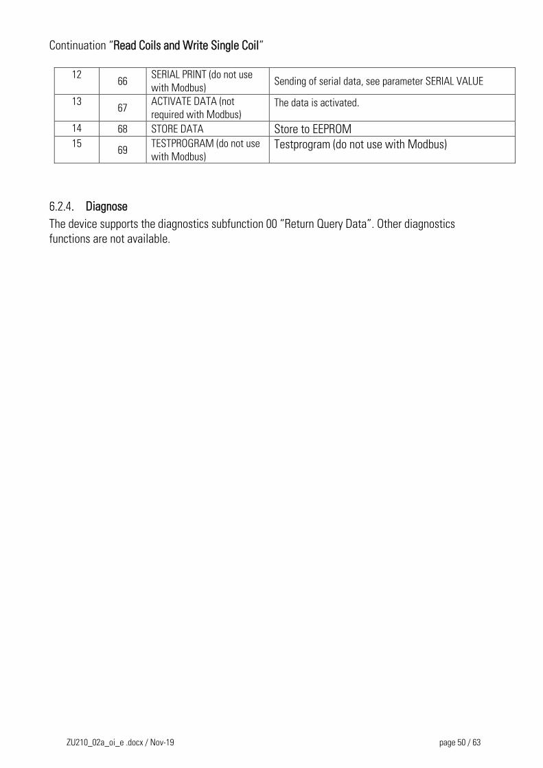
Continuation “Read Coils and Write Single Coil”
12
66 SERIAL PRINT (do not use
with Modbus) Sending of serial data, see parameter SERIAL VALUE
13 67
ACTIVATE DATA (not
required with Modbus) The data is activated.
14 68 STORE DATA Store to EEPROM 15
69 TESTPROGRAM (do not use
with Modbus) Testprogram (do not use with Modbus)
Diagnose
The device supports the diagnostics subfunction 00 “Return Query Data”. Other diagnostics
functions are not available.
ZU210_02a_oi_e .docx / Nov-19 page 51 / 63
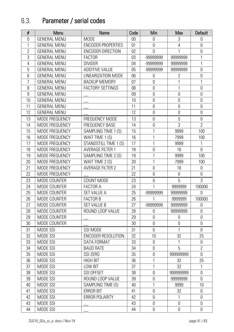
Parameter / serial codes
# Menu Name Code Min Max Default
0 GENERAL MENU MODE 00 0 3 0
1 GENERAL MENU ENCODER PROPERTIES 01 0 4 0
2 GENERAL MENU ENCODER DIRECTION 02 0 1 0
3 GENERAL MENU FACTOR 03 -99999999 99999999 1
4 GENERAL MENU DIVIDER 04 -99999999 99999999 1
5 GENERAL MENU ADDITIVE VALUE 05 -99999999 99999999 0
6 GENERAL MENU LINEARIZATION MODE 06 0 2 0
7 GENERAL MENU BACKUP MEMORY 07 0 1 1
8 GENERAL MENU FACTORY SETTINGS 08 0 1 0
9 GENERAL MENU __ 09 0 0 0
10 GENERAL MENU __ 10 0 0 0
11 GENERAL MENU __ 11 0 0 0
12 GENERAL MENU __ 12 0 0 0
13 MODE FREQUENCY FREQUENCY MODE 13 0 5 0
14 MODE FREQUENCY FREQUENCY BASE 14 0 3 2
15 MODE FREQUENCY SAMPLING TIME 1 (S) 15 1 9999 100
16 MODE FREQUENCY WAIT TIME 1 (S) 16 1 7999 100
17 MODE FREQUENCY STANDSTILL TIME 1 (S) 17 1 9999 1
18 MODE FREQUENCY AVERAGE FILTER 1 18 0 16 0
19 MODE FREQUENCY SAMPLING TIME 2 (S) 19 1 9999 100
20 MODE FREQUENCY WAIT TIME 2 (S) 20 1 7999 100
21 MODE FREQUENCY AVERAGE FILTER 2 21 0 16 0
22 MODE FREQUENCY __ 22 0 0 0
23 MODE COUNTER COUNT MODE 23 0 5 3
24 MODE COUNTER FACTOR A 24 1 9999999 100000
25 MODE COUNTER SET VALUE A 25 -99999999 99999999 0
26 MODE COUNTER FACTOR B 26 1 9999999 100000
27 MODE COUNTER SET VALUE B 27 -99999999 99999999 0
28 MODE COUNTER ROUND LOOP VALUE 28 0 99999999 0
29 MODE COUNTER __ 29 0 0 0
30 MODE COUNTER __ 30 0 0 0
31 MODE SSI SSI MODE 31 0 1 0
32 MODE SSI ENCODER RESOLUTION 32 10 32 25
33 MODE SSI DATA FORMAT 33 0 1 0
34 MODE SSI BAUD RATE 34 0 5 2
35 MODE SSI SSI ZERO 35 0 999999999 0
36 MODE SSI HIGH BIT 36 1 32 25
37 MODE SSI LOW BIT 37 1 32 1
38 MODE SSI SSI OFFSET 38 0 999999999 0
39 MODE SSI ROUND LOOP VALUE 39 0 99999999 0
40 MODE SSI SAMPLING TIME (S) 40 1 9999 10
41 MODE SSI ERROR BIT 41 0 32 0
42 MODE SSI ERROR POLARITY 42 0 1 0
43 MODE SSI __ 43 0 0 0
44 MODE SSI __ 44 0 0 0
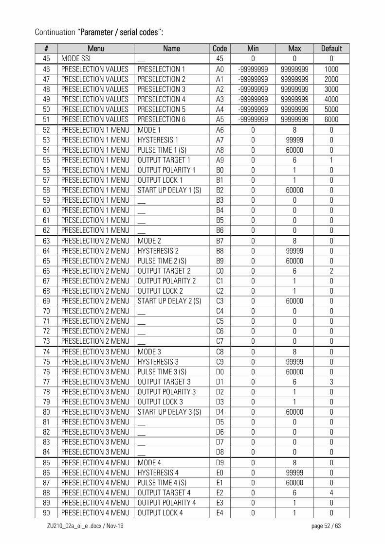
ZU210_02a_oi_e .docx / Nov-19 page 52 / 63
Continuation “Parameter / serial codes”:
# Menu Name Code Min Max Default
45 MODE SSI __ 45 0 0 0
46 PRESELECTION VALUES PRESELECTION 1 A0 -99999999 99999999 1000
47 PRESELECTION VALUES PRESELECTION 2 A1 -99999999 99999999 2000
48 PRESELECTION VALUES PRESELECTION 3 A2 -99999999 99999999 3000
49 PRESELECTION VALUES PRESELECTION 4 A3 -99999999 99999999 4000
50 PRESELECTION VALUES PRESELECTION 5 A4 -99999999 99999999 5000
51 PRESELECTION VALUES PRESELECTION 6 A5 -99999999 99999999 6000
52 PRESELECTION 1 MENU MODE 1 A6 0 8 0
53 PRESELECTION 1 MENU HYSTERESIS 1 A7 0 99999 0
54 PRESELECTION 1 MENU PULSE TIME 1 (S) A8 0 60000 0
55 PRESELECTION 1 MENU OUTPUT TARGET 1 A9 0 6 1
56 PRESELECTION 1 MENU OUTPUT POLARITY 1 B0 0 1 0
57 PRESELECTION 1 MENU OUTPUT LOCK 1 B1 0 1 0
58 PRESELECTION 1 MENU START UP DELAY 1 (S) B2 0 60000 0
59 PRESELECTION 1 MENU __ B3 0 0 0
60 PRESELECTION 1 MENU __ B4 0 0 0
61 PRESELECTION 1 MENU __ B5 0 0 0
62 PRESELECTION 1 MENU __ B6 0 0 0
63 PRESELECTION 2 MENU MODE 2 B7 0 8 0
64 PRESELECTION 2 MENU HYSTERESIS 2 B8 0 99999 0
65 PRESELECTION 2 MENU PULSE TIME 2 (S) B9 0 60000 0
66 PRESELECTION 2 MENU OUTPUT TARGET 2 C0 0 6 2
67 PRESELECTION 2 MENU OUTPUT POLARITY 2 C1 0 1 0
68 PRESELECTION 2 MENU OUTPUT LOCK 2 C2 0 1 0
69 PRESELECTION 2 MENU START UP DELAY 2 (S) C3 0 60000 0
70 PRESELECTION 2 MENU __ C4 0 0 0
71 PRESELECTION 2 MENU __ C5 0 0 0
72 PRESELECTION 2 MENU __ C6 0 0 0
73 PRESELECTION 2 MENU __ C7 0 0 0
74 PRESELECTION 3 MENU MODE 3 C8 0 8 0
75 PRESELECTION 3 MENU HYSTERESIS 3 C9 0 99999 0
76 PRESELECTION 3 MENU PULSE TIME 3 (S) D0 0 60000 0
77 PRESELECTION 3 MENU OUTPUT TARGET 3 D1 0 6 3
78 PRESELECTION 3 MENU OUTPUT POLARITY 3 D2 0 1 0
79 PRESELECTION 3 MENU OUTPUT LOCK 3 D3 0 1 0
80 PRESELECTION 3 MENU START UP DELAY 3 (S) D4 0 60000 0
81 PRESELECTION 3 MENU __ D5 0 0 0
82 PRESELECTION 3 MENU __ D6 0 0 0
83 PRESELECTION 3 MENU __ D7 0 0 0
84 PRESELECTION 3 MENU __ D8 0 0 0
85 PRESELECTION 4 MENU MODE 4 D9 0 8 0
86 PRESELECTION 4 MENU HYSTERESIS 4 E0 0 99999 0
87 PRESELECTION 4 MENU PULSE TIME 4 (S) E1 0 60000 0
88 PRESELECTION 4 MENU OUTPUT TARGET 4 E2 0 6 4
89 PRESELECTION 4 MENU OUTPUT POLARITY 4 E3 0 1 0
90 PRESELECTION 4 MENU OUTPUT LOCK 4 E4 0 1 0
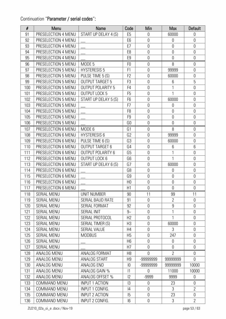
ZU210_02a_oi_e .docx / Nov-19 page 53 / 63
Continuation “Parameter / serial codes”:
# Menu Name Code Min Max Default
91 PRESELECTION 4 MENU START UP DELAY 4 (S) E5 0 60000 0
92 PRESELECTION 4 MENU __ E6 0 0 0
93 PRESELECTION 4 MENU __ E7 0 0 0
94 PRESELECTION 4 MENU __ E8 0 0 0
95 PRESELECTION 4 MENU __ E9 0 0 0
96 PRESELECTION 5 MENU MODE 5 F0 0 8 0
97 PRESELECTION 5 MENU HYSTERESIS 5 F1 0 99999 0
98 PRESELECTION 5 MENU PULSE TIME 5 (S) F2 0 60000 0
99 PRESELECTION 5 MENU OUTPUT TARGET 5 F3 0 6 5
100 PRESELECTION 5 MENU OUTPUT POLARITY 5 F4 0 1 0
101 PRESELECTION 5 MENU OUTPUT LOCK 5 F5 0 1 0
102 PRESELECTION 5 MENU START UP DELAY 5 (S) F6 0 60000 0
103 PRESELECTION 5 MENU __ F7 0 0 0
104 PRESELECTION 5 MENU __ F8 0 0 0
105 PRESELECTION 5 MENU __ F9 0 0 0
106 PRESELECTION 5 MENU __ G0 0 0 0
107 PRESELECTION 6 MENU MODE 6 G1 0 8 0
108 PRESELECTION 6 MENU HYSTERESIS 6 G2 0 99999 0
109 PRESELECTION 6 MENU PULSE TIME 6 (S) G3 0 60000 0
110 PRESELECTION 6 MENU OUTPUT TARGET 6 G4 0 6 6
111 PRESELECTION 6 MENU OUTPUT POLARITY 6 G5 0 1 0
112 PRESELECTION 6 MENU OUTPUT LOCK 6 G6 0 1 0
113 PRESELECTION 6 MENU START UP DELAY 6 (S) G7 0 60000 0
114 PRESELECTION 6 MENU __ G8 0 0 0
115 PRESELECTION 6 MENU __ G9 0 0 0
116 PRESELECTION 6 MENU __ H0 0 0 0
117 PRESELECTION 6 MENU __ H1 0 0 0
118 SERIAL MENU UNIT NUMBER 90 11 99 11
119 SERIAL MENU SERIAL BAUD RATE 91 0 2 0
120 SERIAL MENU SERIAL FORMAT 92 0 9 0
121 SERIAL MENU SERIAL INIT 9~ 0 1 0
122 SERIAL MENU SERIAL PROTOCOL H2 0 1 0
123 SERIAL MENU SERIAL TIMER (S) H3 0 60000 0
124 SERIAL MENU SERIAL VALUE H4 0 3 0
125 SERIAL MENU MODBUS H5 0 247 0
126 SERIAL MENU __ H6 0 0 0
127 SERIAL MENU __ H7 0 0 0
128 ANALOG MENU ANALOG FORMAT H8 0 2 0
129 ANALOG MENU ANALOG START H9 -99999999 99999999 0
130 ANALOG MENU ANALOG END I0 -99999999 99999999 10000
131 ANALOG MENU ANALOG GAIN % I1 0 11000 10000
132 ANALOG MENU ANALOG OFFSET % I2 -9999 9999 0
133 COMMAND MENU INPUT 1 ACTION I3 0 23 0
134 COMMAND MENU INPUT 1 CONFIG. I4 0 3 2
135 COMMAND MENU INPUT 2 ACTION I5 0 23 0
136 COMMAND MENU INPUT 2 CONFIG. I6 0 3 2
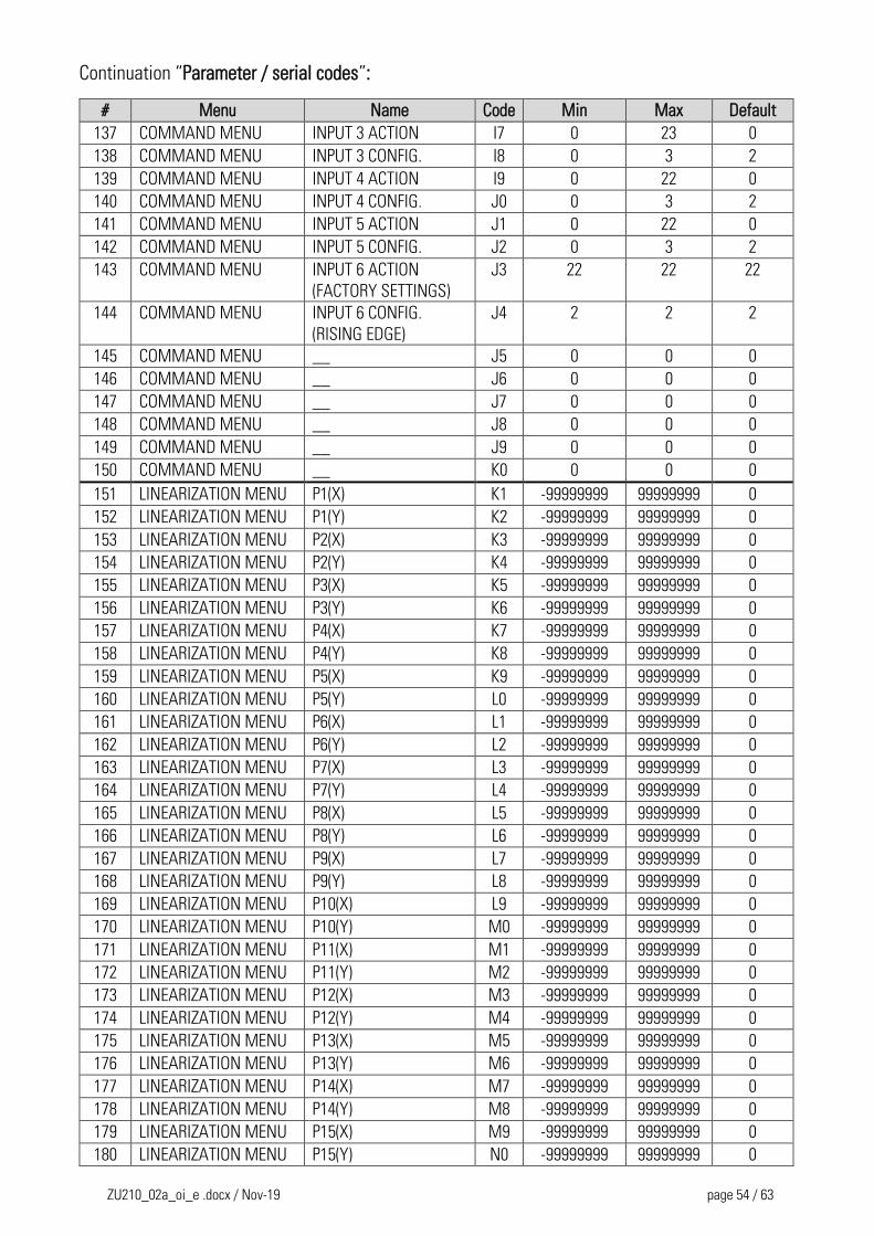
ZU210_02a_oi_e .docx / Nov-19 page 54 / 63
Continuation “Parameter / serial codes”:
# Menu Name Code Min Max Default
137 COMMAND MENU INPUT 3 ACTION I7 0 23 0
138 COMMAND MENU INPUT 3 CONFIG. I8 0 3 2
139 COMMAND MENU INPUT 4 ACTION I9 0 22 0
140 COMMAND MENU INPUT 4 CONFIG. J0 0 3 2
141 COMMAND MENU INPUT 5 ACTION J1 0 22 0
142 COMMAND MENU INPUT 5 CONFIG. J2 0 3 2
143 COMMAND MENU INPUT 6 ACTION
(FACTORY SETTINGS)
J3 22 22 22
144 COMMAND MENU INPUT 6 CONFIG.
(RISING EDGE)
J4 2 2 2
145 COMMAND MENU __ J5 0 0 0
146 COMMAND MENU __ J6 0 0 0
147 COMMAND MENU __ J7 0 0 0
148 COMMAND MENU __ J8 0 0 0
149 COMMAND MENU __ J9 0 0 0
150 COMMAND MENU __ K0 0 0 0
151 LINEARIZATION MENU P1(X) K1 -99999999 99999999 0
152 LINEARIZATION MENU P1(Y) K2 -99999999 99999999 0
153 LINEARIZATION MENU P2(X) K3 -99999999 99999999 0
154 LINEARIZATION MENU P2(Y) K4 -99999999 99999999 0
155 LINEARIZATION MENU P3(X) K5 -99999999 99999999 0
156 LINEARIZATION MENU P3(Y) K6 -99999999 99999999 0
157 LINEARIZATION MENU P4(X) K7 -99999999 99999999 0
158 LINEARIZATION MENU P4(Y) K8 -99999999 99999999 0
159 LINEARIZATION MENU P5(X) K9 -99999999 99999999 0
160 LINEARIZATION MENU P5(Y) L0 -99999999 99999999 0
161 LINEARIZATION MENU P6(X) L1 -99999999 99999999 0
162 LINEARIZATION MENU P6(Y) L2 -99999999 99999999 0
163 LINEARIZATION MENU P7(X) L3 -99999999 99999999 0
164 LINEARIZATION MENU P7(Y) L4 -99999999 99999999 0
165 LINEARIZATION MENU P8(X) L5 -99999999 99999999 0
166 LINEARIZATION MENU P8(Y) L6 -99999999 99999999 0
167 LINEARIZATION MENU P9(X) L7 -99999999 99999999 0
168 LINEARIZATION MENU P9(Y) L8 -99999999 99999999 0
169 LINEARIZATION MENU P10(X) L9 -99999999 99999999 0
170 LINEARIZATION MENU P10(Y) M0 -99999999 99999999 0
171 LINEARIZATION MENU P11(X) M1 -99999999 99999999 0
172 LINEARIZATION MENU P11(Y) M2 -99999999 99999999 0
173 LINEARIZATION MENU P12(X) M3 -99999999 99999999 0
174 LINEARIZATION MENU P12(Y) M4 -99999999 99999999 0
175 LINEARIZATION MENU P13(X) M5 -99999999 99999999 0
176 LINEARIZATION MENU P13(Y) M6 -99999999 99999999 0
177 LINEARIZATION MENU P14(X) M7 -99999999 99999999 0
178 LINEARIZATION MENU P14(Y) M8 -99999999 99999999 0
179 LINEARIZATION MENU P15(X) M9 -99999999 99999999 0
180 LINEARIZATION MENU P15(Y) N0 -99999999 99999999 0
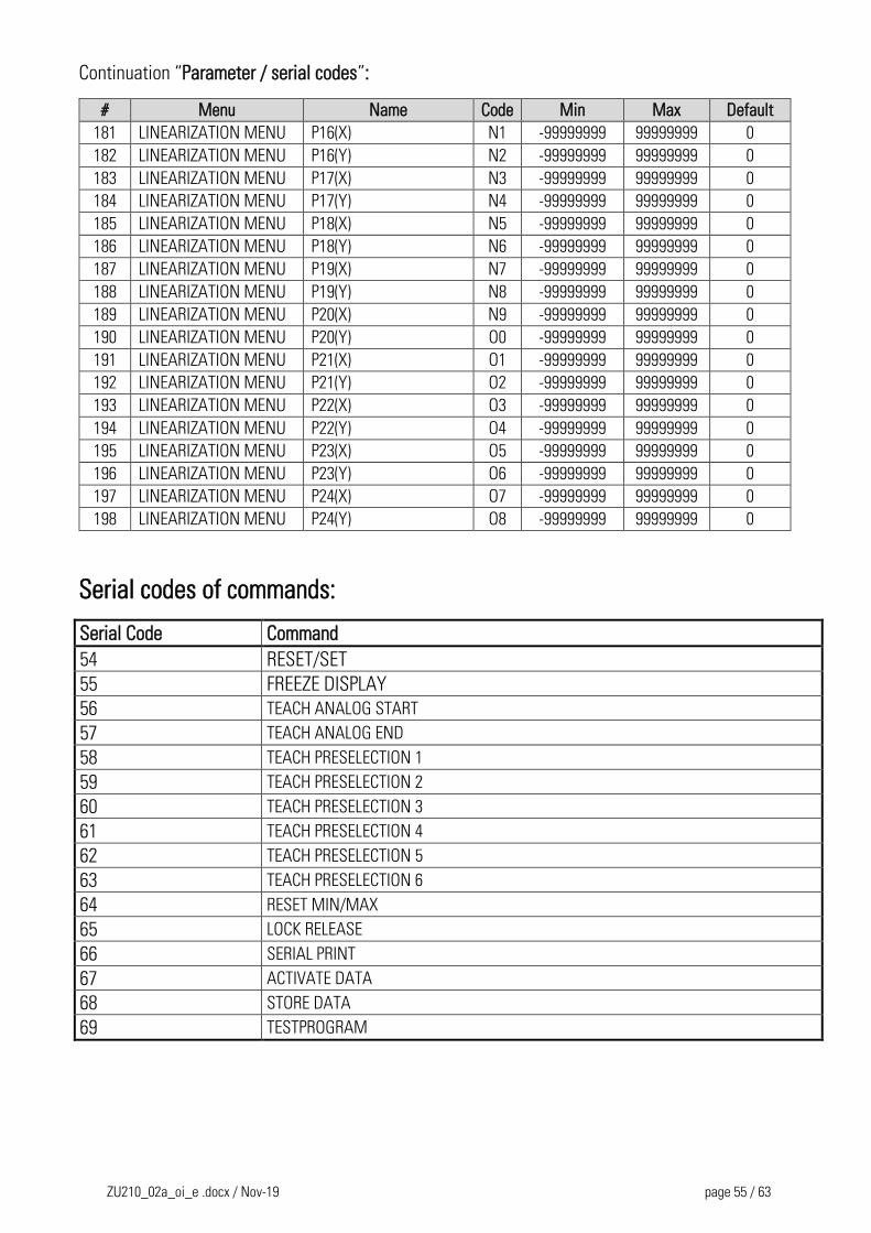
ZU210_02a_oi_e .docx / Nov-19 page 55 / 63
Continuation “Parameter / serial codes”:
# Menu Name Code Min Max Default
181 LINEARIZATION MENU P16(X) N1 -99999999 99999999 0
182 LINEARIZATION MENU P16(Y) N2 -99999999 99999999 0
183 LINEARIZATION MENU P17(X) N3 -99999999 99999999 0
184 LINEARIZATION MENU P17(Y) N4 -99999999 99999999 0
185 LINEARIZATION MENU P18(X) N5 -99999999 99999999 0
186 LINEARIZATION MENU P18(Y) N6 -99999999 99999999 0
187 LINEARIZATION MENU P19(X) N7 -99999999 99999999 0
188 LINEARIZATION MENU P19(Y) N8 -99999999 99999999 0
189 LINEARIZATION MENU P20(X) N9 -99999999 99999999 0
190 LINEARIZATION MENU P20(Y) O0 -99999999 99999999 0
191 LINEARIZATION MENU P21(X) O1 -99999999 99999999 0
192 LINEARIZATION MENU P21(Y) O2 -99999999 99999999 0
193 LINEARIZATION MENU P22(X) O3 -99999999 99999999 0
194 LINEARIZATION MENU P22(Y) O4 -99999999 99999999 0
195 LINEARIZATION MENU P23(X) O5 -99999999 99999999 0
196 LINEARIZATION MENU P23(Y) O6 -99999999 99999999 0
197 LINEARIZATION MENU P24(X) O7 -99999999 99999999 0
198 LINEARIZATION MENU P24(Y) O8 -99999999 99999999 0
Serial codes of commands:
Serial Code Command
54 RESET/SET
55 FREEZE DISPLAY
56 TEACH ANALOG START
57 TEACH ANALOG END
58 TEACH PRESELECTION 1
59 TEACH PRESELECTION 2
60 TEACH PRESELECTION 3
61 TEACH PRESELECTION 4
62 TEACH PRESELECTION 5
63 TEACH PRESELECTION 6
64 RESET MIN/MAX
65 LOCK RELEASE
66 SERIAL PRINT
67 ACTIVATE DATA
68 STORE DATA
69 TESTPROGRAM
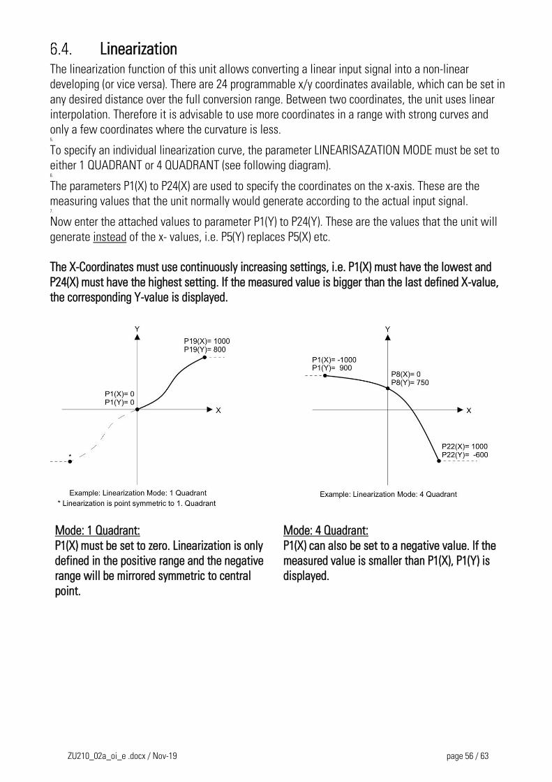
ZU210_02a_oi_e .docx / Nov-19 page 56 / 63
Linearization The linearization function of this unit allows converting a linear input signal into a non-linear
developing (or vice versa). There are 24 programmable x/y coordinates available, which can be set in
any desired distance over the full conversion range. Between two coordinates, the unit uses linear
interpolation. Therefore it is advisable to use more coordinates in a range with strong curves and
only a few coordinates where the curvature is less. 5.
To specify an individual linearization curve, the parameter LINEARISAZATION MODE must be set to
either 1 QUADRANT or 4 QUADRANT (see following diagram). 6.
The parameters P1(X) to P24(X) are used to specify the coordinates on the x-axis. These are the
measuring values that the unit normally would generate according to the actual input signal. 7.
Now enter the attached values to parameter P1(Y) to P24(Y). These are the values that the unit will
generate instead of the x- values, i.e. P5(Y) replaces P5(X) etc.
The X-Coordinates must use continuously increasing settings, i.e. P1(X) must have the lowest and
P24(X) must have the highest setting. If the measured value is bigger than the last defined X-value,
the corresponding Y-value is displayed.
Mode: 1 Quadrant: Mode: 4 Quadrant:
P1(X) must be set to zero. Linearization is only
defined in the positive range and the negative
range will be mirrored symmetric to central
point.
P1(X) can also be set to a negative value. If the
measured value is smaller than P1(X), P1(Y) is
displayed.
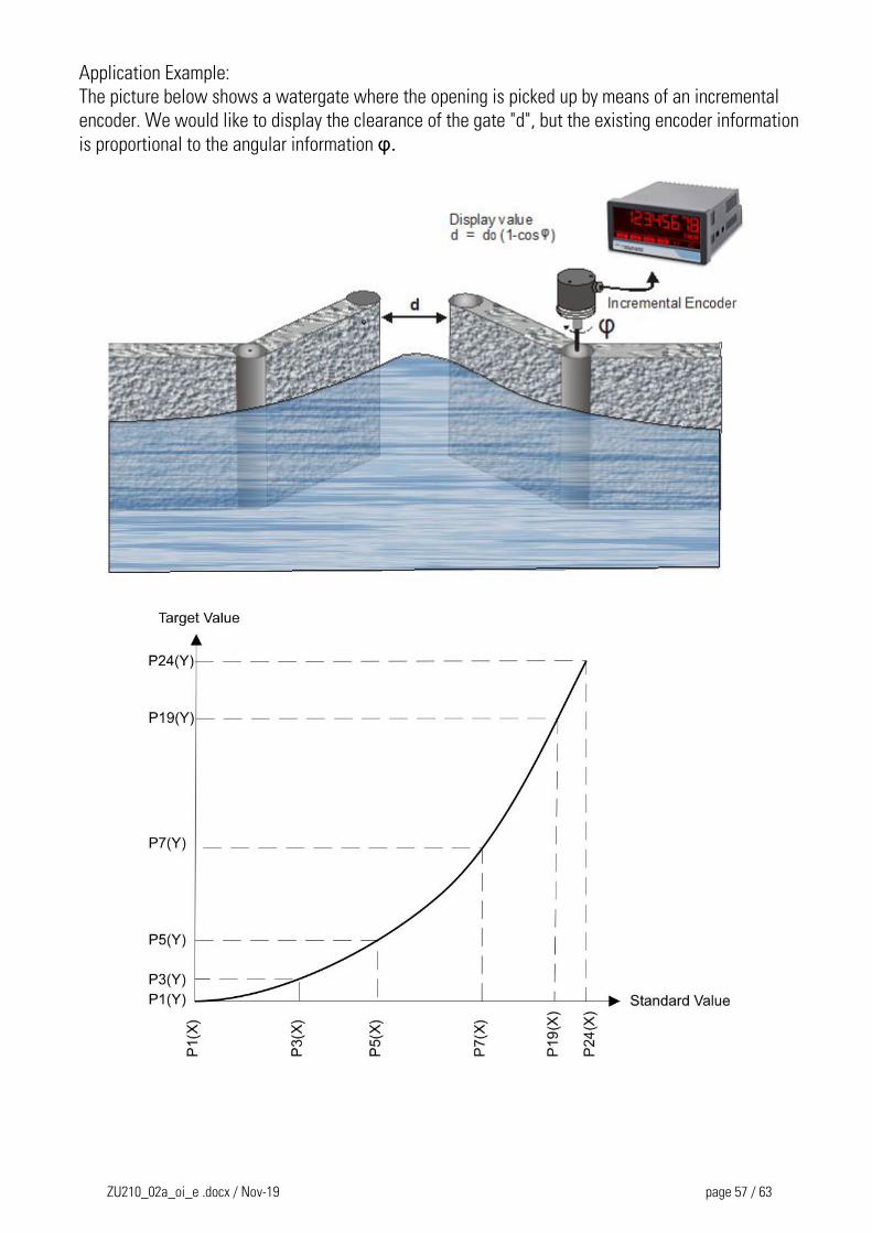
ZU210_02a_oi_e .docx / Nov-19 page 57 / 63
Application Example:
The picture below shows a watergate where the opening is picked up by means of an incremental
encoder. We would like to display the clearance of the gate "d", but the existing encoder information
is proportional to the angular information φ.
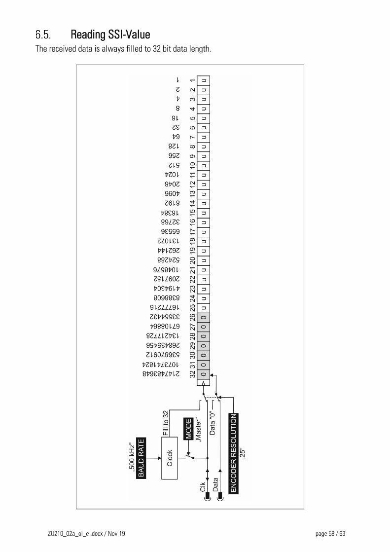
ZU210_02a_oi_e .docx / Nov-19 page 58 / 63
Reading SSI-Value The received data is always filled to 32 bit data length.
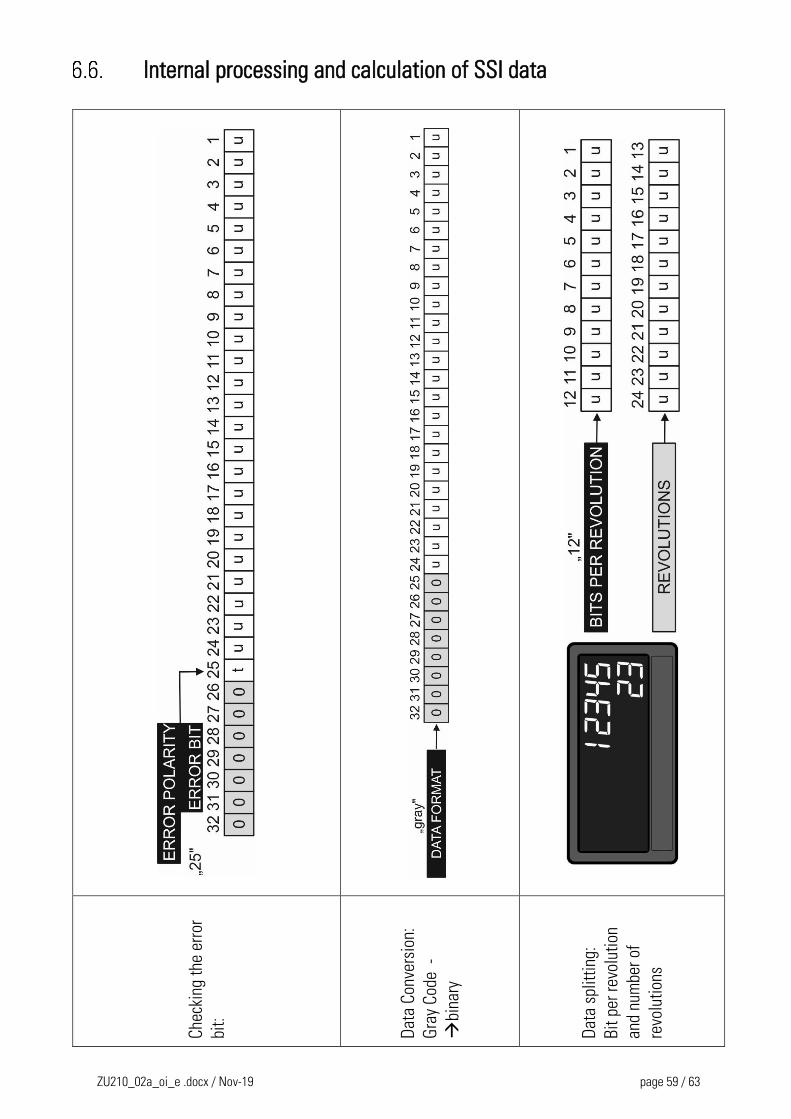
ZU210_02a_oi_e .docx / Nov-19 page 59 / 63
Internal processing and calculation of SSI data
Che
ckin
g th
e er
ror
bit:
Dat
a C
onve
rsio
n:
Gra
y C
ode
-
bi
nary
Dat
a sp
litti
ng:
Bit
per
rev
olut
ion
and
num
ber
of
revo
luti
ons
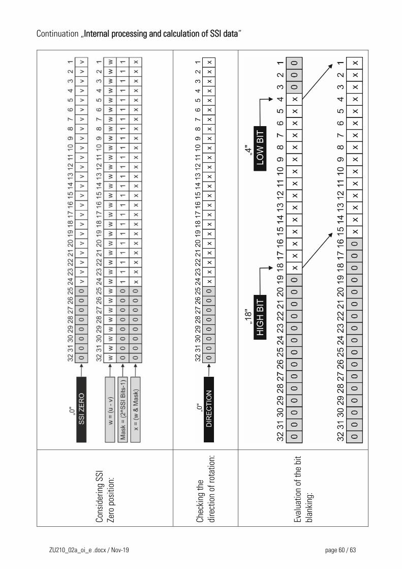
ZU210_02a_oi_e .docx / Nov-19 page 60 / 63
Continuation „Internal processing and calculation of SSI data”
Con
side
ring
SS
I
Zero
pos
itio
n:
Che
ckin
g th
e
dire
ctio
n of
rot
atio
n:
Eval
uati
on o
f th
e bi
t
blan
king
:
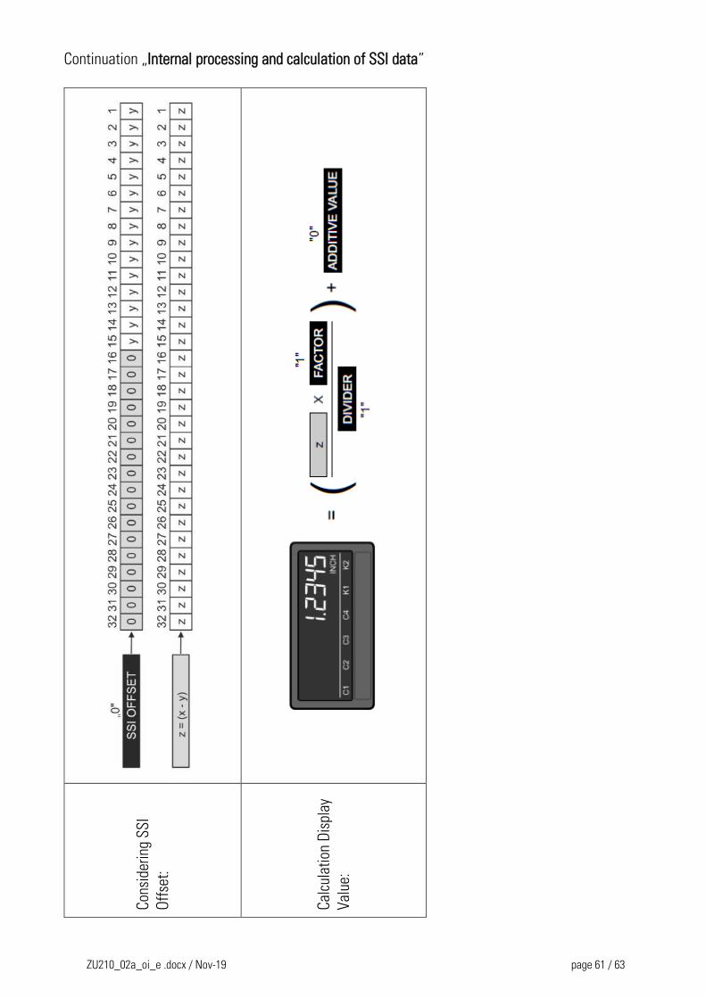
ZU210_02a_oi_e .docx / Nov-19 page 61 / 63
Continuation „Internal processing and calculation of SSI data”
Con
side
ring
SS
I
Off
set:
Cal
cula
tion
Dis
play
Val
ue:
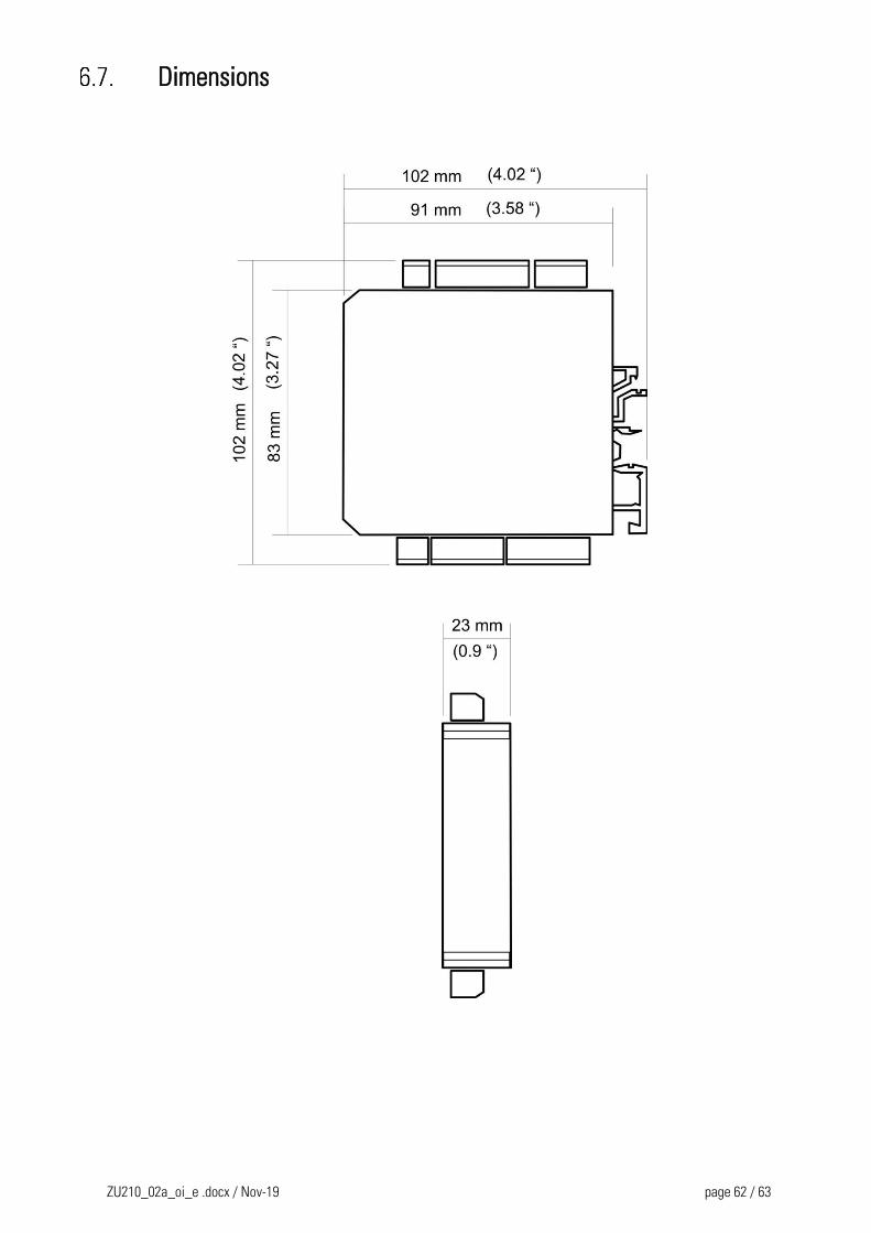
ZU210_02a_oi_e .docx / Nov-19 page 62 / 63
Dimensions
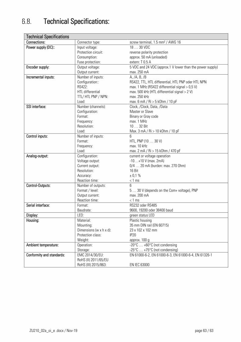
ZU210_02a_oi_e .docx / Nov-19 page 63 / 63
Technical Specifications:
Technical Specifications Connections: Connector type: screw terminal, 1.5 mm² / AWG 16
Power supply (DC):: Input voltage:
Protection circuit:
Consumption:
Fuse protection:
18 … 30 VDC
reverse polarity protection
approx. 50 mA (unloaded)
extern: T 0.5 A
Encoder supply: Output voltage:
Output current:
5 VDC and 24 VDC (approx.1 V lower than the power supply)
max. 250 mA
Incremental inputs: Number of inputs:
Configuration::
RS422:
HTL differential
TTL/ HTL PNP / NPN:
Load:
A, /A, B, /B
RS422, TTL, HTL differential, HTL PNP oder HTL NPN
max. 1 MHz (RS422 differential signal > 0,5 V)
max. 500 kHz (HTL differential signal > 2 V)
max. 250 kHz
max. 6 mA / Ri > 5 kOhm / 10 pF
SSI interface: Number (channels):
Configuration:
Format:
Frequency:
Resolution:
Load:
Clock, /Clock, Data, /Data
Master or Slave
Binary or Gray code
max. 1 MHz
10 … 32 Bit
Max. 3 mA / Ri > 10 kOhm / 10 pF
Control inputs: Number of inputs:
Format:
Frequency:
Load:
6
HTL, PNP (10 … 30 V)
max. 10 kHz
max. 2 mA / Ri > 15 kOhm / 470 pF
Analog-output: Configuration:
Voltage output:
Current output:
Resolution:
Accuracy:
Reaction time:
current or voltage operation
-10…+10 V (max. 2mA)
0/4 … 20 mA (burden: max. 270 Ohm)
16 Bit
± 0,1 %
< 1 ms
Control-Outputs: Number of outputs:
Format / level:
Output current:
Reaction time:
6
5 … 30 V (depends on the Com+ voltage), PNP
max. 200 mA
< 1 ms
Serial interface: Format:
Baudrate:
RS232 oder RS485
9600, 19200 oder 38400 baud
Display: LED: green status LED
Housing: Material:
Mounting:
Dimensions (w x h x d):
Protection class:
Weight:
Plastic housing
35 mm DIN rail (EN 60715)
23 x 102 x 102 mm
IP20
approx. 100 g
Ambient temperature: Operation:
Storage:
-20°C … +60°C (not condensing
-25°C … +75°C (not condensing)
Conformity and standards: EMC 2014/30/EU:
RoHS (II) 2011/65/EU
RoHS (III) 2015/863:
EN 61000-6-2, EN 61000-6-3, EN 61000-6-4, EN 61326-1
EN IEC 63000
Related Documents