Part No. 987096 ProMinent Dosiertechnik GmbH · 69123 Heidelberg · Germany BA VA 016 05/08 GB Operating Instructions Vario, VAMc Metering Pumps For safe and correct operation of ProMinent ® Vario metering pumps, two sets of Operating Instructions are required: The product-specific Vario Operating Instructions and “General Operating Instructions ProMinent ® Motor-Driven Metering Pumps and Hydraulic Accessories”. Operating Instructions must be read together! Please completly read through these operating instructions first! · Do not discard! The operator shall be liable for any damage caused by installation or operating errors! Pr o Minent ® Please enter ident code of the device here. VAMc ___ ___ ___ ___ ___ ___ ___ ___

Welcome message from author
This document is posted to help you gain knowledge. Please leave a comment to let me know what you think about it! Share it to your friends and learn new things together.
Transcript
ProMinent® Page 1Part No. 987096 ProMinent Dosiertechnik GmbH · 69123 Heidelberg · Germany BA VA 016 05/08 GB
Operating InstructionsVario, VAMcMetering Pumps
For safe and correct operation of ProMinent® Vario metering pumps,two sets of Operating Instructions are required:
The product-specific Vario Operating Instructions and “General Operating Instructions ProMinent®
Motor-Driven Metering Pumps and Hydraulic Accessories”. Operating Instructions must be read together!
Please completly read through these operating instructions first! · Do not discard!The operator shall be liable for any damage caused by installation or operating errors!
ProM
inen
t®
Please enter ident code of the device here.
VAMc ___ ___ ___ ___ ___ ___ ___ ___
BA_VA_016_05_08_GB.p65 15.05.2008, 8:03 Uhr1
ProMinent®Page 2
Publishing details:Operating Instructions ProMinent® Vario C© ProMinent Dosiertechnik GmbH, 2003
ProMinent Dosiertechnik GmbHIm Schuhmachergewann 5-1169123 [email protected]
Subject to technical modifications.
Publishing details
BA_VA_016_05_08_GB.p65 15.05.2008, 8:03 Uhr2
ProMinent® Page 3
Table of Contents
Page
Product Identification/Identcode ...................................................... 4
1 Safety relevant instructions for ProMinent®
metering pumps ................................................................... 5
1.1 General notes.................................................................. 5
1.2 Notes for installation, commissioning and operation ..... 6
1.3 Notes on servicing and repair ......................................... 6
2 Product Description ........................................................... 7
2.1 Marking/Identification of pump type ............................... 7
2.2 Construction and functional description of drive unit ..... 8
2.2.1 Diagram showing operation of stroke .................... 8
2.3 Construction and functional description ofdiaphragm delivery unit .................................................. 8
2.3.1 Integrated overflow valve withbleeder function ..................................................... 9
2.4 The drive motor and the types of control ....................... 9
3 Commissioning .................................................................... 10
3.1 General notes.................................................................. 10
3.2 Installing and connecting ................................................ 10
3.3 Commissioning ............................................................... 11
3.4 Troubleshooting .............................................................. 12
4 Servicing/Maintenance ...................................................... 13
4.1 General servicing notes .................................................. 13
4.2 Replacement of wear parts ............................................. 13
4.3 Disposal of old parts ....................................................... 14
4.4 Spare parts set ............................................................... 14
5 Technical Data ..................................................................... 15
5.1 Performance data ........................................................... 15
5.2 Dimensions sheet ........................................................... 16
5.3 Motor data ...................................................................... 18
6 EC Declaration of Conformity .......................................... 21
BA_VA_016_05_08_GB.p65 15.05.2008, 8:03 Uhr3
ProMinent®Page 4
Product Identification/Identcode
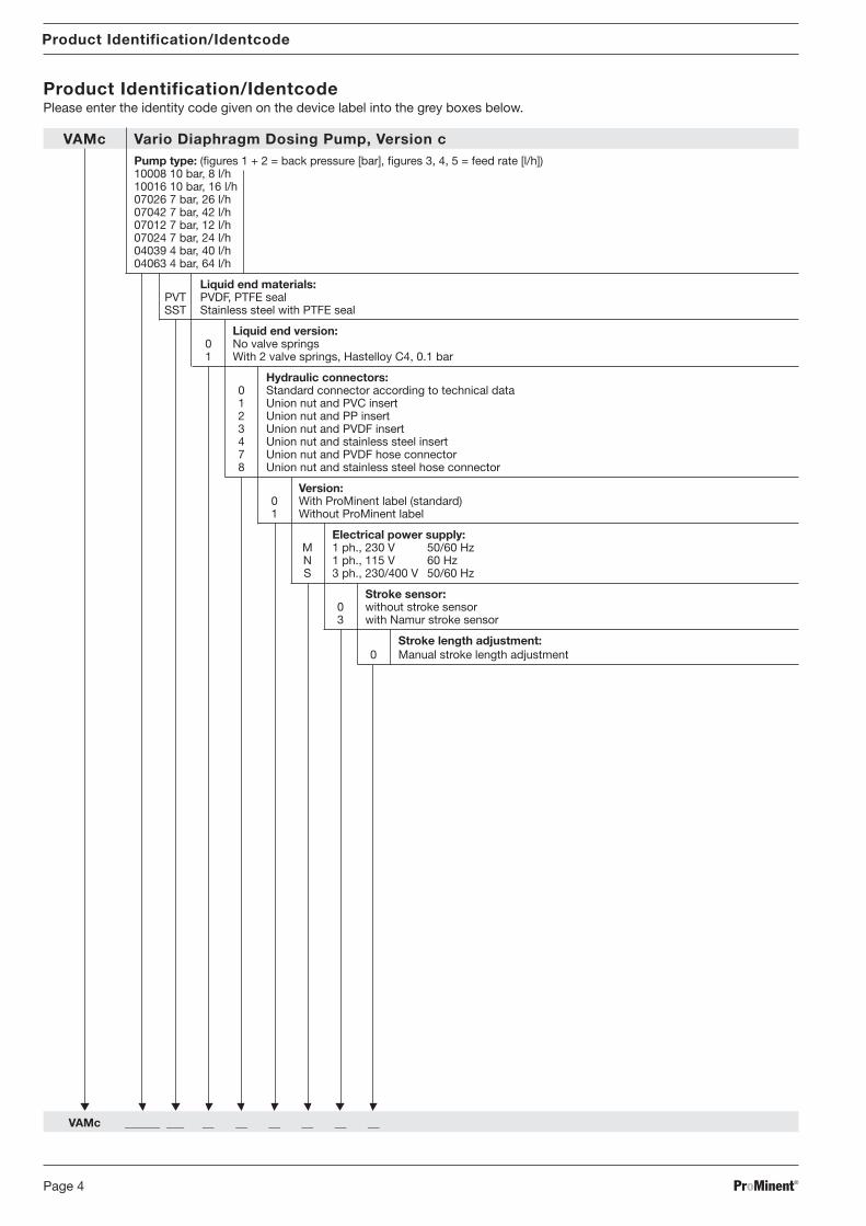
Product Identification/IdentcodePlease enter the identity code given on the device label into the grey boxes below.
VAMc Vario Diaphragm Dosing Pump, Version cPump type: (figures 1 + 2 = back pressure [bar], figures 3, 4, 5 = feed rate [l/h])10008 10 bar, 8 l/h10016 10 bar, 16 l/h07026 7 bar, 26 l/h07042 7 bar, 42 l/h07012 7 bar, 12 l/h07024 7 bar, 24 l/h04039 4 bar, 40 l/h04063 4 bar, 64 l/h
Liquid end materials:PVT PVDF, PTFE sealSST Stainless steel with PTFE seal
Liquid end version:0 No valve springs1 With 2 valve springs, Hastelloy C4, 0.1 bar
Hydraulic connectors:0 Standard connector according to technical data1 Union nut and PVC insert2 Union nut and PP insert3 Union nut and PVDF insert4 Union nut and stainless steel insert7 Union nut and PVDF hose connector8 Union nut and stainless steel hose connector
Version:0 With ProMinent label (standard)1 Without ProMinent label
Electrical power supply:M 1 ph., 230 V 50/60 HzN 1 ph., 115 V 60 HzS 3 ph., 230/400 V 50/60 Hz
Stroke sensor:0 without stroke sensor3 with Namur stroke sensor
Stroke length adjustment:0 Manual stroke length adjustment
VAMc ______ ___ __ __ __ __ __ __
BA_VA_016_05_08_GB.p65 15.05.2008, 8:03 Uhr4
ProMinent® Page 5
1 Safety relevant instructions for ProMinent® meteringpumps
Safety precautions and important operating instructions are divided into classes and providedwith symbols. Please familiarise yourself with the following designations and symbols.
WARNING
Describes a potentially dangerous situation. Could result in loss of life or serious injury ifpreventative measures are not taken.
CAUTION
Describes a potentially dangerous situation. Could result in lesser injuries or damage toproperty if preventative measures are not taken.
IMPORTANT
Describes a potentially threatening situation. Could result in damage to property ifpreventative measures are not taken.
NOTE
Guidelines are intended to make your work easier.
1.1 General notes
Correct use
• The Vario must be used for liquids only!
• The Vario may be used only in compliance with the technical data and specifications given inthe operating instructions!
• It is forbidden to use the Vario for any other purpose, or to modify it in any way!
• The Vario is not suitable for dosing gases or solids!
• The Vario must be used by trained and authorised personnel only!
CAUTION
• Assembly of ProMinent® metering pumps with foreign parts which are not tested orrecommended by ProMinent is not permissible and can lead to injury to persons ordamage for which no responsibility is accepted!
• Pumps must be accessible for operating and servicing at all times. Accesses must notbe obstructed or blocked!
• For servicing and repair work where dangerous or unknown dosing media are beingused, first empty and flush out the liquid end! Observe the safety data sheets for thedosing liquid!
• When metering dangerous or unknown liquids those working on the liquid ends mustwear protective clothing (goggles, gloves, ...)!
• The plug (item. 9 in Fig. 6, page 13) must be fitted during operation!
Sound intensity level
The sound intensity level is < 70 dB (A)at maximum stroke, maximum stroke rate, maximum back pressure (water) in accordance with:
DIN EN 12639 (Metering Pump Noise Measurement)
Safety relevant instructions for ProMinent® metering pumps
BA_VA_016_05_08_GB.p65 15.05.2008, 8:03 Uhr5
ProMinent®Page 6
1.2 Notes for installation, commissioning and operation
CAUTION• The metering pump may still contain residual water in the liquid end from testing in the
factory.
In the case of media which must not come into contact with water, the liquid end mustbe cleared of all water before commissioning. To do this rotate the pump 180° andempty the liquid end and then flush from above through the intake connection using asuitable medium.
• When operating the metering pump against a closed isolator at the pressure end, thebackpressure can reach several times the maximum permissible backpressure.This can cause the delivery line to burst!To avoid this, a pressure relief valve is recommended which limits the backpressure!
IMPORTANT• Design the pressure lines so that pressure peaks on the discharge stroke do not exceed
the maximum permissible pressure (fit a pressure relief valve if necessary)!• Adjustments to the stroke length should only be carried out with the pump running!
NOTE• The pump shall be secured in such a way that no vibration can occur!
The valves of the liquid end must always be vertical to ensure correct operation!• Intake and delivery pipes must always be arranged such that strain-free connection to
the liquid end is guaranteed!Pipes shall be secured in such a way that no vibration can occur!
• Use only the locking rings and hose fittings designed for the particular hose diameterand also use original hoses with the specified hose dimensions and wall thickness,otherwise the security of the connection is not guaranteed!Reductions in hose sizes are to be avoided!The permissible pressure stress of the hoses is to be observed.
• When dosing extremely aggressive or dangerous media an arrangement which relievesback into the tank is advisable!Moreover, an shut-off valve should be fitted on the pressure and suction sides!
1.3 Notes on servicing and repair
CAUTION• Metering pumps and their peripherals may only be serviced by expert and authorised
persons!• When carrying out servicing or repairs where dangerous or unknown media are used,
always flush the liquid end first!• When metering dangerous or unknown liquids, those working on the liquid end must
wear protective clothing (goggles, gloves, ...)!• The pressure in the metering pipe must first be released before working on the pump.
Always empty and flush the liquid end!Observe the safety data sheets for the metering liquid!
WARNING
• Isolate the supply cable or withdraw the mains plug before opening the pump.Check for freedom from voltage!Always secure the pump against unauthorised restarting during repair work!
• Pumps which are used for dosing radioactive media must not be shipped!
Safety relevant instructions for ProMinent® metering pumps
BA_VA_016_05_08_GB.p65 15.05.2008, 8:03 Uhr6
ProMinent® Page 7
Product Description
Only send the equipment for repair or maintenance in a cleaned condition and with theliquid end flushed. However, should any safety precautions be necessary even after carefuldraining and cleaning of the equipment, the required information must be listed in theSafety Declaration!
• The Safety Declaration forms part of the inspection/repair contract.
Maintenance or repair work will only be carried out if a Safety Declaration - correctly andfully completed by an authorised and qualified member of the Operator's staff - is available.
A copy of the form is included in the “General operating instructions for ProMinentmotor-driven dosing pumps and hydraulic accessories” or can be downloaded atwww.prominent.com .
2 Product Description
2.1 Marking/Identification of pump type
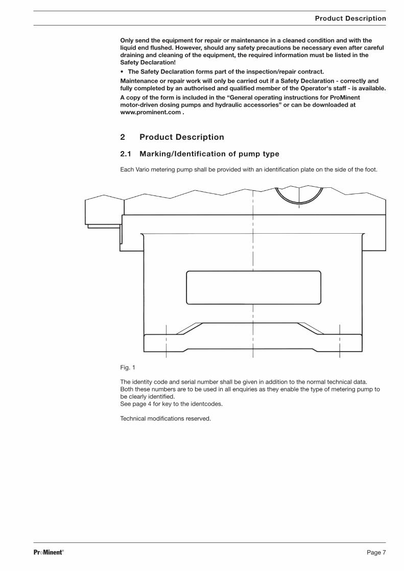
Each Vario metering pump shall be provided with an identification plate on the side of the foot.
The identity code and serial number shall be given in addition to the normal technical data.Both these numbers are to be used in all enquiries as they enable the type of metering pump tobe clearly identified.See page 4 for key to the identcodes.
Technical modifications reserved.
Fig. 1
BA_VA_016_05_08_GB.p65 15.05.2008, 8:03 Uhr7
ProMinent®Page 8
Product Description
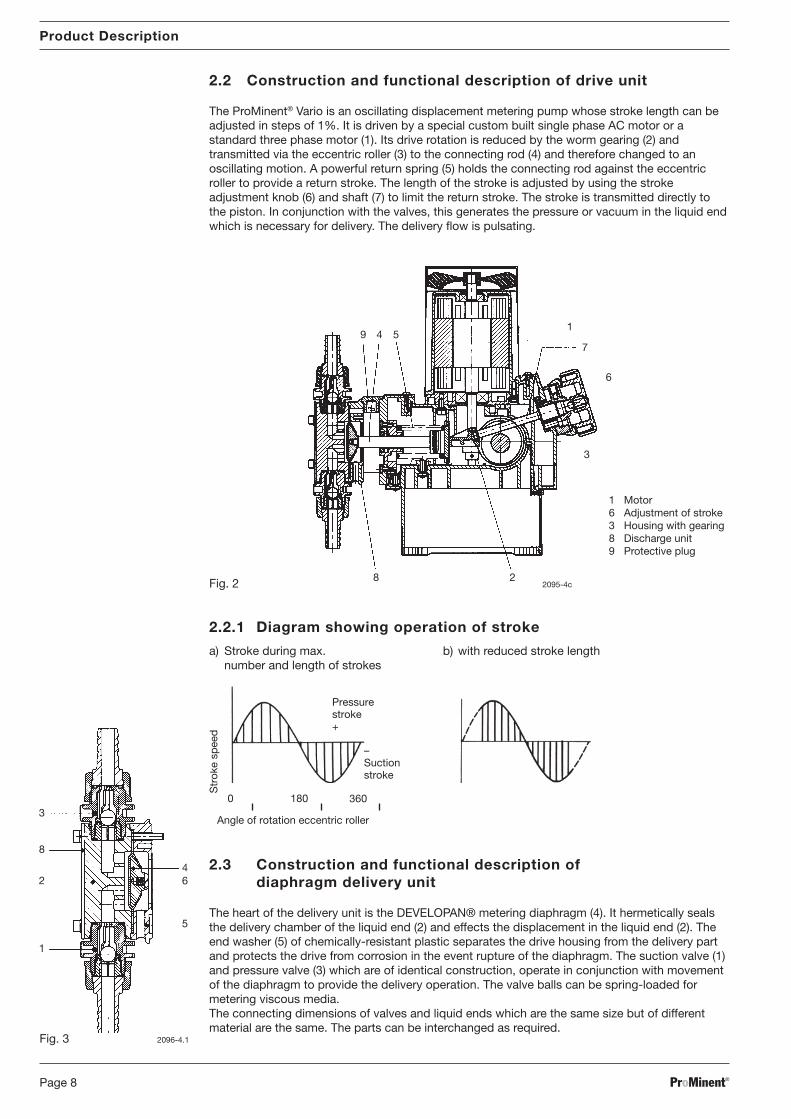
2.2 Construction and functional description of drive unit
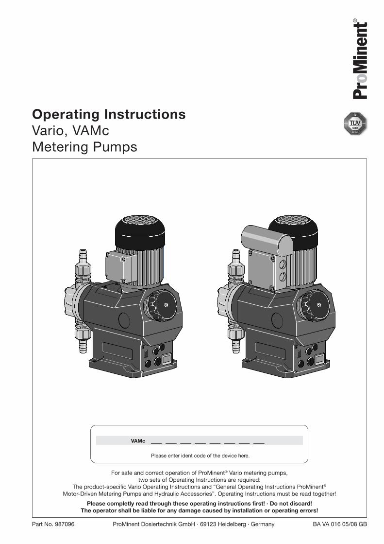
The ProMinent® Vario is an oscillating displacement metering pump whose stroke length can beadjusted in steps of 1%. It is driven by a special custom built single phase AC motor or astandard three phase motor (1). Its drive rotation is reduced by the worm gearing (2) andtransmitted via the eccentric roller (3) to the connecting rod (4) and therefore changed to anoscillating motion. A powerful return spring (5) holds the connecting rod against the eccentricroller to provide a return stroke. The length of the stroke is adjusted by using the strokeadjustment knob (6) and shaft (7) to limit the return stroke. The stroke is transmitted directly tothe piston. In conjunction with the valves, this generates the pressure or vacuum in the liquid endwhich is necessary for delivery. The delivery flow is pulsating.
2.3 Construction and functional description of diaphragm delivery unit
The heart of the delivery unit is the DEVELOPAN® metering diaphragm (4). It hermetically sealsthe delivery chamber of the liquid end (2) and effects the displacement in the liquid end (2). Theend washer (5) of chemically-resistant plastic separates the drive housing from the delivery partand protects the drive from corrosion in the event rupture of the diaphragm. The suction valve (1)and pressure valve (3) which are of identical construction, operate in conjunction with movementof the diaphragm to provide the delivery operation. The valve balls can be spring-loaded formetering viscous media.The connecting dimensions of valves and liquid ends which are the same size but of differentmaterial are the same. The parts can be interchanged as required.
Pressurestroke+
Str
oke
spee
d
Angle of rotation eccentric roller
–Suctionstroke
0 360180
2.2.1 Diagram showing operation of stroke
a) Stroke during max. b) with reduced stroke lengthnumber and length of strokes
1 Motor6 Adjustment of stroke3 Housing with gearing8 Discharge unit9 Protective plug
2096-4.1
3
8
2
1
46
5
1
7
6
9 4 5
28
3
2095-4cFig. 2
Fig. 3
BA_VA_016_05_08_GB.p65 15.05.2008, 8:03 Uhr8
ProMinent® Page 9
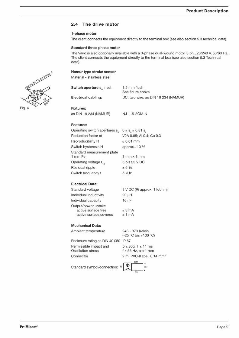
Switch aperture sn inset 1.5 mm flushSee figure above
Electrical cabling: DC, two wire, as DIN 19 234 (NAMUR)
Fixtures:
as DIN 19 234 (NAMUR) NJ 1.5-8GM-N
Features:
Operating switch apertures sa 0 ≤ sa ≤ 0.81 sn
Reduction factor at V2A 0.85; Al 0.4; Cu 0.3
Reproducibility R ≤ 0.01 mm
Switch hysteresis H approx.. 10 %
Standard measurement plate1 mm Fe 8 mm x 8 mm
Operating voltage UB 5 bis 25 V DC
Residual ripple ≤ 5 %
Switch frequency f 5 kHz
Electrical Data:
Standard voltage 8 V DC (Ri approx. 1 k/ohm)
Individual inductivity 20 µH
Individual capacity 16 nF
Output/power uptakeactive surface free ≤ 3 mAactive surface covered ≤ 1 mA
Mechanical Data:
Ambient temperature 248 - 373 Kelvin(-25 °C bis +100 °C)
Enclosure rating as DIN 40 050 IP 67
Permissible impact and b ≤ 30g, T ≤ 11 msOscillation stress f ≤ 55 Hz, a ≤ 1 mm
Connector 2 m, PVC-Kabel, 0,14 mm2
Standard symbol/connection:
Product Description
2.4 The drive motor
1-phase motor
The client connects the equipment directly to the terminal box (see also section 5.3 technical data).
Standard three-phase motor
The Vario is also optionally available with a 3-phase dual-wound motor. 3 ph., 23/240 V, 50/60 Hz.The client connects the equipment directly to the terminal box (see also section 5.3 Technicaldata).
Namur type stroke sensor
Material - stainless steel
key width 13, th
ickness 4
M8x1
22
(60)x
Fig. 4
BM
BU
N+DC
-
BA_VA_016_05_08_GB.p65 15.05.2008, 8:03 Uhr9
ProMinent®Page 10
Commissioning
3 Commissioning
3.1 General notes
The pulsating operation of the ProMinent® Vario as an oscillating displacement metering pumpcauses high pressure differences in the pipes on each discharge stroke. If these pressuredifferences are too great because of unsatisfactory lines, it can lead to high metering errors or tofailure of the metering pump. When dosing very viscous media or where the metering lines arevery long, a larger internal diameter for the pipe should be chosen if necessary and/or acompressed air chamber or diaphragm pulsation damper should be fitted.
CAUTION
• Check that the materials used can withstand the chemicals which are being metered(refer to ProMinent® Resistance List in the Product Catalogue).
• The safety notes in Chapter 1 must be observed.
3.2 Installing and connecting
- The metering pump must be installed vertically with its base on a horizontal support.- The intake and delivery lines shall be laid in such a way that the coupling to the liquid end is
free of mechanical strain.- The pumps and pipes shall be secured so that no vibration can occur.- The pipes shall be attached in such a way that the pump and liquid end can be moved
sideways if necessary.- When metering extremely aggressive or dangerous media it is advisable to have a relief back
to the tank and to have an isolating valve on both the delivery and intake side.- If the installation instructions are complied with and the stroke length is greater than 30%, a
reproducible metering accuracy of more than ± 2% is obtained.
Delivery line- The delivery line shall be designed in such a manner that pressure peaks on the discharge
stroke do not exceed the maximum permissible operating pressure.- To protect against overload, a pressure relief valve with a return to the feed tank is to be
provided on the pressure side.- A pressure relief valve shall always be fitted in conjunction with a compressed air chamber or
pulsation damper.
CAUTION:
• Motorised metering pumps may under certain circumstances work against a substantiallyincreased operating pressure for short periods without the electrical safety devicesresponding.For this reason the maximum permissible operating pressure must be complied with toprotect against accidents and premature wear.
Intake line- The intake line must always be laid vertically.- It should be as short as possible.- It shall be dimensioned with regard to cross-section and length such that vacuum which
occurs on suction does not reach the vapour pressure of the medium to be metered.- Curves should be used where possible instead of angles for bends.- Excessive vacuum on the intake side leads in extreme cases to a break in the column of liquid
or to an incomplete return stroke (the return stroke can no longer be detected at the strokeadjusting knob).
- The product h · rho shall not exceed the specified maximum suction head.h = geodetic heightrho = density
e.g.: h = 2 m rho = 1.48 2 · 1.48 = 2.96 mWS (mWG)
For details of the suction head refer to Chapter 5.1, page 15 „Performance data“.
- It must also be guaranteed that no overload of the drive unit occurs on the suction side.Where there is a positive suction head the above limits shall be observed.
- The suction line shall be dimensioned such that no overload occurs at the end of the suctionstroke due to mass lag.
BA_VA_016_05_08_GB.p65 15.05.2008, 8:03 Uhr10
ProMinent® Page 11
Commissioning
Pipe calculationsThe necessary lines can be calculated in accordance with the „Calculations of metering lines“instructions.
When submitting all necessary data in accordance with technical information sheet “Data fordischarge line calculation” (see “General Operating Instructions Manual ProMinent® Motor DrivenMetering Pumps and Hydraulic Accessories”) the discharge line can be tested at short notice inthe plant free of charge.
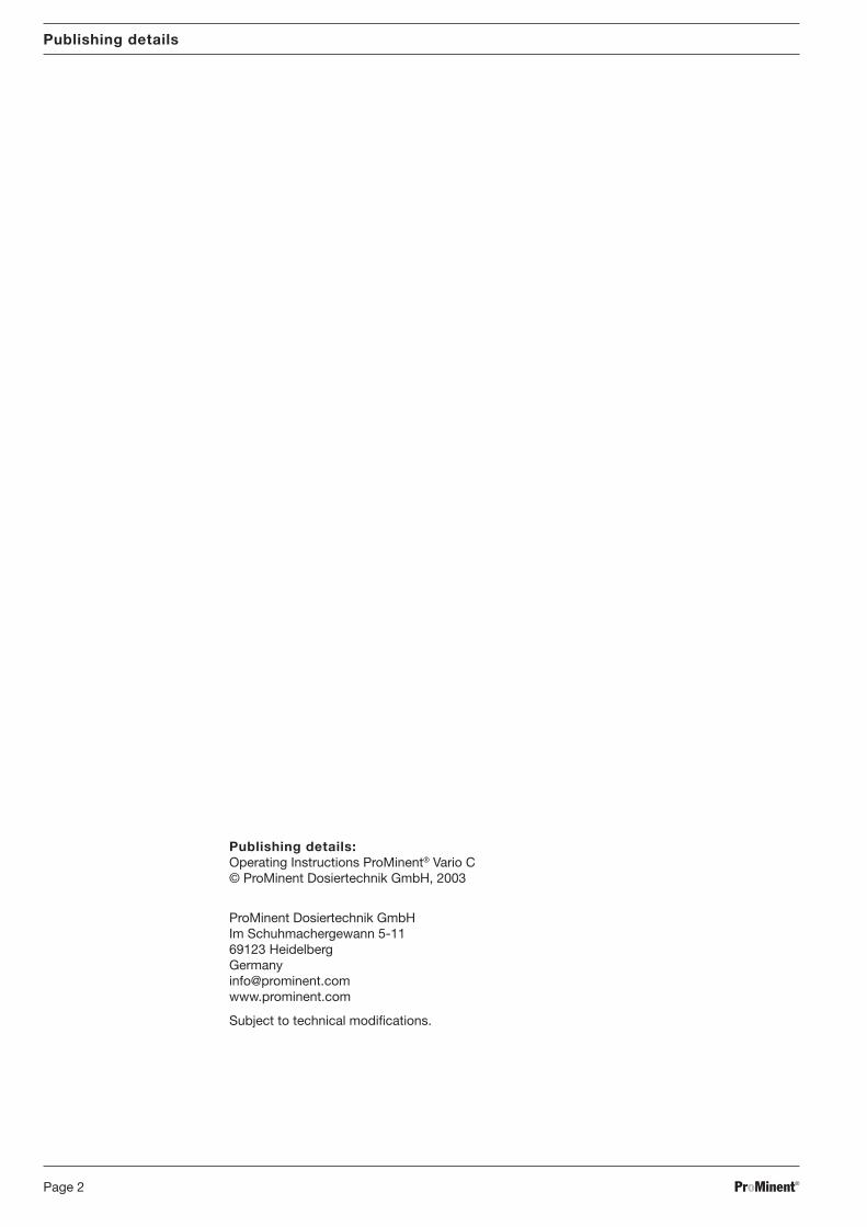
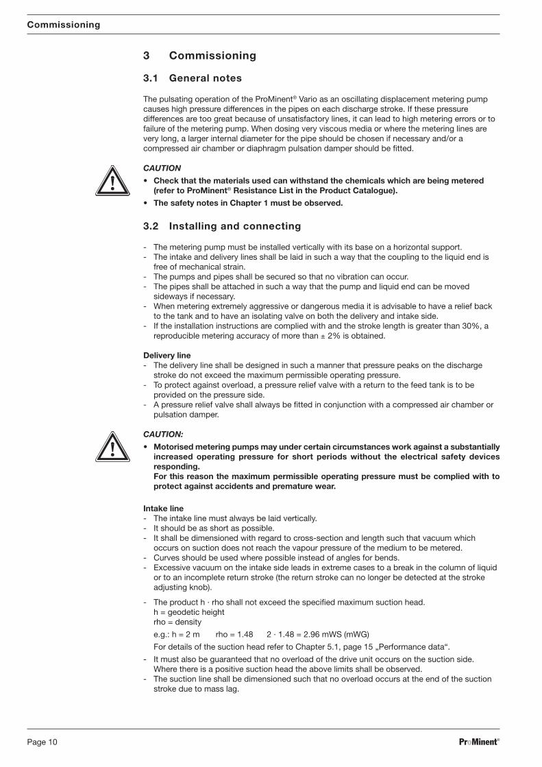
3.3 Commissioning- Check correct installation in accordance with the aforementioned points and installation notes.- Bleed the pressure side. Switch on the pump and allow to operate at maximum stroke length
until the liquid end is charged. Switch off the pump.- Close the bleed on the pressure side, if necessary open the shut off valve in the discharge line
and allow the pump to operate.- Check the response pressure of the pressure relief valve.- Set the required meter rate in accordance with the „Meter rate relative to stroke length“
diagram.- Check the meter rate and correct if necessary.
Diagram for setting the meter rate
Meter rate relative to stroke length (Vario with FM 042)
0
5
10
15
20
25
30
35
40
45
0 20 40 60 80 100 120
Stroke length in (%)
Q (
l/h)
VAMc 07042
VAMc 07026
VAMc 10008
VAMc 10016
Meter rate relative to stroke length (Vario with FM 042)
0
5
10
15
20
25
30
35
40
45
0 2 4 6 8 10 12
pressure (bar)
Q (
l/h)
VAMc 07042
VAMc 07026
VAMc 10008
VAMc 10016
Meter rate relative to stroke length (Vario with FM 063)
0
5
10
15
20
25
30
35
40
45
50
Q (
l/h)
0 2 4 6 8 10 12
pressure (bar)
55
60
65
VAMc 04063
VAMc 04039
VAMc 07012
VAMc 07024
Setting the stroke length
1 rotation (360 °) =̂ 50 % stroke length 2625-4.1
30 % 75 % 100 %
Fig. 5
BA_VA_016_05_08_GB.p65 15.05.2008, 8:03 Uhr11

ProMinent®Page 12
Commissioning
3.4 Troubleshooting
Symptom Possible cause Remedy
- Metering pumps does not suck - Suction head too high - Install pump closing to feed tank(on commissioning)
- Back pressure in the injection line - Remove backpressure,(pressure side) (e.g. via bypass line)
- No metering even though the drive is - Stroke setting 0% - Increase stroke length (➪100 %)running (after long operation)
- Feed tank empty - Replenish metering medium and restartsystem
- Gas bubble in intake line and liquid - Bleed intake line, check for leaks andend restart system
- Leakage of metering liquid at the leak - Defective diaphragm - Replace diaphragm (refer to Chapter 4.2)outlet of the liquid end
- Loss of metering performance - Defective wear parts in the valves - Replace(after long operation) (refer to Chapter 4.2)
- Deposits in the valves - Clean or replace valve parts(refer to Chapter 4.2)
BA_VA_016_05_08_GB.p65 15.05.2008, 8:03 Uhr12
ProMinent® Page 13
4 Servicing/Maintenance
CAUTION:
• Repairs to electrical equipment may only be carried by qualified electricians. Seriousdanger can arise to the user due to incorrect repairs. Repaired electrical equipmentmust be subjected to a function and safety inspection in accordance with the validregulations of the consumer country.
• The safety precautions given in Chapter 1 must be complied with.
4.1 General servicing notes
- The servicing of Vario metering pumps is limited to checking the metering line and checkingfor leaks.
- The gearing is lubricated for life by packing with grease.(Type 1: Klüber ISOFLEX Topas NB 5051), capacity 24 ml).
- Spare parts are given in the accompanying spare parts list.- The individual parts given in the spare parts list are regarded as wear parts.
4.2 Replacement of wear parts
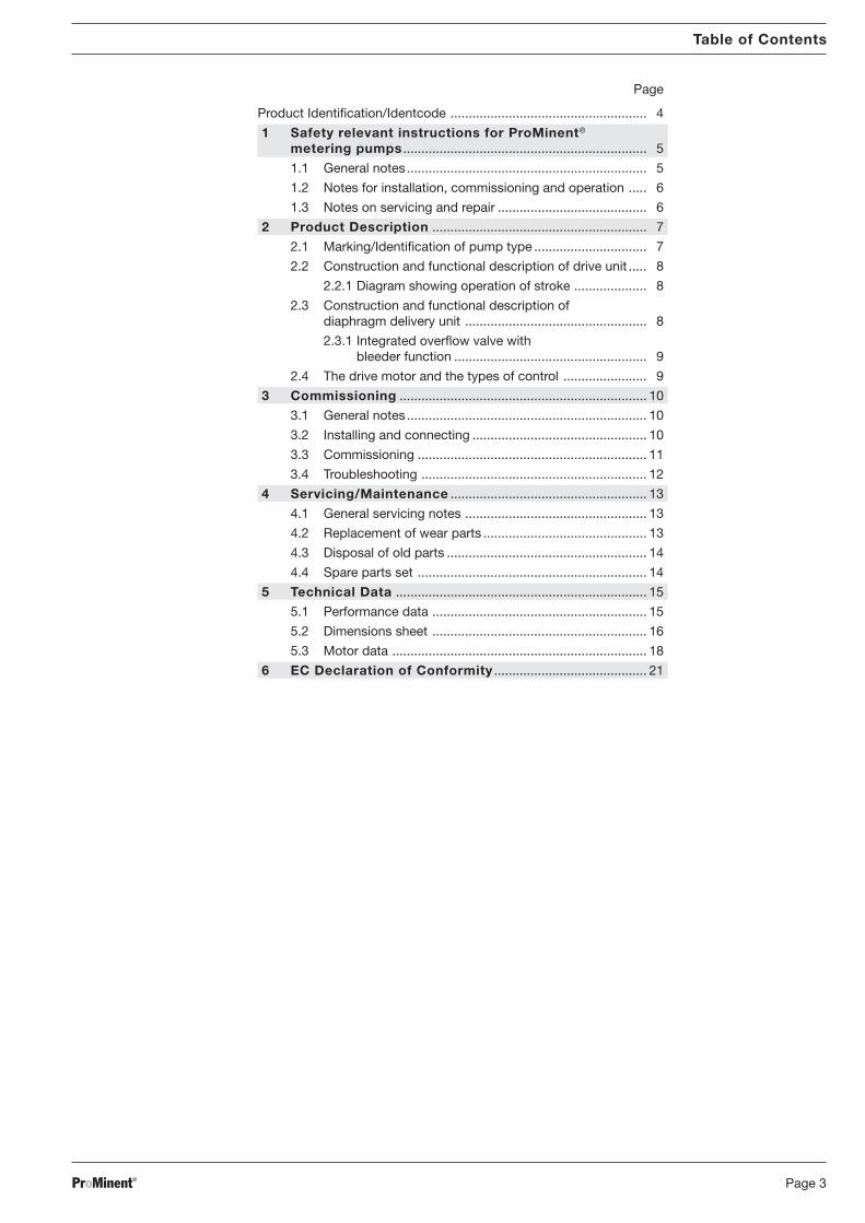
Replacement of diaphragm
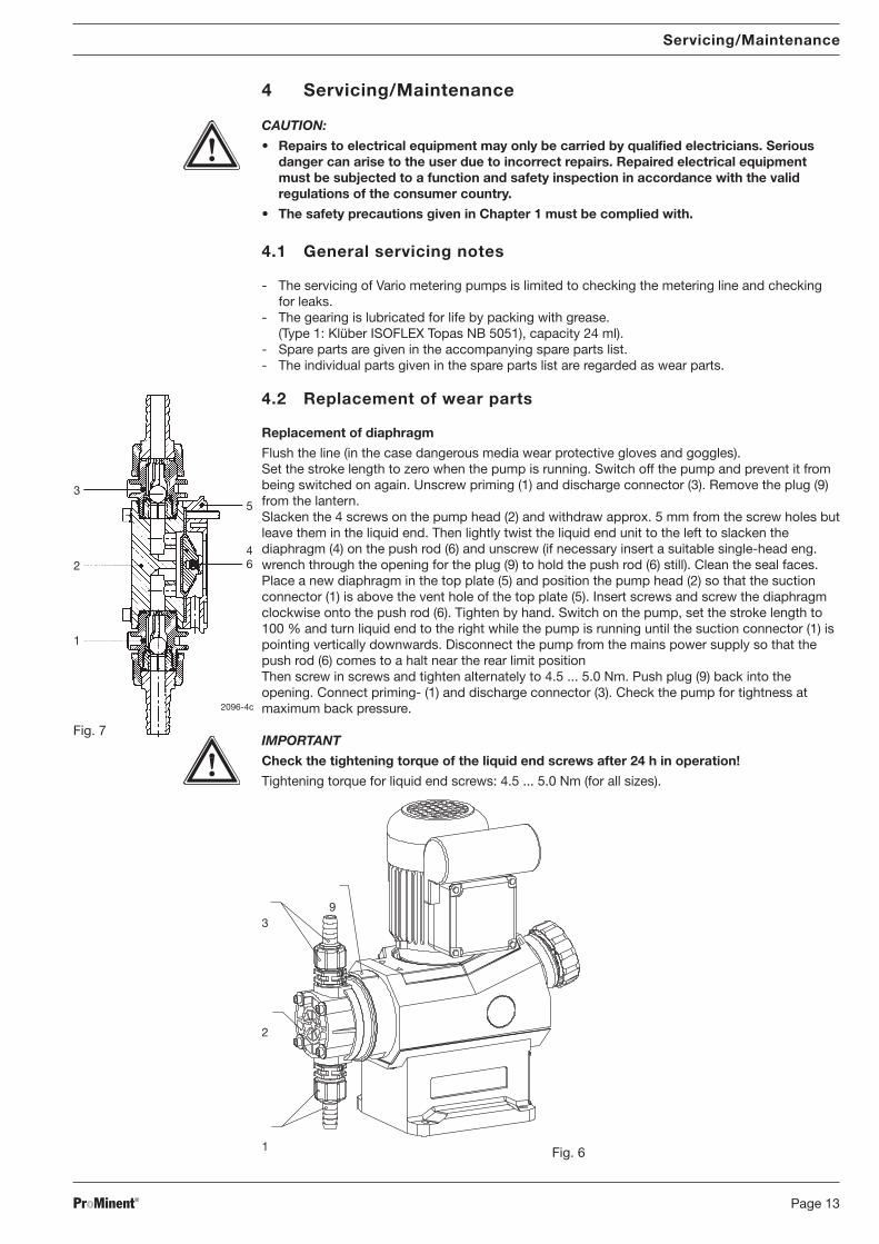
Flush the line (in the case dangerous media wear protective gloves and goggles).Set the stroke length to zero when the pump is running. Switch off the pump and prevent it frombeing switched on again. Unscrew priming (1) and discharge connector (3). Remove the plug (9)from the lantern.Slacken the 4 screws on the pump head (2) and withdraw approx. 5 mm from the screw holes butleave them in the liquid end. Then lightly twist the liquid end unit to the left to slacken thediaphragm (4) on the push rod (6) and unscrew (if necessary insert a suitable single-head eng.wrench through the opening for the plug (9) to hold the push rod (6) still). Clean the seal faces.Place a new diaphragm in the top plate (5) and position the pump head (2) so that the suctionconnector (1) is above the vent hole of the top plate (5). Insert screws and screw the diaphragmclockwise onto the push rod (6). Tighten by hand. Switch on the pump, set the stroke length to100 % and turn liquid end to the right while the pump is running until the suction connector (1) ispointing vertically downwards. Disconnect the pump from the mains power supply so that thepush rod (6) comes to a halt near the rear limit positionThen screw in screws and tighten alternately to 4.5 ... 5.0 Nm. Push plug (9) back into theopening. Connect priming- (1) and discharge connector (3). Check the pump for tightness atmaximum back pressure.
IMPORTANT
Check the tightening torque of the liquid end screws after 24 h in operation!
Tightening torque for liquid end screws: 4.5 ... 5.0 Nm (for all sizes).
Servicing/Maintenance
93
2
1 Fig. 6
3
246
1
2096-4c
5
Fig. 7
BA_VA_016_05_08_GB.p65 15.05.2008, 8:03 Uhr13
ProMinent®Page 14
Servicing/Maintenance
Replacement of valve parts
Flush the line (in the case of dangerous media wear protective gloves, goggles, ...). Switch offthe pump and disconnect from the mains. Slacken the connecting unions. Unscrew valve (1)and remove. Where the „valve assembly“ is being changed clean the sealing surfaces and fitthe new valve and seal in place and tighten. Connect up. Switch on the pump and check theconnections for leaks.If the internal parts of the valves are being exchanged, unscrew and remove the valve andslacken the valve seat bush using a special tool and unscrew. Replace the parts as necessaryand reassemble in reverse order. Clean the sealing faces. Continue as before.
4.3 Disposal of old parts
WARNING
• Spring under pressure!Ensure that the return spring (pos. 5, section 2.2) is held under strong mechanicalpressure when dismantling the pump.
• For disposal please observe all locally applicable directives!
4.4 Spare parts set
pk_2_002
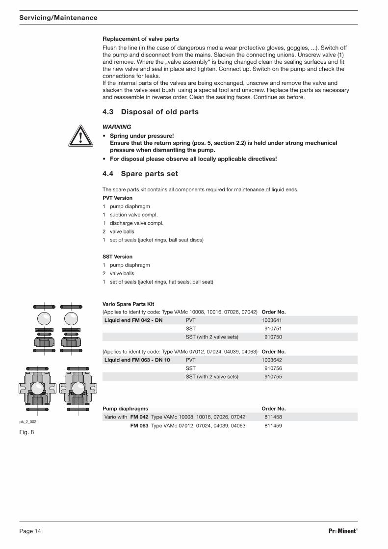
The spare parts kit contains all components required for maintenance of liquid ends.
PVT Version
1 pump diaphragm
1 suction valve compl.
1 discharge valve compl.
2 valve balls
1 set of seals (jacket rings, ball seat discs)
SST Version
1 pump diaphragm
2 valve balls
1 set of seals (jacket rings, flat seals, ball seat)
Vario Spare Parts Kit
(Applies to identity code: Type VAMc 10008, 10016, 07026, 07042) Order No.
Liquid end FM 042 - DN PVT 1003641
SST 910751
SST (with 2 valve sets) 910750
(Applies to identity code: Type VAMc 07012, 07024, 04039, 04063) Order No.
Liquid end FM 063 - DN 10 PVT 1003642
SST 910756
SST (with 2 valve sets) 910755
Pump diaphragms Order No.
Vario with FM 042 Type VAMc 10008, 10016, 07026, 07042 811458
FM 063 Type VAMc 07012, 07024, 04039, 04063 811459Fig. 8
BA_VA_016_05_08_GB.p65 15.05.2008, 8:03 Uhr14
ProMinent® Page 15
Technical Data
5 Technical Data
WARNING
Only for modified version: Please observe the „Supplement for modified version“ at the endof the section!It replaces and supplements the technical data!
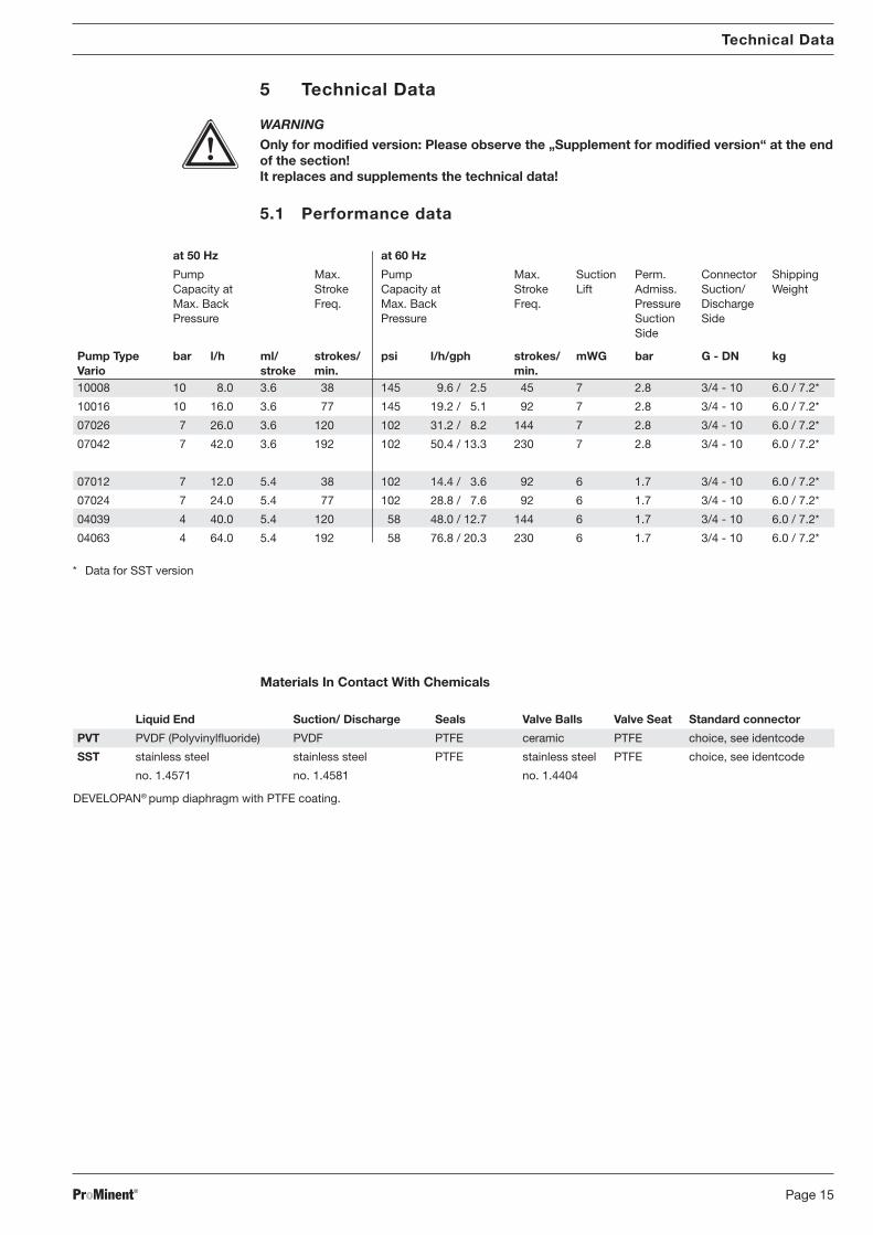
5.1 Performance data
Materials In Contact With Chemicals
Liquid End Suction/ Discharge Seals Valve Balls Valve Seat Standard connector
PVT PVDF (Polyvinylfluoride) PVDF PTFE ceramic PTFE choice, see identcode
SST stainless steel stainless steel PTFE stainless steel PTFE choice, see identcode
no. 1.4571 no. 1.4581 no. 1.4404
DEVELOPAN® pump diaphragm with PTFE coating.
* Data for SST version
at 50 Hz at 60 Hz
Pump Max. Pump Max. Suction Perm. Connector ShippingCapacity at Stroke Capacity at Stroke Lift Admiss. Suction/ WeightMax. Back Freq. Max. Back Freq. Pressure DischargePressure Pressure Suction Side
Side
Pump Type bar l/h ml/ strokes/ psi l/h/gph strokes/ mWG bar G - DN kgVario stroke min. min.10008 10 8.0 3.6 38 145 9.6 / 2.5 45 7 2.8 3/4 - 10 6.0 / 7.2*
10016 10 16.0 3.6 77 145 19.2 / 5.1 92 7 2.8 3/4 - 10 6.0 / 7.2*
07026 7 26.0 3.6 120 102 31.2 / 8.2 144 7 2.8 3/4 - 10 6.0 / 7.2*
07042 7 42.0 3.6 192 102 50.4 / 13.3 230 7 2.8 3/4 - 10 6.0 / 7.2*
07012 7 12.0 5.4 38 102 14.4 / 3.6 92 6 1.7 3/4 - 10 6.0 / 7.2*
07024 7 24.0 5.4 77 102 28.8 / 7.6 92 6 1.7 3/4 - 10 6.0 / 7.2*
04039 4 40.0 5.4 120 58 48.0 / 12.7 144 6 1.7 3/4 - 10 6.0 / 7.2*
04063 4 64.0 5.4 192 58 76.8 / 20.3 230 6 1.7 3/4 - 10 6.0 / 7.2*
BA_VA_016_05_08_GB.p65 15.05.2008, 8:03 Uhr15
ProMinent®Page 16
Technical Data
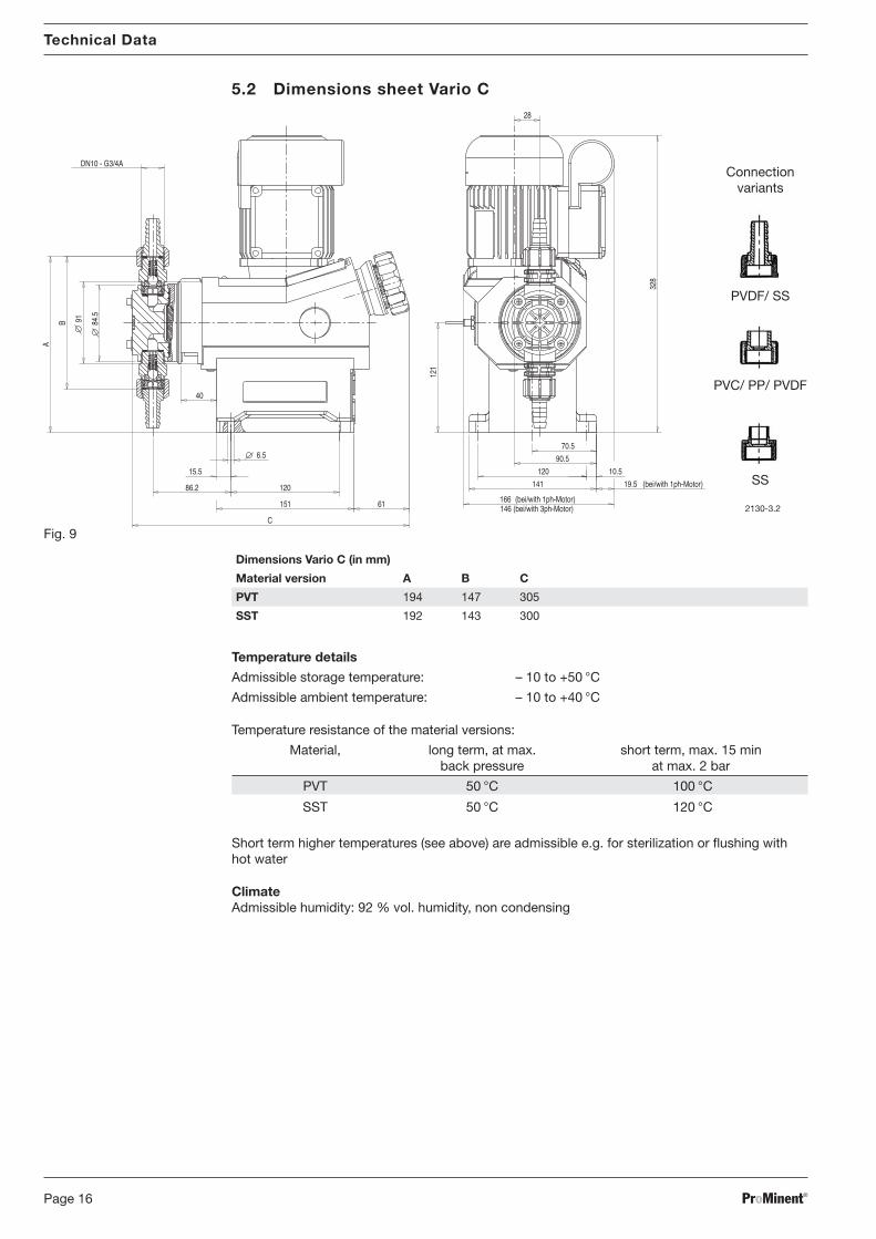
2130-3.2
DN10 - G3/4A
120 10.5
90.5
70.5
166146 (bei/with 3ph-Motor)
(bei/with 1ph-Motor)
19.5 (bei/with 1ph-Motor)
28
A
B
C
61
86.2
40
151
15.5
120 141
328
121
6.5
91 84.5
Dimensions Vario C (in mm)
Material version A B C
PVT 194 147 305
SST 192 143 300
Connectionvariants
PVDF/ SS
PVC/ PP/ PVDF
SS
Fig. 9
Temperature details
Admissible storage temperature: – 10 to +50 °C
Admissible ambient temperature: – 10 to +40 °C
Temperature resistance of the material versions:
Material, long term, at max. short term, max. 15 minback pressure at max. 2 bar
PVT 50 °C 100 °C
SST 50 °C 120 °C
Short term higher temperatures (see above) are admissible e.g. for sterilization or flushing withhot water
ClimateAdmissible humidity: 92 % vol. humidity, non condensing
5.2 Dimensions sheet Vario C
BA_VA_016_05_08_GB.p65 15.05.2008, 8:03 Uhr16
ProMinent® Page 17
Technical Data
Supplement for modified version:(Identity code item „Version“: „M-modified“)
[Affix sticker with modified data here!]
BA_VA_016_05_08_GB.p65 15.05.2008, 8:03 Uhr17
ProMinent®Page 18
Technical Data
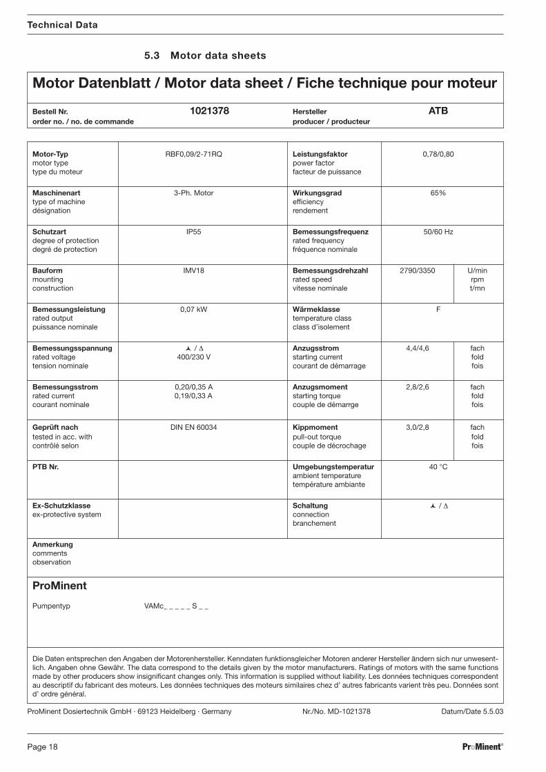
Motor-Typ RBF0,09/2-71RQ Leistungsfaktor 0,78/0,80motor type power factortype du moteur facteur de puissance
Maschinenart 3-Ph. Motor Wirkungsgrad 65%type of machine efficiencydésignation rendement
Schutzart IP55 Bemessungsfrequenz 50/60 Hzdegree of protection rated frequencydegré de protection fréquence nominale
Bauform IMV18 Bemessungsdrehzahl 2790/3350 U/minmounting rated speed rpmconstruction vitesse nominale t/mn
Bemessungsleistung 0,07 kW Wärmeklasse Frated output temperature classpuissance nominale class d’isolement
Bemessungsspannung � / ∆ Anzugsstrom 4,4/4,6 fachrated voltage 400/230 V starting current foldtension nominale courant de démarrage fois
Bemessungsstrom 0,20/0,35 A Anzugsmoment 2,8/2,6 fachrated current 0,19/0,33 A A starting torque foldcourant nominale couple de démarrge fois
Geprüft nach DIN EN 60034 Kippmoment 3,0/2,8 fachtested in acc. with pull-out torque foldcontrôlé selon couple de décrochage fois
PTB Nr. Umgebungstemperatur 40 °Cambient temperaturetempérature ambiante
Ex-Schutzklasse Schaltung � / ∆ex-protective system connection
branchement
Anmerkungcommentsobservation
ProMinent
Pumpentyp VAMc_ _ _ _ _ S _ _
Die Daten entsprechen den Angaben der Motorenhersteller. Kenndaten funktionsgleicher Motoren anderer Hersteller ändern sich nur unwesent-lich. Angaben ohne Gewähr. The data correspond to the details given by the motor manufacturers. Ratings of motors with the same functionsmade by other producers show insignificant changes only. This information is supplied without liability. Les données techniques correspondentau descriptif du fabricant des moteurs. Les données techniques des moteurs similaires chez d’ autres fabricants varient très peu. Données sontd’ ordre général.
Motor Datenblatt / Motor data sheet / Fiche technique pour moteur
Bestell Nr. 1021378 Hersteller ATBorder no. / no. de commande producer / producteur
ProMinent Dosiertechnik GmbH · 69123 Heidelberg · Germany Nr./No. MD-1021378 Datum/Date 5.5.03
5.3 Motor data sheets
BA_VA_016_05_08_GB.p65 15.05.2008, 8:03 Uhr18
ProMinent® Page 19
Technical Data
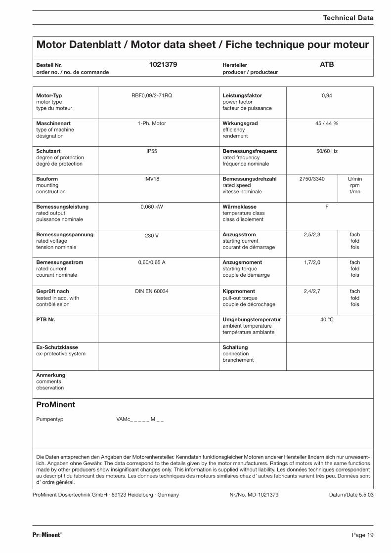
Motor-Typ RBF0,09/2-71RQ Leistungsfaktor 0,94motor type power factortype du moteur facteur de puissance
Maschinenart 1-Ph. Motor Wirkungsgrad 45 / 44 %type of machine efficiencydésignation rendement
Schutzart IP55 Bemessungsfrequenz 50/60 Hzdegree of protection rated frequencydegré de protection fréquence nominale
Bauform IMV18 Bemessungsdrehzahl 2750/3340 U/minmounting rated speed rpmconstruction vitesse nominale t/mn
Bemessungsleistung 0,060 kW Wärmeklasse Frated output temperature classpuissance nominale class d’isolement
Bemessungsspannung 230 V Anzugsstrom 2,5/2,3 fachrated voltage starting current foldtension nominale courant de démarrage fois
Bemessungsstrom 0,60/0,65 A Anzugsmoment 1,7/2,0 fachrated current A starting torque foldcourant nominale couple de démarrge fois
Geprüft nach DIN EN 60034 Kippmoment 2,4/2,7 fachtested in acc. with pull-out torque foldcontrôlé selon couple de décrochage fois
PTB Nr. Umgebungstemperatur 40 °Cambient temperaturetempérature ambiante
Ex-Schutzklasse Schaltungex-protective system connection
branchement
Anmerkungcommentsobservation
ProMinent
Pumpentyp VAMc_ _ _ _ _ M _ _
Die Daten entsprechen den Angaben der Motorenhersteller. Kenndaten funktionsgleicher Motoren anderer Hersteller ändern sich nur unwesent-lich. Angaben ohne Gewähr. The data correspond to the details given by the motor manufacturers. Ratings of motors with the same functionsmade by other producers show insignificant changes only. This information is supplied without liability. Les données techniques correspondentau descriptif du fabricant des moteurs. Les données techniques des moteurs similaires chez d’ autres fabricants varient très peu. Données sontd’ ordre général.
Motor Datenblatt / Motor data sheet / Fiche technique pour moteur
Bestell Nr. 1021379 Hersteller ATBorder no. / no. de commande producer / producteur
ProMinent Dosiertechnik GmbH · 69123 Heidelberg · Germany Nr./No. MD-1021379 Datum/Date 5.5.03
BA_VA_016_05_08_GB.p65 15.05.2008, 8:03 Uhr19
ProMinent®Page 20
Technical Data
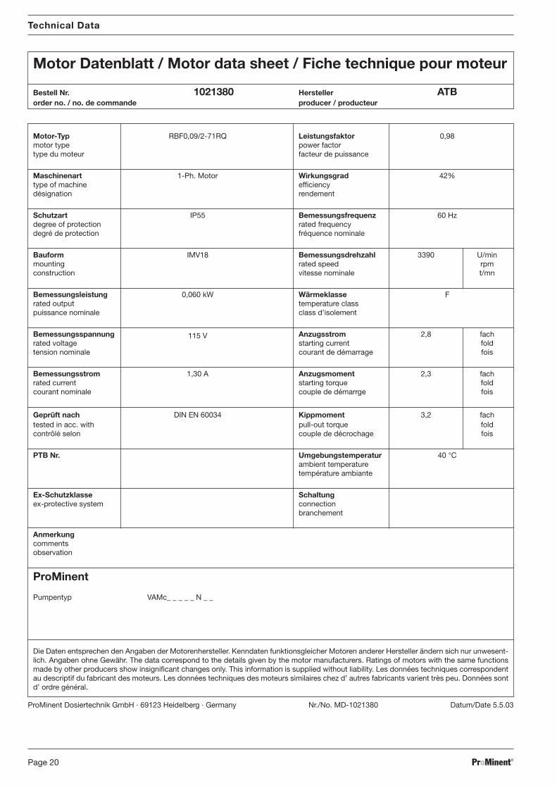
Motor-Typ RBF0,09/2-71RQ Leistungsfaktor 0,98motor type power factortype du moteur facteur de puissance
Maschinenart 1-Ph. Motor Wirkungsgrad 42%type of machine efficiencydésignation rendement
Schutzart IP55 Bemessungsfrequenz 60 Hzdegree of protection rated frequencydegré de protection fréquence nominale
Bauform IMV18 Bemessungsdrehzahl 3390 U/minmounting rated speed rpmconstruction vitesse nominale t/mn
Bemessungsleistung 0,060 kW Wärmeklasse Frated output temperature classpuissance nominale class d’isolement
Bemessungsspannung 115 V Anzugsstrom 2,8 fachrated voltage starting current foldtension nominale courant de démarrage fois
Bemessungsstrom 1,30 A Anzugsmoment 2,3 fachrated current A starting torque foldcourant nominale couple de démarrge fois
Geprüft nach DIN EN 60034 Kippmoment 3,2 fachtested in acc. with pull-out torque foldcontrôlé selon couple de décrochage fois
PTB Nr. Umgebungstemperatur 40 °Cambient temperaturetempérature ambiante
Ex-Schutzklasse Schaltungex-protective system connection
branchement
Anmerkungcommentsobservation
ProMinent
Pumpentyp VAMc_ _ _ _ _ N _ _
Die Daten entsprechen den Angaben der Motorenhersteller. Kenndaten funktionsgleicher Motoren anderer Hersteller ändern sich nur unwesent-lich. Angaben ohne Gewähr. The data correspond to the details given by the motor manufacturers. Ratings of motors with the same functionsmade by other producers show insignificant changes only. This information is supplied without liability. Les données techniques correspondentau descriptif du fabricant des moteurs. Les données techniques des moteurs similaires chez d’ autres fabricants varient très peu. Données sontd’ ordre général.
Motor Datenblatt / Motor data sheet / Fiche technique pour moteur
Bestell Nr. 1021380 Hersteller ATBorder no. / no. de commande producer / producteur
ProMinent Dosiertechnik GmbH · 69123 Heidelberg · Germany Nr./No. MD-1021380 Datum/Date 5.5.03
BA_VA_016_05_08_GB.p65 15.05.2008, 8:03 Uhr20
ProMinent® Page 21
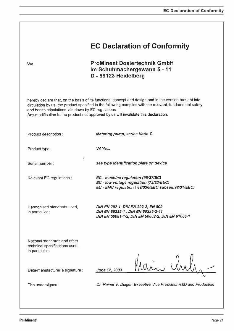
EC Declaration of Conformity
BA_VA_016_05_08_GB.p65 15.05.2008, 8:03 Uhr21

ProMinent®Page 22
BA_VA_016_05_08_GB.p65 15.05.2008, 8:03 Uhr22

ProMinent® Page 23
BA_VA_016_05_08_GB.p65 15.05.2008, 8:03 Uhr23
ProMinent Argentina S.A. (Argentina)Tel.: +54 11 [email protected]
ProMinent Fluid Controls Pty. Ltd. (Australia)Tel.: +61 2 [email protected]
ProMinent Dosiertechnik Ges. mbH (Austria)Tel.: +43 7448 [email protected]
ProMinent Fluid Controls (Bangladesh) Ltd.(Bangladesh)Tel.: +8802 [email protected].
ProMinent Belgium S.A., N.V. (Belgium)Tel.: +32 2 [email protected]
ProMinent Brasil Ltda. (Brazil)Tel.: +55 11 [email protected]
ProMinent Fluid Controls BG (Bulgaria)Tel.: +359 2 [email protected]
ProMinent Fluid Controls Ltd. (Canada)Tel.: +1 519 [email protected]
ProMinent Fluid Controls China Co. Ltd.(P.R. of China)Tel.: +86 411 [email protected]
ProMinent Bermat S.A. (Chile)Tel.: +56 2 3354 [email protected]
ProMinent Dosiertechnik CS s.r.o.(Czech Republ.)Tel.: +420 585 [email protected]
ProMinent Finland OY (Finland)Tel.: +35 89 [email protected]
ProMinent France S.A. (France)Tel.: +33 3 [email protected]
ProMinent ProMaqua GmbH (Germany)Tel.: +49 6221 [email protected]
ProMinent Fluid Controls (UK) Ltd. (Great Britain)Tel.: +44 1530 [email protected]
Tochtergesellschaften / Subsidiaries
Vertretungen weltweit / Distributors WorldwideAngola · Bahrain · Bolivia · Botswana · Cameroon · Colombia · Costa Rica · Croatia · Cuba · Cyprus · Denmark · Ecuador · Egypt · El Salvador · Ethiopia · Ghana ·Guatemala · Hong Kong · Indonesia · Iran · Ireland · Island · Israel · Jordan · Kenya · Kuwait · Macedonien · Malta · Mauritius · Montenegro · Mozambique ·Namibia · New Zealand · Nigeria · Norway · Oman · Pakistan · Panama · Paraguay · Peru · Philippines · Qatar · Saudi Arabia · Serbia · Slovenia · Sudan · Syria ·Tanzania · Tunesia · Turkey · Turkmenistan · UAE · Uganda · Uruguay · Venezuela · Vietnam · White Russia · Zambia · Zimbabwe
Anschriftennachweise erhalten Sie durch: / Addresses of distributors are available from: ProMinent Dosiertechnik GmbH, Germany
Die ProMinent Firmengruppe / The ProMinent Group
ProMinent Hellas Ltd. (Greece)Tel.: +30 210 5134621 / [email protected]
ProMinent Magyarország Kft. (Hungary)Tel.: +36 96 [email protected]
Heidelberg ProMinent Fluid Controls India Pvt. Ltd.(India)Tel.: +91 80 [email protected]
ProMinent Fluid Controls Ltd. (Ireland)Tel.: +353 71 [email protected]
ProMinent Italiana S.R.L. (Italy)Tel.: +39 0471 [email protected]
ProMinent Japan Ltd. (Japan)Tel.: +81 35812 [email protected]
ProMinent Korea Co. Ltd. (Republic of Korea)Tel.: +82 31 [email protected]
ProMinent Office Kazakhstan (Kazakhstan)Tel.: +7 3272 [email protected]
ProMinent Office Kaunas (Lithuania)Tel.: +370 37 [email protected]
ProMinent Fluid Controls (M) Sdn. Bhd.(Malaysia)Tel: +603-806 825 [email protected]
ProMinent Fluid Controls Ltd. (Malta)Tel.: +356 [email protected]
ProMinent Fluid Controls de México, S.A. de C.V.(Mexico)Tel.: +52 (442) 2189920 / [email protected]
ProMinent Verder B.V. (Netherlands)Tel.: +31 30 [email protected]
ProMinent Dozotechnika Sp. z o.o. (Poland)Tel.: +48 71 [email protected]
ProMinent Portugal Controlo de Fluídos, Lda.(Portugal)Tel.: +35 121 [email protected]
05/08
ProMinent Verder s.r.l. (Romania)Tel.: +40 269 [email protected]
ProMinent Dositechnika OOO (Russia)Tel.: +7 095 [email protected]
Proshield Ltd. (Scotland)Tel.: +44 1698 [email protected]
ProMinent Fluid Controls (Far East) Pte. Ltd.(Singapore)Tel.: +65 [email protected]
ProMinent Slovensko s.r.o. (Slovak. Republ.)Tel.: +421 2 [email protected]
ProMinent Fluid Controls Pty. Ltd. (South Africa)Tel.: +27 11 [email protected]
ProMinent Gugal S.A. (Spain)Tel.: +34 972 287011/[email protected]
ProMinent Doserteknik AB (Sweden)Tel.: +46 31 [email protected]
Tomal AB (Sweden)Tel.: +46 (0) [email protected]
ProMinent Dosiertechnik AG (Switzerland)Tel.: +41 44 [email protected]
ProMinent Fluid Controls (Taiwan) Ltd. (Taiwan)Tel.: +886 7 [email protected]
ProMinent Fluid Controls (Thailand) Co. Ltd.(Thailand)Tel.: +66 2 [email protected]
ProMinent Office Kiev (Ukraine)Tel.: +380 44576 [email protected]
ProMinent Fluid Controls, Inc. (USA)Tel.: +1 412 [email protected]
ProMinent Juffali FZC (UAE)Tel.: +97 1655 [email protected]
Stammhaus / Head officeProMinent Dosiertechnik GmbH · Im Schuhmachergewann 5-11 · 69123 Heidelberg · [email protected] · www.prominent.com · Tel.: +49 6221 842-0 · Fax: +49 6221 842-617
Anschr_D_GB_05_08_sw.p65 07.05.2008, 14:49 Uhr1
Related Documents