Operating Instructions Bedienungsanleitung Manuel d‘utilisation Type 8694 Positioner TopControl Basic Electropneumatic position controller Elektropneumatischer Stellungsregler Positionneur électropneumatique

Welcome message from author
This document is posted to help you gain knowledge. Please leave a comment to let me know what you think about it! Share it to your friends and learn new things together.
Transcript

Operating Instructions
Bedienungsanleitung Manuel d‘utilisation
Type8694
Positioner TopControl Basic
Electropneumatic position controllerElektropneumatischer StellungsreglerPositionneur électropneumatique

We reserve the right to make technical changes without notice.Technische Änderungen vorbehalten.Sous réserve de modifications techniques.
© 2008 - 2012 Bürkert Werke GmbH
Operating Instructions 1203/03_EU-ML_00805886 / Original DE

3
Table of ConTenTs
1. OperatinginstructiOns........................................................................................................................................................7
1.1. symbols......................................................................................................................................................................................7
2. authOrizeduse.............................................................................................................................................................................8
2.1. restrictions...............................................................................................................................................................................8
3. BasicsafetyinstructiOns.................................................................................................................................................9
4. generalinfOrmatiOn.............................................................................................................................................................10
4.1. contactaddress..................................................................................................................................................................10
4.2. Warranty...................................................................................................................................................................................10
4.3. trademarks............................................................................................................................................................................10
4.4. informationontheinternet............................................................................................................................................10
5. systemdescriptiOn................................................................................................................................................................11
5.1. intendedapplicationarea...............................................................................................................................................11
5.2. functionofthepositionerandcombinationwithvalvetypes....................................................................11
5.3. featuresofthevalvetypes...........................................................................................................................................12
5.4. structureofthepositioner............................................................................................................................................13
5.4.1. Representation .........................................................................................................................................13
5.4.2. Features .....................................................................................................................................................14
5.4.3. Function diagram of the positioner with single-acting actuator ...................................................15
5.5. type8694positioner(positioncontroller)............................................................................................................16
5.5.1. Schematic representation of the position control Type 8694.......................................................16
5.5.2. Functions of the position controller software ....................................................................................17
5.6. interfacesofthepositioner..........................................................................................................................................19
6. technicaldata.............................................................................................................................................................................20
6.1. conformity..............................................................................................................................................................................20
6.2. standards................................................................................................................................................................................20
6.3. Operatingconditions........................................................................................................................................................20
6.4. mechanicaldata...................................................................................................................................................................20
Positioner Type 8694
English
Type8694

4
6.5. pneumaticdata....................................................................................................................................................................21
6.6. typelabel...............................................................................................................................................................................21
6.7. electricaldata.......................................................................................................................................................................22
6.7.1. Electrical data without bus control 24 V DC ....................................................................................22
6.7.2. Electrical data with AS-Interface bus control ...................................................................................22
6.8. factorysettingsofthepositioner..............................................................................................................................23
7. cOntrOlanddisplayelements...................................................................................................................................24
7.1. Operatingstatus...................................................................................................................................................................... 24
7.2. controlanddisplayelementsofthepositioner.................................................................................................24
7.3. configurationofthekeys................................................................................................................................................... 26
7.4. functionofthedipswitches........................................................................................................................................... 28
7.5. displayoftheleds............................................................................................................................................................... 30
7.6. errormessages....................................................................................................................................................................... 31
7.6.1. Error messages in MANUAL and AUTOMATIC operating statuses ..............................................31
7.6.2. Error messages while the X.TUNE function is running ...................................................................31
8. installatiOn...................................................................................................................................................................................32
8.1. safetyinstructions.............................................................................................................................................................32
8.2. installationofthepositionertype8694onprocessvalvesofseries2103,2300and2301...........................................................................................32
8.3. installingthepositionertype8694onprocessvalvesbelongingtoseries26xxand27xx................................................................................................ 35
8.4. rotatingtheactuatormodule......................................................................................................................................39
8.5. rotatingthepositionerforprocessvalvesbelongingtoseries26xxand27xx..........................................................................................41
9. fluidinstallatiOn....................................................................................................................................................................42
9.1. safetyinstructions.............................................................................................................................................................42
9.2. installingtheprocessvalve...........................................................................................................................................42
9.3. pneumaticconnectionofthepositioner................................................................................................................43
English
Type8694

5
10. electricalinstallatiOn24Vdc...................................................................................................................................44
10.1. safetyinstructions.............................................................................................................................................................44
10.2. electricalinstallationwithcircularplug-inconnector.....................................................................................44
10.2.1. Designation of the contacts Type 8694 .............................................................................................44
10.2.2. Connection of the positioner Type 8694 ...........................................................................................45
10.3. electricalinstallationwithcablegland....................................................................................................................46
10.3.1. Designation of the screw-type terminals ...........................................................................................46
10.3.2. Connection of the positioner Type 8694 ...........................................................................................46
11. as-interfaceinstallatiOn................................................................................................................................................48
11.1. as-interfaceconnection.................................................................................................................................................48
11.2. technicaldataforas-interfacepcBs.....................................................................................................................48
11.3. programmingdata..............................................................................................................................................................48
11.4. communicationsequencefortheversions-7.a.5profile..........................................................................49
11.5. ledstatusdisplay..............................................................................................................................................................50
11.6. electricalinstallationas-interface............................................................................................................................51
11.6.1. Safety instructions ...................................................................................................................................51
11.6.2. Connection with circular plug-in connector M12 x 1, 4-pole, male ............................................51
11.6.3. Connection with multi-pole cable and ribbon cable terminal........................................................52
12. start-up.............................................................................................................................................................................................53
12.1. safetyinstructions.............................................................................................................................................................53
12.2. specifyingthestandardsettings................................................................................................................................53
12.2.1. Running the automatic adjustment X.TUNE..............................................................................53
13. OperatiOnandfunctiOn....................................................................................................................................................55
13.1. Basicfunctions........................................................................................................................................................................ 55
13.1.1..DIR.CMD - Effective direction of the positioner set-point value .................................................56
13.1.2..CUTOFF - Sealing function for the positioner .................................................................................57
13.1.3..CHARACT - Select the transfer characteristic between input signal (position set-point value) and stroke ..........................................................................58
13.2. auxiliaryfunctions.................................................................................................................................................................. 59
14. safetypOsitiOns.......................................................................................................................................................................60
14.1. safetypositionsafterfailureoftheelectricalorpneumaticauxiliarypower.....................................60
English
Type8694

6
15. maintenance..................................................................................................................................................................................61
15.1. safetyinstructions.............................................................................................................................................................61
15.2. serviceattheairintakefilter.......................................................................................................................................62
16. accessOries..................................................................................................................................................................................63
16.1. communicationssoftware(pcsOftWarebasedonfdt/dtmtechnology).................................63
16.1.1. PACTware 3.6 ..........................................................................................................................................63
16.1.2. USB interface ...........................................................................................................................................63
16.1.3. Download ..................................................................................................................................................63
17. disassemBly...................................................................................................................................................................................64
17.1. safetyinstructions.............................................................................................................................................................64
17.2. disassemblythepositioner...........................................................................................................................................64
18. packagingandtranspOrt...............................................................................................................................................66
19. stOrage..............................................................................................................................................................................................66
20. dispOsal............................................................................................................................................................................................66
English
Type8694

7
Operating instructions
1. OperaTinginsTrucTiOnsThe operating instructions describe the entire life cycle of the device. Keep these instructions in a location which is easily accessible to every user, and make these instructions available to every new owner of the device.
Warning!
theoperatinginstructionscontainimportantsafetyinformation!
Failure to observe these instructions may result in hazardous situations.
• The operating instructions must be read and understood.
1.1. symbols
Danger!
Warnsofanimmediatedanger!
• Failure to observe the warning will result in a fatal or serious injury.
Warning!
Warnsofapotentiallydangeroussituation!
• Failure to observe the warning may result in serious injuries or death.
CauTion!
Warnsofapossibledanger!
• Failure to observe this warning may result in a moderate or minor injury.
noTe!
Warnsofdamagetoproperty!
• Failure to observe the warning may result in damage to the device or the equipment.
Indicates important additional information, tips and recommendations.
refers to information in these operating instructions or in other documentation.
→ Designates a procedure which you must carry out.
English
Type8694

8
Authorized use
2. auThOrizeduse
non-authorizeduseofthepositionertype8694maybeahazardtopeople,nearbyequipmentandtheenvironment.
• The device is designed to be mounted on pneumatic actuators of process valves for the control of media.
• Do not expose the device to direct sunlight.
• Use according to the authorized data, operating conditions and conditions of use specified in the contract documents and operating instructions. These are described in the chapter entitled “6. Technical data”.
• The device may be used only in conjunction with third-party devices and components recommended and authorized by Bürkert.
• In view of the large number of options for use, before installation, it is essential to study and if necessary to test whether the positioner is suitable for the actual use planned.
• Correct transportation, correct storage and installation and careful use and maintenance are essential for reli-able and faultless operation.
• Use the positioner Type 8694 only as intended.
2.1. restrictions
If exporting the system/device, observe any existing restrictions.
English
Type8694
9
Basic safety instructions
3. BasicsafeTyinsTrucTiOnsThese safety instructions do not make allowance for any
• contingencies and events which may arise during the installation, operation and maintenance of the devices.
• local safety regulations – the operator is responsible for observing these regulations, also with reference to the installation personnel.
Danger!
danger–highpressure!
• Before dismounting pneumatic lines and valves, turn off the pressure and vent the lines.
riskofelectricshock!
• Before reaching into the device or the equipment, switch off the power supply and secure to prevent reactivation!
• Observe applicable accident prevention and safety regulations for electrical equipment!
generalhazardoussituations.
To prevent injury, ensure:
• that the system cannot be activated unintentionally.
• Installation and repair work may be carried out by authorized technicians only and with the appropriate tools.
• After an interruption in the power supply or pneumatic supply, ensure that the process is restarted in a defined or controlled manner.
• The device may be operated only when in perfect condition and in consideration of the operating instructions.
• The general rules of technology apply to application planning and operation of the device.
To prevent damage to property on the device, ensure:
• Do not feed any aggressive or flammable media into the pilot air port.
• Do not feed any liquids into the pilot air port.
• Do not put any loads on the body (e.g. by placing objects on it or standing on it).
• Do not make any external modifications to the device bodies. Do not paint the body parts or screws.
noTe!
electrostaticsensitivecomponents/modules!
• The device contains electronic components, which react sensitively to electrostatic discharge (ESD). Contact with electrostatically charged persons or objects is hazardous to these components. In the worst case scenario, they will be destroyed immediately or will fail after start-up.
• Observe the requirements in accordance with EN 100 015 - 1 and 5 - 2 to minimize or avoid the possibility of damage caused by sudden electrostatic discharge!
• Also ensure that you do not touch electronic components when the power supply is on!
English
Type8694

10
Basic safety instructions
The positioner Type 8694 was developed with due consideration given to the accepted safety rules and is state-of-the-art. Nevertheless, dangerous situations may occur.
Failure to observe this operating manual and its operating instructions as well as unauthorized tampering with the device release us from any liability and also invalidate the warranty covering the devices and accessories!
4. generalinfOrmaTiOn
4.1. contactaddress
germany
Bürkert Fluid Control System Sales Center Chr.-Bürkert-Str. 13-17 D-74653 Ingelfingen Tel. + 49 (0) 7940 - 10 91 111 Fax + 49 (0) 7940 - 10 91 448 E-mail: [email protected]
international
Contact addresses can be found on the final pages of the printed operating instructions.
And also on the Internet at:
www.burkert.com
4.2. Warranty
The warranty is only valid if the positioner Type 8694 is used as intended in accordance with the specified appli-cation conditions.
4.3. Trademarks
Brands and trademarks listed below are trademarks of the corresponding companies / associations / organizations
Loctite Henkel Loctite Deutschland GmbH
4.4. informationontheinternet
The operating instructions and data sheets for Type 8694 can be found on the Internet at:
www.burkert.com
English
Type8694

11
System description
5. sysTemdescripTiOn
5.1. intendedapplicationarea
The positioner Type 8694 is designed to be mounted on pneumatic actuators of process valves for the control of media.
5.2. functionofthepositionerandcombinationwithvalvetypes
Positioner Type 8694 is an electropneumatic position controller for pneumatically actuated control valves with single-acting actuators.
Together with the pneumatic actuator, the positioner forms a functional unit.
The control valve systems can be used for a wide range of control tasks in fluid technology and, depending on the application conditions, different process valves belonging to series 2103, 2300, 2301, 26xx or 27xx from the Bürkert range can be combined with the positioner. Angle-seat valves, diaphragm valves or ball valves fitted with a control cone are suitable.
“Figure 1” shows an overview of the possible combinations of positioner and different pneumatically actuated valves. Different actuator sizes and valve nominal widths, not illustrated here, are available for each type. More precise specifications can be found on the respective data sheets. The product range is being continuously expanded.
Positioner Type 8694
with angle seat valve
Type 2702
with diaphragm valve
Type 2730
with angle seat valve
Type 2300
with straight seat valve
Type 2301
Figure 1: Overview of possible combinations
English
Type8694

12
System description
The position of the actuator is regulated according to the position set-point value. The position set-point value is specified by an external standard signal.
Pneumatically actuated piston actuators and rotary actuators can be used as an actuator. Single-acting actuators are offered in combination with the positioner.
For single-acting actuators, only one chamber is aerated and deaerated in the actuator. The generated pressure works against a spring. The piston moves until there is an equilibrium of forces between compressive force and spring force.
5.3. featuresofthevalvetypes
angleseatcontrolvalves/straightseatcontrolvalves
diaphragmvalves Ballvalves flapvalves
types • 2300
• 2301
• 2702
• 2712
• 2103
• 2730
• 2731
• 2652
• 2655
• 2658
• 2672
• 2675
features • incoming flow under seat
• no closing impact
• straight flow path of the medium
• self-adjusting stuffing box for high leak-tightness
• medium is hermeti-cally separated from the actuator and environment
• cavity-free and self-draining body design
• any flow direction with low-turbulence flow
• steam-sterilizable
• CIP-compliant
• no closing impact
• actuator and dia-phragm can be removed when the body is installed
• scrapable
• minimum dead space
• unaffected by contamination
• little pressure loss compared to other valve types
• seat and seal can be exchanged in the three-piece ball valve when installed
Note can be used as process controller only
• unaffected by contamination
• little pressure loss compared to other valve types
• inexpensive
• low construction volume
typicalmedia
• water, steam and gases
• alcohols, oils, propel-lants, hydraulic fluids
• salt solutions, lyes (organic)
• solvents
• neutral gases and liquids
• contaminated, abrasive and aggressive media
• media of higher viscosity
• neutral gases and liquids
• clean water
• slightly aggressive media
• neutral gases and liquids
• slightly aggressive media
Table 1: Features of the valve types
English
Type8694

13
System description
5.4. structureofthepositioner
The positioner Type 8694 consists of the micro-processor controlled electronics, the position measuring system and the control system. The device is designed using three-wire technology. The positioner is operated via 2 keys and a 4-pole DIP switch. The pneumatic control system for single-acting actuators consists of 2 solenoid valves.
5.4.1. representation
LED
Screw-type terminals
Pressure supply connection (label: 1)
Exhaust air con-nection (label: 3)
Electrical connection (cable gland M16 x 1.5 or circular plug-in connector M12 x 1)
Body casing removed: Buttons
DIP Switches
LED
Transparent cap
Pressure limiting valve (for protection against too high internal pressure in
case of error)
Air intake filter (exchangeable)
Body casing
Version1 Version2
Communications interface
Pressure supply connection (label: 1)
Exhaust air con-nection (label: 3)
Communications interface
Air intake filter (exchangeable)
Additional exhaust air port (label: 3.1) only for Type 23xx and 2103
with pilot-operated control system for high air output (actuator size ø 130)
Figure 2: Structure
English
Type8694

14
System description
5.4.2. features
• Models for single-acting valve actuators.
• Position measuring system Contactless and therefore wear-free position measuring system.
• Microprocessor-controlled electronicsfor signal processing, control and valve control.
• Control module The device is controlled via 2 buttons and a 4-pole DIP switch. 2x 2-colored LEDs indicate different statuses of the device.
• Control system The control system consists of 2 solenoid valves. One valve is used to aerate and another to deaerate the pneumatic actuator. The solenoid valves operate according to the rocker principle and are controlled with a PWM voltage via the controller. Doing so achieves a higher flexibility with regard to actuator volume and final control speed. The direct-action model has an orifice of DN 0.6. In larger pneumatic actuators the solenoid valves feature diaphragm amplifiers to increase the maximum flow and therefore to improve the dynamics (DN 2.5).
• Position feedback (optional) The position of the valve can be transmitted to the PLC via an analog 0/4-20 mA output.
• Binary inputIf a voltage > 10 V is applied, SAFE POSITION is activated, i.e. the valve is moved to the safety position (factory setting, can be changed with communications software).
Pneumatic interface
Electrical interface
• Pneumatic interfaces 1/4“ connections with different thread forms (G, NPT) hose plug-in connection
• electrical interfaces Circular plug-in connector or cable gland
• Body The body of the positioner is protected from excessively high internal pressure, e.g. due to leaks, by a pressure limiting valve.
• Communications interface For configuration and parameterization.
English
Type8694

15
System description
5.4.3. functiondiagramofthepositionerwithsingle-actingactuator
The illustrated function diagram describes the function of the positioner (Type 8694).
Control system
1
2
Position controller
Control system 1: Aeration valve 2: Bleed valve
Pressure supply
Exhaust air
Position measuring system
Actual position
external position set-point value
Positioner
Pneumatic actuator (single-acting)
Valve (actuator)
Figure 3: Function diagram
English
Type8694

16
System description
5.5. Type8694positioner(positioncontroller)
The position measuring system records the current position (POS) of the pneumatic actuator. The position controller compares this actual position value with the set-point value (CMD) which is definable as standard signal. In case of a control deviation (Xd1), a pulse-width modulated voltage signal is sent to the control system as a manipu-lated variable. If there is a positive control difference in single-acting actuators, the air inlet valve is controlled via output B1. If the control difference is negative, the bleed valve is controlled via output E1. In this way the position of the actuator is changed until control difference is 0. Z1 represents a disturbance variable.
Valve opening
Control valveControl system Solenoid valves
Position measuring system
Position controller
Position set-point value
CMD Xd1B1
E1PK
Z1
POS
Position control circuit
+ -
Figure 4: Signal flow plan of position controller
5.5.1. schematicrepresentationofthepositioncontrolType8694
4 ... 20 mA1) 0 ... 20 mA
CHARACTSPLTRNG2)DIR.CMD CUTOFF X.TIME2)
X.CONTROL
DBND
POS
CMDINP
POS
CMD
DIR.ACT2) X.LIMIT2)
1) Default setting2) Can only be activated with communications software
Figure 5: Schematic representation of position control
English
Type8694
17
System description
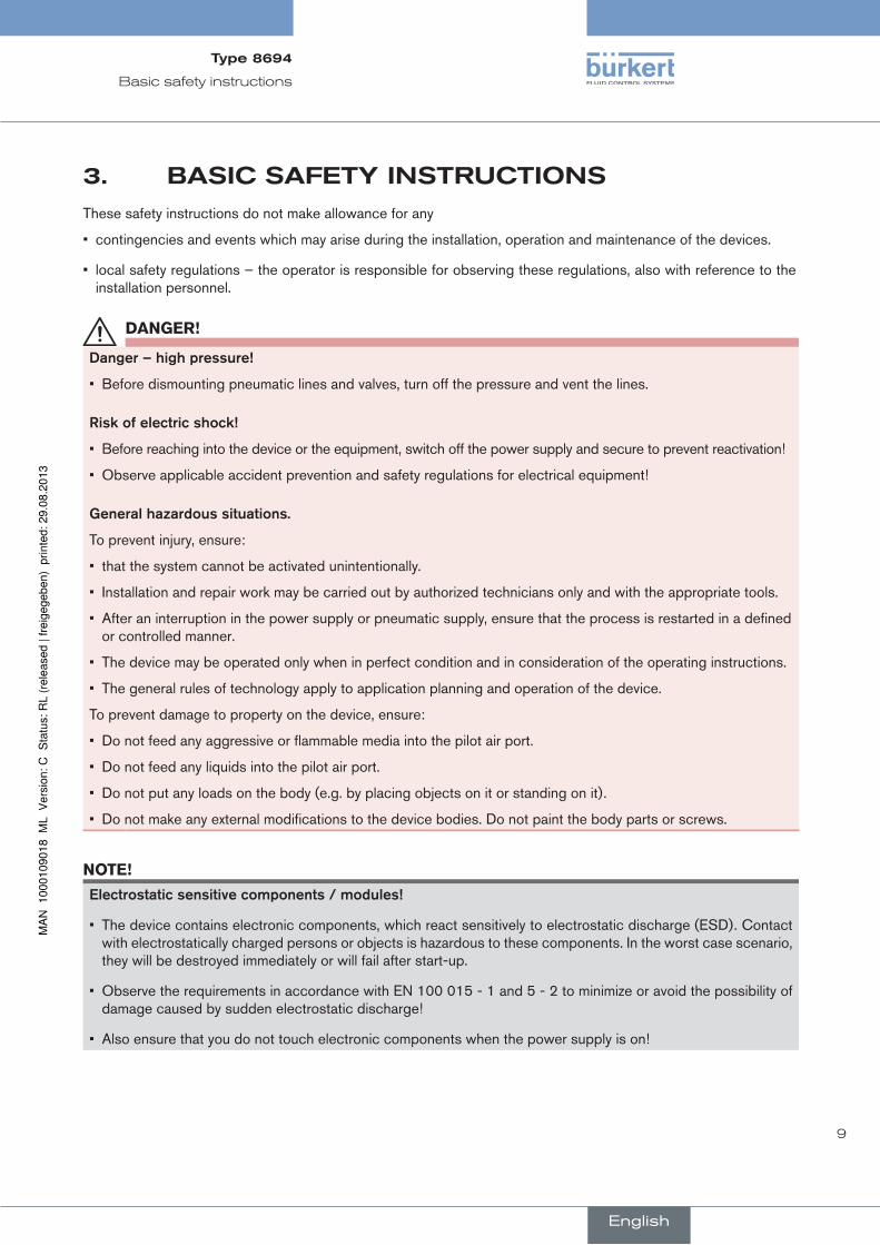
5.5.2. functionsofthepositioncontrollersoftware
functionsi
• Activation via DIP switches
• Parameter setting via communications software
additionalfunction effect
Sealing function
CUTOFF
Valve closes tight outside the control range. Specification of the value (as %), from which the actuator is completely deaerated (when 0 %) or aerated (when 100 %) (see chapter “7.4. Function of the DIP switches”).
Correction line to adjust the operating characteristic
CHARACT
Linearization of the operating characteristic can be implemented (see chapter “7.4. Function of the DIP switches”).
Effective direction of the controller set-point value
DIR.CMD
Reversal of the effective direction of the set-point value (see chapter “7.4. Function of the DIP switches”).
Table 2: Functions I
English
Type8694
18
System description
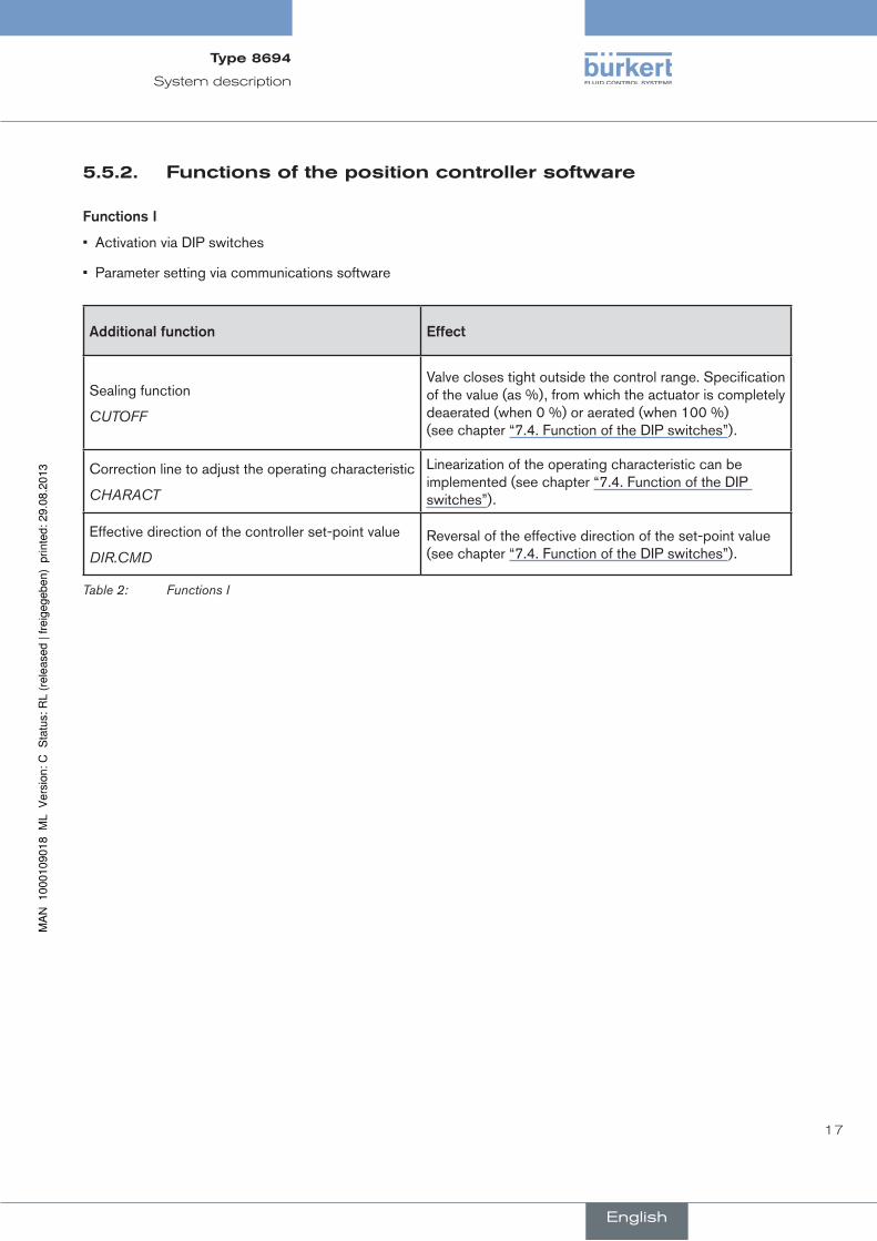
functionsii
• Activation and parameter setting via communications software
additionalfunction effect
Standard signal for set-point value
INPUTSelect set-point value standard signal
Effective direction of the actuator
DIR.ACTUATOR
Assignment of the aeration status of the actuator chamber to the actual position.
Signal split range
SPLITRANGE
Standard signal as % for which the valve runs through the entire mechanical stroke range.
Mechanical stroke range limit
X.LIMITLimit the mechanical stroke range
Opening and closing time
X.TIMELimit the control speed
Position controller
X.CONTROLParameterize the position controller
Safety position
SAFE POSITIONDefinition of the safety position
Signal level fault detection
SIGNAL ERRORConfiguration of signal level fault detection
Binary input
BINARY INPUTConfiguration of the binary input
Analog output
OUTPUTConfiguration of the analog output (optional)
Reset
RESETReset to factory settings
Table 3: Functions II
English
Type8694
19
System description
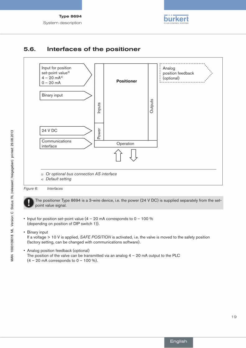
5.6. interfacesofthepositioner
Input for position set-point value3) 4 – 20 mA4) 0 – 20 mA
Binary input
24 V DC
Communications interface
Positioner
Analog position feedback (optional)
Inpu
ts
Out
puts
Pow
er
Operation
3) Or optional bus connection AS interface4) Default setting
Figure 6: Interfaces
The positioner Type 8694 is a 3-wire device, i.e. the power (24 V DC) is supplied separately from the set-point value signal.
• Input for position set-point value (4 – 20 mA corresponds to 0 – 100 % (depending on position of DIP switch 1)).
• Binary input If a voltage > 10 V is applied, SAFE POSITION is activated, i.e. the valve is moved to the safety position (factory setting, can be changed with communications software).
• Analog position feedback (optional) The position of the valve can be transmitted via an analog 4 – 20 mA output to the PLC (4 – 20 mA corresponds to 0 – 100 %).
English
Type8694

20
Technical data
6. TechnicaldaTa
6.1. conformity
In accordance with the EC Declaration of conformity, the positioner Type 8694 is compliant with the EC Directives.
6.2. standards
Conformity with the EC Directives is verified by the following standards.
EN 61000-6-3, EN 61000-6-2, EN 61010-1
6.3. Operatingconditions
Warning!
solarradiationandtemperaturefluctuationsmaycausemalfunctionsorleaks.
• If the device is used outdoors, do not expose it unprotected to the weather conditions.
• Ensure that the permitted ambient temperature does not exceed the maximum value or drop below the mini-mum value.
Ambient temperature 0 ... +60 °C
Protection class: IP65 / IP67 according to EN 60529 (only if cables, plugs and sockets have been connected correctly and in compliance with the exhaust air concept in chapter “Pneumatic connection of the positioner”)
6.4. mechanicaldata
Dimensions See data sheet
Body material exterior: PPS, PC, VA, interior: PA 6; ABS
Sealing material EPDM / (NBR)
Stroke range of valve spindle: 3 ... 45 mm
English
Type8694

21
Technical data
6.5. pneumaticdata
Control medium neutral gases, air Quality classes in accordance with DIN ISO 8573-1
Dust content Class 5 max. particle size 40 µm, max. particle density 10 mg/m³
Water content Class 3 max. pressure dew point - 20 °C or min. 10 °C below the lowest operating temperature
Oil content Class 5 max. 25 mg/m³
Temperature range of the compressed air 0 ... +60 °C
Pressure range 3 ... 7 bar
Air output of control valve 7 lN / min (for aeration and deaeration) (QNn - value according to definition for pressure drop from 7 to 6 bar absolute)
optional: 130 lN / min (for aeration and deaeration) (only single-acting)
Connections Plug-in hose connector Ø6 mm / 1/4" Socket connection G1/8
6.6. Typelabel
8694 24 V DC single act Pilot 0,6 Pmax 7bar Tamb 0°C - +60°C S/N 001000 00185134D
-746
53 In
gelfi
ngen
W14UNce
Identification number
Supply voltage / Control
Nominal pressure
Type Control function - Pilot valve
Bar-code
Serial number - CE mark
Max. ambient temperature
Figure 7: Example of type label
English
Type8694

22
Technical data
6.7. electricaldata
6.7.1. electricaldatawithoutbuscontrol24Vdc
Connections Cable gland M16 x 1.5, wrench size 22 (clamping area 5 – 10 mm) with screw-type terminals for cable cross-sections 0.14 – 1.5 mm²
Circular plug-in connector (M12 x 1, 8-pole)
Control valve Power supply 24 V DC ± 10% - max. residual ripple 10 % Power input ≤ 3.5 W
Input resistance for set-point value signal 75 Ω at 0/4 - 20 mA / 12 bit resolution
Protection class 3 in accordance with VDE 0580
Analogue position feedback max. load for current output 0/4 – 20 mA 560 Ω
Binary input not galvanically isolated 0 – 5 V = log “0”, 12 - 30 V = log “1” inverted input in reverse order
Communications interface Direct connection to PC via USB adapter with integrated interface driver, communication with communications software based on FDT/DTM technology, see “Table 34: Accessories”.
6.7.2. electricaldatawithas-interfacebuscontrol
Connections Circular plug-in connector (M12 x 1, 4-pole)
Electrical supply voltage 29.5 V – 31.6 V DC (according to specification)
deviceswithoutexternalsupplyvoltage:
Max. power consumption 150 mA
deviceswithexternalsupplyvoltage:
External supply voltage 24 V ± 10 % The power supply unit must
include a secure disconnection in accordance with IEC 364-4-41 (PELV or SELV)
Max. power consumption 100 mA
Max. power consumption from AS-Interface 50 mA
English
Type8694

23
Technical data
6.8. factorysettingsofthepositioner
Functions can be activated via DIP switches:
function parameter Value
CUTOFF Sealing function below Sealing function above
2 % 98 %
CHARACT Select characteristic FREE5)
DIR.CMD Effective direction set-point value rise
Table 4: Factory settings - Functions I
Functions can be activated via communications software:
function parameter Value
INPUT Set-point value input 4 ... 20 mA
DIR.ACTUATOR Effective direction actual value rise
SPLITRANGE Function deactivated
Signal split range below Signal split range above
0 % 100 %
X.LIMIT Function deactivated
Stroke limit below Stroke limit above
0 % 100 %
X.TIME Function deactivated
Actuating time Open Actuating time Closed
(1 s) values determined by X.TUNE (1 s) values determined by X.TUNE After implementation of RESET: 1 s
X.CONTROL Deadband Open amplification factor Close amplification factor
1,0 % (1) values determined by X.TUNE (1) values determined by X.TUNE After implementation of RESET: 1
SAFE POSITION Safety position 0 %
SIGNAL ERROR Function deactivated
Sensor break detection set-point value OFF
BINARY INPUT Binary input function Operating principle of binary input
Safety position Normally open
OUTPUT (optional)
Norm signal output: Parameter Norm signal output: Type
Position 4 – 20 mA
Table 5: Factory settings Functions II
5) Without change to the settings via the communications software a linear characteristic is stored in FREE.
English
Type8694

24
Control and display elements
7. cOnTrOlanddisplayelemenTsThe following chapter describes the operating statuses as well as the control and display elements of the positioner.
Further information on the operation of the positioner can be found in the chapter entitled “12. Start-up”.
7.1. Operatingstatus
autOmatic(autO)
Normal controller mode is implemented and monitored in AUTOMATIC operating status.
→ LED 1 flashes green.
manual
In MANUAL operating status the valve can be opened and closed manually via the keys.
→ LED 1 flashes red / green alternately.
DIP switch 4 can be used to switch between the two operating statuses AUTOMATIC and MANUAL.
On dip
1 2 3 4
7.2. controlanddisplayelementsofthepositioner
DIP Switches
Key 2
Key 1
LED 2LED 1
Communications interface
Version 1 Version 2
1 2 3 4
ON DIP
Key 1
Key 2
LED 1
LED 2
Communications interface
Figure 8: Description of control elements
English
Type8694

25
Control and display elements
The positioner features 2 buttons, 4-pole DIP switches and 2x 2-colored LEDs as a display element.
→ To operate the buttons and DIP switches, for Version 1: unscrew the body casing Version 2: unscrew the transparent cap
Seal body casing
Body casing
Figure 9: Position of the seal in the body casing
→ Version 1: Check that the seal is correctly positioned in the body casing.
noTe!
damageormalfunctionduetopenetrationofdirtandhumidity!
• To observe protection class IP65 / IP67, screw the transparent cap in all the way.
→ Close the device (assembly tool: 6740776)).
6) The assembly tool (674077) is available from your Bürkert sales office.
English
Type8694
26
Control and display elements
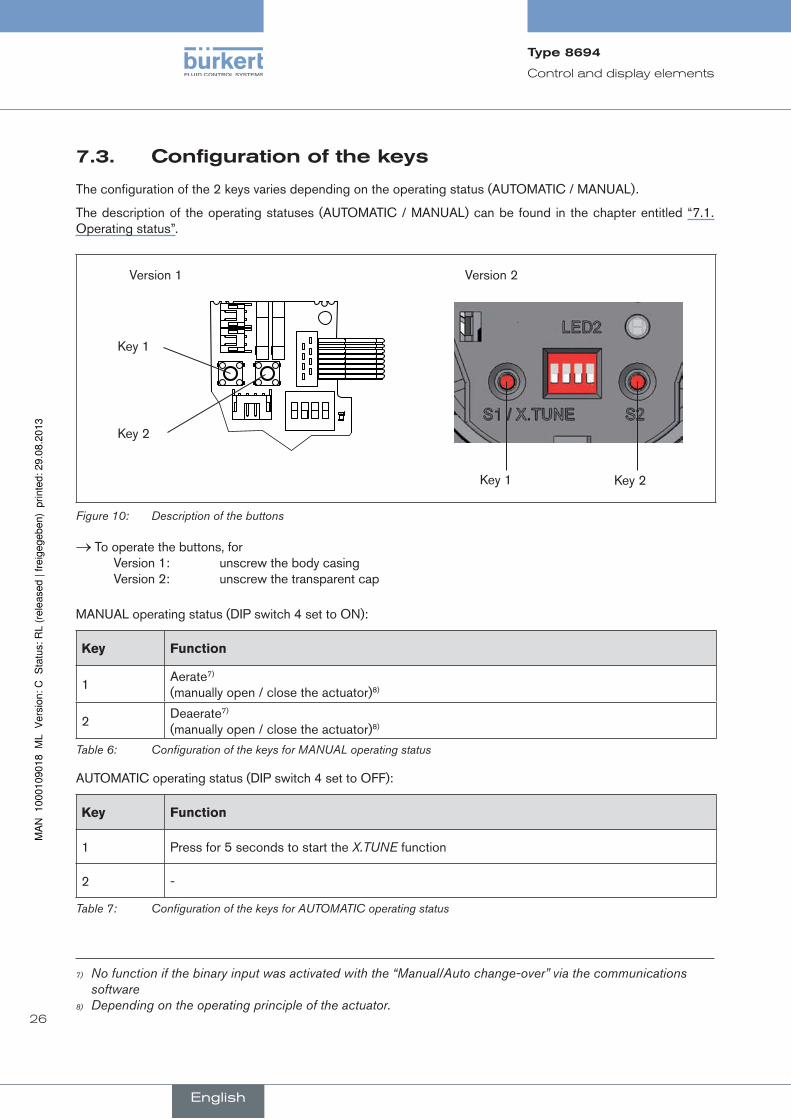
7.3. configurationofthekeys
The configuration of the 2 keys varies depending on the operating status (AUTOMATIC / MANUAL).
The description of the operating statuses (AUTOMATIC / MANUAL) can be found in the chapter entitled “7.1. Operating status”.
Key 2
Key 1
Key 1 Key 2
Version 1 Version 2
Figure 10: Description of the buttons
→ To operate the buttons, for Version 1: unscrew the body casing Version 2: unscrew the transparent cap
MANUAL operating status (DIP switch 4 set to ON):
Key Function
1Aerate7) (manually open / close the actuator)8)
2Deaerate7) (manually open / close the actuator)8)
Table 6: Configuration of the keys for MANUAL operating status
AUTOMATIC operating status (DIP switch 4 set to OFF):
Key Function
1 Press for 5 seconds to start the X.TUNE function
2 -
Table 7: Configuration of the keys for AUTOMATIC operating status
7) No function if the binary input was activated with the “Manual/Auto change-over” via the communications software
8) Depending on the operating principle of the actuator.
English
Type8694

27
Control and display elements
Seal body casing
Body casing
Figure 11: Position of the seal in the body casing
→ Version 1: Check that the seal is correctly positioned in the body casing.
noTe!
damageormalfunctionduetopenetrationofdirtandhumidity!
• To observe protection class IP65 / IP67, screw the transparent cap in all the way.
→ Close the device (assembly tool: 6740779)).
9) The assembly tool (674077) is available from your Bürkert sales office.
English
Type8694

28
Control and display elements
7.4. functionofthedipswitches
On dip
1 2 3 4
→ To operate the DIP switches, for Version 1: unscrew the body casing Version 2: unscrew the transparent cap
DiP Switches Position Function
1 ON Reversal of the effective direction of the set-point value (DIR.CMD) (set-point value 20 – 4 mA corresponds to position 0 – 100 %), descending
OFF Normal effective direction of the set-point value (set-point value 4 – 20 mA corresponds to position 0 – 100 %), ascending
2 ON Sealing function active. The valve completely closes below 2 %10) and opens above 98 % of the set-point value (CUTOFF)
OFF No sealing function
3 ON Correction characteristic for adjustment of the operating characteristic (linearization of the process characteristic CHARACT) 11)
OFF Linear characteristic
4 ON Operating status MANUAL (BY HAND)
OFF Operating status AUTOMATIC (AUTO)
Table 8: DIP Switches
informationaboutthecommunicationssoftware:
The switching position of the DIP switch has priority over the settings via the communications software!
If the values of the sealing function (CUTOFF) or the correction characteristic (CHARACT) are changed via the communications software, the corresponding function must be active (DIP switches set to ON). The effective direction of the set-point value (DIR.CMD) can be changed via the DIP switches only. If the correction characteristic (CHARACT) is not changed via the communications software, a linear char-acteristic is saved when DIP switch 3 is set to ON.
A detailed description of the functions can be found in the chapter entitled “Basic functions” and in the operating instructions for the communications software.
10) Factory setting, can be changed via communications software.11) The characteristic type can be changed via communications software
English
Type8694

29
Control and display elements
Seal body casing
Body casing
Figure 12: Position of the seal in the body casing
→ Version 1: Check that the seal is correctly positioned in the body casing.
noTe!
damageormalfunctionduetopenetrationofdirtandhumidity!
• To observe protection class IP65 / IP67, screw the transparent cap in all the way.
→ Close the device (assembly tool: 67407712)).
12) The assembly tool (674077) is available from your Bürkert sales office.
English
Type8694

30
Control and display elements
7.5. displayoftheleds
Version 1 Version 2
LED 1 LED 2LED 1
(green / red)
Display of mode statuses AUTO, MANUAL, X.TUNE and FAULT
LED 2
(green / yellow)
Display of the actuator status (open, closed, opens or closes)
Figure 13: LED display
LeD 1 (green / red)
LeD statusesDisplay
green red
on off Acceleration phase when Power ON
flashes slowly off Operating status AUTO (AUTOMATIC)
flashing flashing MANUAL operating statusalternating
flashes quickly off X.TUNE function
off on ERROR (see chapter entitled “7.6. Error messages”)
flashing flashing AUTO operating status for sensor break detectionslow
Table 9: Display LED 1
LeD 2 (green / yellow)
LeD statusesDisplay
green yellow
on off Actuator closed
off on Actuator open
flashes slowly offremaining control deviation (actual value > set-point value)
off flashes slowlyremaining control deviation (actual value < set-point value)
flashes quickly off Closing in MANUAL operating status
off flashes quickly Opening in MANUAL operating status
Table 10: Display LED 2
English
Type8694
31
Control and display elements
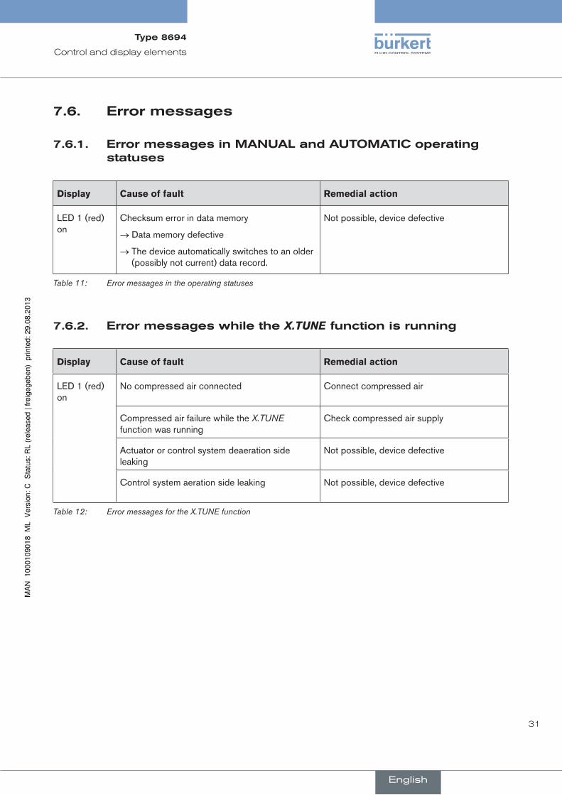
7.6. errormessages
7.6.1. errormessagesinmanualandauTOmaTicoperatingstatuses
Display Cause of fault remedial action
LED 1 (red) on
Checksum error in data memory
→ Data memory defective
→ The device automatically switches to an older (possibly not current) data record.
Not possible, device defective
Table 11: Error messages in the operating statuses
7.6.2. errormessageswhiletheX.TUNEfunctionisrunning
Display Cause of fault remedial action
LED 1 (red) on
No compressed air connected Connect compressed air
Compressed air failure while the X.TUNE function was running
Check compressed air supply
Actuator or control system deaeration side leaking
Not possible, device defective
Control system aeration side leaking Not possible, device defective
Table 12: Error messages for the X.TUNE function
English
Type8694
32
Installation
8. insTallaTiOn
8.1. safetyinstructions
Danger!
riskofinjuryfromhighpressure!
• Before dismounting pneumatic lines and valves, turn off the pressure and vent the lines.
riskofelectricshock!
• Before reaching into the device or the equipment, switch off the power supply and secure to prevent reactivation!
• Observe applicable accident prevention and safety regulations for electrical equipment!
Warning!
riskofinjuryfromimproperinstallation!
• Installation may be carried out by authorized technicians only and with the appropriate tools!
riskofinjuryfromunintentionalactivationofthesystemandanuncontrolledrestart!
• Secure system from unintentional activation.
• Following assembly, ensure a controlled restart.
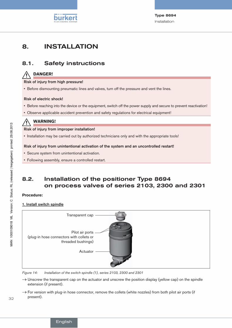
8.2. installationofthepositionerType8694onprocessvalvesofseries2103,2300and2301
Procedure:
1.installswitchspindle
Transparent cap
Actuator
Pilot air ports (plug-in hose connectors with collets or
threaded bushings)
Figure 14: Installation of the switch spindle (1), series 2103, 2300 and 2301
→ Unscrew the transparent cap on the actuator and unscrew the position display (yellow cap) on the spindle extension (if present).
→ For version with plug-in hose connector, remove the collets (white nozzles) from both pilot air ports (if present).
English
Type8694
33
Installation
O-ring
Spindle extension
Guide element
Actuator cover
Groove ring
Puck holder
Switch spindle
10
max. 5 Nm
max. 1 Nm
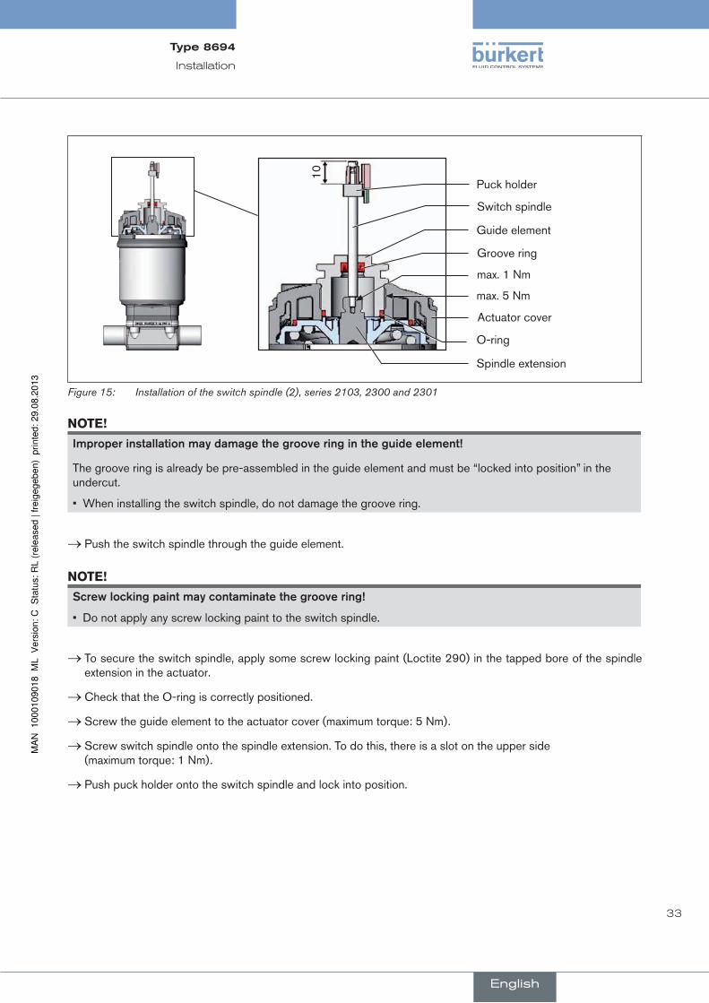
Figure 15: Installation of the switch spindle (2), series 2103, 2300 and 2301
noTe!
improperinstallationmaydamagethegrooveringintheguideelement!
The groove ring is already be pre-assembled in the guide element and must be “locked into position” in the undercut.
• When installing the switch spindle, do not damage the groove ring.
→ Push the switch spindle through the guide element.
noTe!
screwlockingpaintmaycontaminatethegroovering!
• Do not apply any screw locking paint to the switch spindle.
→ To secure the switch spindle, apply some screw locking paint (Loctite 290) in the tapped bore of the spindle extension in the actuator.
→ Check that the O-ring is correctly positioned.
→ Screw the guide element to the actuator cover (maximum torque: 5 Nm).
→ Screw switch spindle onto the spindle extension. To do this, there is a slot on the upper side (maximum torque: 1 Nm).
→ Push puck holder onto the switch spindle and lock into position.
English
Type8694

34
Installation
2.installsealingrings
→ Pull the form seal onto the actuator cover (smaller diameter points upwards).
→ Check that the O-rings are correctly positioned in the pilot air ports.
When the positioner is being installed, the collets of the pilot air ports must not be fitted to the actuator.
Form seal
Pilot air port
Caution: collets must not be
fitted !
Installation of the form seal
Figure 16: Installation of the sealing rings, series 2103, 2300 and 2301
3.installpositioner
→ Align the puck holder and the positioner until 1. the puck holder can be inserted into the guide rail of the positioner (see “Figure 17”) and 2. the supports of the positioner can be inserted into the pilot air ports of the actuator (see also “Figure 18”).
noTe!
damagedprintedcircuitboardormalfunction!
• Ensure that the puck holder is situated flat on the guide rail.
Guide rail
Puck holder
Figure 17: Aligning the puck holder
English
Type8694
35
Installation
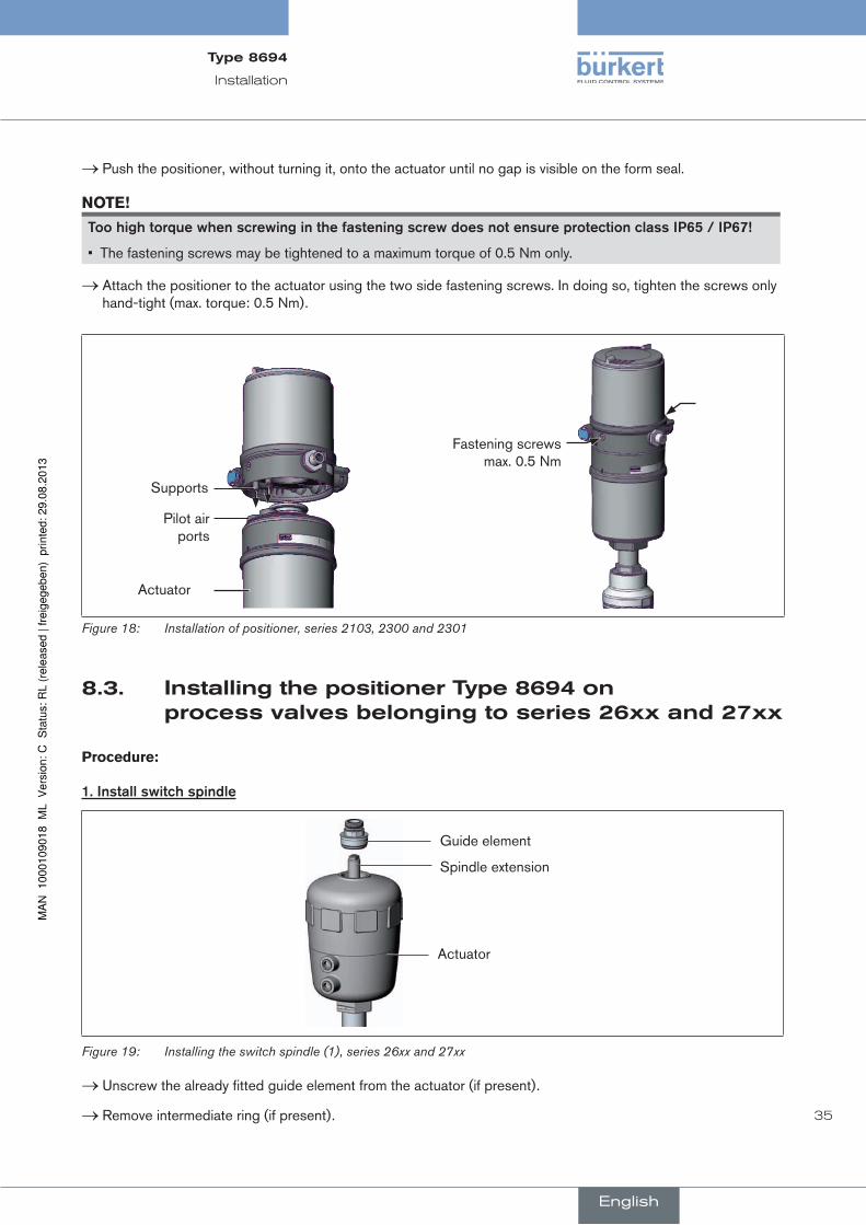
→ Push the positioner, without turning it, onto the actuator until no gap is visible on the form seal.
noTe!
toohightorquewhenscrewinginthefasteningscrewdoesnotensureprotectionclassip65/ip67!
• The fastening screws may be tightened to a maximum torque of 0.5 Nm only.
→ Attach the positioner to the actuator using the two side fastening screws. In doing so, tighten the screws only hand-tight (max. torque: 0.5 Nm).
Supports
Pilot air ports
Fastening screws max. 0.5 Nm
Actuator
Figure 18: Installation of positioner, series 2103, 2300 and 2301
8.3. installingthepositionerType8694onprocessvalvesbelongingtoseries26xxand27xx
Procedure:
1.installswitchspindle
Guide element
Spindle extension
Actuator
Figure 19: Installing the switch spindle (1), series 26xx and 27xx
→ Unscrew the already fitted guide element from the actuator (if present).
→ Remove intermediate ring (if present).
English
Type8694

36
Installation
Guide element
O-ring
Switch spindle
Puck holder
Switch spindle
Spindle (actuator)
Figure 20: Installing the switch spindle (2), series 26xx and 27xx
→ Press the O-ring downwards into the cover of the actuator.
→ Actuator size 125 and bigger with large air output: remove existing spindle extension and replace with the new one. To do this, apply some screw locking paint (Loctite 290) in the tapped bore of the spindle extension.
→ Screw the guide element into the cover of the actuator using a face wrench13) (torque: 8.0 Nm).
→ To secure the switch spindle, apply some screw locking paint (Loctite 290) to the thread of the switch spindle.
→ Screw the switch spindle onto the spindle extension. To do this, there is a slot on the upper side (maximum torque: 1 Nm).
→ Push the puck holder onto the switch spindle until it engages.
13) Journal Ø: 3 mm; journal gap: 23.5 mm
English
Type8694

37
Installation
2.installpositioner
→ Push the positioner onto the actuator. The puck holder must be aligned in such a way that it is inserted into the guide rail of the positioner.
noTe!
damagedprintedcircuitboardormalfunction!
• Ensure that the puck holder is situated flat on the guide rail.
Guide rail
Puck holder
Figure 21: Aligning the puck holder
→ Press the positioner all the way down as far as the actuator and turn it into the required position.
Fastening screws max. 0.5 Nm
Figure 22: Installing the positioner
Ensure that the pneumatic connections of the positioner and those of the valve actuator are situated pref-erably vertically one above the other. If they are positioned differently, longer hoses may be required other than those supplied in the accessory kit.
noTe!
toohightorquewhenscrewinginthefasteningscrewdoesnotensureprotectionclassip65/ip67!
• The fastening screws may be tightened to a maximum torque of 0.5 Nm only.
→ Attach the positioner to the actuator using the two side fastening screws. In doing so, tighten the fastening screws hand-tight only (maximum torque: 0.5 Nm).
English
Type8694

38
Installation
3.installpneumaticconnectionbetweenpositionerandactuator
Pilot air outlet 21
Pilot air outlet 22
Upper pilot air port
Lower pilot air port Example ∅ 80, CFA
Figure 23: Installing the positioner
→ Screw the plug-in hose connectors onto the positioner and the actuator.
→ Using the hoses supplied in the accessory kit, make the pneumatic connection between the positioner and actuator with the following “Table 13: Pneumatic connection to actuator - CFA” or “Table 14: Pneumatic con-nection to actuator - CFB”.
noTe!
damageormalfunctionduetoingressofdirtandmoisture!
To observe protection class IP65 / IP67:
• In the case of actuator size ∅ 80, ∅ 100 connect the pilot air outlet which is not required to the free pilot air port of the actuator or seal with a plug.
• In the case of actuator size ∅ 125 seal the pilot air outlet 22 which is not required with a plug and feed the free pilot air port of the actuator via a hose into a dry environment.
controlfunctiona(cfa) Process valve closed in rest position (by spring force)
Actuator size ∅ 80, ∅ 100
∅ 125
Pos
ition
er Pilot air outlet
22 2122 21
Act
uato
r Upper pilot air port
Lower pilot air port
Dry area
Table 13: Pneumatic connection to actuator - CFA
English
Type8694

39
Installation
controlfunctionB(cfB) Process valve open in rest position (by spring force)
Actuator size ∅ 80, ∅ 100
∅ 125
Pos
ition
er Pilot air outlet
22 2122 21
Act
uato
r Upper pilot air port
Lower pilot air port
Dry area
Table 14: Pneumatic connection to actuator - CFB
"In rest position" means that the pilot valves of the positioner Type 8694 are isolated or not actuated.
8.4. rotatingtheactuatormodule
The actuator module (positioner and actuator) can be rotated for straight seat valves and angle seat valves belonging to series 2300, 2301 and 27xx only!
The position of the connections can be aligned steplessly by rotating the actuator module (positioner and actuator) through 360°.
Only the entire actuator module can be rotated. The positioner cannot be rotated contrary to the actuator. The process valve must be in the open position for alignment of the actuator module!
Danger!
riskofinjuryfromhighpressure!
• Before dismounting pneumatic lines and valves, turn off the pressure and vent the lines.
procedure:
→ Clamp valve body in a holding device (only required if the process valve has not yet been installed).
noTe!
damagetotheseatsealortheseatcontour!
• When removing the actuator module, ensure that the valve is in open position.
→ Control function A: Open process valve.
English
Type8694

40
Installation
Actuator module
Key contour HexagonNipple
with hexagonwithout hexagon
Nipple
Figure 24: Rotating the actuator module
→ Using a suitable open-end wrench, counter the wrench flat on the pipe.
→ Actuator module without hexagon: Fit special key14) exactly in the key contour on the underside of the actuator.
→ Actuator module with hexagon: Place suitable open-end wrench on the hexagon of the actuator.
Warning!
riskofinjuryfromdischargeofmediumandpressure!
If the direction of rotation is wrong, the body interface may become detached.
• Rotate the actuator module in the specified direction only (see “Figure 25”) !
→ Actuator module without hexagon: Rotate clockwise (as seen from below) to bring the actuator module into the required position.
→ Actuator module with hexagon: Rotate counter-clockwise (as seen from below) to bring the actuator module into the required position.
Special key
Open-end wrench
without hexagonwith hexagon
Figure 25: Rotating with special key / open-end wrench
14) The special key (665702) is available from your Bürkert sales office.
English
Type8694

41
Installation
8.5. rotatingthepositionerforprocessvalvesbelongingtoseries26xxand27xx
If the connecting cables or hoses cannot be fitted properly following installation of the process valve, the positioner can be rotated contrary to the actuator.
Fastening screw (2x)
Pneumatic connection
Positioner
Actuator
Figure 26: Rotating the positioner, series 26xx and 27xx
Procedure
→ Loosen the pneumatic connection between the positioner and the actuator.
→ Loosen the fastening screws (hexagon socket wrench size 2.5).
→ Rotate the positioner into the required position.
noTe!
toohightorquewhenscrewinginthefasteningscrewdoesnotensureprotectionclassip65/ip67!
• The fastening screw may be tightened to a maximum torque of 0.5 Nm only.
→ Tighten the fastening screws hand-tight only (maximum torque: 0.5 Nm).
→ Re-attach the pneumatic connections between the positioner and the actuator. If required, use longer hoses.
English
Type8694

42
Fluid installation
9. fluidinsTallaTiOnThe dimensions of the positioner and the different complete device models, consisting of positioner, actuator and valve, can be found in the relevant data sheets.
9.1. safetyinstructions
Danger!
riskofinjuryfromhighpressure!
• Before dismounting pneumatic lines and valves, turn off the pressure and vent the lines.
riskofelectricshock!
• Before reaching into the device or the equipment, switch off the power supply and secure to prevent reactivation!
• Observe applicable accident prevention and safety regulations for electrical equipment!
Warning!
riskofinjuryfromimproperinstallation!
• Installation may be carried out by authorized technicians only and with the appropriate tools!
riskofinjuryfromunintentionalactivationofthesystemandanuncontrolledrestart!
• Secure system from unintentional activation.
• Following installation, ensure a controlled restart.
9.2. installingtheprocessvalve
Thread type and dimensions can be found in the corresponding data sheet.
→ Connect the valve according to the operating instructions for the valve.
English
Type8694

43
Fluid installation
9.3. pneumaticconnectionofthepositioner
Danger!
riskofinjuryfromhighpressure!
• Before dismounting pneumatic lines and valves, turn off the pressure and vent the lines.
procedure:
→ Connect the control medium to the pilot air port (1) (3 – 7 bar; instrument air, free of oil, water and dust).
→ Attach the exhaust air line or a silencer to the exhaust air port (3) and, if available to the exhaust air port (3.1)
Important information for the problem-free functioning of the device:
• The installation must not cause back pressure to build up.
• Select a hose for the connection with an adequate cross-section.
• The exhaust air line must be designed in such a way that no water or other liquid can get into the device through the exhaust air port (3) or (3.1).
Pilot air port (label: 1)
Exhaust air port (label: 3)
Additional exhaust air port (label: 3.1) only for Type 23xx and 2103 with pilot-operated control system for high air output (actuator size ø 130)
Figure 27: Pneumatic Connection
Caution:(Exhaust air concept): In compliance with protection class IP67, an exhaust air line must be installed in the dry area. Keep the adjacent supply pressure always at least 0.5 – 1 bar above the pressure which is required to move the actuator to its end position. This ensures that the control behavior is not extremely negatively affected in the upper stroke range on account of too little pressure difference.
During operation keep the fluctuations of the pressure supply as low as possible (max. ±10 %). If fluctua-tions are greater, the control parameters measured with the X.TUNE function are not optimum.
English
Type8694
44
Electrical installation 24 V DC
10. elecTricalinsTallaTiOn24VdcTwo kinds of connections are used for the electrical bonding of the positioner:
• cablegland with cable gland M16 x 1.5 and screw-type terminals
• multi-pole with circular plug-in connector M12 x 1, 8-pole
10.1. safetyinstructions
Danger!
riskofelectricshock!
• Before reaching into the system, switch off the power supply and secure to prevent reactivation!
• Observe applicable accident prevention and safety regulations for electrical equipment!
Warning!
riskofinjuryfromimproperinstallation!
• Installation may be carried out by authorized technicians only and with the appropriate tools!
riskofinjuryfromunintentionalactivationofthesystemandanuncontrolledrestart!
• Secure system from unintentional activation.
• Following installation, ensure a controlled restart.
10.2. electricalinstallationwithcircularplug-inconnector
Danger!
riskofelectricshock!
• Before reaching into the device or the equipment, switch off the power supply and secure to prevent reactivation!
• Observe applicable accident prevention and safety regulations for electrical equipment!
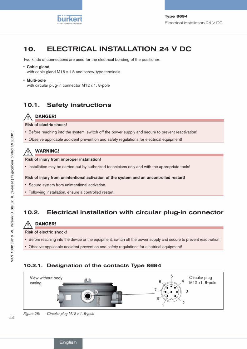
10.2.1. designationofthecontactsType8694
View without body casing
Circular plug M12 x1, 8-pole6
1
7
54
3
28
Figure 28: Circular plug M12 x 1, 8-pole
English
Type8694
45
Electrical installation 24 V DC
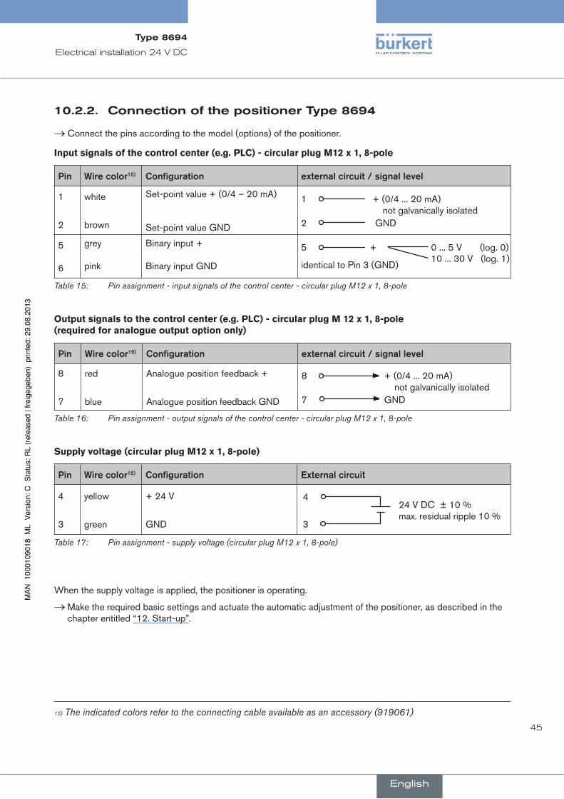
10.2.2. connectionofthepositionerType8694
→ Connect the pins according to the model (options) of the positioner.
input signals of the control center (e.g. PLC) - circular plug M12 x 1, 8-pole
pin Wirecolor15) configuration externalcircuit/signallevel
1
2
white
brown
Set-point value + (0/4 – 20 mA)
Set-point value GND
1
2 GND
+ (0/4 ... 20 mA) not galvanically isolated
5 6
grey pink
Binary input + Binary input GND
5 + 0 ... 5 V (log. 0)10 ... 30 V (log. 1)
identical to Pin 3 (GND)
Table 15: Pin assignment - input signals of the control center - circular plug M12 x 1, 8-pole
output signals to the control center (e.g. PLC) - circular plug M 12 x 1, 8-pole (required for analogue output option only)
pin Wirecolor15) configuration externalcircuit/signallevel
8
7
red
blue
Analogue position feedback +
Analogue position feedback GND
8
7 GND
+ (0/4 ... 20 mA) not galvanically isolated
Table 16: Pin assignment - output signals of the control center - circular plug M12 x 1, 8-pole
Supply voltage (circular plug M12 x 1, 8-pole)
pin Wirecolor15) configuration externalcircuit
4
3
yellow
green
+ 24 V
GND
4
3
24 V DC ± 10 % max. residual ripple 10 %
Table 17: Pin assignment - supply voltage (circular plug M12 x 1, 8-pole)
When the supply voltage is applied, the positioner is operating.
→ Make the required basic settings and actuate the automatic adjustment of the positioner, as described in the chapter entitled “12. Start-up”.
15) The indicated colors refer to the connecting cable available as an accessory (919061)
English
Type8694

46
Electrical installation 24 V DC
10.3. electricalinstallationwithcablegland
Danger!
riskofelectricshock!
• Before reaching into the device or the equipment, switch off the power supply and secure to prevent reactivation!
• Observe applicable accident prevention and safety regulations for electrical equipment!
10.3.1. designationofthescrew-typeterminals
1216)
316)
4567
Figure 29: Connection of screw-type terminals
10.3.2. connectionofthepositionerType8694
→ The screw-type terminals can be accessed by unscrewing the body casing (stainless steel).
→ Push the cables through the cable gland.
→ Connect the positioner according to the following tables:
input signals from the control centre (e.g. PLC)
terminal configuration externalcircuit
4 5
Set-point value + Set-point value GND
4
5 GND
+ (0/4 ... 20 mA)
1
Binary input +
1 + 0 ... 5 V (log. 0)10 ... 30 V (log. 1)
with reference to terminal 7 (GND)
Table 18: Assignment of screw-type terminals - input signals of the control center - cable gland
16) Option only
English
Type8694

47
Electrical installation 24 V DC
output signals to the control center (e.g. PLC; for analog output option only)
terminal configuration externalcircuit
2 3
Analogue position feedback +
Analogue position feedback GND
2
3 GND
+ (0/4 ... 20 mA) not galvanically isolated
Table 19: Assignment of screw-type terminals - output signals to the control center - cable gland
electrical supply voltage
terminal configuration externalcircuit
6 7
Supply voltage + Supply voltage GND
6
7
24 V DC ± 10 % max. residual ripple 10 %
Table 20: Assignment of screw-type terminals - Supply voltage - cable gland
Seal body casing
Body casing
Figure 30: Position of the seal in the body casing
→ Check that the seal is correctly positioned in the body casing.
noTe!
damageormalfunctionduetopenetrationofdirtandhumidity!
To ensure protection class IP65 / IP67:
• Tighten the union nut on the cable gland according to the cable size or dummy plugs used (approx. 1.5 Nm).
• Screw the body casing in all the way.
→ Tighten union nut on the cable gland (torque approx. 1.5 Nm).
→ Close the device (assembly tool: 67407717)).
When the power supply is applied, the positioner is operating.
→ Make the required basic settings and actuate the automatic adjustment of the positioner, as described in the chapter entitled “12. Start-up”.
17) The assembly tool (674077) is available from your Bürkert sales office.
English
Type8694

48
AS-Interface installation
11. as-inTerfaceinsTallaTiOn
11.1. as-interfaceconnection
AS-Interface (Actuator Sensor Interface) is a field bus system which is used primarily for networking binary sensors and actuators (slaves) with a higher-level control (master).
Busline
Unshielded two-wire line (AS-Interface line as AS-Interface cable harness) along which both information (data) and energy (power supply for the actuators and sensors) are transmitted.
networktopology
Freely selectable within wide limits, i.e. star, tree and line networks are possible. Further details are described in the AS-Interface specification (A/B slave model conforms to the version 3.0 specification).
11.2. Technicaldataforas-interfacepcBs
Version Profile S-7.3.4 Version Profile S-7.A.5
Supply via AS-Interface via AS-Interface
Outputs 16 bit set-point value 16 bit set-point value
Inputs - 16 bit feedback
Certification Certificate no. 87301 after version 3.0 Certificate no. xxxxx after version 3.0
Table 21: Technical data
11.3. programmingdata
Version Profile S-7.3.4 Version Profile S-7.A.5
I/O configuration 7 hex 7 hex
ID code 3 hex (analog profile) A hex
Extended ID code 1F hex (Default value, can be changed by the user)
7 hex
Extended ID code 2 4 hex 5 hex
Profile S-7.3.4 S-7.A.5
Table 22: Programming data
English
Type8694

49
AS-Interface installation
Bit configuration
1. Output set-point value (Value range 0 – 10.000, is equivalent to 0 – 100 %)
2. Input feedback18) (Value range 0 – 10.000, is equivalent to 0 – 100 %)
Byte 2 Byte 1
0 0 D13 D12 D11 D10 D9 D8 D7 D6 D5 D4 D3 D2 D1 D0
parameterbit p3 p2 p1 p0
Output not used not used not used not used
Table 23: Bit configuration
11.4. communicationsequencefortheversions-7.a.5profile
1. Following start-up, the AS-Interface master (from master class 4) automatically replaces the ID object with the S-7.A.5 slave.
S-7.A.5 slave replies with 6 bytes
1. Byte: Code = 80 dez
2. Byte: Vendor ID (high)= 120 dez
3. Byte: Vendor ID (low)
4. Byte: Device ID (high)= 1 dez
5. Byte: Device ID (low)
6. Byte: 1 word output + 1 word input
=
34
dez
or with 2 Byte (Read Response not OK)
1. Byte: Code = 144 dez
2. Byte: Error Code = 0 1 2 3
4
dez (no error) dez (illegal index) dez (illegal length) dez (request not implemented) dez (busy)
Master transmits 3 bytes:
1. Byte: Code = 16 dez
2. Byte: Index = 0 dez
3. Byte: Length = 5 dez
2. Then the following cyclical commands can be used:
Code = 0 (get cyclic data from Slave) → for feedback 0 – 100 %
Code = 1 (put cylic data to slave) → for set-point value 0 – 100 %
18) Only for version with S-7.A.5 profile
English
Type8694

50
AS-Interface installation
11.5. ledstatusdisplay
The LED status display indicates the bus status (LED green and red).
Bus LED green
Bus LED red
Figure 31: LED status display AS-Interface
ledgreen ledred
off off POWER OFF
off on No data traffic (expired Watch Dog at slave address does not equal 0)
on off OK
flashing on Slave address equals 0
off flashing Electronic error or external reset
flashing flashing Timeout bus communication after 100 ms (periphery error)
Table 24: LED Status Display AS-Interface
Seal body casing
Body casing
Figure 32: Position of the seal in the body casing
→ Check that the seal is correctly positioned in the body casing.
noTe!
damageormalfunctionduetopenetrationofdirtandhumidity!
• To observe protection class IP65 / IP67, screw the transparent cap in all the way.
→ Close the device (assembly tool: 67407719)).
19) The assembly tool (674077) is available from your Bürkert sales office.
English
Type8694

51
AS-Interface installation
11.6. electricalinstallationas-interface
11.6.1. safetyinstructions
Danger!
riskofelectricshock!
• Before reaching into the system, switch off the power supply and secure to prevent reactivation!
• Observe applicable accident prevention and safety regulations for electrical equipment!
Warning!
riskofinjuryfromimproperinstallation!
• Installation may be carried out by authorized technicians only and with the appropriate tools!
riskofinjuryfromunintentionalactivationofthesystemandanuncontrolledrestart!
• Secure system from unintentional activation.
• Following installation, ensure a controlled restart.
11.6.2. connectionwithcircularplug-inconnectorm12x1,4-pole,male
It is not necessary to open the positioner for the multi-pole model.
Bus connection without external / with external supply voltage
pin designation configuration
1 Bus + AS-Interface bus line +
2 NC or GND (optional) not used or external supply voltage – (optional)
3 Bus – AS-Interface bus line -
4 NC or 24 V + (optional) not used or external supply voltage + (optional)
Table 25: Pin assignment of circular plug-in connector for AS-Interface
Views of plug: From the front onto the pins, the soldered connections are behind
Pin 4:
NC
Pin 1:
Bus +
Pin 3:
Bus –
Pin 2:
NC
Pin 4:
24 V +
Pin 1:
Bus +
Pin 3:
Bus –
Pin 2:
GND
Figure 33: Bus connection without external supply voltage
Figure 34: Bus connection with external supply voltage (optional)
English
Type8694
52
AS-Interface installation
When the supply voltage is applied, the positioner is operating.
→ Make the required basic settings and actuate the automatic adjustment of the positioner, as described in the chapter entitled “12. Start-up”.
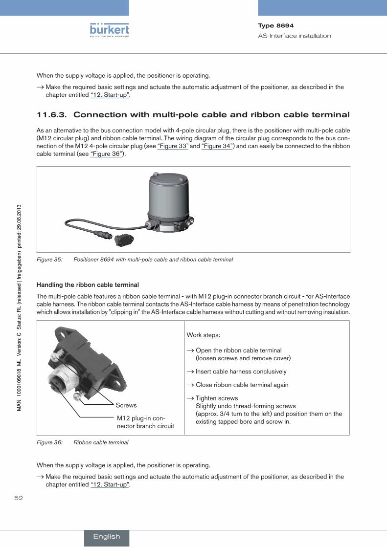
11.6.3. connectionwithmulti-polecableandribboncableterminal
As an alternative to the bus connection model with 4-pole circular plug, there is the positioner with multi-pole cable (M12 circular plug) and ribbon cable terminal. The wiring diagram of the circular plug corresponds to the bus con-nection of the M12 4-pole circular plug (see “Figure 33” and “Figure 34”) and can easily be connected to the ribbon cable terminal (see “Figure 36”).
Figure 35: Positioner 8694 with multi-pole cable and ribbon cable terminal
handlingtheribboncableterminal
The multi-pole cable features a ribbon cable terminal - with M12 plug-in connector branch circuit - for AS-Interface cable harness. The ribbon cable terminal contacts the AS-Interface cable harness by means of penetration technology which allows installation by "clipping in" the AS-Interface cable harness without cutting and without removing insulation.
Screws
M12 plug-in con-nector branch circuit
Work steps:
→ Open the ribbon cable terminal (loosen screws and remove cover)
→ Insert cable harness conclusively
→ Close ribbon cable terminal again
→ Tighten screws Slightly undo thread-forming screws (approx. 3/4 turn to the left) and position them on the existing tapped bore and screw in.
Figure 36: Ribbon cable terminal
When the supply voltage is applied, the positioner is operating.
→ Make the required basic settings and actuate the automatic adjustment of the positioner, as described in the chapter entitled “12. Start-up”.
English
Type8694

53
Start-up
12. sTarT-up
12.1. safetyinstructions
Danger!
danger–highpressure!
There is a serious risk of injury when reaching into the equipment.
• Before dismounting pneumatic lines and valves, turn off the pressure and vent the lines.
Warning!
riskofinjuryfromimproperoperation!
Improper operation may result in injuries as well as damage to the device and the area around it.
• Before start-up, ensure that the operating personnel are familiar with and completely understand the contents of the operating instructions.
• Observe the safety instructions and intended use.
• Only adequately trained personnel may operate the equipment/the device.
12.2. specifyingthestandardsettings
The basic settings of the positioner are implemented at the factory.
To adjust the positioner to local conditions, the X.TUNE function must be run following installation.
12.2.1. runningtheautomaticadjustmentX.TUNE
Warning!
dangerduetothevalvepositionchangingwhentheX.TUNEfunctionisrunning!
When the X.TUNE is running under operating pressure, there is an acute risk of injury.
• Never run X.TUNE while a process is running!
• Take appropriate measures to prevent the equipment from being accidentally actuated!
noTe!
avoidmaladjustmentofthecontrollerduetoanincorrectpilotpressureorappliedoperatingmediumpressure!
• Run X.TUNE whenever the pilot pressure (= pneumatic auxiliary energy) is available during subsequent operation.
• Run the X.TUNE function preferably without operating medium pressure to exclude interference caused by flow forces.
To run X.TUNE, the positioner must be in the AUTOMATIC operating status (DIP switch 4 = OFF).
English
Type8694

54
Start-up
→ To operate the buttons and DIP switches, for Version 1: unscrew the body casing Version 2: unscrew the transparent cap
DIP Switches
Key 2
Key 1
LED 2
LED 1
Communications interface
Version 1
Version 2
1 2 3 4
ON DIP
Key 1
Key 2
LED 1
LED 2
Communications interface
Figure 37: Automatic adjustment X.TUNE
→ Start the X.TUNE by pressing button 120) for 5 s.
While the X.TUNE is running, LED 1 flashes quickly (green).
When the automatic adjustment is complete, LED 1 flashes slowly (green)21).
The changes are automatically transferred to the memory (EEPROM) provided the X.TUNE function is successful.
important:When the X.TUNE function is activated, the actuator cannot be actuated via the AS-Interface communication.
Seal body casing
Body casing
Figure 38: Position of the seal in the body casing
→ Version 1: Check that the seal is correctly positioned in the body casing.
noTe!
damageormalfunctionduetopenetrationofdirtandhumidity!
• To observe protection class IP65 / IP67, screw the transparent cap in all the way.
→ Close the device (assembly tool: 67407722)).
20) The X.TUNE can also be started via communications software. 21) If a fault occurs, LED 1 is lit red.22) The assembly tool (674077) is available from your Bürkert sales office.
English
Type8694

55
Operation and function
13. OperaTiOnandfuncTiOnThe positioner type 8694 has different basic and additional functions which can be configured and parameterized via the DIP switches or the communications software.
13.1. Basicfunctions
The following basic functions can be activated via the DIP switches (CUTOFF and CHARACT) or changed (DIR.CMD).
function description dipswitches Off On
DIR.CMD Effective direction between input signal and set-point position
1 rise fall
CUTOFF Sealing function for position controller
2 Sealing function off Sealing function on
CHARACT Selection of the Transfer Charac-teristic between Input Signal and Stroke (Correction Characteristic)
3 Linear characteristic Correction characteristic
Table 26: Basic functions of DIP switches
The following basic function can be changed via the communications software only.
function description factorysetting
INPUT Entry of the standard signal input for the set-point value
4 ... 20 mA
Table 27: Basic function of communications software
The INPUT, CUTOFF and CHARACT functions can be parameterized via the communications software.
The operating instructions for the communications software describe in detail the individual functions, as well as parameterization and configuration.
These instructions can be found on the Internet at www.burkert.com and are also available on CD which can be ordered by quoting identification number 804625.
English
Type8694

56
Operation and function
13.1.1. DIR.CMD-effectivedirectionofthepositionerset-pointvalue
You can use this function to adjust the effective direction between the input signal (INPUT) and the nominal position of the actuator.
Factory setting: DIP switch set to OFF (ascending)
DiP Switches Position Function
1 ON Reversal of the effective direction of the set-point value (DIR.CMD) (set-point value 20 – 4 mA corresponds to position 0 – 100 %), fall
OFF Normal effective direction of the set-point value (set-point value 4 – 20 mA corresponds to position 0 – 100 %), rise
Table 28: DIP switch 1
The effective direction (DIR.CMD) can only be changed via DIP switch 1 in the positioner.
Nominal position
Input signal (INPUT)
rise
fall
Figure 39: DIR.CMD graph
English
Type8694

57
Operation and function
13.1.2. CUTOFF-sealingfunctionforthepositioner
This function causes the valve to be sealed outside the control range.
Control mode resumes at a hysteresis of 1%.
Factory setting: DIP switch 2 set to OFF (no sealing function)
DiP Switches Position Function
2 ON Sealing function active. The valve completely closes below 2 %23) and opens above 98 % of the set-point value (CUTOFF)
OFF No sealing function
Table 29: DIP switch 2
The communications software can be used to change the limits for the position set-point value as a percentage.
The switching position of the DIP switches in the positioner has priority over the communications software, i.e. settings of the sealing function (CUTOFF) which are modified via the communications software are only active if DIP switch 2 in the positioner is set to ON.
Valve stroke [%]
Adjustable from 75 – 100 %
Set-point value [%]
Adjustable from 0 – 25 %
Figure 40: CUTOFF graph
23) Factory setting can be changed via communications software.
English
Type8694

58
Operation and function
13.1.3. CHARACT-selectthetransfercharacteristicbetweeninputsignal(positionset-pointvalue)andstroke
Characteristic (customer-specific characteristic)
This function can be used to activate a transfer characteristic with respect to set-point value (set-point position) and valve stroke for correction of the flow-rate or operating characteristic.
The transfer characteristic can be changed via the communications software only.
Factory setting: DIP switch 3 set to OFF (linear)
DiP Switches Position Function
3 ON Correction characteristic for adjustment of the operating characteristic (linearization of the process characteristic CHARACT) 24)
OFF Linear characteristic
Table 30: DIP switch 3
The switching position of the DIP switches in the positioner has priority over the communications software, i.e. settings of the correction characteristic (CHARACT) which are modified via the communica-tions software are only active if DIP switch 3 in the positioner is set to ON.
Characteristics which can be selected via the communications software:
Characteristic Description
linear Linear characteristic
1 : 25 Equal percentage characteristic 1 : 25
1 : 33 Equal percentage characteristic 1 : 33
1 : 50 Equal percentage characteristic 1 : 50
25 : 1 Inversely equal percentage characteristic 25 : 1
33 : 1 Inversely equal percentage characteristic 33 : 1
55 : 1 Inversely equal percentage characteristic 55 : 1
FREE User-defined characteristic, freely programmable via nodes
Table 31: Selection of characteristics
A detailed description of the characteristics can be found in the operating instructions for the communica-tions software for positioners.
24) The characteristic type can be changed via the communications software only.
English
Type8694

59
Operation and function
13.2. auxiliaryfunctions
The following additional functions can be configured and parameterized via the communications software:
function description
DIR.ACTUATOR Assignment of the aeration status of the actuator chamber to the actual position
SPLITRANGE Signal split range; input signal as a % for which the valve runs through the entire stroke range.
X.LIMIT Limit the mechanical stroke range
X.TIME Limit the control speed
X.CONTROL Parameterize the position controller
SAFE POSITION Input the safety position
SIGNAL ERROR Configuration of signal level fault detection
BINARY INPUT Activation of the binary input
OUTPUT Configuration of the outputs (only with auxiliary board for analogue feedback signal or binary outputs)
Table 32: Auxiliary functions
The operating instructions for the communications software describe in detail the individual functions, as well as parameterization and configuration.
These instructions can be found on the Internet at www.burkert.com and are also available on CD which can be ordered by quoting identification number 804625.
English
Type8694

60
Safety positions
14. safeTypOsiTiOns
14.1. safetypositionsafterfailureoftheelectricalorpneumaticauxiliarypower
actuatorsystem designation
safetypositionsafterfailureoftheauxiliarypower
electrical pneumatic
up
down
single-acting
Control function A
down
pilot-controlled control system:
down
direct-acting control system:
not defined
up
down
single-acting
Control function B
up
pilot-controlled control system:
up
direct-acting control system:
not defined
Table 33: Safety positions
English
Type8694

61
Maintenance
15. mainTenance
15.1. safetyinstructions
Danger!
danger–highpressureintheequipment!
• Before loosening the lines and valves, turn off the pressure and vent the lines.
riskofinjuryduetoelectricalshock!
• Before reaching into the system, switch off the power supply and secure to prevent reactivation!
• Observe applicable accident prevention and safety regulations for electrical equipment!
Warning!
riskofinjuryfromimpropermaintenance!
• Maintenance may be performed by authorised technicians only!
riskofinjuryfromunintentionalactivationofthesystemandanuncontrolledrestart!
• Secure system from unintentional activation.
• Following maintenance, ensure a controlled restart.
English
Type8694

62
Maintenance
15.2. serviceattheairintakefilter
Danger!
riskofinjuryfromhighpressureintheequipment!
• Before dismounting pneumatic lines and valves, turn off the pressure and vent the lines.
To protect the internal solenoid valves and the actuator, the pilot air is filtered.
The direction of flow of the air intake filter in installed state is from the inside to the outside through the filter material.
Air intake filter
Quick connector
O-ring
Figure 41: Service on the air intake filter
procedure:
→ Unlock the quick connector by pressing the holding element and pulling out the air intake filter (if necessary, use a suitable tool in between the recesses in the head of the filter).
→ Clean the filter or, if necessary, replace the filter.
→ Check inner O-ring and, if required, clean.
→ Insert the air intake filter all the way into the quick connector.
Danger!
riskofinjuryduetoimproperinstallation!
• Ensure that the air intake filter is installed correctly.
→ Check that the air intake filter is secure.
English
Type8694

63
Accessories
16. accessOries
designation Orderno.
USB adapter for connection to a PC in conjunction with an extension cable 227093
Communications software based on FDT/DTM technology (Information see chapter entitled “16.1. Communications software (PC SOFTWARE based on FDT/DTM technology)”)
Information at www.buerkert.de
Connection cable M12 x 1, 8-pole 919061
Assembly tool 647077
Table 34: Accessories
16.1. communicationssoftware(pcsOfTWarebasedonfdT/dTmtechnology)
The communications software consists of the Bürkert DTM devices (configuration and parameterization software) and an associated frame application, e.g. PACTware 3.6.
The DTMs can only run in conjunction with an FDT frame application such as PACTware.
The PC operating program is designed for communication with the devices from the Bürkert positioner family (basic models without display).
A detailed description and precise schedule of the procedure for the installation and operation of the software can be found in the associated documentation.
16.1.1. pacTware3.6
Frame program of the PACTware Consortium e. V. for the recording and operation of FDT 1.2 or FDT 1.2.1 com-pliant DTMs of any manufacturers.
Microsoft .NET Framework 1.1 + .NET Framework 1.1 SP1 must be installed.
16.1.2. usBinterface
The PC requires an USB interface for communication with the positioners as well as an additional adapter with interface driver (see “Table 34: Accessories”).
The data transfer must be according to HART specification; the HART communications DTM, also installed during the installation of PACTware, can be used for this.
16.1.3. download
Download the software (DTM and PACTware) at: www.burkert.com or www.pactware.com
The latest version of the communications software is always available by means of the download function.
English
Type8694

64
Disassembly
17. disassemBly
17.1. safetyinstructions
Danger!
riskofinjuryfromhighpressure!
• Before dismounting pneumatic lines and valves, turn off the pressure and vent the lines.
riskofelectricshock!
• Before reaching into the device or the equipment, switch off the power supply and secure to prevent reactivation!
• Observe applicable accident prevention and safety regulations for electrical equipment!
Warning!
riskofinjuryfromimproperdisassembly!
• Disassembly may be carried out by authorized technicians only and with the appropriate tools!
riskofinjuryfromunintentionalactivationofthesystemandanuncontrolledrestart!
• Secure system from unintentional activation.
• Following disassembly, ensure a controlled restart.
17.2. disassemblythepositioner
procedure:
1. Pneumatic connection
Danger!
riskofinjuryfromhighpressure!
• Before dismounting pneumatic lines and valves, turn off the pressure and vent the lines.
→ Loosen the pneumatic connection.
→ Series 20xx: Loosen the pneumatic connection between positioner and actuator.
English
Type8694

65
Disassembly
2. Electrical connection
Danger!
riskofelectricshock!
• Before reaching into the device or the equipment, switch off the power supply and secure to prevent reactivation!
• Observe applicable accident prevention and safety regulations for electrical equipment!
Circular plug-in connector:
→ Loosen the circular plug-in connector.
Cable gland:
→ Open the positioner: unscrewing the body casing in an anticlockwise direction.
→ Unscrew the screw terminals and pull out cables.
→ Close the positioner.
3. Mechanical connection
→ Loosen the fastening screws.
→ Remove the positioner upwards.
Pneumatic connections
Positioner
Actuator
Fastening screws (2x)
Pneumatic connection to
the actuator
Actuator
Electrical connection
circular plug-in connector
Series 21xx Series 20xx
Figure 42: Disassembly the positioner
English
Type8694

66
Packaging and transport
18. packagingandTranspOrT
noTe!
transportdamages!
Inadequately protected equipment may be damaged during transport.
• During transportation protect the device against wet and dirt in shock-resistant packaging.
• Avoid the effects of heat and cold which could result in temperatures above or below the permitted storage temperature.
19. sTOrage
noTe!
incorrectstoragemaydamagethedevice.
• Store the device in a dry and dust-free location!
• Storage temperature -20 ... +65°C.
20. dispOsal
→ Dispose of the device and packaging in an environmentally friendly manner.
noTe!
damagetotheenvironmentcausedbydevicecomponentscontaminatedwithmedia.
• Observe the relevant disposal and environmental protection regulations.
note:
Observe national waste disposal regulations.
English
Type8694

67
InhalT
1. dieBedienungsanleitung.................................................................................................................................................71
1.1. darstellungsmittel..............................................................................................................................................................71
2. BestimmungsgemässeVerWendung.......................................................................................................................72
2.1. Beschränkungen.................................................................................................................................................................72
2.2. Vorhersehbarerfehlgebrauch.....................................................................................................................................72
3. grundlegendesicherheitshinWeise.....................................................................................................................73
4. allgemeinehinWeise..............................................................................................................................................................74
4.1. kontaktadresse....................................................................................................................................................................74
4.2. gewährleistung....................................................................................................................................................................74
4.3. Warenzeichen........................................................................................................................................................................74
4.4. informationeniminternet...............................................................................................................................................74
5. systemBeschreiBung............................................................................................................................................................75
5.1. Vorgesehenereinsatzbereich......................................................................................................................................75
5.2. funktiondespositionersundkombinationmitVentiltypen.......................................................................75
5.3. merkmalederVentiltypen..............................................................................................................................................76
5.4. aufbaudespositioners...................................................................................................................................................77
5.4.1. Darstellung ................................................................................................................................................77
5.4.2. Merkmale ...................................................................................................................................................78
5.4.3. Funktionsschema des Positioners mit einfachwirkendem Antrieb ...............................................79
5.5. typ8694positioner(stellungsregler).....................................................................................................................80
5.5.1. Schematische Darstellung der Stellungsregelung Typ 8694 .......................................................80
5.5.2. Funktionen der Stellungsregler-Software ..........................................................................................81
5.6. schnittstellendespositioners....................................................................................................................................83
Positioner Typ 8694
Typ8694
deutsch
68
6. technischedaten.....................................................................................................................................................................84
6.1. konformität.............................................................................................................................................................................84
6.2. normen.....................................................................................................................................................................................84
6.3. Betriebsbedingungen.......................................................................................................................................................84
6.4. mechanischedaten...........................................................................................................................................................84
6.5. pneumatischedaten.........................................................................................................................................................85
6.6. typschild................................................................................................................................................................................85
6.7. elektrischedaten................................................................................................................................................................86
6.7.1. Elektrische Daten ohne Busansteuerung 24 V DC .........................................................................86
6.7.2. Elektrische Daten mit Busansteuerung AS-Interface .....................................................................86
6.8. Werkseinstellungendespositioners........................................................................................................................87
7. Bedien-undanzeigeelemente.......................................................................................................................................88
7.1. Betriebszustand...................................................................................................................................................................... 88
7.2. Bedien-undanzeigeelementedespositioners.................................................................................................88
7.3. Belegungdertasten............................................................................................................................................................. 90
7.4. funktionderdip-schalter................................................................................................................................................. 92
7.5. anzeigederleds................................................................................................................................................................... 94
7.6. fehlermeldungen.................................................................................................................................................................... 95
7.6.1. Fehlermeldungen in den Betriebszuständen HAND und AUTOMATIK .........................................95
7.6.2. Fehlermeldungen bei der Durchführung der Funktion X.TUNE ....................................................95
8. mOntage.............................................................................................................................................................................................96
8.1. sicherheitshinweise..........................................................................................................................................................96
8.2. montagedespositionerstyp8694anprozessventilederreihe2103,2300und2301..........................................................................................96
8.3. montagedespositionerstyp8694anprozessventilederreihe26xxund27xx............................................................................................................... 99
8.4. drehendesantriebsmoduls..................................................................................................................................... 103
8.5. drehendespositionersbeiprozessventilenderreihe26xxund27xx................................................................................................. 105
Typ8694
deutsch

69
9. fluidischeinstallatiOn................................................................................................................................................... 106
9.1. sicherheitshinweise....................................................................................................................................................... 106
9.2. installationdesprozessventils................................................................................................................................. 106
9.3. pneumatischeranschlussdespositioners....................................................................................................... 107
10. elektrischeinstallatiOn24Vdc............................................................................................................................ 108
10.1. sicherheitshinweise....................................................................................................................................................... 108
10.2. elektrischeinstallationmitrundsteckverbinder............................................................................................ 108
10.2.1. Bezeichnung der Kontakte Typ 8694 .............................................................................................. 108
10.2.2. Anschluss des Positioners Typ 8694 .............................................................................................. 109
10.3. elektrischeinstallationmitkabelverschraubung........................................................................................... 110
10.3.1. Bezeichnung der Schraubklemmen ................................................................................................. 110
10.3.2. Anschluss des Positioners Typ 8694 .............................................................................................. 110
11. as-interface-installatiOn............................................................................................................................................. 112
11.1. as-interface-anschaltung........................................................................................................................................... 112
11.2. technischedatenfüras-interface-platinen..................................................................................................... 112
11.3. programmierdaten.......................................................................................................................................................... 112
11.4. ablaufderkommunikationbeiderVersionprofils-7.a.5........................................................................ 113
11.5. ledzustandsanzeigeas-interface....................................................................................................................... 114
11.6. elektrischeinstallationas-interface..................................................................................................................... 115
11.6.1. Sicherheitshinweise ............................................................................................................................. 115
11.6.2. Anschluss mit Rundsteckverbinder M12 x 1, 4-polig, male ....................................................... 115
11.6.3. Anschluss mit Multipolkabel und Flachkabelklemme ................................................................... 116
12. inBetrieBnahme....................................................................................................................................................................... 117
12.1. sicherheitshinweise....................................................................................................................................................... 117
12.2. festlegendergrundeinstellungen......................................................................................................................... 117
12.2.1. Ausführen der automatischen Anpassung X.TUNE................................................................117
Typ8694
deutsch

70
13. BedienungundfunktiOn................................................................................................................................................ 119
13.1. grundfunktionen...................................................................................................................................................................119
13.1.1..DIR.CMD - Wirkrichtung (Direction) des Positioner Sollwerts ....................................................................... 120
13.1.2..CUTOFF - Dichtschließfunktion für den Positioner ........................................................................................... 121
13.1.3..CHARACT - Übertragungskennlinie zwischen Eingangssignal (Stellungs-Sollwert) und Hub ................. 122
13.2. zusatzfunktionen..................................................................................................................................................................123
14. sicherheitsstellungen................................................................................................................................................... 124
14.1. sicherheitsstellungennachausfallderelektrischenbzw.pneumatischenhilfsenergie........ 124
15. Wartung......................................................................................................................................................................................... 125
15.1. sicherheitshinweise....................................................................................................................................................... 125
15.2. serviceamzuluftfilter................................................................................................................................................... 126
16. zuBehör.......................................................................................................................................................................................... 127
16.1. kommunikationssoftware(pc-sOftWareauffdt/dtmtechnologie):......................................... 127
16.1.1. PACTware 3.6 ....................................................................................................................................... 127
16.1.2. USB Schnittstelle ................................................................................................................................. 127
16.1.3. Download ............................................................................................................................................... 127
17. demOntage................................................................................................................................................................................... 128
17.1. sicherheitshinweise....................................................................................................................................................... 128
17.2. demontagepositioner.................................................................................................................................................. 128
18. Verpackung,transpOrt.................................................................................................................................................. 130
19. lagerung....................................................................................................................................................................................... 130
20. entsOrgung................................................................................................................................................................................ 130
Typ8694
deutsch

71
Die Bedienungsanleitung
1. dieBedienungsanleiTungDie Bedienungsanleitung beschreibt den gesamten Lebenszyklus des Geräts. Bewahren Sie diese Anleitung so auf, dass sie für jeden Benutzer gut zugänglich ist und jedem neuen Eigentümer des Geräts wieder zur Verfügung steht.
Warnung!
dieBedienungsanleitungenthältwichtigeinformationenzursicherheit!
Das Nichtbeachten dieser Hinweise kann zu gefährlichen Situationen führen.
• Die Bedienungsanleitung muss gelesen und verstanden werden.
1.1. darstellungsmittel
geFahr!
Warntvoreinerunmittelbarengefahr!
• Bei Nichtbeachtung sind Tod oder schwere Verletzungen die Folge.
Warnung!
Warntvoreinermöglicherweisegefährlichensituation!
• Bei Nichtbeachtung drohen schwere Verletzungen oder Tod.
VorSiChT!
Warntvoreinermöglichengefährdung!
• Nichtbeachtung kann mittelschwere oder leichte Verletzungen zur Folge haben.
hinWeiS!
Warntvorsachschäden!
• Bei Nichtbeachtung kann das Gerät oder die Anlage beschädigt werden.
bezeichnet wichtige Zusatzinformationen, Tipps und Empfehlungen.
verweist auf Informationen in dieser Bedienungsanleitung oder in anderen Dokumentationen.
→ markiert einen Arbeitsschritt, den Sie ausführen müssen.
Typ8694
deutsch

72
Bestimmungsgemäße Verwendung
2. BesTimmungsgemässeVerWendung
Beinichtbestimmungsgemäßemeinsatzdespositionerstyp8694könnengefahrenfürpersonen,anlageninderumgebungunddieumweltentstehen.
• Das Gerät ist für den Anbau an pneumatische Antriebe von Prozessventilen zur Steuerung von Medien konzipiert.
• Das Gerät nicht der direkten Sonneneinstrahlung aussetzen.
• Für den Einsatz die in den Vertragsdokumenten und der Bedienungsanleitung spezifizierten zulässigen Daten, Betriebs- und Einsatzbedingungen beachten. Diese sind im Kapitel „6. Technische Daten“ beschrieben.
• Das Gerät nur in Verbindung mit von Bürkert empfohlenen bzw. zugelassenen Fremdgeräten und -komponen-ten einsetzen.
• Angesichts der Vielzahl von Einsatz- und Verwendungsfällen, muss vor dem Einbau geprüft und erforderli-chenfalls getestet werden, ob der Positioner für den konkreten Einsatzfall geeignet ist.
• Voraussetzungen für den sicheren und einwandfreien Betrieb sind sachgemäßer Transport, sachgemäße Lagerung und Installation sowie sorgfältige Bedienung und Instandhaltung.
• Setzen Sie den Positioner Typ 8694 nur bestimmungsgemäß ein.
2.1. Beschränkungen
Beachten Sie bei der Ausfuhr des Systems/Geräts gegebenenfalls bestehende Beschränkungen.
Typ8694
deutsch

73
Grundlegende Sicherheitshinweise
3. grundlegendesicherheiTshinWeiseDiese Sicherheitshinweise berücksichtigen keine
• Zufälligkeiten und Ereignisse, die bei Montage, Betrieb und Wartung der Geräte auftreten können.
• ortsbezogenen Sicherheitsbestimmungen, für deren Einhaltung, auch in Bezug auf das Montagepersonal, der Betreiber verantwortlich ist.
geFahr!
gefahrdurchhohendruck!
• Vor dem Lösen von Leitungen und Ventilen den Druck abschalten und Leitungen entlüften.
gefahrdurchelektrischespannung!
• Vor Eingriffen in das Gerät oder in die Anlage die Spannung abschalten und vor Wiedereinschalten sichern!
• Die geltenden Unfallverhütungs- und Sicherheitsbestimmungen für elektrische Geräte beachten!
allgemeinegefahrensituationen.
Zum Schutz vor Verletzungen ist zu beachten:
• Dass die Anlage nicht unbeabsichtigt betätigt werden kann.
• Installations- und Instandhaltungsarbeiten dürfen nur von autorisiertem Fachpersonal mit geeignetem Werk-zeug ausgeführt werden.
• Nach einer Unterbrechung der elektrischen oder pneumatischen Versorgung ist ein definierter oder kontrollier-ter Wiederanlauf des Prozesses zu gewährleisten.
• Das Gerät darf nur in einwandfreiem Zustand und unter Beachtung der Bedienungsanleitung betrieben werden.
• Für die Einsatzplanung und den Betrieb des Geräts müssen die allgemeinen Regeln der Technik eingehalten werden.
Zum Schutz vor Sachschäden am Gerät ist zu beachten:
• In den Steuerluftanschluss keine aggressiven oder brennbaren Medien einspeisen.
• In den Steuerluftanschluss keine Flüssigkeiten einspeisen.
• Gehäuse nicht mechanisch belasten (z. B. durch Ablage von Gegenständen oder als Trittstufe).
• Keine äußerlichen Veränderungen an den Gerätegehäusen vornehmen. Gehäuseteile und Schrauben nicht lackieren.
hinWeiS!
elektrostatischgefährdeteBauelemente/Baugruppen!
• Das Gerät enthält elektronische Bauelemente, die gegen elektrostatische Entladung (ESD) empfindlich reagieren. Berührung mit elektrostatisch aufgeladenen Personen oder Gegenständen gefährdet diese Bauelemente. Im schlimmsten Fall werden sie sofort zerstört oder fallen nach der Inbetriebnahme aus.
• Beachten Sie die Anforderungen nach EN 100 015 - 1 und 5 - 2, um die Möglichkeit eines Schadens durch schlagartige elektrostatische Entladung zu minimieren bzw. zu vermeiden!
• Achten Sie ebenso darauf, dass Sie elektronische Bauelemente nicht bei anliegender Spannung berühren!
Typ8694
deutsch

74
Grundlegende Sicherheitshinweise
Der Positioner Typ 8694 wurde unter Einbeziehung der anerkannten sicherheitstechnischen Regeln entwickelt und entspricht dem Stand der Technik. Trotzdem können Gefahren entstehen.
Bei Nichtbeachtung dieser Bedienungsanleitung und ihrer Hinweise sowie bei unzulässigen Eingriffen in das Gerät entfällt jegliche Haftung unsererseits, ebenso erlischt die Gewährleistung auf Geräte und Zubehörteile!
4. allgemeinehinWeise
4.1. kontaktadresse
Deutschland
Bürkert Fluid Control System Sales Center Chr.-Bürkert-Str. 13-17 D-74653 Ingelfingen Tel. + 49 (0) 7940 - 10 91 111 Fax + 49 (0) 7940 - 10 91 448 E-mail: [email protected]
international
Die Kontaktadressen finden Sie auf den letzten Seiten der gedruckten Bedienungsanleitung.
Außerdem im Internet unter:
www.burkert.com
4.2. gewährleistung
Voraussetzung für die Gewährleistung ist der bestimmungsgemäße Gebrauch des Positioners Typ 8694 unter Beachtung der spezifizierten Einsatzbedingungen.
4.3. Warenzeichen
Die aufgeführen Marken sind Warenzeichen der entsprechenden Firmen / Vereine / Organisationen
Loctite Henkel Loctite Deutschland GmbH
4.4. informationeniminternet
Bedienungsanleitungen und Datenblätter zum Typ 8694 finden Sie im Internet unter:
www.buerkert.de
Typ8694
deutsch

75
Systembeschreibung
5. sysTemBeschreiBung
5.1. Vorgesehenereinsatzbereich
Der Positioner Typ 8694 ist für den Anbau an pneumatische Antriebe von Prozessventilen zur Steuerung von Medien vorgesehen.
5.2. funktiondespositionersundkombinationmitVentiltypen
Der Positioner Typ 8694 ist ein elektropneumatischer Stellungsregler für pneumatisch betätigte Stellventile mit einfachwirkenden Antrieben.
Der Positioner bildet mit dem pneumatischen Antrieb eine funktionelle Einheit.
Die Regelventilsysteme können für vielfältige Regelungsaufgaben in der Fluidtechnik genutzt werden und je nach Einsatzbedingungen können verschiedene Prozessventile der Baureihe 2103, 2300, 2301, 26xx oder 27xx aus dem Bürkert-Programm mit dem Positioner kombiniert werden. Geeignet sind mit Regelkegel versehene Schrägsitz-, Membran- oder Kugelventile.
„Bild 1“ zeigt eine Übersicht der möglichen Kombinationen von Positioner und verschiedenen pneumatisch betätigten Ventilen. Für jeden Typ sind verschiedene, hier nicht abgebildete Antriebsgrößen und Ventilnennweiten lieferbar. Genauere Angaben hierzu entnehmen Sie den jeweiligen Datenblättern. Die Produktpalette wird laufend erweitert.
Positioner Typ 8694
mit Schrägsitzventil
Typ 2702
mit Membranventil
Typ 2730
mit Schrägsitzventil
Typ 2300
mit Geradsitzventil
Typ 2301
Bild 1: Übersicht möglicher Kombinationen
Typ8694
deutsch

76
Systembeschreibung
Die Stellung des Antriebs wird entsprechend des Stellungs-Sollwerts geregelt. Der Stellungs-Sollwert wird durch ein externes Normsignal vorgegeben.
Als Antrieb können pneumatisch betätigte Kolbenantriebe und Drehantriebe verwendet werden. In Kombination mit dem Positioner werden einfachwirkende Antriebe angeboten.
Bei einfachwirkenden Antrieben wird nur eine Kammer im Antrieb be- und entlüftet. Der entstehende Druck arbeitet gegen eine Feder. Der Kolben bewegt sich so lange, bis sich ein Kräftegleichgewicht zwischen Druckkraft und Federkraft einstellt.
5.3. merkmalederVentiltypen
schrägsitz-stellventile/geradsitz-stellventile
membranventile kugelventile klappenventile
typen • 2300
• 2301
• 2702
• 2712
• 2103
• 2730
• 2731
• 2652
• 2655
• 2658
• 2672
• 2675
merkmale • Anströmung unter Sitz
• schließschlagfrei
• gerader Durch-flussweg des Mediums
• selbstnachstellende Stopfbuchse für hohe Dichtheit
• Medium ist hermetisch getrennt von Antrieb und Umgebung
• totraumarmes und selbstentleerendes Gehäusedesign
• beliebige Durchfluss-richtung mit turbulenz-armer Strömung
• dampfsterilisierbar
• CIP-fähig
• schließschlagfrei
• Antrieb und Membran sind abnehmbar bei eingebautem Gehäuse
• molchbar
• totraumarm
• verschmutzungsun-empfindlich
• weniger Druckverlust gegenüber anderen Ventiltypen
• Sitz und Dichtung beim dreiteiligen Kugelventil im ein-gebauten Zustand austauschbar
Hinweis: nur als Prozessregler verwendbar
• verschmutzungs-unempfindlich
• weniger Druckverlust gegenüber anderen Ventiltypen
• preiswert
• kleines Bauvolumen
typischemedien
• Wasser, Dampf und Gase
• Alkohole, Öle, Treibstoffe, Hydraulikflüssigkeiten
• Salzlösungen, Laugen (organische)
• Lösungsmittel
• neutrale Gase und Flüssigkeiten
• verschmutzte, abrasive und aggressive Medien
• Medien höherer Viskosität
• neutrale Gase und Flüssigkeiten
• reines Wasser
• leicht aggressive Medien
• neutrale Gase und Flüssigkeiten
• leicht aggressive Medien
Tabelle 1: Merkmale der Ventiltypen
Typ8694
deutsch

77
Systembeschreibung
5.4. aufbaudespositioners
Der Positioner Typ 8694 besteht aus der mikroprozessor gesteuerten Elektronik, dem Wegmesssystem und dem Stell-system. Das Gerät ist in Dreileitertechnik ausgeführt. Die Bedienung des Positioners erfolgt über 2 Tasten und einen 4-poligen DIP-Schalter. Das pneumatische Stellsystem für einfachwirkende Antriebe besteht aus 2 Magnetventilen.
5.4.1. darstellung
LED
Schraub-klemmen
Steuerluftanschluss (Beschriftung: 1)
Abluftanschluss (Beschriftung: 3)
Elektrischer Anschluss (Kabelverschraubung M16 x 1,5 oder Rundsteckverbinder M12 x 1)
Gehäusemantel abgenommen:
Tasten
DIP-Schalter
LED
Klarsichthaube
Druckbegrenzungsventil (zum Schutz vor zu
hohem Innendruck im Fehlerfall)
Zuluftfilter (tauschbar)
Gehäusemantel
Version1 Version2
Kommunikations-schnittstelle
Steuerluftanschluss (Beschriftung: 1)
Abluftanschluss (Beschriftung: 3)
Kommunikations-schnittstelle
Zuluftfilter (tauschbar)
zusätzlicher Abluftanschluss (Beschriftung: 3.1)
nur für Typ 23xx und 2103 mit vorgesteuertem Stellsystem für hohe Luftleistung (Antriebsgröße ø 130)
Bild 2: Aufbau
Typ8694
deutsch

78
Systembeschreibung
5.4.2. merkmale
• ausführungen für einfachwirkende Ventilantriebe.
• Wegmesssystem Berührungsloses und damit verschleißfreies Wegmesssystem.
• Mikroprozessorgesteuerte elektronikfür die Signalverarbeitung, Regelung und Ventilansteuerung.
• Bedienmodul Die Bedienung des Geräts erfolgt über 2 Tasten und 4-poligen DIP-Schalter. 2 je 2-farbige LEDs ermöglichen die Anzeige verschiedener Gerätestatus.
• Stellsystem Das Stellsystem besteht aus 2 Magnetventilen. Ein Ventil dient zur Belüftung und ein weiteres zur Entlüftung des pneumatischen Antriebs. Die Magnetventile arbeiten nach dem Wippenprinzip und werden über den Regler mit einer PWM-Spannung angesteuert. Dadurch wird eine größere Flexibilität hinsichtlich Antriebsvo-lumen und Stellgeschwindigkeit erreicht. Die direktwirkende Ausführung hat eine Nennweite von DN 0,6. Bei größeren pneumatischen Antrieben sind die Magnetventile zur Vergrößerung des Maximaldurchflusses und damit zur Verbesserung der Dynamik mit Membranverstärkern ausgestattet (DN 2,5).
• Stellungsrückmeldung (optional) Die Position des Ventils kann über einen analogen 0/4-20 mA Ausgang an die SPS weitergeleitet werden.
• BinäreingangBei Anlegen einer Spannung > 10 V wird SAFE POSITION aktiv, d. h. das Ventil wird in die Sicherheitsstellung gebracht (Werkseinstellung, kann mit Kommunikationssoftware geändert werden).
Pneumatische Schnittstelle
Elektrische Schnittstelle
• Pneumatische Schnittstellen G1/8“ - Anschluss Schlauchsteckanschluss Ø 6 mm
• elektrische Schnittstellen Rundsteckverbinder oder Kabelverschraubung
• gehäuse Das Gehäuse des Positioners wird durch ein Druckbegrenzungsventil vor zu hohem Innendruck, z. B. infolge von Leckagen, geschützt.
• Kommunikationsschnittstelle Zur Konfiguration und Parametrierung.
Typ8694
deutsch

79
Systembeschreibung
5.4.3. funktionsschemadespositionersmiteinfachwirkendemantrieb
Das dargestellte Funktionsschema beschreibt die Funktion des Positioners Typ 8694.
Stellsystem1
2
Stellungs- regler
Stellsystem 1: Belüftungsventil 2: Entlüftungsventil
Druckver-sorgung
Abluft
Wegmess-system
Ist-Position
externer Stellungs- Sollwert
Positioner
Pneumatischer Antrieb (einfachwirkend)
Ventil (Stellglied)
Bild 3: Funktionsschema
Typ8694
deutsch
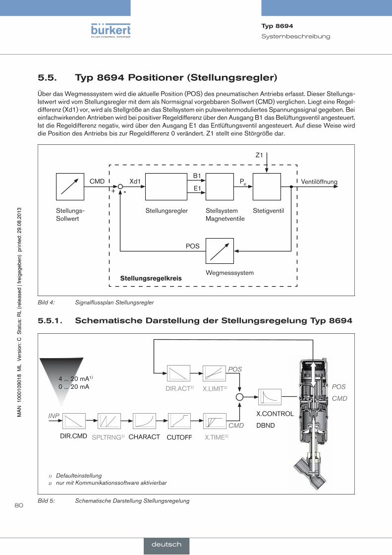
80
Systembeschreibung
5.5. Typ8694positioner(stellungsregler)
Über das Wegmesssystem wird die aktuelle Position (POS) des pneumatischen Antriebs erfasst. Dieser Stellungs-Istwert wird vom Stellungsregler mit dem als Normsignal vorgebbaren Sollwert (CMD) verglichen. Liegt eine Regel-differenz (Xd1) vor, wird als Stellgröße an das Stellsystem ein pulsweitenmoduliertes Spannungssignal gegeben. Bei einfachwirkenden Antrieben wird bei positiver Regeldifferenz über den Ausgang B1 das Belüftungsventil angesteuert. Ist die Regeldifferenz negativ, wird über den Ausgang E1 das Entlüftungsventil angesteuert. Auf diese Weise wird die Position des Antriebs bis zur Regeldifferenz 0 verändert. Z1 stellt eine Störgröße dar.
Ventilöffnung
StetigventilStellsystem Magnetventile
Wegmesssystem
StellungsreglerStellungs- Sollwert
CMD Xd1B1
E1PK
Z1
POS
Stellungsregelkreis
+ -
Bild 4: Signalflussplan Stellungsregler
5.5.1. schematischedarstellungderstellungsregelungTyp8694
4 ... 20 mA1) 0 ... 20 mA
CHARACTSPLTRNG2)DIR.CMD CUTOFF X.TIME2)
X.CONTROL
DBND
POS
CMDINP
POS
CMD
DIR.ACT2) X.LIMIT2)
1) Defaulteinstellung2) nur mit Kommunikationssoftware aktivierbar
Bild 5: Schematische Darstellung Stellungsregelung
Typ8694
deutsch

81
Systembeschreibung
5.5.2. funktionenderstellungsregler-software
funktioneni
• Aktivierung über DIP-Schalter
• Parametereinstellung über Kommunikationssoftware
zusatzfunktion Wirkung
Dichtschließfunktion
CUTOFF
Ventil schließt außerhalb des Regelbereichs dicht. Angabe des Wertes (in %), ab dem der Antrieb voll-ständig entlüftet (bei 0 %) bzw. belüftet (bei 100 %) wird (siehe Kapitel „7.4. Funktion der DIP-Schalter“).
Korrekturlinie zur Anpassung der Betriebskennlinie
CHARACT
Linearisierung der Betriebskennlinie kann durchgeführt werden (siehe Kapitel „7.4. Funktion der DIP-Schalter“).
Wirkrichtung des Regler-Sollwerts
DIR.CMD
Umkehr der Wirkrichtung des Sollwerts (siehe Kapitel „7.4. Funktion der DIP-Schalter“).
Tabelle 2: Funktionen I
Typ8694
deutsch
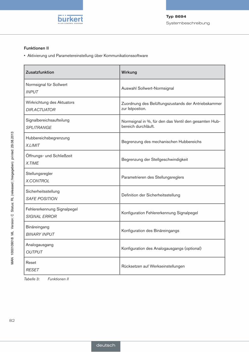
82
Systembeschreibung
funktionenii
• Aktivierung und Parametereinstellung über Kommunikationssoftware
zusatzfunktion Wirkung
Normsignal für Sollwert
INPUTAuswahl Sollwert-Normsignal
Wirkrichtung des Aktuators
DIR.ACTUATOR
Zuordnung des Belüftungszustands der Antriebskammer zur Istpostion.
Signalbereichsaufteilung
SPLITRANGE
Normsignal in %, für den das Ventil den gesamten Hub-bereich durchläuft.
Hubbereichsbegrenzung
X.LIMITBegrenzung des mechanischen Hubbereichs
Öffnungs- und Schließzeit
X.TIMEBegrenzung der Stellgeschwindigkeit
Stellungsregler
X.CONTROLParametrieren des Stellungsreglers
Sicherheitsstellung
SAFE POSITIONDefinition der Sicherheitsstellung
Fehlererkennung Signalpegel
SIGNAL ERRORKonfiguration Fehlererkennung Signalpegel
Binäreingang
BINARY INPUTKonfiguration des Binäreingangs
Analogausgang
OUTPUTKonfiguration des Analogausgangs (optional)
Reset
RESETRücksetzen auf Werkseinstellungen
Tabelle 3: Funktionen II
Typ8694
deutsch

83
Systembeschreibung
5.6. schnittstellendespositioners
Eingang für Stellungs-Sollwert3) 4 ... 20 mA4) 0 ... 20 mA
Binäreingang
24 V DC
Kommunikations-schnittstelle
Positioner
Analoge Stellungsrückmeldung (Option)
Ein
gäng
e
Aus
gäng
e
Vers
org.
Bedienung
3) oder optional Busanschaltung AS-Interface4) Defaulteinstellung
Bild 6: Schnittstellen
Der Positioner Typ 8694 ist ein 3-Leiter-Gerät, d. h. die Versorgungsspannung (24 V DC) erfolgt getrennt vom Sollwertsignal.
• Eingang für Stellungs-Sollwert (4 ... 20 mA entspricht 0 ... 100 % (abhängig von Stellung des DIP-Schalters 1)).
• Binäreingang Bei Anlegen einer Spannung > 10 V wird SAFE POSITION aktiv, d. h. das Ventil wird in die Sicherheitsstellung gebracht (Werkseinstellung, kann mit Kommunikationssoftware geändert werden).
• Analoge Stellungsrückmeldung (optional) Die Position des Ventils kann über einen analogen 4 ... 20 mA Ausgang an die SPS weitergeleitet werden (4 ... 20 mA entspricht 0 ... 100 %).
Typ8694
deutsch
84
Technische Daten
6. TechnischedaTen
6.1. konformität
Der Positioner, Typ 8694 ist konform zu den EG-Richtlinien entsprechend der EG-Konformitätserklärung.
6.2. normen
Die Konformität zu den EG-Richtlinien wird durch folgende Normen erfüllt:
EN 61000-6-3, EN 61000-6-2, EN 61010-1
6.3. Betriebsbedingungen
Warnung!
sonneneinstrahlungundtemperaturschwankungenkönnenfehlfunktionenoderundichtheitenbewirken.
• Das Gerät bei Einsatz im Außenbereich nicht ungeschützt den Witterungsverhältnissen aussetzen.
• Darauf achten, dass die zulässige Umgebungstemperatur nicht über- oder unterschritten wird.
Umgebungstemperatur 0 ... +60 °C
Schutzart: IP65 / IP67 nach EN 60529 (nur bei korrekt angeschlossenem Kabel bzw. Stecker und Buchsen und bei Beachtung des Abluftkonzeptes im Kapitel „9.3. Pneumatischer Anschluss des Positioners“)
6.4. mechanischedaten
Maße siehe Datenblatt
Gehäusematerial außen: PPS, PC, VA, innen: PA 6; ABS
Dichtungsmaterial EPDM / (NBR)
Hubbereich Ventilspindel 2 ... 45 mm
Typ8694
deutsch

85
Technische Daten
6.5. pneumatischedaten
Steuermedium neutrale Gase, Luft Qualitätsklassen nach DIN ISO 8573-1
Staubgehalt Klasse 5 max. Teilchengröße 40 µm, max. Teilchendichte 10 mg/m³
Wassergehalt Klasse 3 max. Drucktaupunkt - 20 °C oder min. 10 °C unterhalb der niedrigsten Betriebstemperatur
Ölgehalt Klasse 5 max. 25 mg/m³
Temperaturbereich Steuerluft 0 ... +60 °C
Druckbereich Steuerluft 3 ... 7 bar
Luftleistung Steuerventil 7 lN / min (für Belüftung und Entlüftung) (QNn - Wert nach Definition bei Druckabfall von 7 auf 6 bar absolut)
optional: 130 lN / min (für Belüftung und Entlüftung) (nur einfachwirkend)
Anschlüsse Schlauchsteckverbinder Ø 6 mm / 1/4“ Muffenanschluss G1/8
6.6. Typschild
Beispiel:
8694 24 V DC single act Pilot 0,6 Pmax 7 bar Tamb 0°C - +55°C S/N 001000 00185134D
-746
53 In
gelfi
ngen
W14UNce
Identnummer
Betriebsspannung / Ansteuerung
Nenndruck
Typ Steuerfunktion - Steuerventil
Bar-Code
Seriennummer - CE-Zeichen
Max. Umgebungstemperatur
Bild 7: Typschild Beispiel
Typ8694
deutsch

86
Technische Daten
6.7. elektrischedaten
6.7.1. elektrischedatenohneBusansteuerung24Vdc
Anschlüsse Kabelverschraubung M16 x 1,5, SW22 (Klemmbereich 5 ... 10 mm) mit Schraubklemmen für Leitungsquerschnitte 0,14 ... 1,5 mm²
Rundsteckverbinder (M12 x 1, 8-polig)
Steuerventil Betriebsspannung 24 V DC ± 10 % - max. Restwelligkeit 10 % Leistungsaufnahme ≤ 3,5 W
Eingangswiderstand für Sollwertsignal 75 Ω bei 0/4 ... 20 mA / Auflösung 12 bit
Schutzklasse 3 nach VDE 0580
Analoge Stellungsrückmeldung max. Bürde für Stromausgang 0/4 ... 20 mA 560 Ω
Binäreingang nicht galvanisch getrennt 0 ... 5 V = log „0“, 12 ... 30 V = log „1“ invertierter Eingang entsprechend umgekehrt
Kommunikationsschnittstelle Direkter Anschluss an PC über USB-Adapter mit integriertem Schnittstellentreiber, Kommunikation mit Kommunikationssoftware auf FDT/DTM Technologie, siehe „Tabelle 34: Zubehör“.
6.7.2. elektrischedatenmitBusansteuerungas-interface
Anschlüsse Rundsteckverbinder (M12 x 1, 4-polig)
Betriebsspannung 29,5 V ... 31,6 V DC (gemäß Spezifikation)
geräteohneexterneVersorgungsspannung:
Max. Stromaufnahme 150 mA
gerätemitexternerVersorgungsspannung:
Externe Versorgungsspannung 24 V ± 10 % Das Netzgerät muss eine sichere
Trennung nach IEC 364-4-41 (PELV oder SELV) enthalten
Max. Stromaufnahme 100 mA
Max. Stromaufnahme aus AS-Interface 50 mA
Typ8694
deutsch

87
Technische Daten
6.8. Werkseinstellungendespositioners
Über DIP-Schalter aktivierbare Funktionen:
funktion parameter Wert
CUTOFF Dichtschließfunktion unten Dichtschließfunktion oben
2 % 98 %
CHARACT Auswahl Kennlinie FREE5)
DIR.CMD Wirkrichtung Sollwert steigend
Tabelle 4: Werkseinstellungen - Funktionen I
Über Kommunikationssoftware aktivierbare Funktionen:
funktion parameter Wert
INPUT Sollwerteingang 4 ... 20 mA
DIR.ACTUATOR Wirkrichtung Istwert steigend
SPLITRANGE Funktion deaktiv
Signalbereichsaufteilung unten Signalbereichsaufteilung oben
0 % 100 %
X.LIMIT Funktion deaktiv
Hubbegrenzung unten Hubbegrenzung oben
0 % 100 %
X.TIME Funktion deaktiv
Stellzeit Auf Stellzeit Zu
(1 s) Werte von X.TUNE ermittelt (1 s) Werte von X.TUNE ermittelt Nach Ausführen von RESET: 1 s
X.CONTROL Totband Verstärkungsfaktor öffnen Verstärkungsfaktor schließen
1,0 % (1) Werte von X.TUNE ermittelt (1) Werte von X.TUNE ermittelt Nach Ausführen von RESET: 1
SAFE POSITION Sicherheitsstellung 0 %
SIGNAL ERROR Funktion deaktiv
Fühlerbrucherkennung Sollwert AUS
BINARY INPUT Funktion Binäreingang Wirkungsweise Binäreingang
Sicherheitsstellung Schließer
OUTPUT (optional)
Normsignalausgang: Parameter Normsignalausgang: Typ
Position 4 ... 20 mA
Tabelle 5: Werkseinstellungen Funktionen II
5) ohne Änderung der Einstellungen über die Kommunikationssoftware ist bei FREE eine lineare Kennlinie hinterlegt.
Typ8694
deutsch

88
Bedien- und Anzeigeelemente
7. Bedien-undanzeigeelemenTeDas folgende Kapitel beschreibt die Betriebszustände, sowie die Bedien- und Anzeigeelemente des Positioners.
Weitere Informationen zur Bedienung des Positioners finden Sie im Kapitel „12. Inbetriebnahme“.
7.1. Betriebszustand
autOmatik(autO)
Im Betriebszustand AUTOMATIK wird der normale Reglerbetrieb ausgeführt und überwacht.
→ LED 1 blinkt grün.
hand
Im Betriebszustand HAND kann das Ventil manuell über die Tasten auf- oder zugefahren werden.
→ LED 1 blinkt rot / grün im Wechsel.
Über den DIP-Schalter 4 kann zwischen den beiden Betriebszuständen AUTOMATIK und HAND gewechselt werden.
On dip
1 2 3 4
7.2. Bedien-undanzeigeelementedespositioners
DIP-Schalter
Taste 2
Taste 1
LED 2LED 1
Kommunikations-schnittstelle
Version 1 Version 2
1 2 3 4
ON DIP
Taste 1
Taste 2
LED 1
LED 2
Kommunikations-schnittstelle
Bild 8: Beschreibung Bedienelemente
Typ8694
deutsch

89
Bedien- und Anzeigeelemente
Der Positioner ist mit 2 Tasten, 4-poligen DIP-Schalter und 2 je 2-farbige LEDs als Anzeigeelement ausgestattet.
→ Um die Tasten und DIP-Schalter zu bedienen, bei Version 1: den Gehäusemantel Version 2: die Klarsichthaube abschrauben.
Dichtung Gehäusemantel
Gehäusemantel
Bild 9: Position Dichtung Gehäusemantel
→ Version 1: Die korrekte Position der Dichtung im Gehäusemantel prüfen.
hinWeiS!
BeschädigungoderfunktionsausfalldurcheindringenvonVerschmutzungundfeuchtigkeit!
• Zur Einhaltung der Schutzart IP65 / IP67 die Klarsichthaube bzw. den Gehäusemantel bis auf Anschlag einschrauben.
→ Gehäuse schließen (Schraubwerkzeug: 6740776)).
6) Das Schraubwerkzeug (674077) ist über Ihre Bürkert-Vertriebsniederlassung erhältlich.
Typ8694
deutsch

90
Bedien- und Anzeigeelemente
7.3. BelegungderTasten
Die Belegung der 2 Tasten sind je nach Betriebszustand (AUTOMATIK / HAND) unterschiedlich.
Die Beschreibung der Betriebszustände (AUTOMATIK / HAND) finden Sie im Kapitel„7.1. Betriebszustand“.
Taste 2
Taste 1
Taste 1 Taste 2
Version 1 Version 2
Bild 10: Beschreibung Tasten
→ Um die Tasten zu bedienen, bei Version 1: den Gehäusemantel Version 2: die Klarsichthaube abschrauben.
Betriebszustand HAND (DIP-Schalter 4 auf ON):
Taste Funktion
1Belüften7) (manuelles Auf- / Zufahren des Antriebs)8)
2Entlüften7) (manuelles Auf- / Zufahren des Antriebs)8)
Tabelle 6: Tastenbelegung Betriebszustand HAND
Betriebszustand AUTOMATIK (DIP-Schalter 4 auf OFF):
Taste Funktion
1 durch 5 Sekunden langes Drücken startet die Funktion X.TUNE
2 -
Tabelle 7: Tastenbelegung Betriebszustand AUTOMATIK
7) ohne Funktion, wenn über die Kommunikationssoftware der Binäreingang mit Funktion „Hand-Auto-Umschaltung“ aktiviert wurde.
8) abhängig von der Wirkungsweise des Antriebs.
Typ8694
deutsch
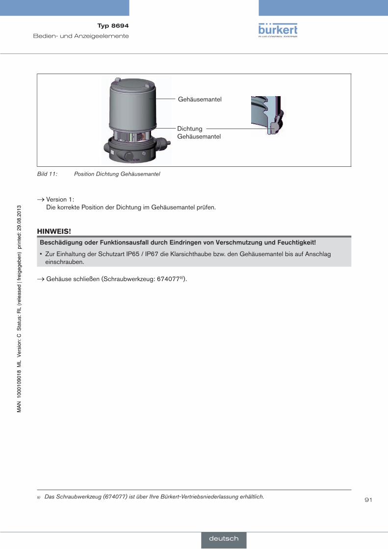
91
Bedien- und Anzeigeelemente
Dichtung Gehäusemantel
Gehäusemantel
Bild 11: Position Dichtung Gehäusemantel
→ Version 1: Die korrekte Position der Dichtung im Gehäusemantel prüfen.
hinWeiS!
BeschädigungoderfunktionsausfalldurcheindringenvonVerschmutzungundfeuchtigkeit!
• Zur Einhaltung der Schutzart IP65 / IP67 die Klarsichthaube bzw. den Gehäusemantel bis auf Anschlag einschrauben.
→ Gehäuse schließen (Schraubwerkzeug: 6740779)).
9) Das Schraubwerkzeug (674077) ist über Ihre Bürkert-Vertriebsniederlassung erhältlich.
Typ8694
deutsch

92
Bedien- und Anzeigeelemente
7.4. funktionderdip-schalter
On dip
1 2 3 4
→ Um die DIP-Schalter zu bedienen, bei Version 1: den Gehäusemantel Version 2: die Klarsichthaube abschrauben.
DiP-Schalter Stellung Funktion
1 ON Umkehr der Wirkrichtung des Sollwerts (DIR.CMD) (Sollwert 20 ... 4 mA entspricht Position 0 ... 100 %), fallend
OFF normale Wirkrichtung des Sollwerts (Sollwert 4 ... 20 mA entspricht Position 0 ... 100 %), steigend
2 ON Dichtschließfunktion aktiv. Das Ventil schließt unterhalb 2 %10) und öffnet oberhalb 98 % des Sollwerts vollständig (CUTOFF)
OFF keine Dichtschließfunktion
3 ON Korrekturkennlinie zur Anpassung der Betriebskennlinie (Linearisierung der Betriebskennlinie, CHARACT) 11)
OFF lineare Kennlinie
4 ON Betriebszustand Manuell (HAND)
OFF Betriebszustand AUTOMATIK (AUTO)
Tabelle 8: DIP-Schalter
hinweisezurkommunikationssoftware:
Die Schaltstellung des DIP-Schalters hat Vorrang vor Einstellungen über die Kommunikationssoftware!
Wenn die Werte der Dichtschließfunktion (CUTOFF) oder der Korrekturkennlinie (CHARACT) über die Kom-munikationssoftware geändert werden, muss die entsprechende Funktion aktiv sein (DIP-Schalter auf ON). Die Wirkrichtung des Sollwerts (DIR.CMD) kann nur über die DIP-Schalter geändert werden. Erfolgt keine Änderung der Korrekturkennlinie (CHARACT) über die Kommunikationssoftware, ist bei DIP-Schalter 3 auf ON eine lineare Kennlinie hinterlegt.
Eine detaillierte Beschreibung der Funktionen finden Sie in Kapitel „13.1. Grundfunktionen“ und in der Bedienungsanleitung der Kommunikationssoftware.
10) Werkseinstellung, kann über Kommunikationssoftware geändert werden.11) Der Kennlinientyp kann über Kommunikationssoftware geändert werden
Typ8694
deutsch

93
Bedien- und Anzeigeelemente
Dichtung Gehäusemantel
Gehäusemantel
Bild 12: Position Dichtung Gehäusemantel
→ Version 1: Die korrekte Position der Dichtung im Gehäusemantel prüfen.
hinWeiS!
BeschädigungoderfunktionsausfalldurcheindringenvonVerschmutzungundfeuchtigkeit!
• Zur Einhaltung der Schutzart IP65 / IP67 die Klarsichthaube bzw. den Gehäusemantel bis auf Anschlag einschrauben.
→ Gehäuse schließen (Schraubwerkzeug: 67407712)).
12) Das Schraubwerkzeug (674077) ist über Ihre Bürkert-Vertriebsniederlassung erhältlich.
Typ8694
deutsch

94
Bedien- und Anzeigeelemente
7.5. anzeigederleds
Version 1 Version 2
LED 1 LED 2LED 1
(grün / rot)
Anzeige der Zustände AUTO, HAND, X.TUNE und FEHLER
LED 2
(grün / gelb)
Anzeige des Zustandes des Antriebs (offen, geschlossen, öffnet oder schließt)
Bild 13: Anzeige LED
LeD 1 (grün / rot)
LeD Zuständeanzeige
grün rot
an aus Hochlaufphase bei Power ON
blinkt langsam aus Betriebszustand AUTO (AUTOMATIK)
blinkt blinkt Betriebszustand HANDim Wechsel
blinkt schnell aus X.TUNE Funktion
aus an FEHLER (siehe Kapitel „7.6. Fehlermeldungen“)
blinkt blinkt Betriebszustand AUTO bei Fühlerbrucherkennunglangsam
Tabelle 9: Anzeige LED 1
LeD 2 (grün / gelb)
LeD Zuständeanzeige
grün gelb
an aus Antrieb geschlossen
aus an Antrieb offen
blinkt langsam ausbleibende Regelabweichung (Istwert > Sollwert)
aus blinkt langsambleibende Regelabweichung (Istwert < Sollwert)
blinkt schnell aus Schließen im Betriebszustand HAND
aus blinkt schnell Öffnen im Betriebszustand HAND
Tabelle 10: Anzeige LED 2
Typ8694
deutsch
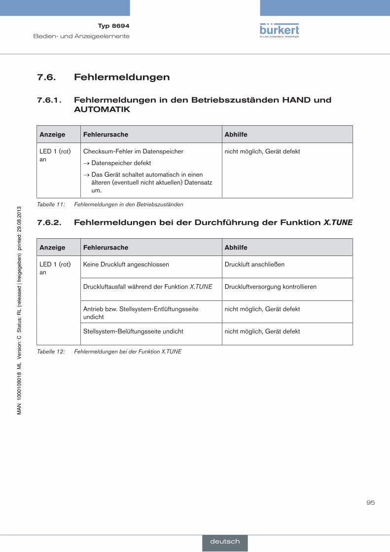
95
Bedien- und Anzeigeelemente
7.6. fehlermeldungen
7.6.1. fehlermeldungenindenBetriebszuständenhandundauTOmaTik
anzeige Fehlerursache abhilfe
LED 1 (rot) an
Checksum-Fehler im Datenspeicher
→ Datenspeicher defekt
→ Das Gerät schaltet automatisch in einen älteren (eventuell nicht aktuellen) Datensatz um.
nicht möglich, Gerät defekt
Tabelle 11: Fehlermeldungen in den Betriebszuständen
7.6.2. fehlermeldungenbeiderdurchführungderfunktionX.TUNE
anzeige Fehlerursache abhilfe
LED 1 (rot) an
Keine Druckluft angeschlossen Druckluft anschließen
Druckluftausfall während der Funktion X.TUNE Druckluftversorgung kontrollieren
Antrieb bzw. Stellsystem-Entlüftungsseite undicht
nicht möglich, Gerät defekt
Stellsystem-Belüftungsseite undicht nicht möglich, Gerät defekt
Tabelle 12: Fehlermeldungen bei der Funktion X.TUNE
Typ8694
deutsch

96
Montage
8. mOnTage
8.1. sicherheitshinweise
geFahr!
Verletzungsgefahrdurchhohendruck!
• Vor dem Lösen von Leitungen und Ventilen den Druck abschalten und Leitungen entlüften.
Verletzungsgefahrdurchelektrischespannung!
• Vor Eingriffen in das Gerät oder in die Anlage die Spannung abschalten und vor Wiedereinschalten sichern!
• Die geltenden Unfallverhütungs- und Sicherheitsbestimmungen für elektrische Geräte beachten!
Warnung!
Verletzungsgefahrbeiunsachgemäßermontage!
• Die Montage darf nur autorisiertes Fachpersonal mit geeignetem Werkzeug durchführen!
VerletzungsgefahrdurchungewollteseinschaltenderanlageundunkontrolliertenWiederanlauf!
• Anlage vor unbeabsichtigtem Betätigen sichern.
• Nach der Montage einen kontrollierten Wiederanlauf gewährleisten.
8.2. montagedespositionersTyp8694anprozessventilederreihe2103,2300und2301
Vorgehensweise:
1.schaltspindelmontieren
Klarsichthaube
Antrieb
Steuerluftanschlüsse (Schlauchsteckverbinder mit Collets
oder Gewindebuchsen)
Bild 14: Montage der Schaltspindel (1), Reihe 2103, 2300 und 2301
→ Die Klarsichthaube am Antrieb und die Stellungsanzeige (gelbe Kappe) an der Spindelverlängerung abschrauben (falls vorhanden).
→ Bei Version mit Schlauchsteckverbinder die Collets (weiße Tüllen) aus den beiden Steuerluftanschlüssen ent-fernen (falls vorhanden).
Typ8694
deutsch

97
Montage
O-Ring
Spindelverlängerung
Führungselement
Antriebsdeckel
Nutring
Puckhalter
Schaltspindel
10
max. 5 Nm
max. 1 Nm
Bild 15: Montage der Schaltspindel (2), Reihe 2103, 2300 und 2301
hinWeiS!
unsachgemäßemontagekanndennutringimführungselementbeschädigen!
Der Nutring ist im Führungselement schon vormontiert und muss im Hinterschnitt „eingerastet“ sein.
• Bei Montage der Schaltspindel den Nutring nicht beschädigen.
→ Die Schaltspindel durch das Führungselement schieben.
hinWeiS!
schraubensicherungslackkanndennutringkontaminieren!
• Kein Schraubensicherungslack auf die Schaltspindel auftragen.
→ Zur Sicherung der Schaltspindel etwas Schraubensicherungslack (Loctite 290) in die Gewindebohrung der Spindelverlängerung im Antrieb einbringen.
→ Die korrekte Position des O-Rings prüfen.
→ Das Führungselement mit dem Antriebsdeckel verschrauben (maximales Drehmoment: 5 Nm).
→ Schaltspindel auf die Spindelverlängerung schrauben. Dazu ist an der Oberseite ein Schlitz angebracht (maxi-males Drehmoment: 1 Nm).
→ Puckhalter auf die Schaltspindel aufschieben und einrasten.
Typ8694
deutsch
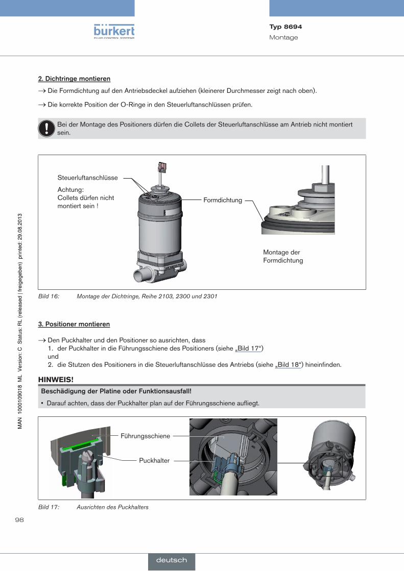
98
Montage
2.dichtringemontieren
→ Die Formdichtung auf den Antriebsdeckel aufziehen (kleinerer Durchmesser zeigt nach oben).
→ Die korrekte Position der O-Ringe in den Steuerluftanschlüssen prüfen.
Bei der Montage des Positioners dürfen die Collets der Steuerluftanschlüsse am Antrieb nicht montiert sein.
Formdichtung
Steuerluftanschlüsse
Achtung: Collets dürfen nicht montiert sein !
Montage der Formdichtung
Bild 16: Montage der Dichtringe, Reihe 2103, 2300 und 2301
3.positionermontieren
→ Den Puckhalter und den Positioner so ausrichten, dass 1. der Puckhalter in die Führungsschiene des Positioners (siehe „Bild 17“) und 2. die Stutzen des Positioners in die Steuerluftanschlüsse des Antriebs (siehe „Bild 18“) hineinfinden.
hinWeiS!
Beschädigungderplatineoderfunktionsausfall!
• Darauf achten, dass der Puckhalter plan auf der Führungsschiene aufliegt.
Führungsschiene
Puckhalter
Bild 17: Ausrichten des Puckhalters
Typ8694
deutsch

99
Montage
→ Den Positioner ohne Drehbewegung soweit auf den Antrieb schieben, dass an der Formdichtung kein Spalt mehr sichtbar ist.
hinWeiS!
durcheinzuhohesdrehmomentbeimeinschraubenderBefestigungsschraubekanndieschutzartip65/ip67nichtsichergestelltwerden!
• Die Befestigungsschrauben dürfen nur mit einem maximalen Drehmoment von 0,5 Nm angezogen werden.
→ Den Positioner mit den beiden seitlichen Befestigungsschrauben auf dem Antrieb befestigen. Dabei die Schrauben nur leicht anziehen (maximales Drehmoment: 0,5 Nm).
Stutzen
Steuerluft-anschlüsse
Befestigungsschrauben max. 0,5 Nm
Antrieb
Bild 18: Montage Positioner, Reihe 2103, 2300 und 2301
8.3. montagedespositionersTyp8694anprozessventilederreihe26xxund27xx
Vorgehensweise:
1.schaltspindelmontieren
Führungselement
Spindelverlängerung
Antrieb
Bild 19: Montage der Schaltspindel (1), Reihe 26xx und 27xx
→ Das bereits montierte Führungselement am Antrieb abschrauben (falls vorhanden).
→ Zwischenring entfernen (falls vorhanden).
Typ8694
deutsch

100
Montage
Führungselement
O-Ring
Spindelverlängerung
Puckhalter
Schaltspindel
Spindel (Antrieb)
Bild 20: Montage der Schaltspindel (2), Reihe 26xx und 27xx
→ Den O-Ring nach unten in den Deckel des Antriebs drücken.
→ Antriebsgröße 125 und größer mit großer Luftleistung: vorhandene Spindelverlängerung demontieren und durch die neue ersetzen. Dazu etwas Schraubensiche-rungslack (Loctite 290) in die Gewindebohrung der Spindelverlängerung einbringen.
→ Das Führungselement in den Deckel des Antriebs mit einem Stirnlochschlüssel13) einschrauben (Drehmoment: 8,0 Nm).
→ Zur Sicherung der Schaltspindel etwas Schraubensicherungslack (Loctite 290) auf das Gewinde der Schaltspindel aufbringen.
→ Die Schaltspindel auf die Spindelverlängerung schrauben. Dazu ist an der Oberseite ein Schlitz angebracht (maximales Drehmoment: 1 Nm).
→ Den Puckhalter auf die Schaltspindel schieben bis er einrastet.
13) Zapfen Ø: 3 mm; Zapfenabstand: 23,5 mm
Typ8694
deutsch
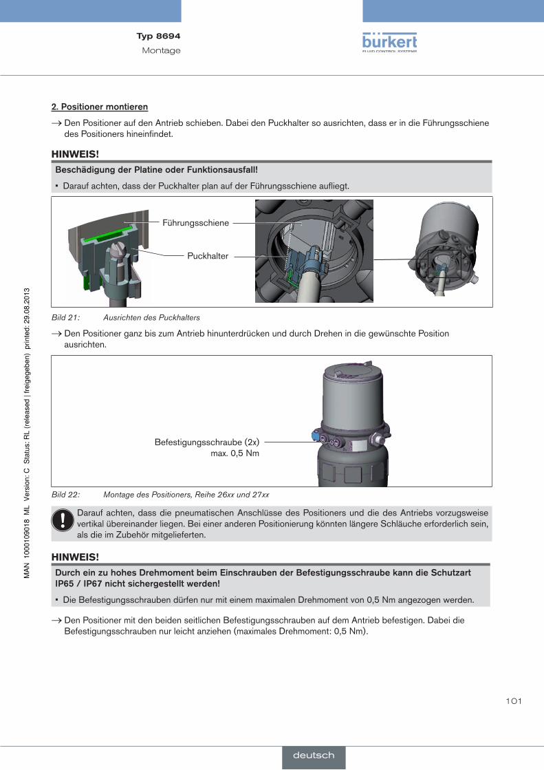
101
Montage
2.positionermontieren
→ Den Positioner auf den Antrieb schieben. Dabei den Puckhalter so ausrichten, dass er in die Führungsschiene des Positioners hineinfindet.
hinWeiS!
Beschädigungderplatineoderfunktionsausfall!
• Darauf achten, dass der Puckhalter plan auf der Führungsschiene aufliegt.
Führungsschiene
Puckhalter
Bild 21: Ausrichten des Puckhalters
→ Den Positioner ganz bis zum Antrieb hinunterdrücken und durch Drehen in die gewünschte Position ausrichten.
Befestigungsschraube (2x) max. 0,5 Nm
Bild 22: Montage des Positioners, Reihe 26xx und 27xx
Darauf achten, dass die pneumatischen Anschlüsse des Positioners und die des Antriebs vorzugsweise vertikal übereinander liegen. Bei einer anderen Positionierung könnten längere Schläuche erforderlich sein, als die im Zubehör mitgelieferten.
hinWeiS!
durcheinzuhohesdrehmomentbeimeinschraubenderBefestigungsschraubekanndieschutzartip65/ip67nichtsichergestelltwerden!
• Die Befestigungsschrauben dürfen nur mit einem maximalen Drehmoment von 0,5 Nm angezogen werden.
→ Den Positioner mit den beiden seitlichen Befestigungsschrauben auf dem Antrieb befestigen. Dabei die Befestigungsschrauben nur leicht anziehen (maximales Drehmoment: 0,5 Nm).
Typ8694
deutsch

102
Montage
3.pneumatischeVerbindungpositioner-antriebmontieren
Steuerluftausgang 21
Steuerluftausgang 22
Steuerluftanschluss oben
Steuerluftanschluss unten
Beispiel ∅ 80, SFA
Bild 23: Montage der pneumatischen Verbindungen
→ Die Schlauchsteckverbinder an den Positioner und den Antrieb schrauben.
→ Mit den im Zubehörsatz mitgelieferten Schläuchen die pneumatische Verbindung zwischen Positioner und Antrieb mit „Tabelle 13: Pneumatische Verbindung mit Antrieb - SFA“ oder „Tabelle 14: Pneumatische Ver-bindung mit Antrieb - SFB“ herstellen.
hinWeiS!
BeschädigungoderfunktionsausfalldurcheindringenvonVerschmutzungundfeuchtigkeit!
Zur Einhaltung der Schutzart IP65 / IP67:
• Bei Antriebsgröße ∅ 80, ∅ 100 den nicht benötigten Steuerluftausgang 22 mit dem freien Steuerluftanschluss des Antriebs verbinden oder mit einem Verschlussstopfen verschließen.
• Bei Antriebsgröße ∅ 125 den nicht benötigten Steuerluftausgang 22 mit einem Verschlussstopfen verschließen und den freien Steuer-luftanschluss des Antriebs über einen Schlauch in trockene Umgebung ableiten.
steuerfunktiona(sfa)Prozessventil in Ruhestellung geschlossen (durch Federkraft)
Antriebsgröße ∅ 80, ∅ 100
∅ 125
Pos
ition
er Steuerluftausgang
22 2122 21
Ant
rieb
Steuerlufteingang oben
Steuerlufteingang unten
Trockene Umgebung
Tabelle 13: Pneumatische Verbindung mit Antrieb - SFA
Typ8694
deutsch

103
Montage
steuerfunktionB(sfB)Prozessventil in Ruhestellung offen (durch Federkraft)
Antriebsgröße ∅ 80, ∅ 100
∅ 125
Pos
ition
er Steuerluftausgang
22 2122 21
Ant
rieb
Steuerlufteingang oben
Steuerlufteingang unten
Trockene Umgebung
Tabelle 14: Pneumatische Verbindung mit Antrieb - SFB
„In Ruhestellung“ bedeutet, dass die Steuerventile des Positioners Typ 8694 stromlos bzw. nicht betätigt sind.
8.4. drehendesantriebsmoduls
Das Antriebsmodul (Positioner und Antrieb) kann nur bei Geradsitz- und Schrägsitzventilen der Reihe 2300, 2301 und 27xx gedreht werden!
Die Position der Anschlüsse kann durch Verdrehen des Antriebsmoduls (Positioner und Antrieb) um 360° stufenlos ausgerichtet werden.
Es kann nur das gesamte Antriebsmodul gedreht werden. Das Verdrehen des Positioners gegen den Antrieb ist nicht möglich. Das Prozessventil muss sich beim Ausrichten des Antriebmoduls in geöffneter Stellung befinden!
geFahr!
Verletzungsgefahrdurchhohendruck!
• Vor dem Lösen von Leitungen und Ventilen den Druck abschalten und Leitungen entlüften.
Vorgehensweise:
→ Ventilgehäuse in eine Haltevorrichtung einspannen (nur nötig, wenn das Prozessventil noch nicht eingebaut ist).
hinWeiS!
Beschädigungdersitzdichtungbzw.dersitzkontur!
• Das Ventil muss sich bei beim Drehen des Antriebmoduls in geöffneter Stellung befinden.
→ Bei Steuerfunktion A: Prozessventil öffnen.
Typ8694
deutsch

104
Montage
Antriebs-modul
Schlüsselkontur SechskantNippel
mit Sechskantkonturohne Sechskantkontur
Nippel
Bild 24: Drehen des Antriebsmoduls
→ An der Schlüsselfläche des Nippels mit passendem Gabelschlüssel gegenhalten.
→ Antriebsmodule ohne Sechskantkontur: Spezialschlüssel14) genau in die Schlüsselkontur an der Unterseite des Antriebs einpassen.
→ Antriebsmodule mit Sechskantkontur: Passender Gabelschlüssel am Sechskant des Antriebs ansetzen.
Warnung!
Verletzungsgefahrdurchmediumsaustrittunddruckentladung!
Bei falscher Drehrichtung kann sich die Gehäuseschnittstelle lösen.
• Das Antriebsmodul nur im vorgegebenen Richtungssinn drehen (siehe „Bild 25“) !
→ Antriebsmodule ohne Sechskantkontur: Durch Drehen im Uhrzeigersinn (von unten gesehen) das Antriebsmodul in die gewünschte Position bringen.
→ Antriebsmodule mit Sechskantkontur: Durch Drehen gegen den Uhrzeigersinn (von unten gesehen) das Antriebsmodul in die gewünschte Position bringen.
Spezialschlüssel
Gabelschlüssel
ohne Sechskantkonturmit Sechskantkontur
Bild 25: Drehen mit Spezialschlüssel / Gabelschlüssel
14) Der Spezialschlüssel (665702) ist über Ihre Bürkert-Vertriebsniederlassung erhältlich.
Typ8694
deutsch

105
Montage
8.5. drehendespositionersbeiprozessventilenderreihe26xxund27xx
Sollte nach Einbau des Prozessventils die Anschlusskabel bzw. Schläuche schlecht montiert werden können, kann der Positioner gegen den Antrieb verdreht werden.
Befestigungsschraube (2x)
Pneumatische Verbindung
Positioner
Antrieb
Bild 26: Drehen des Positioners, Reihe 26xx und 27xx
Vorgehensweise:
→ Die pneumatische Verbindung zwischen dem Positioner und dem Antrieb lösen.
→ Die Befestigungsschrauben lösen (Innensechskant SW2,5).
→ Den Positioner in die gewünschte Position drehen.
hinWeiS!
durcheinzuhohesdrehmomentbeimeinschraubenderBefestigungsschraubekanndieschutzartip65/ip67nichtsichergestelltwerden!
• Die Befestigungsschraube darf nur mit einem maximalen Drehmoment von 0,5 Nm angezogen werden.
→ Die Befestigungsschrauben nur leicht anziehen (maximales Drehmoment: 0,5 Nm).
→ Die pneumatischen Verbindungen zwischen dem Positioner und dem Antrieb wieder herstellen. Bei Bedarf längere Schläuche verwenden.
Typ8694
deutsch

106
Fluidische Installation
9. fluidischeinsTallaTiOnDie Abmessungen des Positioners und der verschiedenen Komplettgerätevarianten, bestehend aus Positioner, Antrieb und Ventil, entnehmen Sie den jeweiligen Datenblättern.
9.1. sicherheitshinweise
geFahr!
Verletzungsgefahrdurchhohendruck!
• Vor dem Lösen von Leitungen und Ventilen den Druck abschalten und Leitungen entlüften.
Verletzungsgefahrdurchelektrischespannung!
• Vor Eingriffen in das Gerät oder in die Anlage die Spannung abschalten und vor Wiedereinschalten sichern!
• Die geltenden Unfallverhütungs- und Sicherheitsbestimmungen für elektrische Geräte beachten!
Warnung!
Verletzungsgefahrbeiunsachgemäßerinstallation!
• Die Installation darf nur autorisiertes Fachpersonal mit geeignetem Werkzeug durchführen!
VerletzungsgefahrdurchungewollteseinschaltenderanlageundunkontrolliertenWiederanlauf!
• Anlage vor unbeabsichtigtem Betätigen sichern.
• Nach der Installation einen kontrollierten Wiederanlauf gewährleisten.
9.2. installationdesprozessventils
Gewindeart und Abmessungen sind dem entsprechenden Datenblatt zu entnehmen.
→ Das Ventil entsprechend der Bedienungsanleitung des Ventils anschließen.
Typ8694
deutsch

107
Fluidische Installation
9.3. pneumatischeranschlussdespositioners
geFahr!
Verletzungsgefahrdurchhohendruck!
• Vor dem Lösen von Leitungen und Ventilen den Druck abschalten und Leitungen entlüften.
Vorgehensweise:
→ Das Steuermedium an den Steuerluftanschluss (1) anschließen (3 ... 7 bar; Instrumentenluft, öl-, wasser- und staubfrei).
→ Die Abluftleitung oder einen Schalldämpfer an den Abluftanschluss (3) und wenn vorhanden an den Abluftan-schluss (3.1) montieren.
Wichtiger Hinweis zur einwandfreien Funktion des Geräts:
• Durch die Installation darf sich kein Rückdruck aufbauen.
• Für den Anschluss einen Schlauch mit ausreichendem Querschnitt wählen.
• Die Abluftleitung muss so konzipiert sein, dass kein Wasser oder sonstige Flüssigkeit durch den Abluft-anschluss (3) oder (3.1) in das Gerät gelangen kann.
Steuerluftanschluss (Beschriftung: 1)
Abluftanschluss (Beschriftung: 3)
Zusätzlicher Abluftanschluss (Beschriftung: 3.1) nur für Typ 23xx und 2103 mit vorgesteuertem Stellsystem für hohe Luftleistung (Antriebsgröße ø 130)
Bild 27: Pneumatischer Anschluss
achtung (Abluftkonzept): Für die Einhaltung der Schutzart IP67 muss eine Abluftleitung in den trockenen Bereich montiert werden. Den anliegenden Steuerdruck unbedingt mindestens 0,5 ... 1 bar über dem Druck halten, der notwendig ist, den Antrieb in seine Endstellung zu bringen. Sie gewährleisten dadurch, dass das Regelverhalten im oberen Hubbereich aufgrund zu kleiner Druckdifferenz nicht stark negativ beeinflusst wird.
Die Schwankungen des Steuerdrucks während des Betriebs möglichst gering halten (max. ±10 %). Bei größeren Schwankungen sind die mit der Funktion X.TUNE eingemessenen Reglerparameter nicht optimal.
Typ8694
deutsch
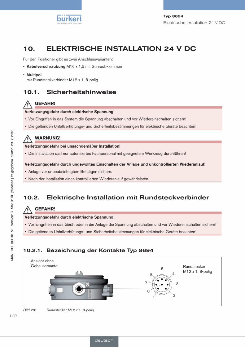
108
Elektrische Installation 24 V DC
10. elekTrischeinsTallaTiOn24VdcFür den Positioner gibt es zwei Anschlussvarianten:
• kabelverschraubung M16 x 1,5 mit Schraubklemmen
• multipol mit Rundsteckverbinder M12 x 1, 8-polig
10.1. sicherheitshinweise
geFahr!
Verletzungsgefahrdurchelektrischespannung!
• Vor Eingriffen in das System die Spannung abschalten und vor Wiedereinschalten sichern!
• Die geltenden Unfallverhütungs- und Sicherheitsbestimmungen für elektrische Geräte beachten!
Warnung!
Verletzungsgefahrbeiunsachgemäßerinstallation!
• Die Installation darf nur autorisiertes Fachpersonal mit geeignetem Werkzeug durchführen!
VerletzungsgefahrdurchungewollteseinschaltenderanlageundunkontrolliertenWiederanlauf!
• Anlage vor unbeabsichtigtem Betätigen sichern.
• Nach der Installation einen kontrollierten Wiederanlauf gewährleisten.
10.2. elektrischeinstallationmitrundsteckverbinder
geFahr!
Verletzungsgefahrdurchelektrischespannung!
• Vor Eingriffen in das Gerät oder in die Anlage die Spannung abschalten und vor Wiedereinschalten sichern!
• Die geltenden Unfallverhütungs- und Sicherheitsbestimmungen für elektrische Geräte beachten!
10.2.1. BezeichnungderkontakteTyp8694
Ansicht ohne Gehäusemantel Rundstecker
M12 x 1, 8-polig6
1
7
54
3
28
Bild 28: Rundstecker M12 x 1, 8-polig
Typ8694
deutsch

109
Elektrische Installation 24 V DC
10.2.2. anschlussdespositionersTyp8694
→ Die Pins entsprechend der Ausführung (Optionen) des Positioners anschließen.
eingangssignale der Leitstelle (z. B. SPS) - rundstecker M 12 x 1, 8-polig
pin aderfarbe15) Belegung äußereBeschaltung/signalpegel
1
2
weiß
braun
Sollwert + (0/4 ... 20 mA)
Sollwert GND
1
2 GND
+ (0/4 ... 20 mA) nicht galvanisch getrennt
5
6
grau
rosa
Binäreingang +
Binäreingang GND
5 + 0 ... 5 V (log. 0)10 ... 30 V (log. 1)
identisch mit Pin 3 (GND)
Tabelle 15: Pin-Belegung - Eingangssignale der Leitstelle - Rundstecker M 12 x 1, 8-polig
ausgangssignale zur Leitstelle (z. B. SPS) - rundstecker M 12 x1, 8-polig (nur bei option analogausgang erforderlich)
pin aderfarbe15) Belegung äußereBeschaltung/signalpegel
8
7
rot
blau
Analoge Stellungsrückmeldung +
Analoge Stellungsrückmeldung GND
8
7 GND
+ (0/4 ... 20 mA) nicht galvanisch getrennt
Tabelle 16: Pin-Belegung - Ausgangssignale zur Leitstelle - Rundstecker M 12 x 1, 8-polig
Betriebsspannung (rundstecker M 12 x 1, 8-polig)
pin aderfarbe15) Belegung äußereBeschaltung
4
3
gelb
grün
+ 24 V
GND
4
3
24 V DC ± 10 % max. Restwelligkeit 10 %
Tabelle 17: Pin-Belegung - Betriebsspannung (Rundstecker M 12 x 1, 8-polig)
Nach Anlegen der Betriebsspannung ist der Positioner in Betrieb.
→ Die erforderlichen Grundeinstellungen vornehmen und die automatische Anpassung des Positioners auslösen, wie in Kapitel „12. Inbetriebnahme“ beschrieben.
15) Die angegebenen Farben beziehen sich auf das als Zubehör erhältliche Anschlusskabel (919061)
Typ8694
deutsch

110
Elektrische Installation 24 V DC
10.3. elektrischeinstallationmitkabelverschraubung
geFahr!
Verletzungsgefahrdurchelektrischespannung!
• Vor Eingriffen in das Gerät oder in die Anlage die Spannung abschalten und vor Wiedereinschalten sichern!
• Die geltenden Unfallverhütungs- und Sicherheitsbestimmungen für elektrische Geräte beachten!
10.3.1. Bezeichnungderschraubklemmen
1216)
316)
4567
Bild 29: Anschluss Schraubklemmen
10.3.2. anschlussdespositionersTyp8694
→ Durch Herausdrehen des Gehäusemantels (Edelstahl) werden die Schraubklemmen zugänglich.
→ Die Kabel durch die Kabelverschraubung schieben.
→ Den Positioner entsprechend den folgenden Tabellen anschließen:
eingangssignale der Leitstelle (z. B. SPS)
klemme Belegung äußereBeschaltung
4 5
Sollwert + Sollwert GND
4
5 GND
+ (0/4 ... 20 mA)
1
Binäreingang +
1 + 0 ... 5 V (log. 0)10 ... 30 V (log. 1)
bezogen auf Klemme 7 (GND)
Tabelle 18: Belegung Schraubklemmen - Eingangssignale der Leitstelle - Kabelverschraubung
16) nur Option
Typ8694
deutsch
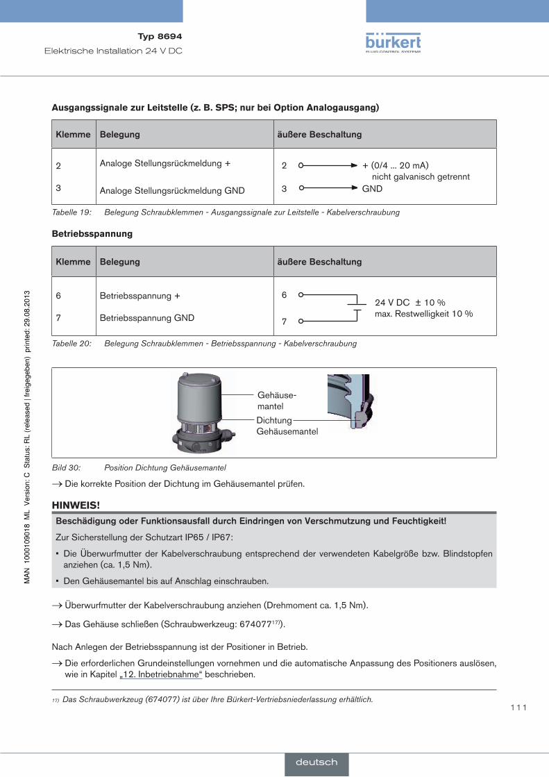
111
Elektrische Installation 24 V DC
ausgangssignale zur Leitstelle (z. B. SPS; nur bei option analogausgang)
klemme Belegung äußereBeschaltung
2 3
Analoge Stellungsrückmeldung +
Analoge Stellungsrückmeldung GND
2
3 GND
+ (0/4 ... 20 mA) nicht galvanisch getrennt
Tabelle 19: Belegung Schraubklemmen - Ausgangssignale zur Leitstelle - Kabelverschraubung
Betriebsspannung
klemme Belegung äußereBeschaltung
6 7
Betriebsspannung + Betriebsspannung GND
6
7
24 V DC ± 10 % max. Restwelligkeit 10 %
Tabelle 20: Belegung Schraubklemmen - Betriebsspannung - Kabelverschraubung
Dichtung Gehäusemantel
Gehäuse-mantel
Bild 30: Position Dichtung Gehäusemantel
→ Die korrekte Position der Dichtung im Gehäusemantel prüfen.
hinWeiS!
BeschädigungoderfunktionsausfalldurcheindringenvonVerschmutzungundfeuchtigkeit!
Zur Sicherstellung der Schutzart IP65 / IP67:
• Die Überwurfmutter der Kabelverschraubung entsprechend der verwendeten Kabelgröße bzw. Blindstopfen anziehen (ca. 1,5 Nm).
• Den Gehäusemantel bis auf Anschlag einschrauben.
→ Überwurfmutter der Kabelverschraubung anziehen (Drehmoment ca. 1,5 Nm).
→ Das Gehäuse schließen (Schraubwerkzeug: 67407717)).
Nach Anlegen der Betriebsspannung ist der Positioner in Betrieb.
→ Die erforderlichen Grundeinstellungen vornehmen und die automatische Anpassung des Positioners auslösen, wie in Kapitel „12. Inbetriebnahme“ beschrieben.
17) Das Schraubwerkzeug (674077) ist über Ihre Bürkert-Vertriebsniederlassung erhältlich.
Typ8694
deutsch

112
AS-Interface-Installation
11. as-inTerface-insTallaTiOn
11.1. as-interface-anschaltung
AS-Interface (Aktor-Sensor-Interface) ist ein Feldbussystem, das hauptsächlich zur Vernetzung von binären Sensoren und Aktoren (Slaves) mit einer übergeordneten Steuerung (Master) dient.
Busleitung
Ungeschirmte Zweidrahtleitung (AS-Interface-Leitung als AS-Interface-Formkabel), auf der sowohl Informationen (Daten) als auch Energie (Versorgungsspannung der Aktoren und Sensoren) übertragen werden.
netztopologie
In breiten Grenzen frei wählbar, d. h. es sind Stern,- Baum- und Liniennetze möglich. Weitere Details beschreibt die AS-Interface-Spezifikation (Ausführung A/B-Slave konform zur Spezifikation Version 3.0).
11.2. Technischedatenfüras-interface-platinen
Version Profil S-7.3.4 Version Profil S-7.A.5
Versorgung über AS-Interface über AS-Interface
Ausgänge 16 Bit Sollwert 16 Bit Sollwert
Eingänge - 16 Bit Rückmeldung
Zertifizierung Zertifikat Nr. 87301 nach Version 3.0 Zertifikat Nr. xxxxx nach Version 3.0
Tabelle 21: Technische Daten
11.3. programmierdaten
Version Profil S-7.3.4 Version Profil S-7.A.5
E/A-Konfiguration 7 hex 7 hex
ID-Code 3 hex (analoges Profil) A hex
Erweiterter ID-Code 1F hex (Default-Wert, vom Anwender veränderbar)
7 hex
Erweiterter ID-Code 2 4 hex 5 hex
Profil S-7.3.4 S-7.A.5
Tabelle 22: Programmierdaten
Typ8694
deutsch
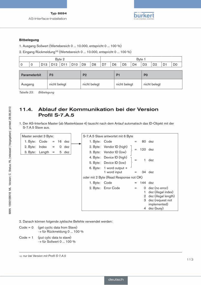
113
AS-Interface-Installation
Bitbelegung
1. Ausgang Sollwert (Wertebereich 0 ... 10.000, entspricht 0 ... 100 %)
2. Eingang Rückmeldung18) (Wertebereich 0 ... 10.000, entspricht 0 ... 100 %)
Byte 2 Byte 1
0 0 D13 D12 D11 D10 D9 D8 D7 D6 D5 D4 D3 D2 D1 D0
parameterbit p3 p2 p1 p0
Ausgang nicht belegt nicht belegt nicht belegt nicht belegt
Tabelle 23: Bitbelegung
11.4. ablaufderkommunikationbeiderVersionprofils-7.a.5
1. Der AS-Interface Master (ab Masterklasse 4) tauscht nach dem Anlauf automatisch das ID-Objekt mit der S-7.A.5 Slave aus.
S-7.A.5 Slave antwortet mit 6 Byte
1. Byte: Code = 80 dez
2. Byte: Vendor ID (high)= 120 dez
3. Byte: Vendor ID (low)
4. Byte: Device ID (high)= 1 dez
5. Byte: Device ID (low)
6. Byte: 1 word output + 1 word input
=
34
dez
oder mit 2 Byte (Read Response not OK)
1. Byte: Code = 144 dez
2. Byte: Error Code = 0 1 2 3
4
dez (no error) dez (illegal index) dez (illegal length) dez (request not implemented) dez (busy)
Master sendet 3 Byte:
1. Byte: Code = 16 dez
2. Byte: Index = 0 dez
3. Byte: Length = 5 dez
2. Danach können folgende zyklische Befehle verwendet werden:
Code = 0 (get cyclic data from Slave) → für Rückmeldung 0 ... 100 %
Code = 1 (put cylic data to slave) → für Sollwert 0 ... 100 %
18) nur bei Version mit Profil S-7.A.5
Typ8694
deutsch

114
AS-Interface-Installation
11.5. ledzustandsanzeigeas-interface
Die LED Zustandsanzeige zeigt den Busstatus (LED grün und rot) an.
Bus LED grün
Bus LED rot
Bild 31: LED Zustandsanzeige AS-Interface
ledgrün ledrot
aus aus POWER OFF
aus ein kein Datenverkehr (abgelaufener Watch-Dog bei Slaveadresse ungleich 0)
ein aus OK
blinkt ein Slaveadresse gleich 0
aus blinkt Fehler Elektronik oder externer Reset
blinkt blinkt Timeout Buskommunikation nach 100 ms (Peripherie-Fehler)
Tabelle 24: LED Zustandsanzeige AS-Interface
Dichtung Gehäusemantel
Gehäuse-mantel
Bild 32: Position Dichtung Gehäusemantel
→ Die korrekte Position der Dichtung im Gehäusemantel prüfen.
hinWeiS!
BeschädigungoderfunktionsausfalldurcheindringenvonVerschmutzungundfeuchtigkeit!
• Zur Sicherstellung der Schutzart IP65 / IP67 den Gehäusemantel bis auf Anschlag einschrauben.
→ Das Gehäuse schließen (Schraubwerkzeug: 67407719)).
19) Das Schraubwerkzeug (674077) ist über Ihre Bürkert-Vertriebsniederlassung erhältlich.
Typ8694
deutsch

115
AS-Interface-Installation
11.6. elektrischeinstallationas-interface
11.6.1. sicherheitshinweise
geFahr!
Verletzungsgefahrdurchelektrischespannung!
• Vor Eingriffen in das System die Spannung abschalten und vor Wiedereinschalten sichern!
• Die geltenden Unfallverhütungs- und Sicherheitsbestimmungen für elektrische Geräte beachten!
Warnung!
Verletzungsgefahrbeiunsachgemäßerinstallation!
• Die Installation darf nur autorisiertes Fachpersonal mit geeignetem Werkzeug durchführen!
VerletzungsgefahrdurchungewollteseinschaltenderanlageundunkontrolliertenWiederanlauf!
• Anlage vor unbeabsichtigtem Betätigen sichern.
• Nach der Installation einen kontrollierten Wiederanlauf gewährleisten.
11.6.2. anschlussmitrundsteckverbinderm12x1,4-polig,male
Für die Multipolvariante ist das Öffnen des Positioners nicht erforderlich.
Busanschluss ohne externe / mit externer Versorgungsspannung
pin Bezeichnung Belegung
1 Bus + Busleitung AS-Interface +
2 NC oder GND (optional) nicht belegt oder externe Versorgungsspannung – (optional)
3 Bus – Busleitung AS-Interface –
4 NC oder 24 V + (optional) nicht belegt oder externe Versorgungsspannung + (optional)
Tabelle 25: Anschlussbelegung Rundsteckverbinder AS-Interface
Steckeransichten: Von vorn auf die Stifte, die Lötanschlüsse liegen dahinter
Pin 4:
NC
Pin 1:
Bus +
Pin 3:
Bus –
Pin 2:
NC
Pin 4:
24 V +
Pin 1:
Bus +
Pin 3:
Bus –
Pin 2:
GND
Bild 33: Busanschluss ohne externe Versorgungsspannung
Bild 34: Busanschluss mit externer Versorgungsspannung (optional)
Typ8694
deutsch

116
AS-Interface-Installation
Nach Anlegen der Betriebsspannung ist der Positioner in Betrieb.
→ Die erforderlichen Grundeinstellungen vornehmen und die automatische Anpassung des Positioners auslösen, wie in Kapitel „12. Inbetriebnahme“ beschrieben.
11.6.3. anschlussmitmultipolkabelundflachkabelklemme
Alternativ zur Busanschlussausführung mit 4-poligem Rundstecker, gibt es den Positioner mit Multipolkabel (M12 Rundstecker) und Flachkabelklemme. Das Anschlussbild des Rundsteckers entspricht dem Busanschluss M12 Rundstecker 4-polig (siehe „Bild 33“ und „Bild 34“ und kann einfach mit der Flachkabelklemme (siehe „Bild 36“) verbunden werden.
Bild 35: Positioner 8694 mit Multipolkabel und Flachkabelklemme
handhabungderflachkabelklemme
Am Multipolkabel befindet sich eine, mit M12 Steckverbinder Abgang versehene, Flachkabelklemme für AS-Interface-Formkabel. Die Flachkabelklemme realisiert die Kontaktierung des AS-Interface-Formkabel in Form einer Durchdringungstechnik, die eine Installation durch „Einklipsen“ des AS-Interface-Formkabel ohne Schneiden und Abisolieren ermöglicht.
Schrauben
M12 Steckverbinder Abgang
Vorgehensweise:
→ Flachkabelklemme öffnen (Schrauben lösen und Deckel abheben)
→ Formkabel schlüssig einlegen
→ Flachkabelklemme wieder schließen
→ Schrauben festziehen Gewindeformende Schrauben durch kurzes Zurückdrehen (ca. 3/4 Umdrehung nach links) an der bestehenden Gewindebohrung ansetzen und einschrauben.
Bild 36: Flachkabelklemme
Nach Anlegen der Betriebsspannung ist der Positioner in Betrieb.
→ Die erforderlichen Grundeinstellungen vornehmen und die automatische Anpassung des Positioners auslösen, wie in Kapitel „12. Inbetriebnahme“ beschrieben.
Typ8694
deutsch

117
Inbetriebnahme
12. inBeTrieBnahme
12.1. sicherheitshinweise
geFahr!
gefahrdurchhohendruck!
Bei Eingriffen in die Anlage besteht akute Verletzungsgefahr.
• Vor dem Lösen von Leitungen und Ventilen den Druck abschalten und Leitungen entlüften.
Warnung!
VerletzungsgefahrbeiunsachgemäßemBetrieb!
Nicht sachgemäßer Betrieb kann zu Verletzungen, sowie Schäden am Gerät und seiner Umgebung führen.
• Vor der Inbetriebnahme muss gewährleistet sein, dass der Inhalt der Bedienungsanleitung dem Bedienungs-personal bekannt ist und vollständig verstanden wurde.
• Die Sicherheitshinweise und die Bestimmungsgemäße Verwendung müssen beachtet werden.
• Nur ausreichend geschultes Personal darf die Anlage/das Gerät in Betrieb nehmen.
12.2. festlegendergrundeinstellungen
Die Grundeinstellungen des Positioners werden werkseitig durchgeführt.
Zur Anpassung des Positioners an örtliche Bedingungen muss nach der Installation die Funktion X.TUNE ausgeführt werden.
12.2.1. ausführenderautomatischenanpassungX.TUNE
geFahr!
gefahrdurchänderungenderVentilstellungbeiausführungderfunktionX.TUNE!
Bei der Ausführung der X.TUNE unter Betriebsdruck besteht akute Verletzungsgefahr.
• X.TUNE niemals bei laufendem Prozess durchführen!
• Anlage vor unbeabsichtigtem Betätigen sichern!
hinWeiS!
durcheinenfalschensteuerdruckoderaufgeschaltetenBetriebsdruckamVentilsitzkanneszurfehlanpassungdesreglerskommen!
• X.TUNE in jedem Fall bei der im späteren Betrieb zur Verfügung stehenden Steuerdruck (= pneumatische Hilfsenergie) durchführen.
• Die Funktion X.TUNE vorzugsweise ohne Betriebsdruck durchführen, um Störeinflüsse infolge von Strö-mungskräften auszuschließen.
Zur Durchführung der X.TUNE muss sich der Positioner im Betriebszustand AUTOMATIK befinden (DIP-Schalter 4 = OFF).
Typ8694
deutsch
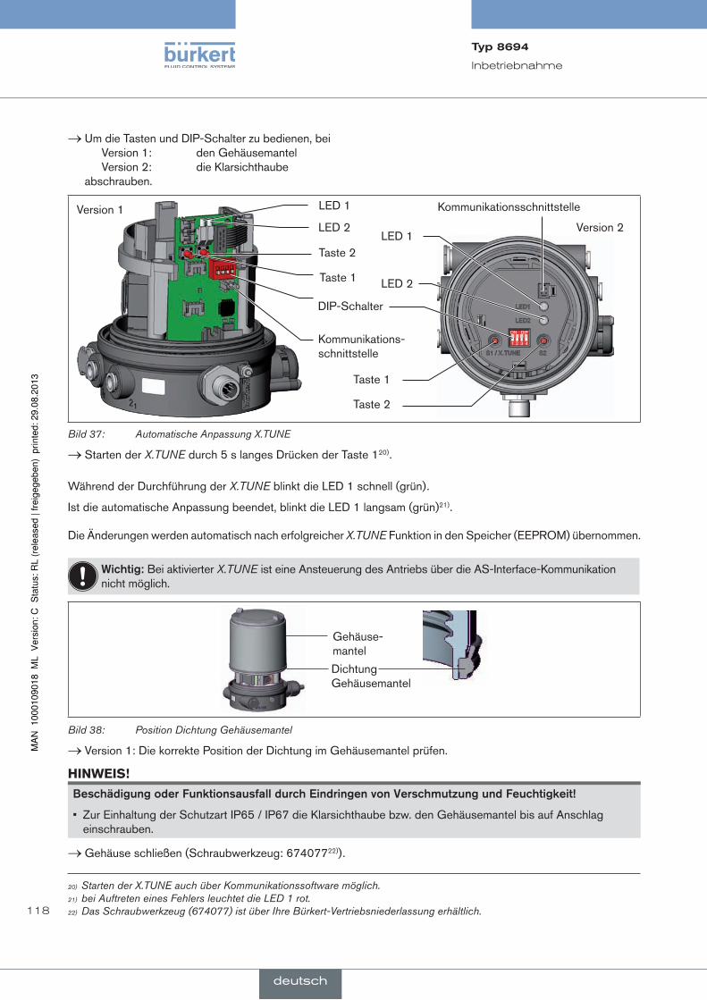
118
Inbetriebnahme
→ Um die Tasten und DIP-Schalter zu bedienen, bei Version 1: den Gehäusemantel Version 2: die Klarsichthaube abschrauben.
DIP-Schalter
Taste 2
Taste 1
LED 2
LED 1
Kommunikations-schnittstelle
Version 1
Version 2
1 2 3 4
ON DIP
Taste 1
Taste 2
LED 1
LED 2
Kommunikationsschnittstelle
Bild 37: Automatische Anpassung X.TUNE
→ Starten der X.TUNE durch 5 s langes Drücken der Taste 120).
Während der Durchführung der X.TUNE blinkt die LED 1 schnell (grün).
Ist die automatische Anpassung beendet, blinkt die LED 1 langsam (grün)21).
Die Änderungen werden automatisch nach erfolgreicher X.TUNE Funktion in den Speicher (EEPROM) übernommen.
Wichtig:Bei aktivierter X.TUNE ist eine Ansteuerung des Antriebs über die AS-Interface-Kommunikation nicht möglich.
Dichtung Gehäusemantel
Gehäuse-mantel
Bild 38: Position Dichtung Gehäusemantel
→ Version 1: Die korrekte Position der Dichtung im Gehäusemantel prüfen.
hinWeiS!
BeschädigungoderfunktionsausfalldurcheindringenvonVerschmutzungundfeuchtigkeit!
• Zur Einhaltung der Schutzart IP65 / IP67 die Klarsichthaube bzw. den Gehäusemantel bis auf Anschlag einschrauben.
→ Gehäuse schließen (Schraubwerkzeug: 67407722)).
20) Starten der X.TUNE auch über Kommunikationssoftware möglich. 21) bei Auftreten eines Fehlers leuchtet die LED 1 rot.22) Das Schraubwerkzeug (674077) ist über Ihre Bürkert-Vertriebsniederlassung erhältlich.
Typ8694
deutsch

119
Bedienung und Funktion
13. BedienungundfunkTiOnDer Positioner Typ 8694 hat verschiedene Grund- und Zusatzfunktionen, die über die DIP-Schalter bzw. die Kom-munikationssoftware konfigurier- und parametrierbar sind.
13.1. grundfunktionen
Folgende Grundfunktionen sind über die DIP-Schalter aktivierbar (CUTOFF und CHARACT) bzw. veränderbar (DIR.CMD).
funktion Beschreibung dip-schalter Off On
DIR.CMD Wirkrichtung zwischen Eingangs-signal und Soll-Position
1 steigend fallend
CUTOFF Dichtschließfunktion für Stellungsregler
2 Dichtschließfunktion aus
Dichtschließfunktion ein
CHARACT Auswahl der Übertragungskennlinie zwischen Eingangssignal und Hub (Korrekturkennlinie)
3 lineare Kennlinie Korrekturkennlinie
Tabelle 26: Grundfunktionen DIP-Schalter
Folgende Grundfunktion ist nur über die Kommunikationssoftware veränderbar.
funktion Beschreibung Werkseinstellung
INPUT Eingabe des Normsignaleingangs für die Sollwertvorgabe
4 ... 20 mA
Tabelle 27: Grundfunktion Kommunikationssoftware
Die Funktionen INPUT, CUTOFF und CHARACT können über die Kommunikationssoftware parametriert werden.
Zur Kommunikationssoftware gibt es eine Bedienungsanleitung in der die einzelnen Funktionen , sowie die Parametrierung und Konfiguration detailliert beschrieben sind.
Diese Anleitung finden Sie im Internet unter www.buerkert.de und unter anderem auf einer CD , die unter der Identnummer 804625 bestellt werden kann.
Typ8694
deutsch
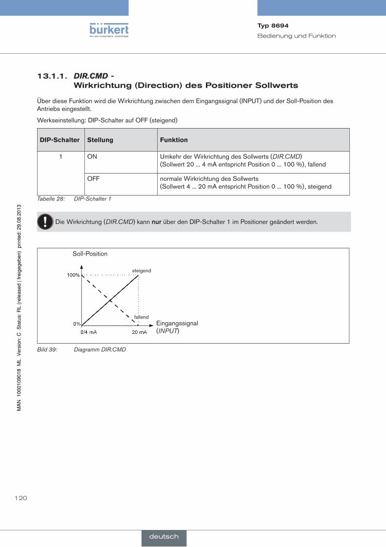
120
Bedienung und Funktion
13.1.1. DIR.CMD-Wirkrichtung(direction)despositionersollwerts
Über diese Funktion wird die Wirkrichtung zwischen dem Eingangssignal (INPUT) und der Soll-Position des Antriebs eingestellt.
Werkseinstellung: DIP-Schalter auf OFF (steigend)
DiP-Schalter Stellung Funktion
1 ON Umkehr der Wirkrichtung des Sollwerts (DIR.CMD) (Sollwert 20 ... 4 mA entspricht Position 0 ... 100 %), fallend
OFF normale Wirkrichtung des Sollwerts (Sollwert 4 ... 20 mA entspricht Position 0 ... 100 %), steigend
Tabelle 28: DIP-Schalter 1
Die Wirkrichtung (DIR.CMD) kann nur über den DIP-Schalter 1 im Positioner geändert werden.
Soll-Position
Eingangssignal (INPUT)
steigend
fallend
Bild 39: Diagramm DIR.CMD
Typ8694
deutsch

121
Bedienung und Funktion
13.1.2. CUTOFF-dichtschließfunktionfürdenpositioner
Diese Funktion bewirkt, dass das Ventil außerhalb des Regelbereichs dicht schließt.
Die Wiederaufnahme des Regelbetriebs erfolgt mit einer Hysterese von 1 %.
Werkseinstellung: DIP-Schalter 2 auf OFF (keine Dichtschließfunktion)
DiP-Schalter Stellung Funktion
2 ON Dichtschließfunktion aktiv. Das Ventil schließt unterhalb 2 %23) und öffnet oberhalb 98 % des Sollwerts vollständig (CUTOFF)
OFF keine Dichtschließfunktion
Tabelle 29: DIP-Schalter 2
Mit der Kommunikationssoftware können die Grenzen für den Stellungs-Sollwert in Prozent verändert werden.
Die Schaltstellung der DIP-Schalter im Positioner hat Vorrang vor der Kommunikationssoftware, d. h. Ein-stellungen der Dichtschließfunktion (CUTOFF), die über die Kommunikationssoftware geändert werden sind nur aktiv, wenn der DIP-Schalter 2 im Positioner auf ON steht.
Ventilhub [%]
einstellbar von 75 ... 100 %
Sollwert [%]
einstellbar von 0 ... 25 %
Bild 40: Diagramm CUTOFF
23) Werkseinstellung, kann über Kommunikationssoftware geändert werden.
Typ8694
deutsch
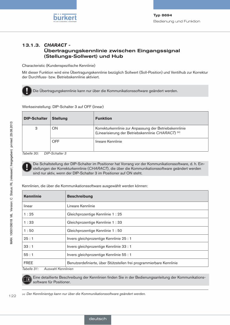
122
Bedienung und Funktion
13.1.3. CHARACT-Übertragungskennliniezwischeneingangssignal(stellungs-sollwert)undhub
Characteristic (Kundenspezifische Kennlinie)
Mit dieser Funktion wird eine Übertragungskennlinie bezüglich Sollwert (Soll-Position) und Ventilhub zur Korrektur der Durchfluss- bzw. Betriebskennlinie aktiviert.
Die Übertragungskennlinie kann nur über die Kommunikationssoftware geändert werden.
Werkseinstellung: DIP-Schalter 3 auf OFF (linear)
DiP-Schalter Stellung Funktion
3 ON Korrekturkennlinie zur Anpassung der Betriebskennlinie (Linearisierung der Betriebskennlinie CHARACT) 24)
OFF lineare Kennlinie
Tabelle 30: DIP-Schalter 3
Die Schaltstellung der DIP-Schalter im Positioner hat Vorrang vor der Kommunikationssoftware, d. h. Ein-stellungen der Korrekturkennlinie (CHARACT), die über die Kommunikationssoftware geändert werden sind nur aktiv, wenn der DIP-Schalter 3 im Positioner auf ON steht.
Kennlinien, die über die Kommunikationssoftware ausgewählt werden können:
Kennlinie Beschreibung
linear Lineare Kennlinie
1 : 25 Gleichprozentige Kennlinie 1 : 25
1 : 33 Gleichprozentige Kennlinie 1 : 33
1 : 50 Gleichprozentige Kennlinie 1 : 50
25 : 1 Invers gleichprozentige Kennlinie 25 : 1
33 : 1 Invers gleichprozentige Kennlinie 33 : 1
55 : 1 Invers gleichprozentige Kennlinie 55 : 1
FREE Benutzerdefinierte, über Stützstellen frei programmierbare Kennlinie
Tabelle 31: Auswahl Kennlinien
Eine detaillierte Beschreibung der Kennlinien finden Sie in der Bedienungsanleitung der Kommunikations-software für Positioner.
24) Der Kennlinientyp kann nur über die Kommunikationssoftware geändert werden.
Typ8694
deutsch

123
Bedienung und Funktion
13.2. zusatzfunktionen
Folgende Zusatzfunktionen können über die Kommunikationssoftware konfiguriert und parametriert werden:
funktion Beschreibung
DIR.ACTUATOR Zuordnung des Belüftungszustands der Antriebskammer zur Ist-Position
SPLITRANGESignalbereichsaufteilung; Eingangssignal in %, für den das Ventil den gesamten Hubbereich durchläuft.
X.LIMIT Begrenzung des mechanischen Hubbereichs
X.TIME Begrenzung der Stellgeschwindigkeit
X.CONTROL Parametrieren des Stellungsreglers
SAFE POSITION Eingabe der Sicherheitsstellung
SIGNAL ERROR Konfiguration Fehlererkennung Signalpegel
BINARY INPUT Aktivierung des Binäreingangs
OUTPUTKonfigurierung der Ausgänge (nur mit Zusatzplatine für analoge Rückmeldung bzw. Binärausgänge)
Tabelle 32: Zusatzfunktionen
Zur Kommunikationssoftware gibt es eine Bedienungsanleitung in der die einzelnen Funktionen , sowie die Parametrierung und Konfiguration detailliert beschrieben sind.
Diese Anleitung finden Sie im Internet unter www.buerkert.de und unter anderem auf einer CD , die unter der Identnummer 804625 bestellt werden kann.
Typ8694
deutsch

124
Sicherheitsstellungen
14. sicherheiTssTellungen
14.1. sicherheitsstellungennachausfallderelektrischenbzw.pneumatischenhilfsenergie
antriebsart Bezeichnung
sicherheitsstellungennachausfallderhilfsenergie
elektrisch pneumatisch
up
down
einfachwirkend
Steuer- funktion A
down
vorgesteuertes Stellsystem:
down
direktwirkendes Stellsystem:
nicht definiert
up
down
einfachwirkend
Steuer- funktion B
up
vorgesteuertes Stellsystem:
up
direktwirkendes Stellsystem:
nicht definiert
Tabelle 33: Sicherheitsstellungen
Typ8694
deutsch

125
Wartung
15. WarTung
15.1. sicherheitshinweise
geFahr!
Verletzungsgefahrdurchhohendruckinderanlage!
• Vor dem Lösen von Leitungen oder Ventilen den Druck abschalten und Leitungen entlüften.
Verletzungsgefahrdurchstromschlag!
• Vor Eingriffen in das Gerät oder die Anlage, Spannung abschalten und vor Wiedereinschalten sichern!
• Die geltenden Unfallverhütungs- und Sicherheitsbestimmungen für elektrische Geräte beachten!
Warnung!
VerletzungsgefahrbeiunsachgemäßenWartungsarbeiten!
• Die Wartung darf nur autorisiertes Fachpersonal mit geeignetem Werkzeug durchführen!
VerletzungsgefahrdurchungewollteseinschaltenderanlageundunkontrolliertenWiederanlauf!
• Anlage vor unbeabsichtigtem Betätigen sichern.
• Nach der Wartung einen kontrollierten Wiederanlauf gewährleisten.
Typ8694
deutsch

126
Wartung
15.2. serviceamzuluftfilter
geFahr!
Verletzungsgefahrdurchhohendruckinderanlage!
• Vor dem Lösen von Leitungen und Ventilen den Druck abschalten und Leitungen entlüften.
Zum Schutz der internen Magnetventile und des Antriebs wird die Steuerluft gefiltert.
Die Durchflussrichtung des Zuluftfilters im eingebauten Zustand ist von innen nach außen durch das Siebgewebe.
Zuluftfilter
Schnellsteckverbinder
O-Ring
Bild 41: Service am Zuluftfilter
Vorgehensweise:
→ Den Schnellsteckverbinder durch Eindrücken des Halteelements entriegeln und Zuluftfilter herausziehen (eventuell unter Zuhilfenahme eines geeigneten Werkzeugs zwischen den Aussparungen im Kopf des Filters).
→ Filter reinigen oder falls nötig Filter auswechseln.
→ Innenliegenden O-Ring prüfen und gegebenenfalls säubern.
→ Zuluftfilter bis zum Anschlag in die Schnellsteckverbindung stecken.
geFahr!
Verletzungsgefahrdurchunsachgemäßemontage!
• Auf richtige Montage des Zuluftfilters achten.
→ Den sicheren Sitz des Zuluftfilters prüfen.
Typ8694
deutsch

127
Zubehör
16. zuBehör
Bezeichnung Bestell-nr.
USB-Adapter zum Anschluss eines PC in Verbindung mit einem Verlängerungskabel
227093
Kommunikationssoftware auf FDT/DTM Technologie (Hinweise siehe Kapitel „16.1. Kommunikationssoftware (PC-SOFTWARE auf FDT/DTM Technologie):“)
Infos unter www.buerkert.de
Anschlusskabel M12 x1, 8-polig 919061
Schraubwerkzeug 674077
Tabelle 34: Zubehör
16.1. kommunikationssoftware(pc-sOfTWareauffdT/dTmTechnologie):
Bestehend aus dem Bürkert Geräte DTM (Konfigurations-und Parametrisiersoftware) und einer dazugehörigen Rahmenapplikation, z. B. PACTware 3.6.
DTMs sind nur lauffähig in Verbindung mit einer FDT Rahmenapplikation, wie z. B. PACTware.
Das PC-Bedienprogramm ist für die Kommunikation mit den Geräten aus der Positioner-Familie der Firma Bürkert konzipiert (Basic Varianten ohne Display).
Eine detaillierte Beschreibung und genaue Auflistung der Vorgehensweise bei der Installation und der Bedienung der Software entnehmen Sie bitte der zugehörigen Dokumentation.
16.1.1. pacTware3.6
Rahmenprogramm des PACTware Consortium e. V. zur Aufnahme und Bedienung von FDT 1.2 bzw. FDT 1.2.1 fähigen DTM beliebiger Hersteller.
Das Vorhandensein des Microsoft .NET Framework 1.1 + .NET Framework 1.1 SP1 ist Voraussetzung.
16.1.2. usBschnittstelle
Der PC benötigt eine USB Schnittstelle für die Kommunikation mit den Positionern, zusätzlich ein Adapter mit Schnittstellentreiber (siehe „Tabelle 34: Zubehör“).
Die Datenübertragung muss nach HART Spezifikation erfolgen, hierzu kann der bei der Installation von PACTware ebenfalls installierte HART Kommunikations-DTM verwendet werden.
16.1.3. download
Download der Software (DTM und PACTware) unter: www.buerkert.de bzw. www.pactware.com
Unter der Downloadfunktion steht immer die aktuellste Version der Kommunikationssoftware zur Verfügung.
Typ8694
deutsch

128
Demontage
17. demOnTage
17.1. sicherheitshinweise
geFahr!
Verletzungsgefahrdurchhohendruck!
• Vor dem Lösen von Leitungen und Ventilen den Druck abschalten und Leitungen entlüften.
Verletzungsgefahrdurchelektrischespannung!
• Vor Eingriffen in das Gerät oder in die Anlage die Spannung abschalten und vor Wiedereinschalten sichern!
• Die geltenden Unfallverhütungs- und Sicherheitsbestimmungen für elektrische Geräte beachten!
Warnung!
Verletzungsgefahrbeiunsachgemäßerdemontage!
• Die Demontage darf nur autorisiertes Fachpersonal mit geeignetem Werkzeug durchführen!
VerletzungsgefahrdurchungewollteseinschaltenderanlageundunkontrolliertenWiederanlauf!
• Anlage vor unbeabsichtigtem Betätigen sichern.
• Nach der Demontage einen kontrollierten Wiederanlauf gewährleisten.
17.2. demontagepositioner
Vorgehensweise:
1. Pneumatische Verbindungen
geFahr!
Verletzungsgefahrdurchhohendruck!
• Vor dem Lösen von Leitungen und Ventilen den Druck abschalten und Leitungen entlüften.
→ Pneumatischer Anschluss lösen.
→ Reihe 20xx: Pneumatische Verbindung zum Antrieb lösen.
Typ8694
deutsch

129
Demontage
2. Elektrische Verbindungen
geFahr!
Verletzungsgefahrdurchelektrischespannung!
• Vor Eingriffen in das Gerät oder in die Anlage die Spannung abschalten und vor Wiedereinschalten sichern!
• Die geltenden Unfallverhütungs- und Sicherheitsbestimmungen für elektrische Geräte beachten!
Rundsteckverbinder:
→ Rundstecker lösen.
Kabeldurchführung:
→ Positioner öffnen: Gehäusemantel gegen den Uhrzeigersinn aufschrauben.
→ Schraubklemmen lösen und Kabel herausziehen.
→ Gehäuse schließen.
3. Mechanische Verbindungen
→ Befestigungsschrauben lösen.
→ Positioner nach oben abziehen.
Pneumatischer Anschluss
Positioner
Antrieb
Befestigungs-schraube (2x)
Pneumatische Verbindung zum Antrieb
Antrieb
Elektrischer Anschluss Rundsteck-verbinder
Reihe 21xx Reihe 20xx
Bild 42: Demontage Positioner
Typ8694
deutsch
130
Verpackung, Transport
18. Verpackung,TranspOrT
hinWeiS!
transportschäden!
Unzureichend geschützte Geräte können durch den Transport beschädigt werden.
• Gerät vor Nässe und Schmutz geschützt in einer stoßfesten Verpackung transportieren.
• Eine Über- bzw. Unterschreitung der zulässigen Lagertemperatur vermeiden.
19. lagerung
hinWeiS!
falschelagerungkannschädenamgerätverursachen.
• Gerät trocken und staubfrei lagern!
• Lagertemperatur -20 ... +65 °C.
20. enTsOrgung
→ Das Gerät und die Verpackung umweltgerecht entsorgen.
hinWeiS!
umweltschädendurchvonmedienkontaminiertegeräteteile.
• Geltende Entsorgungsvorschriften und Umweltbestimmungen einhalten.
Die nationalen Abfallbeseitigungsvorschriften beachten.
Typ8694
deutsch
131
ConTenu
1. aprOpOsdecemanuel.................................................................................................................................................... 135
1.1. symboles.............................................................................................................................................................................. 135
2. utilisatiOncOnfOrme........................................................................................................................................................ 136
2.1. restrictions......................................................................................................................................................................... 136
3. cOnsignesdesécuritéfOndamentales.......................................................................................................... 137
4. indicatiOnsgénérales..................................................................................................................................................... 138
4.1. adresse................................................................................................................................................................................. 138
4.2. garantielégale.................................................................................................................................................................. 138
4.3. marquesdéposées......................................................................................................................................................... 138
4.4. informationssurinternet............................................................................................................................................. 138
5. descriptiOndusystème.................................................................................................................................................. 139
5.1. utilisationprévue............................................................................................................................................................. 139
5.2. fonctiondupositionneuretassociationaveclestypesdevanne....................................................... 139
5.3. caractéristiquesdestypesdevanne.................................................................................................................... 140
5.4. structuredupositionneur........................................................................................................................................... 141
5.4.1. Représentation ...................................................................................................................................... 141
5.4.2. Caractéristiques ................................................................................................................................... 142
5.4.3. Schéma fonctionnel du positionneur avec actionneur à simple effet ....................................... 143
5.5. positionneurtype8694(régulateurdeposition)............................................................................................ 144
5.5.1. Représentation schématique de la régulation de position du type 8694 ............................... 144
5.5.2. Fonctions du logiciel du régulateur de position ............................................................................ 145
5.6. interfacesdupositionneur........................................................................................................................................ 147
Positionneur, type 8694
Type8694
français
132
6. caractéristiquestechniques.................................................................................................................................. 148
6.1. conformité........................................................................................................................................................................... 148
6.2. normes.................................................................................................................................................................................. 148
6.3. conditionsd'exploitation............................................................................................................................................. 148
6.4. caractéristiquesmécaniques.................................................................................................................................... 148
6.5. caractéristiquespneumatiques............................................................................................................................... 149
6.6. descriptiondel’étiquette............................................................................................................................................ 149
6.7. caractéristiquesélectriques...................................................................................................................................... 150
6.7.1. Caractéristiques électriques sans commande bus 24 V DC..................................................... 150
6.7.2. Caractéristiques électriques avec commande bus interface AS .............................................. 150
6.8. réglagesusinedupositionneur.............................................................................................................................. 151
7. elémentsdecOmmandeetd'affichage............................................................................................................ 152
7.1. etatdemarche.......................................................................................................................................................................152
7.2. elémentsdecommandeetd'affichagedupositionneur........................................................................... 152
7.3. affectationdestouches....................................................................................................................................................154
7.4. fonctiondesinterrupteursdip....................................................................................................................................156
7.5. affichagedesled................................................................................................................................................................158
7.6. messagesd'erreur................................................................................................................................................................159
7.6.1. Messages d'erreur dans les états de marche MANUEL et AUTOMATIQUE ............................159
7.6.2. Messages d'erreur lors de l'exécution de la fonction X.TUNE ...................................................159
8. mOntage.......................................................................................................................................................................................... 160
8.1. consignesdesécurité.................................................................................................................................................. 160
8.2. montagedupositionneurtype8694surlesvannesprocessdesséries2103,2300et2301................................................................................................................................. 160
8.3. montagedupositionneurtype8694surlesvannesprocessdesséries26xxet27xx....................................................................................................163
8.4. rotationdumoduleactionneur.............................................................................................................................. 167
8.5. rotationdupositionneurpourlesvannesprocessdesséries26xxet27xx......................................................................................... 169
Type8694
français
133
9. installatiOnfluidique...................................................................................................................................................... 170
9.1. consignesdesécurité.................................................................................................................................................. 170
9.2. installationdelavanneprocess.............................................................................................................................. 170
9.3. raccordementpneumatiquedupositionneur.................................................................................................. 171
10. installatiOnélectrique24Vdc............................................................................................................................... 172
10.1. consignesdesécurité.................................................................................................................................................. 172
10.2. installationélectriqueavecconnecteurrond................................................................................................... 172
10.2.1. Désignation des contacts type 8694 ............................................................................................. 172
10.2.2. Raccordement du positionneur type 8694 .................................................................................... 173
10.3. installationélectriqueavecpresse-étoupe....................................................................................................... 174
10.3.1. Désignation des bornes vissées ....................................................................................................... 174
10.3.2. Raccordement du positionneur type 8694 .................................................................................... 174
11. interfaceas-installatiOn........................................................................................................................................... 176
11.1. connexioninterfaceas................................................................................................................................................ 176
11.2. caractéristiquestechniquespourcircuitsimprimésinterfaceas....................................................... 176
11.3. donnéesdeprogrammation...................................................................................................................................... 176
11.4. déroulementdelacommunicationaveclaversionprofils-7.a.5...................................................... 177
11.5. affichaged'étatled....................................................................................................................................................... 178
11.6. installationélectriqueinterfaceas........................................................................................................................ 179
11.6.1. Consignes de sécurité ........................................................................................................................ 179
11.6.2. Raccordement avec connecteur rond M12 x 1, 4 pôles, mâle .................................................. 179
11.6.3. Raccordement avec câble multipolaire et borne à câble plat .................................................... 180
12. miseenserVice........................................................................................................................................................................ 181
12.1. consignesdesécurité.................................................................................................................................................. 181
12.2. déterminationdesréglagesdebase.................................................................................................................... 181
12.2.1. Exécution de l'adaptation automatique X.TUNE......................................................................181
Type8694
français

134
13. cOmmandeetfOnctiOnnement................................................................................................................................. 183
13.1. fonctionsdebase................................................................................................................................................................183
13.1.1..DIR.CMD - Sens d'action (Direction) de la valeur de consigne du positionneur ........................................ 184
13.1.2..CUTOFF - Fonction de fermeture étanche du positionneur ........................................................................... 185
13.1.3..CHARACT - Caractéristique de transfert entre le signal d'entrée (valeur de consigne de position) et la course ................................................................................ 186
13.2. fonctionssupplémentaires............................................................................................................................................187
14. pOsitiOnsdesécurité....................................................................................................................................................... 188
14.1. positionsdesécuritéaprèsunepanned'énergieauxiliaireélectriqueoupneumatique........ 188
15. maintenance............................................................................................................................................................................... 189
15.1. consignesdesécurité.................................................................................................................................................. 189
15.2. servicesurlefiltred'amenéed'air........................................................................................................................ 190
16. accessOires............................................................................................................................................................................... 191
16.1. logicieldecommunication(logicielpcsurtechnologiefdt/dtm):.............................................. 191
16.1.1. PACTware 3.6 ....................................................................................................................................... 191
16.1.2. Interface USB ........................................................................................................................................ 191
16.1.3. Téléchargement .................................................................................................................................... 191
17. démOntage................................................................................................................................................................................... 192
17.1. consignesdesécurité.................................................................................................................................................. 192
17.2. démontagedupositionneur...................................................................................................................................... 192
18. emBallage,transpOrt...................................................................................................................................................... 194
19. stOckage....................................................................................................................................................................................... 194
20. eliminatiOn................................................................................................................................................................................... 194
Type8694
français
135
A propos de ce manuel
1. aprOpOsdecemanuelCe manuel décrit le cycle de vie complet de l’appareil. Conservez ce manuel de sorte qu’il soit accessible à tout utilisateur et à disposition de tout nouveau propriétaire.
aVerTiSSeMenT !
lesinstructionsdeservicecontiennentdesinformationsimportantessurlasécurité.
Le non-respect de ces consignes peut entraîner des situations dangereuses.
• Les instructions de service doivent être lues et comprises.
1.1. symboles
Danger !
metengardecontreundangerimminent.
• Le non-respect peut entraîner la mort ou de graves blessures.
aVerTiSSeMenT !
metengardecontreunesituationéventuellementdangereuse.
• Risque de blessures graves, voire la mort en cas de non-respect.
aTTenTion !
metengardecontreunrisquepossible.
• Le non-respect peut entraîner des blessures légères ou de moyenne gravité.
reMarque !
metengardecontredesdommagesmatériels.
• L’appareil ou l’installation peut être endommagé(e) en cas de non-respect.
désigne des informations complémentaires importantes, des conseils et des recommandations.
renvoie à des informations dans ces instructions de service ou dans d'autres documentations.
→ identifie une opération que vous devez effectuer.
Type8694
français
136
Utilisation conforme
2. uTilisaTiOncOnfOrme
l’utilisationnonconformedupositionneurtype8694peutprésenterdesdangerspourlespersonnes,lesinstallationsprochesetl’environnement.
• L'appareil est conçu pour être monté sur les actionneurs pneumatiques des vannes process pour la com-mande de fluides.
• L'appareil ne doit pas être exposé au rayonnement solaire direct.
• Lors de l'utilisation, il convient de respecter les données et conditions d'utilisation et d'exploitation admis-sibles spécifiées dans les instructions de service et dans les documents contractuels. Celles-ci sont décrites au chapitre « 6. Caractéristiques techniques ».
• L'appareil peut être utilisé uniquement en association avec les appareils et composants étrangers recomman-dés et homologués par Bürkert.
• Etant donné la multitude de cas d'utilisation, il convient de vérifier et si nécessaire tester avant montage si le positionneur convient pour le cas d'utilisation concret.
• Les conditions pour l'utilisation sûre et parfaite sont un transport, un stockage et une installation dans les règles ainsi qu'une parfaite utilisation et maintenance.
• Veillez à ce que l'utilisation du positionneur type 8694 soit toujours conforme.
2.1. restrictions
Lors de l'exportation du système / de l'appareil, veuillez respecter les restrictions éventuelles existantes.
Type8694
français
137
Consignes de sécurité fondamentales
3. cOnsignesdesécuriTéfOndamenTalesCes consignes de sécurité ne tiennent pas compte
• des hasards et des événements pouvant survenir lors du montage, de l'exploitation et de l'entretien des appareils.
• des prescriptions de sécurité locales que l'exploitant est tenu de faire respecter par le personnel chargé du montage.
Danger !
dangerdûàlahautepression.
• Avant de desserrer les conduites et les vannes, coupez la pression et assurez l'échappement de l'air des conduites.
dangerprésentéparlatensionélectrique.
• Avant d'intervenir dans l'appareil ou l'installation, coupez la tension et empêchez toute remise sous tension par inadvertance.
• Veuillez respecter les réglementations en vigueur pour les appareils électriques en matière de prévention des accidents ainsi qu'en matière de sécurité.
situationsdangereusesd'ordregénéral.
Pour prévenir les blessures, respectez ce qui suit :
• L'installation ne peut pas être actionnée par inadvertance.
• Les travaux d'installation et de maintenance doivent être effectués uniquement par des techniciens qualifiés et habilités disposant de l'outillage approprié.
• Après une interruption de l'alimentation électrique ou pneumatique, un redémarrage défini ou contrôlé du processus doit être garanti.
• L'appareil doit être utilisé uniquement en parfait état et en respectant les instructions de service.
• Les règles générales de la technique sont d'application pour planifier l'utilisation et utiliser l'appareil.
Pour prévenir les dommages matériels, respectez ce qui suit :
• N’alimentez pas le raccord d’air de pilotage en fluides agressifs ou inflammables.
• N’alimentez pas le raccord d’air de pilotage en liquides.
• Ne soumettez pas le corps à des contraintes mécaniques (par ex. pour déposer des objets ou en l’utilisant comme marche).
• N’apportez pas de modifications à l’extérieur du corps de l’appareil. Ne laquez pas les pièces du corps et les vis.
reMarque !
eléments/sous-groupessujetsauxrisquesélectrostatiques.
• L'appareil contient des éléments électroniques sensibles aux décharges électrostatiques (ESD). Ces éléments sont affectés par le contact avec des personnes ou des objets ayant une charge électrostatique. Au pire, ils sont immédiatement détruits ou tombent en panne après mise en service.
• Respectez les exigences selon EN 100 015 - 1 et 5 - 2 pour minimiser ou éviter la possibilité d’un dommage causé par une soudaine décharge électrostatique.
• Veillez également à ne pas toucher d’éléments électroniques lorsqu’ils sont sous tension.
Type8694
français

138
Consignes de sécurité fondamentales
Le positionneur type 8694 a été développé dans le respect des règles reconnues en matière de sécurité et correspond à l’état actuel de la technique. Néanmoins, des risques peuvent se présenter.
Le non-respect de ces instructions de service avec ses consignes ainsi que les interventions non autorisées sur l'appareil excluent toute responsabilité de notre part et entraînent la nullité de la garantie légale concernant les appareils et les accessoires.
4. indicaTiOnsgénérales
4.1. adresse
allemagne
Bürkert Fluid Control System Sales Center Chr.-Bürkert-Str. 13-17 D-74653 Ingelfingen Tél. : + 49 (0) 7940 - 10 91 111 Fax : + 49 (0) 7940 - 10 91 448 E-mail : [email protected]
international
Les adresses se trouvent aux dernières pages des instructions de service imprimées.
Egalement sur internet sous :
www.burkert.com
4.2. garantielégale
La condition pour bénéficier de la garantie légale est l'utilisation conforme du positionneur type 8694 dans le respect des conditions d'utilisation spécifiées.
4.3. marquesdéposées
Les marques mentionnées sont des marques déposées des sociétés / associations / organisations concernées.
Loctite Henkel Loctite Deutschland GmbH
4.4. informationssurinternet
Vous trouverez les instructions de service et les fiches techniques concernant le type 8694 sur Internet sous :
www.buerkert.fr
Type8694
français
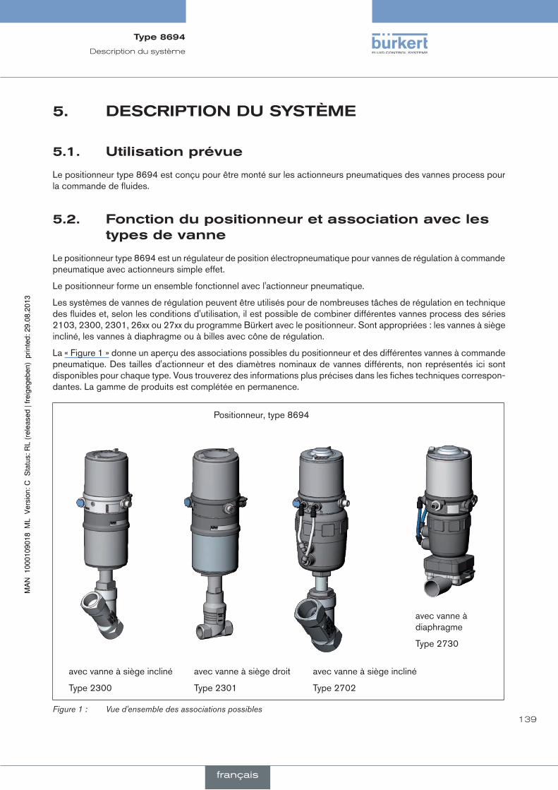
139
Description du système
5. descripTiOndusysTème
5.1. utilisationprévue
Le positionneur type 8694 est conçu pour être monté sur les actionneurs pneumatiques des vannes process pour la commande de fluides.
5.2. fonctiondupositionneuretassociationaveclestypesdevanne
Le positionneur type 8694 est un régulateur de position électropneumatique pour vannes de régulation à commande pneumatique avec actionneurs simple effet.
Le positionneur forme un ensemble fonctionnel avec l'actionneur pneumatique.
Les systèmes de vannes de régulation peuvent être utilisés pour de nombreuses tâches de régulation en technique des fluides et, selon les conditions d'utilisation, il est possible de combiner différentes vannes process des séries 2103, 2300, 2301, 26xx ou 27xx du programme Bürkert avec le positionneur. Sont appropriées : les vannes à siège incliné, les vannes à diaphragme ou à billes avec cône de régulation.
La « Figure 1 » donne un aperçu des associations possibles du positionneur et des différentes vannes à commande pneumatique. Des tailles d'actionneur et des diamètres nominaux de vannes différents, non représentés ici sont disponibles pour chaque type. Vous trouverez des informations plus précises dans les fiches techniques correspon-dantes. La gamme de produits est complétée en permanence.
Positionneur, type 8694
avec vanne à siège incliné
Type 2702
avec vanne à diaphragme
Type 2730
avec vanne à siège incliné
Type 2300
avec vanne à siège droit
Type 2301
Figure 1 : Vue d'ensemble des associations possibles
Type8694
français
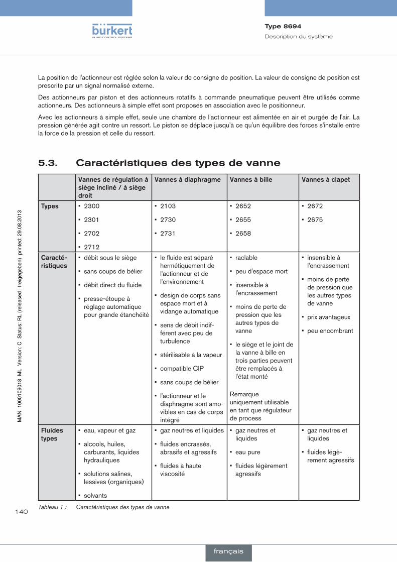
140
Description du système
La position de l'actionneur est réglée selon la valeur de consigne de position. La valeur de consigne de position est prescrite par un signal normalisé externe.
Des actionneurs par piston et des actionneurs rotatifs à commande pneumatique peuvent être utilisés comme actionneurs. Des actionneurs à simple effet sont proposés en association avec le positionneur.
Avec les actionneurs à simple effet, seule une chambre de l'actionneur est alimentée en air et purgée de l'air. La pression générée agit contre un ressort. Le piston se déplace jusqu'à ce qu'un équilibre des forces s'installe entre la force de la pression et celle du ressort.
5.3. caractéristiquesdestypesdevanne
Vannesderégulationàsiègeincliné/àsiègedroit
Vannesàdiaphragme Vannesàbille Vannesàclapet
types • 2300
• 2301
• 2702
• 2712
• 2103
• 2730
• 2731
• 2652
• 2655
• 2658
• 2672
• 2675
caracté-ristiques
• débit sous le siège
• sans coups de bélier
• débit direct du fluide
• presse-étoupe à réglage automatique pour grande étanchéité
• le fluide est séparé hermétiquement de l'actionneur et de l'environnement
• design de corps sans espace mort et à vidange automatique
• sens de débit indif-férent avec peu de turbulence
• stérilisable à la vapeur
• compatible CIP
• sans coups de bélier
• l'actionneur et le diaphragme sont amo-vibles en cas de corps intégré
• raclable
• peu d'espace mort
• insensible à l'encrassement
• moins de perte de pression que les autres types de vanne
• le siège et le joint de la vanne à bille en trois parties peuvent être remplacés à l'état monté
Remarque uniquement utilisable en tant que régulateur de process
• insensible à l'encrassement
• moins de perte de pression que les autres types de vanne
• prix avantageux
• peu encombrant
fluidestypes
• eau, vapeur et gaz
• alcools, huiles, carburants, liquides hydrauliques
• solutions salines, lessives (organiques)
• solvants
• gaz neutres et liquides
• fluides encrassés, abrasifs et agressifs
• fluides à haute viscosité
• gaz neutres et liquides
• eau pure
• fluides légèrement agressifs
• gaz neutres et liquides
• fluides légè-rement agressifs
Tableau 1 : Caractéristiques des types de vanne
Type8694
français

141
Description du système
5.4. structuredupositionneur
Le positionneur, type 8694 est composé d'une électronique de commande par microprocesseur, du système de mesure de déplacement et du système de réglage. L'appareil est conçu selon la technique à trois conducteurs. La commande du positionneur se fait à l'aide de 2 touches et d'un interrupteur DIP à 4 pôles. Le système de réglage pneumatique pour actionneurs simple effet comprend 2 électrovannes.
5.4.1. représentation
LED
Bornes vissées
Raccord de pression d‘alimen-tation (Légende : 1)
Raccord d‘évacuation d‘air (Légende : 3)
Raccordement électrique (passe-câbles M16 x 1,5 ou connecteur rond M12 x 1)
Enveloppe du corps retirée : Touches
Interrupteur DIP
LED
Capot transparent
Limiteur de pression (pour la protection contre la pression intérieure trop élevée en cas de défaut)
Filtre d‘amenée d‘air (remplaçable)
Enveloppe du corps
Version1 Version2
Interface de communication
Raccord de pression d‘ali-mentation (Légende : 1)
Raccord d‘éva-cuation d‘air (Légende : 3)
Interface de communication
Filtre d‘amenée d‘air (remplaçable)
Raccord de purge d’air supplémentaire (Légende : 3.1) uniquement pour type 23xx et 2103 avec système de réglage
à commande pilote pour débit d’air important (Tailles d’actionneur ø 130)
Figure 2 : Structure
Type8694
français

142
Description du système
5.4.2. caractéristiques
• Versions pour actionneurs de vanne simple effet.
• Système de mesure de déplacement Système de mesure de déplacement sans contact et donc sans usure.
• electronique de commande par microprocesseurpour le traitement des signaux, la régulation et la commande des vannes.
• Module de commande La commande de l'appareil se fait à l'aide de 2 touches et d'un interrupteur DIP à 4 pôles. 2 LED bicolores permettent l'affichage de différents états d'appareil.
• Système de réglage Le système de réglage comprend 2 électrovannes. Une vanne sert à l'alimentation en air et une autre à l'échap-pement de l'actionneur pneumatique. Les électrovannes fonctionnent selon le principe de la bascule et sont commandées à l'aide du régulateur avec une tension MIL (PWM). Ceci permet d'obtenir une plus grande flexi-bilité en ce qui concerne le volume de l'actionneur et la vitesse de réglage. Le diamètre nominal de la version à effet direct est DN 0,6. Avec les actionneurs pneumatiques plus grands, les électrovannes sont dotées d'ampli-ficateurs à diaphragme (DN 2,5) pour augmenter le débit maximal et ainsi améliorer la dynamique.
• Message de retour de position (en option) La position de la vanne peut être transmise à l'API via une sortie analogique 0/4-20 mA.
• entrée binaireLorsqu'une tension > 10 V est appliquée, SAFE POSITION est activé, c'est-à-dire que la vanne est amenée en position de sécurité (réglage en usine pouvant être modifiée avec le logiciel de communication).
• interfaces pneumatiques Raccordements 1/4" avec différentes formes de filetage (G, NPT) raccord de flexible enfichable
• interfaces électriques Connecteur rond ou passe-câbles
Interface pneumatique
Interface électrique
• Corps Le corps du positionneur est protégé d'une pression intérieure trop élevée, par ex. causée par des fuites, par un limiteur de pression.
• interface de communication Pour la configuration et le paramétrage.
Type8694
français

143
Description du système
5.4.3. schémafonctionneldupositionneuravecactionneuràsimpleeffet
Le schéma fonctionnel représenté décrit la fonction du positionneur type 8694.
Système de réglage
1
2
Régulateur de position
Système de réglage 1 : Vanne d'alimentation en air 2 : Vanne d'échappement
Pression d'alimentation
Echappement
Système de mesure de déplacement
Position effective
Valeur de consigne de position externe
Positionneur
Actionneur pneumatique (à simple effet)
Vanne (élément de réglage)
Figure 3 : Schéma fonctionnel
Type8694
français

144
Description du système
5.5. positionneurtype8694(régulateurdeposition)Le système de mesure de déplacement permet de détecter la position actuelle (POS) de l'actionneur pneumatique. Le régulateur de position compare cette valeur effective de position à la valeur de consigne pouvant être prescrite en tant que signal normalisé (CMD). En présence d'une différence de régulation (Xd1), un signal de tension PWM (MIL) est transmis au système de réglage comme grandeur de réglage. Avec les actionneurs simple effet, et en présence d'une différence de régulation positive, la vanne d'alimentation en air est commandée via la sortie B1. Si la différence de régulation est négative, la vanne d'échappement est commandée via la sortie E1. De cette façon, la position de l'actionneur est modifiée jusqu'à la différence de régulation 0. Z1 représente une grandeur perturbatrice.
Ouverture de vanne
Vanne de régulation
Système de réglage Electrovannes
Système de mesure de déplacement
Régulateur de position
Valeur de consigne de position
CMD Xd1B1
E1PK
Z1
POS
Circuit de régulation de position
+ -
Figure 4 : Schéma logique du régulateur de position
5.5.1. représentationschématiquedelarégulationdepositiondutype8694
4 ... 20 mA1) 0 ... 20 mA
CHARACTSPLTRNG2)DIR.CMD CUTOFF X.TIME2)
X.CONTROL
DBND
POS
CMDINP
POS
CMD
DIR.ACT2) X.LIMIT2)
1) Réglage par défaut2) Uniquement activable avec le logiciel de communication
Figure 5 : Représentation schématique de la régulation de position
Type8694
français

145
Description du système
5.5.2. fonctionsdulogicieldurégulateurdeposition
fonctionsi
• Activation via interrupteur DIP
• Paramétrage via le logiciel de communication.
fonctionsupplémentaire effet
Fonction de fermeture étanche
CUTOFF
La vanne se ferme en dehors de la plage de régulation. Indication de la valeur (en %) à partir de laquelle l'ac-tionneur fait l'objet d'un échappement complet (à 0 %) ou d'une alimentation en air complète (à 100 %). (voir chapitre« 7.4. Fonction des interrupteurs DIP »).
Caractéristique de correction pour l'adaptation de la caractéristique de fonctionnement
CHARACT
La linéarisation de la caractéristique de correction peut être effectuée (voir chapitre « 7.4. Fonction des interrup-teurs DIP »).
Sens d'action de la valeur de consigne du régulateur
DIR.CMD
Inversion du sens d'action de la valeur de consigne (voir chapitre« 7.4. Fonction des interrupteurs DIP »).
Tableau 2 : Fonctions I
Type8694
français
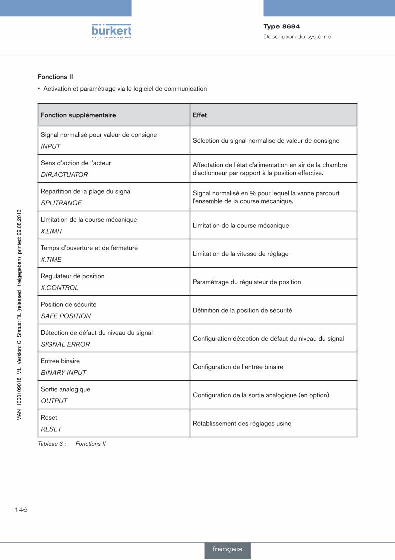
146
Description du système
fonctionsii
• Activation et paramétrage via le logiciel de communication
fonctionsupplémentaire effet
Signal normalisé pour valeur de consigne
INPUTSélection du signal normalisé de valeur de consigne
Sens d’action de l’acteur
DIR.ACTUATOR
Affectation de l'état d'alimentation en air de la chambre d'actionneur par rapport à la position effective.
Répartition de la plage du signal
SPLITRANGE
Signal normalisé en % pour lequel la vanne parcourt l'ensemble de la course mécanique.
Limitation de la course mécanique
X.LIMITLimitation de la course mécanique
Temps d’ouverture et de fermeture
X.TIMELimitation de la vitesse de réglage
Régulateur de position
X.CONTROLParamétrage du régulateur de position
Position de sécurité
SAFE POSITIONDéfinition de la position de sécurité
Détection de défaut du niveau du signal
SIGNAL ERRORConfiguration détection de défaut du niveau du signal
Entrée binaire
BINARY INPUTConfiguration de l’entrée binaire
Sortie analogique
OUTPUTConfiguration de la sortie analogique (en option)
Reset
RESETRétablissement des réglages usine
Tableau 3 : Fonctions II
Type8694
français

147
Description du système
5.6. interfacesdupositionneur
Entrée pour valeur de consigne de position3) 4 ... 20 mA4) 0 ... 20 mA
Entrée binaire
24 V DC
Interface de communication
Positionneur
Message de retour analogique (option)
Ent
rées
Sor
ties
Alim
ent.
Commande
3) Ou en option connexion bus interface AS4) Réglage par défaut
Figure 6 : Interfaces
Le positionneur du type 8694 est un appareil à 3 conducteurs, c.-à-d. que la tension d'alimentation (24 V DC) est effectuée séparément du signal de valeur de consigne.
• Entrée pour valeur de consigne de position (4 ... 20 mA correspond à 0 ... 100 % (en fonction de la position de l'interrupteur DIP 1)).
• Entrée binaire Lorsqu'une tension > 10 V est appliquée, SAFE POSITION est activé, c'est-à-dire que la vanne est amenée en position de sécurité (réglage en usine pouvant être modifiée avec le logiciel de communication).
• Message de retour de position analogique (en option) La position de la vanne peut être transmise à l'API via une sortie analogique 4 ... 20 mA (4 ... 20 mA correspond à 0 ... 100 %).
Type8694
français

148
Caractéristiques techniques
6. caracTérisTiquesTechniques
6.1. conformité
Le positionneur type 8694 est conforme aux directives CE sur la base de la déclaration de conformité CE.
6.2. normes
La conformité avec les directives CE est satisfaite avec les normes suivantes.
EN 61000-6-3, EN 61000-6-2, EN 61010-1
6.3. conditionsd'exploitation
aVerTiSSeMenT !
lerayonnementsolaireetlesvariationsdetempératurepeuventêtreàl'originededysfonctionnementsoudefuites.
• Lorsqu'il est utilisé à l'extérieur, n'exposez pas l'appareil aux intempéries sans aucune protection.
• Veillez à ne pas être en dessous ou au-dessus de la température ambiante admissible.
Température ambiante 0 ... +60 °C
Type de protection : IP65 / IP67 selon EN 60529 (uniquement lorsque le câble, les connecteurs et les douilles sont correctement raccordés et lorsque le concept d'évacuation d'air repris au chapitre « 9.3. Raccordement pneumatique du positionneur »)
6.4. caractéristiquesmécaniques
Cotes voir fiche technique
Matériau du corps extérieur : PPS, PC, VA, intérieur : PA 6 ; ABS
Matériau d'étanchéité EPDM / (NBR)
Course de la tige de vanne : 3 ... 45 mm
Type8694
français

149
Caractéristiques techniques
6.5. caractéristiquespneumatiques
Fluide de commande gaz neutres, air Classes de qualité selon DIN ISO 8573-1
Teneur en poussières Classe 5 Taille maximale des particules 40 µm, densité maximale des particules 10 mg/m³
Teneur en eau Classe 3 Point de rosée maximal - 20 °C ou minimal 10 °C sous la température de service la plus basse
Teneur en huile Classe 5 maxi 25 mg/m³
Plage de température de l'air comprimé 0 ... +60 °C
Plage de pression 3 ... 7 bar
Débit d'air de la vanne pilote 7 IN/min (pour alimentation en air et échappement) (QNnselon la définition de la chute de pression de 7 à 6 bars absolue)
en option : 130 lN / min (pour alimentation en air et échappement) (uniquement simple effet)
Raccordements Connecteur de flexible Ø6 mm / 1/4“ Raccord manchon G1/8
6.6. descriptiondel’étiquette
8694 24 V DC single act Pilot 0,6 Pmax 7bar Tamb 0°C - +60°C S/N 001000 00185134D
-746
53 In
gelfi
ngen
W14UNce
Numéro d’identification
Tension d’alimentation / Commande
Pression nominale
TypeFonction - Vanne pilote
Code barres
N° de série - label CE
Température ambiante maxi
Figure 7 : Description de l’étiquette (exemple)
Type8694
français
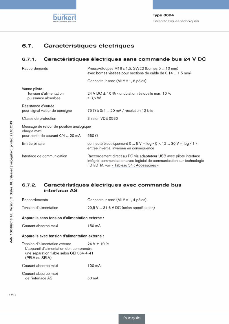
150
Caractéristiques techniques
6.7. caractéristiquesélectriques
6.7.1. caractéristiquesélectriquessanscommandebus24Vdc
Raccordements Presse-étoupes M16 x 1,5, SW22 (bornes 5 ... 10 mm) avec bornes vissées pour sections de câble de 0,14 ... 1,5 mm²
Connecteur rond (M12 x 1, 8 pôles)
Vanne pilote Tension d’alimentation 24 V DC ± 10 % - ondulation résiduelle maxi 10 % puissance absorbée ≤ 3,5 W
Résistance d'entrée pour signal valeur de consigne 75 Ω à 0/4 ... 20 mA / résolution 12 bits
Classe de protection 3 selon VDE 0580
Message de retour de position analogique charge maxi pour sortie de courant 0/4 ... 20 mA 560 Ω
Entrée binaire connecté électriquement 0 ... 5 V = log « 0 », 12 ... 30 V = log « 1 » entrée invertie, inversée en conséquence
Interface de communication Raccordement direct au PC via adaptateur USB avec pilote interface intégré, communication avec logiciel de communication sur technologie FDT/DTM, voir « Tableau 34 : Accessoires ».
6.7.2. caractéristiquesélectriquesaveccommandebusinterfaceas
Raccordements Connecteur rond (M12 x 1, 4 pôles)
Tension d’alimentation 29,5 V ... 31,6 V DC (selon spécification)
appareilssanstensiond’alimentationexterne:
Courant absorbé maxi 150 mA
appareilsavectensiond’alimentationexterne:
Tension d’alimentation externe 24 V ± 10 % L’appareil d’alimentation doit comprendre
une séparation fiable selon CEI 364-4-41 (PELV ou SELV)
Courant absorbé maxi 100 mA
Courant absorbé maxi de l’interface AS 50 mA
Type8694
français

151
Caractéristiques techniques
6.8. réglagesusinedupositionneur
Fonctions activables avec interrupteur DIP :
fonction paramètre Valeur
CUTOFF Fonction de fermeture étanche en bas Fonction de fermeture étanche en haut
2 % 98 %
CHARACT Sélection caractéristique FREE5)
DIR.CMD Sens d’action valeur de consigne Vers le haut
Tableau 4 : Réglages usine - Fonctions I
Fonctions activables avec le logiciel de communication :
fonction paramètre Valeur
INPUT Entrée valeur de consigne 4 ... 20 mA
DIR.ACTUATOR Sens d’action valeur effective Vers le haut
SPLITRANGE Fonction désactivée
Répartition de la plage du signal en bas Répartition de la plage du signal en haut
0 % 100 %
X.LIMIT Fonction désactivée
Limitation de la course en bas Limitation de la course en haut
0 % 100 %
X.TIME Fonction désactivée
Temps de réglage à l'ouverture Temps de réglage à la fermeture
(1 s) valeurs de X.TUNE déterminées (1 s) valeurs de X.TUNE déterminées Après exécution de RESET : 1 s
X.CONTROL Bande morte Facteur d’amplification ouvrir Facteur d’amplification fermer
1,0 % (1) valeurs de X.TUNE déterminées (1) valeurs de X.TUNE déterminées Après exécution de RESET : 1
SAFE POSITION Position de sécurité 0 %
SIGNAL ERROR Fonction désactivée
Détection de rupture de capteur valeur de consigne
OFF
BINARY INPUT Fonction entrée binaire Mode d’action entrée binaire
Position de sécurité Contact de fermeture
OUTPUT (en option)
Sortie signal normalisé : Paramètres Sortie signal normalisé : Type
Position 4 ... 20 mA
Tableau 5 : Réglages usine - Fonctions II
5) Sans modification des réglages à l'aide du logiciel de communication, une caractéristique linéaire est enregistrée avec FREE.
Type8694
français

152
Eléments de commande et d'affichage
7. elémenTsdecOmmandeeTd'affichageLe chapitre suivant décrit les états de marche ainsi que les éléments de commande et d'affichage du positionneur. Vous trouverez d'autres informations concernant la commande du positionneur au chapitre « 12. Mise en service ».
7.1. etatdemarche
autOmatique(autO)
A l'état de marche AUTOMATIQUE, le fonctionnement normal du régulateur est effectué et surveillé.
→ La LED 1 clignote en vert.
manuel
A l'état de marche MANUEL, la vanne peut être ouverte ou fermée manuellement à l'aide des touches.
→ La LED 1 clignote en rouge / vert en alternance.
L'interrupteur DIP 4 permet de passer de l'état de marche AUTOMATIQUE à MANUEL et vice versa.
On dip
1 2 3 4
7.2. elémentsdecommandeetd'affichagedupositionneur
Interrupteur DIP
Touche 2
Touche 1
LED 2LED 1
Interface de communication
Version 1 Version 2
1 2 3 4
ON DIP
Touche 1
Touche 2
LED 1
LED 2
Interface de communication
Figure 8 : Description des éléments de commande
Type8694
français
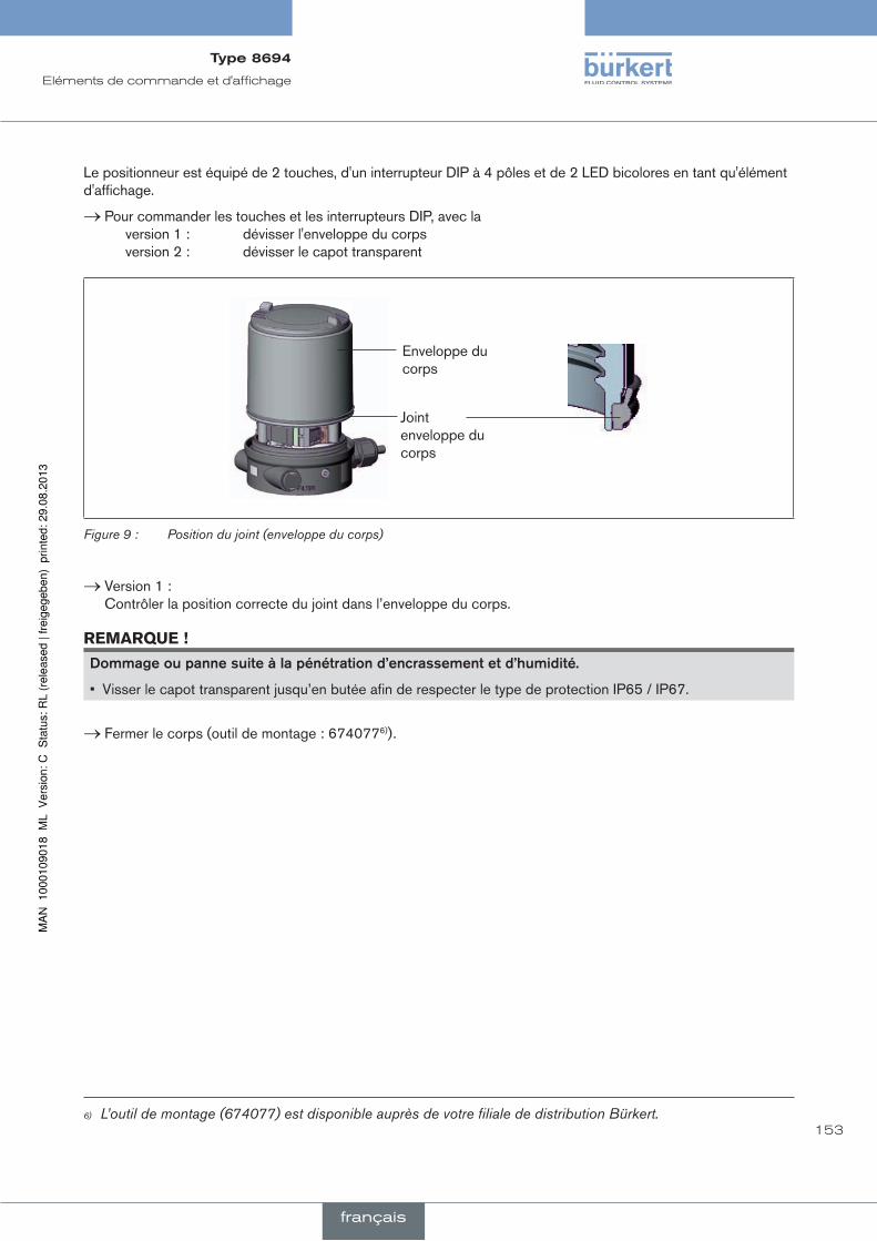
153
Eléments de commande et d'affichage
Le positionneur est équipé de 2 touches, d'un interrupteur DIP à 4 pôles et de 2 LED bicolores en tant qu'élément d'affichage.
→ Pour commander les touches et les interrupteurs DIP, avec la version 1 : dévisser l'enveloppe du corps version 2 : dévisser le capot transparent
Joint enveloppe du corps
Enveloppe du corps
Figure 9 : Position du joint (enveloppe du corps)
→ Version 1 : Contrôler la position correcte du joint dans l’enveloppe du corps.
reMarque !
dommageoupannesuiteàlapénétrationd’encrassementetd’humidité.
• Visser le capot transparent jusqu’en butée afin de respecter le type de protection IP65 / IP67.
→ Fermer le corps (outil de montage : 6740776)).
6) L’outil de montage (674077) est disponible auprès de votre filiale de distribution Bürkert.
Type8694
français

154
Eléments de commande et d'affichage
7.3. affectationdestouches
L'affectation des 2 touches est différente en fonction de l'état de marche (AUTOMATIQUE / MANUEL).
Vous trouverez la description des états de marche (AUTOMATIQUE / MANUEL) au chapitre « 7.1. Etat de marche ».
Touche 2
Touche 1
Touche 1 Touche 2
Version 1 Version 2
Figure 10 : Description des touches
→ Pour commander les touches, avec la version 1 : dévisser l'enveloppe du corps version 2 : dévisser le capot transparent
Etat de marche MANUEL (interrupteur DIP 4 sur ON) :
Touche Fonction
1 Alimentation en air7) (ouverture / fermeture manuelle de l'actionneur)8)
2 Echappement7) (ouverture / fermeture manuelle de l'actionneur)8)
Tableau 6 : Affectation des touches état de marche MANUEL
Etat de marche AUTOMATIQUE (interrupteur DIP 4 sur OFF) :
Touche Fonction
1 la fonction X.TUNE démarre en appuyant pendant 5 secondes
2 -
Tableau 7 : Affectation des touches état de marche AUTOMATIQUE
7) Sans fonction si l’entrée binaire avec la fonction « commutation manuel / automatique » a été activée via le logiciel de communication.
8) En fonction du mode d'action de l'actionneur.
Type8694
français

155
Eléments de commande et d'affichage
Joint enveloppe du corps
Enveloppe du corps
Figure 11 : Position du joint (enveloppe du corps)
→ Version 1 : Contrôler la position correcte du joint dans l’enveloppe du corps.
reMarque !
dommageoupannesuiteàlapénétrationd’encrassementetd’humidité.
• Visser le capot transparent jusqu’en butée afin de respecter le type de protection IP65 / IP67.
→ Fermer le corps (outil de montage : 6740779)).
9) L’outil de montage (674077) est disponible auprès de votre filiale de distribution Bürkert.
Type8694
français

156
Eléments de commande et d'affichage
7.4. fonctiondesinterrupteursdip
On dip
1 2 3 4
→ Pour commander les interrupteurs DIP, avec la version 1 : dévisser l'enveloppe du corps version 2 : dévisser le capot transparent.
interrupteur DiP
Position Fonction
1 ON Inversion du sens d'action de la valeur de consigne (DIR.CMD) (la valeur de consigne 20 ... 4 mA correspond à la position 0 ... 100 %), vers le bas
OFF sens d'action normal de la valeur de consigne (la valeur de consigne 4 ... 20 mA correspond à la position 0 ... 100 %), vers le haut
2 ON Fonction de fermeture étanche activée. La vanne se ferme en dessous de 2 %10) et s'ouvre complètement au-dessus de 98 % de la valeur de consigne (CUTOFF)
OFF aucune fonction de fermeture étanche
3 ON Caractéristique de correction pour l'adaptation de la caractéristique de fonctionnement (linéarisation de la caractéristique de processus CHARACT) 11)
OFF Caractéristique linéaire
4 ON Etat de marche manuel (MANUEL)
OFF Etat de marche AUTOMATIQUE (AUTO)
Tableau 8 : Interrupteur DIP
remarquesconcernantlelogicieldecommunication:
La position de commutation de l’interrupteur DIP est prioritaire par rapport aux réglages effectués à l'aide du logiciel de communication.
Si les valeurs de la fonction de fermeture étanche (CUTOFF) ou de la caractéristique de correction (CHARACT) sont modifiées à l'aide du logiciel de communication, la fonction correspondante doit être activée (interrupteur DIP sur ON). Le sens d'action de la valeur de consigne (DIR.CMD) peut être modifié uniquementà l'aide des interrupteurs DIP. Si aucune modification de la caractéristique de correction (CHARACT) n'a lieu par l'intermédiaire du logiciel de communication, une caractéristique linéaire est enregistrée lorsque l'interrupteur DIP 3 est sur ON.
Vous trouverez une description détaillée des fonctions au chapitre « 13.1. Fonctions de base » et dans les instructions de service du logiciel de communication.
10) Le réglage usine peut être modifié via le logiciel de communication.11) Le type de courbe peut être modifié via le logiciel de communication.
Type8694
français

157
Eléments de commande et d'affichage
Joint enveloppe du corps
Enveloppe du corps
Figure 12 : Position du joint (enveloppe du corps)
→ Version 1 : Contrôler la position correcte du joint dans l’enveloppe du corps.
reMarque !
dommageoupannesuiteàlapénétrationd’encrassementetd’humidité.
• Visser le capot transparent jusqu’en butée afin de respecter le type de protection IP65 / IP67.
→ Fermer le corps (outil de montage : 67407712)).
12) L’outil de montage (674077) est disponible auprès de votre filiale de distribution Bürkert.
Type8694
français

158
Eléments de commande et d'affichage
7.5. affichagedesled
Version 1 Version 2
LED 1 LED 2LED 1
(verte / rouge)
Affichage des états de marche AUTO, MANUEL, X.TUNE et DEFAUT
LED 2
(verte / jaune)
Affichage de l'état de l'actionneur (ouvert, fermé, s'ouvre ou se ferme)
Figure 13 : Affichage LED
LeD 1 (verte / rouge)
etats des LeDaffichage
vert rouge
allumée éteinte phase de démarrage pour Power ON
clignote lentement éteinte Etat de marche AUTO (AUTOMATIQUE)
clignote clignote Etat de marche MANUELen alternance
clignote rapidement
éteinte Fonction X.TUNE
éteinte allumée DEFAUT (voir chapitre « 7.6. Messages d’erreur »)
clignote clignote Etat de marche AUTO en cas de détection de rupture de capteurlentement
Tableau 9 : Affichage LED 1
LeD 2 (verte / jaune)
etats des LeDaffichage
vert jaune
allumée éteinte actionneur fermé
éteinte allumée actionneur ouvert
clignote lentement éteinteécart de régulation permanent (valeur effective > valeur de consigne)
éteinte clignote lentementécart de régulation permanent (valeur effective < valeur de consigne)
clignote rapidement
éteinte Fermeture en état de marche MANUEL
éteinte clignote rapidement Ouverture en état de marche MANUEL
Tableau 10 : Affichage LED 2
Type8694
français
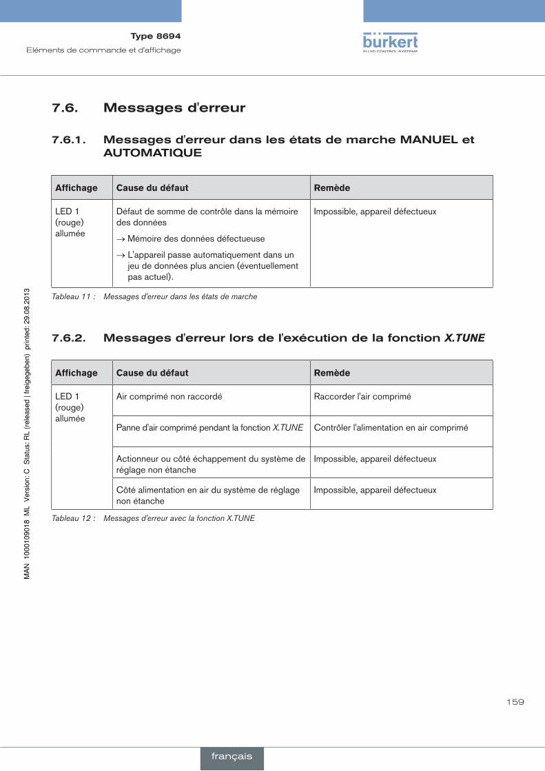
159
Eléments de commande et d'affichage
7.6. messagesd'erreur
7.6.1. messagesd'erreurdanslesétatsdemarchemanueletauTOmaTique
affichage Cause du défaut remède
LED 1 (rouge) allumée
Défaut de somme de contrôle dans la mémoire des données
→ Mémoire des données défectueuse
→ L'appareil passe automatiquement dans un jeu de données plus ancien (éventuellement pas actuel).
Impossible, appareil défectueux
Tableau 11 : Messages d'erreur dans les états de marche
7.6.2. messagesd'erreurlorsdel'exécutiondelafonctionX.TUNE
affichage Cause du défaut remède
LED 1 (rouge) allumée
Air comprimé non raccordé Raccorder l'air comprimé
Panne d'air comprimé pendant la fonction X.TUNE Contrôler l'alimentation en air comprimé
Actionneur ou côté échappement du système de réglage non étanche
Impossible, appareil défectueux
Côté alimentation en air du système de réglage non étanche
Impossible, appareil défectueux
Tableau 12 : Messages d'erreur avec la fonction X.TUNE
Type8694
français
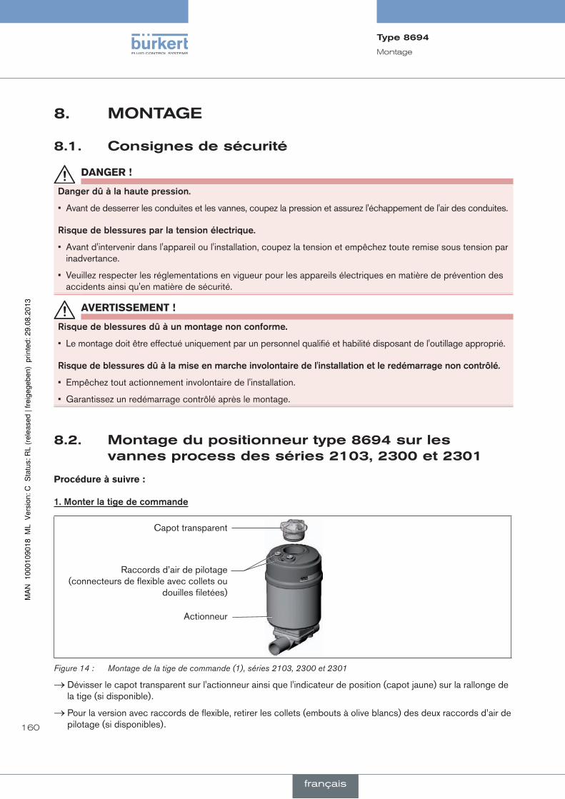
160
Montage
8. mOnTage
8.1. consignesdesécurité
Danger !
dangerdûàlahautepression.
• Avant de desserrer les conduites et les vannes, coupez la pression et assurez l'échappement de l'air des conduites.
risquedeblessuresparlatensionélectrique.
• Avant d'intervenir dans l'appareil ou l'installation, coupez la tension et empêchez toute remise sous tension par inadvertance.
• Veuillez respecter les réglementations en vigueur pour les appareils électriques en matière de prévention des accidents ainsi qu'en matière de sécurité.
aVerTiSSeMenT !
risquedeblessuresdûàunmontagenonconforme.
• Le montage doit être effectué uniquement par un personnel qualifié et habilité disposant de l'outillage approprié.
risquedeblessuresdûàlamiseenmarcheinvolontairedel'installationetleredémarragenoncontrôlé.
• Empêchez tout actionnement involontaire de l'installation.
• Garantissez un redémarrage contrôlé après le montage.
8.2. montagedupositionneurtype8694surlesvannesprocessdesséries2103,2300et2301
Procédure à suivre :
1.monterlatigedecommande
Capot transparent
Actionneur
Raccords d’air de pilotage (connecteurs de flexible avec collets ou
douilles filetées)
Figure 14 : Montage de la tige de commande (1), séries 2103, 2300 et 2301
→ Dévisser le capot transparent sur l'actionneur ainsi que l'indicateur de position (capot jaune) sur la rallonge de la tige (si disponible).
→ Pour la version avec raccords de flexible, retirer les collets (embouts à olive blancs) des deux raccords d’air de pilotage (si disponibles).
Type8694
français

161
Montage
Joint torique
Rallonge de tige
Élément de guidage
Couvercle d’actionneur
Bague rainurée
Support de rouleau presseur
Tige de commande
10
max. 5 Nm
max. 1 Nm
Figure 15 : Montage de la tige de commande (2), séries 2103, 2300 et 2301
reMarque !
lemontagenonconformepeutendommagerlabaguerainuréedansl’élémentdeguidage.
La bague rainurée est déjà montée dans l’élément de guidage et doit être engagée dans la coupe arrière.
• N'endommagez pas la bague rainurée lors du montage de la tige de commande.
→ Pousser la tige de commande à travers l’élément de guidage.
reMarque !
lefrein-filetpeutcontaminerlabaguerainurée.
• N’appliquez pas de frein-filet sur la tige de commande.
→ Pour assurer le blocage de la tige de commande, appliquer un peu de frein-filet (Loctite 290) dans l’alésage de la rallonge de tige située dans l’actionneur.
→ Contrôler le bon positionnement du joint torique.
→ Visser l’élément de guidage avec le couvercle d'actionneur (couple de serrage maximal : 5 Nm).
→ Visser la tige de commande sur la rallonge de tige. A cet effet, une fente est présente sur le dessus de la tige (couple de serrage maximal : 1 Nm).
→ Glisser le support du rouleau presseur sur la tige de commande et l'engager.
Type8694
français

162
Montage
2.monterlesbaguesd'étanchéité
→ Placer le joint profilé sur le couvercle d'actionneur (le plus petit diamètre est dirigé vers le haut).
→ Contrôler le bon positionnement des joints toriques dans les raccords d’air de pilotage.
Lors du montage du positionneur, les collets des raccords d’air de pilotage ne doivent pas être montés sur l’actionneur.
Joint profilé
Raccords d’air de pilotage
Attention : les collets ne doivent
pas être montés.
Montage du joint profilé
Figure 16 : Montage des bagues d'étanchéité, séries 2103, 2300 et 2301
3.monterlepositionneur
→ Disposer le support de rouleau presseur et le positionneur de façon 1. qu‘il entre dans le rail de guidage du positionneur (voir « Figure 17 ») et 2. que les manchons du positionneur entrent dans les raccords d’air de pilotage de l’actionneur
(voir « Figure 18 »).
reMarque !
endommagementdelaplatineoupanne.
• Veiller à ce que le support de rouleau presseur repose bien à plat sur le rail de guidage.
Rail de guidage
Support de rouleau presseur
Figure 17 : Disposition du support de rouleau presseur
Type8694
français

163
Montage
→ Glisser le positionneur sur l’actionneur sans la faire tourner jusqu’à ce que le joint profilé ne présente plus d’interstice.
reMarque !
letypedeprotectionip65/ip67nepeutêtregarantisilecoupledeserragedelavisdefixationesttropélevé.
• Les vis de fixation doivent être serrées uniquement avec un couple de serrage maximal de 0,5 Nm.
→ Fixer le positionneur sur l'actionneur à l'aide des deux vis de fixation latérales. Ne serrer les vis que légèrement (couple de serrage maxi : 0,5 Nm).
Manchons
Raccords d’air de pilotage
Vis de fixation maxi 0,5 Nm
Actionneur
Figure 18 : Montage du positionneur, séries 2103, 2300 et 2301
8.3. montagedupositionneurtype8694surlesvannesprocessdesséries26xxet27xx
Procédure à suivre :
1.monterlatigedecommande
Élément de guidage
Rallonge de tige
Actionneur
Figure 19 : Montage de la tige de commande (1), séries 26xx et 27xx - 1
→ Dévisser l’élément de guidage déjà montée sur l'actionneur (si disponible).
→ Retirer la bague intermédiaire (si disponible).
Type8694
français

164
Montage
Élément de guidage
Joint torique
Rallonge de tige
Support de rouleau presseur
Tige de commande
Tige (actionneur)
Figure 20 : Montage de la tige de commande (2), séries 26xx et 27xx
→ Enfoncer le joint torique vers le bas dans le couvercle de l'actionneur.
→ Taille d'actionneur 125 et supérieure à grand débit d'air : démonter la rallonge de tige disponible et la remplacer par une neuve. Pour ce faire, appliquer un peu de frein-filet (Loctite 290) dans l'alésage de la rallonge de tige.
→ Visser l’élément de guidage dans le couvercle de l'actionneur à l'aide d'une clé à ergots13) (couple de serrage : 8,0 Nm).
→ Pour assurer le blocage de la tige de commande, appliquer un peu de frein-filet (Loctite 290) au filet de la tige de commande.
→ Visser la tige de commande sur la rallonge de tige. A cet effet, une fente est présente sur le dessus de la tige (couple de serrage maximal : 1 Nm).
→ Glisser le support de rouleau presseur sur la tige de commande jusqu'à ce qu'il s'engage.
13) Pivot Ø : 3 mm ; écartement du pivot : 23,5 mm
Type8694
français
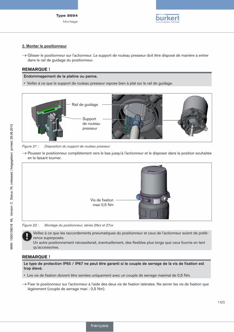
165
Montage
2.monterlepositionneur
→ Glisser le positionneur sur l'actionneur. Le support de rouleau presseur doit être disposé de manière à entrer dans le rail de guidage du positionneur.
reMarque !
endommagementdelaplatineoupanne.
• Veiller à ce que le support de rouleau presseur repose bien à plat sur le rail de guidage.
Rail de guidage
Support de rouleau presseur
Figure 21 : Disposition du support de rouleau presseur
→ Pousser le positionneur complètement vers le bas jusqu'à l'actionneur et le disposer dans la position souhaitée en le faisant tourner.
Vis de fixation maxi 0,5 Nm
Figure 22 : Montage du positionneur, séries 26xx et 27xx
Veillez à ce que les raccordements pneumatiques du positionneur et ceux de l'actionneur soient de préfé-rence superposés. Un autre positionnement nécessiterait, éventuellement, des flexibles plus longs que ceux fournis en tant qu'accessoires.
reMarque !
letypedeprotectionip65/ip67nepeutêtregarantisilecoupledeserragedelavisdefixationesttropélevé.
• Les vis de fixation doivent être serrées uniquement avec un couple de serrage maximal de 0,5 Nm.
→ Fixer le positionneur sur l'actionneur à l'aide des deux vis de fixation latérales. Ne serrer les vis de fixation que légèrement (couple de serrage maxi : 0,5 Nm).
Type8694
français

166
Montage
3.réaliserleraccordementpneumatiqueentrelepositionneuretl'actionneur
Sortie d’air de pilotage 21
Sortie d’air de pilotage 22
Raccord d’air de pilotage supérieure
Raccord d’air de pilotage inférieure
Exemple ∅ 80, CFA
Figure 23 : Montage du raccordement pneumatique, série 26xx et 27xx
→ Visser les connecteurs de flexible sur le positionneur et l'actionneur.
→ Réaliser le raccordement pneumatique entre le positionneur et l'actionneur à l'aide des flexibles fournis avec le jeu d'accessoires et du « Tableau 13 : Raccordement pneumatique à l’actionneur - CFA » ou « Tableau 14 : Raccordement pneumatique à l’actionneur - CFB ».
reMarque !
dommageoupannesuiteàlapénétrationd’encrassementetd’humidité.
Afin de respecter les types de protection IP65 / IP67:
• Avec une taille d‘actionneur ∅ 80, ∅ 100 Relier la sortie d’air de pilotage non utilisé au raccord d’air de pilotage libre de l’actionneur ou l’obturer.
• Avec une taille d‘actionneur ∅ 125 obturer la sortie d’air de pilotage non utilisée 22 avec un bouchon de fermeture et dévier le raccord d’air de pilotage libre de l’actionneur dans un environnement sec au moyen d’un flexible.
fonctiona(cfa) Vanne process fermée en position de repos (par ressort)
Tailles d’actionneur ∅ 80, ∅ 100
∅ 125
Pos
ition
neur
Sortie d’air de pilotage
22 2122 21
Act
ionn
eur Raccord d’air de pilotage
supérieure
Raccord d’air de pilotage inférieureZone sèche
Tableau 13 : Raccordement pneumatique à l’actionneur - CFA
Type8694
français

167
Montage
fonctionB(cfB) Vanne process ouverte en position de repos (par ressort)
Tailles d’actionneur ∅ 80, ∅ 100
∅ 125
Pos
ition
neur Sortie d’air de pilotage
22 2122 21
Act
ionn
eur Raccord d’air de pilotage
supérieureRaccord d’air de pilotage inférieureZone sèche
Tableau 14 : Raccordement pneumatique à l’actionneur - CFB
« En position de repos » signifie que les vannes pilote du positionneur type 8694 ne sont pas alimentées en courant ou ne sont pas activées.
8.4. rotationdumoduleactionneur
La rotation du module actionneur (positionneur et actionneur) est uniquement possible pour les vannes à siège droit et à siège incliné des séries 2300, 2301 et 27xx.
La position des raccordements peut être alignée en continu par la rotation du module actionneur (positionneur et actionneur) de 360°.
Seul le module actionneur complet peut être tourné. La rotation du positionneur contre l'actionneur n'est pas possible. Lors de l'alignement du module actionneur, la vanne process doit être en position ouverte.
Danger !
dangerdûàlahautepression.
• Avant de desserrer les conduites et les vannes, coupez la pression et assurez l'échappement de l'air des conduites.
procédureàsuivre:
→ Serrer le corps de la vanne dans un dispositif de maintien (nécessaire uniquement si la vanne process n'est pas encore montée).
reMarque !
endommagementdujointouducontourdesiège.
• Lors de la démontage du module actionneur, la vanne doit être en position ouverte.
→ Avec la fonction de commande A : ouvrir la vanne process.
Type8694
français
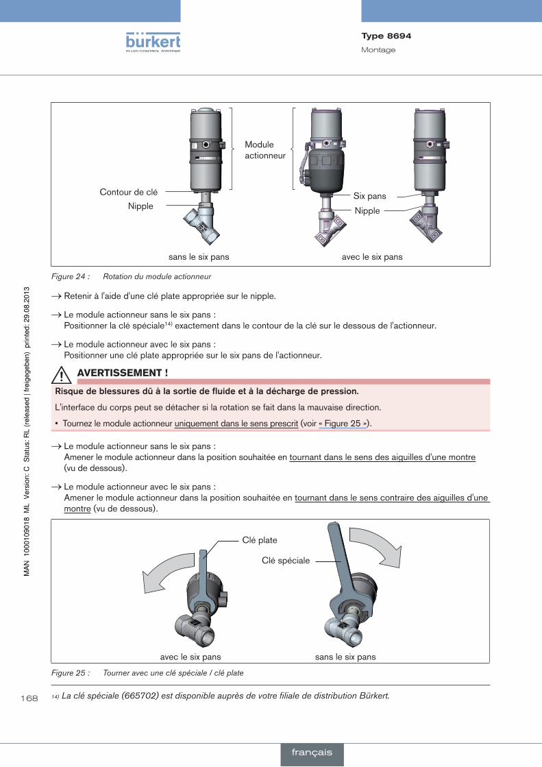
168
Montage
Module actionneur
Contour de clé Six pansNipple
avec le six panssans le six pans
Nipple
Figure 24 : Rotation du module actionneur
→ Retenir à l'aide d'une clé plate appropriée sur le nipple.
→ Le module actionneur sans le six pans : Positionner la clé spéciale14) exactement dans le contour de la clé sur le dessous de l'actionneur.
→ Le module actionneur avec le six pans : Positionner une clé plate appropriée sur le six pans de l'actionneur.
aVerTiSSeMenT !
risquedeblessuresdûàlasortiedefluideetàladéchargedepression.
L'interface du corps peut se détacher si la rotation se fait dans la mauvaise direction.
• Tournez le module actionneur uniquement dans le sens prescrit (voir « Figure 25 »).
→ Le module actionneur sans le six pans : Amener le module actionneur dans la position souhaitée en tournant dans le sens des aiguilles d'une montre (vu de dessous).
→ Le module actionneur avec le six pans : Amener le module actionneur dans la position souhaitée en tournant dans le sens contraire des aiguilles d'une montre (vu de dessous).
Clé spéciale
Clé plate
sans le six pansavec le six pans
Figure 25 : Tourner avec une clé spéciale / clé plate
14) La clé spéciale (665702) est disponible auprès de votre filiale de distribution Bürkert.
Type8694
français

169
Montage
8.5. rotationdupositionneurpourlesvannesprocessdesséries26xxet27xx
Si après montage de la vanne process, le montage des câbles de raccordement ou des flexibles est difficile, il est possible de tourner le positionneur contre l'actionneur.
Vis de fixation (2x)
Raccord pneumatique
Positionneur
Actionneur
Figure 26 : Rotation du positionneur, séries 26xx et 27xx
Procédure à suivre
→ Desserrer le raccord pneumatique entre le positionneur et l'actionneur.
→ Desserrer les vis de fixation (six pans creux clé de 2,5).
→ Tourner le positionneur dans la position souhaitée.
reMarque !
letypedeprotectionip65/ip67nepeutêtregarantisilecoupledeserragedelavisdefixationesttropélevé.
• La vis de fixation doit être serrée uniquement avec un couple de serrage maximal de 0,5 Nm.
→ Ne serrer les vis de fixation que légèrement (couple de serrage maxi : 0,5 Nm).
→ Rétablir les raccords pneumatiques entre le positionneur et l'actionneur. Si nécessaire, utiliser des flexibles plus longs.
Type8694
français

170
Installation fluidique
9. insTallaTiOnfluidiqueLes dimensions du positionneur et des différentes variantes d'appareils complets, comprenant le positionneur, l'actionneur et la vanne, peuvent être consultées dans les fiches techniques correspondantes.
9.1. consignesdesécurité
Danger !
dangerdûàlahautepression.
• Avant de desserrer les conduites et les vannes, coupez la pression et assurez l'échappement de l'air des conduites.
risquedeblessuresparlatensionélectrique.
• Avant d'intervenir dans l'appareil ou l'installation, coupez la tension et empêchez toute remise sous tension par inadvertance.
• Veuillez respecter les réglementations en vigueur pour les appareils électriques en matière de prévention des accidents ainsi qu'en matière de sécurité.
aVerTiSSeMenT !
risquedeblessuresdûàunmontagenonconforme.
• Le montage doit être effectué uniquement par un personnel qualifié et habilité disposant de l’outillage approprié.
risquedeblessuresdûàlamiseenmarcheinvolontairedel'installationetleredémarragenoncontrôlé.
• Empêchez tout actionnement involontaire de l'installation.
• Garantissez un redémarrage contrôlé après le montage.
9.2. installationdelavanneprocess
Le type de filet et les dimensions peuvent être consultés dans la fiche technique correspondante.
→ Raccorder la vanne conformément aux instructions de service la concernant.
Type8694
français

171
Installation fluidique
9.3. raccordementpneumatiquedupositionneur
Danger !
dangerdûàlahautepression.
• Avant de desserrer les conduites et les vannes, coupez la pression et assurez l'échappement de l'air des conduites.
procédureàsuivre:
→ Raccorder le fluide de commande au raccord d’air de pilotage (1) (3 ... 7 bars ; air d’instrument, exempt d’huile, d’eau et de poussières).
→ Monter la conduite d’évacuation d’air ou un silencieux sur le raccord d’évacuation d’air (3) sur le raccord d’évacuation d’air (3.1) si disponible.
Remarque importante concernant le parfait fonctionnement de l’appareil :
• L’installation ne doit pas générer de contre-pression.
• Pour le raccordement, choisissez un flexible d’une section suffisante.
• La conduite d’évacuation d’air doit être conçue de façon à empêcher l’entrée d’eau ou d’autre liquide dans l’appareil par le raccord d’évacuation d’air (3) ou (3.1).
Raccord d’air de pilotage (Légende : 1)
Raccord d’évacuation d’air (Légende : 3)
Raccord de purge d’air supplémentaire (Légende : 3.1) uniquement pour type 23xx et 2103 avec système de réglage à commande pilote pour débit d’air important (Tailles d’actionneur ø 130)
Figure 27 : Raccordement pneumatique
attention (concept d'évacuation d'air) : Pour le respect du type de protection IP67, il convient de monter une conduite d'évacuation d'air dans la zone sèche. Maintenez la pression d'alimentation appliquée absolument à au moins 0,5 ... 1 bar au-dessus de la pression nécessaire pour amener l'actionneur dans sa position finale. De cette façon, vous avez la garantie que le comportement de régulation dans la course supérieure ne subit pas de forte influence négative du fait d'une différence de pression trop faible. Maintenez aussi faibles que possible les variations de pression d'alimentation pendant le fonctionnement (maxi ±10 %). Si les variations sont plus importantes, les paramètres du régulateur mesurés avec la fonction X.TUNE ne sont pas optimaux.
Type8694
français
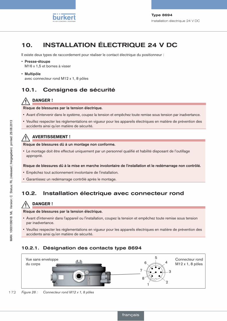
172
Installation électrique 24 V DC
10. insTallaTiOnélecTrique24VdcIl existe deux types de raccordement pour réaliser le contact électrique du positionneur :
• presse-étoupe M16 x 1,5 et bornes à visser
• multipôle avec connecteur rond M12 x 1, 8 pôles
10.1. consignesdesécurité
Danger !
risquedeblessuresparlatensionélectrique.
• Avant d'intervenir dans le système, coupez la tension et empêchez toute remise sous tension par inadvertance.
• Veuillez respecter les réglementations en vigueur pour les appareils électriques en matière de prévention des accidents ainsi qu'en matière de sécurité.
aVerTiSSeMenT !
risquedeblessuresdûàunmontagenonconforme.
• Le montage doit être effectué uniquement par un personnel qualifié et habilité disposant de l’outillage approprié.
risquedeblessuresdûàlamiseenmarcheinvolontairedel'installationetleredémarragenoncontrôlé.
• Empêchez tout actionnement involontaire de l'installation.
• Garantissez un redémarrage contrôlé après le montage.
10.2. installationélectriqueavecconnecteurrond
Danger !
risquedeblessuresparlatensionélectrique.
• Avant d'intervenir dans l'appareil ou l'installation, coupez la tension et empêchez toute remise sous tension par inadvertance.
• Veuillez respecter les réglementations en vigueur pour les appareils électriques en matière de prévention des accidents ainsi qu'en matière de sécurité.
10.2.1. désignationdescontactstype8694
Vue sans enveloppe du corps
Connecteur rond M12 x 1, 8 pôles6
1
7
54
3
28
Figure 28 : Connecteur rond M12 x 1, 8 pôles
Type8694
français

173
Installation électrique 24 V DC
10.2.2. raccordementdupositionneurtype8694
→ Raccorder les broches conformément à la version (options) du positionneur.
Signaux d'entrée du poste de commande (par ex. aPi) – connecteur rond M12 x 1, 8 pôles
Broche couleurdefil15) affectation câblageexterne/niveaudesignal
1
2
blanc
brun
Valeur de consigne + (0/4 ... 20 mA)
Valeur de consigne GND
1
2 GND
+ (0/4 ... 20 mA) connecté électriquement
5 6
gris rose
Entrée binaire + Entrée binaire GND
5 + 0 ... 5 V (log. 0)10 ... 30 V (log. 1)
identique à la broche 3 (GND)
Tableau 15 : Affectation des broches ; signaux d'entrée du poste de commande - connecteur rond M12 x 1, 8 pôles
Signaux de sortie vers le poste de commande (par ex. aPi) - conducteur rond M12 x 1, 8 pôles (nécessaire uniquement avec l'option sortie analogique)
Broche couleurdefil15) affectation câblageexterne/niveaudesignal
8
7
rouge
bleu
Message de retour de position + analogique
Message de retour de position GND analogique
8
7 GND
+ (0/4 ... 20 mA) connecté électriquement
Tableau 16 : Affectation des broches ; signaux de sortie vers le poste de commande - connecteur rond M12 x 1, 8 pôles
Tension d’alimentation (connecteur rond M 12 x 1, 8 pôles)
Broche couleurdefil15) affectation câblageexterne
4
3
jaune
vert
+ 24 V
GND
4
3
24 V DC ± 10 % ondulation résiduelle maxi 10 %
Tableau 17 : Affectation des broches ; tension d’alimentation (connecteur rond M12 x 1, 8 pôles)
Après application de la tension d'alimentation, le positionneur est en marche.
→ Effectuer les réglages de base nécessaires et déclencher l'adaptation automatique du positionneur comme cela est décrit au chapitre « 12. Mise en service ».
15) Les couleurs indiquées se rapportent aux câbles de raccordement disponibles en tant qu’accessoires (919061)
Type8694
français

174
Installation électrique 24 V DC
10.3. installationélectriqueavecpresse-étoupe
Danger !
risquedeblessuresparlatensionélectrique.
• Avant d'intervenir dans l'appareil ou l'installation, coupez la tension et empêchez toute remise sous tension par inadvertance.
• Veuillez respecter les réglementations en vigueur pour les appareils électriques en matière de prévention des accidents ainsi qu'en matière de sécurité.
10.3.1. désignationdesbornesvissées
1216)
316)
4567
Figure 29 : Raccordement des bornes vissées
10.3.2. raccordementdupositionneurtype8694
→ Les bornes vissées sont accessibles en dévissant l'enveloppe du corps (acier inoxydable).
→ Pousser les câbles à travers le presse-étoupes.
→ Raccorder le positionneur conformément aux tableaux suivants :
Signaux d'entrée du poste de commande (par ex. aPi)
Borne affectation câblageexterne
4 5
Valeur de consigne + Valeur de consigne GND
4
5 GND
+ (0/4 ... 20 mA)
1
Entrée binaire +
1 + 0 ... 5 V (log. 0)10 ... 30 V (log. 1)
par rapport à la broche 7 (GND)
Tableau 18 : Affectation des bornes vissées ; signaux d'entrée du poste de commande - presse-étoupes
16) Uniquement l’option
Type8694
français

175
Installation électrique 24 V DC
Signaux de sortie vers le poste de commande (par ex. aPi ; uniquement avec l'option sortie analogique)
Borne affectation câblageexterne
2
3
Message de retour de position + analogique
Message de retour de position GND analogique
2
3 GND
+ (0/4 ... 20 mA) connecté électriquement
Tableau 19 : Affectation des bornes vissées ; signaux de sortie vers le poste de commande - presse-étoupes
Tension d’alimentation
Borne affectation câblageexterne
6 7
Tension d’alimentation + Tension d’alimentation GND
6
7
24 V DC ± 10 % ondulation résiduelle maxi 10 %
Tableau 20 : Affectation des bornes vissées ; tension d’alimentation - presse-étoupes
Joint enveloppe du corps
Enveloppe du corps
Figure 30 : Position du joint (enveloppe du corps)
→ Contrôler la position correcte du joint dans l’enveloppe du corps.
reMarque !
dommageoupannesuiteàlapénétrationd’encrassementetd’humidité.
Pour garantir le type de protection IP65 / IP67 :
• Serrer l’écrou-raccord du passe-câbles à vis en fonction de la taille de câble, resp. du bouchon borgne utilisé(e).
• Visser l’enveloppe du corps jusqu’en butée.
→ Serrer l’écrou-raccord du passe-câbles à vis (couple env. 1,5 Nm).
→ Fermer le corps (outil de montage : 67407717)).
Après application de la tension d'alimentation, le positionneur est en marche.
→ Effectuer les réglages de base nécessaires et déclencher l'adaptation automatique du positionneur comme cela est décrit au chapitre « 12. Mise en service ».
17) L’outil de montage (674077) est disponible auprès de votre filiale de distribution Bürkert.
Type8694
français
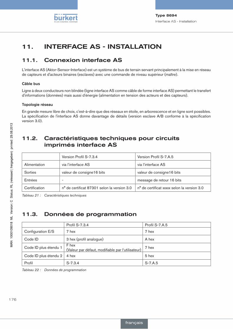
176
Interface AS - Installation
11. inTerfaceas-insTallaTiOn
11.1. connexioninterfaceas
L'interface AS (Aktor-Sensor-Interface) est un système de bus de terrain servant principalement à la mise en réseau de capteurs et d'acteurs binaires (esclaves) avec une commande de niveau supérieur (maître).
câblebus
Ligne à deux conducteurs non blindée (ligne interface AS comme câble de forme interface AS) permettant le transfert d'informations (données) mais aussi d'énergie (alimentation en tension des acteurs et des capteurs).
topologieréseau
En grande mesure libre de choix, c'est-à-dire que des réseaux en étoile, en arborescence et en ligne sont possibles. La spécification de l'interface AS donne davantage de détails (version esclave A/B conforme à la spécification version 3.0).
11.2. caractéristiquestechniquespourcircuitsimprimésinterfaceas
Version Profil S-7.3.4 Version Profil S-7.A.5
Alimentation via l’interface AS via l’interface AS
Sorties valeur de consigne16 bits valeur de consigne16 bits
Entrées - message de retour 16 bits
Certification n° de certificat 87301 selon la version 3.0 n° de certificat xxxxx selon la version 3.0
Tableau 21 : Caractéristiques techniques
11.3. donnéesdeprogrammation
Profil S-7.3.4 Profil S-7.A.5
Configuration E/S 7 hex 7 hex
Code ID 3 hex (profil analogue) A hex
Code ID plus étendu 1F hex (Valeur par défaut, modifiable par l‘utilisateur)
7 hex
Code ID plus étendu 2 4 hex 5 hex
Profil S-7.3.4 S-7.A.5
Tableau 22 : Données de programmation
Type8694
français
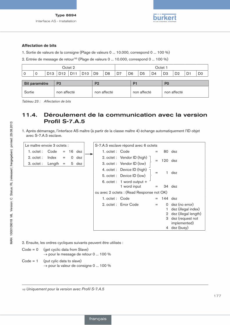
177
Interface AS - Installation
affectation de bits
1. Sortie de valeurs de la consigne (Plage de valeurs 0 ... 10.000, correspond 0 ... 100 %)
2. Entrée de message de retour18) (Plage de valeurs 0 ... 10.000, correspond 0 ... 100 %)
Octet 2 Octet 1
0 0 D13 D12 D11 D10 D9 D8 D7 D6 D5 D4 D3 D2 D1 D0
Bitparamètre p3 p2 p1 p0
Sortie non affecté non affecté non affecté non affecté
Tableau 23 : Affectation de bits
11.4. déroulementdelacommunicationaveclaversionprofils-7.a.5
1. Après démarrage, l’interface AS maître (à partir de la classe maître 4) échange automatiquement l’ID objet avec S-7.A.5 esclave.
S-7.A.5 esclave répond avec 6 octets
1. octet : Code = 80 dez
2. octet : Vendor ID (high)= 120 dez
3. octet : Vendor ID (low)
4. octet : Device ID (high)= 1 dez
5. octet : Device ID (low)
6. octet : 1 word output + 1 word input
=
34
dez
ou avec 2 octets : (Read Response not OK)
1. octet : Code = 144 dez
2. octet : Error Code = 0 1 2 3
4
dez (no error) dez (illegal index) dez (illegal length) dez (request not implemented) dez (busy)
Le maître envoie 3 octets :
1. octet : Code = 16 dez
2. octet : Index = 0 dez
3. octet : Length = 5 dez
2. Ensuite, les ordres cycliques suivants peuvent être utilisés :
Code = 0 (get cyclic data from Slave) → pour le message de retour 0 ... 100 %
Code = 1 (put cylic data to slave) → pour la valeur de consigne 0 ... 100 %
18) Uniquement pour la version avec Profil S-7.A.5
Type8694
français

178
Interface AS - Installation
11.5. affichaged'étatled
L'affichage d'état LED indique l'état du bus (LED verte et rouge).
Bus LED verte
Bus LED rouge
Figure 31 : Affichage d'état LED
ledverte ledrouge
éteinte éteinte POWER OFF
éteinte alluméeaucune exploitation des données (chien de garde terminé avec adresse esclave différente de 0)
allumée éteinte OK
clignote allumée Adresse esclave égale à 0
éteinte clignote Défaut de l’électronique ou une mise à niveau externe
clignote clignote Timeout communication bus après 100 ms (défaut périphérie)
Tableau 24 : Affichage d'état LED
Joint enveloppe du corps
Enveloppe du corps
Figure 32 : Position du joint (enveloppe du corps)
→ Contrôler la position correcte du joint dans l’enveloppe du corps.
reMarque !
dommageoupannesuiteàlapénétrationd’encrassementetd’humidité.
• Visser le capot transparent jusqu’en butée afin de respecter le type de protection IP65 / IP67.
→ Fermer le corps (outil de montage : 67407719)).
19) L’outil de montage (674077) est disponible auprès de votre filiale de distribution Bürkert.
Type8694
français

179
Interface AS - Installation
11.6. installationélectriqueinterfaceas
11.6.1. consignesdesécurité
Danger !
risquedeblessuresparlatensionélectrique.
• Avant d'intervenir dans le système, coupez la tension et empêchez toute remise sous tension par inadvertance.
• Veuillez respecter les réglementations en vigueur pour les appareils électriques en matière de prévention des accidents ainsi qu'en matière de sécurité.
aVerTiSSeMenT !
risquedeblessuresdûàunmontagenonconforme.
• Le montage doit être effectué uniquement par un personnel qualifié et habilité disposant de l’outillage approprié.
risquedeblessuresdûàlamiseenmarcheinvolontairedel'installationetleredémarragenoncontrôlé.
• Empêchez tout actionnement involontaire de l'installation.
• Garantissez un redémarrage contrôlé après le montage.
11.6.2. raccordementavecconnecteurrondm12x1,4pôles,mâle
Il n'est pas nécessaire d'ouvrir le positionneur pour la variante multipolaire.
Raccordement bus sans / avec tension d’alimentation externe
Broche désignation affectation
1 Bus + Câble bus interface AS +
2 CN ou GND (en option) non affecté ou tension d’alimentation externe -(en option)
3 Bus - Câble bus interface AS -
4 CN ou 24 V + (en option) non affecté ou tension d’alimentation externe +(en option)
Tableau 25 : Affectation du raccordement connecteur rond interface AS
Vues du connecteur : de devant sur les fiches, les raccords soudés sont à l'arrière
Broche 4 :
NC
Broche 1 :
Bus +
Broche 3 :
Bus -
Broche 2 :
NC
Broche 4 :
24 V +
Broche 1 :
Bus +
Broche 3 :
Bus -
Broche 2 :
GND
Figure 33 : Raccordement bus sans tension d’ali-mentation externe
Figure 34 : Raccordement bus avec tension d’ali-mentation externe (en option)
Type8694
français

180
Interface AS - Installation
Après application de la tension d'alimentation, le positionneur est en marche.
→ Effectuer les réglages de base nécessaires et déclencher l'adaptation automatique du positionneur comme cela est décrit au chapitre « 12. Mise en service ».
11.6.3. raccordementaveccâblemultipolaireetborneàcâbleplat
Le positionneur avec câble multipolaire (connecteur rond M12) et borne à câble plat représente une alternative à la version de raccordement bus avec connecteur rond 4 pôles. Le raccordement du connecteur rond correspond à celui du raccordement bus connecteur rond M12 4 pôles (voir « Figure 33 » et « Figure 34 ») et peut être aisément raccordé à la borne à câble plat (voir « Figure 36 »).
Figure 35 : Positionneur 8694 avec câble multipolaire et borne à câble plat
manipulationdelaborneàcâbleplat
Le câble multipolaire dispose d'une borne à câble plat pourvue d'une sortie connecteur M12 pour le câble de forme de l'interface AS. La borne à câble plat réalise le contact du câble de forme de l'interface AS sous la forme de la technique de pénétration permettant l'installation par « clipsage » du câble de forme de l'interface AS sans couper ni dénuder.
Vis
M12 connecteur enfichable sortie
Opérations :
→ Ouvrir la borne à câble plat (dévisser les vis et soulever le couvercle)
→ Poser le câble de forme correctement
→ Refermer la borne à câble plat
→ Serrer les vis Positionner les vis auto-taraudeuses sur l'alésage existant en les dévissant un peu (environ 3/4 de tour vers la gauche) et les visser.
Figure 36 : Borne à câble plat
Après application de la tension d'alimentation, le positionneur est en marche.
→ Effectuer les réglages de base nécessaires et déclencher l'adaptation automatique du positionneur comme cela est décrit au chapitre « 12. Mise en service ».
Type8694
français

181
Mise en service
12. miseenserVice
12.1. consignesdesécurité
Danger !
dangerdûàlahautepression.
Il y a risque important de blessures lors d'interventions sur l'installation.
• Avant de desserrer les conduites et les vannes, coupez la pression et assurez l'échappement de l'air des conduites.
aVerTiSSeMenT !
risquedeblessuresdûàunmontagenonconforme.
Une utilisation non conforme peut entraîner des blessures et endommager l’appareil et son environnement.
• Avant la mise en service, il faut s’assurer que le contenu des instructions de service est connu et parfaitement compris par les opérateurs.
• Respectez les consignes de sécurité et l'utilisation conforme.
• L’appareil / l'installation doit être mis(e) en service uniquement par un personnel suffisamment formé.
12.2. déterminationdesréglagesdebase
Les réglages de base du positionneur sont effectués en usine.
Pour assurer l'adaptation du positionneur aux conditions locales, exécuter la fonction X.TUNE après installation.
12.2.1. exécutiondel'adaptationautomatiqueX.TUNE
aVerTiSSeMenT !
dangerencasdemodificationsdelapositiondevannelorsquelafonctionX.TUNEestexécutée.
Lors de l’exécution de X.TUNE sous pression de service, il y a un risque imminent de blessures.
• N'exécutez jamais X.TUNE lorsque le process est en cours.
• Evitez l'actionnement involontaire de l'installation par des mesures appropriées.
reMarque !
evitezunemauvaiseadaptationdurégulateursuiteàunepressiond'alimentationouunepressiondefluidedeserviceerronée.
• Exécutez dans tous les cas X.TUNE avec la pression d'alimentation disponible lors du fonctionnement ulté-rieur (= énergie auxiliaire pneumatique).
• Exécutez la fonction X.TUNE de préférence sans pression de fluide de service, afin d'exclure les perturbations dues aux forces en relation avec le débit.
Pour exécuter la fonction X.TUNE, le positionneur doit être à l'état de marche AUTOMATIQUE (Interrupteur DIP 4 = OFF).
Type8694
français

182
Mise en service
→ Pour commander les touches et les interrupteurs DIP, avec la version 1 : dévisser l’enveloppe du corps version 2 : dévisser le capot transparent
Interrupteur DIP
Touche 2
Touche 1
LED 2
LED 1
Interface de communication
Version 1
Version 2
1 2 3 4
ON DIP
Touche 1
Touche 2
LED 1
LED 2
Interface de communication
Figure 37 : adaptation automatique X.TUNE
→ Démarrage de X.TUNE en appuyant pendant 5 s sur la touche 120).
Pendant l'exécution de X.TUNE, la LED 1 clignote rapidement (verte).
Dès que l'adaptation automatique est terminée, la LED 1 clignote lentement (verte)21).
Les modifications sont automatiquement enregistrées dans la mémoire (EEPROM), dès que la fonction X.TUNE a été exécutée avec succès.
important:Lorsque la fonction X.TUNE est activée, la commande de l'actionneur via Interface AS de com-munication n'est pas possible.
Joint enveloppe du corps
Enveloppe du corps
Figure 38 : Position du joint (enveloppe du corps)
→ Version 1 : Contrôler la position correcte du joint dans l’enveloppe du corps.
reMarque !
dommageoupannesuiteàlapénétrationd’encrassementetd’humidité.
• Visser le capot transparent jusqu’en butée afin de respecter le type de protection IP65 / IP67.
→ Fermer le corps (outil de montage : 67407722)).
20) Démarrage de X.TUNE également possible via le logiciel de communication. 21) la LED 1 est allumée en rouge lors de la survenue d'un défaut.22) L’outil de montage (674077) est disponible auprès de votre filiale de distribution Bürkert.
Type8694
français

183
Commande et fonctionnement
13. cOmmandeeTfOncTiOnnemenTLe positionneur type 8694 a différentes fonctions de base et supplémentaires pouvant être configurées et para-métrées à l'aide des interrupteurs DIP et/ou du logiciel de communication.
13.1. fonctionsdebase
Les fonctions de base suivantes peuvent être activées avec les interrupteurs DIP (CUTOFF et CHARACT) et modifiées avec (DIR.CMD).
fonction descriptioninterrupteurdip
Off On
DIR.CMD Sens d'action entre le signal d'entrée et la position de consigne
1 Vers le haut Vers le bas
CUTOFF Fonction de fermeture étanche du régulateur de position
2 Fonction de fermeture étanche, arrêt
Fonction de fermeture étanche, marche
CHARACT Sélection de la caractéristique de transfert entre le signal d'entrée et la course (caractéristique de correction)
3 Caractéristique linéaire
Caractéristique de correction
Tableau 26 : Fonctions de base interrupteur DIP
La fonction de base suivante peut être modifiée uniquement à l'aide du logiciel de communication.
fonction description réglageusine
INPUT Saisie de l'entrée du signal normalisé pour la consigne
4 ... 20 mA
Tableau 27 : Fonction de base, logiciel de communication
Les fonctions INPUT, CUTOFF et CHARACT peuvent être paramétrées à l'aide du logiciel de communication.
En ce qui concerne le logiciel de communication, des instructions de service décrivent dans le détail les différentes fonctions ainsi que le paramétrage et la configuration.
Vous trouverez ces instructions sur Internet sous www.buerkert.fr et entre autres sur CD pouvant être commandé sous le numéro d'identification 804625.
Type8694
français

184
Commande et fonctionnement
13.1.1. DIR.CMD-sensd'action(direction)delavaleurdeconsignedupositionneur
Cette fonction permet de régler le sens d'action entre le signal d'entrée (INPUT) et la position de consigne de l'actionneur.
Réglage usine : Interrupteur DIP sur OFF (vers le haut)
interrupteur DiP
Position Fonction
1 ON Inversion du sens d'action de la valeur de consigne (DIR.CMD) (la valeur de consigne 20 ... 4 mA correspond à la position 0 ... 100 %), vers le bas
OFF sens d'action normal de la valeur de consigne (la valeur de consigne 4 ... 20 mA correspond à la position 0 ... 100 %), vers le haut
Tableau 28 : Interrupteur DIP 1
Le sens d’action (DIR.CMD) peut être modifié uniquement avec l'interrupteur DIP 1 dans le positionneur.
Position de consigne
Signal d'entrée (INPUT)
Vers le haut
Vers le bas
Figure 39 : Diagramme DIR.CMD
Type8694
français
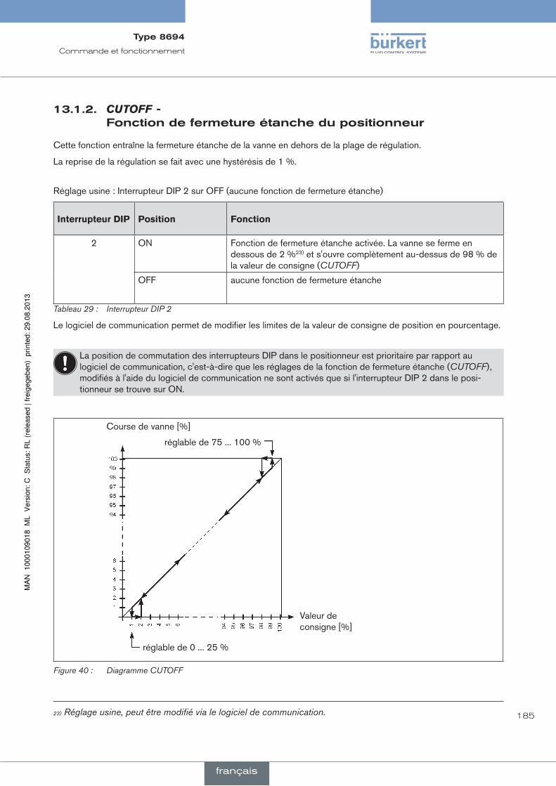
185
Commande et fonctionnement
13.1.2. CUTOFF-fonctiondefermetureétanchedupositionneur
Cette fonction entraîne la fermeture étanche de la vanne en dehors de la plage de régulation.
La reprise de la régulation se fait avec une hystérésis de 1 %.
Réglage usine : Interrupteur DIP 2 sur OFF (aucune fonction de fermeture étanche)
interrupteur DiP Position Fonction
2 ON Fonction de fermeture étanche activée. La vanne se ferme en dessous de 2 %23) et s'ouvre complètement au-dessus de 98 % de la valeur de consigne (CUTOFF)
OFF aucune fonction de fermeture étanche
Tableau 29 : Interrupteur DIP 2
Le logiciel de communication permet de modifier les limites de la valeur de consigne de position en pourcentage.
La position de commutation des interrupteurs DIP dans le positionneur est prioritaire par rapport au logiciel de communication, c'est-à-dire que les réglages de la fonction de fermeture étanche (CUTOFF), modifiés à l'aide du logiciel de communication ne sont activés que si l'interrupteur DIP 2 dans le posi-tionneur se trouve sur ON.
Course de vanne [%]
réglable de 75 ... 100 %
Valeur de consigne [%]
réglable de 0 ... 25 %
Figure 40 : Diagramme CUTOFF
23) Réglage usine, peut être modifié via le logiciel de communication.
Type8694
français

186
Commande et fonctionnement
13.1.3. CHARACT-caractéristiquedetransfertentrelesignald'entrée(valeurdeconsignedeposition)etlacourse
Characteristic (caractéristique spécifique au client)
Cette fonction permet d'activer une caractéristique de transfert concernant la valeur de consigne (position de consigne) et la course de la vanne pour corriger les caractéristiques de débit et de fonctionnement.
La caractéristique de transfert peut être modifiée uniquement à l'aide du logiciel de communication.
Réglage usine : Interrupteur DIP 3 sur OFF (linéaire)
interrupteur DiP
Position Fonction
3 ON Caractéristique de correction pour l'adaptation de la caractéristique de fonctionnement (linéarisation de la caractéristique de processus CHARACT) 24)
OFF Caractéristique linéaire
Tableau 30 : Interrupteur DIP 3
La position de commutation des interrupteurs DIP dans le positionneur est prioritaire par rapport au logiciel de communication, c'est-à-dire que les réglages de la caractéristique de correction (CHARACT), modifiés à l'aide du logiciel de communication ne sont activés que si l'interrupteur DIP 3 dans le posi-tionneur se trouve sur ON.
Caractéristiques pouvant être sélectionnées à l'aide du logiciel de communication :
Caractéristique Description
linear Caractéristique linéaire
1 : 25 Caractéristique à pourcentage égal 1 : 25
1 : 33 Caractéristique à pourcentage égal 1 : 33
1 : 50 Caractéristique à pourcentage égal 1 : 50
25 : 1 Caractéristique à pourcentage égal inverse 25 : 1
33 : 1 Caractéristique à pourcentage égal inverse 33 : 1
55 : 1 Caractéristique à pourcentage égal inverse 55 : 1
FREE Caractéristique définie par l'utilisateur, librement programmable au moyen de points
Tableau 31 : Sélection caractéristiques
Vous trouverez une description détaillée des caractéristiques dans les instructions de service du logiciel de communication pour positionneurs.
24) Le type de caractéristique peut être modifié uniquement à l'aide du logiciel de communication.
Type8694
français
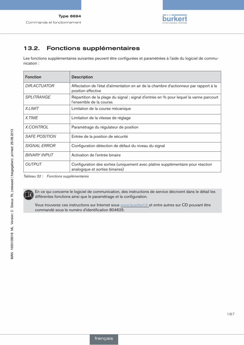
187
Commande et fonctionnement
13.2. fonctionssupplémentaires
Les fonctions supplémentaires suivantes peuvent être configurées et paramétrées à l'aide du logiciel de commu-nication :
fonction description
DIR.ACTUATOR Affectation de l'état d'alimentation en air de la chambre d'actionneur par rapport à la position effective
SPLITRANGE Répartition de la plage du signal ; signal d'entrée en % pour lequel la vanne parcourt l'ensemble de la course.
X.LIMIT Limitation de la course mécanique
X.TIME Limitation de la vitesse de réglage
X.CONTROL Paramétrage du régulateur de position
SAFE POSITION Entrée de la position de sécurité
SIGNAL ERROR Configuration détection de défaut du niveau du signal
BINARY INPUT Activation de l'entrée binaire
OUTPUT Configuration des sorties (uniquement avec platine supplémentaire pour réaction analogique et sorties binaires)
Tableau 32 : Fonctions supplémentaires
En ce qui concerne le logiciel de communication, des instructions de service décrivent dans le détail les différentes fonctions ainsi que le paramétrage et la configuration.
Vous trouverez ces instructions sur Internet sous www.buerkert.fr et entre autres sur CD pouvant être commandé sous le numéro d'identification 804625.
Type8694
français

188
Positions de sécurité
14. pOsiTiOnsdesécuriTé
14.1. positionsdesécuritéaprèsunepanned'énergieauxiliaireélectriqueoupneumatique
typed'actionneur désignation
réglagesdesécuritéaprèsunepannedel'énergieauxiliaire
électrique pneumatique
up
down
simple effet
Fonction de commande A
down
système de réglage à action pilotée :
down
système de réglage à action directe :
non défini
up
down
simple effet
Fonction de commande B
up
système de réglage à action pilotée :
up
système de réglage à action directe :
non défini
Tableau 33 : Positions de sécurité
Type8694
français

189
Maintenance
15. mainTenance
15.1. consignesdesécurité
Danger !
risquedeblessuresdûàlaprésencedehautepressiondansl’installation.
• Avant de desserrer les conduites et les vannes, coupez la pression et purgez l’air des conduites.
risquedechocélectrique.
• Avant d’intervenir dans le système, coupez la tension et empêchez toute remise sous tension par inadvertance.
• Veuillez respecter les réglementations en vigueur pour les appareils électriques en matière de prévention des accidents ainsi qu’en matière de sécurité.
aVerTiSSeMenT !
risquedeblessuresdûàdestravauxdemaintenancenonconformes.
• La maintenance doit être effectué uniquement par un personnel qualifié et habilité.
risquedeblessuresdûàlamiseenmarcheinvolontairedel’installationetleredémarragenoncontrôlé.
• Empêchez tout actionnement involontaire de l’installation.
• Garantissez un redémarrage contrôlé après la maintenance.
Type8694
français

190
Maintenance
15.2. servicesurlefiltred'amenéed'air
Danger !
risquedeblessuresdûàlaprésencedehautepressiondansl'installation.
• Avant de desserrer les conduites et les vannes, coupez la pression et assurez l'échappement de l'air des conduites.
L'air de l’air de pilotage est filtré afin de protéger les électrovannes internes et l'actionneur.
Le sens de débit du filtre d'amenée d'air à l'état monté est de l'intérieur vers l'extérieur à travers la gaze métallique.
Filtre d‘amenée d‘air
Raccord enfichable rapide
Joint torique
Figure 41 : Service sur le filtre d'amenée d'air
procédureàsuivre:
→ Déverrouiller le raccord enfichable rapide en enfonçant la pièce de maintien et retirer le filtre d'amenée d'air (éventuellement à l'aide d'un outil approprié entre les évidements dans la tête du filtre).
→ Nettoyer le filtre ou le remplacer si nécessaire.
→ Contrôler le joint torique interne et le nettoyer si nécessaire.
→ Placer le filtre d'amenée d'air dans le raccord enfichable rapide jusqu'en butée.
Danger !
risquedeblessuresdûàunmontagenonconforme.
• Veillez au montage correct du filtre d'amenée d'air.
→ Contrôler la bonne assise du filtre d'amenée d'air.
Type8694
français
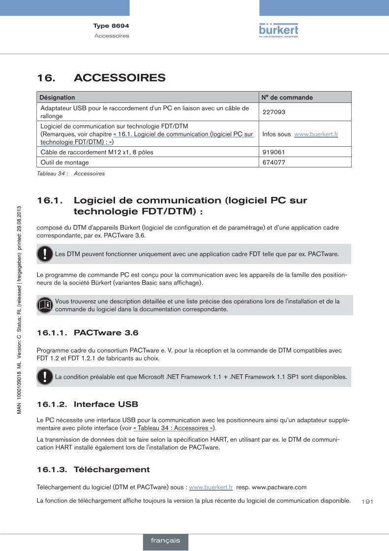
191
Accessoires
16. accessOires
désignation n°decommande
Adaptateur USB pour le raccordement d'un PC en liaison avec un câble de rallonge
227093
Logiciel de communication sur technologie FDT/DTM (Remarques, voir chapitre « 16.1. Logiciel de communication (logiciel PC sur technologie FDT/DTM) : »)
Infos sous www.buerkert.fr
Câble de raccordement M12 x1, 8 pôles 919061
Outil de montage 674077
Tableau 34 : Accessoires
16.1. logicieldecommunication(logicielpcsurtechnologiefdT/dTm):
composé du DTM d'appareils Bürkert (logiciel de configuration et de paramétrage) et d’une application cadre correspondante, par ex. PACTware 3.6.
Les DTM peuvent fonctionner uniquement avec une application cadre FDT telle que par ex. PACTware.
Le programme de commande PC est conçu pour la communication avec les appareils de la famille des position-neurs de la société Bürkert (variantes Basic sans affichage).
Vous trouverez une description détaillée et une liste précise des opérations lors de l'installation et de la commande du logiciel dans la documentation correspondante.
16.1.1. pacTware3.6
Programme cadre du consortium PACTware e. V. pour la réception et la commande de DTM compatibles avec FDT 1.2 et FDT 1.2.1 de fabricants au choix.
La condition préalable est que Microsoft .NET Framework 1.1 + .NET Framework 1.1 SP1 sont disponibles.
16.1.2. interfaceusB
Le PC nécessite une interface USB pour la communication avec les positionneurs ainsi qu’un adaptateur supplé-mentaire avec pilote interface (voir « Tableau 34 : Accessoires »).
La transmission de données doit se faire selon la spécification HART, en utilisant par ex. le DTM de communi-cation HART installé également lors de l'installation de PACTware.
16.1.3. Téléchargement
Téléchargement du logiciel (DTM et PACTware) sous : www.buerkert.fr resp. www.pactware.com
La fonction de téléchargement affiche toujours la version la plus récente du logiciel de communication disponible.
Type8694
français
192
Démontage
17. démOnTage
17.1. consignesdesécurité
Danger !
dangerdûàlahautepression.
• Avant de desserrer les conduites et les vannes, coupez la pression et assurez l’échappement de l’air des conduites.
risquedeblessuresparlatensionélectrique.
• Avant d’intervenir dans l’appareil ou l’installation, coupez la tension et empêchez toute remise sous tension par inadvertance.
• Veuillez respecter les réglementations en vigueur pour les appareils électriques en matière de prévention des accidents ainsi qu’en matière de sécurité.
aVerTiSSeMenT !
risquedeblessuresdûàundémontagenonconforme.
• Le démontage doit être effectué uniquement par un personnel qualifié et habilité disposant de l’outillage approprié.
risquedeblessuresdûàlamiseenmarcheinvolontairedel’installationetleredémarragenoncontrôlé.
• Empêchez tout actionnement involontaire de l’installation.
• Garantissez un redémarrage contrôlé après le démontage.
17.2. démontagedupositionneur
procédureàsuivre:
1. Raccordement pneumatique
Danger !
dangerdûàlahautepression.
• Avant de desserrer les conduites et les vannes, coupez la pression et assurez l’échappement de l’air des conduites.
→ Desserrer le raccord pneumatique.
→ Séries 20xx: Desserrer le raccord pneumatique entre l’unité de commande pneumatique et l’actionneur.
Type8694
français

193
Démontage
2. Raccordement électrique
Danger !
risquedeblessuresparlatensionélectrique.
• Avant d’intervenir dans l’appareil ou l’installation, coupez la tension et empêchez toute remise sous tension par inadvertance.
• Veuillez respecter les réglementations en vigueur pour les appareils électriques en matière de prévention des accidents ainsi qu’en matière de sécurité.
Connecteur rond :
→ Desserrer le connecteur rond.
Presse-étoupe :
→ Ouvrir le positionneur tout en dévissant l’enveloppe du corps en tournant vers la gauche.
→ Desserrer les bornes vissées et enlever les câbles.
→ Fermer le positionneur.
3. Raccordement mécanique
→ Desserrer le vis de fixation.
→ Enlever le positionneur vers le haut.
Raccord pneumatique
Positionneur
Actionneur
Vis de fixation (2x)
Raccord pneu-matique par l’actionneur
Actionneur
Raccordement électrique
connecteur rond
Séries 21xx Séries 20xx
Figure 42 : Démontage du positionneur
Type8694
français

194
Emballage, transport
18. emBallage,TranspOrT
reMarque !
dommagesdusautransport.
Les appareils insuffisamment protégés peuvent être endommagés pendant le transport.
• Transportez l'appareil à l'abri de l'humidité et des impuretés et dans un emballage résistant aux chocs.
• Evitez les effets de la chaleur et du froid pouvant entraîner le dépassement vers le haut ou le bas de la tem-pérature de stockage admissible.
19. sTOckage
reMarque !
unmauvaisstockagepeutendommagerl'appareil.
• Stockez l'appareil au sec et à l'abri des poussières.
• Température de stockage : -20 ... +65 °C.
20. eliminaTiOn
→ Eliminez l'appareil et l'emballage dans le respect de l'environnement.
reMarque !
dommagesàl'environnementcauséspardespiècesd'appareilcontaminéespardesfluides.
• Respectez les prescriptions en matière d’élimination des déchets et de protection de l’environnement en vigueur.
remarque:
Respectez les prescriptions nationales en matière d'élimination des déchets.
Type8694
français


www.burkert.com
Related Documents