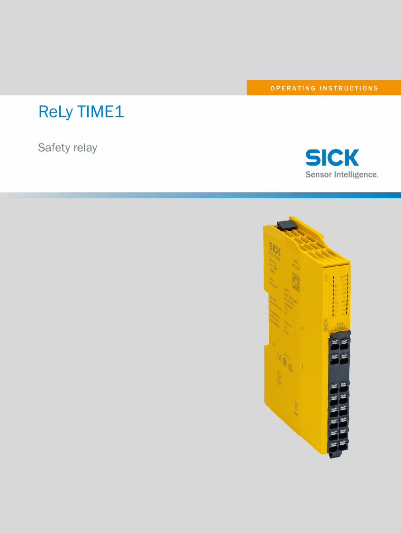
OPERATING INSTRUCTIONS ReLy TIME1 Safety relay

Welcome message from author
This document is posted to help you gain knowledge. Please leave a comment to let me know what you think about it! Share it to your friends and learn new things together.
Transcript
O P E R A T I N G I N S T R U C T I O N S
ReLy TIME1
Safety relay

Described product
ReLy TIME1
Manufacturer
SICK AGErwin-Sick-Str. 179183 WaldkirchGermany
Legal information
This work is protected by copyright. Any rights derived from the copyright shall bereserved for SICK AG. Reproduction of this document or parts of this document is onlypermissible within the limits of the legal determination of Copyright Law. Any modifica‐tion, abridgment or translation of this document is prohibited without the express writ‐ten permission of SICK AG.
The trademarks stated in this document are the property of their respective owner.
© SICK AG. All rights reserved.
Original document
This document is an original document of SICK AG.
2 O P E R A T I N G I N S T R U C T I O N S | ReLy TIME1 8024303/2019-12-18 | SICKSubject to change without notice
Contents
1 About this document........................................................................ 51.1 Purpose of this document........................................................................ 51.2 Scope......................................................................................................... 51.3 Target groups and structure of these operating instructions................ 51.4 Additional information.............................................................................. 51.5 Symbols and document conventions...................................................... 6
2 Safety information............................................................................ 72.1 General safety notes................................................................................ 72.2 Intended use............................................................................................. 72.3 Improper use............................................................................................. 72.4 Requirements for the qualification of personnel.................................... 8
3 Product description........................................................................... 93.1 Construction and function........................................................................ 93.2 Product characteristics............................................................................ 9
3.2.1 Device overview....................................................................... 93.2.2 Interfaces................................................................................. 93.2.3 Compatible sensor types......................................................... 103.2.4 Release-delayed enabling current paths................................ 103.2.5 Restart interlock...................................................................... 103.2.6 External device monitoring...................................................... 103.2.7 Cross-circuit detection............................................................. 103.2.8 Status indicators...................................................................... 10
4 Project planning................................................................................ 124.1 Manufacturer of the machine.................................................................. 124.2 Operating entity of the machine.............................................................. 124.3 Design........................................................................................................ 124.4 Electrical integration................................................................................. 13
4.4.1 Enabling current paths............................................................ 134.4.2 Application diagnostic output................................................. 134.4.3 Restart interlock...................................................................... 144.4.4 External device monitoring (EDM).......................................... 144.4.5 Connection diagrams.............................................................. 15
4.5 Testing plan............................................................................................... 154.5.1 Minimum requirements for the regular thorough check....... 15
5 Mounting............................................................................................. 165.1 Safety......................................................................................................... 165.2 Mounting procedure................................................................................. 165.3 Disassembly.............................................................................................. 175.4 Module exchange...................................................................................... 17
6 Electrical installation........................................................................ 19
CONTENTS
8024303/2019-12-18 | SICK O P E R A T I N G I N S T R U C T I O N S | ReLy TIME1 3Subject to change without notice

6.1 Device connection.................................................................................... 19
7 Configuration..................................................................................... 227.1 DIP switch.................................................................................................. 227.2 Configuring release delay......................................................................... 227.3 Configuring sensor type........................................................................... 237.4 Activating configuration............................................................................ 247.5 Resetting the configuration...................................................................... 24
8 Commissioning.................................................................................. 258.1 Safety......................................................................................................... 258.2 Thorough check........................................................................................ 25
9 Troubleshooting................................................................................. 269.1 Safety......................................................................................................... 269.2 Status indicator (LED)............................................................................... 26
10 Decommissioning............................................................................. 2810.1 Disposal..................................................................................................... 28
11 Technical data.................................................................................... 2911.1 Data sheet................................................................................................. 2911.2 Dimensional drawings.............................................................................. 3511.3 Internal circuitry........................................................................................ 35
12 Ordering information........................................................................ 3612.1 Ordering information for ReLy.................................................................. 36
13 Annex.................................................................................................. 3713.1 Compliance with EU directives................................................................. 37
14 List of figures..................................................................................... 38
15 List of tables....................................................................................... 39
CONTENTS
4 O P E R A T I N G I N S T R U C T I O N S | ReLy TIME1 8024303/2019-12-18 | SICKSubject to change without notice

1 About this document
1.1 Purpose of this document
These operating instructions contain the information required during the life cycle of thesafety relay.
These operating instructions must be made available to everyone who works with thesafety relay.
1.2 Scope
This document only applies to a ReLy safety relay with the following type label entries inthe Operating Instructions field:
• 8024299
1.3 Target groups and structure of these operating instructions
These operating instructions are intended for the following target groups: project devel‐opers (planners, developers, designers), installers, electricians, safety experts (such asCE authorized representatives, compliance officers, people who test and approve theapplication), operators, and maintenance personnel.
These operating instructions are organized by the life phases of the device: projectplanning, mounting, electrical installation, commissioning, operation and maintenance.
The table below shows the target groups and how – for many applications – these aretypically divided up between the manufacturer and the entity operating the machine inwhich the device is to be integrated:
Area of responsibility Target group Specific chapters of these operating instruc‐tions 1)
Manufacturer Project developers(planners, developers,designers)
"Project planning", page 12"Technical data", page 29
Installers "Mounting", page 16
Electricians "Electrical installation", page 19
Safety experts "Project planning", page 12"Commissioning", page 25"Technical data", page 29
Operating entity Operators "Troubleshooting", page 26
Maintenance person‐nel
"Troubleshooting", page 26"Ordering information", page 36
1) Chapters not listed here are intended for all target groups. All target groups must follow all of the safetyand warning instructions in all chapters of the operating instructions!
In other applications, the operating organization is also the manufacturer of the equip‐ment with the corresponding allocation of the target groups.
1.4 Additional information
www.sick.com
The following information is available on the Internet:
• This document in other languages• Data sheets and application examples• CAD data and dimensional drawings
ABOUT THIS DOCUMENT 1
8024303/2019-12-18 | SICK O P E R A T I N G I N S T R U C T I O N S | ReLy TIME1 5Subject to change without notice

• Certificates (e.g. EU declaration of conformity)• Guide for Safe Machinery Six steps to a safe machine
1.5 Symbols and document conventions
The following symbols and conventions are used in this document:
Safety notes and other notes
DANGERIndicates a situation presenting imminent danger, which will lead to death or seriousinjuries if not prevented.
WARNINGIndicates a situation presenting possible danger, which may lead to death or seriousinjuries if not prevented.
CAUTIONIndicates a situation presenting possible danger, which may lead to moderate or minorinjuries if not prevented.
NOTICEIndicates a situation presenting possible danger, which may lead to property damage ifnot prevented.
NOTEIndicates useful tips and recommendations.
Instructions to action
b The arrow denotes instructions to action.
1. The sequence of instructions for action is numbered.2. Follow the order in which the numbered instructions are given.✓ The check mark denotes the result of an instruction.
LED symbols
These symbols indicate the status of an LED:
o The LED is off.Ö The LED is flashing.O The LED is illuminated continuously.
1 ABOUT THIS DOCUMENT
6 O P E R A T I N G I N S T R U C T I O N S | ReLy TIME1 8024303/2019-12-18 | SICKSubject to change without notice

2 Safety information
2.1 General safety notes
DANGERIf the safety component is integrated incorrectly, the dangerous state may be ended tolate.
b Plan the integration of the safety component in accordance with the machinerequirements, see "Project planning", page 12.
DANGERHazard due to lack of effectiveness of the protective deviceIn the case of non-compliance, it is possible that the dangerous state of the machinemay not be stopped or not stopped in a timely manner.
b Please read this document carefully and make sure that you understand the con‐tent fully before working with the device.
b Follow all safety notes in this document.
Improper installation or manipulation can lead to serious injuries.
2.2 Intended use
The safety relay is an evaluation unit device for switching safety-related circuits on andoff for the following sensor types:
• Emergency stop pushbutton• Safety switches• Sensors with OSSDs• Safety devices with OSSDs
The safety relay complies with class A, group 1 as per EN 55011. Group 1 encom‐passes all ISM devices in which intentionally generated and/or used conductor-boundRF energy that is required for the inner function of the device itself occurs.
The safety relay must only be used within the limits of the prescribed and specifiedtechnical data and operating conditions at all times.
Incorrect use, improper modification or manipulation of the safety relay will invalidateany warranty from SICK; in addition, any responsibility and liability of SICK for damageand secondary damage caused by this is excluded.
UL/CSA applications
If the product is being used in accordance with UL 508 or CSA C22.2 No. 14, the follow‐ing conditions must also be met:• To protect the device’s 24-volt voltage supply, use a fuse with a maximum voltage
of 4 A and a minimum of 30 V DC in accordance with UL 248.
NOTEThe safety functions have not be evaluated by UL. Authorization is in accordance withUL 508, general applications.
2.3 Improper use
The safety relay is not suitable for the following applications (this list is not exhaustive):
SAFETY INFORMATION 2
8024303/2019-12-18 | SICK O P E R A T I N G I N S T R U C T I O N S | ReLy TIME1 7Subject to change without notice
• At altitudes of over 4,000 m above sea level• In explosion-hazardous areas
2.4 Requirements for the qualification of personnel
The protective device must be configured, installed, connected, commissioned, and ser‐viced by qualified safety personnel only.
Project planning
For project planning, a person is considered competent when he/she has expertise andexperience in the selection and use of protective devices on machines and is familiarwith the relevant technical rules and national work safety regulations.
Mechanical mounting, electrical installation, and commissioning
For the task, a person is considered qualified when he/she has the expertise and expe‐rience in the relevant field and is sufficiently familiar with the application of the protec‐tive device on the machine to be able to assess whether it is in an operationally safestate.
Operation and maintenance
For operation and maintenance, a person is considered competent when he/she hasthe expertise and experience in the relevant field and is sufficiently familiar with theapplication of the protective device on the machine and has been instructed by themachine operator in its operation.
2 SAFETY INFORMATION
8 O P E R A T I N G I N S T R U C T I O N S | ReLy TIME1 8024303/2019-12-18 | SICKSubject to change without notice
3 Product description
3.1 Construction and function
The safety relay ReLy TIME1 is an electrical switching device with inputs and outputs.
The safety capable inputs of the safety relay are connected to safety sensors or safetyswitches.
2 safety capable inputs control the internal relays, which are used to reliably switch theenabling current paths.
The enabling current paths close only when the two safety capable inputs close within3 s of one another.
Actuators with positively guided contacts are connected to the enabling current paths.
Opening the input circuit causes the two enabling current paths to open immediatelyand for the release-delayed enabling current path to open after a delay. The delay timeis adjustable.
3.2 Product characteristics
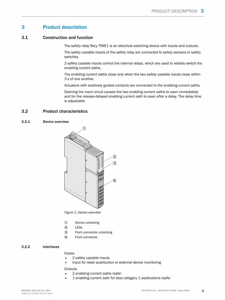
3.2.1 Device overview
RELY PW
R
OUT
13
23
I1
Y1
14
24
I2
Y2
A2
S1
37
A1
38
X1X2R1
1
2
3
4
Figure 1: Device overview
1 Device unlocking2 LEDs3 Front connector unlocking4 Front connector
3.2.2 Interfaces
Inputs• 2 safety capable inputs• Input for reset pushbutton or external device monitoring
Outputs• 2 enabling current paths (safe)• 1 enabling current path for stop category 1 applications (safe)
PRODUCT DESCRIPTION 3
8024303/2019-12-18 | SICK O P E R A T I N G I N S T R U C T I O N S | ReLy TIME1 9Subject to change without notice

• 2 application diagnostic outputs (not safe)• 3 test outputs (not safe)
3.2.3 Compatible sensor types
The safety relay is suitable for:
• Safety sensors and safety switches with volt-free output contacts (EMSS), e.g.:Dual-channel safety command devices (emergency stop pushbuttons, rope pullswitches, etc.), dual-channel contact-based interlocking devices (safety lockingdevices and safety switches) and dual-channel magnetic safety switches with reedcontacts
• Safety sensors and safety switches with OSSD output, e.g.: Electro-sensitive pro‐tective equipment (ESPE) with a single-channel or dual-channel monitored activeswitching output with cross-circuit detection (OSSD)
3.2.4 Release-delayed enabling current paths
The release-delayed enabling current path opens with a set delay time.
3.2.5 Restart interlock
A restart interlock can be implemented with a reset pushbutton.
3.2.6 External device monitoring
Permanent external device monitoring can be implemented using external wiring.
3.2.7 Cross-circuit detection
A cross-circuit is detected on the safety capable inputs if the “Contacts” sensor type isconfigured.
3.2.8 Status indicators
LEDs
RELY PW
R
OUT
13
23
I1
Y1
14
24
I2
Y2
A2
S1
37
A1
38
X1X2R1
PWR
OUT
13
23
I1
Y1
14
24
I2
Y2
A2
R1
A1
S1
X1 X2
TIME1
1100688
RELY
37 38
Figure 2: LEDs
The labeled positions are only partially assigned LEDs. The positions and their labeling(except for the upper 2 lines) also show the pin assignment of the terminals on the frontconnector.
3 PRODUCT DESCRIPTION
10 O P E R A T I N G I N S T R U C T I O N S | ReLy TIME1 8024303/2019-12-18 | SICKSubject to change without notice
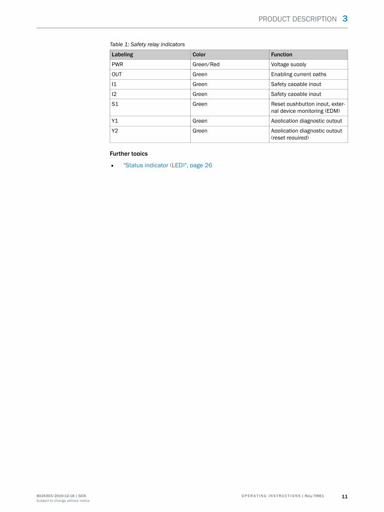
Table 1: Safety relay indicators
Labeling Color Function
PWR Green/Red Voltage supply
OUT Green Enabling current paths
I1 Green Safety capable input
I2 Green Safety capable input
S1 Green Reset pushbutton input, exter‐nal device monitoring (EDM)
Y1 Green Application diagnostic output
Y2 Green Application diagnostic output(reset required)
Further topics
• "Status indicator (LED)", page 26
PRODUCT DESCRIPTION 3
8024303/2019-12-18 | SICK O P E R A T I N G I N S T R U C T I O N S | ReLy TIME1 11Subject to change without notice

4 Project planning
4.1 Manufacturer of the machine
DANGERFailure to comply with manufacturer’s obligationsHazard due to lack of effectiveness of the protective device
b Carry out a risk assessment before using the safety relay.b Do not manipulate, open or modify the components of the safety relay.b Make sure the safety relay is only repaired by the manufacturer or by someone
authorized by the manufacturer. Improper repair can lead to a loss of the protec‐tive function.
4.2 Operating entity of the machine
DANGERFailure to observe operator obligationsHazard due to lack of effectiveness of the protective device
b Changes to the machine and changes to the mechanical mounting of the safetyrelay necessitate a new risk assessment. The results of this risk assessment mayrequire the entity operating the machine to meet the obligations of a manufac‐turer.
b Apart from the procedures described in this document, the components of thesafety relay must not be opened or modified.
b Do not carry out any repair work on components. Improper repair of the safetyrelay can lead to a loss of the protective function.
4.3 Design
The safety relay must be installed in a control cabinet with an enclosure rating of IP54or higher.
The safety relay must be installed on a mounting rail (35 mm) in accordance with IEC60715.
Space requirements in the control cabinet
To ensure sufficient air circulation and cooling, sufficient distance must be kept in thecontrol cabinet above and below the safety relay.
Sufficient distance must be kept for the connected cables before the module (frontside).
4 PROJECT PLANNING
12 O P E R A T I N G I N S T R U C T I O N S | ReLy TIME1 8024303/2019-12-18 | SICKSubject to change without notice
≥ 5
0≥
50
≥ 25
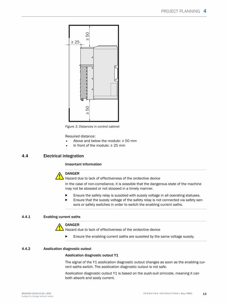
Figure 3: Distances in control cabinet
Required distance:• Above and below the module: ≥ 50 mm• In front of the module: ≥ 25 mm
4.4 Electrical integration
Important information
DANGERHazard due to lack of effectiveness of the protective deviceIn the case of non-compliance, it is possible that the dangerous state of the machinemay not be stopped or not stopped in a timely manner.
b Ensure the safety relay is supplied with supply voltage in all operating statuses.b Ensure that the supply voltage of the safety relay is not connected via safety sen‐
sors or safety switches in order to switch the enabling current paths.
4.4.1 Enabling current paths
DANGERHazard due to lack of effectiveness of the protective device
b Ensure the enabling current paths are supplied by the same voltage supply.
4.4.2 Application diagnostic output
Application diagnostic output Y1
The signal of the Y1 application diagnostic output changes as soon as the enabling cur‐rent paths switch. The application diagnostic output is not safe.
Application diagnostic output Y1 is based on the push-pull principle, meaning it canboth absorb and apply current.
PROJECT PLANNING 4
8024303/2019-12-18 | SICK O P E R A T I N G I N S T R U C T I O N S | ReLy TIME1 13Subject to change without notice
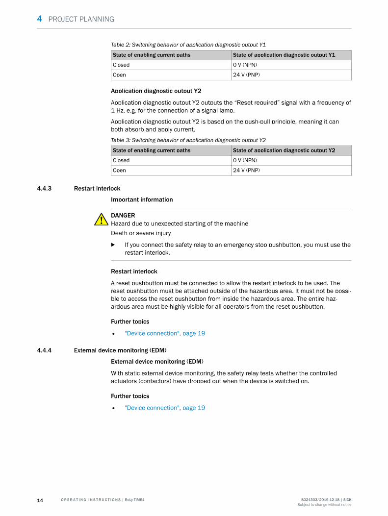
Table 2: Switching behavior of application diagnostic output Y1
State of enabling current paths State of application diagnostic output Y1
Closed 0 V (NPN)
Open 24 V (PNP)
Application diagnostic output Y2
Application diagnostic output Y2 outputs the “Reset required” signal with a frequency of1 Hz, e.g. for the connection of a signal lamp.
Application diagnostic output Y2 is based on the push-pull principle, meaning it canboth absorb and apply current.
Table 3: Switching behavior of application diagnostic output Y2
State of enabling current paths State of application diagnostic output Y2
Closed 0 V (NPN)
Open 24 V (PNP)
4.4.3 Restart interlock
Important information
DANGERHazard due to unexpected starting of the machineDeath or severe injury
b If you connect the safety relay to an emergency stop pushbutton, you must use therestart interlock.
Restart interlock
A reset pushbutton must be connected to allow the restart interlock to be used. Thereset pushbutton must be attached outside of the hazardous area. It must not be possi‐ble to access the reset pushbutton from inside the hazardous area. The entire haz‐ardous area must be highly visible for all operators from the reset pushbutton.
Further topics
• "Device connection", page 19
4.4.4 External device monitoring (EDM)
External device monitoring (EDM)
With static external device monitoring, the safety relay tests whether the controlledactuators (contactors) have dropped out when the device is switched on.
Further topics
• "Device connection", page 19
4 PROJECT PLANNING
14 O P E R A T I N G I N S T R U C T I O N S | ReLy TIME1 8024303/2019-12-18 | SICKSubject to change without notice
4.4.5 Connection diagrams
+24 V DC
0 V
k2
k1
F0
E254877/00/2019-10-28
X1 Y1 Y2 14X2 A2 3824
I1 I2 S1 A1R1 1323 37
RLY3-TIME1
K1
K2
Reset
RESState
3 2 4
1 5STR1
ENABLE
NO ERROR
M
3
M
3
Figure 4: ReLy TIME1 connection diagram
4.5 Testing plan
The safety relay must be thoroughly checked by appropriately qualified safety personnelduring commissioning, after modifications, and at regular intervals, see "Thoroughcheck", page 25.
The regular thorough checks serve to assess the effectiveness of the safety relay and toidentify defects as a result of modifications or other influences (e.g., damage or manip‐ulation).
The manufacturer and user must define the type and frequency of the thorough checkson the machine on the basis of the application conditions and the risk assessment.Determination of the thorough checks must be documented in a traceable manner.
4.5.1 Minimum requirements for the regular thorough check
The following thorough checks must be carried out at regular intervals:
• Thorough check of the housing for damage• Thorough check of the cables for damage• Thorough check of the safety relay for signs of misuse or manipulation• Thorough check of the safety function
The required interval for performing these thorough checks depends on the applicablesafety capability of the overall application, see table 6, page 29.
PROJECT PLANNING 4
8024303/2019-12-18 | SICK O P E R A T I N G I N S T R U C T I O N S | ReLy TIME1 15Subject to change without notice
5 Mounting
5.1 Safety
DANGERHazard due to unexpected starting of the machineHazard due to electrical voltage
b Make sure that the outputs of the safety relay have no effect on the machine dur‐ing mounting and electrical installation.
b Make sure that the safety relay and the connected components are isolated fromall voltage sources during mounting and electrical installation of the device andduring mounting/dismantling of the front connector.
NOTICEEnclosure rating IP20 only applies if the front connector is mounted.
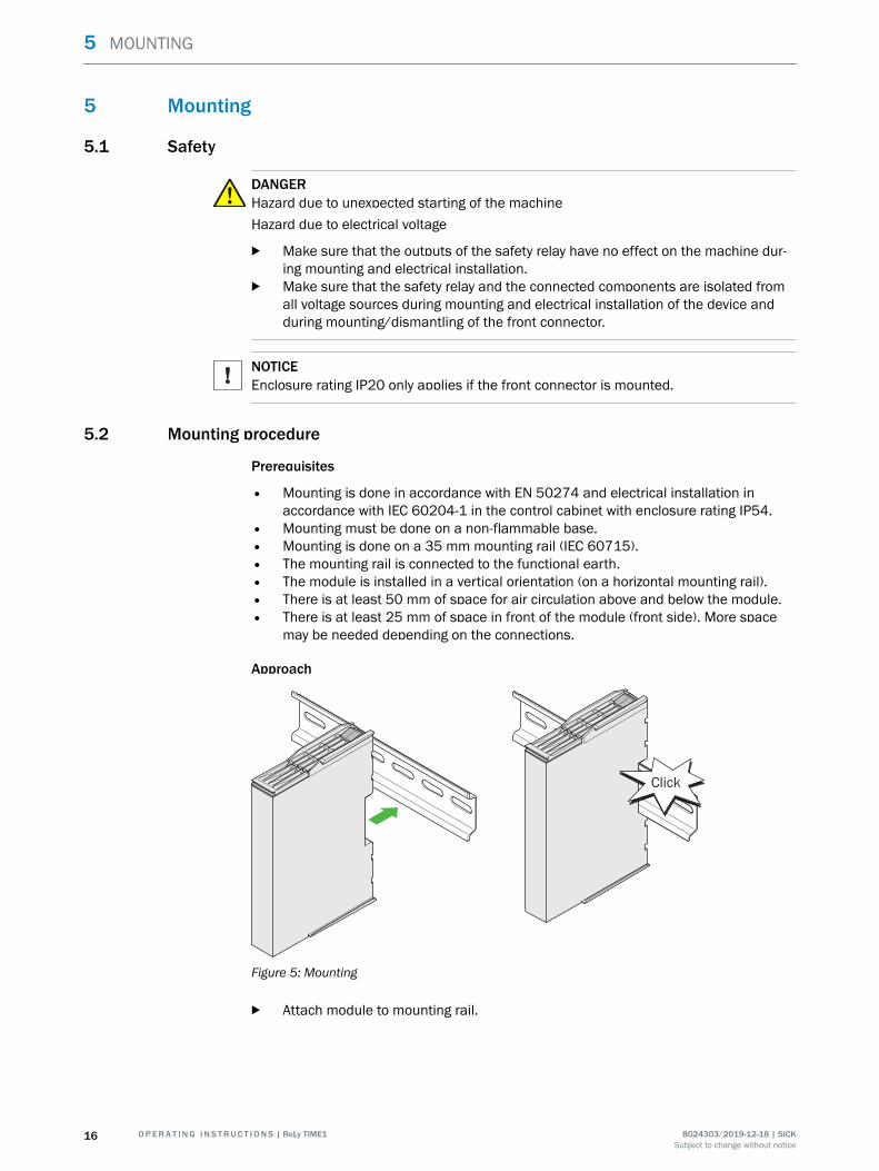
5.2 Mounting procedure
Prerequisites
• Mounting is done in accordance with EN 50274 and electrical installation inaccordance with IEC 60204-1 in the control cabinet with enclosure rating IP54.
• Mounting must be done on a non-flammable base.• Mounting is done on a 35 mm mounting rail (IEC 60715).• The mounting rail is connected to the functional earth.• The module is installed in a vertical orientation (on a horizontal mounting rail).• There is at least 50 mm of space for air circulation above and below the module.• There is at least 25 mm of space in front of the module (front side). More space
may be needed depending on the connections.
Approach
Click
Figure 5: Mounting
b Attach module to mounting rail.
5 MOUNTING
16 O P E R A T I N G I N S T R U C T I O N S | ReLy TIME1 8024303/2019-12-18 | SICKSubject to change without notice

5.3 Disassembly
Prerequisites
• Electrician screwdriver (slotted screwdriver)
Approach
Figure 6: Disassembly
1. Press the unlocking mechanism on the upper side of the module towards the backusing the electrician screwdriver.
2. Loosen module from the mounting rail.
5.4 Module exchange
Approach
1. Disconnect module and the connected components from all voltage sources.2. Take front connector with connected cables off the defective device: Press the
unlocking mechanism of the front connector downwards and pull out the front con‐nector.
Figure 7: Dismantle front connector
MOUNTING 5
8024303/2019-12-18 | SICK O P E R A T I N G I N S T R U C T I O N S | ReLy TIME1 17Subject to change without notice

3. Dismantle the defective module.4. Mount new module.5. Mount front connector with connected cables to the new module: First mount in
the module with bent hook and then engage in the housing.
Click
Figure 8: Mount the front connector
✓ The front connector engages with an audible click.
5 MOUNTING
18 O P E R A T I N G I N S T R U C T I O N S | ReLy TIME1 8024303/2019-12-18 | SICKSubject to change without notice

6 Electrical installation
6.1 Device connection
Important information
DANGERHazard due to lack of effectiveness of the protective deviceIn the case of non-compliance, it is possible that the dangerous state of the machinemay not be stopped or not stopped in a timely manner.
b Ensure the safety relay is supplied with supply voltage in all operating statuses.b Ensure that the supply voltage of the safety relay is not connected via safety sen‐
sors or safety switches in order to switch the enabling current paths.
DANGERHazard due to unexpected starting of the machineHazard due to electrical voltage
b Make sure that the outputs of the safety relay have no effect on the machine dur‐ing mounting and electrical installation.
b Make sure that the safety relay and the connected components are isolated fromall voltage sources during mounting and electrical installation of the device andduring mounting/dismantling of the front connector.
NOTICEEnclosure rating IP20 only applies if the front connector is mounted.
Prerequisites
• Electrical installation is done in conformity with IEC 60204-1.• The mounting rail is connected to the functional earth.• The voltage supply and connected signals meet the requirements for SELV/PELV
(EN 61140) or NEC Class 2 (UL 1310).• The external voltage supply must be capable of bridging a brief power failure of
20 ms as specified in IEC 60204-1. Suitable power supply units are available asaccessories from SICK.
• The safety outputs and external device monitoring (EDM) must be wired within thecontrol cabinet.
• When using the safety relay with voltages larger than the safety extra-low voltage:The N/C contacts of the controlled contactors must be safely isolated from theother contactor contacts.
• Contact fuse with safety fuse gG or circuit breaker C: 6 A, maximum short-circuitcurrent I ≤ 400 A
• The ground connection of all connected devices must have the same potential asA2.
• All connected devices and the reset pushbutton comply with the required categoryin accordance with ISO 13849-1 and SILCL in accordance with IEC 62061 (e.g.shielded single sheathed cables, separate installation).
ELECTRICAL INSTALLATION 6
8024303/2019-12-18 | SICK O P E R A T I N G I N S T R U C T I O N S | ReLy TIME1 19Subject to change without notice

Pin assignment
14
24
Y2
A2
13
23
S1
Y1
A1
1
3
7
9
11
13
15
17
2
4
8
10
12
14
16
18
I2I1
X2X1
R1
3837
Figure 9: Terminals on front connector
Table 4: Pin assignment of the terminals
Terminal Description
13, 14 1) 2) Enabling current path
23, 24 1) 2) Enabling current path
37, 38 1) 3) Enabling current path, release-delayed
I1 4) Safety capable input
I2 4) Safety capable input 3)
S1 2) 5) Reset pushbutton input, external device monitoring (EDM)
R1 Test pulse output
X1 4) Test pulse output
X2 4) Test pulse output
Y1 Application diagnostic output (NC)
Y2 Application diagnostic output (reset required)
A1 Voltage supply 24 V DC
A2 Voltage supply 0 V DC
1) The enabling current paths must be supplied by the same voltage supply.2) The enabling current path and external device monitoring (EDM) must be wired within the control cabinet.3) With single-channel base device: Connect jumper between I1 and I2.4) Connect dual-channel switching elements of the safety sensors between X1 and I1 or X2 and I2.5) • Use with restart interlock, with external device monitoring (EDM): Connect the N/C contacts of the
actuators between voltage supply Uv, the N/O contact of the reset pushbutton and S1.
• Use with restart interlock, without external device monitoring (EDM): Connect the N/O contact ofthe reset pushbutton between S1 and voltage supply UV.
• Use without restart interlock, with external device monitoring (EDM): Connect the N/C contacts ofthe actuators between R1 and S1.
• Use without restart interlock, without external device monitoring (EDM): Connect R1 and S1 with awire jumper.
6 ELECTRICAL INSTALLATION
20 O P E R A T I N G I N S T R U C T I O N S | ReLy TIME1 8024303/2019-12-18 | SICKSubject to change without notice

Complementary information
To protect and increase the service life of contact outputs, equip all connected loadswith varistors or RC elements. The response times will increase depending on the sup‐pressor used.
Further topics
• "Connection diagrams", page 15
ELECTRICAL INSTALLATION 6
8024303/2019-12-18 | SICK O P E R A T I N G I N S T R U C T I O N S | ReLy TIME1 21Subject to change without notice
7 Configuration
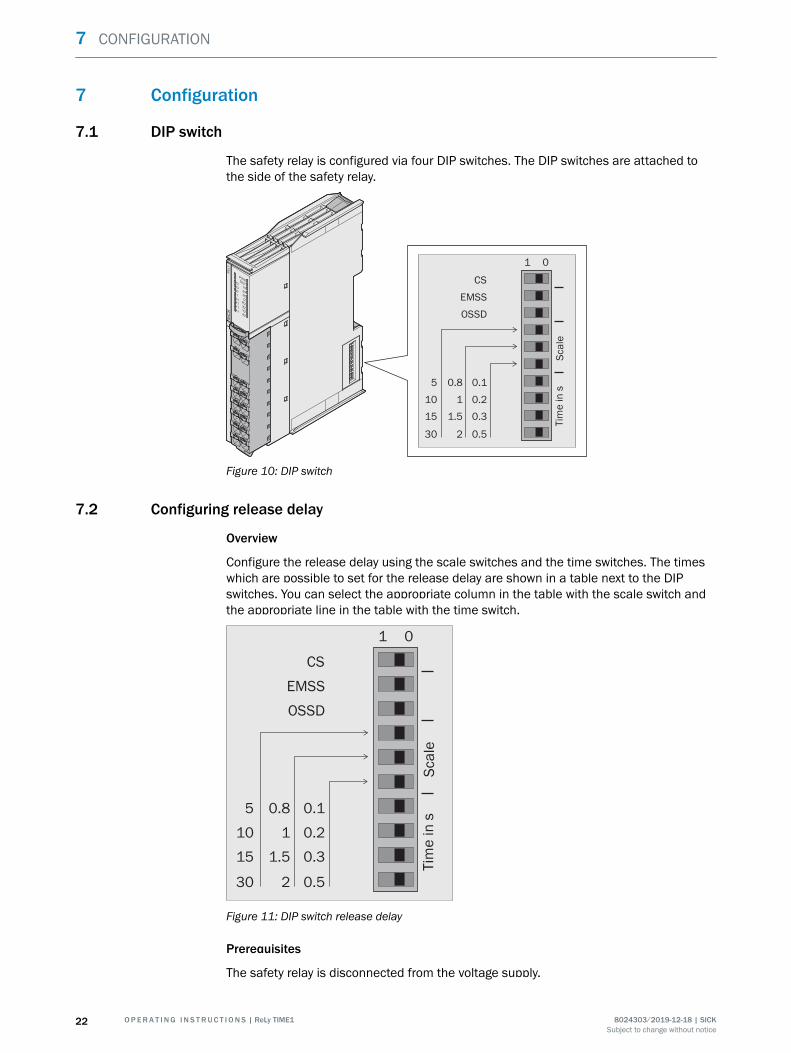
7.1 DIP switch
The safety relay is configured via four DIP switches. The DIP switches are attached tothe side of the safety relay.
Sca
leTim
e in
s
5
10
15
30
01
CS
EMSS
OSSD
0.8
1
1.5
2
0.1
0.2
0.3
0.5
RELY
PWR
OUT
13
23
I1
Y1
14
24
I2
Y2A2
38
X2
37
S1X1
A1
R2
Figure 10: DIP switch
7.2 Configuring release delay
Overview
Configure the release delay using the scale switches and the time switches. The timeswhich are possible to set for the release delay are shown in a table next to the DIPswitches. You can select the appropriate column in the table with the scale switch andthe appropriate line in the table with the time switch.
Sca
leTim
e in
s
5
10
15
30
01
CS
EMSS
OSSD
0.8
1
1.5
2
0.1
0.2
0.3
0.5
Figure 11: DIP switch release delay
Prerequisites
The safety relay is disconnected from the voltage supply.
7 CONFIGURATION
22 O P E R A T I N G I N S T R U C T I O N S | ReLy TIME1 8024303/2019-12-18 | SICKSubject to change without notice

Approach
1. Select the column with the right time and set the respective scale switch to posi‐tion 1.
2. Select the line with the right time and set the respective time switch to position 1.
Example
To select a release delay of 1.5 s, scale switch 2 and time switch 3 must be set to posi‐tion 1.
Sca
leTim
e in
s5
10
15
30
01
CS
EMSS
OSSD
0.8
1
1.5
2
0.1
0.2
0.3
0.5
Figure 12: Release delay example
Complementary information
You can only activate one time, i.e. set a combination of time and scale switches.
Further topics
• "Activating configuration", page 24
7.3 Configuring sensor type
Prerequisites
The safety relay is disconnected from the voltage supply.
Approach
You can configure the sensor type connected to the safety relay here.
b OSSD sensor type: If there are sensors with OSSD outputs connected to the safetyrelay, set the OSSD switch to position 1.
b EMSS sensor type: If sensors and safety devices with volt-free contact outputs areconnected to the safety relay, set the EMSS switch to position 1.
Complementary information
You can only configure one sensor type.
Further topics
• "Compatible sensor types", page 10• "Activating configuration", page 24
CONFIGURATION 7
8024303/2019-12-18 | SICK O P E R A T I N G I N S T R U C T I O N S | ReLy TIME1 23Subject to change without notice

7.4 Activating configuration
Prerequisites
The safety relay is disconnected from the voltage supply.
Approach
You must activate the configuration after configuration is complete. After activation, thesafety relay will detect the configuration.
1. Set the CS switch to the corresponding position to activate the configuration:
° If the CS switch is in position 0, set the CS switch to position 1.
° If the CS switch is in position 1, set the CS switch to position 0.2. Connect the safety relay to the supply voltage.✓ If configuration is successful, the LEDs of safety relay 2 × light up one after
another, from top to bottom.
Complementary information
• You only have to complete configuration once and activate the successful configu‐ration process. If a configuration is faulty, you can fix the error without reactivatingthe configuration.
• If a configuration is already valid and becomes invalid at a later time (e.g. acciden‐tally changing the DIP switch position), you have to fix the error and then reactivatethe configuration.
• For module exchange, it can be helpful if the CS switch is at 1 at the end of config‐uration. With module exchange, the configuration can therefore be transmitted tothe new module.
7.5 Resetting the configuration
Prerequisites
The safety relay is disconnected from the voltage supply.
Approach
1. Set all DIP switches to position 0.2. Connect the safety relay to the supply voltage.✓ The PWR LED flashes red (1 Hz).
7 CONFIGURATION
24 O P E R A T I N G I N S T R U C T I O N S | ReLy TIME1 8024303/2019-12-18 | SICKSubject to change without notice

8 Commissioning
8.1 Safety
DANGERDangerous state of the machineDuring commissioning, the machine or the protective device may not yet behave as youhave planned.
b Make sure that there is no-one in the hazardous area during commissioning.
8.2 Thorough check
Requirements for the thorough check during commissioning and in certain situations
The device and its application must be thoroughly checked in the following situations:
• Before commissioning• After changes to the configuration or the safety function• After changes to the mounting or the electrical installation• After exceptional events, such as after manipulation has been detected, after
modification of the machine, or after replacing components
The thorough check ensures the following:
• All relevant regulations are complied with and the device is effective in all of themachine’s operating modes.
• The documentation accurately reflects the state/condition of the machine, includ‐ing the protective device.
The thorough checks must be carried out by qualified safety personnel or specially qual‐ified and authorized personnel, and must be documented in a traceable manner.
COMMISSIONING 8
8024303/2019-12-18 | SICK O P E R A T I N G I N S T R U C T I O N S | ReLy TIME1 25Subject to change without notice

9 Troubleshooting
9.1 Safety
DANGERHazard due to lack of effectiveness of the protective deviceIn the case of non-compliance, it is possible that the dangerous state of the machinemay not be stopped or not stopped in a timely manner.
b Immediately shut the machine down if the behavior of the machine cannot beclearly identified.
b If a machine fault cannot be definitively determined or safely rectified, immediatelyshut the machine down.
b Secure the machine so that it cannot switch on unintentionally.
NOTEAdditional information on troubleshooting can be found at the responsible SICK sub‐sidiary.
9.2 Status indicator (LED)
Status indicator (LED)
Table 5: Fault indicators and operational statuses
LED Status Possible cause
PWR o No supply voltage
All LEDs Ö All colors Initialization with LED test
PWR O Green No fault
PWR Ö Red (2 Hz) • Supply voltage too low temporarily or per‐manently
• Internal error
PWR Ö Red (1 Hz) Configuration is invalid
PWR Ö Red/green ErrorAdditional LEDs flash for accurate diagnosis.
OUT o Enabling current paths open
OUT O Green Enabling current paths closed
OUT Ö green (1 Hz) Error in enabling current path
OUT Ö green (5 Hz) Release delay active
S1 Ö Green When using without restart interlock: Inputerror (e.g. stuck at HIGH)
S1 O Green Reset pushbutton actuated, N/C contact of theactuator closed
I1 and I2 Ö Green, alternate Input error: discrepancy time expired
I1 and I2 Ö Green, simultane‐ous
Input error: cross-circuit, process error
Y1 o Enabling current paths closed
Y1 O Green Enabling current paths open
Y2 o Output with LOW status
Y2 Ö Green Reset required
Y2 O Green Reset pushbutton actuated
9 TROUBLESHOOTING
26 O P E R A T I N G I N S T R U C T I O N S | ReLy TIME1 8024303/2019-12-18 | SICKSubject to change without notice
Complementary information
• "Configuration", page 22
TROUBLESHOOTING 9
8024303/2019-12-18 | SICK O P E R A T I N G I N S T R U C T I O N S | ReLy TIME1 27Subject to change without notice

10 Decommissioning
10.1 Disposal
Approach
b Always dispose of unusable devices in accordance with national waste disposalregulations.
Complementary information
SICK will be glad to help you dispose of these devices on request.
10 DECOMMISSIONING
28 O P E R A T I N G I N S T R U C T I O N S | ReLy TIME1 8024303/2019-12-18 | SICKSubject to change without notice

11 Technical data
11.1 Data sheet
Table 6: Safety-related parameters
Desired safety integrity level (IEC 61508) 1)
SIL3 SIL2 SIL1
SIL claim limit(IEC 62061)
SILCL3 SILCL2 SILCL1
Cate‐gory (ISO 13849-1)
4 3 3
Performance level (ISO13849-1)
PL e PL d PL c
Hardware error toler‐ance
1
Maximum test intervalof the safety function
1 month 1 year –
MTTFD (single chan‐nel) (ISO 13849-1)
300 years 100 years 100 years
PFHD (mean probability of a dangerous failure per hour) 2)
For operatingheights ≤ 2,000 mabove sea level
1.5 × 10⁻⁹ 1.5 × 10⁻⁸ 1.5 × 10⁻⁷
For operatingheights 2,000...4,000 m above sealevel
7.5 × 10⁻⁹ 7.5 × 10⁻⁸ 1.5 × 10⁻⁷
PFDavg (mean probability of a dangerous failure on demand) 2)
For operatingheights ≤ 2,000 mabove sea level
7.5 × 10⁻⁵ 7.5 × 10⁻⁴ 7.5 × 10⁻³
For operatingheights 2,000...4,000 m above sealevel
4 × 10⁻⁴ 4 × 10⁻³ 7.5 × 10⁻³
TM (mission time) 20 years (ISO 13849-1)
Safe status when afault occurs
The normally open is open; in other words, the safety-related enablingcurrent paths are interrupted.The release-delayed enabling current path opens after the configuredrelease delay.
Stop category 0 (IEC 60204-1)1 (IEC 60204-1) for release-delayed enabling current path (37, 38)
1) The required safety integration level depends on your application.2) If service life curve is adhered to, see figure 14, page 34.
Table 7: Mechanical data
Weight 160 g
Mounting Mounting rail (IEC 60715)
Connection type Spring terminals
Stripping length 8 mm
Wire cross-section
TECHNICAL DATA 11
8024303/2019-12-18 | SICK O P E R A T I N G I N S T R U C T I O N S | ReLy TIME1 29Subject to change without notice

Single wire (1×) 0.2 mm2 … 1.5 mm2
Fine wire (1×) 0.2 mm2 … 1.5 mm2
Fine wire with ferrules (2 ×, same cross-sec‐tion) with TWIN ferrule with plastic collar
≤ 0.5 mm2
Fine wire with ferrules with or without collar(1×)
0.25 mm2 … 1.0 mm2
For UL and CSA applications 26 AWG … 14 AWG(use only copper wire (60/75 °C))
Table 8: Electrical data - operating data
Supply voltage UV 24 V DC (16,8 V DC … 30 V DC) (safety extra-low voltage) 1) 2)
Rated voltage 24 V DC
Residual ripple Uss 2.4 V
Power consumption ≤ 2.5 W
Power-up delay after supply voltage is applied(if configuration was successful)
≤ 5 s 3)
1) The external voltage supply must be capable of bridging a brief power failure of 20 ms as specified inIEC 60204-1. Suitable power supply units are available as accessories from SICK.Protect supply voltage against short-circuit.
2) For use according to the requirements of ANSI/UL 508, ANSI/UL 60947-5-1 and ANSI/UL 60947-1, volt‐age supply UV must be protected with 4 A and safety fuse gG.
3) The power-up delay doubles with a new configuration.
Table 9: Electrical data - inputs (I1, I2, S1)
Input voltage HIGH 24 V DC (11 V DC … 30 V DC)
Input voltage LOW 0 V DC (–3 V DC … 5 V DC)
Input capacity ≤ 15 nF
Input current 4 mA … 6 mA
Reset time
Manual ≤ 400 ms
Automatic ≤ 400 ms
Actuation time of reset button 140 ms ... 30 s
Minimum power-up delay 1) 130 ms
Minimum switch-off time 2) 5 ms
Test pulse width ≤ 1,000 µs
Test pulse rate ≤ 10 Hz
Concurrence monitoring ≤ 3,000 ms
Length of cable (single) ≤ 100 m
1) Time in which an input signal must have the HIGH status before the outputs switch.2) Time in which an input signal must have the LOW status before the outputs switch.3) The reset time between the enabling current paths and the release-delayed enabling current path can
differ by up to 20 ms.
Table 10: Electrical data - test pulse outputs (X1, X2, R1)
Type of output PNP semiconductor output, short-circuit pro‐tected
Output voltage (UV – 3 V) … UV
Test pulse interval 40 ms
11 TECHNICAL DATA
30 O P E R A T I N G I N S T R U C T I O N S | ReLy TIME1 8024303/2019-12-18 | SICKSubject to change without notice
Test pulse width 2 ms
Length of cable (single) ≤ 100 m
Cable resistance ≤ 10 Ω
Table 11: Electrical data - application diagnostic output (Y1, Y2)
Type of output Push-pull semiconductor output, short-circuitprotected
Output voltage HIGH: (UV – 3 V) … UV
Output voltage LOW: 0 V … 3 V
Input current (NPN) ≤ 15 mA
Output current (PNP) ≤ 120 mA
Table 12: Electrical data - enabling current paths (13, 14, 23, 24, 37, 38)
Response time when EMSS sensor type is configured
Dual-channel switch-off with positive open‐ing normally closed contacts
≤ 12 ms
Dual-channel switch off (without positiveopening, e.g. reed switch)
≤ 16 ms
Response time when OSSD sensor type is con‐figured
≤ 12 ms
Release delay between enabling current pathsand release-delay enabling current path
Configured release delay ± 10 %
Contact type Positively guided
Contact material Silver alloy, gold flash plated
Sum current ≤ 12 A
Minimum switch-off time 1) 300 ms
Mechanical service life 10 × 106 switching operations
Max. short-circuit protection ≤ 400 A
1) Time the enabling current paths of the safety relay remain open before closing again.
Table 13: Electrical data - enabling current paths (13, 14, 23, 24)
Utilization category AC-15: 230 V, 5 A (IEC 60947-5-1)DC-13 (0,1 Hz): 24 V, 4 A (IEC 60947-5-1)
Number of enabling current paths, not delayed(normally open, safe)
2
Switching voltage
At altitudes below 2,000 m above sea level 10 V DC … 230 V DC10 V AC … 230 V AC
At altitudes 2,000 m above sea level …4,000 m above sea level
10 V DC … 150 V DC10 V AC … 150 V AC
Switching current 10 mA … 6 A, see figure 13, page 33, seefigure 14, page 34
DC switching capacity 0.1 W … 200 W, see figure 13, page 33
AC switching capacity 0.1 VA … 1500 VA
Switching frequency ≤ 1 Hz
Contact fuse with safety fuse gG or circuitbreaker C
Max. 6 A
TECHNICAL DATA 11
8024303/2019-12-18 | SICK O P E R A T I N G I N S T R U C T I O N S | ReLy TIME1 31Subject to change without notice

Rated insulation voltage
At altitudes up to 2,000 m above sea level 230 V AC
At altitudes 2,000 m above sea level …4,000 m above sea level
150 V AC
Overvoltage category III
Contamination rating 2
Rated impulse withstand voltage Uimp 6 kV
1)) Time the enabling current paths of the safety relay remain open before closing again.
Table 14: Electrical data - enabling current path, release-delayed (37, 38)
Utilization category DC-13 (0,1 Hz): 24 V, 2 A (IEC 60947-5-1)
Number of release-delayed enabling currentpaths (normally open)
1
Switching voltage 10 V DC … 30 V DC
Switching current 2 mA … 2 A, see figure 13, page 33, seefigure 15, page 34
DC switching capacity 0.02 W … 70 W, see figure 13, page 33
Switching frequency ≤ 1 Hz depending on the release delay
Contact fuse with safety fuse gG or circuitbreaker C
Max. 2 A
1)) Time the enabling current paths of the safety relay remain open before closing again.
Table 15: Ambient data
Enclosure rating IP20 (IEC 60529)
Ambient operating temperature
At altitudes up to 2,000 m above sea level(UL/CSA: surrounding air temperature)
–25 °C … +55 °C
At altitudes 2,000 m above sea level …3,000 m above sea level
–25 °C to 50 °C
At altitudes 3,000 m above sea level …4,000 m above sea level
–25 °C … +45 °C
Storage temperature –25 °C … +70 °C
Permissible operating height ≤ 4,000 m
Air humidity 10% … 95%, non-condensing for climatic con‐ditions according to IEC 61131-2
Emitted interference In accordance with IEC 61000-6-4
Immunity to interference In accordance with IEC 61326-3-1In accordance with IEC 61000-6-2In accordance with IEC 60947-5-1
11 TECHNICAL DATA
32 O P E R A T I N G I N S T R U C T I O N S | ReLy TIME1 8024303/2019-12-18 | SICKSubject to change without notice

0,1 0,5 1,0 5,0 100
50
100
150
200
250
U (
VD
C)
→
I (A) →
1
2
Figure 13: Switch-off delay without continuous arcing
1 Inductive load L/R 40 ms2 Resistive load
TECHNICAL DATA 11
8024303/2019-12-18 | SICK O P E R A T I N G I N S T R U C T I O N S | ReLy TIME1 33Subject to change without notice

0,1 0,5 1,0 5,0 1010
100
1000
10000
1
→
2 →
DC 1: 24V
AC 1: 230V
AC 15: 230V
DC 13: 24V
Figure 14: Electrical endurance of contacts 13/14 and 23/24
1 Switching operations × 1,0002 Switching current (A)
Figure 15: Electrical endurance of contacts 37/38
1 Switching operations × 1,0002 Switching current (A)
11 TECHNICAL DATA
34 O P E R A T I N G I N S T R U C T I O N S | ReLy TIME1 8024303/2019-12-18 | SICKSubject to change without notice

11.2 Dimensional drawings
20,1
18 85,5
87,7
12
4,6
64
,4
12
8,3
78,7
12
0,7
Figure 16: Dimensional drawing
11.3 Internal circuitry
Figure 17: Internal circuitry
TECHNICAL DATA 11
8024303/2019-12-18 | SICK O P E R A T I N G I N S T R U C T I O N S | ReLy TIME1 35Subject to change without notice

12 Ordering information
12.1 Ordering information for ReLy
Table 16: Ordering information
Part Usage Type code Part number
ReLy TIME1 Safety switches, opto-electronic protectivedevices, magneticsafety switches
RLY3-TIME100 1100688
12 ORDERING INFORMATION
36 O P E R A T I N G I N S T R U C T I O N S | ReLy TIME1 8024303/2019-12-18 | SICKSubject to change without notice

13 Annex
13.1 Compliance with EU directives
EU declaration of conformity (extract)
The undersigned, representing the manufacturer, herewith declares that the product isin conformity with the provisions of the following EU directive(s) (including all applicableamendments), and that the standards and/or technical specifications stated in the EUdeclaration of conformity have been used as a basis for this.
Complete EU declaration of conformity for download
You can call up the EU declaration of conformity and the current operating instructionsfor the protective device by entering the part number in the search field atwww.sick.com (part number: see the type label entry in the “Ident. no.” field).
ANNEX 13
8024303/2019-12-18 | SICK O P E R A T I N G I N S T R U C T I O N S | ReLy TIME1 37Subject to change without notice

14 List of figures
1. Device overview.............................................................................................................92. LEDs.............................................................................................................................103. Distances in control cabinet...................................................................................... 134. ReLy TIME1 connection diagram............................................................................... 155. Mounting..................................................................................................................... 166. Disassembly................................................................................................................177. Dismantle front connector......................................................................................... 178. Mount the front connector......................................................................................... 189. Terminals on front connector.....................................................................................2010. DIP switch....................................................................................................................2211. DIP switch release delay.............................................................................................2212. Release delay example...............................................................................................2313. Switch-off delay without continuous arcing...............................................................3314. Electrical endurance of contacts 13/14 and 23/24............................................... 3415. Electrical endurance of contacts 37/38...................................................................3416. Dimensional drawing..................................................................................................3517. Internal circuitry..........................................................................................................35
14 LIST OF FIGURES
38 O P E R A T I N G I N S T R U C T I O N S | ReLy TIME1 8024303/2019-12-18 | SICKSubject to change without notice
15 List of tables
1. Safety relay indicators................................................................................................ 112. Switching behavior of application diagnostic output Y1.......................................... 143. Switching behavior of application diagnostic output Y2.......................................... 144. Pin assignment of the terminals................................................................................205. Fault indicators and operational statuses................................................................ 266. Safety-related parameters......................................................................................... 297. Mechanical data......................................................................................................... 298. Electrical data - operating data..................................................................................309. Electrical data - inputs (I1, I2, S1)............................................................................. 3010. Electrical data - test pulse outputs (X1, X2, R1).......................................................3011. Electrical data - application diagnostic output (Y1, Y2)........................................... 3112. Electrical data - enabling current paths (13, 14, 23, 24, 37, 38)...........................3113. Electrical data - enabling current paths (13, 14, 23, 24)........................................ 3114. Electrical data - enabling current path, release-delayed (37, 38)...........................3215. Ambient data...............................................................................................................3216. Ordering information.................................................................................................. 36
LIST OF TABLES 15
8024303/2019-12-18 | SICK O P E R A T I N G I N S T R U C T I O N S | ReLy TIME1 39Subject to change without notice

Detailed addresses and further locations at www.sick.com
Australia Phone +61 (3) 9457 0600 1800 33 48 02 – tollfree E-Mail [email protected] Phone +43 (0) 2236 62288-0 E-Mail [email protected]/Luxembourg Phone +32 (0) 2 466 55 66 E-Mail [email protected] Phone +55 11 3215-4900 E-Mail [email protected] Phone +1 905.771.1444 E-Mail [email protected] Republic Phone +420 234 719 500 E-Mail [email protected] Phone +56 (2) 2274 7430 E-Mail [email protected] Phone +86 20 2882 3600 E-Mail [email protected] Phone +45 45 82 64 00 E-Mail [email protected] Phone +358-9-25 15 800 E-Mail [email protected] Phone +33 1 64 62 35 00 E-Mail [email protected] Phone +49 (0) 2 11 53 010 E-Mail [email protected] Phone +30 210 6825100 E-Mail [email protected] Kong Phone +852 2153 6300 E-Mail [email protected]
Hungary Phone +36 1 371 2680 E-Mail [email protected] Phone +91-22-6119 8900 E-Mail [email protected] Phone +972 97110 11 E-Mail [email protected] Phone +39 02 27 43 41 E-Mail [email protected] Phone +81 3 5309 2112 E-Mail [email protected] Phone +603-8080 7425 E-Mail [email protected] Phone +52 (472) 748 9451 E-Mail [email protected] Phone +31 (0) 30 229 25 44 E-Mail [email protected] Zealand Phone +64 9 415 0459 0800 222 278 – tollfree E-Mail [email protected] Phone +47 67 81 50 00 E-Mail [email protected] Phone +48 22 539 41 00 E-Mail [email protected] Phone +40 356-17 11 20 E-Mail [email protected] Phone +7 495 283 09 90 E-Mail [email protected] Phone +65 6744 3732 E-Mail [email protected]
Slovakia Phone +421 482 901 201 E-Mail [email protected] Phone +386 591 78849 E-Mail [email protected] Africa Phone +27 10 060 0550 E-Mail [email protected] Korea Phone +82 2 786 6321/4 E-Mail [email protected] Spain Phone +34 93 480 31 00 E-Mail [email protected] Phone +46 10 110 10 00 E-Mail [email protected] Phone +41 41 619 29 39 E-Mail [email protected] Phone +886-2-2375-6288 E-Mail [email protected] Phone +66 2 645 0009 E-Mail [email protected] Phone +90 (216) 528 50 00 E-Mail [email protected] Arab Emirates Phone +971 (0) 4 88 65 878 E-Mail [email protected] Kingdom Phone +44 (0)17278 31121 E-Mail [email protected] Phone +1 800.325.7425 E-Mail [email protected] Phone +65 6744 3732 E-Mail [email protected]
SICK AG | Waldkirch | Germany | www.sick.com
8024
303/
2019
-12-
18/e
n
Related Documents