SPECIALISTS IN THE MEASUREMENT AND CONTROL OF VISCOSITY T EL 508-946-6200 F AX 508-946-6262 or 800-628-8139 (USA e xcluding MA) INTERNET http://www .brookfieldengineering.com BROOKFIELD ENGINEERING LABORATORIES, INC. 11 Commerce Boulevard, Middleboro, MA 02346 USA with offices in : Boston • Chicago • London • Stuttgart • Guangzhou BROOKFIELD KU-2 Viscometer Operating Instructions Manual No. M04-242-D0612

Welcome message from author
This document is posted to help you gain knowledge. Please leave a comment to let me know what you think about it! Share it to your friends and learn new things together.
Transcript

SPECIALISTS IN THE
MEASUREMENT AND
CONTROL OF VISCOSITY
TEL 508-946-6200FAX 508-946-6262
or 800-628-8139 (USA e xcluding MA)INTERNET http://www.brook�eldengineering.com
BROOKFIELD ENGINEERING LABORATORIES, INC.11 Commerce Boulevard, M iddleboro, M A 02346 USA
with o�ces in : Boston • Chicago • London • Stuttgart • Guangzhou
BROOKFIELD KU-2
Viscometer
Operating Instructions
Manual No. M04-242-D0612

Brookfield Engineering Labs., Inc. Page 2 Manual No. M04-242-D0612

Brookfield Engineering Labs., Inc. Page 3 Manual No. M04-242-D0612
TABLE OF CONTENTS
I. INTRODUCTION .....................................................................................4 I.1 Components ................................................................................................................4 I.2 Options ........................................................................................................................5 I.2.1 Air Purge .................................................................................................................5 I.2.2 Optional Paste Spindle ............................................................................................5 I.3 Specifications ..............................................................................................................6 I.4 Sample Container Specifications ................................................................................6 I.5 Utilities ........................................................................................................................6 I.6 Safety Symbols and Precautions .................................................................................7 I.7 Printer Connection ......................................................................................................7 I.8 Viscosity Units ............................................................................................................8 I.9 Cleaning ......................................................................................................................8
II. OPERATION ...........................................................................................9 II.1 Set-Up ........................................................................................................................9 II.2 Taking Measurements ................................................................................................9 II.3 Troubleshooting .......................................................................................................10
Appendix A - KU-2 Calibration Information ............................................................... 11Appendix B - References ..........................................................................................16Appendix C - Online Help and Addtional Resources .................................................17Appendix D - Warranty Repair and Service ..............................................................18
Brookfield Engineering Labs., Inc. Page 4 Manual No. M04-242-D0612
I. INTRODUCTION
The Brookfield KU-2 Viscometer measures fluid viscosity in Krebs units. A paddle type spindle is driven at 200 rpm by a constant speed motor. The reaction torque of the spindle rotating at 200 rpm is converted to viscosity in Krebs Units. The digital display of the Viscometer shows viscosity in Krebs Units (KU), the associated grams value (gm), and viscosity in centipoise (cP). The value for centipoise is a conversion from the Krebs value as described in the ASTM standard D562. The Viscometer will measure viscosity from 40 KU to 141 KU, at weights of 32 to 1,099 grams (the equivalent centipoise range is 27 - 5,274 cP). Application reference information can be found in ASTM D562.
I.1 Components
The KU-2 Viscometer package (Figure 1 and Figure 1.1) includes:
(1) KU-2 Viscometer, upright rod and base (1) U.S. pint can (KU1-34) - not shown (1) Paddle spindle (KU1-10) (1) Power Cord, 115 VAC (DVP-65) or (1) US 1/2 pint can adapter (KU1-73) 220 VAC (DVP-66) (1) US pint can adapter (KU1-74) (1) Operating instructions (M/04-242)
KU-2VISCOMETER
POWER
KREBS UNITS cP
HOLD
gm
KU1-74
KU1-10
KU1-73
Figure 1 (front view) Figure 1.1 (side view)
Please check to be sure that you have received all components, and that there is no damage. If you are missing any parts, please notify Brookfield or your local Brookfield agent immediately. Any shipping damage must be reported to the carrier.
Brookfield Engineering Labs., Inc. Page 5 Manual No. M04-242-D0612
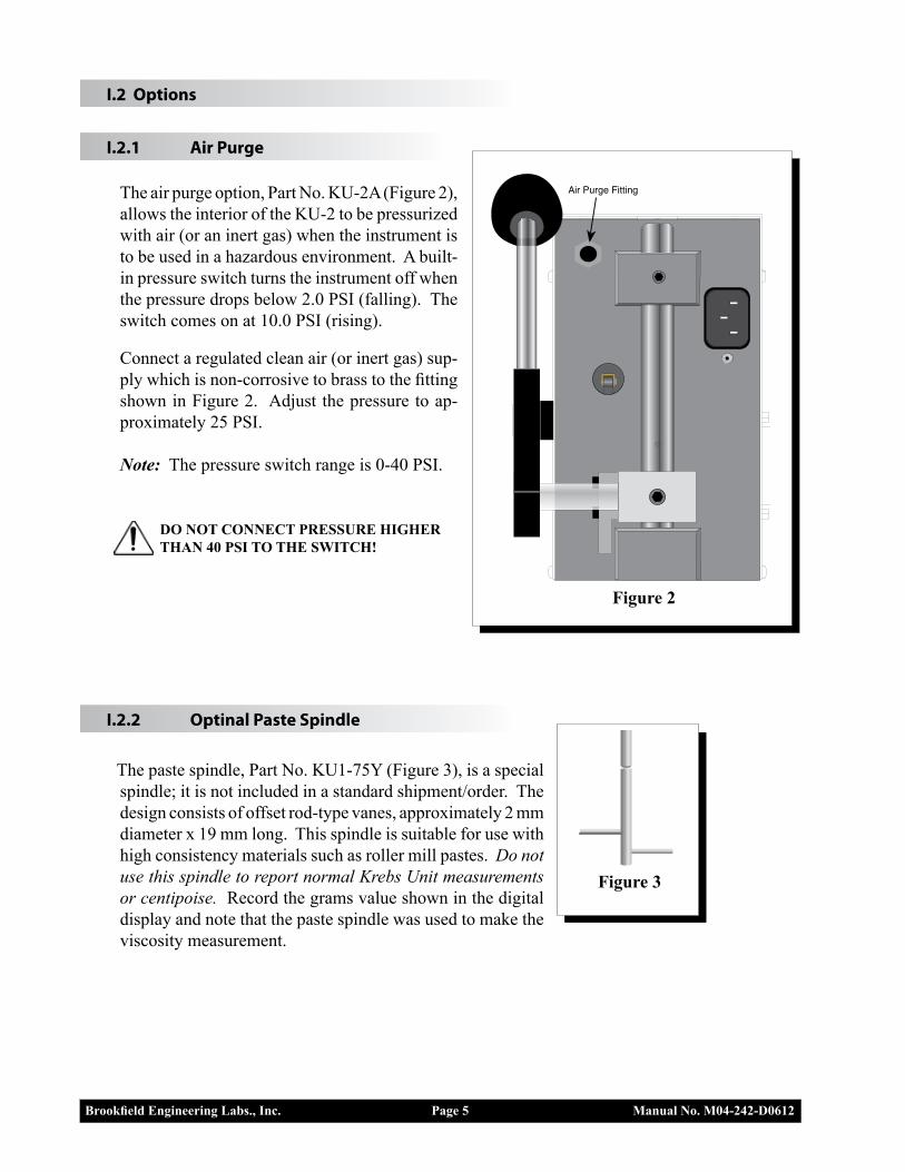
Figure 3
I.2 Options
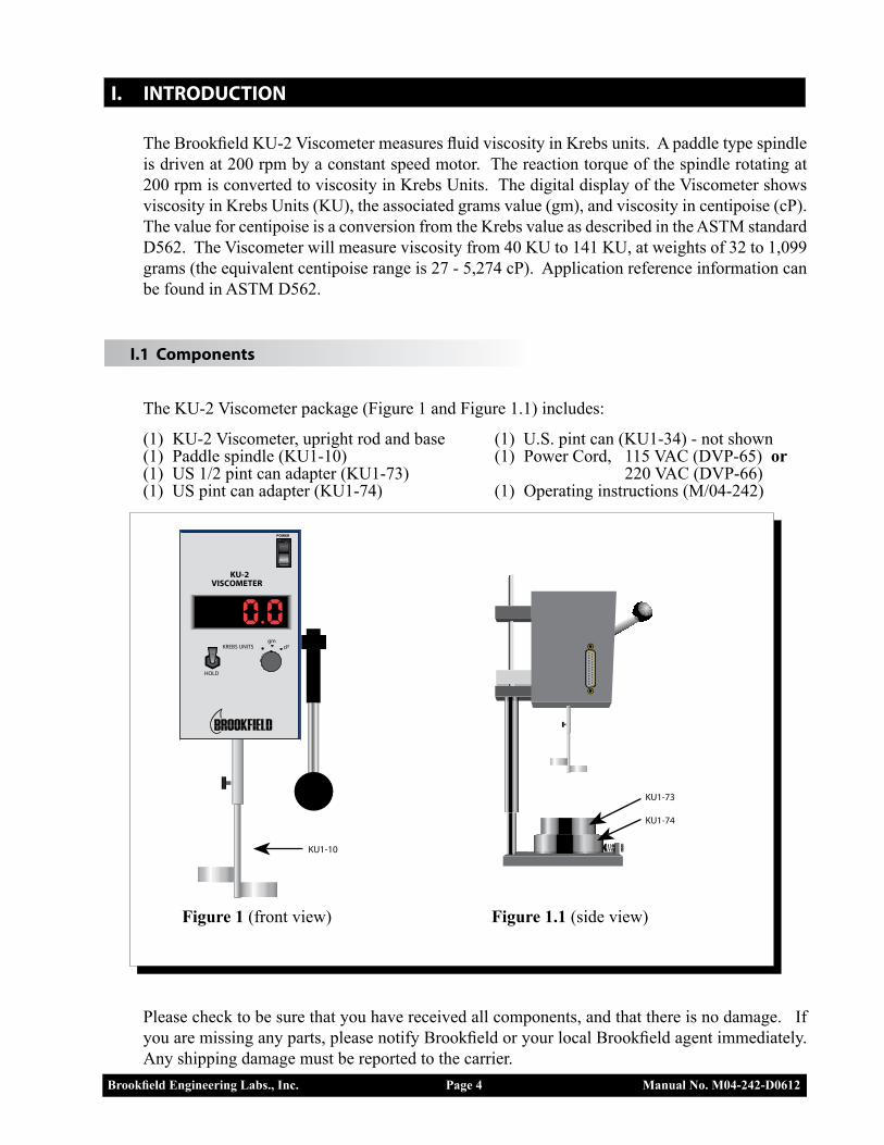
I.2.1 Air Purge The air purge option, Part No. KU-2A (Figure 2),
allows the interior of the KU-2 to be pressurized with air (or an inert gas) when the instrument is to be used in a hazardous environment. A built-in pressure switch turns the instrument off when the pressure drops below 2.0 PSI (falling). The switch comes on at 10.0 PSI (rising).
Connect a regulated clean air (or inert gas) sup-ply which is non-corrosive to brass to the fitting shown in Figure 2. Adjust the pressure to ap-proximately 25 PSI.
Note: The pressure switch range is 0-40 PSI.
DO NOT CONNECT PRESSURE HIGHER THAN 40 PSI TO THE SWITCH!
I.2.2 Optinal Paste Spindle
The paste spindle, Part No. KU1-75Y (Figure 3), is a special spindle; it is not included in a standard shipment/order. The design consists of offset rod-type vanes, approximately 2 mm diameter x 19 mm long. This spindle is suitable for use with high consistency materials such as roller mill pastes. Do not use this spindle to report normal Krebs Unit measurements or centipoise. Record the grams value shown in the digital display and note that the paste spindle was used to make the viscosity measurement.
Air Purge Fitting
Figure 2
Brookfield Engineering Labs., Inc. Page 6 Manual No. M04-242-D0612
I.3 Specifications
Range: 40–141 KU 32–1,099 gm 27 - 5,274 cP* Accuracy: ± 1% of full scale range Repeatability: ± 0.5% of full scale range Paddle speed: 200 rpm ± 0.1 rpm Printer output: 25D-Type Centronics Parallel Printer Output Net weight: 22 lb. (10 kg) Gross weight: 25 lb. (11 kg) Dimensions: 15 x 11 x 20 Operating Environment: 0°C (32°F) to 40°C (104°F) 20% - 80% R.H.: non-condensing atmosphere
Electrical Certifications: Conforms to CE Standards for: Electromagnetic Compatibility (EMC), Low Voltage (LVD) and Safety Requirements for electrical equipment for measurement control and laboratory use.
*Centipoise scale is for reference only. Do not use for calibration.
I.4 Sample Container Specifications
Container Dimensions Can Height Bottom Flange Diameter U.S. Pint 3.850" (9.78 cm) 3.385" (8.60 cm) U.S. Half Pint 2.850" (7.24 cm) 2.875" (7.30 cm) U.S. Quart 4.845" (12.31 cm) 4.230" (10.74 cm)
If you have a requirement for container dimensions other than those listed above, please contact Brookfield or an authorized Brookfield agent.
I.5 Utilities
Input voltage: 115 VAC or 230 VAC* Input frequency: 50/60 Hz Power consumption: 16 VA (watts) Power cord color code:
USA Outside USA
Hot (live) Black BrownNeutral White BlueGround (earth) Green Green/Yellow
*Main supply voltage fluctuations are not to exceed ± 10% of the nominal supply voltage.

Brookfield Engineering Labs., Inc. Page 7 Manual No. M04-242-D0612
I.6 Safety Symbols and Precautions
Safety SymbolsThe following explains safety symbols which may be found in this operating manual.
Indicates hazardous voltages may be present.
Refer to the manual for specific warning or caution information to avoid personal injury or damage to the instrument.
Precautions
If this instrument is used in a manner not specified by the manufacturer, the protection provided by the instrument may be impaired.
This instrument is not intended for use in a potentially hazardous environment.
In case of emergency, turn off the instrument and then disconnect the electrical cord from the wall outlet
The user should ensure that the substances placed under test do not release poisonous, toxic or flammable gases at the temperatures to which they are subjected to during the testing.
I.7 Printer Connection
The KU-2 is equipped with a parallel printer port located on the side of the instrument allowing printing with a parallel printer. A standard parallel printer cable (25 pin, Type D Centronics, avail-able from Brookfield as part number CAP-86) is used to connect the viscometer to the printer.
When connected to a printer, the KU-2 will print one line of data each time the "Hold Reading" switch is moved to the down position.
The data line includes the viscosity (in Krebs Units and centipoise) and the associated weight (in grams):
xxxxgm xxxxxKU xxxxcP 51gm 46.6KU 120cP Dashes in the printout indicate an "over-range"
condition or that the handle has risen to the top position (i.e. the spindle is not rotating):
- - - - g - - - . - KU - - - - cP
When connecting the cable to the KU-2, THE PRINTER POWER (AC mains) SHOULD BE "OFF"!
Pin Function1 STB2 D03 D14 D25 D36 D47 D58 D69 D7
25 GND
Parallel Printer Output Connection
Figure 4
Brookfield Engineering Labs., Inc. Page 8 Manual No. M04-242-D0612
I.8 Viscosity Units
The Krebs Unit is a special measure of viscosity that is not based on the Newtonian model of flow. The ASTM test method D562 was originally developed around the special conditions of an instrument that used gravity to drive a paddle spindle at 200 rpm. The weight required to achieve 200 rpm varied depending upon the viscosity of the fluid under test. The Krebs unit was devel-oped through the correlation of the weights used and the time required for 100 revolutions of the paddle. The ASTM standard also provided a correlation from Krebs Units to the scientific measure of viscosity in centipoise.
The Grams scale represents the weight required to drive the paddle through the test fluid at a rate of 200 rpm. The gravity drive system specified in ASTM D562 required that the weight be varied until 100 revolutions were achieved in 30 seconds (200 rpm). The KU-2 drives the unit at 200 rpm automatically and provides the grams value that would be required on the gravity drive system. The grams scale is not a viscosity unit.
The Centipoise scale is available through a correlation originally defined in the ASTM test method. Since this value is based on the Krebs Unit, it is not equivalent to centipoise values determined using other types of viscometers, such as the Brookfield RVDV-I+. The centipoise values displayed on the KU-2 are for reference only. Comparisons to measured values from other instruments should not be made.
I.9 Cleaning
Make sure the instrument is in a decent working environment (dust-free, moderate temperature, low humidity, etc.).
Make sure the instrument is on a level surface.
Hands/fingers must be clean and free of residue sample. Not doing so may result in deposit build up on the upper part of the shaft and cause interference between the shaft and the pivot cup.
Be sure to remove the spindle from the instrument prior to cleaning. Note left-handed thread. Severe instrument damage may result if the spindle is cleaned in place.
Instrument and Keypad: Clean with a dry, non-abrasive cloth. Do not use solvents or cleaners.
Immersed Components (spindles): Spindles are made of stainless steel. Clean with a non-abrasive cloth and solvent appropriate for sample material.
When cleaning, do not apply excessive force, which may result in bending spindles.
Brookfield Engineering Labs., Inc. Page 9 Manual No. M04-242-D0612
II. OPERATION
II.1 Set-Up
1) Be sure that the power switch is off. Attach the power cord to the appropriate power source.
2) Move the operating handle to the top (upper most) position.
3) Connect the printer (if used) to the parallel port. Be sure the printer power is off.
4) Loosen the thumb screw on the Viscometer shaft; insert the paddle spindle into the Viscom-eter shaft, as far as it will go. Line up the groove on the spindle with the hole that the thumb screw goes into. Tighten the thumb screw.
5) For Quart Cans: The can will be placed directly on the viscometer base.
6) For Pint Cans: Place the pint can adapter (KU1-74) on the viscometer base, pulling the spring loaded front locator out and placing the adapter against the rear locating pins. Release the locator to secure the adapter in place.
7) For 1/2 Pint Cans: Follow the procedure for pint cans. Place the 1/2 pint can adapter (KU1-73) on top of the pint can adapter (KU1-74).
II.2 Taking Measurements
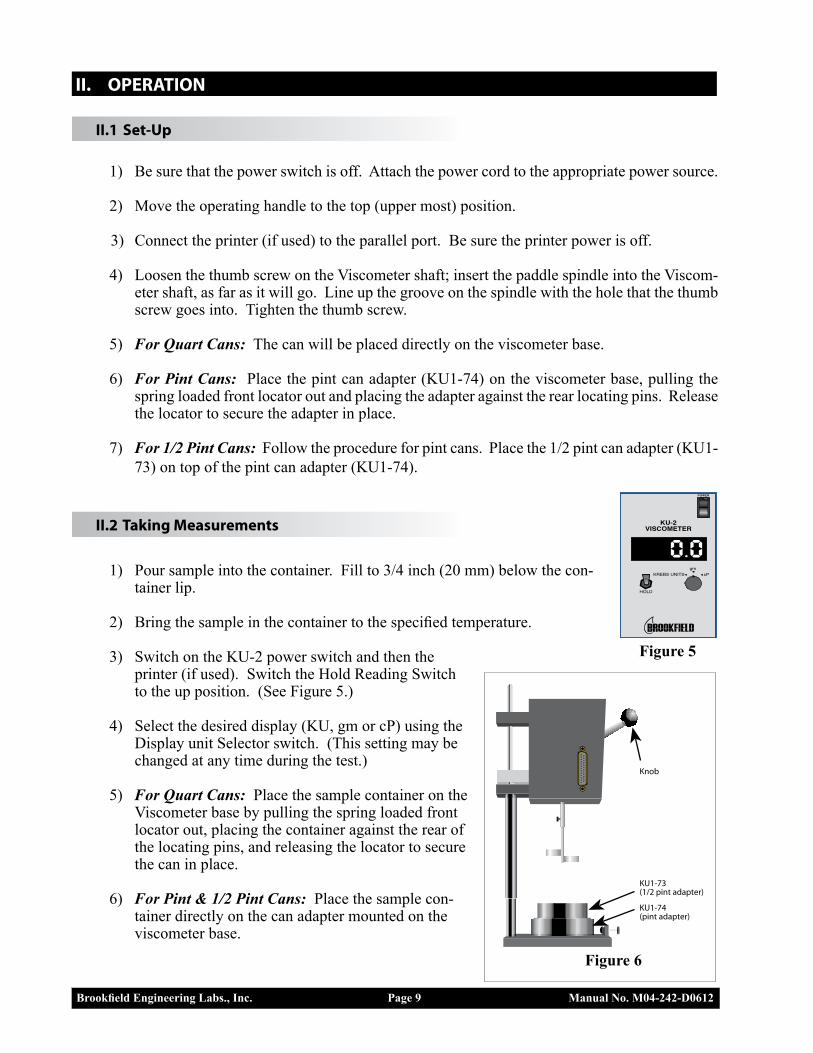
1) Pour sample into the container. Fill to 3/4 inch (20 mm) below the con-tainer lip.
2) Bring the sample in the container to the specified temperature.
3) Switch on the KU-2 power switch and then the printer (if used). Switch the Hold Reading Switch to the up position. (See Figure 5.)
4) Select the desired display (KU, gm or cP) using the Display unit Selector switch. (This setting may be changed at any time during the test.)
5) For Quart Cans: Place the sample container on the Viscometer base by pulling the spring loaded front locator out, placing the container against the rear of the locating pins, and releasing the locator to secure the can in place.
6) For Pint & 1/2 Pint Cans: Place the sample con-tainer directly on the can adapter mounted on the viscometer base.
KU-2VISCOMETER
POWER
KREBS UNITSgm
HOLD
cP
Figure 5
Figure 6
KU1-74(pint adapter)
KU1-73(1/2 pint adapter)
Knob
Brookfield Engineering Labs., Inc. Page 10 Manual No. M04-242-D0612
7) Move the Viscometer handle down to the lowest position. This will automatically immerse the spindle into the fluid. If the correct amount of fluid has been put into the container, the surface of the fluid will be at the immersion mark of the spindle.
CAUTION: When using the 1/2 pint can, do not lower the spindle directly into the container. The narrow diameter of the can requires the spindle to be in-troduced at an angle. Tilt the 1/2 pint can while lowering the viscometer.
8) The spindle will begin to rotate once the handle is within 1/2 inch of the lowest position.
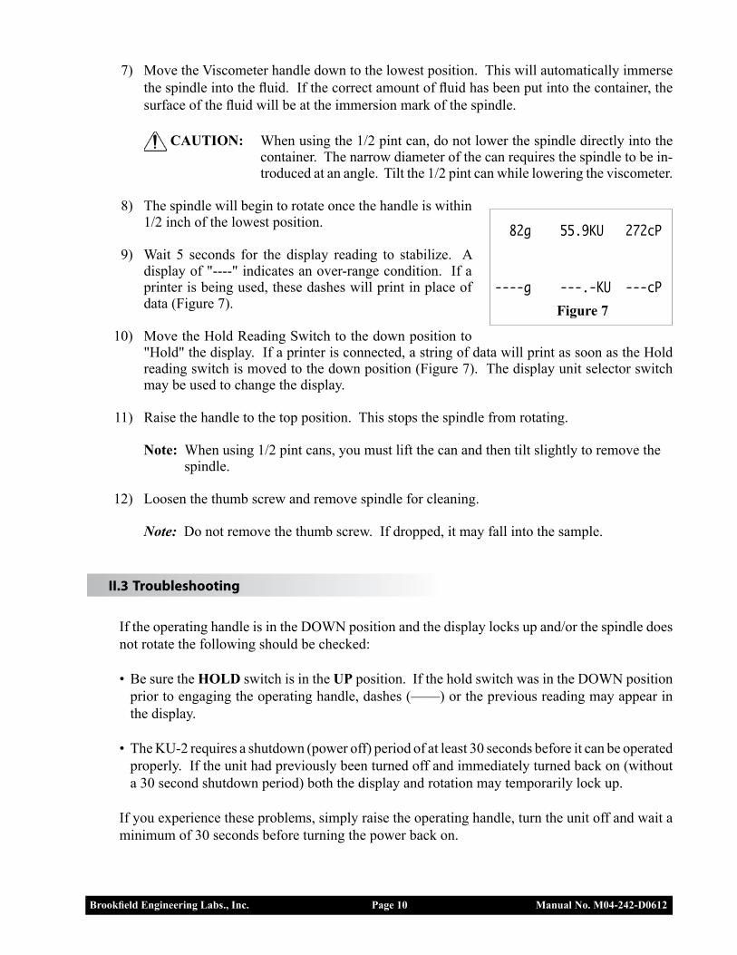
9) Wait 5 seconds for the display reading to stabilize. A display of "----" indicates an over-range condition. If a printer is being used, these dashes will print in place of data (Figure 7).
10) Move the Hold Reading Switch to the down position to "Hold" the display. If a printer is connected, a string of data will print as soon as the Hold reading switch is moved to the down position (Figure 7). The display unit selector switch may be used to change the display.
11) Raise the handle to the top position. This stops the spindle from rotating.
Note: When using 1/2 pint cans, you must lift the can and then tilt slightly to remove the spindle.
12) Loosen the thumb screw and remove spindle for cleaning.
Note: Do not remove the thumb screw. If dropped, it may fall into the sample.
II.3 Troubleshooting
If the operating handle is in the DOWN position and the display locks up and/or the spindle does not rotate the following should be checked:
• Be sure the HOLD switch is in the UP position. If the hold switch was in the DOWN position prior to engaging the operating handle, dashes (——) or the previous reading may appear in the display.
• The KU-2 requires a shutdown (power off) period of at least 30 seconds before it can be operated properly. If the unit had previously been turned off and immediately turned back on (without a 30 second shutdown period) both the display and rotation may temporarily lock up.
If you experience these problems, simply raise the operating handle, turn the unit off and wait a minimum of 30 seconds before turning the power back on.
Figure 7
82g 55.9KU 272cP
----g ---.-KU ---cP
Brookfield Engineering Labs., Inc. Page 11 Manual No. M04-242-D0612
Appendix A - KU-2 Calibration Information
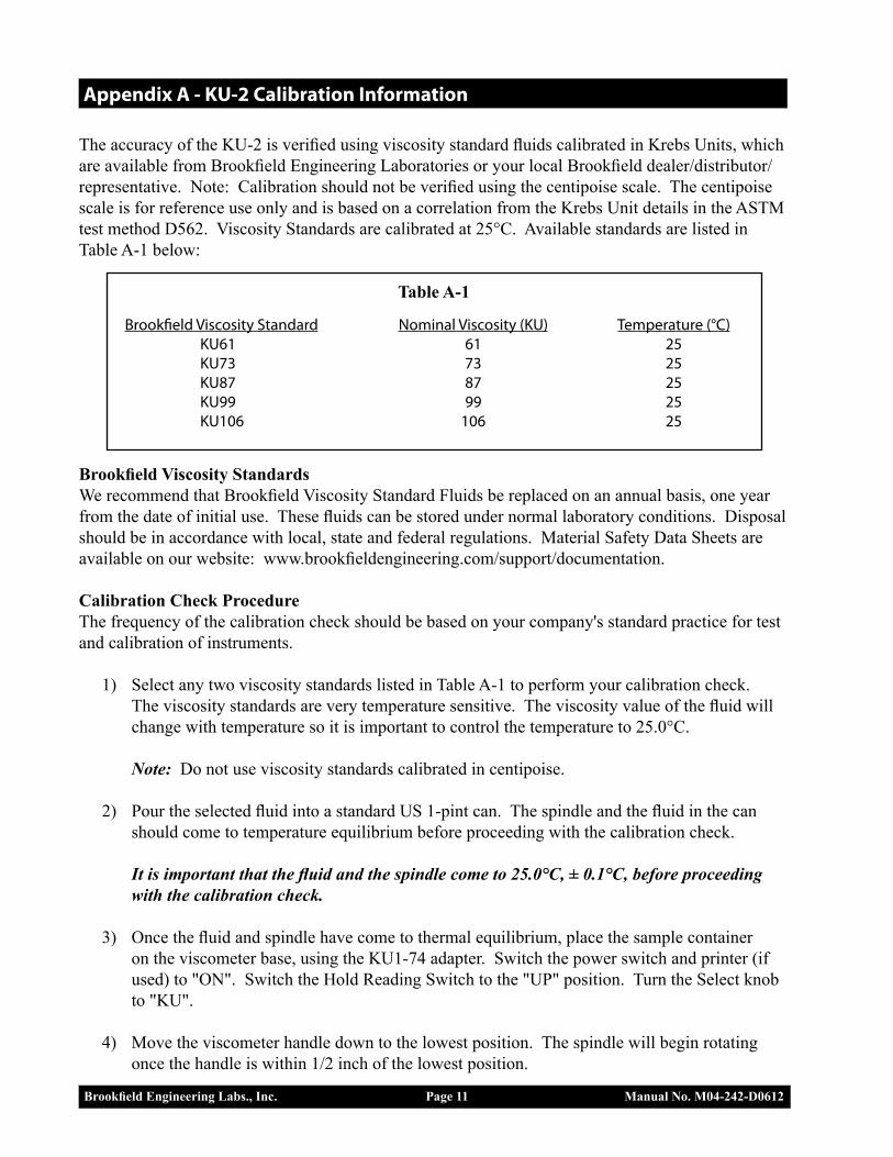
The accuracy of the KU-2 is verified using viscosity standard fluids calibrated in Krebs Units, which are available from Brookfield Engineering Laboratories or your local Brookfield dealer/distributor/representative. Note: Calibration should not be verified using the centipoise scale. The centipoise scale is for reference use only and is based on a correlation from the Krebs Unit details in the ASTM test method D562. Viscosity Standards are calibrated at 25°C. Available standards are listed in Table A-1 below:
Table A-1
Brookfield Viscosity Standard Nominal Viscosity (KU) Temperature (°C) KU61 61 25 KU73 73 25 KU87 87 25 KU99 99 25 KU106 106 25
Brookfield Viscosity StandardsWe recommend that Brookfield Viscosity Standard Fluids be replaced on an annual basis, one year from the date of initial use. These fluids can be stored under normal laboratory conditions. Disposal should be in accordance with local, state and federal regulations. Material Safety Data Sheets are available on our website: www.brookfieldengineering.com/support/documentation.
Calibration Check ProcedureThe frequency of the calibration check should be based on your company's standard practice for test and calibration of instruments.
1) Select any two viscosity standards listed in Table A-1 to perform your calibration check. The viscosity standards are very temperature sensitive. The viscosity value of the fluid will change with temperature so it is important to control the temperature to 25.0°C.
Note: Do not use viscosity standards calibrated in centipoise.
2) Pour the selected fluid into a standard US 1-pint can. The spindle and the fluid in the can should come to temperature equilibrium before proceeding with the calibration check.
It is important that the fluid and the spindle come to 25.0°C, ± 0.1°C, before proceeding with the calibration check.
3) Once the fluid and spindle have come to thermal equilibrium, place the sample container on the viscometer base, using the KU1-74 adapter. Switch the power switch and printer (if used) to "ON". Switch the Hold Reading Switch to the "UP" position. Turn the Select knob to "KU".
4) Move the viscometer handle down to the lowest position. The spindle will begin rotating once the handle is within 1/2 inch of the lowest position.
Brookfield Engineering Labs., Inc. Page 12 Manual No. M04-242-D0612
5) Wait five (5) seconds for the reading to stabilize. Switch the Hold Reading Switch to the "DOWN" position. You will need to record measurements in KU and gm. These two values work together to let you interpret the calibration results.
6) After you have recorded results in KU, then move the Selector knob to the "gm" position and record your reading in grams. If you are using a printer, three measurements will be sent to the printer and will print out as soon as the Hold Display switch is switched back to the DOWN position.
Interpretation of Calibration Check Results
When verifying the calibration of the KU-2, the instrument tolerance and viscosity standard fluid tolerance must be combined to calculate the total allowable error.
The KU-2 is accurate to ± 11 grams, which is 1% of the full scale range in grams. The Brookfield Viscosity Standard is accurate to ± 1% of the stated viscosity in KU.
The total allowable error should be stated in KU. Since the instrument accuracy is stated in grams, you will have to use the comparison table (Table A-2) and convert from grams to KU.
Correct interpretation of your calibration results requires that you compare your readings in grams to the equivalent in KU. You must then bracket your reading with upper and lower limits based on the allowable error of ± 11.0 grams. Convert this acceptable range in grams (as defined by the upper and lower limits) to KU units.
Example: Calculate the allowable error of the KU-2 using fluid KU106; the stated viscosity of the fluid is 104.8 KU. The viscometer indicated a measured viscosity of 105 KU and 410 grams.
1) Measured results from the calibration check in grams were 410 grams. Locate 410 grams on the conversion chart (Table A-2).
2) The KU-2 is accurate to ± 11.0 grams. Starting from 410 grams, count 11 places above and below the 410 grams. This is called "bracketing" the acceptable range. In this case, the acceptable range will be from 399 grams to 421 grams.
3) Convert the acceptable range in grams to KU. Locate the minimum and maximum grams bracketed. Look to the right of each number for the conversion to KU. In this case, it will be 103.9 KU minimum and 105.7 KU maximum. The total difference between 103.9 and 105.7 KU is 1.8 KU. Therefore, the accuracy is ± 0.9 KU. This is the accuracy for the Viscometer in KU, ± 0.9 KU.
Brookfield Engineering Labs., Inc. Page 13 Manual No. M04-242-D0612
4) Now that you have the accuracy for the instrument, you can add it to the accuracy of the fluid. The fluid is accurate to ± 1% of the stated value in KU. The viscosity standard is calibrated at 104.8 KU, ± 1% is equal to ± 1.0 KU.
0.9 KU (instrument accuracy) + 1.0 KU (fluid accuracy) 1.9 KU (total allowable error)
5) Total allowable error for the calibration check in this example is 104.8 KU, ± 1.9 KU (102.9 KU to 106.7 KU). Since the measured reading of 105 KU falls within this range, the Viscometer is considered in calibration.

Brookfield Engineering Labs., Inc. Page 14 Manual No. M04-242-D0612
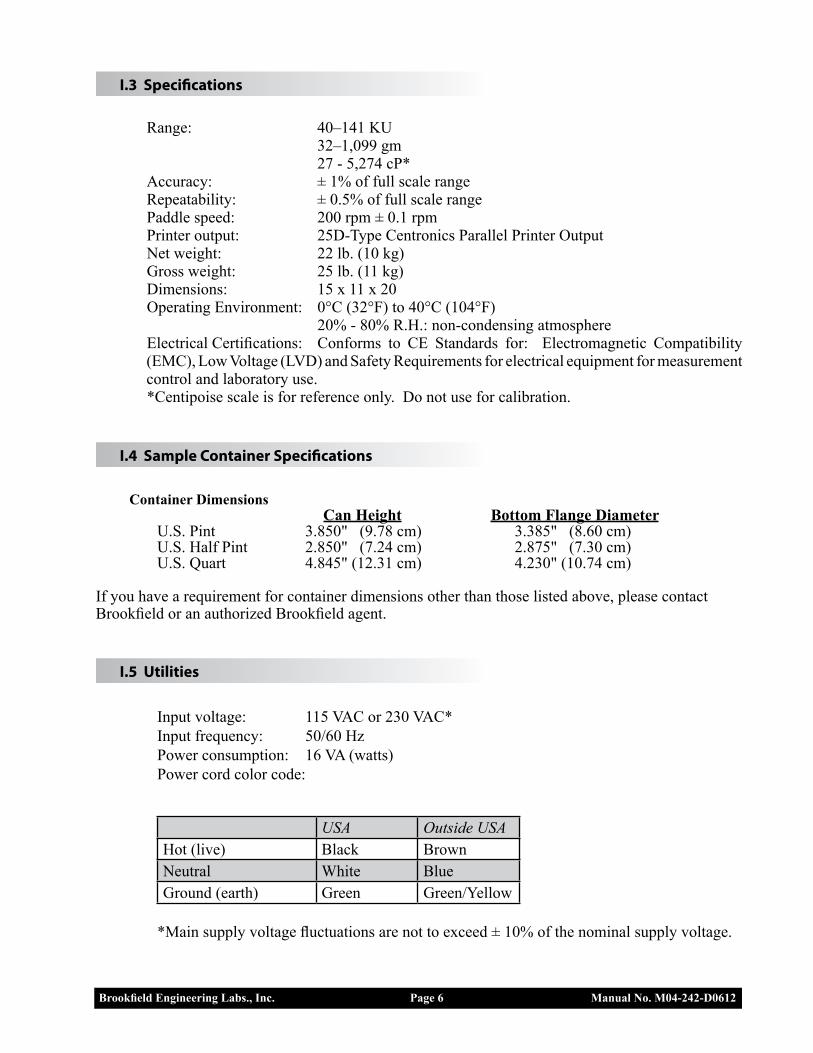
Table A-2
g KU cP g KU cP g KU cP g KU cP g KU cP g KU cP g KU cP g KU cP 101 60.9 366 176 77.2 735 251 89.1 1104 326 97.6 1472 401 104.1 1841 476 110.1 2210 551 116.1 2579 102 61.1 371 177 77.4 740 252 89.2 1109 327 97.7 1477 402 104.2 1846 477 110.2 2215 552 116.2 2584 103 61.4 376 178 77.6 745 253 89.3 1113 328 97.8 1482 403 104.2 1851 478 110.2 2220 553 116.2 2589 104 61.6 381 179 77.8 750 254 89.4 1118 329 97.9 1487 404 104.3 1856 479 110.3 2225 554 116.3 2594 105 61.9 386 180 78.0 754 255 89.6 1123 330 98.0 1492 405 104.4 1861 480 110.4 2230 555 116.4 2599 106 62.1 391 181 78.2 759 256 89.7 1128 331 98.1 1497 406 104.5 1866 481 110.5 2235 556 116.5 2604 32 40.2 27 107 62.4 395 182 78.4 764 257 89.8 1133 332 98.2 1502 407 104.6 1871 482 110.6 2240 557 116.6 2609 33 40.6 32 108 62.6 400 183 78.6 769 258 89.9 1138 333 98.3 1507 408 104.6 1876 483 110.6 2245 558 116.6 2613 34 40.9 36 109 62.8 405 184 78.8 774 259 90.1 1143 334 98.4 1512 409 104.7 1881 484 110.7 2250 559 116.7 2618 35 41.3 41 110 63.1 410 185 79.0 779 260 90.2 1148 335 98.5 1517 410 104.8 1886 485 110.8 2254 560 116.8 2623 36 41.6 46 111 63.3 415 186 79.1 784 261 90.3 1153 336 98.6 1522 411 104.9 1891 486 110.9 2259 561 116.9 2628 37 42.0 51 112 63.6 420 187 79.3 789 262 90.4 1158 337 98.7 1527 412 105.0 1895 487 111.0 2264 562 117.0 2633 38 42.3 56 113 63.8 425 188 79.5 794 263 90.6 1163 338 98.8 1532 413 105.0 1900 488 111.0 2269 563 117.0 2638 39 42.6 61 114 64.0 430 189 79.7 799 264 90.7 1168 339 98.9 1536 414 105.1 1905 489 111.1 2274 564 117.1 2643 40 43.0 66 115 64.3 435 190 79.9 804 265 90.8 1172 340 99.0 1541 415 105.2 1910 490 111.2 2279 565 117.2 2648 41 43.3 71 116 64.5 440 191 80.1 809 266 90.9 1177 341 99.1 1546 416 105.3 1915 491 111.3 2284 566 117.3 2653 42 43.6 76 117 64.7 445 192 80.3 813 267 91.0 1182 342 99.2 1551 417 105.4 1920 492 111.4 2289 567 117.4 2658 43 44.0 81 118 65.0 450 193 80.4 818 268 91.2 1187 343 99.3 1556 418 105.4 1925 493 111.4 2294 568 117.4 2663 44 44.3 86 119 65.2 454 194 80.6 823 269 91.3 1192 344 99.4 1561 419 105.5 1930 494 111.5 2299 569 117.5 2668 45 44.6 91 120 65.4 459 195 80.8 828 270 91.4 1197 345 99.4 1566 420 105.6 1935 495 111.6 2304 570 117.6 2672 46 45.0 95 121 65.7 464 196 81.0 833 271 91.5 1202 346 99.5 1571 421 105.7 1940 496 111.7 2309 571 117.7 2677 47 45.3 100 122 65.9 469 197 81.2 838 272 91.6 1207 347 99.6 1576 422 105.8 1945 497 111.8 2313 572 117.7 2682 48 45.6 105 123 66.1 474 198 81.3 843 273 91.8 1212 348 99.7 1581 423 105.8 1950 498 111.8 2318 573 117.8 2687 49 45.9 110 124 66.3 479 199 81.5 848 274 91.9 1217 349 99.8 1586 424 105.9 1954 499 111.9 2323 574 117.9 2692 50 46.3 115 125 66.6 484 200 81.7 853 275 92.0 1222 350 99.9 1591 425 106.0 1959 500 112.0 2328 575 117.9 2697 51 46.6 120 126 66.8 489 201 81.8 858 276 92.1 1227 351 100.0 1595 426 106.1 1964 501 112.1 2333 576 118.0 2702 52 46.9 125 127 67.0 494 202 82.0 863 277 92.2 1232 352 100.1 1600 427 106.2 1969 502 112.2 2338 577 118.1 2707 53 47.2 130 128 67.2 499 203 82.2 868 278 92.3 1236 353 100.2 1605 428 106.2 1974 503 112.2 2343 578 118.2 2712 54 47.5 135 129 67.5 504 204 82.3 872 279 92.5 1241 354 100.3 1610 429 106.3 1979 504 112.3 2348 579 118.2 2717 55 47.9 140 130 67.7 509 205 82.5 877 280 92.6 1246 355 100.3 1615 430 106.4 1984 505 112.4 2353 580 118.3 2722 56 48.2 145 131 67.9 513 206 82.7 882 281 92.7 1251 356 100.4 1620 431 106.5 1989 506 112.5 2358 581 118.4 2727 57 48.5 150 132 68.1 518 207 82.8 887 282 92.8 1256 357 100.5 1625 432 106.6 1994 507 112.6 2363 582 118.4 2732 58 48.8 154 133 68.4 523 208 83.0 892 283 92.9 1261 358 100.6 1630 433 106.6 1999 508 112.6 2368 583 118.5 2736 59 49.1 159 134 68.6 528 209 83.2 897 284 93.0 1266 359 100.7 1635 434 106.7 2004 509 112.7 2372 584 118.6 2741 60 49.4 164 135 68.8 533 210 83.3 902 285 93.2 1271 360 100.8 1640 435 106.8 2009 510 112.8 2377 585 118.6 2746 61 49.7 169 136 69.0 538 211 83.5 907 286 93.3 1276 361 100.9 1645 436 106.9 2013 511 112.9 2382 586 118.7 2751 62 50.0 174 137 69.2 543 212 83.6 912 287 93.4 1281 362 101.0 1650 437 107.0 2018 512 113.0 2387 587 118.8 2756 63 50.3 179 138 69.5 548 213 83.8 917 288 93.5 1286 363 101.0 1654 438 107.0 2023 513 113.0 2392 588 118.8 2761 64 50.6 184 139 69.7 553 214 84.0 922 289 93.6 1291 364 101.1 1659 439 107.1 2028 514 113.1 2397 589 118.9 2766 65 50.9 189 140 69.9 558 215 84.1 927 290 93.7 1295 365 101.2 1664 440 107.2 2033 515 113.2 2402 590 119.0 2771 66 51.2 194 141 70.1 563 216 84.3 932 291 93.8 1300 366 101.3 1669 441 107.3 2038 516 113.3 2407 591 119.0 2776 67 51.5 199 142 70.3 568 217 84.4 936 292 94.0 1305 367 101.4 1674 442 107.4 2043 517 113.4 2412 592 119.1 2781 68 51.8 204 143 70.5 572 218 84.5 941 293 94.1 1310 368 101.4 1679 443 107.4 2048 518 113.4 2417 593 119.2 2786 69 52.1 209 144 70.7 577 219 84.7 946 294 94.2 1315 369 101.5 1684 444 107.5 2053 519 113.5 2422 594 119.2 2791 70 52.4 213 145 71.0 582 220 84.8 951 295 94.3 1320 370 101.6 1689 445 107.6 2058 520 113.6 2427 595 119.3 2795 71 52.7 218 146 71.2 587 221 85.0 956 296 94.4 1325 371 101.7 1694 446 107.7 2063 521 113.7 2432 596 119.4 2800 72 53.0 223 147 71.4 592 222 85.1 961 297 94.5 1330 372 101.8 1699 447 107.8 2068 522 113.8 2436 597 119.4 2805 73 53.3 228 148 71.6 597 223 85.3 966 298 94.6 1335 373 101.8 1704 448 107.8 2072 523 113.8 2441 598 119.5 2810 74 53.6 233 149 71.8 602 224 85.4 971 299 94.7 1340 374 101.9 1709 449 107.9 2077 524 113.9 2446 599 119.5 2815 75 53.9 238 150 72.0 607 225 85.6 976 300 94.8 1345 375 102.0 1713 450 108.0 2082 525 114.0 2451 600 119.6 2820 76 54.2 243 151 72.2 612 226 85.7 981 301 95.0 1350 376 102.1 1718 451 108.1 2087 526 114.1 2456 601 119.7 2825 77 54.5 248 152 72.4 617 227 85.9 986 302 95.1 1354 377 102.2 1723 452 108.2 2092 527 114.2 2461 602 119.7 2830 78 54.8 253 153 72.6 622 228 86.0 991 303 95.2 1359 378 102.2 1728 453 108.2 2097 528 114.2 2466 603 119.8 2835 79 55.0 258 154 72.8 627 229 86.1 995 304 95.3 1364 379 102.3 1733 454 108.3 2102 529 114.3 2471 604 119.8 2840 80 55.3 263 155 73.0 632 230 86.3 1000 305 95.4 1369 380 102.4 1738 455 108.4 2107 530 114.4 2476 605 119.9 2845 81 55.6 268 156 73.2 636 231 86.4 1005 306 95.5 1374 381 102.5 1743 456 108.5 2112 531 114.5 2481 606 120.0 2850 82 55.9 272 157 73.4 641 232 86.6 1010 307 95.6 1379 382 102.6 1748 457 108.6 2117 532 114.6 2486 607 120.0 2854 83 56.2 277 158 73.6 646 233 86.7 1015 308 95.7 1384 383 102.6 1753 458 108.6 2122 533 114.6 2491 608 120.1 2859 84 56.5 282 159 73.8 651 234 86.8 1020 309 95.8 1389 384 102.7 1758 459 108.7 2127 534 114.7 2495 609 120.1 2864 85 56.7 287 160 74.0 656 235 87.0 1025 310 95.9 1394 385 102.8 1763 460 108.8 2132 535 114.8 2500 610 120.2 2869 86 57.0 292 161 74.2 661 236 87.1 1030 311 96.0 1399 386 102.9 1768 461 108.9 2136 536 114.9 2505 611 120.2 2874 87 57.3 297 162 74.4 666 237 87.2 1035 312 96.1 1404 387 103.0 1772 462 109.0 2141 537 115.0 2510 612 120.3 2879 88 57.6 302 163 74.6 671 238 87.4 1040 313 96.2 1409 388 103.0 1777 463 109.0 2146 538 115.0 2515 613 120.3 2884 89 57.8 307 164 74.8 676 239 87.5 1045 314 96.3 1413 389 103.1 1782 464 109.1 2151 539 115.1 2520 614 120.4 2889 90 58.1 312 165 75.0 681 240 87.6 1050 315 96.4 1418 390 103.2 1787 465 109.2 2156 540 115.2 2525 615 120.4 2894 91 58.4 317 166 75.2 686 241 87.8 1054 316 96.5 1423 391 103.3 1792 466 109.3 2161 541 115.3 2530 616 120.5 2899 92 58.6 322 167 75.4 691 242 87.9 1059 317 96.7 1428 392 103.4 1797 467 109.4 2166 542 115.4 2535 617 120.6 2904 93 58.9 327 168 75.6 695 243 88.0 1064 318 96.8 1433 393 103.4 1802 468 109.4 2171 543 115.4 2540 618 120.6 2909 94 59.1 332 169 75.8 700 244 88.2 1069 319 96.9 1438 394 103.5 1807 469 109.5 2176 544 115.5 2545 619 120.7 2913 95 59.4 336 170 76.0 705 245 88.3 1074 320 97.0 1443 395 103.6 1812 470 109.6 2181 545 115.6 2550 620 120.7 2918 96 59.6 341 171 76.2 710 246 88.4 1079 321 97.1 1448 396 103.7 1817 471 109.7 2186 546 115.7 2554 621 120.8 2923 97 59.9 346 172 76.4 715 247 88.6 1084 322 97.2 1453 397 103.8 1822 472 109.8 2191 547 115.8 2559 622 120.8 2928 98 60.1 351 173 76.6 720 248 88.7 1089 323 97.3 1458 398 103.8 1827 473 109.8 2195 548 115.8 2564 623 120.9 2933 99 60.4 356 174 76.8 725 249 88.8 1094 324 97.4 1463 399 103.9 1832 474 109.9 2200 549 115.9 2569 624 120.9 2938 100 60.6 361 175 77.0 730 250 88.9 1099 325 97.5 1468 400 104.0 1836 475 110.0 2205 550 116.0 2574 625 121.0 2943

Brookfield Engineering Labs., Inc. Page 15 Manual No. M04-242-D0612
g KU cP g KU cP g KU cP g KU cP g KU cP g KU cP g KU cP g KU cP 101 60.9 366 176 77.2 735 251 89.1 1104 326 97.6 1472 401 104.1 1841 476 110.1 2210 551 116.1 2579 102 61.1 371 177 77.4 740 252 89.2 1109 327 97.7 1477 402 104.2 1846 477 110.2 2215 552 116.2 2584 103 61.4 376 178 77.6 745 253 89.3 1113 328 97.8 1482 403 104.2 1851 478 110.2 2220 553 116.2 2589 104 61.6 381 179 77.8 750 254 89.4 1118 329 97.9 1487 404 104.3 1856 479 110.3 2225 554 116.3 2594 105 61.9 386 180 78.0 754 255 89.6 1123 330 98.0 1492 405 104.4 1861 480 110.4 2230 555 116.4 2599 106 62.1 391 181 78.2 759 256 89.7 1128 331 98.1 1497 406 104.5 1866 481 110.5 2235 556 116.5 2604 32 40.2 27 107 62.4 395 182 78.4 764 257 89.8 1133 332 98.2 1502 407 104.6 1871 482 110.6 2240 557 116.6 2609 33 40.6 32 108 62.6 400 183 78.6 769 258 89.9 1138 333 98.3 1507 408 104.6 1876 483 110.6 2245 558 116.6 2613 34 40.9 36 109 62.8 405 184 78.8 774 259 90.1 1143 334 98.4 1512 409 104.7 1881 484 110.7 2250 559 116.7 2618 35 41.3 41 110 63.1 410 185 79.0 779 260 90.2 1148 335 98.5 1517 410 104.8 1886 485 110.8 2254 560 116.8 2623 36 41.6 46 111 63.3 415 186 79.1 784 261 90.3 1153 336 98.6 1522 411 104.9 1891 486 110.9 2259 561 116.9 2628 37 42.0 51 112 63.6 420 187 79.3 789 262 90.4 1158 337 98.7 1527 412 105.0 1895 487 111.0 2264 562 117.0 2633 38 42.3 56 113 63.8 425 188 79.5 794 263 90.6 1163 338 98.8 1532 413 105.0 1900 488 111.0 2269 563 117.0 2638 39 42.6 61 114 64.0 430 189 79.7 799 264 90.7 1168 339 98.9 1536 414 105.1 1905 489 111.1 2274 564 117.1 2643 40 43.0 66 115 64.3 435 190 79.9 804 265 90.8 1172 340 99.0 1541 415 105.2 1910 490 111.2 2279 565 117.2 2648 41 43.3 71 116 64.5 440 191 80.1 809 266 90.9 1177 341 99.1 1546 416 105.3 1915 491 111.3 2284 566 117.3 2653 42 43.6 76 117 64.7 445 192 80.3 813 267 91.0 1182 342 99.2 1551 417 105.4 1920 492 111.4 2289 567 117.4 2658 43 44.0 81 118 65.0 450 193 80.4 818 268 91.2 1187 343 99.3 1556 418 105.4 1925 493 111.4 2294 568 117.4 2663 44 44.3 86 119 65.2 454 194 80.6 823 269 91.3 1192 344 99.4 1561 419 105.5 1930 494 111.5 2299 569 117.5 2668 45 44.6 91 120 65.4 459 195 80.8 828 270 91.4 1197 345 99.4 1566 420 105.6 1935 495 111.6 2304 570 117.6 2672 46 45.0 95 121 65.7 464 196 81.0 833 271 91.5 1202 346 99.5 1571 421 105.7 1940 496 111.7 2309 571 117.7 2677 47 45.3 100 122 65.9 469 197 81.2 838 272 91.6 1207 347 99.6 1576 422 105.8 1945 497 111.8 2313 572 117.7 2682 48 45.6 105 123 66.1 474 198 81.3 843 273 91.8 1212 348 99.7 1581 423 105.8 1950 498 111.8 2318 573 117.8 2687 49 45.9 110 124 66.3 479 199 81.5 848 274 91.9 1217 349 99.8 1586 424 105.9 1954 499 111.9 2323 574 117.9 2692 50 46.3 115 125 66.6 484 200 81.7 853 275 92.0 1222 350 99.9 1591 425 106.0 1959 500 112.0 2328 575 117.9 2697 51 46.6 120 126 66.8 489 201 81.8 858 276 92.1 1227 351 100.0 1595 426 106.1 1964 501 112.1 2333 576 118.0 2702 52 46.9 125 127 67.0 494 202 82.0 863 277 92.2 1232 352 100.1 1600 427 106.2 1969 502 112.2 2338 577 118.1 2707 53 47.2 130 128 67.2 499 203 82.2 868 278 92.3 1236 353 100.2 1605 428 106.2 1974 503 112.2 2343 578 118.2 2712 54 47.5 135 129 67.5 504 204 82.3 872 279 92.5 1241 354 100.3 1610 429 106.3 1979 504 112.3 2348 579 118.2 2717 55 47.9 140 130 67.7 509 205 82.5 877 280 92.6 1246 355 100.3 1615 430 106.4 1984 505 112.4 2353 580 118.3 2722 56 48.2 145 131 67.9 513 206 82.7 882 281 92.7 1251 356 100.4 1620 431 106.5 1989 506 112.5 2358 581 118.4 2727 57 48.5 150 132 68.1 518 207 82.8 887 282 92.8 1256 357 100.5 1625 432 106.6 1994 507 112.6 2363 582 118.4 2732 58 48.8 154 133 68.4 523 208 83.0 892 283 92.9 1261 358 100.6 1630 433 106.6 1999 508 112.6 2368 583 118.5 2736 59 49.1 159 134 68.6 528 209 83.2 897 284 93.0 1266 359 100.7 1635 434 106.7 2004 509 112.7 2372 584 118.6 2741 60 49.4 164 135 68.8 533 210 83.3 902 285 93.2 1271 360 100.8 1640 435 106.8 2009 510 112.8 2377 585 118.6 2746 61 49.7 169 136 69.0 538 211 83.5 907 286 93.3 1276 361 100.9 1645 436 106.9 2013 511 112.9 2382 586 118.7 2751 62 50.0 174 137 69.2 543 212 83.6 912 287 93.4 1281 362 101.0 1650 437 107.0 2018 512 113.0 2387 587 118.8 2756 63 50.3 179 138 69.5 548 213 83.8 917 288 93.5 1286 363 101.0 1654 438 107.0 2023 513 113.0 2392 588 118.8 2761 64 50.6 184 139 69.7 553 214 84.0 922 289 93.6 1291 364 101.1 1659 439 107.1 2028 514 113.1 2397 589 118.9 2766 65 50.9 189 140 69.9 558 215 84.1 927 290 93.7 1295 365 101.2 1664 440 107.2 2033 515 113.2 2402 590 119.0 2771 66 51.2 194 141 70.1 563 216 84.3 932 291 93.8 1300 366 101.3 1669 441 107.3 2038 516 113.3 2407 591 119.0 2776 67 51.5 199 142 70.3 568 217 84.4 936 292 94.0 1305 367 101.4 1674 442 107.4 2043 517 113.4 2412 592 119.1 2781 68 51.8 204 143 70.5 572 218 84.5 941 293 94.1 1310 368 101.4 1679 443 107.4 2048 518 113.4 2417 593 119.2 2786 69 52.1 209 144 70.7 577 219 84.7 946 294 94.2 1315 369 101.5 1684 444 107.5 2053 519 113.5 2422 594 119.2 2791 70 52.4 213 145 71.0 582 220 84.8 951 295 94.3 1320 370 101.6 1689 445 107.6 2058 520 113.6 2427 595 119.3 2795 71 52.7 218 146 71.2 587 221 85.0 956 296 94.4 1325 371 101.7 1694 446 107.7 2063 521 113.7 2432 596 119.4 2800 72 53.0 223 147 71.4 592 222 85.1 961 297 94.5 1330 372 101.8 1699 447 107.8 2068 522 113.8 2436 597 119.4 2805 73 53.3 228 148 71.6 597 223 85.3 966 298 94.6 1335 373 101.8 1704 448 107.8 2072 523 113.8 2441 598 119.5 2810 74 53.6 233 149 71.8 602 224 85.4 971 299 94.7 1340 374 101.9 1709 449 107.9 2077 524 113.9 2446 599 119.5 2815 75 53.9 238 150 72.0 607 225 85.6 976 300 94.8 1345 375 102.0 1713 450 108.0 2082 525 114.0 2451 600 119.6 2820 76 54.2 243 151 72.2 612 226 85.7 981 301 95.0 1350 376 102.1 1718 451 108.1 2087 526 114.1 2456 601 119.7 2825 77 54.5 248 152 72.4 617 227 85.9 986 302 95.1 1354 377 102.2 1723 452 108.2 2092 527 114.2 2461 602 119.7 2830 78 54.8 253 153 72.6 622 228 86.0 991 303 95.2 1359 378 102.2 1728 453 108.2 2097 528 114.2 2466 603 119.8 2835 79 55.0 258 154 72.8 627 229 86.1 995 304 95.3 1364 379 102.3 1733 454 108.3 2102 529 114.3 2471 604 119.8 2840 80 55.3 263 155 73.0 632 230 86.3 1000 305 95.4 1369 380 102.4 1738 455 108.4 2107 530 114.4 2476 605 119.9 2845 81 55.6 268 156 73.2 636 231 86.4 1005 306 95.5 1374 381 102.5 1743 456 108.5 2112 531 114.5 2481 606 120.0 2850 82 55.9 272 157 73.4 641 232 86.6 1010 307 95.6 1379 382 102.6 1748 457 108.6 2117 532 114.6 2486 607 120.0 2854 83 56.2 277 158 73.6 646 233 86.7 1015 308 95.7 1384 383 102.6 1753 458 108.6 2122 533 114.6 2491 608 120.1 2859 84 56.5 282 159 73.8 651 234 86.8 1020 309 95.8 1389 384 102.7 1758 459 108.7 2127 534 114.7 2495 609 120.1 2864 85 56.7 287 160 74.0 656 235 87.0 1025 310 95.9 1394 385 102.8 1763 460 108.8 2132 535 114.8 2500 610 120.2 2869 86 57.0 292 161 74.2 661 236 87.1 1030 311 96.0 1399 386 102.9 1768 461 108.9 2136 536 114.9 2505 611 120.2 2874 87 57.3 297 162 74.4 666 237 87.2 1035 312 96.1 1404 387 103.0 1772 462 109.0 2141 537 115.0 2510 612 120.3 2879 88 57.6 302 163 74.6 671 238 87.4 1040 313 96.2 1409 388 103.0 1777 463 109.0 2146 538 115.0 2515 613 120.3 2884 89 57.8 307 164 74.8 676 239 87.5 1045 314 96.3 1413 389 103.1 1782 464 109.1 2151 539 115.1 2520 614 120.4 2889 90 58.1 312 165 75.0 681 240 87.6 1050 315 96.4 1418 390 103.2 1787 465 109.2 2156 540 115.2 2525 615 120.4 2894 91 58.4 317 166 75.2 686 241 87.8 1054 316 96.5 1423 391 103.3 1792 466 109.3 2161 541 115.3 2530 616 120.5 2899 92 58.6 322 167 75.4 691 242 87.9 1059 317 96.7 1428 392 103.4 1797 467 109.4 2166 542 115.4 2535 617 120.6 2904 93 58.9 327 168 75.6 695 243 88.0 1064 318 96.8 1433 393 103.4 1802 468 109.4 2171 543 115.4 2540 618 120.6 2909 94 59.1 332 169 75.8 700 244 88.2 1069 319 96.9 1438 394 103.5 1807 469 109.5 2176 544 115.5 2545 619 120.7 2913 95 59.4 336 170 76.0 705 245 88.3 1074 320 97.0 1443 395 103.6 1812 470 109.6 2181 545 115.6 2550 620 120.7 2918 96 59.6 341 171 76.2 710 246 88.4 1079 321 97.1 1448 396 103.7 1817 471 109.7 2186 546 115.7 2554 621 120.8 2923 97 59.9 346 172 76.4 715 247 88.6 1084 322 97.2 1453 397 103.8 1822 472 109.8 2191 547 115.8 2559 622 120.8 2928 98 60.1 351 173 76.6 720 248 88.7 1089 323 97.3 1458 398 103.8 1827 473 109.8 2195 548 115.8 2564 623 120.9 2933 99 60.4 356 174 76.8 725 249 88.8 1094 324 97.4 1463 399 103.9 1832 474 109.9 2200 549 115.9 2569 624 120.9 2938 100 60.6 361 175 77.0 730 250 88.9 1099 325 97.5 1468 400 104.0 1836 475 110.0 2205 550 116.0 2574 625 121.0 2943
Table A-2 (continued)
g KU cP g KU cP g KU cP g KU cP g KU cP g KU cP g KU cP 626 121.0 2948 701 125.1 3317 776 129.7 3686 851 133.8 4054 926 137.0 4423 1001 139.8 4792 1076 141.0 5161 627 121.1 2953 702 125.1 3322 777 129.8 3691 852 133.9 4059 927 137.1 4428 1002 139.8 4797 1077 141.0 5166 628 121.1 2958 703 125.2 3327 778 129.8 3695 853 133.9 4064 928 137.1 4433 1003 139.8 4802 1078 141.0 5171 629 121.2 2963 704 125.2 3332 779 129.9 3700 854 134.0 4069 929 137.2 4438 1004 139.8 4807 1079 141.0 5176 630 121.2 2968 705 125.3 3336 780 130.0 3705 855 134.0 4074 930 137.2 4443 1005 139.9 4812 1080 141.0 5181 631 121.3 2972 706 125.4 3341 781 130.0 3710 856 134.0 4079 931 137.2 4448 1006 139.9 4817 1081 141.0 5186 632 121.3 2977 707 125.4 3346 782 130.1 3715 857 134.1 4084 932 137.3 4453 1007 139.9 4822 1082 141.0 5191 633 121.4 2982 708 125.5 3351 783 130.2 3720 858 134.1 4089 933 137.3 4458 1008 139.9 4827 1083 141.0 5195 634 121.4 2987 709 125.5 3356 784 130.2 3725 859 134.2 4094 934 137.4 4463 1009 139.9 4832 1084 141.0 5200 635 121.5 2992 710 125.6 3361 785 130.3 3730 860 134.2 4099 935 137.4 4468 1010 139.9 4836 1085 141.0 5205 636 121.6 2997 711 125.7 3366 786 130.4 3735 861 134.3 4104 936 137.4 4472 1011 139.9 4841 1086 141.0 5210 637 121.6 3002 712 125.7 3371 787 130.4 3740 862 134.3 4109 937 137.5 4477 1012 140.0 4846 1087 141.0 5215 638 121.7 3007 713 125.8 3376 788 130.5 3745 863 134.4 4113 938 137.5 4482 1013 140.0 4851 1088 141.0 5220 639 121.7 3012 714 125.8 3381 789 130.5 3750 864 134.4 4118 939 137.6 4487 1014 140.0 4856 1089 141.0 5225 640 121.8 3017 715 125.9 3386 790 130.6 3754 865 134.5 4123 940 137.6 4492 1015 140.0 4861 1090 141.0 5230 641 121.8 3022 716 126.0 3391 791 130.7 3759 866 134.5 4128 941 137.6 4497 1016 140.0 4866 1091 141.0 5235 642 121.9 3027 717 126.0 3395 792 130.7 3764 867 134.6 4133 942 137.7 4502 1017 140.0 4871 1092 141.0 5240 643 121.9 3032 718 126.1 3400 793 130.8 3769 868 134.6 4138 943 137.7 4507 1018 140.0 4876 1093 141.0 5245 644 122.0 3036 719 126.1 3405 794 130.8 3774 869 134.7 4143 944 137.8 4512 1019 140.1 4881 1094 141.0 5250 645 122.0 3041 720 126.2 3410 795 130.9 3779 870 134.7 4148 945 137.8 4517 1020 140.1 4886 1095 141.0 5254 646 122.0 3046 721 126.3 3415 796 131.0 3784 871 134.8 4153 946 137.8 4522 1021 140.1 4891 1096 141.0 5259 647 122.1 3051 722 126.3 3420 797 131.0 3789 872 134.8 4158 947 137.9 4527 1022 140.1 4895 1097 141.0 5264 648 122.1 3056 723 126.4 3425 798 131.1 3794 873 134.9 4163 948 137.9 4532 1023 140.1 4900 1098 141.0 5269 649 122.2 3061 724 126.4 3430 799 131.1 3799 874 134.9 4168 949 138.0 4536 1024 140.1 4905 1099 141.0 5274 650 122.2 3066 725 126.5 3435 800 131.2 3804 875 134.9 4172 950 138.0 4541 1025 140.1 4910 651 122.3 3071 726 126.6 3440 801 131.2 3809 876 135.0 4177 951 138.0 4546 1026 140.2 4915 652 122.3 3076 727 126.6 3445 802 131.3 3813 877 135.0 4182 952 138.1 4551 1027 140.2 4920 653 122.4 3081 728 126.7 3450 803 131.3 3818 878 135.1 4187 953 138.1 4556 1028 140.2 4925 654 122.4 3086 729 126.7 3454 804 131.4 3823 879 135.1 4192 954 138.2 4561 1029 140.2 4930 655 122.5 3091 730 126.8 3459 805 131.4 3828 880 135.2 4197 955 138.2 4566 1030 140.2 4935 656 122.6 3095 731 126.9 3464 806 131.5 3833 881 135.2 4202 956 138.2 4571 1031 140.2 4940 657 122.6 3100 732 126.9 3469 807 131.6 3838 882 135.3 4207 957 138.3 4576 1032 140.2 4945 658 122.7 3105 733 127.0 3474 808 131.6 3843 883 135.3 4212 958 138.3 4581 1033 140.3 4950 659 122.7 3110 734 127.0 3479 809 131.7 3848 884 135.4 4217 959 138.4 4586 1034 140.3 4954 660 122.8 3115 735 127.1 3484 810 131.7 3853 885 135.4 4222 960 138.4 4591 1035 140.3 4959 661 122.8 3120 736 127.2 3489 811 131.8 3858 886 135.4 4227 961 138.4 4595 1036 140.3 4964 662 122.9 3125 737 127.2 3494 812 131.8 3863 887 135.5 4232 962 138.5 4600 1037 140.3 4969 663 122.9 3130 738 127.3 3499 813 131.9 3868 888 135.5 4236 963 138.5 4605 1038 140.4 4974 664 123.0 3135 739 127.3 3504 814 131.9 3872 889 135.6 4241 964 138.6 4610 1039 140.4 4979 665 123.0 3140 740 127.4 3509 815 132.0 3877 890 135.6 4246 965 138.6 4615 1040 140.4 4984 666 123.1 3145 741 127.5 3513 816 132.0 3882 891 135.6 4251 966 138.6 4620 1041 140.4 4989 667 123.1 3150 742 127.5 3518 817 132.1 3887 892 135.7 4256 967 138.7 4625 1042 140.4 4994 668 123.2 3154 743 127.6 3523 818 132.1 3892 893 135.7 4261 968 138.7 4630 1043 140.5 4999 669 123.2 3159 744 127.6 3528 819 132.2 3897 894 135.8 4266 969 138.8 4635 1044 140.5 5004 670 123.3 3164 745 127.7 3533 820 132.2 3902 895 135.8 4271 970 138.8 4640 1045 140.5 5009 671 123.3 3169 746 127.8 3538 821 132.3 3907 896 135.8 4276 971 138.8 4645 1046 140.5 5013 672 123.4 3174 747 127.8 3543 822 132.3 3912 897 135.9 4281 972 138.9 4650 1047 140.5 5018 673 123.4 3179 748 127.9 3548 823 132.4 3917 898 135.9 4286 973 138.9 4654 1048 140.6 5023 674 123.5 3184 749 128.0 3553 824 132.4 3922 899 136.0 4291 974 139.0 4659 1049 140.6 5028 675 123.6 3189 750 128.0 3558 825 132.5 3927 900 136.0 4295 975 139.0 4664 1050 140.6 5033 676 123.6 3194 751 128.1 3563 826 132.6 3932 901 136.0 4300 976 139.0 4669 1051 140.6 5038 677 123.7 3199 752 128.2 3568 827 132.6 3936 902 136.1 4305 977 139.1 4674 1052 140.6 5043 678 123.7 3204 753 128.2 3572 828 132.7 3941 903 136.1 4310 978 139.1 4679 1053 140.7 5048 679 123.8 3209 754 128.3 3577 829 132.7 3946 904 136.2 4315 979 139.1 4684 1054 140.7 5053 680 123.8 3213 755 128.4 3582 830 132.8 3951 905 136.2 4320 980 139.2 4689 1055 140.7 5058 681 123.9 3218 756 128.4 3587 831 132.8 3956 906 136.2 4325 981 139.2 4694 1056 140.7 5063 682 123.9 3223 757 128.5 3592 832 132.9 3961 907 136.3 4330 982 139.2 4699 1057 140.7 5068 683 124.0 3228 758 128.6 3597 833 132.9 3966 908 136.3 4335 983 139.3 4704 1058 140.7 5072 684 124.0 3233 759 128.6 3602 834 133.0 3971 909 136.4 4340 984 139.3 4709 1059 140.8 5077 685 124.1 3238 760 128.7 3607 835 133.0 3976 910 136.4 4345 985 139.3 4713 1060 140.8 5082 686 124.2 3243 761 128.7 3612 836 133.0 3981 911 136.4 4350 986 139.4 4718 1061 140.8 5087 687 124.2 3248 762 128.8 3617 837 133.1 3986 912 136.5 4354 987 139.4 4723 1062 140.8 5092 688 124.3 3253 763 128.9 3622 838 133.1 3991 913 136.5 4359 988 139.4 4728 1063 140.8 5097 689 124.3 3258 764 128.9 3627 839 133.2 3995 914 136.6 4364 989 139.5 4733 1064 140.8 5102 690 124.4 3263 765 129.0 3632 840 133.2 4000 915 136.6 4369 990 139.5 4738 1065 140.8 5107 691 124.5 3268 766 129.1 3636 841 133.3 4005 916 136.6 4374 991 139.5 4743 1066 140.9 5112 692 124.5 3272 767 129.1 3641 842 133.3 4010 917 136.7 4379 992 139.6 4748 1067 140.9 5117 693 124.6 3277 768 129.2 3646 843 133.4 4015 918 136.7 4384 993 139.6 4753 1068 140.9 5122 694 124.6 3282 769 129.3 3651 844 133.4 4020 919 136.8 4389 994 139.6 4758 1069 140.9 5127 695 124.7 3287 770 129.3 3656 845 133.5 4025 920 136.8 4394 995 139.6 4763 1070 140.9 5132 696 124.8 3292 771 129.4 3661 846 133.6 4030 921 136.8 4399 996 139.7 4768 1071 140.9 5136 697 124.8 3297 772 129.5 3666 847 133.6 4035 922 136.9 4404 997 139.7 4772 1072 140.9 5141 698 124.9 3302 773 129.5 3671 848 133.7 4040 923 136.9 4409 998 139.7 4777 1073 140.9 5146 699 124.9 3307 774 129.6 3676 849 133.7 4045 924 137.0 4413 999 139.7 4782 1074 140.9 5151 700 125.0 3312 775 129.7 3681 850 133.8 4050 925 137.0 4418 1000 139.8 4787 1075 140.9 5156
Brookfield Engineering Labs., Inc. Page 16 Manual No. M04-242-D0612
Appendix B - References
The KU-2 Viscometer is compatible with:
ASTM D 562 Standard Test Method for Consistency of Paint Using the Stormer Viscometer
II.1 Set-Up
Brookfield Engineering Labs., Inc. Page 17 Manual No. M04-242-D0612
II.1 Set-Up
Appendix C - Online Help and Additional Resources
www.brookfieldengineering.com**The Brookfield website is a good resource for additional and self-help whenever you need it. Our website offers a selection of “how-to” videos, application notes, conversion tables, instructional manuals, material safety data sheets, calibration templates and other technical resources.
http://www.youtube.com/user/BrookfieldEngBrookfield has its own YouTube channel. Videos posted to our website can be found here as well as other “home-made” videos made by our own technical sales group.
Viscosityjournal.comBrookfield is involved with a satellite website that should be your first stop in viscosity research. This site serves as a library of interviews with experts in the viscosity field as well as Brookfield technical articles and conversion charts. Registration is required, so that you can be notified of upcoming interviews and events, however, this information will not be shared with other vendors, institutions, etc..
Article Reprints - Available in Print Only - Brookfield has an extensive library of published articles relating to viscosity, texture and
powder testing. Due to copyright restrictions, these articles cannot be emailed. Please request your hardcopy of articles by calling our customer service department directly or by emailing: [email protected]
- Available Online - Brookfield has a growing number of published articles that can be downloaded directly from
the Brookfield website. These articles can be found on our main site by following this path: http://www.brookfieldengineering.com/support/documentation/article reprints
More Solutions to Sticky ProblemsLearn more about viscosity and rheology with our most popular publication. This informative booklet will provide you with measurement techniques, advice and much more. It’s a must-have for any Brookfield Viscometer or Rheometer operator. More Solutions is avaiable in print and also as a downloadable pdf on the Brookfield website by following this path: http://www.brookfieldengineering.com/support/documentation
Training/CoursesWhether it is instrument-specific courses, training to help you better prepare for auditing concerns, or just a better understanding of your methods, who better to learn from than the worldwide leaders of viscosity measuring equipment? Visit our Services section on our website to learn more about training.
** Downloads will require you to register your name, company and email address. We respect your privacy and will not share this information outside of Brookfield.

Brookfield Engineering Labs., Inc. Page 18 Manual No. M04-242-D0612
Appendix D - Warranty Repair and Service
Warranty Brookfield Viscometers are guaranteed for one year from date of purchase against defects in materials and workmanship. They are certified against primary viscosity standards traceable to the National Institute of Standards and Technology (NIST). The Viscometer must be returned to Brookfield Engineering Laboratories, Inc. or the Brookfield dealer from whom it was purchased for no charge warranty service. Transportation is at the purchaser’s expense. The Viscometer should be shipped in its carrying case together with all spindles originally provided with the instrument. If returning to Brookfield please contact us for a return authorization number prior to shipping.
For repair or service in the United States return to:Brookfield Engineering Laboratories, Inc.
11 Commerce BoulevardMiddleboro, MA 02346 U.S.A.
Telephone: (508) 946-6200 FAX: (508) 923-5009www.brookfieldengineering.com
Before shipping the viscometer to Brookfield:1. Visit our website and download the Repair Return Form. Complete this form and place
it inside the viscometer carrying case. www.brookfieldengineering.com2. Contact Brookfield to receive a Return Authorization Number. Please have the viscometer
model number and serial number available. This return authorization number must be listed on the attention line of the shipping label.
For repair or service outside the United States consult Brookfield Engineering Laboratories, Inc. or the dealer from whom you purchased the instrument.
For repair or service in the United Kingdom return to:Brookfield Viscometers Limited
1 Whitehall EstateFlex Meadow, Pinnacles West
Harlow, Essex CM19 5TJ, United KingdomTelephone: (44) 27/945 1774 FAX: (44) 27/945 1775
www.brookfield.co.uk
For repair or service in Germany return to:Brookfield Engineering Laboratories Vertriebs GmbH
Hauptstrasse 18D-73547 Lorch, Germany
Telephone: (49) 7172/927100 FAX: (49) 7172/927105www.brookfield-gmbh.de
For repair or service in China return to:Guangzhou Brookfield Viscometers and Texture Instruments Service Company Ltd.
Room C1, 5/F, Tianxing Building East Tower, No. 21, Zhongshan Yi Road, Yuexiu DistrictGuangzhou, 510600, P. R. China
Telephone: (86) 20/3760-0548 FAX: (86) 20/3760-0548www.brookfield.com.cn
On-site service at your facility is also available from Brookfield. Please contact our Service Depart-ment in the United States, United Kingdom, Germany or China for details.

Related Documents