EZIARC 160/200 OPERATING INSTRUCTIONS MMA (STICK) WELDERS LIFT TIG (OPTIONAL TORCH) CONSTANT CURRENT www.strata.co.nz

Welcome message from author
This document is posted to help you gain knowledge. Please leave a comment to let me know what you think about it! Share it to your friends and learn new things together.
Transcript

EZIARC 160/200
OPERATING INSTRUCTIONS
MMA (STICK) WELDERS
LIFT TIG(OPTIONAL
TORCH)
CONSTANTCURRENT
www.strata.co.nz
2 www.strata.co.nz
EZIARC 160 • EZIARC200
Congratulations on your new Strata product! The Strata range from Euroquip uses latest technology design and engineering to produce welding products that combine market leading value and features with durability. Designed for discerning operators who seek professional results and product quality without the price tag of a full professional setup. Design emphasis is placed on simple, functional design and operation. Strata product is subject to stringent quality control and designed and manufactured to NZ & Australian standards.
Common use of Strata products include: • LightEngineering • Automotive • Home/hobbyEngineering • Farming • IndustrialMaintenance&Repairs
Forindustrialweldingsolutions,checkouttheStratarangefromEuroquip:www.strata.co.nz
Euroquip is a market leading provider of innovative power equipment solutions to a wide range of industries across New Zealand and Australia. Key product categories are; welding equipment, air compressors, power generators and cleaning equipment.
Euroquip’s slogan is ‘empowering industries’, find out more about the advantage Euroquip brings at www.euroquip.co.nz.
Providing exceptional product support is a key component of Euroquip’s market leading customer advantage focus. As part of this program, it is required for all products to be registered with Euroquip to qualify for product support. Products not registered with Euroquip are supported by a base 12 month warranty only. Spare parts and technical support will not beavailableforanunregisteredproductoutsideofthisbasewarrantyperiod.IfaEuroquipdealer has not already registered your product, please register it online at www.euroquip.co.nz. To request a physical registration form, please download one at www.euroquip.co.nz under the ‘Contact Us’ tab.
3www.strata.co.nz
EZIARC 160 • EZIARC200
ContentsKnowYourMachine..........................................................5
Quick Start Guide..............................................................6
Available Parts & Accessories...........................................7
Wiring Diagram.................................................................8
Care&Maintenance..........................................................9
Electrodes.........................................................................9
EffectsofMMAWeldingVariousMetals...........................10
BasicMMAWeldingGuide..............................................11
Welding Techniques........................................................12
OtherKnowledge&Resources........................................15
Troubleshooting..............................................................16
Safety..............................................................................17
Warranty.........................................................................23
4 www.strata.co.nz
EZIARC 160 • EZIARC200
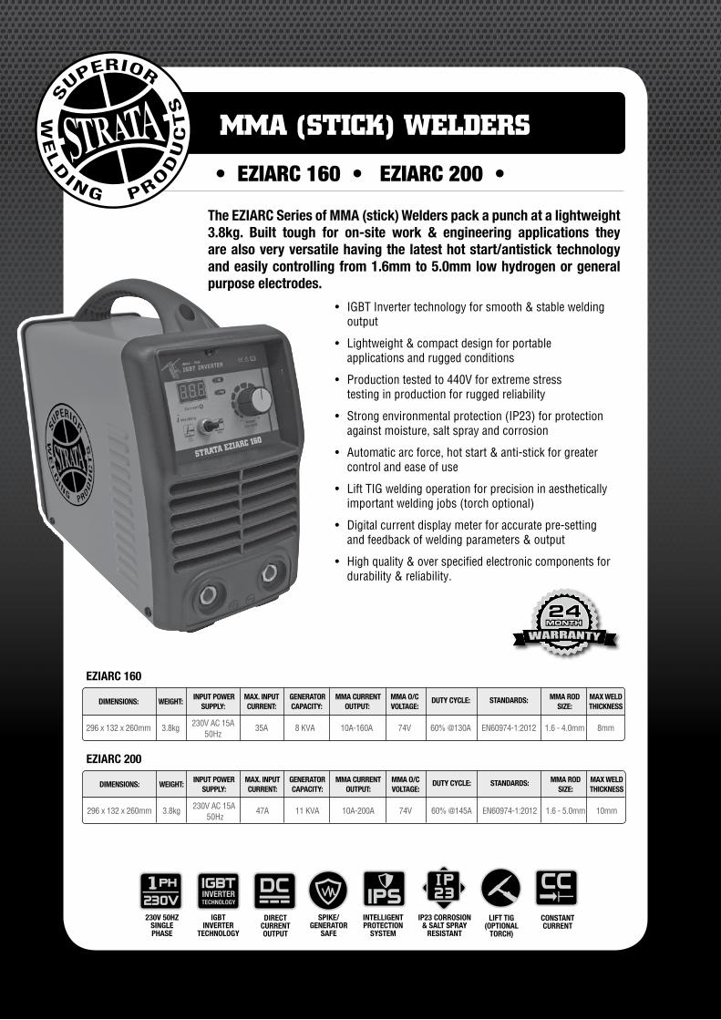
The EZIARC Series of MMA (stick) Welders pack a punch at a lightweight 3.8kg. Built tough for on-site work & engineering applications they are also very versatile having the latest hot start/antistick technology and easily controlling from 1.6mm to 5.0mm low hydrogen or general purpose electrodes.
• IGBTInvertertechnologyforsmooth& stable welding output
• Lightweight&compactdesignforportable applications and rugged conditions
• Productiontestedto440Vforextremestress testing in production for rugged reliability
• Strongenvironmentalprotection(IP23)forprotection against moisture, salt spray and corrosion
• Automaticarcforce,hotstart&anti-stickforgreater control and ease of use
• LiftTIGweldingoperationforprecisioninaesthetically importantweldingjobs(torchoptional)
• Digitalcurrentdisplaymeterforaccuratepre-setting and feedback of welding parameters & output
• Highquality&overspecifiedelectroniccomponentsfor durability & reliability.
EZIARC 160
DIMENSIONS: WEIGHT: INPUT POWER MAX. INPUT GENERATOR MMA CURRENT MMA O/C DUTY CYCLE: STANDARDS: MMA ROD MAX WELD
SUPPLY: CURRENT: CAPACITY: OUTPUT: VOLTAGE: SIZE: THICKNESS
296x132x260mm 3.8kg 230VAC15A 35A 8KVA 10A-160A 74V 60%@130A EN60974-1:2012 1.6-4.0mm 8mm 50Hz
EZIARC 200
DIMENSIONS: WEIGHT: INPUT POWER MAX. INPUT GENERATOR MMA CURRENT MMA O/C DUTY CYCLE: STANDARDS: MMA ROD MAX WELD
SUPPLY: CURRENT: CAPACITY: OUTPUT: VOLTAGE: SIZE: THICKNESS
296x132x260mm 3.8kg 230VAC15A 47A 11KVA 10A-200A 74V 60%@145A EN60974-1:2012 1.6-5.0mm 10mm 50Hz
LIFT TIG(OPTIONAL
TORCH)
CONSTANTCURRENT
• EZIARC 160 • EZIARC 200 •
MMA (STICK) WELDERS
5www.strata.co.nz
EZIARC 160 • EZIARC200
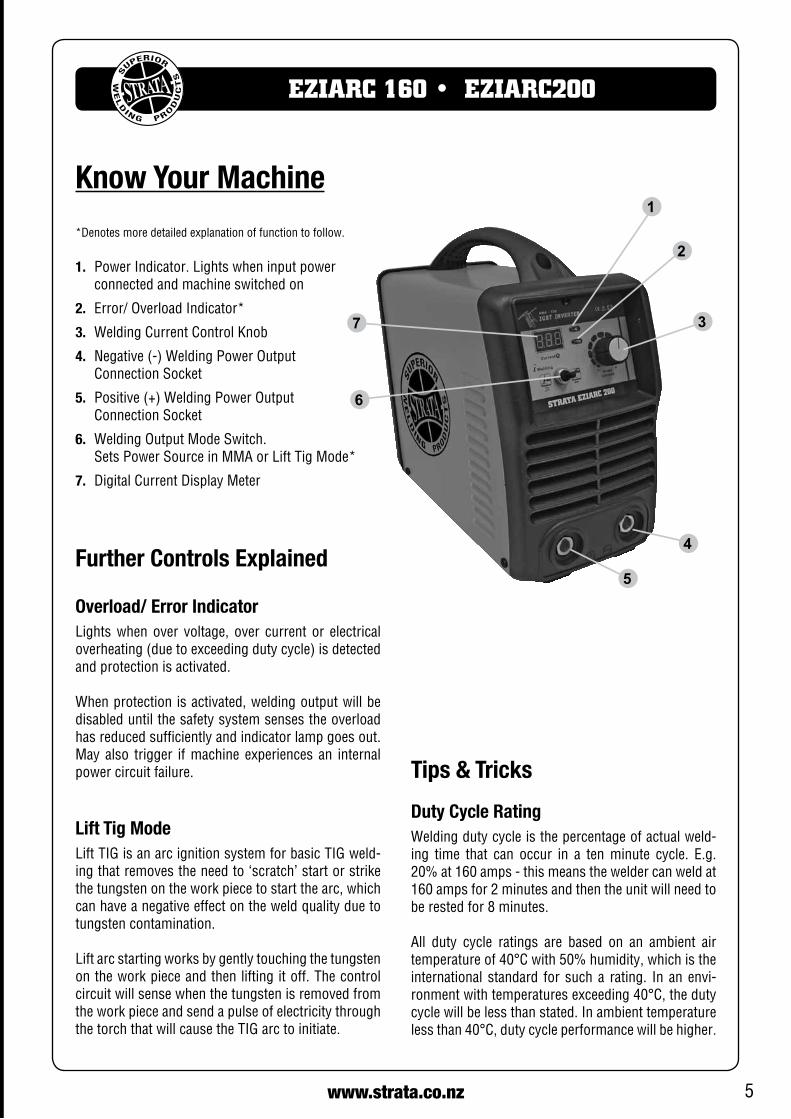
*Denotes more detailed explanation of function to follow.
1. PowerIndicator.Lightswheninputpower connected and machine switched on
2. Error/OverloadIndicator*
3. Welding Current Control Knob
4. Negative(-)WeldingPowerOutput Connection Socket
5. Positive(+)WeldingPowerOutput Connection Socket
6. WeldingOutputModeSwitch. SetsPowerSourceinMMAorLiftTigMode*
7. DigitalCurrentDisplayMeter
1
2
3
4
6
5
7
Further Controls Explained
Overload/ Error Indicator Lightswhenover voltage, over current or electricaloverheating(duetoexceedingdutycycle)isdetectedand protection is activated.
When protection is activated, welding output will be disabled until the safety system senses the overload has reduced sufficiently and indicator lamp goes out. Mayalso trigger ifmachine experiences an internalpower circuit failure.
Lift Tig Mode LiftTIGisanarcignitionsystemforbasicTIGweld-ing that removes the need to ‘scratch’ start or strike the tungsten on the work piece to start the arc, which can have a negative effect on the weld quality due to tungsten contamination.
Liftarcstartingworksbygentlytouchingthetungstenon the work piece and then lifting it off. The control circuit will sense when the tungsten is removed from the work piece and send a pulse of electricity through thetorchthatwillcausetheTIGarctoinitiate.
Tips & Tricks
Duty Cycle RatingWelding duty cycle is the percentage of actual weld-ing time that can occur in a ten minute cycle. E.g. 20%at160amps-thismeanstheweldercanweldat160ampsfor2minutesandthentheunitwillneedtobe rested for 8 minutes.
All duty cycle ratings are based on an ambient air temperatureof40°Cwith50%humidity,whichistheinternational standard for sucha rating. Inanenvi-ronmentwithtemperaturesexceeding40°C,thedutycyclewillbelessthanstated.Inambienttemperaturelessthan40°C,dutycycleperformancewillbehigher.
Know Your Machine
6 www.strata.co.nz
EZIARC 160 • EZIARC200
Electrical ConnectionTheEZIARC160/200isdesignedtooperateona15A230VACpowersupply.Ifanextensioncordmustbeused, it should be a heavy duty version with a mini-mumcablecoresizeof2.5mm2.Itisrecommendedto use the Euroquip industrial duty 15A extensionlead,partnumber;16895.
Operating EnvironmentAdequate ventilation is required to provide proper coolingfortheEZIARC160/200.Ensurethatthema-chine is placed on a stable level surface where clean coolaircaneasilyflowthroughtheunit.TheEZIARC160/200haselectricalcomponentsandcontrolcircuitboards which may be damaged by excessive dust and dirt, so a clean operating environment is essential.
Basic Operation
1. ARC/ MMA Welding Operation
1.1 Connect the earth cable quick connector to the negativeweldingpoweroutputsocket(4)Con-nect the earth clamp to the work piece. Contact with the work piece must be firm contact with clean, bare metal, with no corrosion, paint or scale at the contact point.
1.2 Insertanelectrodeintotheelectrodeholderandconnect the electrode holder and work lead to thepositiveweldingpoweroutputsocket(5).
Note: This polarity connection configuration is valid for most GP (General Purpose)MMAelectrodes. There are variances tothis.Ifindoubt,checktheelectrodespecificationsorconsulttheelectrode manufacturer.
1.3 Connect the machine to suitable mains power using the mains input power lead. Switch the
Quick Start Guide - Welder Installation
mains power switch to ‘on’ to power up the ma-chine.Settheweldingmodeswitch(6)to‘MMA’.
1.4 Select the required output current using the cur-rentcontrolknob(3).Youarenowreadytoweld!
2. Lift TIG Operation
Note: Lift TIG operation requires an optional valve control TIGtorch, and argon gas cylinder.
2.1 Connect the earth cable quick connector to the positiveweldingpoweroutputsocket(5).Con-nect the earth clamp to the work piece. Contact with the work piece must be firm contact with clean, bare metal, with no corrosion, paint or scale at the contact point.
2.2 InsertTIGtorchpowerconnectionintothenega-tivewelding power output socket (4). ConnectvalveTIGtorchgaslinetotheregulator,ensur-ing all connections are tight.
2.3 Open gas cylinder valve and adjust regulator, flow should be between 5-10 l/min dependingonapplication.Re-checkregulatorflowpressurewith torch valve open as static gas flow setting may drop once gas is flowing.
2.4 Connect the machine to suitable mains power using the mains input power lead. Switch the mains power switch to ‘on’ to power up the ma-chine.Set theweldingmodeswitch (6) to ‘LiftTIG’.
2.5 Select the required output current using thecurrentcontrolknob(3).Youarenowreadytoweld!
Pleasenote, the EZIARC160/200 is aDC (DirectCurrent) out-putwelder only, thismeans that it is unable to TIGweld reac-tivemetals such as aluminiumalloys andbrass (which requireACoutput).DCTIGoutputissuitableforsteel,stainlesssteelandcopper.TheSTRATAADVANCEARCAC/DCmodelsaredesignedforTIGweldingAluminiumanditsalloy.
7www.strata.co.nz
EZIARC 160 • EZIARC200
Available Parts & AccessoriesEZIARC 160: ALS1625 MMALeadSet200A2+3m3/8”DinseConnector
AAL1625 ArcLead16mm2cable,16-25mmplug,4m
AEL1625 EarthLead16mm2cable,16-25mmplug,3m
TWP17V-12-2D WP17Torchc/wValve&1625CablePlug
A200EC 200AEarthclamp
A400EH 400AScrewtypeElect.holder
SPCH Chippinghammer
CP1625 CablePlug-15-25mm³
16895 15mH/D15AExtensionLead(3x2.5mm2wiring)
ETCPH4825 OvercordR922.5mmElectrodes(350mm)
ETCPH4832 OvercordR923.2mmElectrodes(350mm)
ETCPH4840 OvercordR924.0mmElectrodes(350mm)
ETCPH6825 Overcord2.5mmElectrodes(350mm)
ETCPH6832 Overcord3.2mmElectrodes(350mm)
ETCPH6840 Overcord4.0mmElectrodes(350mm)
ETCPH7725 Supercito2.5mmElectrodes(350mm)
ETCPH7732 Supercito3.2mmElectrodes(450mm)
ETCPH7740 Supercito4.0mmElectrodes(450mm)
ETCPH56S25 Tenax56S2.5mmElectrodes(350mm)
ETCPH56S32 Tenax56S3.2mmElectrodes(350mm)
ETCPH56S40 Tenax56S4.0mmElectrodes(450mm)
DW3000 AutoDarkeningHelmet,Shade9-13
GR101AR ArgonTwinGaugeRegulator
EZIARC 200:AEL1625 EarthLead16mm2cable,16-25mmplug,3m
AAL1625 ArcLead16mm2cable,16-25mmplug,4m
CP1625 CablePlug-15-25mm³
ALS1625 MMALeadSet200A2+3m3/8”DinseConnector
TWP17V-12-2D WP17ValveTIGTorch12ft1625CablePlug
A200EC 200AEarthClamp
A400EH 400AScrewTypeElectrodeHolder
SPCH ChippingHammer
16895 15mH/D15AExtensionLead(3x2.5mm2wiring)
DW3000 AutoDarkeningHelmet,Shade9-13
ETCPH4825 OvercordR922.5mmElectrodes(350mm)
ETCPH4832 OvercordR923.2mmElectrodes(350mm)
ETCPH4840 OvercordR924.0mmElectrodes(350mm)
ETCPH6825 Overcord2.5mmElectrodes(350mm)
ETCPH6832 Overcord3.2mmElectrodes(350mm)
ETCPH6840 Overcord4.0mmElectrodes(350mm)
ETCPH6850 Overcord5.0mmElectrodes(350mm)
ETCPH7725 Supercito2.5mmElectrodes(350mm)
ETCPH7732 Supercito3.2mmElectrodes(450mm)
ETCPH7740 Supercito4.0mmElectrodes(450mm)
ETCPH7750 Supercito5.0mmElectrodes(450mm)
ETCPH56S25 Tenax56S2.5mmElectrodes(350mm)
ETCPH56S32 Tenax56S3.2mmElectrodes(350mm)
ETCPH56S40 Tenax56S4.0mmElectrodes(450mm)
ETCPH56S50 Tenax56S5.0mmElectrodes(450mm)
GR101AR ArgonTwinGaugeRegulator
TheseaccessorieslistedareavailablefromyourStrataSupplier.RefertotheStrataCatalogue,yourStrataSupplieror look online at www.strata.co.nz for other accessories and consumables available.
8 www.strata.co.nz
EZIARC 160 • EZIARC200
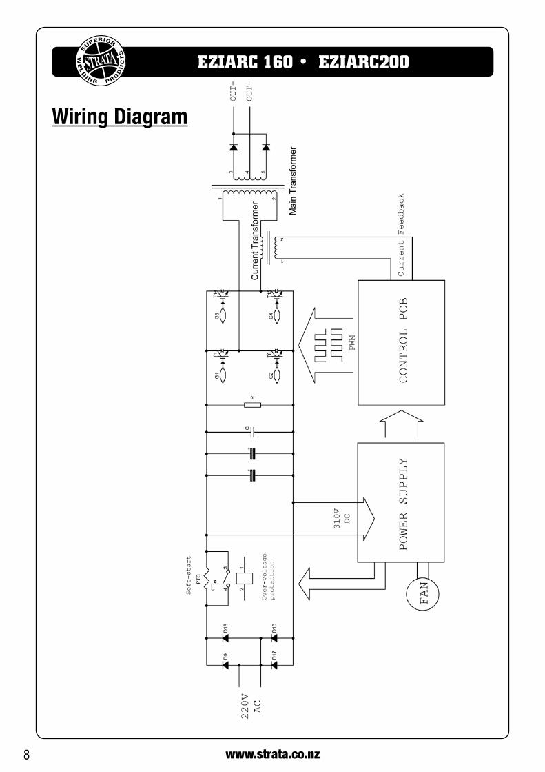
Wiring Diagram
9www.strata.co.nz
EZIARC 160 • EZIARC200
Care & MaintenanceKeep your Welding Machine in Top ConditionThe EZIARC 160/200 does not require any specialmaintenance, however the user should take care of the machine as follows:
• Regularlycleantheventilationslots.
• Keepthecasingclean.
• Checkallcablesbeforeuse.
• Checkelectrodeholders,worklead/clampsand welding torches before use.
• Replacewornelectrodeholdersandearth clamps, which do not provide a good connection.
• Replacewornconsumablepartsinatimely manner.
• Useasoftclothorbrushtocleanelectrical components.
• Donotuseliquidcleaningproducts,wateror especially solvents.
• Donotusecompressedairtocleanelectricalcomponents as this can force dirt and dust further into components, causing electrical short circuits.
• Checkfordamagedparts.Donotusethewelderwith damaged parts.
• Adamagedweldermustbecarefullycheckedbya qualified person to determine that it will operate properly. Check for breakage of parts, mountings and other conditions that may affect its operation. An authorised service centre should properly repairadamagedpart.Haveyourwelderrepairedby an expert.
This appliance is manufactured in accordance with relevant safety standards. Only experts must carry
out repairing of electrical appliances, otherwise considerable danger for the user may result. Use only genuine replacement parts. Do not use modified or non-genuineparts.
Storing the Welder When not in use the welder should be stored in the dryandfrost-freeenvironment.
WARNING! Before performing cleaning/main-tenance,replacingcables/connections,makesure the welding machine is switched off and disconnected from the power supply.
ElectrodesSize of ElectrodesThe electrode size is determined by the thickness of metals being joined and can also be governed by the type of welding machine available. Small welding ma-chines will only provide current (amperage) to runsmaller sized electrodes.
Forthinsections,itisnecessarytousesmallerelec-trodes otherwise the arc may burn holes through the job. A little practice will soon establish the most suit-able electrode for a given application.
Storage of ElectrodesAlways store electrodes in a dry place and in their original containers.
Electrode PolarityElectrodes are generally connected to the electrode holder with the electrode holder connected positive polarity.
The work lead is connected to the negative polarity andisconnectedtotheworkpiece.Ifindoubtconsultthe electrode data sheet.
10 www.strata.co.nz
EZIARC 160 • EZIARC200
High Tensile and Alloy SteelsThe two most prominent effects of welding these steels are the formation of a hardened zone in the weld area, and, if suitable precautions are not taken,the occurrence in this zone of under-bead cracks.Hardenedzoneandunderbeadcracksintheweldareamay be reduced by using the correct electrodes, pre-heating, using higher current settings, using larger electrodes sizes, short runs for larger electrode de-posits or tempering in a furnace.
Manganese SteelsThe effect on manganese steel of slow cooling from high temperatures causes embrittlement. For thisreason it is absolutely essential to keep manganese steelcool during welding by quenching after each weld or skip welding to distribute the heat.
Cast IronMosttypesofcastiron,exceptwhiteiron,areweld-able. White iron, because of its extreme brittleness, generally cracks when attempts are made to weld it.Trouble may also be experienced when welding white-heartmalleable,duetotheporositycausedbygas held in this type of iron.
Copper and AlloysThe most important factor is the high rate of heat conductivityofcopper,makingpre-heatingofheavysections necessary to give proper fusion of weld and base metal.
Types of ElectrodesARCWeldingelectrodesareclassifiedintoanumberof groups depending on their applications. There are a great number of electrodes used for specialised in-dustrial purposes which are not of particular interest for everyday general work. These include some low hydrogen types for high tensile steel, cellulose types for welding large diameter pipes, etc. The range of electrodes dealt with in this publication will cover the vast majority of applications likely to be encountered; are all easy to use.
MILD STEEL :
E6011-Thiselectrodeisusedforall-positionweldingor forweldingonrusty,dirty,less-than-newmetal.Ithasadeep, penetrating arc and is often the first choice for repair or maintenance work.
E6013 -Thisall-positionelectrodeisusedforweldingclean,newsheetmetal.Itssoftarchasminimalspatter,moderatepenetrationandaneasy-to-cleanslag.
E7014 - All positional, ease to use electrode for use onthickersteelthanE6013.Especiallysuitableforsheetmetallap joints, fillet welds and general purpose plate welding.
E7018-Alow-hydrogen,all-positionelectrodeusedwhenqualityisanissueorforhard-to-weldmetals.Ithastheca-pability of producing more uniform weld metal, which has better impact properties at low temperatures.
CAST IRON:
ENI-CL -Suitableforjoiningallcastironsexceptwhitecast iron.
STAINLESS STEEL:
E318L-16 -Highcorrosionresistances.Idealfordairywork etc.
Electrodes for joining different metals
Effects of MMA Welding Various Materials
11www.strata.co.nz
EZIARC 160 • EZIARC200
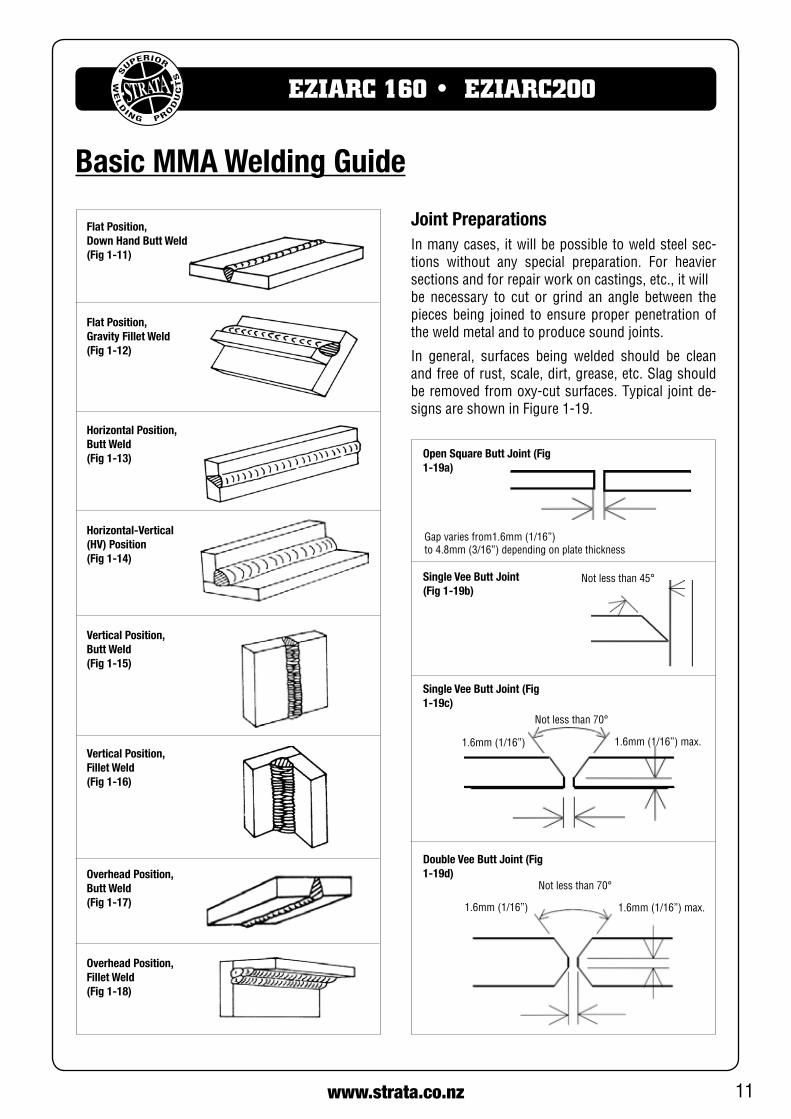
Flat Position, Down Hand Butt Weld (Fig 1-11)
Flat Position, Gravity Fillet Weld (Fig 1-12)
Horizontal Position, Butt Weld (Fig 1-13)
Horizontal-Vertical (HV) Position (Fig 1-14)
Vertical Position, Butt Weld (Fig 1-15)
Vertical Position, Fillet Weld (Fig 1-16)
Overhead Position, Butt Weld (Fig 1-17)
Overhead Position, Fillet Weld (Fig 1-18)
Joint PreparationsInmanycases, itwillbepossibletoweldsteelsec-tions without any special preparation. For heaviersections and for repair work on castings, etc., it willbe necessary to cut or grind an angle between the pieces being joined to ensure proper penetration of the weld metal and to produce sound joints.
In general, surfaces being welded should be cleanand free of rust, scale, dirt, grease, etc. Slag should beremovedfromoxy-cutsurfaces.Typical jointde-signsareshowninFigure1-19.
Open Square Butt Joint (Fig 1-19a)
Gapvariesfrom1.6mm(1/16”)to4.8mm(3/16”)dependingonplatethickness
Single Vee Butt Joint (Fig 1-19b)
Notlessthan45°
Single Vee Butt Joint (Fig 1-19c)
Notlessthan70°
1.6mm(1/16”)max.1.6mm(1/16”)
Double Vee Butt Joint (Fig 1-19d)
Notlessthan70°
1.6mm(1/16”)max.1.6mm(1/16”)
Basic MMA Welding Guide
12 www.strata.co.nz
EZIARC 160 • EZIARC200
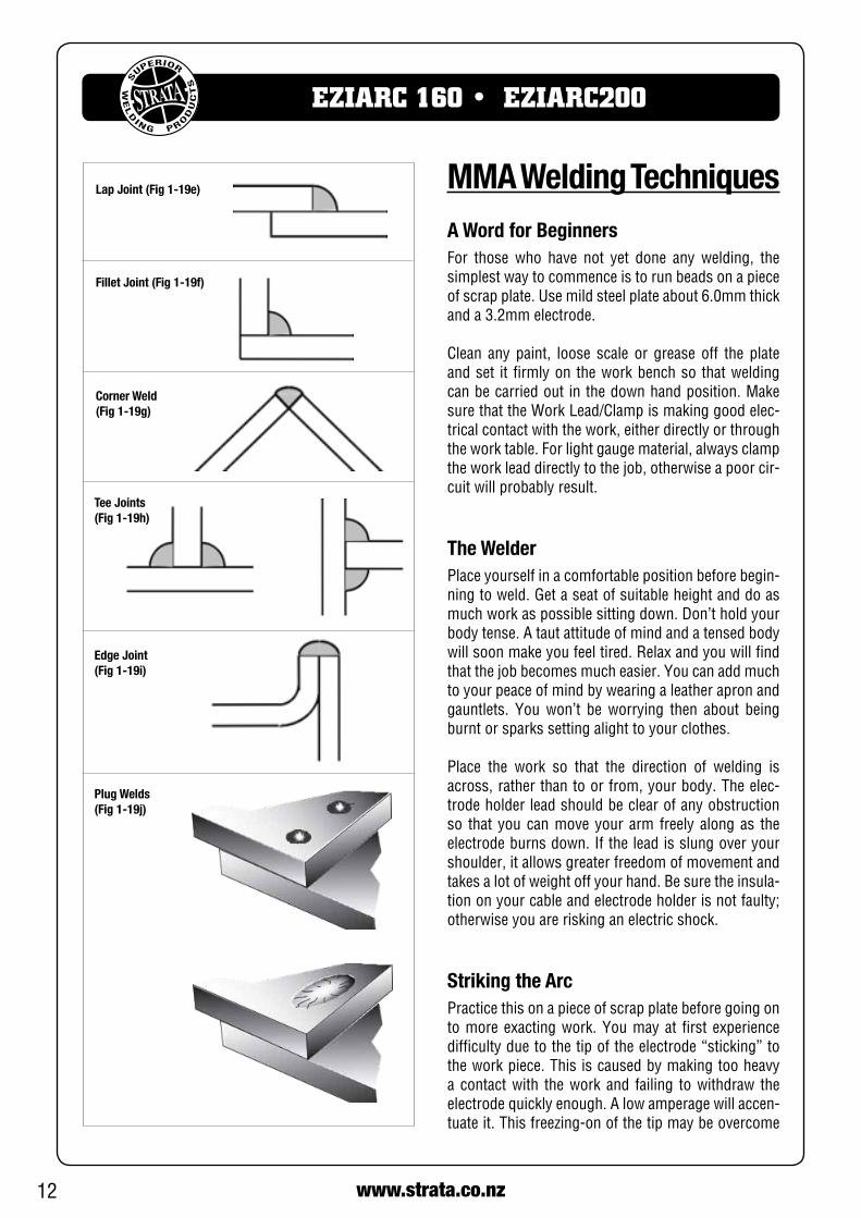
Lap Joint (Fig 1-19e)
Fillet Joint (Fig 1-19f)
Corner Weld (Fig 1-19g)
Tee Joints (Fig 1-19h)
Edge Joint (Fig 1-19i)
Plug Welds (Fig 1-19j)
MMA Welding TechniquesA Word for BeginnersFor those who have not yet done any welding, the simplest way to commence is to run beads on a piece ofscrapplate.Usemildsteelplateabout6.0mmthickand a 3.2mm electrode.
Clean any paint, loose scale or grease off the plate and set it firmly on the work bench so that welding canbecarriedoutinthedownhandposition.MakesurethattheWorkLead/Clampismakinggoodelec-trical contact with the work, either directly or through theworktable.Forlightgaugematerial,alwaysclampthe work lead directly to the job, otherwise a poor cir-cuit will probably result.
The WelderPlace yourself in a comfortable position before begin-ning to weld. Get a seat of suitable height and do as much work as possible sitting down. Don’t hold your body tense. A taut attitude of mind and a tensed body willsoonmakeyoufeeltired.Relaxandyouwillfindthat the job becomes much easier. You can add much to your peace of mind by wearing a leather apron and gauntlets. You won’t be worrying then about being burnt or sparks setting alight to your clothes.
Place the work so that the direction of welding is across, rather than to or from, your body. The elec-trode holder lead should be clear of any obstruction so that you can move your arm freely along as the electrodeburnsdown.Iftheleadisslungoveryourshoulder, it allows greater freedom of movement and takes a lot of weight off your hand. Be sure the insula-tion on your cable and electrode holder is not faulty; otherwise you are risking an electric shock.
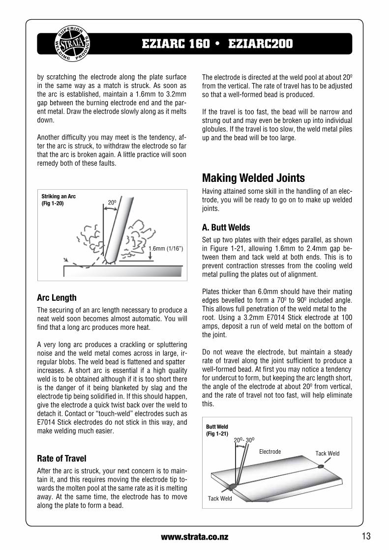
Striking the ArcPractice this on a piece of scrap plate before going on to more exacting work. You may at first experience difficultyduetothetipoftheelectrode“sticking”tothe work piece. This is caused by making too heavy a contact with the work and failing to withdraw the electrode quickly enough. A low amperage will accen-tuateit.Thisfreezing-onofthetipmaybeovercome
13www.strata.co.nz
EZIARC 160 • EZIARC200
20o
1.6mm(1/16”)
Striking an Arc(Fig 1-20)
Arc LengthThe securing of an arc length necessary to produce a neat weld soon becomes almost automatic. You will find that a long arc produces more heat.
A very long arc produces a crackling or spluttering noise and the weld metal comes across in large, ir-regular blobs. The weld bead is flattened and spatterincreases. A short arc is essential if a high quality weld is to be obtained although if it is too short there is the danger of it being blanketed by slag and the electrodetipbeingsolidifiedin.Ifthisshouldhappen,give the electrode a quick twist back over the weld to detachit.Contactor“touch-weld”electrodessuchasE7014Stickelectrodesdonotstickinthisway,andmake welding much easier.
Rate of TravelAfter the arc is struck, your next concern is to main-tain it, and this requires moving the electrode tip to-wards the molten pool at the same rate as it is melting away. At the same time, the electrode has to move along the plate to form a bead.
Making Welded JointsHavingattainedsomeskillinthehandlingofanelec-trode, you will be ready to go on to make up welded joints.
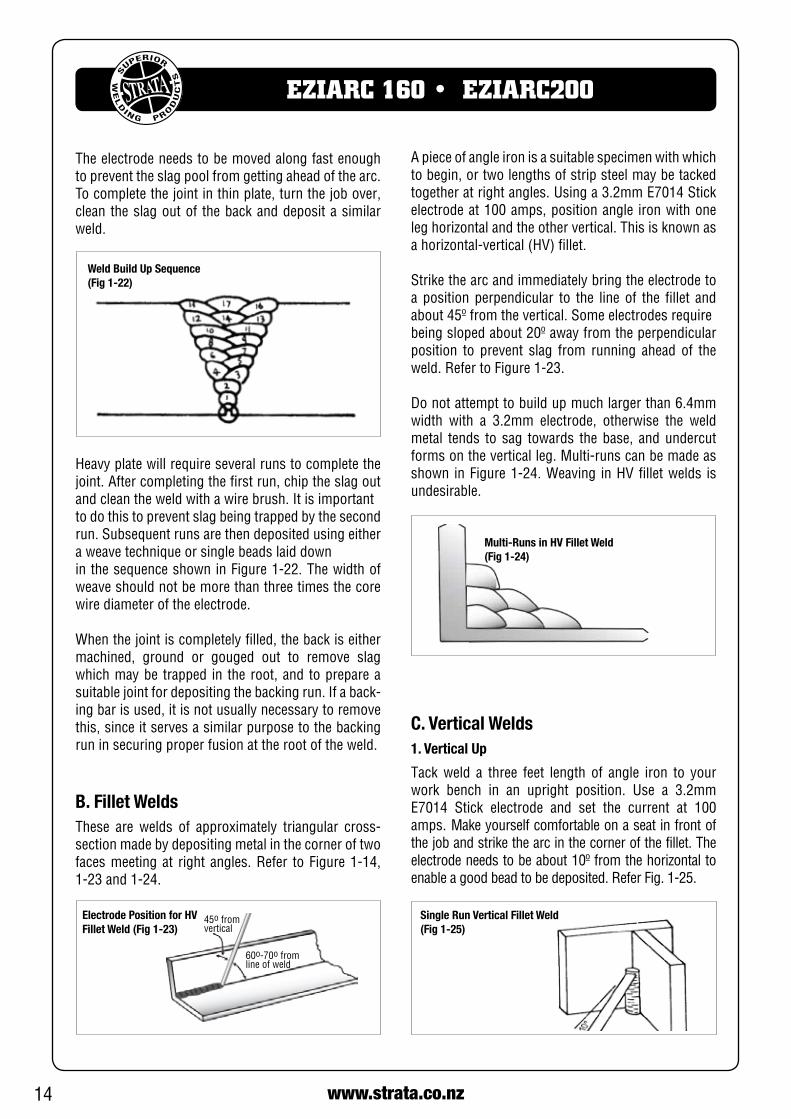
A. Butt WeldsSet up two plates with their edges parallel, as shown in Figure 1-21, allowing 1.6mm to 2.4mm gap be-tween them and tack weld at both ends. This is to prevent contraction stresses from the cooling weld metal pulling the plates out of alignment.
Platesthickerthan6.0mmshouldhavetheirmatingedgesbevelled to forma70º to90º includedangle.This allows full penetration of the weld metal to theroot. Using a 3.2mm E7014 Stick electrode at 100amps, deposit a run of weld metal on the bottom of the joint.
Do not weave the electrode, but maintain a steady rate of travel along the joint sufficient to produce a well-formedbead.Atfirstyoumaynoticeatendencyfor undercut to form, but keeping the arc length short, theangleoftheelectrodeatabout20ºfromvertical,and the rate of travel not too fast, will help eliminate this.
Tack Weld
Butt Weld (Fig 1-21)
Electrode
20o-30o
Tack Weld
by scratching the electrode along the plate surface in the same way as a match is struck. As soon as the arc is established, maintain a 1.6mm to 3.2mm gap between the burning electrode end and the par-ent metal. Draw the electrode slowly along as it melts down.
Another difficulty you may meet is the tendency, af-ter the arc is struck, to withdraw the electrode so far that the arc is broken again. A little practice will soon remedy both of these faults.
Theelectrodeisdirectedattheweldpoolatabout20ºfrom the vertical. The rate of travel has to be adjusted sothatawell-formedbeadisproduced.
If thetravel istoofast, thebeadwillbenarrowandstrung out and may even be broken up into individual globules.Ifthetravelistooslow,theweldmetalpilesup and the bead will be too large.
14 www.strata.co.nz
EZIARC 160 • EZIARC200
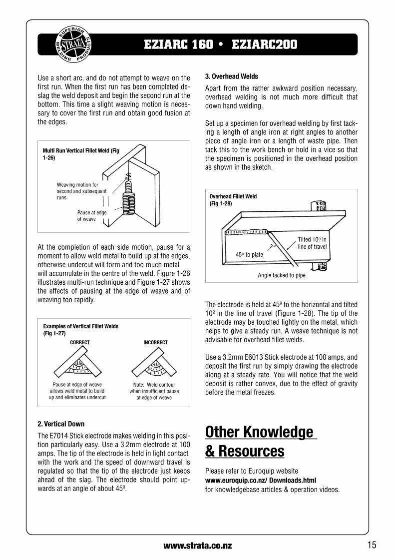
Weld Build Up Sequence (Fig 1-22)
Heavyplatewillrequireseveralrunstocompletethejoint. After completing the first run, chip the slag out andcleantheweldwithawirebrush.Itisimportantto do this to prevent slag being trapped by the second run. Subsequent runs are then deposited using either a weave technique or single beads laid downinthesequenceshowninFigure1-22.Thewidthofweave should not be more than three times the core wire diameter of the electrode.
When the joint is completely filled, the back is either machined, ground or gouged out to remove slag which may be trapped in the root, and to prepare a suitablejointfordepositingthebackingrun.Ifaback-ing bar is used, it is not usually necessary to remove this, since it serves a similar purpose to the backing run in securing proper fusion at the root of the weld.
B. Fillet WeldsThese are welds of approximately triangular cross-section made by depositing metal in the corner of two facesmeetingat rightangles.Refer toFigure1-14,1-23and1-24.
A piece of angle iron is a suitable specimen with which to begin, or two lengths of strip steel may be tacked togetheratrightangles.Usinga3.2mmE7014Stickelectrodeat100amps,positionangle ironwithoneleg horizontal and the other vertical. This is known as ahorizontal-vertical(HV)fillet.
Strike the arc and immediately bring the electrode to a position perpendicular to the line of the fillet and about45ºfromthevertical.Someelectrodesrequirebeingslopedabout20ºawayfromtheperpendicularposition to prevent slag from running ahead of the weld.RefertoFigure1-23.
Do not attempt to build up much larger than 6.4mm width with a 3.2mm electrode, otherwise the weld metal tends to sag towards the base, and undercut formsontheverticalleg.Multi-runscanbemadeasshown inFigure1-24.Weaving inHVfilletwelds isundesirable.
Electrode Position for HV Fillet Weld (Fig 1-23)
45o from vertical
60o-70o fromline of weld
The electrode needs to be moved along fast enough to prevent the slag pool from getting ahead of the arc. To complete the joint in thin plate, turn the job over, clean the slag out of the back and deposit a similar weld.
C. Vertical Welds1. Vertical Up
Tack weld a three feet length of angle iron to your work bench in an upright position. Use a 3.2mm E7014 Stick electrode and set the current at 100amps.Makeyourselfcomfortableonaseatinfrontofthe job and strike the arc in the corner of the fillet. The electrodeneedstobeabout10ºfromthehorizontaltoenableagoodbeadtobedeposited.ReferFig.1-25.
Multi-Runs in HV Fillet Weld (Fig 1-24)
Single Run Vertical Fillet Weld (Fig 1-25)
15www.strata.co.nz
EZIARC 160 • EZIARC200
Weaving motion for second and subsequent runs
Pause at edgeof weave
Multi Run Vertical Fillet Weld (Fig 1-26)
Examples of Vertical Fillet Welds (Fig 1-27)
Pause at edge of weave allows weld metal to build up and eliminates undercut
Note: Weld contourwhen insufficient pause
at edge of weave
CORRECT INCORRECT
2. Vertical Down
TheE7014Stickelectrodemakesweldinginthisposi-tionparticularlyeasy.Usea3.2mmelectrodeat100amps. The tip of the electrode is held in light contactwith the work and the speed of downward travel is regulated so that the tip of the electrode just keeps ahead of the slag. The electrode should point up-wardsatanangleofabout45º.
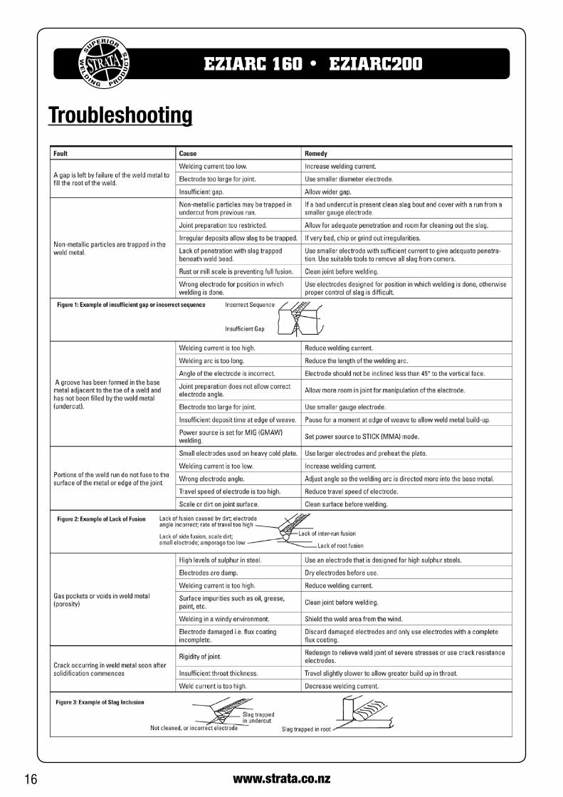
Theelectrodeisheldat45ºtothehorizontalandtilted10º inthelineoftravel(Figure1-28).Thetipoftheelectrode may be touched lightly on the metal, which helps to give a steady run. A weave technique is not advisable for overhead fillet welds.
Usea3.2mmE6013Stickelectrodeat100amps,anddeposit the first run by simply drawing the electrode along at a steady rate. You will notice that the weld deposit is rather convex, due to the effect of gravity before the metal freezes.
Tilted10o inline of travel
Overhead Fillet Weld (Fig 1-28)
Angle tacked to pipe
45o to plate
Use a short arc, and do not attempt to weave on the firstrun.Whenthefirstrunhasbeencompletedde-slag the weld deposit and begin the second run at the bottom. This time a slight weaving motion is neces-sary to cover the first run and obtain good fusion at the edges.
At the completion of each side motion, pause for a moment to allow weld metal to build up at the edges, otherwise undercut will form and too much metalwillaccumulateinthecentreoftheweld.Figure1-26illustratesmulti-runtechniqueandFigure1-27showsthe effects of pausing at the edge of weave and of weaving too rapidly.
3. Overhead Welds
Apart from the rather awkward position necessary, overhead welding is not much more difficult that down hand welding.
Set up a specimen for overhead welding by first tack-ing a length of angle iron at right angles to another piece of angle iron or a length of waste pipe. Then tack this to the work bench or hold in a vice so that the specimen is positioned in the overhead position as shown in the sketch.
Other Knowledge & ResourcesPlease refer to Euroquip website www.euroquip.co.nz/ Downloads.html for knowledgebase articles & operation videos.
16 www.strata.co.nz
EZIARC 160 • EZIARC200
Troubleshooting
17www.strata.co.nz
EZIARC 160 • EZIARC200
Safety
Store and Retain this ManualRetainthismanual for thesafetywarningsandpre-cautions, assembly, operating, inspection, mainte-nance and cleaning procedures. Write the product’s serial number into the NOTES section at the rear, and keep this manual and the receipt in a safe and dry place for future reference.
Important Safety InformationFailure to follow thewarningsand instructionsmayresult in electric shock, fire, serious injury and/ordeath. Save all warnings and instructions for future reference.
This is the safety alert symbol to alert you to potential personal injury hazards. Obey all safety messages that follow this symbol to avoid possible injury or death.
DANGER! indicates a hazardous situation which, if not avoided, will result in death or se-rious injury.
WARNING! indicates a hazardous situation which, if not avoided, could result in death or serious injury.
CAUTION, used with the safety alert symbol,indicates a hazardous situation which, if not avoided, could result in minor or moderate in-jury.
NOTE, used to address practices not related to per-sonal injury.
CAUTION, without the safety alert symbol, is used to address practices not related to personal injury.
General Safety Warnings1. Maintain labels and nameplates on the welder. These carry important information. If unreadable ormiss-ing, contact Euroquip for a replacement.
2. Avoid unintentional starting. Makesurethewelderis setup correctly and you are prepared to begin work before turning on the welder.
3. Unplug before performing maintenance. Always unplug the welder from its electrical outlet before performing any inspection, maintenance, or cleaning procedures.
4. Never leave the welder unattended while ener-gised. Turn power off before leaving the welder unat-tended.
5. Do not touch live electrical parts. Wear dry, insulat-ing gloves. Do not touch the electrode or the conduc-tor tong with bare hands. Do not wear wet ordamaged gloves.
6. Protect yourself from electric shock. Do not usethewelderoutdoors.Insulateyourselffromtheworkpieceandtheground.Usenon-flammable,dryinsu-lating material if possible, or use dry rubber mats, dry wood or plywood, or other dry insulating mate-rial large enough to cover the area of contact with the work or the ground.
7. Avoid inhaling dust. Some dust created by powersanding, sawing, grinding, drilling, cutting, welding and other construction activities, contain chemicals known to cause cancer, birth defects or other harm. Your risk from these exposures varies, depending on how often you do this type of work. To reduce your exposuretothesechemicals,workinawell-ventilatedarea, and work with approved safety equipment, such as dust masks that are specially designed to filter out microscopic particles.
8. People with pacemakers should consult theirphysician(s) before using this machine.
WARNING!Electromagnetic fields in close proximity to a heart pacemaker could cause interference, or failure of the pacemaker. The use of a Welder is NOTRECOMMENDEDforpacemakerwearers.Consult your doctor.
9. Ensure that the unit is placed on a stable location before use.
18 www.strata.co.nz
EZIARC 160 • EZIARC200
Personal Safety
CAUTION!Keeptheworkareawelllit.Makesurethereisadequate space surrounding the work area. Al-ways keep the work area free of obstructions, grease, oil, trash, and other debris. Do not use equipment in areas near flammable chemicals, dust, and vapours. Do not use this product in a damp or wet location.
1. Stay alert, watch what you are doing and use common sense when operating equipment. Do not use a tool while you are tired or under the influence of drugs, alcohol or medication. A mo-ment of distraction when operating equipment
may result in serious personal injury.
2. Do not overreach. Keep proper footing and bal-ance at all times. This enables better control of the power tool in unexpected situations.
WARNING!Ifthisunitfallswhilepluggedin,severeinjury,electric shock, or fire may result.
10. Transportation Methods Liftunitwiththehandlesprovided, or use a handcart or similar device of ad-equatecapacity.Ifusingaforkliftvehicle,securetheunit to a skid before transporting.
CAUTION!Disconnect inputpower conductors fromde-energized supply line before moving the weld-ing power source.
11. Exercise good work practices. The warnings, pre-cautions, and instructions discussed in this instruc-tion manual cannot cover all possible conditions and situationsthatmayoccur.Itmustbeunderstoodbythe operator that common sense and caution are fac-tors which cannot be built into this product, but must be considered by the operator.
Welding Safety Instructions & Warnings
WARNING!Protect yourself and others from possible seri-ousinjuryordeath.Keepchildrenaway.Readthe operating/Instruction manual before in-stalling, operating or servicing this equipment. Have all installation, operation, maintenance,and repair work performed by qualified people.
Ifanoperatordoesnotstrictlyobserveallsafetyrulesand take precautionary actions, welding products and welding processes can cause serious injury or death, or damage to other equipment or property.Safe practices have developed from past experience in the use of welding and cutting.
These practices must be learned through study and training before using this equipment. Some of these practices apply to equipment connected to power lines; other practices apply to engine driven equip-ment. Anyone not having extensive training in weld-ing and cutting practices should not attempt to weld.
Safe practices are outlined in the European Standard EN60974-1entitled:Safetyinweldingandalliedpro-cesses.
WARNING!Only use safety equipment that has been ap-proved by an appropriate standards agency. Unapproved safety equipment may not provide adequate protection. Eye and breathing protec-tionmustbeAS/NZScompliantforthespecifichazards in the work area.
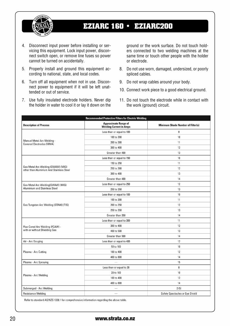
DANGER!AlwayswearAS/NZScompliantsafetyglassesand full face shield fitted with appropriate filter shade number. (ReferFilterTableonpage17.)
CAUTION!Heavy-dutyworkgloves,non-skidsafetyshoesand hearing protection used for appropriate conditions will reduce personal injuries.
CAUTION!Havetheequipmentservicedbyaqualifiedre-pair person using identical replacement parts. This will ensure that the safety of the power tool is maintained.
19www.strata.co.nz
EZIARC 160 • EZIARC200
Arc Rays can Burn Eyes and Skin
DANGER!Arc rays from the welding process produceintense heat and strong ultraviolet rays that can burn eyes and skin.
1. UseaWeldingHelmetorWeldingFaceShieldfit-tedwith a proper shade filter (refer AS60974-1, AS/NZS 1337.1 and AS/NZS 1338.1 SafetyStandards) toprotect your face andeyeswhenweldingorwatching.(SeeFilterTableonPage20)
2. Wear approved safety glasses. Side shields are recommended.
3. Use protective screens or barriers to protect others from flash and glare; warn others not to watch the arc.
4. Wear protective clothing made from durable, flame-resistantmaterial(woolandleather)and foot safety protection.
5. Neverwearcontactlenseswhilewelding.
Noise Can Damage Hearing
CAUTION!Noise from some processes can damage hear-ing. Use AS/NZS compliant ear plugs or earmuffs if the noise level is high.
Work Environment Safety
DANGER!Remove any combustible material from thework area.
1. When possible, move the work to a location well away from combustible materials. If relocation
is not possible, protect the combustibles with a cover made of fire resistant material.
2. Removeormakesafeallcombustiblematerialsforaradiusof10metresaroundtheworkarea.Use a fire resistant material to cover or block all doorways, windows, cracks, and other openings.
3. Enclose the work area with portable fire resistant screens. Protect combustible walls, ceilings,
floors, etc., from sparks and heat with fire re-sistant covers.
4. Ifworkingonametalwall,ceiling,etc.,preventignition of combustibles on the other side by moving the combustibles to a safe location. Ifrelocation of combustibles is not possible, desig-nate someone to serve as a fire watch, equipped with a fire extinguisher, during the welding pro-cess and well after the welding is completed.
5. Donotweldorcutonmaterialshavingacombus-tible coating or combustible internal structure, as in walls or ceilings, without an approved method for eliminating the hazard.
6. After welding, make a thorough examination for evidence of fire. Be aware that visible smoke or
flame may not be present for some time after the fire has started. Do not weld or cut in atmos-pheres containing dangerously reactive or flam-mable gases, vapours, liquids, and dust. Provide adequate ventilation in work areas to prevent accu-mulation of flammable gases, vapours, and dust.
7. Do not apply heat to a container that has held an unknown substance or a combustible mate-rial whose contents, when heated, can produce flammable or explosive vapours. Clean and purge containersbeforeapplyingheat.Ventclosedcon-tainers, including castings, before preheating, welding, or cutting.
Electricity Can Kill
DANGER!Touching live electrical parts can cause fatal shocks or severe burns. The electrode and work circuit is electrically live whenever the output is on.
The input power circuit and machine internal circuits arealsolivewhenpowerison.Insemi-automaticorautomatic wire welding, the wire, wire reel, drive roll housing, and all metal parts touching the welding wire areelectricallylive.Incorrectlyinstalledorimproperlygrounded equipment is a hazard.
1. Do not touch live electrical parts.
2. Wear dry, hole-free insulating gloves and bodyprotection.
3. Insulateyourself fromtheworkandthegroundusing dry insulating mats or covers.
20 www.strata.co.nz
EZIARC 160 • EZIARC200
4. Disconnect input power before installing or ser-vicingthisequipment.Lockinputpower,discon-nect switch open, or remove line fuses so power cannot be turned on accidentally.
5. Properly install and ground this equipment ac-cording to national, state, and local codes.
6. Turn off all equipment when not in use. Discon-nect power to equipment if it will be left unat-tended or out of service.
7. Use fully insulated electrode holders. Never dip the holder in water to cool it or lay it down on the
ground or the work surface. Do not touch hold-ers connected to two welding machines at the same time or touch other people with the holder or electrode.
8. Do not use worn, damaged, undersized, or poorly spliced cables.
9. Donotwrapcablesaroundyourbody.
10.Connectworkpiecetoagoodelectricalground.
11. Do not touch the electrode while in contact with thework(ground)circuit.
21www.strata.co.nz
EZIARC 160 • EZIARC200
5. Workinaconfinedspaceonlyifitiswellventi-lated,orwhilewearinganair-suppliedrespirator.Shielding ga es used for welding can displace air causing injury or death. Be sure the breathing air is safe.
6. Do not weld in locations near degreasing, clean-ing, or spraying operations. The heat and rays of the arc can react with vapours to form highly toxic and irritating gases.
7. Do not weld on coated metals, such as galva-nized, lead, or cadmium plated steel, unless the coating is removed from the weld area, the area is well ventilated, and if necessary, while wearing anair-suppliedrespirator.Thecoatingsandanymetals containing these elements can give off toxic fumes if welded.
Fire & Explosive RisksWARNING!Sparks and spatter fly off from the welding arc.The flying sparks and hot metal, weld spatter,work piece, and hot equipment can cause firesand burns.
Accidental contact of electrode or welding wire to metal objects can cause sparks, overheating, or fire.
1. Protect yourself and others from flying sparks and hot metal.
2. Do not weld where flying sparks can strike flam-mable material.
3. Removeallflammableswithin10moftheweld-ing site.
4. Be alert that welding sparks and hot materials from welding can easily go through small cracks
and openings to adjacent areas.
5. Watchforfire,andkeepafireextinguishernearby.
6. Be aware that welding on a ceiling, floor, bulk-head, or partition can cause fire on the hidden side.
7. Do not weld on closed containers such as tanks or drums.
8. Connecttheworklead/clamptothejobascloseto the welding area as practical to prevent weld-ing current from travelling long, possibly un-known paths and causing electric shock and fire hazards.
Fumes And GasesWARNING!Welding produces fumes and gases. Breathingthese fumes and gases can be hazardous to your health.
1. Keep your head out of the fumes. Do not breathe the fumes.
2. Ifinside,ventilatetheareaand/oruseanexhaust at the arc to remove welding fumes and gases.3. If ventilation is poor, use an approved air-sup-
plied respirator.
4. ReadtheSafetyDataSheets(SDS)andtheman-ufacturer’s instruction for the metals, consuma-bles, coatings, and cleaners.
12. Use only well-maintained equipment. Repair orreplace damaged parts as soon as practical.
13.Inconfinedspacesordamplocations,donotusea welder with AC output unless equipped with a voltage reducer.
Arc rays from the welding process produce intense heat and strong ultraviolet rays that can burn eyes and skin. Use the following table to select the appro-priateshadenumberforaWeldingHelmetorWeldingFaceShield.
1. UseaWeldingHelmetorWeldingFaceShieldfit-tedwithapropershadeoffilter(seeAS60974-1, AS/NZS 1337.1 and AS/NZS 1338.1 SafetyStandards) toprotect your face andeyeswhenwelding or watching.
2. Wear approved safety glasses. Side shields are recommended.
3. Use protective screens or barriers to protect others from flash and glare; warn others not to watch the arc.
4. Wear protective clothing made from durable, flame-resistantmaterial (wool and leather) andfoot protection.
5. Neverwearcontactlenseswhilewelding.

22 www.strata.co.nz
EZIARC 160 • EZIARC200
9. Donotuseaweldertothawfrozenpipes.
10.Removethestickelectrodefromtheholderorcut off the welding wire at the contact tip when not in use.
Sparks & Hot MetalWARNING!Chipping and grinding causes flying metal, and as welds cool they can throw off slag.
1. WearanAS/NZSapprovedfaceshieldorsafetygoggles. Side shields are recommended.
2. Wear appropriate safety equipment to protect the skin and body.
CylindersWARNING!Gas cylinders contain gas under high pressure. Ifdamaged,acylindercanexplode.Sincegascylinders are normally part of the weldingprocess, be sure to treat them carefully.
1. Protect compressed gas cylinders from exces-sive heat, mechanical shocks, and arcs.
2. Install and secure cylinders in an upright posi-tion by chaining them to a stationary support or equipment cylinder rack to prevent falling or tip-ping.
3. Keep cylinders away from any welding or other electrical circuits.
4. Never allow a welding electrode to touch any cyl-inder.
5. Useappropriateshieldinggas,regulators,hoses, and fittings designed for the specific application; maintain them and their associated parts in good
condition.
6. Turn your face away from the valve outlet when opening the cylinder valve.
23www.strata.co.nz
EZIARC 160 • EZIARC200
Scan here to register your product
Aspartofanon-goingcommitmenttoexcellenceinprod-uct support, Euroquip offers a comprehensive product warranty program.
Inordertoqualifyforfullwarrantysupport,yourproductmust be registered. Product not registered with Euroquip is supported by a base 12 month warranty only. Spare parts and technical support will not be available for an unreg-isteredproductoutsideof thisbasewarrantyperiod. IfaEuroquip dealer has not already registered your product, please register it online or download a physical registration form at www.euroquip.co.nz.
Registered warranty period for the EZIARC 160/200:
Commercial Use: 24 Months
Domestic Use: 24 Months
Warranty covers failure caused by manufacturing and ma-terial defects in the product, during the warranty period specified. The warranty period begins when the product is purchased by the end user. Warranty is not transferrable and is only claimable by the original purchaser.
Warranty does not cover parts that are subject to wear and tear from usage.
Warranty covers failure of a product caused by defective materials and/ormanufacturing for the period given andthe usage specified by Euroquip. The warranty period begins when the product is purchased by the end user. Warranty is not transferrable and is only claimable by the original purchaser.
Warranty also does not cover failure caused by the untime-ly replacement or service of the above wearing parts. Evi-dence must be provided that the product has been main-tained and serviced suitably for a claim to be considered under warranty.
Failurecausedbyincorrectoperationoftheproduct,lackof proper care and maintenance of the product, external damage, external circumstances such as contaminated fuel or poor water supply, modifications to the product, at-temptedrepair/servicebyapartyotherthananApprovedService Agent, is not covered under warranty.
Warranty does not cover pre delivery service and adjust-ment,orfailurethatmayoccurasaresultoflackof/incor-rect pre delivery service and adjustment.
Warranty does not cover any incidental, indirect or conse-quential loss, damage or expense that may result from any defect, failure or malfunction of a product.
Should any issue be found to be a combination of a war-rantyfailureandanon-warrantyissue,therepaircostcom-ponenttorectifyandrepairthenon-warrantyfailureisthecustomers’ full responsibility.
The decision that an issue with a product qualifies as a warranty claim is made at the sole jurisdiction of Euroquip.
No costs incurred will be considered under warranty if re-pairs are carried out by a party other than a Euroquip Ap-proved Service Agent, unless with prior consent in writing from Euroquip.
It istheresponsibilityofthepurchasertodeliveraprod-uct under warranty to the nearest relevant service agent or product reseller. Warranty does not cover call outs, mile-age and freight costs.
Ifaproductisrepairedunderwarranty,partsandlabourre-quired for the repair will be supplied at no charge. Warranty assessment and repair will be scheduled and executed ac-cording to the normal work flow at the service location and depending on the availability of suitable replacement parts.
This warranty policy is an additional benefit and does not affect the legal rights of any end user, reseller or service agent.
Warranty
http://www.euroquip.co.nz/Contact+Us/Product+Registration+Form.html

www.strata.co.nz
Congratulations on your new STRATA product. We are
proud to have you as our customer and will strive to
provide you with the best service and reliability in
the industry. This product is backed by our extensive
warranty and world-wide service network. To locate
your nearest distributor or service agency visit www.
strata.co.nz, or email us at [email protected].
Related Documents