EN Operating Instructions Transponder-Coded Safety Switch With Guard Locking CTP-AP Unicode/Multicode

Welcome message from author
This document is posted to help you gain knowledge. Please leave a comment to let me know what you think about it! Share it to your friends and learn new things together.
Transcript

EN
Operating Instructions
Transponder-Coded Safety Switch With Guard Locking
CTP-AP Unicode/Multicode
Operating InstructionsTransponder-Coded Safety Switch CTP-AP
2 (translation of the original operating instructions) 2124217-06-05/19
Contents
1. About this document ............................................................................................. 41.1. Scope ............................................................................................................................................4
1.2. Target group ..................................................................................................................................4
1.3. Key to symbols ...............................................................................................................................4
1.4. Supplementary documents ..............................................................................................................4
2. Correct use .......................................................................................................... 5
3. Description of the safety function .......................................................................... 6
4. Exclusion of liability and warranty ......................................................................... 7
5. General safety precautions ................................................................................... 7
6. Function ............................................................................................................... 86.1. Guard locking monitoring .................................................................................................................8
6.2. Door monitoring output (OD) ............................................................................................................8
6.3. Diagnostics output (OI) ....................................................................................................................8
6.4. Guard locking monitoring output (OL)................................................................................................8
6.5. Version CTP Extended .....................................................................................................................8
6.6. Guard locking on version CTP-L1 ......................................................................................................8
6.7. Guard locking on version CTP-L2 ......................................................................................................9
6.8. Switching states .............................................................................................................................9
7. Manual release ................................................................................................... 107.1. Auxiliary release and auxiliary key release .......................................................................................10
7.1.1. Actuating auxiliary release .............................................................................................107.1.2. Actuating auxiliary key release .......................................................................................10
7.2. Emergency unlocking ....................................................................................................................117.2.1. Actuating emergency unlocking ......................................................................................11
7.3. Escape release (optional) ..............................................................................................................117.3.1. Actuating escape release...............................................................................................11
7.4. Wire front release .........................................................................................................................127.4.1. Laying wire front release ................................................................................................12
8. Changing the approach direction ........................................................................ 13
9. Installation ......................................................................................................... 14
10. Electrical connection .......................................................................................... 1510.1. Notes about .........................................................................................................................16
10.2. Safety in case of faults ..................................................................................................................16
10.3. Fuse protection for power supply ...................................................................................................16
10.4. Requirements for connection cables ...............................................................................................17
10.5. Pin assignment safety switch CTP-…-AP-…-SAB-… with plug connectors 2 x M12 ..............................18
32124217-06-05/19 (translation of the original operating instructions)
Operating InstructionsTransponder-Coded Safety Switch CTP-AP
EN
10.6. Pin assignment safety switches CTP-…-AP-…-SH-… with plug connector M23 (RC18) ........................18
10.7. Pin assignment of safety switch CTP-…-AP-…-SA-… with plug connector M12, 8-pin ..........................18
10.8. Pin assignment safety switch CTP-…-AP-…-SII-… with plug connectors 2 x M12, 5-pin .......................19
10.9. Connection CTP-AP .......................................................................................................................19
10.10. Notes on operation with safe control systems .................................................................................20
10.11. Connection of guard locking control ...............................................................................................2110.11.1. Guard locking control for variants with IMM connection ....................................................2110.11.2. Guard locking control for variants without IMM connection ................................................21
11. Setup ................................................................................................................. 2211.1. LED displays ................................................................................................................................22
11.2. Teach-in function for actuator (only for unicode evaluation) ...............................................................2211.2.1. Actuator teach-in ...........................................................................................................22
11.3. Functional check ...........................................................................................................................2311.3.1. Mechanical function test ................................................................................................2311.3.2. Electrical function test ...................................................................................................23
12. System status table ............................................................................................ 24
13. Technical data .................................................................................................... 2513.1. Technical data for safety switch CTP-AP ..........................................................................................25
13.1.1. Typical system times .....................................................................................................2613.2. Radio frequency approvals.............................................................................................................27
13.3. Dimension drawing for safety switch CTP… ....................................................................................28
13.4. Technical data for actuator CTP-... .................................................................................................3013.4.1. Dimension drawing for actuator CTP-... ...........................................................................30
14. Ordering information and accessories ................................................................. 33
15. Inspection and service ........................................................................................ 33
16. Service .............................................................................................................. 33
17. Declaration of conformity ................................................................................... 34
Operating InstructionsTransponder-Coded Safety Switch CTP-AP
4 (translation of the original operating instructions) 2124217-06-05/19
1. About this document1.1. ScopeThese operating instructions are valid for all CTP-L.-AP… from version V1.0.0. These operating instructions, the document “Safety information and maintenance” and any enclosed data sheet form the complete user information for your device.
1.2. Target groupDesign engineers and installation planners for safety devices on machines, as well as setup and servicing staff possessing special expertise in handling safety components.
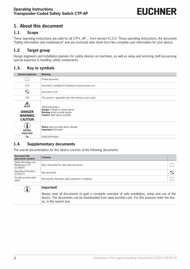
1.3. Key to symbolsSymbol/depiction Meaning
Printed document
Internet
www Document is available for download at www.euchner.com
Document on CD
MEM This section is applicable only if the memory card is used
DANGER WARNING CAUTION
Safety precautionsDanger of death or severe injuriesWarning about possible injuriesCaution slight injuries possible
NOTICE Important!
Notice about possible device damageImportant information
Tip Useful information
1.4. Supplementary documentsThe overall documentation for this device consists of the following documents:
Document title(document number) Contents
Safety Information and Maintenance CTP(2138087)
Basic information for safe setup and service
Operating Instructions(2124217) (this document)
Possibly enclosed data sheet Item-specific information about deviations or additions
Important!
Always read all documents to gain a complete overview of safe installation, setup and use of the device. The documents can be downloaded from www.euchner.com. For this purpose enter the doc. no. in the search box.
52124217-06-05/19 (translation of the original operating instructions)
Operating InstructionsTransponder-Coded Safety Switch CTP-AP
EN
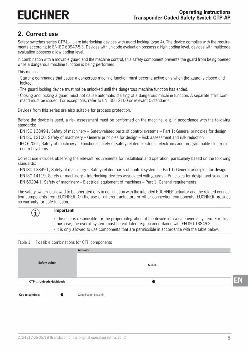
2. Correct useSafety switches series CTP-L.-… are interlocking devices with guard locking (type 4). The device complies with the require-ments according to EN IEC 60947-5-3. Devices with unicode evaluation possess a high coding level, devices with multicode evaluation possess a low coding level.
In combination with a movable guard and the machine control, this safety component prevents the guard from being opened while a dangerous machine function is being performed.
This means: Ì Starting commands that cause a dangerous machine function must become active only when the guard is closed and locked. Ì The guard locking device must not be unlocked until the dangerous machine function has ended. Ì Closing and locking a guard must not cause automatic starting of a dangerous machine function. A separate start com-mand must be issued. For exceptions, refer to EN ISO 12100 or relevant C-standards.
Devices from this series are also suitable for process protection.
Before the device is used, a risk assessment must be performed on the machine, e.g. in accordance with the following standards: Ì EN ISO 13849-1, Safety of machinery – Safety-related parts of control systems – Part 1: General principles for design Ì EN ISO 12100, Safety of machinery – General principles for design – Risk assessment and risk reduction Ì IEC 62061, Safety of machinery – Functional safety of safety-related electrical, electronic and programmable electronic control systems
Correct use includes observing the relevant requirements for installation and operation, particularly based on the following standards: Ì EN ISO 13849-1, Safety of machinery – Safety-related parts of control systems – Part 1: General principles for design Ì EN ISO 14119, Safety of machinery – Interlocking devices associated with guards – Principles for design and selection Ì EN 60204-1, Safety of machinery – Electrical equipment of machines – Part 1: General requirements
The safety switch is allowed to be operated only in conjunction with the intended EUCHNER actuator and the related connec-tion components from EUCHNER. On the use of different actuators or other connection components, EUCHNER provides no warranty for safe function.
Important!
Ì The user is responsible for the proper integration of the device into a safe overall system. For this purpose, the overall system must be validated, e.g. in accordance with EN ISO 13849-2. Ì It is only allowed to use components that are permissible in accordance with the table below.
Table 1: Possible combinations for CTP components
Safety switch
Actuator
A-C-H-...
CTP-… Unicode/Multicode
Key to symbols Combination possible
Operating InstructionsTransponder-Coded Safety Switch CTP-AP
6 (translation of the original operating instructions) 2124217-06-05/19
3. Description of the safety functionDevices from this series feature the following safety functions:
Monitoring of guard locking and the position of the guard (interlocking device with guard locking according to EN ISO 14119)
Ì Safety function (see chapter 6.8. Switching states on page 9): - The safety outputs are switched off when guard locking is released (monitoring of the locking element). - The safety outputs are switched off when the guard is open (monitoring of the door position). - Guard locking can be activated only when the actuator is located in the switch head (failsafe locking mechanism).
Ì Safety characteristics: category, Performance Level, PFHD (see chapter 13. Technical data on page 25).
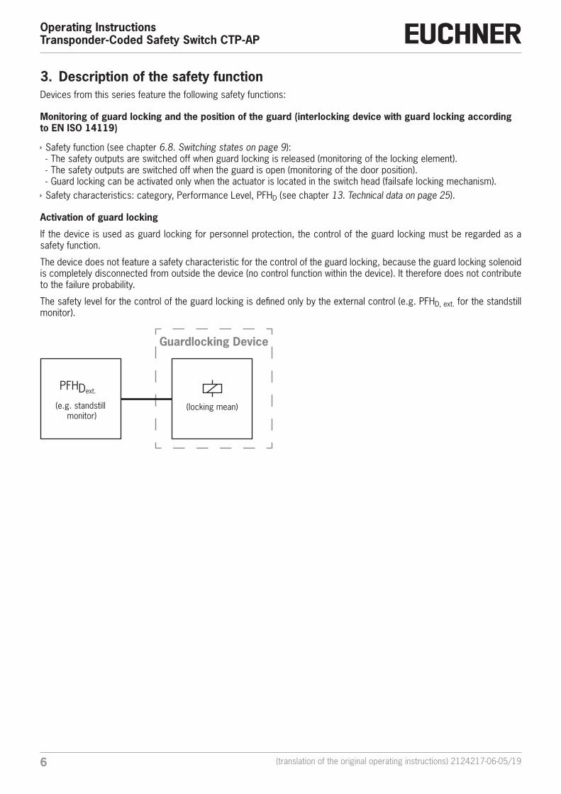
Activation of guard locking
If the device is used as guard locking for personnel protection, the control of the guard locking must be regarded as a safety function.
The device does not feature a safety characteristic for the control of the guard locking, because the guard locking solenoid is completely disconnected from outside the device (no control function within the device). It therefore does not contribute to the failure probability.
The safety level for the control of the guard locking is defined only by the external control (e.g. PFHD, ext. for the standstill monitor).
Guardlocking Device
PFHDext.
(e.g. standstill monitor)
(locking mean)
72124217-06-05/19 (translation of the original operating instructions)
Operating InstructionsTransponder-Coded Safety Switch CTP-AP
EN
4. Exclusion of liability and warrantyIn case of failure to comply with the conditions for correct use stated above, or if the safety instructions are not followed, or if any servicing is not performed as required, liability will be excluded and the warranty void.
5. General safety precautionsSafety switches fulfill personnel protection functions. Incorrect installation or tampering can lead to fatal injuries to personnel.
Check the safe function of the guard particularly Ì after any setup work Ì after the replacement of a system component Ì after an extended period without use Ì after every fault
Independent of these checks, the safe function of the guard should be checked at suitable intervals as part of the mainte-nance schedule.
WARNING
Danger to life due to improper installation or due to bypassing (tampering). Safety components perform a personnel protection function. Ì Safety components must not be bypassed, turned away, removed or otherwise rendered ineffec-tive. On this topic pay attention in particular to the measures for reducing the possibility of bypass-ing according to EN ISO 14119:2013, section 7. Ì The switching operation must be triggered only by actuators designated for this purpose. Ì Prevent bypassing by means of replacement actuators (only for multicode evaluation). For this purpose, restrict access to actuators and to keys for releases, for example. Ì Mounting, electrical connection and setup only by authorized personnel possessing the following knowledge: - specialist knowledge in handling safety components - knowledge about the applicable EMC regulations - knowledge about the applicable regulations on occupational safety and accident prevention.
Important!
Prior to use, read the operating instructions and keep these in a safe place. Ensure the operating instructions are always available during mounting, setup and servicing. EUCHNER cannot provide any warranty in relation to the readability of the CD for the storage period required. For this reason you should archive a printed copy of the operating instructions. You can download the operating instruc-tions from www.euchner.com.
Operating InstructionsTransponder-Coded Safety Switch CTP-AP
8 (translation of the original operating instructions) 2124217-06-05/19
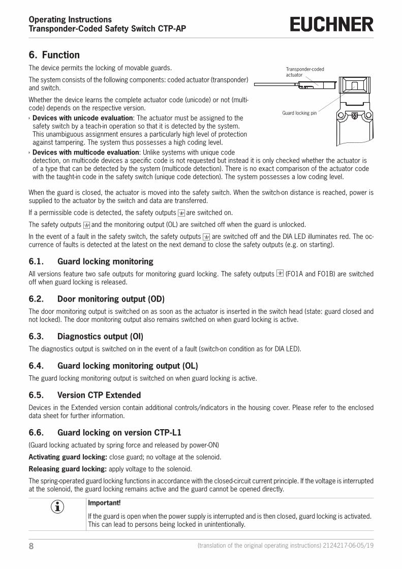
6. FunctionThe device permits the locking of movable guards.
The system consists of the following components: coded actuator (transponder) and switch.
Whether the device learns the complete actuator code (unicode) or not (multi-code) depends on the respective version. Ì Devices with unicode evaluation: The actuator must be assigned to the safety switch by a teach-in operation so that it is detected by the system. This unambiguous assignment ensures a particularly high level of protection against tampering. The system thus possesses a high coding level. Ì Devices with multicode evaluation: Unlike systems with unique code detection, on multicode devices a specific code is not requested but instead it is only checked whether the actuator is of a type that can be detected by the system (multicode detection). There is no exact comparison of the actuator code with the taught-in code in the safety switch (unique code detection). The system possesses a low coding level.
When the guard is closed, the actuator is moved into the safety switch. When the switch-on distance is reached, power is supplied to the actuator by the switch and data are transferred.
If a permissible code is detected, the safety outputs are switched on.
The safety outputs and the monitoring output (OL) are switched off when the guard is unlocked.
In the event of a fault in the safety switch, the safety outputs are switched off and the DIA LED illuminates red. The oc-currence of faults is detected at the latest on the next demand to close the safety outputs (e.g. on starting).
6.1. Guard locking monitoringAll versions feature two safe outputs for monitoring guard locking. The safety outputs (FO1A and FO1B) are switched off when guard locking is released.
6.2. Door monitoring output (OD)The door monitoring output is switched on as soon as the actuator is inserted in the switch head (state: guard closed and not locked). The door monitoring output also remains switched on when guard locking is active.
6.3. Diagnostics output (OI)The diagnostics output is switched on in the event of a fault (switch-on condition as for DIA LED).
6.4. Guard locking monitoring output (OL)The guard locking monitoring output is switched on when guard locking is active.
6.5. Version CTP ExtendedDevices in the Extended version contain additional controls/indicators in the housing cover. Please refer to the enclosed data sheet for further information.
6.6. Guard locking on version CTP-L1(Guard locking actuated by spring force and released by power-ON)
Activating guard locking: close guard; no voltage at the solenoid.
Releasing guard locking: apply voltage to the solenoid.
The spring-operated guard locking functions in accordance with the closed-circuit current principle. If the voltage is interrupted at the solenoid, the guard locking remains active and the guard cannot be opened directly.
Important!
If the guard is open when the power supply is interrupted and is then closed, guard locking is activated. This can lead to persons being locked in unintentionally.
Transponder-coded actuator
Guard locking pin
92124217-06-05/19 (translation of the original operating instructions)
Operating InstructionsTransponder-Coded Safety Switch CTP-AP
EN
The actuator cannot be pulled out of the switch and the guard is locked as long as the guard locking pin is extended.
If a voltage is applied to the guard locking solenoid, the guard locking pin is retracted and the actuator is released. The guard can be opened.
6.7. Guard locking on version CTP-L2(Guard locking actuated by power-ON and released by spring force)
Important!
Use as guard locking for personnel protection is possible only in special cases, after strict assessment of the accident risk (see EN ISO 14119:2013, section 5.7.1)!
Activating guard locking: apply voltage to the solenoid.
Releasing guard locking: disconnect voltage from the solenoid.
The magnetically actuated guard locking operates in accordance with the open-circuit current principle. If the voltage is interrupted at the solenoid, the guard locking is released and the guard can be opened directly!
The guard can be opened as long as no voltage is applied to the guard locking solenoid.
If a voltage is applied to the guard locking solenoid, the guard locking pin is held in the extended position and the guard is locked.
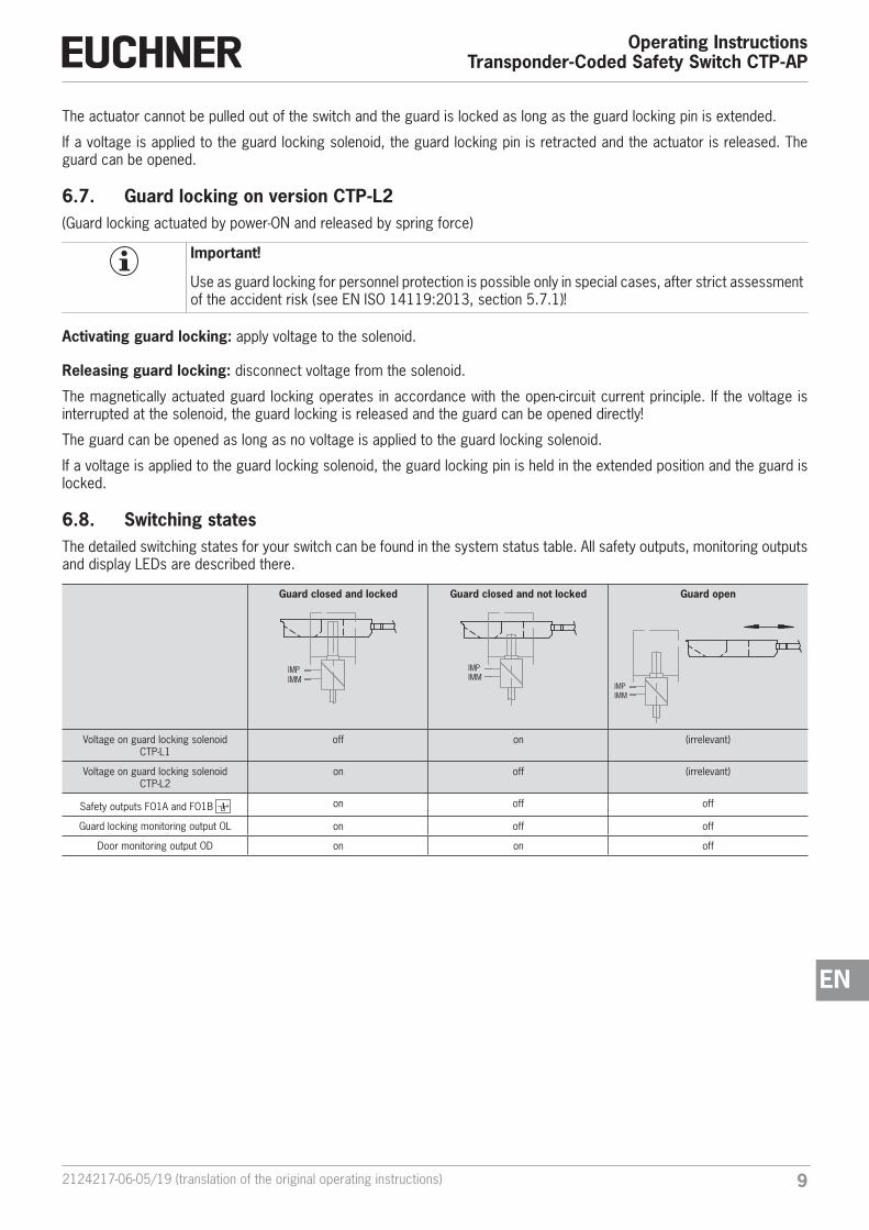
6.8. Switching statesThe detailed switching states for your switch can be found in the system status table. All safety outputs, monitoring outputs and display LEDs are described there.
Guard closed and locked
IMPIMM
Guard closed and not locked
IMPIMM
Guard open
IMPIMM
Voltage on guard locking solenoid CTP-L1
off on (irrelevant)
Voltage on guard locking solenoid CTP-L2
on off (irrelevant)
Safety outputs FO1A and FO1B on off off
Guard locking monitoring output OL on off off
Door monitoring output OD on on off
Operating InstructionsTransponder-Coded Safety Switch CTP-AP
10 (translation of the original operating instructions) 2124217-06-05/19
7. Manual releaseImportant!
S1
S2S3
No further release functions can be retrofitted on Extended variants with controls in position 1 (S1) and position 2 (S2).
Some situations require the guard locking to be released manually (e.g. malfunctions or an emergency). A function test should be performed after release.
More information on this topic can be found in the standard EN ISO 14119:2013, section 5.7.5.1. The device can feature the following release functions:
7.1. Auxiliary release and auxiliary key releaseIn the event of malfunctions, the guard locking can be released with the auxiliary release irrespective of the state of the solenoid.
The safety outputs are switched off when the auxiliary release is actuated. Use the safety outputs to generate a stop command.
The monitoring output OL is switched off; OD can assume an undefined state. Open the guard and close it again after re-setting the auxiliary release. The device will then operate normally again.
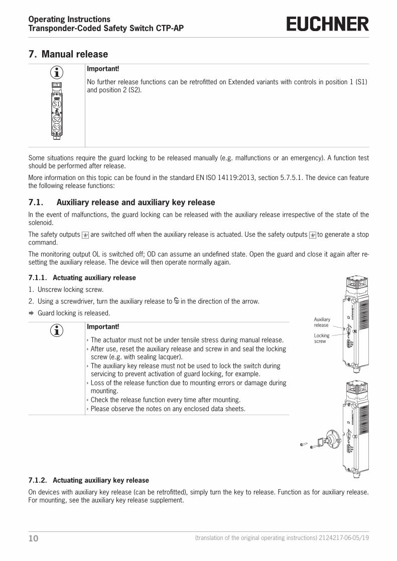
7.1.1. Actuating auxiliary release
1. Unscrew locking screw.
2. Using a screwdriver, turn the auxiliary release to in the direction of the arrow.
¨ Guard locking is released.
Important!
Ì The actuator must not be under tensile stress during manual release. Ì After use, reset the auxiliary release and screw in and seal the locking screw (e.g. with sealing lacquer). Ì The auxiliary key release must not be used to lock the switch during servicing to prevent activation of guard locking, for example. Ì Loss of the release function due to mounting errors or damage during mounting. Ì Check the release function every time after mounting. Ì Please observe the notes on any enclosed data sheets.
7.1.2. Actuating auxiliary key release
On devices with auxiliary key release (can be retrofitted), simply turn the key to release. Function as for auxiliary release. For mounting, see the auxiliary key release supplement.
Auxiliary release
Locking screw
112124217-06-05/19 (translation of the original operating instructions)
Operating InstructionsTransponder-Coded Safety Switch CTP-AP
EN
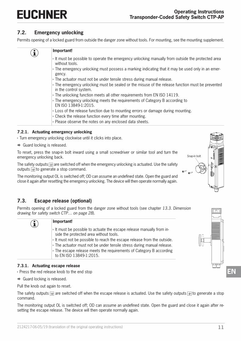
7.2. Emergency unlockingPermits opening of a locked guard from outside the danger zone without tools. For mounting, see the mounting supplement.
Important!
Ì It must be possible to operate the emergency unlocking manually from outside the protected area without tools. Ì The emergency unlocking must possess a marking indicating that it may be used only in an emer-gency. Ì The actuator must not be under tensile stress during manual release. Ì The emergency unlocking must be sealed or the misuse of the release function must be prevented in the control system. Ì The unlocking function meets all other requirements from EN ISO 14119. Ì The emergency unlocking meets the requirements of Category B according to EN ISO 13849-1:2015. Ì Loss of the release function due to mounting errors or damage during mounting. Ì Check the release function every time after mounting. Ì Please observe the notes on any enclosed data sheets.
7.2.1. Actuating emergency unlocking Ì Turn emergency unlocking clockwise until it clicks into place.
¨ Guard locking is released.
To reset, press the snap-in bolt inward using a small screwdriver or similar tool and turn the emergency unlocking back.
The safety outputs are switched off when the emergency unlocking is actuated. Use the safety outputs to generate a stop command.
The monitoring output OL is switched off; OD can assume an undefined state. Open the guard and close it again after resetting the emergency unlocking. The device will then operate normally again.
7.3. Escape release (optional)Permits opening of a locked guard from the danger zone without tools (see chapter 13.3. Dimension drawing for safety switch CTP… on page 28).
Important!
Ì It must be possible to actuate the escape release manually from in-side the protected area without tools. Ì It must not be possible to reach the escape release from the outside. Ì The actuator must not be under tensile stress during manual release. Ì The escape release meets the requirements of Category B according to EN ISO 13849-1:2015.
7.3.1. Actuating escape release Ì Press the red release knob to the end stop
¨ Guard locking is released.
Pull the knob out again to reset.
The safety outputs are switched off when the escape release is actuated. Use the safety outputs to generate a stop command.
The monitoring output OL is switched off; OD can assume an undefined state. Open the guard and close it again after re-setting the escape release. The device will then operate normally again.
Snap-in bolt
Operating InstructionsTransponder-Coded Safety Switch CTP-AP
12 (translation of the original operating instructions) 2124217-06-05/19
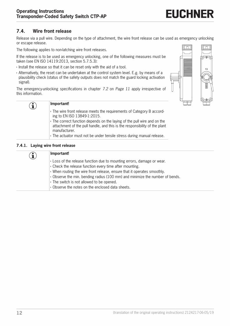
7.4. Wire front releaseRelease via a pull wire. Depending on the type of attachment, the wire front release can be used as emergency unlocking or escape release.
The following applies to non-latching wire front releases.
If the release is to be used as emergency unlocking, one of the following measures must be taken (see EN ISO 14119:2013, section 5.7.5.3): Ì Install the release so that it can be reset only with the aid of a tool. Ì Alternatively, the reset can be undertaken at the control system level. E.g. by means of a plausibility check (status of the safety outputs does not match the guard locking activation signal).
The emergency-unlocking specifications in chapter 7.2 on Page 11 apply irrespective of this information.
Important!
Ì The wire front release meets the requirements of Category B accord-ing to EN ISO 13849-1:2015. Ì The correct function depends on the laying of the pull wire and on the attachment of the pull handle, and this is the responsibility of the plant manufacturer. Ì The actuator must not be under tensile stress during manual release.
7.4.1. Laying wire front release
Important!
Ì Loss of the release function due to mounting errors, damage or wear. Ì Check the release function every time after mounting. Ì When routing the wire front release, ensure that it operates smoothly. Ì Observe the min. bending radius (100 mm) and minimize the number of bends. Ì The switch is not allowed to be opened. Ì Observe the notes on the enclosed data sheets.
132124217-06-05/19 (translation of the original operating instructions)
Operating InstructionsTransponder-Coded Safety Switch CTP-AP
EN
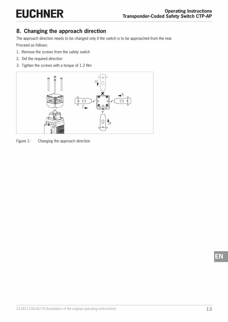
8. Changing the approach directionThe approach direction needs to be changed only if the switch is to be approached from the rear.
Proceed as follows:
1. Remove the screws from the safety switch
2. Set the required direction
3. Tighten the screws with a torque of 1.2 Nm
C
B
D
A
Figure 1: Changing the approach direction
Operating InstructionsTransponder-Coded Safety Switch CTP-AP
14 (translation of the original operating instructions) 2124217-06-05/19
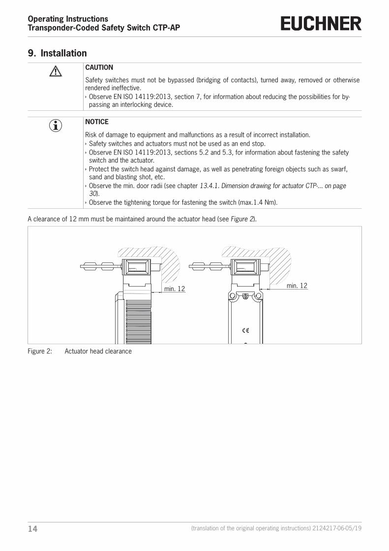
9. InstallationCAUTION
Safety switches must not be bypassed (bridging of contacts), turned away, removed or otherwise rendered ineffective. Ì Observe EN ISO 14119:2013, section 7, for information about reducing the possibilities for by-passing an interlocking device.
NOTICE
Risk of damage to equipment and malfunctions as a result of incorrect installation. Ì Safety switches and actuators must not be used as an end stop. Ì Observe EN ISO 14119:2013, sections 5.2 and 5.3, for information about fastening the safety switch and the actuator. Ì Protect the switch head against damage, as well as penetrating foreign objects such as swarf, sand and blasting shot, etc. Ì Observe the min. door radii (see chapter 13.4.1. Dimension drawing for actuator CTP‑... on page 30). Ì Observe the tightening torque for fastening the switch (max.1.4 Nm).
A clearance of 12 mm must be maintained around the actuator head (see Figure 2).
min. 12 min. 12
Figure 2: Actuator head clearance
152124217-06-05/19 (translation of the original operating instructions)
Operating InstructionsTransponder-Coded Safety Switch CTP-AP
EN
10. Electrical connectionWARNING
If there is a mistake, loss of the safety function due to incorrect connection. Ì To ensure safety, both safety outputs (FO1A and FO1B) must always be evaluated. Ì Monitoring outputs must not be used as safety outputs. Ì Lay the connection cables with protection to prevent the risk of short circuits.
CAUTION
Risk of damage to equipment or malfunctions as a result of incorrect connection. Ì The power supply for the evaluation electronics is electrically isolated from the power supply for the guard locking solenoid. Ì The device generates its own test pulses on the output lines FO1A/FO1B. A downstream control system must tolerate these test pulses, which may have a length of up to 0.35 ms. Depending on the inertia of the downstream device (control system, relay, etc.), this can lead to short switching processes. Ì The inputs on an evaluation unit connected must be positive-switching, as the two outputs on the safety switch deliver a level of +24 V in the switched-on state. Ì All the electrical connections must either be isolated from the mains supply by a safety transformer according to IEC 61558-2-6 with limited output voltage in the event of a fault, or by other equivalent isolation measures (PELV). Ì All electrical outputs must have an adequate protective circuit for inductive loads. The outputs must be protected with a free-wheeling diode for this purpose. RC interference suppression units must not be used. Ì Power devices which are a powerful source of interference must be installed in a separate location away from the input and output circuits for signal processing. The cable routing for safety circuits should be as far away as possible from the cables of the power circuits. Ì To avoid EMC interference, the physical environmental and operating conditions at the in-stallation site of the device must comply with the requirements according to the standard EN 60204-1:2006, section 4.4.2 (EMC).
Please pay attention to any interference fields from devices such as frequency converters or induction heating systems. Observe the EMC instructions in the manuals from the respective manufacturer.
Important!
If the device does not appear to function when operating voltage is applied (e.g. green STATE LED does not flash), the safety switch must be returned unopened to the manufacturer.
Operating InstructionsTransponder-Coded Safety Switch CTP-AP
16 (translation of the original operating instructions) 2124217-06-05/19
10.1. Notes about
Important!
Ì For use and operation as per the requirements 1), a power supply with the feature “for use in class 2 circuits” must be used.Alternative solutions must comply with the following requirements:Electrically isolated power supply unit in combination with fuse as per UL248. This fuse should be designed for max. 3.3 A and should be integrated into the 30 V DC voltage section. Ì For use and applications as per the requirements 1), a connection cable listed under UL cate-gory code CYJV/7, min. 24 AWG, min 80 °C, must be used.
1) Note on the scope of the UL approval: the devices have been tested as per the requirements of UL508 and CSA/ C22.2 no. 14 (protection against electric shock and fire).
10.2. Safety in case of faults Ì The operating voltage UB and the solenoid voltage IMP are reverse polarity protected. Ì The safety outputs FO1A/FO1B are short circuit-proof. Ì A short circuit between FO1A and FO1B is detected by the switch. Ì A short circuit in the cable can be excluded by laying the cable with protection.
10.3. Fuse protection for power supplyThe power supply must be provided with fuse protection depending on the number of switches and current required for the outputs. The following rules apply:
Max. current consumption Imax
Imax = IUB + IFO1A+FO1B + IOL + IOD
IUB = Switch operating current (40 mA)
IOL/IOD = Load current of monitoring outputs (max. 50 mA per monitoring output)
IFO1A+FO1B = Load current of safety outputs FO1A + FO1B (2 x max. 150 mA)
172124217-06-05/19 (translation of the original operating instructions)
Operating InstructionsTransponder-Coded Safety Switch CTP-AP
EN
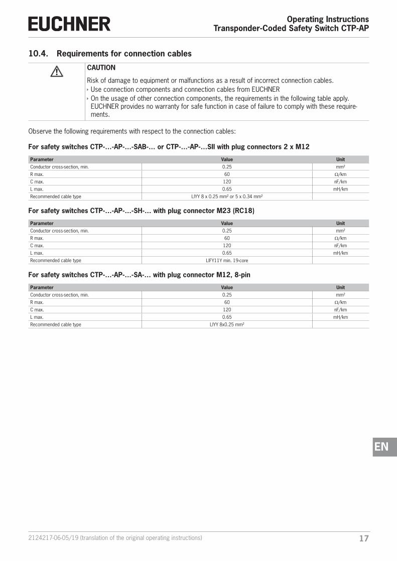
10.4. Requirements for connection cables
CAUTION
Risk of damage to equipment or malfunctions as a result of incorrect connection cables. Ì Use connection components and connection cables from EUCHNER Ì On the usage of other connection components, the requirements in the following table apply. EUCHNER provides no warranty for safe function in case of failure to comply with these require-ments.
Observe the following requirements with respect to the connection cables:
For safety switches CTP-…-AP-…-SAB-… or CTP-…-AP-…SII with plug connectors 2 x M12
Parameter Value UnitConductor cross-section, min. 0.25 mm²
R max. 60 W/km
C max. 120 nF/km
L max. 0.65 mH/km
Recommended cable type LIYY 8 x 0.25 mm² or 5 x 0.34 mm²
For safety switches CTP-…-AP-…-SH-… with plug connector M23 (RC18)
Parameter Value UnitConductor cross-section, min. 0.25 mm²
R max. 60 W/km
C max. 120 nF/km
L max. 0.65 mH/km
Recommended cable type LIFY11Y min. 19-core
For safety switches CTP-…-AP-…-SA-… with plug connector M12, 8-pin
Parameter Value UnitConductor cross-section, min. 0.25 mm²
R max. 60 W/km
C max. 120 nF/km
L max. 0.65 mH/km
Recommended cable type LIYY 8x0.25 mm²
Operating InstructionsTransponder-Coded Safety Switch CTP-AP
18 (translation of the original operating instructions) 2124217-06-05/19
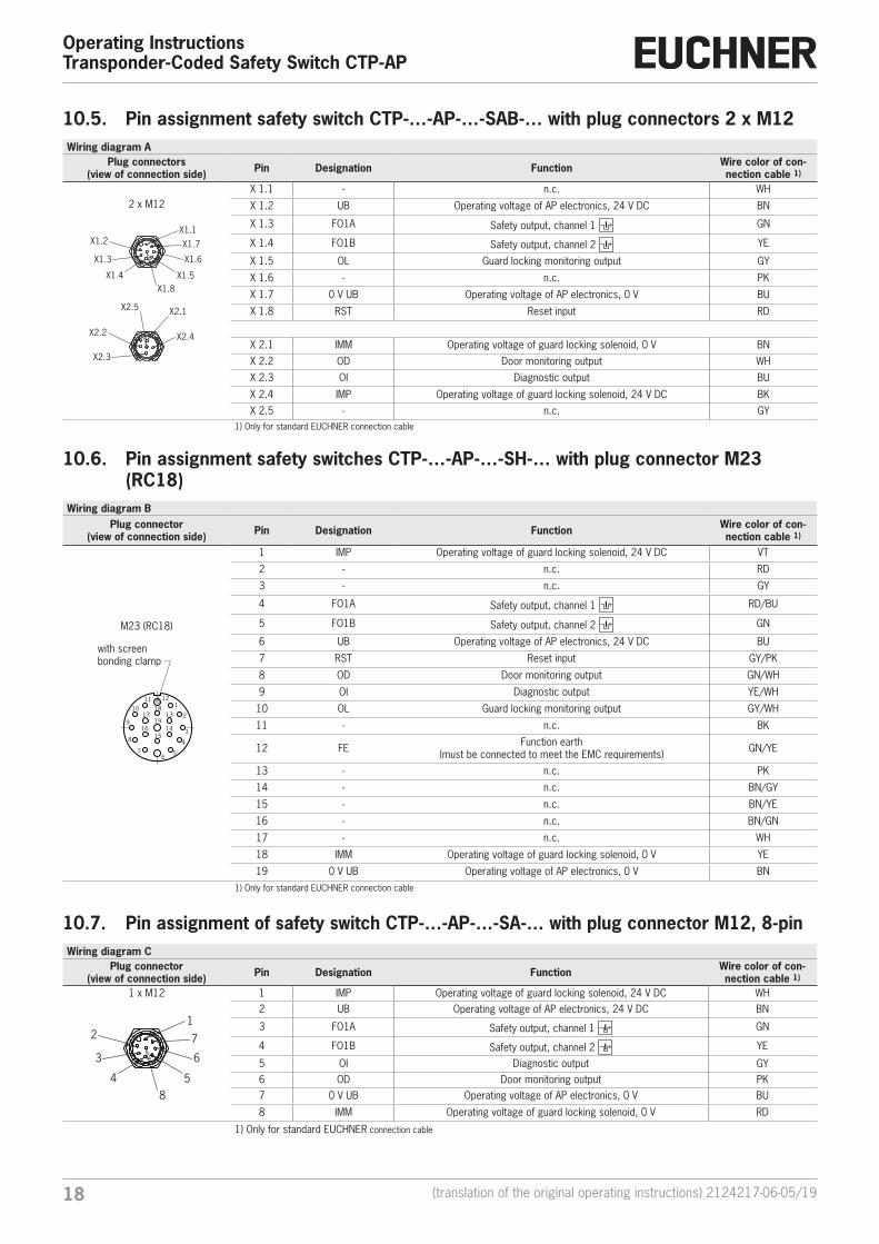
10.5. Pin assignment safety switch CTP-…-AP-…-SAB-… with plug connectors 2 x M12Wiring diagram A
Plug connectors(view of connection side) Pin Designation Function Wire color of con-
nection cable 1)
2 x M12
X2.5
X1.8X1.5
X1.6
X1.7X1.2
X2.4
X2.3
X2.1
X2.2
X1.4
X1.3
X1.1
X 1.1 - n.c. WH
X 1.2 UB Operating voltage of AP electronics, 24 V DC BN
X 1.3 FO1A Safety output, channel 1 GN
X 1.4 FO1B Safety output, channel 2 YE
X 1.5 OL Guard locking monitoring output GY
X 1.6 - n.c. PK
X 1.7 0 V UB Operating voltage of AP electronics, 0 V BU
X 1.8 RST Reset input RD
X 2.1 IMM Operating voltage of guard locking solenoid, 0 V BNX 2.2 OD Door monitoring output WHX 2.3 OI Diagnostic output BU
X 2.4 IMP Operating voltage of guard locking solenoid, 24 V DC BKX 2.5 - n.c. GY
1) Only for standard EUCHNER connection cable
10.6. Pin assignment safety switches CTP-…-AP-…-SH-… with plug connector M23 (RC18)
Wiring diagram BPlug connector
(view of connection side) Pin Designation Function Wire color of con-nection cable 1)
M23 (RC18)
with screen bonding clamp
18
19
15
1211
9
5
4
3
2
1
17
16 14
13
6
10
8
7
1 IMP Operating voltage of guard locking solenoid, 24 V DC VT
2 - n.c. RD
3 - n.c. GY
4 FO1A Safety output, channel 1 RD/BU
5 FO1B Safety output, channel 2 GN
6 UB Operating voltage of AP electronics, 24 V DC BU
7 RST Reset input GY/PK
8 OD Door monitoring output GN/WH
9 OI Diagnostic output YE/WH
10 OL Guard locking monitoring output GY/WH
11 - n.c. BK
12 FE Function earth(must be connected to meet the EMC requirements) GN/YE
13 - n.c. PK
14 - n.c. BN/GY
15 - n.c. BN/YE
16 - n.c. BN/GN
17 - n.c. WH
18 IMM Operating voltage of guard locking solenoid, 0 V YE
19 0 V UB Operating voltage of AP electronics, 0 V BN1) Only for standard EUCHNER connection cable
10.7. Pin assignment of safety switch CTP-…-AP-…-SA-… with plug connector M12, 8-pinWiring diagram C
Plug connector(view of connection side) Pin Designation Function Wire color of con-
nection cable 1)
1 x M12
85
6
72
4
3
1
1 IMP Operating voltage of guard locking solenoid, 24 V DC WH2 UB Operating voltage of AP electronics, 24 V DC BN
3 FO1A Safety output, channel 1 GN
4 FO1B Safety output, channel 2 YE
5 OI Diagnostic output GY6 OD Door monitoring output PK7 0 V UB Operating voltage of AP electronics, 0 V BU
8 IMM Operating voltage of guard locking solenoid, 0 V RD
1) Only for standard EUCHNER connection cable
192124217-06-05/19 (translation of the original operating instructions)
Operating InstructionsTransponder-Coded Safety Switch CTP-AP
EN
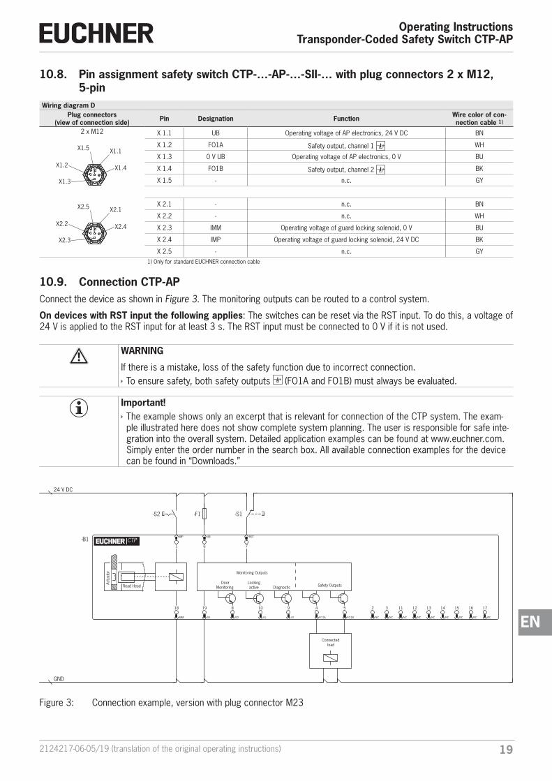
10.8. Pin assignment safety switch CTP-…-AP-…-SII-… with plug connectors 2 x M12, 5-pin
Wiring diagram DPlug connectors
(view of connection side) Pin Designation Function Wire color of con-nection cable 1)
2 x M12
X2.5
X2.4
X2.3
X2.1
X2.2
X1.5
X1.4
X1.3
X1.1
X1.2
X 1.1 UB Operating voltage of AP electronics, 24 V DC BN
X 1.2 FO1A Safety output, channel 1 WH
X 1.3 0 V UB Operating voltage of AP electronics, 0 V BU
X 1.4 FO1B Safety output, channel 2 BK
X 1.5 - n.c. GY
X 2.1 - n.c. BN
X 2.2 - n.c. WH
X 2.3 IMM Operating voltage of guard locking solenoid, 0 V BU
X 2.4 IMP Operating voltage of guard locking solenoid, 24 V DC BK
X 2.5 - n.c. GY1) Only for standard EUCHNER connection cable
10.9. Connection CTP-APConnect the device as shown in Figure 3. The monitoring outputs can be routed to a control system.
On devices with RST input the following applies: The switches can be reset via the RST input. To do this, a voltage of 24 V is applied to the RST input for at least 3 s. The RST input must be connected to 0 V if it is not used.
WARNING
If there is a mistake, loss of the safety function due to incorrect connection. Ì To ensure safety, both safety outputs (FO1A and FO1B) must always be evaluated.
Important! Ì The example shows only an excerpt that is relevant for connection of the CTP system. The exam-ple illustrated here does not show complete system planning. The user is responsible for safe inte-gration into the overall system. Detailed application examples can be found at www.euchner.com. Simply enter the order number in the search box. All available connection examples for the device can be found in “Downloads.”
Safety OutputsDoor
Monitoring Read Head
Actu
ator Monitoring Outputs
11
NC
9
OI
DiagnosticLockingactive
-B1 UB
6
IMP
1
18
IMM
RST
7
19
0V
8
OD
4
FO1A
5
FO1B
10
OL
CTP
12
NC
13
NC
14
NC
15
NC
16
NC
17
NC
3
NC
2
NC
24 V DC
GND
-F1
Connected load
-S1-S2
Figure 3: Connection example, version with plug connector M23
Operating InstructionsTransponder-Coded Safety Switch CTP-AP
20 (translation of the original operating instructions) 2124217-06-05/19
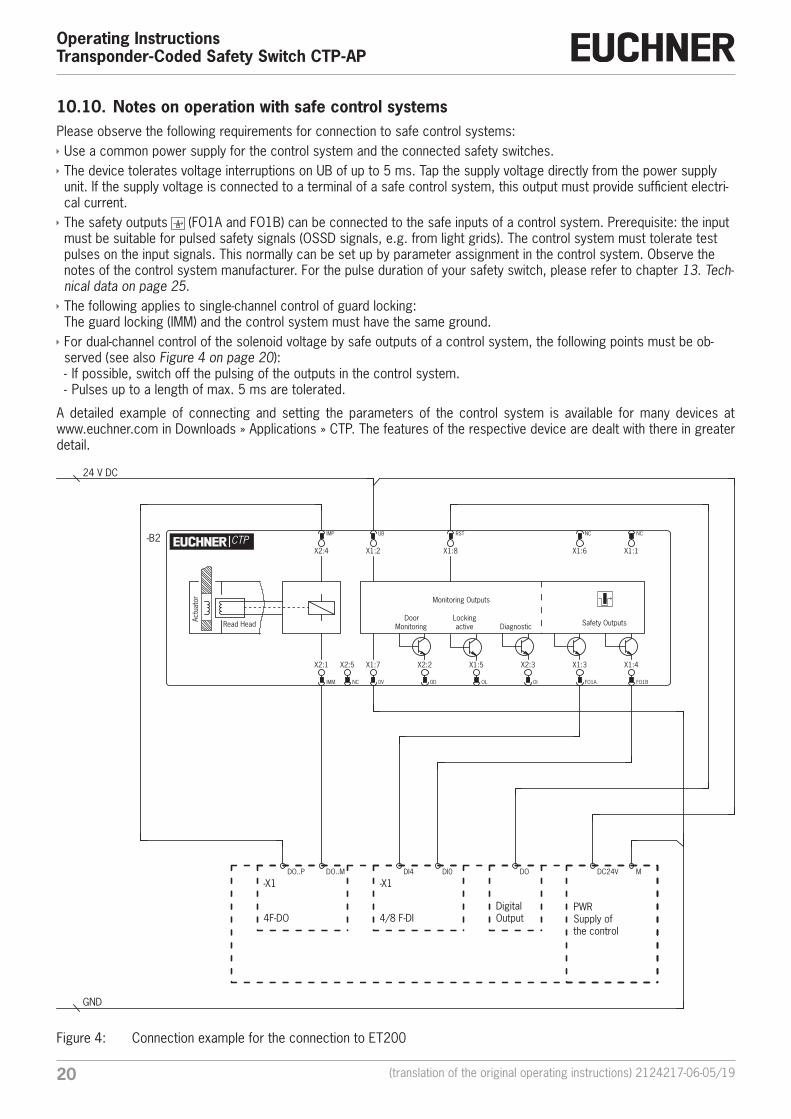
10.10. Notes on operation with safe control systemsPlease observe the following requirements for connection to safe control systems: Ì Use a common power supply for the control system and the connected safety switches. Ì The device tolerates voltage interruptions on UB of up to 5 ms. Tap the supply voltage directly from the power supply unit. If the supply voltage is connected to a terminal of a safe control system, this output must provide sufficient electri-cal current. Ì The safety outputs (FO1A and FO1B) can be connected to the safe inputs of a control system. Prerequisite: the input must be suitable for pulsed safety signals (OSSD signals, e.g. from light grids). The control system must tolerate test pulses on the input signals. This normally can be set up by parameter assignment in the control system. Observe the notes of the control system manufacturer. For the pulse duration of your safety switch, please refer to chapter 13. Tech‑nical data on page 25. Ì The following applies to single-channel control of guard locking: The guard locking (IMM) and the control system must have the same ground. Ì For dual-channel control of the solenoid voltage by safe outputs of a control system, the following points must be ob-served (see also Figure 4 on page 20): - If possible, switch off the pulsing of the outputs in the control system. - Pulses up to a length of max. 5 ms are tolerated.
A detailed example of connecting and setting the parameters of the control system is available for many devices at www.euchner.com in Downloads » Applications » CTP. The features of the respective device are dealt with there in greater detail.
Safety OutputsDoor
Monitoring Read Head
Actu
ator Monitoring Outputs
X2:5
NC
X2:3
OI
DiagnosticLockingactive
NC
X1:6
NC
X1:1
-B2 UB
X1:2
IMP
X2:4
X2:1
IMM
RST
X1:8
X1:7
0V
X2:2
OD
X1:3
FO1A
X1:4
FO1B
X1:5
OL
CTP
24 V DC
GND
4/8 F-DIDigital Output
PWRSupply ofthe control
4F-DO
-X1DI4 DI0 DO DC24V M
-X1DO..P DO..M
Figure 4: Connection example for the connection to ET200
212124217-06-05/19 (translation of the original operating instructions)
Operating InstructionsTransponder-Coded Safety Switch CTP-AP
EN
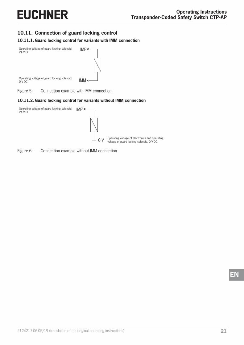
10.11. Connection of guard locking control10.11.1. Guard locking control for variants with IMM connection
Operating voltage of guard locking solenoid, 24 V DC
IMP
IMMOperating voltage of guard locking solenoid, 0 V DC
Figure 5: Connection example with IMM connection
10.11.2. Guard locking control for variants without IMM connection
Operating voltage of guard locking solenoid, 24 V DC
IMP
0 V Operating voltage of electronics and operating voltage of guard locking solenoid, 0 V DC
Figure 6: Connection example without IMM connection
Operating InstructionsTransponder-Coded Safety Switch CTP-AP
22 (translation of the original operating instructions) 2124217-06-05/19
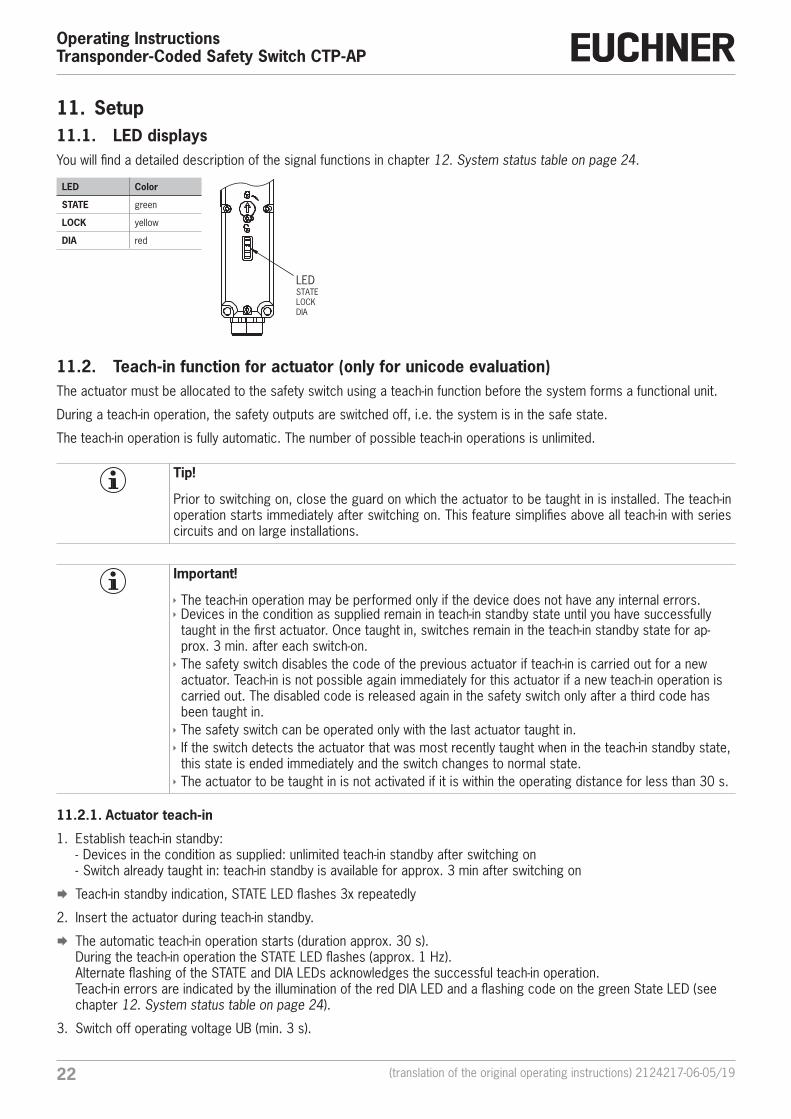
11. Setup11.1. LED displaysYou will find a detailed description of the signal functions in chapter 12. System status table on page 24.
LED Color
STATE green
LOCK yellow
DIA red
11.2. Teach-in function for actuator (only for unicode evaluation)The actuator must be allocated to the safety switch using a teach-in function before the system forms a functional unit.
During a teach-in operation, the safety outputs are switched off, i.e. the system is in the safe state.
The teach-in operation is fully automatic. The number of possible teach-in operations is unlimited.
Tip!
Prior to switching on, close the guard on which the actuator to be taught in is installed. The teach-in operation starts immediately after switching on. This feature simplifies above all teach-in with series circuits and on large installations.
Important!
Ì The teach-in operation may be performed only if the device does not have any internal errors. Ì Devices in the condition as supplied remain in teach-in standby state until you have successfully taught in the first actuator. Once taught in, switches remain in the teach-in standby state for ap-prox. 3 min. after each switch-on. Ì The safety switch disables the code of the previous actuator if teach-in is carried out for a new actuator. Teach-in is not possible again immediately for this actuator if a new teach-in operation is carried out. The disabled code is released again in the safety switch only after a third code has been taught in. Ì The safety switch can be operated only with the last actuator taught in. Ì If the switch detects the actuator that was most recently taught when in the teach-in standby state, this state is ended immediately and the switch changes to normal state. Ì The actuator to be taught in is not activated if it is within the operating distance for less than 30 s.
11.2.1. Actuator teach-in
1. Establish teach-in standby: - Devices in the condition as supplied: unlimited teach-in standby after switching on - Switch already taught in: teach-in standby is available for approx. 3 min after switching on
¨ Teach-in standby indication, STATE LED flashes 3x repeatedly
2. Insert the actuator during teach-in standby.
¨ The automatic teach-in operation starts (duration approx. 30 s). During the teach-in operation the STATE LED flashes (approx. 1 Hz). Alternate flashing of the STATE and DIA LEDs acknowledges the successful teach-in operation. Teach-in errors are indicated by the illumination of the red DIA LED and a flashing code on the green State LED (see chapter 12. System status table on page 24).
3. Switch off operating voltage UB (min. 3 s).
LEDSTATELOCKDIA
232124217-06-05/19 (translation of the original operating instructions)
Operating InstructionsTransponder-Coded Safety Switch CTP-AP
EN
¨ The code of the actuator that was just taught in is activated in the safety switch.
4. Switch on operating voltage UB.
¨ The device operates normally.
11.3. Functional check
WARNING
Danger of fatal injury as a result of faults in installation and functional check. Ì Before carrying out the functional check, make sure that there are no persons in the danger zone. Ì Observe the applicable accident prevention regulations.
11.3.1. Mechanical function test
The actuator must slide easily into the actuating head. Close the guard several times to check the function. For devices with mechanical release (emergency unlocking or escape release), the correct function of the release must be checked as well.
11.3.2. Electrical function test
After installation and any fault, the safety function must be fully checked. Proceed as follows:
1. Switch on operating voltage.
¨ The machine must not start automatically.
¨ The safety switch carries out a self-test. The green STATE LED then flashes at regular intervals.
2. Close all guards. Guard locking by solenoid force: activate guard locking.
¨ The machine must not start automatically. It must not be possible to open the guard.
¨ The green STATE LED and the yellow LOCK LED are illuminated continuously.
3. Enable operation in the control system.
¨ It must not be possible to deactivate guard locking as long as operation is enabled.
4. Disable operation in the control system and deactivate guard locking.
¨ The guard must remain locked until there is no longer any risk of injury.
¨ It must not be possible to start the machine as long as the guard locking is deactivated.
Repeat steps 2 - 4 for each guard.
Operating InstructionsTransponder-Coded Safety Switch CTP-AP
24 (translation of the original operating instructions) 2124217-06-05/19
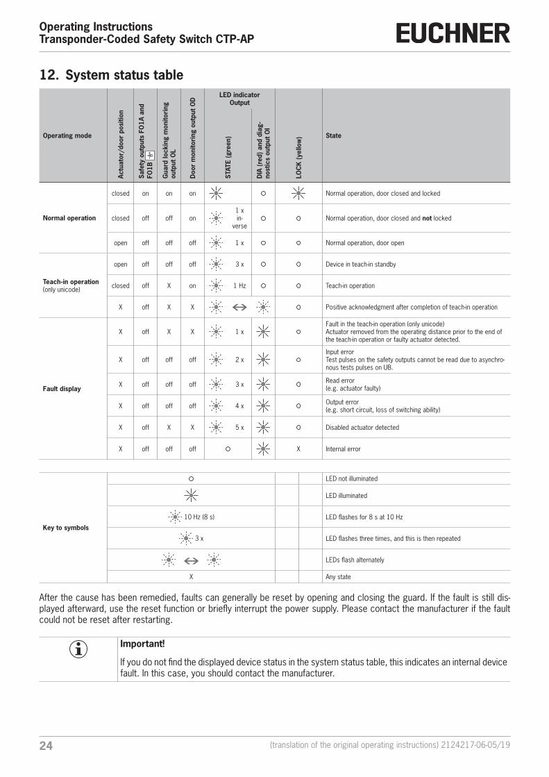
12. System status table
Operating mode
Actu
ator
/doo
r po
sitio
n
Safe
ty o
utpu
ts F
O1A
and
FO
1B
Gua
rd lo
ckin
g m
onito
ring
ou
tput
OL
Doo
r m
onito
ring
out
put O
D
LED indicatorOutput
State
STAT
E (g
reen
)
DIA
(red
) and
dia
g-no
stic
s ou
tput
OI
LOC
K (y
ello
w)
Normal operation
closed on on on Normal operation, door closed and locked
closed off off on1 x in-
verseNormal operation, door closed and not locked
open off off off 1 x Normal operation, door open
Teach-in operation(only unicode)
open off off off 3 x Device in teach-in standby
closed off X on 1 Hz Teach-in operation
X off X X Positive acknowledgment after completion of teach-in operation
Fault display
X off X X 1 xFault in the teach-in operation (only unicode) Actuator removed from the operating distance prior to the end of the teach-in operation or faulty actuator detected.
X off off off 2 xInput errorTest pulses on the safety outputs cannot be read due to asynchro-nous tests pulses on UB.
X off off off 3 x Read error (e.g. actuator faulty)
X off off off 4 x Output error(e.g. short circuit, loss of switching ability)
X off X X 5 x Disabled actuator detected
X off off off X Internal error
Key to symbols
LED not illuminated
LED illuminated
10 Hz (8 s) LED flashes for 8 s at 10 Hz
3 x LED flashes three times, and this is then repeated
LEDs flash alternately
X Any state
After the cause has been remedied, faults can generally be reset by opening and closing the guard. If the fault is still dis-played afterward, use the reset function or briefly interrupt the power supply. Please contact the manufacturer if the fault could not be reset after restarting.
Important!
If you do not find the displayed device status in the system status table, this indicates an internal device fault. In this case, you should contact the manufacturer.
252124217-06-05/19 (translation of the original operating instructions)
Operating InstructionsTransponder-Coded Safety Switch CTP-AP
EN
13. Technical dataNOTICE
If a data sheet is included with the product, the information on the data sheet applies.
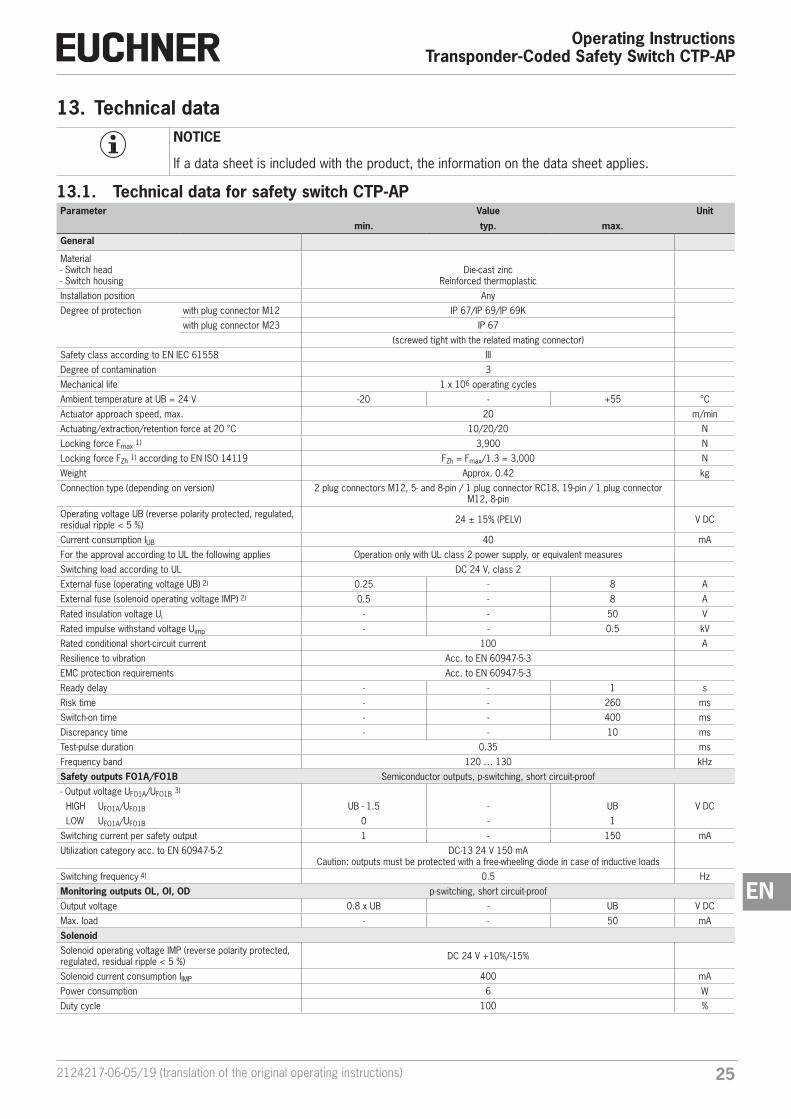
13.1. Technical data for safety switch CTP-APParameter Value Unit
min. typ. max.General
Material- Switch head- Switch housing
Die-cast zincReinforced thermoplastic
Installation position Any
Degree of protection with plug connector M12 IP 67/IP 69/IP 69K
with plug connector M23 IP 67
(screwed tight with the related mating connector)
Safety class according to EN IEC 61558 III
Degree of contamination 3
Mechanical life 1 x 10⁶ operating cycles
Ambient temperature at UB = 24 V -20 - +55 °C
Actuator approach speed, max. 20 m/min
Actuating/extraction/retention force at 20 °C 10/20/20 N
Locking force Fmax 1) 3,900 N
Locking force FZh 1) according to EN ISO 14119 FZh = Fmax/1.3 = 3,000 N
Weight Approx. 0.42 kg
Connection type (depending on version) 2 plug connectors M12, 5- and 8-pin / 1 plug connector RC18, 19-pin / 1 plug connector M12, 8-pin
Operating voltage UB (reverse polarity protected, regulated, residual ripple < 5 %) 24 ± 15% (PELV) V DC
Current consumption IUB 40 mA
For the approval according to UL the following applies Operation only with UL class 2 power supply, or equivalent measures
Switching load according to UL DC 24 V, class 2
External fuse (operating voltage UB) 2) 0.25 - 8 A
External fuse (solenoid operating voltage IMP) 2) 0.5 - 8 A
Rated insulation voltage Ui - - 50 V
Rated impulse withstand voltage Uimp - - 0.5 kV
Rated conditional short-circuit current 100 A
Resilience to vibration Acc. to EN 60947-5-3
EMC protection requirements Acc. to EN 60947-5-3
Ready delay - - 1 s
Risk time - - 260 ms
Switch-on time - - 400 ms
Discrepancy time - - 10 ms
Test-pulse duration 0.35 ms
Frequency band 120 … 130 kHz
Safety outputs FO1A/FO1B Semiconductor outputs, p-switching, short circuit-proof
- Output voltage UFO1A/UFO1B 3)
V DC HIGH UFO1A/UFO1B UB - 1.5 - UB
LOW UFO1A/UFO1B 0 - 1
Switching current per safety output 1 - 150 mA
Utilization category acc. to EN 60947-5-2 DC-13 24 V 150 mACaution: outputs must be protected with a free-wheeling diode in case of inductive loads
Switching frequency 4) 0.5 Hz
Monitoring outputs OL, OI, OD p-switching, short circuit-proof
Output voltage 0.8 x UB - UB V DC
Max. load - - 50 mA
SolenoidSolenoid operating voltage IMP (reverse polarity protected, regulated, residual ripple < 5 %) DC 24 V +10%/-15%
Solenoid current consumption IIMP 400 mA
Power consumption 6 W
Duty cycle 100 %
Operating InstructionsTransponder-Coded Safety Switch CTP-AP
26 (translation of the original operating instructions) 2124217-06-05/19
Parameter Value Unit
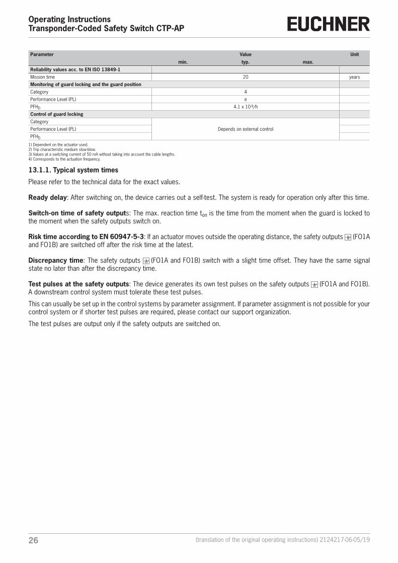
min. typ. max.Reliability values acc. to EN ISO 13849-1Mission time 20 years
Monitoring of guard locking and the guard positionCategory 4
Performance Level (PL) e
PFHD 4.1 x 10⁻⁹/h
Control of guard lockingCategory
Depends on external controlPerformance Level (PL)
PFHD
1) Dependent on the actuator used. 2) Trip characteristic medium slow-blow.3) Values at a switching current of 50 mA without taking into account the cable lengths.4) Corresponds to the actuation frequency.
13.1.1. Typical system times
Please refer to the technical data for the exact values.
Ready delay: After switching on, the device carries out a self-test. The system is ready for operation only after this time.
Switch-on time of safety outputs: The max. reaction time ton is the time from the moment when the guard is locked to the moment when the safety outputs switch on.
Risk time according to EN 60947-5-3: If an actuator moves outside the operating distance, the safety outputs (FO1A and FO1B) are switched off after the risk time at the latest.
Discrepancy time: The safety outputs (FO1A and FO1B) switch with a slight time offset. They have the same signal state no later than after the discrepancy time.
Test pulses at the safety outputs: The device generates its own test pulses on the safety outputs (FO1A and FO1B). A downstream control system must tolerate these test pulses.
This can usually be set up in the control systems by parameter assignment. If parameter assignment is not possible for your control system or if shorter test pulses are required, please contact our support organization.
The test pulses are output only if the safety outputs are switched on.
272124217-06-05/19 (translation of the original operating instructions)
Operating InstructionsTransponder-Coded Safety Switch CTP-AP
EN
13.2. Radio frequency approvals
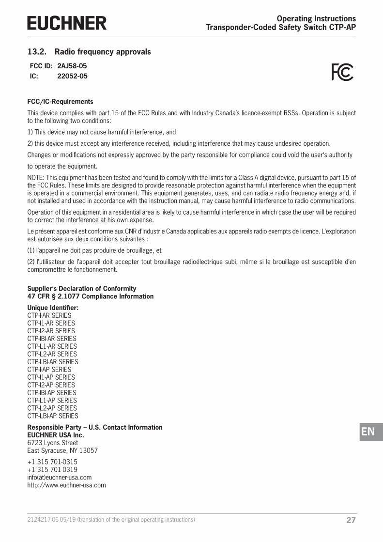
FCC ID: 2AJ58-05IC: 22052-05
FCC/IC-Requirements
This device complies with part 15 of the FCC Rules and with Industry Canada’s licence-exempt RSSs. Operation is subject to the following two conditions:
1) This device may not cause harmful interference, and
2) this device must accept any interference received, including interference that may cause undesired operation.
Changes or modifications not expressly approved by the party responsible for compliance could void the user‘s authority
to operate the equipment.
NOTE: This equipment has been tested and found to comply with the limits for a Class A digital device, pursuant to part 15 of the FCC Rules. These limits are designed to provide reasonable protection against harmful interference when the equipment is operated in a commercial environment. This equipment generates, uses, and can radiate radio frequency energy and, if not installed and used in accordance with the instruction manual, may cause harmful interference to radio communications.
Operation of this equipment in a residential area is likely to cause harmful interference in which case the user will be required to correct the interference at his own expense.
Le présent appareil est conforme aux CNR d’Industrie Canada applicables aux appareils radio exempts de licence. L’exploitation est autorisée aux deux conditions suivantes :
(1) l’appareil ne doit pas produire de brouillage, et
(2) l’utilisateur de l’appareil doit accepter tout brouillage radioélectrique subi, même si le brouillage est susceptible d’en compromettre le fonctionnement.
Supplier‘s Declaration of Conformity47 CFR § 2.1077 Compliance Information
Unique Identifier:CTP-I-AR SERIESCTP-I1-AR SERIESCTP-I2-AR SERIESCTP-IBI-AR SERIESCTP-L1-AR SERIESCTP-L2-AR SERIESCTP-LBI-AR SERIESCTP-I-AP SERIESCTP-I1-AP SERIESCTP-I2-AP SERIESCTP-IBI-AP SERIESCTP-L1-AP SERIESCTP-L2-AP SERIESCTP-LBI-AP SERIES
Responsible Party – U.S. Contact InformationEUCHNER USA Inc.6723 Lyons StreetEast Syracuse, NY 13057
+1 315 701-0315+1 315 701-0319info(at)euchner-usa.comhttp://www.euchner-usa.com
Operating InstructionsTransponder-Coded Safety Switch CTP-AP
28 (translation of the original operating instructions) 2124217-06-05/19
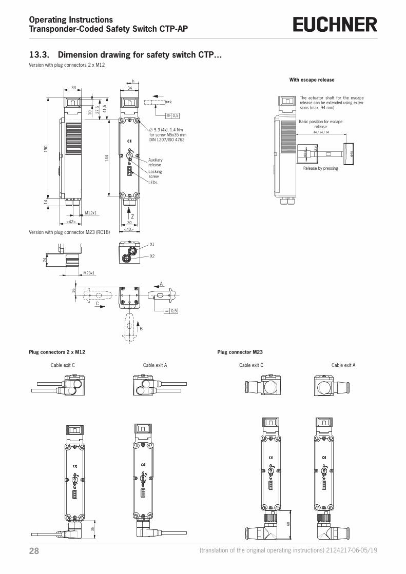
13.3. Dimension drawing for safety switch CTP…
44 / 74 / 94
35
40
14
144
30
<40>
34
h
Z
0,5
16
C
B
A
0,5
<42>
33 1
0
190
1
4
M12x1
41,
5
37,
5
X1
X2
Auxiliary release
∅ 5.3 (4x), 1.4 Nmfor screw M5x35 mmDIN 1207/ISO 4762
Basic position for escape release
Release by pressing
With escape release
M23x1
24
Version with plug connector M23 (RC18)
Version with plug connectors 2 x M12
60
Cable exit C Cable exit A
Locking screwLEDs
The actuator shaft for the escape release can be extended using exten-sions (max. 94 mm)
36
Cable exit C Cable exit A
Plug connectors 2 x M12 Plug connector M23
292124217-06-05/19 (translation of the original operating instructions)
Operating InstructionsTransponder-Coded Safety Switch CTP-AP
EN
19
39
20
,5
max. 50
38
25
25
21,5
38
25
39
32,4
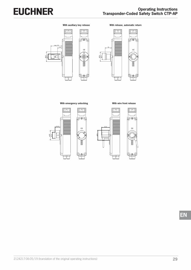
With auxiliary key release
With wire front release
With release, automatic return
With emergency unlocking
Operating InstructionsTransponder-Coded Safety Switch CTP-AP
30 (translation of the original operating instructions) 2124217-06-05/19
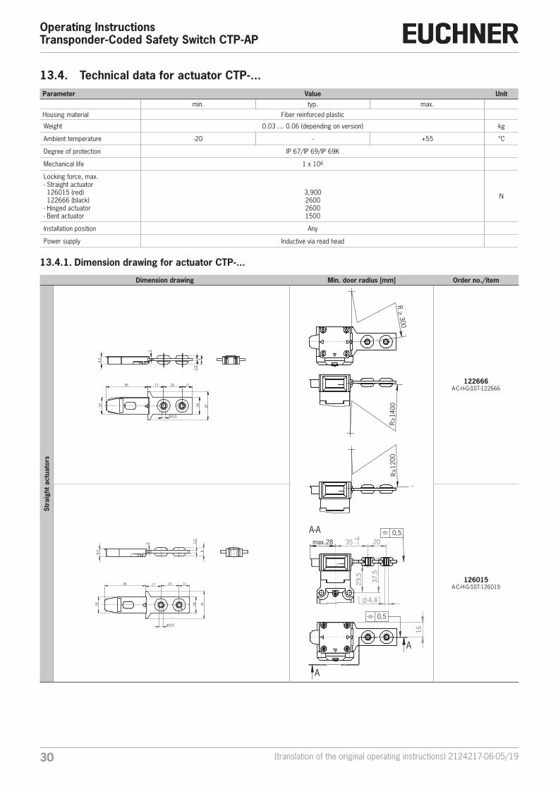
13.4. Technical data for actuator CTP-...Parameter Value Unit
min. typ. max.
Housing material Fiber reinforced plastic
Weight 0.03 … 0.06 (depending on version) kg
Ambient temperature -20 - +55 °C
Degree of protection IP 67/IP 69/IP 69K
Mechanical life 1 x 10⁶
Locking force, max.- Straight actuator 126015 (red) 122666 (black)
- Hinged actuator- Bent actuator
3,900260026001500
N
Installation position Any
Power supply Inductive via read head
13.4.1. Dimension drawing for actuator CTP-...
Dimension drawing Min. door radius [mm] Order no./item
Stra
ight
act
uato
rs
8,5
2
2,5
9
45 17 20
18
30
11
4,4
18
R > 300
R>
1400
R
>12
00
16
A
A
0,5
29,
5
37,
5
4,4
max.28 35 +-41 20
A-A 0,5
122666A-C-H-G-SST-122666
17 20 11
18
30
4,4
18
45
8,5
2 2,5
9
126015A-C-H-G-SST-126015
312124217-06-05/19 (translation of the original operating instructions)
Operating InstructionsTransponder-Coded Safety Switch CTP-AP
EN
Dimension drawing Min. door radius [mm] Order no./item
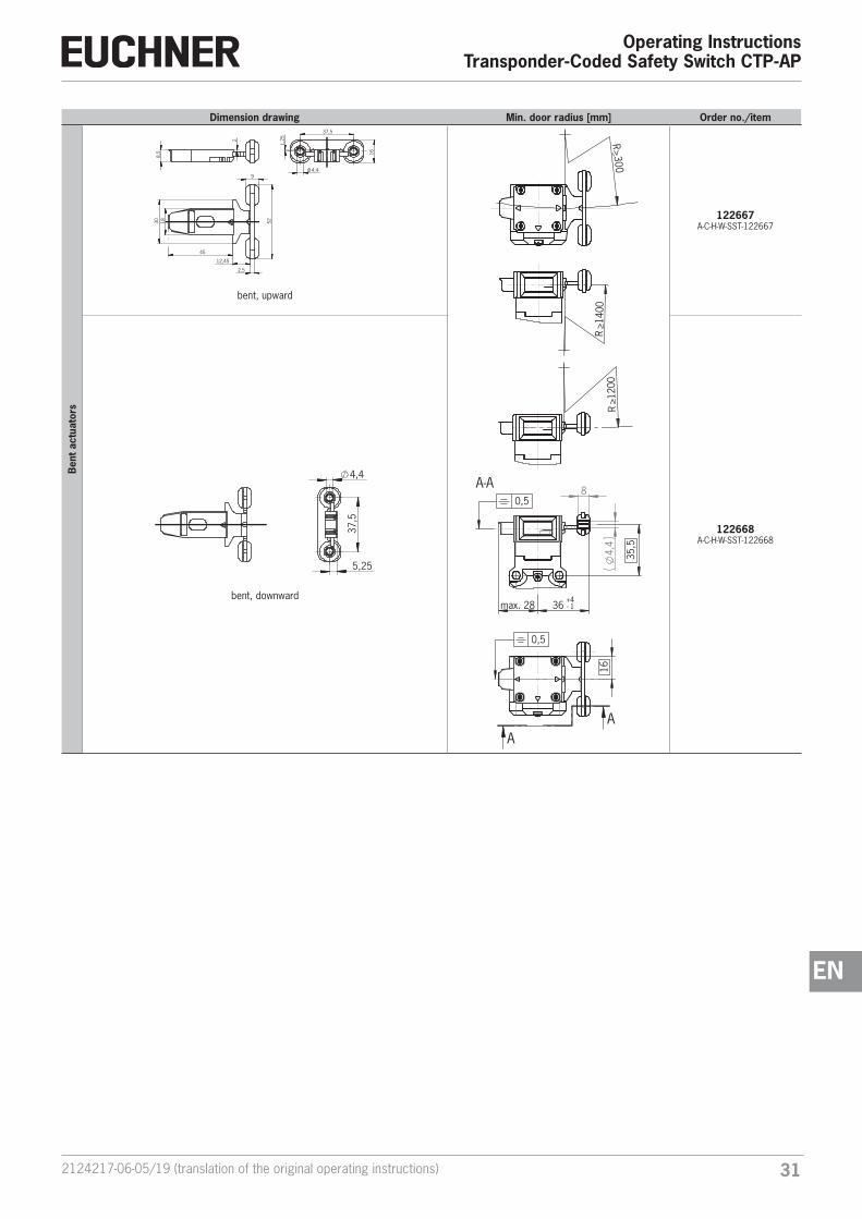
Ben
t act
uato
rs
8,5
2
12,45
2,5
9
18
30
52
4,4
37,5
1,2
5
16
45
bent, upward
R>300
0041>R
0021>R
16
AA
0,5
4,
4
8
35,5
max. 28 36 +-41
A-A0,5
122667A-C-H-W-SST-122667
37,
5
5,25
4,4
bent, downward
122668A-C-H-W-SST-122668
Operating InstructionsTransponder-Coded Safety Switch CTP-AP
32 (translation of the original operating instructions) 2124217-06-05/19
Dimension drawing Min. door radius [mm] Order no./item
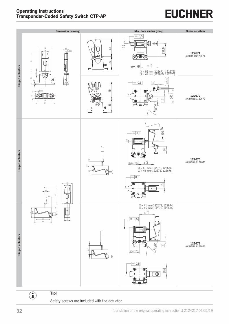
Hin
ged
actu
ator
s
4
12
35
45
18
30
40
50
14
5,5
8,5 3,25
35
45
16
4 5,
5
R>
200
40
0,5
33,5 1
max. 28 X +-41
X = 53 mm (122671, 122672)X = 49 mm (122669, 122670)
0,5
122671A-C-H-RL-LS-122671
35
45
122672A-C-H-RR-LS-122672
Hin
ged
actu
ator
s
40
50
5,
5 2
8
8,5
13,2
27
45
16
18 30
27
16
0,5
20
R>200
max. 28 X +-41
X = 41 mm (122673, 122674)X = 45 mm (122675, 122676)
0,5
122675A-C-H-RO-LS-122675
Hin
ged
actu
ator
s
27
16
0,5
7
max.28 R>
200
X +-41
X = 41 mm (122673, 122674)X = 45 mm (122675, 122676)
0,5
122676A-C-H-RU-LS-122676
Tip!
Safety screws are included with the actuator.
332124217-06-05/19 (translation of the original operating instructions)
Operating InstructionsTransponder-Coded Safety Switch CTP-AP
EN
14. Ordering information and accessoriesTip!
Suitable accessories, e.g. cables or assembly material, can be found at www.euchner.com. To order, enter the order number of your item in the search box and open the item view. Accessories that can be combined with the item are listed in “Accessories.”
15. Inspection and serviceWARNING
Danger of severe injuries due to the loss of the safety function. Ì If damage or wear is found, the complete switch and actuator assembly must be replaced. Re-placement of individual parts or assemblies is not permitted. Ì Check the device for proper function at regular intervals and after every fault. For information about possible time intervals, refer to EN ISO 14119:2013, section 8.2.
Regular inspection of the following is necessary to ensure trouble-free long-term operation: Ì Check the switching function (see chapter 11.3. Functional check on page 23) Ì Check all additional functions (e.g. escape release, lockout bar, etc.) Ì Check the secure fastening of the devices and the connections Ì Check for soiling
No servicing is required. Repairs to the device are only allowed to be made by the manufacturer.
NOTICE
The year of manufacture is given in the laser marking at the bottom right corner. The current version number in the format (V X.X.X) can also be found on the device.
16. ServiceIf service support is required, please contact:
EUCHNER GmbH + Co. KG
Kohlhammerstraße 16
70771 Leinfelden-Echterdingen
Service telephone:
+49 711 7597-500
E-mail:
Internet:
www.euchner.com
Operating InstructionsTransponder-Coded Safety Switch CTP-AP
34 (translation of the original operating instructions) 2124217-06-05/19
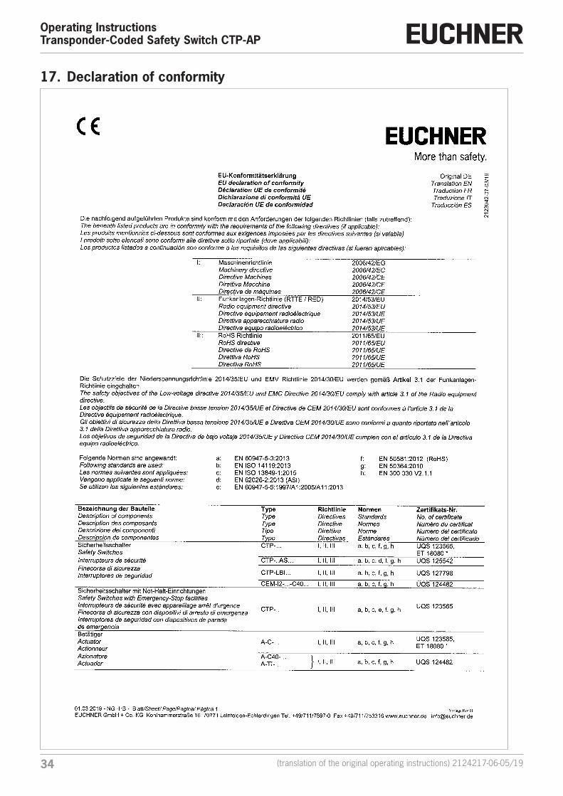
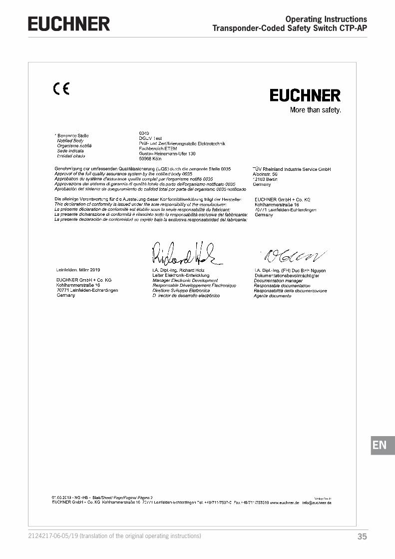
17. Declaration of conformity
352124217-06-05/19 (translation of the original operating instructions)
Operating InstructionsTransponder-Coded Safety Switch CTP-AP
EN

Euchner GmbH + Co. KGKohlhammerstraße 1670771 [email protected]
Edition:2124217-06-05/19Title: Operating Instructions Transponder-Coded Safety Switch CTP-AP (translation of the original operating instructions)Copyright:© EUCHNER GmbH + Co. KG, 05/2019
Subject to technical modifications; no responsibility is accept-ed for the accuracy of this information.
Related Documents