Operating & Instruction manual Electromagnetic Flowmeter Model : EMFF/EMFS Series (Integral Type / Remote Type) Valid for Software Versions B. 12 Valid for HART-Software Versions X. 30 ientek .Co., Ltd. Factor 2 (p)153-803 Daeryung Technotown 5th #407 493, Gasan-dong Gumcheon-Gu Seoul, Korea TEL : +82 (2) 2107-7999 FAX : +82 (2) 2107-7990 http:// www.flowcountry.com , E-mail: [email protected]

Welcome message from author
This document is posted to help you gain knowledge. Please leave a comment to let me know what you think about it! Share it to your friends and learn new things together.
Transcript

Operating & Instruction manual
Electromagnetic Flowmeter Model : EMFF/EMFS Series (Integral Type / Remote Type)
Valid for Software Versions B. 12 Valid for HART-Software Versions X. 30
ientek .Co., Ltd. Factor 2 (p)153-803 Daeryung Technotown 5th #407
493, Gasan-dong Gumcheon-Gu Seoul, Korea
TEL : +82 (2) 2107-7999 FAX : +82 (2) 2107-7990
http:// www.flowcountry.com , E-mail: [email protected]

Contents
1 Principle of Measurement, Flowmeter Primary and Converter Coordination ----------- 1
1.1 Abstract ----------- 1
1.2 Measurement Principle ----------- 1
1.3 Design ----------- 1
1.4 Flowmeter Primary and Converter Coordination ----------- 2
2 Assembly and Installation ----------- 3
2.1 Inspection ----------- 3
2.2
2.2.1
2.2.2
Transport General Transport of Flanged Instruments ≥DN 350 [14"] Foundation and Supports DN 350 [14"]
-----------
-----------
-----------
3
3
4
2.3 Installation Requirements ----------- 4
2.3.1 Recommended Installation Conditions ----------- 4
2.3.2 In- and Outlet Straight Sections ----------- 6
2.3.3 Installation of the Flowmeter Primary ----------- 7
2.3.4 Torque Values ----------- 8
2.3.5 Installations in Larger Size Pipelines ----------- 9
2.3.6 Meter Sizes, Pressure Ratings and Flow Ranges ----------- 10
3 Electrical Connections, Grounding ----------- 12
3.1
3.1.1
3.1.2
3.1.3
Grounding the Flowmeter Grounding Models EMF-EMFS_ and EMF-EMFS_ Grounding Instruments with Hard or Soft Rubber Liners Grounding for Instruments with Protection Plates
-----------
-----------
-----------
-----------
12
15
15
15
3.2 Signal and Excitation Cable Connections for Model EMFS (Remote Type), Special Requirements for Protection Class IP67
----------- 16
3.2.1 Signal and Excitation Cable Construction ----------- 16
3.2.2 Connection Area Flowmeter Primary ----------- 17
3.2.3 Assembly and Installation for Protection Class IP67 ----------- 19
3.2.4 Electrical Connection Area in the Converter ----------- 20
3.3 Interconnection Diagrams ----------- 22
3.3.1 Interconnection Diagram Integral Type, Connection Options for Analog Communication (incl. HART)
----------- 22
3.3.2 Interconnection Diagram Integral Type, Connection Options for Digital Communication (PROFIBUS DP, PROFIBUS PA, FOUNDATION Fieldbus, ASCII)
----------- 23
3.3.3 Interconnection Diagram Remote Type, Connection Options for Analog Communication (incl. HART)
----------- 24
3.3.4 Interconnection Diagram Remote Type, Connection Options for Digital Communication (PROFIBUS DP, PROFIBUS PA, FOUNDATION Fieldbus, ASCII)
----------- 25
3.3.5 Interconnection Diagram Remote Type(two cables), Connection Options for Analog Communication (incl. HART)
----------- 26
3.3.6 Interconnection Diagram Remote Type(two cables), Connection Options for Digital Communication (PROFIBUS DP, PROFIBUS PA, FOUNDATION Fieldbus, ASCII)
----------- 27
3.3.7 Connection Examples for Peripherals for Analog Communication (incl. HART) ----------- 28
3.3.8 Interconnection Examples for Peripherals for Digital Communication (PROFIBUS DP, PROFIBUS PA, FOUNDATION Fieldbus, ASCII-Protocol)
----------- 29
4 Start-Up ----------- 31
4.1 Preliminary Checks/Starting Up the Flowmeter System ----------- 31
4.1.1 Flowmeter Integral Type ----------- 31
4.1.2 Flowmeter Remote Type ----------- 31
4.2 System Zero Adjustment ----------- 32
4.3 Detector“Empty Pipe” ----------- 32
4.4 Converter Exchange ----------- 32
4.5 Socket Location for the Memory Module (external EEPROM) ----------- 33
4.6 Rotate Display / Rotate Housing ----------- 33

5 Setup the Converter ----------- 34
5.1 Initial value setup ----------- 34
5.2 Data Entry ----------- 35
5.3 Data Entry in“Condensed Form” ----------- 36
5.4 Parameter and Data Entry in“Condensed Form” ----------- 46
6 Parameter Entries ----------- 47
6.1 Range / Numeric Entry ----------- 48
6.2 Pulse Factor Forward and Reverse Flow Directions / numeric entry ----------- 48
6.3 Pulse Width / numeric entry ----------- 49
6.4 Filter (Noise Reduction) / entry from table ----------- 50
6.5 Density / numeric entry ----------- 51
6.6 System Zero Adj. / numeric entry ----------- 51
6.7 Submenu Unit ----------- 51
6.7.1 Range Unit / entry from table ----------- 52
6.7.2 Units Totalizer / entry from table ----------- 52
6.7.3 User Programmable Units ----------- 53
6.8 Submenu "Programmable In/Output" / entry from table ----------- 53
6.8.1 Function Terminals P7, G2 (Ux, P7 for PROFIBUS DP) ----------- 54
6.8.2 Terminals X1/G2 (not available with PROFIBUS PA/DP and FOUNDATION Fieldbus) ----------- 55
6.9 Submenu Function Test / numeric entry only for Iout ----------- 55
7 Error Messages ----------- 57
8
8.1
Maintenance and Repair General Information
-----------
-----------
58
58
9 Replaceable Parts List ----------- 60
9.1 Replaceable Parts List for Compact Design Instrument ----------- 60
9.2 Replaceable Parts for Flowmeter Primary ----------- 61
9.3
9.3.1
Replaceable Parts List for Converter E4 Field Mount Housing
-----------
-----------
62
62
10 Dimensions ----------- 63
10.1 Dimensions Converter Remote Type ----------- 63
11 Accuracy ----------- 64
12 Specifications Converter ----------- 65
13 Overview Parameter Settings and Flowmeter Design Options ----------- 66

1. Principle of Measurement, Flowmeter Primary and Converter Coordination
1.1. Abstract
The electromagnetic flowmeters(EMF) from ientek. Products are the ideal flowmeters for metering the
flow of all liquids, slurries and sludges that have a specific minimum electrical conductivity.
These flowmeters measure accurately, create no additional pressure drop, contain no moving or
protruding parts, are wear free and corrosion resistant.
Installations are possible in any existing piping system.
The ientek. Products EMF has proven itself over many decades and is the preferred flowmeter in the
Chemical, Pharmaceutical and Cosmetic industries, Municipal Water and Waste Water treatment facilities
and in the Food and Paper industries.
1.2. Measurement Principle
Faraday’s Laws of Induction form the basis for the electromagnetic flowmeter which states that a
voltage is generated in a conductor as it moves through a magnetic field.
This principle is applied to a conductive fluid which flows through the meter tube perpendicular to
the direction of the magnetic field (see Schematic). U E ~ B ·D ·V·K The voltage induced in the fluid is measured by two electrodes located diametrically opposite to each
other.
This signal voltage U E is proportional to the magnetic induction B, the electrode spacing D and the
average flow velocity v. Noting that the magnetic induction B and the electrode spacing D are
constant values indicates that a proportionality exists between the signal voltage U E and the average
flow velocity v. From the equation for calculating the volume flowrate*) U E ~ qv, it follows that
the signal voltage is linear and proportional to the volumetric flowrate.
Fig. 1 : Schematic of an Electromagnetic Flowmeter
1.3. Design
An electromagnetic flow metering system consists of a flowmeter primary and a converter.
The flowmeter primary is installed in the specified pipeline while the converter can be mounted
locally (Remote type) or at a central location. In the Compact Design (Integral type) the flowmeter
primary and converter constitute a single entity.
1

1.4. Flowmeter Primary and Converter Coordination
Compact Design Integral Type
The μP-converter and the flowmeter primary con-Statute a single mechanical entity.
Flowmeter primary with Aluminum housing: Models EMF-EMFF and EMF-EMFS
Flowmeter primary with a stainless steel housing: Model EMF-EMFF_
Integral Type
-EMFF -EMFS -EMFS -EMFF -EMFF
Flanged Wafer Multiple Process Connections Design Stainless Steel
Remote Design Remote Type
The μP-converter is mounted remote from the Flowmeter primary.
Cable lengths up to 50m are Permitted for conductivities above 5 μS/cm.
The electrical interconnection between the converter and flowmeter primary are made in
connection boxes using a single signal cable.
Flowmeter primary with Aluminum housing: Models EMF-EMFF and EMF-EMFS
Flowmeter primary with a stainless steel housing: Model EMF-EMFS
Remote Type
-EMFF -EMFS -EMFS -EMFF -EMFF
Flanged Wafer Multiple Process Connections
Design Stainless Steel
2

2. Assembly and Installation 2.1. Inspection
Before installing the electromagnetic flowmeter system, check for mechanical damage due to possible
mishandling during shipment. All claims for damage are to be made promptly to the shipper before
installing the flowmeter. 2.2. Transport General
Note when transporting the instrument to the meter installation site:
• the center of gravity may be off-center.
• the protection plates or caps mounted on the process connections for PTFE/PFA lined meters should
only be removed just prior to installing the instrument in the pipeline.
• care must be exercised to assure that the liner is not cut off or damaged during installation to
avoid leaks
• flanged meters should not be lifted by the converter housing or connection box.
• when transporting flanged instruments ≤DN 300 [12”] please use lifting straps and position them
around both process connections (Fig. 2).
Chains are to be avoided since they might damage the housing. Warning! The center of gravity of the complete instrument may be above the lifting points of the straps. Injury
may result if the instrument moves! Assure that the instrument does not unintentionally slip or rotate
during transport.
Fig. 2 : Transport of Flanged Instruments ≤DN 300 [12”]
2.2.1. Transport of Flanged Instruments ≥DN 350 [14"] Flanged instruments may not be lifted by the connection box. Exclusively use the lifting eye bolts on
the instrument to lift and position the flowmeter in the pipeline.
Attention! Do not lift using a fork truck in the middle of the housing for flanged meters.
The housing could be crushed and the internal coils may be damaged.
Fig. 3 : Transport of Flanged Instruments ≥DN 350[14”]
3
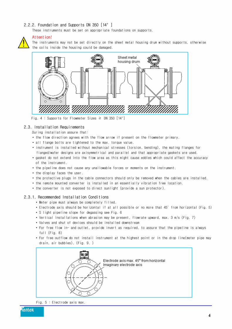
2.2.2. Foundation and Supports DN 350 [14" ] These instruments must be set on appropriate foundations on supports. Attention! The instruments may not be set directly on the sheet metal housing drum without supports, otherwise
the coils inside the housing could be damaged.
Fig. 4 : Supports for Flowmeter Sizes ≥DN 350 [14"] 2.3. Installation Requirements
During installation assure that:
• the flow direction agrees with the flow arrow if present on the flowmeter primary.
• all flange bolts are tightened to the max. torque value.
• instrument is installed without mechanical stresses (torsion, bending), the mating flanges for
flanged/wafer designs are axisymmetrical and parallel and that appropriate gaskets are used.
• gasket do not extend into the flow area as this might cause eddies which could affect the accuracy
of the instrument.
• the pipeline does not cause any unallowable forces or moments on the instrument.
• the display faces the user.
• the protective plugs in the cable connectors should only be removed when the cables are installed.
• the remote mounted converter is installed in an essentially vibration free location.
• the converter is not exposed to direct sunlight (provide a sun protector).
2.3.1. Recommended Installation Conditions • Meter pipe must always be completely filled.
• Electrode axis should be horizontal if at all possible or no more that 45°from horizontal (Fig. 5)
• S light pipeline slope for degassing see Fig. 6
• Vertical Installations when abrasion may be present, flowrate upward, max. 3 m/s (Fig. 7)
• Valves and shut of devices should be installed downstream
• For free flow in- and outlet, provide invert as required, to assure that the pipeline is always
full (Fig. 8)
• For free outflow do not install instrument at the highest point or in the drop line(meter pipe may
drain, air bubbles), (Fig. 9. )
Fig. 5 : Electrode axis max.
4

Fig. 6 : Installation in Horizontal Pipeline
Fig. 7 : Installation in Vertical Pipeline
Fig. 8 :
Fig. 9 :
5

2.3.2. In- and Outlet Straight Sections The measurement principle is independent of flow profile as long as standing eddies do not extend
into the measurement region (e.g. after double elbows, tangential inflows or half open valves
upstream of the flowmeter primary). In such situations measures to condition the flow are required.
Experience indicates that in most cases a straight upstream section with a length of 3 x D and a downstream section of 2 x D length are sufficient (D = flowmeter primary size) Fig. 10. For calibration stands the reference conditions of EN 29104 require straight lengths of 10 x D upstream
and 5 x D downstream.
Instruments for certified custody transfer applications special requirements apply.
Fig. 10 : Wafer valves are to be installed in such a manner that the wafer, when open, does not extend into the flowmeter. Valves or other shut off devices should be installed downstream. For highly contaminated fluids a bypass line Fig. 11, is recommended so that the during mechanical cleaning system operation need not be interrupted.
Fig. 11 : For flowmeter primaries which are to be installed in the vicinity of pumps or other vibration generating equipment, the utilization of mechanical snubbers is advantageous (Fig. 12).
Fig. 12 :
6

2.3.3. Installation of the Flowmeter Primary
The electromagnetic flowmeter can be installed at any arbitrary location in the pipeline as long
as the installation requirements are satisfied (see 2.3).
When selecting the installation site consideration should be given to assure that moisture cannot
enter into the electrical connection or converter areas. Make certain to carefully seat the gaskets and secure the covers after installation and start-up have been completed. Tighten the cable connectors.
The protective plugs in the cable connectors should only be removed when the cables are ready for installation.
The flowmeter primaries sizes DN 3 to DN 8 [1/10”to 5/16”] in the flanged design have a DN 10
[3/8”] connection flange. The diameter reduction to DN 3, 4, 6 or 8 [1/10”, 5/32”, 1/4”or
5/16”] is incorporated in the instrument.
As an option, flowmeter primaries sizes DN 3 to DN 8 [1/10”to 5/16”] are also available with a
DN 15 [1/2”] connection flange.
Information!
Graphite may not be used for the flange or process connection gaskets because, it might be possible,
that under certain conditions, an electrically conductive coating could form on the interior of the meter pipe. Vacuum shocks in the pipeline should be avoided to prevent possible damage to the liners
(PTFE) and destruction of the instrument. Gasket Surface on the Mating Flanges
In every installation it is essential that the material used for the gaskets for the parallel mating
flanges is suitable for the fluid and the operating conditions.
Only in this way will leaks be avoided. To assure optimum measurement results assure that the
flowmeter primary gaskets are correctly centered on the flanges.
Protection Plates
The protection plates are designed to prevent damage to the liners. They should not be removed until the meter is ready to be installed in the pipeline. Care must be exercised to assure that the liner is not cut off or damaged during installation to avoid leaks. Flange Bolt Tightening Torque The mounting bolts are to be tightened equally in the usual manner without excessive one-sided
tightening.
We recommend that the bolts be greased prior to tightening and that they be tightened in a
crisscross pattern as shown in Fig. 13. Tighten the bolts during the first pass to approx. 50 %,
during the second pass to approx. 80 % and only during the third pass to100 % of the max. torque
value. The max. torque values should not be exceeded, see the table below.
Fig. 13 :
7

2.3.4. Torque Values 2.3.4.1. Torque Specifications for Flanged Instruments
Table. 1
2.3.4.2. Torque Specifications for Wafer Design Instruments and Variable Process Connections
Table. 2
Liner
Meter Size DN Inch
Process Connection
Bolts
Torque max. Nm
Press. Ratingbar
PFA/PTFE/Hard rubber
3-10
15
20
25
32
40
50
65
80
100
1/10-3/8
1/2
3/4
1
1-1/4
1-1/2
2
2-1/2
3
4
Flange or
Wafer Design
4 x M12
4 x M12
4 x M12
4 x M12
4 x M16
4 x M16
4 x M16
8 x M16
8 x M16
8 x M16
8
10
16
21
34
43
56
39
49
47
40
40
40
40
40
40
40
40
40
16
PTFE/Hard rubber
125
150
200
250
300
350
400
5
6
8
10
12
14
16
Flange
8 x M16
8 x M20
12 x M20
12 x M24
12 x M24
16 x M24
16 x M27
62
83
81
120
160
185
250
16
16
16
16
16
16
16
PTFE/Hard rubber
500
600
700
800
900
1000
20
24
28
32
36
40
Flange
20 x M24
20 x M27
24 x M27
24 x M30
28 x M30
28 x M33
200
260
300
390
385
480
10
10
10
10
10
10
Liner
Meter Size DN Inch
Bolts
Torque max. Nm
Press. Rating bar
PFA 3 - 8 1/10-5/16 4 x M12 2.3 40
10
15
20
25
3/8
1/2
3/4
1
4 x M12
4 x M12
4 x M12
4 x M12
7.0
7.0
11.0
15.0
40
40
40
40
32
40
50
1-1/4
1-1/2
1
4 x M16
4 x M16
4 x M16
26.0
33.0
46.0
40
40
40
PFA
65
80
100
2-1/2
3
4
8 x M16
8 x M16
8 x M20
30.0
40.0
67.0
40
40
40
8

2.3.5. Installations in Larger Size Pipelines
The flowmeter can readily be installed in larger size pipe lines by using of reducers.
The pressure drop resulting from the reduction can be determined using the Nomograph Fig. 14 using
the following procedure: 1. Calculate the diameter ratio d/D. 2. Calculate the flow velocity as a function of the meter size and the flowrate.
The flow velocity can also be determined from the Flow Rate Nomograph (Fig. 15). 3. The pressure drop can be read on the -Y- axis at the intersection of the flow velocity curve and
the“Diameter Ratio d/D“ value on -X- axis in Fig. 14.
Fig. 14 : Nomograph for Pressure Drop Determination for EMF with Flanged Reducers, a/2 = 8°
d = Inside diameter of the EMF
D = Inside diameter of the pipeline
v = Flow velocity in (m/s)
∆p= Pressure drop in mbar
9

2.3.6. Meter Sizes, Pressure Ratings and Flow Ranges
Table. 3
Meter Size DN Inch
Std. Press. Rating PN
Min. Flow Range 0 to 0.5 m/s Flow Velocity
Max. Flow Range 0 to 10 m/s Flow Velocity
3
4
6
1/10
5/32
1/4
40
40
40
0
0
0
to
to
to
0.2
0.4
1
l/min
l/min
l/min
0
0
0
to
to
to
4
8
20
l/min
l/min
l/min
8
10
15
20
5/16
3/8
1/2
3/4
40
40
40
40
0
0
0
0
to
to
to
to
1.5
2.25
5.0
7.5
l/min
l/min
l/min
l/min
0
0
0
0
to
to
to
to
30
45
100
150
l/min
l/min
l/min
l/min
25
32
40
1
1-1/4
1-1/2
40
40
40
0
0
0
to
to
to
10
20
30
l/min
l/min
l/min
0
0
0
to
to
to
200
400
600
l/min
l/min
l/min
50
65
80
2
2-1/2
3
40
40
40
0
0
0
to
to
to
3
6
9
m3/h
m3/h
m3/h
0
0
0
to
to
to
60
120
180
m3/h
m3/h
m3/h
100
125
150
4
5
6
16
16
16
0
0
0
to
to
to
12
21
30
m3/h
m3/h
m3/h
0
0
0
to
to
to
240
420
600
m3/h
m3/h
m3/h
200
250
300
8
10
12
10/16
10/16
10/16
0
0
0
to
to
to
54
90
120
m3/h
m3/h
m3/h
0
0
0
to
to
to
1080
1800
2400
m3/h
m3/h
m3/h
350
400
450
500
14
16
18
20
10/16
10/16
10/16
10
0
0
0
0
to
to
to
to
165
225
300
330
m3/h
m3/h
m3/h
m3/h
0
0
0
0
to
to
to
to
3300
4500
6000
6600
m3/h
m3/h
m3/h
m3/h
600
700
800
24
28
32
10
10
10
0
0
0
to
to
to
480
660
900
m3/h
m3/h
m3/h
0
0
0
to
to
to
9600
13200
18000
m3/h
m3/h
m3/h
900
1000
36
40
10
10
0
0
to
to
1200
1350
m3/h
m3/h
0
0
to
to
24000
27000
m3/h
m3/h
10

Flowrate Nomograph
The flowrate is a function of the flow velocity of the fluid and the size the flowmeter.
The Flowrate Nomograph shows the flow ranges for each of the different flowmeter sizes as well as
the flowmeter sizes suitable for a specific flow range. Example: Flowrate = 7 m3/h (maximum flowrate = flow range end value). Suitable are flowmeter sizes DN 20
to DN 65 [3/4”to 2-1/2”] for flow velocities between 0.5 and 10 m/s.
Fig. 15 : Flowrate Nomograph DN 3 to DN 1000 [1/10”to 40”]
11

3. Electrical Connections, Grounding
3.1. Grounding the Flowmeter The grounding procedure described in this manual must be observed. Corresponding to VDE 0100, Part 540 the grounding screws on the flowmeter primary (on the flange and on the converter housing) are to be connected to earth with a copper wire whose cross section is at least 2.5 mm2. In order to comply with the EMC-Resistance/Low Voltage Regulations both the meter pipe of the flowmeter primary and the connection box or COPA-housing must be connected to earth. Please use the green/yellow cables included with the shipment for these connections. For measurement
reasons the earth potential should be identical to the potential of the pipeline. An additional
earth connection at the terminals in the connection box is not required.
For plastic pipelines or pipelines lined with insulating materials the fluid is grounded using
grounding plates or grounding electrodes. When there are stray currents in the pipeline it is
recommended that grounding plates be installed at both ends of the flowmeter primary.
In the following three different grounding schemes are described. In examples a) and b) the fluid
is in electrical contact with the pipeline. In example c) the fluid is insulated from the pipeline.
a) Metal pipeline with fixed flanges
1. Drill blind holes in the flanges on the pipeline (18 mm deep)
2. Thread holes, (M6, 12 mm deep). 3. Attach the ground strap to the flange using a screw (M6), spring washer and flat washer and connect to the ground connection on the flowmeter primary.
4. Connect a 2.5 mm2 CU wire between the ground connection on the flowmeter primary and a good earth.
Fig. 16 : Flowmeter Primary DN 3 - DN 100 [1/10”- 4”] Flanged
Fig. 17 : Flowmeter Primary DN 3 - DN 100 [1/10”- 4”] Wafer Design *) Use the green/yellow cable included with the shipment for these connections.
12

b) Metal Pipeline with Loose Flanges 1. In order to assure a trouble free ground connection to the fluid and the flowmeter primary in a pipeline with loose flanges, 6 mm threaded studs should be welded to the pipeline. 2. Attach the ground strap using a nut, spring washer and flat washer and connect to the ground connection on the flowmeter primary. 3. Connect a 2.5 mm2 CU wire between the ground connection on the flowmeter primary and a good earth.
Fig. 18 : Flowmeter Primary DN 3 - DN 100 [1/10”- 4”] Flanged
Fig. 19 : Flowmeter Primary DN 3 - DN 100 [1/10”- 4”] Wafer Design
*) Use the green/yellow cable included with the shipment for these connections.
13

c) Plastic, Concrete or Pipelines with Insulating Liners. 1. Install EMF in pipeline with a grounding plate. 2. Connect the connection tab on the grounding plate to the ground connection on the flowmeter primary with a ground strap. 3. Connect a 2.5 mm2 CU wire between the ground connection on the flowmeter primary and a good earth.
For plastic pipelines or pipelines with insulating liners the fluid is grounded using the grounding
plate as shown in Fig. 20 or using grounding electrodes, when installed in the flowmeter primary
(option). If grounding electrodes are installed the grounding plates shown Fig. 21 are not required.
When there are stray currents in the pipeline it is recommended that, if grounding plates are to be
used, to install one at both ends of the flowmeter primary.
Fig. 20 : Flowmeter Primary DN 3 - DN 100 [1/10”- 4”] Flanged
Fig. 21 : Flowmeter Primary DN 3 - DN 100 [1/10”- 4”] Wafer Design
*) Use the green/yellow cable included with the shipment for these connections.
14

3.1.1. Grounding Models EMF-EMFS_ and EMF-EMFS_
The ground connections are made as shown in Fig.22. The fluid is ground by the metal adapter pieces,
so that an additional ground is not required.
Fig. 22 : Flowmeter Primary DN3-DN100 [1/10”-4”]
3.1.2. Grounding Instruments with Hard or Soft Rubber Liners
In these Instruments, starting at meter size DN 125[5”], an electrically conductive element is
Integrated in the Liner. This element grounds the fluid.
3.1.3. Grounding for Instruments with Protection Plates
Fig. 23 : Protection Plates
The Protection plates protect the edges of the liners, e.g. for abrasive fluid. In addition they
also provide the Same function as a grounding plate. Connect these protection plates in the same
manner as the grounding plates when used with plastic pipelines or pipelines with electrically
insulated liners.
15

3.2. Signal and Excitation Cable Connections for Model EMFS(Remote Type), Special
Requirements for Protection Class IP67
The electromagnetic flowmeter primary is connected to the converter by a signal/excitation cable.
The magnet coils in the flowmeter primary are supplied from terminals M1/M2 in the converter with
an excitation voltage.
The signal/excitation cable is connected at the flowmeter primary to terminals 1, 2, M1, M2, 3,
SE. The terminal assignments are described in Fig. 25. The shield 3 is at the common potential of
the flowmeter primary and connected to earth. The ground connection on the exterior of the
connection box of the flowmeter primary should also be connected to earth.
3.2.1. Signal and Excitation Cable Construction
The signal/excitation cable conducts signals of only a few millivolts and should therefore be
routed in the shortest manner. The maximum allowable signal cable length is 50 m.
Fig. 24 : Signal Cable Construction
1 Jacket of PVC, white
2 Steel wire weave
3 Cu wire weave
4 Flow signal, jacket red and blue
5 Excitation, jacket white
6 Each 1x shielded, Cu wire weave
7 Polyethylene, natural
16

Fig. 25 :
The cables should not be routed in the vicinity of large electrical machinery or switch gear
equipment which could induce stray fields, pulses and voltages. All leads are to be surrounded
by shields connected to earth.
The signal cable should not be fed through branch fittings or terminals strips. A shielded
excitation cable(white) is located parallel to the signal leads (red and blue) in the cable
assembly so that only one cable is required between the flowmeter primary and the converter.
Attention!
If plant conditions make it impossible to avoid proximity to electrical machinery or switch
gear equipment, it is advisable to route the signal/excitation cable in metallic conduits which
are connected to earth.
3.2.2. Connection Area Flowmeter Primary
The leads of the signal/excitation cable are to be routed in the shortest way to the connection
terminals. Loops are to be avoided (see Fig. 26)
Fig. 26 : Flowmeter Primary Connection Area
17

3.2.2.1. Using the Spring Loaded Connection Terminals
Fig. 27 :
Information!
When installing the signal/excitation cable assure that a water trap is provided, (Fig. 28).
For vertical installations the cable connectors should point downward.
When reinstalling and tightening the housing cover care should be exercised.
Check to make sure that the gaskets are seated properly. Only then will the Protection Class
be effective.
Fig. 28 : Cable Routing
18

3.2.3. Assembly and Installation for Protection Class IP67
There are 2 different designs available.
3.2.3.1. Design with Hose Connection
For flowmeter primaries for use in Protection Class IP67 areas the max. submergence depth is 5m.
In place of the cable connectors a connector surrounded by a hose is used. The signal/excitation
cable must be Routed through the 1/2”hose from the connection box to a point above the maximum
submergence level(Fig.29).
Above the submergence level the water tight connector included with the shipment is installed on
the cable. Then the hose is sealed to the hose connector with a threaded clamp.
Finally, the connection box must be carefully closed.
Fig. 29 : Installation IP67(Hose Connection)
3.2.3.2. Design without Hose Connection
Two signal cables are to be used to connect flowmeter primary and the converter(see Fig 38, 39).
After the connections have been made, the cable connectors are to be tightened and the connection
box carefully dosed. The jacket of the signal cable may not be damaged.
Only then will Protection Class IP67 for the flowmeter primary be assured.
19

3.2.4. Electrical Connection Area in the Converter
3.2.4.1. Remote Type
Fig. 30 : Connection Box Field Mount Housing
Attention!
The supply power connections must be made in agreement with the specifications on the type tag on
the converter at terminals L (Phase) and N (Neutral) or 1+ and 2. through a main fuse and a main
switch.
Using the Spring Loaded Connection Terminals Remote Type Converter
Fig. 31 :
20

3.2.4.2. Integral Type
Fig. 32 : Connection Box
Using the Spring Loaded Connection Terminals Integral Type
Fig. 33 :
21

3.3. Interconnection Diagrams
3.3.1. Interconnection Diagram Integral Type, Connection Options for Analog Communication
(incl. HART)
Fig. 34 : Interconnection Diagram integral Type, Connection Options for Analog Communication
(incl. HART)
1) a) Scaled pulse output, passive, pulse width settable from 0.1 ms to 2000 ms,
Terminals: V8, V9, function E9, C9
Optocoupler specifications:
fmax 5 kHz
0 V ≤UCEL ≤2 V, 16 V ≤UCEH ≤30 V
0 mA ≤ICEH ≤0.2 mA, 2 mA ≤ICEL ≤220 mA
b) Scaled pulse output, active, pulse width settable from 0.1 to 2000 ms,
terminals V8, V9, function 9, 10
20 mA < I ≤150 mA; fmax ≤4 Hz, pulse width ≤50 ms, pulse T16V ≤25 ms,
16 V ≤U ≤30 V;
On/off ratio 1:4 (Ton : Toff),
fmax 5 kHz, 2 mA ≤I ≤20 mA; 16 V ≤U ≤30 V 2) Contact output, function selectable in software as system monitor, empty pipe,
Max.-Min.-Alarm or F/R signal*, terminals G2, P7
Optocoupler specifications:
0 V ≤UCEL ≤2 V, 16 V ≤UCEH ≤30 V;
0 mA ≤ICEH ≤0.2 mA, 2 mA ≤ICEL ≤220 mA 3) Contact input, function selectable in software as external zero return, external
totalizer reset, external totalizer stop
Terminals: G2, X1
Optocoupler, 16 V ≤U ≤30 V, Ri = 2kΩ 4) Current output selectable, terminals: +/-, load ≤600 Ωfor 0/4 to 20 mA,
Load ≤1200 Ωfor 0/2 to 10 mA,
Load ≤2400 Ωfor 0 to 5 mA,
Option: HART-Protocol 5) Supply power, see Type Tag
*) When shipped the function forward direction signal was selected.
22

3.3.2. Interconnection Diagram Integral Type, Connection Options for Digital Communication
(PROFIBUS DP, PROFIBUS PA, FOUNDATION Fieldbus, ASCII)
Fig. 35 : Interconnection Diagram integral Type, Connection Options for Digital Communication
Design a) Terminals PA+, PA-
Connection for PROFIBUS PA per IEC 61158-2 (Profile 3.0),
U = 9-32 V, I = 13 mA (normal operation); 17 mA (during fault condition / FDE)
Design b) Terminals Ux, V8
Scaled pulse output, passive (optocoupler), pulse width settable from 0.1 ms to
2000 ms, Optocoupler specifications:
fmax 5 kHz
0 V ≤UCEL ≤2 V, 16 V ≤UCEH ≤30 V;
0 mA ≤ICEH ≤0.2 mA, 2 mA ≤ICEL ≤220 mA
Terminals Ux, P7
Contact output, function selectable in software as system monitor, empty pipe,
Max.-Min.-Alarm or F/R signal
Optocoupler specifications:
0 V ≤UCEL ≤2 V, 16 V ≤UCEH ≤30 V;
0 mA ≤ICEH ≤0.2 mA, 2 mA ≤ICEL ≤220 mA
Terminals A, B
Serial data link RS485 for communication using ASCII-Protocol
Terminals +, -
Current output, terminals: +/-, load ≤600 Ωfor 0/4 to 20 mA Design c)
Same as design b), except
Terminals +VD, A, B, GND
Connection for PROFIBUS DP per EN 50170 Design d) Terminals FF+, FF-
Connection for FOUNDATION Fieldbus (H1) per IEC 61158-2,
U = 9-32 V, I = 13 mA (normal operation); 17 mA (during fault condition / FDE) Supply power
see Type Tag
a) PROFIBUS PA (Profile 3.0)
b) RS485 (ASCII Protocol)
c) PROFIBUS DP
d) FOUNDATION Fieldbus
23

3.3.3. Interconnection Diagram Remote Type, Connection Options for Analog Communication
(incl. HART)
Fig. 36 : Interconnection Diagram Remote Type, Connection Options for Analog Communication
(incl. HART)
1) a) Scaled pulse output, passive, pulse width settable from 0.1 ms to 2000 ms,
Terminals: V8, V9, function E9, C9,
Optocoupler specifications:
fmax 5 kHz
V ≤UCEL ≤2 V, 16 V ≤UCEH ≤30 V
0 mA ≤ICEH ≤0.2 mA, 2 mA ≤ICEL ≤220 mA
b) Scaled pulse output, active, pulse width settable from 0.1 to 2000 ms,
terminals V8, V9, function 9, 10
20 mA < I ≤150 mA; fmax ≤4 Hz, pulse width ≤50 ms, pulse T16V ≤25 ms,
16 V ≤U ≤30 V
On/off ratio 1:4 (Ton : Toff), fmax 5 kHz, 2 mA ≤I ≤20 mA; 16 V ≤U ≤30 V 2) Contact output, function selectable in software as system monitor, empty pipe,
Max.-Min.-Alarm or F/R signal*, terminals G2, P7
Optocoupler specifications:
0 V ≤UCEL ≤2 V, 16 V ≤UCEH ≤30 V;
0 mA ≤ICEH ≤0.2 mA, 2 mA ≤ICEL ≤220 mA 3) Contact input, function selectable in software as external zero return, external
totalizer reset, external totalizer stop
Terminals: G2, X1
Optocoupler, 16 V ≤U ≤30 V, Ri = 2kΩ 4) Current output selectable, terminals: +/-, load ≤600 Ωfor 0/4 to 20 mA,
Load ≤1200 Ωfor 0/2 to mA, load ≤2400 Ωfor 0 to 5 mA
Option: HART-Protocol 5) Supply power, see Type Tag
*) When shipped the function forward direction signal was selected.
24

3.3.4. Interconnection Diagram Remote Type, Connection Options for Digital Communication
(PROFIBUS DP, PROFIBUS PA, FOUNDATION Fieldbus, ASCII)
Fig. 37 : Interconnection Diagram Remote Type, Connection Options for Digital Communication
(PROFIBUS DP, PROFIBUS PA, FOUNDATION Fieldbus, ASCII)
Design a) Terminals PA+, PA- Connection for PROFIBUS PA per IEC 61158-2 (Profile 3.0),
U = 9-32 V, I = 13 mA (normal operation); 17 mA (during fault condition / FDE)
Design b) Terminals Ux, V8 Scaled pulse output, passive (optocoupler), pulse width settable from 0.1 ms to
2000 ms,
Optocoupler specifications: fmax 5 kHz
0 V ≤UCEL ≤2 V, 16 V ≤UCEH ≤30 V;
0 mA ≤ICEH ≤0.2 mA, 2 mA ≤ICEL ≤220 mA
Terminals Ux, P7
Contact output, function selectable in software as system monitor, empty pipe,
Max.-Min.-Alarm or F/R signal
Optocoupler specifications:
0 V ≤UCEL ≤2 V, 16 V ≤UCEH ≤30 V;
0 mA ≤ICEH ≤0.2 mA, 2 mA ≤ICEL ≤220 mA
Terminals A, B
Serial data link RS485 for communication using ASCII-Protocol
Terminals +, -
Current output, terminals: +/-, load ≤600 Ωfor 0/4 to 20 mA Design c)
Same as design b), except
Terminals +VD, A, B, GND
Connection for PROFIBUS DP per EN 50170 Design d) Terminals FF+, FF-
Connection for FOUNDATION Fieldbus (H1) per IEC 61158-2,
U = 9-32 V, I = 13 mA (normal operation); 17 mA (during fault condition / FDE) Supply power
see Type Tag
25

3.3.5. Interconnection Diagram Remote Type(two cables), Connection Options for Analog
Communication(incl. HART)
Fig. 38 : Interconnection Diagram Remote Type(two cables), Connection Options for Analog
Communication (incl. HART)
1) a) Scaled pulse output, passive, pulse width settable from 0.1 ms to 2000 ms,
Terminals; V8,V9, function E9,C9,
Optocoupler specifications;
fmax 5KHZ
0 V ≤UCEL ≤2 V, 16 V ≤UCEH ≤30 V
0 mA ≤ICEH ≤0.2 mA, 2 mA ≤ICEL ≤220 mA
b) Scaled pulse output, active, pulse width settable from 0.1 to 2000 ms,
terminals V8, V9, function 9, 10
20 mA≤I≤150mA;fmax≤4Hz, pulse width ≤ 50ms, pulse T16V≤25ms, 16V≤U ≤30V
On/off ratio 1:4(Ton:Toff), fmax 5 KHz, 2 mA ≤ I ≤ 20 mA; 16 V ≤ U ≤ 30 V 2) Contact output, function selectable in software as system monitor, empty pipe,
Max.-Min.-Alarm or F/R signal*, terminals G2,P7
Optocoupler specifications;
0 V ≤ UCEL ≤ 2 V, 16 V ≤ UCEH ≤ 30 V;
0 mA ≤ ICEH ≤ 0.2 mA, 2 mA ≤ ICEL ≤ 220 mA 3) Contact input, function selectable in software as extemal zero return, extemal
totalizer reset, extemal totalizer stop
Terminals: G2, X1
Optocoupler, 16 V ≤U ≤30 V, Ri = 2 kΩ 4) Current output selectable, terminals: +/-, load ≤600 Ωfor 0/4 to 20 mA,
Load ≤ 1200 Ω for 0/2 to mA, load ≤ 2400 Ω for 0 to 5 mA
Option: HART-Protocol
5) Supply power, see Type Tag
*) When shipped the function forward direction signal was selected.
26

3.3.6. Interconnection Diagram Remote Type(two cables), Connection Options for Digital
Communication (PROFIBUS DP, PROFIBUS PA, FOUNDATION Fieldbus, ASCII)
Fig. 39 : Interconnection Diagram Remote Type(two cables), Connection Options for Digital
Communication (PROFIBUS DP, PROFIBUS PA, FOUNDATION Fieldbus, ASCII)
Design a) Terminals PA+, PA- Connection for PROFIBUS PA per IEC 61158-2 (Profile 3.0),
U = 9-32 V, I = 13 mA (normal operation); 17 mA (during fault condition / FDE)
Design b) Terminals Ux, V8 Scaled pulse output, passive (optocoupler), pulse width settable from 0.1 ms to
2000 ms,
Optocoupler specifications: fmax 5 kHz
0 V ≤UCEL ≤2 V, 16 V ≤UCEH ≤30 V;
0 mA ≤ICEH ≤0.2 mA, 2 mA ≤ICEL ≤220 mA
Terminals Ux, P7
Contact output, function selectable in software as system monitor, empty pipe,
Max.-Min.-Alarm or F/R signal
Optocoupler specifications:
0 V ≤UCEL ≤2 V, 16 V ≤UCEH ≤30 V;
0 mA ≤ICEH ≤0.2 mA, 2 mA ≤ICEL ≤220 mA
Terminals A, B
Serial data link RS485 for communication using ASCII-Protocol
Terminals +, -
Current output, terminals: +/-, load ≤600 Ωfor 0/4 to 20 mA Design c)
Same as design b), except
Terminals +VD, A, B, GND
Connection for PROFIBUS DP per EN 50170 Design d) Terminals FF+, FF-
Connection for FOUNDATION Fieldbus (H1) per IEC 61158-2,
U = 9-32 V, I = 13 mA (normal operation); 17 mA (during fault condition / FDE) Supply power
see Type Tag
27

3.3.7. Connection Examples for Peripherals for Analog Communication (incl. HART)
Fig. 40 : Connection Examples for Peripherals for Analog Communication (incl. HART)
Current Output
Pulse Output (optocoupler) Pulse Output (active)
Contact Input for External Zero Return or External Totalizer Reset
Function selectable in software
Ri = 2kΩ Ri = 2kΩ
Contact Output e.g. for System Pulse Output (passive optocoupler),
Monitor, Max.-Min.-Alarm, Empty Separate Forward and Reverse Pulses
Pipe or Forward/Reverse Signal over Contact Output
0/4-20 mA
0/2-10 mA
0-5 mA
0-10, 10-20 mA
4-12, 12-20 mA
0/4-20 mA load: max. 600 Ohm
0/2-10 mA load: max. 1200 Ohm
0 - 5 mA load: max. 2400 Ohm
Contact settings:
Output is turned off
when contact is closed.
Contact settings:
internal totalizer is reset,
when contact is closed.
28
Function selectable in software

3.3.8. Interconnection Examples for Peripherals for Digital Communication
(PROFIBUS DP, PROFIBUS PA, FOUNDATION Fieldbus, ASCII-Protocol)
Fig. 41 : Connection Examples for Peripherals for Digital Communication (PROFIBUS DP, PROFIBUS PA,
FOUNDATION Fieldbus, ASCII-Protocol)
Current Output (only available for ASCII-Communication) 0/4-20 mA load: max. 600 Ohm
Pulse Output and Contact Output Circuit example for separate pulses for forward
(only available for PROFIBUS DP or and reverse directions using the contact output
ASCII Protocol)
Contact output Ux / P7 For system monitor, max.-min.-Alarm, empty pipe or forward /reverse signal,
function selectable in software
Pulse output optocoupler Ux/V8
29

Fig. 42 : Connection Examples for Peripherals for Digital Communication
(PROFIBUS DP, PROFIBUS PA, FOUNDATION Fieldbus, ASCII)
PROFIBUS DP Data link RS485 (ASCII Protocol)
The resistors R1, R2, R3 are bus termination 2-wire data link, half-duplex, max.
resistors. They are to be installed if the cable length: 1200 m, max. 32
instrument is connected at the end of the bus cable. instruments in parallel on bus
R1 = 390 Ω;R2 = 220 Ω;R3 = 390 Ω twisted pair cable.
PROFIBUS PA / FOUNDATION Fieldbus The resistor R and the capacitor C form the bus termination. They are to be installed if the instrument is connected at the end of the bus cable.
R = 100 Ω;C = 1 F
Connection Example for PROFIBUS PA using M12 plug
Connection using M12 plug (only for PROFIBUS PA) As an option, the bus connection can be made using a M12 plug instead of a cable connector
(see Ordering Information for the instrument).
The instrument is then shipped completely wired. Suitable sockets (Type EPG300) as well as
other accessories may be found in the List Sheet 10/63.6.44 S E.
30

4. Start-Up 4.1. Preliminary Checks/Starting Up the Flowmeter System 4.1.1. Flowmeter Integral Type
The start-up procedure described below is to be used after the assembly and installation of the
flowmeter have been completed.
The supply power is turned off.
• Check the grounds.
• Check that the temperature limits were not exceeded.
• Check connections based on the Interconnection Diagrams.
• Assure that the supply power values agree with those specified on the type tag.
• The connections for the supply power in the COPA-XE are located under the semicircular cover in
the connection area!
Turn on supply power!
• After the supply power is turned on, the flowmeter primary data stored in the external EEPROM are
compared to the values stored internally. If the data are not identical, an automatic exchange of
the data in the converter is initiated (upload). The converter displays the message“Primary data
are loaded”. The system is now operational.
• The display indicates the instantaneous flowrate value.
• In order to set up the system only a few entries or selections of parameters must be made.
The flow range is automatically set to 10 m/s. Enter the desired flow range in the submenu“Range
“. Hydraulically ideal range end values are equivalent to ca. 2-3 m/s. In the submenu“current
output”the required current range can be selected. For the pulse output the pulse factor
(pulses per unit) and the pulse width should be entered in the submenu“Totalizer”.
(see Section 5)
• The system zero value should be checked (see Section 4.2).
• To finish the start-up procedure, the menu“Store data in external EEPROM”should be called in
order to store all the settings which were made during the start-up. If the converter was
exchanged, then the EEPROM is to be removed from the old converter and plugged into the new one
(see Section 4.4). 4.1.2. Flowmeter Remote Type
The start-up procedures described below are to be used after the assembly and installation of the
flowmeter primary and the converter.
The supply power is turned off.
• Assure that the supply power values agree with those specified on the type tag.
• Check if the converter is installed in an essentially vibration free location.
• Check that the ambient temperature limits for the converter are not exceeded (-20 °C and +60 °C).
• Check for proper coordination between the flowmeter primary and the converter.
• Check that the EEPROM is plugged into the socket on the display board of the converter
(see Fig. 43). There is a sticker on this EEPROM which has the same order and end numbers as those
listed on the factory tag of the flowmeter primary. Both must be identical!
Turn on supply power.
• After the supply power is turned on the flowmeter primary data stored in the external EEPROM are
compared to the values stored internally. If the data are not identical, an automatic exchange of
the data in the converter is initiated (upload). The converter displays the message“Primary data
are loaded”. The system is now operational.
• The display indicates the instantaneous flowrate value.
• In order to set up the system only a few entries or selection of parameters must be made. The flow
range is automatically set to 10 m/s. Enter the desired flow range in the submenu“Range”.
Hydraulically ideal range end values are equivalent to ca. 2-3 m/s. In the submenu“Current
31

output”the required current range can be selected. For the pulse output the pulse factor
(pulses per unit) and the pulse width should be entered in the submenu“Totalizer”.
(see Section 5)
• The system zero value should be checked (see Section 4.2).
• To finish the start-up procedure, the menu“Store data in external EEPROM”should be called,
in order to store all the settings which were made during the start-up. If the converter was
exchanged, then the EEPROM is to be removed from the old converter and plugged into the new one
(see Section 4.4).
4.2. System Zero Adjustment
The System-Zero for the system is set in the converter. To check or adjust the zero the flow in
the pipeline must be at absolute zero and the pipeline must be completely filled.
Using the parameter“System Zero Adj.”the adjustment can be made manually or automatically:
Select parameter using ENTER, use the arrow keys to select“manual”or“automatic”.
For an automatic“adjustment”, initiate the procedure using ENTER. After the counter displayed in
the 2nd line counts down from 255 to 0 the adjustment procedure is finished. The adjustment takes
approx. 20 seconds, see also Section 6.6.
Start-up of PROFIBUS PA/DP Instruments
A detailed description of the data link communication may be found in the separate Operation Manuals.
For PROFIBUS PA: Part No. D184B093U11
For PROFIBUS DP: Part No. D184B093U09
These data link descriptions are included with the shipment of the PROFIBUS instrument including
the GSD File.
4.3. Detector“Empty Pipe”
At start-up the detector empty pipe must be adjusted for the existing operating conditions.
For adjustment procedure see Section 5.
Attention!
After the start-up has been completed, assure that the housing cover has been tightly closed and
can only be opened using the special tool.
4.4. Converter Exchange
The parameter settings are stored in an external EEPROM which is located on the display board.
When an electronic module is exchanged, the original parameter settings can be transferred by
installing the old EEPROM in the new converter. Converter specific data is automatically updated.
32

4.5. Socket Location for the Memory Module (external EEPROM)
The socket for the ext. EEPROM is located on the front of the display board.
Fig. 43 : Display Board
Attention!
Information for Opening the Housing
The following information must be observed when the housing for the converter is opened;
• All connections must be potential free.
• When the housing cover is removed, EMC and personnel protection are no longer provided.
4.6. Rotate Display/Rotate Housing
Warning!
Turn off the supply power!
Unscrew the housing cover. The display board is secured by 4 Phillips head screws.
After the screws are removed the display can be pulled off and rotated 90°to the left or 90°to
the right, Carefully plug in the display again and reinstall the screws. Carefully reinstall the
cover. Check that the gaskets are properly seated. Only then will Protection Class IP67 be
maintained.
The converter housing can be rotated 90°to the left after the two screws have been loosened.
Fig. 44 :
33

5. Setup the Converter
5.1. Initial value setup When the supply power is turned on the Model Number of the converter is displayed
In the first line together with the software version and revision level in the
second line. The process information for the flowmeter is then displayed. In the first line the present flow direction (→F for forward or ←R for reverse)
and the instantaneous flowrate value in percent or direct reading engineering units
is displayed. The totalizer value (7 digits) for the present flow direction is
displayed with its units. The totalizer value displayed is always the actual measured flow in its units
regardless of the pulse factor value. This display format is called Process
Information in the following text. The totalizer value for the other flow direction can be displayed by pressing the
STEP or DATA key.
1st line Instantaneous forward flowrate value
2nd line Forward totalizer value 1st line Instantaneous forward flowrate value
2nd line Reverse totalizer value (multiplex operation)
1st line Instantaneous forward flowrate value
2nd line Reverse totalizer value (multiplex operation)
A totalizer overflow is always registered when the totalizer value reaches
10,000,000 units. When the totalizer value in a flow direction exceeds 9,999,999
units, the flow direction indicators (→F or ←R) and the totalizer units in the
2nd line blink. The software can record up to 250 totalizer overflows. The overflow
message can be cleared independently for each flow direction using ENTER.
During an error condition an error message is displayed in the 1st line. The display alternates between a clear text message and the error code. During the
clear text message display only the error with the highest priority is shown.
In the alternate display the error codes for all the detected errors are shown.
Error Code Table Listed by Priority
In addition to displaying an error message the alarm output is activated over the
optocoupler and the current output is set to its programmed alarm value (submenu
“lout at Alarm”) (does not apply to Error 6).
Error
Codes Clear Text Cause
0
1
2
3
4
5
6
7
8
9
A
B
C
Empty pipe
A/D saturated
Uref too small
Flow >130 %
Ext. zero return
RAM invalid
Totalizer
Urefp too large
Urefn too large
Excit. frequency
Max. Alarm
Min. Alarm
Primary data
Pipeline not filled.
A/D-Converter saturated.
Pos. or. neg. reference too small.
Flowrate greater than 130 %.
Ext. zero contact activated.
Data in RAM invalid.
Totalizer value invalid.
Positive reference too large
Negative reference too large
Supply power frequency or driver/digital board error.
Flowrate above max. alarm limit.
Flowrate below min. alarm limit.
Error in external EEPROM or module not installed.
34
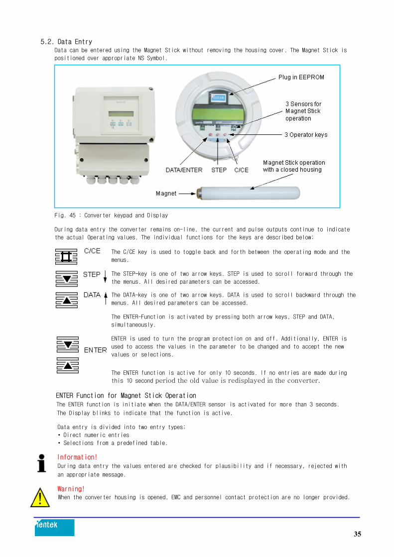
5.2. Data Entry Data can be entered using the Magnet Stick without removing the housing cover. The Magnet Stick is
positioned over appropriate NS Symbol.
Fig. 45 : Converter keypad and Display
During data entry the converter remains on-line, the current and pulse outputs continue to indicate
the actual Operating values. The individual functions for the keys are described below;
The C/CE key is used to toggle back and forth between the operating mode and the
menus.
The STEP-key is one of two arrow keys. STEP is used to scroll forward through the
the menus. All desired parameters can be accessed. The DATA-key is one of two arrow keys. DATA is used to scroll backward through the
menus. All desired parameters can be accessed.
The ENTER-Function is activated by pressing both arrow keys, STEP and DATA,
simultaneously.
ENTER is used to turn the program protection on and off. Additionally, ENTER is
used to access the values in the parameter to be changed and to accept the new
values or selections.
The ENTER function is active for only 10 seconds. If no entries are made during
this 10 second period the old value is redisplayed in the converter.
ENTER Function for Magnet Stick Operation The ENTER function is initiate when the DATA/ENTER sensor is activated for more than 3 seconds.
The Display blinks to indicate that the function is active. Data entry is divided into two entry types;
• Direct numeric entries
• Selections from a predefined table.
Information! During data entry the values entered are checked for plausibility and if necessary, rejected with an appropriate message.
Warning! When the converter housing is opened, EMC and personnel contact protection are no longer provided.
35

5.3. Data Entry in“Condensed Form”
Action → Use Keys = Display Information ↓ ↓ ↓ Starting basis - “Process information” ↓ ↓ ↓ Examples: Change Range F(numeric) C/CE Change Current Output(table) ↓ ↓ ↓ Find parameter STEP “Program protection” or DATA
↓ ↓ ↓ “Program protection” ENTER
Direct Numeric Entry Selection from a Table Action → Use Keys = Display Information Action → Use Keys = Display Information
↓ ↓ ↓ ↓ ↓ ↓
Find STEP Find submenu STEP Parameter or DATA “Current output” or DATA “Range” ↓ ↓ ↓ ↓ ↓ ↓
Change ENTER Change Parameter Parameter ENTER “Range” “Current output” ↓ ↓ ↓ ↓ ↓ ↓ Change Current output ENTER from 0-20 mA to 4-20 mA ↓ ↓ ↓ 6 x DATA 6 STEP Find desired 2 x DATA 2 current output STEP STEP range in table or DATA Enter the 4 x DATA 4 Find 4- 20 mA desired STEP 0 ↓ ↓ ↓ numbers in STEP Accept new ENTER sequence 10 x DATA, current output range STEP 0 STEP 0 Accept new Range ENTER value
Exit from Range STEP or Current Output. or DATA Find Parameter ↓ “Program Protection” ↓ ↓ Turn Program Protection ENTER on again ↓ ↓ ↓ End basis C/CE Process information (Converter remained online)
36

5.4. Parameter and Data Entry in“Condensed Form”
Submenu/Parameter Entry Type Comments from table/numeric Data can be entered only after the Program Protection has been turned off. on/off
If a number other than“0”(factory default setting)
has been programmed for the Prog. Prot. Code, the Program Protection can only be turned off after the correct PP-Code (1-255) has been entered. After the Prog. Protection has been turned off,
parameters can be changed.
numeric After the Prog. Protection has been turned off it is
possible to change the PP-Code. Enter the old PP-Code 0 = factory default setting
Enter new PP-Code(0-255) and press ENTER to activate. The new PP-Code is now active. German, English, French, Finnish, Spanish, Italian, from table Dutch, Danish, Swedish. For HART-Protocol, PROFIBUS PA, FOUNDATION Fieldbus only German, English In this submenu parameters other than the meter size for the flowmeter primary are located. These cannot be changed. Their values are listed on the factory tag of the flowmeter primary.
They must be identical!
Actual meter size, see factory tag on flowmeter primary
Flowmeter primary span value Cs for the selected
excitation frequency, see factory tag on flowmeter
primary Flowmeter primary zero value Cz for the selected excitation frequency, see factory tag on flowmeter
primary
Short Model Number of the flowmeter primary
Order number of the flowmeter primary. This number
must be identical to the value on the factory tag and
on the sticker located on the external EEPROM plugged
in above the display.
37

Submenu/Parameter Entry Type Comments numeric Cal-factor is the flowrate value at 10 m/s flow velocity. The Cal-factor is automatically selected when the flowmeter size is selected. Flow range for the forward and reverse flow directions. Min. flow range setting is 0 - 0.5 m/s (0-0.05 Cal-fact) Max. flow range setting is 0 - 10 m/s (0-1 Cal-fact) The flow range end value can be entered anywhere between 0.5 and 10 m/s. The units are selected in the submenu Unit. (See also Section 6.7) For int. and ext. flow totalization, range 0.001-1000 pulse per selected unit, max. count frequency 5 kHz. The units are selected in the submenu Unit. (See also Section 6.2 and 6.8) For external pulse output, pulse width can be set numeric between 0.1 and 2000 ms. For PROFIBUS PA and FOUNDATION Fieldbus this menu is not displayed. (See also Section 6.3) Range 0-10 % of the flow range set in“Range”. numeric Applies to the values in the display and all outputs. When the flowrate is below the low flow cut-off value the flow is no longer measured. The current output is set to its zero value. The switching hysteresis for the flow cut-off is 1 %. The damping can be set between 0.5 and 99.9999 s. numeric The value is the time for the indication to reach 99% of its final value for a flowrate step change. It applies to the instantaneous values in the display and the current output. numeric On/off. (factory default setting = OFF). When the output signal is noisy, turn the filter on and enter a damping time > 2.4 s . (See also Section 6.4) If the totalizer values and flowrate display are to numeric use mass units (g/kg/t/pound or uton), then a fixed density value must be entered for the calculations. Density values in the range between 0.01 and 5.0 g/cm3 can be entered. Zero value adjustment (See also Section 6.6)
Manual entry
Valve must be closed. Pipeline must be completely
full. Flowrate must be at zero.
The auto. adjustment is initiated using ENTER. from table/numeric Exit the submenu (See also Section 6.7) lbs/s, lbs/min, lbs/h, uton/min, uton/h, uton/day, l/s, l/min, l/h, hl/s, hl/min, hl/h, m3/s, m3/min, m3/h, igps, igpm, igph, mgd, gpm, gph, bbl/s, bbl/min, bbl/h, bbl/day, bbl/min, bbl/h, kg/s, kg/min, kg/h, t/s, t/min, t/h, g/s, g/min, g/h, kgal/s, kgal/min, kgal/h
38

Submenu/Parameter Entry Type Comments
ml, l, hl, m3, igal, gal, mgal, bbl, bls, kg, t, g,
Ml, lb, uton, kgal
If a desired unit is not included in the table, it is
possible to program a user defined flow unit, based
on Liters. The value of 3785.41 shown here is for the
kgal unit kgal (factory default setting).
Four character name for the user programmed unit.
Programmed unit for mass (with density) or volume
flowrate (without density)
from table/numeric Exit the submenu
All detected errors (Error 0-9, A, B, C) are stored.
Use ENTER to clear the Error Log.
To display the clear text for all Error Codes press
ENTER and then STEP.
The value of the desired MAX-Alarm limit can be set
in 1%-steps from 0 to 130 % of the flow range entered
in“Range”. This value applies to the forward and
reverse flow directions.
Selecting the MAX-Alarm function causes the contact
across the terminals to be actuated when the flowrate
exceeds the limit value entered.
In addition, whenever the MAX-alarm is active an
upward blinking arrow is displayed.
Alarm, range 0-130 % of the flow range entered in
“Range”. Set in 1% steps, switching hysteresis 1 %
(see MAX-Alarm)
from table This menu is not displayed for PROFIBUS PA and
FOUNDATION Fieldbus. (See also Section 6.8 )
Contact output terminals P7/G2 selections: General
alarm1), empty pipe1), F/R-Signal, no function,
MAX-Alarm1), MIN-Alarm1), MAX/MINAlarm1)
1) Contact can be configured as normally open or closed.
Contact input terminals X1/G2 selections: External
zero return, totalizer reset, external totalizer stop,
no function.
For HART-Protocol the external totalizer stop is not
available.
For PROFIBUS the contact input is not available.
(See also Section 6.8)
39

Submenu/Parameter Entry Type Comments from table This menu is not displayed for PROFIBUS PA and FOUNDATION Fieldbus. For instruments without HART-Protocol the menu structure in the“Current output”menu is as follows: Selections: 0-20 mA/4-20 mA, 0-10 mA/2-10 mA, 0-5 mA/9-10 mA, 10-20 mA/4-12 mA, 12-20 mA
During an error condition the contact output can be activated by the converter, an error message displayed and the current output set to a fixed value. The selections are: 3.8 mA or 0 or130 % of the selected current output range. For Error 3 Flow > 130 % the current output is set to 130 % of the selected current output maximum value. If“HART Communication”was selected in the submenu Data Link (only available when this option was ordered ), then the menu structure in the“Current output” menu is as follows: Attention: For HART Protocol the current output is fixed at 4-20 mA. The value to which the current is set during an alarm condition can be set as described in the following menus (for instruments with HART Protocol). Current output during an error condition selections: “Low”or“High”. The“Low” or“High”value is set in the following menus. User selectable value for the “Low”status between 3.000 and 4.000 mA User selectable value for the “High”status between 20.000 and 26.000 mA from table/numeric Exit the submenu
The submenu Data Link is only displayed when this option was ordered and a data link is recognized by the converter. Details for ASCII, HART, PROFIBUS PA or FOUNDATION Fieldbus communication may be found in the appropriate supplementary Operation Manuals. 1. Communication ASCII For this option the menu structure in the submenu Data Link is shown to the left: Selections: ASCII or ASCII2w. ASCII2w indicates ASCII-Communication on a 2-wire line. The communication is then half-duplex. Default setting: ASCII If multiple instruments are connected to a single bus (RS485 with ASCII Protocol), each instrument must have a unique address. In the submenu“Instrument Address”an address between 0 and 99 can be entered. Default value: 0 In this submenu the transmission speed for the ASCII communication can be set between 110 and 28800 Baud.
40

Submenu/Parameter Entry Type Comments 2. Communication HART (Only available when this option was ordered). For this option the menu structure in the submenu Data Link is shown to the left: Read only display, no changes possible. For HART-Protocol the instrument address can also be set. HART-Protocol allows a bus with up to 15 instruments (1-15). Attention: If for HART-Protocol an address greater than 0 is entered, then the instrument operates in the Multidrop-Mode, i.e. the current output is fixed at 4 mA and only digital information it transmitted on the leads. 3. Communication PROFIBUS PA 3.0 (Only available when this option was ordered). For this option the menu structure in the submenu Data Link is shown to the left: Only for display of the Communication Protocol: no changes can be made. Only for Communication PROFIBUS PA(no function for FF) Display of the Slave Address. Factory default setting: 126 Information for the DIP-Switch settings : DIP-Switches 1 to 7 define the PROFIBUS Address DIP-Switch 8 defines the Address mode: DIP-Switch 8 = Off = Address over the bus or using the converter keypad and menus. The display indicates “-BUS-” DIP-Switch 8 = On = Address using DIP-Switches 1-7. The display indicates“-switch-” Factory default setting for DIP-Switch 8: Off Only for Communication PROFIBUS PA(no function for FF) Setting the Ident-Number-Selectors. selections: 0x9700; 0x9740: 0x0691, 6668 Factory default setting: 0x0691. Changes cannot be made during cyclical operation, only when the status is STOP. The Ident-Number 0x6668 assures backward compatibility with Profile 2.0 Display of the Gateway software version Read only display, no changes possible. If the instrument is not connected to the bus, the display indicates“No Gateway” 4. Communication PROFIBUS DP (Only available when this option was ordered). For this option the menu structure in the submenu Data Link is shown to the left: PROFIBUS DP can be selected The instrument address for PROFIBUS DP can be entered in this menu or over the bus. The instrument address is to be entered as a 3 digit number. Entry range 0-125; default value: 126 Read only display, no changes possible A detailed description may be found in the separate document Data Link Description for PROFIBUS DP Instruments.
41

Submenu/Parameter Entry Type Comments
from table/numeric
This menu is not displayed for PROFIBUS DP/PA, FOUNDATION Fieldbus Function test current output, enter value in mA. For additional information see Section 6.9 Function test int. modules. Auto. Test: RAM (ASIC), NVRAM, EPROM (Program), EEPROM, ext. EEPROM. Additional test functions: terminals P7/G2, switch S201, display, terminals X1/G2, HART-Command, Simulation and Test Mode. For additional information see Section 6.9 from table/numeric A full pipeline is essential for accurate measurements. If this condition cannot be maintained continually, the function“Detector empty pipe”can be utilized to automatically turn off all output signals when the pipeline empties. Use ENTER and then STEP, to turn the detector on and off. off = Detector not active on = When the pipeline is empty, message in the display. The following menus are only displayed when the detector empty pipe is turned“On”. Current output status when pipeline is empty: When the pipe is empty and the detector and the alarms are turned on, the following selections for the current output value are available: For 0-20 mA 0 % = 0 mA or 130 % = 26 mA For 4-20 mA 0 % = 3.6 mA or 130 % = 26 mA For Error 3 (Flow >130 %) the output is always set to 130 % = 26 mA. For HART-Protocol the display for Iout at empty pipe is“Low”or“High”. The“Low”or“High”state is defined in the menu “Current output”. The alarm output is activated and the message Empty pipe“and Error 0”are displayed. This menu is not available for PROFIBUS PA or FOUNDATION Fieldbus. On = when the pipeline is empty, signal over contact P7, G2 or Ux, P7 Off = when the pipeline is empty, no signal over the contact This menu is not available for PROFIBUS PA or FOUNDATION Fieldbus. Threshold 2300Hz for activating the empty pipe alarm The pipeline must be full. After ENTER the following message is displayed (as an example) Use STEP or DATA keys to adjust the 18750 value to 2000 ±25 Hz. Use ENTER to accept this value. Then empty the pipeline. The adjustment value in the display must increase above the value set in the menu“Threshold”. The detector empty pipe is adjusted.
42

Submenu/Parameter Entry Type Comments
from table/numeric Exit the submenu
The totalizer values and overflow messages can be reset independently for the forward and reverse flow directions with ENTER. First the overflow counter value (if any) is reset and using ENTER again the totalizer value. When an overflow has occurred, the forward or reverse direction indicators and the units blink in the process display. The software can record up to 250 totalizer overflows. When an overflow occurs (totalizer value >9/999/999 units) the totalizer is reset and the overflow counter incremented by 1. If more that 250 overflows occur, the message “Overflows >250”is displayed. The forward totalizer is reset using ENTER. If overflow >0, then only the overflow counter value is displayed. This function is not available for certified instruments. The totalizer value for the“Forward”and“Reverse” flow directions can be manually preset to any value. This feature could be used to transfer the totalizer value from an old converter to a new converter after an exchange. Use STEP or DATA to access the parameter, the present totalizer value is displayed in the 2nd line; after using ENTER a new value can be entered and accepted using ENTER again. Preset totalizer (totalizer value settable) 2nd display line = present value This function is not available for certified instruments. Overflow counter max. 250, 1 Overflow = totalizer value 10,000,000 units (display indication reset and overflow counter increment by 1. See Forward Totalizer See Forward Totalizer See Forward Overflow Selections:“Standard”or“Difference” The selection is made using STEP and DATA and closed
using ENTER. In the“Totalizer function Standard”the count pulses for the forward and reverse flow direction totalizers and integrated on two separate totalizers. If in menu“Operating mode”the flow direction is selected as“Forward”only, then only the forward totalizer counts. For the“Difference” selection the flows in both directions are integrated in a single totalizer. In the forward direction the pulses are added while in the reverse direction they are subtracted from the totalizer value. The pulse output is not affected by these selections. If a blinking asterisk is displayed in the first line, a power outage has occurred, it can be reset using ENTER. This function is only available for instruments with HART-Protocol.
43

Submenu/Parameter Entry Type Comments
from table Exit the submenu
Selections for display in the 1st line: flowrate in %, in direct reading engineering units, totalizer, totalizer forward, totalizer reverse, TAG-Number or Bargraph See 1st line
In addition to the display selections for the 1st line it is possible to display an additional value in multiplex operation: flowrate in %, in direct reading engineering units, totalizer, totalizer forward, totalizer reverse, TAG-Number or Bargraph or a blank line The display automatically alternates every 10 seconds See 1st line multiplex For instruments with PROFIBUS PA or FOUNDATION Fieldbus in addition to the standard display selections: flowrate in % or direct reading engineering units, totalizer, totalizer forward, totalizer reverse, TAGNumber or Bargraph, additional selections are available: Slaveaddress, Protection and Status; Channel, Mode, Status Example for display of "Slave address, Protection and Status" in 1st line This is how the values are displayed
The 1st line displays the actual Bus-Address (Add: 46) followed by the Address mode "Prot" (BUS; i.e. the address settings are defined over the bus and not by the DIP-Switch settings on the instrument). If the DIP-Switch 8 is "ON", then the BUS-Address is defined by the DIP-Switch settings 1-7and“switch” is displayed instead of“Bus” The communication status is also displayed (Stop). Options are: Operate, Clear or Stop for cyclical communication Stop is displayed if there is no cyclical communication. The 2nd line in the above example displays the totalizer value Example for display of "Channel, Mode and Status" in 1st line This is how the values are displayed
The 1st line displays the block A1 corresponds to the AI-Block A2 corresponds to the totalizer Block Tot 1 A3 corresponds to the totalizer Block Tot 2 In addition the Mode of the selected Block is displayed (Auto, Manual or OOS - out of service) with the Status (Go.Not = Good not cascade,
Go.Cas=Good cascade, Bad, unc=uncertain) The display shows in sequence the 3 Channels (A1, A2, A3) with their Mode and Status.
44

Submenu/Parameter Entry Type Comments Example for display of "A1, Value and Unit" in 1st line
This is how the values are
displayed
First the block is shown from which the values and
units originate
A1 corresponds to the AI-Block
A2 corresponds to the totalizer Block Tot 1
A3 corresponds to the totalizer Block Tot 2
Then its value is displayed (149.501) with units
("l" = Liter) The display shows in sequence the 3
Blocks (A1, A2, A3) with their value and units.
Information:
If when turning the power to the instrument on, the
bus is not connected then the message "No Gateway" is
displayed
from table Exit the submenu
Standard/Fast
Standard: continuous flow metering
Fast: accelerated measurement signal processing
(short time batches > 3 s or pulsating flow)
The converter must be equipped with a higher
excitation frequency. In this operating mode a better
reproducibility for short measurement times or piston
pump operation is achieved through use of accelerated
signal measurements. Defining the flow direction for metering Forward/
Reverse“or only Forward”.
For“Forward”the instrument only meters in the
forward flow direction.
No measurement or totalization is made in the reverse
flow direction. “Standard”or“Opposite”
Here the flow direction indicators in the display can
be reversed.
I.e. the forward flow direction can be defined as the
reverse flow direction.
Select“Flow indication opposite” When a converter is replaced the data stored in the
from table external EEPROM are automatically uploaded when the
supply power is turned on. It is also possible to
upload the data from the external EEPROM on comand. from table Information!
After the start-up has been completed the actual
settings must be stored in the external EEPROM.
The same applies after any settings are changed. Identifies the installed software version.
05/02 = Date of the release
B.12 = Revision level
45

5.4. Parameter and Data Entry in“Condensed Form”
Submenu/Parameter Entry Type Comments A max. 16-character, alphanumeric TAG-Number to
identify the meter location with upper and lower case
letters and numbers can be entered.
For instruments with HART-Protocol or PROFIBUS PA or
FOUNDATION Fieldbus the following menu is displayed:
An alphanumeric meter
location identifier can be
entered (8 characters)
An alphanumeric meter
location identifier can be
entered (16 characters).
Can only be set over the bus
using, e.g. SMART VISION
An alphanumeric meter
location identifier can be
entered (32 characters).
Can only be set over the bus
using, e.g. SMART VISION
Only for ientek Co., Ltd. Service
46

6. Parameter Entries
6.1. Range / numeric entry
6.2. Pulse factor forward and reverse / numeric entry
6.3. Pulse width / numeric entry
6.4. Filter (noise reduction) / entry from table
6.5. Density / numeric entry
6.6. System zero adj. / numeric entry
6.7. Submenu Unit
6.7.1. Range unit / entry from table
6.7.2. Unit totalizer / entry from table
6.7.3. User configurable unit
6.7.3.1. Unit factor / numeric entry
6.7.3.2. Unit name / entry from table
6.7.3.3. Prog. Unit / entry from table
6.8. Submenu "Prog. in/output" / entry from table
6.8.1. Function terminal P7, G2 (Ux, P7 for PROFIBUS DP)
6.8.1.1. General alarm (Error 0 to 9, A, B) / entry from table
6.8.1.2. Empty pipe / entry from table
6.8.1.3. F/R-Signal / entry from table
6.8.1.4. No function
6.8.1.5. MAX-Alarm / entry from table
6.8.1.6. MIN-Alarm / entry from table
6.8.1.7. MAX/MIN-Alarm / entry from table
6.8.2. Terminals X1/G2 (not available with PROFIBUS PA/DP and FOUNDATION Fieldbus)
6.8.2.1. External zero return / entry from table
6.8.2.2. External totalizer reset / entry from table
6.8.2.3. External totalizer stop
6.8.2.4. No function / entry from table
6.9. Submenu Function test / numeric entry only for Iout
47

6.1. Range / Numeric Entry
The flow range end value Range applies to both flow directions.
The flow range can be set between 0.05 Cal-fact and 1.0 Cal-fact. The selection can be made using the STEP and DATA keys.
The units are selected in the Submenu“Unit”.
The selected values for the totalizer functions are checked by the converter based
upon the selections for the pulse factor (0.01 to 1000 pulses/unit), the pulse
width (0.1 ms to 2000 ms), the totalizer units (e.g. ml. l. m3) or mass units
(e.g. g. kg. t) together with the density correction factor.
If any of these parameters are changed the resultant pulse width cannot exceed
50 % of the period of the output frequency at 100% flowrate (on/off ratio 1:1).
If the pulse width is greater, it is automatically reduced to 50 % of the period
and a warning message is displayed.
If the output frequency is too low an error message is displayed:
If the output frequency is too high an Error message is displayed:
6.2. Pulse Factor Forward and Reverse Flow Directions / numeric entry
The pulse factor is equivalent to the number of pulses for one measured flow unit
transmitted to the pulse output (Terminals V8/V9) and for the internal flow
totalizer. For instruments with the PROFIBUS PA or FOUNDATION Fieldbus options the
totalizer display format is configured using their settings.
If the pulse factor value is changed, the totalizer value is maintained in the
selected units. The pulse factor can be set in the range from 0.001 to 1000
pulses/unit.
The selected pulse factor value is checked by the converter based upon the
selections for the range, the pulse width (0.1 ms to 2000 ms), the totalizer units
(e.g. ml. l. m3) or mass units (e.g. g. kg. t) together with the density correction
factor. If any of these parameters are changed the resultant pulse width cannot
exceed 50 % of the period of the output frequency at 100 % flowrate (on/off ratio
1:1).
If the pulse width is greater, it is automatically reduced to 50 % of the period
and a warning message is displayed.
If the resultant output frequency is too low, an error message is displayed.
48

6.3. Pulse Width / numeric entry
The pulse width (duration of the pulses) of the scaled pulse output can be set
in the range from 0.1 ms to 2000 ms. For technical reasons the pulse width is
always a multiple of 0.032 ms. On the one hand the pulse width must small enough
so that at the max. output frequency (flowrate max. 130 % = 5 kHz) pulse overlaps
do not occur. On the other hand, it must be large enough so that any connected
instrumentation can respond to the pulses.
Example:
Flow range = 100 l/min (Qmax = 100 % - flow range end value)
Pulse factor = 1 pulse/l
100 pulses/min f = = 1.666Hz 60s
When flow range is exceeded by 30 %
f = 1.666Hz . 1.3 = 2.166Hz (l/s) on/off ratio 1:1 (pulse width = pause width) 1
tp = . 0.5 = 230ms 2,166 In this example any value < 230 ms can be set. Mechanical counters usually require
a pulse width ≥30 ms.
The converter automatically checks the pulse width setting. Its max. value cannot
exceed 80 % of the period at an output frequency at 130 % flowrate. If this limit
is exceeded, the new value is not accepted and an error message is displayed. For instruments with the PROFIBUS PA or FOUNDATION Fieldbus option the Menu“Pulse
Width”is not available.
Additional information for active pulse output When an active or passive counter is connected the allowable current and pulse
frequency values must be considered.
Example for an active pulse output: For an output frequency of up to 4 Hz (4 pulses per second) the following applies:
The current of the pulse output may be between 20 mA and 150 mA due to the
resistance of the counter.
The ratio of pulse/pause may not be less than 1:4. The the value of the 24 V pulse
drops exponentially as the load increases ( see Fig. 46).
Fig. 46 :
49

Example for a passive pulse output: A passive 24 V counter or a SPC is connected: The max. output frequency from the
flowmeter is 5 kHz (5000 pulses per second).
The optocoupler specifications must be considered (internal in the converter):
Optocoupler specifications: fmax 5 kHz
0 V ≤ UCEL ≤ 2 V, 16 V ≤ UCEH ≤ 30 V
0 mA ≤ ICEH ≤ 0.2 mA, 2 mA ≤ ICEL ≤ 220 mA
Fig. 47 :
6.4. Filter (Noise Reduction) / entry from table A digital filter is incorporated in the converter particularly for pulsating flows
or very noisy flow signals. The filter quiets the values in the flowrate display
and smooths the current output. The damping can be reduced when the filter is
turned on. The response time of the converter is not affected.
The“Filter”is turned“on”using the STEP or DATA keys and then pressing ENTER.
The filter is active if the damping time is set > 2.4 s.
Fig. 48 : The output signal from the converter with and without a filter.
50

6.5. Density / numeric entry
When the flowrate indications and the totalization are to be in mass units, g.,
kg., t, pounds or uton, a fixed density value can be entered for the calculations.
The density used for the conversion to mass flowrate can be set in the range
from 0.01 to 5.00000 g/cm3. 6.6. System Zero Adj. / numeric entry
After the installation has been completed the zero should be adjusted at the
converter. The flowrate is to be reduced to absolute zero. The adjustment can be
made automatically by the converter. A manual value can also be entered.
The zero value can be set to 0 Hz by pressing the C/CE key. A measured output
frequency value can be entered for the correction value. Select parameter "System zero adj." and press ENTER. For security, a confirmation message is displayed: The choice between“manual”and“automatic”can be made with the STEP or
DATA keys.
Select Automatic”. Pressing ENTER initiates the automatic adjustment procedure in the converter.
The values in the display count down from 255 to 0. The procedure is repeated
4 times. The final zero value must be within the limits set in the converter of
± 50 Hz. If the value is outside of the limits the zero value is rejected.
The value determined by the converter is displayed in the 2nd line.
6.7. Submenu Unit The following functions and parameters are included in the submenu: • Direct reading engineering Range units
• Direct reading engineering Totalizer units
• Direct reading engineering units with a user programmable Unit Factor
• User programmable Units Name and
• User Prog. Units with/without a density correction. The last three entry parameters are required for any user desired units which are
not included in the program or in the table on the next Page .
When this function is utilized, the factory set unit "kgal" is no longer available.
51

6.7.1. Range Unit / entry from table
The units listed in the following table can be selected using the STEP and DATA
keys and accepted using ENTER.
Units Standard HART/PROFIBUS/FOUNDATION Fieldbus
Liter l/s, l/min, l/h l/s, l/min, l/h
Hectoliter hl/s, hl/min, hl/h
Cubic meter m3/s, m3/min, m3/h m3/s, m3/min, m3/h
Imperial-gallon per ipgs, igpm, igph ipgs, igpm, igph
U.S-mill-gallon per day mgd mgd
U.S.gallon per gpm, gph gpm, gph
Barrel-Beer
bbl/s, bbl/min
bbl/h
bbl/s, bbl/min, bbl/h
Barrel-Petrochemical
bls/day, bls/min
bls/h
Kilogram kg/s, kg/min, kg/h kg/s, kg/min, kg/h
Ton
t/s, t/min, t/h
t/min, t/h
Gram g/s, g/min, g/h g/s, g/min, g/h
Milliliter ml/s, ml/min, ml/h
Megaliter Ml/min, Ml/h
Ml/day
Pound (454 g) lb/s, lb/min, lb/h lb/s, lb/min, lb/h
US-Ton
uton/min, uton/h
Uton/day, kgal/s
kgal/min, kgal/h
kgal/s, kgal/min
kgal/h
The units selected apply to Cal-fact, Range and the flowrate values in the display
when a display is selected with direct reading engineering units.
6.7.2. Units Totalizer / entry from table The units listed below apply to the totalizer values in the 2nd display line can be
selected using the DATA and STEP keys. They may be different than the flowrate
units. The engineering units selection is accepted by pressing ENTER. Unit: ml, Ml, lb, uton, kgal, l, hl, m3, igal, gal, mgal, bbl, lbs, kg, t, g.
The engineering units selected for the totalizer values are checked by the
converter as a function of the flow range, the pulse factor (0.01 to 1000 pulses/
unit), the pulse width (0.1 ms to 2000 ms) and the density correction factor when
mass units (g, kg, t) have been selected. If any of these parameters are changed,
the pulse width may not exceed 50 % of the period of the output frequency at 100%
flowrate (on/off ratio 1:1).
If the pulse width is greater it is automatically reduced to 50 % of the period
and a message is displayed:
52

If the resultant output frequency is too high an error message is displayed:
If the resultant output frequency is too low an error message is displayed:
6.7.3. User Programmable Units
With this function it is possible to program any desired engineering units in the
converter. The following three parameters are included in the this function: a) Unit factor
b) Unit name
c) Prog. Unit with/without density Entering data in the parameters a), b) and c) is only necessary if the desired
direct reading engineering units are not listed in the table integrated in the
converter.
6.7.3.1. Unit Factor / numeric entry The value entered in this parameter is equivalent to the number of liters in the
new unit. Shown is
kgal = 3785.41 Liter.
6.7.3.2. Unit Name / entry from table The name selection is made using the STEP and DATA keys. Scroll through the
alphabet forward with DATA.
The lower case letters appear first followed by the upper case letters.
Pressing the STEP key shifts the entry location. A maximum of four letters can be
entered. The time units /s, /min and /h can be assigned to the entered programmed units.
6.7.3.3. Programmable Unit / entry from table This function is utilized to indicate whether the programmed units are mass units
(with density) or volumetric units (without density).
6.8. Submenu "Programmable In/Output" / entry from table In this submenu a number of different in- and output functions can be assigned to
the contact output terminals P7/G2 or X1/G2. Output function: terminals P7/G2 or Ux/V8
Input function : terminals X1/G2 For instruments with the PROFIBUS PA or FOUNDATION Fieldbus option these terminals
are not available.
For instruments with the PROFIBUS DP option the input functions (terminal X1/G2)
are not available and the output function is assigned to terminals Ux/P7.
53

6.8.1. Function Terminals P7, G2 (Ux, P7 for PROFIBUS DP) One of the following functions can be assigned to the contact output P7, G2. General alarm (Error 0-9, A, B) (8.8.1.1)*
Empty pipe (8.8.1.2)* (can only be selected when the
detector empty pipe is turned on)
F/R-Signal (8.8.1.3)
No function (8.8.1.4)
MAX-Alarm (8.8.1.5)*
MIN-Alarm (8.8.1.6)*
MAX/MIN-Alarm (8.8.1.7)* * Can be configured as normally open or normally closed. The desired configuration
can be selected using the STEP/DATA keys. Normally closed configuration, i.e. the contact opens when the signal is applied.
Normally open configuration, i.e. the contact closes when the signal is applied.
6.8.1.1. General Alarm (Error 0 to 9, A, B) / entry from table All detected errors (Error 0 to 9, A, B) are signalled over the terminals. During
an error condition, the contact at terminals P7, G2 is opened in the example shown.
6.8.1.2. Empty pipe / entry from table If the function "Detector empty pipe" is turned on, the current output is set to
its programmed value and the pulse totalization is interrupted. The alarm empty
pipe is activated. In this example the contact opens, and the message "Empty pipe"
and "Error 0" are displayed
6.8.1.3. F/R-Signal / entry from table The present flow direction is indicated in the display by the direction arrows and
signalled over the contact output P7, G2.
6.8.1.4. No Function No signal is transmitted over terminal P7, G2 when“No Function”is selected.
6.8.1.5. MAX-Alarm / entry from table When the MAX-Alarm function is selected an alarm is signalled when the flowrate
exceeds the limit value set, in this example the contact opens.
6.8.1.6. MIN-Alarm / entry from table When the MIN-alarm function is selected an alarm is signalled when the flowrate
is below the limit value set, in this example the contact opens.
54

6.8.1.7. MAX/MIN-Alarm / entry from table When the MAX/MIN-Alarm is selected an alarm is signalled over the terminals when
the flowrate is above or below the range between the MAX-Alarm and the MIN-Alarm
values, i.e., when the flowrate is more than the MAX-Alarm value or less than the
MIN-Alarm value. It is also possible in this alarm mode to activate an alarm signal when the
flowrate is between MIN- and MAXAlarm values. In this case the MAX-Alarm value
setting should be less that the MIN-Alarm value. If the flowrate is within this
range, then a alarm is signalled in the display and over terminals P7/G2. Example:
MAX-Alarm = 20 %
MIN-Alarm = 80 %
Blinking double arrow indicates that the flowrate is between 20 and 80 %.
6.8.2. Terminals X1/G2 (not available with PROFIBUS PA/DP and FOUNDATION Fieldbus) One of the following functions can be assigned to the contact input using the
STEP/DATA keys: • External zero return
• External totalizer reset
• External totalizer stop (not with HART-Protocol)
• No function 6.8.2.1. External Zero Return / entry from table
This input function can be assigned to terminals X1/G2, in order, e.g., to turn
off the outputs (current and pulse) during a cleaning cycle (CIP).
When the external zero return is activated the actual flowrate will continue to
be displayed. 6.8.2.2. External Totalizer Reset / entry from table
The contact input can be utilized to reset the internal totalizers for the forward
and reverse flow directions and the overflow counters.
6.8.2.3. External Totalizer Stop If the contact input is activated, the flow integration will be stopped and the
message“Totalizer stop”displayed in place of the totalizer value. This function
is not available with HART-Protocol.
6.8.2.4. No Function / entry from table The contact input is deactivated when "No function" is selected.
6.9. Submenu Function Test / numeric entry only for Iout
The function test offers a variety of routines to test the instrument independent
of the actual flowrate value. During a function test the converter is no longer
On-Line (current and pulse outputs no longer indicate the actual operating conditions). The individual test routines listed below can be selected using the
STEP and DATA keys. IOut, RAM (ASIC), NVRAM, EPROM (Program), EEPROM, External EEPROM, Terminals P7/G2,
Switch S201 (not available in custody transfer certified designs), Display, Pulse
Output, Terminals X1/G2, HART Command, HART Transmitter, Simulation and Test Mode. The function tests are terminated using the C/CE key.
55

Select IOut, press ENTER and enter the desired value in mA (for HART-Protocol enter
in %). Check the value at the output terminals with a digital multimeter (mA range)
and the process instrumentation for agreement with the value set. Information! No automatic return to process measurements. Terminate using the C/CE key. Select Pulse Output, press ENTER. A scaled pulse output with a frequency of1 Hz
and a pulse width of 500 ms is transmitted. Select terminal P7/G2 and press ENTER. The contact can be toggled on and off using
the STEP or DATA key. Use an ohmmeter to measure the response at terminals P7/G2. Select RAM (ASIC) and press ENTER. The computer automatically tests its RAM and
displays the diagnosis. Select NVRAM and press ENTER. The computer automatically tests its NVRAM and
displays the diagnosis. Select EPROM (Program) and press ENTER. The computer automatically tests the EPROM
and displays the diagnosis. Select EEPROM and press ENTER. The computer automatically tests the EEPROM and
displays the diagnosis. Select S201 and press ENTER. The status of switch S201 on/off and the jumper
settings BR 201... 5 are identified by an asterisk* for the "function turned on"
after the Code Number has been entered. Select Display and press ENTER. The converter writes the numbers 0 to 9 and the
letters A to F in the 1st and 2nd lines of the display. Visually monitor for proper
operation of the dot matrix. Terminals X1/G2
Select External Zero Return and press ENTER. Apply an external 24 V DC voltage to
terminals X1 and G2.
Plus polarity to X1. The converter displays off/on. Terminals X1/G2
Select Totalizer Reset and press ENTER. Apply an external 24 V DC voltage to
terminals X1 and G2. Plus polarity to X1. The converter displays off/on. Select **Simulation** and press ENTER. Use the STEP or DATA key to turn simulation
"on or off".
When the simulation is turned on, press C/CE to return to process metering.
Any desired flowrate value in steps of 1 % can be set. The output values correspond
to the values entered. The message **Simulation** is displayed in the 2nd line
alternately with the totalizer value. After completion of the simulation program
the parameter **Simulation** should be turned off. Test Mode
If the converter is to checked with a simulator, the parameter Test Mode must be
turned "on". Only for HART-Protocol: HART-Command
The display indicates the No. and the slot of the HART command. Information! No automatic return to process measurements. Terminate using the C/CE key. HART Transmitter
This command is used to check the HART communication. Press ENTER and select
“1200 Hz”or“2200 Hz”using the STEP key. This frequency is transmitted over the
current output leads. Exit menu using the C/CE key.
56
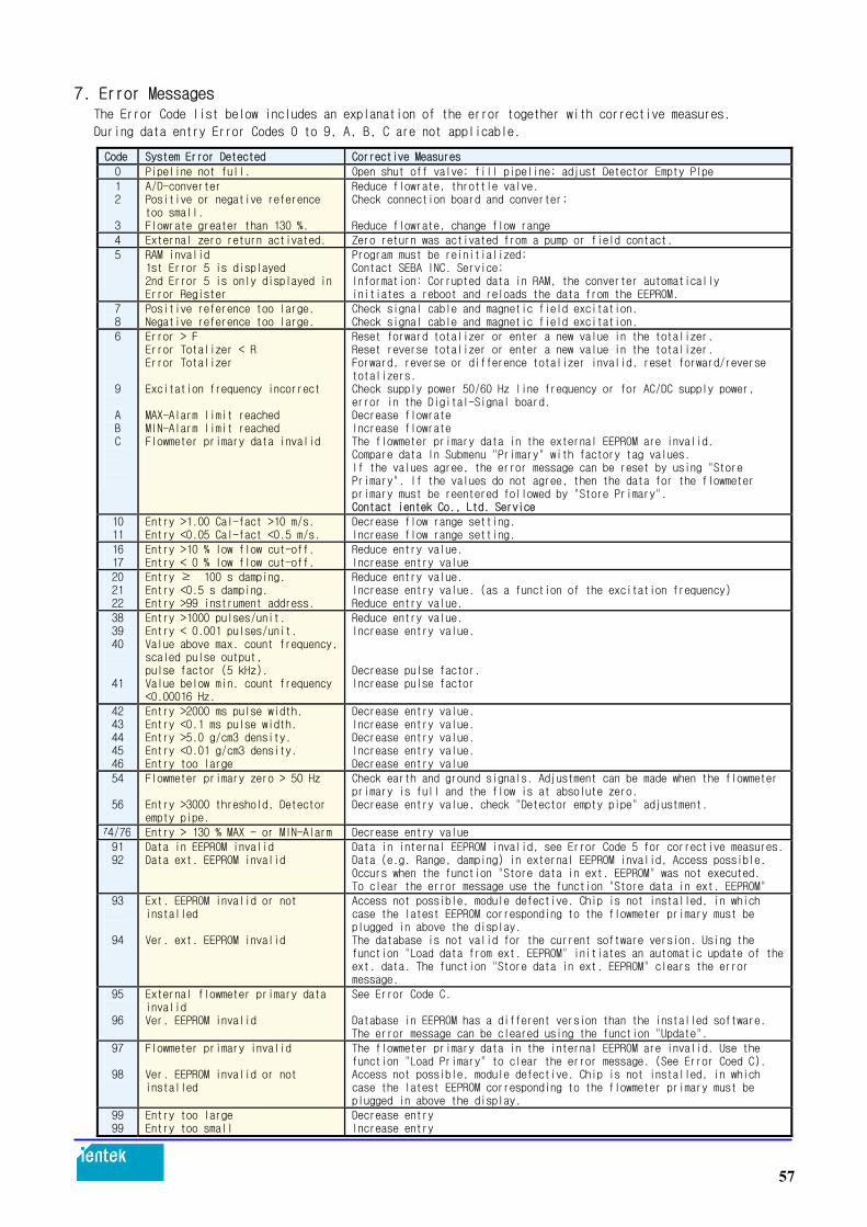
7. Error Messages The Error Code list below includes an explanation of the error together with corrective measures.
During data entry Error Codes 0 to 9, A, B, C are not applicable. Code System Error Detected Corrective Measures
0 Pipeline not full. Open shut off valve; fill pipeline; adjust Detector Empty PIpe 1 2 3
A/D-converter Positive or negative reference too small. Flowrate greater than 130 %.
Reduce flowrate, throttle valve. Check connection board and converter; Reduce flowrate, change flow range
4 External zero return activated. Zero return was activated from a pump or field contact. 5
RAM invalid 1st Error 5 is displayed 2nd Error 5 is only displayed in Error Register
Program must be reinitialized; Contact SEBA INC. Service; Information: Corrupted data in RAM, the converter automatically initiates a reboot and reloads the data from the EEPROM.
7 8
Positive reference too large. Negative reference too large.
Check signal cable and magnetic field excitation. Check signal cable and magnetic field excitation.
6 9 A B C
Error > F Error Totalizer < R Error Totalizer Excitation frequency incorrect MAX-Alarm limit reached MIN-Alarm limit reached Flowmeter primary data invalid
Reset forward totalizer or enter a new value in the totalizer. Reset reverse totalizer or enter a new value in the totalizer. Forward, reverse or difference totalizer invalid, reset forward/reverse totalizers. Check supply power 50/60 Hz line frequency or for AC/DC supply power, error in the Digital-Signal board. Decrease flowrate Increase flowrate The flowmeter primary data in the external EEPROM are invalid. Compare data In Submenu "Primary" with factory tag values. If the values agree, the error message can be reset by using "Store Primary". If the values do not agree, then the data for the flowmeter primary must be reentered followed by "Store Primary". Contact ientek Co., Ltd. Service
10 11
Entry >1.00 Cal-fact >10 m/s. Entry <0.05 Cal-fact <0.5 m/s.
Decrease flow range setting. Increase flow range setting.
16 17
Entry >10 % low flow cut-off. Entry < 0 % low flow cut-off.
Reduce entry value. Increase entry value
20 21 22
Entry ≥100 s damping. Entry <0.5 s damping. Entry >99 instrument address.
Reduce entry value. Increase entry value. (as a function of the excitation frequency) Reduce entry value.
38 39 40
41
Entry >1000 pulses/unit. Entry < 0.001 pulses/unit.
Value above max. count frequency, scaled pulse output, pulse factor (5 kHz). Value below min. count frequency <0.00016 Hz.
Reduce entry value. Increase entry value. Decrease pulse factor. Increase pulse factor
42 43 44 45 46
Entry >2000 ms pulse width. Entry <0.1 ms pulse width. Entry >5.0 g/cm3 density. Entry <0.01 g/cm3 density. Entry too large
Decrease entry value. Increase entry value. Decrease entry value. Increase entry value. Decrease entry value
54
56
Flowmeter primary zero > 50 Hz Entry >3000 threshold, Detector empty pipe.
Check earth and ground signals. Adjustment can be made when the flowmeterprimary is full and the flow is at absolute zero. Decrease entry value, check "Detector empty pipe" adjustment.
74/76 Entry > 130 % MAX - or MIN-Alarm Decrease entry value 91 92
Data in EEPROM invalid Data ext. EEPROM invalid
Data in internal EEPROM invalid, see Error Code 5 for corrective measures.Data (e.g. Range, damping) in external EEPROM invalid, Access possible. Occurs when the function "Store data in ext. EEPROM" was not executed. To clear the error message use the function "Store data in ext. EEPROM"
93
94
Ext. EEPROM invalid or not installed Ver. ext. EEPROM invalid
Access not possible, module defective. Chip is not installed, in which case the latest EEPROM corresponding to the flowmeter primary must be plugged in above the display. The database is not valid for the current software version. Using the function "Load data from ext. EEPROM" initiates an automatic update of the ext. data. The function "Store data in ext. EEPROM" clears the error message.
95
96
External flowmeter primary data invalid Ver. EEPROM invalid
See Error Code C. Database in EEPROM has a different version than the installed software. The error message can be cleared using the function "Update".
97 98
Flowmeter primary invalid Ver. EEPROM invalid or not installed
The flowmeter primary data in the internal EEPROM are invalid. Use the function "Load Primary" to clear the error message. (See Error Coed C). Access not possible, module defective. Chip is not installed, in which case the latest EEPROM corresponding to the flowmeter primary must be plugged in above the display.
99 99
Entry too large Entry too small
Decrease entry Increase entry
57

8. Maintenance and Repair 8.1. General Information
Before opening the housing all connection leads should be potential free. When the housing is opened,
the EMC protection is limited and the personnel contact protection is no longer provided. 8.1.1. Flowmeter Primary
The flowmeter primary is essentially maintenance free. An annual check should be made of the ambient
conditions (air flow, humidity), the seal integrity of the process connections, the condition of the
cable connectors and the tightness of the screws and bolts, safety of the supply power.
lightning protection and the earth connections. All repair and maintenance tasks should only be performed by qualified personnel. Observe the information (Hazardous Material Regulation), if the flowmeter primary is to be returned
to ientek Co., Ltd. Products for repair!
58

8.1.2. Converter Identification of the Converter Design, Socket Location for ext. EEPROM
Fig. 49 :
Fuse A Part No.
For 24V AC/DC 1A D151B025U07
For 100-230V AC 0.5A D151B025U06
Fuse F103 0.125A D151F003U14
Model No.:
Order No.: V/f:
Smax:
Variant:
EMFF
25702/X001 AC/DC 24V 50/60 Hz
<10 VA
04
The Identification of the design of the converter is listed on the type tag which may be
found on the tag located on the frame of the converter (see Figure).
Variant 01 Current output + pulse output active + contact input + contact output
Variant 02 Current output + pulse output active + contact input + contact output + HART Protocol
Variant 03 Current output + pulse output passive + contact input + contact output
Variant 04 Current output + pulse output passive + contact input + contact output + HART Protocol
Variant 05 Current output + pulse output passive + contact output + RS 485
Variant 06 Pulse output passive + contact output + PROFIBUS DP
Variant 14 PROFIBUS PA 3.0
Variant 15 FOUNDATION Fieldbus
Variant 16 PROFIBUS PA 3.0 (with M12 plug)
59

9. Replaceable Parts List 9.1. Replaceable Parts List for Compact Design Instrument
Fig. 50 :
Description Part No.
1 Cover with glass window D614A023U01
2 O-Ring 100x3.5 D101A026U01
3 Cable connector M20x1.5 D150A008U15
4 Cover small D379D134U02
Variant Cable Assembly for In-/Outputs Part No.
01 – 04 Current output + pulse output active + contact input + contact output D677A294U01
05 Current output + pulse output passive + contact output + RS 485 D677A294U04
06 Pulse output passive + contact output + PROFIBUS DP D677A294U05
14 PROFIBUS PA 3.0 D677A294U08
15 FOUNDATION Fieldbus D677A294U09
16 PROFIBUS PA 3.0 (with M12 plug) D677A294U08
60

9.2. Replaceable Parts for Flowmeter Primary
Fig. 51 :
Connection box for flowmeter primary in Connection box for flowmeter primary in
stainless steel design Aluminum design
Description
Connection Box for
Series 3000
Part No.
Connection Box for
Series 6000
Part No.
1 Housing cover D612A127U01 D612A152U01
2 Housing cover gasket D333F016U01 D333F022U01
3 Cable connector D150A008U02 D150A004U14 (M20 x 1.5)
4 Seal ring for cable connector D150Z007U06 -
5 Seal plug D150Z007U05 D150Z007U08 (M20 x 1.5)
6 Gasket for seal plug D150Z007U06 -
7
Screw M4 x 14 with
flat washer and
spacer
D396B013U01 and
D115B004U01 and
D375A018U01
D009G113AU20
D085A021BU20
D106A001U25
8 Connection box, lower section D612A128U01 D612A153U09
9 Connection board, complete D684A690U02 D685A862U02
61

9.3. Replaceable Parts List for Converter E4 9.3.1. Field Mount Housing
Fig. 52 :
No. Description Part No.
1 Field mount housing M20x1.5 complete (empty), without converter module,
without Connection board.
D641A033O01
2
Connection board complete including cable assembly for standard outputs incl.
HART (Variant 01-04)
Connection board complete including cable assembly for RS845 (Variant 05)
Connection board complete including cable assembly for PROFIBUS DP (Variant 06)
Connection board complete including cable assembly for PROFIBUS PA or
FOUNDATION Fieldbus (Variant 14-16)
D674A861U01
D674A861U92
D674A861U03
D674A861U04
3 Cover small D641A029U01
4 Cable connector M20x1.5 D150A008U15
5 Mach, screw, Philips, phillister head M4x10 D004G108AU01
6 Spring washer DC85D020AU20
62

10. Dimensions 10.1. Dimensions Converter Remote Type
Fig. 53 : Dimensions Converter Field Mount Housing, Mounting Options
Field Mount Housing Cable connector M20 x 1.5 with Window
Mounting dimensions
1) Mounting holes for
2Ž pipe mounting kit Mounting kit upon request
(Order-No. 612B091U07)
63

11. Accuracy
Reference conditions per EN 29104 Fluid Temperature 20 °C ± 2 K Supply Power Nominal voltage per type tag UN ± 1 % and
Frequency ± 1 % Installation Requirements, Straight Sections Upstream > 10 x D
Downstream > 5 x D
D = flowmeter primary size Warm Up Phase 30 min
Effect on Current Output Same as pulse output plus ± 0.1 % of rate
Fig. 54: Metering System Accuracy COPA-XE / MAG--XE)
64

12. Specifications Converter
Fig. 55 : Converter Keypad and Display
Flow Range Continuous settings between 0.5 and 10 m/s Max. Measurement Deviation of the Metering System ≤0.5% of rate(0.25 % option) Reproducibility ≤0.15% of rate Minimum Conductivity 5 μS/cm (20μS/cm for demineralized water) Response Time For a step change 0-99% (corresp. 5τ)≥ 1s Supply Power High voltage AC 100-230V (-15/+10 %)
Low voltage AC 16.8-26.4V
Low voltage DC 16.8-31.2V Ripple: <5% Magnetic Field Supply 6 1/4 Hz, 7 1/2 Hz, 12 1/2 Hz, 15 Hz, 25 Hz, 30 Hz (50/60 Hz supply power) Power ≤14VA (flowmeter primary including converter) for
AC supply power ≤6W for DC supply power (flowmeter primary including converter) Ambient Temperature -20 to +60 Electrical Connections Screwless spring loaded terminals
65

13. Overview Parameter Settings and Flowmeter Design Options
Meter location: TAG No.:
Primary type: Converter type:
Order No.: Instrument No.: Order No.:
Instrument No.:
Fluid temp.: Supply voltage :
Liner Electrode: Excitation freq.:
C zero: C zero:
System zero:
Pulse output: Optocoupler Active 24 V
Contact in-/output: Yes optocoupler No
Detector empty pipe: Yes No
Communication: HART-Protocol
Display: None Lighted and Magnet Stick
Parameter Entry Range
Prog. Prot. Code Language Meter size: Range: Pulse factor: Pulse width Low flow cut-off: Damping: Filter: Density: Unit range: Unit totalizer: Max. Alarm: Min. Alarm: Terminals P7/G2: Terminals X1/G2: Current output: Iout at Alarm: Detector e. pipe: Alarm e. pipe Iout at e. pipe: Threshold: Adjust e. pipe: Totalizer function: 1st Display line: 2nd Display line: 1st line Multiplex: 2nd line Multiplex: Operating mode: Flow indication: Flow direction: Store data in ext. EEPROM:
...
... ... ... ... ... ... ... ... ... ... ... ... ... ... ... ... ... ... ... ... ... ... ... ... ... ... ... ... ... ... ...
0-255 (0=factory default setting) German, English, French, Finnish, Spanish, Italian, Dutch, Danish, Swedish DN 3 - 1000 [1/10”- 40”] 0.05 Cal-factor -1 Cal-factor 0.001 - 1000 pulses/unit 0.100 - 2000 ms 0 - 10 % of flow range end value 0.125 - 99.99 seconds ON/OFF 0.01 g/cm3 - 5.0 g/cm3 l/s, l/min, l/h, hl/s, hl/min, hl/h, m3/s, m3/min, m3/h, igps, igpm, igph, mdg, gpm, gph, bbl/s, bbl/min, bbl/h, bls/day, bls/min, bls/h, kg/s, kg/min, kg/h, t/s, t/min, t/h, g/s, g/min, g/h, ml/s, ml/min, ml/h, Ml/min, Ml/h, Ml/day, lb/s, lb/min, lb/h, uton/min, uton/h, uton/day, kgal/s, kgal/min, kgal/h, l, hl, m3, igal, gal, mgal, bbl, bls, g, kg, t, ml, uton, lb, kgal % % Max. Alarm, Min. Alarm, Max./Min. Alarm, General Alarm, empty pipe, F/R-Signal, no function External zero return, totalizer reset, no function 0/4-20 mA, 0/2-10 mA, 0-5 mA, 0-10-20 mA, 4-12-20 mA 0 %, 130 %, 3.8 mA ON/OFF ON/OFF 0 %, 130 %, 3.8 mA 2300 Hz Software potentiometer Standard, difference totalizer Q (%), Q (unit), Q (mA), totalizer F/R, TAG-Number blank line, Bargraph Q (%), Q (unit), Q (mA), totalizer F/R, TAG-Number blank line, Bargraph ON/OFF ON/OFF Standard/fast Forward/reverse, forward Standard, opposite Yes/No
66
Related Documents


