1 NOVAMILL INSTALLATION GUIDE - COMPUTERISED MACHINES AND SYSTEMSS This manual applies only to the machine having the serial number shown below. Please note that this number will be required should Denford Limited be contacted regarding this machine. Machine Serial Number : ________________________ Year of Manufacture : ________________________ Manufactured by Denford Limited, Birds Royd, Brighouse, West Yorkshire, HD6 1NB, England. Telephone: +44 (0)1484 712264. Fax: +44 (0)1484 722160. Email: [email protected] Operating Guide for the Novamill Series of CNC Milling Machines - Installation - Specific Features - Routine Maintenance

Welcome message from author
This document is posted to help you gain knowledge. Please leave a comment to let me know what you think about it! Share it to your friends and learn new things together.
Transcript

1NOVAMILL INSTALLATION GUIDE -
COMPUTERISED MACHINES AND SYSTEMSS
This manual applies only to the machine having theserial number shown below.
Please note that this number will be required shouldDenford Limited be contacted regarding this machine.
Machine Serial Number : ________________________
Year of Manufacture : ________________________
Manufactured byDenford Limited,Birds Royd, Brighouse, West Yorkshire, HD6 1NB, England.Telephone: +44 (0)1484 712264.Fax: +44 (0)1484 722160.Email: [email protected]
Operating Guidefor the NovamillSeries of CNCMilling Machines
- Installation- Specific
Features- Routine
Maintenance
2 - NOVAMILL INSTALLATION GUIDE
CONTENTS.
The Warranty on this machine will be invalidated ifany modifications, additional ancillary equipment isfitted, or any adjustments made to the controllingdevices without prior notification from DenfordLimited.
Do not carry out any portable appliance testing (PAT)on any of the supplied equipment.
This guide will describe how to transport, site andsetup your Denford Novamill CNC Milling Machine.
Any operational features, specific to the Novamill range,are also covered in this guide. General operatingfunctions are explained in the separate "Generic CNCMilling Manual" delivered with your machine.
A Routine Maintenance section is also included. Pleasenote, the Electrical Diagrams for your machine are heldin a folder fixed inside the electrical control box.
IF YOU HAVE ANY DOUBTS AND/OR QUESTIONSREGARDING THE SPECIFICATION, SERVICING ORFEATURES OF YOUR MACHINE, PLEASE CONTACTCUSTOMER SERVICES AT DENFORD.
INTRODUCTION.
WARNING.
Section Page
Introduction. ................................................2Warning.......................................................2EC Declaration of Conformity. ........................3Unpacking & Lifting the Machine. ...................4Levelling & Positioning the Machine. ...............5Connecting the PC. .......................................6Electrical Diagrams and Control Box Seal. ........6Connecting the Mains Supply. ........................7Component Connection Schematic Diagram. ....8Removal of Protective Coatings. .....................10Novamill - General Layout. .............................10General Safety Precautions. ...........................11Install and Run the Machine Control Software. .....12Automatic Search for Datum Point..................13Maintenance Schedule...................................14Lubrication Chart. .........................................14Maintenance - Lubrication Points on the Novamill....15Novamill Specification. ..................................17Denford Contacts, Products and Services. .......18
3NOVAMILL INSTALLATION GUIDE -
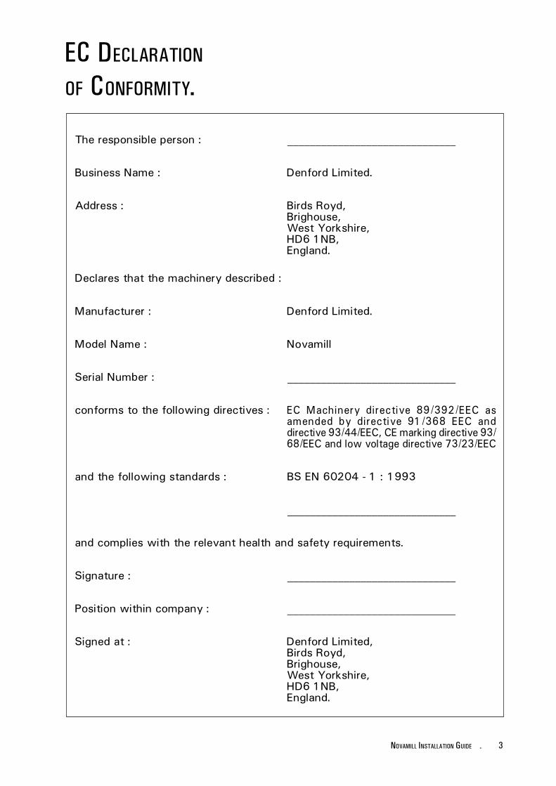
EC DECLARATION
OF CONFORMITY.
The responsible person : ______________________________
Business Name : Denford Limited.
Address : Birds Royd,Brighouse,West Yorkshire,HD6 1NB,England.
Declares that the machinery described :
Manufacturer : Denford Limited.
Model Name : Novamill
Serial Number : ______________________________
conforms to the following directives : EC Machinery directive 89/392/EEC asamended by directive 91/368 EEC anddirective 93/44/EEC, CE marking directive 93/68/EEC and low voltage directive 73/23/EEC
and the following standards : BS EN 60204 - 1 : 1993
______________________________
and complies with the relevant health and safety requirements.
Signature : ______________________________
Position within company : ______________________________
Signed at : Denford Limited,Birds Royd,Brighouse,West Yorkshire,HD6 1NB,England.
4 - NOVAMILL INSTALLATION GUIDE
UNPACKING &LIFTING THE
MACHINE.
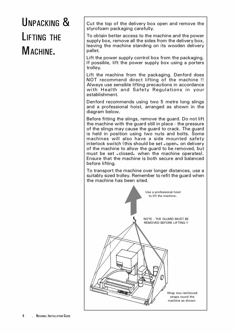
Cut the top of the delivery box open and remove thestyrofoam packaging carefully.To obtain better access to the machine and the powersupply box, remove all the sides from the delivery box,leaving the machine standing on its wooden deliverypallet.Lift the power supply control box from the packaging.If possible, lift the power supply box using a porterstrolley.Lift the machine from the packaging. Denford doesNOT recommend direct lifting of the machine !!Always use sensible lifting precautions in accordancewith Health and Safety Regulations in yourestablishment.Denford recommends using two 5 metre long slingsand a professional hoist, arranged as shown in thediagram below.Before fitting the slings, remove the guard. Do not liftthe machine with the guard still in place - the pressureof the slings may cause the guard to crack. The guardis held in position using two nuts and bolts. Somemachines will also have a side mounted safetyinterlock switch (this should be set "open" on deliveryof the machine to allow the guard to be removed, butmust be set "closed" when the machine operates).Ensure that the machine is both secure and balancedbefore lifting.To transport the machine over longer distances, use asuitably sized trolley. Remember to refit the guard whenthe machine has been sited.
Use a professional hoistto lift the machine..
Wrap two reinforcedstraps round the
machine as shown.
NOTE - THE GUARD MUST BEREMOVED BEFORE LIFTING !!
5NOVAMILL INSTALLATION GUIDE -
LEVELLING &POSITIONING THE
MACHINE.
Remember when positioning the machine in the room,space will be required for the electrical control box.Sufficient room should also be provided for effectivemaintenance to be carried out.
The Novatmill is a bench mounted machine, so it shouldbe sited on a bench of sturdy construction to take theweight of the machine, and of a height which enablescomfortable operating and programming to take place.
The machine should rest level on the two hollowsections which run beneath the machine cabinet. Thelathe itself has been levelled to the machine cabinetprior to dispatch, so it is only necessary to level themachine to the table on which it is to be situated.
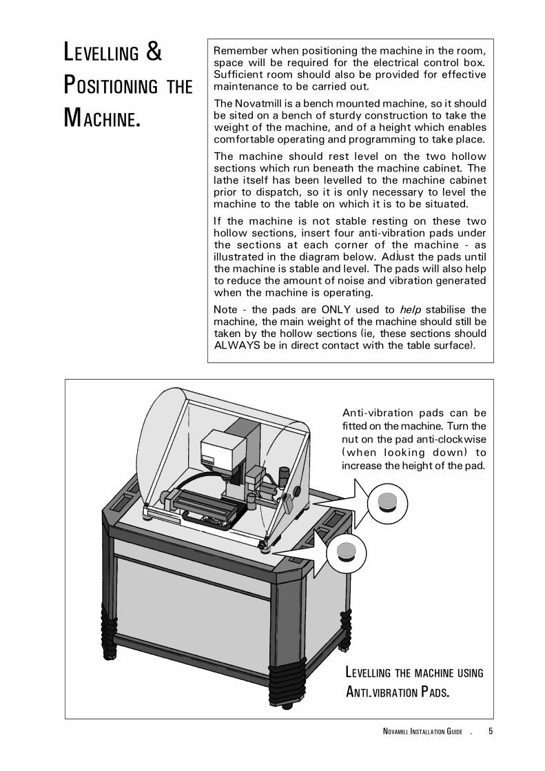
If the machine is not stable resting on these twohollow sections, insert four anti-vibration pads underthe sections at each corner of the machine - asillustrated in the diagram below. Adjust the pads untilthe machine is stable and level. The pads will also helpto reduce the amount of noise and vibration generatedwhen the machine is operating.
Note - the pads are ONLY used to help stabilise themachine, the main weight of the machine should still betaken by the hollow sections (ie, these sections shouldALWAYS be in direct contact with the table surface).
LEVELLING THE MACHINE USING
ANTI-VIBRATION PADS.
Anti-vibration pads can befitted on the machine. Turn thenut on the pad anti-clockwise(when looking down) toincrease the height of the pad.
6 - NOVAMILL INSTALLATION GUIDE
CONNECTING THE
PC.Warning! Do not connect cables between anyelectrical hardware with the mains powerswitched on, since this could damage thehardware.
Ideally, the pc (personal computer) should be placednext to the machine and its electrical control box, withaccess to a mains power supply.
Connect the elements of the pc together as describedin the pc manufacturers operating manual.
The pc and the machines electrical control box arephysically linked by the RS232 cable (supplied). Thiscable is fitted with 25 pin connectors at both ends.
One end connects to the 25 pin port on the electricalcontrol box labelled "RS 232".
The opposite end of this cable connects to the 25 pinport of the pc labelled "COM2". If this port cannot beidentified on the back panel of the pc, please refer tothe pc manufacturers operating manual.
Note. On some personal computers, this port may havea 9 pin connection. If this is the case, a 25 pin to 9 pinadapter, available from most good computer/electricalretailers must be fitted to allow the cable to beconnected to the pc.
A schematic diagram illustrating these componentconnections is shown on page 8.
Warning! Do not connect cables between anyelectrical hardware with the mains powerswitched on, since this could damage thehardware.
The electrical control box is inspected thensealed with a yellow seal; if this seal is brokenon delivery, inform the suppliers immediately.The seal should only be broken for the initialmains power connection.
The Electrical Diagrams for your machine are held in afolder fixed inside the electrical control box.
ELECTRICAL
DIAGRAMS
AND CONTROL
BOX SEAL.
7NOVAMILL INSTALLATION GUIDE -
CONNECTING THE
MAINS SUPPLY.The large flexible machine power cable, leading fromthe side of the electrical control box is connected tothe fixing bracket on the side of the milling machine.Check that the connector is inserted into the bracketwith the main cable from it leading towards the backof the machine (see the diagram on page 9).
Ensure the two roller clips holding the male connectoragainst the female bracket are fully closed. There shouldbe no free movement at the junction.
The mains power supply is fed to the electrical controlbox, which in turn, is connected to the millingmachine.
This electrical control box is delivered with the mainssupply cable connected directly into the isolator withapproximately 3 metres of cable. The cable should thenbe fitted with a standard 13 amp. plug suitable for themains power supply.
The supply is 220/240volt Single Phase 50Hz.
Cable required:- 2 Core + Earth, 1.5mm per core.
Current Taken 11 Amps.
All electrical connections should only be made by asuitably qualified electrical engineer.
A schematic diagram illustrating these componentconnections is shown on page 8 and 9.
Warning! Do not insert the connector into thebracket the wrong way round; this coulddamage the connector pins. Check that theletters and numbers on the two halves of theconnector and bracket match before closingthe junction.
8 - NOVAMILL INSTALLATION GUIDE
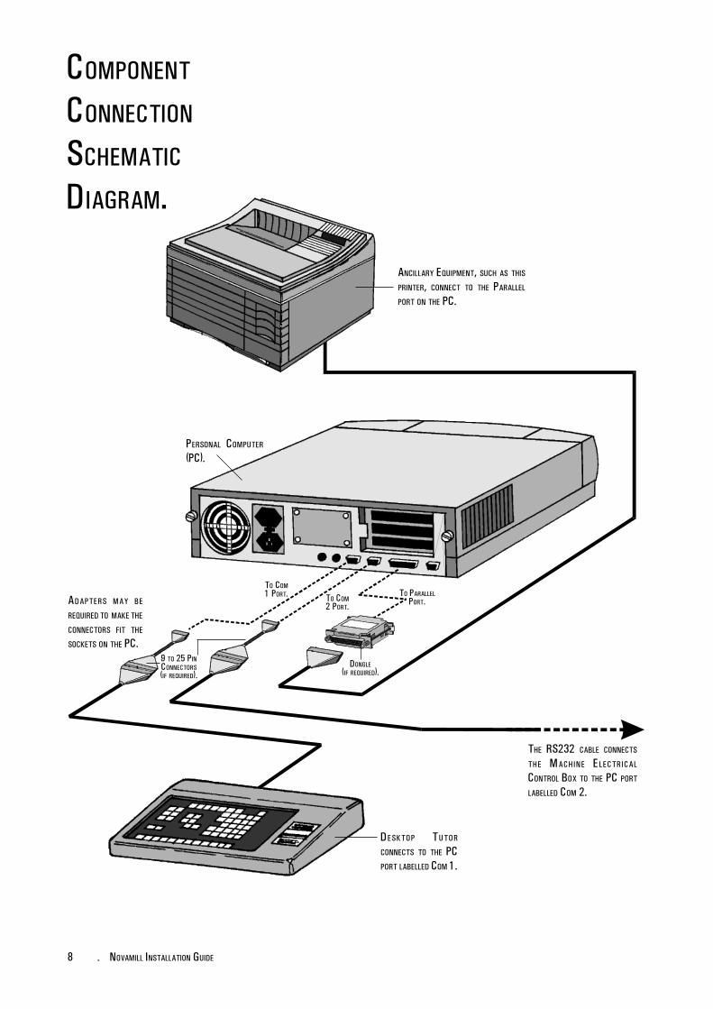
COMPONENT
CONNECTION
SCHEMATIC
DIAGRAM.
PERSONAL COMPUTER
(PC).
TO COM1 PORT. TO COM
2 PORT.
THE RS232 CABLE CONNECTS
THE MACHINE ELECTRICAL
CONTROL BOX TO THE PC PORT
LABELLED COM 2.
ADAPTERS MAY BE
REQUIRED TO MAKE THE
CONNECTORS FIT THE
SOCKETS ON THE PC.9 TO 25 PINCONNECTORS(IF REQUIRED).
DESKTOP TUTOR
CONNECTS TO THE PCPORT LABELLED COM 1.
TO PARALLELPORT.
DONGLE(IF REQUIRED).
ANCILLARY EQUIPMENT, SUCH AS THIS
PRINTER, CONNECT TO THE PARALLEL
PORT ON THE PC.
9NOVAMILL INSTALLATION GUIDE -
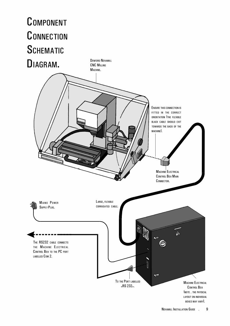
COMPONENT
CONNECTION
SCHEMATIC
DIAGRAM.
THE RS232 CABLE CONNECTS
THE MACHINE ELECTRICAL
CONTROL BOX TO THE PC PORT
LABELLED COM 2.
LARGE, FLEXIBLE
CORRUGATED CABLE.MAINS POWER
SUPPLY PLUG.
ENSURE THIS CONNECTION ISFITTED IN THE CORRECT
ORIENTATION (THE FLEXIBLE
BLACK CABLE SHOULD EXIT
TOWARDS THE BACK OF THE
MACHINE).
DENFORD NOVAMILL
CNC MILLING
MACHINE.
MACHINE ELECTRICAL
CONTROL BOX MAIN
CONNECTOR.
TO THE PORT LABELLED
"RS 232".MACHINE ELECTRICAL
CONTROL BOX
(NOTE - THE PHYSICAL
LAYOUT ON INDIVIDUAL
BOXES MAY VARY).
10 - NOVAMILL INSTALLATION GUIDE
REMOVAL OF
PROTECTIVE
COATINGS.
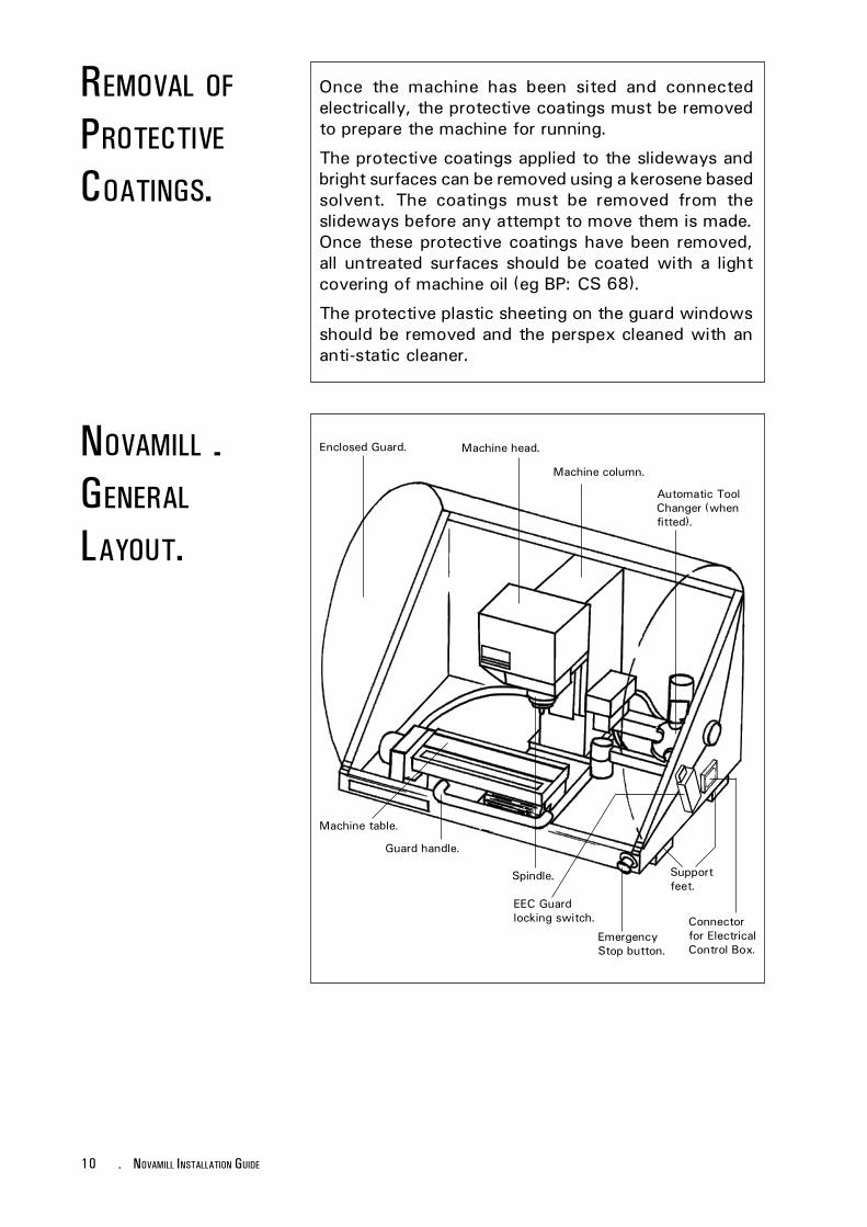
Once the machine has been sited and connectedelectrically, the protective coatings must be removedto prepare the machine for running.
The protective coatings applied to the slideways andbright surfaces can be removed using a kerosene basedsolvent. The coatings must be removed from theslideways before any attempt to move them is made.Once these protective coatings have been removed,all untreated surfaces should be coated with a lightcovering of machine oil (eg BP: CS 68).
The protective plastic sheeting on the guard windowsshould be removed and the perspex cleaned with ananti-static cleaner.
NOVAMILL -GENERAL
LAYOUT.Automatic ToolChanger (whenfitted).
Machine head.
Machine column.
Machine table.
Supportfeet.
Connectorfor ElectricalControl Box.
EEC Guardlocking switch.
Guard handle.
Spindle.
EmergencyStop button.
Enclosed Guard.
11NOVAMILL INSTALLATION GUIDE -
General Safety Precautions :
- Wear clothing suitable for operating the machine andfollow the safe working procedures in place at yourestablishment.
- Do not place any objects so that they interfere withthe guards or the operation of the machine.
- Never try to clean the machine if any part of it isrotating, or in motion.
- Always secure the work on the table or in a fixtureor vice.
- Ensure that the correct cable for the power sourceis used.
- If power fails turn off the yellow isolator (found onthe electrical control box) immediately.
- Ensure the power is switched off before starting anymaintenance work on the machine or opening/working on the electrical control box.
- Check the state of the slideway lubrication daily, toprevent the axes from becoming jammed.
- Further operational safety precautions are outlinedin the separate "Generic CNC Milling Manual".
GENERAL SAFETY
PRECAUTIONS.
12 - NOVAMILL INSTALLATION GUIDE
INSTALLING &RUNNING THE
MACHINE
CONTROL
SOFTWARE.
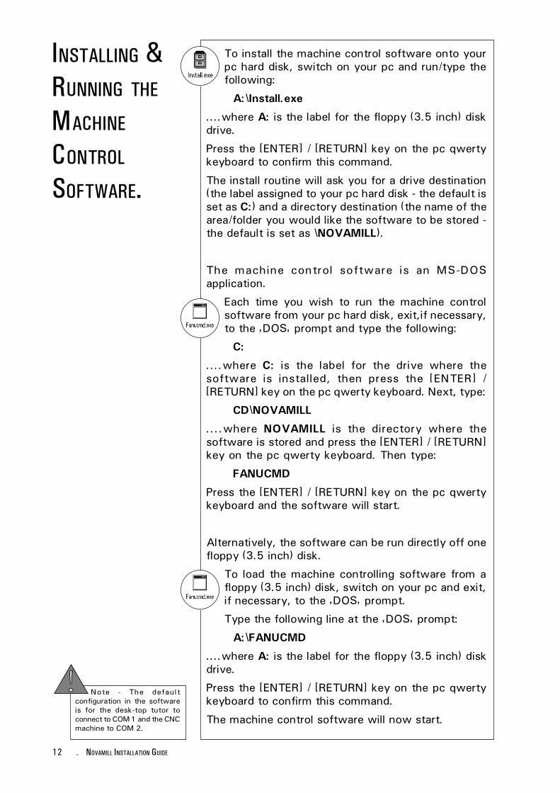
To install the machine control software onto yourpc hard disk, switch on your pc and run/type thefollowing:
A:\Install.exe
....where A: is the label for the floppy (3.5 inch) diskdrive.
Press the [ENTER] / [RETURN] key on the pc qwertykeyboard to confirm this command.
The install routine will ask you for a drive destination(the label assigned to your pc hard disk - the default isset as C:) and a directory destination (the name of thearea/folder you would like the software to be stored -the default is set as \NOVAMILL).
The machine control software is an MS-DOSapplication.
Each time you wish to run the machine controlsoftware from your pc hard disk, exit,if necessary,to the 'DOS' prompt and type the following:
C:
....where C: is the label for the drive where thesoftware is installed, then press the [ENTER] /[RETURN] key on the pc qwerty keyboard. Next, type:
CD\NOVAMILL
....where NOVAMILL is the directory where thesoftware is stored and press the [ENTER] / [RETURN]key on the pc qwerty keyboard. Then type:
FANUCMD
Press the [ENTER] / [RETURN] key on the pc qwertykeyboard and the software will start.
Alternatively, the software can be run directly off onefloppy (3.5 inch) disk.
To load the machine controlling software from afloppy (3.5 inch) disk, switch on your pc and exit,if necessary, to the 'DOS' prompt.
Type the following line at the 'DOS' prompt:
A:\FANUCMD
....where A: is the label for the floppy (3.5 inch) diskdrive.
Press the [ENTER] / [RETURN] key on the pc qwertykeyboard to confirm this command.
The machine control software will now start.
Note - The defaultconfiguration in the softwareis for the desk-top tutor toconnect to COM 1 and the CNCmachine to COM 2.
13NOVAMILL INSTALLATION GUIDE -
MACHINE START-UP
- AUTOMATIC
SEARCH FOR
DATUM POINT .
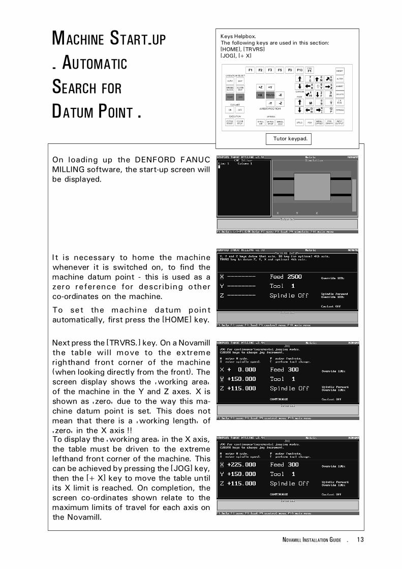
Keys Helpbox.The following keys are used in this section:[HOME], [TRVRS][JOG], [+X]
Tutor keypad.
To display the 'working area' in the X axis,the table must be driven to the extremelefthand front corner of the machine. Thiscan be achieved by pressing the [JOG] key,then the [+X] key to move the table untilits X limit is reached. On completion, thescreen co-ordinates shown relate to themaximum limits of travel for each axis onthe Novamill.
Next press the [TRVRS.] key. On a Novamillthe table will move to the extremerighthand front corner of the machine(when looking directly from the front). Thescreen display shows the 'working area'of the machine in the Y and Z axes. X isshown as 'zero' due to the way this ma-chine datum point is set. This does notmean that there is a 'working length' of'zero' in the X axis !!
On loading up the DENFORD FANUCMILLING software, the start-up screen willbe displayed.
It is necessary to home the machinewhenever it is switched on, to find themachine datum point - this is used as azero reference for describing otherco-ordinates on the machine.
To set the machine datum pointautomatically, first press the [HOME] key.
14 - NOVAMILL INSTALLATION GUIDE
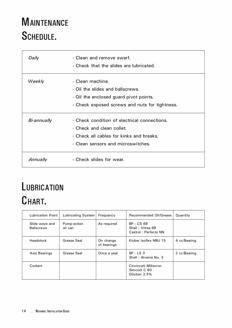
MAINTENANCE
SCHEDULE.
Daily - Clean and remove swarf.
- Check that the slides are lubricated.
Weekly - Clean machine.
- Oil the slides and ballscrews.
- Oil the enclosed guard pivot points.
- Check exposed screws and nuts for tightness.
Bi-annually - Check condition of electrical connections.
- Check and clean collet.
- Check all cables for kinks and breaks.
- Clean sensors and microswitches.
Annually - Check slides for wear.
LUBRICATION
CHART.Lubrication Point Lubricating System Frequency Recommended Oil/Grease Quantity
Slide ways and Pump-action As required BP : CS 68Ballscrews oil can Shell : Vitrea 68
Castrol : Perfecto NN
Headstock Grease Seal On change Kluber Isoflex NBU 15 4 cc/Bearingof bearings
Axis Bearings Grease Seal Once a year BP : LS 3 2 cc/BearingShell : Alvania No. 3
Coolant Cincinnati MillacronSimcool C 60Dilution 2.5%
15NOVAMILL INSTALLATION GUIDE -
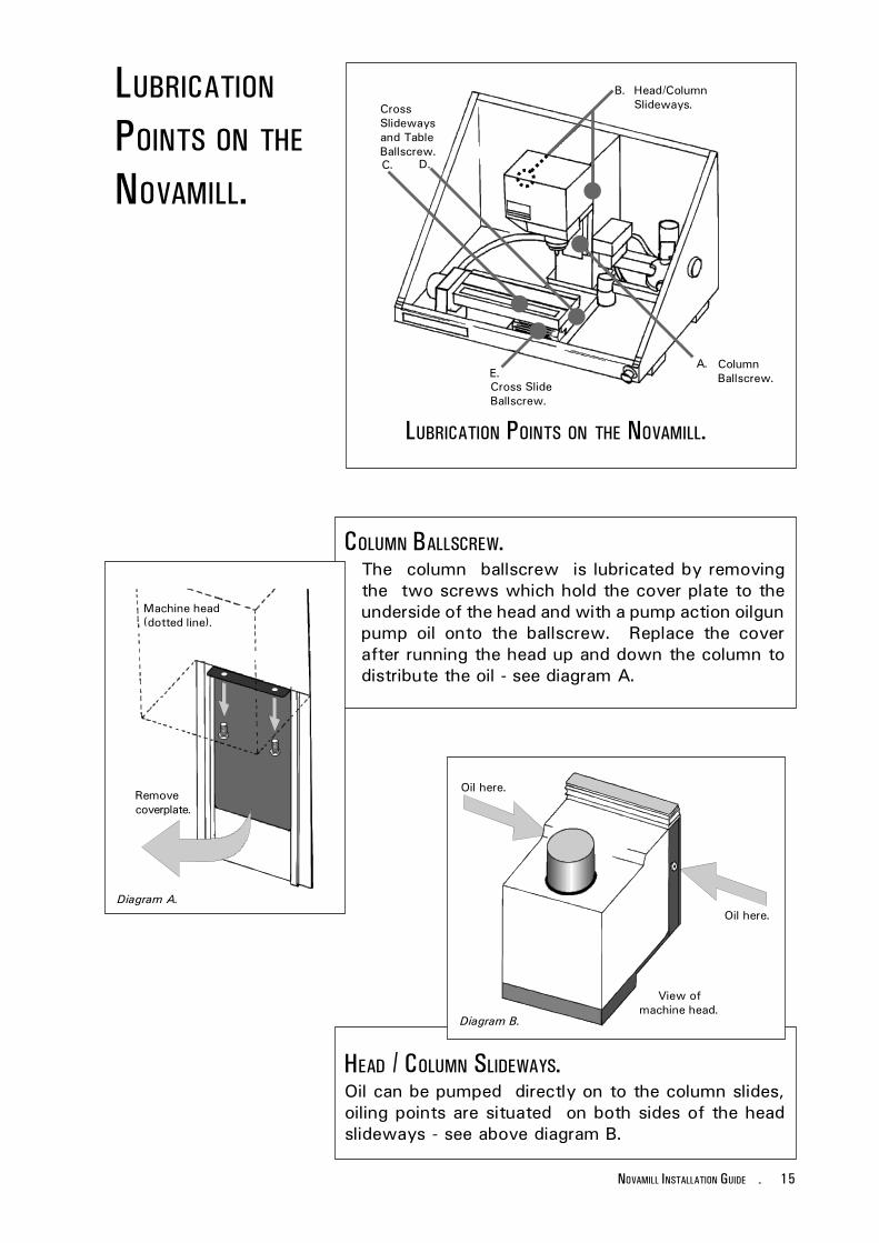
LUBRICATION
POINTS ON THE
NOVAMILL.
HEAD / COLUMN SLIDEWAYS.Oil can be pumped directly on to the column slides,oiling points are situated on both sides of the headslideways - see above diagram B.
Oil here.
Oil here.
View ofmachine head.
LUBRICATION POINTS ON THE NOVAMILL.
COLUMN BALLSCREW.The column ballscrew is lubricated by removingthe two screws which hold the cover plate to theunderside of the head and with a pump action oilgunpump oil onto the ballscrew. Replace the coverafter running the head up and down the column todistribute the oil - see diagram A.
Machine head(dotted line).
C. D.
CrossSlidewaysand TableBallscrew.
Diagram B.
Diagram A.
Removecoverplate.
B. Head/ColumnSlideways.
A. ColumnBallscrew.E.
Cross SlideBallscrew.
16 - NOVAMILL INSTALLATION GUIDE
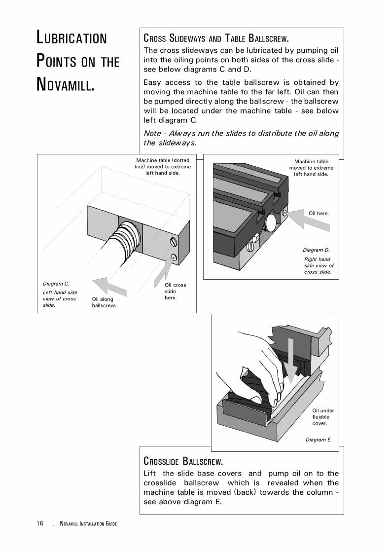
LUBRICATION
POINTS ON THE
NOVAMILL.
CROSS SLIDEWAYS AND TABLE BALLSCREW.The cross slideways can be lubricated by pumping oilinto the oiling points on both sides of the cross slide -see below diagrams C and D.
Easy access to the table ballscrew is obtained bymoving the machine table to the far left. Oil can thenbe pumped directly along the ballscrew - the ballscrewwill be located under the machine table - see belowleft diagram C.
Note - Always run the slides to distribute the oil alongthe slideways.
Oil here.
Machine table (dottedline) moved to extreme
left hand side.
Oil alongballscrew.
Oil crossslidehere.
Left hand sideview of crossslide.
Machine tablemoved to extreme
left hand side.
Right handside view ofcross slide.
Diagram D.
Diagram C.
Oil underflexiblecover.
Diagram E.
CROSSLIDE BALLSCREW.Lift the slide base covers and pump oil on to thecrosslide ballscrew which is revealed when themachine table is moved (back) towards the column -see above diagram E.
17NOVAMILL INSTALLATION GUIDE -
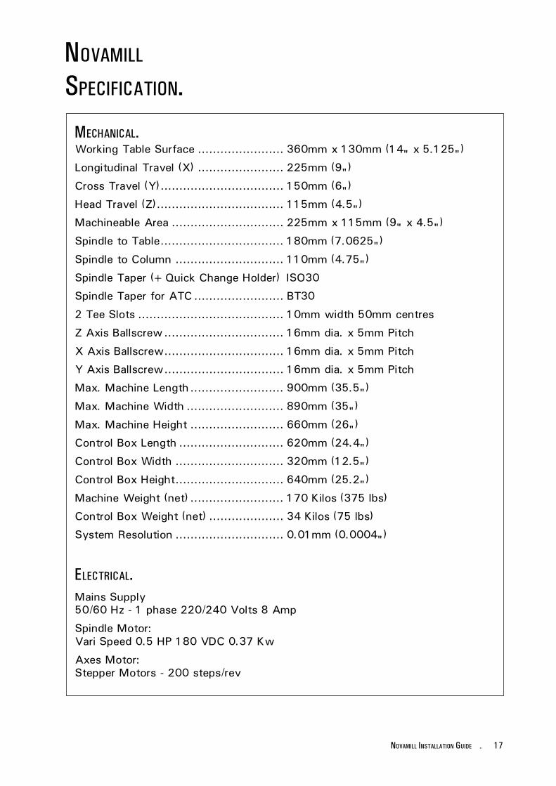
NOVAMILL
SPECIFICATION.
MECHANICAL.Working Table Surface ....................... 360mm x 130mm (14" x 5.125")
Longitudinal Travel (X) ....................... 225mm (9")
Cross Travel (Y) ................................. 150mm (6")
Head Travel (Z).................................. 115mm (4.5")
Machineable Area .............................. 225mm x 115mm (9" x 4.5")
Spindle to Table................................. 180mm (7.0625")
Spindle to Column ............................. 110mm (4.75")
Spindle Taper (+Quick Change Holder) ISO30
Spindle Taper for ATC ........................ BT30
2 Tee Slots ....................................... 10mm width 50mm centres
Z Axis Ballscrew ................................ 16mm dia. x 5mm Pitch
X Axis Ballscrew................................ 16mm dia. x 5mm Pitch
Y Axis Ballscrew................................ 16mm dia. x 5mm Pitch
Max. Machine Length ......................... 900mm (35.5")
Max. Machine Width .......................... 890mm (35")
Max. Machine Height ......................... 660mm (26")
Control Box Length ............................ 620mm (24.4")
Control Box Width ............................. 320mm (12.5")
Control Box Height............................. 640mm (25.2")
Machine Weight (net) ......................... 170 Kilos (375 lbs)
Control Box Weight (net) .................... 34 Kilos (75 lbs)
System Resolution ............................. 0.01mm (0.0004")
ELECTRICAL.Mains Supply50/60 Hz - 1 phase 220/240 Volts 8 Amp
Spindle Motor:Vari Speed 0.5 HP 180 VDC 0.37 Kw
Axes Motor:Stepper Motors - 200 steps/rev

18 - NOVAMILL INSTALLATION GUIDE
DENFORD
CONTACTS,PRODUCTS AND
SERVICES.
If you require specific help regarding thespecification, operation or maintenance of thismachine, contact Denford on the phone/fax numberbelow. Please have the machine serial number andyear of manufacture (printed on the front of this guide)to hand, when you call.
Telephone: +44 (0)1484 712264.Fax: (01484) 722160.Denford Limited,Birds Royd, Brighouse, West Yorkshire, HD6 1NB, England.Email: [email protected]
Stuck for projects and ideas?Denford produces a range of project based coursewarematerial, especially designed for use with our rangeof CNC Milling Machines and software products.Denford Courseware is developed to encourage theuse of CNC machines and software within Keystages3 and 4 of the Design and Technology NationalCurriculum.
Products available include:
- Mill ing Courseware Introductory (a briefintroduction to the milling machine and Denfords"MillCAM Designer" software).
- Keystage 3 Projects for Milling.
- Milling Courseware Intermediate (exploring howthe machine works, basic G-code program writingand the use of CNC machines in Industry).
- Keystage 4 Projects for Milling.
Need further training?
The Denford PTDC (Professional Training andDevelopment Centre) is a purpose built centrespecialising in project guidance, CNC machinetraining and software development skills for Denfordcustomers. Training packages can be tailored to suityour needs, with the help of our experiencedEducation Support team. The centre can cater fortraining sessions from the very basics of CNCmachine operation, upto the complexities of G-codeprogramming, then further into 'new' Technologyareas such as video conferencing.
Denford Limited is committed to the development ofits training guides and manuals. If you have foundcertain sections in this setup guide useful, or feel thatparticular sections could be further developed, or newsections added in future, we would welcome yoursuggestions and comments.
Related Documents