Operating and mounting manual EVO / EVSO _______________________________________________________________________________________________________ 220.100.049-06 Page 1 /20 Version : 02/2008 TM 1710 Operating and mounting manual Safety blow off valve gas – solenoid valve EVO / EVSO Contents 1.0 General remarks 1.1 Valve data 1.2 Application 2.0 Danger Notices 2.1 Safety terms 2.2 Safety notice 2.3 Qualified staff 2.4 Unauthorized modification and spare part production 2.5 Unauthorized operation 2.6 Safety information for the use in explosion-prone areas guideline 94/9/EC 3.0 Handling 3.1 Transport 3.2 Storage 3.3 Handling before mounting 4.0 Product Description 4.1 Function 4.2 Technical Data 4.3 Marking 5.0 Installation 5.1 Warning of Dangers during Installation, Operation and Maintenance 5.2 Installation 6.0 Operation 6.1 Commissioning 6.2 Shutting down 6.3 Maintenance 6.4 Putting back into Operating 7.0 Troubleshooting 7.1 Detection of defects 7.2 Troubleshooting Plan 8.0 Dismantling of the Valve 8.1 Replacement of Wear Parts 9.0 Warranty 10.0 Explanations on Codes and Directives 11.0 Sectional Drawing 11.1 Flange design / thread design 11.2 List of parts 12.0 Declaration of Conformity

Welcome message from author
This document is posted to help you gain knowledge. Please leave a comment to let me know what you think about it! Share it to your friends and learn new things together.
Transcript

Operating and mounting manual EVO / EVSO
_______________________________________________________________________________________________________ 220.100.049-06 Page 1 /20 Version : 02/2008 TM 1710
Operating and mounting manual Safety blow off valve gas – solenoid valve
EVO / EVSO Contents
1.0 General remarks 1.1 Valve data 1.2 Application
2.0 Danger Notices
2.1 Safety terms 2.2 Safety notice 2.3 Qualified staff 2.4 Unauthorized modification and spare part production 2.5 Unauthorized operation 2.6 Safety information for the use in explosion-prone areas guideline 94/9/EC
3.0 Handling
3.1 Transport 3.2 Storage 3.3 Handling before mounting
4.0 Product Description
4.1 Function 4.2 Technical Data 4.3 Marking
5.0 Installation
5.1 Warning of Dangers during Installation, Operation and Maintenance 5.2 Installation
6.0 Operation
6.1 Commissioning 6.2 Shutting down 6.3 Maintenance 6.4 Putting back into Operating
7.0 Troubleshooting
7.1 Detection of defects 7.2 Troubleshooting Plan
8.0 Dismantling of the Valve
8.1 Replacement of Wear Parts
9.0 Warranty 10.0 Explanations on Codes and Directives 11.0 Sectional Drawing
11.1 Flange design / thread design 11.2 List of parts
12.0 Declaration of Conformity
Operating and mounting manual EVO / EVSO
_______________________________________________________________________________________________________ 220.100.049-06 Page 2 /20 Version : 02/2008 TM 1710
1.0 General remarks This operating manual includes instructions to assemble and operate the valve in the prescribed and safe way. Additionally, the adeqaute operating instructions (BTA) of each special solenoid drive must be considered.
Series MG... 220.100.038 Series MG...X 220.100.040 Series MG…Xme 220.100.039
If any difficulties appear that can not be solved by means of the operating manual, further information may be demanded from the manufacturer. This operating manual is in accordance with the relevant valid EN safety standards and the valid prescriptions and rules of the Federal Republic of Germany. If the solenoids are used abroad of the FRG, the operator and/or the person who is responsible for the plant concept must take care that the valid national rules are met. The manufacturer reserves the right of any technical change and improvement. The use of these operating instructions suppose the qualification of the user according to paragraph 2.3 “qualified staff”. The operating staff must be trained in accordance with the operating instructions. The operating manual must always be available at the location where used. 1.1 Valve Instruction Manufacturer: UNI Geräte E. Mangelmann Elektrotechnische Fabrik GmbH Holtumsweg 13 D-47652 Weeze Telefon: +49 (0) 2837/9134-0 Fax: +49 (0) 2837/1444 E-Mail: [email protected] Homepage: www.uni-geraete.de Designation Directly functioning, currentless opened spring safety blow off valve with magnet drive. Type test acc. to 90/396/EEC DIN EN 161 Kl. 0, Gr. 2 DIN 3394-1 Gr. 2 Working pressure: 02-EVO 0 - 02bar
1 -EVO 0 - 1bar 4 -EVO 0 - 4bar 6 -EVO 0 - 6bar
10 -EVO 0 - 10bar 25 -EVSO 0 - 25bar
40 –EVSO 0 - 40bar Medium temperature: -20°C to + 60°C Working pressure 40-EVSO 5NH 0 - 40bar Medium temperature: -30°C to + 140°C Ambient temperature: -20°C to + 60°C Fitting position: vertical drive or vertical or horizontal. Switching cycles: 1000 cycles/h for solenoid drives with one winding,
20 cycles/h for solenoid drives with pickup and holding winding MG…A1/ A2/ A3 see section 4.2. 600 cycles/h for MG…A5
Operating and mounting manual EVO / EVSO
_______________________________________________________________________________________________________ 220.100.049-06 Page 3 /20 Version : 02/2008 TM 1710
Threaded connection dimension at DIN ISO 228-1 Connection
G Prod. Id. CE-0085
1/4 3/8 1/2 3/4 1 1 1/4 1 1/2 2 Design pressure PS = PN
1 -EVO AQ 0564 X X X X X - - - PN 6 4 -EVO AQ 0564 X X X X - - - - PN 10 6 -EVO AQ 0564 - X X - - - - - PN 10 10 -EVO AQ 0564 - - - - X - - - PN 16 25 -EVSO AS 0561 - - X - - - - - PN 40 40 -EVSO AQ 0727 - - X - - - - - PN 40 X Type test acc. to 90/396/EEC, O Acceptance test certificate 3.2 possible, - not available, Flange connection measures acc. to DIN EN 1092-2 / ANSI
Flange DN
ANSI
PN Prod. Id. CE-0085
15
1/2“
20
3/4"
25
1“
32
11/4“
40
11/2“
50
2“
65
21/2“
80
3“
100
4“
125 -
150
6“
Design pressurePS = PN
1 -EVO 16 AQ 0564 X X X X X X O - - - - PN 6 40 -EVSO 40 AQ 0727 X - - - - - - - - - - PN 40 X Type test acc. to 90/396/EEC, O Acceptance test certificate 3.2 possible, - not available, Voltage: 24V– 420V (–15% bis +10%) Protection type: IP54 or IP65 Frequency 40 – 60 Hz Power 10 – 4000W Details to the electrical data can be found on the type signand the adeqaute operating instructions of the solenoid valves. 1.2 Application The UNI-Geräte gas – solenoid valves EVO / EVSO are used for the throughput of a medium without control energy and as solenoid valve through which amounts of gas from leaks can be removed, for example as per DIN EN 746-2 , DIN EN 12952-8. The valves are suitable for gases of the 1st, 2nd and 3rd gas families to G260 and for neutral gases and as a variant with material design for aggressive gases such as e.g. biogas, sewage plant gas or dump gas to G262. If used in other cases, the operator must carefully check if construction/design of valve, accessories and materials are suitable for the new application. The range of application is subject to the responsibility of the plant planner. The service life of the valve is 20 years. 2.0 Danger Notices 2.1 Safety Terms The signal terms DANGER, CAUTION und NOTICE are used in this operating manual in case of notices concerning special dangers, or for unusal information requiring a special marking.
DANGER! means that in case of non-observance there is danger to life and/or considerable damage. CAUTION! means that in case of non-observance there is danger of injury and/or damage. NOTICE! means that attention is drawn to technical correlations/connections.

Operating and mounting manual EVO / EVSO
_______________________________________________________________________________________________________ 220.100.049-06 Page 4 /20 Version : 02/2008 TM 1710
Observance of other, not especially marked notices concerning transport, assembly, operation and maintenance and other data (in the operating manual, product documentation and at the unit itself) is also essential, in order to avoid disturbances that might affect direct or indirect damage to property or injury to persons. 2.2 Safety Notice Non observance of safety instructions can lead to loss of any claim for damages. Non observance can lead to the following mentioned dangers:
• Failure of important functions of the valve/plant • Endangering of persons by electrical or mechanical influences. • Protection against accidental contact for moving parts may not be removed as long as the
valve is in operation. • Leakage of dangerous media (e.g. explosive, toxic, hot) must be removed in the way that
there is no danger for persons or environment. Laws and regulations must be observed. 2.3 Qualified Personnel These are persons who are familiar with erection, assembly, starting, operation and maintenance of the product and who have special qualifications acc. to their activities and functions, e.g.:
• Instruction and obligation to carry out and meet all regional and in-house orders and requirements.
• Education or instruction according to the safety engineering standards in use and maintenance of adequate safety and working protection equipment.
• Training in first aid. 2.4 Unauthorized Modification and Spare Part Production Modification or changes of the valve are only allowed after agreement of the manufacturer. Original drawings and accessories authorized by the manufacturer are for safety purposes. The use of other parts or unauthorized constructive changes at the valve by third persons may cancel and abolish the manufacturere’s liability for resulting consequences. 2.5 Unauthorized Operation Operational reliability of the delivered valve is only guaranteed in case of determined use in accordance to paragraph 1 of the operating manual. The application limits mentioned on the type sign may on no account be exceeded. 2.6 Safety information for the use in explosion-prone areas guideline 94/9/EC
• The temperature of the medium must not exceed the respective temperature class, and respectively, the respective maximum permitted medium temperature as per operation guideline.
• If the valve is heated (e.g. heating jacket), care must be taken, that the specified temperature class is kept in the time.
• The valve must be connected to the ground. In the case most simple this can be realized via pipe screws by means of tooth disc. Otherwise the connection to the ground must be implemented by other measures e.g. cable links.
• Control valves, electrical and electrical/mechanical drives as well as sensors must undergo a separate conformity check as per ATEX. In doing so the respective safety and explosion protection information in the operation instructions are to taken into special consideration.
Furthermore we point out the guideline 95/C332/06(ATEX 118a), which include the minimum regulations for the improvement of the health-related situation and the safety of the employees, who might be jeopardized by an explosive atmosphere. 3.0 Handling 3.1 Transport For any transport works, the generally recognised technical rules and standards as well as rules for prevention of accidents must be observed.

Operating and mounting manual EVO / EVSO
_______________________________________________________________________________________________________ 220.100.049-06 Page 5 /20 Version : 02/2008 TM 1710
In case of transport, storage and stopping, the flange protection caps must be mounted at both valve flanges. The goods to be transported must be carefully treated. During transport, the valve must be protected against strokes, impacts or vibration. The coat of lacquer may not be damaged. Transport temperature is –20°C up to + 60°C. Never transport the valve at screwed cable glands, appliance plugs or add-on units. The valve can be transported at ring nuts, flange borings or by means of a belt under the solenoid drive. Transport the valve in a case or on a pallet with smooth base and put it softly on plain floor. Never put the valve on limit switch box. The goods must be checked on completeness and transport damage. See also section 9.0 3.2 Storage If the valve is not installed immediately after delivery, it must be stored properly.
• Storage temperature -20°C up to + 60°C, dry and clean. • The lacquering protects against corrosion in neutral dry atmosphere. Do not damage colour. • In humid rooms, a drying agent or a heating resp. is necessary because of condensation of
water. Requirements according to DIN 7716 (products made of caoutchouc and rubber) must be met. 3.3 Handling before Assembly
• In case of valve with protection caps, they must be removed before being mounted! • Protect against atmospheric influences such as humidity (otherwise use drying agent). • Appropriate treatment protects against damage.
4.0 Product description The UNI-Geräte gas – solenoid valve EVO / EVSO is a directly controlled, currentless opened safety blow-off valve acc. to DIN EN 13611, DIN 3394-1 and DIN EN 161 with solenoid drive. Sectional drawing 11.1 Fig.1 – Fig.8 shows the valve construction. 4.1 Function By switching on the solenoid drive, the solenoid core (207) is drawn against the upper part (106). The pressure spring (503) is pressed and the valve disc (200) releases the valve cross section. The valve is closes. The valve opened by switching off, interruption or failure of power energy to solenoid drive. Due to press of the pressure spring (503) the valve disc (200) closes. The valve is open. 4.2 Technical Data Closing times: 0,3 – 0,7s depends upon nominal width Opening times:: < 1s Solenoid –drive types MG... Connection G 1/4 3/8 1/2 3/4 1 1 1/4 1 1/2 2 02-EVO -
3803 0801
3803 0801
004
-
-
-
-
1 -EVO 3803 0801
004
004
005-3
008-2
-
-
-
4 - EVO 005-3 005-3 005-3 008-2 - - - - 6 - EVO - 005-3 005-3 - - - - - 10 - EVO - - - - 012 - - - 25 - EVSO - - 008-2 - - - - - 40 - EVSO - - 010 - - - - -
Operating and mounting manual EVO / EVSO
_______________________________________________________________________________________________________ 220.100.049-06 Page 6 /20 Version : 02/2008 TM 1710
Solenoid –drive types MG... Flange DN Flange ANSI
15 1/2"
20 3/4"
25 1”
32 11/4”
40 11/2”
50 2”
65 21/2”
80 3”
100 4”
125 -
150 6”
1 -EVO 008-2 008-2 010 012 014 016 018 - - - - 40 -EVSO 018 - - - - - - - - - - Max. valve loading by pipe power at DIN EN 161 The indicated moments may not work longer than 10s.
DN 8 10 15 20 25 32 40 50 65 80 100 125 150 Torsion Nm 80 35 50 86 125 160 200 2501) 3251) 4001) - - - Bending Nm 35 70 105 225 340 475 610 1100 1600 2400 5000 6000 7600
1) Not valid in case of valves with flanges Starting torque, pipe screws greased
DN 8 10 15 20 25 32 40 50 65 80 100 125 150Torque Nm 20 30 30 30 30 50 50 50 50 50 80 160 160
Starting torque, product screws and nuts greased
Screw M6 M8 M10 M12 M16 M20 M24 Torque Nm 5 11 22 39 70 110 150
4.3 Marking The type sign on the solenoid drive has the following information:
• Fabricator • Valve type, nominal width, pressure and temperature indication, fitting position • Year of construction/ production no. • Product ID No. to 90/396/EEC • Valve class and valve group acc. to DIN EN 161, DIN 3394-1 • CE-sign and no. of relevant location to 97/23/EC • Fluid group and test pressure PT to 97/23/EC • Solenoid drive type • Electr. performance • Voltage • Frequency • Protection type
When using solenoid drives for x-protection zone 1 refer to information in the valid operating instructions.
Refer also to section 10.0. 5.0 Installation 5.1 Warning of Dangers during Installation, Operation and Maintenance
DANGER! Safe operation of the valve can only be guaranteed if it is installed, commissioned and maintained by qualified personnel (see point 2.3 “Qualified staff“) correctly and in observance of the warnings in this operating manual. Apart from that, the operation safety order and the qualified use of tools and protection equipment must be guaranteed. The operating instructions for the valve must be observed during all work on or with the valve. Failure to observe these instructions may result in injury or in damage to the valve or other installations.
When the valve is used as a final sealing element, a safety precaution e.g. blanking disc, blind flange, etc., in accordance with the code of practice of the German Technical and Scientific Association for Gas and Water (DVGW) is recommended during all repair work.

Operating and mounting manual EVO / EVSO
_______________________________________________________________________________________________________ 220.100.049-06 Page 7 /20 Version : 02/2008 TM 1710
5.2 Installation Apart from the general installation guidelines, the following points should be observed: NOTICE!
• Remove the flange covers. • The inside of the valve and the pipeline must be free from foreign particles. • Observe the installation position in relation to the flow direction, see markings
on the valve. • Centre gaskets between the flanges. • The connecting flanges must be aligned. • Ensure that none of the components is strained during installation. • The valve must not be used as a fixed point; it is supported by the pipework
system. • Protect valves from soiling, particularly during construction work. • Thermal expansion of the pipework must be equalized using compensators.
In accordance with DIN 3394-1 and DIN EN 161, a dirt trap must be installed upline of any safety shut-off device. The mesh size of the screen must be smaller than 1.5 mm and not allow a test mandrel of 1 mm diameter to pass. Where two safety shut-off devices are combined to form a group, one dirt trap installed upstream of the first valve is sufficient. The dirt trap must be installed not too far upline of the first valve. The UNI-Geräte dirt traps of the SF / SFR Series are approved for use together with the gas pneumatic valves in accordance with 90/396/EEC.
NOTICE! Please observe the solenoid drive operating instructions (BTA).
6.0 Operation
DANGER! Before commissioning a new installation or before starting up an installation again after repairs or modifications, ensure: • The proper completion of all installation and assembly work! • Commissioning only by “qualified staff” (see point 2.3). • Installation or repair of existing guards and protection equipment.
6.1 Commissioning
• Before commissioning, check the data on material, pressure, temperature and flow direction with the layout plan of the pipework system.
• Depending on the field of application, the local regulations have to be observed, e.g. the operation safety order.
• Residues in the pipework and the valve (dirt, weld beads, etc.) will inevitably result in leaks. • Leakage inspection of the installed valve.
6.2 Shutting Down
• Depending on the field of application, the local regulations have to be observed, e.g. the operation safety order.
6.3 Maintenance Solenoid valves have to be checked at regular intervals for proper function and internal leak tightness. The intervals for regular inspections have to be defined by the operator according to the operating conditions. UNI-Geräte recommends an internal visual inspection once a year and an overhaul of the valve after 2 years or after the following number of switching cycles at the latest:

Operating and mounting manual EVO / EVSO
_______________________________________________________________________________________________________ 220.100.049-06 Page 8 /20 Version : 02/2008 TM 1710
Application temperature
DN ≤ 25 ≤ DN 80 ≤ DN 150 > DN 150
≤ 25°C 150 000 75 000 25 000 20 000 > 25°C 50 000 25 000 25 000 5 000
6.4 Putting Back into Operation When putting a valve back into operation, ensure that all the necessary steps described in section 5.2 (Installation) and section 6.1 (Commissioning) are repeated. 7.0 Troubleshooting 7.1 Detection of defects
DANGER! Be sure to observe the safety instructions during troubleshooting.
If the malfunctions cannot be remedied using the following “Troubleshooting plan (7.2)” please contact the manufacturer. In the event of faults in the function or operating behaviour of the valve, check whether the installation work was carried out and completed as described in this operating manual. Depending on the field of application, the operation safety order must be observed. Check the data on material, pressure, temperature, voltage and flow direction with the layout plan of the pipework system. In addition, check whether the operating conditions correspond to the technical data in the data sheet or on the rating plate. 7.2 Troubleshooting Plan Malfunction Possible causes Remedy
Switch off solenoid drive (800) Valve does not open Check, if there is still any residual voltage.
No flow
Flange covers were not removed Remove flange covers Clogging in the pipework system Check pipework system Low flow rate Contaminated strainer Filter clean/exchange
Valve leaking at seat, no internal tightness
Valve seat gasket (400) or valve seat (100) damaged by external particles
See section 8 or replace valve
No external tightness Gaskets damaged See section 8 or replace valve Valve does not close Working pressure too high. Compare working pressure with
statement on type plate. Flange fracture (valve/ pipework)
Screws not tightened uniformly, mating flanges not aligned
Align pipework. Install new valve
NOTICE! Observe section 10.0 before all installation and repair work!
Observe section 6.4 when putting the valve back into operation! 8.0 Dismantling of the Valve In addition to the general installation guidelines and the operation safety order, the following points must also be observed:

Operating and mounting manual EVO / EVSO
_______________________________________________________________________________________________________ 220.100.049-06 Page 9 /20 Version : 02/2008 TM 1710
DANGER! • Depressurised pipework system • Cooled medium • Emptied installation • Vent pipework systems containing corrosive, inflammable, aggressive or toxic
media • Have dismantling work carried out only by qualified staff (see point 2.3)
8.1 Replacement of Wear Parts Shut down the valve as described in section 6.2. Switch off and dismantle the solenoid drive as described in the operating manual of the solenoid drive.
DANGER! After continuous operation, the solenoid drive may be hot! Danger of burns!
During the visual inspection, pay attention to the following points:
1. Damage to the valve seat (100). 2. Damage to the valve disc seal (400) 3. Wear of the guide rings (206)
In case of damage to the valve seat, replace the whole magnetic valve. If the sealing element becomes damaged (only applies to flange version Fig. 1), the spare parts kit should be used.
Flange Version Fig. 1 1-EVO 5NHR – 25NHR… Unscrew hex. head screws (900/2) and de-install housing flange (108/2) including lock washer (905/2). Remove upper part of housing (106) from solenoid core (207). Afterwards remove bolt (902/1) together with SL-retainer (949/2) and de-install solenoid core (207) with spring cap (203), spring guide pin (204) and pressure spring (503) putting them onto a clean pad. Loosen hex. head screws (900/1) and unscrew housing flange (108/1) with lock washer (905/1) from the valve chamber (100). Completely remove valve disc (200; 201; 202; 205; 400; 403/1; 902/2; 943; 949/1) from valve chamber (100). NOTICE! Before assembly, replace flat gasket (402/1/2).
CAUTION! Install wear parts carefully and properly and do not damage them during assembly.
Assemble the valve in the reverse order to the dismantling. Examine the valve for internal and external leaks in accordance with DIN 3394-1 and finally carry out a function test.
Fig. 2 40-EVSO 5NHR.. Replace the complete solenoid valve

Operating and mounting manual EVO / EVSO
_______________________________________________________________________________________________________ 220.100.049-06 Page 10 /20 Version : 02/2008 TM 1710
Thread version Fig. 3 1-EVO 2R Fig. 4 1-EVO 3-10R ; 4-EVO 2-7R Fig. 5 6-EVO 3/5R Fig. 6 10-EVO 10R… Fig. 7 25-EVSO 5R Fig. 8 40-EVSO 5R Replace the complete solenoid valve
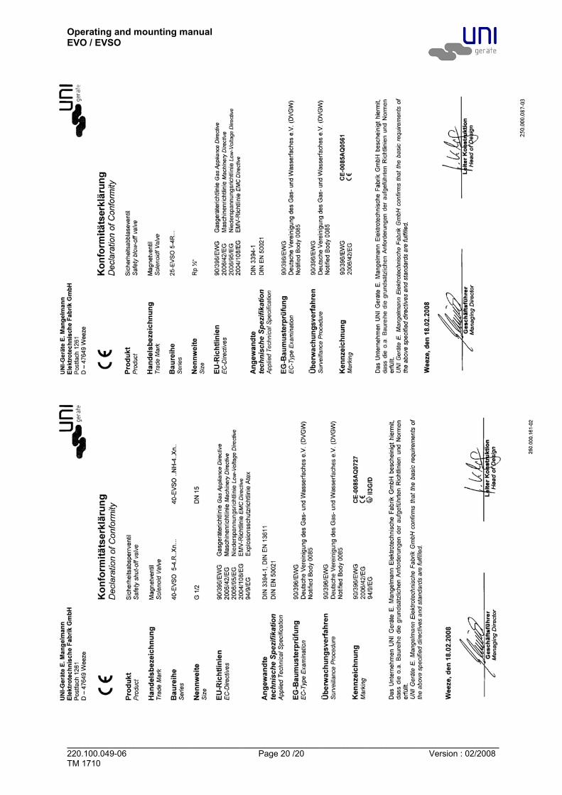
9.0 Warranty Scope and period of the warranty is specified in the edition of the “General Terms of Business of the UNI-Geräte E. Mangelmann Elektrotechnische Fabrik GmbH” valid at the time of delivery or else in the purchase agreement. We warranty that the valve is free from faults in line with the state of the art and for the confirmed field of application. No warranty claims will be accepted for damage resulting from improper use or failure to observe these operating and installation instructions, the statutory accident prevention regulations, the EN, DIN and VDE standards and other codes and regulations. Warranty claims will also not be accepted for damage occurring during operation due to operating conditions deviating from those specified in the data sheet or in other agreements. Justified complaints will be remedied by reworking by us or specialist companies authorised by us. Claims going beyond the scope of the warranty will not be accepted. The customer shall have no right to the supply of a replacement valve. Maintenance work, installation of parts from other manufacturers, any modifications to the design and natural wear are not covered by the warranty. Transport damage must be reported not to us but without delay to your responsible goods handling company, the railway company or the shipping agent as otherwise all claims for damages against these companies will be voided. 10.0 Explanations on Codes and Directives The Commission of the European Union has laid down common directives for the free trading of goods within the Union specifying minimum requirements for safety and health protection. The CE symbol confirms that products comply with the EU directives, i.e. in conformity with the relevant, in particular harmonised standards. Directives 90/396/EEC, 2006/42/EG and 97/23/EC are of relevance for the gas solenoid valve (mechanical part). Notes on Directive 90/396/EEC (Appliances Burning Gaseous Fuels): The valves have been developed, manufactured and tested in accordance with harmonised standard DIN EN 161 (DIN 3394-1, DIN 3391) and comply with the relevant requirements of the Union Directive 90/396/EEC. Unless otherwise stated separately, this has been confirmed by a type test. Notes on Directive 2006/42/EG (Machinery Directive): The valves have been developed, manufactured and tested in accordance with Directive 2006/42/EG. Notes on Directive 97/23/EG (Pressure Equipment Directive, DGRL): It has been conformed that the quality assurance in design control, manufacture and final acceptance of the manufacturer, UNI-Geräte E. Mangelmann Elektrotechnische Fabrik GmbH, satisfy the require-ments of 98/23/EC Annex III Module H. The gas solenoid valves comply with the fundamental require-ments of Directive 97/23/EC. Valves with permissible working pressures ≤ 0.5 bar, DN ≤ 25 and all products certified in accordance with category I and with 94/396/EEC are not covered by 97/23/EC. Only products covered by DGRL and classified in category I or higher may be marked in accordance with 97/23/EC. Fluid group 1 includes explosive, inflammable and toxic media. Fluid group 2 includes media not belonging to fluid group 1. Directives 2006/95/EG and 2004/108/EG are of relevance for the solenoid drive (800).

Operating and mounting manual EVO / EVSO
_______________________________________________________________________________________________________ 220.100.049-06 Page 11 /20 Version : 02/2008 TM 1710
Notes on Directive 2006/95/EG (Low Voltage Directive): The drives have been developed, designed and manufactured in accordance with standard “Electro-magnetic Devices” DIN EDV 0580. The requirements of the Low Voltage Directive that is applicable for rated voltages from 50 to 1000 V AC and 75 to 1500 V DC are therefore also satisfied. Note on Directive 2004/108/EG (EMC Directive): The magnet fulfil the requirements of the product family standards EN 55014-1,-2 , EN 61000-3-2, -3-3 for the industrial sector as well as for the sectors of housing, business and trade in small businesses. When using AC and DC versions, the user must provide a suitable mains filter (e.g. X capacitor 47 nF) at the connection to the mains power supply in order to suppress the physical mains-borne turn-off interference of the solenoid coil. Solenoid drives as drive elements for valves do not represent independently operated devices in the sense of the EMC Directive and are only further processed by specialist companies or are installed in a machine. Commissioning is not permitted until it has been determined that the whole machine or plant complies with the provisions of the EMC Directive. For solenoid drives for explosion-proof zone 1, see the relevant operating manual for the solenoid drives. Note concerning ex-guideline 94/9/EC (explosion guideline ATEX): The product is not subject to guideline 94/9/EC, since due to the loads occurring during practical operation, there is no effective source of ignition even in case of an error case to be assumed. This also applies for spring-loaded components, like for example the pneumatic drive. In case of electric drives, sensors or other electric components the application as per 94/9/EC is to be checked separately. National Codes and Directives For the use of safety shut-off devices in accordance with DIN EN 12952-8 or DIN EN 746, the requirements of DIN EN 161 and DIN 3394-1 have to be satisfied. This is confirmed by a type test or by an acceptance test certificate to EN10204-3.2 (01/05). Thread valves may be installed as follows:
DIN EN 746-2 DIN EN 12952-8 TRD 412 Pressure
bar Nom. dia. Nom. dia. Pressure
bar Nom. dia. Comment
≤ 0,1 ≤ G 3 ≤ G 2 ≤ 4 ≤ G 2 ≤ 2 ≤ G 2 > 4 ≤ G 1 Metal to metal joint ≤ 5 ≤ G 1

Operating and mounting manual EVO / EVSO
_______________________________________________________________________________________________________ 220.100.049-06 Page 12 /20 Version : 02/2008 TM 1710
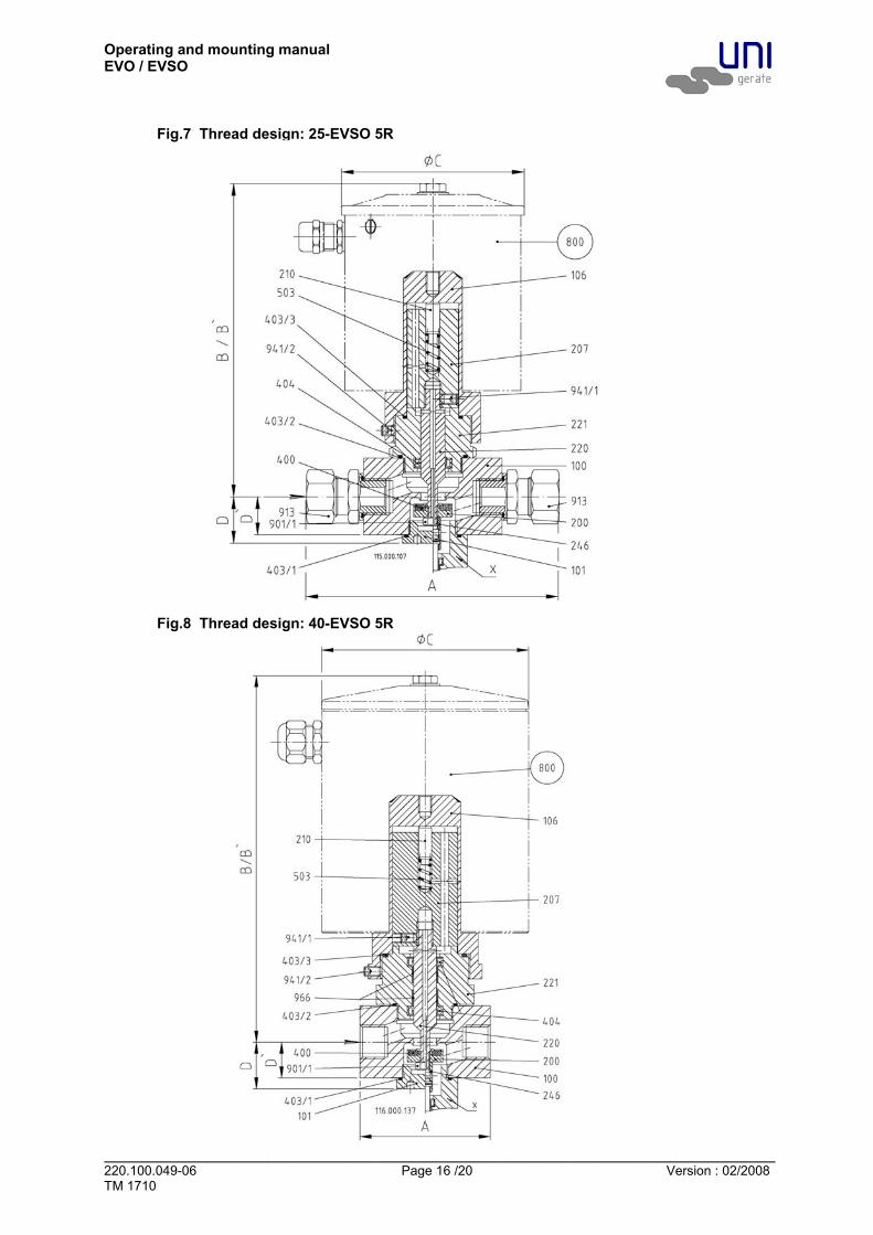
11.0 Sectional drawing 11.1 Fig.1 Flange design: 1-EVO 5NHR – 25NHR…
......
1 = Spare part kit X = Option limit switch mounting

Operating and mounting manual EVO / EVSO
_______________________________________________________________________________________________________ 220.100.049-06 Page 13 /20 Version : 02/2008 TM 1710
Fig.2 Flange design: 40-EVSO 5NHR…

Operating and mounting manual EVO / EVSO
_______________________________________________________________________________________________________ 220.100.049-06 Page 14 /20 Version : 02/2008 TM 1710
Fig.3 Thread design: 1-EVO 2R
Fig.4 Thread design: 1-EVO 3-10R ; 4-EVO 2-7R
Operating and mounting manual EVO / EVSO
_______________________________________________________________________________________________________ 220.100.049-06 Page 15 /20 Version : 02/2008 TM 1710
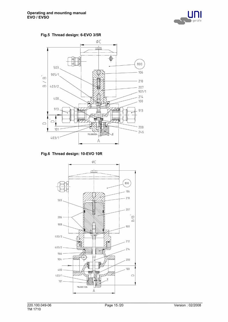
Fig.5 Thread design: 6-EVO 3/5R
Fig.6 Thread design: 10-EVO 10R
Operating and mounting manual EVO / EVSO
_______________________________________________________________________________________________________ 220.100.049-06 Page 16 /20 Version : 02/2008 TM 1710
Fig.7 Thread design: 25-EVSO 5R
Fig.8 Thread design: 40-EVSO 5R

Operating and mounting manual EVO / EVSO
_______________________________________________________________________________________________________ 220.100.049-06 Page 17 /20 Version : 02/2008 TM 1710
11.2 List of parts Pos./ Item Stück/ Qty. Benennung Description
100 1 Ventilgehäuse Valve chamber 101 1 Gehäusemutter Housing nut 106 1 Gehäuseoberteil Upper part of housing
108/1 1 Gehäuseflansch Housing flange 108/2 1 Gehäuseflansch Housing flange 110 1 Distanzstück Spacer 200 1 Ventilteller Valve disc 201 1 Tellerscheibe Disc plate 202 1 Ventilstück Valve piece 203 1 Federkappe Spring cap 204 1 Federführung Spring guide pin 205 1 Ventilspindel Valve spindle 206 2 Führungsring Guide ring 207 1 Magnetkern Solenoid core 210 1 Federbolzen Spring bolt 213 1 Gewindering Threaded ring 214 1 Ventilstift Valve pin 220 1 Ausgleichskolben Balance piston 221 1 Kolbenführung Piston guide 223 1 Buchse Bush 246 1 Verbindungsstück Endschalter Conncetion piece limit switch 269 1 Führungsbolzen Guide bolt 400 1 Ventiltellerdichtung Valve disc sealing
402/1 1 Flachdichtung Flat gasket 402/2 1 Flachdichtung Flat gasket 403/1 1 O-Ring O-ring 403/2 1 O-Ring O-ring 403/3 1 O-Ring O-ring 403/4 1 O-Ring O-ring 404 1 Lippenring Lip-ring 503 1 Druckfeder Pressure spring 800 1 Magnet-Antrieb Solenoid drive
900/1 4 Sechskantschraube Hex. head screw 900/2 4 Sechskantschraube Hex. head screw 901/1 1 Sechskantmutter Hex. nut 901/2 1 Sechskantmutter Hex. nut 902/1 1 Bolzen Bolt 902/2 1 Bolzen Bolt 905/1 1/4 Federring Lock washer 905/2 4 Federring Lock washer 908 1 Sicherungsblech Safety plate 911 4 Stiftschraube Headless screw 912 1 Splint Split-pin 913 2 Gerade Einschraubverschraub. Linear threaded screw connection
941/1 1 Gewindestift Setscrew 941/2 1 Gewindestift Setscrew 943 1 Spannstift Spring dowel sleeve
948/1 4 Nordlockscheiben Safety disc 948/2 4 Nordlockscheiben Safety disc 949/1 1 SL-Sicherung SL-retainer 949/2 1 SL-Sicherung SL-retainer 966 1/2 DU-Buchse DU-liner

Operating and mounting manual EVO / EVSO
_______________________________________________________________________________________________________ 220.100.049-06 Page 18 /20 Version : 02/2008 TM 1710
Wearing parts Version Type Spare parts
1- EVO 5NHR -25NHR.. Spare part kit (1), Solenoid drive (800) Flange version 40- EVSO 5NH... Solenoid drive (800)
1- EVO 2R Solenoid drive (800) 1- EVO3-10R Solenoid drive (800) 4- EVO 2-7R Solenoid drive (800) 6- EVO 3/5R Solenoid drive (800) 10- EVO 10R Solenoid drive (800) 25- EVSO 5R Solenoid drive (800)
Thread version
40- EVSO 5R Solenoid drive (800) Dimension with standard solenoid drive Connection G Dimension 1/4 3/8 1/2 3/4 1 1 1/4 1 1/2 2 Installation
length A 60 80(140*) 80(140*) 95 105 - - -
B 80 136 136 143 190 - - - B` 140 196 196 203 265 - - - ØC 62 83 83 83 106 - - - D 31 34 34 42 56 - - -
1-EVO
D` 20 23 23 30 39 - - - B 136 137 137 165 - - - - B` 196 197 197 240 - - - - ØC 83 83 83 106 - - - - D 31 34 34 42 - - - -
4-EVO
D` 20 23 23 30 - - - - B - 137 137 - - - - - B` - 197 197 - - - - - ØC - 83 83 - - - - - D - 34 34 - - - - -
6-EVO *
D` - 23 23 - - - - - B - - - - 240 - - - B` - - - - 335 - - - ØC - - - - 127 - - - D - - - - 49 - - -
10-EVO
D` - - - - - - - - B - - 180 - - - - - B` - - 255 - - - - - ØC - - 106 - - - - - D - - 28 - - - - -
25-EVSO *
D` - - 23 - - - - - B - - 221 - - - - - B` - - 310 - - - - - ØC - - 127 - - - - - D - - 30 - - - - -
40-EVSO
D` - - 23 - - - - - * (140*) = Anschlussausführung durch Gerade-Einschraubverschraubung Connection by linear threaded screw connection

Operating and mounting manual EVO / EVSO
_______________________________________________________________________________________________________ 220.100.049-06 Page 19 /20 Version : 02/2008 TM 1710
Flange DN Dimension 15 20 25 32 40 50 65 80 100 125 150 Installation lenght
A1) 130 150 160 180 200 230 290 310 350 400 480
Flange ANSI Dimension 1/2" 3/4" 1” 11/4” 11/2” 2” 21/2” 3” 4” - 6” Installation lenght
A2) 108 118 127 140 165 203 216 241 292 - 406
B 212 212 303 321 388 400 455 - - - - B` 287 287 393 420 508 535 605 - - - - ØC 106 106 127 127 153 153 191 - - - - D 84 84 84 103 103 111 126 - - - -
1-EVO
D` 74 74 74 89 89 97 112 - - - - B 454 - - - - - - - - - - B` 603 - - - - - - - - - - ØC 191 - - - - - - - - - - D 84 - - - - - - - - - -
40-EVSO
D` 74 - - - - - - - - - - A1) = Dimension at DIN (resp. flanges ANSI and dimension DIN or flanges and dimension at DIN) A2) = Dimension at ANSI 150lbs (resp. flanges and dimension at ANSI) B` = Dimension for removing the solenoid drive 12.0 Declaration of Conformity
Operating and mounting manual EVO / EVSO
_______________________________________________________________________________________________________ 220.100.049-06 Page 20 /20 Version : 02/2008 TM 1710
Related Documents