Operating instructions K- Control 4960, 4965, 4970. Always on the safe side.

Welcome message from author
This document is posted to help you gain knowledge. Please leave a comment to let me know what you think about it! Share it to your friends and learn new things together.
Transcript
Operating instructionsK- Control 4960, 4965, 4970.
Always on the safe side.

Hersteller/manufacturer:Kaltenbach & Voigt GmbH Bismarckring 39D-88400 Biberach
Vertrieb/distribution:KaVo Dental GmbHBismarckring 39 D-88400 BiberachTel.: 0 73 51 / 56-0 • Fax: 0 73 51 / 56 -14 88

A 1 User information ..............................................................................................................................................................2A 1.1 Meaning of the pictograms ......................................................................................................................................2A 1.2 Important information ..............................................................................................................................................2A 1.3 Precautions ..............................................................................................................................................................2A 1.4 Purpose and potential uses ......................................................................................................................................3A 1.5 Technical data ..........................................................................................................................................................3A 1.6 Combination Controller - handpiece ........................................................................................................................4
A 2 Scope of delivery/Accessories ......................................................................................................................................5
A 3 Electrical connection ......................................................................................................................................................5
A 4 Location ............................................................................................................................................................................6
A 5 Mounting and connection ..............................................................................................................................................7A 5.1 Mounting 4960 ..........................................................................................................................................................7A 5.2 Mounting 4965 / 4970 ..............................................................................................................................................8A 5.3 Connection ..............................................................................................................................................................8
A 6 Controls and functional elements ..................................................................................................................................9
A 7 Preparations for commencing operation ....................................................................................................................10
A 8 Operation ........................................................................................................................................................................11A 8.1 Starting K-Control knee control unit 4960 .............................................................................................................. 11A 8.2 Starting K-Control Benchtop Control unit 4965. ....................................................................................................11A 8.3 Starting a K-Control installation with the type 4970 Foot control unit. ..................................................................11
A 9 Operating faults ............................................................................................................................................................12
Guarantee conditions ......................................................................................................................................................14Spare parts ......................................................................................................................................................................15EC- Declaration of conformity ..........................................................................................................................................18Drilling template ................................................................................................................................................................20
K- Control 4960, 4965, 4970.
1

K- Control 4960, 4965, 4970.
2
A 1.2 Important information
The instructions for use should beread by the user before starting up the
unit for the first time, in order to avoidincorrect operation and other damage. Ifother language versions are required, pleaserequest these from your responsible KaVoagent. Duplication and distribution of theinstructions for use (IU) require KaVo'sprior consent.
All technical data, information and proper-ties of the product described in the IU cor-respond to the state on going to press.
Modifications and improvements to theproduct as a result of new technical devel-opments are possible.
This does not imply any right to retrofittingof existing units.
KaVo assumes no responsibility for damagearising through:
• external influences (poor quality of themedia or inadequate installation)
• use of incorrect information• improper use• improperly performed repairs.
Repair and maintenance work - apart fromthe activities described in these instructionsfor use - may be performed only by quali-fied technical personnel.
In the event of modifications by third par-ties, the approvals become null and void.KaVo recommends using only originalspare parts for operation and for repair.
Please note that the EC Directive onwaste electrical and electronic equip-
ment applies to this product. Within Europetherefore, this product must undergo specialdisposal. For more detailed informationabout this, please contact KaVo or yourspecialist dental supplier.
A 1.3 Precautions
Safe operation and protection of the unit areensured only through proper use in accor-dance with the instructions for use andusing the tools approved for the purpose.The following should also be observed:
• the work safety regulations,• the accident prevention regulations.
! Each time before switching on, check theset speed.! Observe the permissible maximumspeed and maximum pressure of the tools(according to tool manufacturer'sinstructions).
A 1.4 Purpose and potential uses
K-Control-installation is versatile and verysuitable for working on crowns and bridges.
A 1.5 Technical data
Dimensions and weightK-Control Knee-Operated Control Unittype 4960Width: 95 mmDepth: 280 mmHeight: 235 mmWeight: approx.3 kg
K-Control Benchtop Control Unittype 4965Width: 95 mmDepth: 280 mmHeight: 235 mmWeight: approx. 3 kg
K-Control Foot Control Unittype 4960Width: 245 mmDepth: 275 mmHeight: 125 mmWeight: approx.3 kg
Rated voltageLine voltage fluctuations < ± 10 % Voltage range: 100 / 120 / 230 V
50 / 60 Hz
Rated powerK-Control units max.220 W
A 1 User information
A 1.1 Meaning of the pictograms
Situations where failure to follow theinstructions may lead to danger,
damage to material or operating faults.
Important information for operatorand engineer.
Automatic modeAutomatic sequence
Close, screw in, fasten, etc.
Open, release, loosen
+ more, higher
- less, lower
∞ Continuous operation
Time, time sequence
Disconnect mains plug
I Device ON, turned onO Device OFF, unplug from the powersupply

K- Control 4960, 4965, 4970.
3
Speed rangeRight-handed rotation:1 000 - 35 000 min-1 (K 5 Handpiece)1 000 - 25 000 min-1 (K 9 Handpiece)1 000 - 40 000 min-1 (K11 Handpiece)1 000 - 40 000 min-1 (K10 Handpiece)1 000 - 50 000 min-1 (K12 Handpiece)5 000 - 60 000 min-1 (SF-Handpiece)1000 - 50 000 min-1 (K-POWERgrip)1000 - 50 000 min-1 (K-ERGOgrip)Left-handed rotation, limited to about 5,000min-1
Intermittent service 2 min / on8 min / off
Pollution level 2
Overvoltage category ll
Amblent conditions:Max. elevation 2000 m above sea level• Permissible in inner rooms• Permissible ambient temperature range
5 C - 40 C• Permissible up to a max. relative humidityof 80%
We reserve the right to make any alterations.
Transportation and storage conditionsTemperature range: -20 °C to +70°CRelative humidity: 5% to 95% (non-condensing)Air pressure: 700 hPa to 1060 hPa
Prior to start-up, very cold productsmust be heated to a temperature of
20 ° to 25 °C. Avoid condensation.
Rating plate Provides information on:
@ Manufacturer2 Order number (REF number)3 GS-Mark4 For information about proper disposal,see A1.25 CSA-Mark6 Year of manufacture - Serial number7 CE-Mark according to 89/336 EWG8 VDE-Mark9 Mode: intermittent service: 2 min, 8 min pause0 Unit type
4620
4965
03
nmaxx1000/min
Kcontrol
03
nmaxx1000/min
Kcontrol
4960
control
30000/min
max
4970
@ 42
6
05
78
3
9

K- Control 4960, 4965, 4970.
4
A 1.6 Combination Controller - hand-piece
In the combination with K-Control controlunits of types 4960, 4965 and 4970, thefollowing handpieces can be operated:
K 5 Handpiece 4910K 9 Handpiece 950/955K 9 Handpiece 4930K 9 Compact motor 970K 9 Cutter spindle 960K 10 Handpiece 4950
(with Adapter 0.674.4721)K 11 Handpiece 4990K 12 Handpiece 4940SF Handpiece 4005
(with supply cable 0.674.4921)K-POWERgrip 4941K-ERGOgrip 4944
The safty of the K-Control controlunits with handpieces can be
guaranteed only with the handpiece/controlunit combinations approved by KaVo.
4965
03
nmaxx1000/min
Kcontrol
control
30000/min
max
4970
03
nmaxx1000/min
Kcontrol
4960
K-POWERgrip K12 K5 K11 K9 SF K-ERGOgrip
K- Control 4960, 4965, 4970.
5
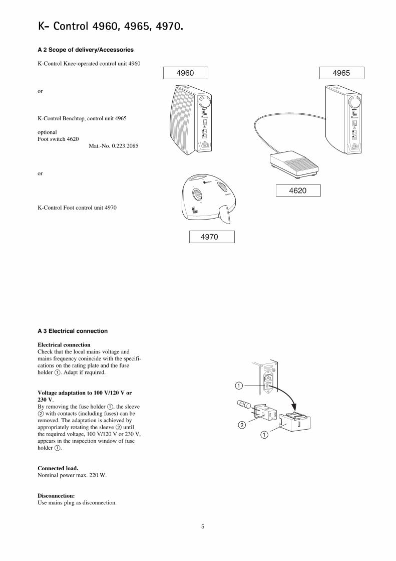
A 2 Scope of delivery/Accessories
K-Control Knee-operated control unit 4960
or
K-Control Benchtop, control unit 4965
optionalFoot switch 4620
Mat.-No. 0.223.2085
or
K-Control Foot control unit 4970
A 3 Electrical connection
Electrical connectionCheck that the local mains voltage andmains frequency conincide with the specifi-cations on the rating plate and the fuseholder @. Adapt if required.
Voltage adaptation to 100 V/120 V or230 V. By removing the fuse holder @, the sleeve2 with contacts (including fuses) can beremoved. The adaptation is achieved byappropriately rotating the sleeve ” untilthe required voltage, 100 V/120 V or 230 V,appears in the inspection window of fuseholder @.
Connected load.Nominal power max. 220 W.
Disconnection:Use mains plug as disconnection.
@
230
120100
4960
03
nmaxx1000/min
Kcontrol
4965
4620
03
nmaxx1000/min
Kcontrol
4970
control
30000/min
max
”@
6
K- Control 4960, 4965, 4970.
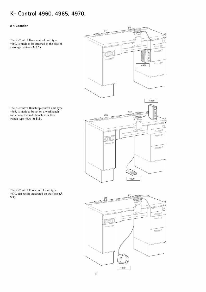
A 4 Location
The K-Control Knee control unit, type4960, is made to be attached to the side ofa storage cabinet (A 5.1).
The K-Control Benchtop control unit, type4965, is made to be set on a workbenchand connected underbench with Footswitch type 4620 (A 5.2).
The K-Control Foot control unit, type 4970, can be set unsecured on the floor (A5.2).
4960
03
nmaxx1000/min
Kcontrol
4965
03
nmaxx1000/min
Kcontrol
4620
4970
control
30000/min
max
7
K- Control 4960, 4965, 4970.
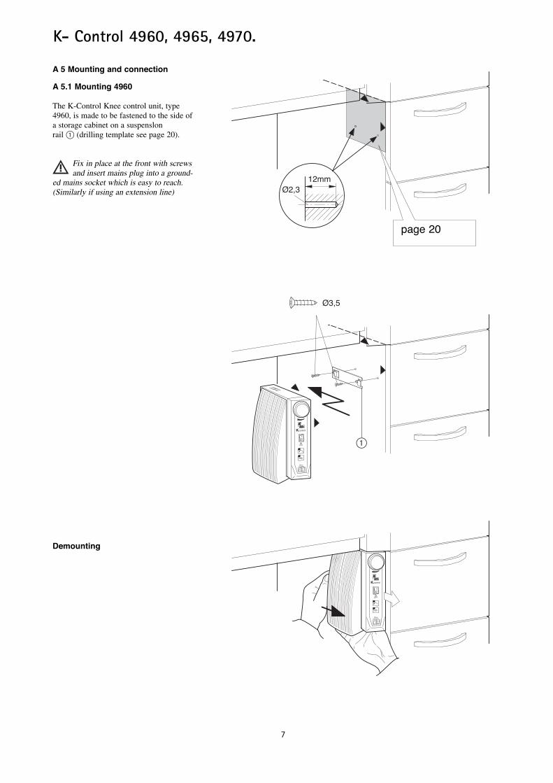
A 5 Mounting and connection
A 5.1 Mounting 4960
The K-Control Knee control unit, type4960, is made to be fastened to the side ofa storage cabinet on a suspenslonrail 1 (drilling template see page 20).
Fix in place at the front with screwsand insert mains plug into a ground-
ed mains socket which is easy to reach.(Similarly if using an extension line)
Demounting
Ø2,312mm
03
nmaxx1000/min
Kcontrol
Ø3,5
03
nmaxx1000/min
Kcontrol
1
page 20
K- Control 4960, 4965, 4970.
8
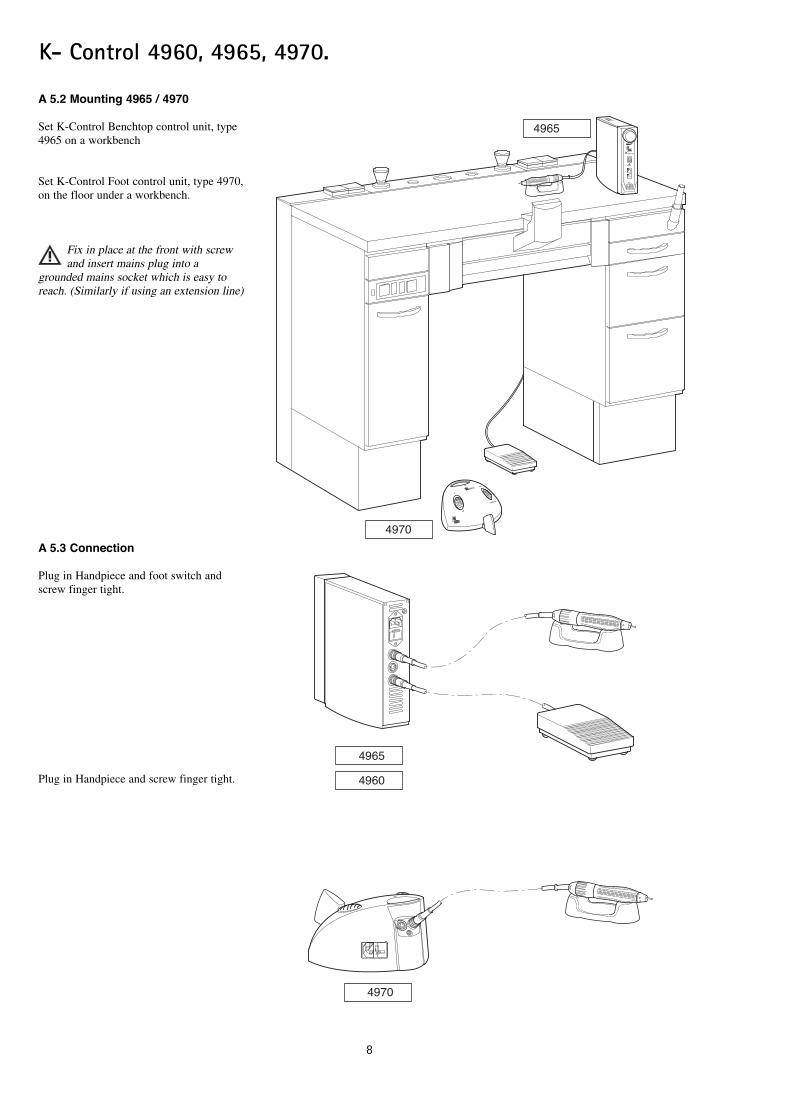
A 5.2 Mounting 4965 / 4970
Set K-Control Benchtop control unit, type4965 on a workbench
Set K-Control Foot control unit, type 4970,on the floor under a workbench.
Fix in place at the front with screwand insert mains plug into a
grounded mains socket which is easy toreach. (Similarly if using an extension line)
A 5.3 Connection
Plug in Handpiece and foot switch andscrew finger tight.
Plug in Handpiece and screw finger tight.
03
nmaxx1000/min
Kcontrol
control
30000/min
max
4965
4970
4960
4965
4970
K- Control 4960, 4965, 4970.
9
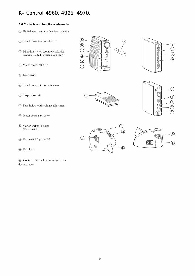
A 6 Controls and functional elements
1 Digital speed and malfunction indicator
2 Speed limitation preselector
3 Direction switch (counterclockwise running limited to max. 5000 min-1)
4 Mains switch "0"/"1"
5 Knee switch
6 Speed preselector (continuous)
7 Suspension rail
8 Fuse holder with voltage adjustment
9 Motor sockets (4-pole)
¯ Starter socket (5-pole) (Foot switch)
» Foot switch Type 4620
w Foot lever
‰ Control cable jack (connection to thedust extractor)
03
nmaxx1000/min
Kcontrol
03
nmaxx1000/min
Kcontrol
control
30000/min
max
#
»
„
@”#£fiÌ \
|·¯
@”#£
Ì
@”
|
·
‰
10
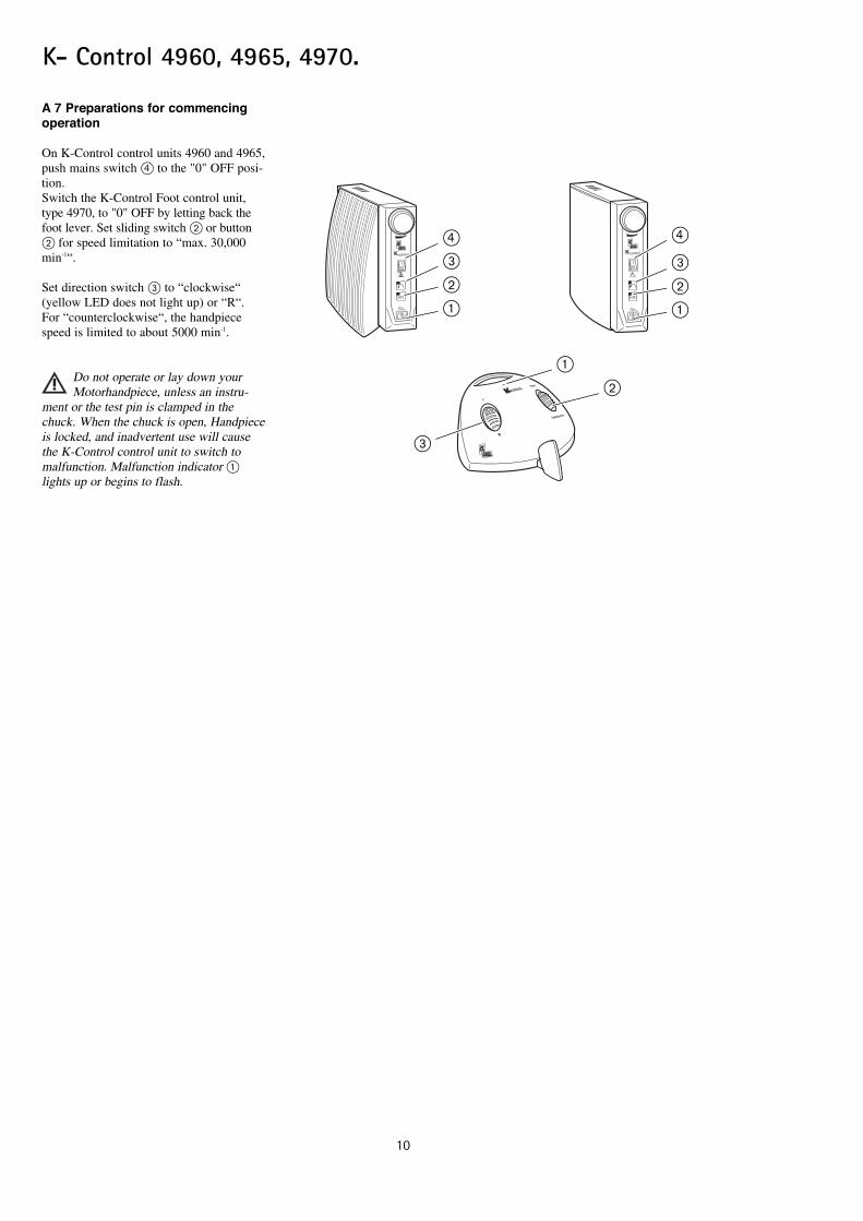
A 7 Preparations for commencingoperation
On K-Control control units 4960 and 4965,push mains switch £ to the "0" OFF posi-tion.Switch the K-Control Foot control unit,type 4970, to "0" OFF by letting back thefoot lever. Set sliding switch 2 or button2 for speed limitation to “max. 30,000min-1“.
Set direction switch # to “clockwise“(yellow LED does not light up) or “R“.For “counterclockwise“, the handpiecespeed is limited to about 5000 min-1.
Do not operate or lay down yourMotorhandpiece, unless an instru-
ment or the test pin is clamped in thechuck. When the chuck is open, Handpieceis locked, and inadvertent use will causethe K-Control control unit to switch tomalfunction. Malfunction indicator 1lights up or begins to flash.
K- Control 4960, 4965, 4970.
03
nmaxx1000/min
Kcontrol
03
nmaxx1000/min
Kcontrol
control
30000/min
max
#
@”
@”#
££#”@

11
K- Control 4960, 4965, 4970.
A 8 Operation
Check set speed each time beforeswitching on.
Regulations for prevention of accidents areto be observed!When preselecting a speed over 30,000 min-1,button 2 should be pressed (yellow LEDlights up). This additional “enabling“serves for consciously registering the highspeed and the resultant possible dangerwhen using tools which may be unsuitable.
A 8.1 Starting K-Control knee con-trol unit 4960
Preselect desired maximum speed on speedlimiter 2.
When the knee switch plate is pressed inthe direction of the arrow the speed can becontinuously regulated from 1000 min-1 tothe preselected maximum speed.
A 8.2 Starting K-Control BenchtopControl unit 4965.
Preselect desired maximum speed on speedlimiter 2.
Start your Handpiece at the preselectedspeed by depressing Foot switch 4620 q.
A 8.3 Starting a K-Control installa-tion with the type 4970 Foot controlunit.
By pressing the foot control lever in thedirection of the arrow, the speed of theHandpiece can be regulated (enabled bysliding switch 2).
Allowing the foot lever | to return underspring pressure all the way back, stops theHandpiece.
03
nmaxx1000/min
Kcontrol
4960
03
nmaxx1000/min
Kcontrol
control
30000/min
max
4970
control
30000/min
max
03
nmaxx1000/min
Kcontrol
4965
03
nmaxx1000/min
Kcontrol
4620»
Ì
”
”
”
|

12
K- Control 4960, 4965, 4970.
A 9 Operating faults
Repairs and servicing work on theelectrical part of this equipment must
only be undertaken by experts or by per-sons trained in our factory who are awareof the safety regulations. Disconnect themains plug from the power supply, resp.switch off the disconnecting switch beforecarrying out any maintenance work.
In K-Control knee and table-top con-trol units, error messages are shown
visually on the display 1. In the K-Control foot control unit, error messagesare indicated by flashing of the malfunctionLED 2 (e.g. error message No. 7 = 7 xflashes, etc.).
C • Main processor not runningR • Repair or replace motor electronics
C • Overloading of motor, motor current above 4 A for 7 sec
R • Reduce motor load or stop and re-startwith foot switch.
C • Handpiece blocked for more than 3 seconds
R • Eliminate blocking, stop and restart
C • No handpiece connected (also open circuit K9, K10)
R • Connect handpiece and restart
C • No handpiece connected (also open circuit K5, K11, K12, SF)
R • Connect handpiece and restart
C •Handpiece speed too high for longer than 2 seconds, a phase of the handpichas been interrupted or electronics are faulty.
R •Repair handpiece or control unit
F = Fault C = Cause R = Rectificatio
F • Error display: F 6
F • Error display: F 4
F • Error display: F 3
F • Error display: F 2
F • Error display: F 1
F • Error display: F 0
4620
4965
03
nmaxx1000/min
Kcontrol
03
nmaxx1000/min
Kcontrol
4960
control
30000/min
max
4970
K12 K5 K11 K9 SF
@
@
”
K- Control 4960, 4965, 4970.
13
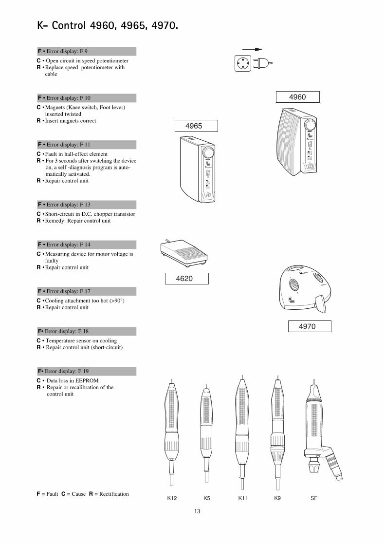
C • Open circuit in speed potentiometerR •Replace speed potentiometer with
cable
C •Magnets (Knee switch, Foot lever) inserted twisted
R • Insert magnets correct
C •Fault in hall-effect elementR • For 3 seconds after switching the device
on, a self -diagnosis program is auto-matically activated.
R •Repair control unit
C •Short-circuit in D.C. chopper transistorR •Remedy: Repair control unit
C •Measuring device for motor voltage is faulty
R •Repair control unit
C •Cooling attachment too hot (>90°)R •Repair control unit
C • Temperature sensor on cooling R • Repair control unit (short-circuit)
C • Data loss in EEPROMR • Repair or recalibration of the
control unit
F = Fault C = Cause R = Rectification
F• Error display: F 19
F• Error display: F 18
F • Error display: F 17
F • Error display: F 14
F • Error display: F 13
F • Error display: F 11
F • Error display: F 10
F • Error display: F 9
4620
4965
03
nmaxx1000/min
Kcontrol
03
nmaxx1000/min
Kcontrol
4960
control
30000/min
max
4970
K12 K5 K11 K9 SF
K- Control 4960, 4965, 4970.
14
Guarantee provisions
For the product cited in the transfer protocol, KaVo warrantees the end customer that the product will function properly, have no materialor manufacturing flaws for 12 months from the date of purchase under the following conditions:In the case of valid complaints due to defects or a short delivery, KaVo will make good its warranty by replacing the product free of cost orrepairing it according to your wishes. All other claims of any kind are excluded, especially claims for damages.In case of delayed performance, gross negligence or criminal intent, this shall apply only if there are no compelling legal regulations to thecontrary. KaVo is not liable for defects and their consequences that arise from natural wear, improper cleaning or servicing, the non-observance of instructions for use, servicing or connection, scale formation or corrosion, impurities in the air and water supply,or chemical or electrical influences that are unusual or impermissible according to the manufacturer's specifications.The warranty does not generally extend to lamps, glassware, rubber parts and the colour fastness of plastic parts.No liability is assumed when defects or their consequences can arise from manipulations or changes to the product by the customer or athird party.Claims from this warranty can only be asserted when the transfer protocol (copy) belonging to the product has been sent to KaVo, and theoriginal can be presented by the operator or user.

15
K- Control 4960, 4965, 4970.
4960
2 3 0 1 2 0 1 0 0
0 3
n m a x x 1 0 0 0 / m i n
K c o n t r o l
0.642.0561
0.642.0252
0.221.9116
0.642.0272 0.245.5015
0.200.6529 0.200.6528
0.260.9677 0.642.0282
0.692.9051
0.223.2735 0.642.0661
0.692.9031
0.692.9041
0.692.9021
0.696.0221 AT 1.002.6852
0.642.0561
0.696.0311
0.201.7065
0.221.4909 0.242.4012 0.260.8505
0.224.2498
0.223.4142 DE 0.692.6881 CH
0.692.6891 USA/JP 0.692.6901 GB
0.692.6851 AUS
0.223.0050 0.223.2801 F 6,3A 250V

16
K- Control 4960, 4965, 4970.
4965
0.642.0561
0.642.0272
0.245.5015 0.200.6529 0.200.6528
0.692.9051
0.692.9031 0.692.9041
0.692.9021
0.696.0221 AT 1.002.6852 0.642.0561
0.696.0311
0.201.7065
0.221.4909
0.223.2735 0.642.0661
0.242.4012 0.260.8505
0.224.2498
0.223.0050
0.223.2801 F 6,3A 250V
0.224.7001 0.617.0511
0.223.2085
0.617.0460 1,8 m 0.617.0410 1,0 m
0.223.2111 0.220.0423
0.223.4142 DE 0.692.6881 CH
0.692.6891 USA/JP 0.692.6901 GB
0.692.6851 AUS
17
K- Control 4960, 4965, 4970.
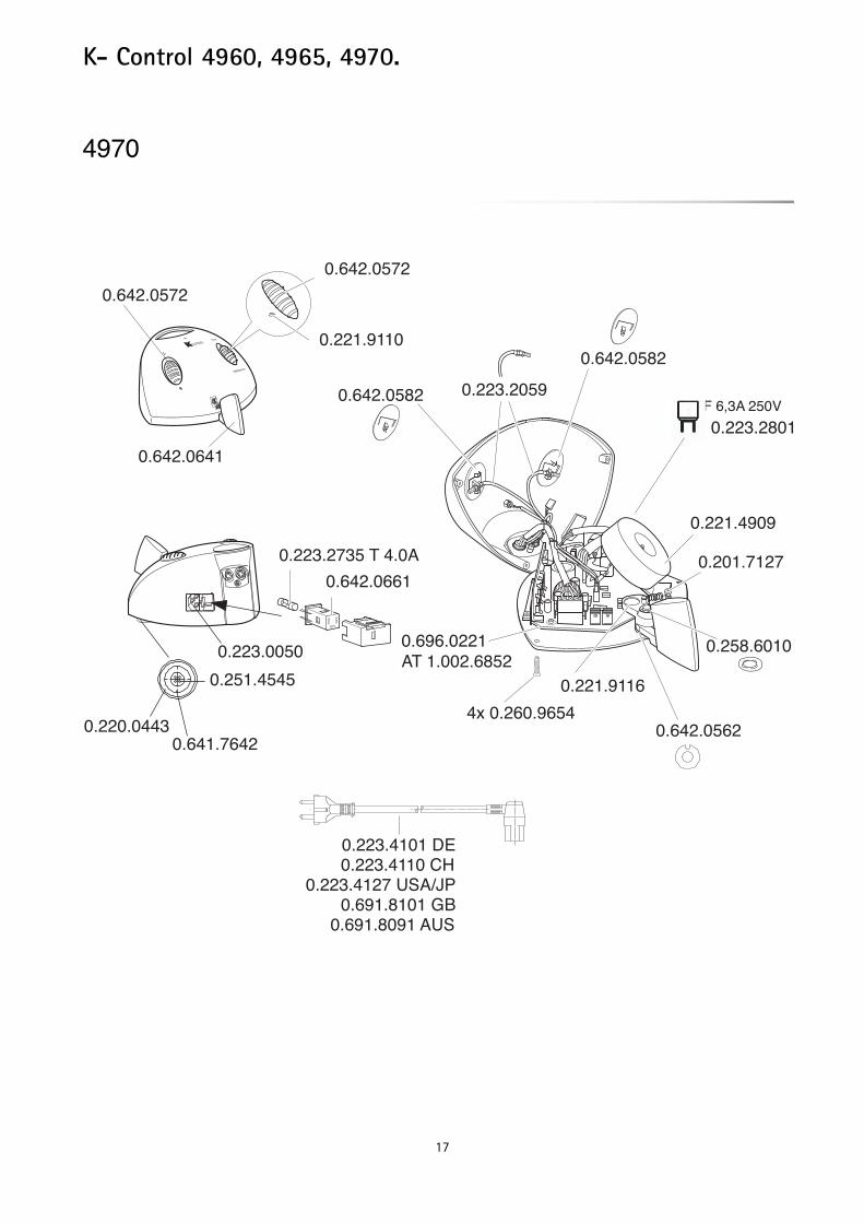
4970
3 0 0 0 0 / m i n
0.223.2735 T 4.0A 0.642.0661
0.223.2059
0.642.0572
0.221.9110
0.642.0641
0.221.4909
0.201.7127
0.258.6010
0.642.0562
0.221.9116
0.696.0221 AT 1.002.6852
4x 0.260.9654
0.642.0582
0.642.0582
0.642.0572
0.220.0443
0.251.4545
0.641.7642
0.223.0050
0.223.2801F 6,3A 250V
0.223.4101 DE 0.223.4110 CH
0.223.4127 USA/JP 0.691.8101 GB
0.691.8091 AUS
18
K- Control 4960, 4965, 4970.

19
K- Control 4960, 4965, 4970.

20
K- Control 4960, 4965, 4970.
156,
5 m
m53
mm
MAS
TERs
pace
51m
m F
LEXs
pace
Ø2,
3 m
mØ
2,3
mm
90 m
m M
ASTE
Rspa
ce93
mm
FLE
Xspa
ce
Drilling template


1.00
0.45
75"
Fk"
11/0
7"
en "
01.2
6
KaVo Dental GmbH. D-88400 Biberach/RissTelefon +49 7351 56-0 Fax +49 7351 56-1488
Internet: www.kavo.com
Related Documents