Welcome message from author
This document is posted to help you gain knowledge. Please leave a comment to let me know what you think about it! Share it to your friends and learn new things together.
Transcript


Praise for OpenGL® ES™ 3.0 Programming Guide, Second Edition
“As a graphics technologist and intense OpenGL ES developer, I can honestly say that if you buy only one book on OpenGL ES 3.0 programming, then this should be the book. Dan and Budirijanto have written a book clearly by programmers for programmers. It is simply required reading for anyone interested in OpenGL ES 3.0. It is informative, well organized, and comprehensive, but best of all practical. You will find yourself reaching for this book over and over again instead of the actual OpenGL ES specification during your programming sessions. I give it my highest recommendation.”
—Rick Tewell, Graphics Technology Architect, Freescale
“This book provides outstanding coverage of the latest version of OpenGL ES, with clear, comprehensive explanations and extensive examples. It belongs on the desk of anyone developing mobile applications.”
—Dave Astle, Graphics Tools Lead, Qualcomm Technologies, Inc., and Founder, GameDev.net
“The second edition of OpenGL® ES™ 3.0 Programming Guide provides a solid introduction to OpenGL ES 3.0 specifications, along with a wealth of practical information and examples to help any level of developer begin programming immediately. We’d recommend this guide as a primer on OpenGL ES 3.0 to any of the thousands of developers creating apps for the many mobile and embedded products using our PowerVR Rogue graphics.”
—Kristof Beets, Business Development, Imagination Technologies
“This is a solid OpenGL ES 3.0 reference book. It covers all aspects of the API and will help any developer get familiar with and understand the API, including specifically the new ES 3.0 functionality.”
—Jed Fisher, Managing Partner, 4D Pipeline
“This is a clear and thorough reference for OpenGL ES 3.0, and an excellent presentation of the concepts present in all modern OpenGL programming. This is the guide I’d want by my side when diving into embedded OpenGL.”
—Todd Furlong, President & Principal Engineer, Inv3rsion LLC

This page intentionally left blank

OpenGL® ES™ 3.0Programming Guide
Second Edition

The OpenGL graphics system is a software interface to graphics hardware.
(“GL” stands for “Graphics Library”.) It allows you to create interactive programs
that produce color images of moving, three-dimensional objects. With OpenGL,
you can control computer-graphics technology to produce realistic pictures, or
ones that depart from reality in imaginative ways.
The OpenGL Series from Addison-Wesley Professional comprises tutorial and
reference books that help programmers gain a practical understanding of OpenGL
standards, along with the insight needed to unlock OpenGL’s full potential.
Visit informit.com/opengl for a complete list of available products.
Make sure to connect with us!informit.com/socialconnect
OpenGL Seriesfrom Addison-Wesley
Dan GinsburgBudirijanto Purnomo
With Earlier Contributions FromDave ShreinerAaftab Munshi
OpenGL® ES™ 3.0Programming Guide
Second Edition

Many of the designations used by manufacturers and sellers to distinguish their products are claimed as trademarks. Where those designations appear in this book, and the publisher was aware of a trademark claim, the designations have been printed with initial capital letters or in all capitals.
Front cover image is from Snapdragon Game Studio’s Fortress: Fire OpenGL® ES™
3.0 demo, courtesy of Qualcomm Technologies Inc.
OpenGL® is a registered trademark and the OpenGL® ES™ logo is a trademark of Silicon Graphics Inc. used by permission by Khronos.
The OpenGL® ES™ shading language built-in functions described in Appendix B are copyrighted by Khronos and are reprinted with permission from the OpenGL® ES™ 3.00.4 Shading Language Specification.
The OpenGL® ES™ 3.0 Reference Card is copyrighted by Khronos and reprinted with permission.
The authors and publisher have taken care in the preparation of this book, but make no expressed or implied warranty of any kind and assume no responsibility for errors or omissions. No liability is assumed for incidental or consequential damages in connection with or arising out of the use of the information or programs contained herein.
For information about buying this title in bulk quantities, or for special sales opportunities (which may include electronic versions; custom cover designs; and content particular to your business, training goals, marketing focus, or branding interests), please contact our corporate sales department at [email protected] or (800) 382-3419.
For government sales inquiries, please contact [email protected].
For questions about sales outside the U.S., please contact [email protected].
Visit us on the Web: informit.com/aw
Library of Congress Cataloging-in-Publication DataGinsburg, Dan. OpenGL ES 3.0 programming guide / Dan Ginsburg, Budirijanto Purnomo ; with earlier contributions from Dave Shreiner, Aaftab Munshi.—Second edition. pages cm Revised edition of: The OpenGL ES 2.0 programming guide / Aaftab Munshi, Dan Ginsburg, Dave Shreiner. 2009. Includes bibliographical references and index. ISBN 978-0-321-93388-1 (paperback : alk. paper)1. OpenGL. 2. Computer graphics—Specifications. 3. Application program
interfaces (Computer software) 4. Computer programming. I. Purnomo, Budirijanto. II. Shreiner, Dave. III. Munshi, Aaftab. IV. Title. T385.G5426 2014 006.6’6—dc23 2013049233
Copyright © 2014 Pearson Education, Inc.
All rights reserved. Printed in the United States of America. This publication is protected by copyright, and permission must be obtained from the publisher prior to any prohibited reproduction, storage in a retrieval system, or transmission in any form or by any means, electronic, mechanical, photocopying, recording, or likewise. To obtain permission to use material from this work, please submit a written request to Pearson Education, Inc., Permissions Department, One Lake Street, Upper Saddle River, New Jersey 07458, or you may fax your request to (201) 236-3290.
ISBN-13: 978-0-321-93388-1 ISBN-10: 0-321-93388-5
Text printed in the United States on recycled paper at RR Donnelley in Crawfordsville, Indiana.
First printing, March 2014
Editor-in-ChiefMark L. Taub
Executive EditorLaura Lewin
Development EditorSheri Cain
Managing EditorJohn Fuller
Project EditorElizabeth Ryan
Copy EditorJill Hobbs
IndexerInfodex Indexing Services, Inc.
ProofreaderLinda Begley
Technical ReviewersEmmanuel AguPeter LohrmannMaurice Ribble
Editorial AssistantOlivia Basegio
Cover DesignerChuti Prasertsith
CompositordiacriTech

vii
Contents
List of Figures ���������������������������������������������������������������������������������������xvii
List of Examples �������������������������������������������������������������������������������������xxi
List of Tables ������������������������������������������������������������������������������������������xxv
Foreword �����������������������������������������������������������������������������������������������xxix
Preface ��������������������������������������������������������������������������������������������������xxxi
Intended Audience ............................................................................xxxiOrganization of This Book ................................................................xxxiiExample Code and Shaders .............................................................xxxviErrata ................................................................................................xxxvi
Acknowledgments ����������������������������������������������������������������������������xxxvii
About the Authors ������������������������������������������������������������������������������xxxix
1� Introduction to OpenGL ES 3�0 ����������������������������������������������������������������1
OpenGL ES 3.0 ........................................................................................3Vertex Shader ....................................................................................4Primitive Assembly ...........................................................................7Rasterization .....................................................................................7Fragment Shader ...............................................................................8Per-Fragment Operations .................................................................9
What’s New in OpenGL ES 3.0 .............................................................11Texturing ........................................................................................11Shaders ............................................................................................13
viii Contents
Geometry ........................................................................................15Buffer Objects .................................................................................16Framebuffer ....................................................................................17
OpenGL ES 3.0 and Backward Compatibility ......................................17EGL .......................................................................................................19
Programming with OpenGL ES 3.0 ................................................20Libraries and Include Files ..............................................................20
EGL Command Syntax .........................................................................20OpenGL ES Command Syntax .............................................................21Error Handling ......................................................................................22Basic State Management .......................................................................23Further Reading ....................................................................................25
2� Hello Triangle: An OpenGL ES 3�0 Example ������������������������������������������27
Code Framework ...................................................................................28Where to Download the Examples .......................................................28Hello Triangle Example ........................................................................29Using the OpenGL ES 3.0 Framework ..................................................34Creating a Simple Vertex and Fragment Shader ...................................35Compiling and Loading the Shaders ....................................................36Creating a Program Object and Linking the Shaders ...........................38Setting the Viewport and Clearing the Color Buffer ............................39Loading the Geometry and Drawing a Primitive .................................40Displaying the Back Buffer ...................................................................41Summary ...............................................................................................42
3� An Introduction to EGL ���������������������������������������������������������������������������43
Communicating with the Windowing System ....................................44Checking for Errors ...............................................................................45Initializing EGL .....................................................................................46Determining the Available Surface Configurations .............................46Querying EGLConfig Attributes ...........................................................48Letting EGL Choose the Configuration ................................................51Creating an On-Screen Rendering Area: The EGL Window .................53Creating an Off-Screen Rendering Area: EGL Pbuffers .........................56Creating a Rendering Context ..............................................................60
Contents ix
Making an EGLContext Current ..........................................................62Putting All Our EGL Knowledge Together............................................63Synchronizing Rendering .....................................................................66Summary ...............................................................................................67
4� Shaders and Programs ���������������������������������������������������������������������������69
Shaders and Programs ...........................................................................69Creating and Compiling a Shader ..................................................70Creating and Linking a Program ....................................................74
Uniforms and Attributes .......................................................................80Getting and Setting Uniforms ........................................................81Uniform Buffer Objects ..................................................................87Getting and Setting Attributes .......................................................92
Shader Compiler ...................................................................................93Program Binaries ...................................................................................94Summary ...............................................................................................95
5� OpenGL ES Shading Language �������������������������������������������������������������97
OpenGL ES Shading Language Basics ...................................................98Shader Version Specification ................................................................98Variables and Variable Types ................................................................99Variable Constructors .........................................................................100Vector and Matrix Components .........................................................101Constants ............................................................................................102Structures ............................................................................................103Arrays ..................................................................................................104Operators ............................................................................................104Functions ............................................................................................106Built-In Functions ...............................................................................107Control Flow Statements ....................................................................107Uniforms .............................................................................................108Uniform Blocks ...................................................................................109Vertex and Fragment Shader Inputs/Outputs ....................................111Interpolation Qualifiers ......................................................................114Preprocessor and Directives ................................................................115Uniform and Interpolator Packing .....................................................117
x Contents
Precision Qualifiers .............................................................................119Invariance ...........................................................................................121Summary .............................................................................................123
6� Vertex Attributes, Vertex Arrays, and Buffer Objects ��������������������������125
Specifying Vertex Attribute Data ........................................................126Constant Vertex Attribute ............................................................126Vertex Arrays ................................................................................126
Declaring Vertex Attribute Variables in a Vertex Shader ....................135Binding Vertex Attributes to Attribute Variables
in a Vertex Shader .....................................................................137Vertex Buffer Objects ..........................................................................140Vertex Array Objects ...........................................................................150Mapping Buffer Objects ......................................................................154
Flushing a Mapped Buffer ............................................................158Copying Buffer Objects ......................................................................159Summary .............................................................................................160
7� Primitive Assembly and Rasterization �������������������������������������������������161
Primitives ............................................................................................161Triangles .......................................................................................162Lines .............................................................................................163Point Sprites ..................................................................................164
Drawing Primitives .............................................................................165Primitive Restart ...........................................................................168Provoking Vertex ..........................................................................169Geometry Instancing ....................................................................169Performance Tips ..........................................................................172
Primitive Assembly .............................................................................174Coordinate Systems ......................................................................175Perspective Division .....................................................................178Viewport Transformation .............................................................178
Rasterization .......................................................................................179Culling ..........................................................................................180Polygon Offset ..............................................................................181
Occlusion Queries ...............................................................................183Summary .............................................................................................185

Contents xi
8� Vertex Shaders ����������������������������������������������������������������������������187
Vertex Shader Overview .....................................................................188Vertex Shader Built-In Variables ...................................................189Precision Qualifiers .......................................................................192Number of Uniforms Limitations in a Vertex Shader ..................193
Vertex Shader Examples .....................................................................196Matrix Transformations ................................................................196Lighting in a Vertex Shader ..........................................................199
Generating Texture Coordinates ........................................................205Vertex Skinning ..................................................................................207Transform Feedback ............................................................................211Vertex Textures ...................................................................................214OpenGL ES 1.1 Vertex Pipeline as an ES 3.0 Vertex Shader ...............215Summary .............................................................................................223
9� Texturing �������������������������������������������������������������������������������������225
Texturing Basics ..................................................................................2262D Textures ...................................................................................226Cubemap Textures ........................................................................2283D Textures ...................................................................................2292D Texture Arrays .........................................................................230Texture Objects and Loading Textures .........................................230Texture Filtering and Mipmapping ..............................................237Automatic Mipmap Generation ...................................................242Texture Coordinate Wrapping ......................................................243Texture Swizzles ............................................................................244Texture Level of Detail .................................................................245Depth Texture Compare (Percentage Closest Filtering) ...............245Texture Formats ............................................................................246Using Textures in a Shader ...........................................................255Example of Using a Cubemap Texture .........................................258Loading 3D Textures and 2D Texture Arrays ...............................260
Compressed Textures ..........................................................................262Texture Subimage Specification ..........................................................266Copying Texture Data from the Color Buffer .....................................269
xii Contents
Sampler Objects ..................................................................................273Immutable Textures ............................................................................276Pixel Unpack Buffer Objects ...............................................................277Summary .............................................................................................278
10� Fragment Shaders �����������������������������������������������������������������������279
Fixed-Function Fragment Shaders ......................................................280Fragment Shader Overview ................................................................282
Built-In Special Variables ..............................................................283Built-In Constants ........................................................................284Precision Qualifiers .......................................................................285
Implementing Fixed-Function Techniques Using Shaders ................286Multitexturing ..............................................................................286Fog ................................................................................................288Alpha Test (Using Discard) ...........................................................291User Clip Planes ............................................................................293
Summary .............................................................................................295
11� Fragment Operations �������������������������������������������������������������������297
Buffers .................................................................................................298Requesting Additional Buffers ......................................................299Clearing Buffers ............................................................................299Using Masks to Control Writing to Framebuffers ........................301
Fragment Tests and Operations ..........................................................303Using the Scissor Test ...................................................................304Stencil Buffer Testing ....................................................................305
Blending ..............................................................................................311Dithering .............................................................................................314Multisampled Anti-Aliasing ................................................................314
Centroid Sampling .......................................................................316Reading and Writing Pixels to the Framebuffer .................................316
Pixel Pack Buffer Objects ..............................................................320Multiple Render Targets ......................................................................320Summary .............................................................................................324
Contents xiii
12� Framebuffer Objects ��������������������������������������������������������������������325
Why Framebuffer Objects? .................................................................325Framebuffer and Renderbuffer Objects ..............................................327
Choosing a Renderbuffer Versus a Texture as a Framebuffer Attachment ........................................................328
Framebuffer Objects Versus EGL Surfaces ....................................329Creating Framebuffer and Renderbuffer Objects ...............................329Using Renderbuffer Objects ................................................................330
Multisample Renderbuffers ..........................................................333Renderbuffer Formats ...................................................................333
Using Framebuffer Objects .................................................................335Attaching a Renderbuffer as a Framebuffer Attachment .............337Attaching a 2D Texture as a Framebuffer Attachment .................338Attaching an Image of a 3D Texture as a Framebuffer
Attachment ...............................................................................339Checking for Framebuffer Completeness .....................................341
Framebuffer Blits .................................................................................342Framebuffer Invalidation ....................................................................344Deleting Framebuffer and Renderbuffer Objects................................346
Deleting Renderbuffer Objects That Are Used as Framebuffer Attachments .....................................................347
Reading Pixels and Framebuffer Objects ......................................347Examples .............................................................................................348Performance Tips and Tricks ...............................................................354Summary .............................................................................................355
13� Sync Objects and Fences ������������������������������������������������������������357
Flush and Finish .................................................................................357Why Use a Sync Object? .....................................................................358Creating and Deleting a Sync Object .................................................358Waiting for and Signaling a Sync Object ...........................................359Example ..............................................................................................360Summary .............................................................................................361
xiv Contents
14� Advanced Programming with OpenGL ES 3�0 �������������������������������363
Per-Fragment Lighting ........................................................................363Lighting with a Normal Map .......................................................364Lighting Shaders ...........................................................................366Lighting Equations .......................................................................369
Environment Mapping .......................................................................370Particle System with Point Sprites ................................................374Particle System Setup ....................................................................374Particle System Vertex Shader ......................................................375Particle System Fragment Shader .................................................377
Particle System Using Transform Feedback ........................................380Particle System Rendering Algorithm ..........................................381Particle Emission with Transform Feedback ................................381Rendering the Particles .................................................................385
Image Postprocessing ..........................................................................387Render-to-Texture Setup ...............................................................387Blur Fragment Shader ...................................................................388
Projective Texturing ............................................................................390Projective Texturing Basics ...........................................................391Matrices for Projective Texturing .................................................392Projective Spotlight Shaders .........................................................394
Noise Using a 3D Texture ...................................................................397Generating Noise ..........................................................................397Using Noise ...................................................................................402
Procedural Texturing ..........................................................................404A Procedural Texture Example .....................................................405Anti-Aliasing of Procedural Textures ............................................407Further Reading on Procedural Textures ......................................410
Rendering Terrain with Vertex Texture Fetch ....................................410Generating a Square Terrain Grid ................................................411Computing Vertex Normal and Fetching Height Value
in Vertex Shader ........................................................................412Further Reading on Large Terrain Rendering ...............................413
Shadows Using a Depth Texture .........................................................414Rendering from the Light Position Into a Depth Texture ...........415Rendering from the Eye Position with the Depth Texture ..........418
Summary .............................................................................................420
Contents xv
15� State Queries ������������������������������������������������������������������������������421
OpenGL ES 3.0 Implementation String Queries ................................421Querying Implementation-Dependent Limits ...................................423Querying OpenGL ES State .................................................................429Hints ...................................................................................................435Entity Name Queries ...........................................................................436Nonprogrammable Operations Control and Queries ........................436Shader and Program State Queries .....................................................438Vertex Attribute Queries .....................................................................440Texture State Queries ..........................................................................441Sampler Queries ..................................................................................442Asynchronous Object Queries ............................................................442Sync Object Queries ............................................................................443Vertex Buffer Queries ..........................................................................444Renderbuffer and Framebuffer State Queries .....................................445Summary .............................................................................................446
16� OpenGL ES Platforms ���������������������������������������������������������������������������447
Building for Microsoft Windows with Visual Studio .........................447Building for Ubuntu Linux .................................................................449Building for Android 4.3+ NDK (C++) ................................................450
Prerequisites ..................................................................................451Building the Example Code with Android NDK ..........................452
Building for Android 4.3+ SDK (Java).................................................452Building for iOS 7 ...............................................................................453
Prerequisites ..................................................................................453Building the Example Code with Xcode 5 ...................................453
Summary .............................................................................................455
A� GL_HALF_FLOAT ������������������������������������������������������������������������457
16-Bit Floating-Point Number ............................................................458Converting a Float to a Half-Float ......................................................459
B� Built-In Functions ������������������������������������������������������������������������463
Angle and Trigonometry Functions ...................................................465Exponential Functions .......................................................................466Common Functions ............................................................................467
xvi Contents
Floating-Point Pack and Unpack Functions .......................................471Geometric Functions ..........................................................................472Matrix Functions ................................................................................474Vector Relational Functions ...............................................................475Texture Lookup Functions ..................................................................476Fragment Processing Functions ..........................................................483
C� ES Framework API ���������������������������������������������������������������������������������485
Framework Core Functions ................................................................485Transformation Functions ..................................................................490
Index �������������������������������������������������������������������������������������������495

xvii
List of Figures
Figure 1-1 OpenGL ES 3.0 Graphics Pipeline .........................................4
Figure 1-2 OpenGL ES 3.0 Vertex Shader ................................................5
Figure 1-3 OpenGL ES 3.0 Rasterization Stage ........................................7
Figure 1-4 OpenGL ES 3.0 Fragment Shader ...........................................8
Figure 1-5 OpenGL ES 3.0 Per-Fragment Operations ...........................10
Figure 2-1 Hello Triangle Example ........................................................33
Figure 5-1 Z Fighting Artifacts Due to Not Using Invariance .............121
Figure 5-2 Z Fighting Avoided Using Invariance ................................122
Figure 6-1 Triangle with a Constant Color Vertex and Per-Vertex Position Attributes ............................................125
Figure 6-2 Position, Normal, and Two Texture Coordinates Stored as an Array ..............................................................128
Figure 6-3 Selecting Constant or Vertex Array Vertex Attribute ........133
Figure 6-4 Specifying and Binding Vertex Attributes for Drawing One or More Primitives .......................................138
Figure 7-1 Triangle Primitive Types ....................................................162
Figure 7-2 Line Primitive Types ..........................................................163
Figure 7-3 gl_PointCoord Values ......................................................165
Figure 7-4 Cube ...................................................................................167
Figure 7-5 Connecting Triangle Strips ................................................173
Figure 7-6 OpenGL ES Primitive Assembly Stage................................175
Figure 7-7 Coordinate Systems ...........................................................175
Figure 7-8 Viewing Volume .................................................................176
Figure 7-9 OpenGL ES Rasterization Stage ..........................................179
Figure 7-10 Clockwise and Counterclockwise Triangles .......................180
Figure 7-11 Polygon Offset ....................................................................182
xviii List of Figures
Figure 8-1 OpenGL ES 3.0 Programmable Pipeline ............................188
Figure 8-2 OpenGL ES 3.0 Vertex Shader ............................................189
Figure 8-3 Geometric Factors in Computing Lighting Equation for a Directional Light ........................................199
Figure 8-4 Geometric Factors in Computing Lighting Equation for a Spotlight .....................................................202
Figure 9-1 2D Texture Coordinates .....................................................227
Figure 9-2 3D Texture Coordinate for Cubemap ................................228
Figure 9-3 3D Texture ..........................................................................229
Figure 9-4 MipMap2D: Nearest Versus Trilinear Filtering ..................241
Figure 9-5 GL_REPEAT, GL_CLAMP_TO_EDGE, and GL_MIRRORED_REPEAT Modes ............................................243
Figure 10-1 OpenGL ES 3.0 Programmable Pipeline ............................280
Figure 10-2 OpenGL ES 3.0 Fragment Shader .......................................283
Figure 10-3 Multitextured Quad ...........................................................287
Figure 10-4 Linear Fog on Torus in PVRShaman ..................................289
Figure 10-5 Alpha Test Using Discard ...................................................292
Figure 10-6 User Clip Plane Example ....................................................294
Figure 11-1 The Post-Shader Fragment Pipeline ...................................297
Figure 12-1 Framebuffer Objects, Renderbuffer Objects, and Textures .......................................................................328
Figure 12-2 Render to Color Texture .....................................................350
Figure 12-3 Render to Depth Texture ....................................................353
Figure 14-1 Per-Fragment Lighting Example ........................................364
Figure 14-2 Environment Mapping Example .......................................370
Figure 14-3 Particle System Sample ......................................................374
Figure 14-4 Particle System with Transform Feedback .........................380
Figure 14-5 Image Postprocessing Example ..........................................387
Figure 14-6 Light Bloom Effect .............................................................389
Figure 14-7 Light Bloom Stages.............................................................390
Figure 14-8 Projective Spotlight Example .............................................391
Figure 14-9 2D Texture Projected onto Object .....................................392
Figure 14-10 Fog Distorted by 3D Noise Texture ....................................397
Figure 14-11 2D Slice of Gradient Noise .................................................402
Figure 14-12 Checkerboard Procedural Texture ......................................407
List of Figures xix
Figure 14-13 Anti-Aliased Checkerboard Procedural Texture .................409
Figure 14-14 Terrain Rendered with Vertex Texture Fetch .....................411
Figure 14-15 Shadow Rendering with a Depth Texture and 6 × 6 PCF .....................................................................414
Figure 16-1 Building Samples with CMake GUI on Windows .............448
Figure 16-2 VertexArrayObjects Sample in Xcode Running on iOS 7 Simulator .............................................................454
Figure A-1 A 16-Bit Floating-Point Number ........................................458

This page intentionally left blank

xxi
List of Examples
Example 1-1 A Vertex Shader Example .......................................................6
Example 1-2 A Fragment Shader Example ..................................................9
Example 2-1 Hello_Triangle.c Example ....................................................29
Example 3-1 Initializing EGL ....................................................................44
Example 3-2 Specifying EGL Attributes ....................................................51
Example 3-3 Querying EGL Surface Configurations.................................52
Example 3-4 Creating an EGL Window Surface .......................................55
Example 3-5 Creating an EGL Pixel Buffer ...............................................59
Example 3-6 Creating an EGL Context.....................................................62
Example 3-7 A Complete Routine for Creating an EGL Window ............64
Example 3-8 Creating a Window Using the esUtil Library ....................65
Example 4-1 Loading a Shader ..................................................................73
Example 4-2 Create, Attach Shaders to, and Link a Program ...................79
Example 4-3 Querying for Active Uniforms .............................................86
Example 5-1 Sample Vertex Shader ........................................................112
Example 5-2 Vertex and Fragment Shaders with Matching Output/Input Declarations ................................................113
Example 6-1 Array of Structures .............................................................129
Example 6-2 Structure of Arrays .............................................................130
Example 6-3 Using Constant and Vertex Array Attributes .....................133
Example 6-4 Creating and Binding Vertex Buffer Objects .....................141
Example 6-5 Drawing with and without Vertex Buffer Objects .............146
Example 6-6 Drawing with a Buffer Object per Attribute ......................149
Example 6-7 Drawing with a Vertex Array Object ..................................152
Example 6-8 Mapping a Buffer Object for Writing .................................157
Example 8-1 Vertex Shader with Matrix Transform for the Position .....196
xxii List of Examples
Example 8-2 Directional Light ................................................................200
Example 8-3 Spotlight .............................................................................203
Example 8-4 Sphere Map Texture Coordinate Generation .....................206
Example 8-5 Cubemap Texture Coordinate Generation ........................206
Example 8-6 Vertex Skinning Shader with No Check of Whether Matrix Weight = 0 ...............................................208
Example 8-7 Vertex Skinning Shader with Checks of Whether Matrix Weight = 0 ..............................................................210
Example 8-8 Displacement Mapping Vertex Shader ..............................214
Example 8-9 OpenGL ES 1.1 Fixed-Function Vertex Pipeline ................216
Example 9-1 Generating a Texture Object, Binding It, and Loading Image Data ...........................................................234
Example 9-2 Loading a 2D Mipmap Chain ............................................238
Example 9-3 Vertex and Fragment Shaders for Performing 2D Texturing ......................................................................255
Example 9-4 Loading a Cubemap Texture ..............................................258
Example 9-5 Vertex and Fragment Shader Pair for Cubemap Texturing ...........................................................259
Example 10-1 Multitexture Fragment Shader ...........................................287
Example 10-2 Vertex Shader for Computing Distance to Eye ..................289
Example 10-3 Fragment Shader for Rendering Linear Fog .......................290
Example 10-4 Fragment Shader for Alpha Test Using Discard .................292
Example 10-5 User Clip Plane Vertex Shader ...........................................294
Example 10-6 User Clip Plane Fragment Shader ......................................295
Example 11-1 Setting up Multiple Render Targets ...................................322
Example 11-2 Fragment Shader with Multiple Render Targets ................324
Example 12-1 Copying Pixels Using Framebuffer Blits ............................343
Example 12-2 Render to Texture ...............................................................348
Example 12-3 Render to Depth Texture ....................................................351
Example 13-1 Inserting a Fence Command and Waiting for Its Result in Transform Feedback Example ........................361
Example 14-1 Per-Fragment Lighting Vertex Shader ................................366
Example 14-2 Per-Fragment Lighting Fragment Shader ...........................367
Example 14-3 Environment Mapping Vertex Shader ...............................371
Example 14-4 Environment Mapping Fragment Shader ..........................372
Example 14-5 Particle System Vertex Shader ............................................375
List of Examples xxiii
Example 14-6 Update Function for Particle System Sample ....................376
Example 14-7 Particle System Fragment Shader .......................................377
Example 14-8 Draw Function for Particle System Sample........................378
Example 14-9 Particle Emission Vertex Shader.........................................382
Example 14-10 Emit Particles with Transform Feedback ............................384
Example 14-11 Particle Rendering Vertex Shader .......................................386
Example 14-12 Blur Fragment Shader ........................................................388
Example 14-13 Projective Texturing Vertex Shader ....................................394
Example 14-14 Projective Texturing Fragment Shader ...............................396
Example 14-15 Generating Gradient Vectors .............................................398
Example 14-16 3D Noise .............................................................................400
Example 14-17 Noise-Distorted Fog Fragment Shader ...............................402
Example 14-18 Checker Vertex Shader .......................................................405
Example 14-19 Checker Fragment Shader with Conditional Checks ........406
Example 14-20 Checker Fragment Shader without Conditional Checks ...........................................................406
Example 14-21 Anti-Aliased Checker Fragment Shader .............................407
Example 14-22 Terrain Rendering Flat Grid Generation ............................411
Example 14-23 Terrain Rendering Vertex Shader .......................................412
Example 14-24 Set up a MVP Matrix from the Light Position ...................415
Example 14-25 Create a Depth Texture and Attach It to a Framebuffer Object ..................................................416
Example 14-26 Rendering to Depth Texture Shaders .................................417
Example 14-27 Rendering from the Eye Position Shaders .........................418

This page intentionally left blank

xxv
List of Tables
Table 1-1 EGL Data Types.....................................................................21
Table 1-2 OpenGL ES Command Suffixes and Argument Data Types ...........................................................22
Table 1-3 OpenGL ES Basic Error Codes ..............................................23
Table 3-1 EGLConfig Attributes ...........................................................49
Table 3-2 Attributes for Window Creation Using eglCreateWindowSurface ..................................................54
Table 3-3 Possible Errors When eglCreateWindowSurface Fails .......55
Table 3-4 EGL Pixel Buffer Attributes ...................................................57
Table 3-5 Possible Errors When eglCreatePbufferSurface Fails .....58
Table 3-6 Attributes for Context Creation Using eglCreateContext ..............................................................61
Table 5-1 Data Types in the OpenGL ES Shading Language ................99
Table 5-2 OpenGL ES Shading Language Operators ..........................104
Table 5-3 OpenGL ES Shading Language Qualifiers ..........................106
Table 5-4 Uniform Block Layout Qualifiers .......................................111
Table 5-5 Extension Behaviors ...........................................................116
Table 5-6 Uniform Storage without Packing ......................................118
Table 5-7 Uniform Storage with Packing ...........................................119
Table 6-1 Data Conversions ...............................................................132
Table 6-2 Buffer Usage ........................................................................143
Table 7-1 Provoking Vertex Selection for the ith Primitive Instance Where Vertices Are Numbered from 1 to n, and n Is the Number of Vertices Drawn .............................169
Table 8-1 Transform Feedback Primitive Mode and Allowed Draw Mode ....................................................213
Table 9-1 Texture Base Formats ..........................................................227
xxvi List of Tables
Table 9-2 Pixel Storage Options .........................................................236
Table 9-3 Texture Wrap Modes ...........................................................243
Table 9-4 Valid Unsized Internal Format Combinations for glTexImage2D ...............................................................247
Table 9-5 Normalized Sized Internal Format Combinations for glTexImage2D ...............................................................248
Table 9-6 Valid Sized Floating-Point Internal Format Combinations for glTexImage2D ......................................249
Table 9-7 Valid Sized Internal Integer Texture Format Combinations for glTexImage2D ......................................251
Table 9-8 Valid Shared Exponent Sized Internal Format Combinations for glTexImage2D ......................................253
Table 9-9 Valid sRGB Sized Internal Format Combinations for glTexImage2D ..............................................................254
Table 9-10 Valid Depth Sized Internal Format Combinations for glTexImage2D ..............................................................255
Table 9-11 Mapping of Texture Formats to Colors ..............................257
Table 9-12 Standard Texture Compression Formats ............................264
Table 9-13 Valid Format Conversions for glCopyTex*Image* ...........273
Table 10-1 OpenGL ES 1.1 RGB Combine Functions ..........................281
Table 11-1 Fragment Test Enable Tokens .............................................304
Table 11-2 Stencil Operations ..............................................................306
Table 11-3 Blending Functions ............................................................312
Table 12-1 Renderbuffer Formats for Color-Renderable Buffer ...........333
Table 12-2 Renderbuffer Formats for Depth-Renderable and Stencil-Renderable Buffer............................................335
Table 15-1 Implementation-Dependent State Queries ........................423
Table 15-2 Application-Modifiable OpenGL ES State Queries ............429
Table 15-3 OpenGL ES 3.0 Capabilities Controlled by glEnable and glDisable ..................................................437
Table B-1 Angle and Trigonometry Functions ...................................465
Table B-2 Exponential Functions .......................................................466
Table B-3 Common Functions ...........................................................467
Table B-4 Floating-Point Pack and Unpack Functions ......................471

List of Tables xxvii
Table B-5 Geometric Functions .........................................................473
Table B-6 Matrix Functions ................................................................474
Table B-7 Vector Relational Functions ...............................................475
Table B-8 Supported Combinations of Sampler and Internal Texture Formats .................................................................476
Table B-9 Texture Lookup Functions .................................................478
Table B-10 Fragment Processing Functions .........................................484

This page intentionally left blank
xxix
Foreword
Five years have passed since the OpenGL ES 2.0 version of this reference book helped alert developers everywhere that programmable 3D graphics on mobile and embedded systems had not just arrived, but was here to stay.
Five years later, more than 1 billion people around the world use OpenGL ES every day to interact with their computing devices, for both information and entertainment. Nearly every pixel on nearly every smartphone screen has been generated, manipulated, or composited by this ubiquitous graphics API.
Now, OpenGL ES 3.0 has been developed by Khronos Group and is shipping on the latest mobile devices, continuing the steady flow of advanced graphics features into the hands of consumers everywhere—features that were first developed and proven on high-end systems shipping with desktop OpenGL.
In fact, OpenGL is now easily the most widely deployed family of 3D APIs, with desktop OpenGL and OpenGL ES being joined by WebGL to bring the power of OpenGL ES to web content everywhere. OpenGL ES 3.0 will be instrumental in powering the evolution of WebGL, enabling HTML5 developers to tap directly into the power of the latest GPUs from the first truly portable 3D applications.
OpenGL ES 3.0 not only places more graphics capabilities into the hands of developers across a huge range of devices and platforms, but also enables faster, more power-efficient 3D applications that are easier to write, port, and maintain—and this book will show you how.

xxx Foreword
There has never been a more fascinating and rewarding time to be a 3D developer. My thanks and congratulations go to the authors for continuing to be a vital part of the evolving story of OpenGL ES, and for working hard to produce this book that helps ensure developers everywhere can better understand and leverage the full power of OpenGL ES 3.0.
—Neil TrevettPresident, Khronos GroupVice President Mobile Ecosystem, NVIDIA

xxxi
Preface
OpenGL ES 3.0 is a software interface for rendering sophisticated 3D graphics on handheld and embedded devices. OpenGL ES is the primary graphics library for handheld and embedded devices with programmable 3D hardware including cell phones, personal digital assistants (PDAs), consoles, appliances, vehicles, and avionics. This book details the entire OpenGL ES 3.0 application programming interface (API) and pipeline, including detailed examples, to provide a guide for developing a wide range of high-performance 3D applications for handheld devices.
Intended Audience
This book is intended for programmers who are interested in learning OpenGL ES 3.0. We expect the reader to have a solid grounding in computer graphics. In the text we explain many of the relevant graphics concepts as they relate to various parts of OpenGL ES 3.0, but we expect the reader to understand basic 3D concepts. The code examples in the book are all written in C. We assume that the reader is familiar with C or C++ and cover language topics only where they are relevant to OpenGL ES 3.0.
The reader will learn about setting up and programming every aspect of the graphics pipeline. The book details how to write vertex and fragment shaders and how to implement advanced rendering techniques such as per-pixel lighting and particle systems. In addition, it provides performance tips and tricks for efficient use of the API and hardware. After finishing the book, the reader will be ready to write OpenGL ES 3.0 applications that fully harness the programmable power of embedded graphics hardware.
xxxii Preface
Organization of This Book
This book is organized to cover the API in a sequential fashion, building up your knowledge of OpenGL ES 3.0 as we go.
Chapter 1—Introduction to OpenGL ES 3�0
Chapter 1 introduces OpenGL ES and provides an overview of the OpenGL ES 3.0 graphics pipeline. We discuss the philosophies and constraints that went into the design of OpenGL ES 3.0. Finally, the chapter covers some general conventions and types used in OpenGL ES 3.0.
Chapter 2—Hello Triangle: An OpenGL ES 3�0 Example
Chapter 2 walks through a simple OpenGL ES 3.0 example program that draws a triangle. Our purpose here is to show what an OpenGL ES 3.0 program looks like, introduce the reader to some API concepts, and describe how to build and run an example OpenGL ES 3.0 program.
Chapter 3—An Introduction to EGL
Chapter 3 presents EGL, the API for creating surfaces and rendering contexts for OpenGL ES 3.0. We describe how to communicate with the native windowing system, choose a configuration, and create EGL rendering contexts and surfaces. We teach you enough EGL so that you can do everything you will need to do to get up and rendering with OpenGL ES 3.0.
Chapter 4—Shaders and Programs
Shader objects and program objects form the most fundamental objects in OpenGL ES 3.0. In Chapter 4, we describe how to create a shader object, compile a shader, and check for compile errors. The chapter also explains how to create a program object, attach shader objects to it, and link a final program object. We discuss how to query the program object for information and how to load uniforms. In addition, you will learn about the difference between source shaders and program binaries and how to use each.

Preface xxxiii
Chapter 5—OpenGL ES Shading Language
Chapter 5 covers the shading language basics needed for writing shaders. These shading language basics include variables and types, constructors, structures, arrays, uniforms, uniform blocks, and input/output variables. This chapter also describes some more nuanced parts of the shading language, such as precision qualifiers and invariance.
Chapter 6—Vertex Attributes, Vertex Arrays, and Buffer Objects
Starting with Chapter 6 (and ending with Chapter 11), we begin our walk through the pipeline to teach you how to set up and program each part of the graphics pipeline. This journey begins with a description of how geometry is input into the graphics pipeline, and includes discussion of vertex attributes, vertex arrays, and buffer objects.
Chapter 7—Primitive Assembly and Rasterization
After discussing how geometry is input into the pipeline in the previous chapter, in Chapter 7 we consider how that geometry is assembled into primitives. All of the primitive types available in OpenGL ES 3.0, including point sprites, lines, triangles, triangle strips, and triangle fans, are covered. In addition, we describe how coordinate transformations are performed on vertices and introduce the rasterization stage of the OpenGL ES 3.0 pipeline.
Chapter 8—Vertex Shaders
The next portion of the pipeline that is covered is the vertex shader. Chapter 8 provides an overview of how vertex shaders fit into the pipeline and the special variables available to vertex shaders in the OpenGL ES Shading Language. Several examples of vertex shaders, including computation of per-vertex lighting and skinning, are covered. We also give examples of how the OpenGL ES 1.0 (and 1.1) fixed-function pipeline can be implemented using vertex shaders.
Chapter 9—Texturing
Chapter 9 begins the introduction to fragment shaders by describing all of the texturing functionality available in OpenGL ES 3.0. This chapter provides details on how to create textures, how to load them with data,

xxxiv Preface
and how to render with them. It describes texture wrap modes, texture filtering, texture formats, compressed textures, sampler objects, immutable textures, pixel unpack buffer objects, and mipmapping. This chapter covers all of the texture types supported in OpenGL ES 3.0: 2D textures, cubemaps, 2D texture arrays, and 3D textures.
Chapter 10—Fragment Shaders
Chapter 9 focused on how to use textures in a fragment shader; Chapter 10 covers the rest of what you need to know to write fragment shaders. We give an overview of fragment shaders and all of the special built-in variables available to them. We also demonstrate how to implement all of the fixed-function techniques that were available in OpenGL ES 1.1 using fragment shaders. Examples of multitexturing, fog, alpha test, and user clip planes are all implemented in fragment shaders.
Chapter 11—Fragment Operations
Chapter 11 discusses the operations that can be applied either to the entire framebuffer, or to individual fragments after the execution of the fragment shader in the OpenGL ES 3.0 fragment pipeline. These operations include the scissor test, stencil test, depth test, multisampling, blending, and dithering. This chapter covers the final phase in the OpenGL ES 3.0 graphics pipeline.
Chapter 12—Framebuffer Objects
Chapter 12 discusses the use of framebuffer objects for rendering to off-screen surfaces. Framebuffer objects have several uses, the most common of which is for rendering to a texture. This chapter provides a complete overview of the framebuffer object portion of the API. Understanding framebuffer objects is critical for implementing many advanced effects such as reflections, shadow maps, and postprocessing.
Chapter 13—Sync Objects and Fences
Chapter 13 provides an overview of sync objects and fences, which are efficient primitives for synchronizing within the host application and GPU execution in OpenGL ES 3.0. We discuss how to use sync objects and fences and conclude with an example.

Preface xxxv
Chapter 14—Advanced Programming with OpenGL ES 3�0
Chapter 14 is the capstone chapter, tying together many of the topics presented throughout the book. We have selected a sampling of advanced rendering techniques and show examples that demonstrate how to implement these features. This chapter includes rendering techniques such as per-pixel lighting using normal maps, environment mapping, particle systems, image postprocessing, procedural textures, shadow mapping, terrain rendering and projective texturing.
Chapter 15—State Queries
A large number of state queries are available in OpenGL ES 3.0. For just about everything you set, there is a corresponding way to get the current value. Chapter 15 is provided as a reference for the various state queries available in OpenGL ES 3.0.
Chapter 16—OpenGL ES Platforms
In the final chapter, we move away from the details of the API to talk about how to build the OpenGL ES sample code in this book for iOS7, Android 4.3 NDK, Android 4.3 SDK, Windows, and Linux. This chapter is intended to serve as a reference to get you up and running with the book sample code on the OpenGL ES 3.0 platform of your choosing.
Appendix A—GL_HALF_FLOAT_OES
Appendix A details the half-float format and provides a reference for how to convert from IEEE floating-point values into half-floats (and back).
Appendix B—Built-In Functions
Appendix B provides a reference for all of the built-in functions available in the OpenGL ES Shading Language.
Appendix C—ES Framework API
Appendix C provides a reference for the utility framework we developed for the book and describes what each function does.

xxxvi Preface
OpenGL ES 3�0 Reference Card
Included as a color insert in the middle of the book is the OpenGL ES 3.0 Reference Card, copyrighted by Khronos and reprinted with permission. This reference contains a complete list of all of the functions in OpenGL ES 3.0, along with all of the types, operators, qualifiers, built-ins, and functions in the OpenGL ES Shading Language.
Example Code and Shaders
This book is filled with example programs and shaders. You can download the examples from the book’s website at opengles-book.com, which provides a link to the github.com site hosting the book code. As of this writing, the example programs have been built and tested on iOS7, Android 4.3 NDK, Android 4.3 SDK, Windows (OpenGL ES 3.0 Emulation), and Ubuntu Linux. Several of the advanced shader examples in the book are implemented in PVRShaman, a shader development tool from PowerVR available for Windows, Mac OS X, and Linux. The book’s website (opengles-book.com) provides links through which to download any of the required tools.
Errata
If you find something in the book that you believe is in error, please send us a note at [email protected]. The list of errata for the book can be found on the book’s website: opengles-book.com.

xxxvii
Acknowledgments
I want to thank Affie Munshi and Dave Shreiner for their enormous contributions to the first edition of this book. I am extremely grateful to have Budi Purnomo join me to update the book for OpenGL ES 3.0. I would also like to thank the many colleagues with whom I have worked over the years, who have helped in my education on computer graphics, OpenGL, and OpenGL ES. There are too many people to list all of them, but special thanks go to Shawn Leaf, Bill Licea-Kane, Maurice Ribble, Benj Lipchak, Roger Descheneaux, David Gosselin, Thorsten Scheuermann, John Isidoro, Chris Oat, Jason Mitchell, Dan Gessel, and Evan Hart.
I would like to extend a special thanks to my wife, Sofia, for her support while I worked on this book. I would also like to thank my son, Ethan, who was born during the writing of this book. Your smile and laugh bring me joy every single day.
— Dan Ginsburg
I would like to express my deepest gratitude to Dan Ginsburg for providing me with an opportunity to contribute to this book. Thank you to my manager, Callan McInally, and colleagues at AMD for supporting this endeavor. I would also like to thank my past professors, Jonathan Cohen, Subodh Kumar, Ching-Kuang Shene, and John Lowther, for introducing me to the world of computer graphics and OpenGL.
I would like to thank my parents and sister for their unconditional love. Special thanks to my wonderful wife, Liana Hadi, whose love and support allowed me to complete this project. Thank you to my daughters, Michelle Lo and Scarlett Lo. They are the sunshine in my life.
— Budi Purnomo

xxxviii Acknowledgments
We all want to thank Neil Trevett for writing the Foreword and getting approval from the Khronos Board of Promoters to allow us to use text from the OpenGL ES Shading Language specification in Appendix B, as well as the OpenGL ES 3.0 Reference Card. A special thank you and debt of gratitude go to the reviewers for their enormously valuable feedback—Maurice Ribble, Peter Lohrmann, and Emmanuel Agu. We also wish to acknowledge the technical reviewers from the first edition of the book—Brian Collins, Chris Grimm, Jeremy Sandmel, Tom Olson, and Adam Smith.
We owe a huge amount of gratitude to our editor, Laura Lewin, at Addison-Wesley, who was enormously helpful in every aspect of creating this book. There were many others at Addison-Wesley who were invaluable in putting together this book and whom we would like to thank, including Debra Williams Cauley, Olivia Basegio, Sheri Cain, and Curt Johnson.
We want to thank our readers from the first edition who have helped us immensely by reporting errata and improving the sample code. We would especially like to thank our reader Javed Rabbani Shah, who ported the OpenGL ES 3.0 sample code to the Android 4.3 SDK in Java. He also helped us with the Android NDK port and resolving many device-specific issues. We thank Jarkko Vatjus-Anttila for providing the Linux X11 port, and Eduardo Pelegri-Llopart and Darryl Gough for porting the first-edition code to the BlackBerry Native SDK.
A big thank you to the OpenGL ARB, the OpenGL ES working group, and everyone who contributed to the development of OpenGL ES.

xxxix
About the Authors
Dan Ginsburg
Dan is the founder of Upsample Software, LLC, a software company offering consulting services in 3D graphics and GPU computing. Dan has coauthored several other books, including the OpenCL Programming Guide and OpenGL Shading Language, Third Edition. In previous roles Dan has worked on developing OpenGL drivers, desktop and handheld 3D demos, GPU developer tools, 3D medical visualization, and games. He holds a B.S. in computer science from Worcester Polytechnic Institute and an M.B.A. from Bentley University.
Budirijanto Purnomo
Budi is a senior software architect at Advanced Micro Devices, Inc., where he leads the software enablement efforts of GPU debugging and profiling technology across multiple AMD software stacks. He collaborates with many software and hardware architects within AMD to define future hardware architectures for debugging and profiling GPU applications. He has published many computer graphics technical articles at international conferences. He received his B.S. and M.S. in computer science from Michigan Technological University, and his M.S.E. and Ph.D. in computer science from Johns Hopkins University.
Aaftab Munshi
Affie has been architecting GPUs for more than a decade. At ATI (now AMD), he was a senior architect in the Handheld Group. He is the spec editor for the OpenGL ES 1.1, OpenGL ES 2.0, and OpenCL specifications. He currently works at Apple.

xl About the Authors
Dave Shreiner
Dave has been working with OpenGL for almost two decades, and more recently with OpenGL ES. He authored the first commercial training course on OpenGL while working at Silicon Graphics Computer Systems (SGI), and has worked as an author on the OpenGL Programming Guide. He has presented introductory and advanced courses on OpenGL programming worldwide at numerous conferences, including SIGGRAPH.
Dave is now a media systems architect at ARM, Inc. He holds a B.S. in mathematics from the University of Delaware.

1
Chapter 1
Introduction to OpenGL ES 3.0
OpenGL for Embedded Systems (OpenGL ES) is an application programming interface (API) for advanced 3D graphics targeted at handheld and embedded devices. OpenGL ES is the dominant graphics API in today’s smartphones and has even extended its reach onto the desktop. The list of platforms supporting OpenGL ES includes iOS, Android, BlackBerry, bada, Linux, and Windows. OpenGL ES also underpins WebGL, a web standard for browser-based 3D graphics.
Since the release of the iPhone 3GS in June 2009 and Android 2.0 in March 2010, OpenGL ES 2.0 has been supported on iOS and Android devices. The first edition of this book covered OpenGL ES 2.0 in detail. The current edition focuses on OpenGL ES 3.0, the next revision of OpenGL ES. It is almost inevitable that every handheld platform that continues to evolve will support OpenGL ES 3.0. Indeed, OpenGL ES 3.0 is already supported on devices using Android 4.3+ and on the iPhone 5s with iOS7. OpenGL ES 3.0 is backward compatible with OpenGL ES 2.0, meaning that applications written for OpenGL ES 2.0 will continue to work with OpenGL ES 3.0.
OpenGL ES is one of a set of APIs created by the Khronos Group. The Khronos Group, founded in January 2000, is a member-funded industry consortium that is focused on the creation of open standard and royalty-free APIs. The Khronos Group also manages OpenGL, a cross-platform standard 3D API for desktop systems running Linux, various flavors of UNIX, Mac OS X, and Microsoft Windows. It is a widely accepted standard 3D API that has seen significant real-world usage.
Due to the widespread adoption of OpenGL as a 3D API, it made sense to start with the desktop OpenGL API in developing an open standard 3D

2 Chapter 1: Introduction to OpenGL ES 3.0
API for handheld and embedded devices and then modify it to meet the needs and constraints of the handheld and embedded device space. In the earlier versions of OpenGL ES (1.0, 1.1, and 2.0), the device constraints that were considered in the design included limited processing capabilities and memory availability, low memory bandwidth, and sensitivity to power consumption. The working group used the following criteria in the definition of the OpenGL ES specification(s):
• The OpenGL API is very large and complex, and the goal ofthe OpenGL ES working group was to create an API suitable forconstrained devices. To achieve this goal, the working group removedany redundancy from the OpenGL API. In any case where the sameoperation could be performed in more than one way, the most usefulmethod was taken and the redundant techniques were removed.A good example of this is seen with specifying geometry, where inOpenGL an application can use immediate mode, display lists, orvertex arrays. In OpenGL ES, only vertex arrays exist; immediate modeand display lists were removed.
• Removing redundancy was an important goal, but maintainingcompatibility with OpenGL was also important. As much as possible,OpenGL ES was designed so that applications written to the embeddedsubset of functionality in OpenGL would also run on OpenGL ES.This was an important goal because it allows developers to leverageboth APIs and to develop applications and tools that use the commonsubset of functionality.
• New features were introduced to address specific constraints ofhandheld and embedded devices. For example, to reduce the powerconsumption and increase the performance of shaders, precisionqualifiers were introduced to the shading language.
• The designers of OpenGL ES aimed to ensure a minimum set offeatures for image quality. In early handheld devices, the screen sizeswere limited, making it essential that the quality of the pixels drawnon the screen was as good as possible.
• The OpenGL ES working group wanted to ensure that any OpenGLES implementation would meet certain acceptable and agreed-onstandards for image quality, correctness, and robustness. This wasachieved by developing appropriate conformance tests that anOpenGL ES implementation must pass to be considered compliant.
Khronos has released four OpenGL ES specifications so far: OpenGL ES 1.0 and ES 1.1 (referred to jointly as OpenGL ES 1.x in this book), OpenGL ES 2.0, and OpenGL ES 3.0. The OpenGL ES 1.0 and 1.1 specifications

OpenGL ES 3.0 3
implement a fixed function pipeline and are derived from the OpenGL 1.3 and 1.5 specifications, respectively.
The OpenGL ES 2.0 specification implements a programmable graphics pipeline and is derived from the OpenGL 2.0 specification. Being derived from a revision of the OpenGL specification means that the corresponding OpenGL specification was used as the baseline for determining the feature set included in the particular revision of OpenGL ES.
OpenGL ES 3.0 is the next step in the evolution of handheld graphics and is derived from the OpenGL 3.3 specification. While OpenGL ES 2.0 was successful in bringing capabilities similar to DirectX9 and the Microsoft Xbox 360 to handheld devices, graphics capabilities have continued to evolve on desktop GPUs. Significant features that enable techniques such as shadow mapping, volume rendering, GPU-based particle animation, geometry instancing, texture compression, and gamma correction were missing from OpenGL ES 2.0. OpenGL ES 3.0 brings these features to handheld devices, while continuing the philosophy of adapting to the constraints of embedded systems.
Of course, some of the constraints that were taken into consideration while designing previous versions of OpenGL ES are no longer relevant today. For example, handheld devices now feature large screen sizes (some offer a higher resolution than most desktop PC monitors). Additionally, many handheld devices now feature high-performance multicore CPUs and large amounts of memory. The focus for the Khronos Group in developing OpenGL ES 3.0 shifted toward appropriate market timing of features relevant to handheld applications rather than addressing the limited capabilities of devices.
The following sections introduce the OpenGL ES 3.0 pipeline.
OpenGL ES 3.0
As noted earlier, OpenGL ES 3.0 is the API covered in this book. Our goal is to cover the OpenGL ES 3.0 specification in thorough detail, give specific examples of how to use the features in OpenGL ES 3.0, and discuss various performance optimization techniques. After reading this book, you should have an excellent grasp of the OpenGL ES 3.0 API, be able to easily write compelling OpenGL ES 3.0 applications, and not have to worry about reading multiple specifications to understand how a feature works.
OpenGL ES 3.0 implements a graphics pipeline with programmable shading and consists of two specifications: the OpenGL ES 3.0

4 Chapter 1: Introduction to OpenGL ES 3.0
API specification and the OpenGL ES Shading Language 3.0 Specification (OpenGL ES SL). Figure 1-1 shows the OpenGL ES 3.0 graphics pipeline. The shaded boxes in this figure indicate the programmable stages of the pipeline in OpenGL ES 3.0. An overview of each stage in the OpenGL ES 3.0 graphics pipeline is presented next.
Vertex Buffer/Arrays Objects
Vertex Shader
Textures
FragmentShader
PrimitiveAssembly
TransformFeedback
Rasterization
Per-FragmentOperations
Framebuffer
API
Figure 1-1 OpenGL ES 3.0 Graphics Pipeline
Vertex Shader
This section gives a high-level overview of vertex shaders. Vertex and fragment shaders are covered in depth in later chapters. The vertex shader implements a general-purpose programmable method for operating on vertices.
The inputs to the vertex shader consist of the following:
• Shader program—Vertex shader program source code or executablethat describes the operations that will be performed on the vertex.
• Vertex shader inputs (or attributes)—Per-vertex data supplied usingvertex arrays.
• Uniforms—Constant data used by the vertex (or fragment) shader.
• Samplers—Specific types of uniforms that represent textures used bythe vertex shader.
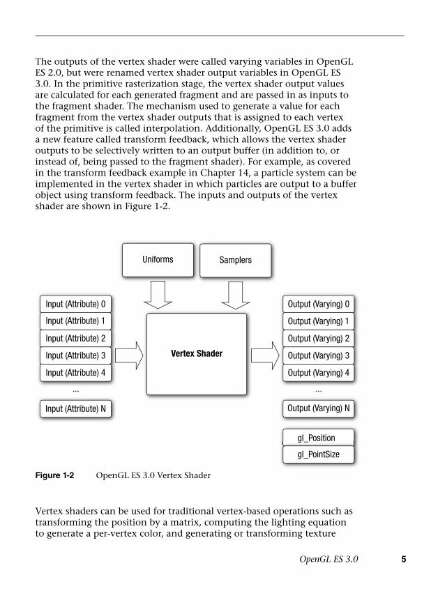
OpenGL ES 3.0 5
The outputs of the vertex shader were called varying variables in OpenGL ES 2.0, but were renamed vertex shader output variables in OpenGL ES 3.0. In the primitive rasterization stage, the vertex shader output values are calculated for each generated fragment and are passed in as inputs to the fragment shader. The mechanism used to generate a value for each fragment from the vertex shader outputs that is assigned to each vertex of the primitive is called interpolation. Additionally, OpenGL ES 3.0 adds a new feature called transform feedback, which allows the vertex shader outputs to be selectively written to an output buffer (in addition to, or instead of, being passed to the fragment shader). For example, as covered in the transform feedback example in Chapter 14, a particle system can be implemented in the vertex shader in which particles are output to a buffer object using transform feedback. The inputs and outputs of the vertex shader are shown in Figure 1-2.
Vertex shaders can be used for traditional vertex-based operations such as transforming the position by a matrix, computing the lighting equation to generate a per-vertex color, and generating or transforming texture
gl_Position
gl_PointSize
Output (Varying) N
...
Vertex Shader
...
Input (Attribute) N
Input (Attribute) 0
Input (Attribute) 1
Input (Attribute) 2
Input (Attribute) 3
Input (Attribute) 4
Uniforms Samplers
Output (Varying) 0
Output (Varying) 1
Output (Varying) 2
Output (Varying) 3
Output (Varying) 4
Figure 1-2 OpenGL ES 3.0 Vertex Shader

6 Chapter 1: Introduction to OpenGL ES 3.0
coordinates. Alternatively, because the vertex shader is specified by the application, vertex shaders can be used to perform custom math that enables new transforms, lighting, or vertex-based effects not allowed in more traditional fixed-function pipelines.
Example 1-1 shows a vertex shader written using the OpenGL ES shading language. We explain vertex shaders in significant detail later in the book. We present this shader here just to give you an idea of what a vertex shader looks like. The vertex shader in Example 1-1 takes a position and its associated color data as input attributes, transforms the position using a 4 × 4 matrix, and outputs the transformed position and color.
Example 1-1 A Vertex Shader Example
1. #version 300 es2. uniform mat4 u_mvpMatrix; // matrix to convert a_position3. // from model space to normalized4. // device space5. 6. // attributes input to the vertex shader7. in vec4 a_position; // position value8. in vec4 a_color; // input vertex color9.10. // output of the vertex shader - input to fragment11. // shader12. out vec4 v_color; // output vertex color13. void main()14. {15. v_color = a_color;16. gl_Position = u_mvpMatrix * a_position;17. }
Line 1 provides the version of the Shading Language—information that must appear on the first line of the shader (#version 300 es indicates the OpenGL ES Shading Language v3.00). Line 2 describes a uniform variable u_mvpMatrix that stores the combined model view and projection matrix. Lines 7 and 8 describe the inputs to the vertex shader and are referred to as vertex attributes. a_position is the input vertex position attribute and a_color is the input vertex color attribute. On line 12, we declare the output v_color to store the output of the vertex shader that describes the per-vertex color. The built-in variable called gl_Position is declared automatically, and the shader must write the transformed position to this variable. A vertex or fragment shader has a single entry point called the main function. Lines 13–17 describe the
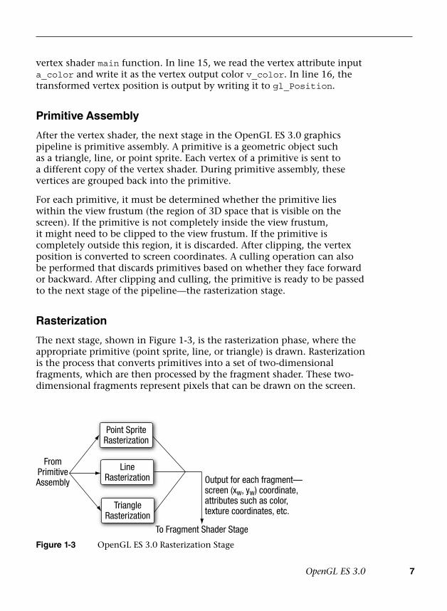
OpenGL ES 3.0 7
vertex shader main function. In line 15, we read the vertex attribute input a_color and write it as the vertex output color v_color. In line 16, the transformed vertex position is output by writing it to gl_Position.
Primitive Assembly
After the vertex shader, the next stage in the OpenGL ES 3.0 graphics pipeline is primitive assembly. A primitive is a geometric object such as a triangle, line, or point sprite. Each vertex of a primitive is sent to a different copy of the vertex shader. During primitive assembly, these vertices are grouped back into the primitive.
For each primitive, it must be determined whether the primitive lies within the view frustum (the region of 3D space that is visible on the screen). If the primitive is not completely inside the view frustum, it might need to be clipped to the view frustum. If the primitive is completely outside this region, it is discarded. After clipping, the vertex position is converted to screen coordinates. A culling operation can also be performed that discards primitives based on whether they face forward or backward. After clipping and culling, the primitive is ready to be passed to the next stage of the pipeline—the rasterization stage.
Rasterization
The next stage, shown in Figure 1-3, is the rasterization phase, where the appropriate primitive (point sprite, line, or triangle) is drawn. Rasterization is the process that converts primitives into a set of two-dimensional fragments, which are then processed by the fragment shader. These two-dimensional fragments represent pixels that can be drawn on the screen.
FromPrimitiveAssembly
LineRasterization
Point SpriteRasterization
TriangleRasterization
Output for each fragment—screen (xw, yw) coordinate,attributes such as color,texture coordinates, etc.
To Fragment Shader Stage
Figure 1-3 OpenGL ES 3.0 Rasterization Stage
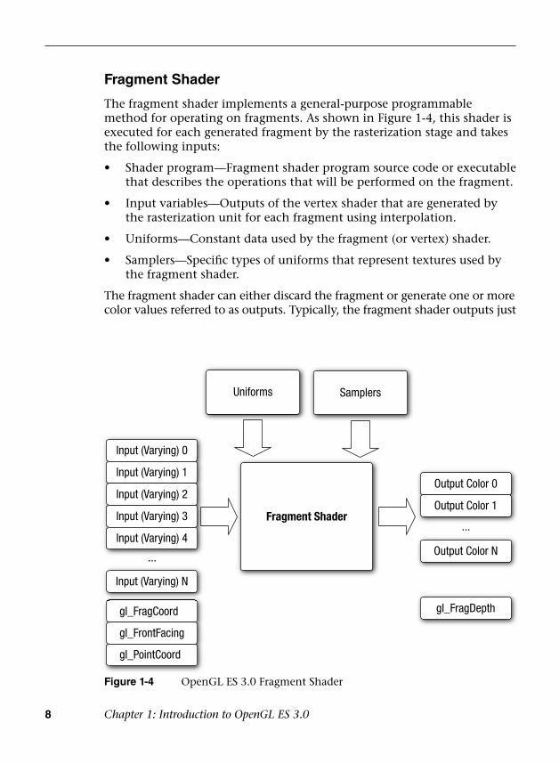
8 Chapter 1: Introduction to OpenGL ES 3.0
Fragment Shader
The fragment shader implements a general-purpose programmable method for operating on fragments. As shown in Figure 1-4, this shader is executed for each generated fragment by the rasterization stage and takes the following inputs:
• Shader program—Fragment shader program source code or executablethat describes the operations that will be performed on the fragment.
• Input variables—Outputs of the vertex shader that are generated bythe rasterization unit for each fragment using interpolation.
• Uniforms—Constant data used by the fragment (or vertex) shader.
• Samplers—Specific types of uniforms that represent textures used bythe fragment shader.
The fragment shader can either discard the fragment or generate one or more color values referred to as outputs. Typically, the fragment shader outputs just
Input (Varying) 0
Input (Varying) 1
Input (Varying) 2
Input (Varying) 3
Input (Varying) 4
Output Color 0
Output Color 1
Output Color N
gl_FragDepthgl_FragCoord
gl_FrontFacing
gl_PointCoord
Input (Varying) N
...
...Fragment Shader
Uniforms Samplers
Figure 1-4 OpenGL ES 3.0 Fragment Shader

OpenGL ES 3.0 9
a single color value, except when rendering to multiple render targets (see the section Multiple Render Targets in Chapter 11); in the latter case, a color value is output for each render target. The color, depth, stencil, and screen coordinate location (x
w, y
w) generated by the rasterization stage become
inputs to the per-fragment operations stage of the OpenGL ES 3.0 pipeline.
Example 1-2 describes a simple fragment shader that can be coupled with the vertex shader described in Example 1-1 to draw a Gouraud-shaded triangle. Again, we will go into much more detail on fragment shaders later in the book. We present this example just to give you a basic idea of what a fragment shader looks like.
Example 1-2 A Fragment Shader Example
1. #version 300 es2. precision mediump float;3. 4. in vec4 v_color; // input vertex color from vertex shader5.6. out vec4 fragColor; // output fragment color7. void main()8. {9. fragColor = v_color;10. }
Just as in the vertex shader, line 1 provides the version of the Shading Language; this information must appear on the first line of the fragment shader (#version 300 es indicates the OpenGL ES Shading Language v3.00). Line 2 sets the default precision qualifier, which is explained in detail in Chapter 4, “Shaders and Programs.” Line 4 describes the input to the fragment shader. The vertex shader must write out the same set of variables that are read in by the fragment shader. Line 6 provides the declaration for the output variable of the fragment shader, which will be the color passed on to the next stage. Lines 7–10 describe the fragment shader main function. The output color is set to the input color v_color. The inputs to the fragment shader are linearly interpolated across the primitive before being passed into the fragment shader.
Per-Fragment Operations
After the fragment shader, the next stage is per-fragment operations. A fragment produced by rasterization with (x
w, y
w) screen coordinates can
only modify the pixel at location (xw, y
w) in the framebuffer. Figure 1-5
describes the OpenGL ES 3.0 per-fragment operations stage.
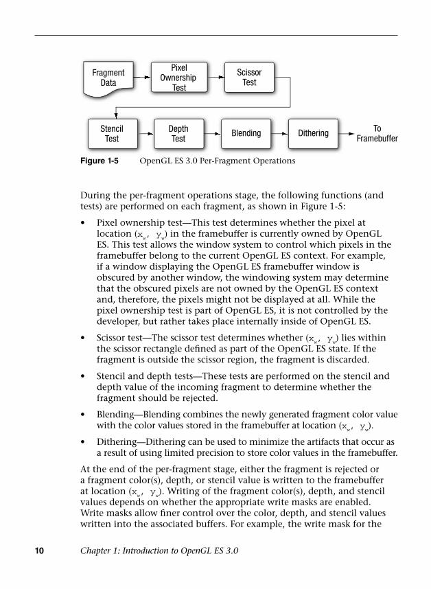
10 Chapter 1: Introduction to OpenGL ES 3.0
PixelOwnership
Test
ScissorTest
FragmentData
StencilTest
DepthTest
Blending Dithering ToFramebuffer
Figure 1-5 OpenGL ES 3.0 Per-Fragment Operations
During the per-fragment operations stage, the following functions (and tests) are performed on each fragment, as shown in Figure 1-5:
• Pixel ownership test—This test determines whether the pixel atlocation (x
w, y
w) in the framebuffer is currently owned by OpenGL
ES. This test allows the window system to control which pixels in theframebuffer belong to the current OpenGL ES context. For example,if a window displaying the OpenGL ES framebuffer window isobscured by another window, the windowing system may determinethat the obscured pixels are not owned by the OpenGL ES contextand, therefore, the pixels might not be displayed at all. While thepixel ownership test is part of OpenGL ES, it is not controlled by thedeveloper, but rather takes place internally inside of OpenGL ES.
• Scissor test—The scissor test determines whether (xw, y
w) lies within
the scissor rectangle defined as part of the OpenGL ES state. If thefragment is outside the scissor region, the fragment is discarded.
• Stencil and depth tests—These tests are performed on the stencil anddepth value of the incoming fragment to determine whether thefragment should be rejected.
• Blending—Blending combines the newly generated fragment color valuewith the color values stored in the framebuffer at location (x
w, y
w).
• Dithering—Dithering can be used to minimize the artifacts that occur asa result of using limited precision to store color values in the framebuffer.
At the end of the per-fragment stage, either the fragment is rejected or a fragment color(s), depth, or stencil value is written to the framebuffer at location (x
w, y
w). Writing of the fragment color(s), depth, and stencil
values depends on whether the appropriate write masks are enabled. Write masks allow finer control over the color, depth, and stencil values written into the associated buffers. For example, the write mask for the
What’s New in OpenGL ES 3.0 11
color buffer could be set such that no red values are written into the color buffer. In addition, OpenGL ES 3.0 provides an interface to read back the pixels from the framebuffer.
Note: Alpha test and LogicOp are no longer part of the per-fragment operations stage. These two stages exist in OpenGL 2.0 and OpenGL ES 1.x. The alpha test stage is no longer needed because the fragment shader can discard fragments; thus the alpha test can be performed in the fragment shader. In addition, LogicOp was removed because it is used only rarely by applications, and the OpenGL ES working group did not receive requests from independent software vendors (ISVs) to support this feature in OpenGL ES 2.0.
What’s New in OpenGL ES 3.0
OpenGL ES 2.0 ushered in the era of programmable shaders for handheld devices and has been wildly successful in powering games, applications, and user interfaces across a wide range of devices. OpenGL ES 3.0 extends OpenGL ES 2.0 to support many new rendering techniques, optimizations, and visual quality enhancements. The following sections provide a categorized overview of the major new features that have been added to OpenGL ES 3.0. Each of these features will be described in detail later in the book.
Texturing
OpenGL ES 3.0 introduces many new features related to texturing:
• sRGB textures and framebuffers—Allow the application to performgamma-correct rendering. Textures can be stored in gamma-correctedsRGB space, uncorrected to linear space upon being fetched in theshader, and then converted back to sRGB gamma-corrected space onoutput to the framebuffer. This enables potentially higher visual fidelityby properly computing lighting and other calculations in linear space.
• 2D texture arrays—A texture target that stores an array of 2D textures.Such arrays might, for example, be used to perform texture animation.Prior to 2D texture arrays, such animation was typically done by tilingthe frames of an animation in a single 2D texture and modifying thetexture coordinates to change animation frames. With 2D texturearrays, each frame of the animation can be specified in a 2D slice ofthe array.

12 Chapter 1: Introduction to OpenGL ES 3.0
• 3D textures—While some OpenGL ES 2.0 implementations supported3D textures through an extension, OpenGL ES 3.0 has made this amandatory feature. 3D textures are essential in many medical imagingapplications, such as those that perform direct volume rendering of3D voxel data (e.g., CT, MRI, or PET data).
• Depth textures and shadow comparison—Enable the depth bufferto be stored in a texture. The most common use for depth texturesis in rendering shadows, where a depth buffer is rendered from theviewpoint of the light source and then used for comparison whenrendering the scene to determine whether a fragment is in shadow.In addition to depth textures, OpenGL ES 3.0 allows the comparisonagainst the depth texture to be done at the time of fetch, therebyallowing bilinear filtering to be done on depth textures (also known aspercentage closest filtering [PCF]).
• Seamless cubemaps—In OpenGL ES 2.0, rendering with cubemapscould produce artifacts at the boundaries between cubemap faces. InOpenGL ES 3.0, cubemaps can be sampled such that filtering uses datafrom adjacent faces and removes the seaming artifact.
• Floating-point textures—OpenGL ES 3.0 greatly expands on thetexture formats supported. Floating-point half-float (16-bit) texturesare supported and can be filtered, whereas full-float (32-bit) texturesare supported but not filterable. The ability to access floating-pointtexture data has many applications, including high dynamic rangetexturing to general-purpose computation.
• ETC2/EAC texture compression—While several OpenGL ES 2.0implementations provided support for vendor-specific compressedtexture formats (e.g., ATC by Qualcomm, PVRTC by ImaginationTechnologies, and Ericsson Texture Compression by Sony Ericsson),there was no standard compression format that developers could relyon. In OpenGL ES 3.0, support for ETC2/EAC is mandatory. The ETC2/EAC formats provide compression for RGB888, RGBA8888, and one- and two-channel signed/unsigned texture data. Texture compressionoffers several advantages, including better performance (due to betterutilization of the texture cache) as well as a reduction in GPU memoryutilization.
• Integer textures—OpenGL ES 3.0 introduces the capability to renderto and fetch from textures stored as unnormalized signed or unsigned8-bit, 16-bit, and 32-bit integer textures.
• Additional texture formats—In addition to those formats alreadymentioned, OpenGL ES 3.0 includes support for 11-11-10 RGB
What’s New in OpenGL ES 3.0 13
floating-point textures, shared exponent RGB 9-9-9-5 textures, 10-10-10-2 integer textures, and 8-bit-per-component signed normalized textures.
• Non-power-of-2 textures (NPOT)—Textures can now be specified withnon-power-of-2 dimensions. This is useful in many situations, such aswhen texturing from a video or camera feed that is captured/recordedat a non-power-of-2 dimension.
• Texture level of detail (LOD) features—The texture LOD parameterused to determine which mipmap to fetch from can now beclamped. Additionally, the base and maximum mipmap level canbe clamped. These two features, in combination, make it possible tostream mipmaps. As larger mipmap levels become available, the baselevel can be increased and the LOD value can be smoothly increasedto provide smooth-looking streaming textures. This is very useful, forexample, when downloading texture mipmap data over a networkconnection.
• Texture swizzles—A new texture object state was introduced to allowindependent control of where each channel (R, G, B, and A) of texturedata is mapped to in the shader.
• Immutable textures—Provide a mechanism for the application tospecify the format and size of a texture before loading it with data. Indoing so, the texture format becomes immutable and the OpenGL ESdriver can perform all consistency and memory checks up-front. Thiscan improve performance by allowing the driver to skip consistencychecks at draw time.
• Increased minimum sizes—All OpenGL ES 3.0 implementations arerequired to support much larger texture resources than OpenGL ES2.0. For example, the minimum supported 2D texture dimension inOpenGL ES 2.0 was 64 but was increased to 2048 in OpenGL ES 3.0.
Shaders
OpenGL ES 3.0 includes a major update to the OpenGL ES Shading Language (ESSL; to v3.00) and new API features to support new shader features:
• Program binaries—In OpenGL ES 2.0, it was possible to store shadersin a binary format, but it was still required to link them into programat runtime. In OpenGL ES 3.0, the entire linked program binary(containing the vertex and fragment shader) can be stored in an
14 Chapter 1: Introduction to OpenGL ES 3.0
offline binary format with no link step required at runtime. This can potentially help reduce the load time of applications. Additionally, OpenGL ES 3.0 provides an interface to retrieve the program binary from the driver so no offline tools are required to use program binaries.
• Mandatory online compiler—OpenGL ES 2.0 made it optionalwhether the driver would support online compilation of shaders. Theintent was to reduce the memory requirements of the driver, but thisachievement came at a major cost to developers in terms of having torely on vendor-specific tools to generate shaders. In OpenGL ES 3.0, allimplementations will have an online shader compiler.
• Non-square matrices—New matrix types other than square matricesare supported, and associated uniform calls were added to the API tosupport loading them. Non-square matrices can reduce the instructioncount required for performing transformations. For example, ifperforming an affine transformation, a 4 × 3 matrix can be used inplace of a 4 × 4 where the last row is (0, 0, 0, 1), thus reducing theinstructions required to perform the transformation.
• Full integer support—Integer (and unsigned integer) scalar and vectortypes, along with full integer operations, are supported in ESSL 3.00.There are various built-in functions such as conversion from int tofloat, and from float to int, as well as the ability to read integer valuesfrom textures and output integer values to integer color buffers.
• Centroid sampling—To avoid rendering artifacts when multisampling,the output variables from the vertex shader (and inputs to thefragment shader) can be declared with centroid sampling.
• Flat/smooth interpolators—In OpenGL ES 2.0, all interpolators wereimplicitly linearly interpolated across the primitive. In ESSL 3.00,interpolators (vertex shader outputs/fragment shader inputs) can beexplicitly declared to have either smooth or flat shading.
• Uniform blocks—Uniform values can be grouped together intouniform blocks. Uniform blocks can be loaded more efficiently andalso shared across multiple shader programs.
• Layout qualifiers—Vertex shader inputs can be declared with layoutqualifiers to explicitly bind the location in the shader source withoutrequiring making API calls. Layout qualifiers can also be used forfragment shader outputs to bind the outputs to each target whenrendering to multiple render targets. Further, layout qualifiers can beused to control the memory layout for uniform blocks.
What’s New in OpenGL ES 3.0 15
• Instance and vertex ID—The vertex index is now accessible in thevertex shader as well as the instance ID if using instance rendering.
• Fragment depth—The fragment shader can explicitly control thedepth value for the current fragment rather than relying on theinterpolation of its depth value.
• New built-in functions—ESSL 3.00 introduces many new built-infunctions to support new texture features, fragment derivatives, half-float data conversion, and matrix and math operations.
• Relaxed limitations—ESSL 3.0 greatly relaxes the restrictions onshaders. Shaders are no longer limited in terms of instruction length,fully support looping and branching on variables, and supportindexing on arrays.
Geometry
OpenGL ES 3.0 introduces several new features related to geometry specification and control of primitive rendering:
• Transform feedback—Allows the output of the vertex shader tobe captured in a buffer object. This is useful for a wide range oftechniques that perform animation on the GPU without any CPUintervention—for example, particle animation or physics simulationusing render-to-vertex-buffer.
• Boolean occlusion queries—Enable the application to query whetherany pixels of a draw call (or a set of draw calls) passes the depthtest. This feature can be used within a variety of techniques, such asvisibility determination for a lens flare effect as well as optimizationto avoid performing geometry processing on objects whose boundingvolume is obscured.
• Instanced rendering—Efficiently renders objects that contain similargeometry but differ by attributes (such as transformation matrix, color,or size). This feature is useful in rendering large quantities of similarobjects, such as for crowd rendering.
• Primitive restart—When using triangle strips in OpenGL ES 2.0 for anew primitive, the application would have to insert indices into theindex buffer to represent a degenerate triangle. In OpenGL ES 3.0, aspecial index value can be used that indicates the beginning of a newprimitive. This obviates the need for generating degenerate triangleswhen using triangle strips.

16 Chapter 1: Introduction to OpenGL ES 3.0
• New vertex formats—New vertex formats, including 10-10-10-2 signedand unsigned normalized vertex attributes; 8-bit, 16-bit, and 32-bitinteger attributes; and 16-bit half-float, are supported in OpenGL ES 3.0.
Buffer Objects
OpenGL ES 3.0 introduces many new buffer objects to increase the efficiency and flexibility of specifying data to various parts of the graphics pipeline:
• Uniform buffer objects—Provide an efficient method for storing/binding large blocks of uniforms. Uniform buffer objects can be usedto reduce the performance cost of binding uniform values to shaders,which is a common bottleneck in OpenGL ES 2.0 applications.
• Vertex array objects—Provide an efficient method for binding andswitching between vertex array states. Vertex array objects areessentially container objects for vertex array states. Using them allowsan application to switch the vertex array state in a single API callrather than making several calls.
• Sampler objects—Separate the sampler state (texture wrap modeand filtering) from the texture object. This provides a more efficientmethod of sharing the sampler state across textures.
• Sync objects—Provide a mechanism for the application to check onwhether a set of OpenGL ES operations has finished executing onthe GPU. A related new feature is a fence, which provides a way forthe application to inform the GPU that it should wait until a set ofOpenGL ES operations has finished executing before queuing up moreoperations for execution.
• Pixel buffer objects—Enable the application to perform asynchronoustransfer of data to pixel operations and texture transfer operations.This optimization is primarily intended to provide faster transferof data between the CPU and the GPU, where the application cancontinue doing work during the transfer operation.
• Buffer subrange mapping—Allows the application to map a subregionof a buffer for access by the CPU. This can provide better performancethan traditional buffer mapping, in which the whole buffer needs tobe available to the client.
• Buffer object to buffer object copies—Provide a mechanism toefficiently transfer data from one buffer object to another withoutintervention on the CPU.

OpenGL ES 3.0 and Backward Compatibility 17
Framebuffer
OpenGL ES 3.0 adds many new features related to off-screen rendering to framebuffer objects:
• Multiple render targets (MRTs)—Allow the application to rendersimultaneously to several color buffers at one time. With MRTs, thefragment shader outputs several colors, one for each attached colorbuffer. MRTs are used in many advanced rendering algorithms, such asdeferred shading.
• Multisample renderbuffers—Enable the application to render to off-screen framebuffers with multisample anti-aliasing. The multisamplerenderbuffers cannot be directly bound to textures, but they canbe resolved to single-sample textures using the newly introducedframebuffer blit.
• Framebuffer invalidation hints—Many implementations of OpenGLES 3.0 are based on GPUs that use tile-based rendering (TBR;explained in the Framebuffer Invalidation section in Chapter 12).It is often the case that TBR incurs a significant performance costwhen having to unnecessarily restore the contents of the tiles forfurther rendering to a framebuffer. Framebuffer invalidation givesthe application a mechanism to inform the driver that the contentsof the framebuffer are no longer needed. This allows the driverto take optimization steps to skip unnecessary restore operationson the tiles. Such functionality is very important to achievepeak performance in many applications, especially those that dosignificant amounts of off-screen rendering.
• New blend equations—The min/max functions are supported inOpenGL ES 3.0 as a blend equation.
OpenGL ES 3.0 and Backward Compatibility
OpenGL ES 3.0 is backward compatible with OpenGL ES 2.0. This means that just about any application written to use OpenGL ES 2.0 will run on implementations of OpenGL ES 3.0. There are some very minor changes to the later version that will affect a small number of applications in terms of backward compatibility. Namely, framebuffer objects are no longer shared between contexts, cubemaps are always filtered using seamless filtering, and there are minor changes in the way signed fixed-point numbers are converted to floating-point numbers.

18 Chapter 1: Introduction to OpenGL ES 3.0
The fact that OpenGL ES 3.0 is backward compatible with OpenGL ES 2.0 differs from what was done for OpenGL ES 2.0 with respect to its backward compatibility with previous versions of OpenGL ES. OpenGL ES 2.0 is not backward compatible with OpenGL ES 1.x. OpenGL ES 2.0/3.0 do not support the fixed-function pipeline that OpenGL ES 1.x supports. The OpenGL ES 2.0/3.0 programmable vertex shader replaces the fixed-function vertex units implemented in OpenGL ES 1.x. The fixed-function vertex units implement a specific vertex transformation and lighting equation that can be used to transform the vertex position, transform or generate texture coordinates, and calculate the vertex color. Similarly, the programmable fragment shader replaces the fixed-function texture combine units implemented in OpenGL ES 1.x. The fixed-function texture combine units implement a texture combine stage for each texture unit. The texture color is combined with the diffuse color and the output of the previous texture combine stage with a fixed set of operations such as add, modulate, subtract, and dot.
The OpenGL ES working group decided against backward compatibility between OpenGL ES 2.0/3.0 and OpenGL ES 1.x for the following reasons:
• Supporting the fixed-function pipeline in OpenGL ES 2.0/3.0implies that the API would support more than one way ofimplementing a feature, in violation of one of the criteria usedby the working group in determining which features should besupported. The programmable pipeline allows applications toimplement the fixed-function pipeline using shaders, so thereis really no compelling reason to be backward compatible withOpenGL ES 1.x.
• Feedback from ISVs indicated that most games do not mixprogrammable and fixed-function pipelines. That is, games are writteneither for a fixed-function pipeline or for a programmable pipeline.Once you have a programmable pipeline, there is no reason to usea fixed-function pipeline, as you have much more flexibility in theeffects that can be rendered.
• The OpenGL ES 2.0/3.0 driver’s memory footprint would be muchlarger if it had to support both the fixed-function and programmablepipelines. For the devices targeted by OpenGL ES, minimizingmemory footprint is an important design criterion. Separating thefixed-function support into the OpenGL ES 1.x API and placing theprogrammable shader support into the OpenGL ES 2.0/3.0 APIs meantthat vendors that do not require OpenGL ES 1.x support no longerneed to include this driver.

EGL 19
EGL
OpenGL ES commands require a rendering context and a drawing surface. The rendering context stores the appropriate OpenGL ES state. The drawing surface is the surface to which primitives will be drawn. The drawing surface specifies the types of buffers that are required for rendering, such as a color buffer, depth buffer, and stencil buffer. The drawing surface also specifies the bit depths of each of the required buffers.
The OpenGL ES API does not mention how a rendering context is created or how the rendering context gets attached to the native windowing system. EGL is one interface between the Khronos rendering APIs such as OpenGL ES and the native window system; there is no hard-and-fast requirement to provide EGL when implementing OpenGL ES. Developers should refer to the platform vendor’s documentation to determine which interface is supported. As of this writing, the only known platform supporting OpenGL ES that does not support EGL is iOS.
Any OpenGL ES application will need to perform the following tasks using EGL before any rendering can begin:
• Query the displays that are available on the device and initializethem. For example, a flip phone might have two LCD panels, and it ispossible that we might use OpenGL ES to render to surfaces that canbe displayed on either or both panels.
• Create a rendering surface. Surfaces created in EGL can be categorizedas on-screen surfaces or off-screen surfaces. On-screen surfaces areattached to the native window system, whereas off-screen surfaces arepixel buffers that do not get displayed but can be used as renderingsurfaces. These surfaces can be used to render into a texture and canbe shared across multiple Khronos APIs.
• Create a rendering context. EGL is needed to create an OpenGL ESrendering context. This context needs to be attached to an appropriatesurface before rendering can actually begin.
The EGL API implements the features just described as well as additional functionality such as power management, support for multiple rendering contexts in a process, sharing objects (such as textures or vertex buffers) across rendering contexts in a process, and a mechanism to get function pointers to EGL or OpenGL ES extension functions supported by a given implementation.
The latest version of the EGL specification is EGL version 1.4.

20 Chapter 1: Introduction to OpenGL ES 3.0
Programming with OpenGL ES 3.0
To write any OpenGL ES 3.0 application, you need to know which header files must be included and with which libraries your application needs to link. It is also useful to understand the syntax used by the EGL and GL command names and command parameters.
Libraries and Include Files
OpenGL ES 3.0 applications need to link with the following libraries: the OpenGL ES 3.0 library named libGLESv2.lib and the EGL library named libEGL.lib.
OpenGL ES 3.0 applications also need to include the appropriate ES 3.0 and EGL header files. The following include files must be included by any OpenGL ES 3.0 application:
#include <EGL/egl.h>#include <GLES3/gl3.h>
egl.h is the EGL header file and gl3.h is the OpenGL ES 3.0 header file. Applications can optionally include gl2ext.h, which is the header file that describes the list of Khronos-approved extensions for OpenGL ES 2.0/3.0.
The header file and library names are platform dependent. The OpenGL ES working group has tried to define the library and header names and indicate how they should be organized, but this arrangement might not be found on all OpenGL ES platforms. Developers should, however, refer to the platform vendor’s documentation for information on how the libraries and include files are named and organized. The official OpenGL ES header files are maintained by Khronos and available from http://khronos.org/registry/gles/. The sample code for the book also includes a copy of the header files (working with the sample code is described in the next chapter).
EGL Command Syntax
All EGL commands begin with the prefix egl and use an initial capital letter for each word making up the command name (e.g., eglCreateWindowSurface). Similarly, EGL data types also begin with the prefix Egl and use an initial capital letter for each word making up the type name, except for EGLint and EGLenum.
Table 1-1 briefly describes the EGL data types used.

OpenGL ES Command Syntax 21
OpenGL ES Command Syntax
All OpenGL ES commands begin with the prefix gl and use an initial capital letter for each word making up the command name (e.g., glBlendEquation). Similarly, OpenGL ES data types also begin with the prefix GL.
In addition, some commands might take arguments in different flavors. The flavors or types vary in terms of the number of arguments taken (one to four arguments), the data type of the arguments used (byte [b], unsigned byte [ub], short [s], unsigned short [us], int [i], and float [f]), and whether the arguments are passed as a vector (v). A few examples of command flavors allowed in OpenGL ES follow.
The following two commands are equivalent except that one specifies the uniform value as floats and the other as integers:
glUniform2f(location, l.Of, O.Of);glUniform2i(location, 1, 0)
The following lines describe commands that are also equivalent, except that one passes command arguments as a vector and the other does not:
GLfloat coord[4] = { l.Of, 0.75f, 0.25f, O.Of };glUniform4fv(location, coord);glUniform4f(location, coord[0], coord[l], coord[2], coord[3]);
Table 1-2 describes the command suffixes and argument data types used in OpenGL ES.
Finally, OpenGL ES defines the type GLvoid. This type is used for OpenGL ES commands that accept pointers.
In the rest of this book, OpenGL ES commands are referred to by their base names only, and an asterisk is used to indicate that this base name refers
Table 1-1 EGL Data Types
Data Type C-Language Type EGL Type
32-bit integer int EGLint
32-bit unsigned integer unsignedint EGLBoolean, EGLenum
Pointer void * EGLConfig, EGLContext, EGLDisplay, EGLSurface, EGLClientBuffer
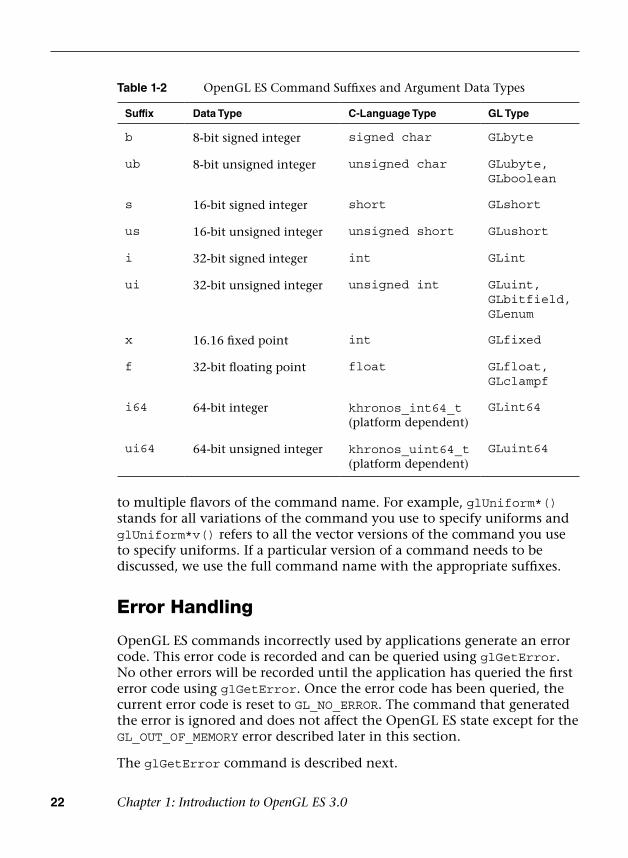
22 Chapter 1: Introduction to OpenGL ES 3.0
to multiple flavors of the command name. For example, glUniform*() stands for all variations of the command you use to specify uniforms and glUniform*v() refers to all the vector versions of the command you use to specify uniforms. If a particular version of a command needs to be discussed, we use the full command name with the appropriate suffixes.
Error Handling
OpenGL ES commands incorrectly used by applications generate an error code. This error code is recorded and can be queried using glGetError. No other errors will be recorded until the application has queried the first error code using glGetError. Once the error code has been queried, the current error code is reset to GL_NO_ERROR. The command that generated the error is ignored and does not affect the OpenGL ES state except for the GL_OUT_OF_MEMORY error described later in this section.
The glGetError command is described next.
Table 1-2 OpenGL ES Command Suffixes and Argument Data Types
Suffix Data Type C-Language Type GL Type
b 8-bit signed integer signed char GLbyte
ub 8-bit unsigned integer unsigned char GLubyte, GLboolean
s 16-bit signed integer short GLshort
us 16-bit unsigned integer unsigned short GLushort
i 32-bit signed integer int GLint
ui 32-bit unsigned integer unsigned int GLuint, GLbitfield, GLenum
x 16.16 fixed point int GLfixed
f 32-bit floating point float GLfloat, GLclampf
i64 64-bit integer khronos_int64_t (platform dependent)
GLint64
ui64 64-bit unsigned integer khronos_uint64_t (platform dependent)
GLuint64
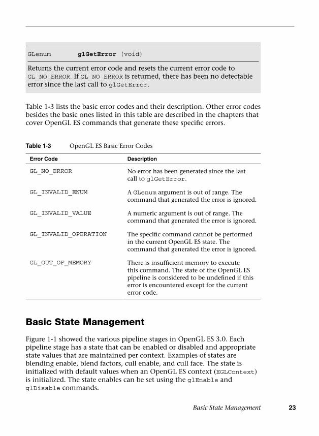
Basic State Management 23
Table 1-3 lists the basic error codes and their description. Other error codes besides the basic ones listed in this table are described in the chapters that cover OpenGL ES commands that generate these specific errors.
Basic State Management
Figure 1-1 showed the various pipeline stages in OpenGL ES 3.0. Each pipeline stage has a state that can be enabled or disabled and appropriate state values that are maintained per context. Examples of states are blending enable, blend factors, cull enable, and cull face. The state is initialized with default values when an OpenGL ES context (EGLContext) is initialized. The state enables can be set using the glEnable and glDisable commands.
GLenum glGetError (void)
Returns the current error code and resets the current error code to GL_NO_ERROR. If GL_NO_ERROR is returned, there has been no detectable error since the last call to glGetError.
Table 1-3 OpenGL ES Basic Error Codes
Error Code Description
GL_NO_ERROR No error has been generated since the last call to glGetError.
GL_INVALID_ENUM A GLenum argument is out of range. The command that generated the error is ignored.
GL_INVALID_VALUE A numeric argument is out of range. The command that generated the error is ignored.
GL_INVALID_OPERATION The specific command cannot be performed in the current OpenGL ES state. The command that generated the error is ignored.
GL_OUT_OF_MEMORY There is insufficient memory to execute this command. The state of the OpenGL ES pipeline is considered to be undefined if this error is encountered except for the current error code.

24 Chapter 1: Introduction to OpenGL ES 3.0
Later chapters will describe the specific state enables for each pipeline stage shown in Figure 1-1. You can also check whether a state is currently enabled or disabled by using the gIisEnabled command.
void glEnable(GLenum cap)
void glDisable(GLenum cap)
glEnable and glDisable enable and disable various capabilities. The initial value for each capability is set to GL_FALSE except for GL_DITHER, which is set to GL_TRUE. The error code GL_INVALID_ENUM is generated if cap is not a valid state enum.
cap state to enable or disable, can be:GL_BLEND
GL_CULL_FACE
GL_DEPTH_TEST
GL_DITHER
GL_POLYGON_OFFSET_FILL
GL_PRIMITIVE_RESTART_FIXED_INDEX
GL_RASTERIZER_DISCARD
GL_SAMPLE_ALPHA_TO_COVERAGE
GL_SAMPLE_COVERAGE
GL_SCISSOR_TEST
GL_STENCIL_TEST
GLboolean gIisEnabled(GLenum cap)
Returns GL_TRUE or GL_FALSE depending on whether the state being queried is enabled or disabled. Generates the error code GL_INVALID_ENUM if cap is not a valid state enum.
Specific state values such as blend factor, depth test values, and so on can also be queried using appropriate glGet*** commands. These commands are described in detail in Chapter 15, “State Queries.”

Further Reading 25
Further Reading
The OpenGL ES 1.0, 1.1, 2.0, and 3.0 specifications can be found at khronos.org/opengles/. In addition, the Khronos website (khronos.org) has the latest information on all Khronos specifications, developer message boards, tutorials, and examples.
• Khronos OpenGL ES 1.1 website: http://khronos.org/opengles/1_X/
• Khronos OpenGL ES 2.0 website: http://khronos.org/opengles/2_X/
• Khronos OpenGL ES 3.0 website: http://khronos.org/opengles/3_X/
• Khronos EGL website: http://khronos.org/egl/

This page intentionally left blank
27
Chapter 2
Hello Triangle: An OpenGL ES 3.0 Example
To introduce the basic concepts of OpenGL ES 3.0, we begin with a simple example. This chapter shows what is required to create an OpenGL ES 3.0 program that draws a single triangle. The program we will write is just about the most basic example of an OpenGL ES 3.0 application that draws geometry. This chapter covers the following concepts:
• Creating an on-screen render surface with EGL
• Loading vertex and fragment shaders
• Creating a program object, attaching vertex and fragment shaders, andlinking a program object
• Setting the viewport
• Clearing the color buffer
• Rendering a simple primitive
• Making the contents of the color buffer visible in the EGL windowsurface
As it turns out, a significant number of steps are required before we can start drawing a triangle with OpenGL ES 3.0. This chapter goes over the basics of each of these steps. Later in this book, we fill in the details on each of these steps and further document the API. Our purpose here is to get you up and running with your first simple example so that you get an idea of what goes into creating an application with OpenGL ES 3.0.
28 Chapter 2: Hello Triangle: An OpenGL ES 3.0 Example
Code Framework
Throughout this book, we build a library of utility functions that form a framework of useful functions for writing OpenGL ES 3.0 programs. In developing example programs for the book, we had several goals for this code framework:
1. It should be simple, small, and easy to understand. We wanted tofocus our examples on the relevant OpenGL ES 3.0 calls, rather thanon a large code framework that we invented. Thus we focused ourframework on simplicity and sought to make the example programseasy to read and understand. The goal of the framework is to allowyou to focus your attention on the important OpenGL ES 3.0 APIconcepts in each example.
2. It should be portable. To the extent possible, we wanted the samplecode to be available on all platforms where OpenGL ES 3.0 is present.
As we go through the examples in the book, we will formally introduce any new code framework functions that we use. In addition, you can find full documentation for the code framework in Appendix C. Any functions called in the example code that have names beginning with es (e.g., esCreateWindow()) are part of the code framework we wrote for the sample programs in this book.
Where to Download the Examples
You can find links to download the examples from the book website at opengles-book.com.
As of this writing, the source code is available for Windows, Linux, Android 4.3+ NDK, Android 4.3+ SDK (Java), and iOS7. On Windows, the code is compatible with the Qualcomm OpenGL ES 3.0 Emulator, ARM OpenGL ES 3.0 Emulator, and PowerVR OpenGL ES 3.0 Emulator. On Linux, the currently available emulators are the Qualcomm OpenGL ES 3.0 Emulator and the PowerVR OpenGL ES 3.0 Emulator. The code should be compatible with any Windows- or Linux-based OpenGL ES 3.0 implementations in addition to those mentioned here. The choice of development tool is up to the reader. We have used cmake, a cross-platform build generation tool, on Windows and Linux, which allows you to use IDEs including Microsoft Visual Studio, Eclipse, Code::Blocks, and Xcode.
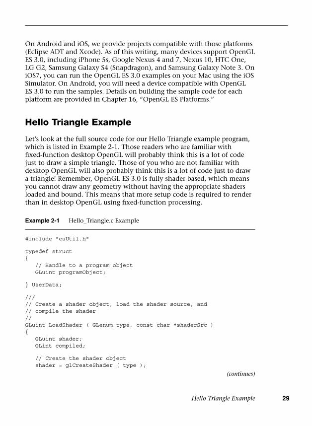
Hello Triangle Example 29
On Android and iOS, we provide projects compatible with those platforms (Eclipse ADT and Xcode). As of this writing, many devices support OpenGL ES 3.0, including iPhone 5s, Google Nexus 4 and 7, Nexus 10, HTC One, LG G2, Samsung Galaxy S4 (Snapdragon), and Samsung Galaxy Note 3. On iOS7, you can run the OpenGL ES 3.0 examples on your Mac using the iOS Simulator. On Android, you will need a device compatible with OpenGL ES 3.0 to run the samples. Details on building the sample code for each platform are provided in Chapter 16, “OpenGL ES Platforms.”
Hello Triangle Example
Let’s look at the full source code for our Hello Triangle example program, which is listed in Example 2-1. Those readers who are familiar with fixed-function desktop OpenGL will probably think this is a lot of code just to draw a simple triangle. Those of you who are not familiar with desktop OpenGL will also probably think this is a lot of code just to draw a triangle! Remember, OpenGL ES 3.0 is fully shader based, which means you cannot draw any geometry without having the appropriate shaders loaded and bound. This means that more setup code is required to render than in desktop OpenGL using fixed-function processing.
Example 2-1 Hello_Triangle.c Example
#include "esUtil.h"
typedef struct{ // Handle to a program object GLuint programObject;
} UserData;
///// Create a shader object, load the shader source, and// compile the shader//GLuint LoadShader ( GLenum type, const char *shaderSrc ){ GLuint shader; GLint compiled;
// Create the shader object shader = glCreateShader ( type );
(continues)
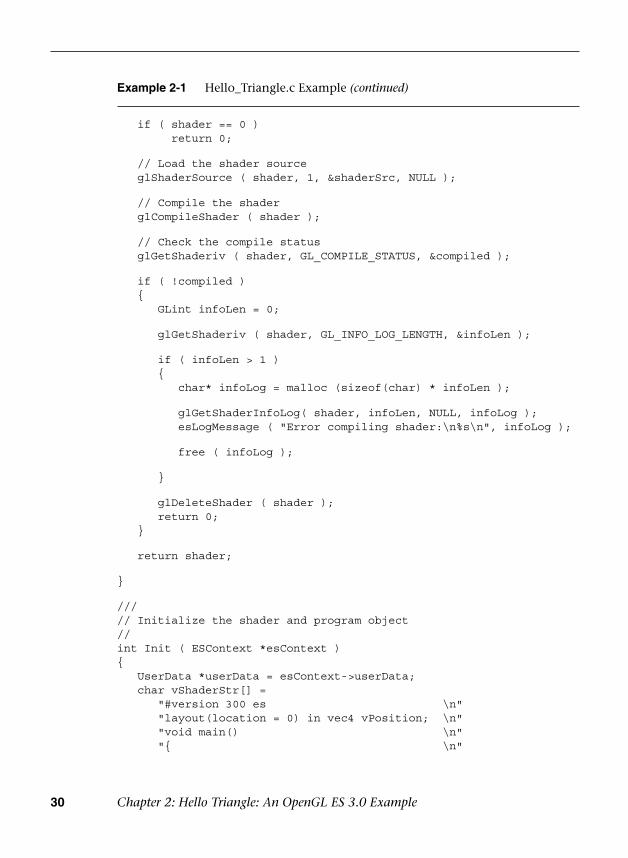
30 Chapter 2: Hello Triangle: An OpenGL ES 3.0 Example
Example 2-1 Hello_Triangle.c Example (continued)
if ( shader == 0 )return 0;
// Load the shader source glShaderSource ( shader, 1, &shaderSrc, NULL );
// Compile the shader glCompileShader ( shader );
// Check the compile status glGetShaderiv ( shader, GL_COMPILE_STATUS, &compiled );
if ( !compiled ) {
GLint infoLen = 0;
glGetShaderiv ( shader, GL_INFO_LOG_LENGTH, &infoLen );
if ( infoLen > 1 ){
char* infoLog = malloc (sizeof(char) * infoLen );
glGetShaderInfoLog( shader, infoLen, NULL, infoLog );esLogMessage ( "Error compiling shader:\n%s\n", infoLog );
free ( infoLog );
}
glDeleteShader ( shader );return 0;
}
return shader;
}
///// Initialize the shader and program object//int Init ( ESContext *esContext ){ UserData *userData = esContext->userData; char vShaderStr[] =
"#version 300 es \n""layout(location = 0) in vec4 vPosition; \n""void main() \n""{ \n"
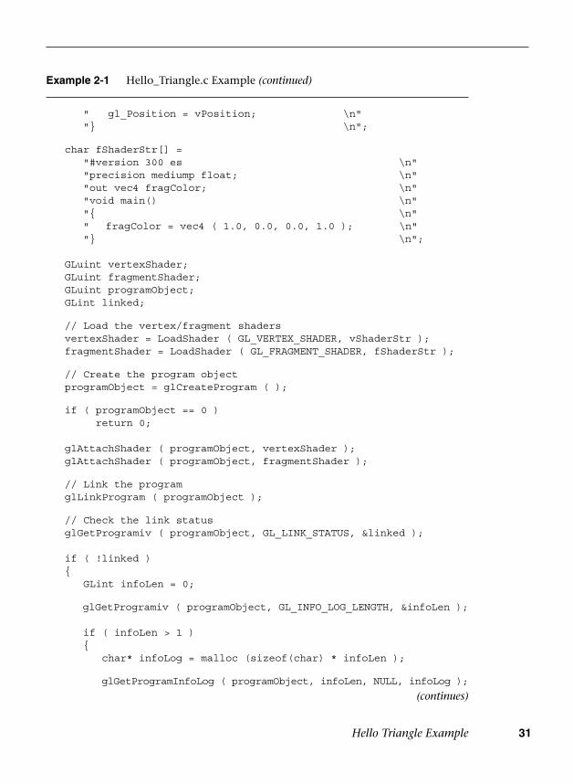
Hello Triangle Example 31
Example 2-1 Hello_Triangle.c Example (continued)
" gl_Position = vPosition; \n""} \n";
char fShaderStr[] ="#version 300 es \n""precision mediump float; \n""out vec4 fragColor; \n""void main() \n""{ \n"" fragColor = vec4 ( 1.0, 0.0, 0.0, 1.0 ); \n""} \n";
GLuint vertexShader; GLuint fragmentShader; GLuint programObject; GLint linked;
// Load the vertex/fragment shaders vertexShader = LoadShader ( GL_VERTEX_SHADER, vShaderStr ); fragmentShader = LoadShader ( GL_FRAGMENT_SHADER, fShaderStr );
// Create the program object programObject = glCreateProgram ( );
if ( programObject == 0 )return 0;
glAttachShader ( programObject, vertexShader ); glAttachShader ( programObject, fragmentShader );
// Link the program glLinkProgram ( programObject );
// Check the link status glGetProgramiv ( programObject, GL_LINK_STATUS, &linked );
if ( !linked ) {
GLint infoLen = 0;
glGetProgramiv ( programObject, GL_INFO_LOG_LENGTH, &infoLen );
if ( infoLen > 1 ){
char* infoLog = malloc (sizeof(char) * infoLen );
glGetProgramInfoLog ( programObject, infoLen, NULL, infoLog );
(continues)
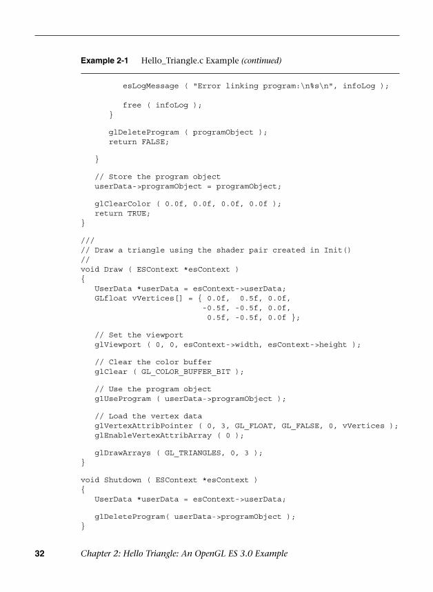
32 Chapter 2: Hello Triangle: An OpenGL ES 3.0 Example
Example 2-1 Hello_Triangle.c Example (continued)
esLogMessage ( "Error linking program:\n%s\n", infoLog );
free ( infoLog );}
glDeleteProgram ( programObject );return FALSE;
}
// Store the program object userData->programObject = programObject;
glClearColor ( 0.0f, 0.0f, 0.0f, 0.0f ); return TRUE;}
///// Draw a triangle using the shader pair created in Init()//void Draw ( ESContext *esContext ){ UserData *userData = esContext->userData; GLfloat vVertices[] = { 0.0f, 0.5f, 0.0f,
-0.5f, -0.5f, 0.0f,0.5f, -0.5f, 0.0f };
// Set the viewport glViewport ( 0, 0, esContext->width, esContext->height );
// Clear the color buffer glClear ( GL_COLOR_BUFFER_BIT );
// Use the program object glUseProgram ( userData->programObject );
// Load the vertex data glVertexAttribPointer ( 0, 3, GL_FLOAT, GL_FALSE, 0, vVertices ); glEnableVertexAttribArray ( 0 );
glDrawArrays ( GL_TRIANGLES, 0, 3 );}
void Shutdown ( ESContext *esContext ){ UserData *userData = esContext->userData;
glDeleteProgram( userData->programObject );}
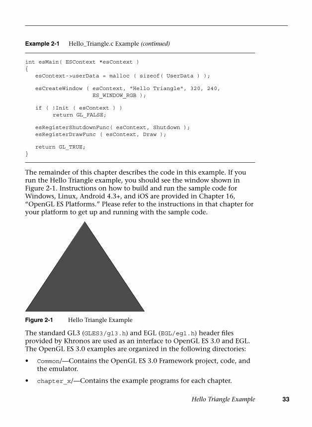
Hello Triangle Example 33
The remainder of this chapter describes the code in this example. If you run the Hello Triangle example, you should see the window shown in Figure 2-1. Instructions on how to build and run the sample code for Windows, Linux, Android 4.3+, and iOS are provided in Chapter 16, “OpenGL ES Platforms.” Please refer to the instructions in that chapter for your platform to get up and running with the sample code.
Figure 2-1 Hello Triangle Example
Example 2-1 Hello_Triangle.c Example (continued)
int esMain( ESContext *esContext ){ esContext->userData = malloc ( sizeof( UserData ) );
esCreateWindow ( esContext, "Hello Triangle", 320, 240,ES_WINDOW_RGB );
if ( !Init ( esContext ) ) return GL_FALSE;
esRegisterShutdownFunc( esContext, Shutdown ); esRegisterDrawFunc ( esContext, Draw );
return GL_TRUE;}
The standard GL3 (GLES3/gl3.h) and EGL (EGL/egl.h) header files provided by Khronos are used as an interface to OpenGL ES 3.0 and EGL. The OpenGL ES 3.0 examples are organized in the following directories:
• Common/—Contains the OpenGL ES 3.0 Framework project, code, andthe emulator.
• chapter_x/—Contains the example programs for each chapter.
34 Chapter 2: Hello Triangle: An OpenGL ES 3.0 Example
Using the OpenGL ES 3.0 Framework
Each application that uses our code framework declares a main entry point named esMain. In the main function in Hello Triangle, you will see calls to several ES utility functions. The esMain function takes an ESContext as an argument.
int esMain( ESContext *esContext )
The ESContext has a member variable named userData that is a void*. Each of the sample programs will store any of the data that are needed for the application in userData. The other elements in the ESContext structure are described in the header file and are intended only to be read by the user application. Other data in the ESContext structure include information such as the window width and height, EGL context, and callback function pointers.
The esMain function is responsible for allocating the userData, creating the window, and initializing the draw callback function:
esContext->userData = malloc ( sizeof( UserData ) );
esCreateWindow( esContext, "Hello Triangle", 320, 240, ES_WINDOW_RGB );
if ( !Init( esContext ) ) return GL_FALSE;
esRegisterDrawFunc(esContext, Draw);
The call to esCreateWindow creates a window of the specified width and height (in this case, 320 × 240). The “Hello Triangle” parameter is used to name the window; on platforms supporting it (Windows and Linux), this name will be displayed in the top band of the window. The last parameter is a bit field that specifies options for the window creation. In this case, we request an RGB framebuffer. Chapter 3, “An Introduction to EGL,” discusses what esCreateWindow does in more detail. This function uses EGL to create an on-screen render surface that is attached to a window. EGL is a platform-independent API for creating rendering surfaces and contexts. For now, we will simply say that this function creates a rendering surface and leave the details on how it works for the next chapter.
After calling esCreateWindow, the main function next calls Init to initialize everything needed to run the program. Finally, it registers a
Creating a Simple Vertex and Fragment Shader 35
callback function, Draw, that will be called to render the frame. After exiting esMain, the framework enters into the main loop, which will call the registered callback functions (Draw, Update) until the window is closed.
Creating a Simple Vertex and Fragment Shader
In OpenGL ES 3.0, no geometry can be drawn unless a valid vertex and fragment shader have been loaded. In Chapter 1, “Introduction to OpenGL ES 3.0,” we covered the basics of the OpenGL ES 3.0 programmable pipeline. There, you learned about the concepts of vertex and fragment shaders. These two shader programs describe the transformation of vertices and drawing of fragments. To do any rendering at all, an OpenGL ES 3.0 program must have at least one vertex shader and one fragment shader.
The biggest task that the Init function in Hello Triangle accomplishes is the loading of a vertex shader and a fragment shader. The vertex shader that is given in the program is very simple:
char vShaderStr[] = "#version 300 es \n" "layout(location = 0) in vec4 vPosition; \n" "void main() \n" "{ \n" " gl_Position = vPosition; \n" "} \n";
The first line of the vertex shader declares the shader version that is being used (#version 300 es indicates OpenGL ES Shading Language v3.00). The vertex shader declares one input attribute array—a four-component vector named vPosition. Later on, the Draw function in Hello Triangle will send in positions for each vertex that will be placed in this variable. The layout(location = 0) qualifier signifies that the location of this variable is vertex attribute 0. The shader declares a main function that marks the beginning of execution of the shader. The body of the shader is very simple; it copies the vPosition input attribute into a special output variable named gl_Position. Every vertex shader must output a position into the gl_Position variable. This variable defines the position that is passed through to the next stage in the pipeline. The topic of writing shaders is a large part of what we cover in this book, but for now we just want to give you a flavor of what a vertex shader looks like. In Chapter 5, “OpenGL ES Shading Language,” we cover the OpenGL ES shading

36 Chapter 2: Hello Triangle: An OpenGL ES 3.0 Example
language; in Chapter 8, “Vertex Shaders,” we specifically cover how to write vertex shaders.
The fragment shader in the example is simple:
char fShaderStr[] = "#version 300 es \n" "precision mediump float; \n" "out vec4 fragColor; \n" "void main() \n" "{ \n" " fragColor = vec4 ( 1.0, 0.0, 0.0, 1.0 ); \n" "} \n";
Just as in the vertex shader, the first line of the fragment shader declares the shader version. The next statement in the fragment shader declares the default precision for float variables in the shader. For more details on this topic, please see the section on precision qualifiers in Chapter 5, “OpenGL ES Shading Language.” The fragment shader declares a single output variable fragColor, which is a vector of four components. The value written to this variable is what will be written out into the color buffer. In this case, the shader outputs a red color (1.0, 0.0, 0.0, 1.0) for all fragments. The details of developing fragment shaders are covered in Chapter 9, “Texturing,” and Chapter 10, “Fragment Shaders.” Again, here we are just showing you what a fragment shader looks like.
Typically, a game or application would not place shader source strings inline in the way we have done in this example. In most real-world applications, the shader is loaded from some sort of text or data file and then loaded to the API. However, for simplicity and to make the example program self-contained, we provide the shader source strings directly in the program code.
Compiling and Loading the Shaders
Now that we have the shader source code defined, we can go about loading the shaders to OpenGL ES. The LoadShader function in the Hello Triangle example is responsible for loading the shader source code, compiling it, and checking it for errors. It returns a shader object, which is an OpenGL ES 3.0 object that can later be used for attachment to a program object (these two objects are detailed in Chapter 4, “Shaders and Programs”).
Let’s look at how the LoadShader function works. First, glCreateShader creates a new shader object of the type specified.
Compiling and Loading the Shaders 37
GLuint LoadShader(GLenum type, const char *shaderSrc){ GLuint shader; GLint compiled;
// Create the shader object shader = glCreateShader(type);
if(shader == 0)return 0;
The shader source code itself is loaded to the shader object using glShaderSource. The shader is then compiled using the glCompileShader function.
// Load the shader sourceglShaderSource(shader, 1, &shaderSrc, NULL);
// Compile the shaderglCompileShader(shader);
After compiling the shader, the status of the compile is determined and any errors that were generated are printed out.
// Check the compile statusglGetShaderiv(shader, GL_COMPILE_STATUS, &compiled);
if(!compiled){ GLint infoLen = 0;
glGetShaderiv(shader, GL_INFO_LOG_LENGTH, &infoLen);
if(infoLen > 1) {
char* infoLog = malloc(sizeof(char) * infoLen);
glGetShaderInfoLog(shader, infoLen, NULL, infoLog); esLogMessage("Error compiling shader:\n%s\n", infoLog);
free(infoLog); }
glDeleteShader(shader); return 0;}
return shader;
}

38 Chapter 2: Hello Triangle: An OpenGL ES 3.0 Example
If the shader compiles successfully, a new shader object is returned that will be attached to the program later. The details of these shader object functions are covered in the first sections of Chapter 4, “Shaders and Programs.”
Creating a Program Object and Linking the Shaders
Once the application has created a shader object for the vertex and fragment shaders, it needs to create a program object. Conceptually, the program object can be thought of as the final linked program. Once the various shaders are compiled into a shader object, they must be attached to a program object and linked together before drawing.
The process of creating program objects and linking is fully described in Chapter 4, “Shaders and Programs.” For now, we provide a brief overview of the process. The first step is to create the program object and attach the vertex shader and fragment shader to it.
// Create the program objectprogramObject = glCreateProgram();
if(programObject == 0) return 0;
glAttachShader(programObject, vertexShader);glAttachShader(programObject, fragmentShader);
Finally, we are ready to link the program and check for errors:
// Link the programglLinkProgram(programObject);
// Check the link statusglGetProgramiv(programObject, GL_LINK_STATUS, &1inked);
if(!linked){ GLint infoLen = 0;
glGetProgramiv(programObject, GL_INFO_LOG_LENGTH,&infoLen);
if(infoLen > 1) {
Setting the Viewport and Clearing the Color Buffer 39
char* infoLog = malloc(sizeof(char) * infoLen);
glGetProgramInfoLog(programObject, infoLen, NULL,infoLog);esLogMessage("Error linking program:\n%s\n", infoLog);
free(infoLog) ; }
glDeleteProgram(programObject) ; return FALSE;}
// Store the program objectuserData->programObject = programObject;
After all of these steps, we have finally compiled the shaders, checked for compile errors, created the program object, attached the shaders, linked the program, and checked for link errors. After successful linking of the program object, we can now finally use the program object for rendering! To use the program object for rendering, we bind it using glUseProgram.
// Use the program objectglUseProgram(userData->programObject);
After calling glUseProgram with the program object handle, all subsequent rendering will occur using the vertex and fragment shaders attached to the program object.
Setting the Viewport and Clearing the Color Buffer
Now that we have created a rendering surface with EGL and initialized and loaded shaders, we are ready to actually draw something. The Draw callback function draws the frame. The first command that we execute in Draw is glViewport, which informs OpenGL ES of the origin, width, and height of the 2D rendering surface that will be drawn to. In OpenGL ES, the viewport defines the 2D rectangle in which all OpenGL ES rendering operations will ultimately be displayed.
// Set the viewportglviewport(0, 0, esContext->width, esContext->height);
The viewport is defined by an origin (x, y) and a width and height. We cover glViewport in more detail in Chapter 7, “Primitive Assembly and Rasterization,” when we discuss coordinate systems and clipping.
40 Chapter 2: Hello Triangle: An OpenGL ES 3.0 Example
After setting the viewport, the next step is to clear the screen. In OpenGL ES, multiple types of buffers are involved in drawing: color, depth, and stencil. We cover these buffers in more detail in Chapter 11, “Fragment Operations.” In the Hello Triangle example, only the color buffer is drawn to. At the beginning of each frame, we clear the color buffer using the glClear function.
// Clear the color bufferglClear(GL_COLOR_BUFFER_BIT);
The buffer will be cleared to the color specified with glClearColor. In the example program at the end of Init, the clear color was set to (1.0, 1.0, 1.0, 1.0), so the screen is cleared to white. The clear color should be set by the application prior to calling glClear on the color buffer.
Loading the Geometry and Drawing a Primitive
Now that we have the color buffer cleared, viewport set, and program object loaded, we need to specify the geometry for the triangle. The vertices for the triangle are specified with three (x, y, z) coordinates in the vVertices array.
GLfloat vVertices[] = { O.Of, 0.5f, O.Of,-0.5f, -0.5f, O.Of, 0.5f, -0.5f, O.Of};
…// Load the vertex dataglVertexAttribPointer(0, 3, GL_FLOAT, GL_FALSE, 0, vVertices);glEnableVertexAttribArray(O) ;glDrawArrays(GL_TRIANGLES, 0, 3);
The vertex positions need to be loaded to the GL and connected to the vPosition attribute declared in the vertex shader. As you will remember, earlier we bound the vPosition variable to the input attribute location 0. Each attribute in the vertex shader has a location that is uniquelyidentified by an unsigned integer value. To load the data into vertex attribute 0, we call the glVertexAttribPointer function. In Chapter 6, “Vertex Attributes, Vertex Arrays, and Buffer Objects,” we cover how to load vertex attributes and use vertex arrays in full.
The final step in drawing the triangle is to actually tell OpenGL ES to draw the primitive. In this example, we use the function glDrawArrays for
Displaying the Back Buffer 41
this purpose. This function draws a primitive such as a triangle, line, or strip. We get into primitives in much more detail in Chapter 7, “Primitive Assembly and Rasterization.”
Displaying the Back Buffer
We have finally gotten to the point where our triangle has been drawn into the framebuffer. Now there is one final detail we must address: how to actually display the framebuffer on the screen. Before we get into that, let’s back up a little bit and discuss the concept of double buffering.
The framebuffer that is visible on the screen is represented by a two-dimensional array of pixel data. One possible way we could think about displaying images on the screen is to simply update the pixel data in the visible framebuffer as we draw. However, there is a significant issue with updating pixels directly on the displayable buffer—that is, in a typical display system, the physical screen is updated from framebuffer memory at a fixed rate. If we were to draw directly into the framebuffer, the user could see artifacts as partial updates to the framebuffer where it is displayed.
To address this problem, we use a system known as double buffering. In this scheme, there are two buffers: a front buffer and a back buffer. All rendering occurs to the back buffer, which is located in an area of memory that is not visible to the screen. When all rendering is complete, this buffer is “swapped” with the front buffer (or visible buffer). The front buffer then becomes the back buffer for the next frame.
Using this technique, we do not display a visible surface until all rendering is complete for a frame. This activity is controlled in an OpenGL ES application through EGL, by using an EGL function called eglSwapBuffers (this function is called by our framework after calling the Draw callback function):
eglSwapBuffers(esContext->eglDisplay, esContext->eglSurface);
This function informs EGL to swap the front buffer and back buffers. The parameters sent to eglSwapBuffers are the EGL display and surface. These two parameters represent the physical display and the rendering surface, respectively. In the next chapter, we explain eglSwapBuffers in more detail and further clarify the concepts of surface, context, and buffer management. For now, suffice it to say that after swapping buffers we finally have our triangle on screen!
42 Chapter 2: Hello Triangle: An OpenGL ES 3.0 Example
Summary
In this chapter, we introduced a simple OpenGL ES 3.0 program that draws a single triangle to the screen. The purpose of this introduction was to familiarize you with several of the key components that make up an OpenGL ES 3.0 application: creating an on-screen render surface with EGL, working with shaders and their associated objects, setting the viewport, clearing the color buffer, and rendering a primitive. Now that you understand the basics of what makes up an OpenGL ES 3.0 application, we will dive into these topics in more detail, starting in the next chapter with more information on EGL.
43
Chapter 3
An Introduction to EGL
In Chapter 2, “Hello Triangle: An OpenGL ES 3.0 Example,” we drew a triangle into a window using OpenGL ES 3.0, but we used some custom functions of our own design to open and manage the window. Although that technique simplifies our examples, it obscures how you might need to work with OpenGL ES 3.0 on your own systems.
As part of the family of APIs provided by the Khronos Group for developing content, a (mostly) platform-independent API, EGL, is available for managing drawing surfaces (windows are just one type; we will talk about others later). EGL provides the mechanisms for the following:
• Communicating with the native windowing system of your device
• Querying the available types and configurations of drawing surfaces
• Creating drawing surfaces
• Synchronizing rendering between OpenGL ES 3.0 and other graphics-rendering APIs (such as desktop OpenGL and OpenVG, a cross-platformAPI for hardware-accelerated vector graphics, or the native drawingcommands of your windowing system)
• Managing rendering resources such as texture maps
This chapter introduces the fundamentals required to open a window. As we describe other operations, such as creating texture maps, we discuss the necessary EGL commands.

44 Chapter 3: An Introduction to EGL
Communicating with the Windowing System
EGL provides a “glue” layer between OpenGL ES 3.0 (and other Khronos graphics APIs) and the native windowing system running on your computer, like the X Window System commonly found on GNU/Linux systems, Microsoft Windows, or Mac OS X’s Quartz. Before EGL can determine which types of drawing surfaces are available—or any other characteristics of the underlying system, for that matter—it needs to open a communications channel with the windowing system. Note that Apple provides its own iOS implementation of the EGL API called EAGL.
Because every windowing system has different semantics, EGL provides a basic opaque type—the EGLDisplay—that encapsulates all of the system dependencies for interfacing with the native windowing system. The first operation that any application using EGL will need to perform is to create and initialize a connection with the local EGL display. This is done in a two-call sequence, as shown in Example 3-1.
To open a connection to the EGL display server, you call the following function:
Example 3-1 Initializing EGL
EGLint majorVersion;EGLint minorVersion;
EGLDisplay display = eglGetDisplay ( EGL_DEFAULT_DISPLAY );if ( display == EGL_NO_DISPLAY ){ // Unable to open connection to local windowing system}
if ( !eglInitialize ( display, &majorVersion, &minorVersion ) ){ // Unable to initialize EGL; handle and recover}
EGLDisplay eglGetDisplay(EGLNativeDisplayType displayId)
displayId specifies the display connection, use EGL_DEFAULT_DISPLAY for the default connection
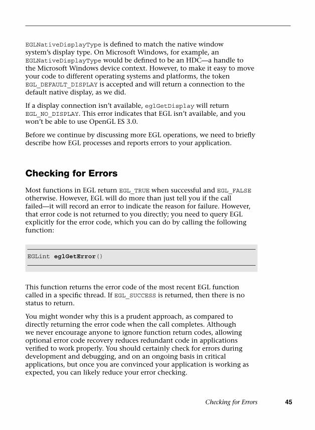
Checking for Errors 45
EGLNativeDisplayType is defined to match the native window system’s display type. On Microsoft Windows, for example, an EGLNativeDisplayType would be defined to be an HDC—a handle to the Microsoft Windows device context. However, to make it easy to move your code to different operating systems and platforms, the token EGL_DEFAULT_DISPLAY is accepted and will return a connection to the default native display, as we did.
If a display connection isn’t available, eglGetDisplay will return EGL_NO_DISPLAY. This error indicates that EGL isn’t available, and you won’t be able to use OpenGL ES 3.0.
Before we continue by discussing more EGL operations, we need to briefly describe how EGL processes and reports errors to your application.
Checking for Errors
Most functions in EGL return EGL_TRUE when successful and EGL_FALSE otherwise. However, EGL will do more than just tell you if the call failed—it will record an error to indicate the reason for failure. However, that error code is not returned to you directly; you need to query EGL explicitly for the error code, which you can do by calling the following function:
This function returns the error code of the most recent EGL function called in a specific thread. If EGL_SUCCESS is returned, then there is no status to return.
You might wonder why this is a prudent approach, as compared to directly returning the error code when the call completes. Although we never encourage anyone to ignore function return codes, allowing optional error code recovery reduces redundant code in applications verified to work properly. You should certainly check for errors during development and debugging, and on an ongoing basis in critical applications, but once you are convinced your application is working as expected, you can likely reduce your error checking.
EGLint eglGetError()

46 Chapter 3: An Introduction to EGL
Initializing EGL
Once you have successfully opened a connection, EGL needs to be initialized, which is done by calling the following function:
This function initializes EGL’s internal data structures and returns the major and minor version numbers of the EGL implementation. If EGL is unable to be initialized, this call will return EGL_FALSE, and set EGL’s error code to
• EGL_BAD_DISPLAY if display doesn’t specify a valid EGLDisplay.
• EGL_NOT_INITIALIZED if the EGL cannot be initialized.
Determining the Available Surface Configurations
Once we have initialized EGL, we are able to determine which types and configurations of rendering surfaces are available to us. There are two ways to go about this:
• Query every surface configuration and find the best choice ourselves.
• Specify a set of requirements and let EGL make a recommendation forthe best match.
In many situations, the second option is simpler to implement, and most likely yields what you would have found using the first option. In either case, EGL will return an EGLConfig, which is an identifier to an EGL-internal data structure that contains information about a particular surface and its characteristics, such as the number of bits for
EGLBoolean eglInitialize(EGLDisplay display, EGLint *majorVersion, EGLint *minorVersion)
display specifies the EGL display connection
majorVersion specifies the major version number returned by the EGL implementation; may be NULL
minorVersion specifies the minor version number returned by the EGL implementation; may be NULL
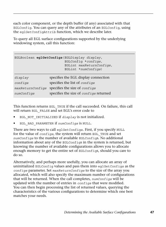
Determining the Available Surface Configurations 47
each color component, or the depth buffer (if any) associated with that EGLConfig. You can query any of the attributes of an EGLConfig, using the eglGetConfigAttrib function, which we describe later.
To query all EGL surface configurations supported by the underlying windowing system, call this function:
EGLBoolean eglGetConfigs(EGLDisplay display, EGLConfig *configs, EGLint maxReturnConfigs, EGLint *numConfigs)
display specifies the EGL display connection
configs specifies the list of configs
maxReturnConfigs specifies the size of configs
numConfigs specifies the size of configs returned
This function returns EGL_TRUE if the call succeeded. On failure, this call will return EGL_FALSE and set EGL’s error code to
• EGL_NOT_INITIALIZED if display is not initialized.
• EGL_BAD_PARAMETER if numConfigs is NULL.
There are two ways to call eglGetConfigs. First, if you specify NULL for the value of configs, the system will return EGL_TRUE and set numConfigs to the number of available EGLConfigs. No additional information about any of the EGLConfigs in the system is returned, but knowing the number of available configurations allows you to allocate enough memory to get the entire set of EGLConfigs, should you care to do so.
Alternatively, and perhaps more usefully, you can allocate an array of uninitialized EGLConfig values and pass them into eglGetConfigs as the configs parameter. Set maxReturnConfigs to the size of the array you allocated, which will also specify the maximum number of configurations that will be returned. When the call completes, numConfigs will be updated with the number of entries in configs that were modified. You can then begin processing the list of returned values, querying the characteristics of the various configurations to determine which one best matches your needs.

48 Chapter 3: An Introduction to EGL
Querying EGLConfig Attributes
We now describe the values that EGL associates with an EGLConfig and explain how you can retrieve those values.
An EGLConfig contains all of the information about a surface made available by EGL. This includes information about the number of available colors, additional buffers associated with the configuration (such as depth and stencil buffers, which we discuss later), the type of surfaces, and numerous other characteristics. The following is a list of the attributes that can be queried from an EGLConfig. We discuss only a subset of these in this chapter, but the entire list appears in Table 3-1 as a reference.
To query a particular attribute associated with an EGLConfig, use the following function:
This function returns EGL_TRUE if the call succeeded. On failure, EGL_FALSE is returned, and an EGL_BAD_ATTRIBUTE error is posted if attribute is not a valid attribute.
This call will return the value for the specific attribute of the associated EGLConfig. This allows you total control over which configuration you choose for ultimately creating rendering surfaces. However, when looking at Table 3-1, you might be somewhat intimidated by the large number of options. EGL provides another routine, eglChooseConfig, that allows you to specify what is important for your application, and will return the best matching configuration given your requests.
EGLBoolean eglGetConfigAttrib(EGLDisplay display, EGLConfig config, EGLint attribute, EGLint *value)
display specifies the EGL display connectionconfig specifies the configuration to be queriedattribute specifies the particular attribute to be returnedvalue specifies the value returned

ptg12025281
Querying EG
LConfi
g Attributes
49
Table 3-1 EGLConfig Attributes
Attribute Description Default Value
EGL_BUFFER_SIZE Number of bits for all color components in the color buffer 0
EGL_RED_SIZE Number of red bits in the color buffer 0
EGL_GREEN_SIZE Number of green bits in the color buffer 0
EGL_BLUE_SIZE Number of blue bits in the color buffer 0
EGL_LUMINANCE_SIZE Number of luminance bits in the color buffer 0
EGL_ALPHA_SIZE Number of alpha bits in the color buffer 0
EGL_ALPHA_MASK_SIZE Number of alpha-mask bits in the mask buffer 0
EGL_BIND_TO_TEXTURE_RGB True if bindable to RGB textures EGL_DONT_CARE
EGL_BIND_TO_TEXTURE_RGBA True if bindable to RGBA textures EGL_DONT_CARE
EGL_COLOR_BUFFER_TYPE Type of the color buffer: either EGL_RGB_BUFFER or EGL_LUMINANCE_BUFFER
EGL_RGB_BUFFER
EGL_CONFIG_CAVEAT Any caveats associated with the configuration EGL_DONT_CARE
EGL_CONFIG_ID The unique EGLConfig identifier value EGL_DONT_CARE
EGL_CONFORMANT True if contexts created with this EGLConfig are conformant —
EGL_DEPTH_SIZE Number of bits in the depth buffer 0
EGL_LEVEL Framebuffer level 0
EGL_MAX_PBUFFER_WIDTH Maximum width for a PBuffer created with this EGLConfig —
EGL_MAX_PBUFFER_HEIGHT Maximum height for a PBuffer created with this EGLConfig —
EGL_MAX_PBUFFER_PIXELS Maximum size of a PBuffer created with this EGLConfig —
EGL_MAX_SWAP_INTERVAL Maximum buffer swap interval EGL_DONT_CARE
(continues)
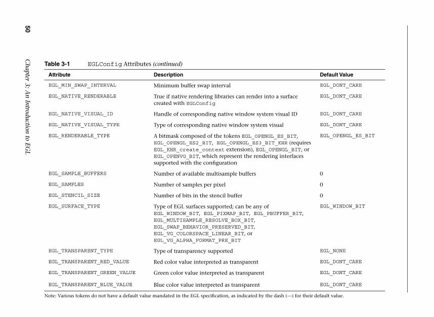
ptg12025281
50 C
hapter 3: An Introduction to EG
L
Table 3-1 EGLConfig Attributes (continued)
Attribute Description Default Value
EGL_MIN_SWAP_INTERVAL Minimum buffer swap interval EGL_DONT_CARE
EGL_NATIVE_RENDERABLE True if native rendering libraries can render into a surface created with EGLConfig
EGL_DONT_CARE
EGL_NATIVE_VISUAL_ID Handle of corresponding native window system visual ID EGL_DONT_CARE
EGL_NATIVE_VISUAL_TYPE Type of corresponding native window system visual EGL_DONT_CARE
EGL_RENDERABLE_TYPE A bitmask composed of the tokens EGL_OPENGL_ES_BIT, EGL_OPENGL_ES2_BIT, EGL_OPENGL_ES3_BIT_KHR (requires EGL_KHR_create_context extension), EGL_OPENGL_BIT, or EGL_OPENVG_BIT, which represent the rendering interfaces supported with the configuration
EGL_OPENGL_ES_BIT
EGL_SAMPLE_BUFFERS Number of available multisample buffers 0
EGL_SAMPLES Number of samples per pixel 0
EGL_STENCIL_SIZE Number of bits in the stencil buffer 0
EGL_SURFACE_TYPE Type of EGL surfaces supported; can be any of EGL_WINDOW_BIT, EGL_PIXMAP_BIT, EGL_PBUFFER_BIT, EGL_MULTISAMPLE_RESOLVE_BOX_BIT, EGL_SWAP_BEHAVIOR_PRESERVED_BIT, EGL_VG_COLORSPACE_LINEAR_BIT, or EGL_VG_ALPHA_FORMAT_PRE_BIT
EGL_WINDOW_BIT
EGL_TRANSPARENT_TYPE Type of transparency supported EGL_NONE
EGL_TRANSPARENT_RED_VALUE Red color value interpreted as transparent EGL_DONT_CARE
EGL_TRANSPARENT_GREEN_VALUE Green color value interpreted as transparent EGL_DONT_CARE
EGL_TRANSPARENT_BLUE_VALUE Blue color value interpreted as transparent EGL_DONT_CARE
Note: Various tokens do not have a default value mandated in the EGL specification, as indicated by the dash (—) for their default value.
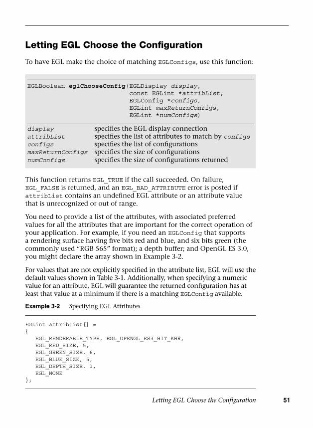
Letting EGL Choose the Configuration 51
Letting EGL Choose the Configuration
To have EGL make the choice of matching EGLConfigs, use this function:
This function returns EGL_TRUE if the call succeeded. On failure, EGL_FALSE is returned, and an EGL_BAD_ATTRIBUTE error is posted if attribList contains an undefined EGL attribute or an attribute value that is unrecognized or out of range.
You need to provide a list of the attributes, with associated preferred values for all the attributes that are important for the correct operation of your application. For example, if you need an EGLConfig that supports a rendering surface having five bits red and blue, and six bits green (the commonly used “RGB 565” format); a depth buffer; and OpenGL ES 3.0, you might declare the array shown in Example 3-2.
For values that are not explicitly specified in the attribute list, EGL will use the default values shown in Table 3-1. Additionally, when specifying a numeric value for an attribute, EGL will guarantee the returned configuration has at least that value at a minimum if there is a matching EGLConfig available.
EGLBoolean eglChooseConfig(EGLDisplay display, const EGLint *attribList, EGLConfig *configs, EGLint maxReturnConfigs, EGLint *numConfigs)
display specifies the EGL display connectionattribList specifies the list of attributes to match by configsconfigs specifies the list of configurationsmaxReturnConfigs specifies the size of configurationsnumConfigs specifies the size of configurations returned
Example 3-2 Specifying EGL Attributes
EGLint attribList[] ={ EGL_RENDERABLE_TYPE, EGL_OPENGL_ES3_BIT_KHR, EGL_RED_SIZE, 5, EGL_GREEN_SIZE, 6, EGL_BLUE_SIZE, 5, EGL_DEPTH_SIZE, 1, EGL_NONE};
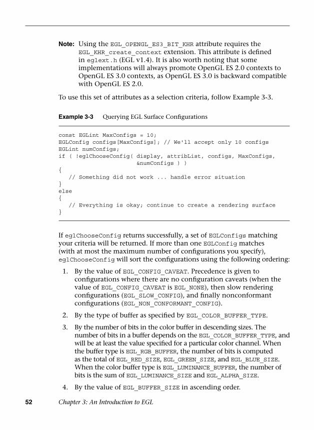
52 Chapter 3: An Introduction to EGL
Note: Using the EGL_OPENGL_ES3_BIT_KHR attribute requires the EGL_KHR_create_context extension. This attribute is defined in eglext.h (EGL v1.4). It is also worth noting that some implementations will always promote OpenGL ES 2.0 contexts to OpenGL ES 3.0 contexts, as OpenGL ES 3.0 is backward compatible with OpenGL ES 2.0.
To use this set of attributes as a selection criteria, follow Example 3-3.
Example 3-3 Querying EGL Surface Configurations
const EGLint MaxConfigs = 10;EGLConfig configs[MaxConfigs]; // We'll accept only 10 configsEGLint numConfigs;if ( !eglChooseConfig( display, attribList, configs, MaxConfigs,
&numConfigs ) ){ // Something did not work ... handle error situation}else{ // Everything is okay; continue to create a rendering surface}
If eglChooseConfig returns successfully, a set of EGLConfigs matching your criteria will be returned. If more than one EGLConfig matches (with at most the maximum number of configurations you specify), eglChooseConfig will sort the configurations using the following ordering:
1. By the value of EGL_CONFIG_CAVEAT. Precedence is given toconfigurations where there are no configuration caveats (when thevalue of EGL_CONFIG_CAVEAT is EGL_NONE), then slow renderingconfigurations (EGL_SLOW_CONFIG), and finally nonconformantconfigurations (EGL_NON_CONFORMANT_CONFIG).
2. By the type of buffer as specified by EGL_COLOR_BUFFER_TYPE.
3. By the number of bits in the color buffer in descending sizes. Thenumber of bits in a buffer depends on the EGL_COLOR_BUFFER_TYPE, andwill be at least the value specified for a particular color channel. Whenthe buffer type is EGL_RGB_BUFFER, the number of bits is computedas the total of EGL_RED_SIZE, EGL_GREEN_SIZE, and EGL_BLUE_SIZE.When the color buffer type is EGL_LUMINANCE_BUFFER, the number ofbits is the sum of EGL_LUMINANCE_SIZE and EGL_ALPHA_SIZE.
4. By the value of EGL_BUFFER_SIZE in ascending order.
Creating an On-Screen Rendering Area: The EGL Window 53
5. By the value of EGL_SAMPLE_BUFFERS in ascending order.
6. By the number of EGL_SAMPLES in ascending order.
7. By the value of EGL_DEPTH_SIZE in ascending order.
8. By the value of the EGL_STENCIL_SIZE in ascending order.
9. By the value of the EGL_ALPHA_MASK_SIZE (which is applicable onlyto OpenVG surfaces).
10. By the EGL_NATIVE_VISUAL_TYPE in an implementation-dependentmanner.
11. By the value of the EGL_CONFIG_ID in ascending order.
Parameters not mentioned in this list are not used in the sorting process.
Note: Because of the third sorting rule, to get the best format that matches what you specified, you will need to add extra logic to go through the returned results. For example, if you ask for “565” RGB format, then the “888” format will appear in the returned results first.
As mentioned in Example 3-3, if eglChooseConfig returns successfully, we have enough information to continue to create something to draw into. By default, if you do not specify which type of rendering surface type you would like (by specifying the EGL_SURFACE_TYPE attribute), EGL assumes you want an on-screen window.
Creating an On-Screen Rendering Area: The EGL Window
Once we have a suitable EGLConfig that meets our requirements for rendering, we are ready to create our window. To create a window, call the following function:
EGLSurface eglCreateWindowSurface(EGLDisplay display, EGLConfig config, EGLNativeWindowType window, const EGLint *attribList)
display specifies the EGL display connectionconfig specifies the configurationwindow specifies the native windowattribList specifies the list of window attributes; may be NULL
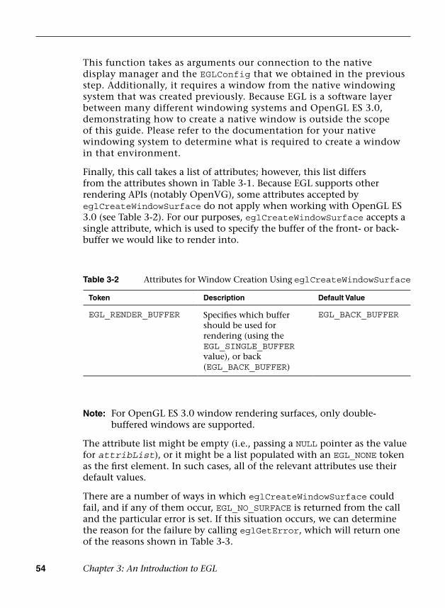
54 Chapter 3: An Introduction to EGL
This function takes as arguments our connection to the native display manager and the EGLConfig that we obtained in the previous step. Additionally, it requires a window from the native windowing system that was created previously. Because EGL is a software layer between many different windowing systems and OpenGL ES 3.0, demonstrating how to create a native window is outside the scope of this guide. Please refer to the documentation for your native windowing system to determine what is required to create a window in that environment.
Finally, this call takes a list of attributes; however, this list differs from the attributes shown in Table 3-1. Because EGL supports other rendering APIs (notably OpenVG), some attributes accepted by eglCreateWindowSurface do not apply when working with OpenGL ES 3.0 (see Table 3-2). For our purposes, eglCreateWindowSurface accepts a single attribute, which is used to specify the buffer of the front- or back-buffer we would like to render into.
Table 3-2 Attributes for Window Creation Using eglCreateWindowSurface
Token Description Default Value
EGL_RENDER_BUFFER Specifies which buffer should be used for rendering (using the EGL_SINGLE_BUFFER value), or back (EGL_BACK_BUFFER)
EGL_BACK_BUFFER
Note: For OpenGL ES 3.0 window rendering surfaces, only double-buffered windows are supported.
The attribute list might be empty (i.e., passing a NULL pointer as the value for attribList), or it might be a list populated with an EGL_NONE token as the first element. In such cases, all of the relevant attributes use their default values.
There are a number of ways in which eglCreateWindowSurface could fail, and if any of them occur, EGL_NO_SURFACE is returned from the call and the particular error is set. If this situation occurs, we can determine the reason for the failure by calling eglGetError, which will return one of the reasons shown in Table 3-3.

Creating an On-Screen Rendering Area:The EGL Window 55
Putting this all together, our code for creating a window is shown in Example 3-4.
Table 3-3 Possible Errors When eglCreateWindowSurface Fails
Error Code Description
EGL_BAD_MATCH This situation occurs when:
• The attributes of the native window do not matchthose of the provided EGLConfig.
• The provided EGLConfig does not support renderinginto a window (i.e., the EGL_SURFACE_TYPE attributedoes not have the EGL_WINDOW_BIT set).
EGL_BAD_CONFIG This error is flagged if the provided EGLConfig is not supported by the system.
EGL_BAD_NATIVE_WINDOW
This error is specified if the provided native window handle is not valid.
EGL_BAD_ALLOC This error occurs if eglCreateWindowSurface is unable to allocate the resources for the new EGL window, or if there is already an EGLConfig associated with the provided native window.
Example 3-4 Creating an EGL Window Surface
EGLint attribList[] ={ EGL_RENDER_BUFFER, EGL_BACK_BUFFER, EGL_NONE);
EGLSurface window = eglCreateWindowSurface ( display, config,nativeWindow,attribList );
if ( window == EGL_NO_SURFACE ){ switch ( eglGetError ( ) ) {
case EGL_BAD_MATCH:// Check window and EGLConfig attributes to determine// compatibility, or verify that the EGLConfig// supports rendering to a windowbreak;
case EGL_BAD_CONFIG:// Verify that provided EGLConfig is validbreak;
(continues)
56 Chapter 3: An Introduction to EGL
This creates a place for us to draw into, but we still have two more steps that must be completed before we can successfully use OpenGL ES 3.0 with our window. Windows, however, are not the only rendering surfaces that you might find useful. We introduce another type of rendering surface next before completing our discussion.
Creating an Off-Screen Rendering Area: EGL Pbuffers
In addition to being able to render into an on-screen window using OpenGL ES 3.0, you can render into nonvisible off-screen surfaces called pbuffers (short for pixel buffer). Pbuffers can take full advantage of any hardware acceleration available to OpenGL ES 3.0, just as a window does. Pbuffers are most often used for generating texture maps. If all you want to do is render to a texture, we recommend using framebuffer objects (covered in Chapter 12, “Framebuffer Objects”) instead of pbuffers because they are more efficient. However, pbuffers can still be useful in some cases where framebuffer objects cannot be used, such as when rendering an off-screen surface with OpenGL ES and then using it as a texture in another API such as OpenVG.
Creating a pbuffer is very similar to creating an EGL window, with a few minor differences. To create a pbuffer, we need to find an EGLConfig just as we did for a window, with one modification: We need to augment the value of EGL_SURFACE_TYPE to include EGL_PBUFFER_BIT. Once we have a suitable EGLConfig, we can create a pbuffer using the function
Example 3-4 Creating an EGL Window Surface (continued)
case EGL_BAD_NATIVE_WINDOW:// Verify that provided EGLNativeWindow is validbreak;
case EGL_BAD_ALLOC:// Not enough resources available; handle and recoverbreak;
}}
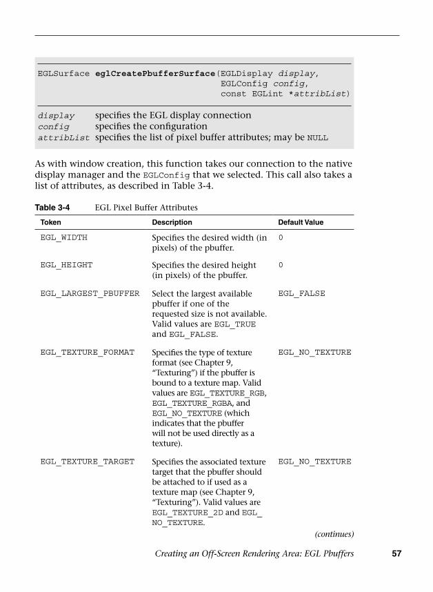
Creating an Off-Screen Rendering Area: EGL Pbuffers 57
EGLSurface eglCreatePbufferSurface(EGLDisplay display, EGLConfig config, const EGLint *attribList)
display specifies the EGL display connectionconfig specifies the configurationattribList specifies the list of pixel buffer attributes; may be NULL
As with window creation, this function takes our connection to the native display manager and the EGLConfig that we selected. This call also takes a list of attributes, as described in Table 3-4.
Table 3-4 EGL Pixel Buffer Attributes
Token Description Default Value
EGL_WIDTH Specifies the desired width (in pixels) of the pbuffer.
0
EGL_HEIGHT Specifies the desired height (in pixels) of the pbuffer.
0
EGL_LARGEST_PBUFFER Select the largest available pbuffer if one of the requested size is not available. Valid values are EGL_TRUE and EGL_FALSE.
EGL_FALSE
EGL_TEXTURE_FORMAT Specifies the type of texture format (see Chapter 9, “Texturing”) if the pbuffer is bound to a texture map. Valid values are EGL_TEXTURE_RGB, EGL_TEXTURE_RGBA, and EGL_NO_TEXTURE (which indicates that the pbuffer will not be used directly as a texture).
EGL_NO_TEXTURE
EGL_TEXTURE_TARGET Specifies the associated texture target that the pbuffer should be attached to if used as a texture map (see Chapter 9, “Texturing”). Valid values are EGL_TEXTURE_2D and EGL_NO_TEXTURE.
EGL_NO_TEXTURE
(continues)

58 Chapter 3: An Introduction to EGL
There are a number of ways that eglCreatePbufferSurface could fail. Just as with window creation, if any of these failures occur, EGL_NO_SURFACE is returned from the call and the particular error is set. In this situation, eglGetError will return one of the errors listed in Table 3-5.
Table 3-5 Possible Errors When eglCreatePbufferSurface Fails
Error Code Description
EGL_BAD_ALLOC This error occurs when the pbuffer cannot be allocated due to a lack of resources.
EGL_BAD_CONFIG This error is flagged if the provided EGLConfig is not a valid EGLConfig supported by the system.
EGL_BAD_PARAMETER This error is generated if either the EGL_WIDTH or EGL_HEIGHT provided in the attribute list is a negative value.
EGL_BAD_MATCH This error is generated if any of the following situations occur: if the EGLConfig provided does not support pbuffer surfaces; if the pbuffer will be used as a texture map (EGL_TEXTURE_FORMAT is not EGL_NO_TEXTURE), and the specified EGL_WIDTH and EGL_HEIGHT specify an invalid texture size; or if either EGL_TEXTURE_FORMAT and EGL_TEXTURE_TARGET is EGL_NO_TEXTURE, and the other attribute is not EGL_NO_TEXTURE.
EGL_BAD_ATTRIBUTE
This error occurs if either EGL_TEXTURE_FORMAT, EGL_TEXTURE_TARGET, or EGL_MIPMAP_TEXTURE is specified, but the provided EGLConfig does not support OpenGL ES rendering (e.g., only OpenVG rendering is supported).
Putting this all together, we create a pbuffer, as shown in Example 3-5.
Table 3-4 EGL Pixel Buffer Attributes (continued)
Token Description Default Value
EGL_MIPMAP_TEXTURE Specifies whether storage for texture mipmap levels (see Chapter 9, “Texturing”) should be additionally allocated. Valid values are EGL_TRUE and EGL_FALSE.
EGL_FALSE
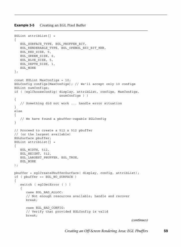
Creating an Off-Screen Rendering Area: EGL Pbuffers 59
(continues)
Example 3-5 Creating an EGL Pixel Buffer
EGLint attribList[] ={ EGL_SURFACE_TYPE, EGL_PBUFFER_BIT, EGL_RENDERABLE_TYPE, EGL_OPENGL_ES3_BIT_KHR, EGL_RED_SIZE, 5, EGL_GREEN_SIZE, 6, EGL_BLUE_SIZE, 5, EGL_DEPTH_SIZE, 1, EGL_NONE};
const EGLint MaxConfigs = 10;EGLConfig configs[MaxConfigs]; // We'll accept only 10 configsEGLint numConfigs;if ( !eglChooseConfig( display, attribList, configs, MaxConfigs,
&numConfigs ) ){ // Something did not work ... handle error situation}else{ // We have found a pbuffer-capable EGLConfig}
// Proceed to create a 512 x 512 pbuffer// (or the largest available)EGLSurface pbuffer;EGLint attribList[] ={ EGL_WIDTH, 512, EGL_HEIGHT, 512, EGL_LARGEST_PBUFFER, EGL_TRUE, EGL_NONE);
pbuffer = eglCreatePbufferSurface( display, config, attribList);if ( pbuffer == EGL_NO_SURFACE ){ switch ( eglGetError ( ) ) {
case EGL_BAD_ALLOC:// Not enough resources available; handle and recoverbreak;
case EGL_BAD_CONFIG:// Verify that provided EGLConfig is validbreak;
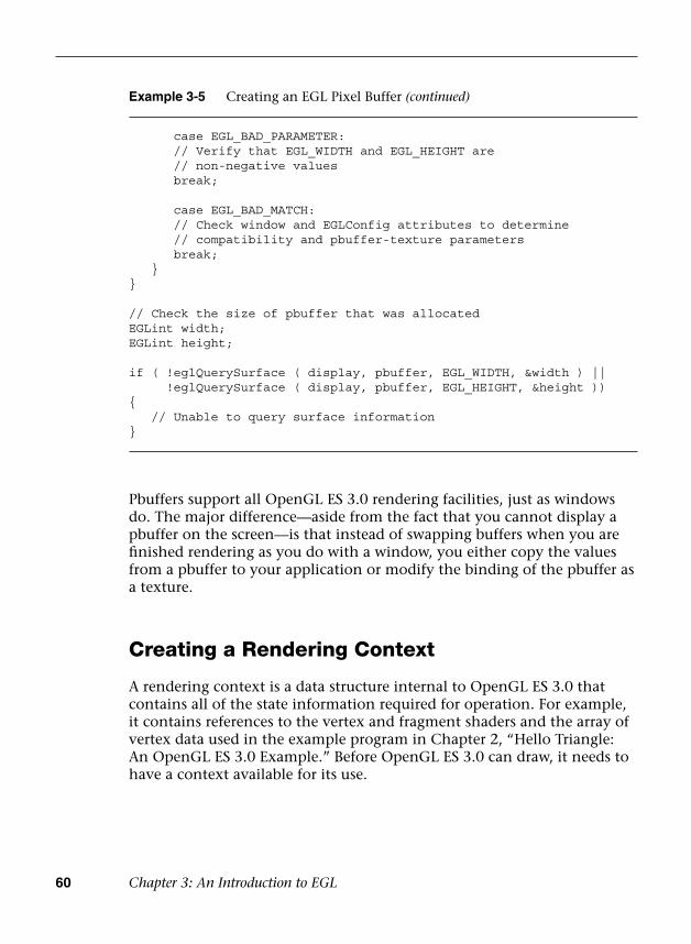
60 Chapter 3: An Introduction to EGL
Pbuffers support all OpenGL ES 3.0 rendering facilities, just as windows do. The major difference—aside from the fact that you cannot display a pbuffer on the screen—is that instead of swapping buffers when you are finished rendering as you do with a window, you either copy the values from a pbuffer to your application or modify the binding of the pbuffer as a texture.
Creating a Rendering Context
A rendering context is a data structure internal to OpenGL ES 3.0 that contains all of the state information required for operation. For example, it contains references to the vertex and fragment shaders and the array of vertex data used in the example program in Chapter 2, “Hello Triangle: An OpenGL ES 3.0 Example.” Before OpenGL ES 3.0 can draw, it needs to have a context available for its use.
Example 3-5 Creating an EGL Pixel Buffer (continued)
case EGL_BAD_PARAMETER:// Verify that EGL_WIDTH and EGL_HEIGHT are// non-negative valuesbreak;
case EGL_BAD_MATCH:// Check window and EGLConfig attributes to determine// compatibility and pbuffer-texture parametersbreak;
}}
// Check the size of pbuffer that was allocatedEGLint width;EGLint height;
if ( !eglQuerySurface ( display, pbuffer, EGL_WIDTH, &width ) || !eglQuerySurface ( display, pbuffer, EGL_HEIGHT, &height )){ // Unable to query surface information}

Creating a Rendering Context 61
EGLContext eglCreateContext(EGLDisplay display, EGLConfig config, EGLContext shareContext, const EGLint *attribList)
display specifies the EGL display connectionconfig specifies the configurationshareContext allows multiple EGL contexts to share specific types of
data, such as shader programs and texture maps; use EGL_NO_CONTEXT for no sharing
attribList specifies the list of attributes for the context to be created; only a single attribute is accepted, EGL_CONTEXT_CLIENT_VERSION
Once again, you will need the display connection and the EGLConfig that best represents your application’s requirements. The third parameter, shareContext, allows multiple EGLContexts to share specific types of data, such as shader programs and texture maps. For the time being, we pass EGL_NO_CONTEXT in as the value for shareContext, indicating that we are not sharing resources with any other contexts.
Finally, as with many EGL calls, a list of attributes specific to eglCreate-Context’s operation is specified. In this case, a single attribute is accepted, EGL_CONTEXT_CLIENT_VERSION, which is discussed in Table 3-6.
Table 3-6 Attributes for Context Creation Using eglCreateContext
Token Description Default Value
EGL_CONTEXT_ CLIENT_VERSION
Specifies the type of context associated with the version of OpenGL ES that you are using
1 (specifies an OpenGL ES 1.X context)
Because we want to use OpenGL ES 3.0, we will always have to specify this attribute to obtain the right type of context.
When eglCreateContext succeeds, it returns a handle to the newly created context. If a context cannot be created, then eglCreateContext returns EGL_NO_CONTEXT, and the reason for the failure is set and can be obtained by calling eglGetError. With our current knowledge, the only
To create a context, use the following function:

62 Chapter 3: An Introduction to EGL
Other errors may be generated by eglCreateContext, but for the moment we will check for only bad EGLConfig errors.
After successfully creating an EGLContext, we need to complete one final step before we can render.
Making an EGLContext Current
As an application might have created multiple EGLContexts for various purposes, we need a way to associate a particular EGLContext with our rendering surface—a process commonly called “make current.”
Example 3-6 Creating an EGL Context
const EGLint attribList[] ={ // EGL_KHR_create_context is required EGL_CONTEXT_CLIENT_VERSION, 3, EGL_NONE};
EGLContext context = eglCreateContext ( display, config,EGL_NO_CONTEXT,attribList );
if ( context == EGL_NO_CONTEXT ){ EGLError error = eglGetError ( );
if ( error == EGL_BAD_CONFIG ) {
// Handle error and recover }}
reason that eglCreateContext would fail is if the EGLConfig we provide is not valid, in which case the error returned by eglGetError is EGL_BAD_CONFIG.
Example 3-6 shows how to create a context after selecting an appropriate EGLConfig.
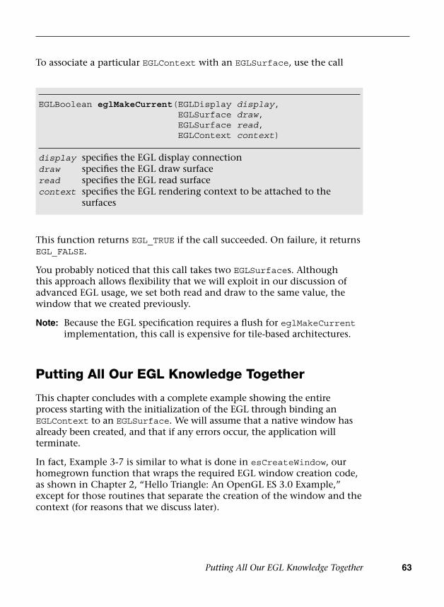
Putting All Our EGL Knowledge Together 63
EGLBoolean eglMakeCurrent(EGLDisplay display, EGLSurface draw, EGLSurface read, EGLContext context)
display specifies the EGL display connectiondraw specifies the EGL draw surfaceread specifies the EGL read surfacecontext specifies the EGL rendering context to be attached to the
surfaces
This function returns EGL_TRUE if the call succeeded. On failure, it returns EGL_FALSE.
You probably noticed that this call takes two EGLSurfaces. Although this approach allows flexibility that we will exploit in our discussion of advanced EGL usage, we set both read and draw to the same value, the window that we created previously.
Note: Because the EGL specification requires a flush for eglMakeCurrent implementation, this call is expensive for tile-based architectures.
Putting All Our EGL Knowledge Together
This chapter concludes with a complete example showing the entire process starting with the initialization of the EGL through binding an EGLContext to an EGLSurface. We will assume that a native window has already been created, and that if any errors occur, the application will terminate.
In fact, Example 3-7 is similar to what is done in esCreateWindow, our homegrown function that wraps the required EGL window creation code, as shown in Chapter 2, “Hello Triangle: An OpenGL ES 3.0 Example,” except for those routines that separate the creation of the window and the context (for reasons that we discuss later).
To associate a particular EGLContext with an EGLSurface, use the call

64 Chapter 3: An Introduction to EGL
Example 3-7 A Complete Routine for Creating an EGL Window
EGLBoolean initializeWindow ( EGLNativeWindow nativeWindow ){ const EGLint configAttribs[] = {
EGL_RENDER_TYPE, EGL_WINDOW_BIT,EGL_RED_SIZE, 8,EGL_GREEN_SIZE, 8,EGL_BLUE_SIZE, 8,EGL_DEPTH_SIZE, 24,EGL_NONE
};
const EGLint contextAttribs[] = {
EGL_CONTEXT_CLIENT_VERSION, 3,EGL_NONE
};
EGLDisplay display = eglGetDisplay ( EGL_DEFAULT_DISPLAY ) if ( display == EGL_NO_DISPLAY ) {
return EGL_FALSE; }
EGLint major, minor; if ( !eglInitialize ( display, &major, &minor ) ) {
return EGL_FALSE; }
EGLConfig config; EGLint numConfigs; if ( !eglChooseConfig ( display, configAttribs, &config, 1,
&numConfigs ) ) {
return EGL_FALSE; }
EGLSurface window = eglCreateWindowSurface ( display, config, nativeWindow, NULL );
if (window == EGL_NO_SURFACE) {
return EGL_FALSE; }

Putting All Our EGL Knowledge Together 65
Example 3-8 Creating a Window Using the esUtil Library
ESContext esContext;const char* title = "OpenGL ES Application Window Title";
if (esCreateWindow(&esContext, title, 512, 512, ES_WINDOW_RGB | ES_WINDOW_DEPTH))
{ // Window creation failed}
This code would be similar if an application made the call in Example 3-8 to open a 512 × 512 window.
The last parameter to esCreateWindow specifies the characteristics we want in our window, and specifies as a bitmask of the following values:
• ES_WINDOW_RGB—Specify an RGB-based color buffer.
• ES_WINDOW_ALPHA—Allocate a destination alpha buffer.
• ES_WINDOW_DEPTH—Allocate a depth buffer.
• ES_WINDOW_STENCIL—Allocate a stencil buffer.
• ES_WINDOW_MULTISAMPLE—Allocate a multisample buffer.
EGLContext context = eglCreateContext ( display, config, EGL_NO_CONTEXT, contextAttribs);
if ( context == EGL_NO_CONTEXT ) {
return EGL_FALSE; }
if ( !eglMakeCurrent ( display, window, window, context ) ) {
return EGL_FALSE; } return EGL_TRUE;}
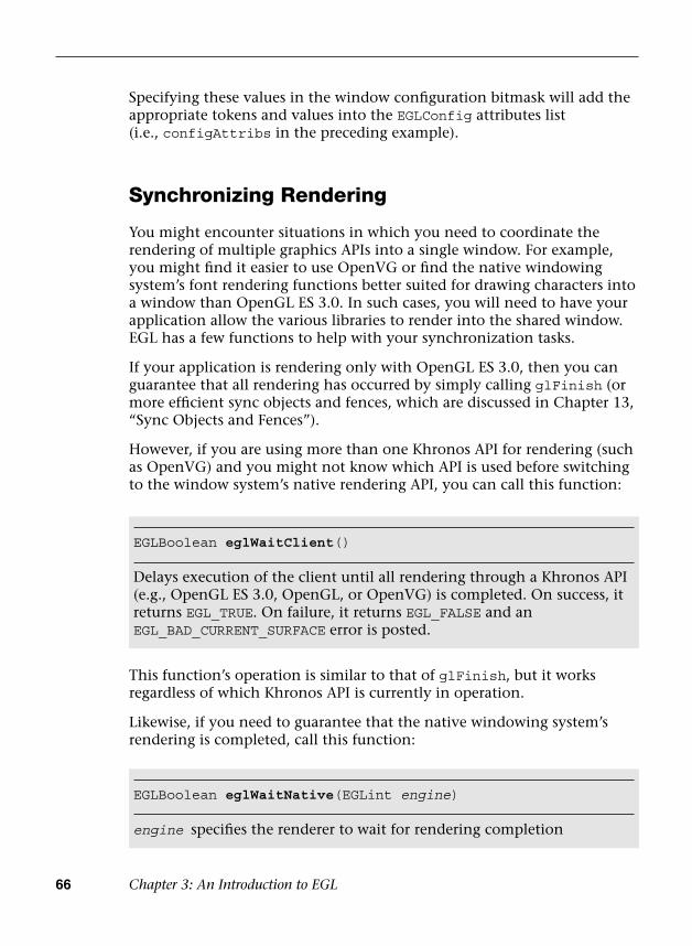
66 Chapter 3: An Introduction to EGL
Specifying these values in the window configuration bitmask will add the appropriate tokens and values into the EGLConfig attributes list (i.e., configAttribs in the preceding example).
Synchronizing Rendering
You might encounter situations in which you need to coordinate the rendering of multiple graphics APIs into a single window. For example, you might find it easier to use OpenVG or find the native windowing system’s font rendering functions better suited for drawing characters into a window than OpenGL ES 3.0. In such cases, you will need to have your application allow the various libraries to render into the shared window. EGL has a few functions to help with your synchronization tasks.
If your application is rendering only with OpenGL ES 3.0, then you can guarantee that all rendering has occurred by simply calling glFinish (or more efficient sync objects and fences, which are discussed in Chapter 13, “Sync Objects and Fences”).
However, if you are using more than one Khronos API for rendering (such as OpenVG) and you might not know which API is used before switching to the window system’s native rendering API, you can call this function:
EGLBoolean eglWaitNative(EGLint engine)
engine specifies the renderer to wait for rendering completion
This function’s operation is similar to that of glFinish, but it works regardless of which Khronos API is currently in operation.
Likewise, if you need to guarantee that the native windowing system’s rendering is completed, call this function:
EGLBoolean eglWaitClient()
Delays execution of the client until all rendering through a Khronos API (e.g., OpenGL ES 3.0, OpenGL, or OpenVG) is completed. On success, it returns EGL_TRUE. On failure, it returns EGL_FALSE and an EGL_BAD_CURRENT_SURFACE error is posted.
Summary 67
EGL_CORE_NATIVE_ENGINE is always accepted, and represents the most common engine supported; other engines are implementation specific, and are specified through EGL extensions. EGL_TRUE is returned on success. On failure, EGL_FALSE is returned and an EGL_BAD_PARAMETER error is posted.
Summary
In this chapter, you learned about EGL, the API for creating surfaces and rendering contexts for OpenGL ES 3.0. Now, you know how to initialize EGL; query various EGL attributes; and create an on-screen, off-screen rendering area and rendering context using EGL. You have learned enough EGL to do everything you will need for rendering with OpenGL ES 3.0. In the next chapter, we show you how to create OpenGL ES shaders and programs.

This page intentionally left blank

69
Chapter 4
Shaders and Programs
Chapter 2, “Hello, Triangle: An OpenGL ES 3.0 Example,” introduced you to a simple program that draws a single triangle. In that example, we created two shader objects (one for the vertex shader and one for the fragment shader) and a single program object to render the triangle. Shader objects and program objects are fundamental concepts when working with shaders in OpenGL ES 3.0. In this chapter, we provide the full details on how to create shaders, compile them, and link them together into a program object. The details of writing vertex and fragment shaders come later in this book. For now, we focus on the following topics:
• Shader and program object overview
• Creating and compiling a shader
• Creating and linking a program
• Getting and setting uniforms
• Getting and setting attributes
• Shader compiler and program binaries
Shaders and Programs
There are two fundamental object types you need to create to render with shaders: shader objects and program objects. The best way to think of a shader object and a program object is by comparison to a C compiler and linker. A C compiler generates object code (e.g., .obj or .o files) for a piece of source code. After the object files have been created, the C linker then links the object files into a final program.
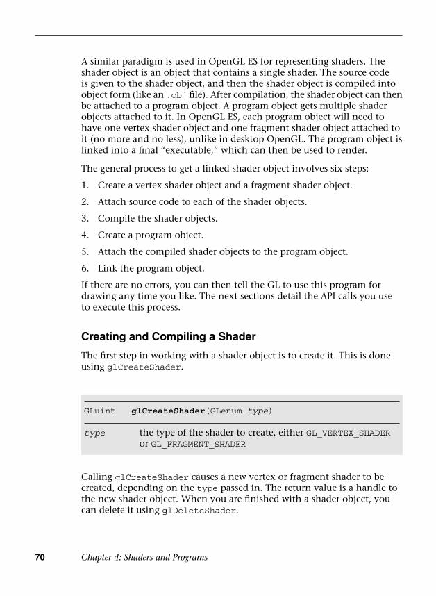
70 Chapter 4: Shaders and Programs
A similar paradigm is used in OpenGL ES for representing shaders. The shader object is an object that contains a single shader. The source code is given to the shader object, and then the shader object is compiled into object form (like an .obj file). After compilation, the shader object can then be attached to a program object. A program object gets multiple shader objects attached to it. In OpenGL ES, each program object will need to have one vertex shader object and one fragment shader object attached to it (no more and no less), unlike in desktop OpenGL. The program object is linked into a final “executable,” which can then be used to render.
The general process to get a linked shader object involves six steps:
1. Create a vertex shader object and a fragment shader object.
2. Attach source code to each of the shader objects.
3. Compile the shader objects.
4. Create a program object.
5. Attach the compiled shader objects to the program object.
6. Link the program object.
If there are no errors, you can then tell the GL to use this program for drawing any time you like. The next sections detail the API calls you use to execute this process.
Creating and Compiling a Shader
The first step in working with a shader object is to create it. This is done using glCreateShader.
GLuint glCreateShader(GLenum type)
type the type of the shader to create, either GL_VERTEX_SHADER or GL_FRAGMENT_SHADER
Calling glCreateShader causes a new vertex or fragment shader to be created, depending on the type passed in. The return value is a handle to the new shader object. When you are finished with a shader object, you can delete it using glDeleteShader.

Shaders and Programs 71
Note that if a shader is attached to a program object (more on this later), calling glDeleteShader will not immediately delete the shader. Rather, the shader will be marked for deletion and its memory will be freed once the shader is no longer attached to any program objects.
Once you have a shader object created, typically the next thing you will do is provide the shader source code using glShaderSource.
void glDeleteShader(GLuint shader)
shader handle to the shader object to delete
void glShaderSource(GLuint shader, GLsizei count,const GLchar* const *string,const GLint *length)
shader handle to the shader object.
count the number of shader source strings. A shader can be composed of a number of source strings, although each shader can have only one main function.
string pointer to an array of strings holding count number of shader source strings.
length pointer to an array of count integers that holds the size of each respective shader string. If length is NULL, the shader strings are assumed to be null terminated. If length is not NULL, then each element of length holds the number of characters in the corresponding shader in the string array. If the value of length for any element is less than zero, then that string is assumed to be null terminated.
void glCompileShader(GLuint shader)
shader handle to the shader object to compile
Once the shader source has been specified, the next step is to compile the shader using glCompileShader.
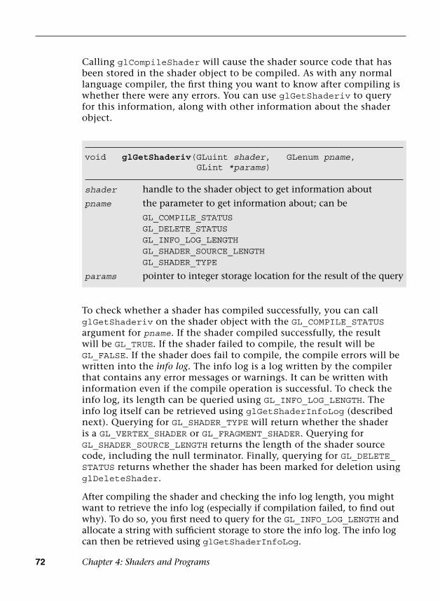
72 Chapter 4: Shaders and Programs
To check whether a shader has compiled successfully, you can call glGetShaderiv on the shader object with the GL_COMPILE_STATUS argument for pname. If the shader compiled successfully, the result will be GL_TRUE. If the shader failed to compile, the result will be GL_FALSE. If the shader does fail to compile, the compile errors will be written into the info log. The info log is a log written by the compiler that contains any error messages or warnings. It can be written with information even if the compile operation is successful. To check the info log, its length can be queried using GL_INFO_LOG_LENGTH. The info log itself can be retrieved using glGetShaderInfoLog (described next). Querying for GL_SHADER_TYPE will return whether the shader is a GL_VERTEX_SHADER or GL_FRAGMENT_SHADER. Querying for GL_SHADER_SOURCE_LENGTH returns the length of the shader source code, including the null terminator. Finally, querying for GL_DELETE_STATUS returns whether the shader has been marked for deletion using glDeleteShader.
After compiling the shader and checking the info log length, you might want to retrieve the info log (especially if compilation failed, to find out why). To do so, you first need to query for the GL_INFO_LOG_LENGTH and allocate a string with sufficient storage to store the info log. The info log can then be retrieved using glGetShaderInfoLog.
void glGetShaderiv(GLuint shader, GLenum pname,GLint *params)
shader handle to the shader object to get information about
pname the parameter to get information about; can be
GL_COMPILE_STATUSGL_DELETE_STATUSGL_INFO_LOG_LENGTHGL_SHADER_SOURCE_LENGTHGL_SHADER_TYPE
params pointer to integer storage location for the result of the query
Calling glCompileShader will cause the shader source code that has been stored in the shader object to be compiled. As with any normal language compiler, the first thing you want to know after compiling is whether there were any errors. You can use glGetShaderiv to query for this information, along with other information about the shader object.
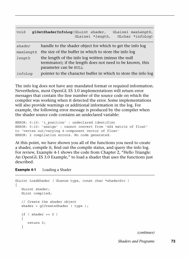
Shaders and Programs 73
void glGetShaderInfoLog(GLuint shader, GLsizei maxLength,GLsizei *length, GLchar *infoLog)
shader handle to the shader object for which to get the info log
maxLength the size of the buffer in which to store the info log
length the length of the info log written (minus the null terminator); if the length does not need to be known, this parameter can be NULL
infoLog pointer to the character buffer in which to store the info log
Example 4-1 Loading a Shader
GLuint LoadShader ( GLenum type, const char *shaderSrc ){ GLuint shader; GLint compiled;
// Create the shader object shader = glCreateShader ( type );
if ( shader == 0 ) {
return 0; }
The info log does not have any mandated format or required information. Nevertheless, most OpenGL ES 3.0 implementations will return error messages that contain the line number of the source code on which the compiler was working when it detected the error. Some implementations will also provide warnings or additional information in the log. For example, the following error message is produced by the compiler when the shader source code contains an undeclared variable:
ERROR: 0:10: ‘i_position’ : undeclared identifierERROR: 0:10: ‘assign’ : cannot convert from ‘4X4 matrix of float’ to ‘vertex out/varying 4-component vector of float’ERROR: 2 compilation errors. No code generated.
At this point, we have shown you all of the functions you need to create a shader, compile it, find out the compile status, and query the info log. For review, Example 4-1 shows the code from Chapter 2, “Hello Triangle: An OpenGL ES 3.0 Example,” to load a shader that uses the functions just described.
(continues)
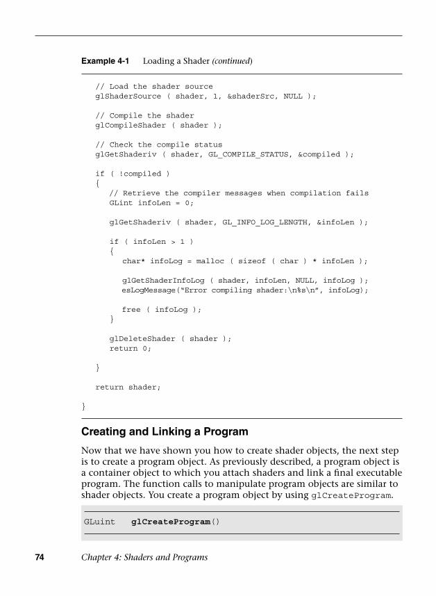
74 Chapter 4: Shaders and Programs
GLuint glCreateProgram()
Example 4-1 Loading a Shader (continued)
// Load the shader source glShaderSource ( shader, 1, &shaderSrc, NULL );
// Compile the shader glCompileShader ( shader );
// Check the compile status glGetShaderiv ( shader, GL_COMPILE_STATUS, &compiled );
if ( !compiled ) {
// Retrieve the compiler messages when compilation failsGLint infoLen = 0;
glGetShaderiv ( shader, GL_INFO_LOG_LENGTH, &infoLen );
if ( infoLen > 1 ){
char* infoLog = malloc ( sizeof ( char ) * infoLen );
glGetShaderInfoLog ( shader, infoLen, NULL, infoLog );esLogMessage(“Error compiling shader:\n%s\n”, infoLog);
free ( infoLog );}
glDeleteShader ( shader );return 0;
}
return shader;
}
Creating and Linking a Program
Now that we have shown you how to create shader objects, the next step is to create a program object. As previously described, a program object is a container object to which you attach shaders and link a final executable program. The function calls to manipulate program objects are similar to shader objects. You create a program object by using glCreateProgram.

Shaders and Programs 75
You might notice that glCreateProgram does not take any arguments; it simply returns a handle to a new program object. You delete a program object by using glDeleteProgram.
Void glDeleteProgram(GLuint program)
program handle to the program object to delete
void glAttachShader(GLuint program, GLuint shader)
program handle to the program object
shader handle to the shader object to attach to the program
void glDetachShader(GLuint program, GLuint shader)
program handle to the program object
shader handle to the shader object to detach from the program
void glLinkProgram(GLuint program)
program handle to the program object to link
Once the shaders have been attached (and the shaders have been successfully compiled), we are finally ready to link the shaders together. Linking a program object is accomplished using glLinkProgram.
Once you have a program object created, the next step is to attach shaders to it. In OpenGL ES 3.0, each program object needs to have one vertex shader and one fragment shader object attached to it. To attach shaders to a program, you use glAttachShader.
This function attaches the shader to the given program. Note that a shader can be attached at any point—it does not necessarily need to be compiled or even have source code before being attached to a program. The only requirement is that every program object must have one and only one vertex shader and fragment shader object attached to it. In addition to attaching shaders, you can detach shaders using glDetachShader.
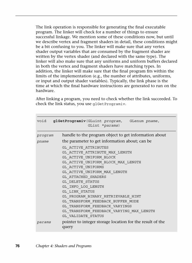
76 Chapter 4: Shaders and Programs
The link operation is responsible for generating the final executable program. The linker will check for a number of things to ensure successful linkage. We mention some of these conditions now, but until we describe vertex and fragment shaders in detail, these conditions might be a bit confusing to you. The linker will make sure that any vertex shader output variables that are consumed by the fragment shader are written by the vertex shader (and declared with the same type). The linker will also make sure that any uniforms and uniform buffers declared in both the vertex and fragment shaders have matching types. In addition, the linker will make sure that the final program fits within the limits of the implementation (e.g., the number of attributes, uniforms, or input and output shader variables). Typically, the link phase is the time at which the final hardware instructions are generated to run on the hardware.
After linking a program, you need to check whether the link succeeded. To check the link status, you use glGetProgramiv.
void glGetProgramiv(GLuint program, GLenum pname,GLint *params)
program handle to the program object to get information about
pname the parameter to get information about; can be
GL_ACTIVE_ATTRIBUTESGL_ACTIVE_ATTRIBUTE_MAX_LENGTHGL_ACTIVE_UNIFORM_BLOCKGL_ACTIVE_UNIFORM_BLOCK_MAX_LENGTHGL_ACTIVE_UNIFORMSGL_ACTIVE_UNIFORM_MAX_LENGTHGL_ATTACHED_SHADERSGL_DELETE_STATUSGL_INFO_LOG_LENGTHGL_LINK_STATUSGL_PROGRAM_BINARY_RETRIEVABLE_HINTGL_TRANSFORM_FEEDBACK_BUFFER_MODEGL_TRANSFORM_FEEDBACK_VARYINGSGL_TRANSFORM_FEEDBACK_VARYING_MAX_LENGTHGL_VALIDATE_STATUS
params pointer to integer storage location for the result of the query

Shaders and Programs 77
To check whether a link was successful, you can query for GL_LINK_STATUS. A large number of other queries can also be executed on program objects. Querying for GL_ACTIVE_ATTRIBUTES returns a count of the number of active attributes in the vertex shader. Querying for GL_ACTIVE_ATTRIBUTE_MAX_LENGTH returns the maximum length (in characters) of the largest attribute name; this information can be used to determine how much memory to allocate to store attribute name strings. Likewise, GL_ACTIVE_UNIFORMS and GL_ACTIVE_UNIFORM_MAX_LENGTH return the number of active uniforms and the maximum length of the largest uniform name, respectively. The number of shaders attached to the program object can be queried using GL_ATTACHED_SHADERS. The GL_DELETE_STATUS query returns whether a program object has been marked for deletion. As with shader objects, program objects store an info log, the length of which can be queried for using GL_INFO_LOG_LENGTH. Querying for GL_TRANSFORM_FEEDBACK_BUFFER_MODE returns either GL_SEPARATE_ATTRIBS or GL_INTERLEAVED_ATTRIBS, which is the buffer mode when transform feedback is active. Queries for GL_TRANSFORM_FEEDBACK_VARYINGS and GL_TRANSFORM_FEEDBACK_VARYING_MAX_LENGTH return the number of output variables to capture in transform feedback mode for the program and the maximum length of the output variable names, respectively. The transform feedback is described in Chapter 8, “Vertex Shaders.” The number of uniform blocks for programs containing active uniforms and the maximum length of the uniform block names can be queried using GL_ACTIVE_UNIFORM_BLOCKS and GL_ACTIVE_UNIFORM_BLOCK_MAX_LENGTH, respectively. Uniform blocks are described in a later section. Querying for GL_PROGRAM_BINARY_RETRIEVABLE_HINT returns a value indicating whether the binary retrieval hint is currently enabled for program. Finally, the status of the last validation operation can be queried for using GL_VALIDATE_STATUS. The validation of program objects is described later in this section.
After linking the program, we next want to get information from the program info log (particularly if a link failure occurred). Doing so is similar to getting the info log for shader objects.
void glGetProgramInfoLog(GLuint program, GLsizei maxLength,GLsizei *length,GLchar *infoLog)
program handle to the program object for which to get information
maxLength the size of the buffer in which to store the info log(continues)

78 Chapter 4: Shaders and Programs
Once we have linked the program successfully, we are almost ready to render with it. Before doing so, however, we might want to check whether the program validates. That is, there are certain aspects of execution that a successful link cannot guarantee. For example, perhaps the application never binds valid texture units to samplers. This behavior will not be known at link time, but instead will become apparent at draw time. To check that your program will execute with the current state, you can call glValidateProgram.
void glValidateProgram(GLuint program)
program handle to the program object to validate
void glUseProgram(GLuint program)
program handle to the program object to make active
(continued)length the length of the info log written (minus the null
terminator); if the length does not need to be known, this parameter can be NULL
infoLog pointer to the character buffer in which to store the info log
The result of the validation can be checked using GL_VALIDATE_STATUS described earlier. The info log will also be updated.
Note: You really want to use glValidateProgram only for debugging purposes. It is a slow operation and certainly not something you want to check before every render. In fact, you can get away with never using it if your application is successfully rendering. We want to make you aware that this function does exist, though.
So far, we have shown you the functions needed for creating a program object, attaching shaders to it, linking, and getting the info log. There is one more thing you need to do with a program object before rendering, and that is to set it as the active program using glUseProgram.
Now that we have our program active, we are set to render. Once again, Example 4-2 shows the code from our sample in Chapter 2, “Hello Triangle: An OpenGL ES 3.0 Example,” that uses these functions.

Shaders and Programs 79
Example 4-2 Create, Attach Shaders to, and Link a Program
// Create the program objectprogramObject = glCreateProgram ( );
if ( programObject == 0 ){ return 0;}
glAttachShader ( programObject, vertexShader );glAttachShader ( programObject, fragmentShader );
// Link the programglLinkProgram ( programObject );
// Check the link statusglGetProgramiv ( programObject, GL_LINK_STATUS, &linked );
if ( !linked ){ // Retrieve compiler error messages when linking fails GLint infoLen = 0;
glGetProgramiv( programObject, GL_INFO_LOG_LENGTH, &infoLen);
if ( infoLen > 1 ) {
char* infoLog = malloc ( sizeof ( char ) * infoLen );
glGetProgramInfoLog ( programObject, infoLen, NULL,infoLog );
esLogMessage ( “Error linking program:\n%s\n”, infoLog );
free ( infoLog ); }
glDeleteProgram ( programObject ); return FALSE;}
// ...
// Use the program objectglUseProgram ( programObject );
80 Chapter 4: Shaders and Programs
Uniforms and Attributes
Once you have a linked program object, there are number of queries that you might want to do on it. First, you will likely need to find out about the active uniforms in your program. Uniforms—as we detail more in the next chapter on the shading language—are variables that store read-only constant values that are passed in by the application through the OpenGL ES 3.0 API to the shader.
Sets of uniforms are grouped into two categories of uniform blocks. The first category is the named uniform block, where the uniform’s value is backed by a buffer object called a uniform buffer object (more on that next). The named uniform block is assigned a uniform block index. The following example declares a named uniform block with the name TransformBlock containing three uniforms (matViewProj, matNormal, and matTexGen):
uniform TransformBlock{ mat4 matViewProj; mat3 matNormal; mat3 matTexGen;};
The second category is the default uniform block for uniforms that are declared outside of a named uniform block. Unlike with the named uniform block, there is no name or uniform block index for default uniform blocks. The following example declares the same three uniforms outside of a named uniform block:
uniform mat4 matViewProj;uniform mat3 matNormal;uniform mat3 matTexGen;
We describe uniform blocks in more detail in the section Uniform Blocks in Chapter 5.
If a uniform is declared in both a vertex shader and a fragment shader, it must have the same type, and its value will be the same in both shaders. During the link phase, the linker will assign uniform locations to each of the active uniforms associated with the default uniform block in the program. These locations are the identifiers the application will use to load the uniform with a value. The linker will also assign offsets and strides (for array and matrix type uniforms) for active uniforms associated with the named uniform blocks.

Uniforms and Attributes 81
Getting and Setting Uniforms
To query for the list of active uniforms in a program, you first call glGetProgramiv with the GL_ACTIVE_UNIFORMS parameter (as described in the previous section). This will tell you the number of active uniforms in the program. The list includes uniforms in named uniform blocks, default block uniforms declared in shader code, and built-in uniforms used in shader code. A uniform is considered “active” if it was used by the program. In other words, if you declare a uniform in one of your shaders but never use it, the linker will likely optimize that away and not return it in the active uniform list. You can also find out the number of characters (including the null terminator) that the largest uniform name has in the program; this can be done by calling glGetProgramiv with the GL_ACTIVE_UNIFORM_MAX_LENGTH parameter.
Once we know the number of active uniforms and the number of characters needed to store the uniform names, we can find out the details on each uniform using glGetActiveUniform and glGetActiveUniformsiv.
void glGetActiveUniform(GLuint program, GLuint index,GLsizei bufSize, GLsizei *length,GLint *size, GLenum *type,GLchar *name)
program handle to the program object
index the uniform index to be queried
bufSize the number of characters in the name array
length if not NULL, will be written with the number of characters written into the name array (less the null terminator)
size if the uniform variable being queried is an array, this variable will be written with the maximum array element used in the program (plus 1); if the uniform variable being queried is not an array, this value will be 1
type will be written with the uniform type; can be
GL_FLOAT, GL_FLOAT_VEC2, GL_FLOAT_VEC3,GL_FLOAT_VEC4, GL_INT, GL_INT_VEC2, GL_INT_VEC3,GL_INT_VEC4, GL_UNSIGNED_INT,GL_UNSIGNED_INT_VEC2, GL_UNSIGNED_INT_VEC3,GL_UNSIGNED_INT_VEC4, GL_BOOL, GL_BOOL_VEC2,GL_BOOL_VEC3, GL_BOOL_VEC4, GL_FLOAT_MAT2,
(continues)

82 Chapter 4: Shaders and Programs
Using glGetActiveUniform, you can determine nearly all of the properties of the uniform. You can determine the name of the uniform variable along with its type. In addition, you can find out if the variable is an array, and if so what the maximum element used in the array was. The name of the uniform is necessary to find the uniform’s location, and the type and size
(continued)GL_FLOAT_MAT3, GL_FLOAT_MAT4, GL_FLOAT_MAT2x3,GL_FLOAT_MAT2x4, GL_FLOAT_MAT3x2, GL_FLOAT_MAT3x4,GL_FLOAT_MAT4x2, GL_FLOAT_MAT4x3, GL_SAMPLER_2D,GL_SAMPLER_3D, GL_SAMPLER_CUBE,GL_SAMPLER_2D_SHADOW, GL_SAMPLER_2D_ARRAY,GL_SAMPLER_2D_ARRAY_SHADOW,GL_SAMPLER_CUBE_SHADOW, GL_INT_SAMPLER_2D,GL_INT_SAMPLER_3D, GL_INT_SAMPLER_CUBE,GL_INT_SAMPLER_2D_ARRAY,GL_UNSIGNED_INT_SAMPLER_2D,GL_UNSIGNED_INT_SAMPLER_3D,GL_UNSIGNED_INT_SAMPLER_CUBE,GL_UNSIGNED_INT_SAMPLER_2D_ARRAY
name will be written with the name of the uniform up to bufSize number of characters; this will be a null-terminated string
void glGetActiveUniformsiv(GLuint program, GLsizei count,const GLuint *indices,GLenum pname, GLint *params)
program handle to the program object
count the number of elements in the array of indices
indices a list of uniform indices
pname property of each uniform in the uniform indices to be written into the elements of params; can be
GL_UNIFORM_TYPE, GL_UNIFORM_SIZE,GL_UNIFORM_NAME_LENGTH, GL_UNIFORM_BLOCK_INDEX,GL_UNIFORM_OFFSET, GL_UNIFORM_ARRAY_STRIDE,GL_UNIFORM_MATRIX_STRIDE, GL_UNIFORM_IS_ROW_MAJOR
params will be written with the result specified by pname corresponding to each uniform in the uniform indices
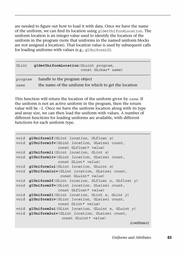
Uniforms and Attributes 83
are needed to figure out how to load it with data. Once we have the name of the uniform, we can find its location using glGetUniformLocation. The uniform location is an integer value used to identify the location of the uniform in the program (note that uniforms in the named uniform blocks are not assigned a location). That location value is used by subsequent calls for loading uniforms with values (e.g., glUniformlf).
GLint glGetUniformLocation(GLuint program,const GLchar* name)
program handle to the program object
name the name of the uniform for which to get the location
void glUniform1f(GLint location, GLfloat x)void glUniform1fv( GLint location, GLsizei count,
const GLfloat* value)void glUniform1i(GLint location, GLint x)void glUniform1iv( GLint location, GLsizei count,
const GLint* value)void glUniform1ui(GLint location, GLuint x)void glUniform1uiv( GLint location, GLsizei count,
const GLuint* value)void glUniform2f(GLint location, GLfloat x, GLfloat y)void glUniform2fv( GLint location, GLsizei count,
const GLfloat* value)void glUniform2i(GLint location, GLint x, GLint y)void glUniform2iv(GLint location, GLsizei count,
const GLint* value)void glUniform2ui(GLint location, GLuint x, GLuint y)void glUniform2uiv(GLint location, GLsizei count,
const GLuint* value)
This function will return the location of the uniform given by name. If the uniform is not an active uniform in the program, then the return value will be –1. Once we have the uniform location along with its type and array size, we can then load the uniform with values. A number of different functions for loading uniforms are available, with different functions for each uniform type.
(continues)
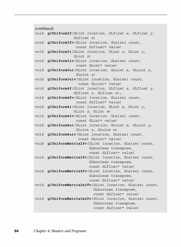
84 Chapter 4: Shaders and Programs
(continued)void glUniform3f( GLint location, GLfloat x, GLfloat y,
GLfloat z)void glUniform3fv( GLint location, GLsizei count,
const GLfloat* value)void glUniform3i( GLint location, GLint x, GLint y,
GLint z)void glUniform3iv( GLint location, GLsizei count,
const GLint* value)void glUniform3ui( GLint location, GLuint x, GLuint y,
GLuint z)void glUniform3uiv( GLint location, GLsizei count,
const GLuint* value)void glUniform4f( GLint location, GLfloat x, GLfloat y,
GLfloat z, GLfloat w);void glUniform4fv( GLint location, GLsizei count,
const GLfloat* value)void glUniform4i( GLint location, GLint x, GLint y,
GLint z, GLint w)void glUniform4iv( GLint location, GLsizei count,
const GLint* value)void glUniform4ui( GLint location, GLuint x, GLuint y,
GLuint z, GLuint w)void glUniform4uiv( GLint location, GLsizei count,
const GLuint* value)void glUniformMatrix2fv( GLint location, GLsizei count,
GLboolean transpose, const GLfloat* value)
void glUniformMatrix3fv( GLint location, GLsizei count, GLboolean transpose, const GLfloat* value)
void glUniformMatrix4fv( GLint location, GLsizei count, GLboolean transpose, const GLfloat* value)
void glUniformMatrix2x3fv( GLint location, GLsizei count, GLboolean transpose, const GLfloat* value)
void glUniformMatrix3x2fv( GLint location, GLsizei count, GLboolean transpose, const GLfloat* value)
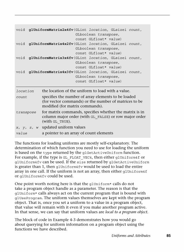
Uniforms and Attributes 85
The functions for loading uniforms are mostly self-explanatory. The determination of which function you need to use for loading the uniform is based on the type returned by the glGetActiveUniform function. For example, if the type is GL_FLOAT_VEC4, then either glUniform4f or glUniform4fv can be used. If the size returned by glGetActiveUniform is greater than 1, then glUniform4fv would be used to load the entire array in one call. If the uniform is not an array, then either glUniform4f or glUniform4fv could be used.
One point worth noting here is that the glUniform* calls do not take a program object handle as a parameter. The reason is that the glUniform* calls always act on the current program that is bound with glUseProgram. The uniform values themselves are kept with the program object. That is, once you set a uniform to a value in a program object, that value will remain with it even if you make another program active. In that sense, we can say that uniform values are local to a program object.
The block of code in Example 4-3 demonstrates how you would go about querying for uniform information on a program object using the functions we have described.
void glUniformMatrix2x4fv( GLint location, GLsizei count, GLboolean transpose, const GLfloat* value)
void glUniformMatrix4x2fv( GLint location, GLsizei count, GLboolean transpose, const GLfloat* value)
void glUniformMatrix3x4fv( GLint location, GLsizei count, GLboolean transpose, const GLfloat* value)
void glUniformMatrix4x3fv( GLint location, GLsizei count, GLboolean transpose, const GLfloat* value)
location the location of the uniform to load with a value.
count specifies the number of array elements to be loaded (for vector commands) or the number of matrices to be modified (for matrix commands).
transpose for matrix commands, specifies whether the matrix is in column major order (with GL_FALSE) or row major order (with GL_TRUE).
x, y, z, w updated uniform values
value a pointer to an array of count elements

86 Chapter 4: Shaders and Programs
Example 4-3 Querying for Active Uniforms
GLint maxUniformLen;GLint numUniforms;char *uniformName;GLint index;
glGetProgramiv ( progObj, GL_ACTIVE_UNIFORMS, &numUniforms );glGetProgramiv ( progObj, GL_ACTIVE_UNIFORM_MAX_LENGTH,
&maxUniformLen );
uniformName = malloc ( sizeof ( char ) * maxUniformLen );
for ( index = 0; index < numUniforms; index++ ){ GLint size; GLenum type; GLint location;
// Get the uniform info glGetActiveUniform ( progObj, index, maxUniformLen, NULL,
&size, &type, uniformName );
// Get the uniform location location = glGetUniformLocation ( progObj, uniformName );
switch ( type ) { case GL_FLOAT:
//break;
case GL_FLOAT_VEC2://break;
case GL_FLOAT_VEC3://break;
case GL_FLOAT_VEC4://break;
case GL_INT://break;
// ... Check for all the types ...
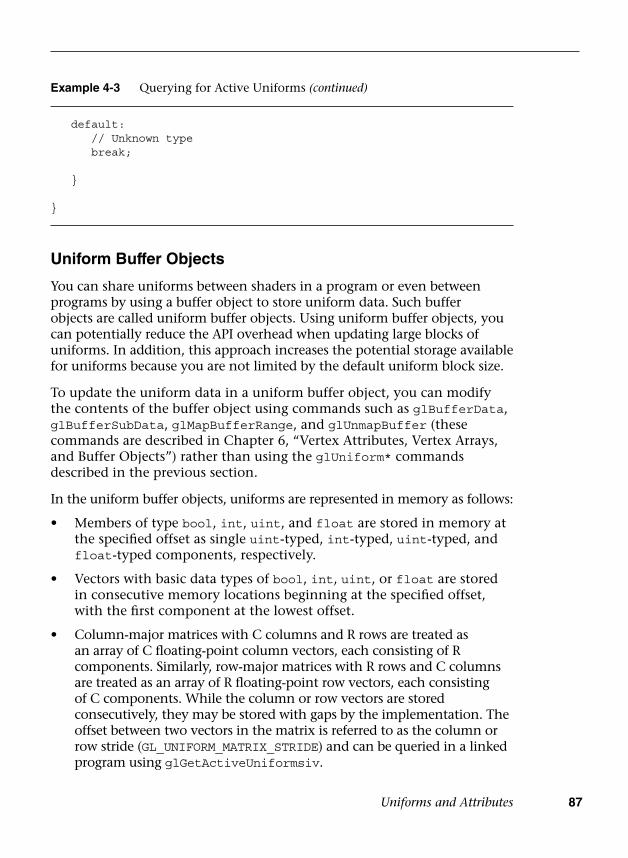
Uniforms and Attributes 87
Uniform Buffer Objects
You can share uniforms between shaders in a program or even between programs by using a buffer object to store uniform data. Such buffer objects are called uniform buffer objects. Using uniform buffer objects, you can potentially reduce the API overhead when updating large blocks of uniforms. In addition, this approach increases the potential storage available for uniforms because you are not limited by the default uniform block size.
To update the uniform data in a uniform buffer object, you can modify the contents of the buffer object using commands such as glBufferData, glBufferSubData, glMapBufferRange, and glUnmapBuffer (these commands are described in Chapter 6, “Vertex Attributes, Vertex Arrays, and Buffer Objects”) rather than using the glUniform* commands described in the previous section.
In the uniform buffer objects, uniforms are represented in memory as follows:
• Members of type bool, int, uint, and float are stored in memory atthe specified offset as single uint-typed, int-typed, uint-typed, andfloat-typed components, respectively.
• Vectors with basic data types of bool, int, uint, or float are storedin consecutive memory locations beginning at the specified offset,with the first component at the lowest offset.
• Column-major matrices with C columns and R rows are treated asan array of C floating-point column vectors, each consisting of Rcomponents. Similarly, row-major matrices with R rows and C columnsare treated as an array of R floating-point row vectors, each consistingof C components. While the column or row vectors are storedconsecutively, they may be stored with gaps by the implementation. Theoffset between two vectors in the matrix is referred to as the column orrow stride (GL_UNIFORM_MATRIX_STRIDE) and can be queried in a linkedprogram using glGetActiveUniformsiv.
Example 4-3 Querying for Active Uniforms (continued)
default:// Unknown typebreak;
}
}
88 Chapter 4: Shaders and Programs
• Arrays of scalars, vectors, and matrices are stored in memory byelement order, with array member zero placed at the lowest offset.The offset between each pair of elements in the array is constant andreferred to as the array stride (GL_UNIFORM_ARRAY_STRIDE) and can bequeried in a linked program using glGetActiveUniformsiv.
Unless you use the std140 uniform block layout (the default), you will need to query the program object for the byte offsets and strides to set uniform data in the uniform buffer object. The std140 layout guarantees a specific packing behavior with an explicit layout specification defined by the OpenGL ES 3.0 specification. Thus using std140 layout allows you to share the uniform block between different OpenGL ES 3.0 implementations. Other packing formats (see Table 5-4) may allow some OpenGL ES 3.0 implementations to pack the data more tightly together than the std140 layout.
The following is an example of a named uniform block LightBlock using the std140 layout:
layout (std140) uniform LightBlock{ vec3 lightDirection; vec4 lightPosition;};
The std140 layout is specified as follows (adapted from the OpenGL ES 3.0 specification). When the uniform block contains the following member:
1. A scalar variable—The base alignment is the size of the scalar. Forexample, sizeof(GLint).
2. A two-component vector—The base alignment is twice the size of theunderlying component type size.
3. A three-component or four-component vector—The base alignmentis four times the size of the underlying component type size.
4. An array of scalars or vectors—The base alignment and array strideare set to match the base alignment of a single element array. Theentire array is padded to a multiple of the size of a vec4.
5. A column-major matrix with C columns and R rows—Stored as anarray of C vectors with R components according to rule 4.
6. An array of M column-major matrices with C columns and R rows—Stored as M × C vectors with R components according to rule 4.
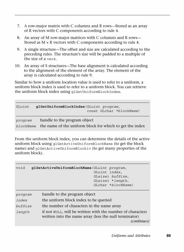
Uniforms and Attributes 89
7. A row-major matrix with C columns and R rows—Stored as an arrayof R vectors with C components according to rule 4.
8. An array of M row-major matrices with C columns and R rows—Stored as M × R vectors with C components according to rule 4.
9. A single structure—The offset and size are calculated according to thepreceding rules. The structure’s size will be padded to a multiple ofthe size of a vec4.
10. An array of S structures—The base alignment is calculated accordingto the alignment of the element of the array. The element of thearray is calculated according to rule 9.
Similar to how a uniform location value is used to refer to a uniform, a uniform block index is used to refer to a uniform block. You can retrieve the uniform block index using glGetUniformBlockIndex.
GLuint glGetUniformBlockIndex(GLuint program,const GLchar *blockName)
program handle to the program object
blockName the name of the uniform block for which to get the index
From the uniform block index, you can determine the details of the active uniform block using glGetActiveUniformBlockName (to get the block name) and glGetActiveUniformBlockiv (to get many properties of the uniform block).
void glGetActiveUniformBlockName(GLuint program,GLuint index,GLsizei bufSize,GLsizei *length,GLchar *blockName)
program handle to the program object
index the uniform block index to be queried
bufSize the number of characters in the name array
length if not NULL, will be written with the number of characters written into the name array (less the null terminator)
(continues)
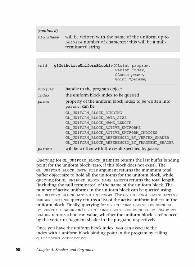
90 Chapter 4: Shaders and Programs
Querying for GL_UNIFORM_BLOCK_BINDING returns the last buffer binding point for the uniform block (zero, if this block does not exist). The GL_UNIFORM_BLOCK_DATA_SIZE argument returns the minimum total buffer object size to hold all the uniforms for the uniform block, while querying for GL_UNIFORM_BLOCK_NAME_LENGTH returns the total length (including the null terminator) of the name of the uniform block. The number of active uniforms in the uniform block can be queried using GL_UNIFORM_BLOCK_ACTIVE_UNIFORMS. The GL_UNIFORM_BLOCK_ACTIVE_NUMBER_INDICES query returns a list of the active uniform indices in the uniform block. Finally, querying for GL_UNIFORM_BLOCK_REFERENCED_BY_VERTEX_SHADER and GL_UNIFORM_BLOCK_REFERENCED_BY_FRAGMENT_SHADER returns a boolean value, whether the uniform block is referenced by the vertex or fragment shader in the program, respectively.
Once you have the uniform block index, you can associate the index with a uniform block binding point in the program by calling glUniformBlockBinding.
void glGetActiveUniformBlockiv( GLuint program, GLuint index, GLenum pname, GLint *params)
program handle to the program object
index the uniform block index to be queried
pname property of the uniform block index to be written into params; can be
GL_UNIFORM_BLOCK_BINDINGGL_UNIFORM_BLOCK_DATA_SIZEGL_UNIFORM_BLOCK_NAME_LENGTHGL_UNIFORM_BLOCK_ACTIVE_UNIFORMSGL_UNIFORM_BLOCK_ACTIVE_UNIFORM_INDICESGL_UNIFORM_BLOCK_REFERENCED_BY_VERTEX_SHADERGL_UNIFORM_BLOCK_REFERENCED_BY_FRAGMENT_SHADER
params will be written with the result specified by pname
(continued)
blockName will be written with the name of the uniform up to bufSize number of characters; this will be a null-terminated string

Uniforms and Attributes 91
void glBindBufferRange( GLenum target, GLuint index, GLuint buffer, GLintptr offset,GLsizeiptr size)
void glBindBufferBase(GLenum target, GLuint index,GLuint buffer)
target must be GL_UNIFORM_BUFFER orGL_TRANSFORM_FEEDBACK_BUFFER
index the binding index
buffer the handle to the buffer object
offset a starting offset in bytes into the buffer object
(glBindBufferRange only)
size the amount of data in bytes that can be read from or written to the buffer object (glBindBufferRange only)
void glUniformBlockBinding(GLuint program,GLuint blockIndex,GLuint blockBinding)
program handle to the program object
blockIndex index of the uniform block
blockBinding uniform buffer object binding point
When programming the uniform blocks, you should pay attention to the following limitations:
• The maximum number of active uniform blocks used by a vertexor fragment shader can be queried using glGetIntegerv withGL_MAX_VERTEX_UNIFORM_BLOCKS or GL_MAX_FRAGMENT_UNIFORM_BLOCKS, respectively. The minimum supported number for anyimplementation is 12.
• The maximum number of combined active uniform blocks used byall shaders in a program can be queried using glGetIntegerv withGL_MAX_COMBINED_UNIFORM_BLOCKS. The minimum supportednumber for any implementation is 24.
Finally, you can bind the uniform buffer object to the GL_UNIFORM_BUFFER target and a uniform block binding point in the program using glBindBufferRange or glBindBufferBase.
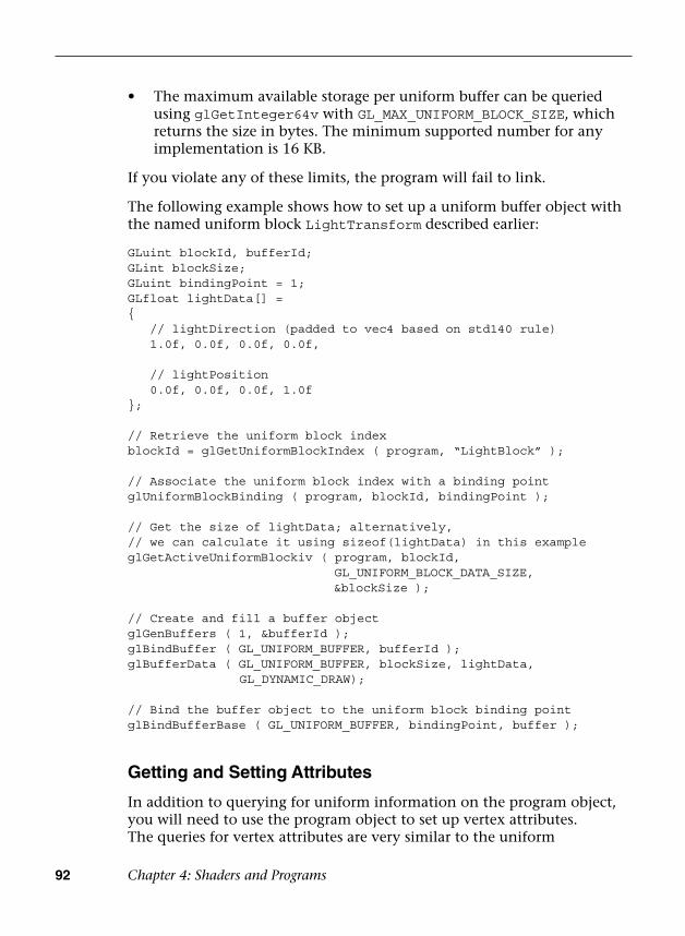
92 Chapter 4: Shaders and Programs
• The maximum available storage per uniform buffer can be queriedusing glGetInteger64v with GL_MAX_UNIFORM_BLOCK_SIZE, whichreturns the size in bytes. The minimum supported number for anyimplementation is 16 KB.
If you violate any of these limits, the program will fail to link.
The following example shows how to set up a uniform buffer object with the named uniform block LightTransform described earlier:
GLuint blockId, bufferId;GLint blockSize;GLuint bindingPoint = 1;GLfloat lightData[] ={ // lightDirection (padded to vec4 based on std140 rule) 1.0f, 0.0f, 0.0f, 0.0f,
// lightPosition 0.0f, 0.0f, 0.0f, 1.0f};
// Retrieve the uniform block indexblockId = glGetUniformBlockIndex ( program, “LightBlock” );
// Associate the uniform block index with a binding pointglUniformBlockBinding ( program, blockId, bindingPoint );
// Get the size of lightData; alternatively,// we can calculate it using sizeof(lightData) in this exampleglGetActiveUniformBlockiv ( program, blockId,
GL_UNIFORM_BLOCK_DATA_SIZE,&blockSize );
// Create and fill a buffer objectglGenBuffers ( 1, &bufferId );glBindBuffer ( GL_UNIFORM_BUFFER, bufferId );glBufferData ( GL_UNIFORM_BUFFER, blockSize, lightData,
GL_DYNAMIC_DRAW);
// Bind the buffer object to the uniform block binding pointglBindBufferBase ( GL_UNIFORM_BUFFER, bindingPoint, buffer );
Getting and Setting Attributes
In addition to querying for uniform information on the program object, you will need to use the program object to set up vertex attributes. The queries for vertex attributes are very similar to the uniform

Shader Compiler 93
queries. You can find the list of active attributes using the GL_ACTIVE_ATTRIBUTES query. You can find the properties of an attribute using glGetActiveAttrib. A set of routines are then available for setting up vertex arrays to load the vertex attributes with values.
However, setting up vertex attributes really requires a bit more understanding of primitives and the vertex shader than we are ready to delve into right now. Instead, we dedicate an entire chapter (Chapter 6, “Vertex Attributes, Vertex Arrays, and Buffer Objects”) to vertex attributes and vertex arrays. If you want to find out how to query for vertex attribute info, jump to Chapter 6 and the section Declaring Vertex Attribute Variables in a Vertex Shader.
Shader Compiler
When you ask OpenGL ES to compile and link a shader, take a minute to think about what the implementation has to do. The shader code is typically parsed into some sort of intermediate representation, as most compiled languages are (e.g., an Abstract Syntax Tree). A compiler must then convert the abstract representation into machine instructions for the hardware. Ideally, this compiler should also do a great deal of optimization, such as dead-code removal, constant propagation, and more. Performing all this work comes at a price—and this price is primarily CPU time and memory.
OpenGL ES 3.0 implementations must support online shader compilation (the value of GL_SHADER_COMPILER retrieved using glGetBooleanv must be GL_TRUE). You can specify your shaders using glShaderSource, as we have done so far in our examples. You can also try to mitigate the resource impact of shader compilation. That is, once you have finished compiling any shaders for your application, you can call glReleaseShaderCompiler. This function provides a hint to the implementation that you are done with the shader compiler, so it can free its resources. Note that this function is only a hint; if you decide to compile more shaders using glCompileShader, the implementation will need to reallocate its resources for the compiler.
void glReleaseShaderCompiler (void)
Provides a hint to the implementation that it can release resources used by the shader compiler. Because this function is only a hint, some implementations may ignore a call to this function.
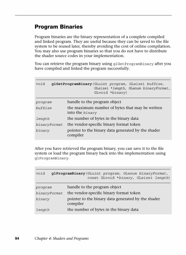
94 Chapter 4: Shaders and Programs
Program Binaries
Program binaries are the binary representation of a complete compiled and linked program. They are useful because they can be saved to the file system to be reused later, thereby avoiding the cost of online compilation. You may also use program binaries so that you do not have to distribute the shader source codes in your implementation.
You can retrieve the program binary using glGetProgramBinary after you have compiled and linked the program successfully.
After you have retrieved the program binary, you can save it to the file system or load the program binary back into the implementation using glProgramBinary.
void glGetProgramBinary( GLuint program, GLsizei bufSize, GLsizei *length, GLenum binaryFormat, GLvoid *binary)
program handle to the program object
bufSize the maximum number of bytes that may be written into the binary
length the number of bytes in the binary data
binaryFormat the vendor-specific binary format token
binary pointer to the binary data generated by the shader compiler
void glProgramBinary( GLuint program, GLenum binaryFormat, const GLvoid *binary, GLsizei length)
program handle to the program object
binaryFormat the vendor-specific binary format token
binary pointer to the binary data generated by the shader compiler
length the number of bytes in the binary data

Summary 95
The OpenGL ES specification does not mandate any particular binary format; instead, the binary format is left completely up to the vendor. This obviously means that programs have less portability, but it also means the vendor can create a less burdensome implementation of OpenGL ES 3.0. In fact, the binary format may change from one driver version to another implemented by the same vendor. To ensure that the stored program binary is still compatible, after calling glProgramBinary, you can query the GL_LINK_STATUS through glGetProgramiv. If it is no longer compatible, then you will need to recompile the shader source code.
Summary
In this chapter, you learned how to create, compile, and link shaders into a program. Shader objects and program objects form the most fundamental objects in OpenGL ES 3.0. We discussed how to query the program object for information and how to load uniforms. In addition, you learned how source shaders and program binaries differ and how to use each. Next, you will learn how to write a shader using the OpenGL ES Shading Language.

This page intentionally left blank

97
Chapter 5
OpenGL ES Shading Language
As you saw in earlier chapters, shaders are a fundamental concept that lies at the heart of the OpenGL ES 3.0 API. Every OpenGL ES 3.0 program requires both a vertex shader and a fragment shader to render a meaningful picture. Given the centrality of the concept of shaders to the API, we want to make sure you are grounded in the fundamentals of writing shaders before diving into more details of the graphics API.
This chapter’s goal is to make sure you understand the following concepts in the shading language:
• Variables and variable types
• Vector and matrix construction and selection
• Constants
• Structures and arrays
• Operators, control flow, and functions
• Input/output variables, uniforms, uniform blocks, and layoutqualifiers
• Preprocessor and directives
• Uniform and interpolator packing
• Precision qualifiers and invariance
You were introduced to some of these concepts in a small amount of detail with the example in Chapter 2, “Hello Triangle: An OpenGL ES 3.0 Example.” Now we will fill in the concepts with a lot more detail to make sure you understand how to write and read shaders.
98 Chapter 5: OpenGL ES Shading Language
OpenGL ES Shading Language Basics
As you read through this book, you will look at a lot of shaders. If you ever start developing your own OpenGL ES 3.0 application, chances are that you will write a lot of shaders. By now, you should understand the fundamental concepts of what a shader does and how it fits in the pipeline. If not, please go back and review Chapter 1, “Introduction to OpenGL ES 3.0,” where we covered the pipeline and described where vertex and fragment shaders fit within it.
What we want to look at now is what exactly makes up a shader. As you have probably already observed, the syntax bears great similarity to that seen in the C programming language. If you can understand C code, you likely will not have much difficulty understanding the syntax of shaders. However, there are certainly some major differences between the two languages, beginning with the version specification and the native data types that are supported.
Shader Version Specification
The first line of your OpenGL ES 3.0 vertex and fragment shaders will always declare a shader version. Declaring the shader version informs the shader compiler which syntax and constructs it can expect to be present in the shader. The compiler checks the shader syntax against the declared version of the shading language used. To declare that your shader uses version 3.00 of the OpenGL ES Shading Language, use the following syntax:
#version 300 es
Shaders that do not declare a version number are assumed to use revision 1.00 of the OpenGL ES Shading Language. Revision 1.00 of the shading language is the version that was used in OpenGL ES 2.0. For OpenGL ES 3.0, the specification authors decided to match the version numbers for the API and Shading Language, which explains why the number jumped from 1.00 to 3.00 for OpenGL ES 3.0. As described in Chapter 1, “Introduction to OpenGL ES 3.0,” the OpenGL ES Shading Language 3.0 adds many new features, including non-square matrices, full integer support, interpolation qualifiers, uniform blocks, layout qualifiers, new built-in functions, full looping, full branching support, and unlimited shader instruction length.

Variables and Variable Types 99
Variables and Variable Types
In computer graphics, two fundamental data types form the basis of transformations: vectors and matrices. These two data types are central to the OpenGL ES Shading Language as well. Specifically, Table 5-1 describes the scalar-, vector-, and matrix-based data types that exist in the shading language.
Variables in the shading language must be declared with a type. For example, the following declarations illustrate how to declare a scalar, a vector, and a matrix:
float specularAtten; // A floating-point-based scalarvec4 vPosition; // A floating-point-based 4-tuple vector
Table 5-1 Data Types in the OpenGL ES Shading Language
Variable Class Types Description
Scalars float, int, uint, bool
Scalar-based data types for floating-point, integer, unsigned integer, and boolean values
Floating-point vectors
float, vec2, vec3, vec4
Floating-point–based vector types of one, two, three, or four components
Integer vector int, ivec2, ivec3, ivec4
Integer-based vector types of one, two, three, or four components
Unsigned integer vector
uint, uvec2, uvec3, uvec4
Unsigned integer-based vector types of one, two, three, or four components
Boolean vector bool, bvec2, bvec3, bvec4
Boolean-based vector types of one, two, three, or four components
Matrices mat2 (or mat2x2), mat2x3, mat2x4, mat3x2, mat3 (or mat3x3), mat3x4, mat4x2, mat4x3, mat4 (or mat4x4)
Floating-point based matrices of size 2 × 2, 2 × 3, 2 × 4, 3 × 2, 3 × 3, 3 × 4, 4 × 2, 4 × 3, or 4 × 4

100 Chapter 5: OpenGL ES Shading Language
mat4 mViewProjection; // A 4 x 4 matrix variable declarationivec2 vOffset; // An integer-based 2-tuple vector
Variables can be initialized either at declaration time or later. Initialization is done through the use of constructors, which are also used for doing type conversions.
Variable Constructors
The OpenGL ES Shading Language has very strict rules regarding type conversion. That is, variables can only be assigned to or operated on other variables of the same type. The reasoning behind not allowing implicit type conversion in the language is that it avoids shader authors encountering unintended conversion that can lead to difficult-to-track-down bugs. To cope with type conversions, a number of constructors are available in the language. You can use constructors for initializing variables and as a way of type-casting between variables of different types. Variables can be initialized at declaration (or later in the shader) through the use of constructors. Each of the built-in variable types has a set of associated constructors.
Let’s first look at how constructors can be used to initialize and type-cast between scalar values.
float myFloat = 1.0;float myFloat2 = 1; // ERROR: invalid type conversionbool myBool = true;int myInt = 0;int myInt2 = 0.0; // ERROR: invalid type conversionmyFloat = float(myBool); // Convert from bool -> floatmyFloat = float(myInt); // Convert from int -> floatmyBool = bool(myInt); // Convert from int -> bool
Similarly, constructors can be used to convert to and initialize vector data types. The arguments to a vector constructor will be converted to the same basic type as the vector being constructed (float, int, or bool). There are two basic ways to pass arguments to vector constructors:
• If only one scalar argument is provided to a vector constructor, thatvalue is used to set all values of the vector.
• If multiple scalar or vector arguments are provided, the values of thevector are set from left to right using those arguments. If multiplescalar arguments are provided, there must be at least as manycomponents in the arguments as in the vector.
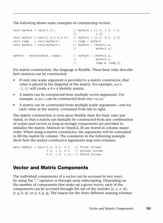
Vector and Matrix Components 101
The following shows some examples of constructing vectors:
vec4 myVec4 = vec4(1.0); // myVec4 = {1.0, 1.0, 1.0,// 1.0}
vec3 myVec3 = vec3(1.0,0.0,0.5); // myVec3 = {1.0, 0.0, 0.5}vec3 temp = vec3(myVec3); // temp = myVec3vec2 myVec2 = vec2(myVec3); // myVec2 = {myVec3.x,
// myVec3.y}
myVec4 = vec4(myVec2, temp); // myVec4 = {myVec2.x,// myVec2.y,// temp.x, temp.y}
For matrix construction, the language is flexible. These basic rules describe how matrices can be constructed:
• If only one scalar argument is provided to a matrix constructor, thatvalue is placed in the diagonal of the matrix. For example, mat4(1.0) will create a 4 × 4 identity matrix.
• A matrix can be constructed from multiple vector arguments. Forexample, a mat2 can be constructed from two vec2s.
• A matrix can be constructed from multiple scalar arguments—one foreach value in the matrix, consumed from left to right.
The matrix construction is even more flexible than the basic rules just stated, in that a matrix can basically be constructed from any combination of scalars and vectors as long as enough components are provided to initialize the matrix. Matrices in OpenGL ES are stored in column major order. When using a matrix constructor, the arguments will be consumed to fill the matrix by column. The comments in the following example show how the matrix constructor arguments map into columns.
mat3 myMat3 = mat3(1.0, 0.0, 0.0, // First column0.0, 1.0, 0.0, // Second column0.0, 1.0, 1.0); // Third column
Vector and Matrix Components
The individual components of a vector can be accessed in two ways: by using the “.” operator or through array subscripting. Depending on the number of components that make up a given vector, each of the components can be accessed through the use of the swizzles {x, y, z, w}, {r, g, b, a}, or {s, t, p, q}. The reason for the three different naming schemes
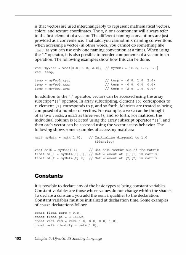
102 Chapter 5: OpenGL ES Shading Language
is that vectors are used interchangeably to represent mathematical vectors, colors, and texture coordinates. The x, r, or s component will always refer to the first element of a vector. The different naming conventions are just provided as a convenience. That said, you cannot mix naming conventions when accessing a vector (in other words, you cannot do something like .xgr, as you can use only one naming convention at a time). When using the “.” operator, it is also possible to reorder components of a vector in an operation. The following examples show how this can be done.
vec3 myVec3 = vec3(0.0, 1.0, 2.0); // myVec3 = {0.0, 1.0, 2.0} vec3 temp;
temp = myVec3.xyz; // temp = {0.0, 1.0, 2.0}temp = myVec3.xxx; // temp = {0.0, 0.0, 0.0}temp = myVec3.zyx; // temp = {2.0, 1.0, 0.0}
In addition to the “.” operator, vectors can be accessed using the array subscript “[]” operator. In array subscripting, element [0] corresponds to x, element [1] corresponds to y, and so forth. Matrices are treated as being composed of a number of vectors. For example, a mat2 can be thought of as two vec2s, a mat3 as three vec3s, and so forth. For matrices, the individual column is selected using the array subscript operator “[]”, and then each vector can be accessed using the vector access behavior. The following shows some examples of accessing matrices:
mat4 myMat4 = mat4(1.0); // Initialize diagonal to 1.0(identity)
vec4 colO = myMat4[0]; // Get colO vector out of the matrixfloat ml_l = myMat4[1][1]; // Get element at [1][1] in matrixfloat m2_2 = myMat4[2].z; // Get element at [2][2] in matrix
Constants
It is possible to declare any of the basic types as being constant variables. Constant variables are those whose values do not change within the shader. To declare a constant, you add the const qualifier to the declaration. Constant variables must be initialized at declaration time. Some examples of const declarations follow:
const float zero = 0.0;const float pi = 3.14159;const vec4 red = vec4(1.0, 0.0, 0.0, 1.0);const mat4 identity = mat4(1.0);

Structures 103
Just as in C or C++, a variable that is declared as const is read-only and cannot be modified within the source.
Structures
In addition to using the basic types provided in the language, it is possible to aggregate variables into structures much like in C. The declaration syntax for a structure in the OpenGL ES Shading Language is shown in the following example:
struct fogStruct{ vec4 color; float start; float end;} fogVar;
The preceding definition will result in a new user type named fogStruct and a new variable named fogVar.
Structures can be initialized using constructors. After a new structure type is defined, a new structure constructor is also defined with the same name as the type. There must be a one-to-one correspondence between types in the structure and those in the constructor. For example, the preceding structure could be initialized using the following construction syntax:
struct fogStruct{ vec4 color; float start; float end;} fogVar;
fogVar = fogStruct(vec4(0.0, 1.0, 0.0, 0.0), // color0.5, // start2.0); // end
The constructor for the structure is based on the name of the type and takes as arguments each of the components. Accessing the elements of a structure is done just as you would with a structure in C, as shown in the following example:
vec4 color = fogVar.color;float start = fogVar.start;float end = fogVar.end;

104 Chapter 5: OpenGL ES Shading Language
Arrays
In addition to structures, the OpenGL ES Shading Language supports arrays. The syntax is very similar to C, with the arrays being based on a 0 index. The following block of code shows some examples of creating arrays:
float floatArray[4];vec4 vecArray[2];
Arrays can be initialized using the array initializer constructor, as shown in the following code:
float a[4] = float[](1.0, 2.0, 3.0, 4.0);float b[4] = float[4](1.0, 2.0, 3.0, 4.0);vec2 c[2] = vec2[2](vec2(1.0), vec2(1.0));
Providing a size to the array constructor is optional. The number of arguments in the array constructor must be equal to the size of the array.
Operators
Table 5-2 lists the operators that are offered in the OpenGL ES Shading Language.
Table 5-2 OpenGL ES Shading Language Operators
Operator Type Description
* Multiply
/ Divide
% Modulus
+ Add
– Subtract
++ Increment (prefix and postfix)
– – Decrement (prefix and postfix)
= Assignment
+=, –=, *=, /= Arithmetic assignment

Operators 105
Most of these operators behave just as they do in C. As mentioned in the constructor section, the OpenGL ES Shading Language has strict type rules that govern operators. That is, the operators must occur between variables that have the same basic type. For the binary operators (*, /, +, –), the basic types of the variables must be floating point or integer. Furthermore, operators such as multiply can operate between combinations of floats, vectors, and matrices. Some examples are provided here:
float myFloat;vec4 myVec4;mat4 myMat4;
myVec4 = myVec4 * myFloat; // Multiplies each component of// myVec4 by a scalar myFloat
myVec4 = myVec4 * myVec4; // Multiplies each component of// myVec4 together (e.g.,// myVec4 ^ 2)
myVec4 = myMat4 * myVec4; // Does a matrix * vector multiply of// myMat4 * myVec4
myMat4 = myMat4 * myMat4; // Does a matrix * matrix multiply of// myMat4 * myMat4
myMat4 = myMat4 * myFloat; // Multiplies each matrix component// by the scalar myFloat
The comparison operators, aside from == and != (<, <=, >, >=), can be used only with scalar values. To compare vectors, special built-in functions allow you to perform comparisons on a component-by-component basis (more on that later).
Table 5-2 OpenGL ES Shading Language Operators (continued)
Operator Type Description
==, !=, <, >, <=, >= Comparison operators
&& Logical and
^^ Logical exclusive or
|| Logical inclusive or
<<, >> Bit-wise shift
&, ^, | Bit-wise and, xor, or
?: Selection
, Sequence
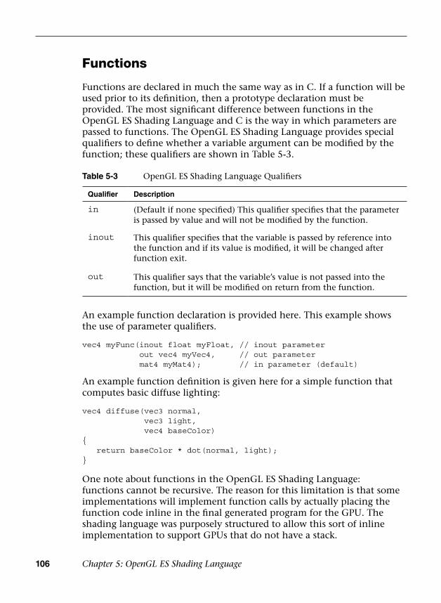
106 Chapter 5: OpenGL ES Shading Language
Functions
Functions are declared in much the same way as in C. If a function will be used prior to its definition, then a prototype declaration must be provided. The most significant difference between functions in the OpenGL ES Shading Language and C is the way in which parameters are passed to functions. The OpenGL ES Shading Language provides special qualifiers to define whether a variable argument can be modified by the function; these qualifiers are shown in Table 5-3.
An example function declaration is provided here. This example shows the use of parameter qualifiers.
vec4 myFunc(inout float myFloat, // inout parameterout vec4 myVec4, // out parametermat4 myMat4); // in parameter (default)
An example function definition is given here for a simple function that computes basic diffuse lighting:
vec4 diffuse(vec3 normal,vec3 light,vec4 baseColor)
{ return baseColor * dot(normal, light);}
One note about functions in the OpenGL ES Shading Language: functions cannot be recursive. The reason for this limitation is that some implementations will implement function calls by actually placing the function code inline in the final generated program for the GPU. The shading language was purposely structured to allow this sort of inline implementation to support GPUs that do not have a stack.
Table 5-3 OpenGL ES Shading Language Qualifiers
Qualifier Description
in (Default if none specified) This qualifier specifies that the parameter is passed by value and will not be modified by the function.
inout This qualifier specifies that the variable is passed by reference into the function and if its value is modified, it will be changed after function exit.
out This qualifier says that the variable’s value is not passed into the function, but it will be modified on return from the function.

Control Flow Statements 107
Built-In Functions
The preceding section described how a shader author creates a function. One of the most powerful features of the OpenGL ES Shading Language is the built-in functions that are provided in the language. As an example, here is some shader code for computing basic specular lighting in a fragment shader:
float nDotL = dot(normal, light);float rDotV = dot(viewDir, (2.0 * normal) * nDotL - light);float specular = specularColor * pow(rDotV, specularPower);
As you can see, this block of shader code uses the dot built-in function to compute the dot product of two vectors and the pow built-in function to raise a scalar to a power. These are just two simple examples; a wide array of built-in functions are available in the OpenGL ES Shading Language to handle the various computational tasks that one typically has to do in a shader. Appendix B of this text provides a complete reference to the built-in functions provided in the OpenGL ES Shading Language. For now, we just want to make you aware that there are a lot of built-in functions in the language. To become proficient in writing shaders, you will need to familiarize yourself with the most common ones.
Control Flow Statements
The syntax for control flow statements in the OpenGL ES Shading Language is similar to that used in C. Simple if-then-else logical tests can be done using the same syntax as C. For example:
if(color.a < 0.25){ color *= color.a;}else{ color = vec4(0.0);}
The expression that is being tested in the conditional statement must evaluate to a boolean value. That is, the test must be based on either a boolean value or some expression that evaluates to a boolean value (e.g., a comparison operator). This is the basic concept underlying how conditionals are expressed in the OpenGL ES Shading Language.
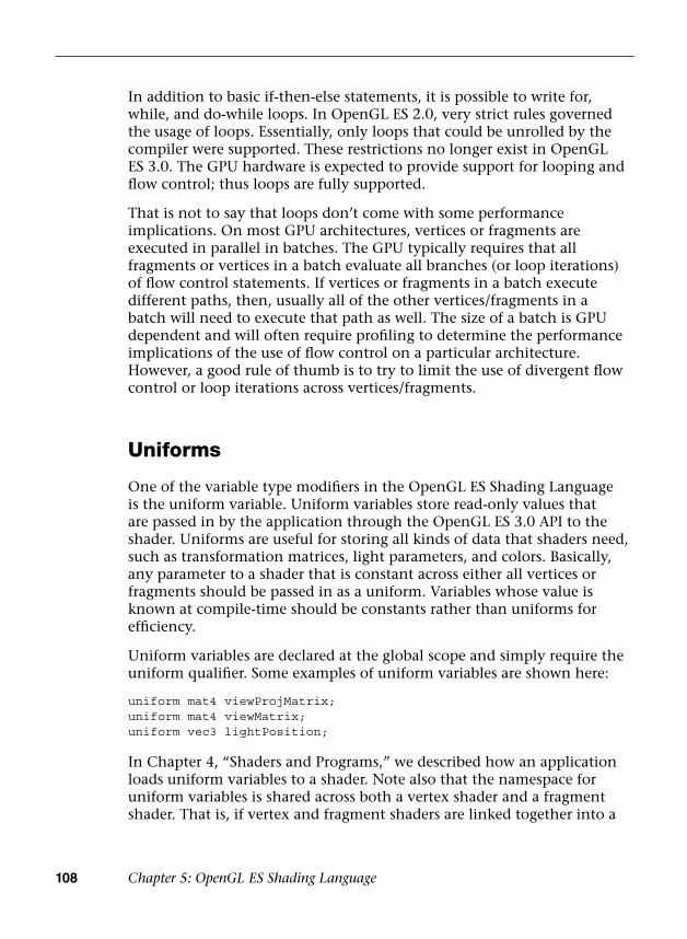
108 Chapter 5: OpenGL ES Shading Language
In addition to basic if-then-else statements, it is possible to write for, while, and do-while loops. In OpenGL ES 2.0, very strict rules governed the usage of loops. Essentially, only loops that could be unrolled by the compiler were supported. These restrictions no longer exist in OpenGL ES 3.0. The GPU hardware is expected to provide support for looping and flow control; thus loops are fully supported.
That is not to say that loops don’t come with some performance implications. On most GPU architectures, vertices or fragments are executed in parallel in batches. The GPU typically requires that all fragments or vertices in a batch evaluate all branches (or loop iterations) of flow control statements. If vertices or fragments in a batch execute different paths, then, usually all of the other vertices/fragments in a batch will need to execute that path as well. The size of a batch is GPU dependent and will often require profiling to determine the performance implications of the use of flow control on a particular architecture. However, a good rule of thumb is to try to limit the use of divergent flow control or loop iterations across vertices/fragments.
Uniforms
One of the variable type modifiers in the OpenGL ES Shading Language is the uniform variable. Uniform variables store read-only values that are passed in by the application through the OpenGL ES 3.0 API to the shader. Uniforms are useful for storing all kinds of data that shaders need, such as transformation matrices, light parameters, and colors. Basically, any parameter to a shader that is constant across either all vertices or fragments should be passed in as a uniform. Variables whose value is known at compile-time should be constants rather than uniforms for efficiency.
Uniform variables are declared at the global scope and simply require the uniform qualifier. Some examples of uniform variables are shown here:
uniform mat4 viewProjMatrix;uniform mat4 viewMatrix;uniform vec3 lightPosition;
In Chapter 4, “Shaders and Programs,” we described how an application loads uniform variables to a shader. Note also that the namespace for uniform variables is shared across both a vertex shader and a fragment shader. That is, if vertex and fragment shaders are linked together into a

Uniform Blocks 109
program object, they share the same set of uniform variables. Therefore, if a uniform variable is declared in the vertex shader and also in the fragment shader, both of those declarations must match. When the application loads the uniform variable through the API, its value will be available in both the vertex and fragment shaders.
Uniform variables generally are stored in hardware into what is known as the “constant store.” This special space is allocated in the hardware for the storage of constant values. Because it is typically of a fixed size, the number of uniforms that can be used in a program is limited.This limitation can be determined by reading the value of the gl_MaxVertexUniformVectors and gl_MaxFragmentUniformVectors built-in variables (or by querying GL_MAX_VERTEX_UNIFORM_VECTORS or GL_MAX_FRAGMENT_UNIFORM_VECTORS using glGetintegerv). An implementation of OpenGL ES 3.0 must provide at least 256 vertex uniform vectors and 224 fragment uniform vectors, although it is free to provide more. We cover the full set of limitations and queries available for the vertex and fragment shaders in Chapter 8, “Vertex Shaders,” and Chapter 10, “Fragment Shaders.”
Uniform Blocks
In Chapter 4, “Shaders and Programs,” we introduced the concept of uniform buffer objects. To review, uniform buffer objects allow the storage of uniform data to be backed by a buffer object. Uniform buffer objects offer several advantages over individual uniform variables in certain situations. For example, with uniform buffer objects, uniform buffer data can be shared across multiple programs but need to be set only once. Further, uniform buffer objects typically allow for storage of larger amounts of uniform data. Finally, it can be more efficient to switch between uniform buffer objects than to individually load one uniform at a time.
Uniform buffer objects can be used in the OpenGL ES Shading Language through application of uniform blocks. An example uniform block follows:
uniform TransformBlock{ mat4 matViewProj; mat3 matNormal; mat3 matTexGen;};

110 Chapter 5: OpenGL ES Shading Language
This code declares a uniform block with the name TransformBlock containing three matrices. The name TransformBlock will be used by the application as the blockName parameter to glGetUniformBlockIndex as described in Chapter 4, “Shaders and Programs,” for uniform buffer objects. The variables in the uniform block declaration are then accessed throughout the shader just as if they were declared as a regular uniform. For example, the matViewProj matrix declared in TransformBlock would be accessed as follows:
#version 300 esuniform TransformBlock{ mat4 matViewProj; mat3 matNormal; mat3 matTexGen;};layout(location = 0) in vec4 a_position;void main(){ gl_Position = matViewProj * a_position;}
A number of optional layout qualifiers can be used to specify how the uniform buffer object that backs the uniform block will be laid out in memory. Layout qualifiers can be provided either for individual uniform blocks or globally for all uniform blocks. At the global scope, setting the default layout for all uniform blocks would look as follows:
layout(shared, column_major) uniform; // default if not// specified
layout(packed, row_major) uniform;
Individual uniform blocks can also set the layout by overriding the default set at the global scope. In addition, individual uniforms within a uniform block can specify a layout qualifier as shown here:
layout(std140) uniform TransformBlock{ mat4 matViewProj; layout(row_major) mat3 matNormal; mat3 matTexGen;};
Table 5-4 lists all of the layout qualifiers that can be provided for uniform blocks.

Vertex and Fragment Shader Inputs/Outputs 111
Vertex and Fragment Shader Inputs/Outputs
Another special variable type in the OpenGL ES Shading Language is the vertex input (or attribute) variable. Vertex input variables are used to specify the per-vertex inputs to the vertex shader and are specified with the in keyword. They typically store data such as positions, normals, texture coordinates, and colors. The key here to understand is that vertex inputs are data that are specified for each vertex being drawn. Example 5-1 is a sample vertex shader that has a position and color vertex input.
The two vertex inputs in this shader, a_position and a_color, will be loaded with data by the application. Essentially, the application will create a vertex array that contains a position and a color for each vertex. Notice that the vertex inputs in Example 5-1 are preceded by the layout qualifier. The layout qualifier in this case is used to specify the index of the vertex attribute. The layout qualifier is optional; if it is not specified, the linker will automatically assign locations for the vertex inputs. We explain this entire process in full detail in Chapter 6, “Vertex Attributes, Vertex Arrays, and Buffer Objects.”
Table 5-4 Uniform Block Layout Qualifiers
Qualifier Description
shared The shared qualifier specifies that the layout in memory of the uniform block across multiple shaders or multiple programs will be the same. To use this qualifier, the row_major/column_major values must be identical across definitions. Overrides std140 and packed. (default)
packed The packed layout qualifier specifies that the compiler can optimize the memory layout of the uniform block. The location of the offsets must be queried when using this qualifier, and the uniform blocks cannot be shared across vertex/fragment shader or programs. Overrides std140 and shared.
std140 The std140 layout qualifier specifies that the layout of the uniform block is based on a set of standard rules defined in the “Standard Uniform Block Layout” section of the OpenGL ES 3.0 Specification. We detail these layout rules in the Uniform Buffer Objects section of Chapter 4. Overrides shared and packed.
row_major Matrices are laid out in row-major order in memory.
column_major Matrices are laid out in column-major order in memory. (default)
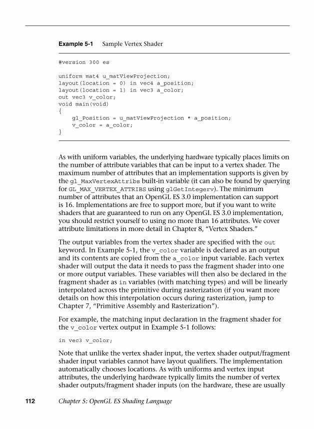
112 Chapter 5: OpenGL ES Shading Language
As with uniform variables, the underlying hardware typically places limits on the number of attribute variables that can be input to a vertex shader. The maximum number of attributes that an implementation supports is given by the gl_MaxVertexAttribs built-in variable (it can also be found by querying for GL_MAX_VERTEX_ATTRIBS using glGetIntegerv). The minimum number of attributes that an OpenGL ES 3.0 implementation can support is 16. Implementations are free to support more, but if you want to write shaders that are guaranteed to run on any OpenGL ES 3.0 implementation, you should restrict yourself to using no more than 16 attributes. We cover attribute limitations in more detail in Chapter 8, “Vertex Shaders.”
The output variables from the vertex shader are specified with the out keyword. In Example 5-1, the v_color variable is declared as an output and its contents are copied from the a_color input variable. Each vertex shader will output the data it needs to pass the fragment shader into one or more output variables. These variables will then also be declared in the fragment shader as in variables (with matching types) and will be linearly interpolated across the primitive during rasterization (if you want more details on how this interpolation occurs during rasterization, jump to Chapter 7, “Primitive Assembly and Rasterization”).
For example, the matching input declaration in the fragment shader for the v_color vertex output in Example 5-1 follows:
in vec3 v_color;
Note that unlike the vertex shader input, the vertex shader output/fragment shader input variables cannot have layout qualifiers. The implementation automatically chooses locations. As with uniforms and vertex input attributes, the underlying hardware typically limits the number of vertex shader outputs/fragment shader inputs (on the hardware, these are usually
Example 5-1 Sample Vertex Shader
#version 300 es
uniform mat4 u_matViewProjection;layout(location = 0) in vec4 a_position;layout(location = 1) in vec3 a_color;out vec3 v_color;void main(void){ gl_Position = u_matViewProjection * a_position; v_color = a_color;}
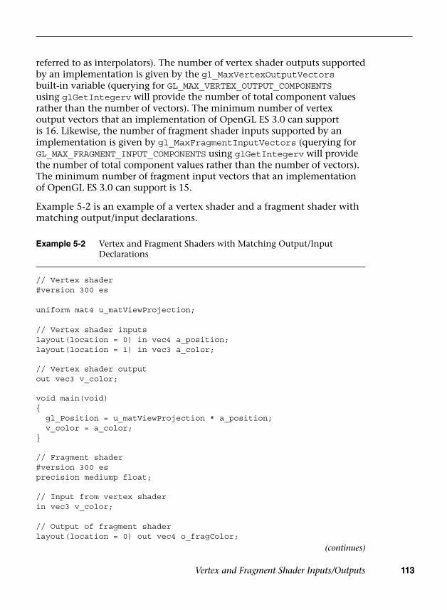
Vertex and Fragment Shader Inputs/Outputs 113
referred to as interpolators). The number of vertex shader outputs supported by an implementation is given by the gl_MaxVertexOutputVectors built-in variable (querying for GL_MAX_VERTEX_OUTPUT_COMPONENTS using glGetIntegerv will provide the number of total component values rather than the number of vectors). The minimum number of vertex output vectors that an implementation of OpenGL ES 3.0 can support is 16. Likewise, the number of fragment shader inputs supported by an implementation is given by gl_MaxFragmentInputVectors (querying for GL_MAX_FRAGMENT_INPUT_COMPONENTS using glGetIntegerv will provide the number of total component values rather than the number of vectors). The minimum number of fragment input vectors that an implementation of OpenGL ES 3.0 can support is 15.
Example 5-2 is an example of a vertex shader and a fragment shader with matching output/input declarations.
Example 5-2 Vertex and Fragment Shaders with Matching Output/Input Declarations
// Vertex shader#version 300 es
uniform mat4 u_matViewProjection;
// Vertex shader inputslayout(location = 0) in vec4 a_position;layout(location = 1) in vec3 a_color;
// Vertex shader outputout vec3 v_color;
void main(void){ gl_Position = u_matViewProjection * a_position; v_color = a_color;}
// Fragment shader#version 300 esprecision mediump float;
// Input from vertex shaderin vec3 v_color;
// Output of fragment shaderlayout(location = 0) out vec4 o_fragColor;
(continues)
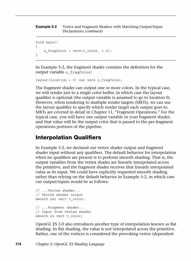
114 Chapter 5: OpenGL ES Shading Language
In Example 5-2, the fragment shader contains the definition for the output variable o_fragColor:
layout(location = 0) out vec4 o_fragColor;
The fragment shader can output one or more colors. In the typical case, we will render just to a single color buffer, in which case the layout qualifier is optional (the output variable is assumed to go to location 0). However, when rendering to multiple render targets (MRTs), we can use the layout qualifier to specify which render target each output goes to. MRTs are covered in detail in Chapter 11, “Fragment Operations.” For the typical case, you will have one output variable in your fragment shader, and that value will be the output color that is passed to the per-fragment operations portions of the pipeline.
Interpolation Qualifiers
In Example 5-2, we declared our vertex shader output and fragment shader input without any qualifiers. The default behavior for interpolation when no qualifiers are present is to perform smooth shading. That is, the output variables from the vertex shader are linearly interpolated across the primitive, and the fragment shader receives that linearly interpolated value as its input. We could have explicitly requested smooth shading rather than relying on the default behavior in Example 5-2, in which case our output/inputs would be as follows:
// ...Vertex shader...// Vertex shader outputsmooth out vec3 v_color;
// ...Fragment shader...// Input from vertex shadersmooth in vec3 v_color;
OpenGL ES 3.0 also introduces another type of interpolation known as flat shading. In flat shading, the value is not interpolated across the primitive. Rather, one of the vertices is considered the provoking vertex (dependent
Example 5-2 Vertex and Fragment Shaders with Matching Output/Input Declarations (continued)
void main(){ o_fragColor = vec4(v_color, 1.0);}

Preprocessor and Directives 115
on the primitive type; we describe this in the Chapter 7 section, Provoking Vertex), and that vertex value is used for all fragments in the primitive. We can declare the output/inputs as flat shaded as follows:
// ...Vertex shader...// Vertex shader outputflat out vec3 v_color;
// ...Fragment shader...// Input from vertex shaderflat in vec3 v_color;
Finally, another qualifier can be added to interpolators with the centroid keyword. The definition of centroid sampling is provided in Chapter 11 in the section Multisampled Anti-Aliasing. Essentially, when rendering with multisampling, the centroid keyword can be used to force interpolation to occur inside the primitive being rendered (otherwise, artifacts can occur at the edges of primitives). See Chapter 11, “Fragment Operations,” for a full definition of centroid sampling. For now, we simply show how you can declare an output/input variable with centroid sampling:
// ...Vertex shader...// Vertex shader outputsmooth centroid out vec3 v_color;
// ...Fragment shader...// Input from vertex shadersmooth centroid in vec3 v_color;
Preprocessor and Directives
One feature of the OpenGL ES Shading Language we have not mentioned yet is the preprocessor. The OpenGL ES Shading Language features a preprocessor that follows many of the conventions of a standard C++ preprocessor. Macros can be defined and conditional tests can be performed using the following directives:
#define#undef#if#ifdef#ifndef#else#elif#endif
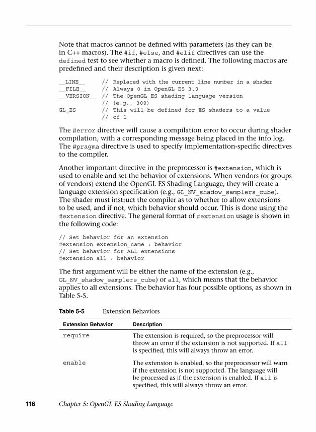
116 Chapter 5: OpenGL ES Shading Language
Note that macros cannot be defined with parameters (as they can be in C++ macros). The #if, #else, and #elif directives can use the defined test to see whether a macro is defined. The following macros are predefined and their description is given next:
__LINE__ // Replaced with the current line number in a shader__FILE__ // Always 0 in OpenGL ES 3.0__VERSION__ // The OpenGL ES shading language version
// (e.g., 300)GL_ES // This will be defined for ES shaders to a value
// of 1
The #error directive will cause a compilation error to occur during shader compilation, with a corresponding message being placed in the info log. The #pragma directive is used to specify implementation-specific directives to the compiler.
Another important directive in the preprocessor is #extension, which is used to enable and set the behavior of extensions. When vendors (or groups of vendors) extend the OpenGL ES Shading Language, they will create a language extension specification (e.g., GL_NV_shadow_samplers_cube). The shader must instruct the compiler as to whether to allow extensions to be used, and if not, which behavior should occur. This is done using the #extension directive. The general format of #extension usage is shown in the following code:
// Set behavior for an extension#extension extension_name : behavior// Set behavior for ALL extensions#extension all : behavior
The first argument will be either the name of the extension (e.g., GL_NV_shadow_samplers_cube) or all, which means that the behavior applies to all extensions. The behavior has four possible options, as shown in Table 5-5.
Table 5-5 Extension Behaviors
Extension Behavior Description
require The extension is required, so the preprocessor will throw an error if the extension is not supported. If all is specified, this will always throw an error.
enable The extension is enabled, so the preprocessor will warn if the extension is not supported. The language will be processed as if the extension is enabled. If all is specified, this will always throw an error.
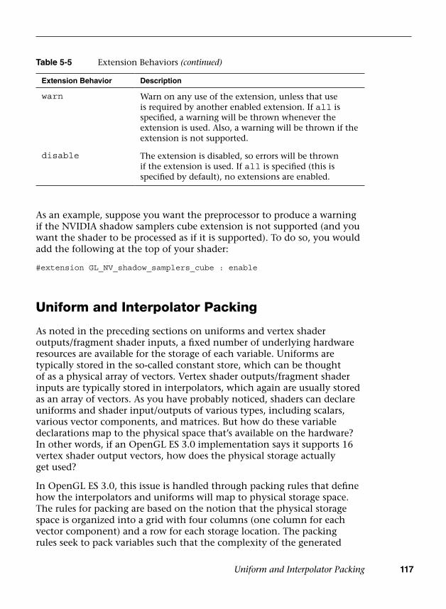
Uniform and Interpolator Packing 117
As an example, suppose you want the preprocessor to produce a warning if the NVIDIA shadow samplers cube extension is not supported (and you want the shader to be processed as if it is supported). To do so, you would add the following at the top of your shader:
#extension GL_NV_shadow_samplers_cube : enable
Uniform and Interpolator Packing
As noted in the preceding sections on uniforms and vertex shader outputs/fragment shader inputs, a fixed number of underlying hardware resources are available for the storage of each variable. Uniforms are typically stored in the so-called constant store, which can be thought of as a physical array of vectors. Vertex shader outputs/fragment shader inputs are typically stored in interpolators, which again are usually stored as an array of vectors. As you have probably noticed, shaders can declare uniforms and shader input/outputs of various types, including scalars, various vector components, and matrices. But how do these variable declarations map to the physical space that’s available on the hardware? In other words, if an OpenGL ES 3.0 implementation says it supports 16 vertex shader output vectors, how does the physical storage actually get used?
In OpenGL ES 3.0, this issue is handled through packing rules that define how the interpolators and uniforms will map to physical storage space. The rules for packing are based on the notion that the physical storage space is organized into a grid with four columns (one column for each vector component) and a row for each storage location. The packing rules seek to pack variables such that the complexity of the generated
Table 5-5 Extension Behaviors (continued)
Extension Behavior Description
warn Warn on any use of the extension, unless that use is required by another enabled extension. If all is specified, a warning will be thrown whenever the extension is used. Also, a warning will be thrown if the extension is not supported.
disable The extension is disabled, so errors will be thrown if the extension is used. If all is specified (this is specified by default), no extensions are enabled.

118 Chapter 5: OpenGL ES Shading Language
code remains constant. In other words, the packing rules will not do reordering that requires the compiler to generate extra instructions to merge unpacked data. Rather, the packing rules seek to optimize the use of the physical address space without negatively impacting runtime performance.
Let’s look at an example group of uniform declarations and see how these would be packed:
uniform mat3 m;uniform float f[6];uniform vec3 v;
If no packing were done at all, you can see that a lot of constant storage space would be wasted. The matrix m would take up three rows, the array f would take up six rows, and the vector v would take up one row. This would use a total of 10 rows to store the variables. Table 5-6 shows what the results would be without any packing. With the packing rules, the variables will get organized such that they pack into the grid as shown in Table 5-7.
Table 5-6 Uniform Storage without Packing
Location X Y Z W
0 m[0].x m[0].y m[0].z —
1 m[l].x m[l].y m[l].z —
2 m[2].x m[2].y m[2].z —
3 f[0] — — —
4 f[l] — — —
5 f[2] — — —
6 f[3] — — —
7 f[4] — — —
8 f[5] — — —
9 v.x v.y v.z -6

Precision Qualifiers 119
With the packing rules, only six physical constant locations need to be used. You will notice that the array f needs to keep its elements spanning across row boundaries. The reason for this is that typically GPUs index the constant store by vector location index. The packing must keep the arrays spanning across row boundaries so that indexing will still work.
All of the packing that is done is completely transparent to the user of the OpenGL ES Shading Language, except for one detail: The packing impacts the way in which uniforms and vertex shader outputs/fragment shader inputs are counted. If you want to write shaders that are guaranteed to run on all implementations of OpenGL ES 3.0, you should not use more uniforms or interpolators than would exceed the minimum allowed storage sizes after packing. For this reason, it’s important to be aware of packing so that you can write portable shaders that will not exceed the minimum allowed storage on any implementation of OpenGL ES 3.0.
Precision Qualifiers
Precision qualifiers enable the shader author to specify the precision with which computations for a shader variable are performed. Variables can be declared to have either low, medium, or high precision. These qualifiers are used as hints to the compiler to allow it to perform computations with variables at a potentially lower range and precision. It is possible that at lower precisions, some implementations of OpenGL ES might be able to run the shaders either faster or with better power efficiency.
Table 5-7 Uniform Storage with Packing
Location X Y Z W
0 m[0].x m[0].y m[0].z f[0]
1 m[l].x m[l].y m[l].z f[l]
2 m[2].x m[2].y m[2].z f[2]
3 v.x v.y v.z f[3]
4 — — — f[4]
5 — — — f[5]

120 Chapter 5: OpenGL ES Shading Language
Of course, that efficiency savings comes at the cost of precision, which can result in artifacts if precision qualifiers are not used properly. Note that nothing in the OpenGL ES specification says that multiple precisions must be supported in the underlying hardware, so it is perfectly valid for an implementation of OpenGL ES to perform all calculations at the highest precision and simply ignore the qualifiers. However, on some implementations, using a lower precision might offer an advantage.
Precision qualifiers can be used to specify the precision of any floating-point or integer-based variable. The keywords for specifying the precision are lowp, mediump, and highp. Some examples of declarations with precision qualifiers are shown here:
highp vec4 position;varying lowp vec4 color;mediump float specularExp;
In addition to precision qualifiers, the notion of default precision is available. That is, if a variable is declared without having a precision qualifier, it will have the default precision for that type. The default precision qualifier is specified at the top of a vertex or fragment shader using the following syntax:
precision highp float;precision mediump int;
The precision specified for float will be used as the default precision for all variables based on a floating-point value. Likewise, the precision specified for int will be used as the default precision for all integer-based variables.
In the vertex shader, if no default precision is specified, then the default precision for both int and float is highp. That is, all variables declared without a precision qualifier in a vertex shader will have the highest precision. The rules for the fragment shader are different. In the fragment shader, there is no default precision given for floating-point values: Every shader must declare a default float precision or specify the precision for every float variable.
One final note is that the precision specified by a precision qualifier has an implementation-dependent range and precision. There is an associated API call for determining the range and precision for a given implementation, which is covered in Chapter 15, “State Queries.” As an example, on the PowerVR SGX GPU, a lowp float variable is represented in a 10-bit fixed point format, a mediump float variable is a 16-bit floating-point value, and a highp float is a 32-bit floating-point value.
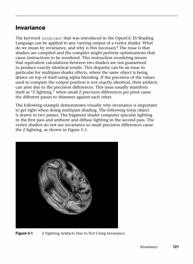
Invariance 121
Invariance
The keyword invariant that was introduced in the OpenGL ES Shading Language can be applied to any varying output of a vertex shader. What do we mean by invariance, and why is this necessary? The issue is that shaders are compiled and the compiler might perform optimizations that cause instructions to be reordered. This instruction reordering means that equivalent calculations between two shaders are not guaranteed to produce exactly identical results. This disparity can be an issue in particular for multipass shader effects, where the same object is being drawn on top of itself using alpha blending. If the precision of the values used to compute the output position is not exactly identical, then artifacts can arise due to the precision differences. This issue usually manifests itself as “Z fighting,” when small Z precision differences per pixel cause the different passes to shimmer against each other.
The following example demonstrates visually why invariance is important to get right when doing multipass shading. The following torus object is drawn in two passes: The fragment shader computes specular lighting in the first pass and ambient and diffuse lighting in the second pass. The vertex shaders do not use invariance so small precision differences cause the Z fighting, as shown in Figure 5-1.
Figure 5-1 Z Fighting Artifacts Due to Not Using Invariance

122 Chapter 5: OpenGL ES Shading Language
Figure 5-2 Z Fighting Avoided Using Invariance
The same multipass vertex shaders using invariance for position produce the correct image in Figure 5-2.
The introduction of invariance gives the shader writer a way to specify that if the same computations are used to compute an output, its value must be exactly the same (or invariant). The invariant keyword can be used either on varying declarations or for varyings that have already been declared. Some examples follow:
invariant gl_Position;invariant texCoord;
Once invariance is declared for an output, the compiler guarantees that the results will be the same given the same computations and inputs into the shader. For example, given two vertex shaders that compute output position by multiplying the view projection matrix by the input position, you are guaranteed that those positions will be invariant.
#version 300 esuniform mat4 u_viewProjMatrix;layout(location = 0) in vec4 a_vertex;invariant gl_Position;
Summary 123
void main(){ // Will be the same value in all shaders with the // same viewProjMatrix and vertex gl_Position = u_viewProjMatrix * a_vertex;}
It is also possible to make all variables globally invariant using a #pragma directive:
#pragma STDGL invariant(all)
A word of caution: Because the compiler needs to guarantee invariance, it might have to limit the optimizations it does. Therefore, the invariant qualifier should be used only when necessary; otherwise, it might result in performance degradation. For this reason, the #pragma directive to globally enable invariance should be used only when invariance is really required for all variables. Note also that while invariance does imply that the calculation will have the same results on a given GPU, it does not mean that the computation will be invariant across any implementation of OpenGL ES.
Summary
This chapter introduced the following features of the OpenGL ES Shading Language:
• Shader version specification with #version
• Scalar, vector, and matrix data types and constructors
• Declaration of constants using the const qualifier
• Creation and initialization of structures and arrays
• Operators, control flow, and functions
• Vertex shader inputs/output and fragment shader inputs/outputsusing the in and out keywords and layout qualifier
• Smooth, flat, and centroid interpolation qualifiers
• Uniforms, uniform blocks, and uniform block layout qualifiers
• Preprocessor and directives
• Uniform and interpolator packing
• Precision qualifiers and invariance

124 Chapter 5: OpenGL ES Shading Language
In the next chapter, we focus on how to load vertex input variables with data from vertex arrays and vertex buffer objects. We will expand your knowledge of the OpenGL ES Shading Language throughout the book. For example, in Chapter 8, “Vertex Shaders,” we describe how to perform transformation, lighting, and skinning in a vertex shader. In Chapter 9, “Texturing,” we explain how to load textures and how to use them in a fragment shader. In Chapter 10, “Fragment Shaders,” we cover how to compute fog, perform alpha testing, and evaluate user clip planes in a fragment shader. In Chapter 14, “Advanced Programming with OpenGL ES 3.0,” we go deep into writing shaders that perform advanced effects such as environment mapping, projective texturing, and per-fragment lighting. With the grounding in the OpenGL ES Shading Language from this chapter, we can show you how to use shaders to achieve a variety of rendering techniques.

125
Chapter 6
Vertex Attributes, Vertex Arrays, and Buffer Objects
This chapter describes how vertex attributes and data are specified in OpenGL ES 3.0. We discuss what vertex attributes are, how to specify them and their supported data formats, and how to bind vertex attributes for use in a vertex shader. After reading this chapter, you will have a good grasp of what vertex attributes are and how to draw primitives with vertex attributes in OpenGL ES 3.0.
Vertex data, also referred to as vertex attributes, specify per-vertex data. This per-vertex data can be specified for each vertex, or a constant value can be used for all vertices. For example, if you want to draw a triangle that has a solid color (for the sake of this example, suppose the color is black, as shown in Figure 6-1), you would specify a constant value that will be used by all three vertices of the triangle. However, the position of the three vertices that make up the triangle will not be the same, so we will need to specify a vertex array that stores three position values.
Figure 6-1 Triangle with a Constant Color Vertex and Per-Vertex Position Attributes

126 Chapter 6: Vertex Attributes, Vertex Arrays, and Buffer Objects
Specifying Vertex Attribute Data
Vertex attribute data can be specified for each vertex using a vertex array, or a constant value can be used for all vertices of a primitive.
All OpenGL ES 3.0 implementations must support a minimum of 16 vertex attributes. An application can query the exact number of vertex attributes that are supported by a particular implementation. The following code shows how an application can query the number of vertex attributes an implementation actually supports:
GLint maxVertexAttribs; // n will be >= 16 glGetIntegerv(GL_MAX_VERTEX_ATTRIBS, &maxVertexAttribs);
Constant Vertex Attribute
A constant vertex attribute is the same for all vertices of a primitive, so only one value needs to be specified for all the vertices of a primitive. It is specified using any of the following functions:
void glVertexAttriblf(GLuint index, GLfloat x);void glVertexAttrib2f(GLuint index, GLfloat x, GLfloat y);void glVertexAttrib3f( GLuint index, GLfloat x, GLfloat y,
GLfloat z);void glVertexAttrib4f( GLuint index, GLfloat x, GLfloat y,
GLfloat z, GLfloat w);void glVertexAttriblfv(GLuint index, const GLfloat *values);void glVertexAttrib2fv(GLuint index, const GLfloat *values);void glVertexAttrib3fv(GLuint index, const GLfloat *values);void glVertexAttrib4fv(GLuint index, const GLfloat *values);
The glVertexAttrib* commands are used to load the generic vertex attribute specified by index. The functions glVertexAttriblf and glVertexAttriblfv load (x, 0.0, 0.0, 1.0) into the generic vertex attribute. glVertexAttrib2f and glVertexAttrib2fv load (x, y, 0.0, 1.0) into the generic vertex attribute. glVertexAttrib3f and glVertexAttrib3fv load (x, y, z, 1.0) into the generic vertex attribute. glVertexAttrib4f and glVertexAttrib4fv load (x, y, z, w) into the generic vertex attribute. In practice, constant vertex attributes provide equivalent functionality to using a scalar/vector uniform, and using either is an acceptable choice.
Vertex Arrays
Vertex arrays specify attribute data per vertex and are buffers stored in the application’s address space (what OpenGL ES calls the client space). They
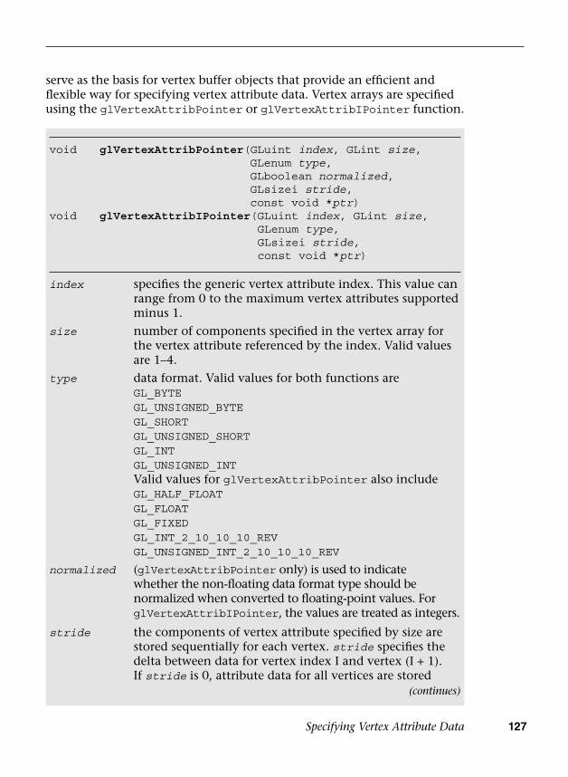
Specifying Vertex Attribute Data 127
serve as the basis for vertex buffer objects that provide an efficient and flexible way for specifying vertex attribute data. Vertex arrays are specified using the glVertexAttribPointer or glVertexAttribIPointer function.
void glVertexAttribPointer(GLuint index, GLint size, GLenum type, GLboolean normalized, GLsizei stride, const void *ptr)
void glVertexAttribIPointer(GLuint index, GLint size,GLenum type, GLsizei stride, const void *ptr)
index specifies the generic vertex attribute index. This value can range from 0 to the maximum vertex attributes supported minus 1.
size number of components specified in the vertex array for the vertex attribute referenced by the index. Valid values are 1–4.
type data format. Valid values for both functions areGL_BYTEGL_UNSIGNED_BYTEGL_SHORTGL_UNSIGNED_SHORTGL_INTGL_UNSIGNED_INTValid values for glVertexAttribPointer also includeGL_HALF_FLOATGL_FLOATGL_FIXEDGL_INT_2_10_10_10_REVGL_UNSIGNED_INT_2_10_10_10_REV
normalized (glVertexAttribPointer only) is used to indicate whether the non-floating data format type should be normalized when converted to floating-point values. For glVertexAttribIPointer, the values are treated as integers.
stride the components of vertex attribute specified by size are stored sequentially for each vertex. stride specifies the delta between data for vertex index I and vertex (I + 1). If stride is 0, attribute data for all vertices are stored
(continues)

128 Chapter 6: Vertex Attributes, Vertex Arrays, and Buffer Objects
Next, we present a few examples that illustrate how to specify vertex attributes with glVertexAttribPointer. Two methods are commonly used for allocating and storing vertex attribute data:
• Store vertex attributes together in a single buffer—a method called anarray of structures. The structure represents all attributes of a vertex,and we have an array of these attributes per vertex.
• Store each vertex attribute in a separate buffer—a method called astructure of arrays.
Suppose each vertex has four vertex attributes—position, normal, and two texture coordinates—and these attributes are stored together in one buffer that is allocated for all vertices. The vertex position attribute is specified as a vector of three floats (x, y, z), the vertex normal is also specified as a vector of three floats, and each texture coordinate is specified as a vector of two floats. Figure 6-2 gives the memory layout of this buffer. In this case, the stride of the buffer is the combined size of all attributes that make up the vertex (one vertex is equal to 10 floats or 40 bytes – 12 bytes for Position, 12 bytes for Normal, 8 bytes for Tex0, and 8 bytes for Tex1).
sequentially. If stride is greater than 0, then we use the stride value as the pitch to get vertex data for next index.
ptr pointer to the buffer holding vertex attribute data if using a client-side vertex array. If using a vertex buffer object, specifies an offset into that buffer.
Position Normal Tex0 Tex1
x y z x y z s t s t x y z x y z s t s t
Position Normal Tex0 Tex1
Figure 6-2 Position, Normal, and Two Texture Coordinates Stored as an Array
Example 6-1 describes how these four vertex attributes are specified with glVertexAttribPointer. Note that we are illustrating how to use client-side vertex arrays here so that we can explain the concept of specifying per-vertex data. We recommend that applications use vertex buffer objects (described later in the chapter) and avoid client-side vertex arrays to achieve best performance. Client-side vertex arrays are supported in OpenGL ES 3.0 only for backward compatibility with OpenGL ES 2.0. In OpenGL ES 3.0, vertex buffer objects are always recommended.
(continued)
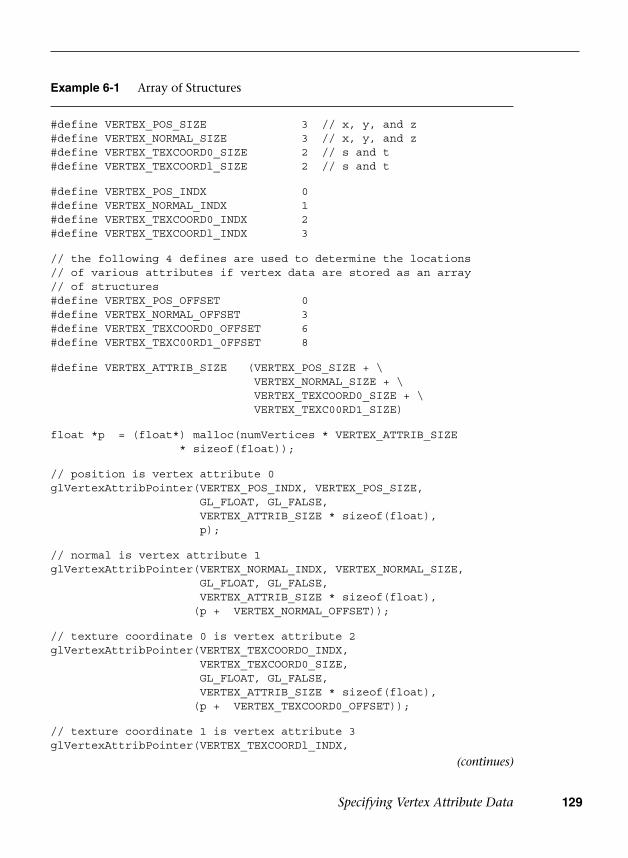
Specifying Vertex Attribute Data 129
Example 6-1 Array of Structures
#define VERTEX_POS_SIZE 3 // x, y, and z#define VERTEX_NORMAL_SIZE 3 // x, y, and z#define VERTEX_TEXCOORD0_SIZE 2 // s and t#define VERTEX_TEXCOORDl_SIZE 2 // s and t
#define VERTEX_POS_INDX 0#define VERTEX_NORMAL_INDX 1#define VERTEX_TEXCOORD0_INDX 2#define VERTEX_TEXCOORDl_INDX 3
// the following 4 defines are used to determine the locations// of various attributes if vertex data are stored as an array // of structures#define VERTEX_POS_OFFSET 0#define VERTEX_NORMAL_OFFSET 3#define VERTEX_TEXCOORD0_OFFSET 6#define VERTEX_TEXC00RD1_0FFSET 8
#define VERTEX_ATTRIB_SIZE (VERTEX_POS_SIZE + \VERTEX_NORMAL_SIZE + \VERTEX_TEXCOORD0_SIZE + \VERTEX_TEXC00RD1_SIZE)
float *p = (float*) malloc(numVertices * VERTEX_ATTRIB_SIZE* sizeof(float));
// position is vertex attribute 0glVertexAttribPointer(VERTEX_POS_INDX, VERTEX_POS_SIZE,
GL_FLOAT, GL_FALSE,VERTEX_ATTRIB_SIZE * sizeof(float),p);
// normal is vertex attribute 1glVertexAttribPointer(VERTEX_NORMAL_INDX, VERTEX_NORMAL_SIZE,
GL_FLOAT, GL_FALSE,VERTEX_ATTRIB_SIZE * sizeof(float),
(p + VERTEX_NORMAL_OFFSET));
// texture coordinate 0 is vertex attribute 2glVertexAttribPointer(VERTEX_TEXCOORDO_INDX,
VERTEX_TEXCOORD0_SIZE,GL_FLOAT, GL_FALSE,VERTEX_ATTRIB_SIZE * sizeof(float),
(p + VERTEX_TEXCOORD0_OFFSET));
// texture coordinate 1 is vertex attribute 3glVertexAttribPointer(VERTEX_TEXCOORDl_INDX,
(continues)
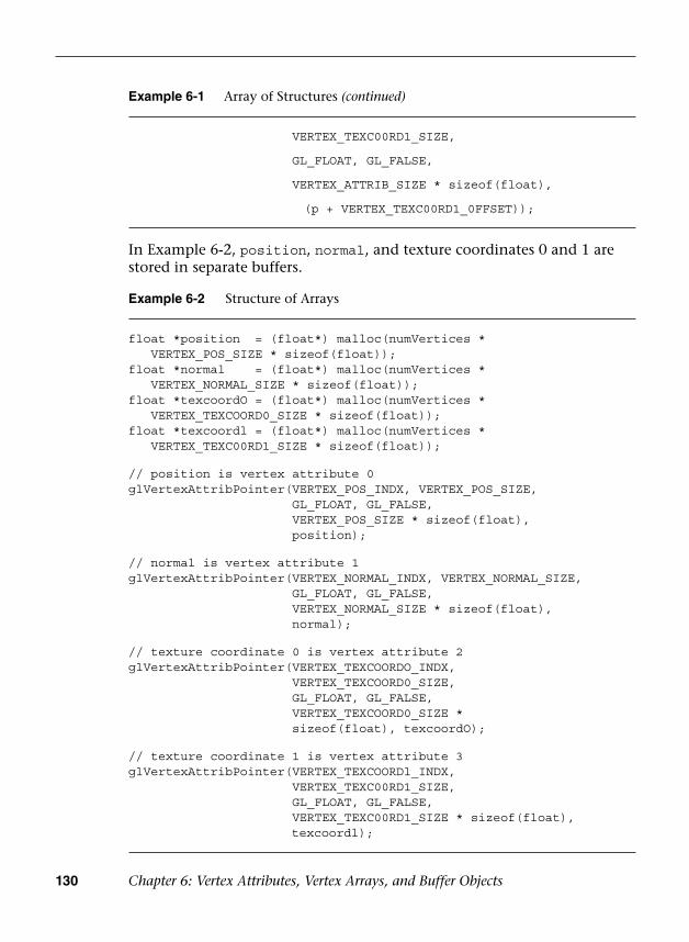
130 Chapter 6: Vertex Attributes, Vertex Arrays, and Buffer Objects
In Example 6-2, position, normal, and texture coordinates 0 and 1 are stored in separate buffers.
Example 6-1 Array of Structures (continued)
VERTEX_TEXC00RD1_SIZE,
GL_FLOAT, GL_FALSE,
VERTEX_ATTRIB_SIZE * sizeof(float),
(p + VERTEX_TEXC00RD1_0FFSET));
Example 6-2 Structure of Arrays
float *position = (float*) malloc(numVertices * VERTEX_POS_SIZE * sizeof(float));float *normal = (float*) malloc(numVertices * VERTEX_NORMAL_SIZE * sizeof(float));float *texcoordO = (float*) malloc(numVertices * VERTEX_TEXCOORD0_SIZE * sizeof(float));float *texcoordl = (float*) malloc(numVertices * VERTEX_TEXC00RD1_SIZE * sizeof(float));
// position is vertex attribute 0glVertexAttribPointer(VERTEX_POS_INDX, VERTEX_POS_SIZE,
GL_FLOAT, GL_FALSE,VERTEX_POS_SIZE * sizeof(float),position);
// normal is vertex attribute 1glVertexAttribPointer(VERTEX_NORMAL_INDX, VERTEX_NORMAL_SIZE,
GL_FLOAT, GL_FALSE,VERTEX_NORMAL_SIZE * sizeof(float),normal);
// texture coordinate 0 is vertex attribute 2glVertexAttribPointer(VERTEX_TEXCOORDO_INDX,
VERTEX_TEXCOORD0_SIZE,GL_FLOAT, GL_FALSE,VERTEX_TEXCOORD0_SIZE *sizeof(float), texcoordO);
// texture coordinate 1 is vertex attribute 3glVertexAttribPointer(VERTEX_TEXCOORDl_INDX,
VERTEX_TEXC00RD1_SIZE,GL_FLOAT, GL_FALSE,VERTEX_TEXC00RD1_SIZE * sizeof(float), texcoordl);
Specifying Vertex Attribute Data 131
Performance Hints
How to Store Different Attributes of a Vertex
We described the two most common ways of storing vertex attributes: an array of structures and a structure of arrays. The question to ask is which allocation method would be the most efficient for OpenGL ES 3.0 hardware implementations. In most cases, the answer is an array of structures. The reason is that the attribute data for each vertex can be read in sequential fashion, which will most likely result in an efficient memory access pattern. A disadvantage of using an array of structures becomes apparent when an application wants to modify specific attributes. If a subset of vertex attribute data needs to be modified (e.g., texture coordinates), this will result in strided updates to the vertex buffer. When the vertex buffer is supplied as a buffer object, the entire vertex attribute buffer will need to be reloaded. You can avoid this inefficiency by storing vertex attributes that are dynamic in nature in a separate buffer.
Which Data Format to Use for Vertex Attributes
The vertex attribute data format specified by the type argument in glVertexAttribPointer can affect not only the graphics memory storage requirements for vertex attribute data, but also the overall performance, which is a function of the memory bandwidth required to render the frame(s). The smaller the data footprint, the lower the memory bandwidth required. OpenGL ES 3.0 supports a 16-bit floating-point vertex format named GL_HALF_FLOAT (described in detail in Appendix A). Our recommendation is that applications use GL_HALF_FLOAT wherever possible. Texture coordinates, normals, binormals, tangent vectors, and so on are good candidates to be stored using GL_HALF_FLOAT for each component. Color could be stored as GL_UNSIGNED_BYTE with four components per vertex color. We also recommend GL_HALF_FLOAT for vertex position, but recognize that this choice might not be feasible for quite a few cases. For such cases, the vertex position could be stored as GL_FLOAT.
How the Normalized Flag in gIVertexAttribPointer Works
Vertex attributes are internally stored as a single-precision floating-point number before being used in a vertex shader. If the data type indicates that the vertex attribute is not a float, then the vertex attribute will be converted to a single-precision floating-point number before it is used in a vertex shader. The normalized flag controls the conversion of the non-float vertex attribute data to a single precision floating-point value. If the normalized flag is false, the vertex data are converted directly to a

132 Chapter 6: Vertex Attributes, Vertex Arrays, and Buffer Objects
floating-point value. This would be similar to casting the variable that is not a float type to float. The following code gives an example:
GLfloat f;GLbyte b;f = (GLfloat)b; // f represents values in the range [-128.0,
// 127.0]
If the normalized flag is true, the vertex data is mapped to the [–1.0, 1.0] range if the data type is GL_BYTE, GL_SHORT, or GL_FIXED, or to the [0.0, 1.0] range if the data type is GL_UNSIGNED_BYTE or GL_UNSIGNED_SHORT.
Table 6-1 describes conversion of non-floating-point data types with the normalized flag set. The value c in the second column of Table 6-1 refers to a value of the format specified in the first column.
Table 6-1 Data Conversions
Vertex Data Format Conversion to Floating Point
GL_BYTE max(c / (27 – 1), –1.0)
GL_UNSIGNED_BYTE c / (28 – 1)
GL_SHORT max(c / (216 – 1), –1.0)
GL_UNSIGNED_SHORT c / (216 – l)
GL_FIXED c/216
GL_FLOAT c
GL_HALF_FLOAT_OES c
It is also possible to access integer vertex attribute data as integers in the vertex shader rather than having them be converted to floats. In this case, the glVertexAttribIPointer function should be used and the vertex attribute should be declared to be of an integer type in the vertex shader.
Selecting Between a Constant Vertex Attribute or a Vertex Array
The application can enable OpenGL ES to use either the constant data or data from vertex array. Figure 6-3 describes how this works in OpenGL ES 3.0.
The commands glEnableVertexAttribArray and glDisableVertex-AttribArray are used to enable and disable a generic vertex attribute array, respectively. If the vertex attribute array is disabled for a generic attribute index, the constant vertex attribute data specified for that index will be used.

Specifying Vertex Attribute Data 133
ConstantVertex Attribute 0
Vertex ArrayVertex Attribute 0
Vertex Attribute 0Enable/Disable
enable
disable
Vertex Data
Figure 6-3 Selecting Constant or Vertex Array Vertex Attribute
void glEnableVertexAttribArray(GLuint index);void glDisableVertexAttribArray(GLuint index);
index specifies the generic vertex attribute index. This value ranges from 0 to the maximum vertex attributes supported minus 1.
Example 6-3 illustrates how to draw a triangle where one of the vertex attributes is constant and the other is specified using a vertex array.
Example 6-3 Using Constant and Vertex Array Attributes
int Init ( ESContext *esContext ){ UserData *userData = (UserData*) esContext->userData; const char vShaderStr[] =
"#version 300 es \n""layout(location = 0) in vec4 a_color; \n""layout(location = 1) in vec4 a_position; \n""out vec4 v_color; \n""void main() \n""{ \n"" v_color = a_color; \n"" gl_Position = a_position; \n""}";
const char fShaderStr[] ="#version 300 es \n""precision mediump float; \n""in vec4 v_color; \n""out vec4 o_fragColor; \n"
(continues)
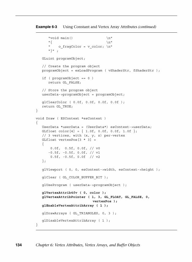
134 Chapter 6: Vertex Attributes, Vertex Arrays, and Buffer Objects
Example 6-3 Using Constant and Vertex Array Attributes (continued)
"void main() \n""{ \n"" o_fragColor = v_color; \n""}" ;
GLuint programObject;
// Create the program object programObject = esLoadProgram ( vShaderStr, fShaderStr );
if ( programObject == 0 )return GL_FALSE;
// Store the program object userData->programObject = programObject;
glClearColor ( 0.0f, 0.0f, 0.0f, 0.0f ); return GL_TRUE;}
void Draw ( ESContext *esContext ){ UserData *userData = (UserData*) esContext->userData; GLfloat color[4] = { 1.0f, 0.0f, 0.0f, 1.0f }; // 3 vertices, with (x, y, z) per-vertex GLfloat vertexPos[3 * 3] = {
0.0f, 0.5f, 0.0f, // v0-0.5f, -0.5f, 0.0f, // v10.5f, -0.5f, 0.0f // v2
};
glViewport ( 0, 0, esContext->width, esContext->height );
glClear ( GL_COLOR_BUFFER_BIT );
glUseProgram ( userData->programObject );
glVertexAttrib4fv ( 0, color ); glVertexAttribPointer ( 1, 3, GL_FLOAT, GL_FALSE, 0,
vertexPos ); glEnableVertexAttribArray ( 1 );
glDrawArrays ( GL_TRIANGLES, 0, 3 );
glDisableVertexAttribArray ( 1 );}
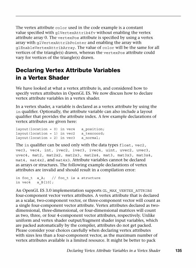
Declaring Vertex Attribute Variables in a Vertex Shader 135
The vertex attribute color used in the code example is a constant value specified with glVertexAttrib4fv without enabling the vertex attribute array 0. The vertexPos attribute is specified by using a vertex array with glVertexAttribPointer and enabling the array with glEnableVertexAttribArray. The value of color will be the same for all vertices of the triangle(s) drawn, whereas the vertexPos attribute could vary for vertices of the triangle(s) drawn.
Declaring Vertex Attribute Variables in a Vertex Shader
We have looked at what a vertex attribute is, and considered how to specify vertex attributes in OpenGL ES. We now discuss how to declare vertex attribute variables in a vertex shader.
In a vertex shader, a variable is declared as a vertex attribute by using the in qualifier. Optionally, the attribute variable can also include a layout qualifier that provides the attribute index. A few example declarations of vertex attributes are given here:
layout(location = 0) in vec4 a_position;layout(location = 1) in vec2 a_texcoord;layout(location = 2) in vec3 a_normal;
The in qualifier can be used only with the data types float, vec2, vec3, vec4, int, ivec2, ivec3, ivec4, uint, uvec2, uvec3, uvec4, mat2, mat2x2, mat2x3, mat2x4, mat3, mat3x3, mat3x4, mat4, mat4x2, and mat4x3. Attribute variables cannot be declared as arrays or structures. The following example declarations of vertex attributes are invalid and should result in a compilation error:
in foo_t a_A; // foo_t is a structurein vec4 a_B[10];
An OpenGL ES 3.0 implementation supports GL_MAX_VERTEX_ATTRIBS four-component vector vertex attributes. A vertex attribute that is declared as a scalar, two-component vector, or three-component vector will count as a single four-component vector attribute. Vertex attributes declared as two-dimensional, three-dimensional, or four-dimensional matrices will count as two, three, or four 4-component vector attributes, respectively. Unlike uniform and vertex shader output/fragment shader input variables, which are packed automatically by the compiler, attributes do not get packed. Please consider your choices carefully when declaring vertex attributes with sizes less than a four-component vector, as the maximum number of vertex attributes available is a limited resource. It might be better to pack
136 Chapter 6: Vertex Attributes, Vertex Arrays, and Buffer Objects
them together into a single four-component attribute instead of declaring them as individual vertex attributes in the vertex shader.
Variables declared as vertex attributes in a vertex shader are read-only variables and cannot be modified. The following code should cause a compilation error:
in vec4 a_pos;uniform vec4 u_v;
void main(){ a_pos = u_v; <--- cannot assign to a_pos as it is read-only}
An attribute can be declared inside a vertex shader—but if it is not used, then it is not considered active and does not count against the limit. If the number of attributes used in a vertex shader is greater than GL_MAX_VERTEX_ATTRIBS, the vertex shader will fail to link.
Once a program has been successfully linked, we may need to find out the number of active vertex attributes used by the vertex shader attached to this program. Note that this step is necessary only if you are not using input layout qualifiers for attributes. In OpenGL ES 3.0, it is recommended that you use layout qualifiers; thus you will not need to query this information after the fact. However, for completeness, the following line of code shows how to get the number of active vertex attributes:
glGetProgramiv(program, GL_ACTIVE_ATTRIBUTES, &numActiveAttribs);
A detailed description of glGetProgramiv is given in Chapter 4, “Shaders and Programs.”
The list of active vertex attributes used by a program and their data types can be queried using the glGetActiveAttrib command.
void glGetActiveAttrib( GLuint program, GLuint index, GLsizei bufsize, GLsizei *length, GLenum *type, GLint *size, GLchar *name)
program name of a program object that was successfully linked previously.

Declaring Vertex Attribute Variables in a Vertex Shader 137
The glGetActiveAttrib call provides information about the attribute selected by index. As detailed in the description of glGetActiveAttrib, index must be a value between 0 and GL_ACTIVE_ATTRIBUTES – l. The value of GL_ACTIVE_ATTRIBUTES is queried using glGetProgramiv. An index of 0 selects the first active attributes, and an index of GL_ACTIVE_ATTRIBUTES – 1 selects the last vertex attribute.
Binding Vertex Attributes to Attribute Variables in a Vertex Shader
We discussed earlier that in a vertex shader, vertex attribute variables are specified by the in qualifier, the number of active attributes can be queried using glGetProgramiv, and the list of active attributes in a program can be queried using glGetActiveAttrib. We also described how generic attribute indices that range from 0 to (GL_MAX_VERTEX_ATTRIBS – 1) are used to enable a generic vertex
index specifies the vertex attribute to query and will be a value between 0 and GL_ACTIVE_ATTRIBUTES – 1. The value of GL_ACTIVE_ATTRIBUTES is determined with glGetProgramiv.
bufsize specifies the maximum number of characters that may be written into name, including the null terminator.
length returns the number of characters written into name, excluding the null terminator, if length is not NULL.
type returns the type of the attribute. Valid values areGL_FLOAT, GL_FLOAT_VEC2, GL_FLOAT_VEC3,GL_FLOAT_VEC4, GL_FLOAT_MAT2, GL_FLOAT_MAT3,GL_FLOAT_MAT4, GL_FLOAT_MAT2x3, GL_FLOAT_MAT2x4, GL_FLOAT_MAT3x2, GL_FLOAT_MAT3x4, GL_FLOAT_MAT4x2, GL_FLOAT_MAT_4x3, GL_INT, GL_INT_VEC2, GL_INT_VEC3, GL_INT_VEC4, GL_UNSIGNED_INT, GL_UNSIGNED_INT_VEC2, GL_UNSIGNED_INT_VEC3, GL_UNSIGNED_INT_VEC4
size returns the size of the attribute. This is specified in units of the type returned by type. If the variable is not an array, size will always be 1. If the variable is an array, then size returns the size of the array.
name name of the attribute variable as declared in the vertex shader.

138 Chapter 6: Vertex Attributes, Vertex Arrays, and Buffer Objects
attribute and specify a constant or per-vertex (i.e., vertex array) value using the glVertexAttrib* and glVertexAttribPointer commands. Now we consider how to map this generic attribute index to the appropriate attribute variable declared in the vertex shader. This mapping will allow appropriate vertex data to be read into the correct vertex attribute variable in the vertex shader.
Figure 6-4 describes how generic vertex attributes are specified and bound to attribute names in a vertex shader.
ConstantVertex Attribute 0
Vertex ArrayVertex Attribute 0
e 0
y
Vertex Attribute 0Enable/Disable
Vertex Attributee 0
ConstantVertex Attribute 1
Vertex ArrayVertex Attribute 1
e 1
1
Vertex Attribute 1Enable/Disable
ConstantVertex Attribute n – 1
Vertex ArrayVertex Attribute n – 1
n – 1
n – 1
Vertex Attribute n – 1Enable/Disable
glDrawArrays/gl DrawElementss/gl DrawElements
Attribute Vertex Attribute Variable Index Bindings
Vertex Shader
Attribute 0
Attribute 1
V
Attribute n – 1
Figure 6-4 Specifying and Binding Vertex Attributes for Drawing One or More Primitives

Declaring Vertex Attribute Variables in a Vertex Shader 139
void glBindAttribLocation( GLuint program, GLuint index, const GLchar *name)
program name of a program objectindex generic vertex attribute indexname name of the attribute variable
If name was bound previously, its assigned binding is replaced with an index. glBindAttribLocation can be called even before a vertex shader is attached to a program object. As a consequence, this call can be used to bind any attribute name. Attribute names that do not exist or are not active in a vertex shader attached to the program object are ignored.
Another option is to let OpenGL ES 3.0 bind the attribute variable name to a generic vertex attribute index. This binding is performed when the program is linked. In the linking phase, the OpenGL ES 3.0 implementation performs the following operation for each attribute variable:
For each attribute variable, check whether a binding has been specified via glBindAttribLocation. If a binding is specified, the appropriate attribute index specified is used. If not, the implementation will assign a generic vertex attribute index.
In OpenGL ES 3.0, three approaches may be used to map a generic vertex attribute index to an attribute variable name in the vertex shader. These approaches can be categorized as follows:
• The index can be specified in the vertex shader source code using thelayout(location = N) qualifier (recommended).
• OpenGL ES 3.0 will bind the generic vertex attribute index to theattribute name.
• The application can bind the vertex attribute index to an attributename.
The easiest way to bind attributes to a location is to simply use the layout(location = N) qualifier; this approach requires the least amount of code. However, in some cases, the other two options might be more desirable. The glBindAttribLocation command can be used to bind a generic vertex attribute index to an attribute variable in a vertex shader. This binding takes effect when the program is linked the next time—it does not change the bindings used by the currently linked program.

140 Chapter 6: Vertex Attributes, Vertex Arrays, and Buffer Objects
This assignment is implementation specific; that is, it can vary from one OpenGL ES 3.0 implementation to another. An application can query the assigned binding by using the glGetAttribLocation command.
GLint glGetAttribLocation ( GLuint program, const GLchar *name)
program program objectname name of attribute variable
glGetAttribLocation returns the generic attribute index that was bound to the attribute variable name when the program object defined by program was last linked. If name is not an active attribute variable, or if program is not a valid program object or was not linked successfully, then –1 is returned, indicating an invalid attribute index.
Vertex Buffer Objects
The vertex data specified using vertex arrays are stored in client memory. This data must be copied from client memory to graphics memory when a draw call such as glDrawArrays or glDrawElements is made. These two commands are described in detail in Chapter 7, “Primitive Assembly and Rasterization.” It would, however, be much better if we did not have to copy the vertex data on every draw call, but instead could cache the data in graphics memory. This approach can significantly improve the rendering performance and also reduce the memory bandwidth and power consumption requirements, both of which are quite important for handheld devices. This is where vertex buffer objects can help. Vertex buffer objects allow OpenGL ES 3.0 applications to allocate and cache vertex data in high-performance graphics memory and render from this memory, thereby avoiding resending data every time a primitive is drawn. Not only the vertex data, but also the element indices that describe the vertex indices of the primitive and are passed as an argument to glDrawElements, can be cached.
OpenGL ES 3.0 supports two types of buffer objects that are used for specifying vertex and primitive data: array buffer objects and element array buffer objects. The array buffer objects specified by the GL_ARRAY_BUFFER token are used to create buffer objects that will store vertex data. The element array buffer objects specified by the GL_ELEMENT_ARRAY_BUFFER
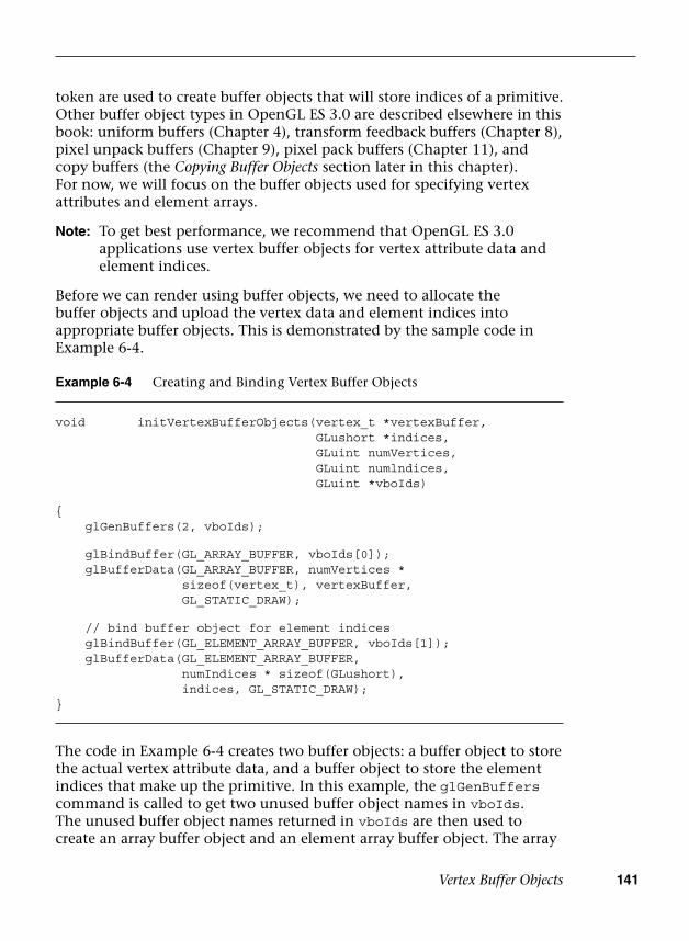
Vertex Buffer Objects 141
token are used to create buffer objects that will store indices of a primitive. Other buffer object types in OpenGL ES 3.0 are described elsewhere in this book: uniform buffers (Chapter 4), transform feedback buffers (Chapter 8), pixel unpack buffers (Chapter 9), pixel pack buffers (Chapter 11), and copy buffers (the Copying Buffer Objects section later in this chapter). For now, we will focus on the buffer objects used for specifying vertex attributes and element arrays.
Note: To get best performance, we recommend that OpenGL ES 3.0 applications use vertex buffer objects for vertex attribute data and element indices.
Before we can render using buffer objects, we need to allocate the buffer objects and upload the vertex data and element indices into appropriate buffer objects. This is demonstrated by the sample code in Example 6-4.
Example 6-4 Creating and Binding Vertex Buffer Objects
void initVertexBufferObjects(vertex_t *vertexBuffer,GLushort *indices,GLuint numVertices,GLuint numlndices,GLuint *vboIds)
{ glGenBuffers(2, vboIds);
glBindBuffer(GL_ARRAY_BUFFER, vboIds[0]); glBufferData(GL_ARRAY_BUFFER, numVertices *
sizeof(vertex_t), vertexBuffer,GL_STATIC_DRAW);
// bind buffer object for element indices glBindBuffer(GL_ELEMENT_ARRAY_BUFFER, vboIds[1]); glBufferData(GL_ELEMENT_ARRAY_BUFFER,
numIndices * sizeof(GLushort),indices, GL_STATIC_DRAW);
}
The code in Example 6-4 creates two buffer objects: a buffer object to store the actual vertex attribute data, and a buffer object to store the element indices that make up the primitive. In this example, the glGenBuffers command is called to get two unused buffer object names in vboIds. The unused buffer object names returned in vboIds are then used to create an array buffer object and an element array buffer object. The array

142 Chapter 6: Vertex Attributes, Vertex Arrays, and Buffer Objects
buffer object is used to store vertex attribute data for vertices of one or more primitives. The element array buffer object stores the indices of one or more primitives. The actual array or element data are specified using glBufferData. Note that GL_STATIC_DRAW is passed as an argument to glBufferData. This value is used to describe how the buffer is accessed by the application and will be described later in this section.
void glGenBuffers(GLsizei n, GLuint *buffers)
n number of buffer object names to returnbuffers pointer to an array of n entries, where allocated buffer
objects are returned
glGenBuffers assigns n buffer object names and returns them in buffers. The buffer object names returned by glGenBuffers are unsigned integer numbers other than 0. The value 0 is reserved by OpenGL ES and does not refer to a buffer object. Attempts to modify or query the buffer object state for buffer object 0 will generate an error.
The glBindBuffer command is used to make a buffer object current. The first time a buffer object name is bound by calling glBindBuffer, the buffer object is allocated with the default state; if the allocation is successful, this allocated object is bound as the current buffer object for the target.
void glBindBuffer(GLenum target, GLuint buffer)
target can be set to any of the following targets:GL_ARRAY_BUFFERGL_ELEMENT_ARRAY_BUFFERGL_COPY_READ_BUFFERGL_COPY_WRITE_BUFFERGL_PIXEL_PACK_BUFFERGL_PIXEL_UNPACK_BUFFERGL_TRANSFORM_FEEDBACK_BUFFERGL_UNIFORM_BUFFER
buffer buffer object to be assigned as the current object to target
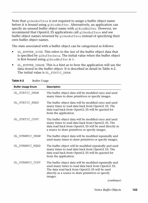
Vertex Buffer Objects 143
Note that glGenBuffers is not required to assign a buffer object name before it is bound using glBindBuffer. Alternatively, an application can specify an unused buffer object name with glBindBuffer. However, we recommend that OpenGL ES applications call glGenBuffers and use buffer object names returned by glGenBuffers instead of specifying their own buffer object names.
The state associated with a buffer object can be categorized as follows:
• GL_BUFFER_SIZE. This refers to the size of the buffer object data thatis specified by glBufferData. The initial value when the buffer objectis first bound using glBindBuffer is 0.
• GL_BUFFER_USAGE. This is a hint as to how the application will use thedata stored in the buffer object. It is described in detail in Table 6-2.The initial value is GL_STATIC_DRAW.
Table 6-2 Buffer Usage
Buffer Usage Enum Description
GL_STATIC_DRAW The buffer object data will be modified once and used many times to draw primitives or specify images.
GL_STATIC_READ The buffer object data will be modified once and used many times to read data back from OpenGL ES. The data read back from OpenGL ES will be queried for from the application.
GL_STATIC_COPY The buffer object data will be modified once and used many times to read data back from OpenGL ES. The data read back from OpenGL ES will be used directly as a source to draw primitives or specify images.
GL_DYNAMIC_DRAW The buffer object data will be modified repeatedly and used many times to draw primitives or specify images.
GL_DYNAMIC_READ The buffer object will be modified repeatedly and used many times to read data back from OpenGL ES. The data read back from OpenGL ES will be queried for from the application.
GL_DYNAMIC_COPY The buffer object data will be modified repeatedly and used many times to read data back from OpenGL ES. The data read back from OpenGL ES will be used directly as a source to draw primitives or specify images.
(continues)

144 Chapter 6: Vertex Attributes, Vertex Arrays, and Buffer Objects
As mentioned earlier, GL_BUFFER_USAGE is a hint to OpenGL ES—not a guarantee. Therefore, an application could allocate a buffer object data store with usage set to GL_STATIC_DRAW and frequently modify it.
The vertex array data or element array data storage is created and initialized using the glBufferData command.
Buffer Usage Enum Description
GL_STREAM_DRAW The buffer object data will be modified once and used only a few times to draw primitives or specify images.
GL_STREAM_READ The buffer object data will be modified once and used only a few times to read data back from OpenGL ES. The data read back from OpenGL ES will be queried for from the application.
GL_STREAM_COPY The buffer object data will be modified once and used only a few times to read data back from OpenGL ES. The data read back from OpenGL ES will be used directly as a source to draw primitives or specify images.
Table 6-2 Buffer Usage (continued)
void glBufferData(GLenum target, GLsizeiptr size,const void *data, GLenum usage)
target can be set to any of the following targets:GL_ARRAY_BUFFERGL_ELEMENT_ARRAY_BUFFERGL_COPY_READ_BUFFERGL_COPY_WRITE_BUFFERGL_PIXEL_PACK_BUFFERGL_PIXEL_UNPACK_BUFFERGL_TRANSFORM_FEEDBACK_BUFFERGL_UNIFORM_BUFFER
size size of buffer data store in bytesdata pointer to the buffer data supplied by the applicationusage a hint on how the application will use the data stored in
the buffer object (refer to Table 6-2 for details)
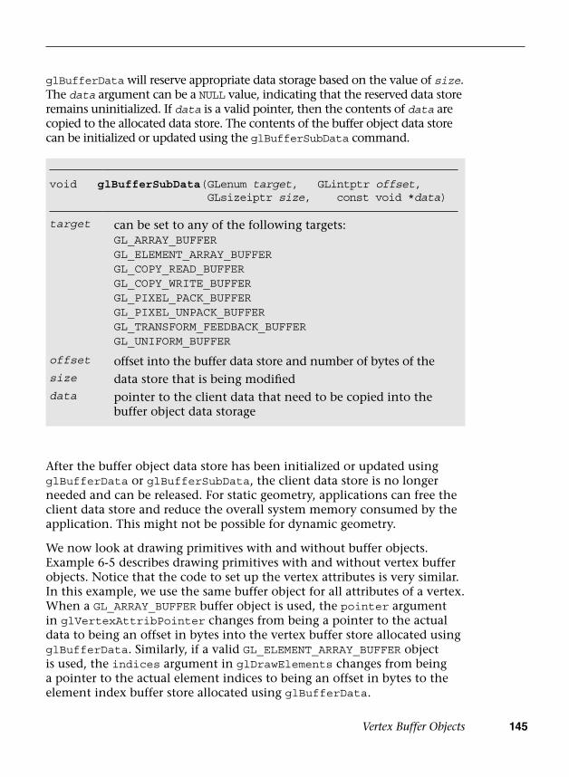
Vertex Buffer Objects 145
glBufferData will reserve appropriate data storage based on the value of size. The data argument can be a NULL value, indicating that the reserved data store remains uninitialized. If data is a valid pointer, then the contents of data are copied to the allocated data store. The contents of the buffer object data store can be initialized or updated using the glBufferSubData command.
void glBufferSubData( GLenum target, GLintptr offset, GLsizeiptr size, const void *data)
target can be set to any of the following targets:GL_ARRAY_BUFFERGL_ELEMENT_ARRAY_BUFFERGL_COPY_READ_BUFFERGL_COPY_WRITE_BUFFERGL_PIXEL_PACK_BUFFERGL_PIXEL_UNPACK_BUFFERGL_TRANSFORM_FEEDBACK_BUFFERGL_UNIFORM_BUFFER
offset offset into the buffer data store and number of bytes of thesize data store that is being modifieddata pointer to the client data that need to be copied into the
buffer object data storage
After the buffer object data store has been initialized or updated using glBufferData or glBufferSubData, the client data store is no longer needed and can be released. For static geometry, applications can free the client data store and reduce the overall system memory consumed by the application. This might not be possible for dynamic geometry.
We now look at drawing primitives with and without buffer objects. Example 6-5 describes drawing primitives with and without vertex buffer objects. Notice that the code to set up the vertex attributes is very similar. In this example, we use the same buffer object for all attributes of a vertex. When a GL_ARRAY_BUFFER buffer object is used, the pointer argument in glVertexAttribPointer changes from being a pointer to the actual data to being an offset in bytes into the vertex buffer store allocated using glBufferData. Similarly, if a valid GL_ELEMENT_ARRAY_BUFFER object is used, the indices argument in glDrawElements changes from being a pointer to the actual element indices to being an offset in bytes to the element index buffer store allocated using glBufferData.

146 Chapter 6: Vertex Attributes, Vertex Arrays, and Buffer Objects
Example 6-5 Drawing with and without Vertex Buffer Objects
#define VERTEX_POS_SIZE 3 // x, y, and z#define VERTEX_COLOR_SIZE 4 // r, g, b, and a
#define VERTEX_POS_INDX 0#define VERTEX_COLOR_INDX 1//// vertices - pointer to a buffer that contains vertex// attribute data// vtxStride - stride of attribute data / vertex in bytes// numIndices - number of indices that make up primitives// drawn as triangles// indices - pointer to element index buffer//void DrawPrimitiveWithoutVBOs(GLfloat *vertices,
GLint vtxStride,GLint numIndices,GLushort *indices)
{ GLfloat *vtxBuf = vertices;
glBindBuffer(GL_ARRAY_BUFFER, 0); glBindBuffer(GL_ELEMENT_ARRAY_BUFFER, 0);
glEnableVertexAttribArray(VERTEX_POS_INDX); glEnableVertexAttribArray(VERTEX_COLOR_INDX);
glVertexAttribPointer(VERTEX_POS_INDX, VERTEX_POS_SIZE,GL_FLOAT, GL_FALSE, vtxStride,vtxBuf);
vtxBuf += VERTEX_POS_SIZE;
glVertexAttribPointer(VERTEX_COLOR_INDX,VERTEX_COLOR_SIZE, GL_FLOAT,GL_FALSE, vtxStride, vtxBuf);
glDrawElements(GL_TRIANGLES, numIndices, GL_UNSIGNED_SHORT,indices);
glDisableVertexAttribArray(VERTEX_POS_INDX); glDisableVertexAttribArray(VERTEX_COLOR_INDX);
}
void DrawPrimitiveWithVBOs(ESContext *esContext,GLint numVertices, GLfloat *vtxBuf,GLint vtxStride, GLint numIndices,GLushort *indices)
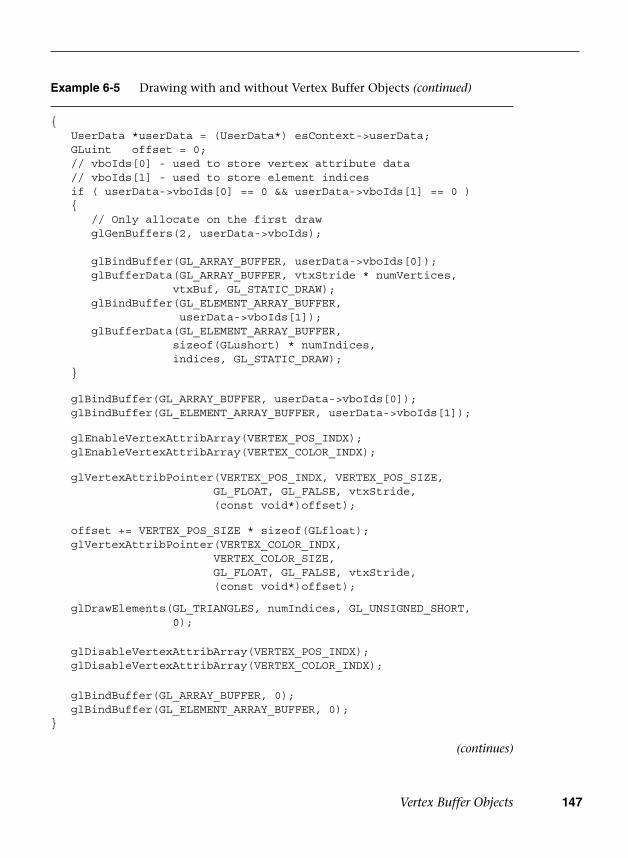
Vertex Buffer Objects 147
Example 6-5 Drawing with and without Vertex Buffer Objects (continued)
{ UserData *userData = (UserData*) esContext->userData; GLuint offset = 0; // vboIds[0] - used to store vertex attribute data // vboIds[l] - used to store element indices if ( userData->vboIds[0] == 0 && userData->vboIds[1] == 0 ) {
// Only allocate on the first drawglGenBuffers(2, userData->vboIds);
glBindBuffer(GL_ARRAY_BUFFER, userData->vboIds[0]);glBufferData(GL_ARRAY_BUFFER, vtxStride * numVertices,
vtxBuf, GL_STATIC_DRAW);glBindBuffer(GL_ELEMENT_ARRAY_BUFFER,
userData->vboIds[1]);glBufferData(GL_ELEMENT_ARRAY_BUFFER,
sizeof(GLushort) * numIndices,indices, GL_STATIC_DRAW);
}
glBindBuffer(GL_ARRAY_BUFFER, userData->vboIds[0]); glBindBuffer(GL_ELEMENT_ARRAY_BUFFER, userData->vboIds[1]);
glEnableVertexAttribArray(VERTEX_POS_INDX); glEnableVertexAttribArray(VERTEX_COLOR_INDX);
glVertexAttribPointer(VERTEX_POS_INDX, VERTEX_POS_SIZE,GL_FLOAT, GL_FALSE, vtxStride,(const void*)offset);
offset += VERTEX_POS_SIZE * sizeof(GLfloat); glVertexAttribPointer(VERTEX_COLOR_INDX,
VERTEX_COLOR_SIZE,GL_FLOAT, GL_FALSE, vtxStride,(const void*)offset);
glDrawElements(GL_TRIANGLES, numIndices, GL_UNSIGNED_SHORT,0);
glDisableVertexAttribArray(VERTEX_POS_INDX); glDisableVertexAttribArray(VERTEX_COLOR_INDX);
glBindBuffer(GL_ARRAY_BUFFER, 0); glBindBuffer(GL_ELEMENT_ARRAY_BUFFER, 0);}
(continues)

148 Chapter 6: Vertex Attributes, Vertex Arrays, and Buffer Objects
Example 6-5 Drawing with and without Vertex Buffer Objects (continued)
void Draw ( ESContext *esContext ){ UserData *userData = (UserData*) esContext->userData;
// 3 vertices, with (x, y, z),(r, g, b, a) per-vertex GLfloat vertices[3 * (VERTEX_POS_SIZE + VERTEX_COLOR_SIZE)] = {
-0.5f, 0.5f, 0.0f, // v01.0f, 0.0f, 0.0f, 1.0f, // c0
-1.0f, -0.5f, 0.0f, // v10.0f, 1.0f, 0.0f, 1.0f, // c10.0f, -0.5f, 0.0f, // v20.0f, 0.0f, 1.0f, 1.0f, // c2
}; // index buffer data GLushort indices[3] = { 0, 1, 2 };
glViewport ( 0, 0, esContext->width, esContext->height ); glClear ( GL_COLOR_BUFFER_BIT ); glUseProgram ( userData->programObject ); glUniform1f ( userData->offsetLoc, 0.0f );
DrawPrimitiveWithoutVBOs ( vertices,sizeof(GLfloat) * (VERTEX_POS_SIZE + VERTEX_COLOR_SIZE),3, indices );
// offset the vertex positions so both can be seen glUniform1f ( userData->offsetLoc, 1.0f );
DrawPrimitiveWithVBOs ( esContext, 3, vertices,sizeof(GLfloat) * (VERTEX_POS_SIZE + VERTEX_COLOR_SIZE),3, indices );
}
In Example 6-5, we used one buffer object to store all the vertex data. This demonstrates the array of structures method of storing vertex attributes described in Example 6-1. It is also possible to have a buffer object for each vertex attribute—that is, the structure of arrays method of storing vertex attributes described in Example 6-2. Example 6-6 illustrates how drawPrimitiveWithVBOs would look with a separate buffer object for each vertex attribute.
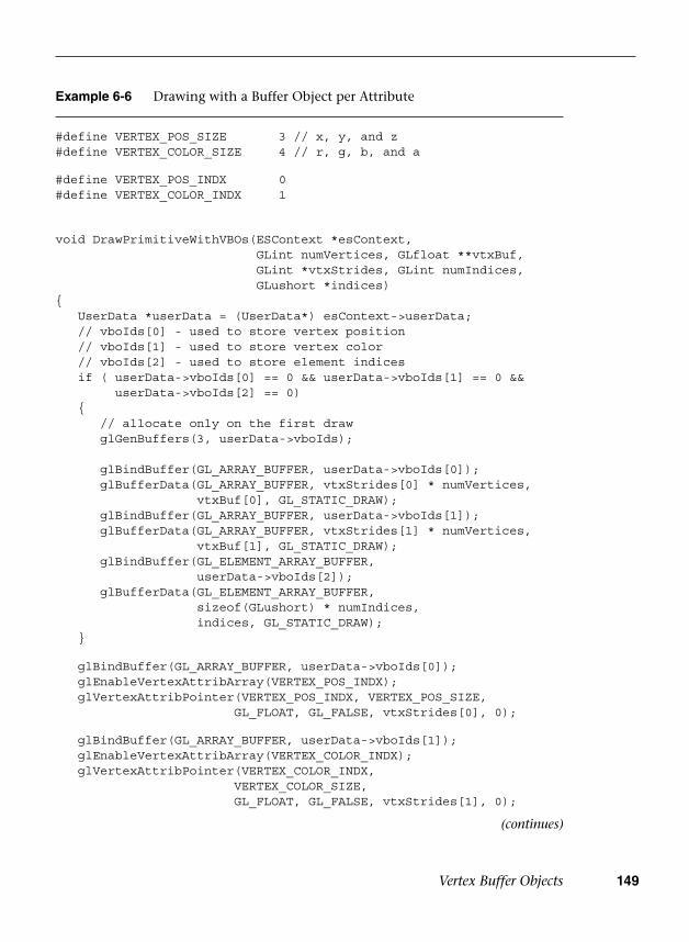
Vertex Buffer Objects 149
Example 6-6 Drawing with a Buffer Object per Attribute
#define VERTEX_POS_SIZE 3 // x, y, and z#define VERTEX_COLOR_SIZE 4 // r, g, b, and a
#define VERTEX_POS_INDX 0#define VERTEX_COLOR_INDX 1
void DrawPrimitiveWithVBOs(ESContext *esContext,GLint numVertices, GLfloat **vtxBuf,GLint *vtxStrides, GLint numIndices,GLushort *indices)
{ UserData *userData = (UserData*) esContext->userData; // vboIds[0] - used to store vertex position // vboIds[1] - used to store vertex color // vboIds[2] - used to store element indices if ( userData->vboIds[0] == 0 && userData->vboIds[1] == 0 &&
userData->vboIds[2] == 0) {
// allocate only on the first drawglGenBuffers(3, userData->vboIds);
glBindBuffer(GL_ARRAY_BUFFER, userData->vboIds[0]);glBufferData(GL_ARRAY_BUFFER, vtxStrides[0] * numVertices,
vtxBuf[0], GL_STATIC_DRAW);glBindBuffer(GL_ARRAY_BUFFER, userData->vboIds[1]);glBufferData(GL_ARRAY_BUFFER, vtxStrides[1] * numVertices,
vtxBuf[1], GL_STATIC_DRAW);glBindBuffer(GL_ELEMENT_ARRAY_BUFFER,
userData->vboIds[2]);glBufferData(GL_ELEMENT_ARRAY_BUFFER,
sizeof(GLushort) * numIndices,indices, GL_STATIC_DRAW);
}
glBindBuffer(GL_ARRAY_BUFFER, userData->vboIds[0]); glEnableVertexAttribArray(VERTEX_POS_INDX); glVertexAttribPointer(VERTEX_POS_INDX, VERTEX_POS_SIZE,
GL_FLOAT, GL_FALSE, vtxStrides[0], 0);
glBindBuffer(GL_ARRAY_BUFFER, userData->vboIds[1]); glEnableVertexAttribArray(VERTEX_COLOR_INDX); glVertexAttribPointer(VERTEX_COLOR_INDX,
VERTEX_COLOR_SIZE,GL_FLOAT, GL_FALSE, vtxStrides[1], 0);
(continues)

150 Chapter 6: Vertex Attributes, Vertex Arrays, and Buffer Objects
After the application has finished using the buffer objects, they can be deleted using the glDeleteBuffers command.
glDeleteBuffers deletes the buffer objects specified in buffers. Once a buffer object has been deleted, it can be reused as a new buffer object that stores vertex attributes or element indices for a different primitive.
As you can see from these examples, using vertex buffer objects is very easy and requires very little extra work to implement over vertex arrays. The minimal extra work involved in supporting vertex buffer objects is well worth it, considering the performance gain this feature provides. In the next chapter, we discuss how to draw primitives using commands such as glDrawArrays and glDrawElements, and how the primitive assembly and rasterization pipeline stages in OpenGL ES 3.0 work.
Vertex Array Objects
So far, we have covered how to load vertex attributes in two different ways: using client vertex arrays and using vertex buffer objects. Vertex buffer objects are preferred to client vertex arrays because they can reduce the amount of data copied between the CPU and GPU and, therefore, have better performance. In OpenGL ES 3.0, a new feature was introduced
void glDeleteBuffers(GLsizei n, const GLuint *buffers)
n number of buffer objects to be deletedbuffers array of n entries that contain the buffer objects to be deleted
Example 6-6 Drawing with a Buffer Object per Attribute (continued)
glBindBuffer(GL_ELEMENT_ARRAY_BUFFER, userData->vboIds[2]);
glDrawElements(GL_TRIANGLES, numIndices,GL_UNSIGNED_SHORT, 0);
glDisableVertexAttribArray(VERTEX_POS_INDX); glDisableVertexAttribArray(VERTEX_COLOR_INDX);
glBindBuffer(GL_ARRAY_BUFFER, 0); glBindBuffer(GL_ELEMENT_ARRAY_BUFFER, 0); }

Vertex Array Objects 151
to make using vertex arrays even more efficient: vertex array objects (VAOs). As we have seen, setting up drawing using vertex buffer objects can require many calls to glBindBuffer, glVertexAttribPointer, and glEnableVertexAttribArray. To make it faster to switch between vertex array configurations, OpenGL ES 3.0 introduced vertex array objects. VAOs provide a single object that contains all of the state required to switch between vertex array/vertex buffer object configurations.
In fact, there is always a vertex array object that is active in OpenGL ES 3.0. All of the examples so far in this chapter have operated on the default vertex array object (the default VAO has the ID of 0). To create a new vertex array object, you use the glGenVertexArrays function.
void glGenVertexArrays(GLsizei n, GLuint *arrays)
n number of vertex array object names to returnarrays pointer to an array of n entries, where allocated vertex
array objects are returned
void glBindVertexArray(GLuint array)
array object to be assigned as the current vertex array object
Once created, the vertex array object can be bound for use using glBindVertexArray.
Each VAO contains a full state vector that describes all of the vertex buffer bindings and vertex client state enables. When the VAO is bound, its state vector provides the current settings of the vertex buffer state. After binding the vertex array object using glBindVertexArray, subsequent calls that change the vertex array state (glBindBuffer, glVertexAttribPointer, glEnableVertexAttribArray, and glDisableVertexAttribArray) will affect the new VAO.
In this way, an application can quickly switch between vertex array configurations by binding a vertex array object that has been set with state. Rather than having to make many calls to change the vertex array state, all of the changes can be made in a single function call. Example 6-7 demonstrates the use of a vertex array object at initialization time to set up the vertex array state. The vertex array state is then set in a single function call at draw time using glBindVertexArray.
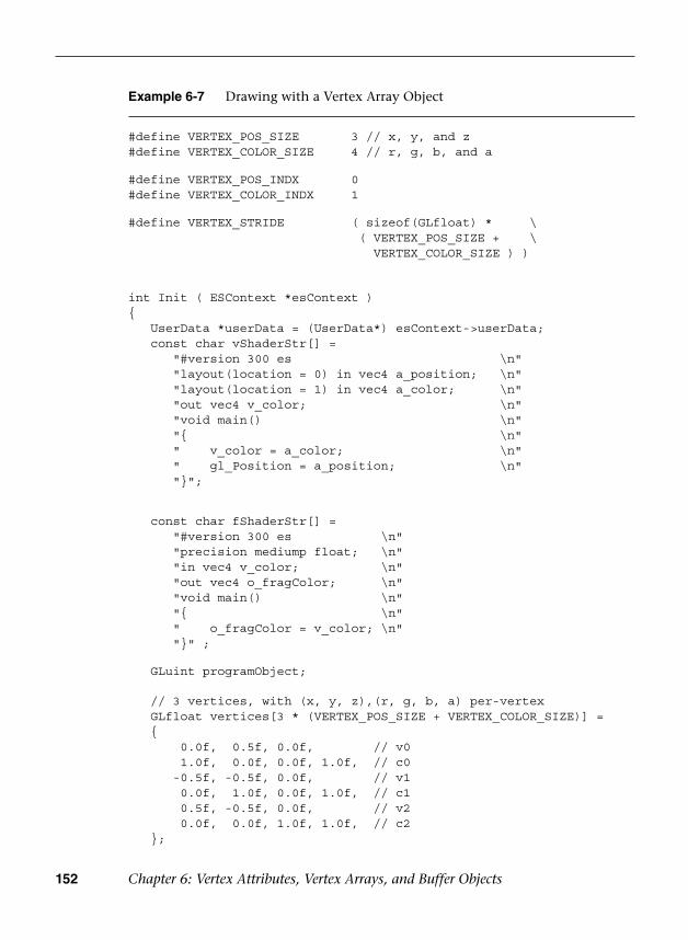
152 Chapter 6: Vertex Attributes, Vertex Arrays, and Buffer Objects
Example 6-7 Drawing with a Vertex Array Object
#define VERTEX_POS_SIZE 3 // x, y, and z#define VERTEX_COLOR_SIZE 4 // r, g, b, and a
#define VERTEX_POS_INDX 0#define VERTEX_COLOR_INDX 1
#define VERTEX_STRIDE ( sizeof(GLfloat) * \( VERTEX_POS_SIZE + \
VERTEX_COLOR_SIZE ) )
int Init ( ESContext *esContext ){ UserData *userData = (UserData*) esContext->userData; const char vShaderStr[] =
"#version 300 es \n""layout(location = 0) in vec4 a_position; \n""layout(location = 1) in vec4 a_color; \n""out vec4 v_color; \n""void main() \n""{ \n"" v_color = a_color; \n"" gl_Position = a_position; \n""}";
const char fShaderStr[] ="#version 300 es \n""precision mediump float; \n""in vec4 v_color; \n""out vec4 o_fragColor; \n""void main() \n""{ \n"" o_fragColor = v_color; \n""}" ;
GLuint programObject;
// 3 vertices, with (x, y, z),(r, g, b, a) per-vertex GLfloat vertices[3 * (VERTEX_POS_SIZE + VERTEX_COLOR_SIZE)] = {
0.0f, 0.5f, 0.0f, // v01.0f, 0.0f, 0.0f, 1.0f, // c0
-0.5f, -0.5f, 0.0f, // v10.0f, 1.0f, 0.0f, 1.0f, // c10.5f, -0.5f, 0.0f, // v20.0f, 0.0f, 1.0f, 1.0f, // c2
};

Vertex Array Objects 153
Example 6-7 Drawing with a Vertex Array Object (continued)
// Index buffer data GLushort indices[3] = { 0, 1, 2 };
// Create the program object programObject = esLoadProgram ( vShaderStr, fShaderStr );
if ( programObject == 0 )return GL_FALSE;
// Store the program object userData->programObject = programObject;
// Generate VBO Ids and load the VBOs with data glGenBuffers ( 2, userData->vboIds );
glBindBuffer ( GL_ARRAY_BUFFER, userData->vboIds[0] ); glBufferData ( GL_ARRAY_BUFFER, sizeof(vertices),
vertices, GL_STATIC_DRAW); glBindBuffer ( GL_ELEMENT_ARRAY_BUFFER, userData->vboIds[1]); glBufferData ( GL_ELEMENT_ARRAY_BUFFER, sizeof ( indices ),
indices, GL_STATIC_DRAW );
// Generate VAO ID glGenVertexArrays ( 1, &userData->vaoId );
// Bind the VAO and then set up the vertex // attributes glBindVertexArray ( userData->vaoId );
glBindBuffer(GL_ARRAY_BUFFER, userData->vboIds[0]); glBindBuffer(GL_ELEMENT_ARRAY_BUFFER, userData->vboIds[1]);
glEnableVertexAttribArray(VERTEX_POS_INDX); glEnableVertexAttribArray(VERTEX_COLOR_INDX);
glVertexAttribPointer ( VERTEX_POS_INDX, VERTEX_POS_SIZE,GL_FLOAT, GL_FALSE, VERTEX_STRIDE, (const void*) 0 );
glVertexAttribPointer ( VERTEX_COLOR_INDX, VERTEX_COLOR_SIZE,GL_FLOAT, GL_FALSE, VERTEX_STRIDE,(const void*) ( VERTEX_POS_SIZE * sizeof(GLfloat) ) );
// Reset to the default VAO glBindVertexArray ( 0 );
glClearColor ( 0.0f, 0.0f, 0.0f, 0.0f ); return GL_TRUE;}
(continues)
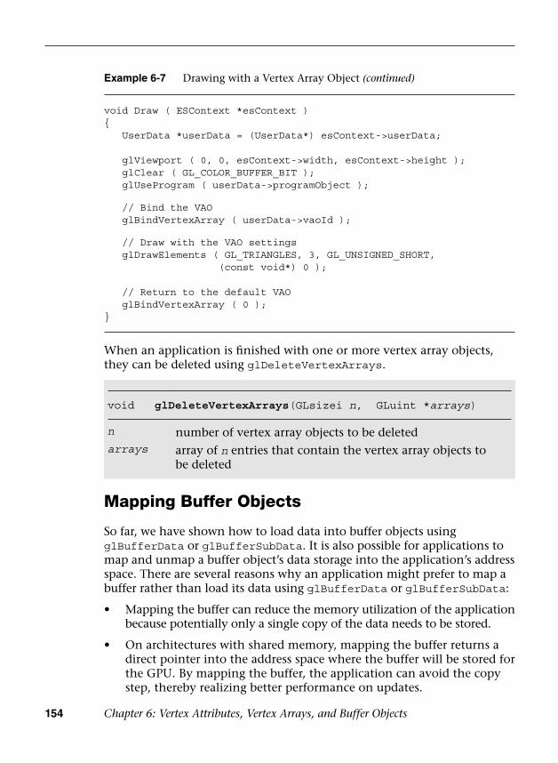
154 Chapter 6: Vertex Attributes, Vertex Arrays, and Buffer Objects
void glDeleteVertexArrays(GLsizei n, GLuint *arrays)
n number of vertex array objects to be deletedarrays array of n entries that contain the vertex array objects to
be deleted
When an application is finished with one or more vertex array objects, they can be deleted using glDeleteVertexArrays.
Example 6-7 Drawing with a Vertex Array Object (continued)
void Draw ( ESContext *esContext ){ UserData *userData = (UserData*) esContext->userData;
glViewport ( 0, 0, esContext->width, esContext->height ); glClear ( GL_COLOR_BUFFER_BIT ); glUseProgram ( userData->programObject );
// Bind the VAO glBindVertexArray ( userData->vaoId );
// Draw with the VAO settings glDrawElements ( GL_TRIANGLES, 3, GL_UNSIGNED_SHORT,
(const void*) 0 );
// Return to the default VAO glBindVertexArray ( 0 );}
Mapping Buffer Objects
So far, we have shown how to load data into buffer objects using glBufferData or glBufferSubData. It is also possible for applications to map and unmap a buffer object’s data storage into the application’s address space. There are several reasons why an application might prefer to map a buffer rather than load its data using glBufferData or glBufferSubData:
• Mapping the buffer can reduce the memory utilization of the applicationbecause potentially only a single copy of the data needs to be stored.
• On architectures with shared memory, mapping the buffer returns adirect pointer into the address space where the buffer will be stored forthe GPU. By mapping the buffer, the application can avoid the copystep, thereby realizing better performance on updates.
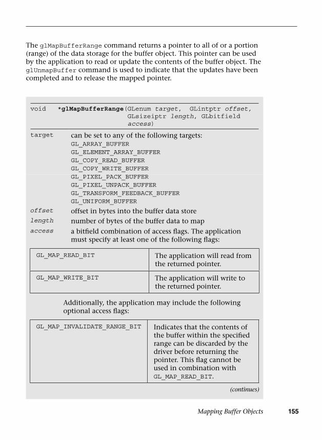
Mapping Buffer Objects 155
void *glMapBufferRange( GLenum target, GLintptr offset,GLsizeiptr length, GLbitfield access)
target can be set to any of the following targets:GL_ARRAY_BUFFERGL_ELEMENT_ARRAY_BUFFERGL_COPY_READ_BUFFERGL_COPY_WRITE_BUFFER
GL_MAP_READ_BIT The application will read from the returned pointer.
GL_MAP_WRITE_BIT The application will write to the returned pointer.
Additionally, the application may include the following optional access flags:
GL_MAP_INVALIDATE_RANGE_BIT Indicates that the contents of the buffer within the specified range can be discarded by the driver before returning the pointer. This flag cannot be used in combination with GL_MAP_READ_BIT.
GL_PIXEL_PACK_BUFFERGL_PIXEL_UNPACK_BUFFERGL_TRANSFORM_FEEDBACK_BUFFERGL_UNIFORM_BUFFER
offset offset in bytes into the buffer data storelength number of bytes of the buffer data to mapaccess a bitfield combination of access flags. The application
must specify at least one of the following flags:
The glMapBufferRange command returns a pointer to all of or a portion (range) of the data storage for the buffer object. This pointer can be used by the application to read or update the contents of the buffer object. The glUnmapBuffer command is used to indicate that the updates have been completed and to release the mapped pointer.
(continues)
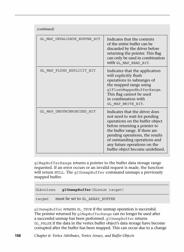
156 Chapter 6: Vertex Attributes, Vertex Arrays, and Buffer Objects
GL_MAP_INVALIDATE_BUFFER_BIT Indicates that the contents of the entire buffer can be discarded by the driver before returning the pointer. This flag can only be used in combination with GL_MAP_READ_BIT.
GL_MAP_FLUSH_EXPLICIT_BIT Indicates that the application will explicitly flush operations to subranges of the mapped range using glFlushMappedBufferRange. This flag cannot be used in combination with GL_MAP_WRITE_BIT.
GL_MAP_UNSYNCHRONIZED_BIT Indicates that the driver does not need to wait for pending operations on the buffer object before returning a pointer to the buffer range. If there are pending operations, the results of outstanding operations and any future operations on the buffer object become undefined.
GLboolean glUnmapBuffer(GLenum target)
target must be set to GL_ARRAY_BUFFER
glMapBufferRange returns a pointer to the buffer data storage range requested. If an error occurs or an invalid request is made, the function will return NULL. The glUnmapBuffer command unmaps a previously mapped buffer.
glUnmapBuffer returns GL_TRUE if the unmap operation is successful. The pointer returned by glMapBufferRange can no longer be used after a successful unmap has been performed. glUnmapBuffer returns GL_FALSE if the data in the vertex buffer object’s data storage have become corrupted after the buffer has been mapped. This can occur due to a change
(continued)
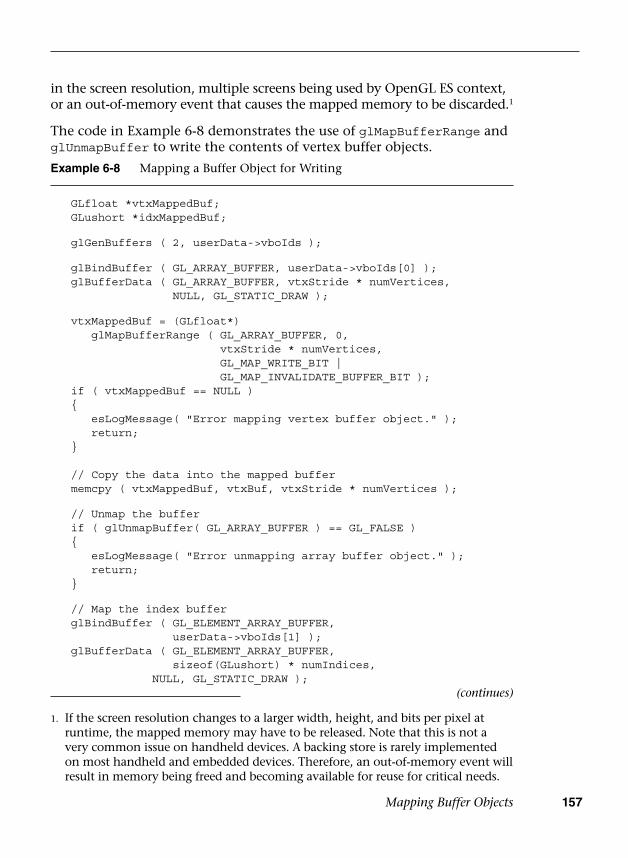
Mapping Buffer Objects 157
Example 6-8 Mapping a Buffer Object for Writing
GLfloat *vtxMappedBuf; GLushort *idxMappedBuf;
glGenBuffers ( 2, userData->vboIds );
glBindBuffer ( GL_ARRAY_BUFFER, userData->vboIds[0] ); glBufferData ( GL_ARRAY_BUFFER, vtxStride * numVertices,
NULL, GL_STATIC_DRAW );
vtxMappedBuf = (GLfloat*)glMapBufferRange ( GL_ARRAY_BUFFER, 0,
vtxStride * numVertices,GL_MAP_WRITE_BIT |GL_MAP_INVALIDATE_BUFFER_BIT );
if ( vtxMappedBuf == NULL ) {
esLogMessage( "Error mapping vertex buffer object." );return;
}
// Copy the data into the mapped buffer memcpy ( vtxMappedBuf, vtxBuf, vtxStride * numVertices );
// Unmap the buffer if ( glUnmapBuffer( GL_ARRAY_BUFFER ) == GL_FALSE ) {
esLogMessage( "Error unmapping array buffer object." );return;
}
// Map the index buffer glBindBuffer ( GL_ELEMENT_ARRAY_BUFFER,
userData->vboIds[1] ); glBufferData ( GL_ELEMENT_ARRAY_BUFFER,
sizeof(GLushort) * numIndices,NULL, GL_STATIC_DRAW );
in the screen resolution, multiple screens being used by OpenGL ES context, or an out-of-memory event that causes the mapped memory to be discarded.1
The code in Example 6-8 demonstrates the use of glMapBufferRange and glUnmapBuffer to write the contents of vertex buffer objects.
1. If the screen resolution changes to a larger width, height, and bits per pixel atruntime, the mapped memory may have to be released. Note that this is not avery common issue on handheld devices. A backing store is rarely implementedon most handheld and embedded devices. Therefore, an out-of-memory event willresult in memory being freed and becoming available for reuse for critical needs.
(continues)
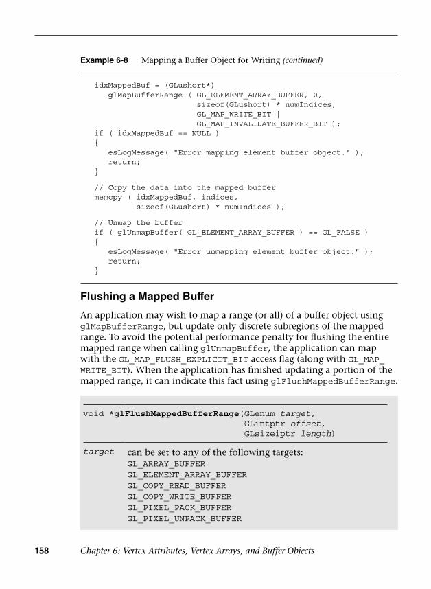
158 Chapter 6: Vertex Attributes, Vertex Arrays, and Buffer Objects
Flushing a Mapped Buffer
An application may wish to map a range (or all) of a buffer object using glMapBufferRange, but update only discrete subregions of the mapped range. To avoid the potential performance penalty for flushing the entire mapped range when calling glUnmapBuffer, the application can map with the GL_MAP_FLUSH_EXPLICIT_BIT access flag (along with GL_MAP_WRITE_BIT). When the application has finished updating a portion of the mapped range, it can indicate this fact using glFlushMappedBufferRange.
Example 6-8 Mapping a Buffer Object for Writing (continued)
idxMappedBuf = (GLushort*)glMapBufferRange ( GL_ELEMENT_ARRAY_BUFFER, 0,
sizeof(GLushort) * numIndices,GL_MAP_WRITE_BIT |GL_MAP_INVALIDATE_BUFFER_BIT );
if ( idxMappedBuf == NULL ) {
esLogMessage( "Error mapping element buffer object." );return;
}
// Copy the data into the mapped buffer memcpy ( idxMappedBuf, indices,
sizeof(GLushort) * numIndices );
// Unmap the buffer if ( glUnmapBuffer( GL_ELEMENT_ARRAY_BUFFER ) == GL_FALSE ) {
esLogMessage( "Error unmapping element buffer object." );return;
}
void *glFlushMappedBufferRange( GLenum target, GLintptr offset, GLsizeiptr length)
target can be set to any of the following targets:GL_ARRAY_BUFFERGL_ELEMENT_ARRAY_BUFFERGL_COPY_READ_BUFFERGL_COPY_WRITE_BUFFERGL_PIXEL_PACK_BUFFERGL_PIXEL_UNPACK_BUFFER
Copying Buffer Objects 159
If an application maps with GL_MAP_FLUSH_EXPLICIT_BIT but does not explicitly flush a modified region with glFlushMappedBufferRange, its contents will be undefined.
Copying Buffer Objects
So far, we have shown how to load buffer objects with data using glBufferData, glBufferSubData, and glMapBufferRange. All of these techniques involve transferring data from the application to the device. It is also possible with OpenGL ES 3.0 to copy data from one buffer object to another entirely on the device. This can be done using the function glCopyBufferSubData.
GL_TRANSFORM_FEEDBACK_BUFFERGL_UNIFORM_BUFFER
offset offset in bytes from the beginning of the mapped bufferlength number of bytes of the buffer from offset to flush
void glCopyBufferSubData( GLenum readtarget, GLenum writetarget, GLintptr readoffset, GLintptr writeoffset, GLsizeiptr size)
readtarget the buffer object target to read from.writetarget the buffer object target to write to. Both readtarget
and writetarget can be set to any of the following targets (although they must not be the same target):GL_ARRAY_BUFFERGL_ELEMENT_ARRAY_BUFFERGL_COPY_READ_BUFFERGL_COPY_WRITE_BUFFERGL_PIXEL_PACK_BUFFERGL_PIXEL_UNPACK_BUFFERGL_TRANSFORM_FEEDBACK_BUFFERGL_UNIFORM_BUFFER
(continues)
160 Chapter 6: Vertex Attributes, Vertex Arrays, and Buffer Objects
Calling glCopyBufferSubData will copy the specified bytes from the buffer bound to the readtarget to the writetarget. The buffer binding is determined based on the last call to glBindBuffer for each target. Any type of buffer object (array, element array, transform feedback, and so on) can be bound to the GL_COPY_READ_BUFFER or GL_COPY_WRITE_BUFFER target. These two targets are provided as a convenience so that the application doesn’t have to change any of the true buffer bindings to perform a copy between buffers.
Summary
This chapter explored how vertex attributes and data are specified in OpenGL ES 3.0. Specifically, it covered the following topics:
• How to specify constant vertex attributes using the glVertexAttrib*functions and vertex arrays using the glVertexAttrib[I]Pointerfunctions
• How to create and store vertex attribute and element data in vertexbuffer objects
• How vertex array state is encapsulated in vertex array objects and howto use VAOs to improve performance
• The variety of methods for loading buffer objects with data:glBuffer[Sub]Data, glMapBufferRange, and glCopyBufferSubData
Now that we know how vertex data are specified, the next chapter covers all of the primitives that can be drawn in OpenGL ES using vertex data.
readoffset offset in bytes into the read buffer data to copy from.writeoffset offset in bytes into the write buffer data to copy to.size the number of bytes to copy from the read buffer
data to the write buffer data.
(continued)
161
Chapter 7
Primitive Assembly and Rasterization
This chapter describes the types of primitives and geometric objects that are supported by OpenGL ES, and explains how to draw them. It then describes the primitive assembly stage, which occurs after the vertices of a primitive are processed by the vertex shader. In the primitive assembly stage, clipping, perspective divide, and viewport transformation operations are performed. These operations are discussed in detail. The chapter concludes with a description of the rasterization stage. Rasterization is the process that converts primitives into a set of two-dimensional fragments, which are processed by the fragment shader. These two-dimensional fragments represent pixels that may be drawn on the screen.
Refer to Chapter 8, “Vertex Shaders,” for a detailed description of vertex shaders. Chapter 9, “Texturing,” and Chapter 10, “Fragment Shaders,” describe processing that is applied to fragments generated by the rasterization stage.
Primitives
A primitive is a geometric object that can be drawn using the glDrawArrays, glDrawElements, glDrawRangeElements, glDrawArraysInstanced, and glDrawElementsInstanced commands in OpenGL ES. The primitive is described by a set of vertices that indicate the vertex position. Other information, such as color, texture coordinates, and geometric normal can also be associated with each vertex as generic attributes.
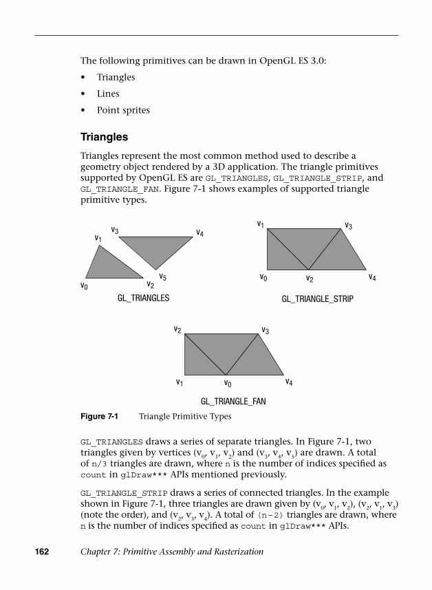
162 Chapter 7: Primitive Assembly and Rasterization
The following primitives can be drawn in OpenGL ES 3.0:
• Triangles
• Lines
• Point sprites
Triangles
Triangles represent the most common method used to describe a geometry object rendered by a 3D application. The triangle primitives supported by OpenGL ES are GL_TRIANGLES, GL_TRIANGLE_STRIP, and GL_TRIANGLE_FAN. Figure 7-1 shows examples of supported triangle primitive types.
GL_TRIANGLES draws a series of separate triangles. In Figure 7-1, two triangles given by vertices (v0, v1, v2) and (v3, v4, v5) are drawn. A total of n/3 triangles are drawn, where n is the number of indices specified as count in glDraw*** APIs mentioned previously.
GL_TRIANGLE_STRIP draws a series of connected triangles. In the example shown in Figure 7-1, three triangles are drawn given by (v0, v1, v2), (v2, v1, v3) (note the order), and (v2, v3, v4). A total of (n – 2) triangles are drawn, where n is the number of indices specified as count in glDraw*** APIs.
GL_TRIANGLE_FAN
GL_TRIANGLES GL_TRIANGLE_STRIP
v0
v1
v2
v3 v4
v5 v0
v1
v2
v3
v4
v2
v1 v0
v3
v4
Figure 7-1 Triangle Primitive Types

Primitives 163
GL_TRIANGLE_FAN also draws a series of connected triangles. In the example shown in Figure 7-1, the triangles drawn are (v0, v1, v2), (v0, v2, v3), and (v0, v3, v4). A total of (n – 2) triangles are drawn, where n is the number of indices specified as count in glDraw*** APIs.
Lines
The line primitives supported by OpenGL ES are GL_LINES, GL_LINE_STRIP, and GL_LINE_LOOP. Figure 7-2 shows examples of supported line primitive types.
GL_LINES
v5
v2
v3
v0
v1
v4
v0 v4
v3v1
v2
GL_LINE_LOOP
v0
v2
v1v3
GL_LINE_STRIP
Figure 7-2 Line Primitive Types
GL_LINES draws a series of unconnected line segments. In the example shown in Figure 7-2, three individual lines are drawn given by (v0, v1), (v2, v3), and (v4, v5). A total of n/2 segments are drawn, where n is the number of indices specified as count in glDraw*** APIs.
GL_LINE_STRIP draws a series of connected line segments. In the example shown in Figure 7-2, three line segments are drawn given by (v0, v1), (vl, v2), and (v2, v3). A total of (n – 1) line segments are drawn, where n is the number of indices specified as count in glDraw*** APIs.
GL_LINE_LOOP works similar to GL_LINE_STRIP, except that a final line segment is drawn from v
n–1 to v0. In the example shown in Figure 7-2,
the line segments drawn are (v0, v1), (v1, v2), (v2, v3), (v3, v4), and (v4, v0). A total of n line segments are drawn, where n is the number of indices specified as count in glDraw*** APIs.

164 Chapter 7: Primitive Assembly and Rasterization
The width specified by glLineWidth will be clamped to the line width range supported by the OpenGL ES 3.0 implementation. In addition, the width specified will be remembered by OpenGL until updated by the application. The supported line width range can be queried using the following command. There is no requirement for lines with widths greater than 1 to be supported.
GLfloat lineWidthRange[2];glGetFloatv ( GL_ALIASED_LINE_WIDTH_RANGE, lineWidthRange );
Point Sprites
The point sprite primitive supported by OpenGL ES is GL_POINTS. A point sprite is drawn for each vertex specified. Point sprites are typically used for rendering particle effects efficiently by drawing them as points instead of quads. A point sprite is a screen-aligned quad specified as a position and a radius. The position describes the center of the square, and the radius is then used to calculate the four coordinates of the quad that describes the point sprite.
gl_PointSize is the built-in variable that can be used to output the point radius (or point size) in the vertex shader. It is important that a vertex shader associated with the point primitive output gl_PointSize; otherwise, the value of the point size is considered undefined and will most likely result in drawing errors. The gl_PointSize value output by a vertex shader will be clamped to the aliased point size range supported by the OpenGL ES 3.0 implementation. This range can be queried using the following command:
GLfloat pointSizeRange[2];glGetFloatv ( GL_ALIASED_POINT_SIZE_RANGE, pointSizeRange );
By default, OpenGL ES 3.0 describes the window origin (0, 0) to be the (left, bottom) region. However, for point sprites, the point coordinate origin is (left, top).
gl_PointCoord is a built-in variable available only inside a fragment shader when the primitive being rendered is a point sprite. It is declared as
void glLineWidth(GLfloat width)
width specifies the width of the line in pixels; the default width is 1.0
The width of a line can be specified using the glLineWidth API call.
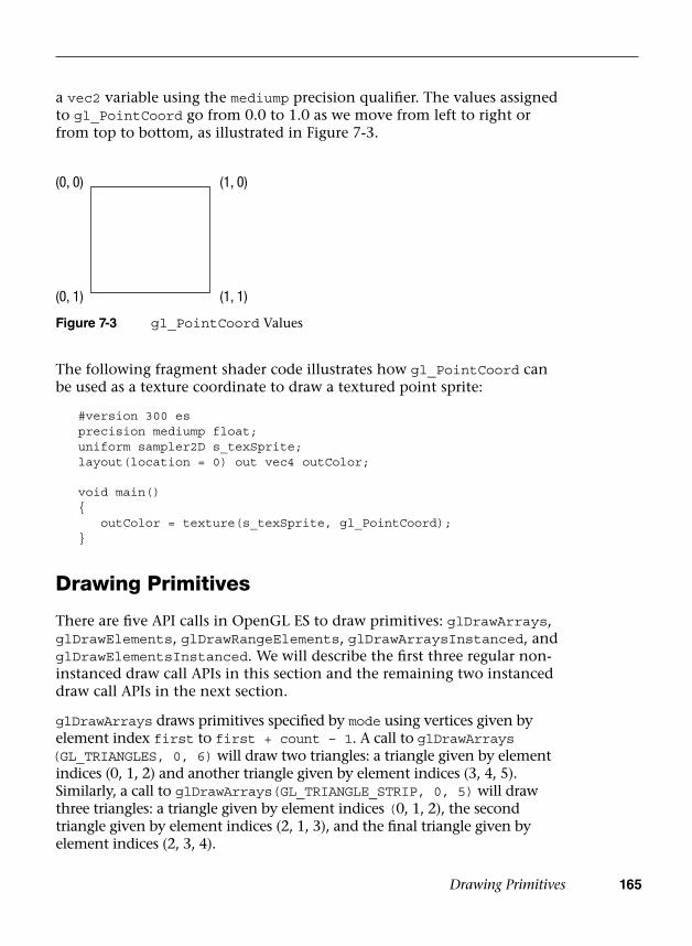
Drawing Primitives 165
a vec2 variable using the mediump precision qualifier. The values assigned to gl_PointCoord go from 0.0 to 1.0 as we move from left to right or from top to bottom, as illustrated in Figure 7-3.
(0, 0)
(0, 1)
(1, 0)
(1, 1)
Figure 7-3 gl_PointCoord Values
The following fragment shader code illustrates how gl_PointCoord can be used as a texture coordinate to draw a textured point sprite:
#version 300 es precision mediump float; uniform sampler2D s_texSprite; layout(location = 0) out vec4 outColor;
void main() {
outColor = texture(s_texSprite, gl_PointCoord); }
Drawing Primitives
There are five API calls in OpenGL ES to draw primitives: glDrawArrays, glDrawElements, glDrawRangeElements, glDrawArraysInstanced, and glDrawElementsInstanced. We will describe the first three regular non-instanced draw call APIs in this section and the remaining two instanced draw call APIs in the next section.
glDrawArrays draws primitives specified by mode using vertices given by element index first to first + count – 1. A call to glDrawArrays (GL_TRIANGLES, 0, 6) will draw two triangles: a triangle given by element indices (0, 1, 2) and another triangle given by element indices (3, 4, 5). Similarly, a call to glDrawArrays(GL_TRIANGLE_STRIP, 0, 5) will draw three triangles: a triangle given by element indices (0, 1, 2), the second triangle given by element indices (2, 1, 3), and the final triangle given by element indices (2, 3, 4).
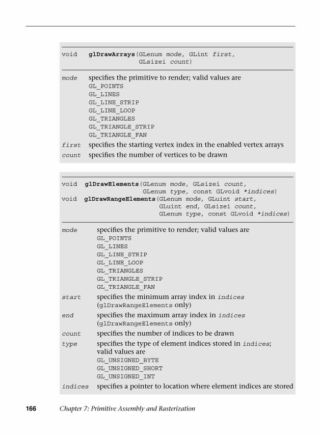
166 Chapter 7: Primitive Assembly and Rasterization
void glDrawArrays( GLenum mode, GLint first, GLsizei count)
mode specifies the primitive to render; valid values areGL_POINTSGL_LINESGL_LINE_STRIPGL_LINE_LOOPGL_TRIANGLESGL_TRIANGLE_STRIPGL_TRIANGLE_FAN
first specifies the starting vertex index in the enabled vertex arrays
count specifies the number of vertices to be drawn
void glDrawElements( GLenum mode, GLsizei count,GLenum type, const GLvoid *indices)
void glDrawRangeElements(GLenum mode, GLuint start, GLuint end, GLsizei count, GLenum type, const GLvoid *indices)
mode specifies the primitive to render; valid values areGL_POINTSGL_LINESGL_LINE_STRIPGL_LINE_LOOPGL_TRIANGLESGL_TRIANGLE_STRIPGL_TRIANGLE_FAN
start specifies the minimum array index in indices(glDrawRangeElements only)
end specifies the maximum array index in indices(glDrawRangeElements only)
count specifies the number of indices to be drawn
type specifies the type of element indices stored in indices; valid values areGL_UNSIGNED_BYTEGL_UNSIGNED_SHORTGL_UNSIGNED_INT
indices specifies a pointer to location where element indices are stored
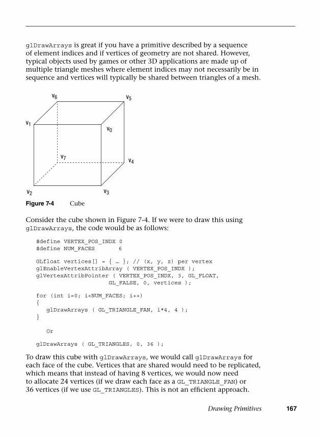
Drawing Primitives 167
glDrawArrays is great if you have a primitive described by a sequence of element indices and if vertices of geometry are not shared. However, typical objects used by games or other 3D applications are made up of multiple triangle meshes where element indices may not necessarily be in sequence and vertices will typically be shared between triangles of a mesh.
v2
v7
v1
v6 v5
v4
v3
v0
Figure 7-4 Cube
Consider the cube shown in Figure 7-4. If we were to draw this using glDrawArrays, the code would be as follows:
#define VERTEX_POS_INDX 0 #define NUM_FACES 6
GLfloat vertices[] = { … }; // (x, y, z) per vertex glEnableVertexAttribArray ( VERTEX_POS_INDX ); glVertexAttribPointer ( VERTEX_POS_INDX, 3, GL_FLOAT,
GL_FALSE, 0, vertices );
for (int i=0; i<NUM_FACES; i++) {
glDrawArrays ( GL_TRIANGLE_FAN, i*4, 4 ); }
Or
glDrawArrays ( GL_TRIANGLES, 0, 36 );
To draw this cube with glDrawArrays, we would call glDrawArrays for each face of the cube. Vertices that are shared would need to be replicated, which means that instead of having 8 vertices, we would now need to allocate 24 vertices (if we draw each face as a GL_TRIANGLE_FAN) or 36 vertices (if we use GL_TRIANGLES). This is not an efficient approach.

168 Chapter 7: Primitive Assembly and Rasterization
This is how the same cube would be drawn using glDrawElements:
#define VERTEX_POS_INDX 0 GLfloat vertices[] = { … };// (x, y, z) per vertex GLubyte indices[36] = {0, 1, 2, 0, 2, 3,
0, 3, 4, 0, 4, 5,0, 5, 6, 0, 6, 1,7, 1, 6, 7, 2, 1,7, 5, 4, 7, 6, 5,7, 3, 2, 7, 4, 3 };
glEnableVertexAttribArray ( VERTEX_POS_INDX ); glVertexAttribPointer ( VERTEX_POS_INDX, 3, GL_FLOAT,
GL_FALSE, 0, vertices ); glDrawElements ( GL_TRIANGLES,
sizeof(indices)/sizeof(GLubyte),GL_UNSIGNED_BYTE, indices );
Even though we are drawing triangles with glDrawElements and a triangle fan with glDrawArrays and glDrawElements, our application will run faster than glDrawArrays on a GPU for many reasons. For example, the size of vertex attribute data will be smaller with glDrawElements as vertices are reused (we will discuss the GPU post-transform vertex cache in a later section). This also leads to a smaller memory footprint and memory bandwidth requirement.
Primitive Restart
Using primitive restart, you can render multiple disconnected primitives (such as triangle fans or strips) using a single draw call. This is beneficial to reduce the overhead of the draw API calls. A less elegant alternative to using primitive restart is generating degenerate triangles (with some caveats), which we will discuss in a later section.
Using primitive restart, you can restart a primitive for indexed draw calls (such as glDrawElements, glDrawElementsInstanced, or glDrawRangeElements) by inserting a special index into the indices list. The special index is the largest possible index for the type of the indices (such as 255 or 65535 when the index type is GL_UNSIGNED_BYTE or GL_UNSIGNED_SHORT, respectively).
For example, suppose two triangle strips have element indices of (0, 1, 2, 3) and (8, 9, 10, 11), respectively. The combined element index list if we were to draw both strips using one call to glDrawElements* with primitive restart would be (0, 1, 2, 3, 255, 8, 9, 10, 11) if the index type is GL_UNSIGNED_BYTE.
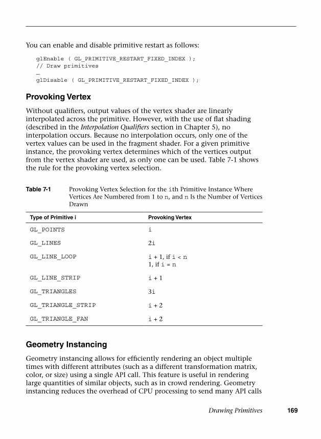
Drawing Primitives 169
You can enable and disable primitive restart as follows:
glEnable ( GL_PRIMITIVE_RESTART_FIXED_INDEX ); // Draw primitives … glDisable ( GL_PRIMITIVE_RESTART_FIXED_INDEX );
Provoking Vertex
Without qualifiers, output values of the vertex shader are linearly interpolated across the primitive. However, with the use of flat shading (described in the Interpolation Qualifiers section in Chapter 5), no interpolation occurs. Because no interpolation occurs, only one of the vertex values can be used in the fragment shader. For a given primitive instance, the provoking vertex determines which of the vertices output from the vertex shader are used, as only one can be used. Table 7-1 shows the rule for the provoking vertex selection.
Table 7-1 Provoking Vertex Selection for the ith Primitive Instance Where Vertices Are Numbered from 1 to n, and n Is the Number of Vertices Drawn
Type of Primitive i Provoking Vertex
GL_POINTS i
GL_LINES 2i
GL_LINE_LOOP i + 1, if i < n1, if i = n
GL_LINE_STRIP i + 1
GL_TRIANGLES 3i
GL_TRIANGLE_STRIP i + 2
GL_TRIANGLE_FAN i + 2
Geometry Instancing
Geometry instancing allows for efficiently rendering an object multiple times with different attributes (such as a different transformation matrix, color, or size) using a single API call. This feature is useful in rendering large quantities of similar objects, such as in crowd rendering. Geometry instancing reduces the overhead of CPU processing to send many API calls
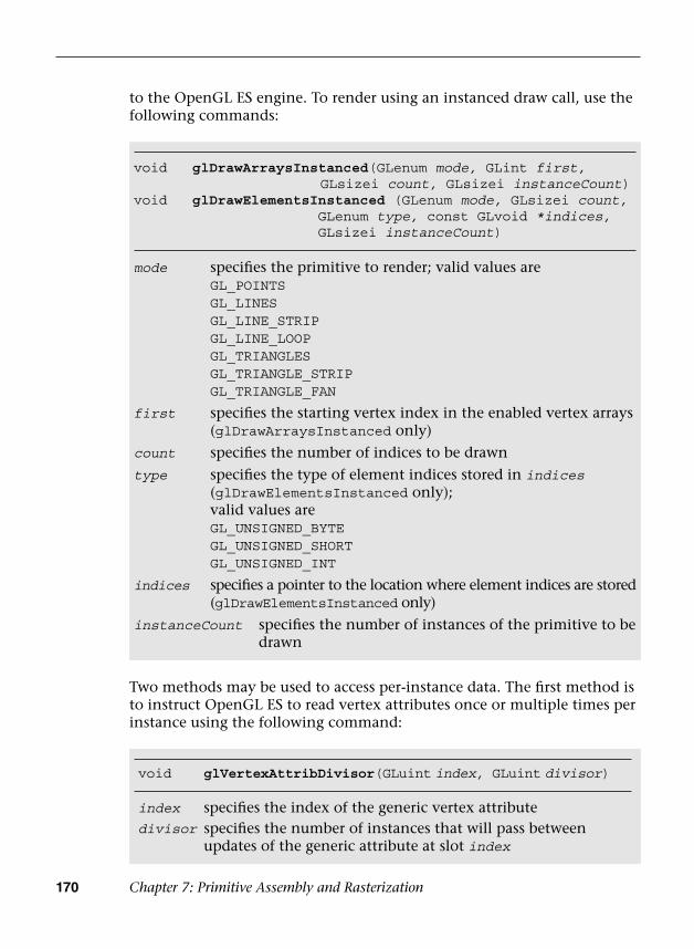
170 Chapter 7: Primitive Assembly and Rasterization
to the OpenGL ES engine. To render using an instanced draw call, use the following commands:
void glVertexAttribDivisor(GLuint index, GLuint divisor)
index specifies the index of the generic vertex attributedivisor specifies the number of instances that will pass between
updates of the generic attribute at slot index
void glDrawArraysIns tanced(GLenum mode, GLint first,GLsizei count, GLsizei instanceCount)
void glDrawElementsI nstanced (GLenum mode, GLsizei count, GLenum type, const GLvoid *indices, GLsizei instanceCount)
mode specifies the primitive to render; valid values areGL_POINTSGL_LINESGL_LINE_STRIPGL_LINE_LOOPGL_TRIANGLESGL_TRIANGLE_STRIPGL_TRIANGLE_FAN
first specifies the starting vertex index in the enabled vertex arrays (glDrawArraysInstanced only)
count specifies the number of indices to be drawn
type specifies the type of element indices stored in indices (glDrawElementsInstanced only); valid values areGL_UNSIGNED_BYTEGL_UNSIGNED_SHORTGL_UNSIGNED_INT
indices specifies a pointer to the location where element indices are stored (glDrawElementsInstanced only)
instanceCount specifies the number of instances of the primitive to be drawn
Two methods may be used to access per-instance data. The first method is to instruct OpenGL ES to read vertex attributes once or multiple times per instance using the following command:
Drawing Primitives 171
By default, if glVertexAttribDivisor is not specified or is specified with divisor equal to 0 for the vertex attributes, then the vertex attributes will be read once per vertex. If divisor equals 1, then the vertex attributes will be read once per primitive instance.
The second method is to use the built-in input variable gl_InstanceID as an index to a buffer in the vertex shader to access the per-instance data. gl_InstanceID will hold the index of the current primitive instance when the previously mentioned geometry instancing API calls are used. When a non-instanced draw call is used, gl_InstanceID will return 0.
The next two code fragments illustrate how to draw many geometry (i.e., cubes) using a single instanced draw call where each cube instance will be colored uniquely. Note that the complete source code is available in Chapter_7/Instancing example.
First, we create a color buffer to store many color data to be used later for the instanced draw call (one color per instance).
// Random color for each instance{ GLubyte colors[NUM_INSTANCES][4]; int instance;
srandom ( 0 );
for ( instance = 0; instance < NUM_INSTANCES; instance++ ) {
colors[instance][0] = random() % 255;colors[instance][1] = random() % 255;colors[instance][2] = random() % 255;colors[instance][3] = 0;
}
glGenBuffers ( 1, &userData->colorVBO ); glBindBuffer ( GL_ARRAY_BUFFER, userData->colorVBO ); glBufferData ( GL_ARRAY_BUFFER, NUM_INSTANCES * 4, colors,
GL_STATIC_DRAW );}
After the color buffer has been created and filled, we can bind the color buffer as one of the vertex attributes for the geometry. Then, we specify the vertex attribute divisor as 1 so that the color will be read per primitive instance. Finally, the cubes are drawn with a single instanced draw call.
// Load the instance color buffer glBindBuffer ( GL_ARRAY_BUFFER, userData->colorVBO );glVertexAttribPointer ( COLOR_LOC, 4, GL_UNSIGNED_BYTE,
GL_TRUE, 4 * sizeof ( GLubyte ),( const void * ) NULL );

172 Chapter 7: Primitive Assembly and Rasterization
glEnableVertexAttribArray ( COLOR_LOC );
// Set one color per instanceglVertexAttribDivisor ( COLOR_LOC, 1 );
// code skipped ...
// Bind the index bufferglBindBuffer ( GL_ELEMENT_ARRAY_BUFFER, userData->indicesIBO );
// Draw the cubes glDrawElementsInstanced ( GL_TRIANGLES, userData->numIndices,
GL_UNSIGNED_INT,(const void *) NULL, NUM_INSTANCES );
Performance Tips
Applications should make sure that glDrawElements and glDrawElementsInstanced are called with as large a primitive size as possible. This is very easy to do if we are drawing GL_TRIANGLES. However, if we have meshes of triangle strips or fans, instead of making individual calls to glDrawElements* for each triangle strip mesh, these meshes could be connected together by using primitive restart (see the earlier section discussing this feature).
If you cannot use the primitive restart mechanism to connect meshes together (to maintain compatibility with an older OpenGL ES version), you can add element indices that result in degenerate triangles at the expense of using more indices and some caveats that we will discuss here. A degenerate triangle is a triangle where two or more vertices of the triangle are coincident. GPUs can detect and reject degenerate triangles very easily, so this is a good performance enhancement that allows us to queue a big primitive to be rendered by the GPU.
The number of element indices (or degenerate triangles) we need to add to connect distinct meshes will depend on whether each mesh is a triangle fan or a triangle strip and the number of indices defined in each strip. The number of indices in a mesh that is a triangle strip matters, as we need to preserve the winding order as we go from one triangle to the next triangle of the strip across the distinct meshes that are being connected.
When connecting separate triangle strips, we need to check the order of the last triangle and the first triangle of the two strips being connected. As seen in Figure 7-5, the ordering of vertices that describe even-numbered
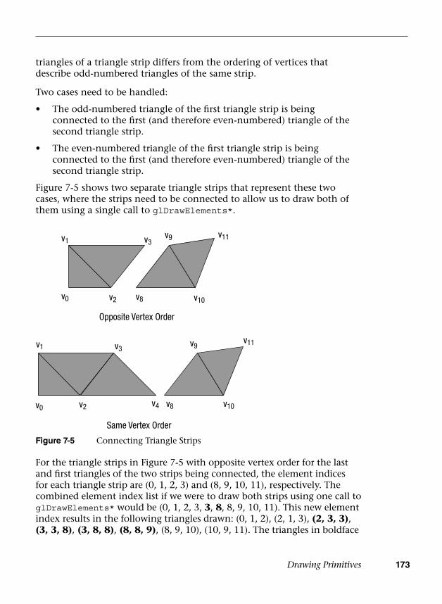
Drawing Primitives 173
triangles of a triangle strip differs from the ordering of vertices that describe odd-numbered triangles of the same strip.
Two cases need to be handled:
• The odd-numbered triangle of the first triangle strip is beingconnected to the first (and therefore even-numbered) triangle of thesecond triangle strip.
• The even-numbered triangle of the first triangle strip is beingconnected to the first (and therefore even-numbered) triangle of thesecond triangle strip.
Figure 7-5 shows two separate triangle strips that represent these two cases, where the strips need to be connected to allow us to draw both of them using a single call to glDrawElements*.
v0 v2 v10
v3v1
v8
v11v9
v3
Opposite Vertex Order
v0 v4
v1
v2
v10v8
v11v9
Same Vertex Order
Figure 7-5 Connecting Triangle Strips
For the triangle strips in Figure 7-5 with opposite vertex order for the last and first triangles of the two strips being connected, the element indices for each triangle strip are (0, 1, 2, 3) and (8, 9, 10, 11), respectively. The combined element index list if we were to draw both strips using one call to glDrawElements* would be (0, 1, 2, 3, 3, 8, 8, 9, 10, 11). This new element index results in the following triangles drawn: (0, 1, 2), (2, 1, 3), (2, 3, 3), (3, 3, 8), (3, 8, 8), (8, 8, 9), (8, 9, 10), (10, 9, 11). The triangles in boldface
174 Chapter 7: Primitive Assembly and Rasterization
type are the degenerate triangles. The element indices in boldface type represent the new indices added to the combined element index list.
For triangle strips in Figure 7-5 with the same vertex order for the last and first triangles of the two strips being connected, the element indices for each triangle strip are (0, 1, 2, 3, 4) and (8, 9, 10, 11), respectively. The combined element index list if we were to draw both strips using one call to glDrawElements would be (0, 1, 2, 3, 4, 4, 4, 8, 8, 9, 10, 11). This new element index results in the following triangles drawn: (0, 1, 2), (2, 1, 3), (2, 3, 4), (4, 3, 4), (4, 4, 4), (4, 4, 8), (4, 8, 8), (8, 8, 9), (8, 9, 10), (10, 9, 11). The triangles in boldface type are the degenerate triangles. The element indices in boldface type represent the new indices added to the combined element index list.
Note that the number of additional element indices required and the number of degenerate triangles generated vary depending on the number of vertices in the first strip. This is required to preserve the winding order of the next strip being connected.
It might also be worth investigating techniques that take the size of the post-transform vertex cache into consideration in determining how to arrange element indices of a primitive. Most GPUs implement a post-transform vertex cache. Before a vertex (given by its element index) is executed by the vertex shader, a check is performed to determine whether the vertex already exists in the post-transform cache. If the vertex exists in the post-transform cache, the vertex is not executed by the vertex shader. If it is not in the cache, the vertex will need to be executed by the vertex shader. Using the post-transform cache size to determine how element indices are created should help overall performance, as it will reduce the number of times a vertex that is reused gets executed by the vertex shader.
Primitive Assembly
Figure 7-6 shows the primitive assembly stage. Vertices that are supplied through glDraw*** are executed by the vertex shader. Each vertex transformed by the vertex shader includes the vertex position that describes the (x, y, z, w) value of the vertex. The primitive type and vertex indices determine the individual primitives that will be rendered. For each individual primitive (triangle, line, and point) and its corresponding vertices, the primitive assembly stage performs the operations shown in Figure 7-6.
Before we discuss how primitives are rasterized in OpenGL ES, we need to understand the various coordinate systems used within OpenGL ES 3.0. This
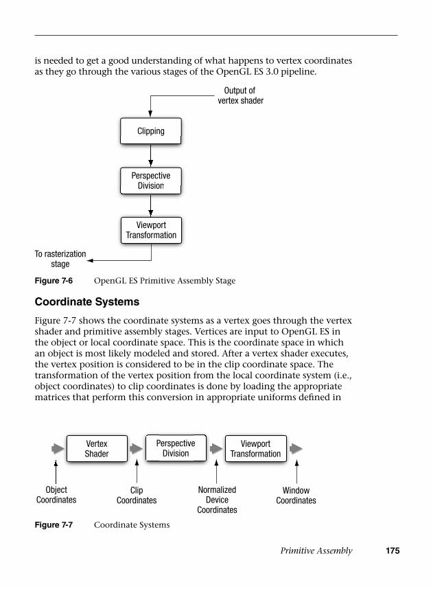
Primitive Assembly 175
is needed to get a good understanding of what happens to vertex coordinates as they go through the various stages of the OpenGL ES 3.0 pipeline.
Clipping
PerspectiveDivisionDivision
ViewportTransformation
Output of vertex shader
To rasterizationstage
Figure 7-6 OpenGL ES Primitive Assembly Stage
Coordinate Systems
Figure 7-7 shows the coordinate systems as a vertex goes through the vertex shader and primitive assembly stages. Vertices are input to OpenGL ES in the object or local coordinate space. This is the coordinate space in which an object is most likely modeled and stored. After a vertex shader executes, the vertex position is considered to be in the clip coordinate space. The transformation of the vertex position from the local coordinate system (i.e., object coordinates) to clip coordinates is done by loading the appropriate matrices that perform this conversion in appropriate uniforms defined in
PerspectiveDivision
PVertexShader
e ViewportTransformation
ObjectCoordinates
ClipCoordinates
NormalizedDevice
Coordinates
WindowCoordinates
Figure 7-7 Coordinate Systems

176 Chapter 7: Primitive Assembly and Rasterization
the vertex shader. Chapter 8, “Vertex Shaders,” describes how to transform the vertex position from object to clip coordinates and how to load appropriate matrices in the vertex shader to perform this transformation.
Clipping
To avoid processing of primitives outside the viewable volume, primitives are clipped to the clip space. The vertex position after the vertex shader has been executed is in the clip coordinate space. The clip coordinate is a homogeneous coordinate given by (xc, yc, zc, wc). The vertex coordinates defined in clip space (xc, yc, zc, wc) get clipped against the viewing volume (also known as the clip volume).
The clip volume, as shown in Figure 7-8, is defined by six clipping planes, referred to as the near, and far clip planes, the left and right clip planes, and the top and bottom clip planes. In clip coordinates, the clip volume is given as follows:
-wc <= x
c <= w
c
-wc <= y
c <= w
c
-wc <= z
c <= w
c
The preceding six checks help determine the list of planes against which the primitive needs to be clipped.
FarPlane
NearPlane
x
y
z
Figure 7-8 Viewing Volume
Primitive Assembly 177
The clipping stage will clip each primitive to the clip volume shown in Figure 7-8. By “primitive,” here we imply each triangle of a list of separate triangles drawn using GL_TRIANGLES, or a triangle of a triangle strip or a fan, or a line from a list of separate lines drawn using GL_LINES, or a line of a line strip or line loop, or a specific point in a list of point sprites. For each primitive type, the following operations are performed:
• Clipping triangles—If the triangle is completely inside the viewingvolume, no clipping is performed. If the triangle is completelyoutside the viewing volume, the triangle is discarded. If the trianglelies partly inside the viewing volume, then the triangle is clippedagainst the appropriate planes. The clipping operation will generatenew vertices that are clipped to the plane that are arranged as atriangle fan.
• Clipping lines—If the line is completely inside the viewing volume,then no clipping is performed. If the line is completely outside theviewing volume, the line is discarded. If the line lies partly inside theviewing volume, then the line is clipped and appropriate new verticesare generated.
• Clipping point sprites—The clipping stage will discard the pointsprite if the point position lies outside the near or far clip plane or ifthe quad that represents the point sprite is outside the clip volume.Otherwise, it is passed unchanged and the point sprite will be scissoredas it moves from inside the clip volume to the outside, or vice versa.
After the primitives have been clipped against the six clipping planes, the vertex coordinates undergo perspective division to become normalized device coordinates. A normalized device coordinate is in the range –1.0 to +1.0.
Note: The clipping operation (especially for lines and triangles) can be quite expensive to perform in hardware. A primitive must be clipped against six clip planes of the viewing volume, as shown in Figure 7-8. Primitives that are partly outside the near and far planes go through the clipping operations. However, primitives that are partially outside the x and y planes do not necessarily need to be clipped. By rendering into a viewport that is bigger than the dimensions of the viewport specified with glViewport, clipping in the x and y planes becomes a scissoring operation. Scissoring is implemented very efficiently by GPUs. This larger viewport region is called the guard-band region. Although OpenGL ES does not allow an application to specify a guard-band region, most—if not all—OpenGL ES implementations implement a guard-band.
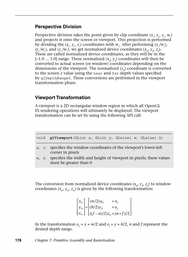
178 Chapter 7: Primitive Assembly and Rasterization
Perspective Division
Perspective division takes the point given by clip coordinate (xc, yc, zc, wc) and projects it onto the screen or viewport. This projection is performed by dividing the (xc, yc, zc) coordinates with wc. After performing (xc /wc), (yc /wc), and (zc /wc), we get normalized device coordinates (xd, yd, zd). These are called normalized device coordinates, as they will be in the [–1.0 ... 1.0] range. These normalized (xd, yd) coordinates will then be converted to actual screen (or window) coordinates depending on the dimensions of the viewport. The normalized (zd) coordinate is converted to the screen z value using the near and far depth values specified by glDepthRangef. These conversions are performed in the viewport transformation phase.
Viewport Transformation
A viewport is a 2D rectangular window region in which all OpenGL ES rendering operations will ultimately be displayed. The viewport transformation can be set by using the following API call:
void glViewport(GLint x, GLint y, GLsizei w, GLsizei h)
x, y specifies the window coordinates of the viewport’s lower-left corner in pixels
w, h specifies the width and height of viewport in pixels; these values must be greater than 0
The conversion from normalized device coordinates (xd, yd, zd) to window coordinates (xw, yw, zw) is given by the following transformation:
=++
− + +
( /2)
( /2)
(( )/2) ( )/2
x
y
z
w x o
h y o
f n z n f
w
w
w
d x
d y
d
In the transformation ox = x + w/2 and oy = y + h/2, n and f represent the desired depth range.
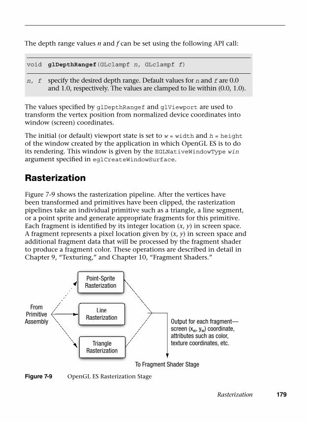
Rasterization 179
The values specified by glDepthRangef and glViewport are used to transform the vertex position from normalized device coordinates into window (screen) coordinates.
The initial (or default) viewport state is set to w = width and h = height of the window created by the application in which OpenGL ES is to do its rendering. This window is given by the EGLNativeWindowType win argument specified in eglCreateWindowSurface.
Rasterization
Figure 7-9 shows the rasterization pipeline. After the vertices have been transformed and primitives have been clipped, the rasterization pipelines take an individual primitive such as a triangle, a line segment, or a point sprite and generate appropriate fragments for this primitive. Each fragment is identified by its integer location (x, y) in screen space. A fragment represents a pixel location given by (x, y) in screen space and additional fragment data that will be processed by the fragment shader to produce a fragment color. These operations are described in detail in Chapter 9, “Texturing,” and Chapter 10, “Fragment Shaders.”
void glDepthRangef(GLclampf n, GLclampf f)
n, f specify the desired depth range. Default values for n and f are 0.0 and 1.0, respectively. The values are clamped to lie within (0.0, 1.0).
FromPrimitiveAssembly
LineRasterization
Line
Point-SpriteRasterization
RasterizationRasterization
TriangleRasterization
Output for each fragment—screen (xw, yw) coordinate,attributes such as color,texture coordinates, etc.
To Fragment Shader Stage
Figure 7-9 OpenGL ES Rasterization Stage
The depth range values n and f can be set using the following API call:
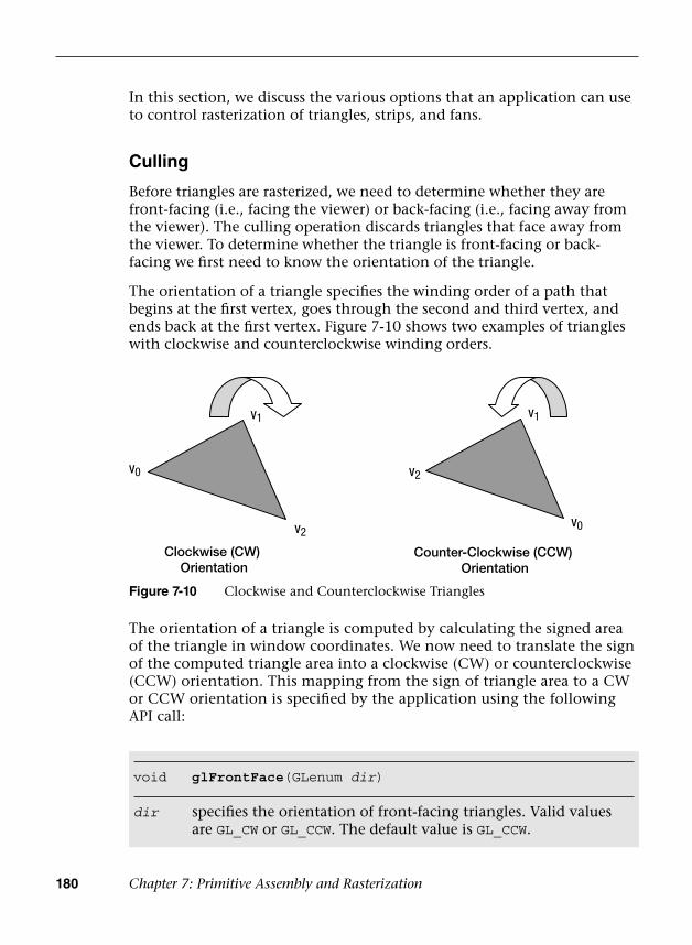
180 Chapter 7: Primitive Assembly and Rasterization
In this section, we discuss the various options that an application can use to control rasterization of triangles, strips, and fans.
Culling
Before triangles are rasterized, we need to determine whether they are front-facing (i.e., facing the viewer) or back-facing (i.e., facing away from the viewer). The culling operation discards triangles that face away from the viewer. To determine whether the triangle is front-facing or back-facing we first need to know the orientation of the triangle.
The orientation of a triangle specifies the winding order of a path that begins at the first vertex, goes through the second and third vertex, and ends back at the first vertex. Figure 7-10 shows two examples of triangles with clockwise and counterclockwise winding orders.
v2
v0
v1
v0
v1
v2
Clockwise (CW) Orientation
Counter-Clockwise (CCW) Orientation
Figure 7-10 Clockwise and Counterclockwise Triangles
The orientation of a triangle is computed by calculating the signed area of the triangle in window coordinates. We now need to translate the sign of the computed triangle area into a clockwise (CW) or counterclockwise (CCW) orientation. This mapping from the sign of triangle area to a CW or CCW orientation is specified by the application using the following API call:
void glFrontFace(GLenum dir)
dir specifies the orientation of front-facing triangles. Valid values are GL_CW or GL_CCW. The default value is GL_CCW.
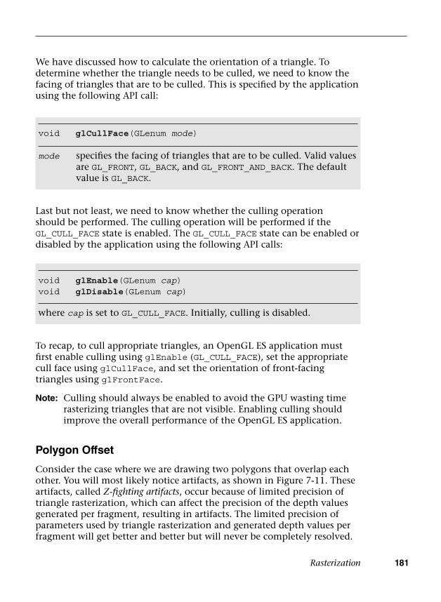
Rasterization 181
We have discussed how to calculate the orientation of a triangle. To determine whether the triangle needs to be culled, we need to know the facing of triangles that are to be culled. This is specified by the application using the following API call:
void glCullFace(GLenum mode)
mode specifies the facing of triangles that are to be culled. Valid values are GL_FRONT, GL_BACK, and GL_FRONT_AND_BACK. The default value is GL_BACK.
Last but not least, we need to know whether the culling operation should be performed. The culling operation will be performed if the GL_CULL_FACE state is enabled. The GL_CULL_FACE state can be enabled or disabled by the application using the following API calls:
void glEnable(GLenum cap)void glDisable(GLenum cap)
where cap is set to GL_CULL_FACE. Initially, culling is disabled.
To recap, to cull appropriate triangles, an OpenGL ES application must first enable culling using glEnable (GL_CULL_FACE), set the appropriate cull face using glCullFace, and set the orientation of front-facing triangles using glFrontFace.
Note: Culling should always be enabled to avoid the GPU wasting time rasterizing triangles that are not visible. Enabling culling should improve the overall performance of the OpenGL ES application.
Polygon Offset
Consider the case where we are drawing two polygons that overlap each other. You will most likely notice artifacts, as shown in Figure 7-11. These artifacts, called Z-fighting artifacts, occur because of limited precision of triangle rasterization, which can affect the precision of the depth values generated per fragment, resulting in artifacts. The limited precision of parameters used by triangle rasterization and generated depth values per fragment will get better and better but will never be completely resolved.
182 Chapter 7: Primitive Assembly and Rasterization
Figure 7-11 shows two coplanar polygons being drawn. The code to draw these two coplanar polygons without polygon offset is as follows:
glClear ( GL_COLOR_BUFFER_BIT | GL_DEPTH_BUFFER_BIT );
// load vertex shader // set the appropriate transformation matrices // set the vertex attribute state
// draw the SMALLER quad glDrawArrays ( GL_TRIANGLE_FAN, 0, 4 );
// set the depth func to <= as polygons are coplanar glDepthFunc ( GL_LEQUAL );
// set the vertex attribute state
// draw the LARGER quad glDrawArrays ( GL_TRIANGLE_FAN, 0, 4 );
To avoid the artifacts shown in Figure 7-11, we need to add a delta to the computed depth value before the depth test is performed and before the depth value is written to the depth buffer. If the depth test passes, the original depth value—and not the original depth value + delta—will be stored in the depth buffer.
The polygon offset is set using the following API call:
Figure 7-11 Polygon Offset
void glPolygonOffset(GLfloat factor, GLfloat units)
The depth offset is computed as follows:
depth offset = m * factor + r * units

Occlusion Queries 183
In this equation, m is maximum depth slope of the triangle and is calculated as
+( )m = ∂z/∂x ∂z/∂y2 2
m can also be calculated as max {|∂z/∂x|, |∂z/∂y|}.
The slope terms ∂z/∂x and ∂z/∂y are calculated by the OpenGL ES implementation during the triangle rasterization stage.
r is an implementation-defined constant and represents the smallest value that can produce a guaranteed difference in depth value.
Polygon offset can be enabled or disabled using glEnable(GL_POLYGON_OFFSET_FILL) and glDisable(GL_POLYGON_OFFSET_FILL), respectively.
With polygon offset enabled, the code for triangles rendered by Figure 7-11 is as follows:
const float polygonOffsetFactor = –l.Of; const float polygonOffsetUnits = –2.Of;
glClear ( GL_COLOR_BUFFER_BIT | GL_DEPTH_BUFFER_BIT );
// load vertex shader // set the appropriate transformation matrices // set the vertex attribute state
// draw the SMALLER quad glDrawArrays ( GL_TRIANGLE_FAN, 0, 4 );
// set the depth func to <= as polygons are coplanar glDepthFunc ( GL_LEQUAL );
glEnable ( GL_POLYGON_OFFSET_FILL ); glPolygonOffset ( polygonOffsetFactor, polygonOffsetUnits );
// set the vertex attribute state
// draw the LARGER quad glDrawArrays ( GL_TRIANGLE_FAN, 0, 4 );
Occlusion Queries
Occlusion queries use query objects to track any fragments or samples that pass the depth test. This approach can be used for a variety of techniques, such as visibility determination for a lens flare effect as well

184 Chapter 7: Primitive Assembly and Rasterization
as optimization to avoid performing geometry processing on obscured objects whose bounding volume is obscured.
Occlusion queries can be started and ended using glBeginQuery and glEndQuery, respectively, with GL_ANY_SAMPLES_PASSED or GL_ANY_SAMPLES_PASSED_CONSERVATIVE target.
void glBeginQuery(GLenum target, GLuint id)void glEndQuery(GLenum target)
target specifies the target type of query object; valid values areGL_ANY_SAMPLES_PASSEDGL_ANY_SAMPLES_PASSED_CONSERVATIVEGL_TRANSFORM_FEEDBACK_PRIMITIVES_WRITTEN
id specifies the name of the query object (glBeginQuery only)
Using the GL_ANY_SAMPLES_PASSED target will return the precise boolean state indicating whether any samples passed the depth test. The GL_ANY_SAMPLES_PASSED_CONSERVATIVE target can offer better performance but a less precise answer. Using GL_ANY_SAMPLES_PASSED_CONSERVATIVE, some implementations may return GL_TRUE even if no sample passed the depth test.
The id is created using glGenQueries and deleted using glDeleteQueries.
void glGenQueries(GLsizei n, GLuint *ids)
n specifies the number of query name objects to be generatedids specifies an array to store the list of query name objects
void glDeleteQueries(GLsizei n, const GLuint *ids)
n specifies the number of query name objects to be deleted
ids specifies an array of the list of query name objects to be deleted
After you have specified the boundary of the query object using glBeginQuery and glEndQuery, you can use glGetQueryObjectuiv to retrieve the result of the query object.

Summary 185
Note: For better performance, you should wait several frames before performing a glGetQueryObjectuiv call to wait for the result to be available in the GPU.
The following example shows how to set up an occlusion query object and query the result:
glBeginQuery ( GL_ANY_SAMPLES_PASSED, queryObject ); // draw primitives here … glEndQuery ( GL_ANY_SAMPLES_PASSED );
… // after several frames have elapsed, query the number of // samples that passed the depth test glGetQueryObjectuiv( queryObject, GL_QUERY_RESULT,
&numSamples );
Summary
In this chapter, you learned the types of primitives supported by OpenGL ES, and saw how to draw them efficiently using regular non-instanced and instanced draw calls. We also discussed how coordinate transformations are performed on vertices. In addition, you learned about the rasterization stage, in which primitives are converted into fragments representing pixels that may be drawn on the screen. Now that you have learned how to draw primitives using vertex data, in the next chapter we describe how to write a vertex shader to process the vertices in a primitive.
void glGetQueryObjectuiv( GLuint id, GLenum pname, GLuint *params)
target specifies the name of a query objectpname specifies the query object parameter to be retrieved,
and can be GL_QUERY_RESULT or GL_QUERY_RESULT_AVAILABLE
params specifies an array of the appropriate type for storing the returned parameter values

This page intentionally left blank

187
Chapter 8
Vertex Shaders
This chapter describes the OpenGL ES 3.0 programmable vertex pipeline. Figure 8-1 illustrates the entire OpenGL ES 3.0 programmable pipeline. The shaded boxes indicate the programmable stages in OpenGL ES 3.0. In this chapter, we discuss the vertex shader stage. Vertex shaders can be used to do traditional vertex-based operations such as transforming the position by a matrix, computing the lighting equation to generate a per-vertex color, and generating or transforming texture coordinates.
The previous chapters—specifically, Chapter 5, “OpenGL ES Shading Language,” and Chapter 6, “Vertex Attributes, Vertex Arrays, and Buffer Objects”—discussed how to specify the vertex attribute and uniform inputs and also gave a good description of the OpenGL ES 3.0 Shading Language. Chapter 7, “Primitive Assembly and Rasterization,” discussed how the output of the vertex shader, referred to as vertex shader output variables, is used by the rasterization stage to generate per-fragment values, which are then input to the fragment shader. In this chapter, we begin with a high-level overview of a vertex shader, including its inputs and outputs. We then describe how to write vertex shaders by discussing a few examples. These examples describe common use cases such as transforming a vertex position with a model view and projection matrix, vertex lighting that generates per-vertex diffuse and specular colors, texture coordinate generation, vertex skinning, and displacement mapping. We hope that these examples help you get a good idea of how to write vertex shaders. Last but not least, we describe a vertex shader that implements the OpenGL ES 1.1 fixed-function vertex pipeline.

188 Chapter 8: Vertex Shaders
Vertex Shader Overview
The vertex shader provides a general-purpose programmable method for operating on vertices. Figure 8-2 shows the inputs and outputs of a vertex shader. The inputs to the vertex shader consist of the following:
• Attributes—Per-vertex data supplied using vertex arrays.
• Uniforms and uniform buffers—Constant data used by the vertexshader.
• Samplers—A specific type of uniform that represents textures used bythe vertex shader.
• Shader program—Vertex shader program source code or executablethat describes the operations that will be performed on the vertex.
The outputs of the vertex shader are called vertex shader output variables. In the primitive rasterization stage, these variables are computed for each generated fragment and are passed in as inputs to the fragment shader.
Vertex Buffer/Array ObjectsArray Objects
VertexShaderShader
Textures
FragmentShader
PrimitiveAssemblyPrimitive
TransformFeedback
Rasterization
Per-FragmentOperations
Framebuffer
API
Figure 8-1 OpenGL ES 3.0 Programmable Pipeline

Vertex Shader Overview 189
Vertex Shader Built-In Variables
The built-in variables of a vertex shader can be categorized into special variables that are input or output of the vertex shader, uniform state such as depth range, and constants that specify maximum values such as the number of attributes, number of vertex shader output variables, and number of uniforms.
Built-In Special Variables
OpenGL ES 3.0 has built-in special variables that serve as inputs to the vertex shader, or outputs by the vertex shader that then become inputs to the fragment shader, or outputs by the fragment shader. The following built-in special variables are available to the vertex shader:
• gl_VertexID is an input variable that holds an integer index for thevertex. This integer variable is declared using the highp precision qualifier.
• gl_InstanceID is an input variable that holds the instance number ofa primitive in an instanced draw call. Its value is 0 for a regular drawcall. gl_InstanceID is an integer variable declared using the highpprecision qualifier.
... ...
Output (Varying) 0
Output (Varying) 1
Output (Varying) 2
Output (Varying) 3
Output (Varying) 4
Uniforms Samplers
Vertex Shader
Input (Attribute) 0
Input (Attribute) 1
Input (Attribute) 2
Input (Attribute) 3
Input (Attribute) 4
Input (Attribute) N Output (Varying) N
gl_PointSize
gl_Position
Figure 8-2 OpenGL ES 3.0 Vertex Shader
190 Chapter 8: Vertex Shaders
• gl_Position is used to output the vertex position in clip coordinates.Its values are used by the clipping and viewport stages to performappropriate clipping of primitives and to convert the vertex positionfrom clip coordinates to screen coordinates. The value of gl_Positionis undefined if the vertex shader does not write to gl_Position.gl_Position is a floating-point variable declared using the highpprecision qualifier.
• gl_PointSize is used to write the size of the point sprite in pixels.It is used when point sprites are rendered. The gl_PointSizevalue output by a vertex shader is then clamped to the aliasedpoint size range supported by the OpenGL ES 3.0 implementation.gl_PointSize is a floating-point variable declared using the highpprecision qualifier.
• gl_FrontFacing is a special variable that, although not directlywritten by the vertex shader, is generated based on the position valuesgenerated by the vertex shader and primitive type being rendered.gl_FrontFacing is a boolean variable.
Built-In Uniform State
The only built-in uniform state available inside a vertex shader is the depth range in window coordinates. This is given by the built-in uniform name gl_DepthRange, which is declared as a uniform of type gl_DepthRangeParameters.
struct gl_DepthRangeParameters{ highp float near; // near Z highp float far; // far Z highp float diff; // far – near}
uniform gl_DepthRangeParameters gl_DepthRange;
Built-In Constants
The following built-in constants are also available inside the vertex shader:
const mediump int gl_MaxVertexAttribs = 16;const mediump int gl_MaxVertexUniformVectors = 256;const mediump int gl_MaxVertexOutputVectors = 16;const mediump int gl_MaxVertexTextureImageUnits = 16;const mediump int gl_MaxCombinedTextureImageUnits = 32;

Vertex Shader Overview 191
The built-in constants describe the following maximum terms:
• gl_MaxVertexAttribs is the maximum number of vertex attributesthat can be specified. The minimum value supported by all ES 3.0implementations is 16.
• gl_MaxVertexUniformVectors is the maximum number ofvec4 uniform entries that can be used inside a vertex shader.The minimum value supported by all ES 3.0 implementations is256 vec4 entries. The number of vec4 uniform entries that canactually be used by a developer can vary from one implementationto another and from one vertex shader to another. For example,some implementations might count user-specified literal valuesused in a vertex shader against the uniform limit. In other cases,implementation-specific uniforms (or constants) might need to beincluded depending on whether the vertex shader makes use of anybuilt-in transcendental functions. There currently is no mechanismthat an application can use to find the number of uniform entriesthat it can use in a particular vertex shader. The vertex shadercompilation will fail and the compile log might provide specificinformation with regard to number of uniform entries beingused. However, the information returned by the compile log isimplementation specific. We provide some guidelines in this chapterto help maximize the use of vertex uniform entries available in avertex shader.
• gl_MaxVertexOutputVectors is the maximum number of outputvectors—that is, the number of vec4 entries that can be outputby a vertex shader. The minimum value supported by all ES 3.0implementations is 16 vec4 entries.
• gl_MaxVertexTextureImageUnits is the maximum number oftexture units available in a vertex shader. The minimum value is 16.
• gl_MaxCombinedTextureImageUnits is the sum of the maximumnumber of texture units available in the vertex + fragment shaders.The minimum value is 32.
The values specified for each built-in constant are the minimum values that must be supported by all OpenGL ES 3.0 implementations. It is possible that implementations might support values greater than the minimum values described. The actual supported values can be queried using the following code:
GLint maxVertexAttribs, maxVertexUniforms, maxVaryings;GLint maxVertexTextureUnits, maxCombinedTextureUnits;

192 Chapter 8: Vertex Shaders
glGetIntegerv ( GL_MAX_VERTEX_ATTRIBS, &maxVertexAttribs );glGetIntegerv ( GL_MAX_VERTEX_UNIFORM_VECTORS,
&maxVertexUniforms );glGetIntegerv ( GL_MAX_VARYING_VECTORS,
&maxVaryings );glGetIntegerv ( GL_MAX_VERTEX_TEXTURE_IMAGE_UNITS,
&maxVertexTextureUnits );glGetIntegerv ( GL_MAX_COMBINED_TEXTURE_IMAGE_UNITS,
&maxCombinedTextureUnits );
Precision Qualifiers
This section briefly reviews precision qualifiers, which are covered in depth in Chapter 5, “OpenGL ES Shading Language.” Precision qualifiers can be used to specify the precision of any floating-point or integer-based variable. The keywords for specifying the precision are lowp, mediump, and highp. Some examples of declarations with precision qualifiers are shown here:
highp vec4 position;out lowp vec4 color;mediump float specularExp;highp int oneConstant;
In addition to precision qualifiers, default precision may be employed. That is, if a variable is declared without having a precision qualifier, it will have the default precision for that type. The default precision qualifier is specified at the top of a vertex or fragment shader using the following syntax:
precision highp float;precision mediump int;
The precision specified for float will be used as the default precision for all variables based on a floating-point value. Likewise, the precision specified for int will be used as the default precision for all integer-based variables. In the vertex shader, if no default precision is specified, the default precision for both int and float is highp.
For operations typically performed in a vertex shader, the precision qualifier that will most likely be needed is highp. For instance, operations that transform a position with a matrix, transform normals and texture coordinates, or generate texture coordinates will need to be done with highp precision. Color computations and lighting equations can most likely be done with mediump precision. Again, this decision will depend
Vertex Shader Overview 193
on the kind of color computations being performed and the range and precision required for the operations being performed. We believe that highp will most likely be the default precision used for most operations in a vertex shader; thus we use highp as the default precision qualifier in the examples that follow.
Number of Uniforms Limitations in a Vertex Shader
gl_MaxVertexUniformVectors describes the maximum number of uniforms that can be used in a vertex shader. The minimum value for gl_MaxVertexUniformVectors that must be supported by any compliant OpenGL ES 3.0 implementation is 256 vec4 entries. The uniform storage is used to store the following variables:
• Variables declared with the uniform qualifier
• Constant variables
• Literal values
• Implementation-specific constants
The number of uniform variables used in a vertex shader along with the variables declared with the const qualifier, literal values, and implementation- specific constants must fit in gl_MaxVertexUniformVectors as per the packing rules described in Chapter 5, “OpenGL ES Shading Language.” If these do not fit, then the vertex shader will fail to compile. A developer might potentially apply the packing rules and determine the amount of uniform storage needed to store uniform variables, constant variables, and literal values. It is not possible to determine the number of implementation-specific constants, however, as this value will not only vary from implementation to implementation but will also change depending on which built-in shading language functions are being used by the vertex shader. Typically, the implementation-specific constants are required when built-in transcendental functions are used.
As far as literal values are concerned, the OpenGL ES 3.0 Shading Language specification states that no constant propagation is assumed. As a consequence, multiple instances of the same literal value(s) will be counted multiple times. Understandably, it is easier to use literal values such as 0.0 or 1.0 in a vertex shader, but our recommendation is that this technique be avoided as much as possible. Instead of using literal values, appropriate constant variables should be declared. This approach avoids having to perform the same literal value count

194 Chapter 8: Vertex Shaders
multiple times, which might cause the vertex shader to fail to compile if vertex uniform storage requirements exceed what the implementation supports.
Consider the following example, which shows a snippet of vertex shader code that transforms two texture coordinates per vertex:
#version 300 es#define NUM_TEXTURES 2
uniform mat4 tex_matrix[NUM_TEXTURES]; // texture// matrices
uniform bool enable_tex[NUM_TEXTURES]; // texture// enables
uniform bool enable_tex_matrix[NUM_TEXTURES]; // texture matrix// enables
in vec4 a_texcoord0; // available if enable_tex[0] is truein vec4 a_texcoordl; // available if enable_tex[1] is true
out vec4 v_texcoord[NUM_TEXTURES];
void main(){ v_texcoord[0] = vec4 ( 0.0, 0.0, 0.0, 1.0 ); // is texture 0 enabled if ( enable_tex[0] ) {
// is texture matrix 0 enabledif ( enable_tex_matrix[0] )
v_texcoord[0] = tex_matrix[0] * a_texcoord0;else
v_texcoord[0] = a_texcoord0; }
v_texcoord[1] = vec4 ( 0.0, 0.0, 0.0, 1.0 ); // is texture 1 enabled if ( enable_tex[1] ) {
// is texture matrix 1 enabledif ( enable_tex_matrix[1] )
v_texcoord[1] = tex_matrix[1] * a_texcoordl;else
v_texcoord[1] = a_texcoordl; }
// set gl_Position to make this into a valid vertex shader}
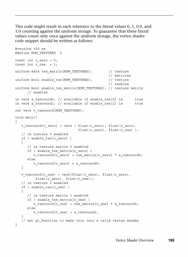
Vertex Shader Overview 195
This code might result in each reference to the literal values 0, 1, 0.0, and 1.0 counting against the uniform storage. To guarantee that these literal values count only once against the uniform storage, the vertex shader code snippet should be written as follows:
#version 300 es#define NUM_TEXTURES 2
const int c_zero = 0;const int c_one = 1;
uniform mat4 tex_matrix[NUM_TEXTURES]; // texture// matrices
uniform bool enable_tex[NUM_TEXTURES]; // texture// enables
uniform bool enable_tex_matrix[NUM_TEXTURES]; // texture matrix// enables
in vec4 a_texcoord0; // available if enable_tex[0] is truein vec4 a_texcoordl; // available if enable_tex[1] is true
out vec4 v_texcoord[NUM_TEXTURES];
void main(){ v_texcoord[c_zero] = vec4 ( float(c_zero), float(c_zero),
float(c_zero), float(c_one) ); // is texture 0 enabled if ( enable_tex[c_zero] ) {
// is texture matrix 0 enabledif ( enable_tex_matrix[c_zero] )
v_texcoord[c_zero] = tex_matrix[c_zero] * a_texcoord0;else
v_texcoord[c_zero] = a_texcoord0; }
v_texcoord[c_one] = vec4(float(c_zero), float(c_zero),float(c_zero), float(c_one));
// is texture 1 enabled if ( enable_tex[c_one] ) {
// is texture matrix 1 enabledif ( enable_tex_matrix[c_one] )
v_texcoord[c_one] = tex_matrix[c_one] * a_texcoordl;else
v_texcoord[c_one] = a_texcoordl; } // set gl_Position to make this into a valid vertex shader}
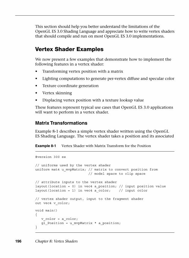
196 Chapter 8: Vertex Shaders
This section should help you better understand the limitations of the OpenGL ES 3.0 Shading Language and appreciate how to write vertex shaders that should compile and run on most OpenGL ES 3.0 implementations.
Vertex Shader Examples
We now present a few examples that demonstrate how to implement the following features in a vertex shader:
• Transforming vertex position with a matrix
• Lighting computations to generate per-vertex diffuse and specular color
• Texture coordinate generation
• Vertex skinning
• Displacing vertex position with a texture lookup value
These features represent typical use cases that OpenGL ES 3.0 applications will want to perform in a vertex shader.
Matrix Transformations
Example 8-1 describes a simple vertex shader written using the OpenGL ES Shading Language. The vertex shader takes a position and its associated
Example 8-1 Vertex Shader with Matrix Transform for the Position
#version 300 es
// uniforms used by the vertex shaderuniform mat4 u_mvpMatrix; // matrix to convert position from
// model space to clip space
// attribute inputs to the vertex shaderlayout(location = 0) in vec4 a_position; // input position valuelayout(location = 1) in vec4 a_color; // input color
// vertex shader output, input to the fragment shaderout vec4 v_color;
void main(){ v_color = a_color; gl_Position = u_mvpMatrix * a_position;}
Vertex Shader Examples 197
color data as inputs or attributes, transforms the position by a 4 × 4 matrix, and outputs the transformed position and color.
The transformed vertex positions and primitive type are then used by the setup and rasterization stages to rasterize the primitive into fragments. For each fragment, the interpolated v_color will be computed and passed as input to the fragment shader.
Example 8-1 introduces the concept of the model–view–projection (MVP) matrix in the uniform u_mvpMatrix. As described in the Coordinate Systems section in Chapter 7, the positions input to the vertex shader are stored in object coordinates and the output position of the vertex shader is stored in clip coordinates. The MVP matrix is the product of three very important transformation matrices in 3D graphics that perform this transformation: the model matrix, the view matrix, and the projection matrix.
The transformations performed by each of the individual matrices that make up the MVP matrix are as follows:
• Model matrix—Transform object coordinates to world coordinates.
• View matrix—Transform world coordinates to eye coordinates.
• Projection matrix—Transform eye coordinates to clip coordinates.
Model–View Matrix
In traditional fixed-function OpenGL, the model and view matrices are combined into a single matrix known as the model–view matrix. This 4 × 4 matrix transforms the vertex position from object coordinates into eye coordinates. It is the combination of the transformation from object to world coordinates and the transformation from world to eye coordinates. In fixed-function OpenGL, the model–view matrix can be created using functions such as glRotatef, glTranslatef, and glScalef. Because these functions do not exist in OpenGL ES 2.0 or 3.0, it is up to the application to handle creation of the model–view matrix.
To simply this process, we have included in the sample code framework esTransform.c, which contains functions that perform equivalently to the fixed-function OpenGL routines for building a model–view matrix. These transformation functions (esRotate, esTranslate, esScale, esMatrixLoadIdentity, and esMatrixMultiply) are detailed in Appendix C. In Example 8-1, the model–view matrix is computed as follows:
ESMatrix modelview;
// Generate a model-view matrix to rotate/translate the cubeesMatrixLoadIdentity ( &modelview );

198 Chapter 8: Vertex Shaders
// Translate away from the vieweresTranslate ( &modelview, 0.0, 0.0, -2.0 );
// Rotate the cubeesRotate ( &modelview, userData->angle, 1.0, 0.0, 1.0 );
First, the identity matrix is loaded into the modelview matrix using esMatrixLoadIdentity. Then the identity matrix is concatenated with a translation that moves the object away from the viewer. Finally, a rotation is concatenated to the modelview matrix that rotates the object around the vector (1.0, 0.0, 1.0) with an angle in degrees that is updated based on time to rotate the object continuously.
Projection Matrix
The projection matrix takes the eye coordinates (computed from applying the model–view matrix) and produces clip coordinates as described in the Clipping section in Chapter 7. In fixed-function OpenGL, this transformation was specified using glFrustum or the OpenGL utility function gluPerspective. In the OpenGL ES Framework API, we have provided two equivalent functions: esFrustum and esPerspective. These functions specify the clip volume detailed in Chapter 7. The esFrustum function describes the clip volume by specifying the coordinates of the clip volume. The esPerspective function is a convenience function that computes the parameters to esFrustum using a field-of-view and aspect ratio description of the viewing volume. The projection matrix is computed for Example 8-1 as follows:
ESMatrix projection;
// Compute the window aspect ratioaspect = (GLfloat) esContext->width /
(GLfloat) esContext->height;
// Generate a perspective matrix with a 60-degree FOV// and near and far clip planes at 1.0 and 20.0esMatrixLoadIdentity ( &projection);esPerspective ( &projection, 60.0f, aspect, 1.0f, 20.0f );
Finally, the MVP matrix is computed as the product of the model–view and projection matrices:
// Compute the final MVP by multiplying the// model-view and projection matrices togetheresMatrixMultiply ( &userData->mvpMatrix, &modelview,
&projection );
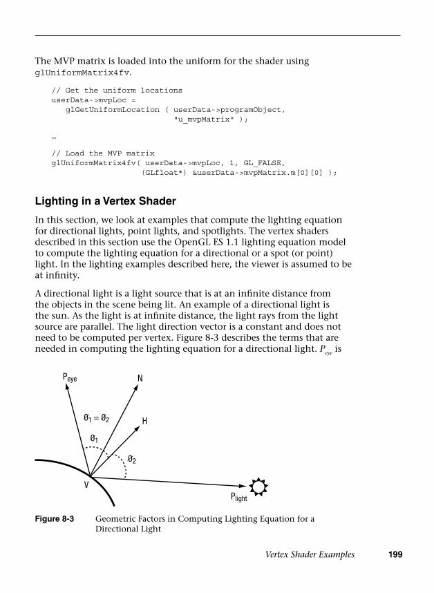
Vertex Shader Examples 199
The MVP matrix is loaded into the uniform for the shader using glUniformMatrix4fv.
// Get the uniform locationsuserData->mvpLoc = glGetUniformLocation ( userData->programObject,
"u_mvpMatrix" );
…
// Load the MVP matrixglUniformMatrix4fv( userData->mvpLoc, 1, GL_FALSE,
(GLfloat*) &userData->mvpMatrix.m[0][0] );
Lighting in a Vertex Shader
In this section, we look at examples that compute the lighting equation for directional lights, point lights, and spotlights. The vertex shaders described in this section use the OpenGL ES 1.1 lighting equation model to compute the lighting equation for a directional or a spot (or point) light. In the lighting examples described here, the viewer is assumed to be at infinity.
A directional light is a light source that is at an infinite distance from the objects in the scene being lit. An example of a directional light is the sun. As the light is at infinite distance, the light rays from the light source are parallel. The light direction vector is a constant and does not need to be computed per vertex. Figure 8-3 describes the terms that are needed in computing the lighting equation for a directional light. Peye is
Peye
Plight
N
01
H
02
01 = 02
V
Figure 8-3 Geometric Factors in Computing Lighting Equation for a Directional Light
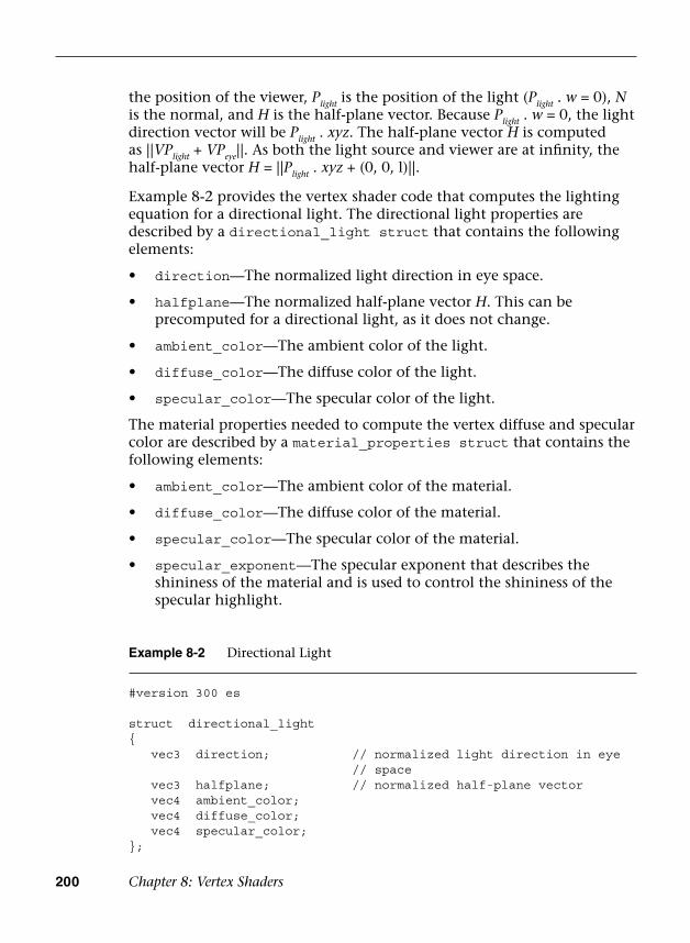
200 Chapter 8: Vertex Shaders
the position of the viewer, Plight is the position of the light (Plight . w = 0), N is the normal, and H is the half-plane vector. Because Plight . w = 0, the light direction vector will be Plight . xyz. The half-plane vector H is computed as ||VPlight + VPeye||. As both the light source and viewer are at infinity, the half-plane vector H = ||Plight . xyz + (0, 0, l)||.
Example 8-2 provides the vertex shader code that computes the lighting equation for a directional light. The directional light properties are described by a directional_light struct that contains the following elements:
• direction—The normalized light direction in eye space.
• halfplane—The normalized half-plane vector H. This can beprecomputed for a directional light, as it does not change.
• ambient_color—The ambient color of the light.
• diffuse_color—The diffuse color of the light.
• specular_color—The specular color of the light.
The material properties needed to compute the vertex diffuse and specular color are described by a material_properties struct that contains the following elements:
• ambient_color—The ambient color of the material.
• diffuse_color—The diffuse color of the material.
• specular_color—The specular color of the material.
• specular_exponent—The specular exponent that describes theshininess of the material and is used to control the shininess of thespecular highlight.
Example 8-2 Directional Light
#version 300 es
struct directional_light{ vec3 direction; // normalized light direction in eye
// space vec3 halfplane; // normalized half-plane vector vec4 ambient_color; vec4 diffuse_color; vec4 specular_color;};

Vertex Shader Examples 201
The directional light vertex shader code described in Example 8-2 combines the per-vertex diffuse and specular color into a single color (given by computed_color). Another option would be to compute the per-vertex diffuse and specular colors and pass them as separate output variables to the fragment shader.
Example 8-2 Directional Light (continued)
struct material_properties{ vec4 ambient_color; vec4 diffuse_color; vec4 specular_color; float specular_exponent;};
const float c_zero = 0.0;const float c_one = 1.0;
uniform material_properties material;uniform directional_light light;
// normal has been transformed into eye space and is a// normalized vector; this function returns the computed colorvec4 directional_light_color ( vec3 normal ){ vec4 computed_color = vec4 ( c_zero, c_zero, c_zero,
c_zero ); float ndotl; // dot product of normal & light direction float ndoth; // dot product of normal & half-plane vector
ndotl = max ( c_zero, dot ( normal, light.direction ) ); ndoth = max ( c_zero, dot ( normal, light.halfplane ) );
computed_color += ( light.ambient_color* material.ambient_color );
computed_color += ( ndotl * light.diffuse_color* material.diffuse_color );
if ( ndoth > c_zero ) {
computed_color += ( pow ( ndoth,material.specular_exponent )*material.specular_color *light.specular_color );
}
return computed_color;}
// add a main function to make this into a valid vertex shader

202 Chapter 8: Vertex Shaders
Note: In Example 8-2, we multiply the material colors (ambient, diffuse, and specular) with the light colors. This is fine if we are computing the lighting equation for only one light. If we have to compute the lighting equation for multiple lights, however, we should compute the ambient, diffuse, and specular values for each light and then compute the final vertex color by multiplying the material ambient, diffuse, and specular colors with appropriate computed terms and then summing them to generate a per-vertex color.
A point light is a light source that emanates light in all directions from a position in space. A point light is given by a position vector (x, y, z, w), where w ≠ 0. The point light shines evenly in all directions but its intensity falls off (i.e., becomes attenuated) based on the distance from the light to the object. This attenuation is computed using the following equation:
distance attenuation K K VP K VPlight light= + × + ×1/ ( || || || || )0 1 22
where K0, K1, and K2 are the constant, linear, and quadratic attenuation factors, respectively.
A spotlight is a light source with both a position and a direction that simulates a cone of light emitted from a position (Plight) in a direction (given by spotdirection). Figure 8-4 describes the terms that are needed in computing the lighting equation for a spotlight.
Peye
Plight
N
01
H
02
01 = 02
V
spot direction
spot cutoff angle
Figure 8-4 Geometric Factors in Computing Lighting Equation for a Spotlight
The intensity of the emitted light is attenuated by a spot cutoff factor based on the angle from the center of the cone. The angle away from the center axis of the cone is computed as the dot product of VPlight and
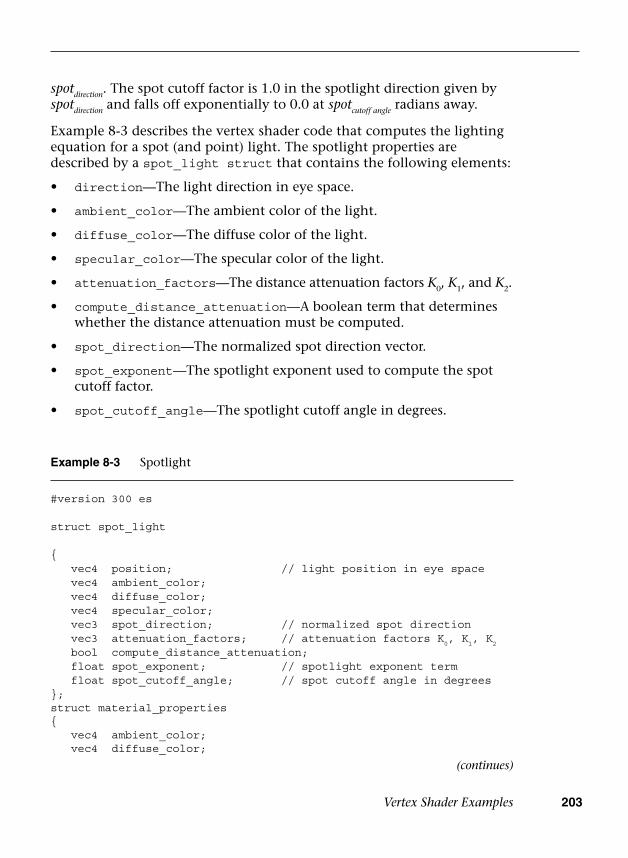
Vertex Shader Examples 203
spotdirection. The spot cutoff factor is 1.0 in the spotlight direction given by spotdirection and falls off exponentially to 0.0 at spotcutoff angle radians away.
Example 8-3 describes the vertex shader code that computes the lighting equation for a spot (and point) light. The spotlight properties are described by a spot_light struct that contains the following elements:
• direction—The light direction in eye space.
• ambient_color—The ambient color of the light.
• diffuse_color—The diffuse color of the light.
• specular_color—The specular color of the light.
• attenuation_factors—The distance attenuation factors K0, K1, and K2.
• compute_distance_attenuation—A boolean term that determineswhether the distance attenuation must be computed.
• spot_direction—The normalized spot direction vector.
• spot_exponent—The spotlight exponent used to compute the spotcutoff factor.
• spot_cutoff_angle—The spotlight cutoff angle in degrees.
Example 8-3 Spotlight
#version 300 es
struct spot_light
{ vec4 position; // light position in eye space vec4 ambient_color; vec4 diffuse_color; vec4 specular_color; vec3 spot_direction; // normalized spot direction vec3 attenuation_factors; // attenuation factors K
0, K
1, K
2
bool compute_distance_attenuation; float spot_exponent; // spotlight exponent term float spot_cutoff_angle; // spot cutoff angle in degrees};struct material_properties{ vec4 ambient_color; vec4 diffuse_color;
(continues)

204 Chapter 8: Vertex Shaders
Example 8-3 Spotlight (continued)
vec4 specular_color; float specular_exponent;};
const float c_zero = 0.0;const float c_one = 1.0;
uniform material_properties material;uniform spot_light light;
// normal and position are normal and position values in// eye space.// normal is a normalized vector.// This function returns the computed color.
vec4 spot_light_color ( vec3 normal, vec4 position ){ vec4 computed_color = vec4 ( c_zero, c_zero, c_zero,
c_zero ); vec3 lightdir; vec3 halfplane; float ndotl, ndoth; float att_factor;
att_factor = c_one;
// we assume "w" values for light position and // vertex position are the same lightdir = light.position.xyz - position.xyz;
// compute distance attenuation if ( light.compute_distance_attenuation ) {
vec3 att_dist;att_dist.x = c_one;att_dist.z = dot ( lightdir, lightdir );att_dist.y = sqrt ( att_dist.z );att_factor = c_one / dot ( att_dist,
light.attenuation_factors ); }
// normalize the light direction vector lightdir = normalize ( lightdir );
// compute spot cutoff factor if ( light.spot_cutoff_angle < 180.0 ) {
float spot_factor = dot ( -lightdir,light.spot_direction );

Generating Texture Coordinates 205
Example 8-3 Spotlight (continued)
if ( spot_factor >= cos ( radians (light.spot_cutoff_angle ) ) )
spot_factor = pow ( spot_factor, light.spot_exponent );else
spot_factor = c_zero;
// compute combined distance and spot attenuation factoratt_factor *= spot_factor;
}
if ( att_factor > c_zero ) {
// process lighting equation --> compute the light colorcomputed_color += ( light.ambient_color *
material.ambient_color );ndotl = max ( c_zero, dot(normal, lightdir ) );computed_color += ( ndotl * light.diffuse_color *
material.diffuse_color );halfplane = normalize ( lightdir + vec3 ( c_zero, c_zero,
c_one ) );ndoth = dot ( normal, halfplane );if ( ndoth > c_zero ){
computed_color += ( pow ( ndoth,material.specular_exponent )*material.specular_color *light.specular_color );
}
// multiply color with computed attenuationcomputed_color *= att_factor;
}
return computed_color;}// add a main function to make this into a valid vertex shader
Generating Texture Coordinates
We look at two examples that generate texture coordinates in a vertex shader. The two examples are used when rendering shiny (i.e., reflective) objects in a scene by generating a reflection vector and then using this vector to compute a texture coordinate that indexes into a latitude–longitude map (also called a sphere map) or a cubemap (represents six
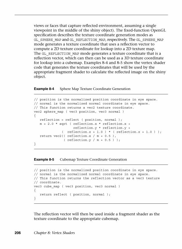
206 Chapter 8: Vertex Shaders
views or faces that capture reflected environment, assuming a single viewpoint in the middle of the shiny object). The fixed-function OpenGL specification describes the texture coordinate generation modes as GL_SPHERE_MAP and GL_REFLECTION_MAP, respectively. The GL_SPHERE_MAP mode generates a texture coordinate that uses a reflection vector to compute a 2D texture coordinate for lookup into a 2D texture map. The GL_REFLECTION_MAP mode generates a texture coordinate that is a reflection vector, which can then can be used as a 3D texture coordinate for lookup into a cubemap. Examples 8-4 and 8-5 show the vertex shader code that generates the texture coordinates that will be used by the appropriate fragment shader to calculate the reflected image on the shiny object.
Example 8-5 Cubemap Texture Coordinate Generation
// position is the normalized position coordinate in eye space.// normal is the normalized normal coordinate in eye space.// This function returns the reflection vector as a vec3 texture // coordinate.vec3 cube_map ( vec3 position, vec3 normal ){ return reflect ( position, normal );}
Example 8-4 Sphere Map Texture Coordinate Generation
// position is the normalized position coordinate in eye space.// normal is the normalized normal coordinate in eye space.// This function returns a vec2 texture coordinate.vec2 sphere_map ( vec3 position, vec3 normal ){ reflection = reflect ( position, normal ); m = 2.0 * sqrt ( reflection.x * reflection.x +
reflection.y * reflection.y +( reflection.z + 1.0 ) * ( reflection.z + 1.0 ) );
return vec2(( reflection.x / m + 0.5 ),( reflection.y / m + 0.5 ) );
}
The reflection vector will then be used inside a fragment shader as the texture coordinate to the appropriate cubemap.
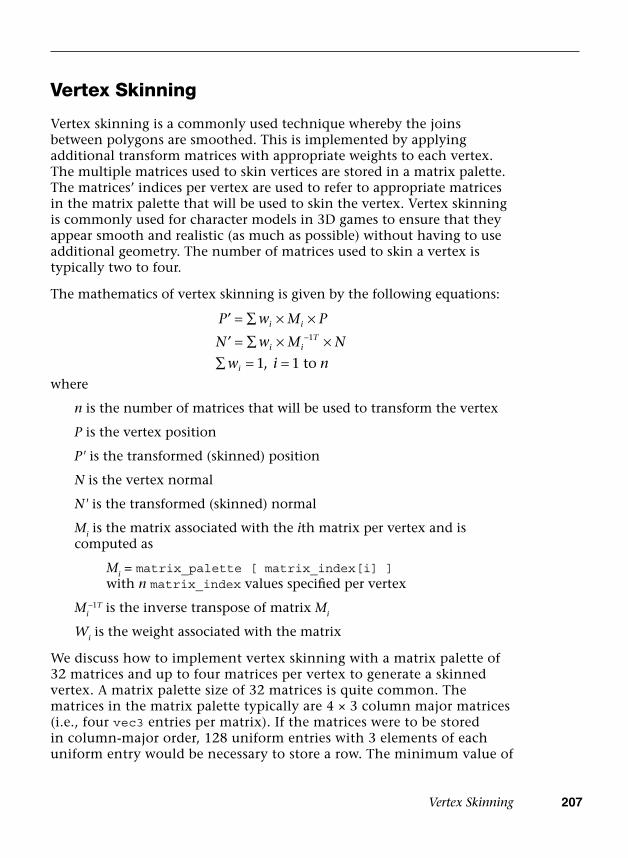
Vertex Skinning 207
Vertex Skinning
Vertex skinning is a commonly used technique whereby the joins between polygons are smoothed. This is implemented by applying additional transform matrices with appropriate weights to each vertex. The multiple matrices used to skin vertices are stored in a matrix palette. The matrices’ indices per vertex are used to refer to appropriate matrices in the matrix palette that will be used to skin the vertex. Vertex skinning is commonly used for character models in 3D games to ensure that they appear smooth and realistic (as much as possible) without having to use additional geometry. The number of matrices used to skin a vertex is typically two to four.
The mathematics of vertex skinning is given by the following equations:
P w M P
N w M N
w i n
i i
i iT
i
′
′
= ∑ × ×
= ∑ × ×∑ = =
−1
1 1, towhere
n is the number of matrices that will be used to transform the vertex
P is the vertex position
P' is the transformed (skinned) position
N is the vertex normal
N' is the transformed (skinned) normal
Mi is the matrix associated with the ith matrix per vertex and is computed as
Mi = matrix_palette [ matrix_index[i] ]with n matrix_index values specified per vertex
Mi–1T is the inverse transpose of matrix Mi
Wi is the weight associated with the matrix
We discuss how to implement vertex skinning with a matrix palette of 32 matrices and up to four matrices per vertex to generate a skinned vertex. A matrix palette size of 32 matrices is quite common. The matrices in the matrix palette typically are 4 × 3 column major matrices (i.e., four vec3 entries per matrix). If the matrices were to be stored in column-major order, 128 uniform entries with 3 elements of each uniform entry would be necessary to store a row. The minimum value of
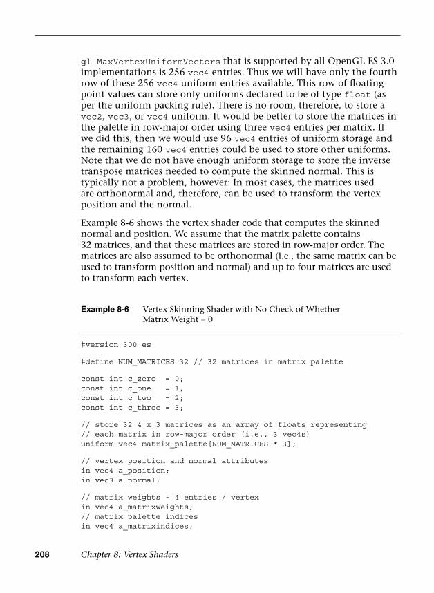
208 Chapter 8: Vertex Shaders
gl_MaxVertexUniformVectors that is supported by all OpenGL ES 3.0 implementations is 256 vec4 entries. Thus we will have only the fourth row of these 256 vec4 uniform entries available. This row of floating-point values can store only uniforms declared to be of type float (as per the uniform packing rule). There is no room, therefore, to store a vec2, vec3, or vec4 uniform. It would be better to store the matrices in the palette in row-major order using three vec4 entries per matrix. If we did this, then we would use 96 vec4 entries of uniform storage and the remaining 160 vec4 entries could be used to store other uniforms. Note that we do not have enough uniform storage to store the inverse transpose matrices needed to compute the skinned normal. This is typically not a problem, however: In most cases, the matrices used are orthonormal and, therefore, can be used to transform the vertex position and the normal.
Example 8-6 shows the vertex shader code that computes the skinned normal and position. We assume that the matrix palette contains 32 matrices, and that these matrices are stored in row-major order. The matrices are also assumed to be orthonormal (i.e., the same matrix can be used to transform position and normal) and up to four matrices are used to transform each vertex.
Example 8-6 Vertex Skinning Shader with No Check of Whether Matrix Weight = 0
#version 300 es
#define NUM_MATRICES 32 // 32 matrices in matrix palette
const int c_zero = 0;const int c_one = 1;const int c_two = 2;const int c_three = 3;
// store 32 4 x 3 matrices as an array of floats representing// each matrix in row-major order (i.e., 3 vec4s)uniform vec4 matrix_palette[NUM_MATRICES * 3];
// vertex position and normal attributesin vec4 a_position;in vec3 a_normal;
// matrix weights - 4 entries / vertexin vec4 a_matrixweights;// matrix palette indicesin vec4 a_matrixindices;
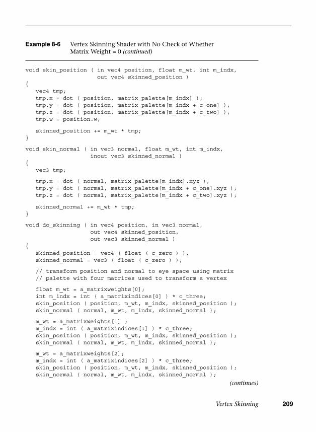
Vertex Skinning 209
Example 8-6 Vertex Skinning Shader with No Check of Whether Matrix Weight = 0 (continued)
void skin_position ( in vec4 position, float m_wt, int m_indx,out vec4 skinned_position )
{ vec4 tmp; tmp.x = dot ( position, matrix_palette[m_indx] ); tmp.y = dot ( position, matrix_palette[m_indx + c_one] ); tmp.z = dot ( position, matrix_palette[m_indx + c_two] ); tmp.w = position.w;
skinned_position += m_wt * tmp;}
void skin_normal ( in vec3 normal, float m_wt, int m_indx,inout vec3 skinned_normal )
{ vec3 tmp;
tmp.x = dot ( normal, matrix_palette[m_indx].xyz ); tmp.y = dot ( normal, matrix_palette[m_indx + c_one].xyz ); tmp.z = dot ( normal, matrix_palette[m_indx + c_two].xyz );
skinned_normal += m_wt * tmp;}
void do_skinning ( in vec4 position, in vec3 normal,out vec4 skinned_position,out vec3 skinned_normal )
{ skinned_position = vec4 ( float ( c_zero ) ); skinned_normal = vec3 ( float ( c_zero ) );
// transform position and normal to eye space using matrix // palette with four matrices used to transform a vertex
float m_wt = a_matrixweights[0]; int m_indx = int ( a_matrixindices[0] ) * c_three; skin_position ( position, m_wt, m_indx, skinned_position ); skin_normal ( normal, m_wt, m_indx, skinned_normal );
m_wt = a_matrixweights[1] ; m_indx = int ( a_matrixindices[1] ) * c_three; skin_position ( position, m_wt, m_indx, skinned_position ); skin_normal ( normal, m_wt, m_indx, skinned_normal );
m_wt = a_matrixweights[2]; m_indx = int ( a_matrixindices[2] ) * c_three; skin_position ( position, m_wt, m_indx, skinned_position ); skin_normal ( normal, m_wt, m_indx, skinned_normal );
(continues)
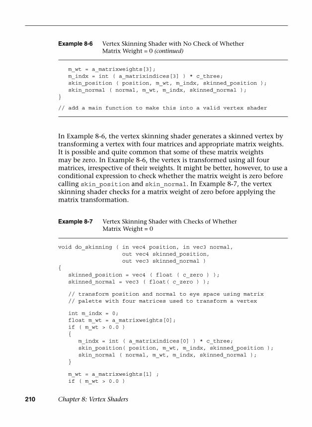
210 Chapter 8: Vertex Shaders
In Example 8-6, the vertex skinning shader generates a skinned vertex by transforming a vertex with four matrices and appropriate matrix weights. It is possible and quite common that some of these matrix weights may be zero. In Example 8-6, the vertex is transformed using all four matrices, irrespective of their weights. It might be better, however, to use a conditional expression to check whether the matrix weight is zero before calling skin_position and skin_normal. In Example 8-7, the vertex skinning shader checks for a matrix weight of zero before applying the matrix transformation.
Example 8-7 Vertex Skinning Shader with Checks of Whether Matrix Weight = 0
void do_skinning ( in vec4 position, in vec3 normal,out vec4 skinned_position,out vec3 skinned_normal )
{ skinned_position = vec4 ( float ( c_zero ) ); skinned_normal = vec3 ( float( c_zero ) );
// transform position and normal to eye space using matrix // palette with four matrices used to transform a vertex
int m_indx = 0; float m_wt = a_matrixweights[0]; if ( m_wt > 0.0 ) {
m_indx = int ( a_matrixindices[0] ) * c_three;skin_position( position, m_wt, m_indx, skinned_position );skin_normal ( normal, m_wt, m_indx, skinned_normal );
}
m_wt = a_matrixweights[1] ; if ( m_wt > 0.0 )
Example 8-6 Vertex Skinning Shader with No Check of Whether Matrix Weight = 0 (continued)
m_wt = a_matrixweights[3]; m_indx = int ( a_matrixindices[3] ) * c_three; skin_position ( position, m_wt, m_indx, skinned_position ); skin_normal ( normal, m_wt, m_indx, skinned_normal );}
// add a main function to make this into a valid vertex shader
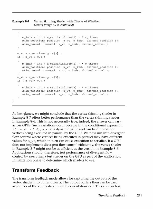
Transform Feedback 211
At first glance, we might conclude that the vertex skinning shader in Example 8-7 offers better performance than the vertex skinning shader in Example 8-6. This is not necessarily true; indeed, the answer can vary across GPUs. Such variations occur because in the conditional expression if (m_wt > 0.0), m_wt is a dynamic value and can be different for vertices being executed in parallel by the GPU. We now run into divergent flow control where vertices being executed in parallel may have different values for m_wt, which in turn can cause execution to serialize. If a GPU does not implement divergent flow control efficiently, the vertex shader in Example 8-7 might not be as efficient as the version in Example 8-6. Applications should, therefore, test performance of divergent flow control by executing a test shader on the GPU as part of the application initialization phase to determine which shaders to use.
Transform Feedback
The transform feedback mode allows for capturing the outputs of the vertex shader into buffer objects. The output buffers then can be used as sources of the vertex data in a subsequent draw call. This approach is
Example 8-7 Vertex Skinning Shader with Checks of Whether Matrix Weight = 0 (continued)
{m_indx = int ( a_matrixindices[1] ) * c_three;skin_position( position, m_wt, m_indx, skinned_position );skin_normal ( normal, m_wt, m_indx, skinned_normal );
}
m_wt = a_matrixweights[2] ; if ( m_wt > 0.0 ) {
m_indx = int ( a_matrixindices[2] ) * c_three;skin_position( position, m_wt, m_indx, skinned_position );skin_normal ( normal, m_wt, m_indx, skinned_normal );
} m_wt = a_matrixweights[3]; if ( m_wt > 0.0 ) {
m_indx = int ( a_matrixindices[3] ) * c_three;skin_position( position, m_wt, m_indx, skinned_position );skin_normal ( normal, m_wt, m_indx, skinned_normal );
}}

212 Chapter 8: Vertex Shaders
After calling glTransformFeedbackVaryings, it is necessary to link the program object using glLinkProgram. For example, to specify two vertex attributes to be captured into one transform feedback buffer, the code will be as follows:
const char* varyings[] = { "v_position", "v_color" };glTransformFeedbackVarying ( programObject, 2, varyings,
GL_INTERLEAVED_ATTRIBS );glLinkProgram ( programObject );
Then, we need to bind one or more buffer objects as the transform feedback buffers using glBindBuffer with GL_TRANSFORM_FEED-BACK_BUFFER. The buffer is allocated using glBufferData with GL_TRANSFORM_FEEDBACK_BUFFER and bound to the indexed binding points using glBindBufferBase or glBindBufferRange. These buffer APIs are described in more details in Chapter 6, “Vertex Attributes, Vertex Arrays, and Buffer Objects.”
void glTransformFeedbackVaryings(GLuint program,GLsizei count,const char** varyings,GLenum bufferMode)
program specifies the handle to the program object.count specifies the number of vertex output variables used for
transform feedback.varyings specifies an array of count zero-terminated strings
specifying the names of the vertex output variables to use for transform feedback.
bufferMode specifies the mode used to capture the vertex output variables when transform feedback is active.Valid values are GL_INTERLEAVED_ATTRIBS, to capture the vertex output variables into a single buffer, and GL_SEPARATE_ATTRIBS, to capture each vertex output variable into its own buffer.
useful for a wide range of techniques that perform animation on the GPU without any CPU intervention, such as particle animation or physics simulation using render-to-vertex-buffer.
To specify the set of vertex attributes to be captured during the transform feedback mode, use the following command:
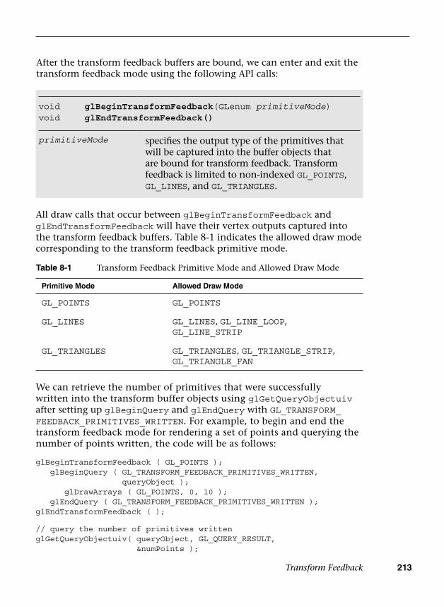
Transform Feedback 213
After the transform feedback buffers are bound, we can enter and exit the transform feedback mode using the following API calls:
Table 8-1 Transform Feedback Primitive Mode and Allowed Draw Mode
Primitive Mode Allowed Draw Mode
GL_POINTS GL_POINTS
GL_LINES GL_LINES, GL_LINE_LOOP, GL_LINE_STRIP
GL_TRIANGLES GL_TRIANGLES, GL_TRIANGLE_STRIP, GL_TRIANGLE_FAN
All draw calls that occur between glBeginTransformFeedback and glEndTransformFeedback will have their vertex outputs captured into the transform feedback buffers. Table 8-1 indicates the allowed draw mode corresponding to the transform feedback primitive mode.
void glBeginTransformFeedback(GLenum primitiveMode)void glEndTransformFeedback()
primitiveMode specifies the output type of the primitives that will be captured into the buffer objects that are bound for transform feedback. Transform feedback is limited to non-indexed GL_POINTS, GL_LINES, and GL_TRIANGLES.
We can retrieve the number of primitives that were successfully written into the transform buffer objects using glGetQueryObjectuiv after setting up glBeginQuery and glEndQuery with GL_TRANSFORM_FEEDBACK_PRIMITIVES_WRITTEN. For example, to begin and end the transform feedback mode for rendering a set of points and querying the number of points written, the code will be as follows:
glBeginTransformFeedback ( GL_POINTS ); glBeginQuery ( GL_TRANSFORM_FEEDBACK_PRIMITIVES_WRITTEN,
queryObject );glDrawArrays ( GL_POINTS, 0, 10 );
glEndQuery ( GL_TRANSFORM_FEEDBACK_PRIMITIVES_WRITTEN );glEndTransformFeedback ( );
// query the number of primitives writtenglGetQueryObjectuiv( queryObject, GL_QUERY_RESULT,
&numPoints );
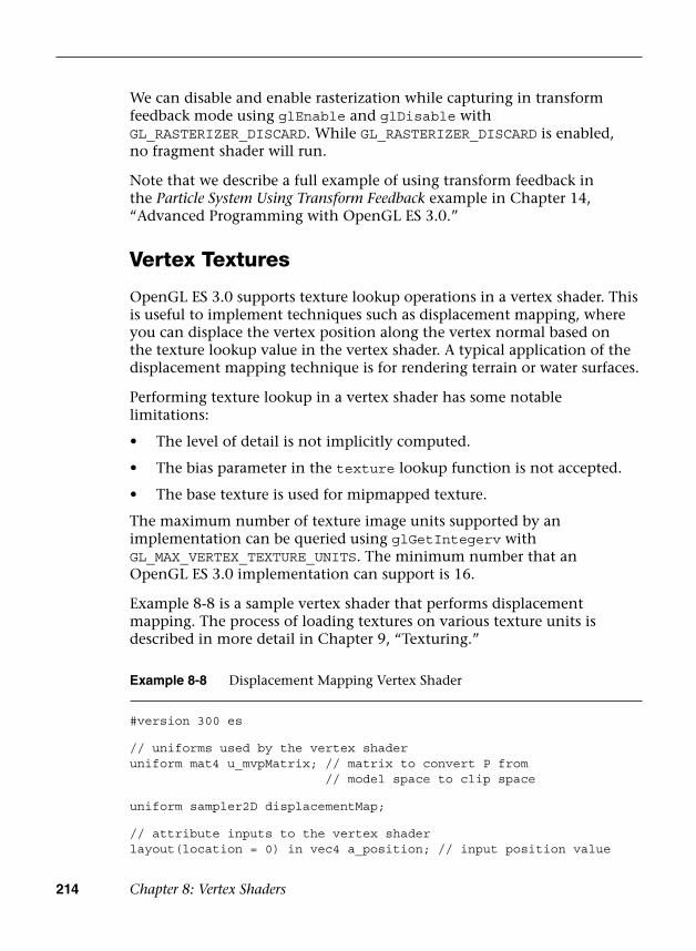
214 Chapter 8: Vertex Shaders
We can disable and enable rasterization while capturing in transform feedback mode using glEnable and glDisable with GL_RASTERIZER_DISCARD. While GL_RASTERIZER_DISCARD is enabled, no fragment shader will run.
Note that we describe a full example of using transform feedback in the Particle System Using Transform Feedback example in Chapter 14, “Advanced Programming with OpenGL ES 3.0.”
Vertex Textures
OpenGL ES 3.0 supports texture lookup operations in a vertex shader. This is useful to implement techniques such as displacement mapping, where you can displace the vertex position along the vertex normal based on the texture lookup value in the vertex shader. A typical application of the displacement mapping technique is for rendering terrain or water surfaces.
Performing texture lookup in a vertex shader has some notable limitations:
• The level of detail is not implicitly computed.
• The bias parameter in the texture lookup function is not accepted.
• The base texture is used for mipmapped texture.
The maximum number of texture image units supported by an implementation can be queried using glGetIntegerv with GL_MAX_VERTEX_TEXTURE_UNITS. The minimum number that an OpenGL ES 3.0 implementation can support is 16.
Example 8-8 is a sample vertex shader that performs displacement mapping. The process of loading textures on various texture units is described in more detail in Chapter 9, “Texturing.”
Example 8-8 Displacement Mapping Vertex Shader
#version 300 es
// uniforms used by the vertex shaderuniform mat4 u_mvpMatrix; // matrix to convert P from
// model space to clip space
uniform sampler2D displacementMap;
// attribute inputs to the vertex shaderlayout(location = 0) in vec4 a_position; // input position value

OpenGL ES 1.1 Vertex Pipeline as an ES 3.0 Vertex Shader 215
We hope that the examples discussed so far have provided a good understanding of vertex shaders, including how to write them and how to use them for a wide-ranging array of effects.
OpenGL ES 1.1 Vertex Pipeline as an ES 3.0 Vertex Shader
We now discuss a vertex shader that implements the OpenGL ES 1.1 fixed-function vertex pipeline without vertex skinning. This is also meant to be an interesting exercise in figuring out how big a vertex shader can be and still run across all OpenGL ES 3.0 implementations.
This vertex shader implements the following fixed functions of the OpenGL ES 1.1 vertex pipeline:
• Transform the normal and position to eye space, if required (typicallyrequired for lighting). Rescale or normalization of normal is alsoperformed.
• Compute the OpenGL ES 1.1 vertex lighting equation for up to eightdirectional lights, point lights, or spotlights with two-sided lightingand color material per vertex.
• Transform the texture coordinates for up to two texture coordinatesper vertex.
Example 8-8 Displacement Mapping Vertex Shader (continued)
layout(location = 1) in vec3 a_normal; // input normal valuelayout(location = 2) in vec2 a_texcoord; // input texcoord valuelayout(location = 3) in vec4 a_color; // input color
// vertex shader output, input to the fragment shaderout vec4 v_color;
void main ( ){ v_color = a_color; float displacement = texture ( displacementMap,
a_texcoord ).a;
vec4 displaced_position = a_position +vec4 ( a_normal * displacement, 0.0 );
gl_Position = u_mvpMatrix * displaced_position;}
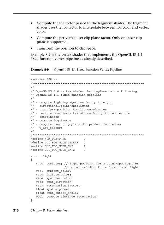
216 Chapter 8: Vertex Shaders
• Compute the fog factor passed to the fragment shader. The fragmentshader uses the fog factor to interpolate between fog color and vertexcolor.
• Compute the per-vertex user clip plane factor. Only one user clipplane is supported.
• Transform the position to clip space.
Example 8-9 is the vertex shader that implements the OpenGL ES 1.1 fixed-function vertex pipeline as already described.
Example 8-9 OpenGL ES 1.1 Fixed-Function Vertex Pipeline
#version 300 es
//**************************************************************//// OpenGL ES 3.0 vertex shader that implements the following// OpenGL ES 1.1 fixed-function pipeline//// - compute lighting equation for up to eight// directional/point/spotlights// - transform position to clip coordinates// - texture coordinate transforms for up to two texture// coordinates// - compute fog factor// - compute user clip plane dot product (stored as// v_ucp_factor)////**************************************************************#define NUM_TEXTURES 2#define GLI_FOG_MODE_LINEAR 0#define GLI_FOG_MODE_EXP 1#define GLI_FOG_MODE_EXP2 2
struct light{ vec4 position; // light position for a point/spotlight or
// normalized dir. for a directional light vec4 ambient_color; vec4 diffuse_color; vec4 specular_color; vec3 spot_direction; vec3 attenuation_factors; float spot_exponent; float spot_cutoff_angle; bool compute_distance_attenuation;};
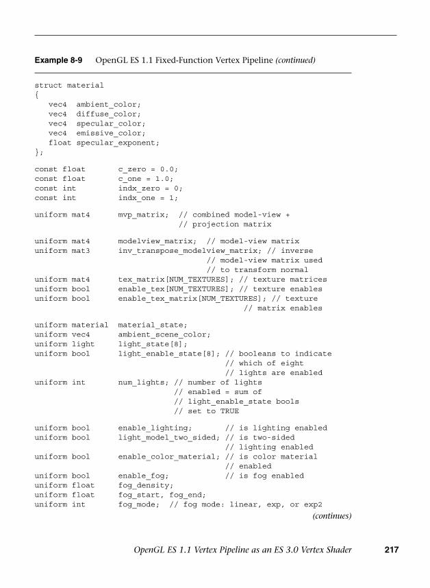
OpenGL ES 1.1 Vertex Pipeline as an ES 3.0 Vertex Shader 217
Example 8-9 OpenGL ES 1.1 Fixed-Function Vertex Pipeline (continued)
struct material{ vec4 ambient_color; vec4 diffuse_color; vec4 specular_color; vec4 emissive_color; float specular_exponent;};
const float c_zero = 0.0;const float c_one = 1.0;const int indx_zero = 0;const int indx_one = 1;
uniform mat4 mvp_matrix; // combined model-view +// projection matrix
uniform mat4 modelview_matrix; // model-view matrixuniform mat3 inv_transpose_modelview_matrix; // inverse
// model-view matrix used// to transform normal
uniform mat4 tex_matrix[NUM_TEXTURES]; // texture matricesuniform bool enable_tex[NUM_TEXTURES]; // texture enablesuniform bool enable_tex_matrix[NUM_TEXTURES]; // texture
// matrix enables
uniform material material_state;uniform vec4 ambient_scene_color;uniform light light_state[8];uniform bool light_enable_state[8]; // booleans to indicate
// which of eight// lights are enabled
uniform int num_lights; // number of lights// enabled = sum of// light_enable_state bools// set to TRUE
uniform bool enable_lighting; // is lighting enableduniform bool light_model_two_sided; // is two-sided
// lighting enableduniform bool enable_color_material; // is color material
// enableduniform bool enable_fog; // is fog enableduniform float fog_density;uniform float fog_start, fog_end;uniform int fog_mode; // fog mode: linear, exp, or exp2
(continues)
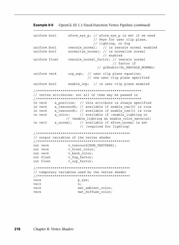
218 Chapter 8: Vertex Shaders
Example 8-9 OpenGL ES 1.1 Fixed-Function Vertex Pipeline (continued)
uniform bool xform_eye_p; // xform_eye_p is set if we need// Peye for user clip plane,// lighting, or fog
uniform bool rescale_normal; // is rescale normal enableduniform bool normalize_normal; // is normalize normal
// enableduniform float rescale_normal_factor; // rescale normal
// factor if// glEnable(GL_RESCALE_NORMAL)
uniform vec4 ucp_eqn; // user clip plane equation;// one user clip plane specified
uniform bool enable_ucp; // is user clip plane enabled
//******************************************************// vertex attributes: not all of them may be passed in//******************************************************in vec4 a_position; // this attribute is always specifiedin vec4 a_texcoord0; // available if enable_tex[0] is truein vec4 a_texcoordl; // available if enable_tex[1] is truein vec4 a_color; // available if !enable_lighting or
// (enable_lighting && enable_color_material)in vec3 a_normal; // available if xform_normal is set
// (required for lighting)
//************************************************// output variables of the vertex shader//************************************************out vec4 v_texcoord[NUM_TEXTURES];out vec4 v_front_color;out vec4 v_back_color;out float v_fog_factor;out float v_ucp_factor;
//************************************************// temporary variables used by the vertex shader//************************************************vec4 p_eye;vec3 n;vec4 mat_ambient_color;vec4 mat_diffuse_color;
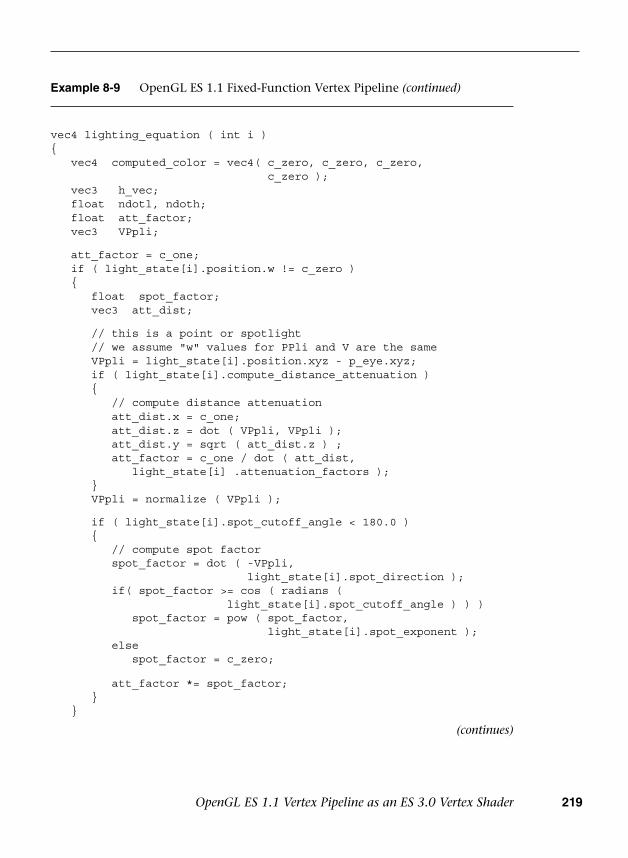
OpenGL ES 1.1 Vertex Pipeline as an ES 3.0 Vertex Shader 219
Example 8-9 OpenGL ES 1.1 Fixed-Function Vertex Pipeline (continued)
vec4 lighting_equation ( int i ){ vec4 computed_color = vec4( c_zero, c_zero, c_zero,
c_zero ); vec3 h_vec; float ndotl, ndoth; float att_factor; vec3 VPpli;
att_factor = c_one; if ( light_state[i].position.w != c_zero ) {
float spot_factor;vec3 att_dist;
// this is a point or spotlight// we assume "w" values for PPli and V are the sameVPpli = light_state[i].position.xyz - p_eye.xyz;if ( light_state[i].compute_distance_attenuation ){
// compute distance attenuationatt_dist.x = c_one;att_dist.z = dot ( VPpli, VPpli );att_dist.y = sqrt ( att_dist.z ) ;att_factor = c_one / dot ( att_dist,
light_state[i] .attenuation_factors );}VPpli = normalize ( VPpli );
if ( light_state[i].spot_cutoff_angle < 180.0 ){
// compute spot factorspot_factor = dot ( -VPpli,
light_state[i].spot_direction );if( spot_factor >= cos ( radians (
light_state[i].spot_cutoff_angle ) ) )spot_factor = pow ( spot_factor,
light_state[i].spot_exponent );else
spot_factor = c_zero;
att_factor *= spot_factor;}
}
(continues)
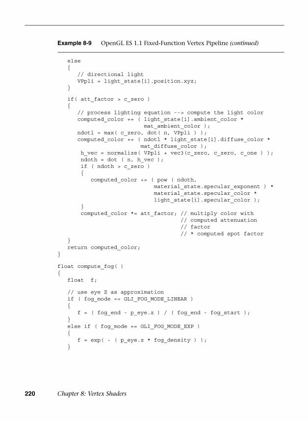
220 Chapter 8: Vertex Shaders
Example 8-9 OpenGL ES 1.1 Fixed-Function Vertex Pipeline (continued)
else {
// directional lightVPpli = light_state[i].position.xyz;
}
if( att_factor > c_zero ) {
// process lighting equation --> compute the light colorcomputed_color += ( light_state[i].ambient_color *
mat_ambient_color );ndotl = max( c_zero, dot( n, VPpli ) );computed_color += ( ndotl * light_state[i].diffuse_color *
mat_diffuse_color );h_vec = normalize( VPpli + vec3(c_zero, c_zero, c_one ) );ndoth = dot ( n, h_vec );if ( ndoth > c_zero ){
computed_color += ( pow ( ndoth,material_state.specular_exponent ) *material_state.specular_color *light_state[i].specular_color );
}computed_color *= att_factor; // multiply color with
// computed attenuation// factor// * computed spot factor
} return computed_color;}
float compute_fog( ){ float f;
// use eye Z as approximation if ( fog_mode == GLI_FOG_MODE_LINEAR ) {
f = ( fog_end - p_eye.z ) / ( fog_end - fog_start ); } else if ( fog_mode == GLI_FOG_MODE_EXP ) {
f = exp( - ( p_eye.z * fog_density ) ); }

OpenGL ES 1.1 Vertex Pipeline as an ES 3.0 Vertex Shader 221
Example 8-9 OpenGL ES 1.1 Fixed-Function Vertex Pipeline (continued)
else {
f = ( p_eye.z * fog_density );f = exp( -( f * f ) );
}
f = clamp ( f, c_zero, c_one) ; return f;}
vec4 do_lighting( ){ vec4 vtx_color; int i, j ;
vtx_color = material_state.emissive_color +( mat_ambient_color * ambient_scene_color );
j = int( c_zero ); for ( i=int( c_zero ); i<8; i++ ) {
if ( j >= num_lights )break;
if ( light_enable_state[i] ){
j++;vtx_color += lighting_equation(i);
} }
vtx_color.a = mat_diffuse_color.a;
return vtx_color;}
void main( void ){ int i, j;
// do we need to transform P if ( xform_eye_p )
p_eye = modelview_matrix * a_position;
if ( enable_lighting ) {
n = inv_transpose_modelview_matrix * a_normal;if ( rescale_normal )
n = rescale_normal_factor * n;
(continues)

222 Chapter 8: Vertex Shaders
Example 8-9 OpenGL ES 1.1 Fixed-Function Vertex Pipeline (continued)
if ( normalize_normal )n = normalize(n);
mat_ambient_color = enable_color_material ? a_color: material_state.ambient_color;
mat_diffuse_color = enable_color_material ? a_color: material_state.diffuse_color;
v_front_color = do_lighting( );v_back_color = v_front_color;
// do two-sided lightingif ( light_model_two_sided ){
n = -n;v_back_color = do_lighting( );
} } else {
// set the default output color to be the per-vertex /// per-primitive colorv_front_color = a_color;v_back_color = a_color;
}
// do texture transforms v_texcoord[indx_zero] = vec4( c_zero, c_zero, c_zero,
c_one ); if ( enable_tex[indx_zero] ) {
if ( enable_tex_matrix[indx_zero] )v_texcoord[indx_zero] = tex_matrix[indx_zero] *
a_texcoord0;else
v_texcoord[indx_zero] = a_texcoord0; }
v_texcoord[indx_one] = vec4( c_zero, c_zero, c_zero, c_one ); if ( enable_tex[indx_one] ) {
if ( enable_tex_matrix[indx_one] )v_texcoord[indx_one] = tex_matrix[indx_one] *
a_texcoordl;else
v_texcoord[indx_one] = a_texcoordl; }
Summary 223
Example 8-9 OpenGL ES 1.1 Fixed-Function Vertex Pipeline (continued)
v_ucp_factor = enable_ucp ? dot ( p_eye, ucp_eqn ) : c_zero; v_fog_factor = enable_fog ? compute_fog( ) : c_one;
gl_Position = mvp_matrix * a_position;}
Summary
In this chapter, we provided a high-level overview of how vertex shaders fit into the pipeline and how to perform transformation, lighting, skinning, and displacement mapping in a vertex shader through some vertex shader examples. In addition, you learned how to use the transform feedback mode to capture the vertex outputs into buffer objects and how to implement the fixed-function pipeline using vertex shaders. Next, before we will discuss fragment shaders, we will cover the texturing functionality in OpenGL ES 3.0.

This page intentionally left blank
225
Chapter 9
Texturing
Now that we have covered vertex shaders in detail, you should be familiar with all of the gritty details of transforming vertices and preparing primitives for rendering. The next step in the pipeline is the fragment shader, where much of the visual magic of OpenGL ES 3.0 occurs. A central aspect of fragment shaders is the application of textures to surfaces. This chapter covers all the details of creating, loading, and applying textures:
• Texturing basics
• Loading textures and mipmapping
• Texture filtering and wrapping
• Texture level-of-detail, swizzles, and depth comparison
• Texture formats
• Using textures in the fragment shader
• Texture subimage specification
• Copying texture data from the framebuffer
• Compressed textures
• Sampler objects
• Immutable textures
• Pixel unpack buffer objects
226 Chapter 9: Texturing
Texturing Basics
One of the most fundamental operations used in rendering 3D graphics is the application of textures to a surface. Textures allow for the representation of additional detail not available just from the geometry of a mesh. Textures in OpenGL ES 3.0 come in several forms: 2D textures, 2D texture arrays, 3D textures, and cubemap textures.
Textures are typically applied to a surface by using texture coordinates, which can be thought of as indices into texture array data. The following sections introduce the different texture types in OpenGL ES and explain how they are loaded and accessed.
2D Textures
A 2D texture is the most basic and common form of texture in OpenGL ES. A 2D texture is—as you might guess—a two-dimensional array of image data. The individual data elements of a texture are known as texels (short for “texture pixels”). Texture image data in OpenGL ES can be represented in many different basic formats. The basic formats available for texture data are shown in Table 9-1.
Each texel in the image is specified according to both its basic format and its data type. Later, we describe in more detail the various data types that can represent a texel. For now, the important point to understand is that a 2D texture is a two-dimensional array of image data. When rendering with a 2D texture, a texture coordinate is used as an index into the texture image. Generally, a mesh will be authored in a 3D content authoring program, with each vertex having a texture coordinate. Texture coordinates for 2D textures are given by a 2D pair of coordinates (s, t), sometimes also called (u, v) coordinates. These coordinates represent normalized coordinates used to look up a texture map, as shown in Figure 9-1.
The lower-left corner of the texture image is specified by the st-coordinates (0.0, 0.0). The upper-right corner of the texture image is specified by the st-coordinates (1.0, 1.0). Coordinates outside of the range [0.0, 1.0] are allowed, and the behavior of texture fetches outside of that range is defined by the texture wrapping mode (described in the section on texture filtering and wrapping).
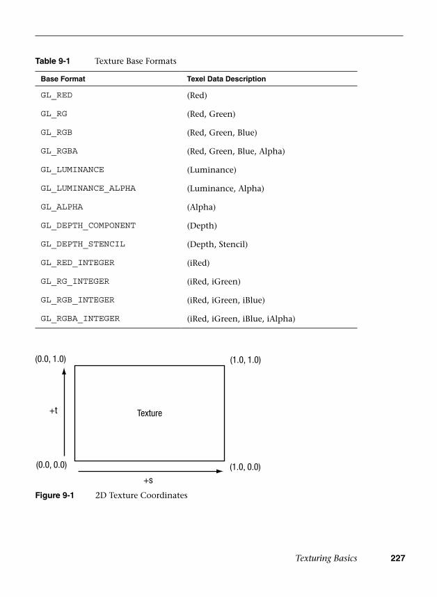
Texturing Basics 227
Table 9-1 Texture Base Formats
Base Format Texel Data Description
GL_RED (Red)
GL_RG (Red, Green)
GL_RGB (Red, Green, Blue)
GL_RGBA (Red, Green, Blue, Alpha)
GL_LUMINANCE (Luminance)
GL_LUMINANCE_ALPHA (Luminance, Alpha)
GL_ALPHA (Alpha)
GL_DEPTH_COMPONENT (Depth)
GL_DEPTH_STENCIL (Depth, Stencil)
GL_RED_INTEGER (iRed)
GL_RG_INTEGER (iRed, iGreen)
GL_RGB_INTEGER (iRed, iGreen, iBlue)
GL_RGBA_INTEGER (iRed, iGreen, iBlue, iAlpha)
(0.0, 1.0)
(0.0, 0.0)
(1.0, 1.0)
(1.0, 0.0)
Texture
+s
+t
Figure 9-1 2D Texture Coordinates
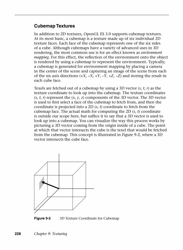
228 Chapter 9: Texturing
Cubemap Textures
In addition to 2D textures, OpenGL ES 3.0 supports cubemap textures. At its most basic, a cubemap is a texture made up of six individual 2D texture faces. Each face of the cubemap represents one of the six sides of a cube. Although cubemaps have a variety of advanced uses in 3D rendering, the most common use is for an effect known as environment mapping. For this effect, the reflection of the environment onto the object is rendered by using a cubemap to represent the environment. Typically, a cubemap is generated for environment mapping by placing a camera in the center of the scene and capturing an image of the scene from each of the six axis directions (+X, –X, +Y, –Y, +Z, –Z) and storing the result in each cube face.
Texels are fetched out of a cubemap by using a 3D vector (s, t, r) as the texture coordinate to look up into the cubemap. The texture coordinates (s, t, r) represent the (x, y, z) components of the 3D vector. The 3D vector is used to first select a face of the cubemap to fetch from, and then the coordinate is projected into a 2D (s, t) coordinate to fetch from the cubemap face. The actual math for computing the 2D (s, t) coordinate is outside our scope here, but suffice it to say that a 3D vector is used to look up into a cubemap. You can visualize the way this process works by picturing a 3D vector coming from the origin inside of a cube. The point at which that vector intersects the cube is the texel that would be fetched from the cubemap. This concept is illustrated in Figure 9-2, where a 3D vector intersects the cube face.
Figure 9-2 3D Texture Coordinate for Cubemap

Texturing Basics 229
3D Texture
+s
+r
+t
Figure 9-3 3D Texture
The faces of a cubemap are each specified in the same manner as one would specify a 2D texture. Each of the faces must be square (e.g., the width and height must be equal), and each must have the same width and height. The 3D vector that is used for the texture coordinate is not normally stored directly on a per-vertex basis on the mesh as it is for 2D texturing. Instead, cubemaps are usually fetched from by using the normal vector as a basis for computing the cubemap texture coordinate. Typically, the normal vector is used along with a vector from the eye to compute a reflection vector that is then used to look up into a cubemap. This computation is described in the environment mapping example in Chapter 14, “Advanced Programming with OpenGL ES 3.0.”
3D Textures
Another type of texture in OpenGL ES 3.0 is the 3D texture (or volume texture). 3D textures can be thought of as an array of multiple slices of 2D textures. A 3D texture is accessed with a three-tuple (s, t, r) coordinate, much like a cubemap. For 3D textures, the r-coordinate selects which slice of the 3D texture to sample from and the (s, t) coordinate is used to fetch into the 2D map at each slice. Figure 9-3 shows a 3D texture where each slice is made up of an individual 2D texture. Each mipmap level in a 3D texture contains half the number of slices in the texture above it (more on this later).

230 Chapter 9: Texturing
2D Texture Arrays
The final type of texture in OpenGL ES 3.0 is a 2D texture array. The 2D texture array is very similar to a 3D texture, but is used for a different purpose. For example, 2D texture arrays are often used to store an animation of a 2D image. Each slice of the array represents one frame of the texture animation. The difference between 2D texture arrays and 3D textures is subtle but important. For a 3D texture, filtering occurs between slices, whereas fetching from a 2D texture array will sample from only an individual slice. As such, mipmapping is also different. Each mipmap level in a 2D texture array contains the same number of slices as the level above it. Each 2D slice is entirely mipmapped independently from any other slices (unlike the case with a 3D texture, for which each mipmap level has half as many slices as above it).
To address a 2D texture array, three texture coordinates (s, t, r) are used just like with a 3D texture. The r-coordinate selects which slice in the 2D texture array to use and the (s, t) coordinates are used on the selected slice in exactly the same way as a 2D texture.
Texture Objects and Loading Textures
The first step in the application of textures is to create a texture object. A texture object is a container object that holds the texture data needed for rendering, such as image data, filtering modes, and wrap modes. In OpenGL ES, a texture object is represented by an unsigned integer that is a handle to the texture object. The function that is used for generating texture objects is glGenTextures.
void glGenTextures(GLsizei n, GLuint *textures)
n
textures
specifies the number of texture objects to generate
an array of unsigned integers that will hold n texture object IDs
At the point of creation, the texture objects(s) generated by glGenTextures are an empty container that will be used for loading texture data and parameters. Texture objects also need to be deleted when an application no longer needs them. This step is typically done either at application shutdown or, for example, when changing levels in a game. It can be accomplished by using glDeleteTextures.
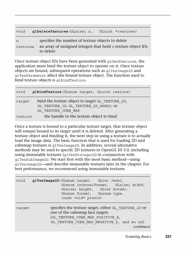
Texturing Basics 231
Once texture object IDs have been generated with glGenTextures, the application must bind the texture object to operate on it. Once texture objects are bound, subsequent operations such as glTexImage2D and glTexParameter affect the bound texture object. The function used to bind texture objects is glBindTexture.
void glDeleteTextures(GLsizei n, GLuint *textures)
n
textures
specifies the number of texture objects to delete
an array of unsigned integers that hold n texture object IDs to delete
void glBindTexture(GLenum target, GLuint texture)
target bind the texture object to target GL_TEXTURE_2D, GL_TEXTURE_3D, GL_TEXTURE_2D_ARRAY, or GL_TEXTURE_CUBE_MAP
texture the handle to the texture object to bind
void glTexImage2D( GLenum target, GLint level, GLenum internalFormat, GLsizei width, GLsizei height, GLint border, GLenum format, GLenum type, const void* pixels)
target specifies the texture target, either GL_TEXTURE_2D or one of the cubemap face targets (GL_TEXTURE_CUBE_MAP_POSITIVE_X, GL_TEXTURE_CUBE_MAP_NEGATIVE_X, and so on).
Once a texture is bound to a particular texture target, that texture object will remain bound to its target until it is deleted. After generating a texture object and binding it, the next step in using a texture is to actually load the image data. The basic function that is used for loading 2D and cubemap textures is glTexImage2D. In addition, several alternative methods may be used to specify 2D textures in OpenGL ES 3.0, including using immutable textures (glTexStorage2D) in conjunction with glTexSubImage2D. We start first with the most basic method—using glTexImage2D—and describe immutable textures later in the chapter. For best performance, we recommend using immutable textures.
(continues)
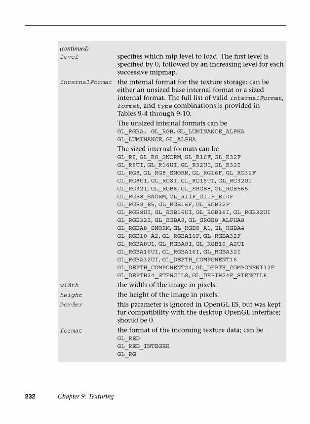
232 Chapter 9: Texturing
(continued)level specifies which mip level to load. The first level is
specified by 0, followed by an increasing level for each successive mipmap.
internalFormat the internal format for the texture storage; can be either an unsized base internal format or a sized internal format. The full list of valid internalFormat, format, and type combinations is provided in Tables 9-4 through 9-10.The unsized internal formats can beGL_RGBA, GL_RGB, GL_LUMINANCE_ALPHAGL_LUMINANCE, GL_ALPHA
The sized internal formats can beGL_R8, GL_R8_SNORM, GL_R16F, GL_R32FGL_R8UI, GL_R16UI, GL_R32UI, GL_R32IGL_RG8, GL_RG8_SNORM, GL_RG16F, GL_RG32FGL_RG8UI, GL_RG8I, GL_RG16UI, GL_RG32UIGL_RG32I, GL_RGB8, GL_SRGB8, GL_RGB565GL_RGB8_SNORM, GL_R11F_G11F_B10FGL_RGB9_E5, GL_RGB16F, GL_RGB32FGL_RGB8UI, GL_RGB16UI, GL_RGB16I, GL_RGB32UIGL_RGB32I, GL_RGBA8, GL_SRGB8_ALPHA8GL_RGBA8_SNORM, GL_RGB5_A1, GL_RGBA4GL_RGB10_A2, GL_RGBA16F, GL_RGBA32FGL_RGBA8UI, GL_RGBA8I, GL_RGB10_A2UIGL_RGBA16UI, GL_RGBA16I, GL_RGBA32IGL_RGBA32UI, GL_DEPTH_COMPONENT16GL_DEPTH_COMPONENT24, GL_DEPTH_COMPONENT32FGL_DEPTH24_STENCIL8, GL_DEPTH24F_STENCIL8
width the width of the image in pixels.
height the height of the image in pixels.border this parameter is ignored in OpenGL ES, but was kept
for compatibility with the desktop OpenGL interface; should be 0.
format the format of the incoming texture data; can beGL_RED GL_RED_INTEGER GL_RG

Texturing Basics 233
Example 9-1, from the Simple_Texture2D example, demonstrates generating a texture object, binding it, and then loading a 2 × 2 2D texture with RGB image data made from unsigned bytes.
GL_RG_INTEGERGL_RGBGL_RGB_INTEGERGL_RGBAGL_RGBA_INTEGER GL_DEPTH_COMPONENTGL_DEPTH_STENCIL GL_LUMINANCE_ALPHAGL_ALPHA
type the type of the incoming pixel data; can beGL_UNSIGNED_BYTEGL_BYTEGL_UNSIGNED_SHORTGL_SHORTGL_UNSIGNED_INTGL_INTGL_HALF_FLOATGL_FLOATGL_UNSIGNED_SHORT_5_6_5GL_UNSIGNED_SHORT_4_4_4_4GL_UNSIGNED_SHORT_5_5_5_1GL_UNSIGNED_INT_2_10_10_10_REVGL_UNSIGNED_INT_10F_11F_11F_REVGL_UNSIGNED_INT_5_9_9_9_REVGL_UNSIGNED_INT_24_8GL_FLOAT_32_UNSIGNED_INT_24_8_REVGL_UNSIGNED_SHORT_5_6_5
pixels contains the actual pixel data for the image. The data must contain (width*height) number of pixels with the appropriate number of bytes per pixel based on the format and type specification. The pixel rows must be aligned to the GL_UNPACK_ALIGNMENT set with glPixelStorei (defined next).

234 Chapter 9: Texturing
In the first part of the code, the pixels array is initialized with simple 2 × 2 texture data. The data is composed of unsigned byte RGB triplets that are in the range [0, 255]. When data is fetched from an 8-bit unsigned byte texture component in the shader, the values are mapped from the range [0, 255] to the floating-point range [0.0, 1.0]. Typically, an application would not create texture data in this simple manner, but rather would load the data from an image file. This example is provided to demonstrate the use of the API.
Prior to calling glTexImage2D, the application makes a call to glPixelStorei to set the unpack alignment. When texture data is uploaded via glTexImage2D, the rows of pixels are assumed to be aligned to the value set for GL_UNPACK_ALIGNMENT. By default, this value is 4, meaning that rows of pixels are assumed to begin on 4-byte boundaries.
Example 9-1 Generating a Texture Object, Binding It, and Loading Image Data
// Texture object handleGLuint textureId;
// 2 x 2 Image, 3 bytes per pixel (R, G, B)GLubyte pixels[4 * 3] =
{ 255, 0, 0, // Red 0, 255, 0, // Green 0, 0, 255, // Blue 255, 255, 0 // Yellow};
// Use tightly packed dataglPixelStorei(GL_UNPACK_ALIGNMENT, 1);
// Generate a texture objectglGenTextures(1, &textureId);
// Bind the texture objectglBindTexture(GL_TEXTURE_2D, textureId);
// Load the textureglTexImage2D(GL_TEXTURE_2D, 0, GL_RGB, 2, 2, 0, GL_RGB,
GL_UNSIGNED_BYTE, pixels);
// Set the filtering modeglTexParameteri(GL_TEXTURE_2D, GL_TEXTURE_MIN_FILTER,
GL_NEAREST);glTexParameteri(GL_TEXTURE_2D, GL_TEXTURE_MAG_FILTER,
GL_NEAREST);

Texturing Basics 235
This application sets the unpack alignment to 1, meaning that each row of pixels begins on a byte boundary (in other words, the data is tightly packed). The full definition for glPixelStorei is given next.
void glPixelStorei(GLenum pname, GLint param)
pname specifies the pixel storage type to set. The following optionsimpact how data is unpacked from memory when calling glTexImage2D, glTexImage3D, glTexSubImage2D, and glTexSubImage3D:GL_UNPACK_ROW_LENGTH, GL_UNPACK_IMAGE_HEIGHT,GL_UNPACK_SKIP_PIXELS, GL_UNPACK_SKIP_ROWS,GL_UNPACK_SKIP_IMAGES, GL_UNPACK_ALIGNMENT
The following options impact how data is packed into memory when calling glReadPixels:GL_PACK_ROW_LENGTH, GL_PACK_IMAGE_HEIGHT,GL_PACK_SKIP_PIXELS, GL_PACK_SKIP_ROWS,GL_PACK_SKIP_IMAGES, GL_PACK_ALIGNMENT
All of these options are described in Table 9-2.param specifies the integer value for the pack or unpack option.
The GL_PACK_xxxxx arguments to glPixelStorei do not have any impact on texture image uploading. The pack options are used by glReadPixels, which is described in Chapter 11, “Fragment Operations.” The pack and unpack options set by glPixelStorei are global state and are not stored or associated with a texture object. In practice, it is rare to use any options other than GL_UNPACK_ALIGNMENT for specifying textures. For completeness, the full list of pixel storage options is provided in Table 9-2.
Returning to the program in Example 9-1, after defining the image data, a texture object is generated using glGenTextures and then that object is bound to the GL_TEXTURE_2D target using glBindTexture. Finally, the image data is loaded into the texture object using glTexImage2D. The format is set as GL_RGB, which signifies that the image data is composed of (R, G, B) triplets. The type is set as GL_UNSIGNED_BYTE, which signifies that each channel of the data is stored in an 8-bit unsigned byte. There are a number of other options for loading texture data, including the different formats described in Table 9-1. All of the texture formats are described later in this chapter in the Texture Formats section.
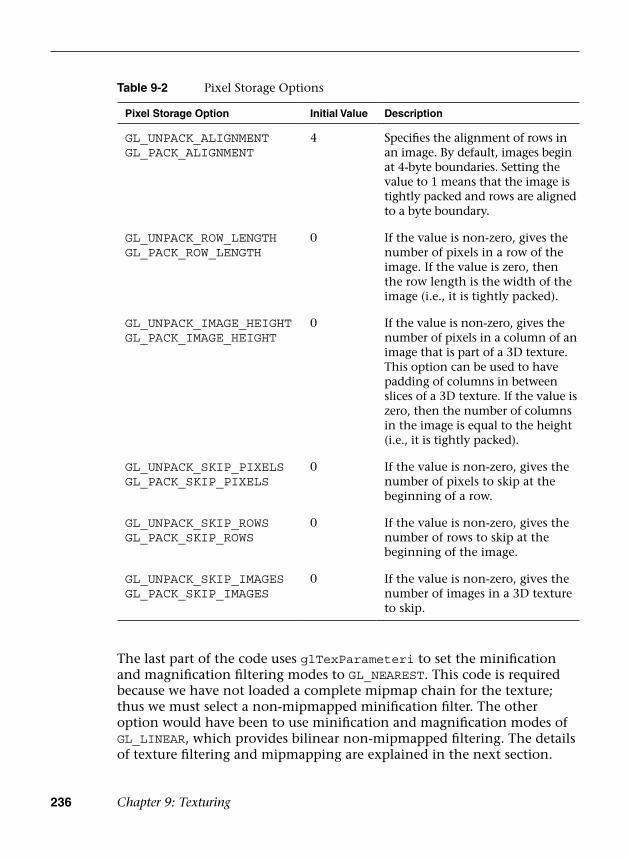
236 Chapter 9: Texturing
The last part of the code uses glTexParameteri to set the minification and magnification filtering modes to GL_NEAREST. This code is required because we have not loaded a complete mipmap chain for the texture; thus we must select a non-mipmapped minification filter. The other option would have been to use minification and magnification modes of GL_LINEAR, which provides bilinear non-mipmapped filtering. The details of texture filtering and mipmapping are explained in the next section.
Table 9-2 Pixel Storage Options
Pixel Storage Option Initial Value Description
GL_UNPACK_ALIGNMENTGL_PACK_ALIGNMENT
4 Specifies the alignment of rows in an image. By default, images begin at 4-byte boundaries. Setting the value to 1 means that the image is tightly packed and rows are aligned to a byte boundary.
GL_UNPACK_ROW_LENGTHGL_PACK_ROW_LENGTH
0 If the value is non-zero, gives the number of pixels in a row of the image. If the value is zero, then the row length is the width of the image (i.e., it is tightly packed).
GL_UNPACK_IMAGE_HEIGHTGL_PACK_IMAGE_HEIGHT
0 If the value is non-zero, gives the number of pixels in a column of an image that is part of a 3D texture. This option can be used to have padding of columns in between slices of a 3D texture. If the value is zero, then the number of columns in the image is equal to the height (i.e., it is tightly packed).
GL_UNPACK_SKIP_PIXELSGL_PACK_SKIP_PIXELS
0 If the value is non-zero, gives the number of pixels to skip at the beginning of a row.
GL_UNPACK_SKIP_ROWSGL_PACK_SKIP_ROWS
0 If the value is non-zero, gives the number of rows to skip at the beginning of the image.
GL_UNPACK_SKIP_IMAGESGL_PACK_SKIP_IMAGES
0 If the value is non-zero, gives the number of images in a 3D texture to skip.
Texturing Basics 237
Texture Filtering and Mipmapping
So far, we have limited our explanation of 2D textures to single 2D images. Although this allowed us to explain the concept of texturing, there is actually a bit more to how textures are specified and used in OpenGL ES. This complexity relates to the visual artifacts and performance issues that occur due to using a single texture map. As we have described texturing so far, the texture coordinate is used to generate a 2D index to fetch from the texture map. When the minification and magnification filters are set to GL_NEAREST, this is exactly what will happen: A single texel will be fetched at the texture coordinate location provided. This is known as point or nearest sampling.
However, nearest sampling might produce significant visual artifacts. The artifacts occur because as a triangle becomes smaller in screen space, the texture coordinates take large jumps when being interpolated from pixel to pixel. As a result, a small number of samples are taken from a large texture map, resulting in aliasing artifacts and a potentially large performance penalty. The solution that is used to resolve this type of artifact in OpenGL ES is known as mipmapping. The idea behind mipmapping is to build a chain of images known as a mipmap chain. The mipmap chain begins with the originally specified image and then continues with each subsequent image being half as large in each dimension as the one before it. This chain continues until we reach a single 1 × 1 texture at the bottom of the chain. The mip levels can be generated programmatically, typically by computing each pixel in a mip level as an average of the four pixels at the same location in the mip level above it (box filtering).
In the Chapter_9/MipMap2D sample program, we provide an example demonstrating how to generate a mipmap chain for a texture using a box filtering technique. The code to generate the mipmap chain is given by the GenMipMap2D function. This function takes an RGB8 image as input and generates the next mipmap level by performing a box filter on the preceding image. See the source code in the example for details on how the box filtering is done. The mipmap chain is then loaded using glTexImage2D, as shown in Example 9-2.
With a mipmap chain loaded, we can then set up the filtering mode to use mipmaps. The result is that we achieve a better ratio between screen pixels and texture pixels, thereby reducing aliasing artifacts. Aliasing is also reduced because each image in the mipmap chain is successively filtered so that high-frequency elements are attenuated more and more as we move down the chain.
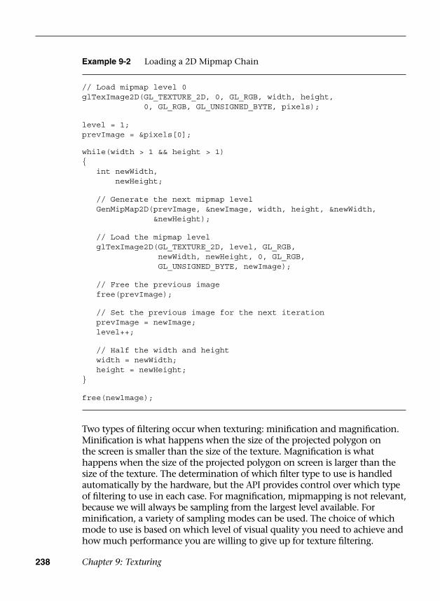
238 Chapter 9: Texturing
Two types of filtering occur when texturing: minification and magnification. Minification is what happens when the size of the projected polygon on the screen is smaller than the size of the texture. Magnification is what happens when the size of the projected polygon on screen is larger than the size of the texture. The determination of which filter type to use is handled automatically by the hardware, but the API provides control over which type of filtering to use in each case. For magnification, mipmapping is not relevant, because we will always be sampling from the largest level available. For minification, a variety of sampling modes can be used. The choice of which mode to use is based on which level of visual quality you need to achieve and how much performance you are willing to give up for texture filtering.
Example 9-2 Loading a 2D Mipmap Chain
// Load mipmap level 0glTexImage2D(GL_TEXTURE_2D, 0, GL_RGB, width, height,
0, GL_RGB, GL_UNSIGNED_BYTE, pixels);
level = 1;prevImage = &pixels[0];
while(width > 1 && height > 1){ int newWidth,
newHeight;
// Generate the next mipmap level GenMipMap2D( prevImage, &newImage, width, height, &newWidth,
&newHeight);
// Load the mipmap level glTexImage2D(GL_TEXTURE_2D, level, GL_RGB,
newWidth, newHeight, 0, GL_RGB,GL_UNSIGNED_BYTE, newImage);
// Free the previous image free(prevImage);
// Set the previous image for the next iteration prevImage = newImage; level++;
// Half the width and height width = newWidth; height = newHeight;}
free(newlmage);
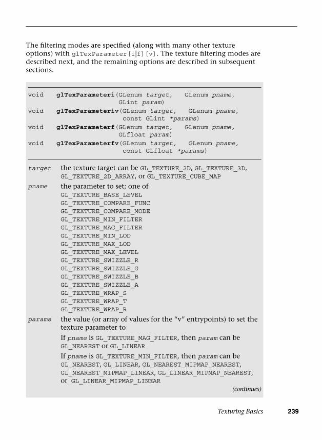
Texturing Basics 239
The filtering modes are specified (along with many other texture options) with glTexParameter[i|f][v]. The texture filtering modes are described next, and the remaining options are described in subsequent sections.
void glTexParameteri( GLenum target, GLenum pname, GLint param)
void glTexParameteriv( GLenum target, GLenum pname, const GLint *params)
void glTexParameterf( GLenum target, GLenum pname, GLfloat param)
void glTexParameterfv( GLenum target, GLenum pname, const GLfloat *params)
target the texture target can be GL_TEXTURE_2D, GL_TEXTURE_3D, GL_TEXTURE_2D_ARRAY, or GL_TEXTURE_CUBE_MAP
pname the parameter to set; one ofGL_TEXTURE_BASE_LEVELGL_TEXTURE_COMPARE_FUNCGL_TEXTURE_COMPARE_MODEGL_TEXTURE_MIN_FILTERGL_TEXTURE_MAG_FILTERGL_TEXTURE_MIN_LODGL_TEXTURE_MAX_LODGL_TEXTURE_MAX_LEVELGL_TEXTURE_SWIZZLE_RGL_TEXTURE_SWIZZLE_GGL_TEXTURE_SWIZZLE_BGL_TEXTURE_SWIZZLE_AGL_TEXTURE_WRAP_SGL_TEXTURE_WRAP_TGL_TEXTURE_WRAP_R
params the value (or array of values for the “v” entrypoints) to set the texture parameter to
If pname is GL_TEXTURE_MAG_FILTER, then param can be GL_NEAREST or GL_LINEAR
If pname is GL_TEXTURE_MIN_FILTER, then param can beGL_NEAREST, GL_LINEAR, GL_NEAREST_MIPMAP_NEAREST, GL_NEAREST_MIPMAP_LINEAR, GL_LINEAR_MIPMAP_NEAREST, or GL_LINEAR_MIPMAP_LINEAR
(continues)
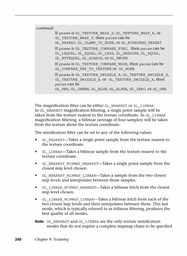
240 Chapter 9: Texturing
The magnification filter can be either GL_NEAREST or GL_LINEAR. In GL_NEAREST magnification filtering, a single point sample will be taken from the texture nearest to the texture coordinate. In GL_LINEAR magnification filtering, a bilinear (average of four samples) will be taken from the texture about the texture coordinate.
The minification filter can be set to any of the following values:
• GL_NEAREST—Takes a single point sample from the texture nearest tothe texture coordinate.
• GL_LINEAR—Takes a bilinear sample from the texture nearest to thetexture coordinate.
• GL_NEAREST_MIPMAP_NEAREST—Takes a single point sample from theclosest mip level chosen.
• GL_NEAREST_MIPMAP_LINEAR—Takes a sample from the two closestmip levels and interpolates between those samples.
• GL_LINEAR_MIPMAP_NEAREST—Takes a bilinear fetch from the closestmip level chosen.
• GL_LINEAR_MIPMAP_LINEAR—Takes a bilinear fetch from each of thetwo closest mip levels and then interpolates between them. This lastmode, which is typically referred to as trilinear filtering, produces thebest quality of all modes.
Note: GL_NEAREST and GL_LINEAR are the only texture minification modes that do not require a complete mipmap chain to be specified
(continued)If pname is GL_TEXTURE_WRAP_S, GL_TEXTURE_WRAP_R, or GL_TEXTURE_WRAP_T, then param can beGL_REPEAT, GL_CLAMP_TO_EDGE, or GL_MIRRORED_REPEAT
If pname is GL_TEXTURE_COMPARE_FUNC, then param can beGL_LEQUAL, GL_EQUAL, GL_LESS, GL_GREATER, GL_EQUAL, GL_NOTEQUAL, GL_ALWAYS, or GL_NEVER
If pname is GL_TEXTURE_COMPARE_MODE, then param can beGL_COMPARE_REF_TO_TEXTURE or GL_NONE
If pname is GL_TEXTURE_SWIZZLE_R, GL_TEXTURE_SWIZZLE_G, GL_TEXTURE_SWIZZLE_B, or GL_TEXTURE_SWIZZLE_A, then param can beGL_RED, GL_GREEN, GL_BLUE, GL_ALPHA, GL_ZERO, or GL_ONE

Texturing Basics 241
for the texture. All of the other modes require that a complete mipmap chain exists for the texture.
The MipMap2D example in Figure 9-4 shows the difference between a polygon drawn with GL_NEAREST versus GL_LINEAR_MIPMAP_LINEAR filtering.
Figure 9-4 MipMap2D: Nearest Versus Trilinear Filtering
It is worth mentioning some performance implications for the texture filtering mode that you choose. If minification occurs and performance is a concern, using a mipmap filtering mode is usually the best choice on most hardware. You tend to get very poor texture cache utilization without mipmaps because fetches happen at sparse locations throughout a map. However, the higher the filtering mode you use, the greater the performance cost in the hardware. For example, on most hardware, doing bilinear filtering is less costly than doing trilinear filtering. You should choose a mode that gives you the quality desired without unduly negatively impacting performance. On some hardware, you might get high-quality filtering virtually for free, particularly if the cost of the texture filtering is not your bottleneck. This is something that needs to be tuned for the application and hardware on which you plan to run your application.
Seamless Cubemap Filtering
One change with respect to filtering that is new to OpenGL ES 3.0 relates to how cubemaps are filtered. In OpenGL ES 2.0, when a linear filter kernel fell on the edge of a cubemap border, the filtering would happen on only a single cubemap face. This would result in artifacts at the borders between cubemap faces. In OpenGL ES 3.0, cubemap filtering is now seamless—if the filter kernel spans more than one cubemap face, the kernel will fetch samples from all of the faces it covers. Seamless filtering results in smoother filtering along cubemap face borders. In OpenGL ES 3.0, there is nothing you need to do to enable seamless cubemap filtering; all linear filter kernels will use it automatically.

242 Chapter 9: Texturing
Automatic Mipmap Generation
In the MipMap2D example in the previous section, the application created an image for level zero of the mipmap chain. It then generated the rest of the mipmap chain by performing a box filter on each image and successively halving the width and height. This is one way to generate mipmaps, but OpenGL ES 3.0 also provides a mechanism for automatically generating mipmaps using glGenerateMipmap.
void glGenerateMipmap(GLenum target)
target the texture target to generate mipmaps for; can be GL_TEXTURE_2D, GL_TEXTURE_3D, GL_TEXTURE_2D_ARRAY, or GL_TEXTURE_CUBE_MAP
When calling glGenerateMipmap on a bound texture object, this function will generate the entire mipmap chain from the contents of the image in level zero. For a 2D texture, the contents of texture level zero will be successively filtered and used for each of the subsequent levels. For a cubemap, each of the cube faces will be generated from the level zero in each cube face. Of course, to use this function with cubemaps, you must have specified level zero for each cube face and each face must have a matching internal format, width, and height. For a 2D texture array, each slice of the array will be filtered as it would be for a 2D texture. Finally, for a 3D texture, the entire volume will be mipmapped by performing filtering across slices.
OpenGL ES 3.0 does not mandate that a particular filtering algorithm be used for generating mipmaps (although the specification recommends box filtering, implementations have latitude in choosing which algorithm they use). If you require a particular filtering method, then you will still need to generate the mipmaps on your own.
Automatic mipmap generation becomes particularly important when you start to use framebuffer objects for rendering to a texture. When rendering to a texture, we don’t want to have to read back the contents of the texture to the CPU to generate mipmaps. Instead, glGenerateMipmap can be used and the graphics hardware can then potentially generate the mipmaps without ever having to read the data back to the CPU. When we cover framebuffer objects in more detail in Chapter 12, “Framebuffer Objects,” this point should become clear.
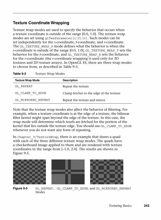
Texturing Basics 243
Texture Coordinate Wrapping
Texture wrap modes are used to specify the behavior that occurs when a texture coordinate is outside of the range [0.0, 1.0]. The texture wrap modes are set using glTexParameter[i|f][v]. Such modes can be set independently for the s-coordinate, t-coordinate, and r-coordinate. The GL_TEXTURE_WRAP_S mode defines what the behavior is when the s-coordinate is outside of the range [0.0, 1.0], GL_TEXTURE_WRAP_T sets the behavior for the t-coordinate, and GL_TEXTURE_WRAP_R sets the behavior for the r-coordinate (the r-coordinate wrapping is used only for 3D textures and 2D texture arrays). In OpenGL ES, there are three wrap modes to choose from, as described in Table 9-3.
Table 9-3 Texture Wrap Modes
Texture Wrap Mode Description
GL_REPEAT Repeat the texture
GL_CLAMP_TO_EDGE Clamp fetches to the edge of the texture
GL_MIRRORED_REPEAT Repeat the texture and mirror
Figure 9-5 GL_REPEAT, GL_CLAMP_TO_EDGE, and GL_MIRRORED_REPEAT Modes
Note that the texture wrap modes also affect the behavior of filtering. For example, when a texture coordinate is at the edge of a texture, the bilinear filter kernel might span beyond the edge of the texture. In this case, the wrap mode will determine which texels are fetched for the portion of the kernel that lies outside the texture edge. You should use GL_CLAMP_TO_EDGE whenever you do not want any form of repeating.
In Chapter_9/TextureWrap, there is an example that draws a quad with each of the three different texture wrap modes. The quads have a checkerboard image applied to them and are rendered with texture coordinates in the range from [–1.0, 2.0]. The results are shown in Figure 9-5.
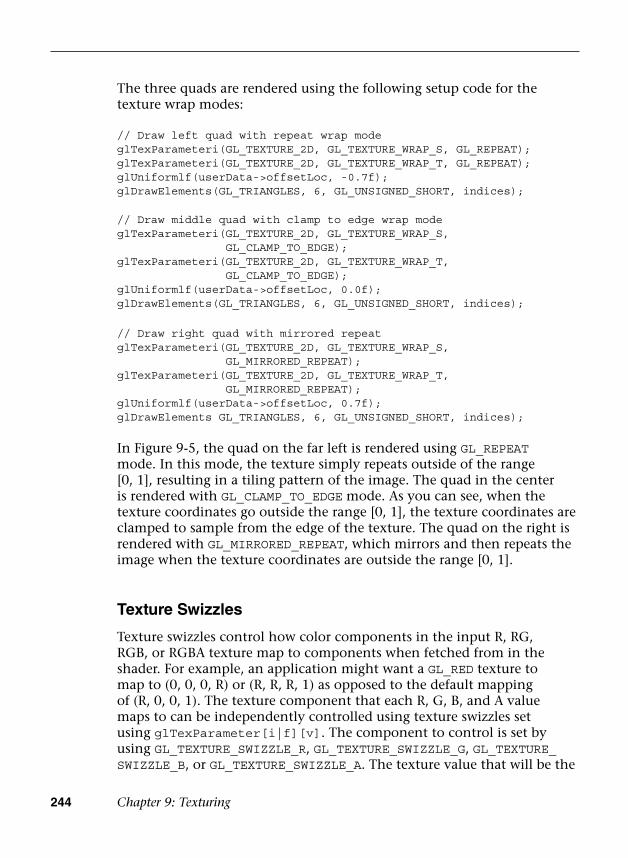
244 Chapter 9: Texturing
The three quads are rendered using the following setup code for the texture wrap modes:
// Draw left quad with repeat wrap modeglTexParameteri(GL_TEXTURE_2D, GL_TEXTURE_WRAP_S, GL_REPEAT); glTexParameteri(GL_TEXTURE_2D, GL_TEXTURE_WRAP_T, GL_REPEAT); glUniformlf(userData->offsetLoc, -0.7f);glDrawElements(GL_TRIANGLES, 6, GL_UNSIGNED_SHORT, indices);
// Draw middle quad with clamp to edge wrap modeglTexParameteri(GL_TEXTURE_2D, GL_TEXTURE_WRAP_S,
GL_CLAMP_TO_EDGE); glTexParameteri(GL_TEXTURE_2D, GL_TEXTURE_WRAP_T,
GL_CLAMP_TO_EDGE); glUniformlf(userData->offsetLoc, 0.0f);glDrawElements(GL_TRIANGLES, 6, GL_UNSIGNED_SHORT, indices);
// Draw right quad with mirrored repeatglTexParameteri(GL_TEXTURE_2D, GL_TEXTURE_WRAP_S,
GL_MIRRORED_REPEAT);glTexParameteri(GL_TEXTURE_2D, GL_TEXTURE_WRAP_T,
GL_MIRRORED_REPEAT); glUniformlf(userData->offsetLoc, 0.7f); glDrawElements GL_TRIANGLES, 6, GL_UNSIGNED_SHORT, indices);
In Figure 9-5, the quad on the far left is rendered using GL_REPEAT mode. In this mode, the texture simply repeats outside of the range [0, 1], resulting in a tiling pattern of the image. The quad in the center is rendered with GL_CLAMP_TO_EDGE mode. As you can see, when the texture coordinates go outside the range [0, 1], the texture coordinates are clamped to sample from the edge of the texture. The quad on the right is rendered with GL_MIRRORED_REPEAT, which mirrors and then repeats the image when the texture coordinates are outside the range [0, 1].
Texture Swizzles
Texture swizzles control how color components in the input R, RG, RGB, or RGBA texture map to components when fetched from in the shader. For example, an application might want a GL_RED texture to map to (0, 0, 0, R) or (R, R, R, 1) as opposed to the default mapping of (R, 0, 0, 1). The texture component that each R, G, B, and A value maps to can be independently controlled using texture swizzles set using glTexParameter[i|f][v]. The component to control is set by using GL_TEXTURE_SWIZZLE_R, GL_TEXTURE_SWIZZLE_G, GL_TEXTURE_SWIZZLE_B, or GL_TEXTURE_SWIZZLE_A. The texture value that will be the
Texturing Basics 245
source for that component can be either GL_RED, GL_GREEN, GL_BLUE, or GL_ALPHA to fetch from the R, G, B, or A component, respectively. Additionally, the application can set the value to be the constant 0 or 1 using GL_ZERO or GL_ONE, respectively.
Texture Level of Detail
In some applications, it is useful to be able to start displaying a scene before all of the texture mipmap levels are available. For example, a GPS application that is downloading texture images over a data connection might start with the lowest-level mipmaps and display the higher levels when they become available. In OpenGL ES 3.0, this can be accomplished by using several of the arguments to glTexParameter[i|f][v]. The GL_TEXTURE_BASE_LEVEL sets the largest mipmap level that will be used for a texture. By default, this has a value of 0, but it can be set to a higher value if mipmap levels are not yet available. Likewise, GL_TEXTURE_MAX_LEVEL sets the smallest mipmap level that will be used. By default, it has a value of 1000 (beyond the largest level any texture could have), but it can be set to a lower number to control the smallest mipmap level to use for a texture.
To select which mipmap level to use for rendering, OpenGL ES automatically computes a level of detail (LOD) value. This floating-point value determines which mipmap level to filter from (and in trilinear filtering, controls how much of each mipmap is used). An application can also control the minimum and maximum LOD values with GL_TEXTURE_MIN_LOD and GL_TEXTURE_MAX_LOD. One reason it is useful to be able to control the LOD clamp separately from the base and maximum mipmap levels is to provide smooth transitioning when new mipmap levels become available. Setting just the texture base and maximum level might result in a popping artifact when new mipmap levels are available, whereas interpolating the LOD can make this transition look smoother.
Depth Texture Compare (Percentage Closest Filtering)
The last texture parameters to discuss are GL_TEXTURE_COMPARE_FUNC and GL_TEXTURE_COMPARE_MODE. These texture parameters were introduced to provide a feature known as percentage closest filtering (PCF). When performing the shadowing technique known as shadow mapping, the fragment shader needs to compare the current depth value of a fragment to the depth value in a depth texture to determine whether a fragment is within or outside of the shadow. To achieve smoother-looking shadow edges, it is useful to be able to perform bilinear filtering on the depth

246 Chapter 9: Texturing
texture. However, when filtering a depth texture, we want the filtering to occur after we sample the depth value and compare to the current depth (or reference value). If filtering were to occur before comparison, then we would be averaging values in the depth texture, which does not provide the correct result. PCF provides the correct filtering, such that each depth value sampled is compared to the reference depth and then the results of those comparisons (0 or 1) are averaged together.
The GL_TEXTURE_COMPARE_MODE defaults to GL_NONE, but when it is set to GL_COMPARE_REF_TO_TEXTURE, the r-coordinate in the (s, t, r) texture coordinate will be compared with the value of the depth texture. The result of this comparison then becomes the result of the shadow texture fetch (either a value of 0 or 1, or an averaging of these values if texture filtering is enabled). The comparison function is set using GL_TEXTURE_COMPARE_FUNC, which can set the comparison function to GL_LEQUAL, GL_EQUAL, GL_LESS, GL_GREATER, GL_EQUAL, GL_NOTEQUAL, GL_ALWAYS, or GL_NEVER. More details on shadow mapping are covered in Chapter 14, “Advanced Programming with OpenGL ES 3.0.”
Texture Formats
OpenGL ES 3.0 offers a wide range of data formats for textures. In fact, the number of formats has greatly increased from OpenGL ES 2.0. This section details the texture formats available in OpenGL ES 3.0.
As described in the previous section Texture Objects and Loading Textures, a 2D texture can be uploaded with either an unsized or sized internal format using glTexImage2D. If the texture is specified with an unsized format, the OpenGL ES implementation is free to choose the actual internal representation in which the texture data is stored. If the texture is specified with a sized format, then OpenGL ES will choose a format with at least as many bits as is specified.
Table 9-4 lists the valid combinations for specifying a texture with an unsized internal format.
If the application wants more control over how the data is stored internally, then it can use a sized internal format. The valid combinations for sized internal formats with glTexImage2D are listed in Tables 9-5 to 9-10. In the last two columns, “R” means renderable and “F” means filterable. OpenGL ES 3.0 mandates only that certain formats be available for rendering to or filtering from. Further, some formats can be specified with input data containing more bits than the internal format. In this case, the implementation may choose to convert to lesser bits or use a format with more bits.
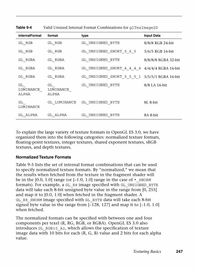
Texturing Basics 247
To explain the large variety of texture formats in OpenGL ES 3.0, we have organized them into the following categories: normalized texture formats, floating-point textures, integer textures, shared exponent textures, sRGB textures, and depth textures.
Normalized Texture Formats
Table 9-5 lists the set of internal format combinations that can be used to specify normalized texture formats. By “normalized,” we mean that the results when fetched from the texture in the fragment shader will be in the [0.0, 1.0] range (or [–1.0, 1.0] range in the case of *_SNORM formats). For example, a GL_R8 image specified with GL_UNSIGNED_BYTE data will take each 8-bit unsigned byte value in the range from [0, 255] and map it to [0.0, 1.0] when fetched in the fragment shader. A GL_R8_SNORM image specified with GL_BYTE data will take each 8-bit signed byte value in the range from [–128, 127] and map it to [–1.0, 1.0] when fetched.
The normalized formats can be specified with between one and four components per texel (R, RG, RGB, or RGBA). OpenGL ES 3.0 also introduces GL_RGB10_A2, which allows the specification of texture image data with 10 bits for each (R, G, B) value and 2 bits for each alpha value.
Table 9-4 Valid Unsized Internal Format Combinations for glTexImage2D
internalFormat format type Input Data
GL_RGB GL_RGB GL_UNSIGNED_BYTE 8/8/8 RGB 24-bit
GL_RGB GL_RGB GL_UNSIGNED_SHORT_5_6_5 5/6/5 RGB 16-bit
GL_RGBA GL_RGBA GL_UNSIGNED_BYTE 8/8/8/8 RGBA 32-bit
GL_RGBA GL_RGBA GL_UNSIGNED_SHORT_4_4_4_4 4/4/4/4 RGBA 16-bit
GL_RGBA GL_RGBA GL_UNSIGNED_SHORT_5_5_5_1 5/5/5/1 RGBA 16-bit
GL_LUMINANCE_ALPHA
GL_LUMINANCE_ALPHA
GL_UNSIGNED_BYTE 8/8 LA 16-bit
GL_LUMINANCE
GL_LUMINANCE GL_UNSIGNED_BYTE 8L 8-bit
GL_ALPHA GL_ALPHA GL_UNSIGNED_BYTE 8A 8-bit
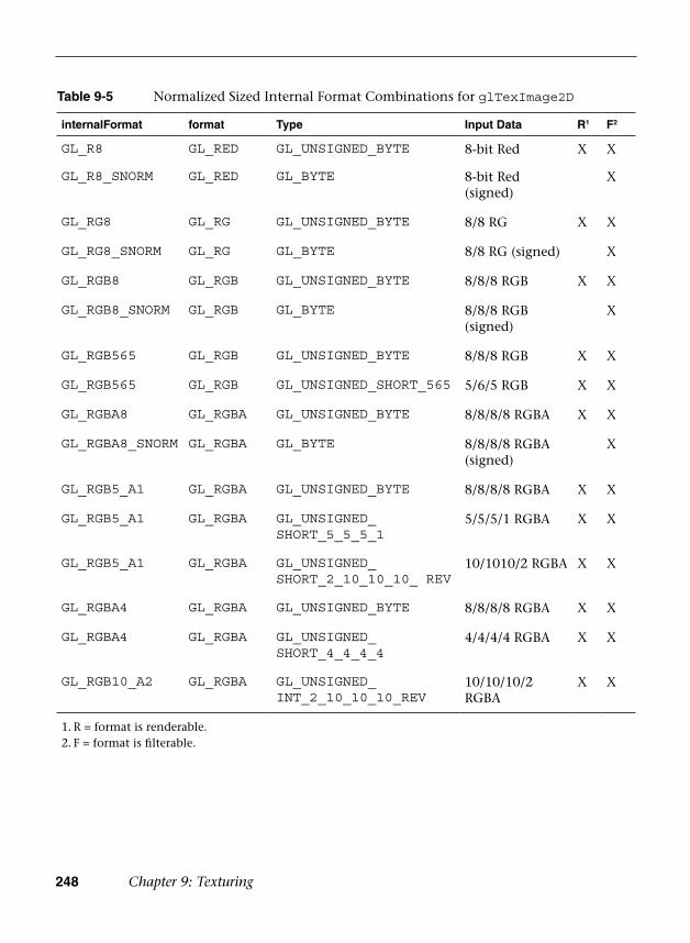
248 Chapter 9: Texturing
Table 9-5 Normalized Sized Internal Format Combinations for glTexImage2D
internalFormat format Type Input Data R1 F2
GL_R8 GL_RED GL_UNSIGNED_BYTE 8-bit Red X X
GL_R8_SNORM GL_RED GL_BYTE 8-bit Red (signed)
X
GL_RG8 GL_RG GL_UNSIGNED_BYTE 8/8 RG X X
GL_RG8_SNORM GL_RG GL_BYTE 8/8 RG (signed) X
GL_RGB8 GL_RGB GL_UNSIGNED_BYTE 8/8/8 RGB X X
GL_RGB8_SNORM GL_RGB GL_BYTE 8/8/8 RGB (signed)
X
GL_RGB565 GL_RGB GL_UNSIGNED_BYTE 8/8/8 RGB X X
GL_RGB565 GL_RGB GL_UNSIGNED_SHORT_565 5/6/5 RGB X X
GL_RGBA8 GL_RGBA GL_UNSIGNED_BYTE 8/8/8/8 RGBA X X
GL_RGBA8_SNORM GL_RGBA GL_BYTE 8/8/8/8 RGBA (signed)
X
GL_RGB5_A1 GL_RGBA GL_UNSIGNED_BYTE 8/8/8/8 RGBA X X
GL_RGB5_A1 GL_RGBA GL_UNSIGNED_SHORT_5_5_5_1
5/5/5/1 RGBA X X
GL_RGB5_A1 GL_RGBA GL_UNSIGNED_SHORT_2_10_10_10_ REV
10/1010/2 RGBA X X
GL_RGBA4 GL_RGBA GL_UNSIGNED_BYTE 8/8/8/8 RGBA X X
GL_RGBA4 GL_RGBA GL_UNSIGNED_SHORT_4_4_4_4
4/4/4/4 RGBA X X
GL_RGB10_A2 GL_RGBA GL_UNSIGNED_INT_2_10_10_10_REV
10/10/10/2 RGBA
X X
1. R = format is renderable.2. F = format is filterable.
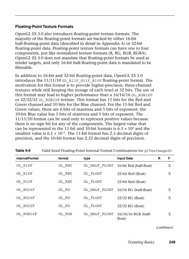
Texturing Basics 249
Floating-Point Texture Formats
OpenGL ES 3.0 also introduces floating-point texture formats. The majority of the floating-point formats are backed by either 16-bit half-floating-point data (described in detail in Appendix A) or 32-bit floating-point data. Floating-point texture formats can have one to four components, just like normalized texture formats (R, RG, RGB, RGBA). OpenGL ES 3.0 does not mandate that floating-point formats be used as render targets, and only 16-bit half-floating-point data is mandated to be filterable.
In addition to 16-bit and 32-bit floating-point data, OpenGL ES 3.0 introduces the 11/11/10 GL_R11F_G11F_B10F floating-point format. The motivation for this format is to provide higher-precision, three-channel textures while still keeping the storage of each texel at 32 bits. The use of this format may lead to higher performance than a 16/16/16 GL_RGB16F or 32/32/32 GL_RGB32F texture. This format has 11 bits for the Red and Green channel and 10 bits for the Blue channel. For the 11-bit Red and Green values, there are 6 bits of mantissa and 5 bits of exponent; the 10-bit Blue value has 5 bits of mantissa and 5 bits of exponent. The 11/11/10 format can be used only to represent positive values because there is no sign bit for any of the components. The largest value that can be represented in the 11-bit and 10-bit formats is 6.5 × 10⁴ and the smallest value is 6.1 × 10⁻⁵. The 11-bit format has 2.5 decimal digits of precision, and the 10-bit format has 2.32 decimal digits of precision.
Table 9-6 Valid Sized Floating-Point Internal Format Combinations for glTexImage2D
internalFormat format type Input Data R F
GL_R16F GL_RED GL_HALF_FLOAT 16-bit Red (half-float) X
GL_R16F GL_RED GL_FLOAT 32-bit Red (float) X
GL_R32F GL_RED GL_FLOAT 32-bit Red (float)
GL_RG16F GL_RG GL_HALF_FLOAT 16/16 RG (half-float) X
GL_RG16F GL_RG GL_FLOAT 32/32 RG (float) X
GL_RG32F GL_RG GL_FLOAT 32/32 RG (float)
GL_RGB16F GL_RGB GL_HALF_FLOAT 16/16/16 RGB (half-float)
X
(continues)
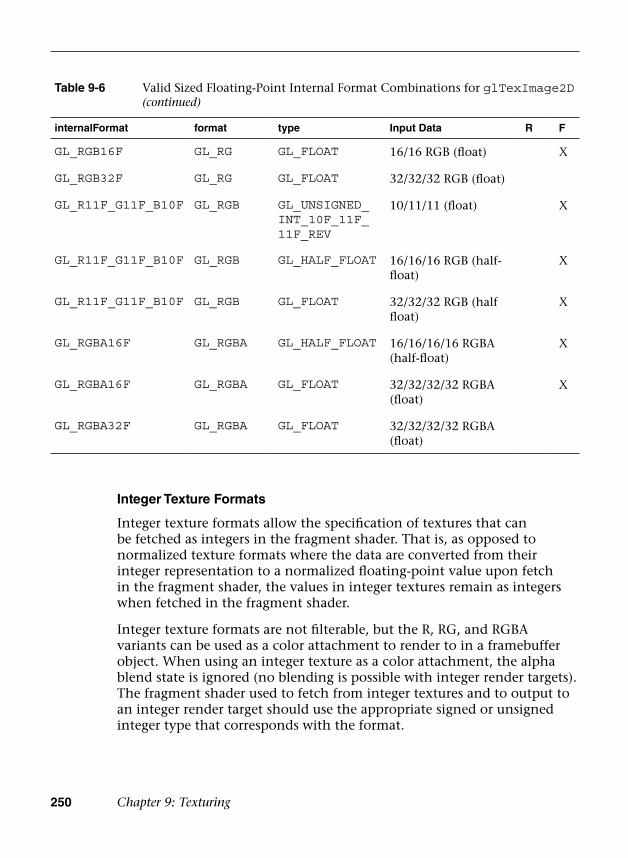
250 Chapter 9: Texturing
Integer Texture Formats
Integer texture formats allow the specification of textures that can be fetched as integers in the fragment shader. That is, as opposed to normalized texture formats where the data are converted from their integer representation to a normalized floating-point value upon fetch in the fragment shader, the values in integer textures remain as integers when fetched in the fragment shader.
Integer texture formats are not filterable, but the R, RG, and RGBA variants can be used as a color attachment to render to in a framebuffer object. When using an integer texture as a color attachment, the alpha blend state is ignored (no blending is possible with integer render targets). The fragment shader used to fetch from integer textures and to output to an integer render target should use the appropriate signed or unsigned integer type that corresponds with the format.
Table 9-6 Valid Sized Floating-Point Internal Format Combinations for glTexImage2D (continued)
internalFormat format type Input Data R F
GL_RGB16F GL_RG GL_FLOAT 16/16 RGB (float) X
GL_RGB32F GL_RG GL_FLOAT 32/32/32 RGB (float)
GL_R11F_G11F_B10F GL_RGB GL_UNSIGNED_INT_10F_11F_ 11F_REV
10/11/11 (float) X
GL_R11F_G11F_B10F GL_RGB GL_HALF_FLOAT 16/16/16 RGB (half-float)
X
GL_R11F_G11F_B10F GL_RGB GL_FLOAT 32/32/32 RGB (half float)
X
GL_RGBA16F GL_RGBA GL_HALF_FLOAT 16/16/16/16 RGBA (half-float)
X
GL_RGBA16F GL_RGBA GL_FLOAT 32/32/32/32 RGBA (float)
X
GL_RGBA32F GL_RGBA GL_FLOAT 32/32/32/32 RGBA (float)
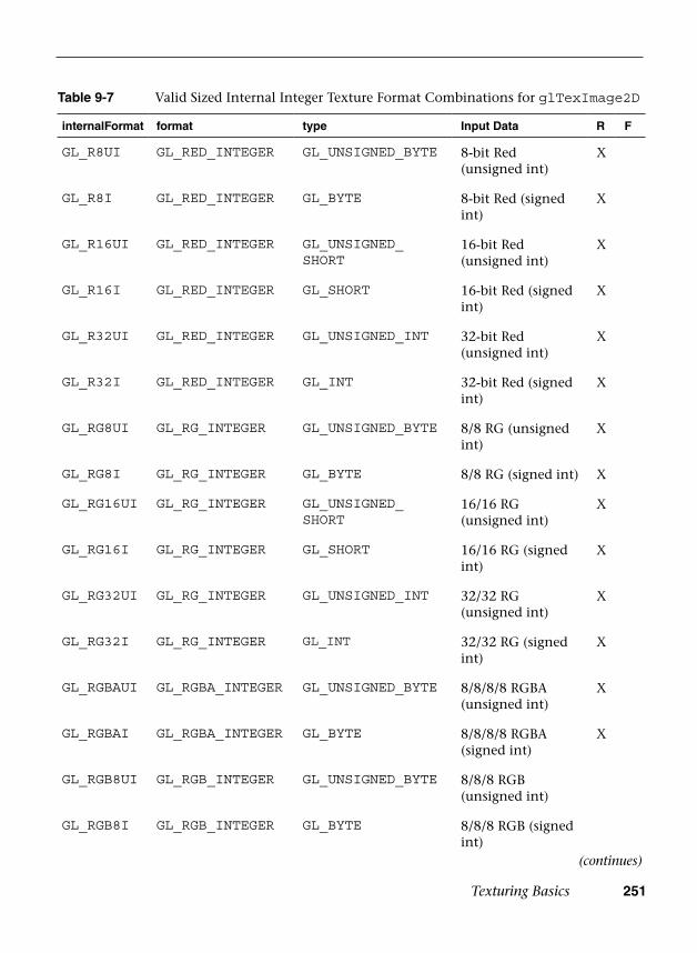
Texturing Basics 251
Table 9-7 Valid Sized Internal Integer Texture Format Combinations for glTexImage2D
internalFormat format type Input Data R F
GL_R8UI GL_RED_INTEGER GL_UNSIGNED_BYTE 8-bit Red (unsigned int)
X
GL_R8I GL_RED_INTEGER GL_BYTE 8-bit Red (signed int)
X
GL_R16UI GL_RED_INTEGER GL_UNSIGNED_SHORT
16-bit Red (unsigned int)
X
GL_R16I GL_RED_INTEGER GL_SHORT 16-bit Red (signed int)
X
GL_R32UI GL_RED_INTEGER GL_UNSIGNED_INT 32-bit Red (unsigned int)
X
GL_R32I GL_RED_INTEGER GL_INT 32-bit Red (signed int)
X
GL_RG8UI GL_RG_INTEGER GL_UNSIGNED_BYTE 8/8 RG (unsigned int)
X
GL_RG8I GL_RG_INTEGER GL_BYTE 8/8 RG (signed int) X
GL_RG16UI GL_RG_INTEGER GL_UNSIGNED_SHORT
16/16 RG (unsigned int)
X
GL_RG16I GL_RG_INTEGER GL_SHORT 16/16 RG (signed int)
X
GL_RG32UI GL_RG_INTEGER GL_UNSIGNED_INT 32/32 RG (unsigned int)
X
GL_RG32I GL_RG_INTEGER GL_INT 32/32 RG (signed int)
X
GL_RGBAUI GL_RGBA_INTEGER GL_UNSIGNED_BYTE 8/8/8/8 RGBA (unsigned int)
X
GL_RGBAI GL_RGBA_INTEGER GL_BYTE 8/8/8/8 RGBA (signed int)
X
GL_RGB8UI GL_RGB_INTEGER GL_UNSIGNED_BYTE 8/8/8 RGB (unsigned int)
GL_RGB8I GL_RGB_INTEGER GL_BYTE 8/8/8 RGB (signed int)
(continues)
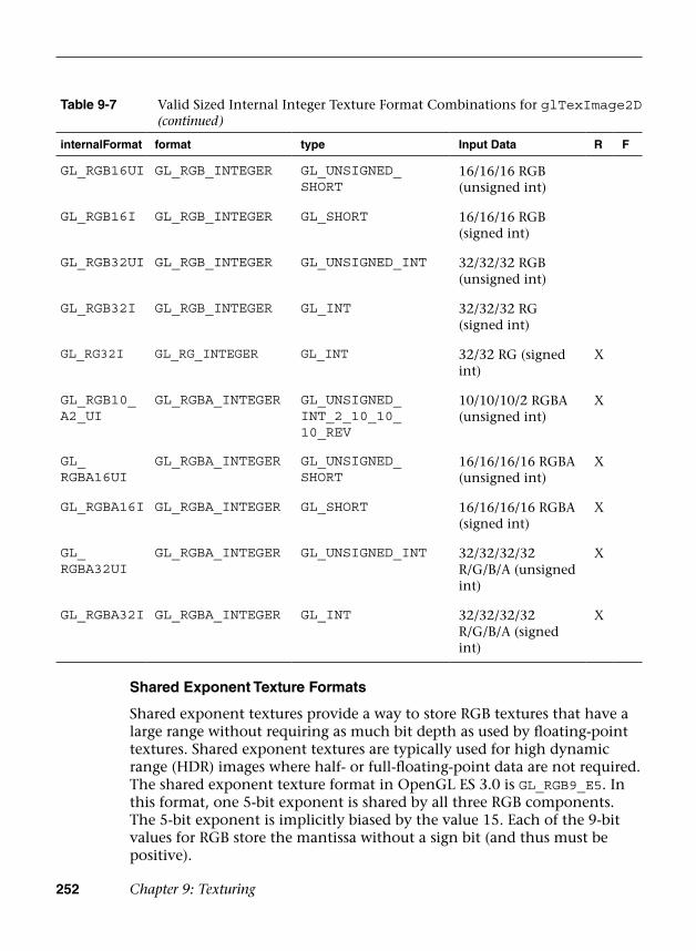
252 Chapter 9: Texturing
Shared Exponent Texture Formats
Shared exponent textures provide a way to store RGB textures that have a large range without requiring as much bit depth as used by floating-point textures. Shared exponent textures are typically used for high dynamic range (HDR) images where half- or full-floating-point data are not required. The shared exponent texture format in OpenGL ES 3.0 is GL_RGB9_E5. In this format, one 5-bit exponent is shared by all three RGB components. The 5-bit exponent is implicitly biased by the value 15. Each of the 9-bit values for RGB store the mantissa without a sign bit (and thus must be positive).
Table 9-7 Valid Sized Internal Integer Texture Format Combinations for glTexImage2D (continued)
internalFormat format type Input Data R F
GL_RGB16UI GL_RGB_INTEGER GL_UNSIGNED_SHORT
16/16/16 RGB (unsigned int)
GL_RGB16I GL_RGB_INTEGER GL_SHORT 16/16/16 RGB (signed int)
GL_RGB32UI GL_RGB_INTEGER GL_UNSIGNED_INT 32/32/32 RGB (unsigned int)
GL_RGB32I GL_RGB_INTEGER GL_INT 32/32/32 RG (signed int)
GL_RG32I GL_RG_INTEGER GL_INT 32/32 RG (signed int)
X
GL_RGB10_A2_UI
GL_RGBA_INTEGER GL_UNSIGNED_INT_2_10_10_ 10_REV
10/10/10/2 RGBA (unsigned int)
X
GL_RGBA16UI
GL_RGBA_INTEGER GL_UNSIGNED_SHORT
16/16/16/16 RGBA (unsigned int)
X
GL_RGBA16I GL_RGBA_INTEGER GL_SHORT 16/16/16/16 RGBA (signed int)
X
GL_RGBA32UI
GL_RGBA_INTEGER GL_UNSIGNED_INT 32/32/32/32 R/G/B/A (unsigned int)
X
GL_RGBA32I GL_RGBA_INTEGER GL_INT 32/32/32/32 R/G/B/A (signed int)
X

Texturing Basics 253
Upon fetch, the three RGB values are derived from the texture using the following equations:
R = R *2
G = G *2
B = B *2
out in(EXP – 15)
out in(EXP – 15)
out in(EXP – 15)
If the input texture is specified in 16-bit half-float or 32-bit float, then the OpenGL ES implementation will automatically convert to the shared exponent format. The conversion is done by first determining the maximum color value:
MAX = max(R,G,B)c
The shared exponent is then computed using the following formula:
EXP = max (–16, floor(log (MAX ))) + 162 c
Finally, the 9-bit mantissa values for RGB are computed as follows:
( )( )( )
= +
= +
= +
+
+
+
R floor R/(2 ) 0.5
G floor G/(2 ) 0.5
B floor B/(2 ) 0.5
s(EXP – 15 9)
s(EXP – 15 9)
s(EXP – 15 9)
An application could use these conversion formulas to derive the 5-bit EXP and 9-bit RGB values from incoming data, or it can simply pass in the 16-bit half-float or 32-bit float data to OpenGL ES and let it perform the conversion.
Table 9-8 Valid Shared Exponent Sized Internal Format Combinations for glTexImage2D
internalFormat format type Input Data R F
GL_RGB9_E5 GL_RGB GL_UNSIGNED_INT_5_9_9_9_REV
9/9/9/ RGB with shared 5-bit exponent
X
GL_RGB9_E5 GL_RGB GL_HALF_FLOAT 16/16/16 RGB (half-float)
X
GL_RGB9_E5 GL_RGB GL_FLOAT 32/32/32 RGB (half-float)
X

254 Chapter 9: Texturing
sRGB Texture Formats
Another texture format introduced in OpenGL ES 3.0 is sRGB textures. sRGB is a nonlinear colorspace that approximately follows a power function. Most images are actually stored in the sRGB colorspace, as the nonlinearity accounts for the fact that humans can differentiate color better at different brightness levels.
If the images used for textures are authored in the sRGB colorspace but are fetched without using sRGB textures, all of the lighting calculations that occur in the shader happen in a nonlinear colorspace. That is, the textures created in standard authoring packages are stored in sRGB and remain in sRGB when fetched from in the shader. The lighting calculations then are occurring in the nonlinear sRGB space. While many applications make this mistake, it is not correct and actually results in discernibly different (and incorrect) output image.
To properly account for sRGB images, an application should use an sRGB texture format that will be converted from sRGB into a linear colorspace on fetch in the shader. Then, all calculations in the shader are done in linear colorspace. Finally, by rendering to a sRGB render target, the image will be correctly converted back to sRGB on write. It is possible to approximate sRGB → linear conversion using a shader instructionpow(value, 2.2) and then to approximate the linear → sRGB conversionusing pow(value, 1/2.2). However, it is preferable to use a sRGB texture where possible because it reduces the shader instructions and provides a more correct sRGB conversion.
Depth Texture Formats
The final texture format type in OpenGL ES 3.0 is depth textures. Depth textures allow the application to fetch the depth (and optionally, stencil) value from the depth attachment of a framebuffer object. This is useful in a variety of advanced rendering algorithms, including shadow mapping. Table 9-10 lists the valid depth texture formats in OpenGL ES 3.0.
Table 9-9 Valid sRGB Sized Internal Format Combinations for glTexImage2D
internalFormat format type Input Data R F
GL_SRGB8 GL_RGB GL_UNSIGNED_BYTE 8/8/8 SRGB X
GL_SRGB8_ALPHA8 GL_RGBA GL_UNSIGNED_BYTE 8/8/8/8 RGBA X X
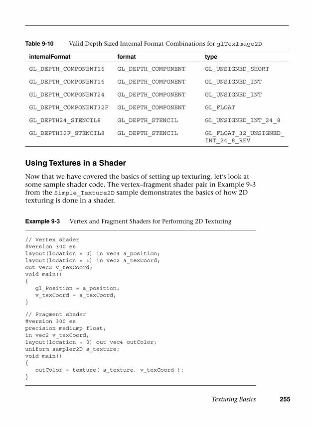
Texturing Basics 255
Using Textures in a Shader
Now that we have covered the basics of setting up texturing, let’s look at some sample shader code. The vertex–fragment shader pair in Example 9-3 from the Simple_Texture2D sample demonstrates the basics of how 2D texturing is done in a shader.
Table 9-10 Valid Depth Sized Internal Format Combinations for glTexImage2D
internalFormat format type
GL_DEPTH_COMPONENT16 GL_DEPTH_COMPONENT GL_UNSIGNED_SHORT
GL_DEPTH_COMPONENT16 GL_DEPTH_COMPONENT GL_UNSIGNED_INT
GL_DEPTH_COMPONENT24 GL_DEPTH_COMPONENT GL_UNSIGNED_INT
GL_DEPTH_COMPONENT32F GL_DEPTH_COMPONENT GL_FLOAT
GL_DEPTH24_STENCIL8 GL_DEPTH_STENCIL GL_UNSIGNED_INT_24_8
GL_DEPTH32F_STENCIL8 GL_DEPTH_STENCIL GL_FLOAT_32_UNSIGNED_INT_24_8_REV
Example 9-3 Vertex and Fragment Shaders for Performing 2D Texturing
// Vertex shader#version 300 eslayout(location = 0) in vec4 a_position;layout(location = 1) in vec2 a_texCoord;out vec2 v_texCoord;void main(){ gl_Position = a_position; v_texCoord = a_texCoord;}
// Fragment shader#version 300 esprecision mediump float;in vec2 v_texCoord;layout(location = 0) out vec4 outColor; uniform sampler2D s_texture;void main(){ outColor = texture( s_texture, v_texCoord );}

256 Chapter 9: Texturing
The vertex shader takes in a two-component texture coordinate as a vertex input and passes it as an output to the fragment shader. The fragment shader consumes that texture coordinate and uses it for the texture fetch. The fragment shader declares a uniform variable of type sampler2D called s_texture. A sampler is a special type of uniform variable that is used to fetch from a texture map. The sampler uniform will be loaded with a value specifying the texture unit to which the texture is bound; for example, specifying that a sampler with a value of 0 says to fetch from unit GL_TEXTURE0, specifying a value of 1 says to fetch from GL_TEXTURE1, and so on. Textures are bound to texture units in the OpenGL ES 3.0 API by using the glActiveTexture function.
void glActiveTexture(GLenum texture)
texture the texture unit to make active: GL_TEXTURE0, GL_TEXTURE1, … , GL_TEXTURE31
The function glActiveTexture sets the current texture unit so that subsequent calls to glBindTexture will bind the texture to the currently active unit. The number of texture units available to the fragment shader on an implementation of OpenGL ES can be queried for by using glGetintegerv with the parameter GL_MAX_TEX TURE_IMAGE_UNITS. The number of texture units available to the vertex shader can be queried for by using glGetIntegerv with the parameter GL_MAX_VERTEX_TEXTURE_IMAGE_UNITS.
The following example code from the Simple_Texture2D example shows how the sampler and texture are bound to the texture unit.
// Get the sampler locations userData->samplerLoc = glGetUniformLocation(
userData->programObject,“s_texture”);
// ...// Bind the textureglActiveTexture(GL_TEXTURE0);glBindTexture(GL_TEXTURE_2D, userData->textureId);
// Set the sampler texture unit to 0 glUniformli(userData->samplerLoc, 0);
At this point, we have the texture loaded, the texture bound to texture unit 0, and the sampler set to use texture unit 0. Going back to the fragment shader in the Simple_Texture2D example, we see that the
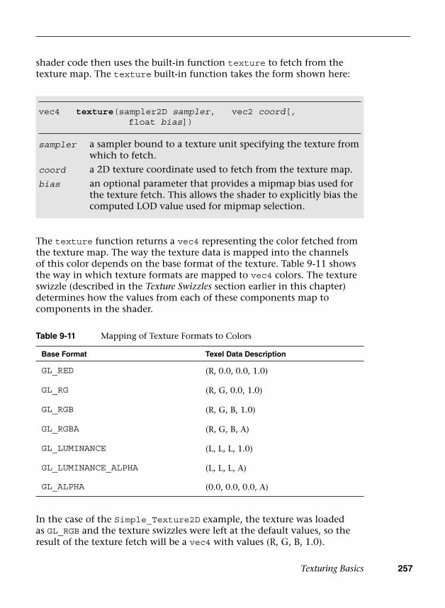
Texturing Basics 257
shader code then uses the built-in function texture to fetch from the texture map. The texture built-in function takes the form shown here:
vec4 texture(sampler2D sampler, vec2 coord[,float bias])
sampler a sampler bound to a texture unit specifying the texture from which to fetch.
coord a 2D texture coordinate used to fetch from the texture map.
bias an optional parameter that provides a mipmap bias used for the texture fetch. This allows the shader to explicitly bias the computed LOD value used for mipmap selection.
The texture function returns a vec4 representing the color fetched from the texture map. The way the texture data is mapped into the channels of this color depends on the base format of the texture. Table 9-11 shows the way in which texture formats are mapped to vec4 colors. The texture swizzle (described in the Texture Swizzles section earlier in this chapter) determines how the values from each of these components map to components in the shader.
Table 9-11 Mapping of Texture Formats to Colors
Base Format Texel Data Description
GL_RED (R, 0.0, 0.0, 1.0)
GL_RG (R, G, 0.0, 1.0)
GL_RGB (R, G, B, 1.0)
GL_RGBA (R, G, B, A)
GL_LUMINANCE (L, L, L, 1.0)
GL_LUMINANCE_ALPHA (L, L, L, A)
GL_ALPHA (0.0, 0.0, 0.0, A)
In the case of the Simple_Texture2D example, the texture was loaded as GL_RGB and the texture swizzles were left at the default values, so the result of the texture fetch will be a vec4 with values (R, G, B, 1.0).

258 Chapter 9: Texturing
Example of Using a Cubemap Texture
Using a cubemap texture is very similar to using a 2D texture. The example Simple_TextureCubemap demonstrates drawing a sphere with a simple cubemap. The cubemap contains six 1 × 1 faces, each with a different color. The code in Example 9-4 is used to load the cubemap texture.
Example 9-4 Loading a Cubemap Texture
GLuint CreateSimpleTextureCubemap() { GLuint textureId; // Six l x l RGB faces GLubyte cubePixels[6][3] = {
// Face 0 - Red255, 0, 0,// Face 1 - Green,0, 255, 0,// Face 2 - Blue0, 0, 255,// Face 3 - Yellow255, 255, 0,// Face 4 - Purple255, 0, 255,// Face 5 - White255, 255, 255
};
// Generate a texture object glGenTextures(1, &textureId);
// Bind the texture object glBindTexture(GL_TEXTURE_CUBE_MAP, textureId);
// Load the cube face - Positive X glTexImage2D(GL_TEXTURE_CUBE_MAP_POSITIVE_X, 0, GL_RGB, 1, 1,
0, GL_RGB, GL_UNSIGNED_BYTE, &cubePixels[0]);
// Load the cube face - Negative X glTexImage2D(GL_TEXTURE_CUBE_MAP_NEGATIVE_X, 0, GL_RGB, 1, 1,
0, GL_RGB, GL_UNSIGNED_BYTE, &cubePixels[1]);
// Load the cube face - Positive Y glTexImage2D(GL_TEXTURE_CUBE_MAP_POSITIVE_Y, 0, GL_RGB, 1, 1,
0, GL_RGB, GL_UNSIGNED_BYTE, &cubePixels[2]);
// Load the cube face - Negative Y glTexImage2D(GL_TEXTURE_CUBE_MAP_NEGATIVE_Y, 0, GL_RGB, 1, 1,
0, GL_RGB, GL_UNSIGNED_BYTE, &cubePixels[3]);
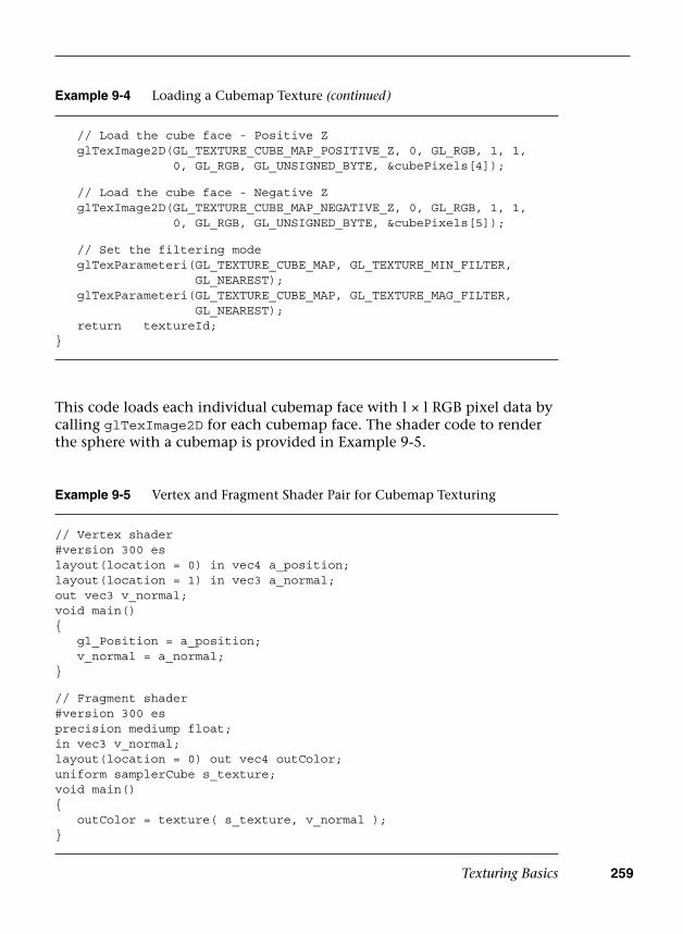
Texturing Basics 259
This code loads each individual cubemap face with l × l RGB pixel data by calling glTexImage2D for each cubemap face. The shader code to render the sphere with a cubemap is provided in Example 9-5.
Example 9-5 Vertex and Fragment Shader Pair for Cubemap Texturing
// Vertex shader#version 300 eslayout(location = 0) in vec4 a_position;layout(location = 1) in vec3 a_normal; out vec3 v_normal; void main(){ gl_Position = a_position; v_normal = a_normal; }
// Fragment shader#version 300 esprecision mediump float;in vec3 v_normal; layout(location = 0) out vec4 outColor; uniform samplerCube s_texture;void main(){ outColor = texture( s_texture, v_normal );}
// Load the cube face - Positive Z glTexImage2D(GL_TEXTURE_CUBE_MAP_POSITIVE_Z, 0, GL_RGB, 1, 1,
0, GL_RGB, GL_UNSIGNED_BYTE, &cubePixels[4]);
// Load the cube face - Negative Z glTexImage2D(GL_TEXTURE_CUBE_MAP_NEGATIVE_Z, 0, GL_RGB, 1, 1,
0, GL_RGB, GL_UNSIGNED_BYTE, &cubePixels[5]);
// Set the filtering mode glTexParameteri(GL_TEXTURE_CUBE_MAP, GL_TEXTURE_MIN_FILTER,
GL_NEAREST); glTexParameteri(GL_TEXTURE_CUBE_MAP, GL_TEXTURE_MAG_FILTER,
GL_NEAREST); return textureId;}
Example 9-4 Loading a Cubemap Texture (continued)
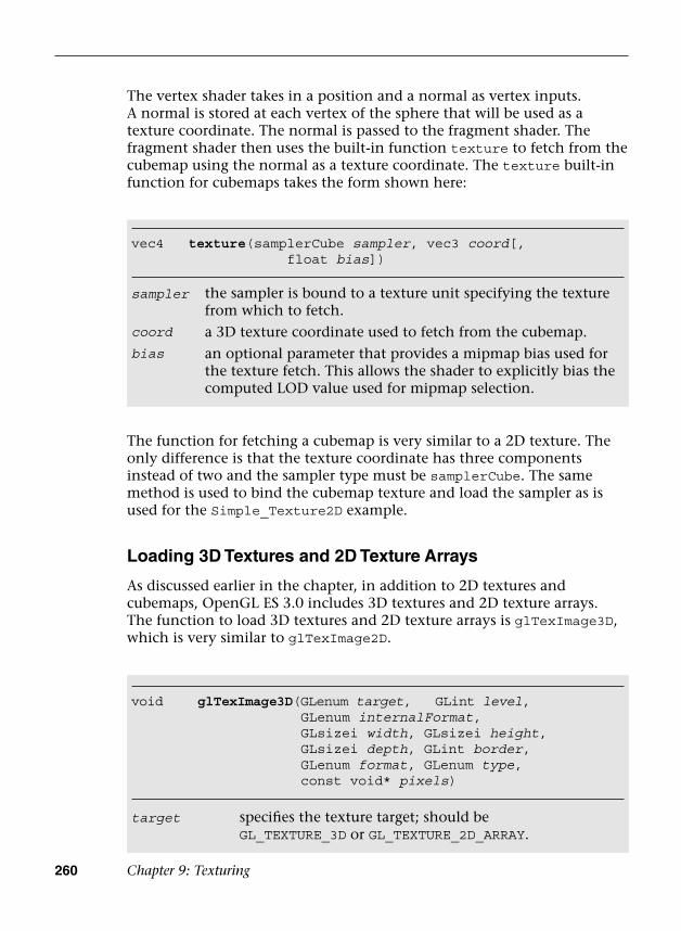
260 Chapter 9: Texturing
The vertex shader takes in a position and a normal as vertex inputs. A normal is stored at each vertex of the sphere that will be used as a texture coordinate. The normal is passed to the fragment shader. The fragment shader then uses the built-in function texture to fetch from the cubemap using the normal as a texture coordinate. The texture built-in function for cubemaps takes the form shown here:
vec4 texture(samplerCube sampler, vec3 coord[,float bias])
sampler the sampler is bound to a texture unit specifying the texture from which to fetch.
coord a 3D texture coordinate used to fetch from the cubemap.bias an optional parameter that provides a mipmap bias used for
the texture fetch. This allows the shader to explicitly bias the computed LOD value used for mipmap selection.
void glTexImage3D(GLenum target, GLint level,GLenum internalFormat,GLsizei width, GLsizei height,GLsizei depth, GLint border,GLenum format, GLenum type,const void* pixels)
target specifies the texture target; should be GL_TEXTURE_3D or GL_TEXTURE_2D_ARRAY.
The function for fetching a cubemap is very similar to a 2D texture. The only difference is that the texture coordinate has three components instead of two and the sampler type must be samplerCube. The same method is used to bind the cubemap texture and load the sampler as is used for the Simple_Texture2D example.
Loading 3D Textures and 2D Texture Arrays
As discussed earlier in the chapter, in addition to 2D textures and cubemaps, OpenGL ES 3.0 includes 3D textures and 2D texture arrays. The function to load 3D textures and 2D texture arrays is glTexImage3D, which is very similar to glTexImage2D.

Texturing Basics 261
level specifies which mip level to load. The base level is specified by 0, followed by an increasing level for each successive mipmap.
internal Format
the internal format for the texture storage; can be either an unsized base internal format or a sized internal format. The full valid internalFormat, format, and type combinations are provided in Tables 9-4 through 9-10.
width the width of the image in pixels.
height the height of the image in pixels.
depth the number of slices of the 3D texture.
border this parameter is ignored in OpenGL ES. It was kept for compatibility with the desktop OpenGL interface. Should be 0.
format the format of the incoming texture data; can beGL_RED GL_RED_INTEGER GL_RG GL_RG_INTEGERGL_RGB GL_RGB_INTEGER GL_RGBAGL_RGBA_INTEGER GL_DEPTH_COMPONENTGL_DEPTH_STENCIL GL_LUMINANCE_ALPHAGL_ALPHA
type the type of the incoming pixel data; can beGL_UNSIGNED_BYTEGL_BYTE GL_UNSIGNED_SHORT GL_SHORT GL_UNSIGNED_INT GL_INT GL_HALF_FLOAT GL_FLOAT
pixels contains the actual pixel data for the image. The data must contain (width * height * depth) number of pixels with the appropriate number of bytes per pixel based on the format and type specification. The image data should be stored as a sequence of 2D texture slices.
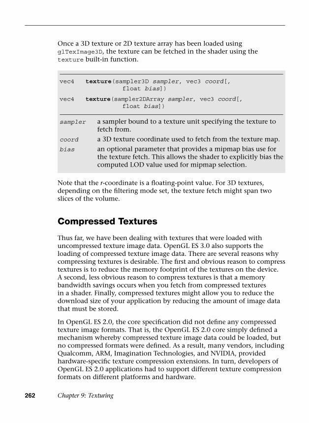
262 Chapter 9: Texturing
Once a 3D texture or 2D texture array has been loaded using glTexImage3D, the texture can be fetched in the shader using the texture built-in function.
vec4 texture(sampler3D sampler, vec3 coord[,float bias])
vec4 texture(sampler2DArray sampler, vec3 coord[,float bias])
sampler a sampler bound to a texture unit specifying the texture to fetch from.
coord a 3D texture coordinate used to fetch from the texture map.
bias an optional parameter that provides a mipmap bias use for the texture fetch. This allows the shader to explicitly bias the computed LOD value used for mipmap selection.
Note that the r-coordinate is a floating-point value. For 3D textures, depending on the filtering mode set, the texture fetch might span two slices of the volume.
Compressed Textures
Thus far, we have been dealing with textures that were loaded with uncompressed texture image data. OpenGL ES 3.0 also supports the loading of compressed texture image data. There are several reasons why compressing textures is desirable. The first and obvious reason to compress textures is to reduce the memory footprint of the textures on the device. A second, less obvious reason to compress textures is that a memory bandwidth savings occurs when you fetch from compressed textures in a shader. Finally, compressed textures might allow you to reduce the download size of your application by reducing the amount of image data that must be stored.
In OpenGL ES 2.0, the core specification did not define any compressed texture image formats. That is, the OpenGL ES 2.0 core simply defined a mechanism whereby compressed texture image data could be loaded, but no compressed formats were defined. As a result, many vendors, including Qualcomm, ARM, Imagination Technologies, and NVIDIA, provided hardware-specific texture compression extensions. In turn, developers of OpenGL ES 2.0 applications had to support different texture compression formats on different platforms and hardware.
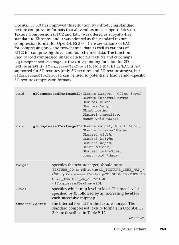
Compressed Textures 263
OpenGL ES 3.0 has improved this situation by introducing standard texture compression formats that all vendors must support. Ericsson Texture Compression (ETC2 and EAC) was offered as a royalty-free standard to Khronos, and it was adopted as the standard texture compression format for OpenGL ES 3.0. There are variants of EAC for compressing one- and two-channel data as well as variants of ETC2 for compressing three- and four-channel data. The function used to load compressed image data for 2D textures and cubemaps is glCompressedTexImage2D; the corresponding function for 2D texture arrays is glCompressedTexImage3D. Note that ETC2/EAC is not supported for 3D textures (only 2D textures and 2D texture arrays), but glCompressedTexImage3D can be used to potentially load vendor-specific 3D texture compression formats.
void glCompressedTexImage2D( GLenum target, GLint level, GLenum internalFormat, GLsizei width,GLsizei height,GLint border,GLsizei imageSize,const void *data)
void glCompressedTexImage3D( GLenum target, GLint level, GLenum internalFormat, GLsizei width,GLsizei height,GLsizei depth,GLint border,GLsizei imageSize,const void *data)
target specifies the texture target; should be GL_TEXTURE_2D or either the GL_TEXTURE_CUBE_MAP_* (for glCompressedTexImage2D) or GL_TEXTURE_3Dor GL_TEXTURE_2D_ARRAY (for glCompressedTexImage3D).
level specifies which mip level to load. The base level is specified by 0, followed by an increasing level for each successive mipmap.
internalFormat the internal format for the texture storage. The standard compressed texture formats in OpenGL ES 3.0 are described in Table 9-12.
(continues)
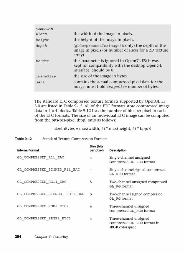
264 Chapter 9: Texturing
The standard ETC compressed texture formats supported by OpenGL ES 3.0 are listed in Table 9-12. All of the ETC formats store compressed image data in 4 × 4 blocks. Table 9-12 lists the number of bits per pixel in each of the ETC formats. The size of an individual ETC image can be computed from the bits-per-pixel (bpp) ratio as follows:
sizeInBytes = max(width, 4) * max(height, 4) * bpp/8
Table 9-12 Standard Texture Compression Formats
internalFormatSize (bits per pixel) Description
GL_COMPRESSED_R11_EAC 4 Single-channel unsigned compressed GL_RED format
GL_COMPRESSED_SIGNED_R11_EAC 4 Single-channel signed compressed GL_RED format
GL_COMPRESSED_RG11_EAC 8 Two-channel unsigned compressed GL_RG format
GL_COMPRESSED_SIGNED_ RG11_EAC 8 Two-channel signed compressed GL_RG format
GL_COMPRESSED_RGB8_ETC2 4 Three-channel unsigned compressed GL_RGB format
GL_COMPRESSED_SRGB8_ETC2 4 Three-channel unsigned compressed GL_RGB format in sRGB colorspace
(continued)width the width of the image in pixels.
height the height of the image in pixels.
depth (glCompressedTexImage3D only) the depth of the image in pixels (or number of slices for a 2D texture array).
border this parameter is ignored in OpenGL ES; it was kept for compatibility with the desktop OpenGL interface. Should be 0.
imageSize the size of the image in bytes.
data contains the actual compressed pixel data for the image; must hold imageSize number of bytes.
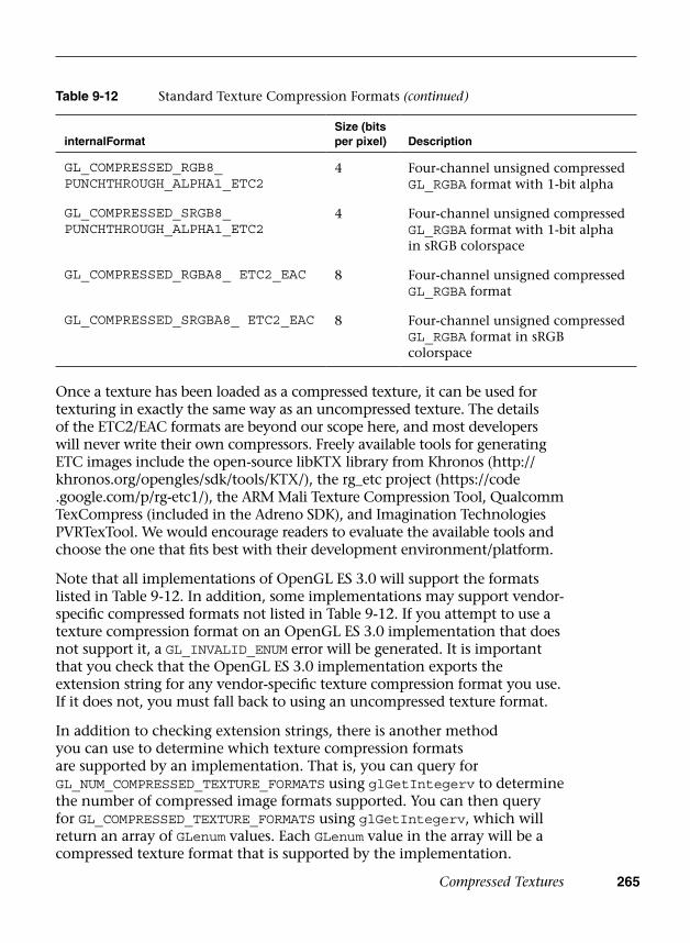
Compressed Textures 265
Once a texture has been loaded as a compressed texture, it can be used for texturing in exactly the same way as an uncompressed texture. The details of the ETC2/EAC formats are beyond our scope here, and most developers will never write their own compressors. Freely available tools for generating ETC images include the open-source libKTX library from Khronos (http:// khronos.org/opengles/sdk/tools/KTX/), the rg_etc project (https://code .google.com/p/rg-etc1/), the ARM Mali Texture Compression Tool, Qualcomm TexCompress (included in the Adreno SDK), and Imagination Technologies PVRTexTool. We would encourage readers to evaluate the available tools and choose the one that fits best with their development environment/platform.
Note that all implementations of OpenGL ES 3.0 will support the formats listed in Table 9-12. In addition, some implementations may support vendor-specific compressed formats not listed in Table 9-12. If you attempt to use a texture compression format on an OpenGL ES 3.0 implementation that does not support it, a GL_INVALID_ENUM error will be generated. It is important that you check that the OpenGL ES 3.0 implementation exports the extension string for any vendor-specific texture compression format you use. If it does not, you must fall back to using an uncompressed texture format.
In addition to checking extension strings, there is another method you can use to determine which texture compression formats are supported by an implementation. That is, you can query for GL_NUM_COMPRESSED_TEXTURE_FORMATS using glGetIntegerv to determine the number of compressed image formats supported. You can then query for GL_COMPRESSED_TEXTURE_FORMATS using glGetIntegerv, which will return an array of GLenum values. Each GLenum value in the array will be a compressed texture format that is supported by the implementation.
internalFormatSize (bits per pixel) Description
GL_COMPRESSED_RGB8_PUNCHTHROUGH_ALPHA1_ETC2
4 Four-channel unsigned compressed GL_RGBA format with 1-bit alpha
GL_COMPRESSED_SRGB8_PUNCHTHROUGH_ALPHA1_ETC2
4 Four-channel unsigned compressed GL_RGBA format with 1-bit alpha in sRGB colorspace
GL_COMPRESSED_RGBA8_ ETC2_EAC 8 Four-channel unsigned compressed GL_RGBA format
GL_COMPRESSED_SRGBA8_ ETC2_EAC 8 Four-channel unsigned compressed GL_RGBA format in sRGB colorspace
Table 9-12 Standard Texture Compression Formats (continued)
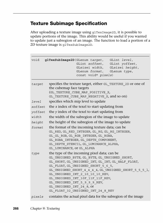
266 Chapter 9: Texturing
Texture Subimage Specification
After uploading a texture image using glTexImage2D, it is possible to update portions of the image. This ability would be useful if you wanted to update just a subregion of an image. The function to load a portion of a 2D texture image is glTexSubImage2D.
void glTexSubImage2D( GLenum target, GLint level, GLint xoffset, GLint yoffset, GLsizei width, GLsizei height, GLenum format, GLenum type, const void* pixels)
target specifies the texture target, either GL_TEXTURE_2D or one of the cubemap face targets (GL_TEXTURE_CUBE_MAP_POSITIVE_X, GL_TEXTURE_CUBE_MAP_NEGATIVE_X, and so on)
level specifies which mip level to update
xoffset the x index of the texel to start updating from
yoffset the y index of the texel to start updating fromwidth the width of the subregion of the image to update
height the height of the subregion of the image to update
format the format of the incoming texture data; can beGL_RED, GL_RED_INTEGER, GL_RG, GL_RG_INTEGER,GL_GL_RGB, GL_RGB_INTEGER, GL_RGBA,GL_RGBA_INTEGER, GL_DEPTH_COMPONENT,GL_DEPTH_STENCIL, GL_LUMINANCE_ALPHA,GL_LUMINANCE, or GL_ALPHA
type the type of the incoming pixel data; can beGL_UNSIGNED_BYTE, GL_BYTE, GL_UNSIGNED_SHORT,GL_SHORT, GL_UNSIGNED_INT, GL_INT, GL_HALF_FLOAT,GL_FLOAT, GL_UNSIGNED_SHORT_5_6_5,GL_UNSIGNED_SHORT_4_4_4_4, GL_UNSIGNED_SHORT_5_5_5_l,GL_UNSIGNED_INT_2_10_10_10_REV,GL_UNSIGNED_INT_10F_11F_11F_REV,GL_UNSIGNED_INT_5_9_9_9_REV,GL_UNSIGNED_INT_24_8, orGL_FLOAT_32_UNSIGNED_INT_24_8_REV
pixels contains the actual pixel data for the subregion of the image
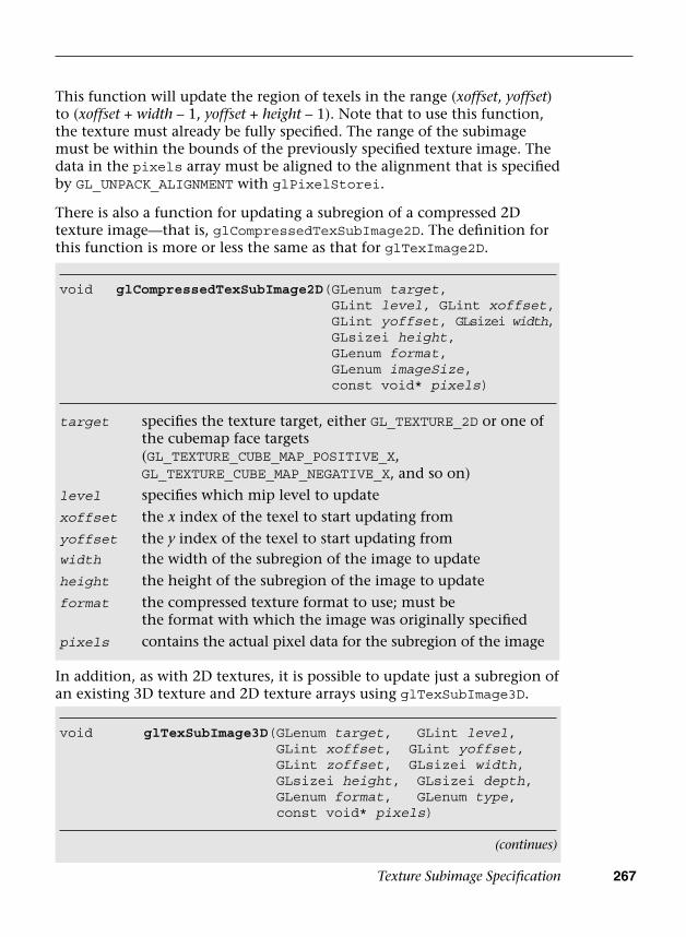
Texture Subimage Specification 267
This function will update the region of texels in the range (xoffset, yoffset) to (xoffset + width – 1, yoffset + height – 1). Note that to use this function, the texture must already be fully specified. The range of the subimage must be within the bounds of the previously specified texture image. The data in the pixels array must be aligned to the alignment that is specified by GL_UNPACK_ALIGNMENT with glPixelStorei.
There is also a function for updating a subregion of a compressed 2D texture image—that is, glCompressedTexSubImage2D. The definition for this function is more or less the same as that for glTexImage2D.
void glCompressedTexSubImage2D( GLenum target, GLint level, GLint xoffset, GLint yoffset, GLsizei width, GLsizei height, GLenum format, GLenum imageSize, const void* pixels)
target specifies the texture target, either GL_TEXTURE_2D or one of the cubemap face targets (GL_TEXTURE_CUBE_MAP_POSITIVE_X, GL_TEXTURE_CUBE_MAP_NEGATIVE_X, and so on)
level specifies which mip level to update
xoffset the x index of the texel to start updating from
yoffset the y index of the texel to start updating fromwidth the width of the subregion of the image to update
height the height of the subregion of the image to update
format the compressed texture format to use; must bethe format with which the image was originally specified
pixels contains the actual pixel data for the subregion of the image
void glTexSubImage3D( GLenum target, GLint level, GLint xoffset, GLint yoffset, GLint zoffset, GLsizei width, GLsizei height, GLsizei depth, GLenum format, GLenum type, const void* pixels)
In addition, as with 2D textures, it is possible to update just a subregion of an existing 3D texture and 2D texture arrays using glTexSubImage3D.
(continues)
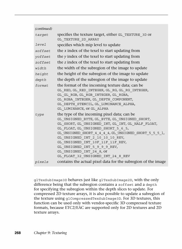
268 Chapter 9: Texturing
glTexSubImage3D behaves just like glTexSubImage2D, with the only difference being that the subregion contains a zoffset and a depth for specifying the subregion within the depth slices to update. For compressed 2D texture arrays, it is also possible to update a subregion of the texture using glCompressedTexSubImage3D. For 3D textures, this function can be used only with vendor-specific 3D compressed texture formats, because ETC2/EAC are supported only for 2D textures and 2D texture arrays.
(continued)
target specifies the texture target, either GL_TEXTURE_3D or GL_TEXTURE_2D_ARRAY
level specifies which mip level to update
xoffset the x index of the texel to start updating from
yoffset the y index of the texel to start updating from
zoffset the z index of the texel to start updating from
width the width of the subregion of the image to update
height the height of the subregion of the image to update
depth the depth of the subregion of the image to update
format the format of the incoming texture data; can beGL_RED, GL_RED_INTEGER, GL_RG, GL_RG_INTEGER,GL_GL_RGB, GL_RGB_INTEGER, GL_RGBA,GL_RGBA_INTEGER, GL_DEPTH_COMPONENT,GL_DEPTH_STENCIL, GL_LUMINANCE_ALPHA,GL_LUMINANCE, or GL_ALPHA
type the type of the incoming pixel data; can beGL_UNSIGNED_BYTE, GL_BYTE, GL_UNSIGNED_SHORT, GL_SHORT, GL_UNSIGNED_INT, GL_INT, GL_HALF_FLOAT,GL_FLOAT, GL_UNSIGNED_SHORT_5_6_5,GL_UNSIGNED_SHORT_4_4_4_4, GL_UNSIGNED_SHORT_5_5_5_l,GL_UNSIGNED_INT_2_10_10_10_REV,GL_UNSIGNED_INT_10F_11F_11F_REV,GL_UNSIGNED_INT_5_9_9_9_REV,GL_UNSIGNED_INT_24_8, orGL_FLOAT_32_UNSIGNED_INT_24_8_REV
pixels contains the actual pixel data for the subregion of the image

Copying Texture Data from the Color Buffer 269
Copying Texture Data from the Color Buffer
An additional texturing feature that is supported in OpenGL ES 3.0 is the ability to copy data from a color buffer to a texture. This can be useful if you want to use the results of rendering as an image in a texture. Framebuffer objects (Chapter 12) provide a fast method for doing render-to-texture and are a faster method than copying image data. However, if performance is not a concern, the ability to copy image data out of the color buffer can be a useful feature.
The color buffer from which to copy image data from can be set using the function glReadBuffer. If the application is rendering to a double-buffered EGL displayable surface, then glReadBuffer must be set to GL_BACK (the back buffer—the default state). Recall that OpenGL ES 3.0 supports only double-buffered EGL displayable surfaces. As a consequence, all OpenGL
void glCompressedTexSubImage3D( GLenum target,GLint level,GLint xoffset,GLint yoffset,GLint zoffset,GLsizei width,GLsizei height,GLsizei depth,GLenum format,GLenum imageSize,const void* data)
target specifies the texture target, either GL_TEXTURE_2D orGL_TEXTURE_2D_ARRAY)
level specifies which mip level to update
xoffset the x index of the texel to start updating from
yoffset the y index of the texel to start updating from
zoffset the z index of the texel to start updating from
width the width of the subregion of the image to update
height the height of the subregion of the image to update
depth the depth of the subregion of the image to update
format the compressed texture format to use; must bethe format with which the image was originally specified
pixels contains the actual pixel data for the subregion of the image

270 Chapter 9: Texturing
The functions to copy data from the color buffer to a texture are glCopyTexImage2D, glCopyTexSubImage2D, and glCopyTexSubImage3D.
void glCopyTexImage2D(GLenum target, GLint level, GLenum internalFormat, GLint x,GLint y, GLsizei width,GLsizei height, Glint border )
target specifies the texture target, either GL_TEXTURE_2D or one of the cubemap face targets (GL_TEXTURE_CUBE_MAP_POSITIVE_X, GL_TEXTURE_CUBE_MAP_NEGATIVE_X, and so on)
level specifies which mip level to loadinternalFormat the internal format of the image; can be
GL_ALPHA, GL_LUMINANCE, GL_LUMINANCE_ALPHA,GL_RGB, GL_RGBA, GL_R8, GL_RG8, GL_RGB565,GL_RGB8, GL_RGBA4, GL_RGB5_A1, GL_RGBA8,GL_RGB10_A2, GL_SRGB8, GL_SRGB8_ALPHA8,
ES 3.0 applications that draw to the display will have a color buffer for both the front and back buffers. The buffer that is currently the front or back is determined by the most recent call to eglSwapBuffers (described in Chapter 3, “An Introduction to EGL”). When you copy image data out of the color buffer from a displayable EGL surface, you will always be copying the contents of the back buffer. If you are rendering to an EGL pbuffer, then copying will occur from the pbuffer surface. Finally, if you are rendering to a framebuffer object, then the framebuffer object color attachment to copy from is set by calling glReadBuffer with GL_COLOR_ATTACHMENTi.
void glReadBuffer(GLenum mode)
mode specifies the color buffer to read from. This will
set the source color buffer for future calls to
glReadPixels, glCopyTexImage2D,
glCopyTexSubImage2D, and
glCopyTexSubImage3D. The value can be either
GL_BACK, GL_COLOR_ATTACHMENTi, or
GL_NONE.
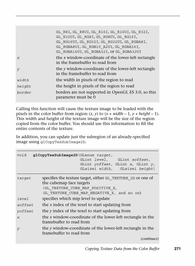
Copying Texture Data from the Color Buffer 271
void glCopyTexSubImage2D(GLenum target,GLint level, GLint xoffset,GLint yoffset, GLint x, GLint y,GLsizei width, GLsizei height)
target specifies the texture target, either GL_TEXTURE_2D or one of the cubemap face targets (GL_TEXTURE_CUBE_MAP_POSITIVE_X, GL_TEXTURE_CUBE_MAP_NEGATIVE_X, and so on)
level specifies which mip level to update
xoffset the x index of the texel to start updating from
yoffset the y index of the texel to start updating from
x the x window-coordinate of the lower-left rectangle in the framebuffer to read from
y the y window-coordinate of the lower-left rectangle in the framebuffer to read from
GL_R8I, GL_R8UI, GL_R16I, GL_R16UI, GL_R32I,GL_R32UI, GL_RG8I, GL_RG8UI, GL_RG16I,GL_RG16UI, GL_RG32I, GL_RG32UI, GL_RGBA8I,GL_RGBA8UI, GL_RGB10_A2UI, GL_RGBA16I,GL_RGBA16UI, GL_RGBA32I, or GL_RGBA32UI
x the x window-coordinate of the lower-left rectangle in the framebuffer to read from
y the y window-coordinate of the lower-left rectangle in the framebuffer to read from
width the width in pixels of the region to read
height the height in pixels of the region to read
border borders are not supported in OpenGL ES 3.0, so this parameter must be 0
Calling this function will cause the texture image to be loaded with the pixels in the color buffer from region (x, y) to (x + width – 1, y + height – 1). This width and height of the texture image will be the size of the region copied from the color buffer. You should use this information to fill the entire contents of the texture.
In addition, you can update just the subregion of an already-specified image using glCopyTexSubImage2D.
(continues)

272 Chapter 9: Texturing
This function will update the subregion of the image starting at (xoffset, yoffset) to (xoffset + width – 1, yoffset + height – 1) with the pixels in the color buffer from (x, y) to (x + width – 1, y + height – 1).
Finally, you can also copy the contents of the color buffer into a slice (or subregion of a slice) of a previously specified 3D texture or 2D texture array using glCopyTexSubImage3D.
void glCopyTexSubImage3D( GLenum target, GLint level, GLint xoffset, GLint yoffset, GLint zoffset, GLint x, GLint y, GLsizei width, GLsizei height)
target specifies the texture target, either GL_TEXTURE_3Dor GL_TEXTURE_2D_ARRAY
level specifies which mip level to update
xoffset the x index of the texel to start updating from
yoffset the y index of the texel to start updating from
zoffset the z index of the texel to start updating from
x the x window-coordinate of the lower-left rectangle in the framebuffer to read from
y the y window-coordinate of the lower-left rectangle in the framebuffer to read from
width the width in pixels of the region to read
height the height in pixels of the region to read
One thing to keep in mind with glCopyTexImage2D, glCopyTexSubImage2D, and glCopyTexSubImage3D is that the texture image format cannot have more components than the color buffer. In other words, when copying data out of the color buffer, it is possible to convert to a format with fewer components, but not with more. Table 9-13 shows the valid format conversions when doing a texture copy. For example, you can copy an RGBA image into any of the possible formats, but you cannot copy an RGB into an RGBA image because no alpha component exists in the color buffer.
(continued)width the width in pixels of the region to readheight the height in pixels of the region to read

Sampler Objects 273
Sampler Objects
Previously in the chapter, we covered how to set texture parameters such as filter modes, texture coordinate wrap modes, and LOD settings using glTexParameter[i|f][v]. The issue with using glTexParameter[i|f][v] is that it can result in a significant amount of unnecessary API overhead. Very often, an application will use the same texture settings for a large number of textures. In such a case, having to set the sampler state with glTexParameter[i|f][v] for every texture object can result in a lot of extra overhead. To mitigate this problem, OpenGL ES 3.0 introduces sampler objects that separate sampler state from texture state. In short, all of the settings that can be set with glTexParameter[i|f][v] can be set for a sampler object and can be bound for use with a texture unit in a single function call. Sampler objects can be used across many textures and, therefore, reduce API overhead.
The function used to generate sampler objects is glGenSamplers.
Table 9-13 Valid Format Conversions for glCopyTex*Image*
(To) Texture Format
Color Format (From)
A L LA R RG RGB RGBA
R N Y N Y N N N
RG N Y N Y Y N N
RGB N Y N Y Y Y N
RGBA Y Y Y Y Y Y Y
void glGenSamplers(GLsizei n, GLuint *samplers)
n specifies the number of sampler objects to generate
samplers an array of unsigned integers that will hold n sampler object IDs
Sampler objects also need to be deleted when an application no longer needs them. This can be done using glDeleteSamplers.
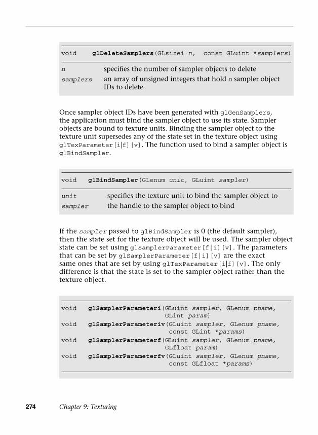
274 Chapter 9: Texturing
Once sampler object IDs have been generated with glGenSamplers, the application must bind the sampler object to use its state. Sampler objects are bound to texture units. Binding the sampler object to the texture unit supersedes any of the state set in the texture object using glTexParameter[i|f][v]. The function used to bind a sampler object is glBindSampler.
void glDeleteSamplers(GLsizei n, const GLuint *samplers)
n specifies the number of sampler objects to delete
samplers an array of unsigned integers that hold n sampler object IDs to delete
void glBindSampler(GLenum unit, GLuint sampler)
unit specifies the texture unit to bind the sampler object to
sampler the handle to the sampler object to bind
void glSamplerParameteri( GLuint sampler, GLenum pname, GLint param)
void glSamplerParameteriv( GLuint sampler, GLenum pname, const GLint *params)
void glSamplerParameterf( GLuint sampler, GLenum pname, GLfloat param)
void glSamplerParameterfv( GLuint sampler, GLenum pname, const GLfloat *params)
If the sampler passed to glBindSampler is 0 (the default sampler), then the state set for the texture object will be used. The sampler object state can be set using glSamplerParameter[f|i][v]. The parameters that can be set by glSamplerParameter[f|i][v] are the exact same ones that are set by using glTexParameter[i|f][v]. The only difference is that the state is set to the sampler object rather than the texture object.

Sampler Objects 275
sampler the sampler object to setpname the parameter to set; one of
GL_TEXTURE_BASE_LEVELGL_TEXTURE_COMPARE_FUNCGL_TEXTURE_COMPARE_MODEGL_TEXTURE_MIN_FILTERGL_TEXTURE_MAG_FILTERGL_TEXTURE_MIN_LODGL_TEXTURE_MAX_LOD GL_TEXTURE_MAX_LEVELGL_TEXTURE_SWIZZLE_RGL_TEXTURE_SWIZZLE_GGL_TEXTURE_SWIZZLE_BGL_TEXTURE_SWIZZLE_AGL_TEXTURE_WRAP_SGL_TEXTURE_WRAP_TGL_TEXTURE_WRAP_R
params the value (or array of values for the “v” entrypoints) to set the texture parameter to
If pname is GL_TEXTURE_MAG_FILTER, then param can beGL_NEAREST or GL_LINEAR
If pname is GL_TEXTURE_MIN_FILTER, then param can beGL_NEAREST, GL_LINEAR, GL_NEAREST_MIPMAP_NEAREST,GL_NEAREST_MIPMAP_LINEAR, GL_LINEAR_MIPMAP_NEAREST, or GL_LINEAR_MIPMAP_LINEAR
If pname is GL_TEXTURE_WRAP_S, GL_TEXTURE_WRAP_R, orGL_TEXTURE_WRAP_T, then param can beGL_REPEAT, GL_CLAMP_TO_EDGE, or GL_MIRRORED_REPEAT
If pname is GL_TEXTURE_COMPARE_FUNC, then param can beGL_LEQUAL, GL_EQUAL, GL_LESS, GL_GREATER, GL_EQUAL, GL_NOTEQUAL, GL_ALWAYS, or GL_NEVER
If pname is GL_TEXTURE_COMPARE_MODE, then param can beGL_COMPARE_REF_TO_TEXTURE or GL_NONE
If pname is GL_TEXTURE_SWIZZLE_R, GL_TEXTURE_SWIZZLE_G, GL_TEXTURE_SWIZZLE_B, or GL_TEXTURE_SWIZZLE_A, then param can beGL_RED, GL_GREEN, GL_BLUE, GL_ALPHA, GL_ZERO, orGL_ONE

276 Chapter 9: Texturing
Immutable Textures
Another feature introduced in OpenGL ES 3.0 to help improve application performance is immutable textures. As discussed earlier in this chapter, an application specifies each mipmap level of a texture independently using functions such as glTexImage2D and glTexImage3D. The problem this creates for the OpenGL ES driver is that it cannot determine until draw time whether a texture has been fully specified. That is, it has to check whether each mipmap level or subimage has matching formats, whether each level has the correct dimensions, and whether there is sufficient memory. This draw time check can be costly and can be avoided by using immutable textures.
The idea behind immutable textures is simple: The application specifies the format and size of a texture before loading it with data. In doing so, the texture format becomes immutable and the OpenGL ES driver can perform all consistency and memory checks up-front. Once a texture has become immutable, its format and dimensions cannot change. However, the application can still load it with image data by using glTexSubImage2D, glTexSubImage3D, or glGenerateMipMap, or by rendering to the texture.
To create an immutable texture, an application would bind the texture using glBindTexture and then allocate its immutable storage using glTexStorage2D or glTexStorage3D.
void glTexStorage2D( GLenum target, GLsizei levels, GLenum internalFormat, GLsizei width, GLsizei height)
void glTexStorage3D( GLenum target, GLsizei levels, GLenum internalFormat, GLsizei width, GLsizei height, GLsizei depth)
target specifies the texture target, either GL_TEXTURE_2D orone of the cubemap face targets (GL_TEXTURE_CUBE_MAP_POSITIVE_X,GL_TEXTURE_CUBE_MAP_NEGATIVE_X, and so on) forglTexStorage2D, or GL_TEXTURE_3D orGL_TEXTURE_2D_ARRAY for glTexStorage3D
levels specifies the number of mipmap levels
internalFormat the sized internal format for the texture storage; the full list of valid internalFormat values is the same as the valid sized internalFormat values for glTexImage2D provided in the Texture Objects and Loading Textures section earlier in this chapter.

Pixel Unpack Buffer Objects 277
Once the immutable texture is created, it is invalid to call glTexImage*, glCompressedTexImage*, glCopyTexImage*, or glTexStorage* on the texture object. Doing so will result in a GL_INVALID_OPERATION error being generated. To fill the immutable texture with image data, the application needs to use glTexSubImage2D, glTexSubImage3D, or glGenerateMipMap, or else render to the image as a texture (by using it as an attachment to a framebuffer object).
Internally, when glTexStorage* is used, OpenGL ES marks the texture object as being immutable by setting GL_TEXTURE_IMMUTABLE_FORMAT to GL_TRUE and GL_TEXTURE_IMMUTABLE_LEVELS to the number of levels passed to glTexStorage*. The application can query for these values by using glGetTexParameter[i|f][v], although it cannot set them directly. The glTexStorage* function must be used to set up the immutable texture parameters.
Pixel Unpack Buffer Objects
In Chapter 6, “Vertex Attributes, Vertex Arrays, and Buffer Objects,” we introduced buffer objects, concentrating the discussion on vertex buffer objects (VBOs) and copy buffer objects. As you will recall, buffer objects allow the storage of data in server-side (or GPU) memory as opposed to client-side (or host) memory. The advantage of using buffer objects is that they reduce the transfer of data from CPU to GPU and, therefore, can improve performance (as well as reduce memory utilization). OpenGL ES 3.0 also introduces pixel unpack buffer objects that are bound and specified with the GL_PIXEL_UNPACK_BUFFER target. The functions that operate on pixel unpack buffer objects are described in Chapter 6. Pixel unpack buffer objects allow the specification of texture data that resides in server-side memory. As a consequence, the pixel unpack operations glTexImage*, glTexSubImage*, glCompressedTexImage*, and glCompressedTexSubImage* can come directly from a buffer object. Much like VBOs with glVertexAttribPointer, if a pixel unpack buffer object is bound during one of those calls, the data pointer is an offset into the pixel unpack buffer rather than a pointer to client memory.
width the width of the base image in pixels
height the height of the base image in pixels
depth (glTexStorage3D only) the depth of the base image in pixels

278 Chapter 9: Texturing
Pixel unpack buffer objects can be used to stream texture data to the GPU. The application could allocate a pixel unpack buffer and then map regions of the buffer for updates. When the calls to load the data to OpenGL are made (e.g., glTexSubImage*), these functions can return immediately because the data already resides in the GPU (or can be copied at a later time, but an immediate copy does not need to be made as it does with client-side data). We recommend using pixel unpack buffer objects in situations where the performance/memory utilization of texture upload operations is important for the application.
Summary
This chapter covered how to use textures in OpenGL ES 3.0. We introduced the various types of textures: 2D, 3D, cubemaps, and 2D texture arrays. For each texture type, we showed how the texture can be loaded with data either in full, in subimages, or by copying data from the framebuffer. We detailed the wide range of texture formats available in OpenGL ES 3.0, which include normalized texture formats, floating-point textures, integer textures, shared exponent textures, sRGB textures, and depth textures. We covered all of the texture parameters that can be set for texture objects, including filter modes, wrap modes, depth texture comparison, and level-of-detail settings. We explored how to set texture parameters using the more efficient sampler objects. Finally, we showed how to create immutable textures that can help reduce the draw-time overhead of using textures. We also saw how textures can be read in the fragment shader with several example programs. With all this information under your belt, you are well on your way toward using OpenGL ES 3.0 for many advanced rendering effects. Next, we cover more details of the fragment shader that will help you further understand how textures can be used to achieve a wide range of rendering techniques.
279
Chapter 10
Fragment Shaders
Chapter 9, “Texturing,” introduced you to the basics of creating and applying textures in the fragment shader. In this chapter, we provide more details on the fragment shader and describe some of its uses. In particular, we focus on how to implement fixed-function techniques using the fragment shader. The topics we cover in this chapter include the following:
• Fixed function fragment shaders
• Programmable fragment shader overview
• Multitexturing
• Fog
• Alpha test
• User clip planes
In Figure 10-1, we have previously covered the vertex shader, primitive assembly, and rasterization stages of the programmable pipeline. We have talked about using textures in the fragment shader. Now, we focus on the fragment shader portion of the pipeline and fill in the remaining details on writing fragment shaders.

280 Chapter 10: Fragment Shaders
Fixed-Function Fragment Shaders
Readers who are new to the programmable fragment pipeline but have worked with OpenGL ES 1.x (or earlier versions of desktop OpenGL) are probably familiar with the fixed-function fragment pipeline. Before diving into details of the fragment shader, we think it is worthwhile to briefly review the old fixed-function fragment pipeline. This will give you an understanding of how the old fixed-function pipeline maps into fragment shaders. It’s a good way to start before moving into more advanced fragment programming techniques.
In OpenGL ES 1.1 (and fixed-function desktop OpenGL), you had a limited set of equations that could be used to determine how to combine the various inputs to the fragment shader. In the fixed-function pipeline, you essentially had three inputs you could use: the interpolated vertex color, the texture color, and the constant color. The vertex color would typically hold either a precomputed color or the result of the vertex lighting computation. The texture color came from fetching from whichever texture was bound using the primitive’s texture coordinates and the constant color could be set for each texture unit.
Vertex Buffer/Array Objects
TransformFeedbackArray Objects
Vertex Shader
FragmentShader
Feedback
r PrimitiveAssembly Rasterization
Per-FragmentOperations
Framebuffer
API
Fragment
Textures
Figure 10-1 OpenGL ES 3.0 Programmable Pipeline

Fixed-Function Fragment Shaders 281
The set of equations you could use to combine these inputs together was quite limited. For example, in OpenGL ES 1.1, the equations listed in Table 10-1 were available. The inputs A, B, and C to these equations could come from the vertex color, texture color, or constant color.
Table 10-1 OpenGL ES 1.1 RGB Combine Functions
RGB Combine Function Equation
REPLACE A
MODULATE A × B
ADD A + B
ADD_SIGNED A + B – 0.5
INTERPOLATE A × C + B × (1 – C)
SUBTRACT A – B
DOT3_RGB (and DOT3_RGBA) 4 × ((A.r – 0.5) × (B.r – 0.5) + (A.g – 0.5) × (B.g – 0.5) + (A.b – 0.5) × (B.b × 0.5))
There actually was a great number of interesting effects one could achieve, even with this limited set of equations. However, this was far from programmable, as the fragment pipeline could be configured only in a very fixed set of ways.
So why are we reviewing this history here? It helps give an understanding of how traditional fixed-function techniques can be achieved with shaders. For example, suppose we had configured the fixed-function pipeline with a single base texture map that we wanted to modulate (multiply) by the vertex color. In fixed-function OpenGL ES (or OpenGL), we would enable a single texture unit, choose a combine equation of MODULATE, and set up the inputs to the equation to come from the vertex color and texture color. The code to do this in OpenGL ES 1.1 is provided here for reference:
glTexEnvi(GL_TEXTURE_ENV, GL_TEXTURE_ENV_MODE, GL_COMBINE);glTexEnvi(GL_TEXTURE_ENV, GL_COMBINE_RGB, GL_MODULATE);glTexEnvi(GL_TEXTURE_ENV, GL_SOURCE0_RGB, GL_PRIMARY_COLOR);glTexEnvi(GL_TEXTURE_ENV, GL_SOURCEl_RGB, GL_TEXTURE);glTexEnvi(GL_TEXTURE_ENV, GL_COMBINE_ALPHA, GL_MODULATE);glTexEnvi(GL_TEXTURE_ENV, GL_SOURCE0_ALPHA, GL_PRIMARY_COLOR);glTexEnvi(GL_TEXTURE_ENV, GL_SOURCEl_ALPHA, GL_TEXTURE);
282 Chapter 10: Fragment Shaders
This code configures the fixed-function pipeline to perform a modulate (A × B) between the primary color (the vertex color) and the texture color. If this code doesn’t make sense to you, don’t worry, as none of it exists in OpenGL ES 3.0. Rather, we are simply trying to show how this would map to a fragment shader. In a fragment shader, this same modulate computation could be accomplished as follows:
#version 300 esprecision mediump float;uniform sampler2D s_tex0;in vec2 v_texCoord;in vec4 v_primaryColor;layout(location = 0) out vec4 outColor;void main(){ outColor = texture(s_tex0, v_texCoord) * v_primaryColor;}
The fragment shader performs the exact same operations that would be performed by the fixed-function setup. The texture value is fetched from a sampler (that is bound to texture unit 0) and a 2D texture coordinate is used to look up that value. Then, the result of that texture fetch is multiplied by v_primaryColor, an input value that is passed in from the vertex shader. In this case, the vertex shader would have passed the color to the fragment shader.
It is possible to write a fragment shader that would perform the equivalent computation as any possible fixed-function texture combine setup. It is also possible, of course, to write shaders with much more complex and varied computations than just fixed functions would allow. However, the point of this section was just to drive home how we have transitioned from fixed-function to programmable shaders. Now, we begin to look at some specifics of fragment shaders.
Fragment Shader Overview
The fragment shader provides a general-purpose programmable method for operating on fragments. The inputs to the fragment shader consist of the following:
• Inputs (or varyings)—Interpolated data produced by the vertex shader.The outputs of the vertex shader are interpolated across the primitiveand passed to the fragment shader as inputs.
• Uniforms—State used by the fragment shader. These are constantvalues that do not vary per fragment.
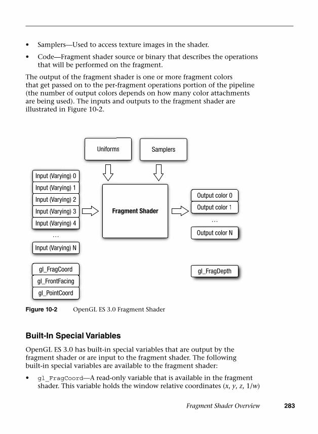
Fragment Shader Overview 283
• Samplers—Used to access texture images in the shader.
• Code—Fragment shader source or binary that describes the operationsthat will be performed on the fragment.
The output of the fragment shader is one or more fragment colors that get passed on to the per-fragment operations portion of the pipeline (the number of output colors depends on how many color attachments are being used). The inputs and outputs to the fragment shader are illustrated in Figure 10-2.
Built-In Special Variables
OpenGL ES 3.0 has built-in special variables that are output by the fragment shader or are input to the fragment shader. The following built-in special variables are available to the fragment shader:
• gl_FragCoord—A read-only variable that is available in the fragmentshader. This variable holds the window relative coordinates (x, y, z, 1/w)
Uniformss Samplers
Fragment Shader
Output color 0
Output color 1Output color 1
Output color N
gl_FragDepth
…
…
Un
Input (Varying) 0
Input (Varying) 1
Input (Varying) 2
Input (Varying) 3
Input (Varying) 4
gl_FragCoord
gl_FrontFacing
gl_PointCoord
…
Input (Varying) 4
gl_FragCoord
l F F i
Input (Varying) N
Figure 10-2 OpenGL ES 3.0 Fragment Shader

284 Chapter 10: Fragment Shaders
of the fragment. There are a number of algorithms where it can be useful to know the window coordinates of the current fragment. For example, you can use the window coordinates as offsets into a texture fetch into a random noise map whose value is used to rotate a filter kernel on a shadow map. This technique is used to reduce shadow map aliasing.
• gl_FrontFacing—A read-only variable that is available in thefragment shader. This boolean variable has a value of true if thefragment is part of a front-facing primitive and false otherwise.
• gl_PointCoord—A read-only variable that can be used when renderingpoint sprites. It holds the texture coordinate for the point sprite that isautomatically generated in the [0, 1] range during point rasterization.In Chapter 14, “Advanced Programming with OpenGL ES 3.0,” there isan example of rendering point sprites that uses this variable.
• gl_FragDepth—A write-only output variable that, when writtento in the fragment shader, overrides the fragment’s fixed-functiondepth value. This functionality should be used sparingly (and onlywhen necessary) because it can disable depth optimization in manyGPUs. For example, many GPUs have a feature called Early-Z wherethe depth test is performed ahead of executing the fragment shader.The benefit of using Early-Z is that fragments that fail the depthtest are never shaded (thus saving performance). However, whengl_FragDepth is used, this feature must be disabled because the GPUdoes not know the depth value ahead of executing the fragmentshader.
Built-In Constants
The following built-in constants are also relevant to the fragment shader:
const mediump int gl_MaxFragmentInputVectors = 15;const mediump int gl_MaxTextureImageUnits = 16;const mediump int gl_MaxFragmentUniformVectors = 224;const mediump int gl_MaxDrawBuffers = 4;const mediump int gl_MinProgramTexelOffset = -8;const mediump int gl_MaxProgramTexelOffset = 7;
The built-in constants describe the following maximum terms:
• gl_MaxFragmentInputVectors—The maximum number of fragmentshader inputs (or varyings). The minimum value supported by allES 3.0 implementations is 15.
Fragment Shader Overview 285
• gl_MaxTextureImageUnits—The maximum number of texture imageunits that are available. The minimum value supported by all ES 3.0implementations is 16.
• gl_MaxFragmentUniformVectors—The maximum number ofvec4 uniform entries that can be used inside a fragment shader.The minimum value supported by all ES 3.0 implementations is224. The number of vec4 uniform entries that can actually be usedby a developer can vary from implementation to implementationand from one fragment shader to another. This issue is described inChapter 8, “Vertex Shaders,” and the same issue applies to fragmentshaders.
• gl_MaxDrawBuffers—The maximum number of multiple rendertargets (MRTs) supported. The minimum value supported by all ES 3.0implementations is 4.
• gl_MinProgramTexelOffset/gl_MaxProgramTexelOffset—Theminimum and maximum offsets supported by the offset parameter tothe texture*Offset() built-in ESSL functions.
The values specified for each built-in constant are the minimum values that must be supported by all OpenGL ES 3.0 implementations. It is possible that implementations may support values greater than the minimum values described. The actual hardware-dependent values for fragment shader built-in values can also be queried from API code. The following code shows how you would query the values of gl_MaxTextureImageUnits and gl_MaxFragmentUniformVectors:
GLint maxTextureImageUnits, maxFragmentUniformVectors;
glGetIntegerv(GL_MAX_TEXTURE_IMAGE_UNITS,&maxTextureImageUnits);
glGetIntegerv(GL_MAX_FRAGMENT_UNIFORM_VECTORS&maxFragmentUniformVectors);
Precision Qualifiers
Precision qualifiers were briefly introduced in Chapter 5, “OpenGL ES Shading Language” and were covered in detail in Chapter 8, “Vertex Shaders.” Please review those sections for full details on precision qualifiers. We remind you here that there is no default precision for fragment shaders. As a consequence, every fragment shader must declare a default precision (or provide precision qualifiers for all variable declarations).

286 Chapter 10: Fragment Shaders
Implementing Fixed-Function Techniques Using Shaders
Now that we have given an overview of fragment shaders, we will demonstrate how to implement several fixed-function techniques using shaders. The fixed-function pipeline in OpenGL ES l.x and desktop OpenGL provided APIs to perform multitexturing, fog, alpha test, and user clip planes. Although none of these techniques is provided explicitly in OpenGL ES 3.0, all of them can still be implemented using shaders. This section reviews each of these fixed-function processes and provides example fragment shaders that demonstrate each technique.
Multitexturing
We start with multitexturing, which is a very common operation in fragment shaders used for combining multiple texture maps. For example, a technique that has been used in many games, such as Quake III, is to store precomputed lighting from radiosity calculations in a texture map. That map is then combined with the base texture map in the fragment shader to represent static lighting. Many other examples of using multiple textures exist, some of which we cover in Chapter 14, “Advanced Programming with OpenGL ES 3.0.” For example, often a texture map is used to store a specular exponent and mask to attenuate and mask specular lighting contributions. Many games also use normal maps, which are textures that store normal information at a higher level of detail than per-vertex normals so that lighting can be computed in the fragment shader.
The point of mentioning this information here is to highlight that you have now learned about all of the parts of the API that are needed to accomplish multitexturing techniques. In Chapter 9, “Texturing,” you learned how to load textures on various texture units and fetch from them in the fragment shader. Combining the textures in various ways in the fragment shader is simply a matter of employing the many operators and built-in functions that exist in the shading language. Using these techniques, you can easily achieve all of the effects that were made possible with the fixed-function fragment pipeline in previous versions of OpenGL ES.
An example of using multiple textures is provided in the Chapter_10/MultiTexture example, which renders the image in Figure 10-3.
This example loads a base texture map and light map texture and combines them in the fragment shader on a single quad. The fragment shader for the sample program is provided in Example 10-1.
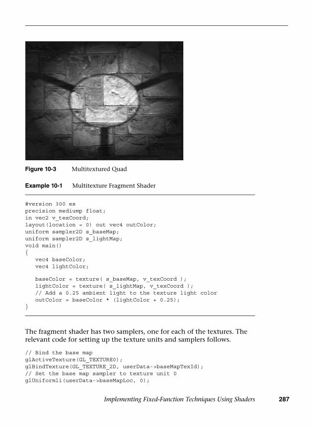
Implementing Fixed-Function Techniques Using Shaders 287
Example 10-1 Multitexture Fragment Shader
#version 300 esprecision mediump float;in vec2 v_texCoord;layout(location = 0) out vec4 outColor;uniform sampler2D s_baseMap;uniform sampler2D s_lightMap;void main(){ vec4 baseColor; vec4 lightColor;
baseColor = texture( s_baseMap, v_texCoord ); lightColor = texture( s_lightMap, v_texCoord ); // Add a 0.25 ambient light to the texture light color outColor = baseColor * (lightColor + 0.25);}
The fragment shader has two samplers, one for each of the textures. The relevant code for setting up the texture units and samplers follows.
// Bind the base mapglActiveTexture(GL_TEXTURE0);glBindTexture(GL_TEXTURE_2D, userData->baseMapTexId);// Set the base map sampler to texture unit 0glUniformli(userData->baseMapLoc, 0);
Figure 10-3 Multitextured Quad
288 Chapter 10: Fragment Shaders
// Bind the light mapglActiveTexture(GL_TEXTUREl);glBindTexture(GL_TEXTURE_2D, userData->lightMapTexId);// Set the light map sampler to texture unit 1glUniformli(userData->lightMapLoc, 1);
As you can see, this code binds each of the individual texture objects to textures units 0 and 1. The samplers are set with values to bind the samplers to the respective texture units. In this example, a single texture coordinate is used to fetch from both of the maps. In typical light mapping, there would be a separate set of texture coordinates for the base map and light map. The light maps are typically paged into a single large texture and the texture coordinates can be generated using offline tools.
Fog
A common technique that is used in rendering 3D scenes is the application of fog. In OpenGL ES 1.1, fog was provided as a fixed-function operation. One of the reasons fog is such a prevalent technique is that it can be used to reduce draw distances and remove “popping” of geometry as it comes in closer to the viewer.
There are a number of possible ways to compute fog, and with programmable fragment shaders you are not limited to any particular equation. Here we show how you would go about computing linear fog with a fragment shader. To compute any type of fog, we will need two inputs: the distance of the pixel to the eye and the color of the fog. To compute linear fog, we also need the minimum and maximum distance range that the fog should cover.
The equation for the linear fog factor
computes a linear fog factor to multiply the fog color by. This color gets clamped in the [0.0, 1.0] range and then is linear interpolated with the overall color of a fragment to compute the final color. The distance to the eye is best computed in the vertex shader and interpolated across the primitive using a varying variable.
A PVRShaman (.POD) workspace is provided as an example in the Chapter_10/PVR_LinearFog folder that demonstrates the fog computation. Figure 10-4 is a screenshot of the workspace. PVRShaman is a shader development integrated development environment (IDE) that is part of the Imagination Technologies PowerVR SDK downloadable from http://powervrinsider.com/. Several subsequent examples in the book use PVRShaman to demonstrate various shading techniques.
=−−
FMaxDist EyeDistMaxDist MinDist
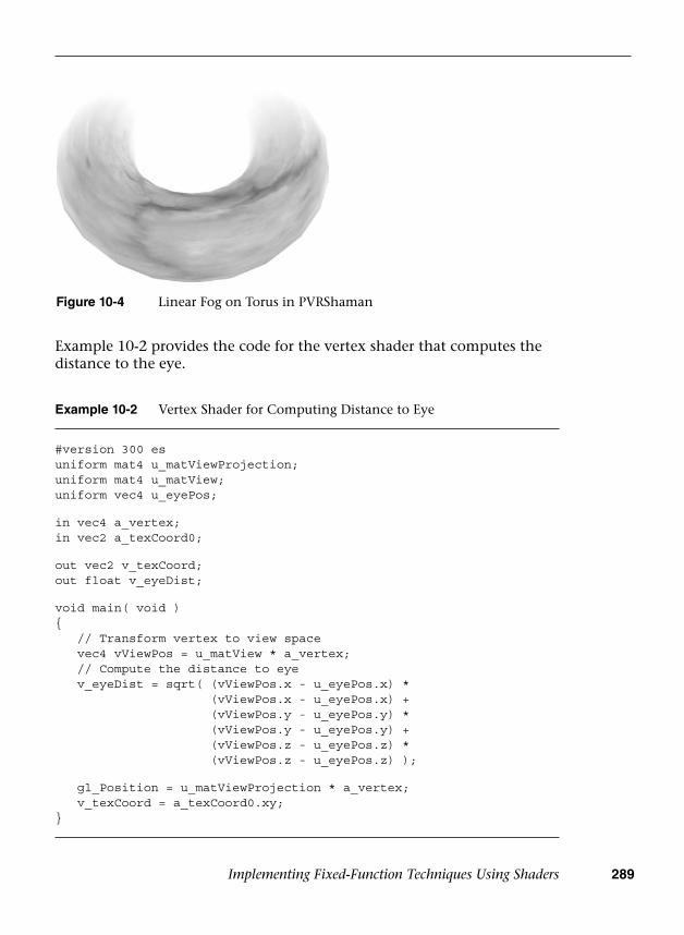
Implementing Fixed-Function Techniques Using Shaders 289
Figure 10-4 Linear Fog on Torus in PVRShaman
Example 10-2 Vertex Shader for Computing Distance to Eye
#version 300 esuniform mat4 u_matViewProjection;uniform mat4 u_matView;uniform vec4 u_eyePos;
in vec4 a_vertex;in vec2 a_texCoord0;
out vec2 v_texCoord;out float v_eyeDist;
void main( void ){ // Transform vertex to view space vec4 vViewPos = u_matView * a_vertex; // Compute the distance to eye v_eyeDist = sqrt( (vViewPos.x - u_eyePos.x) *
(vViewPos.x - u_eyePos.x) +(vViewPos.y - u_eyePos.y) *(vViewPos.y - u_eyePos.y) +(vViewPos.z - u_eyePos.z) *(vViewPos.z - u_eyePos.z) );
gl_Position = u_matViewProjection * a_vertex; v_texCoord = a_texCoord0.xy;}
Example 10-2 provides the code for the vertex shader that computes the distance to the eye.
290 Chapter 10: Fragment Shaders
The important part of this vertex shader is the computation of the v_eyeDist vertex shader output variable. First, the input vertex is transformed into view space using the view matrix and stored in vViewPos. Then, the distance from this point to the u_eyePos uniform variable is computed. This computation gives us the distance in eye space from the viewer to the transformed vertex. We can use this value in the fragment shader to compute the fog factor, as shown in Example 10-3.
Example 10-3 Fragment Shader for Rendering Linear Fog
#version 300 esprecision mediump float;
uniform vec4 u_fogColor;uniform float u_fogMaxDist;uniform float u_fogMinDist;uniform sampler2D baseMap;
in vec2 v_texCoord;in float v_eyeDist;
layout( location = 0 ) out vec4 outColor;
float computeLinearFogFactor(){ float factor; // Compute linear fog equation factor = (u_fogMaxDist − v_eyeDist) /
(u_fogMaxDist − u_fogMinDist );
// Clamp in the [0, 1] range factor = clamp( factor, 0.0, 1.0 ); return factor;}
void main( void ){ float fogFactor = computeLinearFogFactor(); vec4 baseColor = texture( baseMap, v_texCoord );
// Compute final color as a lerp with fog factor outColor = baseColor * fogFactor +
u_fogColor * (1.0 − fogFactor);}
Implementing Fixed-Function Techniques Using Shaders 291
In the fragment shader, the computeLinearFogFactor() function performs the computation for the linear fog equation. The minimum and maximum fog distances are stored in uniform variables, and the interpolated eye distance that was computed in the vertex shader is used to compute the fog factor. The fog factor is then used to perform a linear interpolation (abbreviated as “lerp” in Example 10-3) between the base texture color and the fog color. The result is that we now have linear fog and can easily adjust the distances and colors by changing the uniform values.
Note that with the flexibility of programmable fragment shaders, it is very easy to implement other methods to compute fog. For example, you could easily compute exponential fog by simply changing the fog equation. Alternatively, rather than compute fog based on distance to the eye, you could compute fog based on distance to the ground. A number of possible fog effects can be easily achieved with small modifications to the fog computations provided here.
Alpha Test (Using Discard)
A common effect used in 3D applications is to draw primitives that are fully transparent in certain fragments. This is very useful for rendering something like a chain-link fence. Representing a fence using geometry would require a significant amount of primitives. However, an alternative to using geometry is to store a mask value in a texture that specifies which texels should be transparent. For example, you could store the chain-link fence in a single RGBA texture, where the RGB values represent the color of the fence and the A value represents the mask of whether the texture is transparent. Then you could easily render a fence using just one or two triangles and masking off pixels in the fragment shader.
In traditional fixed-function rendering, this effect was achieved using the alpha test. The alpha test allowed you to specify a comparison test whereby if comparison of an alpha value of a fragment with a reference value failed, that fragment would be killed. That is, if a fragment failed the alpha test, the fragment would not be rendered. In OpenGL ES 3.0, there is no fixed-function alpha test, but the same effect can be achieved in the fragment shader using the discard keyword.
The PVRShaman example in Chapter_10/PVR_AlphaTest gives a very simple example of doing the alpha test in the fragment shader, as shown in Figure 10-5.
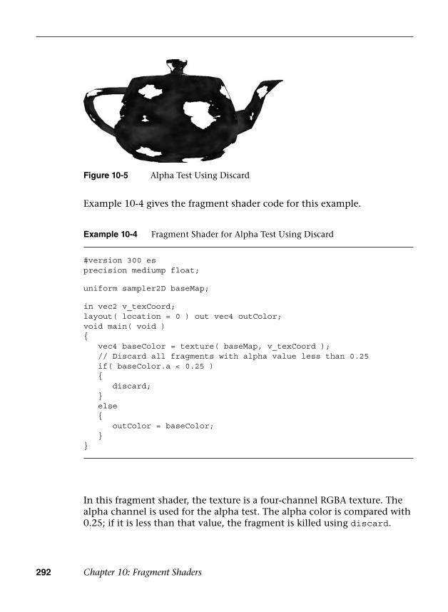
292 Chapter 10: Fragment Shaders
Figure 10-5 Alpha Test Using Discard
Example 10-4 Fragment Shader for Alpha Test Using Discard
#version 300 esprecision mediump float;
uniform sampler2D baseMap;
in vec2 v_texCoord;layout( location = 0 ) out vec4 outColor;void main( void ){ vec4 baseColor = texture( baseMap, v_texCoord ); // Discard all fragments with alpha value less than 0.25 if( baseColor.a < 0.25 ) {
discard; } else {
outColor = baseColor; }}
In this fragment shader, the texture is a four-channel RGBA texture. The alpha channel is used for the alpha test. The alpha color is compared with 0.25; if it is less than that value, the fragment is killed using discard.
Example 10-4 gives the fragment shader code for this example.

Implementing Fixed-Function Techniques Using Shaders 293
Otherwise, the fragment is drawn using the texture color. This technique can be used for implementing the alpha test by simply changing the comparison or alpha reference value.
User Clip Planes
As described in Chapter 7, “Primitive Assembly and Rasterization,” all primitives are clipped against the six planes that make up the view frustum. However, sometimes a user might want to clip against one or more additional user clip planes. There are a number of reasons why you might want to clip against user clip planes. For example, when rendering reflections, you need to flip the geometry about the reflection plane and then render it into an off-screen texture. When rendering into the texture, you need to clip the geometry against the reflection plane, which requires a user clip plane.
In OpenGL ES 1.1, user clip planes could be provided to the API via a plane equation and the clipping would be handheld automatically. In OpenGL ES 3.0, you can still accomplish this same effect, but now you need to do it yourself in the shader. The key to implementing user clip planes is using the discard keyword, which was introduced in the previous section.
Before showing you how to implement user clip planes, let’s review the basics of the mathematics. A plane is specified by the equation
Ax + By + Cz + D = 0
The vector (A, B, C) represents the normal of the plane and the value D is the distance of the plane along that vector from the origin. To figure out whether a point should or should not be clipped against a plane, we need to evaluate the distance from a point P to a plane with the equation
Dist = (A × P·x) + (B × P·y) + (C × P·z) + D
If the distance is less than 0, we know the point is behind the plane and should be clipped. If the distance is greater than or equal to 0, it should not be clipped. Note that the plane equation and P must be in the same coordinate space. A PVRShaman example is provided in the Chapter_10/PVR_ClipPlane workspace and illustrated in Figure 10-6. In the example, a teapot is rendered and clipped against a user clip plane.
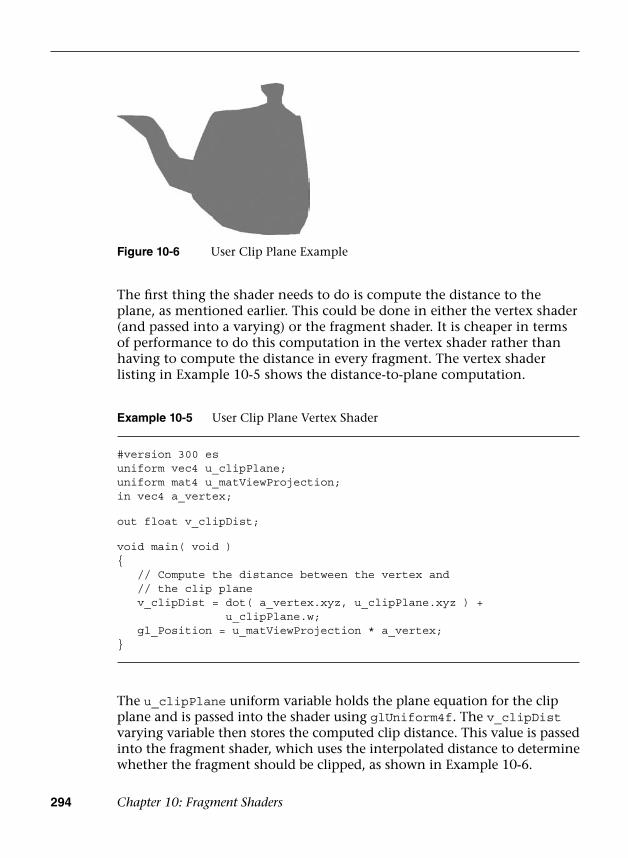
294 Chapter 10: Fragment Shaders
The first thing the shader needs to do is compute the distance to the plane, as mentioned earlier. This could be done in either the vertex shader (and passed into a varying) or the fragment shader. It is cheaper in terms of performance to do this computation in the vertex shader rather than having to compute the distance in every fragment. The vertex shader listing in Example 10-5 shows the distance-to-plane computation.
Example 10-5 User Clip Plane Vertex Shader
#version 300 esuniform vec4 u_clipPlane;uniform mat4 u_matViewProjection;in vec4 a_vertex;
out float v_clipDist;
void main( void ){ // Compute the distance between the vertex and // the clip plane v_clipDist = dot( a_vertex.xyz, u_clipPlane.xyz ) +
u_clipPlane.w; gl_Position = u_matViewProjection * a_vertex;}
The u_clipPlane uniform variable holds the plane equation for the clip plane and is passed into the shader using glUniform4f. The v_clipDist varying variable then stores the computed clip distance. This value is passed into the fragment shader, which uses the interpolated distance to determine whether the fragment should be clipped, as shown in Example 10-6.
Figure 10-6 User Clip Plane Example

Summary 295
As you can see, if the v_clipDist varying variable is negative, this means the fragment is behind the clip plane and must be discarded. Otherwise, the fragment is processed as usual. This simple example just demonstrates the computations needed to implement user clip planes. You can easily implement multiple user clip planes by simply computing multiple clip distances and having multiple discard tests.
Summary
This chapter introduced implementing several rendering techniques using fragment shaders. We focused on implementing fragment shaders that accomplish techniques that were part of fixed-function OpenGL ES 1.1. Specifically, we showed you how to implement multitexturing, linear fog, alpha test, and user clip planes. The number of shading techniques that become possible when using programmable fragment shaders is nearly limitless. This chapter gave you grounding in how to develop some fragment shaders that you can build on to create more sophisticated effects.
Now we are just ready to introduce a number of advanced rendering techniques. The next topics to cover before getting there are what happens after the fragment shader—namely, per-fragment operations and framebuffer objects. These topics are covered in the next two chapters.
Example 10-6 User Clip Plane Fragment Shader
#version 300 esprecision mediump float;in float v_clipDist;layout( location = 0 ) out vec4 outColor;void main( void ){ // Reject fragments behind the clip plane if( v_clipDist < 0.0 )
discard; outColor = vec4( 0.5, 0.5, 1.0, 0.0 );}

This page intentionally left blank

297
ScissorBox
StencilTest
FragmentShader
DepthTest Blending Dithering
Figure 11-1 The Post-Shader Fragment Pipeline
Chapter 11
Fragment Operations
This chapter discusses the operations that can be applied either to the entire framebuffer or to individual fragments after the execution of the fragment shader in the OpenGL ES 3.0 fragment pipeline. As you’ll recall, the output of the fragment shader is the fragment’s colors and depth value. The following operations occur after fragment shader execution and can affect the visibility and final color of a pixel:
• Scissor box testing
• Stencil buffer testing
• Depth buffer testing
• Multisampling
• Blending
• Dithering
The tests and operations that a fragment goes through on its way to the framebuffer are shown in Figure 11-1.
298 Chapter 11: Fragment Operations
As you might have noticed, there isn’t a stage named “multisampling.” Multisampling is an anti-aliasing technique that duplicates operations at a subfragment level. We describe how multisampling affects fragment processing in more depth later in the chapter.
The chapter concludes with a discussion of methods for reading pixels from and writing pixels to the framebuffer.
Buffers
OpenGL ES supports three types of buffers, each of which stores different data for every pixel in the framebuffer:
• Color buffer (composed of front and back color buffers)
• Depth buffer
• Stencil buffer
The size of a buffer—commonly referred to as the “depth of the buffer” (but not to be confused with the depth buffer)—is measured by the number of bits that are available for storing information for a single pixel. The color buffer, for example, will have three components for storing the red, green, and blue color components, and optional storage for the alpha component. The depth of the color buffer is the sum of the number of bits for all of its components. For the depth and stencil buffers, in contrast, a single value represents the bit depth of a pixel in those buffers. For example, a depth buffer might have 16 bits per pixel. The overall size of the buffer is the sum of the bit depths of all of the components. Common framebuffer depths include 16-bit RGB buffers, with 5 bits for red and blue, and 6 bits for green (the human visual system is more sensitive to green than to red or blue), and 32 bits divided equally for an RGBA buffer.
Additionally, the color buffer may be double buffered, such that it contains two buffers: one that is displayed on the output device (usually a monitor or LCD display), named the “front” buffer; and another buffer that is hidden from the viewer, but used for constructing the next image to be displayed, and called the “back” buffer. In double-buffered applications, animation is accomplished by drawing into the back buffer, and then swapping the front and back buffers to display the new image. This swapping of buffers is usually synchronized with the refresh cycle of the display device, which will give the illusion of

Buffers 299
a continuously smooth animation. Recall that double buffering was discussed in Chapter 3, “An Introduction to EGL.”
Although every EGL configuration will have a color buffer, the depth and stencil buffers are optional. However, every EGL implementation must provide at least one configuration that contains all three of the buffers, with the depth buffer being at least 16 bits deep, and at least 8 bits for the stencil buffer.
Requesting Additional Buffers
To include a depth or stencil buffer along with your color buffer, you need to request them when you specify the attributes for your EGL configuration. As discussed in Chapter 3, you pass a set of attribute–value pairs into the EGL that specify the type of rendering surface your application needs. To include a depth buffer in addition to the color buffer, you would specify EGL_DEPTH_SIZE in the list of attributes along with the desired bit depth you need. Likewise, you would add EGL_STENCIL_SIZE along with the number of required bits to obtain a stencil buffer.
Our convenience library, esUtil, simplifies those operations by merely allowing you to say that you would like those buffers along with a color buffer, and it takes care of the rest of the work (requesting a maximally sized buffer). When using our library, you would add (by means of a bit-wise or operation) ES_WINDOW_DEPTH and ES_WINDOW_STENCIL in your call to esCreateWindow. For example,
esCreateWindow ( &esContext, “Application Name”,window_width, window_height, ES_WINDOW_RGB | ES_WINDOW_DEPTH | ES_WINDOW_STENCIL );
Clearing Buffers
OpenGL ES is an interactive rendering system, and it assumes that at the start of each frame, you’ll want to initialize all of the buffers to their default value. Buffers are cleared by calling the glClear function, which takes a bitmask representing the various buffers that should be cleared to their specified clear values.
300 Chapter 11: Fragment Operations
void glClearDepthf(GLfloat depth)
depth specifies the depth value (in the range [0, 1]) that all pixels in the depth buffer should be initialized to when GL_DEPTH_BUFFER_BIT is present in the bitmask passed to glClear
void glClearStencil(GLint s)
s specifies the stencil value (in the range [0, 2n – 1], where n is the number of bits available in the stencil buffer) that all pixels in the stencil buffer should be initialized to when GL_STENCIL_BUFFER_BIT is present in the bitmask passed to glClear
You’re required neither to clear every buffer nor to clear them all at the same time, but you might obtain the best performance by calling glClear only once per frame with all the buffers you want simultaneously cleared.
Each buffer has a default value that’s used when you request that buffer be cleared. For each buffer, you can specify your desired clear value using the functions shown here:
void glClearColor( GLfloat red, GLfloat green, GLfloat blue, GLfloat alpha)
red, green, specifies the color value (in the range [0, 1]) that all
blue, pixels in the color buffers should be initialized to when
alpha GL_COLOR_BUFFER_BIT is present in the bitmask passed to glClear
void glClear(GLbitfield mask)
mask specifies the buffers to be cleared, and is composed of the union of the following bitmasks representing the various OpenGL ES buffers: GL_COLOR_BUFFER_BIT‚ GL_DEPTH_BUFFER_BIT, GL_STENCIL_BUFFER_BIT

Buffers 301
To reduce the number of function calls, you can clear the depth and stencil buffers at the same time using glClearBufferfi.
void glClearBufferiv(GLenum buffer, GLint drawBuffer, const GLint *value)
void glClearBufferuiv(GLenum buffer, GLint drawBuffer, const GLuint *value)
void glClearBufferfv(GLenum buffer, GLint drawBuffer, const GLfloat *value)
buffer
drawBuffer
value
specifies the type of buffer to clear. Can beGL_COLOR, GL_FRONT, GL_BACK, GL_FRONT_AND_BACK,GL_LEFT, GL_RIGHT, GL_DEPTH (glClearBufferfv only) or GL_STENCIL (glClearBufferiv only).
specifies the draw buffer name to clear. Must be zerofor depth or stencil buffers. Otherwise, must be less than GL_MAX_DRAW_BUFFERS for color buffers.
specifies a pointer to a four-element vector (for color buffers) or to a single value (for depth or stencil buffers) to clear the buffer to.
If you have multiple draw buffers in a framebuffer object (see the Multiple Render Targets section), you can clear a specific draw buffer with the following calls:
void glClearBufferfi( GLenum buffer, GLint drawBuffer, GLfloat depth, GLint stencil)
buffer
drawBuffer
depth
stencil
specifies the type of buffer to clear; must beGL_DEPTH_STENCIL
specifies the draw buffer name to clear; must be zero
specifies the value to clear the depth buffer tospecifies the value to clear the stencil buffer to
Using Masks to Control Writing to Framebuffers
You can also control which buffers, or components, in the case of the color buffer, are writable by specifying a buffer write mask. Before a pixel’s
302 Chapter 11: Fragment Operations
Likewise, writing to the depth buffer is controlled by calling glDepthMask with GL_TRUE or GL_FALSE to specify whether the depth buffer is writable.
Often, writing to the depth buffer is disabled when rendering translucent objects. Initially, you would render all of the opaque objects in the scene with writing to the depth buffer enabled (i.e., set to GL_TRUE). This would ensure that all of the opaque objects are correctly depth sorted, and the depth buffer contains the appropriate depth information for the scene. Then, before rendering the translucent objects, you would disable writing to the depth buffer by calling glDepthMask (GL_FALSE). While writing to the depth buffer is disabled, values can still be read from it and used for depth comparisons. This allows translucent objects that are obscured by opaque objects to be correctly depth buffered, but does not modify the depth buffer such that opaque objects would be obscured by translucent ones.
Finally, you can disable writing to the stencil buffer by calling glStencilMask. Unlike with glColorMask or glDepthMask, you can
void glColorMask(GLboolean red, GLboolean green, GLboolean blue, GLboolean alpha)
red, green, specify whether the particular color componentblue, in the color buffer is modifiable while renderingalpha
void glDepthMask(GLboolean depth)
depth specifies whether the depth buffer is modifiable
value is written into a buffer, the buffer’s mask is used to verify that the buffer is writable.
For the color buffer, the glColorMask routine specifies which components in the color buffer will be updated if a pixel is written. If the mask for a particular component is set to GL_FALSE, that component will not be updated if written to. By default, all color components are writable.

Fragment Tests and Operations 303
specify which bits of the stencil buffer are writable by providing a mask.
The glStencilMaskSeparate routine allows you to set the stencil mask based on the face vertex order (sometimes called “facedness”) of the primitive. This allows different stencil masks for front- and back-facing primitives. glStencilMaskSeparate(GL_FRONT_AND_BACK, mask) is identical to calling glStencilMask, which sets the same mask for the front and back polygon faces.
Fragment Tests and Operations
The following sections describe the various tests that can be applied to a fragment in OpenGL ES. By default, all fragment tests and operations are disabled, and fragments become pixels as they are written to the framebuffer in the order in which they are received. By enabling the various fragments, operational tests can be applied to choose which fragments become pixels and affect the final image.
Each fragment test is individually enabled by calling glEnable with the appropriate token listed in Table 11-1.
void glStencilMaskSeparate(GLenum face, GLuint mask)
face specifies the stencil mask to be applied based on the face vertex order of the rendered primitive. Valid values are GL_FRONT, GL_BACK, and GL_FRONT_AND_BACK.
mask specifies a bitmask (in the range [0, 2n], where n is the number of bits in the stencil buffer) of which bits in a pixel in the stencil buffer are specified by face.
void glStencilMask(GLuint mask)
mask specifies a bitmask (in the range [0, 2n – 1], where n is the number of bits in the stencil buffer) of which bits in a pixel in the stencil buffer are modifiable.
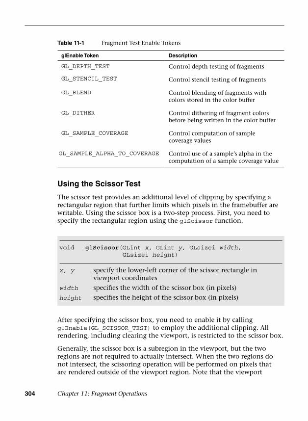
304 Chapter 11: Fragment Operations
Using the Scissor Test
The scissor test provides an additional level of clipping by specifying a rectangular region that further limits which pixels in the framebuffer are writable. Using the scissor box is a two-step process. First, you need to specify the rectangular region using the glScissor function.
After specifying the scissor box, you need to enable it by calling glEnable(GL_SCISSOR_TEST) to employ the additional clipping. All rendering, including clearing the viewport, is restricted to the scissor box.
Generally, the scissor box is a subregion in the viewport, but the two regions are not required to actually intersect. When the two regions do not intersect, the scissoring operation will be performed on pixels that are rendered outside of the viewport region. Note that the viewport
void glScissor(GLint x, GLint y, GLsizei width, GLsizei height)
x, y specify the lower-left corner of the scissor rectangle in viewport coordinates
width specifies the width of the scissor box (in pixels)
height specifies the height of the scissor box (in pixels)
Table 11-1 Fragment Test Enable Tokens
glEnable Token Description
GL_DEPTH_TEST Control depth testing of fragments
GL_STENCIL_TEST Control stencil testing of fragments
GL_BLEND Control blending of fragments with colors stored in the color buffer
GL_DITHER Control dithering of fragment colors before being written in the color buffer
GL_SAMPLE_COVERAGE Control computation of sample coverage values
GL_SAMPLE_ALPHA_TO_COVERAGE Control use of a sample’s alpha in the computation of a sample coverage value

Fragment Tests and Operations 305
transformation happens before the fragment shader stage, while the scissor test happens after the fragment shader stage.
Stencil Buffer Testing
The next operation that might be applied to a fragment is the stencil test. The stencil buffer is a per-pixel mask that holds values that can be used to determine whether a pixel should be updated. The stencil test is enabled or disabled by the application.
Using the stencil buffer can be considered a two-step operation. The first step is to initialize the stencil buffer with the per-pixel masks, which is done by rendering geometry and specifying how the stencil buffer should be updated. The second step is generally to use those values to control subsequent rendering into the color buffer. In both cases, you specify how the parameters are to be used in the stencil test.
The stencil test is essentially a bit test, as you might do in a C program where you use a mask to determine if a bit is set, for example. The stencil function, which controls the operator and values of the stencil test, is controlled by the glStencilFunc or glStencilFuncSeparate functions.
void glStencilFunc(GLenum func, GLint ref, GLuint mask)void glStencilFuncSeparate(GLenum face, GLenum func,
GLint ref, GLuint mask)
face specifies the face associated with the provided stencil function.Valid values are GL_FRONT, GL_BACK, and GL_FRONT_AND_BACK(glStencilFuncSeparate only).
func specifies the comparison function for the stencil test. Valid values are GL_EQUAL, GL_NOTEQUAL, GL_LESS, GL_GREATER, GL_LEQUAL, GL_GEQUAL, GL_ALWAYS, and GL_NEVER.
ref specifies the comparison value for the stencil test.
mask specifies the mask that is bit-wise anded with the bits in the stencil buffer before being compared with the reference value.
To allow finer control of the stencil test, a masking parameter is used to select which bits of the stencil values should be considered for the test. After selecting those bits, their value is compared with a reference value

306 Chapter 11: Fragment Operations
using the operator provided. For example, to specify that the stencil test passes where the lowest three bits of the stencil buffer are equal to 2, you would call
glStencilFunc ( GL_EQUAL, 2, 0x7 );
and enable the stencil test. Note that in binary format, the last three bits of 0x7 are 111.
With the stencil test configured, you generally also need to let OpenGL ES 3.0 know what to do with the values in the stencil buffer when the stencil test passes. In fact, modifying the values in the stencil buffer relies on more than just the stencil tests, but also incorporates the results of the depth test (discussed in the next section). Three possible outcomes can occur for a fragment with the combined stencil and depth tests:
1. The fragment fails the stencil tests. If this occurs, no further testing(i.e., the depth test) is applied to that fragment.
2. The fragment passes the stencil test, but fails the depth test.
3. The fragment passes both the stencil and depth tests.
Each of those possible outcomes can be used to affect the value in the stencil buffer for that pixel location. The glStencilOp and glStencilOpSeparate functions control the actions done on the stencil buffer’s value for each of those test outcomes, and the possible operations on the stencil values are shown in Table 11-2.
Table 11-2 Stencil Operations
Stencil Function Description
GL_ZERO Set the stencil value to zero
GL_REPLACE Replace the current stencil value with the reference value specified in glStencilFunc or glStencilFuncSeparate
GL_INCR, GL_DECR Increment or decrement the stencil value; the stencil value is clamped to zero or 2n, where n is the number of bits in the stencil buffer
GL_INCR_WRAP,GL_DECR_WRAP
Increment or decrement the stencil value, but “wrap” the value if the stencil value overflows
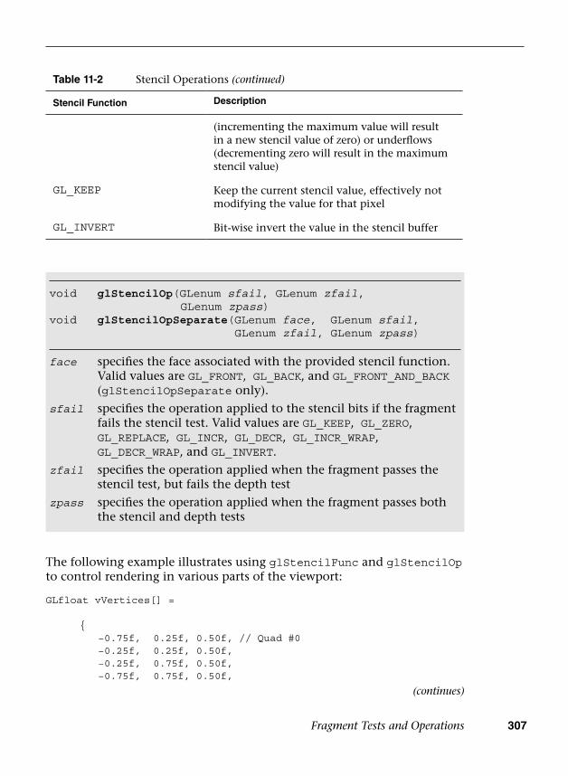
Fragment Tests and Operations 307
The following example illustrates using glStencilFunc and glStencilOp to control rendering in various parts of the viewport:
GLfloat vVertices[] =
{ −0.75f, 0.25f, 0.50f, // Quad #0 −0.25f, 0.25f, 0.50f, −0.25f, 0.75f, 0.50f, −0.75f, 0.75f, 0.50f,
void glStencilOp(GLenum sfail, GLenum zfail, GLenum zpass)
void glStencilOpSeparate(GLenum face, GLenum sfail, GLenum zfail, GLenum zpass)
face specifies the face associated with the provided stencil function. Valid values are GL_FRONT, GL_BACK, and GL_FRONT_AND_BACK(glStencilOpSeparate only).
sfail specifies the operation applied to the stencil bits if the fragment fails the stencil test. Valid values are GL_KEEP, GL_ZERO, GL_REPLACE, GL_INCR, GL_DECR, GL_INCR_WRAP, GL_DECR_WRAP, and GL_INVERT.
zfail specifies the operation applied when the fragment passes the stencil test, but fails the depth test
zpass specifies the operation applied when the fragment passes both the stencil and depth tests
Table 11-2 Stencil Operations (continued)
Stencil Function Description
(incrementing the maximum value will result in a new stencil value of zero) or underflows (decrementing zero will result in the maximum stencil value)
GL_KEEP Keep the current stencil value, effectively not modifying the value for that pixel
GL_INVERT Bit-wise invert the value in the stencil buffer
(continues)
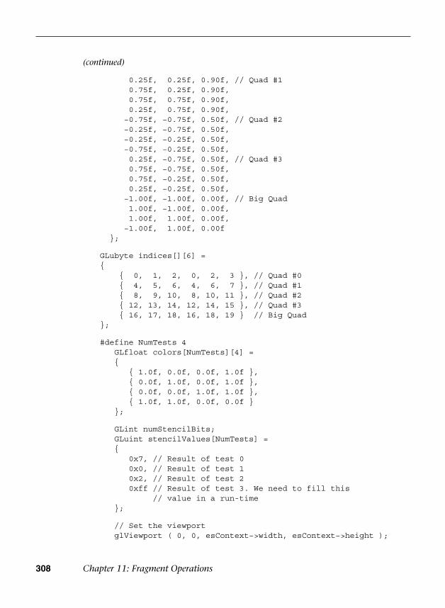
308 Chapter 11: Fragment Operations
0.25f, 0.25f, 0.90f, // Quad #10.75f, 0.25f, 0.90f,0.75f, 0.75f, 0.90f,0.25f, 0.75f, 0.90f,
−0.75f, −0.75f, 0.50f, // Quad #2 −0.25f, −0.75f, 0.50f, −0.25f, −0.25f, 0.50f, −0.75f, −0.25f, 0.50f,
0.25f, −0.75f, 0.50f, // Quad #30.75f, −0.75f, 0.50f,0.75f, −0.25f, 0.50f,0.25f, −0.25f, 0.50f,
−1.00f, −1.00f, 0.00f, // Big Quad1.00f, −1.00f, 0.00f,1.00f, 1.00f, 0.00f,
−1.00f, 1.00f, 0.00f };
GLubyte indices[][6] ={ { 0, 1, 2, 0, 2, 3 }, // Quad #0 { 4, 5, 6, 4, 6, 7 }, // Quad #1 { 8, 9, 10, 8, 10, 11 }, // Quad #2 { 12, 13, 14, 12, 14, 15 }, // Quad #3 { 16, 17, 18, 16, 18, 19 } // Big Quad};
#define NumTests 4 GLfloat colors[NumTests][4] = {
{ 1.0f, 0.0f, 0.0f, 1.0f },{ 0.0f, 1.0f, 0.0f, 1.0f },{ 0.0f, 0.0f, 1.0f, 1.0f },{ 1.0f, 1.0f, 0.0f, 0.0f }
};
GLint numStencilBits; GLuint stencilValues[NumTests] = {
0x7, // Result of test 00x0, // Result of test 10x2, // Result of test 20xff // Result of test 3. We need to fill this
// value in a run-time };
// Set the viewport glViewport ( 0, 0, esContext−>width, esContext−>height );
(continued)
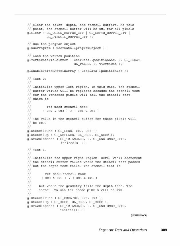
Fragment Tests and Operations 309
// Clear the color, depth, and stencil buffers. At this // point, the stencil buffer will be 0x1 for all pixels. glClear ( GL_COLOR_BUFFER_BIT | GL_DEPTH_BUFFER_BIT |
GL_STENCIL_BUFFER_BIT );
// Use the program object glUseProgram ( userData−>programObject );
// Load the vertex position glVertexAttribPointer ( userData−>positionLoc, 3, GL_FLOAT,
GL_FALSE, 0, vVertices );
glEnableVertexAttribArray ( userData−>positionLoc );
// Test 0: // // Initialize upper-left region. In this case, the stencil- // buffer values will be replaced because the stencil test // for the rendered pixels will fail the stencil test, // which is // // ref mask stencil mask // ( 0x7 & 0x3 ) < ( 0x1 & 0x7 ) // // The value in the stencil buffer for these pixels will // be 0x7. // glStencilFunc ( GL_LESS, 0x7, 0x3 ); glStencilOp ( GL_REPLACE, GL_DECR, GL_DECR ); glDrawElements ( GL_TRIANGLES, 6, GL_UNSIGNED_BYTE,
indices[0] );
// Test 1: // // Initialize the upper-right region. Here, we’ll decrement // the stencil-buffer values where the stencil test passes // but the depth test fails. The stencil test is // // ref mask stencil mask // ( 0x3 & 0x3 ) > ( 0x1 & 0x3 ) // // but where the geometry fails the depth test. The // stencil values for these pixels will be 0x0. // glStencilFunc ( GL_GREATER, 0x3, 0x3 ); glStencilOp ( GL_KEEP, GL_DECR, GL_KEEP ); glDrawElements ( GL_TRIANGLES, 6, GL_UNSIGNED_BYTE,
indices[1] );
(continues)

310 Chapter 11: Fragment Operations
// Test 2: // // Initialize the lower-left region. Here we’ll increment // (with saturation) the stencil value where both the // stencil and depth tests pass. The stencil test for // these pixels will be // // ref mask stencil mask // ( 0x1 & 0x3 ) == ( 0x1 & 0x3 ) // // The stencil values for these pixels will be 0x2. // glStencilFunc ( GL_EQUAL, 0x1, 0x3 ); glStencilOp ( GL_KEEP, GL_INCR, GL_INCR ); glDrawElements ( GL_TRIANGLES, 6, GL_UNSIGNED_BYTE,
indices[2] );
// Test 3: // // Finally, initialize the lower-right region. We’ll invert // the stencil value where the stencil tests fails. The // stencil test for these pixels will be // // ref mask stencil mask // ( 0x2 & 0x1 ) == ( 0x1 & 0x1 ) // // The stencil value here will be set to ~((2^s−1) & 0x1), // (with the 0x1 being from the stencil clear value), // where 's' is the number of bits in the stencil buffer. // glStencilFunc ( GL_EQUAL, 0x2, 0x1 ); glStencilOp ( GL_INVERT, GL_KEEP, GL_KEEP ); glDrawElements ( GL_TRIANGLES, 6, GL_UNSIGNED_BYTE,indices[3]);
// As we don’t know at compile-time how many stencil bits are // present, we’ll query, and update, the correct value in the // stencilValues arrays for the fourth tests. We’ll use this // value later in rendering. glGetIntegerv ( GL_STENCIL_BITS, &numStencilBits );
stencilValues[3] = ~( ( (1 << numStencilBits) – 1 ) & 0x1 ) &0xff;
// Use the stencil buffer for controlling where rendering // will occur. We disable writing to the stencil buffer so we // can test against them without modifying the values we // generated. glStencilMask ( 0x0 );
(continued)
Blending 311
for ( i = 0; i < NumTests; ++i ) {
glStencilFunc ( GL_EQUAL, stencilValues[i], 0xff );glUniform4fv ( userData->colorLoc, 1, colors[i] );glDrawElements ( GL_TRIANGLES, 6, GL_UNSIGNED_BYTE,
indices[4] ); }
Depth Buffer Testing
The depth buffer is typically used for hidden-surface removal. It traditionally keeps the distance value of the closest object to the viewpoint for each pixel in the rendering surface, and for every new incoming fragment, compares its distance from the viewpoint with the stored value. By default, if the incoming fragment’s depth value is less than the value stored in the depth buffer (meaning it’s closer to the viewer), the incoming fragment’s depth value replaces the values stored in the depth buffer, and then its color value replaces the color value in the color buffer. This is the standard method for depth buffering—and if that’s what you would like to do, you simply need to request a depth buffer when you create a window, and then enable the depth test by calling glEnable with GL_DEPTH_TEST. If no depth buffer is associated with the color buffer, the depth test always passes.
Of course, that’s only one way to use the depth buffer. You can modify the depth comparison operator by calling glDepthFunc.
void glDepthFunc(GLenum func)
func specifies the depth value comparison function, which can be one of GL_LESS, GL_GREATER, GL_LEQUAL, GL_GEQUAL, GL_EQUAL, GL_NOTEQUAL, GL_ALWAYS, or GL_NEVER
Blending
This section discusses blending pixel colors. Once a fragment passes all of the enabled fragment tests, its color can be combined with the color that’s already present in the fragment’s pixel location. Before the two colors are combined, they’re multiplied by a scaling factor and combined using the specified blending operator. The blending equation is
opC f C f Cfinal source source destination destination=

312 Chapter 11: Fragment Operations
where fsource and Csource are the incoming fragment’s scaling factor and color, respectively. Likewise, fdestination and Cdestination are the pixel’s scaling factor and color, and op is the mathematical operator for combining the scaled values.
The scaling factors are specified by calling either glBlendFunc or glBlendFuncSeparate.
void glBlendFuncSeparate(GLenum srcRGB, GLenum dstRGB, GLenum srcAlpha, GLenum dstAlpha)
srcRGB specifies the blending coefficient for the incoming fragment’s red, green, and blue components
dstRGB specifies the blending coefficient for the destination pixel’s red, green, and blue components
srcAlpha specifies the blending coefficient for the incoming fragment’s alpha value
dstAlpha specifies the blending coefficient for the destination pixel’s alpha value
Table 11-3 Blending Functions
Blending Coefficient Enum RGB Blending FactorsAlpha Blending Factor
GL_ZERO (0, 0, 0) 0
GL_ONE (1, 1, 1) 1
GL_SRC_COLOR (Rs, Gs, Bs) As
GL_ONE_MINUS_SRC_COLOR (1 – Rs, 1 – Gs, 1 – Bs) 1 – As
GL_SRC_ALPHA (As, As, As) As
GL_ONE_MINUS_SRC_ALPHA (1 – As, 1 – As, 1 – As) 1 – As
void glBlendFunc(GLenum sfactor, GLenum dfactor)
sfactor specifies the blending coefficient for the incoming fragment
dfactor specifies the blending coefficient for the destination pixel
The possible values for the blending coefficients are shown in Table 11-3.

Blending 313
In Table 11-3, (Rs, Gs, Bs, As) are the color components associated with the incoming fragment color, (Rd, Gd, Bd, Ad) are the components associated with the pixel color already in the color buffer, and (Ra, Gc, Bc, Ac) represent a constant color that you set by calling glBlendColor. In the case of GL_SRC_ALHPA_SATURATE, the minimum value computed is applied to the source color only.
void glBlendColor(GLfloat red, GLfloat green, GLfloat blue, GLfloat alpha)
red, green, specify the component values for the constantblue, blending coloralpha
Table 11-3 Blending Functions (continued)
Blending Coefficient Enum RGB Blending FactorsAlpha Blending Factor
GL_DST_COLOR (Rd, Gd, Bd) Ad
GL_ONE_MINUS_DST_COLOR (1 − Rd, 1 − Gd, 1 − Bd) 1− Ad
GL_DST_ALPHA (Ad, Ad, Ad) Ad
GL_ONE_MINUS_DST_ALPHA (1 − Ad, 1 − Ad, 1 − Ad) 1 − Ad
GL_CONSTANT_COLOR (Rc, Gc, Bc) Ac
GL_ONE_MINUS_CONSTANT_COLOR (1 − Rc, 1 − Gc, 1 − Bc) 1 − Ac
GL_CONSTANT_ALPHA (Ac, Ac, Ac) Ac
GL_ONE_MINUS_CONSTANT_ALPHA (1 − Ac, 1 − Ac, 1 − Ac) 1 − Ac
GL_SRC_ALPHA_SATURATE min(As, 1 − Ad) 1
Once the incoming fragment and pixel color have been multiplied by their respective scaling factors, they are combined using the operator specified by glBlendEquation or glBlendEquationSeparate. By default, blended colors are accumulated using the GL_FUNC_ADD operator. The GL_FUNC_SUBTRACT operator subtracts the scaled color from the framebuffer from the incoming fragment’s value. Likewise, the
314 Chapter 11: Fragment Operations
GL_FUNC_REVERSE_SUBTRACT operator reverses the blending equation, such that the incoming fragment colors are subtracted from the current pixel value.
Dithering
On a system where the number of colors available in the framebuffer is limited due to the number of bits per component in the framebuffer, we can simulate greater color depth using dithering. Dithering algorithms arrange colors in such a way that the image appears to have more available colors than are really present. OpenGL ES 3.0 doesn’t specify which dithering algorithm is to be used in supporting its dithering stage; the technique is very implementation dependent.
The only control your application has over dithering is whether it is applied to the final pixels. This decision is entirely controlled by calling glEnable or glDisable with GL_DITHER to specify dithering’s use in the pipeline. Initially, dithering is enabled.
Multisampled Anti-Aliasing
Anti-aliasing is an important technique for improving the quality of generated images by trying to reduce the visual artifacts of rendering into discrete pixels. The geometric primitives that OpenGL ES 3.0 renders are rasterized onto a grid, and their edges may become deformed in that
void glBlendEquationSeparate(GLenum modeRGB, GLenum modeAlpha)
modeRGB specifies the blending operator for the red, green, and blue components
modeAlpha specifies the alpha component blending operator
void glBlendEquation(GLenum mode)
mode specifies the blending operator. Valid values are GL_FUNC_ADD, GL_FUNC_SUBTRACT, GL_FUNC_REVERSE_SUBTRACT, GL_MIN, or GL_MAX.
Multisampled Anti-Aliasing 315
process. You have almost certainly seen the staircase effect that happens to lines drawn diagonally across a monitor.
Various techniques can be used to reduce those aliasing effects, and OpenGL ES 3.0 supports a variant called multisampling. Multisampling divides every pixel into a set of samples, each of which is treated like a “mini-pixel” during rasterization. That is, when a geometric primitive is rendered, it’s like rendering into a framebuffer that has many more pixels than the real display surface. Each sample has its own color, depth, and stencil value, and those values are preserved until the image is ready for display. When it’s time to compose the final image, the samples are resolved into the final pixel color. What makes this process special is that in addition to using every sample’s color information, OpenGL ES 3.0 has even more information about how many samples for a particular pixel were occupied during rasterization. Each sample for a pixel is assigned a bit in the sample coverage mask. Using that coverage mask, we can control how the final pixels are resolved. Every rendering surface created for an OpenGL ES 3.0 application will be configured for multisampling, even if only a single sample per pixel is available. Unlike in supersampling, the fragment shader is executed per pixel rather than per sample.
Multisampling has multiple options that can be turned on and off (using glEnable and glDisable, respectively) to control the usage of sample coverage value.
First, you can specify that the sample’s alpha value should be used to determine the coverage value by enabling GL_SAMPLE_ALPHA_TO_COVERAGE. In this mode, if the geometric primitive covers a sample, the alpha value of incoming fragment is used to determine an additional sample coverage mask computed that is bit-wise anded into the coverage mask that is computed using the samples of the fragment. This newly computed coverage value replaces the original one generated directly from the sample coverage calculation. These sample computations are implementation dependent.
Additionally, you can specify GL_SAMPLE_COVERAGE or GL_SAMPLE_COVERAGE_INVERT, which uses the fragment’s (potentially modified by previous operations) coverage value or its inverted bits, respectively, and computes the bit-wise and of that value with one specified using the glSampleCoverage function. The value specified with glSampleCoverage is used to generate an implementation-specific coverage mask, and includes an inversion flag, invert, that inverts the bits in the generated mask. Using this inversion flag, it becomes possible to create two transparency masks that don’t use entirely distinct sets of samples.
316 Chapter 11: Fragment Operations
Centroid Sampling
When rendering with multisampling, the fragment data is picked from a sample that is closest to a pixel center. This can lead to rendering artifacts near triangle edges, as the pixel center may sometimes fall outside of the triangle. In such case, the fragment data can be extrapolated to a point outside of the triangle. Centroid sampling solves this problem by ensuring that the fragment data is picked from a sample that falls inside the triangle.
To enable centroid sampling, you can declare the output variables of the vertex shader (and input variables to the fragment shader) with the centroid qualifier as follows:
smooth centroid out vec3 v_color;
Note that using centroid sampling can lead to less accurate derivatives for pixels near the triangle edges.
Reading and Writing Pixels to the Framebuffer
If you want to preserve your rendered image for posterity’s sake, you can read the pixel values back from the color buffer, but not from the depth or stencil buffers. When you call glReadPixels, the pixels in the color buffer are returned to your application in an array that has been previously allocated.
void glReadPixels(GLint x, GLint y, GLsizei width, GLsizei height, GLenum format, GLenum type, GLvoid *pixels)
x, y specify the viewport coordinates of the lower-left corner of the pixel rectangle read from the color buffer.
width specify the dimensions of the pixel rectangle read from the
height color buffer.
void glSampleCoverage(GLfloat value, GLboolean invert)
value specifies a value in the range [0, 1] that is converted into a sample mask; the resulting mask should have a proportional number of bits set corresponding to the value
invert specifies that after determining the mask’s value, all of the bits in the mask should be inverted
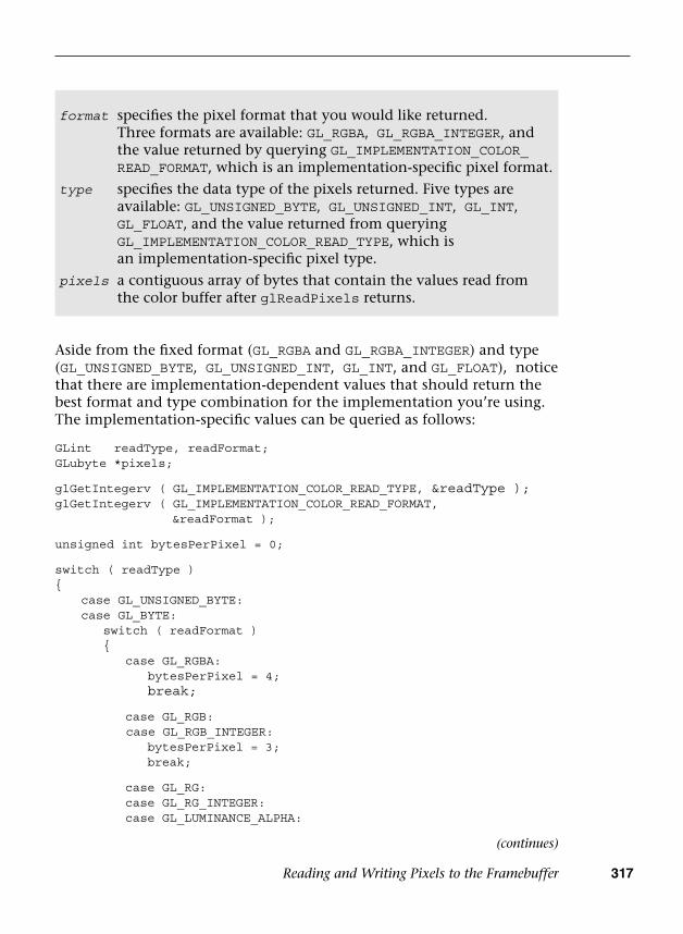
Reading and Writing Pixels to the Framebuffer 317
Aside from the fixed format (GL_RGBA and GL_RGBA_INTEGER) and type (GL_UNSIGNED_BYTE, GL_UNSIGNED_INT, GL_INT, and GL_FLOAT), notice that there are implementation-dependent values that should return the best format and type combination for the implementation you’re using. The implementation-specific values can be queried as follows:
GLint readType, readFormat;GLubyte *pixels;
glGetIntegerv ( GL_IMPLEMENTATION_COLOR_READ_TYPE, &readType );glGetIntegerv ( GL_IMPLEMENTATION_COLOR_READ_FORMAT,
&readFormat );
unsigned int bytesPerPixel = 0;
switch ( readType ){
case GL_UNSIGNED_BYTE:case GL_BYTE: switch ( readFormat ) {
case GL_RGBA:bytesPerPixel = 4;break;
case GL_RGB:case GL_RGB_INTEGER:
bytesPerPixel = 3;break;
case GL_RG:case GL_RG_INTEGER:case GL_LUMINANCE_ALPHA:
format specifies the pixel format that you would like returned.Three formats are available: GL_RGBA, GL_RGBA_INTEGER, and the value returned by querying GL_IMPLEMENTATION_COLOR_ READ_FORMAT, which is an implementation-specific pixel format.
type specifies the data type of the pixels returned. Five types are available: GL_UNSIGNED_BYTE, GL_UNSIGNED_INT, GL_INT, GL_FLOAT, and the value returned from querying GL_IMPLEMENTATION_COLOR_READ_TYPE, which is an implementation-specific pixel type.
pixels a contiguous array of bytes that contain the values read from the color buffer after glReadPixels returns.
(continues)

318 Chapter 11: Fragment Operations
bytesPerPixel = 2;break;
case GL_RED:case GL_RED_INTEGER:case GL_ALPHA:case GL_LUMINANCE:case GL_LUMINANCE_ALPHA:
bytesPerPixel = 1;break;
default:// Undetected format/error break;
}break;
case GL_FLOAT:case GL_UNSIGNED_INT:case GL_INT:
switch ( readFormat ){
case GL_RGBA:case GL_RGBA_INTEGER:
bytesPerPixel = 16;break;
case GL_RGB:case GL_RGB_INTEGER:
bytesPerPixel = 12;break;
case GL_RG:case GL_RG_INTEGER:
bytesPerPixel = 8;break;
case GL_RED:case GL_RED_INTEGER:case GL_DEPTH_COMPONENT:
bytesPerPixel = 4;break;
default:// Undetected format/error break;
}break;
case GL_HALF_FLOAT:case GL_UNSIGNED_SHORT:
(continued)

Reading and Writing Pixels to the Framebuffer 319
case GL_SHORT:switch ( readFormat ){
case GL_RGBA:case GL_RGBA_INTEGER:
bytesPerPixel = 8;break;
case GL_RGB:case GL_RGB_INTEGER:
bytesPerPixel = 6;break;
case GL_RG:case GL_RG_INTEGER:
bytesPerPixel = 4;break;
case GL_RED:case GL_RED_INTEGER:
bytesPerPixel = 2;break;
default:// Undetected format/errorbreak;
}break;
case GL_FLOAT_32_UNSIGNED_INT_24_8_REV: // GL_DEPTH_STENCILbytesPerPixel = 8;break;
// GL_RGBA, GL_RGBA_INTEGER formatcase GL_UNSIGNED_INT_2_10_10_10_REV:case GL_UNSIGNED_INT_10F_11F_11F_REV: // GL_RGB formatcase GL_UNSIGNED_INT_5_9_9_9_REV: // GL_RGB formatcase GL_UNSIGNED_INT_24_8: // GL_DEPTH_STENCIL format
bytesPerPixel = 4;break;
case GL_UNSIGNED_SHORT_4_4_4_4: // GL_RGBA formatcase GL_UNSIGNED_SHORT_5_5_5_1: // GL_RGBA formatcase GL_UNSIGNED_SHORT_5_6_5: // GL_RGB format
bytesPerPixel = 2;break;
default: // Undetected type/error
}
(continues)

320 Chapter 11: Fragment Operations
pixels = ( GLubyte* ) malloc( width * height * bytesPerPixel );
glReadPixels ( 0, 0, windowWidth, windowHeight, readFormat,readType, pixels );
You can read pixels from any currently bound framebuffer, whether it’s one allocated by the windowing system or from a framebuffer object. Because each buffer can have a different layout, you’ll probably need to query the type and format for each buffer you want to read.
OpenGL ES 3.0 provides an efficient mechanism to copy a rectangular block of pixels into the framebuffer, which will be described in Chapter 12, “Framebuffer Objects.”
Pixel Pack Buffer Objects
When a non-zero buffer object is bound to the GL_PIXEL_PACK_BUFFER using glBindBuffer, the glReadPixels command can return immediately and invoke DMA transfer to read pixels from the framebuffer and write the data into the pixel buffer object (PBO).
To keep the CPU busy, you can schedule some CPU processing after the glReadPixels call to overlap CPU computations and the DMA transfer. Depending on the applications, the data may not be available immediately; in such cases, you can use multiple PBO solutions so that while the CPU is waiting for the data transfer from one PBO, it can process the data from an earlier transfer from another PBO.
Multiple Render Targets
Multiple render targets (MRTs) allow the application to render to several color buffers at one time. With multiple render targets, the fragment shader outputs several colors (which can be used to store RGBA colors, normals, depths, or texture coordinates), one for each attached color buffer. MRTs are used in many advanced rendering algorithms, such as deferred shading and fast ambient occlusion approximation (SSAO).
In deferred shading, lighting calculations are performed only once per pixel. This is achieved by separating the geometry and lighting calculations into two separate rendering passes. The first geometry pass outputs multiple attributes (such as position, normal, material color, or texture coordinates) into multiple buffers (using MRTs). The second lighting pass performs the lighting calculations by sampling the attributes
(continued)
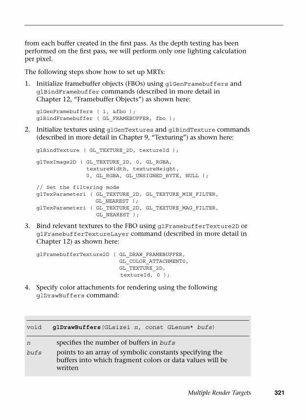
Multiple Render Targets 321
from each buffer created in the first pass. As the depth testing has been performed on the first pass, we will perform only one lighting calculation per pixel.
The following steps show how to set up MRTs:
1. Initialize framebuffer objects (FBOs) using glGenFramebuffers andglBindFramebuffer commands (described in more detail inChapter 12, “Framebuffer Objects”) as shown here:
glGenFramebuffers ( 1, &fbo );glBindFramebuffer ( GL_FRAMEBUFFER, fbo );
2. Initialize textures using glGenTextures and glBindTexture commands(described in more detail in Chapter 9, “Texturing”) as shown here:
glBindTexture ( GL_TEXTURE_2D, textureId );
glTexImage2D ( GL_TEXTURE_2D, 0, GL_RGBA,textureWidth, textureHeight,0, GL_RGBA, GL_UNSIGNED_BYTE, NULL );
// Set the filtering modeglTexParameteri ( GL_TEXTURE_2D, GL_TEXTURE_MIN_FILTER,
GL_NEAREST );glTexParameteri ( GL_TEXTURE_2D, GL_TEXTURE_MAG_FILTER,
GL_NEAREST );
3. Bind relevant textures to the FBO using glFramebufferTexture2D orglFramebufferTextureLayer command (described in more detail inChapter 12) as shown here:
glFramebufferTexture2D ( GL_DRAW_FRAMEBUFFER,GL_COLOR_ATTACHMENT0,GL_TEXTURE_2D, textureId, 0 );
4. Specify color attachments for rendering using the followingglDrawBuffers command:
void glDrawBuffers(GLsizei n, const GLenum* bufs)
n specifies the number of buffers in bufs
bufs points to an array of symbolic constants specifying the buffers into which fragment colors or data values will be written

322 Chapter 11: Fragment Operations
For example, you can set up a FBO with four color outputs (attachments) as follows:
const GLenum attachments[4] = { GL_COLOR_ATTACHMENT0,GL_COLOR_ATTACHMENT1,GL_COLOR_ATTACHMENT2,GL_COLOR_ATTACHMENT3 };
glDrawBuffers ( 4, attachments );
You can query the maximum number of color attachments by calling glGetIntegerv with the symbolic constant GL_MAX_COLOR_ATTACHMENTS. The minimum number of color attachments supported by all OpenGL 3.0 implementations is 4.
5. Declare and use multiple shader outputs in the fragment shader.For example, the following declaration will copy fragmentshader outputs fragData0 to fragData3 to draw buffers 0–3,respectively:
layout(location = 0) out vec4 fragData0;layout(location = 1) out vec4 fragData1;layout(location = 2) out vec4 fragData2;layout(location = 3) out vec4 fragData3;
Putting everything together, Example 11-1 (as part of the Chapter_11/MRTs example) illustrates how to set up four draw buffers for a single framebuffer object.
Example 11-1 Setting up Multiple Render Targets
int InitFBO ( ESContext *esContext){ UserData *userData = esContext−>userData; int i; GLint defaultFramebuffer = 0; const GLenum attachments[4] = {
GL_COLOR_ATTACHMENT0,GL_COLOR_ATTACHMENT1,GL_COLOR_ATTACHMENT2,GL_COLOR_ATTACHMENT3
};
glGetIntegerv ( GL_FRAMEBUFFER_BINDING, &defaultFramebuffer );

Multiple Render Targets 323
Example 11-1 Setting up Multiple Render Targets (continued)
// Set up fbo glGenFramebuffers ( 1, &userData−>fbo ); glBindFramebuffer ( GL_FRAMEBUFFER, userData−>fbo );
// Set up four output buffers and attach to fbo userData−>textureHeight = userData−>textureWidth = 400;
glGenTextures ( 4, &userData−>colorTexId[0] ); for (i = 0; i < 4; ++i) {
glBindTexture ( GL_TEXTURE_2D, userData−>colorTexId[i] );
glTexImage2D ( GL_TEXTURE_2D, 0, GL_RGBA,userData−>textureWidth,userData−>textureHeight,0, GL_RGBA, GL_UNSIGNED_BYTE, NULL );
// Set the filtering modeglTexParameteri ( GL_TEXTURE_2D, GL_TEXTURE_MIN_FILTER,
GL_NEAREST );glTexParameteri ( GL_TEXTURE_2D, GL_TEXTURE_MAG_FILTER,
GL_NEAREST );
glFramebufferTexture2D ( GL_DRAW_FRAMEBUFFER, attachments[i],GL_TEXTURE_2D, userData−>colorTexId[i], 0 );
}
glDrawBuffers ( 4, attachments );
if ( GL_FRAMEBUFFER_COMPLETE !=glCheckFramebufferStatus ( GL_FRAMEBUFFER ) )
{return FALSE;
}
// Restore the original framebuffer glBindFramebuffer ( GL_FRAMEBUFFER, defaultFramebuffer );
return TRUE;}
Example 11-2 (as part of the Chapter_11/MRTs example) illustrates how to output four colors per fragment in a fragment shader.

324 Chapter 11: Fragment Operations
Summary
In this chapter, you learned about tests and operations (scissor box testing, stencil buffer testing, depth buffer testing, multisampling, blending and dithering) that happen after the fragment shader. This is the final phase in the OpenGL ES 3.0 pipeline. In the next chapter, you will learn an efficient method for rendering to a texture or an off-screen surface using framebuffer objects.
Example 11-2 Fragment Shader with Multiple Render Targets
#version 300 es precision mediump float;layout(location = 0) out vec4 fragData0;layout(location = 1) out vec4 fragData1;layout(location = 2) out vec4 fragData2;layout(location = 3) out vec4 fragData3;void main(){ // first buffer will contain red color fragData0 = vec4 ( 1, 0, 0, 1 );
// second buffer will contain green color fragData1 = vec4 ( 0, 1, 0, 1 );
// third buffer will contain blue color fragData2 = vec4 ( 0, 0, 1, 1 );
// fourth buffer will contain gray color fragData3 = vec4 ( 0.5, 0.5, 0.5, 1 );}

325
Chapter 12
Framebuffer Objects
In this chapter, we describe what framebuffer objects are, how applications can create them, and how applications can use them for rendering to an off-screen buffer or rendering to a texture. We start by discussing why we need framebuffer objects. We then introduce framebuffer objects and new object types they add to OpenGL ES, and explain how they differ from the EGL surfaces described in Chapter 3, “An Introduction to EGL.” We go on to discuss how to create framebuffer objects; explore how to specify color, depth, and stencil attachments to a framebuffer object; and then provide examples that demonstrate rendering to a framebuffer object. Last but not least, we discuss performance tips and tricks that can help ensure good performance when using framebuffer objects.
Why Framebuffer Objects?
A rendering context and a drawing surface need to be first created and made current before any OpenGL ES commands can be called by an application. The rendering context and the drawing surface are usually provided by the native windowing system through an API such as EGL. Chapter 3 describes how to create an EGL context and surface and how to attach them to a rendering thread. The rendering context contains the appropriate state required for correct operation. The drawing surface provided by the native windowing system can be a surface that will be displayed on the screen, referred to as the window system–provided framebuffer, or it can be an off-screen surface, referred to as a pbuffer. The calls to create the EGL drawing surfaces let you specify the width and
326 Chapter 12: Framebuffer Objects
height of the surface in pixels; whether the surface uses color, depth, and stencil buffers; and the bit depths of these buffers.
By default, OpenGL ES uses the window system–provided framebuffer as the drawing surface. If the application is drawing only to an on-screen surface, the window system–provided framebuffer is usually sufficient. However, many applications need to render to a texture, and for this purpose using the window system–provided framebuffer as your drawing surface is usually not an ideal option. Examples of where the render-to-texture approach is useful are shadow mapping, dynamic reflections and environment mapping, multipass techniques for depth-of-field, motion blur effects, and postprocessing effects.
Applications can use either of two techniques to render to a texture:
• Implement render to texture by drawing to the window system–provided framebuffer and then copy the appropriate region of theframebuffer to the texture. This can be implemented using theglCopyTexImage2D and glCopyTexSubImage2D APIs. As their namesimply, these APIs perform a copy from the framebuffer to the texturebuffer, and this copy operation can often adversely impact performance.In addition, this approach works only if the dimensions of the textureare less than or equal to the dimensions of the framebuffer.
• Implement render to texture by using a pbuffer that is attachedto a texture. We know that a window system–provided surfacemust be attached to a rendering context. This can be inefficienton some implementations that require separate contexts for eachpbuffer and window surface. Additionally, switching betweenwindow system–provided drawables can sometimes require theimplementation to flush all previous rendering prior to the switch.This can introduce expensive “bubbles” (idling the GPU) into therendering pipeline. On such systems, our recommendation is toavoid using pbuffers to render to textures because of the overheadassociated with context- and window system–provided drawableswitching.
Neither of these two methods is ideal for rendering to a texture or other off-screen surface. What is needed instead are APIs that allow applications to directly render to a texture or the ability to create an off-screen surface within the OpenGL ES API and use it as a rendering target. Framebuffer objects and renderbuffer objects allow applications to do exactly this, without requiring additional rendering contexts to be created. As a consequence, we no longer have to worry about the overhead of a context and drawable switch that can occur when using
Framebuffer and Renderbuffer Objects 327
window system–provided drawables. Framebuffer objects, therefore, provide a better and more efficient method for rendering to a texture or an off-screen surface.
The framebuffer objects API supports the following operations:
• Creating framebuffer objects using OpenGL ES commands only
• Creating and using multiple framebuffer objects within a singleEGL context—that is, without requiring a rendering context perframebuffer
• Creating off-screen color, depth, or stencil renderbuffers and textures,and attaching these to a framebuffer object
• Sharing color, depth, or stencil buffers across multiple framebuffers
• Attaching textures directly to a framebuffer as color or depth, therebyavoiding the need to do a copy operation
• Copying between framebuffers and invalidating framebuffer contents
Framebuffer and Renderbuffer Objects
In this section, we describe what renderbuffer and framebuffer objects are, explain how they differ from window system–provided drawables, and consider when to use a renderbuffer instead of a texture.
A renderbuffer object is a 2D image buffer allocated by the application. The renderbuffer can be used to allocate and store color, depth, or stencil values and can be used as a color, depth, or stencil attachment in a framebuffer object. A renderbuffer is similar to an off-screen window system–provided drawable surface, such as a pbuffer. A renderbuffer, however, cannot be directly used as a GL texture.
A framebuffer object (FBO) is a collection of color, depth, and stencil textures or render targets. Various 2D images can be attached to the color attachment point in the framebuffer object. These include a renderbuffer object that stores color values, a mip level of a 2D texture or a cubemap face, a layer of a 2D array textures, or even a mip level of a 2D slice in a 3D texture. Similarly, various 2D images containing depth values can be attached to the depth attachment point of an FBO. These can include a renderbuffer, a mip level of a 2D texture, or a cubemap face that stores depth values. The only 2D image that can be attached to the stencil attachment point of an FBO is a renderbuffer object that stores stencil values.

328 Chapter 12: Framebuffer Objects
Figure 12-1 shows the relationships among framebuffer objects, renderbuffer objects, and textures. Note that there can be only one color, depth, and stencil attachment in a framebuffer object.
ColorAttachments
Framebuffer Objects
ColorAttachments
DepthAttachment
Framebuffer Objects
DepthAttachment
StencilAttachment
Renderbuffer Objects
DepthBuffer
Renderbuffer Objects
pBuffer
StencilBuffer
Depth
Texture mip Images
Figure 12-1 Framebuffer Objects, Renderbuffer Objects, and Textures
Choosing a Renderbuffer Versus a Texture as a Framebuffer Attachment
For render-to-texture use cases, you would attach a texture object to the framebuffer object. Examples include rendering to a color buffer that will be used as a color texture, and rendering into a depth buffer that will be used as a depth texture for shadows.
There are several reasons to use renderbuffers instead of textures:
• Renderbuffers support multisampling.
• If the image will not be used as a texture, using a renderbuffer maydeliver a performance advantage. This advantage occurs because theimplementation might be able to store the renderbuffer in a muchmore efficient format, better suited for rendering than for texturing.The implementation can only do so, however, if it knows in advancethat the image will not be used as a texture.
Creating Framebuffer and Renderbuffer Objects 329
Framebuffer Objects Versus EGL Surfaces
The differences between an FBO and the window system–provided drawable surface are as follows:
• Pixel ownership test determines whether the pixel at location (xw, yw)in the framebuffer is currently owned by OpenGL ES. This test allowsthe window system to control which pixels in the framebuffer belongto the current OpenGL ES context—for example, when a window thatis being rendered into by OpenGL ES is obscured. For an application-created framebuffer object, the pixel ownership test always succeeds,as the framebuffer object owns all the pixels.
• The window system might support only double-buffered surfaces.Framebuffer objects, in contrast, support only single-bufferedattachments.
• Sharing of stencil and depth buffers between framebuffers ispossible using framebuffer objects but usually not with the windowsystem–provided framebuffer. Stencil and depth buffers and theircorresponding state are usually allocated implicitly with the windowsystem–provided drawable surface and, therefore, cannot be sharedbetween drawable surfaces. With application-created framebufferobjects, stencil and depth renderbuffers can be created independentlyand then associated with a framebuffer object by attaching thesebuffers to appropriate attachment points in multiple framebufferobjects, if desired.
Creating Framebuffer and Renderbuffer Objects
Creating framebuffer and renderbuffer objects is similar to how texture or vertex buffer objects are created in OpenGL ES 3.0.
The glGenRenderbuffers API call is used to allocate renderbuffer object names. This API is described next.
void glGenRenderbuffers(GLsizei n, GLuint *renderbuffers)
n number of renderbuffer object names to return
renderbuffers pointer to an array of n entries, where the allocated renderbuffer object names are returned
330 Chapter 12: Framebuffer Objects
glGenRenderbuffers allocates n renderbuffer object names and returns them in renderbuffers. The renderbuffer object names returned by glGenRenderbuffers are unsigned integer numbers other than 0. These names returned are marked in use but do not have any state associated with them. The value 0 is reserved by OpenGL ES and does not refer to a renderbuffer object. Applications trying to modify or query the buffer object state for renderbuffer object 0 will generate an appropriate error.
The glGenFramebuffers API call is used to allocate framebuffer object names. This API is described here.
glGenFramebuffers allocates n framebuffer object names and returns them in ids. The framebuffer object names returned by glGenFramebuffers are unsigned integer numbers other than 0. The framebuffer names returned are marked in use but do not have any state associated with them. The value 0 is reserved by OpenGL ES and refers to the window system–provided framebuffer. Applications trying to modify or query the buffer object state for framebuffer object 0 will generate an appropriate error.
Using Renderbuffer Objects
In this section, we describe how to specify the data storage, format, and dimensions of the renderbuffer image. To specify this information for a specific renderbuffer object, we need to make this object the current renderbuffer object. The glBindRenderbuffer command is used to set the current renderbuffer object.
void glGenFramebuffers(GLsizei n, GLuint *ids)
n number of framebuffer object names to return
ids pointer to an array of n entries, where allocated framebuffer object are returned
void glBindRenderbuffer(GLenum target, GLuint renderbuffer)
target must be set to GL_RENDERBUFFER
renderbuffer renderbuffer object name

Using Renderbuffer Objects 331
Note that glGenRenderbuffers is not required to assign a renderbuffer object name before it is bound using glBindRenderbuffer. Although it is a good practice to call glGenRenderbuffers, many applications specify compile-time constants for their buffers. An application can specify an unused renderbuffer object name to glBindRenderbuffer. However, we do recommend that OpenGL ES applications call glGenRenderbuffers and use renderbuffer object names returned by glGenRenderbuffers instead of specifying their own buffer object names.
The first time the renderbuffer object name is bound by calling glBindRenderbuffer, the renderbuffer object is allocated with the appropriate default state. If this allocation is successful, the allocated object will become the newly bound renderbuffer object.
The following state and default values are associated with a renderbuffer object:
• Width and height in pixels—The default value is zero.
• Internal format—This describes the format of the pixels stored in therenderbuffer. It must be a color-, depth-, or stencil-renderable format.
• Color bit-depth—This is valid only if the internal format is a color-renderable format. The default value is zero.
• Depth bit-depth—This is valid only if the internal format is a depth-renderable format. The default value is zero.
• Stencil bit-depth—This is valid only if the internal format is a stencil-renderable format. The default value is zero.
glBindRenderbuffer can also be used to bind to an existing renderbuffer object (i.e., an object that has been assigned and used before and, therefore, has a valid state associated with it). No changes to the state of the newly bound renderbuffer object are made by the bind command.
Once a renderbuffer object is bound, we can specify the dimensions and format of the image stored in the renderbuffer. The glRenderbufferStorage command can be used for this purpose.
glRenderbufferStorage looks very similar to glTexImage2D, except that no image data is supplied. You can also create a multisample renderbuffer by using the glRenderbufferStorageMultisample command. glRenderbufferStorage is equivalent to glRenderStorageMultisample with samples set to zero. The width and height of the renderbuffer are specified in pixels and must
332 Chapter 12: Framebuffer Objects
be values that are smaller than the maximum renderbuffer size supported by the implementation. The minimum size value that must be supported by all OpenGL ES implementations is 1. The actual maximum size supported by the implementation can be queried using the following code:
GLint maxRenderbufferSize = 0;glGetIntegerv(GL_MAX_RENDERBUFFER_SIZE, &maxRenderbufferSize);
The internalformat argument specifies the format that the application would like to use to store pixels in the renderbuffer object. Table 12-1 lists the renderbuffer formats to store a color-renderable buffer, and Table 12-2 lists the formats to store a depth-renderable or stencil-renderable buffer.
void glRenderbufferStorage ( GLenum target, GLenum internalformat, GLsizei width, GLsizei height)
void glRenderbufferStorageM ultisample(GLenum target, GLsizei samples, GLenum internalformat, GLsizei width, GLsizei height)
target must be set to GL_RENDERBUFFER.
samples number of samples to be used with the renderbuffer object’s storage. Must be less than GL_MAX_SAMPLES (glRenderbufferStorageMultisample only)
internalformat must be a format that can be used as a color buffer, depth buffer, or stencil buffer.
The supported formats are listed in Tables 12-1 and 12-2.
width width of the renderbuffer in pixels; must be less than or equal to GL_MAX_RENDERBUFFER_SIZE.
height height of the renderbuffer in pixels; must be less than or equal to GL_MAX_RENDERBUFFER_SIZE.

Using Renderbuffer Objects 333
The renderbuffer object can be attached to the color, depth, or stencil attachment of the framebuffer object without the renderbuffer’s storage format and dimensions being specified. The renderbuffer’s storage format and dimensions can be specified before or after the renderbuffer object has been attached to the framebuffer object. This information will, however, need to be correctly specified before the framebuffer object and renderbuffer attachment can be used for rendering.
Multisample Renderbuffers
Multisample renderbuffers enable the application to render to off-screen framebuffers with multisample anti-aliasing. The multisample renderbuffers cannot be directly bound to textures, but they can be resolved to single-sample textures using the newly introduced framebuffer blit (described later in this chapter).
As described in the previous section, to create a multisample renderbuffer, you use the glRenderbufferStorageMultisample API.
Renderbuffer Formats
Table 12-1 lists the renderbuffer formats to store a color-renderable buffer, and Table 12-2 lists the renderbuffer formats to store a depth-renderable or stencil-renderable buffer.
Table 12-1 Renderbuffer Formats for Color-Renderable Buffer
Internal Format Red Bits Green Bits Blue Bits Alpha Bits
GL_R8 8 — — —
GL_R8UI ui8 — — —
GL_R8I i8 — — —
GL_R16UI ui16 — — —
GL_R16I i16 — — —
GL_R32UI ui32 — — —
GL_R32I i32 — — —(continues)

334 Chapter 12: Framebuffer Objects
i denotes an integer; ui denotes an unsigned integer type.
Internal Format Red Bits Green Bits Blue Bits Alpha Bits
GL_RG8 8 8 — —
GL_RG8UI ui8 ui8 — —
GL_RG8I i8 i8 — —
GL_RG16UI ui16 ui16 — —
GL_RG16I i16 i16 — —
GL_RG32UI ui32 ui32 — —
GL_RG32I i32 i32 — —
GL_RGB8 8 8 8 —
GL_RGB565 5 6 5 —
GL_RGBA8 8 8 8 8
GL_SRGB8_ALPHA8 8 8 8 8
GL_RGB5_A1 5 5 5 1
GL_RGBA4 4 4 4 4
GL_RGB10_A2 10 10 10 2
GL_RGBA8UI ui8 ui8 ui8 ui8
GL_RGBA8I i8 i8 i8 i8
GL_RGB10_A2UI ui10 ui10 ui10 ui2
GL_RGBA16UI ui16 ui16 ui16 ui16
GL_RGBA16I i16 i16 i16 i16
GL_RGBA32UI ui32 ui32 ui32 ui32
GL_RGBA32I i32 i32 i32 i32
Table 12-1 Renderbuffer Formats for Color-Renderable Buffer (continued)

Using Framebuffer Objects 335
f denotes a float type.
Using Framebuffer Objects
We describe how to use framebuffer objects to render to an off-screen buffer (i.e., renderbuffer) or to render to a texture. Before we can use a framebuffer object and specify its attachments, we need to make it the current framebuffer object. The glBindFramebuffer command is used to set the current framebuffer object.
Table 12-2 Renderbuffer Formats for Depth-Renderable and Stencil-Renderable Buffer
Internal Format Depth Bits Stencil Bits
GL_DEPTH_COMPONENT16 16 —
GL_DEPTH_COMPONENT24 24 —
GL_DEPTH_COMPONENT32F f32 —
GL_DEPTH24_STENCIL8 24 8
GL_DEPTH32F_STENCIL8 f32 8
GL_STENCIL_INDEX8 — 8
void glBindFramebuffer(GLenum target, GLuint framebuffer)
target must be set to GL_READ_FRAMEBUFFER,GL_DRAW_FRAMEBUFFER, or GL_FRAMEBUFFER
framebuffer framebuffer object name
Note that glGenFramebuffers is not required to assign a framebuffer object name before it is bound using glBindFramebuffer. An application can specify an unused framebuffer object name to glBindFramebuffer. However, we do recommend that OpenGL ES applications call glGenFramebuffers and use framebuffer object names returned by glGenFramebuffers instead of specifying their own buffer object names.

336 Chapter 12: Framebuffer Objects
On some OpenGL ES 3.0 implementations, the first time a framebuffer object name is bound by calling glBindFramebuffer, the framebuffer object is allocated with the appropriate default state. If the allocation is successful, this allocated object is bound as the current framebuffer object for the rendering context.
The following state is associated with a framebuffer object:
• Color attachment point—The attachment point for the color buffer.
• Depth attachment point—The attachment point for the depth buffer.
• Stencil attachment point—The attachment point for the stencil buffer.
• Framebuffer completeness status—Whether the framebuffer is in acomplete state and can be rendered to.
For each attachment point, the following information is specified:
• Object type—Specifies the type of object that is associated with theattachment point. This can be GL_RENDERBUFFER if a renderbufferobject is attached or GL_TEXTURE if a texture object is attached. Thedefault value is GL_NONE.
• Object name—Specifies the name of the object attached. This can beeither the renderbuffer object name or the texture object name. Thedefault value is 0.
• Texture level—If a texture object is attached, then this specifies themip level of the texture associated with the attachment point. Thedefault value is 0.
• Texture cubemap face—If a texture object is attached and the textureis a cubemap, then this specifies which one of the six cubemap facesis to be used as the attachment point. The default value isGL_TEXTURE_CUBE_MAP_POSITIVE_X.
• Texture layer—Specifies the 2D slice of the 3D texture to be used as theattachment point. The default value is 0.
glBindFramebuffer can also be used to bind to an existing framebuffer object (i.e., an object that has been assigned and used before and, therefore, has valid state associated with it). No changes are made to the state of the newly bound framebuffer object.
Once a framebuffer object has been bound, the color, depth, and stencil attachments of the currently bound framebuffer object can be set to
Using Framebuffer Objects 337
a renderbuffer object or a texture. As shown in Figure 12-1, the color attachment can be set to a renderbuffer that stores color values, or to a mip level of a 2D texture or a cubemap face, or to a layer of a 2D array textures, or to a mip level of a 2D slice in a 3D texture. The depth attachment can be set to a renderbuffer that stores depth values or packed depth and stencil values, to a mip level of a 2D depth texture, or to a depth cubemap face. The stencil attachment must be set to a renderbuffer that stores stencil values or packed depth and stencil values.
Attaching a Renderbuffer as a Framebuffer Attachment
The glFramebufferRenderbuffer command is used to attach a renderbuffer object to a framebuffer attachment point.
void glFramebufferRenderbuffer (GLenum target, GLenum attachment, GLenum renderbuffertarget, GLuint renderbuffer)
target must be set to GL_READ_FRAMEBUFFER, GL_DRAW_FRAMEBUFFER, or GL_FRAMEBUFFER
attachment must be one of the following enums:GL_COLOR_ATTACHMENTiGL_DEPTH_ATTACHMENTGL_STENCIL_ATTACHMENTGL_DEPTH_STENCIL_ATTACHMENT
renderbuffertarget must be set to GL_RENDERBUFFERrenderbuffer the renderbuffer object that should be used as
attachment; the renderbuffer must be either zero or the name of an existing renderbuffer object
If glFramebufferRenderbuffer is called with renderbuffer not equal to zero, this renderbuffer object will be used as the new color, depth, or stencil attachment point as specified by the value of the attachment argument.
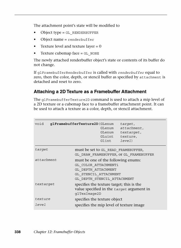
338 Chapter 12: Framebuffer Objects
The attachment point’s state will be modified to
• Object type = GL_RENDERBUFFER
• Object name = renderbuffer
• Texture level and texture layer = 0
• Texture cubemap face = GL_NONE
The newly attached renderbuffer object’s state or contents of its buffer do not change.
If glFramebufferRenderbuffer is called with renderbuffer equal to zero, then the color, depth, or stencil buffer as specified by attachment is detached and reset to zero.
Attaching a 2D Texture as a Framebuffer Attachment
The glFramebufferTexture2D command is used to attach a mip level of a 2D texture or a cubemap face to a framebuffer attachment point. It can be used to attach a texture as a color, depth, or stencil attachment.
void glFramebufferTexture2D( GLenum target, GLenum attachment, GLenum textarget, GLuint texture, Glint level)
target must be set to GL_READ_FRAMEBUFFER, GL_DRAW_FRAMEBUFFER, or GL_FRAMEBUFFER
attachment must be one of the following enums:GL_COLOR_ATTACHMENTiGL_DEPTH_ATTACHMENTGL_STENCIL_ATTACHMENTGL_DEPTH_STENCIL_ATTACHMENT
textarget specifies the texture target; this is the value specified in the target argument in glTexImage2D
texture specifies the texture objectlevel specifies the mip level of texture image
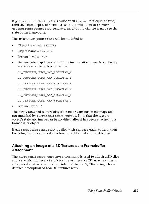
Using Framebuffer Objects 339
If glFramebufferTexture2D is called with texture not equal to zero, then the color, depth, or stencil attachment will be set to texture. If glFramebufferTexture2D generates an error, no change is made to the state of the framebuffer.
The attachment point’s state will be modified to
• Object type = GL_TEXTURE
• Object name = texture
• Texture level = level
• Texture cubemap face = valid if the texture attachment is a cubemapand is one of the following values:
GL_TEXTURE_CUBE_MAP_POSITIVE_X
GL_TEXTURE_CUBE_MAP_POSITIVE_Y
GL_TEXTURE_CUBE_MAP_POSITIVE_Z
GL_TEXTURE_CUBE_MAP_NEGATIVE_X
GL_TEXTURE_CUBE_MAP_NEGATIVE_Y
GL_TEXTURE_CUBE_MAP_NEGATIVE_Z
• Texture layer = 0
The newly attached texture object’s state or contents of its image are not modified by glFramebufferTexture2D. Note that the texture object’s state and image can be modified after it has been attached to a framebuffer object.
If glFramebufferTexture2D is called with texture equal to zero, then the color, depth, or stencil attachment is detached and reset to zero.
Attaching an Image of a 3D Texture as a Framebuffer Attachment
The glFramebufferTextureLayer command is used to attach a 2D slice and a specific mip level of a 3D texture or a level of 2D array textures to a framebuffer attachment point. Refer to Chapter 9, “Texturing,” for a detailed description of how 3D textures work.
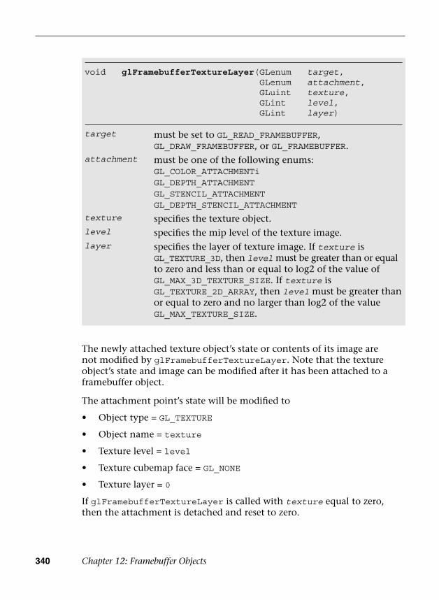
340 Chapter 12: Framebuffer Objects
The newly attached texture object’s state or contents of its image are not modified by glFramebufferTextureLayer. Note that the texture object’s state and image can be modified after it has been attached to a framebuffer object.
The attachment point’s state will be modified to
• Object type = GL_TEXTURE
• Object name = texture
• Texture level = level
• Texture cubemap face = GL_NONE
• Texture layer = 0
If glFramebufferTextureLayer is called with texture equal to zero, then the attachment is detached and reset to zero.
void glFramebufferTextureLayer (GLenum target, GLenum attachment, GLuint texture, GLint level, GLint layer)
target must be set to GL_READ_FRAMEBUFFER, GL_DRAW_FRAMEBUFFER, or GL_FRAMEBUFFER.
attachment must be one of the following enums:GL_COLOR_ATTACHMENTiGL_DEPTH_ATTACHMENTGL_STENCIL_ATTACHMENTGL_DEPTH_STENCIL_ATTACHMENT
texture specifies the texture object.level specifies the mip level of the texture image.layer specifies the layer of texture image. If texture is
GL_TEXTURE_3D, then level must be greater than or equal to zero and less than or equal to log2 of the value of GL_MAX_3D_TEXTURE_SIZE. If texture is GL_TEXTURE_2D_ARRAY, then level must be greater than or equal to zero and no larger than log2 of the value GL_MAX_TEXTURE_SIZE.

Using Framebuffer Objects 341
One interesting question arises: What happens if we are rendering into a texture and at the same time use this texture object as a texture in a fragment shader? Will the OpenGL ES implementation generate an error when such a situation arises? In some cases, it is possible for the OpenGL ES implementation to determine if a texture object is being used as a texture input and a framebuffer attachment into which we are currently drawing. glDrawArrays and glDrawElements could then generate an error. To ensure that glDrawArrays and glDrawElements can be executed as rapidly as possible, however, these checks are not performed. Instead of generating an error, in this case rendering results are undefined. It is the application’s responsibility to make sure that this situation does not occur.
Checking for Framebuffer Completeness
A framebuffer object needs to be defined as complete before it can be used as a rendering target. If the currently bound framebuffer object is not complete, OpenGL ES commands that draw primitives or read pixels will fail and generate an appropriate error that indicates the reason the framebuffer is incomplete.
The rules for a framebuffer object to be considered complete are as follows:
• Make sure that the color, depth, and stencil attachments are valid. Acolor attachment is valid if it is zero (i.e., there is no attachment) orif it is a color-renderable renderbuffer object or a texture object withone of the formats listed in Table 12-1. A depth attachment is validif it is zero or is a depth-renderable renderbuffer object or a depthtexture with one of the formats listed in Table 12-2 with depth bufferbits. A stencil attachment is valid if it is zero or is a stencil-renderablerenderbuffer object with one of the formats listed in Table 12-2 withstencil buffer bits. There is a minimum of one valid attachment.A framebuffer is not complete if it has no attachments, as there isnothing to draw into or read from.
• Valid attachments associated with a framebuffer object must have thesame width and height.
• If depth and stencil attachments exist, they must be the same image.
• The value of GL_RENDERBUFFER_SAMPLES is the same for all renderbufferattachments. If the attachments are a combination of renderbuffers andtextures, the value of GL_RENDERBUFFER_SAMPLES is zero.
342 Chapter 12: Framebuffer Objects
The glCheckFramebufferStatus command can be used to verify that a framebuffer object is complete.
glCheckFramebufferStatus returns zero if target is not equal to GL_FRAMEBUFFER. If target is equal to GL_FRAMEBUFFER, one of the following enums is returned:
• GL_FRAMEBUFFER_COMPLETE—Framebuffer is complete.
• GL_FRAMEBUFFER_UNDEFINED—If target is the default framebufferbut it does not exist.
• GL_FRAMEBUFFER_INCOMPLETE_ATTACHMENT—The framebufferattachment points are not complete. This might be due to the factthat the required attachment is zero or is not a valid texture orrenderbuffer object.
• GL_FRAMEBUFFER_INCOMPLETE_MISSING_ATTACHMENT—No validattachments in the framebuffer.
• GL_FRAMEBUFFER_UNSUPPORTED—The combination of internal formatsused by attachments in the framebuffer results in a nonrenderable target.
• GL_FRAMEBUFFER_INCOMPLETE_MULTISAMPLE—GL_RENDERBUFFER_SAMPLES is not the same for all renderbufferattachments or GL_RENDERBUFFER_SAMPLES is non-zero when theattachments are a combination of renderbuffers and textures.
If the currently bound framebuffer object is not complete, attempts to use that object for reading and writing pixels will fail. In turn, calls to draw primitives, such as glDrawArrays and glDrawElements, and commands that read the framebuffer, such as glReadPixels, glCopyTeximage2D, glCopyTexSubImage2D, and glCopyTexSubImage3D, will generate a GL_INVALID_FRAMEBUFFER_OPERATION error.
Framebuffer Blits
Framebuffer blits allow for efficient copying of a rectangle of pixel values from one framebuffer (i.e., read framebuffer) to another framebuffer (i.e., draw framebuffer). One key application of framebuffer blits is to resolve a
GLenum glCheckFramebufferStatus(GLenum target)
target must be set to GL_READ_FRAMEBUFFER, GL_DRAW_FRAMEBUFFER, or GL_FRAMEBUFFER

Framebuffer Blits 343
multisample renderbuffer to a texture (with a framebuffer object that has a texture bound for the color attachment).
You can perform this operation using the following command:
void glBlitFramebuffer( GLint srcX0, GLint srcY0, GLint srcX1, GLint srcY1, GLint dstX0, GLint dstY0, GLint dstX1, GLint dstY1, GLbitfield mask, GLenum filter)
srcX0, srcY0, srcX1, srcY1 specify the bound of the source rectangle within the read buffer
dstX0, dstY0, dstX1, dstY1 specify the bound of thedestination rectangle within the write buffer
mask specifies the bit-wise or of the flags indicating which buffers are to be copied; consists ofGL_COLOR_BUFFER_BITGL_DEPTH_BUFFER_BITGL_STENCIL_BUFFER_BITGL_DEPTH_STENCIL_ATTACHMENT
filter specifies the interpolation to be applied if the image is stretched; must be GL_NEAREST or GL_LINEAR
Example 12-1 (as part of the Chapter_11/MRTs example) illustrates how to use framebuffer blits to copy four color buffers from a framebuffer object into four quadrants of the window for the default framebuffer.
Example 12-1 Copying Pixels Using Framebuffer Blits
void BlitTextures ( ESContext *esContext ){ UserData *userData = esContext->userData;
// set the default framebuffer for writing glBindFramebuffer ( GL_DRAW_FRAMEBUFFER,
defaultFramebuffer );
// set the fbo with four color attachments for reading glBindFramebuffer ( GL_READ_FRAMEBUFFER, userData->fbo );
(continues)
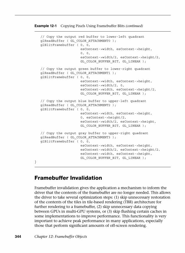
344 Chapter 12: Framebuffer Objects
Framebuffer Invalidation
Framebuffer invalidation gives the application a mechanism to inform the driver that the contents of the framebuffer are no longer needed. This allows the driver to take several optimization steps: (1) skip unnecessary restoration of the contents of the tiles in tile-based rendering (TBR) architecture for further rendering to a framebuffer, (2) skip unnecessary data copying between GPUs in multi-GPU systems, or (3) skip flushing certain caches in some implementations to improve performance. This functionality is very important to achieve peak performance in many applications, especially those that perform significant amounts of off-screen rendering.
Example 12-1 Copying Pixels Using Framebuffer Blits (continued)
// Copy the output red buffer to lower-left quadrant glReadBuffer ( GL_COLOR_ATTACHMENT0 ); glBlitFramebuffer ( 0, 0,
esContext->width, esContext->height,0, 0, esContext->width/2, esContext->height/2, GL_COLOR_BUFFER_BIT, GL_LINEAR );
// Copy the output green buffer to lower-right quadrant glReadBuffer ( GL_COLOR_ATTACHMENT1 ); glBlitFramebuffer ( 0, 0,
esContext->width, esContext->height,esContext->width/2, 0, esContext->width, esContext->height/2, GL_COLOR_BUFFER_BIT, GL_LINEAR );
// Copy the output blue buffer to upper-left quadrant glReadBuffer ( GL_COLOR_ATTACHMENT2 ); glBlitFramebuffer ( 0, 0,
esContext->width, esContext->height,0, esContext->height/2, esContext->width/2, esContext->height, GL_COLOR_BUFFER_BIT, GL_LINEAR );
// Copy the output gray buffer to upper-right quadrant glReadBuffer ( GL_COLOR_ATTACHMENT3 ); glBlitFramebuffer ( 0, 0,
esContext->width, esContext->height,esContext->width/2, esContext->height/2, esContext->width, esContext->height, GL_COLOR_BUFFER_BIT, GL_LINEAR );
}

Framebuffer Invalidation 345
Let us review the design of TBR GPUs to understand why framebuffer invalidation is important for such GPUs. TBR GPUs are commonly employed on mobile devices to minimize the amount of data transferred between the GPU and system memory and thereby reduce one of the biggest consumers of power, memory bandwidth. This is done by adding a fast on-chip memory that can hold a small amount of pixel data. The framebuffer is then divided into many tiles. For each tile, primitives are rendered into the on-chip memory, and then the results are copied to the system memory once completed. Because only a minimal amount of data per pixel (the final pixel result) will be copied to the system memory, this approach saves memory bandwidth between the GPU and system memory.
With framebuffer invalidation, the GPU can remove contents of the framebuffer that are no longer required so as to reduce the amount of contents to be held per frame. In addition, the GPU may remove unnecessary data transfer from the on-chip memory to the system memory if the tile data is no longer valid. Because the memory bandwidth requirement between the GPU and system memory can be reduced significantly, this leads to reduced power consumption and improved performance.
The glInvalidateFramebuffer and glInvalidateSubFramebuffer commands are used to invalidate the entire framebuffer or a pixel subregion of the framebuffer.
void glInvalidateFrameb uffer(GLenum target, GLsizei numAttachments, const GLenum *attachments)
void glInvalidateSubFra mebuffer(GLenum target, GLsizei numAttachments, const GLenum *attachments, GLint x, GLint y, GLsizei width, GLsizei height)
target must be set to GL_READ_FRAMEBUFFER, GL_DRAW_FRAMEBUFFER, or GL_FRAMEBUFFER
numAttachments
attachments
number of attachments in the attachments list
pointer to an array of numAttachments attachments
x, y specify the lower-left origin of the pixel rectangle to invalidate (lower-left corner is 0,0)(glInvalidateSubFramebuffer only)

346 Chapter 12: Framebuffer Objects
Deleting Framebuffer and Renderbuffer Objects
After the application has finished using renderbuffer objects, they can be deleted. Deleting renderbuffer and framebuffer objects is very similar to deleting texture objects.
Renderbuffer objects are deleted using the glDeleteRenderbuffers API.
glDeleteRenderbuffers deletes the renderbuffer objects specified in renderbuffers. Once a renderbuffer object is deleted, it has no state associated with it and is marked as unused; it can then later be reused as a new renderbuffer object. When deleting a renderbuffer object that is also the currently bound renderbuffer object, the renderbuffer object is deleted and the current renderbuffer binding is reset to zero. If the renderbuffer object names specified in renderbuffers are invalid or zero, they are ignored (i.e., no error will be generated). Further, if the renderbuffer is attached to the currently bound framebuffer object, it is first detached from the framebuffer and only then deleted.
Framebuffer objects are deleted using the glDeleteFramebuffers API.
glDeleteFramebuffers deletes the framebuffer objects specified in framebuffers. Once a framebuffer object is deleted, it has no state
void glDeleteRenderbuffers (GLsizei n, GLuint *renderbuffers)
n number of renderbuffer object names to deleterenderbuffers pointer to an array of n renderbuffer object names
to be deleted
void glDeleteFramebuffers( GLsizei n, GLuint *framebuffers)
n number of framebuffer object names to deleteframebuffers pointer to an array of n framebuffer object names
to be deleted
width specifies the width of the pixel rectangle to invalidate(glInvalidateSubFramebuffer only)
height specifies the height of the pixel rectangle to invalidate(glInvalidateSubFramebuffer only)
Deleting Framebuffer and Renderbuffer Objects 347
associated with it and is marked as unused; it can then later be reused as a new framebuffer object. When deleting a framebuffer object that is also the currently bound framebuffer object, the framebuffer object is deleted and the current framebuffer binding is reset to zero. If the framebuffer object names specified in framebuffers are invalid or zero, they are ignored and no error will be generated.
Deleting Renderbuffer Objects That Are Used as Framebuffer Attachments
What happens if a renderbuffer object being deleted is used as an attachment in a framebuffer object? If the renderbuffer object to be deleted is used as an attachment in the currently bound framebuffer object, glDeleteRenderbuffers will reset the attachment to zero. If the renderbuffer object to be deleted is used as an attachment in framebuffer objects that are not currently bound, then glDeleteRenderbuffers will not reset these attachments to zero. It is the responsibility of the application to detach these deleted renderbuffer objects from the appropriate framebuffer objects.
Reading Pixels and Framebuffer Objects
The glReadPixels command reads pixels from the color buffer and returns them in a user-allocated buffer. The color buffer that will be read from is the color buffer allocated by the window system–provided framebuffer or the color attachment of the currently bound framebuffer object. When a non-zero buffer object is bound to GL_PIXEL_PACK_BUFFER using glBindBuffer, the glReadPixels command can return immediately and invoke DMA transfer to read pixels from the framebuffer and write the data into the pixel buffer object.
Several combinations of format and type arguments in glReadPixels are supported: a format of GL_RGBA, GL_RGBA_INTEGER, or implementation-specific values returned by querying GL_IMPLEMENTATION_COLOR_READ_FORMAT; and a type of GL_UNSIGNED_BYTE, GL_UNSIGNED_INT, GL_INT, GL_FLOAT, or implementation-specific values returned by querying GL_IMPLEMENTATION_COLOR_READ_TYPE. The implementation-specific format and type returned will depend on the format and type of the currently attached color buffer. These values can change if the currently bound framebuffer changes. They must be queried whenever the currently bound framebuffer object changes to determine the correct implementation-specific format and type values that must be passed to glReadPixels.
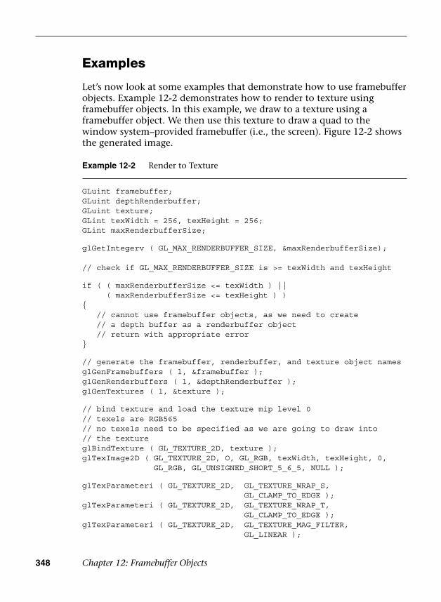
348 Chapter 12: Framebuffer Objects
Examples
Let’s now look at some examples that demonstrate how to use framebuffer objects. Example 12-2 demonstrates how to render to texture using framebuffer objects. In this example, we draw to a texture using a framebuffer object. We then use this texture to draw a quad to the window system–provided framebuffer (i.e., the screen). Figure 12-2 shows the generated image.
Example 12-2 Render to Texture
GLuint framebuffer;GLuint depthRenderbuffer;GLuint texture;GLint texWidth = 256, texHeight = 256;GLint maxRenderbufferSize;
glGetIntegerv ( GL_MAX_RENDERBUFFER_SIZE, &maxRenderbufferSize);
// check if GL_MAX_RENDERBUFFER_SIZE is >= texWidth and texHeight
if ( ( maxRenderbufferSize <= texWidth ) || ( maxRenderbufferSize <= texHeight ) ) { // cannot use framebuffer objects, as we need to create // a depth buffer as a renderbuffer object // return with appropriate error }
// generate the framebuffer, renderbuffer, and texture object namesglGenFramebuffers ( l, &framebuffer ); glGenRenderbuffers ( l, &depthRenderbuffer ); glGenTextures ( l, &texture );
// bind texture and load the texture mip level 0// texels are RGB565// no texels need to be specified as we are going to draw into// the textureglBindTexture ( GL_TEXTURE_2D, texture );glTexImage2D ( GL_TEXTURE_2D, O, GL_RGB, texWidth, texHeight, 0,
GL_RGB, GL_UNSIGNED_SHORT_5_6_5, NULL );
glTexParameteri ( GL_TEXTURE_2D, GL_TEXTURE_WRAP_S, GL_CLAMP_TO_EDGE );
glTexParameteri ( GL_TEXTURE_2D, GL_TEXTURE_WRAP_T, GL_CLAMP_TO_EDGE );
glTexParameteri ( GL_TEXTURE_2D, GL_TEXTURE_MAG_FILTER, GL_LINEAR );
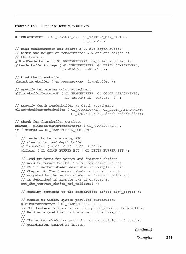
Examples 349
Example 12-2 Render to Texture (continued)
glTexParameteri ( GL_TEXTURE_2D, GL_TEXTURE_MIN_FILTER, GL_LINEAR);
// bind renderbuffer and create a 16-bit depth buffer // width and height of renderbuffer = width and height of // the textureglBindRenderbuffer ( GL_RENDERBUFFER, depthRenderbuffer ); glRenderbufferStorage ( GL_RENDERBUFFER, GL_DEPTH_COMPONENT16,
texWidth, texHeight );
// bind the framebuffer glBindFramebuffer ( GL_FRAMEBUFFER, framebuffer );
// specify texture as color attachmentglFramebufferTexture2D ( GL_FRAMEBUFFER, GL_COLOR_ATTACHMENT0,
GL_TEXTURE_2D, texture, 0 );
// specify depth_renderbuffer as depth attachment glFramebufferRenderbuffer ( GL_FRAMEBUFFER, GL_DEPTH_ATTACHMENT,
GL_RENDERBUFFER, depthRenderbuffer);
// check for framebuffer completestatus = glCheckFramebufferStatus ( GL_FRAMEBUFFER );if ( status == GL_FRAMEBUFFER_COMPLETE ){ // render to texture using FBO // clear color and depth buffer glClearColor ( 0.0f, 0.0f, 0.0f, 1.0f ); glClear ( GL_COLOR_BUFFER_BIT | GL_DEPTH_BUFFER_BIT );
// Load uniforms for vertex and fragment shaders // used to render to FBO. The vertex shader is the // ES 1.1 vertex shader described in Example 8-8 in // Chapter 8. The fragment shader outputs the color // computed by the vertex shader as fragment color and // is described in Example 1-2 in Chapter 1. set_fbo_texture_shader_and_uniforms( );
// drawing commands to the framebuffer object draw_teapot();
// render to window system-provided framebuffer glBindFramebuffer ( GL_FRAMEBUFFER, 0 ); // Use texture to draw to window system-provided framebuffer. // We draw a quad that is the size of the viewport. // // The vertex shader outputs the vertex position and texture // coordinates passed as inputs.
(continues)

350 Chapter 12: Framebuffer Objects
Example 12-2 Render to Texture (continued)
// // The fragment shader uses the texture coordinate to sample // the texture and uses this as the per-fragment color value. set_screen_shader_and_uniforms ( ); draw_screen_quad ( ); }
// clean upglDeleteRenderbuffers ( l, &depthRenderbuffer );glDeleteFramebuffers ( l, &framebuffer);glDeleteTextures ( l, &texture );
Figure 12-2 Render to Color Texture
In Example 12-2, we create the framebuffer, texture, and depthRenderbuffer objects using the appropriate glGen*** commands. The framebuffer object uses a color attachment that is a texture object (texture) and a depth attachment that is a renderbuffer object (depthRenderbuffer).
Before we create these objects, we query the maximum renderbuffer size (GL_MAX_RENDERBUFFER_SIZE) to verify that the maximum renderbuffer size supported by the implementation is less than or equal to the width and height of texture that will be used as a color attachment. This step ensures that we can create a depth renderbuffer successfully and use it as the depth attachment in framebuffer.

Examples 351
After the objects have been created, we call glBindTexture(texture) to make the texture the currently bound texture object. The texture mip level is then specified using glTexImage2D. Note that the pixels argument is NULL: We are rendering to the entire texture region, so there is no reason to specify any input data (this data will be overwritten).
The depthRenderbuffer object is bound using glBindRenderbuffer, and glRenderbufferStorage is called to allocate storage for a 16-bit depth buffer.
The framebuffer object is bound using glBindFramebuffer. texture is attached as a color attachment to framebuffer, and depthRenderbuffer is attached as a depth attachment to framebuffer.
We next check the framebuffer status to see if it is complete before we begin drawing into framebuffer. Once framebuffer rendering is complete, we reset the currently bound framebuffer to the window system–provided framebuffer by calling glBindFramebuffer(GL_FRAMEBUFFER, 0). We can now use texture, which was used as a render target in framebuffer, to draw to the window system–provided framebuffer.
In Example 12-2, the depth buffer attachment to framebuffer was a renderbuffer object. In Example 12-3, we consider how to use a depth texture as a depth buffer attachment to framebuffer. Applications can render to the depth texture used as a framebuffer attachment from the light source. The rendered depth texture can then be used as a shadow map to calculate the percentage in shadow for each fragment. Figure 12-3 shows the generated image.
Example 12-3 Render to Depth Texture
#define COLOR_TEXTURE 0 #define DEPTH_TEXTURE 1
GLuint framebuffer; GLuint textures[2]; GLint texWidth = 256, texHeight = 256;
// generate the framebuffer and texture object names glGenFramebuffers ( l, &framebuffer ); glGenTextures ( 2, textures );
// bind color texture and load the texture mip level 0// texels are RGB565// no texels need to specified as we are going to draw into // the texture
(continues)

352 Chapter 12: Framebuffer Objects
Example 12-3 Render to Depth Texture (continued)
glBindTexture ( GL_TEXTURE_2D, textures[COLOR_TEXTURE] ); glTexImage2D ( GL_TEXTURE_2D, 0, GL_RGB, texWidth, texHeight, 0,
GL_RGB, GL_UNSIGNED_SHORT_5_6_5, NULL );
glTexParameteri ( GL_TEXTURE_2D, GL_TEXTURE_WRAP_S, GL_CLAMP_TO_EDGE );
glTexParameteri ( GL_TEXTURE_2D, GL_TEXTURE_WRAP_T, GL_CLAMP_TO_EDGE );
glTexParameteri ( GL_TEXTURE_2D, GL_TEXTURE_MAG_FILTER,GL_LINEAR );
glTexParameteri ( GL_TEXTURE_2D, GL_TEXTURE_MIN_FILTER, GL_LINEAR );
// bind depth texture and load the texture mip level 0// no texels need to specified as we are going to draw into// the textureglBindTexture ( GL_TEXTURE_2D, textures[DEPTH_TEXTURE] );glTexImage2D ( GL_TEXTURE_2D, 0, GL_DEPTH_COMPONENT, texWidth,
texHeight, 0, GL_DEPTH_COMPONENT, GL_UNSIGNED_SHORT, NULL );
glTexParameteri ( GL_TEXTURE_2D, GL_TEXTURE_WRAP_S, GL_CLAMP_TO_EDGE );
glTexParameteri ( GL_TEXTURE_2D, GL_TEXTURE_WRAP_T, GL_CLAMP_TO_EDGE );
glTexParameteri ( GL_TEXTURE_2D, GL_TEXTURE_MAG_FILTER, GL_NEAREST );
glTexParameteri ( GL_TEXTURE_2D, GL_TEXTURE_MIN_FILTER, GL_NEAREST );
// bind the framebuffer glBindFramebuffer ( GL_FRAMEBUFFER, framebuffer );
// specify texture as color attachment glFramebufferTexture2D ( GL_FRAMEBUFFER, GL_COLOR_ATTACHMENT0,
GL_TEXTURE_2D, textures[COLOR_TEXTURE], 0 );
// specify texture as depth attachment glFramebufferTexture2D ( GL_FRAMEBUFFER, GL_DEPTH_ATTACHMENT,
GL_TEXTURE_2D, textures[DEPTH_TEXTURE], 0 );
// check for framebuffer completestatus = glCheckFramebufferStatus ( GL_FRAMEBUFFER );if ( status == GL_FRAMEBUFFER_COMPLETE ){ // render to color and depth textures using FBO // clear color and depth buffers

Examples 353
Example 12-3 Render to Depth Texture (continued)
glClearColor ( 0.0f, 0.0f, 0.0f, 1.0f ); glClear ( GL_COLOR_BUFFER_BIT | GL_DEPTH_BUFFER_BIT );
// Load uniforms for vertex and fragment shaders // used to render to FBO. The vertex shader is the // ES 1.1 vertex shader described in Example 8-8 in // Chapter 8. The fragment shader outputs the color // computed by vertex shader as fragment color and // is described in Example 1-2 in Chapter 1. set_fbo_texture_shader_and_uniforms( );
// drawing commands to the framebuffer object draw_teapot( );
// render to window system-provided framebuffer glBindFramebuffer ( GL_FRAMEBUFFER, 0 );
// Use depth texture to draw to window system framebuffer. // We draw a quad that is the size of the viewport. // // The vertex shader outputs the vertex position and texture // coordinates passed as inputs. // // The fragment shader uses the texture coordinate to sample // the texture and uses this as the per-fragment color value. set_screen_shader_and_uniforms( ); draw_screen_quad( ); }
// clean upglDeleteFramebuffers ( l, &framebuffer ); glDeleteTextures ( 2, textures );
Figure 12-3 Render to Depth Texture

354 Chapter 12: Framebuffer Objects
Note: The width and height of the off-screen renderbuffers do not have to be a power of 2.
Performance Tips and Tricks
Here, we discuss some performance tips that developers should carefully consider when using framebuffer objects:
• Avoid frequent switching between rendering to the window system–provided framebuffer and rendering to framebuffer objects. This is anissue for handheld OpenGL ES 3.0 implementations, as many of theseimplementations use a tile-based rendering architecture. With a tile-basedrendering architecture, dedicated internal memory is used to store thecolor, depth, and stencil values for a tile (i.e., region) of the framebuffer.The internal memory is used as it is much more efficient in terms ofpower utilization, and it has better memory latency and bandwidthcompared with going to external memory. After rendering to a tile iscompleted, the tile is written out to device (or system) memory. Everytime you switch from one rendering target to another, the appropriatetexture and renderbuffer attachments will need to be rendered, saved,and restored. This can become quite expensive. The best method wouldbe to render to the appropriate framebuffers in the scene first, andthen render to the window system–provided framebuffer, followed byexecution of the eglSwapBuffers command to swap the display buffer.
• Don’t create and destroy framebuffer and renderbuffer objects (or anyother large data objects for that matter) per frame.
• Try to avoid modifying textures (using glTexImage2D,glTexSubImage2D, glCopyTeximage2D, and so on) that areattachments to framebuffer objects used as rendering targets.
• Set the pixels argument in glTexImage2D and glTexImage3D toNULL if the entire texture image will be rendered, as the original datawill not be used anyway. Use glInvalidateFramebuffer to clear thetexture image before drawing to the texture if you expect the image tohave any predefined pixel values in it.
• Share depth and stencil renderbuffers as attachments used byframebuffer objects wherever possible to keep the memory footprintrequirement to a minimum. We recognize that this recommendationhas limited use, as the width and height of these buffers have to bethe same. In a future version of OpenGL ES, the rule that the widthand height of various attachments of a framebuffer object must beequal might be relaxed, making sharing easier.

Summary 355
Summary
In this chapter, you learned about the use of framebuffer objects for rendering to off-screen surfaces. There are several uses of framebuffer objects, the most common of which is for rendering to a texture. You learned how to specify color, depth, and stencil attachments to a framebuffer object and how to copy and invalidate pixels in the framebuffer, and then saw some examples that demonstrated rendering to a framebuffer object. Understanding framebuffer objects is critical for implementing many advanced effects, such as reflections, shadow maps, and postprocessing. Next, you will learn about sync objects and fences—the mechanisms to synchronize the application and GPU execution.

This page intentionally left blank

357
Chapter 13
Sync Objects and Fences
OpenGL ES 3.0 provides a mechanism for the application to wait until a set of OpenGL ES operations have finished executing on the GPU. You can synchronize GL operations among multiple graphics contexts and threads, which can be important in many advanced graphics applications. For example, you may want to wait for transform feedback results before using those results in your applications.
In this chapter, we discuss the flush command, the finish command, and sync objects and fences, including why they are useful and how to use them to synchronize operations in the graphics pipeline. Finally, we conclude with an example of using sync objects and fences.
Flush and Finish
The OpenGL ES 3.0 API inherits the OpenGL client–server model. The application, or client, issues commands, and these commands are processed by the OpenGL ES implementation or server. In OpenGL, the client and the server can reside on different machines over a network. OpenGL ES also allows the client and server to reside on different machines but because OpenGL ES targets handheld and embedded platforms, the client and server will typically be on the same device.
In the client–server model, the commands issued by the client do not necessarily get sent to the server immediately. If the client and server are operating over a network, it will be very inefficient to send individual commands over the network. Instead, the commands can be buffered on the client side and then issued to the server at a later point in time. To support this approach, a mechanism is needed that lets the client know when

358 Chapter 13: Sync Objects and Fences
the server has completed execution of previously submitted commands. Consider another example where multiple OpenGL ES contexts (each current to a different thread) are sharing objects. To synchronize correctly between these contexts, it is important that commands from context A be issued to the server before commands from context B, which depends on OpenGL ES state modified by context A. The glFlush command is used to flush any pending commands in the current OpenGL ES context and issue them to the server. Note that glFlush only issues the commands to the server; it does not wait for them to complete. If the client requires that the commands be completed, the glFinish command should be used. We do not recommend using glFinish unless absolutely necessary. Because glFinish does not return until all queued commands in the context have been completely processed by the server, calling glFinish can adversely impact performance by forcing the client and the server to synchronize their operations.
Why Use a Sync Object?
OpenGL ES 3.0 introduces a new feature, called a fence, that provides a way for the application to inform the GPU to wait until a set of OpenGL ES operations have finished executing before queuing up more for execution. You can insert a fence command into the GL command stream and associate it with a sync object to be waited on.
If we compare using sync objects to the glFinish command, sync objects are more efficient, as you can wait on partial completions of the GL command stream. By comparison, calling the glFinish command may reduce the performance of your applications, as this command will empty the graphics pipeline.
Creating and Deleting a Sync Object
To insert a fence command to the GL command stream and create a sync object, you can call the following function:
GLsync glFenceSync(GLenum condition, GLbitfield flags)
condition specifies the condition that must be met to signal the sync object; must be GL_SYNC_GPU_COMMANDS_COMPLETE
flags specifies a bit-wise combination of flags to control the behavior of the sync object; must be zero presently

Waiting for and Signaling a Sync Object 359
When a sync object is first created, its status is unsignaled. After the specified condition is satisfied by the fence command, then its status becomes signaled. Because sync objects cannot be reused, you must create one sync object for each synchronization operation.
To delete a sync object, you can call the following function:
GLvoid glDeleteSync(GLsync sync)
sync specifies the sync object to be deleted
GLenum glClientWaitSync(GLsync sync, GLbitfield flags, GLuint64 timeout)
sync specifies the sync object to wait on for its status
flags specifies a bitfield controlling the command flushing behavior; may be GL_SYNC_FLUSH_COMMANDS_BIT
timeout specifies the timeout in nanoseconds to wait for the sync object to be signaled
The deletion operation does not occur immediately, as the sync object will be deleted only when no other operation is waiting for it. Thus you can call the glDeleteSync command right after waiting for the sync object, which is described next.
Waiting for and Signaling a Sync Object
You can block the client and wait for a sync object to be signaled with the following call:
If the sync object is already at a signaled state, the glClientWaitSync command will return immediately. Otherwise, the call will block and wait up to timeout nanoseconds for the sync object to be signaled.

360 Chapter 13: Sync Objects and Fences
The glClientWaitSync function can return the following values:
• GL_ALREADY_SIGNALED: the sync object was already at the signaledstate when the function was called.
• GL_TIMEOUT_EXPIRED: the sync object did not become signaled aftertimeout nanoseconds passed.
• GL_CONDITION_SATISFIED: the sync object was signaled before thetimeout expired.
• GL_WAIT_FAILED: an error occurred.
The glWaitSync function is similar to the glClientWaitSync function, except that the function returns immediately and blocks the GPU until the sync object is signaled.
void glWaitSync(GLsync sync, GLbitfield flags,GLuint64 timeout)
sync specifies the sync object to wait on for its status.
flags specifies a bitfield controlling the command flushing behavior; must be zero.
timeout specifies the timeout in nanoseconds that the server should wait before continuing; must be GL_TIMEOUT_IGNORED.
Example
Example 13-1 shows an example of inserting a fence command after transform feedback buffers are created (see the EmitParticles function implementation) and blocking the GPU to wait on the transform feedback results before drawing them (see the Draw function implementation). The EmitParticles function and Draw function are executed by two separate CPU threads.
This code segment is a part of the particle system with transform feedback example that will be described in more detail in Chapter 14, “Advanced Programming with OpenGL ES 3.0.”

Summary 361
Summary
In this chapter, you learned about efficient primitives for synchronizing within the host application and GPU execution in OpenGL ES 3.0. We discussed how to use the sync objects and fences. In the next chapter, you will see many advanced rendering examples that tie together all the concepts you have learned so far throughout the book.
Example 13-1 Inserting a Fence Command and Waiting for Its Result in Transform Feedback Example
void EmitParticles ( ESContext *esContext, float deltaTime ){ // Many codes skipped . . .
// Emit particles using transform feedback glBeginTransformFeedback ( GL_POINTS );
glDrawArrays ( GL_POINTS, 0, NUM_PARTICLES ); glEndTransformFeedback ( );
// Create a sync object to ensure transform feedback results // are completed before the draw that uses them userData->emitSync =
glFenceSync ( GL_SYNC_GPU_COMMANDS_COMPLETE, 0 );
// Many codes skipped . . . }
void Draw ( ESContext *esContext ){ UserData *userData = ( UserData* ) esContext->userData;
// Block the GL server until transform feedback results // are completed glWaitSync ( userData->emitSync, 0, GL_TIMEOUT_IGNORED ); glDeleteSync ( userData->emitSync );
// Many codes skipped . . .
glDrawArrays ( GL_POINTS, 0, NUM_PARTICLES );}

This page intentionally left blank

363
Chapter 14
Advanced Programming with OpenGL ES 3.0
In this chapter, we put together many of the techniques you have learned throughout this book to discuss some advanced uses of OpenGL ES 3.0. A large number of advanced rendering techniques can be accomplished with the programmable flexibility of OpenGL ES 3.0. In this chapter, we cover the following techniques:
• Per-fragment lighting
• Environment mapping
• Particle system with point sprites
• Particle system with transform feedback
• Image postprocessing
• Projective texturing
• Noise using a 3D texture
• Procedural textures
• Terrain rendering with vertex texture fetch
• Shadows using a depth texture
Per-Fragment Lighting
In Chapter 8, “Vertex Shaders,” we covered the lighting equations that can be used in the vertex shader to calculate per-vertex lighting. Commonly, to achieve higher-quality lighting, we seek to evaluate the lighting equations on a per-fragment basis. In this section, we provide an example

364 Chapter 14: Advanced Programming with OpenGL ES 3.0
of evaluating ambient, diffuse, and specular lighting on a per-fragment basis. This example is a PVRShaman workspace that can be found in Chapter_14/PVR_PerFragmentLighting, as pictured in Figure 14-1. Several of the examples in this chapter make use of PVRShaman, a shader development integrated development environment (IDE) that is part of the Imagination Technologies PowerVR SDK (downloadable from http://powervrinsider.com/).
Figure 14-1 Per-Fragment Lighting Example
Lighting with a Normal Map
Before we get into the details of the shaders used in the PVRShaman workspace, we need to discuss the general approach that is used in the example. The simplest way to do lighting per-fragment would be to use the interpolated vertex normal in the fragment shader and then move the lighting computations into the fragment shader. However, for the diffuse term, this would really not yield much better results than doing the lighting on a per-vertex basis. There would be the advantage that the normal vector could be renormalized, which would remove artifacts due to linear interpolation, but the overall quality would be only minimally better. To really take advantage of the ability to do computations on a per-fragment basis, we need to use a normal map to store per-texel normals—a technique that can provide significantly more detail.
A normal map is a 2D texture that stores a normal vector at each texel. The red channel represents the x component, the green channel the y component, and the blue channel the z component. For a normal map stored as GL_RGB8 with GL_UNSIGNED_BYTE data, the values will all be in the range [0, 1]. To represent a normal, these values need to be scaled and biased in the shader to remap to [−1, 1]. The following block of

Per-Fragment Lighting 365
fragment shader code shows how you would go about fetching from a normal map:
// Fetch the tangent space normal from normal mapvec3 normal = texture(s_bumpMap, v_texcoord).xyz;
// Scale and bias from [0, 1] to [−1, 1] and normalizenormal = normalize(normal * 2.0 − 1.0);
As you can see, this small bit of shader code will fetch the color value from a texture map and then multiply the results by 2 and subtract 1. The result is that the values are rescaled into the [−1, 1] range from the [0, 1] range. We could actually avoid this scale and bias in the shader code by using a signed texture format such as GL_RGB8_SNORM, but for the purposes of demonstration we are showing how to use a normal map stored in an unsigned format. In addition, if the data in your normal map are not normalized, you will need to normalize the results in the fragment shader. This step can be skipped if your normal map contains all unit vectors.
The other significant issue to tackle with per-fragment lighting has to do with the space in which the normals in the texture are stored. To minimize computations in the fragment shader, we do not want to have to transform the result of the normal fetched from the normal map. One way to accomplish this would be to store world-space normals in your normal map. That is, the normal vectors in the normal map would each represent a world-space normal vector. Then, the light and direction vectors could be transformed into world space in the vertex shader and could be directly used with the value fetched from the normal map. However, some significant issues arise when storing normal maps in world space. Most importantly, the object must be assumed to be static because no transformation can happen on the object. In addition, the same surface oriented in different directions in space would not be able to share the same texels in the normal map, which can result in much larger maps.
A better solution than using world-space normal maps is to store normal maps in tangent space. The idea behind tangent space is that we define a space for each vertex using three coordinate axes: the normal, binormal, and tangent. The normals stored in the texture map are then all stored in this tangent space. Then, when we want to compute any lighting equations, we transform our incoming lighting vectors into the tangent space and those light vectors can then be used directly with the values in the normal map. The tangent space is typically computed as a preprocess and the binormal and tangent are added to the vertex attribute data. This work is done automatically by PVRShaman, which computes a tangent space for any model that has a vertex normal and texture coordinates.

366 Chapter 14: Advanced Programming with OpenGL ES 3.0
Lighting Shaders
Once we have tangent space normal maps and tangent space vectors set up, we can proceed with per-fragment lighting. First, let’s look at the vertex shader in Example 14-1.
Example 14-1 Per-Fragment Lighting Vertex Shader
#version 300 esuniform mat4 u_matViewInverse;uniform mat4 u_matViewProjection;uniform vec3 u_lightPosition;uniform vec3 u_eyePosition;
in vec4 a_vertex;in vec2 a_texcoord0;in vec3 a_normal;in vec3 a_binormal;in vec3 a_tangent;
out vec2 v_texcoord;out vec3 v_viewDirection;out vec3 v_lightDirection;
void main( void ){ // Transform eye vector into world space vec3 eyePositionWorld =
(u_matViewInverse * vec4(u_eyePosition, 1.0)).xyz;
// Compute world−space direction vector vec3 viewDirectionWorld = eyePositionWorld − a_vertex.xyz;
// Transform light position into world space vec3 lightPositionWorld =
(u_matViewInverse * vec4(u_lightPosition, 1.0)).xyz;
// Compute world−space light direction vector vec3 lightDirectionWorld = lightPositionWorld − a_vertex.xyz;
// Create the tangent matrix mat3 tangentMat = mat3( a_tangent,
a_binormal, a_normal );
// Transform the view and light vectors into tangent space v_viewDirection = viewDirectionWorld * tangentMat; v_lightDirection = lightDirectionWorld * tangentMat;
// Transform output position gl_Position = u_matViewProjection * a_vertex;

Per-Fragment Lighting 367
Note that the vertex shader inputs and uniforms are set up automatically by PVRShaman by setting semantics in the PerFragmentLighting.pfx file. We have two uniform matrices that we need as input to the vertex shader: u_matViewInverse and u_matViewProjection. The u_matViewInverse matrix contains the inverse of the view matrix. This matrix is used to transform the light vector and the eye vector (which are in view space) into world space. The first four statements in main perform this transformation and compute the light vector and view vector in world space. The next step in the shader is to create a tangent matrix. The tangent space for the vertex is stored in three vertex attributes: a_normal, a_binormal, and a_tangent. These three vectors define the three coordinate axes of the tangent space for each vertex. We construct a 3 × 3 matrix out of these vectors to form the tangent matrix tangentMat.
The next step is to transform the view and direction vectors into tangent space by multiplying them by the tangentMat matrix. Remember, our purpose here is to get the view and direction vectors into the same space as the normals in the tangent-space normal map. By doing this transformation in the vertex shader, we avoid performing any transformations in the fragment shader. Finally, we compute the final output position and place it in gl_Position and pass the texture coordinate along to the fragment shader in v_texcoord.
Now we have the view and direction vector in view space and a texture coordinate passed as out variables to the fragment shader. The next step is to actually light the fragments using the fragment shader, as shown in Example 14-2.
Example 14-1 Per-Fragment Lighting Vertex Shader (continued)
// Pass through texture coordinate v_texcoord = a_texcoord0.xy;
}
Example 14-2 Per-Fragment Lighting Fragment Shader
#version 300 esprecision mediump float;
uniform vec4 u_ambient;uniform vec4 u_specular;uniform vec4 u_diffuse;uniform float u_specularPower;
(continues)

368 Chapter 14: Advanced Programming with OpenGL ES 3.0
Example 14-2 Per-Fragment Lighting Fragment Shader (continued)
uniform sampler2D s_baseMap;uniform sampler2D s_bumpMap;
in vec2 v_texcoord;in vec3 v_viewDirection;in vec3 v_lightDirection;
layout(location = 0) out vec4 fragColor;void main( void ){ // Fetch base map color vec4 baseColor = texture(s_baseMap, v_texcoord);
// Fetch the tangent space normal from normal map vec3 normal = texture(s_bumpMap, v_texcoord).xyz;
// Scale and bias from [0, 1] to [−1, 1] and // normalize normal = normalize(normal * 2.0 − 1.0);
// Normalize the light direction and view // direction vec3 lightDirection = normalize(v_lightDirection); vec3 viewDirection = normalize(v_viewDirection);
// Compute N.L float nDotL = dot(normal, lightDirection);
// Compute reflection vector vec3 reflection = (2.0 * normal * nDotL) − lightDirection;
// Compute R.V float rDotV = max(0.0, dot(reflection, viewDirection));
// Compute ambient term vec4 ambient = u_ambient * baseColor;
// Compute diffuse term vec4 diffuse = u_diffuse * nDotL * baseColor;
// Compute specular term vec4 specular = u_specular * pow(rDotV, u_specularPower);
// Output final color fragColor = ambient + diffuse + specular;}

Per-Fragment Lighting 369
The first part of the fragment shader consists of a series of uniform declarations for the ambient, diffuse, and specular colors. These values are stored in the uniform variables u_ambient, u_diffuse, and u_specular, respectively. The shader is also configured with two samplers, s_baseMap and s_bumpMap, which are bound to a base color map and the normal map, respectively.
The first part of the fragment shader fetches the base color from the base map and the normal values from the normal map. As described earlier, the normal vector fetched from the texture map is scaled and biased and then normalized so that it is a unit vector with components in the [−1, 1] range. Next, the light vector and view vector are normalized and stored in lightDirection and viewDirection. Normalization is necessary because of the way fragment shader input variables are interpolated across a primitive. The fragment shader input variables are linearly interpolated across the primitive. When linear interpolation is done between two vectors, the results can become denormalized during interpolation. To compensate for this artifact, the vectors must be normalized in the fragment shader.
Lighting Equations
At this point in the fragment shader, we now have a normal, light vector, and direction vector all normalized and in the same space. This gives us the inputs needed to compute the lighting equations. The lighting computations performed in this shader are as follows:
Ambient = kAmbient × CBase
Diffuse = kDiffuse × N • L × CBase
Specular = kSpecular × pow(max(R • V, 0.0), kSpecular Power
The k constants for ambient, diffuse, and specular colors come from the u_ambient, u_diffuse, and u_specular uniform variables. The CBase is the base color fetched from the base texture map. The dot product of the light vector and the normal vector, N • L, is computed and stored in the nDotL variable in the shader. This value is used to compute the diffuse lighting term. Finally, the specular computation requires R, which is the reflection vector computed from the equation
R = 2 × N × (N • L) − L
Notice that the reflection vector also requires N • L, so the computation used for the diffuse lighting term can be reused in the reflection vector computation. Finally, the lighting terms are stored in the ambient, diffuse, and specular variables in the shader. These results are summed

370 Chapter 14: Advanced Programming with OpenGL ES 3.0
and finally stored in the fragColor output variable. The result is a per-fragment lit object with normal data coming from the normal map.
Many variations are possible on per-fragment lighting. One common technique is to store the specular exponent in a texture along with a specular mask value. This allows the specular lighting to vary across a surface. The main purpose of this example is to give you an idea of the types of computations that are typically done for per-fragment lighting. The use of tangent space, along with the computation of the lighting equations in the fragment shader, is typical of many modern games. Of course, it is also possible to add more lights, more material information, and much more.
Environment Mapping
The next rendering technique we cover—related to the previous technique—is performing environment mapping using a cubemap. The example we cover is the PVRShaman workspace Chapter_14/PVR_EnvironmentMapping. The results are shown in Figure 14-2.
Figure 14-2 Environment Mapping Example
The concept behind environment mapping is to render the reflection of the environment on an object. In Chapter 9, “Texturing,” we introduced cubemaps, which are commonly used to store environment maps. In the PVRShaman example workspace, the environment of a mountain scene is stored in a cubemap. The way such cubemaps can be generated is by positioning a camera at the center of a scene and rendering along each of the positive and negative major axis directions using a 90-degree field of view. For reflections that change dynamically, we can render such a cubemap using a framebuffer object dynamically for each frame. For a static environment, this process can be done as a preprocess and the results stored in a static cubemap.
The vertex shader for the environment mapping example is provided in Example 14-3.

Environment Mapping 371
Example 14-3 Environment Mapping Vertex Shader
#version 300 esuniform mat4 u_matViewInverse;uniform mat4 u_matViewProjection;uniform vec3 u_lightPosition;
in vec4 a_vertex;in vec2 a_texcoord0;in vec3 a_normal;in vec3 a_binormal;in vec3 a_tangent;
out vec2 v_texcoord;out vec3 v_lightDirection;out vec3 v_normal;out vec3 v_binormal;out vec3 v_tangent;
void main( void ){ // Transform light position into world space vec3 lightPositionWorld =
(u_matViewInverse * vec4(u_lightPosition, 1.0)).xyz;
// Compute world−space light direction vector vec3 lightDirectionWorld = lightPositionWorld − a_vertex.xyz;
// Pass the world−space light vector to the fragment shader v_lightDirection = lightDirectionWorld;
// Transform output position gl_Position = u_matViewProjection * a_vertex;
// Pass through other attributes v_texcoord = a_texcoord0.xy; v_normal = a_normal; v_binormal = a_binormal; v_tangent = a_tangent;}
The vertex shader in this example is very similar to the previous per-fragment lighting example. The primary difference is that rather than transforming the light direction vector into tangent space, we keep the light vector in world space. The reason we must do this is because we ultimately want to fetch from the cubemap using a world-space reflection vector. As such, rather than transforming the light vectors into tangent space, we will transform the normal vector from tangent space into world

372 Chapter 14: Advanced Programming with OpenGL ES 3.0
space. To do so, the vertex shader passes the normal, binormal, and tangent as varyings into the fragment shader so that a tangent matrix can be constructed.
The fragment shader listing for the environment mapping sample is provided in Example 14-4.
Example 14-4 Environment Mapping Fragment Shader
#version 300 esprecision mediump float;
uniform vec4 u_ambient;uniform vec4 u_specular;uniform vec4 u_diffuse;uniform float u_specularPower;
uniform sampler2D s_baseMap;uniform sampler2D s_bumpMap;uniform samplerCube s_envMap;
in vec2 v_texcoord;in vec3 v_lightDirection;in vec3 v_normal;in vec3 v_binormal;in vec3 v_tangent;
layout(location = 0) out vec4 fragColor;
void main( void ){ // Fetch base map color vec4 baseColor = texture( s_baseMap, v_texcoord );
// Fetch the tangent space normal from normal map vec3 normal = texture( s_bumpMap, v_texcoord ).xyz;
// Scale and bias from [0, 1] to [−1, 1] normal = normal * 2.0 − 1.0;
// Construct a matrix to transform from tangent to // world space mat3 tangentToWorldMat = mat3( v_tangent,
v_binormal,v_normal );
// Transform normal to world space and normalize normal = normalize( tangentToWorldMat * normal );
// Normalize the light direction vec3 lightDirection = normalize( v_lightDirection );

Environment Mapping 373
In the fragment shader, you will notice that the normal vector is fetched from the normal map in the same way as in the per-fragment lighting example. The difference in this example is that rather than leaving the normal vector in tangent space, the fragment shader transforms the normal vector into world space. This is done by constructing the tangentToWorld matrix out of the v_tangent, v_binormal, and v_normal varying vectors and then multiplying the fetched normal vector by this new matrix. The reflection vector is then calculated using the light direction vector and normal, both in world space. The result of the computation is a reflection vector that is in world space, exactly what we need to fetch from the cubemap as an environment map. This vector is used to fetch into the environment map using the texture function with the reflection vector as a texture coordinate. Finally, the resultant fragColor is written as a combination of the base map color and the environment map color. The base color is attenuated by 0.25 for the purposes of this example so that the environment map is clearly visible.
This example demonstrates the basics of environment mapping. The same basic technique can be used to produce a large variety of effects. For example, the reflection may be attenuated using a fresnel term to more accurately model the reflection of light on a given material. As mentioned earlier, another common technique is to dynamically render a scene into a cubemap so that the environment reflection varies as an object moves through a scene and the scene itself changes. Using the basic technique shown here, you can extend the technique to accomplish more advanced reflection effects.
Example 14-4 Environment Mapping Fragment Shader (continued)
// Compute N.L float nDotL = dot( normal, lightDirection );
// Compute reflection vector vec3 reflection = ( 2.0 * normal * nDotL ) − lightDirection;
// Use the reflection vector to fetch from the environment // map vec4 envColor = texture( s_envMap, reflection );
// Output final color fragColor = 0.25 * baseColor + envColor;}

374 Chapter 14: Advanced Programming with OpenGL ES 3.0
Particle System with Point Sprites
The next example we cover is rendering a particle explosion using point sprites. This example demonstrates how to animate a particle in a vertex shader and how to render particles using point sprites. The example we cover is the sample program in Chapter_14/ParticleSystem, the results of which are pictured in Figure 14-3.
Particle System Setup
Before diving into the code for this example, it’s helpful to cover at a high level the approach this sample uses. One of the goals here is to show how to render a particle explosion without having any dynamic vertex data modified by the CPU. That is, with the exception of uniform variables, there are no changes to any of the vertex data as the explosion animates. To accomplish this goal, a number of inputs are fed into the shaders.
At initialization time, the program initializes the following values in a vertex array, one for each particle, based on a random value:
• Lifetime—The lifetime of a particle in seconds.
• Start position—The start position of a particle in the explosion.
• End position—The final position of a particle in the explosion (theparticles are animated by linearly interpolating between the start andend position).
Figure 14-3 Particle System Sample

Environment Mapping 375
In addition, each explosion has several global settings that are passed in as uniforms:
• Center position—The center of the explosion (the per-vertexpositions are offset from this center).
• Color—An overall color for the explosion.
• Time—The current time in seconds.
Particle System Vertex Shader
With this information, the vertex and fragment shaders are completely responsible for the motion, fading, and rendering of the particles. Let’s begin by looking at the vertex shader code for the sample in Example 14-5.
Example 14-5 Particle System Vertex Shader
#version 300 esuniform float u_time;uniform vec3 u_centerPosition;layout(location = 0) in float a_lifetime;layout(location = 1) in vec3 a_startPosition;layout(location = 2) in vec3 a_endPosition;out float v_lifetime;void main(){ if ( u_time <= a_lifetime ) { gl_Position.xyz = a_startPosition +
(u_time * a_endPosition); gl_Position.xyz += u_centerPosition; gl_Position.w = 1.0; } else { gl_Position = vec4( −1000, −1000, 0, 0 ); } v_lifetime = 1.0 − ( u_time / a_lifetime ); v_lifetime = clamp ( v_lifetime, 0.0, 1.0 ); gl_PointSize = ( v_lifetime * v_lifetime ) * 40.0;}
The first input to the vertex shader is the uniform variable u_time. This variable is set to the current elapsed time in seconds by the application. The value is reset to 0.0 when the time exceeds the length of a single

376 Chapter 14: Advanced Programming with OpenGL ES 3.0
explosion. The next input to the vertex shader is the uniform variable u_centerPosition. This variable is set to the center location of the explosion at the start of a new explosion. The setup code for u_time and u_centerPosition appears in the Update function in the C code of the example program, which is provided in Example 14-6.
Example 14-6 Update Function for Particle System Sample
void Update (ESContext *esContext, float deltaTime){ UserData *userData = esContext−>userData;
userData−>time += deltaTime;
glUseProgram ( userData−>programObject );
if(userData−>time >= l.Of) {
float centerPos[3];float color[4] ;
userData−>time = O.Of;
// Pick a new start location and colorcenterPos[0] = ((float)(rand() % 10000)/10000.0f)−0.5f;centerPos[l] = ((float)(rand() % 10000)/10000.0f)−0.5f;centerPos[2] = ((float)(rand() % 10000)/10000.0f)−0.5f;
glUniform3fv(userData−>centerPositionLoc, 1,¢erPos[0]);
// Random colorcolor[0] = ((float)(rand() % 10000) / 20000.Of) + 0.5f;color[l] = ((float)(rand() % 10000) / 20000.Of) + 0.5f;color[2] = ((float)(rand() % 10000) / 20000.Of) + 0.5f;color[3] = 0.5;
glUniform4fv(userData−>colorLoc, 1, &color[0]); } // Load uniform time variable glUniformlf(userData−>timeLoc, userData−>time);}
As you can see, the Update function resets the time after 1 second elapses and then sets up a new center location and time for another explosion. The function also keeps the u_time variable up-to-date in each frame.
The vertex inputs to the vertex shader are the particle lifetime, particle start position, and end position. These variables are all initialized to randomly

Environment Mapping 377
seeded values in the Init function in the program. The body of the vertex shader first checks whether a particle’s lifetime has expired. If so, the gl_Position variable is set to the value (−1000, −1000), which is just a quick way of forcing the point to be off the screen. Because the point will be clipped, all of the subsequent processing for the expired point sprites can be skipped. If the particle is still alive, its position is set to be a linear interpolated value between the start and end positions. Next, the vertex shader passes the remaining lifetime of the particle down into the fragment shader in the varying variable v_lifetime. The lifetime will be used in the fragment shader to fade the particle as it ends its life. The final piece of the vertex shader causes the point size to be based on the remaining lifetime of the particle by setting the gl_Pointsize built-in variable. This has the effect of scaling the particles down as they reach the end of their life.
Particle System Fragment Shader
The fragment shader code for the example program is provided in Example 14-7.
Example 14-7 Particle System Fragment Shader
#version 300 esprecision mediump float;uniform vec4 u_color;in float v_lifetime;layout(location = 0) out vec4 fragColor;uniform sampler2D s_texture;void main(){ vec4 texColor; texColor = texture( s_texture, gl_PointCoord ); fragColor = vec4( u_color ) * texColor; fragColor.a *= v_lifetime;}
The first input to the fragment shader is the u_color uniform variable, which is set at the beginning of each explosion by the Update function. Next, the v_lifetime input variable set by the vertex shader is declared in the fragment shader. In addition, a sampler is declared to which a 2D texture image of smoke is bound.
The fragment shader itself is relatively simple. The texture fetch uses the gl_PointCoord variable as a texture coordinate. This special variable for point sprites is set to fixed values for the corners of the point sprite (this process was described in Chapter 7, “Primitive Assembly and

378 Chapter 14: Advanced Programming with OpenGL ES 3.0
Rasterization,” in the discussion of drawing primitives). One could also extend the fragment shader to rotate the point sprite coordinates if rotation of the sprite was required. This requires extra fragment shader instructions, but increases the flexibility of the point sprite.
The texture color is attenuated by the u_color variable, and the alpha value is attenuated by the particle lifetime. The application also enables alpha blending with the following blend function:
glEnable ( GL_BLEND );glBlendFunc ( GL_SRC_ALPHA, GL_ONE );
As a consequence of this code, the alpha produced in the fragment shader is modulated with the fragment color. This value is then added into whatever values are stored in the destination of the fragment. The result is an additive blend effect for the particle system. Note that various particle effects will use different alpha blending modes to accomplish the desired effect.
The code to actually draw the particles is shown in Example 14-8.
Example 14-8 Draw Function for Particle System Sample
void Draw ( ESContext *esContext ){ UserData *userData = esContext−>userData;
// Set the viewport glViewport ( 0, 0, esContext−>width, esContext−>height );
// Clear the color buffer glClear ( GL_COLOR_BUFFER_BIT );
// Use the program object glUseProgram ( userData−>programObject );
// Load the vertex attributes glVertexAttribPointer ( ATTRIBUTE_LIFETIME_LOC, 1,
GL_FLOAT, GL_FALSE,PARTICLE_SIZE * sizeof(GLfloat),userData−>particleData );
glVertexAttribPointer ( ATTRIBUTE_ENDPOSITION_LOC, 3,GL_FLOAT, GL_FALSE,PARTICLE_SIZE * sizeof(GLfloat),&userData−>particleData[1] );
glVertexAttribPointer ( ATTRIBUTE_STARTPOSITION_LOC, 3,GL_FLOAT, GL_FALSE,PARTICLE_SIZE * sizeof(GLfloat),&userData−>particleData[4] );

Environment Mapping 379
The Draw function begins by setting the viewport and clearing the screen. It then selects the program object to use and loads the vertex data using glVertexAttribPointer. Note that because the values of the vertex array never change, this example could have used vertex buffer objects rather than client-side vertex arrays. In general, this approach is recommended for any vertex data that does not change because it reduces the vertex bandwidth used. Vertex buffer objects were not used in this example merely to keep the code a bit simpler. After setting the vertex arrays, the function enables the blend function, binds the smoke texture, and then uses glDrawArrays to draw the particles.
Unlike with triangles, there is no connectivity for point sprites, so using glDrawElements does not really provide any advantage for rendering point sprites in this example. However, often particle systems need to be sorted by depth from back to front to achieve proper alpha blending results. In such cases, one potential approach is to sort the element array to modify the draw order. This technique is very efficient, because it requires minimal bandwidth across the bus per frame (only the index data need be changed, and they are almost always smaller than the vertex data).
This example has demonstrated a number of techniques that can be useful in rendering particle systems using point sprites. The particles were animated entirely on the GPU using the vertex shader. The sizes of the particles were attenuated based on particle lifetime using the gl_PointSize variable. In addition, the point sprites were rendered with a texture using the gl_PointCoord built-in texture coordinate variable. These are the fundamental elements needed to implement a particle system using OpenGL ES 3.0.
glEnableVertexAttribArray ( ATTRIBUTE_LIFETIME_LOC ); glEnableVertexAttribArray ( ATTRIBUTE_ENDPOSITION_LOC ); glEnableVertexAttribArray ( ATTRIBUTE_STARTPOSITION_LOC );
// Blend particles glEnable ( GL_BLEND ); glBlendFunc ( GL_SRC_ALPHA, GL_ONE );
// Bind the texture glActiveTexture ( GL_TEXTURE0 ); glBindTexture ( GL_TEXTURE_2D, userData−>textureId );
// Set the sampler texture unit to 0 glUniform1i ( userData−>samplerLoc, 0 );
glDrawArrays( GL_POINTS, 0, NUM_PARTICLES );}
Example 14-8 Draw Function for Particle System Sample (continued)

380 Chapter 14: Advanced Programming with OpenGL ES 3.0
Particle System Using Transform Feedback
The previous example demonstrated one technique for animating a particle system in the vertex shader. Although it included an efficient method for animating particles, the result was severely limited compared to a traditional particle system. In a typical CPU-based particle system, particles are emitted with different initial parameters such as position, velocity, and acceleration and the paths are animated over the particle’s lifetime. In the previous example, all of the particles were emitted simultaneously and the paths were limited to a linear interpolation between the start and end positions.
We can build a much more general-purpose GPU-based particle system by using the transform feedback feature of OpenGL ES 3.0. To review, transform feedback allows the outputs of the vertex shader to be stored in a buffer object. As a consequence, we can implement a particle emitter completely in a vertex shader on the GPU, store its output into a buffer object, and then use that buffer object with another shader to draw the particles. In general, transform feedback allows you to implement render to vertex buffer (sometimes referred to by the shorthand R2VB), which means that a wide range of algorithms can be moved from the CPU to the GPU.
The example we cover in this section is found in Chapter_14/ParticleSystemTransformFeedback. It demonstrates emitting particles for a fountain using transform feedback, as shown in Figure 14-4.
Figure 14-4 Particle System with Transform Feedback

Particle System Using Transform Feedback 381
Particle System Rendering Algorithm
This section provides a high-level overview of how the transform feedback-based particle system works. At initialization time, two buffer objects are allocated to hold the particle data. The algorithm ping-pongs (switches back and forth) between the two buffers, each time switching which buffer is the input or output for particle emission. Each particle contains the following information: position, velocity, size, current time, and lifetime.
The particle system is updated with transform feedback and then rendered in the following steps:
• In each frame, one of the particle VBOs is selected as the inputand bound as a GL_ARRAY_BUFFER. The output is bound as aGL_TRANSFORM_FEEDBACK_BUFFER.
• GL_RASTERIZER_DISCARD is enabled so that no fragments are drawn.
• The particle emission shader is executed using point primitives (eachparticle is one point). The vertex shader outputs new particles tothe transform feedback buffer and copies existing particles to thetransform feedback buffer unchanged.
• GL_RASTERIZER_DISCARD is disabled, so that the application can drawthe particles.
• The buffer that was rendered to for transform feedback is now boundas a GL_ARRAY_BUFFER. Another vertex/fragment shader is bound todraw the particles.
• The particles are rendered to the framebuffer.
• In the next frame, the input/output buffer objects are swapped andthe same process continues.
Particle Emission with Transform Feedback
Example 14-9 shows the vertex shader that is used for emitting particles. All of the output variables in this shader are written to a transform feedback buffer object. Whenever a particle’s lifetime has expired, the shader will make it a potential candidate for emission as a new active particle. If a new particle is generated, the shader uses a randomValue function (shown in the vertex shader code in Example 14-9) that generates a random value to initialize the new particle’s velocity and size. The random number generation is based on using a 3D noise texture and using the gl_VertexID built-in variable to select a unique texture coordinate

382 Chapter 14: Advanced Programming with OpenGL ES 3.0
for each particle. The details of creating and using a 3D Noise texture are described in the Noise Using a 3D Texture section later in this chapter.
Example 14-9 Particle Emission Vertex Shader
#version 300 es#define NUM_PARTICLES 200#define ATTRIBUTE_POSITION 0#define ATTRIBUTE_VELOCITY 1#define ATTRIBUTE_SIZE 2#define ATTRIBUTE_CURTIME 3#define ATTRIBUTE_LIFETIME 4
uniform float u_time;uniform float u_emissionRate;uniform sampler3D s_noiseTex;
layout(location = ATTRIBUTE_POSITION) in vec2 a_position;layout(location = ATTRIBUTE_VELOCITY) in vec2 a_velocity;layout(location = ATTRIBUTE_SIZE) in float a_size;layout(location = ATTRIBUTE_CURTIME) in float a_curtime;layout(location = ATTRIBUTE_LIFETIME) in float a_lifetime;
out vec2 v_position;out vec2 v_velocity;out float v_size;out float v_curtime;out float v_lifetime;
float randomValue( inout float seed ){ float vertexId = float( gl_VertexID ) /
float( NUM_PARTICLES ); vec3 texCoord = vec3( u_time, vertexId, seed ); seed += 0.1; return texture( s_noiseTex, texCoord ).r;}
void main(){ float seed = u_time; float lifetime = a_curtime − u_time; if( lifetime <= 0.0 && randomValue(seed) < u_emissionRate ) { // Generate a new particle seeded with random values for // velocity and size v_position = vec2( 0.0, −1.0 ); v_velocity = vec2( randomValue(seed) * 2.0 − 1.00,
randomValue(seed) * 0.4 + 2.0 );

Particle System Using Transform Feedback 383
To use the transform feedback feature with this vertex shader, the output variables must be tagged as being used for transform feedback before linking the program object. This is done in the InitEmitParticles function in the example code, where the following snippet shows how the program object is set up for transform feedback:
char* feedbackVaryings[5] ={ "v_position", "v_velocity", "v_size", "v_curtime", "v_lifetime"};
// Set the vertex shader outputs as transform// feedback varyingsglTransformFeedbackVaryings ( userData−>emitProgramObject, 5,
feedbackVaryings,GL_INTERLEAVED_ATTRIBS );
// Link program must occur after calling// glTransformFeedbackVaryingsglLinkProgram( userData−>emitProgramObject );
The call to glTransformFeedbackVaryings ensures that the passed-in output variables are used for transform feedback. The GL_INTERLEAVED_ATTRIBS parameter specifies that the output variables will be interleaved in the output buffer object. The order and layout of the variables must
v_size = randomValue(seed) * 20.0 + 60.0; v_curtime = u_time; v_lifetime = 2.0; } else { // This particle has not changed; just copy it to the // output v_position = a_position; v_velocity = a_velocity; v_size = a_size; v_curtime = a_curtime; v_lifetime = a_lifetime; }}
Example 14-9 Particle Emission Vertex Shader (continued)

384 Chapter 14: Advanced Programming with OpenGL ES 3.0
match the expected layout of the buffer object. In this case, our vertex structure is defined as follows:
typedef struct{ float position[2]; float velocity[2]; float size; float curtime; float lifetime;} Particle;
This structure definition matches the order and type of the varyings that are passed in to glTransformFeedbackVaryings.
The code used to emit the particles is provided in the EmitParticles function shown in Example 14-10.
Example 14-10 Emit Particles with Transform Feedback
void EmitParticles ( ESContext *esContext, float deltaTime ){ UserData userData = (UserData) esContext−>userData;
GLuint srcVBO = userData−>particleVBOs[ userData−>curSrcIndex ];
GLuint dstVBO = userData−>particleVBOs[(userData−>curSrcIndex+1) % 2];
glUseProgram( userData−>emitProgramObject );
// glVertexAttribPointer and glEnableVeretxAttribArray // setup SetupVertexAttributes(esContext, srcVBO);
// Set transform feedback buffer glBindBufferBase(GL_TRANSFORM_FEEDBACK_BUFFER, 0, dstVBO);
// Turn off rasterization; we are not drawing glEnable(GL_RASTERIZER_DISCARD);
// Set uniforms glUniform1f(userData−>emitTimeLoc, userData−>time); glUniform1f(userData−>emitEmissionRateLoc, EMISSION_RATE);
// Bind the 3D noise texture glActiveTexture(GL_TEXTURE0); glBindTexture(GL_TEXTURE_3D, userData−>noiseTextureId); glUniform1i(userData−>emitNoiseSamplerLoc, 0);

Particle System Using Transform Feedback 385
The destination buffer object is bound to the GL_TRANSFORM_FEEDBACK_BUFFER target using glBindBufferBase. Rasterization is disabled by enabling GL_RASTERIZER_DISCARD because we will not actually draw any fragments; instead, we simply want to execute the vertex shader and output to the transform feedback buffer. Finally, before the glDrawArrays call, we enable transform feedback rendering by calling glBeginTransformFeedback(GL_POINTS). Subsequent calls to glDrawArrays using GL_POINTS will then be recorded in the transform feedback buffer until glEndTransformFeedback is called. To ensure transform feedback results are completed before the draw call that uses them, we create a sync object and insert a fence command immediately after the glEndTransformFeedback is called. Prior to the draw call execution, we will wait on the sync object using the glWaitSync call. After executing the draw call and restoring state, we ping-pong between the buffers so that the next time EmitShaders is called, it will use the previous frame’s transform feedback output as the input.
Rendering the Particles
After emitting the transform feedback buffer, that buffer is bound as a vertex buffer object from which to render the particles. The vertex shader used for particle rendering with point sprites is provided in Example 14-11.
// Emit particles using transform feedback glBeginTransformFeedback(GL_POINTS);
glDrawArrays(GL_POINTS, 0, NUM_PARTICLES); glEndTransformFeedback();
// Create a sync object to ensure transform feedback // results are completed before the draw that uses them userData−>emitSync = glFenceSync(
GL_SYNC_GPU_COMMANDS_COMPLETE, 0 );
// Restore state glDisable(GL_RASTERIZER_DISCARD); glUseProgram(0); glBindBufferBase(GL_TRANSFORM_FEEDBACK_BUFFER, 0, 0); glBindTexture(GL_TEXTURE_3D, 0);
// Ping−pong the buffers userData−>curSrcIndex = ( userData−>curSrcIndex + 1 ) % 2;}
Example 14-10 Emit Particles with Transform Feedback (continued)
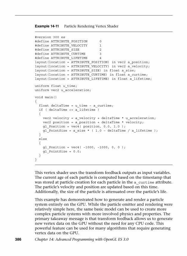
386 Chapter 14: Advanced Programming with OpenGL ES 3.0
This vertex shader uses the transform feedback outputs as input variables. The current age of each particle is computed based on the timestamp that was stored at particle creation for each particle in the a_curtime attribute. The particle’s velocity and position are updated based on this time. Additionally, the size of the particle is attenuated over the particle’s life.
This example has demonstrated how to generate and render a particle system entirely on the GPU. While the particle emitter and rendering were relatively simple here, the same basic model can be used to create more complex particle systems with more involved physics and properties. The primary takeaway message is that transform feedback allows us to generate new vertex data on the GPU without the need for any CPU code. This powerful feature can be used for many algorithms that require generating vertex data on the GPU.
Example 14-11 Particle Rendering Vertex Shader
#version 300 es#define ATTRIBUTE_POSITION 0#define ATTRIBUTE_VELOCITY 1#define ATTRIBUTE_SIZE 2#define ATTRIBUTE_CURTIME 3#define ATTRIBUTE_LIFETIME 4layout(location = ATTRIBUTE_POSITION) in vec2 a_position;layout(location = ATTRIBUTE_VELOCITY) in vec2 a_velocity;layout(location = ATTRIBUTE_SIZE) in float a_size;layout(location = ATTRIBUTE_CURTIME) in float a_curtime;layout(location = ATTRIBUTE_LIFETIME) in float a_lifetime;
uniform float u_time;uniform vec2 u_acceleration;
void main(){ float deltaTime = u_time − a_curtime; if ( deltaTime <= a_lifetime ) { vec2 velocity = a_velocity + deltaTime * u_acceleration; vec2 position = a_position + deltaTime * velocity; gl_Position = vec4( position, 0.0, 1.0 ); gl_PointSize = a_size * ( 1.0 − deltaTime / a_lifetime ); } else { gl_Position = vec4( −1000, −1000, 0, 0 ); gl_PointSize = 0.0; }}

Image Postprocessing 387
Image Postprocessing
The next example covered in this chapter involves image postprocessing. Using a combination of framebuffer objects and shaders, it is possible to perform a wide variety of image postprocessing techniques. The first example presented here is the simple blur effect in the PVRShaman workspace in Chapter_14/PVR_PostProcess, results of which are pictured in Figure 14-5.
Figure 14-5 Image Postprocessing Example
Render-to-Texture Setup
This example renders a textured knot into a framebuffer object and then uses the color attachment as a texture in a subsequent pass. A full-screen quad is drawn to the screen using the rendered texture as a source. A fragment shader is run over the full-screen quad, which performs a blur filter. In general, many types of postprocessing techniques can be accomplished using this pattern:
1. Render the scene into an off-screen framebuffer object (FBO).
2. Bind the FBO texture as a source and render a full-screen quad to thescreen.
3. Execute a fragment shader that performs filtering across the quad.
Some algorithms require performing multiple passes over an image; others require more complicated inputs. However, the general idea is to use a fragment shader over a full-screen quad that performs a postprocessing algorithm.
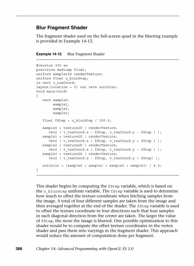
388 Chapter 14: Advanced Programming with OpenGL ES 3.0
Blur Fragment Shader
The fragment shader used on the full-screen quad in the blurring example is provided in Example 14-12.
Example 14-12 Blur Fragment Shader
#version 300 esprecision mediump float;uniform sampler2D renderTexture;uniform float u_blurStep;in vec2 v_texCoord;layout(location = 0) out vec4 outColor;void main(void){ vec4 sample0,
sample1,sample2,sample3;
float fStep = u_blurStep / 100.0;
sample0 = texture2D ( renderTexture,vec2 ( v_texCoord.x − fStep, v_texCoord.y − fStep ) );
sample1 = texture2D ( renderTexture,vec2 ( v_texCoord.x + fStep, v_texCoord.y + fStep ) );
sample2 = texture2D ( renderTexture,vec2 ( v_texCoord.x + fStep, v_texCoord.y − fStep ) );
sample3 = texture2D ( renderTexture,vec2 ( v_texCoord.x − fStep, v_texCoord.y + fStep) );
outColor = (sample0 + sample1 + sample2 + sample3) / 4.0;}
This shader begins by computing the fStep variable, which is based on the u_blurstep uniform variable. The fStep variable is used to determine how much to offset the texture coordinate when fetching samples from the image. A total of four different samples are taken from the image and then averaged together at the end of the shader. The fStep variable is used to offset the texture coordinate in four directions such that four samples in each diagonal direction from the center are taken. The larger the value of fStep, the more the image is blurred. One possible optimization to this shader would be to compute the offset texture coordinates in the vertex shader and pass them into varyings in the fragment shader. This approach would reduce the amount of computation done per fragment.
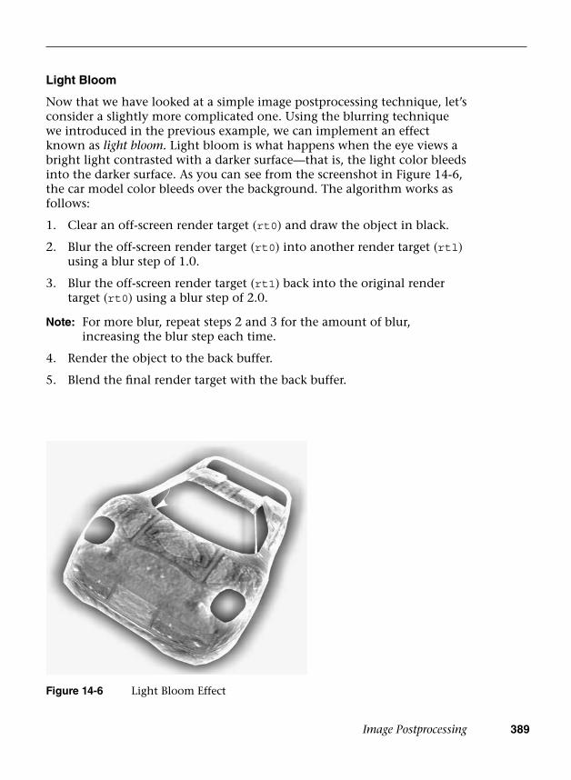
Image Postprocessing 389
Light Bloom
Now that we have looked at a simple image postprocessing technique, let’s consider a slightly more complicated one. Using the blurring technique we introduced in the previous example, we can implement an effect known as light bloom. Light bloom is what happens when the eye views a bright light contrasted with a darker surface—that is, the light color bleeds into the darker surface. As you can see from the screenshot in Figure 14-6, the car model color bleeds over the background. The algorithm works as follows:
1. Clear an off-screen render target (rt0) and draw the object in black.
2. Blur the off-screen render target (rt0) into another render target (rtl)using a blur step of 1.0.
3. Blur the off-screen render target (rt1) back into the original rendertarget (rt0) using a blur step of 2.0.
Note: For more blur, repeat steps 2 and 3 for the amount of blur, increasing the blur step each time.
4. Render the object to the back buffer.
5. Blend the final render target with the back buffer.
Figure 14-6 Light Bloom Effect
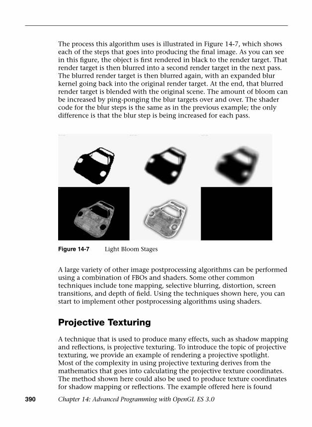
390 Chapter 14: Advanced Programming with OpenGL ES 3.0
The process this algorithm uses is illustrated in Figure 14-7, which shows each of the steps that goes into producing the final image. As you can see in this figure, the object is first rendered in black to the render target. That render target is then blurred into a second render target in the next pass. The blurred render target is then blurred again, with an expanded blur kernel going back into the original render target. At the end, that blurred render target is blended with the original scene. The amount of bloom can be increased by ping-ponging the blur targets over and over. The shader code for the blur steps is the same as in the previous example; the only difference is that the blur step is being increased for each pass.
Figure 14-7 Light Bloom Stages
A large variety of other image postprocessing algorithms can be performed using a combination of FBOs and shaders. Some other common techniques include tone mapping, selective blurring, distortion, screen transitions, and depth of field. Using the techniques shown here, you can start to implement other postprocessing algorithms using shaders.
Projective Texturing
A technique that is used to produce many effects, such as shadow mapping and reflections, is projective texturing. To introduce the topic of projective texturing, we provide an example of rendering a projective spotlight. Most of the complexity in using projective texturing derives from the mathematics that goes into calculating the projective texture coordinates. The method shown here could also be used to produce texture coordinates for shadow mapping or reflections. The example offered here is found
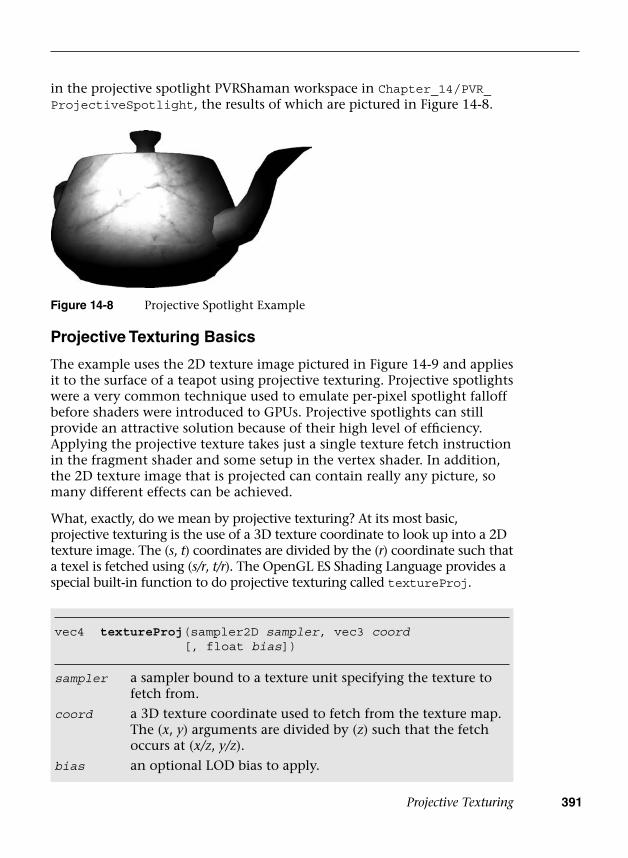
Projective Texturing 391
in the projective spotlight PVRShaman workspace in Chapter_14/PVR_ProjectiveSpotlight, the results of which are pictured in Figure 14-8.
Figure 14-8 Projective Spotlight Example
vec4 textureProj(sampler2D sampler, vec3 coord [, float bias])
sampler a sampler bound to a texture unit specifying the texture to fetch from.
coord a 3D texture coordinate used to fetch from the texture map.The (x, y) arguments are divided by (z) such that the fetch occurs at (x/z, y/z).
bias an optional LOD bias to apply.
Projective Texturing Basics
The example uses the 2D texture image pictured in Figure 14-9 and applies it to the surface of a teapot using projective texturing. Projective spotlights were a very common technique used to emulate per-pixel spotlight falloff before shaders were introduced to GPUs. Projective spotlights can still provide an attractive solution because of their high level of efficiency. Applying the projective texture takes just a single texture fetch instruction in the fragment shader and some setup in the vertex shader. In addition, the 2D texture image that is projected can contain really any picture, so many different effects can be achieved.
What, exactly, do we mean by projective texturing? At its most basic, projective texturing is the use of a 3D texture coordinate to look up into a 2D texture image. The (s, t) coordinates are divided by the (r) coordinate such that a texel is fetched using (s/r, t/r). The OpenGL ES Shading Language provides a special built-in function to do projective texturing called textureProj.
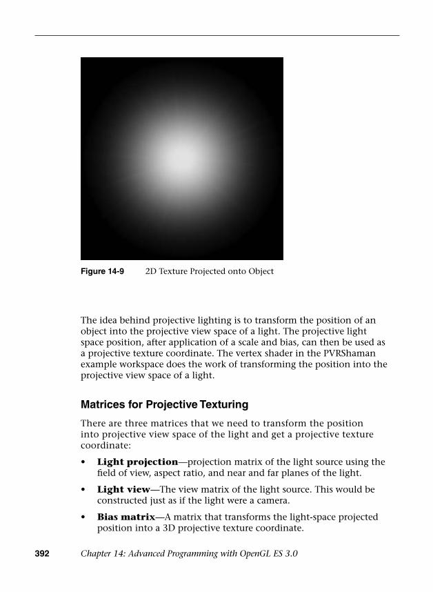
392 Chapter 14: Advanced Programming with OpenGL ES 3.0
The idea behind projective lighting is to transform the position of an object into the projective view space of a light. The projective light space position, after application of a scale and bias, can then be used as a projective texture coordinate. The vertex shader in the PVRShaman example workspace does the work of transforming the position into the projective view space of a light.
Matrices for Projective Texturing
There are three matrices that we need to transform the position into projective view space of the light and get a projective texture coordinate:
• Light projection—projection matrix of the light source using thefield of view, aspect ratio, and near and far planes of the light.
• Light view—The view matrix of the light source. This would beconstructed just as if the light were a camera.
• Bias matrix—A matrix that transforms the light-space projectedposition into a 3D projective texture coordinate.
Figure 14-9 2D Texture Projected onto Object
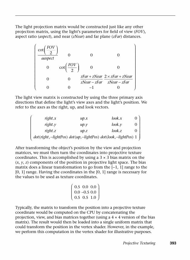
Projective Texturing 393
The light projection matrix would be constructed just like any other projection matrix, using the light’s parameters for field of view (FOV), aspect ratio (aspect), and near (zNear) and far plane (zFar) distances.
+−
× +−
−
FOV
aaspect
FOV
zFar zNearzNear zFar
zFar zNearzNear zFar
cot2 0 0 0
0 cot2
0 0
0 02
0 0 1 0
right x up x look x
right y up y look y
right z up z look z
dot right lightPos dot up lightPos dot look lightPos
. . . 0
. . . 0
. . . 0
( , ) ( , ) ( , ) 1− − −
−
0.5 0.0 0.00.0 0.5 0.00.5 0.5 1.0
The light view matrix is constructed by using the three primary axis directions that define the light’s view axes and the light’s position. We refer to the axes as the right, up, and look vectors.
After transforming the object’s position by the view and projection matrices, we must then turn the coordinates into projective texture coordinates. This is accomplished by using a 3 × 3 bias matrix on the (x, y, z) components of the position in projective light space. The bias matrix does a linear transformation to go from the [−1, 1] range to the [0, 1] range. Having the coordinates in the [0, 1] range is necessary for the values to be used as texture coordinates.
Typically, the matrix to transform the position into a projective texture coordinate would be computed on the CPU by concatenating the projection, view, and bias matrices together (using a 4 × 4 version of the bias matrix). The result would then be loaded into a single uniform matrix that could transform the position in the vertex shader. However, in the example, we perform this computation in the vertex shader for illustrative purposes.
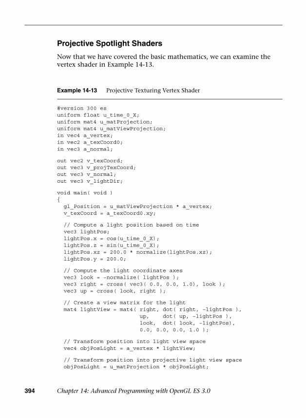
394 Chapter 14: Advanced Programming with OpenGL ES 3.0
Example 14-13 Projective Texturing Vertex Shader
#version 300 esuniform float u_time_0_X;uniform mat4 u_matProjection;uniform mat4 u_matViewProjection;in vec4 a_vertex;in vec2 a_texCoord0;in vec3 a_normal;
out vec2 v_texCoord;out vec3 v_projTexCoord;out vec3 v_normal;out vec3 v_lightDir;
void main( void ){ gl_Position = u_matViewProjection * a_vertex; v_texCoord = a_texCoord0.xy;
// Compute a light position based on time vec3 lightPos; lightPos.x = cos(u_time_0_X); lightPos.z = sin(u_time_0_X); lightPos.xz = 200.0 * normalize(lightPos.xz); lightPos.y = 200.0;
// Compute the light coordinate axes vec3 look = −normalize( lightPos ); vec3 right = cross( vec3( 0.0, 0.0, 1.0), look ); vec3 up = cross( look, right );
// Create a view matrix for the light mat4 lightView = mat4( right, dot( right, −lightPos ),
up, dot( up, −lightPos ),look, dot( look, −lightPos),0.0, 0.0, 0.0, 1.0 );
// Transform position into light view space vec4 objPosLight = a_vertex * lightView;
// Transform position into projective light view space objPosLight = u_matProjection * objPosLight;
Projective Spotlight Shaders
Now that we have covered the basic mathematics, we can examine the vertex shader in Example 14-13.
Projective Texturing 395
The first operation this shader does is to transform the position by the u_matViewProjection matrix and output the texture coordinate for the base map to the v_texCoord output variable. Next, the shader computes a position for the light based on time. This bit of the code can really be ignored, but it was added to animate the light in the vertex shader. In a typical application, this step would be done on the CPU and not in the shader.
Based on the position of the light, the vertex shader then computes the three coordinate axis vectors for the light and places the results into the look, right, and up variables. Those vectors are used to create a view matrix for the light in the lightView variable using the equations previously described. The input position for the object is then transformed by the lightView matrix, which transforms the position into light space. The next step is to use the perspective matrix to transform the light space position into projected light space. Rather than creating a new perspective matrix for the light, this example uses the u_matProjection matrix for the camera. Typically, a real application would want to create its own projection matrix for the light based on how big the cone angle and falloff distance are.
Once the position is transformed into projective light space, a biasMatrix is created to transform the position into a projective texture coordinate. The final projective texture coordinate is stored in the vec3 output variable v_projTexCoord. In addition, the vertex shader passes the light direction and normal vectors into the fragment shader in the v_lightDir and v_normal variables. These vectors will be used to determine whether a fragment is facing the light source so as to mask off the projective texture for fragments facing away from the light.
The fragment shader performs the actual projective texture fetch that applies the projective spotlight texture to the surface (Example 14-14).
// Create bias matrix mat3 biasMatrix = mat3( 0.5, 0.0, 0.5,
0.0, −0.5, 0.5,0.0, 0.0, 1.0 );
// Compute projective texture coordinates v_projTexCoord = objPosLight.xyz * biasMatrix;
v_lightDir = normalize(a_vertex.xyz − lightPos); v_normal = a_normal;}
Example 14-13 Projective Texturing Vertex Shader (continued)

396 Chapter 14: Advanced Programming with OpenGL ES 3.0
The first operation that the fragment shader performs is the projective texture fetch using textureProj. As you can see, the projective texture coordinate that was computed during the vertex shader and passed in the input variable v_projTexCoord is used to perform the projective texture fetch. The wrap modes for the projective texture are set to GL_CLAMP_TO_EDGE and the minification/magnification filters are both set to GL_LINEAR. The fragment shader then fetches the color from the base map using the v_texCoord variable. Next, the shader computes the dot product of the light direction and the normal vector; this result is used to attenuate the final color so that the projective spotlight is not applied to fragments that are facing away from the light. Finally, all of the components are multiplied together (and scaled by 2.0 to increase the brightness). This gives us the final image of the teapot lit by the projective spotlight (refer back to Figure 14-7).
As mentioned at the beginning of this section, the key takeaway lesson from this example is the set of computations that go into computing a projective texture coordinate. The computation shown here is the exact same computation that you would use to produce a coordinate to fetch
Example 14-14 Projective Texturing Fragment Shader
#version 300 esprecision mediump float;
uniform sampler2D baseMap;uniform sampler2D spotLight;in vec2 v_texCoord;in vec3 v_projTexCoord;in vec3 v_normal;in vec3 v_lightDir;out vec4 outColor;
void main( void ){ // Projective fetch of spotlight vec4 spotLightColor =
textureProj( spotLight, v_projTexCoord );
// Base map vec4 baseColor = texture( baseMap, v_texCoord );
// Compute N.L float nDotL = max( 0.0, −dot( v_normal, v_lightDir ) );
outColor = spotLightColor * baseColor * 2.0 * nDotL;}
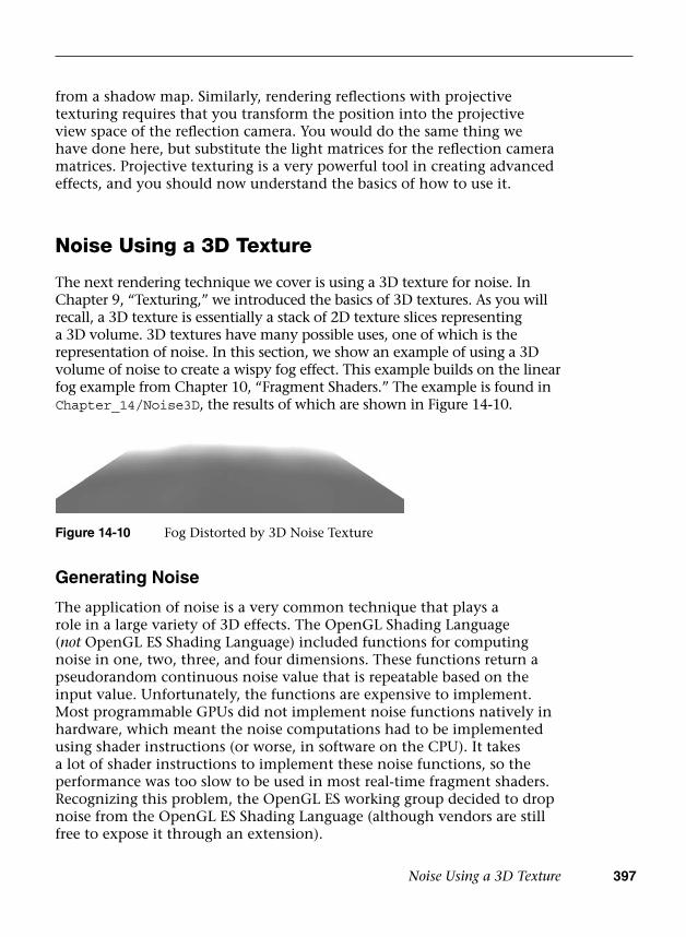
Noise Using a 3D Texture 397
from a shadow map. Similarly, rendering reflections with projective texturing requires that you transform the position into the projective view space of the reflection camera. You would do the same thing we have done here, but substitute the light matrices for the reflection camera matrices. Projective texturing is a very powerful tool in creating advanced effects, and you should now understand the basics of how to use it.
Noise Using a 3D Texture
The next rendering technique we cover is using a 3D texture for noise. In Chapter 9, “Texturing,” we introduced the basics of 3D textures. As you will recall, a 3D texture is essentially a stack of 2D texture slices representing a 3D volume. 3D textures have many possible uses, one of which is the representation of noise. In this section, we show an example of using a 3D volume of noise to create a wispy fog effect. This example builds on the linear fog example from Chapter 10, “Fragment Shaders.” The example is found in Chapter_14/Noise3D, the results of which are shown in Figure 14-10.
Figure 14-10 Fog Distorted by 3D Noise Texture
Generating Noise
The application of noise is a very common technique that plays a role in a large variety of 3D effects. The OpenGL Shading Language (not OpenGL ES Shading Language) included functions for computing noise in one, two, three, and four dimensions. These functions return a pseudorandom continuous noise value that is repeatable based on the input value. Unfortunately, the functions are expensive to implement. Most programmable GPUs did not implement noise functions natively in hardware, which meant the noise computations had to be implemented using shader instructions (or worse, in software on the CPU). It takes a lot of shader instructions to implement these noise functions, so the performance was too slow to be used in most real-time fragment shaders. Recognizing this problem, the OpenGL ES working group decided to drop noise from the OpenGL ES Shading Language (although vendors are still free to expose it through an extension).
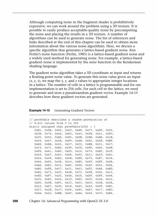
398 Chapter 14: Advanced Programming with OpenGL ES 3.0
Although computing noise in the fragment shader is prohibitively expensive, we can work around the problem using a 3D texture. It is possible to easily produce acceptable-quality noise by precomputing the noise and placing the results in a 3D texture. A number of algorithms can be used to generate noise. The list of references and links described at the end of this chapter can be used to obtain more information about the various noise algorithms. Here, we discuss a specific algorithm that generates a lattice-based gradient noise. Ken Perlin’s noise function (Perlin, 1985) is a lattice-based gradient noise and a widely used method for generating noise. For example, a lattice-based gradient noise is implemented by the noise function in the Renderman shading language.
The gradient noise algorithm takes a 3D coordinate as input and returns a floating-point noise value. To generate this noise value given an input (x, y, z), we map the x, y, and z values to appropriate integer locations in a lattice. The number of cells in a lattice is programmable and for our implementation is set to 256 cells. For each cell in the lattice, we need to generate and store a pseudorandom gradient vector. Example 14-15 describes how these gradient vectors are generated.
Example 14-15 Generating Gradient Vectors
// permTable describes a random permutation of// 8−bit values from 0 to 255static unsigned char permTable[256] = { 0xE1, 0x9B, 0xD2, 0x6C, 0xAF, 0xC7, 0xDD, 0x90, 0xCB, 0x74, 0x46, 0xD5, 0x45, 0x9E, 0x21, 0xFC, 0x05, 0x52, 0xAD, 0x85, 0xDE, 0x8B, 0xAE, 0x1B, 0x09, 0x47, 0x5A, 0xF6, 0x4B, 0x82, 0x5B, 0xBF, 0xA9, 0x8A, 0x02, 0x97, 0xC2, 0xEB, 0x51, 0x07, 0x19, 0x71, 0xE4, 0x9F, 0xCD, 0xFD, 0x86, 0x8E, 0xF8, 0x41, 0xE0, 0xD9, 0x16, 0x79, 0xE5, 0x3F, 0x59, 0x67, 0x60, 0x68, 0x9C, 0x11, 0xC9, 0x81, 0x24, 0x08, 0xA5, 0x6E, 0xED, 0x75, 0xE7, 0x38, 0x84, 0xD3, 0x98, 0x14, 0xB5, 0x6F, 0xEF, 0xDA, 0xAA, 0xA3, 0x33, 0xAC, 0x9D, 0x2F, 0x50, 0xD4, 0xB0, 0xFA, 0x57, 0x31, 0x63, 0xF2, 0x88, 0xBD, 0xA2, 0x73, 0x2C, 0x2B, 0x7C, 0x5E, 0x96, 0x10, 0x8D, 0xF7, 0x20, 0x0A, 0xC6, 0xDF, 0xFF, 0x48, 0x35, 0x83, 0x54, 0x39, 0xDC, 0xC5, 0x3A, 0x32, 0xD0, 0x0B, 0xF1, 0x1C, 0x03, 0xC0, 0x3E, 0xCA, 0x12, 0xD7, 0x99, 0x18, 0x4C, 0x29, 0x0F, 0xB3, 0x27, 0x2E, 0x37, 0x06, 0x80, 0xA7, 0x17, 0xBC, 0x6A, 0x22, 0xBB, 0x8C, 0xA4, 0x49, 0x70, 0xB6,
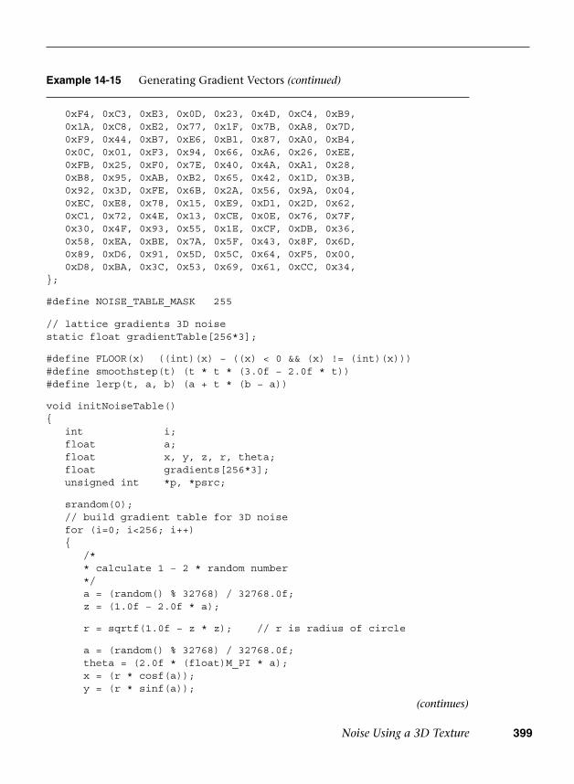
Noise Using a 3D Texture 399
0xF4, 0xC3, 0xE3, 0x0D, 0x23, 0x4D, 0xC4, 0xB9, 0x1A, 0xC8, 0xE2, 0x77, 0x1F, 0x7B, 0xA8, 0x7D, 0xF9, 0x44, 0xB7, 0xE6, 0xB1, 0x87, 0xA0, 0xB4, 0x0C, 0x01, 0xF3, 0x94, 0x66, 0xA6, 0x26, 0xEE, 0xFB, 0x25, 0xF0, 0x7E, 0x40, 0x4A, 0xA1, 0x28, 0xB8, 0x95, 0xAB, 0xB2, 0x65, 0x42, 0x1D, 0x3B, 0x92, 0x3D, 0xFE, 0x6B, 0x2A, 0x56, 0x9A, 0x04, 0xEC, 0xE8, 0x78, 0x15, 0xE9, 0xD1, 0x2D, 0x62, 0xC1, 0x72, 0x4E, 0x13, 0xCE, 0x0E, 0x76, 0x7F, 0x30, 0x4F, 0x93, 0x55, 0x1E, 0xCF, 0xDB, 0x36, 0x58, 0xEA, 0xBE, 0x7A, 0x5F, 0x43, 0x8F, 0x6D, 0x89, 0xD6, 0x91, 0x5D, 0x5C, 0x64, 0xF5, 0x00, 0xD8, 0xBA, 0x3C, 0x53, 0x69, 0x61, 0xCC, 0x34,};
#define NOISE_TABLE_MASK 255
// lattice gradients 3D noisestatic float gradientTable[256*3];
#define FLOOR(x) ((int)(x) − ((x) < 0 && (x) != (int)(x)))#define smoothstep(t) (t * t * (3.0f − 2.0f * t))#define lerp(t, a, b) (a + t * (b − a))
void initNoiseTable(){ int i; float a; float x, y, z, r, theta; float gradients[256*3]; unsigned int *p, *psrc;
srandom(0); // build gradient table for 3D noise for (i=0; i<256; i++) {
/** calculate 1 − 2 * random number*/a = (random() % 32768) / 32768.0f;z = (1.0f − 2.0f * a);
r = sqrtf(1.0f − z * z); // r is radius of circle
a = (random() % 32768) / 32768.0f;theta = (2.0f * (float)M_PI * a);x = (r * cosf(a));y = (r * sinf(a));
(continues)
Example 14-15 Generating Gradient Vectors (continued)
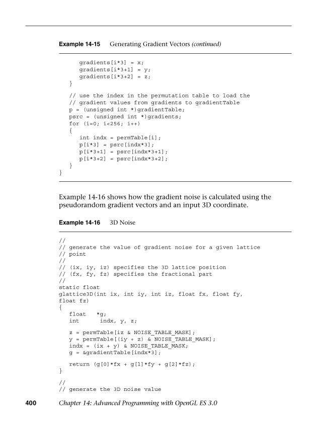
400 Chapter 14: Advanced Programming with OpenGL ES 3.0
Example 14-16 3D Noise
//// generate the value of gradient noise for a given lattice// point//// (ix, iy, iz) specifies the 3D lattice position// (fx, fy, fz) specifies the fractional part//static floatglattice3D(int ix, int iy, int iz, float fx, float fy,float fz){ float *g; int indx, y, z;
z = permTable[iz & NOISE_TABLE_MASK]; y = permTable[(iy + z) & NOISE_TABLE_MASK]; indx = (ix + y) & NOISE_TABLE_MASK; g = &gradientTable[indx*3];
return (g[0]*fx + g[l]*fy + g[2]*fz);}
//// generate the 3D noise value
Example 14-16 shows how the gradient noise is calculated using the pseudorandom gradient vectors and an input 3D coordinate.
gradients[i*3] = x;gradients[i*3+1] = y;gradients[i*3+2] = z;
}
// use the index in the permutation table to load the // gradient values from gradients to gradientTable p = (unsigned int *)gradientTable; psrc = (unsigned int *)gradients; for (i=0; i<256; i++) {
int indx = permTable[i];p[i*3] = psrc[indx*3];p[i*3+1] = psrc[indx*3+1];p[i*3+2] = psrc[indx*3+2];
}}
Example 14-15 Generating Gradient Vectors (continued)

Noise Using a 3D Texture 401
The noise3D function returns a value between −1.0 and 1.0. The value of gradient noise is always 0 at the integer lattice points. For points in between, trilinear interpolation of gradient values across the eight integer lattice points that surround the point is used to generate the scalar noise
// f describes input (x, y, z) position for which the noise value// needs to be computed. noise3D returns the scalar noise value//floatnoise3D(float *f){ int ix, iy, iz; float fxO, fxl, fyO, fyl, fzO, fzl; float wx, wy, wz; float vxO, vxl, vyO, vyl, vzO, vzl;
ix = FLOOR(f[0]); fxO = f[0] − ix; fxl = fxO − 1; wx = smoothstep(fxO);
iy = FLOOR(f[1]); fyO = f[1] − iy; fyl = fyO − 1; wy = smoothstep(fyO);
iz = FLOOR(f[2]); fzO = f[2] − iz; fzl = fzO − 1; wz = smoothstep(fzO);
vxO = glattice3D(ix, iy, iz, fxO, fyO, fzO); vxl = glattice3D(ix+1, iy, iz, fxl, fyO, fzO); vyO = lerp(wx, vxO, vxl); vxO = glattice3D(ix, iy+1, iz, fxO, fyl, fzO); vxl = glattice3D(ix+1, iy+1, iz, fxl, fyl, fzO); vyl = lerp(wx, vxO, vxl); vzO = lerp(wy, vyO, vyl);
vxO = glattice3D(ix, iy, iz+1, fxO, fyO, fzl); vxl = glattice3D(ix+1, iy, iz+1, fxl, fyO, fzl); vyO = lerp(wx, vxO, vxl); vxO = glattice3D(ix, iy+1, iz+1, fxO, fyl, fzl); vxl = glattice3D(ix+1, iy+1, iz+1, fxl, fyl, fzl); vyl = lerp(wx, vxO, vxl); vzl = lerp(wy, vyO, vyl);
return lerp(wz, vzO, vzl);;}
Example 14-16 3D Noise (continued)
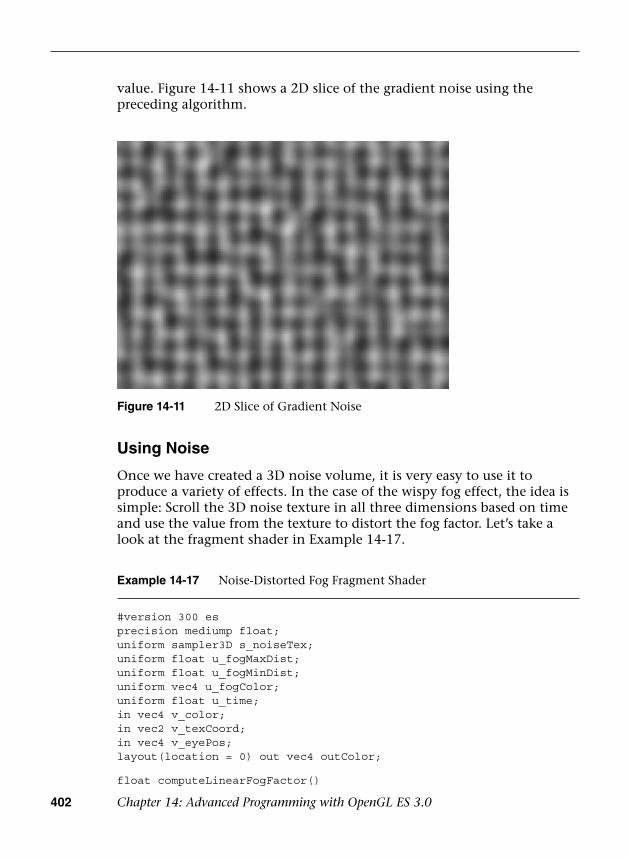
402 Chapter 14: Advanced Programming with OpenGL ES 3.0
value. Figure 14-11 shows a 2D slice of the gradient noise using the preceding algorithm.
Example 14-17 Noise-Distorted Fog Fragment Shader
#version 300 esprecision mediump float;uniform sampler3D s_noiseTex;uniform float u_fogMaxDist;uniform float u_fogMinDist;uniform vec4 u_fogColor;uniform float u_time;in vec4 v_color;in vec2 v_texCoord;in vec4 v_eyePos;layout(location = 0) out vec4 outColor;
float computeLinearFogFactor()
Figure 14-11 2D Slice of Gradient Noise
Using Noise
Once we have created a 3D noise volume, it is very easy to use it to produce a variety of effects. In the case of the wispy fog effect, the idea is simple: Scroll the 3D noise texture in all three dimensions based on time and use the value from the texture to distort the fog factor. Let’s take a look at the fragment shader in Example 14-17.
Noise Using a 3D Texture 403
This shader is very similar to our linear fog example in Chapter 10, “Fragment Shaders.” The primary difference is that the linear fog factor is distorted by the 3D noise texture. The shader computes a 3D texture coordinate based on time and places it in noiseCoord. The u_time uniform variable is tied to the current time and is updated each frame. The 3D texture is set up with s, t, and r wrap modes of GL_MIRRORED_REPEAT so that the noise volume scrolls smoothly on the surface. The (s, t) coordinates are based on the coordinates for the base texture and scroll in both directions. The r-coordinate is based purely on time; thus it is continuously scrolled.
The 3D texture is a single-channel (GL_R8) texture, so only the red component of the texture is used (the green and blue channels have the same value as the red channel). The value fetched from the volume is subtracted from the computed fogFactor and then used to linearly interpolate between the fog color and base color. The result is a wispy fog that appears to roll in from a distance. Its speed can be increased easily by applying a scale to the u_time variable when scrolling the 3D texture coordinates.
You can achieve a number of different effects by using a 3D texture to represent noise. For example, you can use noise to represent dust in a
{ float factor; // Compute linear fog equation float dist = distance( v_eyePos,
vec4( 0.0, 0.0, 0.0, 1.0 ) ); factor = (u_fogMaxDist − dist) /
(u_fogMaxDist − u_fogMinDist ); // Clamp in the [0, 1] range factor = clamp( factor, 0.0, 1.0 ); return factor;}
void main( void ){ float fogFactor = computeLinearFogFactor(); vec3 noiseCoord = vec3( v_texCoord.xy + u_time, u_time ); fogFactor −= texture(s_noiseTex, noiseCoord).r * 0.25; fogFactor = clamp(fogFactor, 0.0, 1.0); vec4 baseColor = v_color; outColor = baseColor * fogFactor +
u_fogColor * (1.0 − fogFactor);}
Example 14-17 Noise-Distorted Fog Fragment Shader (continued)
404 Chapter 14: Advanced Programming with OpenGL ES 3.0
light volume, add a more natural appearance to a procedural texture, and simulate water waves. Applying a 3D texture is a great way to economize on performance, yet still achieve high-quality visual effects. It is unlikely that you can expect handheld devices to compute noise functions in the fragment shader and have enough performance to run at a high frame rate. As such, having a precomputed noise volume will be a very valuable trick to have in your toolkit for creating effects.
Procedural Texturing
The next topic we cover is the generation of procedural textures. Textures are typically described as a 2D image, a cubemap, or a 3D image. These images store color or depth values. Built-in functions defined in the OpenGL ES Shading Language take a texture coordinate, a texture object referred to as a sampler, and return a color or depth value. Procedural texturing refers to textures that are described as a procedure instead of as an image. The procedure describes the algorithm that will generate a texture color or depth value given a set of inputs.
The following are some of the benefits of procedural textures:
• They provide much more compact representation than a stored textureimage. All you need to store is the code that describes the proceduraltexture, which will typically be much smaller in size than a stored image.
• Procedural textures, unlike stored images, have no fixed resolution.As a consequence, they can be applied to the surface without loss ofdetail. Thus we will not see problematic issues such as reduced detailas we zoom onto a surface that uses a procedural texture. We will,however, encounter these issues when using a stored texture imagebecause of its fixed resolution.
The disadvantages of procedural textures are as follows:
• Although the procedural texture might have a smaller footprintthan a stored texture, it might take a lot more cycles to execute theprocedural texture versus doing a lookup in the stored texture. Withprocedural textures, you are dealing with instruction bandwidth,versus memory bandwidth for stored textures. Both the instructionand memory bandwidth are at a premium on handheld devices, and adeveloper must carefully choose which approach to take.
• Procedural textures can lead to serious aliasing artifacts. Althoughmost of these artifacts can be resolved, they result in additionalinstructions to the procedural texture code, which can impact theperformance of a shader.
Procedural Texturing 405
The decision whether to use a procedural texture or a stored texture should be based on careful analysis of the performance and memory bandwidth requirements of each.
A Procedural Texture Example
We now look at a simple example that demonstrates procedural textures. We are familiar with how to use a checkerboard texture image to draw a checkerboard pattern on an object. We now look at a procedural texture implementation that renders a checkerboard pattern on an object. The example we cover is the Checker.pod PVRShaman workspace in Chapter_14/PVR_ProceduralTextures. Examples 14-18 and 14-19 describe the vertex and fragment shaders that implement the checkerboard texture procedurally.
Example 14-18 Checker Vertex Shader
#version 300 esuniform mat4 mvp_matrix; // combined model−view
// + projection matrix
in vec4 a_position; // input vertex positionin vec2 a_st; // input texture coordinateout vec2 v_st; // output texture coordinate
void main(){ v_st = a_st; gl_Position = mvp_matrix * a_position;}
The vertex shader code in Example 14-18 is really straightforward. It transforms the position using the combined model–view and projection matrix and passes the texture coordinate (a_st) to the fragment shader as a varying variable (v_st).
The fragment shader code in Example 14-19 uses the v_st texture coordinate to draw the texture pattern. Although easy to understand, the fragment shader might yield poor performance because of the multiple conditional checks done on values that can differ over fragments being executed in parallel. This can diminish performance, as the number of vertices or fragments executed in parallel by the GPU is reduced. Example 14-20 is a version of the fragment shader that omits any conditional checks.
Figure 14-12 shows the checkerboard image rendered using the fragment shader in Example 14-17 with u_frequency = 10.
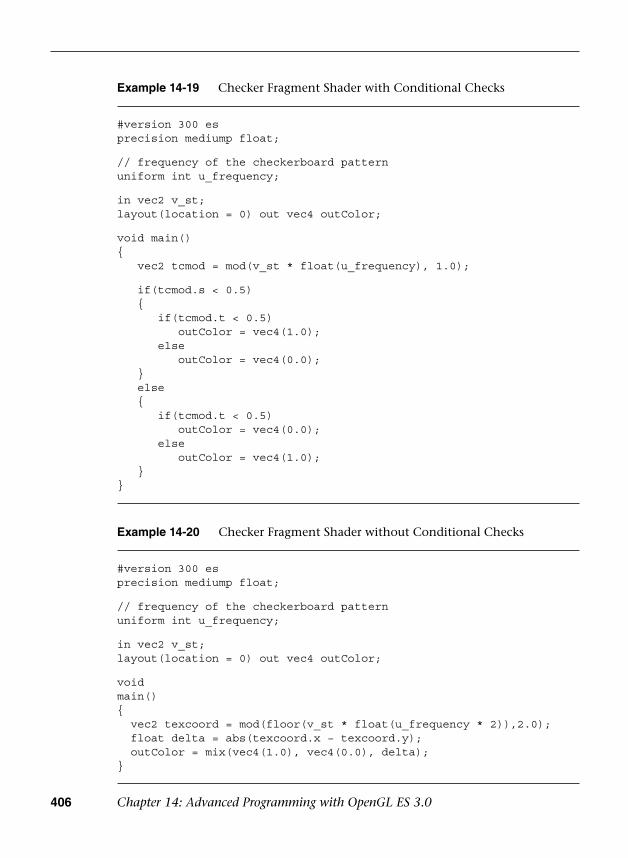
406 Chapter 14: Advanced Programming with OpenGL ES 3.0
Example 14-20 Checker Fragment Shader without Conditional Checks
#version 300 esprecision mediump float;
// frequency of the checkerboard patternuniform int u_frequency;
in vec2 v_st;layout(location = 0) out vec4 outColor;
voidmain(){ vec2 texcoord = mod(floor(v_st * float(u_frequency * 2)),2.0); float delta = abs(texcoord.x − texcoord.y); outColor = mix(vec4(1.0), vec4(0.0), delta);}
Example 14-19 Checker Fragment Shader with Conditional Checks
#version 300 esprecision mediump float;
// frequency of the checkerboard patternuniform int u_frequency;
in vec2 v_st;layout(location = 0) out vec4 outColor;
void main(){ vec2 tcmod = mod(v_st * float(u_frequency), 1.0);
if(tcmod.s < 0.5) {
if(tcmod.t < 0.5)outColor = vec4(1.0);
elseoutColor = vec4(0.0);
} else {
if(tcmod.t < 0.5)outColor = vec4(0.0);
elseoutColor = vec4(1.0);
}}

Procedural Texturing 407
Figure 14-12 Checkerboard Procedural Texture
As you can see, this was really easy to implement. We do see quite a bit of aliasing, which is never acceptable. With a texture checkerboard image, aliasing issues are overcome by using mipmapping and applying preferably a trilinear or bilinear filter. We now look at how to render an anti-aliased checkerboard pattern.
Anti-Aliasing of Procedural Textures
In Advanced RenderMan: Creating CGI for Motion Pictures, Anthony Apodaca and Larry Gritz give a very thorough explanation of how to implement analytic anti-aliasing of procedural textures. We use the techniques described in this book to implement our anti-aliased checker fragment shader. Example 14-21 describes the anti-aliased checker fragment shader code from the CheckerAA.rfx PVR_Shaman workspace in Chapter_14/PVR_ProceduralTextures.
Example 14-21 Anti-Aliased Checker Fragment Shader
#version 300 esprecision mediump float;
uniform int u_frequency;in vec2 v_st;layout(location = 0) out vec4 outColor;
(continues)
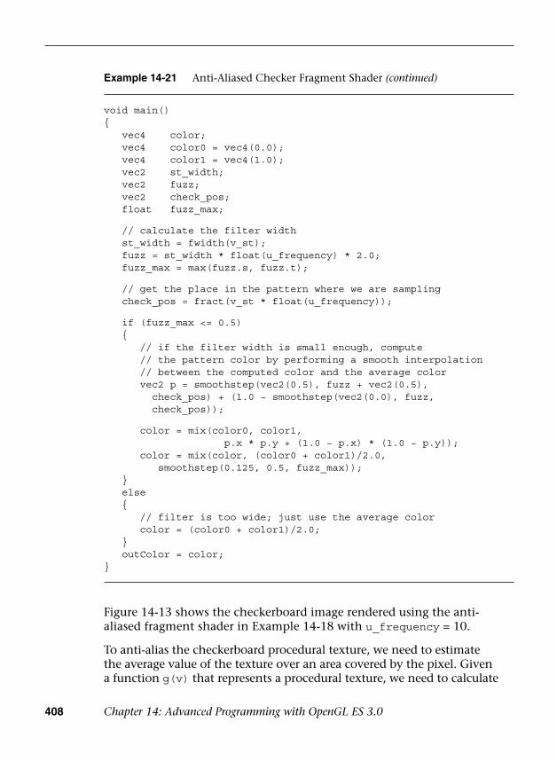
408 Chapter 14: Advanced Programming with OpenGL ES 3.0
Figure 14-13 shows the checkerboard image rendered using the anti-aliased fragment shader in Example 14-18 with u_frequency = 10.
To anti-alias the checkerboard procedural texture, we need to estimate the average value of the texture over an area covered by the pixel. Given a function g(v) that represents a procedural texture, we need to calculate
Example 14-21 Anti-Aliased Checker Fragment Shader (continued)
void main(){ vec4 color; vec4 color0 = vec4(0.0); vec4 color1 = vec4(1.0); vec2 st_width; vec2 fuzz; vec2 check_pos; float fuzz_max;
// calculate the filter width st_width = fwidth(v_st); fuzz = st_width * float(u_frequency) * 2.0; fuzz_max = max(fuzz.s, fuzz.t);
// get the place in the pattern where we are sampling check_pos = fract(v_st * float(u_frequency));
if (fuzz_max <= 0.5) {
// if the filter width is small enough, compute// the pattern color by performing a smooth interpolation// between the computed color and the average colorvec2 p = smoothstep(vec2(0.5), fuzz + vec2(0.5),
check_pos) + (1.0 − smoothstep(vec2(0.0), fuzz,check_pos));
color = mix(color0, color1,p.x * p.y + (1.0 − p.x) * (1.0 − p.y));
color = mix(color, (color0 + color1)/2.0,smoothstep(0.125, 0.5, fuzz_max));
} else {
// filter is too wide; just use the average colorcolor = (color0 + color1)/2.0;
} outColor = color;}
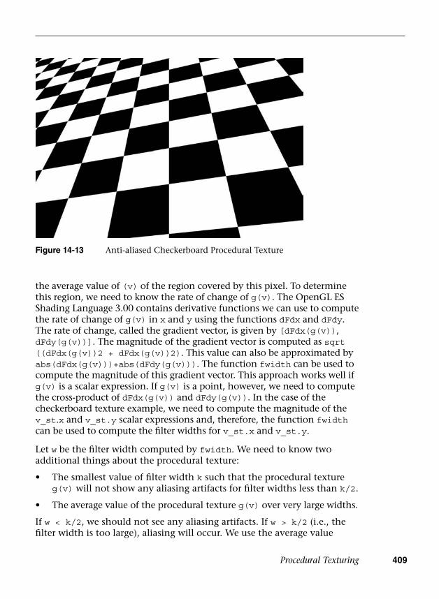
Procedural Texturing 409
the average value of (v) of the region covered by this pixel. To determine this region, we need to know the rate of change of g(v). The OpenGL ES Shading Language 3.00 contains derivative functions we can use to compute the rate of change of g(v) in x and y using the functions dFdx and dFdy. The rate of change, called the gradient vector, is given by [dFdx(g(v)), dFdy(g(v))]. The magnitude of the gradient vector is computed as sqrt ((dFdx(g(v))2 + dFdx(g(v))2). This value can also be approximated by abs(dFdx(g(v)))+abs(dFdy(g(v))). The function fwidth can be used to compute the magnitude of this gradient vector. This approach works well if g(v) is a scalar expression. If g(v) is a point, however, we need to compute the cross-product of dFdx(g(v)) and dFdy(g(v)). In the case of the checkerboard texture example, we need to compute the magnitude of the v_st.x and v_st.y scalar expressions and, therefore, the function fwidth can be used to compute the filter widths for v_st.x and v_st.y.
Let w be the filter width computed by fwidth. We need to know two additional things about the procedural texture:
• The smallest value of filter width k such that the procedural textureg(v) will not show any aliasing artifacts for filter widths less than k/2.
• The average value of the procedural texture g(v) over very large widths.
If w < k/2, we should not see any aliasing artifacts. If w > k/2 (i.e., the filter width is too large), aliasing will occur. We use the average value
Figure 14-13 Anti-aliased Checkerboard Procedural Texture
410 Chapter 14: Advanced Programming with OpenGL ES 3.0
of g(v) in this case. For other values of w, we use a smoothstep to fade between the true function and average values. The full definition of the smoothstep built-in function is provided in Appendix B.
This discussion should have provided you with good insight into how to use procedural textures and how to resolve aliasing artifacts that become apparent when you are using procedural textures. The generation of procedural textures for many different applications is a very broad subject. The following list of references is a good place to start if you are interested in finding more information about procedural texture generation.
Further Reading on Procedural Textures
1. Anthony A. Apodaca and Larry Gritz. Advanced Renderman: CreatingCGI for Motion Pictures (Morgan Kaufmann, 1999).
2. David S. Ebert, F. Kenton Musgrave, Darwyn Peachey, Ken Perlin, andSteven Worley. Texturing and Modeling: A Procedural Approach, 3rd ed.(Morgan Kaufmann, 2002).
3. K. Perlin. An image synthesizer. Computer Graphics (SIGGRAPH 1985Proceedings, pp. 287–296, July 1985).
4. K. Perlin. Improving noise. Computer Graphics (SIGGRAPH 2002Proceedings, pp. 681–682).
5. K. Perlin. Making noise. noisemachine.com/talkl/.
6. Pixar. The Renderman interface specification, version 3.2. July 2000.renderman.pixar.com/products/rispec/index.htm.
7. Randi J. Rost. OpenGL Shading Language, 2nd ed. (Addison-WesleyProfessional, 2006).
Rendering Terrain with Vertex Texture Fetch
The next topic we cover is rendering terrain with the vertex texture fetch feature in OpenGL ES 3.0. In this example, we show how to render a terrain using a height map, as shown in Figure 14-14.
Our terrain rendering example consists of two steps:
1. Generate a square grid for the terrain base.
2. Compute a vertex normal and fetch height values from the heightmap in the vertex shader.

Rendering Terrain with Vertex Texture Fetch 411
Figure 14-14 Terrain Rendered with Vertex Texture Fetch
Example 14-22 Terrain Rendering Flat Grid Generation
int ESUTIL_API esGenSquareGrid ( int size, GLfloat **vertices,GLuint **indices )
{ int i, j; int numIndices = (size−1) * (size−1) * 2 * 3;
// Allocate memory for buffers if ( vertices != NULL ) {
int numVertices = size * size;float stepSize = (float) size − 1; *vertices = malloc ( sizeof(GLfloat) * 3 * numVertices );
for ( i = 0; i < size; ++i ) // row{
for ( j = 0; j < size; ++j ) // column{
(*vertices)[ 3 * (j + i*size) ] = i / stepSize;(*vertices)[ 3 * (j + i*size) + 1 ] = j / stepSize;(*vertices)[ 3 * (j + i*size) + 2 ] = 0.0f;
}}
}
(continues)
Generating a Square Terrain Grid
The code in Example 14-22 generates a square triangle grid that we use as the base terrain.

412 Chapter 14: Advanced Programming with OpenGL ES 3.0
First, we generate the vertex position as a regularly spaced xy-coordinate in the [0, 1] range. The same xy-value can also be used as the vertex texture coordinate to look up the height value from the height map.
Second, we generate a list of indices for GL_TRIANGLES. A better method is to generate a list of indices for GL_TRIANGLE_STRIP, as you can improve the rendering performance by improving the vertex cache locality in the GPU.
Computing Vertex Normal and Fetching Height Value in Vertex Shader
Example 14-23 shows how to compute vertex normals and fetch height values from a height map in a vertex shader.
Example 14-23 Terrain Rendering Vertex Shader
#version 300 esuniform mat4 u_mvpMatrix;uniform vec3 u_lightDirection;layout(location = 0) in vec4 a_position;
Example 14-22 Terrain Rendering Flat Grid Generation (continued)
// Generate the indices if ( indices != NULL ) {
*indices = malloc ( sizeof(GLuint) * numIndices );
for ( i = 0; i < size − 1; ++i ) {
for ( j = 0; j < size − 1; ++j ){
// two triangles per quad(*indices)[ 6*(j+i*(size−1)) ] = j+(i) *(size) ;(*indices)[ 6*(j+i*(size−1))+1 ] = j+(i) *(size)+1 ;(*indices)[ 6*(j+i*(size−1))+2 ] = j+(i+1)*(size)+1 ;
(*indices)[ 6*(j+i*(size−1))+3 ] = j+(i) *(size) ;(*indices)[ 6*(j+i*(size−1))+4 ] = j+(i+1)*(size)+1 ;(*indices)[ 6*(j+i*(size−1))+5 ] = j+(i+1)*(size) ;
} }
}
return numIndices;}
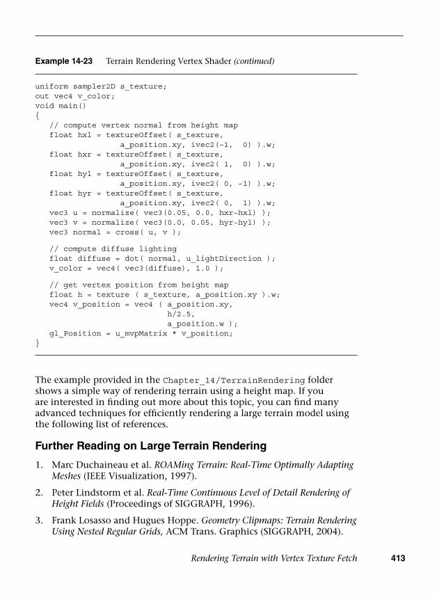
Rendering Terrain with Vertex Texture Fetch 413
The example provided in the Chapter_14/TerrainRendering folder shows a simple way of rendering terrain using a height map. If you are interested in finding out more about this topic, you can find many advanced techniques for efficiently rendering a large terrain model using the following list of references.
Further Reading on Large Terrain Rendering
1. Marc Duchaineau et al. ROAMing Terrain: Real-Time Optimally AdaptingMeshes (IEEE Visualization, 1997).
2. Peter Lindstorm et al. Real-Time Continuous Level of Detail Rendering ofHeight Fields (Proceedings of SIGGRAPH, 1996).
3. Frank Losasso and Hugues Hoppe. Geometry Clipmaps: Terrain RenderingUsing Nested Regular Grids, ACM Trans. Graphics (SIGGRAPH, 2004).
uniform sampler2D s_texture;out vec4 v_color;void main(){ // compute vertex normal from height map float hxl = textureOffset( s_texture,
a_position.xy, ivec2(−1, 0) ).w; float hxr = textureOffset( s_texture,
a_position.xy, ivec2( 1, 0) ).w; float hyl = textureOffset( s_texture,
a_position.xy, ivec2( 0, −1) ).w; float hyr = textureOffset( s_texture,
a_position.xy, ivec2( 0, 1) ).w; vec3 u = normalize( vec3(0.05, 0.0, hxr−hxl) ); vec3 v = normalize( vec3(0.0, 0.05, hyr−hyl) ); vec3 normal = cross( u, v );
// compute diffuse lighting float diffuse = dot( normal, u_lightDirection ); v_color = vec4( vec3(diffuse), 1.0 );
// get vertex position from height map float h = texture ( s_texture, a_position.xy ).w; vec4 v_position = vec4 ( a_position.xy,
h/2.5,a_position.w );
gl_Position = u_mvpMatrix * v_position;}
Example 14-23 Terrain Rendering Vertex Shader (continued)
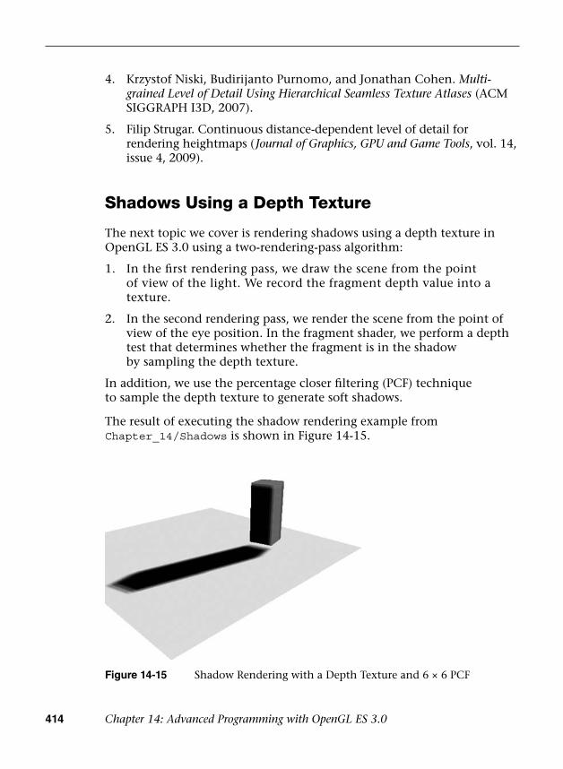
414 Chapter 14: Advanced Programming with OpenGL ES 3.0
4. Krzystof Niski, Budirijanto Purnomo, and Jonathan Cohen. Multi-grained Level of Detail Using Hierarchical Seamless Texture Atlases (ACMSIGGRAPH I3D, 2007).
5. Filip Strugar. Continuous distance-dependent level of detail forrendering heightmaps ( Journal of Graphics, GPU and Game Tools, vol. 14,issue 4, 2009).
Shadows Using a Depth Texture
The next topic we cover is rendering shadows using a depth texture in OpenGL ES 3.0 using a two-rendering-pass algorithm:
1. In the first rendering pass, we draw the scene from the pointof view of the light. We record the fragment depth value into atexture.
2. In the second rendering pass, we render the scene from the point ofview of the eye position. In the fragment shader, we perform a depthtest that determines whether the fragment is in the shadowby sampling the depth texture.
In addition, we use the percentage closer filtering (PCF) technique to sample the depth texture to generate soft shadows.
The result of executing the shadow rendering example from Chapter_14/Shadows is shown in Figure 14-15.
Figure 14-15 Shadow Rendering with a Depth Texture and 6 × 6 PCF
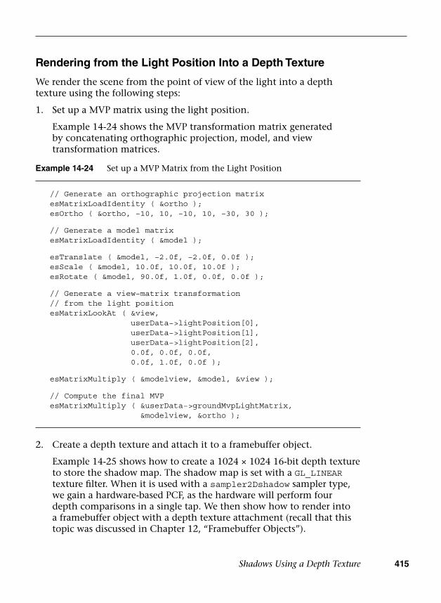
Shadows Using a Depth Texture 415
Example 14-24 Set up a MVP Matrix from the Light Position
// Generate an orthographic projection matrix esMatrixLoadIdentity ( &ortho ); esOrtho ( &ortho, −10, 10, −10, 10, −30, 30 );
// Generate a model matrix esMatrixLoadIdentity ( &model );
esTranslate ( &model, −2.0f, −2.0f, 0.0f ); esScale ( &model, 10.0f, 10.0f, 10.0f ); esRotate ( &model, 90.0f, 1.0f, 0.0f, 0.0f );
// Generate a view−matrix transformation // from the light position esMatrixLookAt ( &view,
userData−>lightPosition[0],userData−>lightPosition[1],userData−>lightPosition[2],0.0f, 0.0f, 0.0f,0.0f, 1.0f, 0.0f );
esMatrixMultiply ( &modelview, &model, &view );
// Compute the final MVP esMatrixMultiply ( &userData−>groundMvpLightMatrix,
&modelview, &ortho );
Rendering from the Light Position Into a Depth Texture
We render the scene from the point of view of the light into a depth texture using the following steps:
1. Set up a MVP matrix using the light position.
Example 14-24 shows the MVP transformation matrix generatedby concatenating orthographic projection, model, and viewtransformation matrices.
2. Create a depth texture and attach it to a framebuffer object.
Example 14-25 shows how to create a 1024 × 1024 16-bit depth textureto store the shadow map. The shadow map is set with a GL_LINEARtexture filter. When it is used with a sampler2Dshadow sampler type,we gain a hardware-based PCF, as the hardware will perform fourdepth comparisons in a single tap. We then show how to render intoa framebuffer object with a depth texture attachment (recall that thistopic was discussed in Chapter 12, “Framebuffer Objects”).
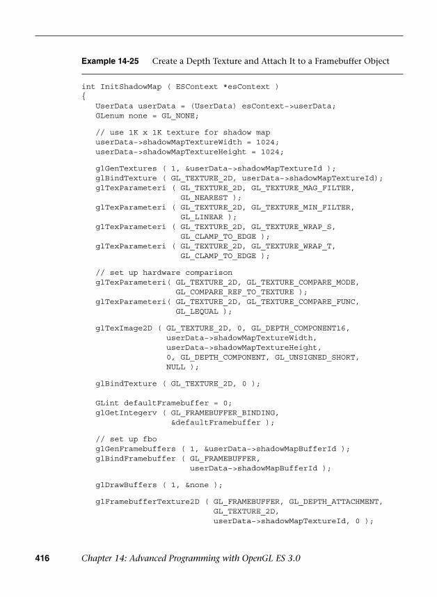
416 Chapter 14: Advanced Programming with OpenGL ES 3.0
Example 14-25 Create a Depth Texture and Attach It to a Framebuffer Object
int InitShadowMap ( ESContext *esContext ){ UserData userData = (UserData) esContext−>userData; GLenum none = GL_NONE;
// use 1K x 1K texture for shadow map userData−>shadowMapTextureWidth = 1024; userData−>shadowMapTextureHeight = 1024;
glGenTextures ( 1, &userData−>shadowMapTextureId ); glBindTexture ( GL_TEXTURE_2D, userData−>shadowMapTextureId); glTexParameteri ( GL_TEXTURE_2D, GL_TEXTURE_MAG_FILTER,
GL_NEAREST ); glTexParameteri ( GL_TEXTURE_2D, GL_TEXTURE_MIN_FILTER,
GL_LINEAR ); glTexParameteri ( GL_TEXTURE_2D, GL_TEXTURE_WRAP_S,
GL_CLAMP_TO_EDGE ); glTexParameteri ( GL_TEXTURE_2D, GL_TEXTURE_WRAP_T,
GL_CLAMP_TO_EDGE );
// set up hardware comparison glTexParameteri( GL_TEXTURE_2D, GL_TEXTURE_COMPARE_MODE,
GL_COMPARE_REF_TO_TEXTURE ); glTexParameteri( GL_TEXTURE_2D, GL_TEXTURE_COMPARE_FUNC,
GL_LEQUAL );
glTexImage2D ( GL_TEXTURE_2D, 0, GL_DEPTH_COMPONENT16,userData−>shadowMapTextureWidth,userData−>shadowMapTextureHeight,0, GL_DEPTH_COMPONENT, GL_UNSIGNED_SHORT,NULL );
glBindTexture ( GL_TEXTURE_2D, 0 );
GLint defaultFramebuffer = 0; glGetIntegerv ( GL_FRAMEBUFFER_BINDING,
&defaultFramebuffer );
// set up fbo glGenFramebuffers ( 1, &userData−>shadowMapBufferId ); glBindFramebuffer ( GL_FRAMEBUFFER,
userData−>shadowMapBufferId );
glDrawBuffers ( 1, &none );
glFramebufferTexture2D ( GL_FRAMEBUFFER, GL_DEPTH_ATTACHMENT,GL_TEXTURE_2D,userData−>shadowMapTextureId, 0 );
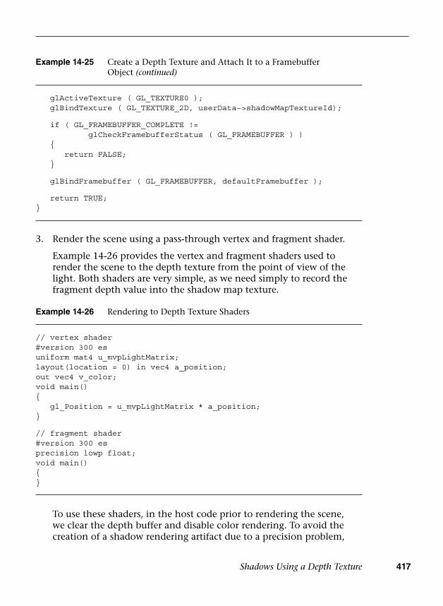
Shadows Using a Depth Texture 417
3. Render the scene using a pass-through vertex and fragment shader.
Example 14-26 provides the vertex and fragment shaders used torender the scene to the depth texture from the point of view of thelight. Both shaders are very simple, as we need simply to record thefragment depth value into the shadow map texture.
Example 14-26 Rendering to Depth Texture Shaders
// vertex shader#version 300 esuniform mat4 u_mvpLightMatrix;layout(location = 0) in vec4 a_position;out vec4 v_color;void main(){ gl_Position = u_mvpLightMatrix * a_position;}
// fragment shader#version 300 esprecision lowp float;void main(){}
To use these shaders, in the host code prior to rendering the scene, we clear the depth buffer and disable color rendering. To avoid the creation of a shadow rendering artifact due to a precision problem,
glActiveTexture ( GL_TEXTURE0 ); glBindTexture ( GL_TEXTURE_2D, userData−>shadowMapTextureId);
if ( GL_FRAMEBUFFER_COMPLETE !=glCheckFramebufferStatus ( GL_FRAMEBUFFER ) )
{return FALSE;
}
glBindFramebuffer ( GL_FRAMEBUFFER, defaultFramebuffer );
return TRUE;}
Example 14-25 Create a Depth Texture and Attach It to a Framebuffer Object (continued)
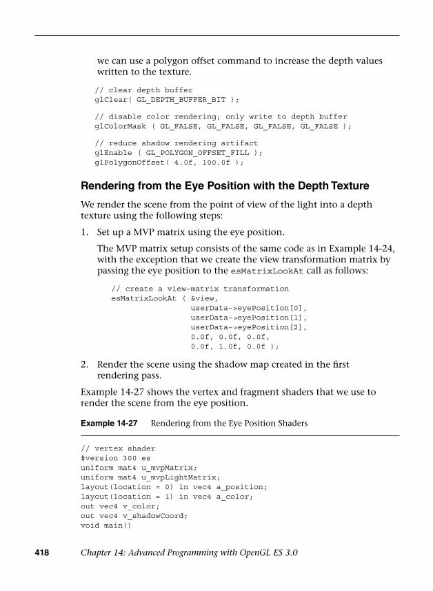
418 Chapter 14: Advanced Programming with OpenGL ES 3.0
we can use a polygon offset command to increase the depth values written to the texture.
// clear depth buffer glClear( GL_DEPTH_BUFFER_BIT );
// disable color rendering; only write to depth buffer glColorMask ( GL_FALSE, GL_FALSE, GL_FALSE, GL_FALSE );
// reduce shadow rendering artifact glEnable ( GL_POLYGON_OFFSET_FILL ); glPolygonOffset( 4.0f, 100.0f );
Rendering from the Eye Position with the Depth Texture
We render the scene from the point of view of the light into a depth texture using the following steps:
1. Set up a MVP matrix using the eye position.
The MVP matrix setup consists of the same code as in Example 14-24,with the exception that we create the view transformation matrix bypassing the eye position to the esMatrixLookAt call as follows:
// create a view−matrix transformation esMatrixLookAt ( &view,
userData−>eyePosition[0],userData−>eyePosition[1],userData−>eyePosition[2],0.0f, 0.0f, 0.0f,0.0f, 1.0f, 0.0f );
2. Render the scene using the shadow map created in the firstrendering pass.
Example 14-27 shows the vertex and fragment shaders that we use to render the scene from the eye position.
Example 14-27 Rendering from the Eye Position Shaders
// vertex shader#version 300 esuniform mat4 u_mvpMatrix;uniform mat4 u_mvpLightMatrix;layout(location = 0) in vec4 a_position;layout(location = 1) in vec4 a_color;out vec4 v_color;out vec4 v_shadowCoord;void main()

Shadows Using a Depth Texture 419
In the vertex shader, we transform the vertex position twice: (1) using the MVP matrix created from the eye position and (2) using the MVP matrix created from the light position. The former result is recorded into gl_Position, while the latter result is recorded into v_shadowCoord. Note that the v_shadowCoord result is exactly the same vertex position result when we render to the shadow map. Armed with this knowledge,
{ v_color = a_color; gl_Position = u_mvpMatrix * a_position; v_shadowCoord = u_mvpLightMatrix * a_position;
// transform from [−1,1] to [0,1]; v_shadowCoord = v_shadowCoord * 0.5 + 0.5;}
// fragment shader#version 300 esprecision lowp float;uniform lowp sampler2DShadow s_shadowMap;in vec4 v_color;in vec4 v_shadowCoord;layout(location = 0) out vec4 outColor;
float lookup ( float x, float y ){ float pixelSize = 0.002; // 1/500 vec4 offset = vec4 ( x * pixelSize * v_shadowCoord.w,
y * pixelSize * v_shadowCoord.w,0.0, 0.0 );
return textureProj ( s_shadowMap, v_shadowCoord + offset );}
void main(){ // 3x3 kernel with 4 taps per sample, effectively 6x6 PCF float sum = 0.0; float x, y; for ( x = −2.0; x <= 2.0; x += 2.0 )
for ( y = −2.0; y <= 2.0; y += 2.0 )sum += lookup ( x, y );
// divide sum by 9.0 sum = sum * 0.11; outColor = v_color * sum;}
Example 14-27 Rendering from the Eye Position Shaders (continued)

420 Chapter 14: Advanced Programming with OpenGL ES 3.0
we can use the v_shadowCoord as the texture coordinate to sample into the shadow map by first transforming the coordinate from homogeneous coordinate [–1, 1] space into [0, 1] space in the vertex shader. Alternatively, we can avoid performing these calculations in the vertex shader by pre-multiplying the MVP matrix from the light position with the following bias matrix in the host code:
0.5, 0.0, 0.0, 0.0, 0.0, 0.5, 0.0, 0.0, 0.0, 0.0, 0.5, 0.0, 0.5, 0.5, 0.5, 1.0
In the fragment shader, we check the current fragment to determine whether it is in the shadow by sampling the shadow map using the v_shadowCoord and textureProj call. We perform 3 × 3 kernel filtering to further increase the effect of PCF (effectively 6 × 6 PCF when combined with four hardware depth comparisons per tap). Then we average the shadow map sample result to modulate the fragment color. When the fragment is in shadow, the sample result will be zero and the fragment will be rendered in black.
Summary
This chapter explored how many of the OpenGL ES 3.0 features presented throughout this book can be applied to achieve various rendering techniques. This chapter covered rendering techniques that made use of features including cubemaps, normal maps, point sprites, transform feedback, image postprocessing, projective texturing, framebuffer objects, vertex texture fetch, shadow maps, and many shading techniques. Next, we will return to the API to discuss the functions your application can use to query OpenGL ES 3.0 for information.

421
Chapter 15
State Queries
OpenGL ES 3.0 maintains “state information” that includes the values of internal variables required for rendering. You’ll need to compile and link shader programs, initialize vertex arrays and attribute bindings, specify uniform values, and probably load and bind texture—and that only scratches the surface.
There are also a large number of values that are intrinsic to OpenGL ES 3.0’s operation. You might need to determine the maximum size of viewport that is supported or the maximum number of texture units, for example. All of those values can be queried by your application.
This chapter describes the functions your applications can use to obtain values from OpenGL ES 3.0, and the parameters that you can query.
OpenGL ES 3.0 Implementation String Queries
One of the most fundamental queries that you will need to perform in your (well-written) applications is to obtain information about the underlying OpenGL ES 3.0 implementation, such as which version of OpenGL ES is supported, whose implementation it is, and which extensions are available. These characteristics are all returned as ASCII strings from the glGetString function.
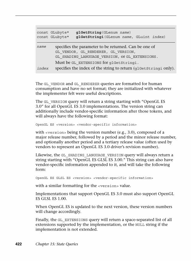
422 Chapter 15: State Queries
The GL_VENDOR and GL_RENDERER queries are formatted for human consumption and have no set format; they are initialized with whatever the implementer felt were useful descriptions.
The GL_VERSION query will return a string starting with “OpenGL ES 3.0” for all OpenGL ES 3.0 implementations. The version string can additionally include vendor-specific information after those tokens, and will always have the following format:
OpenGL ES <version> <vendor-specific information>
with <version> being the version number (e.g., 3.0), composed of a major release number, followed by a period and the minor release number, and optionally another period and a tertiary release value (often used by vendors to represent an OpenGL ES 3.0 driver’s revision number).
Likewise, the GL_SHADING_LANGUAGE_VERSION query will always return a string starting with “OpenGL ES GLSL ES 3.00.” This string can also have vendor-specific information appended to it, and will take the following form:
OpenGL ES GLSL ES <version> <vendor-specific information>
with a similar formatting for the <version> value.
Implementations that support OpenGL ES 3.0 must also support OpenGL ES GLSL ES 1.00.
When OpenGL ES is updated to the next version, these version numbers will change accordingly.
Finally, the GL_EXTENSIONS query will return a space-separated list of all extensions supported by the implementation, or the NULL string if the implementation is not extended.
const GLubyte* glGetString(GLenum name) const GLubyte* glGetStringi(GLenum name, GLuint index)
name
index
specifies the parameter to be returned. Can be one ofGL_VENDOR, GL_RENDERER, GL_VERSION,GL_SHADING_LANGUAGE_VERSION, or GL_EXTENSIONS.
Must be GL_EXTENSIONS for glGetStringi.specifies the index of the string to return (glGetStringi only).

Querying Implementation-Dependent Limits 423
Querying Implementation-Dependent Limits
Many rendering parameters depend on the underlying capabilities of the OpenGL ES implementation—for example, how many texture units are available to a shader, or what the maximum size for a texture map or aliased point is. Values of those types are queried using one of the functions shown here:
void glGetBooleanv(GLenum pname, GLboolean *params) void glGetFloatv(GLenum pname, GLfloat *params) void glGetIntegerv(GLenum pname, GLint *params) void glGetInteger64v(GLenum pname, GLint64 *params)
pname
params
specifies the implementation-specific parameter to be queriedspecifies an array of values of the respective type with enough entries to hold the return values for the associated parameter
A number of implementation-dependent parameters can be queried, as listed in Table 15-1.
Table 15-1 Implementation-Dependent State Queries
State Variable Description
Minimum/Initial Value Get Function
GL_MAX_ELEMENT_INDEX
Maximum element index 2 24 – 1 glGetInteger64v
GL_SUBPIXEL_BITS
Number of subpixel bits supported
4 glGetIntegerv
GL_MAX_TEXTURE_SIZE
Maximum size of a texture
2048 glGetIntegerv
GL_MAX_3D_TEXTURE_SIZE
Maximum size of 3D texture supported
256 glGetIntegerv
GL_MAX_ARRAY_TEXTURE_LAYERS
Maximum number of texture layers supported
256 glGetIntegerv
(continues)

424 Chapter 15: State Queries
State Variable Description
Minimum/Initial Value Get Function
GL_MAX_TEXTURE_LOD_BIAS
Maximum absolute texture level of detail bias supported
2.0 glGetFloatv
GL_MAX_CUBE_MAP_TEXTURE_SIZE
Maximum dimension of a cubemap texture
2048 glGetIntegerv
GL_MAX_RENDERBUFFER_SIZE
Maximum width and height of renderbuffers supported
2048 glGetIntegerv
GL_MAX_DRAW_BUFFERS
Maximum active number of draw buffers supported
4 glGetIntegerv
GL_MAX_COLOR_ATTACHMENTS
Maximum number of color attachments supported
4 glGetIntegerv
GL_MAX_VIEWPORT_DIMS
Dimensions of the maximum supported viewport size
glGetIntegerv
GL_ALIASED_POINT_SIZE_RANGE
Range of aliased point sizes
1, 1 glGetFloatv
GL_ALIASED_LINE_WIDTH_RANGE
Range of aliased line width sizes
1, 1 glGetFloatv
GL_MAX_ELEMENT_INDICES
Maximum number of glDrawRangeElements indices supported
glGetIntegerv
GL_MAX_ELEMENT_VERTICES
Maximum number of glDrawRangeElements vertices supported
glGetIntegerv
GL_NUM_COMPRESSED_TEXTURE_FORMATS
Number of compressed texture formats supported
10 glGetIntegerv
GL_COMPRESSED_TEXTURE_FORMATS
Compressed texture formats supported
glGetIntegerv
Table 15-1 Implementation-Dependent State Queries (continued)

Querying Implementation-Dependent Limits 425
State Variable Description
Minimum/Initial Value Get Function
GL_NUM_PROGRAM_BINARY_FORMATS
Number of program binary formats supported
0 glGetIntegerv
GL_PROGRAM_BINARY_FORMATS
Program binary formats supported
glGetIntegerv
GL_NUM_SHADER_BINARY_FORMATS
Number of shader binary formats supported
0 glGetIntegerv
GL_SHADER_BINARY_FORMATS
Shader binary formats supported
glGetIntegerv
GL_MAX_SERVER_WAIT_TIMEOUT
Maximum glWaitSync timeout interval
0 glGetInteger64v
GL_MAX_VERTEX_ATTRIBS
Maximum number of vertex attributes supported
16 glGetIntegerv
GL_MAX_VERTEX_UNIFORM_COMPONENTS
Maximum number of components for vertex shader uniform variables supported
1024 glGetIntegerv
GL_MAX_VERTEX_UNIFORM_VECTORS
Maximum number of vectors for vertex shader uniform variables supported
256 glGetIntegerv
GL_MAX_VERTEX_UNIFORM_BLOCKS
Maximum number of vertex uniform buffers per program supported
12 glGetIntegerv
GL_MAX_VERTEX_OUTPUT_COMPONENTS
Maximum number of components of outputs written by a vertex shader supported
64 glGetIntegerv
GL_MAX_VERTEX_TEXTURE_IMAGE_UNITS
Maximum number of texture image units accessible by a vertex shader supported
16 glGetIntegerv
Table 15-1 Implementation-Dependent State Queries (continued)
(continues)

426 Chapter 15: State Queries
State Variable Description
Minimum/Initial Value Get Function
GL_MAX_FRAGMENT_UNIFORM_COMPONENTS
Maximum number of components for fragment shader uniform variables supported
896 glGetIntegerv
GL_MAX_FRAGMENT_UNIFORM_VECTORS
Maximum number of vectors for fragment shader uniform variables supported
224 glGetIntegerv
GL_MAX_FRAGMENT_UNIFORM_BLOCKS
Maximum number of fragment uniform buffers per program supported
12 glGetIntegerv
GL_MAX_FRAGMENT_INPUT_COMPONENTS
Maximum number of components of inputs read by a fragment shader supported
60 glGetIntegerv
GL_MAX_TEXTURE_IMAGE_UNITS
Maximum number of texture image units accessible by a fragment shader supported
16 glGetIntegerv
GL_MIN_PROGRAM_TEXEL_OFFSET
Minimum texel offset allowed in a lookup supported
–8 glGetIntegerv
GL_MAX_PROGRAM_TEXEL_OFFSET
Maximum texel offset allowed in a lookup supported
7 glGetIntegerv
GL_MAX_UNIFORM_BUFFER_BINDINGS
Maximum number of uniform buffer bindings supported
24 glGetIntegerv
GL_MAX_UNIFORM_BLOCK_SIZE
Maximum size of a uniform block supported
16384 glGetInteger64v
GL_UNIFORM_BUFFER_OFFSET_ALIGNMENT
Minimum required alignment for uniform buffer sizes and offsets supported
1 glGetIntegerv
Table 15-1 Implementation-Dependent State Queries (continued)
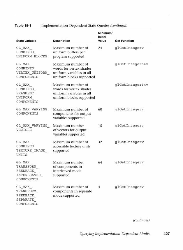
Querying Implementation-Dependent Limits 427
State Variable Description
Minimum/Initial Value Get Function
GL_MAX_COMBINED_UNIFORM_BLOCKS
Maximum number of uniform buffers per program supported
24 glGetIntegerv
GL_MAX_COMBINED_VERTEX_UNIFORM_COMPONENTS
Maximum number of words for vertex shader uniform variables in all uniform blocks supported
glGetInteger64v
GL_MAX_COMBINED_FRAGMENT_UNIFORM_COMPONENTS
Maximum number of words for vertex shader uniform variables in all uniform blocks supported
glGetInteger64v
GL_MAX_VARYING_COMPONENTS
Maximum number of components for output variables supported
60 glGetIntegerv
GL_MAX_VARYING_VECTORS
Maximum number of vectors for output variables supported
15 glGetIntegerv
GL_MAX_COMBINED_TEXTURE_IMAGE_UNITS
Maximum number of accessible texture units supported
32 glGetIntegerv
GL_MAX_TRANSFORM_FEEDBACK_INTERLEAVED_COMPONENTS
Maximum number of components in interleaved mode supported
64 glGetIntegerv
GL_MAX_TRANSFORM_FEEDBACK_SEPARATE_COMPONENTS
Maximum number of components in separate mode supported
4 glGetIntegerv
Table 15-1 Implementation-Dependent State Queries (continued)
(continues)

428 Chapter 15: State Queries
State Variable Description
Minimum/Initial Value Get Function
GL_MAX_TRANSFORM_FEEDBACK_SEPARATE_ATTRIBS
Maximum number of separate attributes that can be captured in transform feedback supported
4 glGetIntegerv
GL_SAMPLE_BUFFER
Number of multisample buffers
0 glGetIntegerv
GL_SAMPLES Coverage mask size 0 glGetIntegerv
GL_MAX_SAMPLES Maximum number of samples supported for multisampling
4 glGetIntegerv
GL_RED_BITS Number of red bits in current color buffer
glGetIntegerv
GL_GREEN_BITS Number of green bits in current color buffer
glGetIntegerv
GL_BLUE_BITS Number of blue bits in current color buffer
glGetIntegerv
GL_ALPHA_BITS Number of alpha bits in current color buffer
glGetIntegerv
GL_DEPTH_BITS Number of bits in the current depth buffer
glGetIntegerv
GL_STENCIL_BITS Number of stencil bits in current stencil buffer
glGetIntegerv
GL_IMPLEMENTATION_COLOR_READ_TYPE
Data type for pixel components for pixel read operations
glGetIntegerv
GL_IMPLEMENTATION_COLOR_READ_FORMAT
Pixel format for pixel read operations
glGetIntegerv
Table 15-1 Implementation-Dependent State Queries (continued)
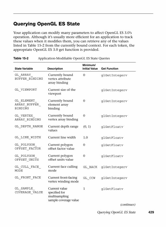
Querying OpenGL ES State 429
Querying OpenGL ES State
Your application can modify many parameters to affect OpenGL ES 3.0’s operation. Although it’s usually more efficient for an application to track these values when it modifies them, you can retrieve any of the values listed in Table 15-2 from the currently bound context. For each token, the appropriate OpenGL ES 3.0 get function is provided.
Table 15-2 Application-Modifiable OpenGL ES State Queries
State Variable DescriptionMinimum/Initial Value Get Function
GL_ARRAY_BUFFER_BINDING
Currently bound vertex attribute array binding
0 glGetIntegerv
GL_VIEWPORT Current size of the viewport
glGetIntegerv
GL_ELEMENT_ARRAY_BUFFER_BINDING
Currently bound element array binding
0 glGetIntegerv
GL_VERTEX_ARRAY_BINDING
Currently bound vertex array binding
0 glGetIntegerv
GL_DEPTH_RANGE Current depth range values
(0, 1) glGetFloatv
GL_LINE_WIDTH Current line width 1.0 glGetFloatv
GL_POLYGON_OFFSET_FACTOR
Current polygon offset factor value
0 glGetFloatv
GL_POLYGON_OFFSET_UNITS
Current polygon offset units value
0 glGetFloatv
GL_CULL_FACE_MODE
Current face culling mode
GL_BACK glGetIntegerv
GL_FRONT_FACE Current front-facing vertex winding mode
GL_CCW glGetIntegerv
GL_SAMPLE_COVERAGE_VALUE
Current value specified for multisampling sample coverage value
1 glGetFloatv
(continues)
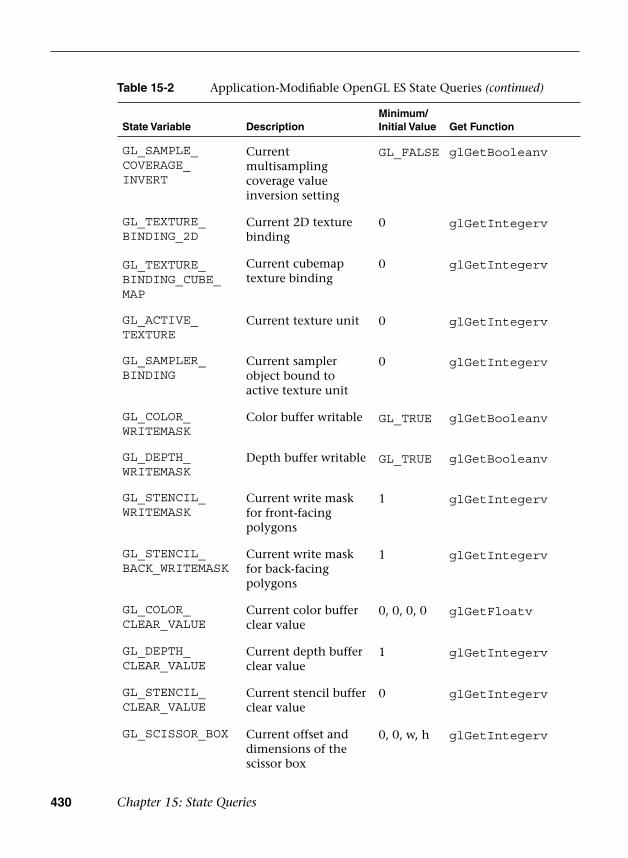
430 Chapter 15: State Queries
State Variable DescriptionMinimum/Initial Value Get Function
GL_SAMPLE_COVERAGE_INVERT
Current multisampling coverage value inversion setting
GL_FALSE glGetBooleanv
GL_TEXTURE_BINDING_2D
Current 2D texture binding
0 glGetIntegerv
GL_TEXTURE_BINDING_CUBE_MAP
Current cubemap texture binding
0 glGetIntegerv
GL_ACTIVE_TEXTURE
Current texture unit 0 glGetIntegerv
GL_SAMPLER_BINDING
Current sampler object bound to active texture unit
0 glGetIntegerv
GL_COLOR_WRITEMASK
Color buffer writable GL_TRUE glGetBooleanv
GL_DEPTH_WRITEMASK
Depth buffer writable GL_TRUE glGetBooleanv
GL_STENCIL_WRITEMASK
Current write mask for front-facing polygons
1 glGetIntegerv
GL_STENCIL_BACK_WRITEMASK
Current write mask for back-facing polygons
1 glGetIntegerv
GL_COLOR_CLEAR_VALUE
Current color buffer clear value
0, 0, 0, 0 glGetFloatv
GL_DEPTH_CLEAR_VALUE
Current depth buffer clear value
1 glGetIntegerv
GL_STENCIL_CLEAR_VALUE
Current stencil buffer clear value
0 glGetIntegerv
GL_SCISSOR_BOX Current offset and dimensions of the scissor box
0, 0, w, h glGetIntegerv
Table 15-2 Application-Modifiable OpenGL ES State Queries (continued)

Querying OpenGL ES State 431
State Variable DescriptionMinimum/Initial Value Get Function
GL_STENCIL_FUNC
Current stencil test operator function
GL_ALWAYS
glGetIntegerv
GL_STENCIL_VALUE_MASK
Current stencil test value mask
1s glGetIntegerv
GL_STENCIL_REF Current stencil test reference value
0 glGetIntegerv
GL_STENCIL_FAIL
Current operation for stencil test failure
GL_KEEP glGetIntegerv
GL_STENCIL_PASS_DEPTH_FAIL
Current operation for when the stencil test passes, but the depth test fails
GL_KEEP glGetIntegerv
GL_STENCIL_PASS_DEPTH_PASS
Current operation when both the stencil and depth tests pass
GL_KEEP glGetIntegerv
GL_STENCIL_BACK_FUNC
Current back-facing stencil test operator function
GL_ALWAYS
glGetIntegerv
GL_STENCIL_BACK_VALUE_MASK
Current back-facing stencil test value mask
1s glGetIntegerv
GL_STENCIL_BACK_REF
Current back-facing stencil test reference value
0 glGetIntegerv
GL_STENCIL_BACK_FAIL
Current operation for back-facing stencil test failure
GL_KEEP glGetIntegerv
GL_STENCIL_BACK_PASS_DEPTH_FAIL
Current operation for when the back-facing stencil test passes, but the depth test fails
GL_KEEP glGetIntegerv
GL_STENCIL_BACK_PASS_DEPTH_PASS
Current operation when both the back-facing stencil and depth tests pass
GL_KEEP glGetIntegerv
Table 15-2 Application-Modifiable OpenGL ES State Queries (continued)
(continues)

432 Chapter 15: State Queries
State Variable DescriptionMinimum/Initial Value Get Function
GL_DEPTH_FUNC Current depth test comparison function
GL_LESS glGetIntegerv
GL_BLEND_SRC_RGB
Current source RGB blending coefficient
GL_ONE glGetIntegerv
GL_BLEND_SRC_ALPHA
Current source alpha blending coefficient
GL_ONE glGetIntegerv
GL_BLEND_DST_RGB
Current destination RGB blending coefficient
GL_ZERO glGetIntegerv
GL_BLEND_DST_ALPHA
Current destination alpha blending coefficient
GL_ZERO glGetIntegerv
GL_BLEND_EQUATION
Current blend equation operator
GL_FUNC_ADD
glGetIntegerv
GL_BLEND_EQUATION_RGB
Current RGB blend equation operator
GL_FUNC_ADD
glGetIntegerv
GL_BLEND_EQUATION_ALPHA
Current alpha blend equation operator
GL_FUNC_ADD
glGetIntegerv
GL_BLEND_COLOR Current blend color 0, 0, 0, 0 glGetFloatv
GL_DRAW_BUFFERi
Current buffers being drawn by the corresponding output color
glGetIntegerv
GL_READ_BUFFER Current color buffer selected for reading
glGetIntegerv
GL_UNPACK_IMAGE_HEIGHT
Current image height for pixel unpacking
0 glGetIntegerv
GL_UNPACK_SKIP_IMAGES
Current number of pixel images skipped before the first pixel for pixel unpacking
0 glGetIntegerv
Table 15-2 Application-Modifiable OpenGL ES State Queries (continued)

Querying OpenGL ES State 433
State Variable DescriptionMinimum/Initial Value Get Function
GL_UNPACK_ROW_LENGTH
Current row length for pixel unpacking
0 glGetIntegerv
GL_UNPACK_SKIP_ROWS
Current number of rows of pixel locations skipped before the first pixel for pixel unpacking
0 glGetIntegerv
GL_UNPACK_SKIP_PIXELS
Current number of pixel locations skipped before the first pixel for pixel unpacking
0 glGetIntegerv
GL_UNPACK_ALIGNMENT
Current byte-boundary alignment for pixel unpacking
4 glGetIntegerv
GL_PACK_ROW_LENGTH
Current row length for pixel packing
0 glGetIntegerv
GL_PACK_SKIP_ROWS
Current number of rows of pixel locations skipped before the first pixel for pixel packing
0 glGetIntegerv
GL_PACK_SKIP_PIXELS
Current number of pixel locations skipped before the first pixel for pixel packing
0 glGetIntegerv
GL_PACK_ALIGNMENT
Current byte-boundary alignment for pixel packing
4 glGetIntegerv
GL_PIXEL_PACK_BUFFER_BINDING
Name of buffer object currently bound for pixel packing
0 glGetIntegerv
GL_PIXEL_UNPACK_BUFFER_BINDING
Name of buffer object currently bound for pixel unpacking
0 glGetIntegerv
Table 15-2 Application-Modifiable OpenGL ES State Queries (continued)
(continues)
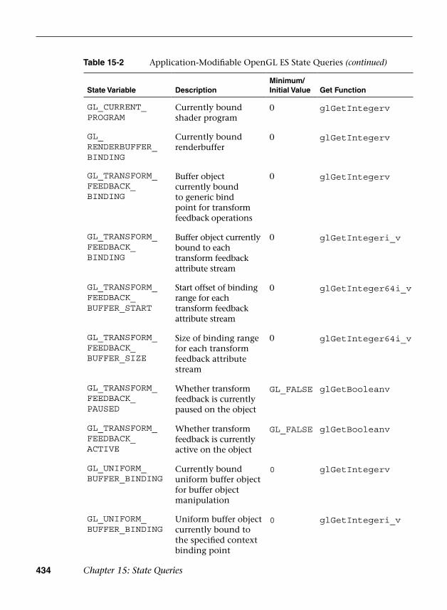
434 Chapter 15: State Queries
State Variable DescriptionMinimum/Initial Value Get Function
GL_CURRENT_PROGRAM
Currently bound shader program
0 glGetIntegerv
GL_RENDERBUFFER_BINDING
Currently bound renderbuffer
0 glGetIntegerv
GL_TRANSFORM_FEEDBACK_BINDING
Buffer object currently bound to generic bind point for transform feedback operations
0 glGetIntegerv
GL_TRANSFORM_FEEDBACK_BINDING
Buffer object currently bound to each transform feedback attribute stream
0 glGetIntegeri_v
GL_TRANSFORM_FEEDBACK_BUFFER_START
Start offset of binding range for each transform feedback attribute stream
0 glGetInteger64i_v
GL_TRANSFORM_FEEDBACK_BUFFER_SIZE
Size of binding range for each transform feedback attribute stream
0 glGetInteger64i_v
GL_TRANSFORM_FEEDBACK_PAUSED
Whether transform feedback is currently paused on the object
GL_FALSE glGetBooleanv
GL_TRANSFORM_FEEDBACK_ACTIVE
Whether transform feedback is currently active on the object
GL_FALSE glGetBooleanv
GL_UNIFORM_BUFFER_BINDING
Currently bound uniform buffer object for buffer object manipulation
0 glGetIntegerv
GL_UNIFORM_BUFFER_BINDING
Uniform buffer object currently bound to the specified context binding point
0 glGetIntegeri_v
Table 15-2 Application-Modifiable OpenGL ES State Queries (continued)

Hints 435
State Variable DescriptionMinimum/Initial Value Get Function
GL_UNIFORM_BUFFER_START
Start of currently bound uniform buffer region
0 glGetInteger64i_v
GL_UNIFORM_BUFFER_SIZE
Size of currently bound uniform buffer region
0 glGetInteger64i_v
GL_GENERATE_MIPMAP_HINT
Mipmap generation hint
GL_DONT_CARE
glGetIntegerv
GL_FRAGMENT_SHADER_DERIVATIVE_HINT
Fragment shader derivative accuracy hint
GL_DONT_CARE
glGetIntegerv
GL_READ_FRAMEBUFFER_BINDING
Currently bound framebuffer for reading
0 glGetIntegerv
GL_DRAW_FRAMEBUFFER_BINDING
Currently bound framebuffer for drawing
0 glGetIntegerv
Table 15-2 Application-Modifiable OpenGL ES State Queries (continued)
Hints
OpenGL ES 3.0 uses hints to modify the operation of features, allowing a bias toward either performance or quality. You can specify a preference by calling the following function:
void glHint(GLenum target, GLenum mode)
target
mode
specifies the hint to be set, and must be either GL_GENERATE_MIPMAP_HINT or GL_FRAGMENT_SHADER_DERIVATIVE_HINT.
specifies the operational mode the feature should use. Valid values are GL_FASTEST to specify performance, GL_NICEST to favor quality, or GL_DONT_CARE to reset any preferences to the implementation default.

436 Chapter 15: State Queries
The current value of any hint can be retrieved by calling glGetIntegerv using the appropriate hint enumerated value.
Entity Name Queries
OpenGL ES 3.0 references numerous entities that you define—textures, shaders, programs, vertex buffers, sampler objects, query objects, sync objects, vertex array objects, transform feedback objects, framebuffers, and renderbuffers—by integer names. You can determine if a name is currently in use (and therefore a valid entity) by calling one of the following functions:
GLboolean glIsTexture(GLuint texture) GLboolean glIsShader(GLuint shader) GLboolean glIsProgram(GLuint program) GLboolean glIsBuffer(GLuint buffer) GLboolean glIsSampler(GLuint sampler) GLboolean glIsQuery(GLuint query) GLboolean glIsSync(GLuint sync) GLboolean glIsVertexArray(GLuint array) GLboolean glIsTransformFeedback(GLuint transform) GLboolean glIsRenderbuffer(GLuint renderbuffer) GLboolean glIsFramebuffer(GLuint framebuffer)
texture, shader,program, buffer,sampler, query,sync, array,transform,renderbuffer,framebuffer
specify the name of the respective entity todetermine if the name is in use
Nonprogrammable Operations Control and Queries
Much of OpenGL ES 3.0’s rasterization functionality, like blending or back-face culling, is controlled by turning on and off the features you need. The functions controlling the various operations are mentioned here.

Nonprogrammable Operations Control and Queries 437
Additionally, you can determine if a feature is in use by calling the following function:
The capabilities controlled by glEnable and glDisable are listed in Table 15-3.
void glEnable(GLenum capability)
capabi1ity specifies the feature that should be turned on and affects all rendering until the feature is turned off
void glDisable(GLenum capability)
capabi1ity specifies the feature that should be turned off
GLboolean glIsEnabled(GLenum capability)
capability specifies which feature should be examined to determine if it’s enabled
Table 15-3 OpenGL ES 3.0 Capabilities Controlled by glEnable and glDisable
Capability Description
GL_CULL_FACE Discard polygons whose vertex winding order is opposite of the specified front-facing mode (GL_CW or GL_CCW, as specified by glFrontFace)
GL_POLYGON_OFFSET_FILL Offset the depth value of a fragment to aid in rendering coplanar geometry
GL_SCISSOR_TEST Further restrict rendering to the scissor box
(continues)
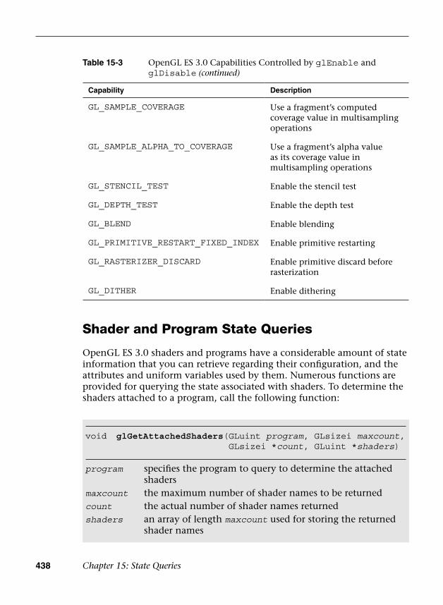
438 Chapter 15: State Queries
Shader and Program State Queries
OpenGL ES 3.0 shaders and programs have a considerable amount of state information that you can retrieve regarding their configuration, and the attributes and uniform variables used by them. Numerous functions are provided for querying the state associated with shaders. To determine the shaders attached to a program, call the following function:
void glGetAttachedShaders( GLuint program, GLsizei maxcount, GLsizei *count, GLuint *shaders)
program
maxcount
count
shaders
specifies the program to query to determine the attached shadersthe maximum number of shader names to be returnedthe actual number of shader names returnedan array of length maxcount used for storing the returned shader names
Capability Description
GL_SAMPLE_COVERAGE Use a fragment’s computed coverage value in multisampling operations
GL_SAMPLE_ALPHA_TO_COVERAGE Use a fragment’s alpha value as its coverage value in multisampling operations
GL_STENCIL_TEST Enable the stencil test
GL_DEPTH_TEST Enable the depth test
GL_BLEND Enable blending
GL_PRIMITIVE_RESTART_FIXED_INDEX Enable primitive restarting
GL_RASTERIZER_DISCARD Enable primitive discard before rasterization
GL_DITHER Enable dithering
Table 15-3 OpenGL ES 3.0 Capabilities Controlled by glEnable and glDisable (continued)
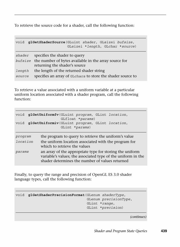
Shader and Program State Queries 439
To retrieve the source code for a shader, call the following function:
void glGetShaderSource( GLuint shader, GLsizei bufsize, GLsizei *length, GLchar *source)
shader
bufsize
length
source
specifies the shader to querythe number of bytes available in the array source for returning the shader’s sourcethe length of the returned shader stringspecifies an array of GLchars to store the shader source to
void glGetUniformfv(GLuint program, GLint location, GLfloat *params)
void glGetUniformiv( GLuint program, GLint location, GLint *params)
program
location
params
the program to query to retrieve the uniform’s valuethe uniform location associated with the program for which to retrieve the valuesan array of the appropriate type for storing the uniform variable’s values; the associated type of the uniform in the shader determines the number of values returned
To retrieve a value associated with a uniform variable at a particular uniform location associated with a shader program, call the following function:
Finally, to query the range and precision of OpenGL ES 3.0 shader language types, call the following function:
void glGetShaderPrecisionFormat( GLenum shaderType, GLenum precisionType, GLint *range, GLint *precision)
(continues)

440 Chapter 15: State Queries
The associated state for accessing the data elements in the vertex attribute array, such as value type or stride, can be obtained by calling the following function:
void glGetVertexAttribPointerv( GLuint index, GLenum pname, GLvoid **pointer)
index
pname
pointer
specifies the index of the generic vertex attribute arrayspecifies the parameter to be retrieved; must be GL_VERTEX_ATTRIB_ARRAY_POINTER
returns the address of the specified vertex attribute array
Vertex Attribute Queries
State information for vertex attribute arrays can also be retrieved from the current OpenGL ES 3.0 context. To obtain the pointer to the current generic vertex attributes for a specific index, call the following function:
(continued)shaderType
precisionType
range
precision
specifies the type of shader, and must be either GL_VERTEX_SHADER or GL_FRAGMENT_SHADERspecifies the precision qualifier type, and must be one of GL_LOW_FLOAT, GL_MEDIUM_FLOAT, GL_HIGH_FLOAT, GL_LOW_INT, GL_MEDIUM_INT, or GL_HIGH_INTa two-element array that returns the minimum and maximum values for precisionType as a log base-2 numberreturns the precision for precisionType as a log base-2 value
void glGetVertexAttribfv(GLuint index, GLenum pname, GLfloat *params)
void glGetVertexAttribiv( GLuint index, GLenum pname, GLint *params)
index specifies the index of the generic vertex attribute array.
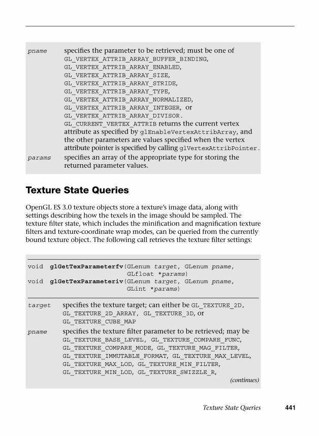
Texture State Queries 441
pname
params
specifies the parameter to be retrieved; must be one ofGL_VERTEX_ATTRIB_ARRAY_BUFFER_BINDING,GL_VERTEX_ATTRIB_ARRAY_ENABLED,GL_VERTEX_ATTRIB_ARRAY_SIZE,GL_VERTEX_ATTRIB_ARRAY_STRIDE,GL_VERTEX_ATTRIB_ARRAY_TYPE,GL_VERTEX_ATTRIB_ARRAY_NORMALIZED,GL_VERTEX_ATTRIB_ARRAY_INTEGER, orGL_VERTEX_ATTRIB_ARRAY_DIVISOR.GL_CURRENT_VERTEX_ATTRIB returns the current vertexattribute as specified by glEnableVertexAttribArray, andthe other parameters are values specified when the vertexattribute pointer is specified by calling glVertexAttribPointer.specifies an array of the appropriate type for storing thereturned parameter values.
Texture State Queries
OpenGL ES 3.0 texture objects store a texture’s image data, along with settings describing how the texels in the image should be sampled. The texture filter state, which includes the minification and magnification texture filters and texture-coordinate wrap modes, can be queried from the currently bound texture object. The following call retrieves the texture filter settings:
void glGetTexParameterfv(GLenum target, GLenum pname, GLfloat *params)
void glGetTexParameteriv( GLenum target, GLenum pname, GLint *params)
target specifies the texture target; can either be GL_TEXTURE_2D,GL_TEXTURE_2D_ARRAY, GL_TEXTURE_3D, or GL_TEXTURE_CUBE_MAP
pname specifies the texture filter parameter to be retrieved; may beGL_TEXTURE_BASE_LEVEL, GL_TEXTURE_COMPARE_FUNC,GL_TEXTURE_COMPARE_MODE, GL_TEXTURE_MAG_FILTER,GL_TEXTURE_IMMUTABLE_FORMAT, GL_TEXTURE_MAX_LEVEL,GL_TEXTURE_MAX_LOD, GL_TEXTURE_MIN_FILTER,GL_TEXTURE_MIN_LOD, GL_TEXTURE_SWIZZLE_R,
(continues)

442 Chapter 15: State Queries
Sampler Queries
State information for sampler objects can be retrieved from the current OpenGL ES 3.0 context by calling the following function:
void glGetSamplerParameterfv(GLuint sampler, GLenum pname, GLfloat *params)
void glGetSamplerParameteriv( GLuint sampler, GLenum pname, GLint *params)
sampler
pname
params
specifies the name of a sampler object
specifies the sampler parameter to be retrieved; may beGL_TEXTURE_MAG_FILTER, GL_TEXTURE_MIN_FILTER,GL_TEXTURE_MIN_LOD, GL_TEXTURE_MAX_LOD,GL_TEXTURE_WRAP_S, GL_TEXTURE_WRAP_T,GL_TEXTURE_WRAP_R, GL_TEXTURE_COMPARE_MODE, orGL_TEXTURE_COMPARE_FUNC
specifies an array of the appropriate type for storing thereturned parameter values
(continued)
params
GL_TEXTURE_SWIZZLE_G, GL_TEXTURE_SWIZZLE_B,GL_TEXTURE_SWIZZLE_A, GL_TEXTURE_WRAP_S,GL_TEXTURE_SWIZZLE_T, or GL_TEXTURE_WRAP_R
specifies an array of the appropriate type for storing thereturned parameter values
Asynchronous Object Queries
Information about a query object can be retrieved from the current OpenGL ES 3.0 context by calling the following function:
void glGetQueryiv( GLuint target, GLenum pname, GLint *params)
target specifies the query target object; can beGL_ANY_SAMPLES_PASSED,
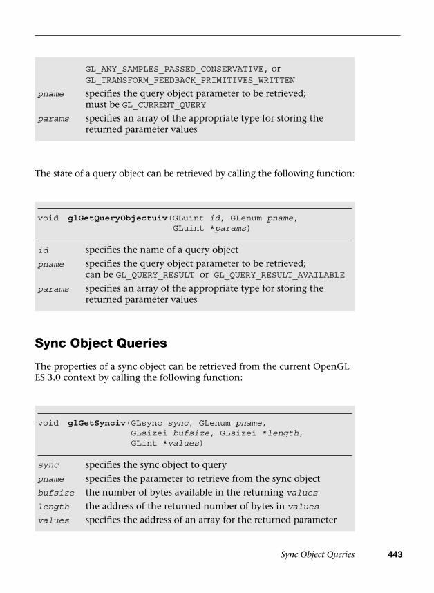
Sync Object Queries 443
The state of a query object can be retrieved by calling the following function:
void glGetQueryObjectuiv(GLuint id, GLenum pname, GLuint *params)
id
pname
params
specifies the name of a query object
specifies the query object parameter to be retrieved;can be GL_QUERY_RESULT or GL_QUERY_RESULT_AVAILABLE
specifies an array of the appropriate type for storing thereturned parameter values
Sync Object Queries
The properties of a sync object can be retrieved from the current OpenGL ES 3.0 context by calling the following function:
void glGetSynciv(GLsync sync, GLenum pname, GLsizei bufsize, GLsizei *length, GLint *values)
sync
pname
specifies the sync object to query
specifies the parameter to retrieve from the sync object
bufsize
length
values
the number of bytes available in the returning values
the address of the returned number of bytes in values
specifies the address of an array for the returned parameter
pname
params
GL_ANY_SAMPLES_PASSED_CONSERVATIVE, orGL_TRANSFORM_FEEDBACK_PRIMITIVES_WRITTEN
specifies the query object parameter to be retrieved;must be GL_CURRENT_QUERY
specifies an array of the appropriate type for storing thereturned parameter values
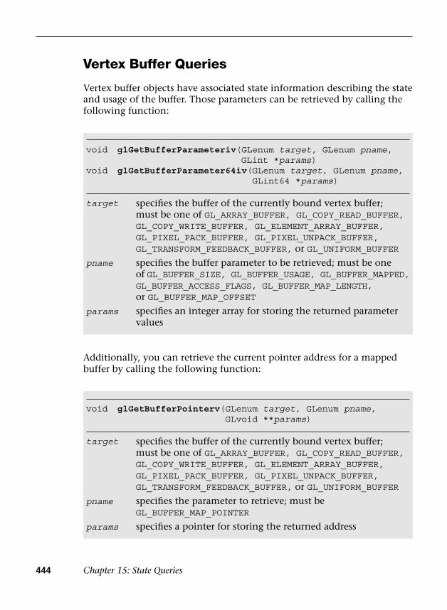
444 Chapter 15: State Queries
Vertex Buffer Queries
Vertex buffer objects have associated state information describing the state and usage of the buffer. Those parameters can be retrieved by calling the following function:
Additionally, you can retrieve the current pointer address for a mapped buffer by calling the following function:
void glGetBufferParameteriv(GLenum target, GLenum pname, GLint *params)
void glGetBufferParameter64iv( GLenum target, GLenum pname, GLint64 *params)
target
pname
params
specifies the buffer of the currently bound vertex buffer;must be one of GL_ARRAY_BUFFER, GL_COPY_READ_BUFFER,GL_COPY_WRITE_BUFFER, GL_ELEMENT_ARRAY_BUFFER,GL_PIXEL_PACK_BUFFER, GL_PIXEL_UNPACK_BUFFER,GL_TRANSFORM_FEEDBACK_BUFFER, or GL_UNIFORM_BUFFER
specifies the buffer parameter to be retrieved; must be oneof GL_BUFFER_SIZE, GL_BUFFER_USAGE, GL_BUFFER_MAPPED, GL_BUFFER_ACCESS_FLAGS, GL_BUFFER_MAP_LENGTH,or GL_BUFFER_MAP_OFFSET
specifies an integer array for storing the returned parametervalues
void glGetBufferPointerv( GLenum target, GLenum pname, GLvoid **params)
target
pname
params
specifies the buffer of the currently bound vertex buffer;must be one of GL_ARRAY_BUFFER, GL_COPY_READ_BUFFER,GL_COPY_WRITE_BUFFER, GL_ELEMENT_ARRAY_BUFFER,GL_PIXEL_PACK_BUFFER, GL_PIXEL_UNPACK_BUFFER,GL_TRANSFORM_FEEDBACK_BUFFER, or GL_UNIFORM_BUFFER
specifies the parameter to retrieve; must beGL_BUFFER_MAP_POINTER
specifies a pointer for storing the returned address
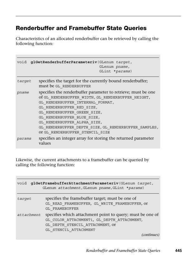
Renderbuffer and Framebuffer State Queries 445
Renderbuffer and Framebuffer State Queries
Characteristics of an allocated renderbuffer can be retrieved by calling the following function:
void glGetRenderbufferParameteriv( GLenum target, GLenum pname, GLint *params)
target
pname
params
specifies the target for the currently bound renderbuffer;must be GL_RENDERBUFFER
specifies the renderbuffer parameter to retrieve; must be oneof GL_RENDERBUFFER_WIDTH, GL_RENDERBUFFER_HEIGHT,GL_RENDERBUFFER_INTERNAL_FORMAT,GL_RENDERBUFFER_RED_SIZE,GL_RENDERBUFFER_GREEN_SIZE,GL_RENDERBUFFER_BLUE_SIZE, GL_RENDERBUFFER_ALPHA_SIZE,GL_RENDERBUFFER_DEPTH_SIZE, GL_RENDERBUFFER_SAMPLES, or GL_RENDERBUFFER_STENCIL_SIZE
specifies an integer array for storing the returned parametervalues
Likewise, the current attachments to a framebuffer can be queried by calling the following function:
void glGet FramebufferAttachmentParameteriv(GLenum target, GLenum attachment,GLenum pname,GLint *params)
target
attachment
specifies the framebuffer target; must be one ofGL_READ_FRAMEBUFFER, GL_WRITE_FRAMEBUFFER, orGL_FRAMEBUFFER
specifies which attachment point to query; must be one ofGL_COLOR_ATTACHMENTi, GL_DEPTH_ATTACHMENT,GL_DEPTH_STENCIL_ATTACHMENT, orGL_STENCIL_ATTACHMENT
(continues)
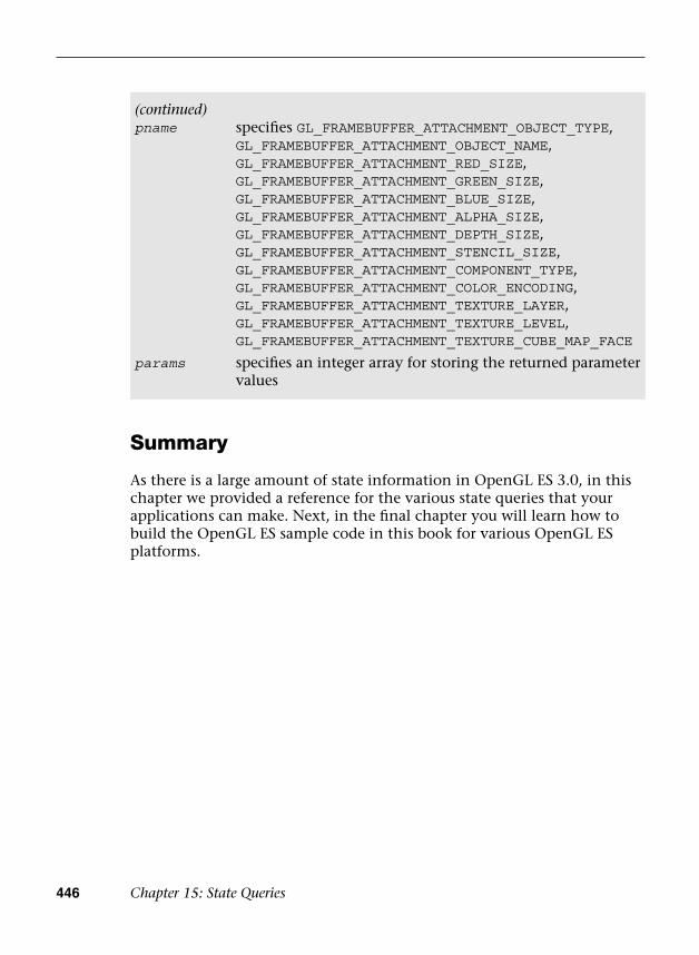
446 Chapter 15: State Queries
Summary
As there is a large amount of state information in OpenGL ES 3.0, in this chapter we provided a reference for the various state queries that your applications can make. Next, in the final chapter you will learn how to build the OpenGL ES sample code in this book for various OpenGL ES platforms.
(continued)pname
params
specifies GL_FRAMEBUFFER_ATTACHMENT_OBJECT_TYPE,GL_FRAMEBUFFER_ATTACHMENT_OBJECT_NAME,GL_FRAMEBUFFER_ATTACHMENT_RED_SIZE,GL_FRAMEBUFFER_ATTACHMENT_GREEN_SIZE,GL_FRAMEBUFFER_ATTACHMENT_BLUE_SIZE,GL_FRAMEBUFFER_ATTACHMENT_ALPHA_SIZE,GL_FRAMEBUFFER_ATTACHMENT_DEPTH_SIZE,GL_FRAMEBUFFER_ATTACHMENT_STENCIL_SIZE,GL_FRAMEBUFFER_ATTACHMENT_COMPONENT_TYPE,GL_FRAMEBUFFER_ATTACHMENT_COLOR_ENCODING,GL_FRAMEBUFFER_ATTACHMENT_TEXTURE_LAYER,GL_FRAMEBUFFER_ATTACHMENT_TEXTURE_LEVEL,GL_FRAMEBUFFER_ATTACHMENT_TEXTURE_CUBE_MAP_FACE
specifies an integer array for storing the returned parameter values

447
Chapter 16
OpenGL ES Platforms
As of this writing, OpenGL ES 3.0 is available in Android 4.3+, iOS 7 (on the iPhone 5s), Windows, and Linux. We attempted to make the sample code for the book available on as many platforms as possible. We want our readers to be able to choose the OpenGL ES 3.0 platform that is most relevant to them. In this chapter, we cover some specifics of getting up and running while building the sample code with the following platforms:
• Windows (OpenGL ES 3.0 Emulation) with Microsoft Visual Studio
• Ubuntu Linux (OpenGL ES 3.0 Emulation)
• Android 4.3+ NDK (C++)
• Android 4.3+ SDK (Java)
• iOS 7 with Xcode 5
Building for Microsoft Windows with Visual Studio
After downloading the sample code from the book’s website (opengles-book.com) and installing CMake v2.8 (http://cmake.org), the next step to build the sample code for Windows is to download an OpenGL ES 3.0 Emulator. Three choices of emulators are currently available:
• Qualcomm Adreno SDK v3.4+, available from http://developer.qualcomm.com/develop/

448 Chapter 16: OpenGL ES Platforms
• ARM Mali OpenGL ES 3.0 Emulator, available from http://malideveloper.arm.com/develop-for-mali/tools/opengl-es-3-0-emulator/
• PowerVR Insider SDK v3.2+, available from http://imgtec.com/PowerVR/insider/sdkdownloads/index.asp
Any of these emulators is a suitable choice for using the sample code for this book. We leave it up to you to choose which option best fits with your development needs. If you want to use the PVRShaman workspaces from Chapters 10 and 14, the PowerVR Insider SDK is required. For this section, we chose to use the Qualcomm Adreno SDK v3.4. After downloading and installing your choice of OpenGL ES 3.0 emulator, you can use CMake to generate the Microsoft Visual Studio solution and projects.
Open the cmake-gui and point the GUI to the location where you have downloaded the source code, as shown in Figure 16-1. Create a folder to build the binaries underneath that base directory and set it as the location to build the binaries in the GUI. You can then click Configure and choose the version of Microsoft Visual Studio you are using. CMake will now give an error because the EGL and OpenGLES3 library are not found.
If you are using the Qualcomm Adreno SDK installed to C:\AdrenoSDK, you must now set the following variables in the cmake-gui:
• EGL_LIBRARY: C:/AdrenoSDK/Lib/Win32/OGLES3/libEGL.lib
• OPENGLES3_LIBRARY: C:/AdrenoSDK/Lib/Win32/OGLES3/libGLESv2.lib
Figure 16-1 Building Samples with CMake GUI on Windows

Building for Ubuntu Linux 449
If you are using a different emulator, locate the EGL and OpenGL ES 3.0 libraries for that library and set them to the CMake variables. After setting the EGL and OpenGL ES 3.0 libraries, click Configure again in the cmake-gui and then click Generate. You can now navigate to the folder you chose to build the binaries in CMake and open ES3_Book.sln in Microsoft Visual Studio. From this solution, you can build and run all of the sample code for the book.
If you do not have libEGL.dll and libGLESv2.dll in your path, you will need to copy those files to the directory to which each sample executable is built to be able to run the sample. Also, note that libGLESv2 is the recommended Khronos naming convention for the OpenGL ES 3.0 library. This is the same name as the OpenGL ES 2.0 library. The names match because OpenGL ES 3.0 is backward compatible with OpenGL ES 2.0; thus the same library can be used for both APIs.
Building for Ubuntu Linux
This section describes how to build the sample code using the PowerVR OpenGL ES 3.0 Emulator on Ubuntu Linux (tested on Ubuntu 12.04.1 LTS 64-bit). In addition to installing the PowerVR OpenGL ES 3.0 Emulator (by default, this installs to /opt/Imagination/PowerVR/GraphicsSDK), you will need to make sure you have installed the appropriate packages, including cmake and gcc. A good starting point is to install the following packages:
$ sudo apt-get install build-essential cmake cmake-curses-gui
To build the sample code, first create a build folder at the root of the source project (where CMakeLists.txt is found):
~/src/opengles-book$ mkdir build~/src/opengles-book/build$ cd build~/src/opengles-book/build$ cmake ../
If all has gone correctly, you will likely see an error message that the EGL_LIBRARY and OPENGLES3_LIBRARY are not found. To set the libraries, run the following (note that it is “ccmake” and not “cmake”):
~/src/opengles-book/build$ ccmake ../
You will see that the value of EGL_LIBRARY is EGL_LIBRARY-NOTFOUND; similarly, OPENGLES3_LIBRARY is set to OPENGLES3_LIBRARY-NOTFOUND.

450 Chapter 16: OpenGL ES Platforms
Assuming you installed the PowerVR SDK to the default location, you can set these variables to the libEGL.so and libGLESv2.so files, as follows:
• EGL_LIBRARY:/opt/Imagination/PowerVR/GraphicsSDK/PVRVFrame/EmulationLibs/Linux_x86_64/libEGL.so
• OPENGLES3_LIBRARY:/opt/Imagination/PowerVR/GraphicsSDK/PVRVFrame/EmulationLibs/Linux_x86_64/libGLESv2.so
Now you can press “c” to configure and “g” to generate and exit ccmake. The code is now ready to build; simply type the following:
~/src/opengles-book/build$ make
This should build libCommon.a along with all of the sample code. You are now ready to run the Hello_Triangle sample:
build$ cd Chapter_2/Hello_Trianglebuild$ ./Hello_Triangle
If you find that you are unable to run the program because the libEGL.so and libGLESv2.so are not found, set LD_LIBRARY_PATH to point to the directory location as follows:
$ exportLD_LIBRARY_PATH=/opt/Imagination/PowerVR/GraphicsSDK/PVRVFrame/EmulationLibs/Linux_x86_64/
Building for Android 4.3+ NDK (C++)
Support for OpenGL ES 3.0 in Android 4.3 was announced in July 2013. There are two ways of accessing OpenGL ES 3.0 on Android: either through the Native Development Kit (NDK) using C/C++ or through the Software Development Kit (SDK) using Java. We have provided the sample code in both C and Java to support development with either language. This section covers how to build and run the C Android 4.3 samples using the NDK. The next section covers how to build and run the Java Android 4.3 samples using the SDK. OpenGL ES 3.0 has been supported in the Android NDK starting with Android NDK r9. OpenGL ES 3.0 is supported on Android devices supporting Android 4.3 (API level 18) or greater.
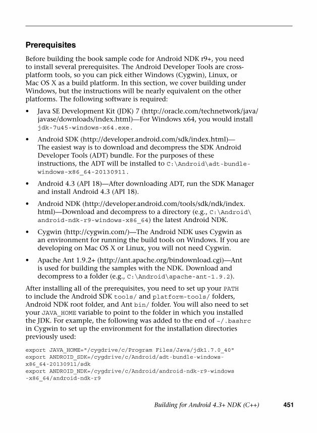
Building for Android 4.3+ NDK (C++) 451
Prerequisites
Before building the book sample code for Android NDK r9+, you need to install several prerequisites. The Android Developer Tools are cross-platform tools, so you can pick either Windows (Cygwin), Linux, or Mac OS X as a build platform. In this section, we cover building under Windows, but the instructions will be nearly equivalent on the other platforms. The following software is required:
• Java SE Development Kit (JDK) 7 (http://oracle.com/technetwork/java/javase/downloads/index.html)—For Windows x64, you would installjdk-7u45-windows-x64.exe.
• Android SDK (http://developer.android.com/sdk/index.html)—The easiest way is to download and decompress the SDK AndroidDeveloper Tools (ADT) bundle. For the purposes of theseinstructions, the ADT will be installed to C:\Android\adt-bundle-windows-x86_64-20130911.
• Android 4.3 (API 18)—After downloading ADT, run the SDK Managerand install Android 4.3 (API 18).
• Android NDK (http://developer.android.com/tools/sdk/ndk/index.html)—Download and decompress to a directory (e.g., C:\Android\android-ndk-r9-windows-x86_64) the latest Android NDK.
• Cygwin (http://cygwin.com/)—The Android NDK uses Cygwin asan environment for running the build tools on Windows. If you aredeveloping on Mac OS X or Linux, you will not need Cygwin.
• Apache Ant 1.9.2+ (http://ant.apache.org/bindownload.cgi)—Antis used for building the samples with the NDK. Download anddecompress to a folder (e.g., C:\Android\apache-ant-1.9.2).
After installing all of the prerequisites, you need to set up your PATH to include the Android SDK tools/ and platform-tools/ folders, Android NDK root folder, and Ant bin/ folder. You will also need to set your JAVA_HOME variable to point to the folder in which you installed the JDK. For example, the following was added to the end of ~/.bashrc in Cygwin to set up the environment for the installation directories previously used:
export JAVA_HOME="/cygdrive/c/Program Files/Java/jdk1.7.0_40"export ANDROID_SDK=/cygdrive/c/Android/adt-bundle-windows- x86_64-20130911/sdkexport ANDROID_NDK=/cygdrive/c/Android/android-ndk-r9-windows -x86_64/android-ndk-r9
452 Chapter 16: OpenGL ES Platforms
export ANT=/cygdrive/c/Android/apache-ant-1.9.2/binexport PATH=$PATH:${ANDROID_NDK}export PATH=$PATH:${ANT}export PATH=$PATH:${ANDROID_SDK}/toolsexport PATH=$PATH:${ANDROID_SDK}/platform-tools
Building the Example Code with Android NDK
Once the prerequisites have been installed, building the samples with the Android NDK is straightforward. From a terminal (Cygwin on Windows), navigate to the Android/ folder for the sample you want to build and enter the following commands:
Hello_Triangle/Android $ android.bat update project -p . -t android-18Hello_Triangle/Android/jni $ cd jniHello_Triangle/Android/jni $ ndk-buildHello_Triangle/Android/jni $ cd ..Hello_Triangle/Android $ ant debugHello_Triangle/Android $ adb install -r bin/NativeActivity-debug.apk
Note that on Mac OS X or Linux, you would use the command android instead of android.bat (the build steps are otherwise the same). The android.bat command will generate the project build files for the example. Navigating to the jni/ folder and entering ndk-build will compile the C source code for the project and generate the library file for the sample. Finally, running ant debug will build the final apk file that is installed to the device (done with the final step using the adb tool).
Once the sample is installed on the device, an icon for it will appear in the Apps list on the device. Any log message output from the sample can be viewed using adb logcat.
Building for Android 4.3+ SDK (Java)
The sample code in the book is written in native C, which is why we chose to port it to the Android NDK. While working with the NDK may be useful to Android developers who plan to write cross-platform native code, many Android applications are written in Java using the SDK instead of the NDK. To help developers who wish to work in Java with the SDK instead of the NDK, we also provide the book sample code in Java.

Building for iOS 7 453
If you have installed the Android ADT bundle (as described in the Prerequisites section of Building for the Android 4.3 NDK [C++]), then you have everything you need to run the Java versions of the applications. The Java samples are located in the Android_Java/ folder at the root of the sample code directory. To build and run the Java examples, simply open Eclipse and in your Workspace choose Import > General > Existing Projects Into Workspace. Point the import dialog to the Android_Java/ folder and you will be able to import all of the sample code from the book. Once you have imported the samples, you will be able to build and run them from Eclipse just as you would any Android application.
In general, the Java samples are equivalent to their native counterparts. The main difference is observed with asset loading, where in some cases the shaders are stored in external assets rather than placed inline with the code. This is generally a better practice and makes editing the shaders more straightforward. The reason this was not done in the C versions of the samples was to reduce platform variability in how files and other assets are loaded and to make the samples self-contained in a single file.
Building for iOS 7
Support for OpenGL ES 3.0 was added to iOS starting with version 7. The iPhone 5s (released in September 2013) is the first iOS device that supports OpenGL ES 3.0. The iOS Simulator that runs on Mac OS X also supports OpenGL ES 3.0, so it is possible to run and debug the book code samples without having an OpenGL ES 3.0–capable iOS device. This section details the steps to get up and running with the code samples on iOS7 using Xcode 5 on Mac OS X 10.8.5.
Prerequisites
The only prerequisite aside from Mac OS X 10.8.5 is to download and install Xcode 5. This version of Xcode contains the SDK for iOS 7 and is capable of building and running the sample code for the book.
Building the Example Code with Xcode 5
Each sample in the book has an iOS/ folder that contains the xcodeproj and related files needed for building on iOS. A screenshot of an example project open in Xcode and running on the iOS 7 Simulator is shown in Figure 16-2.
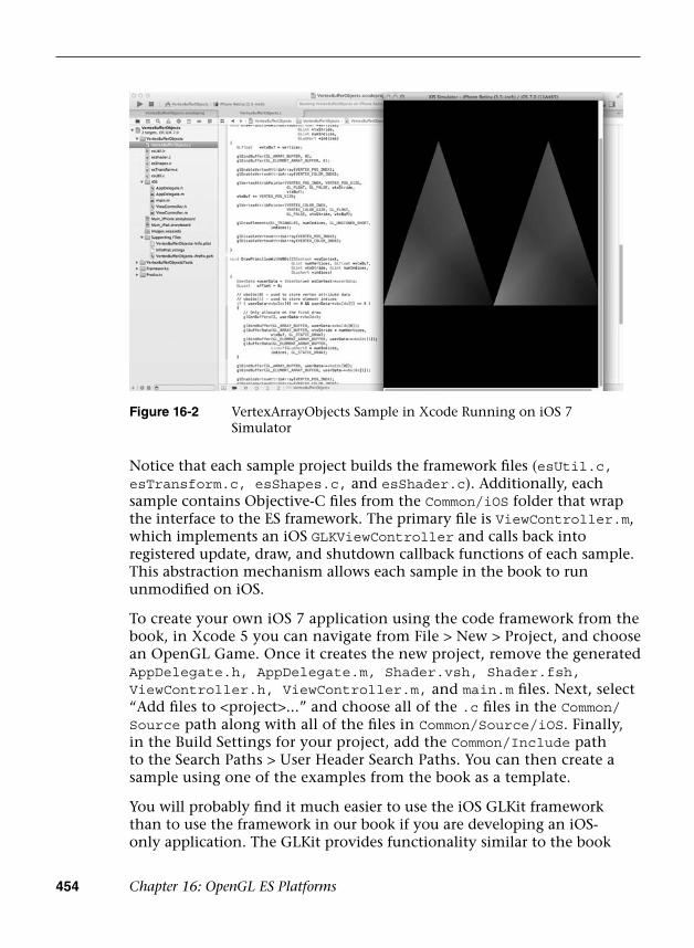
454 Chapter 16: OpenGL ES Platforms
Notice that each sample project builds the framework files (esUtil.c, esTransform.c, esShapes.c, and esShader.c). Additionally, each sample contains Objective-C files from the Common/iOS folder that wrap the interface to the ES framework. The primary file is ViewController.m, which implements an iOS GLKViewController and calls back into registered update, draw, and shutdown callback functions of each sample. This abstraction mechanism allows each sample in the book to run unmodified on iOS.
To create your own iOS 7 application using the code framework from the book, in Xcode 5 you can navigate from File > New > Project, and choose an OpenGL Game. Once it creates the new project, remove the generated AppDelegate.h, AppDelegate.m, Shader.vsh, Shader.fsh, ViewController.h, ViewController.m, and main.m files. Next, select “Add files to <project>...” and choose all of the .c files in the Common/Source path along with all of the files in Common/Source/iOS. Finally, in the Build Settings for your project, add the Common/Include path to the Search Paths > User Header Search Paths. You can then create a sample using one of the examples from the book as a template.
You will probably find it much easier to use the iOS GLKit framework than to use the framework in our book if you are developing an iOS-only application. The GLKit provides functionality similar to the book
Figure 16-2 VertexArrayObjects Sample in Xcode Running on iOS 7 Simulator

Summary 455
ES code framework, but is much more extensive. The one advantage to our framework is that it is not iOS-specific, so you may find this a useful approach if you are developing cross-platform applications designed to run on many different operating systems.
Summary
In this chapter, we covered how to build the sample code using OpenGL ES 3.0 emulators on Windows and Linux. We also covered how to build the sample code for OpenGL ES 3.0 on Android 4.3+ NDK using C, Android 4.3+ SDK with Java, and iOS7. The platforms supporting OpenGL ES are rapidly evolving. Please check the book website (opengles-book .com) for updated information on building for new platforms and new versions of existing platforms.

This page intentionally left blank
457
Appendix A
GL_HALF_FLOAT
GL_HALF_FLOAT is a vertex and texture data type supported by OpenGL ES 3.0. The GL_HALF_FLOAT data type is used to specify 16-bit floating-point values. This can be useful, for example, in specifying vertex attributes such as texture coordinates, normals, binormals, and tangent vectors. Using GL_HALF_FLOAT rather than GL_FLOAT provides a two times reduction in memory bandwidth required to read vertex or texture data by the GPU.
One might argue that we can use GL_SHORT or GL_UNSIGNED_SHORT instead of a 16-bit floating-point data type and get the same memory footprint and bandwidth savings. However, with that approach, you will need to scale the data or matrices appropriately and apply a transform in the vertex shader. For example, consider the case where a texture pattern is to be repeated four times horizontally and vertically over a quad. GL_SHORT can be used to store the texture coordinates. The texture coordinates could be stored as a value of 4.12 or 8.8. The texture coordinate values stored as GL_SHORT are scaled by (1 << 12) or (1 << 8) to give us a fixed-point representation that uses 4 bits or 8 bits of integer and 12 bits or 8 bits of fraction. Because OpenGL ES does not understand such a format, the vertex shader will then need to apply a matrix to unscale these values, which affects the vertex shading performance. These additional transforms are not required if a 16-bit floating-point format is used. Further, values represented as floating-point numbers have a larger dynamic range than fixed-point values because of the use of an exponent in the representation.
Note: Fixed-point values have a different error metric than floating-point values. The absolute error in a floating-point number is proportional to the magnitude of the value, whereas the absolute error in a

458 Appendix A: GL_HALF_FLOAT
fixed-point format is constant. Developers need to be aware of these precision issues when choosing which data type to use when generating coordinates for a particular format.
16-Bit Floating-Point Number
Figure A-1 describes the representation of a half-float number. A half-float is a 16-bit floating-point number with 10 bits of mantissa m, 5 bits of exponent e, and a sign bit s.
Figure A-1 A 16-Bit Floating-Point Number
s exponent (e) mantissa (m)
15 14 10 9 0
The following rules should be used when interpreting a 16-bit floating-point number:
• If exponent e is between 1 and 30, the half-float value is computed as(– l)s * 2e-15 * (1 + m/1024).
• If exponent e and mantissa m are both 0, the half-float value is 0.0.The sign bit is used to represent –ve 0.0 or +ve 0.0.
• If exponent e is 0 and mantissa m is not 0, the half-float value is adenormalized number.
• If exponent e is 31, the half-float value is either infinity (+ve or –ve)or a NaN (“not a number”) depending on whether the mantissa m iszero.
A few examples follow:
0 00000 0000000000 = 0.00 00000 0000001111 = a denorm value0 11111 0000000000 = positive infinity1 11111 0000000000 = negative infinity0 11111 0000011000 = NaN1 11111 1111111111 = NaN0 01111 0000000000 = 1.01 01110 0000000000 = −0.50 10100 1010101010 = 54.375
OpenGL ES 3.0 implementations must be able to accept input half-float data values that are infinity, NaN, or denormalized numbers. They do not
Converting a Float to a Half-Float 459
have to support 16-bit floating-point arithmetic operations with these values. Most implementations will convert denormalized numbers and NaN values to zero.
Converting a Float to a Half-Float
The following routines describe how to convert a single-precision floating-point number to a half-float value, and vice versa. The conversion routines are useful when vertex attributes are generated using single-precision floating-point calculations but then converted to half-floats before they are used as vertex attributes:
// −15 stored using a single-precision bias of 127const unsigned int HALF_FLOAT_MIN_BIASED_EXP_AS_SINGLE_FP_EXP = 0x38000000;// max exponent value in single precision that will be converted// to Inf or NaN when stored as a half-floatconst unsigned int HALF_FLOAT_MAX_BIASED_EXP_AS_SINGLE_FP_EXP = 0x47800000;
// 255 is the max exponent biased valueconst unsigned int FLOAT_MAX_BIASED_EXP = (0x1F << 23);
const unsigned int HALF_FLOAT_MAX_BIASED_EXP = (0x1F << 10);
typedef unsigned short hfloat;
hfloatconvertFloatToHFloat(float *f) { unsigned int x = *(unsigned int *)f; unsigned int sign = (unsigned short)(x >> 31); unsigned int mantissa; unsigned int exp; hfloat hf;
// get mantissa mantissa = x & ((1 << 23) − 1); // get exponent bits exp = X & FLOAT_MAX_BIASED_EXP; if (exp >= HALF_FLOAT_MAX_BIASED_EXP_AS_SINGLE_FP_EXP) {
// check if the original single-precision float number // is a NaN

460 Appendix A: GL_HALF_FLOAT
if (mantissa && (exp == FLOAT_MAX_BIASED_EXP)){
// we have a single-precision NaN mantissa = (1 << 23) − 1;
}else {
// 16-bit half-float representation stores number // as Inf mantissa = 0;
}hf = (((hfloat)sign) << 15) |
(hfloat)(HALF_FLOAT_MAX_BIASED_EXP) | (hfloat)(mantissa >> 13);
} // check if exponent is <= −15 else if (exp <= HALF_FLOAT_MIN_BIASED_EXP_AS_SINGLE_FP_EXP) {
// store a denorm half-float value or zeroexp = (HALF_FLOAT_MIN_BIASED_EXP_AS_SINGLE_FP_EXP − exp)
>> 23;mantissa >>= (14 + exp);
hf = (((hfloat)sign) << 15) | (hfloat)(mantissa); } else {
hf = (((hfloat)sign) << 15) | (hfloat)((exp − HALF_FLOAT_MIN_BIASED_EXP_AS_SINGLE_FP_EXP)>> 13)|(hfloat)(mantissa >> 13);
} return hf; }floatconvertHFloatToFloat(hfloat hf) { unsigned int sign = (unsigned int)(hf >> 15); unsigned int mantissa = (unsigned int)(hf &
((1 << 10) − 1)); unsigned int exp = (unsigned int)(hf &
HALF_FLOAT_MAX_BIASED_EXP); unsigned int f;
if (exp == HALF_FLOAT_MAX_BIASED_EXP) {
// we have a half-float NaN or Inf// half-float NaNs will be converted to a single-// precision NaN
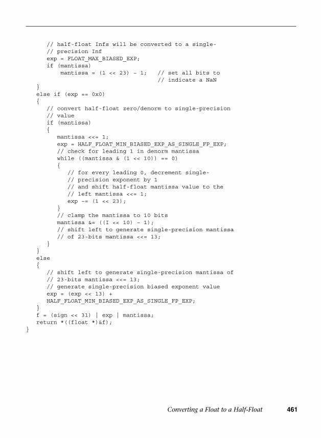
Converting a Float to a Half-Float 461
// half-float Infs will be converted to a single-// precision Inf exp = FLOAT_MAX_BIASED_EXP;if (mantissa)
mantissa = (1 << 23) − 1; // set all bits to // indicate a NaN
} else if (exp == 0x0) {
// convert half-float zero/denorm to single-precision // valueif (mantissa){
mantissa <<= 1;exp = HALF_FLOAT_MIN_BIASED_EXP_AS_SINGLE_FP_EXP;// check for leading 1 in denorm mantissawhile ((mantissa & (1 << 10)) == 0){
// for every leading 0, decrement single-// precision exponent by 1 // and shift half-float mantissa value to the // left mantissa <<= 1; exp −= (1 << 23);
}// clamp the mantissa to 10 bits mantissa &= ((I << 10) − 1);// shift left to generate single-precision mantissa // of 23-bits mantissa <<= 13;
} } else {
// shift left to generate single-precision mantissa of // 23-bits mantissa <<= 13;// generate single-precision biased exponent value exp = (exp << 13) +HALF_FLOAT_MIN_BIASED_EXP_AS_SINGLE_FP_EXP;
} f = (sign << 31) | exp | mantissa; return *((float *)&f); }

This page intentionally left blank
463
Appendix B
Built-In Functions
The OpenGL ES shading language built-in functions described in this appendix are copyrighted by Khronos and are reprinted with permission from the OpenGL ES 3.00.4 Shading Language Specification. The latest OpenGL ES 3.0 Shading Language specification can be downloaded from http://khronos.org/registry/gles/.
The OpenGL ES Shading Language defines an assortment of built-in convenience functions for scalar and vector operations. Many of these built-in functions can be used in more than one type of shader, but some are intended to provide a direct mapping to hardware and so are available only for a specific type of shader.
The built-in functions basically fall into three categories:
• They expose some necessary hardware functionality in a convenientway such as accessing a texture map. There is no way in the languagefor these functions to be emulated by a shader.
• They represent a trivial operation (clamp, mix, etc.) that is simple forthe user to write, but they are very common and might have directhardware support. It is a very hard problem for the compiler to mapexpressions to complex assembler instructions.
• They represent an operation graphics hardware that is likely toaccelerate at some point. The trigonometry functions fall into thiscategory.
Many of the functions are similar to the same named ones in common C libraries, but they support vector input as well as the more traditional scalar input.

464 Appendix B: Built-In Functions
Applications should be encouraged to use the built-in functions rather than do the equivalent computations in their own shader code because the built-in functions are assumed to be optimal (e.g., perhaps supported directly in hardware).
When the built-in functions are specified below, where the input arguments (and corresponding output) can be float, vec2, vec3, or vec4, genType is used as the argument. Where the input arguments (and corresponding output) can be int, ivec2, ivec3, or ivec4, genIType is used as the argument. Where the input arguments (and corresponding output) can be uint, uvec2, uvec3, or uvec4, genUType is used as the argument. Where the input arguments (or corresponding output) can be bool, bvec2, bvec3, or bvec4, genBType is used as the argument. For any specific use of a function, the actual types substituted for genType, genIType, genUType, or genBType have to have the same number of components for all arguments and for the return type. Similarly for mat, which can be any matrix basic type.
The precision of built-in functions is dependent on the function and arguments. There are three categories:
• Some functions have predefined precisions. The precision is specified;for example,
highp ivec2 textureSize (gsampler2D sampler, int lod )
• For the texture sampling functions, the precision of the return typematches the precision of the sampler type:
uniform lowp sampler2D sampler;
highp vec2 coord;
. . .
// texture() returns lowp
lowp vec4 col = texture(sampler, coord);
• For other built-in functions, a call will return a precision qualificationmatching the highest precision qualification of the call’s inputarguments.
The built-in functions are assumed to be implemented according to the equations specified in the following sections.

Angle and Trigonometry Functions 465
Angle and Trigonometry Functions
Function parameters specified as angle are assumed to be in units of radians. In no case will any of these functions result in a divide by zero error. If the divisor of a ratio is 0, then results will be undefined.
These functions all operate component-wise. The description shown in Table B-1 is per component.
Table B-1 Angle and Trigonometry Functions
Syntax Description
genType radians ( genType degrees)
Converts degrees to radians, i.e., π/180 * degrees.
genType degrees ( genType radians)
Converts radians to degrees, i.e., 180/π * radians.
genType sin (genType angle) The standard trigonometric sine function. Return values are in the range [–1, 1].
genType cos (genType angle) The standard trigonometric cosine function. Return values are in the range [–1, 1].
genType tan (genType angle) The standard trigonometric tangent function.
genType asin (genType x) Arc sine. Returns an angle whose sine is x. The range of values returned by this function is [–π/2, π/2]. Results are undefined if |x| > 1.
genType acos (genType x) Arc cosine. Returns an angle with cosine x. The range of values returned by this function is [0, π]. Results are undefined if |x| > 1.
genType atan ( genType y, genType x)
Arc tangent. Returns an angle with tangent y/x. The signs of x and y are used to determine what quadrant the angle is in. The range of values returned by this function is [–π, π]. Results are undefined if x and y are both 0.
genType atan ( genType y_over_x)
Arc tangent. Returns an angle with tangent y_over_x. The range of values returned by this function is [–π/2, π/2].
(continues)

466 Appendix B: Built-In Functions
Exponential Functions
Exponential functions all operate component-wise. The description shown in Table B-2 is per component.
Table B-1 Angle and Trigonometry Functions (continued)
Syntax Description
genType sinh (genType x) Returns the hyperbolic sine function (ex – e−x)/2
genType cosh (genType x) Returns the hyperbolic cosine function (ex + e−x)/2
genType tanh (genType x) Returns the hyperbolic tangent function sinh(x)/cosh(x)
genType asinh (genType x) Arc hyperbolic sine; returns the inverse of sinh.
genType acosh (genType x) Arc hyperbolic cosine; returns the non-negative inverse of cosh. Results are undefined if x < 1.
genType atanh (genType x) Arc hyperbolic tangent; returns the inverse of tanh. Results are undefined if ∣x∣ >= 1.
Table B-2 Exponential Functions
Syntax Description
genType pow ( genType x, genType y) Returns x raised to the y power, i.e., xy.
Results are undefined if x < 0.
Results are undefined if x = 0 and y <= 0.
genType exp (genType x) Returns the natural exponentiation of x, i.e., ex.
genType log (genType angle) Returns the natural logarithm of x, i.e., returns the value y, which satisfies the equation x = ey.
Results are undefined if x <= 0.
genType exp2 (genType angle) Returns 2 raised to the x power, i.e., 2x.

Common Functions 467
Common Functions
Common functions all operate component-wise. The description shown in Table B-3 is per component.
Table B-2 Exponential Functions (continued)
Syntax Description
genType log2 (genType angle) Returns the base 2 logarithm of x, i.e., returns the value y, which satisfies the equation x = 2y.
Results are undefined if x <= 0.
genType sqrt (genType x) Returns the positive square root of x. Results are undefined if x < 0.
genType inversesqrt (genType x) Returns the reciprocal of the positive square root of x.
Results are undefined if x <= 0.
Table B-3 Common Functions
Syntax Description
genType abs (genType x)
genIType abs (genIType x)
Returns x if x >= 0; otherwise, it returns –x.
genType sign (genType x)
genIType sign (genIType x)
Returns 1.0 if x > 0, 0.0 if x = 0, or –1.0 if x < 0.
genType floor (genType x) Returns a value equal to the nearest integer that is less than or equal to x.
genType trunc (genType x) Returns a value equal to the nearest integer to x whose absolute value is not larger than the absolute value of x.
(continues)

468 Appendix B: Built-In Functions
Table B-3 Common Functions (continued)
Syntax Description
genType round (genType x) Returns a value equal to the nearest integer to x. The fraction 0.5 will round in a direction chosen by the implementation, presumably the direction that is fastest. This includes the possibility that round(x) returns the same value as roundEven(x) for all values of x.
genType roundEven (genType x) Returns a value equal to the nearest integer to x. A fractional part of 0.5 will round toward the nearest even integer. (Both 3.5 and 4.5 for x will return 4.0.)
genType ceil (genType x) Returns a value equal to the nearest integer that is greater than or equal to x.
genType fract (genType x) Returns x – floor(x).
genType mod (genType x, float y)
genType mod (genType x, genType y)
Modulus (modulo). Returns x – y * floor(x/y).
genType min (genType x, genType y)
genType min (genType x, float y)
genIType min ( genIType x, genIType y)
genIType min (genIType x, int y)
genUType min ( genUType x, genUType y)
genUType min (genUType x, uint y)
Returns y if y < x; otherwise, it returns x.
genType max (genType x, genType y)
genType max (genType x, float y)
genIType max ( genIType x, genIType y)
genIType max (genIType x, int y)
genUType max ( genUType x, genUType y)
genUType max (genUType x, uint y)
Returns y if x < y; otherwise, it returns x.
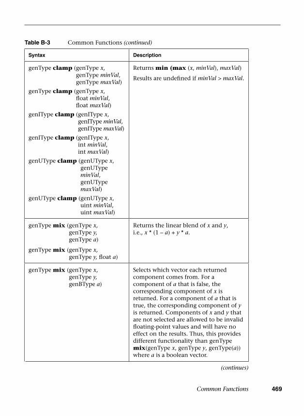
Common Functions 469
Table B-3 Common Functions (continued)
Syntax Description
genType clamp ( genType x, genType minVal, genType maxVal)
genType clamp ( genType x, float minVal, float maxVal)
genIType clamp ( genIType x, genIType minVal, genIType maxVal)
genIType clamp ( genIType x, int minVal, int maxVal)
genUType clamp ( genUType x, genUType minVal, genUType maxVal)
genUType clamp ( genUType x, uint minVal, uint maxVal)
Returns min (max (x, minVal), maxVal)
Results are undefined if minVal > maxVal.
genType mix ( genType x, genType y, genType a)
genType mix ( genType x, genType y, float a)
Returns the linear blend of x and y, i.e., x * (1 – a) + y * a.
genType mix ( genType x, genType y, genBType a)
Selects which vector each returned component comes from. For a component of a that is false, the corresponding component of x is returned. For a component of a that is true, the corresponding component of y is returned. Components of x and y that are not selected are allowed to be invalid floating-point values and will have no effect on the results. Thus, this provides different functionality than genType mix(genType x, genType y, genType(a)) where a is a boolean vector.
(continues)

470 Appendix B: Built-In Functions
Table B-3 Common Functions (continued)
Syntax Description
genType step ( genType edge, genType x)
genType step (float edge, genType x)
Returns 0.0 if x < edge; otherwise, it returns 1.0.
genType smoothstep ( genType edge0, genType edgel, genType x)
genType smoothstep ( float edge0, float edgel, gemType x)
Returns 0.0 if x <= edge0 and 1.0 if x >= edgel and performs smooth Hermite interpolation between 0 and 1 when edge0 < x < edgel. This is useful in cases where you would want a threshold function with a smooth transition. This is equivalent to:
// genType is float, vec2, vec3,// or vec4genType t;t = clamp((x – edge0)/ (edgel – edge0), 0, 1);return t * t * (3 − 2 * t);
Results are undefined if edge0 >= edgel.
genBType isnan (genType x) Returns true if x holds a NaN. Returns false otherwise.
genBType isinf (genType x) Returns true if x holds a positive infinity or negative infinity. Returns false otherwise.
genIType floatBitsToInt ( genType value)
genUType floatBitsToUint (genType value)
Returns a signed or unsigned highp integer value representing the encoding of a floating-point value. For highp floating point, the value’s bit-level representation is preserved. For mediump and lowp, the value is first converted to highp floating point and the encoding of that value is returned.
genType intBitsToFloat ( genIType value)
genType uintBitsToFloat (genUType value)
Returns a highp floating-point value corresponding to a signed or unsigned integer encoding of a floating-point value. If an inf or NaN is passed in, it will not signal, and the resulting floating-point value is unspecified. Otherwise, the bit-level representation is preserved. For lowp and mediump, the value is first converted to the corresponding signed or unsigned highp integer and then reinterpreted as a highp floating-point value as before.
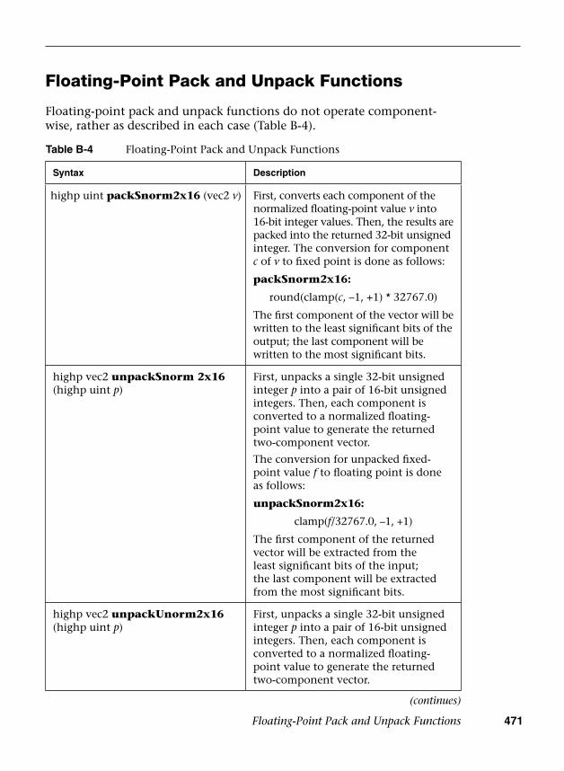
Floating-Point Pack and Unpack Functions 471
Floating-Point Pack and Unpack Functions
Floating-point pack and unpack functions do not operate component-wise, rather as described in each case (Table B-4).
Table B-4 Floating-Point Pack and Unpack Functions
Syntax Description
highp uint packSnorm2x16 (vec2 v) First, converts each component of the normalized floating-point value v into 16-bit integer values. Then, the results are packed into the returned 32-bit unsignedinteger. The conversion for component c of v to fixed point is done as follows:
packSnorm2x16:
round(clamp(c, –1, +1) * 32767.0)
The first component of the vector will be written to the least significant bits of the output; the last component will be written to the most significant bits.
highp vec2 unpackSnorm 2x16 (highp uint p)
First, unpacks a single 32-bit unsigned integer p into a pair of 16-bit unsigned integers. Then, each component is converted to a normalized floating-point value to generate the returned two-component vector.
The conversion for unpacked fixed-point value f to floating point is done as follows:
unpackSnorm2x16:
clamp(f/32767.0, –1, +1)
The first component of the returned vector will be extracted from the least significant bits of the input; the last component will be extracted from the most significant bits.
highp vec2 unpackUnorm2x16 (highp uint p)
First, unpacks a single 32-bit unsigned integer p into a pair of 16-bit unsigned integers. Then, each component is converted to a normalized floating-point value to generate the returned two-component vector.
(continues)
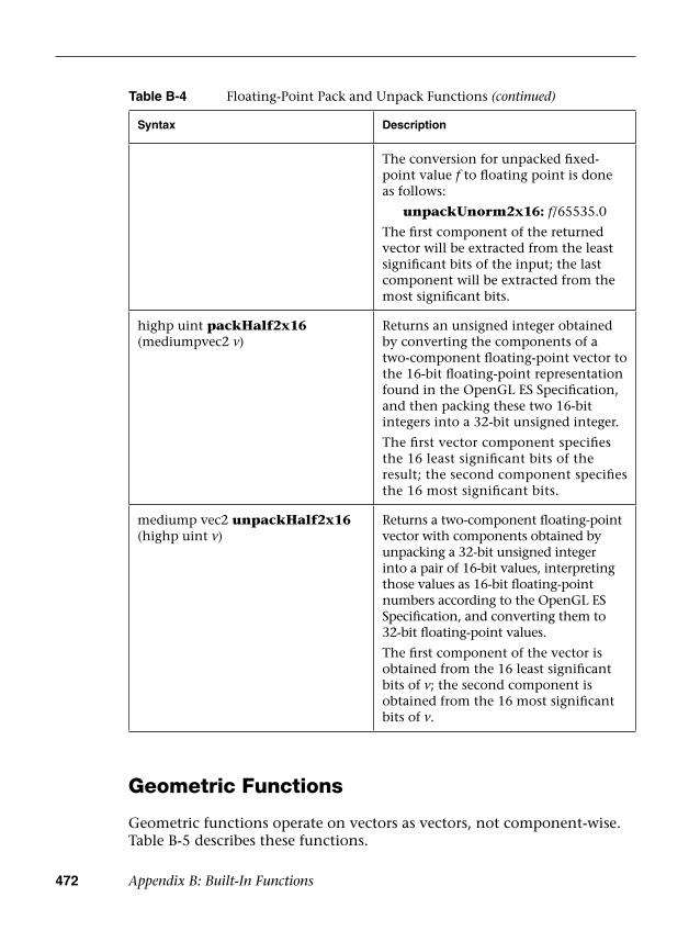
472 Appendix B: Built-In Functions
Table B-4 Floating-Point Pack and Unpack Functions (continued)
Syntax Description
The conversion for unpacked fixed-point value f to floating point is done as follows:
unpackUnorm2x16: f/65535.0
The first component of the returned vector will be extracted from the least significant bits of the input; the last component will be extracted from the most significant bits.
highp uint packHalf2x16 (mediumpvec2 v)
Returns an unsigned integer obtained by converting the components of a two-component floating-point vector to the 16-bit floating-point representation found in the OpenGL ES Specification, and then packing these two 16-bit integers into a 32-bit unsigned integer.
The first vector component specifies the 16 least significant bits of the result; the second component specifies the 16 most significant bits.
mediump vec2 unpackHalf2x16 (highp uint v)
Returns a two-component floating-point vector with components obtained by unpacking a 32-bit unsigned integer into a pair of 16-bit values, interpreting those values as 16-bit floating-point numbers according to the OpenGL ES Specification, and converting them to 32-bit floating-point values.
The first component of the vector is obtained from the 16 least significant bits of v; the second component is obtained from the 16 most significant bits of v.
Geometric Functions
Geometric functions operate on vectors as vectors, not component-wise. Table B-5 describes these functions.

Geometric Functions 473
Table B-5 Geometric Functions
Syntax Description
float length (genType x) Returns the length of vector x,
X X[0] [1] …2 2+ +
float distance ( genType p0, genType p1)
Returns the distance between p0 and p1, i.e., length (p0 – p1).
float dot (genType x, genType y) Returns the dot product of x and y, i.e., x[0] * y[0] + x[l] * y[l] + ...
vec3 cross (vec3 x, vec3 y) Returns the cross product of x and y, i.e.,result[0] = x[1] * y[2] – y[1] * x[2]result[1] = x[2] * y[0] – y[2] * x[0]result[2] = x[0] * y[1] – y[0] * x[1]
genType normalize (genType x) Returns a vector in the same direction as x but with a length of 1.
Returns x/length(x).
genType faceforward (genType N, genType I, genType Nref )
If dot(Nref, I) < 0, return N; otherwise, return –N.
genType reflect ( genType I, genType N)
For the incident vector I and surface orientation N, returns the reflection direction:
I – 2 * dot(N, I) * N
N must already be normalized to achieve the desired result.
genType refract ( genType I, genType N, float eta)
For the incident vector I, surface normal N, and ratio of indices of refraction eta, return the refraction vector. The result is computed by
k = 1.0 – eta * eta * (1.0 – dot(N, I)
* dot(N, I))if (k < 0.0) // genType is float, vec2, // vec3, or vec4 return genType(0.0)else return eta * I – (eta *
dot(N, I) + sqrt(k)) * N
Input parameters for the incident vector I and the surface normal N must already be normalized to get the desired results.

474 Appendix B: Built-In Functions
Matrix Functions
The built-in functions that operate on matrices are described in Table B-6.
Table B-6 Matrix Functions
Syntax Description
mat2 matrixCompMult ( mat2 x, mat2 y) mat3 matrixCompMult ( mat3 x, mat3 y) mat4 matrixCompMult ( mat4 x, mat4 y)
Multiply matrix x by matrix y component-wise, i.e., result[i][j] is the scalar product of x[i][j] and y[i][j].
Note: To get linear algebraic matrix multiplication, use the multiply operator (*).
mat2 outerProduct(vec2 c, vec2 r)mat3 outerProduct(vec3 c, vec3 r)mat4 outerProduct(vec4 c, vec4 r)
mat2x3 outerProduct(vec3 c, vec2 r)mat3x2 outerProduct(vec2 c, vec3 r)mat2x4 outerProduct(vec4 c, vec2 r)mat4x2 outerProduct(vec2 c, vec4 r)mat3x4 outerProduct(vec4 c, vec3 r)mat4x3 outerProduct(vec3 c, vec4 r)
Treats the first parameter c as a column vector (matrix with one column) and the second parameter r as a row vector (matrix with one row) and does a linear algebraic matrix multiply c * r, yielding a matrix whose number of rows is the number of components in c and whose number of columns is the number of components in r.
mat2 transpose(mat2 m)mat3 transpose(mat3 m)mat4 transpose(mat4 m)mat2x3 transpose(mat3x2 m)mat3x2 transpose(mat2x3 m)mat2x4 transpose(mat4x2 m)mat4x2 transpose(mat2x4 m)mat3x4 transpose(mat4x3 m)mat4x3 transpose(mat3x4 m)
Returns a matrix that is the transpose of m. The input matrix m is not modified.
float determinant(mat2 m)float determinant(mat3 m)float determinant(mat4 m)
Returns the determinant of m.
mat2 inverse(mat2 m)mat3 inverse(mat3 m)mat4 inverse(mat4 m)
Returns a matrix that is the inverse of m. The input matrix m is not modified.The values in the returned matrix are undefined if m is singular or poorly conditioned (nearly singular).
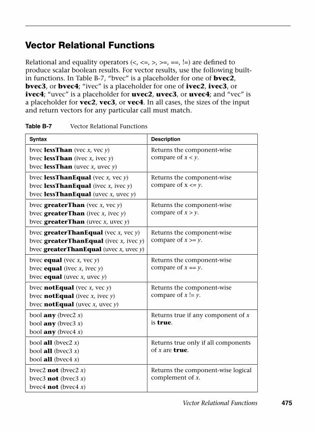
Vector Relational Functions 475
Vector Relational Functions
Relational and equality operators (<, <=, >, >=, ==, !=) are defined to produce scalar boolean results. For vector results, use the following built-in functions. In Table B-7, “bvec” is a placeholder for one of bvec2, bvec3, or bvec4; “ivec” is a placeholder for one of ivec2, ivec3, or ivec4; “uvec” is a placeholder for uvec2, uvec3, or uvec4; and “vec” is a placeholder for vec2, vec3, or vec4. In all cases, the sizes of the input and return vectors for any particular call must match.
Table B-7 Vector Relational Functions
Syntax Description
bvec lessThan (vec x, vec y)bvec lessThan (ivec x, ivec y)bvec lessThan (uvec x, uvec y)
Returns the component-wise compare of x < y.
bvec lessThanEqual (vec x, vec y)bvec lessThanEqual (ivec x, ivec y)bvec lessThanEqual (uvec x, uvec y)
Returns the component-wise compare of x <= y.
bvec greaterThan (vec x, vec y)bvec greaterThan (ivec x, ivec y)bvec greaterThan (uvec x, uvec y)
Returns the component-wise compare of x > y.
bvec greaterThanEqual (vec x, vec y)bvec greaterThanEqual (ivec x, ivec y)bvec greaterThanEqual (uvec x, uvec y)
Returns the component-wise compare of x >= y.
bvec equal (vec x, vec y)bvec equal (ivec x, ivec y)bvec equal (uvec x, uvec y)
Returns the component-wise compare of x == y.
bvec notEqual (vec x, vec y)bvec notEqual (ivec x, ivec y)bvec notEqual (uvec x, uvec y)
Returns the component-wise compare of x != y.
bool any (bvec2 x)bool any (bvec3 x)bool any (bvec4 x)
Returns true if any component of x is true.
bool all (bvec2 x)bool all (bvec3 x)bool all (bvec4 x)
Returns true only if all components of x are true.
bvec2 not (bvec2 x)bvec3 not (bvec3 x)bvec4 not (bvec4 x)
Returns the component-wise logical complement of x.

476 Appendix B: Built-In Functions
Texture Lookup Functions
Texture lookup functions are available to vertex and fragment shaders. However, level of detail is not implicitly computed for vertex shaders. The functions in Table B-8 provide access to textures through samplers, as set up through the OpenGL ES API. Texture properties such as size, pixel format, number of dimensions, filtering method, number of mipmap levels, depth comparison, and so on are also defined by OpenGL ES API calls. Such properties are taken into account as the texture is accessed via the built-in functions defined below.
Texture data can be stored by the GL as floating-point, unsigned normalized integer, unsigned integer, or signed integer data. This is determined by the type of the internal format of the texture. Texture lookups on unsigned normalized integer and floating-point data return floating-point values in the range [0, 1].
Texture lookup functions are provided that can return their result as floating-point, unsigned integer, or signed integer values, depending on the sampler type passed to the lookup function. Care must be taken to use the right sampler type for texture access. Table B-8 lists the supported combinations of sampler types and texture internal formats. Blank entries are unsupported. Doing a texture lookup will return undefined values for unsupported combinations.
If an integer sampler type is used, the result of a texture lookup is an ivec4. If an unsigned integer sampler type is used, the result of a texture lookup is a uvec4. If a floating-point sampler type is used, the result of a texture lookup is a vec4, where each component is in the range [0, 1].
Table B-8 Supported Combinations of Sampler and Internal Texture Formats
Internal Texture Format
Floating-Point Sampler Types
Signed Integer Sampler Types
Unsigned Integer Sampler Types
Floating point Supported
Normalized integer
Supported
Signed integer Supported
Unsigned integer Supported
Texture Lookup Functions 477
In the prototypes below, the “g” in the return type “gvec4” is used as a placeholder for nothing; “i” or “u” making a return type of vec4, ivec4, or uvec4. In these cases, the sampler argument type also starts with “g”, indicating the same substitution done on the return type; it is either a floating-point, signed integer, or unsigned integer sampler, matching the basic type of the return type, as described above.
For shadow forms (the sampler parameter is a shadow type), a depth comparison lookup on the depth texture bound to sampler is done as described in section 3.8.16, “Texture Comparison Modes,” of the OpenGL ES Graphics System Specification. See the table below for which component specifies Dref. The texture bound to sampler must be a depth texture, or results are undefined. If a non-shadow texture call is made to a sampler that represents a depth texture with depth comparisons turned on, then results are undefined. If a shadow texture call is made to a sampler that represents a depth texture with depth comparisons turned off, then results are undefined. If a shadow texture call is made to a sampler that does not represent a depth texture, then results are undefined.
In all functions below, the bias parameter is optional for fragment shaders. The bias parameter is not accepted in a vertex shader. For a fragment shader, if bias is present, it is added to the implicit level of detail prior to performing the texture access operation.
The implicit level of detail is selected as follows: For a texture that is not mipmapped, the texture is used directly. If it is mipmapped and running in a fragment shader, the LOD computed by the implementation is used to do the texture lookup. If it is mipmapped and running on the vertex shader, then the base texture is used.
Some texture functions (non-“Lod” and non-“Grad” versions) may require implicit derivatives. Implicit derivatives are undefined within non-uniform control flow and for vertex texture fetches.
For Cube forms, the direction of P is used to select which face to do a two-dimensional texture lookup in, as described in section 3.8.10, “Cube Map Texture Selection,” in the OpenGL ES Graphics System Specification.
For Array forms, the array layer used will be
max(0,min(d − 1, floor(layer + 0.5)))
where d is the depth of the texture array and layer comes from the component indicated in Table B-9.

ptg12025281
478 A
ppendix B: B
uilt-In Functions
Table B-9 Texture Lookup Functions
Syntax Description
highp ivec2 textureSize (gsampler2D sampler, int lod)highp ivec3 textureSize (gsampler3D sampler, int lod)highp ivec2 textureSize (gsamplerCube sampler, int lod)
highp ivec2 textureSize (sampler2DShadow sampler, int lod)highp ivec2 textureSize (samplerCubeShadow sampler, int lod)
highp ivec3 textureSize (gsampler2DArray sampler, int lod)
highp ivec3 textureSize (sampler2DArrayShadow sampler, int lod)
Returns the dimensions of level lod for the texture bound to sampler, as described in section 2.11.9, “Shader Execution,” of the OpenGL ES 3.0 Graphics System Specification, under “Texture Size Query.”
The components in the return value are filled in, in order, with the width, height, and depth of the texture. For the array forms, the last component of the return value is the number of layers in the texture array.
gvec4 texture (gsampler2D sampler, vec2 P [, float bias] )gvec4 texture (gsampler3D sampler, vec3 P [, float bias] )gvec4 texture (gsamplerCube sampler, vec3 P [, float bias] )float texture (sampler2DShadow sampler, vec3 P [, float bias] )float texture (samplerCubeShadow sampler, vec4 P [, float bias] )gvec4 texture (gsampler2DArray sampler, vec3 P [, float bias] )float texture (sampler2DArrayShadow sampler, vec4 P)
Use the texture coordinate P to do a texture lookup in the texture currently bound to sampler. The last component of P is used as Dref for the shadow forms. For array forms, the array layer comes from the last component of P in the non-shadow forms, and the second-to-last component of P in the shadow forms.
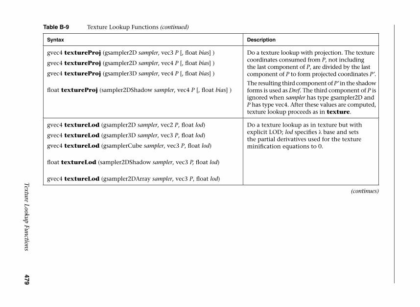
ptg12025281
Texture Lookup Functions 479
Table B-9 Texture Lookup Functions (continued)
Syntax Description
gvec4 textureProj (gsampler2D sampler, vec3 P [, float bias] )
gvec4 textureProj (gsampler2D sampler, vec4 P [, float bias] )
gvec4 textureProj (gsampler3D sampler, vec4 P [, float bias] )
float textureProj (sampler2DShadow sampler, vec4 P [, float bias] )
Do a texture lookup with projection. The texture coordinates consumed from P, not including the last component of P, are divided by the last component of P to form projected coordinates P’.
The resulting third component of P’ in the shadow forms is used as Dref. The third component of P is ignored when sampler has type gsampler2D and P has type vec4. After these values are computed, texture lookup proceeds as in texture.
gvec4 textureLod (gsampler2D sampler, vec2 P, float lod)
gvec4 textureLod (gsampler3D sampler, vec3 P, float lod)
gvec4 textureLod (gsamplerCube sampler, vec3 P, float lod)
float textureLod (sampler2DShadow sampler, vec3 P, float lod)
gvec4 textureLod (gsampler2DArray sampler, vec3 P, float lod)
Do a texture lookup as in texture but with explicit LOD; lod specifies λ base and setsthe partial derivatives used for the texture minification equations to 0.
(continues)
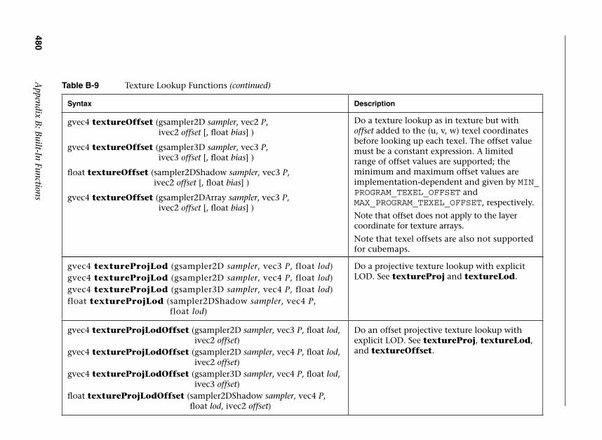
ptg12025281
480 A
ppendix B: B
uilt-In Functions
Table B-9 Texture Lookup Functions (continued)
Syntax Description
gvec4 textureOffset ( gsampler2D sampler, vec2 P, ivec2 offset [, float bias] )
gvec4 textureOffset ( gsampler3D sampler, vec3 P, ivec3 offset [, float bias] )
float textureOffset ( sampler2DShadow sampler, vec3 P, ivec2 offset [, float bias] )
gvec4 textureOffset ( gsampler2DArray sampler, vec3 P, ivec2 offset [, float bias] )
Do a texture lookup as in texture but with offset added to the (u, v, w) texel coordinates before looking up each texel. The offset value must be a constant expression. A limited range of offset values are supported; the minimum and maximum offset values are implementation-dependent and given by MIN_PROGRAM_TEXEL_OFFSET and MAX_PROGRAM_TEXEL_OFFSET, respectively.
Note that offset does not apply to the layer coordinate for texture arrays.
Note that texel offsets are also not supported for cubemaps.
gvec4 textureProjLod ( gsampler2D sampler, vec3 P, float lod)gvec4 textureProjLod ( gsampler2D sampler, vec4 P, float lod)gvec4 textureProjLod ( gsampler3D sampler, vec4 P, float lod)float textureProjLod ( sampler2DShadow sampler, vec4 P,
float lod)
Do a projective texture lookup with explicit LOD. See textureProj and textureLod.
gvec4 textureProjLodOffset ( gsampler2D sampler, vec3 P, float lod, ivec2 offset)
gvec4 textureProjLodOffset ( gsampler2D sampler, vec4 P, float lod, ivec2 offset)
gvec4 textureProjLodOffset ( gsampler3D sampler, vec4 P, float lod, ivec3 offset)
float textureProjLodOffset ( sampler2DShadow sampler, vec4 P, float lod, ivec2 offset)
Do an offset projective texture lookup with explicit LOD. See textureProj, textureLod, and textureOffset.
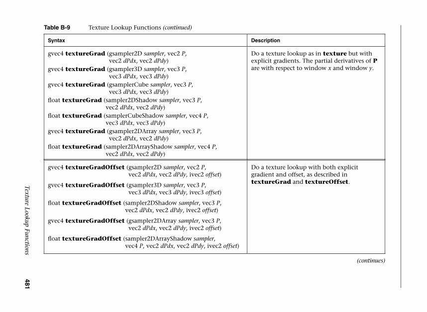
ptg12025281
Texture Lookup Functions 481
Table B-9 Texture Lookup Functions (continued)
Syntax Description
gvec4 textureGrad ( gsampler2D sampler, vec2 P, vec2 dPdx, vec2 dPdy)
gvec4 textureGrad ( gsampler3D sampler, vec3 P, vec3 dPdx, vec3 dPdy)
gvec4 textureGrad ( gsamplerCube sampler, vec3 P, vec3 dPdx, vec3 dPdy)
float textureGrad ( sampler2DShadow sampler, vec3 P, vec2 dPdx, vec2 dPdy)
float textureGrad ( samplerCubeShadow sampler, vec4 P, vec3 dPdx, vec3 dPdy)
gvec4 textureGrad ( gsampler2DArray sampler, vec3 P, vec2 dPdx, vec2 dPdy)
float textureGrad ( sampler2DArrayShadow sampler, vec4 P, vec2 dPdx, vec2 dPdy)
Do a texture lookup as in texture but with explicit gradients. The partial derivatives of P are with respect to window x and window y.
gvec4 textureGradOffset ( gsampler2D sampler, vec2 P, vec2 dPdx, vec2 dPdy, ivec2 offset)
gvec4 textureGradOffset ( gsampler3D sampler, vec3 P, vec3 dPdx, vec3 dPdy, ivec3 offset)
float textureGradOffset ( sampler2DShadow sampler, vec3 P, vec2 dPdx, vec2 dPdy, ivec2 offset)
gvec4 textureGradOffset ( gsampler2DArray sampler, vec3 P, vec2 dPdx, vec2 dPdy, ivec2 offset)
float textureGradOffset ( sampler2DArrayShadow sampler, vec4 P, vec2 dPdx, vec2 dPdy, ivec2 offset)
Do a texture lookup with both explicit gradient and offset, as described in textureGrad and textureOffset.
(continues)

ptg12025281
482 A
ppendix B: B
uilt-In Functions
Table B-9 Texture Lookup Functions (continued)
Syntax Description
gvec4 textureProjGrad ( gsampler2D sampler, vec3 P, vec2 dPdx, vec2 dPdy)
gvec4 textureProjGrad ( gsampler2D sampler, vec4 P, vec2 dPdx, vec2 dPdy)
gvec4 textureProjGrad ( gsampler3D sampler, vec4 P, vec3 dPdx, vec3 dPdy)
float textureProjGrad ( sampler2DShadow sampler, vec4 P, vec2 dPdx, vec2 dPdy)
Do a texture lookup both projectively, as described in textureProj, and with explicit gradient, as described in textureGrad. The partial derivatives dPdx and dPdy are assumed to be already projected.
gvec4 textureProjGradOffset ( gsampler2D sampler, vec3 P, vec2 dPdx, vec2 dPdy, ivec2 offset)
gvec4 textureProjGradOffset ( gsampler2D sampler, vec4 P, vec2 dPdx, vec2 dPdy, ivec2 offset)
gvec4 textureProjGradOffset ( gsampler3D sampler, vec4 P, vec3 dPdx, vec3 dPdy, ivec3 offset)
float textureProjGradOffset ( sampler2DShadow sampler, vec4 P, vec2 dPdx, vec2 dPdy, ivec2 offset)
Do a texture lookup projectively and with explicit gradient as described in textureProjGrad, as well as with offset, as described in textureOffset.
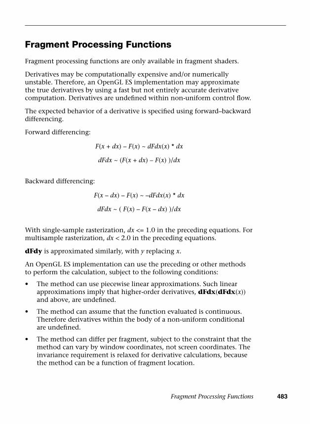
Fragment Processing Functions 483
Fragment Processing Functions
Fragment processing functions are only available in fragment shaders.
Derivatives may be computationally expensive and/or numerically unstable. Therefore, an OpenGL ES implementation may approximate the true derivatives by using a fast but not entirely accurate derivative computation. Derivatives are undefined within non-uniform control flow.
The expected behavior of a derivative is specified using forward–backward differencing.
Forward differencing:
F(x + dx) – F(x) ~ dFdx(x) * dx
dFdx ~ (F(x + dx) – F(x) )/dx
Backward differencing:
F(x – dx) – F(x) ~ –dFdx(x) * dx
dFdx ~ ( F(x) – F(x – dx) )/dx
With single-sample rasterization, dx <= 1.0 in the preceding equations. For multisample rasterization, dx < 2.0 in the preceding equations.
dFdy is approximated similarly, with y replacing x.
An OpenGL ES implementation can use the preceding or other methods to perform the calculation, subject to the following conditions:
• The method can use piecewise linear approximations. Such linearapproximations imply that higher-order derivatives, dFdx(dFdx(x))and above, are undefined.
• The method can assume that the function evaluated is continuous.Therefore derivatives within the body of a non-uniform conditionalare undefined.
• The method can differ per fragment, subject to the constraint that themethod can vary by window coordinates, not screen coordinates. Theinvariance requirement is relaxed for derivative calculations, becausethe method can be a function of fragment location.
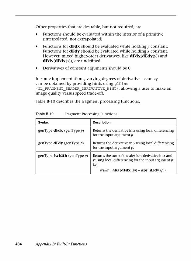
484 Appendix B: Built-In Functions
Table B-10 Fragment Processing Functions
Syntax Description
genType dFdx (genType p) Returns the derivative in x using local differencing for the input argument p.
genType dFdy (genType p) Returns the derivative in y using local differencing for the input argument p.
genType fwidth (genType p) Returns the sum of the absolute derivative in x and y using local differencing for the input argument p; i.e.,
result = abs (dFdx (p)) + abs (dFdy (p)).
Other properties that are desirable, but not required, are
• Functions should be evaluated within the interior of a primitive(interpolated, not extrapolated).
• Functions for dFdx should be evaluated while holding y constant.Functions for dFdy should be evaluated while holding x constant.However, mixed higher-order derivatives, like dFdx(dFdy(y)) anddFdy(dFdx(x)), are undefined.
• Derivatives of constant arguments should be 0.
In some implementations, varying degrees of derivative accuracy can be obtained by providing hints using glHint (GL_FRAGMENT_SHADER_DERIVATIVE_HINT), allowing a user to make an image quality versus speed trade-off.
Table B-10 describes the fragment processing functions.
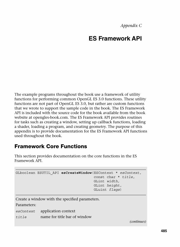
485
Appendix C
ES Framework API
The example programs throughout the book use a framework of utility functions for performing common OpenGL ES 3.0 functions. These utility functions are not part of OpenGL ES 3.0, but rather are custom functions that we wrote to support the sample code in the book. The ES Framework API is included with the source code for the book available from the book website at opengles-book.com. The ES Framework API provides routines for tasks such as creating a window, setting up callback functions, loading a shader, loading a program, and creating geometry. The purpose of this appendix is to provide documentation for the ES Framework API functions used throughout the book.
Framework Core Functions
This section provides documentation on the core functions in the ES Framework API.
GLboolean ESUTIL_API esCreateWindow (ESContext * esContext,const char * title,GLint width,GLint height,GLuint flags)
Create a window with the specified parameters.
Parameters:
esContext application context
title name for title bar of window(continues)
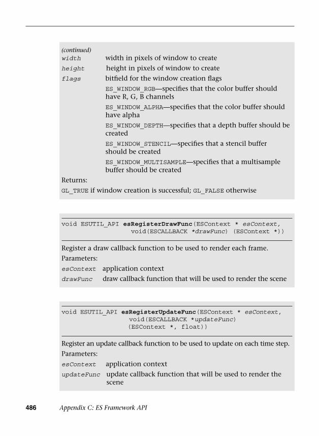
486 Appendix C: ES Framework API
void ESUTIL_API esRegisterDrawFunc(ESContext * esContext, void(ESCALLBACK *drawFunc) (ESContext *))
Register a draw callback function to be used to render each frame.
Parameters:
esContext application context
drawFunc draw callback function that will be used to render the scene
void ESUTIL_API esRegisterUpdateFunc(ESContext * esContext,void(ESCALLBACK *updateFunc)(ESContext *, float))
Register an update callback function to be used to update on each time step.
Parameters:
esContext application context
updateFunc update callback function that will be used to render the scene
(continued)width width in pixels of window to create
height height in pixels of window to create
flags bitfield for the window creation flags
ES_WINDOW_RGB—specifies that the color buffer should have R, G, B channels
ES_WINDOW_ALPHA—specifies that the color buffer should have alpha
ES_WINDOW_DEPTH—specifies that a depth buffer should be created
ES_WINDOW_STENCIL—specifies that a stencil buffer should be created
ES_WINDOW_MULTISAMPLE—specifies that a multisample buffer should be created
Returns:
GL_TRUE if window creation is successful; GL_FALSE otherwise
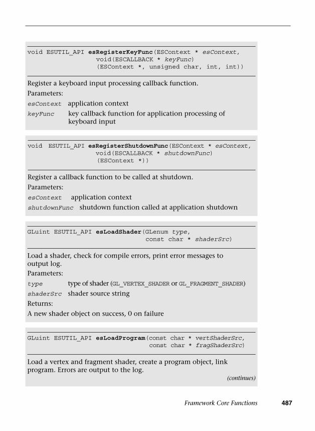
Framework Core Functions 487
void ESUTIL_API esRegisterKeyFunc(ESContext * esContext,void(ESCALLBACK * keyFunc)(ESContext *, unsigned char, int, int))
Register a keyboard input processing callback function.
Parameters:
esContext application context
keyFunc key callback function for application processing of keyboard input
void ESUTIL_API esRegisterShutdownFunc(ESContext * esContext,void(ESCALLBACK * shutdownFunc)(ESContext *))
Register a callback function to be called at shutdown.
Parameters:
esContext application context
shutdownFunc shutdown function called at application shutdown
GLuint ESUTIL_API esLoadShader(GLenum type,const char * shaderSrc)
Load a shader, check for compile errors, print error messages tooutput log.Parameters:
type type of shader (GL_VERTEX_SHADER or GL_FRAGMENT_SHADER)
shaderSrc shader source string
Returns:
A new shader object on success, 0 on failure
GLuint ESUTIL_API esLoadProgram(const char * vertShaderSrc,const char * fragShaderSrc)
Load a vertex and fragment shader, create a program object, link program. Errors are output to the log.
(continues)
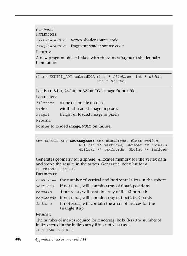
488 Appendix C: ES Framework API
char* ESUTIL_API esLoadTGA(char * fileName, int * width,int * height)
Loads an 8-bit, 24-bit, or 32-bit TGA image from a file.Parameters:filename name of the file on diskwidth width of loaded image in pixelsheight height of loaded image in pixelsReturns:Pointer to loaded image; NULL on failure.
int ESUTIL_API esGenSphere(int numSlices, float radius,GLfloat ** vertices, GLfloat ** normals, GLfloat ** texCoords, GLuint ** indices)
Generates geometry for a sphere. Allocates memory for the vertex data and stores the results in the arrays. Generates index list for a GL_TRIANGLE_STRIP.Parameters:numSlices the number of vertical and horizontal slices in the spherevertices if not NULL, will contain array of float3 positionsnormals if not NULL, will contain array of float3 normalstexCoords if not NULL, will contain array of float2 texCoordsindices if not NULL, will contain the array of indices for the
triangle strip
Returns:The number of indices required for rendering the buffers (the number of indices stored in the indices array if it is not NULL) as a GL_TRIANGLE_STRIP
(continued)Parameters:vertShaderSrc vertex shader source codefragShaderSrc fragment shader source codeReturns:
A new program object linked with the vertex/fragment shader pair; 0 on failure
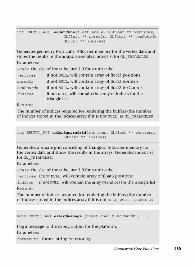
Framework Core Functions 489
int ESUTIL_API esGenCube(float scale, GLfloat ** vertices,GLfloat ** normals, GLfloat ** texCoords, GLuint ** indices)
Generates geometry for a cube. Allocates memory for the vertex data and stores the results in the arrays. Generates index list for GL_TRIANGLES.
Parameters:
Scale the size of the cube, use 1.0 for a unit cube
vertices if not NULL, will contain array of float3 positions
normals if not NULL, will contain array of float3 normals
texCoords if not NULL, will contain array of float2 texCoords
indices if not NULL, will contain the array of indices for the triangle list
Returns:
The number of indices required for rendering the buffers (the number of indices stored in the indices array if it is not NULL) as GL_TRIANGLES
int ESUTIL_API esGenSquareGrid(int size, GLfloat ** vertices,GLuint ** indices)
Generates a square grid consisting of triangles. Allocates memory for the vertex data and stores the results in the arrays. Generates index list for GL_TRIANGLES.
Parameters:
Scale the size of the cube, use 1.0 for a unit cube
vertices if not NULL, will contain array of float3 positions
indices if not NULL, will contain the array of indices for the triangle list
Returns:
The number of indices required for rendering the buffers (the number of indices stored in the indices array if it is not NULL) as GL_TRIANGLES
void ESUTIL_API esLogMessage (const char * formatStr, ...)
Log a message to the debug output for the platform.
Parameters:
formatStr format string for error log
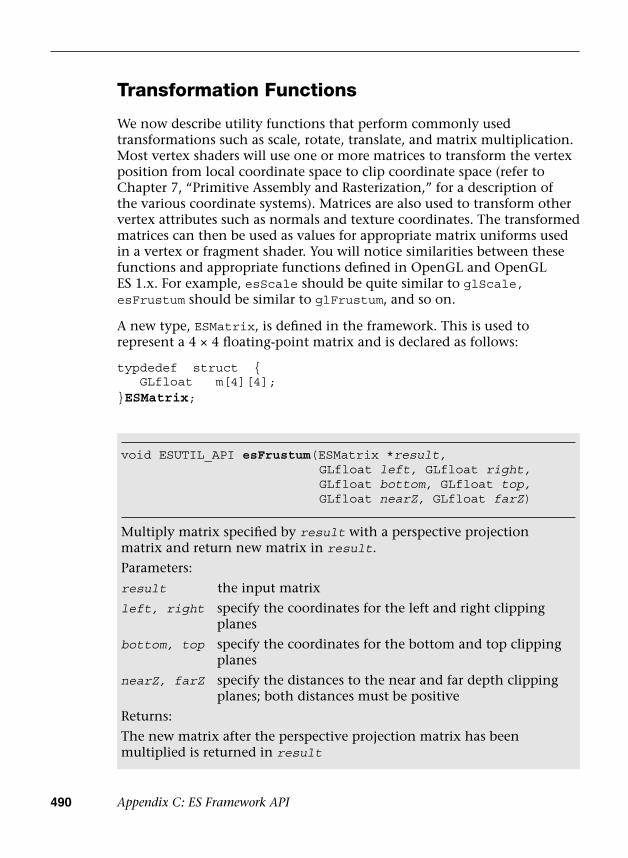
490 Appendix C: ES Framework API
Transformation Functions
We now describe utility functions that perform commonly used transformations such as scale, rotate, translate, and matrix multiplication. Most vertex shaders will use one or more matrices to transform the vertex position from local coordinate space to clip coordinate space (refer to Chapter 7, “Primitive Assembly and Rasterization,” for a description of the various coordinate systems). Matrices are also used to transform other vertex attributes such as normals and texture coordinates. The transformed matrices can then be used as values for appropriate matrix uniforms used in a vertex or fragment shader. You will notice similarities between these functions and appropriate functions defined in OpenGL and OpenGL ES 1.x. For example, esScale should be quite similar to glScale, esFrustum should be similar to glFrustum, and so on.
A new type, ESMatrix, is defined in the framework. This is used to represent a 4 × 4 floating-point matrix and is declared as follows:
typdedef struct { GLfloat m[4][4];}ESMatrix;
void ESUTIL_API esFrustum(ESMatrix *result,GLfloat left, GLfloat right,GLfloat bottom, GLfloat top,GLfloat nearZ, GLfloat farZ)
Multiply matrix specified by result with a perspective projection matrix and return new matrix in result.
Parameters:
result the input matrix
left, right specify the coordinates for the left and right clipping planes
bottom, top specify the coordinates for the bottom and top clipping planes
nearZ, farZ specify the distances to the near and far depth clipping planes; both distances must be positive
Returns:
The new matrix after the perspective projection matrix has been multiplied is returned in result
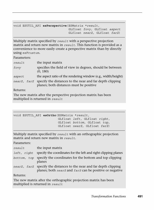
Transformation Functions 491
void ESUTIL_API esPerspective(ESMatrix *result, GLfloat fovy, GLfloat aspect GLfloat nearZ, GLfloat farZ)
Multiply matrix specified by result with a perspective projection matrix and return new matrix in result. This function is provided as a convenience to more easily create a perspective matrix than by directly using esFrustum.
Parameters:
result the input matrix
fovy specifies the field of view in degrees, should be between (0, 180)
aspect the aspect ratio of the rendering window (e.g., width/height)
nearZ, farZ specify the distances to the near and far depth clipping planes; both distances must be positive
Returns:
The new matrix after the perspective projection matrix has been multiplied is returned in result
void ESUTIL_API esOrtho(ESMatrix *result,GLfloat left, GLfloat right, GLfloat bottom, GLfloat top, GLfloat nearZ, GLfloat farZ)
Multiply matrix specified by result with an orthographic projection matrix and return new matrix in result.
Parameters:
result the input matrix
left, right specify the coordinates for the left and right clipping planes
bottom, top specify the coordinates for the bottom and top clipping planes
nearZ, farZ specify the distances to the near and far depth clipping planes; both nearZ and farZ can be positive or negative
Returns:
The new matrix after the orthographic projection matrix has been multiplied is returned in result
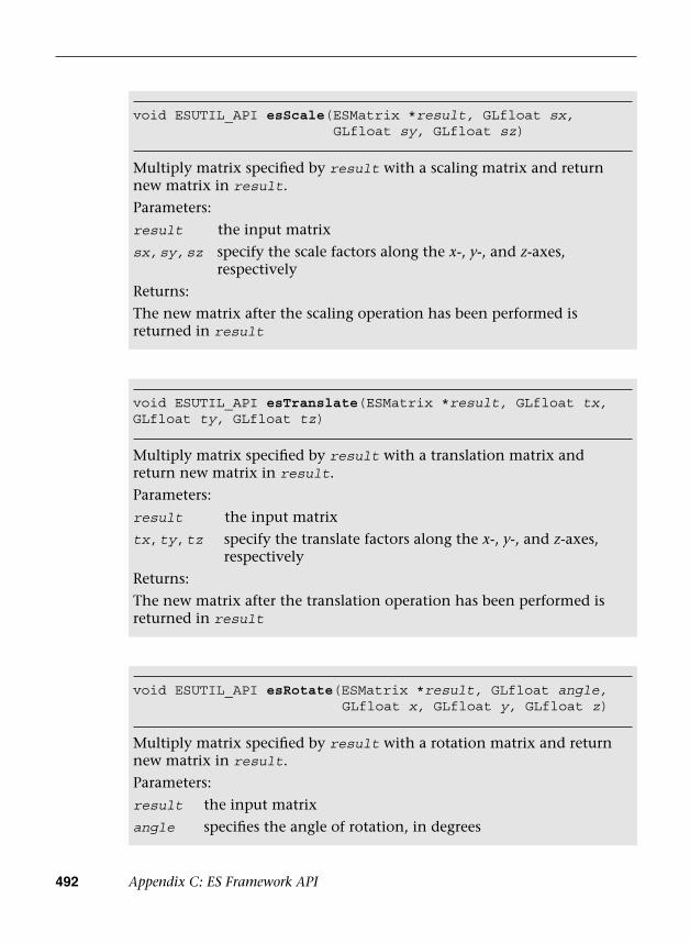
492 Appendix C: ES Framework API
void ESUTIL_API esScale(ESMatrix *result, GLfloat sx,GLfloat sy, GLfloat sz)
Multiply matrix specified by result with a scaling matrix and return new matrix in result.
Parameters:
result the input matrix
sx, sy, sz specify the scale factors along the x-, y-, and z-axes, respectively
Returns:
The new matrix after the scaling operation has been performed is returned in result
void ESUTIL_API esTranslate(ESMatrix *result, GLfloat tx,GLfloat ty, GLfloat tz)
Multiply matrix specified by result with a translation matrix and return new matrix in result.
Parameters:
result the input matrix
tx, ty, tz specify the translate factors along the x-, y-, and z-axes, respectively
Returns:
The new matrix after the translation operation has been performed is returned in result
void ESUTIL_API esRotate(ESMatrix *result, GLfloat angle,GLfloat x, GLfloat y, GLfloat z)
Multiply matrix specified by result with a rotation matrix and return new matrix in result.
Parameters:
result the input matrix
angle specifies the angle of rotation, in degrees
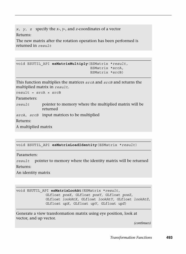
Transformation Functions 493
x, y, z specify the x-, y-, and z-coordinates of a vector
Returns:
The new matrix after the rotation operation has been performed is returned in result
void ESUTIL_API esMatrixMultiply(ESMatrix *result,ESMatrix *srcA, ESMatrix *srcB)
This function multiplies the matrices srcA and srcB and returns the multiplied matrix in result.result = srcA × srcB
Parameters:
result pointer to memory where the multiplied matrix will be returned
srcA, srcB input matrices to be multiplied
Returns:
A multiplied matrix
void ESUTIL_API esMatrixLoadIdentity(ESMatrix *result)
Parameters:
result pointer to memory where the identity matrix will be returned
Returns:
An identity matrix
void ESUTIL_API esMatrixLookAt(ESMatrix *result,GLfloat posX, GLfloat posY, GLfloat posZ, GLfloat lookAtX, GLfloat lookAtY, GLfloat lookAtZ, GLfloat upX, GLfloat upY, GLfloat upZ)
Generate a view transformation matrix using eye position, look at vector, and up vector.
(continues)

494 Appendix C: ES Framework API
(continued)Parameters:
result the output matrix
posX, posY, posZ specify the coordinates of the eye positionlookAtX, lookAtY, lookAtZ specify the look at vectorupX, upY, upZ specify the up vector
Returns:
The view transformation matrix result
495
. (dot), vector access operator, 101–102#elif directive, 116#else directive, 116#error directive, 116#extension directive, 116#if directive, 116#pragma directive
definition, 116enabling global invariance, 123
[ ] (square brackets), array subscript operator, 101–102
2D texture arraysloading, 260–262new features, 11overview, 230
2D texturesattached to framebuffer objects,
338–339base formats, 227overview, 226–227in shaders, 255–257
3D texturesattached to framebuffer objects,
339–340loading, 260–262new features, 12overview, 229
3D textures, noisedust effects, 403–404water wave simulation, 404wispy fog, 402–404
Aabs function, 467acos function, 465
acosh function, 466Advanced RenderMan: Creating CGI for Motion
Pictures, 407Aliasing artifacts. See Anti-aliasing;
Mipmapping.all function, 473Alpha test, 291–293Android 4.3 (API 18), 451Android NDK, 451Android SDK, 451Angles, built-in functions, 465–466Animation, 2D images. See 2D texture
arrays.Anti-aliasing
multi-sampled, 314–316procedural textures, 407–410
any function, 473Apache Ant, 451ARM Mali OpenGL ES Emulator, 448Array buffer objects, 140–141Arrays, 104Arrays of structures, 128. See also
Structures.asin function, 465asinh function, 466Asynchronous objects, querying,
442–443atan function, 465atanh function, 466Attributes. See also specific attributes.
active, counting, 77active, querying, 93getting, 92–93largest name, getting, 77setting, 92–93
Index
496 Index
BBack buffers, 41, 298Backward compatibility, 17–18Bias matrix, 392–393Binaries. See Program binaries.Binding
program objects, example, 39renderbuffer objects, 330–331texture objects, 231vertex array objects, 151vertex attributes, 137–140vertex buffer objects, 141
Blend equations, new features, 17Blending
colors, 311–314per-fragment operations, 10
Blur effects, 387–390Boolean occlusion queries, new features, 15Buffer object to buffer object copies, new
features, 16Buffer objects
copying, 159–160deleting, 150drawing with and without, 145–150initializing, 145updating, 145
Buffer objects, mappingchanging screen resolution, 157data storage pointer, getting, 155–156flushing mapped buffers, 158–159overview, 154–155unmapping, 155–156
Buffer objects, new features. See also Uniform buffer objects; Vertex buffer objects.
buffer object to buffer object copies, 16
buffer subrange mapping, 16pixel buffer objects, 16sampler objects, 16sync objects, 16uniform buffer objects, 16vertex array objects, 16
Buffer subrange mapping, new features, 16Buffer write masks, 301–303Buffers, fragments. See also Pbuffers (pixel
buffers).back, 298buffer write masks, 301–303clearing, 299–301depth of, 298
front, 298making writable, 301–303requesting, 299size of, 298swapping, 298–299types of, 298
Built-in functions. See also Functions.abs function, 467acos, 465acosh, 466all, 473angles, 465–466any, 473asin, 465asinh, 466atan, 465atanh, 466ceil, 468clamp, 469cos, 465cosh, 466cross, 473degrees, 465description, 107determinant, 473dFdx, 484dFdy, 484distance, 473dot, 473equal, 473exp, 466exp2, 466exponential, 466–467faceforward, 473floatBitsToInt, 470floatBitsToUInt, 470floating-point pack and unpack,
471–472floor, 467fract, 468fragment processing, 483–484fwidth, 484geometric, 472–473greaterThan, 475greaterThanEqual, 475intBitsToFloat, 470inverse, 474inversesqrt, 467isinf, 470isnan, 470length, 473
Index 497
lessThan, 475lessThanEqual, 475log, 466log2, 467matrix, 474matrixCompMult, 474max, 468min, 468mix, 469mod, 468new features, 15normalize, 473not, 475notEqual, 475outerProduct, 474packHalf2x16, 472packSnorm2x16, 471pow, 466radians, 465reflect, 473refract, 473round, 468roundEven, 468sign, 467sin, 465sinh, 466smoothstep, 470sqrt, 467step, 470tan, 465tanh, 466texture built-in, 478texture lookup, 476–482textureGrad, 481textureGradOffset, 481textureLod, 479textureOffset, 480textureProj built-in, 479textureProjGrad, 482textureProjGradOffset, 482textureProjLod, 480textureProjLodOffset, 480textureSize, 478transpose, 474trigonometry, 465–466trunc, 467uintBitsToFloat, 470unpackHalf2x16, 472unpackSnorm2x16, 471unpackUnorm2x16, 471–472vector relational, 475
Cceil function, 468centroid keyword, 115Centroid sampling, 14, 316Checkerboard example, 405–407clamp function, 469Client space, 126Clip panes, user, 293–295Clipping
description, 176–177lines, 177point sprites, 177triangles, 177
Colorblending, 311–314color depth, simulating, 314depth, simulating, 314dithering, 314fragments, 311–314specifying for multiple render targets,
321–322Color buffers
clearing, example, 39–40fragment operations, 298–299, 302.
See also Fragments, buffers.column_major qualifier, 110Combining texture maps, 286–287Command syntax, 20–21Compiling shaders, example, 36–38Compressing textures, 262–265Compression formats, textures, 264–265Conditional statements. See Control flow
statements.Conditional tests, preprocessor directives,
115–117const declarations, examples,
102–103Constant store, 109Constants, description, 102–103Constructors. See Variable constructors.Control flow statements, 107–108Coordinate systems
clipping, 176–177guard band region, 177overview, 175
Copyingbuffer objects, 159–160pixels in framebuffer objects, 342–344textures from the color buffer, 269–273
cos function, 465cosh function, 466

498 Index
CreatingEGL windows, 53–56, 64–65EGLContexts, 60–62fragment shaders, example, 35–36pbuffers, 56–60program objects, example, 38–39renderbuffer objects, 329–330rendering context, 60–62shaders, example, 35–36sync objects, 358–359texture objects, 230vertex array objects, 144, 151vertex buffer objects, 141vertex shaders, example, 35–36windows, example, 34–35
cross function, 473Cubemaps
example, 205–206seamless filtering, new features,
12, 241texturing, example, 258–260
Culling, 7, 180–181Cygwin, 451
DData types
EGL, 20–21matrix, 99–100scalar, 99–100type conversion, 100vector, 99–100
Deferred shading, multiple render targets, 320–321
Degenerate triangles, 172degrees function, 465Deleting
buffer objects, 150framebuffer objects, 346–347program objects, 75renderbuffer objects, 346–347shaders, 70sync objects, 358–359texture objects, 230–231vertex array objects, 154
Deletion status, querying, 77Depth buffer test, 311Depth buffers
attached to framebuffer objects, 337–338
sharing, 329
Depth buffers, fragment operations. See also Fragments, buffers.
buffer write masks, 302–303description, 298–299
Depth-of-field. See Rendering, to textures.Depth test, per-fragment
operations, 10Depth texture compare, 245–246Depth textures, 12, 254–255determinant function, 473dFdx function, 484dFdy function, 484Directional light, example, 199–202Directives. See Preprocessor directives.disable behavior, 117Displacement mapping, vertex shaders,
214–215distance function, 473Dithering, 10, 314Dot (.), vector access operator, 101–102dot function, 473Double buffering, example, 41Drawing fragments, example, 35–36Drawing primitives
example, 40–41geometry instancing, 169–172multiple disconnected primitives,
168–169multiple primitives, different attributes,
169–172overview, 165–168performance tips, 172–174primitive restart, 168–169provoking vertex, 168–169
Drawing surface, creating, 325–327. See also FBOs (framebuffer objects).
Dust effects, 403–404Dynamic reflections. See Rendering, to
textures.
EEGL
command syntax, 20–21data types, 20–21description, 19display server, connecting to, 44–45include files, 20initializing, 44, 46libraries, 20
Index 499
programming with OpenGL ES 3.0, 20rendering context, creating, 19rendering surfaces, creating, 19
EGL error codesEGL_BAD_ALLOC, 55, 58EGL_BAD_ATTRIBUTE, 48, 51, 58EGL_BAD_CONFIG, 55, 58, 61EGL_BAD_DISPLAY, 46EGL_BAD_MATCH, 55, 58EGL_BAD_NATIVE_WINDOW, 55EGL_BAD_PARAMETER, 47, 58, 67
EGL windows, creatingdescription, 53–56with the esUtil library, 65–66
eglChooseConfig function, 51–53EGLConfig data type
choosing surface configurations, 51–53creating pbuffers, 56–60determining available surface
configurations, 46–47EGLConfig data type, attributes
querying, 48–50specifying, 51–52summary of, 49–50
EGL_CONTEXT_CLIENT_VERSION attribute, 61
EGLContextsassociating with an EGLSurface,
62–63creating, 60–62making current, 62–63
EGL_CORE_NATIVE_ENGINE, 67eglCreateContext function, 60–62eglCreatePbufferSurface
command, 56–60eglCreateWindowSurface function,
53–56EGLDisplay data type, 44–45eglGetConfigs function, 47eglGetDisplay function, 44–45eglGetError function, 45EGL_HEIGHT attribute, 57EGL_LARGEST_PBUFFER attribute, 57eglMakeCurrent function, 62–63EGL_MIPMAP_TEXTURE attribute, 57EGL_NO_CONTEXT error, 58EGL_NOT_INITIALIZED error, 46–47EGLSurface, 62–63eglSwapBuffers function, 41EGL_TEXTURE_FORMAT attribute, 57
EGL_TEXTURE_TARGET attribute, 57eglWaitClient function, 66–67EGL_WIDTH attribute, 57Element buffer objects, 140–141Emulating OpenGL ES 3.0
ARM Mali OpenGL ES Emulator, 448iOS 7, 453–455OpenGL ES 3.0 Emulator, 447–449PowerVR Insider SDK v 3.2+, 448PowerVR OpenGL ES 3.0 Emulator,
449–450Qualcomm Adreno SDK v3.4+, 447Ubuntu Linux, 449–450Windows, 447–449
enable behavior, 116Entity names, querying, 429–435Environment mapping
definition, 228, 370example, 370fragment shader, 372–373vertex shader, 370–372
equal function, 473Error checking, querying for error codes, 45Error codes. See also specific codes.
querying for, 45summary of, 23
Error handling, 22–23ES Framework API
core functions, 485–489esCreateWindow function, 34,
485–486esFrustrum function, 198, 490esGenCube function, 489esGenSphere function, 488esGenSquareGrid function, 489esLoadProgram function, 487–488esLoadShader function, 487esLoadTGA function, 488esLogMessage function, 489esMatrixLoadIdentity function,
493esMatrixMultiply function, 493esOrtho function, 491esPerspective function,
198–199, 491esRegisterDrawFunc
function, 486esRegisterKeyFunc function, 487esRegisterShutdownFunc
function, 487

500 Index
ES Framework API (cont.)esRegisterUpdateFunc function,
486esRotate function, 492–493esScale function, 492esTranslate function, 492transformation functions, 490–494
esCreateWindow function, 34, 485–486esFrustrum function, 198, 490esGenCube function, 489esGenSphere function, 488esGenSquareGrid function, 489esLoadProgram function, 487–488esLoadShader function, 487esLoadTGA function, 488esLogMessage function, 489esMain function, 34esMatrixLoadIdentity
function, 493esMatrixMultiply function, 493esOrtho function, 491esPerspective function, 198–199, 491esRegisterDrawFunc function, 486esRegisterKeyFunc function, 487esRegisterShutdownFunc function,
487esRegisterUpdateFunc function,
486esRotate function, 492–493esScale function, 492esTranslate function, 492esUtil library, creating EGL windows,
65–66ETC/EAC texture compression, 12, 264–265Example code. See also specific examples.
creating. See Hello Triangle.downloading, 28–29
exp function, 466exp2 function, 466Exponential built-in functions, 466–467Extension behaviors, 116–117Extensions, 116–117
Ffaceforward function, 473FBOs (framebuffer objects). See also
Renderbuffer objects.attachment points, 336–337binding, 335–336blits, 342–344checking for completeness, 341–342
copying pixels, 342–344creating, 329–330definition, 327deleting, 346–347vs. EGL surfaces, 329examples, 348–354invalidation, 344–346new features, 17performance tips, 354purpose of, 325–327querying, 445–446reading pixels, 347vs. renderbuffer objects, 328resolving multisample renderbuffers to
textures, 342–344state values, 336TBR GPUs, 345
FBOs (framebuffer objects), attachments2D textures, 338–3393D textures, 339–340depth buffers, 337–338renderbuffer objects, 337–338, 347
Fences, 358–361Filtering textures. See Texture filtering.Flat/smooth interpolators, 14, 114floatBitsToInt function, 470floatBitsToUInt function, 470Floating-point
numbers. See GL_HALF_FLOAT data type.
pack and unpack, built-in functions, 471–472
texture formats, 249–250textures, new features, 12
floor function, 467Fog effects. See also Particle systems.
linear fog, creating with a fragment shader, 288–291
wispy fog, creating with noise, 402–404fract function, 468Fragment depth, new features, 15Fragment processing, built-in functions,
483–484Fragment shaders
2D texturing, 255–257built-in constants, 284–285built-in special variables, 283–284creating, example, 35–36examples, 9, 113–114fragment depth, overriding, 284front-facing fragments, identifying, 284input variables, 8

Index 501
inputs, 8inputs/outputs, 111–114maximum uniform blocks, querying, 91MRTs (multiple render targets),
minimum/maximum number of, 285
offsets, minimum/maximum, 285overview, 8–9, 282–285precision qualifiers, 285samplers, 8shader inputs, minimum/maximum
number of, 284shader program, 8Shading Language version, specifying, 9texture coordinates for point sprites, 284texture image units, minimum/
maximum number of, 285uniforms, 8vec4 uniform entries, minimum/
maximum number of, 285window coordinates of current fragment,
283–284Fragment shaders, fixed-function
techniquesalpha test, 291–293combining texture maps, 286–287fog effects, 288–291multitexturing, 286–287pipeline description, 280–282transparent fragments, 291–293user clip panes, 293–295
Fragmentsblending pixel colors, 311–314centroid sampling, 316color depth, simulating, 314depth, overriding, 284dithering, 314front-facing, identifying, 284MRTs (multiple render targets), 320–324multi-sampled anti-aliasing, 314–316pixel pack buffer objects, 320pixels, reading and writing, 316–320rendered images, saving, 316–320sample coverage masks, 315transparent, 291–293window coordinates of, 283–284
Fragments, buffersback, 298buffer write masks, 301–303clearing, 299–301depth of, 298double buffering, example, 41
front, 298making writable, 301–303requesting, 299size of, 298swapping, 298–299types of, 298. See also specific types.
Fragments, testsdepth buffer test, 311overview, 303–304scissor test, 304–305stencil buffer test, 305–311test enable tokens, 304
Framebuffer invalidation hints, 17, 344–345Framebuffer objects (FBOs). See FBOs
(framebuffer objects).Front buffers, 298Frustrum, 7Full integer support, new
features, 14Functions. See also Built-in functions; ES
Framework API; specific functions.description, 106passing parameters to, 106recursion, 106
fwidth function, 484
GGamma-correct rendering, new features, 11,
254. See also sRGB textures.Geometric built-in functions, 472–473Geometry, new features, 15. See also
Primitives.Geometry instancing, 169–172GL_ACTIVE_ATTRIBUTE_MAX_
LENGTH, 77GL_ACTIVE_ATTRIBUTES, 77, 93glActiveTexture function, 256GL_ACTIVE_UNIFORM_ BLOCK_
MAX_LENGTH, 77GL_ACTIVE_UNIFORM_BLOCKS, 77GL_ACTIVE_UNIFORM_MAX_LENGTH,
77GL_ACTIVE_UNIFORMS, 77GL_ARRAY_BUFFER token, 140–141GL_ATTACHED_SHADERS, 77glAttachShader function, 75glBeginQuery command, 184glBeginTransformFeedback
command, 213glBindAttribLocation
command, 139
502 Index
glBindBuffer command, 142–143, 212glBindBufferBase function, 91, 212glBindBufferRange function, 91, 212glBindFramebuffer, 335–336glBindRenderbuffer function,
330–331glBindSamplers function, 274–275glBindTextures function, 231glBindVertexArray function, 151GL_BLEND token, 304glBlendColor function, 313glBlendEquation function, 313–314glBlendEquationSeparate
function, 313–314glBlendFunc function, 312–313glBlendFuncSeparate function,
312–313glBlitFramebuffer command,
343–344glBufferData command, 144GL_BUFFER_SIZE, 143glBufferSubData command, 145GL_BUFFER_USAGE, 143glCheckFramebufferStatus
command, 342GL_CLAMP_TO_EDGE mode, 243–244glClear function, 40glClear* functions, 299–300glClientWaitSync function, 359–360glColorMask function, 302glCompileShader function, 37, 71–72glCompresedTexImage* functions,
277–278glCompresedTexSubImage*
functions, 277–278glCompressedTexImage2D function,
263–264glCompressedTexImage3D function,
263–264glCompressedTexSubImage2D
function, 267GL_COMPRESSED_TEXTURE_
FORMATS, 265glCopyBufferSubData function,
159–160glCopyTexImage2D function,
270–272glCopyTexSubImage2D function,
270–272glCopyTexSubImage3D function,
270–272glCreateProgram function, 74–75
glCreateShader function, 36–37, 70–71
glCullFace command, 181GL_CULL_FACE state, 181GL_DECR operation, 306GL_DECR_WRAP operation, 306–307glDeleteBuffers command, 150glDeleteFramebuffers command,
346–347glDeleteProgram function, 75glDeleteQueries command, 184glDeleteRenderbuffers command,
346–347glDeleteSamplers function, 273–274glDeleteShader function, 70–71GL_DELETE_STATUS, 77glDeleteSync function, 359glDeleteTextures function, 230–231glDeleteVertexArrays
command, 154glDepthFunc function, 311glDepthMask function, 302gl_DepthRange uniform type, 190glDepthRangef command, 179gl_DepthRangeParameters uniform
type, 190GL_DEPTH_TEST token, 304, 311glDetachShader function, 75glDisable command, 23–24glDisable function, 437–438glDisableVertexAttribArray
command, 132–135GL_DITHER token, 304glDrawArrays function, 40–41,
165–168, 341glDrawArraysInstanced command,
165–168, 170–172glDrawBuffers function, 321–322glDrawElements function, 165–168,
172–174, 341glDrawElementsInstanced
command, 165–168, 170–172, 172–174
GL_DYNAMIC_COPY, 143GL_DYNAMIC_DRAW, 143GL_DYNAMIC_READ, 143GL_ELEMENT_ARRAY_BUFFER token,
140–141glEnable function, 23–24, 437–438glEnableVertexAttribArray
command, 132–135glEndQuery command, 184

Index 503
glEndTransformFeedback command, 213
glFenceSync function, 358glFinish command, 358glFlush command, 358glFlushMappedBufferRange,
158–159gl_FragCoord variable, 283–284gl_FragDepth variable, 284glFramebufferRenderbuffer
command, 337–338glFramebufferTexture2D
command, 338–339glFramebufferTextureLayer
command, 339–341glFrontFace command, 180gl_FrontFacing variable, 190, 284glFrustrum function, see
esFrustrum functionglGenBuffers command, 142–143glGenerateMipmap function, 242glGenFramebuffers function, 330glGenQueries command, 184glGenRenderbuffers function,
329–330glGenSamplers function, 273glGenTextures function, 230glGenVertexArrays function, 151glGetActiveAttrib command,
136–137glGetActiveAttrib function, 93glGetActiveUniform function,
81–82glGetActiveUniform* functions,
81–82glGetActiveUniformBlockiv
function, 89–90glGetActiveUniformBlockName
function, 89–90glGetActiveUniformsiv function,
82, 87–88glGetAttachedShaders
function, 438glGetAttribLocation
command, 140glGetBooleanv function, 423glGetBufferParameter*
functions, 444glGetBufferPointerv function,
444–446glGetError command, 22–23glGetFloatv function, 423
glGetFramebuffer AttachmentParameteriv function, 445–446
glGetInteger* functions, 423glGetInteger64v function, 92glGetIntegerv command, 91,
214, 265glGetProgramBinary function, 94glGetProgramiv function
checking link status, 76largest uniform name, getting, 81number of active vertex attributes,
querying, 137–140program compatibility, checking, 95
glGetQueryiv function, 442–443glGetQueryObjectuiv function, 185,
213, 443glGetRenderbufferParameteriv
function, 445–446glGetSamplerParameter* functions,
442glGetShaderInfoLog function, 72–73glGetShaderiv function, 72glGetShaderPrecisionFormat
function, 439–440glGetShaderSource function, 439glGetString* functions, 421–422glGetSynciv function, 443glGetTexParameter* functions,
441–442glGetUniform* functions, 439glGetUniformBlockIndex function,
89glGetUniformLocation
function, 83glGetVertexAttrib* functions,
440–441GL_HALF_FLOAT data type
16-bit floating-point numbers, 458–459converting float to half-float, 459–461overview, 457–458
glHint function, 435–436GL_INCR operation, 306GL_INCR_WRAP operation, 306–307GL_INFO_LOG_LENGTH, 77gl_InstanceID variable, 171–172, 189GL_INTERLEAVED_ATTRIBS, 77glInvalidateFramebuffer
command, 345–346glInvalidateSubFramebuffer
command, 345–346GL_INVALID_ENUM code, 23
504 Index
GL_INVALID_OPERATION code, 23GL_INVALID_VALUE code, 23GL_INVERT operation, 307glIs* functions, 436glIsEnabled function, 24, 437GL_KEEP operation, 307GL_LINE_LOOP, 163GL_LINES, 163GL_LINES mode, 213GL_LINE_STRIP, 163glLineWidth API call, 164glLinkProgram command, 212glLinkProgram function, 75–76GL_LINK_STATUS, 95glMapBufferRange command,
155–157gl_MaxCombinedTexture
ImageUnits constant, 190GL_MAX_COMBINED_UNIFORM_
BLOCKS, 91gl_MaxDrawBuffers constant, 285gl_MaxFragmentInputVectors
constant, 284GL_MAX_FRAGMENT_UNIFORM_
BLOCKS, 91GL_MAX_FRAGMENT_UNIFORM_
VECTORS, 109gl_MaxFragmentUniformVectors
constant, 285gl_MaxFragmentUniformVectors
variable, 109gl_MaxProgramTexelOffset
constant, 285gl_MaxTextureImageUnits
constant, 285GL_MAX_UNIFORM_BLOCK_SIZE, 92gl_MaxVertexAttribs constant, 190gl_MaxVertexAttribs variable, 112GL_MAX_VERTEX_ATTRIBS
variable, 112GL_MAX_VERTEX_OUTPUT_
COMPONENTS variable, 113gl_MaxVertexOutputVectors
constant, 190gl_MaxVertexOutputVectors
variable, 113gl_MaxVertexTextureImageUnits
constant, 190GL_MAX_VERTEX_TEXTURE_UNITS,
213GL_MAX_VERTEX_UNIFORM_BLOCKS,
91
GL_MAX_VERTEX_UNIFORM_VECTORS, 109
gl_MaxVertexUniformVectors constant, 190, 193–196
gl_MaxVertexUniformVectors variable, 109
gl_MinProgramTexelOffset constant, 285
GL_MIRRORED_REPEAT mode, 243–244GL_NO_ERROR code, 23GL_OUT_OF_MEMORY code, 23glPixelStorei function, 235GL_PIXEL_UNPACK_BUFFER,
277–278gl_PointCoord variable, 164–165, 284GL_POINTS mode, 164–165, 213gl_PointSize variable, 164, 190glPolygonOffset command, 182–183gl_Position variable, 190glProgramBinary function, 94GL_PROGRAM_BINARY_
RETRIEVABLE_HINT, 77GL_RASTERIZER_DISCARD, 214glReadBuffer function, 269–270glReadPixels function, 316–320,
346–347GL_REFLECTION_MAP mode, 206glReleaseShaderCompiler
function, 93glRenderbufferStorage function,
331–332glRenderbufferStorage
Multisample function, 331–332
GL_REPEAT mode, 243–244GL_REPLACE operation, 306GL_SAMPLE_ALPHA_TO_COVERAGE
token, 304glSampleCoverage function,
315–316GL_SAMPLE_COVERAGE token, 304glScissor test, 304–305GL_SEPARATE_ATTRIBS, 77glShaderSource function, 37, 71GL_SPHERE_MAP mode, 206GL_STATIC_COPY, 143GL_STATIC_DRAW, 143GL_STATIC_READ, 143glStencilFunc function, 305–311glStencilFuncSeparate function,
305–306glStencilMask function, 302–303
Index 505
glStencilMaskSeparate function, 303
glStencilOp function, 306–311glStencilOpSeparate function,
306–307GL_STENCIL_TEST token, 304GL_STREAM_COPY, 144GL_STREAM_DRAW, 144GL_STREAM_READ, 144glTexImage* functions, 277–278glTexImage2D function, 231–234glTexImage3D function, 260–262glTexParameter* commands
API overhead, 273setting minification/magnification
filtering modes, 236, 239–240texture coordinate wrapping, 243texture detail level, setting, 245
glTexStorage2D function, 276–277glTexStorage3D function, 276–277glTexSubImage* functions, 277–278glTexSubImage2D function, 266–267glTexSubImage3D function, 267–269GL_TEXTURE_BASE_LEVEL parameter,
245GL_TEXTURE_COMPARE_FUNC
parameter, 245–246GL_TEXTURE_COMPARE_MODE
parameter, 245–246GL_TEXTURE_MAX_LOD parameter, 245GL_TEXTURE_MIN_LOD parameter,
245GL_TEXTURE_SWIZZLE_A parameter,
244–245GL_TEXTURE_SWIZZLE_B parameter,
244–245GL_TEXTURE_SWIZZLE_G parameter,
244–245GL_TEXTURE_SWIZZLE_R parameter,
244–245GL_TRANSFORM_FEEDBACK_
VARYINGS, 77GL_TRANSFORM_FEEDBACK_BUFFER_
MODE, 77GL_TRANSFORM_FEEDBACK_
PRIMITIVES_WRITTEN, 213GL_TRANSFORM_FEEDBACK_
VARYING_MAX_LENGTH, 77glTransformFeedbackVaryings
command, 212GL_TRIANGLE_FAN, 162–163GL_TRIANGLES, 162
GL_TRIANGLES mode, 213GL_TRIANGLE_STRIP, 162GL_UNIFORM_BLOCK_ACTIVE_
NUMBER_INDICES, 90GL_UNIFORM_BLOCK_ACTIVE_
UNIFORMS, 90GL_UNIFORM_BLOCK_BINDING, 90glUniformBlockBinding function,
90–91GL_UNIFORM_BLOCK_DATA_SIZE, 90GL_UNIFORM_BLOCK_NAME_
LENGTH, 90GL_UNIFORM_BLOCK_REFERENCED_
BY_VERTEX_SHADER, 90GL_UNIFORM_BLOCK_REFERENCED_
BY_FRAGMENT_SHADER, 90glUnmapBuffer command, 156–157gluPerspective function, see
esPerspective functionglUseProgram function, 39, 78glValidateProgram function, 78GL_VALIDATE_STATUS, 77glVertexAttrib* commands, 126glVertexAttribDivisor command,
170–172glVertexAttribPointer function,
40, 131–132gl_VertexID variable, 189glViewport command, 39, 178–179GLvoid data type, 21glWaitSync function, 360GL_ZERO operation, 306greaterThan function, 475greaterThanEqual function, 475Guard band region, 177
HHello Triangle
back buffer, displaying, 41code framework, 28color buffer, clearing, 39–40double buffering, 41drawing fragments, 35–36geometry, loading, 40–41OpenGL ES 3.0 framework, 34–35primitives, drawing, 40–41program objects, 38–39source code, 29–33transforming vertices, 35–36viewport, setting, 39–40windows, creating, 34–35

506 Index
Hello Triangle, shaderscompiling and loading, 36–38creating, 35–36fragment, creating, 35–36linking, 38–39vertex, creating, 35–36
highp keyword, 120, 192–193Hints, 77, 435–436
Iif-then-else tests. See Control flow
statements.Images
dimensions, specifying, 331format, specifying, 331
Images, postprocessingblur effect, 387–390light bloom, 389–390render-to-texture setup, 387
Immutable textures, 13, 276–277in qualifier, 106Include files, EGL, 20info logs, 77–78Initializing
arrays, 104buffer objects, 145EGL, 44, 46scalar data types, 100structures, 103vector data types, 100vertex array objects, 144
inout qualifier, 106Input variables, fragment shader, 8Instance ID, new features, 15Instanced rendering, new features, 15intBitsToFloat function, 470Integer texture formats, 250–252Integer textures, new features, 12Interpolation, 114–115Interpolation qualifiers
centroid sampling, 115default behavior, 114flat shading, 114smooth shading, 114
Interpolatorsdefinition, 113packing, 117–119
Invariance, 121–123invariant keyword, 121–123inverse function, 474inversesqrt function, 467
iOS 7, 453–455isinf function, 470isnan function, 470
JJDK (Java SE Development Kit) 7, 451
KKeywords
centroid, 115highp, 120, 192–193invariant, 121–123lowp, 120, 192–193mediump, 120, 192–193
LLatitude-longitude maps, example, 205–206Layout qualifiers, 14, 109–110length function, 473Lens flare effects, 183–185lessThan function, 475lessThanEqual function, 475Libraries, EGL, 20Light bloom, 389–390Light projection matrix, 392–393Light view matrix, 392–393Lighting
equations, 369–370example, 199–205
Lighting, per fragmentlighting equations, 369–370lighting shaders, 366–369with a normal map, 364–365overview, 363–364
Lighting shaders, 366–369Lines
clipping, 177description, 163–164width, specifying, 164
Linking shaders, example, 38–39Loading
2D texture arrays, 260–2623D textures, 260–262geometry, example, 40–41shaders, 36–38, 73–74shaders, example, 36–38texture objects, 231–234textures, 230–236uniforms, 83–85
LoadShader function, 36–37log function, 466
Index 507
log2 function, 467Loops. See Control flow statements.lowp keyword, 120, 192–193
MMacros, defining, 115–117Magnification filtering mode, 236, 238–241main function, vertex shader, 6–7Mandatory online compiler, new features,
14Mapping, texture formats to colors, 257Mapping buffer objects
changing screen resolution, 157data storage pointer, getting, 155–156flushing mapped buffers, 158–159overview, 154–155unmapping, 155–156
Matricesnon-square, new features, 14projective texturing, 392–393
Matrix built-in functions, 474Matrix components, 101–102Matrix construction, 101Matrix data types, 99–100Matrix transformations, example, 196–199matrixCompMult function, 474max function, 468mediump keyword, 120, 192–193Meshes, connecting, 172min function, 468Min/max functions, new features, 17Minification filtering mode, 236, 238–241Mipmap chains, 237–238Mipmapping
automatic generation, 242detail levels, specifying, 245mipmap chains, 237–238overview, 237–241
mix function, 469mod function, 468Model matrix, example, 197–198Motion blur effects. See Rendering, to
textures.MRTs (multiple render targets)
deferred shading, 320–321in fragment shaders, 285in fragments, 320–324new features, 17overview, 320setting up, 322–324specifying color attachments, 321–322
Multi-sampled anti-aliasing, 314–316Multisample renderbuffers, 17, 333Multitexturing, 286–287
NNaming conventions, 102Nearest sampling, 237New features, buffer objects
buffer object to buffer object copies, 16
buffer subrange mapping, 16pixel buffer objects, 16sampler objects, 16sync objects, 16uniform buffer objects, 16vertex array objects, 16
New features, framebufferblend equations, 17framebuffer invalidation hints, 17min/max functions, 17MRTs (multiple render targets), 17multisample renderbuffers, 17off-screen rendering, 17
New features, geometryBoolean occlusion queries, 15instanced rendering, 15new vertex formats, 15primitive restart, 15transform feedback, 15
New features, shadersbuilt-in functions, 15centroid sampling, 14flat/smooth interpolators, 14fragment depth, 15full integer support, 14instance ID, 15layout qualifiers, 14mandatory online compiler, 14non-square matrices, 14program binaries, 13–14relaxed restrictions, 15uniform blocks, 14vertex ID, 15
New features, texturing2D texture arrays, 113D textures, 12depth textures, 12ETC/EAC texture compression, 12floating-point textures, 12gamma-correct rendering, 11immutable textures, 13

508 Index
New features, texturing (cont.)increased minimum sizes, 13integer textures, 12NPOT (non-power-of-2) textures, 13seamless cubemap filtering, 12, 241shadow comparisons, 12sRGB textures and framebuffers, 11texture LOD (level of detail)
features, 13texture swizzles, 13texturing, 11–13vendor-specific compressed texture
formats, 12New features, vendor-specific compressed
texture formats, 12New vertex formats, new features, 15Noise, 3D texture
dust effects, 403–404example, 397generating, 397–402water wave simulation, 404wispy fog, 402–404
noise3D function, 401Non-square matrices, new features, 14normalize function, 473Normalized flag, 131–132Normalized texture formats, 247–248not function, 475notEqual function, 475NPOT (non-power-of-2) textures, new
features, 13
OOcclusion queries, 183–185Off-screen rendering, new
features, 17Offsetting polygons, 181–183OpenGL ES 1.0, specifications, 2OpenGL ES 1.1
fixed-function vertex pipeline, 215–223
specifications, 2OpenGL ES 2.0, specifications, 2–3OpenGL ES 3.0
API specifications, 3–4command syntax, 21–22data types, 21–22emulating. See Emulating OpenGL
ES 3.0.error handling, 22–23implementations, querying, 421–422
new features. See New features.platforms. See Emulating OpenGL
ES 3.0.specifications, 2–3
OpenGL ES 3.0, graphics pipeline. See also specific components.
diagram, 4fragment shader, 8–9per-fragment operations, 9–11primitive assembly, 7rasterization, 7vertex shader, 4–7
OpenGL ES 3.0 Emulator, 447–449. See also Emulating OpenGL ES 3.0.
OpenGL ES Shading Language 3.0, specifications, 4
Operators, 104–105out qualifier, 106outerProduct function, 474Overlapping polygons, 181–183
Ppacked qualifier, 110packHalf2x16 function, 472Packing
interpolators, 117–119uniforms, 117–119
packSnorm2x16 function, 471Particle emissions, 381–385Particle systems
fragment shader, 377–379particle emissions, 381–385point sprites, 374rendering algorithm, 381rendering particles, 385–386setup, 374–375transform feedback, 380, 381–385vertex shader, 375–377
Pbuffers (pixel buffers)attributes, 57creating, 56–60description, 56errors, 58
PCF (percentage closest filtering), 245–246, 414
Per fragment lightinglighting equations, 369–370lighting shaders, 366–369with a normal map, 364–365overview, 363–364
Index 509
Per-fragment operationsblending, 10depth test, 10dithering, 10overview, 9–11scissor test, 10stencil test, 10
Performancedrawing primitives, 172–174FBOs (framebuffer objects), 354hints, 435–436primitives, drawing, 172–174vertex attributes, storing, 131–135
Perspective division, 178Pixel buffer objects
new features, 16pixel pack buffer objects, 320pixel unpack buffer objects,
277–278Pixel buffers (pbuffers)
attributes, 57creating, 56–60description, 56errors, 59
Pixel pack buffer objects, 320Pixel unpack buffer objects,
277–278Pixels
copying in framebuffer objects, 342–344
in fragments, reading and writing, 316–320
reading in framebuffer objects, 347storage options, 236texels (texture pixels), 226–227
Point light, example, 202Point sampling, 237Point sprites
clipping, 177description, 164–165position, 164radius, 164texture coordinates for, 284
Point sprites in particle systems, 374Polygons
joins, smoothing (example), 207–211
offsetting, 181–183overlapping, 181–183
Position, point sprites, 164Postprocessing effects. See Rendering,
to textures.
pow function, 466PowerVR Insider SDK v 3.2+, 448PowerVR OpenGL ES 3.0 Emulator,
449–450Precision qualifiers
default precision, 120variables, 119–120vertex shaders, 119–120, 192–193
Preprocessor directives. See also specific directives.
conditional tests, 115–117description, 115–117
Primitive assemblyculling primitives, 7overview, 174–175perspective division, 178view frustrum, 7viewport transformation, 178–179
Primitive assembly, coordinate systemsclipping, 176–177guard band region, 177overview, 175
Primitive restart, 15, 168–169Primitives. See also Geometry, new
features.definition, 7, 161drawing, 7. See also Rasterization.types of, 162–165. See also specific
primitives.Primitives, drawing
example, 40–41geometry instancing, 169–172multiple disconnected primitives,
168–169multiple primitives, different attributes,
169–172overview, 165–168performance tips, 172–174primitive restart, 168–169provoking vertex, 168–169
Procedural texturesanti-aliasing, 407–410checkerboard example, 405–407example, 405–407pros and cons, 404
Program binariescompatibility check, 95definition, 94format, 95getting, 94new features, 13–14saving, 94
510 Index
Program objects. See also Shader objects; Shaders.
attached shaders, counting, 77attaching shaders, 75, 79creating, 74–79definition, 69–70deleting, 75deletion status, querying, 77detaching shaders, 75linking, 74–79making active, 78validating, 78
Projection matrix, example, 198–199
Projective texturingbasic techniques, 391–392bias matrix, 392–393definition, 391light projection matrix, 392–393light view matrix, 392–393matrices, 392–393overview, 390–391spotlight shaders, 394–397
Provoking vertex, 168–169
QQualcomm Adreno SDK v3.4+, 447Qualifiers
column_major, 110in, 106inout, 106out, 106packed, 110row_major, 110shared, 110std140, 110
Queries. See State queries.
Rradians function, 465Radius, point sprites, 164Rasterization
culling, 180–181enabling/disabling, 214pipeline, 179polygon offset, 181–183
Recursion, in functions, 106reflect function, 473Reflective surfaces, 205–206. See also
Environment mapping; Projective texturing; Rendering, to textures.
refract function, 473Renderbuffer objects. See also FBOs
(framebuffer objects).attached to framebuffer objects,
337–338, 347binding, 330–331creating, 329–330default values, 331definition, 327deleting, 346–347vs. FBOs (framebuffer objects), 328formats, 333–335image dimensions, specifying, 331image format, specifying, 331multisample, 333state values, 331vs. textures, 328
Renderbuffersmultisample, new features, 17querying, 445–446
Renderingfrom eye position with depth texture,
418–420gamma-correct, new features, 11instanced, new features, 15from light position into depth texture,
415–418off-screen area. See Pbuffers (pixel
buffers).on-screen area. See Windows.particles, 381, 385–386rendered images, saving,
316–320shadows with depth texture, 414–420synchronizing, 66–67terrain with vertex texture fetch,
410–414Rendering, to off-screen surfaces.
See also FBOs (framebuffer objects); Renderbuffer objects.
basic techniques, 326–327new features, 17
Rendering, to textures. See also FBOs (framebuffer objects).
basic techniques, 326–327examples, 348–354uses for, 326while using the texture object in a
fragment shader, 341Rendering context, creating, 19, 60–62,
325–327. See also EGL; FBOs (framebuffer objects).
Index 511
Rendering surfaces, creating with EGL, 19. See also EGL.
require behavior, 116round function, 468roundEven function, 468row_major qualifier, 110
SSample coverage masks, 315Sampler objects, 16, 273–275Samplers
definition, 256fragment shader, 8querying, 442vertex shader, 4
Scalar data typesdescription, 99–100initializing, 100type conversion, 100
Scissor test, 10, 304–305Screen resolution, effect on mapped buffer
objects, 157Seamless cubemap filtering, new features,
12, 241Shader compiler, 93Shader objects, 69–70. See also Program
objects; Shaders.Shaders. See also Fragment shaders; Vertex
shaders.2D textures, 255–257attached to programs, querying, 438–440compiling, 70–74creating, 70–74deleting, 70info log, retrieving, 72–73linking, 70loading, 73–74source, providing, 71texturing, 255–257version specification,
declaring, 98Shaders, new features
built-in functions, 15centroid sampling, 14flat/smooth interpolators, 14fragment depth, 15full integer support, 14instance ID, 15layout qualifiers, 14mandatory online compiler, 14non-square matrices, 14
program binaries, 13–14relaxed restrictions, 15uniform blocks, 14vertex ID, 15
Shading Language version, specifying in fragment shaders, 9
Shadow comparisons, new features, 12Shadow mapping, 245–246. See also
Projective texturing; Rendering, to textures.
Shadows, rendering, 414–420Shared exponent texture formats, 252–253shared qualifier, 110Shimmering. See Z fighting.Shiny surfaces, example, 205–206sign function, 467Signaling sync objects, 359–360sin function, 465sinh function, 466Smoke effects. See Particle systems.Smooth shading, 114smoothstep function, 470Specifications, OpenGL ES
1.0, 21.1, 22.0, 2–33.0, 2–33.0 API, 3–4Shading Language 3.0, 4
Sphere maps, example, 205–206Spotlight, example, 202–205Spotlight shaders, 394–397sqrt function, 467Square brackets ([ ]), array subscript
operator, 101–102sRGB textures, 11, 254. See also Gamma-
correct rendering.Stairstep effects. See Anti-aliasing;
Mipmapping.State management
checking current state, 24enabling/disabling state, 23–24overview, 23–24querying state values, 24
State queriesapplication-modifiable queries,
429–435asynchronous objects, 442–443entity names, 429–435framebuffer, 445–446implementation-dependent limits,
423–428
512 Index
State queries (cont.)nonprogrammable operations control,
436–438OpenGL ES 3.0 implementation string
queries, 421–422renderbuffer, 445–446samplers, 442shaders attached to programs, 438–440sync objects, 443texture state, 441–442vertex attributes, 440–441vertex buffers, 444
std140 qualifier, 88–89, 110Stencil buffer test, 305–311Stencil buffers
buffer write masks, 303fragment operations, 298–299, 303.
See also Fragments, buffers.sharing, 329
Stencil test, per-fragment operations, 10step function, 470Structures, 103. See also Arrays of structures.Structures of arrays, 128. See also Arrays.Surface configurations
available, determining, 46–47choosing with EGL, 51–53
Swapping, buffers, 298–299Swizzles. See Texture swizzles.Sync objects
creating, 358–359deleting, 358–359example, 360–361fences, 358–361new features, 16overview, 357–358querying, 443signaling, 359–360waiting for, 359–360
Synchronizing rendering, 66–67
Ttan function, 465tanh function, 466Terrain surfaces, 214–215, 410–414Test enable tokens, 304Tests, fragments
depth buffer test, 311overview, 303–304scissor test, 304–305stencil buffer test, 305–311test enable tokens, 304
Texels (texture pixels), 226–227texture built-in function, 257, 260, 478Texture coordinates
generating, example, 205–206wrapping, 243–244
Texture filteringmagnification, 236, 238–241minification, 236, 238–241nearest sampling, 237overview, 237–241point sampling, 237seamless cubemap filtering, 241
Texture filtering, mipmappingautomatic generation, 242detail levels, specifying, 245mipmap chains, 237–238overview, 237–241
Texture formatsdepth textures, 254–255floating-point, 249–250integer, 250–252mapping to colors, 257normalized, 247–248overview, 246–247shared exponent, 252–253sRGB, 254unsized, 247
Texture image units, in fragment shaders, 285
Texture LOD (level of detail) features, new features, 13
Texture lookup built-in functions, 476–482Texture maps, combining, 286–287Texture objects
overview, 230–236pixel storage options, 236
Texture pixels (texels), 226–227Texture state, querying, 441–442Texture swizzles
accessing vector components, 101new features, 13overview, 244–245
Texture units, specifying min/max number, 190
textureGrad function, 481textureGradOffset function, 481textureLod function, 479textureOffset function, 480textureProj built-in function, 391, 479textureProjGrad function, 482textureProjGradOffset
function, 482

Index 513
textureProjLod function, 480textureProjLodOffset
function, 480Textures
color components, mapping. See Texture swizzles.
combining texture maps, 286–287compressing, 262–265compression formats, 264–265copying from the color buffer, 269–273immutable, 276–277multitexturing, 286–287vs. renderbuffer objects, 328subimage selection, 266–269
textureSize function, 478Texturing
depth texture compare, 245–246fetching from a texture map, 256loading textures, 230–236PCF (percentage closest filtering),
245–246pixel unpack buffer objects,
277–278sampler objects, 273–275samplers, 256in shaders, 255–257texels (texture pixels), 226–227volume textures. See 3D textures.
Texturing, 2D texture arraysloading, 260–262overview, 230
Texturing, 2D texturesattached to framebuffer objects, 338–339base formats, 227overview, 226–227in shaders, 255–257
Texturing, 3D texturesattached to framebuffer objects, 339–340loading, 260–262overview, 229
Texturing, cubemap texturesenvironment mapping, 228–229overview, 228–229
Texturing, new features2D texture arrays, 113D textures, 12depth textures, 12ETC/EAC texture compression, 12floating-point textures, 12gamma-correct rendering, 11immutable textures, 13increased minimum sizes, 13
integer textures, 12NPOT (non-power-of-2) textures, 13seamless cubemap filtering, 12, 241shadow comparisons, 12sRGB textures and framebuffers, 11texture LOD (level of detail) features, 13texture swizzles, 13texturing, 11–13vendor-specific compressed texture
formats, 12Texturing, texture objects
binding, 231creating, 230deleting, 230–231loading, 231–234minification/magnification filtering
modes, setting, 236overview, 230–236pixel storage options, 236
3D texturesattached to framebuffer objects, 339–340loading, 260–262new features, 12overview, 229
3D textures, noisedust effects, 403–404water wave simulation, 404wispy fog, 402–404
Transform feedbackexample, 211–214new features, 15in particle systems, 380–385vertex shader, 5
Transformation functions, 490–494
Transforming vertices, example, 35–36
Transparent fragments, 291–293transpose function, 474Triangle fans, drawing, 162–163Triangle strips
connecting, 172–174drawing, 162–163generating degenerate triangles, 15primitive restart, 15winding order, 174
Trianglesclipping, 177culling, 180–181degenerate, 15, 172description, 162–163drawing, 162–163
514 Index
Trigonometry built-in functions, 465–466
trunc function, 4672D texture arrays
loading, 260–262new features, 11overview, 230
2D texturesattached to framebuffer objects,
338–339base formats, 227noise, 402overview, 226–227in shaders, 255–257
Type conversion, 100
UUbuntu Linux, emulating OpenGL ES 3.0,
449–450uintBitsToFloat function, 470Uniform block indexes, associating with
binding points, 90Uniform blocks
active uniforms, counting, 90description, 109–111examples, 109–110last buffer binding point, getting, 90layout qualifiers, 109–110maximum for all shaders, querying, 91maximum per shader, querying, 91minimum supported number, 91minimum total buffer object size, 90name length, getting, 90new features, 14references to, querying, 90
Uniform buffer objects. See also Buffer objects.
available storage, querying, 92binding, 91new features, 16overview, 87–92programming limitations, 91
Uniform nameslargest, counting characters, 81largest, getting, 77, 81maximum length, querying, 77
Uniform variables. See Uniforms.Uniforms
active, counting, 77active, querying, 77, 86–87constant store, 109
description, 80, 108–109first category, 80fragment shader, 8getting, 81–87indexes, getting, 89loading, 83–85maximum number in vertex shaders,
193–196maximum number of, determining, 109named uniform blocks, 80, 88packing, 117–119properties, getting, 81–87setting, 81–87sharing, 87–92std140 block layout, 88vertex shader, 4
Unmapping mapped buffer objects, 155–156
unpackHalf2x16 function, 472unpackSnorm2x16 function, 471unpackUnorm2x16 function,
471–472Unsized texture formats, 247Updating, buffer objects, 145User clip panes, 293–295
VValidating programs, description, 78Validation status, querying, 77Variable constructors, 100–101Variables, 119–120. See also specific variables.Varying variables. See Vertex shaders, output
variables.vec4 uniform entries, in fragment shaders,
285Vector components
accessing, 101–102naming conventions, 102
Vector data typesdescription, 99–100initializing, 100type conversion, 100
Vector relational built-in functions, 475Vertex array objects
binding, 151creating, 144, 151deleting, 154drawing with, 152–154initializing, 144new features, 16overview, 150–151
Index 515
Vertex attribute variables, declaring in vertex shaders, 135–137
Vertex attributesactive, listing, 136–137enabling/disabling, 132–135minimum number required, 126querying, 126, 440–441
Vertex attributes, bindingto attribute variables, 137–140to locations, 139–140querying results of, 140
Vertex attributes, specifyingclient vertex arrays, 126–135constant vertex attributes, 126description, 126
Vertex attributes, storing. See also Arrays of structures; Structures of arrays.
constant vertex attributes, 132–135data conversions, 132normalized flag, 131–132performance tips, 131–135selecting a data format, 131vertex arrays, 132–135
Vertex buffer objects. See also Buffer objects.
array buffer objects, 140–141binding, 141creating, 141element buffer objects, 140–141making current, 141overview, 140–141state, 143–144types of, 140–141
Vertex buffers, querying, 444Vertex ID, new features, 15Vertex shaders
2D texturing, 255–257displacement mapping, 214–215inputs/outputs, 111–114, 188–189.
See also specific inputs/outputs.interpolation, 114–115interpolators, 113maximum uniform blocks, querying, 91min/max limits, 190–192, 193–196output variables, 5precision qualifiers, 119–120, 192–193Shading Language version, specifying, 6uniforms, maximum number of,
193–196vertex normal, computing, 412–413vertex textures, 214–215water surfaces, 214–215
Vertex shaders, built-insconstants, 190–192special variables, 189–190uniform state, 190
Vertex shaders, examplescreating vertex shaders, 35–36cube maps, 205–206directional light, 199–202generating texture coordinates, 205–206height value, fetching, 412–413latitude-longitude maps, 205–206lighting, 199–205matrix transformations, 196–199model matrix, 197–198OpenGL ES 1.1 fixed-function vertex
pipeline, 215–223point light, 202polygon joins, smoothing, 207–211projection matrix, 198–199reflective surfaces, 205–206shiny surfaces, 205–206sphere maps, 205–206spotlight, 202–205terrain surfaces, 214–215transform feedback, 211–214vertex skinning, 207–211view matrix, 197–198
Vertex shaders, overviewentry point, 6–7example, 6inputs/outputs, 4–5main function, 6–7samplers, 4shader program, 4transform feedback, 5uniforms, 4vertex shader output variables, 5
Vertex skinning, example, 207–211Vertex textures, 214–215Vertices, transforming (example), 35–36View frustrum, 7View matrix, example, 197–198Viewport, setting (example), 39–40Viewport transformation, 178–179Visual artifacts. See Mipmapping; Z-fighting
artifacts.
WWaiting for sync objects, 359–360warn behavior, 117Water surfaces, vertex shaders, 214–215
516 Index
Water wave simulation, 404Winding order, triangle strips, 174Windowing systems, communicating with,
44–45Windows, 34–35. See also EGL windows.Windows, emulating OpenGL ES 3.0,
447–449
Wrapping, texture coordinates, 243–244
ZZ-fighting artifacts
avoiding, 121–123polygon offset, 181–183
Register the Addison-Wesley, ExamCram, Prentice Hall, Que, andSams products you own to unlockgreat benefi ts.
To begin the registration process,simply go to informit.com/registerto sign in or create an account.You will then be prompted to enterthe 10- or 13-digit ISBN that appearson the back cover of your product.
informIT.comTHE TRUSTED TECHNOLOGY LEARNING SOURCE
Addison-Wesley | Cisco Press | Exam CramIBM Press | Que | Prentice Hall | Sams
SAFARI BOOKS ONLINE
About InformIT — THE TRUSTED TECHNOLOGY LEARNING SOURCE
INFORMIT IS HOME TO THE LEADING TECHNOLOGY PUBLISHING IMPRINTSAddison-Wesley Professional, Cisco Press, Exam Cram, IBM Press, Prentice HallProfessional, Que, and Sams. Here you will gain access to quality and trusted content andresources from the authors, creators, innovators, and leaders of technology. Whether you’relooking for a book on a new technology, a helpful article, timely newsletters, or access tothe Safari Books Online digital library, InformIT has a solution for you.
Registering your products can unlockthe following benefits:
• Access to supplemental content, including bonus chapters,source code, or project files.
• A coupon to be used on yournext purchase.
Registration benefits vary by product. Benefits will be listed on your Account page under Registered Products.
informit.com/register
THIS PRODUCT
aw_regthisprod_7x9.125.indd 1 12/5/08 3:36:19 PM

Register the Addison-Wesley, Exam Cram, Prentice Hall, Que, and Sams products you own to unlock great benefi ts.
To begin the registration process, simply go to informit.com/register to sign in or create an account. You will then be prompted to enter the 10- or 13-digit ISBN that appears on the back cover of your product.
informIT.com THE TRUSTED TECHNOLOGY LEARNING SOURCE
Addison-Wesley | Cisco Press | Exam Cram
IBM Press | Que | Prentice Hall | Sams
SAFARI BOOKS ONLINE
About InformIT — THE TRUSTED TECHNOLOGY LEARNING SOURCE
INFORMIT IS HOME TO THE LEADING TECHNOLOGY PUBLISHING IMPRINTS Addison-Wesley Professional, Cisco Press, Exam Cram, IBM Press, Prentice Hall Professional, Que, and Sams. Here you will gain access to quality and trusted content and resources from the authors, creators, innovators, and leaders of technology. Whether you’re looking for a book on a new technology, a helpful article, timely newsletters, or access to the Safari Books Online digital library, InformIT has a solution for you.
Registering your products can unlock the following benefi ts:
• Access to supplemental content,including bonus chapters,source code, or project fi les.
• A coupon to be used on yournext purchase.
Registration benefi ts vary by product. Benefi ts will be listed on your Account page under Registered Products.
informit.com/register
THIS PRODUCT
aw_regthisprod_7x9.125.indd 1 12/5/08 3:36:19 PM

InformIT is a brand of Pearson and the online presence for the world’s leading technology publishers. It’s your source for reliable and qualified content and knowledge, providing access to the top brands, authors, and contributors from the tech community.
informIT.com THE TRUSTED TECHNOLOGY LEARNING SOURCE
LearnIT at InformITLooking for a book, eBook, or training video on a new technology? Seek-ing timely and relevant information and tutorials? Looking for expert opin-ions, advice, and tips? InformIT has the solution.
• Learn about new releases and special promotions bysubscribing to a wide variety of newsletters.Visit informit.com/newsletters.
• Access FREE podcasts from experts at informit.com/podcasts.
• Read the latest author articles and sample chapters atinformit.com/articles.
• Access thousands of books and videos in the Safari BooksOnline digital library at safari.informit.com.
• Get tips from expert blogs at informit.com/blogs.
Visit informit.com/learn to discover all the ways you can access the hottest technology content.
informIT.com THE TRUSTED TECHNOLOGY LEARNING SOURCE
Are You Part of the IT Crowd?Connect with Pearson authors and editors via RSS feeds, Facebook, Twitter, YouTube, and more! Visit informit.com/socialconnect.
* Available to new subscribers only. Discount applies to the Safari Library and is valid for rst 12 consecutive monthly billing cycles. Safari Library is not available in all countries.
Try Safari Books Online FREE for 15 daysGet online access to Thousands of Books and Videos
FREE 15-DAY TRIAL + 15% OFF*
informit.com/safaritrial
Feed your brainGain unlimited access to thousands of books and videos about technology,digital media and professional development from O’Reilly Media,Addison-Wesley, Microsoft Press, Cisco Press, McGraw Hill, Wiley, WROX,Prentice Hall, Que, Sams, Apress, Adobe Press and other top publishers.
See it, believe itWatch hundreds of expert-led instructional videos on today’s hottest topics.
WAIT, THERE’S MORE!Gain a competitive edgeBe first to learn about the newest technologies and subjects with Rough Cutspre-published manuscripts and new technology overviews in Short Cuts.
Accelerate your projectCopy and paste code, create smart searches that let you know when newbooks about your favorite topics are available, and customize your librarywith favorites, highlights, tags, notes, mash-ups and more.

InformIT is a brand of Pearson and the online presencefor the world’s leading technology publishers. It’s your sourcefor reliable and qualified content and knowledge, providingaccess to the top brands, authors, and contributors fromthe tech community.
informIT.com THE TRUSTED TECHNOLOGY LEARNING SOURCE
LearnIT at InformITLooking for a book, eBook, or training video on a new technology? Seek-ing timely and relevant information and tutorials? Looking for expert opin-ions, advice, and tips? InformIT has the solution.
• Learn about new releases and special promotions bysubscribing to a wide variety of newsletters.Visit informit.com/newsletters.
• Access FREE podcasts from experts at informit.com/podcasts.
• Read the latest author articles and sample chapters atinformit.com/articles.
• Access thousands of books and videos in the Safari BooksOnline digital library at safari.informit.com.
• Get tips from expert blogs at informit.com/blogs.
Visit informit.com/learn to discover all the ways you can access thehottest technology content.
informIT.com THE TRUSTED TECHNOLOGY LEARNING SOURCE
Are You Part of the IT Crowd?Connect with Pearson authors and editors via RSS feeds, Facebook,Twitter, YouTube, and more! Visit informit.com/socialconnect.
* Available to new subscribers only. Discount applies to the Safari Library and is valid for rst 12 consecutive monthly billing cycles. Safari Library is not available in all countries.
Try Safari Books Online FREE for 15 daysGet online access to Thousands of Books and Videos
FREE 15-DAY TRIAL + 15% OFF*
informit.com/safaritrial
Feed your brainGain unlimited access to thousands of books and videos about technology, digital media and professional development from O’Reilly Media, Addison-Wesley, Microsoft Press, Cisco Press, McGraw Hill, Wiley, WROX, Prentice Hall, Que, Sams, Apress, Adobe Press and other top publishers.
See it, believe itWatch hundreds of expert-led instructional videos on today’s hottest topics.
WAIT, THERE’S MORE!Gain a competitive edgeBe first to learn about the newest technologies and subjects with Rough Cuts pre-published manuscripts and new technology overviews in Short Cuts.
Accelerate your projectCopy and paste code, create smart searches that let you know when new books about your favorite topics are available, and customize your library with favorites, highlights, tags, notes, mash-ups and more.

Activate your FREE Online Edition at informit.com/safarifree
STEP 1: Enter the coupon code: VERYYBI.
STEP 2: New Safari users, complete the brief registration form. Safari subscribers, just log in.
If you have diffi culty registering on Safari or accessing the online edition, please e-mail [email protected]
Your purchase of OpenGL® ES™ 3.0 Programming Guide, Second Edition, includes access to a free online edition for 45 days through the Safari Books Online subscription service. Nearly every Addison-Wesley book is available online through Safari Books Online, along with thousands of books and videos from publishers such as Cisco Press, Exam Cram, IBM Press, O’Reilly Media, Prentice Hall, Que, Sams, and VMware Press.
Safari Books Online is a digital library providing searchable, on-demand access to thousands of technology, digital media, and professional development books and videos from leading publishers. With one monthly or yearly subscription price, you get unlimited access to learning tools and information on topics including mobile app and software development, tips and tricks on using your favorite gadgets, networking, project management, graphic design, and much more.
FREE Online Edition
SFOE_9780321933881.indd 1 1/24/14 10:30 AM
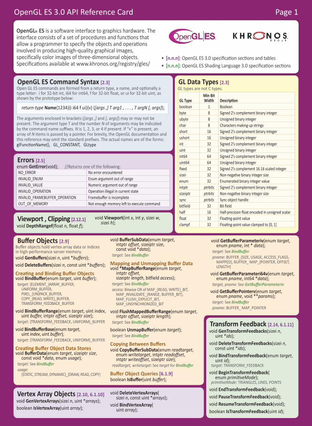
OpenGL ES 3.0 API Reference Card Page 1
Buffer Objects [2.9]Buffer objects hold vertex array data or indices in high-performance server memory.void GenBuffers(sizei n, uint *buffers);void DeleteBuffers(sizei n, const uint *buffers);
Creating and Binding Buffer Objectsvoid BindBuffer(enum target, uint buffer);
target: {ELEMENT_}ARRAY_BUFFER, UNIFORM_BUFFER, PIXEL_{UN}PACK_BUFFER, COPY_{READ, WRITE}_BUFFER, TRANSFORM_FEEDBACK_BUFFER
void BindBufferRange(enum target, uint index, uint buffer, intptr offset, sizeiptr size);
target: {TRANSFORM_FEEDBACK, UNIFORM}_BUFFER
void BindBufferBase(enum target, uint index, uint buffer);
target: {TRANSFORM_FEEDBACK, UNIFORM}_BUFFER
Creating Buffer Object Data Storesvoid BufferData(enum target, sizeiptr size,
const void *data, enum usage);target: See BindBufferusage:
{STATIC, STREAM, DYNAMIC}_{DRAW, READ, COPY}
void BufferSubData(enum target, intptr offset, sizeiptr size, const void *data);
target: See BindBuffer
Mapping and Unmapping Buffer Datavoid *MapBufferRange(enum target,
intptr offset, sizeiptr length, bitfield access);
target: See BindBufferaccess: Bitwise OR of MAP_{READ, WRITE}_BIT,
MAP_INVALIDATE_{RANGE, BUFFER_BIT}, MAP_FLUSH_EXPLICIT_BIT, MAP_UNSYNCHRONIZED_BIT
void FlushMappedBufferRange(enum target, intptr offset, sizeiptr length);
target: See BindBuffer
boolean UnmapBuffer(enum target);target: See BindBuffer
Copying Between Buffersvoid CopyBufferSubData(enum readtarget,
enum writetarget, intptr readoffset, intptr writeoffset, sizeiptr size);
readtarget, writetarget: See target for BindBuffer
Buffer Object Queries [6.1.9] boolean IsBuffer(uint buffer);
void GetBufferParameteriv(enum target, enum pname, int * data);
target: See BindBuffer pname: BUFFER_{SIZE, USAGE, ACCESS_FLAGS,
MAPPED}, BUFFER_ MAP_{POINTER, OFFSET, LENGTH}
void GetBufferParameteri64v(enum target, enum pname, int64 *data);
target, pname: See GetBufferParameteriv void GetBufferPointerv(enum target,
enum pname, void **params);target: See BindBuffer pname: BUFFER_ MAP_POINTER
OpenGL® ES is a software interface to graphics hardware. The interface consists of a set of procedures and functions that allow a programmer to specify the objects and operations involved in producing high-quality graphical images, specifically color images of three-dimensional objects. Specifications available at www.khronos.org/registry/gles/
• [n.n.n]: OpenGL ES 3.0 specification sections and tables• [n.n.n]: OpenGL ES Shading Language 3.0 specification sections
OpenGL ES Command Syntax [2.3]Open GL ES commands are formed from a return type, a name, and optionally a type letter: i for 32-bit int, i64 for int64, f for 32-bit float, or ui for 32-bit uint, as shown by the prototype below:
return-type Name{1234}{i i64 f ui}{v} ([args ,] T arg1 , . . . , T argN [, args]);
The arguments enclosed in brackets ([args ,] and [, args]) may or may not be present. The argument type T and the number N of arguments may be indicated by the command name suffixes. N is 1, 2, 3, or 4 if present. If “v” is present, an array of N items is passed by a pointer. For brevity, the OpenGL documentation and this reference may omit the standard prefixes. The actual names are of the forms: glFunctionName(), GL_CONSTANT, GLtype
Errors [2.5]enum GetError(void); //Returns one of the following: NO_ERROR No error encounteredINVALID_ENUM Enum argument out of rangeINVALID_VALUE Numeric argument out of rangeINVALID_OPERATION Operation illegal in current stateINVALID_FRAMEBUFFER_OPERATION Framebuffer is incompleteOUT_OF_MEMORY Not enough memory left to execute command
GL Data Types [2.3]GL types are not C types.
GL TypeMin Bit Width Description
boolean 1 Booleanbyte 8 Signed 2’s complement binary integerubyte 8 Unsigned binary integerchar 8 Characters making up stringsshort 16 Signed 2’s complement binary integerushort 16 Unsigned binary integerint 32 Signed 2’s complement binary integeruint 32 Unsigned binary integerint64 64 Signed 2’s complement binary integeruint64 64 Unsigned binary integerfixed 32 Signed 2’s complement 16.16 scaled integersizei 32 Non-negative binary integer sizeenum 32 Enumerated binary integer valueintptr ptrbits Signed 2’s complement binary integersizeiptr ptrbits Non-negative binary integer sizesync ptrbits Sync object handlebitfield 32 Bit fieldhalf 16 Half-precision float encoded in unsigned scalarfloat 32 Floating-point valueclampf 32 Floating-point value clamped to [0, 1]
Vertex Array Objects [2.10, 6.1.10]void GenVertexArrays(sizei n, uint *arrays);boolean IsVertexArray(uint array);
void DeleteVertexArrays( sizei n, const uint *arrays);
void BindVertexArray( uint array);
Viewport , Clipping [2.12.1]void DepthRangef(float n, float f);
void Viewport(int x, int y, sizei w, sizei h);
Transform Feedback [2.14, 6.1.11]void GenTransformFeedbacks(sizei n,
uint *ids);void DeleteTransformFeedbacks(sizei n,
const uint *ids);void BindTransformFeedback(enum target,
uint id);target: TRANSFORM_FEEDBACK
void BeginTransformFeedback( enum primitiveMode);
primitiveMode: TRIANGLES, LINES, POINTS
void EndTransformFeedback(void);void PauseTransformFeedback(void);void ResumeTransformFeedback(void);boolean IsTransformFeedback(uint id);
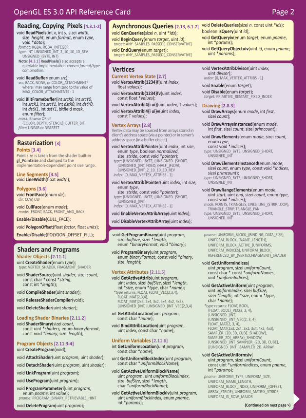
OpenGL ES 3.0 API Reference Card Page 2
void GetProgramBinary(uint program, sizei bufSize, sizei *length, enum *binaryFormat, void *binary);
void ProgramBinary(uint program, enum binaryFormat, const void *binary, sizei length);
Vertex Attributes [2.11.5]void GetActiveAttrib(uint program,
uint index, sizei bufSize, sizei *length, int *size, enum *type, char *name);
*type returns: FLOAT, FLOAT_VEC{2,3,4}, FLOAT_MAT{2,3,4}, FLOAT_MAT{2x3, 2x4, 3x2, 3x4, 4x2, 4x3}, {UNSIGNED_}INT, {UNSIGNED_}INT_VEC{2,3,4}
int GetAttribLocation(uint program, const char *name);
void BindAttribLocation(uint program, uint index, const char *name);
Uniform Variables [2.11.6]int GetUniformLocation(uint program,
const char *name);uint GetUniformBlockIndex(uint program,
const char *uniformBlockName);void GetActiveUniformBlockName(
uint program, uint uniformBlockIndex, sizei bufSize, sizei *length, char *uniformBlockName);
void GetActiveUniformBlockiv(uint program, uint uniformBlockIndex, enum pname, int *params);
pname: UNIFORM_BLOCK_{BINDING, DATA_SIZE}, UNIFORM_BLOCK_{NAME_LENGTH}, UNIFORM_BLOCK_ACTIVE_{UNIFORMS, UNIFORM_INDICES}, UNIFORM_BLOCK_REFERENCED_BY_{VERTEX,FRAGMENT}_SHADER
void GetUniformIndices( uint program, sizei uniformCount, const char * const *uniformNames, uint *uniformIndices);
void GetActiveUniform(uint program, uint uniformIndex, sizei bufSize, sizei *length, int *size, enum *type, char *name);
*type returns: FLOAT, BOOL, {FLOAT, BOOL}_VEC{2, 3, 4}, {UNSIGNED_}INT, {UNSIGNED_}INT_VEC{2, 3, 4}, FLOAT_MAT{2, 3, 4}, FLOAT_MAT{2x3, 2x4, 3x2, 3x4, 4x2, 4x3}, SAMPLER_{2D, 3D, CUBE_SHADOW}, SAMPLER_2D{_ARRAY}_SHADOW, {UNSIGNED_}INT_SAMPLER_{2D, 3D, CUBE}, {{UNSIGNED_}INT_}SAMPLER_2D_ARRAY
void GetActiveUniformsiv( uint program, sizei uniformCount, const uint *uniformIndices, enum pname, int *params);
pname: UNIFORM_TYPE, UNIFORM_SIZE, UNIFORM_NAME_LENGTH, UNIFORM_BLOCK_INDEX, UNIFORM_{OFFSET, ARRAY_STRIDE}, UNIFORM_MATRIX_STRIDE, UNIFORM_IS_ROW_MAJOR
(Continued on next page >)
Shaders and ProgramsShader Objects [2.11.1] uint CreateShader(enum type);
type: VERTEX_SHADER, FRAGMENT_SHADER
void ShaderSource(uint shader, sizei count, const char * const *string, const int *length);
void CompileShader(uint shader);void ReleaseShaderCompiler(void);void DeleteShader(uint shader);
Loading Shader Binaries [2.11.2] void ShaderBinary(sizei count,
const uint *shaders, enum binaryformat, const void *binary, sizei length);
Program Objects [2.11.3-4] uint CreateProgram(void);void AttachShader(uint program, uint shader);void DetachShader(uint program, uint shader);void LinkProgram(uint program);void UseProgram(uint program);void ProgramParameteri(uint program,
enum pname, int value);pname: PROGRAM_BINARY_RETRIEVABLE_HINT
void DeleteProgram(uint program);
Vertices Current Vertex State [2.7]void VertexAttrib{1234}f(uint index,
float values);void VertexAttrib{1234}fv(uint index,
const float *values);void VertexAttribl4{i ui}(uint index, T values);void VertexAttribl4{i ui}v(uint index,
const T values);
Vertex Arrays [2.8]Vertex data may be sourced from arrays stored in client’s address space (via a pointer) or in server’s address space (in a buffer object).void VertexAttribPointer(uint index, int size,
enum type, boolean normalized, sizei stride, const void *pointer);
type: {UNSIGNED_}BYTE, {UNSIGNED_}SHORT, {UNSIGNED_}INT, FIXED, {HALF_}FLOAT, {UNSIGNED_}INT_2_10_10_10_REV
index: [0, MAX_VERTEX_ATTRIBS - 1]
void VertexAttribIPointer(uint index, int size, enum type, sizei stride, const void *pointer);
type: {UNSIGNED_}BYTE, {UNSIGNED_}SHORT, {UNSIGNED_}INT
index: [0, MAX_VERTEX_ATTRIBS - 1]
void EnableVertexAttribArray(uint index);void DisableVertexAttribArray(uint index);
void VertexAttribDivisor(uint index, uint divisor);
index: [0, MAX_VERTEX_ATTRIBS - 1]
void Enable(enum target);void Disable(enum target);
target: PRIMITIVE_RESTART_FIXED_INDEX
Drawing [2.8.3]void DrawArrays(enum mode, int first,
sizei count);void DrawArraysInstanced(enum mode,
int first, sizei count, sizei primcount);void DrawElements(enum mode, sizei count,
enum type, const void *indices);
type: UNSIGNED_BYTE, UNSIGNED_SHORT, UNSIGNED_INT
void DrawElementsInstanced(enum mode, sizei count, enum type, const void *indices, sizei primcount);
type: UNSIGNED_BYTE, UNSIGNED_SHORT, UNSIGNED_INT
void DrawRangeElements(enum mode, uint start, uint end, sizei count, enum type, const void *indices);
mode: POINTS, TRIANGLES, LINES, LINE_{STRIP, LOOP}, TRIANGLE_STRIP, TRIANGLE_FAN
type: UNSIGNED_BYTE, UNSIGNED_SHORT, UNSIGNED_INT
Rasterization [3]Points [3.4]Point size is taken from the shader built-in gl_PointSize and clamped to the implementation-dependent point size range.
Line Segments [3.5]void LineWidth(float width);
Polygons [3.6]void FrontFace(enum dir);
dir: CCW, CW
void CullFace(enum mode);mode: FRONT, BACK, FRONT_AND_BACK
Enable/Disable(CULL_FACE);void PolygonOffset(float factor, float units);Enable/Disable(POLYGON_OFFSET_FILL);
Reading, Copying Pixels [4.3.1-2]void ReadPixels(int x, int y, sizei width,
sizei height, enum format, enum type, void *data);
format: RGBA, RGBA_INTEGER type: INT, UNSIGNED_INT_2_10_10_10_REV,
UNSIGNED_{BYTE, INT}Note: [4.3.1] ReadPixels() also accepts a
queriable implementation-chosen format/type combination.
void ReadBuffer(enum src);src: BACK, NONE, or COLOR_ATTACHMENTi
where i may range from zero to the value of MAX_COLOR_ATTACHMENTS - 1
void BlitFramebuffer(int srcX0, int srcY0, int srcX1, int srcY1, int dstX0, int dstY0, int dstX1, int dstY1, bitfield mask, enum filter);
mask: Bitwise OR of {COLOR, DEPTH, STENCIL}_BUFFER_BIT
filter: LINEAR or NEAREST
Asynchronous Queries [2.13, 6.1.7]void GenQueries(sizei n, uint *ids);void BeginQuery(enum target, uint id);
target: ANY_SAMPLES_PASSED{_CONSERVATIVE}void EndQuery(enum target);
target: ANY_SAMPLES_PASSED{_CONSERVATIVE}
void DeleteQueries(sizei n, const uint *ids);boolean IsQuery(uint id);void GetQueryiv(enum target, enum pname,
int *params);void GetQueryObjectuiv(uint id, enum pname,
uint *params);
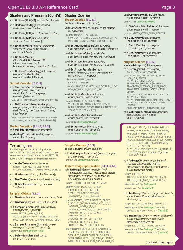
OpenGL ES 3.0 API Reference Card Page 3
Texturing [3.8] Shaders support texturing using at least MAX_VERTEX_TEXTURE_IMAGE_UNITS images for vertex shaders and at least MAX_TEXTURE_IMAGE_UNITS images for fragment shaders.
void ActiveTexture(enum texture);texture: [TEXTURE0..TEXTUREi] where i = [MAX_COMBINED_TEXTURE_IMAGE_UNITS-1]
void GenTextures(sizei n, uint *textures);void BindTexture(enum target, uint texture);void DeleteTextures(sizei n, const uint
*textures);
Sampler Objects [3.8.2]void GenSamplers(sizei count, uint *samplers);void BindSampler(uint unit, uint sampler);void SamplerParameter{if}(uint sampler,
enum pname, T param);pname: TEXTURE_WRAP_{S, T, R},
TEXTURE_{MIN, MAG}_FILTER, TEXTURE_{MIN, MAX}_LOD, TEXTURE_COMPARE_{MODE, FUNC}
void SamplerParameter{if}v(uint sampler, enum pname, const T *params);
pname: See SamplerParameter{if}
void DeleteSamplers(sizei count, const uint *samplers);
Sampler Queries [6.1.5]boolean IsSampler(uint sampler);void GetSamplerParameter{if}v(uint sampler,
enum pname, T *params);pname: See SamplerParameter{if}
Texture Image Specification [3.8.3, 3.8.4]void TexImage3D(enum target, int level,
int internalformat, sizei width, sizei height, sizei depth, int border, enum format, enum type, const void *data);
target: TEXTURE_3D, TEXTURE_2D_ARRAYformat: ALPHA, RGBA, RGB, RG, RED,
{RGBA, RGB, RG, RED}_INTEGER, DEPTH_{COMPONENT, STENCIL}, LUMINANCE_ALPHA, LUMINANCE
type: {UNSIGNED_}BYTE, {UNSIGNED_}SHORT, {UNSIGNED_}INT, UNSIGNED_SHORT_5_6_5, UNSIGNED_SHORT_4_4_4_4, UNSIGNED_SHORT_5_5_5_1, {HALF_}FLOAT, UNSIGNED_INT_2_10_10_10_REV, UNSIGNED_INT_24_8, UNSIGNED_INT_10F_11F_11F_REV, UNSIGNED_INT_5_9_9_9_REV, FLOAT_32_UNSIGNED_INT_24_8_REV
internalformat: R8, R8I, R8UI, R8_SNORM, R16I, R16UI, R16F, R32I, R32UI, R32F, RG8, RG8I, RG8UI, RG8_SNORM, RG16I, RG16UI, RG16F, RG32I, RG32UI, RG32F, RGB, RGB5_A1, RGB565, RGB8, RGB8I, RGB8UI, RGB8_SNORM, RGB9_E5,
RGB10_A2, RGB10_A2UI, RGB16I, RGB16UI, RGB16F, RGB32I, RGB32UI, RGB32F, SRGB8, RGBA, RGBA4, RGBA8, RGBA8I, RGBA8UI, RGBA8_SNORM, RGBA16I, RGBA16UI, RGBA16F, RGBA32I, RGBA32UI, RGBA32F, SRGB8_ALPHA8, R11F_G11F_B10F, DEPTH_COMPONENT16, DEPTH_COMPONENT24, DEPTH_COMPONENT32F, DEPTH24_STENCIL8, DEPTH32F_STENCIL8, LUMINANCE_ALPHA, LUMINANCE, ALPHA
void TexImage2D(enum target, int level, int internalformat, sizei width, sizei height, int border, enum format, enum type, void *data);
target: TEXTURE_2D, TEXTURE_CUBE_MAP_POSITIVE_{X, Y, Z}, TEXTURE_CUBE_MAP_NEGATIVE}{X, Y, Z}
internalformat: See TexImage3Dformat, type: See TexImage3D
void TexStorage2D(enum target, sizei levels, enum internalformat, sizei width, sizei height);
target: TEXTURE_CUBE_MAP, TEXTURE_2Dinternalformat: See TexImage3D except for
unsized base internal formats in [Table 3.3]
void TexStorage3D(enum target, sizei levels, enum internalformat, sizei width, sizei height, sizei depth);
target: TEXTURE_3D, TEXTURE_2D_ARRAYinternalformat: See TexImage3D except for
unsized base internal formats in [Table 3.3]
Shaders and Programs (Cont’d)void Uniform{1234}{if}(int location, T value);void Uniform{1234}{if}v(int location,
sizei count, const T value);void Uniform{1234}ui(int location, T value);void Uniform{1234}uiv(int location,
sizei count, const T value);void UniformMatrix{234}fv(int location,
sizei count, boolean transpose, const float *value);
void UniformMatrix{ 2x3,3x2,2x4,4x2,3x4,4x3}fv( int location, sizei count, boolean transpose, const float *value);
void UniformBlockBinding(uint program, uint uniformBlockIndex, uint uniformBlockBinding);
Output Variables [2.11.8]void TransformFeedbackVaryings(
uint program, sizei count, const char * const *varyings, enum bufferMode);
bufferMode: {INTERLEAVED, SEPARATE}_ATTRIBSvoid GetTransformFeedbackVarying(
uint program, uint index, sizei bufSize, sizei *length, sizei *size, enum *type, char *name);
*type returns any of the scalar, vector, or matrix attribute types returned by GetActiveAttrib().
Shader Execution [2.11.9, 3.9.2]void ValidateProgram(uint program);int GetFragDataLocation(uint program,
const char *name);
Shader QueriesShader Queries [6.1.12] boolean IsShader(uint shader);void GetShaderiv(uint shader, enum pname,
int *params);pname: SHADER_TYPE, {VERTEX,
FRAGMENT_SHADER}, {DELETE, COMPILE}_STATUS, INFO_LOG_LENGTH, SHADER_SOURCE_LENGTH
void GetAttachedShaders(uint program, sizei maxCount, sizei *count, uint *shaders);
void GetShaderInfoLog(uint shader, sizei bufSize, sizei *length, char *infoLog);
void GetShaderSource(uint shader, sizei bufSize, sizei *length, char *source);
void GetShaderPrecisionFormat( enum shadertype, enum precisiontype, int *range, int *precision);
shadertype: VERTEX_SHADER, FRAGMENT_SHADER
precision: LOW_FLOAT, MEDIUM_FLOAT, HIGH_FLOAT, LOW_INT, MEDIUM_INT, HIGH_INT
void GetVertexAttribfv(uint index, enum pname, float *params);
pname: CURRENT_VERTEX_ATTRIB , VERTEX_ATTRIB_ARRAY_x (where x may be BUFFER_BINDING, DIVISOR, ENABLED, INTEGER, SIZE, STRIDE, TYPE, NORMALIZED)
void GetVertexAttribiv(uint index, enum pname, int *params);
pname: See GetVertexAttribfv()
void GetVertexAttribIiv(uint index, enum pname, int *params);
pname: See GetVertexAttribfv()
void GetVertexAttribIuiv(uint index, enum pname, uint *params);
pname: See GetVertexAttribfv()
void GetVertexAttribPointerv(uint index, enum pname, void **pointer);
pname: VERTEX_ATTRIB_ARRAY_POINTER
void GetUniformfv(uint program, int location, float *params);
void GetUniformiv(uint program, int location, int *params);
void GetUniformuiv(uint program, int location, uint *params);
Program Queries [6.1.12] boolean IsProgram(uint program);void GetProgramiv(uint program,
enum pname, int *params); pname: {DELETE, LINK, VALIDATE}_STATUS,
INFO_LOG_LENGTH, ACTIVE_UNIFORM_BLOCKS, TRANSFORM_[FEEDBACK_]VARYINGS, TRANSFORM_FEEDBACK_BUFFER_MODE, TRANSFORM_FEEDBACK_VARYING_MAX_LENGTH, ATTACHED_SHADERS, ACTIVE_ATTRIBUTES, ACTIVE_UNIFORMS, ACTIVE_{ATTRIBUTE, UNIFORM}_MAX_LENGTH, ACTIVE_UNIFORM_BLOCK_MAX_NAME_LENGTH, PROGRAM_BINARY_RETRIEVABLE_HINT
void GetProgramInfoLog(uint program, sizei bufSize, sizei *length, char *infoLog);
(Continued on next page >)

OpenGL ES 3.0 API Reference Card Page 4
Whole FramebufferSelecting a Buffer for Writing [4.2.1]void DrawBuffers(sizei n, const
enum *bufs);bufs points to an array of n BACK, NONE,
or COLOR_ATTACHMENTi where i = [0,MAX_COLOR_ATTACHMENTS - 1].
Fine Control of Buffer Updates [4.2.2]void ColorMask(boolean r, boolean g,
boolean b, boolean a);void DepthMask(boolean mask);void StencilMask(uint mask);void StencilMaskSeparate(enum face,
uint mask);face: FRONT, BACK, FRONT_AND_BACK
Clearing the Buffers [4.2.3]void Clear(bitfield buf);
buf: Bitwise OR of COLOR_BUFFER_BIT, DEPTH_BUFFER_BIT, STENCIL_BUFFER_BIT
void ClearColor(float r, float g, float b, float a);void ClearDepthf(float d);void ClearStencil(int s);void ClearBuffer{if ui}v(enum buffer,
int drawbuffer, const T *value);buffer: COLOR, DEPTH, STENCIL
void ClearBufferfi(enum buffer, int drawbuffer, float depth, int stencil);
buffer: DEPTH_STENCILdrawbuffer: 0
Texturing (continued)Alt. Texture Image Specification
Commands [3.8.5]Texture images may also be specified using image data taken directly from the framebuffer, and rectangular subregions of existing texture images may be respecified.
void CopyTexImage2D(enum target, int level, enum internalformat, int x, int y, sizei width, sizei height, int border);
target: TEXTURE_2D, TEXTURE_CUBE_MAP_POSITIVE_{X, Y, Z}, TEXTURE_CUBE_MAP_NEGATIVE_{X, Y, Z}
internalformat: See TexImage3D, except for DEPTH* values
void TexSubImage3D(enum target, int level, int xoffset, int yoffset, int zoffset, sizei width, sizei height, sizei depth, enum format, enum type, const void *data);
target: TEXTURE_3D, TEXTURE_2D_ARRAYformat, type: See TexImage3D
void TexSubImage2D(enum target, int level, int xoffset, int yoffset, sizei width, sizei height, enum format, enum type, const void *data);
target: TEXTURE_2D, TEXTURE_CUBE_MAP_POSITIVE_{X, Y, Z}, TEXTURE_CUBE_MAP_NEGATIVE_{X, Y, Z}
format, type: See TexImage3D
void CopyTexSubImage3D(enum target, int level, int xoffset, int yoffset, int zoffset, int x, int y, sizei width, sizei height);
target: TEXTURE_3D, TEXTURE_2D_ARRAY
void CopyTexSubImage2D(enum target, int level, int xoffset, int yoffset, int x, int y, sizei width, sizei height);
target: See TexSubImage2D
Compressed Texture Images [3.8.6]void CompressedTexImage2D(enum target,
int level, enum internalformat, sizei width, sizei height, int border, sizei imageSize, const void *data);
target: See TexImage2Dinternalformat: COMPRESSED_RGBA8_ETC2_EAC,
COMPRESSED_{R{G}11, SIGNED_R{G}11}_EAC, COMPRESSED_SRGB8_ALPHA8_ETC2_EAC, COMPRESSED_{S}RGB8{_PUNCHTHROUGH_ALPHA1}_ETC2 [Table 3.16]
void CompressedTexImage3D(enum target, int level, enum internalformat, sizei width, sizei height, sizei depth, int border, sizei imageSize, const void *data);
target: see TexImage3Dinternalformat: See TexImage2D
void CompressedTexSubImage2D(enum target, int level, int xoffset, int yoffset, sizei width, sizei height, enum format, sizei imageSize, const void *data);
target: See TexSubImage2D
void CompressedTexSubImage3D( enum target, int level, int xoffset, int yoffset, int zoffset, sizei width, sizei height, sizei depth, enum format, sizei imageSize, const void *data);
target: See TexSubImage2D
Texture Parameters [3.8.7]void TexParameter{if}(enum target,
enum pname, T param);void TexParameter{if}v(enum target,
enum pname, const T *params);target: TEXTURE_{2D, 3D}, TEXTURE_2D_ARRAY,
TEXTURE_CUBE_MAPpname: TEXTURE_{BASE, MAX}_LEVEL,
TEXTURE_{MIN, MAX}_LOD, TEXTURE_{MIN, MAG}_FILTER, TEXTURE_COMPARE_{MODE,FUNC}, TEXTURE_SWIZZLE_{R,G,B,A}, TEXTURE_WRAP_{S,T,R}
Manual Mipmap Generation [3.8.9]void GenerateMipmap(enum target);
target: TEXTURE_{2D,3D}, TEXTURE_{2D_ARRAY, CUBE_MAP}
Enumerated Queries [6.1.3]void GetTexParameter{if}v(enum target,
enum value, T data);
target: TEXTURE_{2D, 3D}, TEXTURE_{2D_ARRAY, CUBE_MAP}
value: TEXTURE_{BASE, MAX}_LEVEL, TEXTURE_{MIN, MAX}_LOD, TEXTURE_{MIN, MAG}_FILTER, TEXTURE_IMMUTABLE_FORMAT, TEXTURE_COMPARE_{FUNC, MODE}, TEXTURE_WRAP_{S, T, R}, TEXTURE_SWIZZLE_{R, G, B, A}
Texture Queries [6.1.4]boolean IsTexture(uint texture);
Per-Fragment OperationsScissor Test [4.1.2]Enable/Disable(SCISSOR_TEST);void Scissor(int left, int bottom, sizei width,
sizei height);
Multisample Fragment Operations [4.1.3]Enable/Disable(cap);
cap: SAMPLE{_ALPHA_TO}_COVERAGE
void SampleCoverage(float value, boolean invert);
Stencil Test [4.1.4] Enable/Disable(STENCIL_TEST);void StencilFunc(enum func, int ref,
uint mask);func: NEVER, ALWAYS, LESS, GREATER,
{L, G}EQUAL, {NOT}EQUAL
void StencilFuncSeparate(enum face, enum func, int ref, uint mask);
face, func: See StencilOpSeparate
void StencilOp(enum sfail, enum dpfail, enum dppass);
sfail, dpfail, and dppass: KEEP, ZERO, REPLACE, INCR, DECR, INVERT, INCR_WRAP, DECR_WRAP
void StencilOpSeparate(enum face, enum sfail, enum dpfail, enum dppass);
face: FRONT, BACK, FRONT_AND_BACKsfail, dpfail, and dppass: KEEP, ZERO, REPLACE, INCR,
DECR, INVERT, INCR_WRAP, DECR_WRAPfunc: NEVER, ALWAYS, LESS, GREATER,
{L, G}EQUAL, {NOT}EQUAL
Depth Buffer Test [4.1.5] Enable/Disable(DEPTH_TEST);void DepthFunc(enum func);
func: NEVER, ALWAYS, LESS, LEQUAL, EQUAL, GREATER, GEQUAL, NOTEQUAL
Blending [4.1.7] Enable/Disable(BLEND); (all draw buffers)void BlendEquation(enum mode);
void BlendEquationSeparate( enum modeRGB, enum modeAlpha);
mode, modeRGB, and modeAlpha: FUNC_ADD, FUNC[_REVERSE]_SUBTRACT, MIN, MAX
void BlendFuncSeparate( enum srcRGB, enum dstRGB, enum srcAlpha, enum dstAlpha);
srcRGB, dstRGB, srcAlpha, and dstAlpha: ZERO, ONE, {ONE_MINUS_}SRC_COLOR, {ONE_MINUS_}DST_COLOR, {ONE_MINUS_}SRC_ALPHA, {ONE_MINUS_}DST_ALPHA, {ONE_MINUS_}CONSTANT_COLOR, {ONE_MINUS_}CONSTANT_ALPHA, SRC_ALPHA_SATURATE
void BlendFunc(enum src, enum dst);src, dst: See BlendFuncSeparate
void BlendColor(float red, float green, float blue, float alpha);
Dithering [4.1.9] Enable/Disable(DITHER);

OpenGL ES 3.0 API Reference Card Page 5
Special Functions Flush and Finish [5.1]Flush guarantees that commands issued so far will eventually complete. Finish blocks until all commands issued so far have completed.void Flush(void);void Finish(void);
Sync Objects and Fences [5.2]sync FenceSync(enum condition,
bitfield flags);condition: SYNC_GPU_COMMANDS_COMPLETEflags: 0
enum ClientWaitSync(sync sync, bitfield flags, uint64 timeout);
flags: 0 or SYNC_FLUSH_COMMANDS_BITtimeout: nanoseconds
void WaitSync( sync sync, bitfield flags, uint64 timeout);
flags: 0timeout: TIMEOUT_IGNORED
void DeleteSync(sync sync);Hints [5.3]void Hint(enum target, enum hint);
target: GENERATE_MIPMAP_HINT, FRAGMENT_SHADER_DERIVATIVE_HINT
hint: FASTEST, NICEST, DONT_CARE
Sync Object Queries [6.1.8]sync GetSynciv(sync sync, enum pname,
sizei bufSize, sizei *length, int *values);pname: OBJECT_TYPE, SYNC_{STATUS, CONDITION,
FLAGS}
boolean IsSync(sync sync);
Visit khronos.org/opengles for a free PDF of the full-size OpenGL ES 3.0 API referencce card, or purchase a laminated card on amazon.com (search for “Khronos reference card”).
State and State Requests A complete list of symbolic constants for states is shown in the tables in [6.2].
Simple Queries [6.1.1]void GetBooleanv(enum pname,
boolean *data);void GetIntegerv(enum pname, int *data);void GetInteger64v(enum pname,
int64 *data);void GetFloatv(enum pname, float *data);void GetIntegeri_v(enum target, uint index,
int *data ;void GetInteger64i_v(enum target,
uint index, int64 *data);boolean IsEnabled(enum cap);
String Queries [6.1.6] ubyte *GetString(enum name);
name: VENDOR, RENDERER, EXTENSIONS, {SHADING_LANGUAGE_}VERSION
ubyte *GetStringi(enum name, uint index);name: EXTENSIONS
`Framebuffer Objects Binding/Managing Framebuffer [4.4.1]void GenFramebuffers(sizei n,
uint *framebuffers);void BindFramebuffer(enum target,
uint framebuffer);void DeleteFramebuffers(sizei n,
const uint *framebuffers);
Renderbuffer Objects [4.4.2]void GenRenderbuffers(sizei n,
uint *renderbuffers);void BindRenderbuffer(enum target,
uint renderbuffer);target: RENDERBUFFER
void DeleteRenderbuffers(sizei n, const uint *renderbuffers);
void RenderbufferStorageMultisample( enum target, sizei samples, enum internalformat, sizei width, sizei height);
target: RENDERBUFFERinternalformat: {R,RG,RGB}8,
RGB{565, A4, 5_A1, 10_A2}, RGB{10_A2UI}, R{8,16,32}I, RG{8,16,32}I, R{8,16,32}UI, RG{8,16,32}UI, RGBA, RGBA{8, 8I, 8UI, 16I, 16UI, 32I, 32UI}, SRGB8_ALPHA8, STENCIL_INDEX8, DEPTH{24, 32F}_STENCIL8, DEPTH_COMPONENT{16, 24, 32F}
void RenderbufferStorage(enum target, enum internalformat, sizei width, sizei height);
target: RENDERBUFFERinternalformat: See
RenderbufferStorageMultisample
Attach Renderbuffer Images to Framebuffervoid FramebufferRenderbuffer(enum target,
enum attachment, enum renderbuffertarget, uint renderbuffer);
target: FRAMEBUFFER, {DRAW, READ}_FRAMEBUFFER
attachment: DEPTH_ATTACHMENT, {DEPTH_}STENCIL_ATTACHMENT, COLOR_ATTACHMENTi (i = [0, MAX_COLOR_ATTACHMENTS-1])
renderbuffertarget: RENDERBUFFER
Attaching Texture Images to a Framebuffervoid FramebufferTexture2D(enum target,
enum attachment, enum textarget, uint texture, int level);
textarget: TEXTURE_2D, TEXTURE_CUBE_MAP_POSITIVE{X, Y, Z}, TEXTURE_CUBE_MAP_NEGATIVE{X, Y, Z}
target: FRAMEBUFFER, {DRAW, READ}_FRAMEBUFFER
attachment: See FrameBufferRenderbuffer
void FramebufferTextureLayer(enum target, enum attachment, uint texture, int level, int layer);
target: TEXTURE_2D_ARRAY, TEXTURE_3Dattachment: See FrameBufferRenderbuffer
Framebuffer Completeness [4.4.4]enum CheckFramebufferStatus(
enum target);target: FRAMEBUFFER,
{DRAW, READ}_FRAMEBUFFERreturns: FRAMEBUFFER_COMPLETE or a constant
indicating which value violates framebuffer completeness
Invalidating Framebuffer Contents [4.5]void InvalidateSubFramebuffer(
enum target, sizei numAttachments, const enum *attachments, int x, int y, sizei width, sizei height);
target: FRAMEBUFFERattachments: points to an array of COLOR, STENCIL,
{DEPTH, STENCIL}_ATTACHMENT, COLOR_ATTACHMENTi
void InvalidateFramebuffer(enum target, sizei numAttachments, const enum *attachments);
Renderbuffer Object Queries [6.1.14] boolean IsRenderbuffer(uint renderbuffer);void GetRenderbufferParameteriv(
enum target, enum pname, int *params);target: RENDERBUFFERpname: RENDERBUFFER_x, where x may be
WIDTH, HEIGHT, {RED, GREEN, BLUE}_SIZE, {ALPHA, DEPTH, STENCIL}_SIZE, SAMPLES, INTERNAL_FORMAT
Framebuffer Object Queries [6.1.13] boolean IsFramebuffer(uint framebuffer);void
GetFramebufferAttachmentParameteriv( enum target, enum attachment, enum pname, int *params);
target: FRAMEBUFFER, {DRAW, READ}_FRAMEBUFFERattachment: BACK, STENCIL, COLOR_ATTACHMENTi,
{DEPTH, STENCIL, DEPTH_STENCIL}_ATTACHMENTpname: FRAMEBUFFER_ATTACHMENT_x,
where x may be one of OBJECT_{TYPE, NAME}, COMPONENT_TYPE, COLOR_ENCODING, {RED, GREEN, BLUE, ALPHA}_SIZE, {DEPTH, STENCIL}_SIZE, TEXTURE_{LEVEL, LAYER}, TEXTURE_CUBE_MAP_FACE
void GetInternalformativ(enum target, enum internalformat, enum pname, sizei bufSize, int *params);
internalformat: See RenderbufferStorageMultisample
target: RENDERBUFFERpname: NUM_SAMPLE_COUNTS, SAMPLES
Pixel Rectangles [3.7.1]void PixelStorei(enum pname, T param);
pname: {UN}PACK_ROW_LENGTH, {UN}PACK_ALIGNMENT, {UN}PACK_SKIP_{ROWS,PIXELS}, {UN}PACK_IMAGE_HEIGHT, {UN}PACK_SKIP_IMAGES
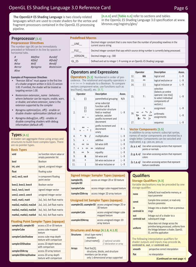
OpenGL ES Shading Language 3.0 Reference Card Page 6
Types [4.1]A shader can aggregate these using arrays and structures to build more complex types. There are no pointer types.Basic Typesvoid no function return value or
empty parameter listbool Boolean
int, uint signed, unsigned integer
float floating scalar
vec2, vec3, vec4 n-component floating point vector
bvec2, bvec3, bvec4 Boolean vector
ivec2, ivec3, ivec4 signed integer vector
uvec2, uvec3, uvec4 unsigned integer vector
mat2, mat3, mat4 2x2, 3x3, 4x4 float matrix
mat2x2, mat2x3, mat2x4 2x2, 2x3, 2x4 float matrix
mat3x2, mat3x3, mat3x4 3x2, 3x3, 3x4 float matrix
mat4x2, mat4x3, mat4x4 4x2, 4x3, 4x4 float matrix
Floating Point Sampler Types (opaque)sampler2D, sampler3D access a 2D or 3D texturesamplerCube access cube mapped
texturesamplerCubeShadow access cube map depth
texture with comparisonsampler2DShadow access 2D depth texture
with comparisonsampler2DArray access 2D array texturesampler2DArrayShadow access 2D array depth
texture with comparison
Signed Integer Sampler Types (opaque)isampler2D, isampler3D
access an integer 2D or 3D texture
isamplerCube access integer cube mapped texture
isampler2DArray access integer 2D array texture
Unsigned Int Sampler Types (opaque)usampler2D, usampler3D access unsigned integer 2D or
3D textureusamplerCube access unsigned integer cube
mapped textureusampler2DArray access unsigned integer 2D
array texture
Structures and Arrays [4.1.8, 4.1.9]Structures struct type-name {
members} struct-name[]; // optional variable
// declaration or array
Arrays float foo[3]; structures, blocks, and structure members can be arrays only 1-dimensional arrays supported
Operators and Expressions Operators [5.1] Numbered in order of pre-cedence. The relational and equality operators > < <= >= == != evaluate to a Boolean. To compare vectors component-wise, use functions such as lessThan(), equal(), etc. [8.7].
Operator Description Assoc.
1. ( ) parenthetical grouping N/A
2. [ ]( ) .
++ --
array subscriptfunction call & constructor structurefield or method selector, swizzler postfix increment and decrement
L - R
3. ++ -- + - ~ !
prefix increment and decrementunary
R - L
4. * % / multiplicative L - R5. + - additive L - R6. << >> bit-wise shift L - R7. < > <= >= relational L - R8. == != equality L - R9. & bit-wise and L - R
10. ^ bit-wise exclusive or L - R11. | bit-wise inclusive or L - R
Operator Description Assoc.12. && logical and L - R13. ^^ logical exclusive or L - R14. | | logical inclusive or L - R
15. ? :
selection (Selects an entire operand. Use mix() to select individual components of vectors.)
L - R
16.
= assignment L - R+= -= *= /= %= <<= >>=
&= ^= |=arithmetic assignments L - R
17. , sequence L - R
Vector Components [5.5]In addition to array numeric subscript syntax, names of vector components are denoted by a single letter. Components can be swizzled and replicated, e.g.: pos.xx, pos.zy
{x, y, z, w} Use when accessing vectors that represent points or normals
{r, g, b, a} Use when accessing vectors that represent colors
{s, t, p, q} Use when accessing vectors that represent texture coordinates
QualifiersStorage Qualifiers [4.3]Variable declarations may be preceded by one storage qualifier.
none (Default) local read/write memory, or input parameter
const Compile-time constant, or read-only function parameter.
incentroid in
linkage into a shader from a previous stage
outcentroid out
linkage out of a shader to a subsequent stage
uniformValue does not change across the primitive being processed, uniforms form the linkage between a shader, OpenGL ES, and the application
The following interpolation qualifiers for shader outputs and inputs may procede in, centroid in, out, or centroid out.smooth perspective correct interpolation
flat no interpolation
Predefined Macros
__LINE__ Decimal integer constant that is one more than the number of preceding newlines in the current source string
__FILE__ Decimal integer constant that says which source string number is currently being processed.
__VERSION__ Decimal integer, e.g.: 300
GL_ES Defined and set to integer 1 if running on an OpenGL-ES Shading Language.
Preprocessor [3.4]Preprocessor DirectivesThe number sign (#) can be immediately preceded or followed in its line by spaces or horizontal tabs.
# #define #undef #if #ifdef #ifndef #else #elif #endif #error #pragma #extension #line
Examples of Preprocessor Directives• “#version 300 es” must appear in the first line
of a shader program written in GLSL ES version 3.00. If omitted, the shader will be treated as targeting version 1.00.
• #extension extension_name : behavior,where behavior can be require, enable, warn, or disable; and where extension_name is the extension supported by the compiler
• #pragma optimize({on, off}) - enable or disable shader optimization (default on)
• #pragma debug({on, off}) - enable or disable compiling shaders with debug information (default off)
The OpenGL® ES Shading Language is two closely-related languages which are used to create shaders for the vertex and fragment processors contained in the OpenGL ES processing pipeline.
[n.n.n] and [Table n.n] refer to sections and tables in the OpenGL ES Shading Language 3.0 specification at www.khronos.org/registry/gles/
(Continued on next page >)
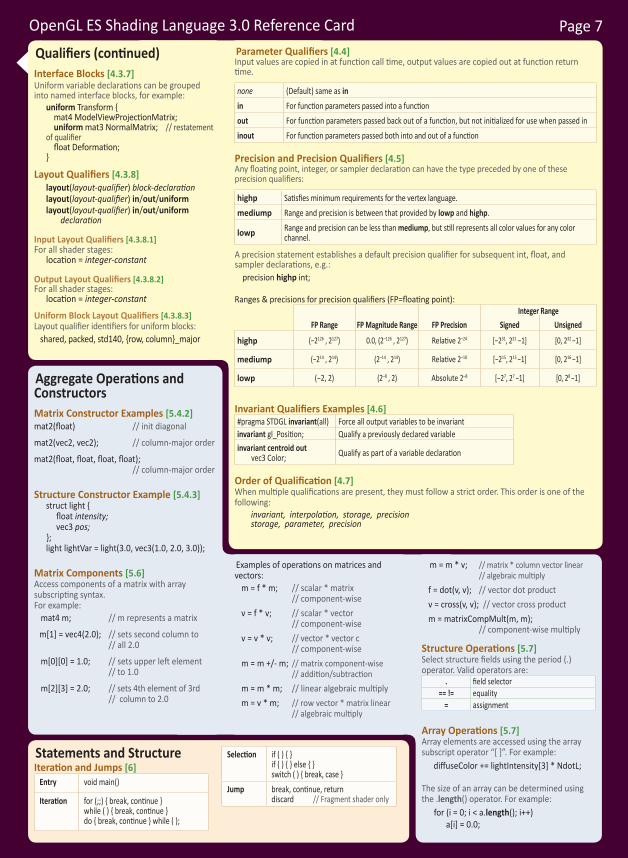
OpenGL ES Shading Language 3.0 Reference Card Page 7
Aggregate Operations and ConstructorsMatrix Constructor Examples [5.4.2]mat2(float) // init diagonal
mat2(vec2, vec2); // column-major order
mat2(float, float, float, float); // column-major order
Structure Constructor Example [5.4.3]struct light { float intensity; vec3 pos;
};light lightVar = light(3.0, vec3(1.0, 2.0, 3.0));
Matrix Components [5.6]Access components of a matrix with array subscripting syntax. For example:
mat4 m; // m represents a matrix
m[1] = vec4(2.0); // sets second column to // all 2.0
m[0][0] = 1.0; // sets upper left element // to 1.0
m[2][3] = 2.0; // sets 4th element of 3rd // column to 2.0
Examples of operations on matrices and vectors:
m = f * m; // scalar * matrix // component-wise
v = f * v; // scalar * vector // component-wise
v = v * v; // vector * vector c // component-wise
m = m +/- m; // matrix component-wise // addition/subtraction
m = m * m; // linear algebraic multiplym = v * m; // row vector * matrix linear
// algebraic multiply
m = m * v; // matrix * column vector linear // algebraic multiply
f = dot(v, v); // vector dot productv = cross(v, v); // vector cross productm = matrixCompMult(m, m);
// component-wise multiply
Structure Operations [5.7]Select structure fields using the period (.) operator. Valid operators are:
. field selector== != equality
= assignment
Array Operations [5.7]Array elements are accessed using the array subscript operator “[ ]”. For example:
diffuseColor += lightIntensity[3] * NdotL;
The size of an array can be determined using the .length() operator. For example: for (i = 0; i < a.length(); i++) a[i] = 0.0;
Qualifiers (continued)Interface Blocks [4.3.7]Uniform variable declarations can be grouped into named interface blocks, for example:
uniform Transform { mat4 ModelViewProjectionMatrix; uniform mat3 NormalMatrix; // restatement of qualifier float Deformation; }
Layout Qualifiers [4.3.8]layout(layout-qualifier) block-declarationlayout(layout-qualifier) in/out/uniformlayout(layout-qualifier) in/out/uniform
declaration
Input Layout Qualifiers [4.3.8.1]For all shader stages:
location = integer-constant
Output Layout Qualifiers [4.3.8.2]For all shader stages:
location = integer-constant
Uniform Block Layout Qualifiers [4.3.8.3]Layout qualifier identifiers for uniform blocks:
shared, packed, std140, {row, column}_major
Parameter Qualifiers [4.4]Input values are copied in at function call time, output values are copied out at function return time.
none (Default) same as inin For function parameters passed into a functionout For function parameters passed back out of a function, but not initialized for use when passed ininout For function parameters passed both into and out of a function
Precision and Precision Qualifiers [4.5]Any floating point, integer, or sampler declaration can have the type preceded by one of these precision qualifiers:
highp Satisfies minimum requirements for the vertex language. mediump Range and precision is between that provided by lowp and highp.
lowp Range and precision can be less than mediump, but still represents all color values for any color channel.
A precision statement establishes a default precision qualifier for subsequent int, float, and sampler declarations, e.g.: precision highp int;
Ranges & precisions for precision qualifiers (FP=floating point):
FP Range FP Magnitude Range FP PrecisionInteger Range
Signed Unsigned
highp (−2126 , 2127) 0.0, (2–126 , 2127) Relative 2–24 [−231, 231 −1] [0, 232 −1]
mediump (−214 , 214) (2–14 , 214) Relative 2–10 [−215, 215 −1] [0, 216 −1]
lowp (−2, 2) (2–8 , 2) Absolute 2–8 [−27, 27 −1] [0, 28 −1]
Invariant Qualifiers Examples [4.6]#pragma STDGL invariant(all) Force all output variables to be invariantinvariant gl_Position; Qualify a previously declared variableinvariant centroid out vec3 Color; Qualify as part of a variable declaration
Order of Qualification [4.7]When multiple qualifications are present, they must follow a strict order. This order is one of the following: invariant, interpolation, storage, precision storage, parameter, precision
Statements and StructureIteration and Jumps [6]
Entry void main()
Iteration for (;;) { break, continue }while ( ) { break, continue }do { break, continue } while ( );
Selection if ( ) { }if ( ) { } else { }switch ( ) { break, case }
Jump break, continue, returndiscard // Fragment shader only

OpenGL ES Shading Language 3.0 Reference Card Page 8
Built-In Functions Angle & Trigonometry Functions [8.1]Component-wise operation. Parameters specified as angle are assumed to be in units of radians. T is float, vec2, vec3, vec4.
T radians (T degrees); degrees to radians
T degrees (T radians); radians to degrees
T sin (T angle); sine
T cos (T angle); cosine
T tan (T angle); tangent
T asin (T x); arc sine
T acos (T x); arc cosine
T atan (T y, T x); T atan (T y_over_x); arc tangent
T sinh (T x); hyperbolic sine
T cosh (T x); hyperbolic cosine
T tanh (T x); hyperbolic tangent
T asinh (T x); arc hyperbolic sine; inverse of sinh
T acosh (T x); arc hyperbolic cosine; non-negative inverse of cosh
T atanh (T x); arc hyperbolic tangent; inverse of tanh
Exponential Functions [8.2]Component-wise operation. T is float, vec2, vec3, vec4.
T pow (T x, T y); xy
T exp (T x); ex
T log (T x); ln
T exp2 (T x); 2x
T log2 (T x); log2T sqrt (T x); square root
T inversesqrt (T x); inverse square root
Common Functions [8.3]Component-wise operation. T is float and vecn, TI is int and ivecn, TU is uint and uvecn, and TB is bool and bvecn, where n is 2, 3, or 4.
T abs(T x);TI abs(TI x); absolute value
T sign(T x);TI sign(TI x); returns -1.0, 0.0, or 1.0
T floor(T x); nearest integer <= x
T trunc (T x); nearest integer a such that |a| <= |x|
T round (T x); round to nearest integer
T roundEven (T x); round to nearest integer
T ceil(T x); nearest integer >= x
T fract(T x); x - floor(x)
T mod(T x, T y);T mod(T x, float y);T modf(T x, out T i);
modulus
T min(T x, T y); TI min(TI x, TI y); TU min(TU x, TU y); T min(T x, float y);TI min(TI x, int y);TU min(TU x, uint y);
minimum value
T max(T x, T y);TI max(TI x, TI y);TU max(TU x, TU y);T max(T x, float y);TI max(TI x, int y);TU max(TU x, uint y);
maximum value
T clamp(TI x, T minVal, T maxVal);TI clamp(V x, TI minVal, TI maxVal); TU clamp(TU x, TU minVal, TU maxVal); T clamp(T x, float minVal, float maxVal);TI clamp(TI x, int minVal, int maxVal);TU clamp(TU x, uint minVal, uint maxVal);
min(max(x, minVal), maxVal)
T mix(T x, T y, T a);T mix(T x, T y, float a); linear blend of x and y
(Continued on next page >)
Built-In Inputs, Outputs, and Constants [7]Shader programs use special variables to communicate with fixed-function parts of the pipeline. Output special variables may be read back after writing. Input special variables are read-only. All special variables have global scope.Vertex Shader Special Variables [7.1]Inputs:
int gl_VertexID; // integer indexint gl_InstanceID; // instance number
Outputs: out gl_PerVertex {
vec4 gl_Position; // transformed vertex position in clip coordinatesfloat gl_PointSize; // transformed point size in pixels (point
// rasterization only)};
Fragment Shader Special Variables [7.2]Inputs:
highp vec4 gl_FragCoord; // fragment position within frame bufferbool gl_FrontFacing; // fragment belongs to a front-facing primitivemediump vec2 gl_PointCoord; // 0.0 to 1.0 for each component
Outputs:highp float gl_FragDepth; // depth range
Built-In Constants With Minimum Values [7.3]Built-in Constant Minimum valueconst mediump int gl_MaxVertexAttribs 16const mediump int gl_MaxVertexUniformVectors 256const mediump int gl_MaxVertexOutputVectors 16const mediump int gl_MaxFragmentInputVectors 15const mediump int gl_MaxVertexTextureImageUnits 16const mediump int gl_MaxCombinedTextureImageUnits 32const mediump int gl_MaxTextureImageUnits 16const mediump int gl_MaxFragmentUniformVectors 224const mediump int gl_MaxDrawBuffers 4const mediump int gl_MinProgramTexelOffset -8const mediump int gl_MaxProgramTexelOffset 7
Built-In Uniform State [7.4]As an aid to accessing OpenGL ES processing state, the following uniform variables are built into the OpenGL ES Shading Language. struct gl_DepthRangeParameters {
float near; // n float far; // f float diff; // f - n }; uniform gl_DepthRangeParameters gl_DepthRange;
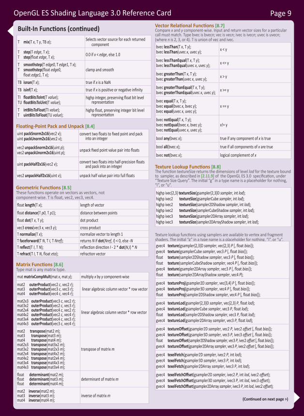
OpenGL ES Shading Language 3.0 Reference Card Page 9
Built-In Functions (continued)
T mix(T x, T y, TB a); Selects vector source for each returned component
T step(T edge, T x);T step(float edge, T x); 0.0 if x < edge, else 1.0
T smoothstep(T edge0, T edge1, T x);T smoothstep(float edge0,
float edge1, T x); clamp and smooth
TB isnan(T x); true if x is a NaNTB isinf(T x); true if x is positive or negative infinityTI floatBitsToInt(T value);TU floatBitsToUint(T value);
highp integer, preserving float bit level representation
T intBitsToFloat(TI value);T uintBitsToFloat(TU value);
highp float, preserving integer bit level representation
Floating-Point Pack and Unpack [8.4]uint packSnorm2x16(vec2 v);uint packUnorm2x16(vec2 v);
convert two floats to fixed point and pack into an integer
vec2 unpackSnorm2x16(uint p);vec2 unpackUnorm2x16(uint p); unpack fixed point value pair into floats
uint packHalf2x16(vec2 v); convert two floats into half-precision floats and pack into an integer
vec2 unpackHalf2x16(uint v); unpack half value pair into full floats
Geometric Functions [8.5]These functions operate on vectors as vectors, not component-wise. T is float, vec2, vec3, vec4.float length(T x); length of vectorfloat distance(T p0, T p1); distance between pointsfloat dot(T x, T y); dot productvec3 cross(vec3 x, vec3 y); cross productT normalize(T x); normalize vector to length 1T faceforward(T N, T I, T Nref); returns N if dot(Nref, I) < 0, else -NT reflect(T I, T N); reflection direction I - 2 * dot(N,I) * NT refract(T I, T N, float eta); refraction vector
Matrix Functions [8.6]Type mat is any matrix type.mat matrixCompMult(mat x, mat y); multiply x by y component-wise
mat2 outerProduct(vec2 c, vec2 r);mat3 outerProduct(vec3 c, vec3 r);mat4 outerProduct(vec4 c, vec4 r);
linear algebraic column vector * row vector
mat2x3 outerProduct(vec3 c, vec2 r);mat3x2 outerProduct(vec2 c, vec3 r);mat2x4 outerProduct(vec4 c, vec2 r);mat4x2 outerProduct(vec2 c, vec4 r);mat3x4 outerProduct(vec4 c, vec3 r);mat4x3 outerProduct(vec3 c, vec4 r);
linear algebraic column vector * row vector
mat2 transpose(mat2 m);mat3 transpose(mat3 m);mat4 transpose(mat4 m);mat2x3 transpose(mat3x2 m);mat3x2 transpose(mat2x3 m);mat2x4 transpose(mat4x2 m);mat4x2 transpose(mat2x4 m);mat3x4 transpose(mat4x3 m);mat4x3 transpose(mat3x4 m);
transpose of matrix m
float determinant(mat2 m);float determinant(mat3 m);float determinant(mat4 m);
determinant of matrix m
mat2 inverse(mat2 m);mat3 inverse(mat3 m);mat4 inverse(mat4 m);
inverse of matrix m
Vector Relational Functions [8.7]Compare x and y component-wise. Input and return vector sizes for a particular call must match. Type bvec is bvecn; vec is vecn; ivec is ivecn; uvec is uvecn; (where n is 2, 3, or 4). T is union of vec and ivec. bvec lessThan(T x, T y);bvec lessThan(uvec x, uvec y); x < y
bvec lessThanEqual(T x, T y);bvec lessThanEqual(uvec x, uvec y); x <= y
bvec greaterThan(T x, T y);bvec greaterThan(uvec x, uvec y); x > y
bvec greaterThanEqual(T x, T y);bvec greaterThanEqual(uvec x, uvec y); x >= y
bvec equal(T x, T y);bvec equal(bvec x, bvec y);bvec equal(uvec x, uvec y);
x == y
bvec notEqual(T x, T y);bvec notEqual(bvec x, bvec y);bvec notEqual(uvec x, uvec y);
x!= y
bool any(bvec x); true if any component of x is true
bool all(bvec x); true if all components of x are true
bvec not(bvec x); logical complement of x
Texture Lookup Functions [8.8]The function textureSize returns the dimensions of level lod for the texture bound to sampler, as described in [2.11.9] of the OpenGL ES 3.0 specification, under “Texture Size Query”. The initial “g” in a type name is a placeholder for nothing, “i”, or “u”.
highp ivec{2,3} textureSize(gsampler{2,3}D sampler, int lod);highp ivec2 textureSize(gsamplerCube sampler, int lod);highp ivec2 textureSize(sampler2DShadow sampler, int lod);highp ivec2 textureSize(samplerCubeShadow sampler, int lod);highp ivec3 textureSize(gsampler2DArray sampler, int lod);highp ivec3 textureSize(sampler2DArrayShadow sampler, int lod);
Texture lookup functions using samplers are available to vertex and fragment shaders. The initial “g” in a type name is a placeholder for nothing, “i”, or “u”.gvec4 texture(gsampler{2,3}D sampler, vec{2,3} P [, float bias]);gvec4 texture(gsamplerCube sampler, vec3 P [, float bias]);float texture(sampler2DShadow sampler, vec3 P [, float bias]);float texture(samplerCubeShadow sampler, vec4 P [, float bias]);gvec4 texture(gsampler2DArray sampler, vec3 P [, float bias]);float texture(sampler2DArrayShadow sampler, vec4 P);
gvec4 textureProj(gsampler2D sampler, vec{3,4} P [, float bias]);gvec4 textureProj(gsampler3D sampler, vec4 P [, float bias]);float textureProj(sampler2DShadow sampler, vec4 P [, float bias]);
gvec4 textureLod(gsampler{2,3}D sampler, vec{2,3} P, float lod);gvec4 textureLod(gsamplerCube sampler, vec3 P, float lod);float textureLod(sampler2DShadow sampler, vec3 P, float lod);gvec4 textureLod(gsampler2DArray sampler, vec3 P, float lod);
gvec4 textureOffset(gsampler2D sampler, vec2 P, ivec2 offset [, float bias]);gvec4 textureOffset(gsampler3D sampler, vec3 P, ivec3 offset [, float bias]);float textureOffset(sampler2DShadow sampler, vec3 P, ivec2 offset [, float bias]);gvec4 textureOffset(gsampler2DArray sampler, vec3 P, ivec2 offset [, float bias]);
gvec4 texelFetch(gsampler2D sampler, ivec2 P, int lod);gvec4 texelFetch(gsampler3D sampler, ivec3 P, int lod);gvec4 texelFetch(gsampler2DArray sampler, ivec3 P, int lod);
gvec4 texelFetchOffset(gsampler2D sampler, ivec2 P, int lod, ivec2 offset);gvec4 texelFetchOffset(gsampler3D sampler, ivec3 P, int lod, ivec3 offset);gvec4 texelFetchOffset(gsampler2DArray sampler, ivec3 P, int lod, ivec2 offset);
(Continued on next page >)
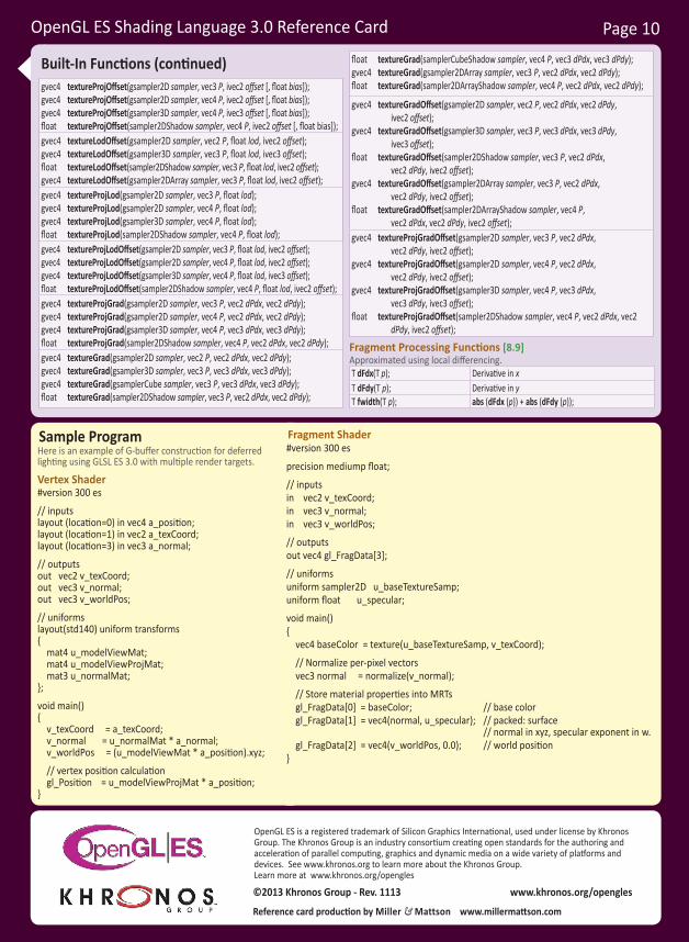
OpenGL ES Shading Language 3.0 Reference Card Page 10
Sample ProgramHere is an example of G-buffer construction for deferred lighting using GLSL ES 3.0 with multiple render targets.
Vertex Shader#version 300 es
// inputslayout (location=0) in vec4 a_position;layout (location=1) in vec2 a_texCoord;layout (location=3) in vec3 a_normal;
// outputsout vec2 v_texCoord;out vec3 v_normal;out vec3 v_worldPos;
// uniformslayout(std140) uniform transforms { mat4 u_modelViewMat; mat4 u_modelViewProjMat; mat3 u_normalMat;};
void main(){ v_texCoord = a_texCoord; v_normal = u_normalMat * a_normal; v_worldPos = (u_modelViewMat * a_position).xyz;
// vertex position calculation gl_Position = u_modelViewProjMat * a_position;}
Fragment Shader#version 300 es
precision mediump float;
// inputsin vec2 v_texCoord;in vec3 v_normal;in vec3 v_worldPos;
// outputsout vec4 gl_FragData[3];
// uniformsuniform sampler2D u_baseTextureSamp;uniform float u_specular;
void main(){ vec4 baseColor = texture(u_baseTextureSamp, v_texCoord);
// Normalize per-pixel vectors vec3 normal = normalize(v_normal);
// Store material properties into MRTs gl_FragData[0] = baseColor; // base color gl_FragData[1] = vec4(normal, u_specular); // packed: surface
// normal in xyz, specular exponent in w. gl_FragData[2] = vec4(v_worldPos, 0.0); // world position}
Reference card production by Miller & Mattson www.millermattson.com
www.khronos.org/opengles©2013 Khronos Group - Rev. 1113
OpenGL ES is a registered trademark of Silicon Graphics International, used under license by Khronos Group. The Khronos Group is an industry consortium creating open standards for the authoring and acceleration of parallel computing, graphics and dynamic media on a wide variety of platforms and devices. See www.khronos.org to learn more about the Khronos Group. Learn more at www.khronos.org/opengles
Built-In Functions (continued)gvec4 textureProjOffset(gsampler2D sampler, vec3 P, ivec2 offset [, float bias]);gvec4 textureProjOffset(gsampler2D sampler, vec4 P, ivec2 offset [, float bias]);gvec4 textureProjOffset(gsampler3D sampler, vec4 P, ivec3 offset [, float bias]);float textureProjOffset(sampler2DShadow sampler, vec4 P, ivec2 offset [, float bias]);gvec4 textureLodOffset(gsampler2D sampler, vec2 P, float lod, ivec2 offset);gvec4 textureLodOffset(gsampler3D sampler, vec3 P, float lod, ivec3 offset);float textureLodOffset(sampler2DShadow sampler, vec3 P, float lod, ivec2 offset);gvec4 textureLodOffset(gsampler2DArray sampler, vec3 P, float lod, ivec2 offset);gvec4 textureProjLod(gsampler2D sampler, vec3 P, float lod);gvec4 textureProjLod(gsampler2D sampler, vec4 P, float lod);gvec4 textureProjLod(gsampler3D sampler, vec4 P, float lod);float textureProjLod(sampler2DShadow sampler, vec4 P, float lod);gvec4 textureProjLodOffset(gsampler2D sampler, vec3 P, float lod, ivec2 offset);gvec4 textureProjLodOffset(gsampler2D sampler, vec4 P, float lod, ivec2 offset);gvec4 textureProjLodOffset(gsampler3D sampler, vec4 P, float lod, ivec3 offset);float textureProjLodOffset(sampler2DShadow sampler, vec4 P, float lod, ivec2 offset);gvec4 textureProjGrad(gsampler2D sampler, vec3 P, vec2 dPdx, vec2 dPdy);gvec4 textureProjGrad(gsampler2D sampler, vec4 P, vec2 dPdx, vec2 dPdy);gvec4 textureProjGrad(gsampler3D sampler, vec4 P, vec3 dPdx, vec3 dPdy);float textureProjGrad(sampler2DShadow sampler, vec4 P, vec2 dPdx, vec2 dPdy);gvec4 textureGrad(gsampler2D sampler, vec2 P, vec2 dPdx, vec2 dPdy);gvec4 textureGrad(gsampler3D sampler, vec3 P, vec3 dPdx, vec3 dPdy);gvec4 textureGrad(gsamplerCube sampler, vec3 P, vec3 dPdx, vec3 dPdy);float textureGrad(sampler2DShadow sampler, vec3 P, vec2 dPdx, vec2 dPdy);
float textureGrad(samplerCubeShadow sampler, vec4 P, vec3 dPdx, vec3 dPdy);gvec4 textureGrad(gsampler2DArray sampler, vec3 P, vec2 dPdx, vec2 dPdy);float textureGrad(sampler2DArrayShadow sampler, vec4 P, vec2 dPdx, vec2 dPdy);
gvec4 textureGradOffset(gsampler2D sampler, vec2 P, vec2 dPdx, vec2 dPdy, ivec2 offset);
gvec4 textureGradOffset(gsampler3D sampler, vec3 P, vec3 dPdx, vec3 dPdy, ivec3 offset);
float textureGradOffset(sampler2DShadow sampler, vec3 P, vec2 dPdx, vec2 dPdy, ivec2 offset);
gvec4 textureGradOffset(gsampler2DArray sampler, vec3 P, vec2 dPdx, vec2 dPdy, ivec2 offset);
float textureGradOffset(sampler2DArrayShadow sampler, vec4 P, vec2 dPdx, vec2 dPdy, ivec2 offset);
gvec4 textureProjGradOffset(gsampler2D sampler, vec3 P, vec2 dPdx, vec2 dPdy, ivec2 offset);
gvec4 textureProjGradOffset(gsampler2D sampler, vec4 P, vec2 dPdx, vec2 dPdy, ivec2 offset);
gvec4 textureProjGradOffset(gsampler3D sampler, vec4 P, vec3 dPdx, vec3 dPdy, ivec3 offset);
float textureProjGradOffset(sampler2DShadow sampler, vec4 P, vec2 dPdx, vec2 dPdy, ivec2 offset);
Fragment Processing Functions [8.9]Approximated using local differencing.T dFdx(T p); Derivative in xT dFdy(T p); Derivative in yT fwidth(T p); abs (dFdx (p)) + abs (dFdy (p));

You love our titles and you love toshare them with your colleagues and friends...why not earn some $$ doing it!
If you have a website, blog, or even a Facebook page, you can start earning money by putting InformIT links on your page.
Whenever a visitor clicks on these links and makes a purchase on informit.com, you earn commissions* on all sales!
Every sale you bring to our site will earn you a commission. All you have to do is post the links to the titles you want, as many as you want, and we’ll take care of the rest.
ApplY And get stArted!It’s quick and easy to apply. To learn more go to: http://www.informit.com/affiliates/*Valid for all books, eBooks and video sales at www.informit.com
Join the
InformItAffiliAte teAm!
Related Documents