Open Vault Storage Hardware V0.5 Authors: Mike Yan, Engineer Jon Ehlen, Engineer

Welcome message from author
This document is posted to help you gain knowledge. Please leave a comment to let me know what you think about it! Share it to your friends and learn new things together.
Transcript

Open Vault Storage Hardware V0.5
Authors:
Mike Yan, Engineer
Jon Ehlen, Engineer

May 2, 2012 2
1 Scope This document describes the technical specifications used in the design of the storage unit for the Open Compute Project, known as the Open Vault.
2 Contents 1 Scope ......................................................................................................................................... 2
2 Contents .................................................................................................................................... 2
3 Open Vault Storage Unit Overview ........................................................................................... 4 3.1 Open Vault Front View .................................................................................................... 4 3.2 Open Vault Rear View ...................................................................................................... 4 3.3 System Component Layout .............................................................................................. 5 3.4 System Block Diagram ..................................................................................................... 5 3.5 System I2C Topology ........................................................................................................ 7
4 Open Vault SAS Expander Board ............................................................................................... 7 4.1 Block Diagram and Configurations .................................................................................. 7 4.2 SEB Placement and Form Factor ...................................................................................... 8 4.3 SAS Expander Chip ........................................................................................................... 9 4.4 Voltage Monitor .............................................................................................................. 9 4.5 Connectors ....................................................................................................................... 9 4.6 LEDs ............................................................................................................................... 12 4.7 PCB Stack-‐up .................................................................................................................. 12
5 Open Vault Drive Plane Board ................................................................................................. 13 5.1 Block Diagram ................................................................................................................ 13 5.2 DPB Placement and Form Factor ................................................................................... 14 5.3 12.5V to 5V Buck Converter ........................................................................................... 14 5.4 Disk Drive Power Control ............................................................................................... 14 5.5 Voltage Monitor ............................................................................................................ 14 5.6 Connectors ..................................................................................................................... 15 5.7 LEDs ............................................................................................................................... 16 5.8 PCB Stack-‐up .................................................................................................................. 16
6 Open Vault Fan Control Board ................................................................................................ 17 6.1 Block Diagram ................................................................................................................ 17 6.2 FCB Placement and Form Factor .................................................................................... 18 6.3 Embedded Hardware Monitor ....................................................................................... 18 6.4 Input Power Monitor ..................................................................................................... 19

Open Vault Storage Hardware v0.5
http://www.facebook.com 3
6.5 Connectors ..................................................................................................................... 19 6.6 LEDs ............................................................................................................................... 21 6.7 PCB Stack-‐up .................................................................................................................. 21
7 Open Vault Power System ....................................................................................................... 21 7.1 Power Budget ................................................................................................................ 21 7.2 SEB Bulk Converter Solutions ........................................................................................ 22 7.3 Hard Drive 5V Power Design .......................................................................................... 22 7.4 Disk Drive Power Control ............................................................................................... 22 7.5 Power-‐On Sequencing ................................................................................................... 22
8 Enclosure Management Firmware .......................................................................................... 23 8.1 Enclosure Service Functionalities .................................................................................. 23 8.2 Enclosure Status Output File ......................................................................................... 23 8.3 Fan Speed Control ......................................................................................................... 24 8.4 Thermal Protection ........................................................................................................ 26 8.5 HDD Spin-‐up Control ...................................................................................................... 26 8.6 HDD Spin-‐down Control Support ................................................................................... 26 8.7 HDD Presence Detect .................................................................................................... 26 8.8 HDD Status LED .............................................................................................................. 26 8.9 Error Code Display on Debug Card ................................................................................ 26
9 Mechanical .............................................................................................................................. 27 9.1 External Chassis ............................................................................................................. 27 9.2 Serviceability .................................................................................................................. 27 9.3 Rack Interface/Slides ..................................................................................................... 27
10 Environmental ......................................................................................................................... 27 10.1 Environmental Requirements ........................................................................................ 27 10.2 Vibration and Shock ....................................................................................................... 27
11 Prescribed Materials ............................................................................................................... 28 11.1 Disallowed Components ................................................................................................ 28 11.2 Capacitors and Inductors ............................................................................................... 28 11.3 Component De-‐Rating ................................................................................................... 28
May 2, 2012 4
3 Open Vault Storage Unit Overview The Open Vault storage unit is a 2U-30HDD storage enclosure, consisting of two identical 1U high HDD trays with 15 x 3.5" HDDs and two SAS expander boards on each, one fan control board, and six redundant fan modules mounted externally in the rear of the chassis. An Open Vault storage server fits into the Open Compute Project Open Rack.
Each HDD tray contains one drive plane board and two SAS expander boards, interfaces external to one or more separate server(s) via x4 SAS 6G link(s). Each SAS expander board and HDD tray can be extracted and serviced independently without impact to the other connected trays. This provides for the easy replacement of one SAS expander board or the replacement of a single HDD while keeping the whole system running. Each fan module is hot pluggable and field replaceable from the rear of the chassis. Also there are power connecter(s) to the Open Rack bus bars so that the 12V main power from the Open Rack can be fed into the Open Vault enclosure.
For the purposes of this specification, "front" refers to the cold aisle side of the chassis, which is where all service (except fan tray removal and replacement) occurs; "rear" refers to the hot aisle side of the chassis, which is where the fan module service occurs; "SEB" refers to the SAS expander board, "DPB" refers to the drive plane board, and "FCB" refers to the fan control board.
3.1 Open Vault Front View
The equipment visible from the front of the Open Vault includes:
• Two (2) HDD trays • Four (4) SAS expander boards • Four (4) external mini-SAS connectors, with status LED • Eight (8) internal mini-SAS connectors, with status LED • Four (4) enclosure status LEDs • Four (4) debug headers
Figure 1 Open Vault Storage Unit Front View
3.2 Open Vault Rear View
The equipment visible from the rear of the Open Vault includes:
• Two (2) bus bar connectors • Six (6) fan modules, with status LED
Figure 2 Open Vault Storage Unit Rear View

Open Vault Storage Hardware v0.5
http://www.facebook.com 5
3.3 System Component Layout
Figure 3 shows the layout from overhead of the Open Vault's major system components.
HDD 5 HDD 6 HDD 7 HDD 8 HDD 9
HDD 0 HDD 1 HDD 2 HDD 3 HDD 4
HDD 11 HDD 14HDD 12HDD 10 HDD 13
Drive Plane Board
SAS Expander Board
FAN 1FAN 2FAN 3FAN 5FAN 6
Fan Control Board
FAN 4
SEB-‐A SEB-‐B Figure 3 Open Vault System Components Layout
3.4 System Block Diagram
Figure 4 shows the system block diagram for Open Vault, mainly addressing SAS data paths. Each SAS expander board has:
• One external mini-SAS port to the host RAID or HBA card
o Using external mini-SAS cable o Max cable length: 10m
• Two internal mini-SAS ports to cascaded Open Vault trays
o Using internal mini-SAS cable located outside the chassis o Max cable length: 1.5m

May 2, 2012 6
Figure 4 Open Vault System Block Diagram

Open Vault Storage Hardware v0.5
http://www.facebook.com 7
3.5 System I2C Topology
Figure 5 shows the system I2C topology of Open Vault. It reflects the enclosure management structure of Open Vault.
SAS Expander
Temp Sensor 3
Temp Sensor 1 EEPROM
EEPROM
Temp Sensor 3
Temp Sensor 2
Temp Sensor 1
Temp Sensor 4
I2C Buffer
I2C Buffer
Fan Controller
Power Monitor
SEB-‐1A
DPB-‐1
FCB
I2C_A
I2C_B
I2C_C
Voltage Monitor
EEPROM
Temp Sensor 2
I2C_D
SAS Expander
Temp Sensor 3
Temp Sensor 2
Temp Sensor 1
I2C Buffer
I2C BufferSEB-‐2B
I2C_A
I2C_B
I2C_C
I2C_D
LED Driver
EEPROM
Voltage Monitor
LED Driver
Voltage Monitor
LED Driver
I2C Buffer
SAS Expander
Temp Sensor 3
Temp Sensor 1
I2C Buffer
I2C Buffer
SEB-‐2AI2C_A
I2C_B
I2C_C
Voltage Monitor
EEPROM
Temp Sensor 2
I2C_DLED Driver I2C
Buffer
I2C Buffer
SAS Expander
Temp Sensor 3
Temp Sensor 2
Temp Sensor 1
I2C Buffer
I2C BufferSEB-‐1B
I2C_A
I2C_B
I2C_C
I2C_D
EEPROM
Voltage Monitor
LED Driver
I2C Buffer
I2C Buffer
EEPROM
Temp Sensor 3
Temp Sensor 2
Temp Sensor 1
Temp Sensor 4
DPB-‐2
Voltage Monitor
I2C Buffer
Figure 5 Open Vault System I2C Topology
4 Open Vault SAS Expander Board
4.1 Block Diagram and Configurations
Figure 6 illustrates the functional block diagram of the Open Vault SAS expander board (SEB), utilizing an LSISAS2x28 6G SAS expander.

May 2, 2012 8
Figure 6 Open Vault LSISAS2108 Block Diagram
4.2 SEB Placement and Form Factor
The SAS expander board (SEB) form factor is 235mm x 195mm. Figure 7 illustrates the board placement. The following devices are placed as close as possible to the front of the SEB for easy access from the front:
• External mini-SAS connector • Internal mini-SAS connector • Status LEDs • Debug header
SAS Expander
PCI-‐E Golden Finger to Drive Plane Board
Mini-‐SAS-‐4x Conn.
Mini-‐SAS-‐4i Conn. x2 Enclosure Status LED
Debug Header
Figure 7 Open Vault SAS Expander Board Placement
ExpanderLSISAS2x28
SAS 2.0 x4
SAS 2.0 x15
Drive Plane Board:EEPROM
Thermal SensorsVoltage Monitor
HDD LEDs
Debug HeaderUART & GPIO
I2C_A
Ext. Mini-‐SAS Connector
Int. Mini-‐SAS Connector
Int. Mini-‐SAS Connector
SAS 2.0 x4
SAS 2.0 x4
HDD HDD HDD HDD HDD
HDD HDD HDD HDD HDD
HDD HDD HDD HDD HDD
Fan Control Board:Fan Controller
EEPROMPower Monitor
FAN LEDs
EEPROM
Flash ROM
Voltage Monitor
Temp Sensors 1, 2, 3
I2C_B, I2C_C, I2C_D, PWM, GPIOs
Mini-‐SAS Link Status LEDs
Enclosure Status LED
Peer SAS Expander BoardSAS 2.0 x15
I2C_C, PWM, GPIOs
I2C_D
LED Driver
I2C_B, I2C_C, I2C_D, PWM, GPIOs

Open Vault Storage Hardware v0.5
http://www.facebook.com 9
4.3 SAS Expander Chip
The Open Vault SAS expander board contains a single 6G SAS expander, part number LSISAS2x28. The board design is compatible with LSISAS2x24 and LSISAS2x20 under different configurations.
4.4 Voltage Monitor
A voltage monitor is required for the Open Vault SAS expander board in order to ensure proper operation of all power rails at all times. The voltages are reported as part of the enclosure status as described in section 8.1. The power rails to be monitored are shown in Figure 8.
Power Rail Voltage
VDDIO33 3.3V
VDDIO 1.8V
VDD 1.0V
VCC for signal re-driver 1.2V
Figure 8 Monitored Power Rails on SEB
4.5 Connectors
Sections 4.5.1 through 4.5.4 describe the connectors that reside on the Open Vault SAS expander board.
4.5.1 Signal Connector to Drive Plane Board
The Open Vault SAS expander board is designed as a field replaceable unit that interfaces to the drive plane board through an OCP-defined pin-out. The drive plane board side connectors are two standard straddle type PCI-E connectors for each SAS expander board. One is x16 connector (164 pin) and the other is x1 connector (36 pin), together to provide up to 200 pins. These connectors will be mated with 1mm pitch gold finger contacts on the SAS expander board side. The design should be capable for 6G SAS signals with reliable margin.
Figure 9 shows the PCI-E 1mm edge golden figures, using 164 pins for x16 connection as an example. The full connector pin definition should be provided by the ODM.
Figure 9 PCI-E 1mm Edge Golden Fingers

May 2, 2012 10
4.5.2 External Mini-SAS Connector and Cage
The Open Vault SAS expander board interfaces with a server head node via one external Mini-SAS connector. It has an SFF-8088 standard form factor, referred to as a Mini-SAS-4x connector. Its part number is G40BR261BEU from AMPHENOL. The connector pin-out is shown in Figure 10.
Pin Assignm ent Pin Assignm ent
A1 GND B1 GND
A2 Rx0P B2 Tx0P
A3 Rx0N B3 Tx0N
A4 GND B4 GND
A5 Rx1P B5 Tx1P
A6 Rx1N B6 Tx1N
A7 GND B7 GND
A8 Rx2P B8 Tx2P
A9 Rx2N B9 Tx2N
A10 GND B10 GND
A11 Rx3P B11 Tx3P
A12 Rx3N B12 Tx3N
A13 GND B13 GND
Figure 10 Mini-SAS-4x Connector Pin-Out
4.5.3 Internal Mini-SAS Connector
Open Vault SAS expander board can also interface with an upper or lower level cascaded Open Vault (node) via two internal mini-SAS connectors. They're SFF-8087 standard form factor, or referred as mini-SAS-4i connectors. The part number is 75783-0012 from Molex. The connector pin-out is shown in Figure 11.
Pin Assignm ent Pin Assignm ent
A1 GND B1 GND
A2 Rx0P B2 Tx0P
A3 Rx0N B3 Tx0N
A4 GND B4 GND
A5 Rx1P B5 Tx1P
A6 Rx1N B6 Tx1N
A7 GND B7 GND
A8 NC B8 NC
A9 NC B9 NC
A10 NC B10 NC
A11 NC B11 NC
A12 GND B12 GND
A13 Rx2P B13 Tx2P
A14 Rx2N B14 Tx2N
A15 GND B15 GND

Open Vault Storage Hardware v0.5
http://www.facebook.com 11
A16 Rx3P B16 Tx3P
A17 Rx3N B17 Tx3N
A18 GND B18 GND
Figure 11 Mini-SAS-4i Connector Pin-Out
4.5.4 Debug Header
The SAS expander board includes a debug header on the front side. It supports hot plugging for an existing debug card. The card has been used in Open Compute servers and contains the following functionality:
• Two 7-segment LED displays: Show firmware POST information and system error codes.
• One RS-232 serial connector: Provides console redirection. • One reset switch: Triggers a system reset when pressed.
The connector for the debug header is a 14-pin, shrouded, right-angled, 2mm pitch connector. Figure 12 shows an illustration. The debug card has a key to match with the notch to avoid pin shift when plugging it in.
Figure 12 Debug Header
Figure 13 lists the pin definition of the debug header:
Pin (CKT) Function
1 Low HEX character [0] least significant bit
2 Low HEX character [1]
3 Low HEX character [2]
4 Low HEX character [3] most significant bit
5 High HEX character [0] least significant bit
6 High HEX character [1]
7 High HEX character [2]
8 High HEX character [3] most significant bit
9 Serial Transmit
10 Serial Receive
11 System Reset
May 2, 2012 12
12 Serial Port Select (1=Console; 0=Debug)
13 GND
14 VCC (+5VDC)
Figure 13 Debug Header Pin-Out
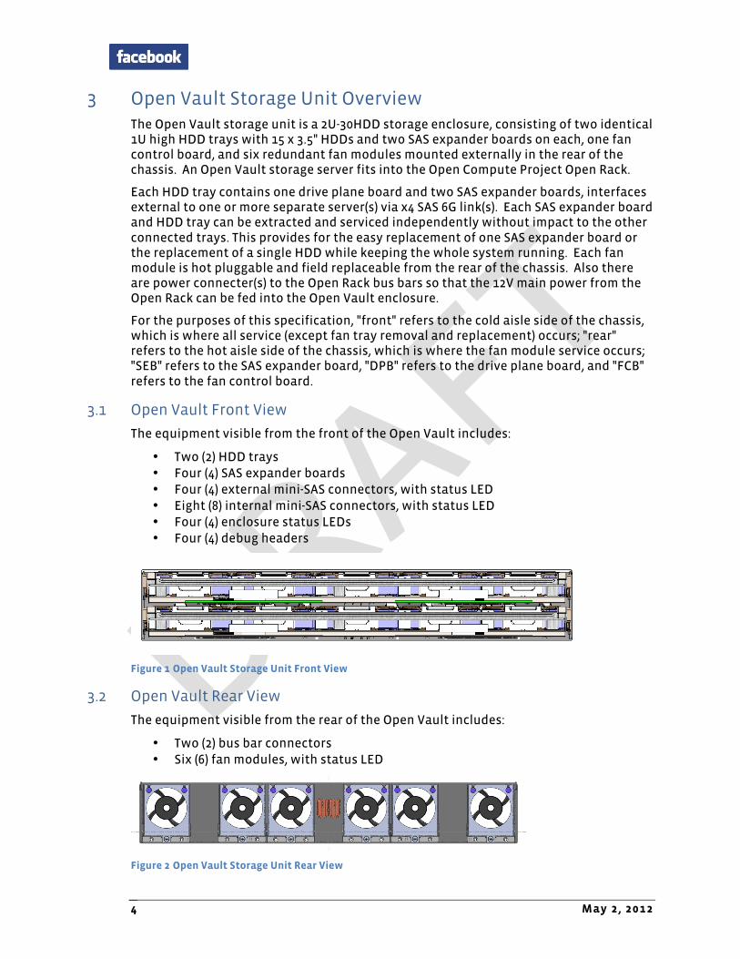
4.6 LEDs
The SAS expander board has several LEDs on its front edge to display various types of information:
• One (1) bi-color (blue/red) for enclosure status • One (1) bi-color (blue/red) for each mini-SAS port link status
Figure 14 and Figure 15 summarize the conditions and actions the LEDs present.
Enclosure Status Blue/Red LED
Normal system operation Blue on
Any fault in whole enclosure Red on
Figure 14 Front Panel LED for Enclosure Status
Mini-SAS Port Link Status Blue/Red LED
SAS links (x4) health Blue on
Loss of SAS links (x1 ~ x 3) Red on
No SAS links Both off
Figure 15 Front Panel LED For Mini-SAS Port Links
4.7 PCB Stack-up
The PCB stack-up and impedance control for the SAS expander board are defined in Figure 16 and Figure 17 below.
Layer Plane D escription Copper Weight (oz)
Thickness (m il) D ielectric (er)
Solder Mask 0.5 3.8
L1 TOP Signal 0.5 + 1.0 1.9
PrePreg 2.7 3.5
L2 GND Ground 2.0 2.6
Core 4.0 3.7
L3 IN1 Signal 1.0 1.3
PrePreg 13.6 4.4
L4 VCC1 Power 2.0 2.6
Core 4.0 4.1
L5 VCC2 Power 2.0 2.6
PrePreg 13.6 4.4
L6 IN4 Signal 1.0 1.3
Core 4.0 3.7

Open Vault Storage Hardware v0.5
http://www.facebook.com 13
L7 GND3 Ground 2.0 2.6
PrePreg 2.7 3.5
L8 BOT Signal 0.5 + 1.0 1.9
Solder Mask 0.5 3.8
Total 62.4 Tolerance: +/-6m il
Figure 16 PCB Stack-up for SAS Expander Board
Trace Width (m il)
Air Gap Spacing (m il)
Im pedance Type
Layer Im pedance Target (ohm )
Tolerance (+/- %)
4.0 Single 1,8 50 15.0
4.0 9.0 Differential 1,8 100 15.0
4.5 Single 3, 6 50 10.0
4.0 8.0 Differential 3, 6 100 10.0
Figure 17 PCB Impedance Control for SAS Expander Board
5 Open Vault Drive Plane Board
5.1 Block Diagram
Figure 18 illustrates the functional block diagram of the drive plane board (DPB).
Figure 18 Open Vault Drive Plane Board Block Diagram
HDD HDD HDD HDD HDD
PCI-‐E x16 & x1 Conn A PCI-‐E x16 & x1 Conn B
SAS 2.0 x15 SAS 2.0 x15
Status LED (Blue/Red)
Drive Power Control
Temp. Sensor 1
Temp. Sensor 2
Temp. Sensor 3
Temp. Sensor 4
EE-‐PROM
HDD GPIO
I2C_B
Signal Connector
I2C_C, PWM, GPIOs
To Fan Control Board
To SAS Expander Board BTo SAS Expander Board A
Present
HDD HDD HDD HDD HDD
HDD HDD HDD HDD HDD
Voltage Monitor

May 2, 2012 14
5.2 DPB Placement and Form Factor
The drive plane board form factor is 450mm x 510mm. Figure 19 illustrates board placement.
PCI-‐E Connectors to SAS Expander Board A PCI-‐E Connectors to SAS Expander Board B
HDD0 HDD1 HDD2 HDD3 HDD4
HDD5 HDD6 HDD7 HDD8 HDD9
HDD10 HDD11 HDD12 HDD13 HDD14
Figure 19 Open Vault Drive Plane Board Placement
5.3 12.5V to 5V Buck Converter
In order to provide a 5V power rail to the hard disk drives, one 12.5V to 5V buck converter will be implemented on the drive plane board for each group of 5 HDDs. It must be 93% efficient at nominal load. For more information, see section 7.3.
5.4 Disk Drive Power Control
Both 12V and 5V power rails to each disk drive are independently controlled through management software. For more information, see section 7.4.
5.5 Voltage Monitor
A voltage monitor is required for the Open Vault drive plane board in order to ensure proper operation of all power rails at all times. The voltages are reported as part of the enclosure status as described in section 8.1. The power rails to be monitored are shown in Figure 20. Power Rail Voltage
5V to HDD group A 5V
5V to HDD group B 5V
5V to HDD group C 5V
12V to all HDD 12V
Figure 20 Monitored Power Rails on DPB

Open Vault Storage Hardware v0.5
http://www.facebook.com 15
5.6 Connectors
Sections 5.6.1 through 5.6.4 describe the connectors on the Open Vault DPB.
5.6.1 Signal Connector to SAS Expander Board
The interfaces from the SAS expander board to the drive plane board are through an OCP-defined pin-out. The DPB-side connectors are two standard PCI-E connectors for each SAS expander board:
• PCI-E x16, 164 pin, straddle type, part number G630HAA12248EU from Amphenol. • PCI-E x1, 36 pin, straddle type, part number G630H3612248EU from Amphenol.
The connectors are PCI-E Gen3 capable.
The ODM should provide the full connector pin definition.
5.6.2 Signal Connector to Fan Control Board
Signals from the drive plane board to the fan control board mainly contain the I2C bus, PWMs and some GPIOs. Use an FFC/FPC cable between these two boards. The connector part number is 196360-10041-3 from P-Two. The pin count is 10, and signals are listed in Figure 21.
Pin Assignm ent
1 SEB Heartbeat out
2 I2C_C SCL
3 I2C_C SDA
4 GND
5 PWM from expander A
6 GND
7 PWM from expander B
8 GND
9 Tray present out
10 Tray present in
Figure 21 Pin-Out of Signal Connector from DPB to FCB
5.6.3 Power Connector to Fan Control Board
A four-pin connector from Molex receives 12V power from the drive plane board via a high-strand power cable. Part number of this right angle connector is PLA04F4BN0A1 from Positronic. Figure 22 shows the pin-out.
Pin D escription
1 12.5V
2 12.5V
3 GND
4 GND
Figure 22 Drive Plane Board Power Cable Connector Pin-Out

May 2, 2012 16
5.6.4 SAS HDD Connectors
The Open Vault drive plane board supports hot plugging of hard disk drives. The drives are connected via a blind mate, standard SAS interface, right-angle connector (an SMT connector from Molex, part number 87945-0001). The mating height is also standard (7.07mm), according to the Open Vault HDD tray design.
Pin Assignm ent Pin Assignm ent
P1 +3.3V_Precharge S1 GND
P2 +3.3V S2 Tx1P
P3 +3.3V S3 Tx1N
P4 GND S4 GND
P5 GND S5 Rx1N
P6 GND S6 Rx1P
P7 +5V_Precharge S7 GND
P8 +5V S8 GND
P9 +5V S9 Tx2P
P10 GND S10 Tx2N
P11 Ready_LED S11 GND
P12 GND S12 Rx2N
P13 +12V_Precharge S13 Rx2P
P14 +12V S14 GND
P15 +12V
Figure 23 SAS HDD Connector Pin-Out
5.7 LEDs
On the drive plane board, each hard disk drive has one bi-color LED to indicate its status; the behavior of both is driven by the SAS expander chip:
• When the HDD is online and healthy, the blue LED turns on; • When any HDD fault occurs, the red LED turns on.
Each drive's LEDs are located near the corresponding drive's cage and are clearly visible from the top when HDD tray is pulled out. An optical path for drive status LEDs can be implemented for easy access.
Figure 24 summarizes the conditions the LEDs present:
D isk D rive Status Blue/Red LED
Drive online and healthy Blue on
Drive failure Red on
Figure 24 Drive plane board LED for HDD Status
5.8 PCB Stack-up
The PCB stack-up and impedance control for the DPB are defined in Figure 25 and Figure 26.

Open Vault Storage Hardware v0.5
http://www.facebook.com 17
Layer Plane D escription Copper Weight (oz)
Thickness (m il) D ielectric (er)
Solder Mask 0.5 3.8
L1 TOP Signal 0.5 + 1.0 1.9
PrePreg 2.7 3.5
L2 GND Ground 2.0 2.6
Core 4.0 3.7
L3 IN1 Signal 1.0 1.3
PrePreg 25.0 4.4
L4 VCC1 Power 2.0 2.6
Core 4.0 4.1
L5 VCC2 Power 2.0 2.6
PrePreg 25.0 4.4
L6 IN4 Signal 1.0 1.3
Core 4.0 3.7
L7 GND3 Ground 2.0 2.6
PrePreg 2.7 3.5
L8 BOT Signal 0.5 + 1.0 1.9
Solder Mask 0.5 3.8
Total 85.2 Tolerance: +/-8m il
Figure 25 PCB Stack-up for Drive Plane Board
Trace Width (m il)
Air Gap Spacing (m il)
Im pedance Type
Layer Im pedance Target (ohm )
Tolerance (+/- %)
4.0 Single 1,8 50 15.0
4.0 9.0 Differential 1,8 100 15.0
4.5 Single 3, 6 50 10.0
4.0 8.0 Differential 3, 6 100 10.0
Figure 26 PCB Impedance Control for Drive Plane Board
6 Open Vault Fan Control Board The Open Vault fan control board is fixed and located at the rear of the system. A pair of bus bar clips connects the Open Vault to the bus bar from the Open Rack, to feed in the main 12V power rail to the fan control board via FusionLug cables. Another connector conducts the +12V power to the drive plane board through high strand power cable. A hardware monitor and PWM comparator work together with control signals from the SAS expander(s) for the fan speed control according to the cooling requirements of the whole storage enclosure.
6.1 Block Diagram
Figure 27 illustrates the functional block diagram of the fan control board (FCB).

May 2, 2012 18
Figure 27 Fan Control Board Functional Block Diagram
6.2 FCB Placement and Form Factor
The fan control board form factor is 480mm x 65mm. Figure 28 illustrates the board placement. The ODM is responsible for complete component placement.
Power & Signal Connectors to Drive Plane Board
Fan Header 6
Fan Header 5
Fan Header 3
Fan Header 2
Fan Header 1
Bus-‐bar ClipsFan
Header 4
FusioLug to Bus-‐bar Clips
Figure 28 Open Vault Fan Control Board Placement
6.3 Embedded Hardware Monitor
An embedded hardware monitor is installed on the fan control board. Its part number is NCT7904D from Nuvoton. The main features for this hardware monitor are:
• Monitors fan tachometer signals; • Monitors the local temperature of the fan control board; • Monitors the voltage rails on fan control board, as Figure 29 shows.
Hardware Monitor
PWM Comparator
Fan Header 5
Fan Header 4
Fan Header 3
Fan Header 2
Fan Header 6
I2C_C
Signal ConnectorFrom Drive Plane Board
Power Monitor
Fan Module Status LED
PWMs
BJT x 2 (Temp Sensor)
Fan Tachs
Fan Header 1
Max Speed
LED Driver
EEPROM

Open Vault Storage Hardware v0.5
http://www.facebook.com 19
Power Rail Voltage
V12_input 12V
V12_upper_tray 12V
V12_lower_tray 12V
Figure 29 Monitored Power Rails on FCB
6.4 Input Power Monitor
There is an input power monitor on the fan control board. It monitors the input current and voltage, reporting input power numbers to the SAS expander chip via the I2C interface. The monitor is part number ADM1276 from Analog Devices.
6.5 Connectors
6.5.1 Signal Connector to Drive Plane Board
Signals from the drive plane board to the fan control board primarily contains the I2C bus, power monitors and some GPIOs. The connector between these two boards is an FFC/FPC cable, part number 6712K-F10M-02L from Entery. The pin count is 10, and the signals are listed in Figure 30.
Pin Assignm ent on Upper Tray Assignm ent on Lower Tray
1 Upper tray heartbeat out Lower tray heartbeat out
2 I2C_C SCL I2C_C SCL
3 I2C_C SDA I2C_C SDA
4 GND GND
5 PWM from expander 1A PWM from expander 2A
6 GND GND
7 PWM from expander 1B PWM from expander 2B
8 GND GND
9 Upper tray present out Lower tray present out
10 Lower tray present to upper Upper tray present to lower
Figure 30 Pin-Out of Signal Connector from FCB to DPB
6.5.2 Power Connector to Drive Plane Board
The 4-pin vertical connector part number is PLA04F3N0A1 from Positronic. The 12V and 5V power rails are carried by high strand power cable. Figure 31 shows the pin-out.
Pin D escription
1 12.5V
2 12.5V
3 GND
4 GND
Figure 31 Fan Control Board Power Cable Connector Pin-Out

May 2, 2012 20
6.5.3 Power Connector to Open Rack Bus Bar
The bus bar connector assembly comprises a floating self-aligning carrier plate, allowing for lateral (X direction as viewed from the cold aisle) misalignment of the chassis and bus bars. This carrier plate is connected to the fan control board (FCB) by a pair of short cables. One qualified connector is part number C5313-07301-00107 from Methode.
The connector matches the bus bar on the Open Rack.
The connector is shown in Figure 32, and its pin definition is in Figure 33.
Figure 32 Bus Bar Connector to Open Rack
Pin D escription
1 12V
2 RTN
Figure 33 Pin-Out of Bus Bar Connector to Open Rack
6.5.4 Fan Module Connector
Each Open Vault fan control board is connected to 6 fan modules. Each fan module contains one dual rotor fan. One right angle 2.54mm pitch connector is used, with the pin definition in Figure 34. The connector's part number is 22-05-1052 from Molex.
Pin D escription
1 Tachometer 1
2 PWM
3 Tachometer 2
4 12VDC
5 GND
Figure 34 Fan Connector Pin-Out

Open Vault Storage Hardware v0.5
http://www.facebook.com 21
6.6 LEDs
The fan control board has six LEDs on its edge to display fan module status, one for each fan module.
Fan Module Status Blue/Red LED
Normal operation Blue On
Fan module fault Red On
Figure 35 Rear Panel LED for Fan Module Status
6.7 PCB Stack-up
The PCB stack-up and impedance control for the SAS expander board are defined in the following figures. Total thickness is 62 mils +/-10%.
Figure 36 PCB Stack-up for Fan Control Board
Figure 37 PCB Impedance Control for Fan Control Board
7 Open Vault Power System
7.1 Power Budget
Overall power consumption of Open Vault storage system is approximately 600W:
• In full-load operation, Open Vault system continuous power consumption is approximated 570W.
• In the extreme worst case, the maximum power consumption of Open Vault system won't exceed 650W.
Figure 38 shows the Open Vault system power budget in full-load operation, based on each module.

May 2, 2012 22
Figure 38 Open Vault System Power Budget in Full Load
7.2 SEB Bulk Converter Solutions
Both the 12V to 3.3V and the 12V to 1.0V buck converters residing on the SAS expander board have a 93% efficiency target under normal load. The ODM determines their components.
7.3 Hard Drive 5V Power Design
7.3.1 Hard Drive 5V Power Requirements
The drive plane board passes through the system power (nominal 12VDC) to the hard disk drives. It also contains power regulators to generate 5VDC from 12VDC for HDDs. The total 5V current for each HDD tray is about 18A maximum. In order to improve reliability, the 15 HDDs are divided into three groups. A VR is required to generate 5VDC for each HDD group. The output current of each VR is about 6A.
The drive plane board design ensures that the PCB traces and power planes are wide/thick enough to support required continuous power as well as the inrush current to start the drive from idle. The 5VDC regulator supports the additional inrush current required by each drive as well.
7.3.2 5V Output Protection
The 5V output power regulator protects against shorts and overload conditions. The protection mode is achieved using a constant current system.
7.3.3 5V Bulk Converter
The 5V buck converter residing on the fan control board must be designed with a 93% efficiency target for normal load. The ODM determines their components.
7.4 Disk Drive Power Control
In order to control both 12V and 5V power rails to each hard disk drive independently through a GPIO, proper MOSFETs (metal-oxide semiconductor field-effect transistors) and related circuits are included. The ODM is responsible for the implementation details and ensures the reliability.
7.5 Power-On Sequencing
The SAS expander chips power on in sequence without any violations, and ensure power cycling with adequate reliability.
ItemQty in one System
Power Consumption of each module (W)
Sub-‐total for all modules (W)
Derating by percentage
Power Consumption after derated (W)
HDD 30 14 420 90% 378Drive Plane Board 2 9 18 90% 16.2SAS Expander Board 4 15.6 62.4 90% 56.16Fan Control Board 1 2 2 90% 1.8Fan Module 6 24 144 80% 115.2Total 646.4 567.36

Open Vault Storage Hardware v0.5
http://www.facebook.com 23
The use of a power button is not required to power on. The system always resumes operation upon restoration of power during a power failure event.
8 Enclosure Management Firmware The ODM is responsible for creating and supporting the firmware to execute all enclosure management features described in the following sections. The ODM is also responsible for creating a set of diagnostic commands that is capable of providing status summary and device information details to a user terminal.
8.1 Enclosure Service Functionalities
Listed below is a high-level enclosure service functional specification of the Open Vault. Refer to SCSI Enclosure Services and SMP Functions (section 8.2) for more information.
• External management interfaces:
o SES commands o Diagnostics CLI
• I/O Connectivity and PHY control/monitoring:
o SMP functions o PHY error counters o Topology discovery and routing table management o Staggered disk drive spin-up
• General enclosure management features:
o Redundant enclosure service processes o Power monitoring and control o Intelligent cooling fan control scheme
• Reliability, availability and serviceability:
o Power on self-test o Enclosure event log o EEPROM contents update for each field replaceable unit o Firmware in-system upgrade for each SAS expander o One command/script to upgrade firmware for all HDDs
8.2 Enclosure Status Output File
A SCSI Enclosure Service (SES) is the service that establishes the mechanical environment, electrical environment, and external indicators and controls for the proper operation and maintenance of devices within an enclosure. SES data is transported in-band to and from the application client.
The Open Vault JBOD system applies a standalone SES model that can be accessed by external host directly via the data channel. Management software running on the host uses "polling" as the reporting method when managing the Open Vault JBOD system.
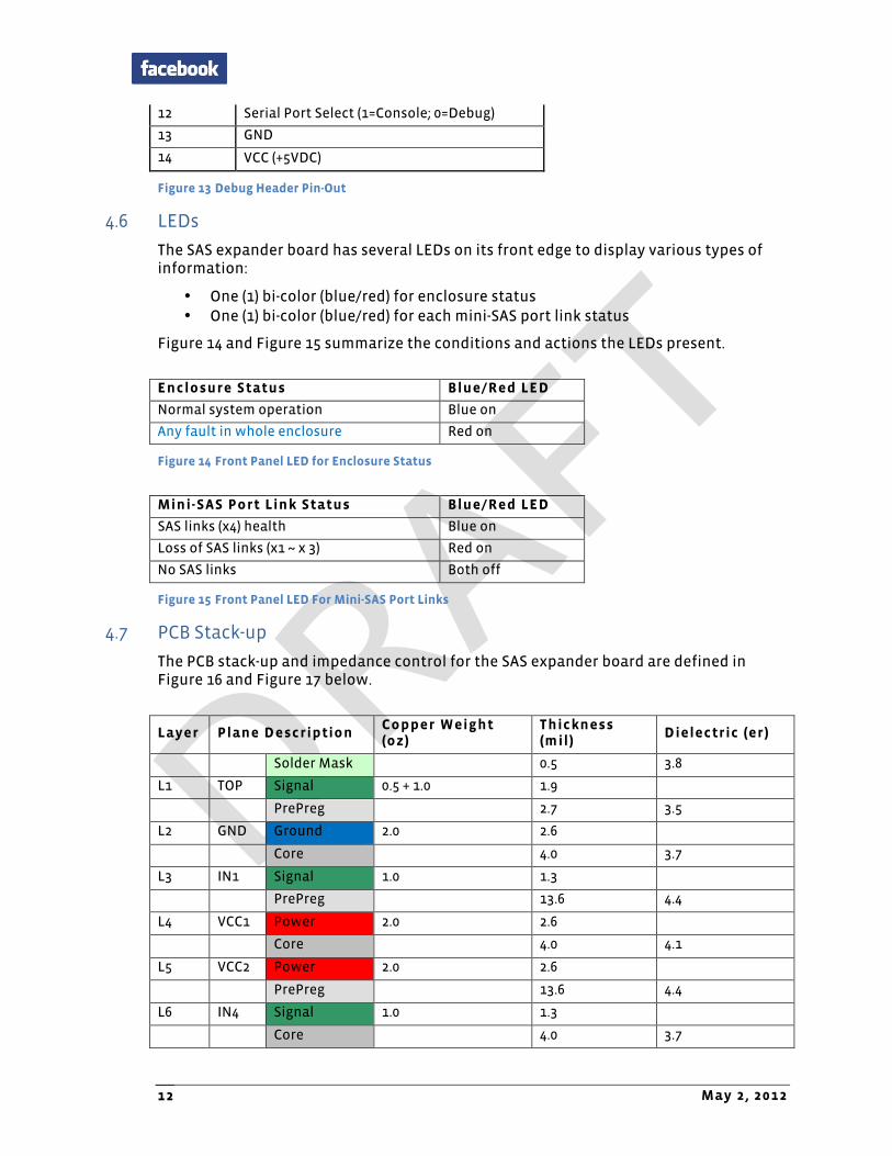
Please refer to Figure 39 for supported SES pages and Figure 40 for supported SMP functions. The ODM is responsible for more detailed design specifications, such as SES element definition, and so forth.
May 2, 2012 24
Page Code Page Nam e
00h Supported Diagnostic Pages
01h Configuration
02h Enclosure Control
Enclosure Status
04h String Out
String In
05h Threshold Out
Threshold In
07h Element Descriptor
0Ah Additional Element Status
0Eh Download Microcode Control
Download Microcode Status
Figure 39 Supported SES Pages
SMP Function Function Field Code
Report general 00h
Report manufacturing information
01h
Report broadcast 06h
Discover 10h
Report PHY error log 11h
Report PHY SATA 12h
PHY control 91h
Figure 40 Supported SMP Functions
8.3 Fan Speed Control
The Open Vault enclosure thermal management supports two schemes:
• One scheme is to control fan power management by each SAS expander chip itself, with environment thermal sensors and HDD S.M.A.R.T. temperature information; a power management comparator on the FCB selects the maximum power management value from the four SAS expanders and drives the fans.
• The other scheme is each expander chip only reports all temperature values to the host server; the host server calculates suitable power management numbers and controls fan speed via SES commands sent to the SAS expander(s).
Figure 41 shows the temperature sensors' location within the Open Vault system.

Open Vault Storage Hardware v0.5
http://www.facebook.com 25
HDD 5 HDD 6 HDD 7 HDD 8 HDD 9
HDD 0 HDD 1 HDD 2 HDD 3 HDD 4
HDD 11 HDD 14HDD 12
Drive-‐Plane Board
SAS Expander Board
HDD 10 HDD 13
Figure 41 Open Vault System Thermal Sensor Locations
The ODM provides a detailed implementation of the fan speed control requirements. Figure 42 shows the high-level strategy of Open Vault fan speed control executed by firmware in each SAS expander.
Figure 42 Open Vault System Fan Speed Control Strategy
15 HDDscompare with
each other
HDD SMART Reading
Using the highest reading of15HDDs to decidea fan duty
Duty
Thermal Sensor 1
Duty
Duty
Duty
Duty
15 HDDscompare with
each other
HDD SMART Reading
Duty
Duty
Duty
Duty
Duty
Thermal Sensor 2
Thermal Sensor 3
Thermal Sensor 10
Thermal Sensor 1
Thermal Sensor 2
Thermal Sensor 3
Thermal Sensor 10
Tray 1 Tray 2
Using the highest reading of15HDDs to decidea fan duty
The Highest Duty of Tray 1
The Highest Duty of Tray 2
Compare
System Fan Duty
May 2, 2012 26
8.4 Thermal Protection
There are different levels of consideration of system/hardware thermal protection for the Open Vault system. They include:
• Setting a Warning level for each monitored parameter (including all temperatures, voltages and input power). When any one of the parameters reaches its warning value, the firmware should report an ALARM status to the host server. The host server can predictively perform some actions to avoid actual (both hardware and software) protection in advance.
• Setting a Software Protection level for each monitored parameter. When one parameter reaches this level, the related fault LED will light, an error code will be generated, and the firmware should report a CRITICAL status to the host server. The host server takes suitable actions to protect the system, such as setting maximum speed to the fan or power off the related HDDs.
• Setting a Hardware Protection level. When some parameters reach this level or meet a set of pre-defined conditions, hardware protection actions will be taken to prevent system damage or reduce the cost of more power and more airflow.
8.5 HDD Spin-up Control
To minimize the impact on the system power budget, the hardware design supports a staggered power-on feature, and the enclosure management firmware implements a grouped spin-up control mechanism.
• The group definition of hard disk drives will follow the SAS expander chip vendor's strategy.
• Details of group spin-up will be decided by ODM, such as quantity of hard disk drives in each group, and delay interval between each group.
8.6 HDD Spin-down Control Support
To be aligned with power saving strategy in future data center operations, the Open Vault design also supports a spin-down control. Both the hardware design and enclosure management firmware implementation support such a feature.
8.7 HDD Presence Detect
The enclosure management firmware reports when it detects the presence of an HDD.
8.8 HDD Status LED
The enclosure management firmware supports control of the HDD status LED as depicted in Figure 24. The LED turns on blue when the HDD is working normally. It turns on red when either of the two PHYs in an HDD reports a fault status.
8.9 Error Code Display on Debug Card
The error codes displayed on the debug card can be defined by the ODM.

Open Vault Storage Hardware v0.5
http://www.facebook.com 27
9 Mechanical
9.1 External Chassis
The overall dimensions of the chassis are: 536mm wide x 88.9mm tall x 878mm deep.
The chassis is designed to use welding and rivets or other approved methods, but not screws. The individual HDD trays are stiff enough to be carried fully loaded. The chassis should be capable of being carried fully loaded with 2 loaded HDD trays. The main chassis has a cover for airflow management and to improve stiffness.
9.2 Serviceability
Most service is from the front of the chassis, which is defined as the "cold aisle" or intake end of the chassis. Fan service is performed from the rear or "hot aisle" end of the chassis. All FRU removal, replacement and service is tool-less.
9.3 Rack Interface/Slides
The rack upon which the chassis is mounted is the Open Rack design as published at opencompute.org.
10 Environmental
10.1 Environmental Requirements
The Open Vault storage system meets the following environmental requirements:
• Gaseous contamination: Severity Level G1 per ANSI/ISA 71.04-1985 • Ambient operating temperature range for system without HDD: -5°C to +45°C • Ambient operating temperature range for system with HDD: 5°C to +35°C • Operating and storage relative humidity: 10% to 90% (non-condensing) • Storage temperature range: -40°C to +70°C • Transportation temperature range: -55°C to +85°C (short-term storage)
In addition, the full Open Vault storage system has an operating altitude with no de-ratings of 1000m (3300 feet).
10.2 Vibration and Shock
The Open Vault PCBs meet shock and vibration requirements according to the following IEC specifications: IEC78-2-(*) & IEC721-3-(*) Standard & Levels. The testing requirements are listed in Figure 43. Operating Non-Operating
Vibration 0.5g acceleration, 5 to 500 Hz, 10 sweeps at 1 octave/minute per each of the three axes (one sweep is 5 to 500 to 5 Hz)
1g acceleration, 5 to 500 Hz, 10 sweeps at 1 octave/minute per each of the three axes (one sweep is 5 to 500 to 5 Hz)
Shock 6g, half-sine 11mS, 5 shocks per each of the three axes
12g, half-sine 11mS, 10 shocks per each of the three axes
Figure 43 Vibration and Shock Requirements

May 2, 2012 28
11 Prescribed Materials
11.1 Disallowed Components
The following components shall not be used in the design of the motherboard:
• Components disallowed by the European Union's Restriction of Hazardous Substances Directive (RoHS 6)
• Trimmers and/or potentiometers • Dip switches
11.2 Capacitors and Inductors
The following limitations shall be applied to the use of capacitors:
• Only aluminum organic polymer capacitors from high-quality manufacturers are used; they must be rated 105°C
• All capacitors have a predicted life of at least 50,000 hours at 45°C inlet air temperature, under worst conditions
• Tantalum capacitors are forbidden • SMT ceramic capacitors with case size > 1206 are forbidden (size 1206 still
allowed when installed far from PCB edge, and with a correct orientation that minimizes risks of cracks)
• Ceramics material for SMT capacitors must be X7R or better material (COG or NP0 type should be used in critical portions of the design)
Only SMT inductors may be used. The use of through-hole inductors is disallowed.
11.3 Component De-Rating
For inductors, capacitors, and FETs, de-rating analysis should be based on at least 20% de-rating.
Related Documents