American Institute of Aeronautics and Astronautics 1 Open Circuit Resonant (SansEC) Sensor for Composite Damage Detection and Diagnosis in Aircraft Lightning Environments Chuantong Wang 1 1 National Institute of Aerospace, Hampton, VA, 23666, USA [email protected] Kenneth L. Dudley 2 and George N. Szatkowski 3 2,3 NASA Langley Research Center, Hampton, VA, 23681-2199, USA [email protected] [email protected] Composite materials are increasingly used in modern aircraft for reducing weight, improving fuel efficiency, and enhancing the overall design, performance, and manufacturability of airborne vehicles. Materials such as fiberglass reinforced composites (FRC) and carbon-fiber-reinforced polymers (CFRP) are being used to great advantage in airframes, wings, engine nacelles, turbine blades, fairings, fuselage and empennage structures, control surfaces and coverings. However, the potential damage from the direct and indirect effects of lightning strikes is of increased concern to aircraft designers and operators. When a lightning strike occurs, the points of attachment and detachment on the aircraft surface must be found by visual inspection, and then assessed for damage by maintenance personnel to ensure continued safe flight operations. In this paper, a new method and system for aircraft in-situ damage detection and diagnosis are presented. The method and system are based on open circuit (SansEC) sensor technology developed at NASA Langley Research Center. SansEC (Sans Electric Connection) sensor technology is a new technical framework for designing, powering, and interrogating sensors to detect damage in composite materials. Damage in composite material is generally associated with a localized change in material permittivity and/or conductivity. These changes are sensed using SansEC. Unique electrical signatures are used for damage detection and diagnosis. NASA LaRC has both experimentally and theoretically demonstrated that SansEC sensors can be effectively used for in-situ composite damage detection. Nomenclature C = equivalent capacitance of sensor ɛ, ɛ r = permittivity and relative permittivity f = frequency J = current distribution function I, I 0 = amplitude of current l = length of sensor trace L = equivalent inductance of sensor ρ = charge distribution function q, q 0 = amplitude of charge density r, r' = distance vector t = time δ = skin depth μ, μ r = permeability and relative permeability σ = conductivity ω = angular frequency of the signal 1 National Institute of Aerospace, 100 Exploration Way, Hampton, VA, 23666. 2 Electromagnetics and Sensors Branch, MS 490 NASA LaRC, Hampton, VA, 23681, AIAA member. 3 Electromagnetics and Sensors Branch, MS 490 NASA LaRC, Hampton, VA, 23681.

Welcome message from author
This document is posted to help you gain knowledge. Please leave a comment to let me know what you think about it! Share it to your friends and learn new things together.
Transcript

American Institute of Aeronautics and Astronautics
1
Open Circuit Resonant (SansEC) Sensor for Composite
Damage Detection and Diagnosis in Aircraft Lightning
Environments
Chuantong Wang1 1National Institute of Aerospace, Hampton, VA, 23666, USA
Kenneth L. Dudley2 and George N. Szatkowski3 2,3NASA Langley Research Center, Hampton, VA, 23681-2199, USA
[email protected] [email protected]
Composite materials are increasingly used in modern aircraft for reducing weight,
improving fuel efficiency, and enhancing the overall design, performance, and
manufacturability of airborne vehicles. Materials such as fiberglass reinforced composites
(FRC) and carbon-fiber-reinforced polymers (CFRP) are being used to great advantage in
airframes, wings, engine nacelles, turbine blades, fairings, fuselage and empennage
structures, control surfaces and coverings. However, the potential damage from the direct
and indirect effects of lightning strikes is of increased concern to aircraft designers and
operators. When a lightning strike occurs, the points of attachment and detachment on the
aircraft surface must be found by visual inspection, and then assessed for damage by
maintenance personnel to ensure continued safe flight operations. In this paper, a new
method and system for aircraft in-situ damage detection and diagnosis are presented. The
method and system are based on open circuit (SansEC) sensor technology developed at
NASA Langley Research Center. SansEC (Sans Electric Connection) sensor technology is a
new technical framework for designing, powering, and interrogating sensors to detect
damage in composite materials. Damage in composite material is generally associated with a
localized change in material permittivity and/or conductivity. These changes are sensed
using SansEC. Unique electrical signatures are used for damage detection and diagnosis.
NASA LaRC has both experimentally and theoretically demonstrated that SansEC sensors
can be effectively used for in-situ composite damage detection.
Nomenclature
C = equivalent capacitance of sensor
ɛ, ɛr = permittivity and relative permittivity f = frequency
J = current distribution function
I, I0 = amplitude of current
l = length of sensor trace
L = equivalent inductance of sensor
ρ = charge distribution function
q, q0 = amplitude of charge density
r, r' = distance vector
t = time
δ = skin depth
µ, µr = permeability and relative permeability
σ = conductivity ω = angular frequency of the signal
1 National Institute of Aerospace, 100 Exploration Way, Hampton, VA, 23666. 2 Electromagnetics and Sensors Branch, MS 490 NASA LaRC, Hampton, VA, 23681, AIAA member. 3 Electromagnetics and Sensors Branch, MS 490 NASA LaRC, Hampton, VA, 23681.

American Institute of Aeronautics and Astronautics
2
I. Introduction
HE aerospace industry has seen a steady increase in the use of composite materials. Modern air vehicles
increasingly rely on the use of composite materials to provide high strength and stiffness structures with
minimal weight. Today’s aircraft incorporates substantial amounts of carbon, aramid, or fiberglass composite
materials. Airframe manufacturers have transitioned from using composite substrates for only cosmetic coverings
and fairings to major aircraft assemblies and entire aircraft fuselage. 1,2
The increased use of composites means an increased potential for damage and/or failure of composite aircraft
structures and materials. It is difficult to predict the degree of composite damage or incipient faults while the aircraft
is in use. This can be especially significant when the aircraft encounters a lightning environment. Statistics on
lightning strikes indicates that an aircraft is likely to receive one or two lightning strikes in a year on average. Depending on geographical regions, flight altitudes, routes, and traffic patterns, the frequency of strike occurrences
can be higher than the average. Lightning strikes are a safety hazard to the aircraft especially for those that have a
considerable amount of composite material structures.3 A means of in-situ health monitoring of composite materials
for damage detection in real time would be highly desirable for enhancing aircraft safety.4,5
An open circuit resonant sensor has been developed for the purpose of detecting and diagnosing damage in non-
conductive and conductive aerospace composite materials. The NASA developed SansEC sensor placed on a
material surface is capable of determining physical characteristics and qualities about the material upon which it is
placed.6-10 The detection of the differences in frequency and amplitude of the induced currents within a material
substrate offers a means of detecting damage or changes to the state and condition of the material substrate. SansEC
sensors are themselves damage tolerant robust resonant sensors that can detect and identify delamination, punctures,
cracks, and rips in composite materials. In this paper we describe the research that has been conducted thus far demonstrating the feasibility of SansEC sensors for use in the detection of damage to modern aircraft composite
materials and structures. We identify two primary forms of composite materials, non-conductive and conductive,
and we show particular configurations of SansEC sensors with the ability to penetrate and sense both non-
conductive and conductive composites.
II. SansEC Sensor System for Lightning Protection and Damage Detection
A. The SansEC Sensor “Smart Skin” for Aircraft Lightning Protection and Damage Detection
Figure 1. Aircraft “Smart Skin” of Open Circuit Sensor Array.
T

American Institute of Aeronautics and Astronautics
3
NASA Langley Research Center has developed a multifunctional new technology for aircraft lightning strike
protection, damage detection and diagnosis for composite structures. The concept is to apply a SansEC sensor array,
as shown in Fig. 1, to the aircraft surface forming a “Smart Skin” layer for the composite parts having external
surface. The SansEC sensor array includes a number of individual SansEC sensors and each individual SansEC
sensor is an open-circuit conductive pattern sans (without) electrical connections. The SansEC sensor is an electromagnetic resonator having specific resonant characteristics. Because of its “open-circuit” character, there is
no single point on the sensor that if damaged will render the sensor non-functional. Each time the sensor is damaged,
for example, by a puncture or partial split on the sensor body, it shifts the resonant frequency to a new frequency
range. This frequency shifting response is used as the signature in detecting structural damage of the sensor and
composite parts. When SansEC sensor is under resonant state, it produces both electric and magnetic fields which
penetrate into the space beyond the sensor surface. Since the sensor is on the surface of composite parts, the electric
field and magnetic field will penetrate into the composite material and therefore the damage underneath the surface
(the inner damage of the composite material that cannot be visually detected) can also be detected.
SansEC sensor is a wireless passive solution having each sensor in the array wirelessly powered and interrogated
by an antenna through the magnetic near field. For interrogation of the sensor array on the aircraft surface, two
methods can be used. The first method is for the in-situ measurement where the sensors are interrogated through the
antennas embedded in the sensor array. In this method, the sensor response is monitored in real-time during the flight. After a lightning strike occurs, the interrogation system can scan the sensor array and compare the scanning
result with the normal base line stored in a database. An alarm will be given if serious damage is detected. The
second method is for ground inspection and maintenance where the scanning of the sensor array is performed either
by a robot arm or a person using an external antenna. The second method is for the health check after lightning
strike to detect the potential damage that cannot be visually discovered. The two interrogation methods are not
exclusive to each other and the sensor system can use different methods in different health checking stages.
B. Multifunctional SansEC Sensor Array
Traditional methods for lightning protection rely on the metal mesh on the composite structures, which provides
lightning protection and shielding effectiveness functions. 11 However, the SansEC sensor array method provides
lightning protection and shielding effectiveness to composite structures, as well as many additional functions, such
as, damage detection. Table 1 summarizes the comparison of SansEC sensor array method with the traditional metal mesh method. The SansEC sensor array is applied on the composite structure of aircraft as a “smart-skin’ layer. The
SansEC sensor can detect damage for both in-situ health monitoring and ground inspection. As a unique feature, the
SansEC sensors are still functional when damaged. For some applications, such as lightning protection and damage
detection, it is meaningful for the sensor to continue to provide useful measurement information even after it is
damaged.
The SansEC sensor also provides other potential functions. Examples include the measuring of aero dynamic
loads, fuel quantity indication, and icing. Furthermore, the SansEC sensors are also capable of lightning current
steering, moisture detection, and hail damage detection, which are hazards to aviation safety. 12-14
Table 1. Comparison of SansEC Sensor Array with Metal Mesh.
Functions SansEC Sensor Array Metal Mesh Commits
Lightning protection Yes Yes SansEC sensor array offers advanced and multiple sensing functions in one system. *A critical system possible
separate system.
Shielding effectiveness Yes Yes
In-situ damage detection Yes No
Ground damage detection Yes No
Sensing function after sensor damage Yes No
Potential Functions
Measuring aero dynamic load Yes No
Icing detection Yes No
Fuel quantity indication* Yes No

American Institute of Aeronautics and Astronautics
4
III. SansEC Sensor Electric and Magnetic Field Penetration
A. Principle of Open-circuit (SansEC) Resonator for Sensing Electric-magnetic resonant theory is well established for the traditional electric-magnetic resonators such as
resonant cavity and LCR (inductance-capacitance-resistance) resonant circuit.15-17 The open-circuit resonator is an
emerging technology having unique features and applications. The open-circuit resonator is composed of a single
self-resonant coil made of conductive material usually in a planar spiral pattern or helix structure. The open-circuit
resonator is interrogated by the magnetic near field and has no electrical connection with interrogation circuits. An
important feature of the open-circuit resonator is that the resonators coupled by magnetic field have high efficiency
power exchange and this feature is the foundation for the wireless power transfer.18 Another important feature is that
the resonant parameters including resonant frequency, response amplitude, phase, and bandwidth are very sensitive
to the environmental parameters, and this is the foundation for using an open-circuit resonator for sensing purposes.
The electro dynamic process of the open-circuit resonator is governed by Maxwell equations with zero current boundary conditions at both ends of the resonator. The free electrons carried by the conductor are uniformly
distributed along the conductive trace without the external sources. Driven by an oscillating magnetic field, the
induced electromotive force (emf) pushes the electrons carried by the conductor into the resonant state where the
electrons move back and forth along the conductive trace. The time-dependent current profile along the conductive
trace has the following form:
(1)
where, x ϵ [-l/2, l/2] is the parameterization coordinate along the length of the conductive trace; l is the trace length;
I0 is the maximum current amplitude; ω is the angular frequency. The induced current along the conductive trace has
the peak magnitude at the middle part of the trace and has zero value at both ends of the trace. During each
oscillation cycle, the total current will reach the peak magnitude twice (in opposite directions) and at these moments
the energy stored in the resonator is in the form of magnetic field. From the continuity equation, the charge density
profile has the following form:
(2)
where, q0 is the maximum charge density value. The charge distribution creates the potential difference along the
trace and consequently induces the electric field between the different localized segments of the trace. During each
oscillation cycle, the electric field reaches its peak magnitude twice and at these moments the energy stored is in the
electric field.
Figure 2 shows an example of an open-circuit resonant sensor modeled in FEKO, a commercial computational electromagnetic software. The sensor (78 mm × 78 mm) has a square spiral pattern with 12 turns of conductive
traces. The distance between neighboring traces (center line) is 3 mm. A loop antenna (50.8 mm ×50.8 mm) is used
to power and interrogate the sensor with a 1 V source. The distance between the sensor and antenna is 12.7 mm (0.5
inches). Figure 3 shows the current distribution along the conductive trace of the sensor driven by the magnetic field
produced by the loop antenna. This result confirms the current has zero magnitude at the two ends of the conductive
trace and has the maximum value in the middle part.
Figure 2. Open-circuit sensor driven by loop antenna. Figure 3. Current distribution along the trace.
Open-circuit sensor
Loop antenna

American Institute of Aeronautics and Astronautics
5
When resonating, the open-circuit sensor produces both electric and magnetic fields which occupy the space
between the conductive traces and also penetrate into the space near the resonator. For the planar spiral sensor, the
magnetic field and electric field will penetrate into the space beyond the planar surface of the sensor. This is an
important feature for sensing purposes because it allows the sensor to measure the properties of the materials placed
in close proximity to it. Figures 4 and 5 show the electric and magnetic field distribution for the example as
previously shown in Fig. 2 when the resonant sensor is driven by the loop antenna at its resonant frequency of 52.8912 MHZ. In this specific case, the electric and magnetic field can penetrate into the space to a depth of about a
half inch.
Any physical quantity that affects the material’s permittivity, permeability, and conductivity will affect the
sensor’s resonant parameters and therefore can be measured. Electric theory describes the LCR resonator by its
lumped parameters of inductance, capacitance, and resistance. For a self-resonant coil, the equivalent lumped
parameters can be calculated based on the distributed parameters, as shown in Eq. (3) and Eq. (4), where J(r) and
ρ(r) are the current and charge density functions along the conductive trace. 18
(3)
(4)
However, the current and charge density functions are not measurable in actual experiments. Therefore, the
equivalent inductance and capacitance values of self-resonator coil are the calculated values and are used only for
principle analysis. From Eq. (3) and Eq. (4), it can be clearly seen the dependency of inductance and capacitance upon the material’s relative permeability µr and relative permittivity ɛr. If the material in the electric and magnetic
field changes its permeability and/or permittivity, the resonator equivalent LC value will change correspondingly, so
will the resonant parameters. It is notable that Eq. (3) and Eq. (4) are for the cases where the resonant sensor trace is
totally embedded in the material having isotropic properties. For most actual applications, for example, the material
is put on one side of the resonant sensor, the dependency function between the sensor parameters and the material
properties is not obvious and needs to be characterized and calibrated by experiments or computational methods.
Figure 4. Magnetic field distribution penetrates beyond the surface of the sensor.
Figure 5. Electric field distribution penetrates beyond the surface of the sensor.
Loop antenna
Sensor
12.7 mm (0.5 inches)
12.7 mm (0.5 inches)
Loop antenna
Sensor
12.7 mm (0.5 inches)
12.7 mm (0.5 inches)
American Institute of Aeronautics and Astronautics
6
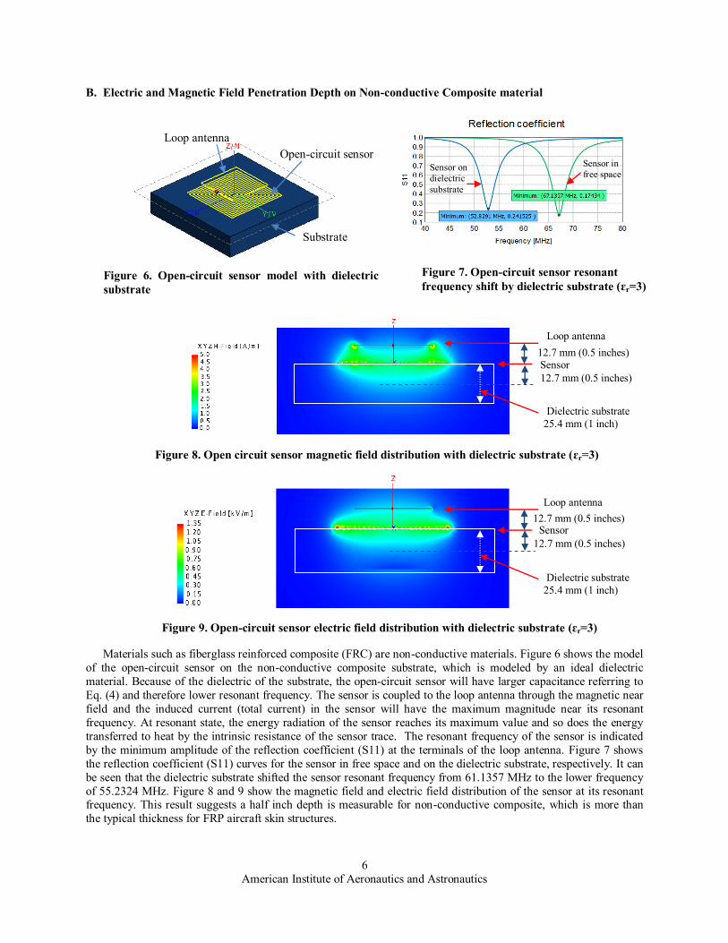
B. Electric and Magnetic Field Penetration Depth on Non-conductive Composite material
Materials such as fiberglass reinforced composite (FRC) are non-conductive materials. Figure 6 shows the model
of the open-circuit sensor on the non-conductive composite substrate, which is modeled by an ideal dielectric
material. Because of the dielectric of the substrate, the open-circuit sensor will have larger capacitance referring to
Eq. (4) and therefore lower resonant frequency. The sensor is coupled to the loop antenna through the magnetic near
field and the induced current (total current) in the sensor will have the maximum magnitude near its resonant
frequency. At resonant state, the energy radiation of the sensor reaches its maximum value and so does the energy
transferred to heat by the intrinsic resistance of the sensor trace. The resonant frequency of the sensor is indicated
by the minimum amplitude of the reflection coefficient (S11) at the terminals of the loop antenna. Figure 7 shows
the reflection coefficient (S11) curves for the sensor in free space and on the dielectric substrate, respectively. It can
be seen that the dielectric substrate shifted the sensor resonant frequency from 61.1357 MHz to the lower frequency
of 55.2324 MHz. Figure 8 and 9 show the magnetic field and electric field distribution of the sensor at its resonant frequency. This result suggests a half inch depth is measurable for non-conductive composite, which is more than
the typical thickness for FRP aircraft skin structures.
Figure 6. Open-circuit sensor model with dielectric
substrate
Figure 7. Open-circuit sensor resonant
frequency shift by dielectric substrate (ɛr=3)
Figure 8. Open circuit sensor magnetic field distribution with dielectric substrate (ɛr=3)
Figure 9. Open-circuit sensor electric field distribution with dielectric substrate (ɛr=3)
Open-circuit sensor
Loop antenna
Substrate
Sensor on
dielectric
substrate
Sensor in
free space
Loop antenna
Sensor 12.7 mm (0.5 inches)
Dielectric substrate
25.4 mm (1 inch)
12.7 mm (0.5 inches)
Loop antenna
Sensor 12.7 mm (0.5 inches)
Dielectric substrate
25.4 mm (1 inch)
12.7 mm (0.5 inches)

American Institute of Aeronautics and Astronautics
7
To illustrate the open circuit sensor affecting the penetration depth of the electric and magnetic field, we show
the electric and magnetic field distribution without the open circuit sensor (only the loop antenna running at the
same frequency) in Fig. 10 a) and b). Comparing to the results in Fig. 8 and 9, it can be seen that the open circuit
sensor made significant contribution to extend the penetration depth of both electric and magnetic fields.
C. Magnetic Field Penetration Depth on Conductive Composite material
Materials such as carbon-fiber-reinforced polymers (CFRP) are conductive materials. When an oscillating
magnetic field hits a conductive material, the magnetic field can penetrate only a limited distance described by the
“skin depth” effect. The skin depth is defined as the depth below the surface of the conductor at which the current
density has fallen to 1/e of the current at the surface. For a general dielectric material with conductivity, the skin
depth δ is governed by the following equation:
(5)
For conductors having high conductivity which satisfies , the skin depth equation can be simplified to:
(6)
The SansEC sensors currently used in this application have a frequency range of 100 kHz to 200 MHz. Aircraft
composite structures have a typical conductivity of 2.54×10⁴ S/m.19 With the given frequency range and
conductivity, the parameters satisfy the condition of and Eq. (6) can be used to calculate the skin depth.
Figure 10. Loop antenna electric and magnetic fields distribution with dielectric substrate (ɛr=3)
a) Magnetic field distribution b) Electric field distribution
Loop antenna Loop antenna
Substrate Substrate
10
510
610
710
810
-4
10-3
10-2
10-1
Frequency (HZ)
Pen
etr
ati
on
Dep
th (
m)
Figure 11. Skin depth for the conductivity of 1×10³, 1×10
4, 2.54×10
4, and 1×10
5 S/m within the
frequency range of 100kHz~200MHz.
σ = 103S/m
σ = 105 S/m
σ = 2.54×10⁴S/m
σ = 104S/m

American Institute of Aeronautics and Astronautics
8
Figure 11 shows the skin depth - frequency curves for the material conductivity of 1×10³~1×10⁵ S/m. The red curve
is for the typical conductive composite structures having the conductivity of 2.54×10⁴ S/m. It can be seen that the
maximum skin depth is 10 mm at frequency of 100 kHz which is toward the lower frequency limit. At frequencies
of 1 MHz, 10 MHz, and 100MHz, the skin depth values are 3 mm, 1 mm, and 0.3 mm, respectively. Figure 11
provides a roadmap for designing SansEC sensors on composite structures for different conductivities. Given
specific conductivity and the penetration depth requirement, the sensor’s working frequency can be determined. For example, if a penetration depth of 5 mm is required for the composite having conductivity of 2.54×10⁴ S/m, the
sensor should be designed to resonate at the frequency of 400 KHz. It is notable that the skin depth is defined by the
factor of 1/e which is about 36.8% amplitude attenuation. The actual magnetic field penetrates deeper than the skin
depth defined in this manner into the material and decreases exponentially. For sensing purpose, the detectable depth
may be extended beyond the skin depth, for example, to 2δ or 3δ.
A challenge with penetration into conductive composite materials is that the electromagnetic field is attenuated
by the loss mechanism of the conductive substrate. When the composite substrate has high conductivity, the
conductive surface of the substrate may absorb all of the electromagnetic field energy and render the sensor’s
response non-detectable. For example, if a SansEC sensor made of copper is put on the surface of a copper substrate,
the sensor’s response characteristics will be totally lost. To solve this problem, we propose a new method of using
both dielectric material and high permeability material between the sensor and the conductive substrate to control
the field coupling. The dielectric material layer is used to insulate the conductive sensor trace from the conductive substrate. The high permeability material layer is used to concentrate the magnetic field inside the high permeability
material. By partially covering the sensor area with high permeability material, the magnetic field can be effectively
coupled into the composite. Experiments and results are shown in Section IV C and the more detailed theory study
and simulation are considered for future study.
IV. Sensor and Composite Damage Detection
A. Sensor Structural Damage Detection
During a lightning strike, the lightning current is channeled onto the aircraft surface through an attachment point
and flows along the aircraft surface to the detachment point. The damage can be potentially caused by three
mechanisms: 1) the mechanical force of the strike, 2) the heat produced by the electrical current, and 3) the electric
Lorentz force. Since the SansEC sensor is on the surface of the composite substrate, the sensor will be the first line
of protection during the lightning strike. Because of the impedance of the sensor and substrate, huge amounts of heat
are produced by the lightning current, and the heat can damage all or a portion of the sensor trace. In the cases where
all of the sensor trace is damaged, the sensor will lose its resonant feature and has no response to the interrogator.
When only a portion of the sensor trace is damaged, the remaining sensor trace forms a new SansEC sensor shifting
the operational resonance to a new frequency. Therefore, the structural damage of the sensor can be effectively
detected by monitoring the sensor’s resonant frequency. In actual situations, once the damaged sensor pattern is defined, a new baseline can be established and its response feature can be predicted. Figure 12 shows the model of a
damaged sensor, which is one of the many possible damaged patterns. In this example, the sensor is damaged at its
corner part having four broken traces.
Original
sensor
Damaged
sensor
Figure 12. Structural damage on sensor Figure 13. Resonant frequency shift caused by the damage
Open-circuit sensor
Loop antenna
Substrate

American Institute of Aeronautics and Astronautics
9
The sensor response from the simulation result is shown in Fig. 13, where the resonant frequency shifted from
52.8571 MHz to 112.374 MHz. It can be seen that the sensor is very sensitive to the structural damage of the sensor
trace. In general, even a small damage on the sensor body which breaks some of the sensor traces will have a
significant shift on the resonant frequency. Figure 14 shows the current distribution of the damaged sensor at
different scales. It can be seen, from Fig. 14 a), that the inner part of the damaged sensor formed a new open circuit
resonant sensor. Figure 14 b) shows that the outer parts (broken traces) are also contributing to the sensor response
carrying the induced current.
B. Damage Detection in Composite by SansEC Sensor Electric and Magnetic Field
Figure 15. Inner damage model of composite
substrate (cut plane view on ZY plane) Figure 16. Sensor resonant frequency
response on the inner damage
No inner
damage
With inner damage
Loop antenna
Sensor
Substrate Slot (Inner damage)
Figure 17. Magnetic field distribution on composite substrate having inner damage slot
Substrate Inner damage slot area
Figure 14. Current distribution of the inner and outer part of the sensor trace on the resonant frequency.
(The current amplitude display in the right figure is scaled by 0.001 to the left figure)
a) Current distribution of the inner part sensor trace b) Current distribution of the outer part sensor trace

American Institute of Aeronautics and Astronautics
10
A major challenge in composite damage detection is detecting the damage underneath the substrate surface. In
general, the structural damage of the substrate is accompanied with localized change of the material properties
including permittivity, permeability, and conductivity in the damaged areas. Figure 15 shows the model for the substrate having inner structural damage which is modeled by a free space slot. The slot has a size of 2.54 mm ×
50.8 mm × 50.8 mm (0.1 inches × 2 inches × 2 inches) and is 2.54 mm (0.1 inches) from the substrate top surface.
The localized permittivity change will change the effective permittivity of the substrate and consequently affect the
resonant parameter of the sensor. In Fig. 16, we show the reflection coefficient curves of the sensor on the substrate
with and without the inner damage slot. The resonant frequency of the sensor is shifted from 54.9254 MHz to
52.8643 MHz and the shift is about 2 MHz. By measuring this frequency shift, the inner damage of the composite
substrate can be effectively identified. Figure 17 and 18 show the magnetic and electric field distribution of the
sensor, where the electric field has an obvious higher than normal density in the slot area. In future study, the
smallest detectable damage limit due to flaws in the material will be investigated both experimentally and
computationally. This will address realistic damages in composites such as voids, delaminations, broken fibers, and
heat damage.
C. Experiment Results on SansEC Sensor Working on Conductive Composite with High Permeability
Material
As discussed in Section III C, there is a significant technical challenge for a SansEC sensor to work on the
surface of a conductive composite substrate because of attenuation. To overcome this problem, we proposed the
method of using a thin film sheet of high permeability material placed above the composite and beneath the SansEC
sensor, as shown in Fig. 19 a) for the actual experimental setup and in Fig. 19 b) for the configuration schematic. In
this experiment, a transmit-receive method is used to power and interrogate the SansEC sensor instead of using the
inductive coupled impedance measurement method.20
a) Actual experimental setup b) Schematic of configuration.
Figure 19: Experimental setup of SansEC sensor above a high permeability sheet over a carbon
composite substrate.
Figure 18. Electric field distribution on composite substrate having inner damage slot
Substrate Inner damage slot area

American Institute of Aeronautics and Astronautics
11
Figure 20: Experimental results of SansEC sensor working with high permeability material and
conductive carbon composite substrate
Using a transmit-receive method, the sensor works in the driven resonant state for transmission and in the self-
resonant state for receiving. The magnetic fields produced by the sensor in the self-resonant state are captured as the
sensor response in the time domain and are transferred into the frequency domain to show the resonant signatures. A
low frequency SansEC sensor is used and different percentages of coverage by the high permeability material are
tested. The sensor area that is not covered by the high permeability material is exposed to the thin dielectric layer
and then the conductive composite substrate. The experiment results of the SansEC sensor are shown in Fig. 20,
where the frequency plot presents the resonant response amplitude in dB collected for three different placements of
the high permeability sheet representing 100%, 50%, and 20% coverage areas.
From the above results, it can be seen that: 1) the SansEC sensor with a high permeability material layer had
clear responses, which confirmed that the high permeability material can be used on the conductive composite
surface to reduce the effective attenuation and increase the sensor response; 2) the sensor having more area covered by the high permeability material had higher response amplitude than the sensor having less area covered by the
high permeability material. The feasibility is confirmed for using high permeability material to control the magnetic
field coupling between the sensor and the composite substrate. Increasing the high permeability material coverage
can effectively reduce the attenuation caused by the conductive composite substrate and consequently increase the
sensor response amplitude. The magnetic field coupling between the sensor and composite substrate is always a “trade-off” requiring
optimized engineering design. For the sensing purpose, it is needed for the strong magnetic field coupling to allow
the field to penetrate deeply into the composite substrate. However, if the coupling is too strong, it will render the
sensor’s response to be non-detectable. For keeping the sensor response and having good signal-to-noise ratio, the
coupling ratio must be controlled to an acceptable limit. The strategy of using high permeability material covering
the sensor with appropriate area percentage is an effective solution to this problem.
V. Conclusion
The SansEC sensor array used on the surface of composite structures is intended as a means for aircraft protection
and as a means for damage detection. This provides many advantages over the traditional metal mesh method. The
simulation results indicated that the sensor produced magnetic and electric fields that penetrate into the space beyond the sensor surface. This allows the sensor to detect the inner damage of the composite substrate and detect
any structural damage to the sensor trace. The ability of the open circuit resonant sensor to work after sustaining
damage makes it especially suitable for aircraft lightning protection and damage detection. The sensor indicates
damage to the composite by a frequency shift and higher electric field density in the damaged area, which lays the
foundation for damage diagnosis. Experiments were conducted using the conductive composite substrate and the
results confirmed the concept of using high permeability material to control the magnetic field coupling between the
sensor and the composite. The coupling ratio can be controlled by varying the percentage of the sensor area covered
by the high permeability material. This finding confirms the feasibility for damage detection and potential
applications on realistic fiber glass composite and carbon composite aircraft structures.

American Institute of Aeronautics and Astronautics
12
Acknowledgments
The authors gratefully acknowledge the NASA’s Aviation Safety Program’s Atmospheric Environmental Safety
Technologies Project team members: John Mielnik of Lockheed Martin, Sandra Koppen, Laura J. Smith, Truong
Nguyen, and Jay Ely of NASA Langley Research Center High Intensity Radiated Fields (HIRF) laboratory for
beneficial discussions and support. Special thanks to Dr. Rensheng Sun at EM Software and System (EMSS) for
technical support of FEKO simulation.
References
1Long, M. W. and Narciso, J. D, “ Probabilistic Design Methodology for Composite Aircraft Structure”, DOT/FAA/AR-99/2 Report, No. ADA365683, 1999.
2Nobuo TAKEDA, Shu MINAKUCHI, Yoji OKABE, “Smart Composite Sandwich Structures for Future Aerospace Application -Damage Detection and Suppression-: a Review”, Journal of Solid Mechanics and Materials Engineering, Vol. 1, No. 1, 2007, pp. 3-17.
3Franklin A. Fhisher, J. Anderson Plumer, and Rodney A. Perala, Lightning Protection of Aircraft, 2nd ed., Lightning
Technologies Inc., Pittsfield, 2004, Chapter 3. 4U. Polimeno M. Meo, “Detecting barely visible impact damage detection on aircraft composites structures”, Composite
Structures, Vol. 91, Issue 4, Dec 2009, Pages 398-402. 5John J. Mielnik, Jr., “Open Circuit Resonant Sensors for Composite Damage Detection and Diagnosis,” NASA/CR-2011-
216884, 2011. 6Laura J. Smith, Kenneth L. Dudley, and George N. Szatkowski, “Computational Electromagnetic Modeling of SansEC
Sensors,” 27th International Review of Progress in Applied Computational Electromagnetics, Williamsburg, VA, Mar. 27-31, 2011.
7Chuantong Wang, Woodard, S.E., and Taylor, B.D.; , "Sensing of multiple unrelated tire parameters using electrically open
circuit sensors having no electrical connections," IEEE Sensors Applications Symposium, New Orleans, 2009, pp.142-147. 8Stanley E. Woodard, Chuantong Wang, and Bryant D. Taylor, “Wireless temperature sensing using temperature-sensitive
dielectrics within responding electric fields of open-circuit sensors having no electrical connections,” Measurement Science and Technology, Vol. 21, No. 7, July 2010.
9Stanley E. Woodard, "SansEC sensing technology — A new tool for designing space systems and components," Aerospace Conference, 2011 IEEE, Big Sky, 2011, pp.1-11.
10Stanley E. Woodard, "Functional Electrical Sensors as Single Component Electrically Open Circuits Having No Electrical Connections," IEEE Transactions on Instrumentation and Measurement, Vol.59, No.12, Dec. 2010, pp.3206-3213.
11Rowan O. Brick, Boeing Company, Seattle, Wash, “Lightning Protection System for Conductive composite Material,” U.S. Patent No.4755904, July 05, 1988.
12Richard Minter, “Certification and continued airworthiness issues for composite structures,” ICAS Biennial Workshop, Radisson Strand, Stockholm, Sweden, Sept. 5, 2011.
13Robert G. Thomson and Robert J. Hayduk, “An Analysis Evaluation of The Denting Of Airplane Surfaces By Hail,” NASA Technical Report No. TN D-5363, August, 1969.
14Thomas Boundreau, “CFR NPRM-Airworthiness Standards; Rain and Hail Ingestion Standards,” Federal Aviation Administration, Docket No. 28652, No. 96-12, Vol. 61, No. 155, August 9, 1996.
15Allen H. Meitzler, Ann Arbor, and George S. Saloka, Ford Motor Company, Dearborn, Mich, “Resonant Cavity Flexible Fuel Sensor and System,” U.S. Patent No.5361035, Nov. 1, 1994.
16Ali Bitar, et al, Caterpillar Inc., Peoria, Ill, “Linear Position Sensor Using A Coaxial Resonant Cavity,” U.S. Patent No.4737705, Apr. 12, 1988.
17Michael A. Fonseca, Mark G. Allen, Jason Kroh, and Jason White, “Flexible Wireless Passive Pressure Sensors for Biomedical Applications,” Solid-State Sensors, Actuators, and Microsystems Workshop, Hilton Head Island, South Carolina, 2006, pp. 37-42.
18André Kurs, Aristeidis Karalis, Robert Moffatt, J. D. Joannopoulos, Peter Fisher, and Marin Soljačić, “Wireless Power
Transfer via Strongly Coupled Magnetic Resonances,” Science, Vol. 137, July 2007, pp. 83-86. 19Mohammadali Ansarizadehm, Alper Ozturk, and Robert Paknys, “Using FEKO for Electromagnetic Analysis of Carbon-
Fiber Composite Structures,” 27th International Review of Progress in Applied Computational Electromagnetics, Williamsburg, VA, Mar. 27-31, 2011.
20Stanley E. Woodard and Bryant D. Talylor, “Magnetic Field Response Measurement Acquisition System,” NASA/TM-2005-213518, 2005.
Related Documents


