This is an author-deposited version published in: http://oatao.univ-toulouse.fr/ Eprints ID: 11385 To link to this article: DOI: 10.1016/j.compositesa.2014.03.014 URL: http://dx.doi.org/10.1016/j.compositesa.2014.03.014 To cite this version: Israr, Haris Ahmad and Rivallant, Samuel and Bouvet, Christophe and Barrau, Jean-Jacques Finite element simulation of 0°/90° CFRP laminated plates subjected to crushing using a free-face- crushing concept. (2014) Composites Part A: Applied Science and Manufacturing, vol. 62. pp. 16-25. ISSN 1359-835X Open Archive Toulouse Archive Ouverte (OATAO) OATAO is an open access repository that collects the work of Toulouse researchers and makes it freely available over the web where possible. Any correspondence concerning this service should be sent to the repository administrator: [email protected]

Welcome message from author
This document is posted to help you gain knowledge. Please leave a comment to let me know what you think about it! Share it to your friends and learn new things together.
Transcript

This is an author-deposited version published in: http://oatao.univ-toulouse.fr/
Eprints ID: 11385
To link to this article: DOI: 10.1016/j.compositesa.2014.03.014
URL: http://dx.doi.org/10.1016/j.compositesa.2014.03.014
To cite this version: Israr, Haris Ahmad and Rivallant, Samuel and
Bouvet, Christophe and Barrau, Jean-Jacques Finite element simulation of
0°/90° CFRP laminated plates subjected to crushing using a free-face-
crushing concept. (2014) Composites Part A: Applied Science and
Manufacturing, vol. 62. pp. 16-25. ISSN 1359-835X
Open Archive Toulouse Archive Ouverte (OATAO) OATAO is an open access repository that collects the work of Toulouse researchers and
makes it freely available over the web where possible.
Any correspondence concerning this service should be sent to the repository
administrator: [email protected]

Finite element simulation of 0°/90° CFRP laminated plates subjectedto crushing using a free-face-crushing concept
H.A. Israr a,b, S. Rivallant a,⇑, C. Bouvet a, J.J. Barrau a
aUniversité de Toulouse: ISAE, INSA, UPS, Emac, ICA (Institut Clement Ader), ISAE, 10 Avenue Edouard Belin, BP 54032, 31055 Toulouse Cedex 4, Franceb Faculty of Mechanical Engineering, Universiti Teknologi Malaysia, 81310 UTM Skudai, Johor, Malaysia
Keywords:
A. Carbon fiber
B. Fragmentation
C. Computational modeling
Crushing
a b s t r a c t
This paper describes the development of a numerical model of (0°/90°) CFRP plates subjected to low
velocity crushing, based on physical observations. The developed model is represented at the meso-scale
and is based on five main ideas: 1 – meshing of each ply of the laminate; 2 – use of cohesive elements to
represent delamination and plies splaying; 3 – simulation of macro-scale fragments; 4 – representation
of the localized crushing of plies at their extremities with the introduction of a free-face-crushing con-
cept; 5 – representation of contacts between plies, plies and impacted base, plies and debris. The results
of the Abaqus/Explicit simulations show a good agreement with the experimental results, which demon-
strates that the proposed methodology is able to predict the force, the main failure mechanisms and the
phenomenology observed during experiments. Furthermore, an analysis of the repartition of absorbed
energies is done, which shows that the most efficient mechanism is the localized crushing in the 0° plies.
1. Introduction
The use of composite materials in vehicles structural design is
increasing significantly which requires a comprehensive under-
standing of their behavior when subjected to crash loads. The
aim is to demonstrate their ability to maintain the same level of
safety and crashworthiness as compared to conventional materials.
Therefore many studies on composite crashworthiness have been
done for the last 30 years with a wide range of knowledge and
information gained concerning their crushing behavior.
However, in recent years [1–6], the interest in crashworthiness
studies focus more on the development of numerical modeling
resulting from the availability of better computational resources
and new explicit finite element codes in order to replace the high
cost experimental works. The numerical modeling of composite
crashworthiness was initiated in 1989 [7]. Starting from that point,
many efforts have been made by many researchers to improve the
numerical modeling of composite crashworthiness in various as-
pects such as the choice of constitutive models [3,4], delamination
techniques [4] and triggering mechanisms [5] in order to predict
with accuracy the crushing morphology, specific energy absorption
(SEA) and force–displacement curve, as observed experimentally.
However, the complex nature of fracture behaviors in crushing
makes them difficult to be predicted numerically. These behaviors
are highly dependent on many parameters such as geometry, lam-
inate sequences, mechanical properties, contact and friction [7,8].
Thus, the capability of existing numerical models to describe the
initiation and progression of a crushing mode right up to the point
of final failure is still limited.
Crush phenomenon in composites generally involves failure
modes different from those observed in conventional metallic
materials which take place at different length scales [8]. Hence,
limitations in numerical models can also result from the choice
of modeling scales to predict the crushing mechanisms. Some of
the models developed in the past [2–5,9,10] are based on global
test characterizations (macro-scale) making the model strongly
dependent on the laminate behavior. Even though this methodol-
ogy makes modeling simpler and decreases computational time,
but it cannot represent the damage mechanisms that takes place
at sub-ply scale.
Concerning models using micro-scale approach, physical repre-
sentation of such a complex phenomenon is difficult, and even if it
is possible, detailed physical parameters and internal variables
concerning each kind of damage involved [11] are needed which
are very difficult to obtain. Furthermore, it requires high computa-
tional time that would restrain study cases only to small
structures.
⇑ Corresponding author. Address: ISAE/DMSM, 10 Avenue Edouard Belin, BP
54032, 31055 Toulouse Cedex 4, France. Tel.: +33 561338158; fax: +33 561338352.
E-mail addresses: [email protected] (H.A. Israr), [email protected]
(S. Rivallant), [email protected] (C. Bouvet).

Between these two scales, the meso-scale approach, commonly
used in composite modeling [12], seems to be the appropriate one.
Although it requires more detailed laws as compared to macro-
scale models, it nonetheless has the potential to capture most of
the physical phenomena occurring at the crushing front [1].
A challenge in composite crashworthiness modeling is to be
able to predict crushing damage modes, their evolution during
crushing, and the energy absorption. This paper describes the
development of a numerical modeling for carbon fiber reinforced
plastic (CFRP) laminated plates subjected to crushing. The model-
ing methodology presented is based on numerous physical obser-
vations made during experimental crushing tests of composite
plates [13–15]. Results of these observations enabled to determine
the appropriate scale (ply scale or meso-scale), to numerically rep-
resent the mechanical phenomena involved in the progressive
crushing of composite plates.
To adequately describe the crushing morphology in the numer-
ical modeling which involves large deformation, the use of non-lin-
ear analyses via an explicit code is recommended along with
suitable damage models [6]. Most of the damage models used in
crushing modeling are based on conventional failure criterions
with varying degrees of success in simulating crushing behaviors
in composite structures. However, in this work an unconventional
damage model is used to develop a meso-scale numerical model in
order to represent the mixed-mode crushing (fragmentation and
splaying) including the modeling of localized crushing at the
extremity of the plies in fragmentation mode and at the same time
other failures that might occur away from the plate extremity dur-
ing progressive crushing. Details of the failure modes, constitutive
laws and the numerical modeling strategy are explained in this pa-
per. All parameters required in this model are elementary material
characteristics, identified at the ply scale.
2. Experiments
2.1. Specimen and test set-up
Two types of experimental tests taken from previous studies
[13–15] are used to observe damage mechanisms involved in low
velocity crushing of plates for the development of the numerical
model and also for validation purpose. For each configuration,
the experimental tests are carried out twice. The same type of
specimen but with different dimensions is used in both tests. These
specimens are 16 ply laminates [(0°/90°)4]s made of T700/M21 car-
bon epoxy UD prepregs and the ply thickness is 0.26 mm. One end
of each specimen is cut to form a 45° chamfer trigger (Fig. 1).
The first kind of test is a dynamic plate crushing test performed
using a drop tower with a 9 m/s initial speed and a 36 kg falling
weight. The specimens are 160 mm � 60 mm flat plates. The test
fixture of this test is shown in Fig. 1a [13,14]. The unsupported
length was fixed to 20 mm and is constant throughout the crushing
test. The design of this test fixture enables introducing constant
boundary conditions across the whole width of the crushing front.
As a result, the visible edges of the plate are representative of the
crushing phenomenon in the whole width. The use of high speed
cameras allows a real-time visualization of the crushing front dur-
ing the initiation and propagation of damage and allows correla-
tions with the force–displacement curve. The image acquisition
speed is 20,000 frames per second, with a 40 pixels per mm reso-
lution. Detailed explanations of this test can be found in [13,14].
The second test is a medium-scale quasi-static crushing test on
smaller specimens: 60 mm length and 10 mm width. This test is
performed using a hydraulic testing machine in compression, at a
6 mm/min constant speed. The unsupported length is set to
30 mm and decreases as the imposed displacement increases.
Cameras are also used to observe precisely the crushing mecha-
nisms (1 Hz acquisition, 100 pixels per mm). Fig. 1b shows this test
set-up, and test details are available in [15].
Apart from that, additional observations are also made frommi-
cro-scale quasi-static crushing tests performed inside a scanning
electron microscope (SEM), on the same laminates (but smaller
specimens), to investigate details of the micro-mechanisms. High
quality images of the front geometry are obtained during all tests
to support a physical observation work in order to develop a phe-
nomenological model.
2.2. Damage mechanisms
Due to the chamfer trigger at one end of the plate, most of the
specimens experienced crushing under a combination of fragmen-
tation and splaying. Generally, during crushing one can observe
three main kinds of damage in both tests (dynamic or static) as
shown in Fig. 2 and described in the following sections.
2.2.1. Splaying
Early in the crushing process, ply interfaces at the tip of the
specimens are subjected to high stresses. This leads to delamina-
tion and then splaying of plies. The proportion of plies that bend
on each side is variable. Initiation and propagation of delamination
can occur either in pure opening (mode I), shear (mode II) or more
often in a combination of these two modes.
2.2.2. Fragmentation
Plies that do not turn to the splaying mode undergo fragmenta-
tion which occurs at two different scales.
The first scale is a fragmentation localized at the tip of the plies.
In 0° plies, localized fragmentation is due to micro-buckling of
Fig. 1. Test fixture: (a) dynamic plate test (b) medium-scale quasi-static test. (For
interpretation of the references to colour in this figure legend, the reader is referred
to the web version of this article.)

fibers near the contact surface between plies and the metallic base
as illustrated in Fig. 2b (case ii). In 90° plies, the localized fragmen-
tation is due to multiple shear micro-cracks at the tip of the plies as
shown in Fig. 2b (case iii) and Fig. 3. This localized fragmentation
(both in 0° and 90° plies) is the mechanism leading to the defini-
tion of the ply mean crushing stress (MCS) presented in [15]. In this
paper, it will be called localized crushing.
The second level of fragmentation is the one induced by classi-
cal intra-laminar ply failure, fiber breakage and matrix cracks due
to a combination of compression, bending and shear, but it is not
localized at the tip of the plies (Fig. 2b case i and iv). In this paper,
it will be called inside ply failure to differentiate from the localized
crushing previously described.
2.2.3. Debris accumulation
These different kinds of failures occurring at the crushing front
generate different sizes of fragments or debris.
The size of fragments created by localized crushing in 0° plies is
under 0.25 mm (Fig. 2b case ii and Fig. 3). In 90° plies, localized
crushing develops multiple micro-cracks that can lead to a
macro-crack through the whole thickness of the ply, and conse-
quently to larger fragments having size from 0 to 0.5 mm as ob-
served in Fig. 3.
On the contrary, in the case of inside ply failure fragmentation
for both 0° and 90°, because failure occurs further from the
extremity of the ply, the debris are bigger: from 0.5 mm to 5 mm
as shown in Fig. 2a and illustrated in Fig. 2b (case i and iv). Besides
that, fragments made of 0° and 90° plies attached together can also
be observed.
The accumulation of fragments can create a debris wedge dur-
ing the crushing process, which can change the evolution of the
crushing front. Unfortunately, from experimental observations, it
seems that the slipping (and evacuation) or accumulation of debris
is quite random. Debris due to localized crushing in 90° plies can
have a particular role in the crushing process. Fig. 3 shows the for-
mation of a trapezoidal wedge at the tip of a 90° ply. The shape of
this wedge, with a 45° angle crack, and its confinement between 0°
plies instigates a transverse load on the 0° neighboring plies that
leads to the delamination of one of the 0°/90° interfaces. If the
transverse force is high enough, it can initiate the splaying of one
of the 0° plies. If this is not the case, the 0° ply will be subjected
to localized crushing.
3. Numerical modeling
3.1. Finite element model
Numerical models of the previously described tests – medium-
scale quasi-static (FEM static) and dynamic plate crushing tests
Fig. 2. (a) Major kinds of damage in mixed-mode crushing (Note: white painted stripes are used to follow the plate displacement) (b) fragmentation modes: (i) inside ply matrix
cracking (ii) 0° localized crushing (iii) 90° localized crushing (iv) inside ply fiber breakage. (For interpretation of the references to colour in this figure legend, the reader is
referred to the web version of this article.)
Fig. 3. Creation of a debris wedge in a 90° ply: SEM in situ test. (For interpretation of the references to colour in this figure legend, the reader is referred to the web version of
this article.)

(FEM dynamic) – have been developed in Abaqus/Explicit. Taking
into account the experimental observations, the choice of the mod-
el scale is essential for accurate representation of the mechanisms
involved in the development and the propagation of a crushing
front in laminates. Because all mechanisms (fragmentations, splay-
ing, fiber ruptures, debris accumulation, etc.) occur at the scale of
the ply, it will be considered as the scale for the model (meso-
scale). Therefore, each ply of the laminate is meshed with one eight
integration points 3D element in the thickness. The 3D element
type used is C3D8I, which improves the behavior in bending, even
with only one element in the thickness [16].
Only one element of 0.25 mm width is used to represent the
whole width of the plate and plane strain conditions are assumed,
making solution effectively 2D. This is consistent with experimen-
tal observations that show little variation across the width. The
dimension of each element is 0.26 mm in the ply thickness and
0.25 mm in the other two directions.
To be able to predict delamination and splaying mode as ob-
served during experiments, 8 nodes 3D cohesive elements
(COH3D8) with zero thickness are used to model 0°/90° plies inter-
faces. The first interface element of each interface (i.e. at the spec-
imen extremity) is removed to initiate delamination.
For each model, boundary conditions and loadings are imposed
according to the experimental test as illustrated in Fig. 4. Never-
theless, to reduce the calculation time, only the first 80 mm of
the length of the plate is modeled for dynamic plate crushing tests,
which is considered long enough to represent the sliding of the
plate inside the vertical guides. The rigid guides and the metallic
base are modeled using analytical rigid bodies. For medium-scale
quasi-static tests, only 35 mm of the specimen is represented with
the first 5 mm being clamped (Fig. 4). Like in the experimental test,
the unsupported length in Fig. 4a decreases as the imposed dis-
placement increases. The constant loading speed in medium-scale
static test modeling is artificially increased from 6 mm/min (exper-
imental test) to 2 m/s to reduce the calculation time in the explicit
simulations. This increase in speed should not affect the results of
simulation, according to the results of the study of Duong et al.
[14]. Using the same specimens, they found that the influence of
crushing speed (from 20 mm/min to 9 m/s) on the energy absorp-
tion and force–displacement curve is relatively small. For dynamic
plate crushing test modeling, an additional mass of 36 kg is added
on the top nodes of the plate to represent the falling weight as im-
posed in the experimental test.
The mechanical input properties are listed in Table 1. They
came from a series of identification tests [17–19] and from the
manufacturer. Based on current simulation results, calculation
times are approximately 2.5 h for medium-scale static model and
3.5 h for dynamic plate model, on 8 CPUs with parallel loops.
3.2. Modeling of fragmentation: free-face-crushing concept
According to the two different kinds of fragmentation observed
in experiments – localized crushing and inside ply damage – it is
essential that the simulation can represent these two mechanisms
for a good prediction of the crushing morphology. In order to take
into account the localized fragmentation, Matzenmiller et al. [20]
introduced a concept of advancing crashfront. It consists in the
use of a SOFT parameter which reduces the allowable strength of
the elements in the crushing zone (only elements directly in con-
tact with the impacted target). This concept has been implemented
in Materials 54-55 of LS-Dyna and used to simulate the crushing of
sinusoidal composite specimens [2] and square tubes [21]. The re-
sults of these simulations show that the deletion of elements leads
to a series of unrealistic peaks in the load–displacement curve,
which need to be filtered in post-processing. Moreover, the SOFT
parameter is not related to any physical property.
To overcome such limitations, a similar free-face-crushing con-
cept is introduced in the current model, coupled with a specific
behavior law. In order to represent the localized crushing, with
small debris and a constant mean crushing stress, elements at
the extremity of plies (i.e. having free face in the direction of crush-
ing) will have a different behavior than others. For elements be-
hind, namely inside ply elements, classical failure criteria are
applied.
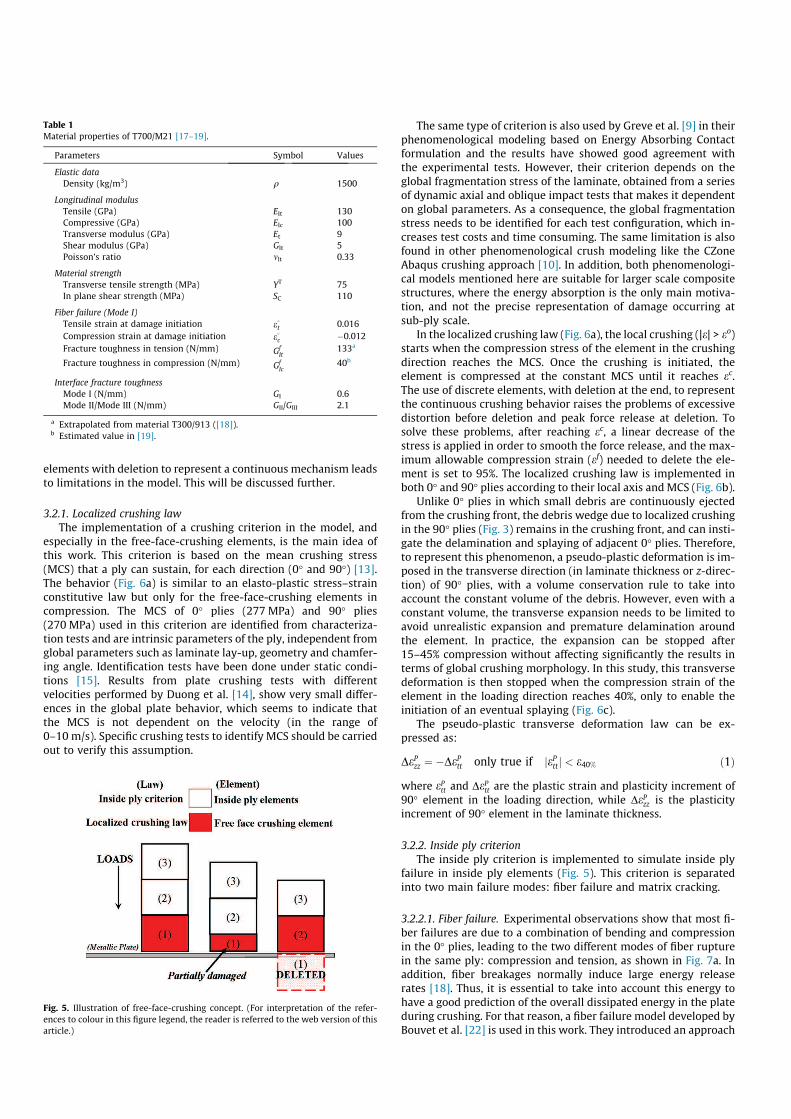
The operating principle is illustrated in Fig. 5. Initially, only the
element at the extremity of the ply is a free-face-crushing element
(1). Subjected to compression, it will be crushed (see next para-
graph for the localized crushing law applied). Once totally dam-
aged, it will be deleted, and the element behind (2) will become a
free-face-crushing element, and its behavior law will automatically
change from inside ply to localized crushing law. Of course, the
choice of this law is of first importance, as the use of discrete
Fig. 4. Model lay-up: (a) medium-scale quasi-static (b) dynamic plate. (For interpretation of the references to colour in this figure legend, the reader is referred to the web
version of this article.)
elements with deletion to represent a continuous mechanism leads
to limitations in the model. This will be discussed further.
3.2.1. Localized crushing law
The implementation of a crushing criterion in the model, and
especially in the free-face-crushing elements, is the main idea of
this work. This criterion is based on the mean crushing stress
(MCS) that a ply can sustain, for each direction (0° and 90°) [13].
The behavior (Fig. 6a) is similar to an elasto-plastic stress–strain
constitutive law but only for the free-face-crushing elements in
compression. The MCS of 0° plies (277 MPa) and 90° plies
(270 MPa) used in this criterion are identified from characteriza-
tion tests and are intrinsic parameters of the ply, independent from
global parameters such as laminate lay-up, geometry and chamfer-
ing angle. Identification tests have been done under static condi-
tions [15]. Results from plate crushing tests with different
velocities performed by Duong et al. [14], show very small differ-
ences in the global plate behavior, which seems to indicate that
the MCS is not dependent on the velocity (in the range of
0–10 m/s). Specific crushing tests to identify MCS should be carried
out to verify this assumption.
The same type of criterion is also used by Greve et al. [9] in their
phenomenological modeling based on Energy Absorbing Contact
formulation and the results have showed good agreement with
the experimental tests. However, their criterion depends on the
global fragmentation stress of the laminate, obtained from a series
of dynamic axial and oblique impact tests that makes it dependent
on global parameters. As a consequence, the global fragmentation
stress needs to be identified for each test configuration, which in-
creases test costs and time consuming. The same limitation is also
found in other phenomenological crush modeling like the CZone
Abaqus crushing approach [10]. In addition, both phenomenologi-
cal models mentioned here are suitable for larger scale composite
structures, where the energy absorption is the only main motiva-
tion, and not the precise representation of damage occurring at
sub-ply scale.
In the localized crushing law (Fig. 6a), the local crushing (|e| > eo)
starts when the compression stress of the element in the crushing
direction reaches the MCS. Once the crushing is initiated, the
element is compressed at the constant MCS until it reaches ec.
The use of discrete elements, with deletion at the end, to represent
the continuous crushing behavior raises the problems of excessive
distortion before deletion and peak force release at deletion. To
solve these problems, after reaching ec, a linear decrease of the
stress is applied in order to smooth the force release, and the max-
imum allowable compression strain (ef) needed to delete the ele-
ment is set to 95%. The localized crushing law is implemented in
both 0° and 90° plies according to their local axis and MCS (Fig. 6b).
Unlike 0° plies in which small debris are continuously ejected
from the crushing front, the debris wedge due to localized crushing
in the 90° plies (Fig. 3) remains in the crushing front, and can insti-
gate the delamination and splaying of adjacent 0° plies. Therefore,
to represent this phenomenon, a pseudo-plastic deformation is im-
posed in the transverse direction (in laminate thickness or z-direc-
tion) of 90° plies, with a volume conservation rule to take into
account the constant volume of the debris. However, even with a
constant volume, the transverse expansion needs to be limited to
avoid unrealistic expansion and premature delamination around
the element. In practice, the expansion can be stopped after
15–45% compression without affecting significantly the results in
terms of global crushing morphology. In this study, this transverse
deformation is then stopped when the compression strain of the
element in the loading direction reaches 40%, only to enable the
initiation of an eventual splaying (Fig. 6c).
The pseudo-plastic transverse deformation law can be ex-
pressed as:
DePzz ¼ ÿDePtt only true if jePttj < e40% ð1Þ
where ePtt and DePtt are the plastic strain and plasticity increment of
90° element in the loading direction, while DePzz is the plasticity
increment of 90° element in the laminate thickness.
3.2.2. Inside ply criterion
The inside ply criterion is implemented to simulate inside ply
failure in inside ply elements (Fig. 5). This criterion is separated
into two main failure modes: fiber failure and matrix cracking.
3.2.2.1. Fiber failure. Experimental observations show that most fi-
ber failures are due to a combination of bending and compression
in the 0° plies, leading to the two different modes of fiber rupture
in the same ply: compression and tension, as shown in Fig. 7a. In
addition, fiber breakages normally induce large energy release
rates [18]. Thus, it is essential to take into account this energy to
have a good prediction of the overall dissipated energy in the plate
during crushing. For that reason, a fiber failure model developed by
Bouvet et al. [22] is used in this work. They introduced an approach
Table 1
Material properties of T700/M21 [17–19].
Parameters Symbol Values
Elastic data
Density (kg/m3) q 1500
Longitudinal modulus
Tensile (GPa) Elt 130
Compressive (GPa) Elc 100
Transverse modulus (GPa) Et 9
Shear modulus (GPa) Glt 5
Poisson’s ratio mlt 0.33
Material strength
Transverse tensile strength (MPa) YT 75
In plane shear strength (MPa) SC 110
Fiber failure (Mode I)
Tensile strain at damage initiation e�
t 0.016
Compression strain at damage initiation e�
cÿ0.012
Fracture toughness in tension (N/mm) GfIt
133a
Fracture toughness in compression (N/mm) GfIc
40b
Interface fracture toughness
Mode I (N/mm) GI 0.6
Mode II/Mode III (N/mm) GII/GIII 2.1
a Extrapolated from material T300/913 ([18]).b Estimated value in [19].
Fig. 5. Illustration of free-face-crushing concept. (For interpretation of the refer-
ences to colour in this figure legend, the reader is referred to the web version of this
article.)

to dissipate the fracture energy in an element defined as a function
of the eight integration points. So, an energy release rate per unit
area of crack can be obtained by dissipating energy throughout
the volume of an element using the formulation in Eq. (2) based
on crack band theory [23], with a characteristic element length.
This approach enables to have a mesh-size independent model.
Z
V
Z e1
0
rl � del
!
dV ¼ S � GfI ð2Þ
where rl(el), e1, S, V are the stress (strain) in the fiber direction,
strain at full damage in the fiber direction, element’s cross section
normal to the fiber direction and element’s volume, respectively.
GfI is the fracture toughness for opening mode (mode I). Details of
this criterion can be found in [19,22].
Besides that, this equation works even if tension and compres-
sion states occur at the same time in one element as shown in
Fig. 7b, in order to represent bending behavior in the element:
compression at certain integration points, tension for the others.
Thus, at each time increment, the choice of damage calculation de-
pends upon the critical loads, either in tension or compression and
the damage evolution is computed taking into account the energy
dissipated in both states (GfIt and Gf
Ic have different values). (Once
an element is fully damaged, it is deleted.)
Fig. 6. (a) Localized crushing law (b) local axis of elements (c) 90° elements expansion in transverse direction. (For interpretation of the references to colour in this figure
legend, the reader is referred to the web version of this article.)
Fig. 7. (a) Ply breakage in bending (b) the fiber failure constitutive law. (For interpretation of the references to colour in this figure legend, the reader is referred to the web
version of this article.)

3.2.2.2. Matrix cracking. Matrix damage is essentially created by the
transverse stress (rt) and the out-of-plane shear stress (stz).
Therefore, the following criterion is used to determinate the failure
in 90° elements:
hrtiþ
YT
� �2
þstz
SC
� �2
¼ 1 ð3Þ
where hrti+, stz are the positive transverse stress and the shear
stress in (tz) plane, respectively. Moreover, hrti+ value is the maxi-
mum transverse stress among the eight nodes of each element,
extrapolated from the eight integration points. While stz is the aver-
age value of eight integration points. This is done to account for the
bending behavior in elements. Damage evolution is not considered
in this criterion since it induces very low energy compared to fiber
failure, and can thus be neglected. Once the criterion reaches unity,
the element is deleted.
The deletion of inside ply elements is important for the creation
of macro-scale fragments (debris) during the simulation. However,
it will cause a loss of mass and debris in the numerical model. Con-
sidering the size of debris in experiments compared to the size of
an element, and the first simulation results, deletion of elements
in these simulations seems acceptable.
3.3. Delamination
In this work, the classical traction–separation damage model in
Abaqus software is used to govern the initiation and propagation of
delamination between plies either in pure opening, shear or
mixed-mode. This damage model [16] is basically derived from
Fig. 8. Simulation for friction coefficient identification. (For interpretation of the references to colour in this figure legend, the reader is referred to the web version of this
article.)
Fig. 9. Comparison of mixed-mode crushing morphologies between simulation and experiment (a) medium-scale quasi-static test (b) dynamic plate test. (For interpretation
of the references to colour in this figure legend, the reader is referred to the web version of this article.)

fracture mechanics approach which considers the amount of
energy required to create new fracture surfaces and has been
developed based on a study by Camanho et al. [24]. The traction–
separation law involves three states: a damage initiation, a damage
evolution and a complete separation. Damage initiation is based on
the quadratic nominal stress criterion presented in Eq. (4).
hrni
ron
� �2
þrs
ros
� �2
þrt
rot
� �2
¼ 1 ð4Þ
where rn, rs, rt are stresses normal to the interface, and in first and
second shear directions.
The propagation of delamination is ruled by a linear decrease in
the traction–separation law, and the mode mix phenomenon is
also taken into account as a linear interaction between the three
energy release rates (Gic), expressed in Eq. (5).
X Gi
Gic
¼ 1 ð5Þ
3.4. Contact
Friction plays an important role during crushing especially fric-
tion between the crushing surface and the metallic base (during
splaying), and as friction relates to debris accumulation and debris
wedge formation. The available general contact formulation with
classical friction model based on Coulomb approximation is used
to simulate the contact behavior between all exterior surfaces
[16]. Since the friction coefficient has a great influence on the
crushing process [6], it is necessary to have a good estimation of it.
The friction coefficient is identified from a series of elementary
simulation tests (both static and dynamic models). Simulations are
done with different friction coefficients from 0.05 up to 0.3. Then,
for a given crushing displacement, the radius curvature and hori-
zontal displacement of certain splaying plies are compared with
experimental results, as presented in Fig. 8. Based on these simula-
tions, friction coefficient l = 0.15 is set in both static and dynamic
models. In this work, static and kinetic coefficients of friction are
assumed to be the same.
4. Results and discussion
Two 0°/90° laminated plates are simulated under crushing with
different loadings and boundary conditions. Fig. 9 presents the
crushing morphologies of both static and dynamic models, com-
pared with the experimental tests. Globally, the numerical models
in both tests are able to represent the mixed crushing mode includ-
ing all the major kinds of damage (splaying, localized crushing, in-
side ply failures and debris creations) and their coupling. The
development of a specific wedge resulting from localized crushing
of 90° elements in the numerical model is effective in initiating the
delamination of 0°/90° interfaces and then drives the adjacent 0°
plies to an eventual splaying. A stable progressive crushing due
to localized crushing in central plies can be observed in both cases,
as in the experiments (Fig. 9a(iii and iv) and b(iii and iv)).
In the model, for most of the fragments due to inside ply failure
in 0° and 90° plies, the sizes are relatively close to the ones mea-
sured in experimental tests. For the medium-scale quasi-static
model, the debris size is between 0.5 mm and 2.0 mm which is
close to experimental results (0.5–2.5 mm), as can be seen in
Fig. 9a. In dynamic plate tests, the size of debris is in the range from
0.5 mm to 5 mm for the experiments and 0.65 mm to 4.0 mm for
the numerical model. This validates the choice made for the
representation of fragments by the means of inside ply elements
deletion.
While all major damage is well represented, during the transi-
tion phase from initiation to the progressive crushing, the numer-
ical models show minor differences in terms of crushing
morphology correlations. For example, in Fig. 9a(iii), the model
simulates well the multiple delaminations on the right side as in
the experimental test, but the delamination length is slightly un-
der-predict in the numerical model. Consequently, both models
have differences in the number of plies involved in splaying or
localized crushing, compared to experiments (see Fig. 9a(iii and
iv) and b(iii and iv)). Nonetheless, this does not affect much the re-
sult of force–displacement curve in numerical model. Crushing of
composite plates involves significant displacements, rotations
and geometric transformations that lead to large dispersion in glo-
bal morphology of crushing processes, as verified experimentally.
For example, the number of plies in fragmentation mode can vary
significantly although tests are performed under the same condi-
tions [13–15].
Force–displacement curves from models and tests are displayed
in Fig. 10 for comparison. The curves from experiments and
numerical model are comparatively close to each other which
means that the main phenomena are well represented i.e. the
curves initiation and the maximum forces obtained for both static
and dynamic models are close with experimental results as a result
of the implementation of localized crushing laws in the models.
After that, both curves are flattened out to have steady crush load
(plateau after peak force) as in experimental tests. One can observe
small differences in the plateau level: 10.5% for the medium-scale
quasi-static model and 10% for the dynamic plate model compared
to the experimental tests. However, by taking into account the
complexity of the fracture modes in the laminated plate crushing
and the dispersion in tests, these small differences can be consid-
ered acceptable [6]. Furthermore, in order to reduce calculation
Fig. 10. Force displacement curves (a) medium-scale quasi-static test and (b)
dynamic plate test (9 m/s).

time, the numerical model for dynamic tests was solved for only
the first 20 mm crushing length, which is considered enough to
represent both initiation step and steady progressive crushing
(plateau).
Results from the simulations also allow quantifying the contri-
bution of eachmechanism in energy absorption during the crushing
tests: (a) 0° plies damage; (b) 90° plies damage; (b) delamination;
(c) friction; and (d) viscous effect. Furthermore, the energy
absorbed by 0° plies damage can be divided into two categories,
which are energy absorbed via localized crushing and via inside
ply failures. For 90° plies, the energy dissipated in inside ply failure
is neglected, as assumed in Section 3.2.2.2.
The evolution of energy dissipation for each of these mecha-
nisms during the crushing tests is presented in Fig. 11 for each test.
In both cases, 0° plies damage mechanism via localized crushing
absorb the highest part of the energy (49% and 30% of the total en-
ergy absorbed for static and dynamic tests, respectively) compared
with the other mechanisms. This matches with the experimental
observations that show the ability of 0° plies to perform a steady
localized crushing throughout the crushing process while there
are less inside ply failures (8% in static and 10% in dynamic tests).
Although 90° plies have the same energy absorption ability as 0°
plies (very close MCS), they dissipate less energy than 0° plies
(13% in static test and 21% in dynamic test). This is due to the
behavior of 90° plies that often turn into inside ply rupture due
to their weakest strength compared to 0° plies. Thus, the volume
of 90° plies involved in localized crushing is actually lower than
in 0° plies during crushing.
The energy absorbed by friction is 17% and 19% of the total en-
ergy for static test and dynamic test respectively. Besides that, the
delamination energy is significant and important to accurately cap-
ture the crushing morphology of mixed-mode crushing plate
although it provides less energy absorption (10% in the static test
and 13% in the dynamic tests, respectively).
5. Conclusion
The aim of this study is to propose a pseudo 2D finite element
model for mixed-mode crushing in laminated plates subjected to
low velocity crushing, depending only on the elementary material
characteristics of the ply. Based on the presented results, the cur-
rent development of the numerical model shows the capability
to represent mixed-mode crushing for 0°/90° laminates with all
major damages as observed experimentally. In addition, a good
correlation is observed between the force–displacement curves
from numerical models and experimental tests.
Despite some small differences in terms of crushing morphol-
ogy, the main idea of this work is the introduction of a free-face-
crushing concept in the model. This concept allows the use of
two failure criteria at the same time in order to represent the phe-
nomenology of localized crushing apart from classical inside ply
failures. Furthermore, the implementation of the localized crush-
ing law and the creation of a specific debris wedge in the 90° plies,
free-face-crushing elements are capable to reproduce the complex
localized damage mechanisms that occur at sub-ply scale and at all
crushing modes (splaying and fragmentation) at the same time.
Results from the simulation also allow making analyses of energy
absorbed by each damage mechanism which is not possible during
the tests. The results have demonstrated that localized crushing,
especially in the 0° plies, dissipates the highest part of the total
energy.
The next step of this work will be the extension of the same
modeling strategy to a full 3D finite element model, including plies
with orientations different from 0° or 90°.
Acknowledgements
Numerical simulations have been performed with the comput-
ing resources of CALcul en Midi Pyrénées (CALMIP, Toulouse-
France). The authors also gratefully acknowledge the Ministry of
Higher Education, Malaysia (MOHE) for the financial support of
PhD program through the Aerospace Scholarship Scheme.
References
[1] Sokolinsky VS, Indermuehle KC, Hurtado JA. Numerical simulation of thecrushing process of a corrugated composite plate. Composites Part A2011;42(9):1119–26.
[2] Feraboli P, Wade B, Deleo F, Rassaian M, Higgins M, Byar A. LS-DYNA MAT54modeling of the axial crushing of a composite tape sinusoidal specimen.Composites Part A 2011;42(11):1809–25.
[3] Xiao X, McGregor C, Vaziri R, Poursartip A. Progress in braided composite tubecrush simulation. Int J Impact Eng 2009;36(5):711–9.
[4] Fleming DC, Morrow C, Clarke CW, Bird CE. Finite element simulation ofdelamination with application to crashworthy design. American HelicopterSociety 62nd Annual Forum, Phoenix, May 2006.
[5] McGregor C, Vaziri R, Xiao X. Simulation of progressive crushing developmentin braided composite tubes under axial compression. Composites Part A2007;38(11):2247–59.
[6] Pinho ST, Camanho PP, de Moura MF. Numerical simulation of the crushingprocess of composite materials. Int J Crash 2004;9(3):263–76.
[7] Farley GL, Jones RM. Energy-absorption capability of composite tubes andbeams. NASA TM-101634, 1989.
[8] Mamalis A, Robinson M, Manolakos D, Demosthenous G, Ioannidis M,Carruthers J. Crashworthy capability of composite material structures.Compos Struct 1997;37(2):109–34.
[9] Greve L, Pickett AK, Payen F. Experimental testing and phenomenologicalmodelling of the fragmentation process of braided carbon epoxy compositetubes under axial and oblique impact. Composites Part B 2008;39(7–8):1221–32.
[10] Nixon S, Barnes G. Effective crushing simulation for composite structures.ICCM-17, Edinburgh, UK, July 2009.
Fig. 11. The evolution of energy absorbed through various mechanisms during
crushing tests of (a) medium-scale quasi-static and (b) dynamic plate crushing
(9 m/s). (For interpretation of the references to colour in this figure legend, the
reader is referred to the web version of this article.)

[11] Laurea ARM. Finite element investigations on the microstructure of compositematerials. PhD thesis., University of Nottingham; 2007.
[12] Ladevéze P, Lubineau G. On a damage mesomodel for laminates: micro–mesorelationships, possibilities and limits. Compos Sci Technol 2001;61(15):2149–58.
[13] Guillon D, Rivallant S, Barrau JJ, Petiot C, Thevenet P, Malherbe B. Experimentaland numerical study of the splaying mode crush of CFRP laminates. ICCM-17,Edinburgh, UK, July 2009.
[14] Duong AV, Rivallant S, Barrau JJ, Petiot C, Malherbe B. Influence of speed on thecrushing behavior of composite plates. ACCM-7, Taipei, Taiwan, November2010.
[15] Israr HA, Rivallant S, Barrau JJ. Experimental investigation on mean crushingstress characterization of carbon-epoxy plies under compressive crushingmode. Compos Struct 2013;96:357–64.
[16] Abaqus 6.9 Analysis user’s manual. Dassault Systèmes, 2009.[17] Prombut P. Caractérisation de la propagation de délaminage des stratifiés
composites multidirectionnels. PhD thesis, Université de Toulouse, 2007.[18] Pinho ST, Robinson P, Iannucci L. Fracture toughness of the tensile and
compressive fibre failure modes in laminated composites. Compos Sci Technol2006;66(13):2069–79.
[19] Hongkarnjanakul N, Bouvet C, Rivallant S. Validation of low velocity impactmodelling on different stacking sequences of CFRP laminates and influence offibre failure. Compos Struct 2013;106:549–59.
[20] Matzenmiller A, Schwizerhof K. Crashworthiness simulations of compositesstructures – a first step with explicit time integration. In: Wriggers P, WagnerW, editors. Non-linear computational/mechanics – state of theart. Berlin: Springer-Verlag; 1991. p. 642–70.
[21] Mamalis A, Manolakos D, Ioannidis M, Papapostolou D. The static and dynamicaxial collapse of CFRP square tubes: finite element modeling. Compos Struct2006;74(2):213–35.
[22] Bouvet C, Rivallant S, Barrau JJ. Low velocity impact modeling in compositelaminates capturing permanent indentation. Compos Sci Technol2012;72(16):1977–88.
[23] Bazant ZP, Oh BH. Crack band theory for fracture of concrete. Mater Struct1983;16:155–177Camanho PP, Davila CG, de Moura MF. Numerical simulationof mixed-mode progressive delamination in composite. J Compos Mater2003;37(16):1415–38.
[24] Camanho PP, Davila CG, de Moura MF. Numerical simulation of mixed-modeprogressive delamination in composite. J ComposMater 2003;37(16):1415–38.
Related Documents