86 The Open Thermodynamics Journal, 2010, 4, 86-91 1874-396X/10 2010 Bentham Open Open Access Multi-Objective Design Optimisation of Inlet and Combustor for Axisym- metric Scramjets H. Ogawa 1, *, R. R. Boyce 1 , A. Isaacs 2 and T. Ray 2 1 Centre for Hypersonics, School of Mechanical and Mining Engineering, The University of Queensland, St. Lucia, Bris- bane, QLD 4072, Australia 2 School of Engineering and Information Technology, University of New South Wales, Australian Defence Force Acad- emy, Canberra, ACT 2600, Australia Abstract: Scramjet airbreathing propulsion is a promising technology for efficient and economical access-to-space. Flow compression in the inlet and fuel combustion in the combustor play a major role in scramjet mechanism, their efficiencies crucially influencing the overall scramjet performance. A double-objective shape optimisation for an axisymmetric inlet and combustor configuration using hydrogen as fuel premixed into air has been performed for minimum total pressure loss and maximum combustion efficiency in the present study. A state-of-the-art MDO (multi-objective design optimisa- tion) capability with surrogate-assisted evolutionary algorithms has been employed, coupled with a CFD solver for invis- cid flowfields involving chemical reactions represented by Evans & Schexnayder’s model. The obtained Pareto optimal front suggests the possibility of substantial improvement in efficiency and the counteracting nature of the two objective functions. Geometries with higher combustion efficiency are characterised by a higher compression inlet with larger lead- ing-edge radius and a longer combustor, whereas opposite trends are observed for configurations with smaller total pres- sure loss. Keywords: Multi-objective design optimisation, axisymmetric scramjet, inlet and combustor. 1. INTRODUCTION Hypersonic air-breathing propulsion offers the potential for reliable and economical systems, providing flexibility for earth-to-space transport as well as atmospheric flight. In par- ticular, scramjet (Supersonic Combustion Ramjet) is a prom- ising technology that can enable efficient and flexible trans- port systems by removing the need to carry oxidisers and other propulsion limitations of conventional rocket engines. Supersonic combustion, which plays a key role in the scramjet technology, was first demonstrated in the laboratory in the 1960s [1,2], followed by an extended scramjet re- search program including airframe integration and combus- tion testing facility development conducted by NASA Lan- gley Research Center in the 1970s and 1980s [3]. Since then, Australian scramjet research has played a major role and achieved significant milestones in the international effort to develop scramjet technology. Net positive installed thrust for a scramjet vehicle was first demonstrated and measured in the T4 shock tunnel of Centre for Hypersonics of The Uni- versity of Queensland (UQ) in 1995 [4,5]. In-flight pure su- personic combustion via the use of the scramjet technology was demonstrated at Mach 7.6 for the first time worldwide in UQ’s HyShot II program in July 2002 [6,7]. Coming on the heels of these major milestones, the potential of scramjets for propelling high-speed vehicles was demonstrated by NASA’s *Address correspondence to this author at the Centre for Hypersonics, School of Mechanical and Mining Engineering, The University of Queen- sland, St. Lucia, Brisbane, QLD 4072, Australia; Tel: +61 (0)7 33656073; E-mail: [email protected] X-43A scramjet in the Hyper-X flight program at Mach 6.8 and 9.6 in March and November 2004, respectively [8]. Further breakthroughs have been seen by the first few years of this century in the Australian scramjet research and development. The concept of injecting and mixing in the scramjet inlet rather than the combustion chamber, using localised shock structures in the combustor to achieve igni- tion even when the mean flow conditions are too mild, was demonstrated successfully in the experiments conducted in the T4 shock tunnel [9,10]. It will lead to shorter and lighter scramjets with greater efficiency. An advanced scramjet con- figuration comprising three-dimensionally curved flowpaths with rectangular-to-elliptical shape transition (REST) has been developed at UQ [11], designed by utilising on the streamline-tracing techniques that have been contrived at NASA Langley Research Center [12]. The REST engines combine ease of vehicle integration with the advantages of elliptical cross-section combustion chambers. Another im- portant concept that has been explored recently is Buse- mann-type axisymmetric scramjets (Fig. (1)). Combined with the aforementioned “inlet-injection radical farming” concept, this elegantly simple geometry offers numerous advantages in various aspects including aerodynamic and combustion efficiency, thermal and structural management as well as manufacture. Illustrated in Fig. (2) is a schematic diagram of an axi- symmetric scramjet, which consists of an inlet, a combustor and a nozzle, and operates in a sequential process. Hyper- sonic inflow is compressed to a desired higher pressure (and consequently high temperature) at the exit of the inlet, which induces combustion in the downstream chamber. The reacted

Welcome message from author
This document is posted to help you gain knowledge. Please leave a comment to let me know what you think about it! Share it to your friends and learn new things together.
Transcript

86 The Open Thermodynamics Journal, 2010, 4, 86-91
1874-396X/10 2010 Bentham Open
Open Access
Multi-Objective Design Optimisation of Inlet and Combustor for Axisym-metric Scramjets
H. Ogawa1,*, R. R. Boyce1, A. Isaacs2 and T. Ray2
1Centre for Hypersonics, School of Mechanical and Mining Engineering, The University of Queensland, St. Lucia, Bris-
bane, QLD 4072, Australia
2School of Engineering and Information Technology, University of New South Wales, Australian Defence Force Acad-
emy, Canberra, ACT 2600, Australia
Abstract: Scramjet airbreathing propulsion is a promising technology for efficient and economical access-to-space. Flow compression in the inlet and fuel combustion in the combustor play a major role in scramjet mechanism, their efficiencies crucially influencing the overall scramjet performance. A double-objective shape optimisation for an axisymmetric inlet and combustor configuration using hydrogen as fuel premixed into air has been performed for minimum total pressure loss and maximum combustion efficiency in the present study. A state-of-the-art MDO (multi-objective design optimisa-tion) capability with surrogate-assisted evolutionary algorithms has been employed, coupled with a CFD solver for invis-cid flowfields involving chemical reactions represented by Evans & Schexnayder’s model. The obtained Pareto optimal front suggests the possibility of substantial improvement in efficiency and the counteracting nature of the two objective functions. Geometries with higher combustion efficiency are characterised by a higher compression inlet with larger lead-ing-edge radius and a longer combustor, whereas opposite trends are observed for configurations with smaller total pres-sure loss.
Keywords: Multi-objective design optimisation, axisymmetric scramjet, inlet and combustor.
1. INTRODUCTION
Hypersonic air-breathing propulsion offers the potential for reliable and economical systems, providing flexibility for earth-to-space transport as well as atmospheric flight. In par-ticular, scramjet (Supersonic Combustion Ramjet) is a prom-ising technology that can enable efficient and flexible trans-port systems by removing the need to carry oxidisers and other propulsion limitations of conventional rocket engines.
Supersonic combustion, which plays a key role in the scramjet technology, was first demonstrated in the laboratory in the 1960s [1,2], followed by an extended scramjet re-search program including airframe integration and combus-tion testing facility development conducted by NASA Lan-gley Research Center in the 1970s and 1980s [3]. Since then, Australian scramjet research has played a major role and achieved significant milestones in the international effort to develop scramjet technology. Net positive installed thrust for a scramjet vehicle was first demonstrated and measured in the T4 shock tunnel of Centre for Hypersonics of The Uni-versity of Queensland (UQ) in 1995 [4,5]. In-flight pure su-personic combustion via the use of the scramjet technology was demonstrated at Mach 7.6 for the first time worldwide in UQ’s HyShot II program in July 2002 [6,7]. Coming on the heels of these major milestones, the potential of scramjets for propelling high-speed vehicles was demonstrated by NASA’s
*Address correspondence to this author at the Centre for Hypersonics, School of Mechanical and Mining Engineering, The University of Queen-sland, St. Lucia, Brisbane, QLD 4072, Australia; Tel: +61 (0)7 33656073; E-mail: [email protected]
X-43A scramjet in the Hyper-X flight program at Mach 6.8 and 9.6 in March and November 2004, respectively [8].
Further breakthroughs have been seen by the first few years of this century in the Australian scramjet research and development. The concept of injecting and mixing in the scramjet inlet rather than the combustion chamber, using localised shock structures in the combustor to achieve igni-tion even when the mean flow conditions are too mild, was demonstrated successfully in the experiments conducted in the T4 shock tunnel [9,10]. It will lead to shorter and lighter scramjets with greater efficiency. An advanced scramjet con-figuration comprising three-dimensionally curved flowpaths with rectangular-to-elliptical shape transition (REST) has been developed at UQ [11], designed by utilising on the streamline-tracing techniques that have been contrived at NASA Langley Research Center [12]. The REST engines combine ease of vehicle integration with the advantages of elliptical cross-section combustion chambers. Another im-portant concept that has been explored recently is Buse-mann-type axisymmetric scramjets (Fig. (1)). Combined with the aforementioned “inlet-injection radical farming” concept, this elegantly simple geometry offers numerous advantages in various aspects including aerodynamic and combustion efficiency, thermal and structural management as well as manufacture.
Illustrated in Fig. (2) is a schematic diagram of an axi-symmetric scramjet, which consists of an inlet, a combustor and a nozzle, and operates in a sequential process. Hyper-sonic inflow is compressed to a desired higher pressure (and consequently high temperature) at the exit of the inlet, which induces combustion in the downstream chamber. The reacted

Multi-Objective Design Optimisation of Inlet The Open Thermodynamics Journal, 2010, Volume 4 87
gas expands in the nozzle to produce thrust. The inlet and combustor, in particular, play a pivotal role in the scramjet mechanism; the combustion critically depends on the tem-perature of the airflow compressed by the inlet and must take place efficiently within limited time and combustor length, which has a direct impact on the structural weight as well as the overall drag due to immense skin friction on the surface of the combustor.
Scramjet technology has thus advanced to a stage where sophisticated geometries must be explored for increased per-formance, in particular net positive thrust, which is essential for an access-to-space system. Scramjet engine design, how-ever, represents a formidable challenge to conventional ap-proaches due to the complexity of the associated flowfields involving various aerodynamic and aerothermal phenomena including shock wave / boundary layer interactions, flow separation and chemical reactions. Such a high degree of coupling necessitates the design of the scramjet components in an integrated manner rather than individual. Substantial research efforts have been dedicated to hypersonic design optimisation problems. Early examples include the applica-tion of sensitivity-based optimisation algorithms to rather simple configurations such as a scramjet aft body [13] and a two-dimensional scramjet flowpath [14]. An extended design optimisation study has been performed for the engine flow-path of an annular-type scramjet configuration by employing a simplex minimisation algorithm [15].
Recent remarkable advancement of optimisation tech-niques offers a powerful ability to assist the design process that involves a high degree of complexity. Evolutionary al-gorithms are particularly attractive for optimisation problems which include complex systems with multiple objectives due to their capability for robust and efficient solution search
enabled by population-based probabilistic approaches [16]. A highly advanced MDO capability has been developed at the University of New South Wales campus at the Australian Defence Force Academy (UNSW@ADFA), incorporating these cutting-edge approaches, i.e. evolutionary algorithms assisted by surrogate modelling based on radial basis func-tion networks [17,18]. A single-objective design optimisa-tion was preliminarily performed for the nose cone shape of the HyShot fore body as the first example of the application of this surrogate-assisted evolutionary algorithm capability to hypersonic shape optimisation [19]. Other recent exam-ples of surrogate-assisted MDO algorithms for hypersonic applications include the optimisation of fuel injectors for annular scramjet configurations conducted at NASA [20] and AFRL [21] by employing response surface modelling and Kriging surrogates, respectively.
This paper presents the results of a shape optimisation focusing on the inlet and combustor configuration with in-viscid assumptions as an intermediate step towards overall vehicle optimisation. A highly sophisticated design method-ology coupling the MDO capability and CFD (computational fluid dynamics) has been applied to the shape optimisation of these sections for two primary objectives, i.e. maximum combustion efficiency and minimum total pressure loss, be-ing the first example of the application of the coupled surro-gate-assisted MDO / CFD approach to a multi-objective de-sign optimisation problem for the flowpath of a scramjet engine.
2. APPROACH
2.1. Configuration and Conditions
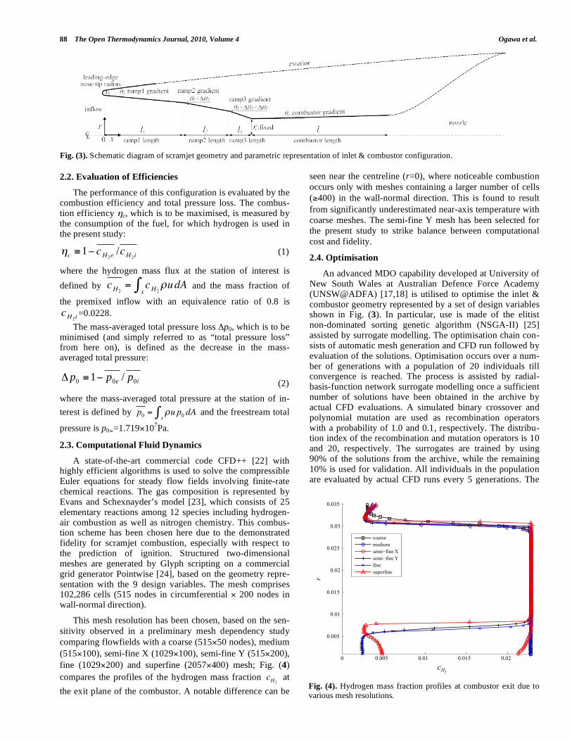
The schematic diagram of the three-ramp inlet and com-bustor configuration is shown in Fig. (3), along with the ge-ometry definition by 9 design variables, namely, the ramp lengths l1, l2, l3, combustor length lc, ramp gradient 1, ramp gradient increments 2, 3, combustor gradient c and leading-edge nose-tip radius rt (note that the nozzle and ex-ternal geometries are not considered in this study). The ra-dius of the combustor is fixed at rc=0.0351m at its entrance, based on the specifications of the reference geometry. To avoid the complexity and computational expense of 3D fuel injection flow calculations, premixed fuel and air is assumed for the inflow and inviscid flow fields are assumed in this study in order to focus on the geometric influence on the engine performance, ruling out viscous effects at this stage. The inflow conditions are M =8.0, p =1197Pa, T =226.5K at an operating altitude of 30km, assuming scramjet opera-tion on a typical trajectory with a constant dynamic pressure of 53.6kPa.
Fig. (1). Axisymmetric scramjet (upstream view).
Fig. (2). Schematic diagram of an axisymmetric scramjet.
nozzle combustorinlet
88 The Open Thermodynamics Journal, 2010, Volume 4 Ogawa et al.
2.2. Evaluation of Efficiencies
The performance of this configuration is evaluated by the combustion efficiency and total pressure loss. The combus-tion efficiency c, which is to be maximised, is measured by the consumption of the fuel, for which hydrogen is used in the present study:
c 1 cH2e/cH2i
(1)
where the hydrogen mass flux at the station of interest is
defined by cH2= cH2
ux
dA and the mass fraction of
the premixed inflow with an equivalence ratio of 0.8 is cH2i
=0.0228.
The mass-averaged total pressure loss p0, which is to be minimised (and simply referred to as “total pressure loss” from here on), is defined as the decrease in the mass-averaged total pressure:
ieppp
000/1
(2)
where the mass-averaged total pressure at the station of in-
terest is defined by p0 = u p0xdA and the freestream total
pressure is p0 =1.719 107Pa.
2.3. Computational Fluid Dynamics
A state-of-the-art commercial code CFD++ [22] with highly efficient algorithms is used to solve the compressible Euler equations for steady flow fields involving finite-rate chemical reactions. The gas composition is represented by Evans and Schexnayder’s model [23], which consists of 25 elementary reactions among 12 species including hydrogen-air combustion as well as nitrogen chemistry. This combus-tion scheme has been chosen here due to the demonstrated fidelity for scramjet combustion, especially with respect to the prediction of ignition. Structured two-dimensional meshes are generated by Glyph scripting on a commercial grid generator Pointwise [24], based on the geometry repre-sentation with the 9 design variables. The mesh comprises 102,286 cells (515 nodes in circumferential 200 nodes in wall-normal direction).
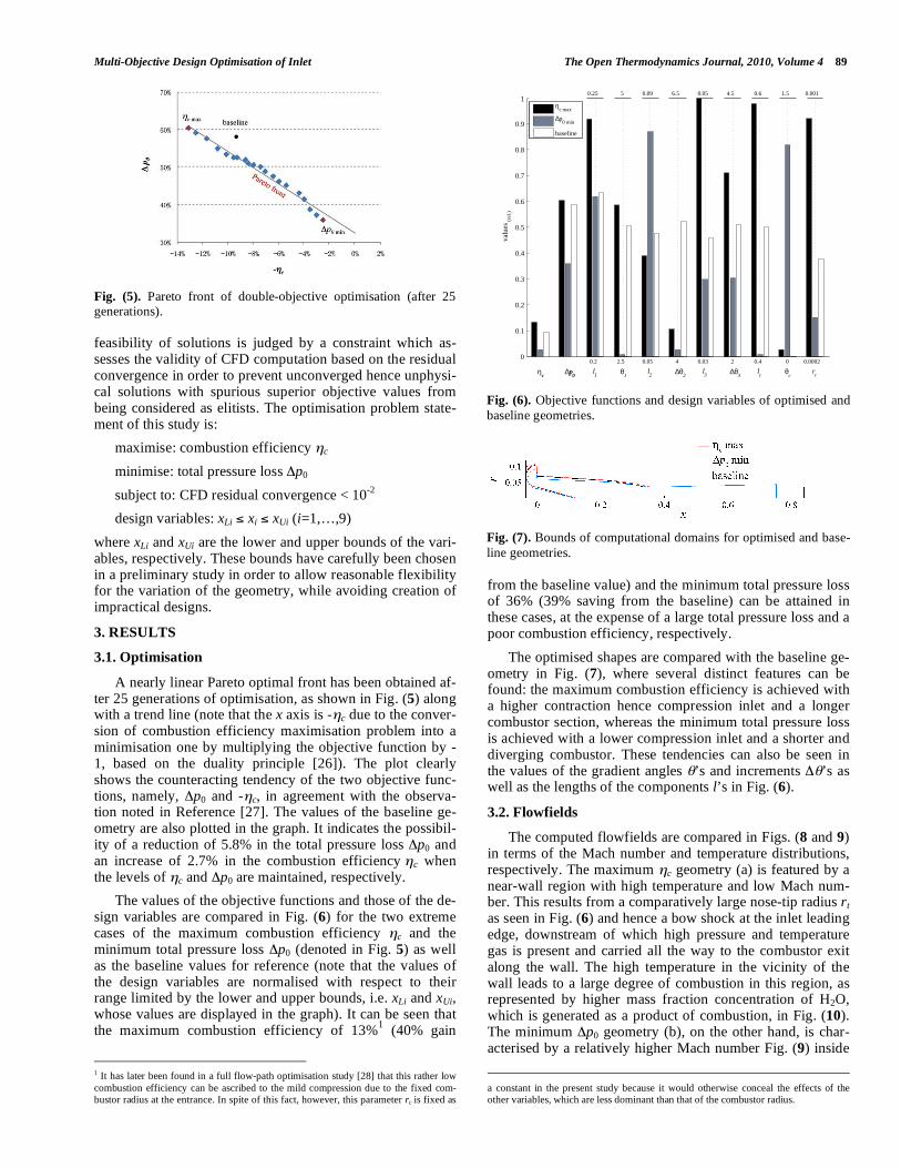
This mesh resolution has been chosen, based on the sen-sitivity observed in a preliminary mesh dependency study comparing flowfields with a coarse (515 50 nodes), medium (515 100), semi-fine X (1029 100), semi-fine Y (515 200), fine (1029 200) and superfine (2057 400) mesh; Fig. (4) compares the profiles of the hydrogen mass fraction cH2 at
the exit plane of the combustor. A notable difference can be
seen near the centreline (r=0), where noticeable combustion occurs only with meshes containing a larger number of cells ( 400) in the wall-normal direction. This is found to result from significantly underestimated near-axis temperature with coarse meshes. The semi-fine Y mesh has been selected for the present study to strike balance between computational cost and fidelity.
2.4. Optimisation
An advanced MDO capability developed at University of New South Wales at Australian Defence Force Academy (UNSW@ADFA) [17,18] is utilised to optimise the inlet & combustor geometry represented by a set of design variables shown in Fig. (3). In particular, use is made of the elitist non-dominated sorting genetic algorithm (NSGA-II) [25] assisted by surrogate modelling. The optimisation chain con-sists of automatic mesh generation and CFD run followed by evaluation of the solutions. Optimisation occurs over a num-ber of generations with a population of 20 individuals till convergence is reached. The process is assisted by radial-basis-function network surrogate modelling once a sufficient number of solutions have been obtained in the archive by actual CFD evaluations. A simulated binary crossover and polynomial mutation are used as recombination operators with a probability of 1.0 and 0.1, respectively. The distribu-tion index of the recombination and mutation operators is 10 and 20, respectively. The surrogates are trained by using 90% of the solutions from the archive, while the remaining 10% is used for validation. All individuals in the population are evaluated by actual CFD runs every 5 generations. The
Fig. (3). Schematic diagram of scramjet geometry and parametric representation of inlet & combustor configuration.
Fig. (4). Hydrogen mass fraction profiles at combustor exit due to various mesh resolutions.
0 0.005 0.01 0.015 0.02
0.005
0.01
0.015
0.02
0.025
0.03
0.035
cH2
r
coarsemediumsemi−fine Xsemi−fine Yfinesuperfine
Multi-Objective Design Optimisation of Inlet The Open Thermodynamics Journal, 2010, Volume 4 89
feasibility of solutions is judged by a constraint which as-sesses the validity of CFD computation based on the residual convergence in order to prevent unconverged hence unphysi-cal solutions with spurious superior objective values from being considered as elitists. The optimisation problem state-ment of this study is:
maximise: combustion efficiency c
minimise: total pressure loss p0
subject to: CFD residual convergence < 10-2
design variables: xLi xi xUi (i=1,…,9)
where xLi and xUi are the lower and upper bounds of the vari-ables, respectively. These bounds have carefully been chosen in a preliminary study in order to allow reasonable flexibility for the variation of the geometry, while avoiding creation of impractical designs.
3. RESULTS
3.1. Optimisation
A nearly linear Pareto optimal front has been obtained af-ter 25 generations of optimisation, as shown in Fig. (5) along with a trend line (note that the x axis is - c due to the conver-sion of combustion efficiency maximisation problem into a minimisation one by multiplying the objective function by -1, based on the duality principle [26]). The plot clearly shows the counteracting tendency of the two objective func-tions, namely, p0 and - c, in agreement with the observa-tion noted in Reference [27]. The values of the baseline ge-ometry are also plotted in the graph. It indicates the possibil-ity of a reduction of 5.8% in the total pressure loss p0 and an increase of 2.7% in the combustion efficiency c when the levels of c and p0 are maintained, respectively.
The values of the objective functions and those of the de-sign variables are compared in Fig. (6) for the two extreme cases of the maximum combustion efficiency c and the minimum total pressure loss p0 (denoted in Fig. 5) as well as the baseline values for reference (note that the values of the design variables are normalised with respect to their range limited by the lower and upper bounds, i.e. xLi and xUi, whose values are displayed in the graph). It can be seen that the maximum combustion efficiency of 13%1 (40% gain
1 It has later been found in a full flow-path optimisation study [28] that this rather low combustion efficiency can be ascribed to the mild compression due to the fixed com-bustor radius at the entrance. In spite of this fact, however, this parameter rc is fixed as
from the baseline value) and the minimum total pressure loss of 36% (39% saving from the baseline) can be attained in these cases, at the expense of a large total pressure loss and a poor combustion efficiency, respectively.
The optimised shapes are compared with the baseline ge-ometry in Fig. (7), where several distinct features can be found: the maximum combustion efficiency is achieved with a higher contraction hence compression inlet and a longer combustor section, whereas the minimum total pressure loss is achieved with a lower compression inlet and a shorter and diverging combustor. These tendencies can also be seen in the values of the gradient angles ’s and increments ’s as well as the lengths of the components l’s in Fig. (6).
3.2. Flowfields
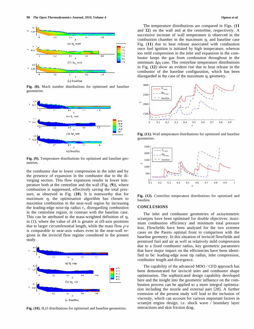
The computed flowfields are compared in Figs. (8 and 9) in terms of the Mach number and temperature distributions, respectively. The maximum c geometry (a) is featured by a near-wall region with high temperature and low Mach num-ber. This results from a comparatively large nose-tip radius rt
as seen in Fig. (6) and hence a bow shock at the inlet leading edge, downstream of which high pressure and temperature gas is present and carried all the way to the combustor exit along the wall. The high temperature in the vicinity of the wall leads to a large degree of combustion in this region, as represented by higher mass fraction concentration of H2O, which is generated as a product of combustion, in Fig. (10). The minimum p0 geometry (b), on the other hand, is char-acterised by a relatively higher Mach number Fig. (9) inside
a constant in the present study because it would otherwise conceal the effects of the other variables, which are less dominant than that of the combustor radius.
Fig. (5). Pareto front of double-objective optimisation (after 25 generations).
Fig. (6). Objective functions and design variables of optimised and baseline geometries. Fig. (7). Bounds of computational domains for optimised and base-line geometries.
0
0.1
0.2
0.3
0.4
0.5
0.6
0.7
0.8
0.9
1
valu
es (r
el.)
ηc
∆p0
0.2
0.25
l1
2.5
5
θ1
0.05
0.09
l2
4
6.5
∆θ2
0.03
0.05
l3
2
4.5
∆θ3
0.4
0.6
lc
0
1.5
θc
0.0002
0.001
rt
ηc max
∆p0 min
baseline
90 The Open Thermodynamics Journal, 2010, Volume 4 Ogawa et al.
the combustor due to lower compression in the inlet and by the presence of expansion in the combustor due to the di-verging section. This flow expansion results in lower tem-perature both at the centreline and the wall (Fig. (9)), where combustion is suppressed, effectively saving the total pres-sure, as observed in Fig. (10). It is noteworthy that for maximum c the optimisation algorithm has chosen to maximise combustion in the near-wall region by increasing the leading-edge nose-tip radius rt, disregarding combustion in the centreline region, in contrast with the baseline case. This can be attributed to the mass-weighted definition of c in (1), where the value of dA is greater at off-axis positions due to larger circumferential length, while the mass flow u is comparable to near-axis values even in the near-wall re-gions in the inviscid flow regime considered in the present study.
The temperature distributions are compared in Figs. (11 and 12) on the wall and at the centreline, respectively. A successive increase of wall temperature is observed in the combustion chamber in the maximum c and baseline case Fig. (11) due to heat release associated with combustion once fuel ignition is initiated by high temperature, whereas too mild compression in the inlet and expansion in the com-bustor keeps the gas from combustion throughout in the minimum p0 case. The centreline temperature distributions in Fig. (12) show an evident rise due to heat release in the combustor of the baseline configuration, which has been disregarded in the case of the maximum c geometry.
Fig. (11). Wall temperature distributions for optimised and baseline geometries.
Fig. (12). Centreline temperature distributions for optimised and baseline.
CONCLUSIONS
The inlet and combustor geometries of axisymmetric scramjets have been optimised for double objectives: maxi-mum combustion efficiency and minimum total pressure loss. Flowfields have been analysed for the two extreme cases on the Pareto optimal front in comparison with the baseline geometry. In this situation of inviscid flowfields and premixed fuel and air as well as relatively mild compression due to a fixed combustor radius, key geometric parameters that have major impact on the efficiencies have been identi-fied to be: leading-edge nose tip radius, inlet compression, combustor length and divergence.
The capability of the advanced MDO / CFD approach has been demonstrated for inviscid inlet and combustor shape optimisation. The sophisticated design capability developed here and the insight into the geometric influence on the com-bustion process can be applied to a more integral optimisa-tion including the nozzle and external part [28]. A further extension of the present study will lead to the inclusion of viscosity, which can account for various important factors in scramjet engine design, i.e. shock wave / boundary layer interactions and skin friction drag.
Fig. (8). Mach number distributions for optimised and baseline geometries.
Fig. (9). Temperature distributions for optimised and baseline geo-metries.
Fig. (10). H2O distributions for optimised and baseline geometries.
0 0.1 0.2 0.3 0.4 0.5 0.6 0.7 0.8 0.9
1500
2000
2500
3000
x
T
η
c max
∆p0 min
baseline
0.1 0.2 0.3 0.4 0.5 0.6 0.7 0.8 0.9 10
500
1000
1500
2000
2500
x
T
η
c max
∆p0 min
baseline

Multi-Objective Design Optimisation of Inlet The Open Thermodynamics Journal, 2010, Volume 4 91
ACKNOWLEDGMENT
Authors are grateful to Mr. Yohan Alazet at École Na-tionale Supérieure de l'Aéronautique et de l'Espace for his invaluable assistance in developing the mesh generation and optimisation methodology.
NOMENCLATURE
p0 = Mass-averaged total pressure
p0 = Mass-averaged total pressure loss
c = Combustion efficiency
cH2 = Mass fraction ratio of hydrogen (fuel)
M = Mach number
p = Pressure [Pa]
T = Temperature [K]
l = Length [m]
= Angle [deg]
x = Streamwise coordinate [m]
r = Radial coordinate [m]
subscripts
i = Values at inlet entrance
e = Values at combustor exit
= Values of inflow
REFERENCES
[1] J. Tamagno, and O. Lindemann, Experimental Results on Super-
sonic Combustion, General Applied Science Laboratories, Ronk-onkoma, NY, December 1962.
[2] I. T. Osgerby, H. K. Smithson, and D. A. Wagner, “Supersonic combustion tests with a double-oblique-shock SCRAMjet in a shock tunnel”, AIAA J., vol. 8, no. 9, pp. 1703-1705, 1970.
[3] G. Y. Anderson, C. R. McClinton, and J. P. Weidner, “Scramjet performance”, In: Scramjet Propulsion, E. T. Curran and S. N. B. Murthy Eds., Reston, VA: AIAA Progress in Astronautics and Aeronautics, 2000, vol. 189, pp. 369-446.
[4] A. Paull, R. J. Stalker and D. J. Mee, “Experiments on supersonic combustion ramjet propulsion in a shock tunnel”, J. Fluid Mech., vol. 296, pp. 159-183, 1995.
[5] R. J. Stalker, A. Paull, D. J. Mee, R. G. Morgan, and P. A. Jacobs, “Scramjets and shock tunnels – The Queensland experience”, Prog
Aerosp Sci., vol. 41, pp. 471-513, 2005. [6] A. Paull, H. Alesi, and S. Anderson, “HyShot flight program and
how it was developed”, AIAA 2002-5248, 11th AIAA/AAF Interna-tional Conference on Space Planes and Hypersonic Systems and
Technologies, Orléans, France, September 2002. [7] R. R. Boyce, S. Gerard, and A. Paull, "The hyshot scramjet flight
experiment – flight data and CFD calculations compared", AIAA 2003-7029, 12th AIAA International Space Planes and Hypersonic
Systems and Technologies Conference, Norfolk: VA, December 2003.
[8] C. R. McClinton, “X-43 – Scramjet power breaks the hypersonic barrier: dryden lectureship in research for 2006”, AIAA 2006-1-317,
43rd AIAA Aerospace Sciences Meeting and Exhibit, Reno, NV, January 2006.
[9] D. C. Hunt, A. Paull, R. R. Boyce, and M. Hagenmaier, “Investiga-tion of an axisymmetric scramjet configuration utilising inlet-injection and radical farming”, in proceedings of 19th International
Symposium on Airbreathing Engines Montreal, Canada, September 2009.
[10] J. R. McGuire, R. R. Boyce, and N. R. Mudford, “Radical farm ignition processes in two-dimensional supersonic combustion”, J.
Propulsion Power, vol. 24, no. 6, pp. 1248-1257, 2008. [11] M. K. Smart, “Scramjets”, Aeronautical J., vol. 111, no. 1124, pp.
605-620, 2007. [12] M. K. Smart, and C. A. Trexler, “Mach 4 Performance of hyper-
sonic inlet with rectangular-to-elliptical shape transition”, J. Pro-pulsion Power, vol. 20, no. 2, pp. 288-293, 2004.
[13] O. Baysal, and M. E. Eleshaky, “Aerodynamic design optimization using sensitivity analysis and computational fluid dynamics”, AIAA
91-0471, 29th Aerospace Sciences Meeting, Reno, NV, January 1991.
[14] P. D. McQuade, S. Eberhardt, and E. Livne, “CFD-Based aerody-namic approximation concepts optimization of a two-dimensional scramjet vehicle”, J. Aircr., vol. 32, no. 2, pp. 262-269, 1995.
[15] C. S. Craddock, “Computational Optimization of Scramjets and
Shock Tunnel Nozzles”, PhD Thesis, The University of Queensland, Australia, 1999.
[16] K. Deb, Multi-Objective Optimization using Evolutionary Algo-rithms, Wiley, New York, ISBN: 978-0471873396, 2001.
[17] T. Ray, and W. Smith, “A surrogate assisted parallel multiobjective evolutionary algorithm for robust engineering design”, Eng Optim, vol. 38, no. 8, pp. 997-1011, 2006.
[18] T. Ray, A. Isaacs, and W. Smith, “Multi-Objective optimization using surrogate assisted evolutionary algorithm”, (Introduction G. P. Rangaiah), Multi-objective Optimization: Tech Applications in
Chemical Engineering, World Scientific, Singapore, 2008, pp. 131-151.
[19] N. R. Deepak, T. Ray, and R. R. Boyce, “Shape optimization of the nose cone for a hypersonic flight experiment trajectory”, J. Spacecr
Rockets [accepted], DOI: 10.2514/1.33826, 2008. [20] C. Steffen, “Fuel injector design optimization for an annular
SCRAMJet geometry”, AIAA 2003-0651, 41st Aerospace Sciences Meeting and Exhibit, Reno, NV, January 2003.
[21] B. T. Sparkman, J. W. Chrissis, M. R. Gruber, and M. A. Abramson, “Optimization of a scramjet fuel injection array: An application of mixed variable generalized pattern search with kriging surrogates”, AIAA 2008-5861, 12th AIAA / ISSMO Multidisciplinary Analysis and
Optimization Conference, Victoria, Canada, 2008. [22] CFD++, Software Package, Ver. 8.11, Metacomp Technologies,
Inc., CA, 2009. [23] J. S. Evans, and C. J. Jr. Schexnayder, “Influence of chemical ki-
netics and unmixedness on burning in supersonic hydrogen flames”, AIAA J., vol. 18, no. 2, pp. 188-193, 1980.
[24] Pointwise, Software Package, Ver. 16.02, Pointwise, Inc., TX, 2008.
[25] K. Deb, A. Pratap, S. Agarwal, and T. Meyarivan, “A fast and elitist multiobjective genetic algorithm: NSGA-II”, IEEE Trans.
Evol. Comput., vol. 6, No. 2, pp.182-197, 2002. [26] K. Deb, Optimization for Engineering Design: Algorithms and
Examples, Prentice-Hall: New Delhi, India, 1995. [27] A. Mack, J. Steelant, K. Hannemann, S. Karl, and J. Odam, “Mix-
ing and combustion enhancement in a generic scramjet combustion chamber”, AIAA 2006-8134, 14th AIAA/AHI Space Planes and Hy-
personic Systems and Technologies Conference, Canberra, Novem-ber 2006.
[28] H. Ogawa, Y. Alazet, R. R. Boyce, A. Isaacs, and T. Ray, “Design optimisation of axisymmetric scramjets for access-to-space”, in
proceedings of 9th Australian Space Science Conference, Sydney, September 2009.
Received: November 26, 2009 Revised: January 13, 2010 Accepted: February 11, 2010
© Ogawa et al.; Licensee Bentham Open.
This is an open access article licensed under the terms of the Creative Commons Attribution Non-Commercial License (http://creativecommons.org/licenses/by-nc/3.0/) which permits unrestricted, non-commercial use, distribution and reproduction in any medium, provided the work is properly cited.
Related Documents