6 The Open Mechanics Journal, 2008, 2, 6-11 1874-1584/08 2008 Bentham Science Publishers Ltd. Open Access Modified Linear Theory for Spinning or Non-Spinning Projectiles D.N. Gkritzapis* ,1 , E.E. Panagiotopoulos 2 , D.P. Margaris 3 and D.G. Papanikas 4 1 Laboratory of Firearms and Tool Marks Section, Criminal Investigation Division, Hellenic Police, and Post graduate Student, Mechanical Engineering and Aeronautics Department, University of Patras, Greece 2 Post-graduate Student, Mechanical Engineering and Aeronautics Department, University of Patras, Greece 3 Professor, Mechanical Engineering and Aeronautics Department, University of Patras, Greece 4 Ex-Professor, Mechanical Engineering and Aeronautics Department, University of Patras, Greece Abstract: Static and dynamic stability are the most important phenomena for stable flight atmospheric motion of spin and fin stabilized projectiles. If the aerodynamic forces and moments and the initial conditions are accurately known, an es- sentially exact simulation of the projectile’s synthesized pitching and yawing motion can be readily obtained by numerical methods. A modified trajectory linear theory of the same problem implies an approximate solution. INTRODUCTION More than 80 years ago, English ballisticians [1] con- structed the first rigid six-degree-of-freedom projectile exte- rior ballistic model. Their model contained a reasonably complete aerodynamic force and moment expansion for a spinning shell and included aerodynamic damping along with Magnus force and moment. Guided by an extensive set of yaw card firings, these researchers also created the first approximate analytic solution of the six-degree-of-freedom projectile equations of motion by introducing a set of simpli- fications based on clever linearization by artificially separat- ing the dynamic equations into uncoupled groups. The re- sulting theory is commonly called projectile linear theory. Kent [2], Neilson and Synge [3], Kelley and McShane [4], and Kelley et al. [5] made refinements and improvements to projectile linear theory. Projectile linear theory has proved an invaluable tool in understanding basic dynamic characteristics of projectiles in atmospheric flight, for establishing stability criteria for fin- and spin-stabilized projectiles, and for extracting projectile aerodynamic loads from spark range data. In the present work, the full six degrees of freedom (6- DOF) projectile flight dynamics atmospheric model is con- sidered for the accurate prediction of short and long range trajectories of high spin and fin-stabilized projectiles. It takes into consideration the influence of the most significant forces and moments, in addition to gravity. Projectiles, which are inherently aerodynamically unsta- ble, can be stabilized with spin. For this condition, the spin rate must be high enough to develop a gyroscopic moment, which overcomes the aerodynamic instability, and the pro- jectile is said to be gyroscopically stable. This is the case for the most gun launched projectiles (handguns, rifles, cannons, *Address correspondence to this author at the Laboratory of Firearms and Tool Marks Section, Criminal Investigation Division, Hellenic Police, and Post graduate Student, Mechanical Engineering and Aeronautics Depart- ment, University of Patras, Greece; E-mail: [email protected] etc.) where the rifling of the barrel provides the required axial spin to projectile. In describing this condition, a gyro- scopic stability factor can be applied, which is obtained from the roots of the modified linear theory in the equations of projectile motion. Also, dynamic stability is defined as the condition where a system is perturbed and the ensuing oscillatory has a ten- dency to either decrease or increase. Note that this definition assumes that the static stability is present, otherwise the os- cillatory motion would not occur. PROJECTILE MODEL The present analysis considers two different types of rep- resentative projectiles: a spin-stabilized of 105mm and a mortar fin-stabilized of 120 mm. Basic physical and geometrical characteristics data of the above-mentioned 105 mm HE M1 and the non-rolling, finned 120 mm HE mortar projectiles are illustrated briefly in Table 1. Table 1. Physical and Geometrical Data of 105 mm and 120mm Projectiles Types Characteristics 105 mm HE M1 projectile 120 mm HE mortar projectile Reference diameter, mm 114.1 119.56 Total Length, mm 494.7 704.98 Total mass, kg 15.00 13.585 Axial moment of inertia, kg-m 2 2326x10 -2 2335x10 -2 Transverse moment of inertia, kg-m 2 23118x10 -2 23187x10 -2 Centre of gravity from the base, mm 113.4 422.9

Welcome message from author
This document is posted to help you gain knowledge. Please leave a comment to let me know what you think about it! Share it to your friends and learn new things together.
Transcript

6 The Open Mechanics Journal, 2008, 2, 6-11
1874-1584/08 2008 Bentham Science Publishers Ltd.
Open Access
Modified Linear Theory for Spinning or Non-Spinning Projectiles
D.N. Gkritzapis*,1, E.E. Panagiotopoulos
2, D.P. Margaris
3 and D.G. Papanikas
4
1Laboratory of Firearms and Tool Marks Section, Criminal Investigation Division, Hellenic Police, and Post graduate
Student, Mechanical Engineering and Aeronautics Department, University of Patras, Greece
2Post-graduate Student, Mechanical Engineering and Aeronautics Department, University of Patras, Greece
3Professor, Mechanical Engineering and Aeronautics Department, University of Patras, Greece
4Ex-Professor, Mechanical Engineering and Aeronautics Department, University of Patras, Greece
Abstract: Static and dynamic stability are the most important phenomena for stable flight atmospheric motion of spin and
fin stabilized projectiles. If the aerodynamic forces and moments and the initial conditions are accurately known, an es-
sentially exact simulation of the projectile’s synthesized pitching and yawing motion can be readily obtained by numerical
methods. A modified trajectory linear theory of the same problem implies an approximate solution.
INTRODUCTION
More than 80 years ago, English ballisticians [1] con-structed the first rigid six-degree-of-freedom projectile exte-rior ballistic model. Their model contained a reasonably complete aerodynamic force and moment expansion for a spinning shell and included aerodynamic damping along with Magnus force and moment. Guided by an extensive set of yaw card firings, these researchers also created the first approximate analytic solution of the six-degree-of-freedom projectile equations of motion by introducing a set of simpli-fications based on clever linearization by artificially separat-ing the dynamic equations into uncoupled groups. The re-sulting theory is commonly called projectile linear theory. Kent [2], Neilson and Synge [3], Kelley and McShane [4], and Kelley et al. [5] made refinements and improvements to projectile linear theory.
Projectile linear theory has proved an invaluable tool in understanding basic dynamic characteristics of projectiles in atmospheric flight, for establishing stability criteria for fin- and spin-stabilized projectiles, and for extracting projectile aerodynamic loads from spark range data.
In the present work, the full six degrees of freedom (6-DOF) projectile flight dynamics atmospheric model is con-sidered for the accurate prediction of short and long range trajectories of high spin and fin-stabilized projectiles. It takes into consideration the influence of the most significant forces and moments, in addition to gravity.
Projectiles, which are inherently aerodynamically unsta-ble, can be stabilized with spin. For this condition, the spin rate must be high enough to develop a gyroscopic moment, which overcomes the aerodynamic instability, and the pro-jectile is said to be gyroscopically stable. This is the case for the most gun launched projectiles (handguns, rifles, cannons,
*Address correspondence to this author at the Laboratory of Firearms and
Tool Marks Section, Criminal Investigation Division, Hellenic Police, and
Post graduate Student, Mechanical Engineering and Aeronautics Depart-
ment, University of Patras, Greece; E-mail: [email protected]
etc.) where the rifling of the barrel provides the required axial spin to projectile. In describing this condition, a gyro-scopic stability factor can be applied, which is obtained from the roots of the modified linear theory in the equations of projectile motion.
Also, dynamic stability is defined as the condition where a system is perturbed and the ensuing oscillatory has a ten-dency to either decrease or increase. Note that this definition assumes that the static stability is present, otherwise the os-cillatory motion would not occur.
PROJECTILE MODEL
The present analysis considers two different types of rep-resentative projectiles: a spin-stabilized of 105mm and a mortar fin-stabilized of 120 mm.
Basic physical and geometrical characteristics data of the above-mentioned 105 mm HE M1 and the non-rolling, finned 120 mm HE mortar projectiles are illustrated briefly in Table 1.
Table 1. Physical and Geometrical Data of 105 mm and
120mm Projectiles Types
Characteristics 105 mm HE M1
projectile
120 mm HE mortar
projectile
Reference diameter, mm 114.1 119.56
Total Length, mm 494.7 704.98
Total mass, kg 15.00 13.585
Axial moment of inertia,
kg-m2
2326x10-2 2335x10-2
Transverse moment of
inertia, kg-m2
23118x10-2 23187x10-2
Centre of gravity from
the base, mm
113.4 422.9
Modified Linear Theory for Spinning The Open Mechanics Journal, 2008, Volume 2 7
TRAJECTORY FLIGHT SIMULATION MODEL
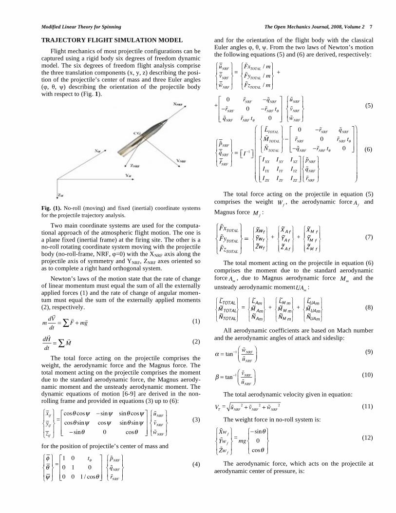
Flight mechanics of most projectile configurations can be captured using a rigid body six degrees of freedom dynamic model. The six degrees of freedom flight analysis comprise the three translation components (x, y, z) describing the posi-tion of the projectile’s center of mass and three Euler angles ( , , ) describing the orientation of the projectile body with respect to (Fig. 1).
Fig. (1). No-roll (moving) and fixed (inertial) coordinate systems
for the projectile trajectory analysis.
Two main coordinate systems are used for the computa-tional approach of the atmospheric flight motion. The one is a plane fixed (inertial frame) at the firing site. The other is a no-roll rotating coordinate system moving with the projectile body (no-roll-frame, NRF, =0) with the XNRF axis along the projectile axis of symmetry and YNRF, ZNRF axes oriented so as to complete a right hand orthogonal system.
Newton’s laws of the motion state that the rate of change of linear momentum must equal the sum of all the externally applied forces (1) and the rate of change of angular momen-tum must equal the sum of the externally applied moments (2), respectively.
mdV
dt= F + mg (1)
dH
dt= M (2)
The total force acting on the projectile comprises the weight, the aerodynamic force and the Magnus force. The total moment acting on the projectile comprises the moment due to the standard aerodynamic force, the Magnus aerody-namic moment and the unsteady aerodynamic moment. The dynamic equations of motion [6-9] are derived in the non-rolling frame and provided in equations (3) up to (6):
xifyifzif
=cos cos sin sin cos
cos sin cos sin sin
sin 0 cos
uNRFvNRFwNRF
(3)
for the position of projectile’s center of mass and
=1 0 t
0 1 0
0 0 1 / cos
pNRFqNRFrNRF
(4)
and for the orientation of the flight body with the classical Euler angles , , . From the two laws of Newton’s motion the following equations (5) and (6) are derived, respectively:
uNRFvNRFwNRF
=
FxTOTAL / m
FyTOTAL / m
FzTOTAL / m
+
+
0 rNRF qNRFrNRF 0 rNRF t
qNRF rNRF t 0
uNRFvNRFwNRF
(5)
pNRFqNRFrNRF
=
I 1
LTOTALMTOTAL
NTOTAL
0 rNRF qNRFrNRF 0 rNRF t
qNRF rNRF t 0
IXX IXY IXZIYX IYY IYZIZX IZY IZZ
pNRFqNRFrNRF
(6)
The total force acting on the projectile in equation (5)
comprises the weight Wf, the aerodynamic force Af
and
Magnus force M f:
FxTOTALFyTOTALFzTOTAL
=
f
f
f
wZ~wY~wX~
+
fA
fA
fA
Z~Y~X~
+
fM
fM
fM
Z~Y~X~
(7)
The total moment acting on the projectile in equation (6)
comprises the moment due to the standard aerodynamic
force Am , due to Magnus aerodynamic force Mm and the
unsteady aerodynamic momentUAm :
TOTAL
TOTAL
TOTAL
N~M~L~
=
mA
mA
mA
N~M~L~
+
mM
mM
mM
N~M~L~
+
mUA
mUA
mUA
N~M~L~
(8)
All aerodynamic coefficients are based on Mach number
and the aerodynamic angles of attack and sideslip:
= tan 1 wNRF
uNRF (9)
= tan 1 vNRFuNRF
(10)
The total aerodynamic velocity given in equation:
VT = uNRF
2+ vNRF
2+ wNRF
2 (11)
The weight force in no-roll system is:
Xwf
Ywf
Zwf
=mg
sin
0
cos
(12)
The aerodynamic force, which acts on the projectile at
aerodynamic center of pressure, is:
8 The Open Mechanics Journal, 2008, Volume 2 Gkritzapis et al.
fA
fA
fA
Z~Y~X~
=2
1 2TV Sref
T
NRFNA
T
NRFNA
2T
2NRF
2X2T
2NRF
2X0X
V
w~
C
V
v~
C
V
v~
CV
w~
CC
(13)
The Magnus, which acts on projectile at the Magnus
force center of pressure, is:
fM
fM
fM
Z~Y~X~
=2
1 2TV ref
S
2T
NRFNRF
2T
NRFNRF
V2
v~CDp~V2
w~CDp~0
(14)
The moment due to aerodynamic force is:
=
fA
fA
fA
MAC
MAC
mA
mA
mA
Z~Y~X~
0R0
R00
000
N~M~L~
(15)
The moment due to Magnus force is:
=
mM
mM
mM
N~M~L~
fM
fM
fM
MAX
MAX
Z~Y~X~
0R0
R00
000
(16)
In addition, for the unsteady moment UAm is:
2T
mUA
mUA
mUA
V2
1
N~M~L~
= D Sref
V
C
V2
DCr~V
C
V2
DCq~V2
DCp~
MAMQNRF
MAMQNRF
LPNRF
+
(17)
The dynamic equations of motion (3-6) are highly non-linear. Thus, numerical integration is commonly used to ob-tain solutions to this initial value problem.
MODIFIED PROJECTILE LINEAR THEORY
To develop the modified projectile linear theory [7], the
following sets of simplifications are employed: the axial ve-
locity uNRF can be replaced by the total velocity VT because
the side velocities vNRF and
wNRF are small.
The aerodynamic angles of attack and sideslip are small for the main part of the atmospheric trajectory
wNRF /VT , vNRF /VT
and the projectiles are geometrically symmetrical
IXY = IYZ = IXZ = 0, IYY = IZZ
Constant aerodynamic coefficients for the most important forces and moments with respect to angle of attack and Mach number are taken into account. Flat-fire and small yaw tra-jectories are considered so the yaw angle is small:
sin( ) , cos( ) 1
The independent variable is changed from time t to di-mensionless arclength s, measured in calibers of travel:
s =1
dVdt
0
t
(18)
This technique causes the equations determining the cou-pled pitching and yawing motion independent of the size of projectile, which turns out to be very convenient in the analysis of free-flight range data.
DIFFERENTIAL EQUATION OF MOTION
The differential equation governing the angular oscilla-tory motion for the complete linearized pitching and yawing motion of slightly symmetric projectiles [6] as a function of distance traveled s is shown below:
+ H iP( ) M + iPT( ) = iPG (19)
where
H =Sd
2mCL
Sd
2mCD y
2 Sd
2mCMQ
(20)
P =IXIY
pd
V (21)
M = y2 Sd
2mCMA
(22)
T =Sd
2mCL + x
2 Sd
2mCNPA
(23)
G =gd cos
V 2 (24)
= + i (25)
This differential equation contains all the significant aerodynamic forces and moments that affect the pitching and yawing motion of a spinning or non-spinning symmetric projectile body. The author’s definition = + i was first chosen by Fowler et al. and was adopted by R. H. Kent. Gunners and engineers usually prefer this definition. The gunner observer looks downrange from a position located just behind the gun. Upward and to the right are always con-sidered as positive directions. It is nature for the gunner to define the axis as positive upward, the axis as positive to right and the clockwise direction of all rotations as posi-tive for right hand twist rifling.
STATIC AND DYNAMIC STABILITY CRITERIA
The solution of differential equation (19) tells us that the epicyclic frequencies depend only on the dimensionless roll rate P and overturning moment M, and are unaffected by any of other aerodynamic forces and moments.
From the definition of an unstable motion, we are led naturally to the concept of static stability:
P2 4M( ) 0 (26)
Classical exterior ballistics defines the static stability factor [5] Sg, as:
Sg =IX
2 p2
2 IY SdV2CMA
(27)
Modified Linear Theory for Spinning The Open Mechanics Journal, 2008, Volume 2 9
Eliminating P2 between equations (26-27), we have:
4M Sg 1( ) 0 (28)
For statically unstable (spin-stabilized) projectile, M > 0 and equation (28) reduces to the classical static stability cri-terion:
Sg 1 (29)
Equation (26) is a more general result than the (29), be-cause it shows that a statically stable missile (M < 0), is statically stable without spin.
Dynamic stability requires that both damping exponents be negative throughout the projectile’s flight. For a non-spinning statically stable missile (M < 0) and P is either zero. For finned missiles, the pitch damping moment coefficient is usually negative. The lift and drag force coefficients are both positive, therefore H is nearly always greater than zero, and the dynamic stability is assured.
The dynamic stability factor Sd is defined as:
Sd =2T
H (30)
and the expressions
H>0 (31)
1
SgSd 2 Sd( ) (32)
are the generalized dynamic stability criteria for any spin-ning or non-spinning symmetric projectile flight body.
COMPUTATIONAL SIMULATION
The constant dynamic flight model [10] uses mean values of the experimental aerodynamic coefficients variations (Ta-ble 2).
Table 2. Constant Aerodynamic Parameters for Dynamic
Trajectory Flight of the Two Projectile Types
105mm Projectile 120mm Projectile
CD = 0.243, CL = 1.76,
CLP = -0.0108, CMQ = -9.300,
CMA = 3.76, CYPA = 0.381
CNPA = 0.215
CD = 0.14, CL = 2.76,
CMQ = -22.300,
CMA = -15.76
Initial data for 105 mm dynamic trajectory model with constant aerodynamic coefficients are:
x = 0.0 m, y = 0.0 m, z = 0.0 m, = 0.0°, = 45.0° and 70.0°, = 3.0°, u
~ =494 m/s, v~ = 0.0 m/s, w
~ = 0.0 m/s, p~ = 1644 rad/s, q~ = 0.0 rad/s and r
~ = 0.0 rad/s.
The axial spin rate is calculated from
p = 2 VT / D (rad/s) (33)
where VT is the total firing velocity (m/s), the rifling twist rate at the gun muzzle (calibers per turn), and D the refer-ence diameter of the projectile type (m).
In addition, the corresponding initial data for 120 mm are:
x = 0.0 m, y = 0.0 m, z = 0.0 m, = 0.0°, = 45.0° and 85.0°, = 8.0°, u
~ =318 m/s, v~ = 0.0 m/s, w
~ = 0.0 m/s, p~ = 0.0 rad/s, q~ = 1.795 rad/s and r
~ = 0.0 rad/s.
The density and pressure are calculated as function of altitude from the simple exponent model atmosphere, and gravity acceleration is taken into account with the constant value g = 9.80665 m/s
2.
The flight dynamic models of 105 mm HE M1 and 120 mm HE mortar projectile types involves the solution of the set of the twelve first order ordinary differentials, equations (3)-(6), which are solved simultaneously by resorting to nu-merical integration using a 4th order Runge-Kutta method, and regard to the 6-D nominal atmospheric projectile flight.
RESULTS AND DISCUSSION
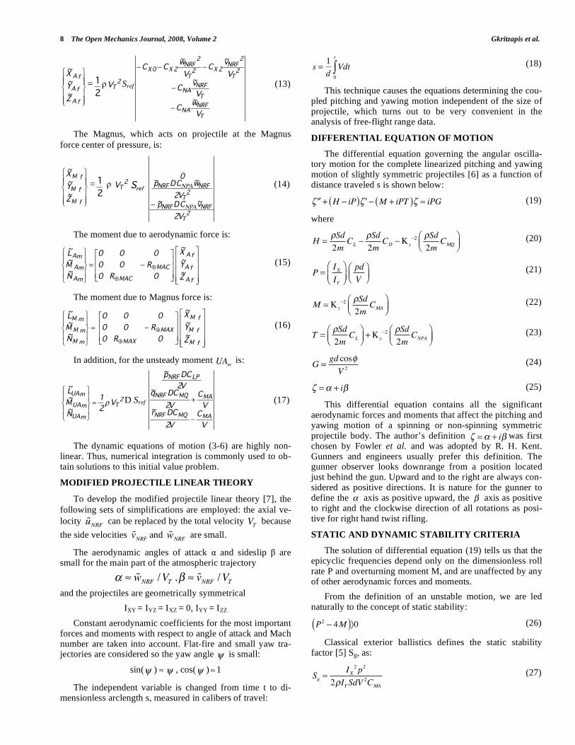
The flight path trajectories motion with constant aerody-namic coefficients of the 105 mm projectile with initial fir-ing velocity of 494 m/sec, initial yaw angle 3 deg and rifling twist rate 1 turn in 18 calibers (1/18) at 45
o and 70
o are illus-
trated in (Fig. 2).
Fig. (2). Impact points and flight path trajectories of 6-DOF and
Modified Linear with constant aerodynamic coefficients for 105
mm projectile.
At 45° the 6-DOF model for 105 mm M1 projectile, fired at sea-level neglecting wind conditions, gives a predicted range to impact of approximately 11,600 m and a maximum height at almost 3,600 m. From the results of the modified linear model, the maximum range and the maximum height are almost the same, as shown in (Fig. 2). Also at 70°, the predicted level-ground range of 6-DOF model is 7,500 m with maximum height at about 6,450 m and the modified linear trajectory simulation gives the same values.
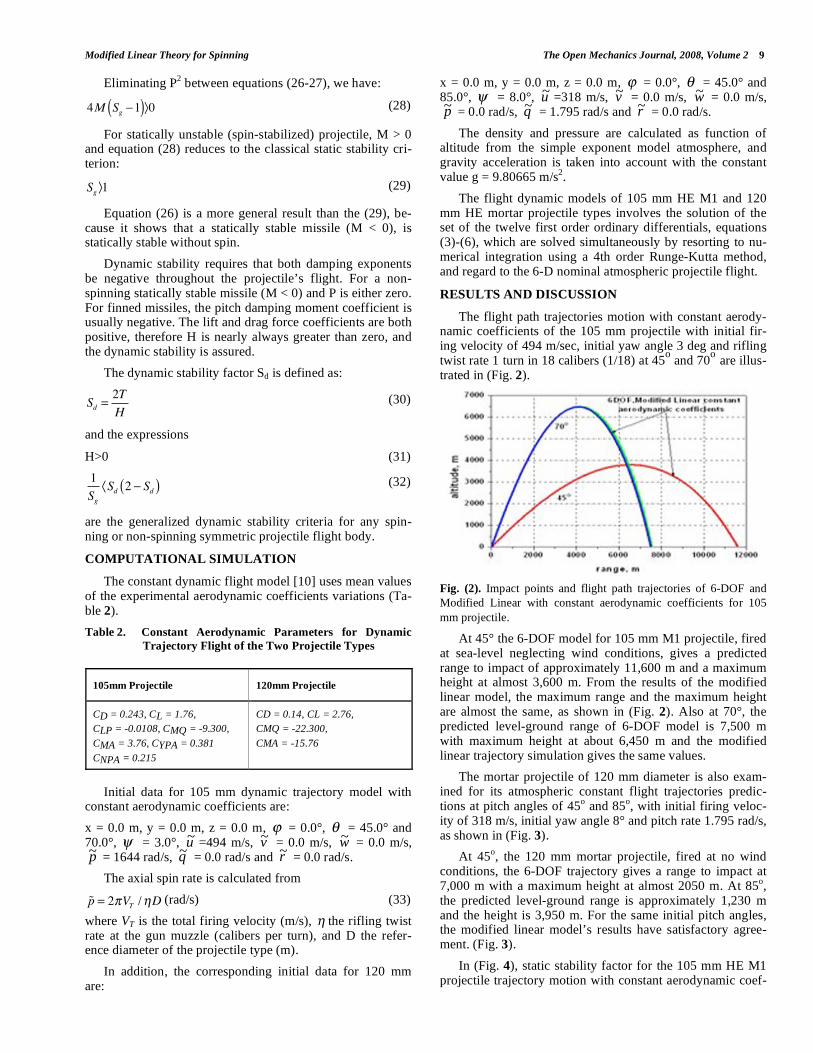
The mortar projectile of 120 mm diameter is also exam-ined for its atmospheric constant flight trajectories predic-tions at pitch angles of 45
o and 85
o, with initial firing veloc-
ity of 318 m/s, initial yaw angle 8° and pitch rate 1.795 rad/s, as shown in (Fig. 3).
At 45o, the 120 mm mortar projectile, fired at no wind
conditions, the 6-DOF trajectory gives a range to impact at 7,000 m with a maximum height at almost 2050 m. At 85
o,
the predicted level-ground range is approximately 1,230 m and the height is 3,950 m. For the same initial pitch angles, the modified linear model’s results have satisfactory agree-ment. (Fig. 3).
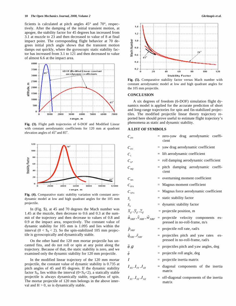
In (Fig. 4), static stability factor for the 105 mm HE M1 projectile trajectory motion with constant aerodynamic coef-
10 The Open Mechanics Journal, 2008, Volume 2 Gkritzapis et al.
ficients is calculated at pitch angles 45° and 70°, respec-tively. After the damping of the initial transient motion, at apogee, the stability factor for 45 degrees has increased from 3.1 at muzzle to 23 and then decreased to value of 8 at final impact point. The corresponding flight behavior at 70 de-grees initial pitch angle shows that the transient motion damps out quickly, where the gyroscopic static stability fac-tor has increased from 3.1 to 121 and then decreased to value of almost 6.6 at the impact area.
Fig. (3). Flight path trajectories of 6-DOF and Modified Linear
with constant aerodynamic coefficients for 120 mm at quadrant
elevation angles of 45o
and 85o.
Fig. (4). Comparative static stability variation with constant aero-
dynamic model at low and high quadrant angles for the 105 mm
projectile.
In (Fig. 5), at 45 and 70 degrees the Mach number was 1.45 at the muzzle, then decrease to 0.6 and 0.3 at the sum-mit of the trajectory and then decrease to values of 0.8 and 0.9 at the impact area, respectively. The constant value of dynamic stability for 105 mm is 1.095 and lies within the interval (0 < Sd < 2). So the spin-stabilized 105 mm projec-tile is gyroscopically and dynamically stable.
On the other hand the 120 mm mortar projectile has un-canted fins, and do not roll or spin at any point along the trajectory. Because of that, the static stability is zero, and we examined only the dynamic stability for 120 mm projectile.
In the modified linear trajectory of the 120 mm mortar projectile, the constant value of dynamic stability is 0.735 at pitch angles of 45 and 85 degrees. If the dynamic stability factor Sd, lies within the interval (0<Sd<2), a statically stable projectile is always dynamically stable, regardless of spin. The mortar projectile of 120 mm belongs in the above inter-val and H > 0, so is dynamically stable.
Fig. (5). Comparative stability factor versus Mach number with
constant aerodynamic model at low and high quadrant angles for
the 105 mm projectile.
CONCLUSION
A six degrees of freedom (6-DOF) simulation flight dy-namics model is applied for the accurate prediction of short and long-range trajectories for spin and fin-stabilized projec-tiles. The modified projectile linear theory trajectory re-ported here should prove useful to estimate flight trajectory’s phenomena as static and dynamic stability.
A LIST OF SYMBOLS
CD0 = zero-yaw drag aerodynamic coeffi-
cient
CD2 = yaw drag aerodynamic coefficient
CL = lift aerodynamic coefficient
CLP = roll damping aerodynamic coefficient
CMQ = pitch damping aerodynamic coeffi-
cient
CMA = overturning moment coefficient
CYPA = Magnus moment coefficient
CNPA = Magnus force aerodynamic coefficient
Sg = static stability factor
Sd = dynamic stability factor
xif , yif , zif = projectile position, m
uNRF ,vNRF ,wNRF = projectile velocity components ex-
pressed in no-roll-frame, m/s
pNRF = projectile roll rate, rad/s
qNRF ,rNRF = projectiles pitch and yaw rates ex-
pressed in no-roll-frame, rad/s
, = projectiles pitch and yaw angles, deg
= projectile roll angle, deg
I = projectile inertia matrix
IXX , IYY , IZZ = diagonal components of the inertia
matrix
IXY , IYZ , IXZ = off-diagonal components of the inertia
matrix
Modified Linear Theory for Spinning The Open Mechanics Journal, 2008, Volume 2 11
VT = total aerodynamic velocity, m/s
= atmospheric density, kg/m3
D = projectile reference diameter, m
Sref = projectile reference area ( D2/4), m
2
m = mass of projectile, kg
t = time, s
, = aerodynamic angles of attack and
sideslip, deg
R MAC = distance from the projectile center of
mass to the center of pressure, m
R MAX = distance from the projectile center of
mass to the Magnus center of pres-
sure, m
g = gravity acceleration, m/s2
REFERENCES
[1] Fowler R, Gallop E, Lock C, Richmond H. The Aerodynamics of
Spinning Shell. London; 1920. [2] Kent R. An Elementary Treatment of the Motion of a Spinning
Projectile About its center of Gravity. USA; 1937. [3] Nielson K, Synge J. On the Motion of Spinning Shell. USA; 1943.
[4] Kelley J, McShane E. On the Motion of a Projectile with Small or Slowly Changing Yaw. USA; 1944.
[5] Kelley J, McShane E, Reno F. Exterior Ballistics. Denver; 1953. [6] McCoy R. Modern Exterior Ballistics. Attlen, PA; 1995.
[7] Hainy L, Costello M. Modified Projectile Linear Theory for Rapid Trajectory Prediction. Journal of Guidance, Control, and Dynam-
ics, 2005; Vol.28: No. 5. [8] Etkin B. Dynamics of Atmospheric Flight, New York; 1972.
[9] Costello M, Anderson D. Effect of Internal Mass Unbalance on the Terminal Accuracy and Stability of a projectile. AIAA Paper;
1996. [10] Gkritzapis DN, Panagiotopoulos EE, the 2nd International Confer-
ence on Experiments / Process / System Modelling / Simulation / Optimization, 2nd IC-EpsMsO. Atmospheric Flight Dynamic
Simulation Modelling of Spin-Stabilized Projectiles; July 2007; Athens, Greece; 2007.
Received: December 06, 2007 Revised: December 31, 2007 Accepted: January 02, 2008
© Gkritzapis et al.; Licensee Bentham Open.
This is an open access article licensed under the terms of the Creative Commons Attribution Non-Commercial License
(http://creativecommons.org/licenses/by-nc/3.0/) which permits unrestricted, non-commercial use, distribution and reproduction in any medium, provided the
work is properly cited.
Related Documents