© May 2014 by Rotary Lift. All rights reserved. CO9020 OM20196 REV. B 5/5/2014 TABLE OF CONTENTS: OWNER/EMPLOYER RESPONSIBILITIES........................................2 SAFETY INSTRUCTIONS ..................................................................3 OPERATING INSTRUCTIONS............................................................4 MAINTENANCE INSTRUCTIONS ......................................................5 TROUBLE SHOOTING .......................................................................6 LIFT LOCKOUT/TAGOUT PRODEDURE...........................................8 OPERATING CONDITIONS ................................................................9 APPROVED ACCESSORIES..............................................................9 O P E R A T I O N & M A I N T E N A N C E M A N U A L O P E R A T I O N & M A I N T E N A N C E M A N U A L SM30/RFL25 SM30 Capacity 30,000 lbs. (15,000 lbs. per axle) 140” Minimum Wheelbase RFL25 Capacity 25,000 lbs. (12,500 lbs. per axle) LP20460

Welcome message from author
This document is posted to help you gain knowledge. Please leave a comment to let me know what you think about it! Share it to your friends and learn new things together.
Transcript

© May 2014 by Rotary Lift. All rights reserved. CO9020 OM20196REV. B 5/5/2014
TABLE OF CONTENTS:
OWNER/EMPLOYER RESPONSIBILITIES ........................................2SAFETY INSTRUCTIONS ..................................................................3OPERATING INSTRUCTIONS ............................................................4MAINTENANCE INSTRUCTIONS ......................................................5TROUBLE SHOOTING .......................................................................6LIFT LOCKOUT/TAGOUT PRODEDURE ...........................................8OPERATING CONDITIONS ................................................................9APPROVED ACCESSORIES ..............................................................9
OPERATION
&
MAINTENANCE
MANUAL
OPERATION
&
MAINTENANCE
MANUAL
SM30/RFL25 SM30 Capacity 30,000 lbs. (15,000 lbs. per axle) 140” Minimum Wheelbase
RFL25 Capacity 25,000 lbs. (12,500 lbs. per axle)
LP20460
2
Owner/Employer Responsibilities
The Owner/Employer:
• Shallensurethatliftoperatorsarequalifiedandthattheyaretrainedinthesafeuseandoperation of the lift using the manufacturer’s operating instructions; ALI/SM01-1, ALI Lifting it Right safety manual; ALI/ST-90 ALI Safety Tipscard;ANSI/ALIALOIM-2000, American National Standard for Automotive Lifts-Safety Requirements for Operation, Inspection and Maintenance; ALI/WL Series, ALI Uniform Warning Label Decals/Placards;andinthecaseofframeengaginglifts,ALI/LP-GUIDE,Vehicle Lift-ing Points/Quick Reference Guide for Frame Engaging Lifts.
• Shallestablishprocedurestoperiodicallyinspecttheliftinaccordancewiththeliftmanufacturer’sinstructionsorANSI/ALIALOIM-2000,American National Standard for Automotive Lifts-Safety Requirements for Operation, Inspection and Maintenance; andTheEmployerShallensurethatliftinspectorsarequalifiedandthattheyaread-equatelytrainedintheinspectionofthelift.
• Shallestablishprocedurestoperiodicallymaintaintheliftinaccordancewiththeliftmanufacturer’sinstructionsorANSI/ALIALOIM-2000,American National Standard for Automotive Lifts-Safety Requirements for Operation, Inspection and Maintenance; andTheEmployerShallensurethatliftmaintenancepersonnelarequalifiedandthattheyareadequatelytrainedinthemaintenanceofthelift.
• ShallmaintaintheperiodicinspectionandmaintenancerecordsrecommendedbythemanufacturerorANSI/ALIALOIM-2000,American National Standard for Automo-tive Lifts-Safety Requirements for Operation, Inspection and Maintenance.
• Shalldisplaytheliftmanufacturer’soperatinginstructions;ALI/SM93-1,ALI Lifting it Right safety manual; ALI/ST-90 ALI Safety Tipscard;ANSI/ALIALOIM-2000,American National Standard for Automotive Lifts-Safety Requirements for Operation, Inspection and Maintenance;andinthecaseofframeengaginglifts,ALI/LP-GUIDE,Vehicle Lifting Points/Quick Reference Guide for Frame Engaging Lifts; in a conspicu-ous location in the lift area convenient to the operator.
• Shallprovidenecessarylockout/tagoutmeansforenergysourcesperANSIZ244.1-1982 (R1993), Safety Requirements for the Lockout/Tagout of Energy Sources, before beginning any lift repairs.
• Shallnotmodifytheliftinanymannerwithoutthepriorwrittenconsentofthemanu-facturer.
3
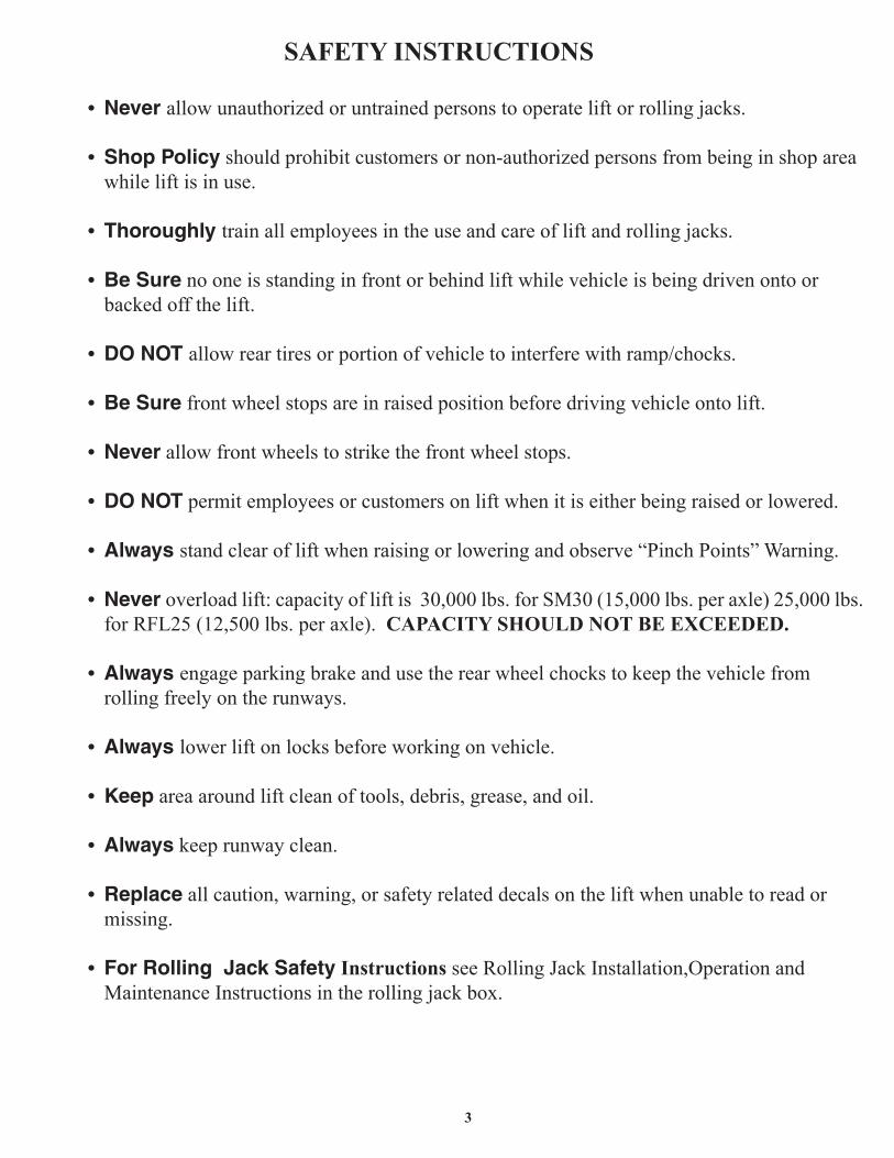
• Never allowunauthorizedoruntrainedpersonstooperateliftorrollingjacks.
• Shop Policy shouldprohibitcustomersornon-authorizedpersonsfrombeinginshopareawhileliftisinuse.
• Thoroughly trainallemployeesintheuseandcareofliftandrollingjacks.
• Be Surenooneisstandinginfrontorbehindliftwhilevehicleisbeingdrivenontoorbackedoffthelift.
• DO NOT allowreartiresorportionofvehicletointerferewithramp/chocks.
• Be Surefrontwheelstopsareinraisedpositionbeforedrivingvehicleontolift.
• Neverallowfrontwheelstostrikethefrontwheelstops.
• DO NOTpermitemployeesorcustomersonliftwhenitiseitherbeingraisedorlowered.
• Always standclearofliftwhenraisingorloweringandobserve“PinchPoints”Warning.
• Never overloadlift:capacityofliftis30,000lbs.forSM30(15,000lbs.peraxle)25,000lbs. for RFL25 (12,500 lbs. per axle). CAPACITY SHOULD NOT BE EXCEEDED.
• Always engageparkingbrakeandusetherearwheelchockstokeepthevehiclefromrollingfreelyontherunways.
• Always lowerliftonlocksbeforeworkingonvehicle.
• Keepareaaroundliftcleanoftools,debris,grease,andoil.
• Alwayskeeprunwayclean.
• Replaceallcaution,warning,orsafetyrelateddecalsontheliftwhenunabletoreadormissing.
• For Rolling Jack Safety Instructions seeRollingJackInstallation,OperationandMaintenanceInstructionsintherollingjackbox.
SAFETY INSTRUCTIONS

4
SAFETY WARNING LABELS for Four-Post Surface Mounted Roll-on Lifts
Fig. 1
A.Thefollowingpictographlabelsarelocated,asshown,ontheliftpowerunitcolumn.B.ObserveandheedSafetyandWarninglabelsonthe lift.
WARNING
Clear area if vehicle is in danger of falling.
©
Keep feet clear of lift while lowering.
©
WARNINGWARNING
Keep clear of pinch points when lift is moving.
©
WARNING
Chock wheel to prevent vehicle movement.
©
WARNING
Do not overideself-closinglift controls.
©
The messages and pictographs shown are generic in nature and are meant togenerally represent hazards common to all automotive lifts regardless of specificstyle.
Funding for the development and validation of these labels was provided by theAutomotive Lift Institute, PO Box 1519 New York, NY. 10101-1519.
They are protected by copyright. Set of labels may be obtained from ALI or itsmember companies.
© 1992 by ALI, Inc. ALI/WL200w
CAUTION
Authorized personnel only in lift area.
©
The messages and pictographs shown are generic in nature and are meant togenerally represent hazards common to all automotive lifts regardless of specificstyle.
Funding for the development and validation of these labels was provided by theAutomotive Lift Institute, PO Box 1519 New York, NY. 10101-1519.
They are protected by copyright. Set of labels may be obtained from ALI or itsmember companies.
© 1992 by ALI, Inc. ALI/WL200c
CAUTION
Lift to be used by trained operatorONLY.
©
? ??
Proper maintenanceand inspection is necessary for safe operation. ©
SAFETYINSTRUCTIONS
Read operatingand safety manualsbefore using lift.
©
SAFETYINSTRUCTIONS
Do not operatea damaged lift.
©
SAFETYINSTRUCTIONS
© 1992 by ALI, Inc. ALI/WL200s
The messages and pictographs shownare generic in nature and are meant togenerally represent hazards commonto all automotive lifts regardless ofspecific style.
Funding for the development andvalidation of these labels was providedby the Automotive Lift Institute, POBox 1519 New York, NY. 10101-1519.
They are protected by copyright. Setof labels may be obtained from ALI orits member companies.
WARNING
Remain clear of liftwhen raising or lowering vehicle.
©
5
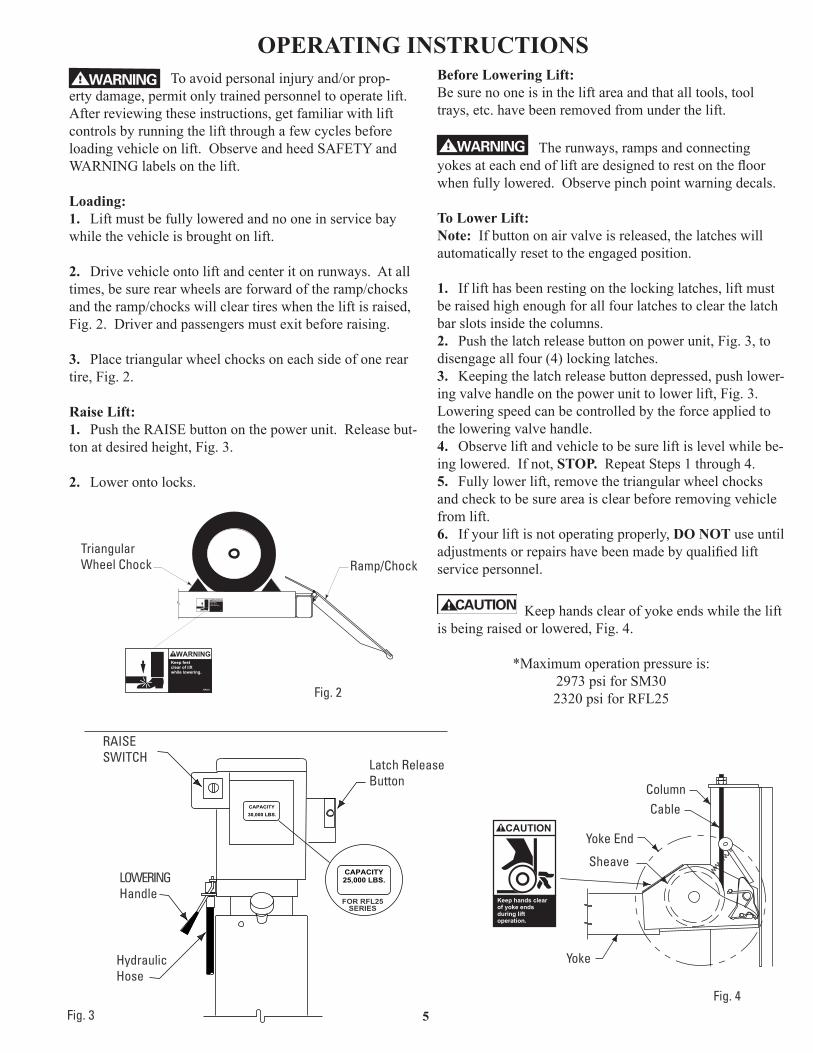
WARNING Toavoidpersonalinjuryand/orprop-ertydamage,permitonlytrainedpersonneltooperatelift.Afterreviewingtheseinstructions,getfamiliarwithliftcontrolsbyrunningtheliftthroughafewcyclesbeforeloadingvehicleonlift.ObserveandheedSAFETYandWARNINGlabelsonthelift.
Loading: 1. Liftmustbefullyloweredandnooneinservicebaywhilethevehicleisbroughtonlift.
2. Drivevehicleontoliftandcenteritonrunways.Atalltimes,besurerearwheelsareforwardoftheramp/chocksandtheramp/chockswillcleartireswhentheliftisraised,Fig.2.Driverandpassengersmustexitbeforeraising.
3. Placetriangularwheelchocksoneachsideofonereartire, Fig. 2.
Raise Lift: 1. PushtheRAISEbuttononthepowerunit.Releasebut-tonatdesiredheight,Fig.3.
2. Lowerontolocks.
Before Lowering Lift: Besurenooneisintheliftareaandthatalltools,tooltrays,etc.havebeenremovedfromunderthelift.
WARNING Therunways,rampsandconnectingyokesateachendofliftaredesignedtorestonthefloorwhenfullylowered.Observepinchpointwarningdecals.
To Lower Lift: Note:Ifbuttononairvalveisreleased,thelatcheswillautomaticallyresettotheengagedposition.
1. Iflifthasbeenrestingonthelockinglatches,liftmustberaisedhighenoughforallfourlatchestoclearthelatchbarslotsinsidethecolumns.2. Pushthelatchreleasebuttononpowerunit,Fig.3,todisengageallfour(4)lockinglatches.3. Keepingthelatchreleasebuttondepressed,pushlower-ingvalvehandleonthepowerunittolowerlift,Fig.3.Loweringspeedcanbecontrolledbytheforceappliedtotheloweringvalvehandle.4. Observeliftandvehicletobesureliftislevelwhilebe-inglowered.Ifnot,STOP. Repeat Steps 1 through 4.5. Fullylowerlift,removethetriangularwheelchocksandchecktobesureareaisclearbeforeremovingvehiclefrom lift.6. If your lift is not operating properly, DO NOT use until adjustmentsorrepairshavebeenmadebyqualifiedliftservice personnel.
CAUTIONKeephandsclearofyokeendswhiletheliftisbeingraisedorlowered,Fig.4.
*Maximumoperationpressureis:2973 psi for SM302320 psi for RFL25
OPERATING INSTRUCTIONS
CAPACITY30,000 LBS.
CAPACITY25,000 LBS.
FOR RFL25SERIES
CAUTION
Keep hands clear of yoke ends during lift operation.
Fig. 3
Yoke
Fig. 4
Keep feet clear of lift while lowering.
NP253
WARNING
Keep feet clear of lift while lowering.
NP253
WARNING
Ramp/ChockTriangularWheel Chock
Fig. 2
ColumnCable
Yoke End
Sheave
Latch ReleaseButton
LOWERINGHandle
HydraulicHose
RAISESWITCH
6
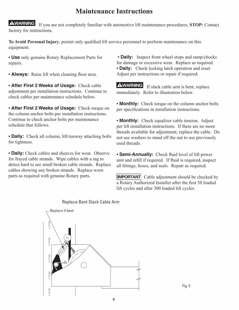
Maintenance InstructionsWARNING Ifyouarenotcompletelyfamiliarwithautomotiveliftmaintenanceprocedures,STOP: Contact
factory for instructions.
To Avoid Personal Injury,permitonlyqualifiedliftservicepersonneltoperformmaintenanceonthisequipment. • UseonlygenuineRotaryReplacementPartsforrepairs.
• Always: Raiseliftwhencleaningfloorarea.
• After First 2 Weeks of Usage: Checkcableadjustmentperinstallationinstructions.Continuetocheckcablespermaintenanceschedulebelow.
• After First 2 Weeks of Usage: Checktorqueonthe column anchor bolts per installation instructions. Continuetocheckanchorboltspermaintenanceschedulethatfollows. • Daily: Checkallcolumn,lift/runwayattachingboltsfor tightness.
• Daily:Checkcablesandsheavesforwear.Observeforfrayedcablestrands.Wipecableswitharagtodetecthardtoseesmallbrokencablestrands.Replacecablesshowinganybrokenstrands.ReplacewornpartsasrequiredwithgenuineRotaryparts.
• Daily:Inspectfrontwheelstopsandramp/chocksfordamageorexcessivewear.Replaceasrequired.• Daily:Checklockinglatchoperationandreset.Adjustperinstructionsorrepairifrequired.
WARNING Ifslackcablearmisbent,replaceimmediately.Refertoillustrationbelow.
• Monthly:Checktorqueonthecolumnanchorboltsperspecificationsininstallationinstructions.
• Monthly: Checkequalizercabletension.Adjustper lift installation instructions. If there are no more threadsavailableforadjustment,replacethecable.Donotusewasherstostandoffthenuttousepreviouslyusedthreads.
• Semi-Annually:Checkfluidlevelofliftpowerunitandrefillifrequired.Iffluidisrequired,inspectallfittings,hoses,andseals.Repairasrequired.
IMPORTANT CableadjustmentshouldbecheckedbyaRotaryAuthorizedInstallerafterthefirst50loadedliftcyclesandafter300loadedliftcycles.
Replace if bent
Fig. 5
Replace Bent Slack Cable Arm

7
Remedy
1. Replaceblownfuseorresetcircuitbreaker.
2. Supply correct voltage to motor.3.Repairandinsulateallconnections.4. Replaceswitch.5. Replace motor.
1. Repairorreplaceloweringvalve.2. Tightenallsuctionlinefittings.3. Replace suction stub.4. FilltankwithDexronIIIATF.
1. Supply correct voltage to motor.2. Cleanloweringvalve.3. Replacereliefvalvecartridge.4. Checkvehicleweightand/orbalance
vehicleweightonlifts.
1. Cleancheckvalve.2. Cleanloweringvalve.3. Repairexternalleaks.
1. ChangefluidtoDexronIIIATF.2. Tightenallsuctionlinefittings.3. Reinstallfluidreturntube.
1. Adjustslackoutofcable.2. Shimlifttolevelcolumns(Notto
exceed2”).
Note:Maximumshimthicknessof2”ispossiblebyusingshimkit.ContactyourProductServiceConsultantforordering
information.
1. Checkfluidlevelandbleedcylinder.Iffluidisrequiredinspectallfittings,hoses,andseals.Repairasrequired.
1. Useafastsettingcementtopourintooversizeholesandresetanchorsorrelocateliftusinganewbittodrillholes.
2. Breakoutoldconcreteandrepournewpadsforliftperinstallationinstructions.
1. Checkairpressure.Airsupplytoliftshouldbebetween:Min.100p.s.i.andMax.120p.s.i.Checkalllinesandfittingsforleaksorcrimps.Repairorreplaceasrequired.
2. Checklatchesperinstallationinstructions.
Cause
1. Checkfuseorcircuitbreaker.
2. Checkforcorrectvoltagetomotor.3. Inspectallwiringconnections.4. Switchburnedout.5. Motorwindingsburnedout.
1. Openloweringvalve.2. Pumpsuckingair.3. Suction stub off pump.4. Lowfluidlevel.
1. Motorrunningonlowvoltage.2. Trashinloweringvalve.3. Improperreliefvalveadjustment.4. Overloadinglift.
1. Trashincheckvalveseat.2. Trashinloweringvalveseat.3. Externalfluidleaks.
1. Airmixedwithfluid.2. Airmixedwithfluidsuction.3. Fluidreturntubeloose. 1. Cablesoutofadjustment.2. Liftinstalledonunlevelfloor.
1. Lowonfluid.
1. Holesdrilledoversize.
2. Concretefloorthicknessorholdingstrengthnotsufficient.
1. Insufficientairsupplytolift.
2. Latchesoutofadjustment.
Trouble
Motordoesnotrun.
Motorrunsbutwillnotraiselift.
Motorruns—raisesunloadedliftbutwillnot raise vehicle.
Liftslowlysettlesdown.
Slowliftingspeedorfluidblowingoutfillerbreathercap.
Lift going up unlevel.
Lift stops short of full rise or chatters.
Anchorswillnotstaytight.
Liftwillnotlower.
Trouble Shooting

8
Remedy
1. Contact lift manufacturer’s Customer Service.
Cause
1. Motor,pump,orcylinderfailure.
Trouble
Liftwillnotraiseoffoflatches.
Trouble Shooting
9
Purpose
This procedure establishes the minimum requirements for the lockout of energy that could cause injury to personnel by the operation of lifts in need of repair or being serviced. All employees shall comply with this procedure.
Responsibility
The responsibility for assuring that this procedure is followed is binding upon all employees and service personnel from outside service companies (i.e., Authorized Rotary Installers, contactors, etc.). All employees shall be instructed in the safety significance of the lockout procedure by the facility owner/manager. Each new or transferred employee along with visiting outside service personnel shall be instructed by the owner/manager (or assigned designee) in the purpose and use of the lockout procedure.
Preparation
Employees authorized to perform lockout shall ensure that the appropriate energy isolating device (i.e., circuit breaker, fuse, disconnect, etc.) is identified for the lift being locked out. Other such devices for other equipment may be located in close proximity of the appropriate energy isolating device. If the identity of the device is in question, see the shop supervisor for resolution. Assure that proper authorization is received prior to performing the lockout procedure.
Sequence of Lockout Procedure
1) Notify all affected employees that a lockout is being performed and the reason for it.2) Unload the subject lift. Shut it down and assure the disconnect switch is “OFF” if one is
provided on the lift.3) The authorized lockout person operates the main energy isolation device removing
power to the subject lift.• If this is a lockable device, the authorized lockout person places the assigned
padlock on the device to prevent its unintentional reactivation. An appropriate tag is applied stating the person’s name, at least 3” x 6” in size, an easily noticeably color, and states not to operate device or remove tag.
• If this device is a non-lockable circuit breaker or fuse, replace with a “dummy” device and tag it appropriately as mentioned above.
4) Attempt to operate lift to assure the lockout is working. Be sure to return any switches to the “OFF” position.
5) The equipment is now locked out and ready for the required maintenance or service.
Restoring Equipment to Service
1) Assure the work on the lift is complete and the area is clear of tools, vehicles, and personnel.
2) At this point, the authorized person can remove the lock (or dummy circuit breaker or fuse) & tag and activate the energy isolating device so that the lift may again be placed into operation.
Rules for Using Lockout Procedure
Use the Lockout Procedure whenever the lift is being repaired or serviced, waiting for repair when current operation could cause possible injury to personnel, or for any other situation when unintentional operation could injure personnel. No attempt shall be made to operate the lift when the energy isolating device is locked out.
Lift Lockout/Tagout Procedure

10
Lift is not intended for outdoor use and has an operating ambient temperature range of 41º-104ºF (5º-40ºC).
Operating Conditions
APPROVED ACCESSORIESItem Capacity Part Number
Air/Electric Utility Box FA915
Air/Electric Utility Box Without FRL FA916
Rolling Jack 15,000 lbs. RJ15000

11
Notes
Trained Operators and Regular Maintenance Ensures Satisfactory Performance of Your Rotary Lift.
Replacement Parts: See installers package for parts breakdown sheet. Order Genuine Rotary replacement parts from your near-
est Authorized Parts Distributor.
Maintenance Assistance: Contact your local Rotary distributor.
Should further assistance be required, contact Rotary Lift, at one of the phone numbers listed below.
Certi�cate of ComplianceRotary Lift is authorized to apply ETL & cETL Listing Marks/Labels to this AC Motor. Authorization: ETL Report No. J98007541-003, FAM. This ETL test certi�es that this AC Motor complies with Underwriters Laboratories, Inc. standard ANSI/UL 201 & CSA standard C22.2 No. 68.
SV0021 B Rev. 5/2/14
© Rotary®, Printed in U.S.A., All RightsReserved. Unless otherwise indicated, ROTARY, DOVER and all other trademarks are property of Dover Corporation and its affiliates.
Rotary World Headquarters2700 Lanier DriveMadison, IN 47250, USAwww.rotarylift.com
North America Contact Information Tech. Support: p 800.445.5438 f 800.578.5438 e [email protected] Sales: p 800.640.5438 f 800.578.5438 e [email protected]
World Wide Contact InformationWorld Headquarters/USA: 1.812.273.1622Canada: 1.905.812.9920European Headquarters/Germany: +49.771.9233.0United Kingdom: +44.178.747.7711Australasia: +60.3.7660.0285Latin America / Caribbean: +54.3488.431.608Middle East / Northern Africa: +49.771.9233.0
Related Documents