Preface, Contents Part I Introduction 1 2 Part II Functions 3 11 Part III Installation and Commissioning 12 15 Part IV Equipment Description and Maintenance 16 19 Part V Appendices A F Glossary, Index Release 05/99 OP27, OP37 Operator Panels Equipment Manual SIMATIC HMI 6AV3991–1AK01–0AB0

Welcome message from author
This document is posted to help you gain knowledge. Please leave a comment to let me know what you think about it! Share it to your friends and learn new things together.
Transcript
Preface, Contents
Part I Introduction
1
2
Part II Functions
3
11
Part III Installation andCommissioning
12
15
Part IV Equipment Descriptionand Maintenance
16
19
Part V Appendices
A
F
Glossary, Index
Release 05/99
OP27, OP37Operator Panels
Equipment Manual
SIMATIC HMI
6AV3991–1AK01–0AB0
This manual contains notices which you should observe to ensure your own personal safety, aswell as to protect the product and connected equipment. These notices are highlighted in themanual by a warning triangle and are marked as follows according to the level of danger:
!Warning
indicates that death, severe personal injury or substantial property damage can result if properprecautions are not taken.
!Caution
indicates that minor personal injury or property damage can result if proper precautions are nottaken.
Note
draws your attention to particularly important information on the product, handling the product,or to a particular part of the documentation.
Equipment may be commissioned and operated only by qualified personnel. Qualified person-nel within the meaning of the safety notices in this manual are persons who are authorized tocommission, ground and identify equipment, systems and circuits in accordance with safetyengineering standards.
Note the following:
!Warning
The equipment may be used only for the applications stipulated in the catalog and in the tech-nical description and only in conjunction with other equipment and components recommendedor approved by Siemens.
Startup must not take place until it is established that the machine, which is to accommodatethis component, is in conformity with the guideline 89/392/EEC.
Faultless and safe operation of the product presupposes proper transportation, proper storage,erection and installation as well as careful operation and maintenance.
The approvals that apply to the device are detailed in the Chapter Technical Data.
SIMATIC�, ProTool/Lite�, ProTool� and ProTool/Pro� are registered trademarks ofSiemens AG.
Some of the other designations used in these documents are also registered trademarks; theowner’s rights may be violated if they are used be third parties for their own purposes.
Editor and Publisher: A&D PT1
We have checked the contents of this manual for agreement withthe hardware and software described. Since deviations cannot beprecluded entirely, we cannot guarantee full agreement. However,the data in this manual are reviewed regularly and any necessarycorrections included in subsequent editions. Suggestions forimprovement are welcomed.
Technical data subject to change.� Siemens AG 1999
Disclaimer of LiabilityCopyright � Siemens AG 1999 All rights reserved
The reproduction, transmission or use of this document or itscontents is not permitted without express written authority.Offenders will be liable for damages. All rights, including rightscreated by patent grant or registration of a utility model or design,are reserved.
Siemens AG,Bereich Automation & DrivesSIMATIC Human Machine InterfaceA&D PT1Postfach 4848, D-90327 Nuernberg
Siemens Aktiengesellschaft Order No. 6AV3991–1AK01–0AB0
Safety Guidelines
Qualified Personnel
Correct Usage
Approvals
Trademarks
Impressum

iOP27, OP37 Equipment ManualRelease 05/99
Preface
This equipment manual provides operation, installation, configuration and sys-tem personnel with information concerning functionality, operation and techni-cal design of the Operator Panels OP27 and OP37.
The ”OP27 , OP37 Operator Panel” equipment manual is organized into thefollowing chapters:
Part Chapters Contents
I 1 - 2 Overview of features and functional scope of theOP in tabular form.
II 3 - 11 Step-by–step instructions on how to operate the OPusing the standard screens.
III 12 - 15 – Mechanical and electrical installation,
– Commissioning
– OP37 in DOS Mode
IV 16 - 19 Detailed information on the OP and itsmaintenance.
V AppendixA – F
– Technical data,
– Interface assignments,
– Hardware test,
– System messages,
– SIMATIC HMI documentation,
– ESD guidelines,
– Glossary of terms
The following conventions are used throughout this manual:
Motor off Text which appears in the OP display is presented inthis typewriter font.
Variable Symbolic names representing variable values on thescreen are presented in this italic typewriter font
Screens Functions selected by the user are presented in thisstandard italic font.
ESC The labels of buttons are presented in a differentfont.
Purpose
Organization of themanual
Conventions
iiOP27, OP37 Equipment Manual
Release 05/99
The various releases of the equipment manual correspond to the followingfirmware and versions:
Release Remarks ProTool VersionRelease Remarks ProTool Version
09/96 First release of the OP37 equipmentmanual
V 2.5 and later
11/97 Inclusion of the OP27 and revisionaccording to the new documentationconcept
V 4.0 and later
05/99 New standard screen for printingmessages; troubleshooting
V 5.0 and later
History
Preface
iiiOP27, OP37 Equipment ManualRelease 05/99
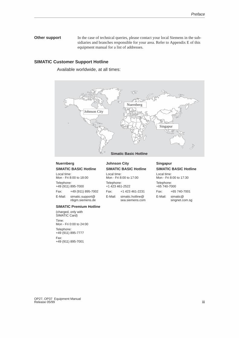
In the case of technical queries, please contact your local Siemens in the sub-sidiaries and branches responsible for your area. Refer to Appendix E of thisequipment manual for a list of addresses.
SIMATIC Customer Support Hotline
Available worldwide, at all times:
Johnson City
Nuernberg
Singapur
Simatic Basic Hotline
Nuernberg
SIMATIC BASIC Hotline
Johnson City
SIMATIC BASIC Hotline
Singapur
SIMATIC BASIC HotlineLocal time: Mon - Fri 8:00 to 18:00
Telephone: +49 (911) 895-7000
Fax: +49 (911) 895-7002
E-Mail: [email protected]
Local time: Mon - Fri 8:00 to 17:00
Telephone: +1 423 461-2522
Fax: +1 423 461-2231
E-Mail: [email protected]
Local time: Mon - Fri 8:00 to 17:30
Telephone: +65 740-7000
Fax: +65 740-7001
E-Mail: [email protected]
SIMATIC Premium Hotline(charged, only with SIMATIC Card)
Time: Mon - Fri 0:00 to 24:00
Telephone: +49 (911) 895-7777
Fax: +49 (911) 895-7001
Other support
Preface
ivOP27, OP37 Equipment Manual
Release 05/99
SIMATIC Customer Online Services
SIMATIC Customer Support offers comprehensive additional informationconcerning SIMATIC products through its Online services as follows:
� Up–to–date general information is provided
– in Internet under http://www.ad.siemens.de/simatic
– via Fax-Polling under 08765-93 02 77 95 00
� Up–to–date product information and downloads for practical use can be found:
– in Internet unter http://www.ad.siemens.de/support/html–00/
– via the Bulletin Board System (BBS) in Nürnberg (SIMATIC CustomerSupport Mailbox) under +49 (911) 895–7100
In order to contact the mailbox, please use a modem with up to28.8kBaud (V.34) capacity. Set the parameters as follows: 8, N, 1,ANSI, or dial for connection via ISDN (x.75, 64 kBit).
Preface
vOP27, OP37 Equipment ManualRelease 05/99
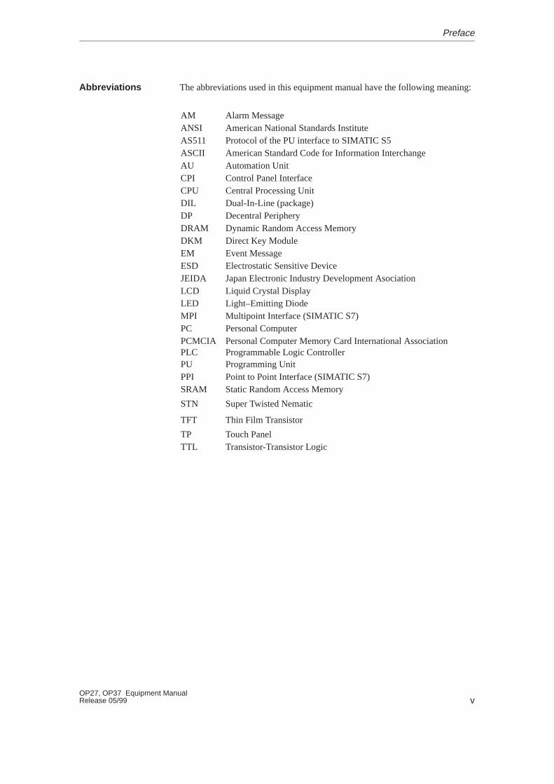
The abbreviations used in this equipment manual have the following meaning:
AM Alarm MessageANSI American National Standards InstituteAS511 Protocol of the PU interface to SIMATIC S5ASCII American Standard Code for Information InterchangeAU Automation UnitCPI Control Panel InterfaceCPU Central Processing UnitDIL Dual-In-Line (package)DP Decentral PeripheryDRAM Dynamic Random Access MemoryDKM Direct Key ModuleEM Event MessageESD Electrostatic Sensitive DeviceJEIDA Japan Electronic Industry Development AsociationLCD Liquid Crystal DisplayLED Light–Emitting DiodeMPI Multipoint Interface (SIMATIC S7)PC Personal ComputerPCMCIAPLC
Personal Computer Memory Card International AssociationProgrammable Logic Controller
PU Programming UnitPPI Point to Point Interface (SIMATIC S7)SRAM Static Random Access Memory
STN Super Twisted Nematic
TFT Thin Film Transistor
TP Touch PanelTTL Transistor-Transistor Logic
Abbreviations
Preface

viOP27, OP37 Equipment Manual
Release 05/99
Preface
iOP27, OP37 Equipment ManualRelease 05/99
Contents
Part I: Introduction
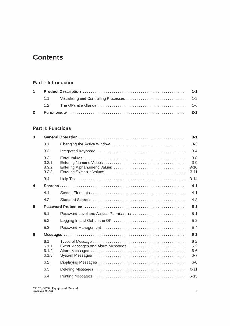
1 Product Description 1-1. . . . . . . . . . . . . . . . . . . . . . . . . . . . . . . . . . . . . . . . . . . . . . . . . . . . .
1.1 Visualizing and Controlling Processes 1-3. . . . . . . . . . . . . . . . . . . . . . . . . . . . . .
1.2 The OPs at a Glance 1-6. . . . . . . . . . . . . . . . . . . . . . . . . . . . . . . . . . . . . . . . . . . . .
2 Functionalty 2-1. . . . . . . . . . . . . . . . . . . . . . . . . . . . . . . . . . . . . . . . . . . . . . . . . . . . . . . . . . . .
Part II: Functions
3 General Operation 3-1. . . . . . . . . . . . . . . . . . . . . . . . . . . . . . . . . . . . . . . . . . . . . . . . . . . . . . .
3.1 Changing the Active Window 3-3. . . . . . . . . . . . . . . . . . . . . . . . . . . . . . . . . . . . . .
3.2 Integrated Keyboard 3-4. . . . . . . . . . . . . . . . . . . . . . . . . . . . . . . . . . . . . . . . . . . . . .
3.3 Enter Values 3-8. . . . . . . . . . . . . . . . . . . . . . . . . . . . . . . . . . . . . . . . . . . . . . . . . . . . 3.3.1 Entering Numeric Values 3-9. . . . . . . . . . . . . . . . . . . . . . . . . . . . . . . . . . . . . . . . . . 3.3.2 Entering Alphanumeric Values 3-10. . . . . . . . . . . . . . . . . . . . . . . . . . . . . . . . . . . . . 3.3.3 Entering Symbolic Values 3-11. . . . . . . . . . . . . . . . . . . . . . . . . . . . . . . . . . . . . . . . .
3.4 Help Text 3-14. . . . . . . . . . . . . . . . . . . . . . . . . . . . . . . . . . . . . . . . . . . . . . . . . . . . . . .
4 Screens 4-1. . . . . . . . . . . . . . . . . . . . . . . . . . . . . . . . . . . . . . . . . . . . . . . . . . . . . . . . . . . . . . . . .
4.1 Screen Elements 4-1. . . . . . . . . . . . . . . . . . . . . . . . . . . . . . . . . . . . . . . . . . . . . . . . .
4.2 Standard Screens 4-3. . . . . . . . . . . . . . . . . . . . . . . . . . . . . . . . . . . . . . . . . . . . . . . .
5 Password Protection 5-1. . . . . . . . . . . . . . . . . . . . . . . . . . . . . . . . . . . . . . . . . . . . . . . . . . . .
5.1 Password Level and Access Permissions 5-1. . . . . . . . . . . . . . . . . . . . . . . . . . .
5.2 Logging In and Out on the OP 5-3. . . . . . . . . . . . . . . . . . . . . . . . . . . . . . . . . . . . .
5.3 Password Management 5-4. . . . . . . . . . . . . . . . . . . . . . . . . . . . . . . . . . . . . . . . . . .
6 Messages 6-1. . . . . . . . . . . . . . . . . . . . . . . . . . . . . . . . . . . . . . . . . . . . . . . . . . . . . . . . . . . . . . .
6.1 Types of Message 6-2. . . . . . . . . . . . . . . . . . . . . . . . . . . . . . . . . . . . . . . . . . . . . . . . 6.1.1 Event Messages and Alarm Messages 6-2. . . . . . . . . . . . . . . . . . . . . . . . . . . . . . 6.1.2 Alarm Messages 6-6. . . . . . . . . . . . . . . . . . . . . . . . . . . . . . . . . . . . . . . . . . . . . . . . . 6.1.3 System Messages 6-7. . . . . . . . . . . . . . . . . . . . . . . . . . . . . . . . . . . . . . . . . . . . . . .
6.2 Displaying Messages 6-8. . . . . . . . . . . . . . . . . . . . . . . . . . . . . . . . . . . . . . . . . . . . .
6.3 Deleting Messages 6-11. . . . . . . . . . . . . . . . . . . . . . . . . . . . . . . . . . . . . . . . . . . . . . .
6.4 Printing Messages 6-13. . . . . . . . . . . . . . . . . . . . . . . . . . . . . . . . . . . . . . . . . . . . . . .
iiOP27, OP37 Equipment Manual
Release 05/99
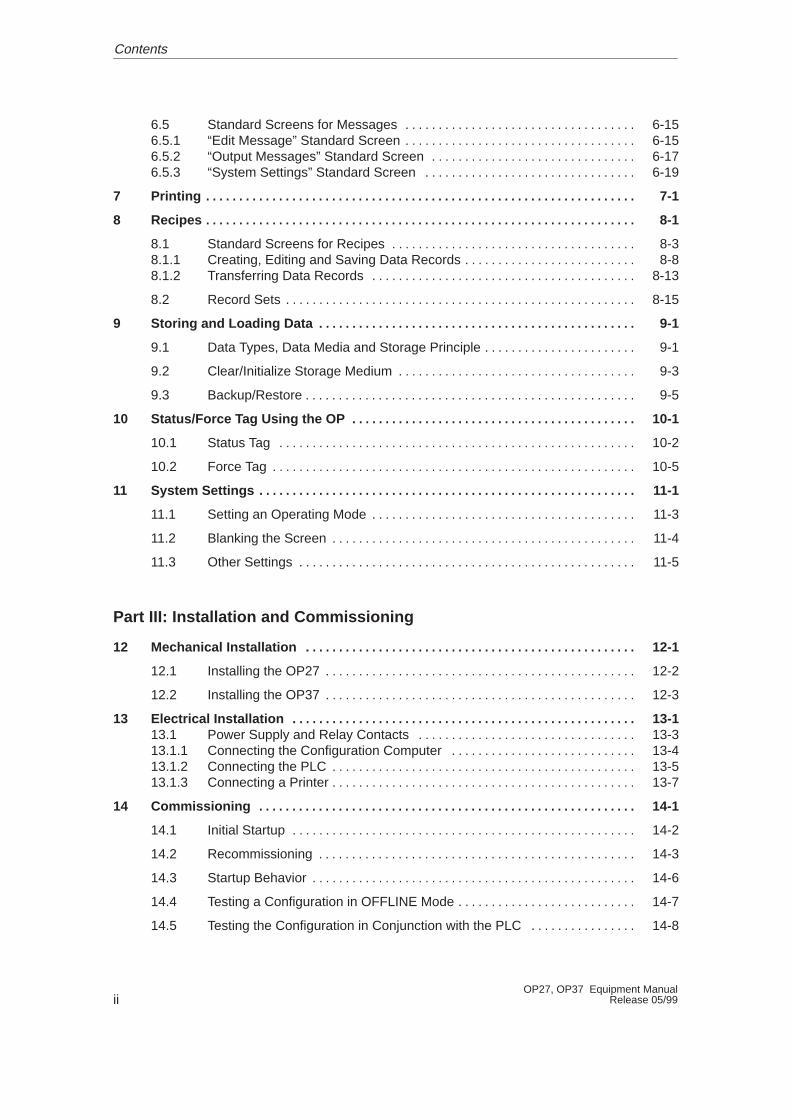
6.5 Standard Screens for Messages 6-15. . . . . . . . . . . . . . . . . . . . . . . . . . . . . . . . . . . 6.5.1 “Edit Message” Standard Screen 6-15. . . . . . . . . . . . . . . . . . . . . . . . . . . . . . . . . . . 6.5.2 “Output Messages” Standard Screen 6-17. . . . . . . . . . . . . . . . . . . . . . . . . . . . . . . 6.5.3 “System Settings” Standard Screen 6-19. . . . . . . . . . . . . . . . . . . . . . . . . . . . . . . .
7 Printing 7-1. . . . . . . . . . . . . . . . . . . . . . . . . . . . . . . . . . . . . . . . . . . . . . . . . . . . . . . . . . . . . . . . .
8 Recipes 8-1. . . . . . . . . . . . . . . . . . . . . . . . . . . . . . . . . . . . . . . . . . . . . . . . . . . . . . . . . . . . . . . . .
8.1 Standard Screens for Recipes 8-3. . . . . . . . . . . . . . . . . . . . . . . . . . . . . . . . . . . . . 8.1.1 Creating, Editing and Saving Data Records 8-8. . . . . . . . . . . . . . . . . . . . . . . . . . 8.1.2 Transferring Data Records 8-13. . . . . . . . . . . . . . . . . . . . . . . . . . . . . . . . . . . . . . . .
8.2 Record Sets 8-15. . . . . . . . . . . . . . . . . . . . . . . . . . . . . . . . . . . . . . . . . . . . . . . . . . . . .
9 Storing and Loading Data 9-1. . . . . . . . . . . . . . . . . . . . . . . . . . . . . . . . . . . . . . . . . . . . . . . .
9.1 Data Types, Data Media and Storage Principle 9-1. . . . . . . . . . . . . . . . . . . . . . .
9.2 Clear/Initialize Storage Medium 9-3. . . . . . . . . . . . . . . . . . . . . . . . . . . . . . . . . . . .
9.3 Backup/Restore 9-5. . . . . . . . . . . . . . . . . . . . . . . . . . . . . . . . . . . . . . . . . . . . . . . . . .
10 Status/Force T ag Using the OP 10-1. . . . . . . . . . . . . . . . . . . . . . . . . . . . . . . . . . . . . . . . . . .
10.1 Status Tag 10-2. . . . . . . . . . . . . . . . . . . . . . . . . . . . . . . . . . . . . . . . . . . . . . . . . . . . . .
10.2 Force Tag 10-5. . . . . . . . . . . . . . . . . . . . . . . . . . . . . . . . . . . . . . . . . . . . . . . . . . . . . . .
11 System Settings 11-1. . . . . . . . . . . . . . . . . . . . . . . . . . . . . . . . . . . . . . . . . . . . . . . . . . . . . . . . .
11.1 Setting an Operating Mode 11-3. . . . . . . . . . . . . . . . . . . . . . . . . . . . . . . . . . . . . . . .
11.2 Blanking the Screen 11-4. . . . . . . . . . . . . . . . . . . . . . . . . . . . . . . . . . . . . . . . . . . . . .
11.3 Other Settings 11-5. . . . . . . . . . . . . . . . . . . . . . . . . . . . . . . . . . . . . . . . . . . . . . . . . . .
Part III: Installation and Commissioning
12 Mechanical Installation 12-1. . . . . . . . . . . . . . . . . . . . . . . . . . . . . . . . . . . . . . . . . . . . . . . . . .
12.1 Installing the OP27 12-2. . . . . . . . . . . . . . . . . . . . . . . . . . . . . . . . . . . . . . . . . . . . . . .
12.2 Installing the OP37 12-3. . . . . . . . . . . . . . . . . . . . . . . . . . . . . . . . . . . . . . . . . . . . . . .
13 Electrical Installation 13-1. . . . . . . . . . . . . . . . . . . . . . . . . . . . . . . . . . . . . . . . . . . . . . . . . . . . 13.1 Power Supply and Relay Contacts 13-3. . . . . . . . . . . . . . . . . . . . . . . . . . . . . . . . . 13.1.1 Connecting the Configuration Computer 13-4. . . . . . . . . . . . . . . . . . . . . . . . . . . . 13.1.2 Connecting the PLC 13-5. . . . . . . . . . . . . . . . . . . . . . . . . . . . . . . . . . . . . . . . . . . . . . 13.1.3 Connecting a Printer 13-7. . . . . . . . . . . . . . . . . . . . . . . . . . . . . . . . . . . . . . . . . . . . . .
14 Commissioning 14-1. . . . . . . . . . . . . . . . . . . . . . . . . . . . . . . . . . . . . . . . . . . . . . . . . . . . . . . . .
14.1 Initial Startup 14-2. . . . . . . . . . . . . . . . . . . . . . . . . . . . . . . . . . . . . . . . . . . . . . . . . . . .
14.2 Recommissioning 14-3. . . . . . . . . . . . . . . . . . . . . . . . . . . . . . . . . . . . . . . . . . . . . . . .
14.3 Startup Behavior 14-6. . . . . . . . . . . . . . . . . . . . . . . . . . . . . . . . . . . . . . . . . . . . . . . . .
14.4 Testing a Configuration in OFFLINE Mode 14-7. . . . . . . . . . . . . . . . . . . . . . . . . . .
14.5 Testing the Configuration in Conjunction with the PLC 14-8. . . . . . . . . . . . . . . .
Contents
iiiOP27, OP37 Equipment ManualRelease 05/99
15 OP37 in DOS Mode 15-1. . . . . . . . . . . . . . . . . . . . . . . . . . . . . . . . . . . . . . . . . . . . . . . . . . . . . .
15.1 Specific OP37 Settings in BIOS Setup 15-2. . . . . . . . . . . . . . . . . . . . . . . . . . . . . .
15.2 Changing Between OP and DOS Modes 15-4. . . . . . . . . . . . . . . . . . . . . . . . . . . .
Part IV: Equipment Description and Maintenance
16 OP27 Unit Description 16-1. . . . . . . . . . . . . . . . . . . . . . . . . . . . . . . . . . . . . . . . . . . . . . . . . . .
16.1 Dimensions 16-1. . . . . . . . . . . . . . . . . . . . . . . . . . . . . . . . . . . . . . . . . . . . . . . . . . . . .
16.2 Operating and Display Elements 16-2. . . . . . . . . . . . . . . . . . . . . . . . . . . . . . . . . . .
16.3 Connection Elements 16-3. . . . . . . . . . . . . . . . . . . . . . . . . . . . . . . . . . . . . . . . . . . . .
16.4 Communication Options 16-4. . . . . . . . . . . . . . . . . . . . . . . . . . . . . . . . . . . . . . . . . .
16.5 Labeling Function Keys 16-5. . . . . . . . . . . . . . . . . . . . . . . . . . . . . . . . . . . . . . . . . . .
17 OP37 Unit Description 17-1. . . . . . . . . . . . . . . . . . . . . . . . . . . . . . . . . . . . . . . . . . . . . . . . . . .
17.1 Dimensions 17-2. . . . . . . . . . . . . . . . . . . . . . . . . . . . . . . . . . . . . . . . . . . . . . . . . . . . .
17.2 Operating and Display Elements 17-3. . . . . . . . . . . . . . . . . . . . . . . . . . . . . . . . . . .
17.3 Connection Elements 17-4. . . . . . . . . . . . . . . . . . . . . . . . . . . . . . . . . . . . . . . . . . . . .
17.4 Communication Options 17-5. . . . . . . . . . . . . . . . . . . . . . . . . . . . . . . . . . . . . . . . . .
17.5 Labeling Function Keys 17-6. . . . . . . . . . . . . . . . . . . . . . . . . . . . . . . . . . . . . . . . . . .
18 Options 18-1. . . . . . . . . . . . . . . . . . . . . . . . . . . . . . . . . . . . . . . . . . . . . . . . . . . . . . . . . . . . . . . . .
18.1 AT Expansion Slot (OP37 only) 18-2. . . . . . . . . . . . . . . . . . . . . . . . . . . . . . . . . . . .
18.2 Direct Key Module 18-4. . . . . . . . . . . . . . . . . . . . . . . . . . . . . . . . . . . . . . . . . . . . . . . 18.2.1 Installing the Direct Key Module 18-5. . . . . . . . . . . . . . . . . . . . . . . . . . . . . . . . . . . . 18.2.2 Connection and Adjusting Elements 18-7. . . . . . . . . . . . . . . . . . . . . . . . . . . . . . . .
18.3 Control Panel Interface 18-10. . . . . . . . . . . . . . . . . . . . . . . . . . . . . . . . . . . . . . . . . . . 18.3.1 Installing the Control Panel Interface 18-11. . . . . . . . . . . . . . . . . . . . . . . . . . . . . . . . 18.3.2 Connection and Adjusting Elements 18-14. . . . . . . . . . . . . . . . . . . . . . . . . . . . . . . .
19 Maintenance/Upkeep 19-1. . . . . . . . . . . . . . . . . . . . . . . . . . . . . . . . . . . . . . . . . . . . . . . . . . . .
19.1 Cleaning the Screen and Keyboard Overlay 19-1. . . . . . . . . . . . . . . . . . . . . . . . .
19.2 Replacing the Backup Battery 19-2. . . . . . . . . . . . . . . . . . . . . . . . . . . . . . . . . . . . .
19.3 Other Maintenance Work on OP27 19-4. . . . . . . . . . . . . . . . . . . . . . . . . . . . . . . . . 19.3.1 Replacing the Display on the OP27M 19-5. . . . . . . . . . . . . . . . . . . . . . . . . . . . . . . 19.3.2 Replacing the Back-Lighting of the OP27C 19-7. . . . . . . . . . . . . . . . . . . . . . . . . .
19.4 Other Maintenance Work on OP37 19-10. . . . . . . . . . . . . . . . . . . . . . . . . . . . . . . . . 19.4.1 Opening the OP37 Housing 19-10. . . . . . . . . . . . . . . . . . . . . . . . . . . . . . . . . . . . . . . 19.4.2 Replacing the Back-Lighting of the OP37 19-12. . . . . . . . . . . . . . . . . . . . . . . . . . . . 19.4.3 Replacing the Floppy Disk Drive 19-14. . . . . . . . . . . . . . . . . . . . . . . . . . . . . . . . . . .
Contents
ivOP27, OP37 Equipment Manual
Release 05/99
Part V: Appendix
A Technical Data A-1. . . . . . . . . . . . . . . . . . . . . . . . . . . . . . . . . . . . . . . . . . . . . . . . . . . . . . . . . .
B Interface Assignments B-1. . . . . . . . . . . . . . . . . . . . . . . . . . . . . . . . . . . . . . . . . . . . . . . . . . .
C Test Functions C-1. . . . . . . . . . . . . . . . . . . . . . . . . . . . . . . . . . . . . . . . . . . . . . . . . . . . . . . . . .
C.1 Hardware Test C-1. . . . . . . . . . . . . . . . . . . . . . . . . . . . . . . . . . . . . . . . . . . . . . . . . . . C.1.1 Individual Tests C-3. . . . . . . . . . . . . . . . . . . . . . . . . . . . . . . . . . . . . . . . . . . . . . . . . . C.1.2 Test Adapters C-6. . . . . . . . . . . . . . . . . . . . . . . . . . . . . . . . . . . . . . . . . . . . . . . . . . . .
D System Messages D-1. . . . . . . . . . . . . . . . . . . . . . . . . . . . . . . . . . . . . . . . . . . . . . . . . . . . . . .
E SIMATIC HMI Documentation E-1. . . . . . . . . . . . . . . . . . . . . . . . . . . . . . . . . . . . . . . . . . . . .
F ESD Guidelines F-1. . . . . . . . . . . . . . . . . . . . . . . . . . . . . . . . . . . . . . . . . . . . . . . . . . . . . . . . .
Contents

INTRODUCTION
1 Product Description
2 Functionality
Part I

-2OP27, OP37 Equipment Manual
Release 05/99
1-1OP27, OP37 Equipment ManualRelease 05/99
Product Description
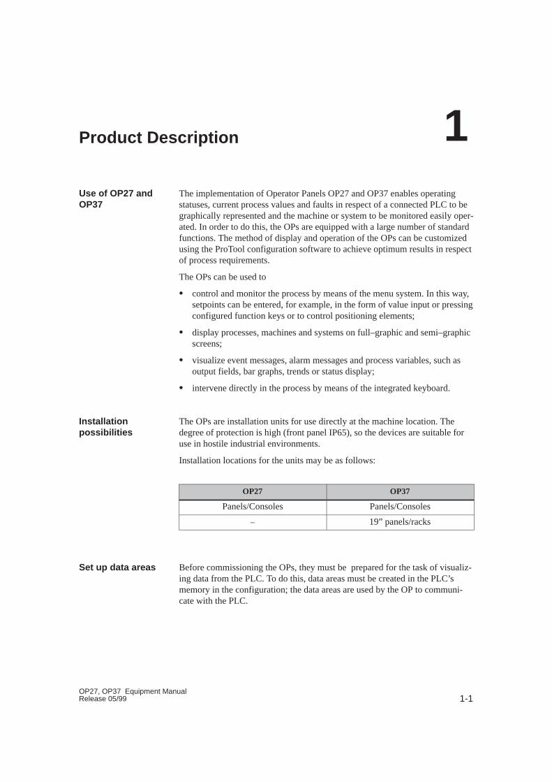
The implementation of Operator Panels OP27 and OP37 enables operatingstatuses, current process values and faults in respect of a connected PLC to begraphically represented and the machine or system to be monitored easily oper-ated. In order to do this, the OPs are equipped with a large number of standardfunctions. The method of display and operation of the OPs can be customizedusing the ProTool configuration software to achieve optimum results in respectof process requirements.
The OPs can be used to
� control and monitor the process by means of the menu system. In this way,setpoints can be entered, for example, in the form of value input or pressingconfigured function keys or to control positioning elements;
� display processes, machines and systems on full–graphic and semi–graphicscreens;
� visualize event messages, alarm messages and process variables, such asoutput fields, bar graphs, trends or status display;
� intervene directly in the process by means of the integrated keyboard.
The OPs are installation units for use directly at the machine location. Thedegree of protection is high (front panel IP65), so the devices are suitable foruse in hostile industrial environments.
Installation locations for the units may be as follows:
OP27 OP37
Panels/Consoles Panels/Consoles
– 19” panels/racks
Before commissioning the OPs, they must be prepared for the task of visualiz-ing data from the PLC. To do this, data areas must be created in the PLC’smemory in the configuration; the data areas are used by the OP to communi-cate with the PLC.
Use of OP27 andOP37
Installationpossibilities
Set up data areas
1
1-2OP27, OP37 Equipment Manual
Release 05/99
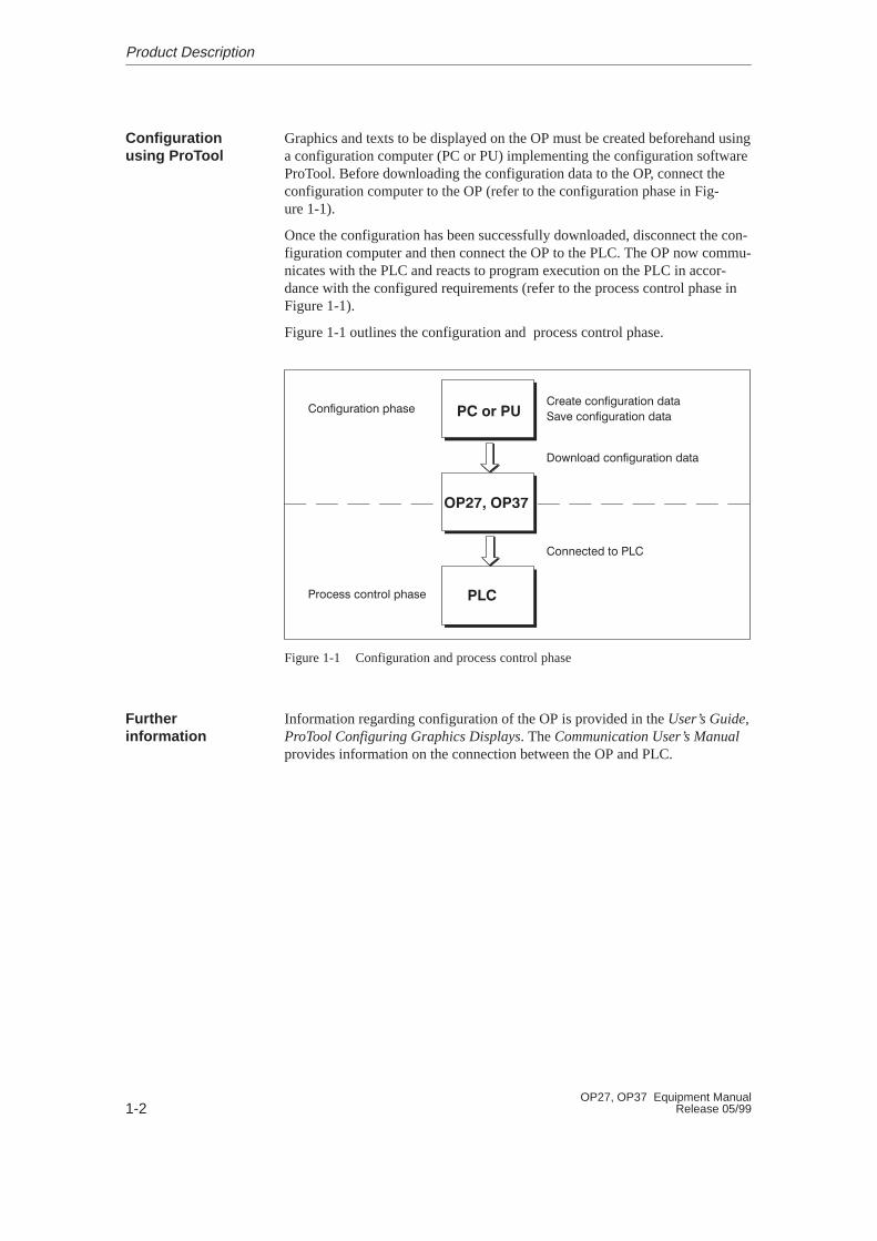
Graphics and texts to be displayed on the OP must be created beforehand usinga configuration computer (PC or PU) implementing the configuration softwareProTool. Before downloading the configuration data to the OP, connect theconfiguration computer to the OP (refer to the configuration phase in Fig-ure 1-1).
Once the configuration has been successfully downloaded, disconnect the con-figuration computer and then connect the OP to the PLC. The OP now commu-nicates with the PLC and reacts to program execution on the PLC in accor-dance with the configured requirements (refer to the process control phase inFigure 1-1).
Figure 1-1 outlines the configuration and process control phase.
���� ���
���� ������������� ���
��� ������������� ���
������� ������������� ���
������ �� ���
������������� � ��
������ ������� � ��
� ��
��
Figure 1-1 Configuration and process control phase
Information regarding configuration of the OP is provided in the User’s Guide,ProTool Configuring Graphics Displays. The Communication User’s Manualprovides information on the connection between the OP and PLC.
Configurationusing ProTool
Furtherinformation
Product Description

1-3OP27, OP37 Equipment ManualRelease 05/99
1.1 Visualizing and Controlling Processes
The basic functions of the OP27 und OP37 Operator Panels are the visualiza-tion of process statuses and the operation of processes. The following displayand operating functions can be configured:
� screens
� input/output of process values
� bar graphs and trends
� text or graphics lists
� messages
� logging
� text
� help text
� recipes
� multiple languages
� password protection
� functions for function keys and soft keys.
Logically related process data from the PLC can be compiled, displayed on ascreen and individual parts of it modified. Screens may contain soft keys,graphics, texts and values.
The OPs can display machines and systems as full–graphics screens. Thismakes it easier for the operator to find his way around.
Numeric, alphanumeric or symbolic values can be entered in input fields on theOP which are then transferred to the PLC. Current values of the PLC are dis-played in output fields in alphanumeric form.
Current process values can be output as numeric values, symbolic text,symbolic graphs or in the form of bar graphs and trend curves.
� Bar graphsrepresent a value as a rectangular area. Bar graphs can be used to displayfill levels or quantities, for example.
� Trendsdisplay a value continuously. This display mode is useful when displayingvalues that vary with time, variations in temperature or pressure, for exam-ple.
Various graphic elements (bitmaps) or texts can be called into the displaydepending on the process status. In this way, for example, the current setting ofa valve can be visualized on the OP screen by means of symbolic graphics, ortext can be modified according to the situation.
Display andoperatingfunctions
Screens
Input / Output
Bar graphs andtrend curves
Symbol lists
Product Description

1-4OP27, OP37 Equipment Manual
Release 05/99
Messages are displayed on the OP in plain text. The message text may alsocontain current process values. Incoming messages are stored in a messagebuffer together with their date and time.
� Event messagesprovide information and operating notes on current processes or machinestates, for exampleMotor running at 3000 revs .
� Alarm messagesprovide information on critical machine states, for exampleMotor speed too high .
Alarm messages must be acknowledged on account of their urgency.
Messages are classified as event messages or alarm messages during configura-tion.
All message events can be additionally recorded by being printed out in onlinemode on a connected printer. Messages which have accumulated in the eventand alarm buffers can also be printed out.
It is possible to print the current status of a screen by pressing PRINT SCREEN. Itis possible to configure a function which enables up to 20 screens to be printedsimultaneously.
Texts identify individual parts of the screen in order to be able to assign thefields displayed to the process.
Help texts represent additional information and notes for the operator whichcan be configured in respect of the screens, input fields and messages. The helptext relating to an alarm message may display information on the cause of amalfunction and how to clear it.
Complete machine data records can be stored as recipes in the OP. A recipedefines the data structure in a configuration. Data is assigned to the configuredstructure on the OP.
The purpose of recipes is to transfer several items of data collectively to thePLC. In this respect, it is immaterial whether actual recipes, specifications ofquantities, distances to be traversed or temperature variations are involved.
Message texts, texts in screens, help texts and system messages can be storedin three languages simultaneously in the OP and selected online.
The password protection feature prevents unauthorized operation of the OP.Dif ferent passwords can be assigned to different users or user groups, thusauthorizing or prohibiting access to specific control functions by assigningdifferent password levels.
Messages
Recording
Texts
Help texts
Recipe
Multiple languages
Passwordprotection
Product Description

1-5OP27, OP37 Equipment ManualRelease 05/99
The OPs are equipped with a range of function keys which can be assignedoperating functions, such as message logging on/off, screen selection and printscreen during configuration. The function keys may be assigned globally orlocally. Globally means that the assignment applies to the whole configuration.Locally means that the assignment applies only to a single screen. A functionkey whose assignment changes from one screen entry to another is known as asoft key.
Functions forfunction keys andsoft keys
Product Description
1-6OP27, OP37 Equipment Manual
Release 05/99
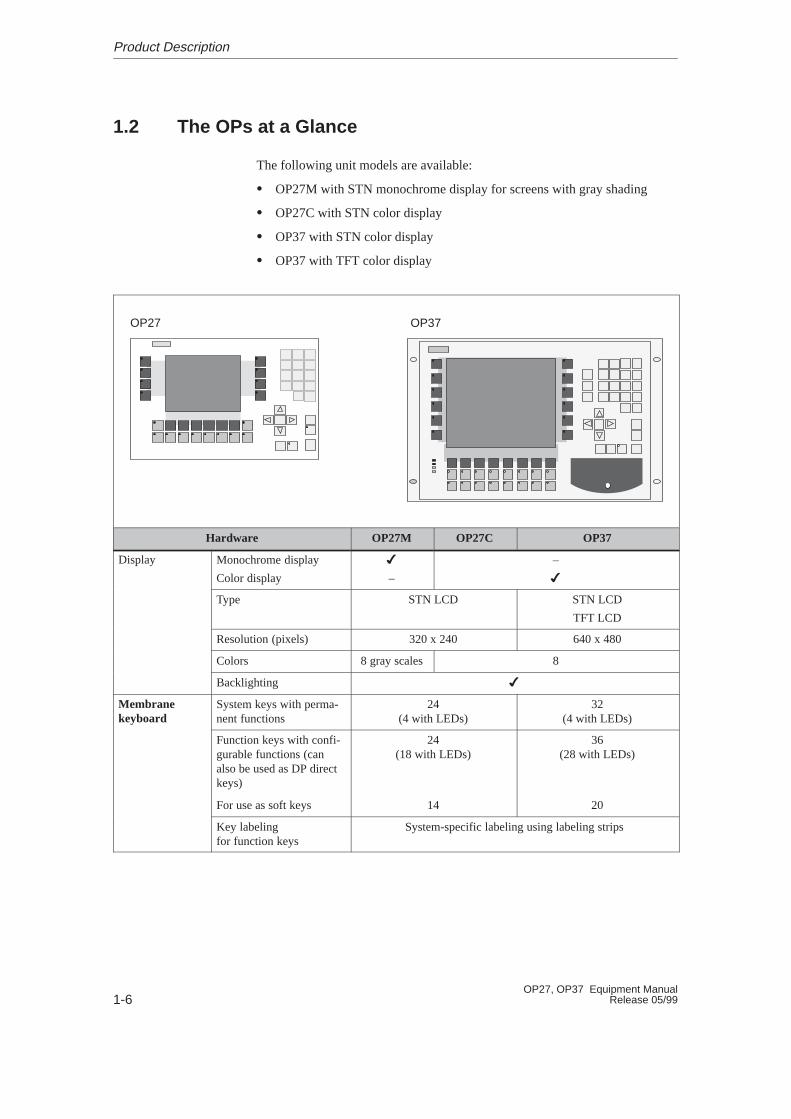
1.2 The OPs at a Glance
The following unit models are available:
� OP27M with STN monochrome display for screens with gray shading
� OP27C with STN color display
� OP37 with STN color display
� OP37 with TFT color display
OP37OP27
Hardware OP27M OP27C OP37
Display Monochrome display
Color display
�
–
–
�
Type STN LCD STN LCD
TFT LCD
Resolution (pixels) 320 x 240 640 x 480
Colors 8 gray scales 8
Backlighting �
Membranekeyboard
System keys with perma-nent functions
24(4 with LEDs)
32(4 with LEDs)
Function keys with confi-gurable functions (canalso be used as DP directkeys)
24(18 with LEDs)
36(28 with LEDs)
For use as soft keys 14 20
Key labelingfor function keys
System-specific labeling using labeling strips
Product Description
1-7OP27, OP37 Equipment ManualRelease 05/99
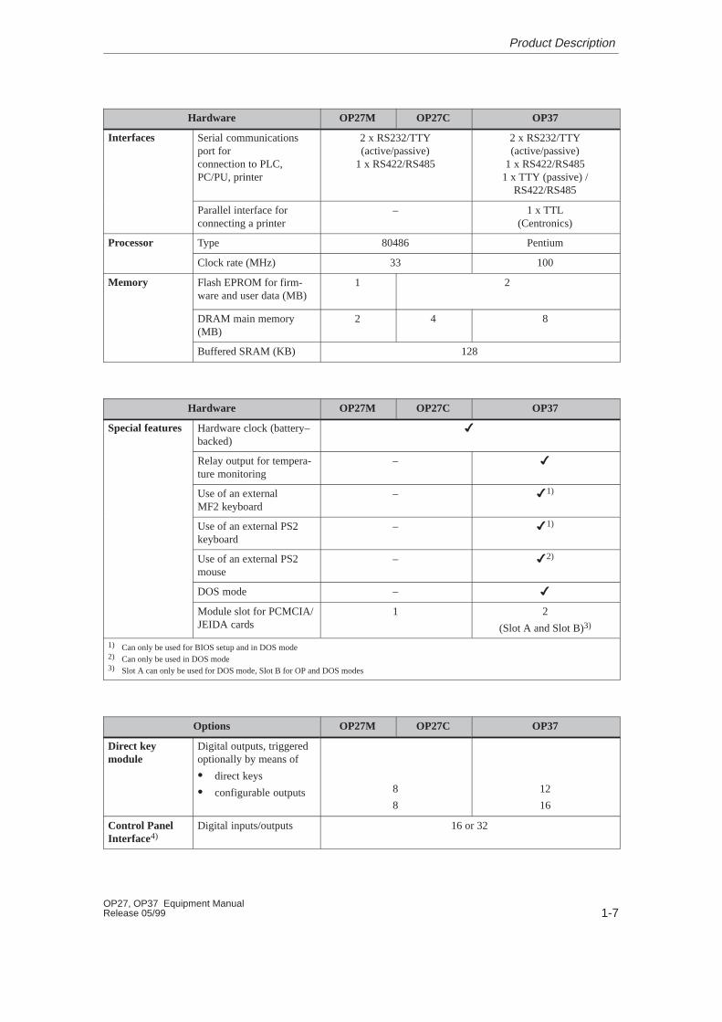
OP37OP27COP27MHardware
Interfaces Serial communicationsport forconnection to PLC,PC/PU, printer
2 x RS232/TTY(active/passive)
1 x RS422/RS485
2 x RS232/TTY(active/passive)
1 x RS422/RS4851 x TTY (passive) /
RS422/RS485
Parallel interface forconnecting a printer
– 1 x TTL(Centronics)
Processor Type 80486 Pentium
Clock rate (MHz) 33 100
Memory Flash EPROM for firm-ware and user data (MB)
1 2
DRAM main memory(MB)
2 4 8
Buffered SRAM (KB) 128
Hardware OP27M OP27C OP37
Special features Hardware clock (battery–backed)
�
Relay output for tempera-ture monitoring
– �
Use of an externalMF2 keyboard
– �1)
Use of an external PS2keyboard
– �1)
Use of an external PS2mouse
– �2)
DOS mode – �
Module slot for PCMCIA/JEIDA cards
1 2
(Slot A and Slot B)3)
1) Can only be used for BIOS setup and in DOS mode2) Can only be used in DOS mode3) Slot A can only be used for DOS mode, Slot B for OP and DOS modes
Options OP27M OP27C OP37
Direct keymodule
Digital outputs, triggeredoptionally by means of
� direct keys
� configurable outputs 8
8
12
16
Control PanelInterface4)
Digital inputs/outputs 16 or 32
Product Description

1-8OP27, OP37 Equipment Manual
Release 05/99
OP37OP27COP27MOptions
Floppy diskdrive
Storage capacity – 1.44 MB
Hard disk5) Storage capacity – � 2 GB
AT extensionslot5)
Plug-in 2/3 length, 16-bitAT cards
– 2
4) Can only be used in conjunction with SIMATIC S7 PLC5) Can only be used in DOS mode
Product Description
2-1OP27, OP37 Equipment ManualRelease 05/99
Functionalty
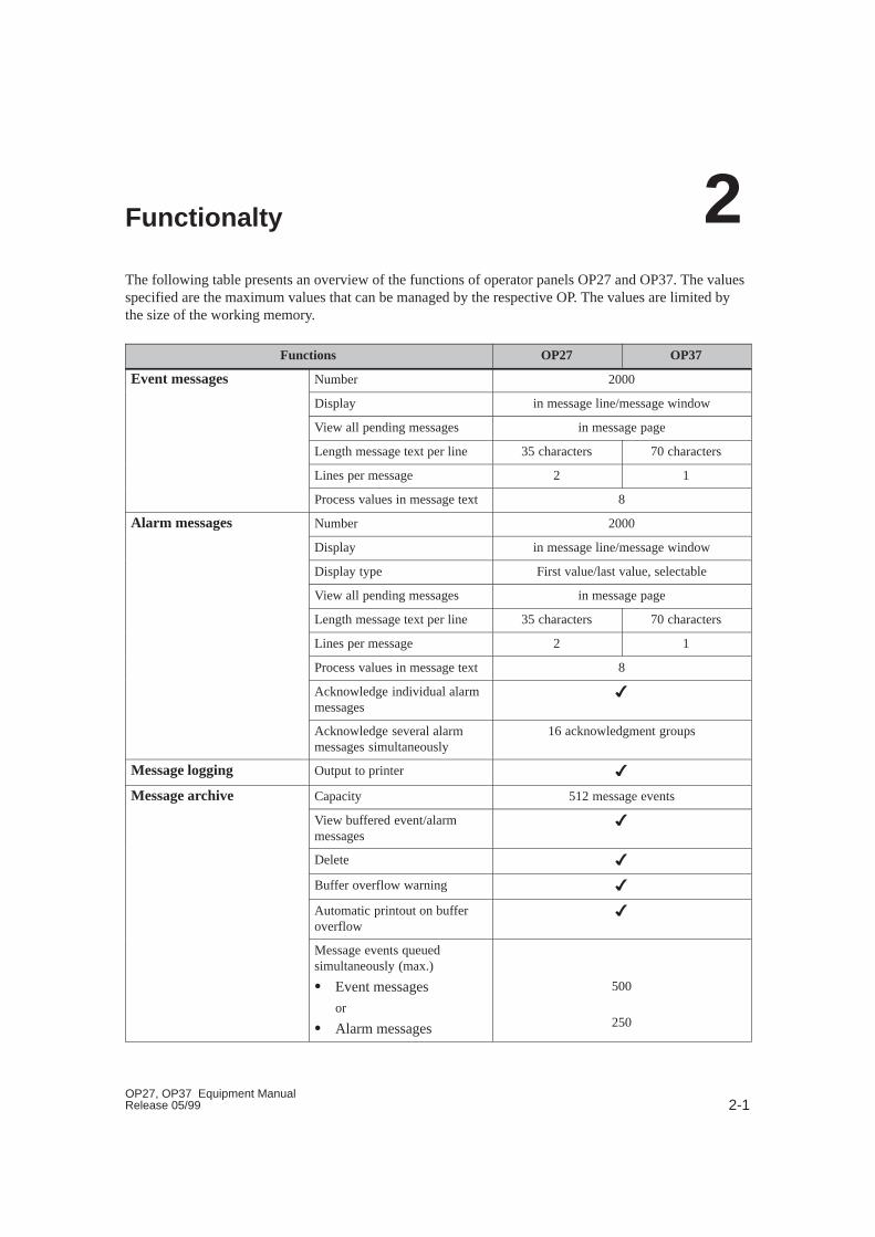
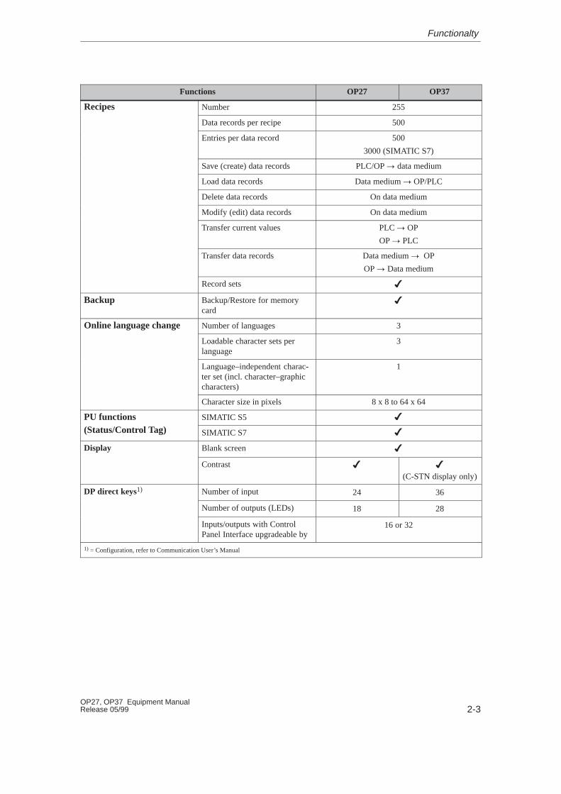
The following table presents an overview of the functions of operator panels OP27 and OP37. The valuesspecified are the maximum values that can be managed by the respective OP. The values are limited bythe size of the working memory.
Functions OP27 OP37
Event messages Number 2000
Display in message line/message window
View all pending messages in message page
Length message text per line 35 characters 70 characters
Lines per message 2 1
Process values in message text 8
Alarm messages Number 2000
Display in message line/message window
Display type First value/last value, selectable
View all pending messages in message page
Length message text per line 35 characters 70 characters
Lines per message 2 1
Process values in message text 8
Acknowledge individual alarmmessages
�
Acknowledge several alarmmessages simultaneously
16 acknowledgment groups
Message logging Output to printer �
Message archive Capacity 512 message events
View buffered event/alarmmessages
�
Delete �
Buffer overflow warning �
Automatic printout on bufferoverflow
�
Message events queuedsimultaneously (max.)
� Event messages
or
� Alarm messages
500
250
2
2-2OP27, OP37 Equipment Manual
Release 05/99
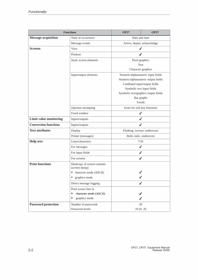
OP37OP27Functions
Message acquisition Time of occurrence Date and time
Message events Arrive, depart, acknowledge
Screens View �
Printout �
Static screen elements Pixel graphics
Text
Character graphics
Input/output elements Numeric/alphanumeric input fields
Numeric/alphanumeric output fields
Combined input/output fields
Symbolic text input fields
Symbolic text/graphics output fields
Bar graphs
Trends
Operator prompting Icons for soft key functions
Fixed window �
Limit value monitoring Inputs/outputs �
Conversion functions Inputs/outputs �
Text attributes Display Flashing, inverse, underscore
Printer (messages) Bold, italic, underscore
Help text Lines/characters 7/35
For messages �
For input fields �
For screens �
Print functions Hardcopy of screen contents(screen dump)
�� character mode (ASCII)
� graphics mode
�
�
Direct message logging �
Print screen lists in
� character mode (ASCII) �� character mode (ASCII)
� graphics mode
�
�
Password protection Number of passwords
Password levels
50
10 (0...9)
Functionalty
2-3OP27, OP37 Equipment ManualRelease 05/99
OP37OP27Functions
Recipes Number 255
Data records per recipe 500
Entries per data record 500
3000 (SIMATIC S7)
Save (create) data records PLC/OP � data medium
Load data records Data medium � OP/PLC
Delete data records On data medium
Modify (edit) data records On data medium
Transfer current values PLC � OP
OP � PLC
Transfer data records Data medium � OP
OP � Data medium
Record sets �
Backup Backup/Restore for memorycard
�
Online language change Number of languages 3
Loadable character sets perlanguage
3
Language–independent charac-ter set (incl. character–graphiccharacters)
1
Character size in pixels 8 x 8 to 64 x 64
PU functions SIMATIC S5 �
(Status/Control Tag) SIMATIC S7 �
Display Blank screen �
Contrast � �
(C-STN display only)
DP direct keys1) Number of input 24 36
Number of outputs (LEDs) 18 28
Inputs/outputs with ControlPanel Interface upgradeable by
16 or 32
1) = Configuration, refer to Communication User’s Manual
Functionalty
2-4OP27, OP37 Equipment Manual
Release 05/99
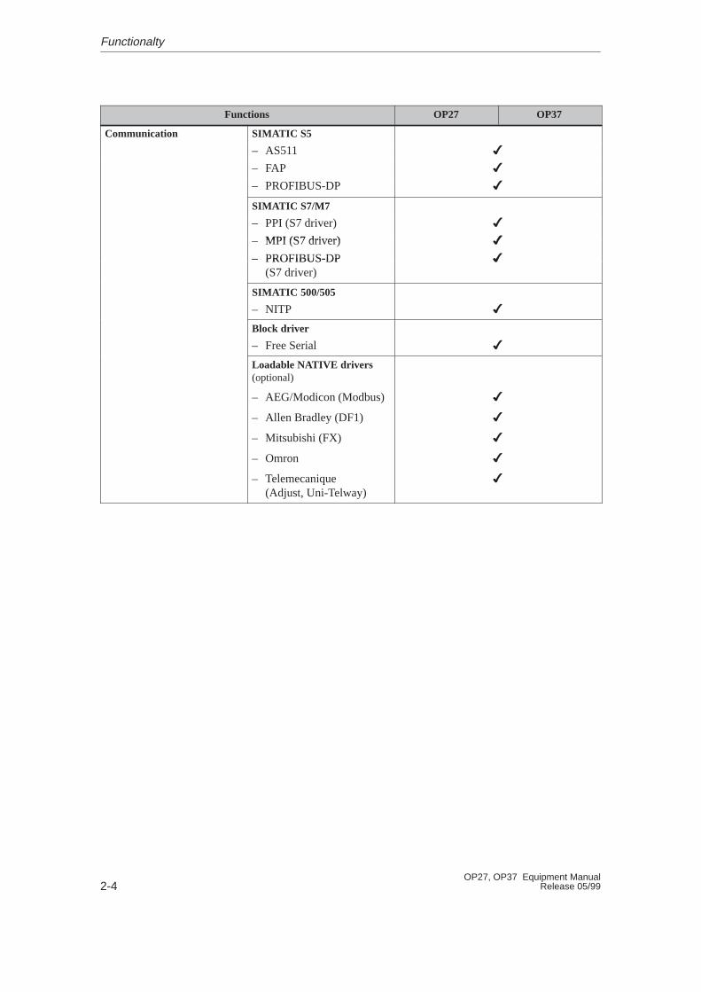
OP37OP27Functions
Communication SIMATIC S5
– AS511 �
– FAP �
– PROFIBUS-DP �
SIMATIC S7/M7
(S d i ) �– PPI (S7 driver)
MPI (S7 driver)
�
�– MPI (S7 driver)
– PROFIBUS-DP
�
�– PROFIBUS-DP(S7 driver)
�
SIMATIC 500/505
– NITP �
Block driver
– Free Serial �
Loadable NATIVE drivers(optional)
– AEG/Modicon (Modbus) �
– Allen Bradley (DF1) �
– Mitsubishi (FX) �
– Omron �
– Telemecanique (Adjust, Uni-Telway)
�
Functionalty
FUNCTIONS
3 General Operation
4 Screens
5 Password Protection
6 Messages
7 Printing
8 Recipes
9 Storing and Loading Data
10 Status/Control Tag with the OP
11 System Settings
Part II

2-2OP27, OP37 Equipment Manual
Release 05/99

3-1OP27, OP37 Equipment ManualRelease 05/99
General Operation
It is possible to observe the operating status of the machine or system beingmonitored using the OP screen and directly intervene in the process runningvia the OP keyboard.
A screen occupies the entire display. An example of screen partitioning is illus-trated in Figure 3-1.
Main area
Fixed window
ESCIcons for soft-keyfunctions
System messages Event and alarm messages
Message indicators
Help window
Figure 3-1 Screen partitioning on the OP (example OP37)
The fixed window can be used to display important process magnitudes or dateand time, since the contents are not affected by the screen currently open.
The main area comprises the entire display. It is superimposed by all otherareas (fixed window, message window etc.). The main area contains the currentcontents of the screen that is currently open.
Icons are used as symbols of specific screen functions. Icons are located aboveor next to soft key function keys in order to describe the functionality of thekey. The configured function is triggered after pressing the function key.
Operating concept
Screen partitioning
Fixed window
Main area
Icons
3
3-2OP27, OP37 Equipment Manual
Release 05/99
The message indicator indicates that alarm messages have been received.Not flashing: Alarm messages have been received.Flashing: Alarm messages have been received which have not been
acknowledged.
Message window:By default, the window for system messages is displayed in the top part of thescreen area. If another window occupies this position on the OP37, the systemmessage window appears at a vacant position. The locations of the event mes-sage and alarm message windows can be configured.
Help window:The window for displaying configured help texts appears at the bottom left ofthe screen.
Message indicator
Window
General Operation
3-3OP27, OP37 Equipment ManualRelease 05/99
3.1 Changing the Active W indow
It is possible to have several windows open at the same time on the OP. It ispossible to switch between the following windows:
� main screen
� fixed window
� message line/message window
Use the middle cursor key to switch between the various windows.
Key Description
A–ZA–ZA–Z The cursor moves from one window to the next each timethe key is pressed.
The window in which the cursor is located is the active window, i.e. the one inwhich entries and operator inputs can be performed. It is not possible to accesswindows which do not have input fields.
The OP27 and OP37 react differently in respect of operation of an input fieldwhen a window is open::
� OP27: The positions of windows displayed are static due to the smallsize of the display; meaning that if an alarm message or pop-upwindow is displayed, the input field beneath it cannot be oper-ated. Generally speaking, no input is possible until all windowshave been closed.
� OP37: When a dynamic window position is configured for the OP37,any window being displayed automatically jumps to a positionin which the input field and the cursor are not concealed. In thisway, input is always possible, regardless of display contents.
Overview
Window selection
Static and dynamicwindows
General Operation
3-4OP27, OP37 Equipment Manual
Release 05/99
3.2 Integrated Keyboard
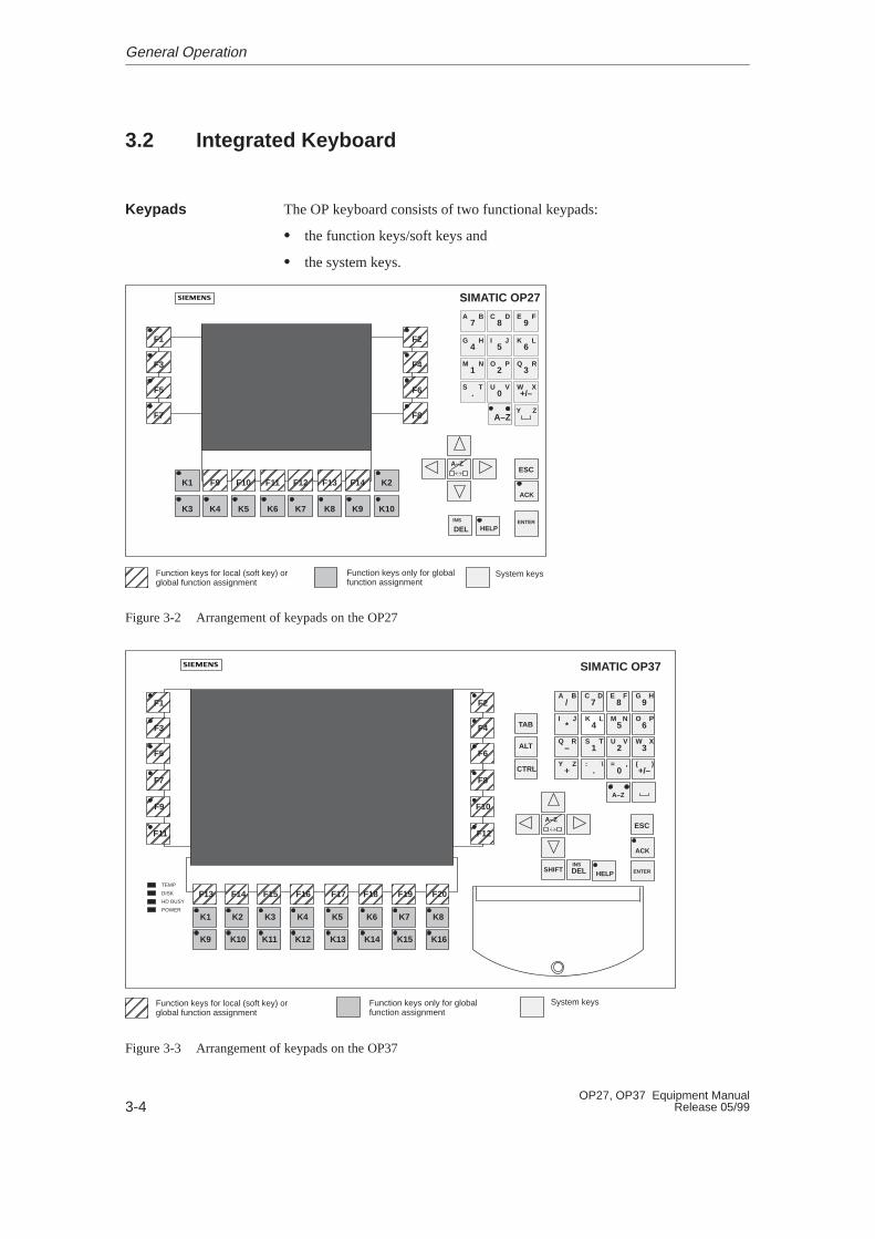
The OP keyboard consists of two functional keypads:
� the function keys/soft keys and
� the system keys.
SIMATIC OP27
8C D
9E F
ÉÉÉÉÉÉÉÉÉÉÉÉÉÉÉÉÉÉÉÉÉÉÉÉÉÉ
ÉÉÉÉÉÉÉÉÉÉÉÉÉÉÉÉ
ÉÉÉÉÉÉÉÉÉÉÉÉÉÉÉÉ
F1
F3
F5
F7
F2
F4
F6
F8
7A B
5I J
6K L
4G H
2O P
3Q R
1M N
0U V
+/–W X
.S T
Y Z
K1 F9 F10 F11 F12 F13 F14 K2
K3 K4 K5 K6 K7 K8 K9 K10
ESC
ENTER
ACK
DELINS
HELP
A–Z
A–Z
ÉÉÉÉ
Function keys for local (soft key) orglobal function assignment
Function keys only for globalfunction assignment
System keys
Figure 3-2 Arrangement of keypads on the OP27
K9 K10 K11 K12 K13 K14 K15
/A B
7C D
8E F
9G H
*I J
4K L
5M N
6O P
–Q R
1S T
2U V
3W X
+Y Z
.: \
0= ,
+/–( )
TAB
DELINS
ESC
A–Z
A–Z
ENTERHELP
ÉÉÉÉÉÉÉÉÉÉÉÉÉÉ
F1
ÉÉÉÉÉÉÉÉ
F3
F5
F7
F9
F11
ALT
CTRL
SHIFT
K1 K2 K3 K4 K5 K6 K7 K8
K16
TEMP
DISK
HD BUSY
POWER
SIMATIC OP37
ÉÉÉÉÉÉÉÉÉÉÉÉÉÉ
F2
ÉÉÉÉÉÉÉÉ
F4
F6
F8
F10
F12
ÉÉÉÉ
F13ÉÉÉÉ
F14ÉÉÉÉ
F15ÉÉÉÉ
F16ÉÉÉÉ
F17ÉÉÉÉ
F18ÉÉÉÉ
F19ÉÉÉÉ
F20
A–Z
ACK
ÉÉÉÉ
Function keys for local (soft key) orglobal function assignment
Function keys only for globalfunction assignment
System keys
Figure 3-3 Arrangement of keypads on the OP37
Keypads
General Operation
3-5OP27, OP37 Equipment ManualRelease 05/99
A “function key for global function assignment” always triggers the sameaction on the OP or PLC, regardless of the screen currently open (globalsignificance on OP). These actions can be:
� opening a screen
� displaying current alarm messages
� initiating a screen printout (Print Screen)
� displaying the time window.
The following keys can be assigned globally:
� on the OP27 –> K1 to K10 and F1 to F14 (Figure 3-2),
� on the OP37 –> K1 to K16 and F1 to F20 (Figure 3-3).
A “function key for local function assignment”, referred to as a “soft key”,means that the respective function keys have a significance only related to aspecific screen (local).
The function of a soft key may differ from screen to screen. The function of asoft key is displayed in the corresponding icon on the border of the currentscreen.
The following keys can be assigned locally:
� on the OP27 –> F1 to F14 (Figure 3-2),
� on the OP37 –> F1 to F20 (Figure 3-3).
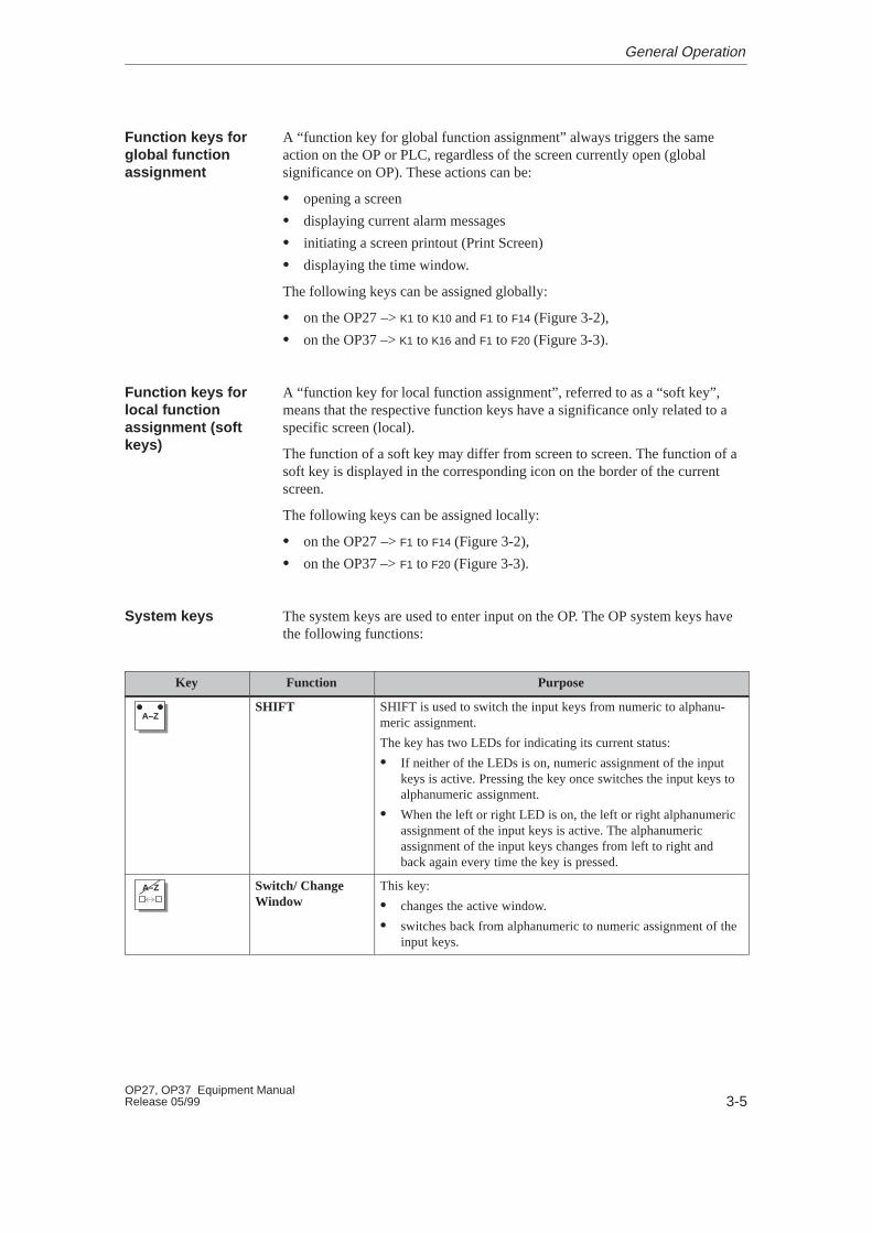
The system keys are used to enter input on the OP. The OP system keys havethe following functions:
Key Function Purpose
A–ZSHIFT SHIFT is used to switch the input keys from numeric to alphanu-
meric assignment.
The key has two LEDs for indicating its current status:
� If neither of the LEDs is on, numeric assignment of the inputkeys is active. Pressing the key once switches the input keys toalphanumeric assignment.
� When the left or right LED is on, the left or right alphanumericassignment of the input keys is active. The alphanumericassignment of the input keys changes from left to right andback again every time the key is pressed.
A–ZA–Z Switch/ ChangeWindow
This key:
� changes the active window.
� switches back from alphanumeric to numeric assignment of theinput keys.
Function keys forglobal functionassignment
Function keys forlocal functionassignment (softkeys)
System keys
General Operation
3-6OP27, OP37 Equipment Manual
Release 05/99
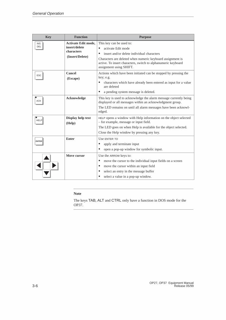
PurposeFunctionKey
DELINS Activate Edit mode,
insert/deletecharacters
(Insert/Delete)
This key can be used to:
� activate Edit mode
� insert and/or delete individual characters
Characters are deleted when numeric keyboard assignment isactive. To insert characters, switch to alphanumeric keyboardassignment using SHIFT.
ESCCancel
(Escape)
Actions which have been initiated can be stopped by pressing thekey; e.g.
� characters which have already been entered as input for a valueare deleted
� a pending system message is deleted.
ACKAcknowledge
This key is used to acknowledge the alarm message currently beingdisplayed or all messages within an acknowledgment group.
The LED remains on until all alarm messages have been acknowl-edged.
HELPDisplay help text
(Help)
HELP opens a window with Help information on the object selected– for example, message or input field.
The LED goes on when Help is available for the object selected.
Close the Help window by pressing any key.
ENTEREnter
Use ENTER TO
� apply and terminate input
� open a pop-up window for symbolic input.
Move cursor Use the ARROW keys to:
� move the cursor to the individual input fields on a screen
� move the cursor within an input field
� select an entry in the message buffer
� select a value in a pop-up window.
Note
The keys TAB, ALT and CTRL only have a function in DOS mode for theOP37.
General Operation

3-7OP27, OP37 Equipment ManualRelease 05/99
The following table indicates key combinations which can be used to definesettings on the OP27 and OP37.
Key Combination OP27 OP37
A–Z +Display contrast is increased. Display contrast is increased.
(STN displays only).
A–Z +Display contrast is reduced. Display contrast is reduced.
(STN displays only).
Key combinations after OP startup
+ESC
ESC
Loading of firmware and configuration is aborted and the system switches to Down-load mode.
It is possible to quit Download mode provided data is not being downloaded from thePC or PU to the OP.
A – Z+ESCToggle between Online and Offline modes .
ESC + + All the data in the OP FLASH is deleted. This includes the firmware the configurationand where available data records. Confirm by pressing DEL. The OP enters Downloadmode.
+ +– Toggle between OP mode and DOS mode.
+ +The selection screen for the hardware testis opened.
–
Key combinations
General Operation

3-8OP27, OP37 Equipment Manual
Release 05/99
3.3 Enter values
Use the input fields on the OP to enter values which can then be downloaded tothe PLC. Carry out the following steps to do this:
Step Action
1 First, call the screen required, as described in Section 4.1.
2 Use the cursor keys to position the cursor on the necessary input field.
3 Enter the appropriate value. Depending on how the field is configured,values can be entered as
� Entering Numeric Values (refer to Chapter 3.3.1),
� Entering Alphanumeric Values (refer to Chapter 3.3.2),
� Entering Symbolic Values (refer to Chapter 3.3.3).
4 Confirm the entry with the system keyENTER
Cancel incorrect input by pressing the system key.
The original value is then entered automatically in the field.Repeat input using the correct value.
ESC
Correct any incorrect input by inserting or deleting individualcharacters at the cursor position by pressing DEL
INS
Confirm the correction by pressing the system keyENTER
Procedure
General Operation
3-9OP27, OP37 Equipment ManualRelease 05/99
3.3.1 Entering Numeric Values
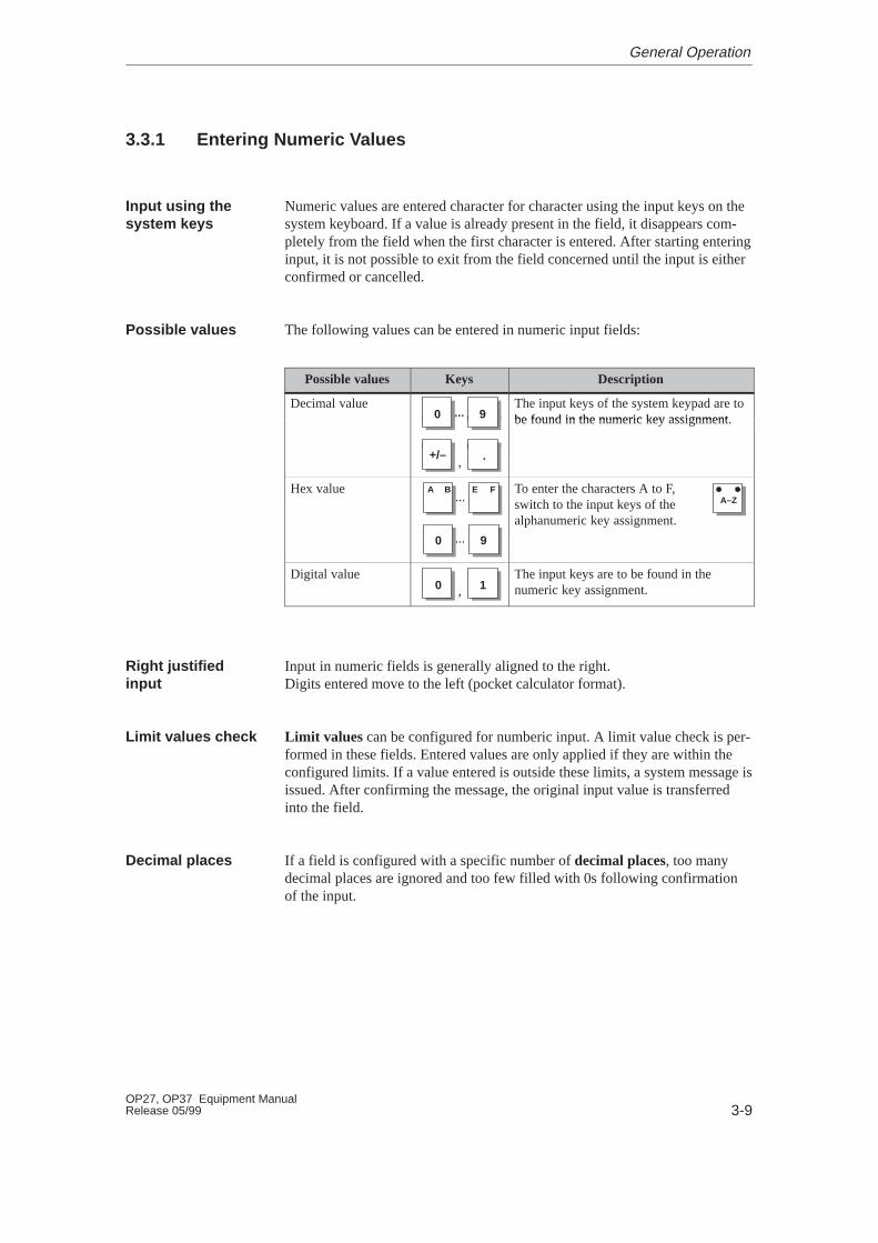
Numeric values are entered character for character using the input keys on thesystem keyboard. If a value is already present in the field, it disappears com-pletely from the field when the first character is entered. After starting enteringinput, it is not possible to exit from the field concerned until the input is eitherconfirmed or cancelled.
The following values can be entered in numeric input fields:
Possible values Keys Description
Decimal value90 ...
The input keys of the system keypad are tobe found in the numeric key assignment90 ... be found in the numeric key assignment.
+/– .,
Hex value
90
...A B FE
...
To enter the characters A to F,switch to the input keys of thealphanumeric key assignment.
A–Z
Digital value, 10
The input keys are to be found in thenumeric key assignment.
Input in numeric fields is generally aligned to the right.Digits entered move to the left (pocket calculator format).
Limit values can be configured for numberic input. A limit value check is per-formed in these fields. Entered values are only applied if they are within theconfigured limits. If a value entered is outside these limits, a system message isissued. After confirming the message, the original input value is transferredinto the field.
If a field is configured with a specific number of decimal places, too manydecimal places are ignored and too few filled with 0s following confirmationof the input.
Input using thesystem keys
Possible values
Right justifiedinput
Limit values check
Decimal places
General Operation
3-10OP27, OP37 Equipment Manual
Release 05/99
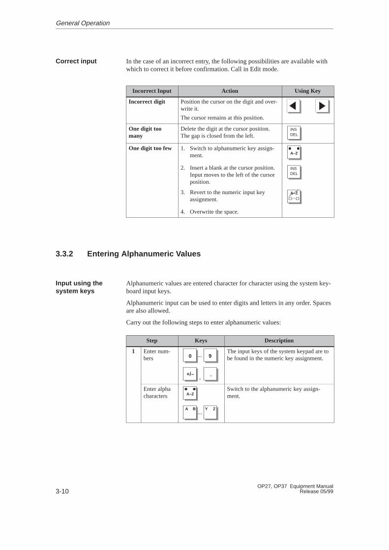
In the case of an incorrect entry, the following possibilities are available withwhich to correct it before confirmation. Call in Edit mode.
Incorrect Input Action Using Key
Incorrect digit Position the cursor on the digit and over-write it.
The cursor remains at this position.
One digit toomany
Delete the digit at the cursor position.The gap is closed from the left. DEL
INS
One digit too few 1. Switch to alphanumeric key assign-ment. A–Z
2. Insert a blank at the cursor position.Input moves to the left of the cursorposition.
DELINS
3. Revert to the numeric input keyassignment.
A–ZA–Z
4. Overwrite the space.
3.3.2 Entering Alphanumeric Values
Alphanumeric values are entered character for character using the system key-board input keys.
Alphanumeric input can be used to enter digits and letters in any order. Spacesare also allowed.
Carry out the following steps to enter alphanumeric values:
Step Keys Description
1 Enter num-bers
+/–
90
.
...
,
The input keys of the system keypad are tobe found in the numeric key assignment.
Enter alphacharacters A–Z
Switch to the alphanumeric key assign-ment.
...A B ZY
Correct input
Input using thesystem keys
General Operation
3-11OP27, OP37 Equipment ManualRelease 05/99
DescriptionKeysStep
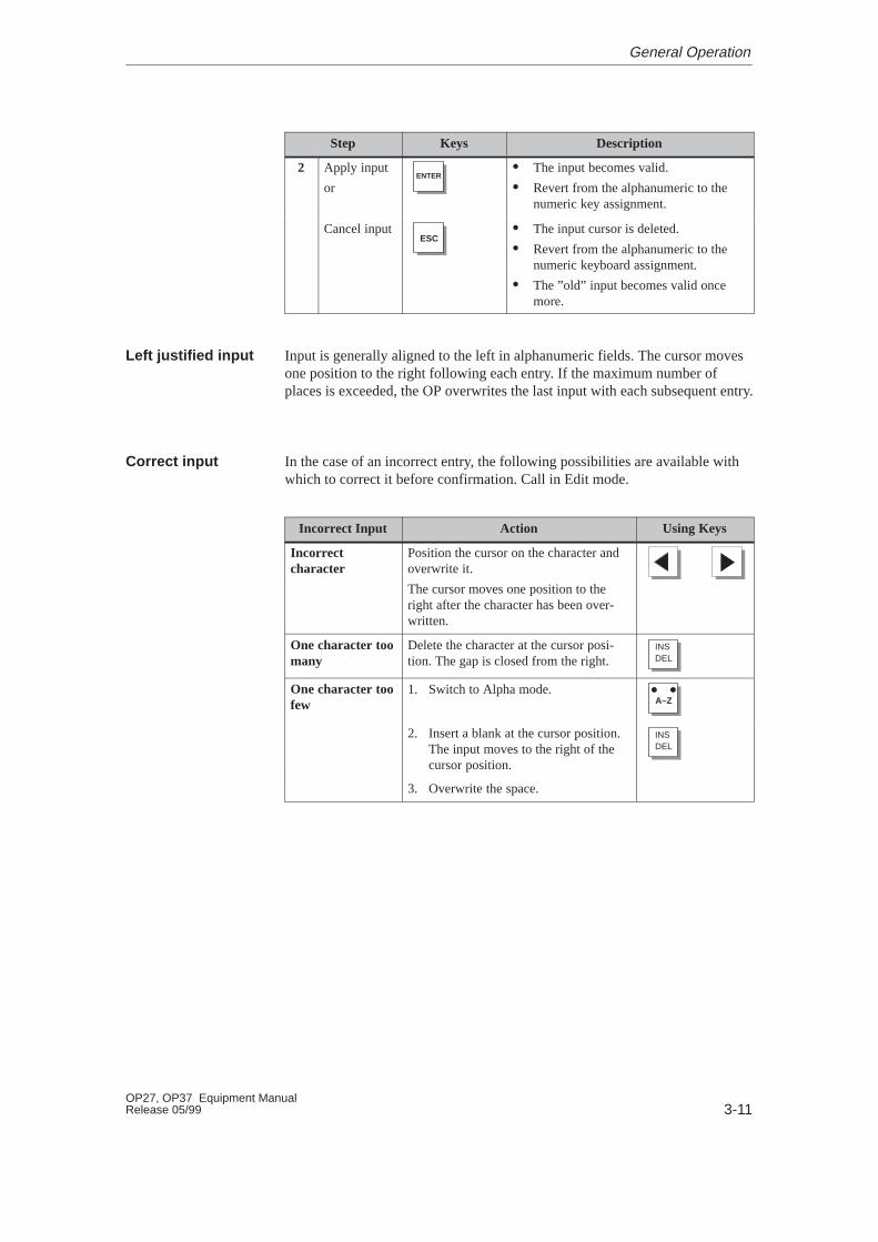
2 Apply input
orENTER
� The input becomes valid.
� Revert from the alphanumeric to thenumeric key assignment.
Cancel inputESC
� The input cursor is deleted.
� Revert from the alphanumeric to thenumeric keyboard assignment.
� The ”old” input becomes valid oncemore.
Input is generally aligned to the left in alphanumeric fields. The cursor movesone position to the right following each entry. If the maximum number ofplaces is exceeded, the OP overwrites the last input with each subsequent entry.
In the case of an incorrect entry, the following possibilities are available withwhich to correct it before confirmation. Call in Edit mode.
Incorrect Input Action Using Keys
Incorrectcharacter
Position the cursor on the character andoverwrite it.
The cursor moves one position to theright after the character has been over-written.
One character toomany
Delete the character at the cursor posi-tion. The gap is closed from the right. DEL
INS
One character toofew
1. Switch to Alpha mode.A–Z
2. Insert a blank at the cursor position.The input moves to the right of thecursor position.
DELINS
3. Overwrite the space.
Left justified input
Correct input
General Operation
3-12OP27, OP37 Equipment Manual
Release 05/99
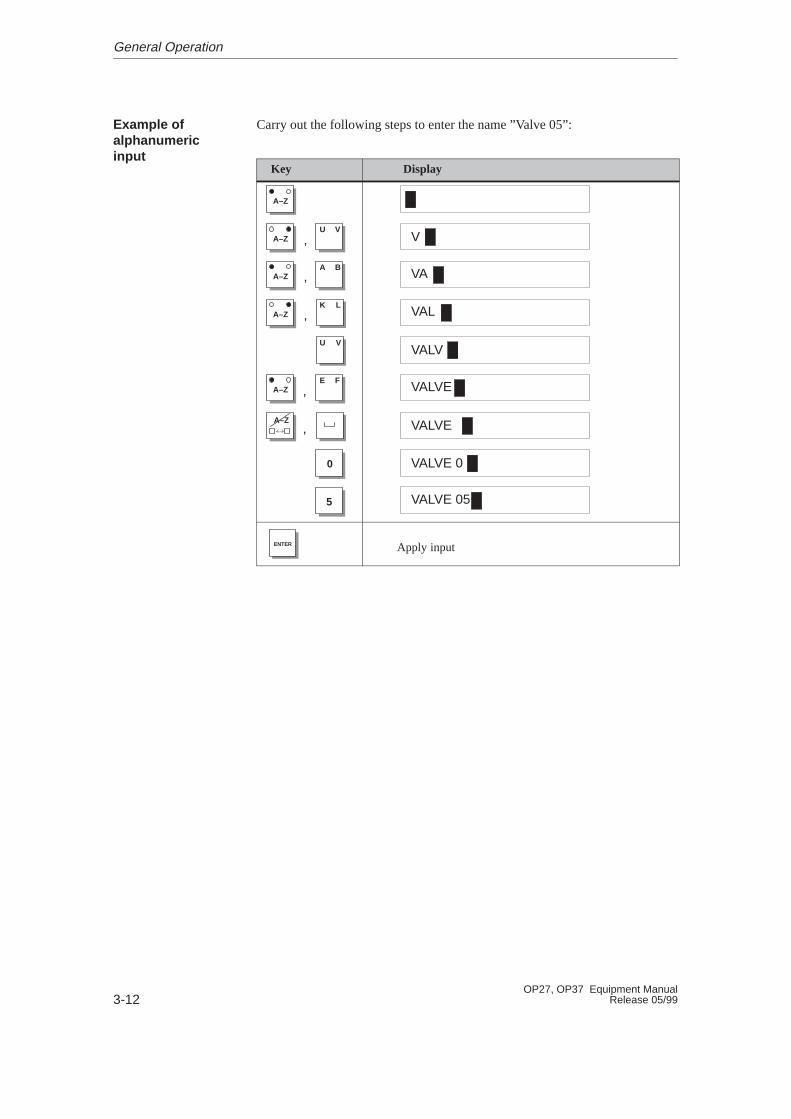
Carry out the following steps to enter the name ”Valve 05”:
Key Display
A–Z
A–Z
A–ZU V
A–ZA B
A–ZK L
U V
A–ZE F
,
,
,
,
,
5
0
V
VA
VAL
VALV
VALVE
VALVE
VALVE 0
VALVE 05
ENTER Apply input
Example ofalphanumericinput
General Operation
3-13OP27, OP37 Equipment ManualRelease 05/99
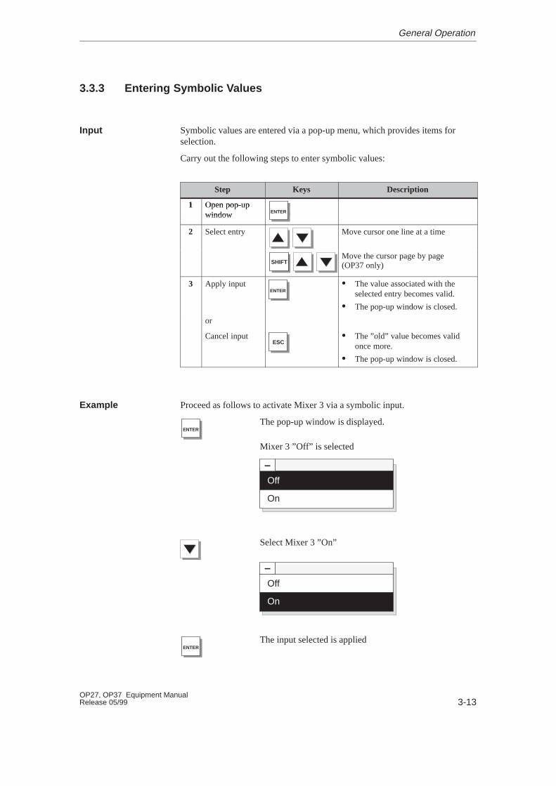
3.3.3 Entering Symbolic Values
Symbolic values are entered via a pop-up menu, which provides items forselection.
Carry out the following steps to enter symbolic values:
Step Keys Description
1 Open pop-up1 Open pop-upwindow ENTERwindow ENTER
2 Select entry Move cursor one line at a time
SHIFTMove the cursor page by page(OP37 only)
3 Apply inputENTER
� The value associated with theselected entry becomes valid.
� The pop-up window is closed.
or
Cancel inputESC
� The ”old” value becomes validonce more.
� The pop-up window is closed.
Proceed as follows to activate Mixer 3 via a symbolic input.
ENTERThe pop-up window is displayed.
Mixer 3 ”Off” is selected
–Off
On
Select Mixer 3 ”On”
–Off
On
ENTERThe input selected is applied
Input
Example
General Operation

3-14OP27, OP37 Equipment Manual
Release 05/99
3.4 Help Text
Help texts are created during configuration using ProTool and provide addi-tional information on the respective subject in the language selected on the OP.Help texts can be configured for
� event and alarm messages
� screens
� input and combined input/output fields.
Help texts can provide information to the user on the permissible range of val-ues for the input field selected, for instance. Help texts referring to an alarmmessage may, for example, contain supplementary details on possible causesand on rectifying the problem.
The help text configured for messages and input fields can be called to thescreen. Carry out the following steps to do this.
Step Action
1 In order to call in help text for a message in the messagewindow or message line, position the cursor on the messageby pressing:
A–ZA–Z
In order to call in help text concerning a message into amessage page, in respect of a message in the message bufferor an input field in a screen, position the cursor on the cor-responding message or input field using:
2 Press the system key illustrated on the right. The Help infor-mation configured for a selected message or selected inputfield is displayed.
HELP
If work is currently being carried out involving a screen and the key ispressed a second time, the help text for the entire screen is displayed.
Figure 3-4 depicts an example of an output window.
Enter temperature setpoint for Tank_1 (Range 40...80 �C)
Figure 3-4 Window with help text (example)
Purpose
Calling help texts
General Operation
4-1OP27, OP37 Equipment ManualRelease 05/99
Screens
Processes (e.g. a processing machine or mixing station) are displayed on andcan be influenced by screens which appear on the OP. These screens arecreated during configuration with ProTool for specific applications.
Logically related process values are compiled on screens and thus provide anoverview of a process or a system. Apart from this graphic mapping of pro-cesses, screens provide an opportunity of entering new process values and,thus, of controlling the process.
4.1 Screen Elements
Various screen elements are used to display and control screens:
� text
� graphics
� character graphics
� input fields for process values
� output fields for process values
� combined input/output fields
� bar graphs
� trends
� text or graphic lists
� icons.
The different screen elements are presented on the basis of the following exam-ples.
Part of the contents of various tanks are filled and mixed in a mixing unit of afruit juice mixing system. The liquid levels in the tanks and in the mixer aredisplayed. The intake valves can be opened and closed by means of operatorinputs on the OP. The motor for the mixer can be turned on and off in a similarmanner.
Process controland monitoring
Screen sections
Example
4
4-2OP27, OP37 Equipment Manual
Release 05/99
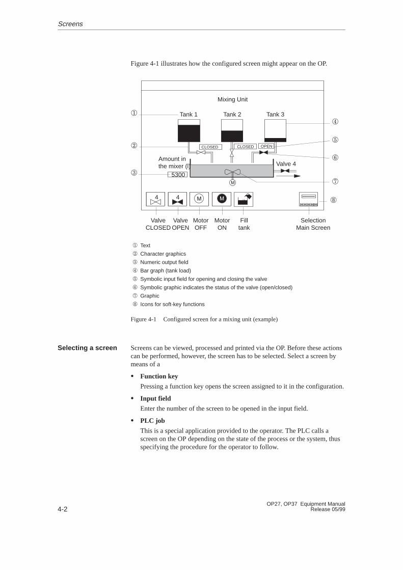
Figure 4-1 illustrates how the configured screen might appear on the OP.
� Text
� Character graphics
� Numeric output field
� Bar graph (tank load)
� Symbolic input field for opening and closing the valve
� Symbolic graphic indicates the status of the valve (open/closed)
� Graphic
� Icons for soft-key functions
Mixing Unit
Tank 1 Tank 2 Tank 3
Valve 4Amount inthe mixer (l)
ValveCLOSED
ValveOPEN
MotorOFF
Filltank
SelectionMain Screen
MotorON
44
5300
�
�
�
�
�
�
�
�
CLOSED CLOSED OPEN
Figure 4-1 Configured screen for a mixing unit (example)
Screens can be viewed, processed and printed via the OP. Before these actionscan be performed, however, the screen has to be selected. Select a screen bymeans of a
� Function key
Pressing a function key opens the screen assigned to it in the configuration.
� Input field
Enter the number of the screen to be opened in the input field.
� PLC job
This is a special application provided to the operator. The PLC calls ascreen on the OP depending on the state of the process or the system, thusspecifying the procedure for the operator to follow.
Selecting a screen
Screens
4-3OP27, OP37 Equipment ManualRelease 05/99
4.2 Standard Screens
A standard configuration containing standard screens is supplied with the con-figuration software ProTool for the OP27 and OP37. The functions needed forbasic operation of the OP have been implemented on the screens. Theyinclude, for example, Call Message Buffer, Edit Passwords and Change Param-eters Online. The individual functions are described in this manual on the basisof the standard screens.
Process-specific implementation, such as event messages or screens for theprocess, are not included in the standard screens.
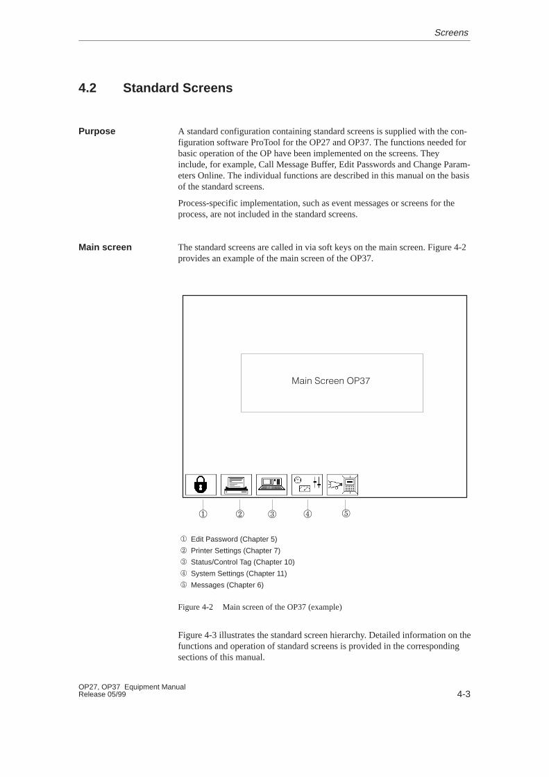
The standard screens are called in via soft keys on the main screen. Figure 4-2provides an example of the main screen of the OP37.
� Edit Password (Chapter 5)
� Printer Settings (Chapter 7)
� Status/Control Tag (Chapter 10)
� System Settings (Chapter 11)
� Messages (Chapter 6)
� � � ��
���� � � ����
Figure 4-2 Main screen of the OP37 (example)
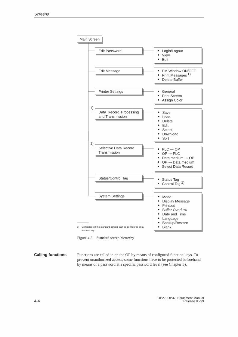
Figure 4-3 illustrates the standard screen hierarchy. Detailed information on thefunctions and operation of standard screens is provided in the correspondingsections of this manual.
Purpose
Main screen
Screens
4-4OP27, OP37 Equipment Manual
Release 05/99
Edit Password
Printer Settings
System Settings
Edit Message
Data Record Processingand Transmission
Selective Data RecordTransmission
Main Screen
� Login/Logout� View� Edit
� General� Print Screen� Assign Color
� Mode� Display Message� Printout� Buffer Overflow� Date and Time� Language� Backup/Restore� Blank
� EM Window ON/OFF� Print Messages� Delete Buffer
� Save� Load� Delete� Edit� Select� Download� Sort
� PLC � OP� OP � PLC� Data medium � OP� OP � Data medium� Select Data Record
1)
1) Contained on the standard screen, can be configured on a
function key
Status/Control Tag � Status Tag� Control Tag
1)
1)
1)
Figure 4-3 Standard screen hierarchy
Functions are called in on the OP by means of configured function keys. Toprevent unauthorized access, some functions have to be protected beforehandby means of a password at a specific password level (see Chapter 5).
Calling functions
Screens
5-1OP27, OP37 Equipment ManualRelease 05/99
Password Protection
Password protection can be configured for function keys/soft keys and inputfields to prevent operation of the OP by unauthorized personnel.
5.1 Password Level and Access Permissions
During the configuration phase with ProTool, the configurer assigns the func-tion keys/soft keys and input fields hierarchically ascending password levelsfrom 0 to 9. When a password is assigned to an individual user or to a wholeuser group, the permission to execute functions at a specific level is assignedsimultaneously.
After logging in with a password of a certain password level on the OP, per-mision to execute functions is granted at that password level and at lower lev-els.
If a function is configured with password level 0, no password need be enteredin order to execute this function. The functions assigned at this level, the low-est in the hierarchy, have little or no effect on operation. These functions do notnormally have input options; an example of this is example is Open MessagePages.
If an attempt is made to call a function which has been assigned to a higherlevel, the OP requests a password.
Levels 1 to 8 should be assigned by the configurer according to the signifi-cance of the respective function. The supervisor (superuser) is responsible forassigning a password level to a password as part of his password managementduties.
Only the superuser has the rights to execute functions assigned to password level 9. The superuser has access to all the functions on the OP. Only the super-user is authorized to perform password management on the OP. Password man-agement involves assigning and changing passwords.
Access protection
Passwordhierarchy
Password level 0
Password level 1 – 8
Password level 9
5

5-2OP27, OP37 Equipment Manual
Release 05/99
The superuser password is defined during configuration. The default value inthe standard configuration is “100”. This setting can be changed using the OP.
The passwords for levels 1 to 8 must be assigned on the OP, not during theconfiguration. Use the Password Processing standard screen (refer to Chapter5.3). The password must be at least three and not more than eight characterslong. Passwords can be composed of digits and characters A to Z. Leadingzeroes are not permitted.
The Password Processing standard screen (Figure 5-1) provides the followingfunctions:
� Login/logout on the OP
� Change and delete passwords,
� View password list.
View password list Exit from standard screen
Password Processing
Login:
Edit:
ESC
Figure 5-1 Standard screen Password Processing
Superuserpassword
Format
Standard screen
Password Protection
5-3OP27, OP37 Equipment ManualRelease 05/99
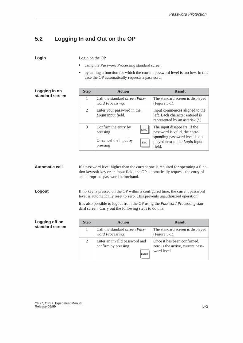
5.2 Logging In and Out on the OP
Login on the OP
� using the Password Processing standard screen
� by calling a function for which the current password level is too low. In thiscase the OP automatically requests a password.
Step Action Result
1 Call the standard screen Pass-word Processing.
The standard screen is displayed(Figure 5-1).
2 Enter your password in theLogin input field.
Input commences aligned to theleft. Each character entered isrepresented by an asterisk (∗).
3 Confirm the entry bypressing
ENTERThe input disappears. If thepassword is valid, the corre-sponding password level is dis-
Or cancel the input bypressing
ESC
sponding password level is dis-played next to the Login inputfield.
If a password level higher than the current one is required for operating a func-tion key/soft key or an input field, the OP automatically requests the entry ofan appropriate password beforehand.
If no key is pressed on the OP within a configured time, the current passwordlevel is automatically reset to zero. This prevents unauthorized operation.
It is also possible to logout from the OP using the Password Processing stan-dard screen. Carry out the following steps to do this:
Step Action Result
1 Call the standard screen Pass-word Processing.
The standard screen is displayed(Figure 5-1).
2 Enter an invalid password andconfirm by pressing
ENTER
Once it has been confirmed,zero is the active, current pass-word level.
Login
Logging in onstandard screen
Automatic call
Logout
Logging off onstandard screen
Password Protection
5-4OP27, OP37 Equipment Manual
Release 05/99
5.3 Password Management
The Password Processing standard screen provides the following functions forpassword management:
� create passwords and assign password levels,
� delete passwords,
� change passwords and password levels,
� view password list.
These functions can only be called in from password level 9 (exception: viewpassword list). Therefore, log in beforehand by means of the Login input fieldusing the superuser password.
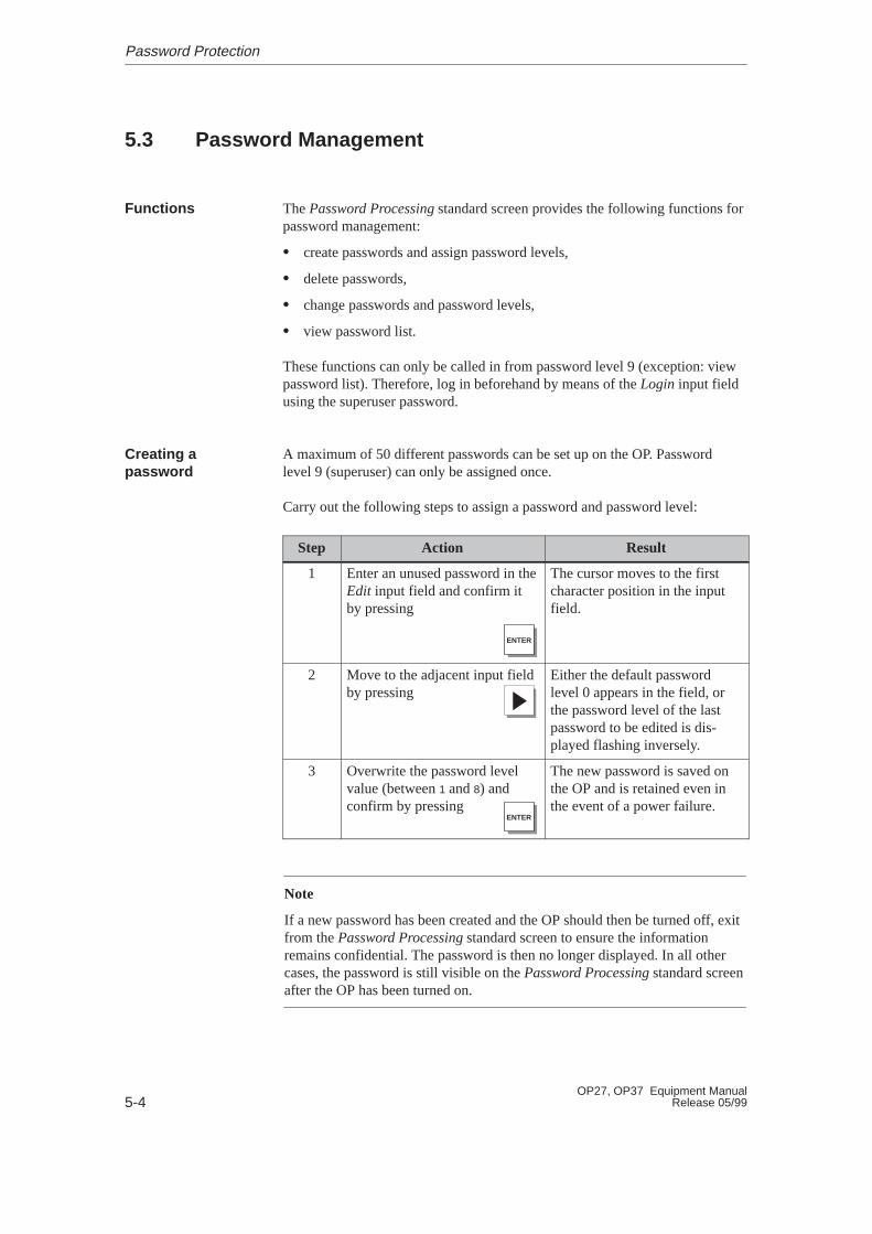
A maximum of 50 different passwords can be set up on the OP. Passwordlevel 9 (superuser) can only be assigned once.
Carry out the following steps to assign a password and password level:
Step Action Result
1 Enter an unused password in theEdit input field and confirm itby pressing
ENTER
The cursor moves to the firstcharacter position in the inputfield.
2 Move to the adjacent input fieldby pressing
Either the default passwordlevel 0 appears in the field, orthe password level of the lastpassword to be edited is dis-played flashing inversely.
3 Overwrite the password levelvalue (between 1 and 8) andconfirm by pressing
ENTER
The new password is saved onthe OP and is retained even inthe event of a power failure.
Note
If a new password has been created and the OP should then be turned off, exitfrom the Password Processing standard screen to ensure the informationremains confidential. The password is then no longer displayed. In all othercases, the password is still visible on the Password Processing standard screenafter the OP has been turned on.
Functions
Creating apassword
Password Protection
5-5OP27, OP37 Equipment ManualRelease 05/99
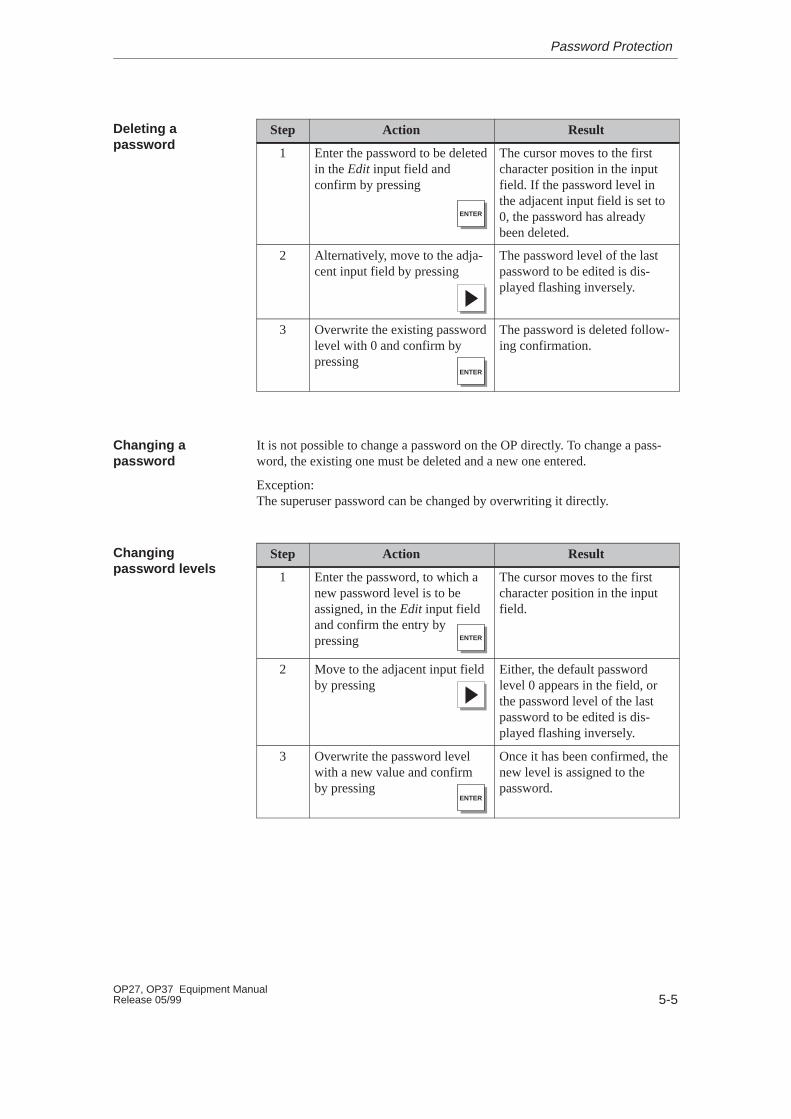
Step Action Result
1 Enter the password to be deletedin the Edit input field andconfirm by pressing
ENTER
The cursor moves to the firstcharacter position in the inputfield. If the password level inthe adjacent input field is set to0, the password has alreadybeen deleted.
2 Alternatively, move to the adja-cent input field by pressing
The password level of the lastpassword to be edited is dis-played flashing inversely.
3 Overwrite the existing passwordlevel with 0 and confirm bypressing
ENTER
The password is deleted follow-ing confirmation.
It is not possible to change a password on the OP directly. To change a pass-word, the existing one must be deleted and a new one entered.
Exception:The superuser password can be changed by overwriting it directly.
Step Action Result
1 Enter the password, to which anew password level is to beassigned, in the Edit input fieldand confirm the entry by pressing ENTER
The cursor moves to the firstcharacter position in the inputfield.
2 Move to the adjacent input fieldby pressing
Either, the default passwordlevel 0 appears in the field, orthe password level of the lastpassword to be edited is dis-played flashing inversely.
3 Overwrite the password levelwith a new value and confirmby pressing
ENTER
Once it has been confirmed, thenew level is assigned to thepassword.
Deleting apassword
Changing apassword
Changingpassword levels
Password Protection
5-6OP27, OP37 Equipment Manual
Release 05/99
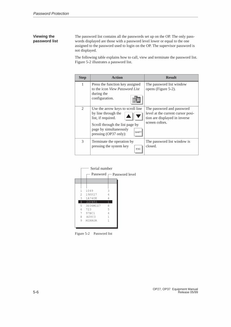
The password list contains all the passwords set up on the OP. The only pass-words displayed are those with a password level lower or equal to the oneassigned to the password used to login on the OP. The supervisor password isnot displayed.
The following table explains how to call, view and terminate the password list.Figure 5-2 illustrates a password list.
Step Action Result
1 Press the function key assignedto the icon View Password List during theconfiguration.
The password list windowopens (Figure 5-2).
2 Use the arrow keys to scroll lineby line through the list, if required.
The password and passwordlevel at the current cursor posi-tion are displayed in inversescreen colorsScroll through the list page by
page by simultaneously pressing (OP37 only): SHIFT
screen colors.
3 Terminate the operation bypressing the system key
ESC
The password list window isclosed.
1 10492 19FF273 1A740K4 22CE515 3D36M1Z76 7237 97BC18 A0YC39 MIRROR
344185411
Serial number
Password Password level
Figure 5-2 Password list
Viewing thepassword list
Password Protection

6-1OP27, OP37 Equipment ManualRelease 05/99
Messages
Messages on the OP indicate events and statuses related to control processes. Amessage consists of static text, at least. It may also contain tags.
The following types of message are displayed on the OP:
� event messages
� alarm messages
� system messages
Once issued, alarm messages and event messages are stored on the OP in amessage buffer which is protected against a power failure. Messages in thebuffer can be called into the display and printed out on a connected printer. TheOP can still be operated when messages are waiting to be displayed.
Alarm and event messages may contain the following information:
� Arrived :Denotes the occurrence of a message.
� Departed:The reason for the message no longer exists.
� Acknowledged (alarm messages only):The message has been noted by the operator or the PLC, acknowledged andconfirmed.
The OP records the exact time of the message states and indicates them when amessage page or message buffer is displayed.
Overview
Message states
6

6-2OP27, OP37 Equipment Manual
Release 05/99
6.1 Types of Message
Event and alarm messages must be configured. Event messages indicate a sta-tus in the process, whereas alarm messages indicate faults or errors. Event mes-sages and alarm messages are issued by the PLC. Alarm messages have to beacknowledged on account of their significance.
System messages are triggered by the OP. They do not have to be configured.System messages provide information on operating status of the OP and onmaloperations or malfunctions in communication.
6.1.1 Event Messages and Alarm Messages
The configuration defines whether a process status is indicated by an eventmessage or alarm message.Messages referring to regular sequences of events or states should be catego-rized as event messages; for example
0000031 10:53:27 04.04.97 11Mixing operation completedFiling level in mixer: 5000 l
Messages relating to disturbances of the process or status should be catego-rized as alarm messages; for example
0000017 10:59:53 04.04.97 QGR 04 3Bottling operation abortedBottling valve closed
Alarm messages have to be acknowledged on account of their urgency. Bydoing so, the operator confirms that he has taken note of the alarm message.Alarm messages can also be acknowledged by the PLC.
Operational hints can be configured as event messages or alarm messages, inaddition to status messages. If, for example, the machine operator wishes tostart the filling operation but has forgotten to open the bottling valve on themixer, he can be requested to rectify the error by means of an event message;for example
0000037 11:01:02 04.04.97 11Open bottling valve
Event and alarmmessages
System messages
Definition
Messages

6-3OP27, OP37 Equipment ManualRelease 05/99
Alarm messages and event messages can be configured so that text compo-nents may be distinguished from the rest of the message text by flashing orunderlining.
Messages may contain text and tag fields. Tag fields display current PLC val-ues in alphanumeric form.
A sub–category of the event message is the standby message. The standbymessage is the event message number 0. It is displayed when no other eventmessage is waiting to be displayed on the OP.
A current event or alarm message can be displayed in either a message line ormessage window. One of the following combinations can be defined in theconfiguration:
� Window/windowEvent messages and alarm mes-sages are displayed in separatewindows.
The alarm message window isopened automatically when analarm message arrives. When thealarm message is acknowledged,the alarm message window disap-pears.
The event message window canonly be opened by pressing a con-figured function key.
Event message window
Alarm message window
� Window/lineAn event message is displayed inthe message line, whereas analarm message is displayed in themessage window. The alarm mes-sage window is opened automati-cally when an alarm messageoccurs. When an alarm messageis acknowledged, the alarm mes-sage window disappears if noother alarm messages are waiting.
Alarm message window
Message line
� Window/hideAn alarm message is displayed inthe message window. Event mes-sages are not displayed.
When the alarm message isacknowledged, the alarm messagewindow is closed.
Alarm message window
Presentation
Standby message
Display mode
Messages
6-4OP27, OP37 Equipment Manual
Release 05/99
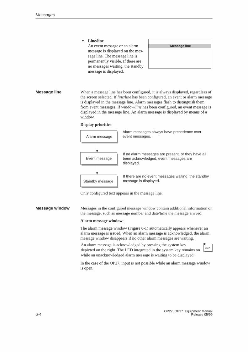
� Line/lineAn event message or an alarmmessage is displayed on the mes-sage line. The message line ispermanently visible. If there areno messages waiting, the standbymessage is displayed.
Message line
When a message line has been configured, it is always displayed, regardless ofthe screen selected. If line/line has been configured, an event or alarm messageis displayed in the message line. Alarm messages flash to distinguish themfrom event messages. If window/line has been configured, an event message isdisplayed in the message line. An alarm message is displayed by means of awindow.
Display priorities:
Alarm messages always have precedence overevent messages.
If no alarm messages are present, or they have allbeen acknowledged, event messages aredisplayed.
If there are no event messages waiting, the standbymessage is displayed.
Alarm message
Event message
Standby message
Only configured text appears in the message line.
Messages in the configured message window contain additional information onthe message, such as message number and date/time the message arrived.
Alarm message window:
The alarm message window (Figure 6-1) automatically appears whenever analarm message is issued. When an alarm message is acknowledged, the alarmmessage window disappears if no other alarm messages are waiting.
An alarm message is acknowledged by pressing the system keydepicted on the right. The LED integrated in the system key remains onwhile an unacknowledged alarm message is waiting to be displayed.
ACK
In the case of the OP27, input is not possible while an alarm message windowis open.
Message line
Message window
Messages
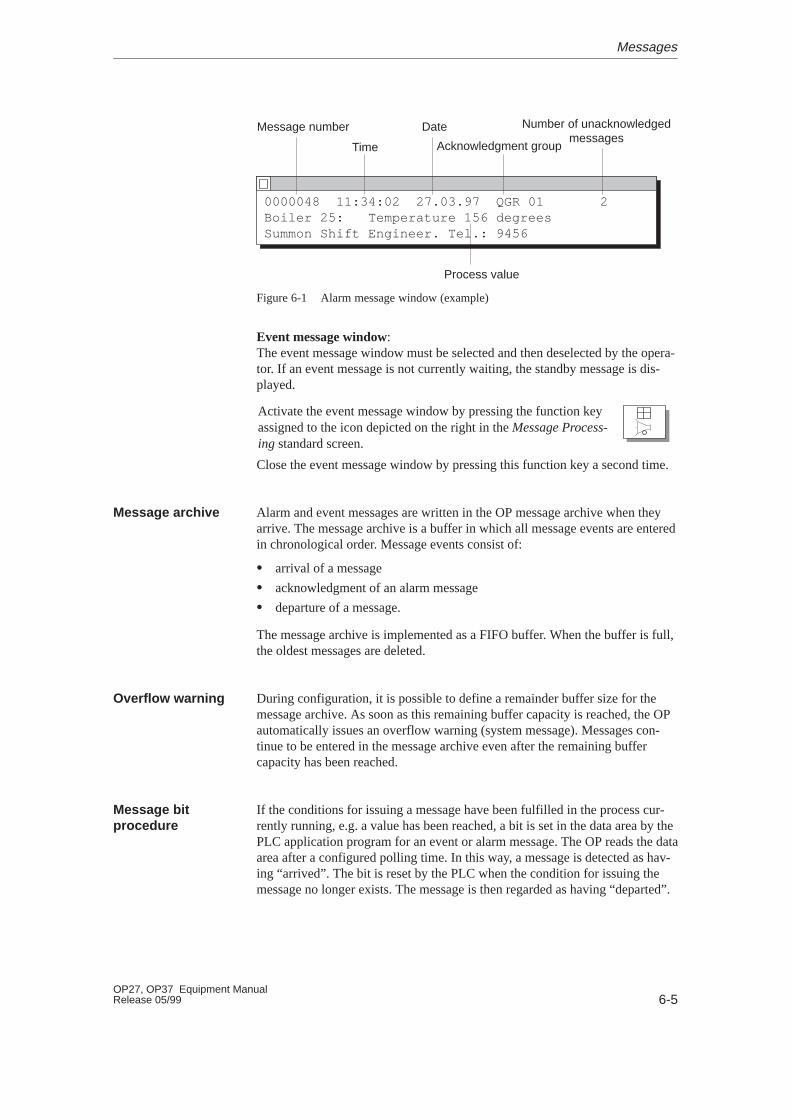
6-5OP27, OP37 Equipment ManualRelease 05/99
0000048 11:34:02 27.03.97 QGR 01 2Boiler 25: Temperature 156 degreesSummon Shift Engineer. Tel.: 9456
Message number Date
Time Acknowledgment group
Number of unacknowledgedmessages
Process value
Figure 6-1 Alarm message window (example)
Event message window:The event message window must be selected and then deselected by the opera-tor. If an event message is not currently waiting, the standby message is dis-played.
Activate the event message window by pressing the function keyassigned to the icon depicted on the right in the Message Process-ing standard screen.
Close the event message window by pressing this function key a second time.
Alarm and event messages are written in the OP message archive when theyarrive. The message archive is a buffer in which all message events are enteredin chronological order. Message events consist of:
� arrival of a message
� acknowledgment of an alarm message
� departure of a message.
The message archive is implemented as a FIFO buffer. When the buffer is full,the oldest messages are deleted.
During configuration, it is possible to define a remainder buffer size for themessage archive. As soon as this remaining buffer capacity is reached, the OPautomatically issues an overflow warning (system message). Messages con-tinue to be entered in the message archive even after the remaining buffercapacity has been reached.
If the conditions for issuing a message have been fulfilled in the process cur-rently running, e.g. a value has been reached, a bit is set in the data area by thePLC application program for an event or alarm message. The OP reads the dataarea after a configured polling time. In this way, a message is detected as hav-ing “arrived”. The bit is reset by the PLC when the condition for issuing themessage no longer exists. The message is then regarded as having “departed”.
Message archive
Overflow warning
Message bitprocedure
Messages
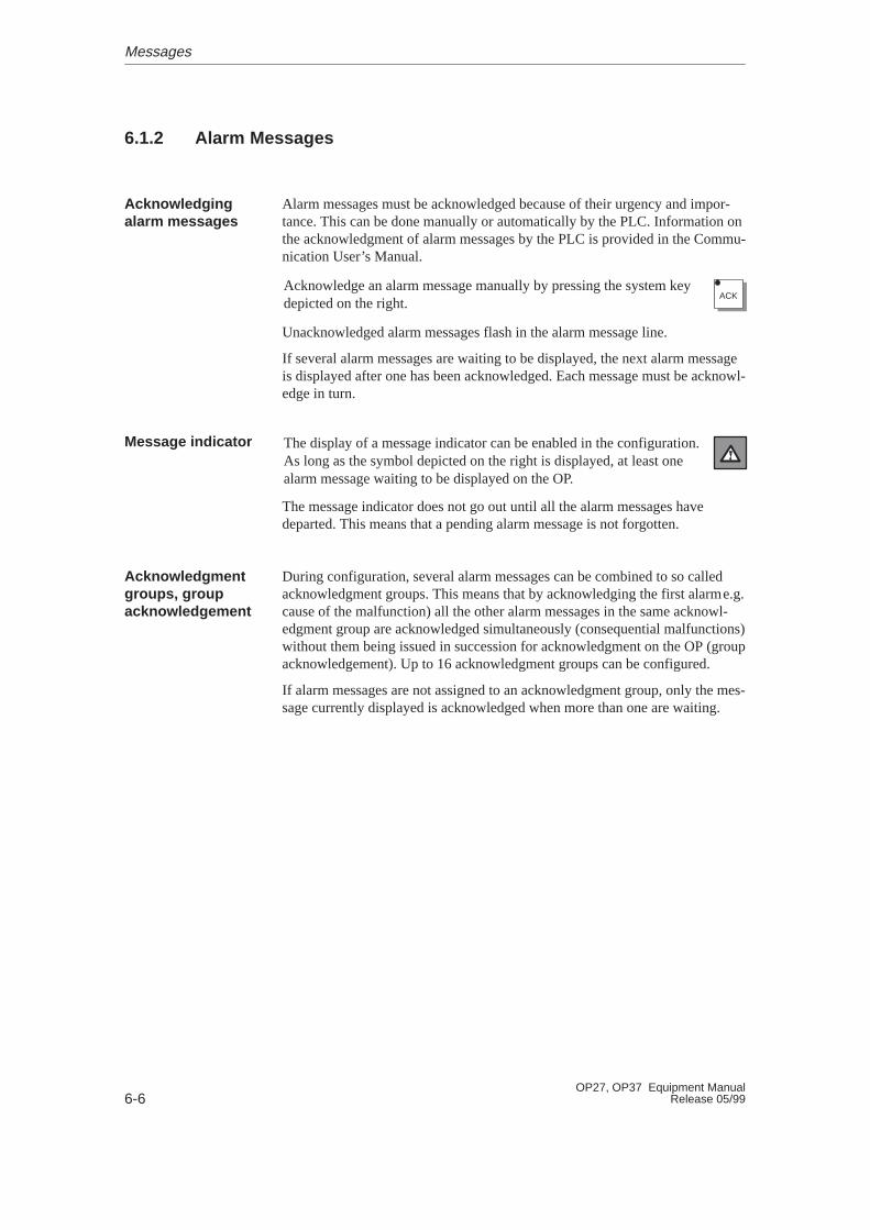
6-6OP27, OP37 Equipment Manual
Release 05/99
6.1.2 Alarm Messages
Alarm messages must be acknowledged because of their urgency and impor-tance. This can be done manually or automatically by the PLC. Information onthe acknowledgment of alarm messages by the PLC is provided in the Commu-nication User’s Manual.
Acknowledge an alarm message manually by pressing the system keydepicted on the right.
ACK
Unacknowledged alarm messages flash in the alarm message line.
If several alarm messages are waiting to be displayed, the next alarm messageis displayed after one has been acknowledged. Each message must be acknowl-edge in turn.
The display of a message indicator can be enabled in the configuration.As long as the symbol depicted on the right is displayed, at least onealarm message waiting to be displayed on the OP.
The message indicator does not go out until all the alarm messages havedeparted. This means that a pending alarm message is not forgotten.
During configuration, several alarm messages can be combined to so calledacknowledgment groups. This means that by acknowledging the first alarme.g.cause of the malfunction) all the other alarm messages in the same acknowl-edgment group are acknowledged simultaneously (consequential malfunctions)without them being issued in succession for acknowledgment on the OP (groupacknowledgement). Up to 16 acknowledgment groups can be configured.
If alarm messages are not assigned to an acknowledgment group, only the mes-sage currently displayed is acknowledged when more than one are waiting.
Acknowledgingalarm messages
Message indicator
Acknowledgmentgroups, groupacknowledgement
Messages
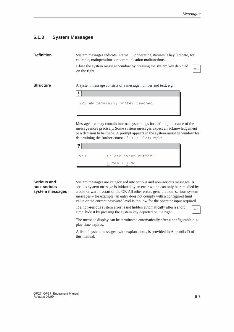
6-7OP27, OP37 Equipment ManualRelease 05/99
6.1.3 System Messages
System messages indicate internal OP operating statuses. They indicate, forexample, maloperations or communication malfunctions.
Close the system message window by pressing the system key depictedon the right.
ESC
A system message consists of a message number and text, e.g.:
222 AM remaining buffer reached
Message text may contain internal system tags for defining the cause of themessage more precisely. Some system messages expect an acknowledgementor a decision to be made. A prompt appears in the system message window fordetermining the further course of action – for example:
559 Delete event buffer?
0 Yes / 1 No
System messages are catagorized into serious and non–serious messages. Aserious system message is initiated by an error which can only be remedied bya cold or warm restart of the OP. All other errors generate non–serious systemmessages – for example, an entry does not comply with a configured limitvalue or the current password level is too low for the operator input required.
If a non-serious system error is not hidden automatically after a shorttime, hide it by pressing the system key depicted on the right.
ESC
The message display can be terminated automatically after a configurable dis-play time expires.
A list of system messages, with explanations, is provided in Appendix D ofthis manual.
Definition
Structure
Serious andnon–serioussystem messages
Messages
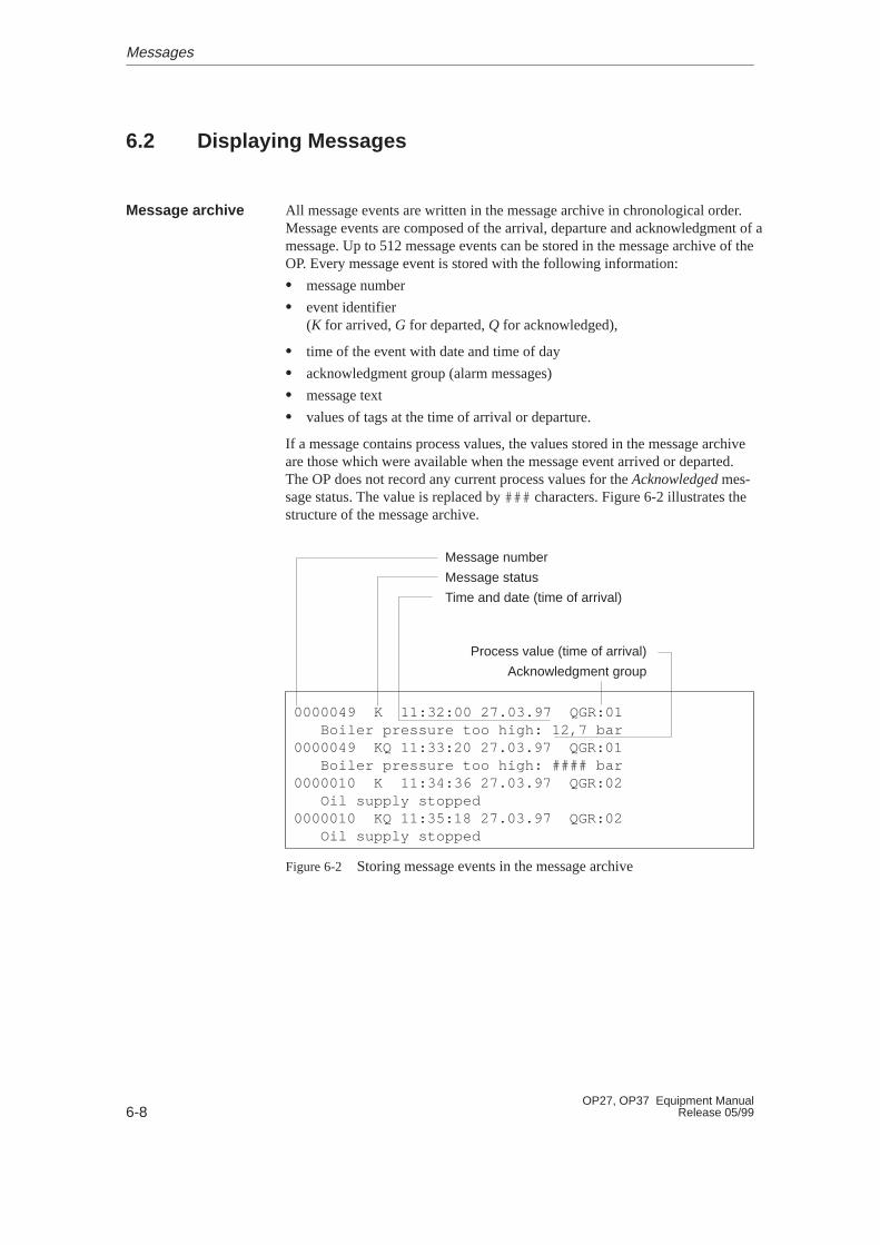
6-8OP27, OP37 Equipment Manual
Release 05/99
6.2 Displaying Messages
All message events are written in the message archive in chronological order.Message events are composed of the arrival, departure and acknowledgment of amessage. Up to 512 message events can be stored in the message archive of theOP. Every message event is stored with the following information:
� message number
� event identifier(K for arrived, G for departed, Q for acknowledged),
� time of the event with date and time of day
� acknowledgment group (alarm messages)
� message text
� values of tags at the time of arrival or departure.
If a message contains process values, the values stored in the message archiveare those which were available when the message event arrived or departed.The OP does not record any current process values for the Acknowledged mes-sage status. The value is replaced by ### characters. Figure 6-2 illustrates thestructure of the message archive.
0000049 K 11:32:00 27.03.97 QGR:01 Boiler pressure too high: 12,7 bar0000049 KQ 11:33:20 27.03.97 QGR:01 Boiler pressure too high: #### bar0000010 K 11:34:36 27.03.97 QGR:02 Oil supply stopped0000010 KQ 11:35:18 27.03.97 QGR:02 Oil supply stopped
Message number
Message status
Time and date (time of arrival)
Process value (time of arrival)
Acknowledgment group
Figure 6-2 Storing message events in the message archive
Message archive
Messages
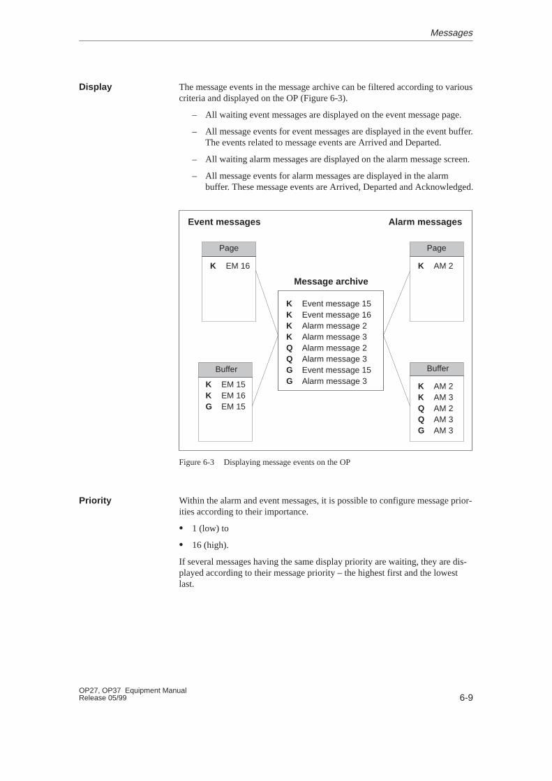
6-9OP27, OP37 Equipment ManualRelease 05/99
The message events in the message archive can be filtered according to variouscriteria and displayed on the OP (Figure 6-3).
– All waiting event messages are displayed on the event message page.
– All message events for event messages are displayed in the event buffer.The events related to message events are Arrived and Departed.
– All waiting alarm messages are displayed on the alarm message screen.
– All message events for alarm messages are displayed in the alarmbuffer. These message events are Arrived, Departed and Acknowledged.
K Event message 15K Event message 16K Alarm message 2K Alarm message 3Q Alarm message 2Q Alarm message 3G Event message 15G Alarm message 3
Message archive
Event messages Alarm messages
K EM 16
K EM 15K EM 16G EM 15
K AM 2
K AM 2K AM 3Q AM 2Q AM 3G AM 3
Page
Buffer
Page
Buffer
Figure 6-3 Displaying message events on the OP
Within the alarm and event messages, it is possible to configure message prior-ities according to their importance.
� 1 (low) to
� 16 (high).
If several messages having the same display priority are waiting, they are dis-played according to their message priority – the highest first and the lowestlast.
Display
Priority
Messages
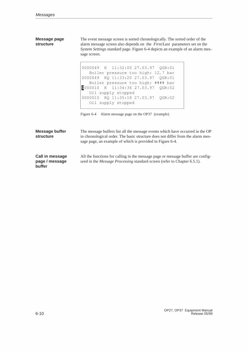
6-10OP27, OP37 Equipment Manual
Release 05/99
The event message screen is sorted chronologically. The sorted order of thealarm message screen also depends on the First/Last parameters set on theSystem Settings standard page. Figure 6-4 depicts an example of an alarm mes-sage screen.
0000049 K 11:32:00 27.03.97 QGR:01 Boiler pressure too high: 12,7 bar0000049 KQ 11:33:20 27.03.97 QGR:01 Boiler pressure too high: #### bar0000010 K 11:34:36 27.03.97 QGR:02 Oil supply stopped0000010 KQ 11:35:18 27.03.97 QGR:02 Oil supply stopped
Figure 6-4 Alarm message page on the OP37 (example)
The message buffers list all the message events which have occurred in the OPin chronological order. The basic structure does not differ from the alarm mes-sage page, an example of which is provided in Figure 6-4.
All the functions for calling in the message page or message buffer are config-ured in the Message Processing standard screen (refer to Chapter 6.5.1).
Message pagestructure
Message bufferstructure
Call in messagepage / messagebuffer
Messages

6-11OP27, OP37 Equipment ManualRelease 05/99
6.3 Deleting Messages
All message events from event and alarm messages are stored automatically inthe message archive. The message archive can contain as many as 512 messageevents. Message events are deleted
� automatically in the case of buffer overflow
� by means of the Message Processing standard screen.
On reaching the configured remaining buffer size, (default setting 10%), anoverflow warning is issued by default. Issue of the overflow warning can beenabled or disabled on the OP by means of the System Settings standard screen.To do so, open the input window in the BUFFER OVERFLOW WARNING symbolicinput field and select either of the parameters OFF or ON.
If the message archive is no longer capable of recording more message events,message events are automatically deleted until the capacity configured for theremaining buffer size is reached. Deletion occurs in the following sequence:
� The oldest messages which have already departed.
The message events Arrived and Departed for an event message which hasdeparted are deleted. The message events Arrived, Departed and Acknowl-edged are deleted in respect of alarm messages which have been cleared.
� Messages still waiting.
If the capacity is still not sufficient for new messages, the oldest waitingmessages are deleted. This triggers the issue of a system message.
In the case of a buffer overflow, a printout of all the alarm and event messagesdeleted is automatically triggered if
� “Printout on overflow” is configured,
� message logging is disabled on the OP and
� a printer which is ready to operate is connected.
Purpose
Overflow warning
Deleting on bufferoverflow
Automatic printout
Messages
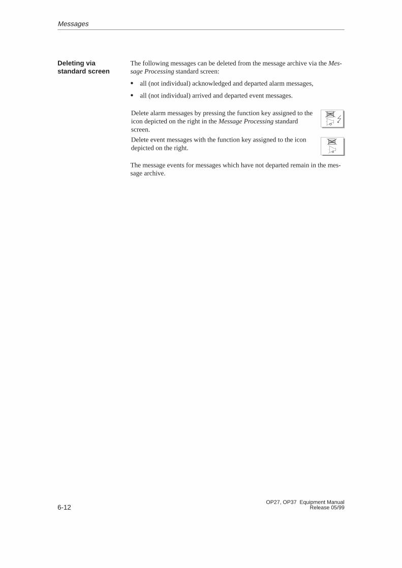
6-12OP27, OP37 Equipment Manual
Release 05/99
The following messages can be deleted from the message archive via the Mes-sage Processing standard screen:
� all (not individual) acknowledged and departed alarm messages,
� all (not individual) arrived and departed event messages.
Delete alarm messages by pressing the function key assigned to theicon depicted on the right in the Message Processing standardscreen.
Delete event messages with the function key assigned to the icondepicted on the right.
The message events for messages which have not departed remain in the mes-sage archive.
Deleting viastandard screen
Messages
6-13OP27, OP37 Equipment ManualRelease 05/99
6.4 Printing Messages
Alarm and event messages can be printed out
� automatically, following buffer overflow (see Chapter 6.3),
� automatically, as direct message logging.
� manually (refer to Chapter 6.5.1).
Set the printer parameters in the Printer Settings standard screen. The standardscreen is described in Chapter 7.
Note
If the message buffer overflows as a result of a messages overload, it is pos-sible that messages cannot be printed. If this happens “****” appears in theprintout instead of messages.
Alarm and event messages can be printed out directly on arrival and departure(alarm messages too, following acknowledgement) when this has been definedin the message configuration. System messages are not logged.
Direct message logging can be enabled/disabled online via the OP using theSystem Settings standard screen. To do so, open the input window in theMESSAGE LOGGING symbolic input field and select the required parameter OFF
or ON.
The table shows the relationships between the settings on the OP and thoseconfigured in ProTool.
Setting in ProTool Setting on OP
Message Logging ON Message Logging OFF
Message event Messages are logged Messages are not logged
Buffer overflow Messages are logged Buffer overflow is printed
Off Messages are logged No effect
Note
If Asian character sets are used for messages, the messages are printed ingraphics mode.
How to print
Direct messagelogging
Direct messagelogging on/off
Messages

6-14OP27, OP37 Equipment Manual
Release 05/99
The buffer contents can be printed out in the following ways:
� The Message Processing standard screen (see Chapter 6.5.1) has a functionkey/soft key to print out alarm and event messages.
� The Output Messages standard screen (see Chapter 6.5.2) has a functionkey/soft key to print out alarm and event messages. In addition, it is pos-sible to enter filter criteria to restrict the messages to be printed.
Manual printout ofbuffer content
Messages

6-15OP27, OP37 Equipment ManualRelease 05/99
6.5 Standard Screens for Messages
The standard standard screens below are significant for messages:
� Message Processing
� Output messages
� System Settings
6.5.1 “Message Processing” Standard Screen
Functions are configured in the Message Processing standard screen which arenecessary to view and delete messages (Figure 6-5).
Open the Message Processing standard screen from the mainscreen. To do this, press the function key assigned to the icondepicted on the right.
Message Processing
Figure 6-5 Message Processing standard screen (example: OP37)
Overview
Purpose
Structure
Messages
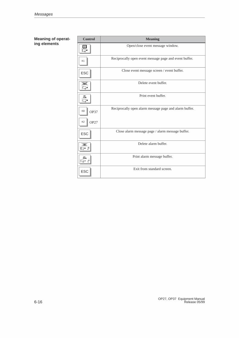
6-16OP27, OP37 Equipment Manual
Release 05/99
Control Meaning
Open/close event message window.
K1Reciprocally open event message page and event buffer.
ESCClose event message screen / event buffer.
Delete event buffer.
Print event buffer.
K8
K2
OP37
OP27
Reciprocally open alarm message page and alarm buffer.
ESCClose alarm message page / alarm message buffer.
Delete alarm buffer.
Print alarm message buffer.
ESCExit from standard screen.
Meaning of operat-ing elements
Messages
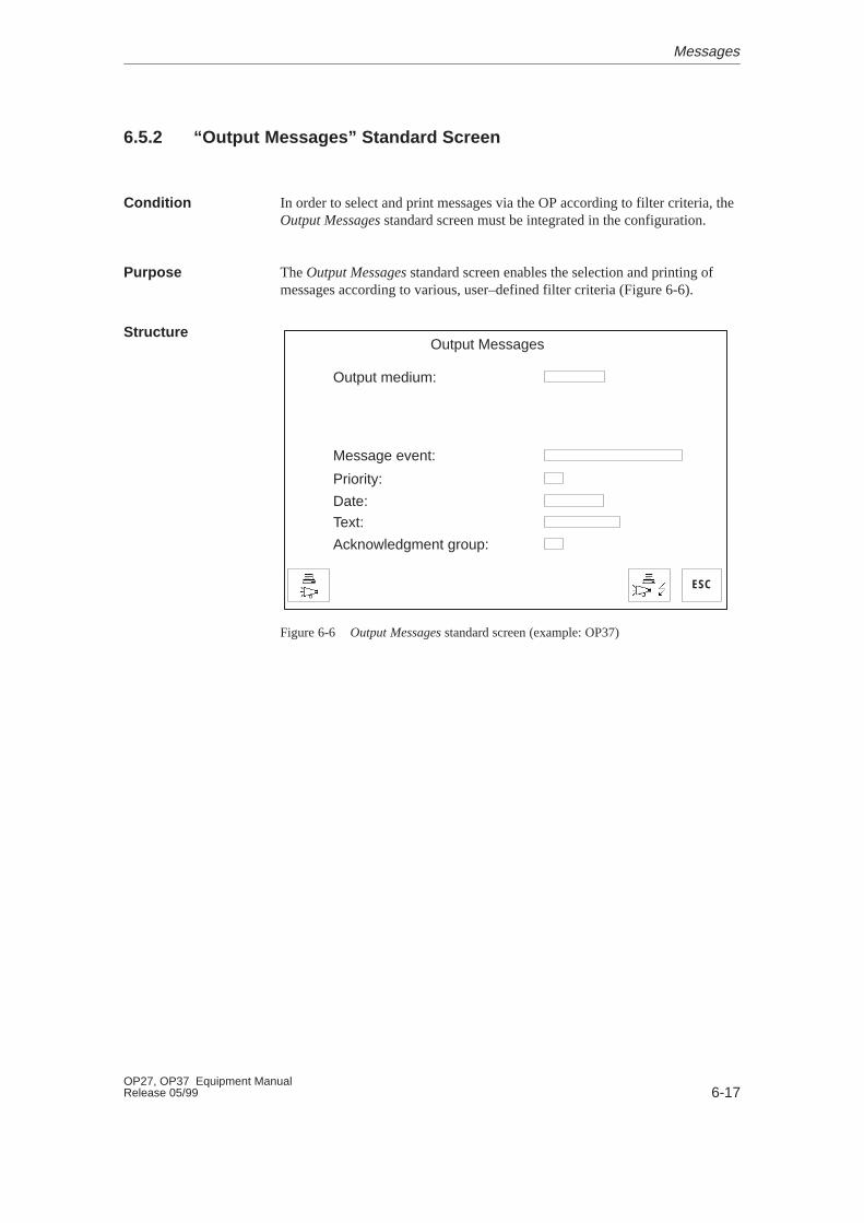
6-17OP27, OP37 Equipment ManualRelease 05/99
6.5.2 “Output Messages” Standard Screen
In order to select and print messages via the OP according to filter criteria, theOutput Messages standard screen must be integrated in the configuration.
The Output Messages standard screen enables the selection and printing ofmessages according to various, user–defined filter criteria (Figure 6-6).
ESC
Output Messages
Output medium:
Message event:
Priority:
Date:
Text:
Acknowledgment group:
Figure 6-6 Output Messages standard screen (example: OP37)
Condition
Purpose
Structure
Messages
6-18OP27, OP37 Equipment Manual
Release 05/99
Output medium PRINTER
The factory setting for output from units OP27and OP37 is to a printer.
Message event ALL
All the alarm messages or event messagebuffer contents are printed out. This includesall message events which have Arrived,Departed or been Acknowledged.
ARRIVED ONLY Only the Arrived messages events stored in thebuffer are printed.
DEPARTED ONLY
Only the Departed messages events stored inthe buffer are printed.
ACKNOWLEDGED ONLY
Only the Acknowledged messages eventsstored in the buffer are printed.
ARRIVED AND DEPARTED Only the Arrived and Departed messagesevents stored in the buffer are printed.
ARRIVED AND ACKNOWLEDGED Only the Arrived and Acknowledged messagesevents stored in the buffer are printed.
DEPARTED AND ACKNOWLEDGED Only the Departed and Acknowledged mes-sages events stored in the buffer are printed.
Priority 0 to 16
Only those message events are printed whichhave at least the specified priority.
Date Only those message events with the specifieddate are printed.
Text Only those message events are printed whichcontain the specified character string. Upper/lower case is not considered.
Acknowledgment group 0 to 16
Only those message events are printed whichbelong to the specified acknowledgementgroup.
Meaning ofoperating elements
Messages
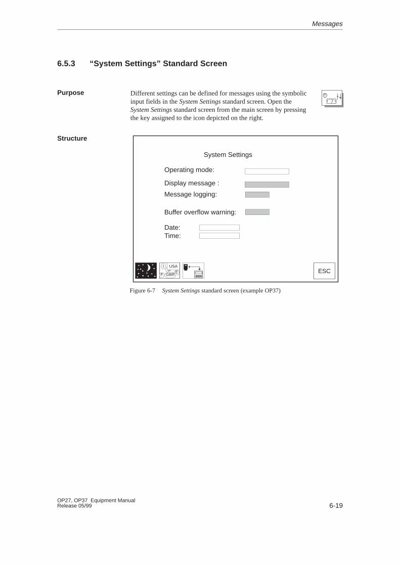
6-19OP27, OP37 Equipment ManualRelease 05/99
6.5.3 “System Settings” Standard Screen
Different settings can be defined for messages using the symbolicinput fields in the System Settings standard screen. Open theSystem Settings standard screen from the main screen by pressingthe key assigned to the icon depicted on the right.
ID
F GBR
USAE ESC
System Settings
Operating mode:
Display message :
Message logging:
Buffer overflow warning:
Date:Time:
Figure 6-7 System Settings standard screen (example OP37)
Purpose
Structure
Messages
6-20OP27, OP37 Equipment Manual
Release 05/99
Only the operating elements of interest as regards messages are listed below.See Chapter 11 for a description of the other fields and keys.
Message display � FIRST
The oldest message is displayed first.
� LAST
The most recent message is displayed first.
Message logging For a description refer to the Table on page 6-13.
Buffer overflow warning � ON
A system message is issued when theremaining buffer size is reached.
� OFF
No message is issued when the remainingbuffer size is reached.
ESCExit from standard screen
Meaning ofoperating elements
Messages
7-1OP27, OP37 Equipment ManualRelease 05/99
Printing
A black and white or color printer can be connected to the OP. Configurationof the connection is described in Section 13.1.3. Descriptions of the interfacesis provided in Appendix B.
The following print functions are provided on the OP:
� Print Messages (see Section 6.4).Screen prints (hardcopies) and screens can be printed during message log-ging.
� Print BufferThe entire event message or alarm message buffer contents are printed onthe printer. Filter criteria can be defined for the printout (see Chapter 6.5.2).
� Print ScreenTo use this function on the OP, assign the PRINT SCREEN function to a func-tion key during configuration. The screen displayed is printed after pressingthe function key. Windows currently displayed on the screen, e.g. the mes-sage window, are not printed together with the screen. Once initiated, can-cel printing of the screenshot by pressing the function key once more.
� Print Screen ListTo use this function on the OP, assign the PRINT SCREEN LIST function to afunction key during configuration. This function can be used to print up totwenty screens in succession at one page per screen. If there are outputfields on a screen for process values, the values valid at the time of printingare read out from the PLC.In order to print all the screens selected using the Print Screen List functionin Graphics mode, it must be defined in the configuration using the globalfunction Automatic Graphics Printing.Printing is performed in the background, so that the OP can still be oper-ated.ASCII is the default printing mode; in other words, graphic elements suchas graphics, trend curves and bar graphs are not printed. Print Screen is notpossible while printing is in progress. If the GRAPHICS MODE UPON PRINTING
SCREEN LIST function has been configured for individual screens, all theelements of these screens are printed when the screen list is printed.
Connecting aprinter
Print functions
7
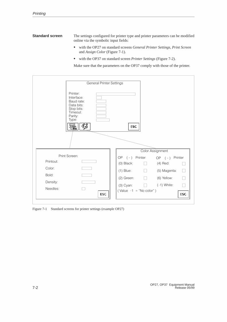
7-2OP27, OP37 Equipment Manual
Release 05/99
The settings configured for printer type and printer parameters can be modifiedonline via the symbolic input fields:
� with the OP27 on standard screens General Printer Settings, Print Screenand Assign Color (Figure 7-1).
� with the OP37 on standard screen Printer Settings (Figure 7-2).
Make sure that the parameters on the OP37 comply with those of the printer.
�#+#.�) �.'+0#. �#00'+%/
�.'+0#.
�+0#.$�!#
��1" .�0#
��0� '0/
�0,- '0/
�'*#,10
��.'03
�3-#
�.'+0 �!.##+
�.'+0,10
�,),.
�,)"
�#+/'03
�##")#/
�,),. �//'%+*#+0
�� � � � �� � � ��.'+0#. �.'+0#.
��� �)�!(
��� �)1#
��� �.##+
�� �3�+
�� �#"
��� ��%#+0�
��� �#)),2
���� �&'0#
� ��)1# �� � 4�, !,),.� �
Figure 7-1 Standard screens for printer settings (example OP27)
Standard screen
Printing
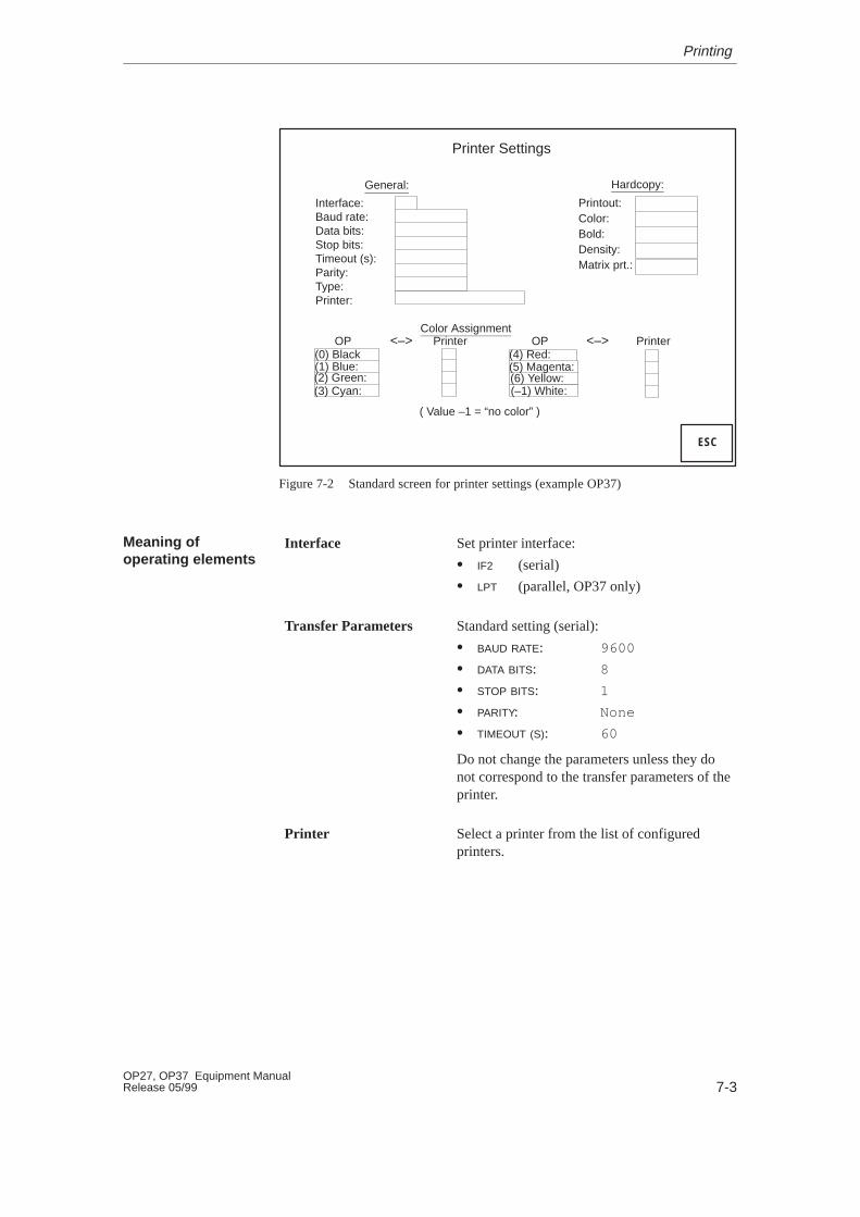
7-3OP27, OP37 Equipment ManualRelease 05/99
(0) Black(1) Blue:(2) Green:(3) Cyan:
(6) Yellow:(5) Magenta:(4) Red:
(–1) White:
Hardcopy:
Printout:Color:Bold:Density:Matrix prt.:
OP Printer OP<–> Printer<–>Color Assignment
( Value –1 = “no color” )
Printer Settings
ESC
General:
Interface:Baud rate:Data bits:Stop bits:Timeout (s):Parity:Type:Printer:
Figure 7-2 Standard screen for printer settings (example OP37)
Interface Set printer interface:
� IF2 (serial)
� LPT (parallel, OP37 only)
Transfer Parameters Standard setting (serial):
� BAUD RATE: 9600
� DATA BITS: 8
� STOP BITS: 1
� PARITY: None
� TIMEOUT (S): 60
Do not change the parameters unless they donot correspond to the transfer parameters of theprinter.
Printer Select a printer from the list of configuredprinters.
Meaning ofoperating elements
Printing

7-4OP27, OP37 Equipment Manual
Release 05/99
Print Screen � ASCII (default setting):Only ASCII characters are printed in ascreen printout (no graphics or charactergraphics). Printing in ASCII format is sig-nificantly quicker than graphics printing.A screen which contains text charactersbelonging to an Asiatic character set isalways printed in graphics mode, irrespec-tive of the default ASCII setting.
� GRAPHICS:All elements on the screen are printed in ascreen print, including graphics, trends andbar graphs.
Color Assignment Disable individual colors (–1) or modify colorassignment.
Example:In order to use black (0) as the color instead ofblue (1).
Switch to Print Screen standard screen (OP27 only).
Switch to Color Assignment standard screen (OP27 only).
ESCExit from standard screen
Printing
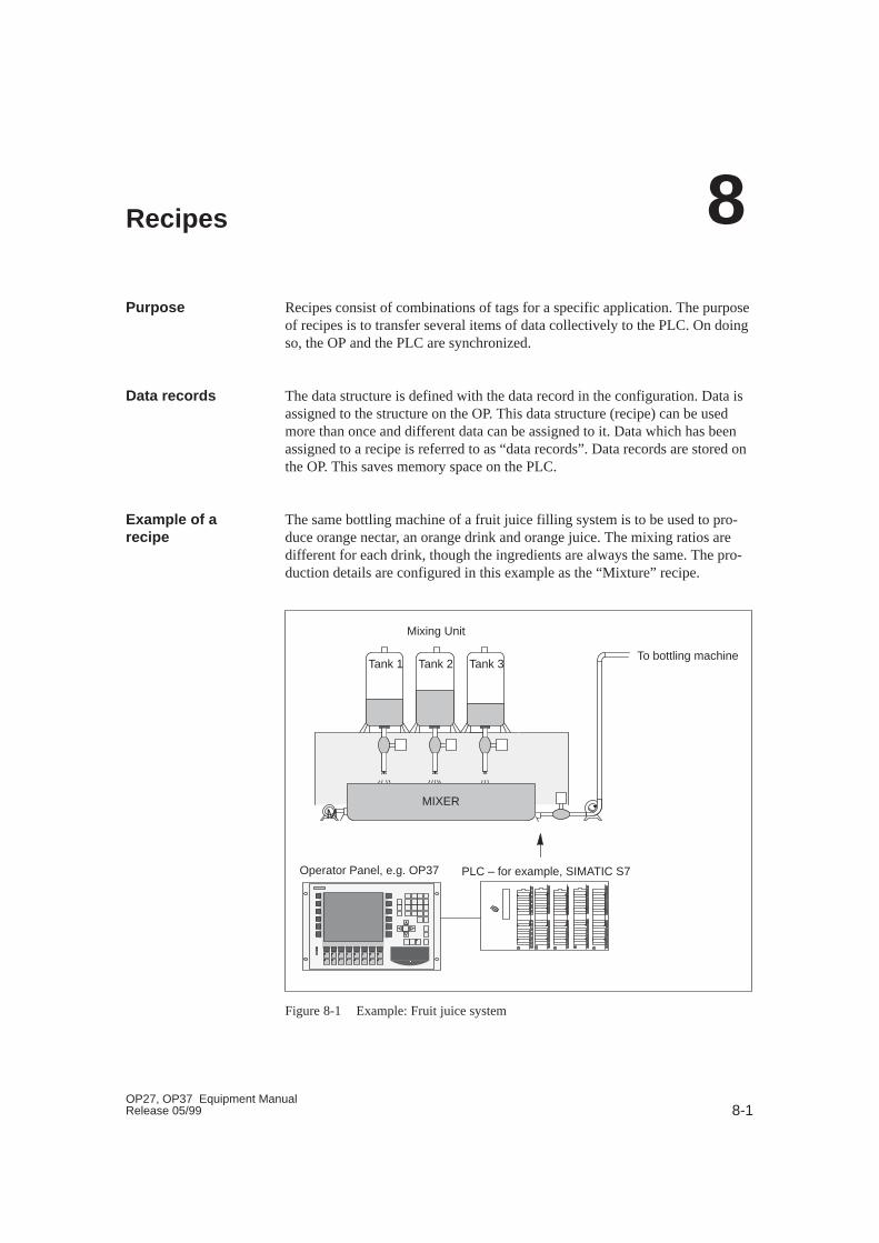
8-1OP27, OP37 Equipment ManualRelease 05/99
Recipes
Recipes consist of combinations of tags for a specific application. The purposeof recipes is to transfer several items of data collectively to the PLC. On doingso, the OP and the PLC are synchronized.
The data structure is defined with the data record in the configuration. Data isassigned to the structure on the OP. This data structure (recipe) can be usedmore than once and different data can be assigned to it. Data which has beenassigned to a recipe is referred to as “data records”. Data records are stored onthe OP. This saves memory space on the PLC.
The same bottling machine of a fruit juice filling system is to be used to pro-duce orange nectar, an orange drink and orange juice. The mixing ratios aredifferent for each drink, though the ingredients are always the same. The pro-duction details are configured in this example as the “Mixture” recipe.
Tank 1 Tank 2 Tank 3To bottling machine
MIXERM
PLC – for example, SIMATIC S7
Mixing Unit
Operator Panel, e.g. OP37
Figure 8-1 Example: Fruit juice system
Purpose
Data records
Example of arecipe
8

8-2OP27, OP37 Equipment Manual
Release 05/99
A recipe consists of a series of recipe entries. Each entry contains no more thanone input field (tag).
The Mixture recipe might contain the following entries:
Name:
Orange:
Water:
Sugar:
Flavor:
l
l
kg
g
Input fields (variables)
Values are assigned to the input field tags on the OP and stored. Together, thesevalues form one data record of the recipe.
Several data records can be created for one recipe. This enables the fruit juicesystem, for example, to produce drinks of different kinds. It uses a differentdata record for each drink:
Name:
Orange:
Water:
Sugar:
Flavor:
“Mixture” recipeentries
Beverage
90 l
10 l
1.5 kg
200 g
Nectar
70 l
30 l
1.5 kg
400 g
Juice
95 l
5 l
0.5 kg
100 g
Data record 2 Data record 3Data record 1
All data records are stored in the OP. Only the currently active data record isstored on the PLC. This saves memory space on the PLC.
A recipe is created under a symbolic name in the configuration. The recipe isalso selected using this symbolic name on the OP.
Ingredients of arecipe
Data records onthe OP
Identifying recipes
Recipes

8-3OP27, OP37 Equipment ManualRelease 05/99
8.1 Standard Screens for Recipes
In order to create, save and download data records using the OP, the Data Re-cord Processing standard screen must be integrated in the configuration. Thestandard screen Selection Data Record Transmission is only required in theconfiguration when current data needs to be transferred directly between theOP and PLC.
Data records are created, modified and deleted using the standard screen DataRecord Processing. This standard screen can also be used to Selection DataRecord Transmissions from data media (flash, memory cards ) to the PLC orvice versa. The standard screen Selection Data Record Transmission is onlyrequired when data records need to be transferred between specific OPs, datamedia or PLCs. A detailed description of handling standard screens is providedin Section 8.1.1.
Use the standard screen Data Record Processing (Figure 8-2) to
� create data records on the OP and store them on a data medium,
� transfer the records from data media to the main memory of the OP andfrom there to the PLC,
ÉÉÉÉÉÉÉÉÉ
OP PLC
e.g.Flash
Mainmemory
Datamedium
SRAM
� delete data records on the data medium
� Data Record Processing on the OP.
The structure of a recipe cannot be modified on the OP.
Condition
Purpose
Standard screenData Record Proc -essing
Recipes
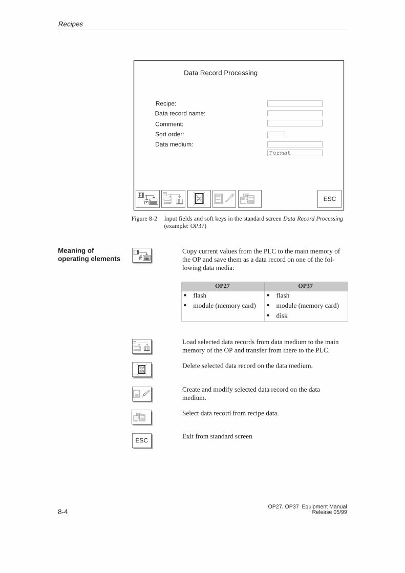
8-4OP27, OP37 Equipment Manual
Release 05/99
ESC
Data Record Processing
Recipe:
Data record name:
Comment:
Data medium:
Sort order:
Format
Figure 8-2 Input fields and soft keys in the standard screen Data Record Processing(example: OP37)
Copy current values from the PLC to the main memory ofthe OP and save them as a data record on one of the fol-lowing data media:
OP27 OP37
� flash
� module (memory card)
� flash
� module (memory card)
� disk
Load selected data records from data medium to the mainmemory of the OP and transfer from there to the PLC.
Delete selected data record on the data medium.
Create and modify selected data record on the datamedium.
Select data record from recipe data.
ESCExit from standard screen
Meaning ofoperating elements
Recipes
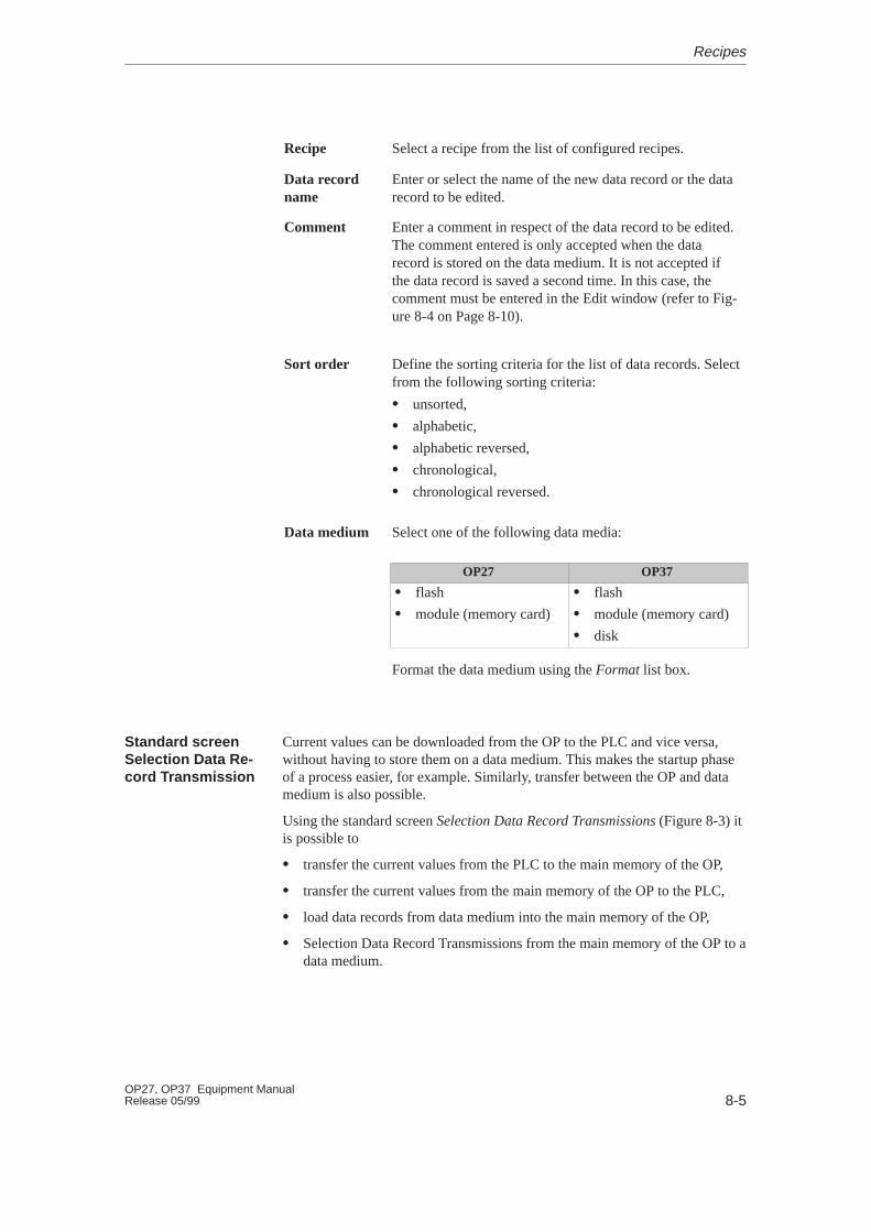
8-5OP27, OP37 Equipment ManualRelease 05/99
Recipe Select a recipe from the list of configured recipes.
Data recordname
Enter or select the name of the new data record or the datarecord to be edited.
Comment Enter a comment in respect of the data record to be edited.The comment entered is only accepted when the datarecord is stored on the data medium. It is not accepted ifthe data record is saved a second time. In this case, thecomment must be entered in the Edit window (refer to Fig-ure 8-4 on Page 8-10).
Sort order Define the sorting criteria for the list of data records. Selectfrom the following sorting criteria:
� unsorted,
� alphabetic,
� alphabetic reversed,
� chronological,
� chronological reversed.
Data medium Select one of the following data media:
OP27 OP37
� flash
� module (memory card)
� flash
� module (memory card)
� disk
Format the data medium using the Format list box.
Current values can be downloaded from the OP to the PLC and vice versa,without having to store them on a data medium. This makes the startup phaseof a process easier, for example. Similarly, transfer between the OP and datamedium is also possible.
Using the standard screen Selection Data Record Transmissions (Figure 8-3) itis possible to
� transfer the current values from the PLC to the main memory of the OP,
� transfer the current values from the main memory of the OP to the PLC,
� load data records from data medium into the main memory of the OP,
� Selection Data Record Transmissions from the main memory of the OP to adata medium.
Standard screenSelection Data Re -cord Transmission
Recipes

8-6OP27, OP37 Equipment Manual
Release 05/99
ESC
Selection Data Record Transmissions
Recipe:
Data record name:
Comment:
Data medium:
Sort order:
Figure 8-3 Input fields and soft keys in the standard screen Data Record Processing(example: OP37)
Download current values from the PLC to the mainmemory of the OP (update values in the OP).
Download current values from the main memory of the OPto the PLC.
Download data records from data medium to the mainmemory of the OP.
Download data records from the main memory of the OPto the data medium.
Select data record.
ESCExit from standard screen
Recipe Select a recipe from the list of configured recipes.
Data recordname
Enter or select the name of the data record to be down-loaded.
Comment Enter a comment in respect of the data record to be edited.
Meaning ofoperating elements
Recipes

8-7OP27, OP37 Equipment ManualRelease 05/99
Sort order Define the sorting criteria for the data records to betransferred. Select from the following sorting criteria:
� unsorted,
� alphabetic,
� alphabetic reversed,
� chronological,
� chronological reversed.
Data medium Select one of the following data media here:
OP27 OP37
� flash
� module (memory card)
� flash
� module (memory card)
� disk
Recipes
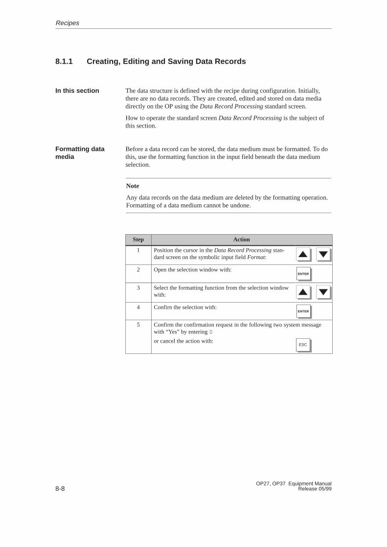
8-8OP27, OP37 Equipment Manual
Release 05/99
8.1.1 Creating, Editing and Saving Data Records
The data structure is defined with the recipe during configuration. Initially,there are no data records. They are created, edited and stored on data mediadirectly on the OP using the Data Record Processing standard screen.
How to operate the standard screen Data Record Processing is the subject ofthis section.
Before a data record can be stored, the data medium must be formatted. To dothis, use the formatting function in the input field beneath the data mediumselection.
Note
Any data records on the data medium are deleted by the formatting operation.Formatting of a data medium cannot be undone.
Step Action
1 Position the cursor in the Data Record Processing stan-dard screen on the symbolic input field Format:
2 Open the selection window with:ENTER
3 Select the formatting function from the selection windowwith:
4 Confirn the selection with:ENTER
5 Confirm the confirmation request in the following two system messagewith “Yes” by entering 0
or cancel the action with:ESC
In this section
Formatting datamedia
Recipes
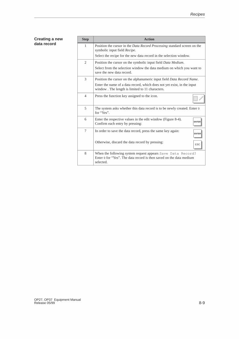
8-9OP27, OP37 Equipment ManualRelease 05/99
Step Action
1 Position the cursor in the Data Record Processing standard screen on thesymbolic input field Recipe.
Select the recipe for the new data record in the selection window.
2 Position the cursor on the symbolic input field Data Medium.
Select from the selection window the data medium on which you want tosave the new data record.
3 Position the cursor on the alphanumeric input field Data Record Name.
Enter the name of a data record, which does not yet exist, in the inputwindow . The length is limited to 11 characters.
4 Press the function key assigned to the icon.
5 The system asks whether this data record is to be newly created. Enter 0
for “Yes”.
6 Enter the respective values in the edit window (Figure 8-4).Confirm each entry by pressing:
ENTER
7 In order to save the data record, press the same key again:ENTER
Otherwise, discard the data record by pressing:ESC
8 When the following system request appears Save Data Record?Enter 0 for “Yes”. The data record is then saved on the data mediumselected.
Creating a newdata record
Recipes
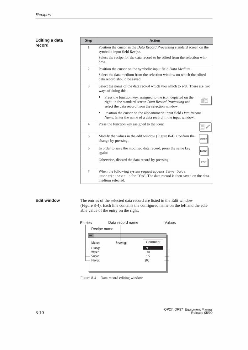
8-10OP27, OP37 Equipment Manual
Release 05/99
Step Action
1 Position the cursor in the Data Record Processing standard screen on thesymbolic input field Recipe.
Select the recipe for the data record to be edited from the selection win-dow.
2 Position the cursor on the symbolic input field Data Medium.
Select the data medium from the selection window on which the editeddata record should be saved .
3 Select the name of the data record which you which to edit. There are twoways of doing this:
� Press the function key, assigned to the icon depicted on theright, in the standard screen Data Record Processing andselect the data record from the selection window.
� Position the cursor on the alphanumeric input field Data RecordName. Enter the name of a data record in the input window.
4 Press the function key assigned to the icon:
5 Modify the values in the edit window (Figure 8-4). Confirm thechange by pressing:
ENTER
6 In order to save the modified data record, press the same keyagain:
ENTER
Otherwise, discard the data record by pressing:ESC
7 When the following system request appears Save DataRecord?Enter 0 for “Yes”. The data record is then saved on the datamedium selected.
The entries of the selected data record are listed in the Edit window (Figure 8-4). Each line contains the configured name on the left and the edit-able value of the entry on the right.
Mixture Beverage
Orange:Water:Sugar:Flavor:
101.5
200
Comment
Entries Data record name Values
Recipe name
90
Figure 8-4 Data record editing window
Editing a datarecord
Edit window
Recipes

8-11OP27, OP37 Equipment ManualRelease 05/99
Current values can be copied from the PLC to the OP main memory and savedas a data record on a data medium. The time at which the data record wassaved is also stored.
Step Action
1 Position the cursor in the Data Record Processing standard screen on thesymbolic input field Recipe.
Select the recipe for the data record to be saved from the selection win-dow.
2 Position the cursor on the symbolic input field Data Medium.
Select the data medium from the selection window on which the editeddata record should be saved.
3 Select the name of the data record to be saved (see Editing a data record,Step 3, Page 8-10).
4 Press the function key assigned to the icon:
If a data record with this name does not exist, it is created. If a data recordwith this name already exists, the system asks whether the existing datarecord should be overwritten.
5 Confirm with “Yes” by entering 0 or enter 1 for “No” to cancel theaction.
6 Repeat steps 1 to 5 for each data record to be saved on the data medium.
Saving datarecords
Recipes
8-12OP27, OP37 Equipment Manual
Release 05/99
Proceed as follows to load data records from data media in the main memoryof the OP and download them to the PLC:
Step Action
1 Position the cursor in the Data Record Processing standard screen on thesymbolic input window Recipe.
Select a recipe for the data record to be loaded from the selection window.
2 Select the name of the data record to be loaded (see Editing a data record,Step 3, Page 8-10).
3 Position the cursor on the symbolic input field Data Medium.
Select the data medium from which the data record is to be loaded fromthe selection window .
4 Press the function key assigned to the icon depicted on theright.
The data record is copied first of all in the main memory of the OP andthen downloaded to the PLC where it overwrites the old data record.
The following section describes the sequence for deleting individual datarecords from the selected data medium. If all the data records on the datamedium are to be deleted, it is more practical to use the Format function (see Page 8-8).
If the data record to be deleted from the data medium is active on the PLC, itremains active on the PLC even after it has been deleted.
Step Action
1 Position the cursor in the Data Record Processing standard screen on thesymbolic input field Recipe.
Select a recipe for the data record to be delete from the selection window.
2 Position the cursor on the symbolic input field Data Medium.
Select the data medium containing the data record to be deleted from theselection window .
3 Select the name of the data record to be deleted (see Editing a datarecord, Step 3, Page 8-10).
4 Press the function key assigned to the icon:
5 Confirm the subsequent confirmation request with “Yes” by entering 0 or1 for “No” to cancel the action.
Loading data re -cords
Deleting datarecords
Recipes
8-13OP27, OP37 Equipment ManualRelease 05/99
8.1.2 Transferring Data Records
The following section describes how to operate the Selection Data RecordTransmission standard screen. This standard screen contains special functionsconfigured for transferring data records between the OP and PLC and betweenthe OP and data medium. As opposed to transfer using standard screen DataRecord Processing, intermediate steps are provided here for the transfer pro-cess. This means that it is possible to load a data record from the PLC in themain memory of the OP, edit the data record and then transfer the record backto the PLC with modified values.
Proceed as follows to update the values in the data record in the OP mainmemory with values from the PLC:
Step Action
1 Position the cursor in the Data Record Processing standard screen on thesymbolic input window Recipe.
Select the recipe for the data record to be updated from the selection win-dow.
2 Select the name of the data record to be loaded in the OP (refer to Editinga data record, Step 3, Page 8-10).
3 Press the function key assigned to the icon:
The data record is copied from the PLC in the main memory of the OP.
Proceed as follows to transfer the current values in the main memory of the OPto the PLC:
Step Action
1 Position the cursor in the Data Record Processing standard screen on thesymbolic input window Recipe.
Select a recipe for the data record to be transferred from the selectionwindow.
2 Select the name of the data record to be loaded in the PLC (refer to Edit-ing a data record, Step 3, Page 8-10).
3 Press the function key assigned to the icon:
The data record is copied from the main memory of the OP to the PLC.
In this section
PLC � OP
OP � PLC
Recipes
8-14OP27, OP37 Equipment Manual
Release 05/99
Proceed as follows to load a data record from a data medium in the mainmemory of the OP:
Step Action
1 Position the cursor in the Data Record Processing standard screen on thesymbolic input window Recipe.
Select a recipe for the data record to be loaded from the selection window.
2 Position the cursor on the symbolic input field Data Medium.
Select the data medium from which the data record is to be loaded fromthe selection window .
3 Select the name of the data record to be loaded in the OP (refer to Editinga data record, Step 3, Page 8-10).
4 Press the function key assigned to the icon:
The data record is copied from the data medium to the main memory ofthe OP.
Proceed as follows to save a data record in the main memory of the OP on thedata medium:
Step Action
1 Position the cursor in the Data Record Processing standard screen on thesymbolic input window Recipe.
Select the recipe for the data record to be saved from the selection win-dow.
2 Position the cursor on the symbolic input field Data Medium.
Select the data medium on which the data record is to be saved from theselection window .
3 Select the name of the data record to be saved (see Editing a data record,Step 3, Page 8-10).
4 Press the function key assigned to the icon:
The data record is copied from the main memory of the OP to the datamedium.
Data medium �OP
OP � data medium
Recipes
8-15OP27, OP37 Equipment ManualRelease 05/99
8.2 Record Sets
A record set combines one data record from several different recipes under acommon name.
In its data records, a record set contains all the values required to set up amachine or system. This means, for example, that the basic settings formachines which operate simultaneously can be loaded to produce differentproducts.
In order to simplify the general overview, the ORANGE fruit juice system usedin this chapter is extended by the production lines GRAPEFRUIT andLEMON. To do this, the recipes GRAPEFRUIT and LEMON are set up. Eachof these recipes has a data record called ”Drink”. These three data records formthe record set called ”Drink”.
The data record ”Drink” for all three recipes can be downloaded simulta-neously to the PLC in a single transfer action, thus starting production of the“Drink”.
A record set is edited in the Edit Data Record standard screen in the same wayas a data record.
The editing options are:
� Select
� Save (Create)
� Load
� Delete
Select the recipe name Record Set from the selection window. If ”Record Set”has been chosen as the recipe, all the data records of all recipes are displayedfollowing selection of the data record. Record sets (data records which arepresent in several recipes) are identified by a * in front of their name.
Definition
Example
Editing
Selecting
Recipes
8-16OP27, OP37 Equipment Manual
Release 05/99
A record set can be created in standard screen Data Record Processing in twodifferent ways, i.e. saved on a data medium:
1. Save a data record for each recipe
Step Action
1 Select RecordSet as the recipe.
2 Define the data record name and the data medium.
3 Save the record set as with a data record.
A data record is created for each recipe.
4 Delete any data records not required.
2. Save a data record individually for selected recipes
Step Action
1 Select the recipe name, e.g. ORANGE.
2 Define the data record name (e.g. Drink) and data medium. Each datarecord name must be created with the same name (= Drink).
3 Edit the data record and save it.
4 Repeat steps 1 and 3 for each data record.
During the loading procedure all the data records with the selected namelocated on the data medium are loaded in the main memory of the OP andtransferred on to the PLC. The sequence of steps corresponds to the proceduredescribed on Page 8-12 under Loading data records.
Note
� It may take a relatively long time to upload a record set from the datamedium to the PLC, depending on the size of the recipes. A record setshould, therefore, only contain essential recipes.
� During the following downloading procedure, all current values of allrecipe tags are transferred, and not just the data records with the samename:
– PLC � OP
– PLC � Data medium
– OP � PLC
Save (Create)
Load
Recipes

8-17OP27, OP37 Equipment ManualRelease 05/99
� Complete record set:
The sequence of steps corresponds to the procedure described on Page 8-12under Deleting data records.
� Partial r ecord set:
Delete the data records with the corresponding name individually from theselected data records. The sequence of steps corresponds to the proceduredescribed on Page 8-12 under Deleting data records.
Record sets cannot be modified. Only the individual data records in the recordset can be modified. The sequence of steps corresponds to the proceduredescribed on Page 8-10 under Editing data records.
Delete
Modify
Recipes

8-18OP27, OP37 Equipment Manual
Release 05/99
Recipes

9-1OP27, OP37 Equipment ManualRelease 05/99
Storing and Loading Data
This chapter explains
� how to transfer data to different data media
� which settings have to be performed and
� what to bear in mind.
Depending on the type and quantity, data is loaded onto data media to
� backup data
� read in stored data (restore),
� load or store recipe data records
� load data from the configuration computer to a different operator panel,
� transfer OP firmware (download).
9.1 Data Types, Data Media and Storage Principle
Data is divided into the following categories:
� configuration data
� firmware data and
� recipe data.
The following data media are available for the OP:
Data medium Operator Panel
OP27 OP37
Internal flash memory � �
Memory card � �
3.5” floppy disk (optional) – �
In this chapter
Purpose
Data types
Data media
9
9-2OP27, OP37 Equipment Manual
Release 05/99
The internal flash memory is a standard storage medium in the OP. The storagecapacity is 1 MB in the case of the OP27M and 2 MB in the case of the OP27Cand OP37. All data types can be stored in the flash memory. Memory alloca-tion depends on the size of the configuration, the firmware and the data areaconfigured for data records.
The memory card is an external memory medium, comparable to a disk.Compared to the internal flash memory, the memory card features the follow-ing advantages:
� The memory card is a portable storage medium. This means, for example,that recipe data can be transported from one OP to another. In this way,changes to configurations or firmware updates can be transferred to sys-tems on which no configuration computer is immediately available fortransferring such data.
� Configurations can be loaded directly from the memory card to the workingmemory since the OP detects an inserted card. In this case, the OP accessesthe memory card first, before accessing the internal flash memory.
� Its storage capacity of up to 16 MB provides space for large configurationsor a large number of recipe data records.
!Caution
Memory cards containing stored configurations may only be used with OPs ofthe same type. Otherwise, a system crash is possible.
The OP37 can be supplied with optional 3.5” floppy disk and hard disk drives.
Note
A floppy disk can only be used to store recipe data records in OP mode(Section 11.1).
The hard disk can only be used in DOS mode (Chapter 15).
When loading new or modified recipe data on the system is frequently neces-sary, but the configuration remains unchanged, the 3.5” floppy disk drive is avery manageable and beneficial solution, since it can be accessed from thefront of the OP37.
Data can only be saved in the following combinations for practical purposes:
� firmware, configuration and recipe data records or
� firmware and configuration1) or
� recipe data.
1) This function is not contained on the standard screen and has to be configured.
Internal flashmemory
Memory card
Disk, hard disk
Storage principle
Storing and Loading Data

9-3OP27, OP37 Equipment ManualRelease 05/99
9.2 Clear/Initialize Storage Medium
Before beginning making a backup copy of new recipe data or a modified con-figuration, delete or initialize the target data medium. This establishes adefined status for the data medium.
Make sure that the storage module is not inserted when the flash memory is tobe deleted because the OP accesses the storage module when switching toDownload mode.
Note
All data on the data medium is lost as a result of deletion. All existing config-urations are deleted on initialization, but the recipe data records are retained.
Perform the following steps to clear or initialize memory:
Step Action
1 Switch off the power supply to the OP. Press theadjacent key combination to restart.
ESC + +
2 Insert the memory card to delete or initialize dataon it. The following messages appear in successionon the OP:
Press ‘DEL’ to erase total Flash
Press ‘DEL’ to init Flash
Press ‘DEL’ to erase total Modules
Press ‘DEL’ to init Module
3 Scroll to the next message using the keys depictedon the right.
ENTER or ESC
4 Confirm the selected function with the keys depic-ted on the right. DEL
INS
Delete flash/memory card
Storing and Loading Data

9-4OP27, OP37 Equipment Manual
Release 05/99
A memory area, with the following default settings, is reserved for recipe datain the flash memory and on the memory card:
� 64 kB (flash memory)
� 128 kB (memory card).
If the default values are not sufficient, they can be reset reset in ProTool.Remember, however, that there is less space available for the configuration ifthe reserved area is enlarged.
Note
Remember that, in addition to the reserved area for recipe data records, 64 kBare required on the internal flash memory and 128 kB on the memory card formanagement data.
Reserved memoryarea for recipedata
Storing and Loading Data
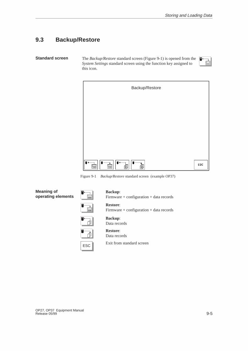
9-5OP27, OP37 Equipment ManualRelease 05/99
9.3 Backup/Restore
The Backup/Restore standard screen (Figure 9-1) is opened from theSystem Settings standard screen using the function key assigned tothis icon.
Backup/Restore
Figure 9-1 Backup/Restore standard screen (example OP37)
Backup:Firmware + configuration + data records
Restore:Firmware + configuration + data records
Backup:Data records
Restore:Data records
ESCExit from standard screen
Standard screen
Meaning ofoperating elements
Storing and Loading Data
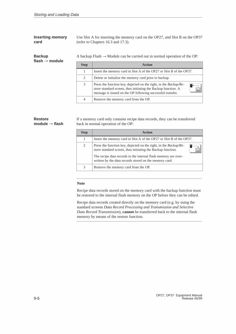
9-6OP27, OP37 Equipment Manual
Release 05/99
Use Slot A for inserting the memory card on the OP27, and Slot B on the OP37(refer to Chapters 16.3 and 17.3).
A backup Flash � Module can be carried out in normal operation of the OP:
Step Action
1 Insert the memory card in Slot A of the OP27 or Slot B of the OP37.
2 Delete or initialize the memory card prior to backup.
3 Press the function key, depicted on the right, in the Backup/Re-store standard screen, thus initiating the Backup function. Amessage is issued on the OP following successful transfer.
4 Remove the memory card from the OP.
If a memory card only contains recipe data records, they can be transferredback in normal operation of the OP:
Step Action
1 Insert the memory card in Slot A of the OP27 or Slot B of the OP37.
2 Press the function key, depicted on the right, in the Backup/Re-store standard screen, thus initiating the Backup function.
The recipe data records in the internal flash memory are over-written by the data records stored on the memory card.
3 Remove the memory card from the OP.
Note
Recipe data records stored on the memory card with the backup function mustbe restored to the internal flash memory on the OP before they can be edited.
Recipe data records created directly on the memory card (e.g. by using thestandard screens Data Record Processing and Transmission and SelectiveData Record Transmission), cannot be transferred back to the internal flashmemory by means of the restore function.
Inserting memorycard
Backupflash � module
Restoremodule � flash
Storing and Loading Data

9-7OP27, OP37 Equipment ManualRelease 05/99
Perform the following steps to load a backup of the firmware/configurationonto the OP:
Step Action
1 Insert the memory card containing the firmware/configuration in Slot A ofthe OP27 or Slot B of the OP37.
2 Restart the OP. The OP is then started up with the firmware/configurationcontained on the memory card.
3 Press the function key, depicted on the right, in the Backup/Re-store standard screen to call in the Restore function.
The memory contents of the internal flash memory are over-written by the firmware/configuration contained on the memorycard.
4 Remove the memory card from the OP.
If the function Backup/Restore is added to the insertion point ”Initialization” inthe configuration, the function is called in each time the OP is started up, beingloaded from the memory card. The system then asks whether the internal flashmemory should be overwritten by the data stored on the memory card.
Step Action
1 Insert the memory card containing the backup into the corresponding slotof the system.
2 Start the OP.
3 Confirm initiation of the restore function by answering ”OK” at theprompt.
4 Remove the memory card from the OP.
Restore firmware/configuration
Automaticrestoring offirmware/configuration
Storing and Loading Data

9-8OP27, OP37 Equipment Manual
Release 05/99
Storing and Loading Data
10-1OP27, OP37 Equipment ManualRelease 05/99
Status/Force Tag Using the OP
The Operator Panels provide two functions, namely Status Tag and Force Tag,which enable operand values from the connected PLC to be displayed in astandard screen and modified in a second screen.
This means that PLC operands can be edited directly on the OP in online modewithout having to connect a programming unit to the PLC to do it.
Status Tag enables the status of SIMATIC S5/S7 operands to be displayed.
Force Tag enables SIMATIC S5/S7 operands to be controlled through modify-ing their values and transferring them back to the PLC.
Purpose
Status Tag
Force Tag
10

10-2OP27, OP37 Equipment Manual
Release 05/99
10.1 Status Tag
The Status Variable standard screen is selected from the basic screen by meansof a soft key.
Status Variable
MPI Operand Format Value12 DB, DBB 100 10 BIN = 00000000 00000000 1 ?????? 0 ????????? 01 ?????? 0 ????????? 01 ?????? 0 ????????? 01 ?????? 0 ????????? 01 ?????? 0 ????????? 01 ?????? 0 ????????? 01 ?????? 0 ????????? 01 ?????? 0 ????????? 01 ?????? 0 ????????? 0
Status:Running
Back to main screen
123 ESC
Start/Stop update
Figure 10-1 Status Variable standard screen (example: OP37 with SIMATIC S7)
Standard screenStatus V ariable
Status/Force Tag Using the OP
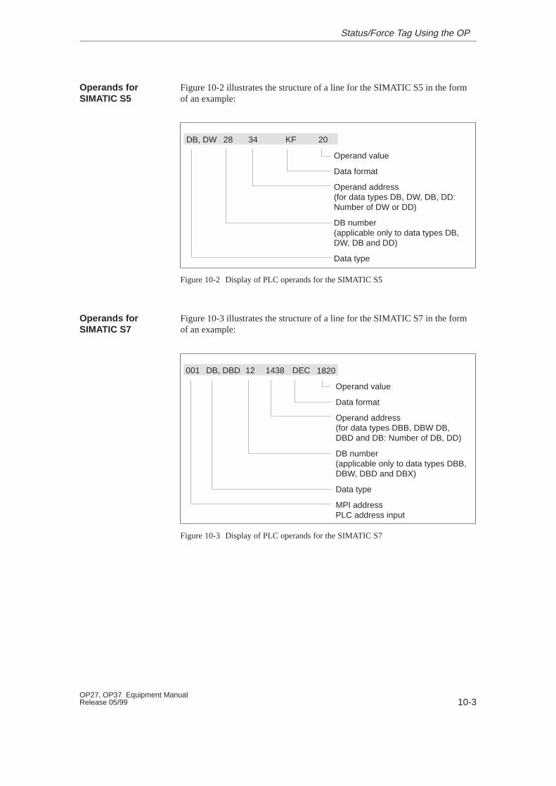
10-3OP27, OP37 Equipment ManualRelease 05/99
Figure 10-2 illustrates the structure of a line for the SIMATIC S5 in the formof an example:
Operand value
Data format
Operand address(for data types DB, DW, DB, DD:Number of DW or DD)
DB number(applicable only to data types DB, DW, DB and DD)
Data type
34 KF28 20DB, DW
Figure 10-2 Display of PLC operands for the SIMATIC S5
Figure 10-3 illustrates the structure of a line for the SIMATIC S7 in the formof an example:
Operand value
Data format
Operand address(for data types DBB, DBW DB, DBD and DB: Number of DB, DD)
DB number(applicable only to data types DBB,DBW, DBD and DBX)
Data type
MPI addressPLC address input
1438 DEC12 1820DB, DBD001
Figure 10-3 Display of PLC operands for the SIMATIC S7
Operands forSIMATIC S5
Operands forSIMATIC S7
Status/Force Tag Using the OP
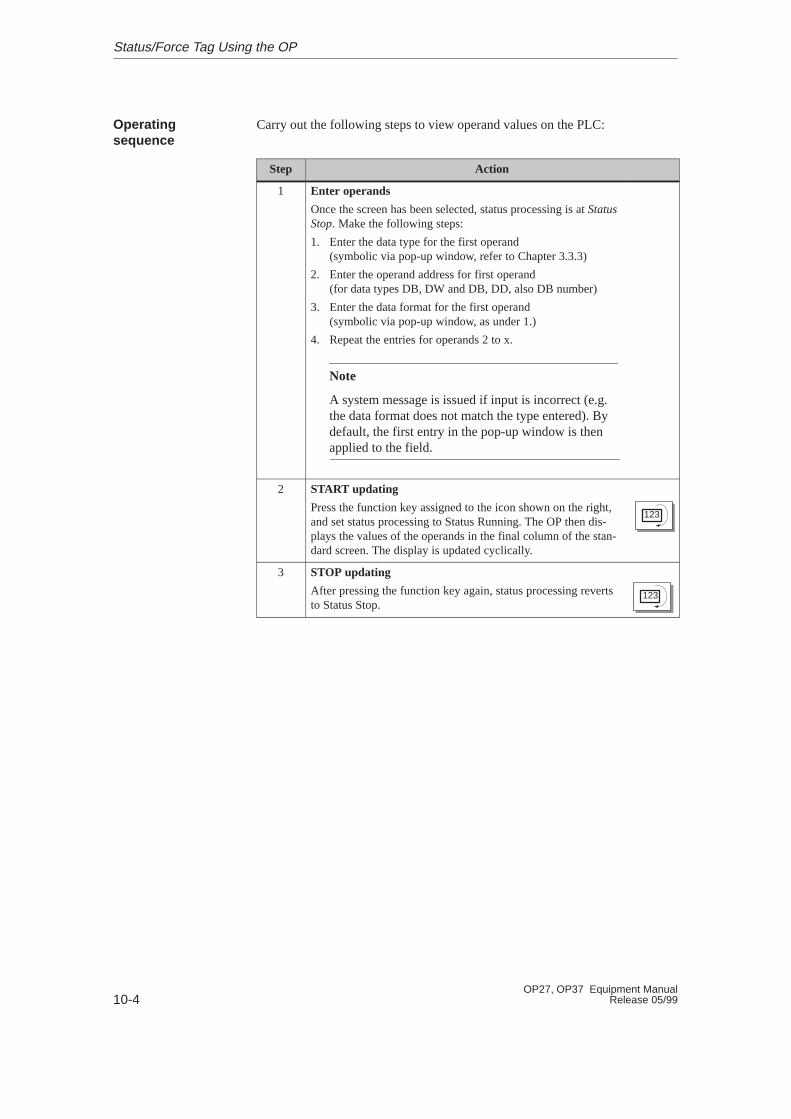
10-4OP27, OP37 Equipment Manual
Release 05/99
Carry out the following steps to view operand values on the PLC:
Step Action
1 Enter operands
Once the screen has been selected, status processing is at StatusStop. Make the following steps:
1. Enter the data type for the first operand(symbolic via pop-up window, refer to Chapter 3.3.3)
2. Enter the operand address for first operand(for data types DB, DW and DB, DD, also DB number)
3. Enter the data format for the first operand (symbolic via pop-up window, as under 1.)
4. Repeat the entries for operands 2 to x.
Note
A system message is issued if input is incorrect (e.g.the data format does not match the type entered). Bydefault, the first entry in the pop-up window is thenapplied to the field.
2 START updating
Press the function key assigned to the icon shown on the right,and set status processing to Status Running. The OP then dis-plays the values of the operands in the final column of the stan-dard screen. The display is updated cyclically.
123
3 STOP updating
After pressing the function key again, status processing revertsto Status Stop.
123
Operatingsequence
Status/Force Tag Using the OP
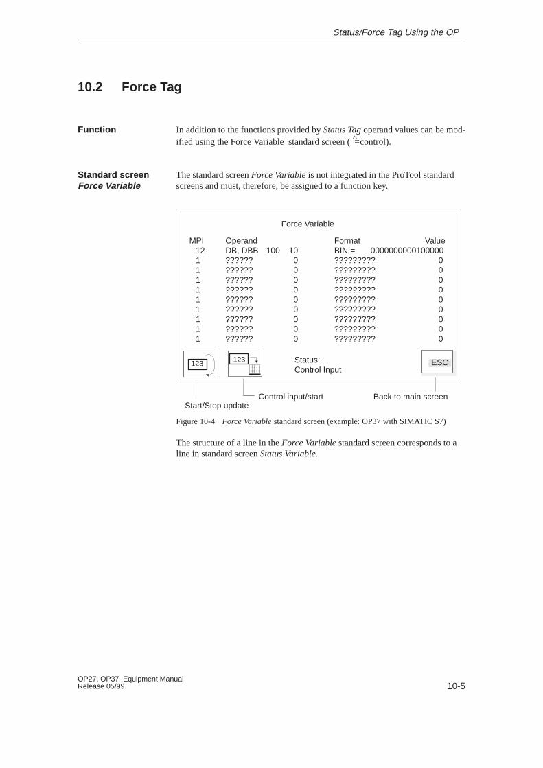
10-5OP27, OP37 Equipment ManualRelease 05/99
10.2 Force Tag
In addition to the functions provided by Status Tag operand values can be mod-ified using the Force Variable standard screen ( = control).
The standard screen Force Variable is not integrated in the ProTool standardscreens and must, therefore, be assigned to a function key.
Force Variable
MPI Operand Format Value12 DB, DBB 100 10 BIN = 00000000001000001 ?????? 0 ????????? 01 ?????? 0 ????????? 01 ?????? 0 ????????? 01 ?????? 0 ????????? 01 ?????? 0 ????????? 01 ?????? 0 ????????? 01 ?????? 0 ????????? 01 ?????? 0 ????????? 01 ?????? 0 ????????? 0
Status:Control Input
Back to main screen
123 ESC
Start/Stop updateControl input/start
123
Figure 10-4 Force Variable standard screen (example: OP37 with SIMATIC S7)
The structure of a line in the Force Variable standard screen corresponds to aline in standard screen Status Variable.
Function
Standard screen Force Variable
Status/Force Tag Using the OP
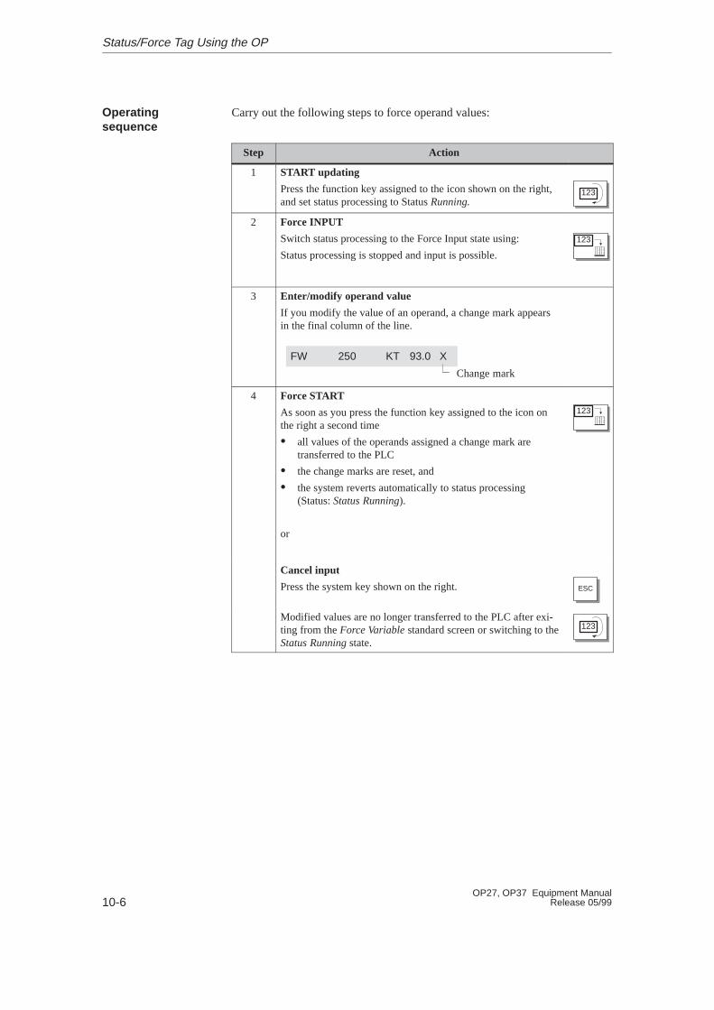
10-6OP27, OP37 Equipment Manual
Release 05/99
Carry out the following steps to force operand values:
Step Action
1 START updating
Press the function key assigned to the icon shown on the right,and set status processing to Status Running.
123
2 Force INPUT
Switch status processing to the Force Input state using:
Status processing is stopped and input is possible.
123
3 Enter/modify operand value
If you modify the value of an operand, a change mark appearsin the final column of the line.
Change mark
FW 250 KT 93.0 X
4 Force START
As soon as you press the function key assigned to the icon onthe right a second time
� all values of the operands assigned a change mark aretransferred to the PLC
� the change marks are reset, and
� the system reverts automatically to status processing (Status: Status Running).
or
123
Cancel input
Press the system key shown on the right. ESC
Modified values are no longer transferred to the PLC after exi-ting from the Force Variable standard screen or switching to theStatus Running state.
123
Operatingsequence
Status/Force Tag Using the OP
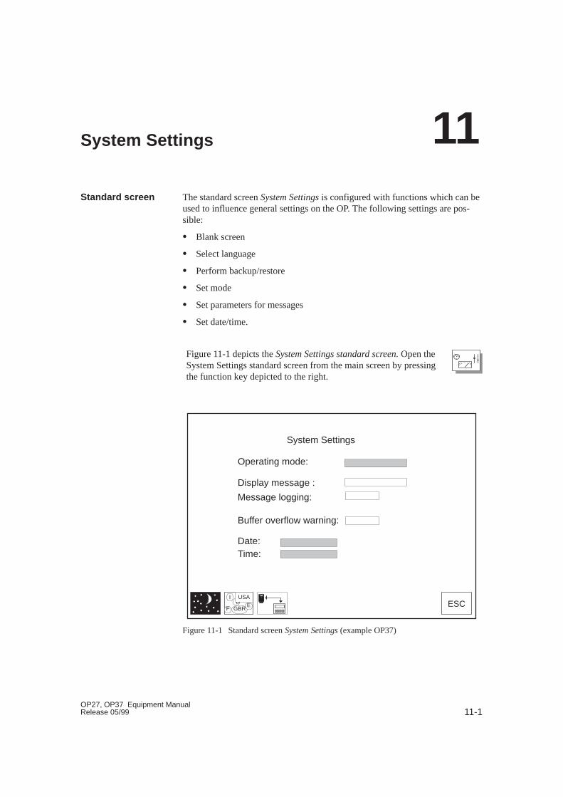
11-1OP27, OP37 Equipment ManualRelease 05/99
System Settings
The standard screen System Settings is configured with functions which can beused to influence general settings on the OP. The following settings are pos-sible:
� Blank screen
� Select language
� Perform backup/restore
� Set mode
� Set parameters for messages
� Set date/time.
Figure 11-1 depicts the System Settings standard screen. Open theSystem Settings standard screen from the main screen by pressingthe function key depicted to the right.
ID
F GBR
USAE ESC
System Settings
Operating mode:
Display message :
Message logging:
Buffer overflow warning:
Date:Time:
Figure 11-1 Standard screen System Settings (example OP37)
Standard screen
11

11-2OP27, OP37 Equipment Manual
Release 05/99
Operating mode The OP can be set to one of the followingmodes:
� Online
� Offline
� Serial Download,
� MPI Download (S7),
Display message For a description, refer to Chapter 6
Message logging For a description, refer to Chapter 6
Buffer overflow warning For a description, refer to Chapter 6
Date and time Set current date and time of day
Blank screen
ID
F GBR
USAE
Switch language
Call Backup/Restore function(for a description, refer to Section 9.3)
ESCExit standard screen
Meanings ofoperating elements
System Settings

11-3OP27, OP37 Equipment ManualRelease 05/99
11.1 Setting an Operating Mode
The OP27 can only be used in OP mode, whereas the OP37 can also be usedin DOS mode.
In OP mode, the entire functionality of the OP is available for operating andmonitoring a system or process. It consists of the following modes� Online� Offline� Serial Download� MPI Download (S7),
This is the standard operating mode for unrestricted process operation and pro-cess visualization. In Online mode, there is a logical connection between theOP and the PLC, or the OP attempts to establish one.
In Offline mode, there is no logical connection between the OP and PLC. TheOP does not attempt to establish a connection. The OP can still be operated.Process control and process visualization are not possible.
In Download mode, data can be downloaded from the configuration computerto the OP (refer to Chapter 14.2). In this mode, there is no logical connectionbetween the PLC and the OP. The OP cannot be operated in Download mode.
� In routine operation
Position the cursor on the System Settings standard screen at the Mode sym-bolic input field and select the mode required from the selection box. TheOP saves the current operating mode in a non-volatile memory. When sub-sequently powered up, the OP automatically reactivates the most recentoperating mode.
� During the startup phase of the OP
The procedure for setting the OP to Download mode in the startup phase isdescribed in Section 14.2
The OP37 can also be used for applications which run under DOS or Windows.The points which need to be taken into account in DOS mode, and the proce-dure for changing from OP to DOS mode, are described in Chapter 15.
OP mode
Online
Offline
Download
Changing theoperating mode
DOS mode
System Settings

11-4OP27, OP37 Equipment Manual
Release 05/99
11.2 Blanking the Screen
The brightness of the LCD back–lighting is reduced during the course of timedue to technological reasons. To extend the useful life of the back-lighting:
� reduce its brightness on the OP27,
� switch it off on the OP37.
� Trigger using the standard screenPress the button assigned to the icon, depicted on the right, inthe System Settings standard screen. This blanks the screen.
� Automatic triggering
If the OP is not operated within a configured period of time, the OP screenis blanked automatically.
The screen is only blanked automatically if this function has beenconfigured in ProTool.
The back-lighting is turned back on after pressing a button.
Purpose
Action
System Settings
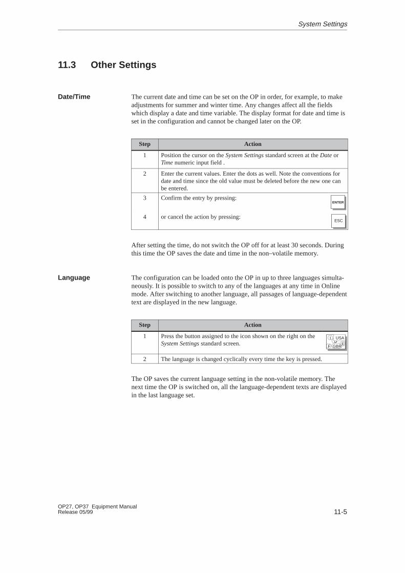
11-5OP27, OP37 Equipment ManualRelease 05/99
11.3 Other Settings
The current date and time can be set on the OP in order, for example, to makeadjustments for summer and winter time. Any changes affect all the fieldswhich display a date and time variable. The display format for date and time isset in the configuration and cannot be changed later on the OP.
Step Action
1 Position the cursor on the System Settings standard screen at the Date orTime numeric input field .
2 Enter the current values. Enter the dots as well. Note the conventions fordate and time since the old value must be deleted before the new one canbe entered.
3 Confirm the entry by pressing:ENTER
4 or cancel the action by pressing:ESC
After setting the time, do not switch the OP off for at least 30 seconds. Duringthis time the OP saves the date and time in the non–volatile memory.
The configuration can be loaded onto the OP in up to three languages simulta-neously. It is possible to switch to any of the languages at any time in Onlinemode. After switching to another language, all passages of language-dependenttext are displayed in the new language.
Step Action
1 Press the button assigned to the icon shown on the right on theSystem Settings standard screen.
ID
F GBR
USAE
2 The language is changed cyclically every time the key is pressed.
The OP saves the current language setting in the non-volatile memory. Thenext time the OP is switched on, all the language-dependent texts are displayedin the last language set.
Date/Time
Language
System Settings

11-6OP27, OP37 Equipment Manual
Release 05/99
System Settings

INSTALLATION AND COMMISSIONING
12 Mechanical Installation
13 Electrical Installation
14 Commissioning
15 OP37 in DOS Mode
Part III

11-2OP27, OP37 Equipment Manual
Release 05/99
12-1OP27, OP37 Equipment ManualRelease 05/99
Mechanical Installation
The OP27 is designed for vertical installation in the front panels of switchingcabinets.
The OP37 can also be installed in 19” panels/racks.
Cut a mounting slot in the front panel in preparation for installation of the OP.The thickness of the front panel must not exceed 6 mm. No other drilled holesare required for mounting.
Details on the mounting depth and mounting cutout are provided in Chapters16 and 17.
!Caution
� The OP must be brought to room temperature before it is commissioned. Ifcondensation forms, do not switch on the OP until it is absolutely dry.
� To prevent the OP from overheating during operation,
– the angle of inclination specified in the technical data must not beexceeded,
– do not expose the OP to direct sunlight,
– make sure that the ventilation slots in the housing remain free afterinstallation.
� When the cabinet is opened, certain parts of the system that may conducthazardous voltage are exposed.
� The OP was function-tested before shipping. Nevertheless, if a fault doesoccur, please enclose a full account of the fault when returning the OP.
The IP65 degree of protection for the front panel can only be assured when theseal on the front plate of the OP fits properly.
If the labeling of the function keys needs to be modified, replace the labelingstrips before installing the OP. Information on replacing the labeling strips isprovided in Chapters 16 and 17.
Locationand installationconditions
Degree ofprotection
Before installing
12
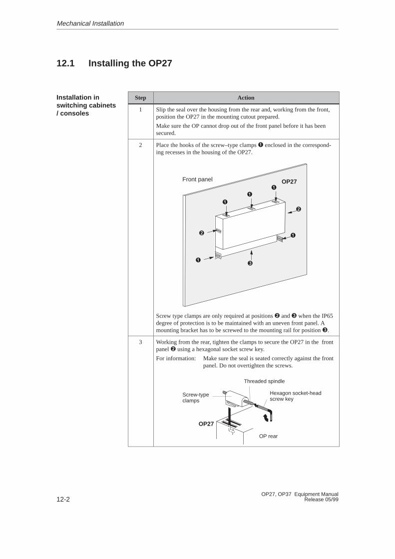
12-2OP27, OP37 Equipment Manual
Release 05/99
12.1 Installing the OP27
Step Action
1 Slip the seal over the housing from the rear and, working from the front,position the OP27 in the mounting cutout prepared.
Make sure the OP cannot drop out of the front panel before it has beensecured.
2
Front panel OP27
Place the hooks of the screw–type clamps � enclosed in the correspond-ing recesses in the housing of the OP27.
�
�
�
�
�
Screw type clamps are only required at positions � and � when the IP65degree of protection is to be maintained with an uneven front panel. Amounting bracket has to be screwed to the mounting rail for position �.
�
�
�
3
OP27
Working from the rear, tighten the clamps to secure the OP27 in the frontpanel � using a hexagonal socket screw key.
For information: Make sure the seal is seated correctly against the frontpanel. Do not overtighten the screws.
OP rear
Threaded spindle
Hexagon socket-headscrew key
Screw-typeclamps
Installation inswitching cabinets/ consoles
Mechanical Installation
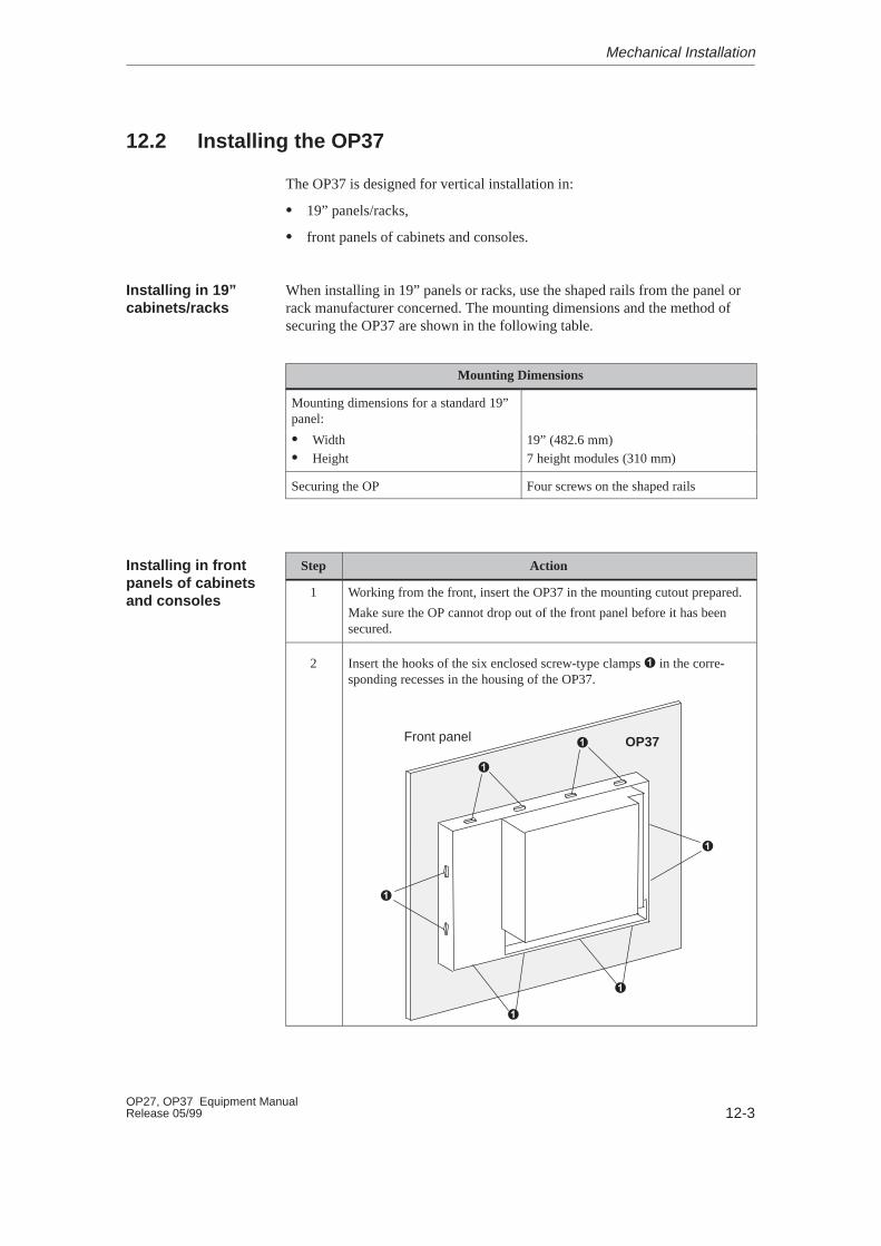
12-3OP27, OP37 Equipment ManualRelease 05/99
12.2 Installing the OP37
The OP37 is designed for vertical installation in:
� 19” panels/racks,
� front panels of cabinets and consoles.
When installing in 19” panels or racks, use the shaped rails from the panel orrack manufacturer concerned. The mounting dimensions and the method ofsecuring the OP37 are shown in the following table.
Mounting Dimensions
Mounting dimensions for a standard 19”panel:
� Width 19” (482.6 mm)� Height 7 height modules (310 mm)
Securing the OP Four screws on the shaped rails
Step Action
1 Working from the front, insert the OP37 in the mounting cutout prepared.
Make sure the OP cannot drop out of the front panel before it has beensecured.
2
Front panel OP37
Insert the hooks of the six enclosed screw-type clamps � in the corre-sponding recesses in the housing of the OP37.
�
�
�
�
�
�
Installing in 19”cabinets/racks
Installing in frontpanels of cabinetsand consoles
Mechanical Installation

12-4OP27, OP37 Equipment Manual
Release 05/99
ActionStep
3 Working from the rear, tighten the grub screws � against the front panel,as illustrated.
Rear of OP
Grub screw �
Hexagon socket-head screw key
Screwtype clamps
Note:
� Make sure the seal is seated correctly against the front panel.
� Do not overtighten the screws.
Mechanical Installation
13-1OP27, OP37 Equipment ManualRelease 05/99
Electrical Installation
The OP requires electrical connections
� to the power supply
� to the configuration computer (PU or PC)
� to the PLC.
The electrical connection to the PU or PC is required purely for downloadingthe firmware and the configuration. Following the configuration and testphases, a serial printer can be connected to the OP instead of the configurationcomputer.
A precondition for error–free operation is an EMC compatible hardware designof the PLC and the use of interference–proof cables. The guidelines on inter-ference-free design of the PLCs apply equally to installation of the OP.
!Caution
� Only shielded cables are allowed for all signal connections.
� Screw or lock all plug connections.
� Do not install signal lines in the same cable ducts as power cables.
� Siemens AG refuses to accept liability for malfunctions and damage aris-ing from use of self-made cables or cables from other manufacturers.
The operating units have reverse battery protection. This has no effect if a con-nection already exists to another unit via RS 232. Therefore, proceed as fol-lows when commissioning the operating unit:
1. Connect the power supply.
2. Switch on the operating unit. If the operating unit does not power up, swapthe connections because the poles are reversed.
3. When the operating unit has been powered up, connect the configurationcomputer or periphery equipment.
Electricalconnections
EMC compatibledesign
Reverse batteryprotection
13

13-2OP27, OP37 Equipment Manual
Release 05/99
Figure 13-1 illustrates a number of configuration options for OP, PLC andperiphery equipment.
ÉÉÉÉÉÉÉÉÉÉÉÉÉÉÉÉÉÉÉÉÉÉÉÉÉÉÉÉÉÉÉÉÉÉÉÉÉÉÉÉÉÉÉÉÉÉÉÉÉÉÉÉÉÉÉÉÉÉÉÉÉÉÉÉÉÉÉÉ
SIMATIC S5SIMATIC 500/505PCOther PLCs
IF2
PLC PROFIBUS-DP
SIMATIC 500/505SIMATIC S7Other PLCs
optional
ÉÉÉÉÉÉÉÉÉÉÉÉÉÉÉ
For example,DR215DR235
Printer
ÉÉÉÉÉÉÉÉÉÉÉÉ
PCPG 7xx
Configurationcomputer
PLC
Power supply withrelay contact
IF1A IF1B
optional
Serial Parallel
LPT
For example,Epson StylusCanon BJC
Printer
Relay contact fortemperaturemonitoring
IF3
Currently unassigned
OP37 only
DIP switches
ÉÉÉÉ
OP27 and OP37
Figure 13-1 Configuration options
Detailed information on connection options is provided in the sections below.The connection plug pin assignment for the interfaces are provided in Appen-dix B of this manual.
Configurationoptions
Electrical Installation
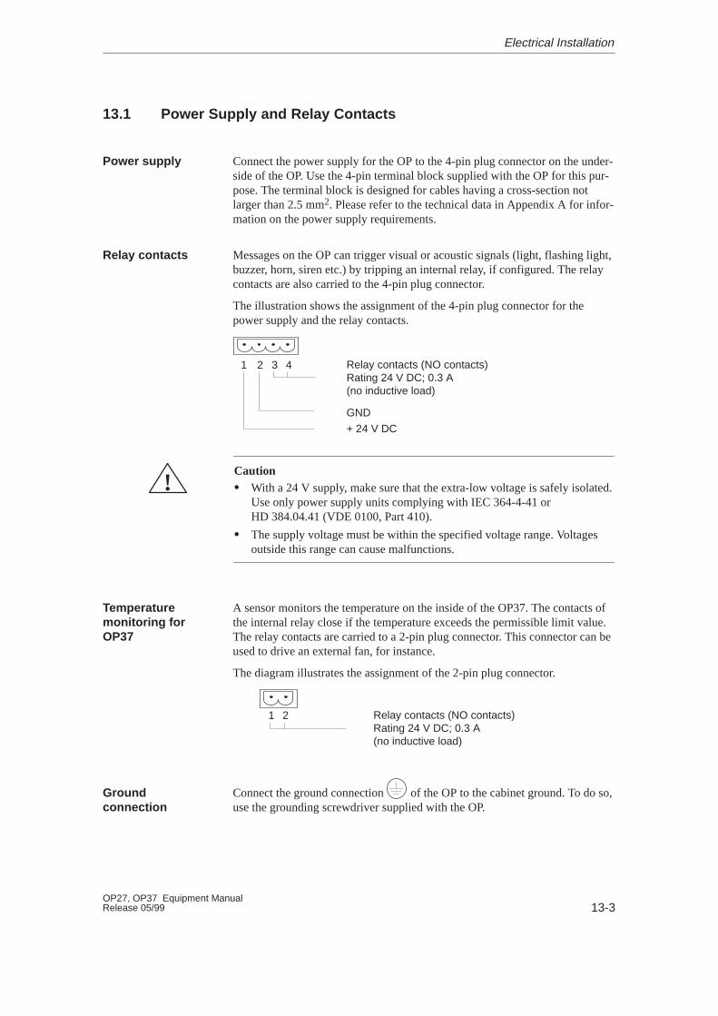
13-3OP27, OP37 Equipment ManualRelease 05/99
13.1 Power Supply and Relay Contacts
Connect the power supply for the OP to the 4-pin plug connector on the under-side of the OP. Use the 4-pin terminal block supplied with the OP for this pur-pose. The terminal block is designed for cables having a cross-section notlarger than 2.5 mm2. Please refer to the technical data in Appendix A for infor-mation on the power supply requirements.
Messages on the OP can trigger visual or acoustic signals (light, flashing light,buzzer, horn, siren etc.) by tripping an internal relay, if configured. The relaycontacts are also carried to the 4-pin plug connector.
The illustration shows the assignment of the 4-pin plug connector for thepower supply and the relay contacts.
1 2 3 4 Relay contacts (NO contacts)Rating 24 V DC; 0.3 A(no inductive load)
GND
+ 24 V DC
!Caution� With a 24 V supply, make sure that the extra-low voltage is safely isolated.
Use only power supply units complying with IEC 364-4-41 orHD 384.04.41 (VDE 0100, Part 410).
� The supply voltage must be within the specified voltage range. Voltagesoutside this range can cause malfunctions.
A sensor monitors the temperature on the inside of the OP37. The contacts ofthe internal relay close if the temperature exceeds the permissible limit value.The relay contacts are carried to a 2-pin plug connector. This connector can beused to drive an external fan, for instance.
The diagram illustrates the assignment of the 2-pin plug connector.
1 2 Relay contacts (NO contacts)Rating 24 V DC; 0.3 A(no inductive load)
Connect the ground connection of the OP to the cabinet ground. To do so,use the grounding screwdriver supplied with the OP.
Power supply
Relay contacts
Temperaturemonitoring forOP37
Groundconnection
Electrical Installation

13-4OP27, OP37 Equipment Manual
Release 05/99
13.1.1 Connecting the Configuration Computer
In order to download the configuration, a connection between the configurationcomputer (PU or PC) and OP must be established. There are two connectionoptions available for this:
� the serial connection of a configuration computer to the OP interface IF2(serial downloading),
� the connection of a configuration computer to the OP interface IF1B (MPIdownloading). In this case, the configuration computer and OP are con-nected to the MPI network. A condition for this is that a configurationalready exists on the OP.
Both connections serve for downloading the firmware and configuration data(Chapter 14.2). Standard cables are available for the connections shown (referto the ST80.1 catalog).
RS232
RS232
RS232
TTY passive
TTY passive
TTY/RS232converter
COM1/2(9-pin)
COM1(25-pin)
COM2(9-pin)
COM1/2(25-pin)
PC or PUwith MPIcard
IF2
OP
PC
IF1B
PG 7xx
Bus
Figure 13-2 Connection configuration diagram for configuration computer
Connectionconfiguration
Electrical Installation
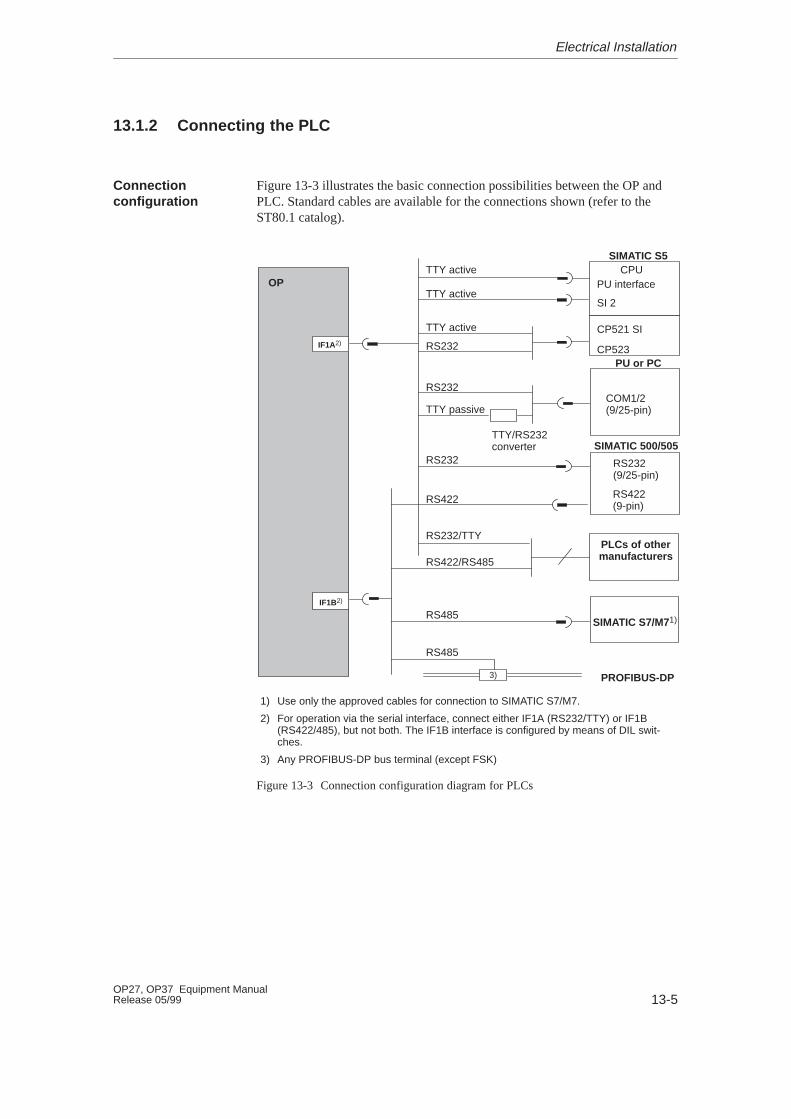
13-5OP27, OP37 Equipment ManualRelease 05/99
13.1.2 Connecting the PLC
Figure 13-3 illustrates the basic connection possibilities between the OP andPLC. Standard cables are available for the connections shown (refer to theST80.1 catalog).
TTY active
RS232
TTY passive
PU interface
SI 2
RS232(9/25-pin)
RS422(9-pin)
SIMATIC S5
TTY active
CP523
TTY active
RS232
TTY/RS232converter
COM1/2(9/25-pin)
RS232
PLCs of othermanufacturers
PU or PC
RS422
RS422/RS485
CPU
SIMATIC 500/505
PROFIBUS-DP
SIMATIC S7/M71)
RS232/TTY
1) Use only the approved cables for connection to SIMATIC S7/M7.
2) For operation via the serial interface, connect either IF1A (RS232/TTY) or IF1B(RS422/485), but not both. The IF1B interface is configured by means of DIL swit-ches.
3) Any PROFIBUS-DP bus terminal (except FSK)
3)
CP521 SIIF1A2)
IF1B2)
OP
RS485
RS485
Figure 13-3 Connection configuration diagram for PLCs
Connectionconfiguration
Electrical Installation

13-6OP27, OP37 Equipment Manual
Release 05/99
The IF1B interface can be configured by using the DIL switches, locatedbeside the 9–pin Sub-D connector. This interchanges the RS422 receive dataand the RTS signal. By default, the RTS signal is not required by the commu-nication peer.
The table shows the permissible DIL switch settings.
Communication Switch SettingCommunication Switch Setti ng
OP PLCRS422/RS485
1 2 3 4ON
OFF
PLC
PPI/MPI/PROFIBUSOP
RTS on Pin 4
RTS on Pin 9 (as PU)
No RTS on connector
(default)
1 2 3 4
1 2 3 4
1 2 3 4
ON
OFF
ON
OFF
ON
OFF
PLCPPI/MPI
Standard cableOP ON
OFF
1 2 3 4
Configure interfaceIF1B
Electrical Installation
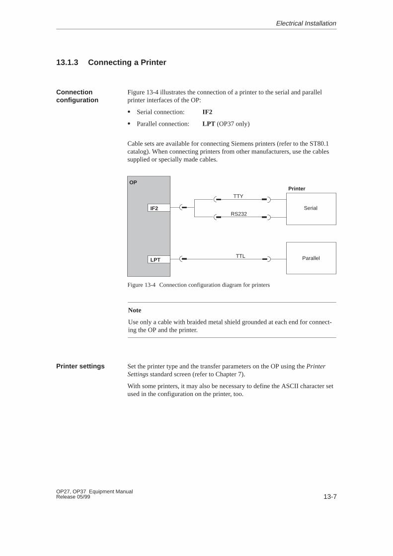
13-7OP27, OP37 Equipment ManualRelease 05/99
13.1.3 Connecting a Printer
Figure 13-4 illustrates the connection of a printer to the serial and parallelprinter interfaces of the OP:
� Serial connection: IF2
� Parallel connection: LPT (OP37 only)
Cable sets are available for connecting Siemens printers (refer to the ST80.1catalog). When connecting printers from other manufacturers, use the cablessupplied or specially made cables.
IF2
OPPrinter
Serial
Parallel
TTY
TTL
RS232
LPT
Figure 13-4 Connection configuration diagram for printers
Note
Use only a cable with braided metal shield grounded at each end for connect-ing the OP and the printer.
Set the printer type and the transfer parameters on the OP using the PrinterSettings standard screen (refer to Chapter 7).
With some printers, it may also be necessary to define the ASCII character setused in the configuration on the printer, too.
Connectionconfiguration
Printer settings
Electrical Installation

13-8OP27, OP37 Equipment Manual
Release 05/99
Electrical Installation

14-1OP27, OP37 Equipment ManualRelease 05/99
Commissioning
The commissioning guide below explains the individual steps for commission-ing the OP27 and OP37. Figure 14-1 provides a diagram of the most importantsteps for initial startup, recommissioning and normal operation of the OP.
Transfer configuration data to the OP
COM1/2
Set the OP to Download mode in thestartup phase (refer to Section 14.2)
Switch on the OP power supply
Initial startup
Neither a configuration norfirmware is available on theOP.
Recommissioning
The OP already has a config-uration but must now use anew configuration or firmware.
Normal operation
The OP is operated with theloaded configuration.
Start screen
ProTool
IF2 OP
Figure 14-1 Commissioning flowchart
Flowchart
14
14-2OP27, OP37 Equipment Manual
Release 05/99
Before commissioning the OP, please observe the following:
!Caution
� With the SIMATIC S5, compression of the internal program memory onthe PLC (PU “Compress” function, integrated FB COMPR) is not allowedwhen an OP is connected. Compression modifies the absolute addresses ofthe blocks in the program memory. Since the OP only reads the address listduring startup, it does not detect any address modifications and accessesthe wrong memory areas.
If compression is inevitable during routine operation, switch off the OPprior to compression.
� In hazardous areas, always de-energize the OP before unplugging connec-tors.
14.1 Initial Startup
The firmware and configuration must be downloaded to the OP when it isstarted up for the first time. Proceed as follows:
Step Action
1 Switch on the OP power supply. As a configuration has not yet beenloaded, the OP automatically switches to Download mode and waits fordata to be downloaded from the PC or PU. The message READY FORSERIAL TRANSFER appears.
The OP cannot be operated in Download mode.
2 Connect the IF2 interface (RS232/TTY) on the OP to the PU or PC bymeans of a suitable standard cable.
3 Start the download operation on the PC or PU to the OP. The OP checksthe connection to the PC or PU. If the connection is not available, or notfunctioning correctly, the OP issues the corresponding error message.
If the connection is in order, downloading of the configuration com-mences. The OP firmware is downloaded automatically.
Following successful downloading, the OP restarts and displays the startscreen of the configuration that has just been loaded.
Note
For information on which settings are required for the downloading operation,please refer to the User’s Guide ProTool Configuring Graphics Displays.
Beforecommissioning
Procedure
Commissioning
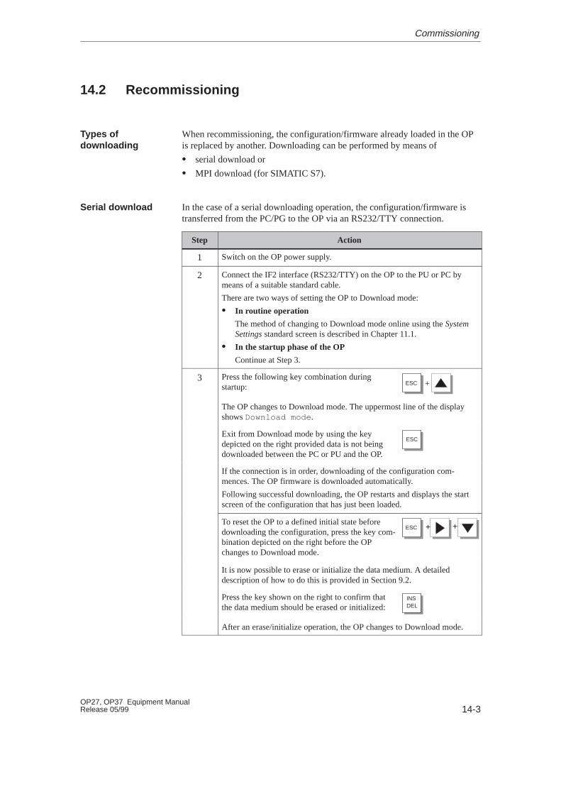
14-3OP27, OP37 Equipment ManualRelease 05/99
14.2 Recommissioning
When recommissioning, the configuration/firmware already loaded in the OPis replaced by another. Downloading can be performed by means of
� serial download or
� MPI download (for SIMATIC S7).
In the case of a serial downloading operation, the configuration/firmware istransferred from the PC/PG to the OP via an RS232/TTY connection.
Step Action
1 Switch on the OP power supply.
2 Connect the IF2 interface (RS232/TTY) on the OP to the PU or PC bymeans of a suitable standard cable.
There are two ways of setting the OP to Download mode:
� In routine operation
The method of changing to Download mode online using the SystemSettings standard screen is described in Chapter 11.1.
� In the startup phase of the OP
Continue at Step 3.
3 Press the following key combination duringstartup: +ESC
The OP changes to Download mode. The uppermost line of the displayshows Download mode .
Exit from Download mode by using the keydepicted on the right provided data is not beingdownloaded between the PC or PU and the OP.
ESC
If the connection is in order, downloading of the configuration com-mences. The OP firmware is downloaded automatically.
Following successful downloading, the OP restarts and displays the startscreen of the configuration that has just been loaded.
To reset the OP to a defined initial state beforedownloading the configuration, press the key com-bination depicted on the right before the OPchanges to Download mode.
+ +ESC
It is now possible to erase or initialize the data medium. A detaileddescription of how to do this is provided in Section 9.2.
Press the key shown on the right to confirm thatthe data medium should be erased or initialized: DEL
INS
After an erase/initialize operation, the OP changes to Download mode.
Types ofdownloading
Serial download
Commissioning
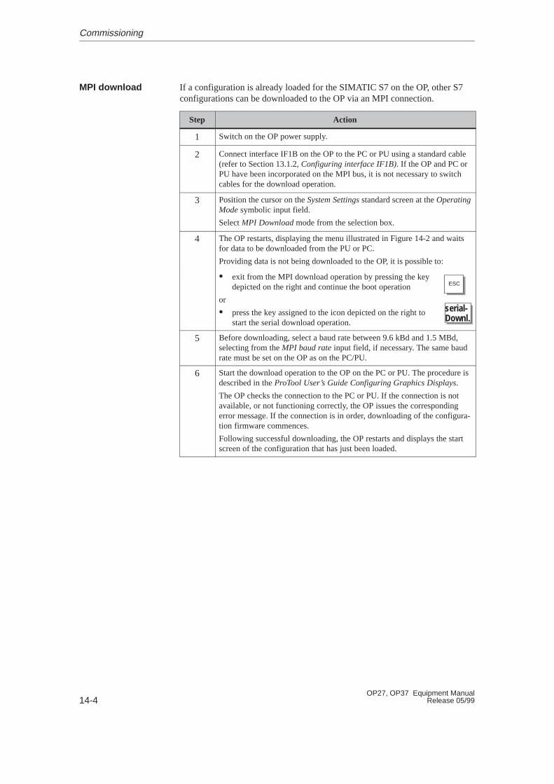
14-4OP27, OP37 Equipment Manual
Release 05/99
If a configuration is already loaded for the SIMATIC S7 on the OP, other S7configurations can be downloaded to the OP via an MPI connection.
Step Action
1 Switch on the OP power supply.
2 Connect interface IF1B on the OP to the PC or PU using a standard cable(refer to Section 13.1.2, Configuring interface IF1B). If the OP and PC orPU have been incorporated on the MPI bus, it is not necessary to switchcables for the download operation.
3 Position the cursor on the System Settings standard screen at the OperatingMode symbolic input field.
Select MPI Download mode from the selection box.
4 The OP restarts, displaying the menu illustrated in Figure 14-2 and waitsfor data to be downloaded from the PU or PC.
Providing data is not being downloaded to the OP, it is possible to:
� exit from the MPI download operation by pressing the keydepicted on the right and continue the boot operation
or
� press the key assigned to the icon depicted on the right tostart the serial download operation.
ESC
serial-Downl.
5 Before downloading, select a baud rate between 9.6 kBd and 1.5 MBd,selecting from the MPI baud rate input field, if necessary. The same baudrate must be set on the OP as on the PC/PU.
6 Start the download operation to the OP on the PC or PU. The procedure isdescribed in the ProTool User’s Guide Configuring Graphics Displays.
The OP checks the connection to the PC or PU. If the connection is notavailable, or not functioning correctly, the OP issues the correspondingerror message. If the connection is in order, downloading of the configura-tion firmware commences.
Following successful downloading, the OP restarts and displays the startscreen of the configuration that has just been loaded.
MPI download
Commissioning
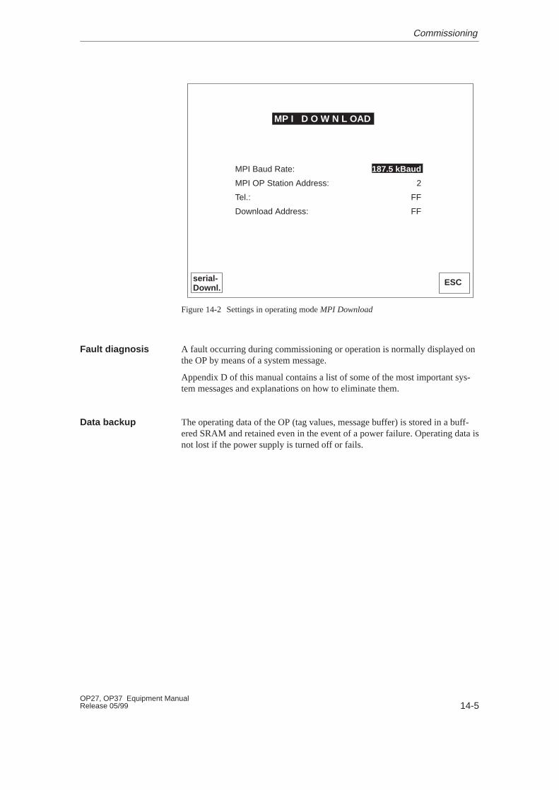
14-5OP27, OP37 Equipment ManualRelease 05/99
serial-Downl.
ESC
MP I D O W N L OAD
187.5 kBaud
2
FF
FF
MPI Baud Rate:
MPI OP Station Address:
Tel.:
Download Address:
Figure 14-2 Settings in operating mode MPI Download
A fault occurring during commissioning or operation is normally displayed onthe OP by means of a system message.
Appendix D of this manual contains a list of some of the most important sys-tem messages and explanations on how to eliminate them.
The operating data of the OP (tag values, message buffer) is stored in a buff-ered SRAM and retained even in the event of a power failure. Operating data isnot lost if the power supply is turned off or fails.
Fault diagnosis
Data backup
Commissioning

14-6OP27, OP37 Equipment Manual
Release 05/99
14.3 Startup Behavior
No Yes
OP startup
Self test
Press the key assigned tothe icon serial Downl. or no
configuration available
After the power supply has been switched on, the OP performs a selftest. In the test, it checks the operability of the most important OPcomponents and displays the test results. The test results are thendeleted.
If a configuration is not present, the OP automatically switches toSerial Download mode.
Downloadoperation
Initialization
Establish connectionto PLC
Start screen
The OP then performs various internal initializations.
In this phase of startup, the OP attempts to establish a connection tothe PLC.
If communication is not possible (e.g. cable to the PLC has not beenconnected) the OP displays a system message.
Following startup, the OP displays the configured start screen.
Commissioning
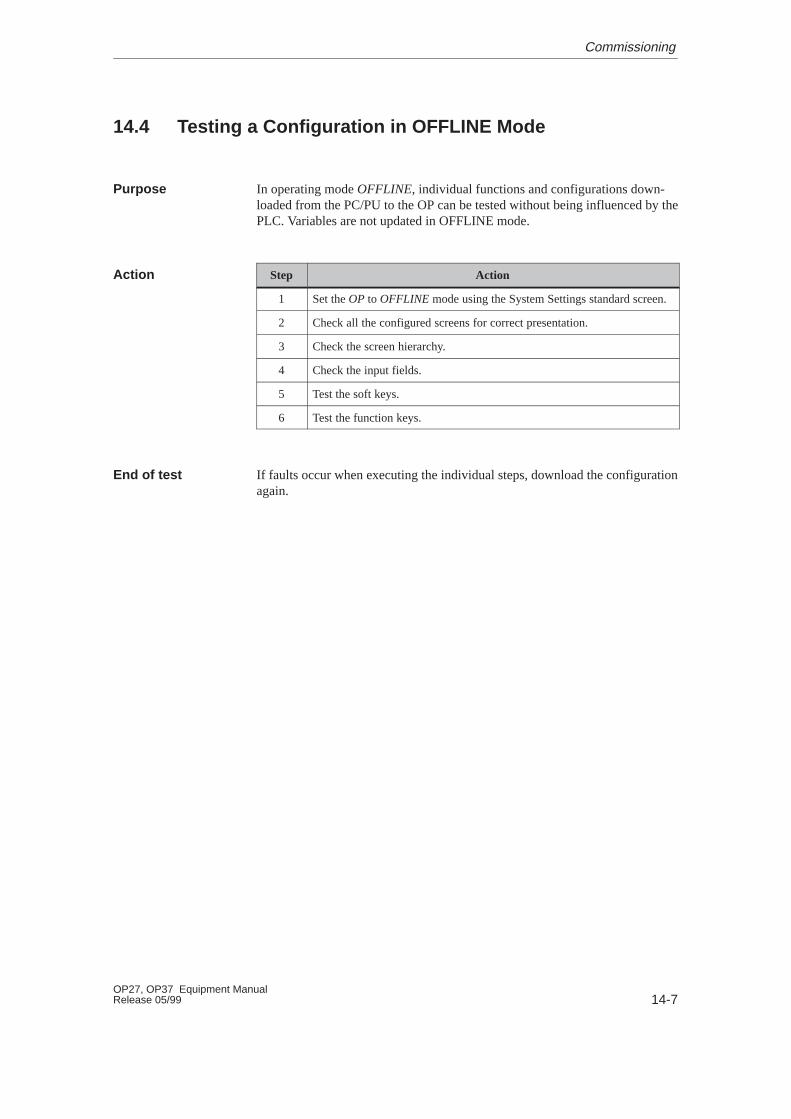
14-7OP27, OP37 Equipment ManualRelease 05/99
14.4 Testing a Configuration in OFFLINE Mode
In operating mode OFFLINE, individual functions and configurations down-loaded from the PC/PU to the OP can be tested without being influenced by thePLC. Variables are not updated in OFFLINE mode.
Step Action
1 Set the OP to OFFLINE mode using the System Settings standard screen.
2 Check all the configured screens for correct presentation.
3 Check the screen hierarchy.
4 Check the input fields.
5 Test the soft keys.
6 Test the function keys.
If faults occur when executing the individual steps, download the configurationagain.
Purpose
Action
End of test
Commissioning
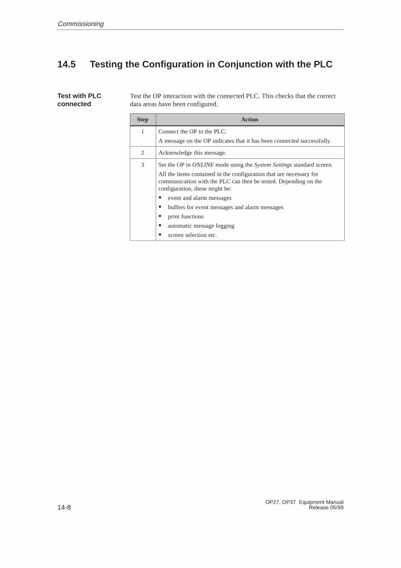
14-8OP27, OP37 Equipment Manual
Release 05/99
14.5 Testing the Configuration in Conjunction with the PLC
Test the OP interaction with the connected PLC. This checks that the correctdata areas have been configured.
Step Action
1 Connect the OP to the PLC.
A message on the OP indicates that it has been connected successfully.
2 Acknowledge this message.
3 Set the OP in ONLINE mode using the System Settings standard screen.
All the items contained in the configuration that are necessary forcommunication with the PLC can then be tested. Depending on theconfiguration, these might be:
� event and alarm messages
� buffers for event messages and alarm messages
� print functions
� automatic message logging
� screen selection etc.
Test with PLCconnected
Commissioning
15-1OP27, OP37 Equipment ManualRelease 05/99
OP37 in DOS Mode
The OP37 is also designed for use in DOS mode. It can be used for differentapplications. The default settings apply to operation with a configurationcreated in ProTool. The OP37 can be used for applications which run underboth DOS or Windows. These applications might be:
� programming software
� a standard application or
� a customized application.
In order that the OP37 can be used in DOS mode, a data medium, such as disk,hard disk or PCMCIA hard disk must be available. Set one of these data mediaas the boot medium in Setup. Also, connect a keyboard and possibly a mouseas well. An MF2 keyboard can be connected to the front connector. A PS2 con-nector is available at the rear of the OP37 for connecting a PS2 keyboard, andthere is another connector for connecting a PS2 mouse.
Use
Conditions
15
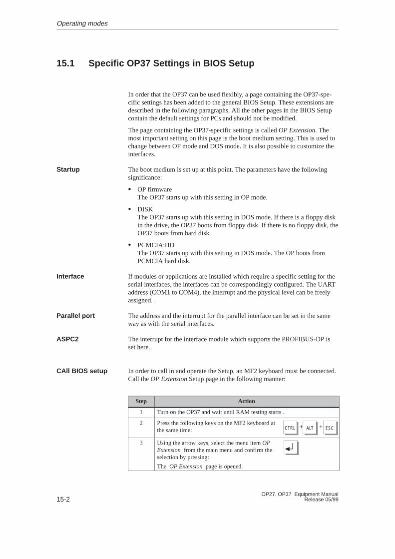
15-2OP27, OP37 Equipment Manual
Release 05/99
15.1 Specific OP37 Settings in BIOS Setup
In order that the OP37 can be used flexibly, a page containing the OP37-spe-cific settings has been added to the general BIOS Setup. These extensions aredescribed in the following paragraphs. All the other pages in the BIOS Setupcontain the default settings for PCs and should not be modified.
The page containing the OP37-specific settings is called OP Extension. Themost important setting on this page is the boot medium setting. This is used tochange between OP mode and DOS mode. It is also possible to customize theinterfaces.
The boot medium is set up at this point. The parameters have the followingsignificance:
� OP firmwareThe OP37 starts up with this setting in OP mode.
� DISKThe OP37 starts up with this setting in DOS mode. If there is a floppy diskin the drive, the OP37 boots from floppy disk. If there is no floppy disk, theOP37 boots from hard disk.
� PCMCIA:HDThe OP37 starts up with this setting in DOS mode. The OP boots fromPCMCIA hard disk.
If modules or applications are installed which require a specific setting for theserial interfaces, the interfaces can be correspondingly configured. The UARTaddress (COM1 to COM4), the interrupt and the physical level can be freelyassigned.
The address and the interrupt for the parallel interface can be set in the sameway as with the serial interfaces.
The interrupt for the interface module which supports the PROFIBUS-DP isset here.
In order to call in and operate the Setup, an MF2 keyboard must be connected.Call the OP Extension Setup page in the following manner:
Step Action
1 Turn on the OP37 and wait until RAM testing starts .
2 Press the following keys on the MF2 keyboard atthe same time: + +CTRL ALT ESC
3 Using the arrow keys, select the menu item OPExtension from the main menu and confirm theselection by pressing:
The OP Extension page is opened.
Startup
Interface
Parallel port
ASPC2
CAll BIOS setup
Operating modes

15-3OP27, OP37 Equipment ManualRelease 05/99
Operations can only be carried out in Setup via the keyboard.
Individual input fields in the BIOS Setup are selected by pressing:TAB
Apply the setting specified by pressing:
Scroll through the definable values with the arrow keys. Some fields allowdirect input from the keyboard.
After clicking on the Default button, the PC standard configuration and operat-ing mode OP mode (OP firmware) are set.
Operate BIOSsetup
Default button
Operating modes
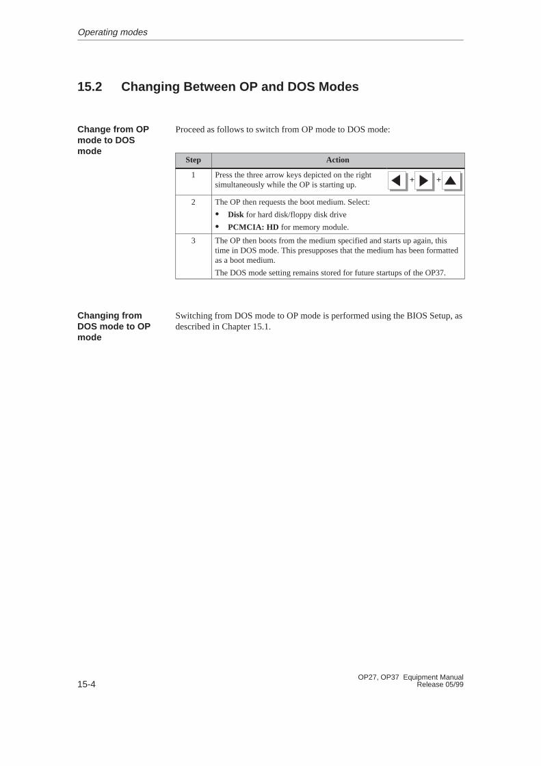
15-4OP27, OP37 Equipment Manual
Release 05/99
15.2 Changing Between OP and DOS Modes
Proceed as follows to switch from OP mode to DOS mode:
Step Action
1 Press the three arrow keys depicted on the rightsimultaneously while the OP is starting up.
+ +
2 The OP then requests the boot medium. Select:
� Disk for hard disk/floppy disk drive
� PCMCIA: HD for memory module.
3 The OP then boots from the medium specified and starts up again, thistime in DOS mode. This presupposes that the medium has been formattedas a boot medium.
The DOS mode setting remains stored for future startups of the OP37.
Switching from DOS mode to OP mode is performed using the BIOS Setup, asdescribed in Chapter 15.1.
Change from OPmode to DOSmode
Changing fromDOS mode to OPmode
Operating modes

EQUIPMENT DESCRIPTIONAND MAINTENANCE
16 Equipment Description OP27
17 Equipment Description OP37
18 Options
19 Maintenance
Part IV

15-2OP27, OP37 Equipment Manual
Release 05/99
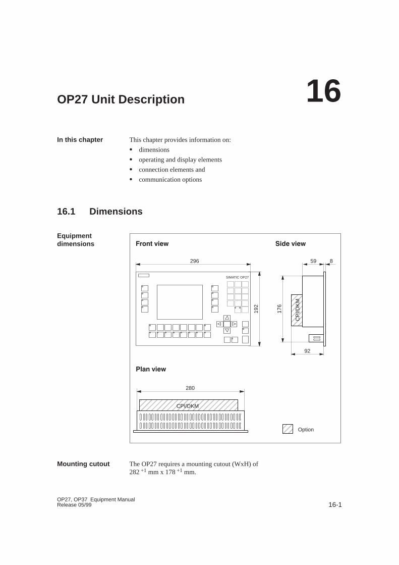
16-1OP27, OP37 Equipment ManualRelease 05/99
OP27 Unit Description
This chapter provides information on:
� dimensions
� operating and display elements
� connection elements and
� communication options
16.1 Dimensions
29619
2
176
859
���� ������� ����
SIMATIC OP27
�� ����
280
ÉÉÉÉÉÉÉÉ
92
ÉÉÉÉÉÉÉÉÉÉÉÉÉÉÉÉÉÉÉÉÉÉCPI/DKM
CP
I/DK
M
ÉÉÉÉ
Option
The OP27 requires a mounting cutout (WxH) of282 +1 mm x 178 +1 mm.
In this chapter
Equipmentdimensions
Mounting cutout
16
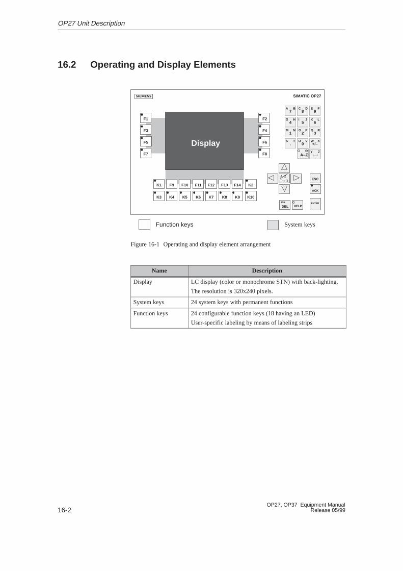
16-2OP27, OP37 Equipment Manual
Release 05/99
16.2 Operating and Display Elements
SIMATIC OP27
8C D
9E F
ÉÉÉÉÉÉÉÉÉÉÉÉÉÉÉÉÉÉÉÉÉÉÉÉÉÉ
ÉÉÉÉÉÉÉÉÉÉÉÉÉÉÉÉ
ÉÉÉÉÉÉÉÉÉÉÉÉÉÉ
F1
F3
F5
F7
F2
F4
F6
F8
7A B
5I J
6K L
4G H
2O P
3Q R
1M N
0U V
+/–W X
.S T
Y Z
K1 F9 F10 F11 F12 F13 F14 K2
K3 K4 K5 K6 K7 K8 K9 K10
ESC
ENTER
ACK
DELINS
HELP
A–Z
A–Z
Display
Function keys System keys
Figure 16-1 Operating and display element arrangement
Name Description
Display LC display (color or monochrome STN) with back-lighting.
The resolution is 320x240 pixels.
System keys 24 system keys with permanent functions
Function keys 24 configurable function keys (18 having an LED)
User-specific labeling by means of labeling strips
OP27 Unit Description
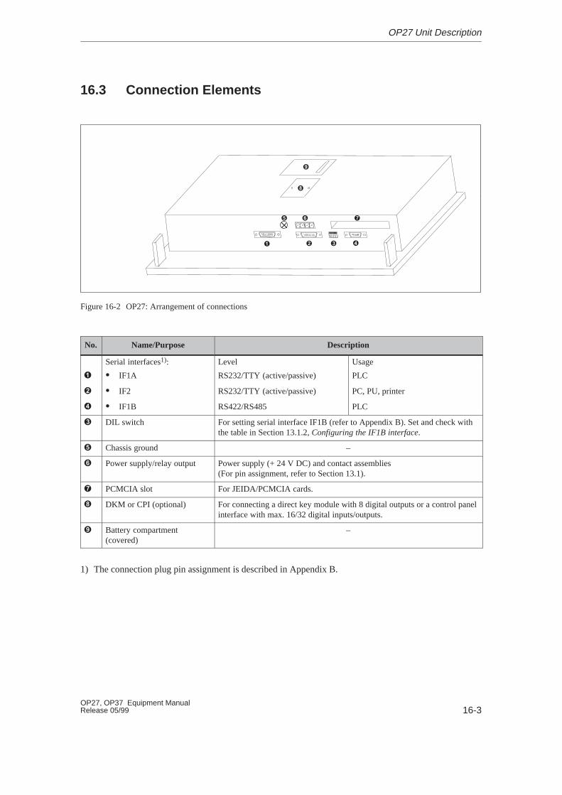
16-3OP27, OP37 Equipment ManualRelease 05/99
16.3 Connection Elements
� � �
� � �
�
�
Figure 16-2 OP27: Arrangement of connections
No. Name/Purpose Description
Serial interfaces1): Level Usage
� � IF1A RS232/TTY (active/passive) PLC
� � IF2 RS232/TTY (active/passive) PC, PU, printer
� � IF1B RS422/RS485 PLC
� DIL switch For setting serial interface IF1B (refer to Appendix B). Set and check withthe table in Section 13.1.2, Configuring the IF1B interface.
� Chassis ground –
� Power supply/relay output Power supply (+ 24 V DC) and contact assemblies(For pin assignment, refer to Section 13.1).
� PCMCIA slot For JEIDA/PCMCIA cards.
� DKM or CPI (optional) For connecting a direct key module with 8 digital outputs or a control panelinterface with max. 16/32 digital inputs/outputs.
Battery compartment(covered)
–
1) The connection plug pin assignment is described in Appendix B.
OP27 Unit Description
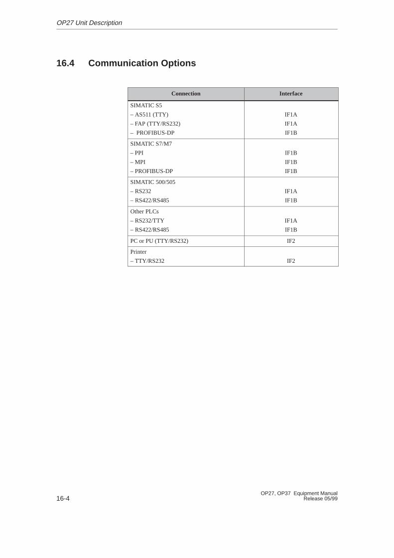
16-4OP27, OP37 Equipment Manual
Release 05/99
16.4 Communication Options
Connection Interface
SIMATIC S5
– AS511 (TTY)
– FAP (TTY/RS232)
– PROFIBUS-DP
IF1A
IF1A
IF1B
SIMATIC S7/M7
– PPI
– MPI
– PROFIBUS-DP
IF1B
IF1B
IF1B
SIMATIC 500/505
– RS232
– RS422/RS485
IF1A
IF1B
Other PLCs
– RS232/TTY
– RS422/RS485
IF1A
IF1B
PC or PU (TTY/RS232) IF2
Printer
– TTY/RS232 IF2
OP27 Unit Description

16-5OP27, OP37 Equipment ManualRelease 05/99
16.5 Labeling Function Keys
The function keys on the OP27 are labeled ex–works as follows:
� F1 to F14
� K1 to K10
A set of unlabeled strips is enclosed with the OP. This means that the keys onthe OP can be labeled according to individual systems.
Proceed as follows to replace the labeling strips:
1. Lay down the device with its front plate facing downwards.
2. Remove the labeling strips to be replaced from the unit.
3. Insert the new strips � with the inscription facing downwards into the slitsat the rear of the front plate (see Figure 16-3).
Note
Labeling on strips must be smudge-proof before they are inserted. If a key-board overlay is soiled on the inside, it cannot be cleaned and has to bereturned to the works for replacement.
�
�
�
Figure 16-3 Inserting labeling strips
State on delivery
Replacing labelingstrips
OP27 Unit Description

16-6OP27, OP37 Equipment Manual
Release 05/99
Use transparent foil to make labeling strips so that the LEDs in the functionkeys remain visible. Use a printer or a smudge-proof foil pen to label the foil.Cut the strips as shown in the examples illustrated in Figure 16-4.
Figure 16-5 Dimensions of labeling strips for OP27
Included with the ProTool configuration software is the directory PROTOOL\UTILITY containing the Word� file SLIDE_27.DOC . The filecontains formatted samples for labeling the function keys on the OP27. Thismeans individual labeling strips can be edited and printed.
Make labelingstrips
File
OP27 Unit Description

17-1OP27, OP37 Equipment ManualRelease 05/99
OP37 Unit Description
This chapter provides information on:
� dimensions
� operating and display elements
� connection elements and
� Communication options
In this chapter
17
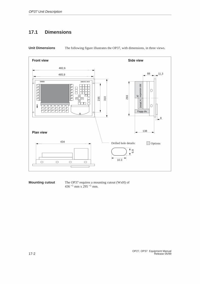
17-2OP27, OP37 Equipment Manual
Release 05/99
17.1 Dimensions
The following figure illustrates the OP37, with dimensions, in three views.
DKM
/CPI
Floppy drv.
482,6
11,3
434
310
293
8
88465,9
235
Drilled hole details:
6.8
10.3
SIMATIC OP37
138
AT expa
nsio
n sl
otOptions
���� ������� ����
�� ����
The OP37 requires a mounting cutout (WxH) of436 +1 mm x 295 +1 mm.
Unit Dimensions
Mounting cutout
OP37 Unit Description
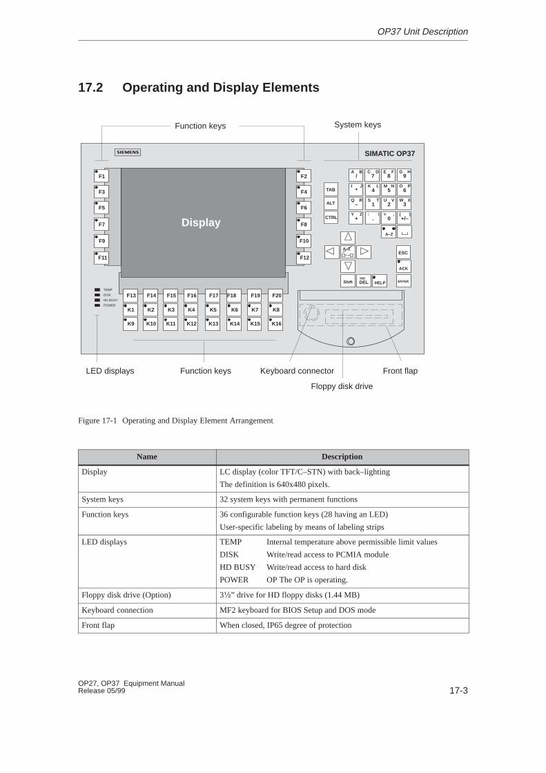
17-3OP27, OP37 Equipment ManualRelease 05/99
17.2 Operating and Display Elements
System keys
/A B
7C D
8E F
9G H
*I J
4K L
5M N
6O P
–Q R
1S T
2U V
3W X
+Y Z
.: \
0= ,
+/–( )
TAB
DELINS
ESC
A–Z
A–Z
ENTERHELP
F1
F3
F5
F7
F9
F11
ALT
CTRL
Shift
K1 K2 K3 K4 K5 K6 K7 K8
K9 K10 K11 K12 K13 K14 K15 K16
TEMP
DISK
HD BUSY
POWER
SIMATIC OP37
Keyboard connector
Floppy disk drive
Front flap
Function keys
Function keysLED displays
F2
F4
F6
F8
F10
F12
F13 F14 F15 F16 F17 F18 F19 F20
A–Z
ACK
Display
Figure 17-1 Operating and Display Element Arrangement
Name Description
Display LC display (color TFT/C–STN) with back–lighting
The definition is 640x480 pixels.
System keys 32 system keys with permanent functions
Function keys 36 configurable function keys (28 having an LED)
User-specific labeling by means of labeling strips
LED displays TEMP Internal temperature above permissible limit values
DISK Write/read access to PCMIA module
HD BUSY Write/read access to hard disk
POWER OP The OP is operating.
Floppy disk drive (Option) 3�” drive for HD floppy disks (1.44 MB)
Keyboard connection MF2 keyboard for BIOS Setup and DOS mode
Front flap When closed, IP65 degree of protection
OP37 Unit Description
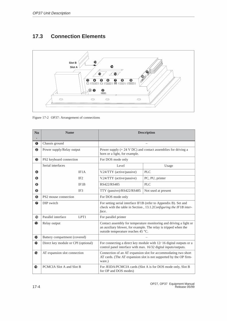
17-4OP27, OP37 Equipment Manual
Release 05/99
17.3 Connection Elements
Slot B
Slot A
� �� ���
��
Figure 17-2 OP37: Arrangement of connections
No.
Name Description
� Chassis ground –
� Power supply/Relay output Power supply (+ 24 V DC) and contact assemblies for driving ahorn or a light, for example.
� PS2 keyboard connection For DOS mode only
Serial interfaces Level Usage
� IF1A V.24/TTY (active/passive) PLC
� IF2 V.24/TTY (active/passive) PC, PU, printer
� IF1B RS422/RS485 PLC
IF3 TTY (passive)/RS422/RS485Not used at present
� PS2 mouse connection For DOS mode only
� DIP switch For setting serial interface IF1B (refer to Appendix B). Set andcheck with the table in Section , 13.1.2Configuring the IF1B inter-face.
Parallel interface LPT1 For parallel printer
Relay output Contact assembly for temperature monitoring and driving a light oran auxiliary blower, for example. The relay is tripped when theoutside temperature reaches 45 °C.
Battery compartment (covered) –
Direct key module or CPI (optional) For connecting a direct key module with 12/ 16 digital outputs or acontrol panel interface with max. 16/32 digital inputs/outputs.
AT expansion slot connection Connection of an AT expansion slot for accommodating two shortAT cards. (The AT expansion slot is not supported by the OP firm-ware.)
PCMCIA Slot A and Slot B For JEIDA/PCMCIA cards (Slot A is for DOS mode only, Slot Bfor OP and DOS modes)
OP37 Unit Description

17-5OP27, OP37 Equipment ManualRelease 05/99
17.4 Communication Options
Connection Interface
SIMATIC S5
– AS511 (TTY)
– FAP (TTY/RS232)
– PROFIBUS-DP
IF1A
IF1A
IF1B
SIMATIC S7/M7
– PPI
– MPI
– PROFIBUS-DP
IF1B
IF1B
IF1B
SIMATIC 500/505
– RS232
– RS422/RS485
IF1A
IF1B
Other PLCs
– RS232/TTY
– RS422/RS485
IF1A
IF1B
PC or PU (TTY/RS232) IF2
Printer
– TTY/RS232
– TTL
IF2
LPT
OP37 Unit Description
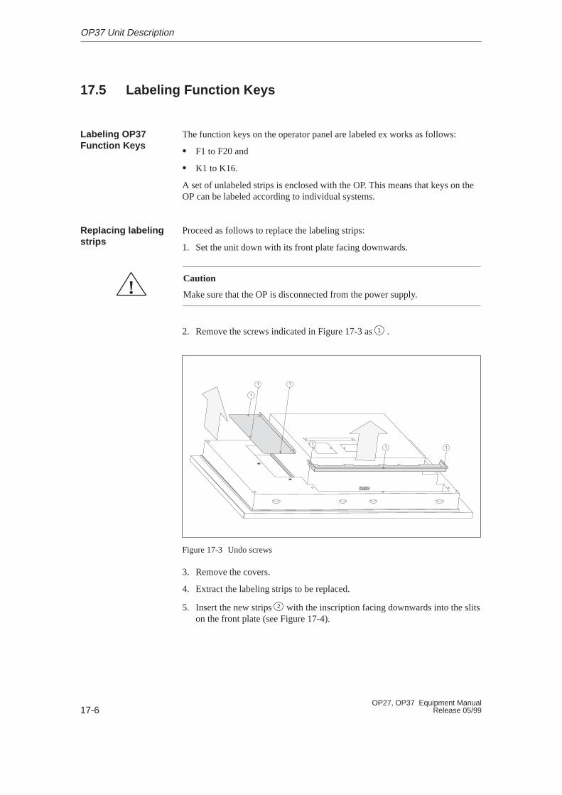
17-6OP27, OP37 Equipment Manual
Release 05/99
17.5 Labeling Function Keys
The function keys on the operator panel are labeled ex works as follows:
� F1 to F20 and
� K1 to K16.
A set of unlabeled strips is enclosed with the OP. This means that keys on theOP can be labeled according to individual systems.
Proceed as follows to replace the labeling strips:
1. Set the unit down with its front plate facing downwards.
!Caution
Make sure that the OP is disconnected from the power supply.
2. Remove the screws indicated in Figure 17-3 as 1 .
�
�� �
�
�
Figure 17-3 Undo screws
3. Remove the covers.
4. Extract the labeling strips to be replaced.
5. Insert the new strips 2 with the inscription facing downwards into the slitson the front plate (see Figure 17-4).
Labeling OP37Function Keys
Replacing labelingstrips
OP37 Unit Description
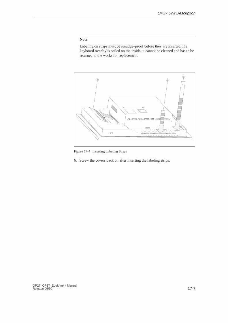
17-7OP27, OP37 Equipment ManualRelease 05/99
Note
Labeling on strips must be smudge–proof before they are inserted. If akeyboard overlay is soiled on the inside, it cannot be cleaned and has to bereturned to the works for replacement.
�
� �
Figure 17-4 Inserting Labeling Strips
6. Screw the covers back on after inserting the labeling strips.
OP37 Unit Description
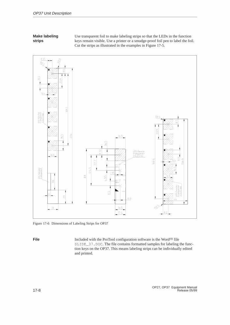
17-8OP27, OP37 Equipment Manual
Release 05/99
Use transparent foil to make labeling strips so that the LEDs in the functionkeys remain visible. Use a printer or a smudge-proof foil pen to label the foil.Cut the strips as illustrated in the examples in Figure 17-5.
Figure 17-6 Dimensions of Labeling Strips for OP37
Included with the ProTool configuration software is the Word� fileSLIDE_37.DOC . The file contains formatted samples for labeling the func-tion keys on the OP37. This means labeling strips can be individually editedand printed.
Make labelingstrips
File
OP37 Unit Description

18-1OP27, OP37 Equipment ManualRelease 05/99
Options
This chapter contains descriptions of the following units which can be option-ally connected:
� AT expansion slot (for OP37 only)
� Direct Key Module (DKM)
� Control Panel Interface (CPI)
18
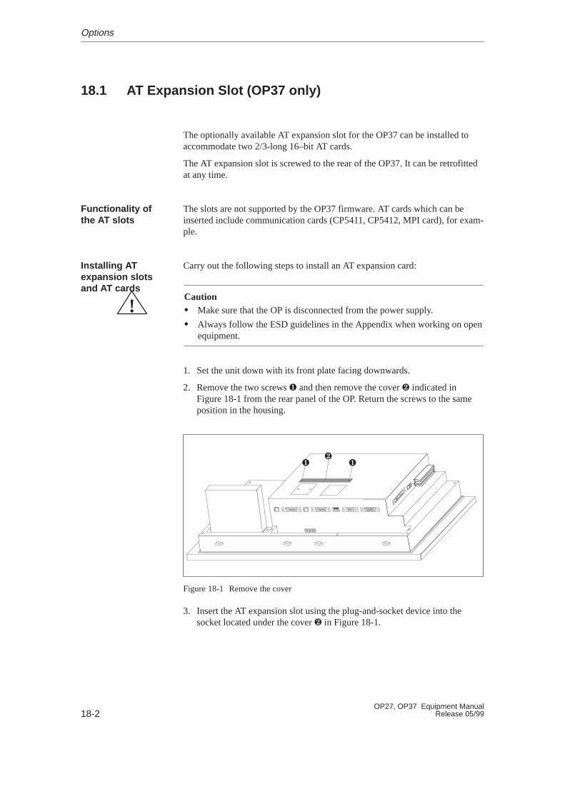
18-2OP27, OP37 Equipment Manual
Release 05/99
18.1 AT Expansion Slot (OP37 only)
The optionally available AT expansion slot for the OP37 can be installed toaccommodate two 2/3-long 16–bit AT cards.
The AT expansion slot is screwed to the rear of the OP37. It can be retrofittedat any time.
The slots are not supported by the OP37 firmware. AT cards which can beinserted include communication cards (CP5411, CP5412, MPI card), for exam-ple.
Carry out the following steps to install an AT expansion card:
!Caution� Make sure that the OP is disconnected from the power supply.
� Always follow the ESD guidelines in the Appendix when working on openequipment.
1. Set the unit down with its front plate facing downwards.
2. Remove the two screws � and then remove the cover � indicated in Figure 18-1 from the rear panel of the OP. Return the screws to the sameposition in the housing.
� ��
Figure 18-1 Remove the cover
3. Insert the AT expansion slot using the plug-and-socket device into thesocket located under the cover � in Figure 18-1.
Functionality ofthe AT slots
Installing ATexpansion slotsand AT cards
Options
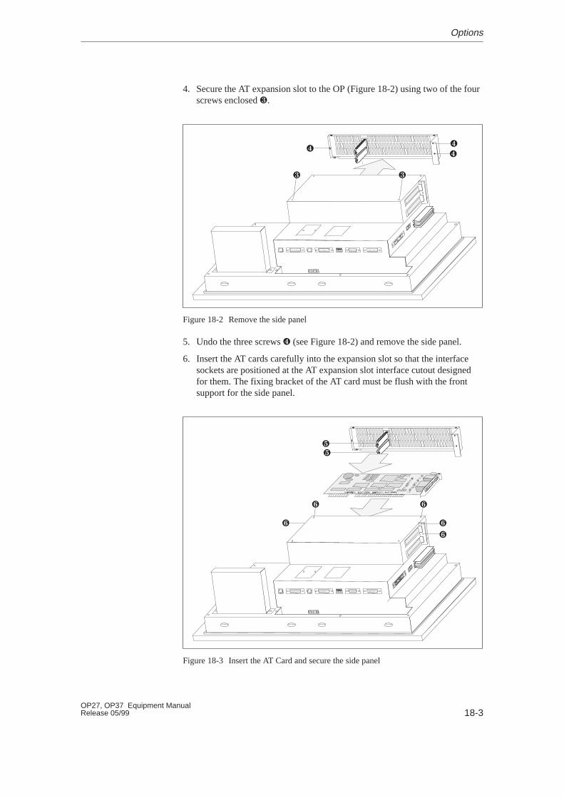
18-3OP27, OP37 Equipment ManualRelease 05/99
4. Secure the AT expansion slot to the OP (Figure 18-2) using two of the fourscrews enclosed �.
� �
��
�
Figure 18-2 Remove the side panel
5. Undo the three screws � (see Figure 18-2) and remove the side panel.
6. Insert the AT cards carefully into the expansion slot so that the interfacesockets are positioned at the AT expansion slot interface cutout designedfor them. The fixing bracket of the AT card must be flush with the frontsupport for the side panel.
�
��
� �
�
�
Figure 18-3 Insert the AT Card and secure the side panel
Options
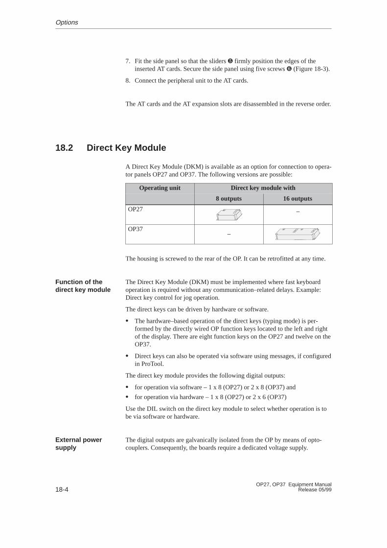
18-4OP27, OP37 Equipment Manual
Release 05/99
7. Fit the side panel so that the sliders � firmly position the edges of theinserted AT cards. Secure the side panel using five screws � (Figure 18-3).
8. Connect the peripheral unit to the AT cards.
The AT cards and the AT expansion slots are disassembled in the reverse order.
18.2 Direct Key Module
A Direct Key Module (DKM) is available as an option for connection to opera-tor panels OP27 and OP37. The following versions are possible:
Operating unit Dir ect key module with
8 outputs 16 outputs
OP27 –
OP37–
The housing is screwed to the rear of the OP. It can be retrofitted at any time.
The Direct Key Module (DKM) must be implemented where fast keyboardoperation is required without any communication–related delays. Example:Direct key control for jog operation.
The direct keys can be driven by hardware or software.
� The hardware–based operation of the direct keys (typing mode) is per-formed by the directly wired OP function keys located to the left and rightof the display. There are eight function keys on the OP27 and twelve on theOP37.
� Direct keys can also be operated via software using messages, if configuredin ProTool.
The direct key module provides the following digital outputs:
� for operation via software – 1 x 8 (OP27) or 2 x 8 (OP37) and
� for operation via hardware – 1 x 8 (OP27) or 2 x 6 (OP37)
Use the DIL switch on the direct key module to select whether operation is tobe via software or hardware.
The digital outputs are galvanically isolated from the OP by means of opto-couplers. Consequently, the boards require a dedicated voltage supply.
Function of thedirect key module
External powersupply
Options
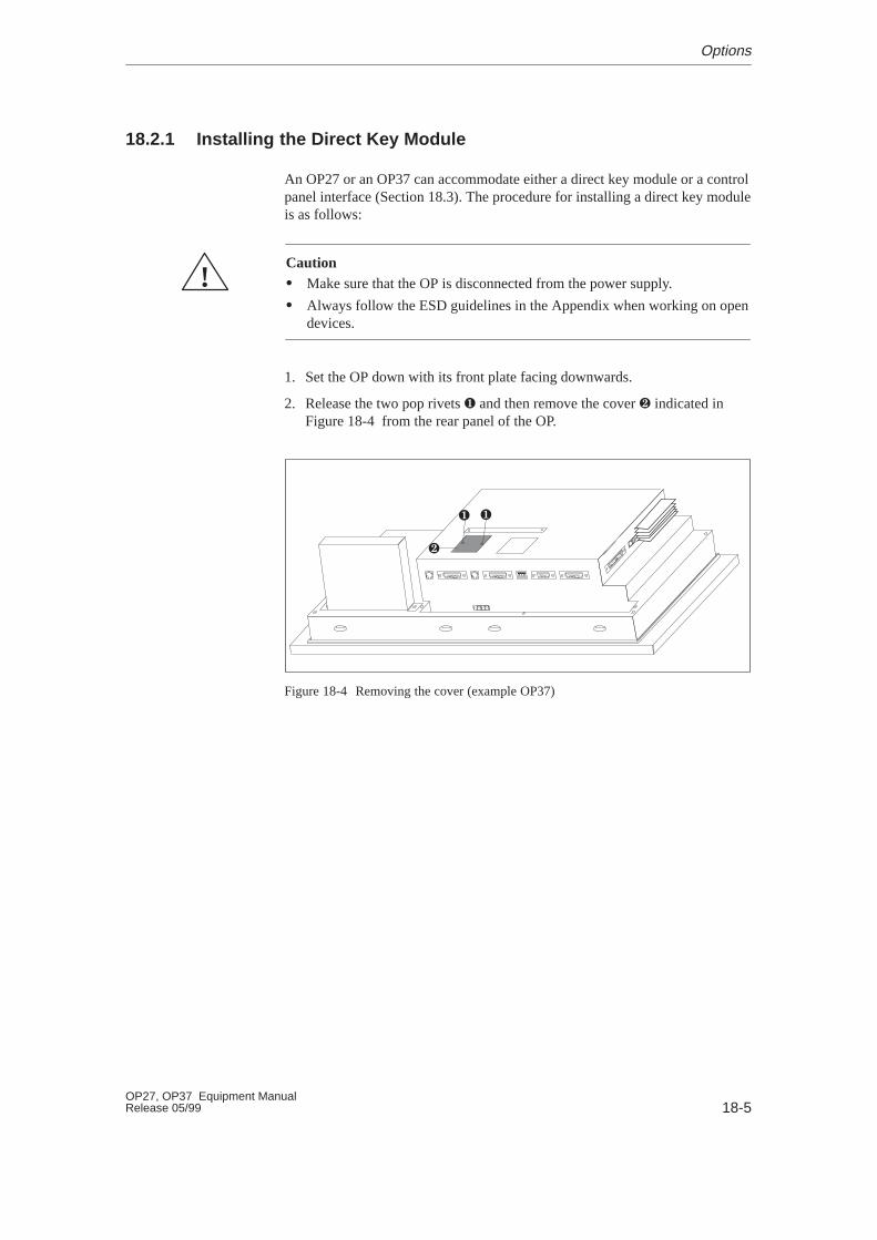
18-5OP27, OP37 Equipment ManualRelease 05/99
18.2.1 Installing the Direct Key Module
An OP27 or an OP37 can accommodate either a direct key module or a controlpanel interface (Section 18.3). The procedure for installing a direct key moduleis as follows:
!Caution� Make sure that the OP is disconnected from the power supply.
� Always follow the ESD guidelines in the Appendix when working on opendevices.
1. Set the OP down with its front plate facing downwards.
2. Release the two pop rivets � and then remove the cover � indicated inFigure 18-4 from the rear panel of the OP.
��
�
Figure 18-4 Removing the cover (example OP37)
Options
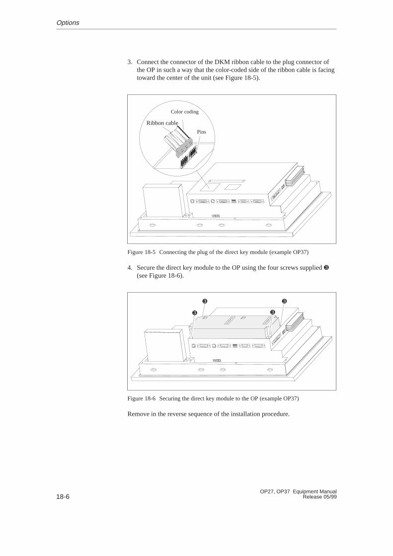
18-6OP27, OP37 Equipment Manual
Release 05/99
3. Connect the connector of the DKM ribbon cable to the plug connector ofthe OP in such a way that the color-coded side of the ribbon cable is facingtoward the center of the unit (see Figure 18-5).
Color coding
Pins
Ribbon cable
Figure 18-5 Connecting the plug of the direct key module (example OP37)
4. Secure the direct key module to the OP using the four screws supplied �
(see Figure 18-6).
� �
��
Figure 18-6 Securing the direct key module to the OP (example OP37)
Remove in the reverse sequence of the installation procedure.
Options

18-7OP27, OP37 Equipment ManualRelease 05/99
18.2.2 Connection and Adjusting Elements
Each module has
� a 10-pin plug connectorfor connecting the outputs and the external power supply
� a DIL switchfor defining whether the outputs are determined by the stroke of a key or bysoftware.
When installed, the plug connector and the DIL switch are located on the rearpanel of the OP.
DIL switch Pins
DKM ADKM B
Figure 18-7 Location of connection and adjustment elements on large module housing(example OP37)
Options
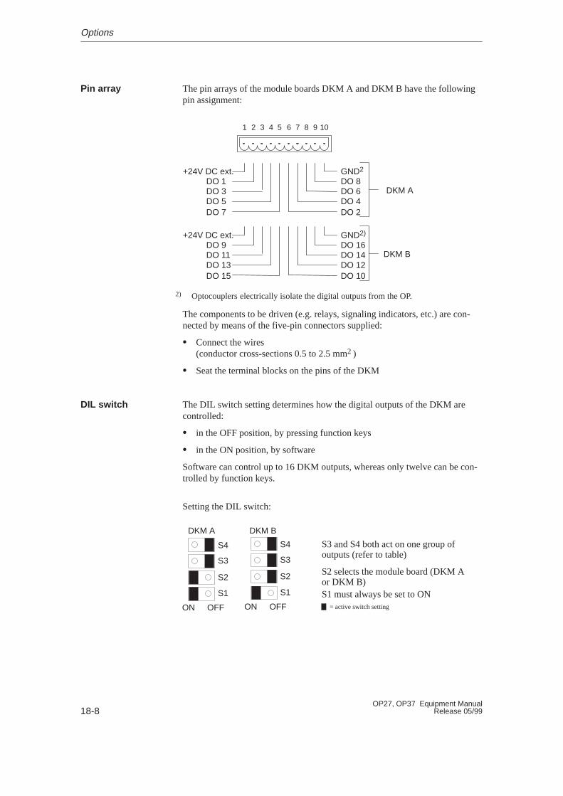
18-8OP27, OP37 Equipment Manual
Release 05/99
The pin arrays of the module boards DKM A and DKM B have the followingpin assignment:
1 2 3 4 5 6 7 8 9 10
GND2
DO 8DO 6DO 4DO 2
+24V DC ext.DO 1DO 3DO 5DO 7
DKM A
GND2)
DO 16DO 14DO 12DO 10
+24V DC ext.DO 9DO 11DO 13DO 15
DKM B
2) Optocouplers electrically isolate the digital outputs from the OP.
The components to be driven (e.g. relays, signaling indicators, etc.) are con-nected by means of the five-pin connectors supplied:
� Connect the wires (conductor cross-sections 0.5 to 2.5 mm2 )
� Seat the terminal blocks on the pins of the DKM
The DIL switch setting determines how the digital outputs of the DKM arecontrolled:
� in the OFF position, by pressing function keys
� in the ON position, by software
Software can control up to 16 DKM outputs, whereas only twelve can be con-trolled by function keys.
Setting the DIL switch:
DKM A DKM B
S1
S2
S3
S4
OFFON
S1 must always be set to ON
S2 selects the module board (DKM Aor DKM B)
S3 and S4 both act on one group ofoutputs (refer to table)
S1
S2
S3
S4
OFFON = active switch setting
Pin array
DIL switch
Options

18-9OP27, OP37 Equipment ManualRelease 05/99
OFF ON On
DK
M A S3 F1/F3/F5/F7
act as direct keys
DO 1/DO 3/DO 5/DO 7
controlled via software
OP27,
OP37
D
S4 F2/F4/F6/F8
act as direct keys
DO 2/DO 4/DO 6/DO 8
controlled via software
OP27,
OP37
DK
M B S3 F9/F11
act as direct keys
DO 9/DO 11/DO 13/DO 15
controlled via software
OP37
DS4 F10/F12
act as direct keys
DO 10/DO 12/DO 14/DO 16
controlled via software
OP37
The function key assignment in this table refers to the default key assignment without insertionstrips.
When switches S3 and S4 are set in the OFF position, the digital outputs arepermanently assigned to keys F1 to F12:
Key F1 sets output DO 1
Key F2 sets output DO 2
�
�
Key F12 sets output DO 12.
Options
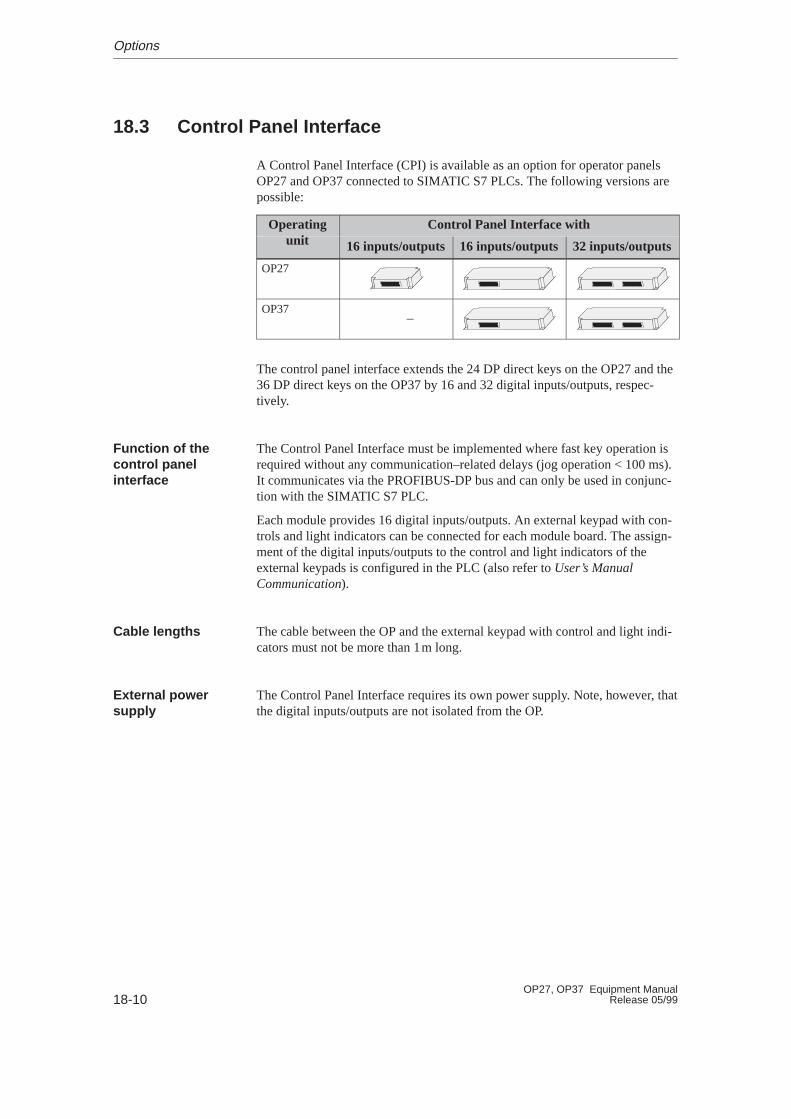
18-10OP27, OP37 Equipment Manual
Release 05/99
18.3 Control Panel Interface
A Control Panel Interface (CPI) is available as an option for operator panelsOP27 and OP37 connected to SIMATIC S7 PLCs. The following versions arepossible:
Operatingit
Control Panel Interface withunit 16 inputs/outputs 16 inputs/outputs 32 inputs/outputs
OP27 – –
OP37–
The control panel interface extends the 24 DP direct keys on the OP27 and the36 DP direct keys on the OP37 by 16 and 32 digital inputs/outputs, respec-tively.
The Control Panel Interface must be implemented where fast key operation isrequired without any communication–related delays (jog operation < 100 ms).It communicates via the PROFIBUS-DP bus and can only be used in conjunc-tion with the SIMATIC S7 PLC.
Each module provides 16 digital inputs/outputs. An external keypad with con-trols and light indicators can be connected for each module board. The assign-ment of the digital inputs/outputs to the control and light indicators of theexternal keypads is configured in the PLC (also refer to User’s ManualCommunication).
The cable between the OP and the external keypad with control and light indi-cators must not be more than 1m long.
The Control Panel Interface requires its own power supply. Note, however, thatthe digital inputs/outputs are not isolated from the OP.
Function of thecontrol panelinterface
Cable lengths
External powersupply
Options

18-11OP27, OP37 Equipment ManualRelease 05/99
18.3.1 Installing the Control Panel Interface
An OP27 or an OP37 can accommodate either a control panel interface or adirect key module (Section 18.2). The procedure for installing a control panelinterface is as follows:
1. Set the OP down with its front plate facing downwards.
!Caution� Make sure that the OP is disconnected from the power supply.
� Always follow the ESD guidelines in the Appendix when working on opendevices.
2. Release the two pop rivets � and then remove the cover � indicated inFigure 18-8 from the rear panel of the OP.
��
�
Figure 18-8 Removing the cover (example OP37)
Options
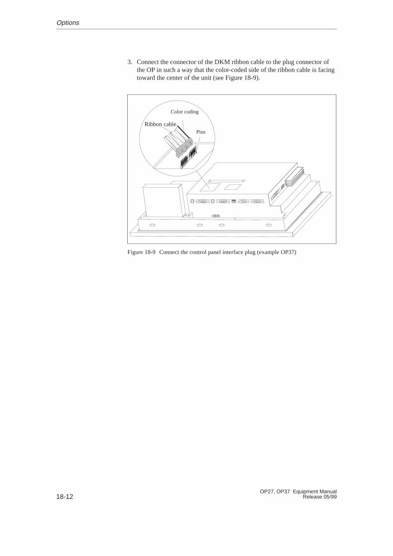
18-12OP27, OP37 Equipment Manual
Release 05/99
3. Connect the connector of the DKM ribbon cable to the plug connector ofthe OP in such a way that the color-coded side of the ribbon cable is facingtoward the center of the unit (see Figure 18-9).
Color coding
Pins
Ribbon cable
Figure 18-9 Connect the control panel interface plug (example OP37)
Options
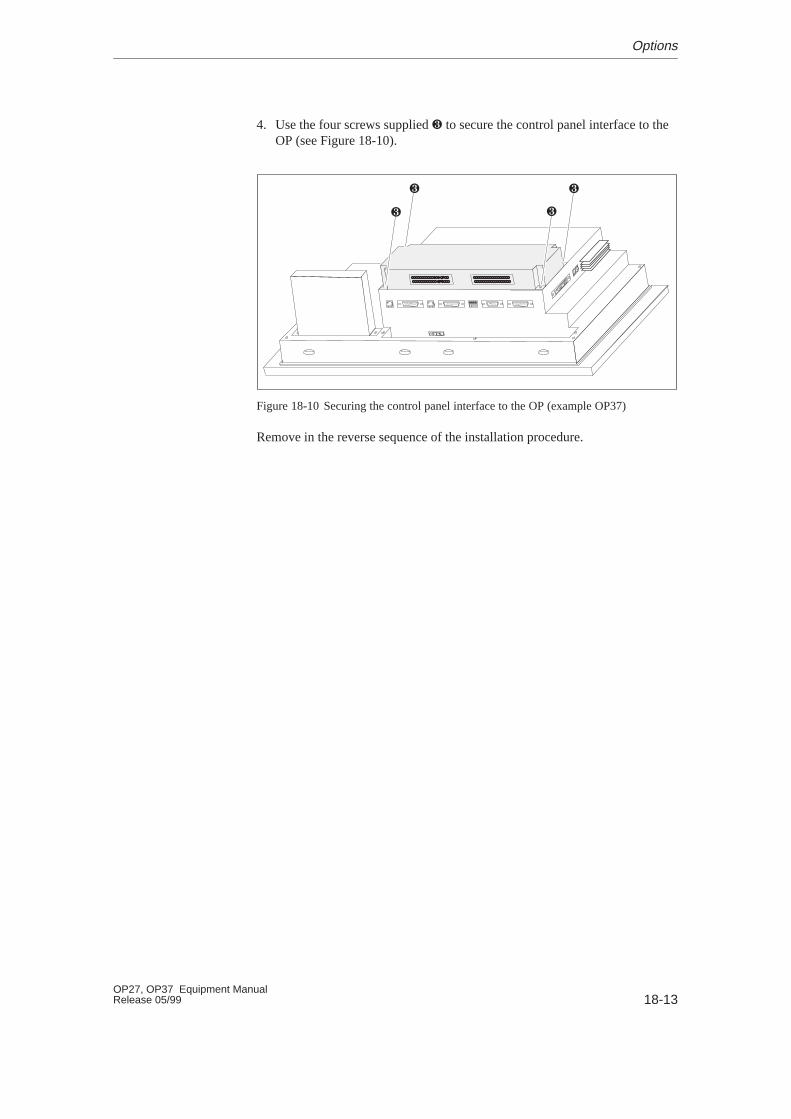
18-13OP27, OP37 Equipment ManualRelease 05/99
4. Use the four screws supplied � to secure the control panel interface to theOP (see Figure 18-10).
� �
��
Figure 18-10 Securing the control panel interface to the OP (example OP37)
Remove in the reverse sequence of the installation procedure.
Options
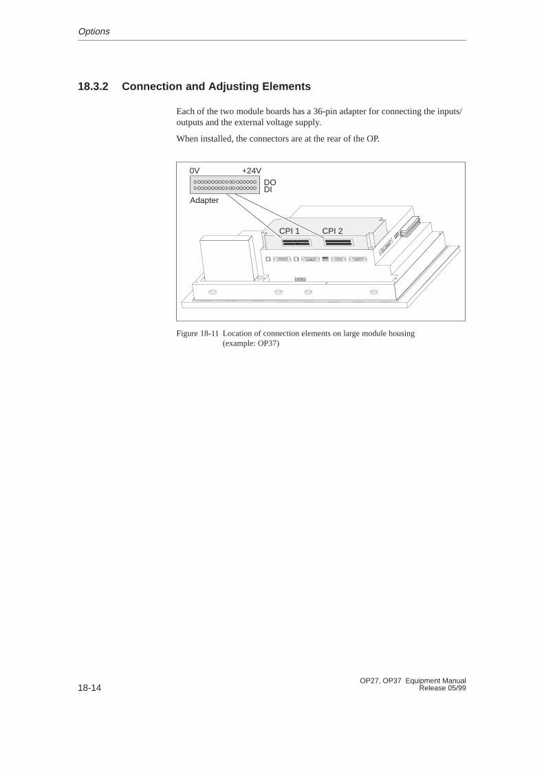
18-14OP27, OP37 Equipment Manual
Release 05/99
18.3.2 Connection and Adjusting Elements
Each of the two module boards has a 36-pin adapter for connecting the inputs/outputs and the external voltage supply.
When installed, the connectors are at the rear of the OP.
0V +24V
Adapter
DODI
CPI 1 CPI 2
Figure 18-11 Location of connection elements on large module housing (example: OP37)
Options

18-15OP27, OP37 Equipment ManualRelease 05/99
The connectors of modules CPI 1 and CPI 2 have the following pin assign-ments:
+24V DC ext.GND1)
DO 16 to DO 1
CPI 1
CPI 2
+24V DC ext.GND)1
DI 16 to DI 1
+24V DC ext.GND1)
DO 32 to DO 17 +24V DC ext.GND1)
DI 32 to DI 17
1) Non-floating
The controls and light indicators to be driven are connected by means of the9-pin connectors supplied.
� Make the cable terminal connections(conductor cross-sections 0.5 to 2.5 mm2)
� Seat the terminal blocks on the adapters of the CPI module boards.
Connector
Options

18-16OP27, OP37 Equipment Manual
Release 05/99
Options
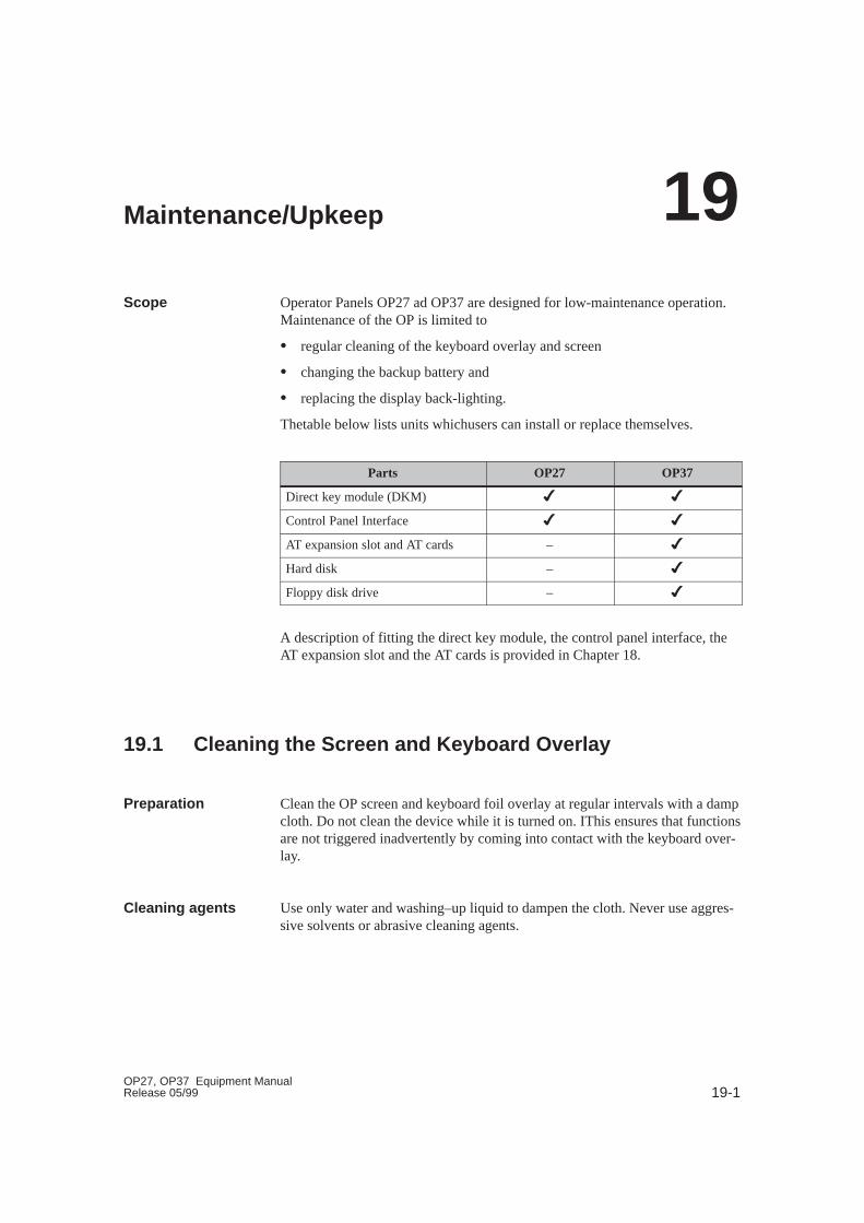
19-1OP27, OP37 Equipment ManualRelease 05/99
Maintenance/Upkeep
Operator Panels OP27 ad OP37 are designed for low-maintenance operation.Maintenance of the OP is limited to
� regular cleaning of the keyboard overlay and screen
� changing the backup battery and
� replacing the display back-lighting.
Thetable below lists units whichusers can install or replace themselves.
Parts OP27 OP37
Direct key module (DKM) � �
Control Panel Interface � �
AT expansion slot and AT cards – �
Hard disk – �
Floppy disk drive – �
A description of fitting the direct key module, the control panel interface, theAT expansion slot and the AT cards is provided in Chapter 18.
19.1 Cleaning the Screen and Keyboard Overlay
Clean the OP screen and keyboard foil overlay at regular intervals with a dampcloth. Do not clean the device while it is turned on. IThis ensures that functionsare not triggered inadvertently by coming into contact with the keyboard over-lay.
Use only water and washing–up liquid to dampen the cloth. Never use aggres-sive solvents or abrasive cleaning agents.
Scope
Preparation
Cleaning agents
19

19-2OP27, OP37 Equipment Manual
Release 05/99
19.2 Replacing the Backup Battery
The backup battery ensures that, in the event of a power failure
� the operating data in the SRAM of the OP are retained and
� the hardware clock does not stop.
A lithium battery is used in the OP. It is already fitted when the device is sup-plied. It has a typical service life under normal operating conditions of approxi-mately four years. An exhausted battery is indicated in routine operation by asystem message on the OP. Replace the backup battery as quickly as possibleafter the message is issued.
The battery can be ordered via the Siemens spare parts service. It is shippedready for installation with a lead and connector. Refer to our catalog ST80.1for the order number.
Observe the following before changing the battery:
!Caution
� Change the battery with the power supply switched on, in order to preventlosses of data – for example, passwords.
� The battery must be changed by a suitably qualified person.
� Before replacing the battery, note the ESD guidelines in Appendix F of thismanual.
Function
Service life
Source of supply
Before changingthe battery
Maintenance/Upkeep
19-3OP27, OP37 Equipment ManualRelease 05/99
Step Action
1 If a direct key module or control panel interface is connected to theOP37, remove it (refer to Section 18.2 or 18.3) in order to gainaccess to the cover of the battery compartment.
Switch off the voltage supply before removing the DKM or CPI.After removing the direct key module or the control panel inter-face, switch on the voltage supply before removing the battery.
2 Remove the gray, plastic cover of the battery compartment at therear of the OP.
3 Remove the battery lead connector from the two-pin plug connec-tor on the OP.
4 Remove the dead battery from the holder and insert the new bat-tery. The snap-in plastic holder secures the battery in the batterycompartment.
5 Insert the battery lead connector back into the plug connector. Theconnector is coded and thus protected against polarity reversal.
6 Stow the lead in the battery compartment and close the batterycompartment.
Please observe the following safety notes to ensure correct handling and dis-posal of lithium batteries:
!Warning
� If the lithium battery is not handled properly, there is risk of explosion.
� Batteries
– should never be charged
– should not be opened
– should not be short-circuited
– should be safeguarded against polarity reversal
– should not be exposed to temperatures in excess of 100 �C
– should be protected against direct sunlight.
� Do not allow condensation to form on batteries.
� Should shipping become necessary, packing must comply with the Danger-ous Chemicals Ordinance for the carrier concerned (coding obligation).
� Treat used lithium batteries as special waste. Pack them in separate leak-proof plastic bags to dispose of them.
Action
General notes
Maintenance/Upkeep
19-4OP27, OP37 Equipment Manual
Release 05/99
19.3 Other Maintenance W ork on OP27
Other maintenance work is necessary only if the back-lighting fails:
� In the case of the OP27M, the monochrome display needs to be replaced.
� In the case of the OP27C, only a CCFL tube has to be replaced.
The service life of the fluorescent tubes can be increased by blanking thescreen (refer to Section 11.2).
The unit must be opened up in order to replace the display and back–lighting.Observe the following notes on safety for opening the OP:
!Warning
� Repairs to the OP must be performed by suitably qualified and authorizedtechnical personnel.
� The user may be exposed to considerable risk as a result of unauthorizedopening of the OP and unqualified repairs.
� The display back-lighting operates at voltages > 1000 V. Make sure thatthe OP27 is disconnected from the power supply before the unit is opened.
� Crystal liquid may leak from a damaged display.
Do not allow liquid to touch your skin; do not inhale vapors. If you comeinto contact with crystal liquid, wash your skin immediately with alcohol.
Consult a doctor without delay.
� Before working on an open unit, observe the ESD guidelines in theAppendix F of this manual.
!Caution
One of the screws in the back panel of the device is sealed. The warranty foryour device ceases if the seal is broken. If the manufacturer’s warranty foryour device has not expired, you should have the back-lighting or displayreplaced by your local Siemens branch office.
Service life
Before replacing
Maintenance/Upkeep
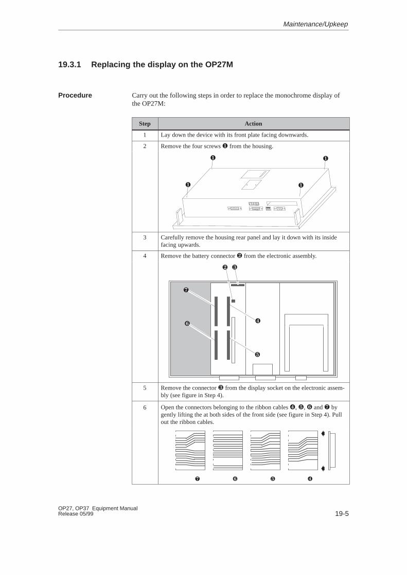
19-5OP27, OP37 Equipment ManualRelease 05/99
19.3.1 Replacing the display on the OP27M
Carry out the following steps in order to replace the monochrome display ofthe OP27M:
Step Action
1 Lay down the device with its front plate facing downwards.
2 Remove the four screws � from the housing.
��
� �
3 Carefully remove the housing rear panel and lay it down with its insidefacing upwards.
4 Remove the battery connector � from the electronic assembly.
� �
�
�
�
�
5 Remove the connector � from the display socket on the electronic assem-bly (see figure in Step 4).
6 Open the connectors belonging to the ribbon cables �, �, � and � bygently lifting the at both sides of the front side (see figure in Step 4). Pullout the ribbon cables.
�
�
����
Procedure
Maintenance/Upkeep
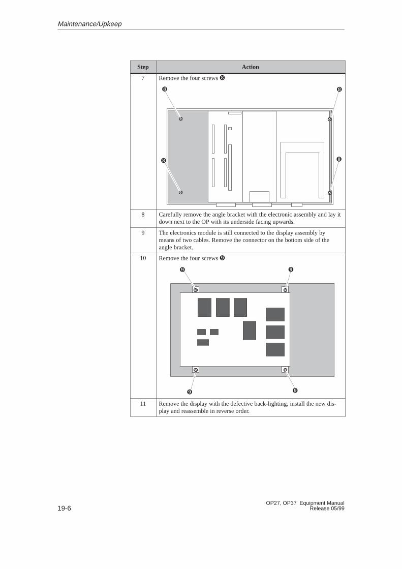
19-6OP27, OP37 Equipment Manual
Release 05/99
ActionStep
7 Remove the four screws �
�
� �
�
8 Carefully remove the angle bracket with the electronic assembly and lay itdown next to the OP with its underside facing upwards.
9 The electronics module is still connected to the display assembly bymeans of two cables. Remove the connector on the bottom side of theangle bracket.
10 Remove the four screws �
�
��
�
11 Remove the display with the defective back-lighting, install the new dis-play and reassemble in reverse order.
Maintenance/Upkeep

19-7OP27, OP37 Equipment ManualRelease 05/99
19.3.2 Replacing the Back-Lighting of the OP27C
Carry out the following steps to replace the back-lighting on the OP27C with acolor display:
Step Action
1 Lay down the device with its front plate facing downwards.
2 Remove the four housing screws � .
��
� �
3 Carefully remove the housing rear panel and lay it down with its insidefacing upwards.
4 Remove the battery connector � from the electronic assembly.
�
�
�
� �
�
5 Remove the connector � from the back-lighting socket on the electronicassembly (see figure in Step 4).
6 Open the labeled connectors �, �, � and � by gently lifting the at bothsides of the front side (see figure in Step 4). Pull out the ribbon cables.
Procedure
Maintenance/Upkeep
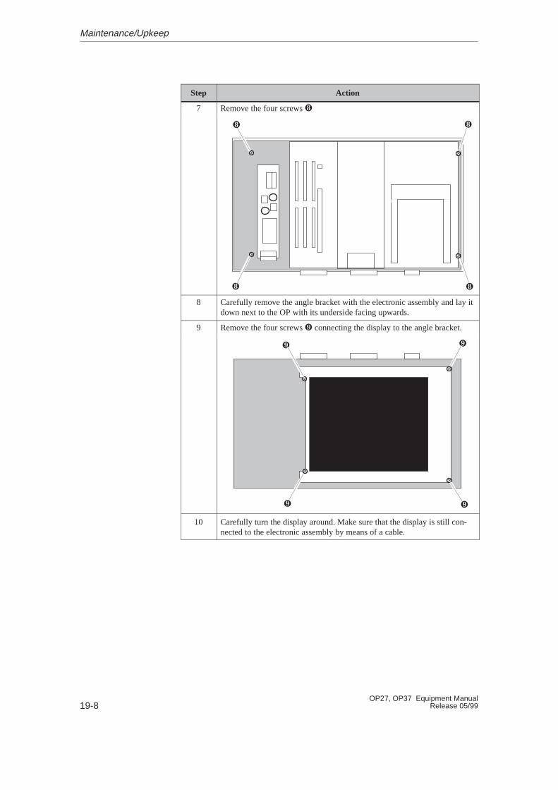
19-8OP27, OP37 Equipment Manual
Release 05/99
ActionStep
7 Remove the four screws �
�
�
�
�
8 Carefully remove the angle bracket with the electronic assembly and lay itdown next to the OP with its underside facing upwards.
9 Remove the four screws � connecting the display to the angle bracket.
�
� �
�
10 Carefully turn the display around. Make sure that the display is still con-nected to the electronic assembly by means of a cable.
Maintenance/Upkeep
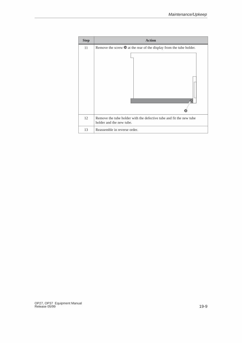
19-9OP27, OP37 Equipment ManualRelease 05/99
ActionStep
11 Remove the screw � at the rear of the display from the tube holder.
�
12 Remove the tube holder with the defective tube and fit the new tubeholder and the new tube.
13 Reassemble in reverse order.
Maintenance/Upkeep

19-10OP27, OP37 Equipment Manual
Release 05/99
19.4 Other Maintenance W ork on OP37
Other maintenance/service work on the OP37 involves replacing the back-lighting and floppy disk drive. To do this, however, the housing must beopened.
19.4.1 Opening the OP37 housing
Observe the following safety notes before starting to open the housing:
!Warning� Repairs to the OP must be performed by suitably qualified and authorized
technical personnel.
� The user may be exposed to considerable risk as a result of unauthorizedopening and unqualified repairs.
!Caution� The back-lighting operates at voltages > 1000 V. Make sure that the OP is
disconnected from the power supply.
� Always follow the ESD guidelines in the Appendix when working on opendevices.
� Do not undo any sealed screws. The manufacturer’s warranty for yourdevice ceases if the seal is broken.
Safety notes
Maintenance/Upkeep

19-11OP27, OP37 Equipment ManualRelease 05/99
Carry out the following steps to open the housing of the OP37:
Step Action
1 Lay down the device with its front plate facing downwards.
2 Remove the eight housing screws � .
�
�
�
� �
�
�
�
3 Remove the rear panel.
–> Refer to Section 19.4.3, Page 19-14 to replace the floppy disk drive.
4 Remove two screws � which hold a hinged plate.
90o
��
�
5 Gently lift the hinged plate and remove the ribbon cable from the connec-tor secured beneath the plate cutout � (see figure in Step 4).
6 Turn the plate to its final position (90 degrees).
–> To remove the back-lighting
– Refer to Chapter 19.4.2, Page 19-12.
Opening the OP37housing
Maintenance/Upkeep
19-12OP27, OP37 Equipment Manual
Release 05/99
19.4.2 Replacing the Back-Lighting of the OP37
The brightness of the LCD back–lighting decreases during the course of timefor technological reasons.
Increase the service life of the two fluorescent tubes by blanking the screen(refer to Section 11.2).
The difference in brightness between a new fluorescent tube and an old one isclearly obvious on the screen. Replace both tubes simultaneously when onefails. This will save having to open up the OP a second time when the secondtube fails.
The back–lighting can only be replaced for an OP37 with TFT display. In thecase of an OP37 with STN display, the complete display must be replaced.
Observe the following safety notes when replacing the back–lighting:
!Warning
Crystal liquid may leak from a damaged display.
Do not allow liquid to touch your skin; do not inhale vapors. If you come intocontact with crystal liquid, wash your skin immediately with alcohol.
Consult a doctor without delay.
Carry out the following steps to replace the back-lighting tubes:
Service life
Before replacing
Procedure
Maintenance/Upkeep
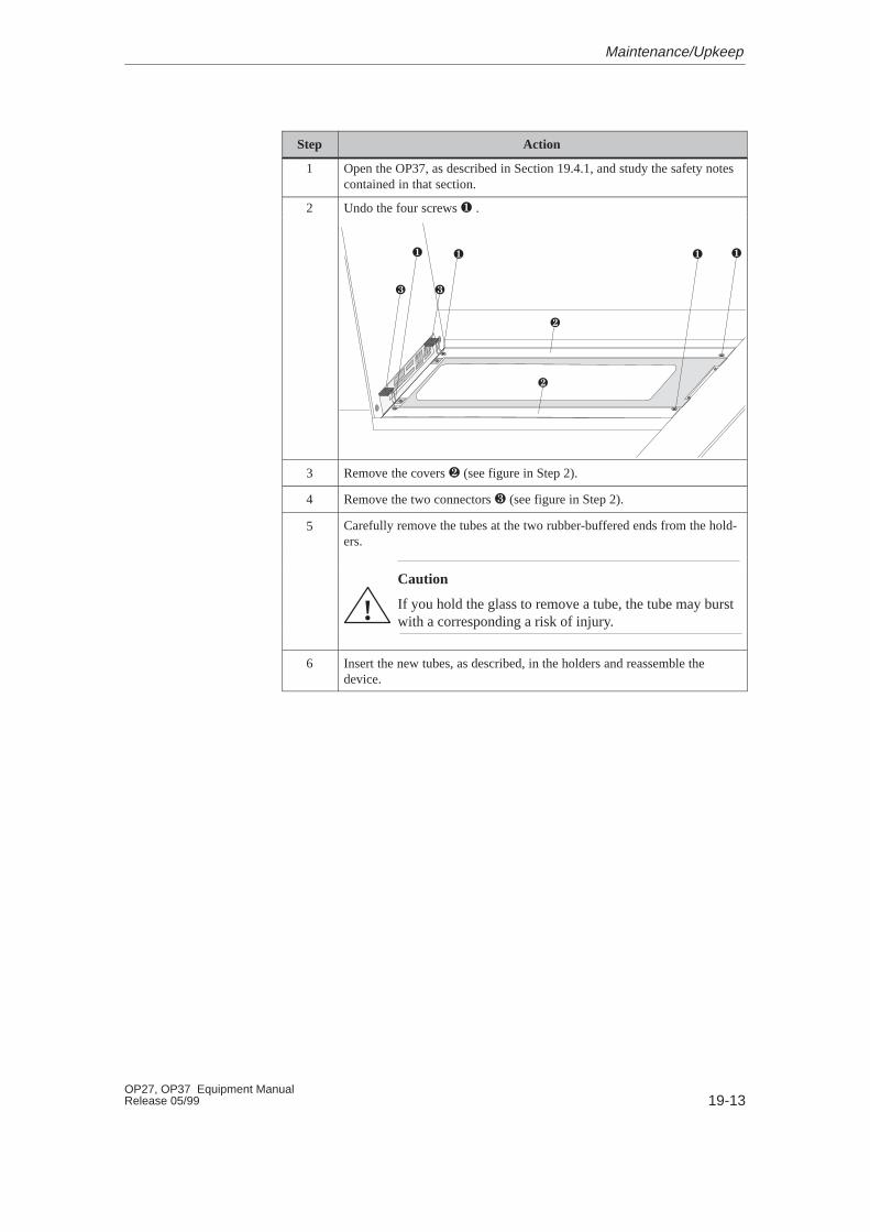
19-13OP27, OP37 Equipment ManualRelease 05/99
Step Action
1 Open the OP37, as described in Section 19.4.1, and study the safety notescontained in that section.
2 Undo the four screws � .
�� � �
�
�
��
3 Remove the covers � (see figure in Step 2).
4 Remove the two connectors � (see figure in Step 2).
5 Carefully remove the tubes at the two rubber-buffered ends from the hold-ers.
Caution
If you hold the glass to remove a tube, the tube may burstwith a corresponding a risk of injury.!
6 Insert the new tubes, as described, in the holders and reassemble thedevice.
Maintenance/Upkeep
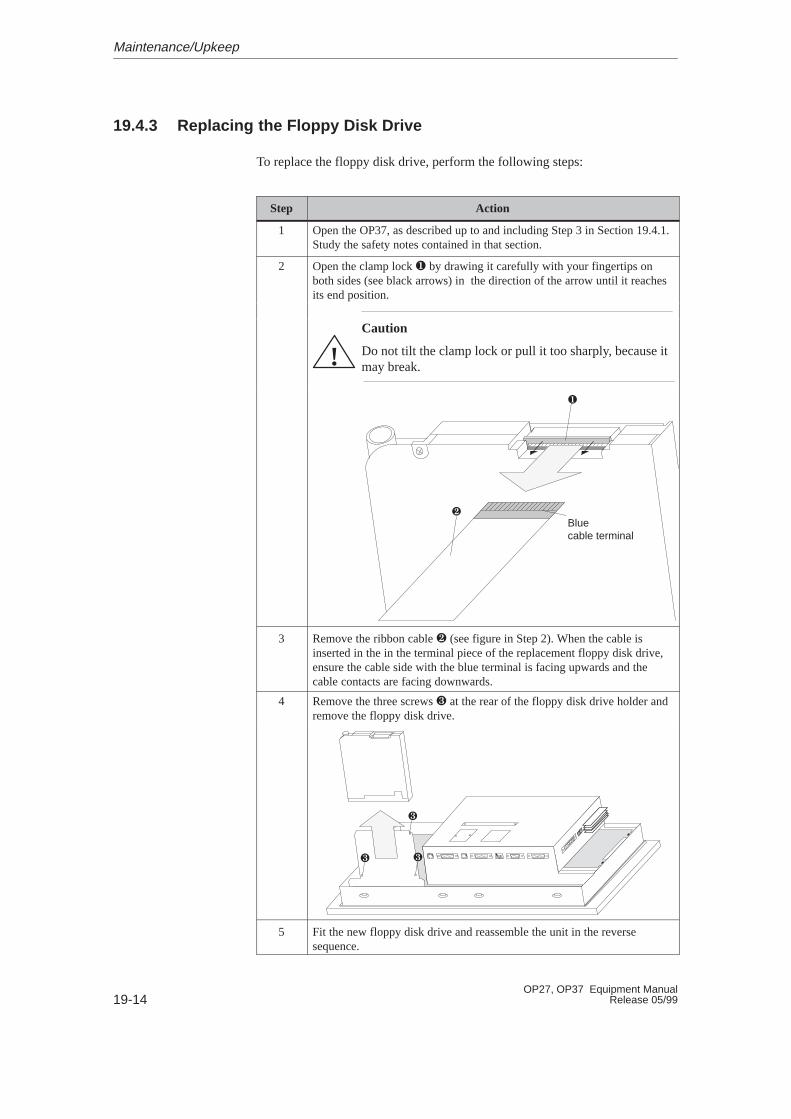
19-14OP27, OP37 Equipment Manual
Release 05/99
19.4.3 Replacing the Floppy Disk Drive
To replace the floppy disk drive, perform the following steps:
Step Action
1 Open the OP37, as described up to and including Step 3 in Section 19.4.1.Study the safety notes contained in that section.
2 Open the clamp lock � by drawing it carefully with your fingertips onboth sides (see black arrows) in the direction of the arrow until it reachesits end position.
Caution
Do not tilt the clamp lock or pull it too sharply, because itmay break.!
Bluecable terminal
�
�
3 Remove the ribbon cable � (see figure in Step 2). When the cable isinserted in the in the terminal piece of the replacement floppy disk drive,ensure the cable side with the blue terminal is facing upwards and thecable contacts are facing downwards.
4 Remove the three screws � at the rear of the floppy disk drive holder andremove the floppy disk drive.
�
� �
5 Fit the new floppy disk drive and reassemble the unit in the reversesequence.
Maintenance/Upkeep
APPENDICES
A Technical Data
B Interface Assignment
C Test Functions
D System Messages
E SIMATIC HMI Documentation
F ESD Guidelines
Part V

S-2OP27, OP37 Equipment Manual
Release 05/99
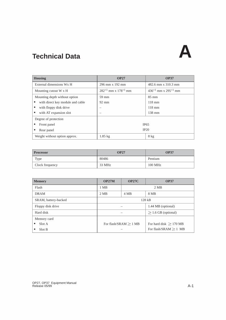
A-1OP27, OP37 Equipment ManualRelease 05/99
Technical Data
Housing OP27 OP37
External dimensions Wx H 296 mm x 192 mm 482.6 mm x 310.3 mm
Mounting cutout W x H 282+1 mm x 178+1 mm 436+1 mm x 295+1 mm
Mounting depth without option
� with direct key module and cable
� with floppy disk drive
� with AT expansion slot
59 mm
92 mm
–
–
85 mm
118 mm
118 mm
138 mm
Degree of protection
� Front panel
� Rear panel
IP65
IP20
Weight without option approx. 1.85 kg 8 kg
Processor OP27 OP37
Type 80486 Pentium
Clock frequency 33 MHz 100 MHz
Memory OP27M OP27C OP37
Flash 1 MB 2 MB
DRAM 2 MB 4 MB 8 MB
SRAM, battery-backed 128 kB
Floppy disk drive – 1.44 MB (optional)
Hard disk – ��1.6 GB (optional)
Memory card
� Slot A
� Slot B
For flash/SRAM ��1 MB
–
For hard disk � 170 MB
For flash/SRAM ��1 MB
A
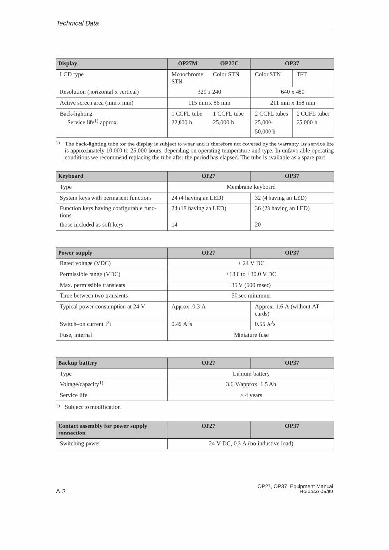
A-2OP27, OP37 Equipment Manual
Release 05/99
Display OP27M OP27C OP37
LCD type MonochromeSTN
Color STN Color STN TFT
Resolution (horizontal x vertical) 320 x 240 640 x 480
Active screen area (mm x mm) 115 mm x 86 mm 211 mm x 158 mm
Back-lighting
Service life1) approx.
1 CCFL tube
22,000 h
1 CCFL tube
25,000 h
2 CCFL tubes
25,000-
50,000 h
2 CCFL tubes
25,000 h
1) The back-lighting tube for the display is subject to wear and is therefore not covered by the warranty. Its service lifeis approximately 10,000 to 25,000 hours, depending on operating temperature and type. In unfavorable operatingconditions we recommend replacing the tube after the period has elapsed. The tube is available as a spare part.
Keyboard OP27 OP37
Type Membrane keyboard
System keys with permanent functions 24 (4 having an LED) 32 (4 having an LED)
Function keys having configurable func-tions
those included as soft keys
24 (18 having an LED)
14
36 (28 having an LED)
20
Power supply OP27 OP37
Rated voltage (VDC) + 24 V DC
Permissible range (VDC) +18.0 to +30.0 V DC
Max. permissible transients 35 V (500 msec)
Time between two transients 50 sec minimum
Typical power consumption at 24 V Approx. 0.3 A Approx. 1.6 A (without ATcards)
Switch–on current I2t 0.45 A2s 0.55 A2s
Fuse, internal Miniature fuse
Backup battery OP27 OP37
Type Lithium battery
Voltage/capacity1) 3.6 V/approx. 1.5 Ah
Service life > 4 years
1) Subject to modification.
Contact assembly for power supplyconnection
OP27 OP37
Switching power 24 V DC, 0.3 A (no inductive load)
Technical Data

A-3OP27, OP37 Equipment ManualRelease 05/99
Contact assembly for temperaturemonitoring
OP27 OP37
Switching power – 24 V DC, 0.3 A
(no inductive load)
Direct key module (DKM) OP27 OP37
Voltage supply for outputs, load voltage supply and internal logic circuitry
Voltage supply
� rated value
� permissible range
� value at t < 0.5 sec
+ 24 V DC
+18.0 to +30.0 V
35 V
Power consumption of logic circuitry 50 mA
Short-circuit protection upon polarity rever-sal of load voltage
�
Outputs1)
No. of outputs 8 per module
Output voltage
� with signal “0”
� with signal “1”
Max. 2 V (idling)
Min. (voltage supply –3 V)
Output current
� with signal “0”
� with signal “1”
Max. 1 mA
Max. 300 mA per output
Switch rate at
� resistive load
� inductive load
� lamp load
Max. 100 Hz
Max. 0.5 Hz
Max. 8 Hz
Short-circuit current Max. 500 mA per output
Note:
With inductive loads, an external free-wheeling diode must be used directly on the load.
1) Outputs are isolated by means of optocouplers.
Technical Data
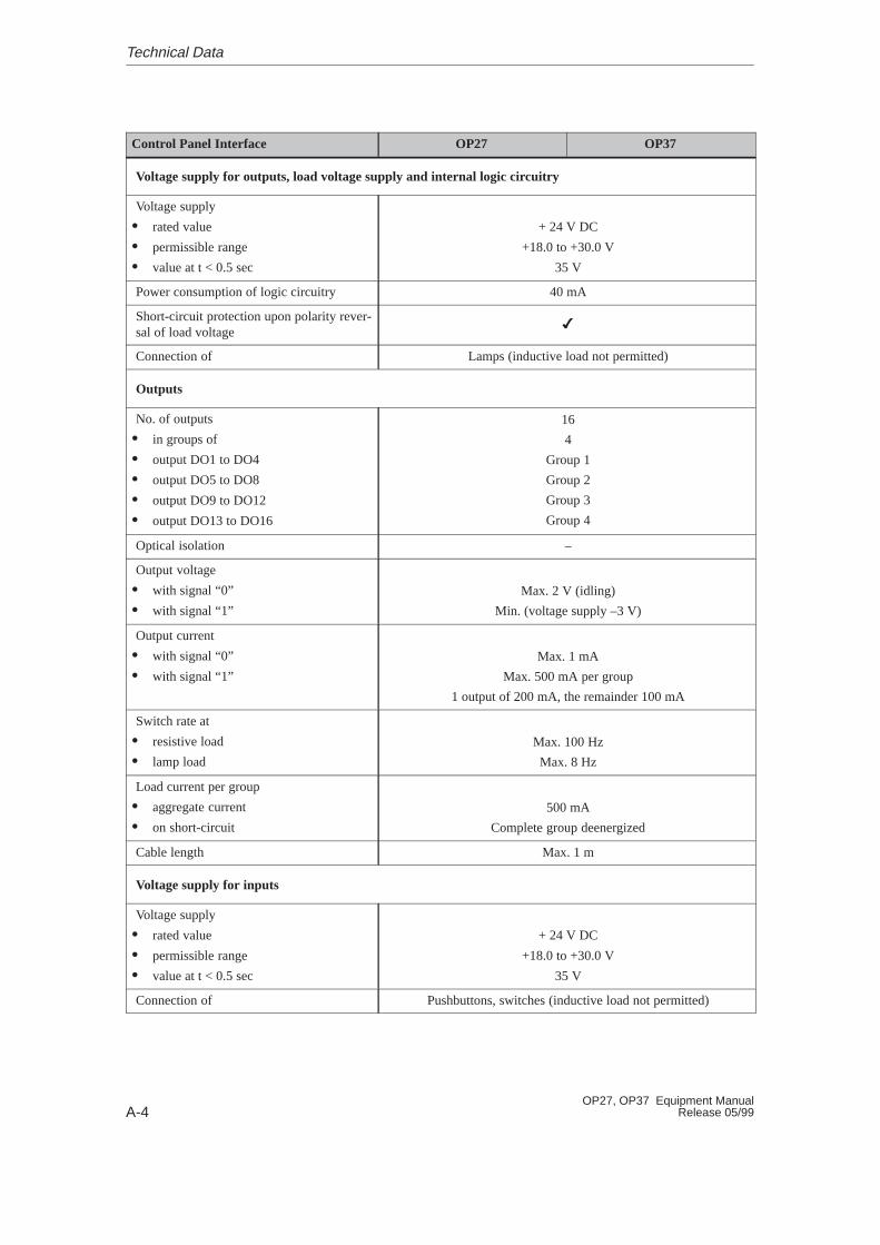
A-4OP27, OP37 Equipment Manual
Release 05/99
Control Panel Interface OP27 OP37
Voltage supply for outputs, load voltage supply and internal logic circuitry
Voltage supply
� rated value
� permissible range
� value at t < 0.5 sec
+ 24 V DC
+18.0 to +30.0 V
35 V
Power consumption of logic circuitry 40 mA
Short-circuit protection upon polarity rever-sal of load voltage
�
Connection of Lamps (inductive load not permitted)
Outputs
No. of outputs
� in groups of
� output DO1 to DO4
� output DO5 to DO8
� output DO9 to DO12
� output DO13 to DO16
16
4
Group 1
Group 2
Group 3
Group 4
Optical isolation –
Output voltage
� with signal “0”
� with signal “1”
Max. 2 V (idling)
Min. (voltage supply –3 V)
Output current
� with signal “0”
� with signal “1”
Max. 1 mA
Max. 500 mA per group
1 output of 200 mA, the remainder 100 mA
Switch rate at
� resistive load
� lamp load
Max. 100 Hz
Max. 8 Hz
Load current per group
� aggregate current
� on short-circuit
500 mA
Complete group deenergized
Cable length Max. 1 m
Voltage supply for inputs
Voltage supply
� rated value
� permissible range
� value at t < 0.5 sec
+ 24 V DC
+18.0 to +30.0 V
35 V
Connection of Pushbuttons, switches (inductive load not permitted)
Technical Data
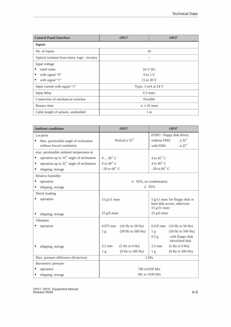
A-5OP27, OP37 Equipment ManualRelease 05/99
OP37OP27Control Panel Interface
Inputs
No. of inputs 16
Optical isolation from intern. logic circuitry –
Input voltage
� rated value
� with signal “0”
� with signal “1”
24 V DC
0 to 5 V
15 to 30 V
Input current with signal “1” Typic. 5 mA at 24 V
Input delay 0.3 msec
Connection of mechanical switches Possible
Bounce time ��10 msec
Cable length of sensors, unshielded 1 m
Ambient conditions OP27 OP37
Location
� Max. permissible angle of inclinationwithout forced ventilation
Vertical�35�
(FDD = floppy disk drive)
without FDD: �35�
with FDD: �25�
max. permissible ambient temperature at
� operation up to 10� angle of inclination
� operation up to 35� angle of inclination
� shipping, storage
0 ... 50� C
0 to 40� C
–20 to 60� C
4 to 45� C
4 to 40� C
–20 to 60� C
Relative humidity
� operation
� shipping, storage
� 95%, no condensation
� 95%
Shock loading
� operation
� shipping, storage
15 g/11 msec
25 g/6 msec
5 g/11 msec for floppy disk orhard disk access, otherwise15 g/11 msec
25 g/6 msec
Vibration
� operation
� shipping, storage
0.075 mm (10 Hz to 58 Hz)
1 g (58 Hz to 500 Hz)
3.5 mm (5 Hz to 9 Hz)
1 g (9 Hz to 500 Hz)
0.035 mm (10 Hz to 58 Hz)
1 g (58 Hz to 500 Hz)
0.5 g with floppy diskdrive/hard disk
3.5 mm (5 Hz to 9 Hz)
1 g (9 Hz to 500 Hz)
Max. pressure difference (front/rear) 2 hPa
Barometric pressure
� operation
� shipping, storage
706 to1030 hPa
581 to 1030 hPa
Technical Data
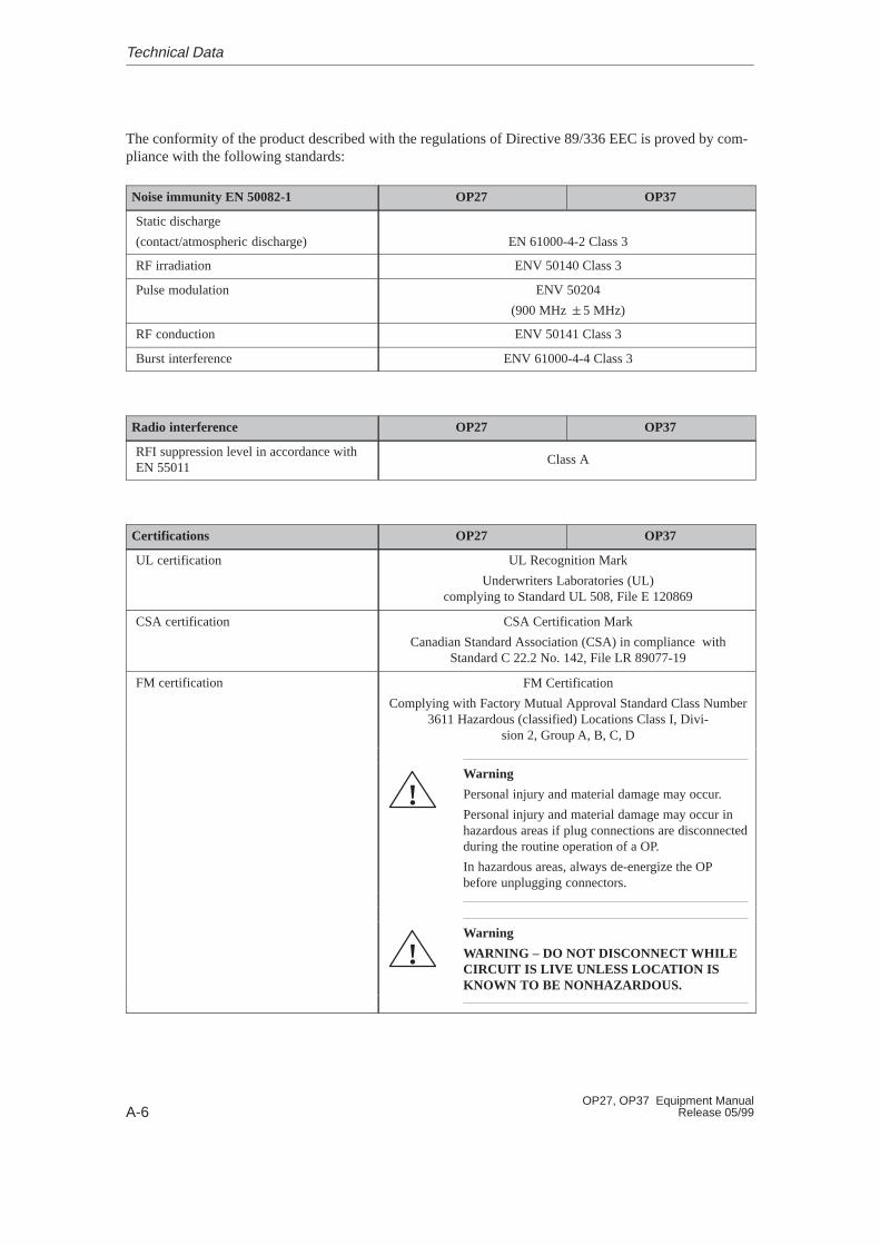
A-6OP27, OP37 Equipment Manual
Release 05/99
The conformity of the product described with the regulations of Directive 89/336 EEC is proved by com-pliance with the following standards:
Noise immunity EN 50082-1 OP27 OP37
Static discharge
(contact/atmospheric discharge) EN 61000-4-2 Class 3
RF irradiation ENV 50140 Class 3
Pulse modulation ENV 50204
(900 MHz �5 MHz)
RF conduction ENV 50141 Class 3
Burst interference ENV 61000-4-4 Class 3
Radio interference OP27 OP37
RFI suppression level in accordance withEN 55011
Class A
Certifications OP27 OP37
UL certification UL Recognition Mark
Underwriters Laboratories (UL)complying to Standard UL 508, File E 120869
CSA certification CSA Certification Mark
Canadian Standard Association (CSA) in compliance withStandard C 22.2 No. 142, File LR 89077-19
FM certification FM Certification
Complying with Factory Mutual Approval Standard Class Number3611 Hazardous (classified) Locations Class I, Divi-
sion 2, Group A, B, C, D
Warning
Personal injury and material damage may occur.
Personal injury and material damage may occur inhazardous areas if plug connections are disconnectedduring the routine operation of a OP.
In hazardous areas, always de-energize the OPbefore unplugging connectors.
!
Warning
WARNING – DO NOT DISCONNECT WHILECIRCUIT IS LIVE UNLESS LOCATION ISKNOWN TO BE NONHAZARDOUS.
!
Technical Data

B-1OP27, OP37 Equipment ManualRelease 05/99
Interface Assignments
Pin assignment of the 15–pin Sub-D socket:
Pin General RS232 TTY
1 Housing
2 RxD–
3 RxD
4 TxD
5 CTS
6 TxD+
7 TxD–
8 Housing
9 RxD+
10 RTS
11 +20 mA1)
12 GND
13 +20 mA1)
14 +5 V
15 GND
1) Not IF2
IF1A and IF2
B
8 1
15 9
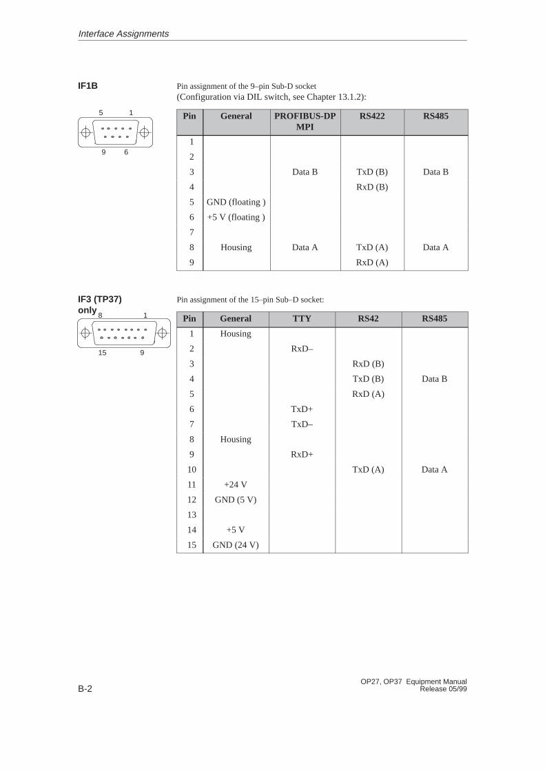
B-2OP27, OP37 Equipment Manual
Release 05/99
Pin assignment of the 9–pin Sub-D socket(Configuration via DIL switch, see Chapter 13.1.2):
Pin General PROFIBUS-DPMPI
RS422 RS485
1
2
3 Data B TxD (B) Data B
4 RxD (B)
5 GND (floating )
6 +5 V (floating )
7
8 Housing Data A TxD (A) Data A
9 RxD (A)
Pin assignment of the 15–pin Sub–D socket:
Pin General TTY RS42 RS485
1 Housing
2 RxD–
3 RxD (B)
4 TxD (B) Data B
5 RxD (A)
6 TxD+
7 TxD–
8 Housing
9 RxD+
10 TxD (A) Data A
11 +24 V
12 GND (5 V)
13
14 +5 V
15 GND (24 V)
IF1B
IF3 (TP37)only
Interface Assignments
5 1
9 6
8 1
15 9
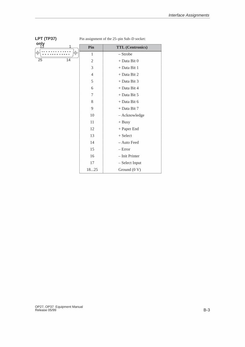
B-3OP27, OP37 Equipment ManualRelease 05/99
Pin assignment of the 25–pin Sub–D socket:
Pin TTL (Centronics)
1 – Strobe
2 + Data Bit 0
3 + Data Bit 1
4 + Data Bit 2
5 + Data Bit 3
6 + Data Bit 4
7 + Data Bit 5
8 + Data Bit 6
9 + Data Bit 7
10 – Acknowledge
11 + Busy
12 + Paper End
13 + Select
14 – Auto Feed
15 – Error
16 – Init Printer
17 – Select Input
18...25 Ground (0 V)
LPT (TP37) only
Interface Assignments
13 1
25 14

B-4OP27, OP37 Equipment Manual
Release 05/99
Interface Assignments
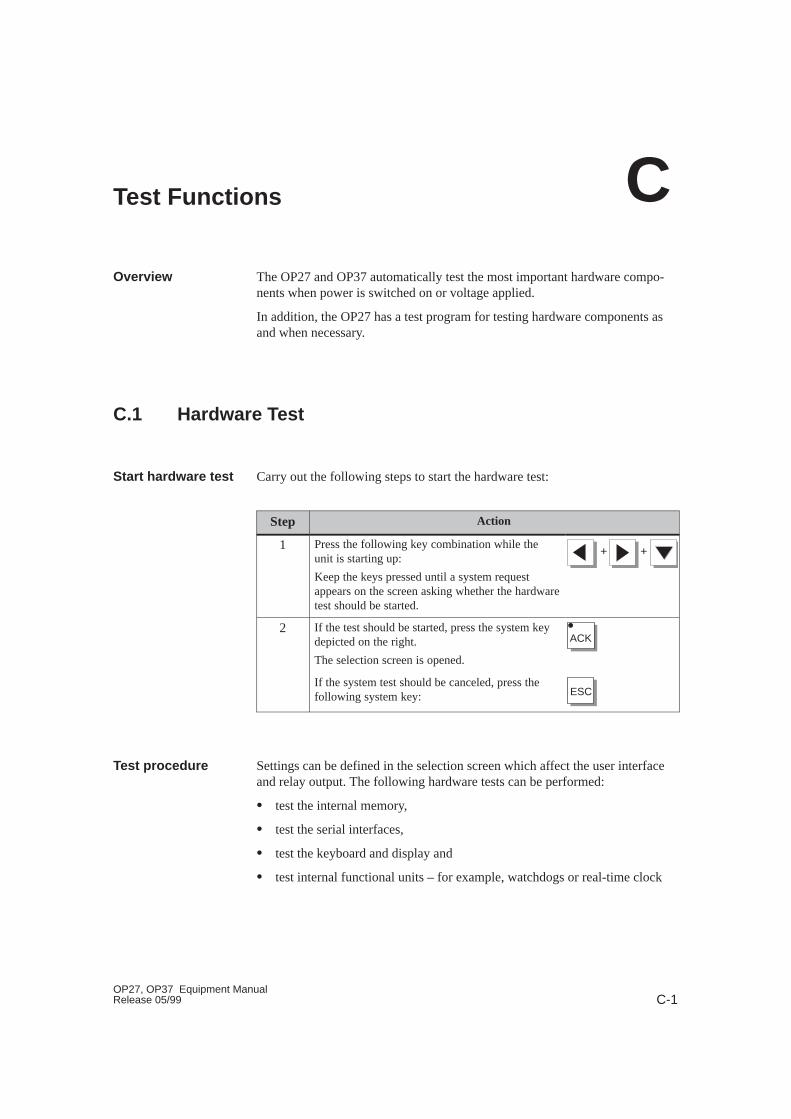
C-1OP27, OP37 Equipment ManualRelease 05/99
Test Functions
The OP27 and OP37 automatically test the most important hardware compo-nents when power is switched on or voltage applied.
In addition, the OP27 has a test program for testing hardware components asand when necessary.
C.1 Hardware Test
Carry out the following steps to start the hardware test:
Step Action
1 Press the following key combination while theunit is starting up:
Keep the keys pressed until a system requestappears on the screen asking whether the hardwaretest should be started.
+ +
2 If the test should be started, press the system keydepicted on the right.
The selection screen is opened.
ACK
If the system test should be canceled, press thefollowing system key: ESC
Settings can be defined in the selection screen which affect the user interfaceand relay output. The following hardware tests can be performed:
� test the internal memory,
� test the serial interfaces,
� test the keyboard and display and
� test internal functional units – for example, watchdogs or real-time clock
Overview
Start hardware test
Test procedure
C
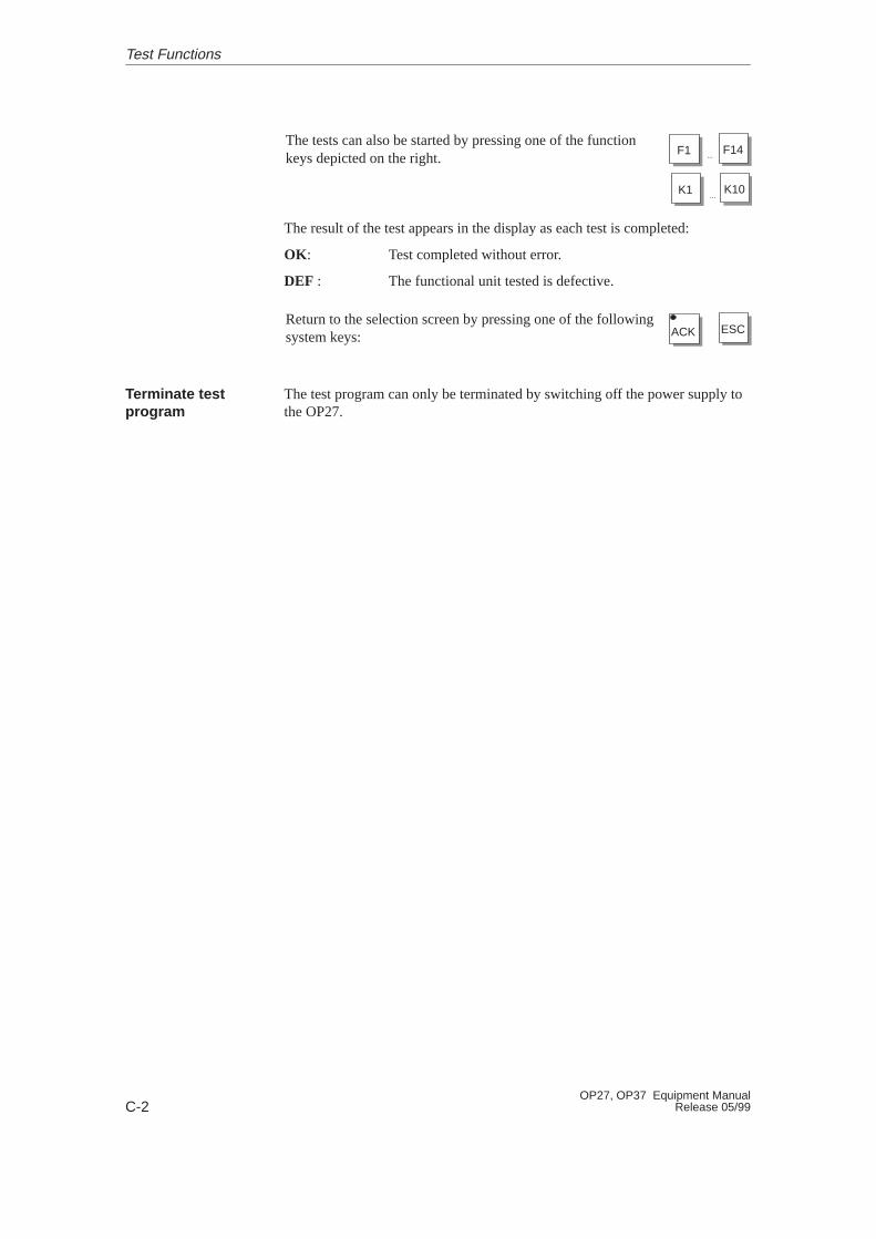
C-2OP27, OP37 Equipment Manual
Release 05/99
The tests can also be started by pressing one of the functionkeys depicted on the right.
F1 F14...
K1 K10...
The result of the test appears in the display as each test is completed:
OK : Test completed without error.
DEF : The functional unit tested is defective.
Return to the selection screen by pressing one of the followingsystem keys: ACK ESC
The test program can only be terminated by switching off the power supply tothe OP27.
Terminate testprogram
Test Functions

C-3OP27, OP37 Equipment ManualRelease 05/99
C.1.1 Individual Tests
Contrast Increase or decrease the contrast of the selectedscreen using the arrow keys depicted on theright.
Brightness Blank or brighten the screen by pressing thearrow keys depicted on the right. This functioncorresponds to the Blank Screen function onthe System Settings standard screen.
Relay on/off Press this button to activate and deactivate thecontact assembly integrated in the power sup-ply connector:
ENTER
The OP memory modules are checked by means of read/write tests.
Should an error occur, the faulty memory address is displayed on the screen.
Note
With SRAM, EEPROM and flash memory, the memory contents are saved toDRAM prior to testing. Consequently, you should begin by testing the DRAMfor errors.
If the test reveals an error, the data copied prior to the test is not re-imported.This means that the content of the memory which failed the test is corrupted.The same applies if the power supply fails.
The individual RAM tests:
RAM Test Initiated by Key Result
DRAMK1
Test each bit in the memory area.
EPROMF9
A checksum test is performed to validatethe integrity of the data stored in memory.
SRAMF10
Test each bit in the memory area.
EEPROMF11
Performingsettings on theselection screen
Internal/Externalmemory
Test Functions
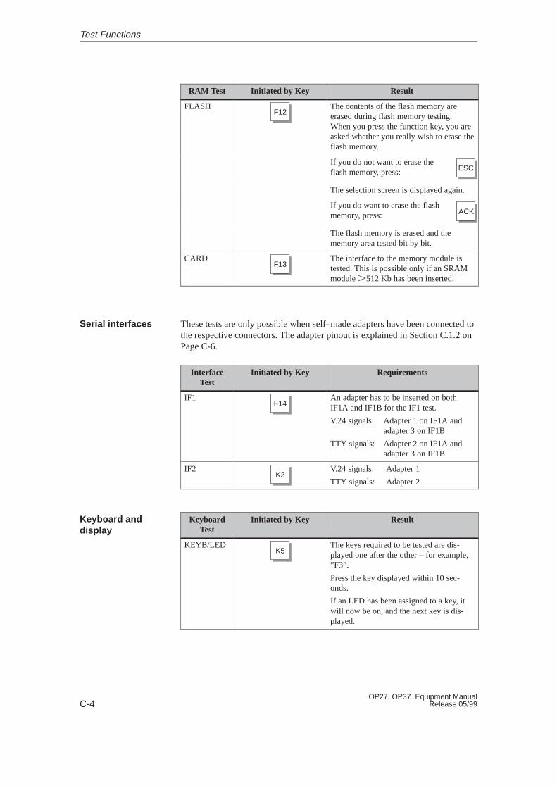
C-4OP27, OP37 Equipment Manual
Release 05/99
ResultInitiated by KeyRAM Test
FLASHF12
The contents of the flash memory areerased during flash memory testing.When you press the function key, you areasked whether you really wish to erase theflash memory.
If you do not want to erase theflash memory, press: ESC
The selection screen is displayed again.
If you do want to erase the flashmemory, press: ACK
The flash memory is erased and thememory area tested bit by bit.
CARDF13
The interface to the memory module istested. This is possible only if an SRAMmodule �512 Kb has been inserted.
These tests are only possible when self–made adapters have been connected tothe respective connectors. The adapter pinout is explained in Section C.1.2 onPage C-6.
InterfaceTest
Initiated by Key Requirements
IF1F14
An adapter has to be inserted on bothIF1A and IF1B for the IF1 test.
V.24 signals: Adapter 1 on IF1A andadapter 3 on IF1B
TTY signals: Adapter 2 on IF1A andadapter 3 on IF1B
IF2K2
V.24 signals: Adapter 1
TTY signals: Adapter 2
KeyboardTest
Initiated by Key Result
KEYB/LEDK5
The keys required to be tested are dis-played one after the other – for example,”F3”.
Press the key displayed within 10 sec-onds.
If an LED has been assigned to a key, itwill now be on, and the next key is dis-played.
Serial interfaces
Keyboard anddisplay
Test Functions
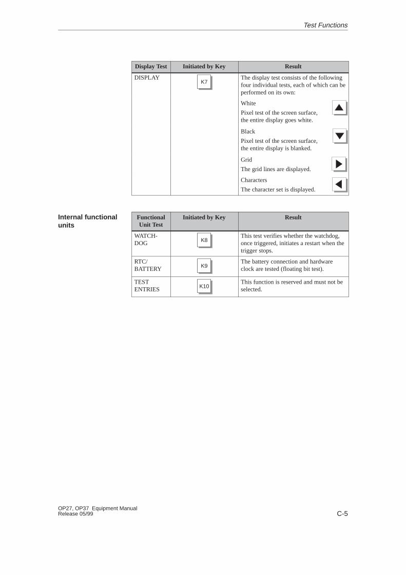
C-5OP27, OP37 Equipment ManualRelease 05/99
Display Test Initiated by Key Result
DISPLAYK7
The display test consists of the followingfour individual tests, each of which can beperformed on its own:
White
Pixel test of the screen surface,the entire display goes white.
Black
Pixel test of the screen surface,the entire display is blanked.
Grid
The grid lines are displayed.
Characters
The character set is displayed.
FunctionalUnit Test
Initiated by Key Result
WATCH-DOG K8
This test verifies whether the watchdog,once triggered, initiates a restart when thetrigger stops.
RTC/BATTERY K9
The battery connection and hardwareclock are tested (floating bit test).
TESTENTRIES K10
This function is reserved and must not beselected.
Internal functionalunits
Test Functions

C-6OP27, OP37 Equipment Manual
Release 05/99
C.1.2 Test adapters
Make up the test adapters in such a way that the pins listed below are con-nected or jumpered, as described:
15–pin Sub-D connector3 –––– 45 –––– 10
15–pin Sub-D connector2 –––– 126 –––– 137 –––– 9
9–pin Sub-D connector3 –––– 48 –––– 9
Adapter 1
Adapter 2
Adapter 3
Test Functions
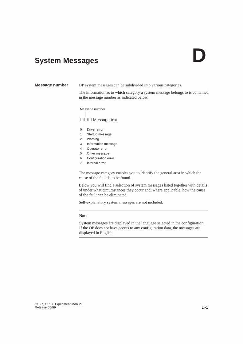
D-1OP27, OP37 Equipment ManualRelease 05/99
System Messages
OP system messages can be subdivided into various categories.
The information as to which category a system message belongs to is containedin the message number as indicated below.
��� Message text
Message number
0 Driver error
1 Startup message
2 Warning
3 Information message
4 Operator error
5 Other message
6 Configuration error
7 Internal error
The message category enables you to identify the general area in which thecause of the fault is to be found.
Below you will find a selection of system messages listed together with detailsof under what circumstances they occur and, where applicable, how the causeof the fault can be eliminated.
Self-explanatory system messages are not included.
Note
System messages are displayed in the language selected in the configuration.If the OP does not have access to any configuration data, the messages aredisplayed in English.
Message number
D

D-2OP27, OP37 Equipment Manual
Release 05/99
In the case of all system messages that relate to ”internal errors”, please followthe procedure outlined below.
a) Switch off the OP, set the PLC to STOP mode and then restart both units.
b) During startup, set the OP to download mode, downlaod the configurationagain and then restart the OP and PLC again.
c) If the fault recurs, please contact your nearest Siemens representative.When doing so, please quote the number of the error that has occurred andany variables referred to in the message.
Message Cause Remedy
Please wait Mode change in progress or recipe functionstarted.
Ready for trans-fer
Waiting for data from PU/PC
Data transfer Data transfer between PU/PC and OP in prog-ress
Firmware notcompatible
The firmware can not be used for the currentconfiguration
EPROMmemory failure
Memory module defective or internal hard-ware fault
Send unit for repair quoting details of errormessage
RAM memoryfailure
g
Flash memoryfailure
Memory module defective or transmission er-ror
Retransfer configuration or send OP for repair
Procedure for ”in -ternal errors”
System Messages
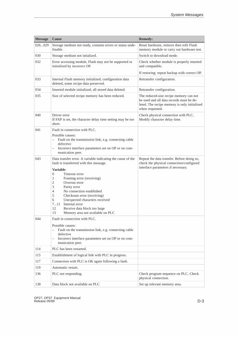
D-3OP27, OP37 Equipment ManualRelease 05/99
Message Cause Remedy:
026...029 Storage medium not ready, contains errors or status unde-finable.
Reset hardware, remove then refit Flashmemory module or carry out hardware test.
030 Storage medium not intialized. Switch to download mode.
032 Error accessing module, Flash may not be supported orinitialized by incorrect OP.
Check whether module is properly insertedand compatible.
If restoring: repeat backup with correct OP.
033 Internal Flash memory initialized; configuration datadeleted, some recipe data preserved.
Retransfer configuration.
034 Inserted module initialized, all stored data deleted. Retransfer configuration.
035 Size of selected recipe memory has been reduced. The reduced-size recipe memory can notbe used and all data records must be de-leted. The recipe memory is only initializedwhen requested.
040 Driver error If FAP is set, the character delay time setting may be tooshort.
Check physical connection with PLC. Modify character delay time.
041 Fault in connection with PLC.
Possible causes:– Fault on the transmission link, e.g. connecting cable
defective– Incorrect interface parameters set on OP or on com-
munication peer.
043 Data transfer error. A variable indicating the cause of thefault is transferred with this message.
Variable:0 Timeout error1 Framing error (receiving)2 Overrun error3 Parity error4 No connection established5 Checksum error (receiving)6 Unexpected characters received7...11 Internal error12 Receive data block too large13 Memory area not available on PLC
Repeat the data transfer. Before doing so,check the physical connection/configuredinterface parameters if necessary.
044 Fault in connection with PLC.
Possible causes:– Fault on the transmission link, e.g. connecting cable
defective– Incorrect interface parameters set on OP or on com-
munication peer.
114 PLC has been restarted.
115 Establishment of logical link with PLC in progress.
117 Connection with PLC is OK again following a fault.
119 Automatic restart.
136 PLC not responding. Check program sequence on PLC. Checkphysical connection.
138 Data block not available on PLC Set up relevant memory area.
System Messages
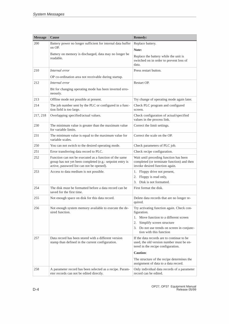
D-4OP27, OP37 Equipment Manual
Release 05/99
Remedy:CauseMessage
200 Battery power no longer sufficient for internal data bufferon OP.
Battery on memory is discharged, data may no longer bereadable.
Replace battery.
Note:
Replace the battery while the unit isswitched on in order to prevent loss ofdata.
210 Internal error
OP co-ordination area not receivable during startup.
Press restart button.
212 Internal error
Bit for changing operating mode has been inverted erro-neously.
Restart OP.
213 Offline mode not possible at present. Try change of operating mode again later.
214 The job number sent by the PLC or configured in a func-tion field is too large.
Check PLC program and configuredscreen.
217, 218 Overlapping specified/actual values. Check configuration of actual/specifiedvalues in the process link.
230 The minimum value is greater than the maximum valuefor variable limits.
Correct the limit settings.
231 The minimum value is equal to the maximum value forvariable scales.
Correct the scale on the OP.
250 You can not switch to the desired operating mode. Check parameters of PLC job.
251 Error transferring data record to PLC. Check recipe configuration.
252 Function can not be executed as a function of the samegroup has not yet been completed (e.g.: setpoint entry isactive, password list can not be opened).
Wait until preceding function has beencompleted (or terminate function) and theninvoke desired function again.
253 Access to data medium is not possible. 1. Floppy drive not present,
2. Floppy is read only,
3. Disk is not formatted.
254 The disk must be formatted before a data record can besaved for the first time.
First format the disk.
255 Not enough space on disk for this data record. Delete data records that are no longer re-quired.
256 Not enough system memory available to execute the de-sired function.
Try activating function again. Check con-figuration.
1. Move function to a different screen
2. Simplify screen structure
3. Do not use trends on screen in conjunc-tion with this function
257 Data record has been stored with a different versionstamp than defined in the current configuration.
If the data records are to continue to beused, the old version number must be en-tered in the recipe configuration.
Caution:
The structure of the recipe determines theassignment of data to a data record.
258 A parameter record has been selected as a recipe. Param-eter records can not be edited directly.
Only individual data records of a parameterrecord can be edited.
System Messages

D-5OP27, OP37 Equipment ManualRelease 05/99
Remedy:CauseMessage
259 Transfer of a data record to the PLC is taking too long.
Example:
PLC is not acknowledging data record or very large datarecords are being transferred.
Check PLC program. In the case of largedata records no modifications are necessaryas the function is being processed correctly.
260 Operating mode of PLC does not match the configura-tion.
Change operating mode of PLC.
261 The data in this data record is no longer consistent and itcan therefore no longer be used.
Edit data record and check that all entriesare correct.
262 Password or query window already in use by anotherfunction.
Complete first function then execute de-sired function again.
263 Specified remaining buffer space for messages has beenreached!
Configure smaller remaining buffer, deleteevent/alarm message buffers.
264 Message buffer overflow. The overflow messages are printed out ifso specified in the configuration.
265 The number of passwords issued has already reached 50.You can not enter any more passwords.
If you wish to issue additional passwords,you must first delete some of the existingones.
266 The field configured in the PLC job does not exist. Change the parameters of the PLC job andretransfer the configuration.
303 Fault in connection with PLC.
S5: this error may occur when transferring large datarecords. In such cases the watchdog is activated.
Check PLC status.
S5: set value in data word 98 to at least2000.
305 Data block number missing. Set up data block or change configuration.
306 Incorrect CPU specified under ”PLC –> Parameters”. Change configuration and retransfer.
307 ...311
Variable not present on PLC Check configuration of process link.
316 Active password level insufficient for menu item Enter password with higher password level.
339 Startup completed. Communication with PLC has been re-sumed.
340 Status processing in progress on PU/PC. The OP can notbe used while this is going on.
341 Internal error
With non-Siemens connections: data block error
342 Network node has illegal address. Max. addresses:
S7-MPI: 32
PROFIBUS-DP: 128
343 You are attempting to edit a variable of a type that cannot be edited in a recipe: currently applies to ARRAYvariables only.
350 PLC is performing initialization. You can not enter anysetpoints during initialization. Scrolling of screens ispossible.
This operating mode may be set by thePLC programmer.
351 PLC has completed initialization. You can resume enter-ing setpoints once this message has appeared.
System Messages

D-6OP27, OP37 Equipment Manual
Release 05/99
Remedy:CauseMessage
352 You are attempting to select a screen that does not existor has been disabled by the function Hide.
353 The minimum value is greater than the maximum valuefor variable scales.
Minimum and maximum values are beingconfused by OP. To prevent this, enter cor-rect minimum and maximum values.
354 You are attempting to enter a value in an input field whenthe current password level is insufficient for input.
Log on with a higher password level.
355 Entry of this variable has not been configured for thecurrent PLC mode.
356 A print function has been initiated on the OP. When at-tempting to print it has been ascertained that the printer isoffline.
Switch the printer online.
Check the connection between the OP andthe printer.
Has the printer been connected to the cor-rect interface?
357 You are attempting to enter a setpoint that contains anillegal character.
Enter the value correctly.
358 The OP is currently executing a function which does notpermit use of the OP while it is in progress.
Wait until the function has been completed.
This message may appear in the case ofrecipe functions, for example.
365 Incorrect index. A multiplex index is outside the definedrange.
370 Hard copy print-out has been cancelled manually.
371 Print function disabled at present.
372 The function started has been cancelled.
383 For information: transfer of data records completed.
384 Data record required is not on data medium. Check the data record selection parameters(recipe, data record name, data medium) oruse the Select function to select the datarecord.
385 Information message: transfer of data records from OP todata medium or vice versa has been initiated.
One possible reason is that operation is nolonger possible: The PLC has not reset the corresponding
386 Information message: transfer of data records from OP toPLC or vice versa has been initiated.
The PLC has not reset the correspondingcontrol and acknowledgment bit, whichdeactivates the recipe mailbox lock, in theinterface area.
387 Data record not found. There is no data record relating to the se-lected recipe on the data medium.
388 Activating selected function.
389 De-activating selected function.
391 No Help text configured. Check configuration.
System Messages
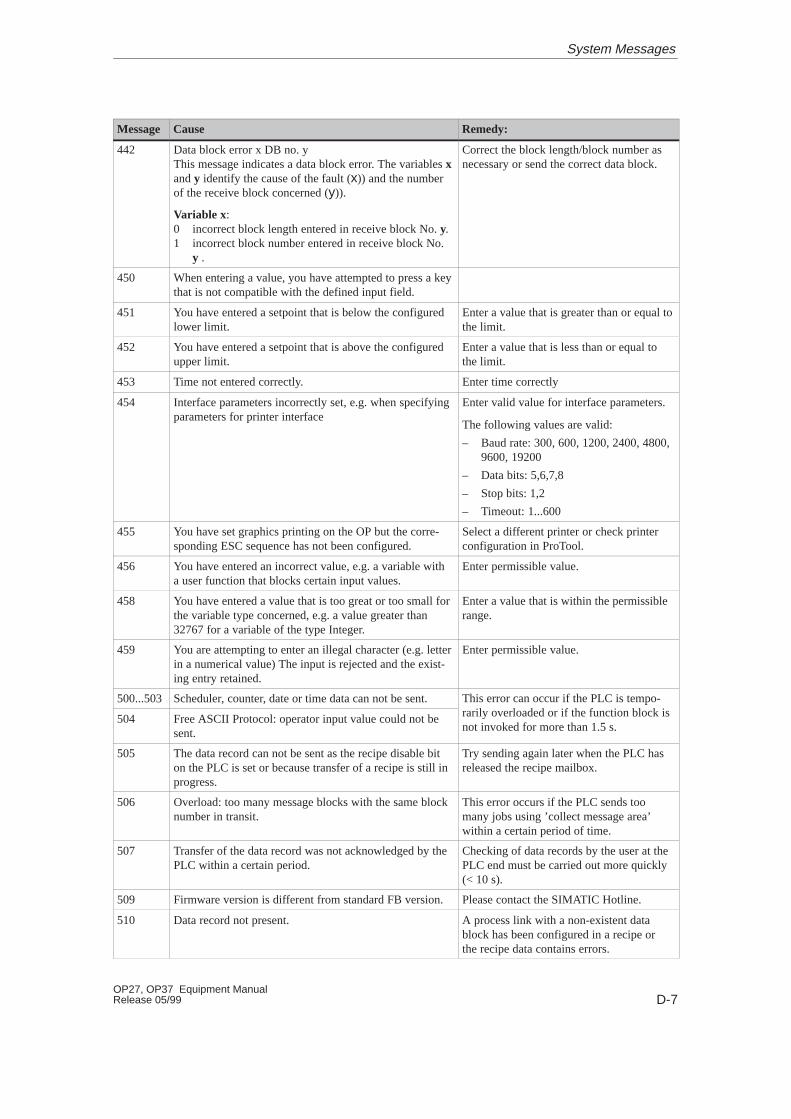
D-7OP27, OP37 Equipment ManualRelease 05/99
Remedy:CauseMessage
442 Data block error x DB no. yThis message indicates a data block error. The variables xand y identify the cause of the fault (x)) and the numberof the receive block concerned (y)).
Variable x:0 incorrect block length entered in receive block No. y.1 incorrect block number entered in receive block No.
y .
Correct the block length/block number asnecessary or send the correct data block.
450 When entering a value, you have attempted to press a keythat is not compatible with the defined input field.
451 You have entered a setpoint that is below the configuredlower limit.
Enter a value that is greater than or equal tothe limit.
452 You have entered a setpoint that is above the configuredupper limit.
Enter a value that is less than or equal tothe limit.
453 Time not entered correctly. Enter time correctly
454 Interface parameters incorrectly set, e.g. when specifyingparameters for printer interface
Enter valid value for interface parameters.
The following values are valid:
– Baud rate: 300, 600, 1200, 2400, 4800,9600, 19200
– Data bits: 5,6,7,8
– Stop bits: 1,2
– Timeout: 1...600
455 You have set graphics printing on the OP but the corre-sponding ESC sequence has not been configured.
Select a different printer or check printerconfiguration in ProTool.
456 You have entered an incorrect value, e.g. a variable witha user function that blocks certain input values.
Enter permissible value.
458 You have entered a value that is too great or too small forthe variable type concerned, e.g. a value greater than32767 for a variable of the type Integer.
Enter a value that is within the permissiblerange.
459 You are attempting to enter an illegal character (e.g. letterin a numerical value) The input is rejected and the exist-ing entry retained.
Enter permissible value.
500...503 Scheduler, counter, date or time data can not be sent. This error can occur if the PLC is tempo-il l d d if h f i bl k i504 Free ASCII Protocol: operator input value could not be
sent.
prarily overloaded or if the function block isnot invoked for more than 1.5 s.
505 The data record can not be sent as the recipe disable biton the PLC is set or because transfer of a recipe is still inprogress.
Try sending again later when the PLC hasreleased the recipe mailbox.
506 Overload: too many message blocks with the same blocknumber in transit.
This error occurs if the PLC sends toomany jobs using ’collect message area’within a certain period of time.
507 Transfer of the data record was not acknowledged by thePLC within a certain period.
Checking of data records by the user at thePLC end must be carried out more quickly(< 10 s).
509 Firmware version is different from standard FB version.Please contact the SIMATIC Hotline.
510 Data record not present. A process link with a non-existent datablock has been configured in a recipe orthe recipe data contains errors.
System Messages
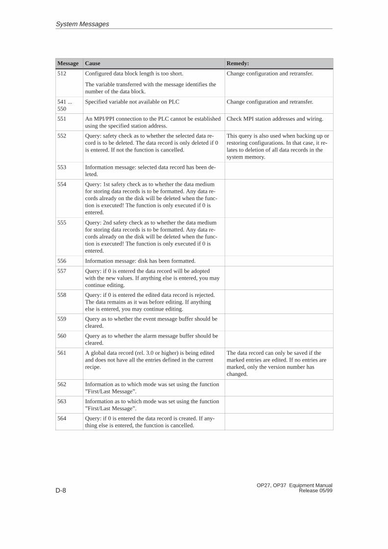
D-8OP27, OP37 Equipment Manual
Release 05/99
Remedy:CauseMessage
512 Configured data block length is too short.
The variable transferred with the message identifies thenumber of the data block.
Change configuration and retransfer.
541 ...550
Specified variable not available on PLC Change configuration and retransfer.
551 An MPI/PPI connection to the PLC cannot be establishedusing the specified station address.
Check MPI station addresses and wiring.
552 Query: safety check as to whether the selected data re-cord is to be deleted. The data record is only deleted if 0is entered. If not the function is cancelled.
This query is also used when backing up orrestoring configurations. In that case, it re-lates to deletion of all data records in thesystem memory.
553 Information message: selected data record has been de-leted.
554 Query: 1st safety check as to whether the data mediumfor storing data records is to be formatted. Any data re-cords already on the disk will be deleted when the func-tion is executed! The function is only executed if 0 isentered.
555 Query: 2nd safety check as to whether the data mediumfor storing data records is to be formatted. Any data re-cords already on the disk will be deleted when the func-tion is executed! The function is only executed if 0 isentered.
556 Information message: disk has been formatted.
557 Query: if 0 is entered the data record will be adoptedwith the new values. If anything else is entered, you maycontinue editing.
558 Query: if 0 is entered the edited data record is rejected.The data remains as it was before editing. If anythingelse is entered, you may continue editing.
559 Query as to whether the event message buffer should becleared.
560 Query as to whether the alarm message buffer should becleared.
561 A global data record (rel. 3.0 or higher) is being editedand does not have all the entries defined in the currentrecipe.
The data record can only be saved if themarked entries are edited. If no entries aremarked, only the version number haschanged.
562 Information as to which mode was set using the function”First/Last Message”.
563 Information as to which mode was set using the function”First/Last Message”.
564 Query: if 0 is entered the data record is created. If any-thing else is entered, the function is cancelled.
System Messages
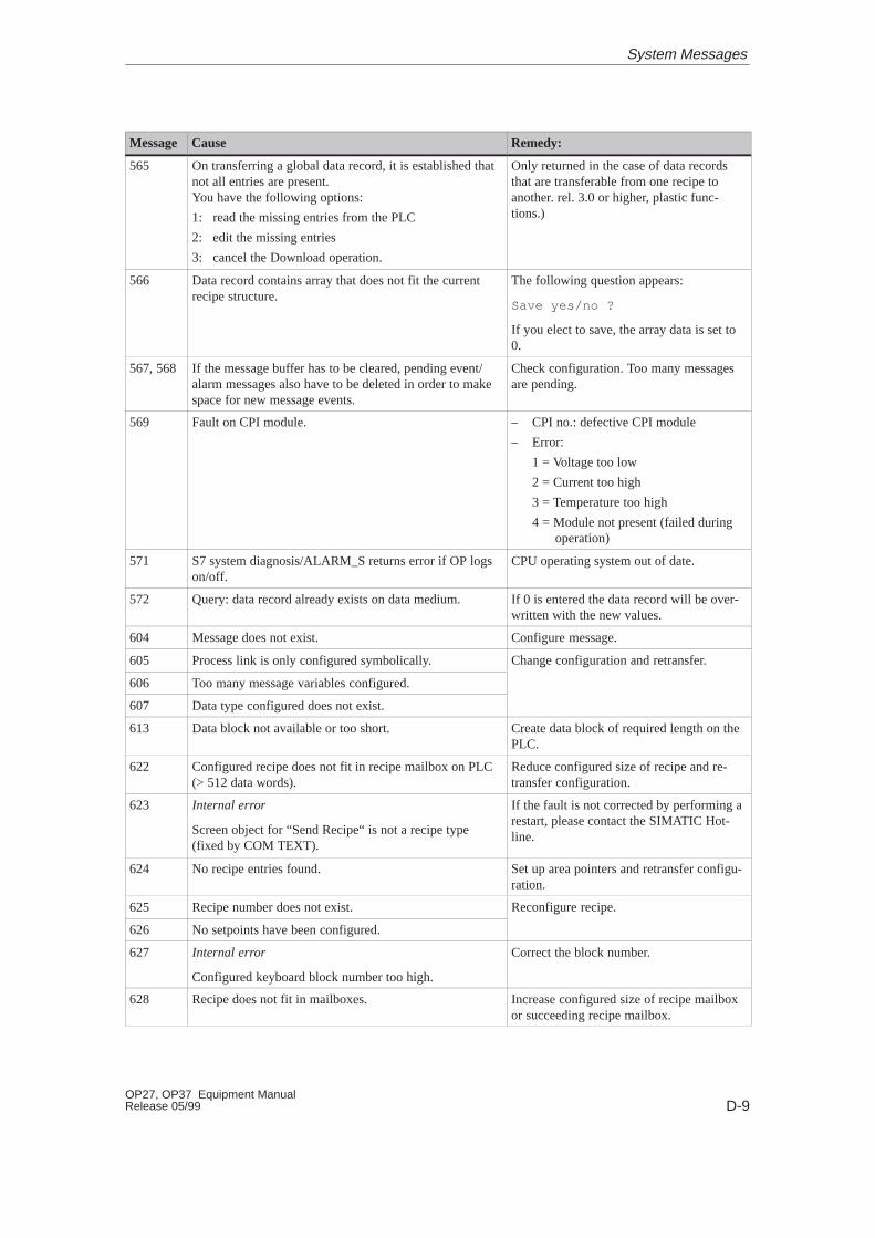
D-9OP27, OP37 Equipment ManualRelease 05/99
Remedy:CauseMessage
565 On transferring a global data record, it is established thatnot all entries are present. You have the following options:
1: read the missing entries from the PLC
2: edit the missing entries
3: cancel the Download operation.
Only returned in the case of data recordsthat are transferable from one recipe toanother. rel. 3.0 or higher, plastic func-tions.)
566 Data record contains array that does not fit the currentrecipe structure.
The following question appears:
Save yes/no ?
If you elect to save, the array data is set to0.
567, 568 If the message buffer has to be cleared, pending event/alarm messages also have to be deleted in order to makespace for new message events.
Check configuration. Too many messagesare pending.
569 Fault on CPI module. – CPI no.: defective CPI module
– Error:
1 = Voltage too low
2 = Current too high
3 = Temperature too high
4 = Module not present (failed duringoperation)
571 S7 system diagnosis/ALARM_S returns error if OP logson/off.
CPU operating system out of date.
572 Query: data record already exists on data medium. If 0 is entered the data record will be over-written with the new values.
604 Message does not exist. Configure message.
605 Process link is only configured symbolically. Change configuration and retransfer.
606 Too many message variables configured.
g g
607 Data type configured does not exist.
613 Data block not available or too short. Create data block of required length on thePLC.
622 Configured recipe does not fit in recipe mailbox on PLC(> 512 data words).
Reduce configured size of recipe and re-transfer configuration.
623 Internal error
Screen object for “Send Recipe“ is not a recipe type(fixed by COM TEXT).
If the fault is not corrected by performing arestart, please contact the SIMATIC Hot-line.
624 No recipe entries found. Set up area pointers and retransfer configu-ration.
625 Recipe number does not exist. Reconfigure recipe.
626 No setpoints have been configured.
g p
627 Internal error
Configured keyboard block number too high.
Correct the block number.
628 Recipe does not fit in mailboxes. Increase configured size of recipe mailboxor succeeding recipe mailbox.
System Messages
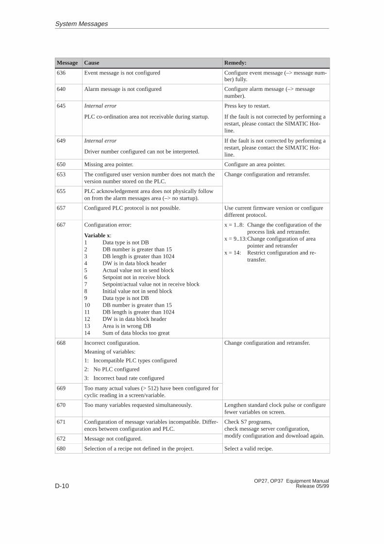
D-10OP27, OP37 Equipment Manual
Release 05/99
Remedy:CauseMessage
636 Event message is not configured Configure event message (–> message num-ber) fully.
640 Alarm message is not configured Configure alarm message (–> messagenumber).
645 Internal error
PLC co-ordination area not receivable during startup.
Press key to restart.
If the fault is not corrected by performing arestart, please contact the SIMATIC Hot-line.
649 Internal error
Driver number configured can not be interpreted.
If the fault is not corrected by performing arestart, please contact the SIMATIC Hot-line.
650 Missing area pointer. Configure an area pointer.
653 The configured user version number does not match theversion number stored on the PLC.
Change configuration and retransfer.
655 PLC acknowledgement area does not physically followon from the alarm messages area (–> no startup).
657 Configured PLC protocol is not possible. Use current firmware version or configuredifferent protocol.
667 Configuration error:
Variable x:1 Data type is not DB2 DB number is greater than 153 DB length is greater than 10244 DW is in data block header5 Actual value not in send block6 Setpoint not in receive block7 Setpoint/actual value not in receive block8 Initial value not in send block9 Data type is not DB10 DB number is greater than 1511 DB length is greater than 102412 DW is in data block header13 Area is in wrong DB14 Sum of data blocks too great
x = 1..8: Change the configuration of theprocess link and retransfer.
x = 9..13:Change configuration of areapointer and retransfer
x = 14: Restrict configuration and re-transfer.
668 Incorrect configuration.
Meaning of variables:
1: Incompatible PLC types configured
2: No PLC configured
3: Incorrect baud rate configured
Change configuration and retransfer.
669 Too many actual values (> 512) have been configured forcyclic reading in a screen/variable.
670 Too many variables requested simultaneously. Lengthen standard clock pulse or configurefewer variables on screen.
671 Configuration of message variables incompatible. Differ-ences between configuration and PLC.
Check S7 programs, check message server configuration,
dif fi i d d l d i672 Message not configured.
g g ,modify configuration and download again.
680 Selection of a recipe not defined in the project. Select a valid recipe.
System Messages
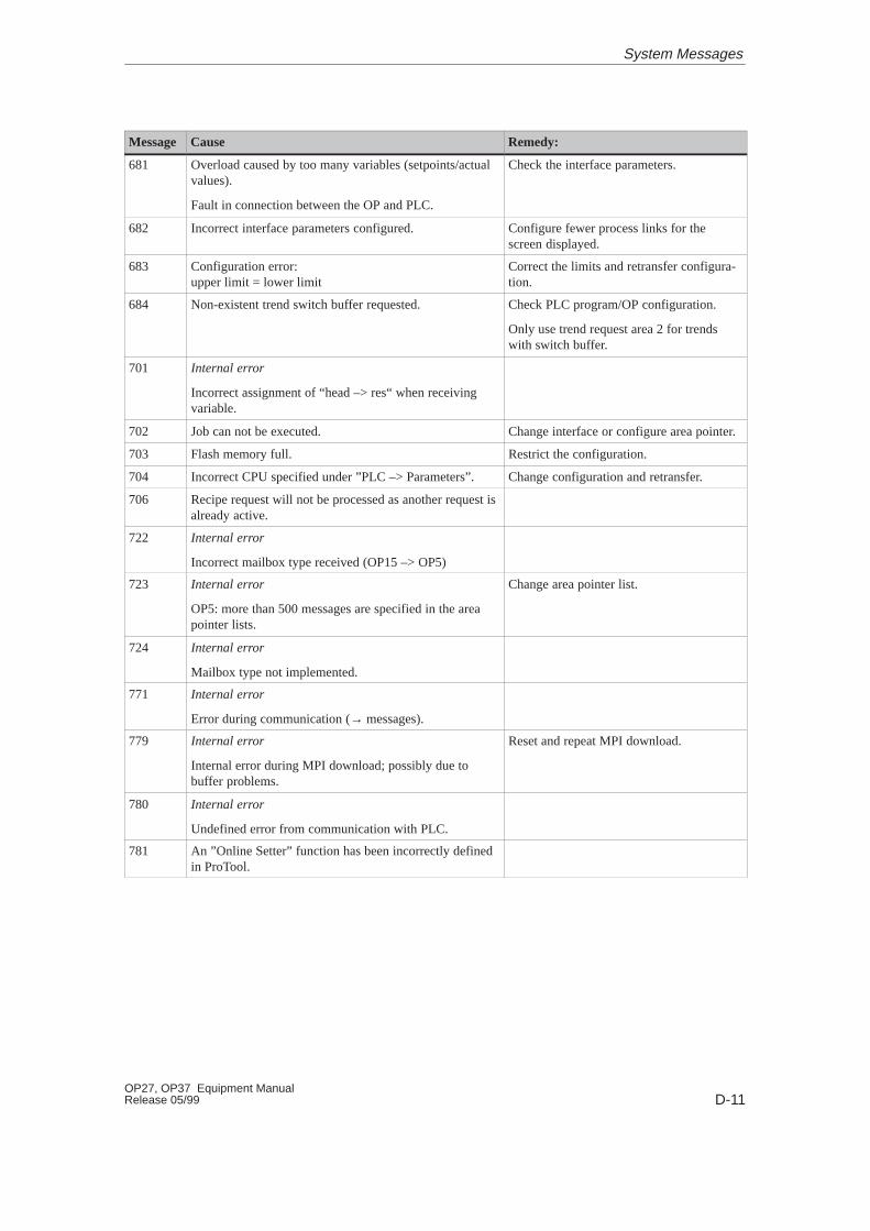
D-11OP27, OP37 Equipment ManualRelease 05/99
Remedy:CauseMessage
681 Overload caused by too many variables (setpoints/actualvalues).
Fault in connection between the OP and PLC.
Check the interface parameters.
682 Incorrect interface parameters configured. Configure fewer process links for thescreen displayed.
683 Configuration error: upper limit = lower limit
Correct the limits and retransfer configura-tion.
684 Non-existent trend switch buffer requested. Check PLC program/OP configuration.
Only use trend request area 2 for trendswith switch buffer.
701 Internal error
Incorrect assignment of “head –> res“ when receivingvariable.
702 Job can not be executed. Change interface or configure area pointer.
703 Flash memory full. Restrict the configuration.
704 Incorrect CPU specified under ”PLC –> Parameters”. Change configuration and retransfer.
706 Recipe request will not be processed as another request isalready active.
722 Internal error
Incorrect mailbox type received (OP15 –> OP5)
723 Internal error
OP5: more than 500 messages are specified in the areapointer lists.
Change area pointer list.
724 Internal error
Mailbox type not implemented.
771 Internal error
Error during communication (→ messages).
779 Internal error
Internal error during MPI download; possibly due tobuffer problems.
Reset and repeat MPI download.
780 Internal error
Undefined error from communication with PLC.
781 An ”Online Setter” function has been incorrectly definedin ProTool.
System Messages

D-12OP27, OP37 Equipment Manual
Release 05/99
System Messages
E-1OP27, OP37 Equipment ManualRelease 05/99
SIMATIC HMI Documentation
Target groups
This manual is part of the SIMATIC HMI documentation. The documentationis aimed at the following target groups:
� Newcomers
� Users
� Configurers
� Programmers
� Commissioning engineers
How the documentation is organized
The SIMATIC HMI documentation consists of the following components:
� User’s Guides / User’s Manuals for:
– Configuration software
– Runtime software
– Communication between PLCs and operating units
� Equipment Manuals for the following operating units:
– MP (Multi Panel)
– OP (Operator Panel)
– TP (Touch Panel)
– TD (Text Display)
– PP (Push Button Panel)
� Online Help on the configuration software
� Start–up Guides
� First Steps
Overview of complete documentation
The following table provides an overview of the SIMATIC HMI documenta-tion and shows you when you require the different documents.
E
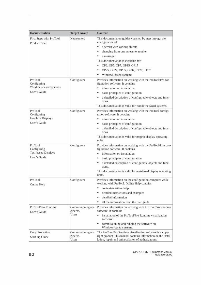
E-2OP27, OP37 Equipment Manual
Release 05/99
Documentation Target Group Content
First Steps with ProTool
Product Brief
Newcomers This documentation guides you step by step through theconfiguration of
� a screen with various objects
� changing from one screen to another
� a message.
This documentation is available for:
� OP3, OP5, OP7, OP15, OP17
� OP25, OP27, OP35, OP37, TP27, TP37
� Windows-based systems
ProToolConfiguring Windows-based Systems
User’s Guide
Configurers Provides information on working with the ProTool/Pro con-figuration software. It contains
� information on installation
� basic principles of configuration
� a detailed description of configurable objects and func-tions.
This documentation is valid for Windows-based systems.
ProToolConfiguring Graphics Displays
User’s Guide
Configurers Provides information on working with the ProTool configu-ration software. It contains
� information on installation
� basic principles of configuration
� a detailed description of configurable objects and func-tions.
This documentation is valid for graphic display operatingunits.
ProToolConfiguring Text-based Displays
User’s Guide
Configurers Provides information on working with the ProTool/Lite con-figuration software. It contains
� information on installation
� basic principles of configuration
� a detailed description of configurable objects and func-tions.
This documentation is valid for text-based display operatingunits.
ProTool
Online Help
Configurers Provides information on the configuration computer whileworking with ProTool. Online Help contains
� context-sensitive help
� detailed instructions and examples
� detailed information
� all the information from the user guide.
ProTool/Pro Runtime
User’s Guide
Commissioning en-gineers, Users
Provides information on working with ProTool/Pro Runtimesoftware. It contains
� installation of the ProTool/Pro Runtime visualizationsoftware
� commissioning and running the software onWindows-based systems.
Copy Protection
Start–up Guide
Commissioning en-gineers, Users
The ProTool/Pro Runtime visualization software is a copy-right product. This manual contains information on the instal-lation, repair and uninstallation of authorizations.
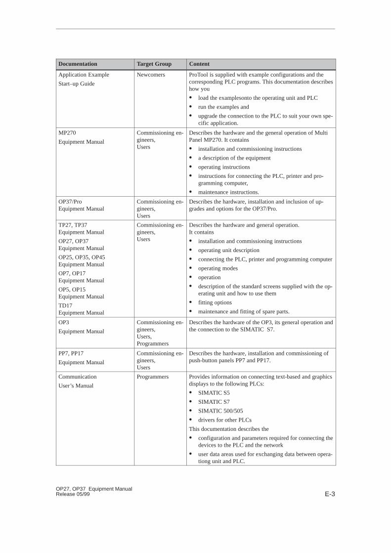
E-3OP27, OP37 Equipment ManualRelease 05/99
ContentTarget GroupDocumentation
Application Example
Start–up Guide
Newcomers ProTool is supplied with example configurations and thecorresponding PLC programs. This documentation describeshow you
� load the examplesonto the operating unit and PLC
� run the examples and
� upgrade the connection to the PLC to suit your own spe-cific application.
MP270
Equipment Manual
Commissioning en-gineers, Users
Describes the hardware and the general operation of MultiPanel MP270. It contains
� installation and commissioning instructions
� a description of the equipment
� operating instructions
� instructions for connecting the PLC, printer and pro-gramming computer,
� maintenance instructions.
OP37/ProEquipment Manual
Commissioning en-gineers, Users
Describes the hardware, installation and inclusion of up-grades and options for the OP37/Pro.
TP27, TP37Equipment Manual
OP27, OP37Equipment Manual
OP25, OP35, OP45Equipment Manual
OP7, OP17Equipment Manual
OP5, OP15Equipment Manual
TD17Equipment Manual
Commissioning en-gineers, Users
Describes the hardware and general operation. It contains
� installation and commissioning instructions
� operating unit description
� connecting the PLC, printer and programming computer
� operating modes
� operation
� description of the standard screens supplied with the op-erating unit and how to use them
� fitting options
� maintenance and fitting of spare parts.
OP3
Equipment Manual
Commissioning en-gineers, Users, Programmers
Describes the hardware of the OP3, its general operation andthe connection to the SIMATIC S7.
PP7, PP17
Equipment Manual
Commissioning en-gineers, Users
Describes the hardware, installation and commissioning ofpush-button panels PP7 and PP17.
Communication
User’s Manual
Programmers Provides information on connecting text-based and graphicsdisplays to the following PLCs:
� SIMATIC S5
� SIMATIC S7
� SIMATIC 500/505
� drivers for other PLCs
This documentation describes the
� configuration and parameters required for connecting thedevices to the PLC and the network
� user data areas used for exchanging data between opera-tiong unit and PLC.
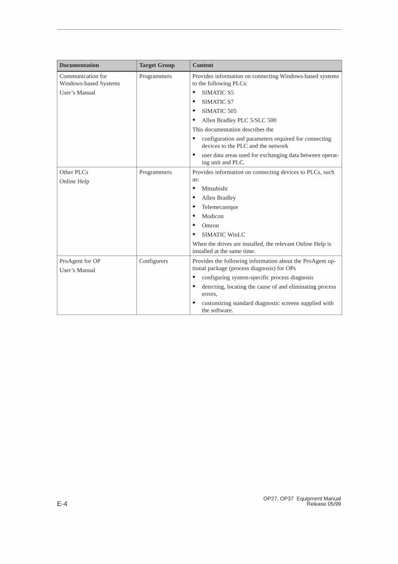
E-4OP27, OP37 Equipment Manual
Release 05/99
ContentTarget GroupDocumentation
Communication for Windows-based Systems
User’s Manual
Programmers Provides information on connecting Windows-based systemsto the following PLCs:
� SIMATIC S5
� SIMATIC S7
� SIMATIC 505
� Allen Bradley PLC 5/SLC 500
This documentation describes the
� configuration and parameters required for connectingdevices to the PLC and the network
� user data areas used for exchanging data between operat-ing unit and PLC.
Other PLCs
Online Help
Programmers Provides information on connecting devices to PLCs, suchas:
� Mitsubishi
� Allen Bradley
� Telemecanique
� Modicon
� Omron
� SIMATIC WinLC
When the drives are installed, the relevant Online Help isinstalled at the same time.
ProAgent for OP
User’s Manual
Configurers Provides the following information about the ProAgent op-tional package (process diagnosis) for OPs
� configuring system-specific process diagnosis
� detecting, locating the cause of and eliminating processerrors,
� customizing standard diagnostic screens supplied withthe software.

F-1OP27, OP37 Equipment ManualRelease 05/99
ESD Guidelines
Virtually all present-day modules incorporate highly integrated MOS devicesor components. For technological reasons, these electronic components arevery sensitive to overvoltages and consequently therefore to electrostatic dis-charge:
These devices are referred to in German as Elektrostatisch GefährdetenBauelemente/ Baugruppen: ”EGB”
The more frequent international name is:
”ESD” (Electrostatic Sensitive Device)
The following symbol on plates on cabinets, mounting racks or packagesdraws attention to the use of electrostatic sensitive devices and thus to the con-tact sensitivity of the assemblies concerned:
ESDs may be destroyed by voltages and energies well below the perceptionthreshold of persons. Voltages of this kind occur as soon as a device or an as-sembly is touched by a person who is not electrostatically discharged . Devicesexposed to such overvoltages cannot immediately be detected as defective inthe majority of cases since faulty behavior may occur only after a long periodof operation.
Most plastics are capable of carrying high charges and it is therefore impera-tive that they be kept away from sensitive components.
When handling electrostatic sensitive devices, make sure that persons, work-places and packages are properly grounded.
What does ESDmean?
Precautionsagainst electro-static discharge
F
F-2OP27, OP37 Equipment Manual
Release 05/99
A general rule is that assemblies should be touched only when this cannot beavoided owing to the work that has to performed on them. Under no circum-stances should you handle printed-circuit boards by touching device pins orcircuitry.
You should touch devices only if
� you are grounded by permanently wearing an ESD wrist strap or
� you are wearing ESD shoes or ESD shoe-grounding protection straps inconjunction with an ESD floor.
Before you touch an electronic assembly, your body must be discharged. Thesimplest way of doing this is to touch a conductive, grounded object immedi-ately beforehand – for example, bare metal parts of a cabinet, water pipe etc.
Assemblies should not be brought into contact with charge-susceptible andhighly insulating materials such as plastic films, insulating table tops and itemsof clothing etc. containing synthetic fibers.
Assemblies should be deposited only on conductive surfaces (tables with anESD coating, conductive ESD cellular material, ESD bags, ESD shipping con-tainers).
Do not place assemblies near visual display units, monitors or television sets(minimum distance to screen > 10 cm).
Perform measurements on ESD assemblies only when
� the measuring instrument is grounded – for example, by means of a protec-tive conductor – or
� the measuring head has been briefly discharged before measurements aremade with a potential-free measuring instrument – for example, by touch-ing a bare metal control cabinet.
When soldering, use only grounded soldering irons.
Always store and ship assemblies and devices in conductive packing – for ex-ample, metallized plastic boxes and tin cans.
If packing is not conductive, assemblies must be conductively wrapped beforethey are packed. You can use, for example, conductive foam rubber, ESD bags,domestic aluminum foil or paper (never use plastic bags or foils).
With assemblies containing fitted batteries, make sure that the conductivepacking does not come into contact with or short-circuit battery connectors. Ifnecessary, cover the connectors beforehand with insulating tape or insulatingmaterial.
Handling ESD as-semblies
Measuring andmodifying ESD as -semblies
Shipping ESD as -semblies
ESD Guidelines
Glossary-1OP27, OP37 Equipment ManualRelease 05/99
Glossary
A
Calls attention to high-priority operating states and has therefore to beacknowledged.
Time between the arrival and departure of an alarm message.
Required for data exchange between the OP and the PLC. It contains informa-tion concerning the length and size of data areas on the PLC.
The point in time at which a message is issued by the PLC or OP.
Option for the OP37 for accommodating two 2/3-length 16 bit AT cards.
PLCs of the SIMATIC S7 series – for example, SIMATIC S7-200/300/400
B
Contains basic settings for the OP37 in DOS mode.
Automatic turn-off of display back lighting.
A load operation which transfers the operating system to working memory onthe OP.
C
Definition of system-specific basic settings, messages and screens using theProTool configuration software.
Alarm message
Alarm time
Area pointer
Arrival of amessage
AT expansion slot
Automationsystems
BIOS Setup
Blanking
Boot
Configuration
Glossary-2OP27, OP37 Equipment Manual
Release 05/99
Option for the OP27 with a maximum of one block and for the OP37 with amaximum of two blocks of 16 digital inputs/outputs for high-speed key opera-tion without communication-related delays. May be used under SIMATIC S7and PROFIBUS-DP.
D
The point in time at which a message is withdrawn by the PLC.
Option for the OP27 with a maximum of one block and for the OP37 with amaximum of two blocks of 8 digital outputs for high-speed key operation wi-thout communication-related delays.
Function causing the contents of the display to be modified – for example, Dis-play Message Level, Display Alarm Buffer And Display Process Screen.
An OP operating mode allowing MS-DOS and Windows applications to beloaded and edited.
Operating mode of the OP during which data are downloaded from the PU orPC to the OP.
The time between the arrival and departure of a message.
E
Draws attention to specific operating states on machines or systems connectedto the PLC.
F
Reserved area in configured and non-configurable text for the output and/orinput of values.
Programmable memory which can quickly be deleted and then re-written.
Printout of alarm messages or event messages which were deleted as a result ofa buffer overflow.
Control panelinterface
Departure of amessage
Direct key module
Display function
DOS mode
Download mode
Duration of display
Event message
Field
Flash memory
Forced printout
Glossary
Glossary-3OP27, OP37 Equipment ManualRelease 05/99
I
Additional, configurable information for messages, screens, screen entries andlist boxes.
M
Printout of alarm messages and event messages simultaneously with their out-put to the display.
N
Operating mode of the OP during which messages can be displayed andscreens can be controlled by the operator.
O
Field for displaying a setpoint.
P
To control a protected function, a password of a specific password level has tobe entered. The password level determines the privileges of the operator. Therequisite password level can be configured, 0 being the lowest level and 9 thehighest.
Personal Computer Memory Card International Association
An association of computer companies whose aim is the establishment of aninternational standard for memory cards and PC expansion cards. Co-operateswith JEIDA .
Generic term for devices and systems with which the OP communicates – forexample, SIMATIC S5/S7 or PCs.
Function triggered by the PLC.
Output of the contents of the display to an attached printer.
Information text
Message log
Normal mode
Output field
Password,Password level
PCMCIA
PLC
PLC job
Printout
Glossary
Glossary-4OP27, OP37 Equipment Manual
Release 05/99
Representation of process values and process sequences in the form of screens,which may contain graphics, pieces of text and values.
S
Form of displaying logically associated process data which may be shown col-lectively on the OP and modified individually.
Element of a screen, consisting of the entry number, text and variables.
Field for the value setting of a parameter (one value can be selected as the de-fault value).
Checks the state of the CPU and memories every time the power supply volt-age is turned on.
Calls attention to internal states on the OP and on the PLC.
Process screen
Screen
Screen entry
Selection field
Startup test
System message
Glossary

Index-1OP27, OP37 Equipment ManualRelease 05/99
Index
AAccess permissions, 5-1Access protection, 5-1Acknowledge, alarm message, 6-4acknowledge , alarm message, 6-2acknowledged, message event, 6-8Acknowledged message, 6-1Acknowledging , Alarm message, 6-6Acknowledgment group
alarm message, 6-5Set, 6-18
acknowledgment group, 6-8Acknowledgment groups, 6-6acknowledgment groups, alarm message, 2-1additional information, 1-4Alarm buffer, deleting, 6-16Alarm message
acknowledging, 6-4, 6-6alarm message, 6-2, 6-6alarm message buffer
close, 6-16print, 6-16
alarm message page, close, 6-16Alarm message window, 6-4alarm messages, 1-4, 2-1Alphanumeric field, 3-11alphanumeric input, example, 3-12Alphanumeric values, entering, 3-10angle of inclination, 12-1, A-5Applications, 1-1Appropriate installation, 12-1Arrived, message, 6-1arrived, message event, 6-8AS511, connection, 16-4, 17-5ASCII
character set, 13-7Hardcopy, 7-4
assign, printer colors, 7-4assignment, interfaces, B-1AT expansion slot, 18-2
connection, 17-4installing, 18-2
atmospheric discharge, A-6authorization, 5-1
BBack–lighting, 11-4, A-2
replacingOP27C, 19-7OP37, 19-12
Backup, Flash module, 9-6backup, 2-3Backup battery, changing, 19-2backup battery, A-2Backup/Restore, Standard screen, 9-5bar graph, 1-3barometric pressure, A-5Basic functions, 1-3Battery, change, 19-2Battery , connection, 17-4battery compartment, 19-3Baud rate, printer, 7-3Blanking, screen, 11-4Block driver, 2-4Boot operation, 14-4bottling machine, example, 8-1Brightness, back lighting, 19-12burst interference, A-6
CCalculator format, 3-9call, Function, 4-4Call in
message buffer, 6-10message page, 6-10
Call setup, CTRL+ALT+ESC, 15-2calling, help text, 3-14Cancel incorrect input, 3-8capacity
backup battery, A-2message buffer, 2-1
Category, System message, D-1category, messages, 6-2cause of malfunction, acknowledging, 6-6Causes, System message, D-2Centronics interface, B-3Certifications, A-6

Index-2OP27, OP37 Equipment Manual
Release 05/99
Changelanguage, 11-5operating mode, 11-3
changepassword, 5-5password level, 5-5
character sets, 2-3number, 2-3
character size, character set, 2-3Chassis ground, 13-3chassis ground, 17-4Clean, 19-1
screen, 19-1Cleaning agents, 19-1Clear, data medium, 9-3Clock frequency, A-1Close, event message window, 6-16close
alarm message buffer, 6-16alarm message page, 6-16event buffer, 6-16event message screen, 6-16event message window, 6-5
color assignment, printer, 7-4Combination, Message window/Message line,
6-3combination, variables, 8-1commissioning, 14-1communication, 1-2, 2-4Communication options, 16-4, 17-5Compress, internal program memory, 14-2concept, operating, 3-1Condensation, 12-1conduction, RF, A-6Configuration, 1-2
loading, 14-2testing in Offline mode, 14-7testing with PLC, 14-8
Configuration computer, connecting, 13-4configuration computer, 1-2configuration data, download, 1-2Configuration options, 13-2configuration software, 1-1Configure, interface IF1B, 13-6Confiuration using ProTool, 1-2Connect
PC or PU, 16-4, 17-5printer, 16-4
connect, printer, 17-5
Connectingconfiguration computer, 13-4ground, 13-3light, siren etc., 13-3PLC, 13-5power supply, 13-3printer, 13-7PU or PC, 13-4
connectionAT expansion slot, 17-4Battery , 17-4MF2 keyboard, 17-4PS2 mouse, 17-4
Connection configuration, Printer, 13-7Connection configuration diagram
configuration computer, 13-4PLC, 13-5printer, 13-7
Connection elements, 16-3, 17-4Connection options, 13-5connections, Electrical, 13-1Connector, battery, 19-2consequential malfunction, acknowledging, 6-6Contact assemblies
power supply connection, A-2temperature monitoring, A-3
contact discharge, A-6contrast, set, 3-7Control panel interface, installing, 18-11Control Tag, 10-1
Operating sequence, 10-6Standard screen, 10-2
control tag, standard screen, 10-5Conversion functions, 2-2Correct, incorrect input, 3-8Create, Record set, 8-16create
data record, 8-9Labeling strips, 16-6, 17-8password, 5-4
CSA-certification, A-6cut, Labeling strips, 17-8cut out, Labeling strips, 16-6
DData, technical, A-1
Index

Index-3OP27, OP37 Equipment ManualRelease 05/99
dataloading, 9-1storing, 9-1
data areas, set up, 1-1data bits, printer, 7-3Data media, 9-1data medium, format, 8-8Data record
Download, 8-12Load, 8-12, 8-14Save, 8-14Update, 8-13
data recordcreating, 8-9deleting, 8-12edit window, 8-10editing, 8-10saving, 8-11
Data records, 8-1data structure, 1-4, 8-1Data types, 9-1Date, Set, 6-18date, message, 6-5Date/time, setting, 11-5Decimals, 3-9Degree of protection, 12-1degree of protection, A-1Delete, 14-3
alarm buffer, 6-16event buffer, 6-16
deletedata record, 8-12messages, 6-11password, 5-5record set, 8-17
Deleting, messages, 6-12Deleting messages, buffer overflow, 6-11Deletion, messages, 6-11Departed, message, 6-1departed, message event, 6-8Departed messages, 6-1Description
OP27, 16-1OP37, 17-1
Design, interference free, 13-1Digital inputs/outputs, 18-10
via control panel interface, 16-3Digital inputs-/outputs, Via control panel inter-
face, 17-4Digital outputs, 18-4
Via direct key module, 17-4via direct key module, 16-3
DIL switch, 13-6, 16-3Dimensions, 16-1, 17-2, A-1DIP-switch, 17-4Direct key module, 18-4
installing, 18-5direct message logging, 6-13disable
message logging, 6-13, 6-20overflow warning, 6-20
discharge, static , A-6disk, 9-2Display, 1-6, 16-2, 17-3
replacing, 19-5display, 2-3, A-2
alarm messages, 2-1event messages, 2-1fill level, 1-3messages, 6-8pressure variation, 1-3quantities, 1-3temperature variation, 1-3
Display contrast, set, 3-7Display elements, 16-2, 17-3Display functions, 1-3Display mode, messages, 6-3Display priorities, messages, 6-4display type, alarm messages, 2-1displaying, graphic elements, 1-3displaying the time window, 3-5Disposal, lithium battery, 19-3Documentation, E-1DOS -mode, 15-1DOS mode, 11-3Download, Data record, 8-12download
configuration data, 1-2Serial, 14-3
Download mode, 11-3, 14-2DP direct keys, 2-3DRAM, A-1Driver
SIMATIC 500/505, 2-4SIMATIC S5, 2-4SIMATIC S7/M7, 2-4
Dynamic window, 3-3
Index
Index-4OP27, OP37 Equipment Manual
Release 05/99
Eedit
data record, 8-10password, 5-5record set, 8-15
Edit Data Record, Standard screen, 8-6Edit Data Records, Standard screen, 8-4Edit Message, Standard screen, 6-12Edit mode, 3-6Edit Password, Standard screen, 5-2Edit window, Data records, 8-10Electrical connections, 13-1Electrical Installation, 13-1EMC compatible installation, 13-1enable
message logging, 6-13, 6-20overflow warning, 6-20
Enlarge, memory area, 9-4enter, password, 5-3Entering alphanumeric values, 3-8Entering numeric values, 3-8Entering values
alphanumeric, 3-8numeric, 3-8symbolic, 3-8
Equipment dimensions, 16-1Error handling, D-2Errors, internal, D-2ESD Guidelines, F-1Event buffer, deleting, 6-16event buffer
close, 6-16open, 6-16print, 6-16
event message, 6-2inhibiting, 6-3
event message screenclose, 6-16open, 6-16
Event message window, 6-5closing, 6-16opening, 6-16
event message window, opening, 6-5event messages, 1-4, 2-1example
alphanumeric input, 3-12Enter symbolic values, 3-13
Exchange, backup battery, 19-2External dimensions, A-1External power supply, 18-4, 18-10
FFan, 13-3FAP connection, 16-4, 17-5Fields
alphanumeric, 3-11numeric, 3-9
File, Labeling strips, 16-6file, Labeling strips, 17-8fill level, display, 1-3Firmware, 13-1
loading, 14-2Fitting, 12-3Fixation, OP27, 12-2Fixed window, 3-1Flash, 9-2, A-1
alarm message, 6-4Flash memory, clearing, 9-3Floppy disk drive, 17-3, A-1
replacing, 19-14Fluorescent tube, 19-12FM-certification, A-6format
data medium, 8-8password, 5-2
Front flap, 17-3Front view, 16-1, 17-2Function, call, 4-4Function key, 4-2Function keys, 16-2, 17-3function keys, 3-5functionality, 2-1Functions, Password management, 5-4Fuse, A-2fuse, A-2
Ggeneral operation, 3-1generate, data record, 8-9graphic elements, display, 1-3Graphics, Hardcopy, 7-4Grounding screwdriver, 13-3group acknowledgement, 6-6
HHard disk, A-1hard disk, 9-2hardware -test , start, C-1
Index

Index-5OP27, OP37 Equipment ManualRelease 05/99
Hardware clock, 19-2Hardware test
display test, C-4internal functional unit test, C-5keyboard test, C-4procedure, C-1setting on selection screen, C-3terminate, C-2test memory, C-3test serial interfaces, C-4
HELP, 3-14Help Text, 3-14help text, 2-2Help texts, 1-4Help window, 3-2help window, 3-1hide
event messages, 6-3system message, 6-7
hierarchyPassword, 5-1standard screens, 4-4
hints on operation, messages, 6-2housing, A-1humidity, A-5
IIcon, 3-1identify, recipe, 8-2IF1A interface, 16-3
Assignment, B-1IF1B interface, 16-3
Assignment, B-2IF2 interface, 16-3
Assignment, B-1IF3 interface, Assignment, B-2Incorrect input, correcting, 3-8Indicator, alarm messages, 6-6ingredients, recipe, 8-2inhibit, event message, 6-3Initial startup, 14-2initial startup, 14-1Initialize
data medium, 9-3OP, 14-6
Inputalphanumeric values, 3-10left justified, 3-11numeric, 3-9right justified, 3-9symbolic, 3-13
input field, 1-3, 4-2Input window, 3-1Insert, memory card, 9-6Install
device, 12-1OP37, 12-3
Installation, 12-119”- panels/racks, 12-3Electrical, 13-1mechanical, 12-1
installation, 12-2OP27, 12-2
Installation conditions, 12-1installation position, 12-1Installation possibilities, 1-1Installation site, A-5Integrated Keyboard, 3-4Interface
IF1A, 16-4IF1B, 13-6, 16-4IF2, 16-4MPI, 16-4PPI, 16-4serial, 16-3
interface, 1-7IF1A, 17-5, B-1IF1B, 17-5, B-2IF2, 17-5, B-1IF3, B-2LPT, 17-5, B-3MPI, 17-5parallel, 17-4PPI, 17-5
interface assignment, B-1Interface test, OP27, C-4interfaces, Serial, 17-4Interference free design, 13-1Internal errors, D-2internal operating state, 6-7irradiation, RF, A-6
Index

Index-6OP27, OP37 Equipment Manual
Release 05/99
issue, password, 5-4
JJob, PLC, 4-2
KKey functions, 3-5, 3-7Key labeling, 16-5, 17-6
system specific, 16-5, 17-6Keyboard, A-2
cleaning, 19-1function keys, 3-4system keys, 3-4
Keyboard connection (front panel), 17-3
LLabeling example, function keys, 16-6Labeling strips, 16-5, 17-6Language, changing, 11-5language change, 2-3languages, 1-4
number, 2-3LCD back lighting, 19-12LCD back–lighting, 11-4LED displays, 17-3Left justified input, 3-11length
alarm messages, message text, 2-1event messages, message text, 2-1
Lighting, screen, 11-4Limit value, 3-9Limit value check, 3-9limit value monitoring, 2-2Line, messages, 6-4line, messages, 6-3lines per message
alarm messages, message text, 2-1event messages, message text, 2-1
Listpasswords, 5-6printer, 7-3System messages, D-1
Literature, E-1Lithium battery, 19-3
Loadconfiguration, 14-2Data record, 8-12, 8-14firmware, 14-2Record set, 8-16
load, data, 9-1logging, messages, 6-13Logging out, OP, 5-3Logical link, OP – PLC, 11-3Login, 5-3login on OP, 5-3Logout, 5-3LPT interface, Assignment, B-3
MMain area, 3-1main area, 3-1Main screen, 4-3maintenance, 19-1make, Labeling strips, 16-6, 17-8management, passwords, 5-4master copy, Labeling strips, 16-6, 17-8master labeling copy, function keys, 17-8Measurements, A-1Mechanical installation, 12-1Membrane keyboard, 1-6Memory, 1-7memory, A-1Memory area, Reserved , 9-4Memory card, 9-2
clearing, 9-3inserting, 9-6
memory card, A-1Memory test, OP27, C-3Message, 1-4message, 6-1
delete, 6-12deleting, 6-11display, 6-3displaying, 6-8printing, 6-13
message acquisition, 2-2Message archive, 2-1, 6-8Message bit procedure, 6-5
Index

Index-7OP27, OP37 Equipment ManualRelease 05/99
message buffer, 1-4, 6-5Alarm messages, 2-1Call in, 6-10event messages, 2-1structure, 6-10
message display, setting, 6-20Message event, 6-5
Set, 6-18message event
acknowledgment of alarm message, 6-5arrival of message, 6-5departure of a message, 6-5
message events, 2-2number, 2-1printing, 1-4
Message indicator, 6-6message indicator, 3-2Message line, 6-3, 6-4message line
Alarm messages, 2-1event messages, 2-1
Message logging, 6-13message logging, 2-1
enabling and disabling, 6-20Message number, D-1message number, 6-5, 6-8message page
Alarm messages, 2-1Call in, 6-10event messages, 2-1structure, 6-10
Message states, 6-1message text, 6-8Message window, 3-2, 6-3, 6-4MF2 keyboard, connection, 17-4mixing unit, example, 4-1, 4-2Modify
memory addresses, 14-2Record set, 8-17
Monitor, temperature, 13-3Mounting cutout, 16-1, 17-2, A-1Mounting depth, A-1Mounting location, 12-1MPI, connection, 16-4, 17-5MPI Download, 14-5MPI download, 14-4Multiple languages, 1-4
NNATIVE drivers, 2-4noise immunity, A-6
Non–Siemens PLC, connection, 16-4, 17-5normal operation, 14-1Number, message, 6-5number
alarm messages, 2-1character sets, 2-3characters
alarm message, 2-1event message, 2-1
data records per recipe, 2-3entries per data record, 2-3event messages, 2-1languages, 2-3message, 6-8password levels, 2-2passwords, 2-2recipes, 2-3
Numeric field, 3-9
OOffline mode, 11-3Online mode, 11-3OP mode, 11-3OP27
installation, 12-2Test adapters, C-6
OP37, installing, 12-3Open, event message window, 6-16open
alarm message buffer, 6-16alarm message page, 6-16event buffer, 6-16event message screen, 6-16event message window, 6-5
opening, Help window, 3-14operate, process, 1-3Operating concept, 3-1Operating elements, 16-2, 17-3operating functions, 1-3Operating mode
Change, 11-3setting, 11-3
operating modechange, OP ––> DOS, 15-4changing, DOS ––> OP, 15-4
operating state, internal, 6-7Operating temperature, A-5operation, general, 3-1operator permission, 5-1operator process control, 1-5operator prompting, 2-2
Index
Index-8OP27, OP37 Equipment Manual
Release 05/99
Options, 1-7, 18-1Other PLCs, connection, 16-4other PLCs, connection, 17-5output field, 1-3Output medium, Set, 6-18overall reset, 14-3Overflow warning, 6-5
switch on/off, 6-11overflow warning, enabling and disabling, 6-20Overview, 1-6overwrite, password, 5-5
PParallel interface, 17-4Parallel printer connection, 13-7Parameter, Printer, 7-3parity, printer, 7-3Partitioning, Screen, 3-1password
changing, 5-5creating, 5-4deleting, 5-5enter, 5-3format, 5-2supervisor, 5-2
Password hierarchy, 5-1password level, 5-1
changing, 5-5password levels, number, 2-2password list, view, 5-6password management, 5-4Password protection, 1-4password protection, 1-4, 2-2, 5-1passwords, number, 2-2PC, connecting, 13-4PC or PU
Connecting, 17-5connecting, 16-4
PCMCIA Slots, 17-4PCMCIA slots, 16-3permission, password protection, 5-1Plan view, 16-1, 17-2PLC, connecting, 13-5PLC job, 4-2Pop-up window, symbolic field, 3-13Position, window, 3-2power consumption, A-2
Power supply, 16-3connecting, 13-3OP37, 17-4
power supply, A-2Power supply unit, 13-3PPI, connection, 16-4, 17-5presentation, message, 6-3Pressure difference, A-5pressure variation, display, 1-3Principle, Data storage, 9-2Print
Buffer, 7-1print screen, 7-1
print, 1-4alarm message buffer, 6-16event buffer, 6-16Labeling strips, 16-6, 17-8messages, 6-11, 6-13, 7-1screen list, 7-1
Print buffer, 7-1Print functions, 2-2, 7-1Print screen, 7-1print screen, parameters, 7-4Printer, connecting, 13-7, 16-4, 17-5Printer interface, Set, 7-3Printer Settings, standard screen, 7-2Printer type, 7-3Priority, 6-9
Set, 6-18priority, messages, 6-4Process
control, 4-1controlling, 1-1monitoring, 1-1, 4-1
processoperating, 1-3visualize, 1-3
process control phase, 1-2process disturbance, reporting, 6-2process state, reporting, 6-2process values
alarm messages, 2-1event messages, 2-1messages, 6-5
process variable, visualizing, 1-1processor, 1-7processor type, A-1Product description, 1-1
Index
Index-9OP27, OP37 Equipment ManualRelease 05/99
PROFIBUS–DP, 16-4, 17-5ProTool, 1-1PS2 mouse, connection, 17-4PU, connecting, 13-4PU functions, Status/Control Tag, 2-3pulse modulation, A-6
Qquantities, display, 1-3
Rradio interference, A-6rated voltage, A-2Recipes, 1-4recipes, 1-4, 2-3, 8-1
identifying, 8-2Recommissioning, 14-3recommissioning, 14-1Record sets, 8-15Recording, 1-4relative humidity, A-5Relay contacts, 13-3Relay output, 16-3
OP37, 17-4remaining buffer size, 6-5, 6-11Remedies, System message, D-2Replace, back–lighting
OP27C, 19-7OP37, 19-12
replacing, Display, 19-5report, process state, 6-2Reserved memory area, 9-4resolution, screen, A-2Restore
Firmware/Configuration, 9-7Module – Flash, 9-6
Reverse battery protection, 13-1RF conduction, A-6RF irradiation, A-6RFI suppression level, A-6Right justified input, 3-9RS232, connection, 16-4, 17-5RS422, connection, 16-4, 17-5RS485, connection, 16-4, 17-5RTS signal, 13-6
SSave
Data record, 8-14Record set, 8-16
save, data record, 8-11Screen
blanking, 11-4cleaning, 19-1
screen, select, 4-2screen elements, 4-1Screen partitioning, 3-1Screen saver, 11-4Screen sections, 4-1Screens, 1-3
print, 1-4screens, 1-3, 2-2, 4-1Screwtype clamps, 12-2, 12-3Sections of a screen, 4-1Securing
OP, 12-3OP37, 12-3
Select, printer, 7-3select
record set, 8-15screen, 4-2
Self test, 14-6Serial download, 14-3Serial interfaces, 16-3, 17-4Serial printer connection, 13-7serious system message, 6-7Service life
Back–lighting, 19-4, 19-12backup battery, 19-2
SetAcknowledgment group, 6-18Date, 6-18date/time, 11-5language, 11-5Message event, 6-18operating mode, 11-3Output medium, 6-18Printer interface, 7-3Priority, 6-18Text, 6-18
setmessage display, 6-20printer colors, 7-4
Index

Index-10OP27, OP37 Equipment Manual
Release 05/99
set up, data areas, 1-1Settings
ASCII character set, 13-7printer, 13-7
settingsprinter, 7-2system, 6-19
Setup, 15-2OP extension, 15-2OP specific settings, 15-2
shipping conditions, A-5shock loading, A-5Side view, 16-1, 17-2Signaling relay, A-2significance, messages, 6-9SIMATIC 500/505, connection, 16-4, 17-5SIMATIC HMI documentation, E-1SIMATIC M7, connection, 16-4, 17-5SIMATIC S5, connection, 16-4, 17-5SIMATIC S7, connection, 16-4, 17-5SLIDE.DOC
File, 17-8file, 16-6
Soft keys, 3-5soft keys, 1-6sort order, messages, 6-10Source of supply, Backup battery, 19-2Spare parts service, 19-2SRAM, A-1SS number, Printer, 7-3standard configuration, 4-3Standard screen
Backup/Restore, 9-5control tag, 10-5Edit Data Record, 8-6Edit Data Records, 8-4Edit Message, 6-12Edit Password, 5-2Output Messages, 6-17Status Tag, 10-2System Settings, 11-1
standard screenEdit Message, 6-15Printer Settings, 7-2System Settings, 6-19
standard screens, 4-3standby message, 6-3Startup behavior, 14-6static discharge, A-6static window, 3-3status, message, 6-1
status disturbance, reporting, 6-2Status Tag, 10-1, 10-2Status tag, Operating sequence, 10-4Status/Control Tag, 2-3stop bits, printer, 7-3storage, A-5Storage medium, 9-2store
data, 9-1data record, 8-11
Structurealarm message page, 6-10Standard screen
Backup/Restore, 9-5Edit Data Record, 8-6Edit Data Records, 8-4System Settings, 11-1
standard screenedit message, 6-15system settings, 6-19
System message, 6-7structure
alarm message, 6-5message buffer, 6-10message page, 6-10standard screen
Edit Message, 6-17Printer Settings, 7-2
Structure of the documentation, E-1Sub–D socket, B-1, B-2Summer and winter time, 11-5Sunlight, 12-1superuser, 5-1supervisor, 5-1
password change, 5-5Switch, interface IF1B, 13-6switching power, relay contacts, A-2, A-3symbol, message indicator, 6-6Symbol lists, 1-3Symbolic, Entering values, 3-8symbolic name, recipe, 8-2Symbolic values
entering, 3-13example, 3-13
System keys, 3-5, 16-2, 17-3system message, 6-7System message window, 6-7System messages, List of, D-1System Settings
Standard screen, 11-1standard screen, 6-19
Index
Index-11OP27, OP37 Equipment ManualRelease 05/99
TTarget groups, E-1Technical data, A-1Temperature monitoring, 13-3temperature variation, display, 1-3Template, Labeling strips, 16-6template, Labeling strips, 17-8Terminal block, 13-3Test, configuration
Offline mode, 14-7With PLC, 14-8
Test adapters, OP27, C-6Test functions, C-1Text, Set, 6-18text attributes, 2-2Texts, 1-4time
message, 6-5message event, 6-8
Time/date, setting, 11-5Timeout, printer, 7-3transfer, data record, 8-13Transfer parameters, Printer, 7-3transients, A-2Transparent foil, 16-6, 17-8trends, 1-3Trigger hardcopy, 3-5Triggering printout, automatically, buffer over-
flow, 6-11TTL connection, 17-5TTY connection, 16-4, 17-5Type, printer, 7-3type, message, 6-2Types of downloading, 14-3
types of message, 6-2
UUL-certification, A-6Unit description
OP27, 16-1OP37, 17-1
Unit variants, 1-6Update, Data record, 8-13upkeep, 19-1Use, 1-1user group, 5-1
VVentilation slots, 12-1vibration, A-5view, password list, 5-6visualize
process, 1-3process variables, 1-1
Voltage, backup battery, A-2
WWeight, A-1window
dynamic, 3-3messages, 6-3select, 3-3static, 3-3
Window positions, 3-2
Index

Index-12OP27, OP37 Equipment Manual
Release 05/99
Index