One Cycle Controlled Bridge-less SEPIC Converter Fed BLDC Motor Drive Sonu Jayachandran, Pavana and Vinatha U Department of Electrical & Electronics Engineering National Institute of Technology, Karnataka, Surathkal Abstract—This paper presents a One Cycle Controlled (OCC) Bridge-less (BL) SEPIC converter fed Brush-Less DC (BLDC) motor drive for air conditioning application. The speed control of proposed drive is obtained by Pulse Amplitude Modulation (PAM) of three-phase Voltage Source Inverter (VSI). The Pulse Amplitude Modulation is facilitated by the DC bus voltage variation via duty ratio modulation of BL-SEPIC converter switches. A non-linear technique called One Cycle Control (OCC) is used to accomplish the duty ratio control of BL-SEPIC converter. Autoshaping of supply current is achieved by designing BL-SEPIC converter to ensure Discontinuous Inductor Current Mode (DICM) operation. The Total Harmonic Distortion (THD) of supply current is maintained within the limits as specified by IEC-61000-3-2. The proposed system is designed and simulated in MATLAB/Simulink environment and its performance is analyzed for speed control over a wide range. Index terms—Bridge-less SEPIC, BLDC motor, DICM, One Cycle Control. I. I NTRODUCTION The rising living standards and urbanization have lead to the global upsurge in demand for air conditioning systems. This resulted in air conditioning load being one of the major part of global electricity demand. Conventionally, compressors for air-conditioners utilize single phase Induction Motors with ON/OFF type control. That is, either it will deliver rated power or it will be turned OFF based on thermostat output. Ad- vances in power electronics and semiconductor devices have enabled the use of adjustable speed drives in air-conditioning systems which employ inverters in conjunction with embedded electronics/DSP systems for speed control. Even though this inverter technology is costlier, it is superior to conventional ON/OFF control owing to its advantages like high energy saving capability, ozone friendly, comfortability and low noise. Recent developments in this area are focused on achieving improved motor efficiency, high power density and superior performance at a lower cost. Considering this scenario, BLDC motors are replacing conventional motors in air condition- ing applications by virtue of their advantages such as high torque/inertia ratio, high energy efficiency, low maintenance, ruggedness etc. [1]. A BLDC motor comprises of permanent magnets in the rotor and three-phase winding in the stator. BLDC motor is also mentioned as electronically commutated motors since stator windings are energized via a three phase voltage source inverter (VSI) based on rotor position informa- tion [2]. The conventional BLDC drive involves a single-phase AC supply feeding the motor-inverter assembly via a Diode Bridge Rectifier (DBR). In this scheme, generally the speed con- trol of BLDC motor is attained by pulse width modulation (PWM) of inverter switches. This method is characterized by disadvantages such as high switching losses in VSI, increased sensor requirement, poor power factor and increased distortion in the input current etc. In order to resolve issues related to power quality at AC mains, a Power Factor Correction (PFC) converter is used in between DBR and three-phase VSI. Another method to attain BLDC motor speed control is Pulse Amplitude Modulation of VSI. PAM based speed control allows VSI to be operated in low frequency, thus reducing switching losses and eliminates the current sensor requisite which is needed in PWM scheme of control. Therefore, a PFC converter with wide voltage modulation ratio will enable the PAM based speed control of BLDC motor, thus reducing switching losses and improving power quality of AC mains [2]. State-of-the-art of PFC converters has been described in various works of literature [3], [4]. Among this, the Bridge-less topologies have gained popularity since they reduce conduc- tion loss at the front end. The buck and boost configurations amidst this can provide only either step-up or step-down operation. Thus, the wide variation of DC bus voltage is not possible in these configurations [5]. Since PAM based speed control requires a wide range of voltage variation, bridge-less buck-boost configurations such as Cuk, SEPIC, Zeta etc. are commonly used. However, the buck-boost and Cuk converter provide negative output voltage polarity that produces com- plexity in gate driver design [6] and Zeta converter is affected by higher EMI issues due to the series connected switch [7]. Among the buck-boost configurations, SEPIC provides a good alternative with lesser EMI issues and simple gate driver designs [8], [9]. The PFC converter has two modes of operation termed as 1) Continuous Inductor Current Mode (CICM) and 2) Dis- continuous Inductor Current Mode (DICM). In comparison, latter has reduced sensor requirement and achieves power factor correction inherently while former has low stresses on converter switches [10]. Thus, a trade-off must be done to choose the operating mode based on the power requirement. 978-1-5386-3864-4/17/$31.00 c 2017 IEEE

Welcome message from author
This document is posted to help you gain knowledge. Please leave a comment to let me know what you think about it! Share it to your friends and learn new things together.
Transcript
One Cycle Controlled Bridge-less SEPIC ConverterFed BLDC Motor Drive
Sonu Jayachandran, Pavana and Vinatha UDepartment of Electrical & Electronics Engineering
National Institute of Technology, Karnataka, Surathkal
Abstract—This paper presents a One Cycle Controlled(OCC) Bridge-less (BL) SEPIC converter fed Brush-Less DC(BLDC) motor drive for air conditioning application. Thespeed control of proposed drive is obtained by Pulse AmplitudeModulation (PAM) of three-phase Voltage Source Inverter(VSI). The Pulse Amplitude Modulation is facilitated by the DCbus voltage variation via duty ratio modulation of BL-SEPICconverter switches. A non-linear technique called One CycleControl (OCC) is used to accomplish the duty ratio control ofBL-SEPIC converter. Autoshaping of supply current is achievedby designing BL-SEPIC converter to ensure DiscontinuousInductor Current Mode (DICM) operation. The Total HarmonicDistortion (THD) of supply current is maintained within thelimits as specified by IEC-61000-3-2. The proposed system isdesigned and simulated in MATLAB/Simulink environment andits performance is analyzed for speed control over a wide range.
Index terms—Bridge-less SEPIC, BLDC motor, DICM, OneCycle Control.
I. INTRODUCTION
The rising living standards and urbanization have lead tothe global upsurge in demand for air conditioning systems.This resulted in air conditioning load being one of the majorpart of global electricity demand. Conventionally, compressorsfor air-conditioners utilize single phase Induction Motors withON/OFF type control. That is, either it will deliver rated poweror it will be turned OFF based on thermostat output. Ad-vances in power electronics and semiconductor devices haveenabled the use of adjustable speed drives in air-conditioningsystems which employ inverters in conjunction with embeddedelectronics/DSP systems for speed control. Even though thisinverter technology is costlier, it is superior to conventionalON/OFF control owing to its advantages like high energysaving capability, ozone friendly, comfortability and low noise.Recent developments in this area are focused on achieving
improved motor efficiency, high power density and superiorperformance at a lower cost. Considering this scenario, BLDCmotors are replacing conventional motors in air condition-ing applications by virtue of their advantages such as hightorque/inertia ratio, high energy efficiency, low maintenance,ruggedness etc. [1]. A BLDC motor comprises of permanentmagnets in the rotor and three-phase winding in the stator.BLDC motor is also mentioned as electronically commutatedmotors since stator windings are energized via a three phasevoltage source inverter (VSI) based on rotor position informa-tion [2].
The conventional BLDC drive involves a single-phase ACsupply feeding the motor-inverter assembly via a Diode BridgeRectifier (DBR). In this scheme, generally the speed con-trol of BLDC motor is attained by pulse width modulation(PWM) of inverter switches. This method is characterized bydisadvantages such as high switching losses in VSI, increasedsensor requirement, poor power factor and increased distortionin the input current etc. In order to resolve issues relatedto power quality at AC mains, a Power Factor Correction(PFC) converter is used in between DBR and three-phaseVSI. Another method to attain BLDC motor speed control isPulse Amplitude Modulation of VSI. PAM based speed controlallows VSI to be operated in low frequency, thus reducingswitching losses and eliminates the current sensor requisitewhich is needed in PWM scheme of control. Therefore, aPFC converter with wide voltage modulation ratio will enablethe PAM based speed control of BLDC motor, thus reducingswitching losses and improving power quality of AC mains[2].
State-of-the-art of PFC converters has been described invarious works of literature [3], [4]. Among this, the Bridge-lesstopologies have gained popularity since they reduce conduc-tion loss at the front end. The buck and boost configurationsamidst this can provide only either step-up or step-downoperation. Thus, the wide variation of DC bus voltage is notpossible in these configurations [5]. Since PAM based speedcontrol requires a wide range of voltage variation, bridge-lessbuck-boost configurations such as Cuk, SEPIC, Zeta etc. arecommonly used. However, the buck-boost and Cuk converterprovide negative output voltage polarity that produces com-plexity in gate driver design [6] and Zeta converter is affectedby higher EMI issues due to the series connected switch[7]. Among the buck-boost configurations, SEPIC provides agood alternative with lesser EMI issues and simple gate driverdesigns [8], [9].
The PFC converter has two modes of operation termed as1) Continuous Inductor Current Mode (CICM) and 2) Dis-continuous Inductor Current Mode (DICM). In comparison,latter has reduced sensor requirement and achieves powerfactor correction inherently while former has low stresses onconverter switches [10]. Thus, a trade-off must be done tochoose the operating mode based on the power requirement.
978-1-5386-3864-4/17/$31.00 c© 2017 IEEE
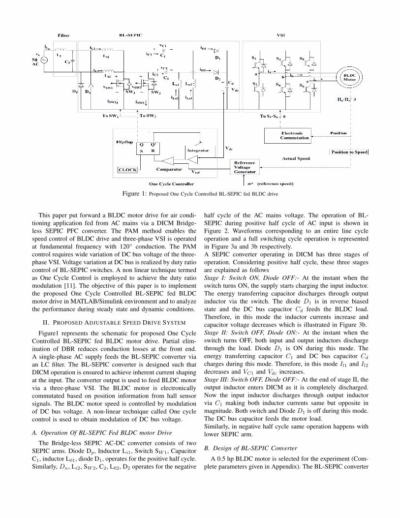
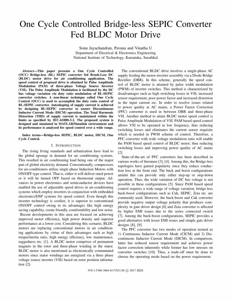
Figure 1: Proposed One Cycle Controlled BL-SEPIC fed BLDC drive
This paper put forward a BLDC motor drive for air condi-tioning application fed from AC mains via a DICM Bridge-less SEPIC PFC converter. The PAM method enables thespeed control of BLDC drive and three-phase VSI is operatedat fundamental frequency with 120 conduction. The PAMcontrol requires wide variation of DC bus voltage of the three-phase VSI. Voltage variation at DC bus is realized by duty ratiocontrol of BL-SEPIC switches. A non linear technique termedas One Cycle Control is employed to achieve the duty ratiomodulation [11]. The objective of this paper is to implementthe proposed One Cycle Controlled BL-SEPIC fed BLDCmotor drive in MATLAB/Simulink environment and to analyzethe performance during steady state and dynamic conditions.
II. PROPOSED ADJUSTABLE SPEED DRIVE SYSTEM
Figure1 represents the schematic for proposed One CycleControlled BL-SEPIC fed BLDC motor drive. Partial elim-ination of DBR reduces conduction losses at the front end.A single-phase AC supply feeds the BL-SEPIC converter viaan LC filter. The BL-SEPIC converter is designed such thatDICM operation is ensured to achieve inherent current shapingat the input. The converter output is used to feed BLDC motorvia a three-phase VSI. The BLDC motor is electronicallycommutated based on position information from hall sensorsignals. The BLDC motor speed is controlled by modulationof DC bus voltage. A non-linear technique called One cyclecontrol is used to obtain modulation of DC bus voltage.
A. Operation Of BL-SEPIC Fed BLDC motor Drive
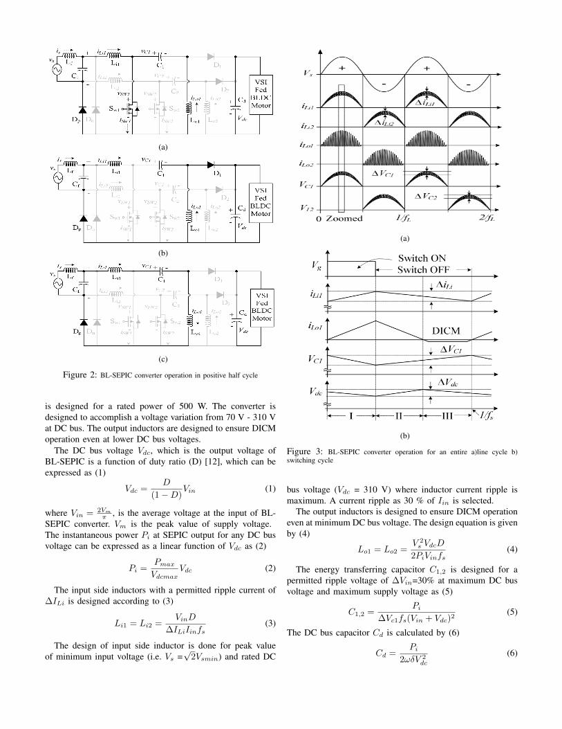
The Bridge-less SEPIC AC-DC converter consists of twoSEPIC arms. Diode Dp, Inductor Li1, Switch SW1, CapacitorC1, inductor L01, diode D1, operates for the positive half cycle.Similarly, Dn, Li2, SW2, C2, L02, D2 operates for the negative
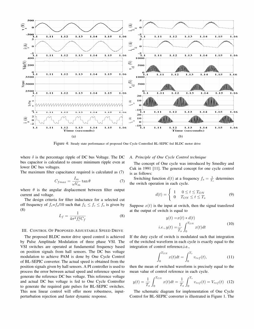
half cycle of the AC mains voltage. The operation of BL-SEPIC during positive half cycle of AC input is shown inFigure 2. Waveforms corresponding to an entire line cycleoperation and a full switching cycle operation is representedin Figure 3a and 3b respectively.A SEPIC converter operating in DICM has three stages ofoperation. Considering positive half cycle, these three stagesare explained as followsStage I: Switch ON, Diode OFF:- At the instant when theswitch turns ON, the supply starts charging the input inductor.The energy transferring capacitor discharges through outputinductor via the switch. The diode D1 is in reverse biasedstate and the DC bus capacitor Cd feeds the BLDC load.Therefore, in this mode the inductor currents increase andcapacitor voltage decreases which is illustrated in Figure 3b.Stage II: Switch OFF, Diode ON:- At the instant when theswitch turns OFF, both input and output inductors dischargethrough the load. Diode D1 is ON during this mode. Theenergy transferring capacitor C1 and DC bus capacitor Cdcharges during this mode. Therefore, in this mode Il1 and Il2decreases and VC1 and Vdc increases.Stage III: Switch OFF, Diode OFF:- At the end of stage II, theoutput inductor enters DICM as it is completely discharged.Now the input inductor discharges through output inductorvia C1 making both inductor currents same but opposite inmagnitude. Both switch and Diode D1 is off during this mode.The DC bus capacitor feeds the motor load.Similarly, in negative half cycle same operation happens withlower SEPIC arm.
B. Design of BL-SEPIC Converter
A 0.5 hp BLDC motor is selected for the experiment (Com-plete parameters given in Appendix). The BL-SEPIC converter
(a)
(b)
(c)
Figure 2: BL-SEPIC converter operation in positive half cycle
is designed for a rated power of 500 W. The converter isdesigned to accomplish a voltage variation from 70 V - 310 Vat DC bus. The output inductors are designed to ensure DICMoperation even at lower DC bus voltages.
The DC bus voltage Vdc, which is the output voltage ofBL-SEPIC is a function of duty ratio (D) [12], which can beexpressed as (1)
Vdc =D
(1−D)Vin (1)
where Vin = 2Vm
π , is the average voltage at the input of BL-SEPIC converter. Vm is the peak value of supply voltage.The instantaneous power Pi at SEPIC output for any DC busvoltage can be expressed as a linear function of Vdc as (2)
Pi =PmaxVdcmax
Vdc (2)
The input side inductors with a permitted ripple current of∆ILi is designed according to (3)
Li1 = Li2 =VinD
∆ILiIinfs(3)
The design of input side inductor is done for peak valueof minimum input voltage (i.e. Vs =
√2Vsmin) and rated DC
(a)
(b)
Figure 3: BL-SEPIC converter operation for an entire a)line cycle b)switching cycle
bus voltage (Vdc = 310 V) where inductor current ripple ismaximum. A current ripple as 30 % of Iin is selected.
The output inductors is designed to ensure DICM operationeven at minimum DC bus voltage. The design equation is givenby (4)
Lo1 = Lo2 =V 2s VdcD
2PiVinfs(4)
The energy transferring capacitor C1,2 is designed for apermitted ripple voltage of ∆Vin=30% at maximum DC busvoltage and maximum supply voltage as (5)
C1,2 =Pi
∆Vc1fs(Vin + Vdc)2(5)
The DC bus capacitor Cd is calculated by (6)
Cd =Pi
2ωδV 2dc
(6)
1.1 1.11 1.12 1.13 1.14 1.15 1.16
v s (V)
-500
0
500
1.1 1.11 1.12 1.13 1.14 1.15 1.16
i s(A)
-5
0
5
1.1 1.11 1.12 1.13 1.14 1.15 1.16
Vdc(
V)
0
200
400
1.1 1.11 1.12 1.13 1.14 1.15 1.16
N(rp
m)
2500
3000
3500
1.1 1.11 1.12 1.13 1.14 1.15 1.16
Te (N*
m)
0
1
2
3
Time (seconds)
1.1 1.11 1.12 1.13 1.14 1.15 1.16
i a (A)
-2
0
2
(a)
1.1 1.11 1.12 1.13 1.14 1.15 1.16
i L i1(A)
-5
0
5
1.1 1.11 1.12 1.13 1.14 1.15 1.16
i L i2 ( A)
-5
0
5
1.1 1.11 1.12 1.13 1.14 1.15 1.16
v c1 (
V)
0
500
1000
1.1 1.11 1.12 1.13 1.14 1.15 1.16
v c2 (V
)
0
500
1000
1.1 1.11 1.12 1.13 1.14 1.15 1.16
i L o1
(A)
-10
0
10
20
Time (seconds)
1.1 1.11 1.12 1.13 1.14 1.15 1.16i L o2
(A)
-10
0
10
20
(b)
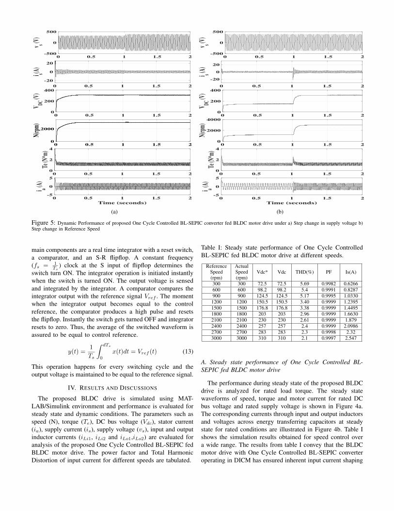
Figure 4: Steady state performance of proposed One Cycle Controlled BL-SEPIC fed BLDC motor drive
where δ is the percentage ripple of DC bus Voltage. The DCbus capacitor is calculated to ensure minimum ripple even atlower DC bus voltages.The maximum filter capacitance required is calculated as (7)
Cfmax =ImωVm
tan θ (7)
where θ is the angular displacement between filter outputcurrent and voltage.
The design criteria for filter inductance for a selected cutoff frequency of fc=fs/10 such that fL ≤ fc ≤ fs is given by(8)
Lf =1
4π2f2cCf(8)
III. CONTROL OF PROPOSED ADJUSTABLE SPEED DRIVE
The proposed BLDC motor drive speed control is achievedby Pulse Amplitude Modulation of three phase VSI. TheVSI switches are operated at fundamental frequency basedon position signals from hall sensors. The DC bus voltagemodulation to achieve PAM is done by One Cycle Controlof BL-SEPIC converter. The actual speed is obtained from theposition signals given by hall sensors. A PI controller is used toprocess the error between actual speed and reference speed togenerate the reference DC bus voltage. This reference voltageand actual DC bus voltage is fed to One Cycle Controllerto generate the required gate pulses for BL-SEPIC switches.This non linear control will offer more robustness, input-perturbation rejection and faster dynamic response.
A. Principle of One Cycle Control technique
The concept of One cycle was introduced by Smedley andCuk in 1991 [11]. The general concept for one cycle controlis as follows:
Switching function d(t) at a frequency fs = 1Ts
determinesthe switch operation in each cycle.
d(t) =
1 0 ≤ t ≤ TON0 TON ≤ t ≤ Ts
(9)
Suppose x(t) is the input at switch, then the signal transferedat the output of switch is equal to
y(t) =x(t) ∗ d(t)
i.e., y(t) =1
Ts
∫ TON
0
x(t)dt(10)
If the duty cycle of switch is modulated such that integrationof the switched waveform in each cycle is exactly equal to theintegration of control reference,i.e.,∫ TON
0
x(t)dt =
∫ Ts
0
vref (t), (11)
then the mean of switched waveform is precisely equal to themean value of control reference in each cycle.
y(t) =1
Ts
∫ TON
0
x(t)dt =1
Ts
∫ Ts
0
vref (t) = Vref (t) (12)
The schematic diagram for implementation of One CycleControl for BL-SEPIC converter is illustrated in Figure 1. The
0 0.5 1 1.5 2
v s (V)
-500
0
500
0 0.5 1 1.5 2
i s(A)
-20
0
20
0 0.5 1 1.5 2
V DC (V
)
0
200
400
0 0.5 1 1.5 2
N(rp
m)
0
2000
0 0.5 1 1.5 2
Te (N
*m)
0
2
4
Time (seconds)
0 0.5 1 1.5 2
i a (A)
-5
0
5
(a)
0 0.5 1 1.5 2
v s (V)
-500
0
500
0 0.5 1 1.5 2
i s (A)
-20
0
20
0 0.5 1 1.5 2
V DC (V
)
0
200
400
0 0.5 1 1.5 2
N(rp
m)
0
2000
4000
0 0.5 1 1.5 2
Te (N
*m)
0
2
4
Time (seconds)
0 0.5 1 1.5 2
i a (A)
-5
0
5
(b)
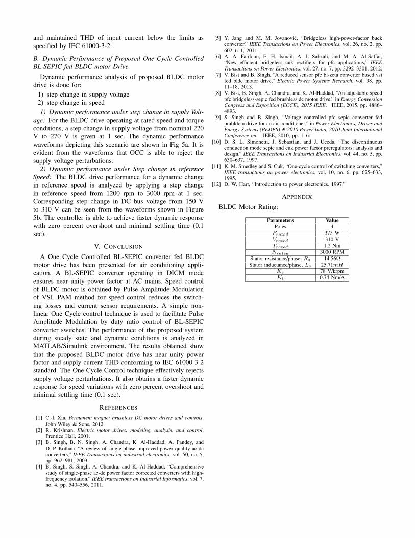
Figure 5: Dynamic Performance of proposed One Cycle Controlled BL-SEPIC converter fed BLDC motor drive under a) Step change in supply voltage b)Step change in Reference Speed
main components are a real time integrator with a reset switch,a comparator, and an S-R flipflop. A constant frequency(fs = 1
Ts) clock at the S input of flipflop determines the
switch turn ON. The integrator operation is initiated instantlywhen the switch is turned ON. The output voltage is sensedand integrated by the integrator. A comparator compares theintegrator output with the reference signal Vref . The momentwhen the integrator output becomes equal to the controlreference, the comparator produces a high pulse and resetsthe flipflop. Instantly the switch gets turned OFF and integratorresets to zero. Thus, the average of the switched waveform isassured to be equal to control reference.
y(t) =1
Ts
∫ dTs
0
x(t)dt = Vref (t) (13)
This operation happens for every switching cycle and theoutput voltage is maintained to be equal to the reference signal.
IV. RESULTS AND DISCUSSIONS
The proposed BLDC drive is simulated using MAT-LAB/Simulink environment and performance is evaluated forsteady state and dynamic conditions. The parameters such asspeed (N), torque (Te), DC bus voltage (Vdc), stator current(ia), supply current (is), supply voltage (vs), input and outputinductor currents (iLi1, iLi2 and iLo1,iLo2) are evaluated foranalysis of the proposed One Cycle Controlled BL-SEPIC fedBLDC motor drive. The power factor and Total HarmonicDistortion of input current for different speeds are tabulated.
Table I: Steady state performance of One Cycle ControlledBL-SEPIC fed BLDC motor drive at different speeds.
ReferenceSpeed(rpm)
ActualSpeed(rpm)
Vdc* Vdc THD(%) PF Is(A)
300 300 72.5 72.5 5.69 0.9982 0.6266600 600 98.2 98.2 5.4 0.9991 0.8287900 900 124.5 124.5 5.17 0.9995 1.0330
1200 1200 150.5 150.5 3.40 0.9999 1.23951500 1500 176.8 176.8 3.38 0.9999 1.44951800 1800 203 203 2.96 0.9999 1.66302100 2100 230 230 2.61 0.9999 1.8792400 2400 257 257 2.4 0.9999 2.09862700 2700 283 283 2.3 0.9998 2.323000 3000 310 310 2.1 0.9997 2.547
A. Steady state performance of One Cycle Controlled BL-SEPIC fed BLDC motor drive
The performance during steady state of the proposed BLDCdrive is analyzed for rated load torque. The steady statewaveforms of speed, torque and motor current for rated DCbus voltage and rated supply voltage is shown in Figure 4a.The corresponding currents through input and output inductorsand voltages across energy transferring capacitors at steadystate for rated conditions are illustrated in Figure 4b. Table Ishows the simulation results obtained for speed control overa wide range. The results from table I convey that the BLDCmotor drive with One Cycle Controlled BL-SEPIC converteroperating in DICM has ensured inherent input current shaping
and maintained THD of input current below the limits asspecified by IEC 61000-3-2.
B. Dynamic Performance of Proposed One Cycle ControlledBL-SEPIC fed BLDC motor Drive
Dynamic performance analysis of proposed BLDC motordrive is done for:
1) step change in supply voltage2) step change in speed1) Dynamic performance under step change in supply Volt-
age: For the BLDC drive operating at rated speed and torqueconditions, a step change in supply voltage from nominal 220V to 270 V is given at 1 sec. The dynamic performancewaveforms depicting this scenario are shown in Fig 5a. It isevident from the waveforms that OCC is able to reject thesupply voltage perturbations.
2) Dynamic performance under Step change in referenceSpeed: The BLDC drive performance for a dynamic changein reference speed is analyzed by applying a step changein reference speed from 1200 rpm to 3000 rpm at 1 sec.Corresponding step change in DC bus voltage from 150 Vto 310 V can be seen from the waveforms shown in Figure5b. The controller is able to achieve faster dynamic responsewith zero percent overshoot and minimal settling time (0.1sec).
V. CONCLUSION
A One Cycle Controlled BL-SEPIC converter fed BLDCmotor drive has been presented for air conditioning appli-cation. A BL-SEPIC converter operating in DICM modeensures near unity power factor at AC mains. Speed controlof BLDC motor is obtained by Pulse Amplitude Modulationof VSI. PAM method for speed control reduces the switch-ing losses and current sensor requirements. A simple non-linear One Cycle control technique is used to facilitate PulseAmplitude Modulation by duty ratio control of BL-SEPICconverter switches. The performance of the proposed systemduring steady state and dynamic conditions is analyzed inMATLAB/Simulink environment. The results obtained showthat the proposed BLDC motor drive has near unity powerfactor and supply current THD conforming to IEC 61000-3-2standard. The One Cycle Control technique effectively rejectssupply voltage perturbations. It also obtains a faster dynamicresponse for speed variations with zero percent overshoot andminimal settling time (0.1 sec).
REFERENCES
[1] C.-l. Xia, Permanent magnet brushless DC motor drives and controls.John Wiley & Sons, 2012.
[2] R. Krishnan, Electric motor drives: modeling, analysis, and control.Prentice Hall, 2001.
[3] B. Singh, B. N. Singh, A. Chandra, K. Al-Haddad, A. Pandey, andD. P. Kothari, “A review of single-phase improved power quality ac-dcconverters,” IEEE Transactions on industrial electronics, vol. 50, no. 5,pp. 962–981, 2003.
[4] B. Singh, S. Singh, A. Chandra, and K. Al-Haddad, “Comprehensivestudy of single-phase ac-dc power factor corrected converters with high-frequency isolation,” IEEE transactions on Industrial Informatics, vol. 7,no. 4, pp. 540–556, 2011.
[5] Y. Jang and M. M. Jovanovic, “Bridgeless high-power-factor buckconverter,” IEEE Transactions on Power Electronics, vol. 26, no. 2, pp.602–611, 2011.
[6] A. A. Fardoun, E. H. Ismail, A. J. Sabzali, and M. A. Al-Saffar,“New efficient bridgeless cuk rectifiers for pfc applications,” IEEETransactions on Power Electronics, vol. 27, no. 7, pp. 3292–3301, 2012.
[7] V. Bist and B. Singh, “A reduced sensor pfc bl-zeta converter based vsifed bldc motor drive,” Electric Power Systems Research, vol. 98, pp.11–18, 2013.
[8] V. Bist, B. Singh, A. Chandra, and K. Al-Haddad, “An adjustable speedpfc bridgeless-sepic fed brushless dc motor drive,” in Energy ConversionCongress and Exposition (ECCE), 2015 IEEE. IEEE, 2015, pp. 4886–4893.
[9] S. Singh and B. Singh, “Voltage controlled pfc sepic converter fedpmbldcm drive for an air-conditioner,” in Power Electronics, Drives andEnergy Systems (PEDES) & 2010 Power India, 2010 Joint InternationalConference on. IEEE, 2010, pp. 1–6.
[10] D. S. L. Simonetti, J. Sebastian, and J. Uceda, “The discontinuousconduction mode sepic and cuk power factor preregulators: analysis anddesign,” IEEE Transactions on Industrial Electronics, vol. 44, no. 5, pp.630–637, 1997.
[11] K. M. Smedley and S. Cuk, “One-cycle control of switching converters,”IEEE transactions on power electronics, vol. 10, no. 6, pp. 625–633,1995.
[12] D. W. Hart, “Introduction to power electronics. 1997.”
APPENDIX
BLDC Motor Rating:
Parameters ValuePoles 4Prated 375 WVrated 310 VTrated 1.2 NmNrated 3000 RPM
Stator resistance/phase, Rs 14.56ΩStator inductance/phase, Ls 25.71mH
Ke 78 V/krpmKt 0.74 Nm/A
Related Documents