Journul of Sound and Vibration (1983) 86(l), 107-128 ON TUNED BLADED DISK DYNAMICS: SOME ASPECTS OF FRICTION RELATED MISTUNING A. MUSZY~~SKA? University of Dayton Research Institute, Dayton, Ohio, U.S.A. AND D. I. G. JONES Air Force Wright Aeronautical Laboratories, Wright-Patterson Air Force Base, Ohio 45433, U.S.A. (Received 18 May 1981, and in revised form 28 April 1982) In this paper, a discrete multi-degree of freedom model of a tuned disk is considered. The hysteretic material damping and interblade and blade-to-disk friction forces are included. It is shown that the irregularities of the friction forces and of the harmonic excitation pattern cause mistuning of the system. Optimal conditions of friction were found analytically for the tuned case. They depend on the values of the friction forces, amplitudes and phases of excitation, represented as variations of a traveling wave of excitation. The response amplitude of the blades is minimum for optimal friction. Similar considerations were applied to find the optimal blade mass and stiffness parameters for minimal response amplitudes. These considerations give a new insight into the effects of blade mass and stiffness characteristics as they affect the reduction of vibratory response amplitudes by friction. 1. INTRODUCTION Interest in the prediction and control of vibrations and accompanying high cycle fatigue problems in turbomachinery blade-disk systems has grown rapidly in recent years. This interest has been expressed through investigations of the following matters, (a) flow phenomena through blade arrays, leading to aerodynamic excitation; (b) mechanical excitation through coupling of rotor and blade-disk system [l-3]; and (c) vibration control through increased blade damping obtained by using coatings, multiple layer damping treatments, or through interface effects such as interblade shrouding, dovetail sliding, blade to blade platform dampers, tuned campers, etc. [4-lo]. One important aspect of bladed disk dynamics is the effect of mistuning on response behavior. Mistuning has beneficial effects in controlling blade flutter boundaries [ll-141, but can have disadvantageous effects on forced resonant vibration [15-231 because it leads to wide divergences from blade to blade of the peak dynamic stresses, as opposed to the equal stresses encountered in a tuned system, and the peak stresses may on occasion be increased by a considerable amount. In this paper, we shall recognize three main aspects of mistuning, namely (a) differences in the mass and/or stiffness characteristics of individual blades, reflected as variations in natural frequencies; (b) differences in blade to blade and/or blade to disk frictional forces; and (c) differences in the external forces acting on individual blades reflected as : Visiting Scientist from Institute of Fundamental Technological Research of Polish Academy of Sciences. Warsaw, Poland. Currently at Bently Nevada Corporation, Minden. Nevada, U.S.A. 107 0022460X/83/010107+22 $03.00/O Q 1983 Academic Press Inc. (London) Limited

Welcome message from author
This document is posted to help you gain knowledge. Please leave a comment to let me know what you think about it! Share it to your friends and learn new things together.
Transcript
Journul of Sound and Vibration (1983) 86(l), 107-128
ON TUNED BLADED DISK DYNAMICS: SOME ASPECTS OF FRICTION RELATED MISTUNING
A. MUSZY~~SKA?
University of Dayton Research Institute, Dayton, Ohio, U.S.A.
AND
D. I. G. JONES
Air Force Wright Aeronautical Laboratories, Wright-Patterson Air Force Base, Ohio 45433, U.S.A.
(Received 18 May 1981, and in revised form 28 April 1982)
In this paper, a discrete multi-degree of freedom model of a tuned disk is considered. The hysteretic material damping and interblade and blade-to-disk friction forces are included. It is shown that the irregularities of the friction forces and of the harmonic excitation pattern cause mistuning of the system. Optimal conditions of friction were found analytically for the tuned case. They depend on the values of the friction forces, amplitudes and phases of excitation, represented as variations of a traveling wave of excitation. The response amplitude of the blades is minimum for optimal friction. Similar considerations were applied to find the optimal blade mass and stiffness parameters for minimal response amplitudes. These considerations give a new insight into the effects of blade mass and stiffness characteristics as they affect the reduction of vibratory response amplitudes by friction.
1. INTRODUCTION
Interest in the prediction and control of vibrations and accompanying high cycle fatigue problems in turbomachinery blade-disk systems has grown rapidly in recent years. This interest has been expressed through investigations of the following matters, (a) flow phenomena through blade arrays, leading to aerodynamic excitation; (b) mechanical excitation through coupling of rotor and blade-disk system [l-3]; and (c) vibration control through increased blade damping obtained by using coatings, multiple layer damping treatments, or through interface effects such as interblade shrouding, dovetail sliding, blade to blade platform dampers, tuned campers, etc. [4-lo].
One important aspect of bladed disk dynamics is the effect of mistuning on response behavior. Mistuning has beneficial effects in controlling blade flutter boundaries [ll-141, but can have disadvantageous effects on forced resonant vibration [15-231 because it leads to wide divergences from blade to blade of the peak dynamic stresses, as opposed to the equal stresses encountered in a tuned system, and the peak stresses may on occasion be increased by a considerable amount.
In this paper, we shall recognize three main aspects of mistuning, namely (a) differences in the mass and/or stiffness characteristics of individual blades, reflected as variations in natural frequencies; (b) differences in blade to blade and/or blade to disk frictional forces; and (c) differences in the external forces acting on individual blades reflected as
: Visiting Scientist from Institute of Fundamental Technological Research of Polish Academy of Sciences. Warsaw, Poland. Currently at Bently Nevada Corporation, Minden. Nevada, U.S.A.
107
0022460X/83/010107+22 $03.00/O Q 1983 Academic Press Inc. (London) Limited
108 A. MUSZYtiSKA AND D. I. G. JONES
irregularities of traveling wave excitation. The first type of mistuning is fully classical, but the other two Pspects also lead to variations of magnitudes and frequencies of peak stresses not observed in fully tuned systems excited by a regular traveling wave.
The response of a classically mistuned system can be predicted only through a full general multiple degree of freedom non-linear model [24-261. However, in this paper, the emphasis will be placed on the effects of the non-classical types of mistuning just described on response of a nominally tuned system, and this can be done in terms of a much simpler analysis. The main contribution of this paper will be (1) to develop a closed form analytical solution (for the tuned system under regular traveling wave excitation, by using the method of harmonic balance) for the dynamic response of a discrete non-linear model of a multiple blade system having identical mass, stiffness and hysteretic damping properties, allowing for blade to blade and/or blade to disk frictional damping, the disk being rigid; (2) to optimize the mass, stiffness and frictional parameters of the system for minimum response amplitude in the frequency range of interest; (3) to compare the analytical results with numerical results of mistuned cases, with emphasis on mistuning associated with irregularities of friction forces or excitation pattern, in order to establish a tendency of the system to seek a “worst case” equilibrium state, a new corollary of Murphy’s law.
The tuned system analysis shows that a parameter W, defined in the text, is an important descriptor of the effect of frictional forces, interblade phase angle and excitation forces on the system response, in effect quantifying the mechanical energy dissipation and the mechanical coupling effects, both in tuned and mistuned systems.
The optimization of mass and stiffness parameters shows that a specific relationship exists between the blade mass ratio (p = m2/m1) and stiffness ratio (r = k2/kl) for which the efficiency of frictional damping in reducing amplitudes is maximized. The implications of this feature in design of blades seem worthy of further investigation.
The validity of the analysis is also briefly addressed, both from the point of view of comparisons between numerical integration of the equations of motion and the steady state solution sought herein, and from the point of view of comparisons with experimental data where available. It is not, however, the aim of this paper to address such matters in depth, since the literature dealing with quasi-harmonic oscillations of non-linear systems is already very extensive, and what the authors have done in this paper is not so much to develop new analytical approaches as to apply a well studied mathematical technique to a particular problem.
2. MATHEMATICAL MODEL OF THE TUNED BLADED DISK
In references [7, 24-301, a model of a single blade allowing for slip and friction at the root has been developed. Since analytical and experimental results agreed well, the model was extended and, in references [24, 251, simple models of a mistuned bladed disk were presented. These papers give some overview of the literature relating to friction damping for vibration control of blades, as well as some results for the vibrational response of blades to various types of excitation.
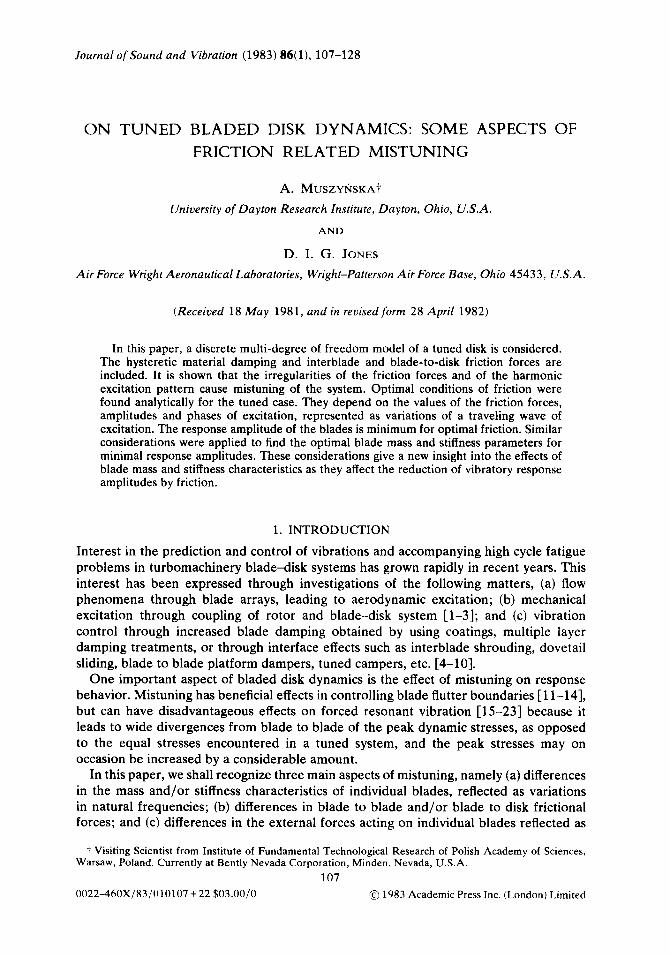
In the present paper, the model proposed in reference [25], for the case of a tuned system (all blades identical), is analyzed. The model, illustrated in Figure 1, consists of n blades each represented by two masses and two springs. The masses and springs may be identified in terms of equivalent masses and stiffnesses describing the first two blade-bending modes [24]. The blades are coupled through massless friction dampers, and other friction dampers join the lower masses to rigid disk. Hysteretic damping in the springs is included.
FRICTIONAL MISTUNING OF BLADED DISKS 109
Figure 1. Model of the tuned bladed disk.
The mathematical model of the system is as follows:
mZra +~I(xI, -Xzo) + (krn/o)(X?1, --i&) = s cos (ot +s,),
mf2w +klh - XI~) + kzxzu + (k1duHi2u -ilm) + bb//who
+ CLN w (.h -i2C+1)+pN sgn (i2rr-i2CP1)+pNN sgn i2V =O, (1)
with (+=l,..., n, where ml, rn2 are corresponding masses, kl, k2 are coefficients of elasticity, 77 is the loss factor, p is the coefficient of friction, N and NN are normal forces depending on the rotational speed of the bladed disk, S and w are the amplitude and frequency of the harmonic exciting force, supposed the same on all blades, and S, is the phase angle (a list of symbols is given in the Appendix). The bladed disk actually rotates in practice, and the pressures arising from the blades cutting the pressure/velocity field of the wakes of prior stages generates an oscillating excitation which is modelled as the traveling wave
s cos (WC + s, ), (2)
where 8, = 2~j(a - 1)/n, u = 1, . . . , n, and j is an integer (j = 1,2, . . .) referred to as the engine order [ 151.
The regular excitation pattern of the system supports the hypothesis that the steady state response of the system will also be regular, as was noticed during the numerical investigations described in reference [31]. The response of the system will then be
x1,(t) =D cos [wt+Y+27rj(c+-1)/n], xZV(f)=A cos[wt+a+2rj((+-1)/n], (3)
where D, A are amplitudes and CX, y are phase angles of the response. Note that D and A may, during calculations, have + or - signs and this is taken into account in the subsequent work.
For calculation purposes we introduce the following simplifications for the non-linear functions (the first term of the Fourier expansions):
sgn [-A sin{wt+a +29rj(a-l)/n}+A sin{wt+cu +2+/n}]
+ (4/r)A[sin {of + a +2+/n}- sin {wt + a + 27rj(a - l)/n}]/2]AI lsin {j7r/n}],
sgn [-A sin {wt + a + 27r(a - l)j/n}] i (4/r)(A/IAI) sin {wt + a + 21rj((+ - 1)/n}. (4)
Then, taking into account relation (4) and the solution (3), one obtains the non-linear functions in equation (1) the following expressions:
I-LN sgn (i2, --h-l) +CLN sgn (in, -~z~+I) +PNN sgn (Go) +--Q(A/IAI) sin (&+a +27rj(cr-- 1)/n),
110 A. MUSZYhSKA AND D. I. G. JONES
Number of blades, n
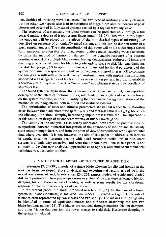
Figure 2. Interblade friction factor 2jsin ~/nl and the phase angle difference 6,+L -6, = 2rr/n versus the number of blades on the disk. --- , 2(sin T/PI 1; -x-, S,_, - 8, = 277/n.
Q = (4/~)(2Nl sin {jr/n}1 +NN), (6)
in which Q may be interpreted as a generalized friction force. One sees from equation (6) that the contribution of the interblade frictional damping is 21 sin {jr/n}] times the contribution of the ground friction. Figure 2 illustrates the function 21 sin {jr/n}] and the phase difference IS, -S,_r( = 2r/n for j = 1 as a function of the number of blades, it. For n > 2, both curves practically coincide.
By using relation (5), equations (1) may be presented in the “linearized” form [29], valid for the steady state case,
rnl.fl +kl(xl, -X2a)+(k1dWH~lcT -i2~)=SCOS(Wt+&),
m2i2c +kl(x2c -xl~T)+k2~2rr+(k177/~)(~2~-~l~)+(k277/~)~2~,
= Q(A/IA 1) sin (wt + CY + S,), (7)
withcr=1,2,..., n. The motion of the o-th blade is now uncoupled from the motion of the other blades. The friction forces act as an additional exciting force depending on the sign of the amplitude of the resulting motion. The system remains non-linear.
Bearing in mind equations (3), one can transform equation (7) to an algebraic form and then find the analytical solutions for the amplitudes [AI, IDI, and phase angles (Y and y in the same manner as for one blade [27-291. The expression for IAl is
lAI=S[-J~p2+dp: +P:)((~+~~*)/P~}--P:~/(P: +P:,, (8)
PI = kdr -PV + v(v - 1+ v2)/pJ, ~2 = vkl(r + v2/pd, p3=(1-V)2+n2,
u = mlw2/k,, p = m2lmb r = k2lkl, W = (Q/S)2.
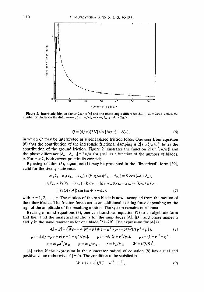
IAl exists if the expression in the numerator radical of equation (8) has a real and positive value (otherwise IA I = 0). The condition to be satisfied is
w<(1+772)/{(1-y)2+772}, (9)
FRICTIONAL MISTUNING OF BLADED DISKS
Rqon of existence
Rqon of existence
111
I-TV3 (I-,,(I-J3, I iI+% Js
(I+?)1 I+Tj Js v-- -5-
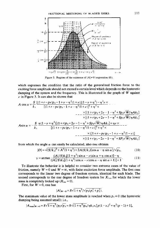
Figure 3. Regions of the existence of jAl # 0 (expression (8)).
which expresses the condition that the ratio of the generalized friction force to the exciting force amplitude should not exceed a certain level which depends on the hysteretic damping of the system and the frequency. This is illustrated in the graph of W against v in Figure 3. It can also be shown that
A coscy =_s_ ~(~+~-p~)p,-1+v-~2(1+v)](l-v+~2)-~2vx --_ k, [(1+r-pY)p~-1+V-~*(1+24]*+~*2
x[(l+r)p~+2~-1-77*+Sp34%7/77Akr] --- x[(l+r)p,+2~-1-77*+Sp3~~/77Akr]
S ~(1--++*)[(1+~)p~+2v-1-~*+Sp~~/~Ak~l+~~x Asina _ --- kl [(1+r-pv)p~-1+v-r/*(1+V)]*+~*X
x([1+r-pv)p3-1+V-n2(1+V)] --- x[(l+r)pj+2V-l-n*+SP+%&Akr]
from which the angle (Y can easily be calculated; also one obtains
~D~=~(S/kI)*+A2(1+~*)+2A(S/k1)[cosa-~ sina]/JE,
(]A]/S)kr[(l+n*)sin~-V(sina+n cosa)]-7 y=arctan(/A~/S)kI[(l+~2)cosa-v(cosa-~ sincr+l)]+l’
(10)
(11)
To illustrate the behavior it is helpful to consider two extreme cases of the value of friction, namely W = 0 and W = CO, with finite excitation force amplitude. The first case corresponds to the linear two degree of freedom system, identical for each blade. The second corresponds to the one degree of freedom system for Xiv, for which the lower mass is completely locked up (X2o = 0).
First, for W = 0, one has
IAlw=t.,= Sd1+,2/dpdp: +p;,.
The maximum value of the lower mass amplitude is reached when p1 + 0 (the hysteretic damping being assumed small): i.e.,
112 A. MUSZYhKA AND D. I. G. JONES
where Y, is a root calculated from the equation p1 = 0: i.e., (r -pv)p3 + Y( Y - 1 + n ‘) = 0. Let p4 = (Y - 1)2 + n2. Then the maximum amplitude of the upper blade mass is
which for small 7 becomes
L&=0 = l/w?(pp4+ 1).
It is evident that the values of both amplitudes IAl and ID I at resonance are controlled by the hysteretic damping in inverse proportion to q. The response amplitude of the upper mass, JD]W=O, remains the same as in equation (lo), so that after some transforma- tions
J~lw=o=(Sl~lPsJP:+P~)~Ps(P:+P~)+k:(l+~2~2
+2ki[p,(l-v+T72+7/2V)+7)p2(1-2V+772)]}1’2. (12)
For the second case, of infinite friction, W = 00, one has X2(f) = 0, whence, from equations (1) and (3),
IAlw=m = 0, IDIw=oo=S/kIJ~=S/klJ(1-v)2+172.
The maximum amplitude occurs for v = 1, and thus is IDJw=,=S/klq, its value also being limited in inverse proportion to n.
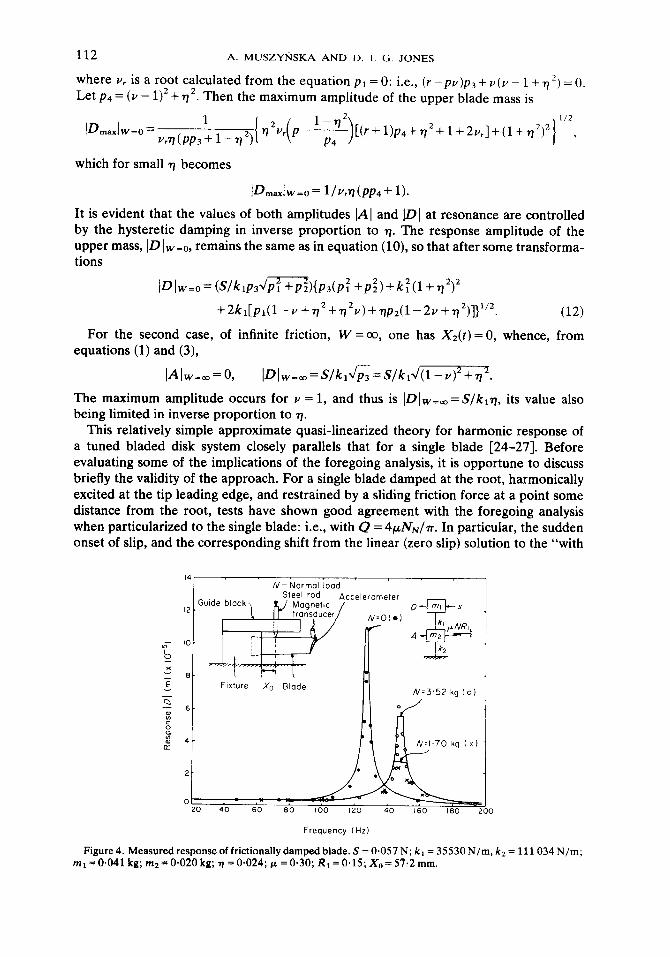
This relatively simple approximate quasi-linearized theory for harmonic response of a tuned bladed disk system closely parallels that for a single blade [24-271. Before evaluating some of the implications of the foregoing analysis, it is opportune to discuss briefly the validity of the approach. For a single blade damped at the root, harmonically excited at the tip leading edge, and restrained by a sliding friction force at a point some distance from the root, tests have shown good agreement with the foregoing analysis when particularized to the single blade: i.e., with Q = 4pNN/7r. In particular, the sudden onset of slip, and the corresponding shift from the linear (zero slip) solution to the “with
N- Normal load
Accelerometer
FlXtlJre Xo Blade
Frequency (Hz)
‘0
Figure 4. Measured response of frictionally damped blade. S = 0.057 N; k, = 35530 N/m, k2 = 111034 N/m; ml = 0.041 kg; mz = 0.020 kg; TJ = 0,024; p =0*30; RI = 0.15; X0= 57.2 mm.
FRICTIONAL MISTUNING OF BLADED DISKS 113
slip” solution, as resonance is approached, is clearly seen in Figure 4. More details of the experiment are described in references [24, 323.
Further general support for the approach is provided by numerical integration of the equation of motion in the time domain, as shown by Plunkett [31].
3. DESCRIPTIVE ANALYSIS OF THE RESPONSE AMPLITUDES FOR ZERO HYSTERETIC DAMPING
For zero hysteretic damping (7 = 0) the expressions (8) and (10) have the simpler forms
dl- W(1 - v)2 IAl=; ,pv2-y(p+r+l)+r,9 (13)
,Dl~_S_J(pv-r-1)~-2W[pv~-u(p+r+l)+r+o.5]
kt Ipv2-zJ(p+r+l)+rJ . (14)
Equation (14) has been obtained after some transformation of equation (lo), with IAl assumed to be non-zero and given by expression (13). From expression (13) one sees that the amplitude IAl has a real value, which means that the solution (3) exists, when there is sufficiently small friction in the system: i.e.,
w < l/(1 - v)2. (15)
Figure 3 shows the regions of existence of (A(. As is evident, it does not depend on the blade parameters p and r. In the region where W 2 l/( 1 - v)~ the friction force locks up on the mass m2 and one has IAl = 0 and the linear response ID]! of the mass ml then has the amplitude
/Dl, = S/kill - ~1. (16)
The non-linear response amplitude IDI (expression (14)) exists within the region of existence of (A( # 0, which is easily seen from expression (10); the apparent extension of the region of existence of the non-linear response IDI arises from the algebraic transformations. It is noteworthy that, around the resonance frequency of the mass ml (v = l), motion of the lower mass m2 always exists. The width of the region of existence of motion of the mass m2 depends on the value of the friction force or, more precisely, on the ratio of the friction force to the amplitude of the exciting force and the interblade difference in excitation phase angle.
One can now analyze the function under the radical in equation (14). It may be rewritten as a polynomial I+!+) in v,
Ijl(V)~V2~(~-2W)-2v[p(1+r)-W(1+r+p)]+(1+r)2-W(2r+1), (17)
with the roots
y,=P(r+l)- W(r+p+1)+(-1)iJW2[(r-p+1)2+2p]- wpz L
P(P -2W 9 i = 1,2. (18)
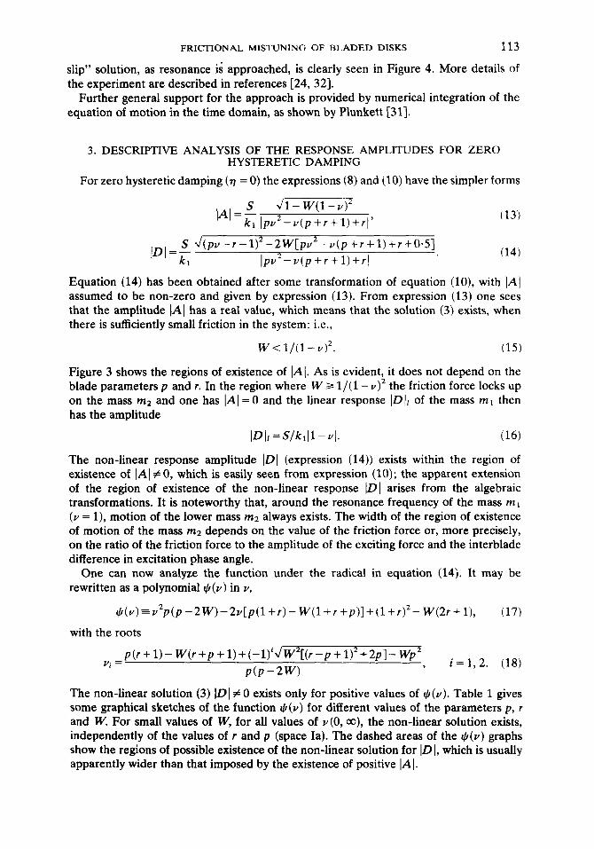
The non-linear solution (3) IDI # 0 exists only for positive values of 4(v). Table 1 gives some graphical sketches of the function G,(v) for different values of the parameters p, r and W. For small values of W, for all values of ~(0, co), the non-linear solution exists, independently of the values of r and p (space Ia). The dashed areas of the Jl(v) graphs show the regions of possible existence of the non-linear solution for ID I, which is usually apparently wider than that imposed by the existence of positive IA I.
114 A. MUSZYIhKA AND D. I. G. JONES
TABLET
Variation of Cc, (v) with v for various W and p (expression (17))
IG I Ib I Ic i 1 I ,r,P
p(1tr) P
- l+(r-pP+2r P
1+r+p n nro~
I I I I $4q IO 1/z v I
* P2 P pil+rl (l+rl* W
l+(r-p12+2r ? I +r+p 2rt1
For higher values of W, the region of existence of IDI is limited to low and high values of v (space II). Finally, for the highest values of W, it is limited to some single region of v (spaces IV and V). These regions should be compared, however, with the regions of existence of (A ( and only the coinciding regions give the final answer regarding existence of IDI as an amplitude of the non-linear solutions; otherwise one has the case IAl = 0 analyzed above (see Figure 3).
In the denominator of equation (14) one has a polynomial in v with the roots ~3, v4 given by
vi+2={r+p +l+(-l)iJ(r-p- 1)‘+4r1/2p, i = 1,2. (19)
For Y = v3 or v4, IDI = co, as the denominator is zero and hence there are resonances. Friction damping, if it is small, does not now control the resonant amplitude, but its effect is noticed in the vicinity, narrowing the resonance region. It will be shown later that higher friction may eliminate one resonance altogether. The addition of hysteretic damping brings a supplementary effect limiting the resonance amplitudes. If small hysteretic damping is present in the system, one may still expect high amplitudes for ID I in the vicinity of vg or v4, so the main interest is to introduce friction damping in such a manner that it controls one or both of these resonance regions.
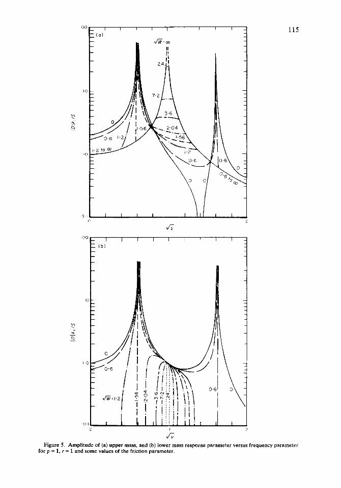
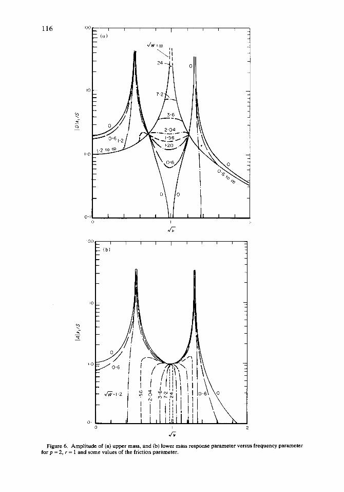
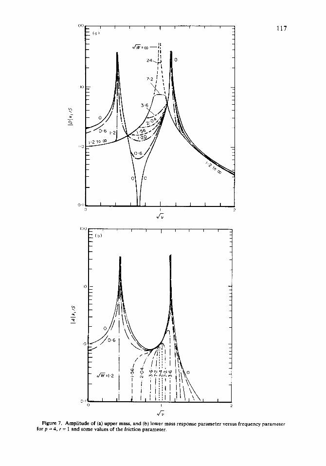
In Figures 5-7, the relationship between the response amplitude parameter and the frequency parameter are presented for some cases. The effect of varying p is clearly seen.
2 ; 0 -
(b)
IO
I-O
0.1 0 I 7
b.4
Figure 5. Amplitude of (a) upper mass, and (b) lower mass response parameter versus frequency parameter for p = 1, r = 1 and some values of the friction parameter.
116
IO -
2 -z 0
I.0
IOC I I I I I I I I I
(b)
Figure 6. Amplitude of (a) upper mass, and (b) lower mass response parameter versus frequency parameter for p = 2, r = 1 and some values of the friction parameter.
IC
Y ; 0 -
1.C
0.1
117
Figure 7. Amplitude of (a) upper mass, and (b) lower mass response parameter versus frequency parameter for p = 4, r = 1 and some values of the friction parameter.
118 A. MUSZYIkSKA AND D. 1. <i. JONES
4. OPTIMIZATION OF DRY FRICTION FOR VIBRATION CONTROL
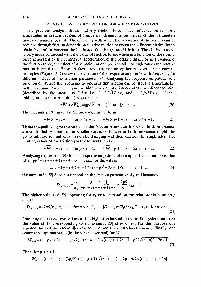
The previous analysis shows that dry friction forces have influence on response amplitudes in certain regions of frequency, depending on values of the parameters involved, namely, p, r, W. The efficiency with which the responses of the system can be reduced through friction depends on relative motion between the adjacent blades (inter- blade friction) or between the blade and the disk (ground friction). The ability to move is very much connected with the value of friction force, which is a function of the normal force generated by the centrifugal acceleration of the rotating disk. For small values of the friction force, the effect of dissipation of energy is small. For high values the relative motion is restricted. Between these two extremes an optimum exists. The numerical examples (Figures 5-7) show the variation of the response amplitude with frequency for different values of the friction parameter W. Analyzing the response amplitude as a function of W, and the frequency o, one sees that friction can control the amplitude ID] in the resonance area if v3, v4 are within the region of existence of the non-linear solution (described by the inequality (15)): i.e., 1- l/JlW*v, and l+ l/J@< ~4. Hence, taking into account equation (19), one gets
JW~J~,i,~~[J(r-p-1)2+4r+Ip-r-11]. (20)
The inequality (20) may also be presented in the form
JWap(v4-1) forp<r+l, JWap(l-v3) forp>r+l. (21)
These inequalities give the values of the friction parameter for which both resonances are controlled by friction. For smaller values of W, one or both resonance amplitudes go to infinity, so that only hysteretic damping will then control the amplitudes. The limiting values of the friction parameter will then be
JW=p(v4-1) forp<r+l, JW=p(l-v3) forp>r+l. (22)
Analyzing expression (14) for the response amplitude of the upper blade, one notes that when pu2 - v (p + r + 1) + r + 0.5 = 0, i.e., for the values
vic4 = {p + r -t 1 + (-l)i J(r -p)*+ 2r + 1]/2p, i=l,2, (23)
the amplitude IDI does not depend on the friction parameter W, and becomes
The higher values of IDI appearing for v5 or V6 depend on the relationship between p and r:
IDI,=,,=(2pS/kl)(v6-1) forp<r+l, IDI.=,=(2pS/k1)(1-vs) forp>r+l. (24)
One may take these two values as the highest values admitted in the system and seek the value of W corresponding to a maximum IDI at v5 or Yg. For this purpose one equates the first derivative d]D]/dv to zero and then introduces v = US,& Finally, one obtains the optimal value (in the sense described) for W:
w,,,= (r-~)~+2r+ I -(p/~)*(r-p + l)~J(r-p)~+~r +1+p/2J(r-p)~+2r+l].
(25)
Then,forp<r+l,
Wept= (r -p + 1)2+(3p/2)+(r -p + l)[J(r-p + 1)2+2p+p/2J(r-p + 1)2+2p]
FRICTIONAL MISTUNING OF BLADED DISKS 119
andforp>r+l,
WoPt= (r -p + 1)‘+(3p/2)-(r -p + l)[J(r -p + 1)2+2p+p/2J(r -p + 1)2+2p]. (26)
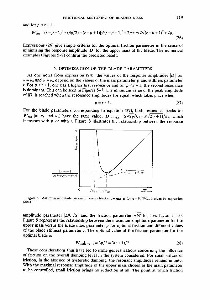
Expressions (26) give simple criteria for the optimal friction parameter in the sense of minimizing the response amplitude ID] for the upper mass of the blade. The numerical examples (Figures 5-7) confirm the predicted result.
5. OPTIMIZATION OF THE BLADE PARAMETERS
As one notes from expression (24), the values of the response amplitudes IDI for v = vs and v = Vg depend on the values of the mass parameter p and stiffness parameter r. For p >r + 1, one has a higher first resonance and for p <r + 1, the second resonance is dominant. This can be seen in Figures 5-7. The minimum value of the peak amplitude of IDI is reached when the resonance amplitudes are equal, which takes place when
p=r+l. (27)
For the blade parameters corresponding to equation (27), both resonance peaks for W,,, (at vs and v6) have the same value, ~DI,=,,~,=S~~/~~ =SJ2(r+l)/kl, which increases with p or with r. Figure 8 illustrates the relationship between the response
Ipv--I-II
IPY~-Ylp+l+l)+rI
v WI&m v W,P! I/w+
Figure 8. Maximum amplitude parameter versus friction parameter for r) = 0. ( Wli, is given by expression (2Oj.J
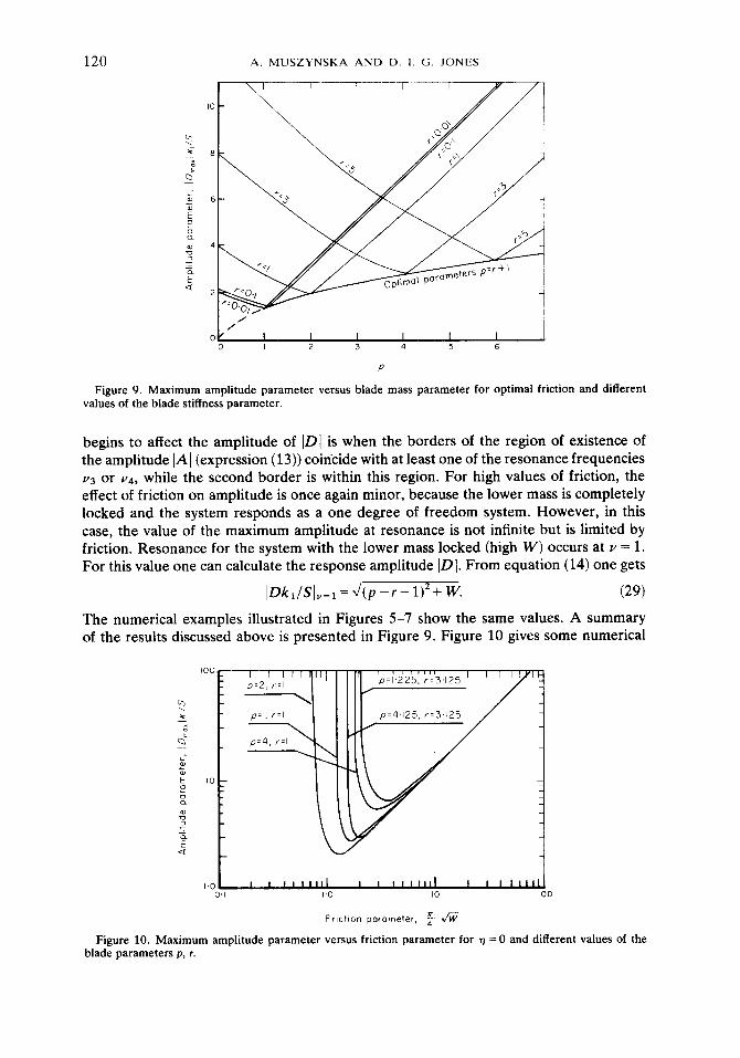
- amplitude parameter IDkJSI and the friction parameter JW for loss factor 77 = 0. Figure 9 represents the relationship between the maximum amplitude parameter for the upper mass versus the blade mass parameter p for optimal friction and different values of the blade stiffness parameter r. The optimal value of the friction parameter for the optimal blade is
Woptlp=r+l = 3p/2 = 3(r + 1)/2. (28)
These considerations thus have led to some generalizations concerning the influence of friction on the overall damping level in the system considered. For small values of friction, in the absence of hysteretic damping, the resonant amplitudes remain infinite. With the maximal response amplitude of the upper mass chosen as the main parameter to be controlled, small friction brings no reduction at all. The point at which friction
120 A. MUSZYkSKA AND D. I. G. JONES
I i---r ----l
/ /
OY I I I I I I 0 I 2 3 4 5 6
P
Figure 9. Maximum amplitude parameter versus blade mass parameter for optimal friction and different values of the blade stiffness parameter.
begins to affect the amplitude of IDI is when the borders of the region of existence of the amplitude IAl (expression (13)) coincide with at least one of the resonance frequencies v3 or v4, while the second border is within this region. For high values of friction, the effect of friction on amplitude is once again minor, because the lower mass is completely locked and the system responds as a one degree of freedom system. However, in this case, the value of the maximum amplitude at resonance is not infinite but is limited by friction. Resonance for the system with the lower mass locked (high W) occurs at v = 1. For this value one can calculate the response amplitude IDI. From equation (14) one gets
IDk1/SI”=l=J(p-r-l)*+ w. (29)
The numerical examples illustrated in Figures 5-7 show the same values. A summary of the results discussed above is presented in Figure 9. Figure 10 gives some numerical
,?=4,125, r=3.125
0.1 I.0 IO 100
Frlctlon parameter, $ fi
Figure 10. Maximum amplitude parameter versus friction parameter for r) = 0 and different values of the blade parameters p, r.
FRICTIONAL MISTUNING OF BLADED DISKS 121
results. In this figure the abscissa has a multiplication factor 7r/4 for more direct comparison with previously obtained results [25].
The optimal blade parameters (equation (27)) and optimal friction (equations (26) and (28)) may serve as a guide concerning the choice of modal mass and stiffness distribution and location of a shroud or platform for rotating machinery blades. The optimal blade will then have the lowest response amplitudes in the frequency range covering the first two resonances.
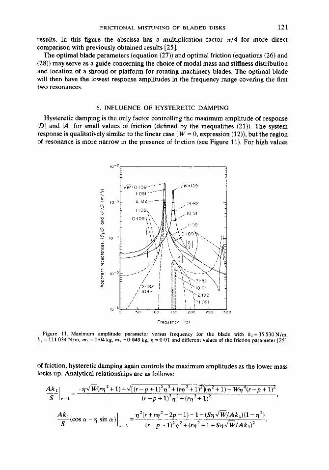
6. INFLUENCE OF HYSTERETIC DAMPING
Hysteretic damping is the only factor controlling the maximum amplitude of response ID/ and IAl for small values of friction (defined by the inequalities (21)). The system response is qualitatively similar to the linear case ( W = 0, expression (12)), but the region of resonance is more narrow in the presence of friction (see Figure 11). For high values
z 2 - 10-3 3 ” T 0
5 0 - 10-4 E 2 e 0 ; ; aI 10-5 G ::
cl
10C6 0 50 100 150 200 250 300
Frequency f Hz)
Figure 11. Maximum amplitude parameter versus frequency for the blade with kl =35 53ON/m, k2 = 111 034 N/m, ml = 0.04 kg, m2 = 0.049 kg, v = 0.01 and different values of the friction parameter [25].
of friction, hysteretic damping again controls the maximum amplitudes as the lower mass locks up. Analytical relationships are as follows:
Akl -~JW(r~2+1)+~[(~-p+1)2~2+(~2++)21(772+1)-Wrl4(~-~+~) 2 - =
S v=l (r-p+1)2~2+(rn2+1)2 ,
Akl - S(
cosa-n sina) =n2(r+rn2-2P-l)-l-(Sr)Jv/Aki)(1-n2)
v=l (r-P-1)2n2+(r772+1+SnJ~/Akr)2 ’
122 A. MUSZYtiSKA AND D. I. G. JONES
Assuming that n CC 1 one has
Akl -I ++,-,JF, Akl s(cos~-7j sin(v) :
WlIS) s v=l .=1=(Ak,/S)+qv’%
and from equation (10)
WlIS) _= hi. (AkdS)+dW
(30)
One knows that the solution (3) with friction exists only in the limited region described by the numerator of equation (8):
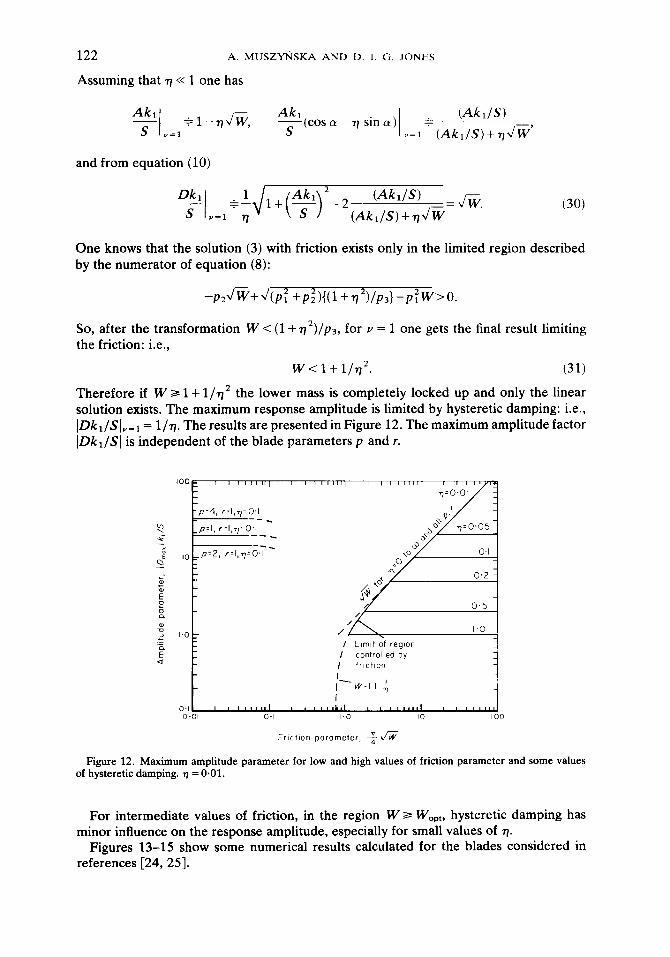
So, after the transformation W < (1 +n2)/p3, for v = 1 one gets the final result limiting the friction: i.e.,
w<l+l/n? (31)
Therefore if W 3 1 + l/n2 the lower mass is completely locked up and only the linear solution exists. The maximum response amplitude is limited by hysteretic damping: i.e., IDkl/SIvsl = l/q. The results are presented in Figure 12. The maximum amplitude factor IDkl/SI is independent of the blade parameters p and r.
p=4, r=I,q=O.I --_
p=l, 1=1,1)20-l --- F --- P’2, r=l,q=O.I
I Llmlt Of regmn
I controlled by
I friction
I- w:1++
I 0.01 0.1 I.0 10 100
Frlctlon parameter, 5 fi
Figure 12. Maximum amplitude parameter for low and high values of friction parameter and some values of hysteretic damping. TJ = 0.01.
For intermediate values of friction, in the region W 3 Wept, hysteretic damping has minor influence on the response amplitude, especially for small values of 7.
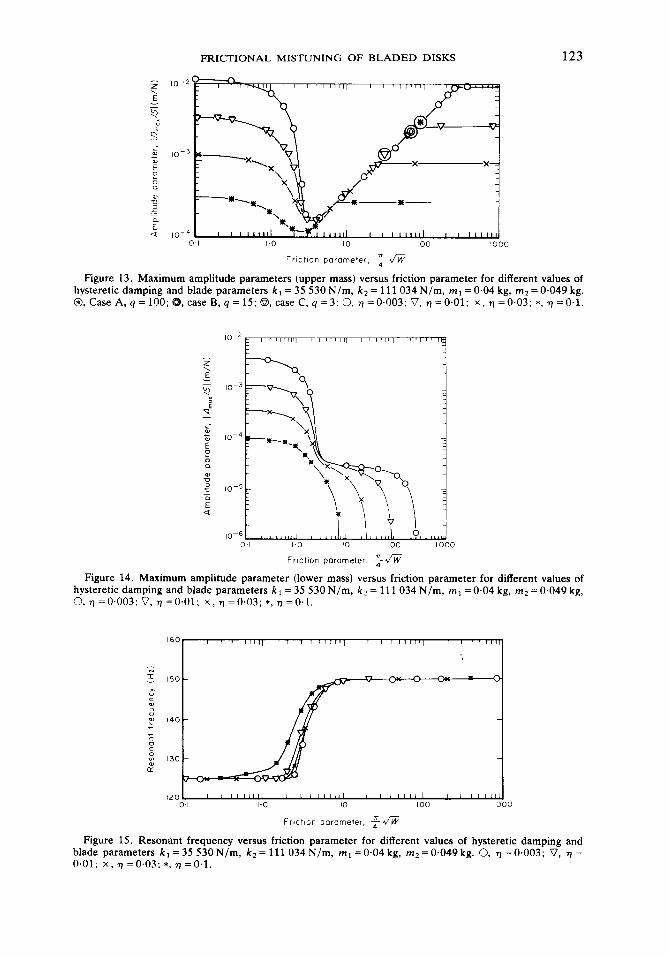
Figures 13-15 show some numerical results calculated for the blades considered in references [24,25].
FRICTIONAL MISTUNING OF BLADED DISKS 123
10.
2
3
-af-
4
0.1 I.0 IO 100 1000
Fr~ctlon parameter. $ fi
Figure 13. Maximum amplitude parameters (upper mass) versus friction parameter for different Values of hysteretic damping and blade parameters kr = 35 530 N/ m, k2 = 111034 N/m, mr = 0.04 kg, mz = 0.049 kg. 0, Case A, q = 100; case R, q = 15; @, case C, q =3; 0, 7 =0.003; V, r) ~0.01; X, q ~0.03; *, 7 =O’l.
Frlctnn parameter, *-J”i;
Figure 14. Maximum amplitude parameter (lower mass) versus friction parameter for different values of hysteretic damping and blade parameters kt = 35 530 N/m, k2 = 111 034 N/m, ml = 0.04 kg, rnz = 0.049 kg, 0, r) = 0.003; V, r) = 0.01; x, Tj =0.03; *, n = 0.1.
Frlctlon parameter, $ 2/cE;
Figure 15. Resonant frequency versus friction parameter for different values of hysteretic damping and blade parameters k, = 35 530 N/m, kg = 111034 N/m, mt = 0.04 kg, m2 = 0.049 kg. 0, n = 0.003; 0, n = 0.01; x, 7) =0.03; *, n =O.l.
124 A. MUSZYtiSKA AND D. I. ‘3. JONES
7. MISTUNING THROUGH FRICTION ELEMENTS
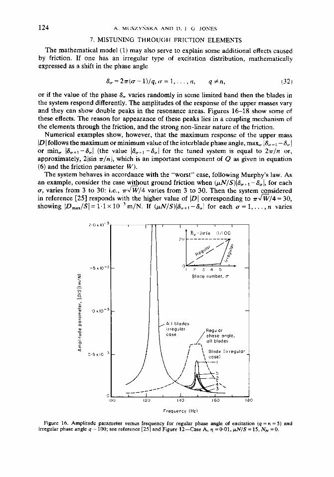
The mathematical model (1) may also serve to explain some additional effects caused by friction. If one has an irregular type of excitation distribution, mathematically expressed as a shift in the phase angle
S,=27r((+-l)/q,a=l,..., It, 4 +fl, (32)
or if the value of the phase S, varies randomly in some limited band then the blades in the system respond differently. The amplitudes of the response of the upper masses vary and they can show double peaks in the resonance areas. Figures 16-18 show some of these effects. The reason for appearance of these peaks lies in a coupling mechanism of the elements through the friction, and the strong non-linear nature of the friction.
Numerical examples show, however, that the maximum response of the upper mass ID] follows the maximum or minimum value of the interblade phase angle, max, I&+r - 8, j or min, ]SV+1 --&,I (the value ISa+l - S,( for the tuned system is equal to 27r/n or, approximately, 2lsin n/n), which is an important component of 0 as given in equation (6) and the friction parameter W).
The system behaves in accordance with the “worst” case, following Murphy’s law. As an example, consider the case w@out ground friction when (@r/S)]8,+1 -&I, for each u, varies from 3 to 30: i.e., 7rJW/4 varies from 3 to 30. Then the system considered in reference [25] responds with the higher value of IDI corresponding to r JW/4 = 30, showing ]D,,,/S] = 1.1 x 10e3 m/N. If (pN/S)IS,+r -&,I for each CT = 1, . . . , n varies
Blade number, u
, All blades
140
Frequency (Hz)
160 0
Figure 16. Amplitude parameter versus frequency for regular phase angle of excitation (q = n = 5) and irregular phase angle q = 100; see reference [25] and Figure 12-Case A, 9 = 0.01, pN/S = 15, NN = 0.
FRICTIONAL MISTUNING OF BLADED DISKS 125
2.0 x lo-
I.5 x lo-
z \ E
G s -
, r
2,3,4 J
-
I
2Tr __-----___
‘) u 123451
Blade number, c
II- 5
Frequency (Hz)
160
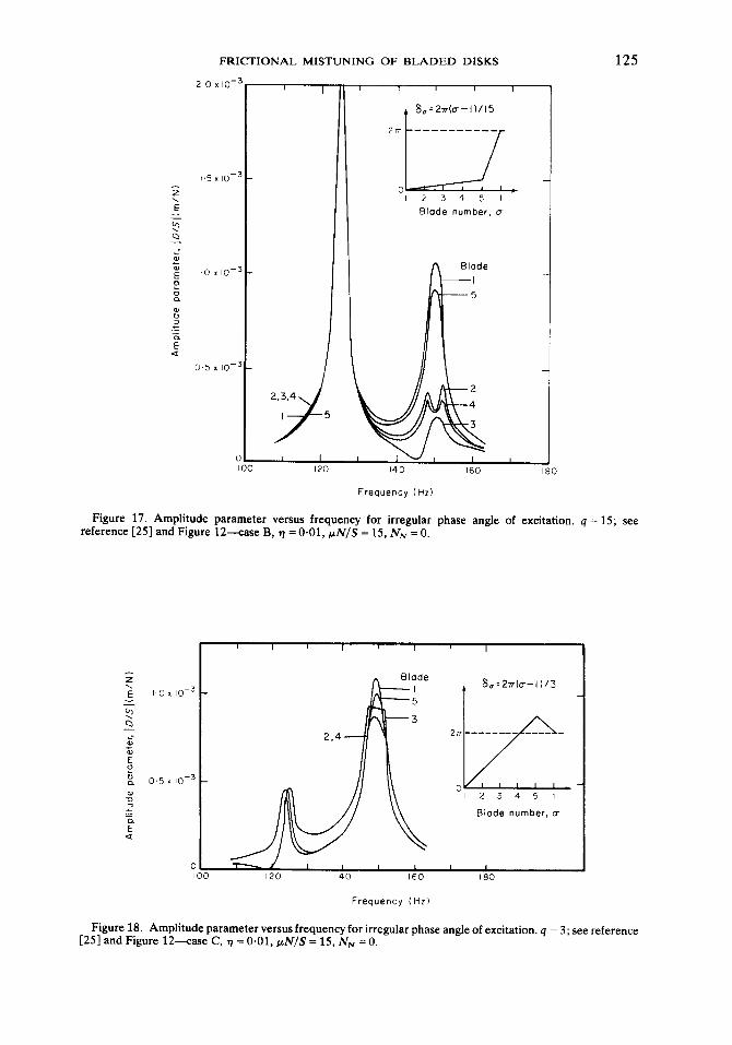
Figure 17. Amplitude parameter versus frequency for irregular reference [25] and Figure 12-ease B, 7 = 0.01, wN/S = 15, NN = 0.
phase angle of excitation. q = 15; see
Blade number, CT
Frequency (Hz)
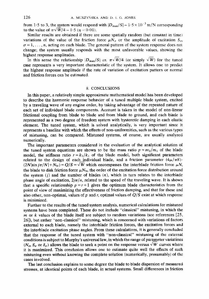
Figure 18. Amplitude parameter versus frequency for irregular phase angle of excitation. q = 3; see reference [25] and Figure 12-ease C, t) = 0.01, pN/S = 15, N+, = 0.
126 A. MUSZYrjSKA AND I>. 1. G. JONES
from 1.5 to 3, the astern would respond with lD,,,/Sl = 1.5 x 10 ~’ m/N corresponding to the value of &W/4 = 1.5 (n = 0.01).
Similar results are obtained if there are some spatially random (but constant in time) variations of the value of the friction force pN, or the amplitude of excitation S,,, ff=l,..., n, acting on each blade. The general pattern of the system response does not change; the system usually responds with the most unfavorable values, showing the highest response amplitudes.
In this sense the relationship lD,,,/SJ vs. 7rJW/4 (or simply JW) for the tuned case represents a very important characteristic of the system. It allows one to predict the highest response amplitude if the rate of variation of excitation pattern or normal and friction forces can be estimated.
8. CONCLUSIONS
In this paper, a relatively simple approximate mathematical model has been developed to describe the harmonic response behavior of a tuned multiple blade system, excited by a traveling wave of any engine order, by taking advantage of the repeated nature of each set of individual blade components. Account is taken in the model of non-linear frictional coupling from blade to blade and from blade to ground, and each blade is represented as a two degree of freedom system with hysteretic damping in each elastic element. The tuned system, which is solved analytically, is very important since it represents a baseline with which the effects of non-uniformities, such as the various types of mistuning, can be compared. Mistuned systems, of course, are usually analyzed numerically.
The important parameters considered in the evaluation of the analytical solution of the tuned system equations are shown to be the mass ratio p = m2/m1 of the blade model, the stiffness ratio r = kz/kl of the blade model, both significant parameters related to the design of eachjndividual blade, and a friction parameter (4~/7rS)- (2Nlsin jm/N] + NN) = Q/S = 4 W which encompasses the interblade friction force HN, the blade to disk friction force pNN, the order of the excitation force distribution around the system (i) and the number of blades (n), which in turn relates to the interblade phase angle of excitation, 2j7r/n, related to the speed of the traveling wave. It is shown that a specific relationship p = r + 1 gives the optimum blade characteristics from the point of view of maximizing the effectiveness of friction damping, and that for these and also other, non-optimal, values of p and r, optimal values of Q/S exist at which response is minimized.
Further to the results of the tuned system analysis, numerical calculations for mistuned systems have been completed. These do not include “classical” mistuning, in which the m or k values of the blade itself are subject to random variations (see references [25, 26]), but rather “non-classical” mistuning, which is concerned with variations of factors external to each blade, namely the interblade friction forces, the excitation forces and the interblade excitation phase angles. From these calculations, it is generally concluded that the response of the tuned system with “non-classical” mistuning of the external conditions is subject to Murphy’s universal law, in which the range of parameter variations (N, S, or 8,) allows the blade to seek a point on the response versus fi curves where it is maximized. This conclusion allows one to estimate quite well the effects of such mistuning even without knowing the complete solution (numerically, presumably) of the cases involved.
The last conclusion explains to some degree the blade to blade dispersion of measured stresses, at identical points of each blade, in actual systems. Small differences in friction
FRICTIONAL MISTUNING OF BLADED DISKS 127
force value and/or excitation force amplitude or phase may lead to significant variations of the response amplitudes and related stresses.
ACKNOWLEDGMENTS
The work described in this paper was conducted under AF project 2307P102 and Contract No. AF-33615-79-C-5129. Thanks are due to R. Mihaloew and L. Whitford of the ASD Computer Center for computational support, and to R. Lemaster, AFWAL/MLLN, and L. Farren, University of Dayton Research Institute, for assistance with preparation of the manuscript.
REFERENCES
1. R. D. C. PASSEY 1976 Progess in Aerospace Science 17, 67-92. Reliability of compressor aerofoils.
2. H. PEARSON 1953 Proceedings of the 4th Anglo-American Aeronautics Conference, London, pp. 127-162. Aerodynamics of compressor blade vibration.
3. C. E. DANFORTH 1975 Journal of Aircraft 12, 333-342. Blade vibration, some key elements in design verification.
4. D. I. G. JONES and C. M. CANNON 1975 American Institute of Aeronautics and Astronautics, Journal of Aircraft 12, 226-229. Control of gas turbine stator blade vibration by means of enamel coatings.
5. E. J. WILLIAMS and S. W. E. EARLES 1973 American Society of Mechanical Engineers Paper 73-DET- 108. Optimization of the response of frictionally damped beam type structures with reference to gas turbine compressor blading.
6 J. H. GRIFFIN 1979 American Society ofMechanical EngineersPaperNo. 796-GT- 109. Friction damping of resonant stresses in gas turbine engine air foils.
7. D. I. G. JONES and A. MUSZY&KA 1979 Shock and Vibration Bulletin 49, 87-96. Design of turbine blades for effective slip damping at high rotational speeds.
8. D. A. RIMKUNAS and H. M. FRYE 1979 AFAPL-TR-79-2054. Investigation of fan blade shroud mechanical damping.
9. B. SADIGHI 1977 M.Sc. Thesis, Imperial College of Science and Technology, London. An analysis of root flexibility effects on turbine blade vibration characteristics.
10. R. L. BIELAWA 1977 American Society of Mechanical Engineers Paper 77-DET-73. An analytic study of the energy dissipation of turbomachinery bladed disk assemblies due to inter-shroud segment rubbing.
11. A. V. SRINIVASAN (Editor) 1976 Proceedings of the American Society ofMechanicalEngineers Winter Annual Meeting. Structural dynamic aspects of bladed disk assemblies.
12. E. K. ARMSTRONG 1967 American Society of Mechanical Engineers, Journal of Engineering for Power 89, 437-444. Recent blade vibration techniques.
13. A. A. MIKOLAJEZAK, R. A. ARNOLDI, L. E. SYNDER and H. STARGARDTER 1975 American Institute of Aeronautics and Astronautics, Journal of Aircraft 12,325-332. Advances in fan and compressor blade flutter analysis and predictions.
14. K. R. V. KAZA and R. E. KIELB 1981 Presented at the AIAAIASME Structures, Structural Dynamics and Materials Conference, Atlanta, Georgia, April 1981. Blade mistuning effects on the coupled bending-torsion flutter and response in a cascade.
15. D. J. EWINS 1973 Journal of Mechanical Engineering Science 15, 165-185. Vibration charac- teristics of blade disk assemblies.
16. L. E. EL-BAYOUMY and A. V. SRINIVASAN 1975 American Institute of Aeronautics and Astronautics Journal 13,460-464. Influence of mistuning on rotor blade vibration.
17. A. L. SALAMA and M. PETYT 1977 American Society of Mechanical Engineers Paper 77-DET- 70. Dynamic response of packets of blades by the finite element method.
18. R. F. C. DYE and T. A. HENRY 1969 American Society of Mechanical Engineering, Journal of Engineering for Power 91, 182. Vibration amplitudes of compressor blades resulting from scatter in blade natural frequencies.
19. A. W. LEISSA 1981 Applied Mechanics Reviews 34, 629-635. Vibrational aspects of rotating turbomachinery blades.
128 A. MUSZYtiSKA AND D. I. G. JONES
20. J. S. RAO 1980 Shock and Vibration Digest 12, 19-26. Turbomachine blade vibration. 21. T. MIYACHI, S. HOSHIYA, Y. SOFUE, S. AMIHOSHI, T. IWABU and K. TAKEDA 1969
National Aerospace Laboratory NAL-TR- 176. On the vibration of axial-flow turbomachine blades, Part 1: Natural frequency, mode and vibratory stress distribution (in Japanese).
22. H. STARGARDTER 1977 American Society of Mechanical Engineering, Journal of Engineering for Power 99, 204-210. Optical determination of rotating fan blade deflections.
23. A. V. SRINIVASAN and H. M. FRYE, 1976 in Proceedings of the American Society of Mechanical Engineers Winter Annual Meeting (A. V. Srinivasan editor) 57-71. Effects of mistuning on resonant stresses of turbine blades.
24. A. MUSZY&KA, D. I. G. JONES, T. LAGNESE and L. WHITFORD 1981 Shock and Vibration Bulletin 51, 89-l 10. On nonlinear response of multiple blade systems.
25. A. MUSZYIQSKA and D. I. G. JONES, 1981 American Society of Mechanical Engineers Paper 81-DET- 137, Proceedings of the ASME Design Engineering Conference, Hartford, Connecticut. A parametric study of dynamic response of a discrete model of turbomachinery bladed disk.
26. A. MUSZYIQSKA 1981 University of Dayton Research Institute, Dayton,’ Ohio, Report No. 93881-09. Coupled bladed-disk lumped parameters study.
27. D. I. G. JONES and A. MUSZY&SKA 1977 American Society of Mechanical Engineers Paper 77- WA/GT-3. Effect of slip damping on response of a vibrating compressor blade.
28. D. I. G. JONES and A. MUSZYASKA 1978 Shock and Vibration Bulletin 48,53-61. Vibration of a compressor blade with slip at the root.
29. D. I. G. JONES and A. MUSZYIQSKA 1978 Proceedings of ICNO Conference on Nonlinear Oscillation, Prague. Nonlinear modelisation of nonconservative blade vibration response.
30. A. MUSZY~~SKA and D. I. G. JONES 1979 Proceedings of the 5th World Congress on Theory of Machines and Mechanisms, Montreal, Canada. On discrete modelization of response of blades with slip and hysteretic damping.
31. R. PLUNKED 1980 in Damping Applications for Vibration Control, ASME Publication AMD-Volume 38 (editor P. J. Torvik), pp. 65-74. Friction damping.
32. D. I. G. JONES 1980 Air Force Wright Aeronautical Laboratory, AFWAL-TR-80-4003. Vibrations of a compressor blade with slip at the root.
A D . .
kLi=l,2 m, i = 1,2
; NN p = m2lm1 PI, I= 1,293 4 Q r = k2/kl S t W = (Qf S)= xi0 (t), i = 1, 2; u = 1, 2, a
&o=l,...,n 9 CL v = m1w2/k1 u w
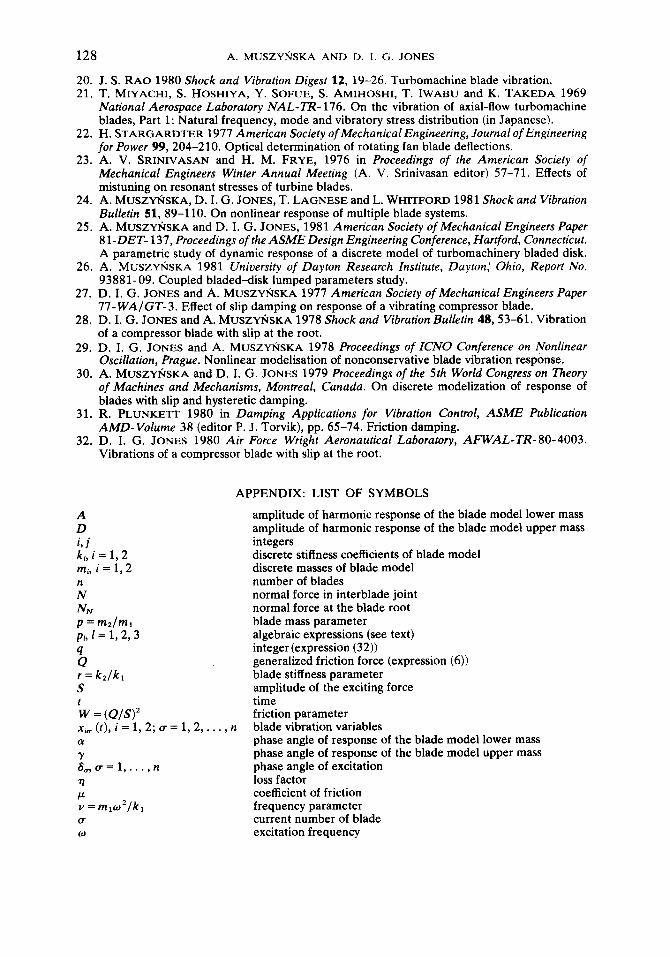
APPENDIX: LIST OF SYMBOLS
amplitude of harmonic response of the blade model lower mass amplitude of harmonic response of the blade model upper mass integers discrete stiffness coefficients of blade model discrete masses of blade model number of blades normal force in interblade joint normal force at the blade root blade mass parameter algebraic expressions (see text) integer(expression (32)) generalized friction force (expression (6)) blade stiffness parameter amplitude of the exciting force time friction parameter
, n blade vibration variables phase angle of response of the blade model lower mass phase angle of response of the blade model upper mass phase angle of excitation loss factor coefficient of friction frequency parameter current number of blade excitation frequency
Related Documents