On the Choice of Tool Material in Friction Stir Welding of Titanium Alloys Gianluca Buffa, Livan Fratini and Fabrizio Micari Dept. of Dept. of Chemical, Management, Computer Science and Mechanical Engineering University of Palermo Palermo, Italy Luca Settineri Department of Production Systems and Business Economics Polytechnic University of Turin ABSTRACT Friction Stir Welding (FSW) is a solid state welding process patented in 1991 by TWI; initially adopted to weld aluminum alloys, is now being successfully used also for magnesium alloys, copper and steels. The wide diffusion the process is having is due to the possibility to weld both materials traditionally considered difficult to be welded or “unweldable” by traditional fusion welding processes due to peculiar thermal and chemical material properties, and complex geometries as sandwich structures and straightening panels. Recently, research is focusing on titanium alloys thanks to the high interest that such materials are getting from the industry due to the extremely high strength-weight ratio together with good corrosion resistance properties. At the moment, the main limit to the industrial applicability of FSW to titanium alloys is the tool life, as ultra wear and deformation resistant materials must be used. In this paper a, experimental study of the tool life in FSW of titanium alloys sheets at the varying of the main process parameters is performed. Numerical simulation provided important information for the fixture design and analysis of results. Tungsten and Rhenium alloy W25Re tools are found to be the most reliable among the ones considered. KEYWORDS Friction Stir Welding, Titanium Alloys, Tungsten alloys, tool life. INTRODUCTION During the last decade, the use of alloys characterized by large resistance-weight ratios has been selected as the best technical solution for automotive as well as aerospace and aeronautical industries. However, besides the several advantages they provide - as increase in the active and passive safety, reduction of fuel consumption and environmental impact - these materials present a few drawbacks that must be properly taken into account. In particular, they are often characterized by lower ductility with respect to steels, anisotropy and are considered difficult to be welded or “non weldable”. At the moment, traditional fusion welding processes for materials as aluminum, magnesium and titanium alloys is often characterized by the insurgence of defects like porosities and inclusions [1], [2]. In particular, as far as titanium alloys are regarded, further issues are the elevated distortion in the welded joints due to the high temperatures reached and the phase change. Among the alternative processes proposed, Friction Stir Welding (FSW) appears as one of the most promising continuous joining techniques. FSW is a solid state weld process invented in 1991 in which the effectiveness of the obtained joint is strongly affected by several geometrical and technological parameters; in particular both rotating speed and feed rate have to be properly chosen in order to obtain effective joints [3], [4]. During the process, the tool rotation speed (R) and feed rate (Vf) are combined in a way that an asymmetric metal flow is obtained. In particular, an advancing side and a retreating side are observed: the former being characterized by the “positive” combination of the tool feed rate and of the peripheral tool velocity while the latter having velocity vectors of feed and rotation opposite to each other. Hence the tool action is the main responsible for both the material softening and the material flow resulting in the weld of the two workpieces. Based on the above description, it is clear how the tool plays a key role in the process. In particular, it must possess good mechanical properties at the temperatures reached during the process, being thus Proceedings of NAMRI/SME, Vol. 40, 2012

Welcome message from author
This document is posted to help you gain knowledge. Please leave a comment to let me know what you think about it! Share it to your friends and learn new things together.
Transcript

On the Choice of Tool Material in Friction Stir Welding of
Titanium Alloys
Gianluca Buffa, Livan Fratini and Fabrizio Micari
Dept. of Dept. of Chemical, Management, Computer Science and Mechanical Engineering
University of Palermo
Palermo, Italy
Luca Settineri
Department of Production Systems and Business Economics
Polytechnic University of Turin
ABSTRACT
Friction Stir Welding (FSW) is a solid state welding process patented in 1991 by TWI; initially adopted to weld aluminum
alloys, is now being successfully used also for magnesium alloys, copper and steels. The wide diffusion the process is having
is due to the possibility to weld both materials traditionally considered difficult to be welded or “unweldable” by traditional
fusion welding processes due to peculiar thermal and chemical material properties, and complex geometries as sandwich
structures and straightening panels. Recently, research is focusing on titanium alloys thanks to the high interest that such
materials are getting from the industry due to the extremely high strength-weight ratio together with good corrosion
resistance properties. At the moment, the main limit to the industrial applicability of FSW to titanium alloys is the tool life, as
ultra wear and deformation resistant materials must be used. In this paper a, experimental study of the tool life in FSW of
titanium alloys sheets at the varying of the main process parameters is performed. Numerical simulation provided important
information for the fixture design and analysis of results. Tungsten and Rhenium alloy W25Re tools are found to be the most
reliable among the ones considered.
KEYWORDS
Friction Stir Welding, Titanium Alloys, Tungsten alloys, tool life.
INTRODUCTION
During the last decade, the use of alloys characterized
by large resistance-weight ratios has been selected as the
best technical solution for automotive as well as aerospace
and aeronautical industries. However, besides the several
advantages they provide - as increase in the active and
passive safety, reduction of fuel consumption and
environmental impact - these materials present a few
drawbacks that must be properly taken into account. In
particular, they are often characterized by lower ductility
with respect to steels, anisotropy and are considered
difficult to be welded or “non weldable”.
At the moment, traditional fusion welding processes for
materials as aluminum, magnesium and titanium alloys is
often characterized by the insurgence of defects like
porosities and inclusions [1], [2]. In particular, as far as
titanium alloys are regarded, further issues are the elevated
distortion in the welded joints due to the high temperatures
reached and the phase change. Among the alternative
processes proposed, Friction Stir Welding (FSW) appears
as one of the most promising continuous joining techniques.
FSW is a solid state weld process invented in 1991 in which
the effectiveness of the obtained joint is strongly affected
by several geometrical and technological parameters; in
particular both rotating speed and feed rate have to be
properly chosen in order to obtain effective joints [3], [4].
During the process, the tool rotation speed (R) and feed rate
(Vf) are combined in a way that an asymmetric metal flow
is obtained. In particular, an advancing side and a retreating
side are observed: the former being characterized by the
“positive” combination of the tool feed rate and of the
peripheral tool velocity while the latter having velocity
vectors of feed and rotation opposite to each other. Hence
the tool action is the main responsible for both the material
softening and the material flow resulting in the weld of the
two workpieces. Based on the above description, it is clear
how the tool plays a key role in the process. In particular, it
must possess good mechanical properties at the
temperatures reached during the process, being thus
Proceedings of NAMRI/SME, Vol. 40, 2012

characterized by significantly larger melting temperature
and ultimate tensile strength with respect to the material to
be welded.
Nowadays, the process can be considered mature for
light materials as aluminum and magnesium alloys and it is
already being utilized for automotive, aeronautical, civil
and naval industrial applications for different joint
morphologies [5], [6], [7]. However, as far as titanium
alloys are regarded, difficulties arise for the application of
the process because of the chemical, mechanical and
thermal peculiar properties of these materials. Due to the
low thermal conductivity [7 W/mK], resulting in a non
uniform temperature distribution and in a significant
thermal gradient along the joint thickness, the effectiveness
of the joint can be compromised as most of the heat is
generated on the top surface of the joint, i.e. the contact
surface between the tool shoulder and the sheets. For such
reasons a specifically designed clamping fixture must be
designed. Additionally, the high reactivity of titanium with
atmospheric gas – hydrogen, oxygen and nitrogen –
requires a shield inert gas protection for the weld in order to
avoid the formation of very hard oxides on the top surface
of the sheets to be welded right where the tool is deforming
and welding the material.
Finally, due to the high temperatures and contact forces
between the sheets and the tool, the choice is limited to
ultra resistant, high melting and high cost tool materials. In
[8] friction stir welding of L80 steel was investigated with
experiments and modeling. Severe tool deformation and
some wear were observed when commercially pure
tungsten was used. Finite element analysis (FEA) was used
to predict the mushrooming of the tool. The temperature
histories in the weld region and tool forces were measured
and supplied to a finite element model. The simulated pin
deformation matched the experimental observation. Using
this model and optimization techniques, the required yield
strength of the pin material is estimated to be 400 MPa at
1000°C to avoid mushrooming. At the moment, in spite of
the recent research efforts, this issue appears as the most
severe limitation to the industrial applicability of FSW to
titanium alloys as significant deformation can be found on
the tool itself even after only a few millimeters of weld
length.
In the recent years to two main categories of materials
have been utilized: ceramic and refractory metal alloys.
Among the former the most commonly utilized are
Polycrystalline cubic Boron Nitride (PcBN); although good
results have been reached, for a wide industrial utilization
of such materials the main limitations consist in the
extremely elevated costs as well as in the significant
brittleness that may lead to unexpected failures [9]. In [10]
friction stir welding was applied to commercial purity
titanium using a polycrystalline cubic boron nitride tool,
and microstructure and hardness in the weld were
examined. Additionally, the microstructural evolution
during friction stir welding was also discussed. The stir
zone consisted of fine equiaxed α grains surrounded by
serrate grain boundaries, which were produced through the
β → α allotropic transformation during the cooling cycle of
friction stir welding. The fine α grains caused higher
hardness than that in the base material. A lath-shaped α
grain structure containing Ti borides and tool debris was
observed in the surface region of the stir zone, whose
hardness was the highest in the weld. In [11] it is stated that
for ferrous alloys, FSW tool material development is at the
heart of the advancement of this novel joining technique.
Polycrystalline cubic boron nitride (PCBN) materials,
produced via high pressure and high temperature (HPHT)
process, have demonstrated good performance in FSW
applications. Thus, it is becoming more practical to friction
stir weld high melting temperature materials such as
stainless steels and alloy steels. The performance of FSW
materials is highly dependent on the design of material
system. This manuscript presents findings on correlations
between material properties and material design such as the
choice of binder phases and matrix and their subsequent
interactions with ultra-hard particles.
Among the refractory metal alloys researchers focused
their attention on Co based and, above all, W based alloys.
In this way a significant cost saving can be achieved,
opening the doors to a full industrial application of the
process. Unfortunately higher wear and deformation are
observed for these materials; hence a detailed investigation
on their performance during the welding process is needed.
In [12] the authors developed a new friction stir welding
(FSW) tool that enables welding of high-softening-
temperature materials, such as steels, and titanium alloys.
The new tool is made of a Co-based alloy strengthened by
precipitating intermetallics, Co3(Al,W), with an Ll2
structure at high temperatures. The Co-based alloy tool can
be manufactured at a low cost through a simple production
method consisting of casting, heat-treatment, and then
machining. It exhibits yield strengths higher than 500 MPa
at 1000°C, so that it might have great potential as a FSW
tool for hard materials. In this study, the feasibility to use
the Co-based alloy tool to friction stir weld various high-
softening-temperature materials was examined through the
analysis of the changes in tool shape during the process and
the weld appearances produced. It should be observed that
there is a great emphasis on the development of friction stir
welding (FSW) tools that are resistant to wear while joining
high-temperature materials such as iron, titanium and
nickel-based alloys. Wear mechanisms may include
deformation, abrasive, and/or adhesive phenomena. In [13]
and [14] three different W based materials, were tested
performing, with the same tool geometry, FSW tests in the
worst, i.e. coldest, conditions on very thick high strength
steel (HSS) plates. The probability of adhesive wear
between tool and substrate material was evaluated using
computational thermodynamics and kinetics models.
Adhesive wear was described as diffusion couple between
tool and substrate materials. First, the combination of
Proceedings of NAMRI/SME, Vol. 40, 2012
tungsten tool and titanium base metal was evaluated. The
experimental data and calculations showed rapid rate of
cross-diffusion at FSW temperatures. Secondly, the
combination of tungsten tool and steel was evaluated. The
calculations showed minimal degradation due to cross-
diffusion. However, microstructural characterization
showed alloying of steel with tungsten. Finally the
deformation of the welding tools was evaluated finding
minimum tool degradation for W25Re and W-Re-hafnium
carbon (HfC) tools.
In the paper a quantitative analysis of the tool life in
FSW of 3 mm thick Ti-6V-4Al titanium alloy sheets is
presented. Three different W based materials have been
selected, and each of them was tested under three different
process conditions till the complete failure of the tool
occurred. An already developed numerical model of the
process was utilized both to set up the welding fixture and
to provide explanations for the obtained results.
EXPERIMENTS
Ti–6Al–4V titanium alloy sheets 100 mm x 200 mm
and 3 mm thick were welded together under different
process conditions. In particular rotating speeds of 300, 700
and 1000 rpm were selected, based on a previously
developed campaign [15]. Fixed advancing speed equal to
35 mm/min, nuting angle equal to 2° and tool shoulder
sinking of 0.2 mm were considered for all the welds. The
tool sinking speed was kept constant and equal to 0.6
mm/min for all the welds. It is worthy notice that this
parameter is crucial for the tool life, being the sinking stage
the most dangerous for the tool as it is in contact with the
still cold titanium of the sheets. In this way three different
process conditions, characterized by an increasing Specific
Thermal Contribution (STC) given to the weld, were taken
into account.
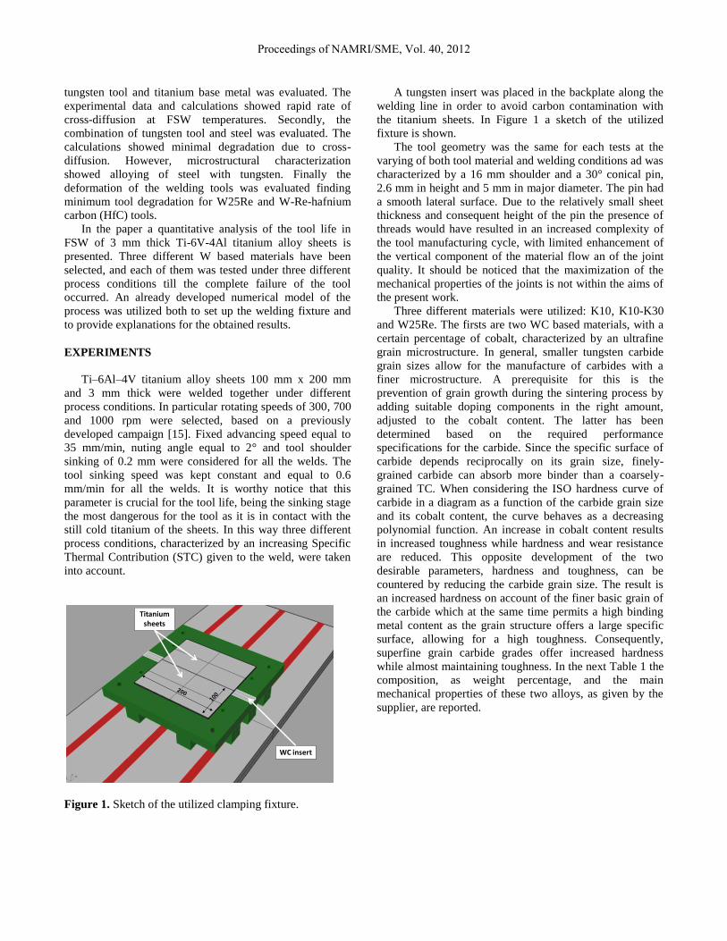
A tungsten insert was placed in the backplate along the
welding line in order to avoid carbon contamination with
the titanium sheets. In Figure 1 a sketch of the utilized
fixture is shown.
The tool geometry was the same for each tests at the
varying of both tool material and welding conditions ad was
characterized by a 16 mm shoulder and a 30° conical pin,
2.6 mm in height and 5 mm in major diameter. The pin had
a smooth lateral surface. Due to the relatively small sheet
thickness and consequent height of the pin the presence of
threads would have resulted in an increased complexity of
the tool manufacturing cycle, with limited enhancement of
the vertical component of the material flow an of the joint
quality. It should be noticed that the maximization of the
mechanical properties of the joints is not within the aims of
the present work.
Three different materials were utilized: K10, K10-K30
and W25Re. The firsts are two WC based materials, with a
certain percentage of cobalt, characterized by an ultrafine
grain microstructure. In general, smaller tungsten carbide
grain sizes allow for the manufacture of carbides with a
finer microstructure. A prerequisite for this is the
prevention of grain growth during the sintering process by
adding suitable doping components in the right amount,
adjusted to the cobalt content. The latter has been
determined based on the required performance
specifications for the carbide. Since the specific surface of
carbide depends reciprocally on its grain size, finely-
grained carbide can absorb more binder than a coarsely-
grained TC. When considering the ISO hardness curve of
carbide in a diagram as a function of the carbide grain size
and its cobalt content, the curve behaves as a decreasing
polynomial function. An increase in cobalt content results
in increased toughness while hardness and wear resistance
are reduced. This opposite development of the two
desirable parameters, hardness and toughness, can be
countered by reducing the carbide grain size. The result is
an increased hardness on account of the finer basic grain of
the carbide which at the same time permits a high binding
metal content as the grain structure offers a large specific
surface, allowing for a high toughness. Consequently,
superfine grain carbide grades offer increased hardness
while almost maintaining toughness. In the next Table 1 the
composition, as weight percentage, and the main
mechanical properties of these two alloys, as given by the
supplier, are reported.
Figure 1. Sketch of the utilized clamping fixture.
Titaniumsheets
WC insert
Proceedings of NAMRI/SME, Vol. 40, 2012
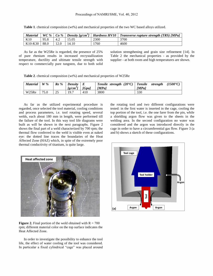
Table 1. chemical composition (wt%) and mechanical properties of the two WC based alloys utilized.
Material WC % Co % Density [g/cm3] Hardness HV10 Transverse rupture strength (TRS) [MPa]
K10 95.8 4.2 15.05 2300 3700
K10-K30 88.0 12.0 14.10 1760 4600
As far as the W25Re is regarded, the presence of 25%
of pure rhenium results in increased recrystallization
temperature, ductility and ultimate tensile strength with
respect to commercially pure tungsten, due to both solid
solution strengthening and grain size refinement [14]. In
Table 2 the mechanical properties - as provided by the
supplier - at both room and high temperatures are shown.
Table 2. chemical composition (wt%) and mechanical properties of W25Re
Material W % Re % Density
[g/cm3]
E
[Gpa]
Tensile strength (20°C)
[MPa]
Tensile strength (1500°C)
[MPa]
W25Re 75.0 25 19.7 410 3800 330
As far as the utilized experimental procedure is
regarded, once selected the tool material, cooling conditions
and process parameters, i.e. tool rotating speed, several
welds, each about 180 mm in length, were performed till
the failure of the tool. In this way tool life diagrams were
built as will be shown in the next paragraphs. Figure 2
shows the final part of a weld characterized by 700 rpm; the
thermal flow conferred to the weld is visible even at naked
eye: the dotted line traces the boundaries of the Heat
Affected Zone (HAZ) which, in spite of the extremely poor
thermal conductivity of titanium, is quite large.
Figure 2. Final portion of the weld obtained with R = 700
rpm; different material color on the top surface indicates the
Heat Affected Zone.
In order to investigate the possibility to enhance the tool
life, the effect of water cooling of the tool was considered.
In particular a fixed cylindrical “cage” was placed around
the rotating tool and two different configurations were
tested: in the first water is inserted in the cage, cooling the
top portion of the tool, i.e. the one farer from the pin, while
a shielding argon flow was given to the sheets in the
welding area. In the second configuration no water was
considered and the argon was introduced directly in the
cage in order to have a circumferential gas flow. Figure 3 (a
and b) shows a sketch of these configurations.
Heat affected zone
Tool cage
Tool holder
Too
l
Argon
ArgonArgon(a)
Proceedings of NAMRI/SME, Vol. 40, 2012

Figure 3. Sketches of the no water (a) and water (b) tool
cooling configurations.
NUMERICAL MODEL
The commercial FEA software DEFORM-3DTM
,
Lagrangian implicit code designed for metal forming
processes, was utilized to investigate the FSW of Titanium
alloys. The numerical simulation was divided into two
stages: the sinking stage and the welding (advancing) one.
During the sinking stage, simulated to reach high enough
temperature level for the subsequent welding process, the
tool moves down vertically at 0.6 mm/sec with the assigned
rotating speed. Then, during welding or advancing stage,
the rotating tool moves along the welding line (seam). As
far as the thermal characteristics of the considered Ti-6Al-
4V alloy are regarded, constant values, taken from literature
[16], [17] were selected. In particular thermal conductivity
equal to 14 [N/s°K] and heat capacity equal to 3.4
[N/mm2°K] were utilized. This assumption makes the
thermal problem linear speeding up the numerical solution
at each time increment.
A temperature, strain and strain rate dependent rigid-
viscoplastic flow stress was used to model the plastic
behavior. Further details on the model and the material data
can be found in [18] and [19]. The tool and the components
of the clamping fixture, namely the backplate and the WC
insert, were modeled as rigid bodies and meshed, for the
thermal analysis, with about 5,000 and 15,000 and 8,000
tetrahedral elements, respectively. The upper part of the
clamping fixture (i.e. the actual clamping system) was
modeled through proper boundary conditions given to the
work-piece. A “single block” continuum model is used to
model the workpiece in order to avoid contact instabilities
due to the intermittent contact at the sheet-sheet interfaces.
The sheet blanks were meshed with about 20,000
tetrahedral elements with single edges of about 0.75mm; in
this way about four elements were placed along the sheet
thickness. A non-uniform mesh with adaptive re-meshing
was adopted with smaller elements close to the tool and a
re-meshing referring volume was identified all along the
tool feed movement [20]. In Figure 4 a close up of the
single block sheet at the end of the sinking stage is shown.
The contact conditions at the tool-workpiece interface
were modeled through a constant interface heat exchange
coefficient of 11[N mm-1
s-1
°C-1
] and a constant shear
friction factor equal to 0.3. The latter was chosen in such a
way to maximize the fitting of the numerical results with
experiments. Details on the contact modeling can be found
in [18] and [20].
As far as the modeling of the two different tool cooling
conditions is regarded, the “no water” case study was
modeled prescribing, for the whole lateral surface of the
tool, a convectional heat exchange with forced gas (see
again Figure 2a) characterized by a coefficient of 2 [N mm-1
s-1
°C-1
]. On the other hand, the water cooled case study was
modeled by dividing the tool lateral surface into three areas:
in the top area thermal exchange with water was considered
through a convection coefficient equal to 15 [N mm-1
s-1
°C-
1]; for the central area no heat exchange with environment
was assigned, being in direct contact with the sealing o-ring
needed in order to avoid water leaking on the sheets to be
welded (see again Figure 2b); finally, forced air convection
was modeled in the bottom area of the tool by a thermal
exchange coefficient equal to 2 [N mm-1
s-1
°C-1
] [17]. In the
following Figure 5 (a and b) the model of the tool is
presented and a sketch of the different areas considered for
thermal exchange phenomena is shown.
Figure 4. Sketch of the continuum sheet model at the
beginning of the welding stage.
Tool cage
Tool holderTo
ol
Water
Argon(b) Argon
Sealingo-ring
Proceedings of NAMRI/SME, Vol. 40, 2012

Figure 5. Tool model and sketch of the different areas
considered for thermal exchange phenomena modeling:
water cooling (a) and no water (b) case studies.
RESULTS
The effectiveness of the tool water cooling was assessed
at the beginning of the experimental campaign with the aid
of the numerical tool. Two simulations, characterized by
tool rotational speed of 700 rpm, were run at the varying of
the thermal exchange conditions as described in the
previous paragraph. Figure 6 shows the obtained
temperature profiles in a longitudinal section of the tool
taken once the process reached the steady state, that is after
the tool advanced for about 22 mm.
Figure 6. Temperature profiles in a tool longitudinal
section after the process reached the steady state (tool
rotation 700 rpm, no water case study).
As it can be observed form the above figure, although
the maximum temperature reached is quite high, the top
area of the tool remains “cold” due to the very poor thermal
conductivity of the WC based alloys. Based on this
observation it was deduced that the possible use of a
coolant chiller would not result in a significant reduction on
the tool temperature. In order to perform a quantitative
comparison between the two case studies, the temperatures
along the tool axis (see the black arrow in Figure 6) have
been collected for both the water and the no water case
study. In the next Figure 7 the obtained curves are shown.
As it could be expected after the analysis of Figure 6, no
significant difference can be observed all along the tool
length; just close to the top of the tool a slightly lower
temperature is calculated for the water case study. Based on
these preliminary results, just one set of experiments was
performed at the varying of the tool cooling conditions. In
particular the K10-K30 tool and rotating speed of 700 rpm
were utilized. Almost identical results were obtained in
terms of tool life, as suggested by the results obtained with
the numerical model, and hence, for the following
experiments, just the no water configuration was taken into
account.
Figure 7. Temperature profiles in a tool longitudinal
section for the water and no water case studies.
As briefly mentioned in the introduction paragraph, the
experimental strategy was to select a tool material and a
process condition, i.e. a tool rotating speed value, being
constant all the other process parameters. Then, several
sheets were welded together, with the given configuration,
till the complete failure of the tool. In this way a certain
number of welds, each of them equal to about 180 mm of
weld length, were performed and the tool life was measured
in terms of meters of welding. The same set up was utilized
Argon
Water
ArgonSealingo-ring
(a) (b)
[°C
]
0
200
400
600
800
1000
1200
0 5 10 15 20 25 30 35
Tem
pe
ratu
re[
C]
Distance from the top of the tool [mm]
Water No water
Proceedings of NAMRI/SME, Vol. 40, 2012

for all the three tool materials and the three process
conditions, obtaining a total of nine different combinations.
In Figure 8 the resulting diagrams are shown.
Figure 8. Tool life – total weld length to failure - at the
varying of tool material and process conditions (tool
rotating speed).
A few important observations can be drawn from the
above figure. First, for the K10 material, no data
corresponding to a rotational speed of 300 rpm is present,
indicating that tool failure occurred during the first weld. It
should be noticed that the test characterized by the K10 tool
material and rotational speed of 300 rpm was repeated three
times and always gave the same result in terms of tool early
failure (the failure mode will be better discussed in the
following). This is due to the combination of two factors:
the brittle behavior of this alloy and the “cold” weld
conditions. As a matter of fact, the lowest rotational speed
corresponds to the lowest STC conferred to the joint, and,
consequently, to a insufficient softening effect of the
titanium sheets as related to this peculiar tool material. By
increasing the STC and keeping the same tool material, a
few sheets could be successfully welded. However, the
overall tool life is very poor, showing the lowest values
among the three materials, and resulting in unacceptable
values for industrial applicability.
As far as the other two materials are regarded, a
significant increase is observed in the tool life. More in
details, all the values obtained at the varying of the tool
rotating speed with the K10-K30 tool are larger than the
maximum obtained with the K10 tool. An analogous
improvement is found when comparing the W2Re tool and
K10-K30 one.
The above described different behavior of the three
materials corresponds to three different failure modes.
Regardless of the process conditions under which they were
utilized, each of the three materials showed the same
morphology at the end of its service. In Figure 9 (a to c) the
pictures of the three broken tools are presented.
Figure 9. Broken tools at the end of their life: (a) K10, (b)
K10-K30 and (c) W25Re.
As it can be seen, the two WC based alloys exhibit a
completely different behavior: K10 shows a typical brittle
fracture due to excess of combined torque, compressive
force, and bending solicitation. Although this alloy is
characterized by larger hardness with respect to the K10-
K30 alloy, it also shows a reduced Transverse Rupture
Strength (TRS) (see again Table 1), which can be easily
connected to fracture toughness. The extreme mechanical
solicitations the tool undergoes to, together with small
vibrations due to random material inhomogeneities and
machine not perfect stiffness, leaded to an early failure.
This phenomenon, as already discussed, is emphasized and
taken to the extreme when the “cold” process conditions are
selected and no weld can be completed.
As far as the K10-K30 alloy is regarded, a ductile
failure mode is observed. Severe deformation progressively
occurs in the shoulder, where, at the end of the tool life, a
significant mushrooming effect is found. Additionally, the
final out of service of the tool is reached when the pin,
previously mushroomed as well, is completely torn away
from the shoulder surface. Finally, visible sign of titanium
adhesive wear are found on the shoulder surface. As a
consequence of the above observations, it arises that the
quality of the welds progressively decreases as the tool
accumulates meters of weld length.
Finally, observing the W25Re tool after failure, no
evident sign of either deformation or adhesive wear is
found. On the contrary, a fracture at mid height of the pin is
visible, resulting in insufficient penetration in the titanium
sheets and in the so called tunnel defect in the welded
joints. In this way it can be stated that the tool went out of
service. However, it should be observed that the broken pin
does not show visible signs of deformation and
mushrooming (Figure 10).
0
5
10
15
20
25
30
35
K10 K10-K30 W25Re
Too
l lif
e [
m]
Tool material
300 700 1000
Broken pin
(a) (b) (c)
Proceedings of NAMRI/SME, Vol. 40, 2012

Figure 10. W25Re tool at about half of its life cycle (≈12
m). 700 rpm case study.
As a consequence, the quality of the welds performed
with this tool is kept about constant during its service. Such
consideration was substantiated by both optical analysis of
the joints and mechanical testing of a few samples
randomly taken during the experimental campaign.
As far as the influence of the process conditions is
regarded, for all the three materials, the shortest life was
found in correspondence of the lowest STC, i.e. with a tool
rotation of 300 rpm. On the other hand, the maximum weld
length was measured with the intermediate STC value.
When the maximum STC was utilized, i.e. when the tool
rotates at 1000 rpm, weld length values in between the two
extremes were observed. In order to explain such behavior
the numerical model was utilized to calculate both the
welding forces and the temperatures reached in the tool.
Thermal data of WC alloys were used for the temperature
calculations. Analogous results were found for the W25Re.
Figure 11 shows the evolution of the vertical force, the
main component in FSW processes, during the weld. It
should be observed that the second major component, i.e.
the advancing one, is usually one order of magnitude lower
than the vertical force [20].
Figure 11. Calculated vertical force vs. time at the varying
of the rotational speed.
The three curves show a decreasing trend till about 40
seconds, corresponding to a tool translation of about 22
mm. As previously mentioned, this is approximately the
distance after which the process reaches the steady state
and, from this moment on, the forces will be quite constant.
As expected, the forces exerted on the tool decrease at the
increasing of the tool rotation due to the increased thermal
flow and, as a consequence, to the enhanced sheets material
softening. However, quite large values are calculated even
for the 1000 rpm case study. Additionally, it can be
observed that at the beginning of the advancing stage, the
magnitude of the forces is significantly larger than the one
calculated for the steady state. This indicates that the final
part of the sinking stage as wells as the initial part of the
welding stage are the process phases during which the tool
experiences the most severe solicitations, ranging the
vertical force between 85 kN and 140 kN. As a matter of
fact, for each of the considered materials and for each of the
considered process conditions, all the tools breakage
occurred during these two phases.
Figure 12. Calculated temperature along the tool axis at the
varying of the rotational speed.
Figure 12 illustrates the temperatures profiles calculated
for the tool along its axis (see again the black arrow in
Figure 6). Starting from the top surface, temperature
assumes similar values for the three configurations. On the
contrary, getting closer to the shoulder surface and the pin,
an appreciable difference is observed, reaching a maximum
value of about 300° between the coldest and the hottest
weld.
It is worthy notice that an increase in the tool rotation,
i.e. an increase in the maximum temperature, results in an
increased thermo-mechanical solicitation and may lead to a
failure of the tool. On the other hand, as observed in Figure
11, at the increasing of the tool rotation the reaction force
transmitted by the sheets to the tool decreases.
0
30
60
90
120
150
0 10 20 30 40
Ve
rtic
al fo
rce
[KN
]
Time [sec]
340 rpm 700 rpm 1000 rpm
0
200
400
600
800
1000
1200
1400
0 5 10 15 20 25 30
Tem
pe
ratu
re [
°C]
Distance from the top of the tool [mm]
340 rpm 700 rpm 1000 rpm
Proceedings of NAMRI/SME, Vol. 40, 2012

These two contrasting effect are summarized in Figure
13, where the maximum temperatures observed in the tool
are plotted together with the steady state force value at the
varying of the tool rotational speed. As anticipated, the
thermal and mechanical solicitations have opposite trends at
the increasing of the tool rotation. A qualitative curve,
taking into account the combined effect of softening and
actual load decreasing was added to the figure in order to
better highlight the presence of a peculiar rotational speed
value – indicated as R* in the figure - minimizing the
overall thermo-mechanical solicitation on the tool. It should
be noticed that no actual minimization procedure was
carried out in this research.
From the above observation it is clear why all the
utilized tools showed the maximum weld length in
correspondence of the intermediate STC value in spite of
the significant reduction in the vertical force observed in
Figure 11.
Figure 13. Maximum tool temperature and steady state
vertical force vs. tool rotation; qualitative overall thermo-
mechanical solicitation on the tool.
SUMMARY & CONCLUSIONS
In the paper an experimental campaign aimed to the
identification of the most suited tool material for Friction
Stir Welding of titanium alloys was developed. 3 mm thick
Ti-6Al-4V titanium alloy sheets were welded together
under three different process conditions. The same tool
design was utilized for all the tests, the effectiveness of
water cooling was assessed and three different ultra
resistant refractory metal alloys were tested.
From the numerical and experimental obtained results
the following main conclusions can be drawn:
Water cooling on the lateral surface of
refractory metal tools does not produce any
significant change in the calculated tool
temperature and no beneficial effect is
observed for the tool life. This is due to the
extremely low thermal conductivity of these
materials. By adopting this tool cooling
configuration, the use of a coolant chiller
would not result in any appreciable
improvement in the heat removal.
All the tools failures were observed between
the end of the sinking stage and the first few
mm of welding. According to the numerical
results, these is the process
Although characterized by a large hardness
value, the K10 material revealed as inadequate
for FSW of titanium alloys as brittle fractures
occur. No weld could be obtained with the low
rotational speed and unsatisfying tool life
values were observed at the increasing of the
tool rotation;
More encouraging results were obtained with
the K10-K30 alloy, characterized by increased
fracture toughness, although severe
deformation was observed in the tool shoulder
and pin during the tool life cycle. This aspect
may seriously compromise the soundness of
the obtained joints;
The best results, both in terms of tool life and
weld quality, were obtained with the W25Re
tool. Satisfying tool life was obtained and no
visible sign of degradation was observed
during the life cycle;
All the tools showed the largest weld length for
an intermediate tool rotation value due to the
concurrent effect of the force acting on the tool
itself and the temperatures it experiences
during the process.
After the preliminary screening of tool materials here
presented, in the future the authors will focus their research
activity on the W25Re alloy. Further developments include
a quantitative analysis of the abrasive and adhesive wear on
the W25Re tool as well as an implementation of the wear
phenomenon in the numerical model.
REFERENCES
[1] Liu, H.J., Fujii, H., Maeda, M., Nogi, K., 2003,
Tensile properties and fracture locations of friction-
stir-welded joints of 2017-T351 aluminum alloy, J.
of Mat. Proc. Tech., 142: 692–696
[2] Winter, E.F.M., Sharp, M.L., Nordmark, G.E.,
Banthia, V.K., 1990, Design considerations for
aluminium spaceframe automotive structures, SAE
technical series, Report No 905178.
R*
Thermo-mechanical load on tool
Proceedings of NAMRI/SME, Vol. 40, 2012

[3] Rhodes, C.G., Mahoney, M.W., Bingel, W.H.,
Spurling, R.A., Bampton, C.C., 1997, Effects of
Friction Stir Welding on Microstructure of 7075
Aluminum, Scripta Materialia, 36: 69-75
[4] Guerra, M., Schmidt, C., McClure, L.C., Murr, L.E.,
Nunes, A.C., 2003, Flow patterns during friction stir
welding, Mater Charact, 49: 95-101
[5] Fratini, L., Buffa, G., Shivpuri, R., 2010,
Mechanical and metallurgical effects of in process
cooling during friction stir welding of AA7075-T6
butt joints, Acta Mater., 58: 2056
[6] Fratini, L., Buffa, G., Micari, F., Shivpuri, R., 2009,
On the material flow in FSW of T-joints: Influence
of geometrical and tecnological parameters, Int. J. of
Adv. Manuf. Technol., 44: 570
[7] Buffa, G., Campanile G., Fratini, L., Prisco, A.,
2009, Friction stir welding of lap joints: Influence of
process parameters on the metallurgical and
mechanical properties, Mater. Sci. and Eng. A, 519:
19.
[8] Gan, W., Li, Z.T., Khurana, S., 2007, Tool
mushrooming in friction stir welding of L80 steel,
TMS Annual Meeting, 279-283.
[9] Mahoney, M., Nelson, T., Sorenson, C., Packer, S.,
2010, Friction Stir Welding of Ferrous Alloys:
Current Status, Materials Science Forum, 638-642:
41-46.
[10] Zhang, Y., Sato, Y.S., Kokawa, H., Park, S.H.C.,
Hirano, S., 2008, Stir zone microstructure of
commercial purity titanium friction stir welded using
pcBN tool, Materials Science and Engineering A,
488 (1-2): 25-30.
[11] Liu, Q., Steel, R., Peterson, J., Horman, S., Collier,
M., Marshall, D.B., Davis, J.B., (...), Mahoney, M.,
2010, Advances in friction stir welding tooling
materials development, Proceedings of the
International Offshore and Polar Engineering
Conference, 4: 298-302.
[12] Sato, Y.S., Miyake, M., Kokawa, H., Omori, T.,
Ishida, K., Imano, S., Park, S.H.C., Hirano, S., 2011,
Development of a cobalt-based alloy FSW tool for
high-softening-temperature materials, 2011 TMS
Annual Meeting , 3-9.
[13] Thompson, B.T., Babu, S.S., Lolla, T., 2011,
Application of diffusion models to predict FSW tool
wear Proceedings of the International Offshore and
Polar Engineering Conference , 520-526
[14] Thompson, B., Babu, S.S., 2010, Tool degradation
characterization in the friction stir welding of hard
metals, Welding Journal (Miami, Fla), 89 (12): 256s-
261s.
[15] Fratini, L., Micari, F., Buffa, G., Ruisi, V.F., 2010,
A new fixture for FSW processes of titanium alloys,
CIRP Annals - Manufacturing Technology,
59(1):271-274
[16] Hot Working Guide – A compendium processing
maps (1997) ASM Interantional.
[17] Deform 3D user manual. SFTC.
[18] Fratini, L., Beccari, S ., Buffa, G., 2005, Friction Stir
Welding FEM model improvement through inverse
thermal characterization, Transactions Of The North
American Manufacturing Research Institution Of
SME 33: 259-266
[19] Buffa, G., Fratini, L., Micari, F., 2011, Mechanical
and Microstructural Properties Prediction by
Artificial Neural Networks in FSW Processes of
Dual Phase Titanium Alloys, Proceedings of
NAMRC 39 Conference.
[20] Buffa, G., Hua, J., Shivpuri, R., Fratini, L., 2006, A
continuum based fem model for friction stir welding
- Model development, Mat. Sci. and Eng. A, 419/1-
2: 389-396.
Proceedings of NAMRI/SME, Vol. 40, 2012
Related Documents