25 The Messenger 136 – June 2009 Frédéric Gonté 1 Constanza Araujo 1 Reynald Bourtembourg 1 Roland Brast 1 Frédéric Derie 1 Philippe Duhoux 1 Christophe Dupuy 1 Christophe Frank 1 Robert Karban 1 Ruben Mazzoleni 1 Lothar Noethe 1 Babak Sedghi 1 Isabelle Surdej 1 Natalia Yaitskova 1 Bruno Luong 2 Sergio Chueca 3 Marcos Reyes 3 Simone Esposito 4 Enrico Pinna 4 Alfio Puglisi 4 Fernando Quiros Pacheco 4 Kjetil Dohlen 5 Arthur Vigan 5 1 ESO 2 Fogale Nanotech, Nîmes, France 3 Instituto de Astrofísica de Canarias, La Laguna, Teneriffe, Spain 4 Osservatorio Astrofisico di Arcetri – INAF, Italy 5 Laboratoire d’Astrophysique de Marseille, France The Active Phasing Experiment (APE) has been used by ESO to gain experi- ence in controlling segmented primary mirrors in preparation for the European Extremely Large Telescope. The experi- ment tested various phasing techniques and explored their advantages and limitations. Four optical phasing sensors were developed using different tech- niques — a curvature sensor, a pyramid sensor, a Shack–Hartmann sensor and a sensor based on a modified Mach– Zehnder interferometer. The design of the APE instrument is described. APE was installed at the VLT visitor focus for on-sky testing and a brief summary of the results of the experiment is given. Alignment of the mirrors of a segmented primary mirror Some of the next generation of giant optical telescopes will be equipped with segmented primary mirrors composed of hundreds of hexagonal segments. It is necessary to operate at the diffraction limit of such telescopes if the telescope is to use adaptive optics and be a science driver, and this can only be achieved if the segments are wellaligned both in height, called from now on “piston”, and in tip and tilt. The fast control of the rigid body positions of the segments will be based on measurements made with edge sensors. These, however, can only measure differential movements between adjacent segments and therefore have to be supplied with reference values for the absolute measurements of the piston steps at the intrasegment borders. At the moment, such reference values can only be obtained with a precision of the order of a few nanometres by optical measurements, preferably using the light of a star in the field of the telescope. The optical phasing sensor (OPS) of the first large segmented telescope, the Keck telescope with 36 segments, is based on the Shack–Hartmann principle, which is also widely used in active and adaptive optics applications. The phasing at the Keck telescopes (Chanan, 1998) is under taken at intervals of around four weeks, using relatively bright guide stars, and takes between half an hour and two hours. For the rest of the time the control of the segment positions, also called phasing, relies on the stability of the edge sensors. In the Shack–Hartmann method small lenslets must be positioned in the strongly reduced image of the primary mirror such that the corresponding sub apertures cover an area with a diameter of approximately 100 mm centred on the border between two segments, with a projected error of less than 10 mm. In extremely large telescopes with potential distortions of the pupil this may be diffi cult to achieve. Other types of sensors working directly with pupil, images may not suffer from the effects of pupil distor tions and misalignments. Furthermore, a phasing sensor that could work with fainter stars would give the option to perform optical phasing measurements during operation and therefore deliver continuous closedloop updates of the reference values of the edge sensors. The Active Phasing Experiment (APE) tests various phasing techniques, explores their advantages and limitations and also allows the participating institutes and ESO to gain experience in the field of phasing. The project started at the end of 2004. It has been carried out by a consortium of three European institutes — Instituto de Astrofisica de Canarias (IAC), Osservatorio Astrofisico de Arcetri, Instituto Nazionale d’Astrofisica (INAF) and Laboratoire d’Astrophysique de Marseille (LAM) — one industrial company (Fogale Nanotech) and ESO. Four optical phasing sensors have been designed and fabricated, all based on technologies that have been used in active and adaptive optics systems during the last 20 years: a pyramid sensor (PYPS) developed by INAF; a curvature sensor, called DIPSI (Diffraction Image Phase Sensing Instrument), developed by IAC; a sensor based on Mach–Zehnder inter ferometry with a combination of phase and spatial filtering, called ZEUS (ZErnike Unit for Segment phasing), developed by LAM; and finally a Shack–Hartmann phasing sensor, called SHAPS, devel oped by ESO. APE had its first light in the laboratory during the spring of 2008 and its first light onsky on the 6 December 2008. The project will end in June 2009, when the instrument will be dismounted from the visitor focus on Melipal (UT3). This experiment has been supported by the FP6 research programme of the Euro pean Union. Goals of APE The basic idea behind APE is to simulate a segmented VLT, with segment diameters and gaps between the segments similar to the ones in real segmented telescopes. The telescope pupil is imaged onto a small Active Segmented Mirror (ASM; Dupuy et al., 2008 and Gonté et al., 2007) to test the phasing techniques both in the labora tory and in an observatory environment. To make comparative tests and make effi cient use of the telescope time, APE had to be capable of measuring with all phas ing sensors in parallel. This meant that the beam had to be split into four with identi cal intensities. Furthermore, the precision of the control of the individual segments of the ASM had to be better than 5 nm root mean square (rms). An internal metrology Telescopes and Instrumentation On-sky Testing of the Active Phasing Experiment

Welcome message from author
This document is posted to help you gain knowledge. Please leave a comment to let me know what you think about it! Share it to your friends and learn new things together.
Transcript
25The Messenger 136 – June 2009
Frédéric Gonté1
Constanza Araujo1
Reynald Bourtembourg1
Roland Brast1
Frédéric Derie1
Philippe Duhoux1
Christophe Dupuy1
Christophe Frank1
Robert Karban1
Ruben Mazzoleni1
Lothar Noethe1
Babak Sedghi1
Isabelle Surdej1
Natalia Yaitskova1
Bruno Luong2
Sergio Chueca3
Marcos Reyes3
Simone Esposito4
Enrico Pinna4
Alfio Puglisi4
Fernando Quiros Pacheco4
Kjetil Dohlen5
Arthur Vigan5
1 ESO 2 Fogale Nanotech, Nîmes, France3 Instituto de Astrofísica de Canarias,
La Laguna, Teneriffe, Spain4 Osservatorio Astrofisico di Arcetri –
INAF, Italy5 Laboratoire d’Astrophysique de
Marseille, France
The Active Phasing Experiment (APE) has been used by ESO to gain experi-ence in controlling segmented primary mirrors in preparation for the European Extremely Large Telescope. The experi-ment tested various phasing techniques and explored their advantages and limitations. Four optical phasing sensors were developed using different tech-niques — a curvature sensor, a pyramid sensor, a Shack–Hartmann sensor and a sensor based on a modified Mach–Zehnder interferometer. The design of the APE instrument is described. APE was installed at the VLT visitor focus for on-sky testing and a brief summary of the results of the experiment is given.
Alignment of the mirrors of a segmented primary mirror
Some of the next generation of giant optical telescopes will be equipped with
segmented primary mirrors composed of hundreds of hexagonal segments. It is necessary to operate at the diffraction limit of such telescopes if the telescope is to use adaptive optics and be a science driver, and this can only be achieved if the segments are wellaligned both in height, called from now on “piston”, and in tip and tilt. The fast control of the rigidbody positions of the segments will be based on measurements made with edge sensors. These, however, can only measure differential movements between adjacent segments and therefore have to be supplied with reference values for the absolute measurements of the piston steps at the intrasegment borders. At the moment, such reference values can only be obtained with a precision of the order of a few nanometres by optical measurements, preferably using the light of a star in the field of the telescope.
The optical phasing sensor (OPS) of the first large segmented telescope, the Keck telescope with 36 segments, is based on the Shack–Hartmann principle, which is also widely used in active and adaptive optics applications. The phasing at the Keck telescopes (Chanan, 1998) is undertaken at intervals of around four weeks, using relatively bright guide stars, and takes between half an hour and two hours. For the rest of the time the control of the segment positions, also called phasing, relies on the stability of the edge sensors.
In the Shack–Hartmann method small lenslets must be positioned in the strongly reduced image of the primary mirror such that the corresponding subapertures cover an area with a diameter of approximately 100 mm centred on the border between two segments, with a projected error of less than 10 mm. In extremely large telescopes with po tential distortions of the pupil this may be difficult to achieve. Other types of sensors working directly with pupil, images may not suffer from the effects of pupil distortions and misalignments. Furthermore, a phasing sensor that could work with fainter stars would give the option to perform optical phasing measurements during operation and therefore deliver continuous closedloop updates of the reference values of the edge sensors.
The Active Phasing Experiment (APE) tests various phasing techniques, explores their advantages and limitations and also allows the participating institutes and ESO to gain experience in the field of phasing. The project started at the end of 2004. It has been carried out by a consortium of three European institutes — Instituto de Astrofisica de Canarias (IAC), Osservatorio Astrofisico de Arcetri, Instituto Nazionale d’Astrofisica (INAF) and Laboratoire d’Astro physique de Marseille (LAM) — one industrial company (Fogale Nanotech) and ESO. Four optical phasing sensors have been designed and fabricated, all based on technologies that have been used in active and adaptive optics systems during the last 20 years: a pyramid sensor (PYPS) developed by INAF; a curvature sensor, called DIPSI (Diffraction Image Phase Sensing In strument), developed by IAC; a sensor based on Mach–Zehnder interferometry with a combination of phase and spatial filtering, called ZEUS (ZErnike Unit for Segment phasing), developed by LAM; and finally a Shack–Hartmann phasing sensor, called SHAPS, developed by ESO. APE had its first light in the laboratory during the spring of 2008 and its first light onsky on the 6 December 2008. The project will end in June 2009, when the instrument will be dismounted from the visitor focus on Melipal (UT3). This experiment has been supported by the FP6 research programme of the European Union.
Goals of APE
The basic idea behind APE is to simulate a segmented VLT, with segment diameters and gaps between the segments similar to the ones in real segmented telescopes. The telescope pupil is imaged onto a small Active Segmented Mirror (ASM; Dupuy et al., 2008 and Gonté et al., 2007) to test the phasing techniques both in the laboratory and in an observatory environment. To make comparative tests and make efficient use of the telescope time, APE had to be capable of measuring with all phasing sensors in parallel. This meant that the beam had to be split into four with identical intensities. Furthermore, the precision of the control of the individual segments of the ASM had to be better than 5 nm root mean square (rms). An internal metrology
Telescopes and Instrumentation
On-sky Testing of the Active Phasing Experiment
26 The Messenger 136 – June 2009
(IM) system was developed to support the positioning control for the segments and as an independent reference system for the OPSs.
The goals for the OPSs were to measure piston, tip and tilt errors of the segments and to use these for closedloop corrections and demonstrate their functionality onsky under various perturbations, for example, variable seeing conditions, limited star brightness and aberrations generated by the telescope. When possible the OPSs should also be able to measure the wavefront errors generated by the telescope, the figure errors of the segments and the lateral displacements, as well as the distortions, of the pupil.
Design of APE
APE has been designed as a modular system on a 3 m by 2 m optical bench. The main subsystems are a turbulence generator (called MAPS), the ASM, the IM, four optical phasing sensors and the junction boxes. Three electronics cabinets contain the amplifiers, the analoguetodigital converter cards, the controllers and the
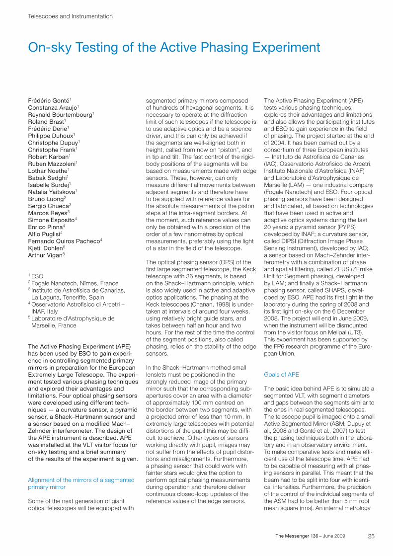
nine central processing units required for the control of the electronic components of APE (six CCDs, five translation stages, twelve rotating stages, two fast steering mirrors and the 183 actuators of the 61 segments incorporated in the ASM). The cabinets are linked to the bench via the junction boxes. Figure 1 shows a top view of APE with its two independent optical paths. The path in pink that includes a reflection of the ASM, feeds the OPSs, with the light coming from either the telescope focus or from MAPS. The path shown in green is the one used by the IM to measure the position of the ASM segments. In total there are 42 optical surfaces (lenses, filters, mirrors, beam splitters, etc.) between the focus of the telescope and the entrance foci of the phasing sensors. The quality of the wavefront delivered to the phasing sensors is better than l/2 peaktovalley across the segmented pupil. APE operates at wavelengths between 500 nm and 920 nm, with the bandpass between 820 nm and 880 nm reserved for the IM. The sensor units, fixed to the bench by kinematic interfaces, the optics and the other subsystems are aligned with a precision better than 100 μm.
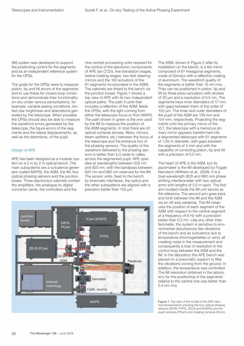
The ASM, shown in Figure 2 after its installation on the bench, is a flat mirror composed of 61 hexagonal segments, made of Zerodur with a reflective coating of aluminium. The wavefront quality of the segments is better than 15 nm rms. They can be positioned in piston, tip and tilt by three piezoactuators with strokes of 30 μm and a resolution of 0.5 nm. The segments have inner diameters of 17 mm with gaps between them of the order of 100 μm. The inner and outer diameters of the pupil of the ASM are 139 mm and 154 mm, respectively. Projecting the segments onto the primary mirror of the VLT, the telescope with a meniscus primary mirror appears transformed into a segmented telescope with 61 segments of 1.05 m diameter, with gaps between the segments of 4 mm and with the capability of correcting piston, tip and tilt with a precision of 0.5 nm.
The heart of APE is the ASM, but its pacemaker is the IM developed by Fogale Nanotech (Wilhelm et al., 2008). It is a dual wavelength (835 and 860 nm) phase shifting interferometer with two optical arms with lengths of 2.5 m each. The first arm located inside the IM unit serves as the reference. The second arm goes back and forth between the IM and the ASM via an offaxis parabola. The IM measures the position of each segment of the ASM with respect to the central segment at a frequency of 8 Hz with a precision better than 0.3 nm. Like any other interferometer, the system is sensitive to environmental disturbances like vibrations of the bench and air turbulence due to temperature inhomogeneities or wind, all creating noise in the measurement and consequently a loss of resolution in the control loop between the ASM and the IM. In the laboratory the APE bench was placed on a pneumatic support to filter the vibrations coming from the ground. In addition, the temperature was controlled. The IM resolution obtained in the laboratory for the positioning of the segments relative to the central one was better than 0.4 nm rms.
Telescopes and Instrumentation Gonté F. et al., Onsky Testing of the Active Phasing Experiment
Junction boxes
ZEUS PCam
GCam
DIPSI PCam
ICam SHAPS
PYPS
ASM
Internalmetrology
Derotator
Calib. source
MAPS
Parabola
Figure 1. Top view of the model of the APE optomechanical bench showing the four optical phasing sensors (DIPSI, PYPS, ZEUS and SHAPS) and the pupil cameras (PCam) and imaging cameras (ICam).
27The Messenger 136 – June 2009
Approximately 50% of the manpower dedicated to APE has been spent on the development of the VLTcompliant software, covering a variety of tasks ranging from the control of the motors to the archiving of the data gathered by APE and its phasing sensors. The complexity of the software is due, on the one hand, to the need for high flexibility in the configuration and execution of the experiment and, on the other hand, to the elaborate algorithms used for the analyses of the data delivered by the four phasing sensors.
The four optical phasing sensors
Four different types of OPSs were built and tested.
DIPSI (Chueca et al., 2008) is a curvature sensor analysing defocused images of the pupil. For low order wavefront errors the signal is approximately proportional to the second derivative of the wavefront and is easily interpreted using geometrical optical theory. For sharp discontinuities generated by phase steps at segment borders, the explanation of the signal
requires Fresnel diffraction theory. The amplitude of the signal has been used as the estimator for the piston step.
PYPS (Pinna et al., 2008) is based on the pyramid sensor technology, originally developed for adaptive optics. PYPS produces an optical signal by splitting the image in a focal plane by a pyramid with four faces. This is equivalent to a simultaneous knifeedge test on two orthogonal axes. The signal is constructed from the intensities in the four pupil images and, broadly speaking, is proportional to the first derivative of the local wavefront. A simulated or measured interaction matrix is then used to retrieve the piston, tip and tilt errors of each segment. To determine the interaction matrix a record of the signal for each degree of freedom of the segmented mirror is made and the pseudoinverse of the matrix is generated. The interaction matrix depends on the number of modes to be corrected. This approach has the advantage that it captures all parameters that affect the signal. The disadvantage is that interaction matrices have to be determined for a variety of parameters like the seeing conditions and the number of modes to be corrected. The modified feature of PYPS, compared to other pyramid sensors, such as the one used in the Multiconjugate Adaptive Optics Demonstrator (MAD, see Marchetti et al., 2007), is that the focus on the pyramid is modulated by a fast steering mirror to increase the sensitivity of the sensor.
SHAPS (Mazzoleni et al., 2008) is based on the Shack–Hartmann technology that has been used in active and adaptive optics for a long time. It is also the standard method used on the Keck telescopes to measure the positions of the segments. The lenslets are aligned so that the centres of the corresponding subapertures lie on the borders between two segments. The signals are the diffraction patterns of the lenslets. Although the piston step affects the position as well as the shape of the signal, only the shape is used as an estimator for the piston steps. SHAPS uses cylindrical lenslets covering the full border between two segments that provides the flexibility to average the signal along any fraction of the border and therefore measure the piston step along
the whole border. The lenslet array also supplies 19 lenslets inside each segment subaperture for the measurement of the segment aberrations.
ZEUS (Surdej et al., 2008) is based on the modified Mach–Zehnder interferometer phasing sensor developed at LAM (Yaitskova et al., 2005). A phase and spatial filter is installed at the focus of the telescope to filter out low spatial frequencies in the wavefront, such as the ones generated by the atmosphere, thereby increasing the contrast for high frequency errors such as those due to segment piston errors. The optimum size of the mask is approximately equal to the diameter of the seeing disc. However, three different masks are sufficient to cover seeing conditions ranging from 0.4” to 2”. The normalised signal is constructed from three images: a signal taken with the filter; an image of the pupil taken without the filter; and a dark image. The piston steps are then estimated by fitting a theoretical expression to the signal. A simpler, but less accurate, method is to use only the amplitude as the estimator for the piston step.
All OPSs suffer from the same limitation. Using monochromatic light with a wavelength, l, the range of the measurable phase difference is limited to (l/2, l/2) and the signals are identical for piston steps differing by integral multiples of l. The ambiguity can be resolved, and the capture range increased, if multiple measurements are performed with a small set of narrowband optical filters. This method, conventionally called the multil technique, allows a capture range of the order of a few μm, following which only a small number of iterations are necessary in closed loop to reduce the piston steps to values well within the (l/2, l/2)range. Another approach to resolve the ambiguity, usually called the coherence method, is to move adjacent segments with respect to each other over a large range of piston values. Using a broadband filter a signal will only appear if the piston step is sufficiently small.
In principle, for all sensors, the highest precision will be obtained with narrowband optical filter measurements, provided that the sources are sufficiently
Figure 2. The active segmented mirror assembled on the optomechanical bench.
Cre
dit:
ES
O/H
. Hey
er
28 The Messenger 136 – June 2009
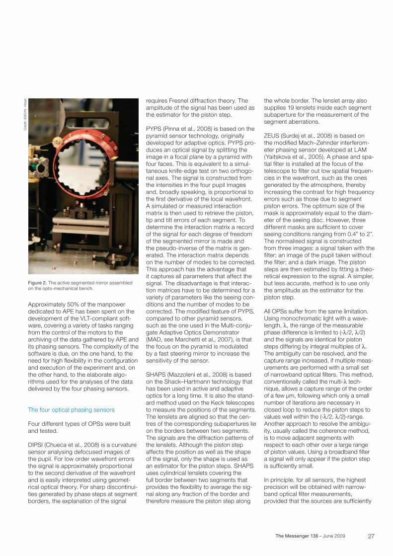
bright. However, sufficient precision with faint stars can only be achieved with broadband optical filter measurements. Figure 3 shows typical signals obtained by the four OPSs.
Tests in the laboratory
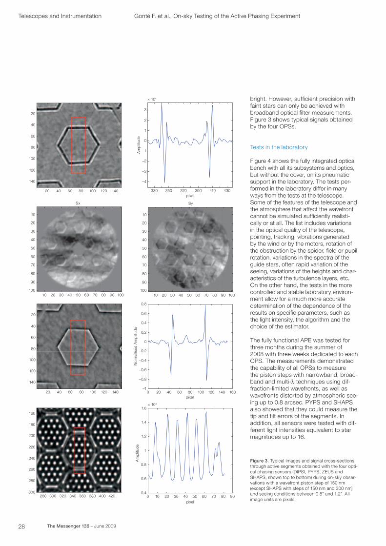
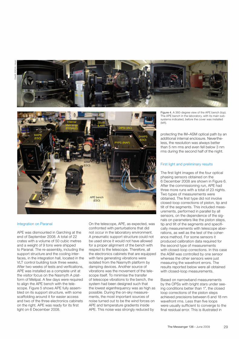
Figure 4 shows the fully integrated optical bench with all its subsystems and optics, but without the cover, on its pneumatic support in the laboratory. The tests performed in the laboratory differ in many ways from the tests at the telescope. Some of the features of the telescope and the atmosphere that affect the wavefront cannot be simulated sufficiently realistically or at all. The list includes variations in the optical quality of the telescope, pointing, tracking, vibrations generated by the wind or by the motors, rotation of the obstruction by the spider, field or pupil rotation, variations in the spectra of the guide stars, often rapid variation of the seeing, variations of the heights and characteristics of the turbulence layers, etc. On the other hand, the tests in the more controlled and stable laboratory environment allow for a much more accurate determination of the dependence of the results on specific parameters, such as the light intensity, the algorithm and the choice of the estimator.
The fully functional APE was tested for three months during the summer of 2008 with three weeks dedicated to each OPS. The measurements demonstrated the capability of all OPSs to measure the piston steps with narrowband, broadband and multil techniques using diffractionlimited wavefronts, as well as wavefronts distorted by atmospheric seeing up to 0.8 arcsec. PYPS and SHAPS also showed that they could measure the tip and tilt errors of the segments. In addition, all sensors were tested with different light intensities equivalent to star magnitudes up to 16.
Telescopes and Instrumentation Gonté F. et al., Onsky Testing of the Active Phasing Experiment
Figure 3. Typical images and signal crosssections through active segments obtained with the four optical phasing sensors (DIPSI, PYPS, ZEUS and SHAPS, shown top to bottom) during onsky observations with a wavefront piston step of 150 nm (except SHAPS with steps of 150 nm and 300 nm) and seeing conditions between 0.8” and 1.2”. All image units are pixels.
20
20 40 60 80 100 120 140
40
60
80
100
120
140
× 104
3
2
1
0
–1
–2
–3
–4
330 350 370pixel
Am
plit
ude
390 410 430
20 403010 6050 70 80 90 100
20
10
30
40
60
70
50
80
90
100
Sx
20 403010 6050 70 80 90 100
20
10
30
40
60
70
50
80
90
100
Sy
280 300 320 340 360 380 400 420300
280
260
240
220
200
180
160
× 105
1.6
1.4
1.2
1
0.8
0.6
0.40 10 20 30 40 50 60 70 80 90
pixel
Am
plit
ude
20 40 60 80 100 120 140
20
40
60
80
100
120
140
0–1
–0.8
–0.6
–0.4
–0.2
0
0.2
0.4
0.6
0.8
20 40 60 80 100 120 140 160pixel
Nor
mal
ised
Am
plit
ude
29The Messenger 136 – June 2009
Figure 4. A 360degree view of the APE bench (top).The APE bench in the laboratory, with its main subsystems indicated, before the cover was installed (left).
MAPS(ESO)
InternalMetrology(FOGALE)
ZEUS (LAM)
DIPSI (IAC)
SHAPS(ESO)
PYPS (INAF)
ASM(ESO)
APE bench(ESO)
Integration on Paranal
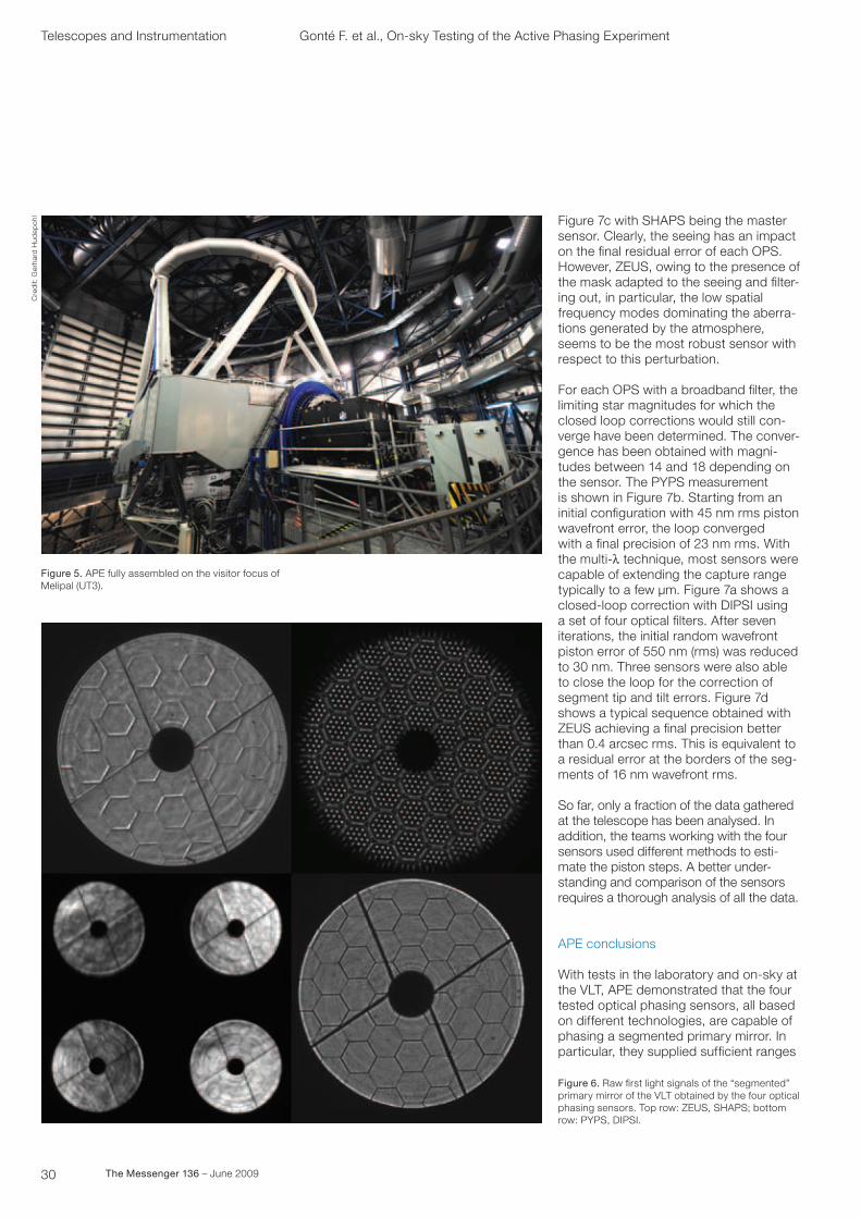
APE was dismounted in Garching at the end of September 2008. A total of 22 crates with a volume of 50 cubic metres and a weight of 9 tons were shipped to Paranal. The reassembly, including the support structure and the cooling interfaces, in the integration hall, located in the VLT control building took three weeks. After two weeks of tests and verifications, APE was installed as a complete unit at the visitor focus on the Nasmyth A platform of Melipal. A few days were required to align the APE bench with the telescope. Figure 5 shows APE fully assembled on its support structure, with some scaffolding around it for easier access and two of the three electronics cabinets on the right. APE was ready for its first light on 6 December 2008.
On the telescope, APE, as expected, was confronted with perturbations that did not occur in the laboratory environment. A pneumatic support structure could not be used since it would not have allowed for a proper alignment of the bench with respect to the telescope. Therefore, all the electronics cabinets that are equipped with fans generating vibrations were isolated from the Nasmyth platform by damping devices. Another source of vibrations was the movement of the telescope itself. To minimise the transfer of telescope vibrations to the bench, the system had been designed such that the lowest eigenfrequency was as high as possible. During the onsky measurements, the most important sources of noise turned out to be the wind forces on APE and temperature gradients inside APE. This noise was strongly reduced by
protecting the IM–ASM optical path by an additional internal enclosure. Nevertheless, the resolution was always better than 5 nm rms and even fell below 3 nm rms during the second half of the night.
First light and preliminary results
The first light images of the four optical phasing sensors obtained on the 6 December 2008 are shown in Figure 6. After the commissioning run, APE had three more runs with a total of 23 nights. Two types of measurements were obtained. The first type did not involve closedloop corrections of piston, tip and tilt of the segments. This included measurements, performed in parallel by all sensors, on the dependence of the signals on parameters like the piston steps, tip and tilt of the segments and specifically measurements with telescope aberrations, as well as the test of the coherence method. For some sensors it produced calibration data required for the second type of measurements with closedloop corrections. In this case the ASM was controlled by one sensor whereas the other sensors were just measuring the wavefront errors. The results reported below were all obtained with closedloop measurements.
Based on narrowband measurements by the OPSs with bright stars under seeing conditions better than 1”, the closed loop corrections of the piston steps achieved precisions between 6 and 18 nm wavefront rms. Less than five loops were usually sufficient to converge to the final residual error. This is illustrated in
Cre
dit:
ES
O/H
. Hey
er
30 The Messenger 136 – June 2009
Telescopes and Instrumentation
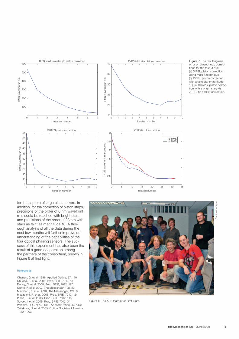
Figure 7c with SHAPS being the master sensor. Clearly, the seeing has an impact on the final residual error of each OPS. However, ZEUS, owing to the presence of the mask adapted to the seeing and filtering out, in particular, the low spatial frequency modes dominating the aberrations generated by the atmosphere, seems to be the most robust sensor with respect to this perturbation.
For each OPS with a broadband filter, the limiting star magnitudes for which the closed loop corrections would still converge have been determined. The convergence has been obtained with magnitudes between 14 and 18 depending on the sensor. The PYPS measurement is shown in Figure 7b. Starting from an initial configuration with 45 nm rms piston wavefront error, the loop converged with a final precision of 23 nm rms. With the multil technique, most sensors were capable of extending the capture range typically to a few μm. Figure 7a shows a closedloop correction with DIPSI using a set of four optical filters. After seven iterations, the initial random wavefront piston error of 550 nm (rms) was reduced to 30 nm. Three sensors were also able to close the loop for the correction of segment tip and tilt errors. Figure 7d shows a typical sequence obtained with ZEUS achieving a final precision better than 0.4 arcsec rms. This is equivalent to a residual error at the borders of the segments of 16 nm wavefront rms.
So far, only a fraction of the data gathered at the telescope has been analysed. In addition, the teams working with the four sensors used different methods to estimate the piston steps. A better understanding and comparison of the sensors requires a thorough analysis of all the data.
APE conclusions
With tests in the laboratory and onsky at the VLT, APE demonstrated that the four tested optical phasing sensors, all based on different technologies, are capable of phasing a segmented primary mirror. In particular, they supplied sufficient ranges
Figure 6. Raw first light signals of the “segmented” primary mirror of the VLT obtained by the four optical phasing sensors. Top row: ZEUS, SHAPS; bottom row: PYPS, DIPSI.
Figure 5. APE fully assembled on the visitor focus of Melipal (UT3).
Gonté F. et al., Onsky Testing of the Active Phasing ExperimentC
red
it: G
erha
rd H
udep
ohl
31The Messenger 136 – June 2009
for the capture of large piston errors. In addition, for the correction of piston steps, precisions of the order of 6 nm wavefront rms could be reached with bright stars and precisions of the order of 23 nm with stars as faint as magnitude 18. A thorough analysis of all the data during the next few months will further improve our understanding of the capabilities of the four optical phasing sensors. The success of this experiment has also been the result of a good cooperation among the partners of the consortium, shown in Figure 8 at first light.
References
Chanan, G. et al. 1998, Applied Optics, 37, 140Chueca, S. et al. 2008, Proc. SPIE, 7012, 13Dupuy, C. et al. 2008, Proc. SPIE, 7012, 127Gonté, F. et al. 2007, The Messenger, 128, 23Marchetti, E. et al. 2007, The Messenger, 129, 8Mazzoleni, R. et al. 2008, Proc. SPIE, 7012, 124Pinna, E. et al. 2008, Proc. SPIE, 7012, 116Surdej, I. et al. 2008, Proc. SPIE, 7012, 34Wilhelm, R. C. et al. 2008, Applied Optics, 47, 5473Yaitskova, N. et al. 2005, Optical Society of America 22, 1093
Figure 7. The resulting rms error on closedloop corrections for the four OPSs: (a) DIPSI, piston correction using multil technique; (b) PYPS, piston correction with a faint star (magnitude 18); (c) SHAPS, piston correction with a bright star; (d) ZEUS, tip and tilt correction.
DIPSI multi-wavelength piston correction
Iteration number
RM
S w
avef
ront
in n
m
600
500
400
300
200
100
0 1 2 3 4 5 6 7
PYPS faint star piston correction
Iteration number
RM
S w
avef
ront
in n
m
40
35
30
25
20
150 1 2 3 4 5 6 7 8 9 10
SHAPS piston correction
Iteration number
RM
S w
avef
ront
in n
m
55
50
45
40
35
30
25
20
15
10
50 1 2 3 4 5 6 7 8 9
ZEUS tip tilt correction
Iteration number
tip RMStilt RMS
RM
S w
avef
ront
in a
rcse
cond
50
0.5
1
1.5
2
2.5
3
10 15 20 25 30 35
Figure 8. The APE team after First Light.
Cre
dit:
Art
hur
Vig
an
Related Documents