© Copyright Distribution and reproduction of this document, commercialisation and publication of its content is strictly forbidden. Contravention is liable to payment of damages. All rights reserved. On-Line - Rotary Lobe Pump -Installation, Operation and Maintenance Manual of Rotary Lobe Pumps Flow Components Capital Equipment Engineered Processing Units

Welcome message from author
This document is posted to help you gain knowledge. Please leave a comment to let me know what you think about it! Share it to your friends and learn new things together.
Transcript
© Copyright
Distribution and reproduction of this document, commercialisation and publication of its content is strictly forbidden. Contraventionis liable to payment of damages. All rights reserved.
On-Line - Rotary Lobe Pump-Installation, Operation and Maintenance Manual of Rotary Lobe Pumps
Flow ComponentsCapital EquipmentEngineered Processing Units
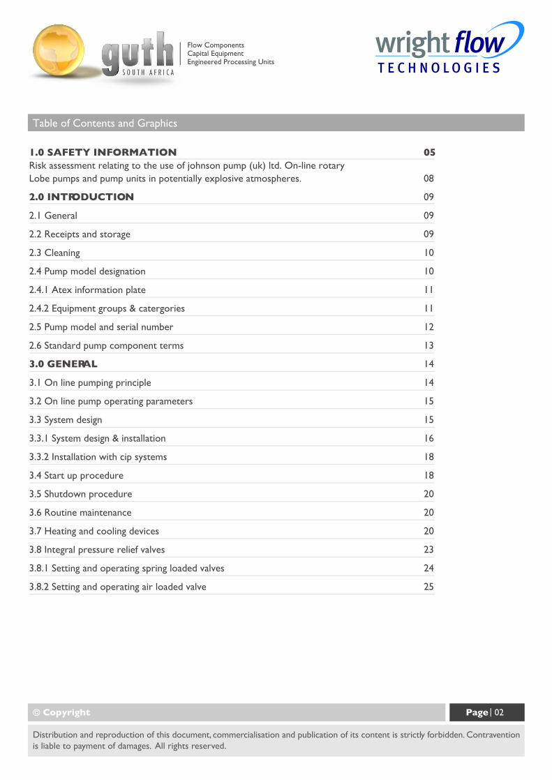
Table of Contents and Graphics
1.0 SAFETY INFORMATION 05Risk assessment relating to the use of johnson pump (uk) ltd. On-line rotaryLobe pumps and pump units in potentially explosive atmospheres. 08
2.0 INTRODUCTION 09
2.1 General 09
2.2 Receipts and storage 09
2.3 Cleaning 10
2.4 Pump model designation 10
2.4.1 Atex information plate 11
2.4.2 Equipment groups & catergories 11
2.5 Pump model and serial number 12
2.6 Standard pump component terms 13
3.0 GENERAL 14
3.1 On line pumping principle 14
3.2 On line pump operating parameters 15
3.3 System design 15
3.3.1 System design & installation 16
3.3.2 Installation with cip systems 18
3.4 Start up procedure 18
3.5 Shutdown procedure 20
3.6 Routine maintenance 20
3.7 Heating and cooling devices 20
3.8 Integral pressure relief valves 23
3.8.1 Setting and operating spring loaded valves 24
3.8.2 Setting and operating air loaded valve 25
© Copyright Page | 02
Distribution and reproduction of this document, commercialisation and publication of its content is strictly forbidden. Contraventionis liable to payment of damages. All rights reserved.
Flow ComponentsCapital EquipmentEngineered Processing Units
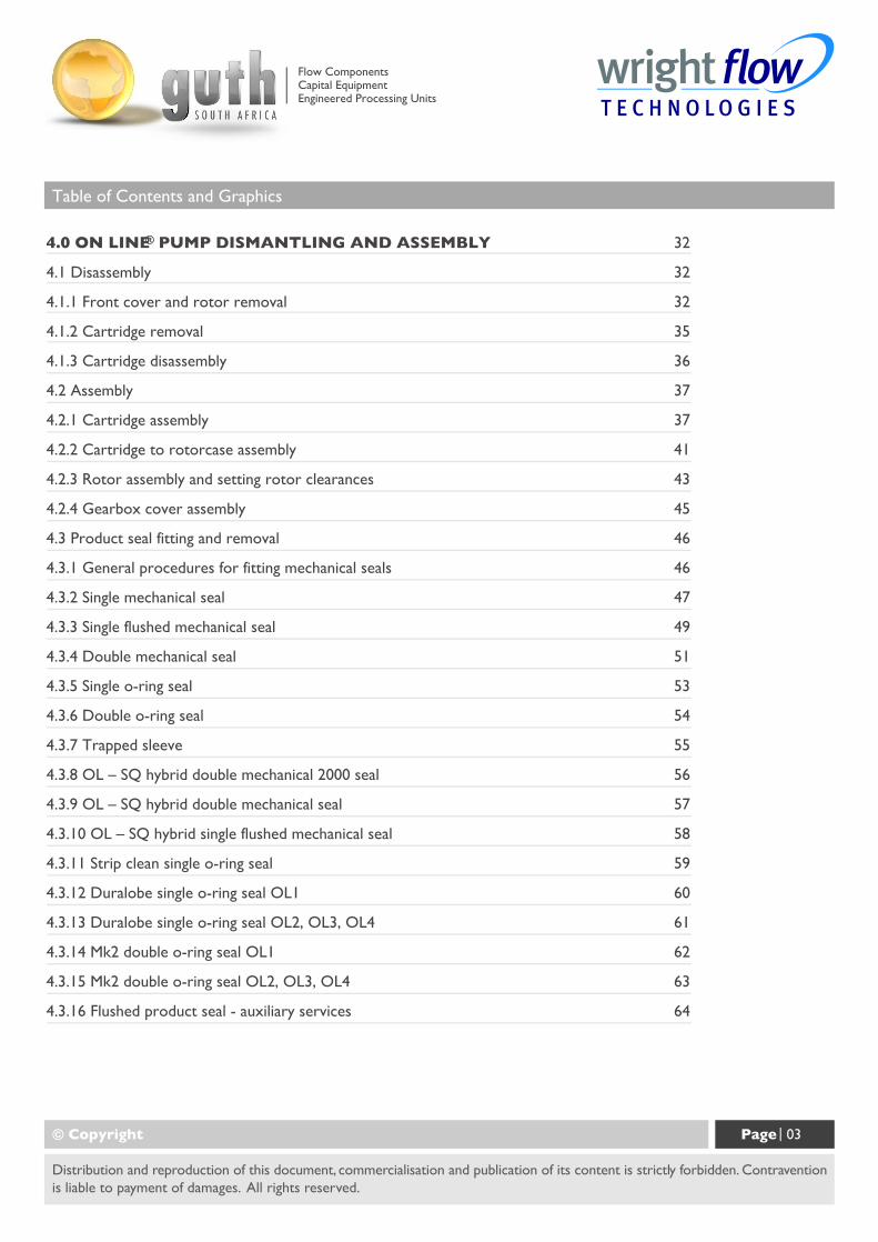
Table of Contents and Graphics
4.0 ON LINE® PUMP DISMANTLING AND ASSEMBLY 32
4.1 Disassembly 32
4.1.1 Front cover and rotor removal 32
4.1.2 Cartridge removal 35
4.1.3 Cartridge disassembly 36
4.2 Assembly 37
4.2.1 Cartridge assembly 37
4.2.2 Cartridge to rotorcase assembly 41
4.2.3 Rotor assembly and setting rotor clearances 43
4.2.4 Gearbox cover assembly 45
4.3 Product seal fitting and removal 46
4.3.1 General procedures for fitting mechanical seals 46
4.3.2 Single mechanical seal 47
4.3.3 Single flushed mechanical seal 49
4.3.4 Double mechanical seal 51
4.3.5 Single o-ring seal 53
4.3.6 Double o-ring seal 54
4.3.7 Trapped sleeve 55
4.3.8 OL – SQ hybrid double mechanical 2000 seal 56
4.3.9 OL – SQ hybrid double mechanical seal 57
4.3.10 OL – SQ hybrid single flushed mechanical seal 58
4.3.11 Strip clean single o-ring seal 59
4.3.12 Duralobe single o-ring seal OL1 60
4.3.13 Duralobe single o-ring seal OL2, OL3, OL4 61
4.3.14 Mk2 double o-ring seal OL1 62
4.3.15 Mk2 double o-ring seal OL2, OL3, OL4 63
4.3.16 Flushed product seal - auxiliary services 64
© Copyright Page | 03
Distribution and reproduction of this document, commercialisation and publication of its content is strictly forbidden. Contraventionis liable to payment of damages. All rights reserved.
Flow ComponentsCapital EquipmentEngineered Processing Units
Table of Contents and Graphics
5.0 SPECIFICATIONS 67
5.1 Clearance chart 67
5.2 Fasteners & torque settings 68
5.3 Lubricants 69
5.4 Material specification 70
5.5 On Line® foundation dimensions 71
5.6 Typical basic pump build 72
5.7 Trouble shooting 73
5.8 Typical noise emission data 74
5.9 Service history 75
5.10 Tool list 76
5.11 Notes 79
© Copyright Page | 04
Distribution and reproduction of this document, commercialisation and publication of its content is strictly forbidden. Contraventionis liable to payment of damages. All rights reserved.
Flow ComponentsCapital EquipmentEngineered Processing Units
1. Safety Information
© Copyright Page | 05
Distribution and reproduction of this document, commercialisation and publication of its content is strictly forbidden. Contraventionis liable to payment of damages. All rights reserved.
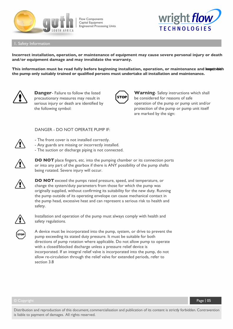
Incorrect installation, operation, or maintenance of equipment may cause severe personal injury or deathand/or equipment damage and may invalidate the warranty.
This information must be read fully before beginning installation, operation, or maintenance and must be kept withthe pump only suitably trained or qualified persons must undertake all installation and maintenance.
Danger - Failure to follow the listedprecautionary measures may result inserious injury or death are identified bythe following symbol:
Warning - Safety instructions which shallbe considered for reasons of safeoperation of the pump or pump unit and/orprotection of the pump or pump unit itselfare marked by the sign:
DANGER - DO NOT OPERATE PUMP IF:
- The front cover is not installed correctly.- Any guards are missing or incorrectly installed.- The suction or discharge piping is not connected.
DO NOT place fingers, etc. into the pumping chamber or its connection portsor into any part of the gearbox if there is ANY possibility of the pump shaftsbeing rotated. Severe injury will occur.
DO NOT exceed the pumps rated pressure, speed, and temperature, orchange the system/duty parameters from those for which the pump wasoriginally supplied, without confirming its suitability for the new duty. Runningthe pump outside of its operating envelope can cause mechanical contact inthe pump head, excessive heat and can represent a serious risk to health andsafety.
Installation and operation of the pump must always comply with health andsafety regulations.
A device must be incorporated into the pump, system, or drive to prevent thepump exceeding its stated duty pressure. It must be suitable for bothdirections of pump rotation where applicable. Do not allow pump to operatewith a closed/blocked discharge unless a pressure relief device isincorporated. If an integral relief valve is incorporated into the pump, do notallow re-circulation through the relief valve for extended periods, refer tosection 3.8
Flow ComponentsCapital EquipmentEngineered Processing Units
1. Safety Information
The mounting of the pump or pump unit should be solid and stable. Pump orientation must be considered inrelation to drainage requirements. Once mounted, shaft drive elements must be checked for correct alignment.Rotate pump shaft by at least one full revolution to ensure smoothness of operation. Incorrect alignment willproduce excessive loading and will create high temperatures and increased noise emissions. Do not use any
drivearrangements that cause side loading of the drive shaft. It may also be necessary to earth the pumpto avoid thebuild up of a potential charge difference that could cause a spark.
The installation must allow safe routine maintenance and inspection (to replenish lubricants, check for leakage,monitor pressures, etc) and provide adequate ventilation necessary to prevent overheating.
Fill all gearboxes with the recommended grades and quantities of lubricant (refer to section 3.4). Beware ofover/under filling the gearbox as this could cause the pump to over heat and mechanical damage to occur.
Before operating the pump, be sure that it and all parts of the system to which it is connected are clean andfree from debris and that all valves in the suction and discharge pipelines are fully opened. Ensure that all pipingconnecting to the pump is fully supported and correctly aligned with its relevant connections. Misalignment
and/orexcess loads will cause severe pump damage. This could result in unexpected mechanical contact in the pumphead and has the potential to be a source of ignition.
Be sure that pump rotation is correct for the desired direction of flow (refer to section 3.4).
Do not install the pump into a system where it will run dry (i.e. without a supply of pumped media) unless it isequipped with a flushed shaft seal arrangement complete with a fully operational flushing system. Mechanicalseals require a thin fluid film to lubricate the seal faces. Dry running can cause excessive heat and seal failure.
Pressure gauges/sensors are recommended, next to the pump suction and discharge connections to monitor pressures.
Caution must be taken when lifting the pump. Suitable lifting devices should be used as appropriate. Lifting eyesinstalled on the pump must only be used to lift the pump, not pump with drive and/or base plate. If pump is baseplate mounted, the base plate must be used for all lifting purposes. If slings are used for lifting, they must be
safelyand securely attached. For weights of bare shaft pumps refer to section 5.5.
© Copyright Page | 06
Distribution and reproduction of this document, commercialisation and publication of its content is strictly forbidden. Contraventionis liable to payment of damages. All rights reserved.
Flow ComponentsCapital EquipmentEngineered Processing Units
1. Safety Information
DO NOT attempt any maintenance or disassembly of the pump or pump unit without first ensuring that:
- The pump is fully isolated from the power source (electric, hydraulic, pneumatic).
- The pumping chamber, pneumatic relief valve and any shaft seal support system are depressurised and purged.
- Any temperature control devices (jackets, heat-tracing, etc) are fully isolated, that they are depressurised andpurged, and components are allowed to reach a safe handling temperature.
DO NOT attempt to dismantle a pressure relief valve, which has not had the spring pressure relieved, is stillconnected to a pressurised gas/air supply or is mounted on a pump that is operating. Serious personal injuryor death and/or pump damage may occur.
DO NOT loosen or undo the front cover, any connections to the pump, shaft seal housings, temperaturecontrol
devices, or other components, until sure that such action will not allow the unsafe escape of any pressurised media.
Pumps and/or drives can produce sound power levels exceeding 85-dB (A) under certain operating conditions.When necessary, personal protection against noise must be taken. Typical noise emission data can be found insection 5.8.
Avoid any contact with hot parts of pumps and/or drives that may cause injury. Certain operatingconditions, temperature control devices (jackets, heat-tracing, etc.), bad installation, or poor maintenance canall promote high temperatures on pumps and/or drives.
When cleaning, either manually or by CIP method, the operator must ensure that a suitable procedure is usedin accordance with the system requirements. During a CIP cleaning cycle, a pump differential pressure of between2 and 3 bar is recommended to ensure suitable velocities are reached within the pump head.The exterior of the pump should be cleaned periodically.
Surface temperature of pump is also dependent on the temperature of pumped medium.
© Copyright Page | 07
Distribution and reproduction of this document, commercialisation and publication of its content is strictly forbidden. Contraventionis liable to payment of damages. All rights reserved.
Flow ComponentsCapital EquipmentEngineered Processing Units
1. Safety Information
© Copyright Page | 08
Distribution and reproduction of this document, commercialisation and publication of its content is strictly forbidden. Contraventionis liable to payment of damages. All rights reserved.
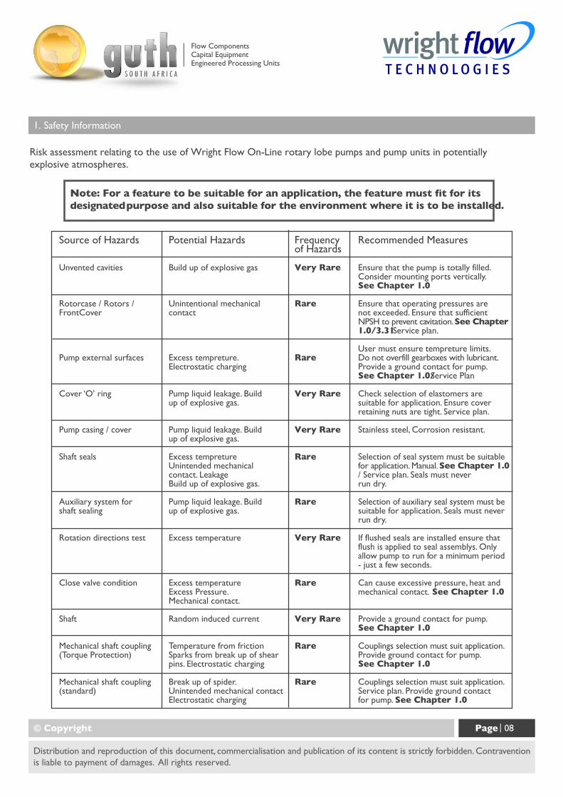
Source of Hazards
Unvented cavities
Rotorcase / Rotors /FrontCover
Pump external surfaces
Cover ‘O’ ring
Pump casing / cover
Shaft seals
Auxiliary system forshaft sealing
Rotation directions test
Close valve condition
Shaft
Mechanical shaft coupling(Torque Protection)
Mechanical shaft coupling(standard)
Potential Hazards
Build up of explosive gas
Unintentional mechanicalcontact
Excess tempreture.Electrostatic charging
Pump liquid leakage. Buildup of explosive gas.
Pump liquid leakage. Buildup of explosive gas.
Excess tempretureUnintended mechanicalcontact. LeakageBuild up of explosive gas.
Pump liquid leakage. Buildup of explosive gas.
Excess temperature
Excess temperatureExcess Pressure.Mechanical contact.
Random induced current
Temperature from frictionSparks from break up of shearpins. Electrostatic charging
Break up of spider.Unintended mechanical contactElectrostatic charging
Frequencyof Hazards
Very Rare
Rare
Rare
Very Rare
Very Rare
Rare
Rare
Very Rare
Rare
Very Rare
Rare
Rare
Recommended Measures
Ensure that the pump is totally filled.Consider mounting ports vertically.See Chapter 1.0
Ensure that operating pressures arenot exceeded. Ensure that sufficientNPSH to prevent cavitation. See Chapter1.0/3.31 Service plan.
User must ensure tempreture limits.Do not overfill gearboxes with lubricant.Provide a ground contact for pump.See Chapter 1.0/ Service Plan
Check selection of elastomers aresuitable for application. Ensure coverretaining nuts are tight. Service plan.
Stainless steel, Corrosion resistant.
Selection of seal system must be suitablefor application. Manual. See Chapter 1.0/ Service plan. Seals must neverrun dry.
Selection of auxiliary seal system must besuitable for application. Seals must neverrun dry.
If flushed seals are installed ensure thatflush is applied to seal assemblys. Onlyallow pump to run for a minimum period- just a few seconds.
Can cause excessive pressure, heat andmechanical contact. See Chapter 1.0
Provide a ground contact for pump.See Chapter 1.0
Couplings selection must suit application.Provide ground contact for pump.See Chapter 1.0
Couplings selection must suit application.Service plan. Provide ground contactfor pump. See Chapter 1.0
Risk assessment relating to the use of Wright Flow On-Line rotary lobe pumps and pump units in potentiallyexplosive atmospheres.
Note: For a feature to be suitable for an application, the feature must fit for itsdesignated purpose and also suitable for the environment where it is to be installed.
Flow ComponentsCapital EquipmentEngineered Processing Units
2. Introduction
2.1 General
On-Line rotary lobe pumps are manufactured by Wright Flow Technologies.
This manual includes all the necessary information for Sterilobe pumps and should be read prior to beginning installation,operation, or maintenance.
Should you require any additional information regarding the On-Line pumps contact Guth South Africa.
When asking for assistance please provide the pump model and serial number. This information can be obtained fromthe pump nameplate which is located on the side of the pump gearbox cover, refer to section 2.6.
Should the nameplate be unreadable or missing the serial number is also stamped on either side of the rotocase referto section 2.6.
If the system or product characteristics are to be changed from the original application for which the pump was selected,Guth South Africa should be consulted to ensure the pump is suitable for the new application.
2.2 Receipts and Storage
Upon receipt of the pump, immediately examine it for any signs of visible damage. If any damage is noted, contact GuthSouth Africa and clearly mark upon the carriers paperwork that the goods have been received in a damaged condition,with a brief description of damage.
If the pump is not required for immediate installation then it should be stored in a clean, dry environment. It is recommendedthat storage temperature should be between – 10°C and 40°C. Further to the above, if the pump is not intended forinstallation or use within 18 months or more then refer to Guth South Africa for storage recommendations.
© Copyright Page | 09
Distribution and reproduction of this document, commercialisation and publication of its content is strictly forbidden. Contraventionis liable to payment of damages. All rights reserved.
Flow ComponentsCapital EquipmentEngineered Processing Units
2. Introduction
2.3 Cleaning.
The On-Line pump series is suitable for both manual cleaning and CIP(Cleaning In Place), refer to section 3.3.2.
The product seals are mounted directly behind the rotors and are designed and positioned to minimise product entrapmentand maximise the effects of cleaning.
This strategic positioning of the product seals, combined with their ease of access provides an arrangement that can bemore effectively cleaned by both manual and CIP procedures.
It is recommended that the exterior of the pump be cleaned periodically.
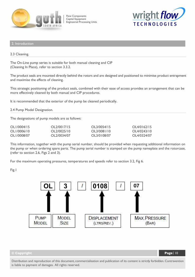
2.4 Pump Model Designation.
The designations of pump models are as follows:
OL1/0004/15 OL2/0017/15 OL3/0054/15 OL4/0162/15OL1/0006/10 OL2/0025/10 OL3/0081/10 OL4/0243/10OL1/0008/07 OL2/0034/07 OL3/0108/07 OL4/0324/07
This information, together with the pump serial number, should be provided when requesting additional information onthe pump or when ordering spare parts. The pump serial number is stamped on the pump nameplate and the rotorcase,(refer to section 2.6, Figs 2 and 3).
For the maximum operating pressures, temperatures and speeds refer to section 3.2, Fig 6.
Fig.1
© Copyright Page | 10
Distribution and reproduction of this document, commercialisation and publication of its content is strictly forbidden. Contraventionis liable to payment of damages. All rights reserved.
OL 3 0108
Flow ComponentsCapital EquipmentEngineered Processing Units
© Copyright Page | 11
Distribution and reproduction of this document, commercialisation and publication of its content is strictly forbidden. Contraventionis liable to payment of damages. All rights reserved.
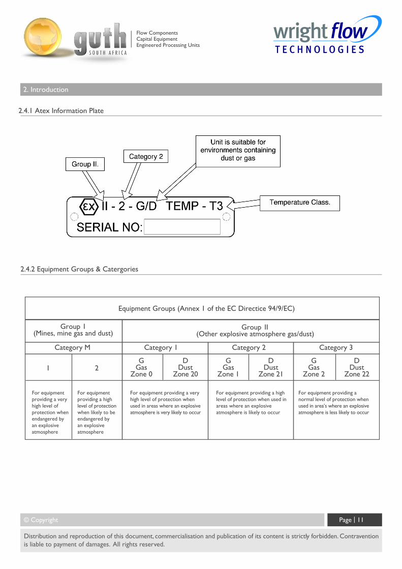
2.4.1 Atex Information Plate
2.4.2 Equipment Groups & Catergories
For equipmentproviding a veryhigh level ofprotection whenendangered byan explosiveatmosphere
For equipmentproviding a highlevel of protectionwhen likely to beendangered byan explosiveatmosphere
For equipment providing a veryhigh level of protection whenused in areas where an explosiveatmosphere is very likely to occur
For equipment providing a highlevel of protection when used inareas where an explosiveatmosphere is likely to occur
For equipment providing anormal level of protection whenused in area’s where an explosiveatmosphere is less likely to occur
GGas
Zone 0
DDust
Zone 20
GGas
Zone 1
DDust
Zone 21
GGas
Zone 2
DDust
Zone 221 2
Category M Category 1 Category 2 Category 3
Group 1(Mines, mine gas and dust)
Group 11(Other explosive atmosphere gas/dust)
Equipment Groups (Annex 1 of the EC Directice 94/9/EC)
2. Introduction
Flow ComponentsCapital EquipmentEngineered Processing Units
2. Introduction
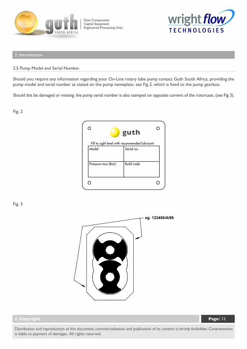
2.5 Pump Model and Serial Number.
Should you require any information regarding your On-Line rotary lobe pump contact Guth South Africa, providing thepump model and serial number as stated on the pump nameplate, see Fig 2, which is fixed to the pump gearbox.
Should this be damaged or missing, the pump serial number is also stamped on opposite corners of the rotorcase, (see Fig 3).
© Copyright Page | 12
Distribution and reproduction of this document, commercialisation and publication of its content is strictly forbidden. Contraventionis liable to payment of damages. All rights reserved.
Fig. 2
Fill to sight level with recommended lubricant
Model:
Pressure max (Bar):
Serial no.
Build code:
guth
Fig. 3
Flow ComponentsCapital EquipmentEngineered Processing Units
2. Introduction
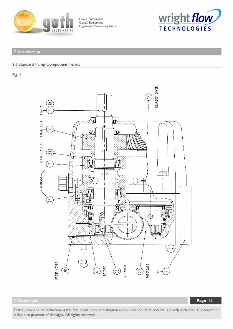
2.6 Standard Pump Component Terms
© Copyright Page | 13
Distribution and reproduction of this document, commercialisation and publication of its content is strictly forbidden. Contraventionis liable to payment of damages. All rights reserved.
Fig. 4
Flow ComponentsCapital EquipmentEngineered Processing Units
3. General
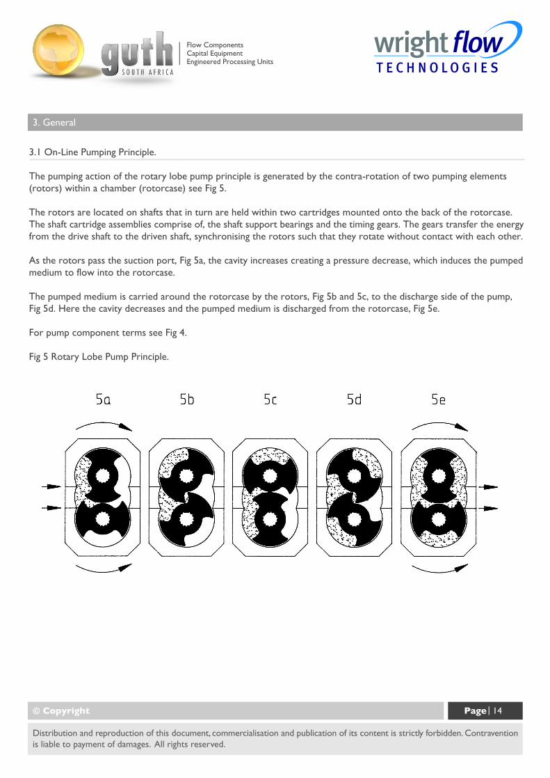
3.1 On-Line Pumping Principle.
The pumping action of the rotary lobe pump principle is generated by the contra-rotation of two pumping elements(rotors) within a chamber (rotorcase) see Fig 5.
The rotors are located on shafts that in turn are held within two cartridges mounted onto the back of the rotorcase.The shaft cartridge assemblies comprise of, the shaft support bearings and the timing gears. The gears transfer the energyfrom the drive shaft to the driven shaft, synchronising the rotors such that they rotate without contact with each other.
As the rotors pass the suction port, Fig 5a, the cavity increases creating a pressure decrease, which induces the pumpedmedium to flow into the rotorcase.
The pumped medium is carried around the rotorcase by the rotors, Fig 5b and 5c, to the discharge side of the pump,Fig 5d. Here the cavity decreases and the pumped medium is discharged from the rotorcase, Fig 5e.
For pump component terms see Fig 4.
Fig 5 Rotary Lobe Pump Principle.
© Copyright Page | 14
Distribution and reproduction of this document, commercialisation and publication of its content is strictly forbidden. Contraventionis liable to payment of damages. All rights reserved.
Flow ComponentsCapital EquipmentEngineered Processing Units
3. General
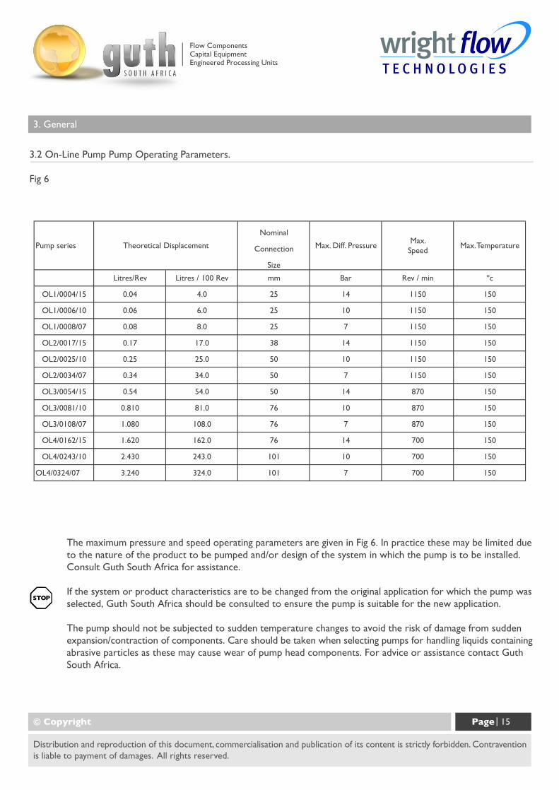
3.2 On-Line Pump Pump Operating Parameters.
Fig 6
© Copyright Page | 15
Distribution and reproduction of this document, commercialisation and publication of its content is strictly forbidden. Contraventionis liable to payment of damages. All rights reserved.
The maximum pressure and speed operating parameters are given in Fig 6. In practice these may be limited dueto the nature of the product to be pumped and/or design of the system in which the pump is to be installed.Consult Guth South Africa for assistance.
If the system or product characteristics are to be changed from the original application for which the pump wasselected, Guth South Africa should be consulted to ensure the pump is suitable for the new application.
The pump should not be subjected to sudden temperature changes to avoid the risk of damage from suddenexpansion/contraction of components. Care should be taken when selecting pumps for handling liquids containingabrasive particles as these may cause wear of pump head components. For advice or assistance contact GuthSouth Africa.
Flow ComponentsCapital EquipmentEngineered Processing Units
3. General
3.3.1 System Design & Installation.
When incorporating any pump into a system it is considered good practice to minimise piping runs and thenumber of fittings (tees, unions, bends etc.) and restrictions. Particular care should be taken in designing thesuction line, which should be as short and straight as possible with a minimum of pipe fittings to minimiserestricting product flow to the pump. The following should be considered at the design stage of any system:
i) Be sure ample room is provided around the pump to allow for:a) Access to the pump and drive for routine inspection and maintenance, i.e. to replenish pump or drive
lubricant or to remove pump front cover and rotors.
b) Ventilation of the drive to prevent over heating.
ii) The pump must not be used to support piping. All piping to and from the pump unit must be independently supported. Failure to observe this may distort the pump head components or assembly and cause serious consequential damage to the pump.
iii) Valves should be provided adjacent to the pump suction and discharge connections to allow the pump tobe isolated from the system for routine inspection and maintenance.
iv) Rotary lobe pumps are of the positive displacement type and therefore an overload protection device mustbe provided. This can take the form of:
a) A pressure relief valve integral with the pump where available and suited to the application, refer tosection 3.8.
b) An in-line pressure relief system, i.e. external to the pump.
c) Incorporation of a torque-limiting device in the drive system.
d) Rupture disc incorporated in the discharge piping.
Where pump rotation and hence flow is to be reversed during normal operation, the overload device must becapable of protection for both directions of rotation/flow. The On Line integral relief valves are described insection 3.8 and are designed to operate under such conditions.
© Copyright Page | 16
Distribution and reproduction of this document, commercialisation and publication of its content is strictly forbidden. Contraventionis liable to payment of damages. All rights reserved.
Flow ComponentsCapital EquipmentEngineered Processing Units
3. General
v) It is recommended that all piping and associated equipment from the tank to the discharge point be thoroughlycleaned before installation of the pump to avoid debris entering the pump and causing damage.
vi) Pressure gauges should be installed adjacent to the pump suction and discharge connections such that systempressures can be monitored. These gauges will provide a clear indication of changes in operating conditionsand where a relief valve is incorporated in the system, will be necessary for setting and checking the functioningof the valve.
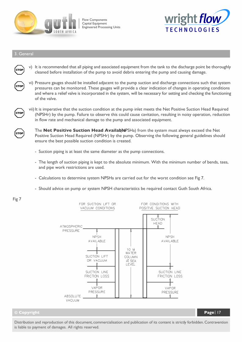
vii) It is imperative that the suction condition at the pump inlet meets the Net Positive Suction Head Required(NPSHr) by the pump. Failure to observe this could cause cavitation, resulting in noisy operation, reductionin flow rate and mechanical damage to the pump and associated equipment.
The Net Positive Suction Head Available (NPSHa) from the system must always exceed the NetPositive Suction Head Required (NPSHr) by the pump. Observing the following general guidelines shouldensure the best possible suction condition is created.
- Suction piping is at least the same diameter as the pump connections.
- The length of suction piping is kept to the absolute minimum. With the minimum number of bends, tees,and pipe work restrictions are used.
- Calculations to determine system NPSHa are carried out for the worst condition see Fig 7.
- Should advice on pump or system NPSH characteristics be required contact Guth South Africa.
Fig 7
© Copyright Page | 17
Distribution and reproduction of this document, commercialisation and publication of its content is strictly forbidden. Contraventionis liable to payment of damages. All rights reserved.
Flow ComponentsCapital EquipmentEngineered Processing Units
3. General
(viii) When installing a pump complete with baseplate, motor and drive the following guidelines must be observed:
a) The preferred drive arrangement for any rotary lobe pump is in-line direct coupled. If an alternative is requiredplease contact Guth South Africa.
b) Flexible couplings must always be incorporated and correctly aligned within the limits recommended by thecoupling manufacturer. To check coupling alignment rotate the shaft by at least one full revolution andensure that the shaft rotates smoothly. Couplings of a non-flexible design must never be used.
c) Couplings must always be enclosed in a suitable guard to prevent contact with rotating parts that could resultin personal injury. Guards should be of suitable material, (see d) and of sufficiently rigid design to preventcontact with rotating parts under normal operating conditions.
d) When installing pump sets in flammable or explosive environments, or for handling flammable or explosivematerials. Special consideration must be given not only to the safety aspects of the drive unit enclosure butalso to the materials used for both the coupling and the guard to eliminate the risk of explosion.
e) Base plates must be secured to a flat level surface such that distortion and misalignment are avoided. Oncebase plates are fastened in position the drive alignment must be re-checked, (see b).
f) When using electric motor drives, ensure that the electrical supply is compatible with the drive and controlsand that the method of wiring is correct for the type of starting required by the motor i.e. Direct On-Line,or other similar method. Ensure all components are correctly grounded.
3.3.2 Installation with CIP Systems
The On-Line has been designed to be effectively cleaned by the CIP procedures recommended for in place cleaning ofprocess equipment. It is recommended that a differential pressure of 2 to 3 bar be developed across the pump headduring cleaning in order to develop the necessary fluid velocities required for thorough cleaning.
3.4 Start Up Procedure
- Check that all piping and associated equipment are clean and free from debris and that all pipe connectionsare secure and leak free.
- For pumps installed with flushed product seals check that all auxiliary services are in place and connectedand provide sufficient flow and pressure for flushing purposes, refer to section 4.3.7.
© Copyright Page | 18
Distribution and reproduction of this document, commercialisation and publication of its content is strictly forbidden. Contraventionis liable to payment of damages. All rights reserved.
Flow ComponentsCapital EquipmentEngineered Processing Units
3. General
- Ensure lubrication is provided for both pump and drive. On-Line pumps are shipped without oil and shouldbe filled to the level of the oil sight glass that must be installed in the upper tapped hole in the side of thegearbox cover, refer to section 5.3 for oil capacities and grades.
- If an external relief valve is incorporated in the system check that it is set correctly. For start up purposes itis considered good practice to set the relief valve lower than the system design pressure. On completionof start up the relief valve should be set for the application. The required setting should never exceed thelower of either the pumps maximum pressure rating or the system design pressure. For setting integral reliefvalves, refer to sections 3.8.1 and 3.8.2.
- Ensure both suction and discharge valves are fully open, and pipe work is free from all obstructions. On-Linepumps are of the positive displacement type and should therefore never be operated against a closed valveas this would result in pressure overload, resulting in damage to the pump and possibly the system.
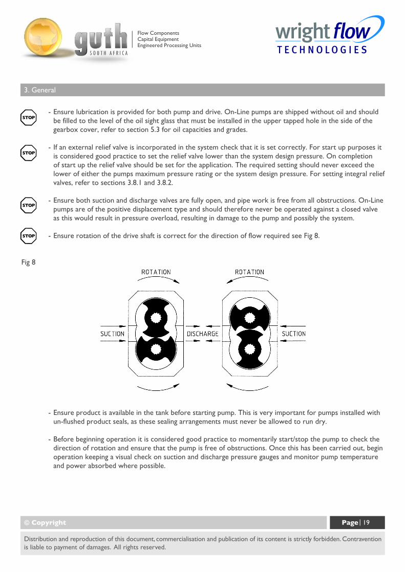
- Ensure rotation of the drive shaft is correct for the direction of flow required see Fig 8.
Fig 8
- Ensure product is available in the tank before starting pump. This is very important for pumps installed withun-flushed product seals, as these sealing arrangements must never be allowed to run dry.
- Before beginning operation it is considered good practice to momentarily start/stop the pump to check thedirection of rotation and ensure that the pump is free of obstructions. Once this has been carried out, beginoperation keeping a visual check on suction and discharge pressure gauges and monitor pump temperatureand power absorbed where possible.
© Copyright Page | 19
Distribution and reproduction of this document, commercialisation and publication of its content is strictly forbidden. Contraventionis liable to payment of damages. All rights reserved.
Flow ComponentsCapital EquipmentEngineered Processing Units
3. General
3.5 Shutdown Procedure.
When shutting the pump down close both the suction and discharge valves and ensure that the necessary safetyprecautions are taken:
- The prime mover power source has been isolated.
- If installed, the pneumatically operated integral relief valve has been depressurised.
- If installed, flushed product seal auxiliary services have been isolated and depressurised.
- Pump head and piping have been drained and purged.
3.6 Routine Maintenance.
- Check oil levels regularly.
- Change the oil every 12 months or 3000 operating hours whichever is the sooner. For lubricant capacitiesand grades refer to section 5.3.
3.7 Heating and Cooling Devices - See Figs 9 and 10.
All On-Line models except the OL1 series can be supplied with a jacketed front cover and rotorcase withports for circulation of a heating/cooling media.
The jacketed front cover and rotorcase heating and cooling ports are strategically positioned such that therequired thermal effect acts on the pumping chamber and product seal area.
The pressure rating of the On-Line series jacketed front cover and rotorcase heating/cooling ports is 3.5 barand should not be exceeded without consulting Guth South Africa.
Heating/cooling of the pump head is used to maintain, rather than increase/decrease the temperature of thepumped media and should be used as part of a complete system where suction and discharge lines and vesselsare also heated /cooled.
Where heating/cooling devices are employed, the heating/cooling media should be circulated 15-20 minutesprior to pump start-up and should be allowed to continue for a similar period of time after the pump has beenshutdown. Where a CIP cycle is employed as part of the process, the heating/cooling media should continueto be circulated during the cleaning cycle.
© Copyright Page | 20
Distribution and reproduction of this document, commercialisation and publication of its content is strictly forbidden. Contraventionis liable to payment of damages. All rights reserved.
Flow ComponentsCapital EquipmentEngineered Processing Units

3. General
Fig 9 Dimensions of Front Cover Jacket for Heating/Cooling.
© Copyright Page | 21
Distribution and reproduction of this document, commercialisation and publication of its content is strictly forbidden. Contraventionis liable to payment of damages. All rights reserved.
Note: For all other dimensions see section 5.5, Foundation Dimensions, and Weights.
Flow ComponentsCapital EquipmentEngineered Processing Units
3. General
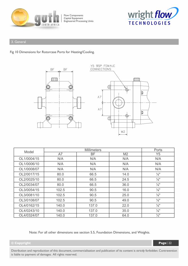
Fig 10 Dimensions for Rotorcase Ports for Heating/Cooling.
© Copyright Page | 22
Distribution and reproduction of this document, commercialisation and publication of its content is strictly forbidden. Contraventionis liable to payment of damages. All rights reserved.
Note: For all other dimensions see section 5.5, Foundation Dimensions, and Weights.
Flow ComponentsCapital EquipmentEngineered Processing Units
3. General
3.8 Integral Pressure Relief Valves - See Figs 11, 12, 13, and 14.
All models in the On-Line® series can be supplied with integral pressure relief valves with both spring and air loadedversions available. The function of the valves can be further enhanced with the option of manual or airlift overrideoffering particular benefits where CIP or SIP is employed. Valves incorporating this option can be opened to regulatethe volume of the cleaning media within the pump chamber thereby avoiding the need for manual cleaning or externalby-pass.
Where the pump is mounted onto a portable base plate complete with motor and drive to be used as a mobile set, itis strongly recommended that a integral pressure relief valve is installed.
The On-Line® integral pressure relief valves available include:
Spring Loaded - see Fig 11 & 12.5
Valve can be set to required pressure relief setting.
Spring Loaded with Manual Lift - see Fig 12.
Valve can be set to required pressure relief setting. Manual lift override can be used to open valve without disturbingpressure relief setting
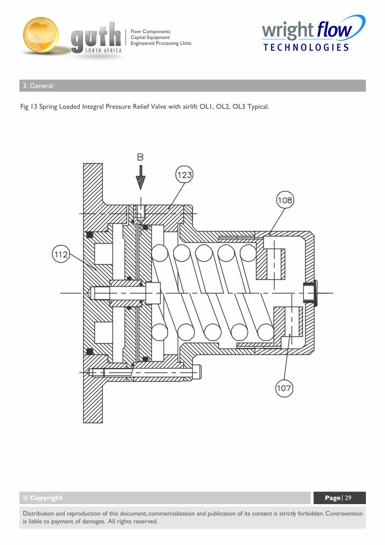
Spring loaded with airlift - see Fig 13.
Valve can be set to required pressure relief setting. Airlift override, which operates on an air supply of up to 7 Bardepending on pressure relief setting, can be used to open valve without disturbing pressure relief setting
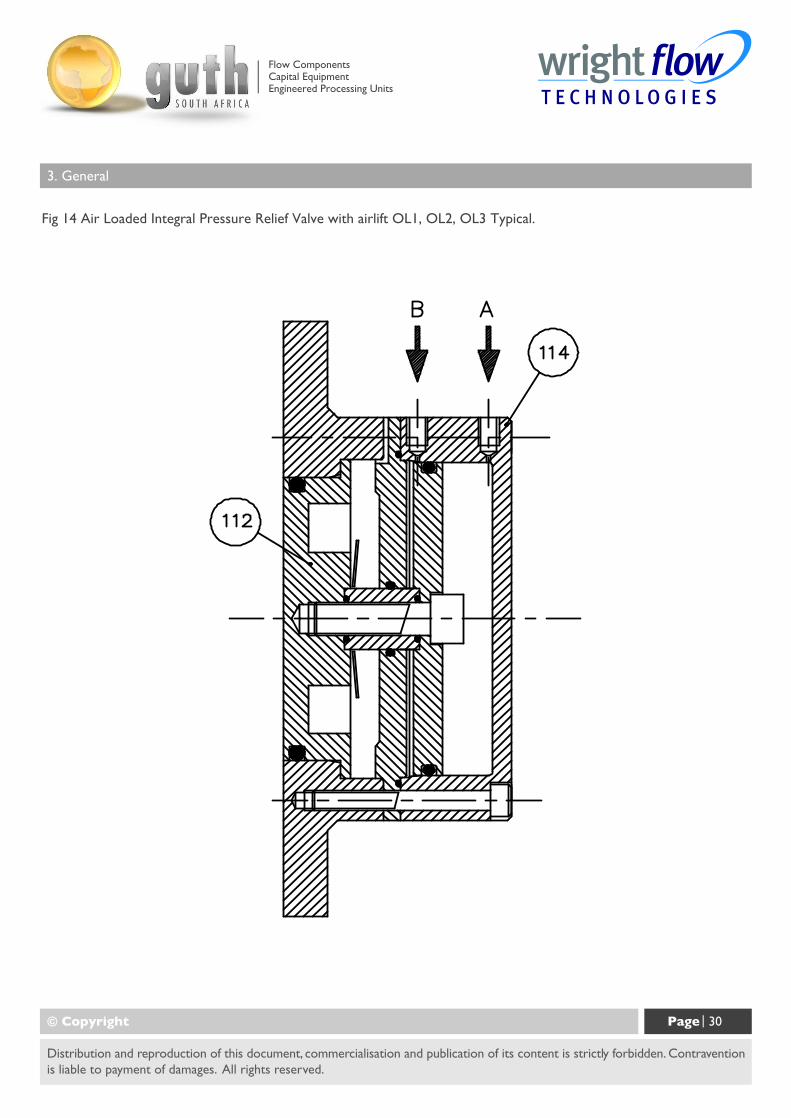
Air loaded with airlift - see Fig 14.
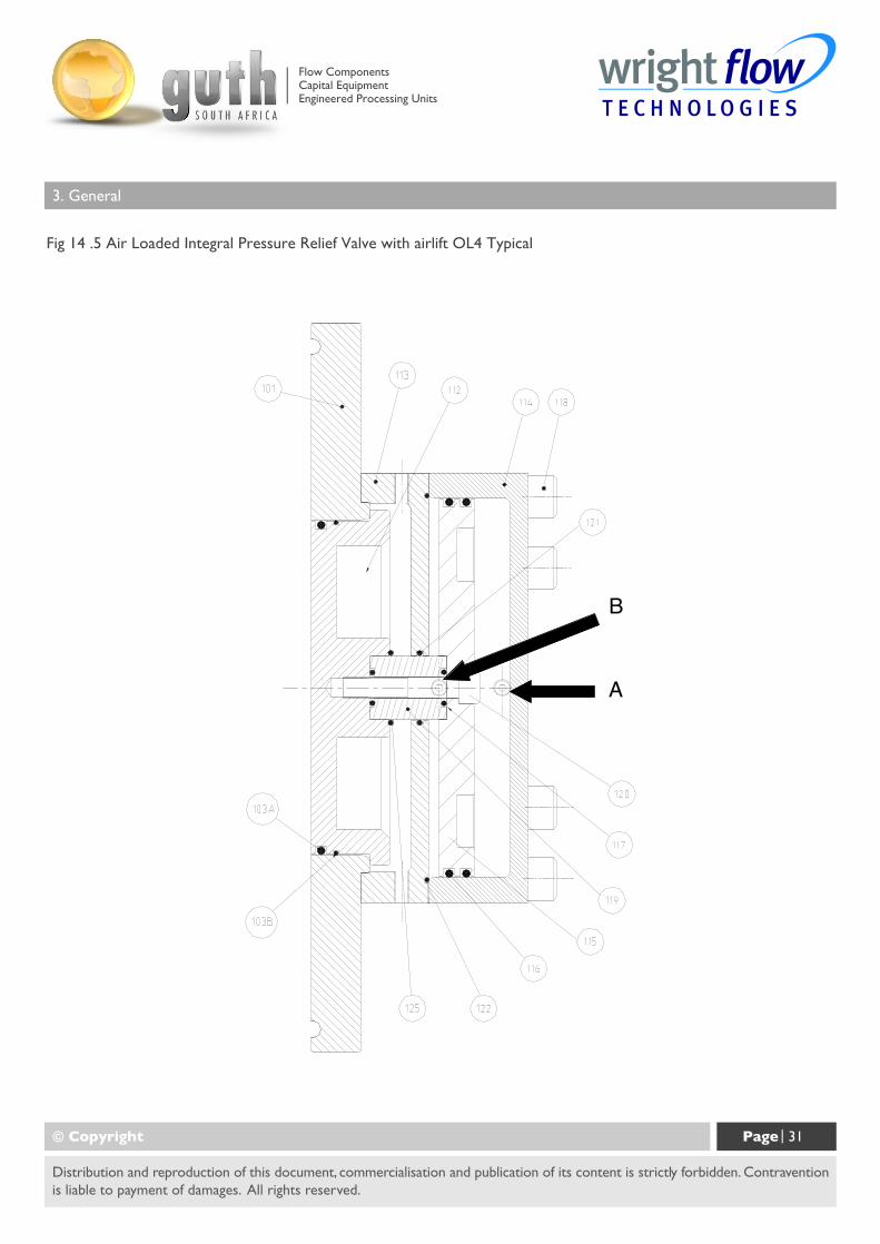
Valve, which operates on an air supply of up to 7 Bar for OL1, OL2, OL3, and 10 Bar for OL4, can be set to requiredpressure relief setting. Airlift override, which operates on an air supply of up to 7 Bar for OL1, OL2, OL3, and 10 Barfor OL4, depending on pressure relief setting, can be used to open valve without disturbing pressure relief setting.
Air actuated relief valves can be operated remotely and interfaced with other elements of the system or process control.
© Copyright Page | 23
Distribution and reproduction of this document, commercialisation and publication of its content is strictly forbidden. Contraventionis liable to payment of damages. All rights reserved.
Flow ComponentsCapital EquipmentEngineered Processing Units
3. General
Integral pressure relief valves are normally used to protect the pump from the effects of increases in systempressure caused, for example, by a restricted or closed discharge line. In response to a pressure increase thevalve opens and internally circulates the pumped media within the pump chamber. When the valve opens, becausethe volume of fluid circulating is relatively small, the temperature of the fluid in the pump chamber may rise ifthe pump continues to operate for an extended period. In severe cases this may result in temperatures in excessof the pumps operating limits or vaporisation of the fluid, both of which should be avoided. For these reasonswhen the valve is activated the cause of the system pressure increase should be eliminated as continuousoperation of the pump with the valve open is not recommended and may cause severe damage to the pump.
If the pump on which the valve is installed is to be installed in either a pressurised system or one incorporatinga vessel under vacuum, the application of the valve should be referred to Guth South Africa.
The selection, setting and application of integral relief valves is influenced by the viscosity and nature of thepumped media, the pump operating speed and the required pressure relief setting and mode of operation. Forthese reasons, and to cover the diverse range of products, the conditions under which they are pumped, andapplication demands, it is not practical to factory set integral relief valves. The setting of the valve should becarried out on site under the proposed duty conditions for which the pump and valve were selected.
For setting and operating On-Line® integral relief valves refer to sections 3.8.1 and 3.8.2. Before beginning therelief valve setting procedure the pump should be installed, refer to section 3.3.1, with a pressure gauge in thedischarge line adjacent to the pump discharge port.
3.8.1 Setting and Operating Spring Loaded Valves - See Figs 11, 12 and 13.
- Remove cover (108). For integral relief valve with manual lift, see Fig 12; first remove nut (129) and handwheel (111).
- Loosen nut (107) using a pry bar in the holes provided, to relieve spring compression. For integral relief valvewith airlift, see Fig 13, the air cylinder must be exhausted prior to unscrewing the nut (107).
- Start pump, refer to section 3.4.
- Screw in nut (107) using pry bar in holes provided until required pressure relief setting is reached.
Note: Care should be taken not to exceed the lower of either the pumps maximum pressurerating or the system design pressure.
© Copyright Page | 24
Distribution and reproduction of this document, commercialisation and publication of its content is strictly forbidden. Contraventionis liable to payment of damages. All rights reserved.
Flow ComponentsCapital EquipmentEngineered Processing Units
3. General
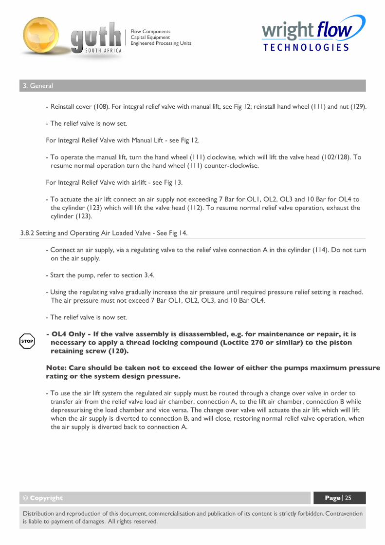
- Reinstall cover (108). For integral relief valve with manual lift, see Fig 12; reinstall hand wheel (111) and nut (129).
- The relief valve is now set.
For Integral Relief Valve with Manual Lift - see Fig 12.
- To operate the manual lift, turn the hand wheel (111) clockwise, which will lift the valve head (102/128). Toresume normal operation turn the hand wheel (111) counter-clockwise.
For Integral Relief Valve with airlift - see Fig 13.
- To actuate the air lift connect an air supply not exceeding 7 Bar for OL1, OL2, OL3 and 10 Bar for OL4 tothe cylinder (123) which will lift the valve head (112). To resume normal relief valve operation, exhaust thecylinder (123).
3.8.2 Setting and Operating Air Loaded Valve - See Fig 14.
- Connect an air supply, via a regulating valve to the relief valve connection A in the cylinder (114). Do not turnon the air supply.
- Start the pump, refer to section 3.4.
- Using the regulating valve gradually increase the air pressure until required pressure relief setting is reached.The air pressure must not exceed 7 Bar OL1, OL2, OL3, and 10 Bar OL4.
- The relief valve is now set.
- OL4 Only - If the valve assembly is disassembled, e.g. for maintenance or repair, it isnecessary to apply a thread locking compound (Loctite 270 or similar) to the pistonretaining screw (120).
Note: Care should be taken not to exceed the lower of either the pumps maximum pressurerating or the system design pressure.
- To use the air lift system the regulated air supply must be routed through a change over valve in order totransfer air from the relief valve load air chamber, connection A, to the lift air chamber, connection B whiledepressurising the load chamber and vice versa. The change over valve will actuate the air lift which will liftwhen the air supply is diverted to connection B, and will close, restoring normal relief valve operation, whenthe air supply is diverted back to connection A.
© Copyright Page | 25
Distribution and reproduction of this document, commercialisation and publication of its content is strictly forbidden. Contraventionis liable to payment of damages. All rights reserved.
Flow ComponentsCapital EquipmentEngineered Processing Units
3. General
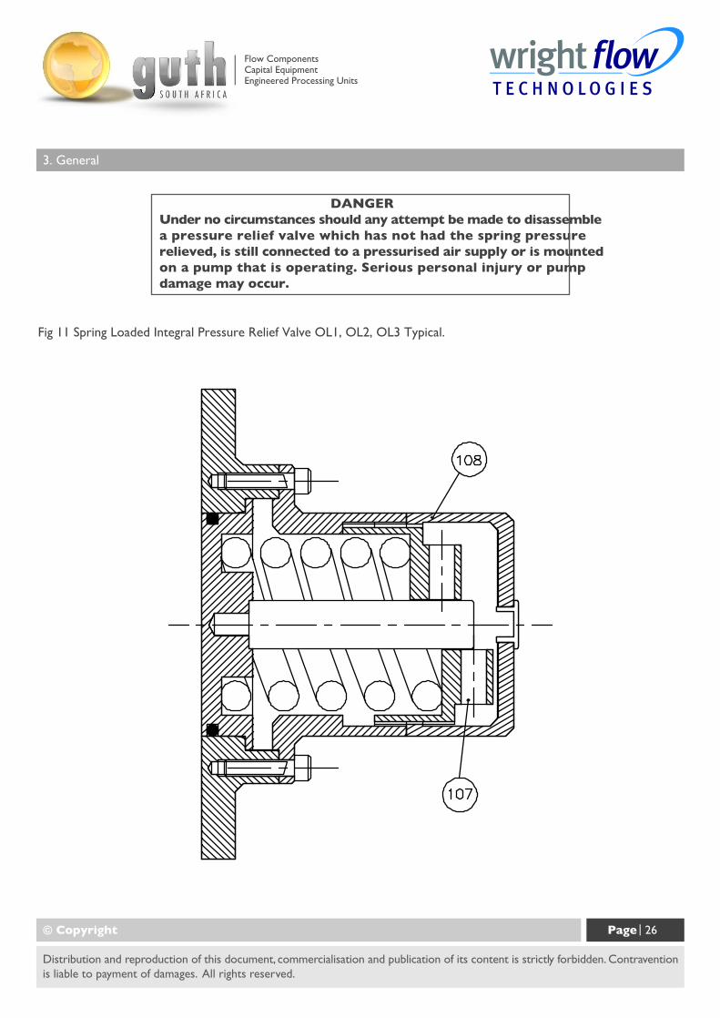
Fig 11 Spring Loaded Integral Pressure Relief Valve OL1, OL2, OL3 Typical.
© Copyright Page | 26
Distribution and reproduction of this document, commercialisation and publication of its content is strictly forbidden. Contraventionis liable to payment of damages. All rights reserved.
DANGERUnder no circumstances should any attempt be made to disassemblea pressure relief valve which has not had the spring pressurerelieved, is still connected to a pressurised air supply or is mountedon a pump that is operating. Serious personal injury or pumpdamage may occur.
Flow ComponentsCapital EquipmentEngineered Processing Units
3. General
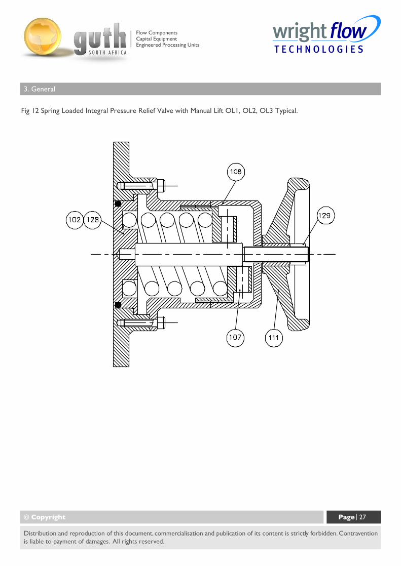
Fig 12 Spring Loaded Integral Pressure Relief Valve with Manual Lift OL1, OL2, OL3 Typical.
© Copyright Page | 27
Distribution and reproduction of this document, commercialisation and publication of its content is strictly forbidden. Contraventionis liable to payment of damages. All rights reserved.
Flow ComponentsCapital EquipmentEngineered Processing Units
3. General
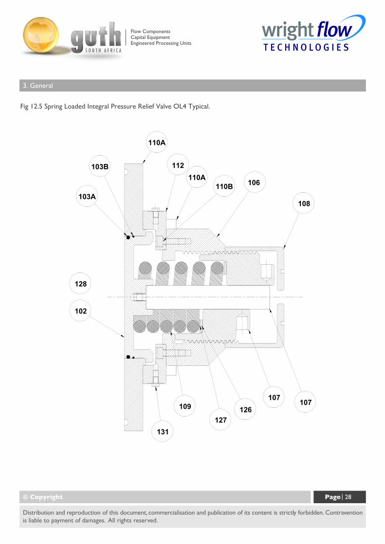
Fig 12.5 Spring Loaded Integral Pressure Relief Valve OL4 Typical.
© Copyright Page | 28
Distribution and reproduction of this document, commercialisation and publication of its content is strictly forbidden. Contraventionis liable to payment of damages. All rights reserved.
110A110B 106
112
108
107107126
127
109
131
110A
103B
103A
102
128
Flow ComponentsCapital EquipmentEngineered Processing Units
3. General
Fig 13 Spring Loaded Integral Pressure Relief Valve with airlift OL1, OL2, OL3 Typical.
© Copyright Page | 29
Distribution and reproduction of this document, commercialisation and publication of its content is strictly forbidden. Contraventionis liable to payment of damages. All rights reserved.
Flow ComponentsCapital EquipmentEngineered Processing Units
3. General
Fig 14 Air Loaded Integral Pressure Relief Valve with airlift OL1, OL2, OL3 Typical.
© Copyright Page | 30
Distribution and reproduction of this document, commercialisation and publication of its content is strictly forbidden. Contraventionis liable to payment of damages. All rights reserved.
Flow ComponentsCapital EquipmentEngineered Processing Units
3. General
Fig 14 .5 Air Loaded Integral Pressure Relief Valve with airlift OL4 Typical
© Copyright Page | 31
Distribution and reproduction of this document, commercialisation and publication of its content is strictly forbidden. Contraventionis liable to payment of damages. All rights reserved.
Flow ComponentsCapital EquipmentEngineered Processing Units
4.0 On-Line® Pump Dismantling and Assembly
Before undertaking any work on the pump the recommended Shutdown Procedure should be followed, referto section 3.5, and site safety practices must be observed.
While dismantling or assembling the pump it is essential to ensure that the pump and/or components are securedto provide adequate stability.
Large pump components or sub assemblies should be lifted using suitable devices. Use threaded holes for theattachment of lifting eyes where appropriate.
During dismantling or before assembly all components should be inspected for fit, wear, and damage. If wornor damaged the components should be replaced before re-assembly.
The position of all parts should be identified as they are removed to ensure they are reinstalled in thesame position.
Lipseals and o-rings are incorporated within the shaft cartridge assemblies and the gearbox cover to containthe lubricant for the bearings and timing gears. Regular inspection and correct maintenance of these items willensure that the lubrication is sustained and the pump maximum working life is achieved. To ensure this, it isextremely important that care is taken when removing and installing new o-rings and lipseals. When removingand replacing lipseals ensure that the location bore for the outside diameter and the seat for the back of thelipseal is not damaged as this may create a leak path for the lubricant.
When removing lipseals or o-rings care should be taken to avoid cutting or tearing thesealing faces as they pass over keyways, splines, threads or other potentially sharp orabrasive edges. All lipseals and o-rings should be carefully examined and if damaged in any way, replacedon assembly.
All o-rings and sealing lips of lipseals should be lightly lubricated with a suitable lubricant (silicon grease, etc.)before installing.
When installing lipseals do not allow the rear face to come into contact with bearings.
Prior to beginning assembly, ensure all parts are clean and free from burrs or damage. Where a vice is to beused, it should have protective jaws to avoid damage to components. Do not hammer or apply undue force toinstall or position components.
All fasteners are required to be tightened to the required torque setting during assembly, refer to section 5.2.
© Copyright Page | 32
Distribution and reproduction of this document, commercialisation and publication of its content is strictly forbidden. Contraventionis liable to payment of damages. All rights reserved.
Flow ComponentsCapital EquipmentEngineered Processing Units
4.0 On-Line® Pump Dismantling and Assembly
The preferred method of installing bearing cones is to heat them to approximately 120°C prior to installation.During this operation protective gloves should be used. Once bearing cones are installed in correct positionthey should be allowed to cool before proceeding with assembly. As an alternative, bearing cones may be pressedinto position providing the proper equipment is employed and the necessary procedures are used to preventcomponent damage.
Under no circumstances should bearing cones or cups be hammered into position.
For torque settings of fasteners and shaft rolling torque, see section 5.2.
4.1 Disassembly
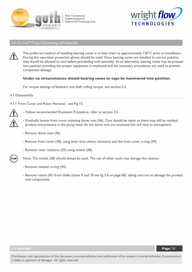
4.1.1 Front Cover and Rotor Removal - see Fig 15.
- Follow recommended Shutdown Procedure, refer to section 3.5.
- Gradually loosen front cover retaining dome nuts (36). Care should be taken as there may still be residualproduct and pressure in the pump head. As the dome nuts are loosened this will vent to atmosphere.
- Remove dome nuts (36).
- Remove front cover (38), using lever slots where necessary and the front cover o-ring (39).
- Remove rotor retainers (35) using socket (58).
Note: The socket (58) should always be used. The use of other tools may damage the retainer.
- Remove retainer o-ring (34).
- Remove rotors (41) from shafts (items 9 and 10 see fig 5.6 on page 60), taking care not to damage the productseal components.
© Copyright Page | 33
Distribution and reproduction of this document, commercialisation and publication of its content is strictly forbidden. Contraventionis liable to payment of damages. All rights reserved.
Flow ComponentsCapital EquipmentEngineered Processing Units
4.0 On-Line® Pump Dismantling and Assembly
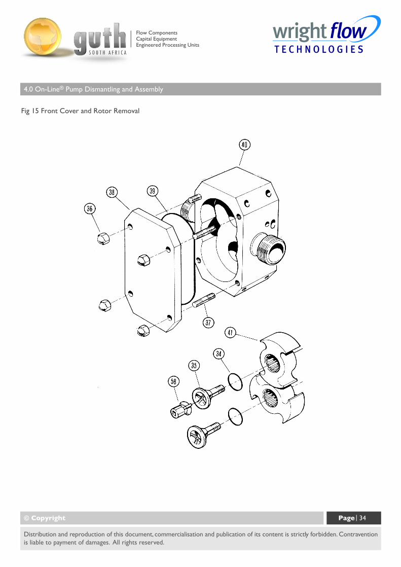
Fig 15 Front Cover and Rotor Removal
© Copyright Page | 34
Distribution and reproduction of this document, commercialisation and publication of its content is strictly forbidden. Contraventionis liable to payment of damages. All rights reserved.
Flow ComponentsCapital EquipmentEngineered Processing Units
4.0 On-Line® Pump Dismantling and Assembly
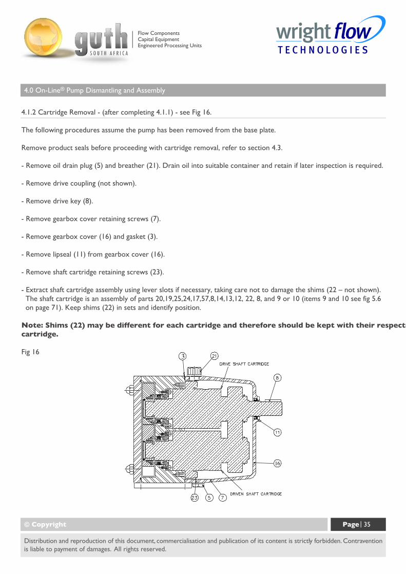
4.1.2 Cartridge Removal - (after completing 4.1.1) - see Fig 16.
The following procedures assume the pump has been removed from the base plate.
Remove product seals before proceeding with cartridge removal, refer to section 4.3.
- Remove oil drain plug (5) and breather (21). Drain oil into suitable container and retain if later inspection is required.
- Remove drive coupling (not shown).
- Remove drive key (8).
- Remove gearbox cover retaining screws (7).
- Remove gearbox cover (16) and gasket (3).
- Remove lipseal (11) from gearbox cover (16).
- Remove shaft cartridge retaining screws (23).
- Extract shaft cartridge assembly using lever slots if necessary, taking care not to damage the shims (22 – not shown). The shaft cartridge is an assembly of parts 20,19,25,24,17,57,8,14,13,12, 22, 8, and 9 or 10 (items 9 and 10 see fig 5.6 on page 71). Keep shims (22) in sets and identify position.
Note: Shims (22) may be different for each cartridge and therefore should be kept with their respectivecartridge.
Fig 16
© Copyright Page | 35
Distribution and reproduction of this document, commercialisation and publication of its content is strictly forbidden. Contraventionis liable to payment of damages. All rights reserved.
Flow ComponentsCapital EquipmentEngineered Processing Units
4.0 On-Line® Pump Dismantling and Assembly
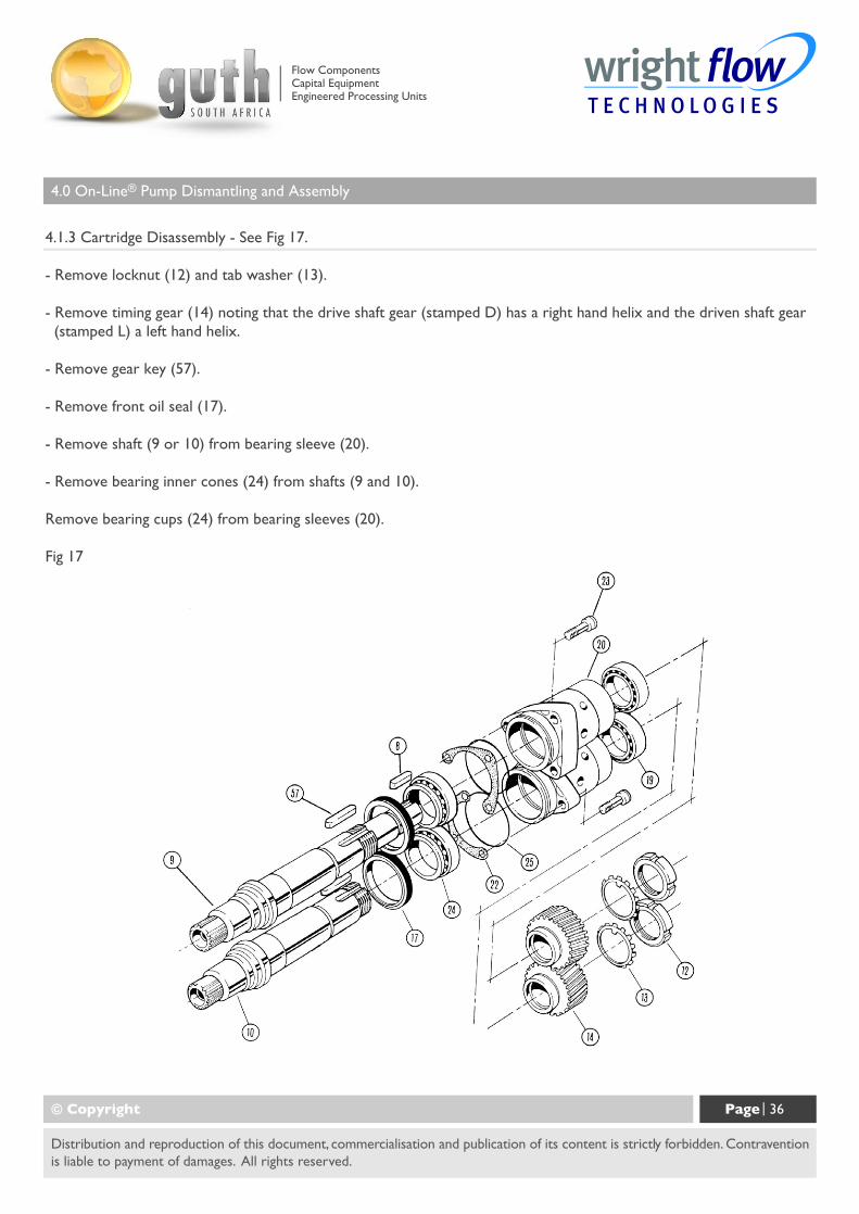
4.1.3 Cartridge Disassembly - See Fig 17.
- Remove locknut (12) and tab washer (13).
- Remove timing gear (14) noting that the drive shaft gear (stamped D) has a right hand helix and the driven shaft gear (stamped L) a left hand helix.
- Remove gear key (57).
- Remove front oil seal (17).
- Remove shaft (9 or 10) from bearing sleeve (20).
- Remove bearing inner cones (24) from shafts (9 and 10).
Remove bearing cups (24) from bearing sleeves (20).
Fig 17
© Copyright Page | 36
Distribution and reproduction of this document, commercialisation and publication of its content is strictly forbidden. Contraventionis liable to payment of damages. All rights reserved.
Flow ComponentsCapital EquipmentEngineered Processing Units
4.0 On-Line® Pump Dismantling and Assembly
4.2 Assembly
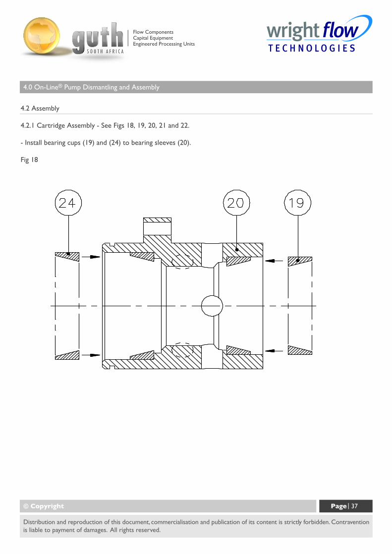
4.2.1 Cartridge Assembly - See Figs 18, 19, 20, 21 and 22.
- Install bearing cups (19) and (24) to bearing sleeves (20).
Fig 18
© Copyright Page | 37
Distribution and reproduction of this document, commercialisation and publication of its content is strictly forbidden. Contraventionis liable to payment of damages. All rights reserved.
Flow ComponentsCapital EquipmentEngineered Processing Units
4.0 On-Line® Pump Dismantling and Assembly
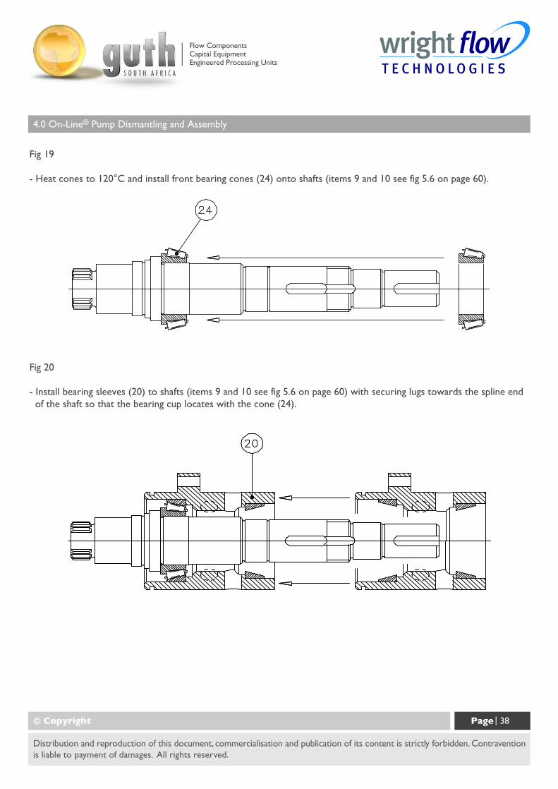
Fig 19
- Heat cones to 120°C and install front bearing cones (24) onto shafts (items 9 and 10 see fig 5.6 on page 60).
© Copyright Page | 38
Distribution and reproduction of this document, commercialisation and publication of its content is strictly forbidden. Contraventionis liable to payment of damages. All rights reserved.
Fig 20
- Install bearing sleeves (20) to shafts (items 9 and 10 see fig 5.6 on page 60) with securing lugs towards the spline end of the shaft so that the bearing cup locates with the cone (24).
Flow ComponentsCapital EquipmentEngineered Processing Units
4.0 On-Line® Pump Dismantling and Assembly
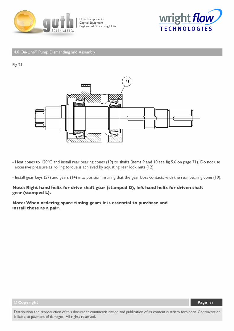
Fig 21
© Copyright Page | 39
Distribution and reproduction of this document, commercialisation and publication of its content is strictly forbidden. Contraventionis liable to payment of damages. All rights reserved.
- Heat cones to 120°C and install rear bearing cones (19) to shafts (items 9 and 10 see fig 5.6 on page 71). Do not use excessive pressure as rolling torque is achieved by adjusting rear lock nuts (12).
- Install gear keys (57) and gears (14) into position insuring that the gear boss contacts with the rear bearing cone (19).
Note: Right hand helix for drive shaft gear (stamped D), left hand helix for driven shaftgear (stamped L).
Note: When ordering spare timing gears it is essential to purchase andinstall these as a pair.
Flow ComponentsCapital EquipmentEngineered Processing Units
4.0 On-Line® Pump Dismantling and Assembly
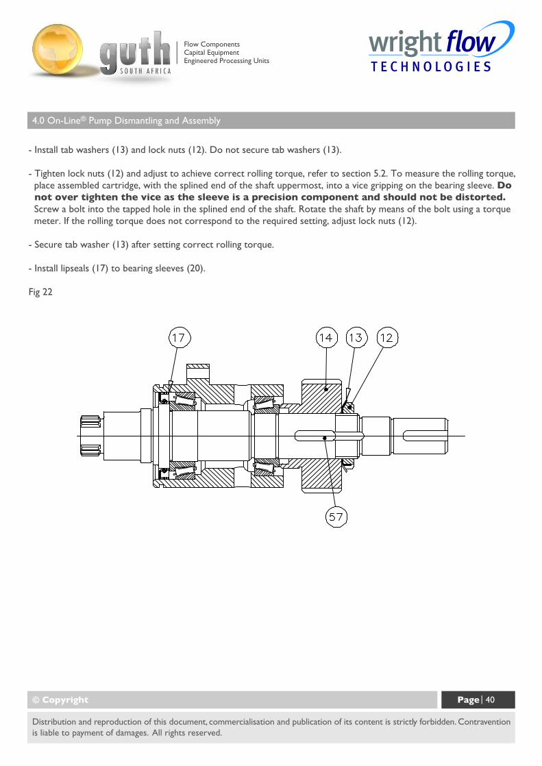
- Install tab washers (13) and lock nuts (12). Do not secure tab washers (13).
- Tighten lock nuts (12) and adjust to achieve correct rolling torque, refer to section 5.2. To measure the rolling torque, place assembled cartridge, with the splined end of the shaft uppermost, into a vice gripping on the bearing sleeve. Do not over tighten the vice as the sleeve is a precision component and should not be distorted. Screw a bolt into the tapped hole in the splined end of the shaft. Rotate the shaft by means of the bolt using a torque meter. If the rolling torque does not correspond to the required setting, adjust lock nuts (12).
- Secure tab washer (13) after setting correct rolling torque.
- Install lipseals (17) to bearing sleeves (20).
Fig 22
© Copyright Page | 40
Distribution and reproduction of this document, commercialisation and publication of its content is strictly forbidden. Contraventionis liable to payment of damages. All rights reserved.
Flow ComponentsCapital EquipmentEngineered Processing Units
4.0 On-Line® Pump Dismantling and Assembly
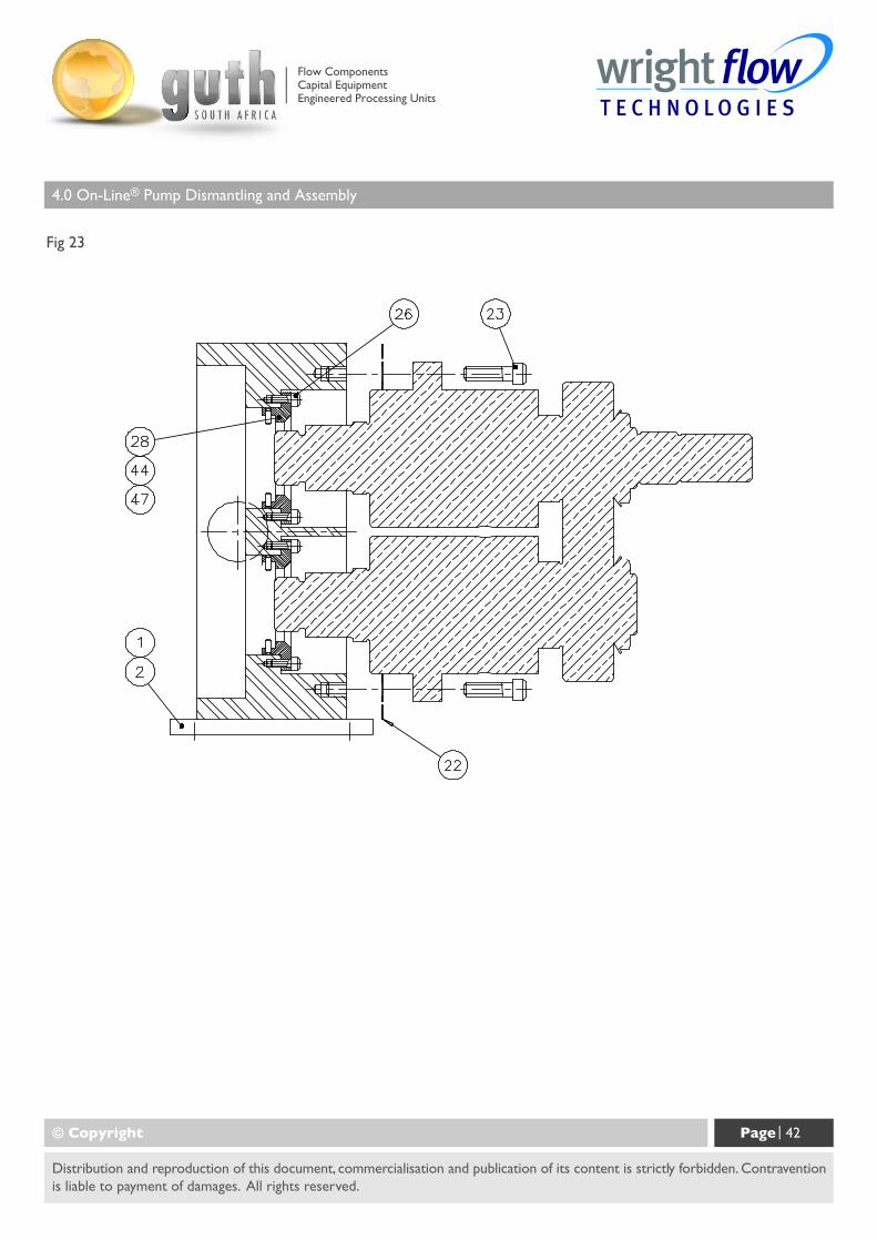
4.2.2 Cartridge to Rotorcase Assembly - See Fig 23.
- If not already installed, mount feet (1) to rotorcase (item 40 see fig 5.6) in the required positions using cap head screws (2). Install the relevant product seal housing (28, 44, 47 or 156) with associated gasket or o-ring or lipseal (single flushed and double flushed mechanical seals only) and wave spring (single mechanical seal only) to the rear of the rotorcase (40) and secure with screws (26).
- Install o-rings (25) to front diameter of bearing sleeves (20).
- Assemble cartridges into rotorcase (40) rear bores insuring that timing marks on the timing gears (14) are in mesh (single dot on drive shaft gear, two dots on driven shaft gear). The timing gears are in correct mesh when the single dot on the drive shaft gear is between the two dots on the driven shaft gear. Leave a small gap between rear face of rotorcase (40) and cartridge mounting face for inserting shims (22).
- Insert shims (22) between rotorcase (40) and cartridge. Shims can be plastic or steel and are either marked with their thickness or are colour coded as follows :
Blue = 0.050mm thickGreen = 0.075mm thickClear = 0.150mm thickWhite = 0.250mm thickNote always check with a micrometer or similar device
- Secure cartridges to rotorcase (40) with cap head screws (23), tightening to correct torque, refer to section 5.2.
- Install rotors (41), refer to section 4.2.3.
- Using a depth micrometer or similar device measure "actual" rotor front clearance. This is the clearance between the front face of the rotorcase and the front face of the rotor. Select "required" front clearance (A) from the Clearance Chart, refer to section 5.1. The difference between the "actual" measured clearance and the "required" clearance, as given on the Clearance Chart, is the amount of shim (22) that needs to be removed or added.
- Having determined the amount of shim (22) to be removed or added, remove rotors (41), refer to section 4.1.1. Remove cap head screws (23). Taking care not to damage the shims (22), ease cartridge from rotorcase (40) using lever slots to create a gap to access the shims (22). Remove or add appropriate amount of shim between rotorcase (40) and shaft cartridge flange.
- Secure cartridges to rotorcase (40) with cap head screws (23) tightening to correct torque refer to section 5.2.
© Copyright Page | 41
Distribution and reproduction of this document, commercialisation and publication of its content is strictly forbidden. Contraventionis liable to payment of damages. All rights reserved.
Flow ComponentsCapital EquipmentEngineered Processing Units
4.0 On-Line® Pump Dismantling and Assembly
Fig 23
© Copyright Page | 42
Distribution and reproduction of this document, commercialisation and publication of its content is strictly forbidden. Contraventionis liable to payment of damages. All rights reserved.
Flow ComponentsCapital EquipmentEngineered Processing Units
4.0 On-Line® Pump Dismantling and Assembly
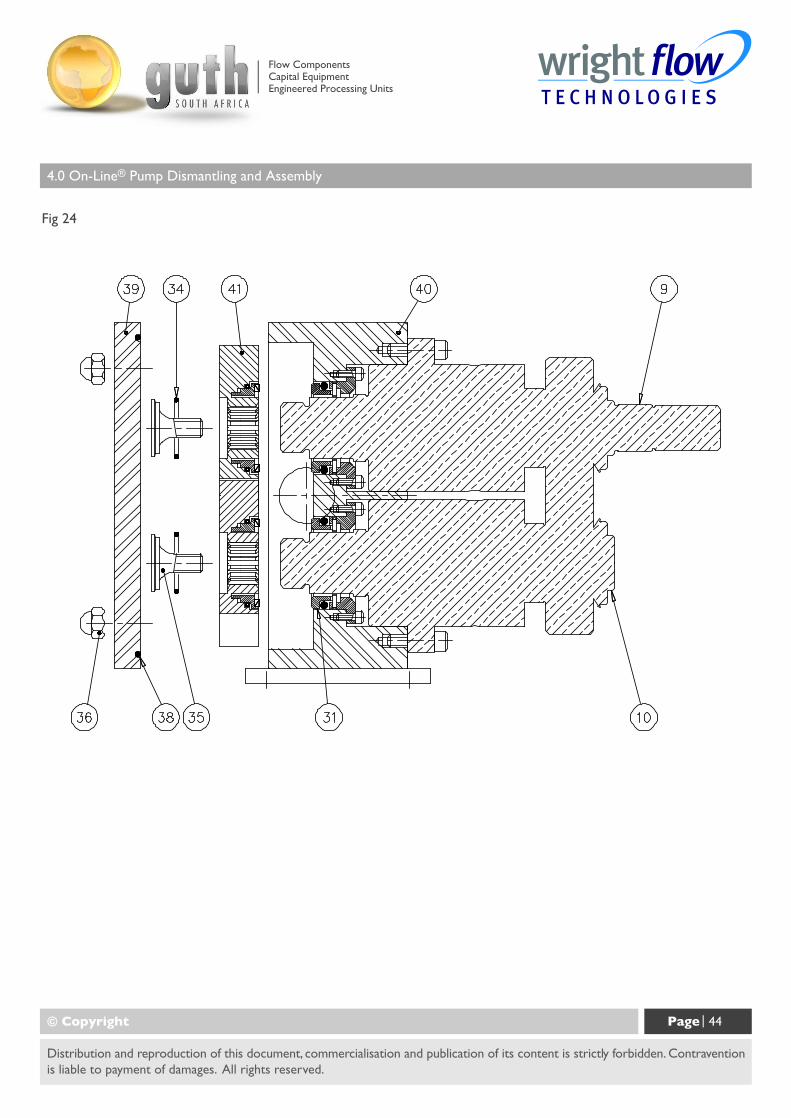
4.2.3 Rotor Assembly and Setting Rotor Clearances - see Fig 24.
- Do not install product seals at this point.
- Install rotors (41) onto shafts (9 and 10) in rotorcase (40), install retainer o-ring (34) into bore in rotor andsecure with rotor retainer (35) set to the correct torque (see section 5.2) using socket (58).
Note: The retainer o-ring (34) seals the shaft/rotor spline and should not be re-used ifcut, distorted or damaged in such a way as to impair its ability to form a seal. If in doubta new o-ring should always be installed.
- Using a depth micrometer or similar device measure front clearance (A) between the rotorcase and rotorfront faces and check that this corresponds to the appropriate clearance as indicated on the Clearance Chart,refer to section 5.1.
- If the front clearance (A) is incorrect adjustment of the shims (22) between the rotorcase and cartridge isrequired, refer to section 4.2.2 Cartridge to Rotorcase Assembly.
- With rotors (41) installed, check all clearances, front (A), radial (C), rear (B) and mesh (D), against the ClearanceChart, refer to section 5.1. Remove rotors (41) and install product seals, refer to section 4.3. Product SealFitting and Removal, and reassemble rotors (41) tightening to the correct torque.
Note: When fitting mechanical seals be sure that the seal stationary seat (31) is properlyengaged with the seal housing (28) drive pin or serious damage to the pump will result.
- Install o-ring (38) to front cover (39).
- Install front cover (39) to rotorcase (40), securing with dome nuts (36), tightening to correct torque, refer tosection 5.2.
Note: It is recommended that rotors should be installed in pairs, although parts areavailable individually.
© Copyright Page | 43
Distribution and reproduction of this document, commercialisation and publication of its content is strictly forbidden. Contraventionis liable to payment of damages. All rights reserved.
Flow ComponentsCapital EquipmentEngineered Processing Units
4.0 On-Line® Pump Dismantling and Assembly
Fig 24
© Copyright Page | 44
Distribution and reproduction of this document, commercialisation and publication of its content is strictly forbidden. Contraventionis liable to payment of damages. All rights reserved.
Flow ComponentsCapital EquipmentEngineered Processing Units
4.0 On-Line® Pump Dismantling and Assembly
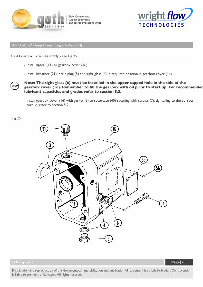
4.2.4 Gearbox Cover Assembly - see Fig 25.
- Install lipseal (11) to gearbox cover (16).
- Install breather (21); drain plug (5) and sight glass (6) in required position in gearbox cover (16).
Note: The sight glass (6) must be installed in the upper tapped hole in the side of thegearbox cover (16). Remember to fill the gearbox with oil prior to start up. For recommendedlubricant capacities and grades refer to section 5.3.
- Install gearbox cover (16) with gasket (3) to rotorcase (40) securing with screws (7), tightening to the correcttorque, refer to section 5.2.
Fig 25
© Copyright Page | 45
Distribution and reproduction of this document, commercialisation and publication of its content is strictly forbidden. Contraventionis liable to payment of damages. All rights reserved.
Flow ComponentsCapital EquipmentEngineered Processing Units
4.0 On-Line® Pump Dismantling and Assembly
4.3 Product Seal Fitting and Removal
4.3.1 General Procedures for Fitting Mechanical Seals.
"Quick summary" of mechanical seal installation.
- Mechanical seals are precision-engineered assemblies incorporating finely lapped seal faces and seats. Theymust therefore be handled with care and will not give optimum performance unless installed carefully andaccording to instructions.
- Where mechanical seals are to be reused ensure that seal components are kept in their appropriate sets.Do not mix old and new seal faces on the same seal.
- Remove any sharp corners and burrs that may damage any elastomers such as o-rings or lip seals.
- Ensure that all seal component fitting bores and housings are thoroughly cleaned before installation.
- The seal faces and seats must be handled with care and cleaned thoroughly before installation.
- Ensure that seal faces are undamaged and the o-rings are not cut, swollen, or cracked.
- All o-rings should be lightly lubricated with a suitable lubricant (silicon grease, soap etc.) before fitting butensure there is no excessive amount of lubricant especially around the seal face area.
- When fitting PTFE encapsulated o-rings it is important to immerse them in hot water for several minutes tosoften them.
- Ensure seal seats are mounted squarely in the rotorcase.
- Ensure when installing seals with brittle faces such as silicon carbide that extra care is taken.
- Do not use any excessive force to install a mechanical seal. If it is difficult to position and assemble the sealthen something is wrong.
- If you drop or damage a seal, do not install it before an inspection has been carried out.
- Do not run a mechanical seal dry.
© Copyright Page | 46
Distribution and reproduction of this document, commercialisation and publication of its content is strictly forbidden. Contraventionis liable to payment of damages. All rights reserved.
Flow ComponentsCapital EquipmentEngineered Processing Units
4.0 On-Line® Pump Dismantling and Assembly
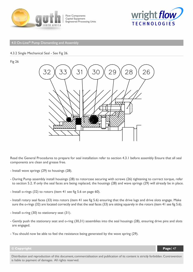
4.3.2 Single Mechanical Seal - See Fig 26.
Fig 26
© Copyright Page | 47
Distribution and reproduction of this document, commercialisation and publication of its content is strictly forbidden. Contraventionis liable to payment of damages. All rights reserved.
Read the General Procedures to prepare for seal installation refer to section 4.3.1 before assembly Ensure that all sealcomponents are clean and grease free.
- Install wave springs (29) to housings (28).
- During Pump assembly install housings (28) to rotorcase securing with screws (26) tightening to correct torque, refer to section 5.2. If only the seal faces are being replaced, the housings (28) and wave springs (29) will already be in place.
- Install o-rings (32) to rotors (item 41 see fig 5.6 on page 60).
- Install rotary seal faces (33) into rotors (item 41 see fig 5.6) ensuring that the drive lugs and drive slots engage. Make sure the o-rings (32) are located correctly and that the seal faces (33) are sitting squarely in the rotors (item 41 see fig 5.6).
- Install o-ring (30) to stationary seat (31).
- Gently push the stationary seat and o-ring (30,31) assemblies into the seal housings (28), ensuring drive pins and slots are engaged.
- You should now be able to feel the resistance being generated by the wave spring (29).
Flow ComponentsCapital EquipmentEngineered Processing Units
4.0 On-Line® Pump Dismantling and Assembly
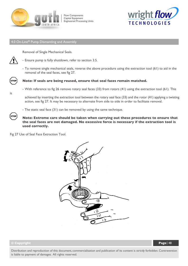
Removal of Single Mechanical Seals.
- Ensure pump is fully shutdown, refer to section 3.5.
- To remove single mechanical seals, reverse the above procedure using the extraction tool (61) to aid in theremoval of the seal faces, see fig 27.
Note: If seals are being reused, ensure that seal faces remain matched.
- With reference to fig 26 remove rotary seal faces (33) from rotors (41) using the extraction tool (61). Thisis
achieved by inserting the extraction tool between the rotary seal face (33) and the rotor (41) applying a twistingaction, see fig 27. It may be necessary to alternate from side to side in order to facilitate removal.
- The static seal face (31) can be removed by using the same technique.
Note: Extreme care should be taken when carrying out these procedures to ensure thatthe seal faces are not damaged. No excessive force is necessary if the extraction tool isused correctly.
Fig 27 Use of Seal Face Extraction Tool.
© Copyright Page | 48
Distribution and reproduction of this document, commercialisation and publication of its content is strictly forbidden. Contraventionis liable to payment of damages. All rights reserved.
Flow ComponentsCapital EquipmentEngineered Processing Units
4.0 On-Line® Pump Dismantling and Assembly
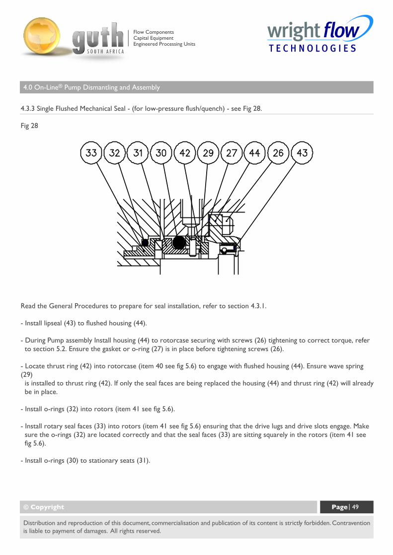
4.3.3 Single Flushed Mechanical Seal - (for low-pressure flush/quench) - see Fig 28.
Fig 28
© Copyright Page | 49
Distribution and reproduction of this document, commercialisation and publication of its content is strictly forbidden. Contraventionis liable to payment of damages. All rights reserved.
Read the General Procedures to prepare for seal installation, refer to section 4.3.1.
- Install lipseal (43) to flushed housing (44).
- During Pump assembly Install housing (44) to rotorcase securing with screws (26) tightening to correct torque, refer to section 5.2. Ensure the gasket or o-ring (27) is in place before tightening screws (26).
- Locate thrust ring (42) into rotorcase (item 40 see fig 5.6) to engage with flushed housing (44). Ensure wave spring(29) is installed to thrust ring (42). If only the seal faces are being replaced the housing (44) and thrust ring (42) will already be in place.
- Install o-rings (32) into rotors (item 41 see fig 5.6).
- Install rotary seal faces (33) into rotors (item 41 see fig 5.6) ensuring that the drive lugs and drive slots engage. Make sure the o-rings (32) are located correctly and that the seal faces (33) are sitting squarely in the rotors (item 41 see fig 5.6).
- Install o-rings (30) to stationary seats (31).
Flow ComponentsCapital EquipmentEngineered Processing Units
4.0 On-Line® Pump Dismantling and Assembly
- Gently push the stationary seat and o-ring assemblies (30 and 31) into the thrust rings (42), ensuring drivepins
and slots are engaged.
- You should now be able to feel the resistance being generated by thewave springs (29).
- Before final assembly, check that the seal faces are absolutely clean, use a soft tissue and a suitable solventbased
cleaner for best results.
Disassembly of Single Flushed Mechanical Seals.
Ensure pump is fully shutdown, refer to section 3.5.
To disassemble, reverse the above procedure using the extraction tool supplied to aid in the removal of theseal
faces, see fig 27.
- Remove rotary seal faces (33) from the rotors (41 see fig 5.6) using the extraction tool (61). This is achievedby inserting the extraction tool between the rotary seal face (33) and the rotor (41) and applying atwisting action, see fig 27. It may be necessary to alternate from side to side to facilitate removal.
- The static seal face (31) can be removed by using the same technique.
Note: Extreme care should be taken when carrying out these procedures to ensure thatthe seal faces are not damaged. No excessive force is necessary if the extraction tool isused correctly.
© Copyright Page | 50
Distribution and reproduction of this document, commercialisation and publication of its content is strictly forbidden. Contraventionis liable to payment of damages. All rights reserved.
Flow ComponentsCapital EquipmentEngineered Processing Units
4.0 On-Line® Pump Dismantling and Assembly
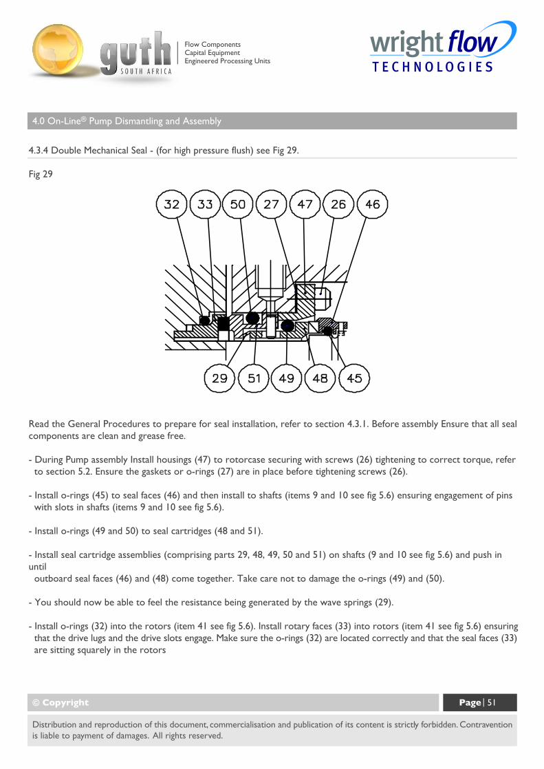
4.3.4 Double Mechanical Seal - (for high pressure flush) see Fig 29.
Fig 29
© Copyright Page | 51
Distribution and reproduction of this document, commercialisation and publication of its content is strictly forbidden. Contraventionis liable to payment of damages. All rights reserved.
Read the General Procedures to prepare for seal installation, refer to section 4.3.1. Before assembly Ensure that all sealcomponents are clean and grease free.
- During Pump assembly Install housings (47) to rotorcase securing with screws (26) tightening to correct torque, refer to section 5.2. Ensure the gaskets or o-rings (27) are in place before tightening screws (26).
- Install o-rings (45) to seal faces (46) and then install to shafts (items 9 and 10 see fig 5.6) ensuring engagement of pins with slots in shafts (items 9 and 10 see fig 5.6).
- Install o-rings (49 and 50) to seal cartridges (48 and 51).
- Install seal cartridge assemblies (comprising parts 29, 48, 49, 50 and 51) on shafts (9 and 10 see fig 5.6) and push inuntil outboard seal faces (46) and (48) come together. Take care not to damage the o-rings (49) and (50).
- You should now be able to feel the resistance being generated by the wave springs (29).
- Install o-rings (32) into the rotors (item 41 see fig 5.6). Install rotary faces (33) into rotors (item 41 see fig 5.6) ensuring that the drive lugs and the drive slots engage. Make sure the o-rings (32) are located correctly and that the seal faces (33) are sitting squarely in the rotors
Flow ComponentsCapital EquipmentEngineered Processing Units
4.0 On-Line® Pump Dismantling and Assembly
Disassembly of Double Mechanical Seals.
Ensure pump is fully shutdown, refer to section 3.5.
To disassemble, reverse the above procedure using the extraction tool supplied to aid in the removal of theseal
faces, see Figs 27 and 30.
Note: If seals are being reused, Ensure that seal faces remain matched.
- Remove rotary seal faces (33) from rotors (41) using extraction tool (61). This is achieved by inserting theextraction tool between the rotary seal face (33) and the rotor (41) and applying a twisting action, see Fig 27.It may be necessary to alternate from side to side to facilitate removal.
- Remove stationary seal cartridge assemblies (29,48 and 51) from the shafts (9 and 10) by pulling off.
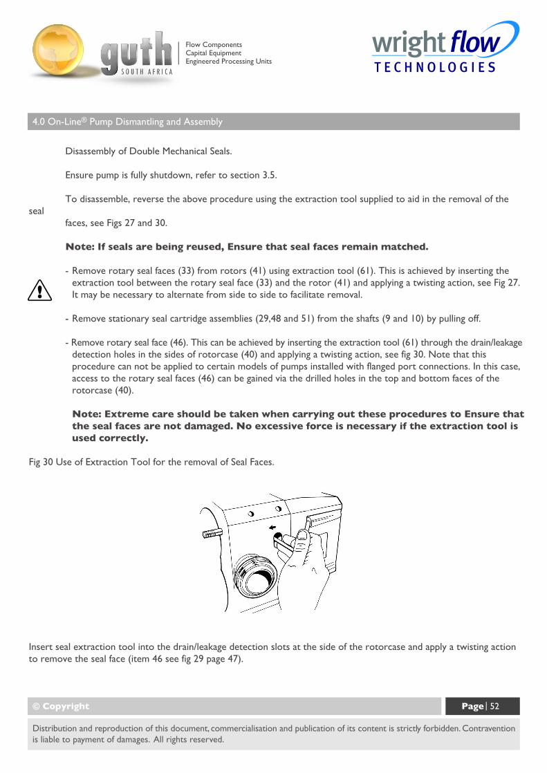
- Remove rotary seal face (46). This can be achieved by inserting the extraction tool (61) through the drain/leakagedetection holes in the sides of rotorcase (40) and applying a twisting action, see fig 30. Note that thisprocedure can not be applied to certain models of pumps installed with flanged port connections. In this case,access to the rotary seal faces (46) can be gained via the drilled holes in the top and bottom faces of therotorcase (40).
Note: Extreme care should be taken when carrying out these procedures to Ensure thatthe seal faces are not damaged. No excessive force is necessary if the extraction tool isused correctly.
Fig 30 Use of Extraction Tool for the removal of Seal Faces.
© Copyright Page | 52
Distribution and reproduction of this document, commercialisation and publication of its content is strictly forbidden. Contraventionis liable to payment of damages. All rights reserved.
Insert seal extraction tool into the drain/leakage detection slots at the side of the rotorcase and apply a twisting actionto remove the seal face (item 46 see fig 29 page 47).
Flow ComponentsCapital EquipmentEngineered Processing Units
4.0 On-Line® Pump Dismantling and Assembly
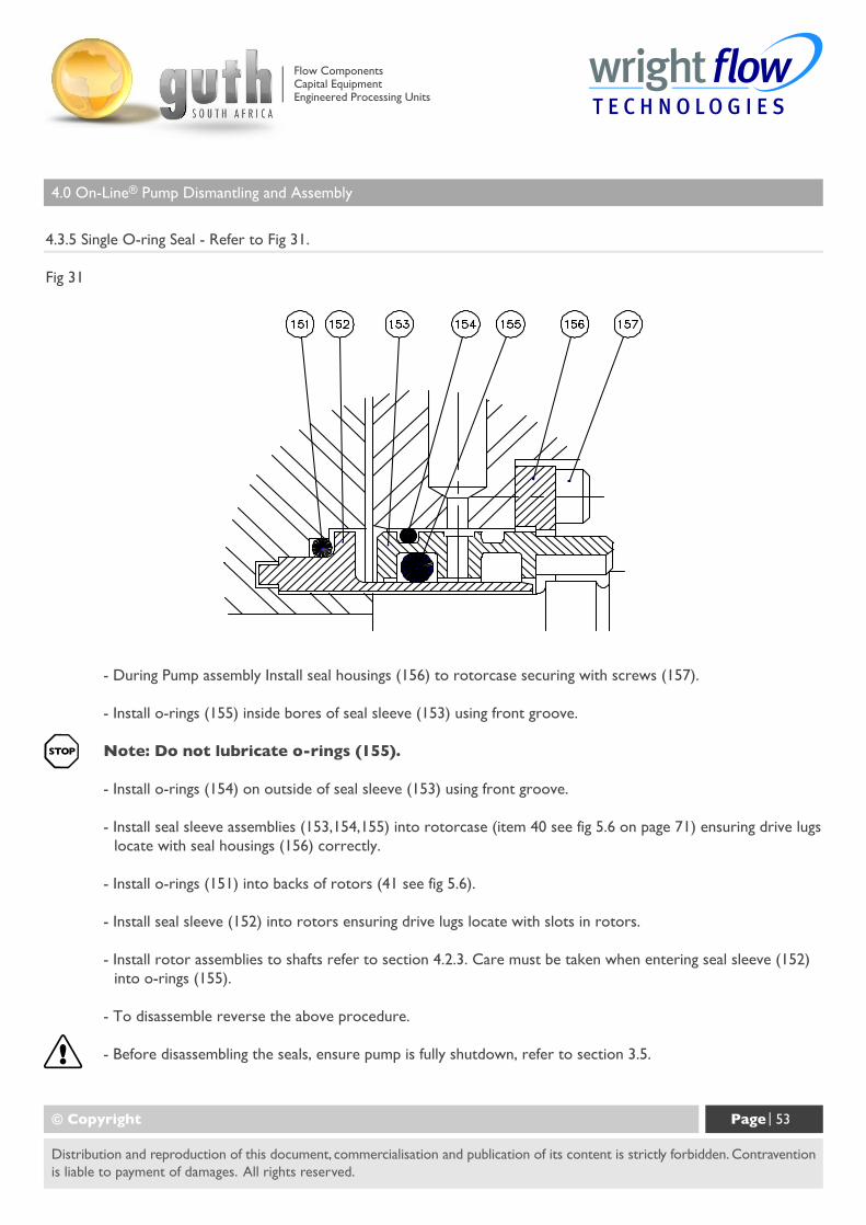
4.3.5 Single O-ring Seal - Refer to Fig 31.
Fig 31
© Copyright Page | 53
Distribution and reproduction of this document, commercialisation and publication of its content is strictly forbidden. Contraventionis liable to payment of damages. All rights reserved.
- During Pump assembly Install seal housings (156) to rotorcase securing with screws (157).
- Install o-rings (155) inside bores of seal sleeve (153) using front groove.
Note: Do not lubricate o-rings (155).
- Install o-rings (154) on outside of seal sleeve (153) using front groove.
- Install seal sleeve assemblies (153,154,155) into rotorcase (item 40 see fig 5.6 on page 71) ensuring drive lugslocate with seal housings (156) correctly.
- Install o-rings (151) into backs of rotors (41 see fig 5.6).
- Install seal sleeve (152) into rotors ensuring drive lugs locate with slots in rotors.
- Install rotor assemblies to shafts refer to section 4.2.3. Care must be taken when entering seal sleeve (152)into o-rings (155).
- To disassemble reverse the above procedure.
- Before disassembling the seals, ensure pump is fully shutdown, refer to section 3.5.
Flow ComponentsCapital EquipmentEngineered Processing Units
4.0 On-Line® Pump Dismantling and Assembly
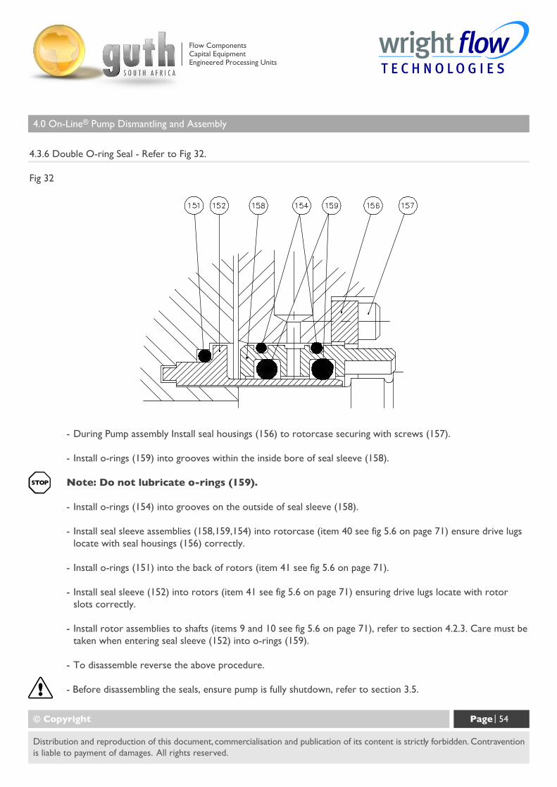
4.3.6 Double O-ring Seal - Refer to Fig 32.
Fig 32
© Copyright Page | 54
Distribution and reproduction of this document, commercialisation and publication of its content is strictly forbidden. Contraventionis liable to payment of damages. All rights reserved.
- During Pump assembly Install seal housings (156) to rotorcase securing with screws (157).
- Install o-rings (159) into grooves within the inside bore of seal sleeve (158).
Note: Do not lubricate o-rings (159).
- Install o-rings (154) into grooves on the outside of seal sleeve (158).
- Install seal sleeve assemblies (158,159,154) into rotorcase (item 40 see fig 5.6 on page 71) ensure drive lugslocate with seal housings (156) correctly.
- Install o-rings (151) into the back of rotors (item 41 see fig 5.6 on page 71).
- Install seal sleeve (152) into rotors (item 41 see fig 5.6 on page 71) ensuring drive lugs locate with rotorslots correctly.
- Install rotor assemblies to shafts (items 9 and 10 see fig 5.6 on page 71), refer to section 4.2.3. Care must betaken when entering seal sleeve (152) into o-rings (159).
- To disassemble reverse the above procedure.
- Before disassembling the seals, ensure pump is fully shutdown, refer to section 3.5.
Flow ComponentsCapital EquipmentEngineered Processing Units
4.0 On-Line® Pump Dismantling and Assembly
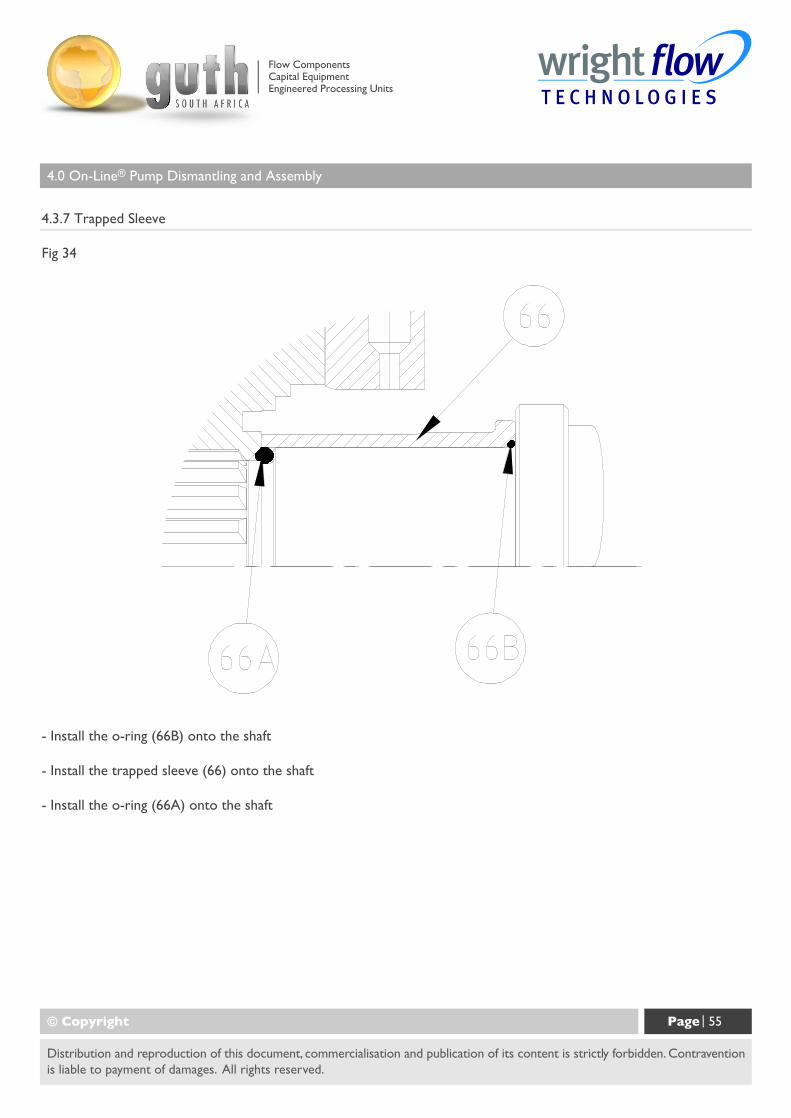
4.3.7 Trapped Sleeve
Fig 34
© Copyright Page | 55
Distribution and reproduction of this document, commercialisation and publication of its content is strictly forbidden. Contraventionis liable to payment of damages. All rights reserved.
- Install the o-ring (66B) onto the shaft
- Install the trapped sleeve (66) onto the shaft
- Install the o-ring (66A) onto the shaft
Flow ComponentsCapital EquipmentEngineered Processing Units
4.0 On-Line® Pump Dismantling and Assembly
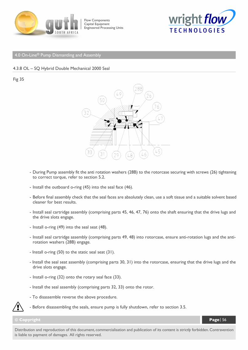
4.3.8 OL – SQ Hybrid Double Mechanical 2000 Seal
Fig 35
© Copyright Page | 56
Distribution and reproduction of this document, commercialisation and publication of its content is strictly forbidden. Contraventionis liable to payment of damages. All rights reserved.
- During Pump assembly fit the anti rotation washers (28B) to the rotorcase securing with screws (26) tighteningto correct torque, refer to section 5.2.
- Install the outboard o-ring (45) into the seal face (46).
- Before final assembly check that the seal faces are absolutely clean, use a soft tissue and a suitable solvent basedcleaner for best results.
- Install seal cartridge assembly (comprising parts 45, 46, 47, 76) onto the shaft ensuring that the drive lugs andthe drive slots engage.
- Install o-ring (49) into the seal seat (48).
- Install seal cartridge assembly (comprising parts 49, 48) into rotorcase, ensure anti-rotation lugs and the anti-rotation washers (28B) engage.
- Install o-ring (50) to the static seal seat (31).
- Install the seal seat assembly (comprising parts 30, 31) into the rotorcase, ensuring that the drive lugs and thedrive slots engage.
- Install o-ring (32) onto the rotary seal face (33).
- Install the seal assembly (comprising parts 32, 33) onto the rotor.
- To disassemble reverse the above procedure.
- Before disassembling the seals, ensure pump is fully shutdown, refer to section 3.5.
Flow ComponentsCapital EquipmentEngineered Processing Units
4.0 On-Line® Pump Dismantling and Assembly
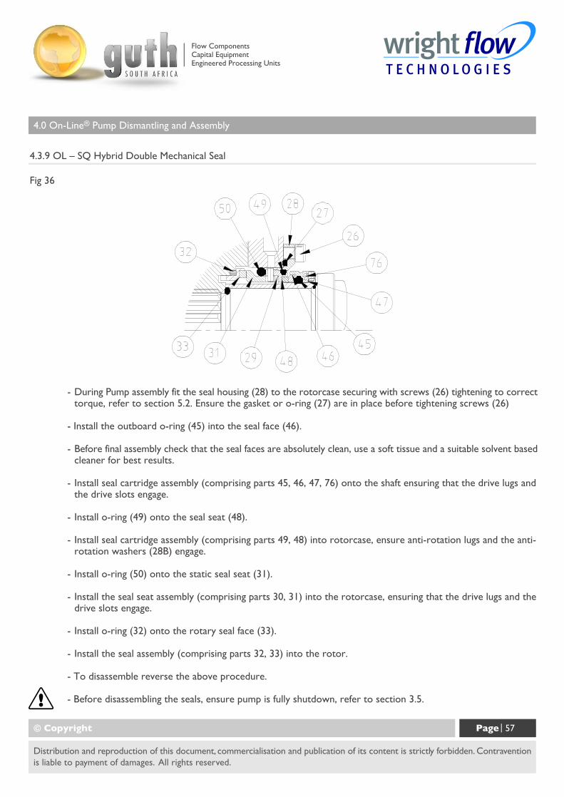
4.3.9 OL – SQ Hybrid Double Mechanical Seal
Fig 36
© Copyright Page | 57
Distribution and reproduction of this document, commercialisation and publication of its content is strictly forbidden. Contraventionis liable to payment of damages. All rights reserved.
- During Pump assembly fit the seal housing (28) to the rotorcase securing with screws (26) tightening to correcttorque, refer to section 5.2. Ensure the gasket or o-ring (27) are in place before tightening screws (26)
- Install the outboard o-ring (45) into the seal face (46).
- Before final assembly check that the seal faces are absolutely clean, use a soft tissue and a suitable solvent basedcleaner for best results.
- Install seal cartridge assembly (comprising parts 45, 46, 47, 76) onto the shaft ensuring that the drive lugs andthe drive slots engage.
- Install o-ring (49) onto the seal seat (48).
- Install seal cartridge assembly (comprising parts 49, 48) into rotorcase, ensure anti-rotation lugs and the anti-rotation washers (28B) engage.
- Install o-ring (50) onto the static seal seat (31).
- Install the seal seat assembly (comprising parts 30, 31) into the rotorcase, ensuring that the drive lugs and thedrive slots engage.
- Install o-ring (32) onto the rotary seal face (33).
- Install the seal assembly (comprising parts 32, 33) into the rotor.
- To disassemble reverse the above procedure.
- Before disassembling the seals, ensure pump is fully shutdown, refer to section 3.5.
Flow ComponentsCapital EquipmentEngineered Processing Units
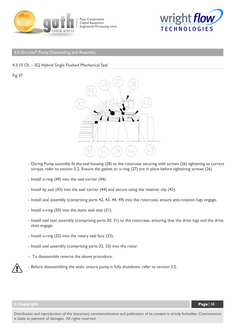
4.0 On-Line® Pump Dismantling and Assembly
4.3.10 OL – SQ Hybrid Single Flushed Mechanical Seal
Fig 37
© Copyright Page | 58
Distribution and reproduction of this document, commercialisation and publication of its content is strictly forbidden. Contraventionis liable to payment of damages. All rights reserved.
- During Pump assembly fit the seal housing (28) to the rotorcase securing with screws (26) tightening to correcttorque, refer to section 5.2. Ensure the gasket or o-ring (27) are in place before tightening screws (26)
- Install o-ring (49) into the seal carrier (44).
- Install lip seal (43) into the seal carrier (44) and secure using the retainer clip (42).
- Install seal assembly (comprising parts 42, 43, 44, 49) into the rotorcase, ensure anti-rotation lugs engage.
- Install o-ring (50) into the static seal seat (31).
- Install seal seat assembly (comprising parts 30, 31) to the rotorcase, ensuring that the drive lugs and the driveslots engage.
- Install o-ring (32) into the rotary seal face (33).
- Install seal assembly (comprising parts 32, 33) into the rotor.
- To disassemble reverse the above procedure.
- Before disassembling the seals, ensure pump is fully shutdown, refer to section 3.5.
Flow ComponentsCapital EquipmentEngineered Processing Units
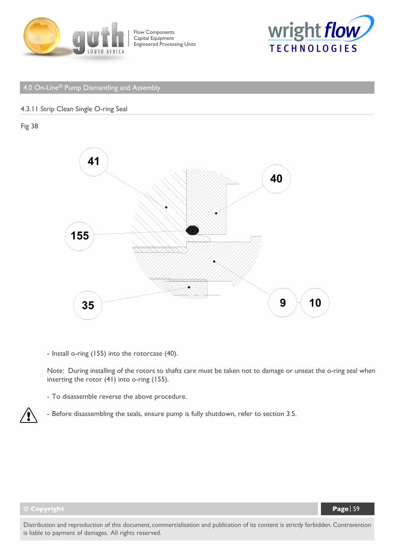
4.0 On-Line® Pump Dismantling and Assembly
4.3.11 Strip Clean Single O-ring Seal
Fig 38
© Copyright Page | 59
Distribution and reproduction of this document, commercialisation and publication of its content is strictly forbidden. Contraventionis liable to payment of damages. All rights reserved.
- Install o-ring (155) into the rotorcase (40).
Note: During installing of the rotors to shafts care must be taken not to damage or unseat the o-ring seal wheninserting the rotor (41) into o-ring (155).
- To disassemble reverse the above procedure.
- Before disassembling the seals, ensure pump is fully shutdown, refer to section 3.5.
Flow ComponentsCapital EquipmentEngineered Processing Units
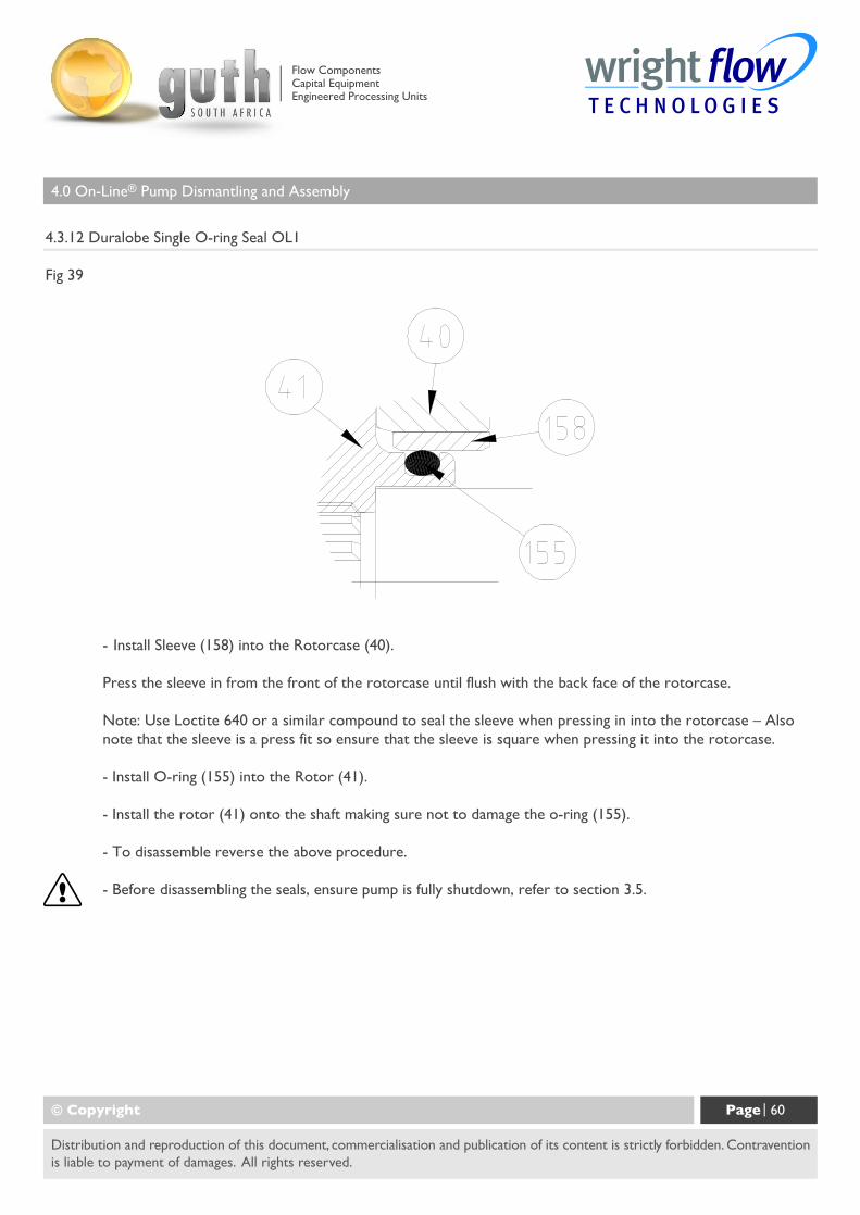
4.0 On-Line® Pump Dismantling and Assembly
4.3.12 Duralobe Single O-ring Seal OL1
Fig 39
© Copyright Page | 60
Distribution and reproduction of this document, commercialisation and publication of its content is strictly forbidden. Contraventionis liable to payment of damages. All rights reserved.
- Install Sleeve (158) into the Rotorcase (40).
Press the sleeve in from the front of the rotorcase until flush with the back face of the rotorcase.
Note: Use Loctite 640 or a similar compound to seal the sleeve when pressing in into the rotorcase – Alsonote that the sleeve is a press fit so ensure that the sleeve is square when pressing it into the rotorcase.
- Install O-ring (155) into the Rotor (41).
- Install the rotor (41) onto the shaft making sure not to damage the o-ring (155).
- To disassemble reverse the above procedure.
- Before disassembling the seals, ensure pump is fully shutdown, refer to section 3.5.
Flow ComponentsCapital EquipmentEngineered Processing Units
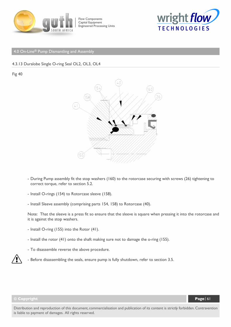
4.0 On-Line® Pump Dismantling and Assembly
4.3.13 Duralobe Single O-ring Seal OL2, OL3, OL4
Fig 40
© Copyright Page | 61
Distribution and reproduction of this document, commercialisation and publication of its content is strictly forbidden. Contraventionis liable to payment of damages. All rights reserved.
- During Pump assembly fit the stop washers (160) to the rotorcase securing with screws (26) tightening tocorrect torque, refer to section 5.2.
- Install O-rings (154) to Rotorcase sleeve (158).
- Install Sleeve assembly (comprising parts 154, 158) to Rotorcase (40).
Note: That the sleeve is a press fit so ensure that the sleeve is square when pressing it into the rotorcase andit is against the stop washers.
- Install O-ring (155) into the Rotor (41).
- Install the rotor (41) onto the shaft making sure not to damage the o-ring (155).
- To disassemble reverse the above procedure.
- Before disassembling the seals, ensure pump is fully shutdown, refer to section 3.5.
Flow ComponentsCapital EquipmentEngineered Processing Units
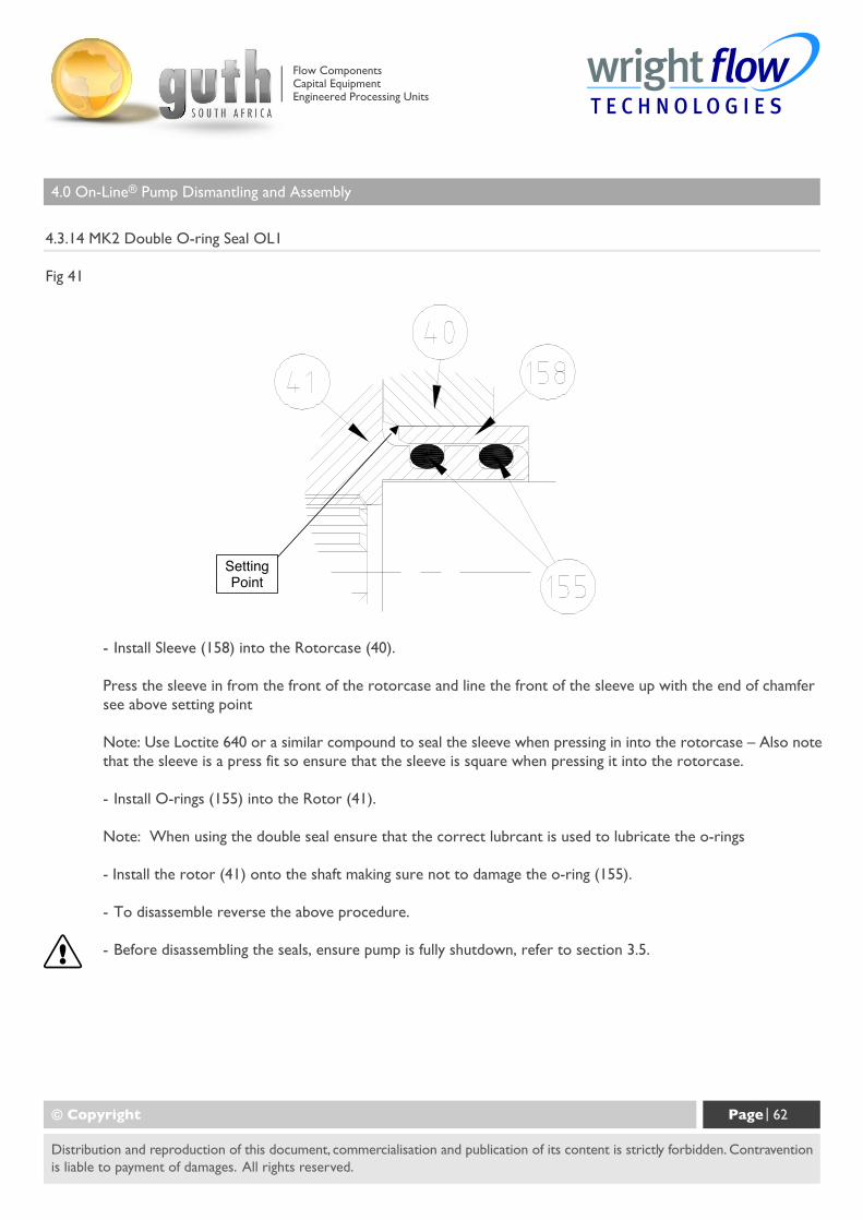
4.0 On-Line® Pump Dismantling and Assembly
4.3.14 MK2 Double O-ring Seal OL1
Fig 41
© Copyright Page | 62
Distribution and reproduction of this document, commercialisation and publication of its content is strictly forbidden. Contraventionis liable to payment of damages. All rights reserved.
- Install Sleeve (158) into the Rotorcase (40).
Press the sleeve in from the front of the rotorcase and line the front of the sleeve up with the end of chamfersee above setting point
Note: Use Loctite 640 or a similar compound to seal the sleeve when pressing in into the rotorcase – Also notethat the sleeve is a press fit so ensure that the sleeve is square when pressing it into the rotorcase.
- Install O-rings (155) into the Rotor (41).
Note: When using the double seal ensure that the correct lubrcant is used to lubricate the o-rings
- Install the rotor (41) onto the shaft making sure not to damage the o-ring (155).
- To disassemble reverse the above procedure.
- Before disassembling the seals, ensure pump is fully shutdown, refer to section 3.5.
Flow ComponentsCapital EquipmentEngineered Processing Units
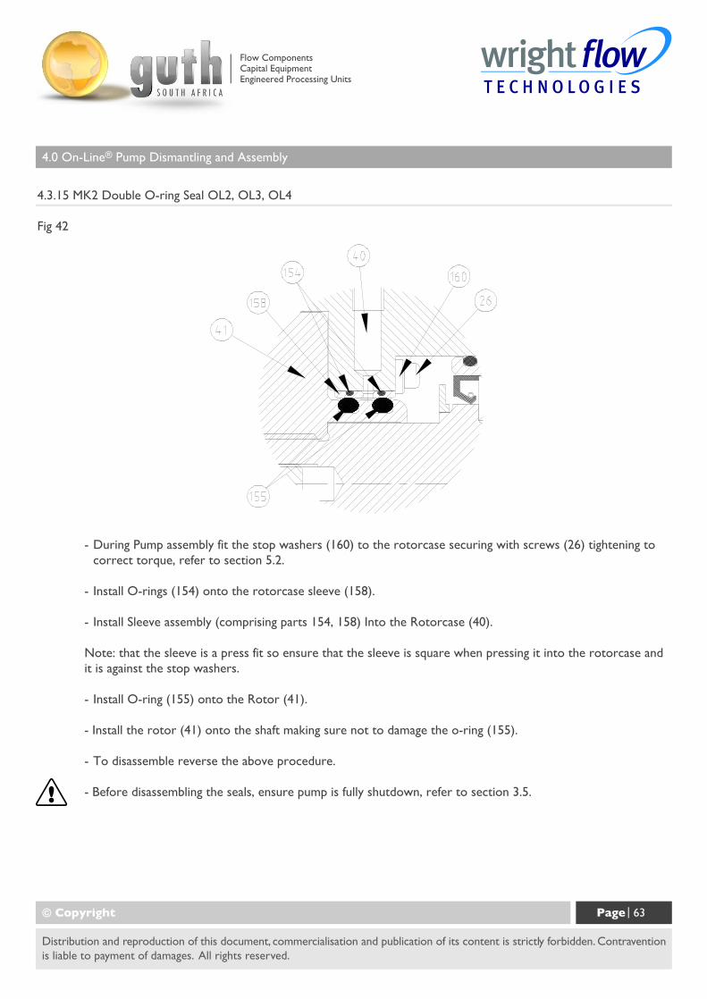
4.0 On-Line® Pump Dismantling and Assembly
4.3.15 MK2 Double O-ring Seal OL2, OL3, OL4
Fig 42
© Copyright Page | 63
Distribution and reproduction of this document, commercialisation and publication of its content is strictly forbidden. Contraventionis liable to payment of damages. All rights reserved.
- During Pump assembly fit the stop washers (160) to the rotorcase securing with screws (26) tightening tocorrect torque, refer to section 5.2.
- Install O-rings (154) onto the rotorcase sleeve (158).
- Install Sleeve assembly (comprising parts 154, 158) Into the Rotorcase (40).
Note: that the sleeve is a press fit so ensure that the sleeve is square when pressing it into the rotorcase andit is against the stop washers.
- Install O-ring (155) onto the Rotor (41).
- Install the rotor (41) onto the shaft making sure not to damage the o-ring (155).
- To disassemble reverse the above procedure.
- Before disassembling the seals, ensure pump is fully shutdown, refer to section 3.5.
Flow ComponentsCapital EquipmentEngineered Processing Units
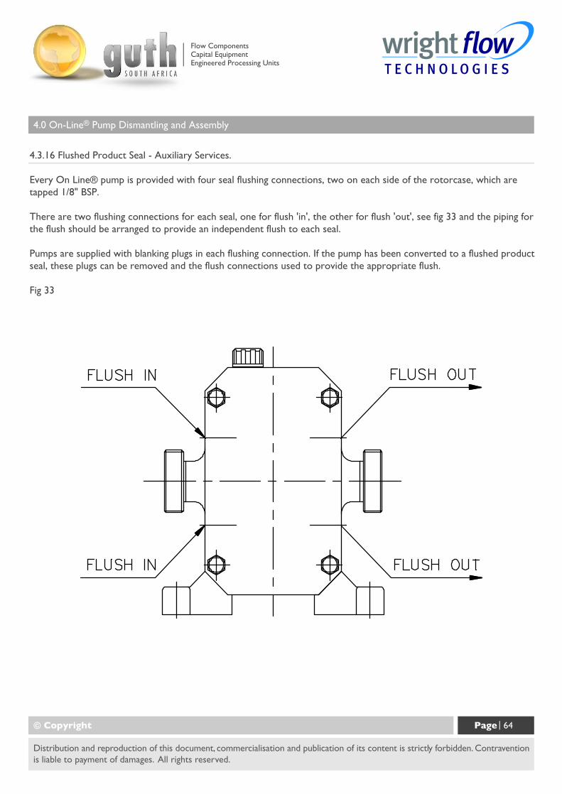
4.0 On-Line® Pump Dismantling and Assembly
4.3.16 Flushed Product Seal - Auxiliary Services.
Every On Line® pump is provided with four seal flushing connections, two on each side of the rotorcase, which aretapped 1/8" BSP.
There are two flushing connections for each seal, one for flush 'in', the other for flush 'out', see fig 33 and the piping forthe flush should be arranged to provide an independent flush to each seal.
Pumps are supplied with blanking plugs in each flushing connection. If the pump has been converted to a flushed productseal, these plugs can be removed and the flush connections used to provide the appropriate flush.
Fig 33
© Copyright Page | 64
Distribution and reproduction of this document, commercialisation and publication of its content is strictly forbidden. Contraventionis liable to payment of damages. All rights reserved.
Flow ComponentsCapital EquipmentEngineered Processing Units
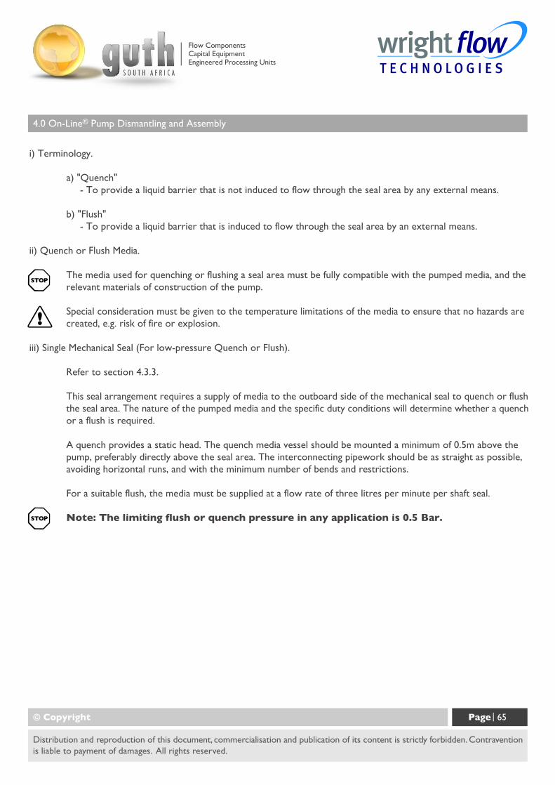
4.0 On-Line® Pump Dismantling and Assembly
i) Terminology.
a) "Quench"- To provide a liquid barrier that is not induced to flow through the seal area by any external means.
b) "Flush"- To provide a liquid barrier that is induced to flow through the seal area by an external means.
ii) Quench or Flush Media.
The media used for quenching or flushing a seal area must be fully compatible with the pumped media, and therelevant materials of construction of the pump.
Special consideration must be given to the temperature limitations of the media to ensure that no hazards arecreated, e.g. risk of fire or explosion.
iii) Single Mechanical Seal (For low-pressure Quench or Flush).
Refer to section 4.3.3.
This seal arrangement requires a supply of media to the outboard side of the mechanical seal to quench or flushthe seal area. The nature of the pumped media and the specific duty conditions will determine whether a quenchor a flush is required.
A quench provides a static head. The quench media vessel should be mounted a minimum of 0.5m above thepump, preferably directly above the seal area. The interconnecting pipework should be as straight as possible,avoiding horizontal runs, and with the minimum number of bends and restrictions.
For a suitable flush, the media must be supplied at a flow rate of three litres per minute per shaft seal.
Note: The limiting flush or quench pressure in any application is 0.5 Bar.
© Copyright Page | 65
Distribution and reproduction of this document, commercialisation and publication of its content is strictly forbidden. Contraventionis liable to payment of damages. All rights reserved.
Flow ComponentsCapital EquipmentEngineered Processing Units
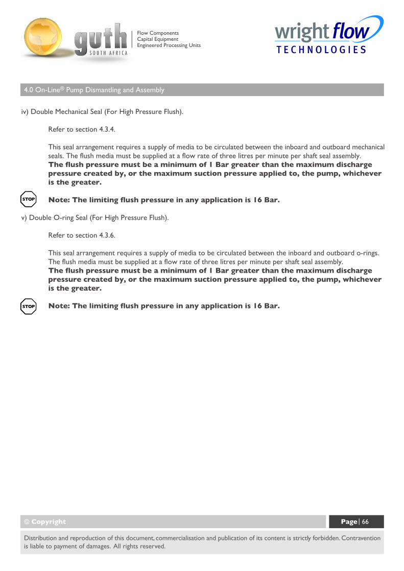
4.0 On-Line® Pump Dismantling and Assembly
iv) Double Mechanical Seal (For High Pressure Flush).
Refer to section 4.3.4.
This seal arrangement requires a supply of media to be circulated between the inboard and outboard mechanicalseals. The flush media must be supplied at a flow rate of three litres per minute per shaft seal assembly.The flush pressure must be a minimum of 1 Bar greater than the maximum dischargepressure created by, or the maximum suction pressure applied to, the pump, whicheveris the greater.
Note: The limiting flush pressure in any application is 16 Bar.
v) Double O-ring Seal (For High Pressure Flush).
Refer to section 4.3.6.
This seal arrangement requires a supply of media to be circulated between the inboard and outboard o-rings.The flush media must be supplied at a flow rate of three litres per minute per shaft seal assembly.The flush pressure must be a minimum of 1 Bar greater than the maximum dischargepressure created by, or the maximum suction pressure applied to, the pump, whicheveris the greater.
Note: The limiting flush pressure in any application is 16 Bar.
© Copyright Page | 66
Distribution and reproduction of this document, commercialisation and publication of its content is strictly forbidden. Contraventionis liable to payment of damages. All rights reserved.
Flow ComponentsCapital EquipmentEngineered Processing Units
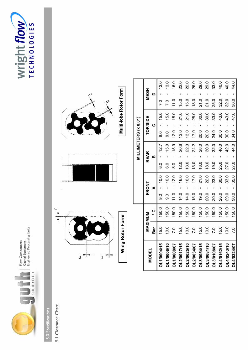
5.0
Spec
ifica
tions
5.1
Cle
aran
ce C
hart
Flow
Com
pone
nts
Cap
ital E
quip
men
tEn
gine
ered
Pro
cess
ing
Uni
ts
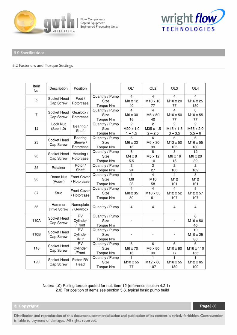
5.0 Specifications
5.2 Fasteners and Torque Settings
© Copyright Page | 68
Distribution and reproduction of this document, commercialisation and publication of its content is strictly forbidden. Contraventionis liable to payment of damages. All rights reserved.
Flow ComponentsCapital EquipmentEngineered Processing Units
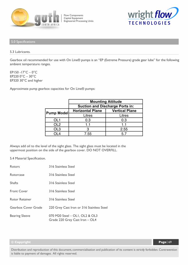
5.0 Specifications
5.3 Lubricants.
Gearbox oil recommended for use with On Line® pumps is an “EP (Extreme Pressure) grade gear lube” for the followingambient temperature ranges.
EP150 -17°C – 0°CEP220 0°C – 30°CEP320 30°C and higher
Approximate pump gearbox capacities for On Line® pumps:
Always add oil to the level of the sight glass. The sight glass must be located in theuppermost position on the side of the gearbox cover. DO NOT OVERFILL.
5.4 Material Specification.
Rotors 316 Stainless Steel
Rotorcase 316 Stainless Steel
Shafts 316 Stainless Steel
Front Cover 316 Stainless Steel
Rotor Retainer 316 Stainless Steel
Gearbox Cover Grade 220 Grey Cast Iron or 316 Stainless Steel
Bearing Sleeve 070 M20 Steel – OL1, OL2 & OL3Grade 220 Grey Cast Iron – OL4
© Copyright Page | 69
Distribution and reproduction of this document, commercialisation and publication of its content is strictly forbidden. Contraventionis liable to payment of damages. All rights reserved.
Flow ComponentsCapital EquipmentEngineered Processing Units
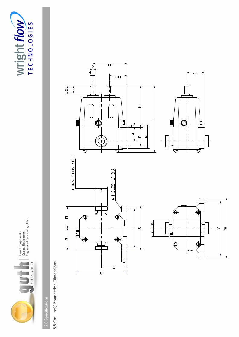
5.0
Spec
ifica
tions
5.5
On
Line
® F
ound
atio
n D
imen
sion
s.
Flow
Com
pone
nts
Cap
ital E
quip
men
tEn
gine
ered
Pro
cess
ing
Uni
ts
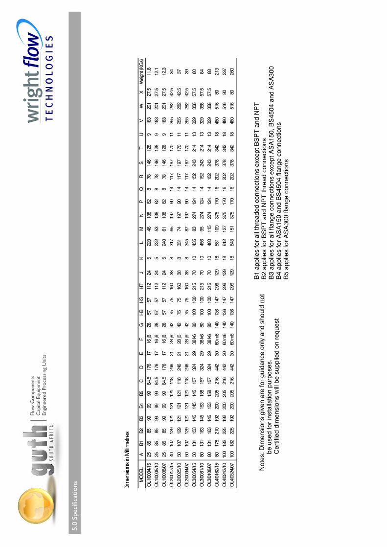
5.0
Spec
ifica
tions
Flow
Com
pone
nts
Cap
ital E
quip
men
tEn
gine
ered
Pro
cess
ing
Uni
ts
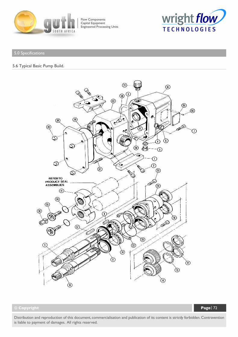
5.0 Specifications
5.6 Typical Basic Pump Build.
© Copyright Page | 72
Distribution and reproduction of this document, commercialisation and publication of its content is strictly forbidden. Contraventionis liable to payment of damages. All rights reserved.
Flow ComponentsCapital EquipmentEngineered Processing Units
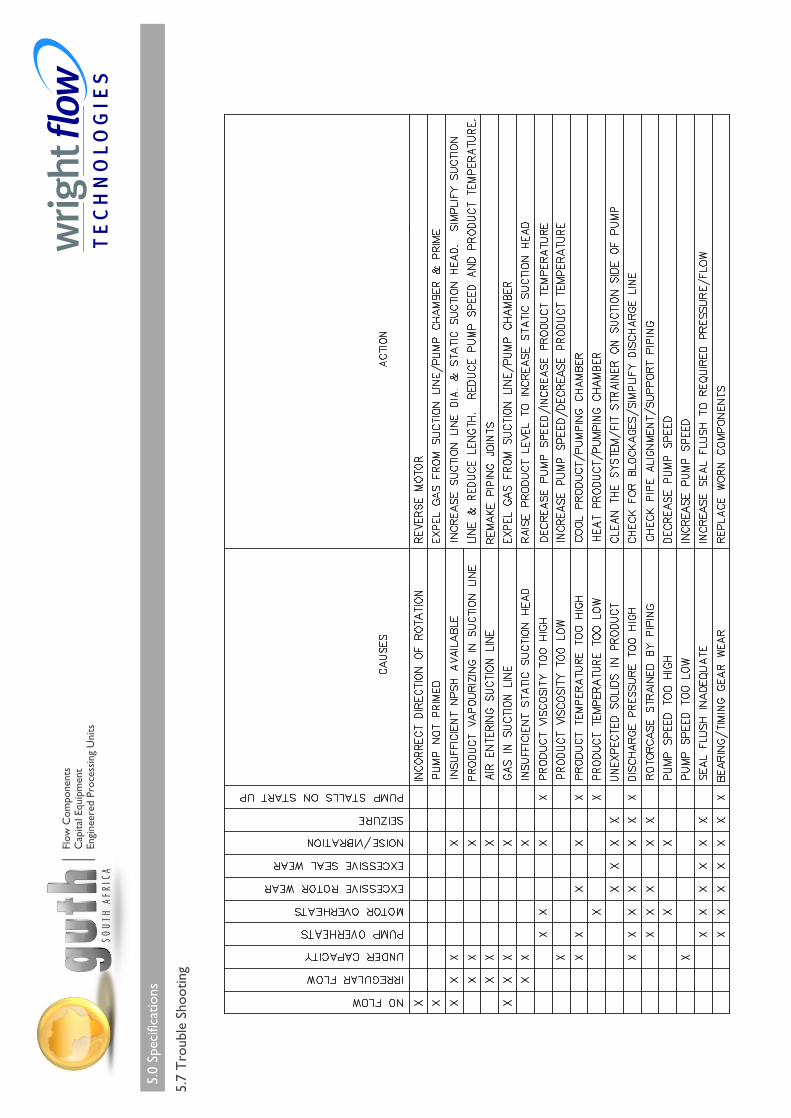
5.0
Spec
ifica
tions
5.7
Tro
uble
Sho
otin
g
Flow
Com
pone
nts
Cap
ital E
quip
men
tEn
gine
ered
Pro
cess
ing
Uni
ts
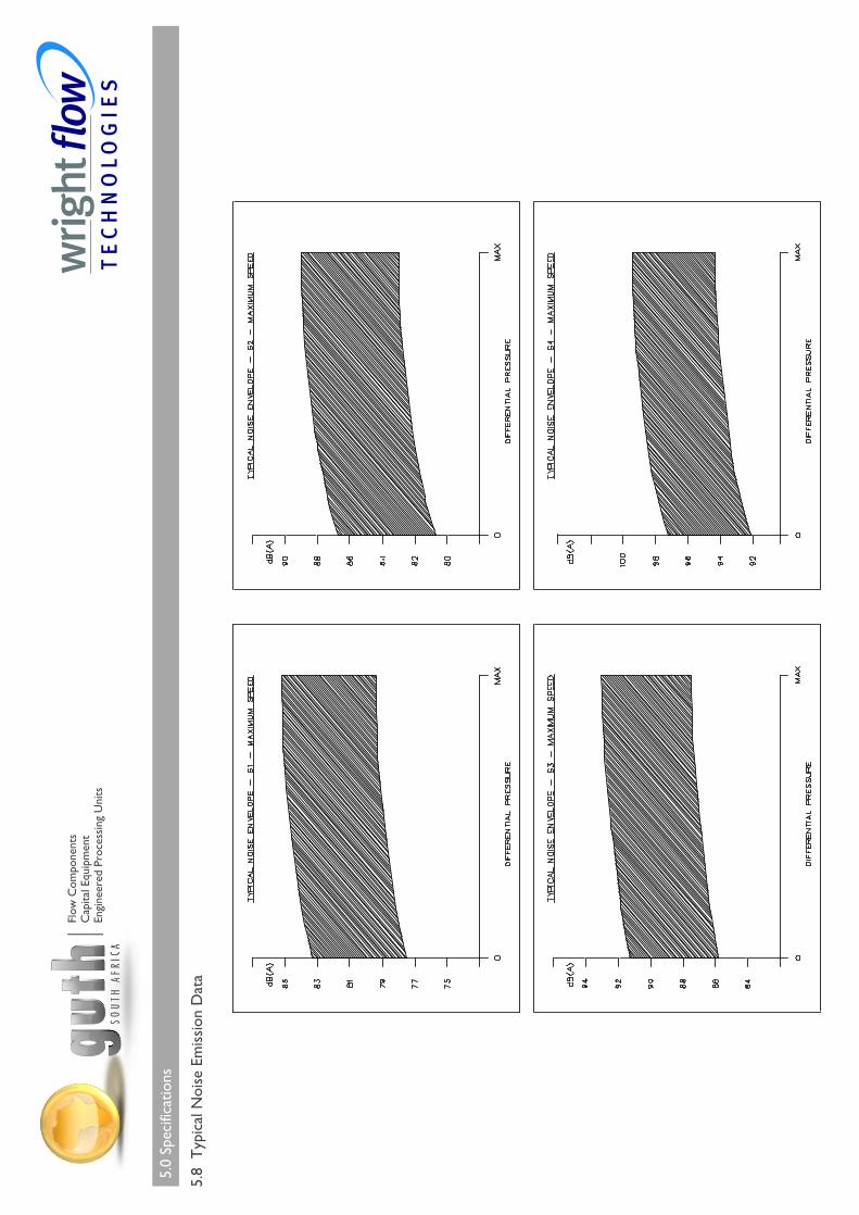
5.0
Spec
ifica
tions
5.8
Typ
ical
Noi
se E
mis
sion
Dat
a
Flow
Com
pone
nts
Cap
ital E
quip
men
tEn
gine
ered
Pro
cess
ing
Uni
ts
© Copyright Page | 75
Distribution and reproduction of this document, commercialisation and publication of its content is strictly forbidden. Contraventionis liable to payment of damages. All rights reserved.
5.0 Specifications
5.9 Service History
Pump Model: Pump Serial No:
Date: Comments:
Flow ComponentsCapital EquipmentEngineered Processing Units
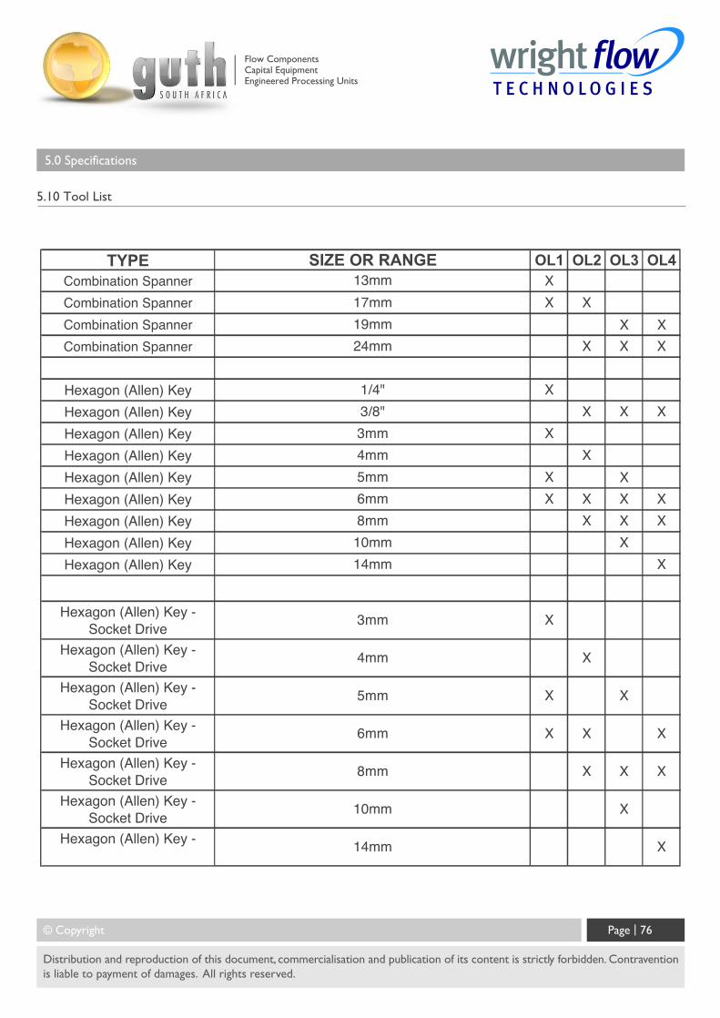
© Copyright Page | 76
Distribution and reproduction of this document, commercialisation and publication of its content is strictly forbidden. Contraventionis liable to payment of damages. All rights reserved.
5.0 Specifications
5.10 Tool List
Flow ComponentsCapital EquipmentEngineered Processing Units
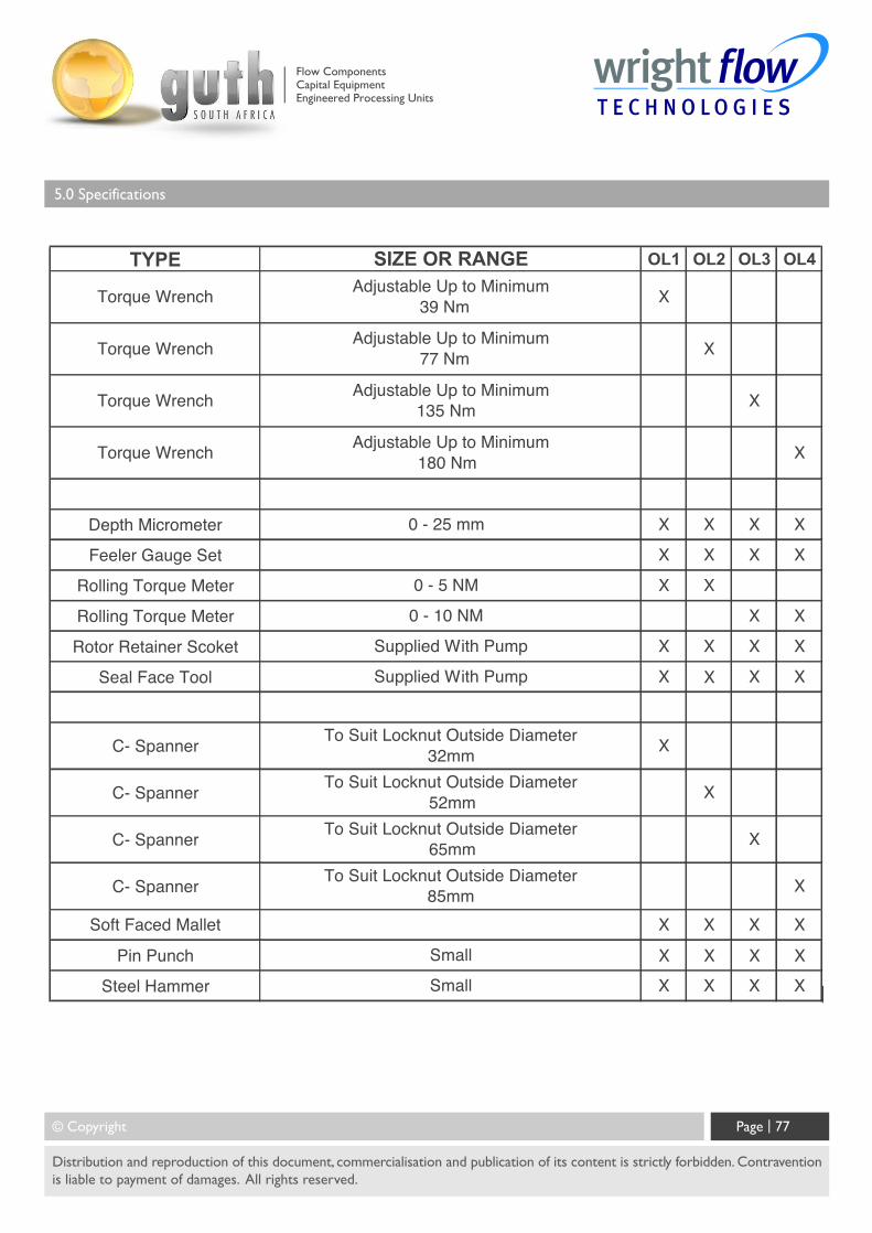
© Copyright Page | 77
Distribution and reproduction of this document, commercialisation and publication of its content is strictly forbidden. Contraventionis liable to payment of damages. All rights reserved.
5.0 Specifications
Flow ComponentsCapital EquipmentEngineered Processing Units
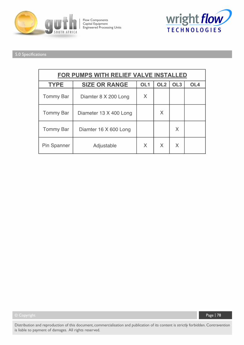
© Copyright Page | 78
Distribution and reproduction of this document, commercialisation and publication of its content is strictly forbidden. Contraventionis liable to payment of damages. All rights reserved.
5.0 Specifications
Flow ComponentsCapital EquipmentEngineered Processing Units
© Copyright Page | 79
Distribution and reproduction of this document, commercialisation and publication of its content is strictly forbidden. Contraventionis liable to payment of damages. All rights reserved.
5.0 Specifications
5.11 Notes
The Information contained in this document is correct at the time of print, but may be subject to change without prior notice.
Flow ComponentsCapital EquipmentEngineered Processing Units
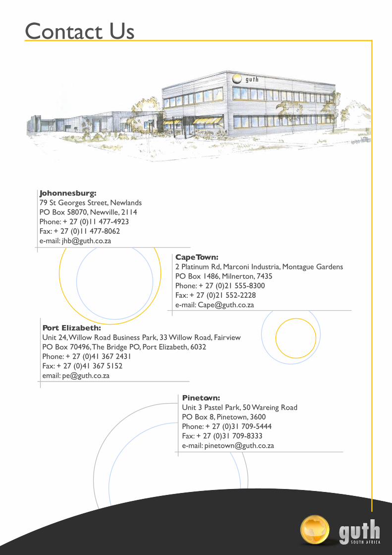
Contact Us
Johonnesburg:79 St Georges Street, NewlandsPO Box 58070, Newville, 2114Phone: + 27 (0)11 477-4923Fax: + 27 (0)11 477-8062e-mail: [email protected]
Cape Town:2 Platinum Rd, Marconi Industria, Montague GardensPO Box 1486, Milnerton, 7435Phone: + 27 (0)21 555-8300Fax: + 27 (0)21 552-2228e-mail: [email protected]
Port Elizabeth:Unit 24, Willow Road Business Park, 33 Willow Road, FairviewPO Box 70496, The Bridge PO, Port Elizabeth, 6032Phone: + 27 (0)41 367 2431Fax: + 27 (0)41 367 5152email: [email protected]
Pinetown:Unit 3 Pastel Park, 50 Wareing RoadPO Box 8, Pinetown, 3600Phone: + 27 (0)31 709-5444Fax: + 27 (0)31 709-8333e-mail: [email protected]
Related Documents