1 On Importance of Steganographic Cost For Network Steganography Wojciech Mazurczyk 1 , Steffen Wendzel 2 , Ignacio Azagra Villares 3 , Krzysztof Szczypiorski 1 1 Warsaw University of Technology, Warsaw, Poland, {wm, ksz}@tele.pw.edu.pl 2 Fraunhofer FKIE, Bonn, Germany, [email protected] 3 Universidad Publica de Navarra, Spain, [email protected] Abstract. Network steganography encompasses the information hiding techniques that can be applied in communication network environments and that utilize hidden data carriers for this purpose. In this paper we introduce a characteristic called steganographic cost which is an indicator for the degradation or distortion of the carrier caused by the application of the steganographic method. Based on exemplary cases for single- and multi-method steganographic cost analyses we observe that it can be an important characteristic that allows to express hidden data carrier degradation – similarly as MSE (Mean-Square Error) or PSNR (Peak Signal-to- Noise Ratio) are utilized for digital media steganography. Steganographic cost can moreover be helpful to analyse the relationships between two or more steganographic methods applied to the same hidden data carrier. Key words: network steganography, steganographic cost, super-position steganography 1. Introduction The main aim of network steganography is to hide secret data in legitimate transmissions of users without destroying the hidden data carrier used. The scope of the network steganography is limited to all information hiding techniques that: (a) can be applied in communication networks to enable hidden data exchange by creating a covert communication channel; (b) are inseparably bounded to the transmission process; (c) do not destroy the hidden data carrier. The main difference between “classic” steganography and that utilized in networks is that the first relies on fooling human senses and the latter tries to deceive network devices (intermediate network nodes or end-user ones). It is important to emphasise that for a third party observer who is not aware of the steganographic procedure, the exchange of secret data inside the carrier (steganogram) remains hidden. This is possible because embedding of a secret data into a chosen carrier remains unnoticeable for users not involved in steganographic communication. Thus, not only the secret data are hidden inside the carriers, but because of the carriers’ features, the fact of the secret data exchange is also concealed. In network steganography a carrier is at least one network traffic flow. Typically, a carrier can be multi-dimensional, i.e. it offers many opportunities for information hiding (called subcarriers). And a subcarrier is defined as a “place” or a timing of “event” (e.g. a header field, padding or intended sequences of packets) in a carrier where secret information can be hidden using a steganographic technique (Fig. 1).

Welcome message from author
This document is posted to help you gain knowledge. Please leave a comment to let me know what you think about it! Share it to your friends and learn new things together.
Transcript
1
On Importance of Steganographic Cost For Network Steganography
Wojciech Mazurczyk1, Steffen Wendzel
2, Ignacio Azagra Villares
3, Krzysztof Szczypiorski
1
1 Warsaw University of Technology, Warsaw, Poland, {wm, ksz}@tele.pw.edu.pl
2 Fraunhofer FKIE, Bonn, Germany, [email protected]
3 Universidad Publica de Navarra, Spain, [email protected]
Abstract. Network steganography encompasses the information hiding techniques that can be
applied in communication network environments and that utilize hidden data carriers for this
purpose. In this paper we introduce a characteristic called steganographic cost which is an
indicator for the degradation or distortion of the carrier caused by the application of the
steganographic method. Based on exemplary cases for single- and multi-method steganographic
cost analyses we observe that it can be an important characteristic that allows to express hidden
data carrier degradation – similarly as MSE (Mean-Square Error) or PSNR (Peak Signal-to-
Noise Ratio) are utilized for digital media steganography. Steganographic cost can moreover be
helpful to analyse the relationships between two or more steganographic methods applied to the
same hidden data carrier.
Key words: network steganography, steganographic cost, super-position steganography
1. Introduction
The main aim of network steganography is to hide secret data in legitimate transmissions of
users without destroying the hidden data carrier used. The scope of the network
steganography is limited to all information hiding techniques that: (a) can be applied in
communication networks to enable hidden data exchange by creating a covert communication
channel; (b) are inseparably bounded to the transmission process; (c) do not destroy the
hidden data carrier. The main difference between “classic” steganography and that utilized in
networks is that the first relies on fooling human senses and the latter tries to deceive network
devices (intermediate network nodes or end-user ones).
It is important to emphasise that for a third party observer who is not aware of the
steganographic procedure, the exchange of secret data inside the carrier (steganogram)
remains hidden. This is possible because embedding of a secret data into a chosen carrier
remains unnoticeable for users not involved in steganographic communication. Thus, not
only the secret data are hidden inside the carriers, but because of the carriers’ features, the
fact of the secret data exchange is also concealed.
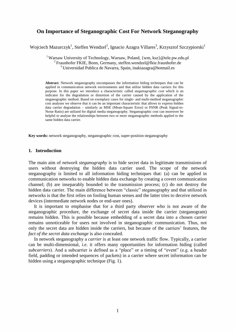
In network steganography a carrier is at least one network traffic flow. Typically, a carrier
can be multi-dimensional, i.e. it offers many opportunities for information hiding (called
subcarriers). And a subcarrier is defined as a “place” or a timing of “event” (e.g. a header
field, padding or intended sequences of packets) in a carrier where secret information can be
hidden using a steganographic technique (Fig. 1).
2
Fig. 1 An example of carrier and subcarriers based on VoIP connection example.
The most favourable carriers for secret messages in communication networks must have
two features:
they should be popular i.e. usage of such carriers should not be considered as an
anomaly itself. The more popular carriers are present and utilized in a network the
better, because they mask existence of hidden communication.
their modification related to embedding of the steganogram should not be “visible” to
the third party not aware of the steganographic procedure. Contrary to typical
steganographic methods, which utilize digital media (pictures, audio, and video files)
as a cover for hidden data, network steganography utilizes network connections i.e.
communication protocols’ control elements and their basic intrinsic functionality.
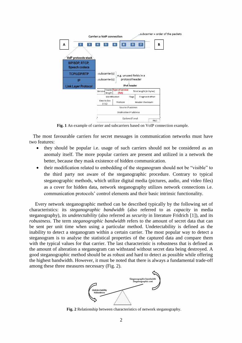
Every network steganographic method can be described typically by the following set of
characteristics: its steganographic bandwidth (also referred to as capacity in media
steganography), its undetectability (also referred as security in literature Fridrich [1]), and its
robustness. The term steganographic bandwidth refers to the amount of secret data that can
be sent per unit time when using a particular method. Undetectability is defined as the
inability to detect a steganogram within a certain carrier. The most popular way to detect a
steganogram is to analyse the statistical properties of the captured data and compare them
with the typical values for that carrier. The last characteristic is robustness that is defined as
the amount of alteration a steganogram can withstand without secret data being destroyed. A
good steganographic method should be as robust and hard to detect as possible while offering
the highest bandwidth. However, it must be noted that there is always a fundamental trade-off
among these three measures necessary (Fig. 2).
Fig. 2 Relationship between characteristics of network steganography.
3
In this paper we want to emphasise that another characteristic is important while
evaluating network steganography methods, namely steganographic cost. This characteristic
indicates the degradation or distortion of the carrier caused by the application of a
steganographic method. In digital media steganography, i.e. for hiding secret data in digital
image, audio, or video, the parameters MSE (Mean-Square Error) or PSNR (Peak Signal-to-
Noise Ratio) are utilized for this purpose. However, these parameters cannot be applied to
dynamic, diverse carriers like network connections. For example, in the case of VoIP
steganography methods, this cost can be expressed by providing a measure of the
conversation quality degradation induced by applying a particular information hiding
technique. If certain fields of the protocol header are used as the hidden data carrier, then the
cost is expressed as a potential loss in that protocol’s functionality. It is also possible that an
information hiding method introduces steganographic cost that can be experienced in two
different “planes”, e.g. it introduces voice quality degradation as well as it adds additional
delays to the overt traffic.
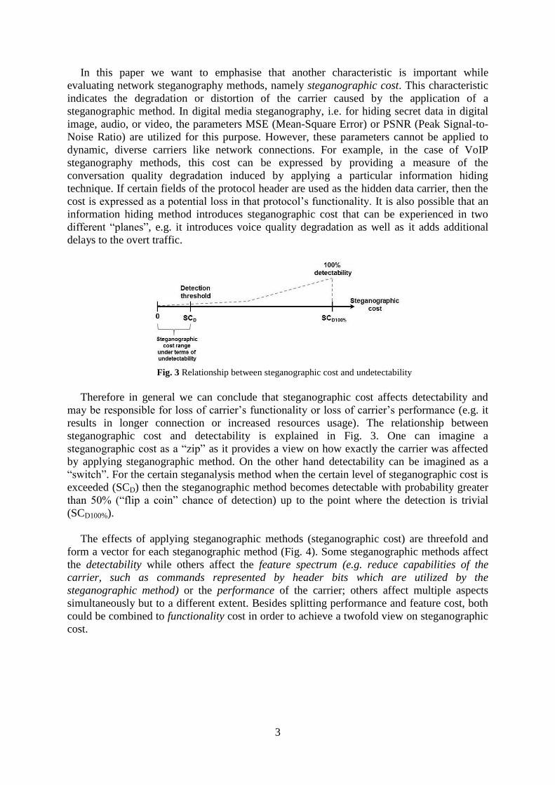
Fig. 3 Relationship between steganographic cost and undetectability
Therefore in general we can conclude that steganographic cost affects detectability and
may be responsible for loss of carrier’s functionality or loss of carrier’s performance (e.g. it
results in longer connection or increased resources usage). The relationship between
steganographic cost and detectability is explained in Fig. 3. One can imagine a
steganographic cost as a “zip” as it provides a view on how exactly the carrier was affected
by applying steganographic method. On the other hand detectability can be imagined as a
“switch”. For the certain steganalysis method when the certain level of steganographic cost is
exceeded (SCD) then the steganographic method becomes detectable with probability greater
than 50% (“flip a coin” chance of detection) up to the point where the detection is trivial
(SCD100%).
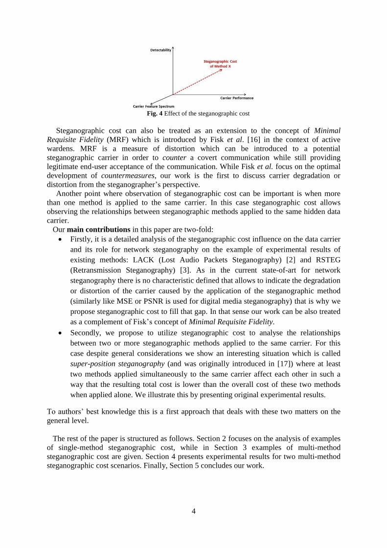
The effects of applying steganographic methods (steganographic cost) are threefold and
form a vector for each steganographic method (Fig. 4). Some steganographic methods affect
the detectability while others affect the feature spectrum (e.g. reduce capabilities of the
carrier, such as commands represented by header bits which are utilized by the
steganographic method) or the performance of the carrier; others affect multiple aspects
simultaneously but to a different extent. Besides splitting performance and feature cost, both
could be combined to functionality cost in order to achieve a twofold view on steganographic
cost.
4
Fig. 4 Effect of the steganographic cost
Steganographic cost can also be treated as an extension to the concept of Minimal
Requisite Fidelity (MRF) which is introduced by Fisk et al. [16] in the context of active
wardens. MRF is a measure of distortion which can be introduced to a potential
steganographic carrier in order to counter a covert communication while still providing
legitimate end-user acceptance of the communication. While Fisk et al. focus on the optimal
development of countermeasures, our work is the first to discuss carrier degradation or
distortion from the steganographer’s perspective.
Another point where observation of steganographic cost can be important is when more
than one method is applied to the same carrier. In this case steganographic cost allows
observing the relationships between steganographic methods applied to the same hidden data
carrier.
Our main contributions in this paper are two-fold:
Firstly, it is a detailed analysis of the steganographic cost influence on the data carrier
and its role for network steganography on the example of experimental results of
existing methods: LACK (Lost Audio Packets Steganography) [2] and RSTEG
(Retransmission Steganography) [3]. As in the current state-of-art for network
steganography there is no characteristic defined that allows to indicate the degradation
or distortion of the carrier caused by the application of the steganographic method
(similarly like MSE or PSNR is used for digital media steganography) that is why we
propose steganographic cost to fill that gap. In that sense our work can be also treated
as a complement of Fisk’s concept of Minimal Requisite Fidelity.
Secondly, we propose to utilize steganographic cost to analyse the relationships
between two or more steganographic methods applied to the same carrier. For this
case despite general considerations we show an interesting situation which is called
super-position steganography (and was originally introduced in [17]) where at least
two methods applied simultaneously to the same carrier affect each other in such a
way that the resulting total cost is lower than the overall cost of these two methods
when applied alone. We illustrate this by presenting original experimental results.
To authors’ best knowledge this is a first approach that deals with these two matters on the
general level.
The rest of the paper is structured as follows. Section 2 focuses on the analysis of examples
of single-method steganographic cost, while in Section 3 examples of multi-method
steganographic cost are given. Section 4 presents experimental results for two multi-method
steganographic cost scenarios. Finally, Section 5 concludes our work.
5
2. Single-method steganographic cost analysis
2.1 Lost Audio Packets Steganography (LACK)
LACK is an IP telephony steganographic method that was originally proposed in [9] and is
currently considered as a state-of-the-art VoIP steganography technique [10]. It operates by
modifying both, RTP packets from the voice stream as well as their time dependencies. It
takes advantage of the fact that in typical multimedia communication protocols, like RTP,
excessively delayed packets are not used for the reconstruction of transmitted data at the
receiver i.e. the packets are considered useless and are discarded.
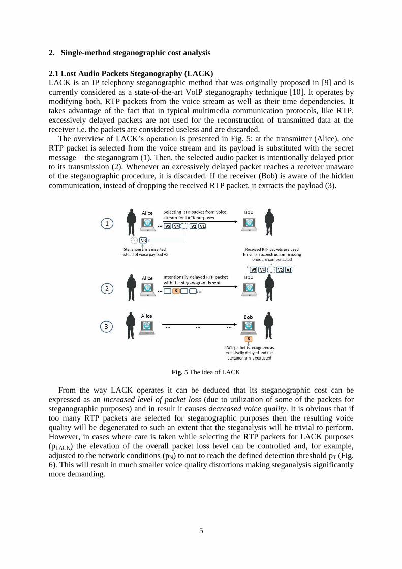
The overview of LACK’s operation is presented in Fig. 5: at the transmitter (Alice), one
RTP packet is selected from the voice stream and its payload is substituted with the secret
message – the steganogram (1). Then, the selected audio packet is intentionally delayed prior
to its transmission (2). Whenever an excessively delayed packet reaches a receiver unaware
of the steganographic procedure, it is discarded. If the receiver (Bob) is aware of the hidden
communication, instead of dropping the received RTP packet, it extracts the payload (3).
Fig. 5 The idea of LACK
From the way LACK operates it can be deduced that its steganographic cost can be
expressed as an increased level of packet loss (due to utilization of some of the packets for
steganographic purposes) and in result it causes decreased voice quality. It is obvious that if
too many RTP packets are selected for steganographic purposes then the resulting voice
quality will be degenerated to such an extent that the steganalysis will be trivial to perform.
However, in cases where care is taken while selecting the RTP packets for LACK purposes
(pLACK) the elevation of the overall packet loss level can be controlled and, for example,
adjusted to the network conditions (pN) to not to reach the defined detection threshold pT (Fig.
6). This will result in much smaller voice quality distortions making steganalysis significantly
more demanding.
6
Fig. 6 The impact of LACK on the total packet loss probability
Therefore we can express LACK’s steganographic cost (SCT-LACK) as ΔMOS which is a
drop in voice quality expressed in MOS (Mean Opinion Score) scale [14] as a difference in
quality of the voice signal (RQ) without and with LACK applied (LQ):
SCT-LACK(t)= ΔMOS(t) = RQ(t) – LQ(t)
Table I provides a summary and characteristics of the voice codecs used in experiments
for LACK in [2]. A variety of codecs were chosen to provide a comparative analysis of
possible IP telephony call configurations – the choice involved selection of voice codec and
appropriate data rate (from 8 to 64 kbits). The voice codecs used in the experiment were:
G.711 A-law [12], GSM-FR (Full Rate) [11] and Speex (8 and 24.6 kbits) [13] (other details
on test-bed and methodology can be found in [2]).
Table I Speech codecs used in the experimental evaluation [2]
Voice codecs G.711 A-law Speex I GSM-FR Speex II
Bit rate [kbit/s] 64 24.6 13.2 8
RTP packet every [ms] 20 20 20 20
Voice payload size [bytes] 160 61.5 33 20
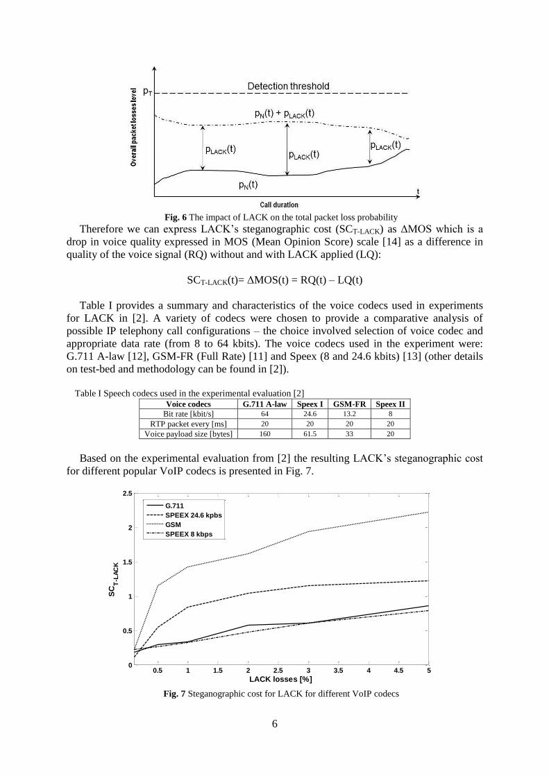
Based on the experimental evaluation from [2] the resulting LACK’s steganographic cost
for different popular VoIP codecs is presented in Fig. 7.
Fig. 7 Steganographic cost for LACK for different VoIP codecs
0.5 1 1.5 2 2.5 3 3.5 4 4.5 50
0.5
1
1.5
2
2.5
LACK losses [%]
SC
T-L
AC
K
G.711
SPEEX 24.6 kpbs
GSM
SPEEX 8 kbps
7
From the results presented above we can observe that depending on how the detection
threshold will be set and which voice codec will be chosen the resulting steganographic cost
can be analysed in two ranges: before and after the detection threshold. For example, if SCT-
LACK= ΔMOS=0.5 then for GSM and Speex 24.6 kbps codecs we can conclude that the
introduced packets losses must be kept to minimum to avoid detection (<0.3%). However, for
the other two codecs Speex 8 kbps and G.711 LACK utilization will be undetectable until
intentionally introduced losses do not exceed 2-2.5%. Therefore by inspecting the
steganographic cost caused by LACK from the beginning of its application we can identify
the degradation of the hidden data carrier even when it is below the detection threshold.
2.2 Retransmission Steganography (RSTEG)
RSTEG (Retransmission Steganography) [3] is a steganographic method that is intended for a
broad class of protocols that utilise retransmission mechanisms. The main innovation of
RSTEG is to not acknowledge a successfully received packet in order to intentionally invoke
retransmission. The retransmitted packet of user data then carries a steganogram in the
payload field.
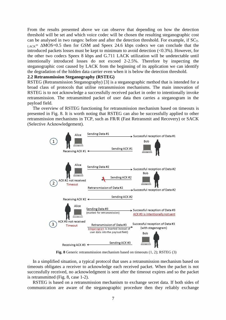
The overview of RSTEG functioning for retransmission mechanism based on timeouts is
presented in Fig. 8. It is worth noting that RSTEG can also be successfully applied to other
retransmission mechanisms in TCP, such as FR/R (Fast Retransmit and Recovery) or SACK
(Selective Acknowledgement).
Fig. 8 Generic retransmission mechanism based on timeouts (1, 2); RSTEG (3)
In a simplified situation, a typical protocol that uses a retransmission mechanism based on
timeouts obligates a receiver to acknowledge each received packet. When the packet is not
successfully received, no acknowledgment is sent after the timeout expires and so the packet
is retransmitted (Fig. 8, case 1-2).
RSTEG is based on a retransmission mechanism to exchange secret data. If both sides of
communication are aware of the steganographic procedure then they reliably exchange
8
packets during their connection e.g. they transfer a file. At some point during the connection
after successfully receiving a packet, the receiver intentionally does not issue an
acknowledgment message. In a normal situation, a sender is obligated to retransmit the lost
packet when the timeframe within which packet acknowledgement should have been received
expires. In RSTEG, a sender replaces an original payload with a secret data instead of
sending the same packet again. When the retransmitted packet reaches the receiver, he/she
can extract the hidden information (Fig. 8, case 3).
From the description of RSTEG functioning provided above it can be deduced that its
steganographic cost can be expressed as an increased level of retransmissions.
Retransmissions in IP networks are a “natural phenomenon”, and so intentional
retransmissions introduced by RSTEG are challenging to detect if they are kept at a
reasonable level.
Therefore we can express RSTEG’s steganographic cost (SCT-RSTEG) as
SCT-RSTEG = RD = RN-RSTEG - RN,
where RD (Retransmissions Difference) denotes the difference between retransmissions in
the network after applying RSTEG (RN-RSTEG) and in the network before applying RSTEG
(RN).
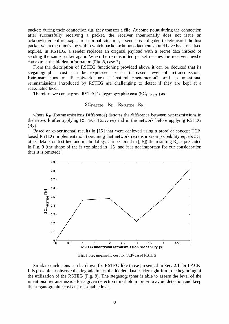
Based on experimental results in [15] that were achieved using a proof-of-concept TCP-
based RSTEG implementation (assuming that network retransmission probability equals 3%,
other details on test-bed and methodology can be found in [15]) the resulting RD is presented
in Fig. 9 (the shape of the is explained in [15] and it is not important for our consideration
thus it is omitted).
Fig. 9 Steganographic cost for TCP-based RSTEG
Similar conclusions can be drawn for RSTEG like those presented in Sec. 2.1 for LACK.
It is possible to observe the degradation of the hidden data carrier right from the beginning of
the utilization of the RSTEG (Fig. 9). The steganographer is able to assess the level of the
intentional retransmission for a given detection threshold in order to avoid detection and keep
the steganographic cost at a reasonable level.
0 0.5 1 1.5 2 2.5 3 3.5 4 4.5 50
0.1
0.2
0.3
0.4
0.5
0.6
0.7
0.8
0.9
RSTEG intentional retransmission probability [%]
SC
T-R
ST
EG
[%
]
9
3. Multi-method steganographic cost analysis
Section 2 covered the scenario of applying one steganographic method to one hidden data
carrier. Let us discuss the extension of our scenario by applying multiple methods
simultaneously. For the sake of simplicity we assume that two different methods are utilized
on the same hidden data carrier. The same observation that can be made for two methods can
be extended to n methods applied to the same carrier (of course n is not a high number as it is
difficult to design many methods that simultaneously applied will not destroy a carrier
completely).
In general, two cases are possible:
(C1) Both methods are applied to the same subcarrier,
(C2) Both methods are applied to the different subcarriers.
It is worth noting that it is also possible that in both cases one method depends on the other,
i.e. overt traffic modified by one of the methods is treated as a carrier for the other method.
Such relationships between two or more methods applied to the same hidden data carrier
were researched by Frączek et al. and are referred to as MLS (Multi-Level Steganography)
[2].
In general, in case C1 the subcarrier tends to degenerate faster when both methods
influence it by introducing their steganographic costs in comparison with case C2. It is due to
the accumulation of the steganographic cost that influences the same subcarrier. For this case
the overall steganographic cost (SCT) can be expressed as
SCT = SCS1-1 + SCS1-2
where SCS1-1 denotes steganographic cost of the first method applied to subcarrier S1 and
SCS1-2 denotes steganographic cost of the second method applied to the same subcarrier.
So if we consider n steganographic methods applied to the same subcarrier then
Of course when utilized subcarriers are different (case C2) the steganographic cost of each
steganographic method applied can be express in different units. For example, let us consider
a VoIP connection: if we apply one steganographic method that affects voice quality and the
second that utilizes some of the protocol header’s fields then the overall steganographic cost
will form a vector of steganographic cost as obviously they cannot be simply added.
Therefore the steganographic cost can be expressed in this case as follows:
However, the more steganographic methods are applied even to different subcarriers the
bigger chance for successful detection if various aspects of the hidden data carrier are subject
to steganalysis.
In general, the following conditions must be given in case of (C1) to decrease the
steganographic cost using two methods simultaneously:
1. two hiding methods utilize the same subcarrier or related subcarriers,
2. the hiding methods utilize the subcarrier(s) in a different way,
n
n
nSCT SCnSC1
1)1( )(
nS
S
S
CT
SC
SC
SC
nSC
1
21
11
)2(...
)(
10
3. the hiding methods do not collide i.e. they do not negatively affect the other method and
thus in result increase the steganographic bandwidth,
4. hiding method 2 modifies the embedding area of method 1 in a way that it benefits from
the caused steganographic cost of method 1 in a way that less additional steganographic
cost is created as if method 2 would be applied to the subcarrier without method 1.
In the remainder we concentrate on multi-method steganographic cost analyses for the
case C1 to show how steganographic costs of different methods applied to the same
subcarrier can interact.
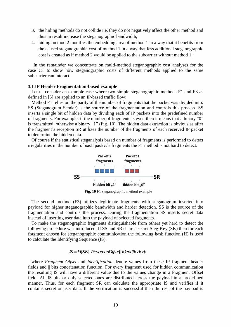
3.1 IP Header Fragmentation-based example
Let us consider an example case where two simple steganographic methods F1 and F3 as
defined in [5] are applied to an IP-based traffic flow:
Method F1 relies on the parity of the number of fragments that the packet was divided into.
SS (Steganogram Sender) is the source of the fragmentation and controls this process. SS
inserts a single bit of hidden data by dividing each of IP packets into the predefined number
of fragments. For example, if the number of fragments is even then it means that a binary “0”
is transmitted, otherwise a binary “1” (Fig. 10). The hidden data extraction is obvious as after
the fragment’s reception SR utilizes the number of the fragments of each received IP packet
to determine the hidden data.
Of course if the statistical steganalysis based on number of fragments is performed to detect
irregularities in the number of each packet’s fragments the F1 method is not hard to detect.
Fig. 10 F1 steganographic method example
The second method (F3) utilizes legitimate fragments with steganogram inserted into
payload for higher steganographic bandwidth and harder detection. SS is the source of the
fragmentation and controls the process. During the fragmentation SS inserts secret data
instead of inserting user data into the payload of selected fragments.
To make the steganographic fragments distinguishable from others yet hard to detect the
following procedure was introduced. If SS and SR share a secret Steg-Key (SK) then for each
fragment chosen for steganographic communication the following hash function (H) is used
to calculate the Identifying Sequence (IS):
where Fragment Offset and Identification denote values from these IP fragment header
fields and || bits concatenation function. For every fragment used for hidden communication
the resulting IS will have a different value due to the values change in a Fragment Offset
field. All IS bits or only selected ones are distributed across the payload in a predefined
manner. Thus, for each fragment SR can calculate the appropriate IS and verifies if it
contains secret or user data. If the verification is successful then the rest of the payload is
)||||( tionIdentificaOffsetFragmentSKHIS
11
considered as hidden data and extracted. Then SR does not utilize this fragment in the
reassembly process of the original IP packet.
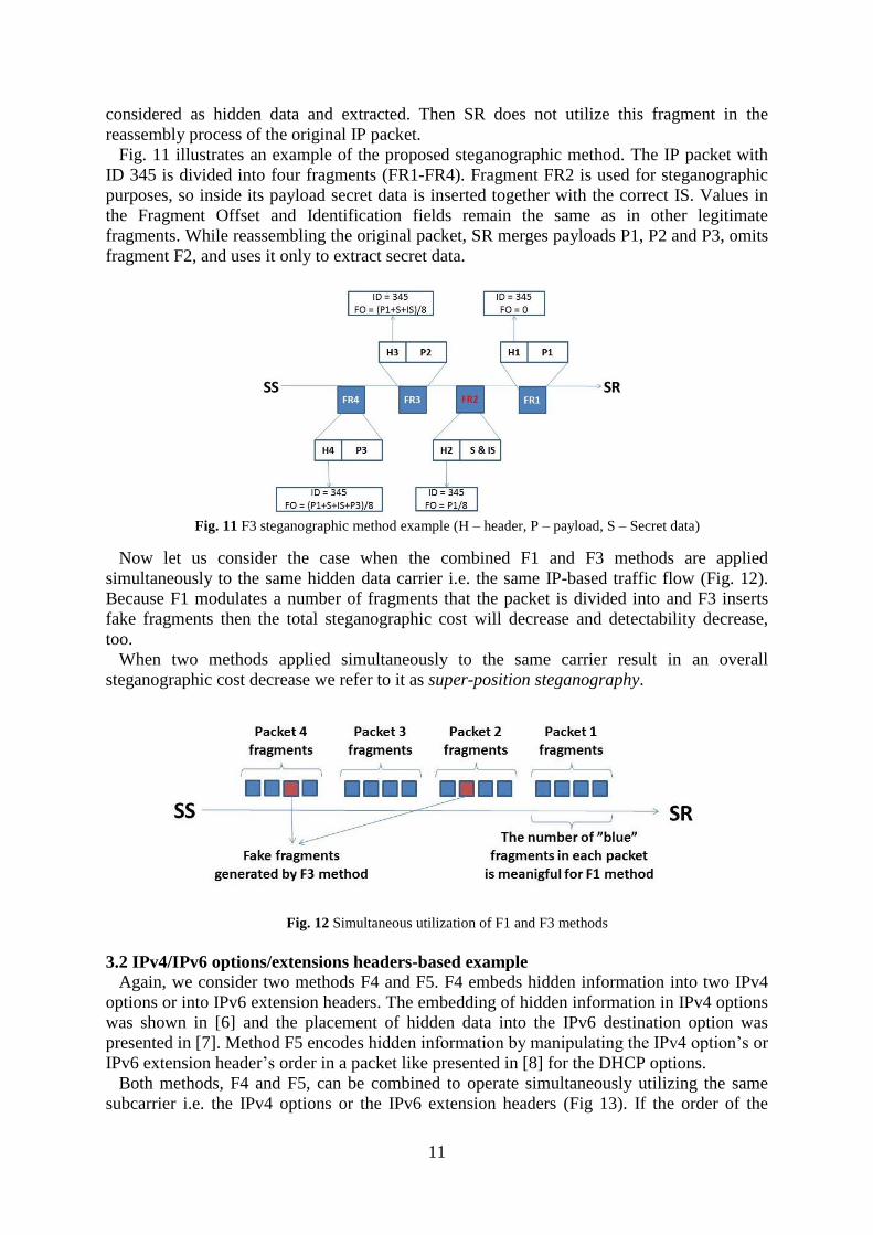
Fig. 11 illustrates an example of the proposed steganographic method. The IP packet with
ID 345 is divided into four fragments (FR1-FR4). Fragment FR2 is used for steganographic
purposes, so inside its payload secret data is inserted together with the correct IS. Values in
the Fragment Offset and Identification fields remain the same as in other legitimate
fragments. While reassembling the original packet, SR merges payloads P1, P2 and P3, omits
fragment F2, and uses it only to extract secret data.
Fig. 11 F3 steganographic method example (H – header, P – payload, S – Secret data)
Now let us consider the case when the combined F1 and F3 methods are applied
simultaneously to the same hidden data carrier i.e. the same IP-based traffic flow (Fig. 12).
Because F1 modulates a number of fragments that the packet is divided into and F3 inserts
fake fragments then the total steganographic cost will decrease and detectability decrease,
too.
When two methods applied simultaneously to the same carrier result in an overall
steganographic cost decrease we refer to it as super-position steganography.
Fig. 12 Simultaneous utilization of F1 and F3 methods
3.2 IPv4/IPv6 options/extensions headers-based example
Again, we consider two methods F4 and F5. F4 embeds hidden information into two IPv4
options or into IPv6 extension headers. The embedding of hidden information in IPv4 options
was shown in [6] and the placement of hidden data into the IPv6 destination option was
presented in [7]. Method F5 encodes hidden information by manipulating the IPv4 option’s or
IPv6 extension header’s order in a packet like presented in [8] for the DHCP options.
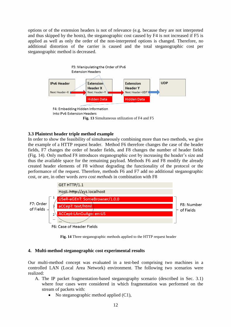
Both methods, F4 and F5, can be combined to operate simultaneously utilizing the same
subcarrier i.e. the IPv4 options or the IPv6 extension headers (Fig 13). If the order of the
12
options or of the extension headers is not of relevance (e.g. because they are not interpreted
and thus skipped by the hosts), the steganographic cost caused by F4 is not increased if F5 is
applied as well as only the order of the non-interpreted options is changed. Therefore, no
additional distortion of the carrier is caused and the total steganographic cost per
steganographic method is decreased.
Fig. 13 Simultaneous utilization of F4 and F5
3.3 Plaintext header triple method example
In order to show the feasibility of simultaneously combining more than two methods, we give
the example of a HTTP request header. Method F6 therefore changes the case of the header
fields, F7 changes the order of header fields, and F8 changes the number of header fields
(Fig. 14). Only method F8 introduces steganographic cost by increasing the header’s size and
thus the available space for the remaining payload. Methods F6 and F8 modify the already
created header elements of F8 without degrading the functionality of the protocol or the
performance of the request. Therefore, methods F6 and F7 add no additional steganographic
cost, or are, in other words zero cost methods in combination with F8
Fig. 14 Three steganographic methods applied to the HTTP request header
4. Multi-method steganographic cost experimental results
Our multi-method concept was evaluated in a test-bed comprising two machines in a
controlled LAN (Local Area Network) environment. The following two scenarios were
realized:
A. The IP packet fragmentation-based steganography scenario (described in Sec. 3.1)
where four cases were considered in which fragmentation was performed on the
stream of packets with:
No steganographic method applied (C1),
13
Only with F1 method applied (C2),
Only with F3 method applied (C3),
Both F1 and F3 methods applied – super-position steganography example
(C4).
B. The HTTP header-based steganography scenario (described in Sec. 3.3) where five
cases were considered:
No steganographic method applied (C5).
Only with F6 method applied (C6),
Only with F7 method applied (C7),
Only with F8 method applied (C8),
All three methods F6-8 applied (C9).
For each scenario, an own proof-of-concept implementation of the steganographic methods
described in Sec. 3.1 and 3.3 was carried out. Measurements for each case in each scenario
were repeated 10 times and only average values are presented. It must be emphasized that
some of the implemented methods are not characterized by high undetectability but they were
chosen to easily illustrate the concept of steganographic cost.
Depending on the scenario the following measures that represent steganographic cost were
captured:
Total connection time for both implemented scenarios,
distribution of the fragment sizes for Scenario A,
distribution of the HTTP header sizes for Scenario B.
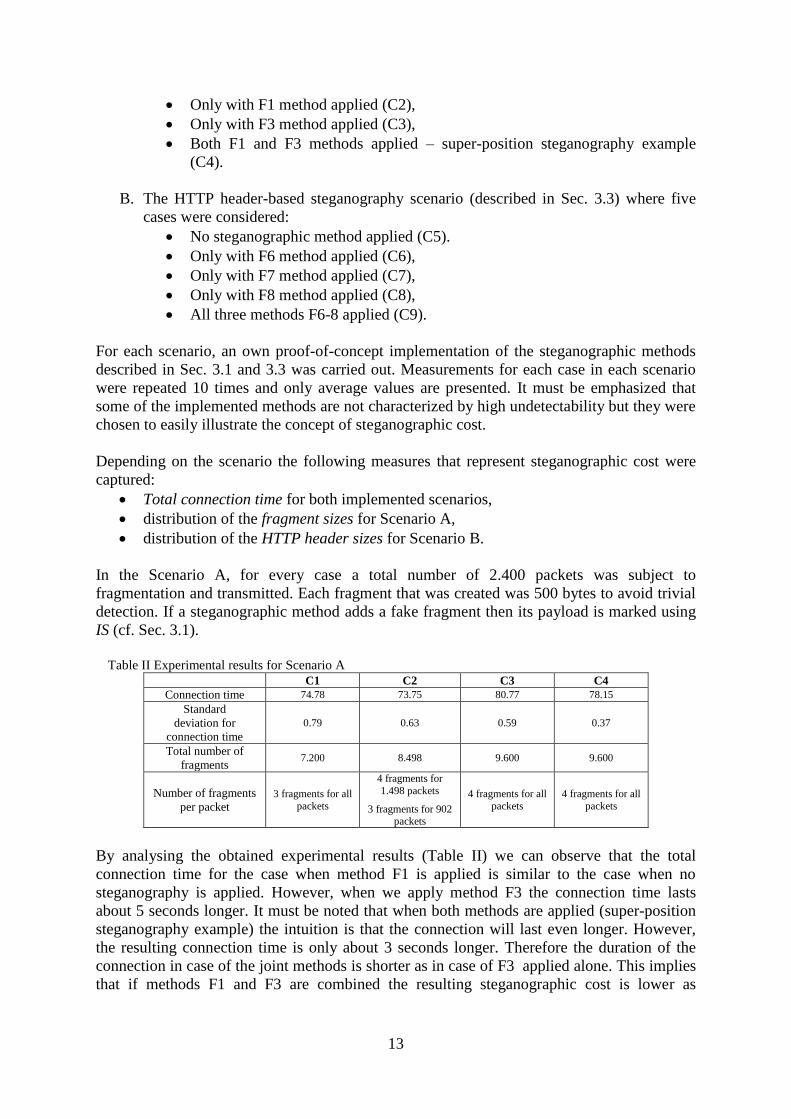
In the Scenario A, for every case a total number of 2.400 packets was subject to
fragmentation and transmitted. Each fragment that was created was 500 bytes to avoid trivial
detection. If a steganographic method adds a fake fragment then its payload is marked using
IS (cf. Sec. 3.1).
Table II Experimental results for Scenario A
C1 C2 C3 C4
Connection time 74.78 73.75 80.77 78.15
Standard
deviation for
connection time
0.79 0.63 0.59 0.37
Total number of
fragments 7.200 8.498 9.600 9.600
Number of fragments
per packet 3 fragments for all
packets
4 fragments for
1.498 packets
3 fragments for 902 packets
4 fragments for all
packets
4 fragments for all
packets
By analysing the obtained experimental results (Table II) we can observe that the total
connection time for the case when method F1 is applied is similar to the case when no
steganography is applied. However, when we apply method F3 the connection time lasts
about 5 seconds longer. It must be noted that when both methods are applied (super-position
steganography example) the intuition is that the connection will last even longer. However,
the resulting connection time is only about 3 seconds longer. Therefore the duration of the
connection in case of the joint methods is shorter as in case of F3 applied alone. This implies
that if methods F1 and F3 are combined the resulting steganographic cost is lower as
14
compared to the steganographic cost of the single method (the one that introduces higher
steganographic cost). This is the effect we call super-position steganography.
When we compare the distribution of the number of fragments per packet the situation is
similar. The F1 method (case C2) introduces irregularities in the number of fragments per
packet, while F3 increases the overall number of fragments per packet. Since the third-party
observer does not possess the knowledge of how many fragments the packets will be divided
into in advance, the F3 technique can be considered less detectable. However it must be noted
that in the joint-method’s case the resulting number of fragments per packet is the same as for
the case when F3 is applied alone. It is the same number of fragments since irregularities
introduced by F1 are “smoothed” by the second method making the overall steganographic
cost for C4 the same as for C3. Therefore the overall steganographic cost is not elevated.
In the Scenario B for every case the total of 900 packets were transmitted and modified
using F6-F8 methods. The obtained experimental results are presented in Table III.
Table III Experimental results for Scenario B
C5 C6 C7 C8 C9
Connection time 67.34 73.85 73.62 73.18 73.57
Standard
deviation for
connection time
0.73 0.72 0.49 0.62 0.6
HTTP header size 178 B
for all packets
178 B
for all packets
178 B
for all packets
178 B for 497 packets
154 B
for 403 packets
178 B for 511 packets
154 B
for 389 packets
By inspecting the overall connection time we can observe that after applying each of the
steganographic methods alone the resulting connection time increases by about 6 seconds.
The same result is achieved for the combined methods case (C9). Therefore simultaneous
utilization of all three methods does not influence the total connection time. That is why such
a situation is called zero cost steganography, as adding additional methods to the existing one
does not influence the resulting steganographic cost.
F8 operates by introducing irregularities in HTTP headers sizes. For C9, where two more
methods are added, the irregularities are still present but they are similar as in case of F8
applied alone. Thus we can conclude that in this case the resulting total steganographic cost is
not higher than in case of method F8 applied alone.
5. Conclusions
We introduce a metric called steganographic cost describing the degradation or distortion of a
carrier by one or more steganographic methods. We propose to take the evaluation of
steganographic cost into account when a steganographic method is evaluated – in addition to
the traditional measures steganographic bandwidth, detectability, and robustness. Our work
complements the existing approach on Minimal Requisite Fidelity (MRF) that introduced a
means to describe the distortion of a carrier by an active warden.
Our obtained experimental results show that it is feasible to combine multiple
steganographic methods to the same carrier in a way that the overall steganographic cost
caused by these methods is lower as in case of a separate combination of these methods
(super-position steganography). Results additionally show that multiple steganographic
methods can be combined with another method without causing any additional cost, which is
a special case of super-position steganography called zero cost steganography.
15
REFERENCES
[1] J. Fridrich, Steganography in digital media – Principles, Algorithms, and Applications, Cambridge
University Press, 2010, ISBN 978-0-521-19019-0
[2] W. Mazurczyk - Lost Audio Packets Steganography: A First Practical Evaluation - International
Journal of Security and Communication Networks, John Wiley & Sons, ISSN: 1939-0114, Vol. 5, Iss.
12, pp. 1394-1403, December 2012
[3] W. Mazurczyk, M. Smolarczyk, K. Szczypiorski - Retransmission Steganography and Its Detection In:
Soft Computing, ISSN: 1432-7643 (print version) ISSN: 1433-7479 (electronic version), Journal no.
500 Springer, Vol. 15, Issue 3, p. 505-515, 2011
[4] W. Frączek, W. Mazurczyk, K. Szczypiorski - Multi-Level Steganography: Improving Hidden
Communication in Networks - Journal of Universal Computer Science (J. UCS), ISSN: 0948-695X,
Graz Univ Technology, Inst. Information Systems Computer Media-IICM, Vol. 18, No. 14, pp. 1967-
1986
[5] W. Mazurczyk, K. Szczypiorski - Evaluation of Steganographic Methods for Oversized IP Packets In:
Telecommunication Systems: Modelling, Analysis, Design and Management, Volume 49, Issue 2
(2012), pp. 207-217
[6] Z. Rabelsi and I. Jawhar – Covert file transfer protocol based on the IP record route option, Journal of
Information Assurance and Security, Vol. 5(1), 2010.
[7] T. Graf – Messaging over IPv6 destination options, http://gray-world.net/papers/messipv6.txt, 2003.
[8] R. Rios, J. Onieva, J. Lopez – HIDE_DHCP: Covert communication through network configuration
messages, Proc. IFIP TC11 27th Int. Information Security Conference, Springer, 2012.
[9] W. Mazurczyk, K. Szczypiorski, Steganography of VoIP Streams, In: R. Meersman and Z. Tari (Eds.):
OTM 2008, Part II - Lecture Notes in Computer Science (LNCS) 5332, Springer-Verlag Berlin
Heidelberg, Proc. of The 3rd International Symposium on Information Security (IS'08), Monterrey,
Mexico, November 10-11, 2008, pp. 1001-1018
[10] M. Hamdaqa, L. Tahvildari - ReLACK: A Reliable VoIP Steganography Approach, 5th International
Conference on Secure Software Integration and Reliability Improvement (SSIRI 2011), pp. 189 - 197
June 2011
[11] ETSI EN 300 961 V8.1.1, Digital cellular telecommunications system (Phase 2+) (GSM); Full rate
speech; Transcoding, GSM 06.10 version 8.1.1 Release 1999, November 2000
[12] ITU-T Recommendation, G.711: Pulse code modulation (PCM) of voice frequencies, November 1988.
[13] Speex: A Free Codec For Free Speech - http://www.speex.org/
[14] ITU-T, Recommendation. P.800, Methods for subjective determination of transmission quality, 1996
[15] W. Mazurczyk, M. Smolarczyk, K. Szczypiorski - On Information Hiding in Retransmissions - In:
Telecommunication Systems: Modelling, Analysis, Design and Management, Volume 52, Issue 2,
2013, pp. 1113-1121, ISSN: 1018-4864 (print version), ISSN: 1572-9451 (electronic version), Springer
US, Journal no. 11235
[16] G. Fisk, M. Fisk, C. Papadopoulos, J. Neil: Eliminating Steganography in Internet Traffic with Active
Wardens, in Proc. Information Hiding (IH’03), LNCS 2578, pp. 18-35, Springer, 2003.
[17] W. Frączek, Network steganography: deep hiding techniques, MSc thesis, Warsaw University of
Technology, Poland, June 2011
Related Documents


![An Overview on Audio Steganography Techniques Vol6 No13 Binder1... · 2012-07-31 · lower payload of the watermarking methods compared to steganographic algorithms [35, 42, 47, 63].](https://static.cupdf.com/doc/110x72/5e740415a2da081283236f7b/an-overview-on-audio-steganography-vol6-no13-binder1-2012-07-31-lower-payload.jpg)