On DESTINY Science Instrument Electrical and Electronics Subsystem Framework Semion Kizhner and Dominic J. Benford National Aeronautics and Space Administration Goddard Space Flight Center Greenbelt Road, Greenbelt MD, 20771 301-286-1294 [email protected] Tod R. Lauer National Optical Astronomy Observatory [email protected] Abstract—F uture space missions are going to require large focal planes with many sensing arrays and hundreds of millions of pixels all read out at high data rates'' ` . This will place unique demands on the electrical and electronics (EE) subsystem design and it will be critically important to have high technology readiness level (TRL) EE concepts ready to support such missions. One such omission is the Joint Dark Energy Mission (JDEM) charged with making precise measurements of the expansion rate of the universe to reveal vital clues about the nature of dark energy - a hypothetical form of energy that permeates all of space and tends to increase the rate of the expansion. One of three JDEM concept studies - the Dark Energy Space Telescope (DESTINY) was conducted in 2008 at the NASA's Goddard Space Flight Center (GSFC) in Greenbelt, Maryland. This paper presents the EE subsystem framework, which evolved from the DESTINY science instrument study. It describes the main challenges and implementation concepts related to the design of an EE subsystem featuring multiple focal planes populated with dozens of large arrays and millions of pixels. The focal planes are passively cooled to cryogenic temperatures (below 140 K). The sensor mosaic is controlled by a large number of Readout Integrated Circuits and Application Specific Integrated Circuits – the ROICs/ASICs in near proximity to their sensor focal planes. The ASICs, in turn, are serviced by a set of "warm" EE subsystem boxes performing Field Programmable Gate Array (FPGA) based digital signal processing (DSP) computations of complex algorithms, such as sampling-up- the-ramp algorithm (SUTR), over large volumes of fast data streams. The SUTR boxes are supported by the Instrument Control/Command and Data Handling box (ICDH Primary and Backup boxes) for lossless data compression, command and low volume telemetry handling, power conversion and for communications with the spacecraft. The paper outlines how the JDEM DESTINY concept instrument EE subsystem can be built now, a design; which is generally U.S. Govemnent work not protected by U.S. copyright IEEEAC paper # 1429. Version 4. Updated October 19, 2009 applicable to a wide variety of missions using large focal planes with lar g e mosaics of sensors. TABLE OF CONTENTS 1.0 INTRODUCTION 2.0 KEY DRIVING REQUIREMENIS 3.0 DESTINY INSTRUMENT EE SUBSYSTEM CONCEPT 4.0 HERITAGE AND KNOW'-HOw AT NASA GSFC CONCLUSIONS ACKNOR'LEDGEMENTS REFERENCES BIOGRAPHY 1. INTRODUCTION In this paper we present the DESTINY concept for the EE subsystem. The EE subsystem is controlling a few large focal planes populated with a mosaic of homogeneous sensors and readout ASICs. The instrument electronics are primarily tasked with the readout and control of a large array of large format detector assemblies (mosaic of HgCdTe Astronomy Wide Area Infrared Imager with 2Kx2K resolution or H2RG sensors) in the science focal plane. The science focal plane is passively cooled to a cryogenic temperature. The science array is sampled (non- destructive sampling allowed by the H2RGs) multiple times within an exposure. The focal plane electronics feature a fast readout and onboard signal and data processing of hundreds of frames within an exposure using large external memories, followed by additional lossless data compression in the ICDH box and formatting the data prior to its transmission to the spacecraft Solid-State Recorder (SSR). For the DESTINY instrument EE subsystem the principal challenges are the large number of science detector elements (pixels) - 36 2Kx2K H2RG sensors (1.512x10 8 pixels, where K=1024) and the short time in which these elements must be read out (1.31072s) on multiple (32) 100 KHz channels (0.1152Gps) and have their data processed and stored (<< 10' s), and the resulting https://ntrs.nasa.gov/search.jsp?R=20090042692 2018-08-18T18:04:06+00:00Z

Welcome message from author
This document is posted to help you gain knowledge. Please leave a comment to let me know what you think about it! Share it to your friends and learn new things together.
Transcript

On DESTINY Science Instrument Electrical andElectronics Subsystem Framework
Semion Kizhner and Dominic J. BenfordNational Aeronautics and Space Administration
Goddard Space Flight CenterGreenbelt Road, Greenbelt MD, 20771
Tod R. LauerNational Optical Astronomy Observatory
Abstract—Future space missions are going to require largefocal planes with many sensing arrays and hundreds ofmillions of pixels all read out at high data rates'' ` . This willplace unique demands on the electrical and electronics (EE)subsystem design and it will be critically important to havehigh technology readiness level (TRL) EE concepts ready tosupport such missions. One such omission is the Joint DarkEnergy Mission (JDEM) charged with making precisemeasurements of the expansion rate of the universe toreveal vital clues about the nature of dark energy - ahypothetical form of energy that permeates all of space andtends to increase the rate of the expansion. One of threeJDEM concept studies - the Dark Energy Space Telescope(DESTINY) was conducted in 2008 at the NASA's GoddardSpace Flight Center (GSFC) in Greenbelt, Maryland. Thispaper presents the EE subsystem framework, which evolvedfrom the DESTINY science instrument study. It describesthe main challenges and implementation concepts related tothe design of an EE subsystem featuring multiple focalplanes populated with dozens of large arrays and millions ofpixels. The focal planes are passively cooled to cryogenictemperatures (below 140 K). The sensor mosaic iscontrolled by a large number of Readout Integrated Circuitsand Application Specific Integrated Circuits – theROICs/ASICs in near proximity to their sensor focal planes.The ASICs, in turn, are serviced by a set of "warm" EEsubsystem boxes performing Field Programmable GateArray (FPGA) based digital signal processing (DSP)computations of complex algorithms, such as sampling-up-the-ramp algorithm (SUTR), over large volumes of fast datastreams. The SUTR boxes are supported by the InstrumentControl/Command and Data Handling box (ICDH Primaryand Backup boxes) for lossless data compression, commandand low volume telemetry handling, power conversion andfor communications with the spacecraft. The paper outlineshow the JDEM DESTINY concept instrument EEsubsystem can be built now, a design; which is generally
U.S. Govemnent work not protected by U.S. copyrightIEEEAC paper # 1429. Version 4. Updated October 19, 2009
applicable to a wide variety of missions using large focalplanes with lar ge mosaics of sensors.
TABLE OF CONTENTS
1.0 INTRODUCTION
2.0 KEY DRIVING REQUIREMENIS
3.0 DESTINY INSTRUMENT EE SUBSYSTEM CONCEPT
4.0 HERITAGE AND KNOW'-HOw AT NASA GSFC
CONCLUSIONS
ACKNOR'LEDGEMENTS
REFERENCES
BIOGRAPHY
1. INTRODUCTION
In this paper we present the DESTINY concept for the EEsubsystem. The EE subsystem is controlling a few largefocal planes populated with a mosaic of homogeneoussensors and readout ASICs. The instrument electronics areprimarily tasked with the readout and control of a largearray of large format detector assemblies (mosaic ofHgCdTe Astronomy Wide Area Infrared Imager with2Kx2K resolution or H2RG sensors) in the science focalplane. The science focal plane is passively cooled to acryogenic temperature. The science array is sampled (non-destructive sampling allowed by the H2RGs) multiple timeswithin an exposure. The focal plane electronics feature afast readout and onboard signal and data processing ofhundreds of frames within an exposure using large externalmemories, followed by additional lossless data compressionin the ICDH box and formatting the data prior to itstransmission to the spacecraft Solid-State Recorder (SSR).
For the DESTINY instrument EE subsystem theprincipal challenges are the large number of sciencedetector elements (pixels) - 36 2Kx2K H2RG sensors(1.512x10 8 pixels, where K=1024) and the short time inwhich these elements must be read out (1.31072s) onmultiple (32) 100 KHz channels (0.1152Gps) and have theirdata processed and stored (<< 10' s), and the resulting
https://ntrs.nasa.gov/search.jsp?R=20090042692 2018-08-18T18:04:06+00:00Z

frame sensor and readout noise level of 6e- (as surnmarizedin Section 2). These require readout by a sensor dedicatedASIC that is retrieving and enhancing sensor frame signal,digitizing the signal and controlling the sensor chipassemble (SCA) — such as the ASIC from Teledyne calledSIDECAR. The 36 SIDECAR ASICs and their built-in 36microprocessors perform the signal digitization at 16 bits,resulting in order of magnitude larger volumes of digitaldata bits. It transmits the digital data to warn electronicsthat ingest and process exposure science data, and transmit asingle resulting exposure frame (for each sensor) to thespacecraft. The fast processing of such large volumes(1.85Gbs) of data using advanced algorithms, such asSUTR based on the up-the-ramp algorithm by Offenberg,Fixsen and John Mather, is at the core of this challenge. TheEE subsystem is processing from 277.5 Gb to 1665 Gb for150s and 900s exposures correspondently and outputs 0.34Gb of data for on-board recording, resulting in SUTR datacompression by a factor L, where 113 <= L <= 670 forexposures of 150 to 900 seconds. This compression factor isthe number of frames from which one frame is generated foroutput as a result of an exposure data processing. Theonboard data processing must sustain the 1.50s integrationsassuming an average 86% observing efficiency over a day.SUTR also reduces the sensor and readout noise by a factorproportional to sgrt(L) or between 10 to 2.5 times, resultingin readout noise reduction to required 6e- level.
The solution to the DESTINY-type instrumentrequirements of intensive data processing for reducingsensor and readout noise to 6e- and output data ratecormnensurate with the state-of-the-art space-to-groundcommunications link is both technically and fiscallyfeasible. The EE subsystem does not require newtechnology development prior to the design phase. Itleverages the HST, JWST, Spitzer, GLAST, SDO, LOLAand GPM missions' EE technologies (presented in Section4) and heritage in Science Sensors, ASICs and ROICs,onboard data processing by using reconfigurable computing(RC), FPGAs, Network and Instrument Sensor Web (ISW)[7] topologies, fine thermal control sensors, high speed datainterfaces (Spacewire, High-Speed Low-VoltageDifferential Signaling or LVDS), harness radiationprotection ; and large 3.6 GB External Synchronous dynamicrandom access memory (SDRAM) augmented by a 0.34 GBSDRAM Buffer for exposure frames output to the ICDH.The SUTR maps the 3.6 GB SDRAM into 0.34 GB memorybuffer for each exposure for all 36 sensors, which in-turn iscompressed conservatively at 2:1 ratio by the ICDH foroutput of 170 MB per exposure to the SC SSR for theshortest exposure of 150 seconds.
The science focal plane's large sensors withreadout electronics are of proven technology for smallmosaic configurations. The science sensors are controlledindividually by high-performance ASICs. Each ASICingests sensor analog signals and outputs 16-bit digital dataon 4 16-MHz channels to powerful processing boards(called "SUTR Boards") with built-in redundancy. Theprocessing boards' FPGA cores ingest the ASIC output
digital data, perform the SUTR data processing and outputan exposure frame for each sensor for different scienceexposure mode integration times (150 seconds to 900seconds) from its exposure buffer to the ICDH. Theinstrument flight software running on the RAD750computer in the ICDH controls the data processing. ASUTR board comprises two large FPGAs (80 FPGAs total)running the pre-processing and SUTR data processing (theinstrument flight software application computationallyintensive functions) in firmware and hardware andsupported by a 125 MB SDRAM module on each SUTRboard. The output of a processing board digital module is asequence of packetized sensor frames comprising anoperational science mode exposure. These packets arenetworked over Spacewire interfaces to the ICDH for 2:1lossless compression and the Consultative Committee forSpace Data Systems (CCSDS) 2% overhead packetization,and forwarded by the ICDH to the Spacecraft SSR overhigh speed Spacewire interface. This results in a maximum170 MB exposure frames data stream transmitted to the SCSSR for each exposure. For 150s exposures and 86%observing efficiency this amounts to 864 daily frames foreach of the 36 sensors or 1.5 Tb that determines the size ofthe SC SSR
The ASIC/ROICs selection of SIDECAR ASICand its configuration architecture, as well as SUTRprocessing and reference pixels utilization for noisereduction, address the sensor readout noise requirements of6e- per exposure. The implementation of the instrumentflight software for the data processing in the FPGAhardware addresses the data volumes, rates and onboardcomputational complexity requirements. The hardwarecompression modules card architecture (assisted byRAD750 and the instrument flight software in the ICDH)implements the required throughput requirements to thespacecraft SSR. All critical hardware components areradiation hardened.
The flow of analog signal and digital data isorganized in packets identifying the data source ; the frameboundaries, the frame unit of information — line beginningand end codes for analog signals and heritage Vpacketencapsulation for digital data.
The harness between cryogenic sensors andSIDECAR ASICs and the EE subsystem boxes comprisesthousands of conductors. However, such harness design isquite mature, but there are to be tradeoffs ofelectrical/thernial issues for the SCA-ASIC harness.
The JDEM DESTINY concepts were developedover the last few years and described in [1-7].
The DESTINY EE subsystem concept andframework were developed to the DESTINY instrumenttop-level and key driving requirements. The followingSection 2 Key Driving Electronics Requirements depictsthese requirements. The EE subsystem concept, frameworkand architecture, which meet these challenges andrequirements, are presented in Section 3. Section 4 depictsrelevant experience and facilities at NASA GSFC to supportthe JDEM DESTINY-type instrument development.
2

2. KEY DRIVING ELECTRONICS REQUIREMENTS • Maintain Focal Plane and cold electronics at
stable cryogenic temperaturesWeak Lensing (WL), Baryon Acoustic Oscillations (BAO)and Super Nova (SN) measurements are the knowntechniques to probe dark matter and energy. The JoinedDark Energy Mission Near Infrared Instrument (NIRI)employs all three techniques.
Although many JDEM requirements are still in theprocesses of change, evolution and refinement, some areknown and mature at this time and sufficient to develop theEE subsystem concept and architecture. Among these are:
• Observations Probe of Faint Super NovaSources in Near Infrared (NIR) Band
• Probe for Barvon Oscillations
• Probe for Weak Lensing
• Precise Pointing and distant-in-time Re-Pointing within Milli-arc Seconds
• Fine Guidance System (FGS) with FGS Sensorsin Observatory Telescope Boresight Focal Plane
• FGS Sensors readout by the EE subsystem andon-board processing within the EE subsystemor Spacecraft Attitude Control System (ACS) orBoth
• EE subsystem Signal and Data Processing on anFGS Control Pulse upon Pointing-for-ExposureCompletion
• Large Science Focal Plane and Sensor/ASICMosaic Control♦ Use of SIDECAR ASIC in Focal PlaneElectronics (FPE) (cold electronics)
• Reduce on-board data volume♦ SUTR data processing resulting in compressionbetter than 1.50:1. followed by♦ Data compression in ICDH at 2:1 ratio
• Reduce on-board Sensor/Readout noise andreject cosmic rays♦ SUTR processing in Image Frame Processorswithin the Off-Focal Plane Electronics in the EEsubsystem (warm electronics)♦ Cosmic Ray Rejection is an Integral Part ofNoise Reduction in SUTR processing
• Science Sensor Readout on maximum numberof channels to reduce frame clock-out rate andreduce readout noise
Maintain Focal Plane and cold electronics atstable cryogenic temperatures♦ Active thermal control electronics by ICDH♦ Appropriate harness materials to minimizeparasitic heat loads
Detectors cutoff is at —1.7 µm*This allows the detector to operate at relativelywarm temperatures (— —120C) with acceptable darkcurrent. This simplifies the instrument by allowingthe use of thermoelectric cooling systems insteadof the heritage cryogens or mechanical cryogenicscoolers that are typical in other NIR instrumentsand thermal control by the EE subsystem ICDH
Operate reliably at the Lagrange 2 Point (L2)environment for three years♦ Thorough modeling of L2 radiation environment♦ Use of proven radiation hardened Electrical.Electronic ; and Electromechanical (EEE) parts♦ Use of radiation mitigation schemes (spotshielding, redundancy, etc.) where necessary
High performance on-board data processing♦ FPGA-based hardware processing in ImageFrame Processors♦ HyperX Experiment on MISSE-7, carryingsuper-computing hardware♦ Proven RAD750 general-purpose processor inICDH♦ Dedicated image compression ASICs in ICDH
at 2:1 ratio and data formatting for storage in SSR
• Warm electronics are housed in spacecraft bay+Ambient temperature
• The FGS carries its own star catalog of some3000 stars, each describes by 5 double-precisionfloating point numbers and requiring 120,000 bytesmemory. It must be upgradable from the ground.
All on-board processing within the EEsubsystem is synchronized with an FGS TimingControl Pulse of Completion of Precise Pointingfor an observation exposure. If FGS is part of theSC ACS there must be a timing control pulseinterface from SC to the EE Subsystem.
• There must be an option for real-time downlink♦ Critical science telemetry subset bypassing theSC SSR for SSR function redundancy.
• For a single string design the SC SSR must beradiation hardened♦Radhard SDRAM-based boards. With 5 1.5Gbmodules per board the SSR is populated withsome 100 boards and weighing more than 50 kg.
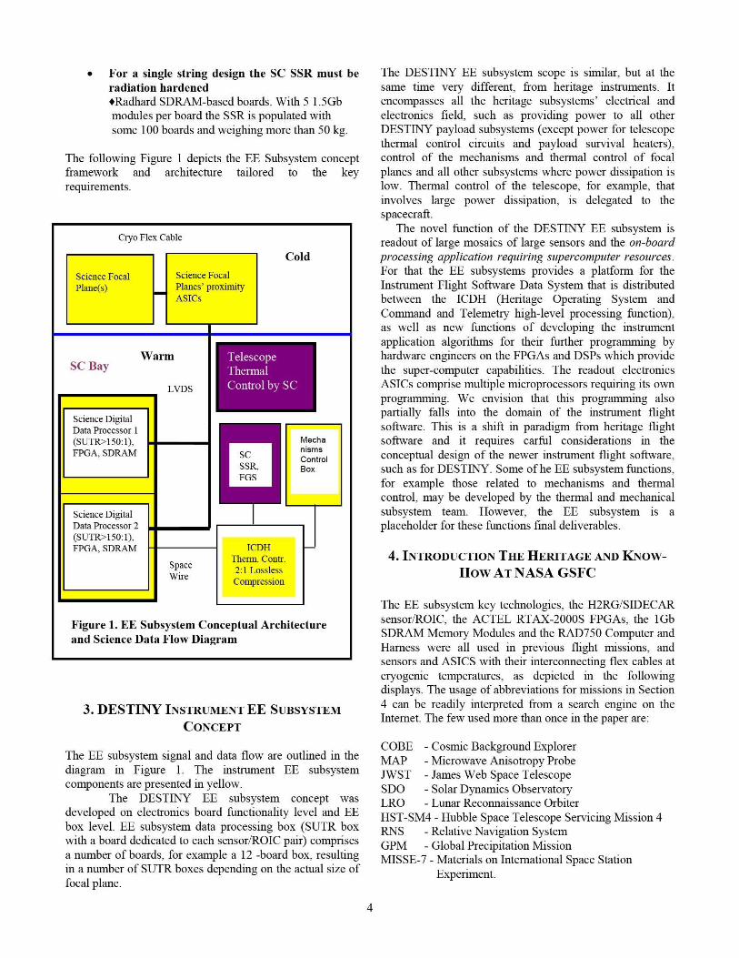
The following Figure 1 depicts the EE Subsystem conceptframework and architecture tailored to the keyrequirements.
Cryo Flex Cable
Cold
Science Focal Science FocalPlane(s) Planes' proximity
ASICs
TelescopeSC Bay
FarmThermal
LVDS Control
Science DigitalData Processor 1(SUTR?150:1), MechaFPGA.. SDRAMSC nisms
ControlSSR. BoxFGS
Science DigitalData Processor 2(SUTR?150:1),FPGA. SDRAM ICDH n
SpaceTherm. Contr.
Wire2:1 LosslessCompression
Figure 1. EE Subsystem Conceptual Architectureand Science Data Flow Diagram
3. DESTINY INSTRUMENT EE SUBSYSTEMCONCEPT
The EE subsystem signal and data flow are outlined in thediagram in Figure 1. The instrument EE subsystemcomponents are presented in yellow.
The DESTINY EE subsystem concept wasdeveloped on electronics board functionality level and EEbox level. EE subsystem data processing box (SUTR boxwith a board dedicated to each sensor'ROIC pair) comprisesa number of boards ; for example a 12 -board box, resultingin a number of SUTR boxes depending on the actual size offocal plane.
The DESTINY EE subsystem scope is similar, but at thesame time very different, from heritage instruments. Itencompasses all the heritage subsystems' electrical andelectronics field, such as providing power to all otherDESTINY payload subsystems (except power for telescopethermal control circuits and payload survival heaters),control of the mechanisms and thermal control of focalplanes and all other subsystems where power dissipation islow. Thermal control of the telescope, for example, thatinvolves large power dissipation, is delegated to thespacecraft.
The novel function of the DESTINY EE subsystem isreadout of large mosaics of large sensors and the on-boardprocessing application requiring supercomputer resources.For that the EE subsystems provides a platform for theInstrument Flight Software Data System that is distributedbetween the ICDH (Heritage Operating System andCommand and Telemetry high-level processing function),as well as new functions of developing the instrumentapplication algorithms for their further programming byhardware engineers on the FPGAs and DSPs which providethe super-computer capabilities. The readout electronicsASICs comprise multiple microprocessors requiring its ownprogramming. We envision that this prograinining alsopartially falls into the domain of the instrument flightsoftware. This is a shift in paradigm from heritage flightsoftware and it requires carful considerations in theconceptual design of the newer instrument flight software,such as for DESTINY. Some of he EE subsystem functions,for example those related to mechanisms and thermalcontrol, may be developed by the thermal and mechanicalsubsystem team. However, the EE subsystem is aplaceholder for these functions final deliverables.
4. INTRODUCTION THE HERITAGE AND KNOw-How AT NASA GSFC
The EE subsystem key technologies, the H2RG/SIDECARsensor./ROIC, the ACTEL RTAX-20005 FPGAs, the 1GbSDRAM Memory Modules and the RAD750 Computer andHarness were all used in previous flight missions, andsensors and ASICS with their interconnecting flex cables atcryogenic temperatures, as depicted in the followingdisplays. The usage of abbreviations for missions in Section4 can be readily interpreted from a search engine on theInternet. The few used more than once in the paper are:
LOBE - Cosmic Background ExplorerMAP - Microwave Anisotropy ProbeJWST - James Web Space TelescopeSDO - Solar Dynamics ObservatoryLRO - Lunar Reconnaissance OrbiterHST-SM4 - Hubble Space Telescope Servicing Mission 4RNS - Relative Navieation SystemGPM - Global Precipitation MissionMISSE-7 - Materials on International Space Station
Experiment.

^ m
MmIll-M^
ASTRO-E2 XRS Detector withCryo Cables, and ADR ControlElectronics
JWST NIRSpecFocal PlaneElectronics
Cryogenics Control Electronics (including Cabling and World leadership and expertise in FPGA's, radiationHarnessing) and Cryogenic Temperature Passive effects, and EEE parts:Control •Related Experience: Numerous In-House and Out-of-•Related Experience: COBE, MAP, ASTRO-E, AN7ST House Missions
•EEE-INST-002 has become the industry standard referencefor testing/qualifying EEE parts-Acknowledged experts in assessment and evaluation ofsingle event effects (both digital and analog) and doseeffects on analog, optoelectronic and fiber optics•GSFC jointly sponsors the annual Nuclear & SpaceRadiation Effects Conference (NIRSpec).
Advanced Packaging Concepts-Related Experience: SWIFT-BAT, MLA Messenger,Mars Science Orbiter
FPGA Flight Design and Application-Related Experience: LRO/LOLA, HST-SM4 RNS•GSFC jointly sponsors the annual Military and AerospaceProgrannnable Logic Device (MAPLD) Conference•GSFC lead an Actel RTAX FPGA risk reduction study forNESC
^:KII MK'
xuvrxsc
Spacecube Virtex-4 LRO Actel RTAX-2000S
di CLOLA Actel RTAX-250S
High Density Memory Devices-Related Experience: LRO, SDO, HST-SM4 RNS
H2RG Detector/SIDECAR ASIC-Related Experience: JWST, HST-ACS
1
i
H2RG Detector with Cryo FlexCable/SIDECAR ASIC fromTeledvne
RAD750 Processor Board-Related Experience: LRO, SDO, GPM
RAD750 Single Board Computer
On-board Digital Signal Processing and Compression-Related Experience: ASTRO-E, ICESAT/GLAS,HST-SM4 RNS Spacecube, MMS, and MISSE-7
I rlm_z..r-I _
1.5Gb SDRAM(SDO Bulk Memorv)
HST-SM4 RNS MMS
Spacecube Data Compression ASICs
ACKNOWLEDGEMENTS
l '
IIIIIIIIIIII
The authors would like to acknowledge and thank thefollowing members of the Goddard Space Flight Center:Robert L. Kasa, John F. McCabe, Maxime Pinchinat,Wesley A. Powel and Richard B. Katz for compiling thetechnology pictures. Special thanks are to Clifton E.Jackson and James M. Lohr for constrictive review of thepaper. We also acknowledge and thank Michael Johnson ofGSFC of providing the HyperX picture.
REFERENCES
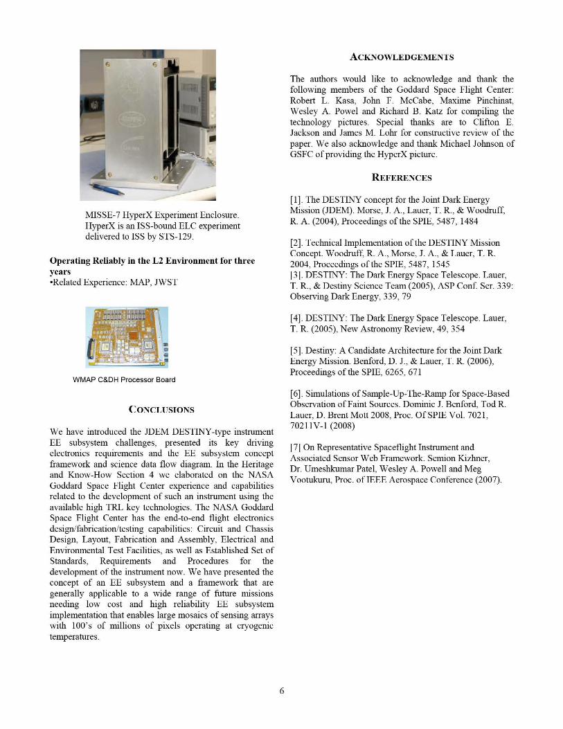
MISSE-7 HyperX Experiment Enclosure.HyperX is an ISS-bound ELC experimentdelivered to ISS by STS-129.
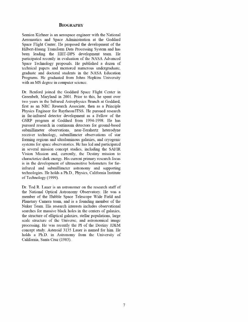
Operating Reliably in the L2 Environment for threeyears-Related Experience: MAP, JWST
r ;4"
WMAP C&DH Processor Board
CONCLUSIONS
We have introduced the JDEM DESTINY-type instrumentEE subsystem challenges, presented its key drivingelectronics requirements and the EE subsystem conceptframework and science data flow diagram. In the Heritageand Know-How Section 4 we elaborated on the NASAGoddard Space Flight Center experience and capabilitiesrelated to the development of such an instrument using theavailable high TRL key technologies. The NASA GoddardSpace Flight Center has the end-to-end flight electronicsdesign/fabrication/testing capabilities: Circuit and ChassisDesign, Layout, Fabrication and Assembly, Electrical andEnvironmental Test Facilities, as well as Established Set ofStandards, Requirements and Procedures for thedevelopment of the instrument now. We have presented theconcept of an EE subsystem and a framework that aregenerally applicable to a wide range of future nussionsneeding low cost and high reliability EE subsystemimplementation that enables large mosaics of sensing arrayswith 100's of millions of pixels operating at cryogenictemperatures.
[1].The DESTINY concept for the Joint Dark EnergyMission (JDEM). Morse, J. A., Lauer, T. R., & Woodruff,R. A. (2004), Proceedings of the SPIE, 5487, 1484
[2].Technical Implementation of the DESTINY MissionConcept. Woodruff, R. A., Morse, J. A., & Lauer, T. R.2004; Proceedings of the SPIE, 5487, 1.54.5[3].DESTINY: The Dark Ener gy Space Telescope. Lauer,T. R., & Destiny Science Team (2005), ASP Conf. Ser. 339:Observing Dark Energy, 339, 79
[4].DESTINY: The Dark Energy Space Telescope. Lauer,T. R. (2005), New Astronomy Review, 49, 354
[5].Destiny: A Candidate Architecture for the Joint DarkEnergy Mission. Benford, D. J., & Lauer, T. R. (2006),Proceedings of the SPIE, 6265, 671
[6].Simulations of Sample-Up-The-Ramp for Space-BasedObservation of Faint Sources. Dominic J. Benford, Tod R.Lauer, D. Brent Mott 2008, Proc. Of SPIE Vol. 7021,70211V-1(2008)
[7] On Representative Spaceflight Instrument andAssociated Sensor Web Framework. Sermon Kizhner.Dr. Umeshkumar Patel, Wesley A. Powell and MegVootukuru, Proc. of IEEE Aerospace Conference (2007).
BIOGRAPHY
Semion Kizhner is an aerospace engineer with the NationalAeronautics and Space Administration at the GoddardSpace Flight Center. He proposed the development of theHilbert-Huang Transform Data Processing System and hasbeen leading the HHT-DPS development team. Heparticipated recently in evaluation of the NASA AdvancedSpace Technology proposals. He published a dozen oftechnical papers and mentored numerous undergraduate,graduate and doctoral students in the NASA EducationPrograms. He graduated from Johns Hopkins Universitywith an MS degree in computer science.
Dr. Benford joined the Goddard Space Flight Center inGreenbelt, Maryland in 2001. Prior to this, he spent overtwo years in the Infrared Astrophysics Branch at Goddard,first as an NRC Research Associate, then as a PrinciplePhysics Engineer for Raytheon/ITSS. He pursued researchin far-infrared detector development as a Fellow of theGSRP program at Goddard from 1994-1998. He haspursued research in continuum detectors for grow id-basedsubmillimeter observations, near-Terahertz heterodynereceiver technology, submillimeter observations of starforming regions and ultraluniinous galaxies, and cryogenicsystems for space observatories. He has led and participatedin several mission concept studies, including the SAFIRVision Mission and, currently, the Destiny mission tocharacterize dark energy. His current primary research focusis in the development of ultrasensitive bolometers for far-infrared and submillimeter astronomy and supportingtechnologies. He holds a Ph.D., Physics, California Instituteof Technology (1999).
Dr. Tod R. Lauer is an astronomer on the research staff ofthe National Optical Astronomy Observatory. He was amember of the Hubble Space Telescope Wide Field andPlanetary Camera team, and is a founding member of theNuker Team. His research interests includes observationalsearches for massive black holes in the centers of galaxies,the structure of elliptical galaxies, stellar populations; largescale structure of the Universe, and astronomical imageprocessing. He was recently the PI of the Destiny JDEMconcept study. Asteroid 3135 Lauer is named for him. Heholds a Ph.D. in Astronomy from the University ofCalifornia, Santa Cruz (1983).
Related Documents