IEEE TRANSACTIONS ON MICROWAVE THEORY AND TECHNIQUES, VOL. 47, NO. 6, JUNE 1999 775 On Causality and Dynamic Stability of Perfectly Matched Layers for FDTD Simulations F. L. Teixeira and W. C. Chew, Fellow, IEEE Abstract—We investigate the spectral properties of the Carte- sian, cylindrical, and spherical perfect matched layer (PML) absorbing boundary conditions. In the case of the anisotropic- medium PML formulation, we analyze the analytical properties of the constitutive PML tensors on the complex -plane. In the case of the complex-space PML formulation (complex coordinate stretching formulation), we analyze the analytical properties of field solutions directly. We determine the conditions under which the PML’s satisfy (or do not satisfy) causality requirements in the sense of the real-axis Fourier inversion contour. In the case of the noncausal PML, we point out the implications on the dynamic stability of time-domain equations and finite-difference time-domain (FDTD) simulations. The conclusions have impact both on the design of PML’s for practical FDTD simulations and on the use of PML’s as a physical basis for engineered artificial absorbers on nonplanar (concave or convex) surfaces. Numerical results illustrate the discussion. Index Terms—Absorbing boundary conditions, anisotropic me- dia, dispersive media, FDTD methods, perfectly matched layer. I. INTRODUCTION T HE perfectly matched layer (PML) absorbing boundary condition (ABC), introduced by Berenger [1], [2] is a very efficient means to truncate the computational domain in the finite-difference time-domain (FDTD) simulation of electromagnetic (EM) problems [1]–[11]. Being a material ABC, the PML retains the nearest neighbor interaction charac- teristic of the FDTD method, making it particularly attractive for parallel simulations. It has also been applied to finite- element method (FEM) simulations [10], [12], [13], elastic- wave problems [14], and paraxial-wave problems [15] with similar success. More recently, the recognition that, via the complex coor- dinate stretching formulation [3], the PML can be interpreted as an analytic continuation of Maxwell’s equations (ME’s) to a complex variable spatial domain (or complex space, for short) [16], [17], [21], provided the basis for the extension of the PML to two-dimensional (2-D) cylindrical [20], [21], 3-D cylindrical [22], and three-dimensional (3-D) spherical coordinates [20], [22] (extensions to 2-D cylindrical coordi- Manuscript received March 25, 1998. This work was supported in part by the Air Force Office of Scientific Research under MURI Grant F49620-96- 1-0025, by the Office of Naval Research under Grant N00014-95-1-0872, by the National Science Foundation under Grant NSF-ECS93-02145, and by a CAPES/Brasilia Graduate Fellowship. The authors are with the Center for Computational Electromagnetics, Elec- tromagnetics Laboratory, Department of Electrical and Computer Engineering, University of Illinois at Urbana-Champaign, Urbana, IL 61801-2991 USA. Publisher Item Identifier S 0018-9480(99)04286-6. nates using different approaches are also considered in [18] and [19]). One of the desirable properties of the artificial PML media in any of these coordinate systems is that it should retain the causality conditions observed by the original ME’s. This naturally leads to the study of the analytic properties on the complex -plane of either the PML tensor constitutive parameters (in case of anisotropic-medium PML’s [6]–[9], [12], [13], [18], [22]), or the complex-space ME’s Green’s functions (in case of complex-space PML’s [3], [5], [10], [14]–[17], [20], [21]). In this paper, we study these analytic properties for the various coordinate system PML’s: Cartesian, cylindrical, and spherical. The discussion is centered on the spectral properties of these PML’s. Therefore, the conclusions do not depend on the peculiarities of the time-domain implementation (e.g., whether or not it utilizes field splitting), but have consequences on any time-domain implementation. In particular, we point out conditions under which causality is violated in the sense of a real-axis inverse Fourier contour and the consequences of this fact on the dynamic stability of the PML–FDTD simulations. The conclusions have impact on the design of PML’s for FDTD simulations and on the use of PML’s as a physical basis for engineered artificial absorbers on nonplanar (concave or convex) surfaces. Numerical results are presented to illustrate the discussion. Throughout this paper, the convention will be used. II. CAUSALITY,DYNAMIC STABILITY, AND FOURIER INVERSION CONTOUR In this section, we examine the connection between the vio- lation of causality in the sense of a real-axis Fourier inversion contour and the dynamic stability of the FDTD algorithm. The discussion is centered on the analytical properties of the tensor. For brevity, we restrict our attention to the electric-field constitutive relation. By invoking the duality principle [23], all of the following conclusions also apply to the magnetic case. In the frequency domain, the constitutive relation for the electric field is written as (1) where is the 3 3 permittivity tensor. In the time-domain, (1) becomes (2) Invoking causality, we have that for . 0018–9480/99$10.00 1999 IEEE

Welcome message from author
This document is posted to help you gain knowledge. Please leave a comment to let me know what you think about it! Share it to your friends and learn new things together.
Transcript

IEEE TRANSACTIONS ON MICROWAVE THEORY AND TECHNIQUES, VOL. 47, NO. 6, JUNE 1999 775
On Causality and Dynamic Stability of PerfectlyMatched Layers for FDTD Simulations
F. L. Teixeira and W. C. Chew,Fellow, IEEE
Abstract—We investigate the spectral properties of the Carte-sian, cylindrical, and spherical perfect matched layer (PML)absorbing boundary conditions. In the case of the anisotropic-medium PML formulation, we analyze the analytical propertiesof the constitutive PML tensors on the complex!-plane. In thecase of the complex-space PML formulation (complex coordinatestretching formulation), we analyze the analytical properties offield solutions directly. We determine the conditions under whichthe PML’s satisfy (or do not satisfy) causality requirements inthe sense of the real-axis Fourier inversion contour. In the caseof the noncausal PML, we point out the implications on thedynamic stability of time-domain equations and finite-differencetime-domain (FDTD) simulations. The conclusions have impactboth on the design of PML’s for practical FDTD simulations andon the use of PML’s as a physical basis for engineered artificialabsorbers on nonplanar (concave or convex) surfaces. Numericalresults illustrate the discussion.
Index Terms—Absorbing boundary conditions, anisotropic me-dia, dispersive media, FDTD methods, perfectly matched layer.
I. INTRODUCTION
T HE perfectly matched layer (PML) absorbing boundarycondition (ABC), introduced by Berenger [1], [2] is a
very efficient means to truncate the computational domainin the finite-difference time-domain (FDTD) simulation ofelectromagnetic (EM) problems [1]–[11]. Being a materialABC, the PML retains the nearest neighbor interaction charac-teristic of the FDTD method, making it particularly attractivefor parallel simulations. It has also been applied to finite-element method (FEM) simulations [10], [12], [13], elastic-wave problems [14], and paraxial-wave problems [15] withsimilar success.
More recently, the recognition that, via the complex coor-dinate stretching formulation [3], the PML can be interpretedas an analytic continuation of Maxwell’s equations (ME’s)to a complex variable spatial domain (or complex space, forshort) [16], [17], [21], provided the basis for the extensionof the PML to two-dimensional (2-D) cylindrical [20], [21],3-D cylindrical [22], and three-dimensional (3-D) sphericalcoordinates [20], [22] (extensions to 2-D cylindrical coordi-
Manuscript received March 25, 1998. This work was supported in part bythe Air Force Office of Scientific Research under MURI Grant F49620-96-1-0025, by the Office of Naval Research under Grant N00014-95-1-0872, bythe National Science Foundation under Grant NSF-ECS93-02145, and by aCAPES/Brasilia Graduate Fellowship.
The authors are with the Center for Computational Electromagnetics, Elec-tromagnetics Laboratory, Department of Electrical and Computer Engineering,University of Illinois at Urbana-Champaign, Urbana, IL 61801-2991 USA.
Publisher Item Identifier S 0018-9480(99)04286-6.
nates using different approaches are also considered in [18]and [19]).
One of the desirable properties of the artificial PML mediain any of these coordinate systems is that it should retainthe causality conditions observed by the original ME’s. Thisnaturally leads to the study of the analytic properties onthe complex -plane of either the PML tensor constitutiveparameters (in case of anisotropic-medium PML’s [6]–[9],[12], [13], [18], [22]), or the complex-space ME’s Green’sfunctions (in case of complex-space PML’s [3], [5], [10],[14]–[17], [20], [21]).
In this paper, we study these analytic properties for thevarious coordinate system PML’s: Cartesian, cylindrical, andspherical. The discussion is centered on thespectralpropertiesof these PML’s. Therefore, the conclusions do not dependon the peculiarities of the time-domain implementation (e.g.,whether or not it utilizes field splitting), but have consequenceson any time-domain implementation. In particular, we pointout conditions under which causality is violated in the senseof a real-axis inverse Fourier contour and the consequencesof this fact on the dynamic stability of the PML–FDTDsimulations. The conclusions have impact on the design ofPML’s for FDTD simulations and on the use of PML’s as aphysical basis for engineered artificial absorbers on nonplanar(concave or convex) surfaces. Numerical results are presentedto illustrate the discussion. Throughout this paper, theconvention will be used.
II. CAUSALITY , DYNAMIC STABILITY , AND
FOURIER INVERSION CONTOUR
In this section, we examine the connection between the vio-lation of causality in the sense of a real-axis Fourier inversioncontour and the dynamic stability of the FDTD algorithm. Thediscussion is centered on the analytical properties of thetensor. For brevity, we restrict our attention to the electric-fieldconstitutive relation. By invoking the duality principle [23], allof the following conclusions also apply to the magnetic case.
In the frequency domain, the constitutive relation for theelectric field is written as
(1)
where is the 3 3 permittivity tensor. In the time-domain,(1) becomes
(2)
Invoking causality, we have that for .
0018–9480/99$10.00 1999 IEEE
776 IEEE TRANSACTIONS ON MICROWAVE THEORY AND TECHNIQUES, VOL. 47, NO. 6, JUNE 1999
By writing
(3)
where is a real-valued constant tensor, it is possible toshow [23] that, if the inversion contour of (3) is carried outalong the real -axis, the condition for impliesthat the integrand in (3) must be analytic (holomorphic) inthe upper half-plane (zeros are also forbidden on the upperhalf-plane; for a more detailed discussion of the connectionbetween causality and the analytical properties of thetensor, see [24]–[26]). It should be noted here that when werefer to causality in the sense of a real-axis Fourier inversioncontour, we are restricting ourselves to theprimitive causalitycondition (i.e., the effect cannot precede the cause), as definedin [26]. The term causality also appears in other contexts.For instance, it is sometimes used to refer to therelativisticcausality condition, which states that no signal can propagatewith velocity greater than [26].
When is not analytic in the upper half-plane, causalitycan still be preserved, provided the Fourier inversion contouris takenaboveany singularities [23]. In this case, the mediumwill behave as anactivemedium and its response will not bedynamically stable anymore. The definition of a dynamicallystable system adopted here is such that all its eigenmodesapproach zero as (asymptotically stable) or remainbounded as (marginally stable).
In FDTD simulations, the fields assume a causal behavior bythe very nature of the method (explicit time-stepping scheme),regardless of the analytic properties on the frequency domain.This means that the Fourier inversion contour should alwaysbe taken above any singularities [23]. Therefore, following thediscussion of the previous paragraph, violation of causality inthe sense of real -axis Fourier inversion contour implies adynamically unstable FDTD method.
Note that the dynamic stability criterion is distinct from:1) the numerical stability criterion that should be satisfied bya particular numerical discretization scheme. For a dynami-cally unstable system, no convergent numerical discretizationschemes prevent the solutions from growing unbounded. For afurther discussion on this aspect, see [27] (note, however, thatthe definition of dynamic stability in [27] is slightly differentfrom the one adopted here and the anisotropic PML constitu-tive parameters considered there are frequency independent)and 2) dynamic stability is also a distinct criterion from theone incurred by a particular field-splitting of the modifiedME’s on the PML, which may induce a weak well posednesson the resultant system of equations, as discussed in [28].Although the weak well posedness is also a characteristic ofthe system of partial differential equations in the continuum,we should stress that it is a distinct property from the dynamicstability issue discussed here. The discussion here is centeredon thespectralcharacteristics of the PML equations and doesnot depend on the particular field-splitting scheme (if any)employed in the time-domain implementation of the PML.
When is analytic on the upper half-plane, it can alsobe definedvia the general time-domain relationship between
and as follows:
(4)
[which is a particular case of (2)], through [24], [25]
(5)
We immediately see that, if the function (generalizedtime-domain complex susceptibility kernel) is finite throughoutthe range of integration, the integral converges in the upperhalf-plane (real-axis excluded) and, therefore, is properlydefined. In some instances, the integral in (5) diverges for
on the real axis or in the lower half-plane, and definition(5) is invalid at these points. However, the function canstill be defined as the analytic continuation of (5) from theupper half-plane. It will, in general, contain singularities inthese regions [24], [25]. This is the case, for instance, for anisotropic media with static conductivity, where the complexdielectric constant is usually written for real frequencies asthe analytic continuation of (5) containing a pole at the origin
(6)
The discussion in the last paragraph is directly related tothe issue of causality of Cartesian PML’s to be treated inSection III.
III. CARTESIAN PML ANALYSIS
In this section, we examine the causality and dynamicstability of the Cartesian PML.
A. Anisotropic Formulation: Analytical Propertiesof the Constitutive Tensors
Berenger first proposed the PML in Cartesian coordinates[1], [2] and, since then, Cartesian-grid FDTD codes have beenimplemented and tested in several radiation and scatteringexamples [1]–[11]. These examples use different anisotropic(unsplit) and split-field schemes where no instability have beenobserved. Since dynamic instability is usually a dramatic (earlytime) effect, we should, therefore, expect the Cartesian PMLto be dynamically stable and causal in the sense of real-axisFourier inversion contour. The analysis on this section willserve to verify this conjecture.
In the anisotropic-medium PML formulation [6]–[9], [12],the fields inside the PML region obey the ME’s in ananisotropic medium with properly chosen constitutive tensors.Therefore, a useful test for violation of causality is tocheck if the resultant frequency-domain constitutive tensors
and satisfy, alongwith the crossing relation (the stardenotes complex conjugation), the Kramers–Kronig relations[23]–[25], [28]–[32]. This should also be true for their inverses
and [24], [25].The Cartesian PML constitutive tensor is given by
(7)

TEIXEIRA AND CHEW: ON CAUSALITY AND DYNAMIC STABILITY OF PML’S FOR FDTD SIMULATIONS 777
where, in usual time-domain simulations, the frequency depen-dence on the complex stretching variables[3]is given by the expression
(8)
with and in practical situations.The choice achieves the reflectionless absorptionof propagating modes and the choice achievesadditional (faster) decay of evanescent modes (if they exist).Note that (8) resembles the expression of a complex dielectricconstant of a conductive media.
Equation (7) is the most general form for an anisotropicCartesian PML media and corresponds to a 3-D PML at acorner interface, where there is a simultaneous stretching onthe three coordinates. This tensor is just the product of threesimpler 3 3 uniaxial tensors
(9)
with
(10)
and analogously for and . In order forto satisfy causality, each of the tensors must
satisfy it individually (there are no pole-zero cancellations).Since the frequency dependence of andis determined by and , the Kramers–Kronig rela-tions must be satisfied individually by these functions. TheKramers–Kronig relations are a consequence of the applicationof the Cauchy’s theorem to the function in theupper half-plane [23]. When presented in their usual form[23]–[26], [29]–[31], the analyticity of over theentire real axis is implicitly assumed. However, this is notthe case, for instance, in conductive media, in which thecomplex dielectric constant has a term and, therefore,has a pole singularity present at . The Kramers–Kronigrelations for conductive-like media must be properly modifiedto account for the deformation of the closed contour in theCauchy’s theorem to avoid the pole at the origin by meansof an infinitesimal semicircle above it. This detail has beenoverlooked on a previous study on this topic [31]. In this moregeneral form, the Kramers–Kronig relations read as [24], [25],[29]
(11)
(12)
where and are the real and imaginary parts of ,denotes the Cauchy principal value, and the integrals are
carried out along the real axis. The and are tobe interpreted as the limiting values asapproaches the realaxis from above. The last term in (12) is the pole contributionat the origin and represents the modification from the usualKramers–Kronig relations. Whenever the stretching variables
are defined as having a pole at , as in (8), theKramers–Kronig relations to be used are as in (11)–(12). Toapply relations (11) and (12) to (8), the following immediateidentifications are made:
so that (11) and (12) become
(13)
(14)
We immediately see that (14) verifies (12). Equation (13) alsoverifies (11) since [32]
(15)
and, thus, (13) is true in the upper half-plane. As a result,(8) obeys the Kramers–Kronig relations, being causal in thesense previously stated. The fact that, in the real axis, we geta Dirac delta function from (15) is related to the divergenceof the integral in (5) for real . The expression (8) does notinclude the Dirac delta function since it must be treated asan analytic continuation from the upper half-plane expressionin a similar fashion as in the (6). Such conclusions should beexpected from the resemblance of (8) to the complex dielectricconstant of a conductive medium. Indeed, given a general fieldrelationship in the frequency domain
(16)
this means to have, in the time-domain,
(17)
where causality and (marginal) stability are evident.A brief digression should be made at this point. In the case
of the relationship , the marginalstability in (17) seems to contradict the fact that, for a con-ductive media, eigenfunctions with faster decay are expected.The point is that the marginal stability in this case is causedjust by the definition of the itself when incorporatingconduction currents through the complex dielectric constant,as in (16). For instance, a DC conduction current
gives rise to linearly growing field,and, similarly, an impulse currentgives rise to a constant field (which is an example ofbounded eigenfunction that does not approach zero at ).However, this marginal stability is not a property of the ME’sthemselves for conductive media since the term which appearsin the equation for the field (Ampere’s law) is ,and the pole at is cancelled. In fact, as increases,the resultant eigenfunctions will have a faster decay since thefactor will have a pole that is shifted downwardsin the lower half complex -plane.
It is a simple exercise to verify that, if and ,the function also satisfies the Kramers–Kronig relations.

778 IEEE TRANSACTIONS ON MICROWAVE THEORY AND TECHNIQUES, VOL. 47, NO. 6, JUNE 1999
In this case, since there are no singularities present on the realaxis, the usual form of Kramers–Kronig relations can be used.
In summary, the Cartesian anisotropic PML media withfrequency dependence, given by (8), is causal in the sense ofreal-axis Fourier inversion contour and, from the discussion inSection II, nodynamicinstability should be expected.
B. Complex-Space Formulation: Analytical Propertiesof the Field Solutions
For the complex-space PML formulation, the most directroute to investigate the dynamic stability of the CartesianPML is to simply write down the frequency-domain closed-form field solutions (or the Green’s functions) for the modifiedME’s inside the PML and study its analytical behavior in thecomplex -plane. This is because the solutions of the modifiedME’s inside the PML [3] are just the analytic continuationto complex space of the closed-form solutions of the usualME’s [16], [17], [20]–[22]. Under this analytic continuation,propagating eigenfuctions of ME’s obeying Sommerfeld’sradiation condition are mapped into exponentially decayingfunctions, allowing for the reflectionless absorption of EMwaves. We shall illustrate this with a simple example.
We take the 2-D Green’s function for a cavity enclosed byperfect electric conducting (PEC) walls at(which can be thought of as the FDTD computational domainwhen using hard boundary conditions), which is written as
(18)
for where
(19)
. By inserting a CartesianPML before the box walls, will be analyticallycontinued to the complex plane through the following mappingon the coordinates (see [16], [17], [21]):
(20)
where is on the physical (real) space and inthe physical space. From (20), we see that the boundaries of thebox are complex valued inside a PML layerand, because of this, the reflection coefficient can be made verysmall [16], [17]. The function in (18) has an infinite numberof poles located along the real-axis (natural frequencies ofthe cavity). With the mapping (20), these poles are translated
to the roots of the equation
(21)
which are always located on the real axis or lower half-planefor and .
In addition to this, it should be noted that is an entirefunction (no poles) and that the branch points induced bythe factors in (19) (which give rise to simple polesin (21) for this 2-D case) are also on the lower half-plane.Consequently, the resultant PML Green’s function is alsoanalytic over the entire upper half-plane and causality inthe sense of real-axis Fourier inversion contour is preserved.This is true for any observation point inside the physicalor PML domains. A similar situation occurs in the 3-Dcase. Consequently, and similarly to the anisotropic-mediumPML, the complex-space PML in Cartesian coordinates isdynamically stable.
IV. CYLINDRICAL PML ANALYSIS
In this section, we examine the causality and dynamicstability of the cylindrical PML. For brevity, the discussionwill focus only on those aspects differing from the previousanalysis of the Cartesian case.
A. Analytical Properties of the Anisotropic Mediumand Complex-Space Formulations
The cylindrical PML is considered in [16]–[22]. In [20], [21]it is derived for the 2-D case through an analytical continuation(complex stretching) on the radialcoordinate. Through thisanalytic continuation, the propagating eigenfunctions of ME’sin cylindrical coordinates obeying Sommerfeld’s radiationcondition (Hankel functions), which originally have only analgebraic decay on , are transformed into functions withexponential decay. In [22], the equations for complex-space3-D case are presented, where a simultaneous stretching onthe and coordinates is effected. The anisotropic cylindricalPML 3-D formulation is also presented in [22] (first derivedgraphically in 2-D in [18]), along with the pertinent field-mapping equations that relate the complex-space PML andanisotropic PML fields.
In cylindrical coordinates, the constitutive tensorfor the anisotropic PML formulation is given by [22]
(22)
In the above, and are the stretching parameters in the- and -directions respectively, in direct analogy with the
Cartesian case
(23)

TEIXEIRA AND CHEW: ON CAUSALITY AND DYNAMIC STABILITY OF PML’S FOR FDTD SIMULATIONS 779
with and . The variable is a “pseu-dostretching” parameter in the coordinate that accounts forthe modification in the metric coefficient after the stretchingin the -direction
(25)
where is on the physical (real) space andin the physical space. The tensor in (22) can also be writtenas the product of three simpler 3 3 uniaxial tensors
(26)
with
(27)
and analogously for and .In order for to satisfy causality, each of the
tensors in (26) must satisfy it individually. Since the tensorsand have the same analytical properties of the Cartesian
PML tensors studied before, we shall limit ourselves to studythe analytical properties of the tensor. The frequencydependence of (and is determined by
and , and, therefore, we must focus our attention onthese factors (dependence on the “pseudostretching”) and theamount they differ from the Cartesian case. Again, to ensurecausality in the sense of a real-axis Fourier inversion contourfor , we must ensure (necessary condition) that thereare no poles due to or above the real axis. For , thisis evident, as the only pole is at , and it can be shownthat this function satisfies the Kramers–Kronig relations of theform (11) and (12). However, a major difference arises inthe angular factor . It is due to the fact that the factor
in the imaginary part of may, at certain instances, benegative. This is in contrast to the correspondingfactors inthe imaginary part of , , , or , which are also chosento be positive to achieve absorption. Due to the fact thatispositive, when used in (25) for a concave cylindrical PML (atthe outer boundary), we will still have . However, fora convexcylindrical PML (inner boundary), we have ,as the integral in (25) is carried overdecreasingvalues of
. The net effect of this is that the factor will thenhave poles in the upper half-plane, and the resultantwill be noncausal in the sense of real-axis Fourier inversioncontour. As a consequence (from the discussion in Section II),we should expect dynamic instability on FDTD simulationswhen employing a convex PML on cylindrical coordinates.Note that we may enforce on convex surfaces if wechoose at the convex PML. However, in this case, itwould be the factor which would give rise to singularitiesin the upper half-plane (this is also related to the fact that, inorder to have absorption in the radial direction, has to bepositive, irrespective of the concave or convex geometry).
Such dynamically unstable behavior can also be expectedfrom a direct analysis of the properties of the formal complex-space Green’s functions of the cylindrical PML. Analogouslyto the Cartesian case, the solutions of the modified ME’s(frequency domain) inside the cylindrical PML are just theanalytic continuation of the solutions of the usual ME’s incylindrical coordinates with the and coordinates mapped,as in (20), with stretching parameters defined by (23) and (24)[16], [17], [22], so that and .
For example, the 2-D Green’s function for a point source atinside a PEC cylinder of radius is given by [23]
(28)
so that, when backed by a concave cylindrical PML, the fieldmaps to
(29)
where is defined as in (25). Note that is also complexvalued. The effect of the cylindrical PML is to make thereflected field [summation term in (29)] exponentially small[16], [17]. Furthermore, this analytic continuation preservesthe analyticity on the upper half-plane of the resultant field in(29). This is because the singularities of (28) are due to branchpoints (located on the real axis) of the and zeros of thedenominator functions (all on the real axis) [33]. When
, as in (25), with , all singularities are translateddown to the lower half -plane, so that the upper half-planeis kept free of any singularity for (29).
In contrast, the 2-D Green’s function for a point source atlocatedoutsidea perfect conducting cylinder of radius
is given by
(30)
so that the solution when the perfect conducting cylinder is“coated” by a convex cylindrical PML is given by the analyticcontinuation
(31)
This analytic continuation does not preserve analyticity in theupper half-plane as the variable now has . Thezeros of the denominator functions located in the lower

780 IEEE TRANSACTIONS ON MICROWAVE THEORY AND TECHNIQUES, VOL. 47, NO. 6, JUNE 1999
Fig. 1. Contour map of the magnitude of the functionH(1)7 (z) on the
complex plane. Darker regions represent smaller values. The zeros on thelower half-plane and the branch cut on the negative real axis are clearlyvisible.
half-plane are translatedupwardsin the complex -plane andwill eventually appear as poles on the upper half-plane of thereflected field terms in (31). Fig. 1 illustrates the location ofthe complex zeros of the function . Branch points ofthe functions on the real axis will also eventually betranslated to the upper half-plane. The lack of analyticity onthe upper half-plane makes these solutions grow unbounded inthe time domain (dynamically unstable behavior), as discussedin Section II.
For generality, we have been focusing on the spectralanalysis, but from an analysis of the resulting PML equationsin time domain, it is observed that the unstable behavioris usually associated with update equations involving theangular derivatives. This can be seen as a consequence ofthe way the stretched differential arc lengths behave understretching for the convex and concave situations. Althoughthe stretched differential arc lengths and
have positive imaginary parts for both the convexand concave cases, resulting in attenuation for- and -directions in both cases, the stretched angular arc lengthhas a positive imaginary part for the concave PML and anegative imaginary part for the convex part (the resultanteffect, in the concave PML case, is a complex “stretch-ing” on the angular coordinate, but translates, in the convexPML case, to a “squeezing” on the angular coordinate). Thenegative imaginary part of gives rise to a temporaloperator of the form with , associ-ated with equations where the operator appears. Thistemporal operator induces exponential growth in time (asopposed to operators with obtained with a positiveimaginary part of in the concave case, which induceexponential decay). In connection with this, we note thatthe singularities in the upper half-plane are solely causedby the angular tensor in (26) . Finally, since the
-dependence of the fields necessarily obeys a fundamen-tal periodic boundary condition, the fields cannot present adefinite growing/attenuative behavior in the-direction (in
(a)
(b)
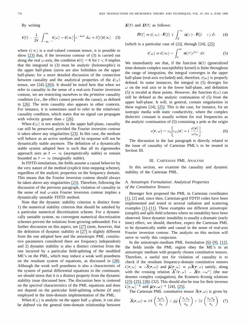
Fig. 2. Configurations for the stability test of the PML–FDTD algorithm incylindrical and spherical coordinates. The computational domain surrounds acylindrical or spherical perfectly conducting scatterer (coated or not coatedby a covex PML). (a) Configuration A. (b) Configuration B.
other words, the angular spectrum must be real and discrete).Instead, the exponential growing behavior should be presentin the time dependence.
B. Numerical Results for the Cylindrical PML
To illustrate the previous discussion, numerical results ofcylindrical grid FDTD simulations with convex and concavecylindrical PML are presented, corresponding to the configu-rations of Fig. 2(a) and (b).
Fig. 3 shows the normalized field from a linesource radiating in the presence of a perfectly conductingcircular cylinder and computed using a cylindrical grid 2-DPML–FDTD algorithm. The time-stepping scheme is the sameas the one described in [20] (complex-space formulation). Thespace discretization follows the usual staggered-grid central-differencing scheme in cylindrical coordinates [34]. The linesource is located at and the field issampled at , where is the (free space)wavelength corresponding to the central frequency of theexcitation pulse. The conducting cylinder is centered at theorigin and has a radius . The excitation pulse isthe first derivative of the Blackman–Harris pulse with centralfrequency MHz. The time step used is ps.
The cylindrical grid is terminated at , where a hardboundary condition is set . In all simulations, theFDTD algorithm includes an eight-layer concave cylindricalPML region before the grid termination (at the outer bound-ary). The PML thickness is for a cell sizein the radial direction. A quadratic taper on is used, varyingfrom zero up to . For simplicity, everywhere.The solid line in Fig. 2 shows the result when using only

TEIXEIRA AND CHEW: ON CAUSALITY AND DYNAMIC STABILITY OF PML’S FOR FDTD SIMULATIONS 781
Fig. 3. 2-D cylindrical-grid FDTD solution with eight-layer cylindricalPML. The solid line represents the case with the concave cylindrical PMLonly. Both the direct and reflected pulse due to the inner PEC cylinder arevisible. No reflected fields due to the grid ends at the outer boundary arevisible. The dashed line represents the FDTD simulation with the convexcylindrical PML coating the inner PEC cylinder. The dramatic early-timeinstability incurred is evident.
a concave cylindrical PML before the outer boundary. Thiscorresponds to the configuration depicted in Fig. 2(a). Boththe direct pulse and nonspurious reflected pulse due to theinner perfect conducting cylinder are visible. No spuriousreflection due to the outer boundary is visible. The dotted lineis the result of the simulation when an eight-layer convexcylindrical PML is placed around the inner cylinder. Thiscorresponds to the configuration depicted in Fig. 2(b). Thesame value of is used for the concave and convexPML’s in this case. A reflected wave from the (PML coated)inner cylinder is nonetheless present and, more importantly,the instability of the resultant FDTD algorithm in this caseis dramatic. It occurs soon after the wave reaches the convexPML (early-time effect).
Fig. 4 shows the results of the same simulation, but alsowith smaller values for in the convex cylindrical PML.This illustrates that the growth rate of the electric field insidethe convex cylindrical PML is proportional to , asexpected.
C. Imposing Stability a Posteriori: The Quasi-PML
The conclusions above have impact on the design of EMPML absorbers both as tools for numerical simulations and ontheir use (anisotropic-medium formulation) as a physical basisfor engineered artificial absorbers [35].
An alternative to avoid the singularities in the upper half-plane for the convex case would be toimpose in (25)for the inner boundary (irrespective of . In this manner,a dynamically stable scheme can be obtained. However, theresultant cylindrical interface is not perfectly matched anymore(since (25) is not true anymore). It should, more appropriately,be called a quasi-PML [36]. This approximation behaves as atrue PML only in the limit , when the cylindricalPML reduces to the Cartesian PML. From our preliminary
Fig. 4. Same simulation as the previous figure, but using different values for��;max in the convex PML. The growth rate of the fields gets smaller as thevalue of��;max is decreased (smaller stretching).
experience, the two important features exhibited by a quasi-PML when compared to a true PML (when the latter isapplicable) are: 1) a nonzero reflection coefficient in thecontinuum limit and 2) the need for a more finely tuned profileto achieve the best results.
Still, a quasi-PML may have practical applications when, for both numerical simulations and as a physical basis
for engineered artificial absorbers.
V. SPHERICAL PML ANALYSIS
In this section, we examine the causality and dynamicstability of the spherical PML. The focus is on those aspectsthat differ from the previous cases.
A. Analytical Properties of the Anisotropic Mediumand Complex-Space Formulations
The spherical PML is considered in [16], [17], [20], and[22]. In [20], it is derived through an analytical continu-ation (complex stretching) on the radial coordinate. Theanisotropic spherical PML formulation is presented in [22],along with the pertinent field-mapping equations that relatethe complex-space PML and anisotropic PML fields.
In the spherical system, the constitutive tensorfor the anisotropic PML formulation is given by [22]
(32)
In the above, is the stretching parameter in the-direction,in direct analogy with the Cartesian case
(33)
with and . The variables and are “pseu-dostretching” parameters in theand angular coordinatesthat account for the modification in the metric coefficient after

782 IEEE TRANSACTIONS ON MICROWAVE THEORY AND TECHNIQUES, VOL. 47, NO. 6, JUNE 1999
the stretching in the -direction
(34)
where is on the physical (real) space and ,in the physical space.
Since , the constitutive tensor in (32) can besimplified to
(35)
Following the same reasoning used in the Cartesian PMLand cylindrical PML cases, it can be shown that hasno poles in the upper half-plane for aconcavespherical PMLand, therefore, the resultant FDTD scheme will be dynamicallystable in this case.
In the case of aconvexspherical PML, we note that, dueto the pole cancellation in the angular terms and in(32), the tensor has no poles in the upper half-plane.However, its inverse has poles in the upper half-plane due to the factor in the radial term of (35), and,therefore, dynamical instability should be expected on FDTDsimulation using a convex PML on spherical coordinates.
This is also predicted by a direct analysis of the field solu-tions in the frequency domain. Analogously to the Cartesianand cylindrical cases, the solutions of the modified ME’sinside the spherical PML are just the analytic continuationof the solutions of the usual ME’s in spherical coordinates,with the coordinate mapped as in (20) with stretchingparameters defined by (33) [16], [17], [20], [22], so that
. When using a convex spherical PML, the analyticityof the solutions in the upper half-plane is again not preserved.The important distinction from the cylindrical case discussedin Section IV is that the Hankel and Besselfunctions are replaced by its spherical counterparts and
. Although not having branch points on the real axis as, thedenominatorfunctions in the spherical case
still have zeros on the lower half-plane, as illustrated in Fig. 5.These zeros will eventually appear as poles on the upperhalf-plane of the field solutions under complex stretching.
The same observations made about the quasi-PML in cylin-drical coordinates also applies to the spherical case. The in-ner/outer domain differentiation is a major asymmetry presenton the cylindrical or spherical PML and has no analogy inthe Cartesian PML. The spatial domain enclosed by an innerboundary on the cylindrical or spherical is of finite extent,in contrast to the Cartesian and outer boundaries cases. Awave propagating into an inner cylindrical or spherical domaineventually emerges back on the outer domain, but the converseis not true. Moreover, astrictly concave or planar PML cannotcompletely coat a body of finite size.
Fig. 5. Contour map of the magnitude of the functionh(1)2 (z) on thecomplex plane. Darker regions represent smaller values. The zeros on thelower half-plane are clearly visible.
Fig. 6. 3-D spherical-grid FDTD solution with eight-layer spherical PML.The solid line represents the case with the concave spherical PML only. Boththe direct and reflected pulse due to the inner PEC sphere are visible. Noreflected fields due to the grid ends at the outer boundary are visible. Thedashed line represents the FDTD simulation with the convex spherical PMLcoating the inner PEC sphere. The dramatic early-time instability incurred isevident.
B. Numerical Results for the Spherical PML
In what follows, some numerical results for FDTD simula-tions using the spherical PML are presented to illustrate theprevious discussion.
Fig. 6 depicts the normalized field from a Hertziandipole radiating in the presence of a perfect conducting sphere.The field is computed using a spherical-grid 3-D PML–FDTDalgorithm. The time-stepping scheme is the same as the onedescribed in [20] (complex-space formulation). The spacediscretization and the treatment of the singularities of thespherical coordinate system follows [37]. The-polarizedHertzian dipole is located at andthe resultant field is sampled at ,where is the (free-space) wavelength corresponding to

TEIXEIRA AND CHEW: ON CAUSALITY AND DYNAMIC STABILITY OF PML’S FOR FDTD SIMULATIONS 783
Fig. 7. Same simulation as the previous figure with another simulation usinga smaller value for�r;max in the convex PML. Similarly to the cylindricalcase, the growth rate of the fields becomes smaller as the complex stretchingis decreased.
the central frequency of the excitation pulse. The perfectlyconducting sphere is centered at the origin and hasa radius . The spherical grid is terminated at
, where a hard boundary condition is set (zerotangential fields). The FDTD algorithm includes an eight-layerconcave spherical PML region before the grid ends. The PMLthickness is for a cell size in the radialdirection. A quadratic taper on is used, varying from zero to
. For simplicity, is set equal to one everywhere. Theexcitation pulse is the first derivative of the Blackman–Harrispulse with central frequency MHz. Due to the highgrid curvature on the simulation region, a very small time stephas to be used: ps. The solid line in the Fig. 6 showsthe result when using only a concave spherical PML beforethe outward boundary. This corresponds to the configurationdepicted in Fig. 2(a). Both the direct pulse and nonspuriousreflected pulse due to the inner perfect conducting sphere arevisible. No spurious reflection due to the outer boundary isvisible. The small oscillations after the passage of the directpulse are due to the numerical dispersion effects caused bythe coarse grid density adopted. The dotted line is the resultof the simulation when an eight-layer convex spherical PMLis placed around the inner sphere. This corresponds to theconfiguration depicted in Fig. 2(b). The same value ofis used for the concave and convex PML in this case. As inthe cylindrical case, we observe the dramatic instability of theresultant FDTD algorithm, with an exponential growth soonafter the wave reaches the convex spherical PML.
Fig. 7 shows the results of the same simulation using alsoa smaller value for in the convex spherical PML. Theinstability is still present, but appears later.
VI. RELATION BETWEEN ANISOTROPIC MEDIUM PMLAND COMPLEX-SPACE PML FIELDS
Although, for clarity, we have addressed the anisotropic-medium and complex-space formulations for the PML sep-arately here, their dynamic stability properties are indeed
intimately connected. The results obtained also seem to suggestthat. Such connection is best appreciated by writing downexplicitly, for the three coordinate systems considered, theformulas relating the resulting fields inside the PML in the twoformulations [22]. They have the very simple generic form
(36)
where stands for the coordinates, , andstands for the stretching or pseudostretching variables in
the appropriate directions, as defined before. The superscripts“ ” and “ ” in (36) stand for anisotropic PML and complex-space PML fields, respectively. If we interpret the complexstretching as a stretching on the metric of space [38], then weconclude that the stretching or pseudostretchingvariablesin (36) are just the factors that multiply the original metriccoefficients to give the new (stretched) metric coefficientson each direction. This interpretation, in view of the metricinvariance of ME’s [38], [39], also explains the reason whythere exist two different PML formulations. As discussedbefore, from the knowledge of the closed-form solutions infree-space , we may directly write down the closed-form field solutions inside the complex-space PMLthrough a simple analytic continuation on the spatial variablesof given by (20), (25), or (34). If we denote suchanalytic continuation more compactly as , then we have
(37)
By combining (36) and (37), we may also write the fieldsolutions inside the anisotropic PML in closed-form in termsof the free-space solutions
(38)
Multiplying (36) by and transforming back to the timedomain, we have
(39)
where and are functions depending on the stretchingparameters. In the physical domain, , , and thefields coincide.
VII. CONCLUSIONS
The analytic continuation (complex coordinate stretching) ofME’s to complex space is a powerful method to achieve thereflectionless absorption of EM waves in different coordinatesystems. Through this approach, it is possible to extend thePML concept to different coordinate systems and even to otherclasses of linear-wave phenomena, such as scalar (Helmholtzequation) [40], paraxial [15], and elastic wave problems [14].
In this paper, we have pointed out some limitations of thisapproach. In particular, the complex stretching should preserveanalyticity on the upper half of the complex-plane to ensurethat causality is not violated.
We have addressed the connection between the violation ofcausality in the sense of a real-axis Fourier inversion contourand the dynamic instability of the resultant time-steppingscheme in the FDTD method.

784 IEEE TRANSACTIONS ON MICROWAVE THEORY AND TECHNIQUES, VOL. 47, NO. 6, JUNE 1999
We have shown that the original Cartesian anisotropicPML does indeed satisfy the Kramers–Kronig relations and,therefore, does not violate causality in the sense of real-axisFourier inversion contour. In addition, the resultant fields onthe complex-space formulation preserve the analyticity onthe upper half-plane and, as a result, the Cartesian PML isdynamically stable.
In the cylindrical and spherical case, the anisotropic-mediumformulation of theconcavePML has constitutive tensors freeof singularities and zeros on the upper half-plane. For theconvexanisotropic PML (i.e., at inner boundaries), however,the resultant constitutive tensors contain singularities and/orpoles on the upper half-plane. For the complex-space formu-lation of the concavePML (i.e., at outer boundaries), bothin cylindrical and spherical coordinates, analyticity of thefrequency-domain field solutions on the upper half-plane ispreserved. In theconvexcase, however, the field solutionscontain singularities in the upper half-plane. These solutionsare noncausal in the sense of a real-axis Fourier inversioncontour. The lack of analyticity on the upper half-plane impliesa dynamically unstable FDTD scheme with solutions that maygrow unbounded. This is illustrated with numerical resultsfrom 2-D cylindrical grid and 3-D spherical grid FDTDsimulations.
We have also pointed out that the anisotropic PML fields andcomplex-space PML fields are related through a set of simpleequations. Furthermore, from the knowledge of the closed-form free-space solutions, both fields can be written in closedform.
To avoid dynamical instability in the convex case, a quasi-PML might be an alternative for large radius of curvature.In principle, the analysis presented here does not completelyrule out the case for a convex PML on cylindrical andspherical surfaces. Instead, it points out that the same methodused to derive a concave PML cannot be naively applied toobtain a convex PML. The conclusions obtained are based onthe particular frequency dependence chosen for the complexstretching variables , which is the one prevalent in theliterature. However, other choices are also possible to obtaindifferent functional dependences on(at the cost of increasedcomplexity on the resultant time-domain equations). It isof interest to investigate whether, by doing so, it might bepossible to derive a stable PML on convex surfaces. Finally,the analysis presented here provides the basis for alocalanalysis of the analytical properties and dynamical stabilityof the conformal PML on a general orthogonal curvilinearcoordinate system [41].
REFERENCES
[1] J. Berenger, “A perfectly matched layer for the absorption of electro-magnetic waves,”J. Comput. Phys., vol. 114, pp. 185–200, 1994.
[2] , “Three-dimensional perfectly matched layer for the absorptionof electromagnetic waves,”J. Comput. Phys., vol. 127, pp. 363–379,1996.
[3] W. C. Chew and W. Weedon “A 3-D perfectly matched medium frommodified Maxwell’s equations with stretched coordinates,”MicrowaveOpt. Technol. Lett., vol. 7, pp. 599–604, 1994.
[4] D. S. Katz, E. T. Thiele, and A. Taflove, “Validation and extension tothree dimensions of the Berenger PML absorbing boundary condition,”IEEE Microwave Guided Wave Lett., vol. 4, pp. 268–270, Aug. 1994.
[5] C. M. Rappaport, “Interpreting and improving the PML absorbingboundary condition using anisotropic lossy mapping of space,”IEEETrans. Magn., vol. 32, pp. 968–974, Mar. 1996.
[6] Z. S. Sacks, D. M. Kingsland, R. Lee, and J.-F. Lee, “A perfectlymatched anisotropic absorber for use as an absorbing boundary con-dition,” IEEE Trans. Antennas Propagat., vol. 43, pp. 1460–1463, Dec.1995.
[7] S. D. Gedney, “An anisotropic PML absorbing media for the FDTDsimulation of fields in lossy and dispersive media,”Electromagn., vol.16, pp. 399–415, 1996.
[8] , “An anisotropic perfectly matched layer absorbing medium forthe truncation of FDTD lattices,”IEEE Trans. Antennas Propagat., vol.44, pp. 1630–1639, Dec. 1996.
[9] L. Zhao and A. C. Cangellaris, “GT–PML: Generalized theory ofperfectly matched layers and its application to the reflectionless functionof finite-difference time-domain grids,”IEEE Trans. Microwave TheoryTech., vol. 44, pp. 2555–2563, Dec. 1996.
[10] W. C. Chew and J. M. Jin, “Perfectly matched layers in the dis-cretized space: an analysis and optimization,”Electromagn., vol. 16,pp. 325–340, 1996.
[11] N. Kantartzis and T. Tsiboukis, “A comparative study of the Berengerperfectly matched layer, the superabsorption technique and several high-order ABC’s for the FDTD algorithm in two and three dimensionalproblems,”IEEE Trans. Magn., vol. 33, pp. 1460–1463, Mar. 1997.
[12] J. -Y. Wu, D. M. Kingsland, J. -F. Lee, and R. Lee, “A comparison ofanisotropic PML to Berenger’s PML and its application to the finite-element method for EM scattering,”IEEE Trans. Antennas Propagat.,vol. 45, pp. 40–50, Jan. 1997.
[13] M. Kuzuoglu and R. Mittra, “Investigation of nonplanar perfectlymatched absorbers for finite-element mesh truncation,”IEEE Trans.Antennas Propagat., vol. 45, pp. 474–486, Mar. 1997.
[14] W. C. Chew and Q. H. Liu, “Perfectly matched layers for elastodynam-ics: a new absorbing boundary condition,”J. Comput. Acoust., vol. 4,pp. 341–359, 1996.
[15] F. Collino, “Perfectly matched absorbing layers for the paraxial equa-tions,” J. Comput. Phys., vol. 131, pp. 164–180, 1997.
[16] W. C. Chew, J. M. Jin, and E. Michielssen, “Complex coordinate systemas a generalized absorbing boundary condition,” inProc. 13th Annu. Rev.Prog. Appl. Comput. Electromag., vol. 2, Monterey, CA, Mar. 17–21,1997, pp. 909–914.
[17] , “Complex coordinate stretching as a generalized absorbingboundary condition,” Microwave Opt. Technol. Lett., vol. 15, pp.363–369, 1997.
[18] J. Maloney, M. Kesler, and G. Smith, “Generalization of PML tocylindrical geometries,” inProc. 13th Annu. Rev. Prog. Appl. Comput.Electromag., vol. 2, Monterey, CA, Mar. 17–21, 1997, pp. 900–908.
[19] B. Yang, D. Gottlieb, and J. S. Hesthaven, “On the use of PML ABC’sin spectral time-domain simulations of electromagnetic scattering,”in Proc. 13th Annu. Rev. Prog. Appl. Comput. Electromag., vol. 2,Monterey, CA, Mar. 17–21, 1997, pp. 926–933.
[20] F. L. Teixeira and W. C. Chew, “PML-FDTD in cylindrical and sphericalgrids,” IEEE Microwave Guided Wave Lett., vol. 7, pp. 285–287, Sept.1997.
[21] F. Collino and P. Monk, “The perfectly matched layer in curvilinearcoordinates,”SIAM J. Sci. Stat. Comput., vol. 19, pp. 2061–2090, 1998.
[22] F. L. Teixeira and W. C. Chew, “Systematic derivation of anisotropicPML absorbing media in cylindrical and spherical coordinates,”IEEEMicrowave Guided Wave Lett., vol. 7, pp. 371–373, Nov. 1997.
[23] W. C. Chew,Waves and Fields in Inhomogeneous Media. New York:Van Nostrand, 1990.
[24] E. M. Lifshitz and L. P. Pitaevskii,Statistical Physics: Part 1. NewYork: Pergamon, 1980, pp. 377–384.
[25] L. D. Landau, E. M. Lifshitz, and L. P. Pitaevskii,Electrodynamics ofContinuous Media. New York: Pergamon, 1984, pp. 279–283.
[26] H. M. Nussenzveig,Causality and Dispersion Relations. New York:Academic, 1972, pp. 43–47.
[27] J. W. Nehrbass, J. -F. Lee, and R. Lee, “Stability analysis for perfectlymatched layered absorbers,”Electromagn., vol. 16, pp. 385–397, 1996.
[28] S. Abarbanel and D. Gottlieb, “A mathematical analysis of the PMLmethod,”J. Comput. Phys., vol. 134, pp. 357–363, 1997.
[29] J. A. Kong, Electromagnetic Wave Theory. New York: Wiley, 1982,pp. 297–299, 344–345.
[30] P. C. Martin, “Sum rules, Kramers-Kronig relations, and transportcoefficients in charged systems,”Phys. Rev., vol. 161, pp. 143–155,1967.
[31] M. Kuzuoglu and R. Mittra, “Frequency dependence of the constitutiveparameters of causal perfectly matched anisotropic absorbers,”IEEEMicrowave Guided Wave Lett., vol. 6, pp. 447–449, Dec. 1996.

TEIXEIRA AND CHEW: ON CAUSALITY AND DYNAMIC STABILITY OF PML’S FOR FDTD SIMULATIONS 785
[32] J. Hilgervoord,Dispersion Relations and Causal Description. Amster-dam, The Netherlands: North-Holland, 1960, pp. 40–49.
[33] M. Abramowitz and I. A. Stegun,Handbook of Mathematical Functions.New York: Dover, 1970, pp. 372, 373, 441.
[34] M. Fusco, “FDTD algorithm in curvilinear coordinates,”IEEE Trans.Antennas Propagat., vol. 38, pp. 76–89, Jan. 1990.
[35] R. W. Ziolkowsky, “The design of Maxwellian absorbers for numericalboundary conditions and for practical applications using engineeredartificial materials,” IEEE Trans. Antennas Propagat., vol. 45, pp.656–671, Apr. 1997.
[36] J. Q. He and Q. H. Liu, “A nonuniform cylindrical FDTD algorithm withimproved PML and quasi-PML absorbing boundary conditions,”IEEETrans. Geosci. Remote Sensing, vol. 37, pp. 1066–1072, Mar. 1999.
[37] R. Holland, “THREDS: A finite-difference time-domain EMP code in 3-D spherical coordinates,”IEEE Trans. Nucl. Sci., vol. 30, pp. 4592–4595,Dec. 1983.
[38] F. L. Teixeira and W. C. Chew, “Differential forms, metrics, and thereflectionless absorption of electromagnetic waves,”J. Electromagn.Wave Applicat., vol. 13, pp. 665–686, 1999.
[39] , “Lattice electromagnetic theory from a topological viewpoint,”J. Math. Phys., vol. 40, no. 1, pp. 169–187, 1999.
[40] , “Extension of the PML absorbing boundary condition to 3-Dspherical coordinates: Scalar case,”IEEE Trans. Magn., vol. 34, pp.2680–2683, Sept. 1998.
[41] , “Analytical derivation of a conformal perfectly matched ab-sorber for electromagnetic waves,”Microwave Opt. Technol. Lett., vol.17, pp. 231–236, 1998.
F. L. Teixeira received the B.S. and M.S. degreesin electrical engineering from the Pontifical CatholicUniversity of Rio de Janeiro (PUC-Rio), Rio deJaneiro, Brazil, in 1991 and 1995, respectively, andis currently working toward the Ph.D. degree inelectrical engineering at the University of Illinoisat Urbana-Champaign.
While at PUC-Rio, he conducted research bothin the Department of Electrical Engineering and inthe Department of Physics. From 1992 to 1994, hewas a Technical Officer with the Military Institute
of Engineering, Rio de Janeiro, and the Brazilian Army R&D Center (IPD-CTEx). From 1994 to 1996, he was a Member of the Technical Staff in theSatellite Transmission Department, EMBRATEL S.A. (Brazilian Telecom),Rio de Janeiro, Brazil. Since 1996, he has been a Research Assistant with theCenter for Computational Electromagnetics, University of Illinois at Urbana-Champaign. His current research interests include wave propagation andscattering modeling for communication, sensing, and device applications. Hisprevious research includes integral-equation analysis of reflector antennas,synthesis of shaped beam reflectors, surface interpolation techniques, andsimulation of lattice gauge theories. He has co-authored 40 refereed papersin these areas.
Mr. Teixeira is a member of Phi Kappa Phi. He was a recipient ofscholarships from the Brazilian agencies FAPERJ, TELEBRAS, and CNPq, aCAPES/Brasilia Fellowship (1996–1999), a 1998–1999 IEEE MTT-S Gradu-ate Fellowship Award, a 1999 USNC/URSI Student Paper Competition Prize,and the Raj Mittra Outstanding Research Award presented by the Universityof Illinois at Urbana-Champaign.
W. C. Chew (S’79–M’80–SM’86–F’93) receivedthe B.S., M.S., and Engineer’s degrees, and thePh.D. degree from the Massachusetts Institute ofTechnology (MIT), Cambridge, in 1976, 1978, and1980, respectively, all in electrical engineering.
From 1981 to 1985, he was with Schlum-berger–Doll Research, Ridgefield, CT. While there,he was a Program Leader and later a DepartmentManager. From 1985 to 1990, he was an AssociateProfessor with the University of Illinois at Urbana-Champaign, where he currently is a Professor
teaching graduate courses in waves and fields in inhomogeneous media,and theory of microwave and optical waveguides and supervising a graduateresearch program. From 1989 to 1993, he was the Associate Director theAdvanced Construction Technology Center, University of Illinois at Urbana-Champaign, and is currently the Director of the Center for ComputationalElectromagnetics and the Electromagnetics Laboratory. He has authoredWaves and Fields in Inhomogeneous Media(Piscataway, NJ: IEEE Press,1995), published over 200 scientific journal articles, and presented over230 conference papers. His recent research interest has been in the area ofwave propagation, scattering, inverse scattering, and fast algorithms relatedto scattering, inhomogeneous media for geophysical subsurface sensing,and nondestructive testing applications. He has also previously analyzedelectrochemical effects and dielectric properties of composite materials,microwave and optical waveguides, and microstrip antennas. His nameis often listed in theList of Excellent Instructorson the University ofIllinois at Urbana-Champaign campus. He is an associate editor for theJournal of Electromagnetic Waves and Applications(1996–present), andMicrowave Optical Technology Letters(1996–present). He was also anassociate editor with theInternational Journal of Imaging Systems andTechnology(1989–1994), and has been a guest editor ofRadio Science(1986), theInternational Journal of Imaging Systems and Technology(1989),and Electromagnetics(1995).
Dr. Chew is a member of Eta Kappa Nu, Tau Beta Pi, URSI CommissionsB and F, and is an active member with the Society of Exploration Geophysics(SEG). He was an National Science Foundation (NSF) Presidential YoungInvestigator in 1986. He was also an AdCom member of the IEEE Geoscienceand Remote Sensing Society. He is currently an associate editor of the IEEETRANSACTIONS OFGEOSCIENCE ANDREMOTE SENSING (1984–present).
Related Documents