On a coupled discontinuous/continuous Galerkin framework and an adaptive penalty scheme for poroelasticity problems R. Liu * , M.F. Wheeler, C.N. Dawson, R.H. Dean Institute for Computational Engineering and Sciences, The University of Texas at Austin, Austin, TX 78712, United States article info Article history: Received 19 April 2009 Received in revised form 2 June 2009 Accepted 27 July 2009 Available online 3 August 2009 Keywords: Discontinuous Galerkin Poroelasticity Continuous Galerkin Nonphysical oscillation Adaptive penalty abstract In this paper a coupled discontinuous/continuous Galerkin framework and an adaptive penalty scheme are proposed to promote the applicability and efficiency of discontinuous Galerkin (DG) methods in mod- eling practical large-scale poroelasticity problems with popular equal-order linear elements. The idea of this coupled DG/continuous Galerkin (CG) framework is to apply DG elements locally, in which the inef- ficiency of DG methods due to an explosion in unknowns resulted from a full DG discretization for the whole domain is greatly improved. Moreover, the implementation of this coupled framework is based on a CG nodal-based program, in which additional effort for applying DG methods is simply focusing on breaking CG elements to form interfaces and computing surface stiffness using the same shape func- tions as CG elements. Such a CG nodal-based implementation for DG methods avoids establishing a new non-nodal based computer program, fits popular commercial finite element codes, and thus greatly pro- motes the applicability of DG methods for practical applications. More importantly, we observe and report that DG methods with constant penalties seriously slow down fluid diffusion at later times. The proposed adaptive penalty scheme targets to recover normal fluid diffusion rates for later time stages. Three numerical examples including the Mandel problem, a footing consolidation problem typical in civil engineering, and a horizontal oil production well problem under compaction popular in petroleum engi- neering are presented to demonstrate the good performance of the proposed coupled DG/CG framework and adaptive penalty scheme. Ó 2009 Elsevier B.V. All rights reserved. 1. Introduction This paper focuses on improving the efficiency and applicability of discontinuous Galerkin (DG) methods in solving practical poro- elasticity problems. The efficiency of DG methods is promoted by using a coupled DG/continuous Galerkin (CG) framework, in which powerful but expensive discontinuous elements are locally used in only areas with potential large pressure gradients. In addition, the proposed coupled DG/CG framework is embedded in a nodal-based CG program, which is attractive to developers working on commer- cial finite element codes. Additionally and importantly, we observe and report that DG methods with constant penalties slow down fluid diffusion rates at later stages, which is a unique challenge that occurs in DG methods for solving coupled solid and fluid flow prob- lems. We further propose an adaptive penalty scheme for handling this challenge. Poroelasticity theories have established governing equations for elastic solids with porous structures filled will fluids. We refer to [1–7] for poroelasticity theory development and special analytical solutions and [8–11,14–16] for finite element formulations and stability analyses. Non-physical spatial pore pressure oscillations obtained from CG finite element methods in solving poroelasticity problems were reported in [12,13]. These spurious pressure solu- tions result from the use of small time steps in the cases where ele- ments with common sizes are meshed and materials have low conductivities. Much effort has been invested in removing spurious pressure oscillations in the framework of CG methods. To avoid nonphysical solutions [12,18] proposed the use of time steps al- ways greater than the minimum time-step sizes derived for some elements. More often, the required minimum time steps are too large and numerical results are useless. On the other hand, it is necessary to use small time steps for achieving converged solu- tions in solving nonlinear poromechanics problems such as poro- plasticity and convection-dominated thermoporomechanics. Other techniques such as using single elements [17] and extremely fine meshes near pressure boundaries are impractical. Rather than seeking stabilized techniques for removing oscilla- tions in the CG frameworks, Liu et al. [28] proposed a DG frame- work for thermoporoelasticity. In this DG framework, equal-order linear discontinuous elements for solid, fluid flow, and tempera- ture fields were focused on. Remarkable performance of these 0045-7825/$ - see front matter Ó 2009 Elsevier B.V. All rights reserved. doi:10.1016/j.cma.2009.07.005 * Corresponding author. Address: ANSYS INC., Southpointe, 275 Technology Drive, Canonsburg, PA 15317, United States. E-mail address: [email protected] (R. Liu). Comput. Methods Appl. Mech. Engrg. 198 (2009) 3499–3510 Contents lists available at ScienceDirect Comput. Methods Appl. Mech. Engrg. journal homepage: www.elsevier.com/locate/cma

Welcome message from author
This document is posted to help you gain knowledge. Please leave a comment to let me know what you think about it! Share it to your friends and learn new things together.
Transcript
Comput. Methods Appl. Mech. Engrg. 198 (2009) 3499–3510
Contents lists available at ScienceDirect
Comput. Methods Appl. Mech. Engrg.
journal homepage: www.elsevier .com/locate /cma
On a coupled discontinuous/continuous Galerkin framework and an adaptivepenalty scheme for poroelasticity problems
R. Liu *, M.F. Wheeler, C.N. Dawson, R.H. DeanInstitute for Computational Engineering and Sciences, The University of Texas at Austin, Austin, TX 78712, United States
a r t i c l e i n f o a b s t r a c t
Article history:Received 19 April 2009Received in revised form 2 June 2009Accepted 27 July 2009Available online 3 August 2009
Keywords:Discontinuous GalerkinPoroelasticityContinuous GalerkinNonphysical oscillationAdaptive penalty
0045-7825/$ - see front matter � 2009 Elsevier B.V. Adoi:10.1016/j.cma.2009.07.005
* Corresponding author. Address: ANSYS INC., SDrive, Canonsburg, PA 15317, United States.
E-mail address: [email protected] (R. Liu).
In this paper a coupled discontinuous/continuous Galerkin framework and an adaptive penalty schemeare proposed to promote the applicability and efficiency of discontinuous Galerkin (DG) methods in mod-eling practical large-scale poroelasticity problems with popular equal-order linear elements. The idea ofthis coupled DG/continuous Galerkin (CG) framework is to apply DG elements locally, in which the inef-ficiency of DG methods due to an explosion in unknowns resulted from a full DG discretization for thewhole domain is greatly improved. Moreover, the implementation of this coupled framework is basedon a CG nodal-based program, in which additional effort for applying DG methods is simply focusingon breaking CG elements to form interfaces and computing surface stiffness using the same shape func-tions as CG elements. Such a CG nodal-based implementation for DG methods avoids establishing a newnon-nodal based computer program, fits popular commercial finite element codes, and thus greatly pro-motes the applicability of DG methods for practical applications. More importantly, we observe andreport that DG methods with constant penalties seriously slow down fluid diffusion at later times. Theproposed adaptive penalty scheme targets to recover normal fluid diffusion rates for later time stages.Three numerical examples including the Mandel problem, a footing consolidation problem typical in civilengineering, and a horizontal oil production well problem under compaction popular in petroleum engi-neering are presented to demonstrate the good performance of the proposed coupled DG/CG frameworkand adaptive penalty scheme.
� 2009 Elsevier B.V. All rights reserved.
1. Introduction
This paper focuses on improving the efficiency and applicabilityof discontinuous Galerkin (DG) methods in solving practical poro-elasticity problems. The efficiency of DG methods is promoted byusing a coupled DG/continuous Galerkin (CG) framework, in whichpowerful but expensive discontinuous elements are locally used inonly areas with potential large pressure gradients. In addition, theproposed coupled DG/CG framework is embedded in a nodal-basedCG program, which is attractive to developers working on commer-cial finite element codes. Additionally and importantly, we observeand report that DG methods with constant penalties slow downfluid diffusion rates at later stages, which is a unique challenge thatoccurs in DG methods for solving coupled solid and fluid flow prob-lems. We further propose an adaptive penalty scheme for handlingthis challenge.
Poroelasticity theories have established governing equations forelastic solids with porous structures filled will fluids. We refer to[1–7] for poroelasticity theory development and special analytical
ll rights reserved.
outhpointe, 275 Technology
solutions and [8–11,14–16] for finite element formulations andstability analyses. Non-physical spatial pore pressure oscillationsobtained from CG finite element methods in solving poroelasticityproblems were reported in [12,13]. These spurious pressure solu-tions result from the use of small time steps in the cases where ele-ments with common sizes are meshed and materials have lowconductivities. Much effort has been invested in removing spuriouspressure oscillations in the framework of CG methods. To avoidnonphysical solutions [12,18] proposed the use of time steps al-ways greater than the minimum time-step sizes derived for someelements. More often, the required minimum time steps are toolarge and numerical results are useless. On the other hand, it isnecessary to use small time steps for achieving converged solu-tions in solving nonlinear poromechanics problems such as poro-plasticity and convection-dominated thermoporomechanics.Other techniques such as using single elements [17] and extremelyfine meshes near pressure boundaries are impractical.
Rather than seeking stabilized techniques for removing oscilla-tions in the CG frameworks, Liu et al. [28] proposed a DG frame-work for thermoporoelasticity. In this DG framework, equal-orderlinear discontinuous elements for solid, fluid flow, and tempera-ture fields were focused on. Remarkable performance of these
3500 R. Liu et al. / Comput. Methods Appl. Mech. Engrg. 198 (2009) 3499–3510
discontinuous elements in blocking solution pollution produced inthe coarse mesh domain from propagating into other domains wasreported. This DG application to coupled multi-field problems wasmotivated by a few notable features of DG methods including localmass and momentum conservation and high stability of schemessummarized in [41] for single field problems. The original and ear-lier development of DG finite element methods including Nitschemethod, non-conforming element, Interior Penalty Galerkin (IPG),and Symmetric Interior Penalty Galerkin (SIPG) is attributed to Nit-sche, Baker, Douglas, Dupont, Wheeler, and Arnold[19,21,20,22,23]. We refer to [38,24,29–31,26] for DG methods ap-plied to fluid problems such as diffusion, convection–diffusion andNavier–Stokes and [32,25,33–35,27] for DG methods applied to lin-ear elasticity and hyperelasticity, in which more DG-related termi-nologies such as Oden, Babuska and Baumann (OBB), Non-Symmetric Interior Penalty Galerkin (NIPG), Incomplete InteriorPenalty Galerkin (IIPG), local DG (LDG), etc. are understood.
In spite of remarkable features of DG methods theoretically andnumerically demonstrated in research effort cited above for morethan thirty years, DG methods have not been widely applied toengineering practice. Three major factors are responsible for theunpopularity of DG in practical applications. First, a full DG discret-ization for large-scale problems results in an explosion in un-knowns. The dramatic increase in unknowns for coupled-fieldproblems is even worse. Second, most reported DG methods havebeen implemented in non-nodal based frameworks, which areunpopular in commercial finite element codes. In addition, it is dif-ficult for non-nodal based implementations to handle the couplingbetween CG and DG elements. Third, most DG methods need pen-alty parameters and DG results are sensitive to the selection onpenalty values.
However, most practical poroelasticity problems have only asmall domain with large pressure gradients. For these problems,we propose DG elements for areas with large pressure gradientsand continuous elements for other remaining domains. MuchCPU can be saved in this DG/CG coupled framework. Moreover,our coupled DG/CG scheme is implemented in popular nodal-basedCG frameworks through adding interface (surface) stiffness intoglobal stiffness. The computation on interface stiffness is not newand is similar to the computation on the surface pressure loadingstiffness in nodal-based CG programs for finite deformation prob-lems. Therefore, our nodal-based programming idea for DG meth-ods fits popular CG programs and needs less effort inimplementation.
More importantly, we propose an adaptive penalty schemefor DG methods for solving poroelasticity problems. This adap-tive idea for penalty schemes is not new. Lew and his coworkers[36,37] developed adaptive stabilization schemes for improvingthe robustness and accuracy of DG methods applied to nonlinearelasticity problems. These adaptive schemes are very importantto practical applications because the magnitude of penaltyparameters is automatically rescaled through taking into accountthe great change of material modulus following its deformation.Unlike nonlinear elasticity problems, material elasticity and con-ductivity parameters are constants in poroelasticity problems.However, the latter are time-dependent. More precisely, our pro-posed penalty scheme is adaptive in time. Our motivation forintroducing a time adaptive penalty scheme for poroelasticityproblems is the following. We observe and report that a cleanDG removal on pore pressure oscillations at early time stages de-pends on a weak enforcement on pore pressure boundary condi-tions and the use of relatively smaller penalties. However, theweak enforcement on pore pressure boundary conditions andthe use of smaller penalties often result in a serious delay influid diffusion at later times. The delay is caused by a DG under-estimation on the pressure gradient near pore pressure bound-
aries. This difficulty is solved through gradually raising aninitial low penalty value to a high value within a few early timesteps. This penalty strategy has its two notable aspects. First, itis able to reduce the pressure residues on the boundary to a verylow level (for zero pore pressure boundary condition) within afew time steps. The corrected pore pressure helps to maintainthe pressure gradient near pressure boundaries at a high level,which eventually recovers a normal diffusion rate for later times.Second, the increase in penalty is slow enough so that a poten-tial new wild oscillation in pressure is not triggered at each earlytime step.
In the following section, the governing equations for poroelas-ticity problems are summarized. In Section 3, we derive IIPG for-mulation. The stability of our designed DG method is discussedin Section 4. In Section 5, we focus on a nodal-based DG implemen-tation. An adaptive penalty scheme is introduced in Section 6. InSection 7, a coupled DG/CG framework is proposed for practicallarger-scale applications. Numerical examples are presented inSection 8. Conclusions follow.
2. Poroelasticity theory
We apply DG methods to standard poroelasticity models, whichare based on the following assumptions: (a) quasi-static state; (b)small deformation and linear elasticity of solid phase; (c) isother-mal process; (d) compressible solid and fluid constituents; (e) fullysaturated media; and (f) positive definite conductivity tensor. Wedenote X � R3 be a physical domain shared by both solid and fluidphases and @X be the boundary of domain X. We further assume@X ¼ Cu [ Ct ¼ Cp [ Cf with Cu \ Ct ¼ Cp \ Cf ¼ ;. Here Cu andCt are the prescribed displacement and traction boundaries forthe solid phase and Cp and Cf the prescribed pore pressure and fluxboundaries for the fluid phase. The governing equations for poro-elasticity problems are given as follows:
r � ðr00ðx; tÞ � apIÞ þ f ðx; tÞ ¼ 0;
ar � _uðx; tÞ þ 1M
_pðx; tÞ þ r � qðx; tÞ ¼ sðx; tÞ x 2 X;ð1Þ
where r� is the divergence operator of a second order tensor or avector, r00 the effective Cauchy stress, a the Biot constant, p the porepressure, f the body force for the medium, � over the heads of vari-ables the time derivative operator, u is the displacement, M the Biotmodulus, q the flow flux, and s the flow source. The total stress r interm of the effective stress and pore pressure is r ¼ r00 � apI, whereI is the second order identity tensor. Boundary and initial conditionscorresponding to these two governing equations are specifiedbelow
uðx; tÞ ¼ �uðx; tÞ; ðx; tÞ 2 Cu � ð0;1Þ;
ðr00 � apIÞn ¼ �t; ðx; tÞ 2 Ct � ð0;1Þ;
p ¼ �pðx; tÞ 2 Cp � ð0;1Þ; ð2Þ
q � n ¼ �qðx; tÞ 2 Cf � ð0;1Þ;
r00ðx; 0Þ ¼ r0ðxÞ and pðx;0Þ ¼ p0ðxÞ; x 2 X;
where n; �u;�t; �p, and �q are the normal vector, prescribed displace-ment, prescribed traction, prescribed pore pressure, prescribed flowflux on the boundaries. r0 and p0 are the prescribed initial effectivestress and pore pressure values for the domain X. Finally, constitu-tive laws for solid and fluid phases are regulated below
r00ðx; tÞ ¼ DuðxÞ : eðx; tÞ; ðx; tÞ 2 X� ð0;1Þ;
qðx; tÞ ¼ �DpðxÞrpðx; tÞ; ðx; tÞ 2 X� ð0;1Þ;ð3Þ

R. Liu et al. / Comput. Methods Appl. Mech. Engrg. 198 (2009) 3499–3510 3501
where Du is the fourth order elasticity tensor and Dp the second or-der conductivity tensor. e is the elastic strain tensor defined asfollows:
eðuðx; tÞÞ ¼ 12ðruðx; tÞ þ ruTðx; tÞÞ ðx; tÞ 2 X� ð0;1Þ; ð4Þ
where r is the gradient operator of a vector.
3. IIPG formulation
Before performing DG formulations, we define DG-related nota-tions. Let v be the set of all hexahedrons or tetrahedrons meshedon domain X; Sin the set of total interior faces, Cu the set of totalfaces on the prescribed displacement boundary, Ct the set of totalfaces on the prescribed traction boundary, Cp the set of total faceson the prescribed pore pressure boundary, and Cf the set of totalfaces on the prescribed flow flux boundary. We denote S be theset of total faces in the whole domain X andS ¼ Sin [ Cu [ Ct ¼ Sin [ Cu [ Ct is deduced. We now define brokenspace for DG methods
H1ðvÞ ¼ fv 2 L2ðXÞ : vjEj2 H1ðEjÞ 8Ej 2 vg
V ¼ fv 2 H1ðvÞ; v ¼ �u on Cu or v ¼ �p on Cpg:ð5Þ
For 8s 2 Sin, we define one of the two elements sharing face s asthe left element and the remaining one is the right element. Wedenote wL and wR be two values of a variable w on face s, inwhich superscripts L and R represent left and right elements.The jump and average values across interior face s are definedbelow
½w� ¼ wL �wR; fwg ¼ 12ðwL þwRÞ 8s 2 Sin; ð6Þ
and the jump and average values across a face on boundaries arespecified as follows:
½w� ¼ fwg ¼ wL 8s 2 S n Sin; ð7Þ
where only the left element is associated with a face on boundaries.We further regulate that the direction of a unit normal vector ns fora face is always outward the left element. We denote jsj be thesquare root of the area of face s 2 S. Finally, we assume the finiteelement subspace consists of discontinuous piecewise tri-linearfunctions:
Q 1ðeÞ ¼ fv : v jE 2 ðP1ðEÞÞ3 8 E 2 vg; ð8Þ
where P1 is a linear polynomial function.Our focus is now on the solid equation, the first governing equa-
tion in (1). Multiplying (1) by v, integrating by parts, separatingeffective stress and pore pressure, and performing simplifications,we obtainZ
Er00ðuÞ : eðvÞdV�
ZEapr�vdV�
Z@Eðr�apÞns �vdS¼
ZE
f �vdV :
ð9Þ
Summing over the set v and applying the average for tractions andjump for displacements using (6) and (7), we haveXE2v
ZEr00ðuÞ : eðvÞdV �
XE2v
ZEapr � vdV
�X
@E2SnCt
Z@Efr00 � apIgns � ½v �dS ¼
XE2v
ZE
f � vdV þX@E
ZCt
�t � vdS:
ð10Þ
To stabilize (10), two additional face integralsR@Efr00ðvÞ�
apðvÞIgns � ½u�dS and GdujsjR@E½u� � ½v�dS are added
XE2v
ZEr00ðuÞ : eðvÞdV�
XE2v
ZEapr�vdV
�X
@E2Si[Cu
Z@Efr00ðuÞ�apIgns � ½v�dS
�X
@E2Si[Cu
hDG
Z@Efr00ðvÞ�apðvÞIgns � ½u�dSþ
X@E2Si[Cu
Gdu
jsj
Z@E½u� � ½v �dS
¼XE2v
ZE
f �vdVþX@E2Ct
Z@E
�t �vdS
�X@E2Cu
hDG
Z@Efr00ðvÞ�apðvÞIgns � �udSþ
X@E2Cu
Gdu
jsj
Z@E
�u �vdS;
ð11Þwhere G is the shear modulus and hDG ¼ �1 and du � 0 refer to theOBB DG, hDG ¼ �1 and du > 0 the NIPG, hDG ¼ 1 and du > 0 the SIPG,and hDG ¼ 0 and du > 0 the IIPG. The following remarks help to de-sign a DG scheme.
Remark 1. The variation formulation in (11) should be valid forany v 2 H1. We discuss the two terms r00ðvÞ and pðvÞ in the term of�P
@E2Sin[CuhDG
R@Efr00ðvÞ � apðvÞIgns � ½u�dS in (11). The effective
stress r00ðvÞ in term of v or u is well defined because of thekinematic relation eðuðx; tÞÞ ¼ 1
2 ðruðx; tÞ þ ruTðx; tÞÞ defined in (4)and the constitutive law r00ðx; tÞ ¼ DuðxÞ : eðx; tÞ defined in (3) forthe solid phase. However, there is no direct relation betweenpressure and displacement. More precisely, an explicit expressionof p in term of u or v is unavailable. However, a choice on hDG � 0naturally avoids this issue. Therefore, we say that the IIPGformulation explicitly fits the variational framework for the solidequation even coupled with fluid pressure.
Remark 2. IIPG scheme saves all face integrals related to the termscontaining of parameter hDG in (11), which is an advantage for com-puter implementation.
Remark 3. IIPG allows a large penalty range and is the best in therobustness and accuracy among DG methods in dealing withnearly incompressible elasticity problems [27]. These advantagesof IIPG are also very important for modeling coupled solid and fluidproblems with nearly incompressible materials such as clays.
Remark 4. IIPG results in a non-symmetric stiffness matrix, apotential drawback in efficiency for practical applications. How-ever, the consistent linearization for poroelasticity problems withfinite deformation or for poroelastoplasticity problems with com-plex material models, in general, destroys any symmetry in stiff-ness. From this point of view, the non-symmetric formulation ofIIPG will not become a major issue for wider topics.
Remark 5. As shown in later derivation for the flow equation, faceintegrals will not present in the coupling term. Here, we furtherpropose to drop the pressure term in the face integralP
@E2Si[Cu
R@Efr00ðuÞ � apIgns � ½v �dS in (11) so that coupling terms
in both solid and flow equations involve only element or volumeintegrals.
Referring to these remarks, we propose IIPG method for model-ing poroelasticity problems. A compacted IIPG formulation for thesolid equation is given belowXE2v
ZEr00ðuÞ : eðvÞdV�
XE2v
ZEapr�vdV�
X@E2Sin[Cu
Z@Efr00ðuÞgns � ½v �dS
þX
@E2Sin[Cu
Gdu
jsj
Z@E½u� � ½v �dS
¼XE2v
ZE
f �vdVþX@E2Ct
Z@E
�t �vdSþX@E2Cu
Gdu
jsj
Z@E
�u �vdS: ð12Þ

3502 R. Liu et al. / Comput. Methods Appl. Mech. Engrg. 198 (2009) 3499–3510
We now focus on IIPG formulation for the flow equation. Multiply-ing the second governing equation in (1) by w, integrating it byparts, and summing over all elements v, we obtain
XE2v
aZ
Er � @u
@t
� �wdV þ
XE2v
1M
ZE
@p@t
wdV �XE2v
ZE
q � rwdV
þXE2v
Z@E
q � nswdS ¼XE2v
ZE
swdV : ð13Þ
Applying the definitions of average and jump terms and adding twoadditional face integrals
R@Efq � nsg½p�dS and trðDpÞdp
jsjR@E½p�½w�dS to sta-
bilize (13), we have
XE2v
aZ
Er � @u
@t
� �wdV þ
XE2v
1M
ZE
@p@t
wdV �XE2v
ZE
q � rwdV
þX
@E2Sin[Cp
Z@Efq � nsg½w�dSþ
X@E2Si[Cp
trðDpÞdp
jsj
Z@E½p�½w�dS
¼XE2v
ZE
swdV �X@E2Cf
Z@E
�qwdSþX@E2Cp
trðDpÞdp
jsj
Z@E
�pwdS; ð14Þ
where tr is the trace operator. Finally, we finish IIPG formulation forporoelasticity problems.
4. Stability analysis
In this section, we discuss the stability of the IIPG scheme. Thisstability analysis is actually performed through checking if the DGscheme satisfies the coercivity requirement. In the analysis, we fo-cused on only the first time step. Thus, the total variables and theircorresponding incrementals are equivalent. Multiplying (14) by Dt,we obtain
XE2v
aZ
Eðr � uÞwdV þ
XE2v
1M
ZE
pwdV þXE2v
ZEðDtDprpÞ � rwdV
�X
@E2Si[Cp
Z@EfDtDprp � nsg½w�dSþ
X@E2Si[Cp
DtdptrðDpÞjsj
Z@E½p�½w�dS
¼XE2v
ZE
DtswdV �X@E2Cf
Z@E
Dt�qwdSþX@E2Cp
DtdptrðDpÞjsj
Z@E
�pwdS:
ð15Þ
Inserting v ¼ u and w ¼ p into (12) and (15), respectively, omittingall terms in the right-hand side, adding (12) and (15) together, not-ing the cancellation of the two coupling terms, and regrouping theremaining terms in the left-hand side into two parts, a00ðu;uÞ andbðp;pÞ, we obtain
aðu;pÞ ¼ a00ðu; uÞ þ bðp;pÞ; ð16Þ
where
a00ðu; uÞ ¼XE2v
ZEr00ðuÞ : eðuÞdV �
X@E2Si[Cu
Z@Efr00ðuÞgns � ½u�dS
þX
@E2Si[Cu
Gdu
jsj
Z@E½u� � ½u�dS; ð17Þ
and
bðp;pÞ¼XE2v
1M
ZE
p2dVþXE2v
ZEðDtDprpÞ �rpdV
�X
@E2Si[Cp
Z@EfDtDprp �nsg½p�dSþ
X@E2Si[Cp
DtdptrðDpÞjsj
Z@E½p�2dS;
ð18Þ
where a00ðu;uÞ and bðp;pÞ in (17) and (18) simply represent two DGforms for pure elasticity and pure fluid diffusion problems, respec-
tively. a00ðu;uÞP 0 and bðp; pÞP 0 8 u or p 2 H1 can be concludedfrom the theoretical results on DG stability derived by Riviereet al. [25] for NIPG and Hansbo and Larson [32] for SIPG for linearelasticity problems and by Richter [39], Oden et al. [24], Riviereet al. [40], and Wihler et al. [38] for diffusion problems. Finally,we finish the stability analysis for the proposed DG method. Asthe stability analyses that are anticipated to quantitatively deter-mine an accurate penalty range for general elements are unavail-able, numerical experiments on penalty selections must beperformed for new practical applications. As addressed in thenumerical example section, the numerical experiments show thatIIPG is robust and stable in a large penalty range. Furthermore, anoptimal linear convergent rate for both displacement and pore pres-sure solutions should be expected for equal-order linear DG ele-ments. Although such a convergent rate is easily confirmednumerically, a strict mathematical proof is more important but re-mains a challenge as it involves an integration of mathematicaltools developed for error estimates in both single solid (elasticity)field and single flow (diffusion) field. Here, we address this chal-lenge for researchers in DG methods and believe that at least a sep-arate research report is needed in error estimates for this coupledproblem.
5. IIPG implementation
In IIPG implementation for poroelasticity problems, we follow anodal-based DG program performed by Liu et al. [27] for pure elas-ticity problems. This DG implementation is based on a compactedVoigt formulation. It fully exploits the popular CG program throughbreaking CG elements, setting up interfaces, and adding interfacestiffnesses into the global stiffness matrix. The interface stiffnessis computed using the same shape functions as the element stiff-ness in the CG method. More importantly, the nodal-based DG pro-gram provides a natural platform for the coupled use of CG and DGelements through implementing a few CG element breaking tech-niques. These breaking techniques will be presented in a latersection.
We denote Du and DP as the incremental nodal displacementand nodal pressure, and Nu;Bu;Bu;Np, and Bp as the interpolationmatrices or vectors for displacement, strain, volume strain, porepressure, and flow rate, respectively. Finally, following the sametime discretization procedures described in traditional continuousGalerkin methods [42], we obtain algebraic equations in an incre-mental form for the IIPG framework as follows:
KV þ KI LV
LTV SV þ DtkðHV þ HIÞ
� �DUDP
� �tkþDtk
¼ 0�DtkðHV þ HIÞP
� �tk
þ DFDQ
� �; ð19Þ
where subscripts V and I indicate the operations of volume and faceintegration and superscript T denotes transpose operation. Eq. (19)is the result of applying the backward Euler method to the time do-main. We denote ns ¼ ðnx;ny;nzÞT be the unit normal vector on sur-faces and also define Ks, the unit normal matrix as follows:
Ks ¼nx 0 0 ny 0 nz
0 ny 0 nx nz 00 0 nz 0 ny nx
0B@
1CA: ð20Þ
A further derivation of the stiffness matrices and load vectors in(19) in term of the interpolations is given below:

R. Liu et al. / Comput. Methods Appl. Mech. Engrg. 198 (2009) 3499–3510 3503
KV ¼ �XE2v
BTuDuBudV ; ð21Þ
LV ¼XE2v
aNTpBudV ; ð22Þ
SV ¼XE2v
1M
NTpNpdV ; ð23Þ
HV ¼XE2v
DtBTpDpBpdV ; ð24Þ
KI ¼ Kð1ÞI þ Kð2ÞI ; ð25Þ
Kð1ÞI ¼12
X@E2Si[Cu
Z@EðNL
u
T � NRu
TÞKsðDLuBL
u þ DRuBR
uÞdS; ð26Þ
Kð2ÞI ¼ �X
@E2Si[Cu
Gdu
jsj
Z@EðNL
u
T � NRu
TÞðNLu � NR
uÞdS; ð27Þ
HI ¼ Hð1ÞI þ Hð2ÞI ; ð28Þ
Hð1ÞI ¼ �12
X@E2Si[Cp
DtZ@EðNL
p
T � NRp
TÞnsðDLpBL
p þ DRpBR
pÞdS; ð29Þ
Hð2ÞI ¼X
@E2Si[Cp
DtdptrðDpÞjsj
Z@EðNL
p
T � NRp
TÞðNLp � NR
pÞdS; ð30Þ
DF ¼ DF1 þ DF2 þ DF3; ð31ÞDF1 ¼ �
XE2v
NTuDfdV ; ð32Þ
DF2 ¼ �X@E2Ct
Z@E
NTuD�tdS; ð33Þ
DF3 ¼ �X@E2Cu
Gdu
jsj
Z@E
NTuD�udS; ð34Þ
DQ ¼ DQ1 þ DQ2 þ DQ 3; ð35ÞDQ 1 ¼
XE2v
NTpDsdV ; ð36Þ
DQ 2 ¼ �X@E2Cf
Z@E
NTpD�qdS; ð37Þ
DQ 3 ¼X@E2Cp
DtdptrðDpÞjsj
Z@E
NTp �pdS; ð38Þ
where the superscripts L and R indicate the left element and rightelement, which share the common interface.
6. Adaptive penalty scheme
In our DG implementation the displacement boundary condi-tion is strongly enforced as in the CG finite element framework.Such a strong enforcement exactly recovers the prescribed valuesfor primary boundary conditions. The pressure boundary conditioncould also be strongly enforced in DG programs. However, inten-sive trials on searching an appropriate penalty must be performedin order to obtain a clean pressure profile near boundaries, which isimpractical. Therefore, a weak enforcement on the pressure bound-ary condition is implemented in our DG program. Again, as ad-dressed in the introduction section, the weak enforcement onpressure boundary conditions slows down fluid diffusion at latertimes. This difficulty will be further discussed in detail in thenumerical example section. In this section, we focus on only pro-posing an adaptive penalty scheme for DG methods to recover anormal fluid diffusion rate for later time stages. The adaptive pen-alty scheme is proposed as follows:
dp ¼di þ n�1
nc�1 ðdc � diÞ if 1 6 n 6 nc
dc if n > nc
(; ð39Þ
where di is the initial penalty for the first time step, dc the constantpenalty for all time steps after nc; n the nth time step, nc the timestep after which the penalty does not change.
The idea of our adaptive penalty scheme is as follows: The ini-tial penalty di is small enough so that a clean pressure profile is ob-tained in the first time step. Following the first time step, thepenalty is linearly raised up to a value still not large enough to trig-ger a new wild pressure oscillation. The increased penalty acceler-ates the reduction process of the weak (non-zero) pressure to theprescribed value (zero pressure boundary is assumed). A normal(larger) diffusion rate is then recovered following the correctionon pressures on boundaries.
7. Coupled DG/CG element
The largest gradient of pore pressure simply happens in thevicinity of the well wall for oil production wells or injection wells.The abrupt change in pore pressure for soil consolidation problemsis located on the ground surface. The area of the vicinity of wells orthe ground surface of foundations occupies only a small percentageof total structures. A full DG discretization for these problems isobviously unnecessary. We propose to apply DG locally for theseproblems; i.e. DG elements are discretized only in the boundaryarea that has an abrupt change in pore pressure while the remain-ing large area is partitioned using CG elements. The use of DG/CGelements is efficient as it avoids an explosion in unknowns, a draw-back of a full DG discretization.
We now focus on a few CG element breaking techniques tofacilitate the coupled use of DG and CG elements. Fig. 1 shows aprocedure of the coupled use of CG and DG elements. Fig. 1a pre-sents a few continuous elements originally meshed in the CG pro-gram and a boundary surface with an abrupt change in porepressure. First, as shown in Fig. 1b, each continuous element closeto the boundary surface breaks and results in multiple nodes thatshare the same coordinates as their representative node, the corre-sponding CG nodes before element breaking. The two broken ele-ments sharing the common interface are further identified into‘‘left” and ‘‘right” elements in the DG program. The interface stiff-ness is then computed by using its left and right elements. Further-more, we call such a breaking shown in Fig. 1b, an isotropicbreaking because it is performed in all directions. The isotropicbreaking could be used in areas where fluid flow directions arecomplex.
Fig. 1. Continuous element breaking for DG.
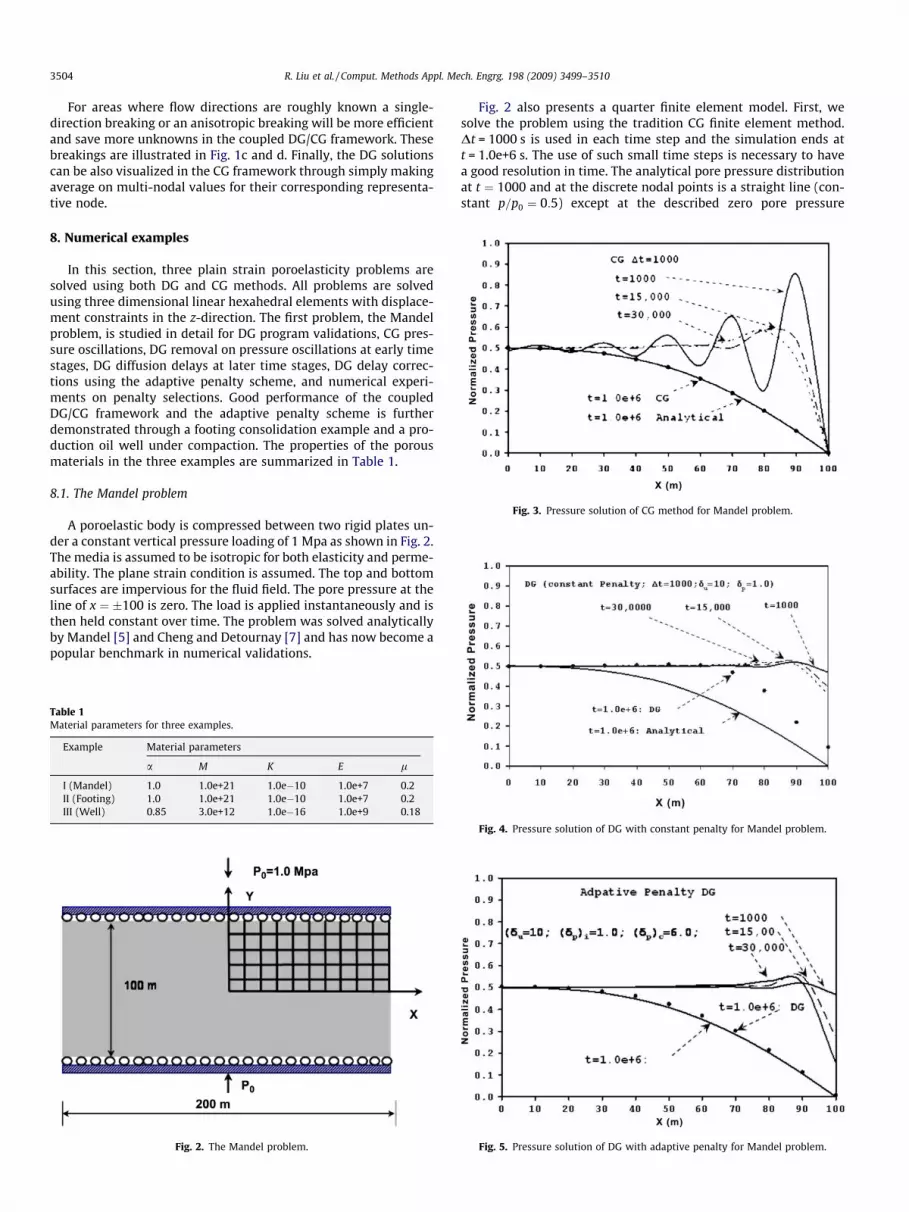
Fig. 3. Pressure solution of CG method for Mandel problem.
3504 R. Liu et al. / Comput. Methods Appl. Mech. Engrg. 198 (2009) 3499–3510
For areas where flow directions are roughly known a single-direction breaking or an anisotropic breaking will be more efficientand save more unknowns in the coupled DG/CG framework. Thesebreakings are illustrated in Fig. 1c and d. Finally, the DG solutionscan be also visualized in the CG framework through simply makingaverage on multi-nodal values for their corresponding representa-tive node.
8. Numerical examples
In this section, three plain strain poroelasticity problems aresolved using both DG and CG methods. All problems are solvedusing three dimensional linear hexahedral elements with displace-ment constraints in the z-direction. The first problem, the Mandelproblem, is studied in detail for DG program validations, CG pres-sure oscillations, DG removal on pressure oscillations at early timestages, DG diffusion delays at later time stages, DG delay correc-tions using the adaptive penalty scheme, and numerical experi-ments on penalty selections. Good performance of the coupledDG/CG framework and the adaptive penalty scheme is furtherdemonstrated through a footing consolidation example and a pro-duction oil well under compaction. The properties of the porousmaterials in the three examples are summarized in Table 1.
8.1. The Mandel problem
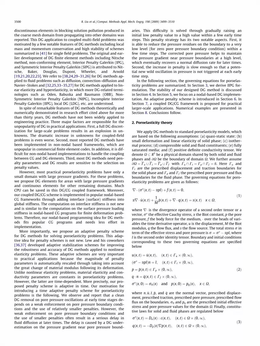
A poroelastic body is compressed between two rigid plates un-der a constant vertical pressure loading of 1 Mpa as shown in Fig. 2.The media is assumed to be isotropic for both elasticity and perme-ability. The plane strain condition is assumed. The top and bottomsurfaces are impervious for the fluid field. The pore pressure at theline of x ¼ �100 is zero. The load is applied instantaneously and isthen held constant over time. The problem was solved analyticallyby Mandel [5] and Cheng and Detournay [7] and has now become apopular benchmark in numerical validations.
Fig. 2. The Mandel problem.
Table 1Material parameters for three examples.
Example Material parameters
a M K E l
I (Mandel) 1.0 1.0e+21 1.0e�10 1.0e+7 0.2II (Footing) 1.0 1.0e+21 1.0e�10 1.0e+7 0.2III (Well) 0.85 3.0e+12 1.0e�16 1.0e+9 0.18
Fig. 2 also presents a quarter finite element model. First, wesolve the problem using the tradition CG finite element method.Dt = 1000 s is used in each time step and the simulation ends att = 1.0e+6 s. The use of such small time steps is necessary to havea good resolution in time. The analytical pore pressure distributionat t ¼ 1000 and at the discrete nodal points is a straight line (con-stant p=p0 ¼ 0:5) except at the described zero pore pressure
Fig. 5. Pressure solution of DG with adaptive penalty for Mandel problem.
Fig. 4. Pressure solution of DG with constant penalty for Mandel problem.
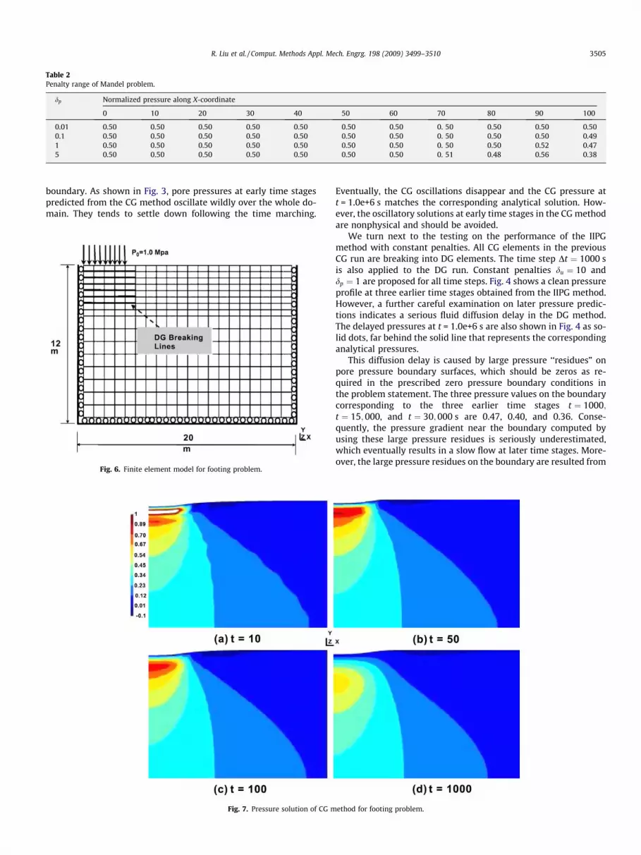
Table 2Penalty range of Mandel problem.
dp Normalized pressure along X-coordinate
0 10 20 30 40 50 60 70 80 90 100
0.01 0.50 0.50 0.50 0.50 0.50 0.50 0.50 0. 50 0.50 0.50 0.500.1 0.50 0.50 0.50 0.50 0.50 0.50 0.50 0. 50 0.50 0.50 0.491 0.50 0.50 0.50 0.50 0.50 0.50 0.50 0. 50 0.50 0.52 0.475 0.50 0.50 0.50 0.50 0.50 0.50 0.50 0. 51 0.48 0.56 0.38
R. Liu et al. / Comput. Methods Appl. Mech. Engrg. 198 (2009) 3499–3510 3505
boundary. As shown in Fig. 3, pore pressures at early time stagespredicted from the CG method oscillate wildly over the whole do-main. They tends to settle down following the time marching.
Fig. 6. Finite element model for footing problem.
Fig. 7. Pressure solution of CG m
Eventually, the CG oscillations disappear and the CG pressure att = 1.0e+6 s matches the corresponding analytical solution. How-ever, the oscillatory solutions at early time stages in the CG methodare nonphysical and should be avoided.
We turn next to the testing on the performance of the IIPGmethod with constant penalties. All CG elements in the previousCG run are breaking into DG elements. The time step Dt ¼ 1000 sis also applied to the DG run. Constant penalties du ¼ 10 anddp ¼ 1 are proposed for all time steps. Fig. 4 shows a clean pressureprofile at three earlier time stages obtained from the IIPG method.However, a further careful examination on later pressure predic-tions indicates a serious fluid diffusion delay in the DG method.The delayed pressures at t = 1.0e+6 s are also shown in Fig. 4 as so-lid dots, far behind the solid line that represents the correspondinganalytical pressures.
This diffusion delay is caused by large pressure ‘‘residues” onpore pressure boundary surfaces, which should be zeros as re-quired in the prescribed zero pressure boundary conditions inthe problem statement. The three pressure values on the boundarycorresponding to the three earlier time stages t ¼ 1000;t ¼ 15;000, and t ¼ 30;000 s are 0.47, 0.40, and 0.36. Conse-quently, the pressure gradient near the boundary computed byusing these large pressure residues is seriously underestimated,which eventually results in a slow flow at later time stages. More-over, the large pressure residues on the boundary are resulted from
ethod for footing problem.
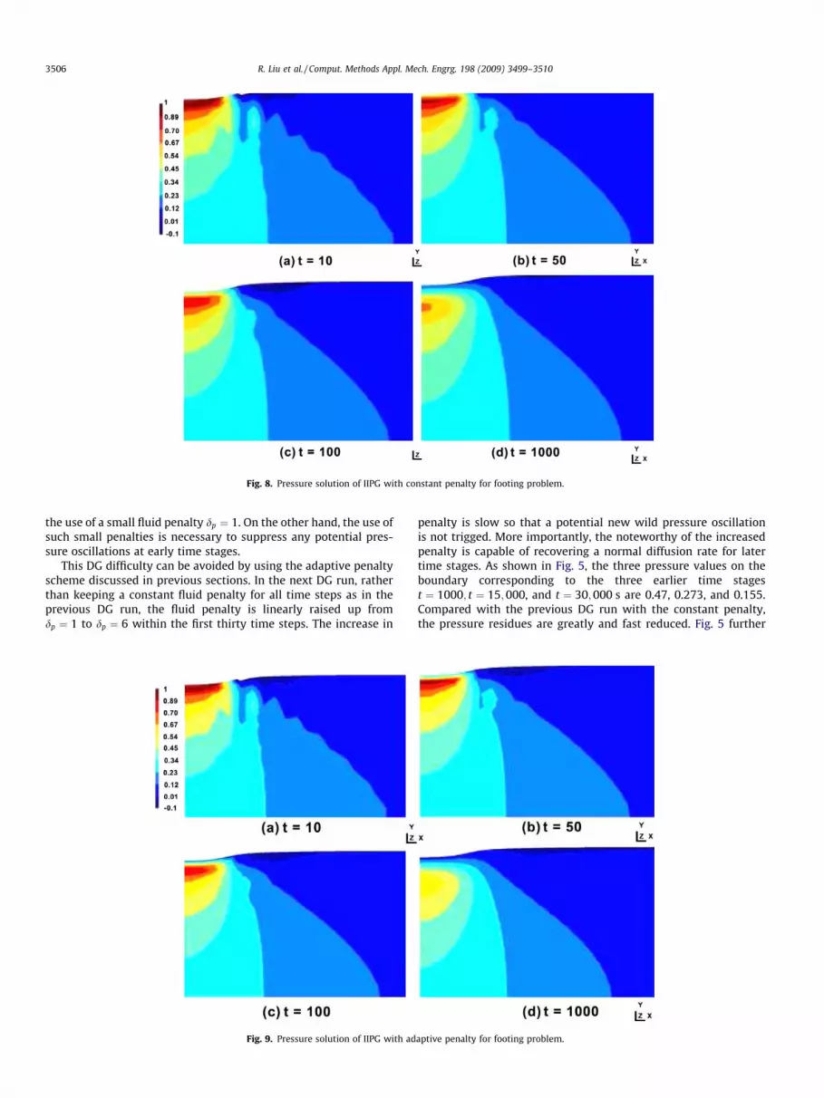
Fig. 8. Pressure solution of IIPG with constant penalty for footing problem.
3506 R. Liu et al. / Comput. Methods Appl. Mech. Engrg. 198 (2009) 3499–3510
the use of a small fluid penalty dp ¼ 1. On the other hand, the use ofsuch small penalties is necessary to suppress any potential pres-sure oscillations at early time stages.
This DG difficulty can be avoided by using the adaptive penaltyscheme discussed in previous sections. In the next DG run, ratherthan keeping a constant fluid penalty for all time steps as in theprevious DG run, the fluid penalty is linearly raised up fromdp ¼ 1 to dp ¼ 6 within the first thirty time steps. The increase in
Fig. 9. Pressure solution of IIPG with ad
penalty is slow so that a potential new wild pressure oscillationis not trigged. More importantly, the noteworthy of the increasedpenalty is capable of recovering a normal diffusion rate for latertime stages. As shown in Fig. 5, the three pressure values on theboundary corresponding to the three earlier time stagest ¼ 1000; t ¼ 15;000, and t ¼ 30;000 s are 0.47, 0.273, and 0.155.Compared with the previous DG run with the constant penalty,the pressure residues are greatly and fast reduced. Fig. 5 further
aptive penalty for footing problem.
R. Liu et al. / Comput. Methods Appl. Mech. Engrg. 198 (2009) 3499–3510 3507
shows a good match between the adaptive penalty result and thecorresponding analytical solution at time 1.0e+6 s.
Finally, we perform a penalty experiment through repeatedlysolving the Mandel problem at a series of different penalties. Table2 presents an appropriate fluid penalty range between 0.01 and 5at the fixed solid penalty du ¼ 10. Similar fluid ranges are also ob-served for solid penalties between 0.01 and 100. Furthermore, be-sides the four penalties shown in Table 2, it is observed that any
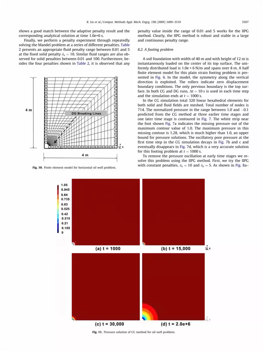
Fig. 10. Finite element model for horizontal oil well problem.
Fig. 11. Pressure solution of CG m
penalty value inside the range of 0.01 and 5 works for the IIPGmethod. Clearly, the IIPG method is robust and stable in a largeand continuous penalty range.
8.2. A footing problem
A soil foundation with width of 40 m and with height of 12 m isinstantaneously loaded on the center of its top surface. The uni-formly distributed load is 1.0e + 6 N/m and spans over 8 m. A halffinite element model for this plain strain footing problem is pre-sented in Fig. 6. In the model, the symmetry along the verticaldirection is exploited. The rollers indicate zero displacementboundary conditions. The only pervious boundary is the top sur-face. In both CG and DG runs, Dt ¼ 10 s is used in each time stepand the simulation ends at t ¼ 1000 s.
In the CG simulation total 320 linear hexahedral elements forboth solid and fluid fields are meshed. Total number of nodes is714. The normalized pressure in the range between 1.0 and �0.1predicted from the CG method at three earlier time stages andone later time stage is contoured in Fig. 7. The white strip nearthe foot shown Fig. 7a indicates the missing pressure out of themaximum contour value of 1.0. The maximum pressure in thismissing contour is 1.28, which is much higher than 1.0, an upperbound for pressure solutions. The oscillatory pore pressure at thefirst time step in the CG simulation decays in Fig. 7b and c andeventually disappears in Fig. 7d, which is a very accurate solutionfor this footing problem at t ¼ 1000 s.
To remove the pressure oscillation at early time stages we re-solve this problem using the IIPG method. First, we try the IIPGwith constant penalties, du ¼ 10 and dp ¼ 5. As shown in Fig. 8a–
ethod for oil well problem.
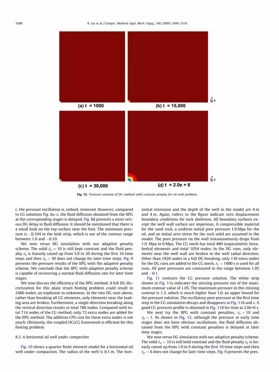
Fig. 12. Pressure solution of DG method with constant penalty for oil well problem.
3508 R. Liu et al. / Comput. Methods Appl. Mech. Engrg. 198 (2009) 3499–3510
c, the pressure oscillation is, indeed, removed. However, comparedto CG solutions Fig. 8a–c, the fluid diffusion obtained from the IIPGat the corresponding stages is delayed. Fig. 8d presents a more seri-ous DG delay in fluid diffusion. It should be mentioned that there isa small kink on the top surface near the foot. The minimum pres-sure is �0.104 in the kink strip, which is out of the contour rangebetween 1.0 and �0.10.
We now rerun DG simulation with our adaptive penaltyscheme. The solid du ¼ 10 is still kept constant and the fluid pen-alty dp is linearly raised up from 5.0 to 30 during the first 10 timesteps and then dp ¼ 30 does not change for later time steps. Fig. 9presents the pressure results of the IIPG with the adaptive penaltyscheme. We conclude that the IIPG with adaptive penalty schemeis capable of recovering a normal fluid diffusion rate for later timestages.
We now discuss the efficiency of the IIPG method. A full DG dis-cretization for this plain strain footing problem could result in2480 nodes, an explosion in unknowns. In the two DG runs above,rather than breaking all CG elements, only elements near the load-ing area are broken. Furthermore, a single-direction breaking alongthe vertical direction results in total 786 nodes. Compared with to-tal 714 nodes of the CG method, only 72 extra nodes are added forthe IIPG method. The addition CPU cost for these extra nodes is notmuch. Obviously, the coupled DG/CG framework is efficient for thisfooting problem.
8.3. A horizontal oil well under compaction
Fig. 10 shows a quarter finite element model for a horizontal oilwell under compaction. The radius of the well is 0.1 m. The hori-
zontal extension and the depth of the well in the model are 4 mand 4 m. Again, rollers in the figure indicate zero displacementboundary conditions for rock skeletons. All boundary surfaces ex-cept the well wall surface are imperious. A compressible materialfor the sand rock, a uniform initial pore pressure 1.0 Mpa for theoil, and an initial zero stress for the rock solid are assumed in themodel. The pore pressure on the wall instantaneously drops from1.0 Mpa to 0 Mpa. The CG mesh has total 480 isoparametric hexa-hedral elements and total 1054 nodes. In the DG runs, only ele-ments near the well wall are broken in the well radial direction.Other than 1920 nodes in a full DG breaking, only 136 extra nodesfor the DG runs are added to the CG mesh. dt ¼ 1000 s is used for allruns. All pore pressures are contoured in the range between 1.05and �0.1.
Fig. 11 contours the CG pressure solution. The white stripshown in Fig. 11a indicates the missing pressure out of the maxi-mum contour value of 1.05. The maximum pressure in this missingcontour is 1.3, which is much higher than 1.0, an upper bound forthe pressure solution. The oscillatory pore pressure at the first timestep in the CG simulation decays and disappears in Fig. 11b and c. Agood CG pressure profile is obtained in Fig. 11d for time at 2.0e+6 s.
We next try the IIPG with constant penalties, du ¼ 10 anddp ¼ 1. As shown in Fig. 12, although the pressure at early timestages does not have obvious oscillations, the fluid diffusion ob-tained from the IIPG with constant penalties is delayed at latertime stages.
We now rerun DG simulation with our adaptive penalty scheme.The solid du ¼ 10 is still held constant and the fluid penalty dp is lin-early raised up from 1.0 to 6 during the first 10 time steps and thendp ¼ 6 does not change for later time steps. Fig. 9 presents the pres-
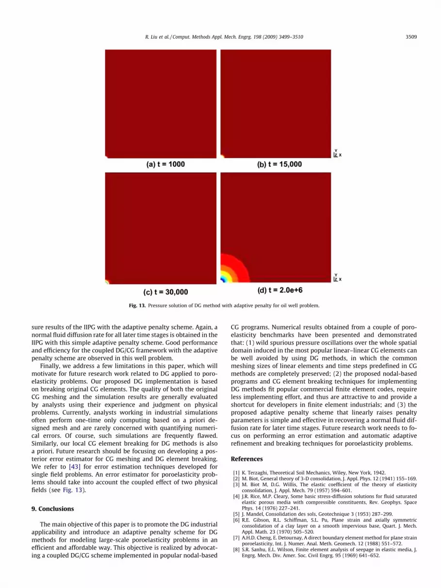
Fig. 13. Pressure solution of DG method with adaptive penalty for oil well problem.
R. Liu et al. / Comput. Methods Appl. Mech. Engrg. 198 (2009) 3499–3510 3509
sure results of the IIPG with the adaptive penalty scheme. Again, anormal fluid diffusion rate for all later time stages is obtained in theIIPG with this simple adaptive penalty scheme. Good performanceand efficiency for the coupled DG/CG framework with the adaptivepenalty scheme are observed in this well problem.
Finally, we address a few limitations in this paper, which willmotivate for future research work related to DG applied to poro-elasticity problems. Our proposed DG implementation is basedon breaking original CG elements. The quality of both the originalCG meshing and the simulation results are generally evaluatedby analysts using their experience and judgment on physicalproblems. Currently, analysts working in industrial simulationsoften perform one-time only computing based on a priori de-signed mesh and are rarely concerned with quantifying numeri-cal errors. Of course, such simulations are frequently flawed.Similarly, our local CG element breaking for DG methods is alsoa priori. Future research should be focusing on developing a pos-terior error estimator for CG meshing and DG element breaking.We refer to [43] for error estimation techniques developed forsingle field problems. An error estimator for poroelasticity prob-lems should take into account the coupled effect of two physicalfields (see Fig. 13).
9. Conclusions
The main objective of this paper is to promote the DG industrialapplicability and introduce an adaptive penalty scheme for DGmethods for modeling large-scale poroelasticity problems in anefficient and affordable way. This objective is realized by advocat-ing a coupled DG/CG scheme implemented in popular nodal-based
CG programs. Numerical results obtained from a couple of poro-elasticity benchmarks have been presented and demonstratedthat: (1) wild spurious pressure oscillations over the whole spatialdomain induced in the most popular linear–linear CG elements canbe well avoided by using DG methods, in which the commonmeshing sizes of linear elements and time steps predefined in CGmethods are completely preserved; (2) the proposed nodal-basedprograms and CG element breaking techniques for implementingDG methods fit popular commercial finite element codes, requireless implementing effort, and thus are attractive to and provide ashortcut for developers in finite element industrials; and (3) theproposed adaptive penalty scheme that linearly raises penaltyparameters is simple and effective in recovering a normal fluid dif-fusion rate for later time stages. Future research work needs to fo-cus on performing an error estimation and automatic adaptiverefinement and breaking techniques for poroelasticity problems.
References
[1] K. Terzaghi, Theoretical Soil Mechanics, Wiley, New York, 1942.[2] M. Biot, General theory of 3-D consolidation, J. Appl. Phys. 12 (1941) 155–169.[3] M. Biot M, D.G. Willis, The elastic coefficient of the theory of elasticity
consolidation, J. Appl. Mech. 79 (1957) 594–601.[4] J.R. Rice, M.P. Cleary, Some basic stress-diffusion solutions for fluid saturated
elastic porous media with compressible constituents, Rev. Geophys. SpacePhys. 14 (1976) 227–241.
[5] J. Mandel, Consolidation des sols, Geotechnique 3 (1953) 287–299.[6] R.E. Gibson, R.L. Schiffman, S.L. Pu, Plane strain and axially symmetric
consolidation of a clay layer on a smooth impervious base, Quart. J. Mech.Appl. Math. 23 (1970) 505–520.
[7] A.H.D. Cheng, E. Detournay, A direct boundary element method for plane strainporoelasticity, Int. J. Numer. Anal. Meth. Geomech. 12 (1988) 551–572.
[8] S.R. Sanhu, E.L. Wilson, Finite element analysis of seepage in elastic media, J.Engrg. Mech. Div. Amer. Soc. Civil Engrg. 95 (1969) 641–652.
3510 R. Liu et al. / Comput. Methods Appl. Mech. Engrg. 198 (2009) 3499–3510
[9] Y. Yokoo, K. Yamagata, H. Nagaoka, Variational principles for consolidation,Soils Found. 11 (4) (1971) 25–36.
[10] J. Ghaboussi, E.L. Wilson, Flow of compressible fluid in porous elastic media,Int. J. Numer. Meth. Engrg. 5 (1973) 419–442.
[11] C.T. Hwang, N.R. Morgenstern, D.W. Nurray, On solutions of plane strainconsolidation problems by finite element Method, Can. Geotech. J. 8 (1971)109–118.
[12] P.A. Vermeer, A. Verruut, An accuracy condition for consolidation by finiteelements, Int. J. Numer. Anal. Meth. Geomech. 5 (1981) 1–14.
[13] M.B. Reed, An investigation of numerical errors in the analysis of consolidationby finite elements, Int. J. Numer. Anal. Meth. Geomech. 8 (1984) 243–2571.
[14] O.C. Zienkiewicz, T. Shiomi, Dynamic behavior of saturated porous media: thegeneralized Biot formulation and its numerical solution, Int. J. Numer. Anal.Meth. Geomech. 8 (1984) 71–96.
[15] J.R. Booker, J.C. Small, An investigation of the stability of numerical solutions ofBiot’s equations of consolidation, Int. J. Solids Struct. 11 (1975) 907–917.
[16] M.A. Murad, A.F.D. Loula, On stability and convergence of finite elementapproximations of Biot’s consolidation problem, J. Numer. Meth. Engrg. 37(1994) 645–667.
[17] R.S. Sanhu, S.C. Lee, H.L. The, Special finite element for analysis of soilconsolidation, Int. J. Numer. Anal. Meth. Geomech. 9 (1985) 125–147.
[18] I. Turska, R.B.A. Schrefler, On convergence conditions of partitioned solutionprocedures for consolidation problems, Comput. Meth. Appl. Mech. Engrg. 106(1993) 51–93.
[19] J. Nitsche, Über ein Variationsprinzip zur Lösung von Dirichlet beiVerwendung von Teilräumen, die keinen Randbedingungen unterworfensind, Abh. Math. Univ. Hamburg 36 (1970) 9–15.
[20] J. Douglas, T. Dupont, Interior penalty procedures for elliptic and parabolicGalerkin methods, Lect. Notes Phys. 58 (1976) 207–216.
[21] G.A. Baker, Finite element methods for elliptic equations using nonconformingelements, Math. Comput. 31 (1977) 45–59.
[22] M.F. Wheeler, An elliptic collocation finite element method with interiorpenalties, SIAM J. Numer. Anal. 15 (1978) 152–161.
[23] D.N. Arnold, An interior penalty finite element method with discontinuouselements, SIAM J. Numer. Anal. 19 (1982) 742–760.
[24] J.T. Oden, I. Bubuska, C.E. Baumann, A discontinuous hp finite element methodfor diffusion problems, J. Comput. Phys. 146 (1998) 491–519.
[25] B. Riviere, S. Shaw, M.F. Wheeler, J.R. Whiteman, Discontinuous Galerkin finiteelement methods for linear elasticity and quasistatic linear viscoelasticity,Numer. Math. 95 (2) (2003) 347–376.
[26] C.N. Dawson, S. Sun, M.F. Wheeler, Compatible algorithms for coupled flowand transport, Comput. Meth. Appl. Meth. Engrg. 193 (2004) 2565–2580.
[27] R. Liu, M.F. Wheeler, C. Dawson, A three-dimensional nodal-basedimplementation of a family of discontinuous Galerkin methods for elasticity,Comput. Struct. 87 (2009) 141–150.
[28] R. Liu, M.F. Wheeler, C. Dawson, R. Dean, Modeling of convection-dominatedthermoporomechanics problems using incomplete interior penalty Galerkinmethod, Comput. Meth. Appl. Mech. Engrg. 198 (2009) 912–919.
[29] B. Cockburn, C. Shu, The local discontinuous Galerkin finite element methodfor convection–diffusion systems, SIAM J. Numer. Anal. 35 (1998) 2440–2463.
[30] B. Cockburn, C. Shu, Runge–Kutta discontinuous Galerkin methods forconvection-dominated problems, J. Sci. Comput. 16 (2001) 173–261.
[31] C.E. Baumann, J.T. Oden, A discontinuous hp finite element method for theEuler and Navier–Stokes equations, Int J. Numer. Meth. Fluid. 31 (1999) 79–95.
[32] P. Hansbo, M.G. Larson, Discontinuous Galerkin method for incompressibleand nearly incompressible elasticity by Nitche’s methods, Computer Meth.Appl. Mech. Engrg. 191 (2002) 1895–1908.
[33] T.P. Wihler, Locking-free DGFEM for elasticity problems in polygons, IMA J.Numer. Anal. 24 (2004) 45–75.
[34] L. Noels, R. Radovitzky, A general discontinuous Galerkin method for finitehyperelasticity. Formulation numerical applications, J. Numer. Meth. Engrg. 68(2006) 64–97.
[35] A.T. Eyck, A. Lew, Discontinuous Galerkin methods for nonlinear elasticity, J.Numer. Meth. Engrg. 67 (2006) 1204–1243.
[36] A.T. Eyck, F. Celiker, A. Lew, Adaptive stabilization of discontinuous Galerkinmethods for nonlinear elasticity, analytical estimates, Comput. Meth. Appl.Mech. Engrg. 197 (2008) 2989–3000.
[37] A.T. Eyck, A. Lew, Adaptive stabilization strategy for enhanced strain methodsin nonlinear elasticity, J. Numer. Meth. Engrg., in press.
[38] T.P. Wihler, P. FrauenFelder, C. Schwab, Exponential convergence of hp-DGFEMfor diffusion problems, Int J. Comp. Math. Appl. 46 (2003) 183–205.
[39] G. Richter, The discontinuous Galerkin method with diffusion, Math. Comput.58 (1992) 631–643.
[40] B. RiViere, M.F. Wheeler, V. Girault, Improved energy estimates for interiorpenalty, constrained and discontinuous Galerkin methods for ellipticproblems. Part I, Comput. Geosci. 8 (1999) 337–360.
[41] B. Cockburn, G.E. Karniadakis, C. Shu, Discontinuous Galerkin Methods: TheoryComputation and Application, Springer-Verlag, 2000.
[42] R.L. Lewis, B.A. Schrefler, The Finite Element Method in the Static and DynamicDeformation and Consolidation of Porous Media, Wiley, Chichester, 1998.
[43] M. Ainsworth, J. Tinsley Oden, A Posteriori Error Estimation in Finite ElementAnalysis, Wiley, New York, 2000.
Related Documents


![Discontinuous Galerkin Methods - [Groupe Calcul]](https://static.cupdf.com/doc/110x72/61fb86042e268c58cd5f2ee4/discontinuous-galerkin-methods-groupe-calcul.jpg)