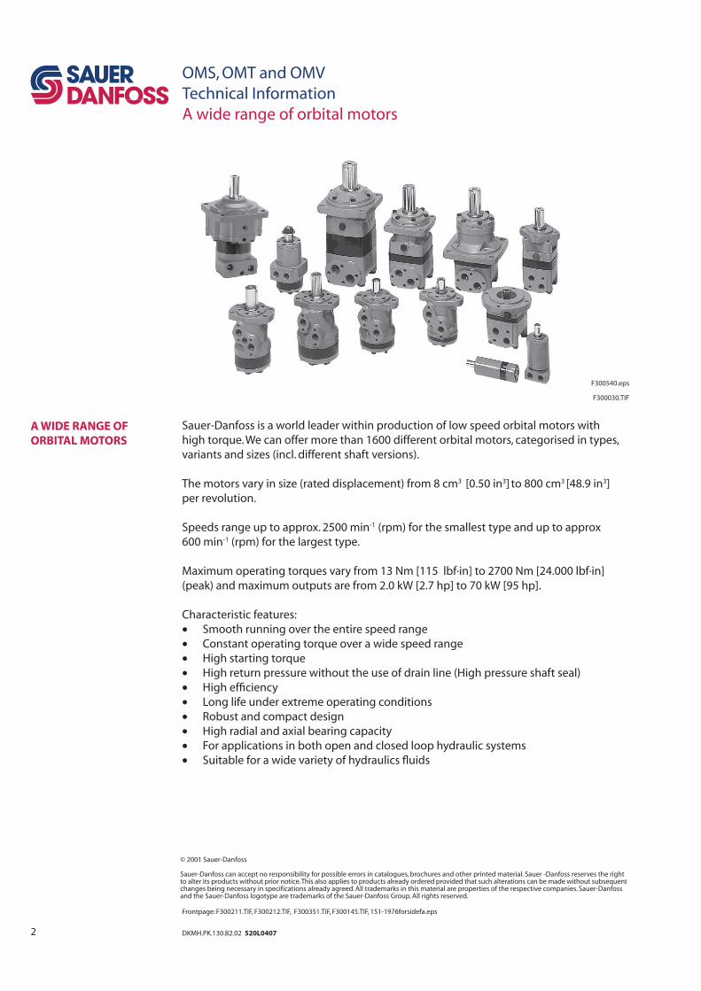
2 DKMH.PK.130.B2.02 520L0407 OMS, OMT and OMV Technical Information A wide range of orbital motors F300540.eps F300030.TIF Sauer-Danfoss is a world leader within production of low speed orbital motors with high torque. We can offer more than 1600 different orbital motors, categorised in types, variants and sizes (incl. different shaft versions). The motors vary in size (rated displacement) from 8 cm 3 [0.50 in 3 ] to 800 cm 3 [48.9 in 3 ] per revolution. Speeds range up to approx. 2500 min -1 (rpm) for the smallest type and up to approx 600 min -1 (rpm) for the largest type. Maximum operating torques vary from 13 Nm [115 lbf·in] to 2700 Nm [24.000 lbf·in] (peak) and maximum outputs are from 2.0 kW [2.7 hp] to 70 kW [95 hp]. Characteristic features: • Smooth running over the entire speed range • Constant operating torque over a wide speed range • High starting torque • High return pressure without the use of drain line (High pressure shaft seal) • High efficiency • Long life under extreme operating conditions • Robust and compact design • High radial and axial bearing capacity • For applications in both open and closed loop hydraulic systems • Suitable for a wide variety of hydraulics fluids A WIDE RANGE OF ORBITAL MOTORS © 2001 Sauer-Danfoss Sauer-Danfoss can accept no responsibility for possible errors in catalogues, brochures and other printed material. Sauer -Danfoss reserves the right to alter its products without prior notice. This also applies to products already ordered provided that such alterations can be made without subsequent changes being necessary in specifications already agreed. All trademarks in this material are properties of the respective companies. Sauer-Danfoss and the Sauer-Danfoss logotype are trademarks of the Sauer-Danfoss Group. All rights reserved. Frontpage: F300211.TIF, F300212.TIF, F300351.TIF, F300145.TIF, 151-1976forsidefa.eps

Welcome message from author
This document is posted to help you gain knowledge. Please leave a comment to let me know what you think about it! Share it to your friends and learn new things together.
Transcript
2 DKMH.PK.130.B2.02 520L0407
OMS, OMT and OMV
Technical Information
A wide range of orbital motors
F300540.eps
F300030.TIF
Sauer-Danfoss is a world leader within production of low speed orbital motors with
high torque. We can offer more than 1600 different orbital motors, categorised in types,
variants and sizes (incl. different shaft versions).
The motors vary in size (rated displacement) from 8 cm3 [0.50 in3] to 800 cm3 [48.9 in3]
per revolution.
Speeds range up to approx. 2500 min-1 (rpm) for the smallest type and up to approx
600 min-1 (rpm) for the largest type.
Maximum operating torques vary from 13 Nm [115 lbf·in] to 2700 Nm [24.000 lbf·in]
(peak) and maximum outputs are from 2.0 kW [2.7 hp] to 70 kW [95 hp].
Characteristic features:
• Smooth running over the entire speed range
• Constant operating torque over a wide speed range
• High starting torque
• High return pressure without the use of drain line (High pressure shaft seal)
• High effi ciency
• Long life under extreme operating conditions
• Robust and compact design
• High radial and axial bearing capacity
• For applications in both open and closed loop hydraulic systems
• Suitable for a wide variety of hydraulics fl uids
A WIDE RANGE OF
ORBITAL MOTORS
© 2001 Sauer-Danfoss
Sauer-Danfoss can accept no responsibility for possible errors in catalogues, brochures and other printed material. Sauer -Danfoss reserves the rightto alter its products without prior notice. This also applies to products already ordered provided that such alterations can be made without subsequentchanges being necessary in specifications already agreed. All trademarks in this material are properties of the respective companies. Sauer-Danfossand the Sauer-Danfoss logotype are trademarks of the Sauer-Danfoss Group. All rights reserved.
Frontpage: F300211.TIF, F300212.TIF, F300351.TIF, F300145.TIF, 151-1976forsidefa.eps
3DKMH.PK.130.B2.02 520L0407
The programme is characterised by technical features appealing to a large number
of applications and a part of the programme is characterised by motors that can be
adapted to a given application. Adaptions comprise the following variants among others:
• Motors with corrosion resistant parts
• Wheel motors with recessed mounting fl ange
• OMP, OMR- motors with needle bearing
• OMR motor in low leakage version
• OMR motors in a super low leakage version
• Short motors without bearings
• Ultra short motors
• Motors with integrated positive holding brake
• Motors with integrated negative holding brake
• Motors with integrated fl ushing valve
• Motors with speed sensor
• Motors with tacho connection
• All motors are available with black fi nish paint
Planetary gears
Sauer-Danfoss complements the motor range with a complete programme of planetary
gears adapted to suit. The combination of motors and gears makes it possible to obtain
smooth running at fractional speeds and with torques up to 650.000 Nm (5.800.000 lbf·in).
The Sauer–Danfoss orbital motors are used in the following application areas:
• Construction equipment
• Agricultural equipment
• Material handling & Lifting equipment
• Forestry equipment
• Lawn and turf equipment
• Special purpose
• Machine tools and stationary equipment
• Marine equipment
Detailed data on all Sauer-Danfoss motors can be found in our motor catalogue, which is
divided into 5 individual subcatalogues:
• General information on Sauer-Danfoss orbital motors: function, use, selection of
orbital motor, hydraulic systems, etc.
• Technical data on small motors: OML and OMM
• Technical data on medium sized motors: OMP, OMR, OMH and OMEW
• Technical data on medium sized motors: DH and DS
• Technical data on large motors: OMS, OMT and OMV
• Technical data on large motors: TMT
A general survey brochure on Sauer-Danfoss orbital motors gives a quick motor
reference based on power, torque, speed and capabilities.
SURVEY OF LITERATURE
WITH TECHNICAL DATA
ON SAUER-DANFOSS
ORBITAL MOTORS
OMS, OMT and OMV
Technical Information
A wide range of orbital motors
4 DKMH.PK.130.B2.02 520L0407
OMS, OMT and OMV
Technical Information
Contents
Page
OMS, OMT and OMV .......................................................................................................................................................5
Speed, torque and output ..........................................................................................................................................5
OMS ........................................................................................................................................................................................6
Version....................................................................................................................................................................................6
Code numbers.....................................................................................................................................................................7
Technical data....................................................................................................................................................................8
Technical data (e.g. speed, torque, pressure etc.) ...............................................................................................8
Max. permissisble shaft seal pressure.....................................................................................................................9
Pressure drop in motor ................................................................................................................................................9
Oil fl ow in drain line, direction of shaft rotation.............................................................................................. 10
Permissible shaft loads ............................................................................................................................................. 11
Function diagrams ..................................................................................................................................................... 14
Shaft version................................................................................................................................................................. 19
Port thread versions................................................................................................................................................... 22
Dimensions ...................................................................................................................................................................... 23
OMSS................................................................................................................................................................................... 32
OMT ..................................................................................................................................................................................... 34
Version................................................................................................................................................................................. 34
Code numbers.................................................................................................................................................................. 35
Technical data................................................................................................................................................................. 36
Technical data (e.g. speed, torque, pressure etc.) ............................................................................................ 36
Max. permissisble shaft seal pressure.................................................................................................................. 38
Pressure drop in motor ............................................................................................................................................. 39
Oil fl ow in drain line, direction of shaft rotation.............................................................................................. 39
Permissible shaft loads ............................................................................................................................................. 40
Function diagrams ..................................................................................................................................................... 42
Shaft version................................................................................................................................................................. 45
Port thread versions................................................................................................................................................... 48
Dimensions ...................................................................................................................................................................... 49
OMTS................................................................................................................................................................................... 56
OMV ..................................................................................................................................................................................... 58
Version................................................................................................................................................................................. 58
Code numbers.................................................................................................................................................................. 59
Technical data................................................................................................................................................................. 60
Technical data (e.g. speed, torque, pressure etc.) ............................................................................................ 60
Max. permissisble shaft seal pressure.................................................................................................................. 61
Pressure drop in motor ............................................................................................................................................. 62
Oil fl ow in drain line, direction of shaft rotation.............................................................................................. 62
Permissible shaft loads ............................................................................................................................................. 63
Function diagrams ..................................................................................................................................................... 65
Shaft version................................................................................................................................................................. 68
Port thread versions................................................................................................................................................... 71
Dimensions ...................................................................................................................................................................... 72
OMVS .................................................................................................................................................................................. 78
Weight of motors .......................................................................................................................................................... 80
CONTENTS
5DKMH.PK.130.B2.02 520L0407
Max. speed
Max. Torque
Max. output
Intermittend values Continuous values
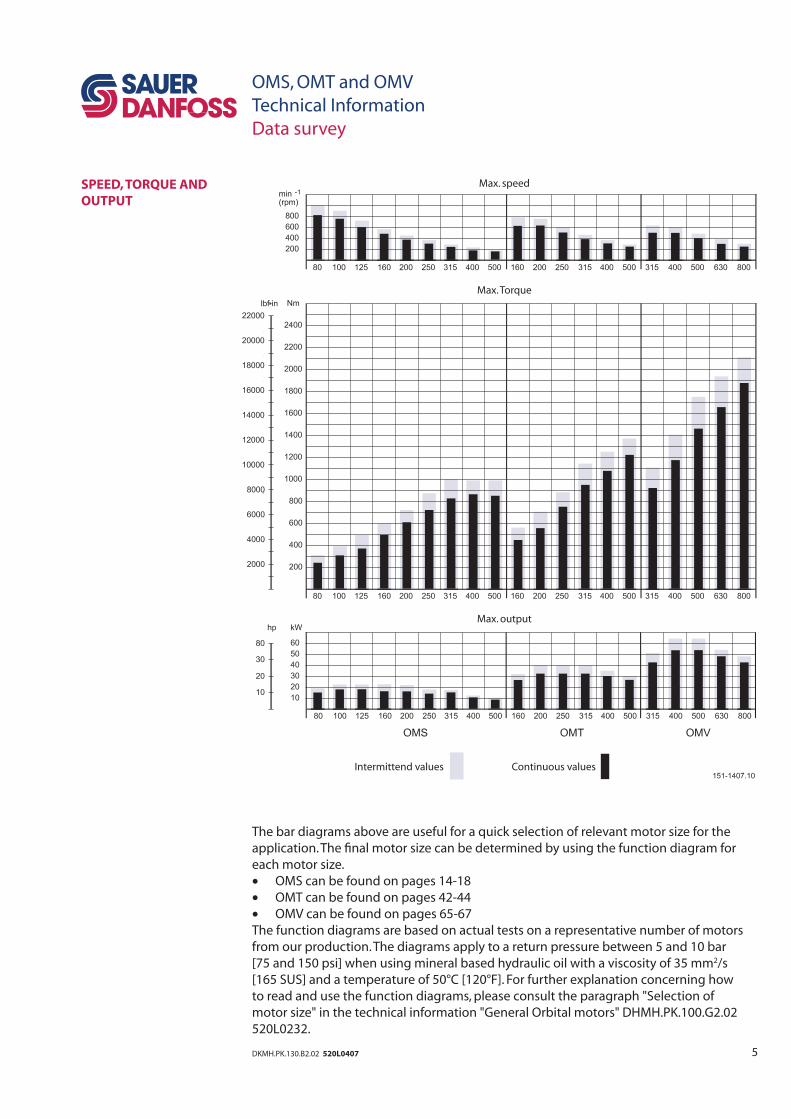
The bar diagrams above are useful for a quick selection of relevant motor size for the
application. The fi nal motor size can be determined by using the function diagram for
each motor size.
• OMS can be found on pages 14-18
• OMT can be found on pages 42-44
• OMV can be found on pages 65-67
The function diagrams are based on actual tests on a representative number of motors
from our production. The diagrams apply to a return pressure between 5 and 10 bar
[75 and 150 psi] when using mineral based hydraulic oil with a viscosity of 35 mm2/s
[165 SUS] and a temperature of 50°C [120°F]. For further explanation concerning how
to read and use the function diagrams, please consult the paragraph "Selection of
motor size" in the technical information "General Orbital motors" DHMH.PK.100.G2.02
520L0232.
SPEED, TORQUE AND
OUTPUT
OMS, OMT and OMV
Technical Information
Data survey
6 DKMH.PK.130.B2.02 520L0407
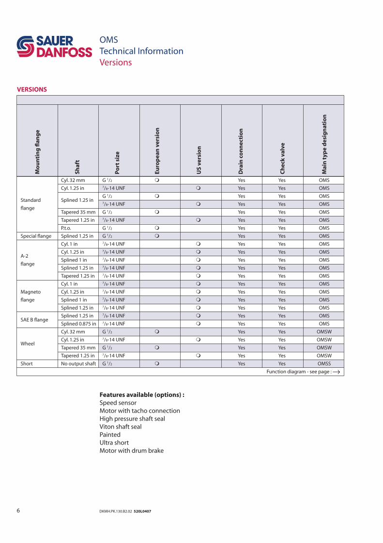
VERSIONS
OMS
Technical Information
Versions
Mo
un
tin
g fl
an
ge
Sh
aft
Po
rt s
ize
Eu
rop
ea
n v
ers
ion
US
ve
rsio
n
Dra
in c
on
ne
ctio
n
Ch
eck
va
lve
Ma
in t
yp
e d
esi
gn
ati
on
Features available (options) :
Speed sensor
Motor with tacho connection
High pressure shaft seal
Viton shaft seal
Painted
Ultra short
Motor with drum brake
Cyl. 32 mm G 1/2 Yes Yes OMS
Cyl. 1.25 in 7/8-14 UNF Yes Yes OMS
Splined 1.25 in
G 1/2 Yes Yes OMS Standard
7/8-14 UNF Yes Yes OMSfl ange
Tapered 35 mm G 1/2 Yes Yes OMS
Tapered 1.25 in 7/8-14 UNF Yes Yes OMS
P.t.o. G 1/2 Yes Yes OMS
Special fl ange Splined 1.25 in G 1/2 Yes Yes OMS
Cyl. 1 in 7/8-14 UNF Yes Yes OMS
A-2 Cyl. 1.25 in 7/8-14 UNF Yes Yes OMS
fl ange Splined 1 in 7/8-14 UNF Yes Yes OMS
Splined 1.25 in 7/8-14 UNF Yes Yes OMS
Tapered 1.25 in 7/8-14 UNF Yes Yes OMS
Cyl. 1 in 7/8-14 UNF Yes Yes OMS
Magneto Cyl. 1.25 in 7/8-14 UNF Yes Yes OMS
fl ange Splined 1 in 7/8-14 UNF Yes Yes OMS
Splined 1.25 in 7/8-14 UNF Yes Yes OMS
SAE B fl ange Splined 1.25 in 7/8-14 UNF Yes Yes OMS
Splined 0.875 in 7/8-14 UNF Yes Yes OMS
Cyl. 32 mm G 1/2 Yes Yes OMSW
Wheel Cyl. 1.25 in 7/8-14 UNF Yes Yes OMSW
Tapered 35 mm G 1/2 Yes Yes OMSW
Tapered 1.25 in 7/8-14 UNF Yes Yes OMSW
Short No output shaft G 1/2 Yes Yes OMSS
Function diagram - see page : →
7DKMH.PK.130.B2.02 520L0407
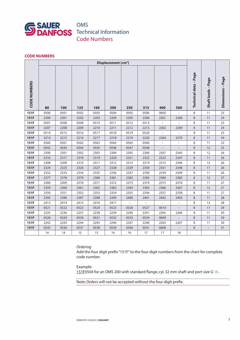
Displacement [cm3]
80 100 125 160 200 250 315 400 500
151F 0500 0501 0502 0503 0504 0505 0506 0605 – 8 11 23
151F 2200 2201 2202 2203 2204 2205 2206 2261 2268 8 11 24
151F 0507 0508 0509 0510 0511 0512 0513 – – 8 11 23
151F 2207 2208 2209 2210 2211 2212 2213 2262 2269 8 11 24
151F 0514 0515 0516 0517 0518 0519 0520 – – 8 11 23
151F 2214 2215 2216 2217 2218 2219 2220 2264 2270 8 11 24
151F 0560 0561 0562 0563 0564 0565 0566 – – 8 11 23
151F 0542 0543 0544 0545 0546 0547 0548 – – 8 12 25
151F 2300 2301 2302 2303 2304 2305 2306 2307 2345 8 12 26
151F 2316 2317 2318 2319 2320 2321 2322 2323 2347 8 11 26
151F 2308 2309 2310 2311 2312 2313 2314 2315 2346 8 12 26
151F 2324 2325 2326 2327 2328 2329 2330 2331 2348 8 11 26
151F 2332 2333 2334 2335 2336 2337 2338 2339 2349 8 11 26
151F 2377 2378 2379 2380 2381 2382 2383 2384 2385 8 12 27
151F 2368 2369 2370 2371 2372 2373 2374 2375 2376 8 11 27
151F 2359 2360 2361 2362 2363 2364 2365 2366 2367 8 12 27
151F 2350 2351 2352 2353 2354 2355 2356 2357 2358 8 11 27
151F 2395 2396 2397 2398 2399 2400 2401 2402 2403 8 11 28
151F 2413 2414 2415 2416 2417 – – – – 8 13 28
151F 0521 0522 0523 0524 0525 0526 0527 0610 – 8 11 29
151F 2235 2236 2237 2238 2239 2240 2241 2265 2266 8 11 30
151F 0528 0529 0530 0531 0532 0533 0534 0609 – 8 11 29
151F 2242 2243 2244 2245 2246 2247 2248 2263 2267 8 11 30
151F 0535 0536 0537 0538 0539 0540 0541 0608 – 8 – 31
14 14 15 15 16 16 17 17 18
CODE NUMBERS
OMS
Technical Information
Code Numbers
Ordering
Add the four digit prefi x “151F” to the four digit numbers from the chart for complete
code number.
Example:
151F0504 for an OMS 200 with standard fl ange, cyl. 32 mm shaft and port size G 1/2 .
Note: Orders will not be accepted without the four digit prefi x.
CO
DE
NU
MB
ER
S
Tech
nic
al
da
ta –
Pa
ge
Sh
aft
lo
ad
s –
Pa
ge
Dim
en
sio
ns
– P
ag
e
8 DKMH.PK.130.B2.02 520L0407
OMS
Technical Information
Technical data
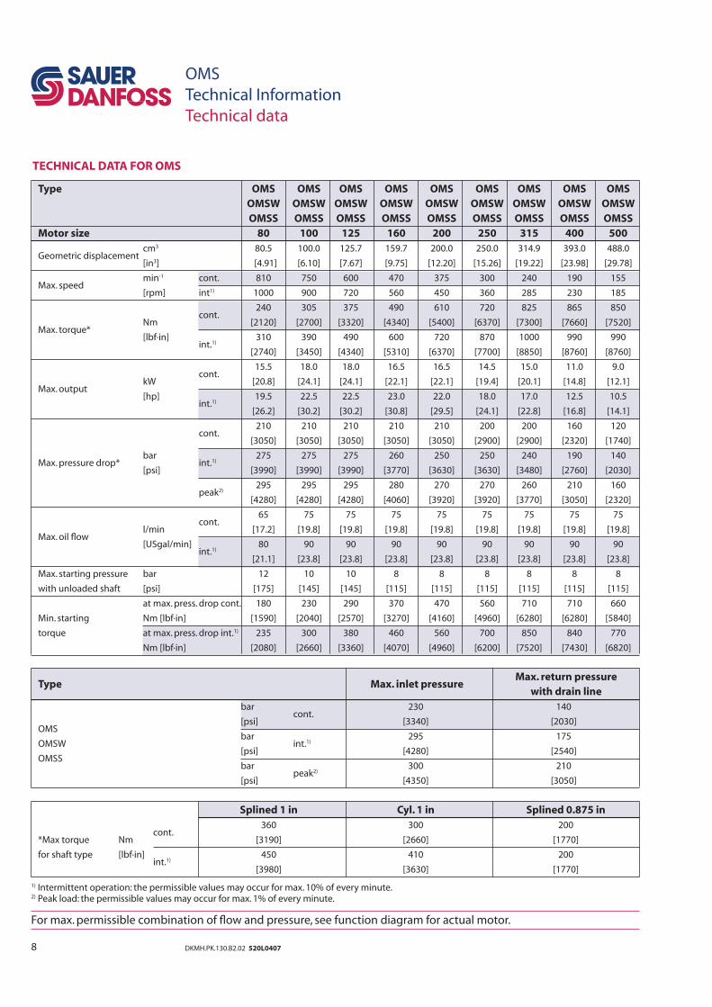
TECHNICAL DATA FOR OMS
Type Max. inlet pressure Max. return pressure
with drain line
bar cont.
230 140
OMS [psi] [3340] [2030]
OMSW bar
int.1) 295 175
[psi] [4280] [2540] OMSS
bar peak2)
300 210
[psi] [4350] [3050]
Splined 1 in Cyl. 1 in Splined 0.875 in
cont.
360 300 200
*Max torque Nm [3190] [2660] [1770]
for shaft type [lbf·in] int.1)
450 410 200
[3980] [3630] [1770]
1) Intermittent operation: the permissible values may occur for max. 10% of every minute.2) Peak load: the permissible values may occur for max. 1% of every minute.
For max. permissible combination of fl ow and pressure, see function diagram for actual motor.
Type OMS OMS OMS OMS OMS OMS OMS OMS OMS
OMSW OMSW OMSW OMSW OMSW OMSW OMSW OMSW OMSW
OMSS OMSS OMSS OMSS OMSS OMSS OMSS OMSS OMSS
Motor size 80 100 125 160 200 250 315 400 500
Geometric displacement cm3 80.5 100.0 125.7 159.7 200.0 250.0 314.9 393.0 488.0
[in3] [4.91] [6.10] [7.67] [9.75] [12.20] [15.26] [19.22] [23.98] [29.78]
Max. speed min-1 cont. 810 750 600 470 375 300 240 190 155
[rpm] int1) 1000 900 720 560 450 360 285 230 185
cont.
240 305 375 490 610 720 825 865 850
Nm [2120] [2700] [3320] [4340] [5400] [6370] [7300] [7660] [7520] Max. torque*
[lbf·in] int.1)
310 390 490 600 720 870 1000 990 990
[2740] [3450] [4340] [5310] [6370] [7700] [8850] [8760] [8760]
cont.
15.5 18.0 18.0 16.5 16.5 14.5 15.0 11.0 9.0
Max. output kW [20.8] [24.1] [24.1] [22.1] [22.1] [19.4] [20.1] [14.8] [12.1]
[hp] int.1)
19.5 22.5 22.5 23.0 22.0 18.0 17.0 12.5 10.5
[26.2] [30.2] [30.2] [30.8] [29.5] [24.1] [22.8] [16.8] [14.1]
cont.
210 210 210 210 210 200 200 160 120
[3050] [3050] [3050] [3050] [3050] [2900] [2900] [2320] [1740]
Max. pressure drop* bar
int.1) 275 275 275 260 250 250 240 190 140
[psi] [3990] [3990] [3990] [3770] [3630] [3630] [3480] [2760] [2030]
peak2)
295 295 295 280 270 270 260 210 160
[4280] [4280] [4280] [4060] [3920] [3920] [3770] [3050] [2320]
Max. oil fl ow
cont.
65 75 75 75 75 75 75 75 75
l/min [17.2] [19.8] [19.8] [19.8] [19.8] [19.8] [19.8] [19.8] [19.8]
[USgal/min] int.1)
80 90 90 90 90 90 90 90 90
[21.1] [23.8] [23.8] [23.8] [23.8] [23.8] [23.8] [23.8] [23.8]
Max. starting pressure bar 12 10 10 8 8 8 8 8 8
with unloaded shaft [psi] [175] [145] [145] [115] [115] [115] [115] [115] [115]
at max. press. drop cont. 180 230 290 370 470 560 710 710 660
Min. starting
Nm [lbf·in] [1590] [2040] [2570] [3270] [4160] [4960] [6280] [6280] [5840]
torque at max. press. drop int.1) 235 300 380 460 560 700 850 840 770
Nm [lbf·in] [2080] [2660] [3360] [4070] [4960] [6200] [7520] [7430] [6820]
9DKMH.PK.130.B2.02 520L0407
OMS
Technical Information
Technical data
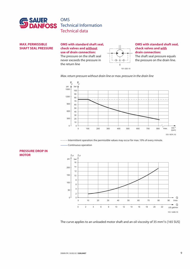
MAX. PERMISSIBLE
SHAFT SEAL PRESSURE
PRESSURE DROP IN
MOTOR
OMS with standard shaft seal, OMS with standard shaft seal,
check valves and without check valves and with
use of drain connection: drain connection:
The pressure on the shaft seal The shaft seal pressure equals
never exceeds the pressure in the pressure on the drain line.
the return line
Max. return pressure without drain line or max. pressure in the drain line
– – – – Intermittent operation: the permissible values may occur for max. 10% of every minute.
Continuous operation
The curve applies to an unloaded motor shaft and an oil viscosity of 35 mm2/s [165 SUS]
10 DKMH.PK.130.B2.02 520L0407
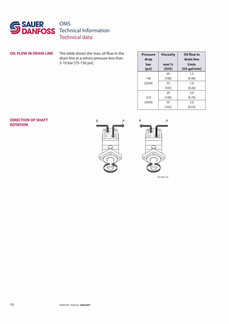
The table shows the max. oil fl ow in the
drain line at a return pressure less than
5-10 bar [75-150 psi].
OIL FLOW IN DRAIN LINE
DIRECTION OF SHAFT
ROTATION
OMS
Technical Information
Technical data
Pressure Viscosity Oil fl ow in
drop drain line
bar mm2/s l/min
[psi] [SUS] [US gal/min]
140
20 1.5
[100] [0.40]
[2030] 35 1.0
[165] [0.26]
210
20 3.0
[100] [0.79]
[3050] 35 2.0
[165] [0.53]
11DKMH.PK.130.B2.02 520L0407
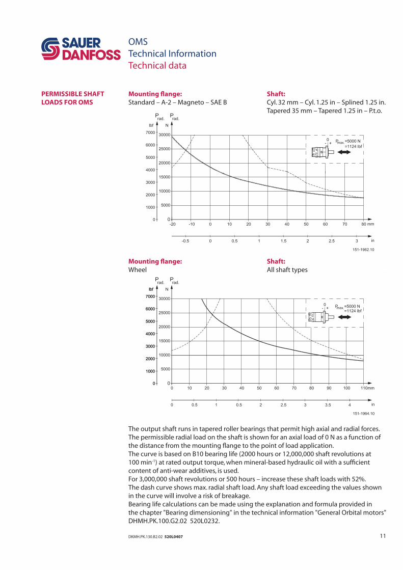
Mounting fl ange: Shaft:
Standard – A-2 – Magneto – SAE B Cyl. 32 mm – Cyl. 1.25 in – Splined 1.25 in.
Tapered 35 mm – Tapered 1.25 in – P.t.o.
Mounting fl ange: Shaft:
Wheel All shaft types
The output shaft runs in tapered roller bearings that permit high axial and radial forces.
The permissible radial load on the shaft is shown for an axial load of 0 N as a function of
the distance from the mounting fl ange to the point of load application.
The curve is based on B10 bearing life (2000 hours or 12,000,000 shaft revolutions at
100 min-1) at rated output torque, when mineral-based hydraulic oil with a suffi cient
content of anti-wear additives, is used.
For 3,000,000 shaft revolutions or 500 hours – increase these shaft loads with 52%.
The dash curve shows max. radial shaft load. Any shaft load exceeding the values shown
in the curve will involve a risk of breakage.
Bearing life calculations can be made using the explanation and formula provided in
the chapter "Bearing dimensioning" in the technical information "General Orbital motors"
DHMH.PK.100.G2.02 520L0232.
PERMISSIBLE SHAFT
LOADS FOR OMS
OMS
Technical Information
Technical data
12 DKMH.PK.130.B2.02 520L0407
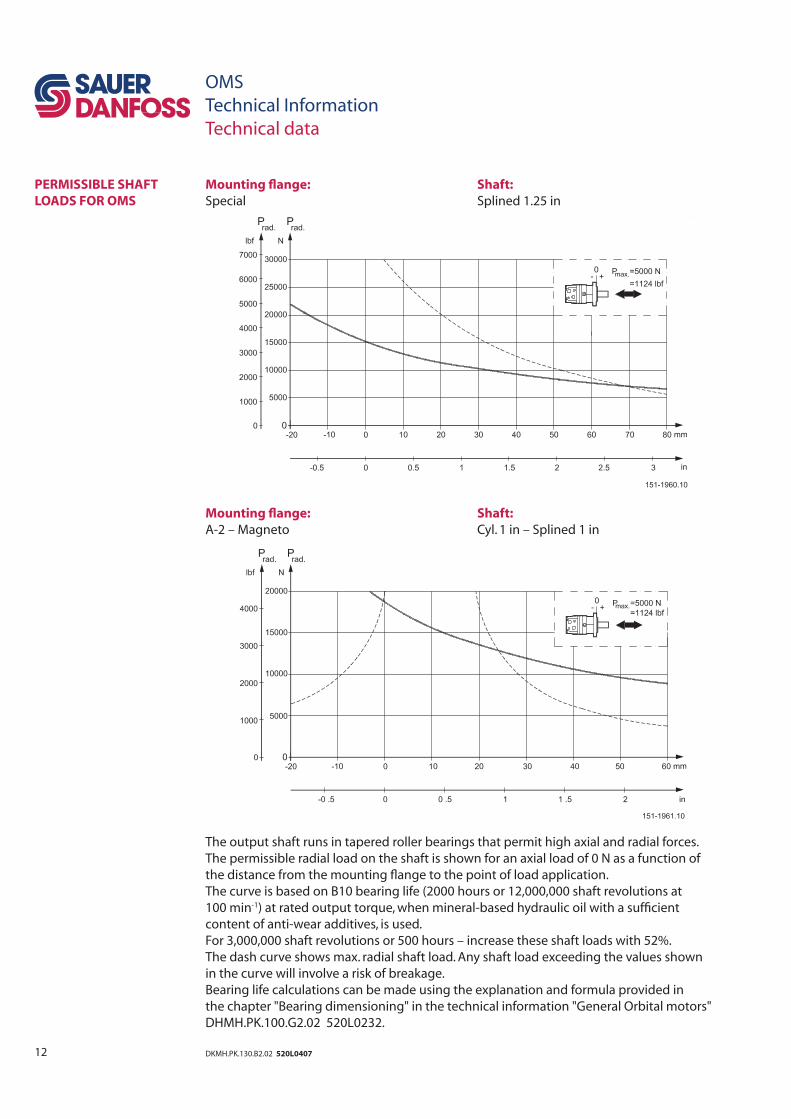
Mounting fl ange: Shaft:
Special Splined 1.25 in
Mounting fl ange: Shaft:
A-2 – Magneto Cyl. 1 in – Splined 1 in
The output shaft runs in tapered roller bearings that permit high axial and radial forces.
The permissible radial load on the shaft is shown for an axial load of 0 N as a function of
the distance from the mounting fl ange to the point of load application.
The curve is based on B10 bearing life (2000 hours or 12,000,000 shaft revolutions at
100 min-1) at rated output torque, when mineral-based hydraulic oil with a suffi cient
content of anti-wear additives, is used.
For 3,000,000 shaft revolutions or 500 hours – increase these shaft loads with 52%.
The dash curve shows max. radial shaft load. Any shaft load exceeding the values shown
in the curve will involve a risk of breakage.
Bearing life calculations can be made using the explanation and formula provided in
the chapter "Bearing dimensioning" in the technical information "General Orbital motors"
DHMH.PK.100.G2.02 520L0232.
PERMISSIBLE SHAFT
LOADS FOR OMS
OMS
Technical Information
Technical data
13DKMH.PK.130.B2.02 520L0407
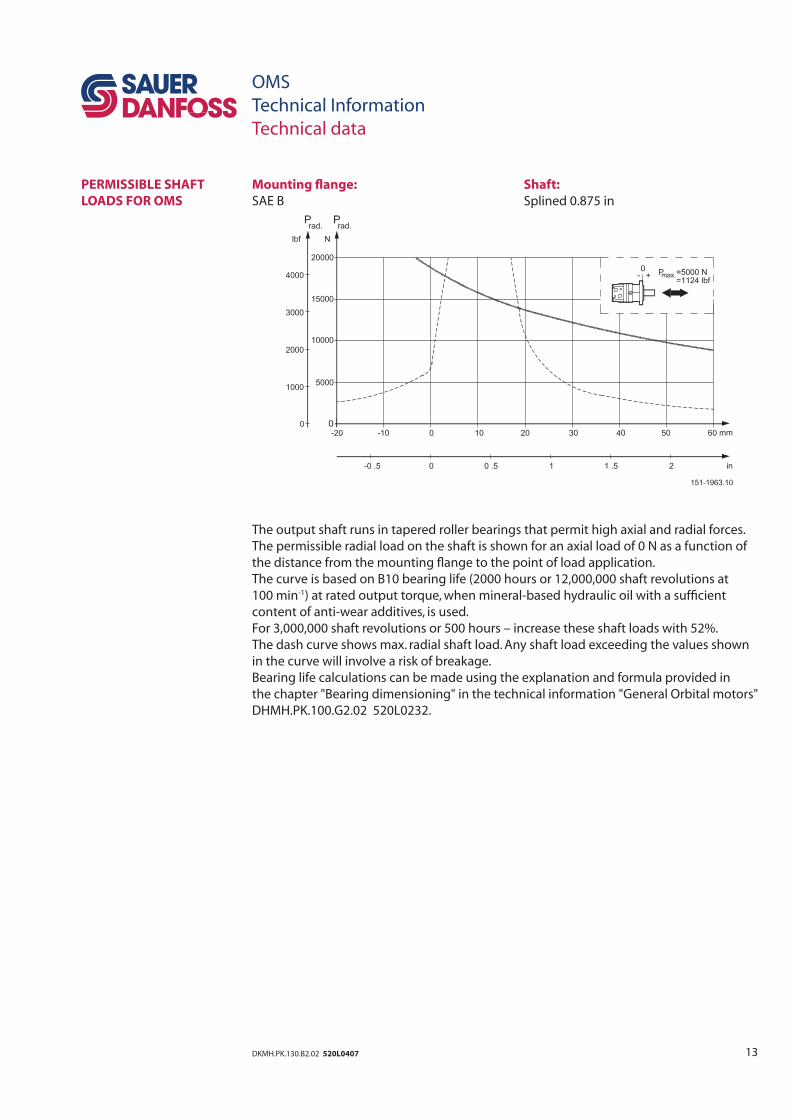
Mounting fl ange: Shaft:
SAE B Splined 0.875 in
The output shaft runs in tapered roller bearings that permit high axial and radial forces.
The permissible radial load on the shaft is shown for an axial load of 0 N as a function of
the distance from the mounting fl ange to the point of load application.
The curve is based on B10 bearing life (2000 hours or 12,000,000 shaft revolutions at
100 min-1) at rated output torque, when mineral-based hydraulic oil with a suffi cient
content of anti-wear additives, is used.
For 3,000,000 shaft revolutions or 500 hours – increase these shaft loads with 52%.
The dash curve shows max. radial shaft load. Any shaft load exceeding the values shown
in the curve will involve a risk of breakage.
Bearing life calculations can be made using the explanation and formula provided in
the chapter "Bearing dimensioning" in the technical information "General Orbital motors"
DHMH.PK.100.G2.02 520L0232.
PERMISSIBLE SHAFT
LOADS FOR OMS
OMS
Technical Information
Technical data
14 DKMH.PK.130.B2.02 520L0407
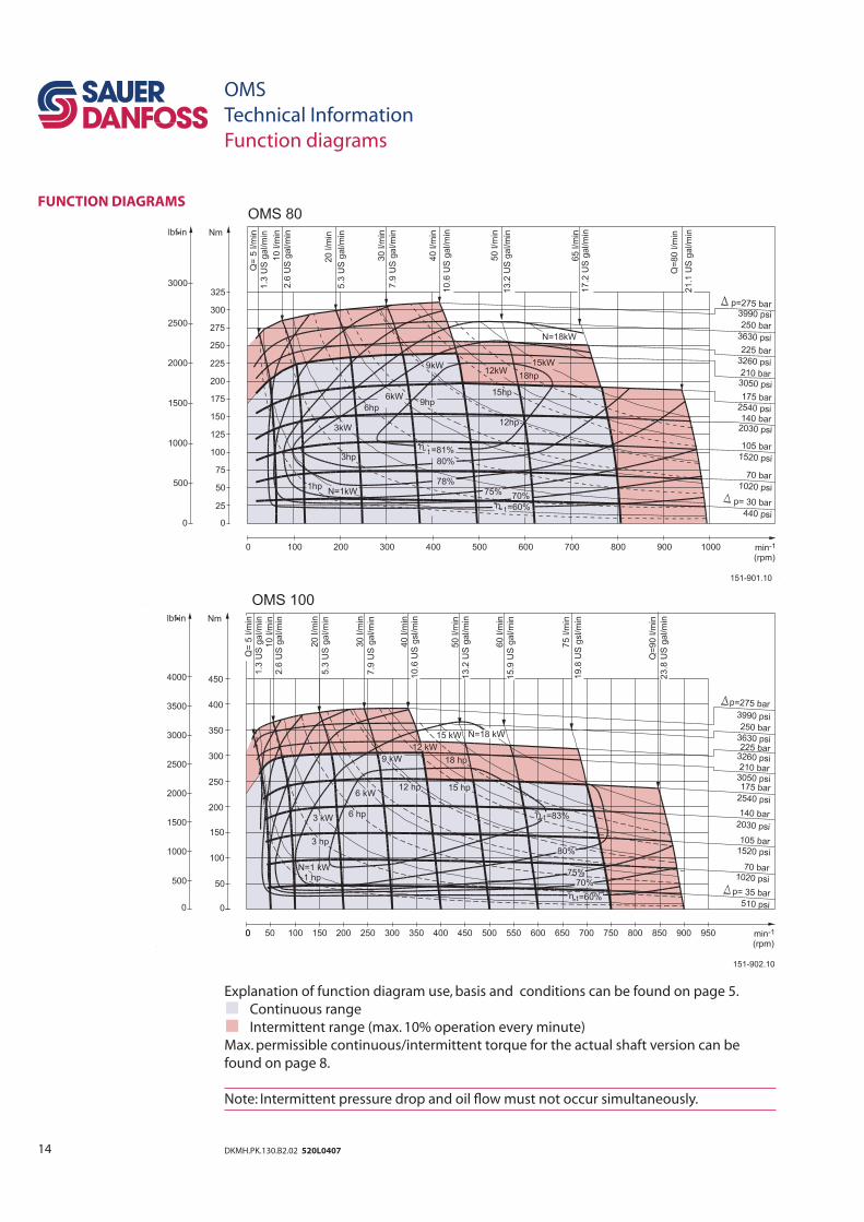
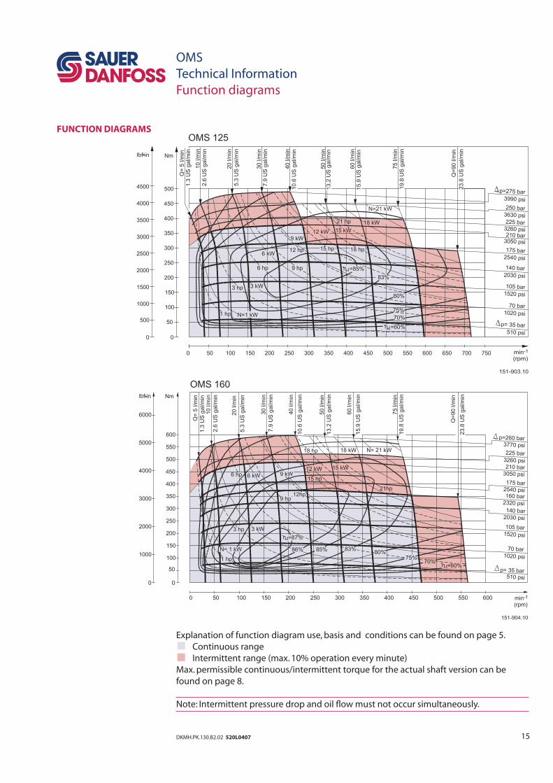
Explanation of function diagram use, basis and conditions can be found on page 5.
Continuous range
Intermittent range (max. 10% operation every minute)
Max. permissible continuous/intermittent torque for the actual shaft version can be
found on page 8.
Note: Intermittent pressure drop and oil fl ow must not occur simultaneously.
FUNCTION DIAGRAMS
OMS
Technical Information
Function diagrams
15DKMH.PK.130.B2.02 520L0407
OMS
Technical Information
Function diagrams
FUNCTION DIAGRAMS
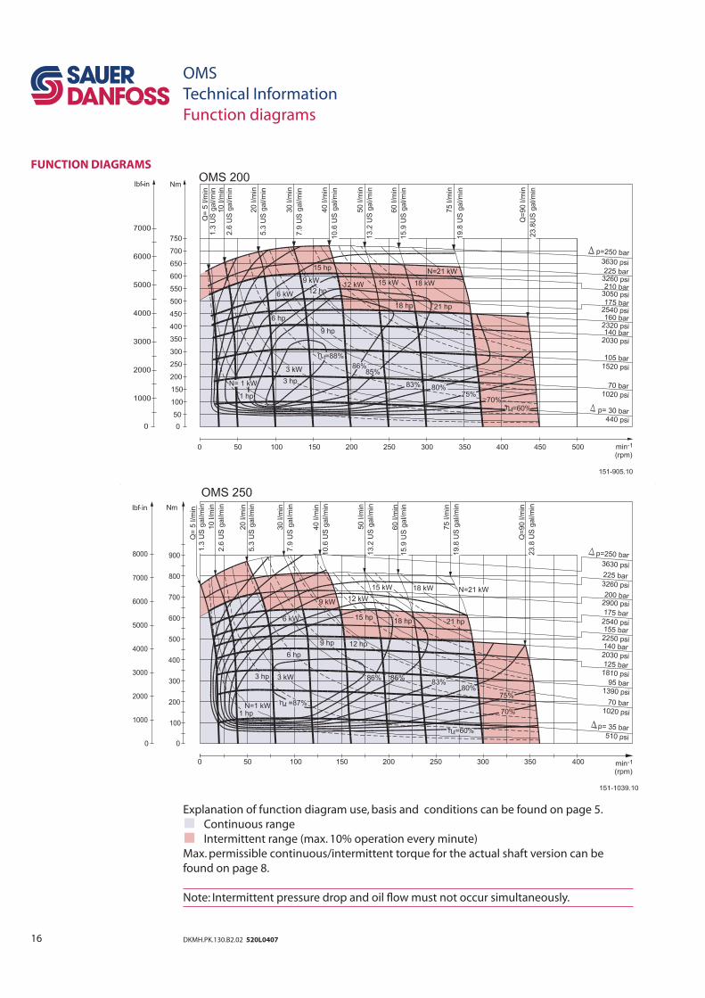
Explanation of function diagram use, basis and conditions can be found on page 5.
Continuous range
Intermittent range (max. 10% operation every minute)
Max. permissible continuous/intermittent torque for the actual shaft version can be
found on page 8.
Note: Intermittent pressure drop and oil fl ow must not occur simultaneously.
16 DKMH.PK.130.B2.02 520L0407
OMS
Technical Information
Function diagrams
FUNCTION DIAGRAMS
Explanation of function diagram use, basis and conditions can be found on page 5.
Continuous range
Intermittent range (max. 10% operation every minute)
Max. permissible continuous/intermittent torque for the actual shaft version can be
found on page 8.
Note: Intermittent pressure drop and oil fl ow must not occur simultaneously.
17DKMH.PK.130.B2.02 520L0407
OMS
Technical Information
Function diagrams
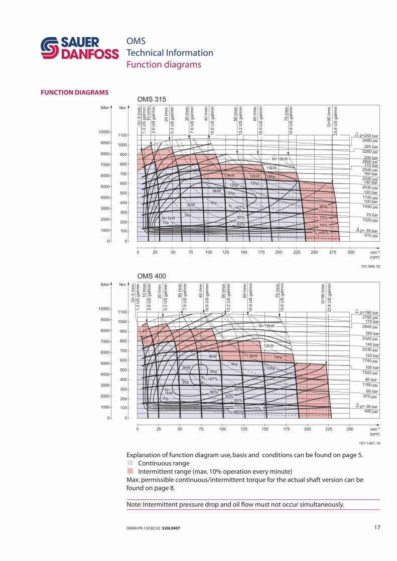
Explanation of function diagram use, basis and conditions can be found on page 5.
Continuous range
Intermittent range (max. 10% operation every minute)
Max. permissible continuous/intermittent torque for the actual shaft version can be
found on page 8.
Note: Intermittent pressure drop and oil fl ow must not occur simultaneously.
FUNCTION DIAGRAMS
18 DKMH.PK.130.B2.02 520L0407
OMS
Technical Information
Function diagrams
FUNCTION DIAGRAMS
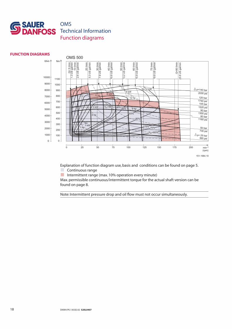
Explanation of function diagram use, basis and conditions can be found on page 5.
Continuous range
Intermittent range (max. 10% operation every minute)
Max. permissible continuous/intermittent torque for the actual shaft version can be
found on page 8.
Note: Intermittent pressure drop and oil fl ow must not occur simultaneously.
19DKMH.PK.130.B2.02 520L0407
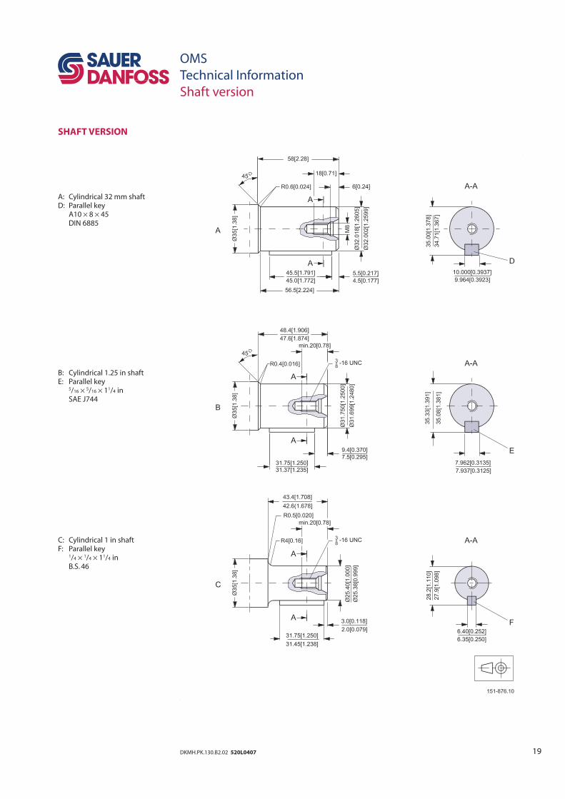
OMS
Technical Information
Shaft version
SHAFT VERSION
A: Cylindrical 32 mm shaftD: Parallel key A10 × 8 × 45 DIN 6885
B: Cylindrical 1.25 in shaftE: Parallel key 5/16 × 5/16 × 11/4 in SAE J744
C: Cylindrical 1 in shaftF: Parallel key 1/4 × 1/4 × 11/4 in B.S. 46
20 DKMH.PK.130.B2.02 520L0407
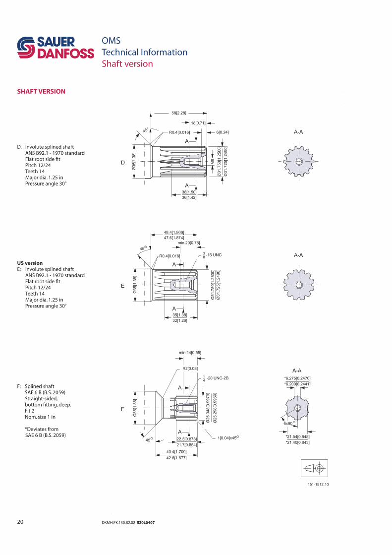
OMS
Technical Information
Shaft version
SHAFT VERSION
D. Involute splined shaft ANS B92.1 - 1970 standard Flat root side fi t Pitch 12/24 Teeth 14 Major dia. 1.25 in Pressure angle 30°
US versionE: Involute splined shaft ANS B92.1 - 1970 standard Flat root side fi t Pitch 12/24 Teeth 14 Major dia. 1.25 in Pressure angle 30°
F: Splined shaft SAE 6 B (B.S. 2059) Straight-sided, bottom fi tting, deep. Fit 2 Nom. size 1 in
*Deviates from SAE 6 B (B.S. 2059)
21DKMH.PK.130.B2.02 520L0407
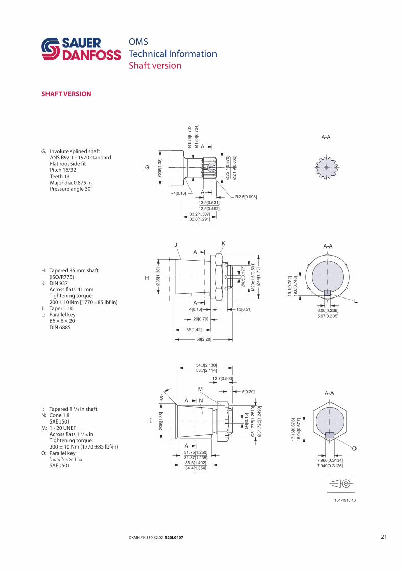
OMS
Technical Information
Shaft version
SHAFT VERSION
G. Involute splined shaft ANS B92.1 - 1970 standard Flat root side fi t Pitch 16/32 Teeth 13 Major dia. 0.875 in Pressure angle 30°
H: Tapered 35 mm shaft (ISO/R775)K: DIN 937 Across fl ats: 41 mm Tightening torque: 200 ± 10 Nm [1770 ±85 lbf·in]J: Taper 1:10L: Parallel key B6 × 6 × 20 DIN 6885
I: Tapered 1 1/4 in shaftN: Cone 1:8 SAE J501M: 1 - 20 UNEF Across fl ats 1 7/16 in Tightening torque: 200 ± 10 Nm (1770 ±85 lbf·in)O: Parallel key 5
/16 × 5/16 × 1 1
/4
SAE J501
22 DKMH.PK.130.B2.02 520L0407
OMS
Technical Information
Technical data
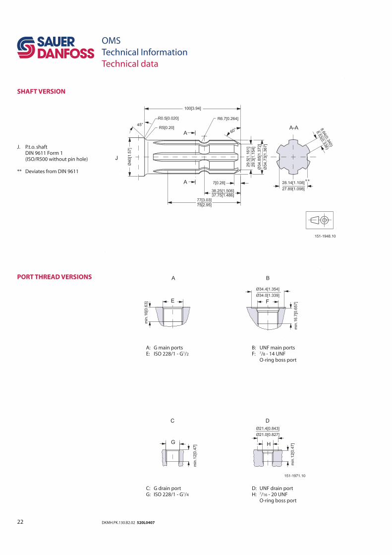
SHAFT VERSION
J. P.t.o. shaft DIN 9611 Form 1 (ISO/R500 without pin hole)
** Deviates from DIN 9611
PORT THREAD VERSIONS
A: G main ports B: UNF main ports E: ISO 228/1 - G1/2 F: 7/8 - 14 UNF O-ring boss port
C: G drain port D: UNF drain port G: ISO 228/1 - G1/4 H: 7/16 - 20 UNF O-ring boss port
23DKMH.PK.130.B2.02 520L0407
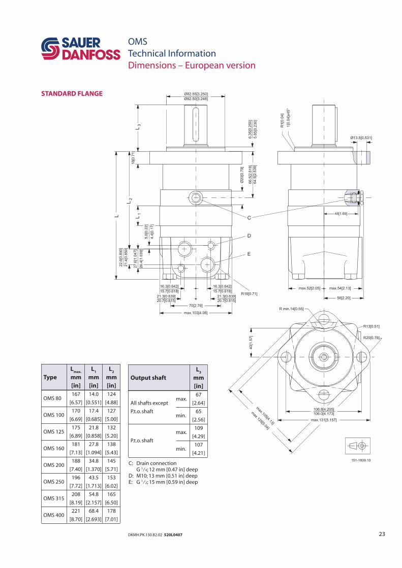
OMS
Technical Information
Dimensions – European version
STANDARD FLANGE
Lmax.
L1 L
2
Type mm mm mm
[in] [in] [in]
OMS 80 167 14.0 124
[6.57] [0.551] [4.88]
OMS 100 170 17.4 127
[6.69] [0.685] [5.00]
OMS 125 175 21.8 132
[6.89] [0.858] [5.20]
OMS 160 181 27.8 138
[7.13] [1.094] [5.43]
OMS 200 188 34.8 145
[7.40] [1.370] [5.71]
OMS 250 196 43.5 153
[7.72] [1.713] [6.02]
OMS 315 208 54.8 165
[8.19] [2.157] [6.50]
OMS 400 221 68.4 178
[8.70] [2.693] [7.01]
L3
Output shaft mm
[in]
67
All shafts except max.
[2.64]
P.t.o. shaft min.
65
[2.56]
max.
109
P.t.o. shaft [4.29]
min.
107
[4.21]
C: Drain connection G 1⁄4; 12 mm [0.47 in] deepD: M10; 13 mm [0.51 in] deep E: G 1⁄2; 15 mm [0.59 in] deep
24 DKMH.PK.130.B2.02 520L0407
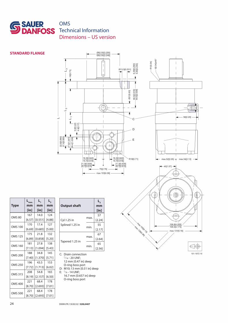
OMS
Technical Information
Dimensions – US version
STANDARD FLANGE
Lmax.
L1 L
2
Type mm mm mm
[in] [in] [in]
OMS 80 167 14.0 124
[6.57] [0.551] [4.88]
OMS 100 170 17.4 127
[6.69] [0.685] [5.00]
OMS 125 175 21.8 132
[6.89] [0.858] [5.20]
OMS 160 181 27.8 138
[7.13] [1.094] [5.43]
OMS 200 188 34.8 145
[7.40] [1.370] [5.71]
OMS 250 196 43.5 153
[7.72] [1.713] [6.02]
OMS 315 208 54.8 165
[8.19] [2.157] [6.50]
OMS 400 221 68.4 178
[8.70] [2.693] [7.01]
OMS 500 221 68.4 178
[8.70] [2.693] [7.01]
L3
Output shaft mm
[in]
57
Cyl.1.25 in max.
[2.24]
Splined 1.25 in min.
55
[2.17]
max.
67
Tapered 1.25 in [2.64]
min.
65
[2.56]
C: Drain connection 7⁄16 - 20 UNF; 12 mm [0.47 in] deep O-ring boss portD: M10; 13 mm [0.51 in] deepE: 7⁄8 - 14 UNF; 16.7 mm [0.657 in] deep O-ring boss port
25DKMH.PK.130.B2.02 520L0407
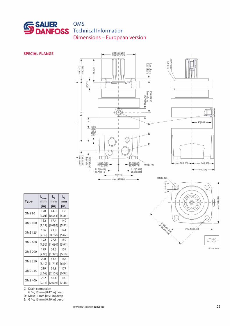
OMS
Technical Information
Dimensions – European version
SPECIAL FLANGE
Lmax.
L1 L
2
Type mm mm mm
[in] [in] [in]
OMS 80 178 14.0 136
[7.01] [0.551] [5.35]
OMS 100 182 17.4 140
[7.17] [0.685] [5.51]
OMS 125 186 21.8 144
[7.32] [0.858] [5.67]
OMS 160 192 27.8 150
[7.56] [1.094] [5.91]
OMS 200 199 34.8 157
[7.83] [1.370] [6.18]
OMS 250 208 43.5 166
[8.19] [1.713] [6.54]
OMS 315 219 54.8 177
[8.62] [2.157] [6.97]
OMS 400 232 68.4 190
[9.13] [2.693] [7.48]
C: Drain connection G 1⁄4; 12 mm [0.47 in] deepD: M10; 13 mm [0.51 in] deep E: G 1⁄2; 15 mm [0.59 in] deep
26 DKMH.PK.130.B2.02 520L0407
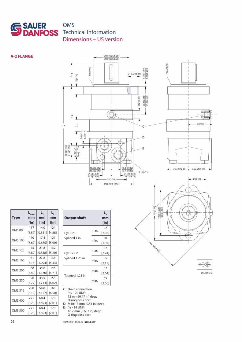
OMS
Technical Information
Dimensions – US version
A-2 FLANGE
Lmax.
L1 L
2
Type mm mm mm
[in] [in] [in]
OMS 80 167 14.0 124
[6.57] [0.551] [4.88]
OMS 100 170 17.4 127
[6.69] [0.685] [5.00]
OMS 125 175 21.8 132
[6.89] [0.858] [5.20]
OMS 160 181 27.8 138
[7.13] [1.094] [5.43]
OMS 200 188 34.8 145
[7.40] [1.370] [5.71]
OMS 250 196 43.5 153
[7.72] [1.713] [6.02]
OMS 315 208 54.8 165
[8.19] [2.157] [6.50]
OMS 400 221 68.4 178
[8.70] [2.693] [7.01]
OMS 500 221 68.4 178
[8.70] [2.693] [7.01]
L3
Output shaft mm
[in]
52
Cyl.1 in max.
[2.05]
Splined 1 in min.
50
[1.97]
57
Cyl.1.25 in max.
[2.24]
Splined 1.25 in min.
55
[2.17]
max.
67
Tapered 1.25 in [2.64]
min.
65
[2.56]
C: Drain connection 7⁄16 - 20 UNF; 12 mm [0.47 in] deep O-ring boss portD: M10; 13 mm [0.51 in] deepE: 7⁄8 - 14 UNF; 16.7 mm [0.657 in] deep O-ring boss port
27DKMH.PK.130.B2.02 520L0407
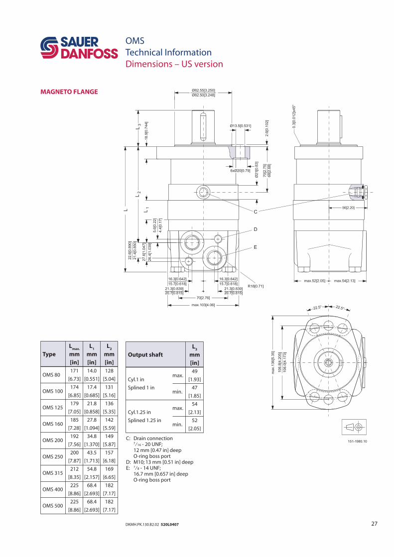
OMS
Technical Information
Dimensions – US version
MAGNETO FLANGE
Lmax.
L1 L
2
Type mm mm mm
[in] [in] [in]
OMS 80 171 14.0 128
[6.73] [0.551] [5.04]
OMS 100 174 17.4 131
[6.85] [0.685] [5.16]
OMS 125 179 21.8 136
[7.05] [0.858] [5.35]
OMS 160 185 27.8 142
[7.28] [1.094] [5.59]
OMS 200 192 34.8 149
[7.56] [1.370] [5.87]
OMS 250 200 43.5 157
[7.87] [1.713] [6.18]
OMS 315 212 54.8 169
[8.35] [2.157] [6.65]
OMS 400 225 68.4 182
[8.86] [2.693] [7.17]
OMS 500 225 68.4 182
[8.86] [2.693] [7.17]
L3
Output shaft mm
[in]
49
Cyl.1 in max.
[1.93]
Splined 1 in min.
47
[1.85]
54
Cyl.1.25 in max.
[2.13]
Splined 1.25 in min.
52
[2.05]
C: Drain connection 7⁄16 - 20 UNF; 12 mm [0.47 in] deep O-ring boss portD: M10; 13 mm [0.51 in] deepE: 7⁄8 - 14 UNF; 16.7 mm [0.657 in] deep O-ring boss port
28 DKMH.PK.130.B2.02 520L0407
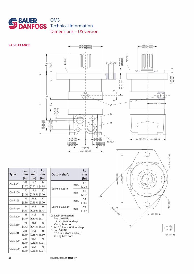
OMS
Technical Information
Dimensions – US version
SAE-B FLANGE
Lmax.
L1 L
2
Type mm mm mm
[in] [in] [in]
OMS 80 167 14.0 124
[6.57] [0.551] [4.88]
OMS 100 170 17.4 127
[6.69] [0.685] [5.00]
OMS 125 175 21.8 132
[6.89] [0.858] [5.20]
OMS 160 181 27.8 138
[7.13] [1.094] [5.43]
OMS 200 188 34.8 145
[7.40] [1.370] [5.71]
OMS 250 196 43.5 153
[7.72] [1.713] [6.02]
OMS 315 208 54.8 165
[8.19] [2.157] [6.50]
OMS 400 221 68.4 178
[8.70] [2.693] [7.01]
OMS 500 221 68.4 178
[8.70] [2.693] [7.01]
L3
Output shaft mm
[in]
57
max.
[2.24]Splined 1.25 in
min.
55
[2.17]
42
max.
[1.65]
Splined 0.875 in min.
40
[1.57]
C: Drain connection 7⁄16 - 20 UNF; 12 mm [0.47 in] deep O-ring boss portD: M10; 13 mm [0.51 in] deepE: 7⁄8 - 14 UNF; 16.7 mm [0.657 in] deep O-ring boss port
29DKMH.PK.130.B2.02 520L0407
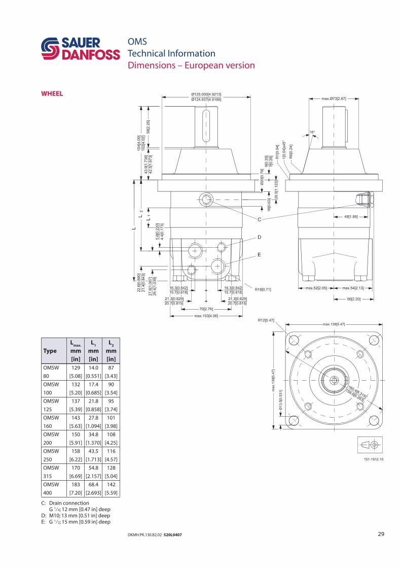
OMS
Technical Information
Dimensions – European version
WHEEL
Lmax.
L1 L
2
Type mm mm mm
[in] [in] [in]
OMSW 129 14.0 87
80 [5.08] [0.551] [3.43]
OMSW 132 17.4 90
100 [5.20] [0.685] [3.54]
OMSW 137 21.8 95
125 [5.39] [0.858] [3.74]
OMSW 143 27.8 101
160 [5.63] [1.094] [3.98]
OMSW 150 34.8 108
200 [5.91] [1.370] [4.25]
OMSW 158 43.5 116
250 [6.22] [1.713] [4.57]
OMSW 170 54.8 128
315 [6.69] [2.157] [5.04]
OMSW 183 68.4 142
400 [7.20] [2.693] [5.59]
C: Drain connection G 1⁄4; 12 mm [0.47 in] deepD: M10; 13 mm [0.51 in] deep E: G 1⁄2; 15 mm [0.59 in] deep
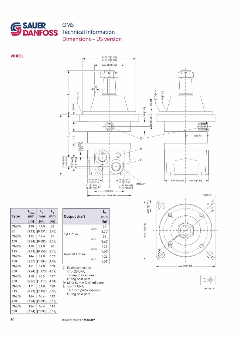
30 DKMH.PK.130.B2.02 520L0407
OMS
Technical Information
Dimensions – US version
WHEEL
Lmax.
L1 L
2
Type mm mm mm
[in] [in] [in]
OMSW 130 14.0 88
80 [5.12] [0.551] [3.46]
OMSW 133 17.4 91
100 [5.24] [0.685] [3.58]
OMSW 138 21.8 96
125 [5.43] [0.858] [3.78]
OMSW 144 27.8 102
160 [5.67] [1.094] [4.02]
OMSW 151 34.8 109
200 [5.94] [1.370] [4.29]
OMSW 159 43.5 117
250 [6.26] [1.713] [4.61]
OMSW 171 54.8 129
315 [6.73] [2.157] [5.08]
OMSW 184 68.4 142
400 [7.24] [2.693] [5.59]
OMSW 184 68.4 142
500 [7.24] [2.693] [5.59]
L3
Output shaft mm
[in]
94
Cyl.1.25 in
max. [3.70]
min.
92
[3.62]
max.
104
Tapered 1.25 in [4.09]
min.
102
[4.02]
C: Drain connection 7⁄16 - 20 UNF; 12 mm [0.47 in] deep O-ring boss portD: M10; 13 mm [0.51 in] deepE: 7⁄8 - 14 UNF; 16.7 mm [0.657 in] deep O-ring boss port
31DKMH.PK.130.B2.02 520L0407
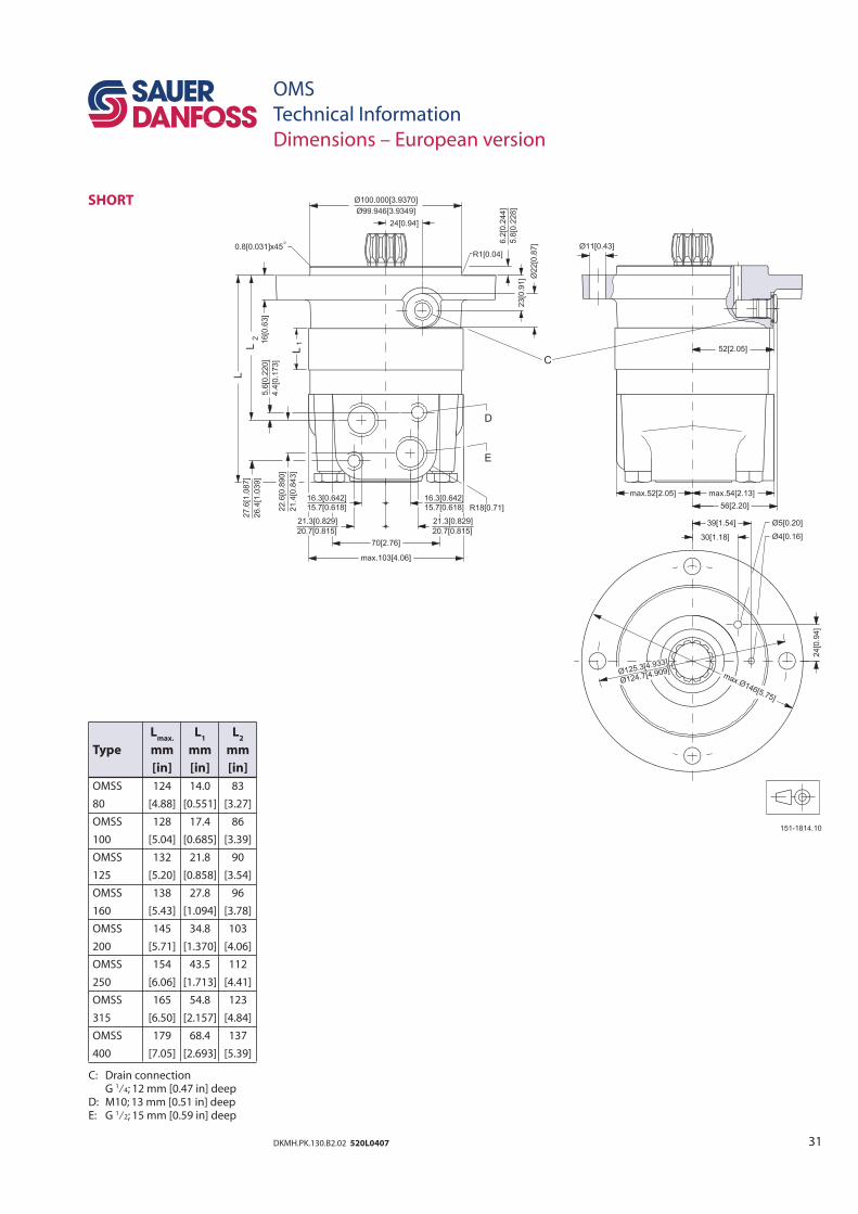
OMS
Technical Information
Dimensions – European version
SHORT
Lmax.
L1 L
2
Type mm mm mm
[in] [in] [in]
OMSS 124 14.0 83
80 [4.88] [0.551] [3.27]
OMSS 128 17.4 86
100 [5.04] [0.685] [3.39]
OMSS 132 21.8 90
125 [5.20] [0.858] [3.54]
OMSS 138 27.8 96
160 [5.43] [1.094] [3.78]
OMSS 145 34.8 103
200 [5.71] [1.370] [4.06]
OMSS 154 43.5 112
250 [6.06] [1.713] [4.41]
OMSS 165 54.8 123
315 [6.50] [2.157] [4.84]
OMSS 179 68.4 137
400 [7.05] [2.693] [5.39]
C: Drain connection G 1⁄4; 12 mm [0.47 in] deepD: M10; 13 mm [0.51 in] deep E: G 1⁄2; 15 mm [0.59 in] deep
32 DKMH.PK.130.B2.02 520L0407
OMS
Technical Information
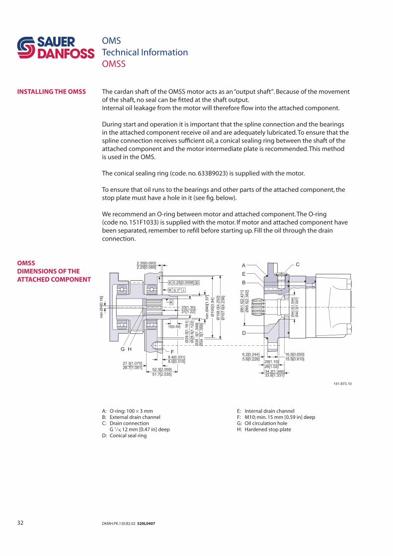
OMSS
INSTALLING THE OMSS
OMSS
DIMENSIONS OF THE
ATTACHED COMPONENT
The cardan shaft of the OMSS motor acts as an “output shaft”. Because of the movement
of the shaft, no seal can be fi tted at the shaft output.
Internal oil leakage from the motor will therefore fl ow into the attached component.
During start and operation it is important that the spline connection and the bearings
in the attached component receive oil and are adequately lubricated. To ensure that the
spline connection receives suffi cient oil, a conical sealing ring between the shaft of the
attached component and the motor intermediate plate is recommended. This method
is used in the OMS.
The conical sealing ring (code. no. 633B9023) is supplied with the motor.
To ensure that oil runs to the bearings and other parts of the attached component, the
stop plate must have a hole in it (see fi g. below).
We recommend an O-ring between motor and attached component. The O-ring
(code no. 151F1033) is supplied with the motor. If motor and attached component have
been separated, remember to refi ll before starting up. Fill the oil through the drain
connection.
A: O-ring: 100 × 3 mm E: Internal drain channelB: External drain channel F: M10; min. 15 mm [0.59 in] deepC: Drain connection G: Oil circulation hole G 1⁄4; 12 mm [0.47 in] deep H: Hardened stop plateD: Conical seal ring
33DKMH.PK.130.B2.02 520L0407
The attached component must have internal splines corresponding to the external
splines on the motor cardan shaft (see drawing below).
Material:
Case hardening steel with a tensile strength corresponding at least to 20 MoCr4
(900 N/mm2) or SAE 8620.
Hardening specifi cation:
• On the surface: HV = 750 ± 50
• 0.7 ± 0.2 mm under the surface: HV = 560
Internal involute spline data
Standard ANS B92.1-1970, class 5 (corrected m · X = 0.8; m = 2.1166)
Fillet root
side fi t mm in
Number of
teeth z 12 12
Pitch DP 12/24 12/24
Pressure angle 30° 30°
Pitch dia. D 25.4 1.0
Major dia. Dri 28.0 0
–0.1 1.10 0
–0.004
Form dia.
(min.) D
fi 27.6 1.09
Minor dia. Di 23.0
0+0.033 0.9055
0+0.0013
Space width
(circular) L
o 4.308 ±0.020 0.1696 ±0.0008
Tooth
thickness So 2.341 0.09217
(circular)
Fillet radius Rmin.
0.2 0.008
Max.
measurement l 17.62 0+0.15 0.700 0
–0.006
between pins*
Pin dia. d 4.835 ±0.001 0.1903 ±0.00004
* Finished dimensions (when hardened)
OMS
Technical Information
OMSS
INTERNAL SPLINE DATA
FOR THE COMPONENT TO
BE ATTACHED
DRAIN CONNECTION ON
OMSS OR ATTACHED
COMPONENT
A drain line ought to be used when pressure in the return line can exceed the permissible
pressure on the shaft seal of the attached component.
The drain line can be connected at two different points:
1) at the motor drain connection
2) at the drain connection of the attached component.
If a drain line is fi tted to the attached component, it must be possible for oil to fl ow freely
between motor and attached component.
The drain line must be led to the tank in such a way that there is no risk of the motor and
attached component being drained of oil when at rest.
The maximum pressure in the drain line is limited by the attached component and its
shaft seal.
Related Documents