2 DKMH.PK.110.B4.02 520L0262 OMP, OMR, OMH and OMEW Hydraulic Motor A wide range of hydraulic motors Motorer.TIF Sauer-Danfoss is a world leader within production of low speed hydraulic motors with high torque. We can offer more than 1600 different hydraulic motors, categorised in types, variants and sizes (incl. different shaft versions). The motors vary in size (rated displacement) from 8 cm 3 (0.50 in 3 ) to 800 cm 3 (48.9 in 3 ) per revolution. Speeds range up to approx. 2500 min -1 (rpm) for the smallest type and up to approx 600 min -1 (rpm) for the largest type. Maximum operating torques vary from 13 Nm (115 lbf·in) to 2700 Nm (24.000 lbf·in) (peak) and maximum outputs are from 2,0 kW (2,7 hp) to 70 kW (95 hp). Characteristic features: • Smooth running over the entire speed range • Constant operating torque over a wide speed range • High starting torque • High return pressure without the use of drain line (High pressure shaft seal) • High efficiency • Long life under extreme operating conditions • Robust and compact design • High radial and axial bearing capacity • For applications in both open and closed loop hydraulic systems • Suitable for a wide variety of hydraulics fluids A WIDE RANGE OF HYDRAULIC MOTORS © 2001 Sauer-Danfoss Sauer-Danfoss can accept no responsibility for possible errors in catalogues, brochures and other printed material. Sauer -Danfoss reserves the right to alter its products without prior notice. This also applies to products already ordered provided that such alterations can be made without subsequent changes being necessary in specifications already agreed. All trademarks in this material are properties of the respective companies. Sauer-Danfoss and the Sauer-Danfoss logotype are trademarks of the Sauer-Danfoss Group. All rights reserved. Frontpage: Drawing 151-1837, F73375.TIF, F73337.TIF, F73338.TIF, F66104.TIF, F71934.eps

Welcome message from author
This document is posted to help you gain knowledge. Please leave a comment to let me know what you think about it! Share it to your friends and learn new things together.
Transcript
2 DKMH.PK.110.B4.02 520L0262
OMP, OMR, OMH and OMEW
Hydraulic Motor
A wide range of hydraulic motors
Motorer.TIF
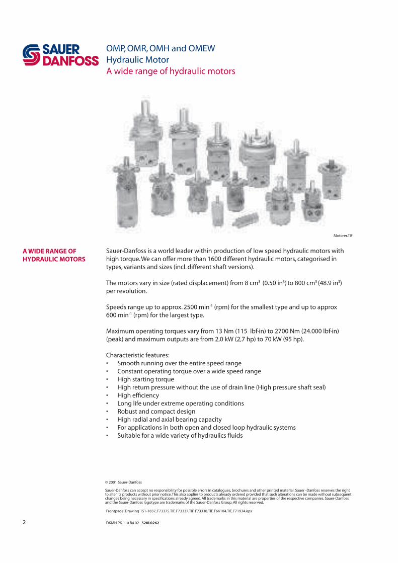
Sauer-Danfoss is a world leader within production of low speed hydraulic motors with
high torque. We can offer more than 1600 different hydraulic motors, categorised in
types, variants and sizes (incl. different shaft versions).
The motors vary in size (rated displacement) from 8 cm3 (0.50 in3) to 800 cm3 (48.9 in3)
per revolution.
Speeds range up to approx. 2500 min-1 (rpm) for the smallest type and up to approx
600 min-1 (rpm) for the largest type.
Maximum operating torques vary from 13 Nm (115 lbf·in) to 2700 Nm (24.000 lbf·in)
(peak) and maximum outputs are from 2,0 kW (2,7 hp) to 70 kW (95 hp).
Characteristic features:
• Smooth running over the entire speed range
• Constant operating torque over a wide speed range
• High starting torque
• High return pressure without the use of drain line (High pressure shaft seal)
• High effi ciency
• Long life under extreme operating conditions
• Robust and compact design
• High radial and axial bearing capacity
• For applications in both open and closed loop hydraulic systems
• Suitable for a wide variety of hydraulics fl uids
A WIDE RANGE OF
HYDRAULIC MOTORS
© 2001 Sauer-Danfoss
Sauer-Danfoss can accept no responsibility for possible errors in catalogues, brochures and other printed material. Sauer -Danfoss reserves the rightto alter its products without prior notice. This also applies to products already ordered provided that such alterations can be made without subsequentchanges being necessary in specifications already agreed. All trademarks in this material are properties of the respective companies. Sauer-Danfossand the Sauer-Danfoss logotype are trademarks of the Sauer-Danfoss Group. All rights reserved.
Frontpage: Drawing 151-1837, F73375.TIF, F73337.TIF, F73338.TIF, F66104.TIF, F71934.eps
3DKMH.PK.110.B4.02 520L0262
The programme is characterised by technical features appealing to a large number
of applications and a part of the programme is characterised by motors that can be
adapted to a given application. Adaptions comprise the following variants among others:
• Motors with corrosion resistant parts
• Wheel motors with recessed mounting fl ange
• OMP, OMR- motors with needle bearing
• OMR motor in low leakage version
• OMR motors in a super low leakage version
• Short motors without bearings
• Ultra short motors
• Motors with integrated positive holding brake
• Motors with integrated negative holding brake
• Motors with integrated fl ushing valve
• Motors with speed sensor
• Motors with tacho connection
• All motors are available with black fi nish paint
Planetary gears
Sauer - Danfoss complements the motor range with a complete programme of planetary
gears adapted to suit. The combination of motors and gears makes it possible to obtain
smooth running at fractional speeds and with torques up to 650.000 Nm (5.800.000 lbf·in).
The Sauer–Danfoss LSHT motors are used in the following application areas:
• Construction equipment
• Agricultural equipment
• Material handling & Lifting equipment
• Forestry equipment
• Lawn and turf equipment
• Special purpose
• Machine tools and stationary equipment
• Marine equipment
Detailed data on all Sauer-Danfoss motors can be found in our motor catalogue, which is
divided into 5 individual subcatalogues:
• General information on Sauer-Danfoss hydraulic motors: function, use, selection of
hydraulic motor, hydraulic systems, etc.
• Technical data on small motors: OML and OMM
• Technical data on medium sized motors: OMP, OMR, OMH and OMEW
• Technical data on medium sized motors: DH and DS
• Technical data on large motors: OMS, OMT and OMV
• Technical data on large motors: TMT
A general survey brochure on Sauer-Danfoss hydraulic motors gives a quick motor
reference based on power, torque, speed and capabilities.
SURVEY OF LITERATURE
WITH TECHNICAL DATA
ON DANFOSS
HYDRAULIC MOTORS
OMP, OMR, OMH and OMEW
Hydraulic Motor
A wide range of hydraulic motors
4 DKMH.PK.110.B4.02 520L0262
OMP, OMR, OMH and OMEW
Hydraulic Motor
Contents
Page
OMP, OMR, OMH and OMEW .......................................................................................................................................6
Speed, torque and output ..........................................................................................................................................6
OMP ........................................................................................................................................................................................8
Version....................................................................................................................................................................................8
Code number.......................................................................................................................................................................9
Technical data...........................................................................................................................................................10-26
Technical data (e.g. speed, torque, pressure etc.) ......................................................................................10-12
Max. permissisble shaft seal pressure.................................................................................................................. 13
Pressure drop in motor, oil fl ow in drain line, direction of shaft rotation ............................................... 14
Permissible shaft loads .......................................................................................................................................15-17
Function diagrams ...............................................................................................................................................18-23
Shaft version...........................................................................................................................................................24-25
Port thread versions................................................................................................................................................... 26
Dimensions..................................................................................................................................................................27-35
OMR ..................................................................................................................................................................................... 36
Version................................................................................................................................................................................. 36
Code number.................................................................................................................................................................... 37
Technical data...........................................................................................................................................................38-54
Technical data (e.g. speed, torque, pressure etc.) .....................................................................................38-40
Max. permissisble shaft seal pressure.................................................................................................................. 41
Pressure drop in motor, oil fl ow in drain line, direction of shaft rotation ............................................... 42
Permissible shaft loads .......................................................................................................................................43-44
Function diagrams ...............................................................................................................................................45-49
Shaft version...........................................................................................................................................................50-53
Port thread versions................................................................................................................................................... 54
Dimensions ...................................................................................................................................................................... 55
Dimensions .............................................................................................................................................................55-65
OMH..................................................................................................................................................................................... 66
Version................................................................................................................................................................................. 66
Code number.................................................................................................................................................................... 67
Technical data...........................................................................................................................................................68-80
Technical data (e.g. speed, torque, pressure etc.) .....................................................................................68-70
Max. permissisble shaft seal pressure.................................................................................................................. 71
Pressure drop in motor, oil fl ow in drain line, direction of shaft rotation ............................................... 72
Permissible shaft loads ............................................................................................................................................. 73
Function diagrams ...............................................................................................................................................74-76
Shaft version...........................................................................................................................................................77-79
Port thread versions................................................................................................................................................... 80
Dimensions ...................................................................................................................................................................... 81
Dimensions .............................................................................................................................................................81-82
CONTENTS
5DKMH.PK.110.B4.02 520L0262
OMP, OMR, OMH and OMEW
Hydraulic Motor
Contents
CONTENTS Page
OMEW ................................................................................................................................................................................. 84
Version................................................................................................................................................................................. 84
Code number.................................................................................................................................................................... 85
Technical data...........................................................................................................................................................86-94
Technical data (e.g. speed, torque, pressure etc.) ........................................................................................... 86
Max. permissisble shaft seal pressure.................................................................................................................. 87
Pressure drop in motor, direction of shaft rotation ........................................................................................ 88
Permissible shaft loads ............................................................................................................................................. 89
Function diagrams ...............................................................................................................................................90-92
Shaft version................................................................................................................................................................. 93
Port thread versions................................................................................................................................................... 94
Dimensions ...................................................................................................................................................................... 95
Dimensions .............................................................................................................................................................95-96
Weight of motors ....................................................................................................................................................97-99
6 DKMH.PK.110.B4.02 520L0262
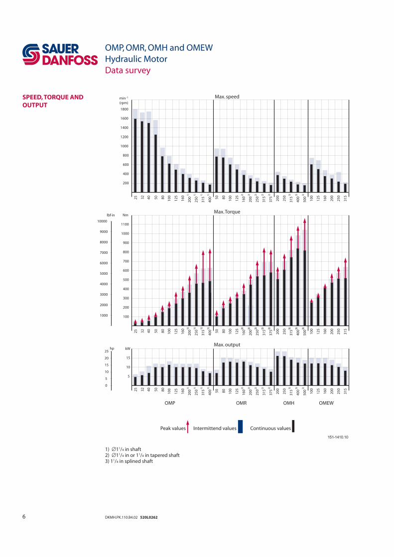
Max. speed
Max. Torque
Max. output
Peak values Intermittend values Continuous values
1) ∅11/4 in shaft 2) ∅11/4 in or 11/4 in tapered shaft 3) 11/4 in splined shaft
SPEED, TORQUE AND
OUTPUT
OMP, OMR, OMH and OMEW
Hydraulic Motor
Data survey
40
32
25
10
080
50
31
51
)
25
0
16
0
12
5
20
01
)
1)
40
01
)
10
0
80
50
31
5
25
0
12
5
16
0
20
02
)
2)
2)
2)
31
5
25
0
37
5
20
02)
3)
50
0
40
03
)
3)
5
10
15
kW
OMP OMR OMH
31
5
10
0
25
0
16
0
12
5
20
0
OMEW
hp25
20
10
15
5
0
40
25
32
50
80
10
0 1)
31
5
1)
20
0
12
5
16
0 1)
25
0
40
01
)
50
80
10
0
31
5
2)
20
0
2)
16
0
12
5
25
02
)
2)
20
0
37
52
)
25
0 3)
31
5
3)
40
0
3)
50
0
100
200
300
400
500
800
600
700
900
1000
1100
Nm
31
5
10
0
20
0
12
5
16
0
25
0
9000
lbf in
8000
6000
7000
3000
2000
4000
5000
1000
10000
25
32
40
12
5
10
0
16
0
20
0
25
0
31
5
40
0 80
10
0
31
5
20
0
12
5
16
0
25
0
37
550
40
0
25
0
20
0
31
5
50
050
80 2
)
2)
2)
2)
2)
3)
3)
3)
1)
1)
1)
1)
1800
1600
1200
1400
1000
200
400
600
800
mi
10
0
12
5
16
0
20
0
25
0
31
5
(rpm)
n -1
.
151-1410.10
7DKMH.PK.110.B4.02 520L0262
The bar diagrams above are useful for a quick selection of relevant motor size for the
application. The fi nal motor size can be determined by using the function diagram for
each motor size.
• OMP and OMPW can be found on pages 18 - 23
• OMR and OMRW can be found on pages 45 - 49
• OMH can be found on pages 74 - 76
• OMEW can be found on pages 90 - 92
The function diagrams are based on actual tests on a representative number of motors
from our production. The diagrams apply to a return pressure between 5 and 10 bar
(75 and 150 psi) when using mineral based hydraulic oil with a viscosity of 35 mm2/s
(165 SUS) and a temperature of 50°C (120°F). For further explanation concerning how to
read and use the function diagrams, please consult the paragraph "Selection of motor
size" in the technical information "General" DHMH.PK.100.G2.02 520L0232.
OMP, OMR, OMH and OMEW
Hydraulic Motor
Data survey
SPEED, TORQUE AND
OUTPUT
8 DKMH.PK.110.B4.02 520L0262
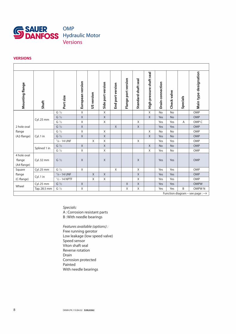
VERSIONS
OMP
Hydraulic Motor
Versions
Mo
un
tin
g fl
an
ge
Sh
aft
Po
rt s
ize
Eu
rop
ea
n v
ers
ion
US
ve
rsio
n
Sid
e p
ort
ve
rsio
n
En
d p
ort
ve
rsio
n
Fla
ng
e p
ort
ve
rsio
n
Sta
nd
ard
sh
aft
se
al
Hig
h p
ress
ure
sh
aft
se
al
Dra
in c
on
ne
cti
on
Ch
eck
va
lve
Sp
eci
als
Main
typ
e d
esig
nati
on
G 1/2 X X X No No OMP
Cyl. 25 mm
G 1/2 X X X Yes No OMP
G 1/2 X X X Yes Yes A OMP C
2 hole oval G 1/2 X X X Yes Yes OMP
fl ange G 1/2 X X X No No OMP
(A2-fl ange) Cyl. 1 in G 1/2 X X X Yes No OMP
7/8 - 14 UNF X X X Yes Yes OMP
G 1/2 X X X No No OMP
Splined 1 in
G 1/2 X X X Yes No OMP
4 hole oval
fl ange Cyl. 32 mm G 1/2 X X X Yes Yes OMP
(A4 fl ange)
Square Cyl. 25 mm G 1/2 X X X Yes Yes OMP
fl ange Cyl. 1 in
7/8 - 14 UNF X X X Yes Yes OMP
(C-fl ange) 1/2 - 14 NPTF X X X Yes Yes OMP
Cyl. 25 mm G 1/2 X X X Yes Yes OMPW Wheel
Tap. 28.5 mm G 1/2 X X X Yes Yes B OMPW N
Function diagram – see page : →
Specials:
A : Corrosion resistant parts
B : With needle bearings
Features available (options) :
Free running gerotor
Low leakage (low speed valve)
Speed sensor
Viton shaft seal
Reverse rotation
Drain
Corrosion protected
Painted
With needle bearings
9DKMH.PK.110.B4.02 520L0262
CODE NUMBERS
OMP
Hydraulic Motor
Code Numbers
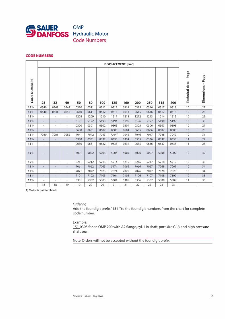
Ordering
Add the four digit prefi x “151-” to the four digit numbers from the chart for complete
code number.
Example:
151-0305 for an OMP 200 with A2 fl ange, cyl. 1 in shaft, port size G 1/2 and high pressure
shaft seal.
Note: Orders will not be accepted without the four digit prefi x.
Te
chn
ica
l d
ata
– P
ag
e
Dim
en
sio
ns
– P
ag
e
CO
DE
NU
MB
ER
S
DISPLACEMENT [cm3]
25 32 40 50 80 100 125 160 200 250 315 400
151- 0340 0341 0342 0310 0311 0312 0313 0314 0315 0316 0317 0318 10 27
151- 0640 0641 0642 0610 0611 0612 0613 0614 0615 0616 0617 0618 10 28
151- - - - 1208 1209 1210 1217 1211 1212 1213 1214 1215 10 29
151- - - - 5191 5192 5193 5194 5195 5196 5197 5198 5199 10 30
151- - - - 0300 0301 0302 0303 0304 0305 0306 0307 0308 10 27
151- - - - 0600 0601 0602 0603 0604 0605 0606 0607 0608 10 28
151- 7080 7081 7082 7041 7042 7043 70441) 7045 7046 7047 7048 7049 10 31
151- - - - 0330 0331 0332 0333 0334 0335 0336 0337 0338 11 27
151- - - - 0630 0631 0632 0633 0634 0635 0636 0637 0638 11 28
151- - - - 5001 5002 5003 5004 5005 5006 5007 5008 5009 12 32
151- - - - 5211 5212 5213 5214 5215 5216 5217 5218 5219 10 33
151- - - - 7061 7062 7063 5174 7065 7066 7067 7068 7069 10 34
151- - - - 7021 7022 7023 7024 7025 7026 7027 7028 7029 10 34
151- - - - 7101 7102 7103 7104 7105 7106 7107 7108 7109 10 35
151- - - - 5301 5302 5303 5304 5305 5306 5307 5308 5309 11 35
18 18 19 19 20 20 21 21 22 22 23 23
1) Motor is painted black
10 DKMH.PK.110.B4.02 520L0262
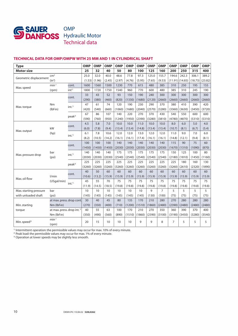
TECHNICAL DATA FOR OMP/OMPW WITH 25 MM AND 1 IN CYLINDRICAL SHAFT
OMP
Hydraulic Motor
Technical data
Type OMP OMP OMP OMP OMP OMP OMP OMP OMP OMP OMP OMP
Motor size 25 32 40 50 80 100 125 160 200 250 315 400
Geometric displacement cm3 25.0 32.0 40.0 48.6 77.8 97.3 125.0 155.7 194.6 242.3 306.1 389.2
(in3) (1.53) (1.96) (2.45) (2.97) (4.76) (5.95) (7.65) (9.53) (11.91) (14.83) (18.73) (23.82)
Max. speed min-1 cont. 1600 1560 1500 1230 770 615 480 385 310 250 195 155
(rpm) int1) 1800 1720 1750 1540 960 770 600 480 385 310 245 190
cont.
33 43 52 93 150 190 240 300 300 300 300 300
(290) (380) (460) (820) (1330) (1680) (2120) (2660) (2660) (2660) (2660) (2660)
Max. torque Nm
int.1) 47 61 74 120 190 230 290 370 380 410 390 420
(lbf·in) (420) (540) (660) (1060) (1680) (2040) (2570) (3280) (3360) (3630) (3450) (3720)
peak2)
67 86 107 140 220 270 370 430 540 550 600 600
(590) (760) (950) (1240) (1950) (2390) (3280) (3810) (4780) (4870) (5310) (5310)
cont.
4.5 5.8 7.0 10.0 10.0 11.0 10.0 10.0 8.0 6.0 5.0 4.0
Max. output kW (6.0) (7.8) (9.4) (13.4) (13.4) (14.8) (13.4) (13.4) (10.7) (8.1) (6.7) (5.4)
(hp) int.1)
6.1 7.8 10.6 12.0 12.0 13.0 12.0 12.0 11.0 9.0 7.0 6.0
(8.2) (10.5) (14.2) (16.1) (16.1) (17.4) (16.1) (16.1) (14.8) (12.1) (9.4) (8.1)
cont.
100 100 100 140 140 140 140 140 115 90 75 60
(1450) (1450) (1450) (2030) (2030) (2030) (2030) (2030) (1670) (1310) (1090) (870)
Max. pressure drop bar
int.1) 140 140 140 175 175 175 175 175 150 125 100 80
(psi) (2030) (2030) (2030) (2540) (2540) (2540) (2540) (2540) (2180) (1810) (1450) (1160)
peak2)
225 225 225 225 225 225 225 225 225 180 160 130
(3260) (3260) (3260) (3260) (3260) (3260) (3260) (3260) (3260) (2610) (2320) (1890)
Max. oil fl ow
cont.
40 50 60 60 60 60 60 60 60 60 60 60
l/min (10.6) (13.2) (15.9) (15.9) (15.9) (15.9) (15.9) (15.9) (15.9) (15.9) (15.9) (15.9)
(USgal/min) int.1)
45 55 70 75 75 75 75 75 75 75 75 75
(11.9) (14.5) (18.5) (19.8) (19.8) (19.8) (19.8) (19.8) (19.8) (19.8) (19.8) (19.8)
Max. starting pressure bar 10 10 10 10 10 10 9 7 5 5 5 5
with unloaded shaft (psi) (145) (145) (145) (145) (145) (145) (130) (100) (75) (75) (75) (75)
at max. press. drop cont. 30 40 45 80 135 170 210 280 270 280 280 280
Min. starting
Nm (lbf·in) (270) (350) (400) (710) (1200) (1510) (1860) (2480) (2390) (2480) (2480) (2480)
torque at max. press. drop int. 1) 40 55 63 100 170 210 270 350 360 390 370 400
Nm (lbf·in) (350) (490) (560) (890) (1510) (1860) (2390) (3100) (3190) (3450) (3280) (3540)
Min. speed3) min-1
20 15 10 10 10 9 9 8 7 5 5 5 (rpm)
1) Intermittent operation: the permissible values may occur for max. 10% of every minute.2) Peak load: the permissible values may occur for max. 1% of every minute.3) Operation at lower speeds may be slightly less smooth.
11DKMH.PK.110.B4.02 520L0262
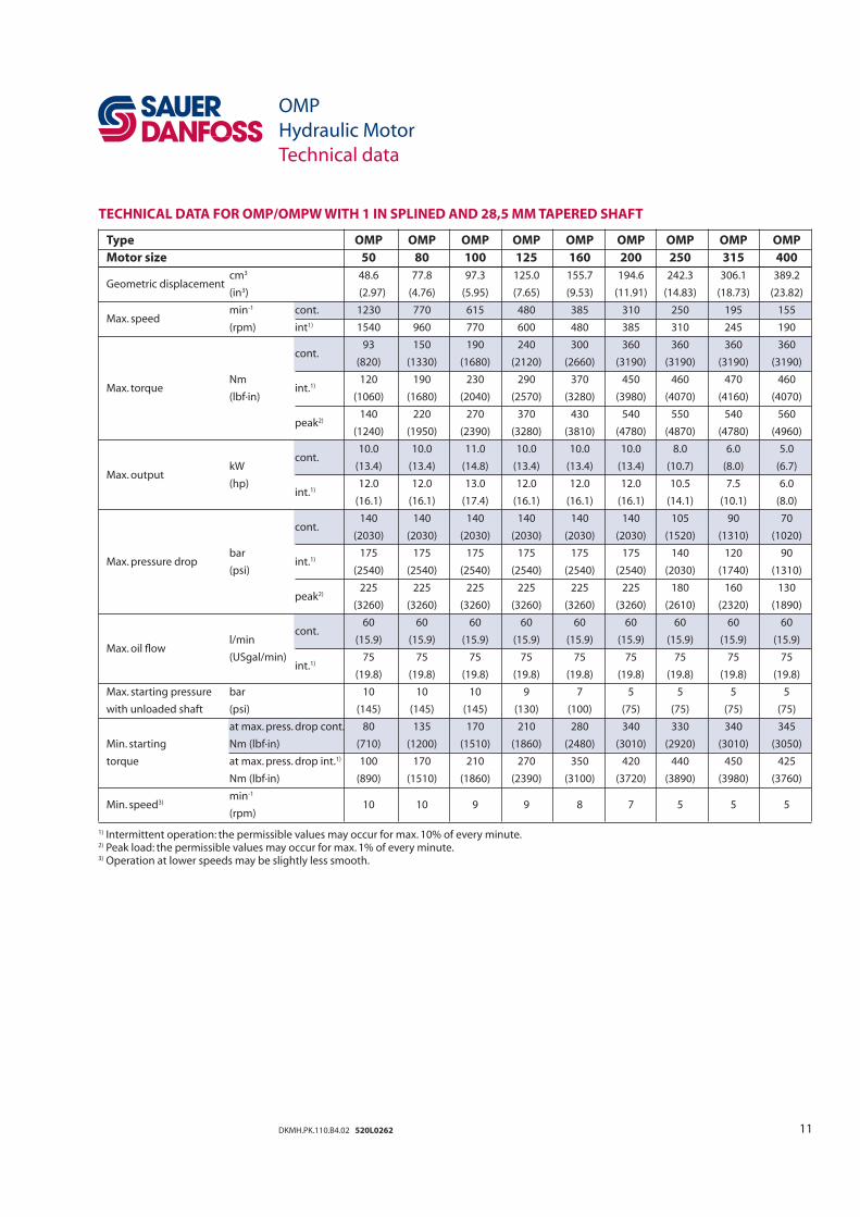
TECHNICAL DATA FOR OMP/OMPW WITH 1 IN SPLINED AND 28,5 MM TAPERED SHAFT
OMP
Hydraulic Motor
Technical data
Type OMP OMP OMP OMP OMP OMP OMP OMP OMP
Motor size 50 80 100 125 160 200 250 315 400
Geometric displacement cm3 48.6 77.8 97.3 125.0 155.7 194.6 242.3 306.1 389.2
(in3) (2.97) (4.76) (5.95) (7.65) (9.53) (11.91) (14.83) (18.73) (23.82)
Max. speed min-1 cont. 1230 770 615 480 385 310 250 195 155
(rpm) int1) 1540 960 770 600 480 385 310 245 190
cont.
93 150 190 240 300 360 360 360 360
(820) (1330) (1680) (2120) (2660) (3190) (3190) (3190) (3190)
Max. torque Nm
int.1) 120 190 230 290 370 450 460 470 460
(lbf·in) (1060) (1680) (2040) (2570) (3280) (3980) (4070) (4160) (4070)
peak2)
140 220 270 370 430 540 550 540 560
(1240) (1950) (2390) (3280) (3810) (4780) (4870) (4780) (4960)
cont.
10.0 10.0 11.0 10.0 10.0 10.0 8.0 6.0 5.0
Max. output kW (13.4) (13.4) (14.8) (13.4) (13.4) (13.4) (10.7) (8.0) (6.7)
(hp) int.1)
12.0 12.0 13.0 12.0 12.0 12.0 10.5 7.5 6.0
(16.1) (16.1) (17.4) (16.1) (16.1) (16.1) (14.1) (10.1) (8.0)
cont.
140 140 140 140 140 140 105 90 70
(2030) (2030) (2030) (2030) (2030) (2030) (1520) (1310) (1020)
Max. pressure drop bar
int.1) 175 175 175 175 175 175 140 120 90
(psi) (2540) (2540) (2540) (2540) (2540) (2540) (2030) (1740) (1310)
peak2)
225 225 225 225 225 225 180 160 130
(3260) (3260) (3260) (3260) (3260) (3260) (2610) (2320) (1890)
Max. oil fl ow
cont.
60 60 60 60 60 60 60 60 60
l/min (15.9) (15.9) (15.9) (15.9) (15.9) (15.9) (15.9) (15.9) (15.9)
(USgal/min) int.1)
75 75 75 75 75 75 75 75 75
(19.8) (19.8) (19.8) (19.8) (19.8) (19.8) (19.8) (19.8) (19.8)
Max. starting pressure bar 10 10 10 9 7 5 5 5 5
with unloaded shaft (psi) (145) (145) (145) (130) (100) (75) (75) (75) (75)
at max. press. drop cont. 80 135 170 210 280 340 330 340 345
Min. starting
Nm (lbf·in) (710) (1200) (1510) (1860) (2480) (3010) (2920) (3010) (3050)
torque at max. press. drop int.1) 100 170 210 270 350 420 440 450 425
Nm (lbf·in) (890) (1510) (1860) (2390) (3100) (3720) (3890) (3980) (3760)
Min. speed3) min-1
10 10 9 9 8 7 5 5 5 (rpm)
1) Intermittent operation: the permissible values may occur for max. 10% of every minute.2) Peak load: the permissible values may occur for max. 1% of every minute.3) Operation at lower speeds may be slightly less smooth.
12 DKMH.PK.110.B4.02 520L0262
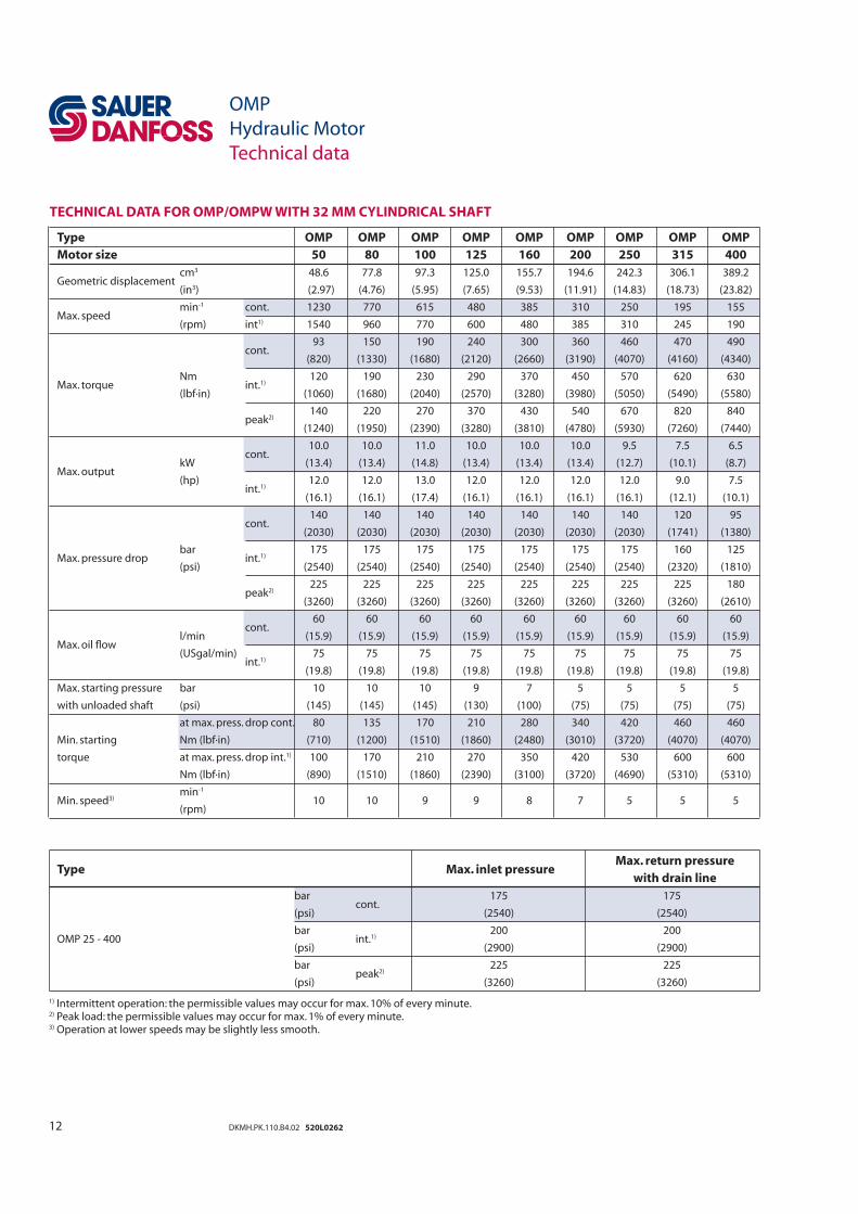
TECHNICAL DATA FOR OMP/OMPW WITH 32 MM CYLINDRICAL SHAFT
OMP
Hydraulic Motor
Technical data
Type OMP OMP OMP OMP OMP OMP OMP OMP OMP
Motor size 50 80 100 125 160 200 250 315 400
Geometric displacement cm3 48.6 77.8 97.3 125.0 155.7 194.6 242.3 306.1 389.2
(in3) (2.97) (4.76) (5.95) (7.65) (9.53) (11.91) (14.83) (18.73) (23.82)
Max. speed min-1 cont. 1230 770 615 480 385 310 250 195 155
(rpm) int1) 1540 960 770 600 480 385 310 245 190
cont.
93 150 190 240 300 360 460 470 490
(820) (1330) (1680) (2120) (2660) (3190) (4070) (4160) (4340)
Max. torque Nm
int.1) 120 190 230 290 370 450 570 620 630
(lbf·in) (1060) (1680) (2040) (2570) (3280) (3980) (5050) (5490) (5580)
peak2)
140 220 270 370 430 540 670 820 840
(1240) (1950) (2390) (3280) (3810) (4780) (5930) (7260) (7440)
cont.
10.0 10.0 11.0 10.0 10.0 10.0 9.5 7.5 6.5
Max. output kW (13.4) (13.4) (14.8) (13.4) (13.4) (13.4) (12.7) (10.1) (8.7)
(hp) int.1)
12.0 12.0 13.0 12.0 12.0 12.0 12.0 9.0 7.5
(16.1) (16.1) (17.4) (16.1) (16.1) (16.1) (16.1) (12.1) (10.1)
cont.
140 140 140 140 140 140 140 120 95
(2030) (2030) (2030) (2030) (2030) (2030) (2030) (1741) (1380)
Max. pressure drop bar
int.1) 175 175 175 175 175 175 175 160 125
(psi) (2540) (2540) (2540) (2540) (2540) (2540) (2540) (2320) (1810)
peak2)
225 225 225 225 225 225 225 225 180
(3260) (3260) (3260) (3260) (3260) (3260) (3260) (3260) (2610)
Max. oil fl ow
cont.
60 60 60 60 60 60 60 60 60
l/min (15.9) (15.9) (15.9) (15.9) (15.9) (15.9) (15.9) (15.9) (15.9)
(USgal/min) int.1)
75 75 75 75 75 75 75 75 75
(19.8) (19.8) (19.8) (19.8) (19.8) (19.8) (19.8) (19.8) (19.8)
Max. starting pressure bar 10 10 10 9 7 5 5 5 5
with unloaded shaft (psi) (145) (145) (145) (130) (100) (75) (75) (75) (75)
at max. press. drop cont. 80 135 170 210 280 340 420 460 460
Min. starting
Nm (lbf·in) (710) (1200) (1510) (1860) (2480) (3010) (3720) (4070) (4070)
torque at max. press. drop int.1) 100 170 210 270 350 420 530 600 600
Nm (lbf·in) (890) (1510) (1860) (2390) (3100) (3720) (4690) (5310) (5310)
Min. speed3) min-1
10 10 9 9 8 7 5 5 5 (rpm)
Type Max. inlet pressure Max. return pressure
with drain line
bar cont.
175 175
(psi) (2540) (2540)
OMP 25 - 400 bar
int.1) 200 200
(psi) (2900) (2900)
bar peak2)
225 225
(psi) (3260) (3260)
1) Intermittent operation: the permissible values may occur for max. 10% of every minute.2) Peak load: the permissible values may occur for max. 1% of every minute.3) Operation at lower speeds may be slightly less smooth.
13DKMH.PK.110.B4.02 520L0262
OMP
Hydraulic Motor
Technical data – max. permissible shaft seal pressure
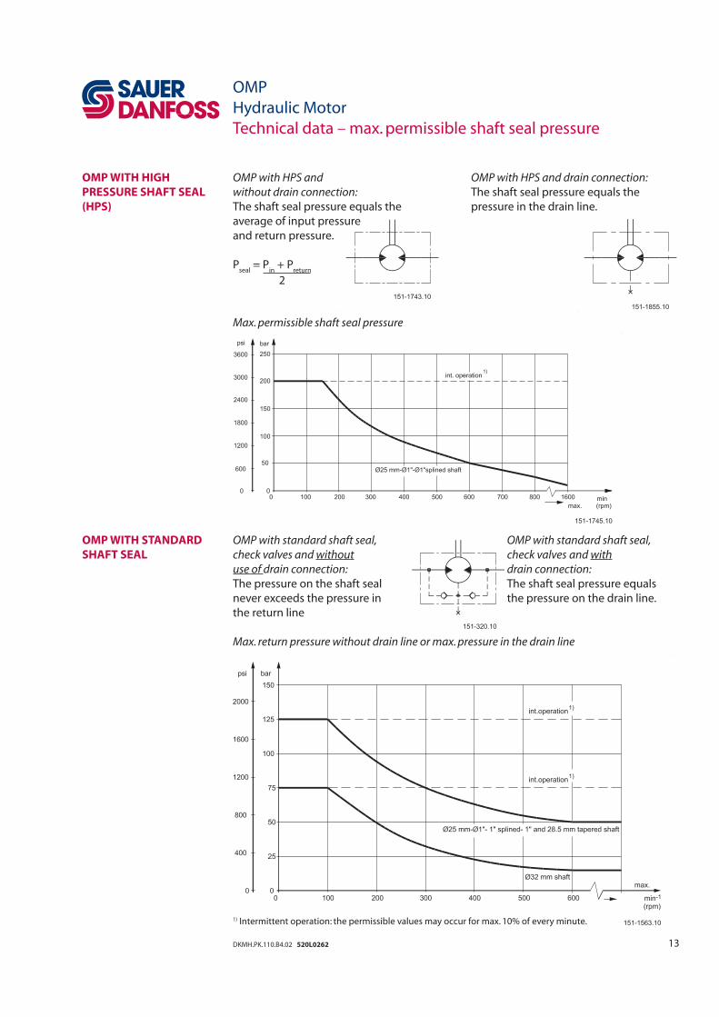
OMP WITH HIGH
PRESSURE SHAFT SEAL
(HPS)
OMP WITH STANDARD
SHAFT SEAL
OMP with HPS and OMP with HPS and drain connection:
without drain connection: The shaft seal pressure equals the
The shaft seal pressure equals the pressure in the drain line.
average of input pressure
and return pressure.
Pseal
= Pin
+ Preturn
2
Max. permissible shaft seal pressure
OMP with standard shaft seal, OMP with standard shaft seal,
check valves and without check valves and with
use of drain connection: drain connection:
The pressure on the shaft seal The shaft seal pressure equals
never exceeds the pressure in the pressure on the drain line.
the return line
Max. return pressure without drain line or max. pressure in the drain line
1) Intermittent operation: the permissible values may occur for max. 10% of every minute.
14 DKMH.PK.110.B4.02 520L0262
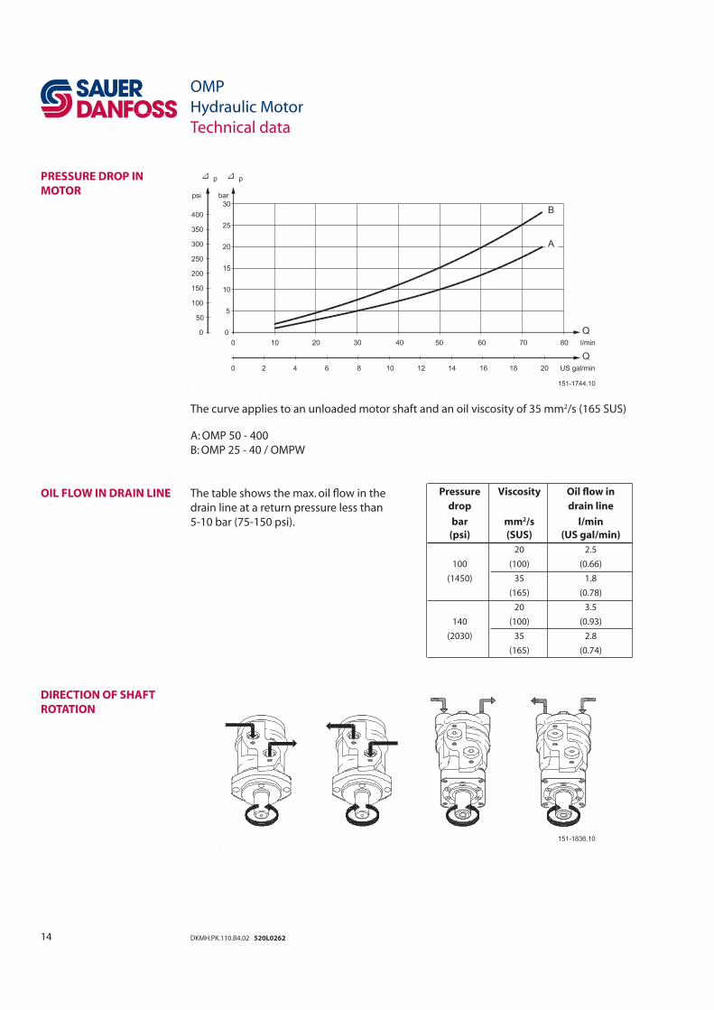
The curve applies to an unloaded motor shaft and an oil viscosity of 35 mm2/s (165 SUS)
A: OMP 50 - 400
B: OMP 25 - 40 / OMPW
The table shows the max. oil fl ow in the
drain line at a return pressure less than
5-10 bar (75-150 psi).
PRESSURE DROP IN
MOTOR
OIL FLOW IN DRAIN LINE
DIRECTION OF SHAFT
ROTATION
OMP
Hydraulic Motor
Technical data
Pressure Viscosity Oil fl ow in
drop drain line
bar mm2/s l/min
(psi) (SUS) (US gal/min)
100
20 2.5
(100) (0.66)
(1450) 35 1.8
(165) (0.78)
140
20 3.5
(100) (0.93)
(2030) 35 2.8
(165) (0.74)
15DKMH.PK.110.B4.02 520L0262
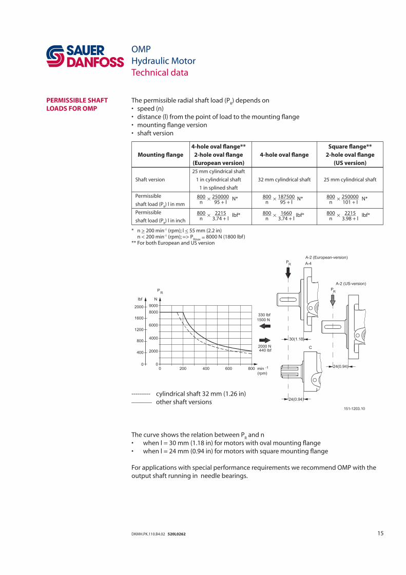
The permissible radial shaft load (PR) depends on
• speed (n)
• distance (l) from the point of load to the mounting fl ange
• mounting fl ange version
• shaft version
--------- cylindrical shaft 32 mm (1.26 in)______ other shaft versions
The curve shows the relation between PR and n
• when l = 30 mm (1.18 in) for motors with oval mounting fl ange
• when l = 24 mm (0.94 in) for motors with square mounting fl ange
For applications with special performance requirements we recommend OMP with the
output shaft running in needle bearings.
4-hole oval fl ange** Square fl ange**
Mounting fl ange 2-hole oval fl ange 4-hole oval fl ange 2-hole oval fl ange
(European version) (US version)
25 mm cylindrical shaft
Shaft version 1 in cylindrical shaft 32 mm cylindrical shaft 25 mm cylindrical shaft
1 in splined shaft
Permissible 800 ×
250000 N* 800 ×
187500 N* 800 ×
250000 N*shaft load (P
R) l in mm n 95 + l n 95 + l n 101 + l
Permissible 800 ×
2215 lbf* 800 ×
1660 lbf* 800 ×
2215 lbf*shaft load (P
R) l in inch n 3.74 + l n 3.74 + l n 3.98 + l
* n > 200 min-1 (rpm); l < 55 mm (2.2 in) n < 200 min-1 (rpm); => P
Rmax = 8000 N (1800 lbf )** For both European and US version
OMP
Hydraulic Motor
Technical data
PERMISSIBLE SHAFT
LOADS FOR OMP
16 DKMH.PK.110.B4.02 520L0262
OMP
Hydraulic Motor
Technical data
PERMISSIBLE SHAFT
LOAD FOR OMPW WITH
SLIDE BEARINGS
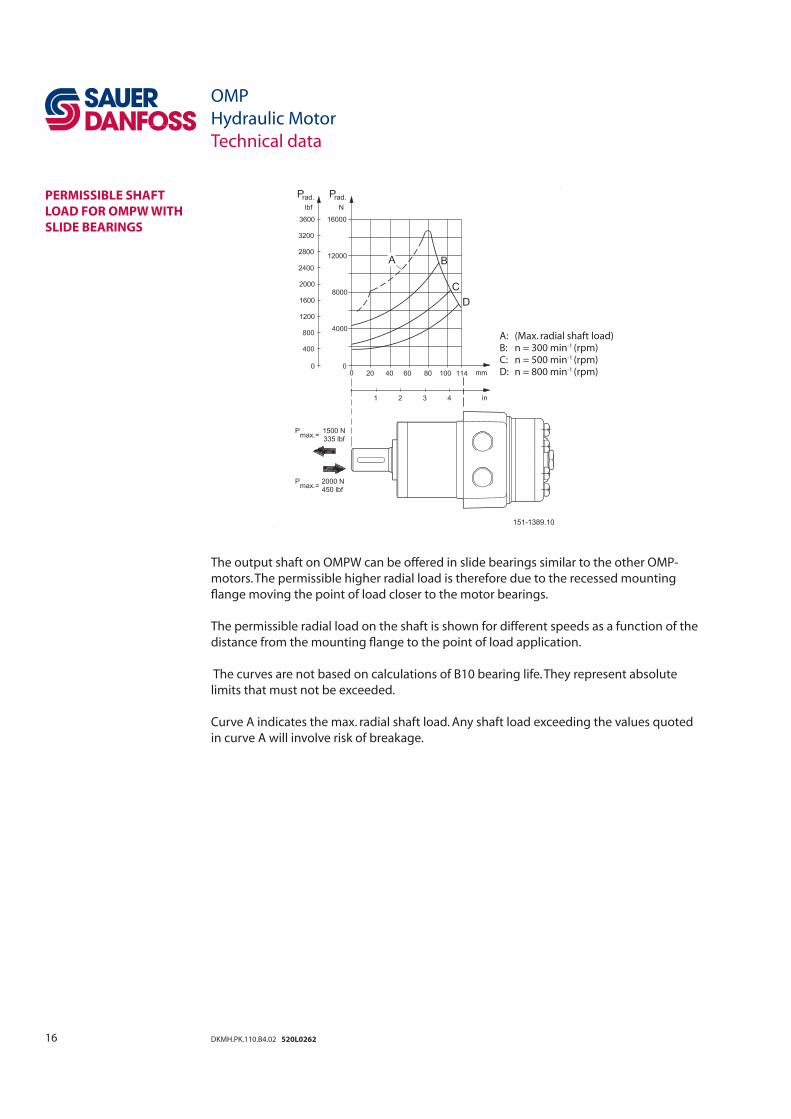
The output shaft on OMPW can be offered in slide bearings similar to the other OMP-
motors. The permissible higher radial load is therefore due to the recessed mounting
fl ange moving the point of load closer to the motor bearings.
The permissible radial load on the shaft is shown for different speeds as a function of the
distance from the mounting fl ange to the point of load application.
The curves are not based on calculations of B10 bearing life. They represent absolute
limits that must not be exceeded.
Curve A indicates the max. radial shaft load. Any shaft load exceeding the values quoted
in curve A will involve risk of breakage.
A: (Max. radial shaft load) B: n = 300 min-1 (rpm) C: n = 500 min-1 (rpm) D: n = 800 min-1 (rpm)
17DKMH.PK.110.B4.02 520L0262
OMP
Hydraulic Motor
Technical data
PERMISSIBLE SHAFT
LOAD FOR OMPW N WITH
NEEDLE BEARING
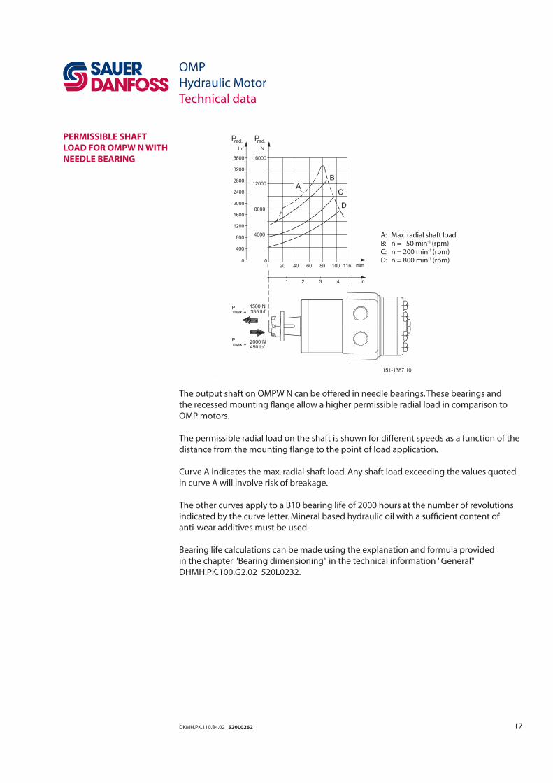
The output shaft on OMPW N can be offered in needle bearings. These bearings and
the recessed mounting fl ange allow a higher permissible radial load in comparison to
OMP motors.
The permissible radial load on the shaft is shown for different speeds as a function of the
distance from the mounting fl ange to the point of load application.
Curve A indicates the max. radial shaft load. Any shaft load exceeding the values quoted
in curve A will involve risk of breakage.
The other curves apply to a B10 bearing life of 2000 hours at the number of revolutions
indicated by the curve letter. Mineral based hydraulic oil with a suffi cient content of
anti-wear additives must be used.
Bearing life calculations can be made using the explanation and formula provided
in the chapter "Bearing dimensioning" in the technical information "General"
DHMH.PK.100.G2.02 520L0232.
A: Max. radial shaft load B: n = 50 min-1 (rpm) C: n = 200 min-1 (rpm) D: n = 800 min-1 (rpm)
18 DKMH.PK.110.B4.02 520L0262
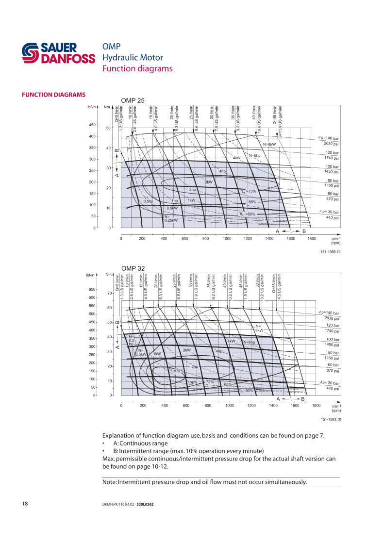
Explanation of function diagram use, basis and conditions can be found on page 7.
• A: Continuous range
• B: Intermittent range (max. 10% operation every minute)
Max. permissible continuous/intermittent pressure drop for the actual shaft version can
be found on page 10-12.
Note: Intermittent pressure drop and oil fl ow must not occur simultaneously.
FUNCTION DIAGRAMS
OMP
Hydraulic Motor
Function diagrams
19DKMH.PK.110.B4.02 520L0262
OMP
Hydraulic Motor
Function diagrams
FUNCTION DIAGRAMS
Explanation of function diagram use, basis and conditions can be found on page 7.
• A: Continuous range
• B: Intermittent range (max. 10% operation every minute)
Max. permissible continuous/intermittent pressure drop for the actual shaft version can
be found on page 10-12.
Note: Intermittent pressure drop and oil fl ow must not occur simultaneously.
20 DKMH.PK.110.B4.02 520L0262
OMP
Hydraulic Motor
Function diagrams
FUNCTION DIAGRAMS
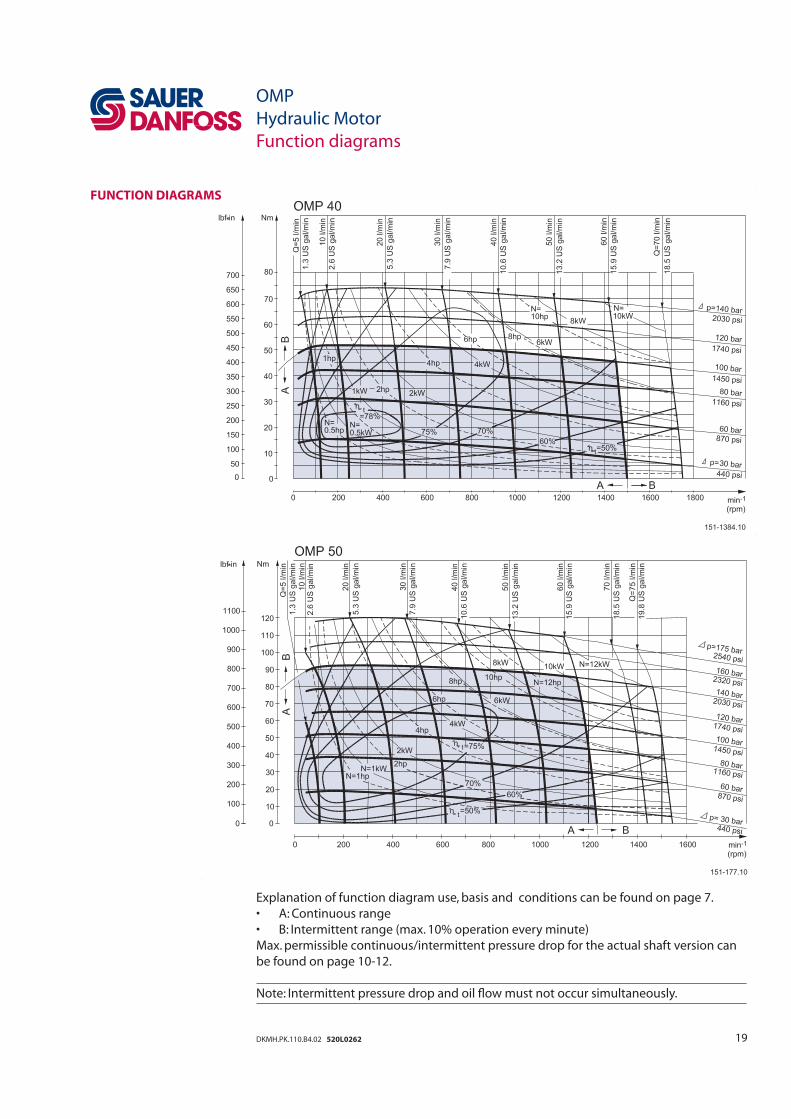
Explanation of function diagram use, basis and conditions can be found on page 7.
• A: Continuous range
• B: Intermittent range (max. 10% operation every minute)
Max. permissible continuous/intermittent pressure drop for the actual shaft version can
be found on page 10-12.
Note: Intermittent pressure drop and oil fl ow must not occur simultaneously.
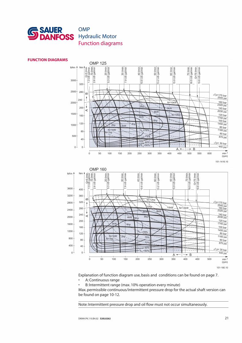
21DKMH.PK.110.B4.02 520L0262
OMP
Hydraulic Motor
Function diagrams
Explanation of function diagram use, basis and conditions can be found on page 7.
• A: Continuous range
• B: Intermittent range (max. 10% operation every minute)
Max. permissible continuous/intermittent pressure drop for the actual shaft version can
be found on page 10-12.
Note: Intermittent pressure drop and oil fl ow must not occur simultaneously.
FUNCTION DIAGRAMS
22 DKMH.PK.110.B4.02 520L0262
OMP
Hydraulic Motor
Function diagrams
FUNCTION DIAGRAMS
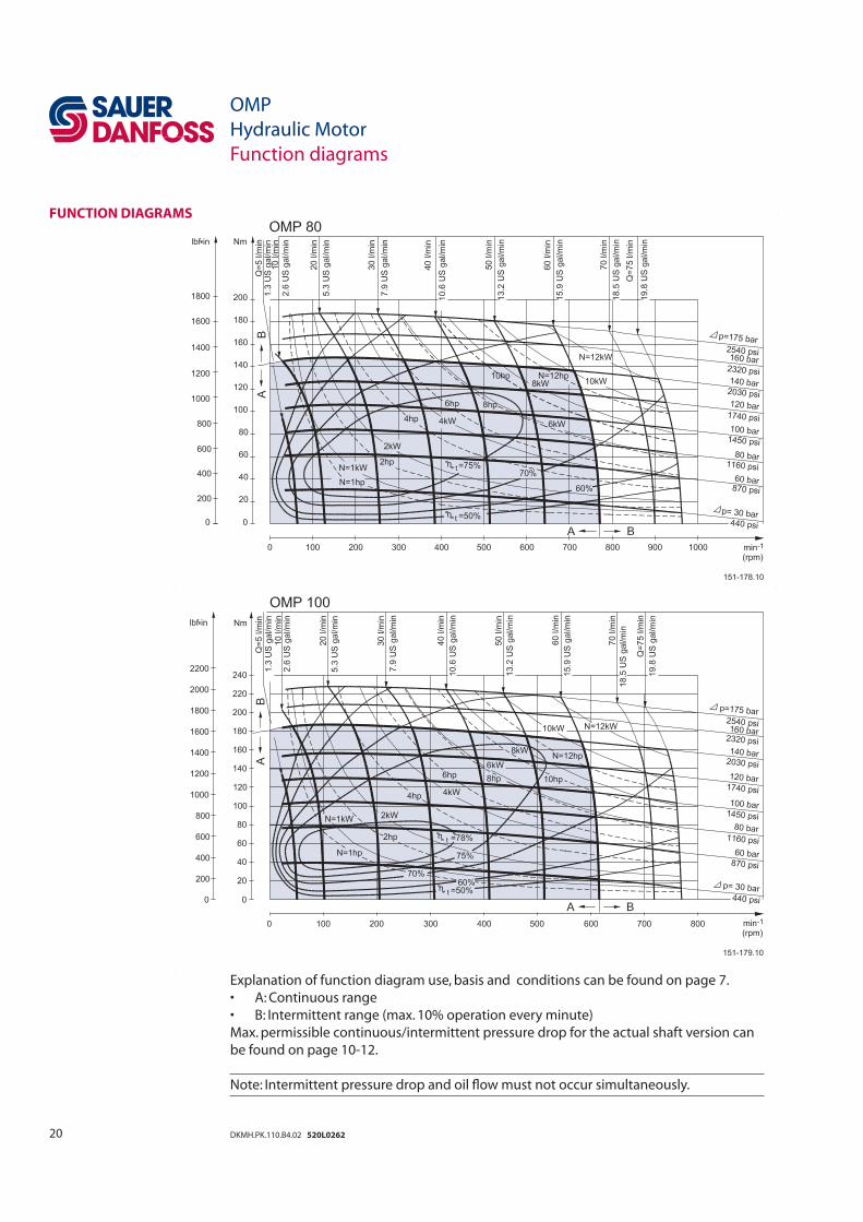
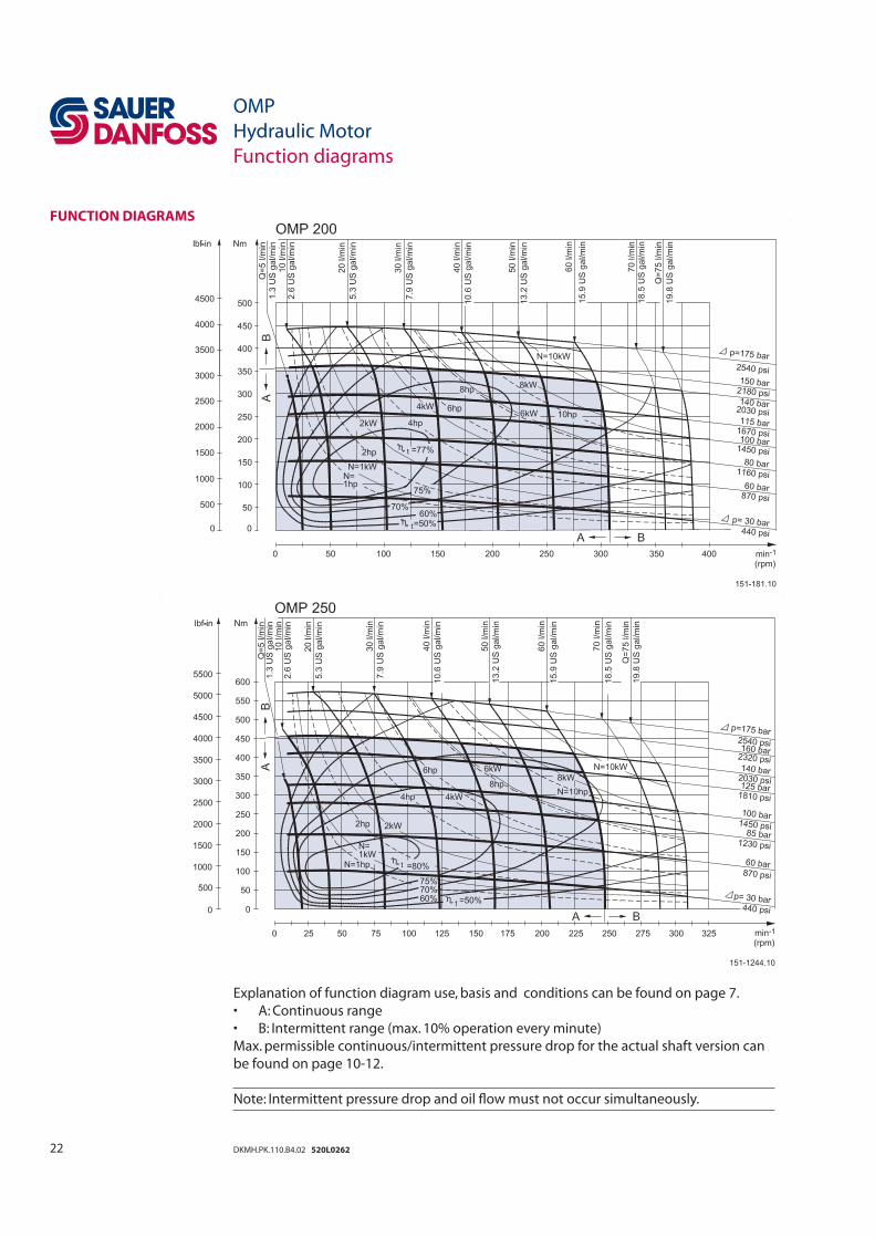
Explanation of function diagram use, basis and conditions can be found on page 7.
• A: Continuous range
• B: Intermittent range (max. 10% operation every minute)
Max. permissible continuous/intermittent pressure drop for the actual shaft version can
be found on page 10-12.
Note: Intermittent pressure drop and oil fl ow must not occur simultaneously.
23DKMH.PK.110.B4.02 520L0262
OMP
Hydraulic Motor
Function diagrams
FUNCTION DIAGRAMS
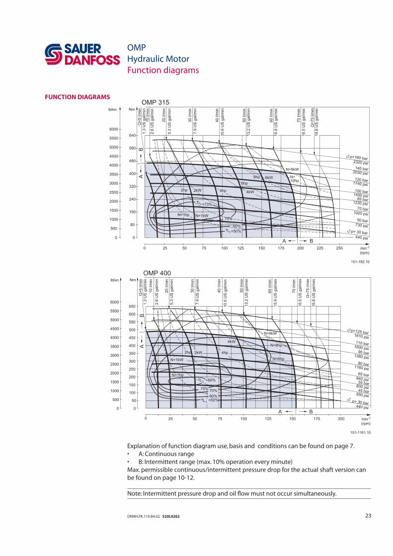
Explanation of function diagram use, basis and conditions can be found on page 7.
• A: Continuous range
• B: Intermittent range (max. 10% operation every minute)
Max. permissible continuous/intermittent pressure drop for the actual shaft version can
be found on page 10-12.
Note: Intermittent pressure drop and oil fl ow must not occur simultaneously.
24 DKMH.PK.110.B4.02 520L0262
OMP
Hydraulic Motor
Shaft version
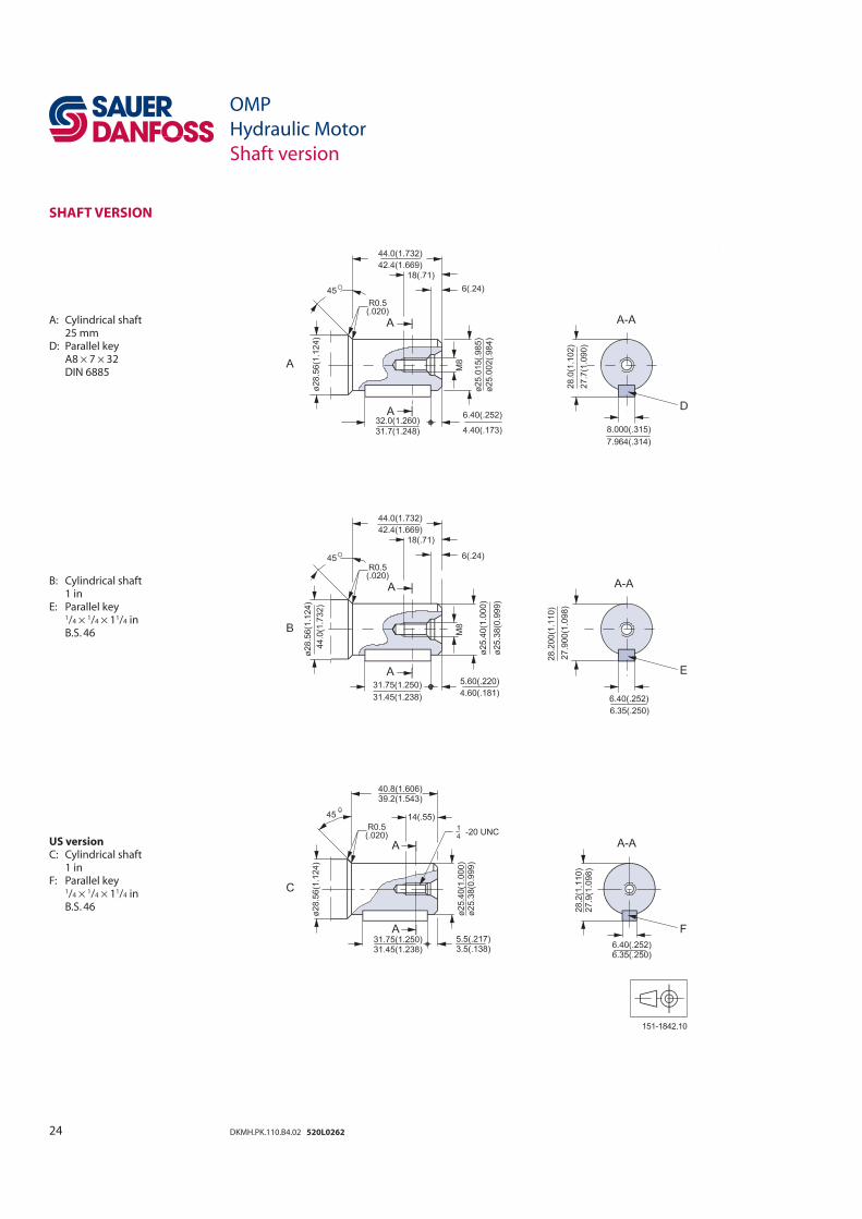
SHAFT VERSION
A: Cylindrical shaft 25 mmD: Parallel key A8 × 7 × 32 DIN 6885
B: Cylindrical shaft 1 inE: Parallel key 1/4 × 1/4 × 11/4 in B.S. 46
US versionC: Cylindrical shaft 1 inF: Parallel key 1/4 × 1/4 × 11/4 in B.S. 46
151-1842.10
25DKMH.PK.110.B4.02 520L0262
OMP
Hydraulic Motor
Shaft version
SHAFT VERSION
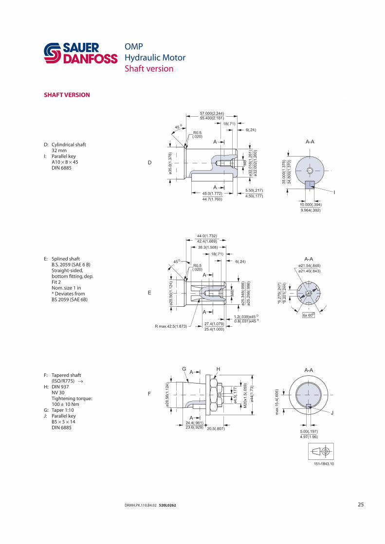
D: Cylindrical shaft 32 mmI: Parallel key A10 × 8 × 45 DIN 6885
E: Splined shaft B.S. 2059 (SAE 6 B) Straight-sided, bottom fi tting, dep. Fit 2 Nom. size 1 in * Deviates from BS 2059 (SAE 6B)
F: Tapered shaft (ISO/R775) → H: DIN 937 NV 30 Tightening torque: 100 ± 10 NmG: Taper 1:10J: Parallel key B5 × 5 × 14 DIN 6885
151-1843.10
26 DKMH.PK.110.B4.02 520L0262
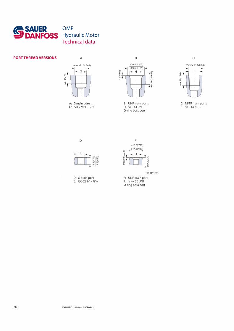
A: G main ports B: UNF main ports C: NPTF main ports G: ISO 228/1 - G1/2 H: 7/8 - 14 UNF I: 1/2 - 14 NPTF O-ring boss port
D: G drain port F: UNF drain port E: ISO 228/1 - G1/4 J: 7/16 - 20 UNF O-ring boss port
OMP
Hydraulic Motor
Technical data
PORT THREAD VERSIONS
151-1844.10
27DKMH.PK.110.B4.02 520L0262
OMP
Hydraulic Motor
Dimensions – European version
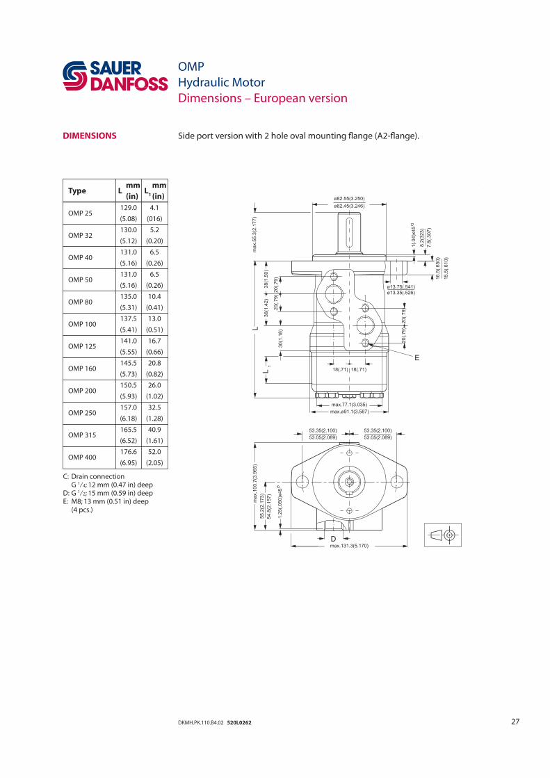
DIMENSIONS Side port version with 2 hole oval mounting fl ange (A2-fl ange).
Type
L mm
L1
mm
(in) (in)
OMP 25 129.0 4.1
(5.08) (016)
OMP 32 130.0 5.2
(5.12) (0.20)
OMP 40 131.0 6.5
(5.16) (0.26)
OMP 50 131.0 6.5
(5.16) (0.26)
OMP 80 135.0 10.4
(5.31) (0.41)
OMP 100 137.5 13.0
(5.41) (0.51)
OMP 125 141.0 16.7
(5.55) (0.66)
OMP 160 145.5 20.8
(5.73) (0.82)
OMP 200 150.5 26.0
(5.93) (1.02)
OMP 250 157.0 32.5
(6.18) (1.28)
OMP 315 165.5 40.9
(6.52) (1.61)
OMP 400 176.6 52.0
(6.95) (2.05)
C: Drain connection G 1⁄4; 12 mm (0.47 in) deepD: G 1⁄2; 15 mm (0.59 in) deepE: M8; 13 mm (0.51 in) deep (4 pcs.)
28 DKMH.PK.110.B4.02 520L0262
DIMENSIONS
Type
L mm
L1
mm
(in) (in)
OMP 25 129.0 4.1
(5.08) (016)
OMP 32 130.0 5.2
(5.12) (0.20)
OMP 40 131.0 6.5
(5.16) (0.26)
OMP 50 131.0 6.5
(5.16) (0.26)
OMP 80 135.0 10.4
(5.31) (0.41)
OMP 100 137.5 13.0
(5.41) (0.51)
OMP 125 141.0 16.7
(5.55) (0.66)
OMP 160 145.5 20.8
(5.73) (0.82)
OMP 200 150.5 26.0
(5.93) (1.02)
OMP 250 157.0 32.5
(6.18) (1.28)
OMP 315 165.5 40.9
(6.52) (1.61)
OMP 400 176.6 52.0
(6.95) (2.05)
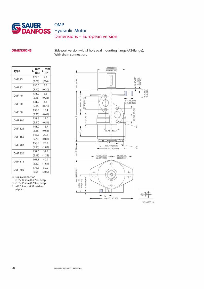
C: Drain connection G 1⁄4; 12 mm (0.47 in) deepD: G 1⁄2; 15 mm (0.59 in) deepE: M8; 13 mm (0.51 in) deep (4 pcs.)
Side port version with 2 hole oval mounting fl ange (A2-fl ange).
With drain connection.
OMP
Hydraulic Motor
Dimensions – European version
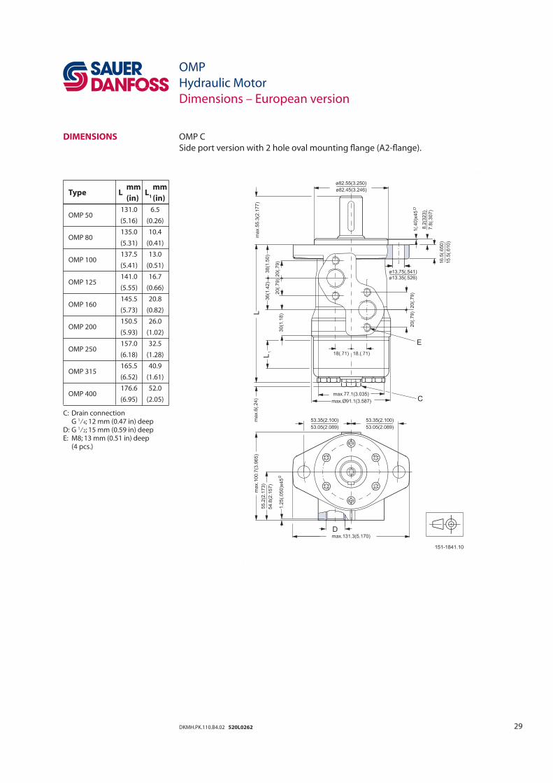
29DKMH.PK.110.B4.02 520L0262
Type
L mm
L1
mm
(in) (in)
OMP 50 131.0 6.5
(5.16) (0.26)
OMP 80 135.0 10.4
(5.31) (0.41)
OMP 100 137.5 13.0
(5.41) (0.51)
OMP 125 141.0 16.7
(5.55) (0.66)
OMP 160 145.5 20.8
(5.73) (0.82)
OMP 200 150.5 26.0
(5.93) (1.02)
OMP 250 157.0 32.5
(6.18) (1.28)
OMP 315 165.5 40.9
(6.52) (1.61)
OMP 400 176.6 52.0
(6.95) (2.05)
C: Drain connection G 1⁄4; 12 mm (0.47 in) deepD: G 1⁄2; 15 mm (0.59 in) deepE: M8; 13 mm (0.51 in) deep (4 pcs.)
DIMENSIONS OMP C
Side port version with 2 hole oval mounting fl ange (A2-fl ange).
OMP
Hydraulic Motor
Dimensions – European version
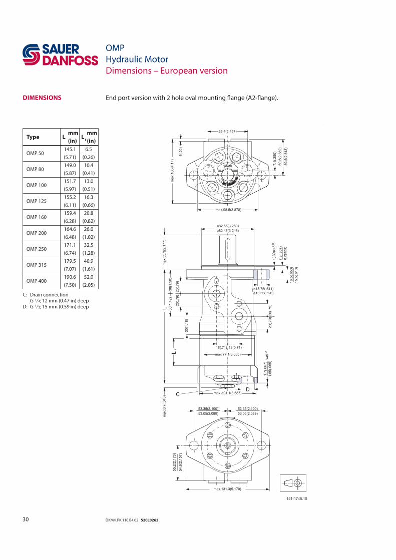
30 DKMH.PK.110.B4.02 520L0262
Type
L mm
L1
mm
(in) (in)
OMP 50 145.1 6.5
(5.71) (0.26)
OMP 80 149.0 10.4
(5.87) (0.41)
OMP 100 151.7 13.0
(5.97) (0.51)
OMP 125 155.2 16.3
(6.11) (0.66)
OMP 160 159.4 20.8
(6.28) (0.82)
OMP 200 164.6 26.0
(6.48) (1.02)
OMP 250 171.1 32.5
(6.74) (1.28)
OMP 315 179.5 40.9
(7.07) (1.61)
OMP 400 190.6 52.0
(7.50) (2.05)
C: Drain connection G 1⁄4; 12 mm (0.47 in) deepD: G 1⁄2; 15 mm (0.59 in) deep
DIMENSIONS End port version with 2 hole oval mounting fl ange (A2-fl ange).
OMP
Hydraulic Motor
Dimensions – European version
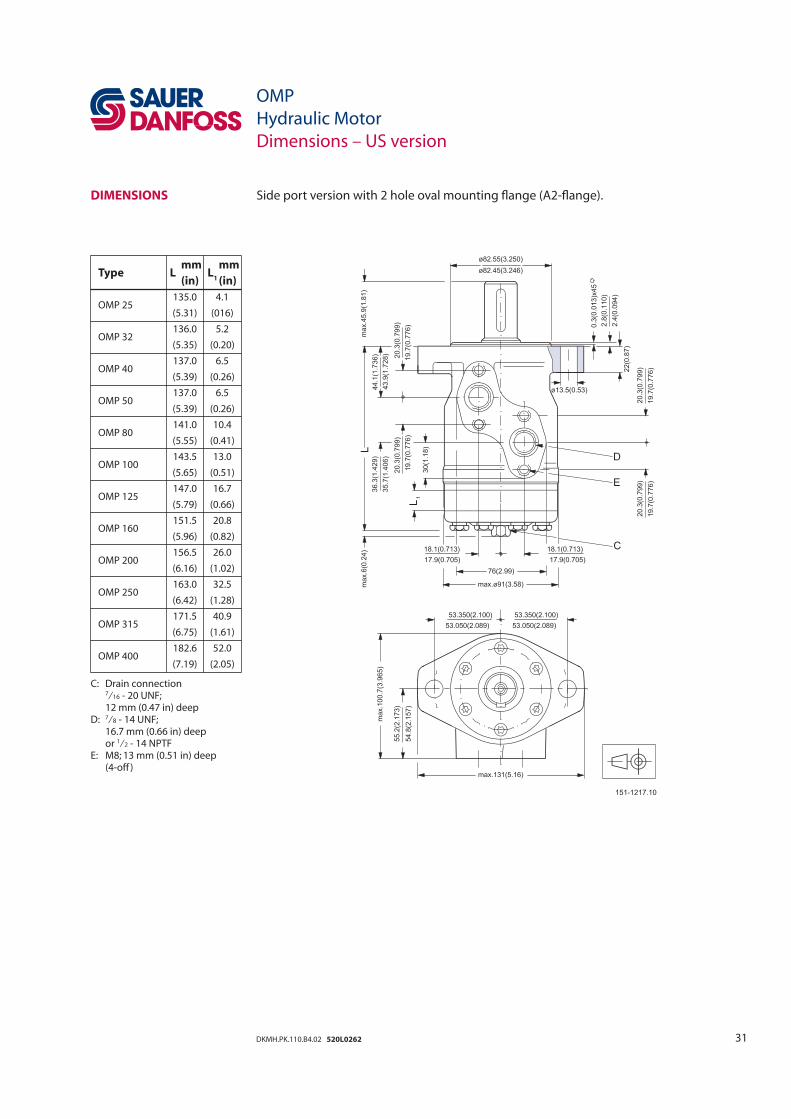
31DKMH.PK.110.B4.02 520L0262
DIMENSIONS Side port version with 2 hole oval mounting fl ange (A2-fl ange).
OMP
Hydraulic Motor
Dimensions – US version
Type
L mm
L1
mm
(in) (in)
OMP 25 135.0 4.1
(5.31) (016)
OMP 32 136.0 5.2
(5.35) (0.20)
OMP 40 137.0 6.5
(5.39) (0.26)
OMP 50 137.0 6.5
(5.39) (0.26)
OMP 80 141.0 10.4
(5.55) (0.41)
OMP 100 143.5 13.0
(5.65) (0.51)
OMP 125 147.0 16.7
(5.79) (0.66)
OMP 160 151.5 20.8
(5.96) (0.82)
OMP 200 156.5 26.0
(6.16) (1.02)
OMP 250 163.0 32.5
(6.42) (1.28)
OMP 315 171.5 40.9
(6.75) (1.61)
OMP 400 182.6 52.0
(7.19) (2.05)
C: Drain connection 7⁄16 - 20 UNF; 12 mm (0.47 in) deepD: 7⁄8 - 14 UNF; 16.7 mm (0.66 in) deep or 1⁄2 - 14 NPTFE: M8; 13 mm (0.51 in) deep (4-off )
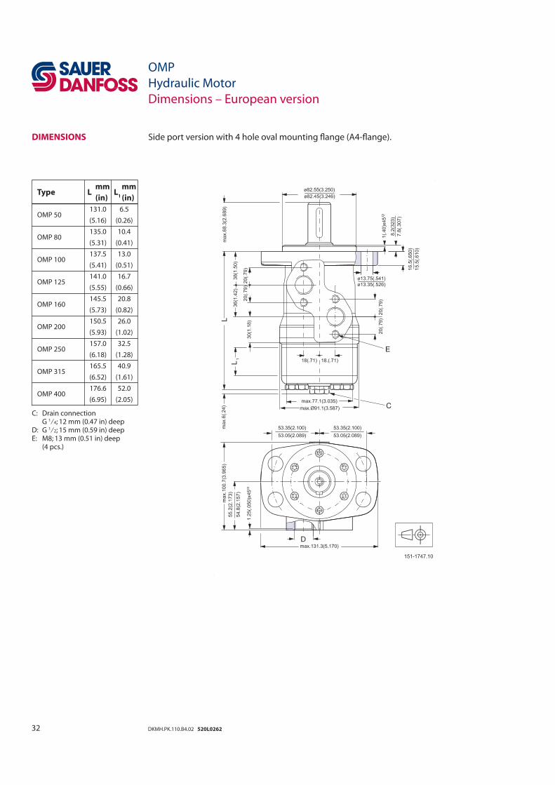
32 DKMH.PK.110.B4.02 520L0262
Type
L mm
L1
mm
(in) (in)
OMP 50 131.0 6.5
(5.16) (0.26)
OMP 80 135.0 10.4
(5.31) (0.41)
OMP 100 137.5 13.0
(5.41) (0.51)
OMP 125 141.0 16.7
(5.55) (0.66)
OMP 160 145.5 20.8
(5.73) (0.82)
OMP 200 150.5 26.0
(5.93) (1.02)
OMP 250 157.0 32.5
(6.18) (1.28)
OMP 315 165.5 40.9
(6.52) (1.61)
OMP 400 176.6 52.0
(6.95) (2.05)
C: Drain connection G 1⁄4; 12 mm (0.47 in) deepD: G 1⁄2; 15 mm (0.59 in) deepE: M8; 13 mm (0.51 in) deep (4 pcs.)
DIMENSIONS Side port version with 4 hole oval mounting fl ange (A4-fl ange).
OMP
Hydraulic Motor
Dimensions – European version
33DKMH.PK.110.B4.02 520L0262
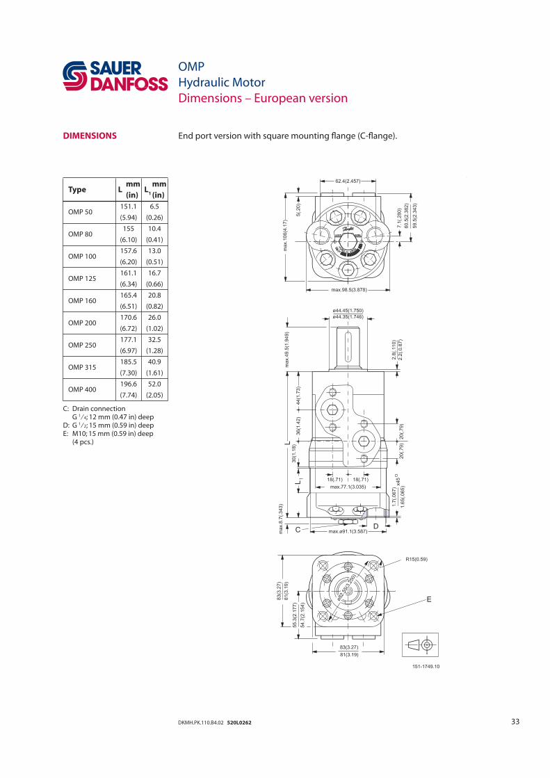
Type
L mm
L1
mm
(in) (in)
OMP 50 151.1 6.5
(5.94) (0.26)
OMP 80 155 10.4
(6.10) (0.41)
OMP 100 157.6 13.0
(6.20) (0.51)
OMP 125 161.1 16.7
(6.34) (0.66)
OMP 160 165.4 20.8
(6.51) (0.82)
OMP 200 170.6 26.0
(6.72) (1.02)
OMP 250 177.1 32.5
(6.97) (1.28)
OMP 315 185.5 40.9
(7.30) (1.61)
OMP 400 196.6 52.0
(7.74) (2.05)
C: Drain connection G 1⁄4; 12 mm (0.47 in) deepD: G 1⁄2; 15 mm (0.59 in) deepE: M10; 15 mm (0.59 in) deep (4 pcs.)
DIMENSIONS End port version with square mounting fl ange (C-fl ange).
OMP
Hydraulic Motor
Dimensions – European version
34 DKMH.PK.110.B4.02 520L0262
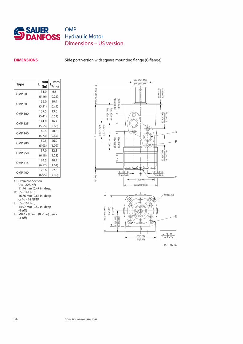
Type
L mm
L1
mm
(in) (in)
OMP 50 131.0 6.5
(5.16) (0.26)
OMP 80 135.0 10.4
(5.31) (0.41)
OMP 100 137.5 13.0
(5.41) (0.51)
OMP 125 141.0 16.7
(5.55) (0.66)
OMP 160 145.5 20.8
(5.73) (0.82)
OMP 200 150.5 26.0
(5.93) (1.02)
OMP 250 157.0 32.5
(6.18) (1.28)
OMP 315 165.5 40.9
(6.52) (1.61)
OMP 400 176.6 52.0
(6.95) (2.05)
C: Drain connection 7⁄16 - 20 UNF; 11.94 mm (0.47 in) deepD: 7⁄8 - 14 UNF; 16.76 mm (0.66 in) deep or 1⁄2 - 14 NPTFE: 3⁄8 - 16 UNC; 14.97 mm (0.59 in) deep (4-off )F: M8; 12.95 mm (0.51 in) deep (4-off )
DIMENSIONS Side port version with square mounting fl ange (C-fl ange).
OMP
Hydraulic Motor
Dimensions – US version
35DKMH.PK.110.B4.02 520L0262
OMP
Hydraulic Motor
Dimensions – European version
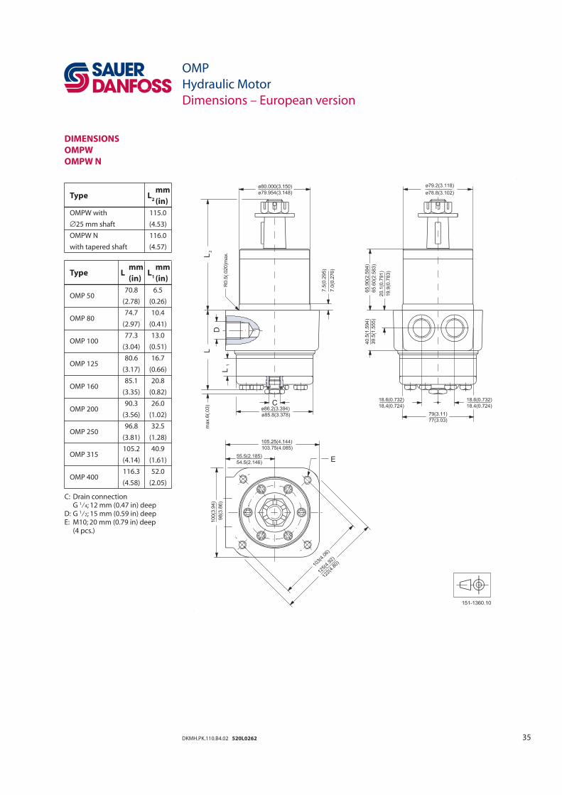
Type
L2
mm
(in)
OMPW with 115.0
∅25 mm shaft (4.53)
OMPW N 116.0
with tapered shaft (4.57)
DIMENSIONS
OMPW
OMPW N
Type
L mm
L1
mm
(in) (in)
OMP 50 70.8 6.5
(2.78) (0.26)
OMP 80 74.7 10.4
(2.97) (0.41)
OMP 100 77.3 13.0
(3.04) (0.51)
OMP 125 80.6 16.7
(3.17) (0.66)
OMP 160 85.1 20.8
(3.35) (0.82)
OMP 200 90.3 26.0
(3.56) (1.02)
OMP 250 96.8 32.5
(3.81) (1.28)
OMP 315 105.2 40.9
(4.14) (1.61)
OMP 400 116.3 52.0
(4.58) (2.05)
C: Drain connection G 1⁄4; 12 mm (0.47 in) deepD: G 1⁄2; 15 mm (0.59 in) deepE: M10; 20 mm (0.79 in) deep (4 pcs.)
Related Documents