Cat. No. I544-E1-06 USER’S MANUAL OMNUC W SERIES MODELS R88M-W@ (AC Servomotors) MODELS R88D-WN@-ML2 (AC Servo Drivers) AC SERVOMOTORS/SERVO DRIVERS WITH BUILT-IN MECHATROLINK-II COMMUNICATIONS

Welcome message from author
This document is posted to help you gain knowledge. Please leave a comment to let me know what you think about it! Share it to your friends and learn new things together.
Transcript

Cat. No. I544-E1-06
USER’S MANUAL
OMNUC W SERIES
MODELS R88M-W@(AC Servomotors)
MODELS R88D-WN@-ML2(AC Servo Drivers)
AC SERVOMOTORS/SERVO DRIVERSWITH BUILT-IN MECHATROLINK-II COMMUNICATIONS
Thank you for choosing this OMNUC W-series product. Proper use and handling of the prod-uct will ensure proper product performance, will length product life, and may prevent possibleaccidents.Please read this manual thoroughly and handle and operate the product with care.
1.To ensure safe and proper use of your OMRON Servomotors and Servo Drivers, please read this manual(Cat. No. I544-E1) to gain sufficient knowledge of the products, safety information, and precautions beforeactual use.
2.The products are illustrated without covers and shieldings to enable showing better detail in this manual.For actual use of the products, make sure to use the covers and shieldings as specified.
3.Copies of this manual and other related manuals must be delivered to the actual end users of the products.4.Please keep a copy of this manual close at hand for future reference.
5. If a product has been left unused for a long time, please consult with your OMRON sales representative.
Items to Check After Unpacking1.Check the following items after removing the product from the package:
• Has the correct product been delivered (i.e., the correct model number and specifications)?
• Has the product been damaged in shipping?
• Are any screws or bolts loose?
NOTICE1.This manual describes the functions of the product and relations with other products. You
should assume that anything not described in this manual is not possible.
2.Although care has been given in documenting the product, please contact your OMRON representative if you have any suggestions on improving this manual.
3.The product contains dangerous high voltages inside. Turn OFF the power and wait for at leastfive minutes to allow power to discharge before handling or working with the product. Neverattempt to disassemble the product.
4.We recommend that you add the following precautions to any instruction manuals you preparefor the system into which the product is being installed.
• Precautions on the dangers of high-voltage equipment.
• Precautions on touching the terminals of the product even after power has been turnedOFF. (These terminals are live even with the power turned OFF.)
5.Specifications and functions may be changed without notice in order to improve product per-formance.
6.Positive and negative rotation of AC Servomotors described in this manual are defined as look-ing at the end of the output shaft of the motor as follows: counterclockwise rotation is positiveand clockwise rotation is negative.
7.Do not perform withstand-voltage or other megameter tests on the product. Doing so maydamage internal components.
8.Servomotors and Servo Drivers have a finite service life. Be sure to keep replacement prod-ucts on hand and to consider the operating environment and other conditions affecting the ser-vice life.
9.The OMNUC W Series can control both incremental and absolute encoders. Differences infunctions or specifications according to the encoder type are indicated in this manual. Be sureto check the model that is being used, and follow the relevant specifications.
• Servomotors with incremental encoders: R88M-W@H-@• Servomotors with absolute encoders: R88M-W@T-@

USER’S MANUAL
OMNUC W SERIES
MODELS R88M-W@(AC Servomotors)
MODELS R88D-WN@-ML2(AC Servo Drivers)
AC SERVOMOTORS/SERVO DRIVERSWITH BUILT-IN MECHATROLINK-II COMMUNICATIONS

Notice:OMRON products are manufactured for use according to proper procedures by a qualified operatorand only for the purposes described in this manual.
The following conventions are used to indicate and classify precautions in this manual. Always heedthe information provided with them. Failure to heed precautions can result in injury to people or dam-age to property.
!DANGER Indicates an imminently hazardous situation which, if not avoided, will result indeath or serious injury. Additionally, there may be severe property damage.
!WARNING Indicates a potentially hazardous situation which, if not avoided, could result indeath or serious injury. Additionally, there may be severe property damage.
!Caution Indicates a potentially hazardous situation which, if not avoided, may result inminor or moderate injury, or property damage.
OMRON Product ReferencesAll OMRON products are capitalized in this manual. The word “Unit” is also capitalized when it refers toan OMRON product, regardless of whether or not it appears in the proper name of the product.
The abbreviation “Ch,” which appears in some displays and on some OMRON products, often means“word” and is abbreviated “Wd” in documentation in this sense.
The abbreviation “PC” means Programmable Controller and is not used as an abbreviation for anythingelse.
Visual AidsThe following headings appear in the left column of the manual to help you locate different types ofinformation.
Note Indicates information of particular interest for efficient and convenient operation of the product.
OMRON, 2004All rights reserved. No part of this publication may be reproduced, stored in a retrieval system, or transmitted, in any form, orby any means, mechanical, electronic, photocopying, recording, or otherwise, without the prior written permission ofOMRON.
No patent liability is assumed with respect to the use of the information contained herein. Moreover, because OMRON is con-stantly striving to improve its high-quality products, the information contained in this manual is subject to change withoutnotice. Every precaution has been taken in the preparation of this manual. Nevertheless, OMRON assumes no responsibilityfor errors or omissions. Neither is any liability assumed for damages resulting from the use of the information contained inthis publication.


General WarningsObserve the following warnings when using the OMNUC Servomotor and Servo Driver and all con-nected or peripheral devices.
This manual may include illustrations of the product with protective covers removed in order todescribe the components of the product in detail. Make sure that these protective covers are on theproduct before use.
Consult your OMRON representative when using the product after a long period of storage.
!WARNING Always connect the frame ground terminals of the Servo Driver and the Servomo-tor to a class-3 ground (to 100 Ω or less). Not connecting to a class-3 ground mayresult in electric shock.
!WARNING Do not touch the inside of the Servo Driver. Doing so may result in electric shock.
!WARNING Do not remove the front cover, terminal covers, cables, Parameter Units, oroptional items while the power is being supplied. Doing so may result in electricshock.
!WARNING Installation, operation, maintenance, or inspection must be performed by autho-rized personnel. Not doing so may result in electric shock or injury.
!WARNING Wiring or inspection must not be performed for at least five minutes after turningOFF the power supply. Doing so may result in electric shock.
!WARNING Do not damage, press, or put excessive stress or heavy objects on the cables.Doing so may result in electric shock.
!WARNING Do not touch the rotating parts of the Servomotor in operation. Doing so mayresult in injury.
!WARNING Do not modify the product. Doing so may result in injury or damage to the product.
!WARNING Provide an appropriate stopping device on the machine side to secure safety. (Aholding brake is not a stopping device for securing safety.) Not doing so may resultin injury.
!WARNING Provide an external emergency stopping device that allows an instantaneous stopof operation and power interruption. Not doing so may result in injury.
!WARNING Do not come close to the machine immediately after resetting momentary powerinterruption to avoid an unexpected restart. (Take appropriate measures to securesafety against an unexpected restart.) Doing so may result in injury.
!Caution Use the Servomotors and Servo Drivers in a specified combination. Using themincorrectly may result in fire or damage to the products.
!Caution Do not store or install the product in the following places. Doing so may result infire, electric shock, or damage to the product.
• Locations subject to direct sunlight.
• Locations subject to temperatures or humidity outside the range specified in the specifi-cations.
• Locations subject to condensation as the result of severe changes in temperature.
• Locations subject to corrosive or flammable gases.
• Locations subject to dust (especially iron dust) or salts.
• Locations subject to shock or vibration.
• Locations subject to exposure to water, oil, or chemicals.
!Caution Do not touch the Servo Driver radiator, regeneration resistor, or Servomotor whilethe power is being supplied or soon after the power is turned OFF. Doing so mayresult in a skin burn due to the hot surfaces.
Storage and Transportation Precautions
!Caution Do not hold the product by the cables or motor shaft while transporting it. Doing somay result in injury or malfunction.
!Caution Do not place any load exceeding the figure indicated on the product. Doing somay result in injury or malfunction.
!Caution Use the motor eye-bolts only for transporting the Motor. Using them for transport-ing the machinery may result in injury or malfunction.
Installation and Wiring Precautions
!Caution Do not step on or place a heavy object on the product. Doing so may result ininjury.
!Caution Do not cover the inlet or outlet ports and prevent any foreign objects from enteringthe product. Doing so may result in fire.
!Caution Be sure to install the product in the correct direction. Not doing so may result inmalfunction.
!Caution Provide the specified clearances between the Servo Driver and the control panelor with other devices. Not doing so may result in fire or malfunction.
!Caution Do not apply any strong impact. Doing so may result in malfunction.

!Caution Be sure to wire correctly and securely. Not doing so may result in motor runaway,injury, or malfunction.
!Caution Be sure that all the mounting screws, terminal screws, and cable connectorscrews are tightened to the torque specified in the relevant manuals. Incorrecttightening torque may result in malfunction.
!Caution Use crimp terminals for wiring. Do not connect bare stranded wires directly to ter-minals. Connection of bare stranded wires may result in burning.
!Caution Always use the power supply voltage specified in the User's Manual. An incorrectvoltage may result in malfunction or burning.
!Caution Take appropriate measures to ensure that the specified power with the rated volt-age and frequency is supplied. Be particularly careful in places where the powersupply is unstable. An incorrect power supply may result in malfunction.
!Caution Install external breakers and take other safety measures against short-circuiting inexternal wiring. Insufficient safety measures against short-circuiting may result inburning.
!Caution Take appropriate and sufficient countermeasures when installing systems in thefollowing locations:
• Locations subject to static electricity or other forms of noise.
• Locations subject to strong electromagnetic fields and magnetic fields.
• Locations subject to possible exposure to radioactivity.
• Locations close to power supplies.
!Caution Do not reverse the polarity of the battery when connecting it. Reversing the polar-ity may damage the battery or cause it to explode.
Operation and Adjustment Precautions
!Caution Confirm that no adverse effects will occur in the system before performing the testoperation. Not doing so may result in equipment damage.
!Caution Check the newly set parameters for proper execution before actually runningthem. Not doing so may result in equipment damage.
!Caution Do not make any extreme adjustments or setting changes. Doing so may result inunstable operation and injury.
!Caution Separate the Servomotor from the machine, check for proper operation, and thenconnect to the machine. Not doing so may cause injury.

!Caution When an alarm occurs, remove the cause, reset the alarm after confirming safety,and then resume operation. Not doing so may result in injury.
!Caution Do not use the built-in brake of the Servomotor for ordinary braking. Doing so mayresult in malfunction.
Maintenance and Inspection Precautions
!Caution Resume operation only after transferring to the new Unit the contents of the datarequired for operation. Not doing so may result in an unexpected operation.
!Caution Do not attempt to disassemble, repair, or modify any Units. Any attempt to do somay result in malfunction, fire, or electric shock.

Warning LabelsWarning labels are pasted on the product as shown in the following illustration. Be sure to follow theinstructions given there.
Precautions for Safe UseDispose of the product and batteries according to local ordinances as they apply.
Have qualified specialists properly dispose of used batteries as industrial waste.
Warning label


Read and Understand this ManualPlease read and understand this manual before using the product. Please consult your OMRON representative if you have any questions or comments.
Warranty and Limitations of Liability
WARRANTY
OMRON's exclusive warranty is that the products are free from defects in materials and workmanship for a period of one year (or other period if specified) from date of sale by OMRON.
OMRON MAKES NO WARRANTY OR REPRESENTATION, EXPRESS OR IMPLIED, REGARDING NON-INFRINGEMENT, MERCHANTABILITY, OR FITNESS FOR PARTICULAR PURPOSE OF THE PRODUCTS. ANY BUYER OR USER ACKNOWLEDGES THAT THE BUYER OR USER ALONE HAS DETERMINED THAT THE PRODUCTS WILL SUITABLY MEET THE REQUIREMENTS OF THEIR INTENDED USE. OMRON DISCLAIMS ALL OTHER WARRANTIES, EXPRESS OR IMPLIED.
LIMITATIONS OF LIABILITY
OMRON SHALL NOT BE RESPONSIBLE FOR SPECIAL, INDIRECT, OR CONSEQUENTIAL DAMAGES, LOSS OF PROFITS OR COMMERCIAL LOSS IN ANY WAY CONNECTED WITH THE PRODUCTS, WHETHER SUCH CLAIM IS BASED ON CONTRACT, WARRANTY, NEGLIGENCE, OR STRICT LIABILITY.
In no event shall the responsibility of OMRON for any act exceed the individual price of the product on which liability is asserted.
IN NO EVENT SHALL OMRON BE RESPONSIBLE FOR WARRANTY, REPAIR, OR OTHER CLAIMS REGARDING THE PRODUCTS UNLESS OMRON'S ANALYSIS CONFIRMS THAT THE PRODUCTS WERE PROPERLY HANDLED, STORED, INSTALLED, AND MAINTAINED AND NOT SUBJECT TO CONTAMINATION, ABUSE, MISUSE, OR INAPPROPRIATE MODIFICATION OR REPAIR.

Application Considerations
SUITABILITY FOR USE
OMRON shall not be responsible for conformity with any standards, codes, or regulations that apply to the combination of products in the customer's application or use of the products.
At the customer's request, OMRON will provide applicable third party certification documents identifying ratings and limitations of use that apply to the products. This information by itself is not sufficient for a complete determination of the suitability of the products in combination with the end product, machine, system, or other application or use.
The following are some examples of applications for which particular attention must be given. This is not intended to be an exhaustive list of all possible uses of the products, nor is it intended to imply that the uses listed may be suitable for the products:
• Outdoor use, uses involving potential chemical contamination or electrical interference, or conditions or uses not described in this manual.
• Nuclear energy control systems, combustion systems, railroad systems, aviation systems, medical equipment, amusement machines, vehicles, safety equipment, and installations subject to separate industry or government regulations.
• Systems, machines, and equipment that could present a risk to life or property.
Please know and observe all prohibitions of use applicable to the products.
NEVER USE THE PRODUCTS FOR AN APPLICATION INVOLVING SERIOUS RISK TO LIFE OR PROPERTY WITHOUT ENSURING THAT THE SYSTEM AS A WHOLE HAS BEEN DESIGNED TO ADDRESS THE RISKS, AND THAT THE OMRON PRODUCTS ARE PROPERLY RATED AND INSTALLED FOR THE INTENDED USE WITHIN THE OVERALL EQUIPMENT OR SYSTEM.
PROGRAMMABLE PRODUCTS
OMRON shall not be responsible for the user's programming of a programmable product, or any consequence thereof.

Disclaimers
CHANGE IN SPECIFICATIONS
Product specifications and accessories may be changed at any time based on improvements and other reasons.
It is our practice to change model numbers when published ratings or features are changed, or when significant construction changes are made. However, some specifications of the products may be changed without any notice. When in doubt, special model numbers may be assigned to fix or establish key specifications for your application on your request. Please consult with your OMRON representative at any time to confirm actual specifications of purchased products.
DIMENSIONS AND WEIGHTS
Dimensions and weights are nominal and are not to be used for manufacturing purposes, even when tolerances are shown.
PERFORMANCE DATA
Performance data given in this manual is provided as a guide for the user in determining suitability and does not constitute a warranty. It may represent the result of OMRON's test conditions, and the users must correlate it to actual application requirements. Actual performance is subject to the OMRON Warranty and Limitations of Liability.
ERRORS AND OMISSIONS
The information in this manual has been carefully checked and is believed to be accurate; however, no responsibility is assumed for clerical, typographical, or proofreading errors, or omissions.

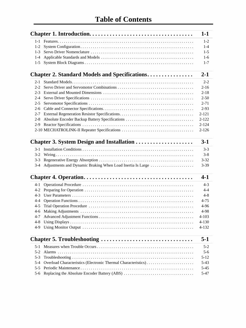
Table of Contents
Chapter 1. Introduction. . . . . . . . . . . . . . . . . . . . . . . . . . . . . . . . . . . . 1-11-1 Features. . . . . . . . . . . . . . . . . . . . . . . . . . . . . . . . . . . . . . . . . . . . . . . . . . . . . . . . . . . . . . . . . . 1-21-2 System Configuration . . . . . . . . . . . . . . . . . . . . . . . . . . . . . . . . . . . . . . . . . . . . . . . . . . . . . . . 1-41-3 Servo Driver Nomenclature . . . . . . . . . . . . . . . . . . . . . . . . . . . . . . . . . . . . . . . . . . . . . . . . . . 1-51-4 Applicable Standards and Models . . . . . . . . . . . . . . . . . . . . . . . . . . . . . . . . . . . . . . . . . . . . . 1-61-5 System Block Diagrams . . . . . . . . . . . . . . . . . . . . . . . . . . . . . . . . . . . . . . . . . . . . . . . . . . . . . 1-7
Chapter 2. Standard Models and Specifications. . . . . . . . . . . . . . . . 2-12-1 Standard Models . . . . . . . . . . . . . . . . . . . . . . . . . . . . . . . . . . . . . . . . . . . . . . . . . . . . . . . . . . . 2-22-2 Servo Driver and Servomotor Combinations . . . . . . . . . . . . . . . . . . . . . . . . . . . . . . . . . . . . . 2-162-3 External and Mounted Dimensions . . . . . . . . . . . . . . . . . . . . . . . . . . . . . . . . . . . . . . . . . . . . 2-182-4 Servo Driver Specifications . . . . . . . . . . . . . . . . . . . . . . . . . . . . . . . . . . . . . . . . . . . . . . . . . . 2-502-5 Servomotor Specifications . . . . . . . . . . . . . . . . . . . . . . . . . . . . . . . . . . . . . . . . . . . . . . . . . . . 2-712-6 Cable and Connector Specifications. . . . . . . . . . . . . . . . . . . . . . . . . . . . . . . . . . . . . . . . . . . . 2-932-7 External Regeneration Resistor Specifications. . . . . . . . . . . . . . . . . . . . . . . . . . . . . . . . . . . . 2-1212-8 Absolute Encoder Backup Battery Specifications . . . . . . . . . . . . . . . . . . . . . . . . . . . . . . . . . 2-1222-9 Reactor Specifications . . . . . . . . . . . . . . . . . . . . . . . . . . . . . . . . . . . . . . . . . . . . . . . . . . . . . . 2-1242-10 MECHATROLINK-II Repeater Specifications . . . . . . . . . . . . . . . . . . . . . . . . . . . . . . . . . . . 2-126
Chapter 3. System Design and Installation . . . . . . . . . . . . . . . . . . . . 3-13-1 Installation Conditions . . . . . . . . . . . . . . . . . . . . . . . . . . . . . . . . . . . . . . . . . . . . . . . . . . . . . . 3-33-2 Wiring . . . . . . . . . . . . . . . . . . . . . . . . . . . . . . . . . . . . . . . . . . . . . . . . . . . . . . . . . . . . . . . . . . . 3-83-3 Regenerative Energy Absorption . . . . . . . . . . . . . . . . . . . . . . . . . . . . . . . . . . . . . . . . . . . . . . 3-323-4 Adjustments and Dynamic Braking When Load Inertia Is Large . . . . . . . . . . . . . . . . . . . . . 3-39
Chapter 4. Operation. . . . . . . . . . . . . . . . . . . . . . . . . . . . . . . . . . . . . . 4-14-1 Operational Procedure . . . . . . . . . . . . . . . . . . . . . . . . . . . . . . . . . . . . . . . . . . . . . . . . . . . . . . 4-34-2 Preparing for Operation . . . . . . . . . . . . . . . . . . . . . . . . . . . . . . . . . . . . . . . . . . . . . . . . . . . . . 4-44-3 User Parameters . . . . . . . . . . . . . . . . . . . . . . . . . . . . . . . . . . . . . . . . . . . . . . . . . . . . . . . . . . . 4-84-4 Operation Functions . . . . . . . . . . . . . . . . . . . . . . . . . . . . . . . . . . . . . . . . . . . . . . . . . . . . . . . . 4-754-5 Trial Operation Procedure . . . . . . . . . . . . . . . . . . . . . . . . . . . . . . . . . . . . . . . . . . . . . . . . . . . 4-964-6 Making Adjustments . . . . . . . . . . . . . . . . . . . . . . . . . . . . . . . . . . . . . . . . . . . . . . . . . . . . . . . 4-984-7 Advanced Adjustment Functions . . . . . . . . . . . . . . . . . . . . . . . . . . . . . . . . . . . . . . . . . . . . . . 4-1034-8 Using Displays . . . . . . . . . . . . . . . . . . . . . . . . . . . . . . . . . . . . . . . . . . . . . . . . . . . . . . . . . . . . 4-1304-9 Using Monitor Output . . . . . . . . . . . . . . . . . . . . . . . . . . . . . . . . . . . . . . . . . . . . . . . . . . . . . . 4-132
Chapter 5. Troubleshooting . . . . . . . . . . . . . . . . . . . . . . . . . . . . . . . . 5-15-1 Measures when Trouble Occurs . . . . . . . . . . . . . . . . . . . . . . . . . . . . . . . . . . . . . . . . . . . . . . . 5-25-2 Alarms . . . . . . . . . . . . . . . . . . . . . . . . . . . . . . . . . . . . . . . . . . . . . . . . . . . . . . . . . . . . . . . . . . 5-65-3 Troubleshooting . . . . . . . . . . . . . . . . . . . . . . . . . . . . . . . . . . . . . . . . . . . . . . . . . . . . . . . . . . . 5-125-4 Overload Characteristics (Electronic Thermal Characteristics) . . . . . . . . . . . . . . . . . . . . . . . 5-435-5 Periodic Maintenance . . . . . . . . . . . . . . . . . . . . . . . . . . . . . . . . . . . . . . . . . . . . . . . . . . . . . . . 5-455-6 Replacing the Absolute Encoder Battery (ABS) . . . . . . . . . . . . . . . . . . . . . . . . . . . . . . . . . . 5-47

Table of Contents
Chapter 6. Appendix . . . . . . . . . . . . . . . . . . . . . . . . . . . . . . . . . . . . . . 6-16-1 Connection Examples . . . . . . . . . . . . . . . . . . . . . . . . . . . . . . . . . . . . . . . . . . . . . . . . . . . . . . . 6-26-2 Parameter Setting Tables . . . . . . . . . . . . . . . . . . . . . . . . . . . . . . . . . . . . . . . . . . . . . . . . . . . . . 6-36-3 Restrictions . . . . . . . . . . . . . . . . . . . . . . . . . . . . . . . . . . . . . . . . . . . . . . . . . . . . . . . . . . . . . . . 6-21
Index . . . . . . . . . . . . . . . . . . . . . . . . . . . . . . . . . . . . . . . . . . . . . . . . . . . I-1
Revision History . . . . . . . . . . . . . . . . . . . . . . . . . . . . . . . . . . . . . . . . . . R-1

Chapter 1
Introduction
1-1 Features
1-2 System Configuration
1-3 Servo Driver Nomenclature
1-4 Applicable Standards and Models
1-5 System Block Diagrams

Chapter 1Introduction
1-1 Features
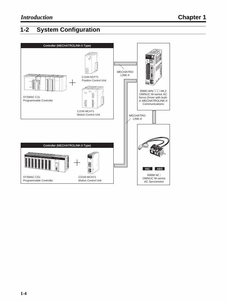
OMNUC W-series AC Servo Drivers with built-in MECHATROLINK-II Communicationsare designed specifically for use with the MECHATROLINK-II high-speed motion fieldnetwork.Combining these Servo Drivers with MECHATROLINK-II-compatible Motion ControlUnits (CS1W-MCH71 or CJ1W-MCH71) or Position Control Units (CJ1W-NCF71) is aneasy way to create a high-speed servo control system with a communications linkbetween the Servo Drivers and the Controllers.
Data Transfer by MECHATROLINK-II CommunicationsWhen a Servo Driver is combined with a MECHATROLINK-II-compatible Motion Control Unit (CS1W-MCH71 or CJ1W-MCH71) or Position Control Unit (CJ1W-NCF71), all control data is transferredbetween the Servo Driver and the Controller by means of data communications.
Control commands are transferred by means of data communications, so Servomotor performance isnot limited by control interface specifications, such as response frequencies for input pulses andencoder feedback pulses. This allows the Servomotor to perform to its fullest capacity.
Moreover, system data control is simplified by having all Servo Driver parameters and monitor datamanaged by the host controller.
Built-in Communications InterfaceThe MECHATROLINK-II communications interface has been built into the Servo Driver. In compari-son with earlier W-series Servo Drivers, in which the MECHATROLINK-II Application Module isinstalled, only 60% of the installation surface area is required. (for 200-V/100-W Servo Drivers). Thisallows a great saving of space in the control panel.
W-series Servomotor CompatibilityA W-series Servomotor can be used as is, including the encoder cable and power cable, so the sys-tem can be upgraded without changing the structural design.
The W-series product line offers 3,000-r/min Servomotors (Cylinder-style: 50-W to 3-kW; Flat-style:100-W to 1.5-kw), 1,000-r/min Servomotors (300-W to 2-kW), and 1,500-r/min Servomotors (450-Wto 1.8-kW). Also, IP67 (waterproof) Servomotors can be connected in the same way.
High-speed, High-precision Motion Control CapabilityA less-deviation control function and a predictive control function are provided to shorten the Servo-motor's settling time and achieving high tracking capability.
The W-series Servomotors handle motion control with increased speed and precision, including syn-chronous control in combination with CS1W-MCH71 or CJ1W-MCH71 Motion Control Units.
1-2
Chapter 1Introduction
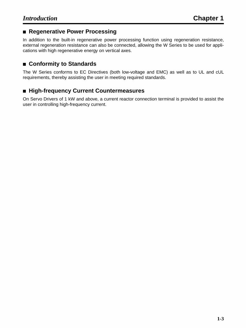
Regenerative Power ProcessingIn addition to the built-in regenerative power processing function using regeneration resistance,external regeneration resistance can also be connected, allowing the W Series to be used for appli-cations with high regenerative energy on vertical axes.
Conformity to StandardsThe W Series conforms to EC Directives (both low-voltage and EMC) as well as to UL and cULrequirements, thereby assisting the user in meeting required standards.
High-frequency Current CountermeasuresOn Servo Drivers of 1 kW and above, a current reactor connection terminal is provided to assist theuser in controlling high-frequency current.
1-3
Chapter 1Introduction
1-2 System Configuration
INCINC ABSABS
MECHATROLINK-II
Controller (MECHATROLINK-II Type)Controller (MECHATROLINK-II Type)
SYSMAC CS1Programmable Controller
CS1W-MCH71Motion Control Unit
Controller (MECHATROLINK-II Type)Controller (MECHATROLINK-II Type)
SYSMAC CJ1Programmable Controller
CJ1W-NCF71Position Control Unit
CJ1W-MCH71Motion Control Unit MECHATRO
LINK-II
MCH71MCH71RUNERCER1ER2SSI
UNITNo.
SSIT.B.
MLKI/O
ERHER3ER4MLK
RUNERCERHERM
MLKNCF71
UNITNo.
MLK
0123456789
ABCDEF
PA205R
POWER
INPUTAC100-240V
L2/N
L1
DC24VAC240V
OUTPUTRUN
PERIPHERAL
ERR/ALMRUN
INH
COMM
PRPHLCONTROLLER
CJ1G-CPU44SYSMAC
PROGRAMMABLE
PORT
OPEN
BUSYMCPWR
0123456789
ABCDEF
MCH71
R88D-WN@@@-ML2OMNUC W-series AC Servo Driver with built-in MECHATROLINK-II
Communications
R88M-W@OMNUC W-series
AC Servomotor
1-4

Chapter 1Introduction
1-3 Servo Driver Nomenclature
With Top Cover Open
ON
1 2 3 4
POWER
COM
5 678
9A
BCDEF0
12
3 4
CN6
A/B
CN3
CN1
CN2
CN4
SW1
CHARGE
U
V
W
U V
WR88D-WN01H-ML2
100W
200VAC SERVO DRIVER
POWER
COM
Servomotor Connector Terminals
These are connector terminals for Servomotor power line.
Input voltage
Top cover
DIP SwitchUsed for MECHATROLINK-II communications settings.
Ground TerminalsThese are ground terminals for preventing electrical shock. Connect to 100 Ω or less.
Charge IndicatorLit when the main-circuit is powered. Also, for Servo Drivers of 1 kW or less, the indicator lights dimly when only the control power supply is ON. Even after the power is turned OFF, it remains lit as long as an electric charge remains in the main-circuit capacitor, so do not touch the Servo Driver's terminals during this period.
Main-circuit Power TerminalsThese are the input terminals for the main-circuit power supply.
Control Power TerminalsThese are input terminals for the control power supply.
Regenerative Resistance Terminals
These are terminals for external regenerative resistance.
Rotary Switch (SW1)Used for setting MECHATROLINK-II node address.
Model Number
Expansion Connector (CN4)This is a supplementary connector for future expansion. It cannot presently be used, so do not connect anything to it.
Encoder Connector (CN2)This is the connector for the encoder provided for the Servomotor.
Nameplate (Side Panel)The nameplate shows the Servo Driver model number and ratings.
I/O Signal Connector (CN1)This is the connector for command input signals and sequence I/O signals.
Personal Computer Connector (CN3)
This is the connector for communications with a personal computer.
MECHATROLINK-II Communications Connectors (CN6A, CN6B)
Connect either a special cable for a MECHATROLINK-II system or a Terminating Resister.
Communications Indicator (COM)
Lit when MECHATROLINK-II communications are in progress.
Power Indicator (POWER)Lit when the control power is being supplied.
Panel DisplayDisplays Servomotor status with a 7-segment LED display.
Analog Monitor Connector (CN5)Motor rotation speeds, torque command values, etc., can be monitored using a special cable.
1-5

Chapter 1Introduction
1-4 Applicable Standards and Models
EC Directives
Note Installation under the conditions specified in 3-2-5 Wiring for Conformity to EMC Directives isrequired to conform to EMC Directives.
UL/cUL Standards
EC Directive Product Applicable standard RemarksLow Voltage AC Servo Drivers EN50178 Safety requirements for electrical equipment for
measurement, control, and laboratory use.
AC Servomotors IEC60034-8EN60034-1, -5, -9
Rotating electrical machines.
EMC AC Servo Drivers and AC Servo-motors
EN55011 class A group 1 Limits and methods for measuring radio distur-bance characteristics of industrial, scientific, and medical (ISM) radio-frequency equipment.
EN61000-6-2 Electromagnetic compatibility generic immunity standard in industrial environments
Standards Product Applicable standard File No. RemarksUL AC Servo Drivers UL508C E179149 Power conversion equipment
AC Servomotors UL1004 E179189 Electric motors
cUL AC Servo Drivers cUL C22.2 No. 14 E179149 Industrial control equipment
AC Servomotors cUL C22.2 No. 100 E179189 Motors and generators
1-6

Chapter 1Introduction
1-5 System Block Diagrams
100 V AC: R88D-WNA5L-ML2/WN01L-ML2/-WL02L-ML2/-WN04L-ML2
200 V AC: R88D-WNA5H-ML2/WN01H-ML2/-WL02H-ML2/-WN04H-ML2
CN10
1KM L1
B1/ B2
L2
L1C
L2C
U
V
W
15 V
±5 V
±12 V
5 V
Personal computer
CN3
1KM
1KM
1Ry
CN2PG
CHARGE M
I/O
I/F
CN1
CN6A
CN6B
CN5
Encoder output
Control I/O
MECHATROLINK-II
Single-phase 100 to 115 V +10%/−15% (50/60 Hz)
Noise filter
Varistor
Voltage detection
Relay drive
VaristorControl power supply
Power OFF
Power ON
Surge protector
Open for servo alarm
Status indicator
Voltage detection
Gate drive
Gate drive over-current protection
Temperature detection
Current detection
Dynamic brake circuit
Servomotor
ASIC (PWM control, etc.)
CPU (position, speed calculations, etc.)
Analog voltage conversion
Analog monitor output
CN10
1KM L1
B1/ B2
L2
L1C
L2C
U
V
W
15 V
±5 V
±12 V
5 V
CN3
1KM
1KM
1Ry
CN2PG
CHARGE M
I/O
I/F
CN1
CN6A
CN6B
CN5
Single-phase 200 to 230 V +10%/−15% (50/60 Hz)
Noise filter
Varistor
Voltage detection
Relay drive
Voltage detection
VaristorControl power supply
Power OFF
Power ON
Surge protector
Open for servo alarm
Personal computer
Status indicator
Gate drive
Gate drive over-current protection
Temperature detection
Current detection
Servomotor
Dynamic brake circuit
ASIC (PWM control, etc.)
CPU (position, speed calculations, etc.)
Analog voltage conversion
Encoder output
Control I/O
MECHATROLINK-II
Analog monitor output
1-7

Chapter 1Introduction
200 V AC: R88D-WN05H-ML2/WN10H-ML2
200 V AC: R88D-WN08H-ML2
CN10
1KM L1
B1/ B2 B3
L2
L3
1
2
L1C
L2C
U
V
W
15 V
±5 V
±12 V
5 V
CN3
1KM
1KM
1Ry
CN2PG
CHARGE M
I/O
I/F
CN1
CN6A
CN6B
CN5
Three-phase 200 to 230 V +10%/−15% (50/60 Hz)
Noise filter
Varistor
Voltage detection
Relay drive
VaristorControl power supply
Power OFF
Power ON
Surge protector
Open for servo alarm
Personal computer
Status indicator
Voltage detection
Gate drive
Gate drive over-current protection
Temperature detection
Current detection
Dynamic brake circuit
Servomotor
Analog voltage conversion
Encoder output
Control I/O
MECHATROLINK-II
Analog monitor output
ASIC (PWM control, etc.)
CPU (position, speed calculations, etc.)
CN10
1KM L1
B1/ B2 B3
L2
L3
1
2
L1C
L2C
U
V
W
15 V
±5 V
±12 V
5 V
CN3
1KM
1KM
1Ry
CN2PG
CHARGE M
I/O
I/F
CN1
CN6A
CN6B
CN5
Single-phase 200 to 230 V +10%/−15% (50/60 Hz)
Noise filter
Varistor
Voltage detection
Relay drive
Voltage detection
VaristorControl power supply
Power OFF
Power ON
Surge protector
Open for servo alarm
Personal computer
Status indicator
ASIC (PWM control, etc.)
CPU (position, speed calculations, etc.)
Gate drive
Gate drive over-current protection
Temperature detection
Current detection
Dynamic brake circuit
Servomotor
Analog voltage conversion
Encoder output
Control I/O
MECHATROLINK-II
Analog monitor output
1-8
Chapter 1Introduction
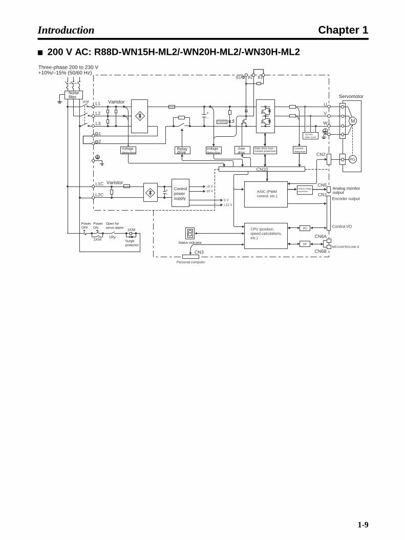
200 V AC: R88D-WN15H-ML2/-WN20H-ML2/-WN30H-ML2
CN10
1KM L1
B1/ B2 B3
L2
L3
1
2
L1C
L2C
U
V
W
15 V
±5 V
±12 V
5 V
CN3
1KM
1KM
1Ry
CN2PG
CHARGE M
I/O
I/F
CN1
CN6A
CN6B
CN5
Three-phase 200 to 230 V +10%/−15% (50/60 Hz)
Noise filter
Varistor
Voltage detection
Relay drive
Voltage detection
VaristorControl power supply
Power OFF
Power ON
Surge protector
Open for servo alarm
Personal computer
Status indicator
ASIC (PWM control, etc.)
CPU (position, speed calculations, etc.)
Analog voltage conversion
Encoder output
Control I/O
MECHATROLINK-II
Analog monitor output
Gate drive
Gate drive over-current protection
Current detection
Dynamic brake circuit
Servomotor
1-9

Chapter 1Introduction
1-10

Chapter 2
Standard Models and Specifications
2-1 Standard Models
2-2 Servo Driver and Servomotor Combinations
2-3 External and Mounted Dimensions
2-4 Servo Driver Specifications
2-5 Servomotor Specifications
2-6 Cable and Connector Specifications
2-7 External Regeneration Resistor Specifications
2-8 Absolute Encoder Backup Battery Specifications
2-9 Reactor Specifications
2-10 MECHATROLINK-II Repeater Specifications
Chapter 2Standard Models and Specifications
2-1 Standard Models
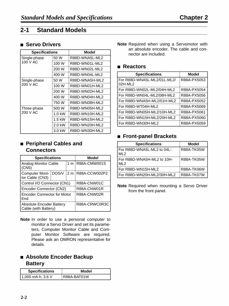
Servo Drivers
Peripheral Cables and Connectors
Note In order to use a personal computer tomonitor a Servo Driver and set its parame-ters, Computer Monitor Cable and Com-puter Monitor Software are required.Please ask an OMRON representative fordetails.
Absolute Encoder Backup Battery
Note Required when using a Servomotor withan absolute encoder. The cable and con-nector are included.
Reactors
Front-panel Brackets
Note Required when mounting a Servo Driverfrom the front panel.
Specifications ModelSingle-phase 100 V AC
50 W R88D-WNA5L-ML2
100 W R88D-WN01L-ML2
200 W R88D-WN02L-ML2
400 W R88D-WN04L-ML2
Single-phase 200 V AC
50 W R88D-WNA5H-ML2
100 W R88D-WN01H-ML2
200 W R88D-WN02H-ML2
400 W R88D-WN04H-ML2
750 W R88D-WN08H-ML2
Three-phase 200 V AC
500 W R88D-WN05H-ML2
1.0 kW R88D-WN10H-ML2
1.5 kW R88D-WN15H-ML2
2.0 kW R88D-WN20H-ML2
3.0 kW R88D-WN30H-ML2
Specifications ModelAnalog Monitor Cable (CN5)
1 m R88A-CMW001S
Computer Moni-tor Cable (CN3)
DOS/V 2 m R88A-CCW002P2
Control I/O Connector (CN1) R88A-CNW01C
Encoder Connector (CN2) R88A-CNW01R
Encoder Connector for Motor End
R88A-CNW02R
Absolute Encoder Battery Cable (with Battery)
R88A-CRWC0R3C
Specifications Model1,000 mA·h, 3.6 V R88A-BAT01W
Specifications ModelFor R88D-WNA5L-ML2/01L-ML2/02H-ML2
R88A-PX5053
For R88D-WN02L-ML2/04H-ML2 R88A-PX5054
For R88D-WN04L-ML2/08H-ML2 R88A-PX5056
For R88D-WNA5H-ML2/01H-ML2 R88A-PX5052
For R88D-WT04H-ML2 R88A-PX5069
For R88D-WN05H-ML2/10H-ML2 R88A-PX5061
For R88D-WN15H-ML2/20H-ML2 R88A-PX5060
For R88D-WN30H-ML2 R88A-PX5059
Specifications ModelFor R88D-WNA5L-ML2 to 04L-ML2
R88A-TK05W
For R88D-WNA5H-ML2 to 10H-ML2
R88A-TK05W
For R88D-WN15H-ML2 R88A-TK06W
For R88D-WN20H-ML2/30H-ML2 R88A-TK07W
2-2

Chapter 2Standard Models and Specifications
Standard Encoder Cables (for Incremental and Absolute Encoders)
Standard Power Cable
Power Cable for 3,000-r/min Servomotors
Power Cable for 3,000-r/min Flat-style Servomotors
Specifications ModelFor 3,000-r/min Servomo-tors
30 to 750 W
3 m R88A-CRWA003C
5 m R88A-CRWA005C
10 m R88A-CRWA010C
15 m R88A-CRWA015C
20 m R88A-CRWA020C
30 m R88A-CRWA030C
40 m R88A-CRWA040C
50 m R88A-CRWA050C
1 to 3 kW
3 m R88A-CRWB003N
5 m R88A-CRWB005N
10 m R88A-CRWB010N
15 m R88A-CRWB015N
20 m R88A-CRWB020N
30 m R88A-CRWB030N
40 m R88A-CRWB040N
50 m R88A-CRWB050N
For 3,000-r/min Flat-style Servomotors
100 W to 1.5 kW
3 m R88A-CRWA003C
5 m R88A-CRWA005C
10 m R88A-CRWA010C
15 m R88A-CRWA015C
20 m R88A-CRWA020C
30 m R88A-CRWA030C
40 m R88A-CRWA040C
50 m R88A-CRWA050C
For 1,000-r/min Servomo-torsFor 1,500-r/min Servomo-tors
300 W to 2.0 kW450 W to 1.8 kW
3 m R88A-CRWB003N
5 m R88A-CRWB005N
10 m R88A-CRWB010N
15 m R88A-CRWB015N
20 m R88A-CRWB020N
30 m R88A-CRWB030N
40 m R88A-CRWB040N
50 m R88A-CRWB050N
Specifications Model
Without brake With brake
30 to 750 W
3 m R88A-CAWA003S R88A-CAWA003B
5 m R88A-CAWA005S R88A-CAWA005B
10 m R88A-CAWA010S R88A-CAWA010B
15 m R88A-CAWA015S R88A-CAWA015B
20 m R88A-CAWA020S R88A-CAWA020B
30 m R88A-CAWA030S R88A-CAWA030B
40 m R88A-CAWA040S R88A-CAWA040B
50 m R88A-CAWA050S R88A-CAWA050B
1 to 2 kW
3 m R88A-CAWC003S R88A-CAWC003B
5 m R88A-CAWC005S R88A-CAWC005B
10 m R88A-CAWC010S R88A-CAWC010B
15 m R88A-CAWC015S R88A-CAWC015B
20 m R88A-CAWC020S R88A-CAWC020B
30 m R88A-CAWC030S R88A-CAWC030B
40 m R88A-CAWC040S R88A-CAWC040B
50 m R88A-CAWC050S R88A-CAWC050B
3 kW 3 m R88A-CAWD003S R88A-CAWD003B
5 m R88A-CAWD005S R88A-CAWD005B
10 m R88A-CAWD010S R88A-CAWD010B
15 m R88A-CAWD015S R88A-CAWD015B
20 m R88A-CAWD020S R88A-CAWD020B
30 m R88A-CAWD030S R88A-CAWD030B
40 m R88A-CAWD040S R88A-CAWD040B
50 m R88A-CAWD050S R88A-CAWD050B
Specifications Model
Without brake With brake
100 to 750 W
3 m R88A-CAWA003S R88A-CAWA003B
5 m R88A-CAWA005S R88A-CAWA005B
10 m R88A-CAWA010S R88A-CAWA010B
15 m R88A-CAWA015S R88A-CAWA015B
20 m R88A-CAWA020S R88A-CAWA020B
30 m R88A-CAWA030S R88A-CAWA030B
40 m R88A-CAWA040S R88A-CAWA040B
50 m R88A-CAWA050S R88A-CAWA050B
2-3
Chapter 2Standard Models and Specifications
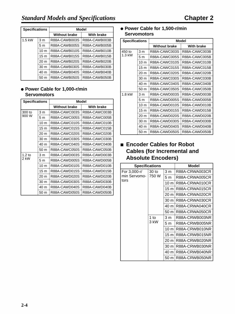
Power Cable for 1,000-r/min Servomotors
Power Cable for 1,500-r/min Servomotors
Encoder Cables for Robot Cables (for Incremental and Absolute Encoders)
1.5 kW 3 m R88A-CAWB003S R88A-CAWB003B
5 m R88A-CAWB005S R88A-CAWB005B
10 m R88A-CAWB010S R88A-CAWB010B
15 m R88A-CAWB015S R88A-CAWB015B
20 m R88A-CAWB020S R88A-CAWB020B
30 m R88A-CAWB030S R88A-CAWB030B
40 m R88A-CAWB040S R88A-CAWB040B
50 m R88A-CAWB050S R88A-CAWB050B
Specifications Model
Without brake With brake
300 to 900 W
3 m R88A-CAWC003S R88A-CAWC003B
5 m R88A-CAWC005S R88A-CAWC005B
10 m R88A-CAWC010S R88A-CAWC010B
15 m R88A-CAWC015S R88A-CAWC015B
20 m R88A-CAWC020S R88A-CAWC020B
30 m R88A-CAWC030S R88A-CAWC030B
40 m R88A-CAWC040S R88A-CAWC040B
50 m R88A-CAWC050S R88A-CAWC050B
1.2 to 2 kW
3 m R88A-CAWD003S R88A-CAWD003B
5 m R88A-CAWD005S R88A-CAWD005B
10 m R88A-CAWD010S R88A-CAWD010B
15 m R88A-CAWD015S R88A-CAWD015B
20 m R88A-CAWD020S R88A-CAWD020B
30 m R88A-CAWD030S R88A-CAWD030B
40 m R88A-CAWD040S R88A-CAWD040B
50 m R88A-CAWD050S R88A-CAWD050B
Specifications Model
Without brake With brake
Specifications Model
Without brake With brake
450 to 1.3 kW
3 m R88A-CAWC003S R88A-CAWC003B
5 m R88A-CAWC005S R88A-CAWC005B
10 m R88A-CAWC010S R88A-CAWC010B
15 m R88A-CAWC015S R88A-CAWC015B
20 m R88A-CAWC020S R88A-CAWC020B
30 m R88A-CAWC030S R88A-CAWC030B
40 m R88A-CAWC040S R88A-CAWC040B
50 m R88A-CAWC050S R88A-CAWC050B
1.8 kW 3 m R88A-CAWD003S R88A-CAWD003B
5 m R88A-CAWD005S R88A-CAWD005B
10 m R88A-CAWD010S R88A-CAWD010B
15 m R88A-CAWD015S R88A-CAWD015B
20 m R88A-CAWD020S R88A-CAWD020B
30 m R88A-CAWD030S R88A-CAWD030B
40 m R88A-CAWD040S R88A-CAWD040B
50 m R88A-CAWD050S R88A-CAWD050B
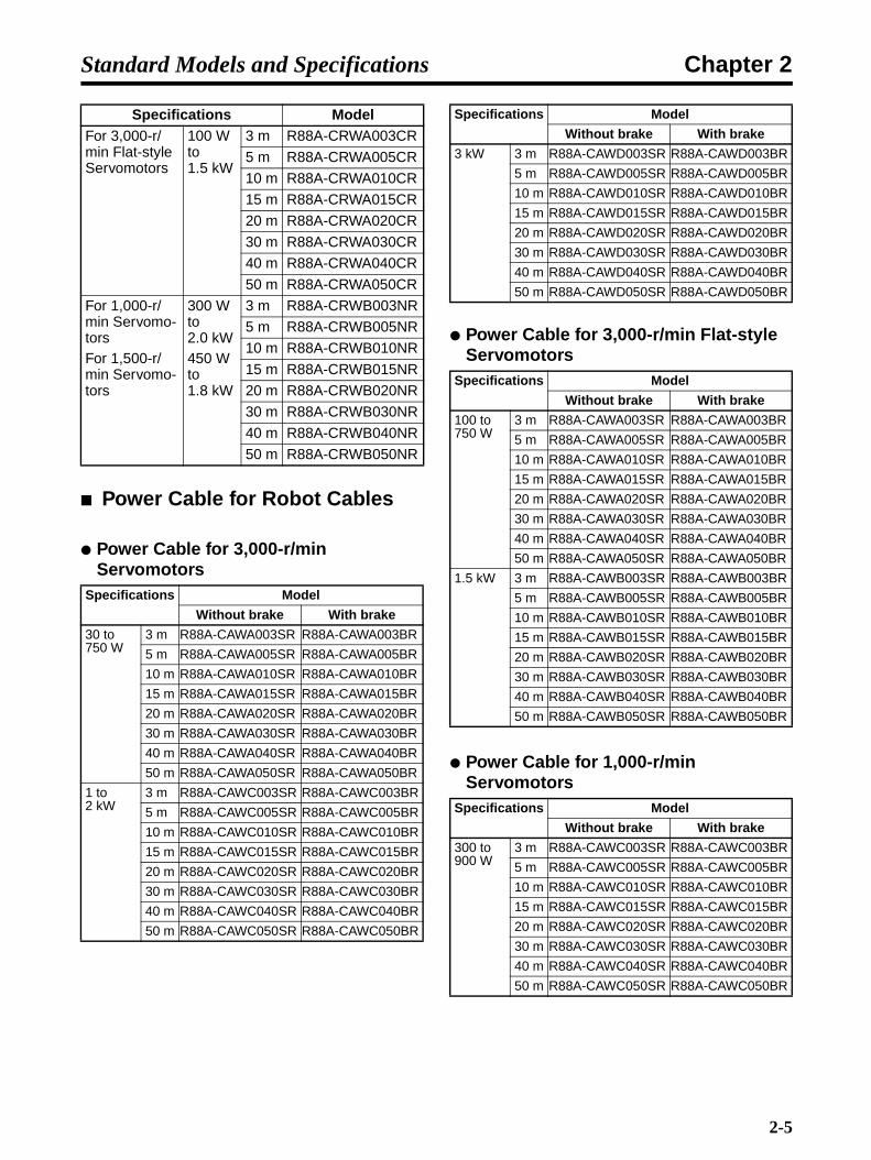
Specifications ModelFor 3,000-r/min Servomo-tors
30 to 750 W
3 m R88A-CRWA003CR
5 m R88A-CRWA005CR
10 m R88A-CRWA010CR
15 m R88A-CRWA015CR
20 m R88A-CRWA020CR
30 m R88A-CRWA030CR
40 m R88A-CRWA040CR
50 m R88A-CRWA050CR
1 to 3 kW
3 m R88A-CRWB003NR
5 m R88A-CRWB005NR
10 m R88A-CRWB010NR
15 m R88A-CRWB015NR
20 m R88A-CRWB020NR
30 m R88A-CRWB030NR
40 m R88A-CRWB040NR
50 m R88A-CRWB050NR
2-4
Chapter 2Standard Models and Specifications
Power Cable for Robot Cables
Power Cable for 3,000-r/min Servomotors
Power Cable for 3,000-r/min Flat-style Servomotors
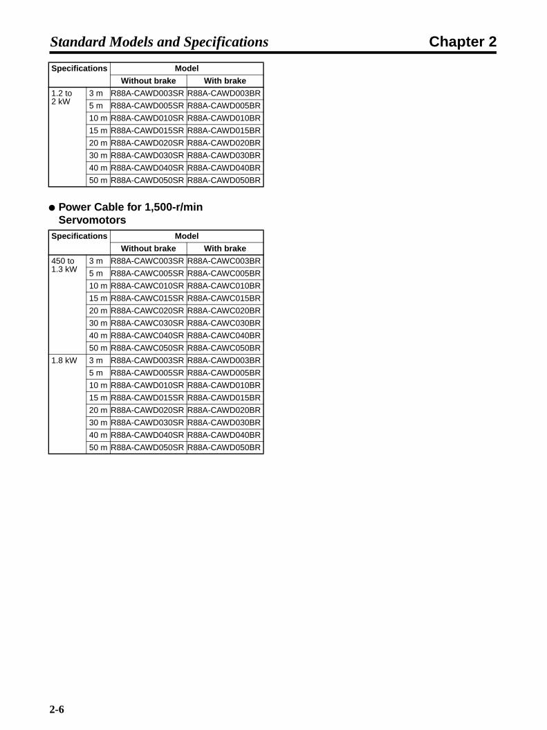
Power Cable for 1,000-r/min Servomotors
For 3,000-r/min Flat-style Servomotors
100 W to 1.5 kW
3 m R88A-CRWA003CR
5 m R88A-CRWA005CR
10 m R88A-CRWA010CR
15 m R88A-CRWA015CR
20 m R88A-CRWA020CR
30 m R88A-CRWA030CR
40 m R88A-CRWA040CR
50 m R88A-CRWA050CR
For 1,000-r/min Servomo-torsFor 1,500-r/min Servomo-tors
300 W to 2.0 kW450 W to 1.8 kW
3 m R88A-CRWB003NR
5 m R88A-CRWB005NR
10 m R88A-CRWB010NR
15 m R88A-CRWB015NR
20 m R88A-CRWB020NR
30 m R88A-CRWB030NR
40 m R88A-CRWB040NR
50 m R88A-CRWB050NR
Specifications Model
Without brake With brake
30 to 750 W
3 m R88A-CAWA003SR R88A-CAWA003BR
5 m R88A-CAWA005SR R88A-CAWA005BR
10 m R88A-CAWA010SR R88A-CAWA010BR
15 m R88A-CAWA015SR R88A-CAWA015BR
20 m R88A-CAWA020SR R88A-CAWA020BR
30 m R88A-CAWA030SR R88A-CAWA030BR
40 m R88A-CAWA040SR R88A-CAWA040BR
50 m R88A-CAWA050SR R88A-CAWA050BR
1 to 2 kW
3 m R88A-CAWC003SR R88A-CAWC003BR
5 m R88A-CAWC005SR R88A-CAWC005BR
10 m R88A-CAWC010SR R88A-CAWC010BR
15 m R88A-CAWC015SR R88A-CAWC015BR
20 m R88A-CAWC020SR R88A-CAWC020BR
30 m R88A-CAWC030SR R88A-CAWC030BR
40 m R88A-CAWC040SR R88A-CAWC040BR
50 m R88A-CAWC050SR R88A-CAWC050BR
Specifications Model
3 kW 3 m R88A-CAWD003SR R88A-CAWD003BR
5 m R88A-CAWD005SR R88A-CAWD005BR
10 m R88A-CAWD010SR R88A-CAWD010BR
15 m R88A-CAWD015SR R88A-CAWD015BR
20 m R88A-CAWD020SR R88A-CAWD020BR
30 m R88A-CAWD030SR R88A-CAWD030BR
40 m R88A-CAWD040SR R88A-CAWD040BR
50 m R88A-CAWD050SR R88A-CAWD050BR
Specifications Model
Without brake With brake
100 to 750 W
3 m R88A-CAWA003SR R88A-CAWA003BR
5 m R88A-CAWA005SR R88A-CAWA005BR
10 m R88A-CAWA010SR R88A-CAWA010BR
15 m R88A-CAWA015SR R88A-CAWA015BR
20 m R88A-CAWA020SR R88A-CAWA020BR
30 m R88A-CAWA030SR R88A-CAWA030BR
40 m R88A-CAWA040SR R88A-CAWA040BR
50 m R88A-CAWA050SR R88A-CAWA050BR
1.5 kW 3 m R88A-CAWB003SR R88A-CAWB003BR
5 m R88A-CAWB005SR R88A-CAWB005BR
10 m R88A-CAWB010SR R88A-CAWB010BR
15 m R88A-CAWB015SR R88A-CAWB015BR
20 m R88A-CAWB020SR R88A-CAWB020BR
30 m R88A-CAWB030SR R88A-CAWB030BR
40 m R88A-CAWB040SR R88A-CAWB040BR
50 m R88A-CAWB050SR R88A-CAWB050BR
Specifications Model
Without brake With brake
300 to 900 W
3 m R88A-CAWC003SR R88A-CAWC003BR
5 m R88A-CAWC005SR R88A-CAWC005BR
10 m R88A-CAWC010SR R88A-CAWC010BR
15 m R88A-CAWC015SR R88A-CAWC015BR
20 m R88A-CAWC020SR R88A-CAWC020BR
30 m R88A-CAWC030SR R88A-CAWC030BR
40 m R88A-CAWC040SR R88A-CAWC040BR
50 m R88A-CAWC050SR R88A-CAWC050BR
Specifications Model
Without brake With brake
2-5
Chapter 2Standard Models and Specifications
Power Cable for 1,500-r/min Servomotors
1.2 to 2 kW
3 m R88A-CAWD003SR R88A-CAWD003BR
5 m R88A-CAWD005SR R88A-CAWD005BR
10 m R88A-CAWD010SR R88A-CAWD010BR
15 m R88A-CAWD015SR R88A-CAWD015BR
20 m R88A-CAWD020SR R88A-CAWD020BR
30 m R88A-CAWD030SR R88A-CAWD030BR
40 m R88A-CAWD040SR R88A-CAWD040BR
50 m R88A-CAWD050SR R88A-CAWD050BR
Specifications Model
Without brake With brake
450 to 1.3 kW
3 m R88A-CAWC003SR R88A-CAWC003BR
5 m R88A-CAWC005SR R88A-CAWC005BR
10 m R88A-CAWC010SR R88A-CAWC010BR
15 m R88A-CAWC015SR R88A-CAWC015BR
20 m R88A-CAWC020SR R88A-CAWC020BR
30 m R88A-CAWC030SR R88A-CAWC030BR
40 m R88A-CAWC040SR R88A-CAWC040BR
50 m R88A-CAWC050SR R88A-CAWC050BR
1.8 kW 3 m R88A-CAWD003SR R88A-CAWD003BR
5 m R88A-CAWD005SR R88A-CAWD005BR
10 m R88A-CAWD010SR R88A-CAWD010BR
15 m R88A-CAWD015SR R88A-CAWD015BR
20 m R88A-CAWD020SR R88A-CAWD020BR
30 m R88A-CAWD030SR R88A-CAWD030BR
40 m R88A-CAWD040SR R88A-CAWD040BR
50 m R88A-CAWD050SR R88A-CAWD050BR
Specifications Model
Without brake With brake
2-6

Chapter 2Standard Models and Specifications
Servomotors
3,000-r/min Servomotors
3,000-r/min Flat-style Servomotors
1,000-r/min Servomotors
Specifications Model
With incremental encoder With absolute encoder
Straight shaft without key
Straight shaft with key Straight shaft without key
Straight shaft with key
Without brake
200 V 50 W R88M-W05030H R88M-W05030H-S1 R88M-W05030T R88M-W05030T-S1
100 W R88M-W10030H R88M-W10030H-S1 R88M-W10030T R88M-W10030T-S1
200 W R88M-W20030H R88M-W20030H-S1 R88M-W20030T R88M-W20030T-S1
400 W R88M-W40030H R88M-W40030H-S1 R88M-W40030T R88M-W40030T-S1
750 W R88M-W75030H R88M-W75030H-S1 R88M-W75030T R88M-W75030T-S1
1 kW R88M-W1K030H R88M-W1K030H-S2 R88M-W1K030T R88M-W1K030T-S2
1.5 kW R88M-W1K530H R88M-W1K530H-S2 R88M-W1K530T R88M-W1K530T-S2
2 kW R88M-W2K030H R88M-W2K030H-S2 R88M-W2K030T R88M-W2K030T-S2
3 kW R88M-W3K030H R88M-W3K030H-S2 R88M-W3K030T R88M-W3K030T-S2
With brake
200 V 50 W R88M-W05030H-B R88M-W05030H-BS1 R88M-W05030T-B R88M-W05030T-BS1
100 W R88M-W10030H-B R88M-W10030H-BS1 R88M-W10030T-B R88M-W10030T-BS1
200 W R88M-W20030H-B R88M-W20030H-BS1 R88M-W20030T-B R88M-W20030T-BS1
400 W R88M-W40030H-B R88M-W40030H-BS1 R88M-W40030T-B R88M-W40030T-BS1
750 W R88M-W75030H-B R88M-W75030H-BS1 R88M-W75030T-B R88M-W75030T-BS1
1 kW R88M-W1K030H-B R88M-W1K030H-BS2 R88M-W1K030T-B R88M-W1K030T-BS2
1.5 kW R88M-W1K530H-B R88M-W1K530H-BS2 R88M-W1K530T-B R88M-W1K530T-BS2
2 kW R88M-W2K030H-B R88M-W2K030H-BS2 R88M-W2K030T-B R88M-W2K030T-BS2
3 kW R88M-W3K030H-B R88M-W3K030H-BS2 R88M-W3K030T-B R88M-W3K030T-BS2
Without brake
200 V 100 W R88M-WP10030H R88M-WP10030H-S1 R88M-WP10030T R88M-WP10030T-S1
200 W R88M-WP20030H R88M-WP20030H-S1 R88M-WP20030T R88M-WP20030T-S1
400 W R88M-WP40030H R88M-WP40030H-S1 R88M-WP40030T R88M-WP40030T-S1
750 W R88M-WP75030H R88M-WP75030H-S1 R88M-WP75030T R88M-WP75030T-S1
1.5 kW R88M-WP1K530H R88M-WP1K530H-S1 R88M-WP1K530T R88M-WP1K530T-S1
With brake
200 V 100 W R88M-WP10030H-B R88M-WP10030H-BS1 R88M-WP10030T-B R88M-WP10030T-BS1
200 W R88M-WP20030H-B R88M-WP20030H-BS1 R88M-WP20030T-B R88M-WP20030T-BS1
400 W R88M-WP40030H-B R88M-WP40030H-BS1 R88M-WP40030T-B R88M-WP40030T-BS1
750 W R88M-WP75030H-B R88M-WP75030H-BS1 R88M-WP75030T-B R88M-WP75030T-BS1
1.5 kW R88M-WP1K530H-B R88M-WP1K530H-BS1 R88M-WP1K530T-B R88M-WP1K530T-BS1
Without brake
200 V 300 W R88M-W30010H R88M-W30010H-S2 R88M-W30010T R88M-W30010T-S2
600 W R88M-W60010H R88M-W60010H-S2 R88M-W60010T R88M-W60010T-S2
900 W R88M-W90010H R88M-W90010H-S2 R88M-W90010T R88M-W90010T-S2
1.2 kW R88M-W1K210H R88M-W1K210H-S2 R88M-W1K210T R88M-W1K210T-S2
2 kW R88M-W2K010H R88M-W2K010H-S2 R88M-W2K010T R88M-W2K010T-S2
With brake
200 V 300 W R88M-W30010H-B R88M-W30010H-BS2 R88M-W30010T-B R88M-W30010T-BS2
600 W R88M-W60010H-B R88M-W60010H-BS2 R88M-W60010T-B R88M-W60010T-BS2
900 W R88M-W90010H-B R88M-W90010H-BS2 R88M-W90010T-B R88M-W90010T-BS2
1.2 kW R88M-W1K210H-B R88M-W1K210H-BS2 R88M-W1K210T-B R88M-W1K210T-BS2
2 kW R88M-W2K010H-B R88M-W2K010H-BS2 R88M-W2K010T-B R88M-W2K010T-BS2
2-7

Chapter 2Standard Models and Specifications
1,500-r/min Servomotors
IP67 (Waterproof) Servomotors
3,000-r/min Servomotors
3,000-r/min Flat-style Servomotors
1,000-r/min Servomotors
Without brake
200 V 450 W --- --- R88M-W45015T R88M-W45015T-S2
850 W --- --- R88M-W85015T R88M-W85015T-S2
1.3 kW --- --- R88M-W1K315T R88M-W1K315T-S2
1.8 kW --- --- R88M-W1K815T R88M-W1K815T-S2
With brake
200 V 450 W --- --- R88M-W45015T-B R88M-W45015T-BS2
850 W --- --- R88M-W85015T-B R88M-W85015T-BS2
1.3 kW --- --- R88M-W1K315T-B R88M-W1K315T-BS2
1.8 kW --- --- R88M-W1K815T-B R88M-W1K815T-BS2
Specifications Model
With incremental encoder With absolute encoder
Straight shaft without key
Straight shaft with key Straight shaft without key
Straight shaft with key
Without brake
200 V 1 kW R88M-W1K030H-O R88M-W1K030H-OS2 R88M-W1K030T-O R88M-W1K030T-OS2
1.5 kW R88M-W1K530H-O R88M-W1K530H-OS2 R88M-W1K530T-O R88M-W1K530T-OS2
2 kW R88M-W2K030H-O R88M-W2K030H-OS2 R88M-W2K030T-O R88M-W2K030T-OS2
3 kW R88M-W3K030H-O R88M-W3K030H-OS2 R88M-W3K030T-O R88M-W3K030T-OS2
With brake
200 V 1 kW R88M-W1K030H-BO R88M-W1K030H-BOS2 R88M-W1K030T-BO R88M-W1K030T-BOS2
1.5 kW R88M-W1K530H-BO R88M-W1K530H-BOS2 R88M-W1K530T-BO R88M-W1K530T-BOS2
2 kW R88M-W2K030H-BO R88M-W2K030H-BOS2 R88M-W2K030T-BO R88M-W2K030T-BOS2
3 kW R88M-W3K030H-BO R88M-W3K030H-BOS2 R88M-W3K030T-BO R88M-W3K030T-BOS2
Without brake
200 V 100 W R88M-WP10030H-W R88M-WP10030H-WS1 R88M-WP10030T-W R88M-WP10030T-WS1
200 W R88M-WP20030H-W R88M-WP20030H-WS1 R88M-WP20030T-W R88M-WP20030T-WS1
400 W R88M-WP40030H-W R88M-WP40030H-WS1 R88M-WP40030T-W R88M-WP40030T-WS1
750 W R88M-WP75030H-W R88M-WP75030H-WS1 R88M-WP75030T-W R88M-WP75030T-WS1
1.5 kW R88M-WP1K530H-W R88M-WP1K530H-WS1 R88M-WP1K530T-W R88M-WP1K530T-WS1
With brake
200 V 100 W R88M-WP10030H-BW R88M-WP10030H-BWS1 R88M-WP10030T-BW R88M-WP10030T-BWS1
200 W R88M-WP20030H-BW R88M-WP20030H-BWS1 R88M-WP20030T-BW R88M-WP20030T-BWS1
400 W R88M-WP40030H-BW R88M-WP40030H-BWS1 R88M-WP40030T-BW R88M-WP40030T-BWS1
750 W R88M-WP75030H-BW R88M-WP75030H-BWS1 R88M-WP75030T-BW R88M-WP75030T-BWS1
1.5 kW R88M-WP1K530H-BW R88M-WP1K530H-BWS1 R88M-WP1K530T-BW R88M-WP1K530T-BWS1
Without brake
200 V 300 W R88M-W30010H-O R88M-W30010H-OS2 R88M-W30010T-O R88M-W30010T-OS2
600 W R88M-W60010H-O R88M-W60010H-OS2 R88M-W60010T-O R88M-W60010T-OS2
900 W R88M-W90010H-O R88M-W90010H-OS2 R88M-W90010T-O R88M-W90010T-OS2
1.2 kW R88M-W1K210H-O R88M-W1K210H-OS2 R88M-W1K210T-O R88M-W1K210T-OS2
2 kW R88M-W2K010H-O R88M-W2K010H-OS2 R88M-W2K010T-O R88M-W2K010T-OS2
With brake
200 V 300 W R88M-W30010H-BO R88M-W30010H-BOS2 R88M-W30010T-BO R88M-W30010T-BOS2
600 W R88M-W60010H-BO R88M-W60010H-BOS2 R88M-W60010T-BO R88M-W60010T-BOS2
900 W R88M-W90010H-BO R88M-W90010H-BOS2 R88M-W90010T-BO R88M-W90010T-BOS2
1.2 kW R88M-W1K210H-BO R88M-W1K210H-BOS2 R88M-W1K210T-BO R88M-W1K210T-BOS2
2 kW R88M-W2K010H-BO R88M-W2K010H-BOS2 R88M-W2K010T-BO R88M-W2K010T-BOS2
2-8

Chapter 2Standard Models and Specifications
1,500-r/min Servomotors
Servomotors with Gears
Combination Table for Servomotors with Standard GearsStandard Gears are highly accurate gears, with a maximum backlash of 3 degrees. The standardshaft is a straight shaft with a key. (Models without keys can also be manufactured for 3,000-r/minmotors from 30 to 750 W and for 3,000-r/min flat-style motors. Models without keys have a suffix of -G@@B.)
Note A check mark in a box indicates that the two models can be combined. If the box is unchecked,then the models cannot be combined.
3,000-r/min Servomotors
3,000-r/min Flat-style Servomotors
Without brake
200 V 450 W --- --- R88M-W45015TO R88M-W45015T-OS2
850 W --- --- R88M-W85015TO R88M-W85015T-OS2
1.3 kW --- --- R88M-W1K315TO R88M-W1K315T-OS2
1.8 kW --- --- R88M-W1K815TO R88M-W1K815T-OS2
With brake
200 V 450 W --- --- R88M-W45015T-BO R88M-W45015T-BOS2
850 W --- --- R88M-W85015T-BO R88M-W85015T-BOS2
1.3 kW --- --- R88M-W1K315T-BO R88M-W1K315T-BOS2
1.8 kW --- --- R88M-W1K815T-BO R88M-W1K815T-BOS2
Specifications Basic model Gear (deceleration rate)
1/5 1/9 1/11 1/20 1/21 1/29 1/33 1/45
-G05BJ -G09BJ -G11BJ -G20BJ -G21BJ -G29BJ -G33BJ -G45BJ
200 V 50 W R88M-W05030H/T Yes Yes Yes Yes
100 W R88M-W10030H/T Yes Yes Yes Yes
200 W R88M-W20030H/T Yes Yes Yes Yes
400 W R88M-W40030H/T Yes Yes Yes Yes
750 W R88M-W75030H/T Yes Yes Yes Yes
1 kW R88M-W1K030H/T Yes Yes Yes Yes Yes
1.5 kW R88M-W1K530H/T Yes Yes Yes Yes Yes
2 kW R88M-W2K030H/T Yes Yes Yes Yes Yes
3 kW R88M-W3K030H/T Yes Yes Yes Yes Yes
Specifications Basic model Gear (deceleration rate)
1/5 1/9 1/11 1/20 1/21 1/29 1/33 1/45
-G05BJ -G09BJ -G11BJ -G20BJ -G21BJ -G29BJ -G33BJ -G45BJ
200 V 100 W R88M-WP10030H/T Yes Yes Yes Yes
200 W R88M-WP20030H/T Yes Yes Yes Yes
400 W R88M-WP40030H/T Yes Yes Yes Yes
750 W R88M-WP75030H/T Yes Yes Yes Yes
1.5 kW R88M-WP1K530H/T Yes Yes Yes Yes
2-9

Chapter 2Standard Models and Specifications
1,000-r/min Servomotors
1,500-r/min Servomotors
Combination Table for Servomotors with Economy GearsEconomy Gears are low-cost gears, with a maximum backlash of 45 degrees. The shaft is a straightshaft with key. Models without keys are not available.
Note 1. The 1,000-r/min and 1,500-r/min Servomotors cannot be combined with Economy Gears.
Note 2. A check mark in a box indicates that the two models can be combined. If the box is un-checked, then the models cannot be combined.
3,000-r/min Servomotors
Specifications Basic model Gear (deceleration rate)
1/5 1/9 1/11 1/20 1/21 1/29 1/33 1/45
-G05BJ -G09BJ -G11BJ -G20BJ -G21BJ -G29BJ -G33BJ -G45BJ
200 V 300 W R88M-W30010H/T Yes Yes Yes Yes Yes
600 W R88M-W60010H/T Yes Yes Yes Yes Yes
900 W R88M-W90010H/T Yes Yes Yes Yes Yes
1.2 kW R88M-W1K210H/T Yes Yes Yes Yes Yes
2 kW R88M-W2K010H/T Yes Yes Yes
Specifications Basic model Gear (deceleration rate)
1/5 1/9 1/11 1/20 1/21 1/29 1/33 1/45
-G05BJ -G09BJ -G11BJ -G20BJ -G21BJ -G29BJ -G33BJ -G45BJ
200 V 450 W R88M-W45015T Yes Yes Yes Yes Yes
850 W R88M-W85015T Yes Yes Yes Yes Yes
1.3 kW R88M-W1K315T Yes Yes Yes Yes Yes
1.8 kW R88M-W1K815T Yes Yes Yes Yes
Specifications Basic model Gear (deceleration rate)
1/5 1/9 1/15 1/25
-G05CJ -G09CJ -G15C -G25CJ
200 V 50 W R88M-W05030H/T
100 W R88M-W10030H/T Yes Yes Yes Yes
200 W R88M-W20030H/T Yes Yes Yes Yes
400 W R88M-W40030H/T Yes Yes Yes Yes
750 W R88M-W75030H/T Yes Yes Yes Yes
1 kW R88M-W1K030H/T
1.5 kW R88M-W1K530H/T
2 kW R88M-W2K030H/T
3 kW R88M-W3K030H/T
2-10

Chapter 2Standard Models and Specifications
3,000-r/min Flat-style ServomotorsSpecifications Basic model Gear (deceleration rate)
1/5 1/9 1/15 1/25
-G05CJ -G09CJ -G15C -G25CJ
200 V 100 W R88M-WP10030H/T Yes Yes Yes Yes
200 W R88M-WP20030H/T Yes Yes Yes Yes
400 W R88M-WP40030H/T Yes Yes Yes Yes
750 W R88M-WP75030H/T Yes Yes Yes Yes
1.5 kW R88M-WP1K530H/T
2-11

Chapter 2Standard Models and Specifications
Servomotors with Standard Gears (Straight Shaft with Key)
3,000-r/min ServomotorsSpecifications Model
With incremental encoder With absolute encoder
Without brake With brake Without brake With brake
200 V 50 W 1/5 R88M-W05030H-G05BJ R88M-W05030H-BG05BJ R88M-W05030T-G05BJ R88M-W05030T-BG05BJ
1/9 R88M-W05030H-G09BJ R88M-W05030H-BG09BJ R88M-W05030T-G09BJ R88M-W05030T-BG09BJ
1/21 R88M-W05030H-G21BJ R88M-W05030H-BG21BJ R88M-W05030T-G21BJ R88M-W05030T-BG21BJ
1/33 R88M-W05030H-G33BJ R88M-W05030H-BG33BJ R88M-W05030T-G33BJ R88M-W05030T-BG33BJ
100 W 1/5 R88M-W10030H-G05BJ R88M-W10030H-BG05BJ R88M-W10030T-G05BJ R88M-W10030T-BG05BJ
1/11 R88M-W10030H-G11BJ R88M-W10030H-BG11BJ R88M-W10030T-G11BJ R88M-W10030T-BG11BJ
1/21 R88M-W10030H-G21BJ R88M-W10030H-BG21BJ R88M-W10030T-G21BJ R88M-W10030T-BG21BJ
1/33 R88M-W10030H-G33BJ R88M-W10030H-BG33BJ R88M-W10030T-G33BJ R88M-W10030T-BG33BJ
200 W 1/5 R88M-W20030H-G05BJ R88M-W20030H-BG05BJ R88M-W20030T-G05BJ R88M-W20030T-BG05BJ
1/11 R88M-W20030H-G11BJ R88M-W20030H-BG11BJ R88M-W20030T-G11BJ R88M-W20030T-BG11BJ
1/21 R88M-W20030H-G21BJ R88M-W20030H-BG21BJ R88M-W20030T-G21BJ R88M-W20030T-BG21BJ
1/33 R88M-W20030H-G33BJ R88M-W20030H-BG33BJ R88M-W20030T-G33BJ R88M-W20030T-BG33BJ
400 W 1/5 R88M-W40030H-G05BJ R88M-W40030H-BG05BJ R88M-W40030T-G05BJ R88M-W40030T-BG05BJ
1/11 R88M-W40030H-G11BJ R88M-W40030H-BG11BJ R88M-W40030T-G11BJ R88M-W40030T-BG11BJ
1/21 R88M-W40030H-G21BJ R88M-W40030H-BG21BJ R88M-W40030T-G21BJ R88M-W40030T-BG21BJ
1/33 R88M-W40030H-G33BJ R88M-W40030H-BG33BJ R88M-W40030T-G33BJ R88M-W40030T-BG33BJ
750 W 1/5 R88M-W75030H-G05BJ R88M-W75030H-BG05BJ R88M-W75030T-G05BJ R88M-W75030T-BG05BJ
1/11 R88M-W75030H-G11BJ R88M-W75030H-BG11BJ R88M-W75030T-G11BJ R88M-W75030T-BG11BJ
1/21 R88M-W75030H-G21BJ R88M-W75030H-BG21BJ R88M-W75030T-G21BJ R88M-W75030T-BG21BJ
1/33 R88M-W75030H-G33BJ R88M-W75030H-BG33BJ R88M-W75030T-G33BJ R88M-W75030T-BG33BJ
1 kW 1/5 R88M-W1K030H-G05BJ R88M-W1K030H-BG05BJ R88M-W1K030T-G05BJ R88M-W1K030T-BG05BJ
1/9 R88M-W1K030H-G09BJ R88M-W1K030H-BG09BJ R88M-W1K030T-G09BJ R88M-W1K030T-BG09BJ
1/20 R88M-W1K030H-G20BJ R88M-W1K030H-BG20BJ R88M-W1K030T-G20BJ R88M-W1K030T-BG20BJ
1/29 R88M-W1K030H-G29BJ R88M-W1K030H-BG29BJ R88M-W1K030T-G29BJ R88M-W1K030T-BG29BJ
1/45 R88M-W1K030H-G45BJ R88M-W1K030H-BG45BJ R88M-W1K030T-G45BJ R88M-W1K030T-BG45BJ
1.5 kW 1/5 R88M-W1K530H-G05BJ R88M-W1K530H-BG05BJ R88M-W1K530T-G05BJ R88M-W1K530T-BG05BJ
1/9 R88M-W1K530H-G09BJ R88M-W1K530H-BG09BJ R88M-W1K530T-G09BJ R88M-W1K530T-BG09BJ
1/20 R88M-W1K530H-G20BJ R88M-W1K530H-BG20BJ R88M-W1K530T-G20BJ R88M-W1K530T-BG20BJ
1/29 R88M-W1K530H-G29BJ R88M-W1K530H-BG29BJ R88M-W1K530T-G29BJ R88M-W1K530T-BG29BJ
1/45 R88M-W1K530H-G45BJ R88M-W1K530H-BG45BJ R88M-W1K530T-G45BJ R88M-W1K530T-BG45BJ
2 kW 1/5 R88M-W2K030H-G05BJ R88M-W2K030H-BG05BJ R88M-W2K030T-G05BJ R88M-W2K030T-BG05BJ
1/9 R88M-W2K030H-G09BJ R88M-W2K030H-BG09BJ R88M-W2K030T-G09BJ R88M-W2K030T-BG09BJ
1/20 R88M-W2K030H-G20BJ R88M-W2K030H-BG20BJ R88M-W2K030T-G20BJ R88M-W2K030T-BG20BJ
1/29 R88M-W2K030H-G29BJ R88M-W2K030H-BG29BJ R88M-W2K030T-G29BJ R88M-W2K030T-BG29BJ
1/45 R88M-W2K030H-G45BJ R88M-W2K030H-BG45BJ R88M-W2K030T-G45BJ R88M-W2K030T-BG45BJ
3 kW 1/5 R88M-W3K030H-G05BJ R88M-W3K030H-BG05BJ R88M-W3K030T-G05BJ R88M-W3K030T-BG05BJ
1/9 R88M-W3K030H-G09BJ R88M-W3K030H-BG09BJ R88M-W3K030T-G09BJ R88M-W3K030T-BG09BJ
1/20 R88M-W3K030H-G20BJ R88M-W3K030H-BG20BJ R88M-W3K030T-G20BJ R88M-W3K030T-BG20BJ
1/29 R88M-W3K030H-G29BJ R88M-W3K030H-BG29BJ R88M-W3K030T-G29BJ R88M-W3K030T-BG29BJ
1/45 R88M-W3K030H-G45BJ R88M-W3K030H-BG45BJ R88M-W3K030T-G45BJ R88M-W3K030T-BG45BJ
2-12

Chapter 2Standard Models and Specifications
3,000-r/min Flat-style ServomotorsSpecifications Model
With incremental encoder With absolute encoder
Without brake With brake Without brake With brake
200 V 100 W 1/5 R88M-WP10030H-G05BJ R88M-WP10030H-BG05BJ R88M-WP10030T-G05BJ R88M-WP10030T-BG05BJ
1/11 R88M-WP10030H-G11BJ R88M-WP10030H-BG11BJ R88M-WP10030T-G11BJ R88M-WP10030T-BG11BJ
1/21 R88M-WP10030H-G21BJ R88M-WP10030H-BG21BJ R88M-WP10030T-G21BJ R88M-WP10030T-BG21BJ
1/33 R88M-WP10030H-G33BJ R88M-WP10030H-BG33BJ R88M-WP10030T-G33BJ R88M-WP10030T-BG33BJ
200 W 1/5 R88M-WP20030H-G05BJ R88M-WP20030H-BG05BJ R88M-WP20030T-G05BJ R88M-WP20030T-BG05BJ
1/11 R88M-WP20030H-G11BJ R88M-WP20030H-BG11BJ R88M-WP20030T-G11BJ R88M-WP20030T-BG11BJ
1/21 R88M-WP20030H-G21BJ R88M-WP20030H-BG21BJ R88M-WP20030T-G21BJ R88M-WP20030T-BG21BJ
1/33 R88M-WP20030H-G33BJ R88M-WP20030H-BG33BJ R88M-WP20030T-G33BJ R88M-WP20030T-BG33BJ
400 W 1/5 R88M-WP40030H-G05BJ R88M-WP40030H-BG05BJ R88M-WP40030T-G05BJ R88M-WP40030T-BG05BJ
1/11 R88M-WP40030H-G11BJ R88M-WP40030H-BG11BJ R88M-WP40030T-G11BJ R88M-WP40030T-BG11BJ
1/21 R88M-WP40030H-G21BJ R88M-WP40030H-BG21BJ R88M-WP40030T-G21BJ R88M-WP40030T-BG21BJ
1/33 R88M-WP40030H-G33BJ R88M-WP40030H-BG33BJ R88M-WP40030T-G33BJ R88M-WP40030T-BG33BJ
750 W 1/5 R88M-WP75030H-G05BJ R88M-WP75030H-BG05BJ R88M-WP75030T-G05BJ R88M-WP75030T-BG05BJ
1/11 R88M-WP75030H-G11BJ R88M-WP75030H-BG11BJ R88M-WP75030T-G11BJ R88M-WP75030T-BG11BJ
1/21 R88M-WP75030H-G21BJ R88M-WP75030H-BG21BJ R88M-WP75030T-G21BJ R88M-WP75030T-BG21BJ
1/33 R88M-WP75030H-G33BJ R88M-WP75030H-BG33BJ R88M-WP75030T-G33BJ R88M-WP75030T-BG33BJ
1.5 kW 1/5 R88M-WP1K530H-G05BJ
R88M-WP1K530H-BG05BJ
R88M-WP1K530T-G05BJ R88M-WP1K530T-BG05BJ
1/11 R88M-WP1K530H-G11BJ
R88M-WP1K530H-BG11BJ
R88M-WP1K530T-G11BJ R88M-WP1K530T-BG11BJ
1/21 R88M-WP1K530H-G21BJ
R88M-WP1K530H-BG21BJ
R88M-WP1K530T-G21BJ R88M-WP1K530T-BG21BJ
1/33 R88M-WP1K530H-G33BJ
R88M-WP1K530H-BG33BJ
R88M-WP1K530T-G33BJ R88M-WP1K530T-BG33BJ
2-13

Chapter 2Standard Models and Specifications
1,000-r/min Servomotors
1,500-r/min Servomotors
Specifications Model
With incremental encoder With absolute encoder
Without brake With brake Without brake With brake
200 V 300 W 1/5 R88M-W30010H-G05BJ R88M-W30010H-BG05BJ R88M-W30010T-G05BJ R88M-W30010T-BG05BJ
1/9 R88M-W30010H-G09BJ R88M-W30010H-BG09BJ R88M-W30010T-G09BJ R88M-W30010T-BG09BJ
1/20 R88M-W30010H-G20BJ R88M-W30010H-BG20BJ R88M-W30010T-G20BJ R88M-W30010T-BG20BJ
1/29 R88M-W30010H-G29BJ R88M-W30010H-BG29BJ R88M-W30010T-G29BJ R88M-W30010T-BG29BJ
1/45 R88M-W30010H-G45BJ R88M-W30010H-BG45BJ R88M-W30010T-G45BJ R88M-W30010T-BG45BJ
600 W 1/5 R88M-W60010H-G05BJ R88M-W60010H-BG05BJ R88M-W60010T-G05BJ R88M-W60010T-BG05BJ
1/9 R88M-W60010H-G09BJ R88M-W60010H-BG09BJ R88M-W60010T-G09BJ R88M-W60010T-BG09BJ
1/20 R88M-W60010H-G20BJ R88M-W60010H-BG20BJ R88M-W60010T-G20BJ R88M-W60010T-BG20BJ
1/29 R88M-W60010H-G29BJ R88M-W60010H-BG29BJ R88M-W60010T-G29BJ R88M-W60010T-BG29BJ
1/45 R88M-W60010H-G45BJ R88M-W60010H-BG45BJ R88M-W60010T-G45BJ R88M-W60010T-BG45BJ
900 W 1/5 R88M-W90010H-G05BJ R88M-W90010H-BG05BJ R88M-W90010T-G05BJ R88M-W90010T-BG05BJ
1/9 R88M-W90010H-G09BJ R88M-W90010H-BG09BJ R88M-W90010T-G09BJ R88M-W90010T-BG09BJ
1/20 R88M-W90010H-G20BJ R88M-W90010H-BG20BJ R88M-W90010T-G20BJ R88M-W90010T-BG20BJ
1/29 R88M-W90010H-G29BJ R88M-W90010H-BG29BJ R88M-W90010T-G29BJ R88M-W90010T-BG29BJ
1/45 R88M-W90010H-G45BJ R88M-W90010H-BG45BJ R88M-W90010T-G45BJ R88M-W90010T-BG45BJ
1.2 kW 1/5 R88M-W1K210H-G05BJ R88M-W1K210H-BG05BJ R88M-W1K210T-G05BJ R88M-W1K210T-BG05BJ
1/9 R88M-W1K210H-G09BJ R88M-W1K210H-BG09BJ R88M-W1K210T-G09BJ R88M-W1K210T-BG09BJ
1/20 R88M-W1K210H-G20BJ R88M-W1K210H-BG20BJ R88M-W1K210T-G20BJ R88M-W1K210T-BG20BJ
1/29 R88M-W1K210H-G29BJ R88M-W1K210H-BG29BJ R88M-W1K210T-G29BJ R88M-W1K210T-BG29BJ
1/45 R88M-W1K210H-G45BJ R88M-W1K210H-BG45BJ R88M-W1K210T-G45BJ R88M-W1K210T-BG45BJ
2 kW 1/5 R88M-W2K010H-G05BJ R88M-W2K010H-BG05BJ R88M-W2K010T-G05BJ R88M-W2K010T-BG05BJ
1/9 R88M-W2K010H-G09BJ R88M-W2K010H-BG09BJ R88M-W2K010T-G09BJ R88M-W2K010T-BG09BJ
1/20 R88M-W2K010H-G20BJ R88M-W2K010H-BG20BJ R88M-W2K010T-G20BJ R88M-W2K010T-BG20BJ
Specifications Model
With incremental encoder With absolute encoder
Without brake With brake Without brake With brake
200 V 450 W 1/5 --- --- R88M-W45015T-G05BJ R88M-W45015T-BG05BJ
1/9 --- --- R88M-W45015T-G09BJ R88M-W45015T-BG09BJ
1/20 --- --- R88M-W45015T-G20BJ R88M-W45015T-BG20BJ
1/29 --- --- R88M-W45015T-G29BJ R88M-W45015T-BG29BJ
1/45 --- --- R88M-W45015T-G45BJ R88M-W45015T-BG45BJ
850 W 1/5 --- --- R88M-W85015T-G05BJ R88M-W85015T-BG05BJ
1/9 --- --- R88M-W85015T-G09BJ R88M-W85015T-BG09BJ
1/20 --- --- R88M-W85015T-G20BJ R88M-W85015T-BG20BJ
1/29 --- --- R88M-W85015T-G29BJ R88M-W85015T-BG29BJ
1/45 --- --- R88M-W85015T-G45BJ R88M-W85015T-BG45BJ
1.3 kW 1/5 --- --- R88M-W1K315T-G05BJ R88M-W1K315T-BG05BJ
1/9 --- --- R88M-W1K315T-G09BJ R88M-W1K315T-BG09BJ
1/20 --- --- R88M-W1K315T-G20BJ R88M-W1K315T-BG20BJ
1/29 --- --- R88M-W1K315T-G29BJ R88M-W1K315T-BG29BJ
1/45 --- --- R88M-W1K315T-G45BJ R88M-W1K315T-BG45BJ
1.8 kW 1/5 --- --- R88M-W1K815T-G05BJ R88M-W1K815T-BG05BJ
1/9 --- --- R88M-W1K815T-G09BJ R88M-W1K815T-BG09BJ
1/20 --- --- R88M-W1K815T-G20BJ R88M-W1K815T-BG20BJ
1/29 --- --- R88M-W1K815T-G29BJ R88M-W1K815T-BG29BJ
2-14

Chapter 2Standard Models and Specifications
Servomotors with Economy Gears (Straight Shaft with Key)
3,000-r/min Servomotors
3,000-r/min Flat-style Servomotors
Specifications Model
With incremental encoder With absolute encoder
Without brake With brake Without brake With brake
200 V 100 W 1/5 R88M-W10030H-G05CJ R88M-W10030H-BG05CJ R88M-W10030T-G05CJ R88M-W10030T-BG05CJ
1/9 R88M-W10030H-G09CJ R88M-W10030H-BG09CJ R88M-W10030T-G09CJ R88M-W10030T-BG09CJ
1/15 R88M-W10030H-G15CJ R88M-W10030H-BG15CJ R88M-W10030T-G15CJ R88M-W10030T-BG15CJ
1/25 R88M-W10030H-G25CJ R88M-W10030H-BG25CJ R88M-W10030T-G25CJ R88M-W10030T-BG25CJ
200 W 1/5 R88M-W20030H-G05CJ R88M-W20030H-BG05CJ R88M-W20030T-G05CJ R88M-W20030T-BG05CJ
1/9 R88M-W20030H-G09CJ R88M-W20030H-BG09CJ R88M-W20030T-G09CJ R88M-W20030T-BG09CJ
1/15 R88M-W20030H-G15CJ R88M-W20030H-BG15CJ R88M-W20030T-G15CJ R88M-W20030T-BG15CJ
1/25 R88M-W20030H-G25CJ R88M-W20030H-BG25CJ R88M-W20030T-G25CJ R88M-W20030T-BG25CJ
400 W 1/5 R88M-W40030H-G05CJ R88M-W40030H-BG05CJ R88M-W40030T-G05CJ R88M-W40030T-BG05CJ
1/9 R88M-W40030H-G09CJ R88M-W40030H-BG09CJ R88M-W40030T-G09CJ R88M-W40030T-BG09CJ
1/15 R88M-W40030H-G15CJ R88M-W40030H-BG15CJ R88M-W40030T-G15CJ R88M-W40030T-BG15CJ
1/25 R88M-W40030H-G25CJ R88M-W40030H-BG25CJ R88M-W40030T-G25CJ R88M-W40030T-BG25CJ
750 W 1/5 R88M-W75030H-G05CJ R88M-W75030H-BG05CJ R88M-W75030T-G05CJ R88M-W75030T-BG05CJ
1/9 R88M-W75030H-G09CJ R88M-W75030H-BG09CJ R88M-W75030T-G09CJ R88M-W75030T-BG09CJ
1/15 R88M-W75030H-G15CJ R88M-W75030H-BG15CJ R88M-W75030T-G15CJ R88M-W75030T-BG15CJ
1/25 R88M-W75030H-G25CJ R88M-W75030H-BG25CJ R88M-W75030T-G25CJ R88M-W75030T-BG25CJ
Specifications Model
With incremental encoder With absolute encoder
Without brake With brake Without brake With brake
200 V 100 W 1/5 R88M-WP10030H-G05CJ R88M-WP10030H-BG05CJ R88M-WP10030T-G05CJ R88M-WP10030T-BG05CJ
1/9 R88M-WP10030H-G09CJ R88M-WP10030H-BG09CJ R88M-WP10030T-G09CJ R88M-WP10030T-BG09CJ
1/15 R88M-WP10030H-G15CJ R88M-WP10030H-BG15CJ R88M-WP10030T-G15CJ R88M-WP10030T-BG15CJ
1/25 R88M-WP10030H-G25CJ R88M-WP10030H-BG25CJ R88M-WP10030T-G25CJ R88M-WP10030T-BG25CJ
200 W 1/5 R88M-WP20030H-G05CJ R88M-WP20030H-BG05CJ R88M-WP20030T-G05CJ R88M-WP20030T-BG05CJ
1/9 R88M-WP20030H-G09CJ R88M-WP20030H-BG09CJ R88M-WP20030T-G09CJ R88M-WP20030T-BG09CJ
1/15 R88M-WP20030H-G15CJ R88M-WP20030H-BG15CJ R88M-WP20030T-G15CJ R88M-WP20030T-BG15CJ
1/25 R88M-WP20030H-G25CJ R88M-WP20030H-BG25CJ R88M-WP20030T-G25CJ R88M-WP20030T-BG25CJ
400 W 1/5 R88M-WP40030H-G05CJ R88M-WP40030H-BG05CJ R88M-WP40030T-G05CJ R88M-WP40030T-BG05CJ
1/9 R88M-WP40030H-G09CJ R88M-WP40030H-BG09CJ R88M-WP40030T-G09CJ R88M-WP40030T-BG09CJ
1/15 R88M-WP40030H-G15CJ R88M-WP40030H-BG15CJ R88M-WP40030T-G15CJ R88M-WP40030T-BG15CJ
1/25 R88M-WP40030H-G25CJ R88M-WP40030H-BG25CJ R88M-WP40030T-G25CJ R88M-WP40030T-BG25CJ
750 W 1/5 R88M-WP75030H-G05CJ R88M-WP75030H-BG05CJ R88M-WP75030T-G05CJ R88M-WP75030T-BG05CJ
1/9 R88M-WP75030H-G09CJ R88M-WP75030H-BG09CJ R88M-WP75030T-G09CJ R88M-WP75030T-BG09CJ
1/15 R88M-WP75030H-G15CJ R88M-WP75030H-BG15CJ R88M-WP75030T-G15CJ R88M-WP75030T-BG15CJ
1/25 R88M-WP75030H-G25CJ R88M-WP75030H-BG25CJ R88M-WP75030T-G25CJ R88M-WP75030T-BG25CJ
2-15
Chapter 2Standard Models and Specifications
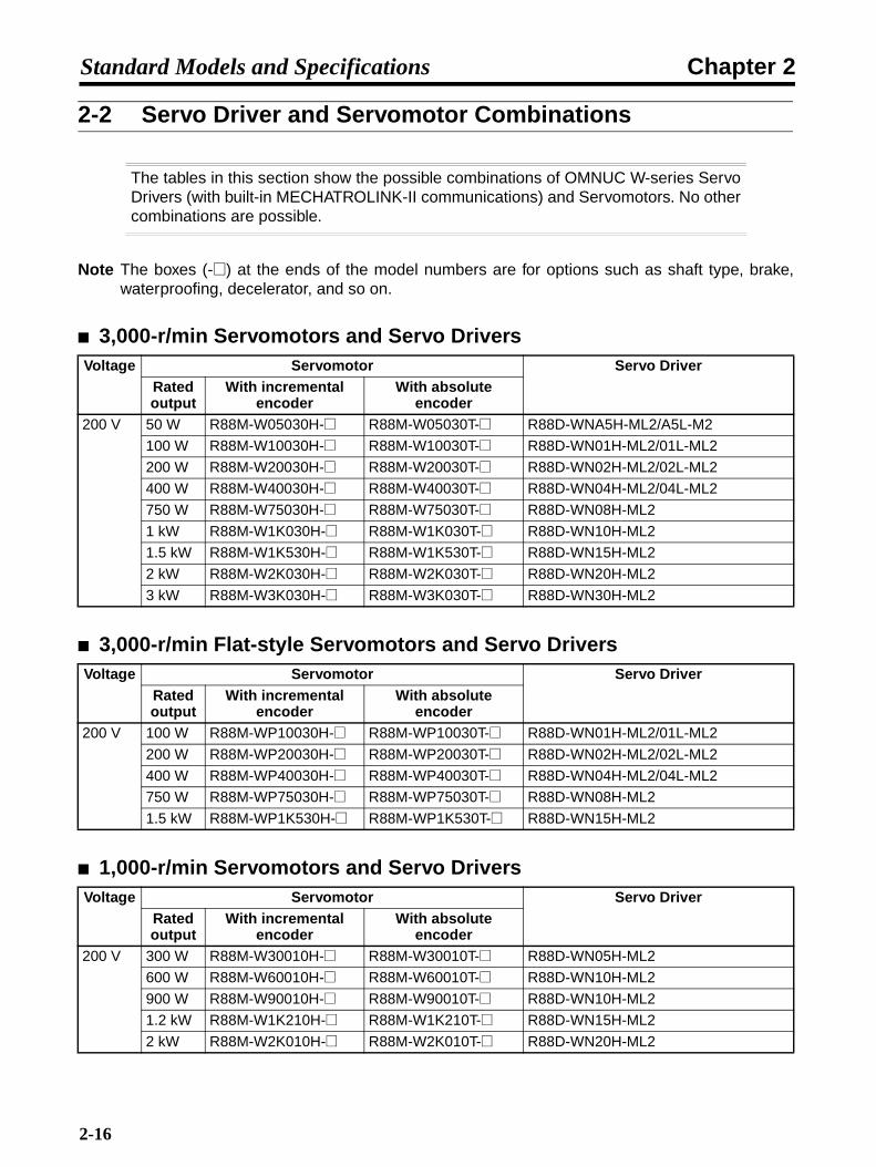
2-2 Servo Driver and Servomotor Combinations
The tables in this section show the possible combinations of OMNUC W-series ServoDrivers (with built-in MECHATROLINK-II communications) and Servomotors. No othercombinations are possible.
Note The boxes (-@) at the ends of the model numbers are for options such as shaft type, brake,waterproofing, decelerator, and so on.
3,000-r/min Servomotors and Servo Drivers
3,000-r/min Flat-style Servomotors and Servo Drivers
1,000-r/min Servomotors and Servo Drivers
Voltage Servomotor Servo DriverRated output
With incremental encoder
With absolute encoder
200 V 50 W R88M-W05030H-@ R88M-W05030T-@ R88D-WNA5H-ML2/A5L-M2
100 W R88M-W10030H-@ R88M-W10030T-@ R88D-WN01H-ML2/01L-ML2
200 W R88M-W20030H-@ R88M-W20030T-@ R88D-WN02H-ML2/02L-ML2
400 W R88M-W40030H-@ R88M-W40030T-@ R88D-WN04H-ML2/04L-ML2
750 W R88M-W75030H-@ R88M-W75030T-@ R88D-WN08H-ML2
1 kW R88M-W1K030H-@ R88M-W1K030T-@ R88D-WN10H-ML2
1.5 kW R88M-W1K530H-@ R88M-W1K530T-@ R88D-WN15H-ML2
2 kW R88M-W2K030H-@ R88M-W2K030T-@ R88D-WN20H-ML2
3 kW R88M-W3K030H-@ R88M-W3K030T-@ R88D-WN30H-ML2
Voltage Servomotor Servo DriverRated output
With incremental encoder
With absolute encoder
200 V 100 W R88M-WP10030H-@ R88M-WP10030T-@ R88D-WN01H-ML2/01L-ML2
200 W R88M-WP20030H-@ R88M-WP20030T-@ R88D-WN02H-ML2/02L-ML2
400 W R88M-WP40030H-@ R88M-WP40030T-@ R88D-WN04H-ML2/04L-ML2
750 W R88M-WP75030H-@ R88M-WP75030T-@ R88D-WN08H-ML2
1.5 kW R88M-WP1K530H-@ R88M-WP1K530T-@ R88D-WN15H-ML2
Voltage Servomotor Servo DriverRated output
With incremental encoder
With absolute encoder
200 V 300 W R88M-W30010H-@ R88M-W30010T-@ R88D-WN05H-ML2
600 W R88M-W60010H-@ R88M-W60010T-@ R88D-WN10H-ML2
900 W R88M-W90010H-@ R88M-W90010T-@ R88D-WN10H-ML2
1.2 kW R88M-W1K210H-@ R88M-W1K210T-@ R88D-WN15H-ML2
2 kW R88M-W2K010H-@ R88M-W2K010T-@ R88D-WN20H-ML2
2-16

Chapter 2Standard Models and Specifications
1,500-r/min Servomotors and Servo DriversVoltage Servomotor Servo Driver
Rated output
With incremental encoder
With absolute encoder
200 V 450 W --- R88M-W45015T-@ R88D-WN05H-ML2
850 W --- R88M-W85015T-@ R88D-WN10H-ML2
1.3 kW --- R88M-W1K315T-@ R88D-WN15H-ML2
1.8 kW --- R88M-W1K815T-@ R88D-WN20H-ML2
2-17
Chapter 2Standard Models and Specifications
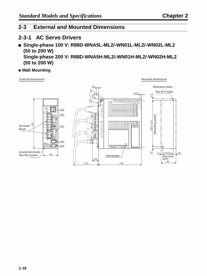
2-3 External and Mounted Dimensions
2-3-1 AC Servo Drivers Single-phase 100 V: R88D-WNA5L-ML2/-WN01L-ML2/-WN02L-ML2
(50 to 200 W)Single-phase 200 V: R88D-WNA5H-ML2/-WN01H-ML2/-WN02H-ML2 (50 to 200 W)
Wall Mounting
External dimensions Mounted dimensions
45
CN4
CN2
CN1
CN6
CN3
150
(16)
125
(6)
(75)
(18)
(4.5)
130
SW1
CHARGE
CN6
CN3
CN1
CN2
CN4
A/B
L1
L2
L1C
L2C
B1/ +
B2
U
V
W
55 8
45
32±0.55.
513
9.5
±0.5
Terminal Block
Nameplate
Mounting Holes
Two M-4 holes
Ground terminals Two M4 screws
(Mou
ntin
g pi
tch)
(Mounting pitch)
2-18
Chapter 2Standard Models and Specifications
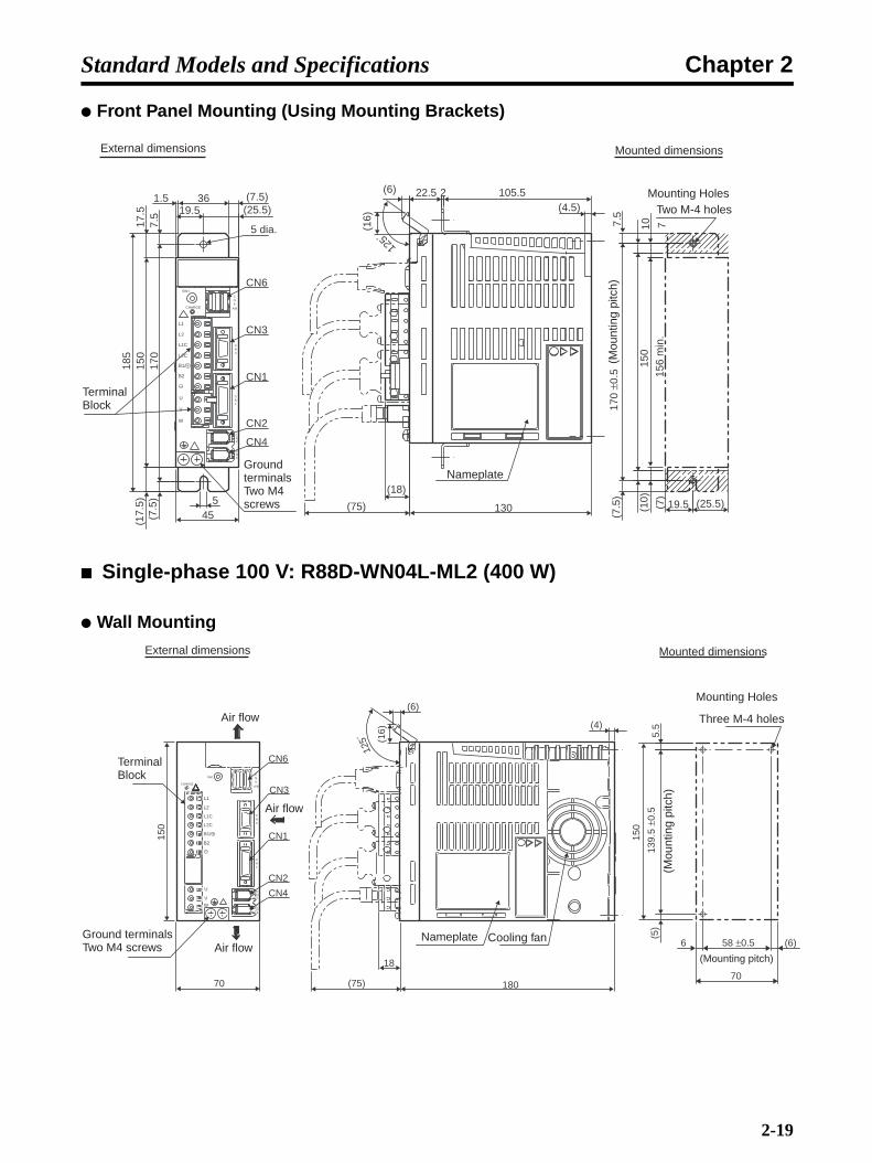
Front Panel Mounting (Using Mounting Brackets)
Single-phase 100 V: R88D-WN04L-ML2 (400 W)
Wall Mounting
(4.5)
(18)
(75) 130
125
22.5 2 105.5
CN6
5 dia.
CN4
CN2
CN3
CN1
150
17.5
5
(25.5)(7.5)
19.5361.5
7.5
170
185
45(25.5)(1
0)
(7)
(7.5
)
150
19.5
10 715
6 m
in.
7.5
170
±0.5
(6)
(16)
(17.
5)(7
.5)
SW1
CHARGE
CN6
CN3
CN1
CN2
CN4
A/B
L1
L2
L1C
L2C
B1/ +
B2
U
V
W
External dimensions
Terminal Block
Ground terminals Two M4 screws
Nameplate
Mounted dimensions
Mounting HolesTwo M-4 holes
(Mou
ntin
g pi
tch)
180
(6)
(75)
18
125
CN4
CN2
CN1
CN3
CN6
150
70 70
(6) 58 ±0.5 6
150
(5)
139
.5 ±
0.5
5.5
(16)
(4)
SW1
CHARGE
L1
L1C
L2C
B1/
B2
U
V
W
L2
CN6
CN3
CN1
CN2
CN4
A/B
External dimensions
Air flow
Terminal Block
Ground terminals Two M4 screws Air flow
Air flow
Nameplate Cooling fan
Mounted dimensions
Mounting Holes
Three M-4 holes
(Mou
ntin
g pi
tch)
(Mounting pitch)
2-19

Chapter 2Standard Models and Specifications
Front Panel Mounting (Using Mounting Brackets)
Single-phase 200 VAC: R88D-WN04H-ML2 (400 W)
Wall Mounting
CN4
CN2
CN1
CN3
CN6
5 dia.
(15.5)3618.5
185
150
17.5
7.5
170
70
5
125
24.52
18
75)( 180
156
min
.
(33.5) 36.5
70
10 7
(7)
(10
)
(7.
5) 1
70 ±
0.5
(7.
5)
150
(7.5
)
(17.
5)
(16)
(6)
(4)36.5 (33.5)
125
External dimensions
Terminal Block
Ground terminals Two M4 screws
Air flow
Air flow
Air flow
Nameplate Cooling fan
Mounted dimensions
Mounting HolesTwo M-4 holes
(Mou
ntin
g pi
tch)
125
130
CN4
CN6
CN3
CN1
CN2
65
150
(5)
139.
5 ±0
.55.
5
47 ±0.510 (18)
(16)
(6)
(4)
(8)
(75)
CN6
CN3
CN1
CN2
CN4
A/B
L1
SW1
CHARGE
L2
L1C
L2C
B1/ +
B2
U
V
W
External dimensions
Terminal Block
Ground terminals Two M4 screws Nameplate
Mounted dimensions
Mounting Holes
Two M-4 holes
(Mou
ntin
g pi
tch)
(Mounting pitch)
2-20

Chapter 2Standard Models and Specifications
Front Panel Mounting (Using Mounting Brackets)
Single-phase 200 VAC: R88D-WN08HML2 (750 W)Three-phase 200 VAC: R88D-WN05H-ML2/-WN10H-ML2 (500 W to 1 kW)
Wall Mounting
125
130
105.522.5 2
CN4
5 dia.
CN6
CN3
CN1
CN2
654520
150
17.5
21.539.5
36
185
7.5
170
5 7)
( 10)
(7.5
)(
39.5
150
170
±0.5
7.5
10715
6 m
in.
(7.5)(25.5)
(17.
5)
(7.5
)
(6)
(75)
(4)
(16)
(18)
(25.5)
External dimensions
Terminal Block
Ground terminals Two M4 screws
Nameplate
Mounted dimensions
Mounting Holes
Two M-4 holes
(Mou
ntin
g pi
tch)
CN4
CN2
CN1
CN3
CN6
70
150
180
(6)
(75)
18
125
70
(6) 58 ±0.5 6
150
(5)
139
.5 ±
0.5
5.5
(16)
(4)
CN6
CN3
CN1
CN2
CN4
A/B
L1
CHARGESW1
L2
L2
L1C
L2C
B1/ +
B2
B3
U
V
W
1
2
External dimensions
Air flow
Terminal Block
Ground terminals Two M4 screws
Air flow
Air flow
Nameplate Cooling fan
Mounted dimensions
Mounting Holes
Three M-4 holes
(Mou
ntin
g pi
tch)
(Mounting pitch)
2-21

Chapter 2Standard Models and Specifications
Front Panel Mounting (Using Mounting Brackets)
Three-phase 200 V: R88D-WN15H-ML2 (1.5 kW)
Wall Mounting
156
min
.
36.5
70
10 7
(7)
(10
)
(7.
5) 1
70 ±
0.5
(7.
5)
150
CN4
CN2
CN1
CN3
CN6
5 dia.
3618.5
185
150
17.5
7.5
170
70
5
125
16)
(
24.52
18
75)( 180
(15.5)
(33.5)
(17.
5)
(7.5
)
(6)
(4)
(33.5)
36.5
External dimensions
Air flow
Terminal Block
Ground terminals Two M4 screws
Air flow
Air flow
Nameplate Cooling fan
Mounted dimensions
Mounting Holes
Two M-4 holes
(Mou
ntin
g pi
tch)
180(75)18
CN4
CN6
CN3
CN1
CN2
90
150
(16)
125˚
(6)
(4)
(5)
(5)
5.5
5
139.
5 ±0
.5
150
80 ±0.5
90
CHARGE
L1
L1
CN6
CN3
CN1
CN2
CN4
A/BL2
L3
L1C
L2C
B1/ +
B2
B3
U
V
W
- 1
- 2
SW1
External dimensions
Terminal Block
Ground terminals Two M4 screws
Nameplate
Mounted dimensions
Mounting Holes
Three M-4 holes
(Mou
ntin
g pi
tch)
(Mounting pitch)
2-22

Chapter 2Standard Models and Specifications
)
Front Panel Mounting (Using Mounting Brackets)
Three-phase 200 V: R88D-WN20H-ML2/-WN30H-ML2 (2 to 3 kW)
Wall Mounting
SW1CN6
CN3
CN1
CN2
CN4
A/B
CHARGE
L1
L2
L3
L1C
L2C
B1/ +
B2
B3
U
V
W
1
2
154
(15.
5)
50
90(2.2)
20 (20)
5
15.5 Two, 5 dia.
CN6
170
7.5
(7.5
)
185
CN3
CN1
CN2
CN4
(6)
(16)
125˚
2
24.518
(75) 180
(7.5
)7.
5
(5)
20 (20
154
156
min
.7
(7)
170
±0.5
50 ±0.5
-
-
External Dimensions
Air flow
Terminal blocks
Ground terminals Two M4 screws
Air flow
Nameplate
Mounted Dimensions
Mounting Holes
Four M-4 holes
(Mou
ntin
g pi
tch)
(Mounting pitch)
(16)
(6)
125˚
(5)(5)
5
5
170
±0.5
180
90 ±0.5
100
(4)
100 180(75)
180
CN4
CN6
CN3
CN1
CN2
External dimensions
Terminal Block M4 screws
Ground ter-minals Two M4 screws
Nameplate
Mounted dimensions
Mounting Holes
Four M-4 holes
(Mou
ntin
g pi
tch)
(Mounting pitch)
2-23
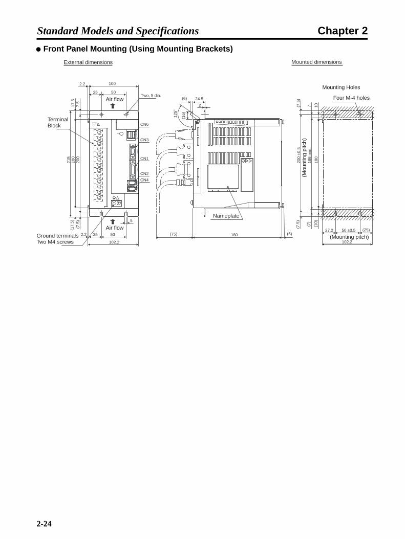
Chapter 2Standard Models and Specifications
Front Panel Mounting (Using Mounting Brackets)
5
100
25
25 50
102.2
2.2
2.2
7.5
200
(7.5
)(1
7.5)
180
215
17.5
50
(6) 24.5
(16)12
5˚
2
180 (5)(75)
1018
0(1
0)
(7)
(7.5
)
186
min
.
200
±0.5
7(7.5
)
50 ±0.5
102.2
(25)27.2
Two, 5 dia.
CN6
CN3
CN1
CN2
CN4
SW1
A/B
CHARGE
CN6
CN3
CN1
CN2
CN4
External dimensions
Air flow
Terminal Block
Ground terminals Two M4 screws
Air flow
Nameplate
Mounted dimensions
Mounting Holes
Four M-4 holes
(Mou
ntin
g pi
tch)
(Mounting pitch)
2-24

Chapter 2Standard Models and Specifications
2-3-2 AC Servomotors
3,000-r/min Servomotors without a Brake
200 V AC: 50 W/100 WR88M-W05030H(-S1)/-W10030H(-S1) [Incremental]R88M-W05030T(-S1)/-W10030T(-S1) [Absolute]
3,000-r/min Servomotors with a Brake
200 V AC: 50 W/100 WR88M-W05030H-B(S1)/-W10030H-B(S1) [Incremental]R88M-W05030T-B(S1)/-W10030T-B(S1) [Absolute]
Two, 4.3 dia.
LL 25
405 2.5
S d
ia.
30h7
dia
.
300 ±30
300 ±30
46 dia.
4014
h
t1
b
ModelDimensions (mm)
SLL b h t1
R88M-W05030@-@
R88M-W10030@-@
77
94.5
6h6
8h6
2 2
3 3
M
M2.5
l
51.2
1.8
14
h
t1
b
6 dia. 7 dia.
9.5
19.5 20
11
21.5 5
M3 6
Dimensions of shaft end with key and tap (-S2)
Dimensions of shaft end with key (-S1)
M (effective depth: l)
14Two, 4.3 dia.
LL 25
405 2.5
S d
ia.
30h7
dia
.
300 ±30
300 ±30
46 dia.
40
ModelDimensions (mm)
SLL b h t1
R88M-W05030@-B@
R88M-W10030@-B@
108.5
135
6h6
8h6
2 2
3 3
1.2
1.8
h
t1
b
6 dia. 7 dia.
9.5
19.5 27
11
21.5 5
M
M2.5
l
5
M3 6
Dimensions of shaft end with key (-BS1)
14
h
t1
b
Dimensions of shaft end with key and tap (-BS2)
M (effective depth: l)
2-25

Chapter 2Standard Models and Specifications
3,000-r/min Servomotors without a Brake
200 V AC: 200 W/400 W/750 WR88M-W20030H(-S1)/-W40030H(-S1)/-W75030H(-S1) [Incremental]R88M-W20030T(-S1)/-W40030T(-S1)/-W75030T(-S1) [Absolute]
300 ±30
300 ±30
S d
ia.
D2
dia.
LL LR
G 3C
C
Four, Z dia.
D1 dia.
ModelDimensions (mm)
LRLL C D1 D2
R88M-W20030@-@
R88M-W40030@-@
R88M-W75030@-@
96.5
124.5
145
30
30
40
60 70
60 70
80 90
50h7
50h7
70h7
G
6
6
8
Z
5.5
5.5
7
S
14h6
14h6
16h6
QK
20
20
30
QK
2
5
5
3
6 dia.
7 dia.
20
11
13
9
21.5
Dimensions of shaft end with key (-S1)
QK
5
5
3
M5
(effective depth: 8)
Dimensions of output section of 750-W Servomotors
Dimensions of shaft end with key and tap (-S2)
2-26
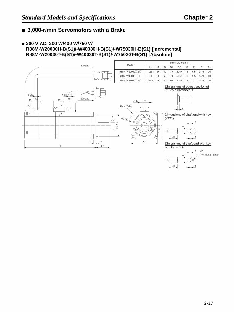
Chapter 2Standard Models and Specifications
8)
3,000-r/min Servomotors with a Brake
200 V AC: 200 W/400 W/750 WR88M-W20030H-B(S1)/-W40030H-B(S1)/-W75030H-B(S1) [Incremental]R88M-W20030T-B(S1)/-W40030T-B(S1)/-W75030T-B(S1) [Absolute]
300 ±30
300 ±30
S d
ia.
D2
dia.
LL LR
G 3
C
C
Four, Z dia.
D1 dia.
ModelDimensions (mm)
LRLL C D1 D2
R88M-W20030@-B@
R88M-W40030@-B@
R88M-W75030@-B@
136
164
189.5
30
30
40
60 70
60 70
80 90
50h7
50h7
70h7
G
6
6
8
Z
5.5
5.5
7
S
14h6
14h6
16h6
QK
20
20
30
6 dia. 7 dia.
21.5
9
13 27
11
QK
2
5
5
3
QK
5
5
3
M5
(effective depth:
Dimensions of output section of 750-W Servomotors
Dimensions of shaft end with key (-BS1)
Dimensions of shaft end with key and tap (-BS2)
2-27
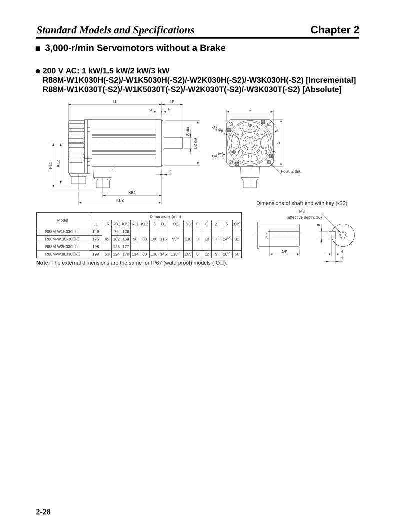
Chapter 2Standard Models and Specifications
3,000-r/min Servomotors without a Brake
200 V AC: 1 kW/1.5 kW/2 kW/3 kWR88M-W1K030H(-S2)/-W1K5030H(-S2)/-W2K030H(-S2)/-W3K030H(-S2) [Incremental]R88M-W1K030T(-S2)/-W1K5030T(-S2)/-W2K030T(-S2)/-W3K030T(-S2) [Absolute]
ModelDimensions (mm)
LRLL C D1 D2
R88M-W2K030@-@
R88M-W3K030@-@
198
199 63 130 145 110h7
G
12
Z
9
S
28h6
QK
R88M-W1K530@-@ 175
R88M-W1K030@-@ 149
45 100 115 95h7 10 7 24h6 32
50
F
6
3
D3
165
130
Dimensions of shaft end with key (-S2)
KB1
125
124
102
76
KB2
177
178
154
128
KL1
114
96
KL2
88
88
QK
8
7
4
M8
KL1 KL2
KB1
KB2
LL LR
G F
S d
ia.
D2
dia.
Four, Z dia.
C
C
D1 dia.
D3 dia.
Note: The external dimensions are the same for IP67 (waterproof) models (-O@).
2
(effective depth: 16)
2-28
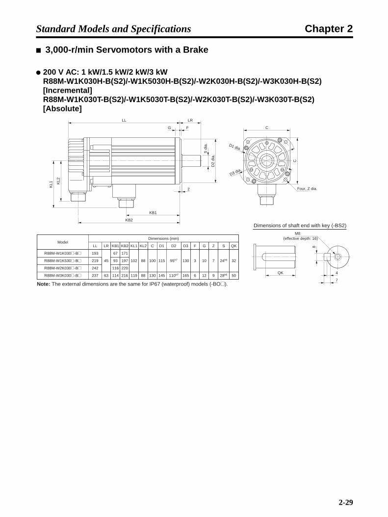
Chapter 2Standard Models and Specifications
3,000-r/min Servomotors with a Brake
200 V AC: 1 kW/1.5 kW/2 kW/3 kWR88M-W1K030H-B(S2)/-W1K5030H-B(S2)/-W2K030H-B(S2)/-W3K030H-B(S2) [Incremental]R88M-W1K030T-B(S2)/-W1K5030T-B(S2)/-W2K030T-B(S2)/-W3K030T-B(S2) [Absolute]
ModelDimensions (mm)
LRLL C D1 D2
R88M-W2K030@-B@
R88M-W3K030@-B@
242
237 63 130 145 110h7
G
12
Z
9
S
28h6
QK
R88M-W1K530@-B@ 219
R88M-W1K030@-B@ 193
45 100 115 95h7 10 7 24h6 32
50
F
6
3
D3
165
130
Dimensions of shaft end with key (-BS2)
KB1
116
114
93
67
KB2
220
216
197
171
KL1
119
102
KL2
88
88
QK
8
7
4
M8
KL1 K
L2
KB1
KB2
LL LR
G F
S d
ia.
D2
dia.
Four, Z dia.
C
C
D1 dia.
D3 dia.
Note: The external dimensions are the same for IP67 (waterproof) models (-BO@).
2
(effective depth: 16)
2-29
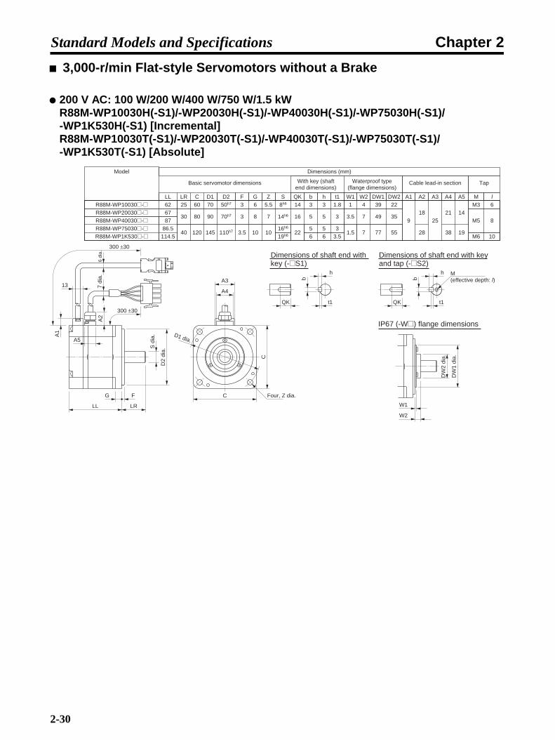
Chapter 2Standard Models and Specifications
3,000-r/min Flat-style Servomotors without a Brake
200 V AC: 100 W/200 W/400 W/750 W/1.5 kWR88M-WP10030H(-S1)/-WP20030H(-S1)/-WP40030H(-S1)/-WP75030H(-S1)/-WP1K530H(-S1) [Incremental]R88M-WP10030T(-S1)/-WP20030T(-S1)/-WP40030T(-S1)/-WP75030T(-S1)/-WP1K530T(-S1) [Absolute]
Model Dimensions (mm)
LRLL C D1 D2
R88M-WP40030@-@R88M-WP75030@-@R88M-WP1K530@-@
8786.5
114.5
G Z S QK b h t1
R88M-WP20030@-@ 67R88M-WP10030@-@ 62
F25 60 70 50h7 3 6 5.5 8h6 14 3 3 1.8
16h6 5 5 319h6 6 6 3.5
30 80 90 70h7 3 8 7
40 120 145 110h7 3.5 10 10
14h6 16
22
5 5 3
W1 W2 DW1 DW21 4 39 22
3.5
1.5
7 49 35
7 77 55
Basic servomotor dimensions
G F
LL LR
S d
ia.
D2
dia.
C
C
300 ±30
300 ±30
Four, Z dia.
D1 dia.
W1
DW
1 di
a.
DW
2 di
a.
W2
IP67 (-W@) flange dimensions
QK
h
t1b
QK
h
t1
b
6 di
a.7
dia.
A1
A2
13
A5
A3
A4
Cable lead-in section
A1 A2 A3 A4 A5
918
28
2521
38 19
14
Tap
M lM3 6
M5 8
M6 10
M (effective depth: l)
With key (shaft end dimensions)
Waterproof type (flange dimensions)
Dimensions of shaft end with key (-@S1)
Dimensions of shaft end with key and tap (-@S2)
2-30

Chapter 2Standard Models and Specifications
3,000-r/min Flat-style Servomotors with a Brake
200 V AC: 100 W/200 W/400 W/750 W/1.5 kWR88M-WP10030H-B(S1)/-WP20030H-B(S1)/-WP40030H-B(S1)/-WP75030H-B(S1)/-WP1K530H-B(S1) [Incremental]R88M-WP10030T-B(S1)/-WP20030T-B(S1)/-WP40030T-B(S1)/-WP75030T-B(S1)/-WP1K530T-B(S1) [Absolute]
G F
LL LR
S d
ia.
D2
dia.
300 ±30
300 ±30
C
C Four, Z dia.
D1 dia.
Model Dimensions (mm)
LRLL C D1 D2
R88M-WP40030@-B@R88M-WP75030@-B@R88M-WP1K530@-B@
118.5120148
G Z S QK b h t1
R88M-WP20030@-B@ 98.5R88M-WP10030@-B@ 91
F25 60 70 50h7 3 6 5.5 8h6 14 3 3 1.8
16h6 5 5 319h6 6 6 3.5
30 80 90 70h7 3 8 7
40 120 145 110h7 3.5 10 10
14h6 16
22
5 5 3
W1 W2 DW1 DW21 4 39 22
3.5
1.5
7 49 35
7 77 55
Basic servomotor dimensions
QK
h
t1b
W1
DW
1 di
a.
DW
2 di
a.
W2
6 di
a.7
dia. A3
A4
A1
13
A2
A5
Cable lead-in section
A1 A2 A3 A4 A5
918
28
2521
38 26
23
Tap
M lM3 6
M5 8
M6 10
QK
h
t1
b
M (effective depth: l)
IP67 (-BW@) flange dimensions
With key (shaft end dimensions)
Waterproof type (flange dimensions)
Dimensions of shaft end with key (-B@S1)
Dimensions of shaft end with key and tap (-B@S2)
2-31

Chapter 2Standard Models and Specifications
1,000-r/min Servomotors without a Brake
200 V AC: 300 W/600 W/900 W/1.2 kW/2.0 kWR88M-W30010H(-S2)/-W60010H(-S2)/-W90010H(-S2)/-W1K210H(-S2)/-W2K010H(-S2) [Incremental]R88M-W30010T(-S2)/-W60010T(-S2)/-W90010T(-S2)/-W1K210T(-S2)/-W2K010T(-S2) [Absolute]
Model (mm)Dimensions (mm)
LRLL C D1 D2
R88M-W90010@-@
R88M-W1K210@-@
R88M-W2K010@-@
185
166
19279 180 200 114.3
G
18
Z
13.5
S
22h6
QK b
R88M-W60010@-@ 161
R88M-W30010@-@ 138
58 130 145 110h7 12 919h6
25
60
M
M5
M12
l
12
25
5
10
F
3.2
6
D3
230
165
KB1
112
89
115
88
65
KB2
164
144
170
140
117
KL1
140
109
KL2
88
88
QK
b
h
t1
M (Effective depth: l)KL1 KL2
KB1
KB2
LL LR
G F
S d
ia.
D2
dia.
Four, Z dia.
C
C
D1 dia.
D3 dia.
0−0.025
6
h
5
8
6
t1
3
5
3.5
35 +0.010
12
30 d
ia.
Note: The external dimensions are the same for IP67 (waterproof) models (-O@).
Dimensions of output section of 300-W to 900-W Servomotors
Dimensions of shaft end with key (-S2)
2-32

Chapter 2Standard Models and Specifications
1,000-r/min Servomotors with a Brake
200 V AC: 300 W/600 W/900 W/1.2 kW/2.0 kWR88M-W30010H-B(S2)/-W60010H-B(S2)/-W90010H-B(S2)/-W1K210H-B(S2)/-W2K010H-B(S2) [Incremental]R88M-W30010T-B(S2)/-W60010T-B(S2)/-W90010T-B(S2)/-W1K210T-B(S2)/-W2K010T-B(S2) [Absolute]
QK
b
h
t1
M (Effective depth: l)
KL1 K
L2
KB1
KB2
LL LR
G F
S d
ia.
D2
dia.
Four, Z dia.
C
C
D1 dia.
D3 dia.
Model (mm)Dimensions (mm)
LRLL C D1 D2
R88M-W90010@-B@
R88M-W1K210@-B@
R88M-W2K010@-B@
223
217
24379 180 200 114.3
G
18
Z
13.5
S
22h6
QK b
R88M-W60010@-B@ 199
R88M-W30010@-B@ 176
58 130 145 110h7 12 919h6
25
60
M
M5
M12
l
12
25
5
10
F
3.2
6
D3
230
165
KB1
103
79
105
79
56
KB2
201
195
221
177
154
KL1
146
120
KL2
88
88
0−0.025 35 +0.01
0
6
h
5
8
6
t1
3
5
3.5
12
30 d
ia.
Note: The external dimensions are the same for IP67 (waterproof) models (-BO@).
Dimensions of output section of 300-W to 900-W Servomotors
Dimensions of shaft end with key (-BS2)
2-33

Chapter 2Standard Models and Specifications
1,500-r/min Servomotors without a Brake
200 V AC: 450 W/850 W/1.3 kW/1.8 kWR88M-W45015T(-S2)/-W85015T(-S2)/-W1K315T(-S2)/-W1K815T(-S2) [Absolute]
Model (mm)Dimensions (mm)
LRLL C D1 D2
R88M-W1K315T-@
R88M-W1K815T-@
185
166 79 180 200 114.3
G
18
Z
13.5
S
22h6
QK b
R88M-W85015T-@ 161
R88M-W45015T-@ 138
58 130 145 110h7 12 919h6
25
60
M
M5
M12
l
12
25
5
10
F
3.2
6
D3
230
165
KB1
112
89
88
65
KB2
164
144
140
117
KL1
140
109
KL2
88
88
QK
b
h
t1
M (Effective depth: l)
KL1 KL2
KB1
KB2
LL LR
G F
S d
ia.
D2
dia.
Four, Z dia.
C
C
D1 dia.
D3 dia.
0−0.025
6
h
5
8
6
t1
3
5
3.5
Note: The external dimensions are the same for IP67 (waterproof) models (O@).
35 +0.010
12
30 d
ia.
Dimensions of output section of 450-W to 1.3-kW Servomotors
Dimensions of shaft end with key (-S2)
2-34
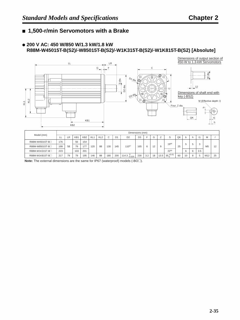
Chapter 2Standard Models and Specifications
1,500-r/min Servomotors with a Brake
200 V AC: 450 W/850 W/1.3 kW/1.8 kWR88M-W45015T-B(S2)/-W85015T-B(S2)/-W1K315T-B(S2)/-W1K815T-B(S2) [Absolute]
QK
b
h
t1
M (Effective depth: l)
KL1 K
L2
KB1
KB2
LL LR
G F
S d
ia.
D2
dia.
Four, Z dia.
C
C
D1 dia.
D3 dia.
Model (mm)Dimensions (mm)
LRLL C D1 D2
223
217 79 180 200 114.3
G
18
Z
13.5
S
22h6
QK b
199
176
58 130 145 110h7 12 919h6
25
60
M
M5
M12
l
12
25
5
10
F
3.2
6
D3
230
165
KB1
103
79
79
56
KB2
201
195
177
154
KL1
146
120
KL2
88
88
0−0.025 35 +0.01
0
6
h
5
8
6
t1
3
5
3.5
12
30 d
ia.
R88M-W1K315T-B@
R88M-W1K815T-B@
R88M-W85015T-B@
R88M-W45015T-B@
Note: The external dimensions are the same for IP67 (waterproof) models (-BO@).
Dimensions of output section of450-W to 1.3-kW Servomotors
Dimensions of shaft end with key (-BS2)
2-35

Chapter 2Standard Models and Specifications
2-3-3 AC Servomotors with Gears
AC Servomotors with Standard Gears 3,000-r/min Servomotors (30 to 750 W) with Standard Gears
Note The values in parentheses are reference values.
Diagram 1
Model Dia-gram No.
Dimensions (mm)
LL LM LR C1 C2 D1 D2 D3 D4 D5 D6
WOB* WB*
50 W 1/5 R88M-W05030@-@G05BJ 1, 1-1 77 108.5 28 55 60 40 80 70 56 55.5 40 ---
1/9 R88M-W05030@-@G09BJ 77 108.5 29 60 70 40 95 80 65 64.5 50 ---
1/21 R88M-W05030@-@G21BJ 1, 1-2 77 108.5 46 60 70 40 (92) 80 65 64.5 40 8
1/33 R88M-W05030@-@G33BJ 77 108.5 46 60 70 40 (92) 80 65 64.5 40 8
100 W 1/5 R88M-W10030@-@G05BJ 94.5 135 29 60 70 40 (92) 80 65 64.5 40 8
1/11 R88M-W10030@-@G11BJ 94.5 135 46 60 70 40 (92) 80 65 64.5 40 8
1/21 R88M-W10030@-@G21BJ 94.5 135 55 74 90 40 (120) 105 85 84 59 9
1/33 R88M-W10030@-@G33BJ 94.5 135 55 74 90 40 (120) 105 85 84 59 9
200 W 1/5 R88M-W20030@-@G05BJ 2 96.5 136 38 74 90 60 (120) 105 85 84 59 9
1/11 R88M-W20030@-@G11BJ 96.5 136 55 74 90 60 (120) 105 85 84 59 9
1/21 R88M-W20030@-@G21BJ 96.5 136 63 84 105 60 (139) 120 100 96 59 12
1/33 R88M-W20030@-@G33BJ 96.5 136 63 84 105 60 (139) 120 100 96 59 12
400 W 1/5 R88M-W40030@-@G05BJ 2 124.5 164 38 74 90 60 (120) 105 85 84 59 9
1/11 R88M-W40030@-@G11BJ 124.5 164 63 84 105 60 (139) 120 100 96 59 12
1/21 R88M-W40030@-@G21BJ 124.5 164 71 105 120 60 (158) 135 115 112 59 14
1/33 R88M-W40030@-@G33BJ 124.5 164 71 105 120 60 (158) 135 115 114 84 14
750 W 1/5 R88M-W75030@-@G05BJ 2 145 189.5 42 84 105 80 (139) 120 100 96 59 12
1/11 R88M-W75030@-@G11BJ 145 189.5 71 105 120 80 (158) 135 115 112 59 14
1/21 R88M-W75030@-@G21BJ 145 189.5 78 142 145 80 (192) 165 140 134 84 16
1/33 R88M-W75030@-@G33BJ 145 189.5 78 142 145 80 (192) 165 140 134 84 16
Sh7
dia
.
D5
dia.
D4
dia.
D3h
7 di
a.
Four, Z dia.
D2 dia.
D1 dia.
C2
× C
2
Key dimensionsM (Effective depth: l)
Diagram 1-1
LL LM LR
T
E1
E2
G F
b
h
t1
C1 × C1
C1 × C1
Diagram 1-2
D1 dia. D2 dia.
Four, Z dia.
Four, RD6
QK
2-36
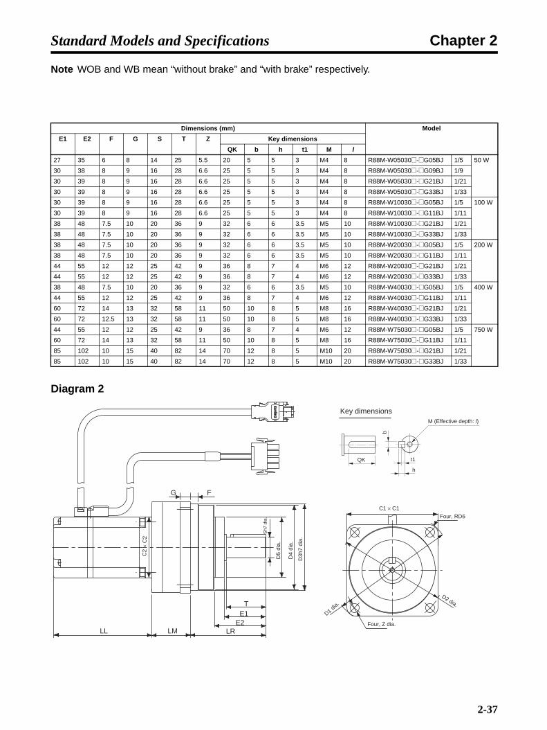
Chapter 2Standard Models and Specifications
Note WOB and WB mean “without brake” and “with brake” respectively.
Diagram 2
Dimensions (mm) Model
E1 E2 F G S T Z Key dimensions
QK b h t1 M l
27 35 6 8 14 25 5.5 20 5 5 3 M4 8 R88M-W05030@-@G05BJ 1/5 50 W
30 38 8 9 16 28 6.6 25 5 5 3 M4 8 R88M-W05030@-@G09BJ 1/9
30 39 8 9 16 28 6.6 25 5 5 3 M4 8 R88M-W05030@-@G21BJ 1/21
30 39 8 9 16 28 6.6 25 5 5 3 M4 8 R88M-W05030@-@G33BJ 1/33
30 39 8 9 16 28 6.6 25 5 5 3 M4 8 R88M-W10030@-@G05BJ 1/5 100 W
30 39 8 9 16 28 6.6 25 5 5 3 M4 8 R88M-W10030@-@G11BJ 1/11
38 48 7.5 10 20 36 9 32 6 6 3.5 M5 10 R88M-W10030@-@G21BJ 1/21
38 48 7.5 10 20 36 9 32 6 6 3.5 M5 10 R88M-W10030@-@G33BJ 1/33
38 48 7.5 10 20 36 9 32 6 6 3.5 M5 10 R88M-W20030@-@G05BJ 1/5 200 W
38 48 7.5 10 20 36 9 32 6 6 3.5 M5 10 R88M-W20030@-@G11BJ 1/11
44 55 12 12 25 42 9 36 8 7 4 M6 12 R88M-W20030@-@G21BJ 1/21
44 55 12 12 25 42 9 36 8 7 4 M6 12 R88M-W20030@-@G33BJ 1/33
38 48 7.5 10 20 36 9 32 6 6 3.5 M5 10 R88M-W40030@-@G05BJ 1/5 400 W
44 55 12 12 25 42 9 36 8 7 4 M6 12 R88M-W40030@-@G11BJ 1/11
60 72 14 13 32 58 11 50 10 8 5 M8 16 R88M-W40030@-@G21BJ 1/21
60 72 12.5 13 32 58 11 50 10 8 5 M8 16 R88M-W40030@-@G33BJ 1/33
44 55 12 12 25 42 9 36 8 7 4 M6 12 R88M-W75030@-@G05BJ 1/5 750 W
60 72 14 13 32 58 11 50 10 8 5 M8 16 R88M-W75030@-@G11BJ 1/11
85 102 10 15 40 82 14 70 12 8 5 M10 20 R88M-W75030@-@G21BJ 1/21
85 102 10 15 40 82 14 70 12 8 5 M10 20 R88M-W75030@-@G33BJ 1/33
Sh7
dia
.
D5
dia.
D4
dia.
D3h
7 di
a.
D1 dia.
Four, Z dia.
Key dimensionsM (Effective depth: l)
G F
C2
× C
2
LL LM LRE2
E1T
D2 dia.
C1 × C1
b
h
t1
Four, RD6
QK
2-37

Chapter 2Standard Models and Specifications
3,000-r/min Servomotors (1 to 5 kW) with Standard Gears
Diagram 1
Model Dia-gram No.
Dimensions (mm)
LL LM LR C1 C2 D1 D2 D3 D4 D5
WOB* WB*
1 kW 1/5 R88M-W1K030@-@G05BJ 1 149 193 154 100 140 100 185 160 130 94 91
1/9 R88M-W1K030@-@G09BJ 149 193 166 100 140 100 185 160 130 94 91
1/20 R88M-W1K030@-@G20BJ 2 149 193 207 140 --- 100 245 220 190 135 130
1/29 R88M-W1K030@-@G29BJ 149 193 207 140 --- 100 245 220 190 135 130
1/45 R88M-W1K030@-@G45BJ 149 193 217 140 --- 100 245 220 190 135 130
1.5 kW 1/5 R88M-W1K530@-@G05BJ 1 175 219 154 100 140 100 185 160 130 94 91
1/9 R88M-W1K530@-@G09BJ 2 175 219 203 140 --- 100 245 220 190 135 130
1/20 R88M-W1K530@-@G20BJ 175 219 207 140 --- 100 245 220 190 135 130
1/29 R88M-W1K530@-@G29BJ 175 219 207 140 --- 100 245 220 190 135 130
1/45 R88M-W1K530@-@G45BJ 175 219 238 160 --- 100 310 280 240 186 182
2 kW 1/5 R88M-W2K030@-@G05BJ 1 198 242 154 100 140 100 185 160 130 94 91
1/9 R88M-W2K030@-@G09BJ 2 198 242 203 140 --- 100 245 220 190 135 130
1/20 R88M-W2K030@-@G20BJ 198 242 207 140 --- 100 245 220 190 135 130
1/29 R88M-W2K030@-@G29BJ 198 242 228 160 --- 100 310 280 240 186 182
1/45 R88M-W2K030@-@G45BJ 198 242 238 160 --- 100 310 280 240 186 182
3 kW 1/5 R88M-W3K030@-@G05BJ 2 199 237 201 140 --- 130 245 220 190 135 130
1/9 R88M-W3K030@-@G09BJ 199 237 228 140 --- 130 245 220 190 135 130
1/20 R88M-W3K030@-@G20BJ 199 237 253 160 --- 130 310 280 240 186 182
1/29 R88M-W3K030@-@G29BJ 199 237 253 160 --- 130 310 280 240 186 182
1/45 R88M-W3K030@-@G45BJ 199 237 263 160 --- 130 310 280 240 186 182
G F
C2
× C
2
LL LM LR
T
E1E3
D5
dia.
D4
dia.
D3h
7 di
a.
Four, Z dia.
D2 dia.
D1 dia.
C1 × C1
QK
b
h
t1
Sh6
dia
.
Key dimensions
2-38

Chapter 2Standard Models and Specifications
Note WOB and WB mean “without brake” and “with brake” respectively.
Diagram 2
Dimensions (mm) Model
E1 E3 F G S T Z IE Key dimensions
QK b h t1
57 20 3 12 35 55 12 --- 47 10 8 5 R88M-W1K030@-@G05BJ 1/5 1 kW
57 20 3 12 35 55 12 --- 47 10 8 5 R88M-W1K030@-@G09BJ 1/9
77 33 5 15 50 75 12 137 65 14 9 5.5 R88M-W1K030@-@G20BJ 1/20
77 33 5 15 50 75 12 137 65 14 9 5.5 R88M-W1K030@-@G29BJ 1/29
77 33 5 15 50 75 12 137 65 14 9 5.5 R88M-W1K030@-@G45BJ 1/45
57 20 3 12 35 55 12 --- 47 10 8 5 R88M-W1K530@-@G05BJ 1/5 1.5 kW
77 33 5 15 50 75 12 137 65 14 9 5.5 R88M-W1K530@-@G09BJ 1/9
77 33 5 15 50 75 12 137 65 14 9 5.5 R88M-W1K530@-@G20BJ 1/20
77 33 5 15 50 75 12 137 65 14 9 5.5 R88M-W1K530@-@G29BJ 1/29
92 38 5 18 60 90 14 171 78 18 11 7 R88M-W1K530@-@G45BJ 1/45
57 20 3 12 35 55 12 --- 47 10 8 5 R88M-W2K030@-@G05BJ 1/5 2 kW
77 33 5 15 50 75 12 137 65 14 9 5.5 R88M-W2K030@-@G09BJ 1/9
77 33 5 15 50 75 12 137 65 14 9 5.5 R88M-W2K030@-@G20BJ 1/20
92 38 5 18 60 90 14 171 78 18 11 7 R88M-W2K030@-@G29BJ 1/29
92 38 5 18 60 90 14 171 78 18 11 7 R88M-W2K030@-@G45BJ 1/45
77 33 5 15 50 75 12 137 65 14 9 5.5 R88M-W3K030@-@G05BJ 1/5 3 kW
77 33 5 15 50 75 12 137 65 14 9 5.5 R88M-W3K030@-@G09BJ 1/9
92 38 5 18 60 90 14 171 78 18 11 7 R88M-W3K030@-@G20BJ 1/20
92 38 5 18 60 90 14 171 78 18 11 7 R88M-W3K030@-@G29BJ 1/29
92 38 5 18 60 90 14 171 78 18 11 7 R88M-W3K030@-@G45BJ 1/45
G F
LL LM LR
T
E1E3
Sh6
dia
.
D5
dia.
D4
dia.
D3h
7 di
a.
C2
× C
2
IE
QK
Six, Z dia.
D2 dia.
D1 dia.
b
h
t1
Key dimensions
2-39
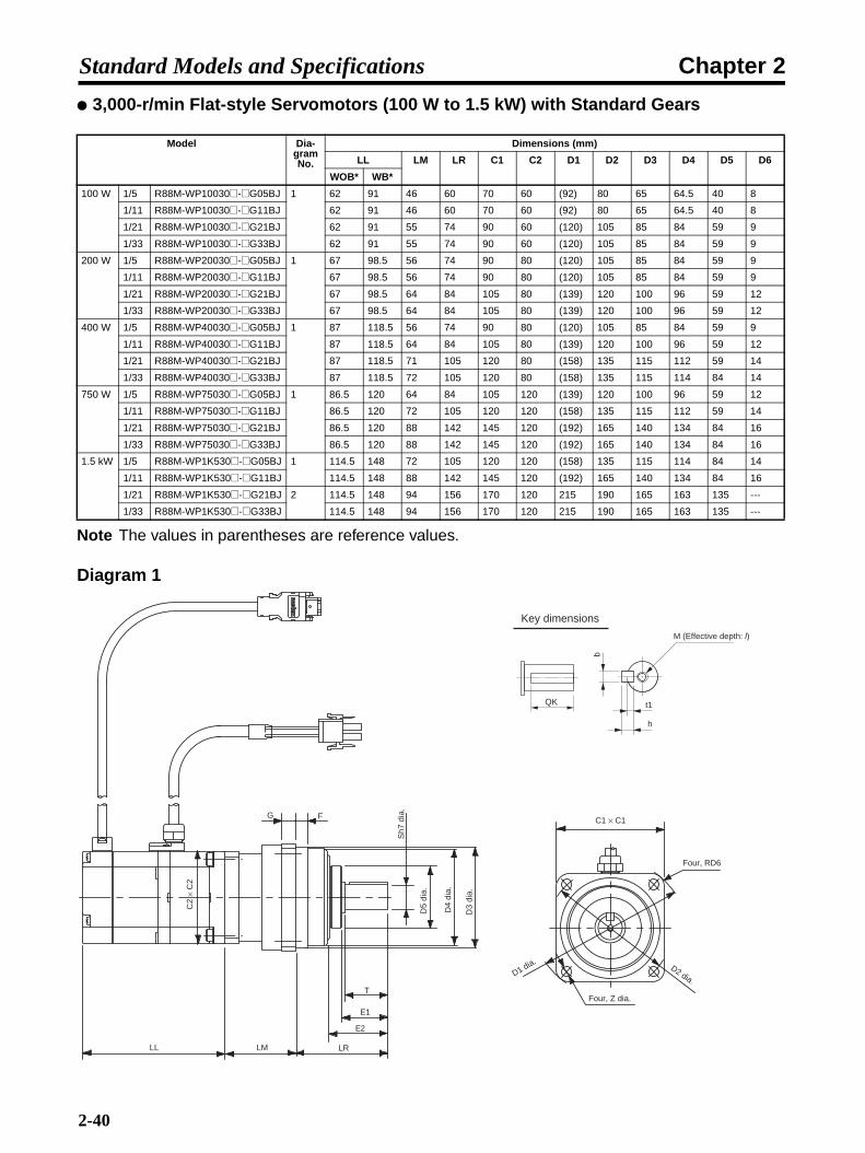
Chapter 2Standard Models and Specifications
3,000-r/min Flat-style Servomotors (100 W to 1.5 kW) with Standard Gears
Note The values in parentheses are reference values.
Diagram 1
Model Dia-gram No.
Dimensions (mm)
LL LM LR C1 C2 D1 D2 D3 D4 D5 D6
WOB* WB*
100 W 1/5 R88M-WP10030@-@G05BJ 1 62 91 46 60 70 60 (92) 80 65 64.5 40 8
1/11 R88M-WP10030@-@G11BJ 62 91 46 60 70 60 (92) 80 65 64.5 40 8
1/21 R88M-WP10030@-@G21BJ 62 91 55 74 90 60 (120) 105 85 84 59 9
1/33 R88M-WP10030@-@G33BJ 62 91 55 74 90 60 (120) 105 85 84 59 9
200 W 1/5 R88M-WP20030@-@G05BJ 1 67 98.5 56 74 90 80 (120) 105 85 84 59 9
1/11 R88M-WP20030@-@G11BJ 67 98.5 56 74 90 80 (120) 105 85 84 59 9
1/21 R88M-WP20030@-@G21BJ 67 98.5 64 84 105 80 (139) 120 100 96 59 12
1/33 R88M-WP20030@-@G33BJ 67 98.5 64 84 105 80 (139) 120 100 96 59 12
400 W 1/5 R88M-WP40030@-@G05BJ 1 87 118.5 56 74 90 80 (120) 105 85 84 59 9
1/11 R88M-WP40030@-@G11BJ 87 118.5 64 84 105 80 (139) 120 100 96 59 12
1/21 R88M-WP40030@-@G21BJ 87 118.5 71 105 120 80 (158) 135 115 112 59 14
1/33 R88M-WP40030@-@G33BJ 87 118.5 72 105 120 80 (158) 135 115 114 84 14
750 W 1/5 R88M-WP75030@-@G05BJ 1 86.5 120 64 84 105 120 (139) 120 100 96 59 12
1/11 R88M-WP75030@-@G11BJ 86.5 120 72 105 120 120 (158) 135 115 112 59 14
1/21 R88M-WP75030@-@G21BJ 86.5 120 88 142 145 120 (192) 165 140 134 84 16
1/33 R88M-WP75030@-@G33BJ 86.5 120 88 142 145 120 (192) 165 140 134 84 16
1.5 kW 1/5 R88M-WP1K530@-@G05BJ 1 114.5 148 72 105 120 120 (158) 135 115 114 84 14
1/11 R88M-WP1K530@-@G11BJ 114.5 148 88 142 145 120 (192) 165 140 134 84 16
1/21 R88M-WP1K530@-@G21BJ 2 114.5 148 94 156 170 120 215 190 165 163 135 ---
1/33 R88M-WP1K530@-@G33BJ 114.5 148 94 156 170 120 215 190 165 163 135 ---
Sh7
dia
.
D5
dia.
D4
dia.
D3
dia.
Four, Z dia.
D2 dia.D1 dia.
Key dimensions
M (Effective depth: l)
LL LM LR
E2
E1
G F
T
C2
× C
2
C1 × C1
b
h
t1
Four, RD6
QK
2-40
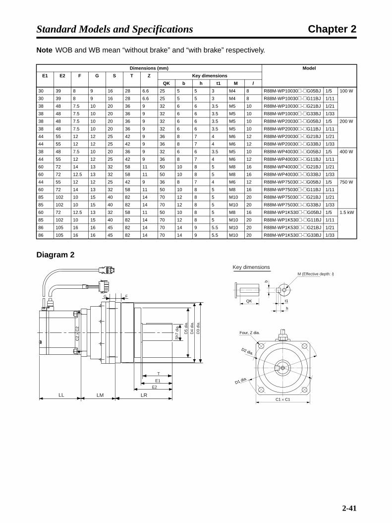
Chapter 2Standard Models and Specifications
Note WOB and WB mean “without brake” and “with brake” respectively.
Diagram 2
Dimensions (mm) Model
E1 E2 F G S T Z Key dimensions
QK b h t1 M l
30 39 8 9 16 28 6.6 25 5 5 3 M4 8 R88M-WP10030@-@G05BJ 1/5 100 W
30 39 8 9 16 28 6.6 25 5 5 3 M4 8 R88M-WP10030@-@G11BJ 1/11
38 48 7.5 10 20 36 9 32 6 6 3.5 M5 10 R88M-WP10030@-@G21BJ 1/21
38 48 7.5 10 20 36 9 32 6 6 3.5 M5 10 R88M-WP10030@-@G33BJ 1/33
38 48 7.5 10 20 36 9 32 6 6 3.5 M5 10 R88M-WP20030@-@G05BJ 1/5 200 W
38 48 7.5 10 20 36 9 32 6 6 3.5 M5 10 R88M-WP20030@-@G11BJ 1/11
44 55 12 12 25 42 9 36 8 7 4 M6 12 R88M-WP20030@-@G21BJ 1/21
44 55 12 12 25 42 9 36 8 7 4 M6 12 R88M-WP20030@-@G33BJ 1/33
38 48 7.5 10 20 36 9 32 6 6 3.5 M5 10 R88M-WP40030@-@G05BJ 1/5 400 W
44 55 12 12 25 42 9 36 8 7 4 M6 12 R88M-WP40030@-@G11BJ 1/11
60 72 14 13 32 58 11 50 10 8 5 M8 16 R88M-WP40030@-@G21BJ 1/21
60 72 12.5 13 32 58 11 50 10 8 5 M8 16 R88M-WP40030@-@G33BJ 1/33
44 55 12 12 25 42 9 36 8 7 4 M6 12 R88M-WP75030@-@G05BJ 1/5 750 W
60 72 14 13 32 58 11 50 10 8 5 M8 16 R88M-WP75030@-@G11BJ 1/11
85 102 10 15 40 82 14 70 12 8 5 M10 20 R88M-WP75030@-@G21BJ 1/21
85 102 10 15 40 82 14 70 12 8 5 M10 20 R88M-WP75030@-@G33BJ 1/33
60 72 12.5 13 32 58 11 50 10 8 5 M8 16 R88M-WP1K530@-@G05BJ 1/5 1.5 kW
85 102 10 15 40 82 14 70 12 8 5 M10 20 R88M-WP1K530@-@G11BJ 1/11
86 105 16 16 45 82 14 70 14 9 5.5 M10 20 R88M-WP1K530@-@G21BJ 1/21
86 105 16 16 45 82 14 70 14 9 5.5 M10 20 R88M-WP1K530@-@G33BJ 1/33
b
h
t1
C1 × C1LL LM LR
E2
E1
T
G F
Sh7
dia
.
D5
dia.
D4
dia.
D3
dia.
Four, Z dia.
D2 dia.
D1 dia.
Key dimensionsM (Effective depth: l)
C2
× C
2
QK
2-41

Chapter 2Standard Models and Specifications
1,000-r/min Servomotors (300 to 3 kW) with Standard Gears
Diagram 1
Model Dia-gram No.
Dimensions (mm)
LL LM LR C1 C2 D1 D2 D3 D4 D5
WOB* WB*
300 W 1/5 R88M-W30010@-@G05BJ 1 138 176 156 100 140 130 185 160 130 94 91
1/9 R88M-W30010@-@G09BJ 138 176 168 100 140 130 185 160 130 94 91
1/20 R88M-W30010@-@G20BJ 138 176 187 100 140 130 185 160 130 94 91
1/29 R88M-W30010@-@G29BJ 2 138 176 213 140 --- 130 245 220 190 135 130
1/45 R88M-W30010@-@G45BJ 138 176 223 140 --- 130 245 220 190 135 130
600 W 1/5 R88M-W60010@-@G05BJ 1 161 199 156 100 140 130 185 160 130 94 91
1/9 R88M-W60010@-@G09BJ 161 199 168 100 140 130 185 160 130 94 91
1/20 R88M-W60010@-@G20BJ 2 161 199 213 140 --- 130 245 220 190 135 130
1/29 R88M-W60010@-@G29BJ 161 199 213 140 --- 130 245 220 190 135 130
1/45 R88M-W60010@-@G45BJ 161 199 244 160 --- 130 310 280 240 186 182
900 W 1/5 R88M-W90010@-@G05BJ 1 185 223 156 100 140 130 185 160 130 94 91
1/9 R88M-W90010@-@G09BJ 2 185 223 209 140 --- 130 245 220 190 135 130
1/20 R88M-W90010@-@G20BJ 185 223 213 140 --- 130 245 220 190 135 130
1/29 R88M-W90010@-@G29BJ 185 223 234 160 --- 130 310 280 240 186 182
1/45 R88M-W90010@-@G45BJ 185 223 244 160 --- 130 310 280 240 186 182
1.2 kW 1/5 R88M-W1K210@-@G05BJ 2 166 217 203 140 --- 180 245 220 190 135 130
1/9 R88M-W1K210@-@G09BJ 166 217 230 140 --- 180 245 220 190 135 130
1/20 R88M-W1K210@-@G20BJ 166 217 255 160 --- 180 310 280 240 186 182
1/29 R88M-W1K210@-@G29BJ 166 217 255 160 --- 180 310 280 240 186 182
1/45 R88M-W1K210@-@G45BJ 166 217 265 160 --- 180 310 280 240 186 182
2 kW 1/5 R88M-W2K010@-@G05BJ 2 192 243 203 140 --- 180 245 220 190 135 130
1/9 R88M-W2K010@-@G09BJ 192 243 230 140 --- 180 245 220 190 135 130
1/20 R88M-W2K010@-@G20BJ 192 243 255 160 --- 180 310 280 240 186 182
G F
C2
× C
2
LL LM LR
T
E1E3
D5
dia.
D4
dia.
D3h
7 di
a.
Four, Z dia.
D2 dia.
D1 dia.
C1 × C1
QK
b
h
t1
Sh6
dia
.
Key dimensions
2-42

Chapter 2Standard Models and Specifications
Note WOB and WB mean “without brake” and “with brake” respectively.
Diagram 2
Dimensions (mm) Model
E1 E3 F G S T Z IE Key dimensions
QK b h t1
57 20 3 12 35 55 12 --- 47 10 8 5 R88M-W30010@-@G05BJ 1/5 300 W
57 20 3 12 35 55 12 --- 47 10 8 5 R88M-W30010@-@G09BJ 1/9
57 20 3 12 35 55 12 --- 47 10 8 5 R88M-W30010@-@G20BJ 1/20
77 33 5 15 50 75 12 137 65 14 9 5.5 R88M-W30010@-@G29BJ 1/29
77 33 5 15 50 75 12 137 65 14 9 5.5 R88M-W30010@-@G45BJ 1/45
57 20 3 12 35 55 12 --- 47 10 8 5 R88M-W60010@-@G05BJ 1/5 600 W
57 20 3 12 35 55 12 --- 47 10 8 5 R88M-W60010@-@G09BJ 1/9
77 33 5 15 50 75 12 137 65 14 9 5.5 R88M-W60010@-@G20BJ 1/20
77 33 5 15 50 75 12 137 65 14 9 5.5 R88M-W60010@-@G29BJ 1/29
92 38 5 18 60 90 14 171 78 18 11 7 R88M-W60010@-@G45BJ 1/45
57 20 3 12 35 55 12 --- 47 10 8 5 R88M-W90010@-@G05BJ 1/5 900 W
77 33 5 15 50 75 12 137 65 14 9 5.5 R88M-W90010@-@G09BJ 1/9
77 33 5 15 50 75 12 137 65 14 9 5.5 R88M-W90010@-@G20BJ 1/20
92 38 5 18 60 90 14 171 78 18 11 7 R88M-W90010@-@G29BJ 1/29
92 38 5 18 60 90 14 171 78 18 11 7 R88M-W90010@-@G45BJ 1/45
77 33 5 15 50 75 12 137 65 14 9 5.5 R88M-W1K210@-@G05BJ 1/5 1.2 kW
77 33 5 15 50 75 12 137 65 14 9 5.5 R88M-W1K210@-@G09BJ 1/9
92 38 5 18 60 90 14 171 78 18 11 7 R88M-W1K210@-@G20BJ 1/20
92 38 5 18 60 90 14 171 78 18 11 7 R88M-W1K210@-@G29BJ 1/29
92 38 5 18 60 90 14 171 78 18 11 7 R88M-W1K210@-@G45BJ 1/45
77 33 5 15 50 75 12 137 65 14 9 5.5 R88M-W2K010@-@G05BJ 1/5 2 kW
77 33 5 15 50 75 12 137 65 14 9 5.5 R88M-W2K010@-@G09BJ 1/9
92 38 5 18 60 90 14 171 78 18 11 7 R88M-W2K010@-@G20BJ 1/20
G F
LL LM LR
T
E1E3
D5
dia.
D4
dia.
D3h
7 di
a.
C2
× C
2
IE
QK
Six, Z dia.
D2 dia.
D1 dia.
b
h
t1
Sh6
dia
.
Key dimensions
2-43

Chapter 2Standard Models and Specifications
1,500-r/min Servomotors (450 W to 4.4 kW) with Standard Gears
Diagram 1
Model Dia-gram No.
Dimensions (mm)
LL LM LR C1 C2 D1 D2 D3 D4 D5
WOB* WB*
450 W 1/5 R88M-W45015T-@G05BJ 1 138 176 156 100 140 130 185 160 130 94 91
1/9 R88M-W45015T-@G09BJ 138 176 168 100 140 130 185 160 130 94 91
1/20 R88M-W45015T-@G20BJ 2 138 176 213 140 --- 130 245 220 190 135 130
1/29 R88M-W45015T-@G29BJ 138 176 213 140 --- 130 245 220 190 135 130
1/45 R88M-W45015T-@G45BJ 138 176 223 140 --- 130 245 220 190 135 130
850 W 1/5 R88M-W85015T-@G05BJ 1 161 199 156 100 140 130 185 160 130 94 91
1/9 R88M-W85015T-@G09BJ 161 199 168 100 140 130 185 160 130 94 91
1/20 R88M-W85015T-@G20BJ 2 161 199 213 140 --- 130 245 220 190 135 130
1/29 R88M-W85015T-@G29BJ 161 199 213 140 --- 130 245 220 190 135 130
1/45 R88M-W85015T-@G45BJ 161 199 244 160 --- 130 310 280 240 186 182
1.3 kW 1/5 R88M-W1K315T-@G05BJ 2 185 223 182 140 --- 130 245 220 190 135 130
1/9 R88M-W1K315T-@G09BJ 185 223 209 140 --- 130 245 220 190 135 130
1/20 R88M-W1K315T-@G20BJ 185 223 213 140 --- 130 245 220 190 135 130
1/29 R88M-W1K315T-@G29BJ 185 223 234 160 --- 130 310 280 240 186 182
1/45 R88M-W1K315T-@G45BJ 185 223 244 160 --- 130 310 280 240 186 182
1.8 kW 1/5 R88M-W1K815T-@G05BJ 2 166 217 203 140 --- 180 245 220 190 135 130
1/9 R88M-W1K815T-@G09BJ 166 217 230 140 --- 180 245 220 190 135 130
1/20 R88M-W1K815T-@G20BJ 166 217 255 160 --- 180 310 280 240 186 182
1/29 R88M-W1K815T-@G29BJ 166 217 255 160 --- 180 310 280 240 186 182
G F
C2
× C
2
LL LM LR
T
E1E3
D5
dia.
D4
dia.
D3h
7 di
a.
Four, Z dia.
D2 dia.
D1 dia.
C1 × C1
QKb
h
t1
Sh6
dia
.
Key dimensions
2-44

Chapter 2Standard Models and Specifications
Note WOB and WB mean “without brake” and “with brake” respectively.
Diagram 2
Dimensions (mm) Model
E1 E3 F G S T Z IE Key dimensions
QK b h t1
57 20 3 12 35 55 12 --- 47 10 8 5 R88M-W45015T-@G05BJ 1/5 450 W
57 20 3 12 35 55 12 --- 47 10 8 5 R88M-W45015T-@G09BJ 1/9
77 33 5 15 50 75 12 137 65 14 9 5.5 R88M-W45015T-@G20BJ 1/20
77 33 5 15 50 75 12 137 65 14 9 5.5 R88M-W45015T-@G29BJ 1/29
77 33 5 15 50 75 12 137 65 14 9 5.5 R88M-W45015T-@G45BJ 1/45
57 20 3 12 35 55 12 --- 47 10 8 5 R88M-W85015T-@G05BJ 1/5 850 W
57 20 3 12 35 55 12 --- 47 10 8 5 R88M-W85015T-@G09BJ 1/9
77 33 5 15 50 75 12 137 65 14 9 5.5 R88M-W85015T-@G20BJ 1/20
77 33 5 15 50 75 12 137 65 14 9 5.5 R88M-W85015T-@G29BJ 1/29
92 38 5 18 60 90 14 171 78 18 11 7 R88M-W85015T-@G45BJ 1/45
77 33 5 15 50 75 12 137 65 14 9 5.5 R88M-W1K315T-@G05BJ 1/5 1.3 kW
77 33 5 15 50 75 12 137 65 14 9 5.5 R88M-W1K315T-@G09BJ 1/9
77 33 5 15 50 75 12 137 65 14 9 5.5 R88M-W1K315T-@G20BJ 1/20
92 38 5 18 60 90 14 171 78 18 11 7 R88M-W1K315T-@G29BJ 1/29
92 38 5 18 60 90 14 171 78 18 11 7 R88M-W1K315T-@G45BJ 1/45
77 33 5 15 50 75 12 137 65 14 9 5.5 R88M-W1K815T-@G05BJ 1/5 1.8 kW
77 33 5 15 50 75 12 137 65 14 9 5.5 R88M-W1K815T-@G09BJ 1/9
92 38 5 18 60 90 14 171 78 18 11 7 R88M-W1K815T-@G20BJ 1/20
92 38 5 18 60 90 14 171 78 18 11 7 R88M-W1K815T-@G29BJ 1/29
G F
LL LM LR
T
E1E3
D5
dia.
D4
dia.
D3h
7 di
a.
C2
× C
2
IE
QK
Six, Z dia.
D2 dia.
D1 dia.
b
h
t1
Sh6
dia
.
Key dimensions
2-45
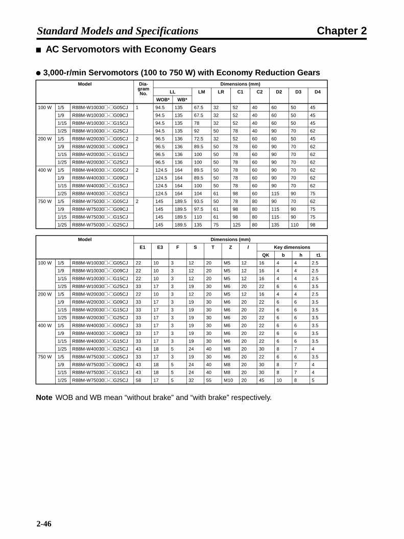
Chapter 2Standard Models and Specifications
AC Servomotors with Economy Gears
3,000-r/min Servomotors (100 to 750 W) with Economy Reduction Gears
Note WOB and WB mean “without brake” and “with brake” respectively.
Model Dia-gram No.
Dimensions (mm)
LL LM LR C1 C2 D2 D3 D4
WOB* WB*
100 W 1/5 R88M-W10030@-@G05CJ 1 94.5 135 67.5 32 52 40 60 50 45
1/9 R88M-W10030@-@G09CJ 94.5 135 67.5 32 52 40 60 50 45
1/15 R88M-W10030@-@G15CJ 94.5 135 78 32 52 40 60 50 45
1/25 R88M-W10030@-@G25CJ 94.5 135 92 50 78 40 90 70 62
200 W 1/5 R88M-W20030@-@G05CJ 2 96.5 136 72.5 32 52 60 60 50 45
1/9 R88M-W20030@-@G09CJ 96.5 136 89.5 50 78 60 90 70 62
1/15 R88M-W20030@-@G15CJ 96.5 136 100 50 78 60 90 70 62
1/25 R88M-W20030@-@G25CJ 96.5 136 100 50 78 60 90 70 62
400 W 1/5 R88M-W40030@-@G05CJ 2 124.5 164 89.5 50 78 60 90 70 62
1/9 R88M-W40030@-@G09CJ 124.5 164 89.5 50 78 60 90 70 62
1/15 R88M-W40030@-@G15CJ 124.5 164 100 50 78 60 90 70 62
1/25 R88M-W40030@-@G25CJ 124.5 164 104 61 98 60 115 90 75
750 W 1/5 R88M-W75030@-@G05CJ 2 145 189.5 93.5 50 78 80 90 70 62
1/9 R88M-W75030@-@G09CJ 145 189.5 97.5 61 98 80 115 90 75
1/15 R88M-W75030@-@G15CJ 145 189.5 110 61 98 80 115 90 75
1/25 R88M-W75030@-@G25CJ 145 189.5 135 75 125 80 135 110 98
Model Dimensions (mm)
E1 E3 F S T Z l Key dimensions
QK b h t1
100 W 1/5 R88M-W10030@-@G05CJ 22 10 3 12 20 M5 12 16 4 4 2.5
1/9 R88M-W10030@-@G09CJ 22 10 3 12 20 M5 12 16 4 4 2.5
1/15 R88M-W10030@-@G15CJ 22 10 3 12 20 M5 12 16 4 4 2.5
1/25 R88M-W10030@-@G25CJ 33 17 3 19 30 M6 20 22 6 6 3.5
200 W 1/5 R88M-W20030@-@G05CJ 22 10 3 12 20 M5 12 16 4 4 2.5
1/9 R88M-W20030@-@G09CJ 33 17 3 19 30 M6 20 22 6 6 3.5
1/15 R88M-W20030@-@G15CJ 33 17 3 19 30 M6 20 22 6 6 3.5
1/25 R88M-W20030@-@G25CJ 33 17 3 19 30 M6 20 22 6 6 3.5
400 W 1/5 R88M-W40030@-@G05CJ 33 17 3 19 30 M6 20 22 6 6 3.5
1/9 R88M-W40030@-@G09CJ 33 17 3 19 30 M6 20 22 6 6 3.5
1/15 R88M-W40030@-@G15CJ 33 17 3 19 30 M6 20 22 6 6 3.5
1/25 R88M-W40030@-@G25CJ 43 18 5 24 40 M8 20 30 8 7 4
750 W 1/5 R88M-W75030@-@G05CJ 33 17 3 19 30 M6 20 22 6 6 3.5
1/9 R88M-W75030@-@G09CJ 43 18 5 24 40 M8 20 30 8 7 4
1/15 R88M-W75030@-@G15CJ 43 18 5 24 40 M8 20 30 8 7 4
1/25 R88M-W75030@-@G25CJ 58 17 5 32 55 M10 20 45 10 8 5
2-46

Chapter 2Standard Models and Specifications
Diagram 1
Diagram 2
C2
× C
2
F
E3
LL LM LR
D4
dia.
D3h
7 di
a.
T
E1
Sh6
dia
.
QK
b
h
t1
C1 × C1
D2 dia.
Key dimensions
Four, Z dia. (Effective depth: l)
F
E3
LL LM LR
D4
dia.
D3h
7 di
a.
T
E1
Sh6
dia
.
QK
b
h
t1
C1 × C1
D2 dia.
C2
× C
2
Key dimensions
Four, Z dia. (Effective depth: l)
2-47

Chapter 2Standard Models and Specifications
3,000-r/min Flat-style Servomotors (100 to 750 W) with Economy Gears
Note WOB and WB mean “without brake” and “with brake” respectively.
Model Dimensions (mm)
LL LM LR C1 C2 D2 D3 D4
WOB* WB*
100 W 1/5 R88M-WP10030@-@G05CJ 62 91 72.5 32 52 60 60 50 45
1/9 R88M-WP10030@-@G09CJ 62 91 72.5 32 52 60 60 50 45
1/15 R88M-WP10030@-@G15CJ 62 91 78 32 52 60 60 50 45
1/25 R88M-WP10030@-@G25CJ 62 91 92 50 78 60 90 70 62
200 W 1/5 R88M-WP20030@-@G05CJ 67 98.5 72.5 32 52 80 60 50 45
1/9 R88M-WP20030@-@G09CJ 67 98.5 89.5 50 78 80 90 70 62
1/15 R88M-WP20030@-@G15CJ 67 98.5 100 50 78 80 90 70 62
1/25 R88M-WP20030@-@G25CJ 67 98.5 100 50 78 80 90 70 62
400 W 1/5 R88M-WP40030@-@G05CJ 87 118.5 89.5 50 78 80 90 70 62
1/9 R88M-WP40030@-@G09CJ 87 118.5 89.5 50 78 80 90 70 62
1/15 R88M-WP40030@-@G15CJ 87 118.5 100 50 78 80 90 70 62
1/25 R88M-WP40030@-@G25CJ 87 118.5 104 61 98 80 115 90 75
750 W 1/5 R88M-WP75030@-@G05CJ 86.5 120 93.5 50 78 120 90 70 62
1/9 R88M-WP75030@-@G09CJ 86.5 120 97.5 61 98 120 115 90 75
1/15 R88M-WP75030@-@G15CJ 86.5 120 110 61 98 120 115 90 75
1/25 R88M-WP75030@-@G25CJ 86.5 120 135 75 125 120 135 110 98
Model Dimensions (mm)
E1 E3 F S T Z l Key dimensions
QK b h t1
100 W 1/5 R88M-WP10030@-@G05CJ 22 10 3 12 20 M5 12 16 4 4 2.5
1/9 R88M-WP10030@-@G09CJ 22 10 3 12 20 M5 12 16 4 4 2.5
1/15 R88M-WP10030@-@G15CJ 22 10 3 12 20 M5 12 16 4 4 2.5
1/25 R88M-WP10030@-@G25CJ 33 17 3 19 30 M6 20 22 6 6 3.5
200 W 1/5 R88M-WP20030@-@G05CJ 22 10 3 12 20 M5 12 16 4 4 2.5
1/9 R88M-WP20030@-@G09CJ 33 17 3 19 30 M6 20 22 6 6 3.5
1/15 R88M-WP20030@-@G15CJ 33 17 3 19 30 M6 20 22 6 6 3.5
1/25 R88M-WP20030@-@G25CJ 33 17 3 19 30 M6 20 22 6 6 3.5
400 W 1/5 R88M-WP40030@-@G05CJ 33 17 3 19 30 M6 20 22 6 6 3.5
1/9 R88M-WP40030@-@G09CJ 33 17 3 19 30 M6 20 22 6 6 3.5
1/15 R88M-WP40030@-@G15CJ 33 17 3 19 30 M6 20 22 6 6 3.5
1/25 R88M-WP40030@-@G25CJ 43 18 5 24 40 M8 20 30 8 7 4
750 W 1/5 R88M-WP75030@-@G05CJ 33 17 3 19 30 M6 20 22 6 6 3.5
1/9 R88M-WP75030@-@G09CJ 43 18 5 24 40 M8 20 30 8 7 4
1/15 R88M-WP75030@-@G15CJ 43 18 5 24 40 M8 20 30 8 7 4
1/25 R88M-WP75030@-@G25CJ 58 17 5 32 55 M10 20 45 10 8 5
2-48

Chapter 2Standard Models and Specifications
Diagram
F
E3
LL LM LRD
4 di
a.
D3h
7 di
a.
T
E1S
h6 d
ia.
QK
b
h
t1
C1 × C1
D2 dia.
C2
× C
2
Key dimensions
Four, Z dia. (Effective depth: l)
2-49

Chapter 2Standard Models and Specifications
2-4 Servo Driver Specifications
R88D-WN@-ML2/OMNUC W-series AC Servo Drivers (with Built-in MECHATROLINK-II Communications)
Referring to 2-2 Servo Driver and Servomotor Combinations, select a Servo Driver to match the Ser-vomotor that is being used.
2-4-1 General Specifications
Note 1. The above items reflect individual evaluation testing. The results may differ under compoundconditions.
Note 2. Absolutely do not conduct a withstand voltage test with a Megger tester on the Servo Driver.If such tests are conducted, internal elements may be damaged.
Item SpecificationsAmbient operating temperature 0° to 55°CAmbient operating humidity 90% max. (with no condensation)
Ambient storage temperature −20° to 85°CAmbient storage humidity 90% max. (with no condensation)
Storage and operating atmo-sphere
No corrosive gasses.
Vibration resistance 10 to 55 Hz in X, Y, and Z directions with 0.1-mm double amplitude; acceler-ation: 4.9 m/s2 max.
Impact resistance Acceleration 19.6 m/s2 max., in X, Y, and Z directions, three times
Insulation resistance Between power line terminals and case: 0.5 MΩ min. (at 500 V DC)
Dielectric strength Between power line terminals and case: 1,500 V AC for 1 min at 50/60 HzBetween each control signal and case: 500 V AC for 1 min
Protective structure Built into panel (IP10).
EC directives EMC directive EN55011 class A group 1
EN61000-6-2
Low-voltage directive
EN50178
UL standards UL508C
cUL standards cUL C22.2 No. 14
2-50
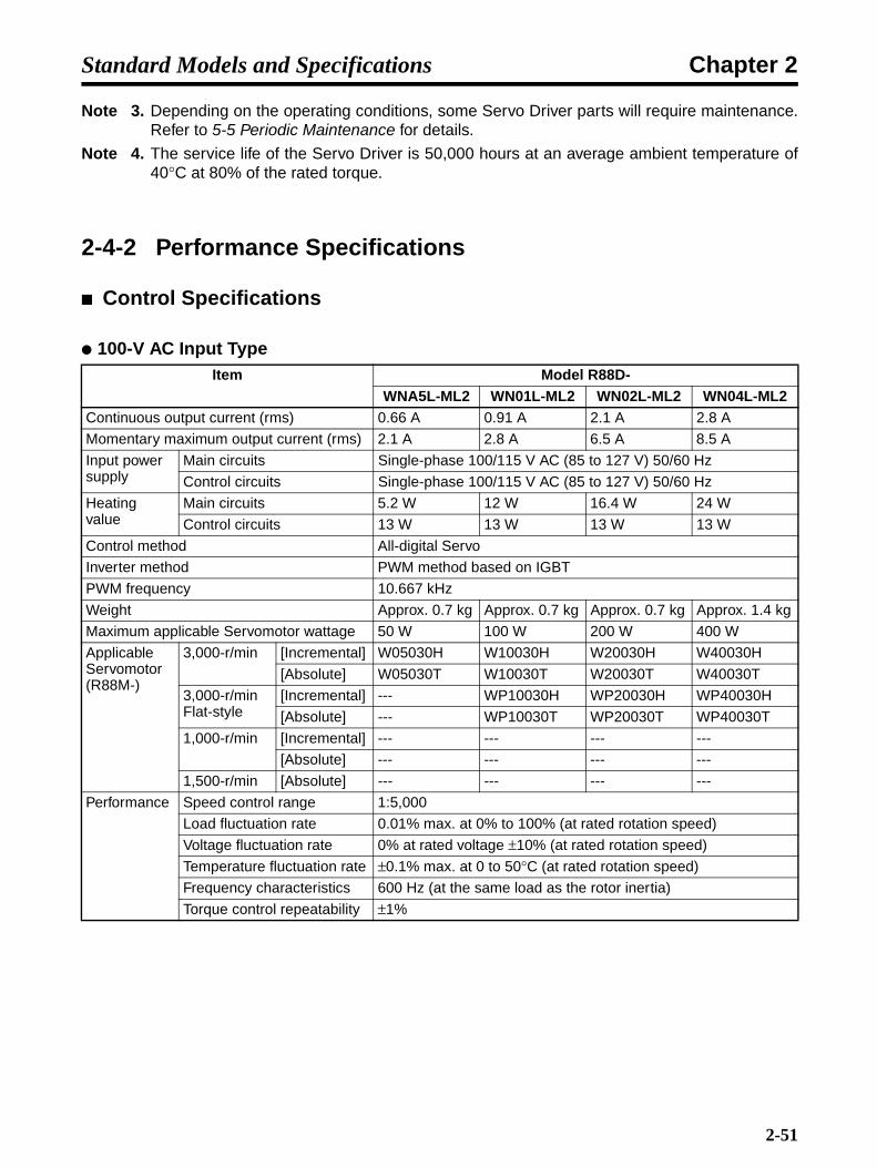
Chapter 2Standard Models and Specifications
Note 3. Depending on the operating conditions, some Servo Driver parts will require maintenance.Refer to 5-5 Periodic Maintenance for details.
Note 4. The service life of the Servo Driver is 50,000 hours at an average ambient temperature of40°C at 80% of the rated torque.
2-4-2 Performance Specifications
Control Specifications
100-V AC Input TypeItem Model R88D-
WNA5L-ML2 WN01L-ML2 WN02L-ML2 WN04L-ML2Continuous output current (rms) 0.66 A 0.91 A 2.1 A 2.8 A
Momentary maximum output current (rms) 2.1 A 2.8 A 6.5 A 8.5 A
Input power supply
Main circuits Single-phase 100/115 V AC (85 to 127 V) 50/60 Hz
Control circuits Single-phase 100/115 V AC (85 to 127 V) 50/60 Hz
Heating value
Main circuits 5.2 W 12 W 16.4 W 24 W
Control circuits 13 W 13 W 13 W 13 W
Control method All-digital Servo
Inverter method PWM method based on IGBT
PWM frequency 10.667 kHz
Weight Approx. 0.7 kg Approx. 0.7 kg Approx. 0.7 kg Approx. 1.4 kg
Maximum applicable Servomotor wattage 50 W 100 W 200 W 400 W
Applicable Servomotor (R88M-)
3,000-r/min [Incremental] W05030H W10030H W20030H W40030H
[Absolute] W05030T W10030T W20030T W40030T
3,000-r/min Flat-style
[Incremental] --- WP10030H WP20030H WP40030H
[Absolute] --- WP10030T WP20030T WP40030T
1,000-r/min [Incremental] --- --- --- ---
[Absolute] --- --- --- ---
1,500-r/min [Absolute] --- --- --- ---
Performance Speed control range 1:5,000
Load fluctuation rate 0.01% max. at 0% to 100% (at rated rotation speed)
Voltage fluctuation rate 0% at rated voltage ±10% (at rated rotation speed)
Temperature fluctuation rate ±0.1% max. at 0 to 50°C (at rated rotation speed)
Frequency characteristics 600 Hz (at the same load as the rotor inertia)
Torque control repeatability ±1%
2-51
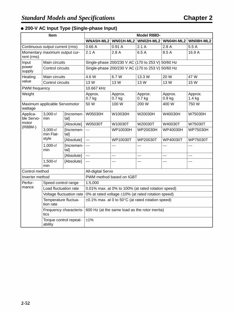
Chapter 2Standard Models and Specifications
200-V AC Input Type (Single-phase Input)Item Model R88D-
WNA5H-ML2 WN01H-ML2 WN02H-ML2 WN04H-ML2 WN08H-ML2Continuous output current (rms) 0.66 A 0.91 A 2.1 A 2.8 A 5.5 A
Momentary maximum output cur-rent (rms)
2.1 A 2.8 A 6.5 A 8.5 A 16.9 A
Input power supply
Main circuits Single-phase 200/230 V AC (170 to 253 V) 50/60 Hz
Control circuits Single-phase 200/230 V AC (170 to 253 V) 50/60 Hz
Heating value
Main circuits 4.6 W 6.7 W 13.3 W 20 W 47 W
Control circuits 13 W 13 W 13 W 13 W 15 W
PWM frequency 10.667 kHz
Weight Approx. 0.7 kg
Approx. 0.7 kg
Approx. 0.7 kg
Approx. 0.9 kg
Approx. 1.4 kg
Maximum applicable Servomotor wattage
50 W 100 W 200 W 400 W 750 W
Applica-ble Servo-motor (R88M-)
3,000-r/min
[Incremen-tal]
W05030H W10030H W20030H W40030H W75030H
[Absolute] W05030T W10030T W20030T W40030T W75030T
3,000-r/min Flat-style
[Incremen-tal]
--- WP10030H WP20030H WP40030H WP75030H
[Absolute] --- WP10030T WP20030T WP40030T WP75030T
1,000-r/min
[Incremen-tal]
--- --- --- --- ---
[Absolute] --- --- --- --- ---
1,500-r/min
[Absolute] --- --- --- --- ---
Control method All-digital Servo
Inverter method PWM method based on IGBT
Perfor-mance
Speed control range 1:5,000
Load fluctuation rate 0.01% max. at 0% to 100% (at rated rotation speed)
Voltage fluctuation rate 0% at rated voltage ±10% (at rated rotation speed)
Temperature fluctua-tion rate
±0.1% max. at 0 to 50°C (at rated rotation speed)
Frequency characteris-tics
600 Hz (at the same load as the rotor inertia)
Torque control repeat-ability
±1%
2-52

Chapter 2Standard Models and Specifications
200-V AC Input Type (Three-phase Input)
Note At a load inertia equivalent to the Servomotor's rotor inertia.
Item Model R88D-WN05H-ML2 WN10H-ML2 WN15H-ML2 WN20H-ML2 WN30H-ML2
Continuous output current (rms) 3.8 A 7.6 A 11.6 A 18.5 A 18.9 A
Momentary maximum output cur-rent (rms)
11.0 A 17.0 A 28.0 A 42.0 A 56.0 A
Input power supply
Main circuits Three-phase 200/230 V AC (170 to 253 V) 50/60 Hz
Control circuits Single-phase 200/230 V AC (170 to 253 V) 50/60 Hz
Heating value
Main circuits 27 W 55 W 92 W 120 W 155 W
Control circuits 15 W 15 W 15 W 15 W 15 W
PWM frequency 10.667 kHz 8.000 kHz 4.000 kHz
Weight Approx. 1.4 kg
Approx. 1.4 kg
Approx. 2.1 kg
Approx. 2.8 kg
Approx. 2.8 kg
Maximum applicable Servomotor wattage
500 W 1 kW 1.5 kW 2 kW 3 kW
Applica-ble Servo-motor (R88M-)
3,000-r/min
[Incremen-tal]
--- W1K030H W1K530H W2K030H W3K030H
[Absolute] --- W1K030T W1K530T W2K030T W3K030T
3,000-r/min Flat-type
[Incremen-tal]
--- --- WP1K530H --- ---
[Absolute] --- --- WP1K530T --- ---
1,000-r/min
[Incremen-tal]
W30010H W60010HW90010H
W1K210H W2K010H ---
[Absolute] W30010T W60010TW90010T
W1K210T W2K010T ---
1,500-r/min
[Absolute] W45015T W85015T W1K315T W1K815T ---
Control method All-digital Servo
Inverter method PWM method based on IGBT
Perfor-mance
Speed control range 1:5,000
Load fluctuation rate 0.01% max. at 0% to 100% (at rated rotation speed)
Voltage fluctuation rate 0% at rated voltage ±10% (at rated rotation speed)
Temperature fluctua-tion rate
±0.1% max. at 0 to 50°C (at rated rotation speed)
Frequency characteris-tics
600 Hz (See note.) 400 Hz (See note.)
Torque control repeat-ability
±1%
2-53
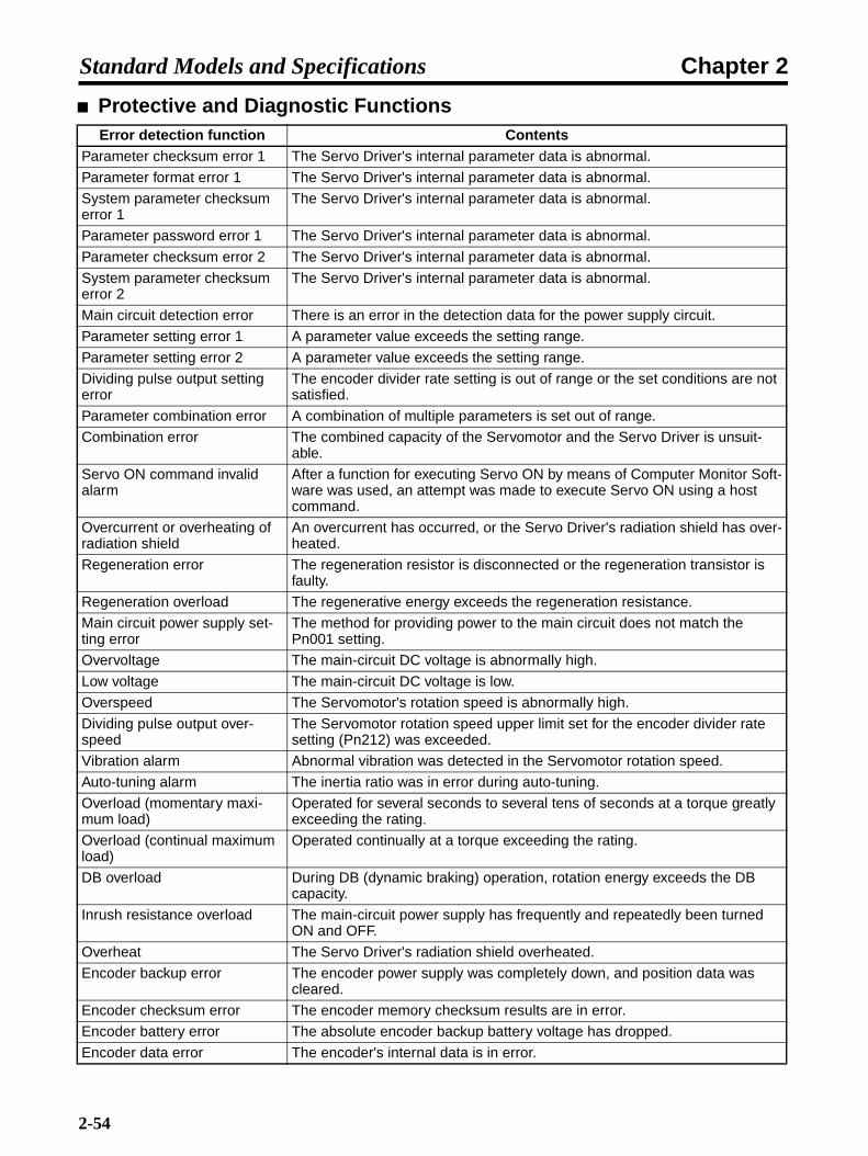
Chapter 2Standard Models and Specifications
Protective and Diagnostic FunctionsError detection function Contents
Parameter checksum error 1 The Servo Driver's internal parameter data is abnormal.
Parameter format error 1 The Servo Driver's internal parameter data is abnormal.
System parameter checksum error 1
The Servo Driver's internal parameter data is abnormal.
Parameter password error 1 The Servo Driver's internal parameter data is abnormal.
Parameter checksum error 2 The Servo Driver's internal parameter data is abnormal.
System parameter checksum error 2
The Servo Driver's internal parameter data is abnormal.
Main circuit detection error There is an error in the detection data for the power supply circuit.
Parameter setting error 1 A parameter value exceeds the setting range.
Parameter setting error 2 A parameter value exceeds the setting range.
Dividing pulse output setting error
The encoder divider rate setting is out of range or the set conditions are not satisfied.
Parameter combination error A combination of multiple parameters is set out of range.
Combination error The combined capacity of the Servomotor and the Servo Driver is unsuit-able.
Servo ON command invalid alarm
After a function for executing Servo ON by means of Computer Monitor Soft-ware was used, an attempt was made to execute Servo ON using a host command.
Overcurrent or overheating of radiation shield
An overcurrent has occurred, or the Servo Driver's radiation shield has over-heated.
Regeneration error The regeneration resistor is disconnected or the regeneration transistor is faulty.
Regeneration overload The regenerative energy exceeds the regeneration resistance.
Main circuit power supply set-ting error
The method for providing power to the main circuit does not match the Pn001 setting.
Overvoltage The main-circuit DC voltage is abnormally high.
Low voltage The main-circuit DC voltage is low.
Overspeed The Servomotor's rotation speed is abnormally high.
Dividing pulse output over-speed
The Servomotor rotation speed upper limit set for the encoder divider rate setting (Pn212) was exceeded.
Vibration alarm Abnormal vibration was detected in the Servomotor rotation speed.
Auto-tuning alarm The inertia ratio was in error during auto-tuning.
Overload (momentary maxi-mum load)
Operated for several seconds to several tens of seconds at a torque greatly exceeding the rating.
Overload (continual maximum load)
Operated continually at a torque exceeding the rating.
DB overload During DB (dynamic braking) operation, rotation energy exceeds the DB capacity.
Inrush resistance overload The main-circuit power supply has frequently and repeatedly been turned ON and OFF.
Overheat The Servo Driver's radiation shield overheated.
Encoder backup error The encoder power supply was completely down, and position data was cleared.
Encoder checksum error The encoder memory checksum results are in error.
Encoder battery error The absolute encoder backup battery voltage has dropped.
Encoder data error The encoder's internal data is in error.
2-54

Chapter 2Standard Models and Specifications
Encoder overspeed The encoder rotated at high speed when the power was ON.
Encoder overheat The encoder's internal temperature is too high.
Current detection error 1 The phase-U current detector is in error.
Current detection error 2 The phase-V current detector is in error.
Current detection error 3 The current detector is in error.
MECHATROLINK communica-tions ASIC error 1
The MECHATROLINK communications ASIC is in error.
MECHATROLINK communica-tions ASIC error 2
A fatal error occurred in the MECHATROLINK communications ASIC.
System alarm 0 Servo Driver internal program error 0 occurred.
System alarm 1 Servo Driver internal program error 1 occurred.
System alarm 2 Servo Driver internal program error 2 occurred.
System alarm 3 Servo Driver internal program error 3 occurred.
System alarm 4 Servo Driver internal program error 4 occurred.
Runaway detected Servomotor runaway occurred.
Multi-turn data error Absolute encoder multi-turn data was cleared or could not be set correctly.
Encoder communications error No communication possible between the encoder and Servo Driver.
Encoder communications posi-tion data error
An error occurred in the encoder's position data calculations.
Encoder communications timer error
An error occurred in the timer for communications between the encoder and Servo Driver.
Encoder parameter error Encoder parameters are corrupted.
Encoder echo-back error The contents of communications with the encoder are wrong.
Multi-turn limit discrepancy The multi-turn limits for the encoder and the Servo Driver do not match.
Deviation counter overflow Position deviation pulses exceeded the level set for Pn520.
Deviation counter overflow alarm at Servo ON
When Servo ON was executed, the accumulated number of position devia-tion pulses reached or exceeded the number set for Pn526.
Deviation counter overflow alarm by speed limit at Servo ON
If Servo ON is executed with position deviation pulses accumulated, the speed is limited by the setting in Pn529. A command pulse was input during this period, without the limit being cleared, and the setting in Pn520 was exceeded.
COM alarm 0 Servo Driver COM error 0 occurred.
COM alarm 1 Servo Driver COM error 1 occurred.
COM alarm 2 Servo Driver COM error 2 occurred.
COM alarm 7 Servo Driver COM error 7 occurred.
COM alarm 8 Servo Driver COM error 8 occurred.
COM alarm 9 Servo Driver COM error 9 occurred.
MECHATROLINK-II transmis-sion cycle setting error
There is an error in the setting for the MECHATROLINK-II communications transmission cycle.
MECHATROLINK-II synchroni-zation error
A synchronization error occurred during MECHATROLINK-II communica-tions.
MECHATROLINK-II synchroni-zation failure
A synchronization failure occurred during MECHATROLINK-II communica-tions.
MECHATROLINK-II communi-cations error
Communications errors occurred consecutively during MECHATROLINK-II communications.
MECHATROLINK-II transmis-sion cycle error
An error occurred in the transmission cycle during MECHATROLINK-II com-munications.
Error detection function Contents
2-55

Chapter 2Standard Models and Specifications
2-4-3 Terminal Block Specifications
DRV alarm 0 Servo Driver DRV error 0 occurred.
DRV alarm 1 Servo Driver DRV error 1 occurred.
DRV alarm 2 Servo Driver DRV error 2 occurred.
Internal command error A command error occurred in the Servo Driver.
Missing phase detected One phase from the three-phase main circuit power supply is not connect-ing.
Symbol Function ConditionL1 Main circuits power
supply inputR88D-WN@H-ML2 (50 to 400 W):Single-phase 200/230 VAC (170 to 253 V), 50/60 Hz (No L3 terminal)R88D-WN08H-ML2 (750 W):Single-phase 200/230 VAC (170 to 253 V), 50/60 HzNote: The L3 terminal is not used, so do not connect it.R88D-WN@H-ML2 (500 W to 3.0 kW):Single-phase 200/230 VAC (170 to 253 V), 50/60 HzR88D-WN@L-ML2 (50 to 400 W):Single-phase 100/115 VAC (85 to 127 V), 50/60 Hz (No L3 terminal)
L2
L3
DC Reactor terminal for power supply har-monic control
R88D-WN@H-ML2 (500 W to 3.0 kW)Normally short-circuit between −1 and −2.If harmonic control measures are required, connect a DC Reactor between −1 and −2.
Main circuit positive terminal
Used for DC power supply input.The R88D-WN@H-ML2 (500 W to 3.0 kW) does not have a − terminal. Use the −2 terminal.Main circuit negative
terminal
L1C Control circuits power supply input
R88D-WN@H-ML2: Single-phase 200/230 V AC (170 to 253 V AC) 50/60 HzR88D-WN@L-ML2: Single-phase 100/115 V AC (85 to 127 V AC) 50/60 Hz
L2C
External regeneration resistance connection terminal
R88D-WN@H-ML2 (50 to 400 W)R88D-WN@L-ML2 (50 to 400 W)This terminal does not normally need to be connected. If regenerative energy is high, connect an External Regeneration Resistor between B1 and B2. (There is no B3 terminal.)R88D-WN@H-ML2 (500 W to 3.0 kW)Short-circuit between B2 and B3. If regenerative energy is high, remove the short bar between B2 and B3 and connect an External Regeneration Resistor between B1 and B2.
B2
B3
U Servomotor connec-tion terminals
Red These are the terminals for outputs to the Servomotor. Be sure to wire these terminals correctly.V White
W Blue
Green/ Yellow
Frame ground This is the ground terminal. Ground to a minimum of 100 Ω (class-3).
Error detection function Contents
− 1
− 2
B1/ +
−
B1/ +
2-56
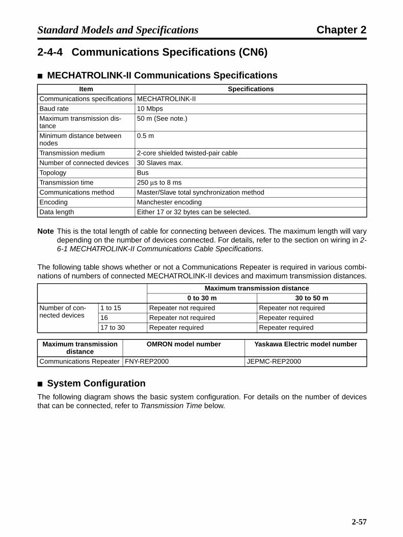
Chapter 2Standard Models and Specifications
2-4-4 Communications Specifications (CN6)
MECHATROLINK-II Communications Specifications
Note This is the total length of cable for connecting between devices. The maximum length will varydepending on the number of devices connected. For details, refer to the section on wiring in 2-6-1 MECHATROLINK-II Communications Cable Specifications.
The following table shows whether or not a Communications Repeater is required in various combi-nations of numbers of connected MECHATROLINK-II devices and maximum transmission distances.
System ConfigurationThe following diagram shows the basic system configuration. For details on the number of devicesthat can be connected, refer to Transmission Time below.
Item SpecificationsCommunications specifications MECHATROLINK-II
Baud rate 10 Mbps
Maximum transmission dis-tance
50 m (See note.)
Minimum distance between nodes
0.5 m
Transmission medium 2-core shielded twisted-pair cable
Number of connected devices 30 Slaves max.
Topology Bus
Transmission time 250 µs to 8 ms
Communications method Master/Slave total synchronization method
Encoding Manchester encoding
Data length Either 17 or 32 bytes can be selected.
Maximum transmission distance0 to 30 m 30 to 50 m
Number of con-nected devices
1 to 15 Repeater not required Repeater not required
16 Repeater not required Repeater required
17 to 30 Repeater required Repeater required
Maximum transmission distance
OMRON model number Yaskawa Electric model number
Communications Repeater FNY-REP2000 JEPMC-REP2000
2-57

Chapter 2Standard Models and Specifications
Connection Example: Connecting to a SYSMAC CS1W-MCH71, CJ1W-MCH71, or CJ1W-NCF71
MECHATROLINK-II Communications SetupThis section describes the required switch settings for MECHATROLINK-II communications.
Communications SpecificationsMECHATROLINK-II communications specifications are set using DIP switch SW2. The settings areshown below. Changes to settings go into effect when the power is turned ON again.
Transmission TimeThe following table shows the transmission times that can be used with the Servo Driver, and thenumber of nodes that can be connected.
Bit Name Setting Contents Default settingBit 1 Reserved for system. ON --- ON
Bit 2 Reserved for system. ON --- ON
Bit 3 Node address setting OFF Node address: 40H + SW1 OFF
ON Node address: 50H + SW1
Bit 4 Reserved for system. OFF --- OFF
M M
Host
Servo Driver Servo Driver
Servomotor Servomotor
ON
OFF
1
CDE
F01
23 4 5
6789
AB
2 3 4
SW2 (default setting)
SW1 (default setting)
2-58

Chapter 2Standard Models and Specifications
Transmission time and number of connectable devices
Note 1. When the transmission time is 0.25 ms, set a communications time that is a multiple of0.5 ms.
Note 2. If the actual number of connected devices is less than the possible number, the extra wordscan be used as communications retry words. The number of communication retries equalsthe number of connectable devices minus the number of devices actually connected plus 1.
Note 3. When there are no communications retries, the number of connectable devices equals thenormal number of connectable devices plus 1.
Note 4. When a C2 Master is connected, the number of connectable devices equals the normalnumber of connectable devices minus 1.
The node address is set as shown in the following table, using the rotary switch (SW1) and the DIPswitch (bit 3 of SW2). Changes in settings go into effect when the power is turned ON again. Thedefault setting for the node address is 41H (bit 3 of SW2: OFF; SW1: 1).
Node address settings
Number of connectable
devices
Transmission time0.25 ms
(See note 1.)
0.5 ms 1.0 ms 1.5 ms 2.0 ms 2.5 ms 3.0 ms 3.5 ms 4.0 ms
0 3 8 14 20 25 30 30 30
SW2 bit 3 SW1 Node address SW2 bit 3 SW1 Node addressOFF 0 Disabled ON 0 50H
OFF 1 41H ON 1 51H
OFF 2 42H ON 2 52H
OFF 3 43H ON 3 53H
OFF 4 44H ON 4 54H
OFF 5 45H ON 5 55H
OFF 6 46H ON 6 56H
OFF 7 47H ON 7 57H
OFF 8 48H ON 8 58H
OFF 9 49H ON 9 59H
OFF A 4AH ON A 5AH
OFF B 4BH ON B 5BH
OFF C 4CH ON C 5CH
OFF D 4DH ON D 5DH
OFF E 4EH ON E 5EH
OFF F 4FH ON F 5FH
2-59

Chapter 2Standard Models and Specifications
2-4-5 I/O Signal Specifications (CN1)
External Signal Processing
Note 1. The inputs at pins 7 to 12 and the outputs at pins 1,2, and 23 to 26 can be changed by pa-rameter settings. The settings in the diagram are the defaults.
Note 2. Connect pin Nos. 14 and 15 when providing an external backup power supply for the abso-lute encoder.
Note 3. The general-purpose input at pin No. 13 can be monitored through MECHATROLINK-II.
Note 4. An automatic reset fuse is provided to protect output. If the fuse is activated for overcurrent,it will automatically reset after a fixed period of time has lapsed without current flowing.
See note 4.
See note 4.
See note 4.
ALMCOM
3
4
SO1+
SO1−
1
2
23
24
25
26
17
18
20
19
21
22
GND1613
12
11
10
9
8
3.3 k
7
+24VIN24 VDC
FG
3.3 k
3.3 k
3.3 k
3.3 k
3.3 k
3.3 k
3.3 k
3.3 k
3.3 k
3.3 k
3.3 k
3.3 k
3.3 k
6
See note 4.
14
15
BAT
BATGND
SO2+
SO2−
SO3+
SO3−
POT
NOT
DEC
EXT1
EXT2
EXT3
SI0
+A
−A
+B
−B
+Z
−Z
ALM
Forward rotation drive prohibit
Reverse rotation drive prohibit
Origin return deceleration switch
Servo Driver
External latch signal 1
External latch signal 2
External latch signal 3
General-purpose signal terminal
Backup battery 2.8 V to 4.5 V
Alarm output
Brake interlockMaximum operating voltage: 30 V DCMaximum output current: 50 mA
Encoder A phase outputs
Encoder B phase outputs
Encoder Z phase outputs
Line driver output EIA-RS422A conforming (Load resistance: 220 Ω min.)
Ground common
Frame ground
Shell
2-60
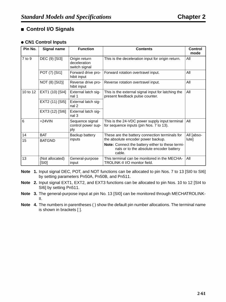
Chapter 2Standard Models and Specifications
Control I/O Signals
CN1 Control Inputs
Note 1. Input signal DEC, POT, and NOT functions can be allocated to pin Nos. 7 to 13 [SI0 to SI6]by setting parameters Pn50A, Pn50B, and Pn511.
Note 2. Input signal EXT1, EXT2, and EXT3 functions can be allocated to pin Nos. 10 to 12 [SI4 toSI6] by setting Pn511.
Note 3. The general-purpose input at pin No. 13 [SI0] can be monitored through MECHATROLINK-II.
Note 4. The numbers in parentheses ( ) show the default pin number allocations. The terminal nameis shown in brackets [ ].
Pin No. Signal name Function Contents Control mode
7 to 9 DEC (9) [SI3] Origin return deceleration switch signal
This is the deceleration input for origin return. All
POT (7) [SI1] Forward drive pro-hibit input
Forward rotation overtravel input. All
NOT (8) [SI2)] Reverse drive pro-hibit input
Reverse rotation overtravel input. All
10 to 12 EXT1 (10) [SI4] External latch sig-nal 1
This is the external signal input for latching the present feedback pulse counter.
All
EXT2 (11) [SI5] External latch sig-nal 2
EXT3 (12) [SI6] External latch sig-nal 3
6 +24VIN Sequence signal control power sup-ply
This is the 24-VDC power supply input terminal for sequence inputs (pin Nos. 7 to 13).
All
14 BAT Backup battery inputs
These are the battery connection terminals for the absolute encoder power backup.Note: Connect the battery either to these termi-
nals or to the absolute encoder battery cable.
All [abso-lute]15 BATGND
13 (Not allocated) [SI0]
General-purpose input
This terminal can be monitored in the MECHA-TROLINK-II I/O monitor field.
All
2-61
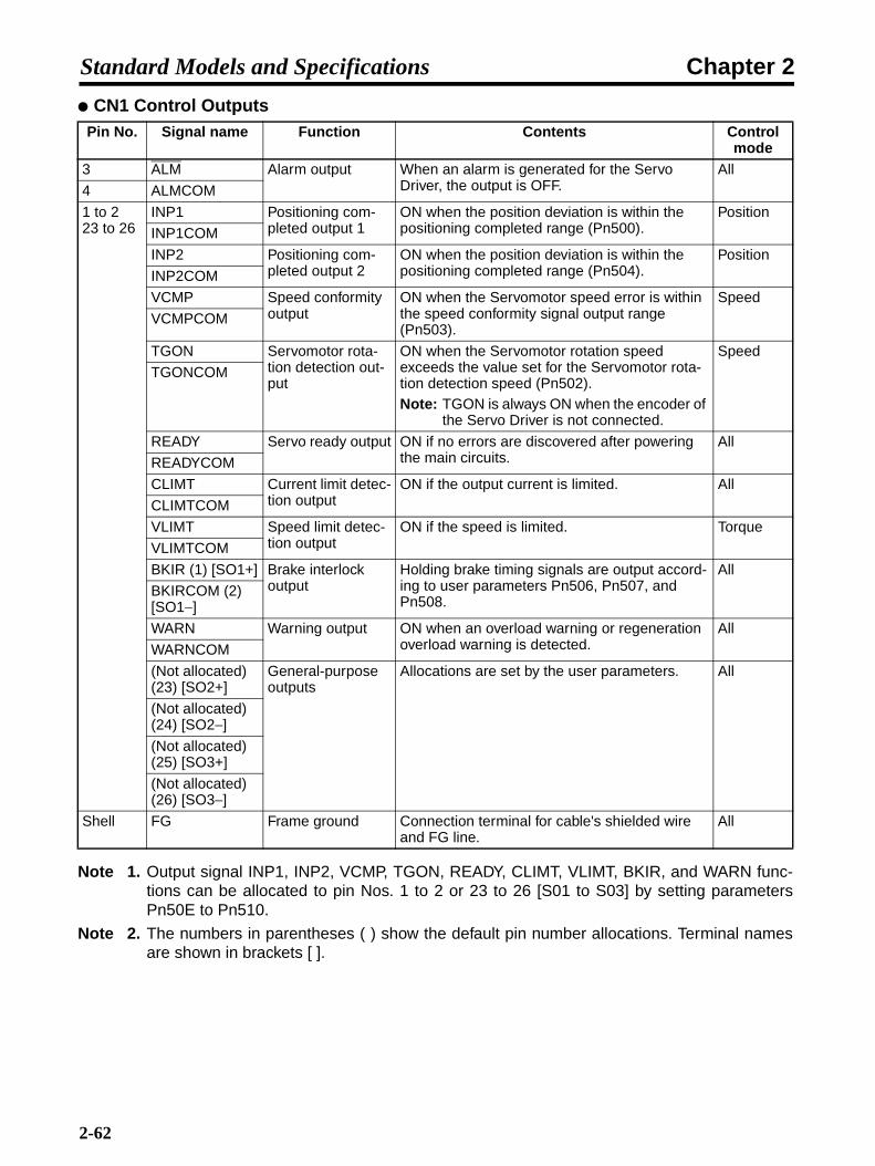
Chapter 2Standard Models and Specifications
CN1 Control Outputs
Note 1. Output signal INP1, INP2, VCMP, TGON, READY, CLIMT, VLIMT, BKIR, and WARN func-tions can be allocated to pin Nos. 1 to 2 or 23 to 26 [S01 to S03] by setting parametersPn50E to Pn510.
Note 2. The numbers in parentheses ( ) show the default pin number allocations. Terminal namesare shown in brackets [ ].
Pin No. Signal name Function Contents Control mode
3 ALM Alarm output When an alarm is generated for the Servo Driver, the output is OFF.
All
4 ALMCOM
1 to 223 to 26
INP1 Positioning com-pleted output 1
ON when the position deviation is within the positioning completed range (Pn500).
Position
INP1COM
INP2 Positioning com-pleted output 2
ON when the position deviation is within the positioning completed range (Pn504).
Position
INP2COM
VCMP Speed conformity output
ON when the Servomotor speed error is within the speed conformity signal output range (Pn503).
Speed
VCMPCOM
TGON Servomotor rota-tion detection out-put
ON when the Servomotor rotation speed exceeds the value set for the Servomotor rota-tion detection speed (Pn502).Note: TGON is always ON when the encoder of
the Servo Driver is not connected.
Speed
TGONCOM
READY Servo ready output ON if no errors are discovered after powering the main circuits.
All
READYCOM
CLIMT Current limit detec-tion output
ON if the output current is limited. All
CLIMTCOM
VLIMT Speed limit detec-tion output
ON if the speed is limited. Torque
VLIMTCOM
BKIR (1) [SO1+] Brake interlock output
Holding brake timing signals are output accord-ing to user parameters Pn506, Pn507, and Pn508.
All
BKIRCOM (2) [SO1−]
WARN Warning output ON when an overload warning or regeneration overload warning is detected.
All
WARNCOM
(Not allocated) (23) [SO2+]
General-purpose outputs
Allocations are set by the user parameters. All
(Not allocated) (24) [SO2−]
(Not allocated) (25) [SO3+]
(Not allocated) (26) [SO3−]
Shell FG Frame ground Connection terminal for cable's shielded wire and FG line.
All
2-62
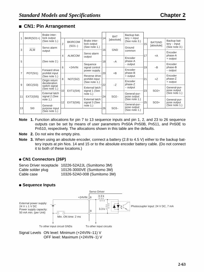
Chapter 2Standard Models and Specifications
CN1: Pin Arrangement
Note 1. Function allocations for pin 7 to 13 sequence inputs and pin 1, 2, and 23 to 26 sequenceoutputs can be set by means of user parameters Pn50A Pn50B, Pn511, and Pn50E toPn510, respectively. The allocations shown in this table are the defaults.
Note 2. Do not wire the empty pins.
Note 3. When using an absolute encoder, connect a battery (2.8 to 4.5 V) either to the backup bat-tery inputs at pin Nos. 14 and 15 or to the absolute encoder battery cable. (Do not connectit to both of these locations.)
CN1 Connectors (26P)Servo Driver receptacle 10226-52A2JL (Sumitomo 3M)Cable solder plug 10126-3000VE (Sumitomo 3M)Cable case 10326-52A0-008 (Sumitomo 3M)
Sequence Inputs
Signal Levels ON level: Minimum (+24VIN−11) VOFF level: Maximum (+24VIN−1) V
1
3
5
7
9
11
13
BKIRCOM(SO1−)
2
4
6
8
10
12
14
16
18
20
22
24
26
15
17
19
21
23
25
+24VIN
EXT1(SI4)
ALMCOM
NOT(SI2)
POT(SI1)
EXT3(SI6)
EXT2(SI5)
SI0
ALM
BKIR(SO1+)
+B
SO2+
−Z
SO3+
SO2−
SO3−
−A
+Z
BATGND[absolute]
BAT[absolute]
+A
GND
−B
DEC(SI3)
Brake inter-lock output (See note 1.)
Servo alarm output
(See note 2.)
Forward drive prohibit input (See note 1.)
Origin return deceleration switch signal (See note 1.)
External latch signal 2 (See note 1.)
General-purpose input (See note 1.)
Brake inter-lock output (See note 1.)
Servo alarm output
Sequence signal control power supply
Reverse drive prohibit input (See note 1.)
External latch signal 1 (See note 1.)
External latch signal 3 (See note 1.)
Backup bat-tery + input (See note 3.)
Ground common
Encoder phase-A − output
Encoder phase-B + output
Encoder phase-Z − output
General-pur-pose output (See note 1.)
General-pur-pose output (See note 1.)
Backup bat-tery − input (See note 3.)
Encoder phase-A + output
Encoder phase-B − output
Encoder phase-Z + output
General-pur-pose output (See note 1.)
General-pur-pose output (See note 1.)
6+24VIN
9
3.3 k
3.3 k
External power supply: 24 V ± 1 V DCPower supply capacity: 50 mA min. (per Unit)
Min. ON time: 2 ms
To other input circuit GNDs To other input circuits
Servo Driver
Photocoupler input: 24 V DC, 7 mA
2-63

Chapter 2Standard Models and Specifications
Control Output Circuits
Position Feedback Output
Sequence and Alarm Outputs
Note An automatic reset fuse is provided to protect output. If the fuse is activated for overcurrent, itwill automatically reset after a fixed period of time has lapsed without current flowing.
Backup Battery + Input (14: BAT)Backup Battery − Input (15: BATGND)
• These are the connection terminals for a backup battery for when power to the absolute encoder isinterrupted.
• Normally a Backup Battery Unit is used and the battery is connected to the battery holder for theabsolute encoder battery cable, so do not connect anything to these terminals. (Absolutely do notconnect to both of them, or it will cause damage.)
• The battery voltage is 2.8 to 4.5 V.
+A17
−A18
+B20
−B19
+Z21
−Z22
GND16
FG
+A
−A
+B
−B
+Z
−Z
GND
FG
0 V
R = 220 to 470 Ω
R
R
R
2
1
6
7
10
9
163
45
12
811
FG
0 V
0 V
+5 V
Servo Driver
Phase A
Phase B
Phase Z
Output line driver SN75ALS174NS or equivalent
Phase A
Phase B
Phase Z
Shell
Applicable line receiver SN75175/MC3486/AM26LS32
+
−
X
Di
See note.
Servo Driver side
To other output circuits
External power supply24 V DC ± 1 V
Maximum operating voltage: 30 V DC Maximum output current: 50 mA
Di: Diode for preventing surge voltage (Use speed diodes.)
2-64

Chapter 2Standard Models and Specifications
Forward Drive Prohibit (7: POT)Reverse Drive Prohibit (8: NOT)
Note This is the default allocation. For either signal, the drive prohibition is normally disabled. Thissetting can be changed by Pn50A.3/Pn50B.0.
• These two signals are the inputs for forward and reverse drive prohibit (overtravel).
• When they are input, driving is possible in the respective direction.
• When driving is prohibited, movement will stop according to the settings of Pn001.0 and Pn001.1.Refer to the diagram below.)
• Alarm status will not be generated at the Servo Driver while driving is prohibited.
Note 1. The position loop will not operate for position control when stopping in this mode.
Note 2. When torque control is being used, the stopping method is determined by Pn001.0 setting.(The Pn001.1 setting is irrelevant.)
Note 3. With a vertical load, the load may fall due to its own weight if it is left at a drive prohibit input.We recommend that you set the stop method for the drive prohibit input (Pn001.1) for decel-erating with the emergency stop torque, and then set stopping with the servo locked (SV: 1)to prevent the load from falling.
Origin Return Deceleration Switch Signal (9: DEC)
Note This is the default allocation. The DEC signal is allocated in Pn511.0.
• This is the deceleration signal for origin search.
• When DEC is input (DEC: 1) during an origin search, the Servomotor speed is changed accordingto the origin return approach speed 1 (Pn817). Then, when the signal is turned OFF (DEC: 0), theServo Driver is switched to latch operation.
POT (NOT) is OFF
Dynamic brake
Free run
Emergency stop torque (Pn406)
Deceleration Method Stopped Status
Servo unlocked
Servo unlocked
Servo locked
Stopping Methods when Forward/Reverse Drive Prohibit is OFF
See note 1.
Pn001.1"0"
"1" or "2"
Pn001.0"0" or "1"
"2"Pn001.1
"1"
"2"
2-65

Chapter 2Standard Models and Specifications
External latch signal 1 (10: EXT1)External latch signal 2 (11: EXT2)External latch signal 3 (12: EXT3)
Note This is the default allocation. The EXT1, EXT2, and EXT3 signals are allocated in Pn511.1,Pn511.2, and Pn511.3 respectively.
• This is the signal for latching the present feedback pulse counter.
Encoder Output (17: Phase A +)Encoder Output (18: Phase A −)Encoder Output (20: Phase B +)Encoder Output (19: Phase B −)Encoder Output (21: Phase Z +)Encoder Output (22: Phase Z −)
Alarm output (3: ALM)Alarm output ground (4: ALMCOM)
• When the Servo Driver detects an error, outputs are turned OFF.
• This output is OFF at the time of powering up, and turns ON when the Servo Driver's initial process-ing is completed.
Positioning Completed Outputs 1, 2 (INP1, INP2)
Note As the default setting, these INP signals are not allocated. The INP1 signal is allocated inPn50E.0, and the INP2 signal in PN510.0.
• The INP1 signal turns ON when the number of accumulated pulses in the deviation counter is lessthan the value set in Pn522 (Positioning completed range 1). INP2 turns ON when the number isless than Pn524 (Positioning completed range 2).
• When the speed command is a low speed and the set value for the positioning completed range islarge, the positioning completed outputs stay ON.
Speed command
DEC
Latch signal
Origin return approach speed 1 (Pn817)
Origin return approach speed 2 (Pn818)
Origin return final travel distance (Pn819)
2-66

Chapter 2Standard Models and Specifications
Note These outputs are always OFF when the control mode is any mode other than position control.
Speed Conformity Output (VCMP)
Note As the default setting, the VCMP signal is not allocated. It is allocated in Pn50E.1.
• The VCMP signal turns ON when the difference between the speed command and the Servomotorrotation speed is equal to or less than the value set for Pn503 (Speed conformity signal outputrange).
• For example, if the speed command is for 3,000 r/min and the set value is for 50 r/min, it turns ONwhen the Servomotor rotation speed is between 2,950 and 3,050 r/min.
Note This output is always OFF when the control mode is any mode other than speed control.
Servomotor Rotation Detection Output (TGON)
Note As the default setting, the TGON signal is not allocated. It is allocated in Pn50E.2.
• The TGON signal turns ON when the Servomotor rotation speed exceeds the value set for Pn502(Rotation speed for motor rotation detection).
Note TGON is always ON when the encoder of the Servo Driver is not connected.
Servo Ready Output (READY)
Note As the default setting, the READY signal is not allocated. It is allocated in Pn50E.3.
• The READY signal turns ON if no errors are detected after the main circuits are powered up.
Current Limit Detection Output (CLIMT)
Note As the default setting, the CLIMT signal is not allocated. It is allocated in Pn50F.0.
• The CLIMT signal is turned ON in any of the following four cases.
• The output torque reaches the limit value set in Pn402 (Forward torque limit) or Pn403 (Re-verse torque limit).
• With the CJ1W-NCF71, the output torque reaches the limit value set in Pn404 (Forward rota-tion external current limit) or Pn405 (Reverse rotation external current limit) while the torquelimit (forward/reverse rotation current limit designation) is ON.
• With the CJ1W-NCF71, the output torque reaches the torque limit value specified by optioncommand value 1 when Pn002.0 (Torque command input change) is set to 1.
• With the CJ1W-NCF71, the output torque reaches the torque limit value specified by optioncommand value 1 or 2 with the torque limit (forward/reverse rotation current limit designation)set to ON when Pn002.0 (Torque command input change) is set to 3.
2-67
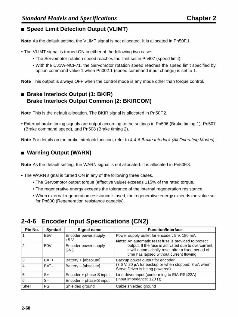
Chapter 2Standard Models and Specifications
Speed Limit Detection Output (VLIMT)
Note As the default setting, the VLIMT signal is not allocated. It is allocated in Pn50F.1.
• The VLIMT signal is turned ON in either of the following two cases.
• The Servomotor rotation speed reaches the limit set in Pn407 (speed limit).
• With the CJ1W-NCF71, the Servomotor rotation speed reaches the speed limit specified byoption command value 1 when Pn002.1 (speed command input change) is set to 1.
Note This output is always OFF when the control mode is any mode other than torque control.
Brake Interlock Output (1: BKIR)Brake Interlock Output Common (2: BKIRCOM)
Note This is the default allocation. The BKIR signal is allocated in Pn50F.2.
• External brake timing signals are output according to the settings in Pn506 (Brake timing 1), Pn507(Brake command speed), and Pn508 (Brake timing 2).
Note For details on the brake interlock function, refer to 4-4-6 Brake Interlock (All Operating Modes).
Warning Output (WARN)
Note As the default setting, the WARN signal is not allocated. It is allocated in Pn50F.3.
• The WARN signal is turned ON in any of the following three cases.
• The Servomotor output torque (effective value) exceeds 115% of the rated torque.
• The regenerative energy exceeds the tolerance of the internal regeneration resistance.
• When external regeneration resistance is used, the regenerative energy exceeds the value setfor Pn600 (Regeneration resistance capacity).
2-4-6 Encoder Input Specifications (CN2)Pin No. Symbol Signal name Function/Interface
1 E5V Encoder power supply +5 V
Power supply outlet for encoder: 5 V, 180 mANote: An automatic reset fuse is provided to protect
output. If the fuse is activated due to overcurrent, it will automatically reset after a fixed period of time has lapsed without current flowing.
2 E0V Encoder power supply GND
3 BAT+ Battery + [absolute] Backup power output for encoder(3.6 V, 20 µA for backup or when stopped; 3 µA when Servo Driver is being powered)
4 BAT− Battery − [absolute]
5 S+ Encoder + phase-S input Line driver input (conforming to EIA-RS422A)(Input impedance: 120 Ω)6 S− Encoder − phase-S input
Shell FG Shielded ground Cable shielded ground
2-68

Chapter 2Standard Models and Specifications
CN2 Connectors Used (6P)Receptacle at Servo Driver 53460-0611 (Molex Japan Co., Ltd.)Cable plug 55100-0670 (Molex Japan Co., Ltd.)
2-4-7 Personal Computer Monitor Connector Specifications (CN3)
CN3 Connectors Used (14P)Receptacle at Servo Driver 10214-52AJL (Sumitomo 3M)Cable plug with solder 10114-3000VE (Sumitomo 3M)Cable case 10314-50A0-008 (Sumitomo 3M)
2-4-8 Analog Monitor Output Connector Specifications (CN5)
CN5 Connectors Used (4P)Pin header at Servo Driver DF11-4DP-2DS (Hirose Electric)Cable connector socket DF11-4DS-2C (Hirose Electric)Cable connector contact DF11-2428SCF (Hirose Electric)
Pin No. Symbol Signal name Function/Interface1, 8 TXD+ Transmission data + This is data transmitted to a personal computer.
Line receiver input2, 9 TXD− Transmission data −3, 10 RXD+ Reception data + This is data received from a personal computer.
Line receiver input4, 6 RXD− Reception data −5 PRMU Unit switching This is the terminal for switching the connection.
7 RT Termination resistance ter-minal
This is the termination resistance terminal for the line receiver.6-pin connection for RS-422 communications (final Servo Driver only).
11, 12 --- (Not used.) (Do not connect.)
13 +5V +5 V output This is the +5-V power supply output.
14 GND Ground
Shell FG Shielded ground Cable shielded ground
Pin No. Symbol Signal name Function/Interface1 NM Analog Monitor 2 Default setting: Servomotor rotation speed, 1 V per
1,000 r/min (Can be changed by Pn007.)
2 AM Analog Monitor 1 Default setting: Torque command: gravity compensation torque, 1 V per 100% of rated torque (Can be changed by Pn006.)
3 GND Analog Monitor Ground Grounds for analog monitors 1 and 2
4 GND Analog Monitor Ground
2-69
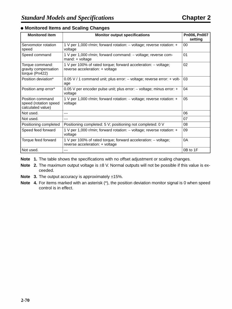
Chapter 2Standard Models and Specifications
Monitored Items and Scaling Changes
Note 1. The table shows the specifications with no offset adjustment or scaling changes.
Note 2. The maximum output voltage is ±8 V. Normal outputs will not be possible if this value is ex-ceeded.
Note 3. The output accuracy is approximately ±15%.
Note 4. For items marked with an asterisk (*), the position deviation monitor signal is 0 when speedcontrol is in effect.
Monitored item Monitor output specifications Pn006, Pn007 setting
Servomotor rotation speed
1 V per 1,000 r/min; forward rotation: − voltage; reverse rotation: + voltage
00
Speed command 1 V per 1,000 r/min; forward command: − voltage; reverse com-mand: + voltage
01
Torque command: gravity compensation torque (Pn422)
1 V per 100% of rated torque; forward acceleration: − voltage; reverse acceleration: + voltage
02
Position deviation* 0.05 V / 1 command unit; plus error: − voltage; reverse error: + volt-age
03
Position amp error* 0.05 V per encoder pulse unit; plus error: − voltage; minus error: + voltage
04
Position command speed (rotation speed calculated value)
1 V per 1,000 r/min; forward rotation: − voltage; reverse rotation: + voltage
05
Not used. --- 06
Not used. --- 07
Positioning completed Positioning completed: 5 V; positioning not completed: 0 V 08
Speed feed forward 1 V per 1,000 r/min; forward rotation: − voltage; reverse rotation: + voltage
09
Torque feed forward 1 V per 100% of rated torque; forward acceleration: − voltage; reverse acceleration: + voltage
0A
Not used. --- 0B to 1F
2-70

Chapter 2Standard Models and Specifications
2-5 Servomotor Specifications
OMNUC W-series AC Servomotors (R88M-W@)
There are three kinds of OMNUC W-Series AC Servomotors, as follows:
• 3,000-r/min Servomotors
• 3,000-r/min Flat-style Servomotors
• 1,000-r/min Servomotors
• 1,500-r/min Servomotors
These Servomotors also have optional specifications, such as shaft type, with or without brake,waterproofing, with or without reduction gears, and so on. Select the appropriate Servomotor for yoursystem according to the load conditions and installation environment.
2-5-1 General SpecificationsItem 3,000-r/min Servomotors 3,000-r/min Flat-
style Servomotors
1,000-r/min and1,500-r/min
Servomotors50 to 750 W 1 to 3 kW
Ambient operating tem-perature
0° to 40°C
Ambient operating humidity
20% to 80% (with no condensation)
Ambient storage temper-ature
−20° to 60°C
Ambient storage humidity 20% to 80% (with no condensation)
Storage and operating atmosphere
No corrosive gasses.
Vibration resistance (See note 1.)
10 to 2,500 Hz in X, Y, and Z direc-tions with accelera-tion 49 m/s2 max.
10 to 2,500 Hz in X, Y, and Z direc-tions with accelera-tion 24.5 m/s2 max.
10 to 2,500 Hz in X, Y, and Z direc-tions with accelera-tion 49 m/s2 max.
10 to 2,500 Hz in X, Y, and Z direc-tions with accelera-tion 24.5 m/s2 max.
Impact resistance Acceleration 490 m/s2 max., in X, Y, and Z direc-tions, two times
Acceleration 490 m/s2 max., in X, Y, and Z direc-tions, two times
Acceleration 490 m/s2 max., in X, Y, and Z direc-tions, two times
Acceleration 490 m/s2 max., in X, Y, and Z direc-tions, two times
Insulation resistance Between power line terminals and FG: 10 MΩ min. (at 500 V DC)
Dielectric strength Between power line terminals and FG: 1,500 V AC for 1 min at 50/60 Hz
2-71

Chapter 2Standard Models and Specifications
Note 1. Vibration may be amplified due to sympathetic resonance of machinery, so use the Servo-motor Driver under conditions which will not exceed 80% of the specification values over along period of time.
Note 2. Water-proof connectors must be used on the Power and Encoder Cables when used in en-vironments subject to direct contact with water. Refer to 3-1-2 Servomotors for the recom-mended connectors.
Note 3. The above items reflect individual evaluation testing. The results may differ under compoundconditions.
Note 4. The Servomotors cannot be used in misty environments.
Protective StructureThe protective structure depends on the type of Servomotor, as shown in the following tables. Servo-motors are available with and without oil seals. The oils seals prevent oil and grease from penetratingaround the shaft. They do not prevent the penetration of water.
3,000-r/min Servomotors
3,000-r/min Flat Servomotors
1,000-r/min and 1,500-r/min Servomotors
Note The user can attach and remove oil seals for the Servomotors marked with an asterisk.
Run position All directions
Insulation grade Type B Type F Type B Type F
Structure Totally-enclosed self-cooling
Vibration grade V-15
Mounting method Flange-mounting
EC Direc-tives
EMC Direc-tive
EN55011 class A group 1
EN61000-6-2
Low-voltage Directive
IEC60034-8, EN60034-1, -5, -9
UL standards UL1004
cUL standards cUL C22.2 No. 100
30 to 750 W 1 to 5 kWWithout oil seal IP55 (except for through-shaft parts) IP67 (except for through-shaft parts)*
With oil seal IP55 (except for through-shaft parts) IP67 (including through-shaft parts)*
Without oil seal IP55 (except for through-shaft parts)
With oil seal IP55 (except for through-shaft parts)
With water-resistance processing IP67 (except for through-shaft parts)
Without oil seal IP67 (except for through-shaft parts)*
With oil seal IP67 (including through-shaft parts)*
Item 3,000-r/min Servomotors 3,000-r/min Flat-style
Servomotors
1,000-r/min and1,500-r/min
Servomotors50 to 750 W 1 to 3 kW
2-72
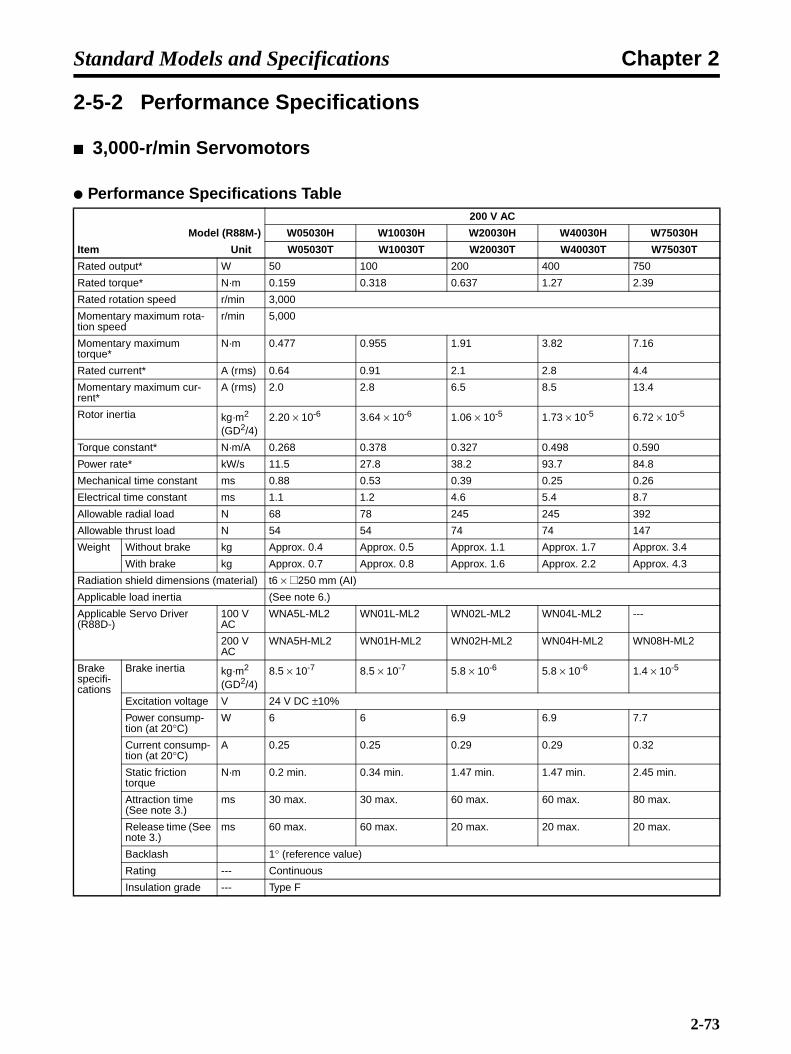
Chapter 2Standard Models and Specifications
2-5-2 Performance Specifications
3,000-r/min Servomotors
Performance Specifications Table200 V AC
Model (R88M-) W05030H W10030H W20030H W40030H W75030H
Item Unit W05030T W10030T W20030T W40030T W75030T
Rated output* W 50 100 200 400 750
Rated torque* N·m 0.159 0.318 0.637 1.27 2.39
Rated rotation speed r/min 3,000
Momentary maximum rota-tion speed
r/min 5,000
Momentary maximum torque*
N·m 0.477 0.955 1.91 3.82 7.16
Rated current* A (rms) 0.64 0.91 2.1 2.8 4.4
Momentary maximum cur-rent*
A (rms) 2.0 2.8 6.5 8.5 13.4
Rotor inertia kg·m2 (GD2/4)
2.20 × 10⁻⁶ 3.64 × 10⁻⁶ 1.06 × 10⁻⁵ 1.73 × 10⁻⁵ 6.72 × 10⁻⁵
Torque constant* N·m/A 0.268 0.378 0.327 0.498 0.590
Power rate* kW/s 11.5 27.8 38.2 93.7 84.8
Mechanical time constant ms 0.88 0.53 0.39 0.25 0.26
Electrical time constant ms 1.1 1.2 4.6 5.4 8.7
Allowable radial load N 68 78 245 245 392
Allowable thrust load N 54 54 74 74 147
Weight Without brake kg Approx. 0.4 Approx. 0.5 Approx. 1.1 Approx. 1.7 Approx. 3.4
With brake kg Approx. 0.7 Approx. 0.8 Approx. 1.6 Approx. 2.2 Approx. 4.3
Radiation shield dimensions (material) t6 × @250 mm (AI)
Applicable load inertia (See note 6.)
Applicable Servo Driver (R88D-)
100 V AC
WNA5L-ML2 WN01L-ML2 WN02L-ML2 WN04L-ML2 ---
200 V AC
WNA5H-ML2 WN01H-ML2 WN02H-ML2 WN04H-ML2 WN08H-ML2
Brake specifi-cations
Brake inertia kg·m2 (GD2/4)
8.5 × 10⁻⁷ 8.5 × 10⁻⁷ 5.8 × 10⁻⁶ 5.8 × 10⁻⁶ 1.4 × 10⁻⁵
Excitation voltage V 24 V DC ±10%
Power consump-tion (at 20°C)
W 6 6 6.9 6.9 7.7
Current consump-tion (at 20°C)
A 0.25 0.25 0.29 0.29 0.32
Static friction torque
N·m 0.2 min. 0.34 min. 1.47 min. 1.47 min. 2.45 min.
Attraction time (See note 3.)
ms 30 max. 30 max. 60 max. 60 max. 80 max.
Release time (See note 3.)
ms 60 max. 60 max. 20 max. 20 max. 20 max.
Backlash 1° (reference value)
Rating --- Continuous
Insulation grade --- Type F
2-73

Chapter 2Standard Models and Specifications
Note 1. *The values for items marked by asterisks are the values at an armature winding tempera-ture of 100°C (for models of 750 W or less) or 20°C (for models of 1 kW or more), combinedwith the Servo Driver. Other values are at normal conditions (20°C, 65%). The momentarymaximum torque shown above indicates the standard value.
Note 2. The brakes are the non-excitation operation type (released when excitation voltage is ap-plied).
Note 3. The operation time is the measured value (reference value) with a surge killer (CR50500, byOkaya Electric Industries co. LTD) inserted.
Note 4. The allowable radial and thrust loads are the values determined for a service life of 20,000hours at normal operating temperatures.
200 VAC
Model (R88M-) W1K030H W1K530H W2K030H W3K030H
Item Unit W1K030T W1K530T W2K030T W3K030T
Rated output* W 1,000 1,500 2,000 3,000
Rated torque* N·m 3.18 4.9 6.36 9.8
Rated rotation speed r/min 3,000
Momentary maximum rota-tion speed
r/min 5,000
Momentary maximum torque*
N·m 9.54 14.7 19.1 29.4
Rated current* A (rms) 5.7 9.7 12.7 18.8
Momentary maximum cur-rent*
A (rms) 17 28 42 56
Rotor inertia kg·m2 (GD2/4)
1.74 × 10⁻⁴ 2.47 × 10⁻⁴ 3.19 × 10⁻⁴ 7.00 × 10⁻⁴
Torque constant* N·m/A 0.64 0.56 0.54 0.57
Power rate* kW/s 57.9 97.2 127 137
Mechanical time constant ms 0.87 0.74 0.62 0.74
Electrical time constant ms 7.1 7.7 8.3 13.0
Allowable radial load N 686 686 686 980
Allowable thrust load N 196 196 196 392
Weight Without brake kg Approx. 4.6 Approx. 5.8 Approx. 7.0 Approx. 11.0
With brake kg Approx. 6.0 Approx. 7.5 Approx. 8.5 Approx. 14.0
Radiation shield dimensions (material) t12 × @300 mm (AI) t20 × @400 mm (AI)
Applicable load inertia (See note 6.)
Applicable Servo Driver (R88D-)
100 V AC
--- --- --- ---
200 V AC
WN10H-ML2 WN15H-ML2 WN20H-ML2 WN30H-ML2
Brake specifi-cations
Brake inertia kg·m2 (GD2/4)
3.25 × 10⁻⁵ 3.25 × 10⁻⁵ 3.25 × 10⁻⁵ 2.1 × 10⁻⁴
Excitation voltage V 24 V DC ±10%
Power consump-tion (at 20°C)
W 7 7 7 9.8
Current consump-tion (at 20°C)
A 0.29 0.29 0.29 0.41
Static friction torque
N·m 7.8 min. 7.8 min. 7.8 min. 20 min.
Attraction time (See note 3.)
ms 180 max. 180 max. 180 max. 180 max.
Release time (See note 3.)
ms 100 max. 100 max. 100 max. 100 max.
Backlash 1° (reference value)
Rating --- Continuous
Insulation grade --- Type F
2-74

Chapter 2Standard Models and Specifications
Note 5. The value indicated for the allowable radial load is for the positions shown in the followingdiagrams.
Note 6. Applicable Load Inertia
1) The drivable load inertia ratio (load inertia/rotor inertia) changes depending on the me-chanical configuration being driven and its rigidity. Highly rigid machines can operate witha large load inertia. Select a Servomotor and verify operation.
2) If the dynamic brake is used frequently with a large load inertia, it may lead to burnout ofthe dynamic brake resistor. Do not repeatedly turn the Servo ON and OFF with the dy-namic brake enabled.
Torque and Rotation Speed Characteristics
3,000-r/min Servomotors (With a 100-VAC Servo Driver)The following graphs show the characteristics with a 3-m standard cable and 100-V AC input.
5 mm
Radial load
Thrust load
(Models of 750 W or less)
Radial load
Thrust load
(Models of 1 kW or more)
End of Servomotor shaft
R88M-W20030H/T (200 W)
01000 2000 3000 4000 5000
0.1
0.2
0.3
0.4
0.5(N•m)
R88M-W05030H/T (50 W)
(r/min)
R88M-W10030H/T (100 W)
01000 2000 3000 4000 5000
0.2
0.4
0.6
0.8
1.0
(r/min) 01000 2000 3000 4000 5000
2.0
1.5
1.0
0.5
(r/min)
(N•m) (N•m)
R88M-W40030H/T (400 W)
01000 2000 3000 4000 5000
4.0
3.0
2.0
1.0
(r/min)
(N•m)
Continuous usage
Repeated usage
0.637 0.637
0.39
1.911.91
Continuous usage
Repeated usage
0.318 0.318
0.19
0.9550.955
Continuous usage
Repeated usage
0.159 0.159
0.09
0.4770.477
Continuous usage
Repeated usage
1.27 1.27
0.76
1.35
3.82 3.82
(3000)
2-75
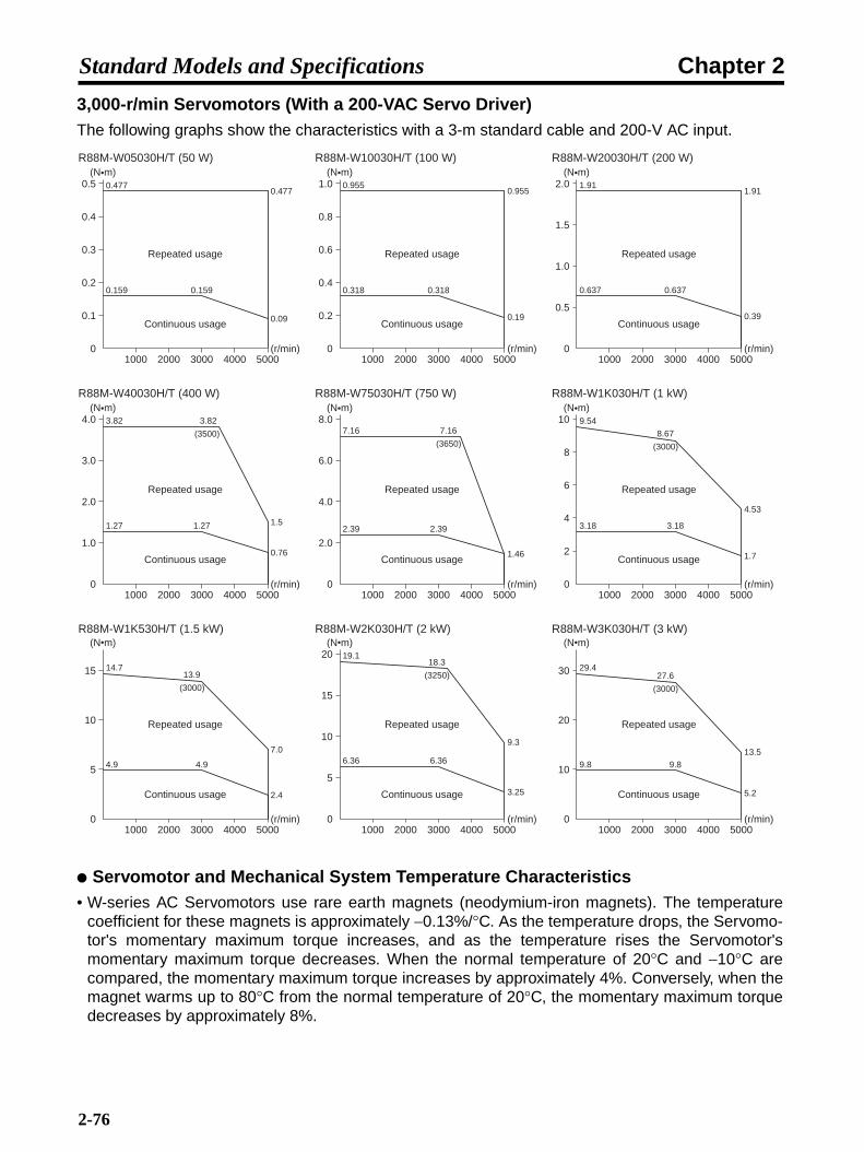
Chapter 2Standard Models and Specifications
3,000-r/min Servomotors (With a 200-VAC Servo Driver)The following graphs show the characteristics with a 3-m standard cable and 200-V AC input.
Servomotor and Mechanical System Temperature Characteristics• W-series AC Servomotors use rare earth magnets (neodymium-iron magnets). The temperature
coefficient for these magnets is approximately −0.13%/°C. As the temperature drops, the Servomo-tor's momentary maximum torque increases, and as the temperature rises the Servomotor'smomentary maximum torque decreases. When the normal temperature of 20°C and −10°C arecompared, the momentary maximum torque increases by approximately 4%. Conversely, when themagnet warms up to 80°C from the normal temperature of 20°C, the momentary maximum torquedecreases by approximately 8%.
Continuous usage
Repeated usage
R88M-W20030H/T (200 W)
01000 2000 3000 4000 5000
0.1
0.2
0.3
0.4
0.5(N•m)
R88M-W05030H/T (50 W)
(r/min)
R88M-W10030H/T (100 W)
0.159 0.159
0.09
0.4770.477
Continuous usage
Repeated usage
01000 2000 3000 4000 5000
0.2
0.4
0.6
0.8
1.0(N•m)
(r/min)
0.318 0.318
0.19
0.9550.955
Continuous usage
Repeated usage
01000 2000 3000 4000 5000
2.0
1.5
1.0
0.5
(N•m)
(r/min)
1.911.91
0.637 0.637
0.39
R88M-W40030H/T (400 W)
Continuous usage
Repeated usage
01000 2000 3000 4000 5000
4.0
3.0
2.0
1.0
(N•m)
(r/min)
1.27 1.27
R88M-W75030H/T (750 W)
Continuous usage
Repeated usage
01000 2000 3000 4000 5000
8.0
6.0
4.0
2.0
(N•m)
(r/min)
2.39 2.39
1.46
R88M-W1K030H/T (1 kW)
Continuous usage
Repeated usage
01000 2000 3000 4000 5000
2
4
6
8
10(N•m)
(r/min)
3.18 3.18
1.7
4.53
9.54
8.67
(3000)
R88M-W2K030H/T (2 kW)
Continuous usage
Repeated usage
01000 2000 3000 4000 5000
20
15
10
5
(N•m)
(r/min)
6.36 6.36
3.25
9.3
R88M-W1K530H/T (1.5 kW)
Continuous usage
Repeated usage
01000 2000 3000 4000 5000
(N•m)
(r/min)
5
10
15
4.9 4.9
2.4
7.0
14.713.9
(3000)
18.3
(3250)
19.1
R88M-W3K030H/T (3 kW)
Continuous usage
Repeated usage
01000 2000 3000 4000 5000
(N•m)
(r/min)
10
20
30
9.8 9.8
29.4
5.2
13.5
27.6
(3000)
0.76
7.16
(3650)
1.5
3.82 3.82
(3500) 7.16
2-76
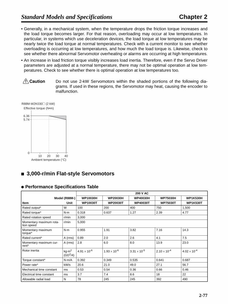
Chapter 2Standard Models and Specifications
• Generally, in a mechanical system, when the temperature drops the friction torque increases andthe load torque becomes larger. For that reason, overloading may occur at low temperatures. Inparticular, in systems which use deceleration devices, the load torque at low temperatures may benearly twice the load torque at normal temperatures. Check with a current monitor to see whetheroverloading is occurring at low temperatures, and how much the load torque is. Likewise, check tosee whether there abnormal Servomotor overheating or alarms are occurring at high temperatures.
• An increase in load friction torque visibly increases load inertia. Therefore, even if the Servo Driverparameters are adjusted at a normal temperature, there may not be optimal operation at low tem-peratures. Check to see whether there is optimal operation at low temperatures too.
!Caution Do not use 2-kW Servomotors within the shaded portions of the following dia-grams. If used in these regions, the Servomotor may heat, causing the encoder tomalfunction.
3,000-r/min Flat-style Servomotors
Performance Specifications Table200 V AC
Model (R88M-) WP10030H WP20030H WP40030H WP75030H WP1K530H
Item Unit WP10030T WP20030T WP40030T WP75030T WP1K530T
Rated output* W 100 200 400 750 1,500
Rated torque* N·m 0.318 0.637 1.27 2.39 4.77
Rated rotation speed r/min 3,000
Momentary maximum rota-tion speed
r/min 5,000
Momentary maximum torque*
N·m 0.955 1.91 3.82 7.16 14.3
Rated current* A (rms) 0.89 2.0 2.6 4.1 7.5
Momentary maximum cur-rent*
A (rms) 2.8 6.0 8.0 13.9 23.0
Rotor inertia kg·m2 (GD2/4)
4.91 × 10⁻⁶ 1.93 × 10⁻⁶ 3.31 × 10⁻⁵ 2.10 × 10⁻⁴ 4.02 × 10⁻⁴
Torque constant* N·m/A 0.392 0.349 0.535 0.641 0.687
Power rate* kW/s 20.6 21.0 49.0 27.1 56.7
Mechanical time constant ms 0.53 0.54 0.36 0.66 0.46
Electrical time constant ms 3.7 7.4 8.6 18 22
Allowable radial load N 78 245 245 392 490
010 20 30 40
6.365.74
Effective torque (N•m)
R88M-W2K030@ (2 kW)
Ambient temperature (°C)
2-77
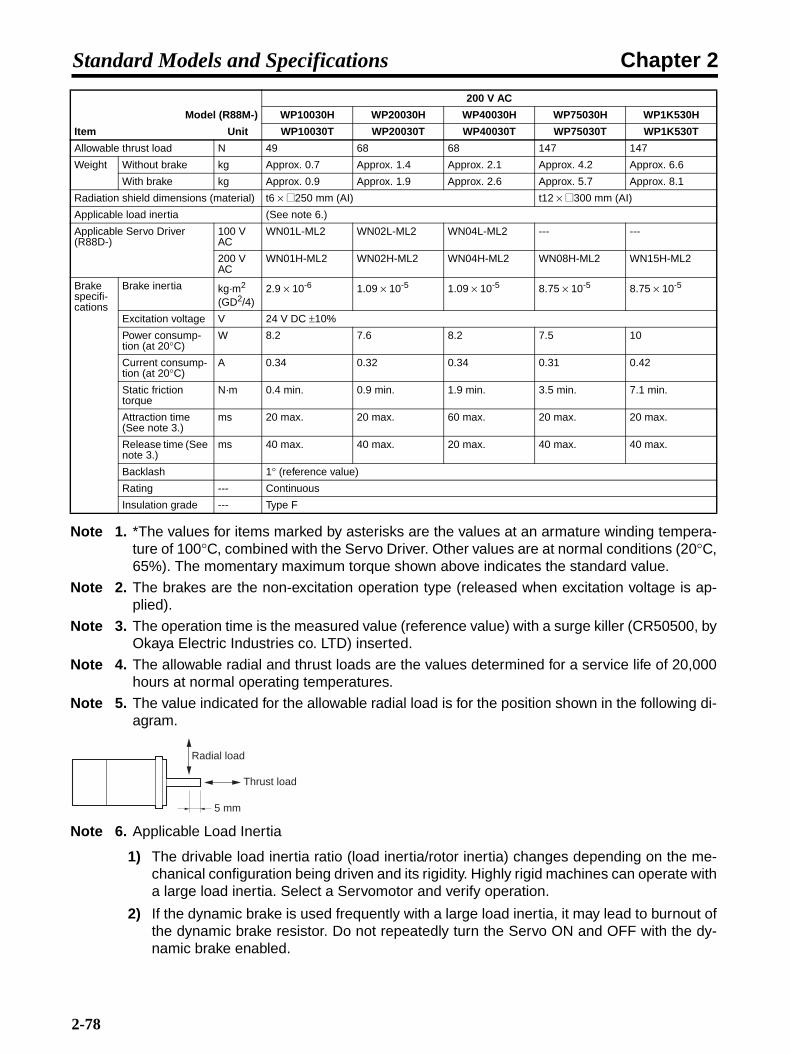
Chapter 2Standard Models and Specifications
Note 1. *The values for items marked by asterisks are the values at an armature winding tempera-ture of 100°C, combined with the Servo Driver. Other values are at normal conditions (20°C,65%). The momentary maximum torque shown above indicates the standard value.
Note 2. The brakes are the non-excitation operation type (released when excitation voltage is ap-plied).
Note 3. The operation time is the measured value (reference value) with a surge killer (CR50500, byOkaya Electric Industries co. LTD) inserted.
Note 4. The allowable radial and thrust loads are the values determined for a service life of 20,000hours at normal operating temperatures.
Note 5. The value indicated for the allowable radial load is for the position shown in the following di-agram.
Note 6. Applicable Load Inertia
1) The drivable load inertia ratio (load inertia/rotor inertia) changes depending on the me-chanical configuration being driven and its rigidity. Highly rigid machines can operate witha large load inertia. Select a Servomotor and verify operation.
2) If the dynamic brake is used frequently with a large load inertia, it may lead to burnout ofthe dynamic brake resistor. Do not repeatedly turn the Servo ON and OFF with the dy-namic brake enabled.
Allowable thrust load N 49 68 68 147 147
Weight Without brake kg Approx. 0.7 Approx. 1.4 Approx. 2.1 Approx. 4.2 Approx. 6.6
With brake kg Approx. 0.9 Approx. 1.9 Approx. 2.6 Approx. 5.7 Approx. 8.1
Radiation shield dimensions (material) t6 × @250 mm (AI) t12 × @300 mm (AI)
Applicable load inertia (See note 6.)
Applicable Servo Driver (R88D-)
100 V AC
WN01L-ML2 WN02L-ML2 WN04L-ML2 --- ---
200 V AC
WN01H-ML2 WN02H-ML2 WN04H-ML2 WN08H-ML2 WN15H-ML2
Brake specifi-cations
Brake inertia kg·m2 (GD2/4)
2.9 × 10⁻⁶ 1.09 × 10⁻⁵ 1.09 × 10⁻⁵ 8.75 × 10⁻⁵ 8.75 × 10⁻⁵
Excitation voltage V 24 V DC ±10%
Power consump-tion (at 20°C)
W 8.2 7.6 8.2 7.5 10
Current consump-tion (at 20°C)
A 0.34 0.32 0.34 0.31 0.42
Static friction torque
N·m 0.4 min. 0.9 min. 1.9 min. 3.5 min. 7.1 min.
Attraction time (See note 3.)
ms 20 max. 20 max. 60 max. 20 max. 20 max.
Release time (See note 3.)
ms 40 max. 40 max. 20 max. 40 max. 40 max.
Backlash 1° (reference value)
Rating --- Continuous
Insulation grade --- Type F
200 V AC
Model (R88M-) WP10030H WP20030H WP40030H WP75030H WP1K530H
Item Unit WP10030T WP20030T WP40030T WP75030T WP1K530T
5 mm
Radial load
Thrust load
2-78

Chapter 2Standard Models and Specifications
Torque and Rotation Speed Characteristics
3,000-r/min Flat-style Servomotors (With a 100-VAC Servo Driver)The following graphs show the characteristics with a 3-m standard cable and 100-V AC input.
3,000-r/min Flat-style Servomotors (With a 200-VAC Servo Driver)The following graphs show the characteristics with a 3-m standard cable and 200-V AC input.
R88M-WP10030H/T (100 W)
Continuous usage
Repeated usage
01000 2000 3000 4000 5000
0.2
0.4
0.6
0.8
1.0
(r/min)
0.318 0.318
0.19
0.7501.45
0.955(N•m)
R88M-WP20030H/T (200 W)
Continuous usage
Repeated usage
01000 2000 3000 4000 5000
2.0
1.5
1.0
0.5
(r/min)
1.91
0.637 0.637
0.39
1.91
(4000)
Continuous usage
Repeated usage
1.00
3.82
1.27 1.27
0.76
3.82
(2500)
(N•m)R88M-WP40030H/T (400 W)
01000 2000 3000 4000 5000
4.0
3.0
2.0
1.0
(r/min)
(N•m)0.955
(4500)
R88M-WP10030H/T (100 W)
Continuous usage
Repeated usage
01000 2000 3000 4000 5000
0.2
0.4
0.6
0.8
1.0
(r/min)
0.318 0.318
0.19
0.750
0.955(N•m)
R88M-WP20030H/T (200 W)
Continuous usage
Repeated usage
01000 2000 3000 4000 5000
2.0
1.5
1.0
0.5
(r/min)
1.91
0.637 0.637
0.39
(N•m)0.955
(4500)1.91
R88M-WP40030H/T (400 W)
Continuous usage
Repeated usage
01000 2000 3000 4000 5000
4.0
3.0
2.0
1.0
(N•m)
(r/min)
1.70
3.82
1.27 1.27
0.76
3.82
(3000)
R88-WP75030H/T (750 W)
Continuous usage
Repeated usage
01000 2000 3000 4000 5000
8.0
6.0
4.0
2.0
(N•m)
(r/min)
2.39 2.39
1.2
7.16 7.16
(3350)
1.6(4890)
R88M-WP1K530H/T (1.5 kW)
01000 2000 3000 4000 5000
(N•m)
(r/min)
5
10
15
Continuous usage
Repeated usage
4.77 4.77
2.4
14.3 14.3
(3400)
3.0(4900)
2-79

Chapter 2Standard Models and Specifications
Servomotor and Mechanical System Temperature Characteristics• W-series AC Servomotors use rare earth magnets (neodymium-iron magnets). The temperature
coefficient for these magnets is approximately −0.13%/°C. As the temperature drops, the Servomo-tor's momentary maximum torque increases, and as the temperature rises the Servomotor'smomentary maximum torque decreases. When the normal temperature of 20°C and −10°C arecompared, the momentary maximum torque increases by approximately 4%. Conversely, when themagnet warms up to 80°C from the normal temperature of 20°C, the momentary maximum torquedecreases by approximately 8%.
• Generally, in a mechanical system, when the temperature drops the friction torque increases andthe load torque becomes larger. For that reason, overloading may occur at low temperatures. Inparticular, in systems which use deceleration devices, the load torque at low temperatures may benearly twice the load torque at normal temperatures. Check with a current monitor to see whetheroverloading is occurring at low temperatures, and how much the load torque is. Likewise, check tosee whether there abnormal Servomotor overheating or alarms are occurring at high temperatures.
• An increase in load friction torque visibly increases load inertia. Therefore, even if the Servo Driverparameters are adjusted at a normal temperature, there may not be optimal operation at low tem-peratures. Check to see whether there is optimal operation at low temperatures too.
1,000-r/min Servomotors
Performance Specifications Table200 V AC
Model (R88M-) W30010H W60010H W90010H W1K210H W2K010H
Item Unit W30010T W60010T W90010T W1K210T W2K010T
Rated output* W 300 600 900 1,200 2,000
Rated torque* N·m 2.84 5.68 8.62 11.5 19.1
Rated rotation speed r/min 1,000
Momentary maximum rota-tion speed
r/min 2,000
Momentary maximum torque*
N·m 7.17 14.1 19.3 28.0 44.0
Rated current* A (rms) 3.0 5.7 7.6 11.6 18.5
Momentary maximum cur-rent*
A (rms) 7.3 13.9 16.6 28 42
Rotor inertia kg·m2 (GD2/4)
7.24 × 10⁻⁴ 1.39 × 10⁻³ 2.05 × 10⁻³ 3.17 × 10⁻³ 4.60 × 10⁻³
Torque constant* N·m/A 1.03 1.06 1.21 1.03 1.07
Power rate* kW/s 11.2 23.2 36.3 41.5 79.4
Mechanical time constant ms 5.1 3.8 2.8 2.0 1.7
Electrical time constant ms 5.1 4.7 5.7 13.5 13.9
Allowable radial load N 490 490 686 1,176 1,470
Allowable thrust load N 98 98 343 490 490
Weight Without brake kg Approx. 5.5 Approx. 7.6 Approx. 9.6 Approx. 14 Approx. 18
With brake kg Approx. 7.5 Approx. 9.6 Approx. 12 Approx. 19 Approx. 23.5
Radiation shield dimensions (material) t20 × @400 mm (Fe) t30 × @550 mm (Fe)
Applicable load inertia (See note 6.)
Applicable Servo Driver (R88D-) WN05H-ML2 WN10H-ML2 WN10H-ML2 WN15H-ML2 WN20H-ML2
2-80

Chapter 2Standard Models and Specifications
Note 1. *The values for items marked by asterisks are the values at an armature winding tempera-ture of 100°C, combined with the Servo Driver. Other values are at normal conditions (20°C,65%). The momentary maximum torque shown above indicates the standard value.
Note 2. The brakes are the non-excitation operation type (released when excitation voltage is ap-plied).
Note 3. The operation time is the measured value (reference value) with a surge killer (CR50500, byOkaya Electric Industries Co. LTD.) inserted.
Note 4. The allowable radial and thrust loads are the values determined for a service life of 20,000hours at normal operating temperatures.
Note 5. The value indicated for the allowable radial load is for the position shown in the following di-agram.
Note 6. Applicable Load Inertia
1) The drivable load inertia ratio (load inertia/rotor inertia) changes depending on the me-chanical configuration being driven and its rigidity. Highly rigid machines can operate witha large load inertia. Select a Servomotor and verify operation.
2) If the dynamic brake is used frequently with a large load inertia, it may lead to burnout ofthe dynamic brake resistor. Do not repeatedly turn the Servo ON and OFF with the dy-namic brake enabled.
Brake specifi-cations
Brake inertia kg·m2 (GD2/4)
2.1 × 10⁻⁴ 2.1 × 10⁻⁴ 2.1 × 10⁻⁴ 8.5 × 10⁻⁴ 8.5 × 10⁻⁴
Excitation voltage V 24 V DC ±10%
Power consump-tion (at 20°C)
W 9.8 9.8 9.8 18.5 18.5
Current consump-tion (at 20°C)
A 0.41 0.41 0.41 0.77 0.77
Static friction torque
N·m 4.41 min. 12.7 min. 12.7 min. 43.1 min. 43.1 min.
Attraction time (See note 3.)
ms 180 max. 180 max. 180 max. 180 max. 180 max.
Release time (See note 3.)
ms 100 max. 100 max. 100 max. 100 max. 100 max.
Backlash 1° (reference value)
Rating --- Continuous
Insulation grade --- Type F
200 V AC
Model (R88M-) W30010H W60010H W90010H W1K210H W2K010H
Item Unit W30010T W60010T W90010T W1K210T W2K010T
Radial load
Thrust load
End of Servomotor shaft
2-81
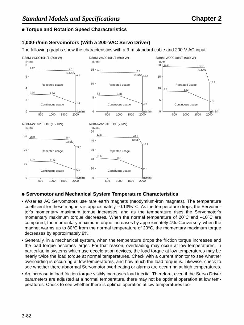
Chapter 2Standard Models and Specifications
Torque and Rotation Speed Characteristics
1,000-r/min Servomotors (With a 200-VAC Servo Driver)The following graphs show the characteristics with a 3-m standard cable and 200-V AC input.
Servomotor and Mechanical System Temperature Characteristics• W-series AC Servomotors use rare earth magnets (neodymium-iron magnets). The temperature
coefficient for these magnets is approximately −0.13%/°C. As the temperature drops, the Servomo-tor's momentary maximum torque increases, and as the temperature rises the Servomotor'smomentary maximum torque decreases. When the normal temperature of 20°C and −10°C arecompared, the momentary maximum torque increases by approximately 4%. Conversely, when themagnet warms up to 80°C from the normal temperature of 20°C, the momentary maximum torquedecreases by approximately 8%.
• Generally, in a mechanical system, when the temperature drops the friction torque increases andthe load torque becomes larger. For that reason, overloading may occur at low temperatures. Inparticular, in systems which use deceleration devices, the load torque at low temperatures may benearly twice the load torque at normal temperatures. Check with a current monitor to see whetheroverloading is occurring at low temperatures, and how much the load torque is. Likewise, check tosee whether there abnormal Servomotor overheating or alarms are occurring at high temperatures.
• An increase in load friction torque visibly increases load inertia. Therefore, even if the Servo Driverparameters are adjusted at a normal temperature, there may not be optimal operation at low tem-peratures. Check to see whether there is optimal operation at low temperatures too.
0200015001000500
(N•m)R88M-W30010H/T (300 W)
Continuous usage
Repeated usage
(r/min)
2
4
6
8
2.95 2.84
1.4
6.2
7.17 7.0
(1875)
0200015001000500
(N•m)R88M-W90010H/T (900 W)
Continuous usage
Repeated usage
(r/min)
5
10
15
20
0200015001000500
(N•m)R88M-W60010H/T (600 W)
Continuous usage
Repeated usage
(r/min)
5
10
15
5.8 5.68
2.8
12.7
14.1 13.8
(1925)
8.8 8.62
4.3
12.5
19.3 18.8
(1800)
0200015001000500
(N•m)R88M-W1K210H/T (1.2 kW)
Continuous usage
Repeated usage
(r/min)
10
20
30
11.8 11.5
21.8
28.0 27.1
(1800)
5.5
R88M-W2K010H/T (2 kW)
Continuous usage
Repeated usage
0
10
20
30
40
50(N•m)
(r/min)200015001000500
21.619.1
9.7
44.0 43.0
(1825)
35.8
2-82
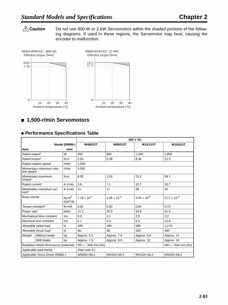
Chapter 2Standard Models and Specifications
!Caution Do not use 900-W or 2-kW Servomotors within the shaded portions of the follow-ing diagrams. If used in these regions, the Servomotor may heat, causing theencoder to malfunction.
1,500-r/min Servomotors
Performance Specifications Table200 V AC
Model (R88M-) W45015T W85015T W1K315T W1K815T
Item Unit
Rated output* W 450 850 1,300 1,800
Rated torque* N·m 2.84 5.39 8.34 11.5
Rated rotation speed r/min 1,500
Momentary maximum rota-tion speed
r/min 3,000
Momentary maximum torque*
N·m 8.92 13.8 23.3 28.7
Rated current* A (rms) 3.8 7.1 10.7 16.7
Momentary maximum cur-rent*
A (rms) 11 17 28 42
Rotor inertia kg·m2 (GD2/4)
7.24 × 10⁻⁴ 1.39 × 10⁻³ 2.05 × 10⁻³ 3.17 × 10⁻³
Torque constant* N·m/A 0.82 0.83 0.84 0.73
Power rate* kW/s 11.2 20.9 33.8 41.5
Mechanical time constant ms 5.0 3.1 2.8 2.2
Electrical time constant ms 5.1 5.3 6.3 12.8
Allowable radial load N 490 490 686 1,176
Allowable thrust load N 98 98 343 490
Weight Without brake kg Approx. 5.5 Approx. 7.6 Approx. 9.6 Approx. 14
With brake kg Approx. 7.5 Approx. 9.6 Approx. 12 Approx. 19
Radiation shield dimensions (material) t20 × @400 mm (Fe) t30 × @550 mm (Fe)
Applicable load inertia (See note 6.)
Applicable Servo Driver (R88D-) WN05H-ML2 WN10H-ML2 WN15H-ML2 WN20H-ML2
010 20 30 40
8.627.73
Effective torque (N•m)R88M-W90010@ (900 W)
Ambient temperature (°C)
010 20 30 40
19.117.7
Effective torque (N•m)R88M-W2K010@ (2 kW)
Ambient temperature (°C)
2-83

Chapter 2Standard Models and Specifications
Note 1. *The values for items marked by asterisks are the values at an armature winding tempera-ture of 20°C, combined with the Servo Driver. Other values are at normal conditions (20°C,65%). The momentary maximum torque shown above indicates the standard value.
Note 2. The brakes are the non-excitation operation type (released when excitation voltage is ap-plied).
Note 3. The operation time is the measured value (reference value) with a surge killer (CR50500, byOkaya Electric Industries Co. LTD.) inserted.
Note 4. The allowable radial and thrust loads are the values determined for a service life of 20,000hours at normal operating temperatures.
Note 5. The value indicated for the allowable radial load is for the position shown in the following di-agram.
Note 6. Applicable Load Inertia
1) The drivable load inertia ratio (load inertia/rotor inertia) changes depending on the me-chanical configuration being driven and its rigidity. Highly rigid machines can operate witha large load inertia. Select a Servomotor and verify operation.
2) If the dynamic brake is used frequently with a large load inertia, it may lead to burnout ofthe dynamic brake resistor. Do not repeatedly turn the Servo ON and OFF with the dy-namic brake enabled.
Brake specifi-cations
Brake inertia kg·m2 (GD2/4)
2.1 × 10⁻⁴ 2.1 × 10⁻⁴ 2.1 × 10⁻⁴ 8.5 × 10⁻⁴
Excitation voltage V 24 V DC ±10%
Power consump-tion (at 20°C)
W 9.8 9.8 9.8 18.5
Current consump-tion (at 20°C)
A 0.41 0.41 0.41 0.77
Static friction torque
N·m 4.41 min. 12.7 min. 12.7 min. 43.1 min.
Attraction time (See note 3.)
ms 180 max. 180 max. 180 max. 180 max.
Release time (See note 3.)
ms 100 max. 100 max. 100 max. 100 max.
Backlash 1° (reference value)
Rating --- Continuous
Insulation grade --- Type F
200 V AC
Model (R88M-) W45015T W85015T W1K315T W1K815T
Item Unit
Radial load
Thrust load
End of Servomotor shaft
2-84

Chapter 2Standard Models and Specifications
Torque and Rotation Speed Characteristics
1,500-r/min Servomotors (With a 200-VAC Servo Driver)The following graphs show the characteristics with a 3-m standard cable and 200-V AC input.
Servomotor and Mechanical System Temperature Characteristics• W-series AC Servomotors use rare earth magnets (neodymium-iron magnets). The temperature
coefficient for these magnets is approximately −0.13%/°C. As the temperature drops, the Servomo-tor's momentary maximum torque increases, and as the temperature rises the Servomotor'smomentary maximum torque decreases. When the normal temperature of 20°C and −10°C arecompared, the momentary maximum torque increases by approximately 4%. Conversely, when themagnet warms up to 80°C from the normal temperature of 20°C, the momentary maximum torquedecreases by approximately 8%.
• Generally, in a mechanical system, when the temperature drops the friction torque increases andthe load torque becomes larger. Therefore, overloading may occur at low temperatures. In particu-lar, in systems which use deceleration devices, the load torque at low temperatures may be nearlytwice the load torque at normal temperatures. Check with a current monitor to see whether over-loading is occurring at low temperatures, and how much the load torque is. Likewise, check to seewhether there is abnormal Servomotor overheating or alarms are occurring at high temperatures.
• An increase in load friction torque visibly increases load inertia. Therefore, even if the Servo Driverparameters are adjusted at a normal temperature, there may not be optimal operation at low tem-peratures. Check to see whether there is optimal operation at low temperatures too.
030001500 2000 2500500 1000
(N•m)R88M-W45015T (450 W)
Continuous usage
Repeated usage
(r/min)
2.94 2.84
1.42
4.80
8.928.40
(2190)
0
(N•m)R88M-W1K315T (1.3 kW)
Continuous usage
Repeated usage
(r/min)0
(N•m)R88M-W85015T (850 W)
Continuous usage
Repeated usage
(r/min)
5.88 5.39
2.70
11.5
13.812.7
(2870)
8.83 8.34
4.17
17.1
23.3 22.3
(2770)
0
(N•m)R88M-W1K815T (1.8 kW)
Continuous usage
Repeated usage
(r/min)
10
20
30
11.5
24.6
28.726.4
(2870)
5.80
30001500 2000 2500500 1000 30001500 2000 2500500 1000
30001500 2000 2500500 1000
2
4
6
8
10
5
10
15
20
10
20
30
11.8
2-85

Chapter 2Standard Models and Specifications
!Caution Do not use 1.3-kW Servomotors within the shaded portions of the following dia-grams. If used in these regions, the Servomotor may overheat, causing theencoder to malfunction.
2-5-3 Specifications for Servomotors with Reduction Gears
3,000-r/min Servomotors with Standard Reduction Gears (50 W to 3 kW)Model Rated
rotation speed
Rated torque
Ratio Maxi-mum
momen-tary
rotation speed
Maxi-mum
momen-tary
torque
Reduction gear
inertia
Allow-able
radial load
Allow-able
thrust load
Weight
Without brake
With brake
r/min N·m % r/min N·m kg·m2 N N kg kg
50 W 1/5 R88M-W05030@-@G05BJ 600 0.557 70 800 1.67 3.60 × 10⁻⁶ 137 127 1.1 1.4
1/9 R88M-W05030@-@G09BJ 333 1.00 70 444 3.01 3.30 × 10⁻⁶ 206 147 1.4 1.7
1/21 R88M-W05030@-@G21BJ 143 2.67 80 190 8.01 1.80 × 10⁻⁶ 235 147 1.6 1.9
1/33 R88M-W05030@-@G33BJ 91 4.20 80 121 12.6 1.3 × 10⁻⁶ 235 147 1.6 1.9
100 W 1/5 R88M-W10030@-@G05BJ 600 1.27 80 800 3.82 7.76 × 10⁻⁶ 167 147 1.4 1.7
1/11 R88M-W10030@-@G11BJ 273 2.80 80 364 8.40 4.76 × 10⁻⁶ 216 147 1.7 2.0
1/21 R88M-W10030@-@G21BJ 143 5.34 80 190 16.0 4.26 × 10⁻⁶ 392 235 2.7 3.0
1/33 R88M-W10030@-@G33BJ 91 8.40 80 121 25.2 3.26 × 10⁻⁶ 431 235 2.7 3.0
200 W 1/5 R88M-W20030@-@G05BJ 600 2.55 80 800 7.64 3.35 × 10⁻⁵ 245 235 3.0 3.5
1/11 R88M-W20030@-@G11BJ 273 5.96 85 364 17.9 8.50 × 10⁻⁶ 323 235 3.5 4.0
1/21 R88M-W20030@-@G21BJ 143 11.4 85 190 34.1 1.10× 10⁻⁵ 549 294 3.7 4.2
1/33 R88M-W20030@-@G33BJ 91 17.9 85 121 53.6 6.50 × 10⁻⁶ 608 294 3.8 4.3
400 W 1/5 R88M-W40030@-@G05BJ 600 5.40 85 800 16.2 3.35 × 10⁻⁵ 245 235 3.6 4.1
1/11 R88M-W40030@-@G11BJ 273 11.9 85 364 35.7 1.95 × 10⁻⁵ 441 294 4.3 4.8
1/21 R88M-W40030@-@G21BJ 143 22.7 85 190 68.2 1.95 × 10⁻⁵ 568 314 4.7 5.2
1/33 R88M-W40030@-@G33BJ 91 33.5 80 121 101 1.73 × 10⁻⁵ 657 314 7.1 7.6
750 W 1/5 R88M-W75030@-@G05BJ 600 10.2 85 800 30.4 5.83 × 10⁻⁵ 343 294 5.8 6.7
1/11 R88M-W75030@-@G11BJ 273 22.3 85 364 67.0 5.28 × 10⁻⁵ 451 314 6.6 7.5
1/21 R88M-W75030@-@G21BJ 143 42.7 85 190 128 5.93 × 10⁻⁵ 813 490 9.9 10.8
1/33 R88M-W75030@-@G33BJ 91 67.0 85 121 201 2.63 × 10⁻⁵ 921 490 9.9 10.8
010 20 30 40
8.347.50
Effective torque (N•m)
R88M-W1K315T (1.3 kW)
Ambient temperature (°C)
2-86

Chapter 2Standard Models and Specifications
Note 1. The reduction gear inertia indicates the Servomotor shaft conversion value.
Note 2. The enclosure rating for Servomotors with reduction gears is IP55 for 50- to 750-W models,and IP44 for 1- to 3-kW models.
Note 3. The maximum momentary rotation speed for the motor shaft of Servomotors with reductiongears is 4,000 r/min.
Note 4. The maximum momentary torque values marked by asterisks are the maximum allowabletorque for the reduction gears. Use torque limits so that these values are not exceeded.
Note 5. The allowable radial loads are measured at a point 5 mm from the end of the shaft for 50- to750-W Servomotors and in the center of the shaft for 1- to 3-W Servomotors.
1 kW 1/5 R88M-W1K030@-@G05BJ 600 12.7 80 800 38.2 3.44 × 10⁻⁴ 833 1,280 13 14.4
1/9 R88M-W1K030@-@G09BJ 333 22.9 80 444 68.7 3.11 × 10⁻⁴ 980 1,570 13 14.4
1/20 R88M-W1K030@-@G20BJ 150 50.9 80 200 153 6.79 × 10⁻⁴ 2,650 4,220 30 31.4
1/29 R88M-W1K030@-@G29BJ 103 73.8 80 138 221 4.88 × 10⁻⁴ 2,940 4,900 30 31.4
1/45 R88M-W1K030@-@G45BJ 67 114 80 89 343 3.92 × 10⁻⁴ 3,430 5,690 30 31.4
1.5 kW 1/5 R88M-W1K530@-@G05BJ 600 19.6 80 800 58.8 3.44 × 10⁻⁴ 833 1,280 14 15.7
1/9 R88M-W1K530@-@G09BJ 333 35.3 80 444 106 4.77 × 10⁻⁴ 1,960 3,000 31 32.7
1/20 R88M-W1K530@-@G20BJ 150 78.4 80 200 235 6.79 × 10⁻⁴ 2,650 4,220 31 32.7
1/29 R88M-W1K530@-@G29BJ 103 114 80 138 341 4.88 × 10⁻⁴ 2,940 4,900 31 32.7
1/45 R88M-W1K530@-@G45BJ 67 176 80 89 529 6.58 × 10⁻⁴ 8,040 8,830 51 52.5
2 kW 1/5 R88M-W2K030@-@G05BJ 600 25.4 80 800 76.4 3.44 × 10⁻⁴ 833 1,280 15 16.5
1/9 R88M-W2K030@-@G09BJ 333 45.8 80 444 138 4.77 × 10⁻⁴ 1,960 3,000 32 33.5
1/20 R88M-W2K030@-@G20BJ 150 102 80 200 306 6.79 × 10⁻⁴ 2,650 4,220 32 33.5
1/29 R88M-W2K030@-@G29BJ 103 148 80 138 443 1.03 × 10⁻³ 6,860 7,350 52 53.5
1/45 R88M-W2K030@-@G45BJ 67 229 80 89 688 6.58 × 10⁻⁴ 8,040 8,830 52 53.5
3 kW 1/5 R88M-W3K030@-@G05BJ 600 39.2 80 800 118 1.02 × 10⁻³ 1,670 1,960 29 32
1/9 R88M-W3K030@-@G09BJ 333 70.6 80 444 212 7.80 × 10⁻⁴ 1,960 3,000 36 39
1/20 R88M-W3K030@-@G20BJ 150 157 80 200 470 2.02 × 10⁻³ 6,080 6,370 56 58.5
1/29 R88M-W3K030@-@G29BJ 103 227 80 138 682 1.34 × 10⁻³ 6,860 7,350 56 58.5
1/45 R88M-W3K030@-@G45BJ 67 353 80 89 1,058 9.70 × 10⁻⁴ 8,040 8,830 56 58.5
Model Rated rotation speed
Rated torque
Ratio Maxi-mum
momen-tary
rotation speed
Maxi-mum
momen-tary
torque
Reduction gear
inertia
Allow-able
radial load
Allow-able
thrust load
Weight
Without brake
With brake
r/min N·m % r/min N·m kg·m2 N N kg kg
2-87
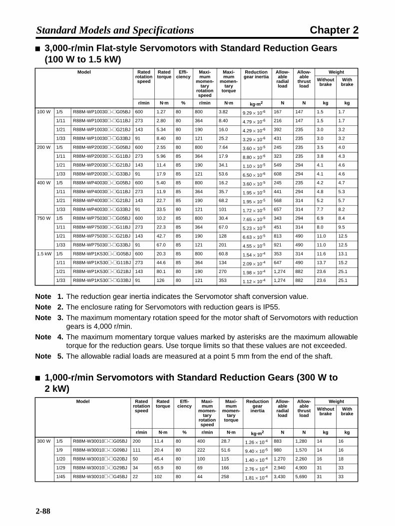
Chapter 2Standard Models and Specifications
3,000-r/min Flat-style Servomotors with Standard Reduction Gears (100 W to 1.5 kW)
Note 1. The reduction gear inertia indicates the Servomotor shaft conversion value.
Note 2. The enclosure rating for Servomotors with reduction gears is IP55.
Note 3. The maximum momentary rotation speed for the motor shaft of Servomotors with reductiongears is 4,000 r/min.
Note 4. The maximum momentary torque values marked by asterisks are the maximum allowabletorque for the reduction gears. Use torque limits so that these values are not exceeded.
Note 5. The allowable radial loads are measured at a point 5 mm from the end of the shaft.
1,000-r/min Servomotors with Standard Reduction Gears (300 W to 2 kW)
Model Rated rotation speed
Rated torque
Effi-ciency
Maxi-mum
momen-tary
rotation speed
Maxi-mum
momen-tary
torque
Reduction gear inertia
Allow-able
radial load
Allow-able
thrust load
Weight
Without brake
With brake
r/min N·m % r/min N·m kg·m2 N N kg kg
100 W 1/5 R88M-WP10030@-@G05BJ 600 1.27 80 800 3.82 9.29 × 10⁻⁶ 167 147 1.5 1.7
1/11 R88M-WP10030@-@G11BJ 273 2.80 80 364 8.40 4.79 × 10⁻⁶ 216 147 1.5 1.7
1/21 R88M-WP10030@-@G21BJ 143 5.34 80 190 16.0 4.29 × 10⁻⁶ 392 235 3.0 3.2
1/33 R88M-WP10030@-@G33BJ 91 8.40 80 121 25.2 3.29 × 10⁻⁶ 431 235 3.0 3.2
200 W 1/5 R88M-WP20030@-@G05BJ 600 2.55 80 800 7.64 3.60 × 10⁻⁵ 245 235 3.5 4.0
1/11 R88M-WP20030@-@G11BJ 273 5.96 85 364 17.9 8.80 × 10⁻⁶ 323 235 3.8 4.3
1/21 R88M-WP20030@-@G21BJ 143 11.4 85 190 34.1 1.10 × 10⁻⁵ 549 294 4.1 4.6
1/33 R88M-WP20030@-@G33BJ 91 17.9 85 121 53.6 6.50 × 10⁻⁶ 608 294 4.1 4.6
400 W 1/5 R88M-WP40030@-@G05BJ 600 5.40 85 800 16.2 3.60 × 10⁻⁵ 245 235 4.2 4.7
1/11 R88M-WP40030@-@G11BJ 273 11.9 85 364 35.7 1.95 × 10⁻⁵ 441 294 4.8 5.3
1/21 R88M-WP40030@-@G21BJ 143 22.7 85 190 68.2 1.95 × 10⁻⁵ 568 314 5.2 5.7
1/33 R88M-WP40030@-@G33BJ 91 33.5 80 121 101 1.72 × 10⁻⁵ 657 314 7.7 8.2
750 W 1/5 R88M-WP75030@-@G05BJ 600 10.2 85 800 30.4 7.65 × 10⁻⁵ 343 294 6.9 8.4
1/11 R88M-WP75030@-@G11BJ 273 22.3 85 364 67.0 5.23 × 10⁻⁵ 451 314 8.0 9.5
1/21 R88M-WP75030@-@G21BJ 143 42.7 85 190 128 6.63 × 10⁻⁵ 813 490 11.0 12.5
1/33 R88M-WP75030@-@G33BJ 91 67.0 85 121 201 4.55 × 10⁻⁵ 921 490 11.0 12.5
1.5 kW 1/5 R88M-WP1K530@-@G05BJ 600 20.3 85 800 60.8 1.54 × 10⁻⁴ 353 314 11.6 13.1
1/11 R88M-WP1K530@-@G11BJ 273 44.6 85 364 134 2.09 × 10⁻⁴ 647 490 13.7 15.2
1/21 R88M-WP1K530@-@G21BJ 143 80.1 80 190 270 1.98 × 10⁻⁴ 1,274 882 23.6 25.1
1/33 R88M-WP1K530@-@G33BJ 91 126 80 121 353 1.12 × 10⁻⁴ 1,274 882 23.6 25.1
Model Rated rotation speed
Rated torque
Effi-ciency
Maxi-mum
momen-tary
rotation speed
Maxi-mum
momen-tary
torque
Reduction gear
inertia
Allow-able
radial load
Allow-able
thrust load
Weight
Without brake
With brake
r/min N·m % r/min N·m kg·m2 N N kg kg
300 W 1/5 R88M-W30010@-@G05BJ 200 11.4 80 400 28.7 1.26 × 10⁻⁴ 883 1,280 14 16
1/9 R88M-W30010@-@G09BJ 111 20.4 80 222 51.6 9.40 × 10⁻⁵ 980 1,570 14 16
1/20 R88M-W30010@-@G20BJ 50 45.4 80 100 115 1.40 × 10⁻⁴ 1,270 2,260 16 18
1/29 R88M-W30010@-@G29BJ 34 65.9 80 69 166 2.76 × 10⁻⁴ 2,940 4,900 31 33
1/45 R88M-W30010@-@G45BJ 22 102 80 44 258 1.81 × 10⁻⁴ 3,430 5,690 31 33
2-88

Chapter 2Standard Models and Specifications
Note 1. The reduction gear inertia indicates the Servomotor shaft conversion value.
Note 2. The enclosure rating for Servomotors with reduction gears is IP44.
Note 3. The maximum momentary torque values marked by asterisks are the maximum allowabletorque for the reduction gears. Use torque limits so that these values are not exceeded.
Note 4. The allowable radial loads are measured in the center of the shaft.
1,500-r/min Servomotors with Standard Reduction Gears (450 W to 1.8 kW)
600 W 1/5 R88M-W60010@-@G05BJ 200 22.7 80 400 56.4 1.30 × 10⁻⁴ 833 1,280 16 18
1/9 R88M-W60010@-@G09BJ 111 40.9 80 222 82.5* 9.00 × 10-5 980 1,570 16 18
1/20 R88M-W60010@-@G20BJ 50 90.9 80 100 226 4.70 × 10⁻⁴ 2,650 4,220 33 35
1/29 R88M-W60010@-@G29BJ 34 132 80 69 327 2.80 × 10⁻⁴ 2,940 4,900 33 35
1/45 R88M-W60010@-@G45BJ 22 204 80 44 508 4.50 × 10⁻⁴ 8,040 8,830 53 55
900 W 1/5 R88M-W90010@-@G05BJ 200 34.5 80 400 77.2 3.40 × 10⁻⁴ 833 1,280 18 20.4
1/9 R88M-W90010@-@G09BJ 111 62.1 80 222 139 4.80 × 10⁻⁴ 1,960 3,000 35 37.4
1/20 R88M-W90010@-@G20BJ 50 138 80 100 309 6.90 × 10⁻⁴ 2,650 4,220 35 37.4
1/29 R88M-W90010@-@G29BJ 34 200 80 69 448 1.04 × 10⁻³ 6,860 7,350 55 57.4
1/45 R88M-W90010@-@G45BJ 22 310 80 44 695 6.70 × 10⁻⁴ 8,040 8,830 55 57.4
1.2 kW 1/5 R88M-W1K210@-@G05BJ 200 46.0 80 400 112 1.02 × 10⁻³ 1,670 1,960 32 37
1/9 R88M-W1K210@-@G09BJ 111 82.8 80 222 202 7.80 × 10⁻⁴ 1,960 3,000 39 44
1/20 R88M-W1K210@-@G20BJ 50 184 80 100 448 2.02 × 10⁻³ 6,080 6,370 59 64
1/29 R88M-W1K210@-@G29BJ 34 267 80 69 650 1.34 × 10⁻³ 6,860 7,350 59 64
1/45 R88M-W1K210@-@G45BJ 22 414 80 44 1,008 9.70 × 10⁻⁴ 8,040 8,830 59 64
2 kW 1/5 R88M-W2K010@-@G05BJ 200 76.4 80 400 176 1.02 × 10⁻³ 1,670 1,960 36 41.5
1/9 R88M-W2K010@-@G09BJ 111 138 80 222 317 7.80 × 10⁻⁴ 1,960 3,000 43 48.5
1/20 R88M-W2K010@-@G20BJ 50 306 80 100 704 2.02 × 10⁻³ 6,080 6,370 63 68.5
Model Rated rotation speed
Rated torque
Effi-ciency
Maxi-mum
momen-tary
rotation speed
Maxi-mum
momen-tary
torque
Reduction gear
inertia
Allow-able
radial load
Allow-able
thrust load
Weight
Without brake
With brake
r/min N·m % r/min N·m kg·m2 N N kg kg
450 W 1/5 R88M-W45015T-@G05BJ 300 11.4 80 600 35.7 1.26 × 10⁻⁴ 883 1,280 14 16
1/9 R88M-W45015T-@G09BJ 167 20.4 80 333 64.2 9.40 × 10⁻⁵ 980 1,570 14 16
1/20 R88M-W45015T-@G20BJ 75 45.4 80 150 143 4.66 × 10⁻⁴ 2,650 4,220 31 33
1/29 R88M-W45015T-@G29BJ 52 65.9 80 103 207 2.76 × 10⁻⁴ 2,940 4,900 31 33
1/45 R88M-W45015T-@G45BJ 33 102 80 67 321 1.81 × 10⁻⁴ 3,430 5,690 31 33
850 W 1/5 R88M-W85015T-@G05BJ 300 21.6 80 600 55.2 1.30 × 10⁻⁴ 883 1,280 16 18
1/9 R88M-W85015T-@G09BJ 167 38.8 80 333 74.5* 9.00 × 10-5 980 1,570 16 18
1/20 R88M-W85015T-@G20BJ 75 86.2 80 150 221 4.70 × 10⁻⁴ 2,650 4,220 33 35
1/29 R88M-W85015T-@G29BJ 52 125 80 103 320 2.80 × 10⁻⁴ 2,940 4,900 33 35
1/45 R88M-W85015T-@G45BJ 33 194 80 67 497 4.50 × 10⁻⁴ 8,040 8,830 53 55
Model Rated rotation speed
Rated torque
Effi-ciency
Maxi-mum
momen-tary
rotation speed
Maxi-mum
momen-tary
torque
Reduction gear
inertia
Allow-able
radial load
Allow-able
thrust load
Weight
Without brake
With brake
r/min N·m % r/min N·m kg·m2 N N kg kg
2-89

Chapter 2Standard Models and Specifications
Note 1. The reduction gear inertia indicates the Servomotor shaft conversion value.
Note 2. The enclosure rating for Servomotors with reduction gears is IP44.
Note 3. The maximum momentary torque values marked by asterisks are the maximum allowabletorque for the reduction gears. Use torque limits so that these values are not exceeded.
Note 4. The allowable radial loads are measured in the center of the shaft.
3,000-r/min Servomotors with Economy Reduction Gears (100 to 750 W)
Note 1. The reduction gear inertia indicates the Servomotor shaft conversion value.
Note 2. The enclosure rating for Servomotors with reduction gears is IP44.
Note 3. The allowable radial loads are measured in the center of the shaft.
1.3 kW 1/5 R88M-W1K315T-@G05BJ 300 33.4 80 600 93.2 7.20 × 10⁻⁴ 1,670 1,960 28 30.4
1/9 R88M-W1K315T-@G09BJ 167 60.0 80 333 168 4.80 × 10⁻⁴ 1,960 3,000 35 37.4
1/20 R88M-W1K315T-@G20BJ 75 133 80 150 373 6.90 × 10⁻⁴ 2,650 4,220 35 37.4
1/29 R88M-W1K315T-@G29BJ 52 193 80 103 541 1.04 × 10⁻³ 6,860 7,350 55 57.4
1/45 R88M-W1K315T-@G45BJ 33 300 80 67 839 6.70 × 10⁻⁴ 8,040 8,830 55 57.4
1.8 kW 1/5 R88M-W1K815T-@G05BJ 300 46.0 80 600 115 1.02 × 10⁻³ 1,670 1,960 32 37
1/9 R88M-W1K815T-@G09BJ 167 82.8 80 333 207 7.80 × 10⁻⁴ 1,960 3,000 39 44
1/20 R88M-W1K815T-@G20BJ 75 184 80 150 459 2.02 × 10⁻³ 6,080 6,370 59 64
1/29 R88M-W1K815T-@G29BJ 52 267 80 103 666 1.34 × 10⁻³ 6,860 7,350 59 64
Model Rated rotation speed
Rated torque
Effi-ciency
Maxi-mum
momen-tary
rotation speed
Maxi-mum
momen-tary
torque
Reduction gear
inertia
Allow-able
radial load
Allow-able
thrust load
Weight
Without brake
With brake
r/min N·m % r/min N·m kg·m2 N N kg kg
100 W 1/5 R88M-W10030@-@G05CJ 600 1.19 75 1,000 3.58 4.08 × 10⁻⁶ 392 196 1.05 1.35
1/9 R88M-W10030@-@G09CJ 333 2.29 80 556 6.88 3.43 × 10⁻⁶ 441 220 1.05 1.35
1/15 R88M-W10030@-@G15CJ 200 3.82 80 333 11.5 3.62 × 10⁻⁶ 588 294 1.2 1.5
1/25 R88M-W10030@-@G25CJ 120 6.36 80 200 19.1 3.92 × 10⁻⁶ 1,323 661 2.2 2.5
200 W 1/5 R88M-W20030@-@G05CJ 600 2.71 85 1,000 8.12 1.53 × 10⁻⁵ 392 196 1.82 2.32
1/9 R88M-W20030@-@G09CJ 333 3.78 66 556 11.3 2.68 × 10⁻⁵ 931 465 2.8 3.3
1/15 R88M-W20030@-@G15CJ 200 6.31 66 333 18.9 2.71 × 10⁻⁵ 1,176 588 3.2 3.7
1/25 R88M-W20030@-@G25CJ 120 11.1 70 200 33.4 2.67 × 10⁻⁵ 1,323 661 3.2 3.7
400 W 1/5 R88M-W40030@-@G05CJ 600 5.40 85 1,000 16.2 3.22 × 10⁻⁵ 784 392 3.4 3.9
1/9 R88M-W40030@-@G09CJ 333 9.49 83 556 28.5 2.68 × 10⁻⁵ 931 465 3.4 3.9
1/15 R88M-W40030@-@G15CJ 200 15.8 83 333 47.6 2.71 × 10⁻⁵ 1,176 588 3.8 4.3
1/25 R88M-W40030@-@G25CJ 120 26.4 83 200 79.3 2.79 × 10⁻⁵ 1,617 808 4.9 5.4
750 W 1/5 R88M-W75030@-@G05CJ 600 10.8 90 1,000 32.2 7.17 × 10⁻⁵ 784 392 5.5 6.4
1/9 R88M-W75030@-@G09CJ 333 18.2 85 556 54.7 6.50 × 10⁻⁵ 1,176 588 6.8 7.7
1/15 R88M-W75030@-@G15CJ 200 30.4 85 333 91.2 7.09 × 10⁻⁵ 1,372 686 7.2 8.1
1/25 R88M-W75030@-@G25CJ 120 50.7 85 200 152 7.05 × 10⁻⁵ 2,058 1,029 10.6 11.5
Model Rated rotation speed
Rated torque
Effi-ciency
Maxi-mum
momen-tary
rotation speed
Maxi-mum
momen-tary
torque
Reduction gear
inertia
Allow-able
radial load
Allow-able
thrust load
Weight
Without brake
With brake
r/min N·m % r/min N·m kg·m2 N N kg kg
2-90

Chapter 2Standard Models and Specifications
3,000-r/min Flat-style Servomotors with Economy Reduction Gears (100 to 750 W)
Note 1. The reduction gear inertia indicates the Servomotor shaft conversion value.
Note 2. The enclosure rating for Servomotors with reduction gears is IP44.
Note 3. The allowable radial loads are measured in the center of the shaft.
2-5-4 Encoder Specifications
Incremental Encoder Specifications
Model Rated rotation speed
Rated torque
Effi-ciency
Maxi-mum
momen-tary
rotation speed
Maxi-mum
momen-tary
torque
Reduction gear
inertia
Allow-able
radial load
Allow-able
thrust load
Weight
Without brake
With brake
r/min N·m % r/min N·m kg·m2 N N kg kg
100 W 1/5 R88M-WP10030@-@G05CJ 600 1.19 75 1,000 3.58 1.60 × 10⁻⁵ 392 196 1.42 1.62
1/9 R88M-WP10030@-@G09CJ 333 2.29 80 556 6.88 1.37 × 10⁻⁵ 441 220 1.42 1.62
1/15 R88M-WP10030@-@G15CJ 200 3.82 80 333 11.5 3.38 × 10⁻⁶ 588 294 1.47 1.67
1/25 R88M-WP10030@-@G25CJ 120 6.36 80 200 19.1 3.68 × 10⁻⁶ 1,323 661 2.5 2.7
200 W 1/5 R88M-WP20030@-@G05CJ 600 2.71 85 1,000 8.12 1.53 × 10⁻⁵ 392 196 2.25 2.75
1/9 R88M-WP20030@-@G09CJ 333 3.78 66 556 11.3 2.56 × 10⁻⁵ 931 465 3.2 3.7
1/15 R88M-WP20030@-@G15CJ 200 6.31 66 333 18.9 2.71 × 10⁻⁵ 1,176 588 3.6 4.1
1/25 R88M-WP20030@-@G25CJ 120 11.1 70 200 33.4 2.67 × 10⁻⁵ 1,323 661 3.6 4.1
400 W 1/5 R88M-WP40030@-@G05CJ 600 5.40 85 1,000 16.2 3.23 × 10⁻⁵ 784 392 3.9 4.4
1/9 R88M-WP40030@-@G09CJ 333 9.49 83 556 28.5 2.56 × 10⁻⁵ 931 465 3.9 4.4
1/15 R88M-WP40030@-@G15CJ 200 15.8 83 333 47.6 2.71 × 10⁻⁵ 1,176 588 4.3 4.8
1/25 R88M-WP40030@-@G25CJ 120 26.4 83 200 79.3 2.79 × 10⁻⁵ 1,617 808 5.4 5.9
750 W 1/5 R88M-WP75030@-@G05CJ 600 10.8 90 1,000 32.2 7.17 × 10⁻⁵ 784 392 6.7 8.2
1/9 R88M-WP75030@-@G09CJ 333 18.2 85 556 54.7 6.50 × 10⁻⁵ 1,176 588 8.0 9.5
1/15 R88M-WP75030@-@G15CJ 200 30.4 85 333 91.2 6.86 × 10⁻⁵ 1,372 686 8.4 9.9
1/25 R88M-WP75030@-@G25CJ 120 50.7 85 200 152 7.05 × 10⁻⁵ 2,058 1,029 11.8 13.3
Item 3,000-r/min Servomotors 3,000-r/min Flat-style Servomotors
1,000-r/min Servomotors50 to 750 W 1 to 3 kW
Encoder method Optical encoder
13 bits 17 bits 13 bits 17 bits
Number of output pulses
A, B phase: 2,048 pulses/revolutionZ phase: 1 pulse/revolution
A, B phase: 32,768 pulses/revolutionZ phase: 1 pulse/revolution
A, B phase: 2,048 pulses/revolutionZ phase: 1 pulse/revolution
A, B phase: 32,768 pulses/revolutionZ phase: 1 pulse/revolution
Power supply voltage 5 V DC ±5%
Power supply current 120 mA 150 mA 120 mA 150 mA
2-91

Chapter 2Standard Models and Specifications
Absolute Encoder Specifications
Maximum rotation speed
5,000 r/min
Output signals +S, −S
Output impedance Conforming to EIA RS-422A.Output based on LTC1485CS or equivalent.
Serial communica-tions data
Position data, poll sensor, U, V, W phase, encoder alarm, Servomotor data
Serial communica-tions method
Bi-directional communications in HDLC format, by Manchester method
Item 3,000-r/min Servomotors 3,000-r/min Flat-style Servomotors
1,000-r/min Servomotors1,500-r/min
Servomotors
50 to 750 W 1 to 3 kW
Encoder method Optical encoder
16 bits 17 bits 16 bits 17 bits
Number of output pulses
A, B phase: 16,384 pulses/revolutionZ phase: 1 pulse/revolution
A, B phase: 32,768 pulses/revolutionZ phase: 1 pulse/revolution
A, B phase: 16,384 pulses/revolutionZ phase: 1 pulse/revolution
A, B phase: 32,768 pulses/revolutionZ phase: 1 pulse/revolution
Maximum rotational speed
−32,768 to +32,767 rotations or 0 to 65,534 rotations
Power supply voltage 5 V DC ±5%
Power supply current 180 mA
Applicable battery volt-age
3.6 V DC
Battery current con-sumption
20 µA (for backup, when stopped), 3 µA (when Servo Driver is powered)
Maximum rotation speed
5,000 r/min
Output signals +S, −S
Output impedance Conforming to EIA RS-422A.Output based on LTC1485CS or equivalent.
Serial communica-tions data
Position data, poll sensor, U, V, W phase, encoder alarm, Servomotor data
Serial communica-tions method
Bi-directional communications in HDLC format, by Manchester method
Absolute value com-munications data
Amount of rotation
Item 3,000-r/min Servomotors 3,000-r/min Flat-style Servomotors
1,000-r/min Servomotors50 to 750 W 1 to 3 kW
2-92
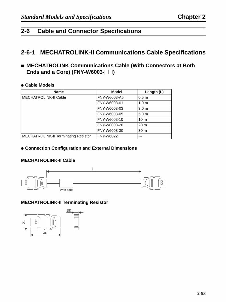
Chapter 2Standard Models and Specifications
2-6 Cable and Connector Specifications
2-6-1 MECHATROLINK-II Communications Cable Specifications
MECHATROLINK Communications Cable (With Connectors at Both Ends and a Core) (FNY-W6003-@@)
Cable Models
Connection Configuration and External Dimensions
MECHATROLINK-II Cable
MECHATROLINK-II Terminating Resistor
Name Model Length (L)MECHATROLINK-II Cable FNY-W6003-A5 0.5 m
FNY-W6003-01 1.0 m
FNY-W6003-03 3.0 m
FNY-W6003-05 5.0 m
FNY-W6003-10 10 m
FNY-W6003-20 20 m
FNY-W6003-30 30 m
MECHATROLINK-II Terminating Resistor FNY-W6022 ---
L
With core
(8)
21
46
2-93

Chapter 2Standard Models and Specifications
WiringThe following example shows the MECHATROLINK-II Communications Cable connections betweena host device and Servo Drivers.
Note 1. Use a minimum cable length of 0.5 m between any two devices (L1, L2 ... Ln).
Note 2. The total cable length (L1, L2 ... Ln) must not exceed 50 m.
0123456789
ABCDEF
Position Control Unit
L1 L2 Ln
5 678
9A
BCDE
F0
12 3 4
CN6
A/B
CN3
CN1
CN2
CN4
SW1
CHARGE
U
V
W
U V
W
R88D-WN01H-ML2
100W
200VAC SERVO DRIVER
POWER
COM
5 678
9A
BCDE
F0
12 3 4
CN6
A/B
CN3
CN1
CN2
CN4
SW1
CHARGE
U
V
W
U V
W
R88D-WN01H-ML2
100W
200VAC SERVO DRIVER
POWER
COM
5 678
9A
BCDE
F0
12 3 4
CN6
A/B
CN3
CN1
CN2
CN4
SW1
CHARGE
U
V
W
U V
W
R88D-WN01H-ML2
100W
200VAC SERVO DRIVER
POWER
COM
Terminating Resistor
2-94

Chapter 2Standard Models and Specifications
Servo Driver Cable (XW2Z-@J-B16)This Cable is for the Connector-Terminal Block Conversion Unit for W-series Servo Drivers (withbuilt-in MECHATROLINK-II communications).
Cables
XW2Z-@J-B16
Connection Configuration and External Dimensions
Wiring
Note Set and use the signal names listed above for the Servo Driver connectors.
Model Length (L) External sheath
diameter
Weight
XW2Z-100J-B16 1 m 8.0 dia. Approx. 0.1 kg
XW2Z-200J-B16 2 m Approx. 0.2 kg
XW2B-20G4XW2B-20G5XW2D-20G6
t = 14
R88D-WN@
Connector-Terminal Block Conversion Unit side Servo Driver side
39L6
30 52.4
Symbol+24V0 V
+24V0 V
+ 24 V0 V
DECPOTNOTEXT1EXT2EXT3
BATGNDBAT
BKIRCOMBKIR
ALMCOMALMFG
No.1234567891011121314151617181920
Connector for Connector-Terminal Block Conversion Unit
Symbol+24VIN
DECPOTNOTEXT1EXT2EXT3
BATGNDBAT
BKIRCOMBKIR
ALMCOMALMFG
No.6
978
10111215142143
Shell
Connector on Servo Driver (CN1)
Connector on Servo Driver Connector plug model 10126-3000VE (Sumitomo 3M) Connector Case model 10326-52A0-008 (Sumitomo 3M)
Cable AWG28 × 3P + AWG28 × 7C, UL2464
Connector Socket Model XG4M-2030 (OMRON) Strain Relief Model XG4T-2004 (OMRON)
Connector on Connector-Terminal Block Conversion Unit
2-95
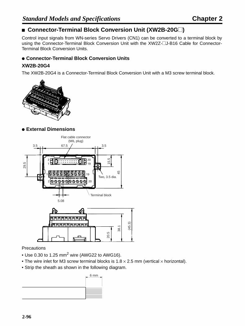
Chapter 2Standard Models and Specifications
Connector-Terminal Block Conversion Unit (XW2B-20G@)Control input signals from WN-series Servo Drivers (CN1) can be converted to a terminal block byusing the Connector-Terminal Block Conversion Unit with the XW2Z-@J-B16 Cable for Connector-Terminal Block Conversion Units.
Connector-Terminal Block Conversion Units
XW2B-20G4The XW2B-20G4 is a Connector-Terminal Block Conversion Unit with a M3 screw terminal block.
External Dimensions
Precautions
• Use 0.30 to 1.25 mm2 wire (AWG22 to AWG16).• The wire inlet for M3 screw terminal blocks is 1.8 × 2.5 mm (vertical × horizontal).• Strip the sheath as shown in the following diagram.
3.5 67.5
29.5
3.5
15.5
45
Two, 3.5 dia.
5.08
Terminal block
20.5
38.1
(45.
3)
Flat cable connector(MIL plug)
6 mm
2-96

Chapter 2Standard Models and Specifications
Terminal Block Model
XW2B-20G5 The XW2B-20G5 is a Connector-Terminal Block Conversion Unit with a M3.5 screw terminal block.
External Dimensions
Note The terminal pitch is 8.5 mm.
Precautions
• When using crimp terminals, use crimp terminals with the following dimensions.
• Use a tightening torque of 0.59 N·m when connecting wires and crimp terminals to the terminalblock.
Applicable Crimp Terminals Applicable WiresRound Terminals 1.25 to 3 AWG22 to AWG16 (0.30 to 1.25 mm2)
2 to 3.5 AWG16 to AWG14 (1.25 to 2.0 mm2)
Fork Terminals 1.25Y to 3 AWG22 to AWG16 (0.30 to 1.25 mm2)
2 to 3.5 AWG16 to AWG14 (1.25 to 2.0 mm2)
112.53.57
3.57
15.5
45
8.5 7.3
Two, 3.5-dia. holes
29.5
Flat cable connector (MIL plug)
Terminal block
43.5
(45.
3)
20.5
Round Crimp Terminals Fork Crimp Terminals
3.7 mm 6.8 mm max.6.8 mm max.
Dia.: 3.7 mm
2-97
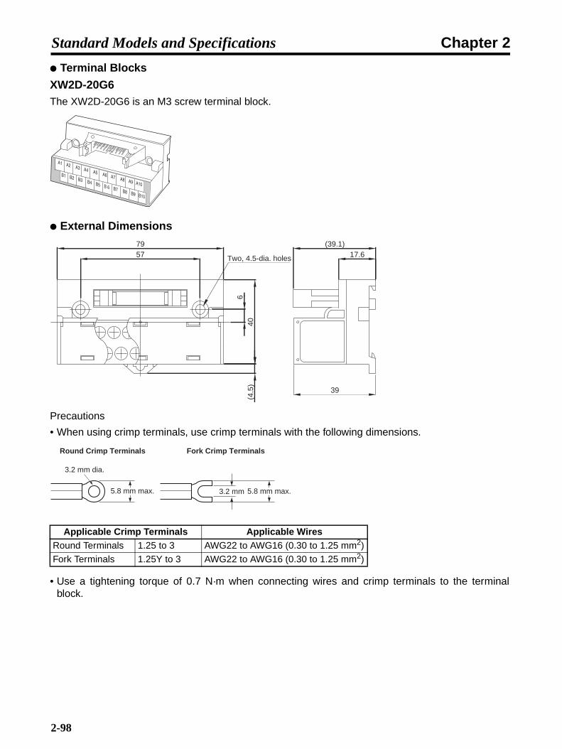
Chapter 2Standard Models and Specifications
Terminal Blocks
XW2D-20G6The XW2D-20G6 is an M3 screw terminal block.
External Dimensions
Precautions
• When using crimp terminals, use crimp terminals with the following dimensions.
• Use a tightening torque of 0.7 N·m when connecting wires and crimp terminals to the terminalblock.
Applicable Crimp Terminals Applicable WiresRound Terminals 1.25 to 3 AWG22 to AWG16 (0.30 to 1.25 mm2)
Fork Terminals 1.25Y to 3 AWG22 to AWG16 (0.30 to 1.25 mm2)
79 (39.1)
39
57 17.6
640
(4.5
)Two, 4.5-dia. holes
Round Crimp Terminals Fork Crimp Terminals
3.2 mm dia.
5.8 mm max. 5.8 mm max.3.2 mm
2-98
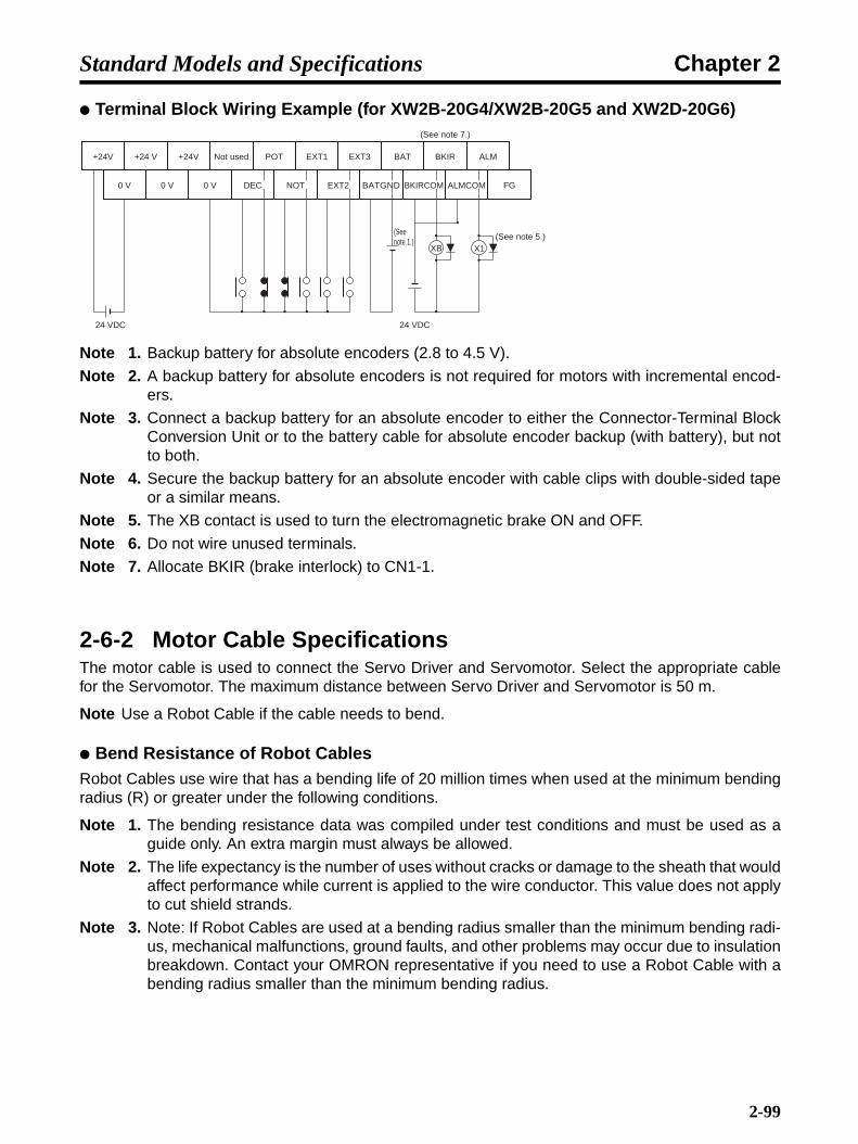
Chapter 2Standard Models and Specifications
Terminal Block Wiring Example (for XW2B-20G4/XW2B-20G5 and XW2D-20G6)
Note 1. Backup battery for absolute encoders (2.8 to 4.5 V).
Note 2. A backup battery for absolute encoders is not required for motors with incremental encod-ers.
Note 3. Connect a backup battery for an absolute encoder to either the Connector-Terminal BlockConversion Unit or to the battery cable for absolute encoder backup (with battery), but notto both.
Note 4. Secure the backup battery for an absolute encoder with cable clips with double-sided tapeor a similar means.
Note 5. The XB contact is used to turn the electromagnetic brake ON and OFF.
Note 6. Do not wire unused terminals.
Note 7. Allocate BKIR (brake interlock) to CN1-1.
2-6-2 Motor Cable SpecificationsThe motor cable is used to connect the Servo Driver and Servomotor. Select the appropriate cablefor the Servomotor. The maximum distance between Servo Driver and Servomotor is 50 m.
Note Use a Robot Cable if the cable needs to bend.
Bend Resistance of Robot CablesRobot Cables use wire that has a bending life of 20 million times when used at the minimum bendingradius (R) or greater under the following conditions.
Note 1. The bending resistance data was compiled under test conditions and must be used as aguide only. An extra margin must always be allowed.
Note 2. The life expectancy is the number of uses without cracks or damage to the sheath that wouldaffect performance while current is applied to the wire conductor. This value does not applyto cut shield strands.
Note 3. Note: If Robot Cables are used at a bending radius smaller than the minimum bending radi-us, mechanical malfunctions, ground faults, and other problems may occur due to insulationbreakdown. Contact your OMRON representative if you need to use a Robot Cable with abending radius smaller than the minimum bending radius.
+24V
0 V
+24 V +24V Not used POT EXT1 EXT3 BAT BKIR ALM
0 V 0 V DEC EXT2 BATGNDNOT BKIRCOM FG
24 VDC 24 VDC
(See note 5.)(See note 1.)
(See note 7.)
ALMCOM
XB X1
2-99

Chapter 2Standard Models and Specifications
Power Cables
@@@: 003 to 050
Encoder Cables
@@@: 003 to 020∆∆∆: 030 to 050
Moving Bending Test
Model Minimum bending radius (R)Without brake R88A-CAWA@@@SR 55 mm
With brake R88A-CAWA@@@BR 55 mm
Without brake R88A-CAWB@@@SR 96 mm
With brake R88A-CAWB@@@BR 96 mm
Without brake R88A-CAWC@@@SR 96 mm
With brake R88A-CAWC@@@BR 96 mm
Without brake R88A-CAWD@@@SR 150 mm
With brake R88A-CAWD@@@BR 150 mm
Model Minimum bending radius (R)R88A-CAWA@@@CR 46 mm
R88A-CAWA∆∆∆CR 78 mm
R88A-CAWB@@@NR 46 mm
R88A-CAWB∆∆∆NR 78 mm
Stroke320 mm
Bending radius (R)
100 times/min
2-100

Chapter 2Standard Models and Specifications
Standard Encoder Cable SpecificationsSelect an Encoder Cable to match the Servomotor being used. The cables range in length from 3 to50 meters. (The maximum distance between the Servomotor and Servo Driver is 50 meters.)
Cable Models
R88A-CRWA@C
R88A-CRWB@N
Connection Configuration and External Dimensions
R88A-CRWA@C
R88A-CRWB@N
Model Length (L) Outer diameter of sheath WeightR88A-CRWA003C 3 m 6.5 dia. Approx. 0.2 kg
R88A-CRWA005C 5 m Approx. 0.4 kg
R88A-CRWA010C 10 m Approx. 0.7 kg
R88A-CRWA015C 15 m Approx. 1.0 kg
R88A-CRWA020C 20 m Approx. 1.3 kg
R88A-CRWA030C 30 m 6.8 dia. Approx. 2.5 kg
R88A-CRWA040C 40 m Approx. 3.3 kg
R88A-CRWA050C 50 m Approx. 4.1 kg
Model Length (L) Outer diameter of sheath WeightR88A-CRWB003N 3 m 6.5 dia. Approx. 0.4 kg
R88A-CRWB005N 5 m Approx. 0.5 kg
R88A-CRWB010N 10 m Approx. 0.8 kg
R88A-CRWB015N 15 m Approx. 1.1 kg
R88A-CRWB020N 20 m Approx. 1.4 kg
R88A-CRWB030N 30 m 6.8 dia. Approx. 2.6 kg
R88A-CRWB040N 40 m Approx. 3.4 kg
R88A-CRWB050N 50 m Approx. 4.2 kg
Servo Driver Servomotor
R88D-WN@-ML2 R88M-W@
43.5L43.5
18.8
18.8
t = 12t = 12
Servomotor
R88M-W@
L43.5
Servo Driver
R88D-WN@-ML2
18.8
37.3
dia
.
t = 12
69.1
2-101

Chapter 2Standard Models and Specifications
Wiring
R88A-CRWA@C
R88A-CRWB@N
Absolute Encoder Battery Cable Specifications [ABS]
Cable Models
Connection Configuration and External Dimensions
R88A-CRWC0R3C
Model Length (L)R88A-CRWC0R3C 0.3 m
Signal No.
Servo Driver
E5V 1E0V 2
BAT+ 3BAT− 4
S+ 5S− 6FG Shell
RedBlackOrangeOrange/WhiteOpenOpen/White
No.123456
Shell
E5VE0V
BAT+BAT−
S+S−FG
Signal
Cable:
AWG22 × 2C + AWG24 × 2P UL20276 (3 to 20 m)
AWG16 × 2C + AWG26 × 2P UL20276 (30 to 50 m)
Connector plug: 3 to 20 m ... 55101-0600 (Molex Japan) 30 to 50 m ... 55100-0670 (Molex Japan)Crimp terminal: 50639-8091 (Molex Japan)
CableConnector socket:54280-0609 (Molex Japan)ServomotorConnector plug:55102-0600 (Molex Japan)
Servomotor
Signal No.Servo Driver
E5VE0V
BAT+BAT−
S+S−FG
RedBlackOrangeOrange/WhiteOpenOpen/White
No.E5VE0V
BAT+BAT−
S+S−FG
Signal
Cable:
AWG22 × 2C + AWG24 × 2P UL20276 (3 to 20 m)
AWG16 × 2C + AWG26 × 2P UL20276 (30 to 50 m)
Connector plug: 3 to 20 m ... 55101-0600 (Molex Japan) 30 to 50 m ... 55100-0670 (Molex Japan)Crimp terminal: 50639-8091 (Molex Japan)
CableStraight plug:N/MS3106B20-29S (JAE Ltd.)Cable plug:N/MS3057-12A (JAE Ltd.)ServomotorReceptacle:MS3102A20-29P (DDK Ltd.)
Servomotor
HGTSCDJ
123456
Shell
R88M-W@
43.50.343.5
18.8
18.8
t = 12t = 12
R88D-WN@-ML2
Servo Driver Servomotor
Battery holder (provided with battery)
2-102
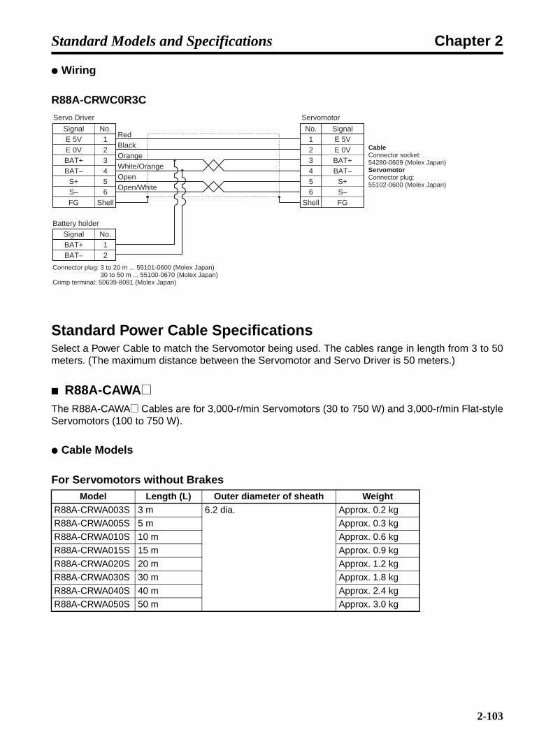
Chapter 2Standard Models and Specifications
Wiring
R88A-CRWC0R3C
Standard Power Cable SpecificationsSelect a Power Cable to match the Servomotor being used. The cables range in length from 3 to 50meters. (The maximum distance between the Servomotor and Servo Driver is 50 meters.)
R88A-CAWA@The R88A-CAWA@ Cables are for 3,000-r/min Servomotors (30 to 750 W) and 3,000-r/min Flat-styleServomotors (100 to 750 W).
Cable Models
For Servomotors without BrakesModel Length (L) Outer diameter of sheath Weight
R88A-CRWA003S 3 m 6.2 dia. Approx. 0.2 kg
R88A-CRWA005S 5 m Approx. 0.3 kg
R88A-CRWA010S 10 m Approx. 0.6 kg
R88A-CRWA015S 15 m Approx. 0.9 kg
R88A-CRWA020S 20 m Approx. 1.2 kg
R88A-CRWA030S 30 m Approx. 1.8 kg
R88A-CRWA040S 40 m Approx. 2.4 kg
R88A-CRWA050S 50 m Approx. 3.0 kg
Signal No.
S− 6S+ 5
BAT− 4BAT+ 3E 0V 2E 5V 1
FGS−S+
BAT−BAT+E 0VE 5V
FGShell
Open/White
Signal No.
Battery holder
BAT− 2BAT+ 1
OpenWhite/OrangeOrangeBlackRed
No.
654321
Shell
Signal
Servo Driver
CableConnector socket:54280-0609 (Molex Japan)ServomotorConnector plug:55102-0600 (Molex Japan)
Servomotor
Connector plug: 3 to 20 m ... 55101-0600 (Molex Japan) 30 to 50 m ... 55100-0670 (Molex Japan)Crimp terminal: 50639-8091 (Molex Japan)
2-103

Chapter 2Standard Models and Specifications
For Servomotors with Brakes
Note If a 750-W Servomotor is to be wired at a distance of 30 meters or more, use R88A-CAWB@@Cable.
Connection Configuration and External Dimensions
For Servomotors without Brakes
For Servomotors with Brakes
Wiring
For Servomotors without Brakes
Model Length (L) Outer diameter of sheath WeightR88A-CRWA003B 3 m 7.4 dia. Approx. 0.3 kg
R88A-CRWA005B 5 m Approx. 0.5 kg
R88A-CRWA010B 10 m Approx. 0.9 kg
R88A-CRWA015B 15 m Approx. 1.3 kg
R88A-CRWA020B 20 m Approx. 1.7 kg
R88A-CRWA030B 30 m Approx. 2.5 kg
R88A-CRWA040B 40 m Approx. 3.3 kg
R88A-CRWA050B 50 m Approx. 4.1 kg
Servo Driver Servomotor
R88D-WN@-ML2 [email protected]
27.4L50
t = 15.7
Servo Driver Servomotor
50 27.4L
t = 28.4
14R88D-WN@-ML2 R88M-W@
No.1234
Phase-UPhase-VPhase-W
FG
Symbol CableConnector cap: 350780-1 (Tyco Electronics AMP KK)Connector socket: 350689-3 (Tyco Electronics AMP KK)ServomotorConnector plug: 350779-1 (Tyco Electronics AMP KK)Connector pins 1 to 3: 350690-3 (Tyco Electronics AMP KK)Connector pin 4: 770210-1 (Tyco Electronics AMP KK)
Servo Driver
RedWhiteBlueGreen/Yellow
Cable: AWG20 × 4C UL2464
Servomotor
M4 crimp terminal
2-104

Chapter 2Standard Models and Specifications
For Servomotors with Brakes
R88A-CAWB@The R88A-CAWB@ Cables are for 3,000-r/min Flat-style Servomotors (1.5 kW).
Cable Models
For Servomotors without Brakes
For Servomotors with Brakes
Note Use these cables if a 750-W Servomotor is to be wired at a distance of 30 meters or more.
Model Length (L) Outer diameter of sheath WeightR88A-CAWB003S 3 m 10.4 dia. Approx. 0.6 kg
R88A-CAWB005S 5 m Approx. 1.0 kg
R88A-CAWB010S 10 m Approx. 1.9 kg
R88A-CAWB015S 15 m Approx. 2.8 kg
R88A-CAWB020S 20 m Approx. 3.7 kg
R88A-CAWB030S 30 m Approx. 5.5 kg
R88A-CAWB040S 40 m Approx. 7.3 kg
R88A-CAWB050S 50 m Approx. 9.2 kg
Model Length (L) Outer diameter of sheath WeightR88A-CAWB003B 3 m 14.5 dia. Approx. 1.0 kg
R88A-CAWB005B 5 m Approx. 1.6 kg
R88A-CAWB010B 10 m Approx. 3.2 kg
R88A-CAWB015B 15 m Approx. 4.8 kg
R88A-CAWB020B 20 m Approx. 6.4 kg
R88A-CAWB030B 30 m Approx. 9.5 kg
R88A-CAWB040B 40 m Approx. 12.7 kg
R88A-CAWB050B 50 m Approx. 15.8 kg
Servo DriverNo.1234
Phase-UPhase-VPhase-W
FG5 Brake6 Brake
Symbol CableConnector cap: 350781-1 (Tyco Electronics AMP KK)Connector socket: 350689-3 (Tyco Electronics AMP KK)ServomotorConnector plug: 350715-1 (Tyco Electronics AMP KK)Connector pins 1 to 3, 5, 6: 350690-3 (Tyco Electronics AMP KK)Connector pin 4: 770210-1 (Tyco Electronics AMP KK)
Servomotor
RedWhiteBlueGreen/Yellow
Cable: AWG20 × 6C UL2464
BlackBrown
M4 crimp terminals
2-105

Chapter 2Standard Models and Specifications
Connection Configuration and External Dimensions
For Servomotors without Brakes
For Servomotors with Brakes
Wiring
For Servomotors without Brakes
For Servomotors with Brakes
Servo Driver Servomotor
R88D-WN@-ML2 R88M-W@
26.7
27.4L50
t = 15.7
Servo Driver Servomotor
50 27.4L
t = 28.4
14R88D-WN@-ML2 R88M-W@
No.1234
Phase-UPhase-VPhase-W
FG
Symbol CableConnector cap: 350780-1 (Tyco Electronics AMP KK)Connector socket: Pins 1 to 3: 350551-6 (Tyco Electronics AMP KK)Pin 4: 350551-3 (Tyco Electronics AMP KK)ServomotorConnector plug: 350779-1 (Tyco Electronics AMP KK)Connector pins 1 to 3: 350547-6 (Tyco Electronics AMP KK)Connector pin 4: 350669-1 (Tyco Electronics AMP KK)
RedWhiteBlueGreen/Yellow
Cable: AWG14 × 4C UL2463
ServomotorServo Driver
M4 crimp terminal
Servo DriversNo.1234
Phase-UPhase-VPhase-W
FG5 Brake6 Brake
Symbol CableConnector plug: 350781-1 (Tyco Electronics AMP KK)Connector socket: Pins 1 to 3: 350551-6 (Tyco Electronics AMP KK)Pins 4 to 6: 350551-3 (Tyco Electronics AMP KK)ServomotorConnector plug: 350715-1 (Tyco Electronics AMP KK)Connector pins 1 to 3: 350547-6 (Tyco Electronics AMP KK)Connector pin 4: 350669-1 (Tyco Electronics AMP KK)Connector pins 5 and 6: 350690-3 (Tyco Electronics AMP KK)
Servomotors
RedWhiteBlueGreen/Yellow
Cable: AWG14 × 6C UL2463
BlackBrown
M4 crimp terminals
2-106

Chapter 2Standard Models and Specifications
R88A-CAWC@The R88A-CAWC@ Cables are for 3,000-r/min Servomotors (1 to 2 kW), 1,000-r/min Servomotors(300 to 900 W), and 1,500-r/min Servomotors (450 W to 1.3 kW).
Cable Models
For Servomotors without Brakes
For Servomotors with Brakes
Connection Configuration and External Dimensions
For Servomotors without Brakes
For Servomotors with Brakes
Model Length (L) Outer diameter of sheath WeightR88A-CAWC003S 3 m 10.4 dia. Approx. 0.6 kg
R88A-CAWC005S 5 m Approx. 1.0 kg
R88A-CAWC010S 10 m Approx. 1.9 kg
R88A-CAWC015S 15 m Approx. 2.8 kg
R88A-CAWC020S 20 m Approx. 3.7 kg
R88A-CAWC030S 30 m Approx. 5.6 kg
R88A-CAWC040S 40 m Approx. 7.4 kg
R88A-CAWC050S 50 m Approx. 9.2 kg
Model Length (L) Outer diameter of sheath WeightR88A-CAWC003B 3 m 14.5 dia. Approx. 1.1 kg
R88A-CAWC005B 5 m Approx. 1.7 kg
R88A-CAWC010B 10 m Approx. 3.3 kg
R88A-CAWC015B 15 m Approx. 4.9 kg
R88A-CAWC020B 20 m Approx. 6.4 kg
R88A-CAWC030B 30 m Approx. 9.6 kg
R88A-CAWC040B 40 m Approx. 12.7 kg
R88A-CAWC050B 50 m Approx. 15.9 kg
Servo Driver Servomotor
R88D-WN@-ML2 R88M-W@
34.1
dia
.
65.9L70
Servo Driver Servomotor
37.3
dia
.
69.1L70
R88D-WN@-ML2 R88M-W@
2-107
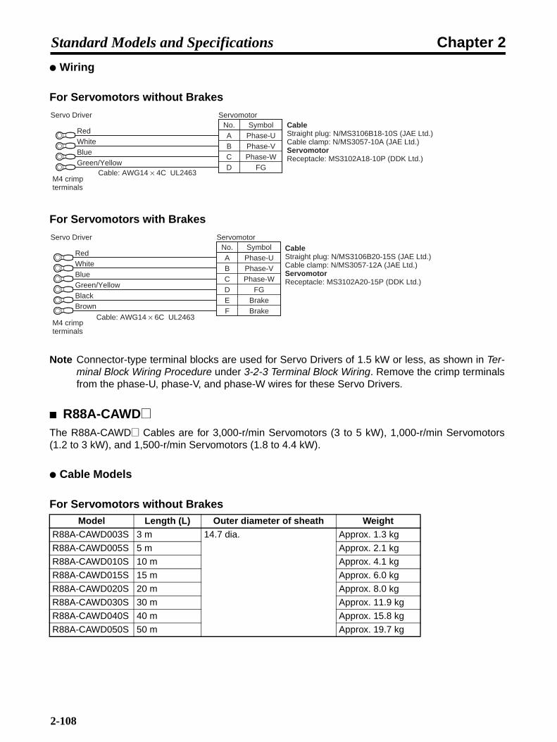
Chapter 2Standard Models and Specifications
Wiring
For Servomotors without Brakes
For Servomotors with Brakes
Note Connector-type terminal blocks are used for Servo Drivers of 1.5 kW or less, as shown in Ter-minal Block Wiring Procedure under 3-2-3 Terminal Block Wiring. Remove the crimp terminalsfrom the phase-U, phase-V, and phase-W wires for these Servo Drivers.
R88A-CAWD@The R88A-CAWD@ Cables are for 3,000-r/min Servomotors (3 to 5 kW), 1,000-r/min Servomotors(1.2 to 3 kW), and 1,500-r/min Servomotors (1.8 to 4.4 kW).
Cable Models
For Servomotors without BrakesModel Length (L) Outer diameter of sheath Weight
R88A-CAWD003S 3 m 14.7 dia. Approx. 1.3 kg
R88A-CAWD005S 5 m Approx. 2.1 kg
R88A-CAWD010S 10 m Approx. 4.1 kg
R88A-CAWD015S 15 m Approx. 6.0 kg
R88A-CAWD020S 20 m Approx. 8.0 kg
R88A-CAWD030S 30 m Approx. 11.9 kg
R88A-CAWD040S 40 m Approx. 15.8 kg
R88A-CAWD050S 50 m Approx. 19.7 kg
No.ABCD
Phase-UPhase-VPhase-W
FG
Symbol CableStraight plug: N/MS3106B18-10S (JAE Ltd.)Cable clamp: N/MS3057-10A (JAE Ltd.)ServomotorReceptacle: MS3102A18-10P (DDK Ltd.)
Servo Driver
RedWhiteBlueGreen/Yellow
Cable: AWG14 × 4C UL2463
Servomotor
M4 crimp terminals
Servo DriverNo.ABCD
Phase-UPhase-VPhase-W
FGE BrakeF Brake
SymbolServomotor
RedWhiteBlueGreen/Yellow
Cable: AWG14 × 6C UL2463
BlackBrown
CableStraight plug: N/MS3106B20-15S (JAE Ltd.)Cable clamp: N/MS3057-12A (JAE Ltd.)ServomotorReceptacle: MS3102A20-15P (DDK Ltd.)
M4 crimp terminals
2-108

Chapter 2Standard Models and Specifications
For Servomotors with Brakes
Connection Configuration and External Dimensions
For Servomotors without Brakes
For Servomotors with Brakes
Wiring
For Servomotors without Brakes
Model Length (L) Outer diameter of sheath WeightR88A-CAWD003B 3 m 17.8 dia. Approx. 1.9 kg
R88A-CAWD005B 5 m Approx. 3.0 kg
R88A-CAWD010B 10 m Approx. 5.8 kg
R88A-CAWD015B 15 m Approx. 8.6 kg
R88A-CAWD020B 20 m Approx. 11.4 kg
R88A-CAWD030B 30 m Approx. 17.0 kg
R88A-CAWD040B 40 m Approx. 22.6 kg
R88A-CAWD050B 50 m Approx. 28.2 kg
Servo Driver Servomotor
R88D-WN@-ML2 R88M-W@
40.5
dia
.
69.1L70
Servo Driver Servomotor43
.6 d
ia.
74.6L70
R88D-WN@-ML2 R88M-W@
No.ABCD
Phase-UPhase-VPhase-W
FG
Symbol CableStraight plug: N/MS3106B22-22S (JAE Ltd.)Cable clamp: N/MS3057-12A (JAE Ltd.)ServomotorReceptacle: MS3102A22-22P (DDK Ltd.)
Servo Driver
RedWhiteBlueGreen/Yellow
Cable: AWG10 × 4C UL2463
Servomotor
M5 crimp terminals
2-109
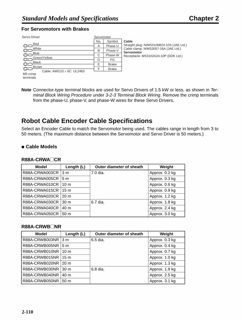
Chapter 2Standard Models and Specifications
For Servomotors with Brakes
Note Connector-type terminal blocks are used for Servo Drivers of 1.5 kW or less, as shown in Ter-minal Block Wiring Procedure under 3-2-3 Terminal Block Wiring. Remove the crimp terminalsfrom the phase-U, phase-V, and phase-W wires for these Servo Drivers.
Robot Cable Encoder Cable SpecificationsSelect an Encoder Cable to match the Servomotor being used. The cables range in length from 3 to50 meters. (The maximum distance between the Servomotor and Servo Driver is 50 meters.)
Cable Models
R88A-CRWA@CR
R88A-CRWB@NR
Model Length (L) Outer diameter of sheath WeightR88A-CRWA003CR 3 m 7.0 dia. Approx. 0.2 kg
R88A-CRWA005CR 5 m Approx. 0.3 kg
R88A-CRWA010CR 10 m Approx. 0.6 kg
R88A-CRWA015CR 15 m Approx. 0.9 kg
R88A-CRWA020CR 20 m Approx. 1.2 kg
R88A-CRWA030CR 30 m 6.7 dia. Approx. 1.8 kg
R88A-CRWA040CR 40 m Approx. 2.4 kg
R88A-CRWA050CR 50 m Approx. 3.0 kg
Model Length (L) Outer diameter of sheath WeightR88A-CRWB003NR 3 m 6.5 dia. Approx. 0.3 kg
R88A-CRWB005NR 5 m Approx. 0.4 kg
R88A-CRWB010NR 10 m Approx. 0.7 kg
R88A-CRWB015NR 15 m Approx. 1.0 kg
R88A-CRWB020NR 20 m Approx. 1.3 kg
R88A-CRWB030NR 30 m 6.8 dia. Approx. 1.9 kg
R88A-CRWB040NR 40 m Approx. 2.5 kg
R88A-CRWB050NR 50 m Approx. 3.1 kg
Servo DriverNo.ABCD
Phase-UPhase-VPhase-W
FGE BrakeF Brake
SymbolServomotor
RedWhiteBlueGreen/Yellow
Cable: AWG10 × 6C UL2463
BlackBrown
CableStraight plug: N/MS3106B24-10S (JAE Ltd.)Cable clamp: N/MS3057-16A (JAE Ltd.)ServomotorReceptacle: MS3102A24-10P (DDK Ltd.)
M5 crimp terminals
2-110

Chapter 2Standard Models and Specifications
Connection Configuration and External Dimensions
R88A-CRWA@CR
R88A-CRWB@NR
Wiring
R88A-CRWA@CR
R88A-CRWB@NR
Servo Driver Servomotor
R88D-WN@-ML2 R88M-W@
43.5L43.5
18.8
18.8
t = 12t = 12
Servomotor
R88M-W@
L43.5
Servo Driver
R88D-WN@-ML2
18.8
37.3
dia
.
t = 12
69.1
Signal No.
Servo Driver
E5V 1E0V 2
BAT+ 3BAT− 4
S+ 5S− 6FG Shell
RedBlackOrangeOrange/WhiteOpenOpen/White
No.123456
Shell
E5VE0V
BAT+BAT−
S+S−FG
Signal
Cable:
AWG22 × 2C + AWG24 × 2P UL20276 (3 to 20 m)
AWG16 × 2C + AWG26 × 2P UL20276 (30 to 50 m)
Connector plug: 55100-0670 (Molex Japan)Crimp terminal: 50639-8091 (Molex Japan)
CableConnector socket:54280-0609 (Molex Japan)ServomotorConnector plug:55102-0600 (Molex Japan)
Servomotor
Signal No.Servo Driver
E5VE0V
BAT+BAT−
S+S−FG
RedBlackOrangeOrange/WhiteOpenOpen/White
No.E5VE0V
BAT+BAT−
S+S−FG
Signal
Cable:
AWG22 × 2C + AWG24 × 2P UL20276 (3 to 20 m)
AWG16 × 2C + AWG26 × 2P UL20276 (30 to 50 m)
Connector plug: 55100-0670 (Molex Japan)Crimp terminal: 50639-8091 (Molex Japan)
CableStraight plug:N/MS3106B20-29S (JAE Ltd.)Cable plug:N/MS3057-12A (JAE Ltd.)ServomotorReceptacle:MS3102A20-29P (DDK Ltd.)
Servomotor
HGTSCDJ
123456
Shell
2-111

Chapter 2Standard Models and Specifications
Robot Cable Power Cable SpecificationsSelect a Power Cable to match the Servomotor being used. The cables range in length from 3 to 50meters. (The maximum distance between the Servomotor and Servo Driver is 50 meters.)
R88A-CAWA@RThe R88A-CAWA@R Cables are for 3,000-r/min Servomotors (30 to 750 W) and 3,000-r/min Flat-style Servomotors (100 to 750 W).
Cable Models
For Servomotors without Brakes
For Servomotors with Brakes
Note If a 750-W Servomotor is to be wired at a distance of 30 meters or more, use R88A-CAWB@RCable.
Connection Configuration and External Dimensions
For Servomotors without Brakes
Model Length (L) Outer diameter of sheath WeightR88A-CRWA003SR 3 m 6.5 dia. Approx. 0.2 kg
R88A-CRWA005SR 5 m Approx. 0.3 kg
R88A-CRWA010SR 10 m Approx. 0.6 kg
R88A-CRWA015SR 15 m Approx. 0.8 kg
R88A-CRWA020SR 20 m Approx. 1.1 kg
R88A-CRWA030SR 30 m Approx. 1.7 kg
R88A-CRWA040SR 40 m Approx. 2.2 kg
R88A-CRWA050SR 50 m Approx. 2.8 kg
Model Length (L) Outer diameter of sheath WeightR88A-CRWA003BR 3 m 7.0 dia. Approx. 0.2 kg
R88A-CRWA005BR 5 m Approx. 0.4 kg
R88A-CRWA010BR 10 m Approx. 0.8 kg
R88A-CRWA015BR 15 m Approx. 1.1 kg
R88A-CRWA020BR 20 m Approx. 1.5 kg
R88A-CRWA030BR 30 m Approx. 2.3 kg
R88A-CRWA040BR 40 m Approx. 3.0 kg
R88A-CRWA050BR 50 m Approx. 3.8 kg
Servo Driver Servomotor
R88D-WN@-ML2 [email protected]
27.4L50
t = 15.7
2-112

Chapter 2Standard Models and Specifications
For Servomotors with Brakes
Wiring
For Servomotors without Brakes
For Servomotors with Brakes
R88A-CAWB@RThe R88A-CAWB@R Cables are for 3,000-r/min Flat-style Servomotors (1.5 kW).
Cable Models
For Servomotors without BrakesModel Length (L) Outer diameter of sheath Weight
R88A-CAWB003SR 3 m 9.5 dia. Approx. 0.5 kg
R88A-CAWB005SR 5 m Approx. 0.8 kg
R88A-CAWB010SR 10 m Approx. 1.5 kg
R88A-CAWB015SR 15 m Approx. 2.2 kg
R88A-CAWB020SR 20 m Approx. 3.0 kg
R88A-CAWB030SR 30 m Approx. 4.5 kg
R88A-CAWB040SR 40 m Approx. 5.9 kg
R88A-CAWB050SR 50 m Approx. 7.4 kg
Servo Driver Servomotor
50 27.4L
t = 28.4
14R88D-WN@-ML2 R88M-W@
No.1234
Phase-UPhase-VPhase-W
FG
Symbol CableConnector cap: 350780-1 (Tyco Electronics AMP KK)Connector socket: 350689-3 (Tyco Electronics AMP KK)ServomotorConnector plug: 350779-1 (Tyco Electronics AMP KK)Connector pins 1 to 3: 350690-3 (Tyco Electronics AMP KK)Connector pin 4: 770210-1 (Tyco Electronics AMP KK)
Servo Driver
RedWhiteBlueGreen/Yellow
Cable: AWG21 × 4C UL2464
Servomotor
M4 crimp terminal
Servo DriverNo.1234
Phase-UPhase-VPhase-W
FG5 Brake6 Brake
Symbol CableConnector cap: 350781-1 (Tyco Electronics AMP KK)Connector socket: 350689-3 (Tyco Electronics AMP KK)ServomotorConnector plug: 350715-1 (Tyco Electronics AMP KK)Connector pins 1 to 3, 5, 6: 350690-3 (Tyco Electronics AMP KK)Connector pin 4: 770210-1 (Tyco Electronics AMP KK)
Servomotor
RedWhiteBlueGreen/Yellow
Cable: AWG21 × 6C UL2464
BlackBrown
M4 crimp terminals
2-113

Chapter 2Standard Models and Specifications
For Servomotors with Brakes
Note Use these cables if a 750-W Servomotor is to be wired at a distance of 30 meters or more.
Connection Configuration and External Dimensions
For Servomotors without Brakes
For Servomotors with Brakes
Wiring
For Servomotors without Brakes
Model Length (L) Outer diameter of sheath WeightR88A-CAWB003BR 3 m 11.5 dia. Approx. 0.7 kg
R88A-CAWB005BR 5 m Approx. 1.1 kg
R88A-CAWB010BR 10 m Approx. 2.2 kg
R88A-CAWB015BR 15 m Approx. 3.3 kg
R88A-CAWB020BR 20 m Approx. 4.4 kg
R88A-CAWB030BR 30 m Approx. 6.6 kg
R88A-CAWB040BR 40 m Approx. 8.8 kg
R88A-CAWB050BR 50 m Approx. 11.0 kg
Servo Driver Servomotor
R88D-WN@-ML2 R88M-W@
26.7
27.4L50
t = 15.7
Servo Driver Servomotor
50 27.4L
t = 28.4
14R88D-WN@-ML2 R88M-W@
No.1234
Phase-UPhase-VPhase-W
FG
Symbol CableConnector cap: 350780-1 (Tyco Electronics AMP KK)Connector socket: Pins 1 to 3: 350550-6 (Tyco Electronics AMP KK)Pin 4: 350551-3 (Tyco Electronics AMP KK)ServomotorConnector plug: 350779-1 (Tyco Electronics AMP KK)Connector pins 1 to 3: 350547-6 (Tyco Electronics AMP KK)Connector pin 4: 350669-1 (Tyco Electronics AMP KK)
RedWhiteBlueGreen/Yellow
Cable: AWG15 × 4C UL2586
ServomotorServo Driver
M4 crimp terminal
2-114
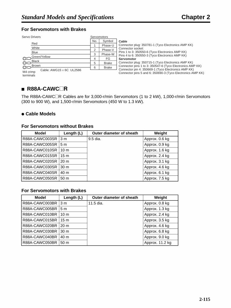
Chapter 2Standard Models and Specifications
For Servomotors with Brakes
R88A-CAWC@RThe R88A-CAWC@R Cables are for 3,000-r/min Servomotors (1 to 2 kW), 1,000-r/min Servomotors(300 to 900 W), and 1,500-r/min Servomotors (450 W to 1.3 kW).
Cable Models
For Servomotors without Brakes
For Servomotors with Brakes
Model Length (L) Outer diameter of sheath WeightR88A-CAWC003SR 3 m 9.5 dia. Approx. 0.6 kg
R88A-CAWC005SR 5 m Approx. 0.9 kg
R88A-CAWC010SR 10 m Approx. 1.6 kg
R88A-CAWC015SR 15 m Approx. 2.4 kg
R88A-CAWC020SR 20 m Approx. 3.1 kg
R88A-CAWC030SR 30 m Approx. 4.6 kg
R88A-CAWC040SR 40 m Approx. 6.1 kg
R88A-CAWC050SR 50 m Approx. 7.5 kg
Model Length (L) Outer diameter of sheath WeightR88A-CAWC003BR 3 m 11.5 dia. Approx. 0.8 kg
R88A-CAWC005BR 5 m Approx. 1.3 kg
R88A-CAWC010BR 10 m Approx. 2.4 kg
R88A-CAWC015BR 15 m Approx. 3.5 kg
R88A-CAWC020BR 20 m Approx. 4.6 kg
R88A-CAWC030BR 30 m Approx. 6.8 kg
R88A-CAWC040BR 40 m Approx. 9.0 kg
R88A-CAWC050BR 50 m Approx. 11.2 kg
Servo DriversNo.1234
Phase-UPhase-VPhase-W
FG5 Brake6 Brake
Symbol CableConnector plug: 350781-1 (Tyco Electronics AMP KK)Connector socket: Pins 1 to 3: 350550-6 (Tyco Electronics AMP KK)Pins 4 to 6: 350550-3 (Tyco Electronics AMP KK)ServomotorConnector plug: 350715-1 (Tyco Electronics AMP KK)Connector pins 1 to 3: 350547-6 (Tyco Electronics AMP KK)Connector pin 4: 350669-1 (Tyco Electronics AMP KK)Connector pins 5 and 6: 350690-3 (Tyco Electronics AMP KK)
Servomotors
RedWhiteBlueGreen/Yellow
Cable: AWG15 × 6C UL2586
BlackBrown
M4 crimp terminals
2-115
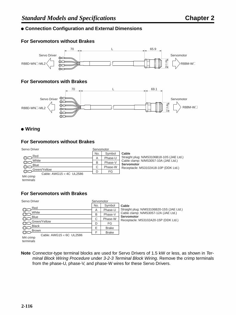
Chapter 2Standard Models and Specifications
Connection Configuration and External Dimensions
For Servomotors without Brakes
For Servomotors with Brakes
Wiring
For Servomotors without Brakes
For Servomotors with Brakes
Note Connector-type terminal blocks are used for Servo Drivers of 1.5 kW or less, as shown in Ter-minal Block Wiring Procedure under 3-2-3 Terminal Block Wiring. Remove the crimp terminalsfrom the phase-U, phase-V, and phase-W wires for these Servo Drivers.
Servo Driver Servomotor
R88D-WN@-ML2 R88M-W@
34.1
dia
.
65.9L70
Servo Driver Servomotor
37.3
dia
.
69.1L70
R88D-WN@-ML2 R88M-W@
No.ABCD
Phase-UPhase-VPhase-W
FG
Symbol CableStraight plug: N/MS3106B18-10S (JAE Ltd.)Cable clamp: N/MS3057-10A (JAE Ltd.)ServomotorReceptacle: MS3102A18-10P (DDK Ltd.)
Servo Driver
RedWhiteBlueGreen/Yellow
Cable: AWG15 × 4C UL2586
Servomotor
M4 crimp terminals
Servo DriverNo.ABCD
Phase-UPhase-VPhase-W
FGE BrakeF Brake
SymbolServomotor
RedWhiteBlueGreen/Yellow
Cable: AWG15 × 6C UL2586
BlackBrown
CableStraight plug: N/MS3106B20-15S (JAE Ltd.)Cable clamp: N/MS3057-12A (JAE Ltd.)ServomotorReceptacle: MS3102A20-15P (DDK Ltd.)
M4 crimp terminals
2-116

Chapter 2Standard Models and Specifications
R88A-CAWD@RThe R88A-CAWD@R Cables are for 3,000-r/min Servomotors (3 to 5 kW), 1,000-r/min Servomotors(1.2 to 3 kW), and 1,500-r/min Servomotors (1.8 to 4.4 kW).
Cable Models
For Servomotors without Brakes
For Servomotors with Brakes
Connection Configuration and External Dimensions
For Servomotors without Brakes
For Servomotors with Brakes
Model Length (L) Outer diameter of sheath WeightR88A-CAWD003SR 3 m 13.5 dia. Approx. 1.1 kg
R88A-CAWD005SR 5 m Approx. 1.7 kg
R88A-CAWD010SR 10 m Approx. 3.3 kg
R88A-CAWD015SR 15 m Approx. 4.9 kg
R88A-CAWD020SR 20 m Approx. 6.4 kg
R88A-CAWD030SR 30 m Approx. 9.5 kg
R88A-CAWD040SR 40 m Approx. 12.6 kg
R88A-CAWD050SR 50 m Approx. 15.7 kg
Model Length (L) Outer diameter of sheath WeightR88A-CAWD003BR 3 m 16.5 dia. Approx. 1.7 kg
R88A-CAWD005BR 5 m Approx. 2.6 kg
R88A-CAWD010BR 10 m Approx. 4.9 kg
R88A-CAWD015BR 15 m Approx. 7.2 kg
R88A-CAWD020BR 20 m Approx. 9.4 kg
R88A-CAWD030BR 30 m Approx. 14.1 kg
R88A-CAWD040BR 40 m Approx. 18.7 kg
R88A-CAWD050BR 50 m Approx. 23.3 kg
Servo Driver Servomotor
R88D-WN@-ML2 R88M-W@
40.5
dia
.
69.1L70
Servo Driver Servomotor
43.6
dia
.
74.6L70
R88D-WN@-ML2 R88M-W@
2-117
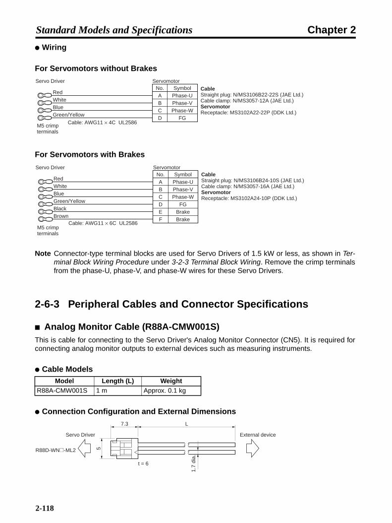
Chapter 2Standard Models and Specifications
Wiring
For Servomotors without Brakes
For Servomotors with Brakes
Note Connector-type terminal blocks are used for Servo Drivers of 1.5 kW or less, as shown in Ter-minal Block Wiring Procedure under 3-2-3 Terminal Block Wiring. Remove the crimp terminalsfrom the phase-U, phase-V, and phase-W wires for these Servo Drivers.
2-6-3 Peripheral Cables and Connector Specifications
Analog Monitor Cable (R88A-CMW001S)This is cable for connecting to the Servo Driver's Analog Monitor Connector (CN5). It is required forconnecting analog monitor outputs to external devices such as measuring instruments.
Cable Models
Connection Configuration and External Dimensions
Model Length (L) WeightR88A-CMW001S 1 m Approx. 0.1 kg
No.ABCD
Phase-UPhase-VPhase-W
FG
Symbol CableStraight plug: N/MS3106B22-22S (JAE Ltd.)Cable clamp: N/MS3057-12A (JAE Ltd.)ServomotorReceptacle: MS3102A22-22P (DDK Ltd.)
Servo Driver
RedWhiteBlueGreen/Yellow
Cable: AWG11 × 4C UL2586
Servomotor
M5 crimp terminals
Servo DriverNo.ABCD
Phase-UPhase-VPhase-W
FGE BrakeF Brake
SymbolServomotor
RedWhiteBlueGreen/Yellow
Cable: AWG11 × 6C UL2586
BlackBrown
CableStraight plug: N/MS3106B24-10S (JAE Ltd.)Cable clamp: N/MS3057-16A (JAE Ltd.)ServomotorReceptacle: MS3102A24-10P (DDK Ltd.)
M5 crimp terminals
7.3 L
1.7
dia.
5
t = 6
Servo Driver
R88D-WN@-ML2
External device
2-118

Chapter 2Standard Models and Specifications
Wiring
Computer Monitor Cables (R88A-CCW002P2)In order to set Servo Driver parameters and monitor a Servo Driver from a personal computer, theComputer Monitor Software and Computer Monitor Cable are required.
Cable Models
For DOS/V Computers
Connection Configuration and External Dimensions
For DOS/V Computers
Wiring
For DOS/V Computers
Model Length (L) Outer diameter of sheath WeightR88A-CCW002P2 2 m 6 dia. Approx. 0.1 kg
No.1234
NMAM
GNDGND
SymbolServo Driver
RedWhiteBlackBlack
Cable: AWG24 × 4C UL1007
Connector socket: DF11-4DS-2C (Hirose Electric)Connector contacts: DF11-2428SCF (Hirose Electric)
38 39L
29.5
32
t = 12.7t = 15
Servo Driver
R88D-WN@-ML2Personal computer (DOS/V)
Symbol No. SymbolNo.
Shell
2 24
14
3785
Shell
RXDRXDTXDTXD
RTSCTSGNDFG
GNDFG
Connector: 17JE-13090-02 (D8A) (DDK Ltd.)
Connector plug: 10114-3000VE (Sumitomo 3M)Connector case: 10314-52A0-008 (Sumitomo 3M)
Cable: AWG26 × 3C UL2464
Computer Servo Driver
2-119

Chapter 2Standard Models and Specifications
Control I/O Connector (R88A-CNW01)This is the connector for connecting to the Servo Driver's Control I/O Connector (CN1). This connec-tor is used when the cable is prepared by the user.
External Dimensions
Encoder Connectors (R88A-CNW0@R)These are the connectors for the encoder cable. These connectors are used when the cable is pre-pared by the user. They are solder-type connectors. Use the following cable.
• Wire size: AWG16 max.
• Stripped outer diameter: 2.1 mm max.
• Outer diameter of sheath: 6.7 ± 0.5 mm
External Dimensions
R88A-CNW01R (For Driver's CN2 Connector)
R88A-CNW02R (For Motor Connector)
37.2
39
t = 14
Connector plug: 10126-3000VE (Sumitomo 3M)Connector case: 10326-52A0-008 (Sumitomo 3M)
t = 12
43.5
18.8 Connector Plug Model Number
55100-0670 (Molex)
t = 12
43.5
18.8 Connector Plug Model Number
54280-0609 (Molex)
2-120

Chapter 2Standard Models and Specifications
2-7 External Regeneration Resistor Specifications
If the Servomotor's regenerative energy is excessive, connect an ExternalRegeneration Resistor.
R88A-RR22047S External Regeneration Resistor
Specifications
External DimensionsAll dimensions are in millimeters.
R88A-RR22047S External Regeneration Resistor
Model Resistance Nominal capacity
Regeneration absorption for 120°C
temperature rise
Heat radiation condition
Thermal switch output
specificationsR88A-RR22047S 47 Ω ±5% 220 W 70 W t1.0 × @350
(SPCC)Operating tempera-ture: 170°C±3%, NC contact, Rated output: 3 A
20
t1.2 200
220
230
6248
4.2
6
Thermal switch output
500
1.5
dia.
(0.3
mm
2 )
3 di
a.(0
.75m
m2 )
2-121

Chapter 2Standard Models and Specifications
2-8 Absolute Encoder Backup Battery Specifications
A backup battery is required when using a Servomotor with an absolute encoder.Install the Battery Unit in the battery holder for the Absolute Encoder Battery Cable(R88A-CRWC0R3C, 0.3 m), and connect the provided connector to the connector inthe battery holder.
R88A-BAT01W Absolute Encoder Backup Battery Unit
Specifications
Connection Configuration and External Dimensions
Wiring
Item SpecificationsBattery model number ER3V (Toshiba)
Battery voltage 3.6 V
Current capacity 1,000 mA·h
5
26 L 6.8
4.6
t = 6
1.7
dia.
17
15 d
ia.
R88A-BAT01W 20 mm
Model Length (L)
BAT
BATGND
Symbol
Cable: AWG24 × 2C UL1007Connector housing: DF3-2S-2C (Hirose Electric)Contact pin: DF3-2428SCFC (Hirose Electric)
No.
1
2
Red
Black
2-122

Chapter 2Standard Models and Specifications
Installation
Manufacturing CodeThe manufacturing code gives the manufacturing date as shown below.
The alphanumeric characters have the following meanings.
Note Some Servomotors manufactured before 2001 have a two-character code.Example1: OMR = 2003 December 18Example 2: LU = 2000 November
Year Code K L M N O P Q R S T
Year 1999 2000 2001 2002 2003 2004 2005 2006 2007 2008
Month Code R A Y D L I T E S H U M
Month 1 2 3 4 5 6 7 8 9 10 11 12
Day of month
Code A B C D E F G H I J K L
Day 1 2 3 4 5 6 7 8 9 10 11 12
Code M N O P Q R S T U V W X
Day 13 14 15 16 17 18 19 20 21 22 23 24
Code Y Z 2 3 4 5 6
Day 25 26 27 28 29 30 31
R88A-CRWC0R3C Absolute Encoder Battery Cable
Servo Driver connector
Install an R88A-BAT01W Battery.
Battery holder
Day of month, one alphanumeric character
Month, one alphanumeric character
Year, one alphanumeric character
2-123

Chapter 2Standard Models and Specifications
2-9 Reactor Specifications
Connect a DC Reactor to the Servo Driver's DC Reactor connection terminal as aharmonic current control measure. Select a model to match the Servo Driver beingused.
R88A-PX@ AC/DC Reactors
Specifications
External Dimensions
Servo Driver model AC/DC ReactorModel Rated current (A) Inductance (mH) Weight (kg)
Single-phase, 100 V AC
R88D-WNA5L-ML2 R88A-PX5053 2.0 20.0 Approx. 0.6
R88D-WN01L-ML2 R88A-PX5053 2.0 20.0 Approx. 0.6
R88D-WN02L-ML2 R88A-PX5054 3.0 5.0 Approx. 0.4
R88D-WN04L-ML2 R88A-PX5056 5.0 2.0 Approx. 0.4
Single-phase, 200 V AC
R88D-WNA5H-ML2 R88A-PX5052 1.0 45.0 Approx. 0.4
R88D-WN01H-ML2 R88A-PX5052 1.0 45.0 Approx. 0.4
R88D-WN02H-ML2 R88A-PX5053 2.0 20.0 Approx. 0.6
R88D-WN04H-ML2 R88A-PX5054 3.0 5.0 Approx. 0.4
R88D-WN08H-ML2 R88A-PX5056 5.0 2.0 Approx. 0.4
Three-phase, 200 V AC
R88D-WN05H-ML2 R88A-PX5061 4.8 2.0 Approx. 0.5
R88D-WN10H-ML2 R88A-PX5061 4.8 2.0 Approx. 0.5
R88D-WN15H-ML2 R88A-PX5060 8.8 1.5 Approx. 1.0
R88D-WN20H-ML2 R88A-PX5060 8.8 1.5 Approx. 1.0
R88D-WN30H-ML2 R88A-PX5059 14.0 1.0 Approx. 1.1
4- H AB
D
G
EF
I
C
1 2
Unit: mm
Nameplate
Notches
2-124

Chapter 2Standard Models and Specifications
Model A B C D E F G H dia. I dia.R88A-PX5052 35 52 80 95 30 40 45 4 4.3
R88A-PX5053 35 52 90 105 35 45 50 4 4.3
R88A-PX5054 35 52 80 95 30 40 45 4 4.5
R88A-PX5056 35 52 80 95 30 40 45 4 4.3
R88A-PX5059 50 74 125 140 35 45 60 5 5.3
R88A-PX5060 40 59 105 125 45 60 65 4 4.3
R88A-PX5061 35 52 80 95 35 45 50 4 4.3
2-125
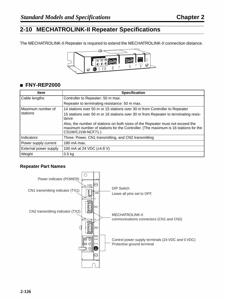
Chapter 2Standard Models and Specifications
2-10 MECHATROLINK-II Repeater Specifications
The MECHATROLINK-II Repeater is required to extend the MECHATROLINK-II connection distance.
FNY-REP2000
Repeater Part Names
Item SpecificationCable lengths Controller to Repeater: 50 m max.
Repeater to terminating resistance: 50 m max.
Maximum number of stations
14 stations over 50 m or 15 stations over 30 m from Controller to Repeater15 stations over 50 m or 16 stations over 30 m from Repeater to terminating resis-tanceAlso, the number of stations on both sizes of the Repeater must not exceed the maximum number of stations for the Controller. (The maximum is 16 stations for the CS1W/CJ1W-NCF71.)
Indicators Three: Power, CN1 transmitting, and CN2 transmitting
Power supply current 180 mA max.
External power supply 100 mA at 24 VDC (±4.8 V)
Weight 0.5 kg
Power indicator (POWER)
CN1 transmitting indicator (TX1)
CN2 transmitting indicator (TX2)
DIP Switch
Leave all pins set to OFF.
MECHATROLINK-II communications connectors (CN1 and CN2)
Control power supply terminals (24 VDC and 0 VDC)Protective ground terminal
2-126

Chapter 2Standard Models and Specifications
MECHATROLINK-II Repeater Dimensions
FNY-REP2000
Dimensions
DimensionsMounting on Bottom Mounting on Back
160
77 30
150
55
50 1512
150
155012
14 106
55
4.84.8 4.8
4.8 dia.4.8
dia.
(20)
1 1
(97) (34)(4)
50
150
14
150
M4 tap
M4 tap
2-127

Chapter 2Standard Models and Specifications
ConnectionsAn example of connections between the host controller, servo drives, and a Repeater is shownbelow.
RUNERCERHERM
MLKNCF71
UNITNo.
MLK
0123456789
ABCDEF
MCH71MCH71RUNERCER1ER2SSI
UNITNo.
SSIT.B.
MLKI/O
ERHER3ER4MLK
SW1
CHARGE
L1
CN6
A/B
CN3
CN1
CN2
CN4
L2
L1
L2
B1
B2
U
V
W
UV
W
R88D-WN01H-ML2
100W
200VAC SERVO DRIVER
POWER
COM
SW1
CHARGE
L1
CN6
A/B
CN3
CN1
CN2
CN4
L2
L1
L2
B1
B2
U
V
W
UV
W
R88D-WN01H-ML2
100W
200VAC SERVO DRIVER
POWER
COM
SW1
CHARGE
L1
CN6
A/B
CN3
CN1
CN2
CN4
L2
L1
L2
B1
B2
U
V
W
UV
W
R88D-WN01H-ML2
100W
200VAC SERVO DRIVER
POWER
COM
SW1
CHARGE
L1
CN6
A/B
CN3
CN1
CN2
CN4
L2
L1
L2
B1
B2
U
V
W
UV
W
R88D-WN01H-ML2
100W
200VAC SERVO DRIVER
POWER
COM
MECHATROLINK-II MECHATROLINK-II
30 m or less: 15 stations max.30 to 50 m: 14 stations max.
30 m or less: 16 stations max.30 to 50 m: 15 stations max.
100 m max.: Maximum number of stations for Controller (The maximum is 16 stations for the CJ1W/CS1W-NCF71
and 30 stations for the CJ1W/CS1W-MCH71.)
2-128

Chapter 3
System Design and Installation
3-1 Installation Conditions
3-2 Wiring
3-3 Regenerative Energy Absorption
3-4 Adjustments and Dynamic Braking When LoadInertia Is Large

Chapter 3System Design and Installation
Installation and Wiring Precautions
!Caution Do not step on or place a heavy object on the product. Doing so may result ininjury.
!Caution Do not cover the inlet or outlet ports and prevent any foreign objects from enteringthe product. Failure to observe this may result in fire.
!Caution Be sure to install the product in the correct direction. Not doing so may result inmalfunction.
!Caution Provide the specified clearances between the Servo Driver and the control box orother devices. Not doing so may result in fire or malfunction.
!Caution Do not apply any strong impact. Doing so may result in malfunction.
!Caution Be sure to wire correctly and securely. Not doing so may result in motor runaway,injury, or malfunction.
!Caution Be sure that all the mounting screws, terminal screws, and cable connectorscrews are tightened to the torque specified in the relevant manuals. Incorrecttightening torque may result in malfunction.
!Caution Use crimp terminals for wiring. Do not connect bare stranded wires directly to ter-minals. Connection of bare stranded wires may result in burning.
!Caution Always use the power supply voltages specified in the this manual. An incorrectvoltage may result in malfunctioning or burning.
!Caution Take appropriate measures to ensure that the specified power with the rated volt-age and frequency is supplied. Be particularly careful in places where the powersupply is unstable. An incorrect power supply may result in malfunctioning.
!Caution Install external breakers and take other safety measures against short-circuiting inexternal wiring. Insufficient safety measures against short-circuiting may result inburning.
!Caution To avoid damage to the product, take appropriate and sufficient countermeasureswhen installing systems in the following locations:
• Locations subject to static electricity or other sources of noise.
• Locations subject to strong electromagnetic fields and magnetic fields.
• Locations subject to possible exposure to radiation.
• Locations close to power supply lines.
!Caution When connecting the battery, be careful to connect the polarity correctly. Incorrectpolarity connections can damage the battery or cause it to explode.
3-2

Chapter 3System Design and Installation
3-1 Installation Conditions
3-1-1 Servo Drivers
Space Around Drivers• Install Servo Drivers according to the dimensions shown in the following illustration to ensure
proper heat dispersion and convection inside the panel. Also install a fan for circulation if ServoDrivers are installed side by side to prevent uneven temperatures from developing inside the panel.
• Take the control cable's connector direction into account when installing the Servo Drivers.
Mounting DirectionMount the Servo Drivers in a direction (perpendicular) such that the lettering for the model number,and so on, can be seen.
Operating EnvironmentThe environment in which Servo Drivers are operated must meet the following conditions.
• Ambient operating temperature: 0 to +55°C (Take into account temperature rises in the individualServo Drivers themselves.)
• Ambient operating humidity: 20% to 90% (with no condensation)
• Atmosphere: No corrosive gases.
Ambient Temperature• Servo Drivers should be operated in environments in which there is minimal temperature rise to
maintain a high level of reliability.
• Temperature rise in any Unit installed in a closed space, such as a control box, will cause the ambi-ent temperature to rise inside the entire closed space. Use a fan or a air conditioner to prevent theambient temperature of the Servo Driver from exceeding 55°C.
• Unit surface temperatures may rise to as much as 30°C above the ambient temperature. Use heat-resistant materials for wiring, and keep separate any devices or wiring that are sensitive to heat.
Ser
vo D
river
Side panel
W
30 mm min.
W
50 mm min.
50 mm min.
Air
Air
Fan Fan
W = 10 mm min.
Ser
vo D
river
Ser
vo D
river
3-3
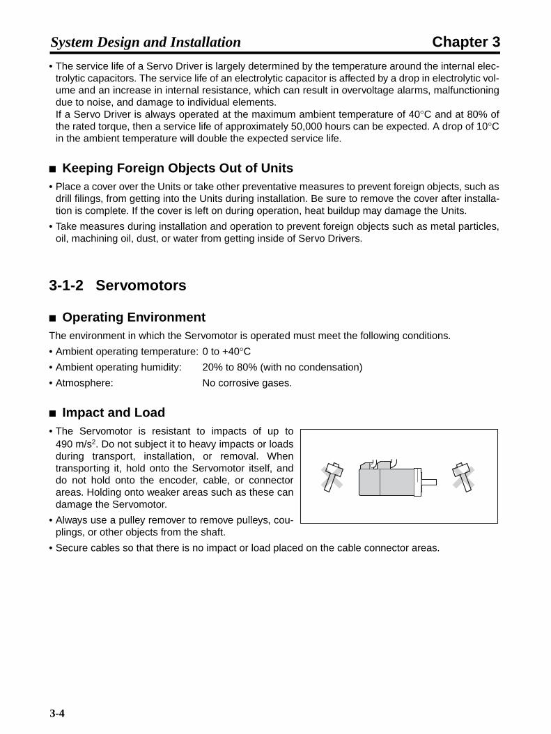
Chapter 3System Design and Installation
• The service life of a Servo Driver is largely determined by the temperature around the internal elec-trolytic capacitors. The service life of an electrolytic capacitor is affected by a drop in electrolytic vol-ume and an increase in internal resistance, which can result in overvoltage alarms, malfunctioningdue to noise, and damage to individual elements. If a Servo Driver is always operated at the maximum ambient temperature of 40°C and at 80% ofthe rated torque, then a service life of approximately 50,000 hours can be expected. A drop of 10°Cin the ambient temperature will double the expected service life.
Keeping Foreign Objects Out of Units• Place a cover over the Units or take other preventative measures to prevent foreign objects, such as
drill filings, from getting into the Units during installation. Be sure to remove the cover after installa-tion is complete. If the cover is left on during operation, heat buildup may damage the Units.
• Take measures during installation and operation to prevent foreign objects such as metal particles,oil, machining oil, dust, or water from getting inside of Servo Drivers.
3-1-2 Servomotors
Operating EnvironmentThe environment in which the Servomotor is operated must meet the following conditions.
• Ambient operating temperature: 0 to +40°C• Ambient operating humidity: 20% to 80% (with no condensation)
• Atmosphere: No corrosive gases.
Impact and Load• The Servomotor is resistant to impacts of up to
490 m/s2. Do not subject it to heavy impacts or loadsduring transport, installation, or removal. Whentransporting it, hold onto the Servomotor itself, anddo not hold onto the encoder, cable, or connectorareas. Holding onto weaker areas such as these candamage the Servomotor.
• Always use a pulley remover to remove pulleys, cou-plings, or other objects from the shaft.
• Secure cables so that there is no impact or load placed on the cable connector areas.
3-4
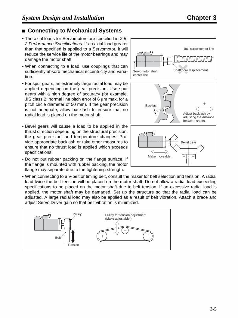
Chapter 3System Design and Installation
Connecting to Mechanical Systems• The axial loads for Servomotors are specified in 2-5-
2 Performance Specifications. If an axial load greaterthan that specified is applied to a Servomotor, it willreduce the service life of the motor bearings and maydamage the motor shaft.
• When connecting to a load, use couplings that cansufficiently absorb mechanical eccentricity and varia-tion.
• For spur gears, an extremely large radial load may beapplied depending on the gear precision. Use spurgears with a high degree of accuracy (for example,JIS class 2: normal line pitch error of 6 µm max. for apitch circle diameter of 50 mm). If the gear precisionis not adequate, allow backlash to ensure that noradial load is placed on the motor shaft.
• Bevel gears will cause a load to be applied in thethrust direction depending on the structural precision,the gear precision, and temperature changes. Pro-vide appropriate backlash or take other measures toensure that no thrust load is applied which exceedsspecifications.
• Do not put rubber packing on the flange surface. Ifthe flange is mounted with rubber packing, the motorflange may separate due to the tightening strength.
• When connecting to a V-belt or timing belt, consult the maker for belt selection and tension. A radialload twice the belt tension will be placed on the motor shaft. Do not allow a radial load exceedingspecifications to be placed on the motor shaft due to belt tension. If an excessive radial load isapplied, the motor shaft may be damaged. Set up the structure so that the radial load can beadjusted. A large radial load may also be applied as a result of belt vibration. Attach a brace andadjust Servo Driver gain so that belt vibration is minimized.
Ball screw center line
Shaft core displacementShaft core displacementShaft core displacementServomotor shaft center line
Backlash
Adjust backlash by adjusting the distance between shafts.
Bevel gear
Make moveable.
Pulley
Belt
Tension
Pulley for tension adjustment (Make adjustable.)
3-5

Chapter 3System Design and Installation
Connectors Conforming to EC DirectivesThe Power Cable and Encoder Cable connectors listed in the following table are recommended forconforming to EC Directives.
Note The connectors for the Servomotor models not listed below, i.e., 3,000-r/min Servomotors (50to 750 W) and all 3,000-r/min Flat-style Servomotor models, already conform to EC Directivesand do not need to be changed.
Recommended Connectors
For Power CablesServomotor type Servomotor model Connector model Cable clamp model Maker
With-out brake
3,000-r/min 1 kW R88M-W1K030@-@ Angled typeCE05-8A18-10SD-B-BASStraight typeCE06-6A18-10SD-B-BSS
For sheath external diameter of 6.5 to 8.7 dia.:CE3057-10A-3 (D265)For sheath external diameter of 8.5 to 11 dia.:CE3057-10A-2 (D265)For sheath external diameter of 10.5 to 14.1 dia.:CE3057-10A-1 (D265)
DDK Ltd.
1.5 kW R88M-W1K530@-@2 kW R88M-W2K030@-@
1,000-r/min 300 W R88M-W30010@-@600 W R88M-W60010@-@900 W R88M-W90010@-@
1,500-r/min 450 W R88M-W45015T-@850 W [email protected] kW R88M-W1K315T-@
3,000-r/min 3 kW R88M-W3K030@-@ Angled typeJL04V-8A22-22SE-EBStraight typeJL04V-6A22-22SE-EB
For sheath external diameter of 6.5 to 9.5 dia.:JL04-2022CK (09)For sheath external diameter of 9.5 to 13 dia.:JL04-2022CK (12)For sheath external diameter of 12.9 to 15.9 dia.:JL04-2022CK (14)
Japan Avia-tion Electron-ics Industry, Ltd. (JAE)
1,000-r/min 1.2 kW R88M-W1K210@-@2 kW R88M-W2K010@-@
1,500-r/min 1.8 kW R88M-W1K815T-@
With brake
3,000-r/min 1 kW R88M-W1K030@-B@ Angled typeJL04V-8A20-15SE-EBStraight typeJL04V-6A20-15SE-EB
For sheath external diameter of 6.5 to 9.5 dia.:JL04-2022CK (09)For sheath external diameter of 9.5 to 13 dia.:JL04-2022CK (12)For sheath external diameter of 12.9 to 15.9 dia.:JL04-2022CK (14)
Japan Avia-tion Electron-ics Industry, Ltd. (JAE)
1.5 kW R88M-W1K530@-B@2 kW R88M-W2K030@-B@
1,000-r/min 300 W R88M-W30010@-B@600 W R88M-W60010@-B@900 W R88M-W90010@-B@
1,500-r/min 450 W R88M-W45015T-B@850 W [email protected] kW R88M-W1K315T-B@
3,000-r/min 3 kW R88M-W3K030@-B@ Angled typeJL04V-8A24-10SE-EBStraight typeJL04V-6A24-10SE-EB
For sheath external diameter of 9 to 12 dia.:JL04-2428CK (11)For sheath external diameter of 12 to 15 dia.:JL04-2428CK (14)For sheath external diameter of 15 to 18 dia.:JL04-2428CK (17)For sheath external diameter of 18 to 20 dia.:JL04-2428CK (20)
Japan Avia-tion Electron-ics Industry, Ltd. (JAE)
1,000-r/min 1.2 kW R88M-W1K210@-B@2 kW R88M-W2K010@-B@
1,500-r/min 1.8 kW R88M-W1K815T-B@
3-6
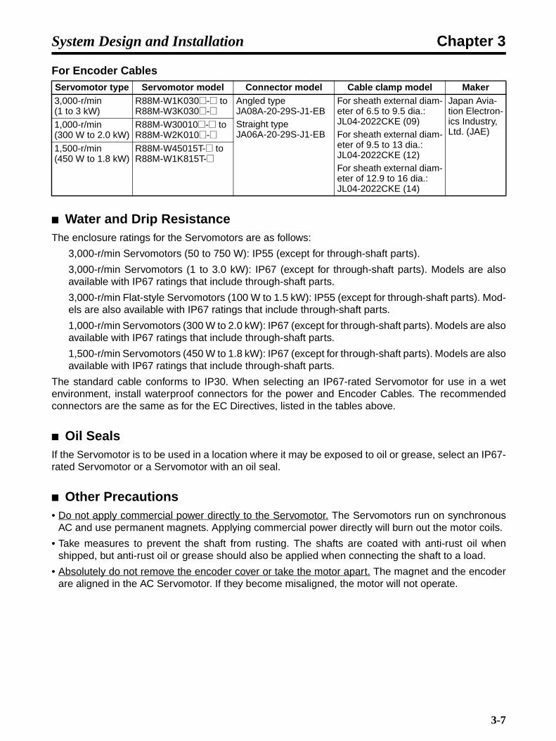
Chapter 3System Design and Installation
For Encoder Cables
Water and Drip ResistanceThe enclosure ratings for the Servomotors are as follows:
3,000-r/min Servomotors (50 to 750 W): IP55 (except for through-shaft parts).
3,000-r/min Servomotors (1 to 3.0 kW): IP67 (except for through-shaft parts). Models are alsoavailable with IP67 ratings that include through-shaft parts.
3,000-r/min Flat-style Servomotors (100 W to 1.5 kW): IP55 (except for through-shaft parts). Mod-els are also available with IP67 ratings that include through-shaft parts.
1,000-r/min Servomotors (300 W to 2.0 kW): IP67 (except for through-shaft parts). Models are alsoavailable with IP67 ratings that include through-shaft parts.
1,500-r/min Servomotors (450 W to 1.8 kW): IP67 (except for through-shaft parts). Models are alsoavailable with IP67 ratings that include through-shaft parts.
The standard cable conforms to IP30. When selecting an IP67-rated Servomotor for use in a wetenvironment, install waterproof connectors for the power and Encoder Cables. The recommendedconnectors are the same as for the EC Directives, listed in the tables above.
Oil SealsIf the Servomotor is to be used in a location where it may be exposed to oil or grease, select an IP67-rated Servomotor or a Servomotor with an oil seal.
Other Precautions• Do not apply commercial power directly to the Servomotor. The Servomotors run on synchronous
AC and use permanent magnets. Applying commercial power directly will burn out the motor coils.
• Take measures to prevent the shaft from rusting. The shafts are coated with anti-rust oil whenshipped, but anti-rust oil or grease should also be applied when connecting the shaft to a load.
• Absolutely do not remove the encoder cover or take the motor apart. The magnet and the encoderare aligned in the AC Servomotor. If they become misaligned, the motor will not operate.
Servomotor type Servomotor model Connector model Cable clamp model Maker3,000-r/min (1 to 3 kW)
R88M-W1K030@-@ to R88M-W3K030@-@
Angled typeJA08A-20-29S-J1-EBStraight typeJA06A-20-29S-J1-EB
For sheath external diam-eter of 6.5 to 9.5 dia.:JL04-2022CKE (09)For sheath external diam-eter of 9.5 to 13 dia.: JL04-2022CKE (12)For sheath external diam-eter of 12.9 to 16 dia.: JL04-2022CKE (14)
Japan Avia-tion Electron-ics Industry, Ltd. (JAE)
1,000-r/min(300 W to 2.0 kW)
R88M-W30010@-@ to R88M-W2K010@-@
1,500-r/min(450 W to 1.8 kW)
R88M-W45015T-@ to R88M-W1K815T-@
3-7

Chapter 3System Design and Installation
3-2 Wiring3-2-1 Connecting Cable
This section shows the types of connecting cable used in an OMNUC W-series ServoSystem. The wide selection of cables provided for configuring a Servo System using aMotion Control Unit or Position Unit makes wiring simple.
Servo System Configuration
SW1
CHARGE
L1
CN6
A/B
CN3
CN1
CN2
CN4
L2
L1
L2
B1
B2
U
V
W
L1L2
L1CL2C
B2
UV
W
R88D-WN01H-ML2
100W
200VAC SERVO DRIVER
POWER
COM
Servo DriverServo Driver
ServomotorServomotor
Power Cable
Robot Cable Power Cable
Encoder Cable
Robot Cable Encoder Cable
CN2(Encoder Connector)
Terminal block
CN1(I/O signal connector)
3
5
4
5
R88D-WN@-ML2
R88M-W@
ControllerController
CJ1W-MCH71CS1W-MCH71
Computer Monitor SoftwareComputer Monitor Software Computer Monitor Cable6
DOS personal computers
CN3 (Personal computer connector)
CN6 (MECHATROLINK-II communications cable)
Absolute Encoder Battery CableR88A-CRWC0R3C 0.3 m
Analog Monitor Cable7
MECHATROLINK-II Cable1
I/O Signal Connector2
CN5
Motion Control Unit
CJ1W-NCF71
Position Control Unit
RUNERCERHERM
MLKNCF71
UNITNo.
MLK
0123456789
ABCDEF
0123456789
ABCDEF
MCH71
Absolute Encoder Backup Battery UnitR88A-BAT01W
(See note.) (See note.)
Note Use a Robot Cable if the cable needs to bend.(Refer to page 2-99.)
3-8
Chapter 3System Design and Installation
1. MECHATROLINK-II Cable
Special MECHATROLINK-II CablesUse the following cables to connect to MECHATROLINK-II devices.
Terminating ResistorUse the following terminating resistor at the end of the MECHATROLINK-II communications line.
2. I/O Signal ConnectorUse the following connector to make your own cable for the Servo Driver I/O connector (CN1).
3. Power CableSelect a Power Cable to match the Servomotor that is to be used.
Note 1. The empty boxes in the model numbers are for cable length. The cables can be 3, 5, 10, 15,20, 30, 40, or 50 meters long. (For example, R88A-CAW003S is 3 meters long.)
Note 2. For 750-W Servomotors, use R88A-CAWB@ Power Cable if the wiring distance will be 30meters or more.
Unit Cable model LengthCJ1W-NCF71CJ1W-MCH71CS1W-MCH71
FNY-W6003-A5 0.5 m
FNY-W6003-01 1.0 m
FNY-W6003-03 3.0 m
FNY-W6003-05 5.0 m
FNY-W6003-10 10 m
FNY-W6003-20 20 m
FNY-W6003-30 30 m
Name ModelMECHATROLINK-II Terminating Resistor FNY-W6022
Name ModelI/O Signal Connector R88A-CNW01C Connects to the I/O signal connector (CN1).
(Connector only)
Servomotor type Power Cables for Servomotors without Brakes
Power Cables for Servomotors with Brakes
3,000-r/min Servo-motors
30 to 750 W R88A-CAWA@@@S R88A-CAWA@@@B
1 to 2kW R88A-CAWC@@@S R88A-CAWC@@@B
3.0 kW R88A-CAWD@@@S R88A-CAWD@@@B
3,000-r/min Flat-style Servomotors
100 to 750 W R88A-CAWA@@@S R88A-CAWA@@@B
1.5 kW R88A-CAWB@@@S R88A-CAWB@@@B
1,000-r/min Servo-motors
300 to 900 W R88A-CAWC@@@S R88A-CAWC@@@B
1.2 to 2.0 kW R88A-CAWD@@@S R88A-CAWD@@@B
1,500-r/min Servo-motors
450 W to 1.3 kW R88A-CAWC@@@S R88A-CAWC@@@B
1.8 kW R88A-CAWD@@@S R88A-CAWD@@@B
3-9

Chapter 3System Design and Installation
4. Encoder CableSelect an Encoder Cable to match the Servomotor that is to be used.
Use the following cable for an absolute encoder.
5. Robot CablesUse a Robot Cable if the encoder or power cables need to bend.
• Encoder Cables
• Power Cables
Note The “@@@” in the model number indicates the cable length. There are 8 cable lengths: 3 m, 5 m, 10 m, 15 m, 20 m, 30 m, 40 m, and 50 m.(Example model number: R88A-CAWA003SR (3 m))
Servomotor type Encoder Cable Remarks3,000-r/min Servomotors 30 to 750 W R88A-CRWA@@@C The empty boxes in the model numbers
are for cable length. The cables can be 3, 5, 10, 15, 20, 30, 40, or 50 meters long. (For example, R88A-CRWA003C is 3 meters long.)
1 to 3.0 kW R88A-CRWB@@@N
3,000-r/min Flat-style Servomotors
100 W to 1.5 kW R88A-CRWA@@@C
1,000-r/min Servomotors 300 W to 2.0 kW R88A-CRWB@@@N
1,500-r/min Servomotors 450 W to 1.8 kW R88A-CRWB@@@N
Name/specifications Model RemarksAbsolute Encoder Battery Cable 0.3 m R88A-CRWC0R3C Only 0.3-meter cables are available.
Motor Encoder Cable Remarks3,000-r/min Servomotors 30 to 750 W R88A-CAWA@@@CR The “@@@” in the model number indi-
cates the cable length.There are 8 cable lengths: 3 m, 5 m, 10 m, 15 m, 20 m, 30 m, 40 m, and 50 m.(Example model number: R88A-CRWA003CR (3 m))
1 to 3.0 kW R88A-CAWB@@@NR
3,000-r/min Flat-style Servomotors
100 to 1.5 kW R88A-CAWA@@@CR
1,000-r/min Servomotors 300 to 2.0 kW R88A-CAWB@@@NR
1,500-r/min Servomotors 450 W to 1.8 kW R88A-CAWB@@@NR
Motor Power Cable for Motors Without Brakes
Power Cable for Motors With Brakes
3,000-r/min Servomotors 30 to 750 W R88A-CAWA@@@SR R88A-CAWA@@@BR
1 to 2 kW R88A-CAWC@@@SR R88A-CAWC@@@BR
3.0 kW R88A-CAWD@@@SR R88A-CAWD@@@BR
3,000-r/min Flat-style Servomotors
100 to 750 W R88A-CAWA@@@SR R88A-CAWA@@@BR
1.5 kW R88A-CAWB@@@SR R88A-CAWB@@@BR
1,000-r/min Servomotors 300 to 900 W R88A-CAWC@@@SR R88A-CAWC@@@BR
1.2 to 2.0 kW R88A-CAWD@@@SR R88A-CAWD@@@BR
1,500-r/min Servomotors 450 W to 1.3 kW R88A-CAWC@@@SR R88A-CAWC@@@BR
1.8 kW R88A-CAWD@@@SR R88A-CAWD@@@BR
3-10

Chapter 3System Design and Installation
6. Computer Monitor CableA Computer Monitor Cable and Computer Monitor Software are required to set or monitor parame-ters from a personal computer.
7. Analog Monitor CableThis cable connects to the Servo Driver's Analog Monitor Connector (CN5). It is required for connect-ing analog monitor outputs to an external device (such as a measuring instrument).
Name/specifications Model RemarksComputer Monitor Cable
For DOS personal computers
2 m R88A-CCW002P2 Only 2-meter cables are available.
Name/specifications Model RemarksAnalog Monitor Cable 1 m R88A-CMW001S Only 1-meter cables are available.
3-11

Chapter 3System Design and Installation
3-2-2 Peripheral Device Connection Examples R88D-WNA5L-ML2/-WN01L-ML2/-WN02L-ML2/-WN04L-ML2/
-WNA5H-ML2/-WN01H-ML2/-WN02H-ML2/-WN04H-ML2R T
NFB
Noise filter (See note 2.)1 2
3 4
E NF
Ground to 100 Ω or less
Single-phase 100/115 V AC, 50/60 Hz: R88D-WN@@L-ML2Single-phase 200/230 V AC, 50/60 Hz: R88D-WN@@H-ML2
OFF
X
ONMain-circuit power supply
1MC X
1MC
PL
Surge killer (See note 2.)
Servo error display
L1C
L2C
L1
L2
OMNUC W-series AC Servo Driver
1MC
AC Reactor
CN6
X1
2
BKIR
BKIRCOM
XB24 V DC
OMNUC W-series AC Servomotor
W
V
U
B
E
M
CN2Ground to
100 Ω or less
Encoder Cable
Power Cable
24 V DC
XB
(See note 1.)
(See note 3.)
CN1
Main-circuit connector (See note 2.)
User-controlled device
MECHATROLINK-II Cable
X
CN1
3
4
ALM
ALMCOM
24 VDC
Note 1. Set by user parameter Pn50F.Note 2. Recommended product in 3-2-4
Wiring for Noise Resistance. Forconformity to EC Directives, refer to3-2-5 Wiring for Conformity to EMCDirectives.
Note 3. Recommended relay: MY Relay(24 V), by OMRON. For example,an MY2 Relay outputs to a 2-A in-ductive load at 24 VDC, making itapplicable to all W-series Motorswith Brakes.
3-12
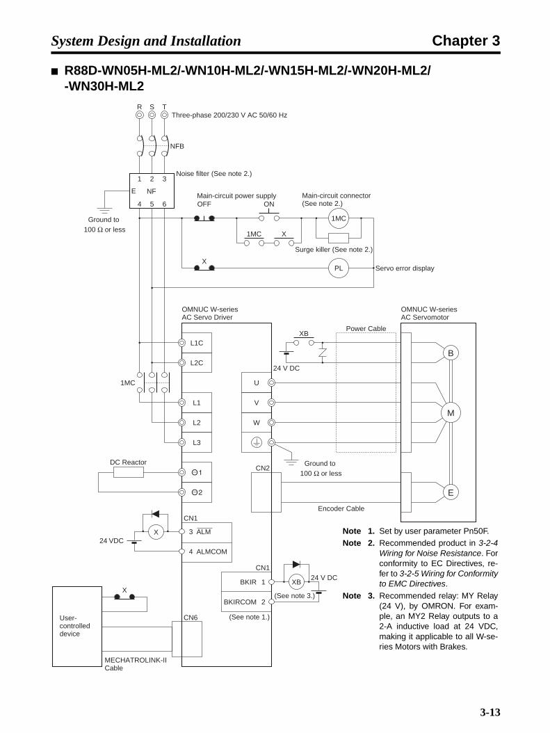
Chapter 3System Design and Installation
R88D-WN05H-ML2/-WN10H-ML2/-WN15H-ML2/-WN20H-ML2/-WN30H-ML2
R T
NFB
S
Noise filter (See note 2.)1 2 3
4 5 6
E NF
Ground to 100 Ω or less
Three-phase 200/230 V AC 50/60 Hz
OFF
X
ONMain-circuit power supply
1MC X
1MC
PL
Surge killer (See note 2.)
Servo error display
L1C
L2C
L1
L2
L3
OMNUC W-series AC Servo Driver
1MC
DC Reactor
CN6
X1
2
BKIR
BKIRCOM
XB24 V DC
OMNUC W-series AC Servomotor
W
V
U
B
E
M
CN2Ground to
100 Ω or less
Encoder Cable
Power Cable
24 V DC
XB
(See note 1.)
(See note 3.)
CN1
Main-circuit connector (See note 2.)
User-controlled device
MECHATROLINK-II Cable
X
CN1
3
4
ALM
ALMCOM
24 VDCNote 1. Set by user parameter Pn50F.Note 2. Recommended product in 3-2-4
Wiring for Noise Resistance. Forconformity to EC Directives, re-fer to 3-2-5 Wiring for Conformityto EMC Directives.
Note 3. Recommended relay: MY Relay(24 V), by OMRON. For exam-ple, an MY2 Relay outputs to a2-A inductive load at 24 VDC,making it applicable to all W-se-ries Motors with Brakes.
3-13

Chapter 3System Design and Installation
R88D-WN08H-ML2R T
NFB
Noise filter (See note 2.)1 2
3 4
E NF
Ground to 100 Ω or less
Single-phase 200/230 V AC 50/60 Hz
OFF
X
ONMain-circuit power supply
1MC X
1MC
PL
Surge killer (See note 2.)
Servo error display
L1C
L2C
L1
L2
OMNUC W-series AC Servo Driver
1MC
DC Reactor
CN6
X1
2
BKIR
BKIRCOM
XB24 V DC
OMNUC W-series AC Servomotor
W
V
U
B
E
M
CN2Ground to
100 Ω or less
Encoder Cable
Power Cable
24 V DC
XB
(See note 1.)
(See note 3.)
CN1
Main-circuit connector (See note 2.)
User-controlled device
MECHATROLINK-II Cable
X
CN1
3
4
ALM
ALMCOM24 VDC
Note 1. Set by user parameter Pn50F.
Note 2. Recommended product in 3-2-4 Wiring for Noise Resistance.For conformity to EC Direc-tives, refer to 3-2-5 Wiring forConformity to EMC Directives.
Note 3. Recommended relay: MY Re-lay (24 V), by OMRON. For ex-ample, an MY2 Relay outputsto a 2-A inductive load at 24VDC, making it applicable to allW-series Motors with Brakes.
3-14
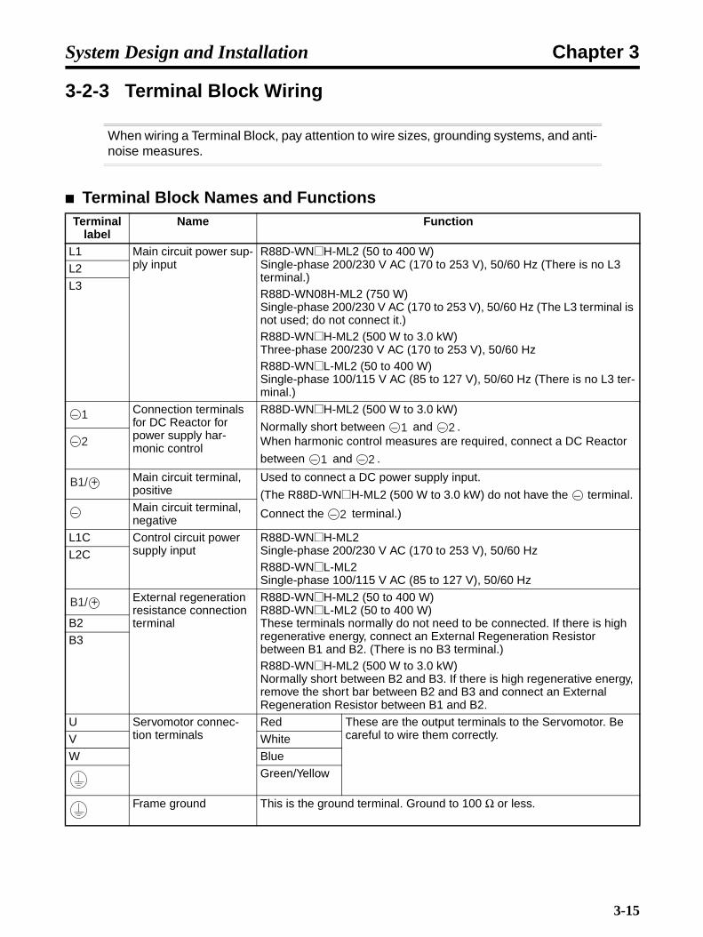
Chapter 3System Design and Installation
3-2-3 Terminal Block Wiring
When wiring a Terminal Block, pay attention to wire sizes, grounding systems, and anti-noise measures.
Terminal Block Names and FunctionsTerminal
labelName Function
L1 Main circuit power sup-ply input
R88D-WN@H-ML2 (50 to 400 W)Single-phase 200/230 V AC (170 to 253 V), 50/60 Hz (There is no L3 terminal.)R88D-WN08H-ML2 (750 W)Single-phase 200/230 V AC (170 to 253 V), 50/60 Hz (The L3 terminal is not used; do not connect it.)R88D-WN@H-ML2 (500 W to 3.0 kW)Three-phase 200/230 V AC (170 to 253 V), 50/60 HzR88D-WN@L-ML2 (50 to 400 W)Single-phase 100/115 V AC (85 to 127 V), 50/60 Hz (There is no L3 ter-minal.)
L2
L3
Connection terminals for DC Reactor for power supply har-monic control
R88D-WN@H-ML2 (500 W to 3.0 kW)
Normally short between and .When harmonic control measures are required, connect a DC Reactor
between and .
Main circuit terminal, positive
Used to connect a DC power supply input.
(The R88D-WN@H-ML2 (500 W to 3.0 kW) do not have the terminal.
Connect the terminal.)Main circuit terminal, negative
L1C Control circuit power supply input
R88D-WN@H-ML2Single-phase 200/230 V AC (170 to 253 V), 50/60 HzR88D-WN@L-ML2Single-phase 100/115 V AC (85 to 127 V), 50/60 Hz
L2C
External regeneration resistance connection terminal
R88D-WN@H-ML2 (50 to 400 W)R88D-WN@L-ML2 (50 to 400 W)These terminals normally do not need to be connected. If there is high regenerative energy, connect an External Regeneration Resistor between B1 and B2. (There is no B3 terminal.)R88D-WN@H-ML2 (500 W to 3.0 kW)Normally short between B2 and B3. If there is high regenerative energy, remove the short bar between B2 and B3 and connect an External Regeneration Resistor between B1 and B2.
B2
B3
U Servomotor connec-tion terminals
Red These are the output terminals to the Servomotor. Be careful to wire them correctly.V White
W Blue
Green/Yellow
Frame ground This is the ground terminal. Ground to 100 Ω or less.
− 1− 1 − 2
− 1 − 2
− 2
B1/ +−
− 2−
B1/ +
3-15

Chapter 3System Design and Installation
Terminal Block Wire Sizes
100-V AC Input (R88D-WN@L-ML2)
Note 1. Use the same wire sizes for , , B1, and B2.
Note 2. Connect special OMRON Power Cable to the Servomotor connection terminals.
200-V AC Input (R88D-WT@H-ML2)
Model (R88D-)Item Unit
WNA05L-ML2 WN01L-ML2 WN02L-ML2 WN04L-ML2
Power supply capacity kVA 0.25 0.4 0.6 1.2
Main circuit power supply input (L1, L2) (See note 1.)
Rated current A (rms) 1.2 2.4 4.7 9.4
Wire size mm2 1.25 1.25 2 2
Screw size --- ---
Torque N·m ---
Control circuit power supply input (L1C, L2C)
Rated current A (rms) 0.13 0.13 0.13 0.13
Wire size mm2 1.25 1.25 1.25 1.25
Screw size --- ---
Torque N·m ---
Servomotor connection ter-minal (U, V, W,
) (See note 2.)
Rated current A (rms) 0.66 0.91 2.1 2.8
Wire size mm2 1.25 1.25 1.25 1.25
Screw size --- ---
Torque N·m ---
Frame ground
( )
Wire size mm2 2 2 2 2
Screw size --- M4 M4 M4 M4
Torque N·m 1.2 1.2 1.2 1.2
Non-fuse breaker or fuse capacity A (rms) 4 4 6 12
Model (R88D-)Item Unit
WNA5H-ML2
WN01H-ML2
WN02H-ML2
WN04H-ML2
WN08H-ML2
WN05H-ML2
WN10H-ML2
WN15H-ML2
WN20H-ML2
WN30H-ML2
Power supply capacity kVA 0.25 0.4 0.75 1.2 2.1 1.4 2.3 3.2 4.3 5.9
Main circuit power sup-ply input (L1, L2 or L1, L2, L3) (See note 1.)
Rated current A (rms) 0.6 1.2 2.4 4.7 8.8 2.5 4.9 7.3 9.7 15.0
Wire size mm2 1.25 1.25 1.25 2 2 2 2 2 3.5 3.5
Screw size --- --- M4 M4
Torque N·m --- 1.2 1.2
Control cir-cuit power supply input (L1C, L2C)
Rated current A (rms) 0.13 0.13 0.13 0.13 0.15 0.15 0.15 0.15 0.15 0.15
Wire size mm2 1.25 1.25 1.25 1.25 1.25 1.25 1.25 1.25 1.25 1.25
Screw size --- --- M4 M4
Torque N·m ---
Servomo-tor connec-tion terminal (U, V, W, ) (See note 2.)
Rated current A (rms) 0.66 0.91 2.1 2.8 5.5 3.8 7.6 11.6 18.5 18.9
Wire size mm2 1.25 1.25 1.25 1.25 1.25 2 2 2 3.5 5.5
Screw size --- --- M4 M4
Torque N·m --- 1.2 1.2
Frame ground ( )
Wire size mm2 2 2 2 2 2 2 2 2 2 2
Screw size --- M4 M4 M4 M4 M4 M4 M4 M4 M4 M4
Torque N·m 1.2 1.2 1.2 1.2 1.2 1.2 1.2 1.2 1.2 1.2
No-fuse breaker or fuse capacity
A (rms) 4 4 4 8 11 4 7 10 13 17
− 1 − 2
3-16

Chapter 3System Design and Installation
Note 1. Use the same wire sizes and tightening torques for , , B1, B2, and B3.
Note 2. Connect special OMRON Power Cable to the Servomotor connection terminals.
Wire Sizes and Allowable CurrentThe following table shows the allowable current for when there are three wires.
600-V Heat-resistant Vinyl Wiring (HIV) (Reference Values)
Terminal Block Wiring ProcedureConnector-type Terminal Blocks are used for Servo Drivers of 1.5 W or less (except for the R88D-WN20H-ML2 to R88D-WN30H-ML2). The procedure for wiring these Terminal Blocks is explainedbelow.
1.Remove the Terminal Block from the Servo Driver.
!Caution The Terminal Block must be removed from the Servo Driver before being wired.The Servo Driver will be damaged if the wiring is done with the Terminal Block inplace.
AWG size Nominal cross-sectional area (mm2)
Configuration (wires/mm2)
Conductive resistance
(Ω/km)
Allowable current (A) for ambient temperature
30°C 40°C 50°C20 0.5 19/0.18 39.5 6.6 5.6 4.5
--- 0.75 30/0.18 26.0 8.8 7.0 5.5
18 0.9 37/0.18 24.4 9.0 7.7 6.0
16 1.25 50/0.18 15.6 12.0 11.0 8.5
14 2.0 7/0.6 9.53 23 20 16
12 3.5 7/0.8 5.41 33 29 24
10 5.5 7/1.0 3.47 43 38 31
8 8.0 7/1.2 2.41 55 49 40
6 14.0 7/1.6 1.35 79 70 57
4 22.0 7/2.0 0.849 99 88 70
− 1 − 2
Connector-type Terminal Block
(Example: R88D-WN01H-ML2)
CN3
CN1
CN2
CN4
U
V
W
U V
W
3-17
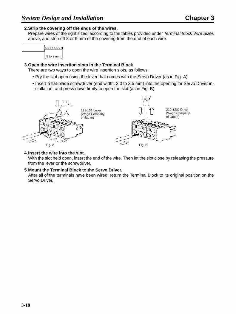
Chapter 3System Design and Installation
2.Strip the covering off the ends of the wires.Prepare wires of the right sizes, according to the tables provided under Terminal Block Wire Sizesabove, and strip off 8 or 9 mm of the covering from the end of each wire.
3.Open the wire insertion slots in the Terminal BlockThere are two ways to open the wire insertion slots, as follows:
• Pry the slot open using the lever that comes with the Servo Driver (as in Fig. A).
• Insert a flat-blade screwdriver (end width: 3.0 to 3.5 mm) into the opening for Servo Driver in-stallation, and press down firmly to open the slot (as in Fig. B).
4.Insert the wire into the slot.With the slot held open, insert the end of the wire. Then let the slot close by releasing the pressurefrom the lever or the screwdriver.
5.Mount the Terminal Block to the Servo Driver.After all of the terminals have been wired, return the Terminal Block to its original position on theServo Driver.
8 to 9 mm
Fig. A Fig. B
231-131 Lever (Wago Company of Japan)
210-120J Driver (Wago Company of Japan)
3-18

Chapter 3System Design and Installation
3-2-4 Wiring for Noise Resistance
System noise resistance will vary greatly depending on the wiring method used. Thissection explains how to reduce noise through proper wiring.
Wiring Method
R88D-WNA5L-ML2 to R88D-WN04L-ML2, R88D-WNA5H-ML2 to R88D-WN04H-ML2, and R88D-WN08H-ML2 Servo Drivers (Single-phase Power Supply Input)
R88D-WN05H-ML2 to R88D-WN30H-ML2 Servo Drivers (Three-phase Power Supply Input)
• Ground the motor's frame to the machine ground when the motor is on a movable shaft.
• Use a grounding plate for the frame ground for each Unit, as shown in the above diagrams, andground to a single point.
NFB
3.5 mm2
Noise filter
1
2
3
4E
NF
ContactorX1 TB
L1
L2
L1C
L2C
U
V
W
TB
CN2
Controller power supplyGround plate
Fuse
R88D-WN@-ML2 R88M-W@
E
M
Machine ground
Thick power line (3.5 mm2)
2 mm2
Metal ductSurge absorberAC power supply
Ground to 100 Ω or less
Ground control box
NFB
3.5 mm2
Noise filter
1
2
3
4
5
6E
NF
ContactorX1 TB
L1
L2
L3
L1C
L2C
U
V
W
TB
CN2
Controller power supplyGround plate
Fuse
R88D-WN@-ML2 R88M-W@
E
M
Machine ground
Thick power line (3.5 mm2)
2 mm2
Metal ductSurge absorberAC power supply
Ground to 100 Ω or less
Ground control box
3-19

Chapter 3System Design and Installation
• Use ground lines with a minimum thickness of 3.5 mm2, and arrange the wiring so that the groundlines are as short as possible.
• If no-fuse breakers are installed at the top and the power supply line is wired from the lower duct,use metal tubes for wiring and make sure that there is adequate distance between the input linesand the internal wiring. If input and output lines are wired together, noise resistance will decrease.
• No-fuse breakers, surge absorbers, and noise filters (NF) should be positioned near the input termi-nal block (ground plate), and I/O lines should be isolated and wired using the shortest distance pos-sible.
• Wire the noise filter as shown at the left in the following illustration. The noise filter should beinstalled at the entrance to the control box whenever possible.
• Use twisted-pair cables for the power supply cables whenever possible, or bind the cables.
• Separate power supply cables and signal cables when wiring.
Selecting Components
This section explains the criteria for selecting the connection components required forimproving noise resistance. These criteria include capacity performance, applicablerange, and so on. For more details, contact the manufacturers directly.
No-fuse Breakers (NFB)When selecting no-fuse breakers, take into consideration the maximum output current and the inrushcurrent.
Correct: Separate input and output WRONG: Noise not filtered effectively
NF123
456E
NF123
456E
AC input AC input
GroundGround
AC output
AC output
Correct: Properly twisted Correct: Cables are bound.Driver
L1CL1
L2
L3L2C
Driver
Binding
3-20

Chapter 3System Design and Installation
Maximum Input Current:• The momentary maximum output for a Servo Driver is approximately three times that of the rated
output, and a maximum output of three seconds can be executed. Therefore, select no-fuse break-ers with an operating time of at least five seconds at 300% of the rated maximum output. General-purpose and low-speed no-fuse breakers are generally suitable (e.g., Mitsubishi S Series).
• The table in 3-2-3 Terminal Block Wiring shows the rated power supply input currents for each Ser-vomotor. Select a no-fuse-breaker with a rated current greater than the total effective load current(when multiple Servomotors are used).
• When making the selection, add in the current consumption of other controllers, and so on.
Servo Driver Inrush Current:• The Servo Driver inrush currents are shown in the above table.
• With low-speed no-fuse breakers, an inrush current 10 times the rated current flows for 0.02 sec-ond.
• For a simultaneous inrush current for multiple Servo Drivers, select a non-fuse breaker with a 20-ms allowable current greater than the total inrush current shown in the above table for the applica-ble Servomotor models.
Noise Filters for Servomotor Output• Use noise filters without built-in capacitors on the Servomotor output lines.
• Select a noise filter with a rated current at least two times the total rated current of the ServoDriver's continuous output current.
W Power supply voltage
Model Capacity Rated current A (rms)
Inrush current (main circuit) A (0-p)
From rated current (*125%)
Single-phase
100 WNA5L 50 W 1.2 14.3 1.5
100 WN01L 100 W 2.4 14.3 3
100 WN02L 200 W 4.7 14.3 5.875
100 WN04L 400 W 9.4 14.3 11.75
Single-phase
200 WNA5H 50 W 0.6 27.6 0.75
200 WN01H 100 W 1.2 27.6 1.5
200 WN02H 200 W 2.4 27.6 3
200 WN04H 400 W 4.7 27.6 5.875
200 WN08H 750 W 8.8 27.6 11
Three-phase
200 WN05H 500 W 2.5 27.6 3.125
200 WN10H 1.0 kW 4.9 27.6 6.125
200 WN15H 1.5 kW 7.3 27.6 9.125
200 WN20H 2.0 kW 9.7 27.6 12.125
200 WN30H 3.0 kW 15.0 27.6 18.75
3-21

Chapter 3System Design and Installation
• The following table shows the noise filters that are recommended for Servomotor output.
Note 1. Servomotor output lines cannot use the same noise filters used for power supplies.
Note 2. Typical noise filters are used with power supply frequencies of 50/60 Hz. If these noise filtersare connected to outputs of 11.7 kHz/5.9 kHz (the Servo Driver's PWM frequency), a verylarge (about 100 times larger) leakage current will flow through the noise filter's condenserand the Servo Driver could be damaged.
Harmonic Current Countermeasures (Reactor)• The AC Reactor is used for suppressing harmonic currents. It suppresses sudden and quick
changes in electric currents.
• In September 1994, the Ministry of International Trade and Industry established guidelines for thesuppression of harmonic waves emitted from home and general electric appliances. To comply withthe guidelines, appropriate measures are required to suppress the influence of harmonic waves onpower supply lines.
• Select the proper AC Reactor or DC Reactor model according to the Servo Driver that is to beused.
Maker Model Rated current RemarksNEC TOKIN LF-310KA 10 A Three-phase block noise filter
LF-320KA 20 A
LF-350KA 50 A
LF-3110KB 110 A
Servo Drive Reactor specificationsModel number Rated current (A) Inductance (mH) Reactor type
R88D-WNA5L-ML2 R88A-PX5053 2.0 20.0 AC Reactor
R88D-WN01L-ML2 R88A-PX5053 2.0 20.0
R88D-WN02L-ML2 R88A-PX5054 3.0 5.0
R88D-WN04L-ML2 R88A-PX5056 5.0 2.0
R88D-WNA5H-ML2 R88A-PX5052 1.0 45.0
R88D-WN01H-ML2 R88A-PX5052 1.0 45.0
R88D-WN02H-ML2 R88A-PX5053 2.0 20.0
R88D-WN04H-ML2 R88A-PX5054 3.0 5.0
R88D-WN08H-ML2 R88A-PX5056 5.0 2.0 DC Reactor
R88D-WN05H-ML2 R88A-PX5061 4.8 2.0
R88D-WN10H-ML2 R88A-PX5061 4.8 2.0
R88D-WN15H-ML2 R88A-PX5060 8.8 1.5
R88D-WN20H-ML2 R88A-PX5060 8.8 1.5
R88D-WN30H-ML2 R88A-PX5059 14.0 1.0
3-22

Chapter 3System Design and Installation
3-2-5 Wiring for Conformity to EMC Directives
When the wiring conditions provided in this section are satisfied, the wiring will conformto EMC Directives (EN55011 Class A Group 1 (EMI), EN61000-6-2 (EMS)). Theseconditions were stipulated when EMC Directive approval was obtained for the WSeries. They will be affected by the installation and wiring conditions resulting from theconnected devices and wiring when the W Series is built into the system. Therefore,the entire system must be checked for conformity.
The following conditions must be satisfied in order to conform to the EC Directives.
• The Servo Driver must be mounted in a metal case (control box). (It is not necessary to mount theServomotor in a metal box.)
• Noise filters and surge absorbers must be inserted in power supply lines.
• Shielded cable must be used for I/O signal cables and encoder cables. (Use tinned soft steel wire.)
• Cables leading out from the control box must be enclosed within metal ducts or conduits withblades. (It is not necessary to enclose the 30-cm power cable, encoder cable, or connectors in ametal duct or conduit.)
• Ferrite cores must be installed for cables with braided shields, and the shield must be directlygrounded to a ground plate.
AC Reactor Connection Example
R88D-WNA5@-ML2 to WN04@-ML2
Servo DriverAC ReactorPower supply
L1
L2
DC Reactor Connection Example
R88D-WN05H-ML2 to WN30H-ML2
Servo DriverDC Reactor
3-23
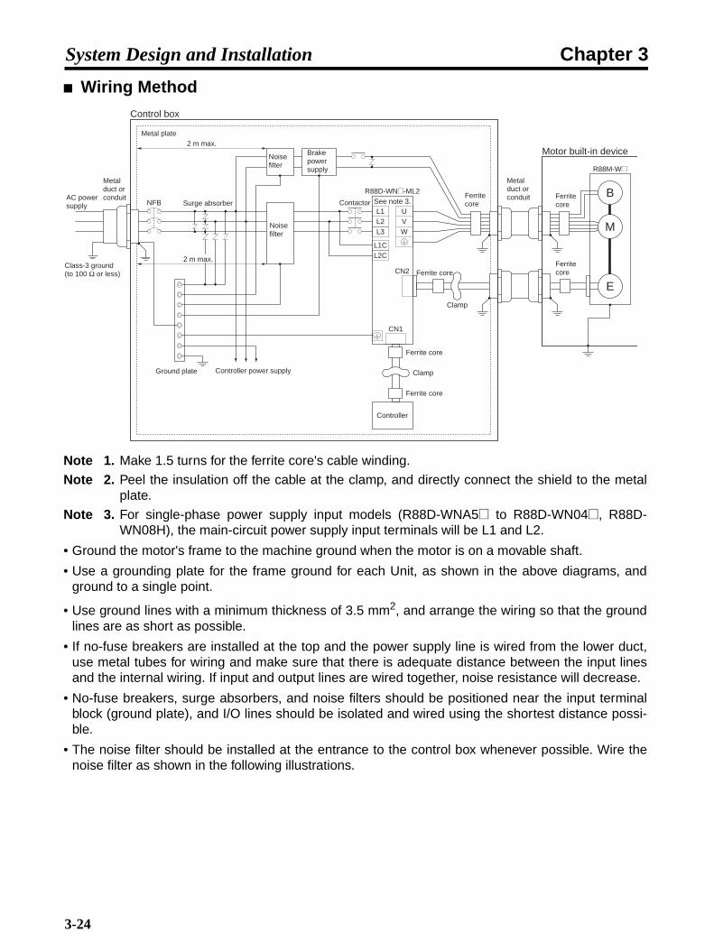
Chapter 3System Design and Installation
Wiring Method
Note 1. Make 1.5 turns for the ferrite core's cable winding.
Note 2. Peel the insulation off the cable at the clamp, and directly connect the shield to the metalplate.
Note 3. For single-phase power supply input models (R88D-WNA5@ to R88D-WN04@, R88D-WN08H), the main-circuit power supply input terminals will be L1 and L2.
• Ground the motor's frame to the machine ground when the motor is on a movable shaft.
• Use a grounding plate for the frame ground for each Unit, as shown in the above diagrams, andground to a single point.
• Use ground lines with a minimum thickness of 3.5 mm2, and arrange the wiring so that the groundlines are as short as possible.
• If no-fuse breakers are installed at the top and the power supply line is wired from the lower duct,use metal tubes for wiring and make sure that there is adequate distance between the input linesand the internal wiring. If input and output lines are wired together, noise resistance will decrease.
• No-fuse breakers, surge absorbers, and noise filters should be positioned near the input terminalblock (ground plate), and I/O lines should be isolated and wired using the shortest distance possi-ble.
• The noise filter should be installed at the entrance to the control box whenever possible. Wire thenoise filter as shown in the following illustrations.
Control box
NFB
Ground plate Controller power supply
L1L2
UVW
CN2
Controller
CN1
Clamp
R88D-WN@-ML2
Ferrite core
Clamp
Motor built-in device
E
M
B
R88M-W@
Surge absorber Contactor
Ferrite core
Ferrite core
L3
L1CL2C
2 m max.
See note 3.
Metal duct or conduitAC power
supply
Class-3 ground (to 100 Ω or less)
Noise filter
Noise filter
Brake power supply
Ferrite core
Metal duct or conduit Ferrite
core
Ferrite core
2 m max.
Metal plate
3-24

Chapter 3System Design and Installation
• Use twisted-pair cables for the power supply cables whenever possible, or bind the cables.
• Separate power supply cables and signal cables when wiring.
Control Box Structure
If there are gaps in the control box from cable openings, operating panel installationholes, gaps around the door, and so on, it may allow electric waves to penetrate. Inorder to prevent this from occurring, take the measures described below.
Case Structure• Construct the control box case of metal, and weld the joints between the top, bottom, and sides so
that they will be electrically conductive.
• For assembly, strip the paint off of joined areas (or mask them during painting), to make them elec-trically conductive.
• If gaps are opened in the control box case when tightening down screws, make adjustments to pre-vent this from occurring.
• Do not leave any conducting part unconnected.
• Connect to the case all Units inside of the case.
Door Structure• Construct the door of metal.
• Use a water draining structure where the door and case fit together, and leave no gaps. (Refer tothe diagrams below.)
• Use conductive packing between the door and the case, as shown in the diagrams below. Strip thepaint off of the sections of the door and case that will be in contact with the conductive packing (ormask them during painting), so that they will be electrically conductive.
Correct: Separate input and output WRONG: Noise not filtered effectively
NF123
456E
NF123
456E
AC input AC input
GroundGround
AC output
AC output
Correct: Properly twisted Correct: Cables are bound.Driver
L1CL1
L2
L3L2C
Driver
Binding
3-25

Chapter 3System Design and Installation
• Be careful not to let gaps be opened in the control box while tightening down screws.
Selecting Components
This section explains the criteria for selecting the connection components required forimproving noise resistance. These criteria include capacity performance, applicablerange, and so on. For more details, contact the manufacturers directly.
No-fuse Breakers (NFB)When selecting no-fuse breakers, take into consideration the maximum output current and the inrushcurrent.
Maximum Input Current:• The momentary maximum output for a Servo Driver is approximately three times that of the rated
output, and a maximum output of three seconds can be executed. Therefore, select no-fuse break-ers with an operating time of at least five seconds at 300% of the rated maximum output. General-purpose and low-speed no-fuse breakers are generally suitable (e.g., Mitsubishi S Series).
• The table in 3-2-3 Terminal Block Wiring shows the rated power supply input currents for each Ser-vomotor. Select a no-fuse-breaker with a rated current greater than the total effective load current(when multiple Servomotors are used).
Case
Door
Control box
Door (interior view)
A
B
Cross-sectional view of A-B
Oil-proof packing
Conductive packing
Door
Oil-proof packing Conductive packing
3-26

Chapter 3System Design and Installation
• When making the selection, add in the current consumption of other controllers, and so on.
Servo Driver Inrush Current:The Servo Driver inrush currents are listed in the following table.
• With low-speed no-fuse breakers, an inrush current 10 times the rated current flows for 0.02 sec-ond.
• For a simultaneous inrush for multiple Servo Drivers, select a no-fuse-breaker with a 20-ms allow-able current greater than the total inrush current shown in the following table for the applicable Ser-vomotor models.
Surge Absorbers• Use surge absorbers to absorb surges from power supply input lines due to lightning, abnormal
voltages, etc.
• When selecting surge absorbers, take into account the varistor voltage, the amount of surge immu-nity, and the amount of energy resistance.
• For 200-V AC systems, use surge absorbers with a varistor voltage of 470 V.
• The surge absorbers shown in the following table are recommended.
Note 1. Refer to the manufacturers' documentation for operating details.
Note 2. The surge immunity is for a standard impulse current of 8/20 µs. If pulses are wide, eitherdecrease the current or change to a larger-capacity surge absorber.
Servo Driver Inrush current (A0-p)Control-circuit power supply Main-circuit power supply
R88D-WNA5L-ML2 22.2 14.3
R88D-WN01L-ML2 22.2 14.3
R88D-WN02L-ML2 22.2 14.3
R88D-WN04L-ML2 22.2 14.3
R88D-WNA5H-ML2 41.6 27.6
R88D-WN01H-ML2 41.6 27.6
R88D-WN02H-ML2 41.6 27.6
R88D-WN04H-ML2 41.6 27.6
R88D-WN08H-ML2 41.6 27.6
R88D-WN05H-ML2 41.6 27.6
R88D-WN10H-ML2 41.6 27.6
R88D-WN15H-ML2 41.6 27.6
R88D-WN20H-ML2 41.6 27.6
R88D-WN30H-ML2 41.6 27.6
Maker Model Max. limit voltage
Surge immunity
Type Remarks
Okaya Electric Industries Co., Ltd.
R·A·V-781BYZ-2 783 V 1,000 A Block Between power supply lines
R·A·V-781BXZ-4 783 V 1,000 A Between power supply line grounds
3-27
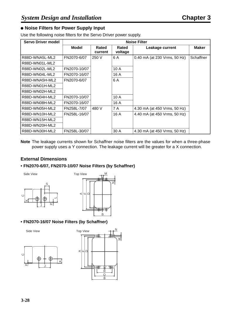
Chapter 3System Design and Installation
Noise Filters for Power Supply InputUse the following noise filters for the Servo Driver power supply.
Note The leakage currents shown for Schaffner noise filters are the values for when a three-phasepower supply uses a Y connection. The leakage current will be greater for a X connection.
External Dimensions• FN2070-6/07, FN2070-10/07 Noise Filters (by Schaffner)
• FN2070-16/07 Noise Filters (by Schaffner)
Servo Driver model Noise FilterModel Rated
currentRated
voltageLeakage current Maker
R88D-WNA5L-ML2 FN2070-6/07 250 V 6 A 0.40 mA (at 230 Vrms, 50 Hz) Schaffner
R88D-WN01L-ML2
R88D-WN02L-ML2 FN2070-10/07 10 A
R88D-WN04L-ML2 FN2070-16/07 16 A
R88D-WNA5H-ML2 FN2070-6/07 6 A
R88D-WN01H-ML2
R88D-WN02H-ML2
R88D-WN04H-ML2 FN2070-10/07 10 A
R88D-WN08H-ML2 FN2070-16/07 16 A
R88D-WN05H-ML2 FN258L-7/07 480 V 7 A 4.30 mA (at 450 Vrms, 50 Hz)
R88D-WN10H-ML2 FN258L-16/07 16 A 4.40 mA (at 450 Vrms, 50 Hz)
R88D-WN15H-ML2
R88D-WN20H-ML2
R88D-WN30H-ML2 FN258L-30/07 30 A 4.30 mA (at 450 Vrms, 50 Hz)
S
J
LP
CK
M
B
N
A DF
Side View Top View
J
K
CP
N
RQB
M
A DF
Side View Top View
3-28

Chapter 3System Design and Installation
• FN258L-7/07, -16/07, -30/07 Noise Filters (by Schaffner)
Surge Killers• Install surge killers for loads that have induction coils, such as relays, solenoids, brakes, clutches,
etc.
• The following table shows types of surge killers and recommended products.
Note Thyristors and varistors are made by the following companies. Refer to manufacturers' docu-mentation for operating details.
Thyristors: Ishizuka Electronics Co.Varistors: Ishizuka Electronics Co., Matsushita Electric Industrial Co.
Model Dimensions (mm)
A B C D F J K L M N P Q R S
FN2070-6/07 113.5 57.5 45.4 94 103 25 8.4 32.4 4.4 6 0.9 --- --- 38
FN2070-10/07 156 130.5 143 5.3
FN2070-16/07 119 85.5 57.6 98.5 109 40 8.6 --- 4.4 7.4 1.2 66 51 ---
Model Dimensions (mm)A B C D E F G H J L O P
FN258L-7/07 255 126 50 225 240 25 6.5 300 1 9 M5 AWG16
FN258L-16/07 303 142 55 275 290 30 AWG14
FN258L-30/07 335 150 60 305 320 35 400 AWG10
Type Features Recommended productsDiode Diodes are used for relatively small
loads when the reset time is not an issue, such as relays. The reset time is increased because the surge voltage is the lowest when power is cut off.Used for 24/48-V DC systems.
Use a fast-recovery diode with a short reverse recovery time.
Example: Fuji Electric Co., ERA22-06
Thyristor or varistor
Thyristors and varistors are used for loads when induction coils are large, as in electromagnetic brakes, solenoids, etc., and when reset time is an issue. The surge voltage when power is cut off is approximately 1.5 times the varistor voltage.
Select the varistor voltage as follows:24 VDC system: 39 V100 VDC system: 200 V100 VAC system: 270 V200 VAC system: 470 V
Capacitor + resistor
The capacitor + resistor combination is used to absorb vibration in the surge when power is cut off. The reset time can be shortened by selecting the appropriate capacitance and resistance.
Okaya Electric Industries Co., Ltd.XEB120020.2 µF – 120 ΩXEB120030.3 µF – 120 Ω
GP
B
OEA
D HL
C
F
J
Side View Top and Side Views
7 A to 55 A Models
3-29
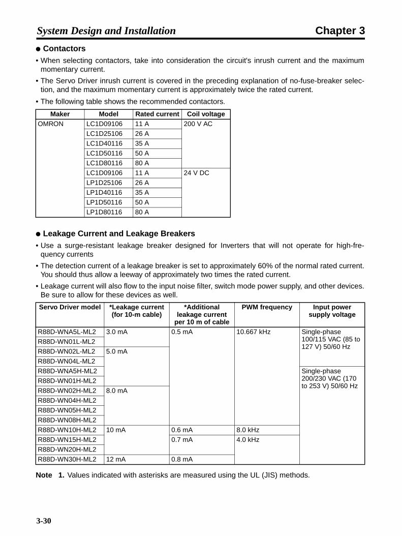
Chapter 3System Design and Installation
Contactors• When selecting contactors, take into consideration the circuit's inrush current and the maximum
momentary current.
• The Servo Driver inrush current is covered in the preceding explanation of no-fuse-breaker selec-tion, and the maximum momentary current is approximately twice the rated current.
• The following table shows the recommended contactors.
Leakage Current and Leakage Breakers• Use a surge-resistant leakage breaker designed for Inverters that will not operate for high-fre-
quency currents
• The detection current of a leakage breaker is set to approximately 60% of the normal rated current.You should thus allow a leeway of approximately two times the rated current.
• Leakage current will also flow to the input noise filter, switch mode power supply, and other devices.Be sure to allow for these devices as well.
Note 1. Values indicated with asterisks are measured using the UL (JIS) methods.
Maker Model Rated current Coil voltageOMRON LC1D09106 11 A 200 V AC
LC1D25106 26 A
LC1D40116 35 A
LC1D50116 50 A
LC1D80116 80 A
LC1D09106 11 A 24 V DC
LP1D25106 26 A
LP1D40116 35 A
LP1D50116 50 A
LP1D80116 80 A
Servo Driver model *Leakage current(for 10-m cable)
*Additional leakage current
per 10 m of cable
PWM frequency Input power supply voltage
R88D-WNA5L-ML2 3.0 mA 0.5 mA 10.667 kHz Single-phase 100/115 VAC (85 to 127 V) 50/60 Hz
R88D-WN01L-ML2
R88D-WN02L-ML2 5.0 mA
R88D-WN04L-ML2
R88D-WNA5H-ML2 Single-phase 200/230 VAC (170 to 253 V) 50/60 Hz
R88D-WN01H-ML2
R88D-WN02H-ML2 8.0 mA
R88D-WN04H-ML2
R88D-WN05H-ML2
R88D-WN08H-ML2
R88D-WN10H-ML2 10 mA 0.6 mA 8.0 kHz
R88D-WN15H-ML2 0.7 mA 4.0 kHz
R88D-WN20H-ML2
R88D-WN30H-ML2 12 mA 0.8 mA
3-30

Chapter 3System Design and Installation
Note 2. The installation conditions of the power cable and the measurement methods greatly affectthese values. Use these values only for reference. The values differ by a factor of approxi-mately 3 between standard breakers and inverter breakers.
Leakage Breaker Connection Example
Improving Encoder Cable Noise ResistanceThe OMNUC W Series uses serial encoders, with phase-S signals from the encoder. The phase-Scommunications speed is 4 Mbits/s.
In order to improve the encoder's noise resistance, take the following measures for wiring and instal-lation.
• Always use the specified Encoder Cables.
• If lines are interrupted in the middle, be sure to connect them with connectors, making sure that thecable insulation is not peeled off for more than 50 mm. In addition, always use shielded cable.
• Do not coil cables. If cables are long and are coiled, mutual induction and inductance will increaseand will cause malfunctions. Always use cables fully extended.
• When installing noise filters for Encoder Cables, use clamp filters. The following table shows therecommended clamp filter models.
• Do not place the Encoder Cable in the same duct as Power Cables and Control Cables for brakes,solenoids, clutches, and valves.
Maker Name ModelNEC TOKIN EMI core ESD-SR-25
TDK Clamp filter ZCAT2032-0930
ZCAT3035-1330
ZCAT2035-0930A
1
2
3
4
5
6E
NF
No-fuse breaker Noise filterSurge absorberAC power supply side
Leakage breaker
Servo Driver side
3-31

Chapter 3System Design and Installation
3-3 Regenerative Energy Absorption
The Servo Drivers have internal regenerative energy absorption circuitry for absorbingthe regenerative energy produced during time such as Servomotor deceleration, andthus preventing the DC voltage from increasing. An overcurrent error is generated,however, if the amount of regenerative energy from the Servomotor is too large. If thisoccurs, measures must be taken to reduce the regenerative energy produced bychanging operating patterns, and so on, or to improve the regenerative energyabsorption capacity by connecting external regeneration resistance.
3-3-1 Regenerative Energy Calculation
Horizontal Axis
Note In the output torque graph, acceleration in the positive direction is shown as positive, andacceleration in the negative direction is shown as negative.
• The regenerative energy values for Eg1 and Eg2 are derived from the following equations.
N1, N2: Rotation speed at beginning of deceleration [r/min]TD1, TD2: Deceleration torque [N·m]t1, t2: Deceleration time [s]
Servomotor operation
Servomotor output torque
+N1
−N2
TD1
TD2
t1 t2
T
Eg1g1Eg1
Eg2g2Eg2
• Eg1 = • • N1 • TD1 • t1 [J ]2 60
60
2π
2π
1
• Eg2 = • • N2 • TD2 • t2 [J ]21
3-32

Chapter 3System Design and Installation
Note There is some loss due to winding resistance, so the actual regenerative energy will be approx-imately 90% of the values derived from these equations.
• For Servo Driver models with internal capacitors for absorbing regenerative energy (i.e., models of400 W or less.), the values for both Eg1 or Eg2 (unit: J) must be lower than the Servo Driver's regen-erative energy absorption capacity. (The capacity varies depending on the model. For details, referto 3-3-2 Servo Driver Regenerative Energy Absorption Capacity.)
• For Servo Driver models with internal regeneration resistance for absorbing regenerative energy(i.e., models of 500 W or more), the average amount of regeneration Pr (unit: W) must be calcu-lated, and this value must be lower than the Servo Driver's regenerative energy absorption capacity.(The capacity varies depending on the model. For details, refer to 3-3-2 Servo Driver RegenerativeEnergy Absorption Capacity.)
The average amount of regeneration (Pr) is the power consumed by regeneration resistance inone cycle of operation.
Pr = (Eg1 + Eg2)/T [W]T: Operation cycle [s]
Vertical Axis
Note In the output torque graph, acceleration in the positive direction (rise) is shown as positive, andacceleration in the negative direction (fall) is shown as negative.
• The regenerative energy values for Eg1, Eg2, and Eg3 are derived from the following equations.
Servomotor operation
Servomotor output torque
+N1
−N2
t1 t2 t3
T
Eg1
Eg3g3Eg3
Rise
Fall
TD2
TL2
TD1
Eg2
• Eg1 = • • N1 • TD1 • t1 [J]2 60
60
2π
2π
1
• Eg2 = • N2 • TL2 • t2 [J]
602π• Eg3 = • • N2 • TD2 • t3 [J]2
1
3-33

Chapter 3System Design and Installation
N1, N2: Rotation speed at beginning of deceleration [r/min]TD1, TD2: Deceleration torque [N·m]TL2: Torque when falling [N·m]t1, t3: Deceleration time [s]t2: Constant-velocity travel time when falling [s]
Note There is some loss due to winding resistance, so the actual regenerative energy will be approx-imately 90% of the values derived from these equations.
• For Servo Driver models with internal capacitors for absorbing regenerative energy (i.e., models of400 W or less.), the values for both Eg1 or Eg2 (unit: J) must be lower than the Servo Driver's regen-erative energy absorption capacity. (The capacity varies depending on the model. For details, referto 3-3-2 Servo Driver Regenerative Energy Absorption Capacity.)
• For Servo Driver models with internal regeneration resistance for absorbing regenerative energy(i.e., models of 500 W or more), the average amount of regeneration Pr (unit: W) must be calcu-lated, and this value must be lower than the Servo Driver's regenerative energy absorption capacity.(The capacity varies depending on the model. For details, refer to 3-3-2 Servo Driver RegenerativeEnergy Absorption Capacity.)
The average amount of regeneration (Pr) is the power consumed by regeneration resistance inone cycle of operation.
Pr = (Eg1 + Eg2 + Eg3)/T [W]T: Operation cycle [s]
3-3-2 Servo Driver Regenerative Energy Absorption Capacity
Amount of Internal Regeneration Resistance in Servo DriversW-series Servo Drivers absorb regenerative energy by means of internal capacitors or resistors. Ifthe regenerative energy is more than can be processed internally, an overvoltage error is generatedand operation cannot continue. The following table shows the regenerative energy (and amount ofregeneration) that the individual Servo Drivers themselves can absorb. If these values are exceeded,take the following measures.
• Connect external regeneration resistance (to improve the regeneration processing capacity).
• Reduce the operating rotation speed. (The amount of regeneration is proportional to the square ofthe rotation speed.)
• Lengthen the deceleration time (to decrease the regenerative energy produced per time unit).
3-34

Chapter 3System Design and Installation
• Lengthen the operation cycle, i.e., the cycle time (to decrease the average regenerative power).
Note These are the values at 100 V AC for 100-V AC models, and at 200 V AC for 200-V AC models.
3-3-3 Regenerative Energy Absorption by External Regeneration Resistance
If the regenerative energy exceeds the absorption capacity of the Servo Driver by itself,then external regeneration resistance must be connected. A Resistor or Unit can beused alone or in combination with other Resistors/Units to provide the requiredregeneration processing capacity.
!Caution Connect the External Regeneration Resistor or External Regeneration ResistanceUnit between the Servo Driver's B1 and B2 terminals. Check the terminal namescarefully when connecting to the terminals. If the Resistor or Unit is connected tothe wrong terminals it will damage the Servomotor.
Note 1. The External Regeneration Resistor can reach a temperature of approximately 120°C, soinstall it at a distance from heat-sensitive devices and wiring. In addition, a radiation shieldmust be installed according to the radiation conditions.
Note 2. For external dimensions, refer to 2-7 External Regeneration Resistor Specifications.
Servo Driver Regenerative energy (J) that can be absorbed by
internal capacitor (See note.)
Internal regeneration resistanceAverage amount of
regeneration that can be absorbed (W)
Resistance (Ω)
R88D-WNA5L-ML2 28.6 --- ---
R88D-WN01L-ML2 28.6 --- ---
R88D-WN02L-ML2 28.6 --- ---
R88D-WN04L-ML2 39.0 --- ---
R88D-WNA5H-ML2 15.2 --- ---
R88D-WN01H-ML2 30.5 --- ---
R88D-WN02H-ML2 30.5 --- ---
R88D-WN04H-ML2 30.5 --- ---
R88D-WN08H-ML2 --- 12 50
R88D-WN05H-ML2 --- 8 50
R88D-WN10H-ML2 --- 12 50
R88D-WN15H-ML2 --- 14 20
R88D-WN20H-ML2 --- 28 12
R88D-WN30H-ML2 --- 28 12
3-35
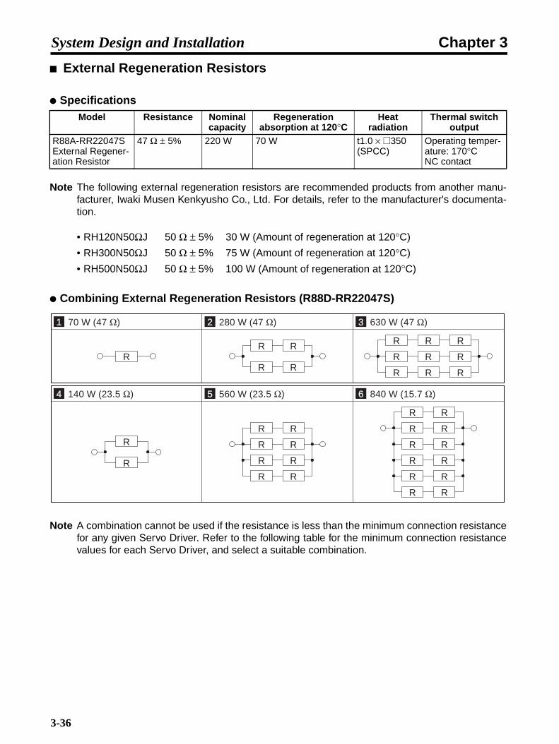
Chapter 3System Design and Installation
External Regeneration Resistors
Specifications
Note The following external regeneration resistors are recommended products from another manu-facturer, Iwaki Musen Kenkyusho Co., Ltd. For details, refer to the manufacturer's documenta-tion.
• RH120N50ΩJ 50 Ω ± 5% 30 W (Amount of regeneration at 120°C)
• RH300N50ΩJ 50 Ω ± 5% 75 W (Amount of regeneration at 120°C)
• RH500N50ΩJ 50 Ω ± 5% 100 W (Amount of regeneration at 120°C)
Combining External Regeneration Resistors (R88D-RR22047S)
Note A combination cannot be used if the resistance is less than the minimum connection resistancefor any given Servo Driver. Refer to the following table for the minimum connection resistancevalues for each Servo Driver, and select a suitable combination.
Model Resistance Nominal capacity
Regeneration absorption at 120°C
Heat radiation
Thermal switch output
R88A-RR22047S External Regener-ation Resistor
47 Ω ± 5% 220 W 70 W t1.0 × @350 (SPCC)
Operating temper-ature: 170°CNC contact
1 70 W (47 Ω) 2 280 W (47 Ω) 3 630 W (47 Ω)
RR R
R R
R R
R
R
R RR
R R
4 140 W (23.5 Ω) 5 560 W (23.5 Ω) 6 840 W (15.7 Ω)
R
RR R
R R
R R
R R
R
R
R
RR
R
RR
RR
RR
3-36

Chapter 3System Design and Installation
Servo Driver Minimum Connection Resistance and External Regeneration Resistor Combinations
Wiring External Regeneration Resistance
R88D-WNA5L-ML2/01L-ML2/02L-ML2/04L-ML2/A5H-ML2/01H-ML2/02H-ML2/04H-ML2
Connect an External Regeneration Resistor between the B1 and B2 terminals.
Note When using the R88A-RR22047S, connect the thermal switch output so that the power supplywill be shut off when open.
R88D-WN05H-ML2/08H-ML2/10H-ML2/20H-ML2/30H-ML2Remove the short-circuit wiring between B2 and B3, and then connect an External RegenerationResistor between the B1 and B2 terminals.
Note 1. The short-circuit wiring between B2 and B3 must be removed.
Note 2. When using the R88A-RR22047S, connect the thermal switch output so that the power sup-ply will be shut off when open.
Servo Driver Minimum Connection Resistance (Ω)
External Regeneration Resistor Combinations
R88D-WNA5L-ML2 to WN01L-ML2 40 1
R88D-WN02L-ML2 to WN04L-ML2 40 1, 2
R88D-WNA5H-ML2 to WN01H-ML2 40 1
R88D-WN02H-ML2 to WN04H-ML2 40 1, 2
R88D-WN05H-ML2 to WN10H-ML2 40 1, 2, 3
R88D-WN15H-ML2 20 1, 2, 3, 4, 5
R88D-WN20H-ML2 to WN30H-ML2 12 1, 2, 3, 4, 5, 6
Servo DriverB2
External Regeneration ResistorB1/
External Regeneration Resistor
Servo Driver B2
B3 ← Remove
B1/
3-37
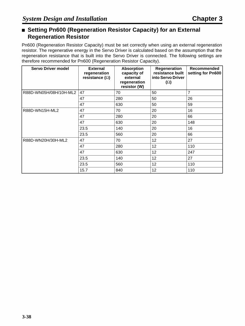
Chapter 3System Design and Installation
Setting Pn600 (Regeneration Resistor Capacity) for an External Regeneration Resistor
Pn600 (Regeneration Resistor Capacity) must be set correctly when using an external regenerationresistor. The regenerative energy in the Servo Driver is calculated based on the assumption that theregeneration resistance that is built into the Servo Driver is connected. The following settings aretherefore recommended for Pn600 (Regeneration Resistor Capacity).
Servo Driver model External regeneration
resistance (Ω)
Absorption capacity of
external regeneration resistor (W)
Regeneration resistance built
into Servo Driver (Ω)
Recommended setting for Pn600
R88D-WN05H/08H/10H-ML2 47 70 50 7
47 280 50 26
47 630 50 59
R88D-WN15H-ML2 47 70 20 16
47 280 20 66
47 630 20 148
23.5 140 20 16
23.5 560 20 66
R88D-WN20H/30H-ML2 47 70 12 27
47 280 12 110
47 630 12 247
23.5 140 12 27
23.5 560 12 110
15.7 840 12 110
3-38

Chapter 3System Design and Installation
3-4 Adjustments and Dynamic Braking When Load Inertia Is Large
The value that is given for the Servomotor's applicable load inertia is the value that willnot damage the Servo Driver's internal circuits (dynamic brake circuit, regenerativecircuit, etc.) when control is basically stable and the operating status is normal. Whenthe Servomotor is used at the applicable load inertia or below, there are certainoperating conditions and precautions that must be observed when making adjustmentsand using the dynamic brake. For details on regenerative energy processing, refer to3-3 Regenerative Energy Absorption.
3-4-1 Adjustments When Load Inertia Is LargeOperation is possible with a large load inertia as long as the load torque is within a range that allowsServo Driver control (i.e., no larger than the rated torque and within the electronic thermal range:these depend on the motor speed and acceleration/deceleration). If the load inertia ratio is large,however, adjustment becomes difficult using only the rigidity setting and autotuning, as shown below.The following table lists the adjustment criteria according to the load inertia.
3-4-2 Dynamic Braking When Load Inertia Is LargeDynamic braking is used to brake the Servomotor by consuming rotational energy using a resistor.The Servomotor's rotational energy can be found by using the following equation.
Servomotor rotational energy - (1/2 × J × ω2) = 1/2 × J × (2 × π)2 × (N/60)2
J: Load inertia + Servomotor rotor inertia
N: Servomotor speed [r/min]
Therefore, if the load inertia ratio is large and the motor speed is high, the load on the dynamic brakecircuit will be great and there will be a risk of burnout. Burnout may also occur if the dynamic brake isused repeatedly within a short period of time. Do not use the dynamic brake under conditions wherethe maximum speeds or load inertia ratios shown in the following table are exceeded. For operatingconditions other than these, use the following equation: 1/2 × J × ω2 = Constant.
Load inertia ratio Adjustment criteriaBelow 500% Adjustment is possible using mainly the factory settings or the rigidity setting function
(Fn001).
500% to 1,000% Adjustment is possible using mainly the rigidity setting and autotuning.
1,000% to 3,000% Adjustment may be possible using the rigidity setting and autotuning, but it may be nec-essary to manually adjust settings such as the gain.
Above 3,000% Adjustment will be difficult using the rigidity setting and autotuning. Set the load inertia based on mechanism settings, and manually adjust the gain.
3-39

Chapter 3System Design and Installation
For Servomotors of 1.5 kW or less, observe the following precautions if there is a possibility of thepower being turned ON while the Servomotor is rotating.
In Servomotors of 1.5 kW or less, the dynamic brake circuit uses a relay. Normally, if an alarm occurswhile the Servo is OFF, the dynamic brake operates according to the function selection applicationswitch (Pn001.0, 1) when drive prohibition is being input. At 1.5 kW or less, however, the dynamicbrake operates regardless of this setting even if the main circuit power supply or the control powersupply is OFF.
Current flows to the relay while the dynamic brake is operating. If 2 (Stop Servomotor by free run) isselected for the function selection application switch (Pn001.0: Stop selection for alarm generationwith Servo OFF), the relay turns OFF when the power is turned ON again.
If the power is turned from OFF to ON while the Servomotor is rotating, the relay operates while cur-rent is flowing to it. This may cause the relay contacts to fuse.
For Servomotors of 1.5 kW or less, if there is a possibility of the power being turned ON during Ser-vomotor rotation, either set 0 (Stop Servomotor by dynamic brake) for the function selection applica-tion switch (Pn001.0: Stop selection for alarm generation with Servo OFF) or make sure that thepower will not be turned ON until the Servomotor has stopped.
Servomotor Load inertia ratio3,000-r/min Servomotors, 30 to 400 W 3,000% max.
3,000-r/min Servomotors, 750 W 2,000% max.
3,000-r/min Servomotors, 1 k to 3 kW 1,000% max.
3,000-r/min Flat-type Servomotors, 100 W 2,500% max.
3,000-r/min Flat-type Servomotors, 200 W or 400 W 1,500% max.
3,000-r/min Flat-type Servomotors, 750 W or 1.5 kW 1,000% max.
1,000-r/min Servomotors, 300 W to 2 kW 1,000% max.
1,500-r/min Servomotors, 450 W to 1.8 kW 1,000% max.
3-40

Chapter 4
Operation
4-1 Operational Procedure
4-2 Preparing for Operation
4-3 User Parameters
4-4 Operation Functions
4-5 Trial Operation Procedure
4-6 Making Adjustments
4-7 Advanced Adjustment Functions
4-8 Using Displays
4-9 Using Monitor Output

Chapter 4Operation
Precautions
!Caution Confirm that there will be no effect on the equipment, and then perform a testoperation. Not doing so may result in equipment damage.
!Caution Check the newly set parameters for proper execution before actually runningthem. Not doing so may result in equipment damage.
!Caution Do not make any extreme adjustments or setting changes. Doing so may result inunstable operation and injury.
!Caution Separate the Servomotor from the machine, check for proper operation, and thenconnect to the machine. Not doing so may cause injury.
!Caution When an alarm occurs, remove the cause, reset the alarm after confirming safety,and then resume operation. Not doing so may result in injury.
!Caution Do not use the built-in brake of the Servomotor for ordinary braking. Doing so mayresult in a malfunction.
4-2

Chapter 4Operation
4-1 Operational Procedure
After mounting, wiring, and connecting a power supply, check the operation of theServomotor and Servo Driver. Then make the function settings as required accordingto the use of the Servomotor and Servo Driver. If the parameters are set incorrectly,there is a risk of an unforeseen Servomotor operation. Set the parameters inaccordance with the instructions in this manual.
1.Mounting and installationInstall the Servomotor and Servo Driver according to the installation conditions. (Do not connectthe Servomotor to the mechanical system before checking the no-load operation.) Refer to 3-1 In-stallation Conditions.
2.Wiring and connectionsConnect to power supply and peripheral devices. Specified installation and wiring requirementsmust be satisfied, particularly for models conforming to the EC Directives. Refer to 3-2 Wiring.
3.Preparing for operationBefore turning ON the power supply, check the necessary items. Check by means of the displaysto see whether there are any internal errors in the Servo Driver. If using a Servomotor with an ab-solute encoder, first set up the absolute encoder. Refer to 4-4-2 Speed Control (Speed).
4.Checking operationCheck the operation of the Servomotor and Servo Driver alone by performing a jogging operationwithout a load. Refer to 4-4-5 Encoder Dividing Function (All Operating Modes).
5.Function settingsBy means of the user parameters, set the functions according to the operating conditions. Referto 4-4-3 Torque Control (Torque) and 4-4-4 Forward and Reverse Drive Prohibit (All OperatingModes).
6.Trial operationTurn the power OFF then ON again to enable the parameter settings. If using a Servomotor withan absolute encoder, set up the absolute encoder and set the Motion Control Unit's initial param-eters. Turn ON the power, and check to see whether protective functions such as emergency stopand operational limits are working reliably. Check operation at both low speed and high speed (us-ing instructions from the Host Controller). Refer to 4-4-5 Encoder Dividing Function (All OperatingModes).
7.Adjustments Manually adjust the gain as required. Further adjust the various functions to further improve thecontrol performance as required. Refer to 4-4-6 Brake Interlock (All Operating Modes) and 4-4-7Torque Limit Function (All Operating Modes).
8.OperationOperation can now begin. If any trouble should occur, refer to Chapter 5 Troubleshooting.
4-3

Chapter 4Operation
4-2 Preparing for Operation
This section explains the procedure following installation and wiring of the Servomotorand Servo Driver, to prepare the mechanical system for operation. It explains what youneed to check both before and after turning ON the power. It also explains the setupprocedure required if using a Servomotor with an absolute encoder.
4-2-1 Turning Power ON and Checking Indicators
Items to Check Before Turning ON the Power
Checking Power Supply Voltage• Check to be sure that the power supply voltage is within the ranges shown below.
R88D-WN@L-ML2 (Single-phase 100 V AC input)
Main-circuit power supply: Single-phase 100/115 V AC (85 to 127 V) 50/60 HzControl-circuit power supply: Single-phase 100/115 V AC (85 to 127 V) 50/60 Hz
R88D-WNA5H-ML2/01H-ML2/02H-ML2/04H-ML2/08H-ML2 (Single-phase 200 V AC input)
Main-circuit power supply: Single-phase 200/230 V AC (170 to 253 V) 50/60 HzControl-circuit power supply: Single-phase 200/230 V AC (170 to 253 V) 50/60 Hz
R88D-WN05H-ML2/10H-ML2/15H-ML2/20H-ML2/30H-ML2 (Three-phase 200 V AC input)
Main-circuit power supply: Three-phase 200/230 V AC (170 to 253 V) 50/60 HzControl-circuit power supply: Single-phase 200/230 V AC (170 to 253 V) 50/60 Hz
Checking Terminal Block Wiring• The main-circuit power supply inputs (L1/L2 or L1/L2/L3) and the control-circuit power supply inputs
(L1C/L2C) must be properly connected to the terminal block.
• The Servomotor's red (U), white (V), and blue (W) power lines and the yellow/green ground wire( ) must be properly connected to the terminal block.
Checking the Servomotor• There should be no load on the Servomotor. (Do not connect to the mechanical system.)
• The power lines at the Servomotor must be securely connected.
Checking the Encoder Connectors• The Encoder Cable must be securely connected to the Encoder Connector (CN2) at the Servo
Driver.
• The Encoder Cable must be securely connected to the Encoder Connector at the Servomotor.
Checking the I/O Connector• The I/O Signal Cable must be securely connected to the I/O Connector (CN1).
4-4

Chapter 4Operation
Checking the MECHATROLINK-II Connections• The MECHATROLINK-II Connector must be securely connected to the MECHATROLINK-II Con-
nector at the host controller.
• The MECHATROLINK-II Cable must be securely connected to the MECHATROLINK-II Connector(CN6) at the Servo Driver.
• The termination resistance must be securely connected to the final Servo Driver.
Turning ON Power• First carry out the preliminary checks, and then turn ON the control-circuit power supply. It makes
no difference whether or not the main-circuit power supply is also turned ON.
• The ALM output will take approximately 2 seconds to turn ON after the power has been turned ON.Do not attempt to detect an alarm using the Host Controller during this time (when power is beingsupplied with the Host Controller connected).
Checking Displays• When the power is turned ON, one of the codes shown below will be displayed at either the indica-
tors or the Parameter Unit.
Note 1. The alarm code (the number shown in the alarm display) changes depending on the con-tents of the error.
Note 2. When using a Servomotor with an absolute encoder for the first time, A.810 (backup error)will be displayed. Clear this error by setting up the absolute encoder. (Refer to 4-2-2 Abso-lute Encoder Setup and Battery Changes).
• If the display is normal (i.e., no errors), manually turn the Servomotor shaft forward and reverse,and check to be sure that it agrees with the positive and negative on the speed display. Display thespeed feedback with the Computer Monitor Software and manually turn the Servomotor shaft for-ward and reverse.
Panel Operator Status Display• Status Display (Bit Data)
Normal Error (Alarm Display)
Item Bit data Display contents(1) Servomotor rotation detection Lit while Servomotor is rotating.
(2) Servo ON/OFF Lit when Servo is OFF.Unlit when Servo is ON.
(3) Command input detection Lit while a command is being input.
(4) CONNECT Lit when CONNECT is complete.
Bit data
(1)(2)(3)
(4)
4-5

Chapter 4Operation
• Code Display
• Codes are displayed one character at a time on the Servo Driver's front panel display, as shownbelow.
Example:When both forward rotation drive prohibit (P) and reverse rotation drive prohibit (n) areON:
Example:A.E60
4-2-2 Absolute Encoder Setup and Battery Changes
You must set up the absolute encoder if using a Servomotor with an absolute encoder.Perform the setup if connecting a Battery Unit (R88A-BAT01W) to an absolute encoderfor the first time, or when setting the mechanical rotation data to 0 for a trial operation.For the absolute encoder setup, refer to Computer Monitor Software procedure.
Cases where Setup is Required
During Trial OperationThe absolute encoder's multi-turn data may become too large when connecting the Servomotor tothe mechanical system for trial operation, so the setup must be executed again.
When Replacing the Battery UnitThe setup must be executed again if an alarm (A.810) occurs after the Battery Unit has beenreplaced.
Code DetailsForward rotation drive prohibited (POT is OFF) or the forward software limit has been exceeded.
Reverse rotation drive prohibited (NOT is OFF) or the reverse software limit has been exceeded.
@@ Alarm display (Refer to 5-2 Alarms.)
Status display
Status display
(bit data)
Code display
Not lit Not lit Not lit
(bit data)
Status display Not lit Not lit Not lit Not lit Not lit
4-6
Chapter 4Operation
Note If no alarm occurs after the Battery Unit has been replaced, there is no need to execute thesetup again or to initialize the Motion Control Unit settings.For details on the Battery Units service life and replacement method, refer to 5-6 Replacing theAbsolute Encoder Battery (ABS).
Other Cases• If the Encoder Cable is removed from the connector (on either the Servo Driver or Servomotor
side), the data within the absolute encoder will be cleared. In this case, perform the setup onceagain.
• If the Battery Unit has completely worn down, the data within the absolute encoder will be cleared.In this case, replace the Battery Unit and perform the setup once again.
4-7

Chapter 4Operation
4-3 User Parameters
Set and check the user parameters using the Setting Mode. Make sure you fullyunderstand the parameter meanings and how to set them before setting userparameters in the system. Some parameters are enabled by turning OFF the Unit, thenturning it ON again. When changing these parameters, turn OFF the power (check thatthe power lamp is not lit), then turn ON the power again.
4-3-1 Parameter Tables• Some parameters are enabled by turning OFF the Unit, then turning it ON again. (See the tables
below.) When changing these parameters, turn OFF the power (check that the power lamp is notlit), then turn ON the power again.
• The specific digit number of a parameter for which each digit number must be set separately is dis-played in the table with “.0" added to the digit number. For example, Pn001.0 (i.e., digit No. 0 ofparameter No. Pn001).
• The default setting for parameters set using 5 digits are displayed in the table with the leftmost dig-its not shown if they are 0 (e.g., if the default setting is 00080, 80 is entered in the table).
• Do not set parameters or digit numbers shown as “Not used.”
Function Selection Parameters (from Pn000)Param-eter No.
Parame-ter
name
Digit No.
Name Setting Explanation Default setting
Unit Setting range
Restart power?
Pn000 Func-tion selec-tion basic switches
0 Reverse rota-tion
0 CCW direction is taken for positive com-mand
0000 --- --- Yes
1 CW direction is taken for positive com-mand
2 to 3 Not used.
1 Not used. 0 (Do not change setting.)
2 Unit No. set-ting
0 to F Servo Driver communications unit num-ber setting (necessary for multiple Servo Driver connections when using personal computer monitoring software)
3 Not used. 0 (Do not change setting.)
Pn001 Func-tion selec-tion applica-tion switches 1
0 Stop selec-tion if an alarm occurs when Servo-motor is OFF
0 Servomotor stopped by dynamic brake. 0002 --- --- Yes
1 Dynamic brake OFF after Servomotor stopped
2 Servomotor stopped with free run
1 Stop selec-tion when drive prohib-ited is input
0 Stop according to Pn001.0 setting (release Servomotor after stopping)
1 Stop Servomotor using torque set in Pn406, and lock Servomotor after stop-ping
2 Stop Servomotor using torque set in Pn406, and release Servomotor after stopping
2 AC/DC power input selection
0 AC power supply: AC power supplied from L1, L2, (L3) terminals
1 DC power supply: DC power from +, −(2) terminals
3 Not used. 0 (Do not change setting.)
4-8

Chapter 4Operation
Pn002 Func-tion selec-tion applica-tion switches 2
0 Torque com-mand input change (dur-ing speed control)
0 Do not use option command value. 0000 --- --- Yes
1 Use option command value 1 as the torque limit value.
2 Use option command value 1 as the torque feed forward command value.
3 Use option command value 1 or 2 as the torque limit value, according to the for-ward and reverse torque limits that are specified.
1 Speed com-mand input change (dur-ing torque control)
0 Do not use option command value.
1 Use option command value 1 as the speed limit value.
2 Operation switch when using abso-lute encoder
0 Use as absolute encoder
1 Use as incremental encoder
3 Not used. 0 (Do not change setting.)
Pn004 Func-tion selec-tion applica-tion switches 4
0 Not used. 0 (Do not change setting.) 0110 --- --- Yes
1 Not used. 1 (Do not change setting.)
2 Not used. 1 (Do not change setting.)
3 Not used. 0 (Do not change setting.)
Pn006 Func-tion selec-tion applica-tion switches 6
0 to 1 Analog moni-tor 1 (AM) signal selec-tion
00 Servomotor rotation speed: 1V/1000 r/min
0002 --- --- ---
01 Speed command: 1 V/1000 r/min
02 Torque command: gravity compensation torque (Pn422)(1 V per 100%)
03 Position deviation: 0.05 V/1 command unit
04 Position amp error (after electronic gear) (0.05 V per encoder pulse unit)
05 Position command speed (1 V/1,000 r/min)
06 Not used.
07 Not used.
08 Positioning completed command (Positioning completed: 5 V; positioning not completed: 0 V
09 Speed feed forward (1 V/1,000 r/min)
0A Torque feed forward (1 V per 100%)
0B to 1F Not used.
2 Analog moni-tor 1 signal multiplier selection
0 1x
1 10x
2 100x
3 1/10x
4 1/100x
3 Not used. 0 (Do not change setting.)
Param-eter No.
Parame-ter
name
Digit No.
Name Setting Explanation Default setting
Unit Setting range
Restart power?
4-9

Chapter 4Operation
Servo Gain Parameters (from Pn100)
Pn007 Func-tion selec-tion applica-tion switches 7
0 to 1 Analog moni-tor 2 (NM) signal selec-tion
00 Servomotor rotation speed: 1V/1000 r/min
0000 --- --- ---
01 Speed command: 1 V/1000 r/min
02 Torque command: gravity compensation torque (Pn422)(1 V per 100%)
03 Position deviation: 0.05 V/1 command unit
04 Position amp error (after electronic gear) (0.05 V per encoder pulse unit)
05 Position command speed (1 V/1,000 r/min)
06 Not used.
07 Not used.
08 Positioning completed command(Positioning completed: 5 V; positioning not completed: 0 V
09 Speed feed forward (1 V/1,000 r/min)
0A Torque feed forward (1 V per 100%)
0B to 1F Not used.
2 Analog moni-tor 2 signal multiplier selection
0 1x
1 10x
2 100x
3 1/10x
4 1/100x
3 Not used. 0 (Do not change setting.)
Pn008 Func-tion selec-tion applica-tion switches 8
0 Lowered bat-tery voltage alarm/warn-ing selection
0 Regard battery voltage drop as alarm (A.830).
4000 --- --- Yes
1 Regard battery voltage drop as warning (A.930).
1 Not used. 0 (Do not change setting.)
2 Warning detection selection
0 Warnings detected.
1 Warnings not detected.
3 Not used. 4 (Do not change setting.)
Param-eter No.
Parameter name
Explanation (See note 1.) Default setting
Unit Setting range
Restart power?Digit
No.Name Setting Explanation (See note 2.)
Pn100 Speed loop gain
Adjusts speed loop response. 800 × 0.1 Hz 10 to 20000
---
Pn101 Speed loop integration constant
Speed loop integral time constant 2000 × 0.01 ms 15 to 51200
---
Pn102 Position loop gain
Adjusts position loop response. 400 × 0.1/s 10 to 20000
---
Pn103 Inertia ratio Set using the ratio between the machine system inertia and the Ser-vomotor rotor inertia.
300 % 0 to 20000
---
Pn104 Speed loop gain 2
Adjusts speed loop response (enabled by gain switching input). 800 × 0.1 Hz 10 to 20000
---
Pn105 Speed loop integration constant 2
Speed loop integral time constant (enabled by gain switching input). 2000 × 0.01 ms 15 to 51200
---
Pn106 Position loop gain 2
Adjusts position loop response (enabled by gain switching input). 400 × 0.1/s 10 to 20000
---
Pn107 Bias rota-tional speed
Sets position control bias. 0 r/min 0 to 450 ---
Param-eter No.
Parame-ter
name
Digit No.
Name Setting Explanation Default setting
Unit Setting range
Restart power?
4-10
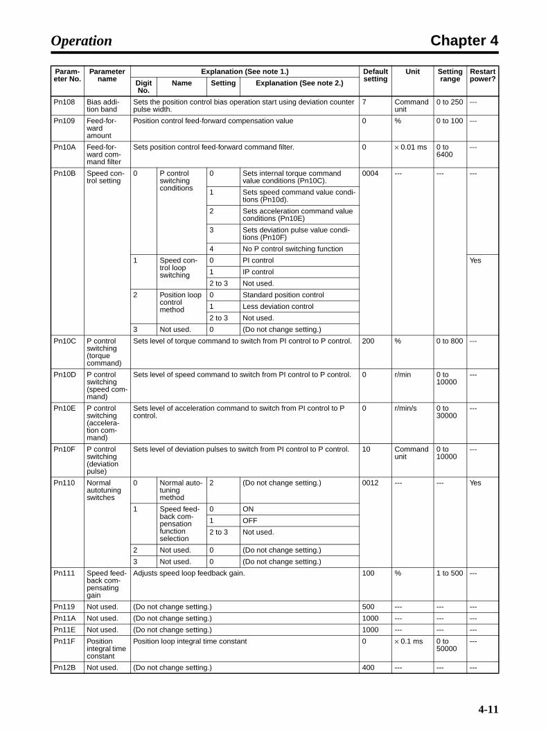
Chapter 4Operation
Pn108 Bias addi-tion band
Sets the position control bias operation start using deviation counter pulse width.
7 Command unit
0 to 250 ---
Pn109 Feed-for-ward amount
Position control feed-forward compensation value 0 % 0 to 100 ---
Pn10A Feed-for-ward com-mand filter
Sets position control feed-forward command filter. 0 × 0.01 ms 0 to 6400
---
Pn10B Speed con-trol setting
0 P control switching conditions
0 Sets internal torque command value conditions (Pn10C).
0004 --- --- ---
1 Sets speed command value condi-tions (Pn10d).
2 Sets acceleration command value conditions (Pn10E)
3 Sets deviation pulse value condi-tions (Pn10F)
4 No P control switching function
1 Speed con-trol loop switching
0 PI control Yes
1 IP control
2 to 3 Not used.
2 Position loop control method
0 Standard position control
1 Less deviation control
2 to 3 Not used.
3 Not used. 0 (Do not change setting.)
Pn10C P control switching (torque command)
Sets level of torque command to switch from PI control to P control. 200 % 0 to 800 ---
Pn10D P control switching (speed com-mand)
Sets level of speed command to switch from PI control to P control. 0 r/min 0 to 10000
---
Pn10E P control switching (accelera-tion com-mand)
Sets level of acceleration command to switch from PI control to P control.
0 r/min/s 0 to 30000
---
Pn10F P control switching (deviation pulse)
Sets level of deviation pulses to switch from PI control to P control. 10 Command unit
0 to 10000
---
Pn110 Normal autotuning switches
0 Normal auto-tuning method
2 (Do not change setting.) 0012 --- --- Yes
1 Speed feed-back com-pensation function selection
0 ON
1 OFF
2 to 3 Not used.
2 Not used. 0 (Do not change setting.)
3 Not used. 0 (Do not change setting.)
Pn111 Speed feed-back com-pensating gain
Adjusts speed loop feedback gain. 100 % 1 to 500 ---
Pn119 Not used. (Do not change setting.) 500 --- --- ---
Pn11A Not used. (Do not change setting.) 1000 --- --- ---
Pn11E Not used. (Do not change setting.) 1000 --- --- ---
Pn11F Position integral time constant
Position loop integral time constant 0 × 0.1 ms 0 to 50000
---
Pn12B Not used. (Do not change setting.) 400 --- --- ---
Param-eter No.
Parameter name
Explanation (See note 1.) Default setting
Unit Setting range
Restart power?Digit
No.Name Setting Explanation (See note 2.)
4-11

Chapter 4Operation
Pn12C Not used. (Do not change setting.) 2000 --- --- ---
Pn12D Not used. (Do not change setting.) 400 --- --- ---
Pn12E Not used. (Do not change setting.) 400 --- --- ---
Pn12F Not used. (Do not change setting.) 2000 --- --- ---
Pn130 Not used. (Do not change setting.) 400 --- --- ---
Pn131 Gain switch-ing time 1
Switching time from No. 1 gain to No. 2 gain 0 ms 0 to 65535
---
Pn132 Gain switch-ing time 2
Switching time from No. 2 gain to No. 1 gain 0 ms 0 to 65535
---
Pn135 Gain switch-ing waiting time 1
The time from when gain switching condition A is satisfied until switching from the No. 1 gain to the No. 2 gain begins.
0 ms 0 to 65535
---
Pn136 Gain switch-ing waiting time 2
The time from when gain switching condition B is satisfied until switching from the No. 2 gain to the No. 1 gain begins.
0 ms 0 to 65535
---
Pn139 Automatic gain changeover related switches 1
0 Gain switch-ing selection switch
0 Manual gain switching 0000 --- --- Yes
1 Automatic switching pattern 1Automatic switching from No. 1 gain to No. 2 gain when gain switching condition A is satisfied.Automatic switching from No. 2 gain to No. 1 gain when gain switching condition B is satisfied.
2 to 4 Not used.
1 Gain switch-ing condition A
0 Positioning completed output 1 (INP1) ON
1 Positioning completed output 1 (INP1) OFF
2 Positioning completed output 2 (INP2) ON
3 Positioning completed output 2 (INP2) OFF
4 The position command filter out-put is 0, and also the position com-mand input is 0.
5 The position command input is not 0.
2 Gain switch-ing condition B
0 to 5 Same as above.
3 Not used. 0 (Do not change setting.)
Pn144 Not used. (Do not change setting.) 1000 --- --- ---
Pn150 Predictive control selection switches
0 Predictive control selec-tion
0 Predictive control not used. 0210 --- --- Yes
1 Predictive control used.
2 Not used. (Do not change setting.)
1 Predictive control type
0 Predictive control for tracking
1 Predictive control for positioning
2 Not used. 2 (Do not change setting.)
3 Not used. 0 (Do not change setting.)
Pn151 Predictive control accelera-tion/deceler-ation gain
Adjusts acceleration and deceleration response for predictive control. 100 % 0 to 300 ---
Pn152 Predictive control weighting ratio
Adjusts position deviation for predictive control. 100 % 0 to 300 ---
Pn1A0 Servo rigid-ity
Adjusts the Servo rigidity for the No. 1 gain. 60 % 1 to 500 ---
Param-eter No.
Parameter name
Explanation (See note 1.) Default setting
Unit Setting range
Restart power?Digit
No.Name Setting Explanation (See note 2.)
4-12

Chapter 4Operation
Note 1. Explanation for parameters set using 5 digits.
Note 2. Explanation for parameters requiring each digit No. to be set separately.
Position Control Parameters (from Pn200)
Pn1A1 Servo rigid-ity 2
Adjusts the Servo rigidity for the No. 2 gain. 60 % 1 to 500 ---
Pn1A2 Speed feed-back filter time con-stant
Sets the filter time constant for No. 1 gain speed feedback. 72 × 0.01 ms 30 to 3200
---
Pn1A3 Speed feed-back filter time con-stant 2
Sets the filter time constant for No. 2 gain speed feedback. 72 × 0.01 ms 30 to 3200
---
Pn1A4 Torque com-mand filter time con-stant 2
Sets the filter time constant for the torque command. 36 × 0.01 ms 0 to 2500
---
Pn1A7 Utility con-trol switches
0 Integral com-pensation processing
0 Integral compensation processing not executed.
1121 --- --- ---
1 Integral compensation processing executed.
2 Integral compensation is executed for No. 1 gain and not for No. 2 gain for less-deviation gain switch-ing.
3 Integral compensation is executed for No. 2 gain and not for No. 1 gain for less-deviation gain switch-ing.
1 Not used. 2 (Do not change setting.)
2 Not used. 1 (Do not change setting.)
3 Not used. 1 (Do not change setting.)
Pn1A9 Utility inte-gral gain
Adjusts the auxiliary integral responsive. 37 Hz 0 to 500 ---
Pn1AA Position pro-portional gain
Adjusts the position proportional responsive. 60 Hz 0 to 500 ---
Pn1AB Speed inte-gral gain
Adjusts the speed integral responsive. 0 Hz 0 to 500 ---
Pn1AC Speed pro-portional gain
Adjusts the speed proportional responsive. 120 Hz 0 to 2000
---
Pn1B5 Not used. (Do not change setting.) 150 --- --- ---
Param-eter No.
Parame-ter name
Explanation Default setting
Unit Setting range
Restart power?Digit
No.Name Setting Explanation
Pn200 Not used. 0 Not used. 0 (Do not change setting.) 0100 --- --- Yes
1 Not used. 0 (Do not change setting.)
2 Not used. 1 (Do not change setting.)
3 Not used. 0 (Do not change setting.)
Pn205 Absolute encoder multi-turn limit set-ting
Sets the multi-turn limit for when a Servomotor with an absolute encoder is used.
65535 Rotation 0 to 65535 Yes
Param-eter No.
Parameter name
Explanation (See note 1.) Default setting
Unit Setting range
Restart power?Digit
No.Name Setting Explanation (See note 2.)
4-13
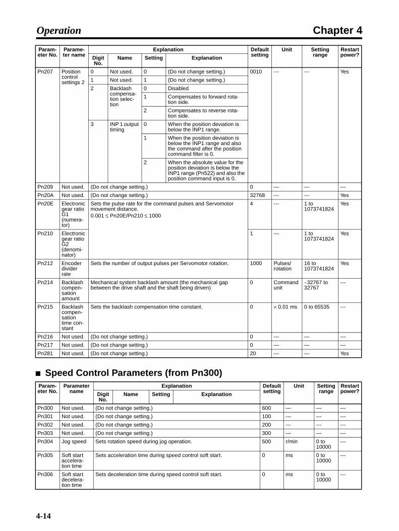
Chapter 4Operation
Speed Control Parameters (from Pn300)
Pn207 Position control settings 2
0 Not used. 0 (Do not change setting.) 0010 --- --- Yes
1 Not used. 1 (Do not change setting.)
2 Backlash compensa-tion selec-tion
0 Disabled
1 Compensates to forward rota-tion side.
2 Compensates to reverse rota-tion side.
3 INP 1 output timing
0 When the position deviation is below the INP1 range.
1 When the position deviation is below the INP1 range and also the command after the position command filter is 0.
2 When the absolute value for the position deviation is below the INP1 range (Pn522) and also the position command input is 0.
Pn209 Not used. (Do not change setting.) 0 --- --- ---
Pn20A Not used. (Do not change setting.) 32768 --- --- Yes
Pn20E Electronic gear ratio G1 (numera-tor)
Sets the pulse rate for the command pulses and Servomotor movement distance.0.001 ≤ Pn20E/Pn210 ≤ 1000
4 --- 1 to 1073741824
Yes
Pn210 Electronic gear ratio G2 (denomi-nator)
1 --- 1 to 1073741824
Yes
Pn212 Encoder divider rate
Sets the number of output pulses per Servomotor rotation. 1000 Pulses/rotation
16 to 1073741824
Yes
Pn214 Backlash compen-sation amount
Mechanical system backlash amount (the mechanical gap between the drive shaft and the shaft being driven)
0 Command unit
−32767 to 32767
---
Pn215 Backlash compen-sation time con-stant
Sets the backlash compensation time constant. 0 × 0.01 ms 0 to 65535 ---
Pn216 Not used. (Do not change setting.) 0 --- --- ---
Pn217 Not used. (Do not change setting.) 0 --- --- ---
Pn281 Not used. (Do not change setting.) 20 --- --- Yes
Param-eter No.
Parameter name
Explanation Default setting
Unit Setting range
Restart power?Digit
No.Name Setting Explanation
Pn300 Not used. (Do not change setting.) 600 --- --- ---
Pn301 Not used. (Do not change setting.) 100 --- --- ---
Pn302 Not used. (Do not change setting.) 200 --- --- ---
Pn303 Not used. (Do not change setting.) 300 --- --- ---
Pn304 Jog speed Sets rotation speed during jog operation. 500 r/min 0 to 10000
---
Pn305 Soft start accelera-tion time
Sets acceleration time during speed control soft start. 0 ms 0 to 10000
---
Pn306 Soft start decelera-tion time
Sets deceleration time during speed control soft start. 0 ms 0 to 10000
---
Param-eter No.
Parame-ter name
Explanation Default setting
Unit Setting range
Restart power?Digit
No.Name Setting Explanation
4-14

Chapter 4Operation
Torque Control Parameters (from Pn400)
Pn307 Not used. (Do not change setting.) 40 --- --- ---
Pn308 Speed feed-back filter time con-stant
Sets constant during filter of speed feedback. 0 × 0.01 ms 0 to 65535
---
Pn310 Vibration detection switches
0 Vibration detection selection
0 Vibration detection not used. 0000 --- --- ---
1 Gives warning (A.911) when vibra-tion is detected.
2 Gives warning (A.520) when vibra-tion is detected.
1 Not used. 0 (Do not change setting.)
2 Not used. 0 (Do not change setting.)
3 Not used. 0 (Do not change setting.)
Pn311 Vibration detection sensitivity
Sets the vibration detection sensitivity. 100 % 50 to 500
---
Pn312 Vibration detection level
Sets the vibration detection level 50 r/min 0 to 5000
---
Param-eter No.
Parameter name
Explanation Default setting
Unit Setting range
Restart power?Digit
No.Name Setting Explanation
Pn400 Not used. (Do not change setting.) 30 --- --- ---
Pn401 1st step 1st torque com-mand filter time con-stant
Sets the filter time constant for internal torque commands. 40 × 0.01 ms 0 to 65535
---
Pn402 Forward torque limit
Forward rotation output torque limit (rated torque ratio). 350 % 0 to 800 ---
Pn403 Reverse torque limit
Reverse rotation output torque limit (rated torque ratio). 350 % 0 to 800 ---
Pn404 Forward rotation external cur-rent limit
Output torque limit during input of forward rotation current limit (rated torque ratio)
100 % 0 to 800 ---
Pn405 Reverse rotation external cur-rent limit
Output torque limit during input of reverse rotation current limit (rated torque ratio)
100 % 0 to 800 ---
Pn406 Emergency stop torque
Deceleration torque when an error occurs (rated torque ratio) 350 % 0 to 800 ---
Pn407 Speed limit Sets the speed limit in torque control mode. 3000 r/min 0 to 10000
---
Pn408 Torque com-mand set-ting
0 Selects notch filter 1 func-tion.
0 Notch filter 1 not used. 0000 --- --- ---
1 Notch filter 1 used for torque com-mands.
1 Not used. 0 (Do not change setting.)
2 Selects notch filter 2 func-tion.
0 Notch filter 2 not used.
1 Notch filter 2 used for torque com-mands.
3 Not used. 0 (Do not change setting.)
Pn409 Notch filter 1 frequency
Sets notch filter 1 frequency for torque command. 2000 Hz 50 to 2000
---
Pn40A Notch filter 1 Q value
Sets Q value of notch filter 1. 70 × 0.01 50 to 1000
---
Pn40C Notch filter 2 frequency
Sets the notch filter 2 frequency for torque commands. 2000 Hz 50 to 2000
---
Param-eter No.
Parameter name
Explanation Default setting
Unit Setting range
Restart power?Digit
No.Name Setting Explanation
4-15

Chapter 4Operation
Sequence Parameters (from Pn500)
Pn40D Notch filter 2 Q value
Sets Q value of notch filter 2. 70 × 0.01 50 to 1000
---
Pn40F 2nd step 2nd torque command filter fre-quency
Sets the filter frequency for internal torque commands. 2000 Hz 100 to 2000
---
Pn410 2nd step 2nd torque command filter Q value
Sets the torque command filter Q value. 70 × 0.01 50 to 1000
---
Pn411 3rd step torque com-mand filter time con-stant
Sets the filter time constant for internal torque commands. 0 µs 0 to 65535
---
Pn412 1st step 2nd torque com-mand filter time con-stant
Sets the filter time constant for No. 2 gain internal torque commands. 100 × 0.01 ms 0 to 65535
---
Pn413 Not used. (Do not change setting.) 100 --- --- ---
Pn414 Not used. (Do not change setting.) 100 --- --- ---
Pn420 Damping for vibration suppres-sion on stopping
Sets the vibration suppression value while stopped. 100 % 10 to 100
---
Pn421 Vibration suppres-sion start-ing time
Sets the time from when the position command becomes 0 until damping for vibration suppression on stopping begins.
1000 ms 0 to 65535
---
Pn422 Gravity compensa-tion torque
Sets the gravity compensation torque. 0 × 0.01% −20000 to 20000
---
Pn456 Sweep torque com-mand ampli-tude
Sets the sweep torque command amplitude. 15 % 1 to 800 ---
Param-eter No.
Parame-ter name
Explanation Default setting
Unit Setting range
Restart power?Digit
No.Name Setting Explanation
Pn501 Not used. (Do not change setting.) 10 --- --- ---
Pn502 Rotation speed for motor rotation detection
Sets the number of rotations for the Servomotor rotation detection output (TGON).
20 r/min 1 to 10000 ---
Pn503 Speed confor-mity sig-nal output width
Sets the allowable fluctuation (number of rotations) for the speed conformity output (VCMP).
10 r/min 0 to 100 ---
Pn506 Brake tim-ing 1
Sets the delay from the brake command to the Servomotor turn-ing OFF.
0 × 10 ms 0 to 50 ---
Pn507 Brake command speed
Sets the number of rotations for outputting the brake command. 100 r/min 0 to 10000 ---
Pn508 Brake tim-ing 2
Sets the delay time from the Servomotor turning OFF to the brake command output.
50 × 10 ms 10 to 100 ---
Pn509 Momen-tary hold time
Sets the time during which alarm detection is disabled when a power failure occurs.
20 ms 20 to 1000 ---
Param-eter No.
Parameter name
Explanation Default setting
Unit Setting range
Restart power?Digit
No.Name Setting Explanation
4-16

Chapter 4Operation
Pn50A Input sig-nal selec-tions 1
0 Not used. 1 (Do not change setting.) 1881 --- --- Yes
1 Not used. 8 (Do not change setting.)
2 Not used. 8 (Do not change setting.)
3 POT (for-ward drive prohibited input) sig-nal Input terminal allocation
0 Allocated to CN1, pin 13: Valid for low input
1 Allocated to CN1, pin 7: Valid for low input
2 Allocated to CN1, pin 8: Valid for low input
3 Allocated to CN1, pin 9: Valid for low input
4 Allocated to CN1, pin 10: Valid for low input
5 Allocated to CN1, pin 11: Valid for low input
6 Allocated to CN1, pin 12: Valid for low input
7 Always enabled.
8 Always disabled.
9 Allocated to CN1, pin 13: Valid for high input
A Allocated to CN1, pin 7: Valid for high input
B Allocated to CN1, pin 8: Valid for high input
C Allocated to CN1, pin 9: Valid for high input
D Allocated to CN1, pin 10: Valid for high input
E Allocated to CN1, pin 11: Valid for high input
F Allocated to CN1, pin 12: Valid for high input
Pn50B Input sig-nal selec-tions 2
0 NOT (reverse drive prohib-ited input) signal Input terminal allocation
0 to F Same as Pn50A.3.NOT (reverse drive prohibited) signal allocation
8882 --- --- Yes
1 Not used. 8 (Do not change setting.)
2 Not used. 8 (Do not change setting.)
3 Not used. 8 (Do not change setting.)
Pn50C Input sig-nal selec-tions 3
0 Not used. 8 (Do not change setting.) 8888 --- --- Yes
1 Not used. 8 (Do not change setting.)
2 Not used. 8 (Do not change setting.)
3 Not used. 8 (Do not change setting.)
Pn50D Input sig-nal selec-tions 4
0 Not used. 8 (Do not change setting.) 8888 --- --- Yes
1 Not used. 8 (Do not change setting.)
2 Not used. 8 (Do not change setting.)
3 Not used. 8 (Do not change setting.)
Param-eter No.
Parame-ter name
Explanation Default setting
Unit Setting range
Restart power?Digit
No.Name Setting Explanation
4-17
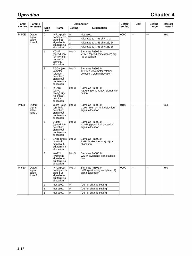
Chapter 4Operation
Pn50E Output signal selec-tions 1
0 INP1 (posi-tioning com-pleted 1) signal out-put terminal allocation
0 Not used. 0000 --- --- Yes
1 Allocated to CN1 pins 1, 2
2 Allocated to CN1 pins 23, 24
3 Allocated to CN1 pins 25, 26
1 VCMP (speed con-formity) sig-nal output terminal allocation
0 to 3 Same as Pn50E.0.VCMP (speed coincidence) sig-nal allocation
2 TGON (ser-vomotor rotation detection) signal out-put terminal allocation
0 to 3 Same as Pn50E.0.TGON (Servomotor rotation detection) signal allocation
3 READY (servo ready) sig-nal output terminal allocation
0 to 3 Same as Pn50E.0.READY (servo ready) signal allo-cation
Pn50F Output signal selec-tions 2
0 CLIMT (cur-rent limit detection) signal out-put terminal allocation
0 to 3 Same as Pn50E.0.CLIMT (current limit detection) signal allocation
0100 --- --- Yes
1 VLIMT (speed limit detection) signal out-put terminal allocation
0 to 3 Same as Pn50E.0.VLIMT (speed limit detection) signal allocation
2 BKIR (brake interlock) signal out-put terminal allocation
0 to 3 Same as Pn50E.0.BKIR (brake interlock) signal allocation.
3 WARN (warning) signal out-put terminal allocation
0 to 3 Same as Pn50E.0.WARN (warning) signal alloca-tion
Pn510 Output signal selec-tions 3
0 INP2 (posi-tioning com-pleted 2) signal out-put terminal allocation
0 to 3 Same as Pn50E.0.INP2 (positioning completed 2) signal allocation
0000 --- --- Yes
1 Not used. 0 (Do not change setting.)
2 Not used. 0 (Do not change setting.)
3 Not used. 0 (Do not change setting.)
Param-eter No.
Parame-ter name
Explanation Default setting
Unit Setting range
Restart power?Digit
No.Name Setting Explanation
4-18

Chapter 4Operation
Pn511 Input sig-nal selec-tions 5
0 DEC signal input termi-nal alloca-tion
0 Allocated to CN1, pin 13: Valid for low input
6543 --- --- Yes
1 Allocated to CN1, pin 7: Valid for low input
2 Allocated to CN1, pin 8: Valid for low input
3 Allocated to CN1, pin 9: Valid for low input
4 Allocated to CN1, pin 10: Valid for low input
5 Allocated to CN1, pin 11: Valid for low input
6 Allocated to CN1, pin 12: Valid for low input
7 Always enabled.
8 Always disabled.
9 Allocated to CN1, pin 13: Valid for high input
A Allocated to CN1, pin 7: Valid for high input
B Allocated to CN1, pin 8: Valid for high input
C Allocated to CN1, pin 9: Valid for high input
D Allocated to CN1, pin 10: Valid for high input
E Allocated to CN1, pin 11: Valid for high input
F Allocated to CN1, pin 12: Valid for high input
1 EXT1 sig-nal input ter-minal allocation
0 to 3 Always disabled.
4 Allocated to CN1, pin 10: Valid for low input
5 Allocated to CN1, pin 11: Valid for low input
6 Allocated to CN1, pin 12: Valid for low input
7 Always enabled.
8 Always disabled.
9 to C Always disabled.
D Allocated to CN1, pin 10: Valid for high input
E Allocated to CN1, pin 11: Valid for high input
F Allocated to CN1, pin 12: Valid for high input
2 EXT2 sig-nal input ter-minal allocation
0 to F Same as for Pn511.1.EXT2 signal allocation
3 EXT3 sig-nal input ter-minal allocation
0 to F Same as for Pn511.1.EXT3 signal allocation
Param-eter No.
Parame-ter name
Explanation Default setting
Unit Setting range
Restart power?Digit
No.Name Setting Explanation
4-19
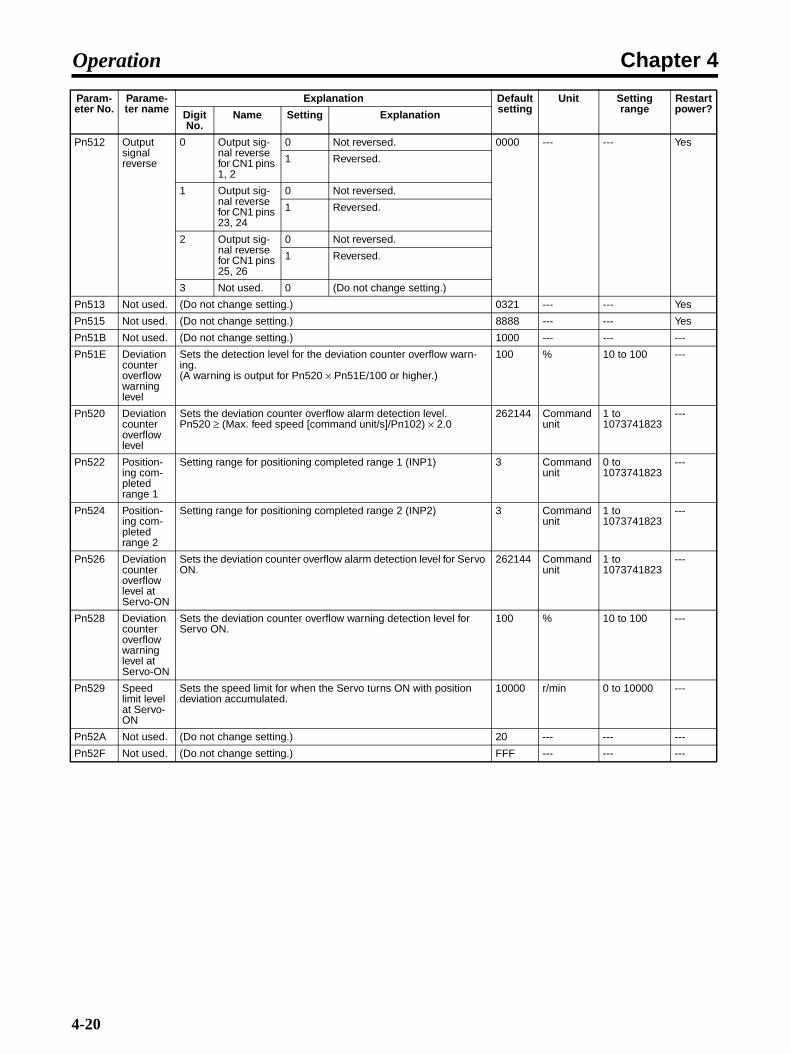
Chapter 4Operation
Pn512 Output signal reverse
0 Output sig-nal reverse for CN1 pins 1, 2
0 Not reversed. 0000 --- --- Yes
1 Reversed.
1 Output sig-nal reverse for CN1 pins 23, 24
0 Not reversed.
1 Reversed.
2 Output sig-nal reverse for CN1 pins 25, 26
0 Not reversed.
1 Reversed.
3 Not used. 0 (Do not change setting.)
Pn513 Not used. (Do not change setting.) 0321 --- --- Yes
Pn515 Not used. (Do not change setting.) 8888 --- --- Yes
Pn51B Not used. (Do not change setting.) 1000 --- --- ---
Pn51E Deviation counter overflow warning level
Sets the detection level for the deviation counter overflow warn-ing. (A warning is output for Pn520 × Pn51E/100 or higher.)
100 % 10 to 100 ---
Pn520 Deviation counter overflow level
Sets the deviation counter overflow alarm detection level.Pn520 ≥ (Max. feed speed [command unit/s]/Pn102) × 2.0
262144 Command unit
1 to 1073741823
---
Pn522 Position-ing com-pleted range 1
Setting range for positioning completed range 1 (INP1) 3 Command unit
0 to 1073741823
---
Pn524 Position-ing com-pleted range 2
Setting range for positioning completed range 2 (INP2) 3 Command unit
1 to 1073741823
---
Pn526 Deviation counter overflow level at Servo-ON
Sets the deviation counter overflow alarm detection level for Servo ON.
262144 Command unit
1 to 1073741823
---
Pn528 Deviation counter overflow warning level at Servo-ON
Sets the deviation counter overflow warning detection level for Servo ON.
100 % 10 to 100 ---
Pn529 Speed limit level at Servo-ON
Sets the speed limit for when the Servo turns ON with position deviation accumulated.
10000 r/min 0 to 10000 ---
Pn52A Not used. (Do not change setting.) 20 --- --- ---
Pn52F Not used. (Do not change setting.) FFF --- --- ---
Param-eter No.
Parame-ter name
Explanation Default setting
Unit Setting range
Restart power?Digit
No.Name Setting Explanation
4-20

Chapter 4Operation
Pn530 Program JOG oper-ation related switches
0 Program JOG operat-ing pattern
0 (Waiting time Pn535 → Forward movement Pn531) × Number of movement operations Pn536
0000 --- --- ---
1 (Waiting time Pn535 → Reverse movement Pn531) × Number of movement operations Pn536
2 (Waiting time Pn535 → Forward movement Pn531) × Number of movement operations Pn536(Waiting time Pn535 → Reverse movement Pn531) × Number of movement operations Pn536
3 (Waiting time Pn535 → Reverse movement Pn531) × Number of movement operations Pn536(Waiting time Pn535 → Forward movement Pn531) × Number of movement operations Pn536
4 (Waiting time Pn535 → Forward movement Pn531 → Waiting time Pn535 → Reverse move-ment Pn531) × Number of move-ment operations Pn536
5 (Waiting time Pn535 → Reverse movement Pn531 → Waiting time Pn535 → Forward move-ment Pn531) × Number of move-ment operations Pn536
1 Not used. 0 (Do not change setting.)
2 Not used. 0 (Do not change setting.)
3 Not used. 0 (Do not change setting.)
Pn531 Program JOG move-ment dis-tance
Sets the program JOG movement distance. 32768 Command unit
1 to 1073741824
---
Pn533 Program JOG move-ment speed
Sets the program JOG operation movement speed. 500 r/min 1 to 10000 ---
Pn534 Program JOG accelera-tion/decel-eration time
Sets the acceleration/deceleration time for program JOG opera-tion.
100 ms 2 to 10000 ---
Pn535 Program JOG wait-ing time
Sets the delay time from the program JOG operation start input until operation starts.
100 ms 0 to 10000 ---
Pn536 Number of program JOG move-ments
Sets the number of repetitions of the program JOG operations. 1 Times 1 to 1000 ---
Pn540 Gain limit Sets the gain limit. 2000 × 0.1 Hz 10 to 2000 ---
Pn550 Analog monitor 1 offset volt-age
Sets the analog monitor 1 offset voltage. 0 × 0.1 V −10000 to 10000
---
Pn551 Analog monitor 2 offset volt-age
Sets the analog monitor 2 offset voltage. 0 × 0.1 V −10000 to 10000
---
Param-eter No.
Parame-ter name
Explanation Default setting
Unit Setting range
Restart power?Digit
No.Name Setting Explanation
4-21

Chapter 4Operation
Other Parameters (from Pn600)Param-eter No.
Parame-ter name
Explanation Default setting
Unit Setting range
Restart power?Digit
No.Name Setting Explanation
Pn600 Regener-ation resistor capacity (See note 1.)
Setting for regeneration resistance load ratio monitoring calcula-tions
0 × 10 W 0 to (varies by model) (See note 2.)
---
Pn800 Communi-cations control
0 MECHA-TROLINK-II communica-tions check mask
0 Normal 0040 --- --- ---
1 Ignore communications errors (A.E6@).
2 Ignore WDT errors (A.E5@).
3 Ignore communications errors (A.E6@) and WDT errors (A.E5@).
1 Warning check mask
0 Normal
1 Ignore data setting warning (A. 94@).
2 Ignore command warning (A. 95@).
3 Ignore A.94@ and A.95@.
4 Ignore communications warn-ing (A. 96@).
5 Ignore A.94@ and A.96@.
6 Ignore A.95@ and A.96@.
7 Ignore A.94@, A.95@ and A.96@.
2 Communi-cations error count at sin-gle trans-mission
0 to F Detects communications errors (A.E60) if they occur consecu-tively for the set value plus two times.
3 Not used. 0 (Do not change setting.)
Pn801 Function selection applica-tion 6 (software LS)
0 Software limit function
0 Software limit enabled. 0003 --- --- ---
1 Forward software limit disabled.
2 Reverse software limit disabled.
3 Forward/reverse software limits disabled.
1 Not used. 0 (Do not change setting.)
2 Software limit check using refer-ence
0 No software limit check using reference
1 Software limit check using refer-ence
3 Not used. 0 (Do not change setting.)
Pn802 Not used. (Do not change setting.) 0000 --- --- ---
Pn803 Zero point width
Sets the origin position detection range. 10 Command unit
0 to 250 ---
Pn804 Forward software limit
Sets the software limit for the positive direction.Note: Pn806 must be set lower than Pn804.
819191808
Command unit
−1073741823 to 1073741823
---
Pn806 Reverse software limit
Sets the software limit for the negative direction.Note: Pn806 must be set lower than Pn804.
−819191808
Command unit
−1073741823 to 1073741823
---
Pn808 Absolute encoder zero point position offset
Sets the encoder position and machine coordinate system offsets for when an absolute encoder is used.
0 Command unit
−1073741823 to 1073741823
---
4-22

Chapter 4Operation
Pn80A First step linear accelera-tion parameter
Sets the step 1 acceleration for when two-step acceleration is used.
100 × 10000Command unit/s2
1 to 65535 ---
Pn80B Second step lin-ear accel-eration parameter
Sets the step 2 acceleration for when two-step acceleration is executed, or the one-step acceleration parameter for when one-step acceleration is executed.
100 × 10000Command unit/s2
1 to 65535 ---
Pn80C Accelera-tion parame-ter switch-ing speed
Sets the switching speed for the step 1 and step 2 acceleration when two-step acceleration is executed.Note: When used as one-step acceleration, 0 must be set.
0 × 100Command unit/s
0 to 65535 ---
Pn80D First step linear decelera-tion parameter
Sets the step 1 deceleration for when two-step deceleration is used.
100 × 10000Command unit/s2
1 to 65535 ---
Pn80E Second step lin-ear decel-eration parameter
Sets the step 2 deceleration for when two-step deceleration is executed, or the one-step deceleration parameter for when one-step deceleration is executed.
100 × 10000Command unit/s2
1 to 65535 ---
Pn80F Decelera-tion parame-ter switch-ing speed
Sets the switching speed for the step 1 and step 2 deceleration when two-step deceleration is executed.Note: When used as one-step acceleration, 0 must be set.
0 × 100Command unit/s
0 to 65535 ---
Pn810 Exponen-tial accel-eration/decelera-tion bias
Sets the bias for when an exponential filter is used for the posi-tion command filter.
0 Command unit/s
0 to 32767 ---
Pn811 Exponen-tial accel-eration/decelera-tion time constant
Sets the time constant for when an exponential filter is used for the position command filter.
0 × 0.1 ms 0 to 5100 ---
Pn812 Moving average time
Sets the average movement time for when S-curve acceleration/deceleration is used, and an average movement filter is used for the position command filter.
0 × 0.1 ms 0 to 5100 ---
Pn813 Not used. (Do not change setting.) (See note 3.) 0 --- --- ---
Pn814 Final travel dis-tance for external position-ing
Sets the distance from the external signal input position when external positioning is executed.Note: For a negative direction or if the distance is short, opera-tion is reversed after decelerating to a stop.
100 Command unit
−1073741823 to 1073741823
---
Pn816 Zero point return mode set-tings
0 Zero point return direc-tion
0 Forward direction 0000 --- --- ---
1 Reverse direction
1 Not used. 0 (Do not change setting.)
2 Not used. 0 (Do not change setting.)
3 Not used. 0 (Do not change setting.)
Pn817 Zero point return approach speed 1
Sets the origin search speed after the deceleration limit switch signal turns ON.
50 × 100Command unit/s
0 to 65535 ---
Pn818 Zero point return approach speed 2
Sets the origin search speed after the deceleration limit switch signal turns ON.
5 × 100Command unit/s
0 to 65535 ---
Param-eter No.
Parame-ter name
Explanation Default setting
Unit Setting range
Restart power?Digit
No.Name Setting Explanation
4-23
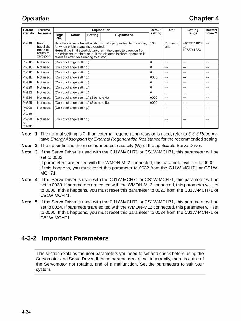
Chapter 4Operation
Note 1. The normal setting is 0. If an external regeneration resistor is used, refer to 3-3-3 Regener-ative Energy Absorption by External Regeneration Resistance for the recommended setting.
Note 2. The upper limit is the maximum output capacity (W) of the applicable Servo Driver.
Note 3. If the Servo Driver is used with the CJ1W-MCH71 or CS1W-MCH71, this parameter will beset to 0032. If parameters are edited with the WMON-ML2 connected, this parameter will set to 0000.If this happens, you must reset this parameter to 0032 from the CJ1W-MCH71 or CS1W-MCH71.
Note 4. If the Servo Driver is used with the CJ1W-MCH71 or CS1W-MCH71, this parameter will beset to 0023. If parameters are edited with the WMON-ML2 connected, this parameter will setto 0000. If this happens, you must reset this parameter to 0023 from the CJ1W-MCH71 orCS1W-MCH71.
Note 5. If the Servo Driver is used with the CJ1W-MCH71 or CS1W-MCH71, this parameter will beset to 0024. If parameters are edited with the WMON-ML2 connected, this parameter will setto 0000. If this happens, you must reset this parameter to 0024 from the CJ1W-MCH71 orCS1W-MCH71.
4-3-2 Important Parameters
This section explains the user parameters you need to set and check before using theServomotor and Servo Driver. If these parameters are set incorrectly, there is a risk ofthe Servomotor not rotating, and of a malfunction. Set the parameters to suit yoursystem.
Pn819 Final travel dis-tance to return to zero point
Sets the distance from the latch signal input position to the origin, for when origin search is executed.Note: If the final travel distance is in the opposite direction from the origin return direction or if the distance is short, operation is reversed after decelerating to a stop.
100 Command unit
−1073741823 to 1073741823
---
Pn81B Not used. (Do not change setting.) 0 --- --- ---
Pn81C Not used. (Do not change setting.) 0 --- --- ---
Pn81D Not used. (Do not change setting.) 0 --- --- ---
Pn81E Not used. (Do not change setting.) 0000 --- --- ---
Pn81F Not used. (Do not change setting.) 0 --- --- ---
Pn820 Not used. (Do not change setting.) 0 --- --- ---
Pn822 Not used. (Do not change setting.) 0 --- --- ---
Pn824 Not used. (Do not change setting.) (See note 4.) 0000 --- --- ---
Pn825 Not used. (Do not change setting.) (See note 5.) 0000 --- --- ---
Pn900 to Pn910
Not used. (Do not change setting.) --- --- ---
Pn920 to Pn95F
Not used. (Do not change setting.) --- --- ---
Param-eter No.
Parame-ter name
Explanation Default setting
Unit Setting range
Restart power?Digit
No.Name Setting Explanation
4-24
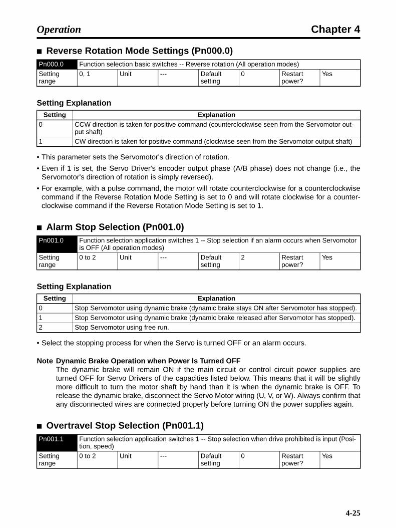
Chapter 4Operation
Reverse Rotation Mode Settings (Pn000.0)
Setting Explanation
• This parameter sets the Servomotor's direction of rotation.
• Even if 1 is set, the Servo Driver's encoder output phase (A/B phase) does not change (i.e., theServomotor's direction of rotation is simply reversed).
• For example, with a pulse command, the motor will rotate counterclockwise for a counterclockwisecommand if the Reverse Rotation Mode Setting is set to 0 and will rotate clockwise for a counter-clockwise command if the Reverse Rotation Mode Setting is set to 1.
Alarm Stop Selection (Pn001.0)
Setting Explanation
• Select the stopping process for when the Servo is turned OFF or an alarm occurs.
Note Dynamic Brake Operation when Power Is Turned OFFThe dynamic brake will remain ON if the main circuit or control circuit power supplies areturned OFF for Servo Drivers of the capacities listed below. This means that it will be slightlymore difficult to turn the motor shaft by hand than it is when the dynamic brake is OFF. Torelease the dynamic brake, disconnect the Servo Motor wiring (U, V, or W). Always confirm thatany disconnected wires are connected properly before turning ON the power supplies again.
Overtravel Stop Selection (Pn001.1)
Pn000.0 Function selection basic switches -- Reverse rotation (All operation modes)
Setting range
0, 1 Unit --- Default setting
0 Restart power?
Yes
Setting Explanation0 CCW direction is taken for positive command (counterclockwise seen from the Servomotor out-
put shaft)
1 CW direction is taken for positive command (clockwise seen from the Servomotor output shaft)
Pn001.0 Function selection application switches 1 -- Stop selection if an alarm occurs when Servomotor is OFF (All operation modes)
Setting range
0 to 2 Unit --- Default setting
2 Restart power?
Yes
Setting Explanation0 Stop Servomotor using dynamic brake (dynamic brake stays ON after Servomotor has stopped).
1 Stop Servomotor using dynamic brake (dynamic brake released after Servomotor has stopped).
2 Stop Servomotor using free run.
Pn001.1 Function selection application switches 1 -- Stop selection when drive prohibited is input (Posi-tion, speed)
Setting range
0 to 2 Unit --- Default setting
0 Restart power?
Yes
4-25
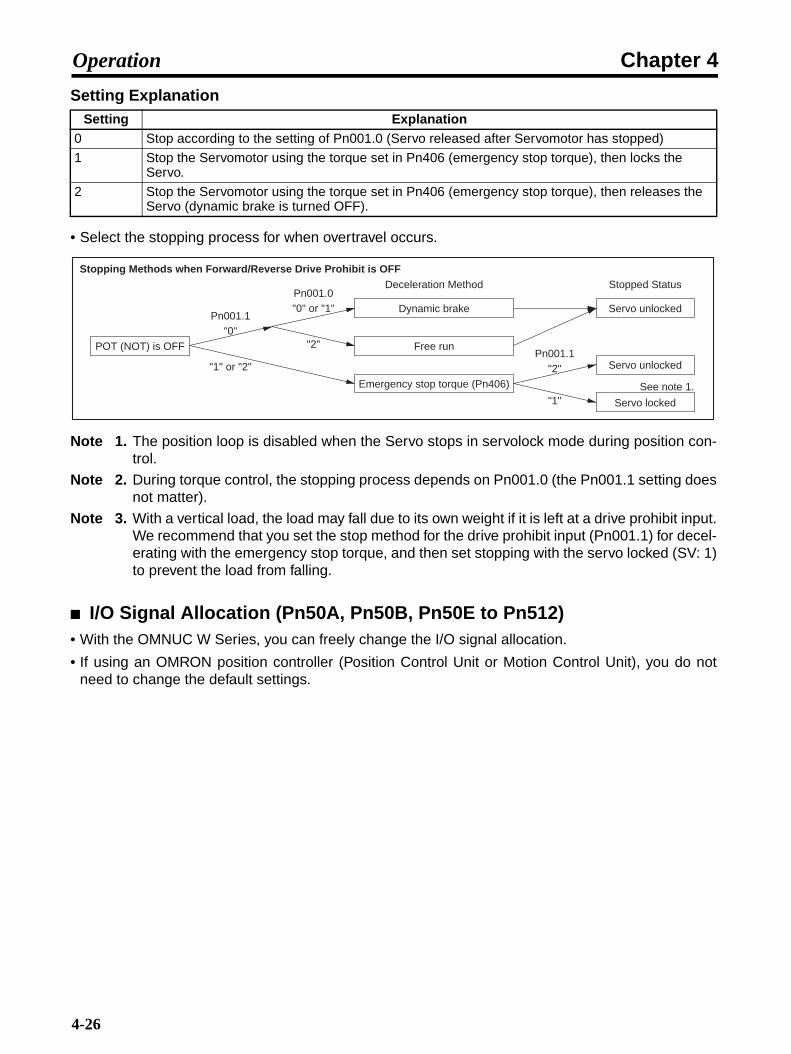
Chapter 4Operation
Setting Explanation
• Select the stopping process for when overtravel occurs.
Note 1. The position loop is disabled when the Servo stops in servolock mode during position con-trol.
Note 2. During torque control, the stopping process depends on Pn001.0 (the Pn001.1 setting doesnot matter).
Note 3. With a vertical load, the load may fall due to its own weight if it is left at a drive prohibit input.We recommend that you set the stop method for the drive prohibit input (Pn001.1) for decel-erating with the emergency stop torque, and then set stopping with the servo locked (SV: 1)to prevent the load from falling.
I/O Signal Allocation (Pn50A, Pn50B, Pn50E to Pn512)• With the OMNUC W Series, you can freely change the I/O signal allocation.
• If using an OMRON position controller (Position Control Unit or Motion Control Unit), you do notneed to change the default settings.
Setting Explanation0 Stop according to the setting of Pn001.0 (Servo released after Servomotor has stopped)
1 Stop the Servomotor using the torque set in Pn406 (emergency stop torque), then locks the Servo.
2 Stop the Servomotor using the torque set in Pn406 (emergency stop torque), then releases the Servo (dynamic brake is turned OFF).
POT (NOT) is OFF
Dynamic brake
Free run
Emergency stop torque (Pn406)
Deceleration Method Stopped Status
Servo unlocked
Servo unlocked
Servo locked
Stopping Methods when Forward/Reverse Drive Prohibit is OFF
See note 1.
Pn001.1"0"
"1" or "2"
Pn001.0"0" or "1"
"2"Pn001.1
"1"
"2"
4-26

Chapter 4Operation
• The default allocations are as follows:
Input Signal Selections (Pn50A, Pn50B, Pn511)
Note Do not change setting.
Note Do not change setting.
Note Do not change setting.
CN1, pin No.
Signal name Condition
Input signal
7 POT (Forward drive prohibit input) Enabled when the CN1-7 input signal turns ON (L level).
8 NOT (Reverse drive prohibit input) Enabled when the CN1-8 input signal turns ON (L level).
9 DEC (Origin return deceleration LS) Enabled when the CN1-9 input signal turns ON (L level).
10 EXT1 (External latch signal 1) Enabled when the CN1-10 input signal turns ON (L level).
11 EXT2 (External latch signal 2) Enabled when the CN1-11 input signal turns ON (L level).
12 EXT3 (External latch signal 3) Enabled when the CN1-12 input signal turns ON (L level).
Output signal
1/2 BKIR (Brake interlock output)
23/24 General-purpose output signal (Not allocated.)
25/26 General-purpose output signal (Not allocated.)
Pn50A.0 Input signal selections 1 -- Not used.
Setting range
--- Unit --- Default setting
1 Restart power?
Yes
Pn50A.1 Input signal selections 1 -- Not used.
Setting range
--- Unit --- Default setting
8 Restart power?
Yes
Pn50A.2 Input signal selections 1 -- Not used.
Setting range
--- Unit --- Default setting
8 Restart power?
Yes
Pn50A.3 Input signal selections 1 -- POT (forward drive prohibited) signal input terminal allocation (All operation modes)
Setting range
0 to F Unit --- Default setting
1 Restart power?
Yes
4-27

Chapter 4Operation
Setting Explanation
• If set to 7 (always ON), the Servo is in always overtravel status (i.e., forward rotation is always drive-prohibited).
• If set to 8 (always OFF), the Servo drive prohibition is OFF (i.e., the forward rotation drive is permit-ted).
• The POT signal permits forward rotation drive upon input.
• Settings are the same as for Pn50A.3.
• If set to 7 (always ON), the Servo is in always in overtravel status (i.e., reverse rotation is alwaysdrive-prohibited).
• If set to 8 (always OFF), the Servo drive prohibition is OFF (i.e., the reverse rotation drive is permit-ted).
• The NOT signal permits reverse rotation drive upon input.
Note Do not change setting.
Note Do not change setting.
Setting Explanation0 Allocated to CN1-13 pin: enabled using L input
1 Allocated to CN1-7 pin: enabled using L input
2 Allocated to CN1-8 pin: enabled using L input
3 Allocated to CN1-9 pin: enabled using L input
4 Allocated to CN1-10 pin: enabled using L input
5 Allocated to CN1-11 pin: enabled using L input
6 Allocated to CN1-12 pin: enabled using L input
7 Always ON
8 Always OFF
9 Allocated to CN1-13 pin: enabled using H input
A Allocated to CN1-7 pin: enabled using H input
B Allocated to CN1-8 pin: enabled using H input
C Allocated to CN1-9 pin: enabled using H input
D Allocated to CN1-10 pin: enabled using H input
E Allocated to CN1-11 pin: enabled using H input
F Allocated to CN1-12 pin: enabled using H input
Pn50B.0 Input signal selections 2 -- NOT (reverse drive prohibited) signal input terminal allocation (All operation modes)
Setting range
0 to F Unit --- Default setting
2 Restart power?
Yes
Pn50B.1 Input signal selections 2 -- Not used.
Setting range
--- Unit --- Default setting
8 Restart power?
Yes
Pn50B.2 Input signal selections 2 -- Not used.
Setting range
--- Unit --- Default setting
8 Restart power?
Yes
4-28

Chapter 4Operation
Note Do not change setting.
• Settings are the same as for Pn50A.3.
• When “7” (always enabled) is set, the deceleration switch is always enabled.
• When “8” (always disabled) is set, the deceleration switch is always disabled.
Setting Explanation
• When “7” (always enabled) is set, the external latch signal is always enabled.
• When “8” (always disabled) is set, the external latch signal is always disabled.
• Settings are the same as for Pn511.1.
• When “7” (always enabled) is set, the deceleration switch is always enabled.
• When “0 to 3” or “8 to C” (always disabled) is set, the deceleration switch is always disabled.
Pn50B.3 Input signal selections 2 -- Not used.
Setting range
--- Unit --- Default setting
8 Restart power?
Yes
Pn511.0 Input signal selections 5 -- DEC (origin return deceleration LS) signal input terminal allocation (All operation modes)
Setting range
0 to F Unit --- Default setting
3 Restart power?
Yes
Pn511.1 Input signal selections 5 -- EXT1 (external latch signal 1) signal input terminal allocation (All operation modes)
Setting range
0 to F Unit --- Default setting
4 Restart power?
Yes
Setting Explanation0 to 3 Always OFF
4 Allocated to CN1-10 pin: enabled using L input
5 Allocated to CN1-11 pin: enabled using L input
6 Allocated to CN1-12 pin: enabled using L input
7 Always ON
8 Always OFF
9 to C Always OFF
D Allocated to CN1-10 pin: enabled using H input
E Allocated to CN1-11 pin: enabled using H input
F Allocated to CN1-12 pin: enabled using H input
Pn511.2 Input signal selections 5 -- EXT2 (external latch signal 2) signal input terminal allocation (All operation modes)
Setting range
0 to F Unit --- Default setting
5 Restart power?
Yes
Pn511.3 Input signal selections 5 -- EXT3 (external latch signal 3) signal input terminal allocation (All operation modes)
Setting range
0 to F Unit --- Default setting
6 Restart power?
Yes
4-29

Chapter 4Operation
• Settings are the same as for Pn511.1.
• When “7” (always enabled) is set, the deceleration switch is always enabled.
• When “0 to 3” or “8 to C” (always disabled) is set, the deceleration switch is always disabled.
Output Signal Selections (Pn50E to Pn510, Pn512)• Output signal selection is performed in Pn50E to Pn510, and whether each signal should be
reversed is set in Pn512.
• You can allocate multiple output signals to the same pin. Such signals are output separately as anOR operation.
• The default setting is for BKIR (brake interlock output) to be allocated to pins No. 1 and 2.
Setting Explanation
Pn50E.0 Output signal selections 1 -- INP1 (positioning completed 1) signal output terminal allocation (Position)
Setting range
0 to 3 Unit --- Default setting
0 Restart power?
Yes
Setting Explanation0 No output
1 Allocated to pins CN1-1 and 2 (pin 2 is the COM port)
2 Allocated to pins CN1-23 and 24 (pin 24 is the COM port)
3 Allocated to pins CN1-25 and 26 (pin 26 is the COM port)
Pn50E.1 Output signal selections 1 -- VCMP (speed conformity) signal output terminal allocation (Speed)
Setting range
0 to 3 Unit --- Default setting
0 Restart power?
Yes
Pn50E.2 Output signal selections 1 -- TGON (Servomotor rotation detection) signal output terminal allo-cation (All operation modes)
Setting range
0 to 3 Unit --- Default setting
0 Restart power?
Yes
Pn50E.3 Output signal selections 1 -- READY (Servo ready) signal output terminal allocation (All opera-tion modes)
Setting range
0 to 3 Unit --- Default setting
0 Restart power?
Yes
Pn50F.0 Output signal selections 2 -- CLIMT (current limit detection) signal output terminal allocation (All operation modes)
Setting range
0 to 3 Unit --- Default setting
0 Restart power?
Yes
Pn50F.1 Output signal selections 2 -- VLIMT (speed limit detection) signal output terminal allocation (Torque)
Setting range
0 to 3 Unit --- Default setting
0 Restart power?
Yes
4-30
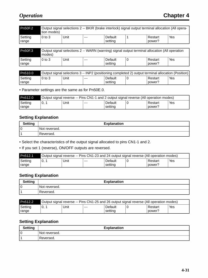
Chapter 4Operation
• Parameter settings are the same as for Pn50E.0.
Setting Explanation
• Select the characteristics of the output signal allocated to pins CN1-1 and 2.
• If you set 1 (reverse), ON/OFF outputs are reversed.
Setting Explanation
Setting Explanation
Pn50F.2 Output signal selections 2 -- BKIR (brake interlock) signal output terminal allocation (All opera-tion modes)
Setting range
0 to 3 Unit --- Default setting
1 Restart power?
Yes
Pn50F.3 Output signal selections 2 -- WARN (warning) signal output terminal allocation (All operation modes)
Setting range
0 to 3 Unit --- Default setting
0 Restart power?
Yes
Pn510.0 Output signal selections 3 -- INP2 (positioning completed 2) output terminal allocation (Position)
Setting range
0 to 3 Unit --- Default setting
0 Restart power?
Yes
Pn512.0 Output signal reverse -- Pins CN1-1 and 2 output signal reverse (All operation modes)
Setting range
0, 1 Unit --- Default setting
0 Restart power?
Yes
Setting Explanation0 Not reversed.
1 Reversed.
Pn512.1 Output signal reverse -- Pins CN1-23 and 24 output signal reverse (All operation modes)
Setting range
0, 1 Unit --- Default setting
0 Restart power?
Yes
Setting Explanation0 Not reversed.
1 Reversed.
Pn512.2 Output signal reverse -- Pins CN1-25 and 26 output signal reverse (All operation modes)
Setting range
0, 1 Unit --- Default setting
0 Restart power?
Yes
Setting Explanation0 Not reversed.
1 Reversed.
4-31

Chapter 4Operation
4-3-3 Parameter Details
This section explains all user parameters not already explained in 4-3-2 ImportantParameters. Make sure you fully understand the meaning of each parameter beforemaking any changes to parameter settings. Be sure not to change parametersdesignated “Not used.”, and digit No. settings.
Function Selection Parameters (from Pn000)
Function Selection Basic Switches (Pn000: Default Setting 0010)
Note Refer to 4-3-2 Important Parameters.
Note Do not change setting.
Setting Explanation
• This setting is required when multiple Servo Drivers are connected and Computer Monitor Softwareis used.
Note Do not change setting.
Function Selection Application Switches 1 (Pn001: Default setting 0000)
Note Refer to 4-3-2 Important Parameters.
Pn000.0 Function selection basic switches -- Reverse rotation (All operation modes)
Setting range
0, 1 Unit --- Default setting
0 Restart power?
Yes
Pn000.1 Function selection basic switches -- Not used
Setting range
--- Unit --- Default setting
0 Restart power?
Yes
Pn000.2 Function selection basic switches -- Unit No. setting (All operation modes)
Setting range
0 to F Unit --- Default setting
0 Restart power?
Yes
Setting Explanation0 to F Sets the Servo Driver unit number
Pn000.3 Function selection basic switches -- Not used.
Setting range
--- Unit --- Default setting
0 Restart power?
Yes
Pn001.0 Function selection application switches 1 -- Stop selection if an alarm occurs when Servomotor is OFF (All operation modes)
Setting range
0 to 2 Unit --- Default setting
2 Restart power?
Yes
4-32

Chapter 4Operation
Note Refer to 4-3-2 Important Parameters.
Setting Explanation
• Select setting 1 if using a DC power supply.
• If using a DC power supply, perform the following operations.
Control circuit power supply: Supply DC power to L1C and L2C. There is no polarity.
Main circuit power supply: Supply DC power as follows: Positive voltage to B1/ 1 terminal, and
ground to or 2 terminal.
External regeneration resistance terminals: Remove the short bar from between B2 and B3 so thatB1, B2, and B3 are open. (For Servo Drivers without B3, open B1 and B2.)
Use 270 to 320 VDC as the input voltage. (100-V input models do not handle DC inputs.)
Note 1. Always set this parameter to 1 when using a DC power supply. If a DC power supply is con-nected with this parameter set to 0, the regeneration absorption circuit will operate, possiblydamaging the Servo Driver. When changing the setting from 0 to 1, either the main circuitpower supply must be OFF, or the external regeneration resistance terminals must be open.
Note 2. If using a DC power supply, the regeneration absorption circuit inside the Servo Driver willnot operate. The regeneration power returns to the DC power supply, so make sure the DCpower supply can absorb the regeneration power.
Note 3. If using a DC power supply, the residual voltage in the main-circuit power supply is not dis-charged rapidly when the power is turned OFF. Be sure to mount a discharge circuit on theDC power supply. Also, check that the charge indicator is not lit before storing the power sup-ply input when the power supply has been turned OFF (the discharge time for the ServoDriver is approximately 30 minutes.)
Note Do not change setting.
Pn001.1 Function selection application switches 1 -- Stop selection when drive prohibited is input (Posi-tion, speed)
Setting range
0 to 2 Unit --- Default setting
0 Restart power?
Yes
Pn001.2 Function selection application switches 1 -- AC/DC power input selection (All operation modes)
Setting range
0, 1 Unit --- Default setting
0 Restart power?
Yes
Setting Explanation0 AC power supply: AC power supplied from L1, L2, (L3) terminals
1 DC power supply input: DC power from B1/ , terminals, or DC power from B1/ , 2 termi-nals.
Pn001.3 Function selection application switches 1 -- Not used.
Setting range
--- Unit --- Default setting
0 Restart power?
Yes
+ − + −
+
− −
4-33
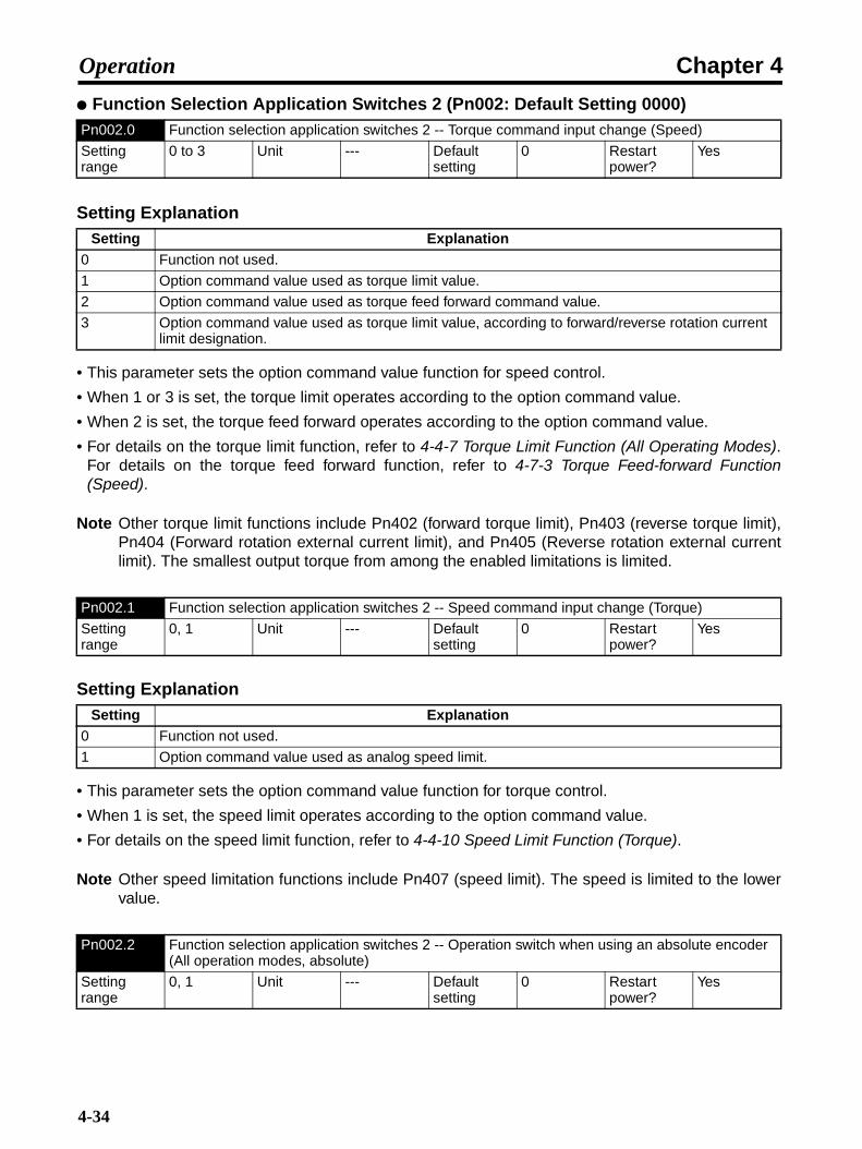
Chapter 4Operation
Function Selection Application Switches 2 (Pn002: Default Setting 0000)
Setting Explanation
• This parameter sets the option command value function for speed control.
• When 1 or 3 is set, the torque limit operates according to the option command value.
• When 2 is set, the torque feed forward operates according to the option command value.
• For details on the torque limit function, refer to 4-4-7 Torque Limit Function (All Operating Modes).For details on the torque feed forward function, refer to 4-7-3 Torque Feed-forward Function(Speed).
Note Other torque limit functions include Pn402 (forward torque limit), Pn403 (reverse torque limit),Pn404 (Forward rotation external current limit), and Pn405 (Reverse rotation external currentlimit). The smallest output torque from among the enabled limitations is limited.
Setting Explanation
• This parameter sets the option command value function for torque control.
• When 1 is set, the speed limit operates according to the option command value.
• For details on the speed limit function, refer to 4-4-10 Speed Limit Function (Torque).
Note Other speed limitation functions include Pn407 (speed limit). The speed is limited to the lowervalue.
Pn002.0 Function selection application switches 2 -- Torque command input change (Speed)
Setting range
0 to 3 Unit --- Default setting
0 Restart power?
Yes
Setting Explanation0 Function not used.
1 Option command value used as torque limit value.
2 Option command value used as torque feed forward command value.
3 Option command value used as torque limit value, according to forward/reverse rotation current limit designation.
Pn002.1 Function selection application switches 2 -- Speed command input change (Torque)
Setting range
0, 1 Unit --- Default setting
0 Restart power?
Yes
Setting Explanation0 Function not used.
1 Option command value used as analog speed limit.
Pn002.2 Function selection application switches 2 -- Operation switch when using an absolute encoder (All operation modes, absolute)
Setting range
0, 1 Unit --- Default setting
0 Restart power?
Yes
4-34
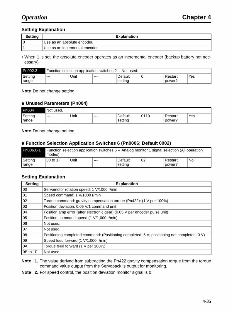
Chapter 4Operation
Setting Explanation
• When 1 is set, the absolute encoder operates as an incremental encoder (backup battery not nec-essary).
Note Do not change setting.
Unused Parameters (Pn004)
Note Do not change setting.
Function Selection Application Switches 6 (Pn0006; Default 0002)
Setting Explanation
Note 1. The value derived from subtracting the Pn422 gravity compensation torque from the torquecommand value output from the Servopack is output for monitoring.
Note 2. For speed control, the position deviation monitor signal is 0.
Setting Explanation0 Use as an absolute encoder.
1 Use as an incremental encoder.
Pn002.3 Function selection application switches 2 -- Not used.
Setting range
--- Unit --- Default setting
0 Restart power?
Yes
Pn004 Not used.
Setting range
--- Unit --- Default setting
0110 Restart power?
Yes
Pn006.0-1 Function selection application switches 6 -- Analog monitor 1 signal selection (All operation modes)
Setting range
00 to 1F Unit --- Default setting
02 Restart power?
No
Setting Explanation00 Servomotor rotation speed: 1 V/1000 r/min
01 Speed command: 1 V/1000 r/min
02 Torque command: gravity compensation torque (Pn422): (1 V per 100%)
03 Position deviation: 0.05 V/1 command unit
04 Position amp error (after electronic gear) (0.05 V per encoder pulse unit)
05 Position command speed (1 V/1,000 r/min)
06 Not used.
07 Not used.
08 Positioning completed command: (Positioning completed: 5 V; positioning not completed: 0 V)
09 Speed feed forward (1 V/1,000 r/min)
0A Torque feed forward (1 V per 100%)
0B to 1F Not used.
4-35
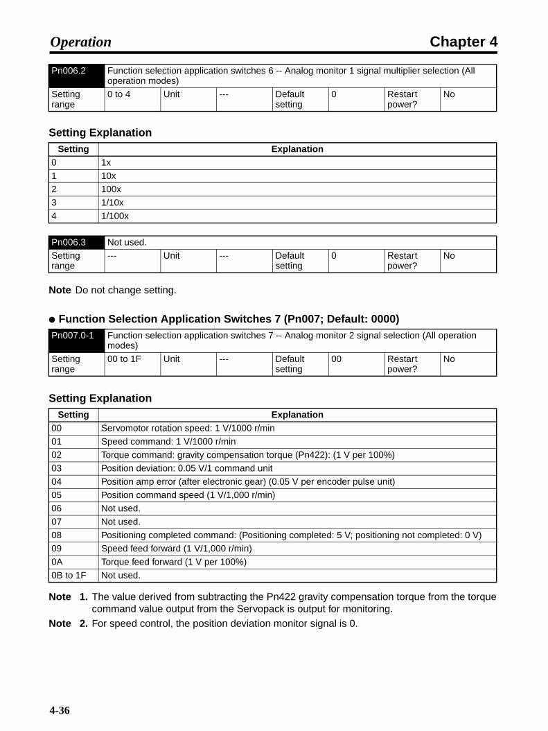
Chapter 4Operation
Setting Explanation
Note Do not change setting.
Function Selection Application Switches 7 (Pn007; Default: 0000)
Setting Explanation
Note 1. The value derived from subtracting the Pn422 gravity compensation torque from the torquecommand value output from the Servopack is output for monitoring.
Note 2. For speed control, the position deviation monitor signal is 0.
Pn006.2 Function selection application switches 6 -- Analog monitor 1 signal multiplier selection (All operation modes)
Setting range
0 to 4 Unit --- Default setting
0 Restart power?
No
Setting Explanation0 1x
1 10x
2 100x
3 1/10x
4 1/100x
Pn006.3 Not used.
Setting range
--- Unit --- Default setting
0 Restart power?
No
Pn007.0-1 Function selection application switches 7 -- Analog monitor 2 signal selection (All operation modes)
Setting range
00 to 1F Unit --- Default setting
00 Restart power?
No
Setting Explanation00 Servomotor rotation speed: 1 V/1000 r/min
01 Speed command: 1 V/1000 r/min
02 Torque command: gravity compensation torque (Pn422): (1 V per 100%)
03 Position deviation: 0.05 V/1 command unit
04 Position amp error (after electronic gear) (0.05 V per encoder pulse unit)
05 Position command speed (1 V/1,000 r/min)
06 Not used.
07 Not used.
08 Positioning completed command: (Positioning completed: 5 V; positioning not completed: 0 V)
09 Speed feed forward (1 V/1,000 r/min)
0A Torque feed forward (1 V per 100%)
0B to 1F Not used.
4-36
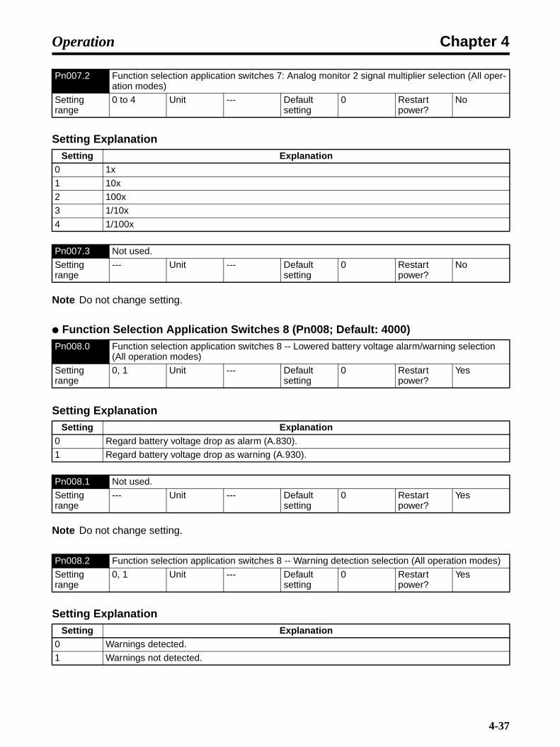
Chapter 4Operation
Setting Explanation
Note Do not change setting.
Function Selection Application Switches 8 (Pn008; Default: 4000)
Setting Explanation
Note Do not change setting.
Setting Explanation
Pn007.2 Function selection application switches 7: Analog monitor 2 signal multiplier selection (All oper-ation modes)
Setting range
0 to 4 Unit --- Default setting
0 Restart power?
No
Setting Explanation0 1x
1 10x
2 100x
3 1/10x
4 1/100x
Pn007.3 Not used.
Setting range
--- Unit --- Default setting
0 Restart power?
No
Pn008.0 Function selection application switches 8 -- Lowered battery voltage alarm/warning selection (All operation modes)
Setting range
0, 1 Unit --- Default setting
0 Restart power?
Yes
Setting Explanation0 Regard battery voltage drop as alarm (A.830).
1 Regard battery voltage drop as warning (A.930).
Pn008.1 Not used.
Setting range
--- Unit --- Default setting
0 Restart power?
Yes
Pn008.2 Function selection application switches 8 -- Warning detection selection (All operation modes)
Setting range
0, 1 Unit --- Default setting
0 Restart power?
Yes
Setting Explanation0 Warnings detected.
1 Warnings not detected.
4-37

Chapter 4Operation
• When 1 (warnings not detected) is set, the following warnings are not detected.A.900, A.901, A.910, A.911, A.920, A.930
Note Do not change setting.
Gain Parameters (from Pn100)
• This gain adjusts the speed loop response.
• Increase the setting (i.e., increase the gain) to raise Servo rigidity. Generally, the greater the inertiaratio, the higher the setting. There is a risk of oscillation, however, if the gain is too high.
• Sets the speed loop integral time constant.
• The higher the setting, the lower the response, and the lower the resiliency to external force. Thereis a risk of oscillation if the setting is too low.
Pn008.3 Not used.
Setting range
--- Unit --- Default setting
4 Restart power?
Yes
Pn100 Speed loop gain (Position, speed)
Setting range
10 to 20000 Unit × 0.1 Hz Default setting
800 Restart power?
No
Pn101 Speed loop integration constant (Position, speed)
Setting range
15 to 51200 Unit × 0.01 ms Default setting
2000 Restart power?
No
Time
When speed loop gain is low.
Servomotor speed (speed monitor)
Overshoots when speed loop gain is high. (Oscillates when gain is too high.)
Time
Overshoots when speed loop integration constant is short.
When speed loop integration constant is long.
Servomotor speed
4-38

Chapter 4Operation
• Adjust the position loop response to suit the mechanical rigidity.
• Servo system response is determined by the position loop gain. Servo systems with a high loopgain have a high response, and positioning is fast. To raise the position loop gain, you must improvemechanical rigidity and raise the specific oscillation. This should be 500 to 700 (0.1/s) for ordinarymachine tools, 300 to 500 (0.1/s) for general-use and assembly machines, and 100 to 300 (0.1/s)for production robots. The default position loop gain is 400 (0.1/s), so be sure to lower the setting formachines with low rigidity.
• Raising the position loop gain in systems with low mechanical rigidity or systems with low specificoscillation may result in machine resonance, causing an overload alarm to occur.
• If the position loop gain is low, you can shorten the positioning time using feed forward. You canalso shorten the positioning time using the bias function.
Position loop gain is generally expressed as follows:
When the position loop gain is manipulated, the response is as shown in the diagram below.
• Set the mechanical system inertia (load inertia for Servomotor shaft conversion) using the ratio (%)of the Servomotor rotor inertia. If the inertia ratio is set incorrectly, the Pn103 (inertia ratio) value willalso be incorrect.
Pn102 Position loop gain (Position)
Setting range
10 to 20000 Unit × 0.1/s Default setting
400 Restart power?
No
Pn103 Inertia ratio (Position, speed)
Setting range
0 to 20000 Unit % Default setting
300 Restart power?
No
Pn104 Speed loop gain 2 (Position, speed)
Setting range
10 to 20000 Unit × 0.1 Hz Default setting
800 Restart power?
No
Pn105 Speed loop integration constant 2 (Position, speed)
Setting range
15 to 51200 Unit × 0.01 ms Default setting
2000 Restart power?
No
Position loop gain (Kp) = Command pulse frequency (pulses/s)
Deviation counter residual pulses (pulses)(0.1/s)
Time
When position loop gain is high
When position loop gain is low
Servomotor speed
4-39

Chapter 4Operation
• These parameters are gain and time constants selected when using gain switching under the fol-lowing conditions.
• When automatic gain switching is set, and the switching conditions are met. → Pn139.2 (Gain switching condition B) must be set.Refer to 4-7-4 Automatic Gain Switching (Position) for details.
• If the mechanical system inertia changes greatly or if you want to change the response for when theServomotor is rotating and when it is stopped, you can achieve the appropriate control by settingthe gain and time constant beforehand for each of these conditions, and then switch according tothe conditions.
Note 1. Automatic gain switching is enabled for position control only. When position control is notused, the Servomotor operates using No. 1 gain (Pn100, Pn101, Pn102).
Note 2. When automatic gain switching is used, set No. 1 gain for gain during operation, and set No.2 gain for gain while stopped.
• These two parameters set the position control bias.
• This function shortens the positioning time by adding the number of bias rotations to the speedcommand (i.e., commands to the speed control loop).
• When the deviation counter residual pulses exceed the Pn108 (bias addition band) setting, thespeed set in Pn107 (bias rotational speed) is added to the speed command, and when they arewithin the limits for Pn108, it stops being added.
Note 1. Set Pn107 to 0 if not using bias function.
Note 2. If the bias rotation speed is too great, the Servomotor operation may become unstable. Theoptimum value will vary depending on the load, gain, and bias addition range, so check andadjust the Servomotor response. (Gradually increase the value, starting from Pn107 = 0.)
Pn106 Position loop gain 2 (Position)
Setting range
10 to 20000 Unit × 0.1/s Default setting
400 Restart power?
No
Pn107 Bias rotational speed (Position)
Setting range
0 to 450 Unit r/min Default setting
0 Restart power?
No
Pn108 Bias addition band (Position)
Setting range
0 to 250 Unit Command unit
Default setting
7 Restart power?
No
Bias function operation
Time
Speed command (command pulse frequency)
Bias function not used.
Bias function used.
Pn107 added to speed command when residual pulses exceed Pn108
Servomotor speed
4-40

Chapter 4Operation
• Sets the feed-forward compensation value during positioning.
• When performing feed-forward compensation, the effective Servo gain rises, improving response.There is almost no effect, however, on systems where the position loop gain is sufficiently high.
• Use to shorten positioning time.
Note Setting a high value may result in machine vibration. Set the feed-forward amount for generalmachinery to 80% maximum. (Check and adjust machine response.)
• Sets the feed-forward primary (lag) command filter during position control.
• If the positioning completed signal is interrupted (i.e., repeatedly turns ON and OFF) because ofperforming feed-forward compensation, and a speed overshoot is generated, alleviate the problemby setting the primary lag filter.
Speed Control Setting (Pn10B: Default Setting 0004)
Setting Explanation
• Sets the speed control loop switching function from PI control to P control.
• Normally, using the speed loop gain and the position loop gain set by means of the auto-tuningoperation will provide adequate control. (Consequently, there is normally no need to change thesetting.)
• When PI control is always being used, switching to P control may help if the Servomotor speedovershoots or undershoots (i.e., the effective Servo gain is reduced by switching to P control to sta-bilize the Servo System). The positioning time can also be shortened in this way.
• If the output torque is saturated during acceleration and deceleration, set speed control to 0(switching by internal torque command), or 2 (switching by acceleration command).
• If the speed control overshoots or undershoots without the output torque being saturated duringacceleration and deceleration, set speed control to 1 (switching by speed command), or 3 (switch-ing by deviation pulse value).
Pn109 Feed-forward amount (Position)
Setting range
0 to 100 Unit % Default setting
0 Restart power?
No
Pn10A Feed-forward command filter (Position)
Setting range
0 to 6400 Unit × 0.01 ms Default setting
0 Restart power?
No
Pn10B.0 Speed control setting -- P control switching conditions (Position, speed)
Setting range
0 to 4 Unit --- Default setting
4 Restart power?
No
Setting Explanation0 Internal torque command (Pn10C) condition (Position, speed)
1 Speed command (Pn10D) condition (Position, speed)
2 Acceleration command (Pn10E) condition (Position, speed)
3 Deviation pulse (Pn10F) condition (Position)
4 P control switching function not used. (Position, speed)
4-41

Chapter 4Operation
• If the setting is made from 0 to 3 (i.e., if P control switching is used), set the switching condition toPn10C to Pn10F.
Note Setting Pn10B.1 (speed control loop switching) to 1 (IP control) changes the parameter toswitch from IP control to P control.
Setting Explanation
• Set the speed control loop to either PI control or IP control.
• There is normally no need to change the setting.
• If you cannot shorten positioning time in PI control, change the setting to 1 (IP control).
Setting Explanation
Note Do not change setting.
• You must set Pn10C if you set Pn10B.0 (P control switching condition) to 0 (switching by internaltorque command).
• Set the condition to switch to P control using Servomotor rated torque ratio (%).
• The Servo switches to P control if the internal torque command exceeds the setting level.
Pn10B.1 Speed control setting -- Speed control loop switching (Position, speed)
Setting range
0, 1 Unit --- Default setting
0 Restart power?
Yes
Setting Explanation0 PI control
1 IP control
Pn10B.2 Speed control setting -- Position loop control method (Position)
Setting range
0 to 3 Unit --- Default setting
0 Restart power?
Yes
Setting Explanation0 Standard position control
1 Less-deviation control
2 Not used.
3 Not used.
Pn10B.3 Speed control setting -- Not used.
Setting range
--- Unit --- Default setting
0 Restart power?
No
Pn10C P control switching (torque command) (Position, speed)
Setting range
0 to 800 Unit % Default setting
200 Restart power?
No
Pn10D P control switching (speed command) (Position, speed)
Setting range
0 to 10000 Unit r/min Default setting
0 Restart power?
No
4-42

Chapter 4Operation
• You must set Pn10D if you set Pn10B.0 (P control switching condition) to 1 (switching by speedcommand).
• Set the speed to switch to P control.
• The Servo switches to P control if the speed command exceeds the setting level.
• You must set Pn10E if you set Pn10B.0 (P control switching condition) to 2 (switching by accelera-tion command).
• Set the acceleration to switch to P control.
• The Servo switches to P control if the acceleration command value exceeds the setting level.
• You must set Pn10F if you set Pn10B.0 (P control switching condition) to 3 (switching by deviationpulse).
• Set the deviation pulse to switch to P control.
• The Servo switches to P control if the deviation counter residual pulses exceed the setting level.
Note Do not change setting.
Setting Explanation
• This function shortens positioning time.
• Use this function to lower speed loop feedback gain, and to raise speed loop gain and position loopgain. In this way, you can improve command response and shorten positioning time. Positioningtime cannot be shortened, however, when external force is applied as with the vertical shaft,because response to external interference is lowered.
• If 0 (function ON) is set, set Pn111 (speed feedback compensating gain).
Pn10E P control switching (acceleration command) (Position, speed)
Setting range
0 to 30000 Unit r/min/s Default setting
0 Restart power?
No
Pn10F P control switching (deviation pulse) (Position)
Setting range
0 to 10000 Unit Command unit
Default setting
10 Restart power?
No
Pn110.0 Normal autotuning switches -- Not used.
Setting range
--- Unit --- Default setting
2 Restart power?
Yes
Pn110.1 Normal autotuning switches -- Speed feedback compensation function selection (Position, speed)
Setting range
0, 1 Unit --- Default setting
1 Restart power?
Yes
Setting Explanation0 Speed feedback compensation function ON
1 Speed feedback compensation function OFF
Pn110.2 Normal autotuning switches -- Not used.
Setting range
--- Unit --- Default setting
0 Restart power?
Yes
4-43
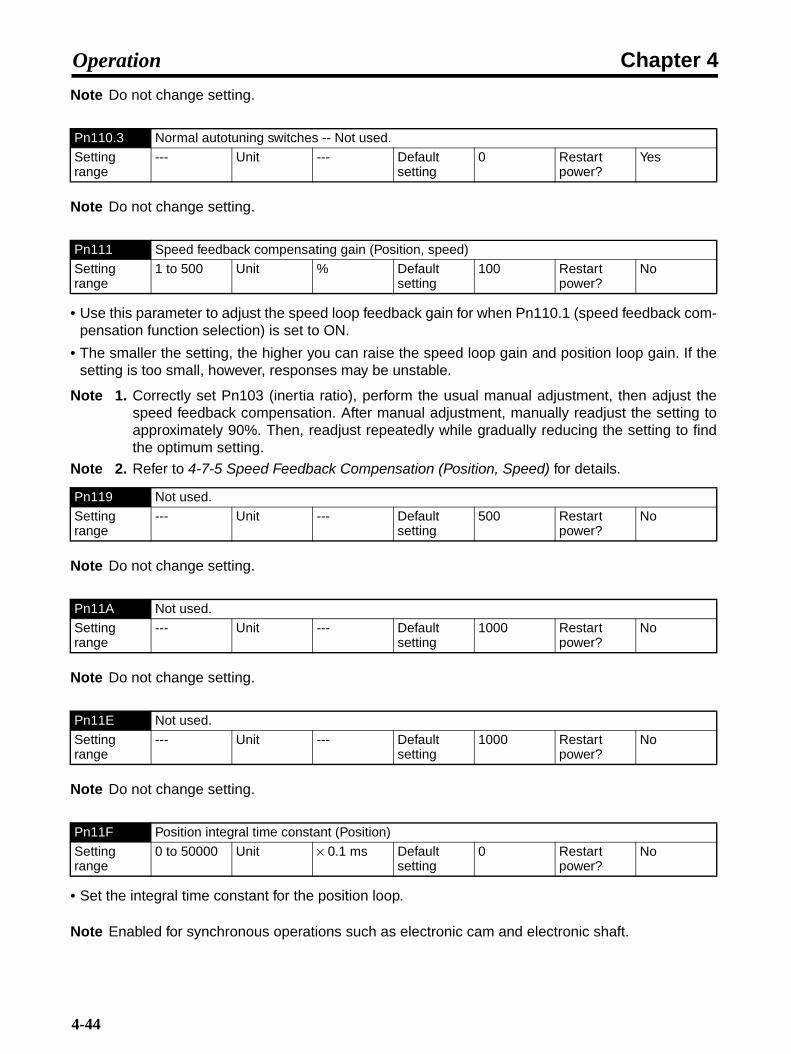
Chapter 4Operation
Note Do not change setting.
Note Do not change setting.
• Use this parameter to adjust the speed loop feedback gain for when Pn110.1 (speed feedback com-pensation function selection) is set to ON.
• The smaller the setting, the higher you can raise the speed loop gain and position loop gain. If thesetting is too small, however, responses may be unstable.
Note 1. Correctly set Pn103 (inertia ratio), perform the usual manual adjustment, then adjust thespeed feedback compensation. After manual adjustment, manually readjust the setting toapproximately 90%. Then, readjust repeatedly while gradually reducing the setting to findthe optimum setting.
Note 2. Refer to 4-7-5 Speed Feedback Compensation (Position, Speed) for details.
Note Do not change setting.
Note Do not change setting.
Note Do not change setting.
• Set the integral time constant for the position loop.
Note Enabled for synchronous operations such as electronic cam and electronic shaft.
Pn110.3 Normal autotuning switches -- Not used.
Setting range
--- Unit --- Default setting
0 Restart power?
Yes
Pn111 Speed feedback compensating gain (Position, speed)
Setting range
1 to 500 Unit % Default setting
100 Restart power?
No
Pn119 Not used.
Setting range
--- Unit --- Default setting
500 Restart power?
No
Pn11A Not used.
Setting range
--- Unit --- Default setting
1000 Restart power?
No
Pn11E Not used.
Setting range
--- Unit --- Default setting
1000 Restart power?
No
Pn11F Position integral time constant (Position)
Setting range
0 to 50000 Unit × 0.1 ms Default setting
0 Restart power?
No
4-44

Chapter 4Operation
Unused Gain Parameters (Pn12B to Pn130)
Note Do not change the settings of the following parameters.
Automatic Gain Switching (Pn131 to Pn139)
Pn12B Not used.
Setting range
--- Unit --- Default setting
400 Restart power?
No
Pn12C Not used.
Setting range
--- Unit --- Default setting
2000 Restart power?
No
Pn12D Not used.
Setting range
--- Unit --- Default setting
400 Restart power?
No
Pn12E Not used.
Setting range
--- Unit --- Default setting
400 Restart power?
No
Pn12F Not used.
Setting range
--- Unit --- Default setting
2000 Restart power?
No
Pn130 Not used.
Setting range
--- Unit --- Default setting
400 Restart power?
No
Pn131 Gain switching time 1 (Position)
Setting range
0 to 65535 Unit ms Default setting
0 Restart power?
No
Pn132 Gain switching time 2 (Position)
Setting range
0 to 65535 Unit ms Default setting
0 Restart power?
No
Pn135 Gain switching waiting time 1 (Position)
Setting range
0 to 65535 Unit ms Default setting
0 Restart power?
No
Pn136 Gain switching waiting time 2 (Position)
Setting range
0 to 65535 Unit ms Default setting
0 Restart power?
No
4-45

Chapter 4Operation
• The following diagram shows the relation between the gain switching waiting time and the gainswitching time constant. In this example, the gain is switched from position loop gain (Pn102) to No.2 position loop gain (Pn106) in automatic gain switching pattern 1, in which the turning ON of thepositioning completed signal (INP1) is taken as the switching condition. From the point at which theINP1 signal turns ON and the switching condition is met, operation is paused for the delay time setin Pn135, and then, during the switching time set in Pn131, the gain is changed in a straight linefrom Pn102 to Pn106.
• In addition to the standard PI and I-P control, automatic gain switching is also possible with less-deviation control. The gain combinations for less-deviation control are provided in 4-7-4 AutomaticGain Switching (Position). The settings for the switching condition, the gain switching waiting time,and the switching time are the same as for PI and I-P control. For details on adjustment methods forless-deviation control, refer to 4-7-9 Less-deviation Control (Position).
Setting Explanation
Pn139.0 Automatic gain changeover related switches 1 -- Gain switching selection switch (Position)
Setting range
0 to 4 Unit --- Default setting
0 Restart power?
Yes
Setting Explanation0 Manual gain switching
1 Automatic switching pattern 1Automatic switching from No. 1 gain to No. 2 gain when gain switching condition A is satisfied.Automatic switching from No. 2 gain to No. 1 gain when gain switching condition B is satisfied.
2 to 4 Not used.
Pn139.1 Automatic gain changeover related switches 1 -- Gain switching condition A (Position)
Setting range
0 to 5 Unit --- Default setting
0 Restart power?
Yes
Pn131Pn135Pn102
INP1
Pn106
Switching Delay Time and Switching Time
Position loop gain
Delay time Switching time
No. 2 position loop gain
Switching condition A met.
4-46

Chapter 4Operation
Setting Explanation
• Settings are the same as for Pn139.1.
Note Do not change setting.
Note Do not change setting.
Predictive Control (Pn150 to Pn152)
Setting Explanation
Setting Explanation
Setting Explanation0 Positioning completed output 1 (INP1) ON
1 Positioning completed output 1 (INP1) OFF
2 Positioning completed output 2 (INP2) ON
3 Positioning completed output 2 (INP2) OFF
4 The position command filter output is 0, and also the position command input is 0.
5 The position command input is not 0.
Pn139.2 Automatic gain changeover related switches 1 -- Gain switching condition B (Position)
Setting range
0 to 5 Unit --- Default setting
0 Restart power?
Yes
Pn139.3 Automatic gain changeover related switches 1 -- Not used.
Setting range
--- Unit --- Default setting
0 Restart power?
Yes
Pn144 Not used.
Setting range
--- Unit --- Default setting
1000 Restart power?
No
Pn150.0 Predictive control selection switches -- Predictive control selection. (Position)
Setting range
0 to 2 Unit --- Default setting
0 Restart power?
Yes
Setting Explanation0 Predictive control not used.
1 Predictive control used.
2 Not used.
Pn150.1 Predictive control selection switches -- Predictive control type (Position)
Setting range
0, 1 Unit --- Default setting
1 Restart power?
Yes
Setting Explanation0 Predictive control for tracking
1 Predictive control for positioning
4-47

Chapter 4Operation
Note Do not change setting.
Note Do not change setting.
• If the value is increased, the settling time will be shortened, but the maximum position deviation willnot significantly change. If the set value is too large, overshooting will occur. The diagram shows anexample of position deviation during operation by trapezoidal speed command. By increasing thepredictive control acceleration/deceleration gain, the position deviation is changed from the brokenline to the solid line, i.e., the settling time is shortened.
• If the value is increased, tracking deviation will be reduced. If the positioning completed range islarge, the settling time will also be reduced. If the set value is too long, the torque may oscillate andovershooting may occur. The diagram shows an example of position deviation during operation bytrapezoidal speed command. By increasing the predictive control weighting ratio, the position devi-ation is changed from the broken line to the solid line and the settling time is shortened.
Pn150.2 Predictive control selection switches -- Not used.
Setting range
--- Unit --- Default setting
2 Restart power?
Yes
Pn150.3 Predictive control selection switches -- Not used.
Setting range
--- Unit --- Default setting
0 Restart power?
Yes
Pn151 Predictive control acceleration/deceleration gain (Position)
Setting range
0 to 300 Unit % Default setting
100 Restart power?
No
Pn152 Predictive control weighting ratio (Position)
Setting range
0 to 300 Unit % Default setting
100 Restart power?
No
Position error
Predictive control acceleration/deceleration gain (Pn151) increased.
Time
4-48

Chapter 4Operation
Less-deviation Control Parameters (Pn1A0 to Pn1AC)
• For details on the less-deviation control function, refer to 4-7-9 Less-deviation Control (Position).
Setting Explanation
Pn1A0 Servo rigidity (Position)
Setting range
1 to 500 Unit % Default setting
60 Restart power?
No
Pn1A1 Servo rigidity 2 (Position)
Setting range
1 to 500 Unit % Default setting
60 Restart power?
No
Pn1A2 Speed feedback filter time constant (Position)
Setting range
30 to 3200 Unit × 0.01 ms Default setting
72 Restart power?
No
Pn1A3 Speed feedback filter time constant 2 (Position)
Setting range
30 to 3200 Unit × 0.01 ms Default setting
72 Restart power?
No
Pn1A4 Torque command filter time constant 2 (Position)
Setting range
0 to 2500 Unit × 0.01 ms Default setting
36 Restart power?
No
Pn1A7.0 Utility control switches -- Integral compensation processing (Position)
Setting range
0 to 3 Unit --- Default setting
1 Restart power?
No
Setting Explanation0 Integral compensation processing is not executed.
1 Integral compensation processing is executed.
2 Integral compensation is executed for No. 1 gain and not for No. 2 gain for less-deviation gain switching.
3 Integral compensation is executed for No. 2 gain and not for No. 1 gain for less-deviation gain switching.
Position error Predictive control weighting ratio (Pn152) increased.
Time
4-49

Chapter 4Operation
Note Do not change setting.
Note Do not change setting.
Note Do not change setting.
Note Do not change setting.
Position Control Parameters (from Pn200)
Position Control Setting 1 (Pn200: Default Setting 0100)
Pn1A7.1 Utility control switches -- Not used.
Setting range
--- Unit --- Default setting
2 Restart power?
No
Pn1A7.2 Utility control switches -- Not used.
Setting range
--- Unit --- Default setting
1 Restart power?
No
Pn1A7.3 Utility control switches -- Not used.
Setting range
--- Unit --- Default setting
1 Restart power?
No
Pn1A9 Utility integral gain (Position)
Setting range
0 to 500 Unit Hz Default setting
37 Restart power?
No
Pn1AA Position proportional gain (Position)
Setting range
0 to 500 Unit Hz Default setting
60 Restart power?
No
Pn1AB Speed integral gain (Position)
Setting range
0 to 500 Unit Hz Default setting
0 Restart power?
No
Pn1AC Speed proportional gain (Position)
Setting range
0 to 2000 Unit Hz Default setting
120 Restart power?
No
Pn1B5 Not used.
Setting range
--- Unit --- Default setting
150 Restart power?
No
Pn200 Not used.
Setting range
--- Unit --- Default setting
0100 Restart power?
Yes
4-50
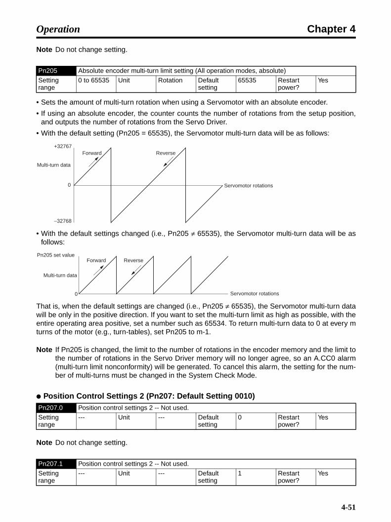
Chapter 4Operation
Note Do not change setting.
• Sets the amount of multi-turn rotation when using a Servomotor with an absolute encoder.
• If using an absolute encoder, the counter counts the number of rotations from the setup position,and outputs the number of rotations from the Servo Driver.
• With the default setting (Pn205 = 65535), the Servomotor multi-turn data will be as follows:
• With the default settings changed (i.e., Pn205 ≠ 65535), the Servomotor multi-turn data will be asfollows:
That is, when the default settings are changed (i.e., Pn205 ≠ 65535), the Servomotor multi-turn datawill be only in the positive direction. If you want to set the multi-turn limit as high as possible, with theentire operating area positive, set a number such as 65534. To return multi-turn data to 0 at every mturns of the motor (e.g., turn-tables), set Pn205 to m-1.
Note If Pn205 is changed, the limit to the number of rotations in the encoder memory and the limit tothe number of rotations in the Servo Driver memory will no longer agree, so an A.CC0 alarm(multi-turn limit nonconformity) will be generated. To cancel this alarm, the setting for the num-ber of multi-turns must be changed in the System Check Mode.
Position Control Settings 2 (Pn207: Default Setting 0010)
Note Do not change setting.
Pn205 Absolute encoder multi-turn limit setting (All operation modes, absolute)
Setting range
0 to 65535 Unit Rotation Default setting
65535 Restart power?
Yes
Pn207.0 Position control settings 2 -- Not used.
Setting range
--- Unit --- Default setting
0 Restart power?
Yes
Pn207.1 Position control settings 2 -- Not used.
Setting range
--- Unit --- Default setting
1 Restart power?
Yes
Multi-turn data
+32767
−32768
Servomotor rotations
Forward Reverse
0
Multi-turn data
Servomotor rotations
Forward Reverse
0
Pn205 set value
4-51
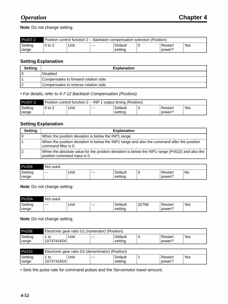
Chapter 4Operation
Note Do not change setting.
Setting Explanation
• For details, refer to 4-7-12 Backlash Compensation (Position).
Setting Explanation
Note Do not change setting.
Note Do not change setting.
• Sets the pulse rate for command pulses and the Servomotor travel amount.
Pn207.2 Position control function 2 -- Backlash compensation selection (Position)
Setting range
0 to 2 Unit --- Default setting
0 Restart power?
Yes
Setting Explanation0 Disabled
1 Compensates to forward rotation side.
2 Compensates to reverse rotation side.
Pn207.3 Position control function 2 -- INP 1 output timing (Position)
Setting range
0 to 2 Unit --- Default setting
0 Restart power?
Yes
Setting Explanation0 When the position deviation is below the INP1 range.
1 When the position deviation is below the INP1 range and also the command after the position command filter is 0.
2 When the absolute value for the position deviation is below the INP1 range (Pn522) and also the position command input is 0.
Pn209 Not used.
Setting range
--- Unit --- Default setting
0 Restart power?
No
Pn20A Not used.
Setting range
--- Unit --- Default setting
32768 Restart power?
Yes
Pn20E Electronic gear ratio G1 (numerator) (Position)
Setting range
1 to 1073741824
Unit --- Default setting
4 Restart power?
Yes
Pn210 Electronic gear ratio G2 (denominator) (Position)
Setting range
1 to 1073741824
Unit --- Default setting
1 Restart power?
Yes
4-52

Chapter 4Operation
• When G1/G2 is 1, inputting (encoder resolution × 4) pulses will rotate the Servomotor once. (TheServo Driver operates internally at a multiple of 4.)
• Set within a range of 0.001 ≤ G1/G2 ≤ 1,000.
Note For details on the electronic gear function, refer to 4-4-9 Electronic Gear Function (Position).
• Sets the number of output pulses from the Servo Driver.
• The encoder resolution for each Servomotor is shown below. Set this resolution as the upper limit.
INC 3,000-r/min Servomotor (30 to 750 W): 2,048 pulses/rotation3,000-r/min Servomotor (1 to 3 kW): 32,768 pulses/rotation3,000-r/min flat-type Servomotor: 2,048 pulses/rotation1,000-r/min Servomotor: 32,768 pulses/rotation
ABS 3,000-r/min Servomotor (30 to 750 W): 16,384 pulses/rotation3,000-r/min Servomotor (1 to 3 kW): 32,768 pulses/rotation3,000-r/min flat-type Servomotor: 16,384 pulses/rotation1,000-r/min Servomotor: 32,768 pulses/rotation1,500-r/min Servomotor: 32,768 pulses/rotation
Note 1. If a value greater than the encoder resolution is set, the encoder resolution will be taken asthe divider rate.
Note 2. For details on the encoder divider rate, refer to 4-4-5 Encoder Dividing Function (All Oper-ating Modes).
Note For details, refer to 4-7-12 Backlash Compensation (Position).
Note Do not change setting.
Note Do not change setting.
Pn212 Encoder divider rate (All operation modes)
Setting range
16 to 1073741824
Unit Pulses/rota-tion
Default setting
1000 Restart power?
Yes
Pn214 Backlash compensation amount (Position)
Setting range
−32767 to 32767
Unit Command unit
Default setting
0 Restart power?
No
Pn215 Backlash compensation time constant (Position)
Setting range
0 to 65535 Unit × 0.01 ms Default setting
0 Restart power?
No
Pn216 Not used.
Setting range
--- Unit --- Default setting
0 Restart power?
No
Pn217 Not used.
Setting range
--- Unit --- Default setting
0 Restart power?
No
4-53
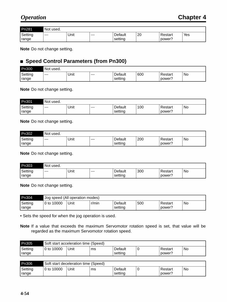
Chapter 4Operation
Note Do not change setting.
Speed Control Parameters (from Pn300)
Note Do not change setting.
Note Do not change setting.
Note Do not change setting.
Note Do not change setting.
• Sets the speed for when the jog operation is used.
Note If a value that exceeds the maximum Servomotor rotation speed is set, that value will beregarded as the maximum Servomotor rotation speed.
Pn281 Not used.
Setting range
--- Unit --- Default setting
20 Restart power?
Yes
Pn300 Not used.
Setting range
--- Unit --- Default setting
600 Restart power?
No
Pn301 Not used.
Setting range
--- Unit --- Default setting
100 Restart power?
No
Pn302 Not used.
Setting range
--- Unit --- Default setting
200 Restart power?
No
Pn303 Not used.
Setting range
--- Unit --- Default setting
300 Restart power?
No
Pn304 Jog speed (All operation modes)
Setting range
0 to 10000 Unit r/min Default setting
500 Restart power?
No
Pn305 Soft start acceleration time (Speed)
Setting range
0 to 10000 Unit ms Default setting
0 Restart power?
No
Pn306 Soft start deceleration time (Speed)
Setting range
0 to 10000 Unit ms Default setting
0 Restart power?
No
4-54
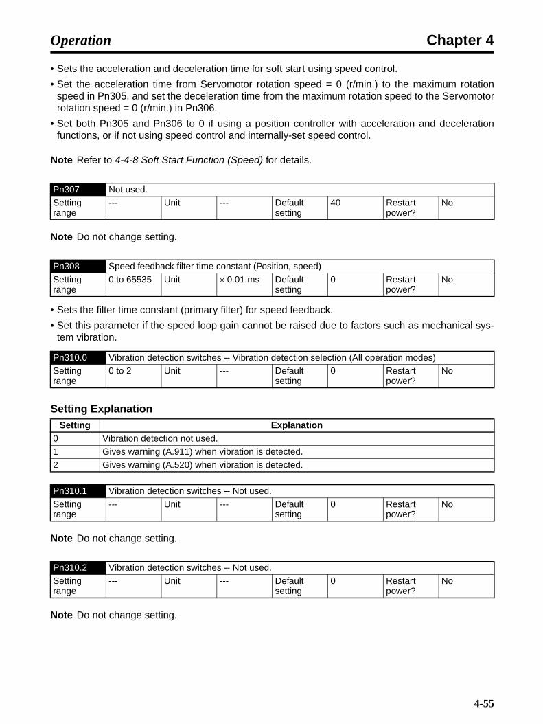
Chapter 4Operation
• Sets the acceleration and deceleration time for soft start using speed control.
• Set the acceleration time from Servomotor rotation speed = 0 (r/min.) to the maximum rotationspeed in Pn305, and set the deceleration time from the maximum rotation speed to the Servomotorrotation speed = 0 (r/min.) in Pn306.
• Set both Pn305 and Pn306 to 0 if using a position controller with acceleration and decelerationfunctions, or if not using speed control and internally-set speed control.
Note Refer to 4-4-8 Soft Start Function (Speed) for details.
Note Do not change setting.
• Sets the filter time constant (primary filter) for speed feedback.
• Set this parameter if the speed loop gain cannot be raised due to factors such as mechanical sys-tem vibration.
Setting Explanation
Note Do not change setting.
Note Do not change setting.
Pn307 Not used.
Setting range
--- Unit --- Default setting
40 Restart power?
No
Pn308 Speed feedback filter time constant (Position, speed)
Setting range
0 to 65535 Unit × 0.01 ms Default setting
0 Restart power?
No
Pn310.0 Vibration detection switches -- Vibration detection selection (All operation modes)
Setting range
0 to 2 Unit --- Default setting
0 Restart power?
No
Setting Explanation0 Vibration detection not used.
1 Gives warning (A.911) when vibration is detected.
2 Gives warning (A.520) when vibration is detected.
Pn310.1 Vibration detection switches -- Not used.
Setting range
--- Unit --- Default setting
0 Restart power?
No
Pn310.2 Vibration detection switches -- Not used.
Setting range
--- Unit --- Default setting
0 Restart power?
No
4-55

Chapter 4Operation
Note Do not change setting.
• Pn312 is set by the vibration detection level initialization by Computer Monitor Software, so there isno need for the user to directly adjust this parameter. Detection sensitivity is set by Pn311 (Vibra-tion detection sensitivity).
• Detection level initialization for vibration detection:This function detects vibration in machine operation and automatically sets the vibration detectionlevel (Pn312) so that the vibration alarm (A.520) and vibration warning (A.911) can be more accu-rately detected.Use this function when the vibration alarm (A.520) and vibration warning (A.911) are not output withthe appropriate timing when vibration is detected at the default setting for the vibration detectionlevel (Pn312). Aside from that situation, there is no need to execute this function.When the vibration detection function detects a certain level of vibration at the Servomotor rotationspeed and the detection level in the equation below is exceeded, an alarm or warning is generatedaccording to the vibration detection switches (Pn310) setting.Depending on the conditions of the machinery being used, there may be a difference in detectionsensitivity between vibration alarms and warnings. If that occurs, a minute adjustment in detectionsensitivity can be set in Pn311 (detection sensitivity) in the equation below.
Note 1. Vibration may be difficult to detect due to an inappropriate Servo gain setting. Moreover, notall vibration that occurs can be detected. Use a uniform criterion for detected results.
Note 2. Set the appropriate inertia rate (Pn103). If the setting inappropriate, it may result in errone-ous detection of vibration alarms or warnings, or in detection failure.
Note 3. To execute this function, the commands that the user is actually using must be input.
Note 4. Execute this function in the operating conditions under which the vibration detection level isto be initialized. If this function is executed with the Servomotor rotating at low speed, vibra-tion will be detected as soon as the Servo is turned ON. “Error” will be displayed if this func-tion is executed while the Servomotor is operating at 10% or less of its maximum rotationspeed.
Torque Control Parameters (from Pn400)
Pn310.3 Vibration detection switches -- Not used.
Setting range
--- Unit --- Default setting
0 Restart power?
No
Pn311 Vibration detection sensitivity (All operation modes)
Setting range
50 to 500 Unit % Default setting
100 Restart power?
No
Pn312 Vibration detection level (All operation modes)
Setting range
0 to 5000 Unit r/min Default setting
50 Restart power?
No
Pn400 Not used.
Setting range
--- Unit --- Default setting
30 Restart power?
No
Vibration detection level (Pn312 [r/min]) × Pn311 [%])100
Detection level =
4-56

Chapter 4Operation
Note Do not change setting.
• Sets the (primary) filter time constant for the internal torque command.
• When the mechanical resonance frequency is within the response frequency of the Servo loop,Servomotor vibration will occur. In order to prevent this from occurring, set the torque command fil-ter time constant.The relationship between the filter time constant and the cut-off frequency can be found by meansof the following formula:
fc (Hz) = 1 / (2πT) : T= Filter time constant (s), fc: cut-off frequency.Set the cut-off frequency to below the mechanical resonance frequency.
• Set Pn402 (forward torque limit) and Pn403 (reverse torque limit) using the ratio (%) of the Servo-motor rated torque for each.
Note These following torque limit functions are available: Analog torque limit (Pn002.0 = 1 or 3),Pn402 (forward torque limit), Pn403 (reverse torque limit), Pn404 (forward rotation external cur-rent limit), and Pn405 (reverse rotation external current limit). The output torque is limited bythe smallest of the enabled limit values. Refer to 4-4-7 Torque Limit Function (All OperatingModes) for details.
• Set in Pn404 the torque limit for when the forward torque limit is input, and set in Pn405 the torquelimit for when the reverse torque limit is input, using the ratio (%) of the Servomotor rated torque foreach.
Note The following torque limit functions are available: Analog torque limit (Pn002.0 = 1 or 3), Pn402(forward torque limit), Pn403 (reverse torque limit), Pn404 (forward rotation external currentlimit), and Pn405 (reverse rotation external current limit). The output torque is limited by thesmallest of the enabled limit values. Refer to 4-4-7 Torque Limit Function (All Operating Modes)for details.
Pn401 1st step 1st torque command filter time constant (All operation modes)
Setting range
0 to 65535 Unit × 0.01 ms Default setting
40 Restart power?
No
Pn402 Forward torque limit (All operation modes)
Setting range
0 to 800 Unit % Default setting
350 Restart power?
No
Pn403 Reverse torque limit (All operation modes)
Setting range
0 to 800 Unit % Default setting
350 Restart power?
No
Pn404 Forward rotation external current limit (All operation modes)
Setting range
0 to 800 Unit % Default setting
100 Restart power?
No
Pn405 Reverse rotation external current limit (All operation modes)
Setting range
0 to 800 Unit % Default setting
100 Restart power?
No
4-57
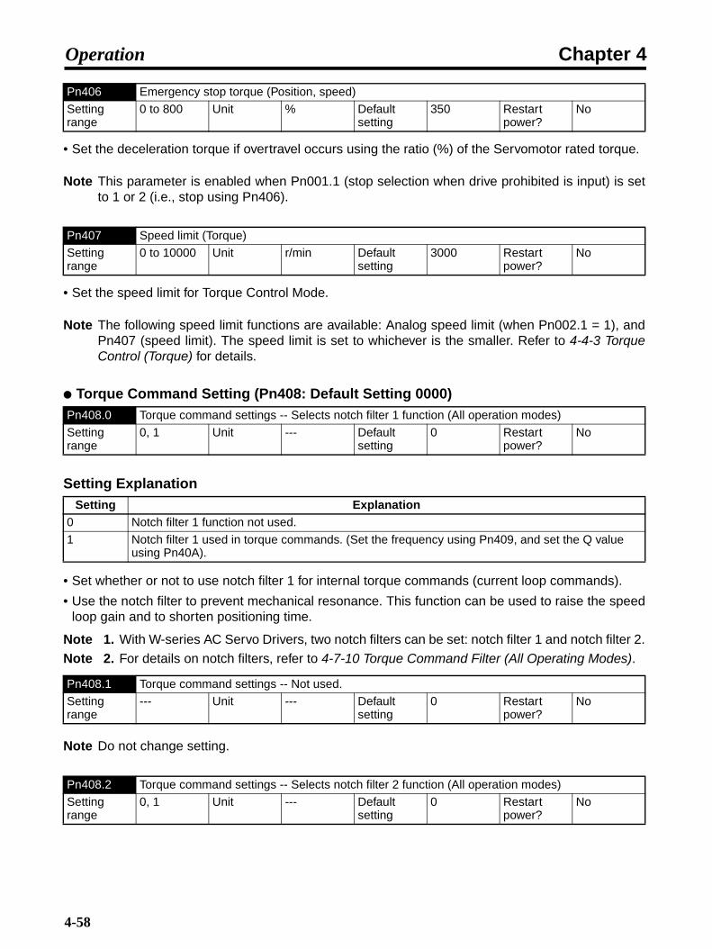
Chapter 4Operation
• Set the deceleration torque if overtravel occurs using the ratio (%) of the Servomotor rated torque.
Note This parameter is enabled when Pn001.1 (stop selection when drive prohibited is input) is setto 1 or 2 (i.e., stop using Pn406).
• Set the speed limit for Torque Control Mode.
Note The following speed limit functions are available: Analog speed limit (when Pn002.1 = 1), andPn407 (speed limit). The speed limit is set to whichever is the smaller. Refer to 4-4-3 TorqueControl (Torque) for details.
Torque Command Setting (Pn408: Default Setting 0000)
Setting Explanation
• Set whether or not to use notch filter 1 for internal torque commands (current loop commands).
• Use the notch filter to prevent mechanical resonance. This function can be used to raise the speedloop gain and to shorten positioning time.
Note 1. With W-series AC Servo Drivers, two notch filters can be set: notch filter 1 and notch filter 2.
Note 2. For details on notch filters, refer to 4-7-10 Torque Command Filter (All Operating Modes).
Note Do not change setting.
Pn406 Emergency stop torque (Position, speed)
Setting range
0 to 800 Unit % Default setting
350 Restart power?
No
Pn407 Speed limit (Torque)
Setting range
0 to 10000 Unit r/min Default setting
3000 Restart power?
No
Pn408.0 Torque command settings -- Selects notch filter 1 function (All operation modes)
Setting range
0, 1 Unit --- Default setting
0 Restart power?
No
Setting Explanation0 Notch filter 1 function not used.
1 Notch filter 1 used in torque commands. (Set the frequency using Pn409, and set the Q value using Pn40A).
Pn408.1 Torque command settings -- Not used.
Setting range
--- Unit --- Default setting
0 Restart power?
No
Pn408.2 Torque command settings -- Selects notch filter 2 function (All operation modes)
Setting range
0, 1 Unit --- Default setting
0 Restart power?
No
4-58

Chapter 4Operation
Setting Explanation
• Set whether or not to use notch filter 2 for internal torque commands (current loop commands).
• Use the notch filter to prevent mechanical resonance. This function can be used to increase thespeed loop gain and to shorten positioning time.
Note 1. With W-series AC Servo Drivers, two notch filters can be set: notch filter 1 and notch filter 2.
Note 2. For details on notch filters, refer to 4-7-10 Torque Command Filter (All Operating Modes).
Note Do not change setting.
• Enabled when Pn408.0 (notch filter 1 function selection) is set to 1.
• Sets the mechanical resonance frequency.
Note For details on notch filters, refer to 4-7-10 Torque Command Filter (All Operating Modes).
• Enabled when Pn408.0 (notch filter 1 function selection) is set to 1.
• Sets the Q value for notch filter 1.
Note For details on notch filters, refer to 4-7-10 Torque Command Filter (All Operating Modes).
• Enabled when Pn408.2 (notch filter 2 function selection) is set to 1.
• Sets the mechanical resonance frequency.
Note For details on notch filters, refer to 4-7-10 Torque Command Filter (All Operating Modes).
Setting Explanation0 Notch filter 2 function not used.
1 Notch filter 2 used in torque commands. (Set the frequency using Pn40B, and set the Q value in Pn40C.)
Pn408.3 Torque command settings -- Not used.
Setting range
--- Unit --- Default setting
0 Restart power?
No
Pn409 Notch filter 1 frequency (All operation modes)
Setting range
50 to 2000 Unit Hz Default setting
2000 Restart power?
No
Pn40A Notch filter 1 Q value (All operation modes)
Setting range
50 to 1000 Unit × 0.01 Default setting
70 Restart power?
No
Pn40C Notch filter 2 frequency (All operation modes)
Setting range
50 to 2000 Unit Hz Default setting
2000 Restart power?
No
Pn40D Notch filter 2 Q value (All operation modes)
Setting range
50 to 1000 Unit × 0.01 Default setting
70 Restart power?
No
4-59

Chapter 4Operation
• Enabled when Pn408.2 (notch filter 2 function selection) is set to 1.
• Set the Q value for notch filter 2.
Note For details on notch filters, refer to 4-7-10 Torque Command Filter (All Operating Modes).
Note Do not change setting.
Note Do not change setting.
Note For details on vibration suppression when stopped, refer to 4-7-11 Vibration Suppression whenStopping (Position).
Pn40F 2nd step 2nd torque command filter frequency (All operation modes)
Setting range
100 to 2000 Unit Hz Default setting
2000 Restart power?
No
Pn410 2nd step 2nd torque command filter Q value (All operation modes)
Setting range
50 to 1000 Unit × 0.01 Default setting
70 Restart power?
No
Pn411 3rd step torque command filter time constant (All operation modes)
Setting range
0 to 65535 Unit µs Default setting
0 Restart power?
No
Pn412 1st step 2nd torque command filter time constant (All operation modes)
Setting range
0 to 65535 Unit × 0.01 ms Default setting
100 Restart power?
No
Pn413 Not used.
Setting range
--- Unit --- Default setting
100 Restart power?
No
Pn414 Not used.
Setting range
--- Unit --- Default setting
100 Restart power?
No
Pn420 Damping for vibration suppression on stopping (Position)
Setting range
10 to 100 Unit % Default setting
100 Restart power?
No
Pn421 Vibration suppression starting time (Position)
Setting range
0 to 65535 Unit ms Default setting
1000 Restart power?
No
Pn422 Gravity compensation torque
Setting range
−20000 to 20000
Unit × 0.01% Default setting
0 Restart power?
No
4-60
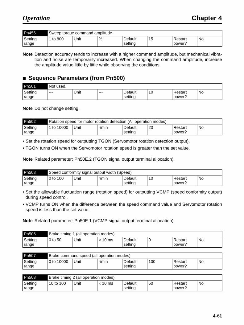
Chapter 4Operation
Note Detection accuracy tends to increase with a higher command amplitude, but mechanical vibra-tion and noise are temporarily increased. When changing the command amplitude, increasethe amplitude value little by little while observing the conditions.
Sequence Parameters (from Pn500)
Note Do not change setting.
• Set the rotation speed for outputting TGON (Servomotor rotation detection output).
• TGON turns ON when the Servomotor rotation speed is greater than the set value.
Note Related parameter: Pn50E.2 (TGON signal output terminal allocation).
• Set the allowable fluctuation range (rotation speed) for outputting VCMP (speed conformity output)during speed control.
• VCMP turns ON when the difference between the speed command value and Servomotor rotationspeed is less than the set value.
Note Related parameter: Pn50E.1 (VCMP signal output terminal allocation).
Pn456 Sweep torque command amplitude
Setting range
1 to 800 Unit % Default setting
15 Restart power?
No
Pn501 Not used.
Setting range
--- Unit --- Default setting
10 Restart power?
No
Pn502 Rotation speed for motor rotation detection (All operation modes)
Setting range
1 to 10000 Unit r/min Default setting
20 Restart power?
No
Pn503 Speed conformity signal output width (Speed)
Setting range
0 to 100 Unit r/min Default setting
10 Restart power?
No
Pn506 Brake timing 1 (all operation modes)
Setting range
0 to 50 Unit × 10 ms Default setting
0 Restart power?
No
Pn507 Brake command speed (all operation modes)
Setting range
0 to 10000 Unit r/min Default setting
100 Restart power?
No
Pn508 Brake timing 2 (all operation modes)
Setting range
10 to 100 Unit × 10 ms Default setting
50 Restart power?
No
4-61

Chapter 4Operation
• This parameter sets the BKIR (brake interlock output) timing to control the electromagnetic brakeON/OFF when a Servomotor with a brake is used.
• This setting prevents damage to the machinery and the Servomotor holding brake.
• Pn506 (brake timing 1): Set the lag time from BKIR OFF to Servo OFF.
• Pn507 (brake command speed): Set the rotation speed for turning OFF BKIR.
• Pn508 (brake timing 2): Set the standby time from Servo OFF to BKIR OFF.
• When RUN is OFF while the Servomotor is stopped, first turn OFF BKIR, wait for the duration set inPn506, then turn OFF the Servo.
• When RUN is OFF while the Servomotor is stopped, if a Servo alarm occurs, and the main circuitpower supply is OFF, the Servomotor will decelerate and the rotation speed will fall. When the rota-tion speed falls to below the Pn507 setting, BKIR will be turned OFF.
Note 1. Related parameter: Pn50F.2 (BKIR signal output terminal allocation).
Note 2. Refer to 4-4-6 Brake Interlock (All Operating Modes) for details of brake interlock functions.
• Sets the time during which alarm detection is disabled if a momentary power failure occurs.
• When the power supply voltage to the Servo Driver is OFF, the Servo Driver detects that the powersupply is OFF and turns OFF the Servo. The 20 ms default setting means that if the power supplyvoltage is recovered within 20 ms, operation will continue without the Servo being turned OFF.
• In the following cases, the Servo is turned OFF regardless of the Pn509 setting:
• If the load is too great, and A.410 (insufficient voltage) occurs during a momentary power stop-page.
• If the control power supply falls during a momentary power stoppage, and cannot be con-trolled.
Note Refer to 4-3-2 Important Parameters.
Note Do not change setting.
Pn509 Momentary hold time (All operation modes)
Setting range
20 to 1000 Unit ms Default setting
20 Restart power?
No
Pn50A Input signal selection 1 (All operation modes)
Default set-ting
1881 Restart power?
Yes
Pn50B Input signal selection 2 (All operation modes)
Default set-ting
8882 Restart power?
Yes
Pn50C Input signal selection 3 (All operation modes)
Default set-ting
8888 Restart power?
Yes
Pn50D Input signal selection 4 (All operation modes)
Default set-ting
8888 Restart power?
Yes
Pn50E Output signal selection 1 (All operation modes)
Default set-ting
0000 Restart power?
Yes
4-62
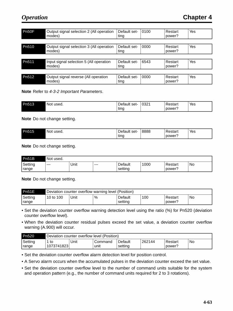
Chapter 4Operation
Note Refer to 4-3-2 Important Parameters.
Note Do not change setting.
Note Do not change setting.
Note Do not change setting.
• Set the deviation counter overflow warning detection level using the ratio (%) for Pn520 (deviationcounter overflow level).
• When the deviation counter residual pulses exceed the set value, a deviation counter overflowwarning (A.900) will occur.
• Set the deviation counter overflow alarm detection level for position control.
• A Servo alarm occurs when the accumulated pulses in the deviation counter exceed the set value.
• Set the deviation counter overflow level to the number of command units suitable for the systemand operation pattern (e.g., the number of command units required for 2 to 3 rotations).
Pn50F Output signal selection 2 (All operation modes)
Default set-ting
0100 Restart power?
Yes
Pn510 Output signal selection 3 (All operation modes)
Default set-ting
0000 Restart power?
Yes
Pn511 Input signal selection 5 (All operation modes)
Default set-ting
6543 Restart power?
Yes
Pn512 Output signal reverse (All operation modes)
Default set-ting
0000 Restart power?
Yes
Pn513 Not used. Default set-ting
0321 Restart power?
Yes
Pn515 Not used. Default set-ting
8888 Restart power?
Yes
Pn51B Not used.
Setting range
--- Unit --- Default setting
1000 Restart power?
No
Pn51E Deviation counter overflow warning level (Position)
Setting range
10 to 100 Unit % Default setting
100 Restart power?
No
Pn520 Deviation counter overflow level (Position)
Setting range
1 to 1073741823
Unit Command unit
Default setting
262144 Restart power?
No
4-63
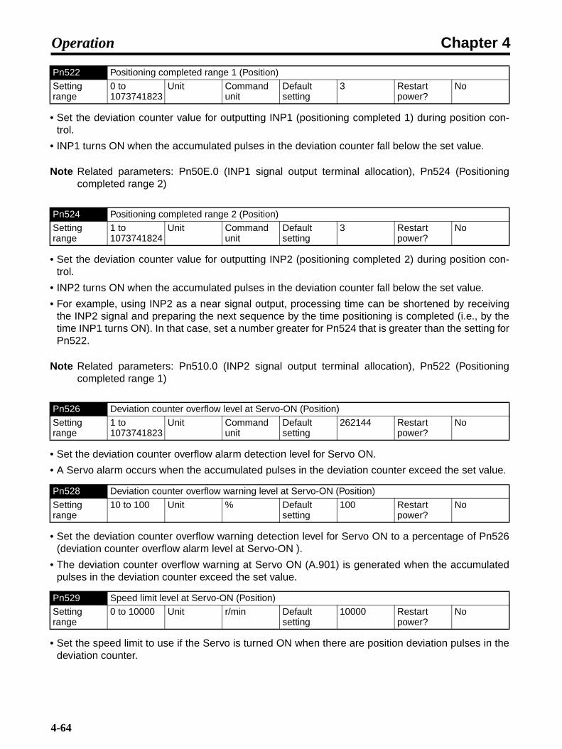
Chapter 4Operation
• Set the deviation counter value for outputting INP1 (positioning completed 1) during position con-trol.
• INP1 turns ON when the accumulated pulses in the deviation counter fall below the set value.
Note Related parameters: Pn50E.0 (INP1 signal output terminal allocation), Pn524 (Positioningcompleted range 2)
• Set the deviation counter value for outputting INP2 (positioning completed 2) during position con-trol.
• INP2 turns ON when the accumulated pulses in the deviation counter fall below the set value.
• For example, using INP2 as a near signal output, processing time can be shortened by receivingthe INP2 signal and preparing the next sequence by the time positioning is completed (i.e., by thetime INP1 turns ON). In that case, set a number greater for Pn524 that is greater than the setting forPn522.
Note Related parameters: Pn510.0 (INP2 signal output terminal allocation), Pn522 (Positioningcompleted range 1)
• Set the deviation counter overflow alarm detection level for Servo ON.
• A Servo alarm occurs when the accumulated pulses in the deviation counter exceed the set value.
• Set the deviation counter overflow warning detection level for Servo ON to a percentage of Pn526(deviation counter overflow alarm level at Servo-ON ).
• The deviation counter overflow warning at Servo ON (A.901) is generated when the accumulatedpulses in the deviation counter exceed the set value.
• Set the speed limit to use if the Servo is turned ON when there are position deviation pulses in thedeviation counter.
Pn522 Positioning completed range 1 (Position)
Setting range
0 to 1073741823
Unit Command unit
Default setting
3 Restart power?
No
Pn524 Positioning completed range 2 (Position)
Setting range
1 to 1073741824
Unit Command unit
Default setting
3 Restart power?
No
Pn526 Deviation counter overflow level at Servo-ON (Position)
Setting range
1 to 1073741823
Unit Command unit
Default setting
262144 Restart power?
No
Pn528 Deviation counter overflow warning level at Servo-ON (Position)
Setting range
10 to 100 Unit % Default setting
100 Restart power?
No
Pn529 Speed limit level at Servo-ON (Position)
Setting range
0 to 10000 Unit r/min Default setting
10000 Restart power?
No
4-64
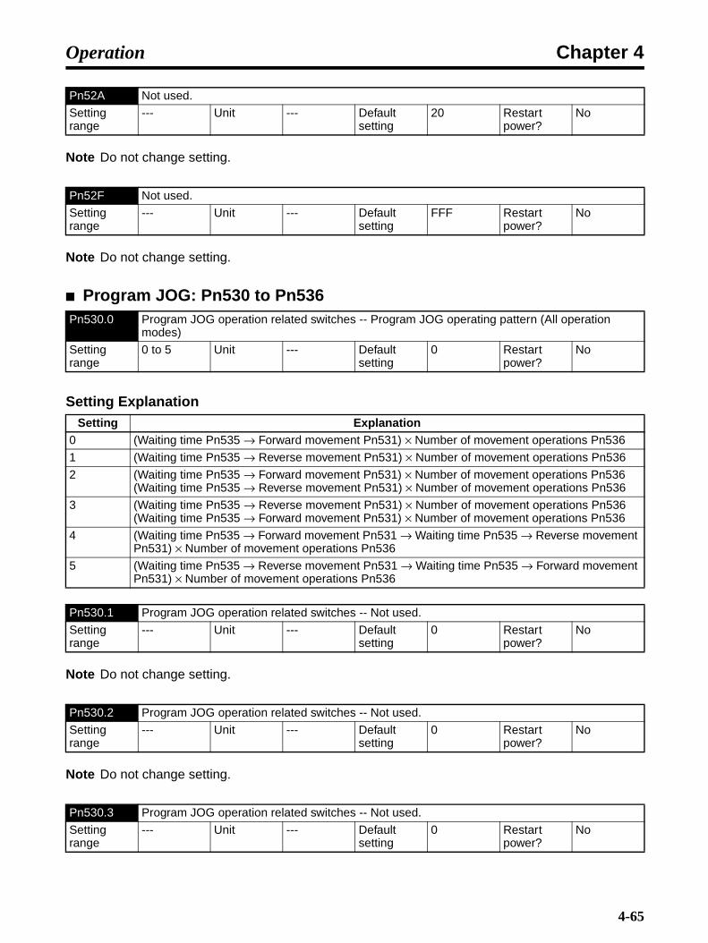
Chapter 4Operation
Note Do not change setting.
Note Do not change setting.
Program JOG: Pn530 to Pn536
Setting Explanation
Note Do not change setting.
Note Do not change setting.
Pn52A Not used.
Setting range
--- Unit --- Default setting
20 Restart power?
No
Pn52F Not used.
Setting range
--- Unit --- Default setting
FFF Restart power?
No
Pn530.0 Program JOG operation related switches -- Program JOG operating pattern (All operation modes)
Setting range
0 to 5 Unit --- Default setting
0 Restart power?
No
Setting Explanation0 (Waiting time Pn535 → Forward movement Pn531) × Number of movement operations Pn536
1 (Waiting time Pn535 → Reverse movement Pn531) × Number of movement operations Pn536
2 (Waiting time Pn535 → Forward movement Pn531) × Number of movement operations Pn536(Waiting time Pn535 → Reverse movement Pn531) × Number of movement operations Pn536
3 (Waiting time Pn535 → Reverse movement Pn531) × Number of movement operations Pn536(Waiting time Pn535 → Forward movement Pn531) × Number of movement operations Pn536
4 (Waiting time Pn535 → Forward movement Pn531 → Waiting time Pn535 → Reverse movement Pn531) × Number of movement operations Pn536
5 (Waiting time Pn535 → Reverse movement Pn531 → Waiting time Pn535 → Forward movement Pn531) × Number of movement operations Pn536
Pn530.1 Program JOG operation related switches -- Not used.
Setting range
--- Unit --- Default setting
0 Restart power?
No
Pn530.2 Program JOG operation related switches -- Not used.
Setting range
--- Unit --- Default setting
0 Restart power?
No
Pn530.3 Program JOG operation related switches -- Not used.
Setting range
--- Unit --- Default setting
0 Restart power?
No
4-65

Chapter 4Operation
Note Do not change setting.
Note For details on the program JOG function, refer to 4-4-13 Program JOG Operation.
• As the value is increased, response improves but vibration becomes easier. Likewise, as the valueis decreased, operation becomes more stable but response declines.
• When Pn006 is set to 0102, Pn422 [%] to 10.0, and Pn550 to 3.0 [V]:Analog monitor 1: Torque command
= (−1) × (Torque command [%] − 10%) × 10 + 3 [V]If the torque here is 52%
= (−1) × (52 [%] − 10 [%]) × 1 [V]/100 [%] + 3 [V]= −7.2 [V] (Analog monitor 1 output voltage)
Other Parameters (from Pn600)
Pn531 Program JOG movement distance (All operation modes)
Setting range
1 to 1073741824
Unit Command unit
Default setting
32768 Restart power?
No
Pn533 Program JOG movement speed (All operation modes)
Setting range
1 to 10000 Unit r/min Default setting
500 Restart power?
No
Pn534 Program JOG acceleration/deceleration time (All operation modes)
Setting range
2 to 10000 Unit ms Default setting
100 Restart power?
No
Pn535 Program JOG waiting time (All operation modes)
Setting range
0 to 10000 Unit ms Default setting
100 Restart power?
No
Pn536 Number of program JOG movement (All operation modes)
Setting range
1 to 1000 Unit Times Default setting
1 Restart power?
No
Pn540 Gain limit (Position, speed)
Setting range
10 to 2000 Unit × 0.1 Hz Default setting
2000 Restart power?
No
Pn550 Analog monitor 1 offset voltage (All operation modes)
Setting range
−10000 to 10000
Unit × 0.1 V Default setting
0 Restart power?
No
Pn551 Analog monitor 2 offset voltage (All operation modes)
Setting range
−10000 to 10000
Unit × 0.1 V Default setting
0 Restart power?
No
Pn600 Regeneration resistor capacity (All operation modes)
Setting range
0 to (varies by model)
Unit × 10 W Default setting
0 Restart power?
No
4-66

Chapter 4Operation
• If using an External Regeneration Resistor or External Regeneration Resistance Unit, set theregeneration absorption amount. Set the regeneration absorption amount for when the temperaturerises above 120°C, not the nominal amount. (Refer to 3-3-3 Regenerative Energy Absorption byExternal Regeneration Resistance for details.)
• A.920 (Regenerative overload warning and A.320 (Regenerative overload alarm) are detectedbased on the set value.
Note If an External Regeneration Resistor or External Regeneration Resistance Unit is not con-nected, set Pn600 to 0.
Setting Explanation
• This function is used for ignoring communications alarm checks in operations such as debuggingduring trial operation.When it is used for normal operation,0 (with check) must be set.
Setting Explanation
• Depending on the setting for Pn800.1, warnings are not detected for A. 94@, A. 95@, and A. 96@.(Warnings are detected for A. 94@ and A. 95@ A. in the default settings.)
Pn800.0 Communications control -- MECHATROLINK-II communications check mask (All operation modes)
Setting range
0 to 3 Unit --- Default setting
0 Restart power?
No
Setting Explanation0 Normal
1 Ignore communications errors (A.E6@).
2 Ignore WDT errors (A.E5@).
3 Ignore communications errors (A.E6@) and WDT errors (A.E5@).
Pn800.1 Communications control -- Warning check mask (All operation modes)
Setting range
0 to 7 Unit --- Default setting
4 Restart power?
No
Setting Explanation0 Normal
1 Ignore data setting warning (A. 94@).
2 Ignore command warning (A. 95@).
3 Ignore A.94@ and A.95@.
4 Ignore communications warning (A. 96@).
5 Ignore A.94@ and A.96@.
6 Ignore A.95@ and A.96@.
7 Ignore A.94@, A.95@ and A.96@.
4-67

Chapter 4Operation
• When connecting to the CJ1W-NCF71 or CS1W-NCF71, always use the default setting (4) or a set-ting of 0.
Setting Explanation
Note Do not change setting.
Setting Explanation
• Enables or disables software limits. Software limit function settings are executed according to thenext user constant. Software limits are enabled in the cases described below. In all other cases,software limits do not go into effect even when the software limit range is exceeded.
When the origin is established (when the No-origin Flag is OFF for the CJ1W-NCF71, CS1W-MCH71, CJ1W-MCH71)
When an infinite length axis is used (CS1W-MCH71, CJ1W-MCH71)
Set enable/disable with the above setting method described above.
Note Do not change setting.
Pn800.2 Communications control -- Communications error count at single transmission (All operation modes)
Setting range
0 to F Unit --- Default setting
0 Restart power?
No
Setting Explanation0 to F Detects communications errors (A.E60) if errors occur consecutively for the set value plus two
times.
Pn800.3 Communications control -- Not used.
Setting range
--- Unit --- Default setting
0 Restart power?
No
Pn801.0 Function selection application 6 (software LS) -- Software limit function (All operation modes)
Setting range
0 to 3 Unit --- Default setting
3 Restart power?
No
Setting Explanation0 Software limit enabled.
1 Forward software limit disabled.
2 Reverse software limit disabled.
3 Forward/reverse software limits disabled.
Pn801.1 Function selection application 6 (software LS) -- Not used.
Setting range
--- Unit --- Default setting
0 Restart power?
No
Pn801.2 Function selection application 6 (software LS) -- Software limit check using reference (Position)
Setting range
0, 1 Unit --- Default setting
0 Restart power?
No
4-68
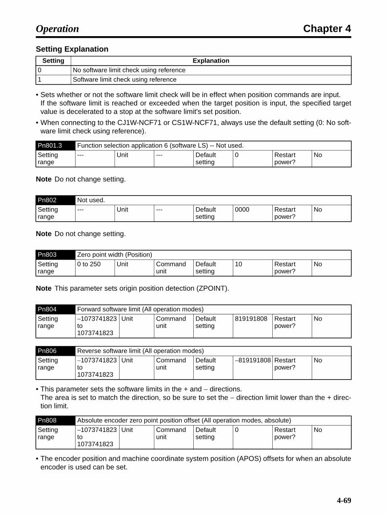
Chapter 4Operation
Setting Explanation
• Sets whether or not the software limit check will be in effect when position commands are input.If the software limit is reached or exceeded when the target position is input, the specified targetvalue is decelerated to a stop at the software limit's set position.
• When connecting to the CJ1W-NCF71 or CS1W-NCF71, always use the default setting (0: No soft-ware limit check using reference).
Note Do not change setting.
Note Do not change setting.
Note This parameter sets origin position detection (ZPOINT).
• This parameter sets the software limits in the + and − directions.The area is set to match the direction, so be sure to set the − direction limit lower than the + direc-tion limit.
• The encoder position and machine coordinate system position (APOS) offsets for when an absoluteencoder is used can be set.
Setting Explanation0 No software limit check using reference
1 Software limit check using reference
Pn801.3 Function selection application 6 (software LS) -- Not used.
Setting range
--- Unit --- Default setting
0 Restart power?
No
Pn802 Not used.
Setting range
--- Unit --- Default setting
0000 Restart power?
No
Pn803 Zero point width (Position)
Setting range
0 to 250 Unit Command unit
Default setting
10 Restart power?
No
Pn804 Forward software limit (All operation modes)
Setting range
−1073741823 to 1073741823
Unit Command unit
Default setting
819191808 Restart power?
No
Pn806 Reverse software limit (All operation modes)
Setting range
−1073741823 to 1073741823
Unit Command unit
Default setting
−819191808 Restart power?
No
Pn808 Absolute encoder zero point position offset (All operation modes, absolute)
Setting range
−1073741823 to 1073741823
Unit Command unit
Default setting
0 Restart power?
No
4-69

Chapter 4Operation
• The settings are shown below. To take the machine coordinate system origin (0) as the encoderposition (X), set Pn808 to −X.
Acceleration/Deceleration Speed Parameters (Pn80A to Pn812)
• Sets the step 1 acceleration speed for when two-step acceleration is used.
• Sets the step 2 acceleration for when two-step acceleration is executed, or the one-step accelera-tion parameter for when one-step acceleration is executed.
• Sets the switching speed for the step 1 and step 2 acceleration for when two-step acceleration isexecuted. When using one-step acceleration, set the acceleration parameter switching speed(Pn80C) to 0.
• Sets the step 1 deceleration for when two-step acceleration is used.
• Sets the step 2 deceleration for when two-step deceleration is executed. When using one-stepacceleration, set Pn80E as the one-step deceleration parameter.
Pn80A First step linear acceleration parameter (Position)
Setting range
1 to 65535 Unit × 10000 Command unit/s2
Default setting
100 Restart power?
No
Pn80B Second step linear acceleration parameter (Position)
Setting range
1 to 65535 Unit × 10000 Command unit/s2
Default setting
100 Restart power?
No
Pn80C Acceleration parameter switching speed (Position)
Setting range
0 to 65535 Unit × 100 Com-mand unit/s
Default setting
0 Restart power?
No
Pn80D First step linear deceleration parameter (Position)
Setting range
1 to 65535 Unit × 10000 Command unit/s2
Default setting
100 Restart power?
No
Pn80E Second step linear deceleration parameter (Position)
Setting range
1 to 65535 Unit × 10000 Command unit/s2
Default setting
100 Restart power?
No
Pn808
Machine coordinate system position (APOS)
Encoder position
Encoder position: origin
Encoder position ×
Origin
4-70
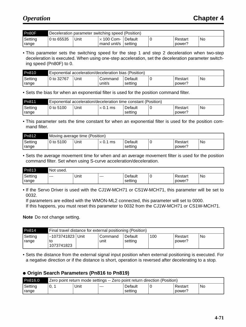
Chapter 4Operation
• This parameter sets the switching speed for the step 1 and step 2 deceleration when two-stepdeceleration is executed. When using one-step acceleration, set the deceleration parameter switch-ing speed (Pn80F) to 0.
• Sets the bias for when an exponential filter is used for the position command filter.
• This parameter sets the time constant for when an exponential filter is used for the position com-mand filter.
• Sets the average movement time for when and an average movement filter is used for the positioncommand filter. Set when using S-curve acceleration/deceleration.
• If the Servo Driver is used with the CJ1W-MCH71 or CS1W-MCH71, this parameter will be set to0032. If parameters are edited with the WMON-ML2 connected, this parameter will set to 0000.If this happens, you must reset this parameter to 0032 from the CJ1W-MCH71 or CS1W-MCH71.
Note Do not change setting.
• Sets the distance from the external signal input position when external positioning is executed. Fora negative direction or if the distance is short, operation is reversed after decelerating to a stop.
Origin Search Parameters (Pn816 to Pn819)
Pn80F Deceleration parameter switching speed (Position)
Setting range
0 to 65535 Unit × 100 Com-mand unit/s
Default setting
0 Restart power?
No
Pn810 Exponential acceleration/deceleration bias (Position)
Setting range
0 to 32767 Unit Command unit/s
Default setting
0 Restart power?
No
Pn811 Exponential acceleration/deceleration time constant (Position)
Setting range
0 to 5100 Unit × 0.1 ms Default setting
0 Restart power?
No
Pn812 Moving average time (Position)
Setting range
0 to 5100 Unit × 0.1 ms Default setting
0 Restart power?
No
Pn813 Not used.
Setting range
--- Unit --- Default setting
0 Restart power?
No
Pn814 Final travel distance for external positioning (Position)
Setting range
−1073741823 to 1073741823
Unit Command unit
Default setting
100 Restart power?
No
Pn816.0 Zero point return mode settings -- Zero point return direction (Position)
Setting range
0, 1 Unit --- Default setting
0 Restart power?
No
4-71

Chapter 4Operation
Setting Explanation
• Sets the direction for executing origin search.
Note Do not change setting.
Note Do not change setting.
Note Do not change setting.
• Sets the origin search speed after the deceleration limit switch signal turns ON.
• Sets the origin search speed from when the deceleration limit switch signal turns ON until it turnsOFF.
• Sets the distance from the latch signal input position to the origin, for when origin search is exe-cuted. If the final travel distance is in the opposite direction from the origin return direction or if thedistance is short, operation is reversed after decelerating to a stop.
Setting Explanation0 Forward
1 Reverse
Pn816.1 Zero point return mode settings -- Not used.
Setting range
--- Unit --- Default setting
0 Restart power?
No
Pn816.2 Zero point return mode settings -- Not used.
Setting range
--- Unit --- Default setting
0 Restart power?
No
Pn816.3 Zero point return mode settings -- Not used.
Setting range
--- Unit --- Default setting
0 Restart power?
No
Pn817 Zero point return approach speed 1 (Position)
Setting range
0 to 65535 Unit × 100 Com-mand unit/s
Default setting
50 Restart power?
No
Pn818 Zero point return approach speed 2 (Position)
Setting range
0 to 65535 Unit × 100 Com-mand unit/s
Default setting
5 Restart power?
No
Pn819 Final travel distance to return to zero point (Position)
Setting range
−1073741823 to 1073741823
Unit Command unit/s
Default setting
100 Restart power?
No
Pn81B Not used.
Setting range
--- Unit --- Default setting
0 Restart power?
No
4-72

Chapter 4Operation
Note Do not change setting.
Note Do not change setting.
Note Do not change setting.
Input Signal Monitor Parameter (Pn81E)
Note Do not change setting.
Note Do not change setting.
Latch Area Parameters (Pn820, Pn822)
Note Do not change setting.
Option Monitor Parameters (Pn824, Pn825)
• If the Servo Driver is used with the CJ1W-MCH71 or CS1W-MCH71, this parameter will be set to0032. If parameters are edited with the WMON-ML2 connected, this parameter will set to 0000. Ifthis happens, you must reset this parameter to 0032 from the CJ1W-MCH71 or CS1W-MCH71.
Pn81C Not used.
Setting range
--- Unit --- Default setting
0 Restart power?
No
Pn81D Not used.
Setting range
--- Unit --- Default setting
0 Restart power?
No
Pn81E Not used.
Setting range
--- Unit --- Default setting
0000 Restart power?
No
Pn81F Not used.
Setting range
--- Unit --- Default setting
0 Restart power?
No
Pn820 Not used.
Setting range
--- Unit --- Default setting
00000000 Restart power?
No
Pn822 Not used.
Setting range
--- Unit --- Default setting
00000000 Restart power?
No
Pn824 Not used.
Setting range
--- Unit --- Default setting
0000 Restart power?
No
4-73

Chapter 4Operation
Note Do not change setting.
• If the Servo Driver is used with the CJ1W-MCH71 or CS1W-MCH71, this parameter will be set to0024. If parameters are edited with the WMON-ML2 connected, this parameter will set to 0000. Ifthis happens, you must reset this parameter to 0024 from the CJ1W-MCH71 or CS1W-MCH71.
Note Do not change setting.
Other Unused Parameters
Note Do not change setting.
Note Do not change setting.
Pn825 Not used.
Setting range
--- Unit --- Default setting
0000 Restart power?
No
Pn900 to Pn910
Not used.
Setting range
--- Unit --- Default setting
--- Restart power?
No
Pn920 to Pn95F
Not used.
Setting range
--- Unit --- Default setting
--- Restart power?
No
4-74

Chapter 4Operation
4-4 Operation Functions
4-4-1 Position Control (Position)
Functions• Position control is performed according to commands from MECHATROLINK-II.
• The motor is rotated by the command value multiplied by the gear ratio (Pn20E, Pn210).
Parameters Requiring Settings
Related Functions• The main functions related to position control that can be used during position control are as fol-
lows:
Parameter No.
Parameter name Explanation Reference
Pn20E Electronic gear ratio G1 (numerator)
Set the pulse rates for the position command value and the Servomotor travel amount.0.001 ≤ G1/G2 ≤ 1000
4-4-9 Electronic Gear Function (Position)Pn210 Electronic gear ratio
G2 (denominator)
Function name Explanation ReferenceFeed-forward function Adds the position command value differential to the speed loop
to reduce positioning time.4-7-2 Feed-for-ward Function (Position)
Bias function Calculates number of bias rotations for the speed loop to reduce positioning time.
4-7-1 Bias Func-tion (Position)
Torque limit function Limits the Servomotor's torque output. 4-4-7 Torque Limit Function (All Oper-ating Modes)
P control switching function
Switches the speed control loop automatically from PI control to P control to lower Servo rigidity. (Switching conditions can be selected.)
4-7-7 P Control Switching (Posi-tion, Speed)
OMNUC W-series Servo Driver
OMNUC W-series Servomotor
Controller (MECHATROLINK-II Model)
Motion Control Unit CS1W-MCH71 CJ1W-MCH71
Electronic gears(Pn20E, Pn210)
G1/G2
Position Control Mode
Position Control Unit CJ1W-NCF71
Positioning command executed.
4-75
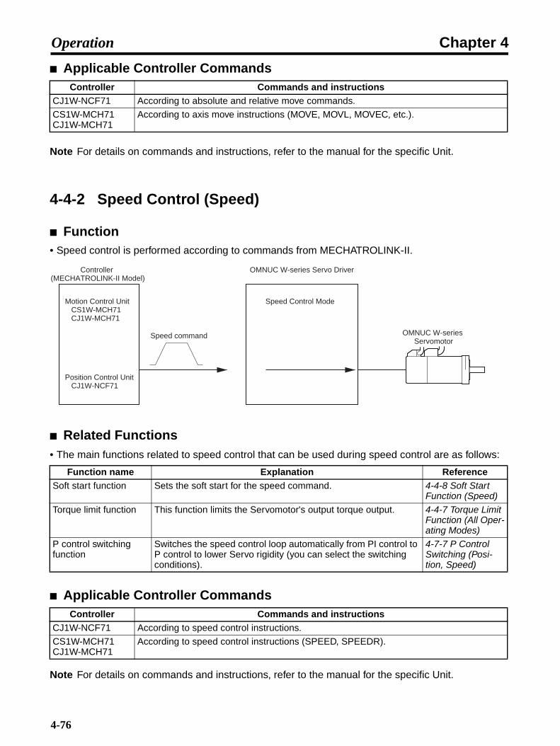
Chapter 4Operation
Applicable Controller Commands
Note For details on commands and instructions, refer to the manual for the specific Unit.
4-4-2 Speed Control (Speed)
Function• Speed control is performed according to commands from MECHATROLINK-II.
Related Functions• The main functions related to speed control that can be used during speed control are as follows:
Applicable Controller Commands
Note For details on commands and instructions, refer to the manual for the specific Unit.
Controller Commands and instructionsCJ1W-NCF71 According to absolute and relative move commands.
CS1W-MCH71CJ1W-MCH71
According to axis move instructions (MOVE, MOVL, MOVEC, etc.).
Function name Explanation ReferenceSoft start function Sets the soft start for the speed command. 4-4-8 Soft Start
Function (Speed)
Torque limit function This function limits the Servomotor's output torque output. 4-4-7 Torque Limit Function (All Oper-ating Modes)
P control switching function
Switches the speed control loop automatically from PI control to P control to lower Servo rigidity (you can select the switching conditions).
4-7-7 P Control Switching (Posi-tion, Speed)
Controller Commands and instructionsCJ1W-NCF71 According to speed control instructions.
CS1W-MCH71CJ1W-MCH71
According to speed control instructions (SPEED, SPEEDR).
Speed Control Mode
Speed command
OMNUC W-series Servo Driver
OMNUC W-series Servomotor
Controller (MECHATROLINK-II Model)
Motion Control Unit CS1W-MCH71 CJ1W-MCH71
Position Control Unit CJ1W-NCF71
4-76

Chapter 4Operation
4-4-3 Torque Control (Torque)
Function• Torque control is performed according to commands from MECHATROLINK-II.
Related Functions• Functions related to torque control that can be used during torque control are as follows:
Note Servomotor rotation speed during torque control changes depending on the Servomotor loadconditions (friction, external force, inertia). Apply safety measures at the machinery to preventServomotor runaway.
Applicable Controller Commands
Note For details on commands and instructions, refer to the manual for the specific Unit.
Function name Explanation ReferenceTorque limit function This function limits the Servomotor's torque output. 4-4-7 Torque Limit
Function (All Oper-ating Modes)
Speed limit function This function limits the Servomotor rotation speed from becom-ing too high.
4-4-10 Speed Limit Function (Torque)
Controller Commands and instructionsCJ1W-NCF71 According to torque control commands.
CS1W-MCH71CJ1W-MCH71
According to torque control commands (TORQUE, TORQUER).
Torque Control Mode
Torque command
OMNUC W-series Servo Driver
OMNUC W-series Servomotor
Controller (MECHATROLINK-II Model)
Motion Control Unit CS1W-MCH71 CJ1W-MCH71
Position Control Unit CJ1W-NCF71
4-77

Chapter 4Operation
4-4-4 Forward and Reverse Drive Prohibit (All Operating Modes)
Functions• When forward drive prohibit (POT: CN1-7) and reverse drive prohibit (NOT: CN1-8) are OFF, stops
the Servomotor rotating (Pin No. is allocated in the default settings).
• You can stop the Servomotor from rotating beyond the device's movement range by connecting a litinput.
Parameters Requiring Settings
Operation
Note 1. If the Servomotor stops in this mode during position control, the position loop is disabled.
Note 2. The position method used during torque control depends on Pn001.0 setting (the P001.1setting is unrelated).
Note 3. With a vertical load, the load may fall due to its own weight if it is left at a drive prohibit input.We recommend that you set the stop method for the drive prohibit input (Pn001.1) for decel-erating with the emergency stop torque, and then set stopping with the servo locked (SV: 1)to prevent the load from falling.
Parameter No.
Parameter name Explanation Reference
Pn50A.3Pn50B.0
Input signal selection 1: POT signal selectionInput signal selection 2: NOT signal selec-tion
You must allocate both POT and NOT. Note: As the default setting, they are allocated
to CN1 pins 7 and 8.
4-3-2 Important Parameters
Pn001 Function selection application switch 1
Set the stop method when POT and NOT in Pn001.1 (stop selection for drive prohibition input) are OFF.If Pn001.1 is set to 0 (stop according to Pn001.0 setting), be sure to set Pn001.0 (stop selection for alarm generation with Servo OFF).
4-3-2 Important Parameters
Pn406 Emergency stop torque
If Pn001.1 is set to 1 or 2, set emergency stop torque in Pn406.
4-3-3 Parameter Details
POT (NOT) is OFF
Dynamic brake
Free run
Emergency stop torque (Pn406)
Deceleration Method Stopped Status
Servo unlocked
Servo unlocked
Servo locked
Stopping Methods when Forward/Reverse Drive Prohibit is OFF
See note 1.
Pn001.1"0"
"1" or "2"
Pn001.0"0" or "1"
"2"Pn001.1
"1"
"2"
4-78

Chapter 4Operation
Note 1. When a command to travel in a prohibited direction within the drive prohibit area is input, theServomotor is stopped using the method set in Pn001.1. If a command to travel in the op-posite direction is input, the Servomotor automatically resumes operation.
Note 2. With position control, the feedback pulses and command pulses continue to be countedwithout the deviation counter's residual pulses being reset. If the drive prohibit input turnsON in this state (i.e., drive permitted), the position will be shifted by the amount of the resid-ual pulses.
4-4-5 Encoder Dividing Function (All Operating Modes)
Functions• With this function, any number of pulses can be set for encoder signals output from the Servo
Driver.
• The number of pulses per Servomotor revolution can be set within a range of 16 to (number ofencoder resolution pulses). The upper limit is 1,073,741,824 pulses/rotation.
• Use this function for the following applications:When using a controller with a low response frequency.When it is desirable to set a pulse rate that is easily divisible.(For example, in a mechanical system in which a single Servomotor revolution corresponds to atravel of 10 mm, if the resolution is 5 µm/pulse, set the encoder divider rate to 2,000 (pulses/revolu-tion).
Parameters Requiring Settings
Note 1. The default setting is 1,000 (pulses/rotation), and the setting range is 16 to 1,073,741,824(pulses/rotation).
Note 2. These parameters are enabled when the power is turned ON again after having been turnedOFF. (Check to see that the LED display has gone OFF.)
Note 3. If a value greater than the encoder resolution is set, operation will proceed according to theformula: (divider rate setting) = (encoder resolution)
Parameter No.
Parameter name Explanation Reference
Pn212 Encoder divider rate Set the number of encoder pulses to be output. (See notes 1, 2, and 3).
4-3-3 Parameter Details
ON
OFF
ON
OFF
Position
Position
→ Forward direction
Reverse direction ←
Only forward drive allowed Only reverse drive allowed
POT (forward drive prohibited)
NOT (reverse drive prohibited)
Both forward and reverse drive allowed
4-79
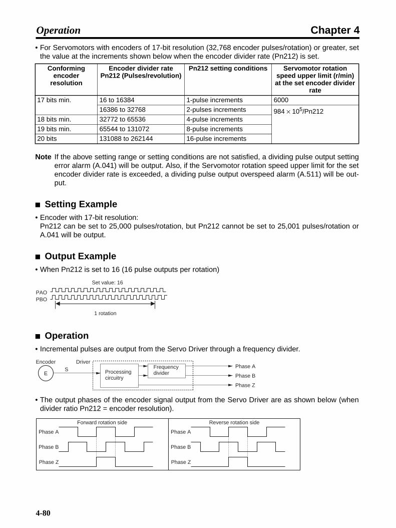
Chapter 4Operation
• For Servomotors with encoders of 17-bit resolution (32,768 encoder pulses/rotation) or greater, setthe value at the increments shown below when the encoder divider rate (Pn212) is set.
Note If the above setting range or setting conditions are not satisfied, a dividing pulse output settingerror alarm (A.041) will be output. Also, if the Servomotor rotation speed upper limit for the setencoder divider rate is exceeded, a dividing pulse output overspeed alarm (A.511) will be out-put.
Setting Example• Encoder with 17-bit resolution:
Pn212 can be set to 25,000 pulses/rotation, but Pn212 cannot be set to 25,001 pulses/rotation orA.041 will be output.
Output Example• When Pn212 is set to 16 (16 pulse outputs per rotation)
Operation• Incremental pulses are output from the Servo Driver through a frequency divider.
• The output phases of the encoder signal output from the Servo Driver are as shown below (whendivider ratio Pn212 = encoder resolution).
Conforming encoder
resolution
Encoder divider rate Pn212 (Pulses/revolution)
Pn212 setting conditions Servomotor rotation speed upper limit (r/min) at the set encoder divider
rate17 bits min. 16 to 16384 1-pulse increments 6000
16386 to 32768 2-pulses increments 984 × 105/Pn21218 bits min. 32772 to 65536 4-pulse increments
19 bits min. 65544 to 131072 8-pulse increments
20 bits 131088 to 262144 16-pulse increments
Set value: 16
1 rotation
PAOPBO
E
Encoder DriverS
Phase A
Phase B
Phase Z
Processing circuitry
Frequency divider
Phase A
Phase B
Phase Z
Forward rotation side
Phase A
Phase B
Phase Z
Reverse rotation side
4-80

Chapter 4Operation
• When the encoder divider rate is set to other than 2n (16,384, 8,192, 4,096, 2,048, 1,024, etc.), thephase difference for phases A and B is not 90°, but scatters for time T. (See the diagram below.)
In this diagram, T represents the processing circuit output between phase A and phase B, and n isan integer that satisfies the following formula (with digits below the decimal point discarded).
n = resolution/encoder divider rate
4-4-6 Brake Interlock (All Operating Modes)
Precautions for Using Electromagnetic Brake• The electromagnetic brake Servomotor with a brake is a non-excitation brake especially for holding.
First stop the Servomotor, then turn OFF the power supply to the brake before setting the parame-ters. If the brake is applied while the Servomotor is operating, the brake disk may become damagedor malfunction due to friction, causing damage to the Servomotor.
Function• You can set the BKIR (brake interlock) signal output timing to turn ON and OFF the electromagnetic
brake.
Parameters Requiring Settings
Note As the default setting, BKIR is allocated to CN1 pins 1 and 2.
Parameter No.
Parameter name Explanation Reference
Pn50F.2 Output signal selec-tions 2: BKIR signal selection
Be sure to allocate BKIR. (See note.) 4-4-3 Torque Con-trol (Torque)
Pn506 Brake timing 1 This parameter sets the BKIR output timing.Pn506: Sets lag time from BKIR OFF to Servo OFF.Pn507: Sets the rotation speed for turning BKIR OFF.Pn508: Sets the standby time from Servo OFF to BKIR OFF.
4-4-4 Forward and Reverse Drive Pro-hibit (All Operat-ing Modes)
Pn507 Brake command speed
Pn508 Brake timing 2
Phase A
Phase B
t1 t1 t1 t1 t1t2 t2
t1 = nT, t2 = (n + 1)T
Phase A
Phase B
T
Input to frequency divider (processing circuit output)
4-81

Chapter 4Operation
Operation
RUN Timing (When Servomotor Is Stopped)
Note 1. The time from turning ON the brake power supply to the brake being released is 200 msmax. Set the speed command (pulse command) to be given after the brake has been re-leased, taking this delay into account.
Note 2. The time from turning OFF the brake power supply to the brake engaging is 100 ms max. Ifusing the Servomotor on a vertical axis, set Pn506 (brake timing 1) so that the Servomotordeenergizes after the brake has engaged, taking this delay into account.
Power Supply Timing (when Servomotor Is Stopped)
Note The time from turning OFF the brake power supply to the brake engaging is 100 ms max. Ifusing the Servomotor on a vertical axis, set Pn506 (brake timing 1) so that the Servomotordeenergizes after the brake has engaged, in consideration of this delay.
RUNON
OFF
BKIR (brake interlock)ON
OFF
Brake power supplyON
OFF
Brake operationON
OFF
Energized
Deenergized
+V
−V
0 to 35 ms
200 ms max. 100 ms max.
See note 1.
Approx. 2 ms
Pn506 (See note 2.)
Speed command or pulse command
Servomotor energizing
Main circuit power supplyON
OFF
BKIR (brake interlock)ON
OFF
Energized
Deenergized
25 to 35 ms
Pn506 (See note.)Servomotor energized
4-82
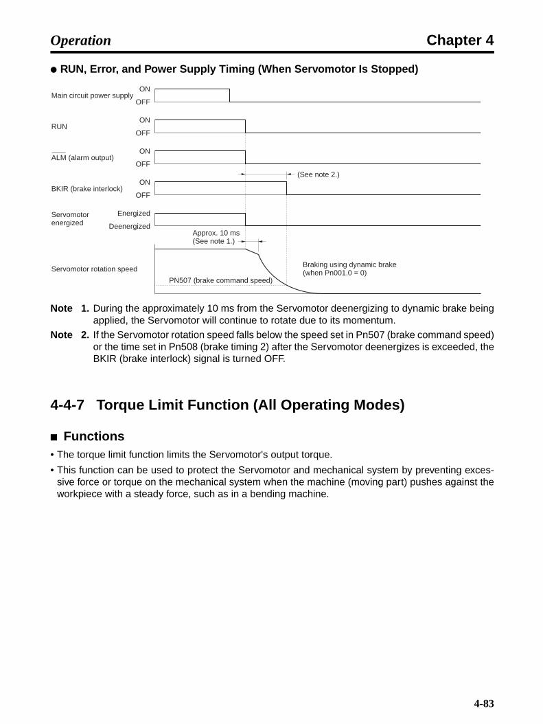
Chapter 4Operation
RUN, Error, and Power Supply Timing (When Servomotor Is Stopped)
Note 1. During the approximately 10 ms from the Servomotor deenergizing to dynamic brake beingapplied, the Servomotor will continue to rotate due to its momentum.
Note 2. If the Servomotor rotation speed falls below the speed set in Pn507 (brake command speed)or the time set in Pn508 (brake timing 2) after the Servomotor deenergizes is exceeded, theBKIR (brake interlock) signal is turned OFF.
4-4-7 Torque Limit Function (All Operating Modes)
Functions• The torque limit function limits the Servomotor's output torque.
• This function can be used to protect the Servomotor and mechanical system by preventing exces-sive force or torque on the mechanical system when the machine (moving part) pushes against theworkpiece with a steady force, such as in a bending machine.
Main circuit power supplyON
OFF
RUNON
OFF
ALM (alarm output)ON
OFF
BKIR (brake interlock)ON
OFF
Servomotor rotation speed
Energized
Deenergized
(See note 2.)
PN507 (brake command speed)
Servomotor energized
Approx. 10 ms (See note 1.)
Braking using dynamic brake (when Pn001.0 = 0)
4-83

Chapter 4Operation
• There are four methods that can be used to limit the torque (pin No. is allocated at the factory):
Note For details on commands and instructions, refer to the manual for the specific Unit.
• When torque limit is ON, CLIMT (current limit detection) signal is output (if the signal has been allo-cated using parameter Pn50F.0).
• If multiple torque limits are enabled, the output torque is limited to the minimum limit value.
Parameters Requiring Settings
Limiting Steady Torque During Operation with User Parameters (All Operating Modes)
Note 1. Set these parameters to 350 (the default setting) when the torque limit function is not beingused.
Note 2. If the connected Servomotor is set to a value greater than the maximum momentary torque,the maximum momentary torque will become the set limit.
Function CJ1W-NCF71 CS1W-MCH71CJ1W-MCH71
Limiting steady torque during opera-tion with user parameters (all operation modes)
Limit the steady force applied during normal operation with user parameters Pn402 (forward torque limit) and Pn403 (reverse torque limit).
Limiting torque when an external signal turns ON with user parameters (all operation modes)
Limit the torque with user parameters Pn404 (For-ward rotation external current limit) and Pn405 (Reverse rotation external current limit), by turning ON the axis operation output bit area's forward and reverse rotation current limit designation and start-ing axis operation.
---
Limiting torque with option command values (speed)
Use option command values as torque limit values. ---
Limiting torque when an external signal turns ON with option command values (speed)
Limit torque using option command values as torque limit values by turning ON the axis operation output bit area's forward and reverse rotation cur-rent limit designation and starting axis operation.
---
Parameter No.
Parameter name Explanation Reference
Pn402 Forward torque limit Set the output torque limit for the forward direc-tion as a percentage of the rated torque (setting range: 0% to 800%).
4-3-3 Parameter Details
Pn403 Reverse torque limit Set the output torque limit for the reverse direc-tion as a percentage of the rated torque (setting range: 0% to 800%).
4-3-3 Parameter Details
4-84

Chapter 4Operation
Limiting Operation with External Signals (All Operating Modes) (CJ1W-NCF71 Only)
Note If the connected Servomotor is set to a value greater than the maximum momentary torque,the maximum momentary torque will become the set limit.
Limiting Torque with Option Command Values (Speed) (CJ1W-NCF71 Only)• When 1 is set for Pn002.0 (Torque command input change), torque limit values can be specified
with option command values.Unit: %; command range: 0 to 399% (% of Servomotor momentary maximum torque)
• Limiting torque by option command values operates by taking option command value 1 as the for-ward torque limit and option command value 2 as the reverse torque limit.
Limiting Torque with Option Command Values by Turning ON External Signals (Speed) (CJ1W-NCF71 Only)
• If 3 is set for Pn002.0 (Torque command input switching), torque limit values can be specified withoption command values when the forward or reverse rotation current limit designation is turned ON.Unit: %; command range: 0 to 399% (% of Servomotor momentary maximum torque)
• When the forward rotation current limit designation turns ON, option command value 1 is taken asthe forward torque limit and the torque limit functions for forward rotation.
• When the reverse rotation current limit designation turns ON, option command value 2 is taken asthe reverse torque limit and the torque limit functions for reverse rotation.
Parameter No.
Parameter name Explanation Reference
Pn404 Forward rotation exter-nal current limit
Set the output torque limit when the forward rotation current limit designation is ON as a per-centage of the Servomotor rated torque (setting range: 0% to 800%).
4-3-3 Parameter Details
Pn405 Reverse rotation exter-nal current limit
Set the output torque limit when the reverse rotation current limit designation is ON as a per-centage of the Servomotor rated torque (setting range: 0% to 800%).
4-3-3 Parameter Details
Parameter No.
Parameter name Explanation Reference
Pn002.0 Torque command input switching
Set Pn002.0 to 1 (option command value used as torque limit command).
4-3-3 Parameter Details
Parameter No.
Parameter name Explanation Reference
Pn002.0 Torque command input switching
Set Pn002.0 to 3 (Option command value used as torque limit value, according to the forward/reverse rotation current limit designation).
4-3-3 Parameter Details
4-85
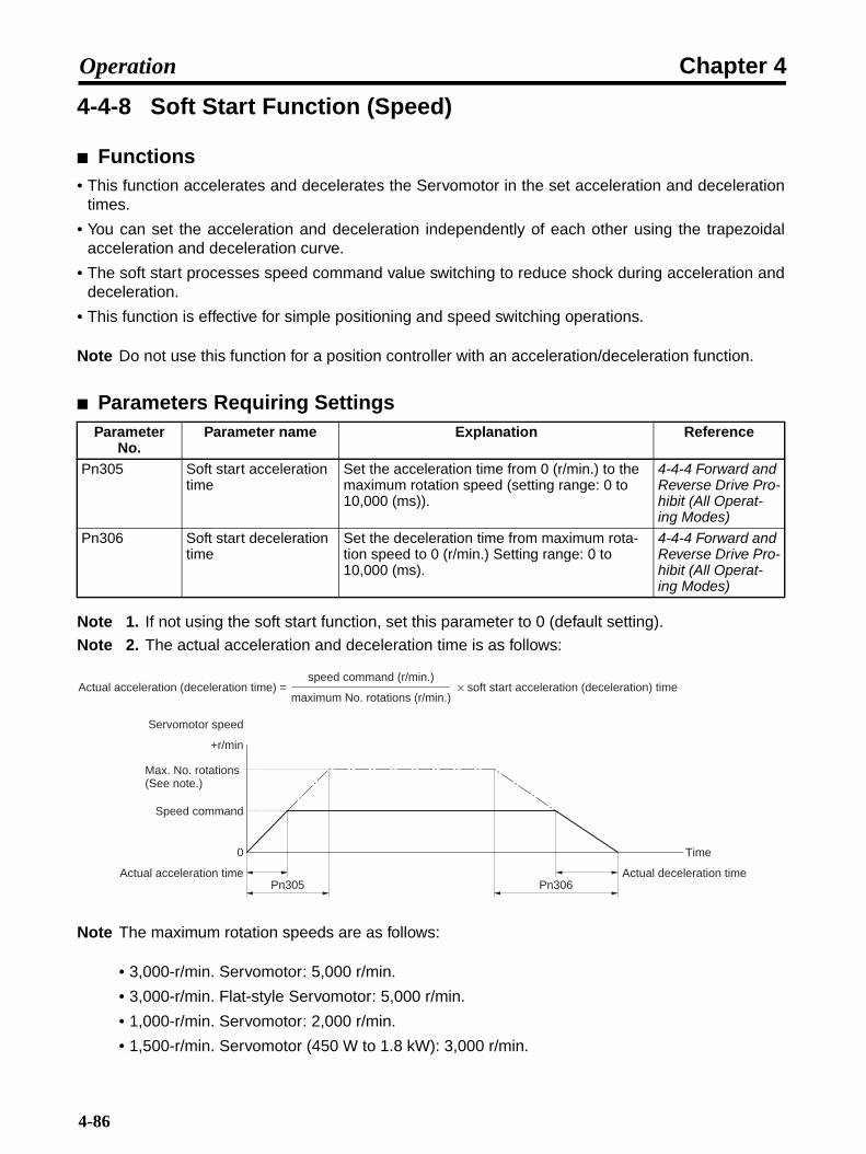
Chapter 4Operation
4-4-8 Soft Start Function (Speed)
Functions• This function accelerates and decelerates the Servomotor in the set acceleration and deceleration
times.
• You can set the acceleration and deceleration independently of each other using the trapezoidalacceleration and deceleration curve.
• The soft start processes speed command value switching to reduce shock during acceleration anddeceleration.
• This function is effective for simple positioning and speed switching operations.
Note Do not use this function for a position controller with an acceleration/deceleration function.
Parameters Requiring Settings
Note 1. If not using the soft start function, set this parameter to 0 (default setting).
Note 2. The actual acceleration and deceleration time is as follows:
Note The maximum rotation speeds are as follows:
• 3,000-r/min. Servomotor: 5,000 r/min.
• 3,000-r/min. Flat-style Servomotor: 5,000 r/min.
• 1,000-r/min. Servomotor: 2,000 r/min.
• 1,500-r/min. Servomotor (450 W to 1.8 kW): 3,000 r/min.
Parameter No.
Parameter name Explanation Reference
Pn305 Soft start acceleration time
Set the acceleration time from 0 (r/min.) to the maximum rotation speed (setting range: 0 to 10,000 (ms)).
4-4-4 Forward and Reverse Drive Pro-hibit (All Operat-ing Modes)
Pn306 Soft start deceleration time
Set the deceleration time from maximum rota-tion speed to 0 (r/min.) Setting range: 0 to 10,000 (ms).
4-4-4 Forward and Reverse Drive Pro-hibit (All Operat-ing Modes)
Servomotor speed
+r/min
Actual acceleration (deceleration time) =speed command (r/min.)
maximum No. rotations (r/min.)× soft start acceleration (deceleration) time
Time
Pn305 Pn306
0
Speed command
Actual acceleration time Actual deceleration time
Max. No. rotations (See note.)
4-86
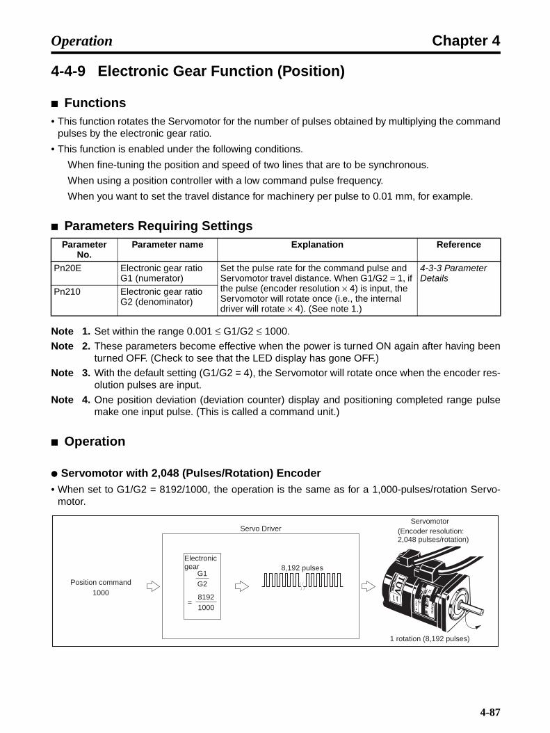
Chapter 4Operation
4-4-9 Electronic Gear Function (Position)
Functions• This function rotates the Servomotor for the number of pulses obtained by multiplying the command
pulses by the electronic gear ratio.
• This function is enabled under the following conditions.
When fine-tuning the position and speed of two lines that are to be synchronous.
When using a position controller with a low command pulse frequency.
When you want to set the travel distance for machinery per pulse to 0.01 mm, for example.
Parameters Requiring Settings
Note 1. Set within the range 0.001 ≤ G1/G2 ≤ 1000.
Note 2. These parameters become effective when the power is turned ON again after having beenturned OFF. (Check to see that the LED display has gone OFF.)
Note 3. With the default setting (G1/G2 = 4), the Servomotor will rotate once when the encoder res-olution pulses are input.
Note 4. One position deviation (deviation counter) display and positioning completed range pulsemake one input pulse. (This is called a command unit.)
Operation
Servomotor with 2,048 (Pulses/Rotation) Encoder• When set to G1/G2 = 8192/1000, the operation is the same as for a 1,000-pulses/rotation Servo-
motor.
Parameter No.
Parameter name Explanation Reference
Pn20E Electronic gear ratio G1 (numerator)
Set the pulse rate for the command pulse and Servomotor travel distance. When G1/G2 = 1, if the pulse (encoder resolution × 4) is input, the Servomotor will rotate once (i.e., the internal driver will rotate × 4). (See note 1.)
4-3-3 Parameter Details
Pn210 Electronic gear ratio G2 (denominator)
Position command1000
Servo Driver
8,192 pulsesG1G2
81921000
=
Servomotor
1 rotation (8,192 pulses)
Electronic gear
(Encoder resolution: 2,048 pulses/rotation)
4-87
Chapter 4Operation
4-4-10 Speed Limit Function (Torque)
Functions• This function limits Servomotor rotation speed when torque control is used.
• Set a limit so that the Servomotor rotation speed does not exceed the maximum speed of themechanical system.
• Outside of the speed limit range, a torque in proportion to the difference from the speed limit valueis generated to slow down the Servomotor rotation speed. In such cases the number of Servomotorrotations does not necessarily match the speed limit value. (The number of Servomotor rotationsvaries depending on the load.)
• The two ways to limit the speed are given in the following table. The Controllers that support eachmethod are also shown.
Note For details on commands and instructions, refer to the manual for the specific Unit.
• When the speed limit is in operation, VLIMT (speed limit detection) is output (when the signal hasbeen allocated in Pn50F.1).
• When there are multiple speed limit functions in effect, Servomotor rotation speed is limited by thesmallest value.
Parameters Requiring Settings
Limiting Using a Constant Fixed Speed Limit (Parameter Setting) for Torque Control
Limiting Speeds with Option Command Values (CJ1W-NCF71 Only)• When 1 is set for Pn002.1 (Speed command input change), speed limit values can be specified with
option command value 1.Unit: 0.001%; command range: 0 to 100.000% (% of maximum number of Servomotor rotations)
• Speed limits based on option command values are the same for forward and reverse rotation.
Function CJ1W-NCF71 CS1W-MCH71CJ1W-MCH71
Limiting using a constant fixed speed limit (parameter setting) for torque con-trol
Use Pn407 (speed limit).
Limiting the speed by means of an option command value
Use option command value 1 as the speed control value.
---
Parameter No.
Parameter name Explanation Reference
Pn407 Speed limit Set the speed limit for torque control. Setting range: 0 to 10,000 (r/min).
4-3-3 Parameter Details
Parameter No.
Parameter name Explanation Reference
Pn002.1 Speed command input change
Set Pn002.1 to 1 (option command value used as speed limit command).
4-3-3 Parameter Details
4-88

Chapter 4Operation
4-4-11 Acceleration/Deceleration Function (Position)
Functions• This function sets the speed during acceleration and deceleration to two levels.
• The setting is made by a host device from MECHATROLINK-II.
Parameters Requiring Settings
Note When trapezoidal acceleration/deceleration (not using two-step acceleration/deceleration) isexecuted, set Pn80C and Pn80F to 0, set the acceleration speed in Pn80B, and set the decel-eration speed in Pn80E.
Parameter No.
Parameter name Explanation Reference
Pn80A First-step linear accel-eration parameter
Sets the step 1 acceleration for when two-step acceleration is used.
4-3-3 Parameter Details
Pn80B Second-step linear acceleration parameter
Sets the step 2 acceleration for when two-step acceleration is executed. When using one-step acceleration, set this parameter as a one-step acceleration parameter.
4-3-3 Parameter Details
Pn80C Acceleration parame-ter switching speed
Sets the switching speed for the step 1 and step 2 acceleration when two-step acceleration is executed. When using one-step acceleration, set 0 for this parameter.
4-3-3 Parameter Details
Pn80D First-step linear decel-eration parameter
Sets the step 1 deceleration for when two-step deceleration is used.
4-3-3 Parameter Details
Pn80E Second-step linear deceleration parame-ter
Sets the step 2 deceleration for when two-step deceleration is executed. When using one-step deceleration, set this parameter as a one-step deceleration parameter.
4-3-3 Parameter Details
Pn80F Deceleration parame-ter switching speed
Sets the switching speed for the step 1 and step 2 deceleration when two-step deceleration is executed. When using one-step deceleration, set 0 for this parameter.
4-3-3 Parameter Details
Pn810 Exponential accelera-tion/deceleration bias
Sets the bias for when an exponential filter is used for the position command filter.
4-3-3 Parameter Details
Pn811 Exponential accelera-tion/deceleration time constant
Sets the time constant for when an exponential filter is used for the position command filter.
4-3-3 Parameter Details
Pn812 Moving average time Sets the moving average time for when and an average movement filter is used for the position command filter. Set when using S-curve accel-eration/deceleration.
4-3-3 Parameter Details
4-89
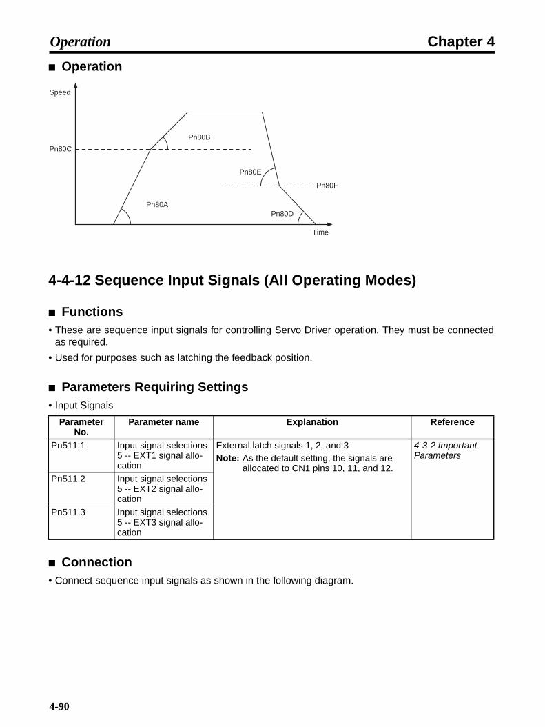
Chapter 4Operation
Operation
4-4-12 Sequence Input Signals (All Operating Modes)
Functions• These are sequence input signals for controlling Servo Driver operation. They must be connected
as required.
• Used for purposes such as latching the feedback position.
Parameters Requiring Settings• Input Signals
Connection• Connect sequence input signals as shown in the following diagram.
Parameter No.
Parameter name Explanation Reference
Pn511.1 Input signal selections 5 -- EXT1 signal allo-cation
External latch signals 1, 2, and 3Note: As the default setting, the signals are
allocated to CN1 pins 10, 11, and 12.
4-3-2 Important Parameters
Pn511.2 Input signal selections 5 -- EXT2 signal allo-cation
Pn511.3 Input signal selections 5 -- EXT3 signal allo-cation
Pn80B
Pn80A
Pn80C
Pn80E
Pn80D
Pn80F
Time
Speed
4-90
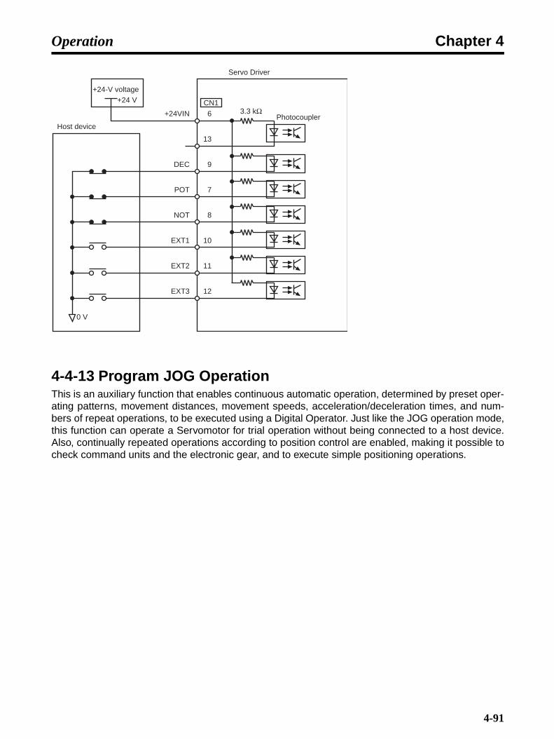
Chapter 4Operation
4-4-13 Program JOG OperationThis is an auxiliary function that enables continuous automatic operation, determined by preset oper-ating patterns, movement distances, movement speeds, acceleration/deceleration times, and num-bers of repeat operations, to be executed using a Digital Operator. Just like the JOG operation mode,this function can operate a Servomotor for trial operation without being connected to a host device.Also, continually repeated operations according to position control are enabled, making it possible tocheck command units and the electronic gear, and to execute simple positioning operations.
0 V
DEC
+24VIN 6
CN1
13
9
7
8
10
11
12
+24-V voltage
3.3 kΩ+24 V
Host device
POT
NOT
EXT1
EXT2
EXT3
Photocoupler
Servo Driver
4-91

Chapter 4Operation
Parameters Requiring Settings
Precautions
The following restrictions apply during operation.• When setting this function, set the operating range for the machinery and the safe operating speed
in user constants such as the program JOG movement distance and the program JOG movementspeed.
• This function is executed with the Servo Driver in Servo ready status. It cannot be executed whilethe Servo is ON.
• If the Servo ON command is ON, turn it OFF.
• If user parameter Pn50A.1 is set to 7 and Servo-ON is selected to be always enabled, clear thealways enabled setting for the Servo-ON signal.
• The mode during program JOG operation is the position control mode, but pulse command inputsto the Servo Driver are prohibited and not received.
• The overtravel function is disabled in JOG mode, but it is enabled for program JOG operation.
• The SEN signal is always enabled when an absolute encoder is used.
• Functions such as position command filters, that can be used for position control, can be used.
• This function cannot be executed when Pn200.2 is set to 1 (Deviation counter not reset when Servois OFF).
Parameter No.
Parameter name Explanation Reference
Pn530.0 Program JOG opera-tion related switches -- Program JOG operat-ing pattern
Set the program JOG operating pattern. 4-3-3 Parameter Details
Pn531 Program JOG move-ment distance
Set the program JOG movement distance.Setting range: 1 to 1,073,741,824 (command units)
4-3-3 Parameter Details
Pn533 Program JOG move-ment speed
Sets the program JOG movement speed.Setting range: 1 to 10,000 (r/min)
4-3-3 Parameter Details
Pn534 Program JOG acceler-ation/deceleration time
Set the acceleration/deceleration time for pro-gram JOG operation.Setting range: 2 to 10,000 (ms)
4-3-3 Parameter Details
Pn535 Program JOG waiting time
Set the program JOG waiting time (the time that the Servomotor is to be stopped).Setting range: 0 to 10,000 (ms)
4-3-3 Parameter Details
Pn536 Number of program JOG movements
Sets the number of repetitions of the operating pattern set in Pnn530.0, under the conditions set in Pn531 to Pn535.Setting range: 1 to 1,000 (times)
4-3-3 Parameter Details
4-92

Chapter 4Operation
Program Operating PatternsPn530.0: 0 (Waiting time Pn535 → Forward movement Pn531) × Number of movement operations
Pn536Speed line dia-gram
Servomotor oper-ating status
Pn530.0: 1 (Waiting time Pn535 → Reverse movement Pn531) × Number of movement operations Pn536
Speed line dia-gram
Servomotor oper-ating status
Pn535 Pn535 Pn535
Pn533
Up Key ON
Speed 0
Pn531 Pn531 Pn531
Number of travel operations Pn536
Travel speed Travel distance
Travel distance
Travel distance
Waiting time Waiting time Waiting timeAcceleration/deceleration time Pn534
(Stopped) (Stopped) (Stopped)(Forward operation)
(Forward operation)
(Forward operation)
Pn533
Pn531 Pn531 Pn531
Down Key ON
Pn535 Pn535 Pn535
Speed 0
Number of travel operations Pn536
Travel speed Travel distance
Waiting time Acceleration/deceleration time Pn534
Travel distance
Travel distance
Waiting timeWaiting time
(Stopped) (Stopped) (Stopped)(Reverse operation)
(Reverse operation)
(Reverse operation)
4-93

Chapter 4Operation
Pn530.0: 2 (Waiting time Pn535 → Forward movement Pn531) × Number of movement operations Pn536(Waiting time Pn535 → Reverse movement Pn531) × Number of movement operations Pn536
Speed line dia-gram
Servomotor oper-ating status
Pn530.0: 3 (Waiting time Pn535 → Reverse movement Pn531) × Number of movement operations Pn536(Waiting time Pn535 → Forward movement Pn531) × Number of movement operations Pn536
Speed line dia-gram
Servomotor oper-ating status
Pn533
Pn531 Pn531
Pn531 Pn531
Pn535 Pn535
Pn535
Pn533
Pn535
Up Key ON
Speed 0
Number of travel operations Pn536
Travel speed Travel distance
Waiting time Acceleration/deceleration time Pn534
Number of travel operations Pn536
Travel distance
Waiting time
Waiting time Waiting time
Acceleration/deceleration time Pn534
Travel distance
Travel distance
Travel speed
(Stopped) (Stopped)(Forward operation)
(Forward operation)
(Stopped) (Stopped)(Reverse operation)
(Reverse operation)
Pn533
Pn535
Pn533Pn535Pn535 Pn535
Pn531 Pn531
Pn531 Pn531
Down Key ON
Speed 0
Number of travel operations Pn536
Travel speed
Travel distance
Waiting time
Acceleration/deceleration time Pn534
Number of travel operations Pn536
Waiting time
Travel distance
Waiting time
Travel speed
Acceleration/deceleration time Pn534
Waiting time
Travel distance
Travel distance
(Stopped) (Stopped)(Forward operation)
(Forward operation)
(Stopped) (Stopped)(Reverse operation)
(Reverse operation)
4-94

Chapter 4Operation
Pn530.0: 4 (Waiting time Pn535 → Forward movement Pn531 → Waiting time Pn535 → Forward movement Pn531) × Number of movement operations Pn536
Speed line dia-gram
Servomotor oper-ating status
Pn530.0:5 (Waiting time Pn535 → Reverse movement Pn531 → Waiting time Pn535 → Reverse movement Pn531) × Number of movement operations Pn536
Speed line dia-gram
Servomotor oper-ating status
Pn533
Pn535 Pn535Pn533
Pn531
Pn531Up Key ON
Speed 0
Number of travel operations Pn536
Travel speedTravel distance
Waiting timeAcceleration/deceleration time Pn534
Waiting time Travel distance
Travel speed
(Stopped) (Forward operation)
(Stopped) (Reverse operation)
(Stopped)
Pn533
Pn535 Pn535
Pn531
Pn531
Down Key ON
Speed 0
Number of travel operations Pn536
Travel speed
Travel distance
Waiting timeAcceleration/decel-eration time Pn534 Waiting time
Travel distance
(Stopped) (Forward operation)
(Stopped) (Reverse operation)
(Stopped)
4-95

Chapter 4Operation
4-5 Trial Operation Procedure
When you have finished installation, wiring, verifying Servomotor and Servo Driveroperations (i.e., jog operation), and setting the user parameters, perform a trialoperation. The main purpose of a trial operation is to confirm that the Servo System isoperating correctly electrically. Make sure that the host controller and all theprogramming devices are connected, then turn ON the power. First perform a trialoperation at low speed to confirm that the system is operating correctly. Next, performa normal run pattern to confirm that the system is operating correctly.
Note 1. If an error occurs during the trial operation, refer to Troubleshooting to eliminate the cause.Then check for safety and reset the alarm, and then retry the trial operation.
Note 2. If the system vibrates due to insufficient gain adjustment, making it difficult to check the op-eration, refer to 4-6 Making Adjustments, and adjust the gain.
Preparation for Trial Operation
Turn OFF the PowerSome parameters are enabled by turning OFF the Unit, then turning it ON again. Consequently, firstturn OFF the power to the control circuits and main circuits.
Mechanical System ConnectionFirmly connect the Servomotor shaft and the load (i.e., the mechanical system). Tighten screws tomake sure they are not loose.
Absolute Encoder Setup ABSIf using Servomotor with an absolute encoder, refer to 4-2-2 Absolute Encoder Setup and BatteryChanges for the setup procedure. After performing a jog operation, the amount of multi-turn rotationmay be too large, so when connecting the absolute encoder to the mechanical system, be sure to setthe rotation speed to zero.
Turning OFF the ServomotorSet up the system so that the power and the RUN command can be turned OFF to enable turningOFF Servomotor immediately if an error occurs in the machinery.
Trial Operation
1.Turn ON the Power Supply.
• Turn ON the power supply to the control circuits and main circuits, and then turn ON the RUNcommand.
• Check that the Servomotor is ON.
4-96

Chapter 4Operation
2.Low-speed Operation
• Send a low speed command from the host controller to rotate the Servomotor. (The definitionof low speed varies depending on the mechanical system, but a rough estimate is 1/10 to 1/5normal operating speed.)
• Check the following items.
Is the emergency stop operating correctly?Are the limit switches operating correctly?Is the operating direction of the machinery correct?Are the operating sequences correct?Are there any abnormal sounds or vibration?Is any error (or alarm) generated?
Note 1. If anything abnormal occurs, refer to Chapter 5 Troubleshooting and apply the appropriatecountermeasures.
Note 2. If the system vibrates due to insufficient gain adjustment, making it difficult to check the op-eration, refer to 4-6 Making Adjustments, and adjust the gain.
3.Operation Under Actual Load Conditions
• Operate the Servomotor in a regular pattern and check the following items.
Is the operating speed correct? (Use the speed feedback monitor.)Is the load torque roughly equivalent to the measured value? (Use the torque command monitor andthe accumulated load monitor.)Are the positioning points correct?When an operation is repeated, is there any discrepancy in positioning?Are there any abnormal sounds or vibration?Is either the Servomotor or the Servo Driver abnormally overheating?Is any error (or alarm) generated?
Note 1. Refer to 4-9 Using Monitor Output for how to display the speed feedback monitor, torquecommand monitor, and the cumulative load rate monitor.
Note 2. If anything abnormal occurs, refer to Chapter 5 Troubleshooting and apply the appropriatecountermeasures.
Note 3. If the system vibrates due to insufficient gain adjustment impeding, making it difficult tocheck the operation, refer to 4-6 Making Adjustments, and adjust the gain.
4.Completing the Trial Operation
• Performing the above completes the trial operation. Next, adjust the gain to improve commandefficiency. (Refer to 4-6 Making Adjustments for details.)
4-97

Chapter 4Operation
4-6 Making Adjustments
The OMNUC R88D-WN@@@-ML2 Series is equipped with a responsive auto-tuningfunction. When auto-tuning cannot be used, make adjustments manually.
4-6-1 Adjustment MethodsThe Servo gain can be adjusted either using auto-tuning for simple adjustment or using manualadjustment. auto-tuning is performed using the Computer Monitor Software. The features of the vari-ous means of adjustment are listed in the following table. Select the method that is most suitable forthe purpose.
Note Refer to 6-3 Restrictions.
4-6-2 Advanced Auto-tuning
What is Advanced Auto-tuning?• Advanced auto-tuning is a control function that estimates the operating inertia, increases the Servo
gain, and automatically seeks a no-vibration range that matches the characteristics of the machin-ery.
• Advanced auto-tuning is executed from the Computer Monitor Software.
Adjustment method Description Guidelines for selectionAdvanced auto-tuning with inertia
An automatic operation pattern is used to automatically calculated the inertia ratio and set the Servo gain and notch filter.
Use this method to automatically calcu-late the Servo gain. A stroke must be pro-vided for the automatic operation pattern. Gain adjustment is possible only using the automatic operation pattern.
Advanced auto-tuning without inertia
An automatic operation pattern is used to automatically set the Servo gain and notch filter. The inertia ratio is not calcu-lated.
Use this method when manually setting the Servo gain in Pn103. A stroke must be provided for the automatic operation pattern. Gain adjustment is possible only using the automatic operation pattern.
One-parameter auto-tuning
One parameter is set to adjust and bal-ance the following four parameters.These are adjusted during operation from the host.• Position loop gain
• Speed loop gain
• Speed loop integration constant
• Torque command filter time constant
Use this method when manually setting the Servo gain in Pn103. Machine response can be monitored while chang-ing just one parameter to reduce the trou-ble of manual tuning. The results are judged by the user.
Manual tuning The Servo gain parameters are adjusted at the discretion of the user.
Use this method when suitable adjust-ments cannot be achieved using autotun-ing.
4-98
Chapter 4Operation
Note Advanced auto-tuning cannot be used in the following cases.
• When the load inertia fluctuates at 200 ms or less.
• When the load rigidity is low and mechanisms (such as belt drive inputs) tends to vibrate, orviscosity friction is high.
• When the range of movement is narrow, e.g., only several rotations.
• When movement is possible only in a fixed direction.
• When P (proportional) control is used.
Use the following method to make adjustments if any of the above conditions apply, or if operation isnot satisfactory when normal auto-tuning is executed.
• Set Pn103 (Inertia ratio), and then execute one-parameter tuning or manual adjustment.
User Parameters Related to Advanced Auto-tuning• The following user parameters are set automatically by advanced auto-tuning.
Pn100 Speed loop gainPn101 Speed loop integration constantPn102 Position loop gainPn103 Inertia ratioPn401 1st step 1st torque command filter time constant
• The following parameters are also set automatically as required.
Pn408.0 Torque command setting -- Notch filter selection 1Pn409 Notch filter 1 frequencyPn408.2 Torque command setting -- Notch filter selection 2Pn40C Notch filter 2 frequency
• If the electronic gear ratio is not set within the following range, an A042 error (parameter combina-tion error) will occur. Always set the electronic gear ratio within the following range.
Electronic gear ratio (Pn20E/Pn210) ≤ 218
4-6-3 One-parameter Tuning
What is One-parameter Tuning?• One-parameter tuning is a function that smoothly changes the status of four gain parameters
(Pn100, Pn101, Pn102, Pn401) during operation by changing just one tuning level.
• One-parameter tuning is used to adjust the Servo gain at the user's discretion, while checkingServo and machinery responses.
Parameters Related to One-parameter Tuning• The following user parameters are set automatically by one-parameter tuning.
Pn100 Speed loop gainPn101 Speed loop integration constantPn102 Position loop gainPn401 1st step 1st torque command filter time constant
4-99

Chapter 4Operation
4-6-4 Manual Tuning
Rigidity Settings During Tuning• If the gain is adjusted as an initial setting using manual tuning, tuning can be performed compara-
tively quickly. Therefore it is recommended that the rigidity be set first.
• Select the rigidity setting to suit the mechanical system from the following 10 levels.
• The speed loop handles both PI and I-P control.Switching between PI and I-P control is performed by means of the Pn10B.1 setting. SettingPn10B.1 to 0 switches to PI control, and setting it to 1 switches to I-P control. The new setting isenabled by turning the power OFF and back ON after the setting has been made.
1.Speed Loop PI Control
Note Make sure that the location of the decimal point is correct when setting the parameters.
2.Speed Loop I-P Control
Response Rigidity setting
Position loop gain
(s−1)Pn102
Speed loop gain(Hz)
Pn100
Speed loop integration constant
(ms)Pn101
1st step 1st torque
command filter time constant
(ms)Pn401
Representative applications (mechanical
system)
Low 01 15.0 15.0 60.00 2.50 Articulated robots, har-monic drives, chain drives, belt drives, rack and pinion drives, etc.
02 20.0 20.0 45.00 2.00
03 30.0 30.0 30.00 1.30
Medium 04 40.0 40.0 20.00 1.00 XY tables, Cartesian-coor-dinate robots, general-pur-pose machinery, etc.
High 05 60.0 60.0 15.00 0.70 Ball screws (direct cou-pling), feeders, etc.06 80.0 80.0 10.00 0.50
07 100.0 100.0 8.00 0.40
08 120.0 120.0 7.00 0.35
09 140.0 140.0 6.00 0.30
10 160.0 160.0 5.00 0.25
Response Rigidity setting
Position loop gain
(s−1)Pn102
Speed loop gain(Hz)
Pn100
Speed loop integration constant
(ms)Pn101
1st step 1st torque
command filter time constant
(ms)Pn401
Representative applications (mechanical
system)
Low 01 15.0 15.0 18.00 2.50 Articulated robots, har-monic drives, chain drives, belt drives, rack and pinion drives, etc.
02 20.0 20.0 14.00 2.00
03 30.0 30.0 9.00 1.30
Medium 04 40.0 40.0 7.00 1.00 XY tables, Cartesian-coor-dinate robots, general-pur-pose machinery, etc.
4-100

Chapter 4Operation
Note 1. Make sure that the location of the decimal point is correct when setting the parameters.
Note 2. The Servo System loop gain will rise in response to a higher rigidity setting, shortening thepositioning time. If the setting is too large, however, the machinery may vibrate. In that case,make the setting smaller.
Manual Tuning-related User Parameters• The following user parameters are set by manual tuning.
Pn100 Speed loop gainPn101 Speed loop integration constantPn102 Position loop gainPn103 Inertia ratioPn401 1st step 1st torque command filter time constant
Manually Adjusting Servo Gain
1.Increase the speed loop gain (Pn100) as much as possible without having the machinery vibrate,and simultaneously reduce the speed loop integration constant (Pn101).
2.Adjust the 1st step 1st torque command filter time constant (Pn401) and set it so there is no vibra-tion.
3.Repeat steps 1 and 2, and return 10% to 20% from the changed values.
4.For position control, increase the position loop gain (Pn102) to the point where the machinery doesnot vibrate.
High 05 60.0 60.0 4.50 0.70 Ball screws (direct cou-pling), feeders, etc.06 80.0 80.0 3.50 0.50
07 100.0 100.0 3.00 0.40
08 120.0 120.0 2.50 0.35
09 140.0 140.0 2.00 0.30
10 160.0 160.0 2.00 0.25
Response Rigidity setting
Position loop gain
(s−1)Pn102
Speed loop gain(Hz)
Pn100
Speed loop integration constant
(ms)Pn101
1st step 1st torque
command filter time constant
(ms)Pn401
Representative applications (mechanical
system)
4-101

Chapter 4Operation
Procedure for Adjusting Gain• A Servo System control block is configured of a position loop, a speed loop, and a current loop.
• The current loop is the most interior, followed by the speed loop and then the position loop.
• An output from an exterior loop is an input for an interior loop. As a condition for the exterior loop tooperate properly, the interior loop must be able to give a sufficient response to that input. In otherwords, high response is required from the interior loop. Also, when adjusting gain, the adjustmentproceeds from the interior loop gain.
• In order for the current loop to have a sufficient response, it is adjusted at the time of shipping.Therefore first adjust the speed loop, and then the position loop.
• The speed loop adjustment increases tracking for speed commands. Perform this adjustment inservolock status, while checking the Servo rigidity (the force holding the position against externalforce).
• The position loop adjustment increases tracking for position commands. Input the position com-mand in the actual operating pattern while checking the positioning time.
M
PG
Tf
Position control loopSpeed control loop
Speed Speed pattern
Time
Move com-mand
Deviation counter
Position loop gainKp
Speed com-mand
Position loop
Speed control unit KV, Ti
Speed loop
Current conver-sion unit
Power conver-sion unit
Current loop
Servomotor
Encoder
Servopack
Host device (provided by user)
Kp: Position loop gain (Pn102)Kv: Speed loop gain (Pn100)Ti: Speed loop integration constant (Pn101)Tf: First-level No. 1 torque command filter time constant (Pn401)
4-102
Chapter 4Operation
4-7 Advanced Adjustment Functions
4-7-1 Bias Function (Position)
Functions• The bias function shortens positioning time by adding bias revolutions to speed commands (i.e.,
commands to the speed control loop).
• If the residual pulses in the deviation counter exceed the setting in Pn108 (bias addition band), thespeed set in Pn107 (bias rotational speed) is added to the speed command, and when the residualpulses in the deviation counter are within the setting in Pn108, adding to the number of bias rota-tions stops.
• By setting the following user constants and providing a bias to the speed command unit in theServo Driver, the settling time can be shortened during positioning control.
Parameters Requiring Settings
Note 1. When not using the bias function, set Pn107 to 0.
Note 2. If the bias rotational speed is set too high, it will cause Servomotor operation to be unstable.The optimum setting depends on the load, the gain, and the bias addition band, so adjustthe setting while observing the Servomotor response. (Begin with a bias setting of Pn107 =0, and gradually increase it.)
Setting Procedure• Complete the gain adjustment before adjusting the bias.
• Increase the Pn107 (bias rotational speed) setting until positioning time is minimal. At this point, ifthere are no problems with using overshoot, adjustments are complete.
• If the overshoot is too large, increase Pn108 (bias addition band) to reduce it.
• To shorten positioning time, make the settings according to the mechanical conditions. The biasaddition band (Pn108) is the value that indicates by position deviation pulses the timing for addingthe bias (Pn107). Bias is added when the position deviation pulses exceed the set value for the biasaddition band.
Parameter No.
Parameter name Explanation Reference
Pn107 Bias rotational speed Set the rotation speed to be added to the bias (setting range: 0 to 450 (r/min.)).
4-3-3 Parameter Details
Pn108 Bias addition band Set the residual pulses to be added to the num-ber of bias rotations using command units (set-ting range: 0 to 250 (command units)).
4-3-3 Parameter Details
4-103

Chapter 4Operation
Operation
4-7-2 Feed-forward Function (Position)
Functions• This function shortens positioning time by automatically, in the Servo Driver, adding the position
command value differential to the speed loop.
• Perform feed-forward compensation to increase Servo gain efficiency, thus improving response.There is very little effect, however, on systems with sufficiently high position loop gain.
Parameters Requiring Settings
Note When not using the feed-forward function, set Pn10A to 0.
Setting Procedure• Finish adjusting the gain before adjusting the feed-forward.
• Increase the Pn109 (feed-forward amount) setting until positioning time is minimal. At this point, ifthere are no problems with using overshoot, adjustments are complete. A high setting may causethe machinery to vibrate. With ordinary machinery, set the gain to 80% maximum. (Adjust the gainwhile checking the machine response.)
• If the overshoot is too large, increase Pn10A (feed-forward command filter) to reduce the it.
• In the Servo Driver, feed forward compensation is applied to position control. This function is usedto shorten positioning time. If the value is set too high, the machinery may vibrate. Set it to 80% orless.
Parameter No.
Parameter name Explanation Reference
Pn109 Feed forward amount Set the feed-forward gain (setting rage: 0 to 100 (%)).
4-3-3 Parameter Details
Pn10A Feed forward com-mand filter
Set the feed-forward command filter (primary lag). (Setting range: 0 to 6400 (× 0.01 ms).)
4-3-3 Parameter Details
Speed command
Bias addition band (Pn108)
Bias (Pn107)
When bias is set
No bias
Bias (Pn107)
Position error pulses
Bias addition band (Pn108)
4-104
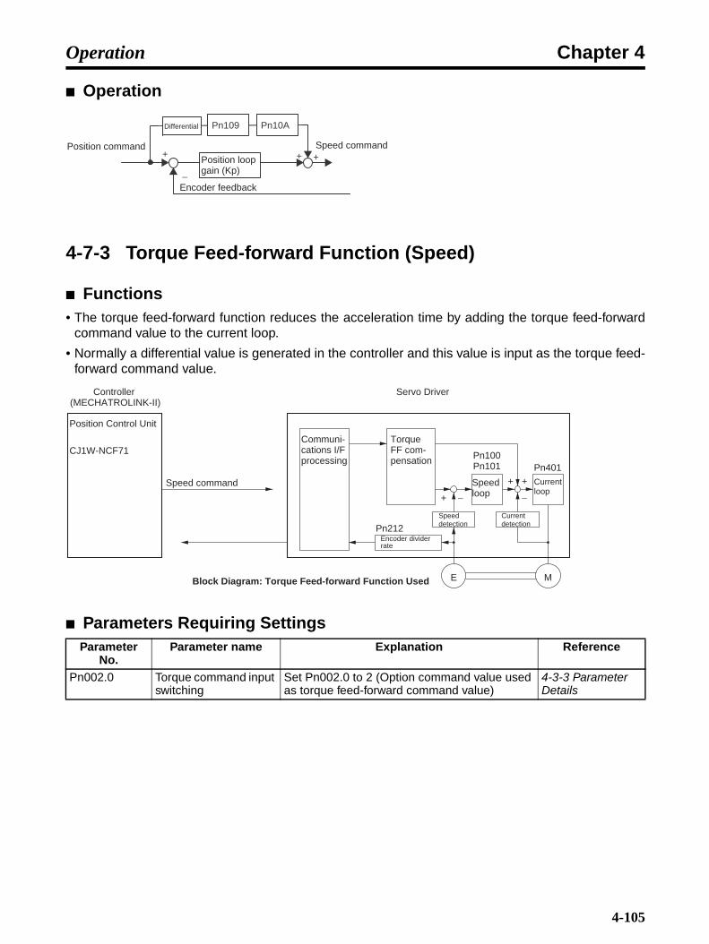
Chapter 4Operation
Operation
4-7-3 Torque Feed-forward Function (Speed)
Functions• The torque feed-forward function reduces the acceleration time by adding the torque feed-forward
command value to the current loop.
• Normally a differential value is generated in the controller and this value is input as the torque feed-forward command value.
Parameters Requiring SettingsParameter
No.Parameter name Explanation Reference
Pn002.0 Torque command input switching
Set Pn002.0 to 2 (Option command value used as torque feed-forward command value)
4-3-3 Parameter Details
+ + +
−
Pn109 Pn10A
Position command
Differential
Position loop gain (Kp)
Speed command
Encoder feedback
Speed command
ME
+ −
Position Control Unit
Pn401Pn100Pn101
Pn212
+
−
+
Block Diagram: Torque Feed-forward Function Used
Controller (MECHATROLINK-II)
Servo Driver
CJ1W-NCF71Communi-cations I/F processing
Torque FF com-pensation
Speed loop
Speed detection
Current loop
Current detection
Encoder divider rate
4-105

Chapter 4Operation
Operation
Note If torque feed-forward is input when the Servomotor's rotation speed is fixed, the rotation speedwon't match the speed command. Design the Controller's circuit so that torque feed-forward isapplied only when the Servomotor is accelerating or decelerating.
Applicable Controller Commands
Note For details on commands and instructions, refer to the manual for the specific Unit.
4-7-4 Automatic Gain Switching (Position)
Functions• This function switches the speed loop and position loop gain.
• When Pn139.0 (Gain switching selection switch) is set to 1, and the conditions set in Pn139.1 (Gainswitching condition A) and Pn139.2 (Gain switching condition B) are satisfied, the No. 1 gain andthe No. 2 gain are switched alternately. Switching from the No. 1 gain to the No. 2 gain occurs whengain switching condition A is satisfied, and switching from the No. 2 gain to the No. 1 gain occurswhen gain switching condition B is satisfied.
Controller Commands and instructionsCJ1W-NCF71 According to option command values during speed control.
CS1W-MCH71CJ1W-MCH71
Not available.
Speed command value
+
0
+
−
Servomotor output torque
+
−
Servomotor operation
0
+r/min
Without the torque feed-forward function
Without the torque feed-forward function
Torque feed-forward command value
4-106
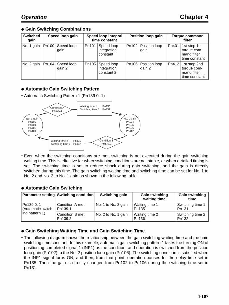
Chapter 4Operation
Gain Switching Combinations
Automatic Gain Switching Pattern• Automatic Switching Pattern 1 (Pn139.0: 1)
• Even when the switching conditions are met, switching is not executed during the gain switchingwaiting time. This is effective for when switching conditions are not stable, or when detailed timing isset. The switching time is set to reduce shock during gain switching, and the gain is directlyswitched during this time. The gain switching waiting time and switching time can be set for No. 1 toNo. 2 and No. 2 to No. 1 gain as shown in the following table.
Automatic Gain Switching
Gain Switching Waiting Time and Gain Switching Time• The following diagram shows the relationship between the gain switching waiting time and the gain
switching time constant. In this example, automatic gain switching pattern 1 takes the turning ON ofpositioning completed signal 1 (INP1) as the condition, and operation is switched from the positionloop gain (Pn102) to the No. 2 position loop gain (Pn106). The switching condition is satisfied whenthe INP1 signal turns ON, and then, from that point, operation pauses for the delay time set inPn135. Then the gain is directly changed from Pn102 to Pn106 during the switching time set inPn131.
Switched gain
Speed loop gain Speed loop integral time constant
Position loop gain Torque command filter
No. 1 gain Pn100 Speed loop gain
Pn101 Speed loop integration constant
Pn102 Position loop gain
Pn401 1st step 1st torque com-mand filter time constant
No. 2 gain Pn104 Speed loop gain 2
Pn105 Speed loop integration constant 2
Pn106 Position loop gain 2
Pn412 1st step 2nd torque com-mand filter time constant
Parameter setting Switching condition Switching gain Gain switching waiting time
Gain switching time
Pn139.0: 1 (Automatic switch-ing pattern 1)
Condition A met.Pn139.1
No. 1 to No. 2 gain Waiting time 1Pn135
Switching time 1Pn131
Condition B met.Pn139.2
No. 2 to No. 1 gain Waiting time 2Pn136
Switching time 2Pn132
Condition APn139.1
Waiting time 1 Pn135Switching time 1 Pn131
Waiting time 2 Pn136Switching time 2 Pn132
Condition BPn139.2
No. 1 gainPn100Pn101Pn102Pn401
No. 2 gainPn104Pn105Pn106Pn412
4-107

Chapter 4Operation
• Automatic gain switching is also possible with less-deviation control, in addition to the standard PIand I-P control. The following table shows the gain combinations for less-deviation control. Themethod for setting the switching conditions, and the settings for the gain switching waiting time andgain switching time are the same as for PI and I-P control. For details on adjusting less-deviationcontrol, refer to 4-7-9 Less-deviation Control (Position).
Automatic Gain Switching Combinations for Less-deviation Control
• Observe the following points when using the gain switching function.The control method corresponds to less-deviation control as well as to IP and I-P control.If automatic switching is interrupted in progress by an event such as Servo OFF or an alarm, theNo. 1 gain is set.
Switching gain
Servo rigidity Speed feedback filter time constant
Integral compensation processing Pn1A7.00 1 2 3
No. 1 gain Servo rigidityPn1A0
Speed feedback filter time constantPn1A2
Disabled Enabled Enabled Disabled
No. 2 gain Servo rigidity 2Pn1A1
Speed feedback filter time constant 2Pn1A3
Disabled Enabled Disabled Enabled
Pn131Pn135Pn102
INP1
Pn106
Position loop gain
Waiting time Switching time
No. 2 position loop gain
Switching condition A met.
4-108

Chapter 4Operation
Parameters Requiring Settings
4-7-5 Speed Feedback Compensation (Position, Speed)
Functions• This function shortens positioning time.
• This function works to lower the speed loop feedback gain, and raise the speed loop gain and posi-tion loop gain. Consequently, response to commands is improved, and positioning time can beshortened. Noise sensitivity is lowered, however, so positioning time cannot be shortened wherethere is external force applied, such as with the vertical axis.
• Using speed feedback compensation is effective in suppressing vibration and raising the speedloop gain. If the speed loop gain can be raised, the position loop gain can be raised as well, so thiscan effectively reduce the settling time for positioning.
Parameter No.
Parameter name Explanation Reference
Pn139.0 Automatic gain changeover related switches 1 -- Gain switching selection switch
Set Pn139.0 to 1 (Automatic switching pattern 1) in order to use the automatic gain switching function.
4-3-3 Parameter Details
Pn139.1 Automatic gain changeover related switches 1 -- Gain switching condition A
Set the condition for switching from No. 1 gain to No. 2.
4-3-3 Parameter Details
Pn131 Gain switching time 1 Set the switching time for switching from No. 1 gain to No. 2.Setting range: 0 to 65,535 (ms)
4-3-3 Parameter Details
Pn135 Gain switching waiting time 1
Set the time for starting to switch from No. 1 gain to No. 2 after gain switching condition A has been satisfied.Setting range: 0 to 65,535 (ms)
4-3-3 Parameter Details
Pn139.2 Automatic gain changeover related switches 1 -- Gain switching condition B
Set the switching time for switching from No. 2 gain to No. 1.
4-3-3 Parameter Details
Pn132 Gain switching time 2 Set the switching time for switching from No. 2 gain to No. 1.Setting range: 0 to 65,535 (ms)
4-3-3 Parameter Details
Pn136 Gain switching waiting time 2
Set the time for starting to switch from No. 2 gain to No. 1 after gain switching condition B has been satisfied.Setting range: 0 to 65,535 (ms)
4-3-3 Parameter Details
Pn104 No. 2 speed loop gain Set the speed loop gain for the No. 2 gain.Setting range: 10 to 20,000 (× 0.1 Hz)
4-3-3 Parameter Details
Pn105 No.2 speed loop inte-gration constant
Set the speed loop integral time constant for the No. 2 gain.Setting range: 15 to 51,200 (× 0.01 ms)
4-3-3 Parameter Details
Pn106 No. 2 position loop gain.
Set the position loop gain for the No. 2 gain.Setting range: 10 to 20,000 (× 0.01/s)
4-3-3 Parameter Details
4-109

Chapter 4Operation
Parameters Requiring Settings
• Reduce the setting value for Pn111 (speed feedback compensating gain) to increase the speedloop gain and position loop gain. If the value is too small, the response may vibrate.
• For this function to be used, it is a prerequisite that the inertia ratio (Pn103) value be correctly set.Make sure that the inertia ratio is set correctly.
Setting Procedure• To perform adjustment, monitor position deviation and torque commands. Either monitor the analog
monitor output or use Computer Monitor Software.
• Follow 4-6-4 Manual Tuning to adjust Pn100 (speed loop gain), Pn101 (speed loop integration con-stant), Pn102 (position loop gain), and Pn401 (1st step 1st torque command filter time constant) toquickly set the position deviation to zero without the torque command vibrating.
• After completing tuning, lower Pn111 to 10, and adjust Pn100, Pn101, Pn102, and Pn401 in thesame way.
• Repeat this adjustment procedure and perform optional adjustment.
Adjustment Example
This section describes the adjustment method for when speed loop gain cannot be raised due tovibration in the mechanical system. If speed loop feedback compensation is added, be sure to moni-tor position deviation and torque commands with the analog monitor while adjusting the Servo gain.(Refer to 4-9 Using Monitor Output.)
1.Set user constant Pn110 to 0002.
• Speed feedback compensation will be used.
Parameter No.
Parameter name Explanation Reference
Pn110.1 Normal autotuning switches -- Speed feedback compensa-tion function selection
To use the speed feedback compensation func-tion, set Pn110.1 to 0 (speed feedback com-pensation function ON).
4-3-3 Parameter Details
Pn111 Speed feedback com-pensating gain
Adjusts the speed loop feedback gain.Setting range: 1 to 500 (%)
4-3-3 Parameter Details
Position deviation output Position loop
gain (Pn102)
Speed command Speed loop gain,
speed loop integra-tion constant (Pn100, Pn101)
1st step 1st tor-que command filter time con-stant (Pn401)
Torque command
Speed feedback
Speed feedback compensation (Pn111)
Speed feedback compensation function selection (Pn110.1)
Speed feedback compensation function
4-110

Chapter 4Operation
2.Gradually raise the speed loop gain (Pn100) with PI control, while lowering the speed loop inte-gration constant (Pn101). At this time, equalize the set values for the speed loop gain (Pn100) andthe position loop gain (Pn102). The relationship between the speed loop gain and the integral timeconstant is shown in the equation below. Take the value derived from this equation as the criterionfor the integration constant (Pn101) set value.
Speed loop integration constant (Pn101) = 4000/2π × Pn100 set value
Speed loop gain setting unit: [× 0.1 Hz]When setting the speed loop integration constant (Pn101), confirm the unit. The setting unit forPn101 is [× 0.01ms]. This differs from the setting units for speed loop gain [× 0.1 Hz] and positionloop gain [× 0.1/s], but the numbers set are the same.
3.Repeat step 2 and raise the gain while monitoring the settling time conditions with an analog mon-itor position deviation and the vibration conditions with a torque command. If oscillation can beheard or if vibration increases too much, gradually increase the 1st step 1st torque command filtertime constant (Pn401).
4.Raise only the position loop gain little by little. When the gain has been raised to approximatelythe limit, go to the next step. Lower the speed feedback compensation gain (Pn111) from 100% to90%. Then repeat steps 2 and 3 above.
5.Further lower the speed feedback compensation gain from 90%, and repeat steps 2 to 4 to shortenthe settling time. If the speed feedback compensation value is lowered too much, however, the re-sponse waveform will oscillate.
6.Seek the lowest settling time, in a range where torque command waveforms and position deviationmonitored by the analog monitor do not become unstable through oscillation.
7.The Servo gain adjustment is complete at the point where the positioning time cannot be short-ened any further.
Note When the speed feedback compensation function is used, the speed loop gain and positionloop gain can normally be raised. However, if the compensation value is greatly changed withthe speed loop gain and position loop gain raised, or if the speed feedback compensation func-tion is disabled (i.e., Pn110.1 set to 1), the machinery may strongly vibrate and cause damageto the machinery.
4-7-6 Speed Feedback Filter (Position, Speed)
Functions• This function sets the primary filter for the speed feedback gain.
• Use the filter function when you cannot raise the speed loop feedback due to mechanical systemvibration, etc.
Parameters Requiring SettingsParameter
No.Parameter name Explanation Reference
Pn308 Speed feedback filter time constant
Set the filter time constant for the speed feed-back. (Setting range: 0 to 65535 (× 0.01 ms).)
4-3-3 Parameter Details
4-111

Chapter 4Operation
• Set the primary delay filter for the speed loop speed feedback. The feedback speed will be evenedout and vibration will be reduced. If a large value is entered, it will contribute to delay and responsewill be reduced.
Setting Procedure• Measure the machinery vibration cycle, and set Pn508 (speed feedback filter time constant) to that
value.
4-7-7 P Control Switching (Position, Speed)
Functions• For speed control, to suppress overshooting during acceleration and deceleration.
• For position control, to suppress undershooting during positioning operations and shorten the set-tling time.
Operation Examples
• The P control switching function automatically switches the control mode from PI control to P con-trol, with the status amount in the Servo Driver above or below the detection point set by the userconstant.
Note 1. The P control switching function is used when it is necessary to push Servo Driver perfor-mance to it's limits in order to obtain especially high-speed positioning. To perform adjust-ments, it is necessary to monitor the speed response waveform.
Note 2. In normal operation, sufficient control can be executed by means of the speed loop gain andposition loop gain set by auto-tuning operations. Also, even when overshooting or under-shooting occurs, it can be suppressed by setting the acceleration/deceleration time constantfor the host device and the soft start time (Pn305, Pn306) and the position command accel-eration/deceleration time constant (Pn216) for the Servo Driver.
Speed Overshooting
Actual Servomotor movement
Command
Time
Undershooting Settling time
4-112

Chapter 4Operation
Parameters Requiring Settings
P Control Switching Condition Taken as Internal Torque Command (Pn10B.0 = 0)• When the torque command is equal to or greater than the torque set in the user constant (Pn10C),
the speed loop is switched to P control. For the Servo Driver this mode is set at the factory as thestandard setting. The torque command level is set to 200%.
• Operation ExampleWhen P control switching is not used, and PI control is always used, the torque during accelerationand deceleration may be saturated and the Servomotor speed may overshoot or undershoot. UsingP control switching suppresses torque saturation and eliminates Servomotor speed overshootingand undershooting.
Parameter No.
Parameter name Explanation Reference
Pn10B.0 Speed control setting -- P control switching condition
Sets the condition for switching the speed loop from PI control to P control. Use Pn10C to Pn10F to make the switching level settings.
4-3-3 Parameter Details
Pn10C P control switching (torque command)
Set when Pn10B.0 = 0 (switch using internal torque command value). Set the conditions for switching to P control using the ratio (%) of the Servomotor rated torque. (Setting range: 0 to 800%)
4-3-3 Parameter Details
Pn10D P control switching (speed command)
Set when Pn10B.0 = 1 (switch using speed command value). Set the speed (r/min.) to switch to P control. (Setting range: 0 to 10,000 r/min)
4-3-3 Parameter Details
Pn10E P control switching (acceleration com-mand)
Set when Pn10B.0 = 2 (switch using accelera-tion command value). Set the acceleration (r/min./s) to switch to P control. (Setting range: 0 to 30,000 r/min/s)
4-3-3 Parameter Details
Pn10F P control switching (deviation pulse)
Set when Pn10B.0 = 3 (switch using deviation pulse value). Set the deviation pulse value (command unit) to switch to P control. (Setting range: 0 to 10,000 command units)
4-3-3 Parameter Details
+Pn10C
0
−Pn10C
PI PP
SpeedCommand speed
Servomotor speed
Torque commandTorque command
PI control PI control
Without P control switching With P control switching
Servomotor speed
Overshooting
Under-shooting
Time Time
Servo-motor speed
4-113

Chapter 4Operation
P Control Switching Condition Taken as Speed Command (Pn10B.0 = 1)• When the speed command is equal to or greater than the speed set in the user constant (Pn10D),
the speed loop is switched to P control.
• Operation ExampleUsed to shorten the settling time. In general, the speed loop gain must be raised in order to shortenthe settling time, but in this case overshooting and undershooting are suppressed.
P Control Switching Condition Taken as Acceleration Speed (Pn10B.0 = 2)• When the Servomotor acceleration speed is equal to or greater than the acceleration speed set in
the user constant (Pn10E), the speed loop is switched to P control.
• Operation ExampleWhen P control switching is not used, and PI control is always used, the torque during accelerationand deceleration may be saturated and the Servomotor speed may overshoot or undershoot. UsingP control switching suppresses torque saturation and eliminates Servomotor speed overshootingand undershooting.
Pn10D
PI
SpeedSpeed command
Servomotor speed
Time
PI controlP control
Without P control switching With P control switching
Servomotor speed
Speed command
Servomotor speed
Long settling time
Speed loop gain raised.
Overshooting
Servomotor speed Under-
shooting
Time
Servo-motor speed
Settling time
+Pn10E
0
−Pn10E
PI PP
SpeedCommand speed
Servomotor speed
Acceleration speed
Servomotor acceleration speed
PI control PI control
Without P control switching With P control switching
Servomotor speed
Overshooting
Under-shooting
Time Time
Servo-motor speed
4-114
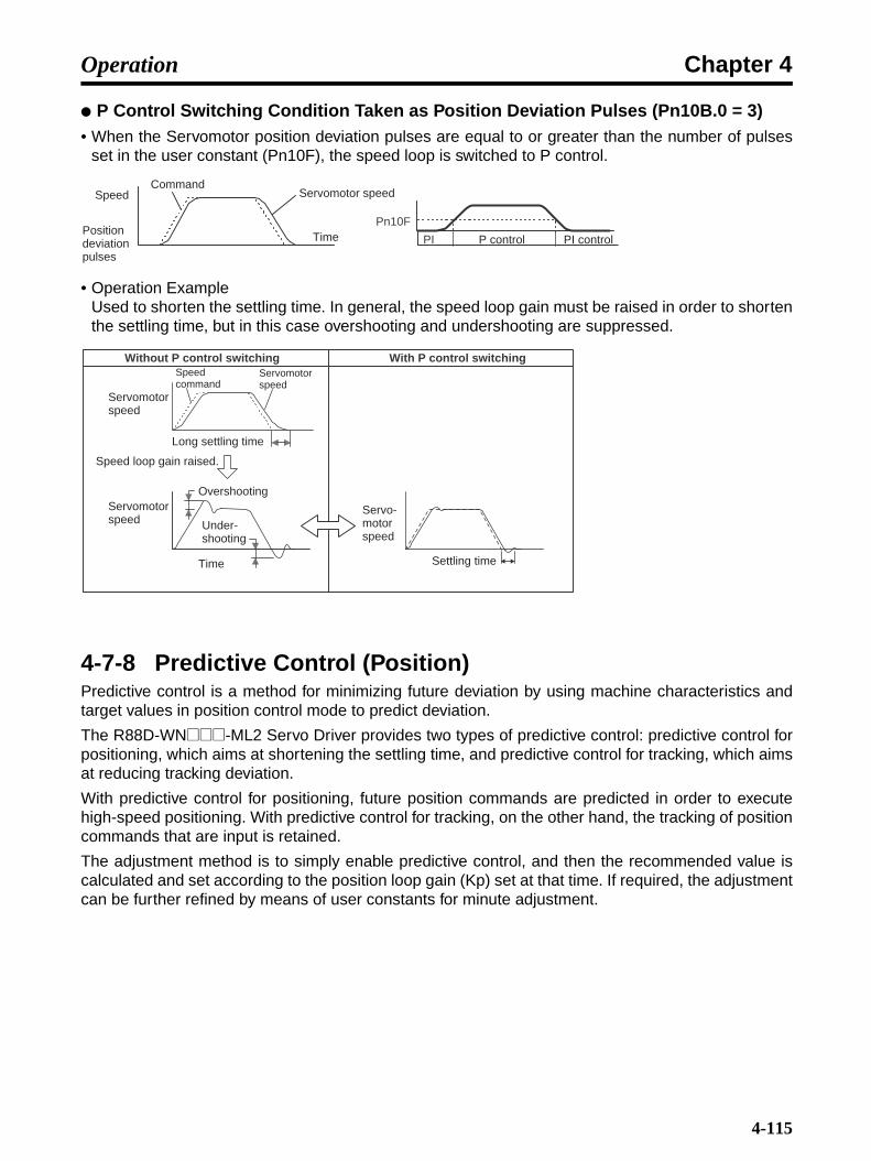
Chapter 4Operation
P Control Switching Condition Taken as Position Deviation Pulses (Pn10B.0 = 3)• When the Servomotor position deviation pulses are equal to or greater than the number of pulses
set in the user constant (Pn10F), the speed loop is switched to P control.
• Operation ExampleUsed to shorten the settling time. In general, the speed loop gain must be raised in order to shortenthe settling time, but in this case overshooting and undershooting are suppressed.
4-7-8 Predictive Control (Position)Predictive control is a method for minimizing future deviation by using machine characteristics andtarget values in position control mode to predict deviation.
The R88D-WN@@@-ML2 Servo Driver provides two types of predictive control: predictive control forpositioning, which aims at shortening the settling time, and predictive control for tracking, which aimsat reducing tracking deviation.
With predictive control for positioning, future position commands are predicted in order to executehigh-speed positioning. With predictive control for tracking, on the other hand, the tracking of positioncommands that are input is retained.
The adjustment method is to simply enable predictive control, and then the recommended value iscalculated and set according to the position loop gain (Kp) set at that time. If required, the adjustmentcan be further refined by means of user constants for minute adjustment.
Pn10F
PI
Speed
Position deviation pulses
CommandServomotor speed
Time P control PI control
Without P control switching With P control switching
Servomotor speed
Speed command
Servomotor speed
Long settling time
Speed loop gain raised.
Servomotor speed
Overshooting
Under-shooting
Time Settling time
Servo-motor speed
4-115
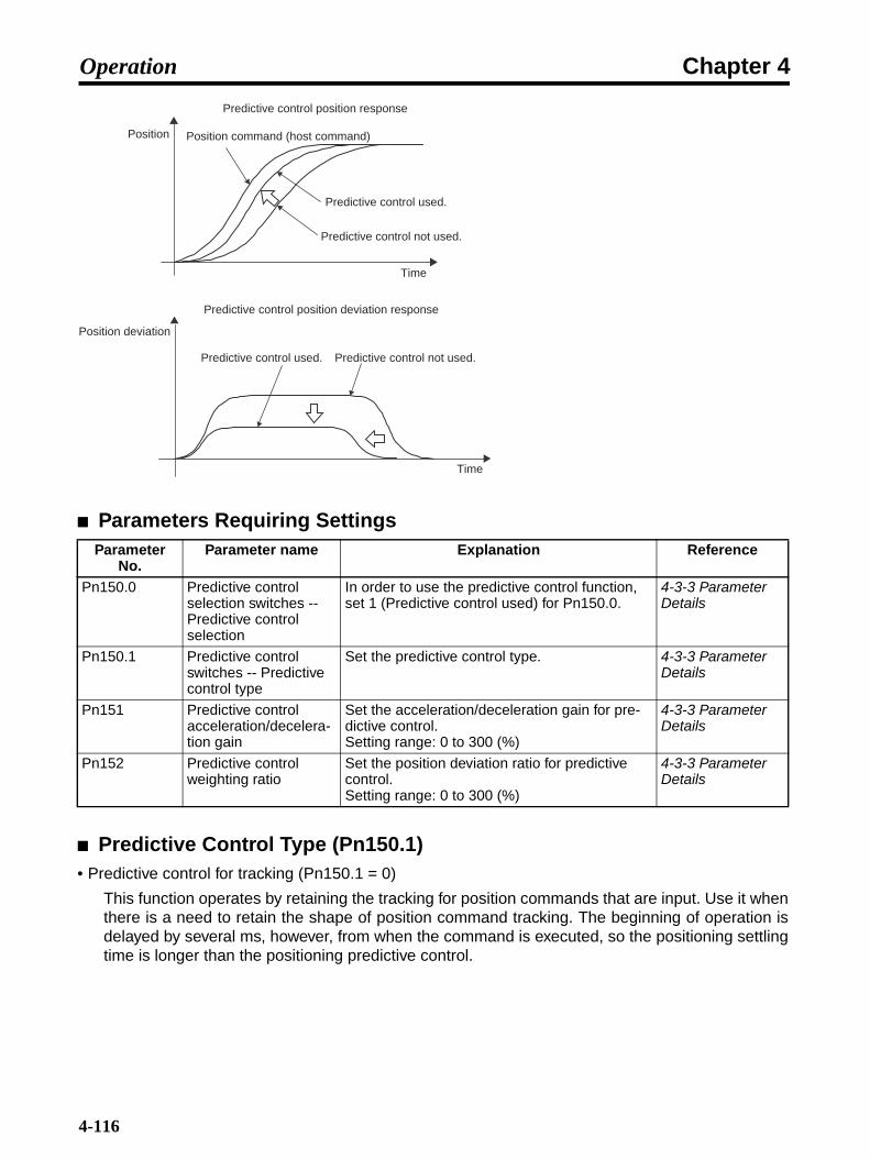
Chapter 4Operation
Parameters Requiring Settings
Predictive Control Type (Pn150.1)• Predictive control for tracking (Pn150.1 = 0)
This function operates by retaining the tracking for position commands that are input. Use it whenthere is a need to retain the shape of position command tracking. The beginning of operation isdelayed by several ms, however, from when the command is executed, so the positioning settlingtime is longer than the positioning predictive control.
Parameter No.
Parameter name Explanation Reference
Pn150.0 Predictive control selection switches -- Predictive control selection
In order to use the predictive control function, set 1 (Predictive control used) for Pn150.0.
4-3-3 Parameter Details
Pn150.1 Predictive control switches -- Predictive control type
Set the predictive control type. 4-3-3 Parameter Details
Pn151 Predictive control acceleration/decelera-tion gain
Set the acceleration/deceleration gain for pre-dictive control.Setting range: 0 to 300 (%)
4-3-3 Parameter Details
Pn152 Predictive control weighting ratio
Set the position deviation ratio for predictive control.Setting range: 0 to 300 (%)
4-3-3 Parameter Details
Predictive control position response
Position Position command (host command)
Predictive control used.
Predictive control not used.
Time
Predictive control position deviation response
Position deviation
Predictive control used. Predictive control not used.
Time
4-116

Chapter 4Operation
• Predictive control for positioning (Pn150.1 = 1)
This function operates by anticipating future position commands. It starts operation simultaneous-ly with a command and is effective in shortening positioning time.The tracking is different from the command tracking shape. With machinery that is prone to vibra-tion, the vibration may increase when stopping. In that case, even with a positioning application,use predictive control for tracking.
Predictive Control Acceleration/Deceleration Gain (Pn151)As this value is increased, the settling time is shortened without significantly changing the maximumposition deviation. If the value is set too high, overshooting will occur. The following diagram showsan example of position deviation during operation by a trapezoidal speed command. Raising the pre-dictive control acceleration/deceleration gain changes the position deviation from the dotted line tothe solid line and shortens the settling time.
Predictive Control Weighting Ratio (Pn152)As this value is increased, the tracking deviation is reduced. If the positioning completed range islarge, this is also effective in shortening the settling time. If the value is set too high, torque vibrationand overshooting may occur. The following diagram shows an example of position deviation duringoperation by a trapezoidal speed command. Raising the predictive control weighting ratio changesthe position deviation from the dotted line to the solid line and lowers the tracking deviation.
Position
Predictive control for positioning:Enables high-speed positioning.
Predictive control for tracking:Retains command shape.
Position command
Position propor-tional control
Time
Position deviation
Time
Predictive control acceleration/deceleration gain (Pn151) is raised.
4-117
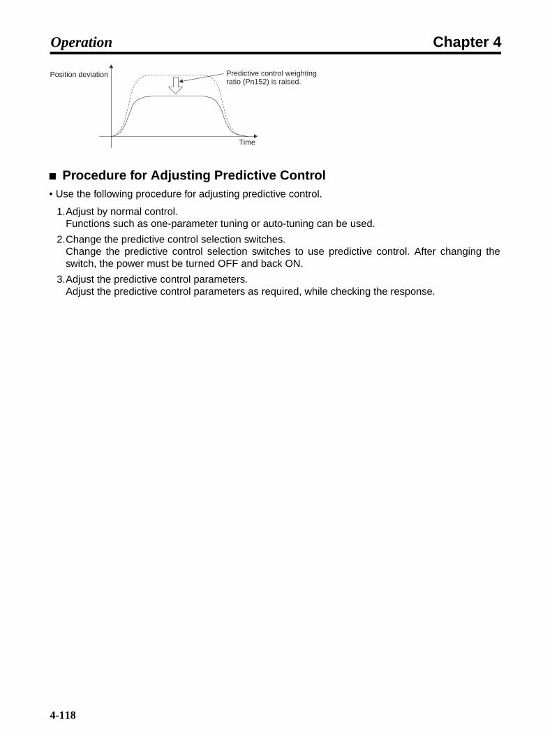
Chapter 4Operation
Procedure for Adjusting Predictive Control• Use the following procedure for adjusting predictive control.
1.Adjust by normal control.Functions such as one-parameter tuning or auto-tuning can be used.
2.Change the predictive control selection switches.Change the predictive control selection switches to use predictive control. After changing theswitch, the power must be turned OFF and back ON.
3.Adjust the predictive control parameters.Adjust the predictive control parameters as required, while checking the response.
Position deviation
Time
Predictive control weighting ratio (Pn152) is raised.
4-118

Chapter 4Operation
Applicable Restriction• Advanced auto-tuning cannot be used while the predictive control function is in use (Pn150.0 = 1).
No
Yes
No
Yes
Start operation with the predictive control OFF (Pn150.0 = 0), and adjust the parameters such as the Kp and Ky filters. One-parameter tuning
Advanced auto-tuning can be used.
Related parametersPn150: Predictive control selection
switchPn151: Predictive control
acceleration/deceleration gainPn152: Predictive control weighting ratioPn102: Position loop gain
Positioning control?Tracking control?
Positioning control
Tracking control
Set the predictive control type to positioning (Pn150.1 = 1).
Set the predictive control type to tracking (Pn150.1 = 0).
Turn ON predictive control (Pn150.0 = 1), and turn ON the power. Predictive control will be set
automatically, linked to the position loop gain (Pn102).
Operates with predictive control basic adjustments.
Specifications satisfied or
adjustment limited?
Performance improvement?
Eliminate overshooting?
Performance improvement
Eliminate overshooting
Shorten settling time?
Reduce tracking deviation?
Shorten settling time.
Reduce tracking deviation
Raise the predictive con-trol acceleration/deceler-ation gain (Pn151) to a range where overshoot-ing does not occur.
Increase the predictive control weighting ratio (Pn152) to a range where overshooting does not occur and the torque waveform does not oscillate.
Eliminate overshooting?
Lower the predictive control acceleration/deceleration gain (Pn151) or the predictive con-trol weighting ratio (Pn152) while checking for overshoot-ing due to position deviation.
Lower the position gain (Pn102) while checking for overshooting due to position deviation.
End
4-119

Chapter 4Operation
4-7-9 Less-deviation Control (Position)Less-deviation control is a method for shortening the settling time and lowering tracking deviation byreducing as much as possible the deviation during movement in position control mode. Using less-deviation one-parameter tuning makes it easy to perform adjustments. Also, when even higher per-formance is required, user adjustment constants for less-deviation control can be used to makeminute adjustments.
Parameters Requiring SettingsParameter
No.Parameter name Explanation Reference
Pn10B.2 Speed control setting -- Position loop control method
To execute less-deviation control, set Pn10B.2 to 1.
4-3-3 Parameter Details
Pn1A0 Servo rigidity Set the Servo rigidity for the No. 1 gain.Setting range: 1 to 500 (%)
4-3-3 Parameter Details
Pn1A1 Servo rigidity 2 Set the Servo rigidity for the No. 2 gain.Setting range: 1 to 500 (%)
4-3-3 Parameter Details
Pn1A2 Speed feedback filter time constant
Set the speed feedback filter time constant for the No. 1 gain.Setting range: 30 to 3,200 (× 0.01 ms)
4-3-3 Parameter Details
Pn1A3 Speed feedback filter time constant 2
Set the speed feedback filter time constant for the No. 2 gain.Setting range: 30 to 3,200 (× 0.01 ms)
4-3-3 Parameter Details
Pn1A4 Torque command filter time constant 2
Adjust for less-deviation control (set Pn10B.2 to 1).Setting range: 0 to 2,500 (× 0.01 ms)
4-3-3 Parameter Details
Pn1A7.0 Utility control switches -- Integral compensa-tion processing
Set the integral compensation processing for the No. 1 gain and the No. 2 gain during less-deviation gain switching.
4-3-3 Parameter Details
No-deviation control response waveform examples
Position
Position command (host command)
No-deviation control used.
No-deviation control not used.
Time
Positiondeviation No-deviation
control used.No-deviation control not used.
Time
4-120
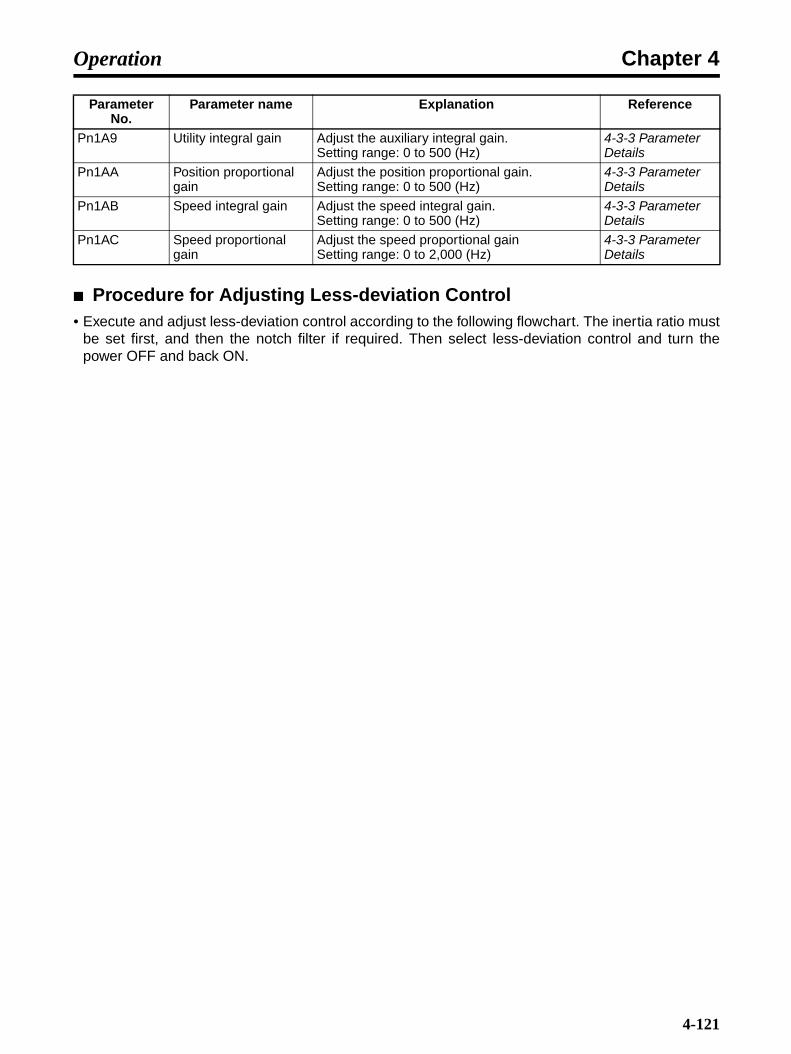
Chapter 4Operation
Procedure for Adjusting Less-deviation Control• Execute and adjust less-deviation control according to the following flowchart. The inertia ratio must
be set first, and then the notch filter if required. Then select less-deviation control and turn thepower OFF and back ON.
Pn1A9 Utility integral gain Adjust the auxiliary integral gain.Setting range: 0 to 500 (Hz)
4-3-3 Parameter Details
Pn1AA Position proportional gain
Adjust the position proportional gain.Setting range: 0 to 500 (Hz)
4-3-3 Parameter Details
Pn1AB Speed integral gain Adjust the speed integral gain.Setting range: 0 to 500 (Hz)
4-3-3 Parameter Details
Pn1AC Speed proportional gain
Adjust the speed proportional gainSetting range: 0 to 2,000 (Hz)
4-3-3 Parameter Details
Parameter No.
Parameter name Explanation Reference
4-121

Chapter 4Operation
No
Yes
Set the inertia ratio.
Start
Manually set Pn103 or use the inertia calculation function.
Set the notch filter.Measure the frequency and set the notch filter if required.
Set the no-deviation con-trol selection (Pn10B.2 = 1).
Turn ON the power.
Increase the value of Pn1A2.
Vibration?
Increase Pn1A4 to a value where there is no vibration.
Increase Pn1AA to a value where there is no vibration.
Increase Pn1A9 to a value where there is no vibration. (See note.)
End
No
End
Yes
Execute less-deviation one-parameter tuning.
Suitableresult
achieved?
Note: For Pn1A9, take a fac-tor of 0.8 of Pn1AA as the upper limit.
4-122

Chapter 4Operation
Less-deviation Gain Switching• For details on gain switching when using less-deviation control, refer to the information on Auto-
matic Gain Switching Combinations for Less-deviation Control in 4-7-4 Automatic Gain Switching(Position).
Function Limitations when Less-deviation Control is Used• Auxiliary Functions
The following auxiliary functions will not operate effectively even if they are selected.
Advanced auto-tuning
One-parameter tuning
• Control Methods used for Normal Position Control
The following control methods will not operate.
Feed forward
P control switching function
Speed feedback compensation
Predictive control
Average movement filter
4-7-10 Torque Command Filter (All Operating Modes)As shown in the following diagram, three torque command filters and two notch filters are wired inseries in the torque command filter, and they are used independently. The notch filters can beenabled or disables by parameter settings.
Pn409Pn40A Pn411Pn401
Pn408
Pn40CPn40D
Pn40FPn410
Torque command before filter
Torque-related function switch
Notch filter 2
1st step 1st torque command filter
Notch filter 1
2nd step 2nd torque command filter
3rd step torque command filter
Torque command after filter
Notch filter Primary delay filter Notch filterSecondary delay filter
Primary delay filter
4-123
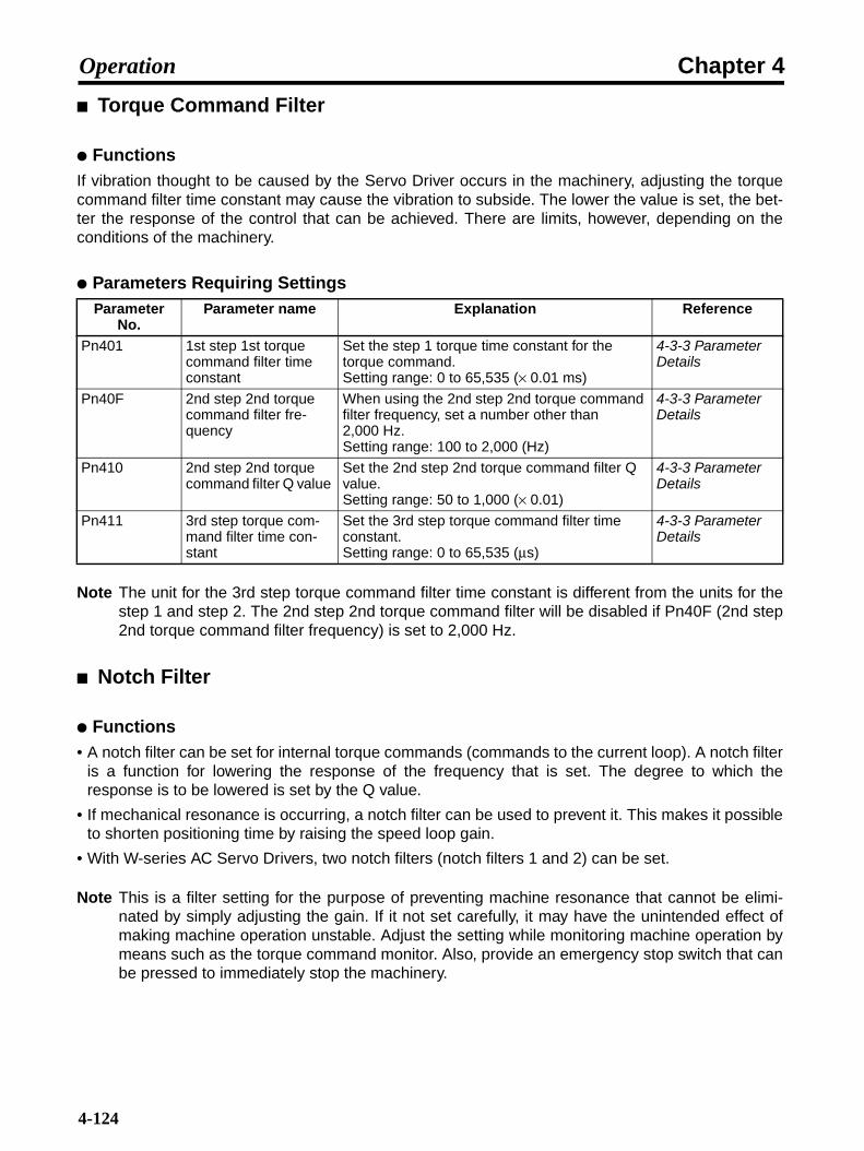
Chapter 4Operation
Torque Command Filter
FunctionsIf vibration thought to be caused by the Servo Driver occurs in the machinery, adjusting the torquecommand filter time constant may cause the vibration to subside. The lower the value is set, the bet-ter the response of the control that can be achieved. There are limits, however, depending on theconditions of the machinery.
Parameters Requiring Settings
Note The unit for the 3rd step torque command filter time constant is different from the units for thestep 1 and step 2. The 2nd step 2nd torque command filter will be disabled if Pn40F (2nd step2nd torque command filter frequency) is set to 2,000 Hz.
Notch Filter
Functions• A notch filter can be set for internal torque commands (commands to the current loop). A notch filter
is a function for lowering the response of the frequency that is set. The degree to which theresponse is to be lowered is set by the Q value.
• If mechanical resonance is occurring, a notch filter can be used to prevent it. This makes it possibleto shorten positioning time by raising the speed loop gain.
• With W-series AC Servo Drivers, two notch filters (notch filters 1 and 2) can be set.
Note This is a filter setting for the purpose of preventing machine resonance that cannot be elimi-nated by simply adjusting the gain. If it not set carefully, it may have the unintended effect ofmaking machine operation unstable. Adjust the setting while monitoring machine operation bymeans such as the torque command monitor. Also, provide an emergency stop switch that canbe pressed to immediately stop the machinery.
Parameter No.
Parameter name Explanation Reference
Pn401 1st step 1st torque command filter time constant
Set the step 1 torque time constant for the torque command.Setting range: 0 to 65,535 (× 0.01 ms)
4-3-3 Parameter Details
Pn40F 2nd step 2nd torque command filter fre-quency
When using the 2nd step 2nd torque command filter frequency, set a number other than 2,000 Hz.Setting range: 100 to 2,000 (Hz)
4-3-3 Parameter Details
Pn410 2nd step 2nd torque command filter Q value
Set the 2nd step 2nd torque command filter Q value.Setting range: 50 to 1,000 (× 0.01)
4-3-3 Parameter Details
Pn411 3rd step torque com-mand filter time con-stant
Set the 3rd step torque command filter time constant.Setting range: 0 to 65,535 (µs)
4-3-3 Parameter Details
4-124

Chapter 4Operation
Parameters Requiring Settings
Note 1. The Q value determines the notch filter characteristics. The smaller the Q value is set, thelarger the frequencies that lower response, so current loop response for frequencies otherthan for resonance frequencies is lowered. If the Q value is increased, the frequencies thatlowers response can be reduced to the resonance frequencies. If the resonance frequenciesvary due to influences such as the load or temperature, the effectiveness of the notch filteris decreased. Therefore determine the optimum setting while making adjustments.
Note 2. Be very careful when setting the notch frequency (Pn409 or Pn40C). Do not set the notchfrequency near the speed loop response frequency. Set the frequency at least four timesgreater than speed loop response frequency, or it may cause damage to the machinery.
Note 3. Make sure that the Servomotor is stopped while the notch filter frequency (Pn409, Pn40C)is being changed. The Servomotor will vibrate if the frequency is changed during operation.
Parameter No.
Parameter name Explanation Reference
Pn408.0 Torque command set-ting -- Selects notch fil-ter 1 function
When using notch filter 1, set Pn408.0 to 1 (Notch filter 1 used).
4-3-3 Parameter Details
Pn409 Notch filter 1 frequency Set the machine resonance frequency.Setting range: 50 to 2,000 (Hz)
4-3-3 Parameter Details
Pn40A Notch filter 1 Q value Set the Q value for notch filter 1.Setting range: 50 to 1,000 (× 0.01)
4-3-3 Parameter Details
Pn408.2 Torque command set-ting -- Selects notch fil-ter 2 function
When using notch filter 2, set Pn408.2 to 1 (Notch filter 2 used).
4-3-3 Parameter Details
Pn40C Notch filter 2 frequency Set the machine resonance frequency.Setting range: 50 to 2,000 (Hz)
4-3-3 Parameter Details
Pn40D Notch filter 2 Q value Set the Q value for notch filter 2.Setting range: 50 to 1,000 (× 0.01)
4-3-3 Parameter Details
4-125
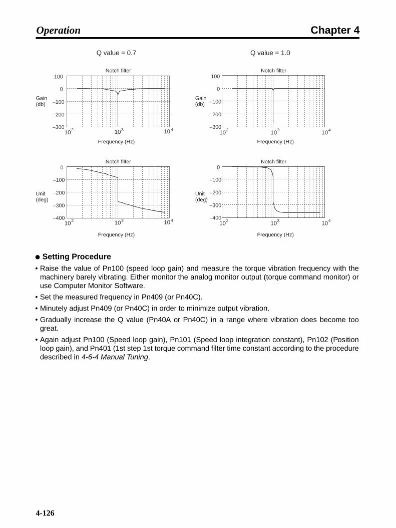
Chapter 4Operation
Setting Procedure• Raise the value of Pn100 (speed loop gain) and measure the torque vibration frequency with the
machinery barely vibrating. Either monitor the analog monitor output (torque command monitor) oruse Computer Monitor Software.
• Set the measured frequency in Pn409 (or Pn40C).
• Minutely adjust Pn409 (or Pn40C) in order to minimize output vibration.
• Gradually increase the Q value (Pn40A or Pn40C) in a range where vibration does become toogreat.
• Again adjust Pn100 (Speed loop gain), Pn101 (Speed loop integration constant), Pn102 (Positionloop gain), and Pn401 (1st step 1st torque command filter time constant according to the proceduredescribed in 4-6-4 Manual Tuning.
Q value = 0.7 Q value = 1.0
−300
−200
−100
0
100
2 10103 104
2 10103 104−400
−300
−200
−100
0
−300
−200
−100
0
100
2 1010 3 104
2 1010 3 104−400
−300
−200
−100
0
Notch filter Notch filter
Notch filter Notch filter
Gain (db)
Gain (db)
Frequency (Hz) Frequency (Hz)
Frequency (Hz) Frequency (Hz)
Unit (deg)
Unit (deg)
4-126

Chapter 4Operation
4-7-11 Vibration Suppression when Stopping (Position)
FunctionsWhen the Servo gain is increased, there may be vibration (such as the limit cycle) while stopped,even though there is no vibration while moving. It was previously necessary to lower the response toa gain where vibration while stopped subsided, sacrificing response during movement. To suppressthe vibration while movement is stopped, this function lowers the internal Servo gain only whilemovement is stopped. Use this function by adjusting the parameters given below. After the vibrationsuppression starting time (Pn421) has elapsed from the point where the position command is 0, theinternal Servo gain will change to the percentage set for the damping for vibration suppression onstopping (Pn420).
Parameters Requiring Settings
Note Use when the damping for vibration suppression on stopping (Pn420) is 50% or higher, and thevibration suppression starting time (Pn421) is 10 ms or longer. If a low value is set, theresponse characteristics may be lowered and vibration may occur.
Parameter No.
Parameter name Explanation Reference
Pn420 Damping for vibration suppression on stop-ping
Sets the gain reduction rate for when the Servo-motor is stopped.Setting range: 10 to 100%
4-3-3 Parameter Details
Pn421 Vibration suppression starting time
Set the time for Pn420 to be enabled after the motor stops. Setting range: 0 to 65,535 (ms)
4-3-3 Parameter Details
K × Pn420/100
K KPn421
Position commandPosition command = 0
Servo gain
4-127
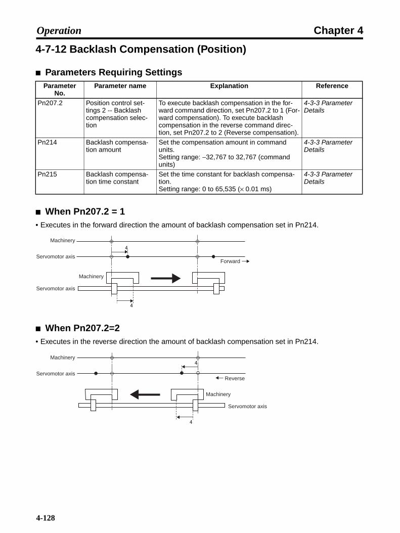
Chapter 4Operation
4-7-12 Backlash Compensation (Position)
Parameters Requiring Settings
When Pn207.2 = 1• Executes in the forward direction the amount of backlash compensation set in Pn214.
When Pn207.2=2• Executes in the reverse direction the amount of backlash compensation set in Pn214.
Parameter No.
Parameter name Explanation Reference
Pn207.2 Position control set-tings 2 -- Backlash compensation selec-tion
To execute backlash compensation in the for-ward command direction, set Pn207.2 to 1 (For-ward compensation). To execute backlash compensation in the reverse command direc-tion, set Pn207.2 to 2 (Reverse compensation).
4-3-3 Parameter Details
Pn214 Backlash compensa-tion amount
Set the compensation amount in command units.Setting range: −32,767 to 32,767 (command units)
4-3-3 Parameter Details
Pn215 Backlash compensa-tion time constant
Set the time constant for backlash compensa-tion.Setting range: 0 to 65,535 (× 0.01 ms)
4-3-3 Parameter Details
Machinery
Servomotor axis
Servomotor axis
Machinery
Forward
Machinery
Servomotor axis
Machinery
Servomotor axis
Reverse
4-128

Chapter 4Operation
4-7-13 Position Integration (Position)
Parameters Requiring Settings
Note Effective for synchronous operations such as electronic cam and electronic shift.
Parameter No.
Parameter name Explanation Reference
Pn11F Position integral time constant
Set the integral time constant for the position loop.Setting range: 0 to 50,000 (× 0.1 ms)
4-3-3 Parameter Details
4-129
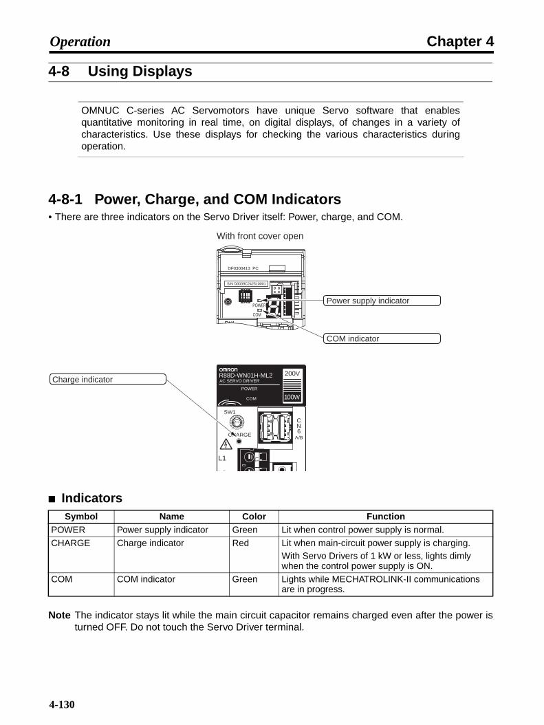
Chapter 4Operation
4-8 Using Displays
OMNUC C-series AC Servomotors have unique Servo software that enablesquantitative monitoring in real time, on digital displays, of changes in a variety ofcharacteristics. Use these displays for checking the various characteristics duringoperation.
4-8-1 Power, Charge, and COM Indicators• There are three indicators on the Servo Driver itself: Power, charge, and COM.
Indicators
Note The indicator stays lit while the main circuit capacitor remains charged even after the power isturned OFF. Do not touch the Servo Driver terminal.
Symbol Name Color FunctionPOWER Power supply indicator Green Lit when control power supply is normal.
CHARGE Charge indicator Red Lit when main-circuit power supply is charging.With Servo Drivers of 1 kW or less, lights dimly when the control power supply is ON.
COM COM indicator Green Lights while MECHATROLINK-II communications are in progress.
5 678
9A
BCDEF0
12
3 4
CN6
A/B
SW1
CHARGE
L1
L2
L1
R88D-WN01H-ML2
100W
200VAC SERVO DRIVER
POWER
COM
DF0300413 PC
ON
1 2 3 4
POWER
COM
S/N D0039C242510001
Charge indicator
Power supply indicator
COM indicator
With front cover open
4-130
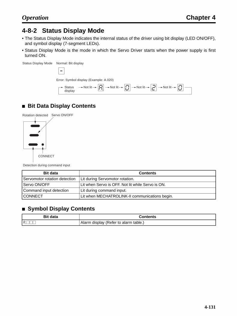
Chapter 4Operation
4-8-2 Status Display Mode• The Status Display Mode indicates the internal status of the driver using bit display (LED ON/OFF),
and symbol display (7-segment LEDs).
• Status Display Mode is the mode in which the Servo Driver starts when the power supply is firstturned ON.
Bit Data Display Contents
Symbol Display Contents
Bit data ContentsServomotor rotation detection Lit during Servomotor rotation.
Servo ON/OFF Lit when Servo is OFF. Not lit while Servo is ON.
Command input detection Lit during command input.
CONNECT Lit when MECHATROLINK-II communications begin.
Bit data Contentsa.@@@ Alarm display (Refer to alarm table.)
Normal: Bit displayStatus Display Mode
Error: Symbol display (Example: A.020)
Not lit Not lit Not lit Not litStatus display
Rotation detected
Detection during command input
CONNECT
Servo ON/OFF
4-131

Chapter 4Operation
4-9 Using Monitor Output
OMNUC W-series AC Servo Drivers output in analog form the Servomotor rotationspeed, torque command, position difference, and other proportional voltage amountsfrom the Analog Monitor Output Connector (CN5). This function can be used insituations such as making fine gain adjustments or when a meter is attached to thecontrol panel. Select the monitor items using parameters Pn006.0 to Pn006.1 andPn007.0 to Pn007.1. Also, use parameters Pn006.2 and Pn007.2 to change scalingand Pn550 and Pn551 to adjust the offset.
Analog Monitor Output Connector (CN5)• The Analog Monitor Output Connector (CN5) is located inside the top cover of the Servo Driver.
Note 1. Displays status with no change to scaling.
Note 2. Maximum output voltage is ±8 V. Exceeding this value may result in an abnormal output.(Clamped at ±8 V.)
Note 3. Output accuracy is approximately ±15%.
Pin No. Symbol Name Function and interface1 NM Analog monitor 2 Default setting: Speed monitor 1 V/1000 r/min. (change
using Pn007.0-1)
2 AM Analog monitor 1 Default setting: Current monitor 1 V/rated torque (change using Pn006.0-1)
3 GND Analog monitor ground Ground for analog monitors 1 and 2
4 GND Analog monitor ground
DF0300413 PC
ON
1 2 3 4
POWER
COM
S/N D0039C242510001
Analog Monitor Output Connector (CN5)
View with upper cover open
CN5 pin distribution (front panel view)
31
2 4
Driver pin header: DF11-4DP-2DSCable connector socket: DF11-4DS-2CCable connector contact: DF11-2428SCF(Manufactured by Hirose.)
4-132

Chapter 4Operation
Analog Monitor Output Circuit
Analog Monitor Cable (R88A-CMW001S)Use this cable to connect the Servo Driver's Analog Monitor Connector (CN5)
Monitored Item SelectionPn006.0-1 Function selection application switches 6 -- Analog monitor 1 signal selection (All operation
modes)
Setting range
00 to 1F Unit --- Default setting
2 Restart power?
No
Pn007.0-1 Function selection application switches 7 -- Analog monitor 2 signal selection (All operation modes)
Setting range
00 to 1F Unit --- Default setting
0 Restart power?
No
Servo Driver
NM (analog monitor 2)CN5-147 Ω
AM (analog monitor 1)CN5-2
GND (analog monitor ground)CN5-3
GND (analog monitor ground)CN5-4
47 Ω
7.3 1000
1.7
dia.
5
t = 6
Servo Driver
R88D-WT@
External devices
No.1234
NMAM
GNDGND
SymbolServo Driver
RedWhiteBlackBlack
Cable: AWG24 × 4C UL1007
Connector socket modelDF11-4DS-2C (Hirose)Connector socket modelDF11-2428SCF (Hirose)
4-133
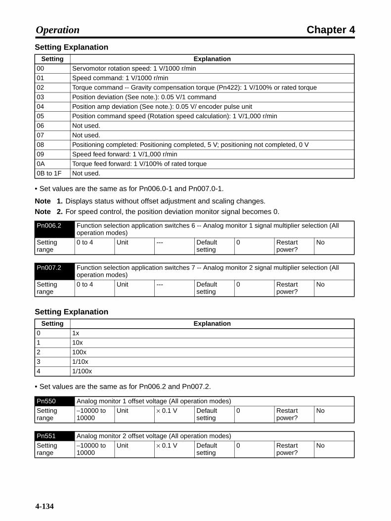
Chapter 4Operation
Setting Explanation
• Set values are the same as for Pn006.0-1 and Pn007.0-1.
Note 1. Displays status without offset adjustment and scaling changes.
Note 2. For speed control, the position deviation monitor signal becomes 0.
Setting Explanation
• Set values are the same as for Pn006.2 and Pn007.2.
Setting Explanation00 Servomotor rotation speed: 1 V/1000 r/min
01 Speed command: 1 V/1000 r/min
02 Torque command -- Gravity compensation torque (Pn422): 1 V/100% or rated torque
03 Position deviation (See note.): 0.05 V/1 command
04 Position amp deviation (See note.): 0.05 V/ encoder pulse unit
05 Position command speed (Rotation speed calculation): 1 V/1,000 r/min
06 Not used.
07 Not used.
08 Positioning completed: Positioning completed, 5 V; positioning not completed, 0 V
09 Speed feed forward: 1 V/1,000 r/min
0A Torque feed forward: 1 V/100% of rated torque
0B to 1F Not used.
Pn006.2 Function selection application switches 6 -- Analog monitor 1 signal multiplier selection (All operation modes)
Setting range
0 to 4 Unit --- Default setting
0 Restart power?
No
Pn007.2 Function selection application switches 7 -- Analog monitor 2 signal multiplier selection (All operation modes)
Setting range
0 to 4 Unit --- Default setting
0 Restart power?
No
Setting Explanation0 1x
1 10x
2 100x
3 1/10x
4 1/100x
Pn550 Analog monitor 1 offset voltage (All operation modes)
Setting range
−10000 to 10000
Unit × 0.1 V Default setting
0 Restart power?
No
Pn551 Analog monitor 2 offset voltage (All operation modes)
Setting range
−10000 to 10000
Unit × 0.1 V Default setting
0 Restart power?
No
4-134

Chapter 4Operation
• When Pn006 = 0102, Pn422 = 100 [%], and Pn550 =3.0 [V]
Analog monitor 1 = Torque command
= (−1) × (Torque command [%] − 10%) × 10 + 3 [V]
If the torque here is 52%
= (−1) × (52 [%] − 10%) × 1 [V]/100 [%] × 10 + 3 [V]= −7.2 [V] (Analog monitor 1 output voltage)
Note The analog monitor output voltage is ±8 V max. If ±8 V is exceeded, the output is fixed at ±8 V.
4-135

Chapter 4Operation
4-136
Chapter 5
Troubleshooting
5-1 Measures when Trouble Occurs
5-2 Alarms
5-3 Troubleshooting
5-4 Overload Characteristics (Electronic ThermalCharacteristics)
5-5 Periodic Maintenance
5-6 Replacing the Absolute Encoder Battery (ABS)
Chapter 5Troubleshooting
5-1 Measures when Trouble Occurs
5-1-1 Preventive Checks Before Trouble Occurs
This section explains the preventive checks and analysis tools required to determinethe cause of trouble when it occurs.
Check the Power Supply Voltage• Check the voltage to the power supply input terminals.
Main-circuit Power Supply Input Terminals (L1, L2, (L3))
R88D-WN@H-ML2(50 to 400 W, 750W): Single-phase 200/230 V AC (170 to 253 V) 50/60 Hz(500 W to 3 kW): 3-phase 200/230 V AC (170 to 253 V) 50/60 Hz
R88D-WN@L-ML2 (50 to 400 W): Single-phase 100/115 V AC (85 to 127 V) 50/60 Hz
Control-circuit Power Supply Input Terminals (L1C, L2C)
R88D-WN@H-ML2: Single-phase 200/230 V AC (170 to 253 V) 50/60 Hz
R88D-WN@L-ML2: Single-phase 100/115 V AC (85 to 127 V) 50/60 Hz
If the voltage falls outside of this range, there is a risk of malfunction, so make sure that the powersupply is correct.
• Make sure that the voltage of the sequence input power supply (+24 VIN Terminal (CN1-6 pin)) iswithin the range 23 to 25 VDC. If the voltage falls outside of this range, there is a risk of malfunc-tion, so make sure that the power supply is correct.
Selecting Analysis Tools
Check Whether an Alarm Has Occurred• If an alarm has occurred, check the alarm code (A.@@@), and perform analysis depending on the
alarm code.
• If an alarm has not occurred, perform analysis depending on the error.
Note Refer to 5-3 Troubleshooting in either case.
Types of Analysis Tools• The types of analysis tools are as follows:
Servo Driver Indicators and Parameter Unit• Perform analysis using the display (7-segment LEDs) and the operation keys on the front panel of
the Servo Driver. This manual explains analysis using these methods.
5-2

Chapter 5Troubleshooting
Computer Monitor Software• Install and use the Computer Monitor Software. The following three items are required: A Windows
95/98-compatible computer, Computer Monitor Software, and R88A-CCW002P@ ConnectingCable.
• Refer to the Computer Monitor Software for operation details.
5-1-2 Precautions
When checking and verifying I/O after trouble has occurred, the Servo Driver maysuddenly start to operate or suddenly stop, so take precautions. Also, do not attemptoperations not specified in this manual.
Precautions• Disconnect any cables before checking if they have burned out. Even if you have checked the con-
duction of the wiring, there is a risk of conduction due to the return circuit.
• If the encoder signal is lost, the Servomotor may run away, or an error may be generated. Makesure the Servomotor is disconnected from the mechanical system before checking the encoder sig-nal.
• When measuring the encoder output, measure using the ground (CN1-16 pin) as standard. If mea-suring using an oscilloscope, measure using the differential between CH1 and CH2 to reduce inter-ference from noise.
• When performing tests, first check that there are no personnel inside the machine facilities, and thatthe facilities will not be damaged even if the Servomotor runs away. Also, check that even if the Ser-vomotor runs away, you can immediately stop the machine using an emergency stop before per-forming the tests.
Checking Alarm Codes at the Controller• The alarm codes that occur at the Servo Driver with regard to CS1W-MCH71 and CJ1W-MCH71
Motion Control Units and CJ1W-NCF71 Position Control Units are stored in the Controller as shownbelow.
Controller Alarm Codes• Alarm codes such as the following are stored at the Controller for alarms that occur at the Servo
Driver.
Controller alarm (error) code: 40@@ (Hex)
The leftmost two digits from the Servo Driver's 3-digit alarm code are entered at the two boxes(@@).
Example: Deviation counter overflow alarm at Servo-ON (A.d01).The alarm code stored at the Controller is 40D0 (hex).
5-3
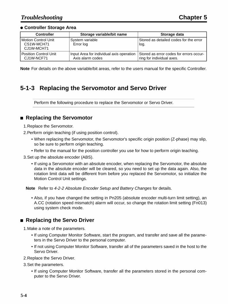
Chapter 5Troubleshooting
Controller Storage Area
Note For details on the above variable/bit areas, refer to the users manual for the specific Controller.
5-1-3 Replacing the Servomotor and Servo Driver
Perform the following procedure to replace the Servomotor or Servo Driver.
Replacing the Servomotor
1.Replace the Servomotor.
2.Perform origin teaching (if using position control).
• When replacing the Servomotor, the Servomotor's specific origin position (Z-phase) may slip,so be sure to perform origin teaching.
• Refer to the manual for the position controller you use for how to perform origin teaching.
3.Set up the absolute encoder (ABS).
• If using a Servomotor with an absolute encoder, when replacing the Servomotor, the absolutedata in the absolute encoder will be cleared, so you need to set up the data again. Also, therotation limit data will be different from before you replaced the Servomotor, so initialize theMotion Control Unit settings.
Note Refer to 4-2-2 Absolute Encoder Setup and Battery Changes for details.
• Also, if you have changed the setting in Pn205 (absolute encoder multi-turn limit setting), anA.CC (rotation speed mismatch) alarm will occur, so change the rotation limit setting (Fn013)using system check mode.
Replacing the Servo Driver
1.Make a note of the parameters.
• If using Computer Monitor Software, start the program, and transfer and save all the parame-ters in the Servo Driver to the personal computer.
• If not using Computer Monitor Software, transfer all of the parameters saved in the host to theServo Driver.
2.Replace the Servo Driver.
3.Set the parameters.
• If using Computer Monitor Software, transfer all the parameters stored in the personal com-puter to the Servo Driver.
Controller Storage variable/bit name Storage dataMotion Control Unit
CS1W-MCH71CJ1W-MCH71
System variableError log
Stored as detailed codes for the error log.
Position Control UnitCJ1W-NCF71
Input Area for individual axis operation Axis alarm codes
Stored as error codes for errors occur-ring for individual axes.
5-4

Chapter 5Troubleshooting
• If using Computer Monitor Software, transfer all of the parameters saved in the host to the Ser-vo Driver. Refer to the manuals for the host for operating procedures.
4.Set up the absolute encoder (ABS).
• If using a Servomotor with an absolute encoder, when replacing the Servomotor, the absolutedata in the absolute encoder will be cleared, so you need to reset the data. Also, the multi-turndata will be different from before the Servo Driver was replaced. If the host device is a CS1W-MCH71 or CJ1W-MCH71, make the initial settings for the host device.
Note Refer to 4-2-2 Absolute Encoder Setup and Battery Changes for details.
5-5

Chapter 5Troubleshooting
5-2 Alarms
If the Servo Driver detects an error, ALM (alarm output) and ALO1 to ALO3 (alarmcodes) are output, the power drive circuit in the Servo Driver turns OFF, and the alarmis displayed. If the Servo Driver detects a warning (e.g., overload warning orregenerative overload warning), WARN (warning output) and ALO1 to ALO3 (warningcodes) are output, and the warning is displayed. (Operation continues.)
Note 1. Warning outputs and warning codes are output only if the parameters have been set(Pn50F.3, Pn001.1).
Note 2. Refer to 5-3-1 Error Diagnosis Using Alarm Display for appropriate alarm countermeasures.
Note 3. Cancel the alarm using one of the following methods. (Remove the cause of the alarm first.)
• Turn OFF the power supply, then turn it ON again.
• Input a RESET signal from the host device.
The following alarms can only be cancelled by turning OFF the power supply, then turning it ONagain: A.02@, A.04@, A.100, A.810, A.820, A.840, A.850, A.860, A.b@@, A.C8@, A.C9@, A.CA0,A.Cb0, A.CC0, A.E02, A.E07, A.E08, A.E09, A.EA0, and A.EA1.
Note 4. When an alarm occurs, the Servo Driver stops the Servomotor by the following methods.
• DB stop: The Servomotor is stopped according to the method set in Pn001.0.
• Zero-speed stop: The speed command at the Servo Driver is set to zero, and then the Servo-motor is stopped according to the method set in Pn001.0.
Alarm TableDisplay Error detection function Cause of error Stopping
method at alarm
Alarm reset possible?
a.020 Parameter checksum error 1
The Servo Driver's internal param-eter data is abnormal.
DB stop No
a.021 Parameter format error 1 The Servo Driver's internal param-eter data is abnormal.
DB stop No
a.022 System parameter check-sum error 1
The Servo Driver's internal param-eter data is abnormal.
DB stop No
a.023 Parameter password error 1
The Servo Driver's internal param-eter data is abnormal.
DB stop No
a.02a Parameter checksum error 2
The Servo Driver's internal param-eter data is abnormal.
DB stop No
a.02b System parameter check-sum error 2
The Servo Driver's internal param-eter data is abnormal.
DB stop No
a.030 Main circuit detection error There is an error in the detection data for the power supply circuit.
DB stop Yes
a.040 Parameter setting error 1 A parameter value exceeds the set-ting range.
DB stop No
a.04a Parameter setting error 2 A parameter value exceeds the set-ting range.
DB stop No
5-6

Chapter 5Troubleshooting
a.041 Dividing pulse output set-ting error
The encoder divider rate setting is out of range or the set conditions are not satisfied.
DB stop No
a.042 Parameter combination error
A combination of multiple parame-ters is set out of range.
DB stop No
a.050 Combination error The combined capacity of the Ser-vomotor and the Servo Driver is unsuitable.
DB stop Yes
a.0b0 Servo ON command invalid alarm
After a function for executing Servo ON by means of Computer Monitor Software was used, an attempt was made to execute Servo ON using a host command.
DB stop Yes
a.100 Overcurrent or overheat-ing of radiation shield
An overcurrent has occurred, or the Servo Driver's radiation shield has overheated.
DB stop No
a.300 Regeneration error The regeneration resistance is dis-connected or the regeneration tran-sistor is faulty.
DB stop Yes
a.320 Regeneration overload The regenerative energy exceeds the regeneration resistance.
Zero-speed stop
Yes
a.330 Main circuit power supply setting error
The method for providing power to the main circuit does not match the Pn001 setting.
DB stop Yes
a.400 Overvoltage The main-circuit DC voltage is abnormally high.
DB stop Yes
a.410 Low voltage The main-circuit DC voltage is low. Zero-speed stop
Yes
a.510 Overspeed The Servomotor's rotation speed is abnormally high.
DB stop Yes
a.511 Dividing pulse output over-speed
The Servomotor rotation speed upper limit set for the encoder divider rate setting (Pn212) was exceeded.
DB stop Yes
a.520 Vibration alarm Abnormal vibration was detected in the Servomotor rotation speed.
DB stop Yes
a.521 Auto-tuning alarm The inertia ratio was in error during auto-tuning.
DB stop Yes
a.710 Overload (momentary maximum load)
Operated for several seconds to several tens of seconds at a torque greatly exceeding the rating.
Zero-speed stop
Yes
a.720 Overload (continual maxi-mum load)
Operated continually at a torque exceeding the rating.
DB stop Yes
a.730 DB overload During DB (dynamic braking) oper-ation, rotation energy exceeds the DB capacity.
DB stop Yes
a.740 Inrush resistance overload The main-circuit power supply has frequently and repeatedly been turned ON and OFF.
DB stop Yes
a.7a0 Overheat The Servo Driver's radiation shield overheated.
Zero-speed stop
Yes
Display Error detection function Cause of error Stopping method at
alarm
Alarm reset possible?
5-7

Chapter 5Troubleshooting
a.810 Encoder backup error The encoder power supply was completely down, and position data was cleared.
DB stop No
a.820 Encoder checksum error The encoder memory checksum results are in error.
DB stop No
a.830 Encoder battery error The absolute encoder backup bat-tery voltage has dropped.
DB stop Yes
a.840 Encoder data error The encoder's internal data is in error.
DB stop No
a.850 Encoder overspeed The encoder rotated at high speed when the power was ON.
DB stop No
a.860 Encoder overheat The encoder's internal temperature is too high.
DB stop No
a.b31 Current detection error 1 The phase-U current detector is in error.
DB stop No
a.b32 Current detection error 2 The phase-V current detector is in error.
DB stop No
a.b33 Current detection error 3 The current detector is in error. DB stop No
a.b6a MECHATROLINK commu-nications ASIC error 1
The MECHATROLINK communica-tions ASIC is in error.
DB stop No
a.b6b MECHATROLINK commu-nications ASIC error 2
A fatal error occurred in the MECHATROLINK communications ASIC.
DB stop No
a.bf0 System alarm 0 Servo Driver internal program error 0 occurred.
DB stop No
a.bf1 System alarm 1 Servo Driver internal program error 1 occurred.
DB stop No
a.bf2 System alarm 2 Servo Driver internal program error 2 occurred.
DB stop No
a.bf3 System alarm 3 Servo Driver internal program error 3 occurred.
DB stop No
a.bf4 System alarm 4 Servo Driver internal program error 4 occurred.
DB stop No
a.c10 Runaway detected Servomotor runaway occurred. DB stop Yes
a.c80 Multi-turn data error Absolute encoder multi-turn data was cleared or could not be set correctly.
DB stop No
a.c90 Encoder communications error
No communication possible between the encoder and Servo Driver.
DB stop No
a.c91 Encoder communications position data error
An error occurred in the encoder's position data calculations.
DB stop No
a.c92 Encoder communications timer error
An error occurred in the timer for communications between the encoder and Servo Driver.
DB stop No
a.ca0 Encoder parameter error Encoder parameters are corrupted. DB stop No
a.cb0 Encoder echo-back error The contents of communications with the encoder are wrong.
DB stop No
Display Error detection function Cause of error Stopping method at
alarm
Alarm reset possible?
5-8

Chapter 5Troubleshooting
a.cc0 Multi-turn limit discrepancy The multi-turn limits for the encoder and the Servo Driver do not match.
DB stop No
a.d00 Deviation counter overflow Position deviation pulses exceeded the level set for Pn520.
DB stop Yes
a.d01 Deviation counter overflow alarm at Servo-ON
When Servo ON was executed, the accumulated number of position deviation pulses reached or exceeded the number set for Pn526.
DB stop Yes
a.d02 Deviation counter overflow alarm by speed limit at Servo-ON
If Servo ON is executed with posi-tion deviation pulses accumulated, the speed is limited by the setting in Pn529. A command pulse was input during this period, without the limit being cleared, and the setting in Pn520 was exceeded.
Zero stop Yes
a.e00 COM alarm 0 Servo Driver COM error 0 occurred.
Zero-speed stop
Yes
a.e01 COM alarm 1 Servo Driver COM error 1 occurred.
Zero-speed stop
Yes
a.e02 COM alarm 2 Servo Driver COM error 2 occurred.
DB stop No
a.e07 COM alarm 7 Servo Driver COM error 7 occurred.
DB stop No
a.e08 COM alarm 8 Servo Driver COM error 8 occurred.
Zero-speed stop
No
a.e09 COM alarm 9 Servo Driver COM error 9 occurred.
Zero-speed stop
No
a.e40 MECHATROLINK-II trans-mission cycle setting error
There is an error in the setting for the MECHATROLINK-II communi-cations transmission cycle.
Zero-speed stop
Yes
a.e50 MECHATROLINK-II syn-chronization error
A synchronization error occurred during MECHATROLINK-II commu-nications.
Zero-speed stop
Yes
a.e51 MECHATROLINK-II syn-chronization failure
A synchronization failure occurred during MECHATROLINK-II commu-nications.
Zero-speed stop
Yes
a.e60 MECHATROLINK-II com-munications error
Communications errors occurred continuously during MECHA-TROLINK-II communications.
Zero-speed stop
Yes
a.e61 MECHATROLINK-II trans-mission cycle error
An error occurred in the transmis-sion cycle during MECHA-TROLINK-II communications.
Zero-speed stop
Yes
a.ea0 DRV alarm 0 Servo Driver DRV error 0 occurred. DB stop No
a.ea1 DRV alarm 1 Servo Driver DRV error 1 occurred. DB stop No
a.ea2 DRV alarm 2 Servo Driver DRV error 2 occurred. Zero-speed stop
Yes
Display Error detection function Cause of error Stopping method at
alarm
Alarm reset possible?
5-9

Chapter 5Troubleshooting
Warning Table
a.ed0 Internal command error A command error occurred in the Servo Driver.
Zero-speed stop
Yes
a.f10 Missing phase detected One phase from the three-phase main circuit power supply is not connecting.
Zero-speed stop
Yes
Display Warning detection function
Meaning
a.900 Deviation counter overflow The accumulated position deviation pulses equaled or exceeded the parameter (Pn520 × Pn51E/100) setting.
a.901 Deviation counter overflow at Servo-ON
The accumulated position deviation pulses when the Servo turned ON equaled or exceeded the parameter (Pn526 × Pn528/100) set-ting.
a.910 Overload This is a warning before the overload alarm (A.710 or A.720) is reached. If operation continues at this point, an alarm may be gener-ated.
a.911 Vibration Faulty oscillation was detected in the Servomotor rotation speed. The detection level is the same as for A520, but the difference is in whether an alarm or warning is to be set by the Pn310 vibration detection switches.
a.920 Regeneration overload This is the warning display before the regenerative overload alarm (A.320) is reached. If operation continues at this point, an alarm may be generated.
a.930 Absolute encoder battery warning
This is the warning display indicating that the absolute encoder bat-tery voltage is low.
a.941 Parameter change requir-ing restarting
A parameter requiring the power to be turned ON again was changed.
a.94a Data setting warning 1 (parameter No.)
There is an error in a command parameter number.
a.94b Data setting warning 2 (out of range)
The setting outside of the command data range.If the Servo Driver is connected to the CJ1W-MCH71 or CS1W-MCH71, the option monitor parameters may not be set correctly. Check the setting of Pn813 and change it to 0032 hex if any other value is set.
a.94c Data setting warning 3 (calculation error)
A calculation error was detected.
a.94d Data setting warning 4 (parameter size)
A non-conforming data size was detected.
a.95a Command warning 1 (com-mand conditions not met)
A command was specified even though the command conditions were not completely met.
a.95b Command warning 2 (unsupported command)
An unsupported command was specified.
a.95c Command warning 3 Command conditions set by parameters were not met.
a.95d Command warning 4 Command interference (mainly latch command interference)
a.95e Command warning 5 Sub-command and main command interference
a.960 MECHATROLINK-II com-munications warning
A communications error occurred during MECHATROLINK-II com-munications.
Display Error detection function Cause of error Stopping method at
alarm
Alarm reset possible?
5-10

Chapter 5Troubleshooting
Note 1. When Pn008.2 is set to 1 (Warnings not detected), the following warnings are not detected.A.900, A.901, A.910, A.911, A.920, A.930
Note 2. Depending on the setting for Pn800.1 (Warning check mask), A.94@, A.95@, and A.96@warnings may not be detected. With the default setting, A.94@, A.95@, and A.96@ warningsare detected.
5-11
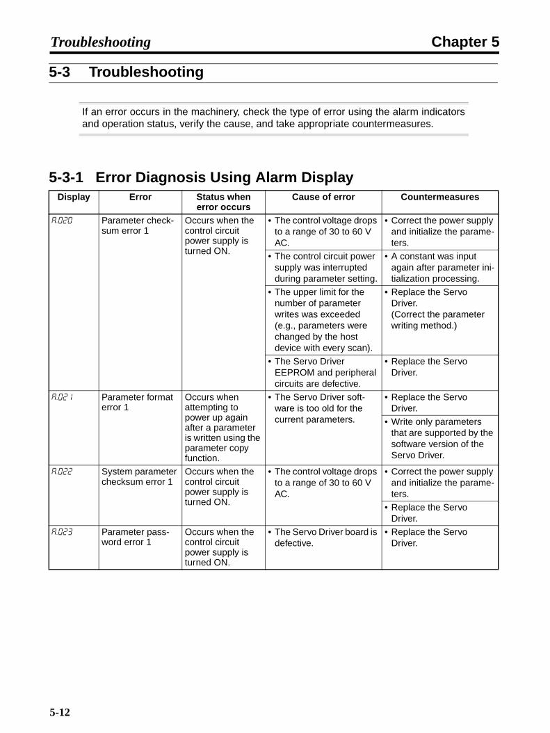
Chapter 5Troubleshooting
5-3 Troubleshooting
If an error occurs in the machinery, check the type of error using the alarm indicatorsand operation status, verify the cause, and take appropriate countermeasures.
5-3-1 Error Diagnosis Using Alarm DisplayDisplay Error Status when
error occursCause of error Countermeasures
a.020 Parameter check-sum error 1
Occurs when the control circuit power supply is turned ON.
• The control voltage drops to a range of 30 to 60 V AC.
• Correct the power supply and initialize the parame-ters.
• The control circuit power supply was interrupted during parameter setting.
• A constant was input again after parameter ini-tialization processing.
• The upper limit for the number of parameter writes was exceeded (e.g., parameters were changed by the host device with every scan).
• Replace the Servo Driver.(Correct the parameter writing method.)
• The Servo Driver EEPROM and peripheral circuits are defective.
• Replace the Servo Driver.
a.021 Parameter format error 1
Occurs when attempting to power up again after a parameter is written using the parameter copy function.
• The Servo Driver soft-ware is too old for the current parameters.
• Replace the Servo Driver.
• Write only parameters that are supported by the software version of the Servo Driver.
a.022 System parameter checksum error 1
Occurs when the control circuit power supply is turned ON.
• The control voltage drops to a range of 30 to 60 V AC.
• Correct the power supply and initialize the parame-ters.
• Replace the Servo Driver.
a.023 Parameter pass-word error 1
Occurs when the control circuit power supply is turned ON.
• The Servo Driver board is defective.
• Replace the Servo Driver.
5-12

Chapter 5Troubleshooting
a.02a Parameter check-sum error 2
Occurs when the control circuit power supply is turned ON.
• The control voltage drops to a range of 30 to 60 V AC.
• Correct the power supply and initialize the parame-ters.
• The control circuit power supply was interrupted during parameter setting.
• A constant was input again after parameter ini-tialization processing.
• The upper limit for the number of parameter writes was exceeded (e.g., parameters were changed by the host device with every scan).
• Replace the Servo Driver.(Correct the parameter writing method.)
a.02b System parameter checksum error 2
Occurs when the control circuit power supply is turned ON.
• The control voltage drops to a range of 30 to 60 V AC.
• Correct the power supply and initialize the parame-ters.
• The Servo Driver EEPROM and peripheral circuits are defective.
• Replace the Servo Driver.
a.030 Main circuit detec-tion error
Occurs when the control circuit power supply is turned ON or dur-ing operation.
• Servo Driver is defective. • Replace the Servo Driver.
a.040 Parameter setting error 1
Occurs when the control circuit power supply is turned ON.
• A value outside of the setting range was set in the parameters.
• Reset the parameters within the setting range.
a.04a Parameter setting error 2
• The Servo Driver EEPROM and peripheral circuits are defective.
• Replace the Servo Driver.
a.041 Dividing pulse out-put setting error
Occurs when the control circuit power supply is turned ON.
• The encoder dividing pulses set in Pn212 are out of range or do not meet the setting condi-tions.
• Set an appropriate value for Pn212.
Display Error Status when error occurs
Cause of error Countermeasures
5-13

Chapter 5Troubleshooting
a.042 Parameter combi-nation error
Occurs when pow-ering up again after changing the electronic gear ratio (Pn20E, Pn210), or after changing to a Ser-vomotor with a dif-ferent number of encoder pulses.
• Due to the change in the electronic gear ratio (Pn20E, Pn210) or the Servomotor, the speed for the program JOG operation command was out of the setting range.
• Lower the value for the electronic gear ratio (Pn20E, Pn210).
Occurs when the setting for the pro-gram JOG speed (Pn533) is changed.
• Due to the change in the program JOG speed (Pn533), the speed for the program JOG opera-tion command was out of the setting range.
• Increase the program JOG speed (Pn533).
Occurs when pow-ering up again and attempting to exe-cute advanced auto-tuning after changing the elec-tronic gear ratio (Pn20E, Pn210), or after changing to a Servomotor with a different number of encoder pulses.
• Due to the change in the electronic gear ratio (Pn20E, Pn210) or the Servomotor, the travel speed for advanced auto-tuning was out of the set-ting range.
• Set the electronic gear ratio within the following range.
Electronic gear ratio (Pn20E/Pn210) ≤ 218
a.050 Combination error Occurs when the control circuit power supply is turned ON.
• The Servo Driver capac-ity and the Servomotor capacity do not match.Servomotor capacity / Servo Driver capacity ≤ 1/4, or Servomotor capacity / Servo Driver capacity ≥ 4
• Match the Servo Driver capacity to the capacity of the Servomotor.
• There is an error in a parameter written for the encoder.
• Replace the Servomotor (encoder)
• The Servo Driver board is defective.
• Replace the Servo Driver.
a.060 Servo ON com-mand invalid alarm
Occurs when the Servo is turned ON after one of the following functions is used: JOG, ori-gin search, pro-gram JOG, EasyFFT.
• A Servo ON command was input when a Servo ON command invalid alarm was in effect.
• Turn the control circuit power supply OFF and back ON.
Display Error Status when error occurs
Cause of error Countermeasures
5-14
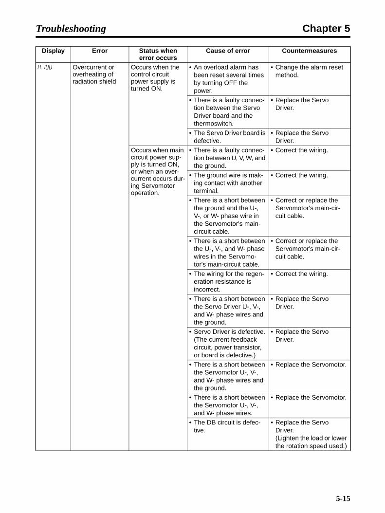
Chapter 5Troubleshooting
a.100 Overcurrent or overheating of radiation shield
Occurs when the control circuit power supply is turned ON.
• An overload alarm has been reset several times by turning OFF the power.
• Change the alarm reset method.
• There is a faulty connec-tion between the Servo Driver board and the thermoswitch.
• Replace the Servo Driver.
• The Servo Driver board is defective.
• Replace the Servo Driver.
Occurs when main circuit power sup-ply is turned ON, or when an over-current occurs dur-ing Servomotor operation.
• There is a faulty connec-tion between U, V, W, and the ground.
• Correct the wiring.
• The ground wire is mak-ing contact with another terminal.
• Correct the wiring.
• There is a short between the ground and the U-, V-, or W- phase wire in the Servomotor's main-circuit cable.
• Correct or replace the Servomotor's main-cir-cuit cable.
• There is a short between the U-, V-, and W- phase wires in the Servomo-tor's main-circuit cable.
• Correct or replace the Servomotor's main-cir-cuit cable.
• The wiring for the regen-eration resistance is incorrect.
• Correct the wiring.
• There is a short between the Servo Driver U-, V-, and W- phase wires and the ground.
• Replace the Servo Driver.
• Servo Driver is defective.(The current feedback circuit, power transistor, or board is defective.)
• Replace the Servo Driver.
• There is a short between the Servomotor U-, V-, and W- phase wires and the ground.
• Replace the Servomotor.
• There is a short between the Servomotor U-, V-, and W- phase wires.
• Replace the Servomotor.
• The DB circuit is defec-tive.
• Replace the Servo Driver.(Lighten the load or lower the rotation speed used.)
Display Error Status when error occurs
Cause of error Countermeasures
5-15

Chapter 5Troubleshooting
a.100 Overcurrent or overheating of radiation shield
Occurs when main circuit power sup-ply is turned ON, or when an over-current occurs dur-ing Servomotor operation.
• The DB has frequent use. (A DB overload alarm occurred.)
• Replace the Servo Driver.(Reduce the frequency of DB use.)
• An overload alarm has been reset several times by turning OFF the power.
• Change the alarm reset method.
• Was the load excessive, or was the regeneration processing capacity exceeded?
• Recheck the load and operating conditions.
• The Servo Driver was mounted in an unsuit-able way (direction, spac-ing). (Is there heat radiation in the or is there a heating effect from the surroundings?)
• Reduce the Servo Driver's ambient temper-ature to 55°C or below.
• The Servo Driver's fan is stopped.
• Replace the Servo Driver.
• Servo Driver is defective. • Replace the Servo Driver.
Display Error Status when error occurs
Cause of error Countermeasures
5-16
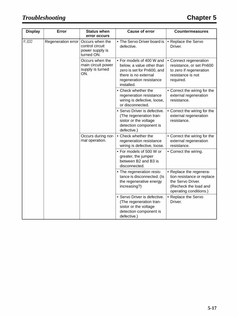
Chapter 5Troubleshooting
a.300 Regeneration error Occurs when the control circuit power supply is turned ON.
• The Servo Driver board is defective.
• Replace the Servo Driver.
Occurs when the main circuit power supply is turned ON.
• For models of 400 W and below, a value other than zero is set for Pn600, and there is no external regeneration resistance installed.
• Connect regeneration resistance, or set Pn600 to zero if regeneration resistance is not required.
• Check whether the regeneration resistance wiring is defective, loose, or disconnected.
• Correct the wiring for the external regeneration resistance.
• Servo Driver is defective. (The regeneration tran-sistor or the voltage detection component is defective.)
• Correct the wiring for the external regeneration resistance.
Occurs during nor-mal operation.
• Check whether the regeneration resistance wiring is defective, loose.
• Correct the wiring for the external regeneration resistance.
• For models of 500 W or greater, the jumper between B2 and B3 is disconnected.
• Correct the wiring.
• The regeneration resis-tance is disconnected. (Is the regenerative energy increasing?)
• Replace the regenera-tion resistance or replace the Servo Driver. (Recheck the load and operating conditions.)
• Servo Driver is defective. (The regeneration tran-sistor or the voltage detection component is defective.)
• Replace the Servo Driver.
Display Error Status when error occurs
Cause of error Countermeasures
5-17

Chapter 5Troubleshooting
a.320 Regeneration overload
Occurs when the control circuit power supply is turned ON.
• The Servo Driver board is defective.
• Replace the Servo Driver.
Occurs when the main circuit power supply is turned ON.
• The power supply voltage is 270 V or higher.
• Correct the voltage.
Occurs during nor-mal operation. (Large increase in regeneration resis-tor temperature)
• Regenerative energy is excessive.
• Reselect the regenera-tion resistance amount, or recheck the load con-ditions and operating conditions.
• Regeneration is continu-ous.
Occurs during nor-mal operation. (Small increase in regeneration resis-tor temperature)
• The capacity set in Pn600 is smaller than the external regeneration resistance capacity.
• Correct the setting for Pn600.
• Servo Driver is defective. • Replace the Servo Driver.
Occurs during Ser-vomotor decelera-tion.
• Regenerative energy is excessive.
• Reselect the regenera-tion resistance amount, or recheck the load con-ditions and operating conditions.
a.330 Main circuit power supply setting error
Occurs when the control circuit power supply is turned ON.
• The Servo Driver board is defective.
• Replace the Servo Driver.
Occurs when the main circuit power supply is turned ON.
• While in DC power sup-ply input mode, AC power was supplied via L1 and L2 (or L1, L2, and L3).
• For AC power supply input, set Pn001.2 to 0.For DC power supply input, set Pn001.2 to 1.
• While in AC power supply input mode, DC power
was supplied via B1/
and terminals.
• Pn600 is not set to 0 even though no regener-ation resistance is con-nected.
Display Error Status when error occurs
Cause of error Countermeasures
+
−
5-18

Chapter 5Troubleshooting
a.400 Overvoltage Occurs when the control circuit power supply is turned ON.
• The Servo Driver board is defective.
• Replace the Servo Driver.
Occurs when the main circuit power supply is turned ON.
• The AC power supply voltage is 290 V or higher.
• Set the AC power supply voltage in the correct range.
• Servo Driver is defective. • Replace the Servo Driver.
Occurs during nor-mal operation.
• Check the AC power sup-ply voltage. (Was there an excessive change in voltage?)
• Set the AC power supply voltage in the correct range.
• The operating rotation frequency is high, and the load inertia is exces-sive. (The regeneration capacity is insufficient.)
• Recheck the load and operating conditions. (Check the load inertia and minus load specifica-tions.)
• Servo Driver is defective. • Replace the Servo Driver.
Occurs during Ser-vomotor decelera-tion.
• The operating rotation frequency is high, and the load inertia is exces-sive.
• Check the load and oper-ating conditions.
Display Error Status when error occurs
Cause of error Countermeasures
5-19
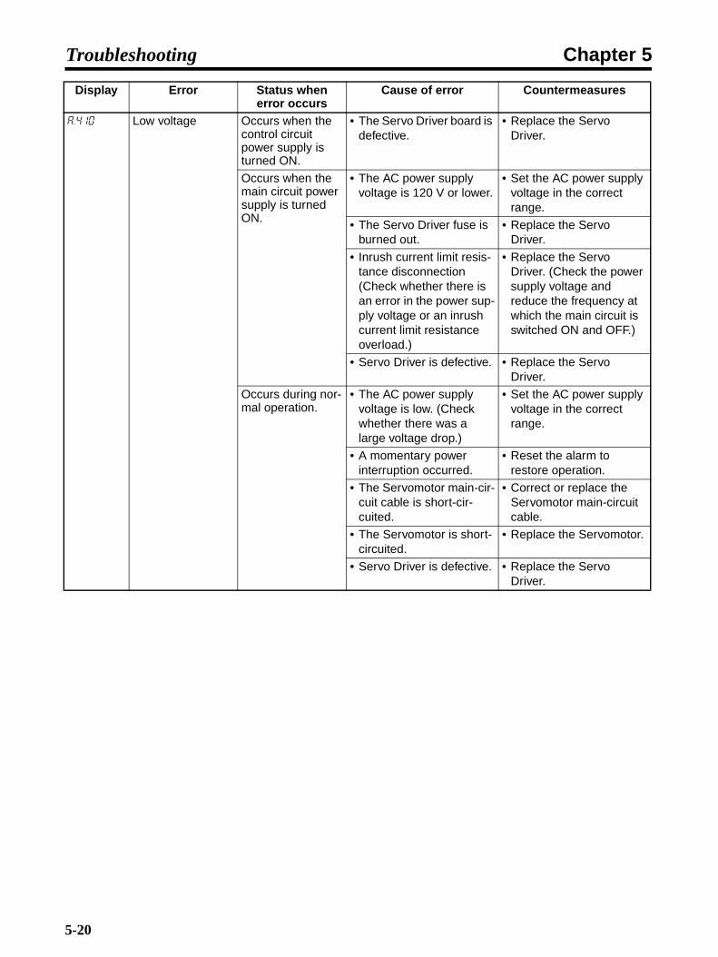
Chapter 5Troubleshooting
a.410 Low voltage Occurs when the control circuit power supply is turned ON.
• The Servo Driver board is defective.
• Replace the Servo Driver.
Occurs when the main circuit power supply is turned ON.
• The AC power supply voltage is 120 V or lower.
• Set the AC power supply voltage in the correct range.
• The Servo Driver fuse is burned out.
• Replace the Servo Driver.
• Inrush current limit resis-tance disconnection (Check whether there is an error in the power sup-ply voltage or an inrush current limit resistance overload.)
• Replace the Servo Driver. (Check the power supply voltage and reduce the frequency at which the main circuit is switched ON and OFF.)
• Servo Driver is defective. • Replace the Servo Driver.
Occurs during nor-mal operation.
• The AC power supply voltage is low. (Check whether there was a large voltage drop.)
• Set the AC power supply voltage in the correct range.
• A momentary power interruption occurred.
• Reset the alarm to restore operation.
• The Servomotor main-cir-cuit cable is short-cir-cuited.
• Correct or replace the Servomotor main-circuit cable.
• The Servomotor is short-circuited.
• Replace the Servomotor.
• Servo Driver is defective. • Replace the Servo Driver.
Display Error Status when error occurs
Cause of error Countermeasures
5-20

Chapter 5Troubleshooting
a.510 Overspeed Occurs when the control circuit power supply is turned ON.
• The Servo Driver board is defective.
• Replace the Servo Driver.
Occurs when the Servo is turned ON.
• The U, V, and W phases are wired out of order in the Servomotor.
• Correct the Servomotor wiring.
• The encoder wiring is incorrect.
• Correct the encoder wir-ing.
• Noise in the encoder wir-ing is causing malfunc-tioning.
• Implement measures against noise in the encoder wiring.
• Servo Driver is defective. • Replace the Servo Driver.
Occurs at start of Servomotor opera-tion or at high-speed rotation.
• The U, V, and W phases are wired out of order in the Servomotor.
• Correct the Servomotor wiring.
• The encoder wiring is incorrect.
• Correct the encoder wir-ing.
• Noise in the encoder wir-ing is causing malfunc-tioning.
• Implement measures against noise in the encoder wiring.
• Position, speed com-mand inputs are exces-sive.
• Lower the command value.
• The command input gain setting is incorrect.
• Correct the command input gain.
• The Servo Driver board is defective.
• Replace the Servo Driver.
a.511 Dividing pulse out-put overspeed
Occurs during Ser-vomotor operation.
• The dividing pulse fre-quency equaled or exceeded 1.6 MHz.
• Lower the setting for the encoder divider rate (Pn212)
• Lower the Servomotor rotation speed.
a.520 Vibration alarm Occurs during Ser-vomotor operation.
• An abnormal oscillation was detected in the Ser-vomotor's rotation speed.
• Lower the Servomotor rotation speed.
• Lower the speed loop gain (Pn100).
• The inertia ratio (Pn103) value is greater than the actual value, or it is greatly fluctuating.
• Set a suitable value for the inertia ratio (Pn103).
a.521 Auto-tuning alarm Occurs during advanced auto-tuning.
• The motor speed oscil-lated during operation.
• Without using advanced auto-tuning, set Pn103 by calculating the inertia ratio from various machine elements.
Display Error Status when error occurs
Cause of error Countermeasures
5-21
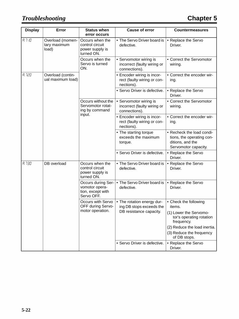
Chapter 5Troubleshooting
a.710 Overload (momen-tary maximum load)
Occurs when the control circuit power supply is turned ON.
• The Servo Driver board is defective.
• Replace the Servo Driver.
Occurs when the Servo is turned ON.
• Servomotor wiring is incorrect (faulty wiring or connections).
• Correct the Servomotor wiring.
a.720 Overload (contin-ual maximum load)
• Encoder wiring is incor-rect (faulty wiring or con-nections).
• Correct the encoder wir-ing.
• Servo Driver is defective. • Replace the Servo Driver.
Occurs without the Servomotor rotat-ing by command input.
• Servomotor wiring is incorrect (faulty wiring or connections).
• Correct the Servomotor wiring.
• Encoder wiring is incor-rect (faulty wiring or con-nections).
• Correct the encoder wir-ing.
• The starting torque exceeds the maximum torque.
• Recheck the load condi-tions, the operating con-ditions, and the Servomotor capacity.
• Servo Driver is defective. • Replace the Servo Driver.
a.730 DB overload Occurs when the control circuit power supply is turned ON.
• The Servo Driver board is defective.
• Replace the Servo Driver.
Occurs during Ser-vomotor opera-tion, except with Servo OFF.
• The Servo Driver board is defective.
• Replace the Servo Driver.
Occurs with Servo OFF during Servo-motor operation.
• The rotation energy dur-ing DB stops exceeds the DB resistance capacity.
• Check the following items.
(1) Lower the Servomo-tor's operating rotation frequency.
(2) Reduce the load inertia.(3) Reduce the frequency
of DB stops.
• Servo Driver is defective. • Replace the Servo Driver.
Display Error Status when error occurs
Cause of error Countermeasures
5-22
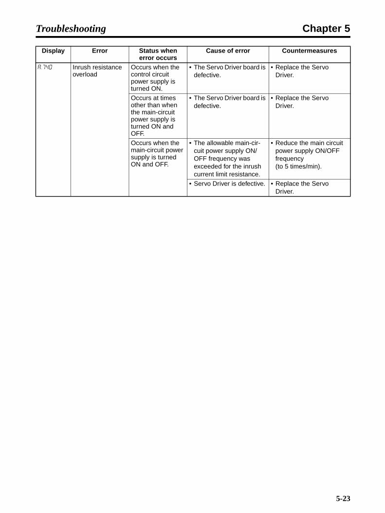
Chapter 5Troubleshooting
a.740 Inrush resistance overload
Occurs when the control circuit power supply is turned ON.
• The Servo Driver board is defective.
• Replace the Servo Driver.
Occurs at times other than when the main-circuit power supply is turned ON and OFF.
• The Servo Driver board is defective.
• Replace the Servo Driver.
Occurs when the main-circuit power supply is turned ON and OFF.
• The allowable main-cir-cuit power supply ON/OFF frequency was exceeded for the inrush current limit resistance.
• Reduce the main circuit power supply ON/OFF frequency (to 5 times/min).
• Servo Driver is defective. • Replace the Servo Driver.
Display Error Status when error occurs
Cause of error Countermeasures
5-23

Chapter 5Troubleshooting
a.7a0 Overheat Occurs when the control circuit power supply is turned ON.
• Servo Driver is defective. • Replace the Servo Driver.
• An overload alarm has been reset several times by turning OFF the power.
• Change the alarm reset method.
Overheating of radiation shield occurs when the main circuit power supply is turned ON, or during Ser-vomotor operation.
• The load exceeds the rated load.
• Recheck the load condi-tions, the operating con-ditions, and the Servomotor capacity.
• The Servo Driver's ambi-ent temperature exceeds 55°C.
• Reduce the Servo Driver's ambient temper-ature to 55°C or below.
• Servo Driver is defective. • Replace the Servo Driver.
• An overload alarm has been reset several times by turning OFF the power.
• Change the alarm reset method.
• There is a faulty connec-tion between the Servo Driver board and the Ser-vomotor switch.
• Replace the Servo Driver.
• Was the load excessive, or was the regeneration processing capacity exceeded?
• Recheck the load and operating conditions.
• The Servo Driver was mounted in an unsuit-able way (direction, spac-ing). (Is there heat radiation in the panel or is there a heating effect from the surroundings?)
• Reduce the Servo Driver's ambient temper-ature to 55°C or below.
• The Servo Driver's fan is stopped.
• Replace the Servo Driver.
Display Error Status when error occurs
Cause of error Countermeasures
5-24

Chapter 5Troubleshooting
a.810 Encoder backup error
Occurs when the control circuit power supply is turned ON.(Setting: Pn002.2 = 1)
• The Servo Driver board is defective. (When abso-lute values are used incrementally.)
• Replace the Servo Driver.
Occurs when the control circuit power supply is turned ON.Used with absolute value (setting: Pn002.2 = 0).
• The power was turned ON for the first time to the absolute encoder.
• Execute the encoder's setup operation.
• The encoder cable was disconnected.
• Check the connections and execute the encoder's setup opera-tion.
• The encoder power sup-ply (+5 V) from the Servo Driver and the battery power supply are both down.
• Restore power to the encoder (e.g., replacing the battery), and then execute the encoder's setup operation.
• Absolute encoder is defective.
• If the alarm is still not cleared even after exe-cuting the setup opera-tion again, then replace the encoder.
• Servo Driver is defective. • Replace the Servo Driver.
a.820 Encoder check-sum error
Occurs when the control circuit power supply is turned ON or dur-ing operation.
• Encoder is defective. (Encoder self-diagnosis)
• If the problem continues to occur frequently even after the encoder has been set up, replace the Servomotor.
• Servo Driver is defective. • Replace the Servo Driver.
Occurs when the SENSOR ON (SENS_ON) com-mand is executed.
• Encoder is defective. (Encoder self-diagnosis)
• If the problem continues to occur frequently even after the encoder has been set up, replace the Servomotor.
a.830 Encoder battery error
Occurs when the control circuit power supply is turned ON.(Setting: Pn002 = 1)
• The Servo Driver board is defective. (When abso-lute values are used incrementally.)
• Replace the Servo Driver.
Occurs when the control circuit power supply is turned ON.Used with absolute value (setting: Pn002.2 = 0).
• The battery has a faulty connection or is discon-nected.
• Correct the battery con-nections.
• The battery voltage is lower than the prescribed value (2.7 V).
• Replace the battery and turn ON the encoder power again.
• The Servo Driver board is defective.
• Replace the Servo Driver.
Display Error Status when error occurs
Cause of error Countermeasures
5-25
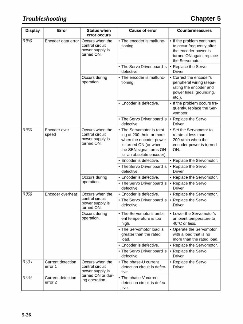
Chapter 5Troubleshooting
a.840 Encoder data error Occurs when the control circuit power supply is turned ON.
• The encoder is malfunc-tioning.
• If the problem continues to occur frequently after the encoder power is turned ON again, replace the Servomotor.
• The Servo Driver board is defective.
• Replace the Servo Driver.
Occurs during operation.
• The encoder is malfunc-tioning.
• Correct the encoder's peripheral wiring (sepa-rating the encoder and power lines, grounding, etc.).
• Encoder is defective. • If the problem occurs fre-quently, replace the Ser-vomotor.
• The Servo Driver board is defective.
• Replace the Servo Driver.
a.850 Encoder over-speed
Occurs when the control circuit power supply is turned ON.
• The Servomotor is rotat-ing at 200 r/min or more when the encoder power is turned ON (or when the SEN signal turns ON for an absolute encoder).
• Set the Servomotor to rotate at less than 200 r/min when the encoder power is turned ON.
• Encoder is defective. • Replace the Servomotor.
• The Servo Driver board is defective.
• Replace the Servo Driver.
Occurs during operation.
• Encoder is defective. • Replace the Servomotor.
• The Servo Driver board is defective.
• Replace the Servo Driver.
a.860 Encoder overheat Occurs when the control circuit power supply is turned ON.
• Encoder is defective. • Replace the Servomotor.
• The Servo Driver board is defective.
• Replace the Servo Driver.
Occurs during operation.
• The Servomotor's ambi-ent temperature is too high.
• Lower the Servomotor's ambient temperature to 40°C or less.
• The Servomotor load is greater than the rated load.
• Operate the Servomotor with a load that is no more than the rated load.
• Encoder is defective. • Replace the Servomotor.
• The Servo Driver board is defective.
• Replace the Servo Driver.
a.b31 Current detection error 1
Occurs when the control circuit power supply is turned ON or dur-ing operation.
• The phase-U current detection circuit is defec-tive.
• Replace the Servo Driver.
a.b32 Current detection error 2
• The phase-V current detection circuit is defec-tive.
Display Error Status when error occurs
Cause of error Countermeasures
5-26
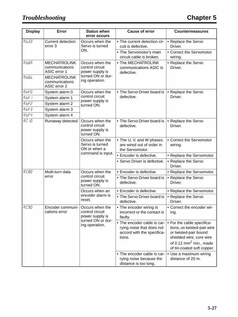
Chapter 5Troubleshooting
a.b33 Current detection error 3
Occurs when the Servo is turned ON.
• The current detection cir-cuit is defective.
• Replace the Servo Driver.
• The Servomotor’s main circuit cable is broken.
• Correct the Servomotor wiring.
a.b6a MECHATROLINK communications ASIC error 1
Occurs when the control circuit power supply is turned ON or dur-ing operation.
• The MECHATROLINK communications ASIC is defective.
• Replace the Servo Driver.
a.b6b MECHATROLINK communications ASIC error 2
a.bf0 System alarm 0 Occurs when the control circuit power supply is turned ON.
• The Servo Driver board is defective.
• Replace the Servo Driver.a.bf1 System alarm 1
a.bf2 System alarm 2
a.bf3 System alarm 3
a.bf4 System alarm 4
a.c10 Runaway detected Occurs when the control circuit power supply is turned ON.
• The Servo Driver board is defective.
• Replace the Servo Driver.
Occurs when the Servo is turned ON or when a command is input.
• The U, V, and W phases are wired out of order in the Servomotor.
• Correct the Servomotor wiring.
• Encoder is defective. • Replace the Servomotor.
• Servo Driver is defective. • Replace the Servo Driver.
a.c80 Multi-turn data error
Occurs when the control circuit power supply is turned ON.
• Encoder is defective. • Replace the Servomotor.
• The Servo Driver board is defective.
• Replace the Servo Driver.
Occurs when an encoder alarm is reset.
• Encoder is defective. • Replace the Servomotor.
• The Servo Driver board is defective.
• Replace the Servo Driver.
a.c90 Encoder communi-cations error
Occurs when the control circuit power supply is turned ON or dur-ing operation.
• The encoder wiring is incorrect or the contact is faulty.
• Correct the encoder wir-ing.
• The encoder cable is car-rying noise that does not accord with the specifica-tions.
• For the cable specifica-tions, us twisted-pair wire or twisted-pair bound shielded wire, core wire
of 0.12 mm2 min., made of tin-coated soft copper.
• The encoder cable is car-rying noise because the distance is too long.
• Use a maximum wiring distance of 20 m.
Display Error Status when error occurs
Cause of error Countermeasures
5-27
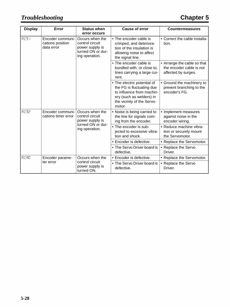
Chapter 5Troubleshooting
a.c91 Encoder communi-cations position data error
Occurs when the control circuit power supply is turned ON or dur-ing operation.
• The encoder cable is crimped, and deteriora-tion of the insulation is allowing noise to affect the signal line.
• Correct the cable installa-tion.
• The encoder cable is bundled with, or close to, lines carrying a large cur-rent.
• Arrange the cable so that the encoder cable is not affected by surges.
• The electric potential of the FG is fluctuating due to influence from machin-ery (such as welders) in the vicinity of the Servo-motor.
• Ground the machinery to prevent branching to the encoder's FG.
a.c92 Encoder communi-cations timer error
Occurs when the control circuit power supply is turned ON or dur-ing operation.
• Noise is being carried to the line for signals com-ing from the encoder.
• Implement measures against noise in the encoder wiring.
• The encoder is sub-jected to excessive vibra-tion and shock.
• Reduce machine vibra-tion or securely mount the Servomotor.
• Encoder is defective. • Replace the Servomotor.
• The Servo Driver board is defective.
• Replace the Servo Driver.
a.ca0 Encoder parame-ter error
Occurs when the control circuit power supply is turned ON.
• Encoder is defective. • Replace the Servomotor.
• The Servo Driver board is defective.
• Replace the Servo Driver.
Display Error Status when error occurs
Cause of error Countermeasures
5-28

Chapter 5Troubleshooting
a.cb0 Encoder echo-back error
Occurs when the control circuit power supply is turned ON or dur-ing operation.
• The encoder wiring is incorrect or the contact is faulty.
• Correct the encoder wir-ing.
• The encoder cable is car-rying noise that does not accord with the specifica-tions.
• For the cable specifica-tions, us twisted-pair wire or twisted-pair bound shielded wire, core wire
of 0.12 mm2 min., made of tin-coated soft copper.
• The encoder cable is car-rying noise because the distance is too long.
• Use a maximum wiring distance of 20 m.
• The encoder cable is crimped, and deteriora-tion of the insulation is allowing noise to affect the signal line.
• Correct the cable installa-tion.
• The encoder cable is bundled with, or close to, lines carrying a large cur-rent.
• Arrange the cable so that the encoder cable is not affected by surges.
• The electric potential of the FG is fluctuating due to influence from machin-ery (such as welders) in the vicinity of the Servo-motor.
• Ground the machinery ground to prevent branching to the encoder's FG.
• Noise is being carried to the line for signals com-ing from the encoder.
• Implement measures against noise in the encoder wiring.
• The encoder is sub-jected to excessive vibra-tion and shock.
• Reduce machine vibra-tion or securely mount the Servomotor.
• Encoder is defective. • Replace the Servomotor.
• The Servo Driver board is defective.
• Replace the Servo Driver.
a.cc0 Multi-turn limit dis-crepancy
Occurs when the control circuit power supply is turned ON.
• A Servo Driver parameter is set incorrectly.
• Correct the setting for Pn205 (0 to 65,535).
• The encoder's multi-turn limit setting was omitted or changed.
• Change settings when an alarm occurs.
Occurs during operation.
• The Servo Driver board is defective.
• Replace the Servo Driver.
Display Error Status when error occurs
Cause of error Countermeasures
5-29

Chapter 5Troubleshooting
a.d00 Deviation counter overflow
Occurs when the control circuit power supply is turned ON.
• The Servo Driver board is defective.
• Replace the Servo Driver.
Occurs during high-speed rota-tion.
• The Servomotor's U, V, and W wiring is incorrect (faulty connections).
• Correct the Servomotor wiring.
• Correct the encoder wir-ing.
• The Servo Driver board is defective.
• Replace the Servo Driver.
Occurs without Servomotor rota-tion when there is a position com-mand.
• The Servomotor's U, V, and W wiring is faulty.
• Correct the Servomotor wiring.
• The Servo Driver board is defective.
• Replace the Servo Driver.
Occurs when oper-ation is normal but a long command is sent.
• Servo Motor gain is poorly adjusted.
• Increase the speed loop gain (Pn100) and the position loop gain (Pn102).
• The position command pulse frequency is too high.
• Increase/decrease the position command pulse frequency slowly.
• Use the smoothing func-tion.
• Check the electronic gear ratio.
• The deviation counter overflow level (Pn520) is not suitable.
• Correct the setting for Pn520.
• The load conditions (torque, inertia) do not conform to the Servomo-tor specifications.
• Check the load and the Servomotor capacity.
a.d01 Deviation counter overflow alarm at Servo-ON
Occurs when the control circuit power supply is turned ON.
• Position deviation pulses have accumulated exces-sively with the Servo OFF.
• The Servomotor was operated form outside when the Servo was OFF.
• Set so that the Servomo-tor does not operate with the Servo OFF.
• Correct the detection level.
Display Error Status when error occurs
Cause of error Countermeasures
5-30

Chapter 5Troubleshooting
a.d02 Deviation counter overflow alarm by speed limit at Servo-ON
Occurs during Ser-vomotor drive.
• The Servo turned ON with position deviation pulses accumulated, and command pulses were input during operation at the limit speed. Position deviation pulses accumu-lated exceeding the devi-ation counter overflow level (Pn520).
• Set so that the Servomo-tor does not operate with the Servo OFF.
• Correct the detection level.
• Set a suitable value for the limit speed level at Servo-ON (Pn529).
a.e00 COM alarm 0 Occurs when the control circuit power supply is turned ON.
• Servo Driver is defective.
• The conditions in 6-3 Restrictions were not met when using the Com-puter Monitor Software.
• Replace the Servo Driver.
• Make sure the conditions in 6-3 Restrictions are met.
a.e01 COM alarm 1
a.e02 COM alarm 2
a.e07 COM alarm 7
a.e08 COM alarm 8
a.e09 COM alarm 9
a.e40 MECHATROLINK-II transmission cycle setting error
Occurs when MECHATROLINK-II communications are started.
• The MECHATROLINK-II transmission cycle set-ting is out of the range in the specifications.
• Set a suitable value for the MECHATROLINK-II transmission cycle.
a.e50 MECHATROLINK-II synchronization error
Occurs during MECHATROLINK-II communications.
• The WDT data refreshing for the host device is not correct.
• Correct the WDT data refreshing for the host device.
• Servo Driver is defective. • Replace the Servo Driver.
a.e51 MECHATROLINK-II synchronization failure
Occurs when MECHATROLINK-II synchronous communications are started.
• The WDT data refreshing for the host device was not correct when syn-chronous communica-tions started, so they could not be started.
• Correct the WDT data refreshing for the host device.
• Servo Driver is defective. • Replace the Servo Driver.
a.e60 MECHATROLINK-II communications error
Occurs during MECHATROLINK-II communications.
• Correct the MECHA-TROLINK-II wiring.
• Wire the MECHA-TROLINK-II communica-tions cable correctly.Connect the terminator correctly.
• Servo Driver is defective. • Replace the Servo Driver.
• A MECHATROLINK-II data reception error occurred due to noise.
• Implement measures against noise (such as using MECHATROLINK-II communications cable, checking the FG wiring, and installing a ferrite core in the MECHA-TROLINK-II communica-tions cable).
Display Error Status when error occurs
Cause of error Countermeasures
5-31
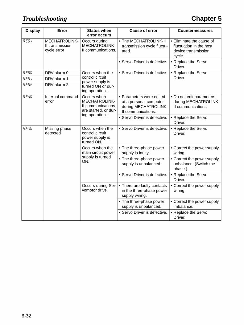
Chapter 5Troubleshooting
a.e61 MECHATROLINK-II transmission cycle error
Occurs during MECHATROLINK-II communications.
• The MECHATROLINK-II transmission cycle fluctu-ated.
• Eliminate the cause of fluctuation in the host device transmission cycle.
• Servo Driver is defective. • Replace the Servo Driver.
a.ea0 DRV alarm 0 Occurs when the control circuit power supply is turned ON or dur-ing operation.
• Servo Driver is defective. • Replace the Servo Driver.a.ea1 DRV alarm 1
a.ea2 DRV alarm 2
a.ed0 Internal command error
Occurs when MECHATROLINK-II communications are started, or dur-ing operation.
• Parameters were edited at a personal computer during MECHATROLINK-II communications.
• Do not edit parameters during MECHATROLINK-II communications.
• Servo Driver is defective. • Replace the Servo Driver.
a.f10 Missing phase detected
Occurs when the control circuit power supply is turned ON.
• Servo Driver is defective. • Replace the Servo Driver.
Occurs when the main circuit power supply is turned ON.
• The three-phase power supply is faulty.
• Correct the power supply wiring.
• The three-phase power supply is unbalanced.
• Correct the power supply unbalance. (Switch the phase.)
• Servo Driver is defective. • Replace the Servo Driver.
Occurs during Ser-vomotor drive.
• There are faulty contacts in the three-phase power supply wiring.
• Correct the power supply wiring.
• The three-phase power supply is unbalanced.
• Correct the power supply imbalance.
• Servo Driver is defective. • Replace the Servo Driver.
Display Error Status when error occurs
Cause of error Countermeasures
5-32
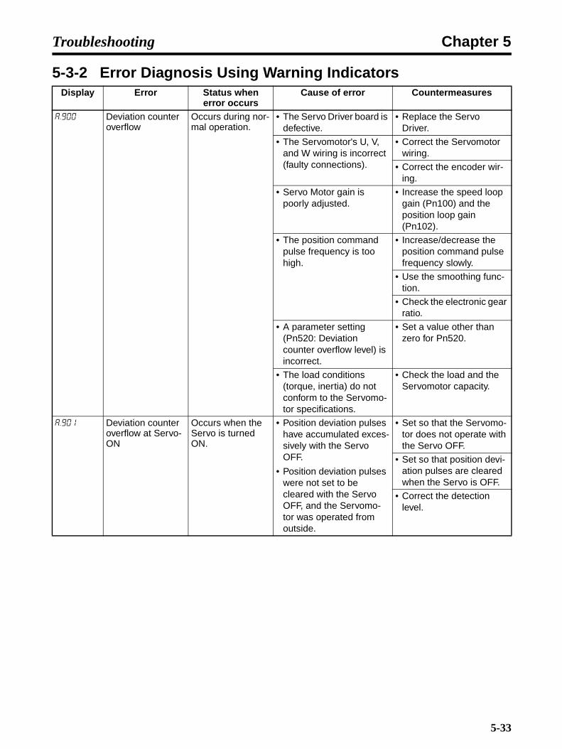
Chapter 5Troubleshooting
5-3-2 Error Diagnosis Using Warning IndicatorsDisplay Error Status when
error occursCause of error Countermeasures
a.900 Deviation counter overflow
Occurs during nor-mal operation.
• The Servo Driver board is defective.
• Replace the Servo Driver.
• The Servomotor's U, V, and W wiring is incorrect (faulty connections).
• Correct the Servomotor wiring.
• Correct the encoder wir-ing.
• Servo Motor gain is poorly adjusted.
• Increase the speed loop gain (Pn100) and the position loop gain (Pn102).
• The position command pulse frequency is too high.
• Increase/decrease the position command pulse frequency slowly.
• Use the smoothing func-tion.
• Check the electronic gear ratio.
• A parameter setting (Pn520: Deviation counter overflow level) is incorrect.
• Set a value other than zero for Pn520.
• The load conditions (torque, inertia) do not conform to the Servomo-tor specifications.
• Check the load and the Servomotor capacity.
a.901 Deviation counter overflow at Servo-ON
Occurs when the Servo is turned ON.
• Position deviation pulses have accumulated exces-sively with the Servo OFF.
• Position deviation pulses were not set to be cleared with the Servo OFF, and the Servomo-tor was operated from outside.
• Set so that the Servomo-tor does not operate with the Servo OFF.
• Set so that position devi-ation pulses are cleared when the Servo is OFF.
• Correct the detection level.
5-33

Chapter 5Troubleshooting
a.910 Overload Occurs when the Servo is turned ON.
• Servomotor wiring is incorrect (faulty wiring or connections).
• Correct the Servomotor wiring.
• Encoder wiring is incor-rect (faulty wiring or con-nections).
• Correct the encoder wir-ing.
• Servo Driver is defective. • Replace the Servo Driver.
Occurs without Servomotor rota-tion by command input.
• Servomotor wiring is incorrect (faulty wiring or connections).
• Correct the Servomotor wiring.
• Encoder wiring is incor-rect (faulty wiring or con-nections).
• Correct the encoder wir-ing.
• The starting torque exceeds the maximum torque.
• Recheck the load condi-tions, the operating con-ditions, and the Servomotor capacity.
• Servo Driver is defective. • Replace the Servo Driver.
Occurs during nor-mal operation.
• The effective torque exceeds the rated torque.
• Recheck the load condi-tions, the operating con-ditions, and the Servomotor capacity.
• The temperature is high in the Servo Driver's panel
• Lower the temperature in the panel to 55°C or less.
• Servo Driver is defective. • Replace the Servo Driver.
a.911 Vibration Occurs during nor-mal operation.
• The Servo Driver gain is incorrect.
• In order to set the correct gain, lower the speed loop gain (Pn100) and the position loop gain (Pn101), and increase fil-ter time constants such as the1st step 1st torque command filter time con-stant (Pn401).
• The inertia ratio (Pn103) value is greater than the actual value, or it is greatly fluctuating.
• Set a suitable value for the inertia ratio (Pn103).
Display Error Status when error occurs
Cause of error Countermeasures
5-34

Chapter 5Troubleshooting
a.920 Regeneration overload
Occurs when the control circuit power supply is turned ON.
• The Servo Driver board is defective.
• Replace the Servo Driver.
Occurs during nor-mal operation. (Large increase in regeneration resis-tance tempera-ture)
• Regenerative energy is excessive.
• Reselect the regenera-tion resistance amount, or recheck the load con-ditions and operating conditions.
• Regeneration is continu-ous.
Occurs during nor-mal operation. (Small increase in regeneration resis-tance tempera-ture)
• The capacity set in Pn600 is smaller than the external regeneration resistance capacity.
• Correct the setting for Pn600.
• Servo Driver is defective. • Replace the Servo Driver.
Occurs during Ser-vomotor decelera-tion.
• Regenerative energy is excessive.
• Reselect the regenera-tion resistance amount, or recheck the load con-ditions and operating conditions.
a.930 Absolute encoder battery warning
Occurs when the control circuit power supply is turned ON.
• The Servo Driver board is defective.
• Replace the Servo Driver.
Occurs when the control circuit power supply is turned ON.(Setting: Pn002 = 1)
• The Servo Driver board is defective. (When abso-lute values are used incrementally.)
• Replace the Servo Driver.
Occurs when four seconds or more have elapsed after the control power supply is turned ON. Used with absolute value (setting: Pn002.2 = 0).
• The battery has a faulty connection or is discon-nected.
• Correct the battery con-nections.
• The battery voltage is lower than the prescribed value (2.7 V).
• Replace the battery and turn the encoder power supply ON again.
• The Servo Driver board is defective.
• Replace the Servo Driver.
a.941 Parameter change requiring restart
Occurs when parameters are changed.
• A parameter was changed that required the power to be turned OFF and back ON.
• Turn the power OFF and back ON.
a.94a Data setting warn-ing 1 (parameter No.)
Occurs when a PRM_RD, PRM_W, or PPRM_WR com-mand is sent.
• An unusable parameter number was used.
• Use a correct parameter number.
Display Error Status when error occurs
Cause of error Countermeasures
5-35

Chapter 5Troubleshooting
a.94b Data setting warn-ing 2 (out of range)
Occurs when a MECHATROLINK-II command is sent.
• An attempt was made to set a value outside of the setting range for the com-mand data.
• If the Servo Driver is con-nected to the CJ1W-MCH71 or CS1W-MCH71, the option moni-tor parameters may not be set correctly.
• Set a value in the setting range.
• Check the setting of Pn813 and change it to 0032 hex if any other value is set.
a.94c Data setting warn-ing 3 (calculation error)
Occurs when a PRM_WR or PPRM_WR com-mand is sent.
• An error occurred in the calculation results for the set value.
• Set a value in the setting range for the parameter.
a.94d Data setting warn-ing 4 (parameter size)
Occurred during MECHATROLINK-II communications.
• The parameter size set by the command is not correct.
• Use the correct parame-ter size.
a.95a Command warning 1 (command con-ditions not met)
Occurred during MECHATROLINK-II communications.
• The command transmis-sion conditions have not been met.
• Satisfy all the command transmission conditions before sending the com-mand.
a.95b Command warning 2 (unsupported command)
Occurred during MECHATROLINK-II communications.
• An unsupported com-mand was received.
• Do not send unsupported commands.
a.95c Command warning 3
Occurred during MECHATROLINK-II communications.
• A MECHATROLINK-II command cannot be exe-cuted according to the setting conditions.
• Set the parameters required for command execution.
a.95d Command warning 4
Occurred during MECHATROLINK-II communications.
• The transmission condi-tions for a latch-related command have not been satisfied.
• Satisfy all the latch-related command trans-mission conditions before sending the command.
a.95e Command warning 5
Occurred during MECHATROLINK-II communications.
• The sub-command trans-mission conditions have not been satisfied.
• Satisfy all the sub-com-mand transmission con-ditions before sending the command.
a.960 MECHATROLINK-II communications warning
Occurred during MECHATROLINK-II communications.
• Connection is faulty or line is disconnected.
• Review the connector wiring.
• Check for disconnec-tions in the communica-tions wiring.
• Communications error due to noise or other fac-tors.
• Implement noise counter-measures.
• Check system operation and, if there are no prob-lems (or if the problems are acceptable), set to ignore the A.96@ warn-ing using the warning check mask.
Display Error Status when error occurs
Cause of error Countermeasures
5-36
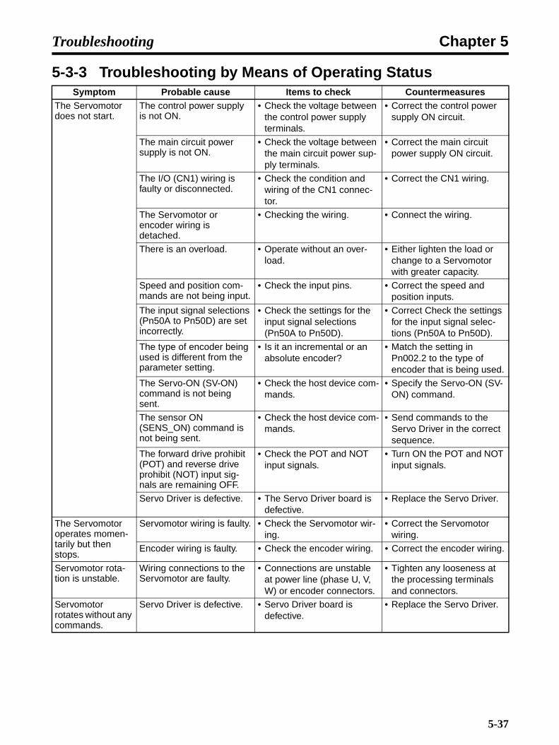
Chapter 5Troubleshooting
5-3-3 Troubleshooting by Means of Operating StatusSymptom Probable cause Items to check Countermeasures
The Servomotor does not start.
The control power supply is not ON.
• Check the voltage between the control power supply terminals.
• Correct the control power supply ON circuit.
The main circuit power supply is not ON.
• Check the voltage between the main circuit power sup-ply terminals.
• Correct the main circuit power supply ON circuit.
The I/O (CN1) wiring is faulty or disconnected.
• Check the condition and wiring of the CN1 connec-tor.
• Correct the CN1 wiring.
The Servomotor or encoder wiring is detached.
• Checking the wiring. • Connect the wiring.
There is an overload. • Operate without an over-load.
• Either lighten the load or change to a Servomotor with greater capacity.
Speed and position com-mands are not being input.
• Check the input pins. • Correct the speed and position inputs.
The input signal selections (Pn50A to Pn50D) are set incorrectly.
• Check the settings for the input signal selections (Pn50A to Pn50D).
• Correct Check the settings for the input signal selec-tions (Pn50A to Pn50D).
The type of encoder being used is different from the parameter setting.
• Is it an incremental or an absolute encoder?
• Match the setting in Pn002.2 to the type of encoder that is being used.
The Servo-ON (SV-ON) command is not being sent.
• Check the host device com-mands.
• Specify the Servo-ON (SV-ON) command.
The sensor ON (SENS_ON) command is not being sent.
• Check the host device com-mands.
• Send commands to the Servo Driver in the correct sequence.
The forward drive prohibit (POT) and reverse drive prohibit (NOT) input sig-nals are remaining OFF.
• Check the POT and NOT input signals.
• Turn ON the POT and NOT input signals.
Servo Driver is defective. • The Servo Driver board is defective.
• Replace the Servo Driver.
The Servomotor operates momen-tarily but then stops.
Servomotor wiring is faulty. • Check the Servomotor wir-ing.
• Correct the Servomotor wiring.
Encoder wiring is faulty. • Check the encoder wiring. • Correct the encoder wiring.
Servomotor rota-tion is unstable.
Wiring connections to the Servomotor are faulty.
• Connections are unstable at power line (phase U, V, W) or encoder connectors.
• Tighten any looseness at the processing terminals and connectors.
Servomotor rotates without any commands.
Servo Driver is defective. • Servo Driver board is defective.
• Replace the Servo Driver.
5-37

Chapter 5Troubleshooting
DB (dynamic brake) does not operate.
The parameter setting is incorrect.
• Check the setting for Pn001.0.
• Correct the parameter set-ting.
DB resistance is discon-nected.
• Is there excessive inertia, rotation speed, or fre-quency of DB use?
• Replace the Servo Driver and check the load system.
DB drive circuit is defec-tive.
• A DB circuit component is defective.
• Replace the Servo Driver.
The Servomotor is making strange noises.
The mechanical installation is faulty.
• Are Servomotor mounting screws loose?
• Tighten the mounting screws.
• Are couplings off center? • Center the couplings.
• Are couplings unbalanced? • Balance the couplings.
There is a problem with the bearings.
• Check for sounds and vibration around the bear-ings.
• If there are any abnormali-ties, please contact an OMRON representative.
The source of vibration is in another machine.
• Have any foreign objects gotten into the movable parts of the machine, or is there any damage or defor-mation?
• Consult with the maker of the machine.
Noise is carried because the input signal line specifi-cations are incorrect.
• Is twisted-pair wire or twisted-pair bound shielded
core wire of 0.12 mm2 min., made of tin-coated soft copper, being used?
• Make sure that input signal lines conform to the specifi-cations.
Noise is carried because the encoder cable specifi-cations are incorrect.
• Is twisted-pair wire or twisted-pair bound shielded
core wire of 0.12 mm2 min., made of tin-coated soft copper, being used?
• Make sure that the encoder cable conforms to the spec-ifications.
The encoder cable is car-rying noise because the distance exceeds the oper-ating range.
• Use a maximum wiring dis-tance of 50 m.
• Make sure that the encoder cable distance conforms to the specifications.
Noise interference is occurring because of dam-age to the encoder cable.
• The encoder cable is crimped, or deterioration of the insulation is allowing noise to affect the signal line.
• Correct the cable installa-tion.
There is excessive noise interference to the encoder cable.
• Is the encoder cable bun-dled with, or close to, lines carrying a large current?
• Arrange the cable so that the encoder cable is not affected by surges.
The electric potential of the FG is fluctuating due to influence from machinery (such as welders) in the vicinity of the Servomotor.
• What is the grounding sta-tus of equipment such as welding machines near the Servomotor (e.g., imper-fectly grounded, not grounded at all)?
• Ground the machinery to prevent branching to the encoder's FG.
The Servo Driver pulse count is incorrect due to noise.
• Is noise being carried to the line for signals coming from the encoder?
• Implement measures against noise in the encoder wiring.
Symptom Probable cause Items to check Countermeasures
5-38
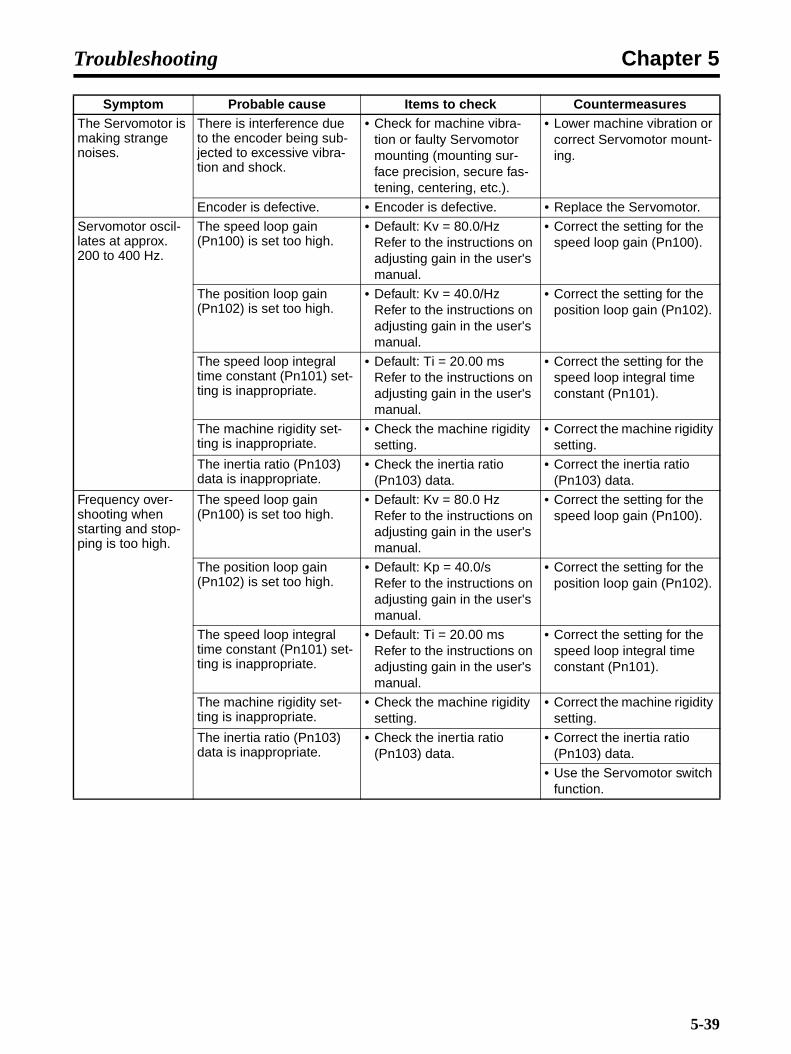
Chapter 5Troubleshooting
The Servomotor is making strange noises.
There is interference due to the encoder being sub-jected to excessive vibra-tion and shock.
• Check for machine vibra-tion or faulty Servomotor mounting (mounting sur-face precision, secure fas-tening, centering, etc.).
• Lower machine vibration or correct Servomotor mount-ing.
Encoder is defective. • Encoder is defective. • Replace the Servomotor.
Servomotor oscil-lates at approx. 200 to 400 Hz.
The speed loop gain (Pn100) is set too high.
• Default: Kv = 80.0/HzRefer to the instructions on adjusting gain in the user's manual.
• Correct the setting for the speed loop gain (Pn100).
The position loop gain (Pn102) is set too high.
• Default: Kv = 40.0/HzRefer to the instructions on adjusting gain in the user's manual.
• Correct the setting for the position loop gain (Pn102).
The speed loop integral time constant (Pn101) set-ting is inappropriate.
• Default: Ti = 20.00 msRefer to the instructions on adjusting gain in the user's manual.
• Correct the setting for the speed loop integral time constant (Pn101).
The machine rigidity set-ting is inappropriate.
• Check the machine rigidity setting.
• Correct the machine rigidity setting.
The inertia ratio (Pn103) data is inappropriate.
• Check the inertia ratio (Pn103) data.
• Correct the inertia ratio (Pn103) data.
Frequency over-shooting when starting and stop-ping is too high.
The speed loop gain (Pn100) is set too high.
• Default: Kv = 80.0 HzRefer to the instructions on adjusting gain in the user's manual.
• Correct the setting for the speed loop gain (Pn100).
The position loop gain (Pn102) is set too high.
• Default: Kp = 40.0/sRefer to the instructions on adjusting gain in the user's manual.
• Correct the setting for the position loop gain (Pn102).
The speed loop integral time constant (Pn101) set-ting is inappropriate.
• Default: Ti = 20.00 msRefer to the instructions on adjusting gain in the user's manual.
• Correct the setting for the speed loop integral time constant (Pn101).
The machine rigidity set-ting is inappropriate.
• Check the machine rigidity setting.
• Correct the machine rigidity setting.
The inertia ratio (Pn103) data is inappropriate.
• Check the inertia ratio (Pn103) data.
• Correct the inertia ratio (Pn103) data.
• Use the Servomotor switch function.
Symptom Probable cause Items to check Countermeasures
5-39

Chapter 5Troubleshooting
Absolute encoder position displace-ment error (The position in the host device's memory when the power is turned OFF is dif-ferent from the position when the power is next turned ON.)
Noise is carried because the encoder cable specifi-cations are incorrect.
• Check whether the cable is twisted-pair wire or twisted-pair bound shielded core
wire of 0.12 mm2 min., made of tin-coated soft copper.
• Make sure that the encoder cable conforms to the spec-ifications.
The encoder cable is car-rying noise because the distance exceeds the oper-ating range.
• Use a maximum wiring dis-tance of 50 m.
• Make sure that the encoder cable distance conforms to the specifications.
Noise interference is occurring because of dam-age to the encoder cable.
• The encoder cable is crimped, or deterioration of the insulation is allowing noise to affect the signal line.
• Correct the cable installa-tion.
There is excessive noise interference to the encoder cable.
• Is the encoder cable bun-dled with, or close to, lines carrying a large current?
• Arrange the cable so that the encoder cable is not affected by surges.
The electric potential of the FG is fluctuated due to noise from machinery (such as welders) in the vicinity of the Servomotor.
• What is the grounding sta-tus of equipment such as welding machines near the Servomotor (e.g., imper-fectly grounded, not grounded at all)?
• Ground the machinery to prevent branching to the encoder's FG.
The Servo Driver pulse count is incorrect due to noise.
• Is noise being carried to the line for signals coming from the encoder?
• Implement measures against noise in the encoder wiring.
There is interference due to the encoder being sub-jected to excessive vibra-tion and shock.
• Check for machine vibra-tion or faulty Servomotor mounting (mounting sur-face precision, secure fas-tening, centering, etc.).
• Reduce machine vibration or correct the Servomotor mounting.
Encoder is defective. • Encoder is defective. (Pulses are not changing.)
• Replace the Servomotor.
Servo Driver is defective. • Multi-turn data is not output from the Servo Driver.
• Replace the Servo Driver.
Symptom Probable cause Items to check Countermeasures
5-40

Chapter 5Troubleshooting
Overtravel (OT) (Travelling outside of the zone speci-fied by the host device)
The forward/reverse drive prohibit input signal does not change. (POT (CN1-7 or NOT (CN1-8) is at H level.)
• Is the voltage correct for the external power supply (+24 V) for input signals?
• Use a +24-V external power supply.
• Is the operating status cor-rect for the overtravel limit switch?
• Correct the status of the overtravel limit switch.
• Is the wiring to the over-travel limit switch correct?
• Correct the wiring to the overtravel limit switch.
The forward/reverse drive prohibit input signal is mal-functioning. (Does the POT or NOT signal sometimes change?)
• Does the external power supply (+24 V) voltage fluc-tuate?
• Eliminate the fluctuation in the external power supply (+24 V) voltage.
• Is overtravel limit switch operation unstable?
• Stabilize overtravel limit switch operation.
• Is the overtravel limit switch wiring correct (cable undamaged, screws tight-ened, etc.)
• Correct the wiring to the overtravel limit switch.
The forward/reverse drive prohibit input signal (POT/NOT) selection is incorrect.
• Check the POT signal selection (Pn50A.3).
• Correct the POT signal selection (Pn50A.3)
• Check the NOT signal selection (Pn50B.0)
• Correct the NOT signal selection (Pn50B.0)
The Servomotor stopping method selection is incor-rect.
• Is the free-run stopping method selected for the Servomotor?
• Check the settings for Pn001.0 and Pn001.1.
• Is free-run set for torque control?
• Check the settings for Pn001.0 and Pn001.1.
The overtravel limit switch position is inappropriate.
• The overtravel limit switch position is less than the coasting amount.
• Set the overtravel limit switch position correctly.
Noise is carried because the encoder cable specifi-cations are incorrect.
• Is twisted-pair wire or twisted-pair bound shielded
core wire of 0.12 mm2 min., made of tin-coated soft copper, being used?
• Make sure that the encoder cable conforms to the spec-ifications.
The encoder cable is car-rying noise because the distance exceeds the oper-ating range.
• Use a maximum wiring dis-tance of 50 m.
• Make sure that the encoder cable distance conforms to the specifications.
Noise interference is occurring because of dam-age to the encoder cable.
• The encoder cable is crimped, or deterioration of the insulation is allowing noise to affect the signal line.
• Correct the cable installa-tion.
There is excessive noise interference to the encoder cable.
• Is the encoder cable bun-dled with, or close to, lines carrying a large current?
• Arrange the cable so that the encoder cable is not affected by surges.
Symptom Probable cause Items to check Countermeasures
5-41
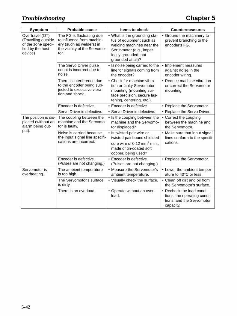
Chapter 5Troubleshooting
Overtravel (OT) (Travelling outside of the zone speci-fied by the host device)
The FG is fluctuating due to influence from machin-ery (such as welders) in the vicinity of the Servomo-tor.
• What is the grounding sta-tus of equipment such as welding machines near the Servomotor (e.g., imper-fectly grounded, not grounded at all)?
• Ground the machinery to prevent branching to the encoder's FG.
The Servo Driver pulse count is incorrect due to noise.
• Is noise being carried to the line for signals coming from the encoder?
• Implement measures against noise in the encoder wiring.
There is interference due to the encoder being sub-jected to excessive vibra-tion and shock.
• Check for machine vibra-tion or faulty Servomotor mounting (mounting sur-face precision, secure fas-tening, centering, etc.).
• Reduce machine vibration or correct the Servomotor mounting.
Encoder is defective. • Encoder is defective. • Replace the Servomotor.
Servo Driver is defective. • Servo Driver is defective. • Replace the Servo Driver.
The position is dis-placed (without an alarm being out-put).
The coupling between the machine and the Servomo-tor is faulty.
• Is the coupling between the machine and the Servomo-tor displaced?
• Correct the coupling between the machine and the Servomotor.
Noise is carried because the input signal line specifi-cations are incorrect.
• Is twisted-pair wire or twisted-pair bound shielded
core wire of 0.12 mm2 min., made of tin-coated soft copper, being used?
• Make sure that input signal lines conform to the specifi-cations.
Encoder is defective. (Pulses are not changing.)
• Encoder is defective. (Pulses are not changing.)
• Replace the Servomotor.
Servomotor is overheating.
The ambient temperature is too high.
• Measure the Servomotor's ambient temperature.
• Lower the ambient temper-ature to 40°C or less.
The Servomotor's surface is dirty.
• Visually check the surface. • Clean off dirt and oil from the Servomotor's surface.
There is an overload. • Operate without an over-load.
• Recheck the load condi-tions, the operating condi-tions, and the Servomotor capacity.
Symptom Probable cause Items to check Countermeasures
5-42
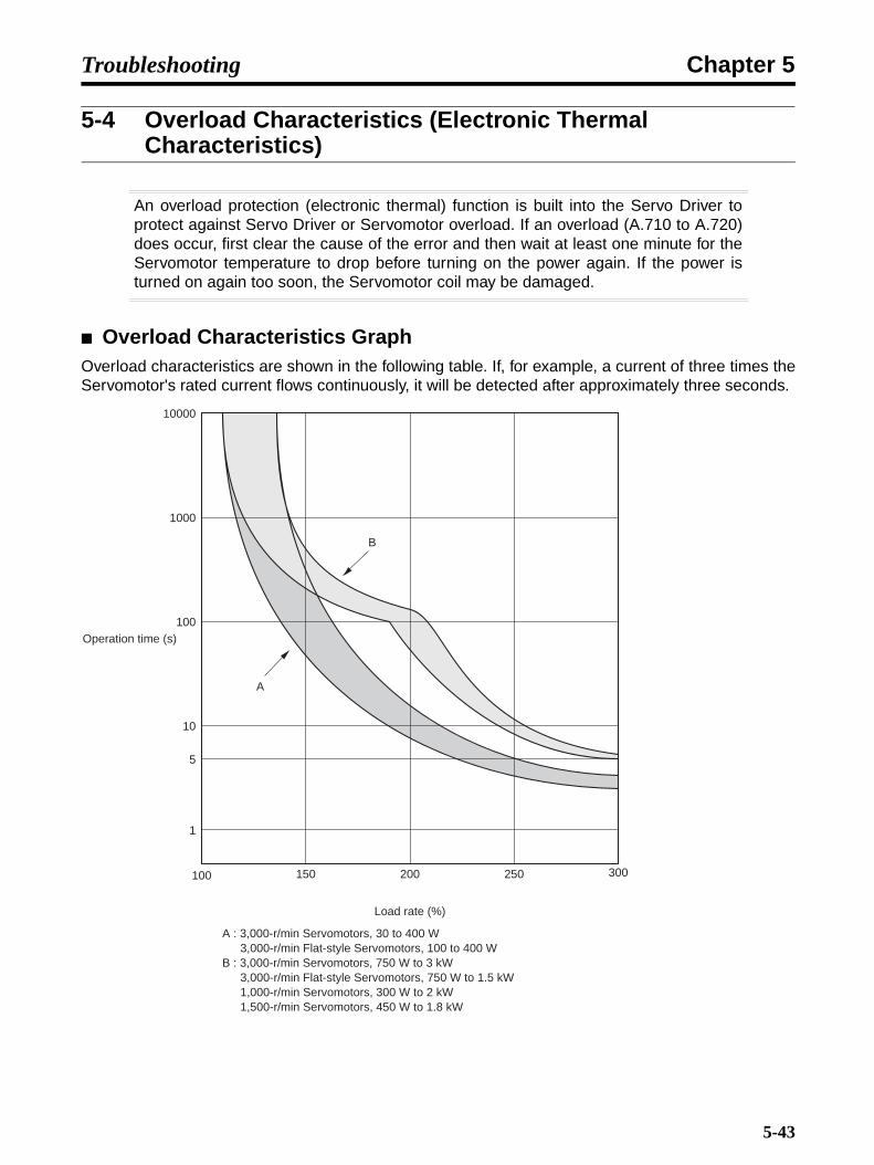
Chapter 5Troubleshooting
5-4 Overload Characteristics (Electronic Thermal Characteristics)
An overload protection (electronic thermal) function is built into the Servo Driver toprotect against Servo Driver or Servomotor overload. If an overload (A.710 to A.720)does occur, first clear the cause of the error and then wait at least one minute for theServomotor temperature to drop before turning on the power again. If the power isturned on again too soon, the Servomotor coil may be damaged.
Overload Characteristics GraphOverload characteristics are shown in the following table. If, for example, a current of three times theServomotor's rated current flows continuously, it will be detected after approximately three seconds.
150 200 250
1000
100
10
5
1
Operation time (s)
100
A
B
A : 3,000-r/min Servomotors, 30 to 400 W 3,000-r/min Flat-style Servomotors, 100 to 400 WB : 3,000-r/min Servomotors, 750 W to 3 kW 3,000-r/min Flat-style Servomotors, 750 W to 1.5 kW 1,000-r/min Servomotors, 300 W to 2 kW 1,500-r/min Servomotors, 450 W to 1.8 kW
300
Load rate (%)
10000
5-43

Chapter 5Troubleshooting
Interpreting the GraphIf a current that is equivalent to the maximum torque is applied continuously to a Servomotor equiva-lent to B in the above graph, an overload will be detected in approximately 5 s.
5-44

Chapter 5Troubleshooting
5-5 Periodic Maintenance
Maintenance and Inspection Precautions
!WARNING Do not attempt to disassemble, repair, or modify any Units. Any attempt to do somay result in malfunction, fire, or electric shock.
!Caution Resume operation only after transferring to the new Unit the contents of the datarequired for operation. Not doing so may result in an unexpected operation.
Servomotors and Servo Drivers contain many components and will operate properlyonly when each of the individual components is operating properly. Some of theelectrical and mechanical components require maintenance depending on applicationconditions. In order to ensure proper long-term operation of Servomotors and Drivers,periodic inspection and part replacement is required according to the life of thecomponents.
The periodic maintenance cycle depends on the installation environment and application conditionsof the Servomotor or Driver. Recommended maintenance times are listed below for Servomotors andDrivers. Use these for reference in determining actual maintenance schedules.
Servomotors• Recommended Periodic Maintenance
Bearings: 20,000 hoursReduction gear: 20,000 hoursOil seal: 5,000 hours
Application Conditions: Ambient Servomotor operating temperature of 40°C, within allowable shaftload, rated operation (rated torque and r/m), installed as described in oper-ation manual.
• The radial loads during operation (rotation) on timing pulleys and other components contactingbelts is twice the still load. Consult with the belt and pulley manufacturers and adjust designs andsystem settings so that the allowable shaft load is not exceeded even during operation. If a Servo-motor is used under a shaft load exceeding the allowable limit, the Servomotor shaft can break, thebearings can burn out, and other problems can occur.
Servo Drivers• Recommended Periodic Maintenance
Aluminum analytical capacitors: 50,000 hours, at an ambient Servo Driver operating temperatureof 40°C, rated operation (rated torque), installed as described inoperation manual.
Axle fan: 30,000 hours, at an ambient Servo Driver operating temperature of 40°C and an ambienthumidity of 65%.
5-45

Chapter 5Troubleshooting
Absolute encoder backup battery: 50,000 hours, at an ambient Servo Driver operating tempera-ture of 20°C.
• When using the Servo Driver under the continuous operation mode, cool the Servo Driver with fansand air conditioners to maintain an ambient operating temperature below 40°C.
• The life of aluminum analytical capacitors is greatly affected by the ambient operating temperature.Generally speaking, an increase of 10°C in the ambient operating temperature will reduce capacitorlife by 50%. We recommend that ambient operating temperature be lowered and the power supplytime be reduced as much as possible to lengthen the maintenance times for Servo Drivers.
• If the Servomotor or Servo Driver is not to be used for a long time, or if they are to be used underconditions worse than those described above, a periodic inspection schedule of five years is recom-mended. Please consult with OMRON to determine whether or not components need to bereplaced.
5-46

Chapter 5Troubleshooting
5-6 Replacing the Absolute Encoder Battery (ABS)
Replace the absolute encoder backup battery if it has been used for at least five years,or if an A.930 (battery warning) warning or an A.830 (battery error) alarm occurs.
Battery Model and Specifications
Note Refer to 2-8 Absolute Encoder Backup Battery Specifications for dimensions and wiringdetails.
Battery Replacement Procedure• Replace the battery using the following replacement procedure. After replacing the battery, if a
A.810 (backup error) alarm does not occur, the replacement is completed. If an A.810 alarmoccurs, you need to set up the absolute encoder.
1.Turn ON the power supply to the Servo Driver's control circuit.
• Turn ON the power supply to the Servo Driver's control circuit only. This will supply power tothe absolute encoder.
Note If an A.930 warning occurs when the power supply is ON, turn OFF only the main circuitpower supply after completing operation and then perform the following replacement proce-dure. If the control circuit power supply is turned OFF, the absolute data in the absolute en-coder may be inadvertently cleared.
2.Replace the battery.
• Remove the old battery from the absolute encoder battery cable's battery holder, and discon-nect the connector to the battery from the battery connector.
• Place the new battery in the battery holder, and insert the connector correctly into battery con-nector.
3.Turn the power supply OFF, then ON again.
• After correctly connecting the new battery, turn OFF the power supply to the Servo Driver, thenturn it ON again.
• If a Servo Driver alarm is not displayed, battery replacement is completed.
Note If A.810 (backup error) is displayed, you need to set up the absolute encoder. Refer to 4-2-2 Absolute Encoder Setup and Battery Changes, and perform the setup and make the initialsettings for the Motion Control Unit.
Item SpecificationName Absolute Encoder Backup Battery Unit
Model numbers R88A-BAT01W
Battery model ER3V (Toshiba)
Battery voltage 3.6 V
Current capacity 1,000 mA·h
5-47

Chapter 5Troubleshooting
5-48

Chapter 6
Appendix
6-1 Connection Examples
6-2 Parameter Setting Tables
6-3 Restrictions

Chapter 6Appendix
6-1 Connection Examples
Connection Example: Connecting to SYSMAC CS1W-MCH71, CJ1W-MCH71, CJ1W-NCF71 Position Control Units
Note 1. The example shows a three-phase, 200-V AC input to the Servo Driver for the main circuitpower supply. Be sure to provide a power supply and wiring conforming to the power supplyspecifications for the Servo Driver in use.
Note 2. Incorrect signal wiring can cause damage to Units and the Servo Driver.
Note 3. Leave unused signal lines open and do not wire them.
Note 4. The diode recommended for surge absorption is the ERB44-02 (Fuji Electric).
CJ1W-NCF71CJ1W-MCH71CS1W-MCH71 R88D-WN@-ML2
R88M-W@
CN1
CN6A/B
Terminating ResistorFNY-W6022
MLK
TB
6 +24VI
L1CL2CL1L2L3
B2B3
UVW
7 POT8 NOT9 DEC
12 EXT311 EXT210 EXT1
3 ALM
4 ALMCOI
CN2
M
E
X1
RedWhiteBlue
Green/Yellow
Power CableR88A-CAW@
R88A-CAW@R
Encoder CableR88A-CRW@
R88A-CAW@R
MECHATROLINK-IICommunications Cable
FNY-W6003-@N
oise
filte
rR
S
T
3-phase 200/230 V AC 50/60Hz
MC
MC
SUP
NFB ONOFF
X1MC
Main circuit power supply
Main circuit contactSurge killer
Class-3 ground(100 Ω or less)
24 V DC
24 V DC
DC reactor
6-2

Chapter 6Appendix
6-2 Parameter Setting Tables
Function Selection Parameters (from Pn000)Param-eter No.
Param-eter
name
Digit No.
Name Setting Explanation Default setting
Unit Setting range
Restart power?
Set value
Pn000 Func-tion selec-tion basic switches
0 Reverse rota-tion
0 CCW direction is taken for posi-tive command
0000 --- --- Yes 0@0@
1 CW direction is taken for positive command
2 to 3 Not used.
1 Not used. 0 (Do not change setting.)
2 Unit No. set-ting
0 to F Servo Driver communications unit number setting (necessary for multiple Servo Driver connec-tions when using personal com-puter monitoring software)
3 Not used. 0 (Do not change setting.)
Pn001 Func-tion selec-tion applica-tion switches 1
0 Stop selec-tion if an alarm occurs when Servo-motor is OFF
0 Servomotor stopped by dynamic brake.
0002 --- --- Yes 0@@@
1 Dynamic brake OFF after Servo-motor stopped
2 Servomotor stopped with free run
1 Stop selec-tion when drive prohib-ited is input
0 Stop according to Pn001.0 set-ting (release Servomotor after stopping)
1 Stop Servomotor using torque set in Pn406, and lock Servomo-tor after stopping
2 Stop Servomotor using torque set in Pn406, and release Servo-motor after stopping
2 AC/DC power input selection
0 AC power supply: DC power supplied from L1, L2, (L3) termi-nals
1 DC power supply: DC power from +1, − terminals
3 Not used. 0 (Do not change setting.)
Pn002 Func-tion selec-tion applica-tion switches 2
0 Torque com-mand input change (dur-ing speed control)
0 Do not use option command value.
0000 --- --- Yes 0@@@
1 Use option command value 1 as the torque limit value.
2 Use option command value 1 as the torque feed forward com-mand value.
3 Use option command value 1 or 2 as the torque limit value, according to the forward and reverse torque limits that are specified.
1 Speed com-mand input change (dur-ing torque control)
0 Do not use option command value.
1 Use option command value 1 as the speed limit value.
2 Operation switch when using abso-lute encoder
0 Use as absolute encoder
1 Use as incremental encoder
3 Not used. 0 (Do not change setting.)
6-3

Chapter 6Appendix
Pn004 Func-tion selec-tion applica-tion switches 4
0 Not used. 0 (Do not change setting.) 0110 --- --- Yes 011@1 Not used. 1 (Do not change setting.)
2 Not used. 1 (Do not change setting.)
3 Not used. 0 (Do not change setting.)
Pn006 Func-tion selec-tion applica-tion switches 6
0 to 1 Analog moni-tor 1 (AM) signal selec-tion
00 Servomotor rotation speed: 1V/1000 r/min
0002 --- --- --- 0@@@
01 Speed command: 1 V/1000 r/min
02 Torque command: gravity com-pensation torque (Pn422)(1 V per 100%)
03 Position deviation: 0.05 V/1 com-mand unit
04 Position amp error (after elec-tronic gear) (0.05 V per encoder pulse unit)
05 Position command speed (1 V/1,000 r/min)
06 Not used.
07 Not used.
08 Positioning completed command (Positioning completed: 5 V; positioning not completed: 0 V)
09 Speed feed forward (1 V/1,000 r/min)
0A Torque feed forward (1 V per 100%)
0B to 1F Not used.
2 Analog moni-tor 1 signal multiplier selection
0 1x
1 10x
2 100x
3 1/10x
4 1/100x
3 Not used. 0 (Do not change setting.)
Param-eter No.
Param-eter
name
Digit No.
Name Setting Explanation Default setting
Unit Setting range
Restart power?
Set value
6-4

Chapter 6Appendix
Servo Gain Parameters (from Pn100)
Pn007 Func-tion selec-tion applica-tion switches 7
0 to 1 Analog moni-tor 2 (NM) signal selec-tion
00 Servomotor rotation speed: 1V/1000 r/min
0000 --- --- --- 0@@@
01 Speed command: 1 V/1000 r/min
02 Torque command: gravity com-pensation torque (Pn422)(1 V per 100%)
03 Position deviation: 0.05 V/1 com-mand unit
04 Position amp error (after elec-tronic gear) (0.05 V per encoder pulse unit)
05 Position command speed (1 V/1,000 r/min)
06 Not used.
07 Not used.
08 Positioning completed command (Positioning completed: 5 V; positioning not completed: 0 V)
09 Speed feed forward (1 V/1,000 r/min)
0A Torque feed forward (1 V per 100%)
0B to 1F Not used.
2 Analog moni-tor 2 signal multiplier selection
0 1x
1 10x
2 100x
3 1/10x
4 1/100x
3 Not used. 0 (Do not change setting.)
Pn008 Func-tion selec-tion applica-tion switches 8
0 Lowered bat-tery voltage alarm/warn-ing selection
0 Regard battery voltage drop as alarm (A.830).
4000 --- --- Yes 4@0@
1 Regard battery voltage drop as warning (A.930).
1 Not used. 0 (Do not change setting.)
2 Warning detection selection
0 Warnings detected.
1 Warnings not detected.
3 Not used. 4 (Do not change setting.)
Param-eter No.
Parameter name
Explanation (See note 1.) Default setting
Unit Setting range
Restart power?
Set valueDigit
No.Name Setting Explanation (See note 2.)
Pn100 Speed loop gain
Adjusts speed loop response. 800 × 0.1 Hz 10 to 20000
---
Pn101 Speed loop integration constant
Speed loop integral time constant 2000 × 0.01 ms 15 to 51200
---
Pn102 Position loop gain
Adjusts position loop response. 400 × 0.1/s 10 to 20000
---
Pn103 Inertia ratio Set using the ratio between the machine system inertia and the Servomotor rotor inertia.
300 % 0 to 20000
---
Pn104 Speed loop gain 2
Adjusts speed loop response (enabled by gain switching input).
800 × 0.1 Hz 10 to 20000
---
Pn105 Speed loop integration constant 2
Speed loop integral time constant (enabled by gain switching input).
2000 × 0.01 ms 15 to 51200
---
Pn106 Position loop gain 2
Adjusts position loop response (enabled by gain switching input).
400 × 0.1/s 10 to 20000
---
Param-eter No.
Param-eter
name
Digit No.
Name Setting Explanation Default setting
Unit Setting range
Restart power?
Set value
6-5
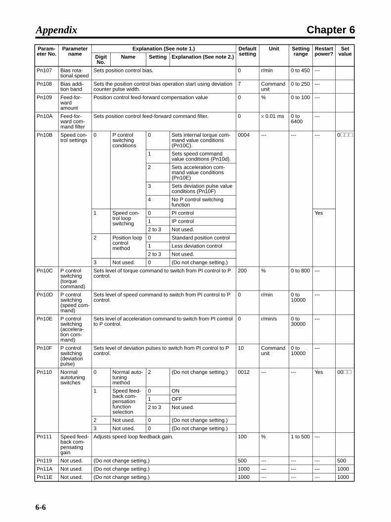
Chapter 6Appendix
Pn107 Bias rota-tional speed
Sets position control bias. 0 r/min 0 to 450 ---
Pn108 Bias addi-tion band
Sets the position control bias operation start using deviation counter pulse width.
7 Command unit
0 to 250 ---
Pn109 Feed-for-ward amount
Position control feed-forward compensation value 0 % 0 to 100 ---
Pn10A Feed-for-ward com-mand filter
Sets position control feed-forward command filter. 0 × 0.01 ms 0 to 6400
---
Pn10B Speed con-trol settings
0 P control switching conditions
0 Sets internal torque com-mand value conditions (Pn10C).
0004 --- --- --- 0@@@
1 Sets speed command value conditions (Pn10d).
2 Sets acceleration com-mand value conditions (Pn10E)
3 Sets deviation pulse value conditions (Pn10F)
4 No P control switching function
1 Speed con-trol loop switching
0 PI control Yes
1 IP control
2 to 3 Not used.
2 Position loop control method
0 Standard position control
1 Less deviation control
2 to 3 Not used.
3 Not used. 0 (Do not change setting.)
Pn10C P control switching (torque command)
Sets level of torque command to switch from PI control to P control.
200 % 0 to 800 ---
Pn10D P control switching (speed com-mand)
Sets level of speed command to switch from PI control to P control.
0 r/min 0 to 10000
---
Pn10E P control switching (accelera-tion com-mand)
Sets level of acceleration command to switch from PI control to P control.
0 r/min/s 0 to 30000
---
Pn10F P control switching (deviation pulse)
Sets level of deviation pulses to switch from PI control to P control.
10 Command unit
0 to 10000
---
Pn110 Normal autotuning switches
0 Normal auto-tuning method
2 (Do not change setting.) 0012 --- --- Yes 00@@
1 Speed feed-back com-pensation function selection
0 ON
1 OFF
2 to 3 Not used.
2 Not used. 0 (Do not change setting.)
3 Not used. 0 (Do not change setting.)
Pn111 Speed feed-back com-pensating gain
Adjusts speed loop feedback gain. 100 % 1 to 500 ---
Pn119 Not used. (Do not change setting.) 500 --- --- --- 500
Pn11A Not used. (Do not change setting.) 1000 --- --- --- 1000
Pn11E Not used. (Do not change setting.) 1000 --- --- --- 1000
Param-eter No.
Parameter name
Explanation (See note 1.) Default setting
Unit Setting range
Restart power?
Set valueDigit
No.Name Setting Explanation (See note 2.)
6-6
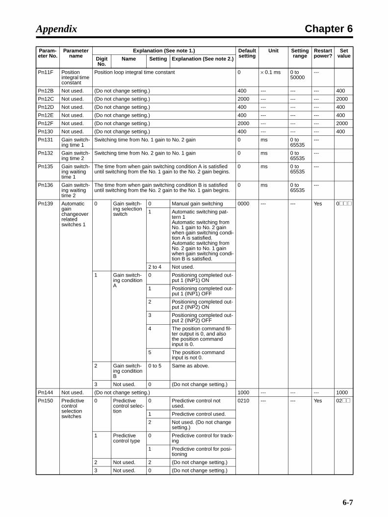
Chapter 6Appendix
Pn11F Position integral time constant
Position loop integral time constant 0 × 0.1 ms 0 to 50000
---
Pn12B Not used. (Do not change setting.) 400 --- --- --- 400
Pn12C Not used. (Do not change setting.) 2000 --- --- --- 2000
Pn12D Not used. (Do not change setting.) 400 --- --- --- 400
Pn12E Not used. (Do not change setting.) 400 --- --- --- 400
Pn12F Not used. (Do not change setting.) 2000 --- --- --- 2000
Pn130 Not used. (Do not change setting.) 400 --- --- --- 400
Pn131 Gain switch-ing time 1
Switching time from No. 1 gain to No. 2 gain 0 ms 0 to 65535
---
Pn132 Gain switch-ing time 2
Switching time from No. 2 gain to No. 1 gain 0 ms 0 to 65535
---
Pn135 Gain switch-ing waiting time 1
The time from when gain switching condition A is satisfied until switching from the No. 1 gain to the No. 2 gain begins.
0 ms 0 to 65535
---
Pn136 Gain switch-ing waiting time 2
The time from when gain switching condition B is satisfied until switching from the No. 2 gain to the No. 1 gain begins.
0 ms 0 to 65535
---
Pn139 Automatic gain changeover related switches 1
0 Gain switch-ing selection switch
0 Manual gain switching 0000 --- --- Yes 0@@@1 Automatic switching pat-
tern 1Automatic switching from No. 1 gain to No. 2 gain when gain switching condi-tion A is satisfied.Automatic switching from No. 2 gain to No. 1 gain when gain switching condi-tion B is satisfied.
2 to 4 Not used.
1 Gain switch-ing condition A
0 Positioning completed out-put 1 (INP1) ON
1 Positioning completed out-put 1 (INP1) OFF
2 Positioning completed out-put 2 (INP2) ON
3 Positioning completed out-put 2 (INP2) OFF
4 The position command fil-ter output is 0, and also the position command input is 0.
5 The position command input is not 0.
2 Gain switch-ing condition B
0 to 5 Same as above.
3 Not used. 0 (Do not change setting.)
Pn144 Not used. (Do not change setting.) 1000 --- --- --- 1000
Pn150 Predictive control selection switches
0 Predictive control selec-tion
0 Predictive control not used.
0210 --- --- Yes 02@@
1 Predictive control used.
2 Not used. (Do not change setting.)
1 Predictive control type
0 Predictive control for track-ing
1 Predictive control for posi-tioning
2 Not used. 2 (Do not change setting.)
3 Not used. 0 (Do not change setting.)
Param-eter No.
Parameter name
Explanation (See note 1.) Default setting
Unit Setting range
Restart power?
Set valueDigit
No.Name Setting Explanation (See note 2.)
6-7
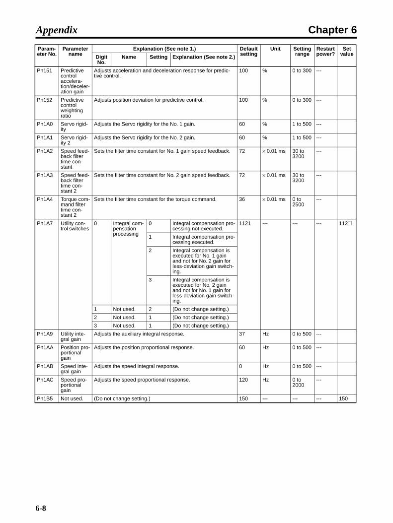
Chapter 6Appendix
Pn151 Predictive control accelera-tion/deceler-ation gain
Adjusts acceleration and deceleration response for predic-tive control.
100 % 0 to 300 ---
Pn152 Predictive control weighting ratio
Adjusts position deviation for predictive control. 100 % 0 to 300 ---
Pn1A0 Servo rigid-ity
Adjusts the Servo rigidity for the No. 1 gain. 60 % 1 to 500 ---
Pn1A1 Servo rigid-ity 2
Adjusts the Servo rigidity for the No. 2 gain. 60 % 1 to 500 ---
Pn1A2 Speed feed-back filter time con-stant
Sets the filter time constant for No. 1 gain speed feedback. 72 × 0.01 ms 30 to 3200
---
Pn1A3 Speed feed-back filter time con-stant 2
Sets the filter time constant for No. 2 gain speed feedback. 72 × 0.01 ms 30 to 3200
---
Pn1A4 Torque com-mand filter time con-stant 2
Sets the filter time constant for the torque command. 36 × 0.01 ms 0 to 2500
---
Pn1A7 Utility con-trol switches
0 Integral com-pensation processing
0 Integral compensation pro-cessing not executed.
1121 --- --- --- 112@
1 Integral compensation pro-cessing executed.
2 Integral compensation is executed for No. 1 gain and not for No. 2 gain for less-deviation gain switch-ing.
3 Integral compensation is executed for No. 2 gain and not for No. 1 gain for less-deviation gain switch-ing.
1 Not used. 2 (Do not change setting.)
2 Not used. 1 (Do not change setting.)
3 Not used. 1 (Do not change setting.)
Pn1A9 Utility inte-gral gain
Adjusts the auxiliary integral response. 37 Hz 0 to 500 ---
Pn1AA Position pro-portional gain
Adjusts the position proportional response. 60 Hz 0 to 500 ---
Pn1AB Speed inte-gral gain
Adjusts the speed integral response. 0 Hz 0 to 500 ---
Pn1AC Speed pro-portional gain
Adjusts the speed proportional response. 120 Hz 0 to 2000
---
Pn1B5 Not used. (Do not change setting.) 150 --- --- --- 150
Param-eter No.
Parameter name
Explanation (See note 1.) Default setting
Unit Setting range
Restart power?
Set valueDigit
No.Name Setting Explanation (See note 2.)
6-8
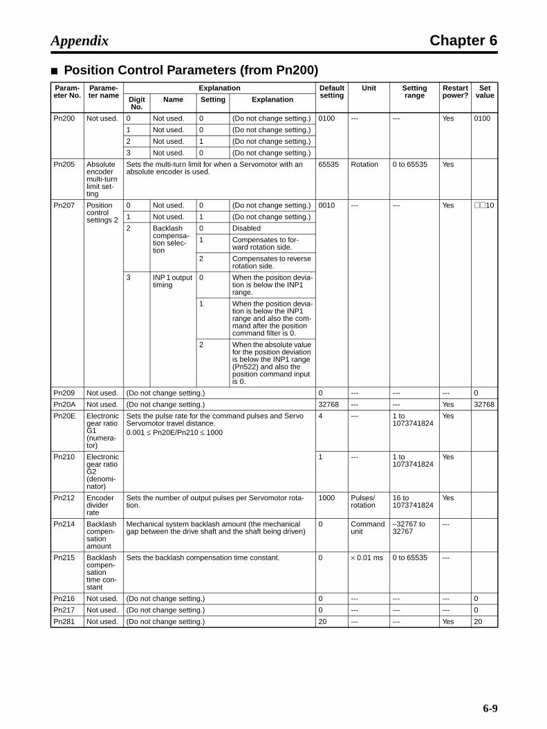
Chapter 6Appendix
Position Control Parameters (from Pn200)Param-eter No.
Parame-ter name
Explanation Default setting
Unit Setting range
Restart power?
Set valueDigit
No.Name Setting Explanation
Pn200 Not used. 0 Not used. 0 (Do not change setting.) 0100 --- --- Yes 0100
1 Not used. 0 (Do not change setting.)
2 Not used. 1 (Do not change setting.)
3 Not used. 0 (Do not change setting.)
Pn205 Absolute encoder multi-turn limit set-ting
Sets the multi-turn limit for when a Servomotor with an absolute encoder is used.
65535 Rotation 0 to 65535 Yes
Pn207 Position control settings 2
0 Not used. 0 (Do not change setting.) 0010 --- --- Yes @@10
1 Not used. 1 (Do not change setting.)
2 Backlash compensa-tion selec-tion
0 Disabled
1 Compensates to for-ward rotation side.
2 Compensates to reverse rotation side.
3 INP 1 output timing
0 When the position devia-tion is below the INP1 range.
1 When the position devia-tion is below the INP1 range and also the com-mand after the position command filter is 0.
2 When the absolute value for the position deviation is below the INP1 range (Pn522) and also the position command input is 0.
Pn209 Not used. (Do not change setting.) 0 --- --- --- 0
Pn20A Not used. (Do not change setting.) 32768 --- --- Yes 32768
Pn20E Electronic gear ratio G1 (numera-tor)
Sets the pulse rate for the command pulses and Servo Servomotor travel distance.0.001 ≤ Pn20E/Pn210 ≤ 1000
4 --- 1 to 1073741824
Yes
Pn210 Electronic gear ratio G2 (denomi-nator)
1 --- 1 to 1073741824
Yes
Pn212 Encoder divider rate
Sets the number of output pulses per Servomotor rota-tion.
1000 Pulses/rotation
16 to 1073741824
Yes
Pn214 Backlash compen-sation amount
Mechanical system backlash amount (the mechanical gap between the drive shaft and the shaft being driven)
0 Command unit
−32767 to 32767
---
Pn215 Backlash compen-sation time con-stant
Sets the backlash compensation time constant. 0 × 0.01 ms 0 to 65535 ---
Pn216 Not used. (Do not change setting.) 0 --- --- --- 0
Pn217 Not used. (Do not change setting.) 0 --- --- --- 0
Pn281 Not used. (Do not change setting.) 20 --- --- Yes 20
6-9

Chapter 6Appendix
Speed Control Parameters (from Pn300)
Torque Control Parameters (from Pn400)
Param-eter No.
Parameter name
Explanation Default setting
Unit Setting range
Restart power?
Set valueDigit
No.Name Setting Explanation
Pn300 Not used. (Do not change setting.) 600 --- --- --- 600
Pn301 Not used. (Do not change setting.) 100 --- --- --- 100
Pn302 Not used. (Do not change setting.) 200 --- --- --- 200
Pn303 Not used. (Do not change setting.) 300 --- --- --- 300
Pn304 Jog speed Sets rotation speed during jog operation. 500 r/min 0 to 10000
---
Pn305 Soft start accelera-tion time
Sets acceleration time during speed control soft start. 0 ms 0 to 10000
---
Pn306 Soft start decelera-tion time
Sets deceleration time during speed control soft start. 0 ms 0 to 10000
---
Pn307 Not used. (Do not change setting.) 40 --- --- --- 40
Pn308 Speed feed-back filter time con-stant
Sets constant during filter of speed feedback. 0 × 0.01 ms 0 to 65535
---
Pn310 Vibration detection switches
0 Vibration detection selection
0 Vibration detection not used.
0000 --- --- --- 000@
1 Gives warning (A.911) when vibration is detected.
2 Gives warning (A.520) when vibration is detected.
1 Not used. 0 (Do not change setting.)
2 Not used. 0 (Do not change setting.)
3 Not used. 0 (Do not change setting.)
Pn311 Vibration detection sensitivity
Sets the vibration detection sensitivity. 100 % 50 to 500
---
Pn312 Vibration detection level
Sets the vibration detection level 50 r/min 0 to 5000
---
Param-eter No.
Parameter name
Explanation Default setting
Unit Setting range
Restart power?
Set valueDigit
No.Name Setting Explanation
Pn400 Not used. (Do not change setting.) 30 --- --- --- 30
Pn401 1st step 1st torque com-mand filter time con-stant
Sets the filter time constant for internal torque commands. 40 × 0.01 ms 0 to 65535
---
Pn402 Forward torque limit
Forward rotation output torque limit (rated torque ratio). 350 % 0 to 800 ---
Pn403 Reverse torque limit
Reverse rotation output torque limit (rated torque ratio). 350 % 0 to 800 ---
Pn404 Forward rotation external cur-rent limit
Output torque limit during input of forward rotation current limit (rated torque ratio)
100 % 0 to 800 ---
Pn405 Reverse rotation external cur-rent limit
Output torque limit during input of reverse rotation current limit (rated torque ratio)
100 % 0 to 800 ---
Pn406 Emergency stop torque
Deceleration torque when an error occurs (rated torque ratio) 350 % 0 to 800 ---
6-10

Chapter 6Appendix
Pn407 Speed limit Sets the speed limit in torque control mode. 3000 r/min 0 to 10000
---
Pn408 Torque com-mand set-ting
0 Selects notch filter 1 func-tion.
0 Notch filter 1 not used. 0000 --- --- --- 0@0@1 Notch filter 1 used for
torque commands.
1 Not used. 0 (Do not change setting.)
2 Selects notch filter 2 func-tion.
0 Notch filter 2 not used.
1 Notch filter 2 used for torque commands.
3 Not used. 0 (Do not change setting.)
Pn409 Notch filter 1 frequency
Sets notch filter 1 frequency for torque command. 2000 Hz 50 to 2000
---
Pn40A Notch filter 1 Q value
Sets Q value of notch filter 1. 70 × 0.01 50 to 1000
---
Pn40C Notch filter 2 frequency
Sets the notch filter 2 frequency for torque commands. 2000 Hz 50 to 2000
---
Pn40D Notch filter 2 Q value
Sets Q value of notch filter 2. 70 × 0.01 50 to 1000
---
Pn40F 2nd step 2nd torque command filter fre-quency
Sets the filter frequency for internal torque commands. 2000 Hz 100 to 2000
---
Pn410 2nd step 2nd torque command filter Q value
Sets the torque command filter Q value. 70 × 0.01 50 to 1000
---
Pn411 3rd step torque com-mand filter time con-stant
Sets the filter time constant for internal torque commands. 0 µs 0 to 65535
---
Pn412 1st step 2nd torque com-mand filter time con-stant
Sets the filter time constant for No. 2 gain internal torque commands.
100 × 0.01 ms 0 to 65535
---
Pn413 Not used. (Do not change setting.) 100 --- --- --- 100
Pn414 Not used. (Do not change setting.) 100 --- --- --- 100
Pn420 Damping for vibration suppres-sion on stopping
Sets the vibration suppression value while stopped. 100 % 10 to 100
---
Pn421 Vibration suppres-sion start-ing time
Sets the time from when the position command becomes 0 until the stopped vibration suppression begins.
1000 ms 0 to 65535
---
Pn422 Gravity compensa-tion torque
Sets the gravity compensation torque. 0 × 0.01% −20000 to 20000
---
Pn456 Sweep torque com-mand ampli-tude
Sets the sweep torque command amplitude. 15 % 1 to 800 ---
Param-eter No.
Parameter name
Explanation Default setting
Unit Setting range
Restart power?
Set valueDigit
No.Name Setting Explanation
6-11

Chapter 6Appendix
Sequence Parameters (from Pn500)Param-eter No.
Parame-ter name
Explanation Default setting
Unit Setting range
Restart power?
Set valueDigit
No.Name Setting Explanation
Pn501 Not used. (Do not change setting.) 10 --- --- --- 10
Pn502 Rotation speed for motor rotation detection
Sets the number of rotations for the Servomotor rotation detection output (TGON).
20 r/min 1 to 10000 ---
Pn503 Speed confor-mity sig-nal output width
Sets the allowable fluctuation (number of rotations) for the speed conformity output (VCMP).
10 r/min 0 to 100 ---
Pn506 Brake tim-ing 1
Sets the delay from the brake command to the Servomo-tor turning OFF.
0 × 10 ms 0 to 50 ---
Pn507 Brake command speed
Sets the number of rotations for outputting the brake com-mand.
100 r/min 0 to 10000 ---
Pn508 Brake tim-ing 2
Sets the delay time from the Servomotor turning OFF to the brake command output.
50 × 10 ms 10 to 100 ---
Pn509 Momen-tary hold time
Sets the time during which alarm detection is disabled when a power failure occurs.
20 ms 20 to 1000 ---
Pn50A Input sig-nal selec-tions 1
0 Not used. 1 (Do not change setting.) 1881 --- --- Yes @881
1 Not used. 8 (Do not change setting.)
2 Not used. 8 (Do not change setting.)
3 POT (for-ward drive prohibited input) sig-nal Input terminal allocation
0 Allocated to CN1, pin 13: Valid for low input
1 Allocated to CN1, pin 7: Valid for low input
2 Allocated to CN1, pin 8: Valid for low input
3 Allocated to CN1, pin 9: Valid for low input
4 Allocated to CN1, pin 10: Valid for low input
5 Allocated to CN1, pin 11: Valid for low input
6 Allocated to CN1, pin 12: Valid for low input
7 Always enabled.
8 Always disabled.
9 Allocated to CN1, pin 13: Valid for high input
A Allocated to CN1, pin 7: Valid for high input
B Allocated to CN1, pin 8: Valid for high input
C Allocated to CN1, pin 9: Valid for high input
D Allocated to CN1, pin 10: Valid for high input
E Allocated to CN1, pin 11: Valid for high input
F Allocated to CN1, pin 12: Valid for high input
6-12
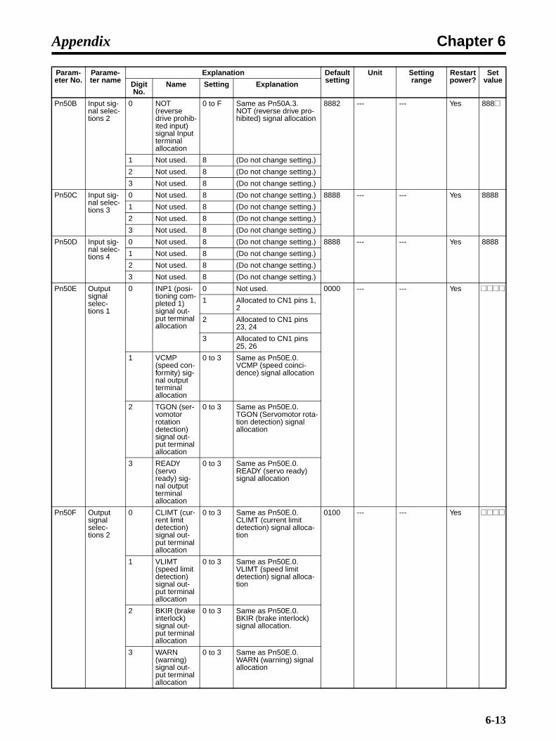
Chapter 6Appendix
Pn50B Input sig-nal selec-tions 2
0 NOT (reverse drive prohib-ited input) signal Input terminal allocation
0 to F Same as Pn50A.3.NOT (reverse drive pro-hibited) signal allocation
8882 --- --- Yes 888@
1 Not used. 8 (Do not change setting.)
2 Not used. 8 (Do not change setting.)
3 Not used. 8 (Do not change setting.)
Pn50C Input sig-nal selec-tions 3
0 Not used. 8 (Do not change setting.) 8888 --- --- Yes 8888
1 Not used. 8 (Do not change setting.)
2 Not used. 8 (Do not change setting.)
3 Not used. 8 (Do not change setting.)
Pn50D Input sig-nal selec-tions 4
0 Not used. 8 (Do not change setting.) 8888 --- --- Yes 8888
1 Not used. 8 (Do not change setting.)
2 Not used. 8 (Do not change setting.)
3 Not used. 8 (Do not change setting.)
Pn50E Output signal selec-tions 1
0 INP1 (posi-tioning com-pleted 1) signal out-put terminal allocation
0 Not used. 0000 --- --- Yes @@@@1 Allocated to CN1 pins 1,
2
2 Allocated to CN1 pins 23, 24
3 Allocated to CN1 pins 25, 26
1 VCMP (speed con-formity) sig-nal output terminal allocation
0 to 3 Same as Pn50E.0.VCMP (speed coinci-dence) signal allocation
2 TGON (ser-vomotor rotation detection) signal out-put terminal allocation
0 to 3 Same as Pn50E.0.TGON (Servomotor rota-tion detection) signal allocation
3 READY (servo ready) sig-nal output terminal allocation
0 to 3 Same as Pn50E.0.READY (servo ready) signal allocation
Pn50F Output signal selec-tions 2
0 CLIMT (cur-rent limit detection) signal out-put terminal allocation
0 to 3 Same as Pn50E.0.CLIMT (current limit detection) signal alloca-tion
0100 --- --- Yes @@@@
1 VLIMT (speed limit detection) signal out-put terminal allocation
0 to 3 Same as Pn50E.0.VLIMT (speed limit detection) signal alloca-tion
2 BKIR (brake interlock) signal out-put terminal allocation
0 to 3 Same as Pn50E.0.BKIR (brake interlock) signal allocation.
3 WARN (warning) signal out-put terminal allocation
0 to 3 Same as Pn50E.0.WARN (warning) signal allocation
Param-eter No.
Parame-ter name
Explanation Default setting
Unit Setting range
Restart power?
Set valueDigit
No.Name Setting Explanation
6-13

Chapter 6Appendix
Pn510 Output signal selec-tions 3
0 INP2 (posi-tioning com-pleted 2) signal out-put terminal allocation
0 to 3 Same as Pn50E.0.INP2 (positioning com-pleted 2) signal alloca-tion
0000 --- --- Yes 000@
1 Not used. 0 (Do not change setting.)
2 Not used. 0 (Do not change setting.)
3 Not used. 0 (Do not change setting.)
Param-eter No.
Parame-ter name
Explanation Default setting
Unit Setting range
Restart power?
Set valueDigit
No.Name Setting Explanation
6-14

Chapter 6Appendix
Pn511 Input sig-nal selec-tions 5
0 DEC signal input termi-nal alloca-tion
0 Allocated to CN1, pin 13: Valid for low input
6543 --- --- Yes @@@@
1 Allocated to CN1, pin 7: Valid for low input
2 Allocated to CN1, pin 8: Valid for low input
3 Allocated to CN1, pin 9: Valid for low input
4 Allocated to CN1, pin 10: Valid for low input
5 Allocated to CN1, pin 11: Valid for low input
6 Allocated to CN1, pin 12: Valid for low input
7 Always enabled.
8 Always disabled.
9 Allocated to CN1, pin 13: Valid for high input
A Allocated to CN1, pin 7: Valid for high input
B Allocated to CN1, pin 8: Valid for high input
C Allocated to CN1, pin 9: Valid for high input
D Allocated to CN1, pin 10: Valid for high input
E Allocated to CN1, pin 11: Valid for high input
F Allocated to CN1, pin 12: Valid for high input
1 EXT1 sig-nal input ter-minal allocation
0 to 3 Always disabled.
4 Allocated to CN1, pin 10: Valid for low input
5 Allocated to CN1, pin 11: Valid for low input
6 Allocated to CN1, pin 12: Valid for low input
7 Always enabled.
8 Always disabled.
9 to C Always disabled.
D Allocated to CN1, pin 10: Valid for high input
E Allocated to CN1, pin 11: Valid for high input
F Allocated to CN1, pin 12: Valid for high input
2 EXT2 sig-nal input ter-minal allocation
0 to F Same as for Pn511.1.EXT2 signal allocation
3 EXT3 sig-nal input ter-minal allocation
0 to F Same as for Pn511.1.EXT3 signal allocation
Param-eter No.
Parame-ter name
Explanation Default setting
Unit Setting range
Restart power?
Set valueDigit
No.Name Setting Explanation
6-15

Chapter 6Appendix
Pn512 Output signal reverse
0 Output sig-nal reverse for CN1 pins 1, 2
0 Not reversed. 0000 --- --- Yes 0@@@1 Reversed.
1 Output sig-nal reverse for CN1 pins 23, 24
0 Not reversed.
1 Reversed.
2 Output sig-nal reverse for CN1 pins 25, 26
0 Not reversed.
1 Reversed.
3 Not used. 0 (Do not change setting.)
Pn513 Not used. (Do not change setting.) 0321 --- --- Yes 0321
Pn515 Not used. (Do not change setting.) 8888 --- --- Yes 8888
Pn51B Not used. (Do not change setting.) 1000 --- --- --- 1000
Pn51E Deviation counter overflow warning level
Sets the detection level for the deviation counter overflow warning. (A warning is output for Pn520 × Pn51E/100 or higher.)
100 % 10 to 100 ---
Pn520 Deviation counter overflow level
Sets the deviation counter overflow alarm detection level.Pn520 ≥ (Max. feed speed [command unit/s]/Pn102) × 2.0
262144 Command unit
1 to 1073741823
---
Pn522 Position-ing com-pleted range 1
Setting range for positioning completed range 1 (INP1) 3 Command unit
0 to 1073741824
---
Pn524 Position-ing com-pleted range 2
Setting range for positioning completed range 2 (INP2) 3 Command unit
1 to 1073741824
---
Pn526 Deviation counter overflow level at Servo-ON
Sets the deviation counter overflow alarm detection level for Servo ON.
262144 Command unit
1 to 1073741823
---
Pn528 Deviation counter overflow warning level at Servo-ON
Sets the deviation counter overflow warning detection level for Servo ON.
100 % 10 to 100 ---
Pn529 Speed limit level at Servo-ON
Sets the speed limit for when the Servo turns ON with position deviation accumulated.
10000 r/min 0 to 10000 ---
Pn52A Not used. (Do not change setting.) 20 --- --- --- 20
Pn52F Not used. (Do not change setting.) FFF --- --- --- FFF
Param-eter No.
Parame-ter name
Explanation Default setting
Unit Setting range
Restart power?
Set valueDigit
No.Name Setting Explanation
6-16

Chapter 6Appendix
Pn530 Program JOG oper-ation related switches
0 Program JOG operat-ing pattern
0 (Waiting time Pn535 → Forward movement Pn531) × Number of movement operations Pn536
0000 --- --- --- 000@
1 (Waiting time Pn535 → Reverse movement Pn531) × Number of movement operations Pn536
2 (Waiting time Pn535 → Forward movement Pn531) × Number of movement operations Pn536(Waiting time Pn535 → Reverse movement Pn531) × Number of movement operations Pn536
3 (Waiting time Pn535 → Reverse movement Pn531) × Number of movement operations Pn536(Waiting time Pn535 → Forward movement Pn531) × Number of movement operations Pn536
4 (Waiting time Pn535 → Forward movement Pn531 → Waiting time Pn535 → Reverse movement Pn531) × Number of movement operations Pn536
5 (Waiting time Pn535 → Reverse movement Pn531 → Waiting time Pn535 → Forward movement Pn531) × Number of movement operations Pn536
1 Not used. 0 (Do not change setting.)
2 Not used. 0 (Do not change setting.)
3 Not used. 0 (Do not change setting.)
Pn531 Program JOG move-ment dis-tance
Sets the program JOG movement distance. 32768 Command unit
1 to 1073741823
---
Pn533 Program JOG move-ment speed
Sets the program JOG operation movement speed. 500 r/min 1 to 10000 ---
Pn534 Program JOG accelera-tion/decel-eration time
Sets the acceleration/deceleration time for program JOG operation.
100 ms 2 to 10000 ---
Param-eter No.
Parame-ter name
Explanation Default setting
Unit Setting range
Restart power?
Set valueDigit
No.Name Setting Explanation
6-17

Chapter 6Appendix
Other Parameters (from 600)
Pn535 Program JOG wait-ing time
Sets the delay time from the program JOG operation start input until operation starts.
100 ms 0 to 10000 ---
Pn536 Number of program JOG movement
Sets the number of repetitions of the program JOG opera-tions.
1 Times 1 to 1000 ---
Pn540 Gain limit Sets the gain limit. 2000 × 0.1 Hz 10 to 2000 ---
Pn550 Analog monitor 1 offset volt-age
Sets the analog monitor 1 offset voltage. 0 × 0.1 V −10000 to 10000
---
Pn551 Analog monitor 2 offset volt-age
Sets the analog monitor 2 offset voltage. 0 × 0.1 V −10000 to 10000
---
Param-eter No.
Parame-ter name
Explanation Default setting
Unit Setting range
Restart power?
Set valueDigit
No.Name Setting Explanation
Pn600 Regener-ation resistor capacity (See note 1.)
Setting for regeneration resistance load ratio monitoring calculations
0 × 10 W 0 to (varies by model) (See note 2.)
---
Pn800 Communi-cations control
0 MECHA-TROLINK-II communica-tions check mask
0 Normal 0040 --- --- --- 0@@@1 Ignore communications
errors (A.E6@).
2 Ignore WDT errors (A.E5@).
3 Ignore communications errors (A.E6@) and WDT errors (A.E5@).
1 Warning check mask
0 Normal
1 Ignore data setting warning (A. 94@).
2 Ignore command warn-ing (A. 95@).
3 Ignore A.94@ and A.95@.
4 Ignore communications warning (A. 96@).
5 Ignore A.94@ and A.96@.
6 Ignore A.95@ and A.96@.
7 Ignore A.94@, A.95@ and A.96@.
2 Communi-cations error count at sin-gle trans-mission
0 to F Detects communica-tions errors (A.E60) if errors occur consecu-tively for the set value plus two times.
3 Not used. 0 (Do not change setting.)
Param-eter No.
Parame-ter name
Explanation Default setting
Unit Setting range
Restart power?
Set valueDigit
No.Name Setting Explanation
6-18
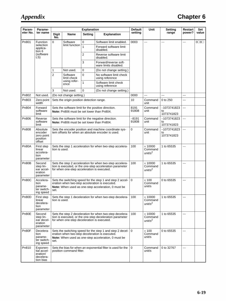
Chapter 6Appendix
Pn801 Function selection applica-tion 6 (software LS)
0 Software limit function
0 Software limit enabled. 0003 --- --- --- 0@0@1 Forward software limit
disabled.
2 Reverse software limit disabled.
3 Forward/reverse soft-ware limits disabled.
1 Not used. 0 (Do not change setting.)
2 Software limit check using refer-ence
0 No software limit check using reference
1 Software limit check using reference
3 Not used. 0 (Do not change setting.)
Pn802 Not used. (Do not change setting.) 0000 --- --- ---
Pn803 Zero point width
Sets the origin position detection range. 10 Command unit
0 to 250 ---
Pn804 Forward software limit
Sets the software limit for the positive direction.Note: Pn806 must be set lower than Pn804.
819191808
Command unit
−1073741823 to 1073741823
---
Pn806 Reverse software limit
Sets the software limit for the negative direction.Note: Pn806 must be set lower than Pn804.
−819191808
Command unit
−1073741823 to 1073741823
---
Pn808 Absolute encoder zero point position offset
Sets the encoder position and machine coordinate sys-tem offsets for when an absolute encoder is used.
0 Command unit
−1073741823 to 1073741823
---
Pn80A First step linear accelera-tion parameter
Sets the step 1 acceleration for when two-step accelera-tion is used.
100 × 10000Command unit/s2
1 to 65535 ---
Pn80B Second step lin-ear accel-eration parameter
Sets the step 2 acceleration for when two-step accelera-tion is executed, or the one-step acceleration parameter for when one-step acceleration is executed.
100 × 10000Command unit/s2
1 to 65535 ---
Pn80C Accelera-tion parame-ter switch-ing speed
Sets the switching speed for the step 1 and step 2 accel-eration when two-step acceleration is executed.Note: When used as one-step acceleration, 0 must be set.
0 × 100Command unit/s
0 to 65535 ---
Pn80D First step linear decelera-tion parameter
Sets the step 1 deceleration for when two-step decelera-tion is used.
100 × 10000Command unit/s2
1 to 65535 ---
Pn80E Second step lin-ear decel-eration parameter
Sets the step 2 deceleration for when two-step decelera-tion is executed, or the one-step deceleration parameter for when one-step deceleration is executed.
100 × 10000Command unit/s2
1 to 65535 ---
Pn80F Decelera-tion parame-ter switch-ing speed
Sets the switching speed for the step 1 and step 2 decel-eration when two-step deceleration is executed.Note: When used as one-step acceleration, 0 must be set.
0 × 100Command unit/s
0 to 65535 ---
Pn810 Exponen-tial accel-eration/decelera-tion bias
Sets the bias for when an exponential filter is used for the position command filter.
0 Command unit/s
0 to 32767 ---
Param-eter No.
Parame-ter name
Explanation Default setting
Unit Setting range
Restart power?
Set valueDigit
No.Name Setting Explanation
6-19

Chapter 6Appendix
Note 1. The normal setting is 0. If an external regeneration resistor is used, refer to 3-3-3 Regener-ative Energy Absorption by External Regeneration Resistance for the recommended setting.
Note 2. The upper limit is the maximum output capacity (W) of the Servo Driver.
Pn811 Exponen-tial accel-eration/decelera-tion time constant
Sets the time constant for when an exponential filter is used for the position command filter.
0 × 0.1 ms 0 to 5100 ---
Pn812 Moving average time
Sets the moving average time for when S-curve acceler-ation/deceleration is used, and an average movement fil-ter is used for the position command filter.
0 × 0.1 ms 0 to 5100 ---
Pn813 Not used. (Do not change setting.) 0 --- --- --- 0
Pn814 Final travel dis-tance for external position-ing
Sets the distance from the external signal input position when external positioning is executed.Note: For a negative direction or if the distance is short, operation is reversed after decelerating to a stop.
100 Command unit
−1073741823 to 1073741823
---
Pn816 Zero point return mode set-tings
0 Zero point return direc-tion
0 Forward direction 0000 --- --- --- 000@1 Reverse direction
1 Not used. 0 (Do not change setting.)
2 Not used. 0 (Do not change setting.)
3 Not used. 0 (Do not change setting.)
Pn817 Zero point return approach speed 1
Sets the origin search speed after the deceleration limit switch signal turns ON.
50 × 100Command unit/s
0 to 65535 ---
Pn818 Zero point return approach speed 2
Sets the origin search speed after the deceleration limit switch signal turns ON.
5 × 100Command unit/s
0 to 65535 ---
Pn819 Final travel dis-tance to return to zero point
Sets the distance from the latch signal input position to the origin, for when origin search is executed.Note: If the final travel distance is in the opposite direc-tion from the origin return direction or if the distance is short, operation is reversed after decelerating to a stop.
100 Command unit
−1073741823 to 1073741823
---
Pn81B Not used. (Do not change setting.) 0 --- --- --- 0
Pn81C Not used. (Do not change setting.) 0 --- --- --- 0
Pn81D Not used. (Do not change setting.) 0 --- --- --- 0
Pn81E Not used. (Do not change setting.) 0000 --- --- --- 0000
Pn81F Not used. (Do not change setting.) 0 --- --- --- 0
Pn820 Not used. (Do not change setting.) 0 --- --- --- 0
Pn822 Not used. (Do not change setting.) 0 --- --- --- 0
Pn824 Not used. (Do not change setting.) 0000 --- --- --- 0000
Pn825 Not used. (Do not change setting.) 0000 --- --- --- 0000
Pn900 to Pn910
Not used. (Do not change setting.) --- --- ---
Pn920 to Pn95F
Not used. (Do not change setting.) --- --- ---
Param-eter No.
Parame-ter name
Explanation Default setting
Unit Setting range
Restart power?
Set valueDigit
No.Name Setting Explanation
6-20

Chapter 6Appendix
6-3 Restrictions
This section describes the restrictions for the following functions of the Computer Monitor Software. Ifthese restrictions are violated, a COM2 alarm (A.E02) may occur.
1.Advanced auto-tuning
2.Online vibration monitor
3.Easy FFT
4.Tracing
Functions that cannot be used together with the above functions are listed in the following table. Usethe default settings for any functions that cannot be used together with the above functions.
OK: Can be used together, No: Cannot be used together, ---: Not used together.
Function Pn number
Advanced auto-tuning Online vibration monitor
Easy FFT TracingMode 0: With
inertiaMode 1: Without inertia
Commands via MECHATROLINK-II
--- --- OK --- OK
Jogging --- --- --- --- ---
Speed feed for-ward compensa-tion
Pn110.1 No OK No No No
Less-deviation control
Pn10B.2 --- --- No No No
Predictive control Pn150.0 --- --- OK OK OK
Automatic gain switching
Pn139.0 No OK No No OK
Backlash compen-sation
Pn207.2 No OK No No OK
Vibration detection Pn310.0 No OK No No OK
Notch filter 1 Pn408.0 OK OK OK OK OK
Notch filter 2 Pn408.2 No OK No No OK
Damping for vibra-tion suppression on stopping
Pn420Pn421
No OK No No OK
6-21

Chapter 6Appendix
6-22
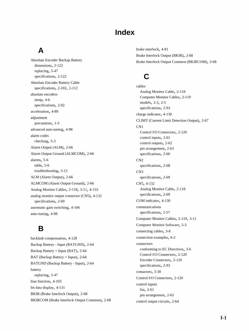
Index
AAbsolute Encoder Backup Battery
dimensions, 2-122
replacing, 5-47
specifications, 2-122
Absolute Encoder Battery Cable
specifications, 2-102, 2-112
absolute encoders
setup, 4-6
specifications, 2-92
acceleration, 4-89
adjustment
precautions, 1-3
advanced auto-tuning, 4-98
alarm codes
checking, 5-3
Alarm Output (ALM), 2-66
Alarm Output Ground (ALMCOM), 2-66
alarms, 5-6
table, 5-6
troubleshooting, 5-12
ALM (Alarm Output), 2-66
ALMCOM (Alarm Output Ground), 2-66
Analog Monitor Cables, 2-118, 3-11, 4-133
analog monitor output connector (CN5), 4-132
specifications, 2-69
automatic gain switching, 4-106
auto-tuning, 4-98
Bbacklash compensation, 4-128
Backup Battery - Input (BATGND), 2-64
Backup Battery + Input (BAT), 2-64
BAT (Backup Battery + Input), 2-64
BATGND (Backup Battery - Input), 2-64
battery
replacing, 5-47
bias function, 4-103
bit data display, 4-131
BKIR (Brake Interlock Output), 2-68
BKIRCOM (Brake Interlock Output Common), 2-68
brake interlock, 4-81
Brake Interlock Output (BKIR), 2-68
Brake Interlock Output Common (BKIRCOM), 2-68
Ccables
Analog Monitor Cable, 2-118
Computer Monitor Cables, 2-119
models, 2-3, 2-5
specifications, 2-93
charge indicator, 4-130
CLIMT (Current Limit Detection Output), 2-67
CN1
Control I/O Connectors, 2-120
control inputs, 2-61
control outputs, 2-62
pin arrangement, 2-63
specifications, 2-60
CN2
specifications, 2-68
CN3
specifications, 2-69
CN5, 4-132
Analog Monitor Cable, 2-118
specifications, 2-69
COM indicator, 4-130
communications
specifications, 2-57
Computer Monitor Cables, 2-119, 3-11
Computer Monitor Software, 5-3
connecting cables, 3-8
connection examples, 6-2
connectors
conforming to EC Directives, 3-6
Control I/O Connectors, 2-120
Encoder Connectors, 2-120
specifications, 2-93
contactors, 3-30
Control I/O Connectors, 2-120
control inputs
list, 2-61
pin arrangement, 2-63
control output circuits, 2-64
I-1

Index
control outputs
pin arrangement, 2-63
Current Limit Detection Output (CLIMT), 2-67
DDEC (Origin Return Deceleration Switch Signal), 2-65
deceleration, 4-89
dimensions
Absolute Encoder Backup Battery, 2-122
AC Servo Drivers, 2-18
AC Servomotors, 2-25
with Economy Gears, 2-46
with Standard Gears, 2-36
Reactors, 2-124
displays, 4-130
bit data, 4-131
status, 4-131
symbols, 4-131
drive prohibit, 4-78
dynamic brake, 4-25
EEC Directives
conforming connectors, 3-6
electronic gear, 4-87
electronic thermal characteristics, 5-43
EMC Directives
wiring conditions, 3-23
Encoder Cables, 2-3, 2-4, 3-10
noise resistance, 3-31
specifications, 2-101, 2-110
Encoder Connectors, 2-120
encoder dividing function, 4-79
encoder input
specifications, 2-68
encoders
specifications, 2-91, 2-92
error diagnosis
alarms, 5-12
warning indicators, 5-33
EXT1, EXT2, EXT3 (External Latch Signals 1, 2, 3), 2-66
External Latch Signals 1, 2, 3 (EXT1, EXT2, EXT3), 2-66
external regeneration resistance, 3-35
External Regeneration Resistor
specifications, 2-121
Ffeed-forward function, 4-104
Forward Drive Prohibit (POT), 2-65, 4-78
function selection parameters (from Pn000), 4-32
Ggain adjustment, 4-102
gain parameters (from Pn100), 4-38
Hharmonic currents
countermeasures, 3-22
II/O signals
specifications, 2-60
incremental encoders
specifications, 2-91
indicators, 4-130
INP1, INP2 (Positioning Completed Outputs 1, 2), 2-66
inspection
precautions, 5-45
installation
conditions, 3-3
precautions, 1-2, 3-2
Lless-deviation control, 4-120
Mmaintenance, 5-45
precautions, 1-4, 5-45
manual tuning, 4-100
MECHATROLINK-II Cable, 2-93
MECHATROLINK-II Cables, 2-93, 3-9
MECHATROLINK-II communications
cable specifications, 2-93
setup, 2-58
specifications, 2-57
MECHATROLINK-II Terminating Resistor, 2-93
I-2
Index
MECHATROLINK-II Terminating Resistors, 2-93, 3-9
models, 2-2
NNFB (no-fuse breakers), 3-20, 3-26
no-fuse breakers (NFB), 3-20, 3-26
noise filters, 3-28
noise resistance
Encoder Cables, 3-31
wiring, 3-19
nomenclature, 1-5
NOT (Reverse Drive Prohibit), 2-65
notch filter, 4-125
Oone-parameter tuning, 4-99
operation
precautions, 1-3
preparations, 4-4
procedure, 4-3
trial operation, 4-96
Origin Return Deceleration Switch Signal (DEC), 2-65
overload characteristics, 5-43
PP control switching, 4-112
parameter tables, 4-8, 6-3
function selection parameters (from Pn000), 4-8
other parameters (from Pn600), 4-22
position control parameters (from Pn200), 4-13
sequence parameters (from Pn500), 4-16
Servo gain parameters (from Pn100), 4-10
speed control parameters (from Pn300), 4-14
torque control parameters (from Pn400), 4-15
parameters
absolute encoder zero point position offset (Pn808), 4-69
acceleration/deceleration parameters (Pn80A to Pn812),4-70
details, 4-32
final travel distance for external positioning (Pn814), 4-71
forward software limit (Pn804), 4-69
function selection application switches 1
stop selection if an alarm occurs when Servomotor isOFF (Pn001.0), 4-25
stop selection when drive prohibited is input (Pn001.1),4-25
function selection application switches 2
operation switch when using an absolute encoder(Pn002.2), 4-34
speed command input change (Pn002.1), 4-34
torque command input change (Pn002.0), 4-34
function selection application switches 6
software limit function (Pn801.0), 4-68
function selection basic switches
reverse rotation (Pn000.0), 4-25
Unit No. setting (Pn000.2), 4-32
gain parameters
automatic gain changeover related switches 1 (Pn131 toPn139), 4-45
bias addition band (Pn108), 4-40
bias rotational speed (Pn107), 4-40
feed-forward amount (Pn109), 4-41
feed-forward command filter (Pn10A), 4-41
inertia ratio (Pn103), 4-39
less-deviation control parameters (Pn1A0 to Pn1AC),4-49
P control switching (acceleration command) (Pn10E),4-43
P control switching (deviation pulse) (Pn10F), 4-43
P control switching (speed command) (Pn10D), 4-42
P control switching (torque command) (Pn10C), 4-42
P control switching conditions (Pn10B.0), 4-41
position loop control method (Pn10B.2), 4-42
position loop gain (Pn102), 4-39
position loop gain 2 (Pn106), 4-40
predictive control selection switches (Pn150 to Pn152),4-47
speed control loop switching (Pn10B.1), 4-42
speed feedback compensating gain (Pn111), 4-44
speed feedback compensation function selection(Pn110.1), 4-43
speed loop gain (Pn100), 4-38
speed loop gain 2 (Pn104), 4-39
speed loop integration constant (Pn101), 4-38
speed loop integration constant 2 (Pn105), 4-39
I/O signal allocation (Pn50A, Pn50B, Pn50E to Pn512),4-26
important parameters, 4-24
input signal selections (Pn50A, Pn50B, Pn511), 4-27
input signal selections 1
POT (forward drive prohibited) signal (Pn50A.3), 4-27
input signal selections 2
NOT (reverse drive prohibited) signal (Pn50B.0), 4-28
input signal selections 5
DEC (origin return deceleration LS) signal (Pn511.0),4-29
I-3
Index
EXT1 (external latch signal 1) signal (Pn511.1), 4-29
EXT2 (external latch signal 2) signal (Pn511.2), 4-29
EXT3 (external latch signal 3) signal (Pn511.3), 4-29
origin search parameters (Pn816 to Pn819), 4-71
output signal reverse
pins CN1-1 and 2 (Pn512.0), 4-31
pins CN1-23 and 24 (Pn512.1), 4-31
pins CN1-25 and 26 (Pn512.2), 4-31
output signal selections 1
INP1 (positioning completed 1) signal (Pn50E.0), 4-30
READY (Servo ready) signal (Pn50E.3), 4-30
TGON (Servomotor rotation direction) signal(Pn50E.2), 4-30
VCMP (speed conformity) signal (Pn50E.1), 4-30
output signal selections 2
BKIR (brake interlock) signal (Pn50F.2), 4-31
CLIMT (current limit detection) signal (Pn50F.0), 4-30
VLIMT (speed limit detection) signal (Pn50F.1), 4-30
WARN (warning) signal (Pn50F.3), 4-31
output signal selections 3
INP2 (positioning completed 2) signal (Pn510.0), 4-31
position control parameters
absolute encoder multi-turn limit setting (Pn205), 4-51
backlash compensation amount (Pn214), 4-53
backlash compensation selection (Pn207.2), 4-52
backlash compensation time constant (Pn215), 4-53
electronic gear ratio G1, G2 (Pn20E, Pn210), 4-52
encoder divider rate (Pn212), 4-53
soft start deceleration time (Pn306), 4-54
regeneration resistor capacity (Pn600), 4-66
reverse software limit (Pn806), 4-69
sequence parameters
brake command speed (Pn507), 4-61
brake timing 1 (Pn506), 4-61
brake timing 2 (Pn508), 4-61
deviation counter overflow warning level (Pn51E), 4-63
momentary hold time (Pn509), 4-62
positioning completed range 1 (Pn522), 4-64
positioning completed range 2 (Pn524), 4-64
program jog settings (Pn530 to Pn536), 4-65
rotation speed for motor rotation detection (Pn502), 4-61
speed conformity signal output width (Pn503), 4-61
speed control parameters
soft start acceleration time (Pn305), 4-54
speed feedback filter time constant (Pn308), 4-55
torque control parameters
emergency stop torque (Pn406), 4-58
forward rotation external current limit (Pn404), 4-57
forward torque limit (Pn402), 4-57
notch filter 1 frequency (Pn409), 4-59
notch filter 1 Q value (Pn40A), 4-59
notch filter 2 frequency (Pn40C), 4-59
notch filter 2 Q value (Pn40D), 4-59
reverse rotation external current limit (Pn405), 4-57
reverse torque limit (Pn403), 4-57
select notch filter 1 function (Pn408.0), 4-58
select notch filter 2 function (Pn408.2), 4-58
speed limit (Pn407), 4-58
zero point width (Pn803), 4-69
zero-point return parameters (Pn816 to Pn819), 4-71
peripheral devices
connection examples, 3-12
personal computer monitor connector
specifications, 2-69
pin arrangement
CN1, 2-63
position control, 4-75
position control parameters (from Pn200), 4-50
position integration, 4-129
Positioning Completed Outputs 1, 2 (INP1, INP2), 2-66
POT (Forward Drive Prohibit), 2-65
Power Cables, 2-3, 2-5, 3-6, 3-9
specifications, 2-103, 2-112
power indicator, 4-130
precautions, 5-3
adjustment, 1-3
general, 1-1
inspection, 1-4
installation, 1-2, 3-2
maintenance, 1-4
maintenance and inspection, 5-45
operation, 1-3, 4-2
storage, 1-2
transportation, 1-2
wiring, 1-2, 3-2
predictive control, 4-115
program JOG operation, 4-91
QQ value (notch filter), 4-59, 4-125
RReactors, 2-2, 3-15, 3-22
dimensions, 2-124
specifications, 2-124
READY (Servo Ready Output), 2-67
I-4
Index
regenerative energy, 3-32
absorption capacity, 3-34
external regeneration resistance, 3-35
replacing
Absolute Encoder Backup Battery (ABS), 5-47
Servomotor and Servo Driver, 5-4
Reverse Drive Prohibit (NOT), 2-65, 4-78
Ssequence parameters (from Pn500), 4-61
Servo Drivers
combinations with Servomotors, 2-16
dimensions, 2-18
installation conditions, 3-3
regenerative energy absorption capacity, 3-34
replacing, 5-4
specifications, 2-50
general, 2-50
performance, 2-51
transmission times, 2-58
Servo Ready Output (READY), 2-67
Servomotor Rotation Detection Output (TGON), 2-67
Servomotors
combinations with Servo Drivers, 2-16
dimensions, 2-25
installation conditions, 3-4
replacing, 5-4
specifications, 2-71
general, 2-71
performance, 2-73, 2-77, 2-80, 2-83
with Economy Gears, 2-15
combinations, 2-10
dimensions, 2-46
with Reduction Gears
specifications, 2-86
with Standard Gears, 2-12
combinations, 2-9
dimensions, 2-36
soft start, 4-86
specifications
Absolute Encoder Backup Battery, 2-122
Absolute Encoder Battery Cable, 2-102
absolute encoders, 2-92
cables, 2-93
CN1 (I/O signals), 2-60
CN2 (encoder input), 2-68
CN3 (personal computer monitor connector), 2-69
CN5 (analog monitor output connector), 2-69
communications, 2-57
connectors, 2-93
DC Reactor, 2-124
Encoder Cables, 2-101, 2-110
External Regeneration Resistor, 2-121
incremental encoders, 2-91
MECHATROLINK-II Cables, 2-93
MECHATROLINK-II communications, 2-57
Power Cables, 2-103, 2-112
Servo Drivers, 2-50
Servomotors, 2-71, 2-73
Servomotors with Reduction Gears, 2-86
terminal blocks, 2-56
Speed Conformity Output (VCMP), 2-67
speed control, 4-76
speed control parameters (from Pn300), 4-54
speed feedback compensation, 4-43, 4-109
speed feedback filter, 4-111
speed limit, 4-88
Speed Limit Detection Output (VLIMT), 2-68
standards, 1-6
startup, 4-4
status display mode, 4-131
surge absorbers, 3-27
surge killers, 3-29
symbol display, 4-131
system block diagrams, 1-7
system configuration, 1-4, 3-8
Tterminal blocks
names and functions, 3-15
specifications, 2-56
wire sizes, 3-16
wiring, 3-15
TGON (Servomotor Rotation Detection Output), 2-67
torque command filter, 4-123
torque control, 4-77
torque control parameters (from Pn400), 4-56
torque feed-forward function, 4-105
torque limit function, 4-83
transmission times, 2-58
trial operation procedure, 4-96
troubleshooting, 5-2
using alarm display, 5-12
using operating status, 5-37
I-5

Index
using warning indicators, 5-33
tuning, 4-98
VVCMP (Speed Conformity Output), 2-67
vibration suppression when stopping, 4-127
VLIMT (Speed Limit Detection Output), 2-68
WWARN (Warning Output), 2-68
warning labels, 1-5
Warning Output (WARN), 2-68
warnings
table, 5-10
troubleshooting, 5-33
wiring
conforming to EMC Directives, 3-23
for noise resistance, 3-19
precautions, 1-2, 3-2
terminal blocks, 3-15
I-6

Revision History
A manual revision code appears as a suffix to the catalog number on the front cover of the manual.
The following table outlines the changes made to the manual during each revision. Page numbersrefer to the previous version.
Revision code
Date Revised content
01 November 2004 Original production
02 November 2006 Page 2-34: Graphics replaced, diagram numbers added, and dimensions D1, D4, D5, D6, E2, and F changed/added.Pages 2-38 and 2-39: Graphics replaced/added, diagram numbers added, and dimensions LM, D1, D4, D6, E2, and F changed/added.Page 2-44: Dimensions LM changed from 110 to 97.5 for 750 W model.Pages 2-45, 2-62, 3-11, and 3-12: Graphics corrected.Pages 2-84 and 2-85: Specifications changed from 50 W through 750 W models.Page 2-86: Specifications changed in top table.Pages 2-88 and 2-89: Weights and reduction gear inertia changed for 750 W models.Page 4-10: Settings changed for Pn110.Page 4-38: Last paragraph deleted from Pn103.Pages 4-38 and 4-38: Description of Pn106 changed.Pages 4-41, 4-43, 4-44, 4-55, 4-56, 4-109, and 4-111: Notes deleted.Pages 4-42 and 4-43: Material deleted.Page 4-46: Paragraph below graphic changed.Pages 4-81 and 4-82: “Power supply” changed to “main circuit power supply” in timing charts.Page 4-90: Last paragraph removed.Page 4-97: Section 4-6-1 changed.Page 4-98: Second paragraph removed.Page 4-110: Item 1 at top of page changed.Page 4-118: Parameter numbers removed at top of flowchart.Page 4-121: Flowchart changed.Page 4-122: Lists changed.Page 5-22: Part of description of A.S21 deleted.Page 5-30: Part of description of A.d01 deleted.Page 5-31: Countermeasure for A.d02 deleted, material added for A.E00, and countermea-sure for A.Ed0 deleted.Page 5-39: “When auto-tuning is used” and “when auto-tuning is not used” deleted in two places each.Page 6-6: Description of Pn110 changed.
Cat. No. I544-E1-06
Revision code
R-1
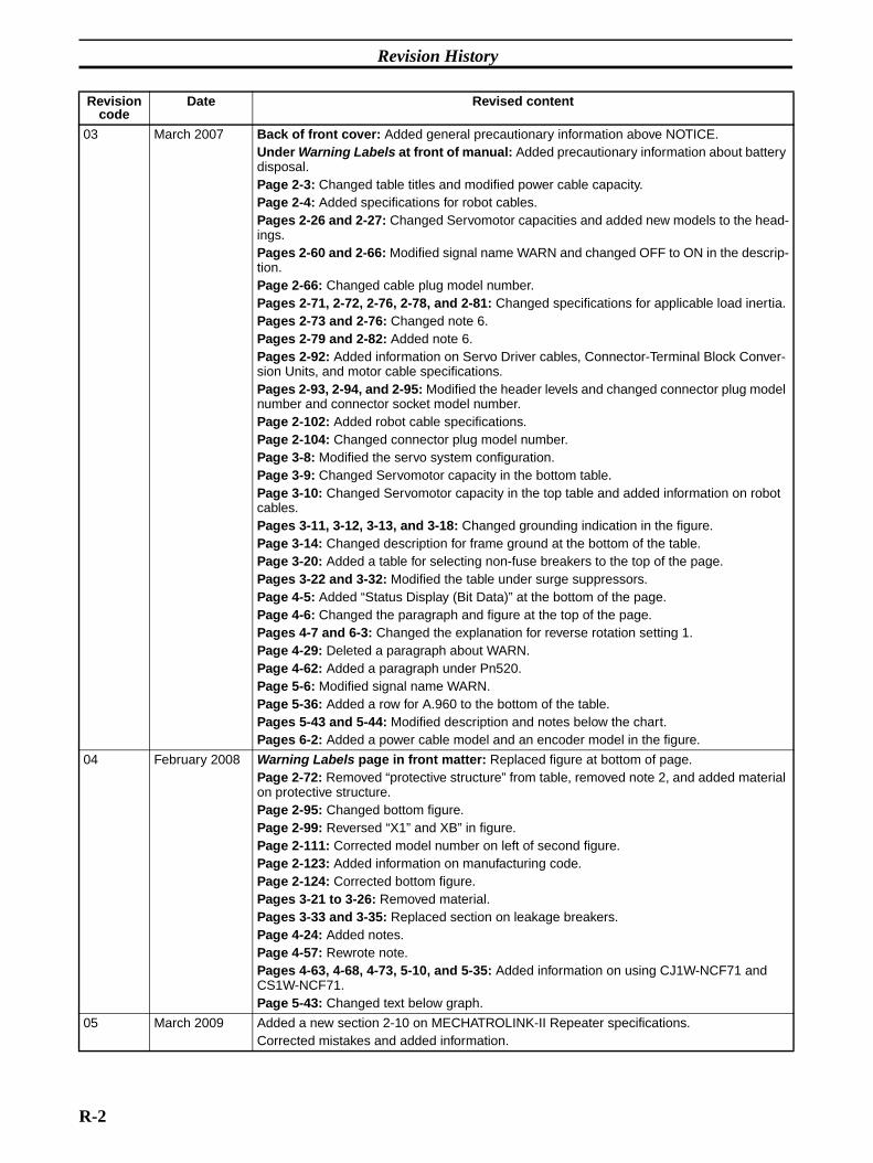
Revision History
03 March 2007 Back of front cover: Added general precautionary information above NOTICE.Under Warning Labels at front of manual: Added precautionary information about battery disposal.Page 2-3: Changed table titles and modified power cable capacity.Page 2-4: Added specifications for robot cables.Pages 2-26 and 2-27: Changed Servomotor capacities and added new models to the head-ings.Pages 2-60 and 2-66: Modified signal name WARN and changed OFF to ON in the descrip-tion.Page 2-66: Changed cable plug model number.Pages 2-71, 2-72, 2-76, 2-78, and 2-81: Changed specifications for applicable load inertia.Pages 2-73 and 2-76: Changed note 6.Pages 2-79 and 2-82: Added note 6.Pages 2-92: Added information on Servo Driver cables, Connector-Terminal Block Conver-sion Units, and motor cable specifications.Pages 2-93, 2-94, and 2-95: Modified the header levels and changed connector plug model number and connector socket model number.Page 2-102: Added robot cable specifications.Page 2-104: Changed connector plug model number.Page 3-8: Modified the servo system configuration.Page 3-9: Changed Servomotor capacity in the bottom table.Page 3-10: Changed Servomotor capacity in the top table and added information on robot cables.Pages 3-11, 3-12, 3-13, and 3-18: Changed grounding indication in the figure.Page 3-14: Changed description for frame ground at the bottom of the table.Page 3-20: Added a table for selecting non-fuse breakers to the top of the page.Pages 3-22 and 3-32: Modified the table under surge suppressors.Page 4-5: Added “Status Display (Bit Data)” at the bottom of the page.Page 4-6: Changed the paragraph and figure at the top of the page.Pages 4-7 and 6-3: Changed the explanation for reverse rotation setting 1.Page 4-29: Deleted a paragraph about WARN.Page 4-62: Added a paragraph under Pn520.Page 5-6: Modified signal name WARN.Page 5-36: Added a row for A.960 to the bottom of the table.Pages 5-43 and 5-44: Modified description and notes below the chart.Pages 6-2: Added a power cable model and an encoder model in the figure.
04 February 2008 Warning Labels page in front matter: Replaced figure at bottom of page. Page 2-72: Removed “protective structure” from table, removed note 2, and added material on protective structure. Page 2-95: Changed bottom figure. Page 2-99: Reversed “X1” and XB” in figure. Page 2-111: Corrected model number on left of second figure. Page 2-123: Added information on manufacturing code. Page 2-124: Corrected bottom figure. Pages 3-21 to 3-26: Removed material. Pages 3-33 and 3-35: Replaced section on leakage breakers. Page 4-24: Added notes. Page 4-57: Rewrote note. Pages 4-63, 4-68, 4-73, 5-10, and 5-35: Added information on using CJ1W-NCF71 and CS1W-NCF71. Page 5-43: Changed text below graph.
05 March 2009 Added a new section 2-10 on MECHATROLINK-II Repeater specifications. Corrected mistakes and added information.
Revision code
Date Revised content
R-2

Revision History
06 December 2010 Page 2-62: Description added to the contents for TGONCOM.Page 2-67: Description added below the note for Motor Rotation Detection Output.Page 3-37: Information on Pn600 settings added below the note.Page 4-24: Note 1 modified.Pages 5-38 and 5-41: Wiring distance changed from 20 m to 50 m in the items to check col-umn.Page 6-20: Notes added below the table.
Revision code
Date Revised content
R-3

Revision History
R-4


Authorized Distributor:
In the interest of product improvement, specifications are subject to change without notice.
Cat. No. I544-E1-06Printed in Japan
1210
© OMRON Corporation 2004 All Rights Reserved.
OMRON Corporation Industrial Automation Company
OMRON ELECTRONICS LLCOne Commerce Drive Schaumburg,IL 60173-5302 U.S.A.Tel: (1) 847-843-7900/Fax: (1) 847-843-7787
Regional HeadquartersOMRON EUROPE B.V.Wegalaan 67-69-2132 JD HoofddorpThe NetherlandsTel: (31)2356-81-300/Fax: (31)2356-81-388
Contact: www.ia.omron.comTokyo, JAPAN
OMRON ASIA PACIFIC PTE. LTD.No. 438A Alexandra Road # 05-05/08 (Lobby 2), Alexandra Technopark, Singapore 119967Tel: (65) 6835-3011/Fax: (65) 6835-2711
OMRON (CHINA) CO., LTD.Room 2211, Bank of China Tower, 200 Yin Cheng Zhong Road, PuDong New Area, Shanghai, 200120, ChinaTel: (86) 21-5037-2222/Fax: (86) 21-5037-2200
Related Documents