Omnidirectional Locomotion for Quadruped Robots Bernhard Hengst, Darren Ibbotson, Son Bao Pham, Claude Sammut School of Computer Science and Engineering University of New South Wales, UNSW Sydney 2052 AUSTRALIA {bernhardh,s2207509,sonp,claude}@cse.unsw.edu.au Abstract. Competing at the RoboCup 2000 Sony legged robot league, the UNSW team won both the challenge competition and all their soccer matches, emerging the outright winners for this league against eleven other international teams. The main advantage that the UNSW team had was speed. A major contributor to the speed was a novel omnidirectional locomotion method developed for the quadruped Sony ERS-110 robot used in the competition. It is believed to be the fastest walk style known for this type of robot. In this paper we describe the parameterised omnidirectional walk in detail. The walk also made a positive contribution to other robot tasks such as ball tracking and localisation while playing soccer. The authors believe that this omnidirectional locomotion could be applied more generally in other quadruped robots. 1 Introduction In RoboCup 1999 our own robots, as well as those of our competitors, moved slowly and gingerly, often falling over, even when unprovoked. From our observations in that competition, we concluded that locomotion was a fruitful area for research. In 1999, the UNSW team, Dalgliesh and Lawther [2], used what they called “atomic actions” to control the robot’s movements. The atomic actions were simple macro actions to perform specific effector sub-tasks such as turning, walking forward or walking sideways. These atomic actions needed to be activated sequentially and could not be interrupted once initiated. Consequently robots would often continue to the completion an atomic action, long after it was appropriate, in the circumstances. The transition between atomic actions was problematic in that robots could lose their balance and fall over because the legs positions were mismatched at the point of transition. While a fall and the struggle to get up are entertaining for the audience, they lose valuable time during a soccer match. For RoboCup 2000 we decided to address these shortcomings by redesigning the locomotion for the Sony ERS-110 entertainment robot. The rest of this paper will describe the approach and implementation of an omnidirectional walk style that characterised the University of New South Wales entry in the competition. The omnidirectional walk gave the UNSW team a decisive advantage over the other teams. It is also a good illustration of the advantage a simplifying representation gives in making a difficult task more easily achievable.

Welcome message from author
This document is posted to help you gain knowledge. Please leave a comment to let me know what you think about it! Share it to your friends and learn new things together.
Transcript
Omnidirectional Locomotion for Quadruped Robots
Bernhard Hengst, Darren Ibbotson, Son Bao Pham, Claude Sammut
School of Computer Science and EngineeringUniversity of New South Wales, UNSW Sydney 2052 AUSTRALIA
{bernhardh,s2207509,sonp,claude}@cse.unsw.edu.au
Abstract. Competing at the RoboCup 2000 Sony legged robot league, theUNSW team won both the challenge competition and all their soccer matches,emerging the outright winners for this league against eleven other internationalteams. The main advantage that the UNSW team had was speed. A majorcontributor to the speed was a novel omnidirectional locomotion methoddeveloped for the quadruped Sony ERS-110 robot used in the competition. It isbelieved to be the fastest walk style known for this type of robot. In this paperwe describe the parameterised omnidirectional walk in detail. The walk alsomade a positive contribution to other robot tasks such as ball tracking andlocalisation while playing soccer. The authors believe that this omnidirectionallocomotion could be applied more generally in other quadruped robots.
1 Introduction
In RoboCup 1999 our own robots, as well as those of our competitors, moved slowlyand gingerly, often falling over, even when unprovoked. From our observations inthat competition, we concluded that locomotion was a fruitful area for research.
In 1999, the UNSW team, Dalgliesh and Lawther [2], used what they called“atomic actions” to control the robot’s movements. The atomic actions were simplemacro actions to perform specific effector sub-tasks such as turning, walking forwardor walking sideways. These atomic actions needed to be activated sequentially andcould not be interrupted once initiated. Consequently robots would often continue tothe completion an atomic action, long after it was appropriate, in the circumstances.The transition between atomic actions was problematic in that robots could lose theirbalance and fall over because the legs positions were mismatched at the point oftransition. While a fall and the struggle to get up are entertaining for the audience,they lose valuable time during a soccer match.
For RoboCup 2000 we decided to address these shortcomings by redesigning thelocomotion for the Sony ERS-110 entertainment robot. The rest of this paper willdescribe the approach and implementation of an omnidirectional walk style thatcharacterised the University of New South Wales entry in the competition. Theomnidirectional walk gave the UNSW team a decisive advantage over the otherteams. It is also a good illustration of the advantage a simplifying representation givesin making a difficult task more easily achievable.
2 Design Objectives
Our three primary design objectives were to:
1. Drive the robot as if controlled by a joystick with three degrees of freedom. Wewanted to be able to move forward or backward, sideways left or right and to turnon the spot clockwise or counterclockwise. This requirement suggested itselfbecause of the shortcomings described above. Ideally we would like to be able toinfinitely vary the speed of movement for any of the three degrees of freedomrapidly and simultaneously to allow the robots to react quickly to environmentalchanges.
2. Move the robot over the ground at a constant speed. This should reduce the strainon the robot motors by not accelerating and decelerating the body. It should alsoallow a faster walking pace to be achieved after the robot has gained momentum.
3. Keep the camera as steady as possible. The camera is located in the nose of therobot. We observed that, using previous walks, images from the robot's camerashowed wildly erratic movements due to the robots head and leg motions. Wepostulated that a steadier stream of images would assist in object tracking. Whenapproaching a ball, for example, it is desirable not lose sight of it.
3 The Representation
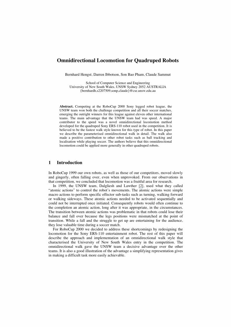
We chose to describe the leg action of the robots by a rectangular paw motion. Thebottom edge of the rectangle describes that part of the path during which the paws
Robot Leg
paw
Time T
Time T
Ground
Leg lift height
home
home
Fig. 1. Rectangular Locus of Each Robot Paw
make contact with the ground. The sides and top of the locus describe the path used tolift the paw back ready for it to take the next step. The legs that are touching theground exert the forces that move the robot. In the trot gait diagonally opposite legstouch the ground alternately. If the paws that touch the ground move at a constantvelocity, the robot should move at that same constant velocity. This requires that thetime taken to move the paw along the bottom edge of the rectangle is equivalent to thetotal time taken to move the paw along the other three edges as shown in figure 1.Another way to think of the locus action is to see that its effect is similar to a wheelturning.
Design objectives 2 and 3 were achieved in this way. The speed over the ground isconstant as long as the size of the rectangular locus does not change and its traversalis at a constant frequency. The robot’s camera is steadied because the bottom edge ofthe rectangular locus is a straight line lying in the ground plane. When the robotlooses balance in the trot walk there is camera movement until it is arrested by fallingon one of the legs that is off the ground. This movement can be minimised by liftingthe legs as little as possible during the walk. Unfortunately in practice it wasnecessary to specify a significant leg lift height to ensure that the spring-loaded clawswould clear the carpet. This introduced some unwanted camera movement.
4 Omnidirectional Control
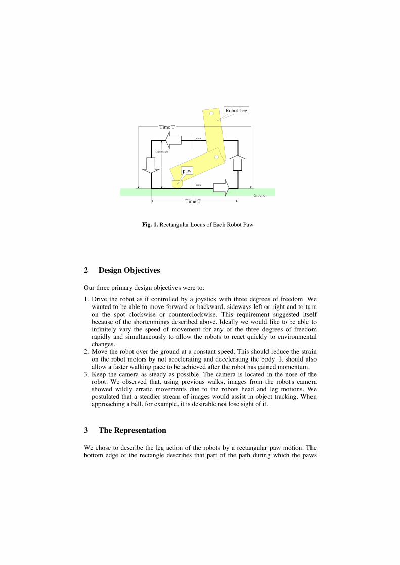
We will now address design objective 1, that is, how to control which way the robotmoves. The plane containing the rectangular locus for the paw is alwaysperpendicular to the ground. By changing the inclination of this plane relative to thesides of the robot we can determine whether the robot moves forward/backwards orsideways. For example if the locus plane is parallel to the robot sides, the robot willmove forwards or backwards. Whether the robot moves forward or backward isdetermined by the direction in which the paw moves around the locus. It helps toimagine that the paw moving around the locus acts similarly to a rotating wheel. If welook at the robot side on and it is facing left, then if the paws move in a anti-clockwisedirection around the rectangular locus the robot will move forward. If the paws aremade to move clockwise the robot will walk backwards.
Fig. 2. Locomotion forward, sideways, and turning by moving the paws of the legs in arectangular locus
If we incline the locus plane perpendicular to the sides of the robot it will moveeither left or right in a similar fashion to the way it moves forward/backward. Aninclination of the locus plan at another angle will cause the robot to move both
forward or backward and left or right calculated by adding the vectors of bothcomponents.
So far we have assumed that all the locus planes are kept parallel to each other andall the paws move either clockwise or counterclockwise. Before we move on toexplain how the robot is made to turn, we should also note that the width of therectangular locus and the speed at which it is traversed by the paw determines thespeed at which the robot moves. There are limitations to these parameters and we willsee later how they were tuned to achieve a locally optimal performance.
How can the robot be made to turn? Using the analogy of each rectangular locus asa wheel we can imagine that if we were able to turn each locus plane around a verticalaxis we would have the freedom of movement of a supermarket trolley with each ofits wheels motorised. This large degree of freedom may introduce conflicts where oneleg can work against another. If we take a plan view of the robot and describe a circlethat passes through each of the upper leg joints, then by inclining the locus planestangentially at each joint we can coordinate them to turn the robot clockwise or anti-clockwise. This constraint gives us the third property of our omnidirectionallocomotion, that is, being able to turn on the spot. Fig. 2 illustrates the threecomponents of the omnidirectional locomotion.
Again, it is possible to combine components of each of the three movementdimensions (forward/backward, sideways and turning) creating complex waltz likemovements in which the robot moves forward, sideways and turns simultaneously.
5 Gait Selection
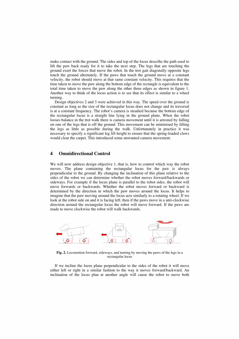
Hornby, et al in [4] describe three of the most common gaits used by quadrupedrobots, the crawl, trot and pace gaits as show in Fig.3.
The crawl gait operates by moving each leg in turn lifting one at a time. This gait isstatic in the sense that it keeps the centre of gravity inside the triangle described bythe three legs that touch the ground. The trot gait lifts the two diagonally opposite legsalternately. The robot balances along the diagonal joining the two feet that are on theground. In practice the robot is steadied by either of the other two legs not supportingthe robot's weight. That is, the robot falls onto a third leg. The pace gait lifts both legs
Quadruped Gaits
Crawl Trot Pace
right front
left front
right rear
left rear
Fig. 3. Gait Styles for Quadruped Robots
on the same side of the body simultaneously, alternating between the sides. This is theleast stable gait as it is easy for the robot to lose balance and fall over sideways.
We experimented with all three gaits. From the results of early prototype walks, werejected the pace gait because the robot would not walk forward reliably. It wasdifficult to synchronise the shifting of weight from side to side with the legmovements and it easily became unstable. The crawl gait was stable but slow incomparison with the trot gait. We therefore decided on the trot gait for thecompetition.
6 Trot Gait Parameterisation
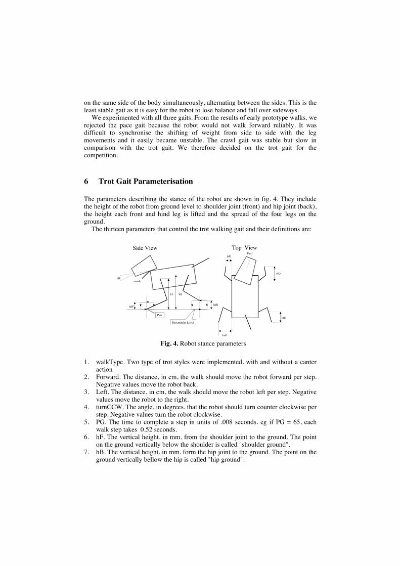
The parameters describing the stance of the robot are shown in fig. 4. They includethe height of the robot from ground level to shoulder joint (front) and hip joint (back),the height each front and hind leg is lifted and the spread of the four legs on theground.
The thirteen parameters that control the trot walking gait and their definitions are:
1. walkType. Two type of trot styles were implemented, with and without a canteraction
2. Forward. The distance, in cm, the walk should move the robot forward per step.Negative values move the robot back.
3. Left. The distance, in cm, the walk should move the robot left per step. Negativevalues move the robot to the right.
4. turnCCW. The angle, in degrees, that the robot should turn counter clockwise perstep. Negative values turn the robot clockwise.
5. PG. The time to complete a step in units of .008 seconds. eg if PG = 65, eachwalk step takes 0.52 seconds.
6. hF. The vertical height, in mm, from the shoulder joint to the ground. The pointon the ground vertically below the shoulder is called "shoulder ground".
7. hB. The vertical height, in mm, form the hip joint to the ground. The point on theground vertically bellow the hip is called "hip ground".
hBhF
tilt
Side View Top ViewfsO
ffO
bsO
bfO
hdF hdB
Pan
mouth
Paw
Rectangular Locus
Fig. 4. Robot stance parameters
8. hdF. The height, in mm, that the robot lifts the front legs while walking.9. hbF. The height, in mm, that the robot lifts the back legs while walking.10. ffO. The home position of the front paws, in mm, forward from shoulder ground.11. fsO. The home position of the front paws, in mm, spread left and right from
shoulder ground.12. bfO. The home position of the back paws, in mm, forward from hip ground.13. bsO. The home position of the back paws, in mm, spread left and right from hip
ground.
7 Inverse Kinematics
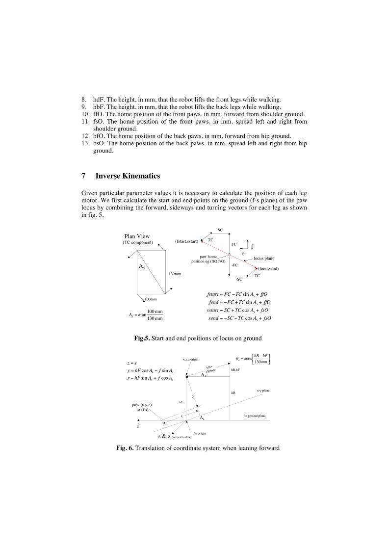
Given particular parameter values it is necessary to calculate the position of each legmotor. We first calculate the start and end points on the ground (f-s plane) of the pawlocus by combining the forward, sideways and turning vectors for each leg as shownin fig. 5.
130mm
100mm
Plan View (TC component)
A5
paw homeposition eg (ffO,fsO)
FC
-FC
SC
-SC-TC
TC
fs
fsOATCSCsendfsOATCSCsstart
ffOATCFCfendffOATCFCfstart
+=
++=
++=
+=
5
5
5
5
coscos
sinsin
mm130mm100atan5 =A
(fstart,sstart)
(fend,send)
locus plane
Fig.5. Start and end positions of locus on ground
paw (x,y,z) or (f,s)
lsh=
130mm
hF
hBx-y plane
f-s ground plane
hB-hFA4
A4
=mmhFhB
130acos4
f-s origin
x,y,z origin
f
s & z (vertical to slide)
y
x
44
44
cossinsincos
AfAhFxAfAhFy
sz
+=
=
=
Fig. 6. Translation of coordinate system when leaning forward
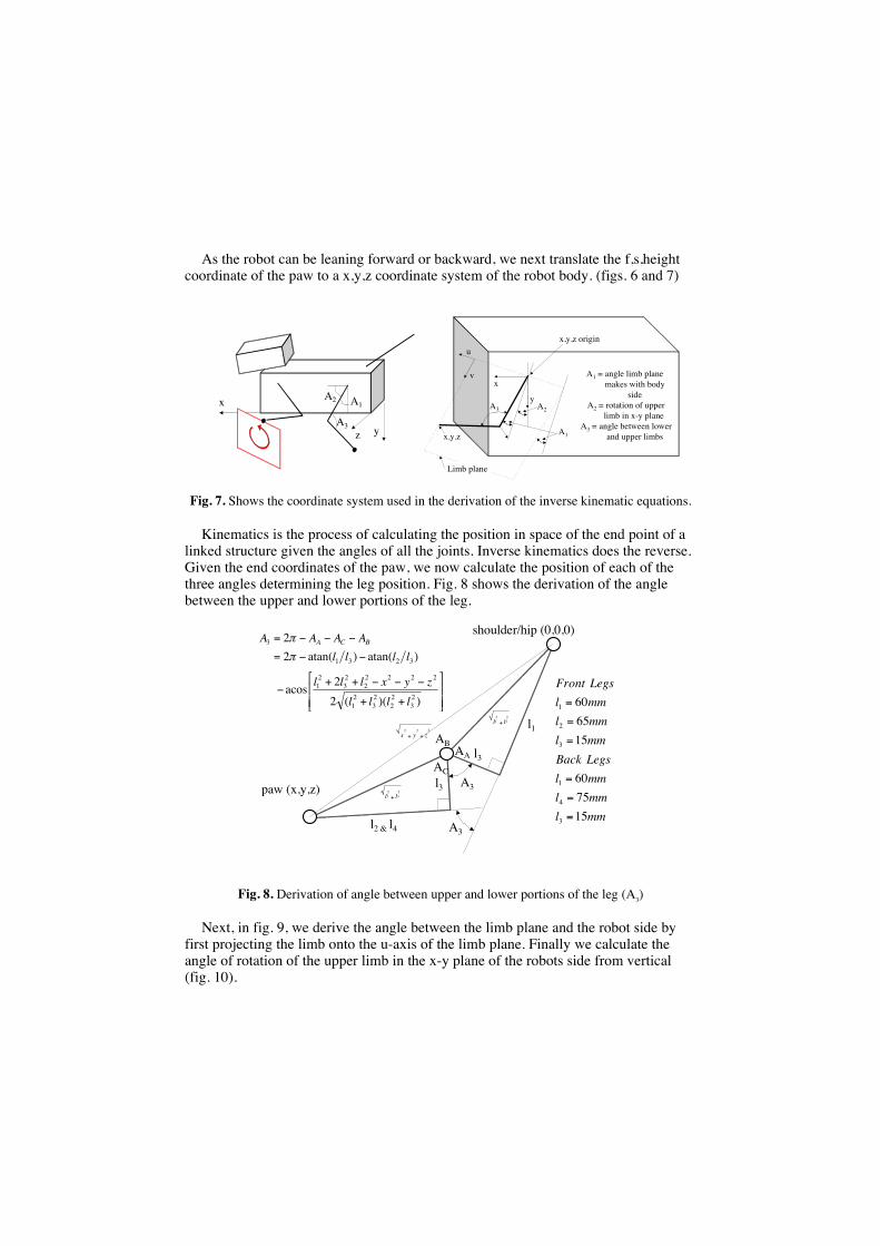
As the robot can be leaning forward or backward, we next translate the f,s,heightcoordinate of the paw to a x,y,z coordinate system of the robot body. (figs. 6 and 7)
x
yzA3
A1A2
x
yA3
A1
A2
x,y,z origin
A1 = angle limb plane makes with body
sideA2 = rotation of upper limb in x-y plane
A3 = angle between lower and upper limbs
u
v
Limb plane
x,y,z
Fig. 7. Shows the coordinate system used in the derivation of the inverse kinematic equations.
Kinematics is the process of calculating the position in space of the end point of alinked structure given the angles of all the joints. Inverse kinematics does the reverse.Given the end coordinates of the paw, we now calculate the position of each of thethree angles determining the leg position. Fig. 8 shows the derivation of the anglebetween the upper and lower portions of the leg.
A3
A3l2 & l4
l1
l3
l3
shoulder/hip (0,0,0)
paw (x,y,z)
AA
AB
AC
23
21 ll +
23
22 ll +
222zyx ++
++
++
=
=
))((22acos
)atan()atan(22
23
22
23
21
22222
23
21
3231
3
llllzyxlll
llllAAAA BCA
mmlmmlmmlLegsBackmmlmmlmmlLegsFront
157560
156560
3
4
1
3
2
1
=
=
=
=
=
=
Fig. 8. Derivation of angle between upper and lower portions of the leg (A3)
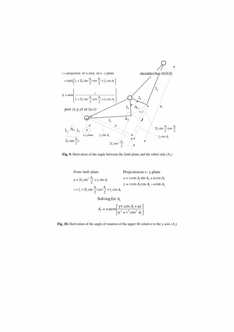
Next, in fig. 9, we derive the angle between the limb plane and the robot side byfirst projecting the limb onto the u-axis of the limb plane. Finally we calculate theangle of rotation of the upper limb in the x-y plane of the robots side from vertical(fig. 10).
A3
l2
l1
l3
l3
shoulder/hip (0,0,0)
paw (x,y,z) or (u,v)
z
z
l3 l3A3
)2
sin(2 33
Al
2cos
2sin2 33
3AAl
32 cos Al
A3
++=
=
3233
311
1
cos2
cos2
sin2sin
planey -on x u.sin of projection
AlAAllA
Az
++=
3233
31
1
cos2
cos2
sin2asin
AlAAll
zA
2sin2 32
3Al
32 sin Al
u
v
A3/2
x-y plane
Fig. 9. Derivation of the angle between the limb plane and the robot side (A1)
3233
31
3232
3
cos2
cos2
sin2
sin2
sin2
plane limb From
AlAAllv
AlAlu
++=
+=
221
221
sincoscoscossincos
planey -on x Projection
AuAAvyAuAAvx
=
+=
+
+±=
1222
12
2
coscos.yvacos
for Solving
AvuuxAA
A
Fig. 10. Derivation of the angle of rotation of the upper lib relative to the y-axis (A2)
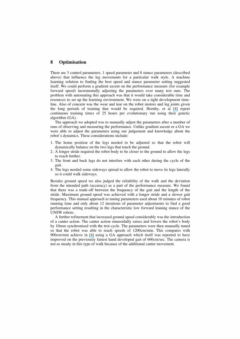
8 Optimisation
There are 3 control parameters, 1 speed parameter and 8 stance parameters (describedabove) that influence the leg movements for a particular walk style. A machinelearning solution to finding the best speed and stance parameter setting suggesteditself. We could perform a gradient ascent on the performance measure (for exampleforward speed) incrementally adjusting the parameters over many test runs. Theproblem with automating this approach was that it would take considerable time andresources to set up the learning environment. We were on a tight development time-line. Also of concern was the wear and tear on the robot motors and leg joints giventhe long periods of training that would be required. Hornby, et al [4] reportcontinuous training times of 25 hours per evolutionary run using their geneticalgorithm (GA).
The approach we adopted was to manually adjust the parameters after a number ofruns of observing and measuring the performance. Unlike gradient ascent or a GA wewere able to adjust the parameters using our judgement and knowledge about therobot’s dynamics. These considerations include:
1. The home position of the legs needed to be adjusted so that the robot willdynamically balance on the two legs that touch the ground.
2. A longer stride required the robot body to be closer to the ground to allow the legsto reach further.
3. The front and back legs do not interfere with each other during the cycle of thegait.
4. The legs needed some sideways spread to allow the robot to move its legs laterallyso it could walk sideways.
Besides ground speed we also judged the reliability of the walk and the deviationfrom the intended path (accuracy) as a part of the performance measure. We foundthat there was a trade-off between the frequency of the gait and the length of thestride. Maximum ground speed was achieved with a longer stride and a slower gaitfrequency. This manual approach to tuning parameters used about 10 minutes of robotrunning time and only about 12 iterations of parameter adjustments to find a goodperformance setting resulting in the characteristic low forward leaning stance of theUNSW robots.
A further refinement that increased ground speed considerably was the introductionof a canter action. The canter action sinusoidally raises and lowers the robot’s bodyby 10mm synchronised with the trot cycle. The parameters were then manually tunedso that the robot was able to reach speeds of 1200cm/min. This compares with900cm/min achieve in [4] using a GA approach which itself was reported to haveimproved on the previously fastest hand developed gait of 660cm/sec. The camera isnot as steady in this type of walk because of the additional canter movement.
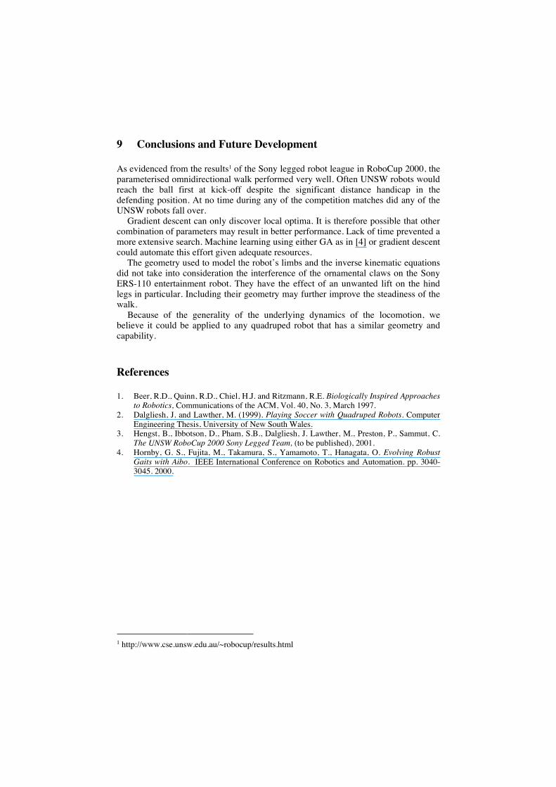
9 Conclusions and Future Development
As evidenced from the results1 of the Sony legged robot league in RoboCup 2000, theparameterised omnidirectional walk performed very well. Often UNSW robots wouldreach the ball first at kick-off despite the significant distance handicap in thedefending position. At no time during any of the competition matches did any of theUNSW robots fall over.
Gradient descent can only discover local optima. It is therefore possible that othercombination of parameters may result in better performance. Lack of time prevented amore extensive search. Machine learning using either GA as in [4] or gradient descentcould automate this effort given adequate resources.
The geometry used to model the robot’s limbs and the inverse kinematic equationsdid not take into consideration the interference of the ornamental claws on the SonyERS-110 entertainment robot. They have the effect of an unwanted lift on the hindlegs in particular. Including their geometry may further improve the steadiness of thewalk.
Because of the generality of the underlying dynamics of the locomotion, webelieve it could be applied to any quadruped robot that has a similar geometry andcapability.
References
1. Beer, R.D., Quinn, R.D., Chiel, H.J. and Ritzmann, R.E. Biologically Inspired Approachesto Robotics, Communications of the ACM, Vol. 40, No. 3, March 1997.
2. Dalgliesh, J. and Lawther, M. (1999). Playing Soccer with Quadruped Robots. ComputerEngineering Thesis, University of New South Wales.
3. Hengst, B., Ibbotson, D., Pham, S.B., Dalgliesh, J. Lawther, M., Preston, P., Sammut, C.The UNSW RoboCup 2000 Sony Legged Team, (to be published), 2001.
4. Hornby, G. S., Fujita, M., Takamura, S., Yamamoto, T., Hanagata, O. Evolving RobustGaits with Aibo. IEEE International Conference on Robotics and Automation. pp. 3040-3045. 2000.
1 http://www.cse.unsw.edu.au/~robocup/results.html
Related Documents


![Leg Locomotion Adaption for Quadruped Robots with Ground Compliance Estimation · 2020. 7. 18. · terrain mobility [3]. MIT Cheetah was designed with propri-oceptive actuator for](https://static.cupdf.com/doc/110x72/6139465aa4cdb41a985b98f0/leg-locomotion-adaption-for-quadruped-robots-with-ground-compliance-estimation-2020.jpg)