OMM154566 H6 JOHN DEERE WORLDWIDE COMMERCIAL & CONSUMER EQUIPMENT DIVISION OMM154566 H6 M154566 H6 John Deere Z225, Z425, Z445 EZtrak OPERATOR’S MANUAL North American Version Litho in U.S.A.

Welcome message from author
This document is posted to help you gain knowledge. Please leave a comment to let me know what you think about it! Share it to your friends and learn new things together.
Transcript
JOHN DEEREWORLDWIDE COMMERCIAL & CONSUMER
EQUIPMENT DIVISION
OMM154566 H6
M154566
H6
John DeereZ225, Z425, Z445 EZtrak
OMM154566 H6
OPERATOR’S MANUAL
North American VersionLitho in U.S.A.
All information, illustrations and specifications in this manual are based on
the latest information at the time of publication. The right is reserved to make
changes at any time without notice.COPYRIGHT© 2006
Deere & Co.John Deere Worldwide Commercial and
Consumer Equipment DivisionAll rights reservedPrevious Editions
COPYRIGHT©
c WARNING: The Engine Exhaust from this product contains chemicals known to the State of California to cause cancer, birth defects or other reproductive harm.
California Proposition 65 Warning
Introduc
INTRODUCTION
Table of ContentsIntroduction................................................................................................ 1
Product Identification................................................................................. 2
Safety Labels............................................................................................. 2
Safety ........................................................................................................ 4
Assembly................................................................................................... 7
Operating - Controls .................................................................................. 9
Operating................................................................................................. 10
Service Intervals...................................................................................... 18
Service Lubrication.................................................................................. 19
Service Engine ........................................................................................ 19
Service Transmission ............................................................................. 26
Service Mower......................................................................................... 30
Service Electrical..................................................................................... 36
Service Miscellaneous ............................................................................ 38
Troubleshooting ....................................................................................... 40
Storage.................................................................................................... 42
Specifications .......................................................................................... 42
Warranty.................................................................................................. 44
Getting Quality Service ........................................................................... 46
Service Record........................................................................................ 47
IntroductionThank You for Purchasing a John Deere ProductWe appreciate having you as a customer and wish you many years of safe and satisfied use of your machine.
Using Your Operator’s ManualThis manual is an important part of your machine and should remain with the machine when you sell it.
Reading your operator’s manual will help you and others avoid personal injury or damage to the machine. Information given in this manual will provide the operator with the safest and most effective use of the machine. Knowing how to operate this machine safely and correctly will allow you to train others who may operate this machine.
If you have an attachment, use the safety and operating information in the attachment operator’s manual along with the machine operator’s manual to operate the attachment safely and correctly.
This manual and safety signs on your machine may also be available in other languages (see your authorized dealer to order).
Sections in your operator’s manual are placed in a specific order to help you understand all the safety messages and learn the controls so you can operate this machine safely. You can also use this manual to answer any specific operating or servicing questions.
The machine shown in this manual may differ slightly from your machine, but will be similar enough to help you understand our instructions.
RIGHT-HAND and LEFT-HAND sides are determined by facing in the direction the machine will travel when going forward. When you see a broken line (------), the item referred to is hidden from view.
Before delivering this machine, your dealer performed a predelivery inspection to ensure best performance.
Special MessagesYour manual contains special messages to bring attention to potential safety concerns, machine damage as well as helpful operating and servicing information. Please read all the information carefully to avoid injury and machine damage.
NOTE: General information is given throughout the manual that may help the operator in the operation or service of the machine.
c CAUTION: Avoid injury! This symbol and text highlight potential hazards or death to the operator or bystanders that may occur if the hazards or procedures are ignored.
IMPORTANT: Avoid damage! This text is used to tell the operator of actions or conditions that might result in damage to the machine.
tion - 1
PRODUCT IDENTIFICATION
Product IdentificationRecord Identification Numbers
Lawn Tractors
Z225, Z425 and Z445 PIN (010001-)
If you need to contact an Authorized Service Center for information on servicing, always provide the product model and identification numbers.
You will need to locate the model and serial number for the machine and for the engine of your machine and record the information in the spaces provided below.
DATE OF PURCHASE:
_________________________________________
DEALER NAME:
_________________________________________
DEALER PHONE:
_________________________________________
PRODUCT IDENTIFICATION NUMBER:
__ __ __ __ __ __ __ __ __ __ __ __ __ __ __ __ __
ENGINE SERIAL NUMBER:
__ __ __ __ __ __ __ __ __ __ __ __ __ __ __ __ __
Register Your Product and Warranty OnlineTo register your product through the Internet, simply go to www.JohnDeereWarrantyRegistration.com. Completing the information, either online or with the product warranty card, will ensure the customer that their product receives all post sales service and important product information.
Safety LabelsUnderstanding The Machine Safety LabelsThe machine safety labels shown in this section are placed in important areas on your machine to draw attention to potential safety hazards.
On your machine safety labels, the words DANGER, WARNING, and CAUTION are used with this safety-alert symbol. DANGER identifies the most serious hazards.
The operator’s manual also explains any potential safety hazards whenever necessary in special safety messages that are identified with the word, CAUTION, and the safety-alert symbol.
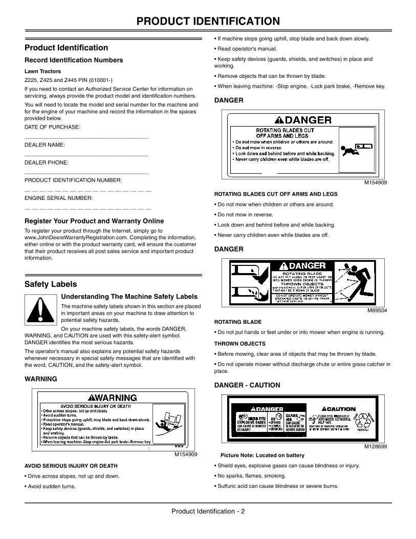
WARNING
M154909
AVOID SERIOUS INJURY OR DEATH
• Drive across slopes, not up and down.
• Avoid sudden turns.
• If machine stops going uphill, stop blade and back down slowly.
• Read operator's manual.
• Keep safety devices (guards, shields, and switches) in place and working.
• Remove objects that can be thrown by blade.
• When leaving machine: -Stop engine, -Lock park brake, -Remove key.
DANGER
M154909
ROTATING BLADES CUT OFF ARMS AND LEGS
• Do not mow when children or others are around.
• Do not mow in reverse.
• Look down and behind before and while backing.
• Never carry children even while blades are off.
DANGER
M89504
ROTATING BLADE
• Do not put hands or feet under or into mower when engine is running.
THROWN OBJECTS
• Before mowing, clear area of objects that may be thrown by blade.
• Do not operate mower without discharge chute or entire grass catcher in place.
DANGER - CAUTION
M128699
Picture Note: Located on battery
• Shield eyes, explosive gases can cause blindness or injury.
• No sparks, flames, smoking.
• Sulfuric acid can cause blindness or severe burns.
Product Identification - 2
SAFETY LABELS
• Flush eyes immediately with water. Get medical help fast.• Keep out of reach of children.
• Do not tip.
• Keep vent caps tight and level.
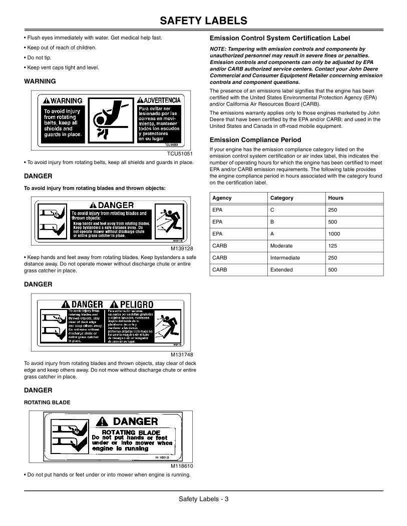
WARNING
TCU51051
• To avoid injury from rotating belts, keep all shields and guards in place.
DANGER
To avoid injury from rotating blades and thrown objects:
M139128
• Keep hands and feet away from rotating blades. Keep bystanders a safe distance away. Do not operate mower without discharge chute or entire grass catcher in place.
DANGER
M131748
To avoid injury from rotating blades and thrown objects, stay clear of deck edge and keep others away. Do not mow without discharge chute or entire grass catcher in place.
DANGER
ROTATING BLADE
M118610
• Do not put hands or feet under or into mower when engine is running.
Emission Control System Certification Label
NOTE: Tampering with emission controls and components by unauthorized personnel may result in severe fines or penalties. Emission controls and components can only be adjusted by EPA and/or CARB authorized service centers. Contact your John Deere Commercial and Consumer Equipment Retailer concerning emission controls and component questions.
The presence of an emissions label signifies that the engine has been certified with the United States Environmental Protection Agency (EPA) and/or California Air Resources Board (CARB).
The emissions warranty applies only to those engines marketed by John Deere that have been certified by the EPA and/or CARB; and used in the United States and Canada in off-road mobile equipment.
Emission Compliance PeriodIf your engine has the emission compliance category listed on the emission control system certification or air index label, this indicates the number of operating hours for which the engine has been certified to meet EPA and/or CARB emission requirements. The following table provides the engine compliance period in hours associated with the category found on the certification label.
Agency Category Hours
EPA C 250
EPA B 500
EPA A 1000
CARB Moderate 125
CARB Intermediate 250
CARB Extended 500
Safety Labels - 3
SAFETY
SafetyOperating SafelyThis cutting machine is capable of amputating hands and feet and throwing objects. Failure to observe the following safety instructions could result in serious injury or death.
• Read, understand and follow all instructions on the machine and in manuals provided, and view safety video, before starting. Be thoroughly familiar with the controls and the proper use of the machine before starting.
• The residential zero radius lawn mower drives differently than a traditional riding mower. Learning to operate the controls smoothly and safely will take some time.
• Practice operating the residential zero radius lawn mower in a large open area with the blades off. Keep practicing until you feel confident in your maneuvering and driving skills.
• Only allow responsible adults, who have practiced driving the residential zero radius lawn mower and are familiar with the instructions to operate the machine. Local restrictions may restrict the age of the operator.
• Do not put hands or feet near rotating parts or under the machine. Keep clear of the discharge opening at all times.
• Clear the area of objects such as rocks, wire and toys which could be thrown by the blades.
• Be sure the area is clear of bystanders before operating. Stop machine if anyone enters the area.
• Never carry passengers.
• Do not mow in reverse unless absolutely necessary. Always look down and behind before and while backing.
• Never direct discharged material toward anyone. Avoid discharging material against a wall or obstruction. Material may ricochet back toward the operator. Stop the blades when crossing gravel surfaces.
• Do not operate the machine without the entire grasscatcher, discharge guard, or other safety devices in place and working. Never operate with the discharge deflector raised, removed, or altered, unless using a grasscatcher.
• Slow down before turning.
• Never leave a running machine unattended. Always turn off blades, lock park brake, stop engine and remove key before dismounting.
• Disengage blades when not mowing. Shut off engine and wait for all parts to come to a complete stop before cleaning the machine, removing the grasscatcher, or unclogging the discharge chute.
• Operate machine only in daylight or good artificial light.
• Do not operate the machine while under the influence of alcohol or drugs.
• Watch for traffic when operating near or crossing roadways. Stop blades before crossing roads or sidewalks.
• Use extra care when loading or unloading the machine into a trailer or truck.
• Always wear safety goggles or safety glasses with side shields when operating machine.
• Data indicates operators 60 years and above are involved in a large percentage of riding mower-related injuries. These operators should evaluate their ability to operate the riding mower safely enough to protect themselves and others from serious injury.
• Follow the manufacturer’s recommendation for wheel weights or
counterweights.
• Inspect machine before you operate. Be sure hardware is tight. Repair or replace damaged, badly worn, or missing parts. Be sure guards and shields are in good condition and fastened in place. Make any necessary adjustments before you operate.
• Before using, always visually inspect to see that the blades, blade bolts and the mower assembly are not worn and damaged. Replace worn and damaged blades and bolts in sets to preserve balance.
• Make sure spark plug, muffler, fuel cap and air cleaner are in place before starting the engine.
• Be sure all drives are in neutral and parking brake is locked before starting engine. Only start engine from the operator’s position.
• Do not change the engine governor settings or overspeed the engine. Operating the engine at excessive speed can increase the hazard of personal injury.
• If you hit an object or if abnormal vibration occurs, stop the machine and inspect it. Make repairs before you operate.
• Use only accessories and attachments approved by the manufacturer of the machine. Keep safety labels visible when installing accessories and attachments.
• Do not wear radio or music headphones. Safe service and operation requires your full attention.
• When machine is left unattended, stored, or parked, lower the mower deck unless a positive mechanical lock is used.
Using a Spark ArrestorThe engine in this machine is not equipped with a spark arrestor muffler. It is a violation of California Public Resource Code Section 4442 to use or operate this engine on or near any forest-covered, brush-covered or grass-covered land unless the exhaust system is equipped with a spark arrestor meeting any applicable local or state laws. Other states or federal areas may have similar laws.
A spark arrestor for your machine may be available from your authorized dealer. An installed spark arrestor must be maintained in good working order by the operator.
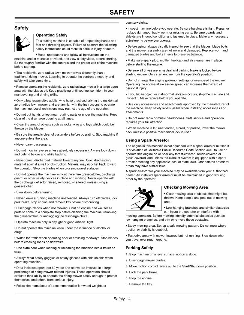
Checking Mowing Area
• Clear mowing area of objects that might be thrown. Keep people and pets out of mowing area.
• Low-hanging branches and similar obstacles can injure the operator or interfere with
mowing operation. Before mowing, identify potential obstacles such as low-hanging branches, and trim or remove those obstacles.
• Study mowing area. Set up a safe mowing pattern. Do not mow where traction or stability is doubtful.
• Test drive area with mower lowered but not running. Slow down when you travel over rough ground.
Parking Safely
1. Stop machine on a level surface, not on a slope.
2. Disengage mower blades.
3. Move motion control levers out to the Start/Shutdown position.
4. Lock the park brake.
5. Stop the engine.
6. Remove the key.
Safety - 4
SAFETY
7. Wait for engine and all moving parts to stop before you leave the operator’s seat.8. Disconnect the negative battery cable or remove the spark plug wire (for gasoline engines) before servicing the machine.
Rotating Blades are Dangerous
HELP PREVENT SERIOUS OR FATAL ACCIDENTS:
• Rotating blades can cut off arms and legs, and throw objects. Failure to observe safety instructions could result in serious injury or
death.
• Keep hands, feet and clothing away from mower deck when engine is running.
• Be alert at all times, drive forward and in reverse carefully. People, especially children can move quickly into the mowing area before you know it.
• Before backing up, stop mower blades or attachments and look down and behind the machine carefully, especially for children.
• Do not mow in reverse.
• Shut off blades when you are not mowing.
• Park machine safely before leaving the operator’s station for any reason including emptying the grasscatchers or unplugging the chute.
• The mower blades should stop in approximately five seconds when the mower is disengaged. If you believe that your blades may not be stopping in that period of time, take your machine to your authorized dealer where they can safely check and service your machine.
Protect Children
• Death or serious injury can occur when young children associate having fun with a lawn mowing machine simply because someone has given them a ride on a machine.
• Children are attracted to lawn mowing machines and mowing activities. They don’t understand the dangers of rotating blades or the fact that the operator is unaware of their presence.
• Children who have been given rides in the past may suddenly appear in the mowing area for another ride and be run over or backed over by the machine.
• Tragic accidents with children can occur if the operator is not alert to the presence of children, especially when a child approaches a machine from behind. Before and while backing up, stop mower blades and look down and behind the machine carefully, especially for children.
• Never carry children on a machine or attachment, even with the blades off. Do not tow children in a cart or trailer. They can fall off and be seriously injured or interfere with safe machine operation.
• Never use the machine as a recreational vehicle or to entertain children.
• Never allow children or an untrained person operate the machine. Instruct all operators not to give children a ride on the machine or in an attachment.
• Keep children indoors, out of the mowing area, and in the watchful eye of a responsible adult, other than the operator, when a mower is being operated.
• Stay alert to the presence of children. Never assume that children will remain where you last saw them. Turn the machine off if a child enters the work area.
• Use extreme care when approaching blind corners, shrubs, trees, or other objects that may block your view of a child.
Avoid Tipping
• Slopes are a major factor related to loss-of-control and tip-over accidents, which can result in severe injury or death. Operation on all slopes requires extra caution.
• Mow across slopes, not up and down.
• Never mow on any slope that is more than 10 degrees, or a slope that rises more than 3-1/2 feet within a distance of 20 feet of distance.
• Make a safe choice when operating on slopes. If you feel uncomfortable on a hillside, or if you feel the front of the machine start to creep down the slope, stop mowing immediately and proceed slowly and safely down the slope.
• If steering direction cannot be maintained with slight steering corrections, the slope is too steep to mow.
• Watch for holes, ruts, bumps, rocks, or other hidden objects. Uneven terrain could overturn the machine. Tall grass can hide obstacles.
• Choose a low ground speed so you will not have to stop or shift while on a slope.
• Do not mow or operate machine on wet grass. Tires may lose traction. Tires may lose traction on slopes even though the brakes are functioning properly.
• Avoid starting, stopping or turning on a slope. If the tires lose traction, disengage the blades and proceed slowly, straight down the slope.
• Keep all movement on slopes slow and gradual. Do not make sudden changes in speed or direction, which could cause the machine to roll over.
• Use extra care while operating machine with grasscatchers or other attachments, they can affect stability of the machine. Do not use on steep slopes.
• Do not mow near drop-offs, ditches, embankments, or bodies of water. The machine could suddenly roll over if a wheel goes over the edge or the edge caves in.
• Leave at least the width of the machine as a safety area between the machine and any safety hazard. Mow those areas with a hand-held trimmer or walk-behind mower.
• Follow the manufacturer’s recommendations for wheel weights or counterweights for added stability when operating on slopes or using front or rear mounted attachments. Remove weights when not required.
• Drive machine slowly and avoid quick stops if attachment has been removed for servicing mower or machine.
Keep Riders Off
• Only allow the operator on the machine. Keep riders off.
• Riders on the machine or attachment may be struck by foreign objects or thrown off the
machine causing serious injury.
• Riders obstruct the operator’s view resulting in the machine being operated in an unsafe manner.
Wear Appropriate Clothing
• Always wear eye protection when operating the machine.
• Wear close fitting clothing and safety equipment appropriate for the job.
Safety - 5
SAFETY
• While mowing, always wear substantial footwear and long trousers. Do not operate the equipment when barefoot or wearing open sandals.• Wear a suitable protective device such as earplugs. Loud noise can cause impairment or loss of hearing.
Driving Safely on Public RoadsAvoid personal injury or death resulting from a collision with another vehicle on public roads:
• Use safety lights and devices. Slow moving machines when driven on public roads are hard to see, especially at night.
• Whenever driving on public roads, use flashing warning lights and turn signals according to local regulations. Extra flashing warning lights may need to be installed.
Practice Safe Maintenance
• Only qualified, trained adults should service this machine. Understand service procedure before doing work.
• Never operate machine in a closed area where dangerous carbon monoxide fumes can collect.
• Keep all nuts and bolts tight, especially blade attachment bolts, to be sure the equipment is in safe working condition.
• Never tamper with safety devices. Check their proper operation regularly.
• Keep machine free of grass, leaves or other debris build-up. Clean up oil or fuel spillage and remove any fuel-soaked debris. Allow the machine to cool before storing.
• If you strike a foreign object, stop and inspect the machine. Repair, if necessary, before restarting.
• Never make any adjustments or repairs with the engine running. Wait for all movement to stop on machine before adjusting, cleaning or repairing.
• Check grasscatcher components and the discharge guard frequently and replace with manufacturer’s recommended parts, when necessary. Grasscatcher components are subject to wear, damage, and deterioration which could expose moving parts or allow objects to be thrown.
• Mower blades are sharp. Wrap the blade or wear gloves, and use extra care when servicing them. Only replace blades. Never straighten or weld them.
• Check brake operation frequently. Adjust and service as required.
• Maintain or replace safety and instruction labels, as necessary.
• On multi-bladed machines, take care as rotating one blade can cause other blades to rotate.
• Keep hands, feet, clothing, jewelry, and long hair away from any moving parts, to prevent them from getting caught.
• Lower any attachments to the ground before cleaning or servicing machine. Disengage all power and stop the engine. Lock park brake and remove the key. Let machine cool.
• Securely support any machine elements that must be raised for service work. Use jack stands or lock service latches to support components when needed.
• Disconnect battery or remove spark plug wire (for gasoline engines) before making any repairs. Disconnect negative terminal first and positive last. Install positive terminal first and negative last.
• Before servicing machine or attachment, carefully release pressure from any components with stored energy, such as hydraulic components or springs.
• Keep all parts in good condition and properly installed. Fix damage immediately. Replace worn or broken parts.
• Charge batteries in an open, well-ventilated area, away from sparks. Unplug battery charger before connecting or disconnecting from the battery. Wear protective clothing and use insulated tools.
• Do not strike the flywheel with a hammer or hard object because the flywheel may later shatter during operation.
• If equipped with hydraulic lift - release hydraulic pressure by lowering attachment or cutting units to the ground or to a mechanical stop and move hydraulic control levers back and forth.
Avoid High Pressure Fluids
• Hydraulic hoses and lines can fail due to physical damage, kinks, age, and exposure. Check hoses and lines regularly. Replace damaged hoses and lines.
• Hydraulic fluid connections can loosen due to physical damage and vibration. Check connections regularly. Tighten loose connections.
• Escaping fluid under pressure can penetrate the skin causing serious injury. Avoid the hazard by relieving pressure before disconnecting hydraulic or other lines. Tighten all connections before applying pressure.
• Search for leaks with a piece of cardboard. Protect hands and body from high pressure fluids.
• If an accident occurs, see a doctor immediately. Any fluid injected into the skin must be surgically removed within a few hours or gangrene may result. Doctors unfamiliar with this type of injury should reference a knowledgeable medical source. Such information is available from Deere & Company Medical Department in Moline, Illinois, U.S.A. Information may be obtained in the United States and Canada only by calling 1-800-822-8262.
Prevent Fires
• Remove grass and debris from engine compartment and muffler area, before and after operating machine, especially after mowing or mulching in dry conditions.
• Empty the grasscatcher completely before storing.
• Always shut off fuel when storing or transporting machine, if the machine has a fuel shutoff.
• Do not store machine near an open flame or source of ignition, such as a water heater or furnace.
• Check fuel lines, tank, cap, and fittings frequently for cracks or leaks. Replace if necessary.
Handling Fuel Safely
To avoid personal injury or property damage, use extreme care in handling fuel. Fuel is extremely flammable and fuel vapors are explosive:
• Extinguish all cigarettes, cigars, pipes, and other sources of ignition.
• Use only an approved fuel container. Use only non-metal, portable fuel containers approved by the Underwriter’s Laboratory (U.L.) or the American Society for Testing & Materials (ASTM). If using a funnel, make sure it is plastic and has no screen or filter.
• Never remove the fuel tank cap or add fuel with the engine running. Allow engine to cool before refueling.
Safety - 6
ASSEMBLY
• Never add fuel to or drain fuel from the machine indoors. Move machine outdoors and provide adequate ventilation.• Clean up spilled fuel immediately. If fuel is spilled on clothing, change clothing immediately. If fuel is spilled near machine, do not attempt to start the engine but move the machine away from the area of spillage. Avoid creating any source of ignition until fuel vapors have dissipated.
• Never store the machine or fuel container where there is an open flame, spark, or pilot light such as on a water heater or other appliance.
• Prevent fire and explosion caused by static electric discharge. Static electric discharge can ignite fuel vapors in an ungrounded fuel container.
• Never fill containers inside a vehicle or on a truck or trailer bed with a plastic liner. Always place containers on the ground away from your vehicle before fueling.
• Remove fuel-powered equipment from the truck or trailer and refuel it on the ground. If this is not possible, then refuel such equipment with a portable container, rather than from a fuel dispenser nozzle.
• Keep the nozzle in contact with the rim of the fuel tank or container opening at all times until the fueling is complete. Do not use a nozzle lock-open device.
• Never overfill fuel tank. Replace fuel tank cap and tighten securely.
• Replace all fuel container caps securely after use.
• For gasoline engines, do not use gas with methanol. Methanol is harmful to your health and to the environment.
Tire SafetyExplosive separation of a tire and rim parts can cause serious injury or death:
• Do not attempt to mount a tire without the proper equipment and experience to perform the job.
• Always maintain the correct tire pressure. Do not inflate the tires above the recommended pressure. Never weld or heat a wheel and tire assembly. The heat can cause an increase in air pressure resulting in a tire explosion. Welding can structurally weaken or deform the wheel.
• When inflating tires, use a clip-on chuck and extension hose long enough to allow you to stand to one side and NOT in front of or over the tire assembly.
• Check tires for low pressure, cuts, bubbles, damaged rims or missing lug bolts and nuts.
Checking Wheel Hardware
• A serious accident could occur causing serious injury if wheel hardware is not tight.
• Check wheel hardware tightness often during the first 100 hours of operation.
• Wheel hardware must be tightened to specified torque using the proper procedure anytime it is loosened.
Handling Waste Product and Chemicals Waste products, such as, used oil, fuel, coolant, brake fluid, and batteries, can harm the environment and people:
• Do not use beverage containers for waste fluids - someone may drink from them.
• See your local Recycling Center or authorized dealer to learn how to recycle or get rid of waste products.
• A Material Safety Data Sheet (MSDS) provides specific details on
chemical products: physical and health hazards, safety procedures, and emergency response techniques. The seller of the chemical products used with your machine is responsible for providing the MSDS for that product.
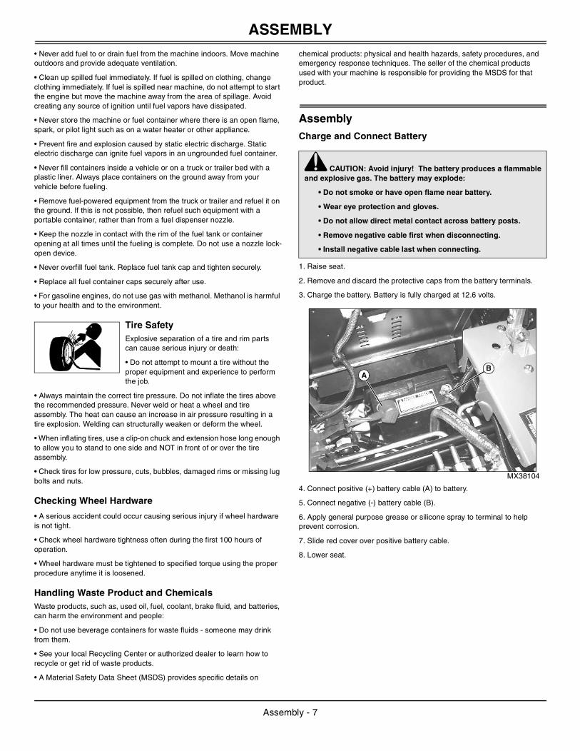
AssemblyCharge and Connect Battery
1. Raise seat.
2. Remove and discard the protective caps from the battery terminals.
3. Charge the battery. Battery is fully charged at 12.6 volts.
MX38104
4. Connect positive (+) battery cable (A) to battery.
5. Connect negative (-) battery cable (B).
6. Apply general purpose grease or silicone spray to terminal to help prevent corrosion.
7. Slide red cover over positive battery cable.
8. Lower seat.
c CAUTION: Avoid injury! The battery produces a flammable and explosive gas. The battery may explode:
• Do not smoke or have open flame near battery.
• Wear eye protection and gloves.
• Do not allow direct metal contact across battery posts.
• Remove negative cable first when disconnecting.
• Install negative cable last when connecting.
BA
Assembly - 7
ASSEMBLY
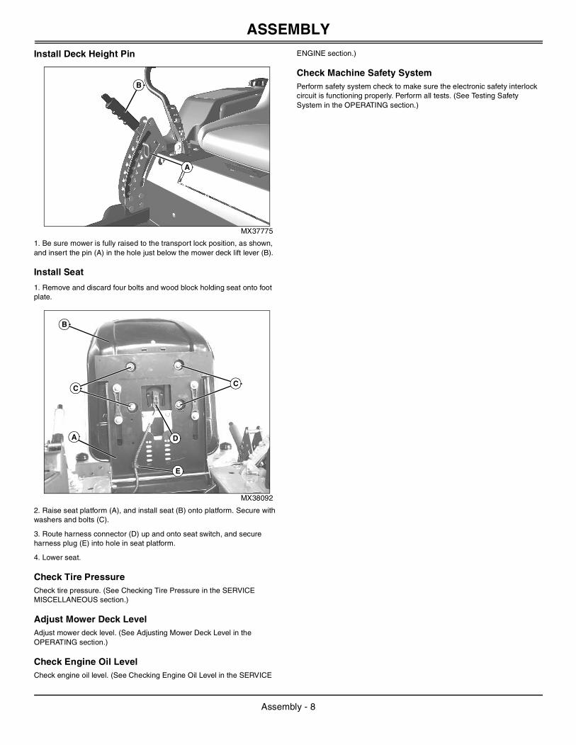
Install Deck Height Pin
MX37775
1. Be sure mower is fully raised to the transport lock position, as shown, and insert the pin (A) in the hole just below the mower deck lift lever (B).
Install Seat
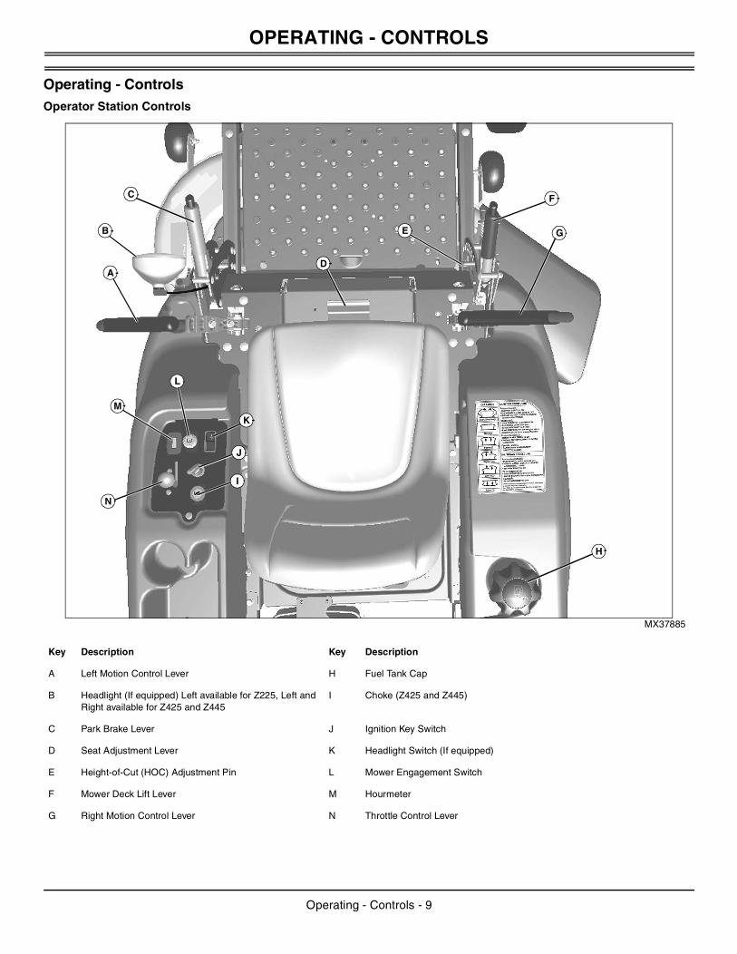
1. Remove and discard four bolts and wood block holding seat onto foot plate.
MX38092
2. Raise seat platform (A), and install seat (B) onto platform. Secure with washers and bolts (C).
3. Route harness connector (D) up and onto seat switch, and secure harness plug (E) into hole in seat platform.
4. Lower seat.
Check Tire PressureCheck tire pressure. (See Checking Tire Pressure in the SERVICE MISCELLANEOUS section.)
Adjust Mower Deck LevelAdjust mower deck level. (See Adjusting Mower Deck Level in the OPERATING section.)
Check Engine Oil LevelCheck engine oil level. (See Checking Engine Oil Level in the SERVICE
ENGINE section.)
Check Machine Safety SystemPerform safety system check to make sure the electronic safety interlock circuit is functioning properly. Perform all tests. (See Testing Safety System in the OPERATING section.)
A
B
B
CC
D
E
A
Assembly - 8
OPERATING - CONTROLS
Operating - ControlsOperator Station Controls
MX37885
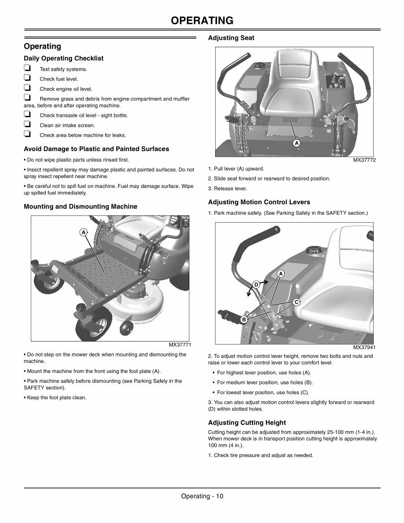
Key Description Key Description
A Left Motion Control Lever H Fuel Tank Cap
B Headlight (If equipped) Left available for Z225, Left and Right available for Z425 and Z445
I Choke (Z425 and Z445)
C Park Brake Lever J Ignition Key Switch
D Seat Adjustment Lever K Headlight Switch (If equipped)
E Height-of-Cut (HOC) Adjustment Pin L Mower Engagement Switch
F Mower Deck Lift Lever M Hourmeter
G Right Motion Control Lever N Throttle Control Lever
H
M
G
A
F
E
D
L
J
I
N
K
B
C
Operating - Controls - 9
OPERATING
OperatingDaily Operating Checklist
❏ Test safety systems.
❏ Check fuel level.
❏ Check engine oil level.
❏ Remove grass and debris from engine compartment and muffler area, before and after operating machine.
❏ Check transaxle oil level - sight bottle.
❏ Clean air intake screen.
❏ Check area below machine for leaks.
Avoid Damage to Plastic and Painted Surfaces
• Do not wipe plastic parts unless rinsed first.
• Insect repellent spray may damage plastic and painted surfaces. Do not spray insect repellent near machine.
• Be careful not to spill fuel on machine. Fuel may damage surface. Wipe up spilled fuel immediately.
Mounting and Dismounting Machine
MX37771
• Do not step on the mower deck when mounting and dismounting the machine.
• Mount the machine from the front using the foot plate (A).
• Park machine safely before dismounting (see Parking Safely in the SAFETY section).
• Keep the foot plate clean.
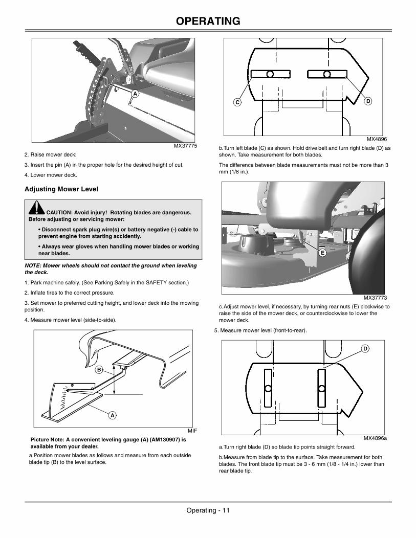
Adjusting Seat
MX37772
1. Pull lever (A) upward.
2. Slide seat forward or rearward to desired position.
3. Release lever.
Adjusting Motion Control Levers
1. Park machine safely. (See Parking Safely in the SAFETY section.)
MX37941
2. To adjust motion control lever height, remove two bolts and nuts and raise or lower each control lever to your comfort level.
• For highest lever position, use holes (A).
• For medium lever position, use holes (B).
• For lowest lever position, use holes (C).
3. You can also adjust motion control levers slightly forward or rearward (D) within slotted holes.
Adjusting Cutting HeightCutting height can be adjusted from approximately 25-100 mm (1-4 in.). When mower deck is in transport position cutting height is approximately 100 mm (4 in.).
1. Check tire pressure and adjust as needed.
A
A
A
C
B
D
Operating - 10
OPERATING
MX37775
2. Raise mower deck:
3. Insert the pin (A) in the proper hole for the desired height of cut.
4. Lower mower deck.
Adjusting Mower Level
NOTE: Mower wheels should not contact the ground when leveling the deck.
1. Park machine safely. (See Parking Safely in the SAFETY section.)
2. Inflate tires to the correct pressure.
3. Set mower to preferred cutting height, and lower deck into the mowing position.
4. Measure mower level (side-to-side).
MIF
Picture Note: A convenient leveling gauge (A) (AM130907) is available from your dealer.
a.Position mower blades as follows and measure from each outside blade tip (B) to the level surface.
MX4896
b.Turn left blade (C) as shown. Hold drive belt and turn right blade (D) as shown. Take measurement for both blades.
The difference between blade measurements must not be more than 3 mm (1/8 in.).
MX37773
c.Adjust mower level, if necessary, by turning rear nuts (E) clockwise to raise the side of the mower deck, or counterclockwise to lower the mower deck.
5. Measure mower level (front-to-rear).
MX4896a
a.Turn right blade (D) so blade tip points straight forward.
b.Measure from blade tip to the surface. Take measurement for both blades. The front blade tip must be 3 - 6 mm (1/8 - 1/4 in.) lower than rear blade tip.
c CAUTION: Avoid injury! Rotating blades are dangerous. Before adjusting or servicing mower:
• Disconnect spark plug wire(s) or battery negative (-) cable to prevent engine from starting accidently.
• Always wear gloves when handling mower blades or working near blades.
A
A
B
DC
E
D
Operating - 11
OPERATING
MX37774
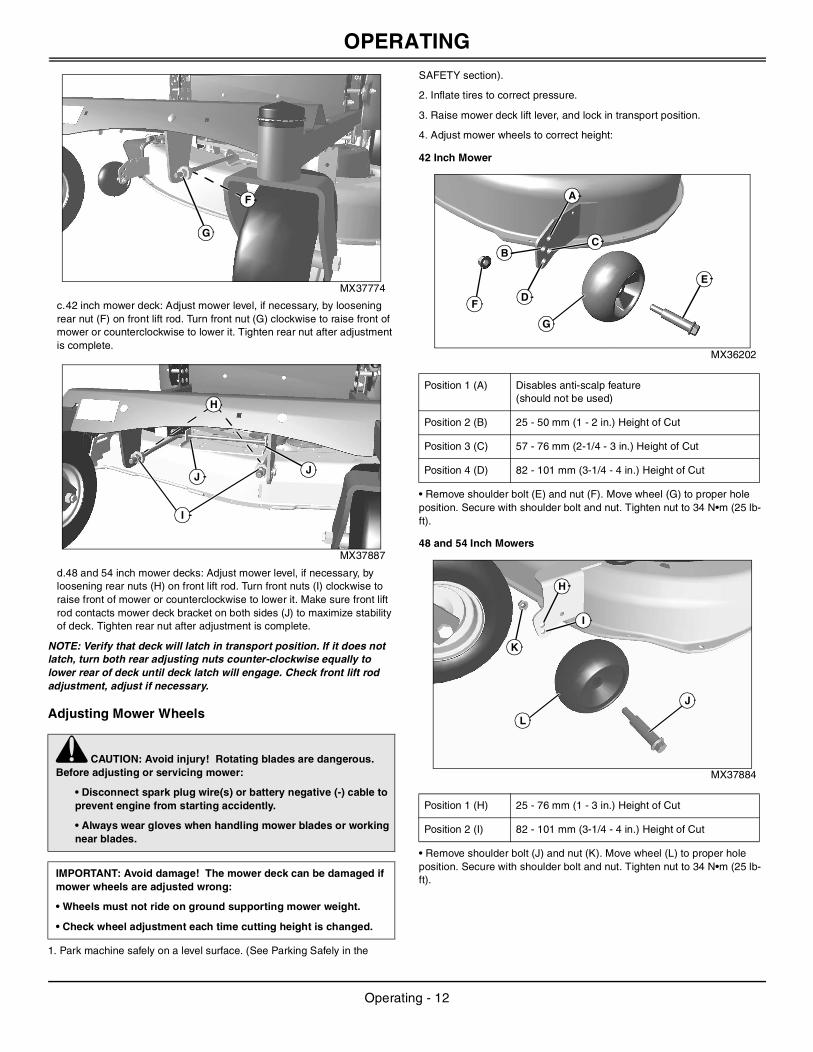
c.42 inch mower deck: Adjust mower level, if necessary, by loosening rear nut (F) on front lift rod. Turn front nut (G) clockwise to raise front of mower or counterclockwise to lower it. Tighten rear nut after adjustment is complete.
MX37887
d.48 and 54 inch mower decks: Adjust mower level, if necessary, by loosening rear nuts (H) on front lift rod. Turn front nuts (I) clockwise to raise front of mower or counterclockwise to lower it. Make sure front lift rod contacts mower deck bracket on both sides (J) to maximize stability of deck. Tighten rear nut after adjustment is complete.
NOTE: Verify that deck will latch in transport position. If it does not latch, turn both rear adjusting nuts counter-clockwise equally to lower rear of deck until deck latch will engage. Check front lift rod adjustment, adjust if necessary.
Adjusting Mower Wheels
1. Park machine safely on a level surface. (See Parking Safely in the
SAFETY section).
2. Inflate tires to correct pressure.
3. Raise mower deck lift lever, and lock in transport position.
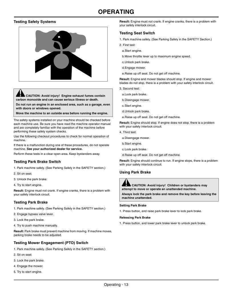
4. Adjust mower wheels to correct height:
42 Inch Mower
MX36202
• Remove shoulder bolt (E) and nut (F). Move wheel (G) to proper hole position. Secure with shoulder bolt and nut. Tighten nut to 34 N•m (25 lb-ft).
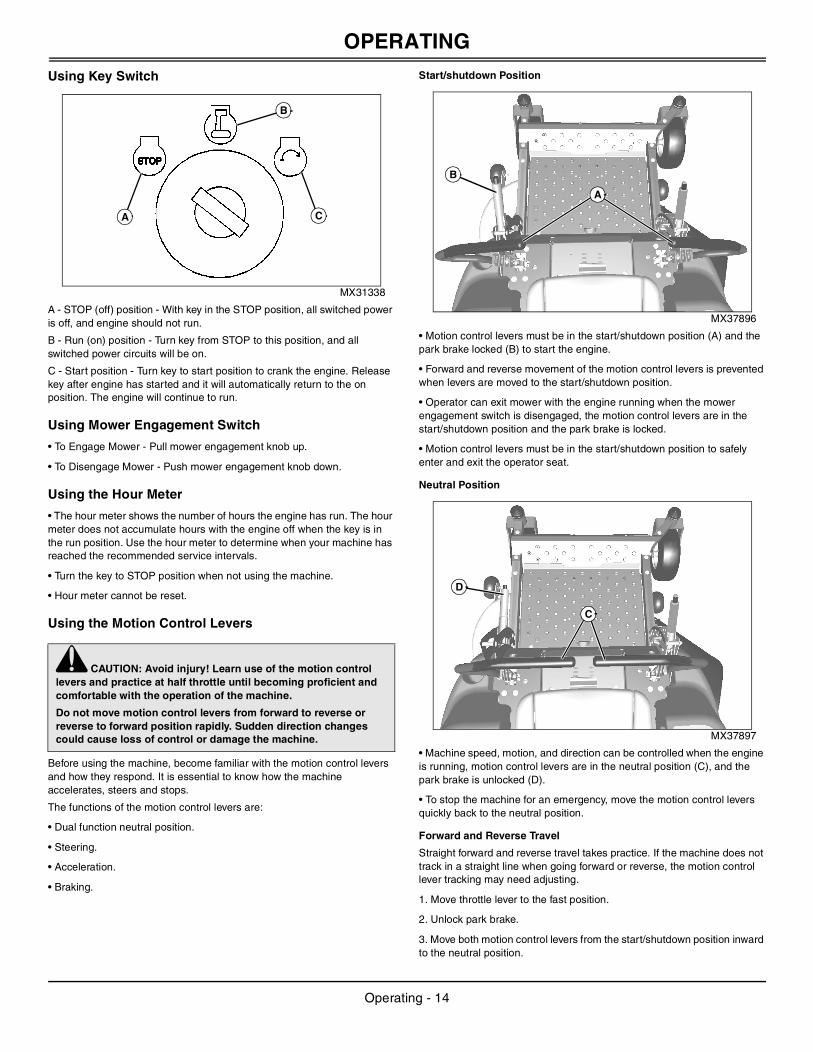
48 and 54 Inch Mowers
MX37884
• Remove shoulder bolt (J) and nut (K). Move wheel (L) to proper hole position. Secure with shoulder bolt and nut. Tighten nut to 34 N•m (25 lb-ft).
c CAUTION: Avoid injury! Rotating blades are dangerous. Before adjusting or servicing mower:
• Disconnect spark plug wire(s) or battery negative (-) cable to prevent engine from starting accidently.
• Always wear gloves when handling mower blades or working near blades.
IMPORTANT: Avoid damage! The mower deck can be damaged if mower wheels are adjusted wrong:
• Wheels must not ride on ground supporting mower weight.
• Check wheel adjustment each time cutting height is changed.
G
F
I
H
JJ
Position 1 (A) Disables anti-scalp feature(should not be used)
Position 2 (B) 25 - 50 mm (1 - 2 in.) Height of Cut
Position 3 (C) 57 - 76 mm (2-1/4 - 3 in.) Height of Cut
Position 4 (D) 82 - 101 mm (3-1/4 - 4 in.) Height of Cut
Position 1 (H) 25 - 76 mm (1 - 3 in.) Height of Cut
Position 2 (I) 82 - 101 mm (3-1/4 - 4 in.) Height of Cut
F
G
E
A
CB
D
K
L
J
H
I
Operating - 12
OPERATING
Testing Safety Systems
The safety systems installed on your machine should be checked before each machine use. Be sure you have read the machine operator manual and are completely familiar with the operation of the machine before performing these safety system checks.
Use the following checkout procedures to check for normal operation of machine.
If there is a malfunction during one of these procedures, do not operate machine. See your authorized dealer for service.
Perform these tests in a clear open area. Keep bystanders away.
Testing Park Brake Switch
1. Park machine safely. (See Parking Safely in the SAFETY section.)
2. Sit on seat.
3. Unlock the park brake.
4. Try to start engine.
Result: Engine must not crank. If engine cranks, there is a problem with your safety interlock circuit.
Testing Park Brake
1. Park machine safely. (See Parking Safely in the SAFETY section.)
2. Engage bypass valve lever.
3. Lock the park brake.
4. Try to push machine manually.
Result: Park brake must prevent machine from moving. If machine moves, parking brake needs to be adjusted.
Testing Mower Engagement (PTO) Switch
1. Park machine safely. (See Parking Safely in the SAFETY section.)
2. Sit on seat.
3. Lock the park brake.
4. Engage the mower.
5. Try to start engine.
Result: Engine must not crank. If engine cranks, there is a problem with your safety interlock circuit.
Testing Seat Switch
1. Park machine safely. (See Parking Safely in the SAFETY Section.)
2. First test:
a.Start engine.
b.Move throttle lever up to maximum engine speed.
c.Unlock park brake.
d.Engage mower.
e.Raise up off seat. Do not get off machine.
Result: Engine and mower blades should stop. If engine and mower blades do not stop, there is a problem with your safety interlock circuit.
3. Second test:
a.Lock park brake.
b.Disengage mower.
c.Start engine.
d.Unlock park brake.
e.Raise up off seat. Do not get off machine.
Result: Engine should stop. If engine does not stop, there is a problem with your safety interlock circuit.
4. Third test:
a.Disengage mower.
b.Start engine.
c.Lock park brake.
d.Raise up off seat. Do not get off machine.
Result: Engine should continue to run. If engine stops, there is a problem with your safety interlock circuit.
Using Park Brake
Setting Park Brake
1. Press button, and raise park brake lever to lock park brake.
Releasing Park Brake
1. Press button, and lower park brake lever to unlock park brake.
c CAUTION: Avoid injury! Engine exhaust fumes contain carbon monoxide and can cause serious illness or death.
Do not run an engine in an enclosed area, such as a garage, even with doors or windows opened.
Move the machine to an outside area before running the engine.
c CAUTION: Avoid injury! Children or bystanders may attempt to move or operate an unattended machine.
Always lock the park brake and remove the key before leaving the machine unattended.
Operating - 13
OPERATING
Using Key Switch
MX31338
A - STOP (off) position - With key in the STOP position, all switched power is off, and engine should not run.
B - Run (on) position - Turn key from STOP to this position, and all switched power circuits will be on.
C - Start position - Turn key to start position to crank the engine. Release key after engine has started and it will automatically return to the on position. The engine will continue to run.
Using Mower Engagement Switch
• To Engage Mower - Pull mower engagement knob up.
• To Disengage Mower - Push mower engagement knob down.
Using the Hour Meter
• The hour meter shows the number of hours the engine has run. The hour meter does not accumulate hours with the engine off when the key is in the run position. Use the hour meter to determine when your machine has reached the recommended service intervals.
• Turn the key to STOP position when not using the machine.
• Hour meter cannot be reset.
Using the Motion Control Levers
Before using the machine, become familiar with the motion control levers and how they respond. It is essential to know how the machine accelerates, steers and stops.
The functions of the motion control levers are:
• Dual function neutral position.
• Steering.
• Acceleration.
• Braking.
Start/shutdown Position
MX37896
• Motion control levers must be in the start/shutdown position (A) and the park brake locked (B) to start the engine.
• Forward and reverse movement of the motion control levers is prevented when levers are moved to the start/shutdown position.
• Operator can exit mower with the engine running when the mower engagement switch is disengaged, the motion control levers are in the start/shutdown position and the park brake is locked.
• Motion control levers must be in the start/shutdown position to safely enter and exit the operator seat.
Neutral Position
MX37897
• Machine speed, motion, and direction can be controlled when the engine is running, motion control levers are in the neutral position (C), and the park brake is unlocked (D).
• To stop the machine for an emergency, move the motion control levers quickly back to the neutral position.
Forward and Reverse Travel
Straight forward and reverse travel takes practice. If the machine does not track in a straight line when going forward or reverse, the motion control lever tracking may need adjusting.
1. Move throttle lever to the fast position.
2. Unlock park brake.
3. Move both motion control levers from the start/shutdown position inward to the neutral position.
c CAUTION: Avoid injury! Learn use of the motion control levers and practice at half throttle until becoming proficient and comfortable with the operation of the machine.
Do not move motion control levers from forward to reverse or reverse to forward position rapidly. Sudden direction changes could cause loss of control or damage the machine.
CA
B
A
B
C
D
Operating - 14
OPERATING
4. Move the motion control levers forward to begin forward travel.5. Move the motion control levers rearward to begin reverse travel.
6. To stop travel, move motion control levers back to the neutral position.
Forward Travel
MX37898
1. Gradually move both motion control levers evenly forward (A) from neutral. To speed up, move the levers farther forward. To slow down smoothly, slowly move the levers toward neutral.
Reverse Travel
MX37899
1. Look down and behind, then gradually move both motion control levers evenly rearward (B) from neutral. To speed up, move the levers farther rearward. To slow down smoothly, slowly move the levers toward neutral.
Left Turn
MX37900
1. To turn slightly to the left, push right control lever (C) further forward than the left control lever (D).
MX37901
2. To turn sharply to the left, push right control lever (C) forward and pull left control lever (D) rearward at the same time.
A A
B B
CD
D
C
Operating - 15
OPERATING
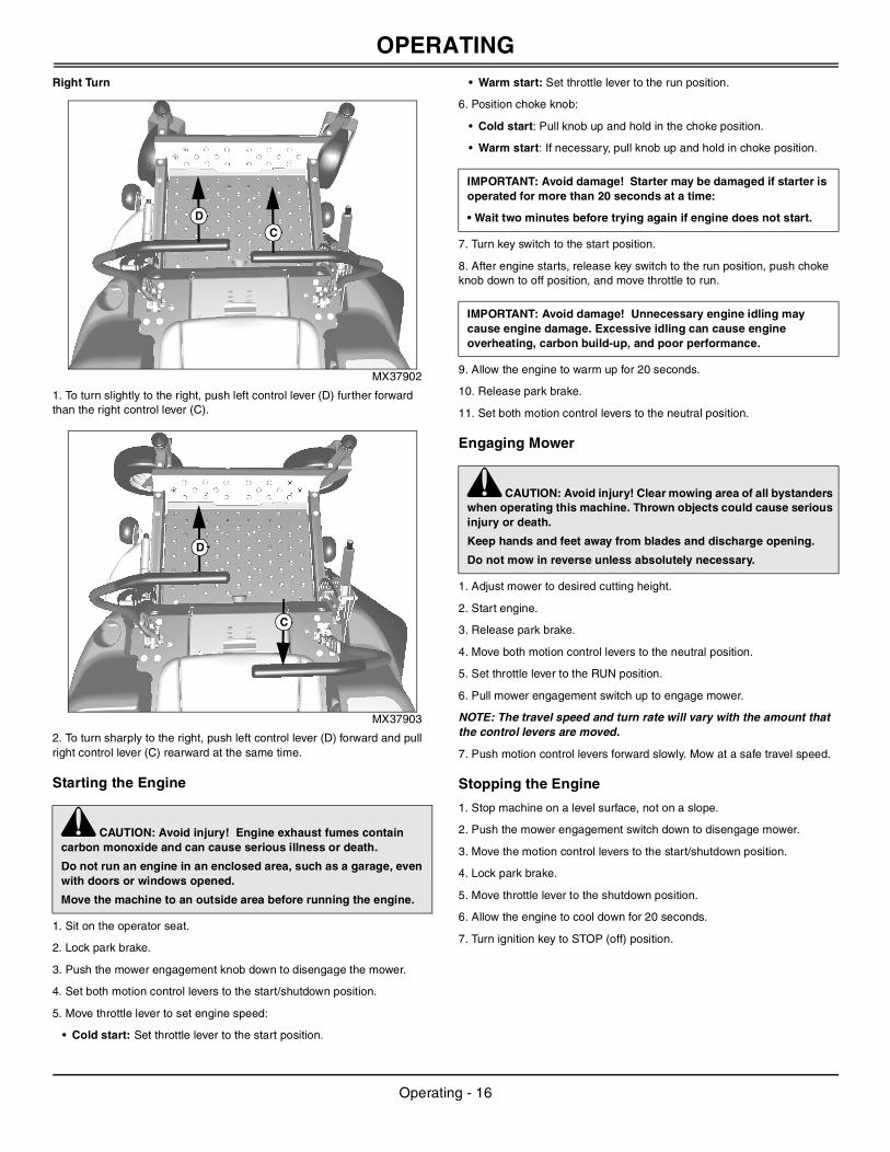
Right TurnMX37902
1. To turn slightly to the right, push left control lever (D) further forward than the right control lever (C).
MX37903
2. To turn sharply to the right, push left control lever (D) forward and pull right control lever (C) rearward at the same time.
Starting the Engine
1. Sit on the operator seat.
2. Lock park brake.
3. Push the mower engagement knob down to disengage the mower.
4. Set both motion control levers to the start/shutdown position.
5. Move throttle lever to set engine speed:
• Cold start: Set throttle lever to the start position.
• Warm start: Set throttle lever to the run position.
6. Position choke knob:
• Cold start: Pull knob up and hold in the choke position.
• Warm start: If necessary, pull knob up and hold in choke position.
7. Turn key switch to the start position.
8. After engine starts, release key switch to the run position, push choke knob down to off position, and move throttle to run.
9. Allow the engine to warm up for 20 seconds.
10. Release park brake.
11. Set both motion control levers to the neutral position.
Engaging Mower
1. Adjust mower to desired cutting height.
2. Start engine.
3. Release park brake.
4. Move both motion control levers to the neutral position.
5. Set throttle lever to the RUN position.
6. Pull mower engagement switch up to engage mower.
NOTE: The travel speed and turn rate will vary with the amount that the control levers are moved.
7. Push motion control levers forward slowly. Mow at a safe travel speed.
Stopping the Engine
1. Stop machine on a level surface, not on a slope.
2. Push the mower engagement switch down to disengage mower.
3. Move the motion control levers to the start/shutdown position.
4. Lock park brake.
5. Move throttle lever to the shutdown position.
6. Allow the engine to cool down for 20 seconds.
7. Turn ignition key to STOP (off) position.
c CAUTION: Avoid injury! Engine exhaust fumes contain carbon monoxide and can cause serious illness or death.
Do not run an engine in an enclosed area, such as a garage, even with doors or windows opened.
Move the machine to an outside area before running the engine.
CD
D
C
IMPORTANT: Avoid damage! Starter may be damaged if starter is operated for more than 20 seconds at a time:
• Wait two minutes before trying again if engine does not start.
IMPORTANT: Avoid damage! Unnecessary engine idling may cause engine damage. Excessive idling can cause engine overheating, carbon build-up, and poor performance.
c CAUTION: Avoid injury! Clear mowing area of all bystanders when operating this machine. Thrown objects could cause serious injury or death.
Keep hands and feet away from blades and discharge opening.
Do not mow in reverse unless absolutely necessary.
Operating - 16
OPERATING
8. Remove key.
Moving Machine by Hand
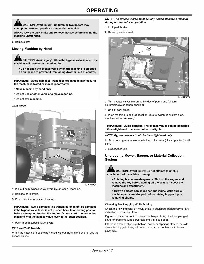
Z225 Model:
MX37904
1. Pull out both bypass valve levers (A) at rear of machine.
2. Release park brake.
3. Push machine to desired location.
4. Push in both bypass valve levers.
Z425 and Z445 Models:
When the machine needs to be moved without starting the engine, use the bypass valves:
NOTE: The bypass valves must be fully turned clockwise (closed) during normal vehicle operation.
1. Lock park brake.
2. Raise operator’s seat.
MX37905
3. Turn bypass valves (A) on both sides of pump one full turn counterclockwise (open position).
4. Unlock park brake.
5. Push machine to desired location. Due to hydraulic system drag, machine will move slowly.
NOTE: Bypass valves should be hand tightened only.
6. Turn both bypass valves one full turn clockwise (closed position) until tight.
7. Lock park brake.
Unplugging Mower, Bagger, or Material Collection System
Checking For Plugging While Driving
Check the flow indicator on MCS chute (if equipped) periodically for any indication of loss of air flow.
If grass builds up in front of mower discharge chute, check for plugged chute or problems with blower assembly (if equipped).
If there is a trail of clippings behind mower or clippings blow to the side, check for plugged chute, full collector bags, or problems with blower assembly.
c CAUTION: Avoid injury! Children or bystanders may attempt to move or operate an unattended machine.
Always lock the park brake and remove the key before leaving the machine unattended.
c CAUTION: Avoid injury! When the bypass valve is open, the machine will have unrestricted motion.
• Do not open the bypass valve when the machine is stopped on an incline to prevent it from going downhill out of control.
IMPORTANT: Avoid damage! Transmission damage may occur if the machine is towed or moved incorrectly:
• Move machine by hand only.
• Do not use another vehicle to move machine.
• Do not tow machine.
IMPORTANT: Avoid damage! The transmission might be damaged if the bypass valve lever is not pushed back to operating position before attempting to start the engine. Do not start or operate the machine with the bypass valve lever in the push position.
A
IMPORTANT: Avoid damage! The bypass valves can be damaged if overtightened. Use care not to overtighten.
c CAUTION: Avoid injury! Do not attempt to unplug attachment with machine running.
• Rotating blades are dangerous. Shut off the engine and remove the key before getting off the seat to inspect the machine and attachment.
• Thrown objects can cause serious injury. Make sure all machine parts are stopped before raising hopper top or removing chutes.
A
Operating - 17
SERVICE INTERVALS
Removing Debris From Inspection Points:1. Park machine safely. Wait for all moving parts to stop before getting off to inspect machine.
2. Open hopper cover. Check chute outlet.
3. Remove chute from mower deck or blower assembly. Check chute inlet.
4. Check under mower deck for debris.
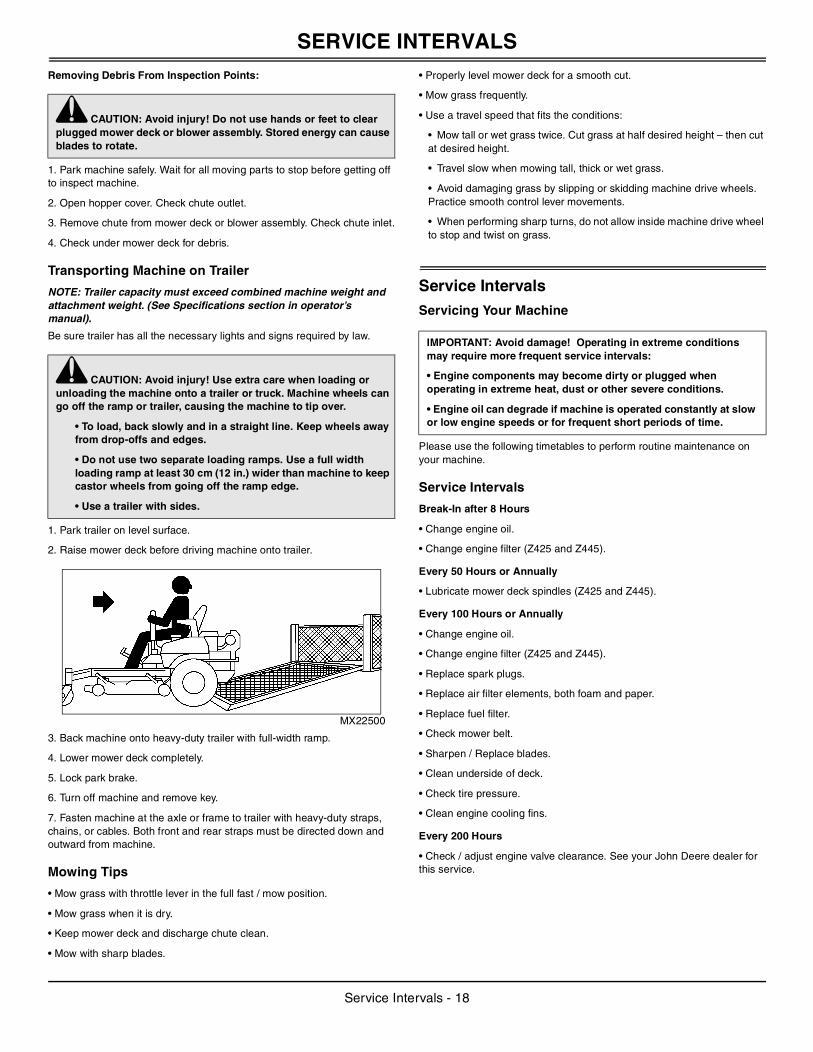
Transporting Machine on Trailer
NOTE: Trailer capacity must exceed combined machine weight and attachment weight. (See Specifications section in operator’s manual).
Be sure trailer has all the necessary lights and signs required by law.
1. Park trailer on level surface.
2. Raise mower deck before driving machine onto trailer.
MX22500
3. Back machine onto heavy-duty trailer with full-width ramp.
4. Lower mower deck completely.
5. Lock park brake.
6. Turn off machine and remove key.
7. Fasten machine at the axle or frame to trailer with heavy-duty straps, chains, or cables. Both front and rear straps must be directed down and outward from machine.
Mowing Tips
• Mow grass with throttle lever in the full fast / mow position.
• Mow grass when it is dry.
• Keep mower deck and discharge chute clean.
• Mow with sharp blades.
• Properly level mower deck for a smooth cut.
• Mow grass frequently.
• Use a travel speed that fits the conditions:
• Mow tall or wet grass twice. Cut grass at half desired height – then cut at desired height.
• Travel slow when mowing tall, thick or wet grass.
• Avoid damaging grass by slipping or skidding machine drive wheels. Practice smooth control lever movements.
• When performing sharp turns, do not allow inside machine drive wheel to stop and twist on grass.
Service IntervalsServicing Your Machine
Please use the following timetables to perform routine maintenance on your machine.
Service Intervals
Break-In after 8 Hours
• Change engine oil.
• Change engine filter (Z425 and Z445).
Every 50 Hours or Annually
• Lubricate mower deck spindles (Z425 and Z445).
Every 100 Hours or Annually
• Change engine oil.
• Change engine filter (Z425 and Z445).
• Replace spark plugs.
• Replace air filter elements, both foam and paper.
• Replace fuel filter.
• Check mower belt.
• Sharpen / Replace blades.
• Clean underside of deck.
• Check tire pressure.
• Clean engine cooling fins.
Every 200 Hours
• Check / adjust engine valve clearance. See your John Deere dealer for this service.
c CAUTION: Avoid injury! Do not use hands or feet to clear plugged mower deck or blower assembly. Stored energy can cause blades to rotate.
c CAUTION: Avoid injury! Use extra care when loading or unloading the machine onto a trailer or truck. Machine wheels can go off the ramp or trailer, causing the machine to tip over.
• To load, back slowly and in a straight line. Keep wheels away from drop-offs and edges.
• Do not use two separate loading ramps. Use a full width loading ramp at least 30 cm (12 in.) wider than machine to keep castor wheels from going off the ramp edge.
• Use a trailer with sides.
IMPORTANT: Avoid damage! Operating in extreme conditions may require more frequent service intervals:
• Engine components may become dirty or plugged when operating in extreme heat, dust or other severe conditions.
• Engine oil can degrade if machine is operated constantly at slow or low engine speeds or for frequent short periods of time.
Service Intervals - 18
SERVICE LUBRICATION
Service LubricationGrease
The following greases are preferred:
• John Deere Multi-Purpose SD Polyurea Grease
• John Deere Multi-Purpose HD Lithium Complex Grease
If not using any of the preferred greases, be sure to use a general all-purpose grease with an NLGI grade No.2 rating.
Wet or high speed conditions may require use of a special-use grease. Contact your Servicing dealer for information.
Lubricating Mower Deck Spindles
NOTE: Removal of belt shields is not necessary to lubricate the spindles.
1. Remove mower deck foot plate.
42 in. Mower Deck
MX37890
• Lubricate two mower deck spindle grease fittings (A) with two pumps of grease at specified interval.
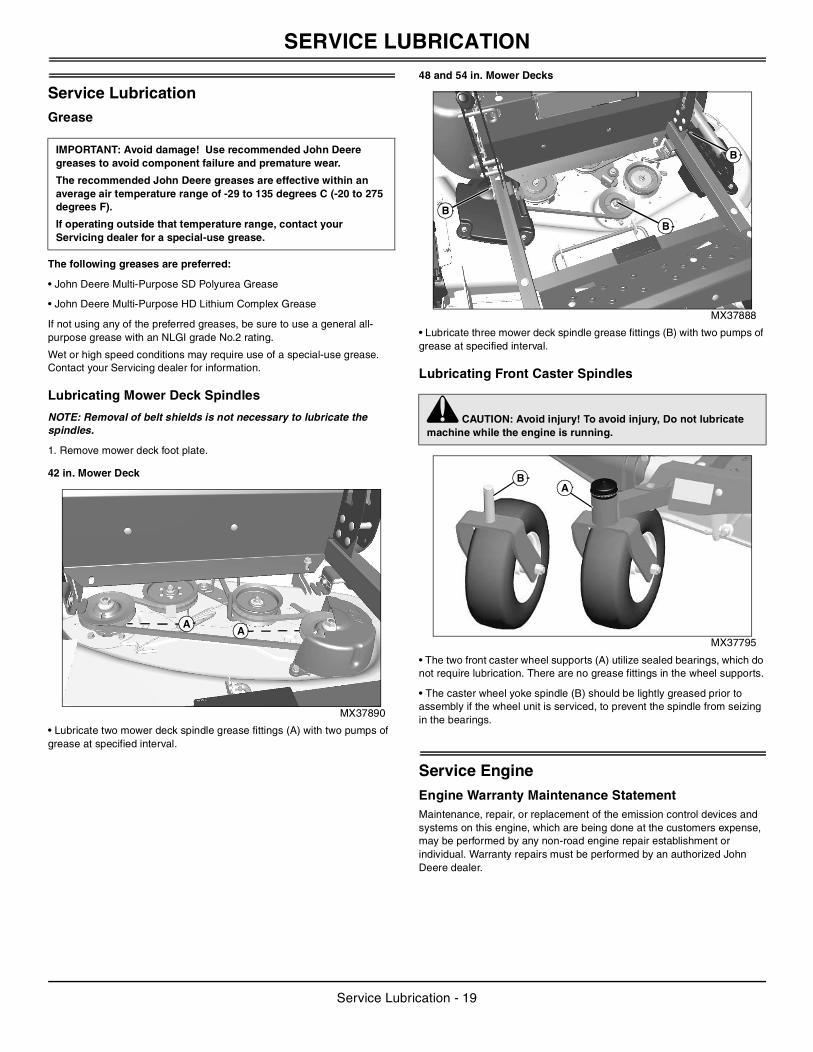
48 and 54 in. Mower Decks
MX37888
• Lubricate three mower deck spindle grease fittings (B) with two pumps of grease at specified interval.
Lubricating Front Caster Spindles
MX37795
• The two front caster wheel supports (A) utilize sealed bearings, which do not require lubrication. There are no grease fittings in the wheel supports.
• The caster wheel yoke spindle (B) should be lightly greased prior to assembly if the wheel unit is serviced, to prevent the spindle from seizing in the bearings.
Service EngineEngine Warranty Maintenance StatementMaintenance, repair, or replacement of the emission control devices and systems on this engine, which are being done at the customers expense, may be performed by any non-road engine repair establishment or individual. Warranty repairs must be performed by an authorized John Deere dealer.
IMPORTANT: Avoid damage! Use recommended John Deere greases to avoid component failure and premature wear.
The recommended John Deere greases are effective within an average air temperature range of -29 to 135 degrees C (-20 to 275 degrees F).
If operating outside that temperature range, contact your Servicing dealer for a special-use grease.
AA
c CAUTION: Avoid injury! To avoid injury, Do not lubricate machine while the engine is running.
B
B
B
BA
Service Lubrication - 19
SERVICE ENGINE
Avoid Fumes
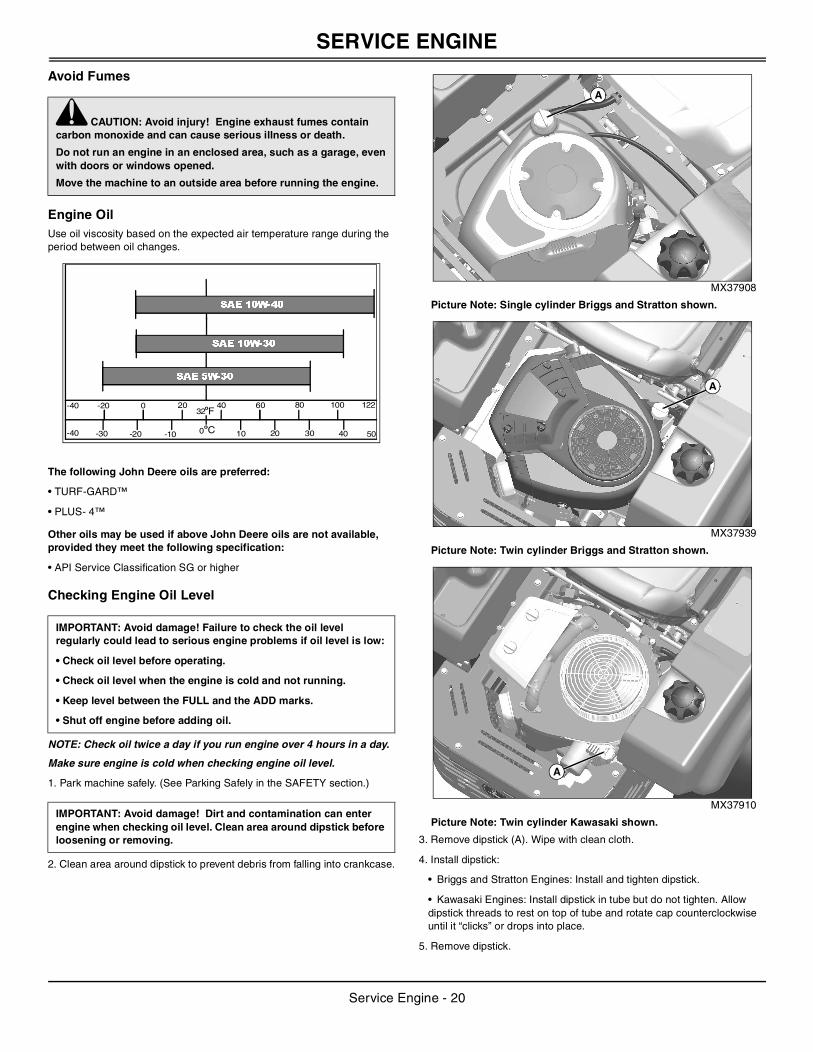
Engine OilUse oil viscosity based on the expected air temperature range during the period between oil changes.
The following John Deere oils are preferred:
• TURF-GARD™
• PLUS- 4™
Other oils may be used if above John Deere oils are not available, provided they meet the following specification:
• API Service Classification SG or higher
Checking Engine Oil Level
NOTE: Check oil twice a day if you run engine over 4 hours in a day.
Make sure engine is cold when checking engine oil level.
1. Park machine safely. (See Parking Safely in the SAFETY section.)
2. Clean area around dipstick to prevent debris from falling into crankcase.
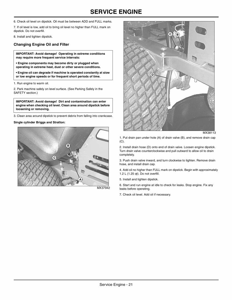
MX37908
Picture Note: Single cylinder Briggs and Stratton shown.
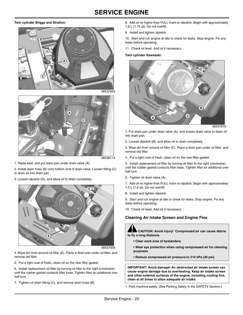
MX37939
Picture Note: Twin cylinder Briggs and Stratton shown.
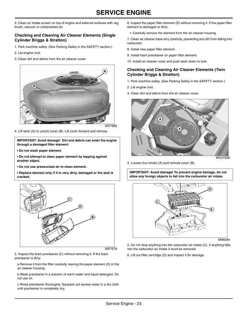
MX37910
Picture Note: Twin cylinder Kawasaki shown.
3. Remove dipstick (A). Wipe with clean cloth.
4. Install dipstick:
• Briggs and Stratton Engines: Install and tighten dipstick.
• Kawasaki Engines: Install dipstick in tube but do not tighten. Allow dipstick threads to rest on top of tube and rotate cap counterclockwise until it “clicks” or drops into place.
5. Remove dipstick.
c CAUTION: Avoid injury! Engine exhaust fumes contain carbon monoxide and can cause serious illness or death.
Do not run an engine in an enclosed area, such as a garage, even with doors or windows opened.
Move the machine to an outside area before running the engine.
IMPORTANT: Avoid damage! Failure to check the oil level regularly could lead to serious engine problems if oil level is low:
• Check oil level before operating.
• Check oil level when the engine is cold and not running.
• Keep level between the FULL and the ADD marks.
• Shut off engine before adding oil.
IMPORTANT: Avoid damage! Dirt and contamination can enter engine when checking oil level. Clean area around dipstick before loosening or removing.
32
0 10 20 30 40-10-20-30
-20 0 20 40 60 80 100
50
122
-40
-40F
C
SAE 5W-30
SAE 10W-30
SAE 10W-40
A
A
A
Service Engine - 20
SERVICE ENGINE
6. Check oil level on dipstick. Oil must be between ADD and FULL marks.7. If oil level is low, add oil to bring oil level no higher than FULL mark on dipstick. Do not overfill.
8. Install and tighten dipstick.
Changing Engine Oil and Filter
1. Run engine to warm oil.
2. Park machine safely on level surface. (See Parking Safely in the SAFETY section.)
3. Clean area around dipstick to prevent debris from falling into crankcase.
Single cylinder Briggs and Stratton:
MX37942
MX38113
1. Put drain pan under hole (A) of drain valve (B), and remove drain cap (C).
2. Install drain hose (D) onto end of drain valve. Loosen engine dipstick. Turn drain valve counterclockwise and pull outward to allow oil to drain completely.
3. Push drain valve inward, and turn clockwise to tighten. Remove drain hose, and install drain cap.
4. Add oil no higher than FULL mark on dipstick. Begin with approximately 1.2 L (1.25 qt). Do not overfill.
5. Install and tighten dipstick.
6. Start and run engine at idle to check for leaks. Stop engine. Fix any leaks before operating.
7. Check oil level. Add oil if necessary.
IMPORTANT: Avoid damage! Operating in extreme conditions may require more frequent service intervals:
• Engine components may become dirty or plugged when operating in extreme heat, dust or other severe conditions.
• Engine oil can degrade if machine is operated constantly at slow or low engine speeds or for frequent short periods of time.
IMPORTANT: Avoid damage! Dirt and contamination can enter engine when checking oil level. Clean area around dipstick before loosening or removing.
C
A
B
D
BC
Service Engine - 21
SERVICE ENGINE
Twin cylinder Briggs and Stratton:MX37943
MX38114
1. Raise seat, and put drain pan under drain valve (A).
2. Install drain hose (B) onto bottom end of drain valve. Loosen fitting (C) to drain oil into drain pan.
3. Loosen dipstick (D), and allow oil to drain completely.
MX37939
4. Wipe dirt from around oil filter (E). Place a drain pan under oil filter, and remove old filter.
5. Put a light coat of fresh, clean oil on the new filter gasket.
6. Install replacement oil filter by turning oil filter to the right (clockwise) until the rubber gasket contacts filter base. Tighten filter an additional one-half turn.
7. Tighten oil drain fitting (C), and remove drain hose (B).
8. Add oil no higher than FULL mark on dipstick. Begin with approximately 1.6 L (1.75 qt). Do not overfill.
9. Install and tighten dipstick.
10. Start and run engine at idle to check for leaks. Stop engine. Fix any leaks before operating.
11. Check oil level. Add oil if necessary.
Twin cylinder Kawasaki:
MX37910
1. Put drain pan under drain valve (A), and loosen drain valve to drain oil into drain pan.
2. Loosen dipstick (B), and allow oil to drain completely.
3. Wipe dirt from around oil filter (C). Place a drain pan under oil filter, and remove old filter.
4. Put a light coat of fresh, clean oil on the new filter gasket.
5. Install replacement oil filter by turning oil filter to the right (clockwise) until the rubber gasket contacts filter base. Tighten filter an additional one-half turn.
6. Tighten oil drain valve (A).
7. Add oil no higher than FULL mark on dipstick. Begin with approximately 1.5 L (1.6 qt). Do not overfill.
8. Install and tighten dipstick.
9. Start and run engine at idle to check for leaks. Stop engine. Fix any leaks before operating.
10. Check oil level. Add oil if necessary.
Cleaning Air Intake Screen and Engine Fins
1. Park machine safely. (See Parking Safely in the SAFETY Section.)
C
A
D
C
A
B
E
c CAUTION: Avoid injury! Compressed air can cause debris to fly a long distance.
• Clear work area of bystanders.
• Wear eye protection when using compressed air for cleaning purposes.
• Reduce compressed air pressure to 210 kPa (30 psi).
IMPORTANT: Avoid damage! An obstructed air intake screen can cause engine damage due to overheating. Keep air intake screen and other external surfaces of the engine, including cooling fins, clean at all times to allow adequate air intake.
AC
B
Service Engine - 22
SERVICE ENGINE
2. Clean air intake screen on top of engine and external surfaces with rag, brush, vacuum or compressed air.Checking and Cleaning Air Cleaner Elements (Single Cylinder Briggs & Stratton)
1. Park machine safely. (See Parking Safely in the SAFETY section.)
2. Let engine cool.
3. Clean dirt and debris from the air cleaner cover.
MX7680
4. Lift latch (A) to unlock cover (B). Lift cover forward and remove.
MX7679
5. Inspect the foam precleaner (C) without removing it. If the foam precleaner is dirty:
a.Remove it from the filter carefully, leaving the paper element (D) in the air cleaner housing.
b.Wash precleaner in a solution of warm water and liquid detergent. Do not use oil.
c.Rinse precleaner thoroughly. Squeeze out excess water in a dry cloth until precleaner is completely dry.
6. Inspect the paper filter element (D) without removing it. If the paper filter element is damaged or dirty:
• Carefully remove the element from the air cleaner housing.
7. Clean air cleaner base very carefully, preventing any dirt from falling into carburetor.
8. Install new paper filter element.
9. Install foam precleaner on paper filter element.
10. Install air cleaner cover and push latch down to lock.
Checking and Cleaning Air Cleaner Elements (Twin Cylinder Briggs & Stratton)
1. Park machine safely. (See Parking Safely in the SAFETY section.)
2. Let engine cool.
3. Clean dirt and debris from the air cleaner cover.
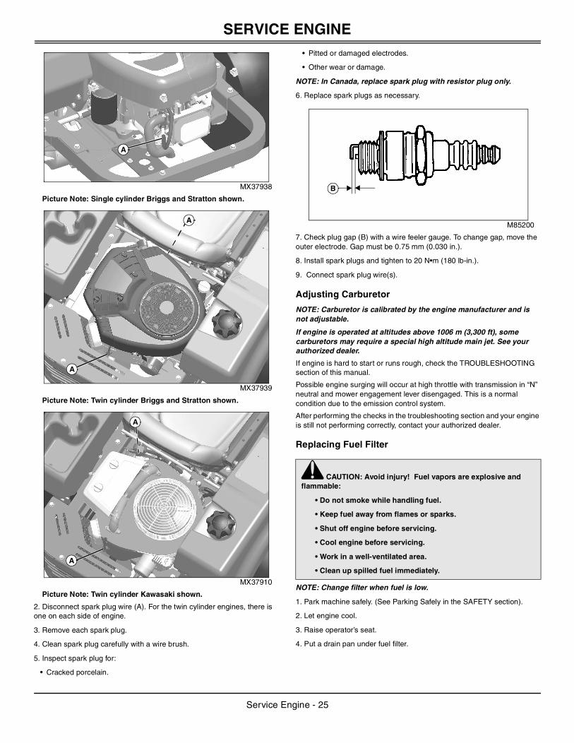
MX37939
4. Loosen four knobs (A) and remove cover (B).
M96094
5. Do not drop anything into the carburetor air intake (C). If anything falls into the carburetor air intake it must be removed.
6. Lift out filter cartridge (D) and inspect it for damage.
IMPORTANT: Avoid damage! Dirt and debris can enter the engine through a damaged filter element:
• Do not wash paper element.
• Do not attempt to clean paper element by tapping against another object.
• Do not use pressurized air to clean element.
• Replace element only if it is very dirty, damaged or the seal is cracked.
B
A
B
D
C
IMPORTANT: Avoid damage! To prevent engine damage, do not allow any foreign objects to fall into the carburetor air intake.
A
A
B
D
E
C
Service Engine - 23
SERVICE ENGINE
7. Inspect the foam precleaner (E) without removing it. If the foam precleaner is dirty:
a.Remove it from the filter carefully.
b.Wash precleaner in a solution of warm water and liquid detergent.
c.Rinse precleaner thoroughly. Squeeze out excess water in a dry cloth until precleaner is completely dry.
8. Clean air cleaner housing carefully. Prevent any dirt from falling into carburetor.
9. Install foam precleaner mesh side up.
10. Install cartridge. Make sure cartridge and seal are properly seated and sealing the carburetor air intake area.
11. Install air cleaner cover and tighten knobs. Do not overtighten.
Checking and Cleaning Air Cleaner Elements (Twin Cylinder Kawasaki)
1. Park machine safely (See Parking Safely in the SAFETY section).
2. Let engine cool.
3. Clean dirt and debris from the air cleaner cover.
MX37910
4. Loosen two knobs (A) and remove cover (B).
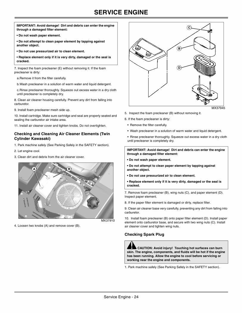
MX37945
5. Inspect the foam precleaner (B) without removing it.
6. If the foam precleaner is dirty:
• Remove the filter carefully.
• Wash precleaner in a solution of warm water and liquid detergent.
• Rinse precleaner thoroughly. Squeeze out excess water in a dry cloth until precleaner is completely dry.
7. Remove foam precleaner (B), wing nuts (C), and paper element (D). Inspect paper element.
8. If the paper filter element is damaged or dirty, replace filter.
9. Clean air cleaner base very carefully, preventing any dirt from falling into carburetor.
10. Install foam precleaner (B) onto paper filter element (D). Install paper element onto carburetor base, and secure with two wing nuts (C). Install air cleaner cover and tighten wing nuts.
Checking Spark Plug
1. Park machine safely (See Parking Safely in the SAFETY section).
IMPORTANT: Avoid damage! Dirt and debris can enter the engine through a damaged filter element:
• Do not wash paper element.
• Do not attempt to clean paper element by tapping against another object.
• Do not use pressurized air to clean element.
• Replace element only if it is very dirty, damaged or the seal is cracked.
BA
IMPORTANT: Avoid damage! Dirt and debris can enter the engine through a damaged filter element:
• Do not wash paper element.
• Do not attempt to clean paper element by tapping against another object.
• Do not use pressurized air to clean element.
• Replace element only if it is very dirty, damaged or the seal is cracked.
c CAUTION: Avoid injury! Touching hot surfaces can burn skin. The engine, components, and fluids will be hot if the engine has been running. Allow the engine to cool before servicing or working near the engine and components.
B
D
C
Service Engine - 24
SERVICE ENGINE
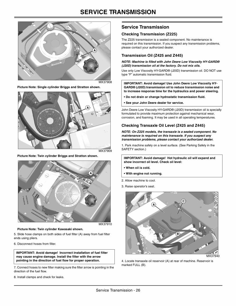
MX37938
Picture Note: Single cylinder Briggs and Stratton shown.
MX37939
Picture Note: Twin cylinder Briggs and Stratton shown.
MX37910
Picture Note: Twin cylinder Kawasaki shown.
2. Disconnect spark plug wire (A). For the twin cylinder engines, there is one on each side of engine.
3. Remove each spark plug.
4. Clean spark plug carefully with a wire brush.
5. Inspect spark plug for:
• Cracked porcelain.
• Pitted or damaged electrodes.
• Other wear or damage.
NOTE: In Canada, replace spark plug with resistor plug only.
6. Replace spark plugs as necessary.
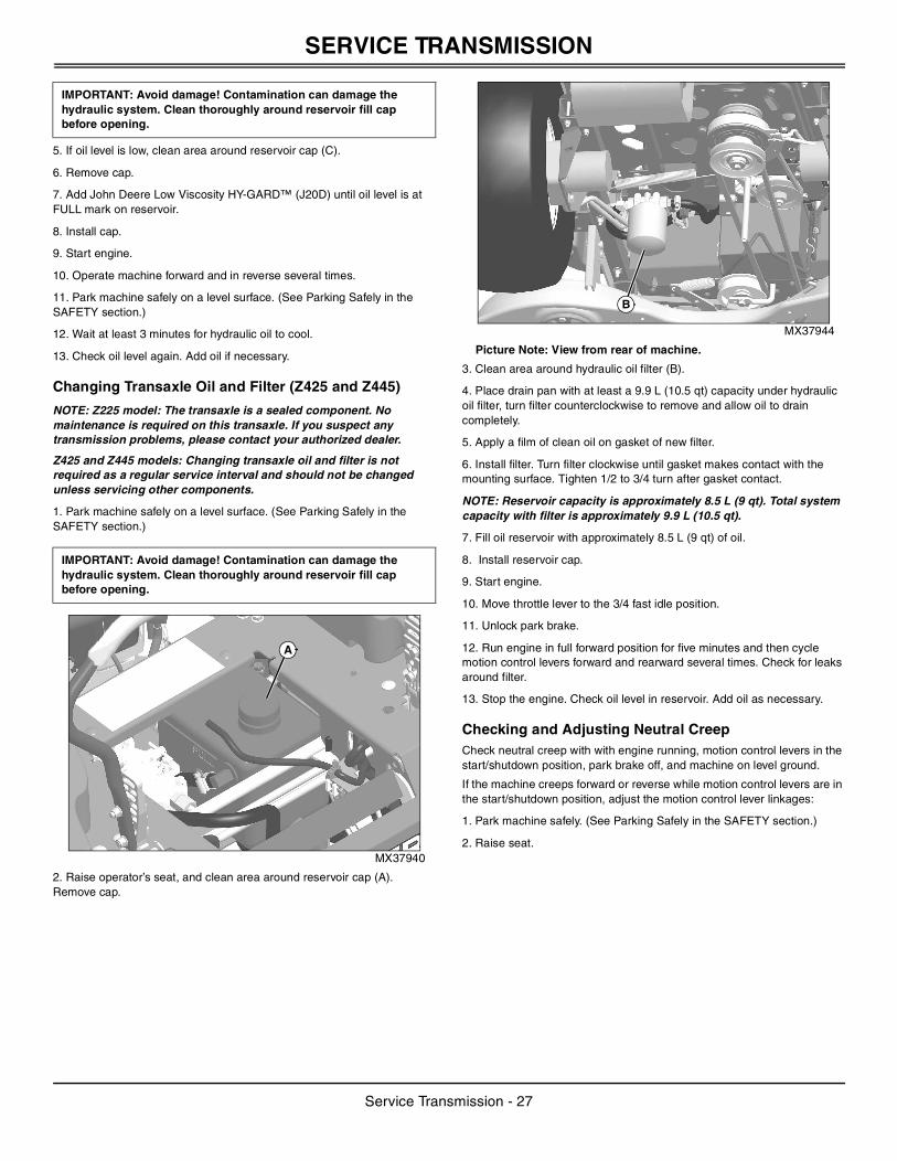
M85200
7. Check plug gap (B) with a wire feeler gauge. To change gap, move the outer electrode. Gap must be 0.75 mm (0.030 in.).
8. Install spark plugs and tighten to 20 N•m (180 lb-in.).
9. Connect spark plug wire(s).
Adjusting Carburetor
NOTE: Carburetor is calibrated by the engine manufacturer and is not adjustable.
If engine is operated at altitudes above 1006 m (3,300 ft), some carburetors may require a special high altitude main jet. See your authorized dealer.
If engine is hard to start or runs rough, check the TROUBLESHOOTING section of this manual.
Possible engine surging will occur at high throttle with transmission in “N” neutral and mower engagement lever disengaged. This is a normal condition due to the emission control system.
After performing the checks in the troubleshooting section and your engine is still not performing correctly, contact your authorized dealer.
Replacing Fuel Filter
NOTE: Change filter when fuel is low.
1. Park machine safely. (See Parking Safely in the SAFETY section).
2. Let engine cool.
3. Raise operator’s seat.
4. Put a drain pan under fuel filter.
A
A
A
A
A
c CAUTION: Avoid injury! Fuel vapors are explosive and flammable:
• Do not smoke while handling fuel.
• Keep fuel away from flames or sparks.
• Shut off engine before servicing.
• Cool engine before servicing.
• Work in a well-ventilated area.
• Clean up spilled fuel immediately.
B
Service Engine - 25
SERVICE TRANSMISSION
MX37908
Picture Note: Single cylinder Briggs and Stratton shown.
MX37909
Picture Note: Twin cylinder Briggs and Stratton shown.
MX37910
Picture Note: Twin cylinder Kawasaki shown.
5. Slide hose clamps on both sides of fuel filter (A) away from fuel filter ends using pliers.
6. Disconnect hoses from filter.
7. Connect hoses to new filter making sure the filter arrow is pointing in the direction of the fuel flow.
8. Install clamps and check for leaks.
Service Transmission Checking Transmission (Z225)The Z225 transmission is a sealed component. No maintenance is required on this transmission. If you suspect any transmission problems, please contact your authorized dealer.
Transmission Oil (Z425 and Z445)
NOTE: Machine is filled with John Deere Low Viscosity HY-GARD® (J20D) transmission oil at the factory. Do not mix oils.
Use only Low Viscosity HY-GARD® (J20D) transmission oil. DO NOT use type “F” automatic transmission fluid.
John Deere Low Viscosity HY-GARD® (J20D) transmission oil is specially formulated to provide maximum protection against mechanical wear, corrosion, and foaming. It may be used in all operating temperatures.
Checking Transaxle Oil Level (Z425 and Z445)
NOTE: On Z225 models, the transaxle is a sealed component. No maintenance is required on this transaxle. If you suspect any transmission problems, please contact your authorized dealer.
1. Park machine safely on a level surface. (See Parking Safely in the SAFETY section.)
2. Allow machine to cool.
3. Raise operator’s seat.
MX37940
4. Locate transaxle oil reservoir (A) at rear of machine. Reservoir is marked FULL (B).
IMPORTANT: Avoid damage! Incorrect installation of fuel filter may cause engine damage. Install the filter with the arrow pointing in the direction of fuel flow for proper operation.
A
A
A
IMPORTANT: Avoid damage! Use John Deere Low Viscosity HY-GARD® (J20D) transmission oil to reduce transmission noise and to increase response time for the hydraulics and power steering.
• Do not drain or change hydrostatic transmission fluid.
• See your John Deere dealer for service.
IMPORTANT: Avoid damage! Hot hydraulic oil will expand and show incorrect oil level. Check oil level:
• When oil is cold.
• With engine not running.
AC
B
Service Transmission - 26
SERVICE TRANSMISSION
5. If oil level is low, clean area around reservoir cap (C).
6. Remove cap.
7. Add John Deere Low Viscosity HY-GARD™ (J20D) until oil level is at FULL mark on reservoir.
8. Install cap.
9. Start engine.
10. Operate machine forward and in reverse several times.
11. Park machine safely on a level surface. (See Parking Safely in the SAFETY section.)
12. Wait at least 3 minutes for hydraulic oil to cool.
13. Check oil level again. Add oil if necessary.
Changing Transaxle Oil and Filter (Z425 and Z445)
NOTE: Z225 model: The transaxle is a sealed component. No maintenance is required on this transaxle. If you suspect any transmission problems, please contact your authorized dealer.
Z425 and Z445 models: Changing transaxle oil and filter is not required as a regular service interval and should not be changed unless servicing other components.
1. Park machine safely on a level surface. (See Parking Safely in the SAFETY section.)
MX37940
2. Raise operator’s seat, and clean area around reservoir cap (A). Remove cap.
MX37944
Picture Note: View from rear of machine.
3. Clean area around hydraulic oil filter (B).
4. Place drain pan with at least a 9.9 L (10.5 qt) capacity under hydraulic oil filter, turn filter counterclockwise to remove and allow oil to drain completely.
5. Apply a film of clean oil on gasket of new filter.
6. Install filter. Turn filter clockwise until gasket makes contact with the mounting surface. Tighten 1/2 to 3/4 turn after gasket contact.
NOTE: Reservoir capacity is approximately 8.5 L (9 qt). Total system capacity with filter is approximately 9.9 L (10.5 qt).
7. Fill oil reservoir with approximately 8.5 L (9 qt) of oil.
8. Install reservoir cap.
9. Start engine.
10. Move throttle lever to the 3/4 fast idle position.
11. Unlock park brake.
12. Run engine in full forward position for five minutes and then cycle motion control levers forward and rearward several times. Check for leaks around filter.
13. Stop the engine. Check oil level in reservoir. Add oil as necessary.
Checking and Adjusting Neutral CreepCheck neutral creep with with engine running, motion control levers in the start/shutdown position, park brake off, and machine on level ground.
If the machine creeps forward or reverse while motion control levers are in the start/shutdown position, adjust the motion control lever linkages:
1. Park machine safely. (See Parking Safely in the SAFETY section.)
2. Raise seat.
IMPORTANT: Avoid damage! Contamination can damage the hydraulic system. Clean thoroughly around reservoir fill cap before opening.
IMPORTANT: Avoid damage! Contamination can damage the hydraulic system. Clean thoroughly around reservoir fill cap before opening.
A
B
Service Transmission - 27
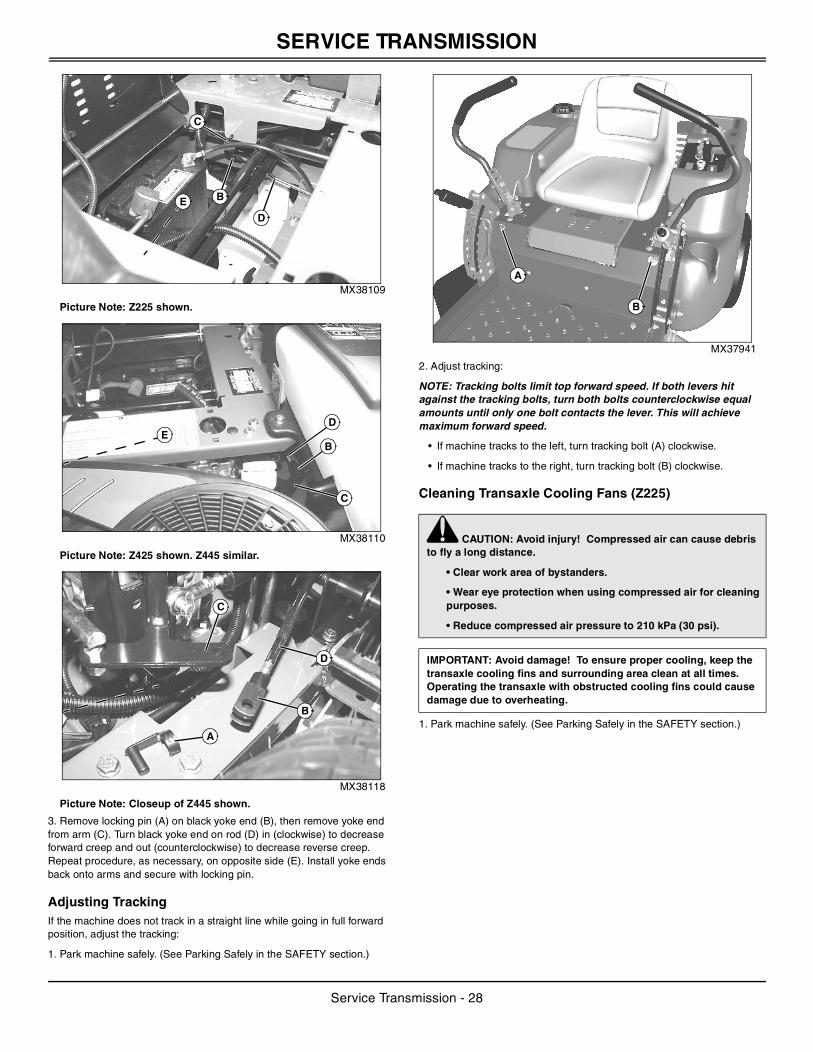
SERVICE TRANSMISSION
MX38109
Picture Note: Z225 shown.
MX38110
Picture Note: Z425 shown. Z445 similar.
MX38118
Picture Note: Closeup of Z445 shown.
3. Remove locking pin (A) on black yoke end (B), then remove yoke end from arm (C). Turn black yoke end on rod (D) in (clockwise) to decrease forward creep and out (counterclockwise) to decrease reverse creep. Repeat procedure, as necessary, on opposite side (E). Install yoke ends back onto arms and secure with locking pin.
Adjusting TrackingIf the machine does not track in a straight line while going in full forward position, adjust the tracking:
1. Park machine safely. (See Parking Safely in the SAFETY section.)
MX37941
2. Adjust tracking:
NOTE: Tracking bolts limit top forward speed. If both levers hit against the tracking bolts, turn both bolts counterclockwise equal amounts until only one bolt contacts the lever. This will achieve maximum forward speed.
• If machine tracks to the left, turn tracking bolt (A) clockwise.
• If machine tracks to the right, turn tracking bolt (B) clockwise.
Cleaning Transaxle Cooling Fans (Z225)
1. Park machine safely. (See Parking Safely in the SAFETY section.)
B
D
E
C
ED
B
C
C
A
D
B
c CAUTION: Avoid injury! Compressed air can cause debris to fly a long distance.
• Clear work area of bystanders.
• Wear eye protection when using compressed air for cleaning purposes.
• Reduce compressed air pressure to 210 kPa (30 psi).
IMPORTANT: Avoid damage! To ensure proper cooling, keep the transaxle cooling fins and surrounding area clean at all times. Operating the transaxle with obstructed cooling fins could cause damage due to overheating.
A
B
Service Transmission - 28
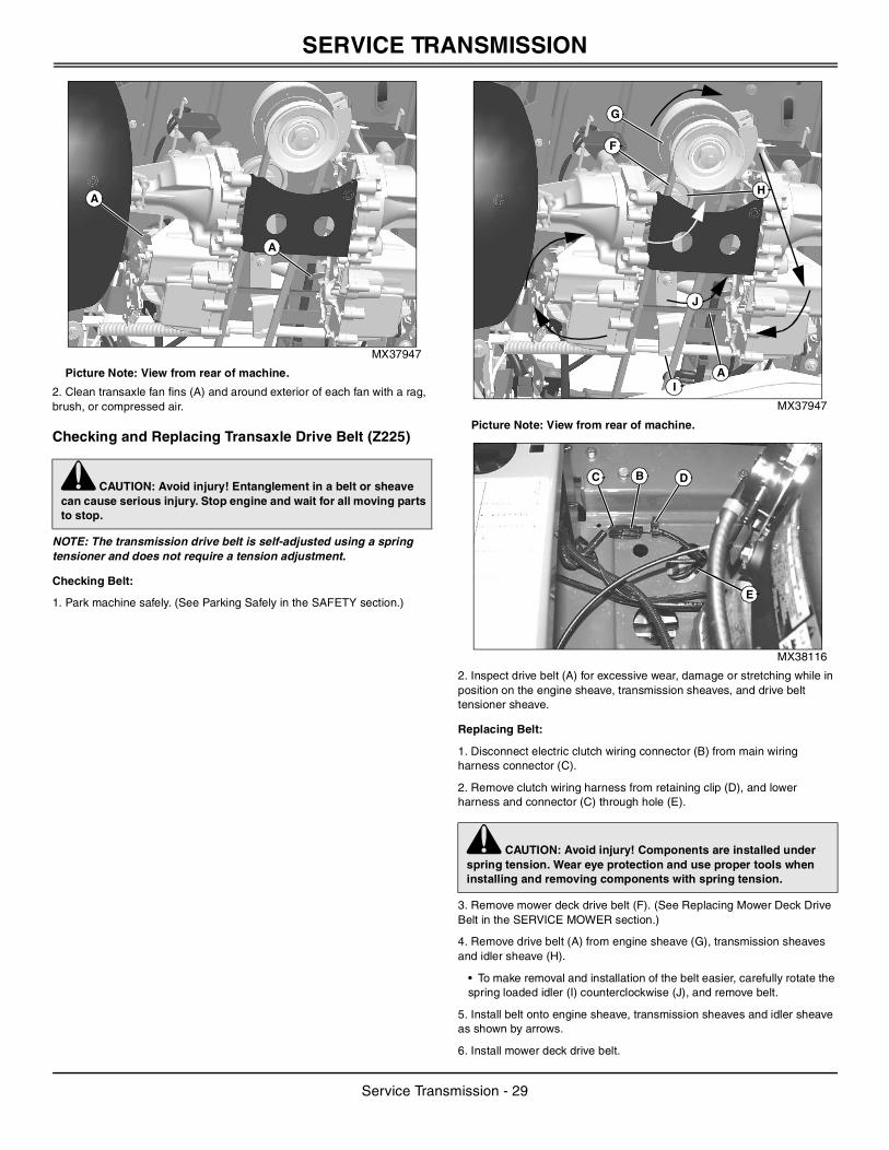
SERVICE TRANSMISSION
MX37947
Picture Note: View from rear of machine.
2. Clean transaxle fan fins (A) and around exterior of each fan with a rag, brush, or compressed air.
Checking and Replacing Transaxle Drive Belt (Z225)
NOTE: The transmission drive belt is self-adjusted using a spring tensioner and does not require a tension adjustment.
Checking Belt:
1. Park machine safely. (See Parking Safely in the SAFETY section.)
MX37947
Picture Note: View from rear of machine.
MX38116
2. Inspect drive belt (A) for excessive wear, damage or stretching while in position on the engine sheave, transmission sheaves, and drive belt tensioner sheave.
Replacing Belt:
1. Disconnect electric clutch wiring connector (B) from main wiring harness connector (C).
2. Remove clutch wiring harness from retaining clip (D), and lower harness and connector (C) through hole (E).
3. Remove mower deck drive belt (F). (See Replacing Mower Deck Drive Belt in the SERVICE MOWER section.)
4. Remove drive belt (A) from engine sheave (G), transmission sheaves and idler sheave (H).
• To make removal and installation of the belt easier, carefully rotate the spring loaded idler (I) counterclockwise (J), and remove belt.
5. Install belt onto engine sheave, transmission sheaves and idler sheave as shown by arrows.
6. Install mower deck drive belt.
c CAUTION: Avoid injury! Entanglement in a belt or sheave can cause serious injury. Stop engine and wait for all moving parts to stop.
A
A
c CAUTION: Avoid injury! Components are installed under spring tension. Wear eye protection and use proper tools when installing and removing components with spring tension.
IA
F
G
J
H
C B D
E
Service Transmission - 29
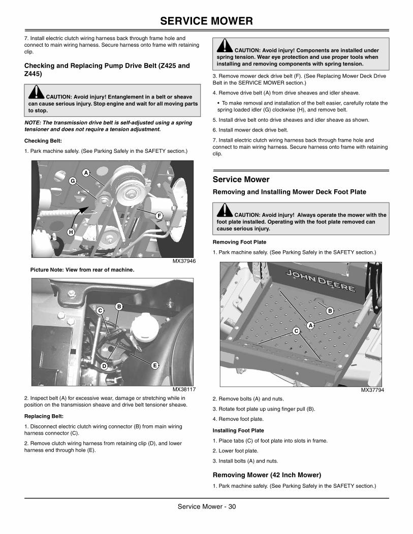
SERVICE MOWER
7. Install electric clutch wiring harness back through frame hole and connect to main wiring harness. Secure harness onto frame with retaining clip.Checking and Replacing Pump Drive Belt (Z425 and Z445)
NOTE: The transmission drive belt is self-adjusted using a spring tensioner and does not require a tension adjustment.
Checking Belt:
1. Park machine safely. (See Parking Safely in the SAFETY section.)
MX37946
Picture Note: View from rear of machine.
MX38117
2. Inspect belt (A) for excessive wear, damage or stretching while in position on the transmission sheave and drive belt tensioner sheave.
Replacing Belt:
1. Disconnect electric clutch wiring connector (B) from main wiring harness connector (C).
2. Remove clutch wiring harness from retaining clip (D), and lower harness end through hole (E).
3. Remove mower deck drive belt (F). (See Replacing Mower Deck Drive Belt in the SERVICE MOWER section.)
4. Remove drive belt (A) from drive sheaves and idler sheave.
• To make removal and installation of the belt easier, carefully rotate the spring loaded idler (G) clockwise (H), and remove belt.
5. Install drive belt onto drive sheaves and idler sheave as shown.
6. Install mower deck drive belt.
7. Install electric clutch wiring harness back through frame hole and connect to main wiring harness. Secure harness onto frame with retaining clip.
Service MowerRemoving and Installing Mower Deck Foot Plate
Removing Foot Plate
1. Park machine safely. (See Parking Safely in the SAFETY section.)
MX37794
2. Remove bolts (A) and nuts.
3. Rotate foot plate up using finger pull (B).
4. Remove foot plate.
Installing Foot Plate
1. Place tabs (C) of foot plate into slots in frame.
2. Lower foot plate.
3. Install bolts (A) and nuts.
Removing Mower (42 Inch Mower)
1. Park machine safely. (See Parking Safely in the SAFETY section.)
c CAUTION: Avoid injury! Entanglement in a belt or sheave can cause serious injury. Stop engine and wait for all moving parts to stop.
A
G
H
F
CB
D E
c CAUTION: Avoid injury! Components are installed under spring tension. Wear eye protection and use proper tools when installing and removing components with spring tension.
c CAUTION: Avoid injury! Always operate the mower with the foot plate installed. Operating with the foot plate removed can cause serious injury.
C
B
A
Service Mower - 30
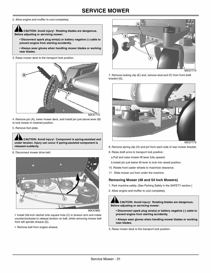
SERVICE MOWER
2. Allow engine and muffler to cool completely.3. Raise mower deck to the transport lock position.
MX37775
4. Remove pin (A), lower mower deck, and install pin just above lever (B) to lock mower in lowered position.
5. Remove foot plate.
6. Disconnect mower drive belt:
MX37890
• Install 3/8-inch ratchet onto square hole (C) in tension arm and rotate counterclockwise to release tension on belt, while removing mower belt from left spindle sheave (D).
• Remove belt from engine sheave.
MX37774
7. Remove locking clip (E) and, remove stud end (F) from front draft bracket (G).
MX37773
8. Remove spring clip (H) and pin from each side of rear mower bracket.
9. Raise draft arms to transport lock position:
a.Pull and raise mower lift lever fully upward.
b.Install pin just below lift lever to lock into raised position.
10. Rotate front caster wheels to maximize clearance.
11. Slide mower out from under the machine.
Removing Mower (48 and 54 Inch Mowers)
1. Park machine safely. (See Parking Safely in the SAFETY section.)
2. Allow engine and muffler to cool completely.
3. Raise mower deck to the transport lock position.
c CAUTION: Avoid injury! Rotating blades are dangerous. Before adjusting or servicing mower:
• Disconnect spark plug wire(s) or battery negative (-) cable to prevent engine from starting accidently.
• Always wear gloves when handling mower blades or working near blades.
c CAUTION: Avoid injury! Component is spring-assisted and under tension. Injury can occur if spring-assisted component is released suddenly.
A
B
CD c CAUTION: Avoid injury! Rotating blades are dangerous.
Before adjusting or servicing mower:
• Disconnect spark plug wire(s) or battery negative (-) cable to prevent engine from starting accidently.
• Always wear gloves when handling mower blades or working near blades.
G
E
F
H
Service Mower - 31
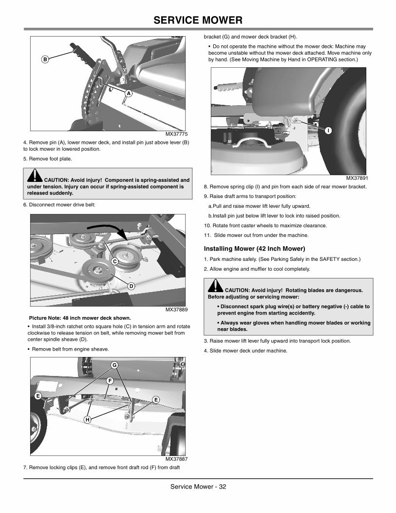
SERVICE MOWER
MX37775
4. Remove pin (A), lower mower deck, and install pin just above lever (B) to lock mower in lowered position.
5. Remove foot plate.
6. Disconnect mower drive belt:
MX37889
Picture Note: 48 inch mower deck shown.
• Install 3/8-inch ratchet onto square hole (C) in tension arm and rotate clockwise to release tension on belt, while removing mower belt from center spindle sheave (D).
• Remove belt from engine sheave.
MX37887
7. Remove locking clips (E), and remove front draft rod (F) from draft
bracket (G) and mower deck bracket (H).
• Do not operate the machine without the mower deck: Machine may become unstable without the mower deck attached. Move machine only by hand. (See Moving Machine by Hand in OPERATING section.)
MX37891
8. Remove spring clip (I) and pin from each side of rear mower bracket.
9. Raise draft arms to transport position:
a.Pull and raise mower lift lever fully upward.
b.Install pin just below lift lever to lock into raised position.
10. Rotate front caster wheels to maximize clearance.
11. Slide mower out from under the machine.
Installing Mower (42 Inch Mower)
1. Park machine safely. (See Parking Safely in the SAFETY section.)
2. Allow engine and muffler to cool completely.
3. Raise mower lift lever fully upward into transport lock position.
4. Slide mower deck under machine.
c CAUTION: Avoid injury! Component is spring-assisted and under tension. Injury can occur if spring-assisted component is released suddenly.
A
B
C
D
EE
G
F
H
c CAUTION: Avoid injury! Rotating blades are dangerous. Before adjusting or servicing mower:
• Disconnect spark plug wire(s) or battery negative (-) cable to prevent engine from starting accidently.
• Always wear gloves when handling mower blades or working near blades.
I
Service Mower - 32
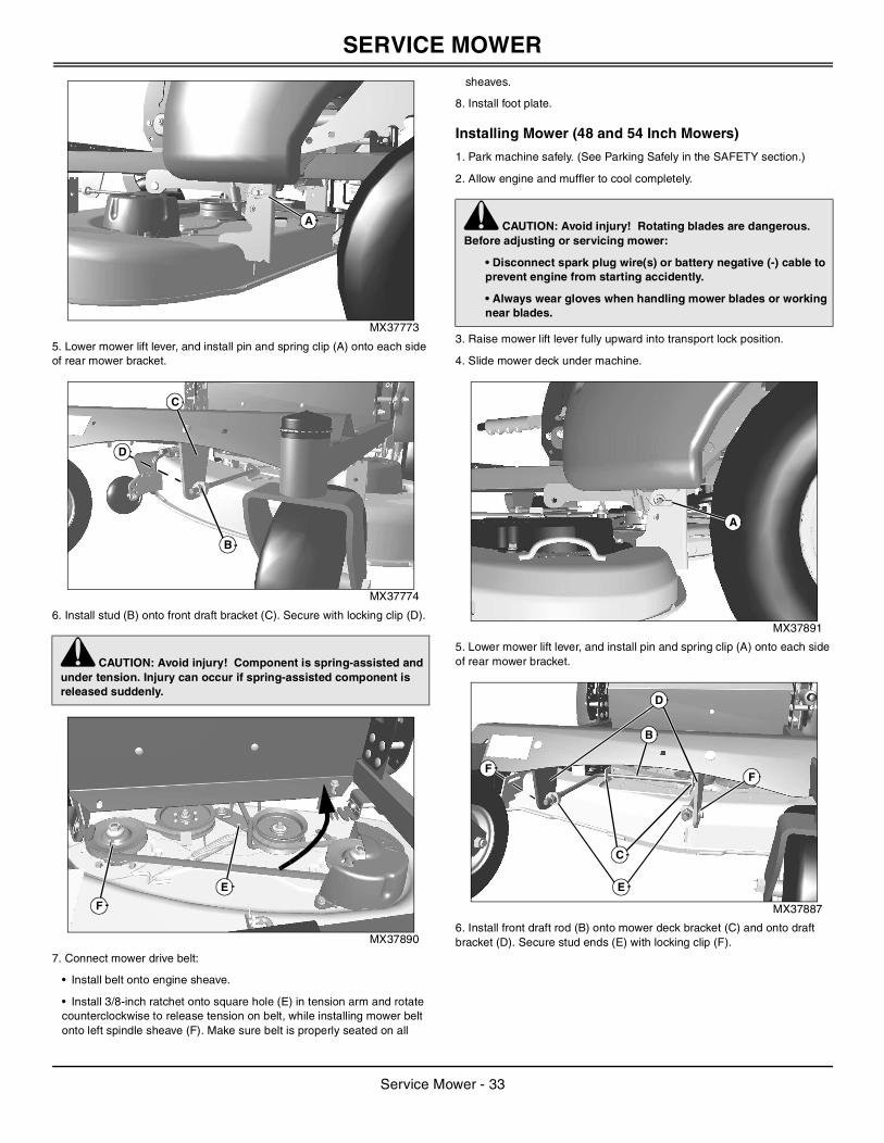
SERVICE MOWER
MX37773
5. Lower mower lift lever, and install pin and spring clip (A) onto each side of rear mower bracket.
MX37774
6. Install stud (B) onto front draft bracket (C). Secure with locking clip (D).
MX37890
7. Connect mower drive belt:
• Install belt onto engine sheave.
• Install 3/8-inch ratchet onto square hole (E) in tension arm and rotate counterclockwise to release tension on belt, while installing mower belt onto left spindle sheave (F). Make sure belt is properly seated on all
sheaves.
8. Install foot plate.
Installing Mower (48 and 54 Inch Mowers)
1. Park machine safely. (See Parking Safely in the SAFETY section.)
2. Allow engine and muffler to cool completely.
3. Raise mower lift lever fully upward into transport lock position.
4. Slide mower deck under machine.
MX37891
5. Lower mower lift lever, and install pin and spring clip (A) onto each side of rear mower bracket.
MX37887
6. Install front draft rod (B) onto mower deck bracket (C) and onto draft bracket (D). Secure stud ends (E) with locking clip (F).
c CAUTION: Avoid injury! Component is spring-assisted and under tension. Injury can occur if spring-assisted component is released suddenly.
A
C
D
B
E
F
c CAUTION: Avoid injury! Rotating blades are dangerous. Before adjusting or servicing mower:
• Disconnect spark plug wire(s) or battery negative (-) cable to prevent engine from starting accidently.
• Always wear gloves when handling mower blades or working near blades.
A
E
FF
D
C
B
Service Mower - 33
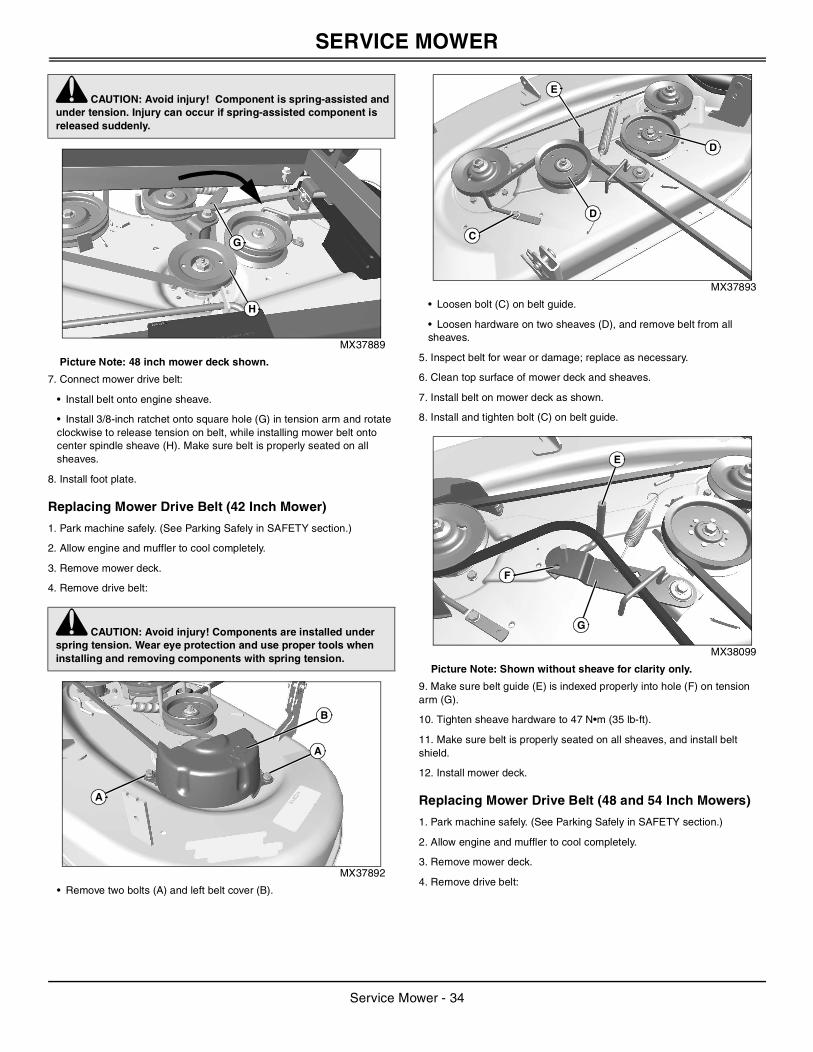
SERVICE MOWER
MX37889
Picture Note: 48 inch mower deck shown.
7. Connect mower drive belt:
• Install belt onto engine sheave.
• Install 3/8-inch ratchet onto square hole (G) in tension arm and rotate clockwise to release tension on belt, while installing mower belt onto center spindle sheave (H). Make sure belt is properly seated on all sheaves.
8. Install foot plate.
Replacing Mower Drive Belt (42 Inch Mower)
1. Park machine safely. (See Parking Safely in SAFETY section.)
2. Allow engine and muffler to cool completely.
3. Remove mower deck.
4. Remove drive belt:
MX37892
• Remove two bolts (A) and left belt cover (B).
MX37893
• Loosen bolt (C) on belt guide.
• Loosen hardware on two sheaves (D), and remove belt from all sheaves.
5. Inspect belt for wear or damage; replace as necessary.
6. Clean top surface of mower deck and sheaves.
7. Install belt on mower deck as shown.
8. Install and tighten bolt (C) on belt guide.
MX38099
Picture Note: Shown without sheave for clarity only.
9. Make sure belt guide (E) is indexed properly into hole (F) on tension arm (G).
10. Tighten sheave hardware to 47 N•m (35 lb-ft).
11. Make sure belt is properly seated on all sheaves, and install belt shield.
12. Install mower deck.
Replacing Mower Drive Belt (48 and 54 Inch Mowers)
1. Park machine safely. (See Parking Safely in SAFETY section.)
2. Allow engine and muffler to cool completely.
3. Remove mower deck.
4. Remove drive belt:
c CAUTION: Avoid injury! Component is spring-assisted and under tension. Injury can occur if spring-assisted component is released suddenly.
c CAUTION: Avoid injury! Components are installed under spring tension. Wear eye protection and use proper tools when installing and removing components with spring tension.
G
H
A
A
B
C
D
D
E
E
G
F
Service Mower - 34
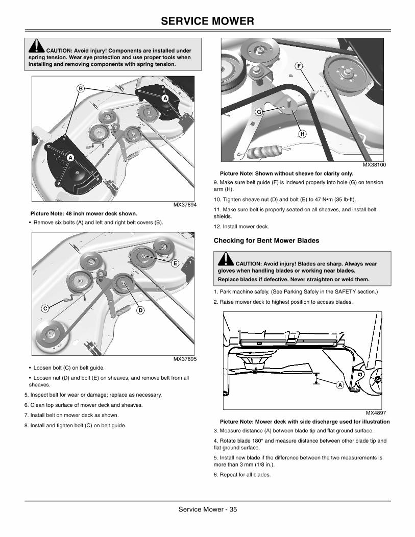
SERVICE MOWER
MX37894
Picture Note: 48 inch mower deck shown.
• Remove six bolts (A) and left and right belt covers (B).
MX37895
• Loosen bolt (C) on belt guide.
• Loosen nut (D) and bolt (E) on sheaves, and remove belt from all sheaves.
5. Inspect belt for wear or damage; replace as necessary.
6. Clean top surface of mower deck and sheaves.
7. Install belt on mower deck as shown.
8. Install and tighten bolt (C) on belt guide.
MX38100
Picture Note: Shown without sheave for clarity only.
9. Make sure belt guide (F) is indexed properly into hole (G) on tension arm (H).
10. Tighten sheave nut (D) and bolt (E) to 47 N•m (35 lb-ft).
11. Make sure belt is properly seated on all sheaves, and install belt shields.
12. Install mower deck.
Checking for Bent Mower Blades
1. Park machine safely. (See Parking Safely in the SAFETY section.)
2. Raise mower deck to highest position to access blades.
MX4897
Picture Note: Mower deck with side discharge used for illustration
3. Measure distance (A) between blade tip and flat ground surface.
4. Rotate blade 180° and measure distance between other blade tip and flat ground surface.
5. Install new blade if the difference between the two measurements is more than 3 mm (1/8 in.).
6. Repeat for all blades.
c CAUTION: Avoid injury! Components are installed under spring tension. Wear eye protection and use proper tools when installing and removing components with spring tension.
A
A
B
C D
E c CAUTION: Avoid injury! Blades are sharp. Always wear gloves when handling blades or working near blades.
Replace blades if defective. Never straighten or weld them.
G
F
H
A
Service Mower - 35
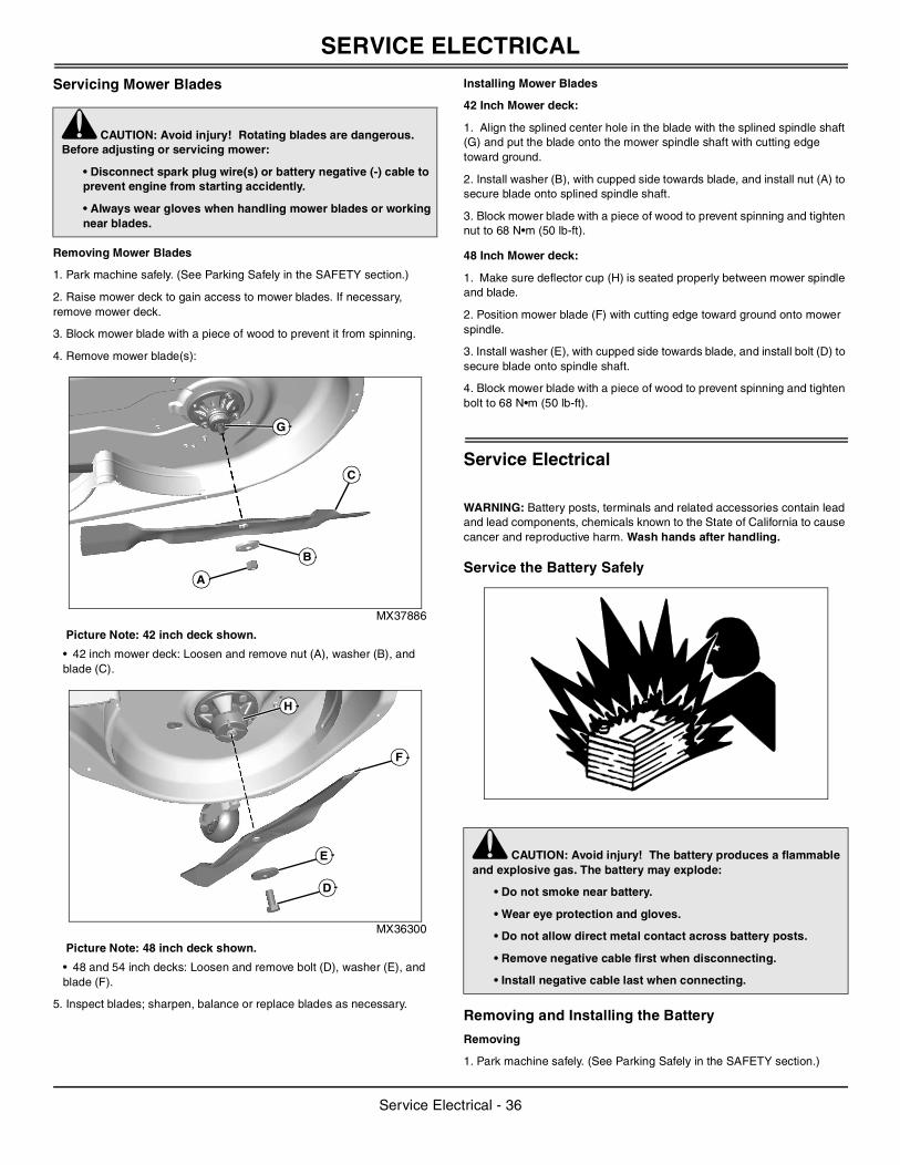
SERVICE ELECTRICAL
Servicing Mower Blades
Removing Mower Blades
1. Park machine safely. (See Parking Safely in the SAFETY section.)
2. Raise mower deck to gain access to mower blades. If necessary, remove mower deck.
3. Block mower blade with a piece of wood to prevent it from spinning.
4. Remove mower blade(s):
MX37886
Picture Note: 42 inch deck shown.
• 42 inch mower deck: Loosen and remove nut (A), washer (B), and blade (C).
MX36300
Picture Note: 48 inch deck shown.
• 48 and 54 inch decks: Loosen and remove bolt (D), washer (E), and blade (F).
5. Inspect blades; sharpen, balance or replace blades as necessary.
Installing Mower Blades
42 Inch Mower deck:
1. Align the splined center hole in the blade with the splined spindle shaft (G) and put the blade onto the mower spindle shaft with cutting edge toward ground.
2. Install washer (B), with cupped side towards blade, and install nut (A) to secure blade onto splined spindle shaft.
3. Block mower blade with a piece of wood to prevent spinning and tighten nut to 68 N•m (50 lb-ft).
48 Inch Mower deck:
1. Make sure deflector cup (H) is seated properly between mower spindle and blade.
2. Position mower blade (F) with cutting edge toward ground onto mower spindle.
3. Install washer (E), with cupped side towards blade, and install bolt (D) to secure blade onto spindle shaft.
4. Block mower blade with a piece of wood to prevent spinning and tighten bolt to 68 N•m (50 lb-ft).
Service Electrical
WARNING: Battery posts, terminals and related accessories contain lead and lead components, chemicals known to the State of California to cause cancer and reproductive harm. Wash hands after handling.
Service the Battery Safely
Removing and Installing the Battery
Removing
1. Park machine safely. (See Parking Safely in the SAFETY section.)
c CAUTION: Avoid injury! Rotating blades are dangerous. Before adjusting or servicing mower:
• Disconnect spark plug wire(s) or battery negative (-) cable to prevent engine from starting accidently.
• Always wear gloves when handling mower blades or working near blades.
A
B
C
G
D
E
F
H
c CAUTION: Avoid injury! The battery produces a flammable and explosive gas. The battery may explode:
• Do not smoke near battery.
• Wear eye protection and gloves.
• Do not allow direct metal contact across battery posts.
• Remove negative cable first when disconnecting.
• Install negative cable last when connecting.
Service Electrical - 36
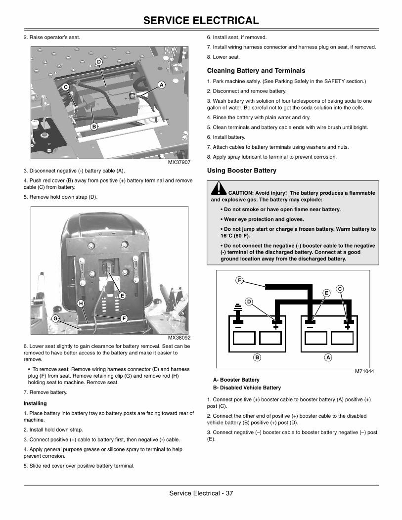
SERVICE ELECTRICAL
2. Raise operator’s seat.MX37907
3. Disconnect negative (-) battery cable (A).
4. Push red cover (B) away from positive (+) battery terminal and remove cable (C) from battery.
5. Remove hold down strap (D).
MX38092
6. Lower seat slightly to gain clearance for battery removal. Seat can be removed to have better access to the battery and make it easier to remove.
• To remove seat: Remove wiring harness connector (E) and harness plug (F) from seat. Remove retaining clip (G) and remove rod (H) holding seat to machine. Remove seat.
7. Remove battery.
Installing
1. Place battery into battery tray so battery posts are facing toward rear of machine.
2. Install hold down strap.
3. Connect positive (+) cable to battery first, then negative (-) cable.
4. Apply general purpose grease or silicone spray to terminal to help prevent corrosion.
5. Slide red cover over positive battery terminal.
6. Install seat, if removed.
7. Install wiring harness connector and harness plug on seat, if removed.
8. Lower seat.
Cleaning Battery and Terminals
1. Park machine safely. (See Parking Safely in the SAFETY section.)
2. Disconnect and remove battery.
3. Wash battery with solution of four tablespoons of baking soda to one gallon of water. Be careful not to get the soda solution into the cells.
4. Rinse the battery with plain water and dry.
5. Clean terminals and battery cable ends with wire brush until bright.
6. Install battery.
7. Attach cables to battery terminals using washers and nuts.
8. Apply spray lubricant to terminal to prevent corrosion.
Using Booster Battery
M71044
A- Booster Battery
B- Disabled Vehicle Battery
1. Connect positive (+) booster cable to booster battery (A) positive (+) post (C).
2. Connect the other end of positive (+) booster cable to the disabled vehicle battery (B) positive (+) post (D).
3. Connect negative (–) booster cable to booster battery negative (–) post (E).
C A
B
D
E
FG
H
c CAUTION: Avoid injury! The battery produces a flammable and explosive gas. The battery may explode:
• Do not smoke or have open flame near battery.
• Wear eye protection and gloves.
• Do not jump start or charge a frozen battery. Warm battery to 16°C (60°F).
• Do not connect the negative (-) booster cable to the negative (-) terminal of the discharged battery. Connect at a good ground location away from the discharged battery.
B A
EC
D
F
Service Electrical - 37
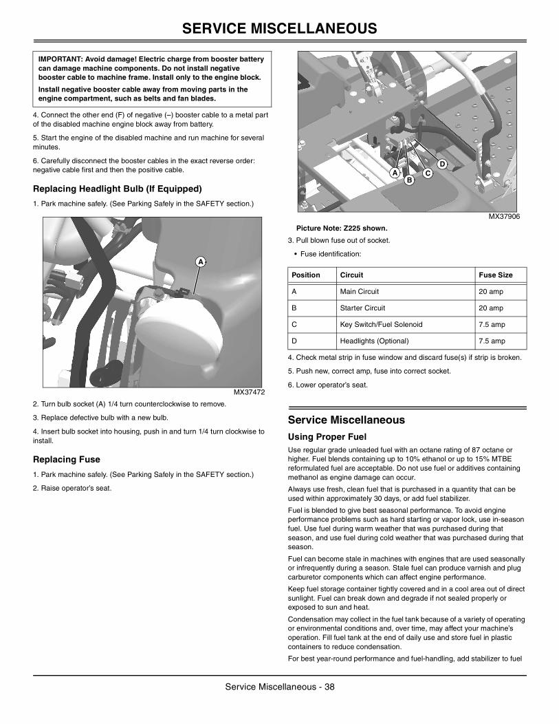
SERVICE MISCELLANEOUS
4. Connect the other end (F) of negative (–) booster cable to a metal part of the disabled machine engine block away from battery.
5. Start the engine of the disabled machine and run machine for several minutes.
6. Carefully disconnect the booster cables in the exact reverse order: negative cable first and then the positive cable.
Replacing Headlight Bulb (If Equipped)
1. Park machine safely. (See Parking Safely in the SAFETY section.)
MX37472
2. Turn bulb socket (A) 1/4 turn counterclockwise to remove.
3. Replace defective bulb with a new bulb.
4. Insert bulb socket into housing, push in and turn 1/4 turn clockwise to install.
Replacing Fuse
1. Park machine safely. (See Parking Safely in the SAFETY section.)
2. Raise operator’s seat.
MX37906
Picture Note: Z225 shown.
3. Pull blown fuse out of socket.
• Fuse identification:
4. Check metal strip in fuse window and discard fuse(s) if strip is broken.
5. Push new, correct amp, fuse into correct socket.
6. Lower operator’s seat.
Service MiscellaneousUsing Proper FuelUse regular grade unleaded fuel with an octane rating of 87 octane or higher. Fuel blends containing up to 10% ethanol or up to 15% MTBE reformulated fuel are acceptable. Do not use fuel or additives containing methanol as engine damage can occur.
Always use fresh, clean fuel that is purchased in a quantity that can be used within approximately 30 days, or add fuel stabilizer.
Fuel is blended to give best seasonal performance. To avoid engine performance problems such as hard starting or vapor lock, use in-season fuel. Use fuel during warm weather that was purchased during that season, and use fuel during cold weather that was purchased during that season.
Fuel can become stale in machines with engines that are used seasonally or infrequently during a season. Stale fuel can produce varnish and plug carburetor components which can affect engine performance.
Keep fuel storage container tightly covered and in a cool area out of direct sunlight. Fuel can break down and degrade if not sealed properly or exposed to sun and heat.
Condensation may collect in the fuel tank because of a variety of operating or environmental conditions and, over time, may affect your machine’s operation. Fill fuel tank at the end of daily use and store fuel in plastic containers to reduce condensation.
For best year-round performance and fuel-handling, add stabilizer to fuel
IMPORTANT: Avoid damage! Electric charge from booster battery can damage machine components. Do not install negative booster cable to machine frame. Install only to the engine block.
Install negative booster cable away from moving parts in the engine compartment, such as belts and fan blades.
A
Position Circuit Fuse Size
A Main Circuit 20 amp
B Starter Circuit 20 amp
C Key Switch/Fuel Solenoid 7.5 amp
D Headlights (Optional) 7.5 amp
A CD
B
Service Miscellaneous - 38
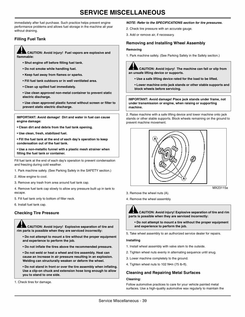
SERVICE MISCELLANEOUS
immediately after fuel purchase. Such practice helps prevent engine performance problems and allows fuel storage in the machine all year without draining.Filling Fuel Tank
Fill fuel tank at the end of each day’s operation to prevent condensation and freezing during cold weather.
1. Park machine safely. (See Parking Safely in the SAFETY section.)
2. Allow engine to cool.
3. Remove any trash from area around fuel tank cap.
4. Remove fuel tank cap slowly to allow any pressure built up in tank to escape.
5. Fill fuel tank only to bottom of filler neck.
6. Install fuel tank cap.
Checking Tire Pressure
1. Check tires for damage.
NOTE: Refer to the SPECIFICATIONS section for tire pressures.
2. Check tire pressure with an accurate gauge.
3. Add or remove air, if necessary.
Removing and Installing Wheel Assembly
Removing
1. Park machine safely. (See Parking Safely in the Safety section.)
2. Raise machine with a safe lifting device and lower machine onto jack stands or other stable supports. Block wheels remaining on the ground to prevent machine movement.
MX23115a
3. Remove the wheel nuts (A).
4. Remove the wheel assembly.
5. Take wheel assembly to an authorized service dealer for repairs.
Installing
1. Install wheel assembly with valve stem to the outside.
2. Tighten wheel nuts evenly in alternating sequence until snug.
3. Lower machine completely to the ground.
4. Tighten wheel nuts to 102 N•m (75 lb-ft).
Cleaning and Repairing Metal Surfaces
Cleaning:
Follow automotive practices to care for your vehicle painted metal surfaces. Use a high-quality automotive wax regularly to maintain the
c CAUTION: Avoid injury! Fuel vapors are explosive and flammable:
• Shut engine off before filling fuel tank.
• Do not smoke while handling fuel.
• Keep fuel away from flames or sparks.
• Fill fuel tank outdoors or in well ventilated area.
• Clean up spilled fuel immediately.
• Use clean approved non-metal container to prevent static electric discharge.
• Use clean approved plastic funnel without screen or filter to prevent static electric discharge.
IMPORTANT: Avoid damage! Dirt and water in fuel can cause engine damage:
• Clean dirt and debris from the fuel tank opening.
• Use clean, fresh, stabilized fuel.
• Fill the fuel tank at the end of each day’s operation to keep condensation out of the fuel tank.
• Use a non-metallic funnel with a plastic mesh strainer when filling the fuel tank or container.
c CAUTION: Avoid injury! Explosive separation of tire and rim parts is possible when they are serviced incorrectly:
• Do not attempt to mount a tire without the proper equipment and experience to perform the job.
• Do not inflate the tires above the recommended pressure.
• Do not weld or heat a wheel and tire assembly. Heat can cause an increase in air pressure resulting in an explosion. Welding can structurally weaken or deform the wheel.
• Do not stand in front or over the tire assembly when inflating. Use a clip-on chuck and extension hose long enough to allow you to stand to one side.
c CAUTION: Avoid injury! The machine can fall or slip from an unsafe lifting device or supports.
• Use a safe lifting device rated for the load to be lifted.
• Lower machine onto jack stands or other stable supports and block wheels before servicing.
IMPORTANT: Avoid damage! Place jack stands under frame, not under transmission or engine, when raising or supporting machine.
c CAUTION: Avoid injury! Explosive separation of tire and rim parts is possible when they are serviced incorrectly:
• Do not attempt to mount a tire without the proper equipment and experience to perform the job.
A
A
Service Miscellaneous - 39
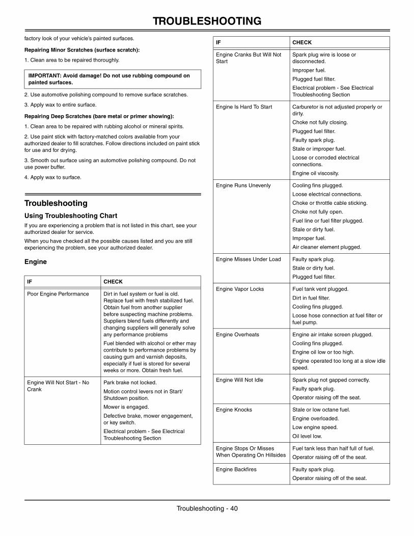
TROUBLESHOOTING
factory look of your vehicle’s painted surfaces.Repairing Minor Scratches (surface scratch):
1. Clean area to be repaired thoroughly.
2. Use automotive polishing compound to remove surface scratches.
3. Apply wax to entire surface.
Repairing Deep Scratches (bare metal or primer showing):
1. Clean area to be repaired with rubbing alcohol or mineral spirits.
2. Use paint stick with factory-matched colors available from your authorized dealer to fill scratches. Follow directions included on paint stick for use and for drying.
3. Smooth out surface using an automotive polishing compound. Do not use power buffer.
4. Apply wax to surface.
TroubleshootingUsing Troubleshooting ChartIf you are experiencing a problem that is not listed in this chart, see your authorized dealer for service.
When you have checked all the possible causes listed and you are still experiencing the problem, see your authorized dealer.
Engine
IMPORTANT: Avoid damage! Do not use rubbing compound on painted surfaces.
IF CHECK
Poor Engine Performance Dirt in fuel system or fuel is old. Replace fuel with fresh stabilized fuel. Obtain fuel from another supplier before suspecting machine problems. Suppliers blend fuels differently and changing suppliers will generally solve any performance problems
Fuel blended with alcohol or ether may contribute to performance problems by causing gum and varnish deposits, especially if fuel is stored for several weeks or more. Obtain fresh fuel.
Engine Will Not Start - No Crank
Park brake not locked.
Motion control levers not in Start/Shutdown position.
Mower is engaged.
Defective brake, mower engagement, or key switch.
Electrical problem - See Electrical Troubleshooting Section
Engine Cranks But Will Not Start
Spark plug wire is loose or disconnected.
Improper fuel.
Plugged fuel filter.
Electrical problem - See Electrical Troubleshooting Section
Engine Is Hard To Start Carburetor is not adjusted properly or dirty.
Choke not fully closing.
Plugged fuel filter.
Faulty spark plug.
Stale or improper fuel.
Loose or corroded electrical connections.
Engine oil viscosity.
Engine Runs Unevenly Cooling fins plugged.
Loose electrical connections.
Choke or throttle cable sticking.
Choke not fully open.
Fuel line or fuel filter plugged.
Stale or dirty fuel.
Improper fuel.
Air cleaner element plugged.
Engine Misses Under Load Faulty spark plug.
Stale or dirty fuel.
Plugged fuel filter.
Engine Vapor Locks Fuel tank vent plugged.
Dirt in fuel filter.
Cooling fins plugged.
Loose hose connection at fuel filter or fuel pump.
Engine Overheats Engine air intake screen plugged.
Cooling fins plugged.
Engine oil low or too high.
Engine operated too long at a slow idle speed.
Engine Will Not Idle Spark plug not gapped correctly.
Faulty spark plug.
Operator raising off the seat.
Engine Knocks Stale or low octane fuel.
Engine overloaded.
Low engine speed.
Oil level low.
Engine Stops Or Misses When Operating On Hillsides
Fuel tank less than half full of fuel.
Operator raising off of the seat.
Engine Backfires Faulty spark plug.
Operator raising off of the seat.
IF CHECK
Troubleshooting - 40
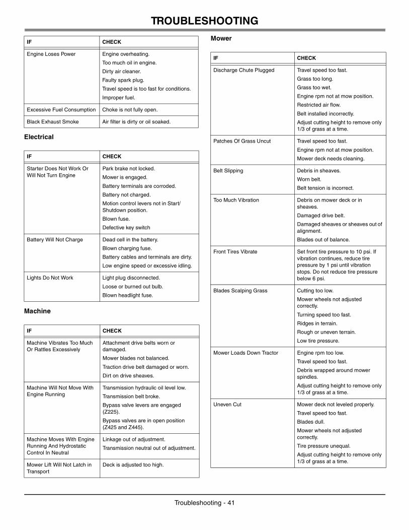
TROUBLESHOOTING
Electrical
Machine
Mower
Engine Loses Power Engine overheating.
Too much oil in engine.
Dirty air cleaner.
Faulty spark plug.
Travel speed is too fast for conditions.
Improper fuel.
Excessive Fuel Consumption Choke is not fully open.
Black Exhaust Smoke Air filter is dirty or oil soaked.
IF CHECK
Starter Does Not Work Or Will Not Turn Engine
Park brake not locked.
Mower is engaged.
Battery terminals are corroded.
Battery not charged.
Motion control levers not in Start/Shutdown position.
Blown fuse.
Defective key switch
Battery Will Not Charge Dead cell in the battery.
Blown charging fuse.
Battery cables and terminals are dirty.
Low engine speed or excessive idling.
Lights Do Not Work Light plug disconnected.
Loose or burned out bulb.
Blown headlight fuse.
IF CHECK
Machine Vibrates Too Much Or Rattles Excessively
Attachment drive belts worn or damaged.
Mower blades not balanced.
Traction drive belt damaged or worn.
Dirt on drive sheaves.
Machine Will Not Move With Engine Running
Transmission hydraulic oil level low.
Transmission belt broke.
Bypass valve levers are engaged (Z225).
Bypass valves are in open position (Z425 and Z445).
Machine Moves With Engine Running And Hydrostatic Control In Neutral
Linkage out of adjustment.
Transmission neutral out of adjustment.
Mower Lift Will Not Latch in Transport
Deck is adjusted too high.
IF CHECK
IF CHECK
Discharge Chute Plugged Travel speed too fast.
Grass too long.
Grass too wet.
Engine rpm not at mow position.
Restricted air flow.
Belt installed incorrectly.
Adjust cutting height to remove only 1/3 of grass at a time.
Patches Of Grass Uncut Travel speed too fast.
Engine rpm not at mow position.
Mower deck needs cleaning.
Belt Slipping Debris in sheaves.
Worn belt.
Belt tension is incorrect.
Too Much Vibration Debris on mower deck or in sheaves.
Damaged drive belt.
Damaged sheaves or sheaves out of alignment.
Blades out of balance.
Front Tires Vibrate Set front tire pressure to 10 psi. If vibration continues, reduce tire pressure by 1 psi until vibration stops. Do not reduce tire pressure below 6 psi.
Blades Scalping Grass Cutting too low.
Mower wheels not adjusted correctly.
Turning speed too fast.
Ridges in terrain.
Rough or uneven terrain.
Low tire pressure.
Mower Loads Down Tractor Engine rpm too low.
Travel speed too fast.
Debris wrapped around mower spindles.
Adjust cutting height to remove only 1/3 of grass at a time.
Uneven Cut Mower deck not leveled properly.
Travel speed too fast.
Blades dull.
Mower wheels not adjusted correctly.
Tire pressure unequal.
Adjust cutting height to remove only 1/3 of grass at a time.
Troubleshooting - 41
STORAGE
StorageStoring Safety
Preparing Machine for Storage
1. Repair any worn or damaged parts. Replace parts if necessary. Tighten loose hardware.
2. Repair scratched or chipped metal surfaces to prevent rust.
3. Remove grass and debris from machine.
4. Clean under the deck and remove grass and debris from inside chute and bagger.
5. Wash the machine and apply wax to appropriate surfaces.
6. Run machine for five minutes to dry belts and pulleys.
7. Apply light coat of engine oil to pivot and wear points to prevent rust.
8. Lubricate grease points and check tire pressure.
Preparing Fuel and Engine For Storage
Fuel:
If you have been using “Stabilized Fuel,” add stabilized fuel to tank until the tank is full.
NOTE: Filling the fuel tank reduces the amount of air in the fuel tank and helps reduce deterioration of fuel.
If you are not using “Stabilized Fuel:”
1. Park machine safely in a well-ventilated area. (See Parking Safely in the SAFETY section.)
NOTE: Try to anticipate the last time the machine will be used for the season so very little fuel is left in the fuel tank.
2. Turn on engine and allow to run until it runs out of fuel.
3. For machines equipped with key switch, turn key to off position.
4. Mix fresh fuel and fuel stabilizer in separate container. Follow stabilizer instructions for mixing.
5. Fill fuel tank with stabilized fuel.
6. Run engine for a few minutes to allow fuel mixture to circulate through carburetor on gas engine or fuel injectors on diesel engine.
Engine:
Engine storage procedure should be used when vehicle is not to be used
for longer than 60 days.
1. Change engine oil and filter while engine is warm.
2. Service air filter if necessary.
3. Clean debris from engine air intake screen.
4. On gas engines:
• Remove spark plugs. Put 30 mL (1 oz) of clean engine oil in cylinder(s).
• Install spark plugs, but do not connect spark plug wires.
• Crank the engine five or six times to allow oil to be distributed.
5. Clean the engine and engine compartment.
6. Remove battery.
7. Clean the battery and battery posts. Check the electrolyte level, if your battery is not maintenance free.
8. Close fuel shut-off valve, if your machine is equipped.
9. Store the battery in a cool, dry place where it will not freeze.
NOTE: The stored battery should be recharged every 90 days.
10. Charge the battery.
11. Store the vehicle in a dry, protected place. If vehicle is stored outside, put a waterproof cover over it.
Removing Machine From Storage
1. Check tire pressure.
2. Check engine oil level.
3. Check battery electrolyte level, if your battery is not maintenance free. Charge battery if necessary.
4. Install battery.
5. On gas engines: Check spark plug gap. Install and tighten plugs to specified torque.
6. Lubricate all grease points.
7. Open fuel shut-off valve, if your machine is equipped.
8. Run the engine 5 minutes without the mower or any attachments running to allow oil to be distributed throughout engine.
9. Be sure all shields and guards or deflectors are in place.
SpecificationsEngine
Z225
Make . . . . . . . . . . . . . . . . . . . . . . . . . . . . . . . . . . . . Briggs and Stratton
Model Number . . . . . . . . . . . . . . . . . . . . . . . . . . . . . . . . . .Intek - 31P707
Cylinders . . . . . . . . . . . . . . . . . . . . . . . . . . . . . . . . . . . . . . . . . . . . Single
Cycle . . . . . . . . . . . . . . . . . . . . . . . . . . . . . . . . . . . . . . . . . . . . . . . . . .Four
Spark Plug Gap . . . . . . . . . . . . . . . . . . . . . . . . . . . . 0.76 mm (0.030 in.)
Spark Plug Torque . . . . . . . . . . . . . . . . . . . . . . . . . .20 N•m (180 lb-in.)
c CAUTION: Avoid injury! Fuel vapors are explosive and flammable. Engine exhaust fumes contain carbon monoxide and can cause serious illness or death:
• Run the engine only long enough to move the machine to or from storage.
• Do not store vehicle with fuel in the tank inside a building where fumes may reach an open flame or spark.
• Allow the engine to cool before storing the machine in any enclosure.
IMPORTANT: Avoid damage! Stale fuel can produce varnish and plug carburetor or injector components and affect engine performance.
• Add fuel conditioner or stabilizer to fresh fuel before filling tank.
IMPORTANT: Avoid damage! Prolonged exposure to sunlight could damage the hood surface. Store machine inside or use a cover if stored outside.
Storage - 42
SPECIFICATIONS
Z425Make . . . . . . . . . . . . . . . . . . . . . . . . . . . . . . . . . . . . . Briggs and Stratton
Model Number . . . . . . . . . . . . . . . . . . . . . . . . . . . . . . . . . . Intek - 445577
Cylinders . . . . . . . . . . . . . . . . . . . . . . . . . . . . . . . . . . . . . . . . . . . . V-Twin
Cycle. . . . . . . . . . . . . . . . . . . . . . . . . . . . . . . . . . . . . . . . . . . . . . . . . . Four
Spark Plug Gap . . . . . . . . . . . . . . . . . . . . . . . . . . . . 0.76 mm (0.030 in.)
Spark Plug Torque . . . . . . . . . . . . . . . . . . . . . . . . . . 20 N•m (180 lb-in.)
Z445
Make . . . . . . . . . . . . . . . . . . . . . . . Torque™ Power System - Kawasaki
Model Number . . . . . . . . . . . . . . . . . . . . . . . . . . . . . . . . . . . . . . . FH721V
Cylinders . . . . . . . . . . . . . . . . . . . . . . . . . . . . . . . . . . . . . . . . . . . . V-Twin
Cycle. . . . . . . . . . . . . . . . . . . . . . . . . . . . . . . . . . . . . . . . . . . . . . . . . . Four
Spark Plug Gap . . . . . . . . . . . . . . . . . . . . . . . . . . . . 0.76 mm (0.030 in.)
Spark Plug Torque . . . . . . . . . . . . . . . . . . . . . . . . . . 20 N•m (180 lb-in.)
DrivetrainPump (Z425, Z445). . . . . . . . . . . . . . . . . . . . . . . . . . . . . Kanzaki DUP-10
Transaxle Motors (Z225) . . . . . . . . . . . . . . . . . . . . . . . . Hydro-Gear EZT
Wheel Motors (Z425, Z445) . . . . . . . . . . . . . . . . . . . . . . . Parker TE0195
Number of Speeds. . . . . . . . . . . . . . . . . . . Hydrostatic, Variable Speed
Fuel System
Fuel Types (Recommended):
. . . . . . . . . . . . . . . . . . . . . . . .Regular Grade 87 Octane Unleaded Fuel
. . . . . . . . . . . . . . . . . . . . . . . . . . . . . Ethanol Blended Fuel (Up to 10%)
. . . . . . . . . . . . . . . . . . . . . . . . . . MTBE Reformulated Fuel (Up to 15%)
Fuel Filter . . . . . . . . . . . . . . . . . . . . . . . . . .Replaceable - paper element
Fuel Pump . . . . . . . . . . . . . . . . . . . . . . . . . . . . . . . . . . . . . . . . . . . . Pulse
Fuel Delivery . . . . . . . . . . . . . . . . . . . . . . . . . . . . . . . . . . . . . .Carburetor
Electrical SystemBattery Type. . . . . . . . . . . . . . . . . . . . . . . . . . . . . . . . . . . . . . . . . . 12 Volt
Cold Cranking Capacity . . . . . . . . . . . . . . . . . . . . . . . . . . . . . 165 Amps
TiresFront . . . . . . . . . . . . . . . . . . . . . . . . . . . . . . . . . . . . . . 13x5.00-6 (Ribbed)
Rear (Z225). . . . . . . . . . . . . . . . . . . . . . . . . . . . . . . . . . . .18x8.50-8 (Turf)
Rear (Z425 and Z445) . . . . . . . . . . . . . . . . . . . . . . . . . . .22x9.5-10 (Turf)
Inflation - Front . . . . . . . . . . . . . . . . . . . . . . . . . . . . . . . . 69 kPa (10 psi)
Inflation - Rear . . . . . . . . . . . . . . . . . . . . . . . . . . . . . . . . 69 kPa (10 psi)
Capacities
Crankcase:
Single cylinder Briggs and Stratton . . . . . . . . . . . . . . . . 1.2 L (1.25 qt)
Twin cylinder Briggs and Stratton . . . . . . . . . . . . . . . . . . 1.6 L (1.75 qt)
Twin cylinder Kawasaki . . . . . . . . . . . . . . . . . . . . . . . . . . . 1.5 L (1.6 qt)
Fuel Tank . . . . . . . . . . . . . . . . . . . . . . . . . . . . . . . . . . . . 13.2 L (3.5 gal)
Transaxle Reservoir (Z425 and Z445) . . . . . . . . . . . . . 7.57 L (2.0 gal)
Travel Speeds at Full Engine RPM
Z225
Forward. . . . . . . . . . . . . . . . . . . . . . . . . . . . . . . 0-11.3 km/h (0-7.0 mph)
Reverse . . . . . . . . . . . . . . . . . . . . . . . . . . . . . . . . 0-5.6 km/h (0-3.5 mph)
Z425 and Z445
Forward. . . . . . . . . . . . . . . . . . . . . . . . . . . . . . . 0-12.9 km/h (0-8.0 mph)
Reverse . . . . . . . . . . . . . . . . . . . . . . . . . . . . . . . . 0-5.6 km/h (0-3.5 mph)
Dimensions
Z225
Height . . . . . . . . . . . . . . . . . . . . . . . . . . . . . . . . . . . . 980 mm (38-1/2 in.)
Width. . . . . . . . . . . . . . . . . . . . . . . . . . . . . . . . . . . . . . . 1320 mm (52 in.)
Length. . . . . . . . . . . . . . . . . . . . . . . . . . . . . . . . . . . . . . 1878 mm (74 in.)
Weight . . . . . . . . . . . . . . . . . . . . . . . . . . . . . . . . . . . . . . 249.5 kg (550 lb)
Z425
Height . . . . . . . . . . . . . . . . . . . . . . . . . . . . . . . . . . . . 980 mm (38-1/2 in.)
Width. . . . . . . . . . . . . . . . . . . . . . . . . . . . . . . . . . 1592 mm (62-43/64 in.)
Length. . . . . . . . . . . . . . . . . . . . . . . . . . . . . . . . . . . . . . 1878 mm (74 in.)
Weight . . . . . . . . . . . . . . . . . . . . . . . . . . . . . . . . . . . . . . 294.8 kg (650 lb)
Z445
Height . . . . . . . . . . . . . . . . . . . . . . . . . . . . . . . . . . . . . . 1065 mm (42 in.)
Width. . . . . . . . . . . . . . . . . . . . . . . . . . . . . . . . . . . . 1750 mm (68-7/8 in.)
Length. . . . . . . . . . . . . . . . . . . . . . . . . . . . . . . . . . . . . . 1878 mm (74 in.)
Weight . . . . . . . . . . . . . . . . . . . . . . . . . . . . . . . . . . . . . . 310.7 kg (685 lb)
42 Edge™ MowerCutting Width . . . . . . . . . . . . . . . . . . . . . . . . . . . . . . . . . . .1.07 m (42 in.)
Blades-Rotary . . . . . . . . . . . . . . . . . . . . . . . . . . . . . . . . . . . . . . . . . . . . .2
Blade Nut Torque . . . . . . . . . . . . . . . . . . . . . . . . . . . . . 68 N•m (50 lb-ft)
Cutting Height (Approximately) . . . . . . . . . . . . 25 - 102 mm (1 - 4 in.)
48 Edge™ Mower Cutting Width . . . . . . . . . . . . . . . . . . . . . . . . . . . . . . . . . . .1.22 m (48 in.)
Blades-Rotary . . . . . . . . . . . . . . . . . . . . . . . . . . . . . . . . . . . . . . . . . . . . .3
Blade Bolt Torque . . . . . . . . . . . . . . . . . . . . . . . . . . . . 68 N•m (50 lb-ft)
Cutting Height (Approximately) . . . . . . . . . . . . 25 - 102 mm (1 - 4 in.)
54 Edge™ MowerCutting Width . . . . . . . . . . . . . . . . . . . . . . . . . . . . . . . . . . 1.37 m (54 in.)
Blades-Rotary . . . . . . . . . . . . . . . . . . . . . . . . . . . . . . . . . . . . . . . . . . . . .3
Blade Bolt Torque . . . . . . . . . . . . . . . . . . . . . . . . . . . . 68 N•m (50 lb-ft)
Cutting Height (Approximately) . . . . . . . . . . . . 25 - 102 mm (1 - 4 in.)
Recommended LubricantsEngine Oil . . . . . . . . . . . . . . . . . . . . . . . . . . TURF-GARD® OR PLUS-4®
Grease:
. . . . . . . . . . . . . John Deere MOLY HIGH TEMPERATURE EP GREASE
. . . . . . . . . . . . . . . . . . .John Deere Multi-Purpose SD Polyurea Grease
. . . . . . . . . . . .John Deere Multi-Purpose HD Lithium Complex Grease
(Specifications and design subject to change without notice.)
Specifications - 43
WARRANTY
WarrantyProduct WarrantyProduct warranty is provided as part of John Deere’s support program for customers who operate and maintain their equipment as described in this manual.
Engine related warranties stated in this manual refer only to emissions-related parts and components of your engine. The complete engine warranty, less emission-related parts and components, is provided separately as the “Limited Warranty for New John Deere Commercial & Consumer Equipment”.
John Deere, Federal and California Emissions Control System Warranty Statement (Small Off-Road Gas Engines)Your Warranty Rights and Obligations
California Air Resources Board (CARB), the United States Environmental Protection Agency (EPA), and John Deere are pleased to explain the emissions control system warranty on your small off-road engine and equipment. In California, 2006 and later small off-road engines and equipment must be designed, built and equipped to meet the State’s stringent anti-smog standards. (In other states, 1997 and later model year equipment engines must be designed, built and equipped to meet the U.S. EPA regulations for small non-road, spark ignition engines.) John Deere must warrant the emissions control system on your small off-road engine and equipment for the periods of time listed below provided there has been no abuse, neglect or improper maintenance of your small off-road engine and equipment.
Your emissions control system may include parts such as the carburetor, fuel hose, fuel-injection system and ignition system. Also included may be connectors and other emissions related assemblies.
Where a warrantable condition exists, John Deere will repair your small off-road engine and equipment at no cost to you including diagnosis, parts and labor.
John Deere Emissions Control System Warranty Coverage
Small off-road engines and equipment are warranted relative to emissions control parts for two years. If any emissions related part on your engine or equipment is defective, the part will be repaired or replaced by John Deere.
Owner’s Warranty Responsibilities
As the small off-road engine and equipment owner, you are responsible for the performance of the required maintenance listed in your owner’s manual. John Deere recommends that you retain all receipts covering maintenance on your small off-road engine and equipment, but John Deere cannot deny warranty solely for lack of receipts or for your failure to ensure the performance of all scheduled maintenance.
As the small off-road engine and equipment owner, you should however be aware that John Deere may deny you warranty coverage if your small off-road engine and equipment or a part has failed due to abuse, neglect, improper maintenance or unapproved modifications.
You are responsible for presenting your small off-road engine and equipment to an authorized John Deere Commercial and Consumer Equipment Retailer as soon as a problem exists. The warranty repairs should be completed in a reasonable amount of time, not to exceed 30 days.
If you have any questions regarding your warranty rights and responsibilities, you should contact your John Deere Commercial and Consumer Equipment Retailer, or the John Deere Customer Contact Center at 1-800-537-8233.
Length Of Warranty Coverage
John Deere warrants to the initial owner and each subsequent purchaser
that the small off-road engine and equipment is:
• Designed, built and equipped so as to conform with all applicable regulations adopted by the California Air Resources Board (CARB) for 2006 and later engines and equipment, and all applicable regulations of the United States Environmental Protection Agency (EPA) for 1997 and later equipment engines; and
• Free from defects in materials and workmanship which can cause the failure of an emissions warranted part for a period of two years after the engine and equipment is delivered to the initial retail purchaser. John Deere is liable for damages to other engine components caused by the failure of a warranted part during the warranty period. If any emissions related part on your engine or equipment is defective, the part will be repaired or replaced by John Deere.
Warranted Parts
Coverage under this warranty extends only to the parts listed below (the emissions control system parts) to the extent these parts were present on the engine and equipment purchased.
Fuel Metering System:
• Carburetor and internal parts (or fuel injection system).
• Air/fuel ratio feedback and control system.
• Cold start enrichment system.
• Fuel hose, line, fittings, clamps.
• Fuel pump.
Air Induction System:
• Air Cleaner
• Intake manifold.
Ignition System:
• Spark plugs.
• Magneto or electronic ignition system.
• Spark advance/retard system.
Exhaust System:
• Exhaust manifold.
• Catalyst.
Miscellaneous Items Used in Above Systems
• Vacuum and temperature switches.
• Electronic controls.
• Hoses, belts, connectors and assemblies.
Since emissions related parts may vary slightly from model to model, certain models may not contain all of these parts and certain models may contain functionally equivalent parts.
Warranty Service And Charges
Warranty service shall be provided during customary business hours at any authorized John Deere Commercial and Consumer Equipment Retailer. Repair or replacement of any warranted part will be performed at no charge to the owner, including diagnostic labor which leads to the determination that a warranted part is defective, if the diagnostic work is performed at an authorized John Deere Commercial and Consumer Equipment Retailer. Any parts replaced under this warranty shall become the property of John Deere.
Maintenance Warranty Coverage
a) Any warranted part that is not scheduled for replacement as required maintenance is warranted as to defects for the warranty period. Any such part repaired or replaced under the warranty is warranted for the remaining warranty period.
Warranty - 44
WARRANTY
b) Any warranted part that is scheduled only for regular inspection to the effect of “repair or replace as necessary” is warranted as to defects for the warranty period. Any such part repaired or replaced under the warranty is warranted for the remaining warranty period.c) Any warranted part which is scheduled for replacement as required maintenance is warranted as to defects only for the period of time up to the first scheduled replacement for that part. Any such part repaired or replaced under the warranty is warranted for the remainder of the period prior to the first scheduled replacement point for that part.
d) Normal maintenance, replacement or repair of emissions control devices and systems, which are being done at the customer’s expense, may be performed by any repair establishment or individual; however, warranty repairs must be performed by an authorized John Deere Commercial and Consumer Equipment Retailer.
e) Any replacement part that is equivalent in performance and durability may be used in the performance of any non-warranty maintenance or repairs, and shall not reduce the warranty obligations of John Deere.
Consequential Warranty Coverage
Warranty coverage shall extend to the failure of any engine components caused by the failure of any warranted part still under warranty.
Limitations
This Emissions Control System Warranty shall NOT cover any of the following:
a) Repair or replacement required as a result of (i) misuse or neglect, (ii) improper maintenance or unapproved modifications, (iii) repairs improperly performed or replacements improperly installed, (iv) use of replacement parts or accessories not conforming to John Deere specifications which adversely affect performance and/or durability, (v) alterations or modifications not recommended or approved in writing by John Deere.
b) Replacement parts, other services and adjustments necessary for normal maintenance.
c) Transportation to and from the John Deere Commercial and Consumer Equipment Retailer, or service calls made by the Retailer.
Limited Liability
a) The liability of John Deere under this Emissions Control System Warranty is limited solely to the remedying of defects in materials or workmanship. This warranty does not cover inconvenience or loss of use of the small off-road engine and equipment or transportation of the equipment to or from the John Deere Commercial And Consumer Equipment Retailer. JOHN DEERE SHALL NOT BE LIABLE FOR ANY OTHER EXPENSE, LOSS, OR DAMAGE, WHETHER DIRECT, INCIDENTAL, CONSEQUENTIAL (EXCEPT AS LISTED ABOVE UNDER “COVERAGE”) OR EXEMPLARY ARISING IN CONNECTION WITH THE SALE OR USE OF OR INABILITY TO USE THE SMALL OFF-ROAD ENGINE AND EQUIPMENT FOR ANY OTHER PURPOSE.
b) NO EXPRESS EMISSIONS CONTROL SYSTEM WARRANTY IS GIVEN BY JOHN DEERE WITH RESPECT TO THE ENGINE AND EQUIPMENT EXCEPT AS SPECIFICALLY SET FORTH IN THIS DOCUMENT. ANY EMISSIONS CONTROL SYSTEM WARRANTY IMPLIED BY LAW, INCLUDING ANY WARRANTY OF MERCHANTABILITY OR FITNESS FOR A PARTICULAR PURPOSE, IS EXPRESSLY LIMITED TO THE EMISSIONS CONTROL SYSTEM WARRANTY TERMS SET FORTH IN THIS DOCUMENT.
c) No dealer is authorized to modify this Federal, California and John Deere Emissions Control System Warranty.
Tire WarrantyJohn Deere warranty applies for tires available through the John Deere parts system. For tires not available through the John Deere parts system, the tire manufacturer’s warranty applicable to your machine may not apply outside the U.S. (See your John Deere dealer for specific information.)
Limited Battery Warranty
NOTE: Applicable in North America only. For complete machine warranty, reference a copy of the John Deere warranty statement. Contact your John Deere dealer to obtain a copy.
TO SECURE WARRANTY SERVICE
The purchaser must request warranty service from a John Deere dealer authorized to sell John Deere batteries, and present the battery to the dealer with the top cover plate codes intact.
FREE REPLACEMENT
Any new battery which becomes unserviceable (not merely discharged) due to defects in material or workmanship within 90 days of purchase will be replaced free of charge. Installation costs will be covered by warranty if (1) the unserviceable battery was installed by a John Deere factory or dealer, (2) failure occurs within 90 days of purchase, and (3) the replacement battery is installed by a John Deere dealer.
PRO RATA ADJUSTMENT
Any new battery which becomes unserviceable (not merely discharged) due to defects in material or workmanship more than 90 days after purchase, but before the expiration of the applicable adjustment period, will be replaced upon payment of the battery’s current list price less a pro rata credit for unused months of service. The applicable adjustment period is determined from the Warranty Code printed at the top of the battery and chart below. Installation costs are not covered by warranty after 90 days from the date of purchase.
THIS WARRANTY DOES NOT COVER
A. Breakage of the container, cover, or terminals.
B. Depreciation or damage caused by lack of reasonable and necessary maintenance or by improper maintenance.
C. Transportation, mailing, or service call charges for warranty service.
LIMITATION OF IMPLIED WARRANTIES AND PURCHASER’S REMEDIES
To the extent permitted by law, neither John Deere nor any company affiliated with it makes any warranties, representations, or promises as to the quality, performance or freedom from defect of the products covered by this warranty. IMPLIED WARRANTIES OF MERCHANTABILITY AND FITNESS FOR A PARTICULAR PURPOSE, TO THE EXTENT APPLICABLE, SHALL BE LIMITED IN DURATION TO THE APPLICABLE ADJUSTMENT PERIOD SET FORTH HERE. THE PURCHASER’S ONLY REMEDIES IN CONNECTION WITH THE BREACH OR PERFORMANCE OF ANY WARRANTY ON JOHN DEERE BATTERIES ARE THOSE SET FORTH HERE. IN NO EVENT WILL THE DEALER, JOHN DEERE OR ANY COMPANY AFFILIATED WITH JOHN DEERE BE LIABLE FOR INCIDENTAL OR CONSEQUENTIAL DAMAGES. (Note: Some states do not allow limitations on how long an implied warranty lasts or the exclusion or limitation of incidental or consequential damages. So these limitations and exclusions may not apply to you.) This warranty gives you specific legal rights, and you may also have some rights which vary from state to state.
NO DEALER WARRANTY
The selling dealer makes no warranty of it’s own and the dealer has no authority to make any representation or promise on behalf of John Deere, or to modify the terms or limitations of this warranty in any way.
PRO RATA MONTHS OF ADJUSTMENT
NOTE: If your battery is not labeled with a warranty code, it is a warranty code “B”.
Warranty - 45
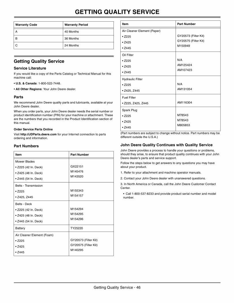
GETTING QUALITY SERVICE
Getting Quality ServiceService LiteratureIf you would like a copy of the Parts Catalog or Technical Manual for this machine call:
• U.S. & Canada: 1-800-522-7448.
• All Other Regions: Your John Deere dealer.
PartsWe recommend John Deere quality parts and lubricants, available at your John Deere dealer.
When you order parts, your John Deere dealer needs the serial number or product identification number (PIN) for your machine or attachment. These are the numbers that you recorded in the Product Identification section of this manual.
Order Service Parts Online
Visit http://JDParts.deere.com for your Internet connection to parts ordering and information.
Part Numbers
(Part numbers are subject to change without notice. Part numbers may be different outside the U.S.A.)
John Deere Quality Continues with Quality ServiceJohn Deere provides a process to handle your questions or problems, should they arise, to ensure that product quality continues with your John Deere dealer’s parts and service support.
Follow the steps below to get answers to any questions you may have about your product.
1. Refer to your attachment and machine operator manuals.
2. Contact your John Deere dealer with unanswered questions.
3. In North America or Canada, call the John Deere Customer Contact Center.
• Call 1-800-537-8233 and provide product serial number and model number.
Warranty Code Warranty Period
A 40 Months
B 36 Months
C 24 Months
Item Part Number
Mower Blades
• Z225 (42 In. Deck)
• Z425 (48 In. Deck)
• Z445 (54 In. Deck)
GX22151
M145476
M143520
Belts - Transmission
• Z225
• Z425, Z445
M155343
M154157
Belts - Deck
• Z225 (42 In. Deck)
• Z425 (48 In. Deck)
• Z445 (54 In. Deck)
M154294
M154295
M154296
Battery TY25220
Air Cleaner Element (Foam)
• Z225
• Z425
• Z445
GY20573 (Filter Kit)
GY20575 (Filter Kit)
M140295
Air Cleaner Element (Paper)
• Z225
• Z425
• Z445
GY20573 (Filter Kit)
GY20575 (Filter Kit)
M150949
Oil Filter
• Z225
• Z425
• Z445
N/A
AM125424
AM107423
Hydraulic Filter
• Z225
• Z425, Z445
N/A
AM131054
Fuel Filter
• Z225, Z425, Z445 AM116304
Spark Plug
• Z225
• Z425
• Z445
M78543
M78543
M805853
Item Part Number
Getting Quality Service - 46
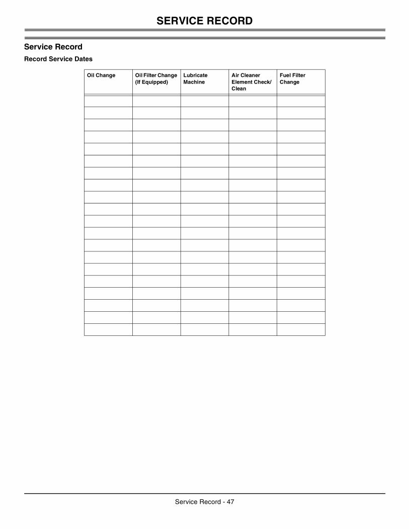
SERVICE RECORD
Service RecordRecord Service Dates
Oil Change Oil Filter Change (If Equipped)
Lubricate Machine
Air Cleaner Element Check/Clean
Fuel Filter Change
Service Record - 47
Related Documents