Welcome message from author
This document is posted to help you gain knowledge. Please leave a comment to let me know what you think about it! Share it to your friends and learn new things together.
Transcript


Table of Contents
TABLE OF CONTENTS
PAGE
Section One - Introduction 1
Company Profile 2
Technical Service and Support 3
Quality Assurance 4
Notes 5
Section Two - General Technical Information 7
Installation Information 8
Installation Methods 9
Single Core Cables in Parallel 12
Rating Factors 13
Bending Radii and Duct Sizes 15
Pulling Tension 16
Notes 17
Section Three – Medium Voltage TR-XLPE Cables 19
Explanatory Information - Construction 20
- Installation Tests 22
- Distributed Temperature Measuring System (DTS) 24
- Current Ratings 25
- Rating Factors 26
Product Sheets (See Section Three Contents Page 19 for Product Sheets Listing)

Introduction Section One
SECTION ONE - INTRODUCTION
PAGE
Company Profile 2
Technical Service and Support 3
Quality Assurance 4
Notes 5
Page 1

Section One Introduction
COMPANY PROFILE Power cables have been manufactured and tested at the Olex New Zealand Limited Bell Block factory on the outskirts of New Plymouth for more than 36 years. Established in 1967 as a joint venture between Tolley and Son and Canada Wire and Cable Company of Toronto, it was known as Canzac until 1984 when it was purchased by the Pacific Dunlop Group, one of Australia's largest international companies, and became part of the Pacific Dunlop Cables Group. In 1999 Olex Cables (New Zealand), together with other Pacific Dunlop Cables Group businesses, was bought by a management buy out consortium, and is now known as Olex New Zealand Limited, a Subsidiary of Olex Holdings Pty Limited. Olex Holdings Pty Limited, a world leader in cable technology and production, has manufacturing facilities in New Plymouth, Melbourne, and Sydney. With over 50 years experience behind it, Olex employs more than 1500 people and has the financial backing, the expertise and the commitment to maintain and expand its position as a world leader in cable technology, manufacturing and installation. At its New Plymouth factory, Olex New Zealand Limited produces a wide range of electrical power cables, ranging from building wires and control cables to power cables with rated voltages up to 35 kV. Complementing this range is a wide selection of power and data/communications cables manufactured by other Olex Holdings factories. Olex has proven its expertise and commitment to quality and service in fulfilling contracts in many New Zealand and international markets. The company has a strong commitment to further growth and expansion internationally. With this background, Olex is well placed to retain its leading role in terms of customer service, quality and research.
Page 2
Introduction Section One
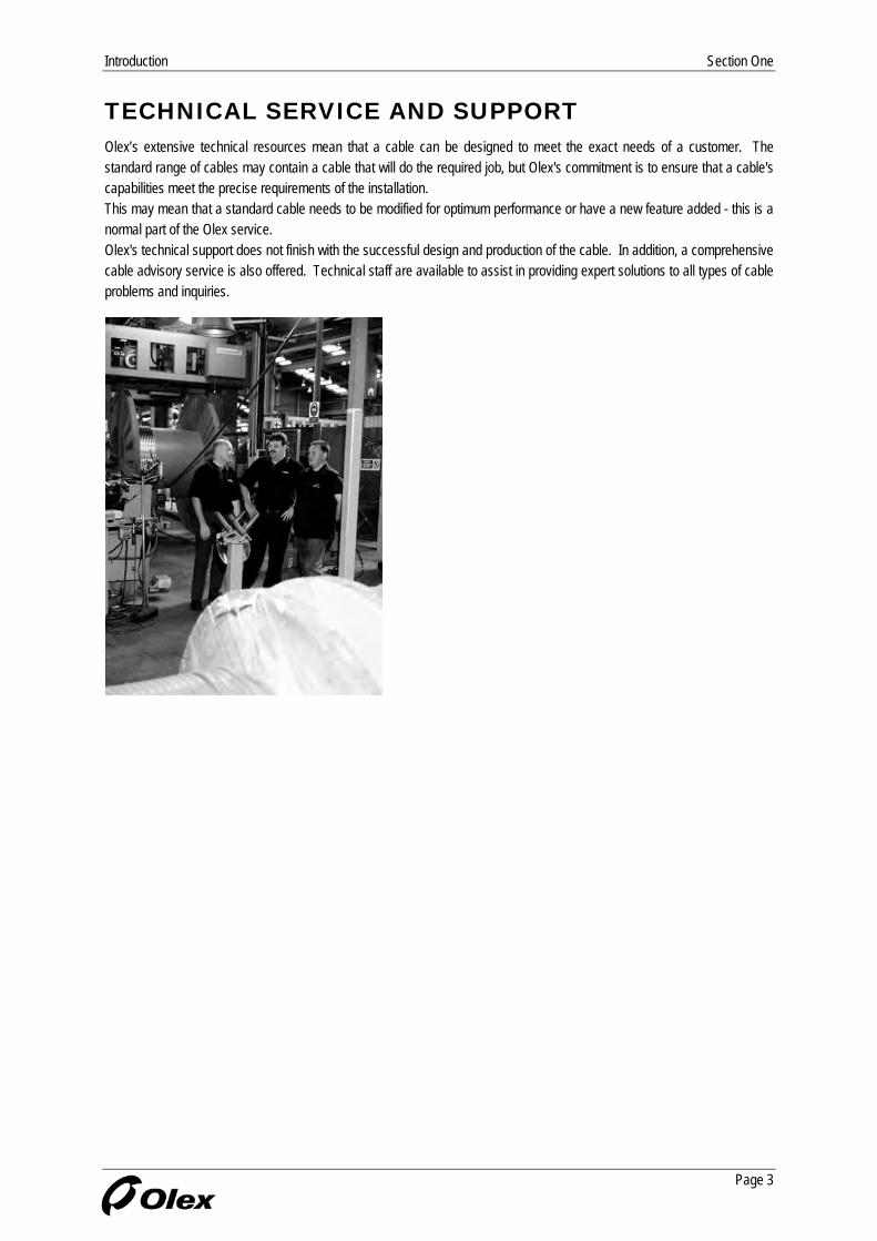
TECHNICAL SERVICE AND SUPPORT Olex’s extensive technical resources mean that a cable can be designed to meet the exact needs of a customer. The standard range of cables may contain a cable that will do the required job, but Olex's commitment is to ensure that a cable's capabilities meet the precise requirements of the installation. This may mean that a standard cable needs to be modified for optimum performance or have a new feature added - this is a normal part of the Olex service. Olex's technical support does not finish with the successful design and production of the cable. In addition, a comprehensive cable advisory service is also offered. Technical staff are available to assist in providing expert solutions to all types of cable problems and inquiries.
Page 3
Section One Introduction
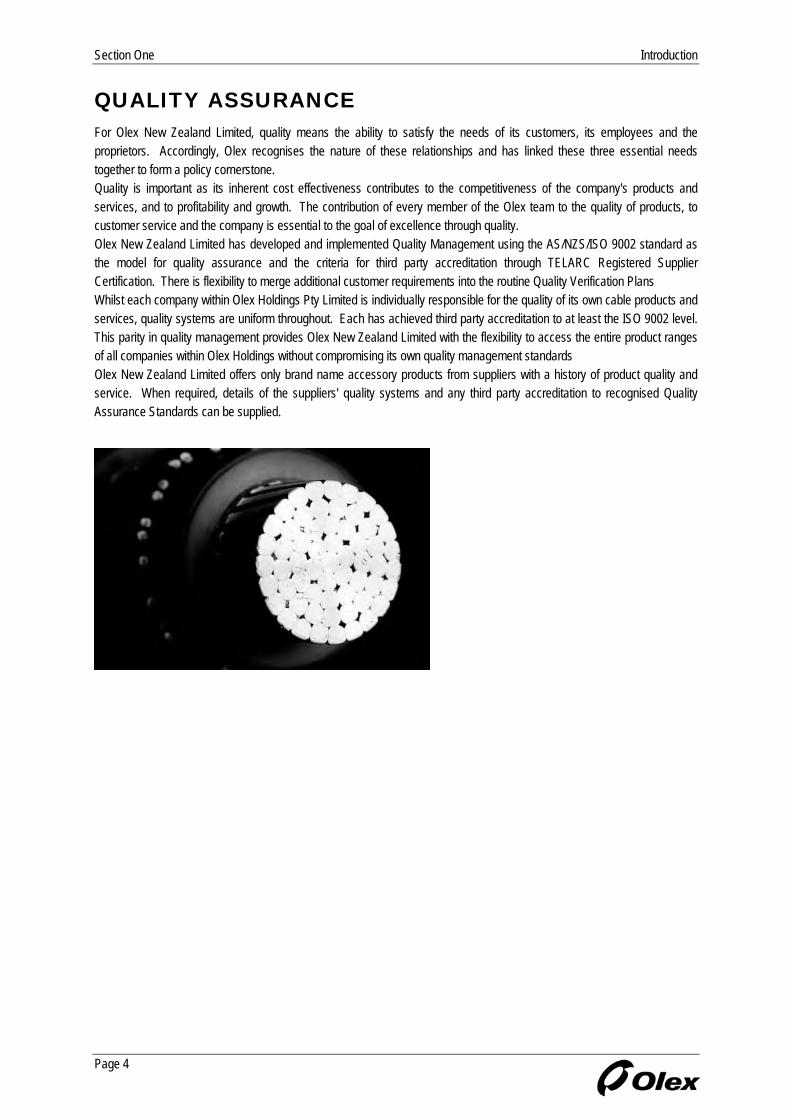
QUALITY ASSURANCE For Olex New Zealand Limited, quality means the ability to satisfy the needs of its customers, its employees and the proprietors. Accordingly, Olex recognises the nature of these relationships and has linked these three essential needs together to form a policy cornerstone. Quality is important as its inherent cost effectiveness contributes to the competitiveness of the company's products and services, and to profitability and growth. The contribution of every member of the Olex team to the quality of products, to customer service and the company is essential to the goal of excellence through quality. Olex New Zealand Limited has developed and implemented Quality Management using the AS/NZS/ISO 9002 standard as the model for quality assurance and the criteria for third party accreditation through TELARC Registered Supplier Certification. There is flexibility to merge additional customer requirements into the routine Quality Verification Plans Whilst each company within Olex Holdings Pty Limited is individually responsible for the quality of its own cable products and services, quality systems are uniform throughout. Each has achieved third party accreditation to at least the ISO 9002 level. This parity in quality management provides Olex New Zealand Limited with the flexibility to access the entire product ranges of all companies within Olex Holdings without compromising its own quality management standards Olex New Zealand Limited offers only brand name accessory products from suppliers with a history of product quality and service. When required, details of the suppliers' quality systems and any third party accreditation to recognised Quality Assurance Standards can be supplied.
Page 4

Introduction Section One
NOTES
Page 5
Section One Introduction
NOTES
Page 6

General Technical Information Section Two
SECTION TWO - GENERAL TECHNICAL INFORMATION
PAGE
Installation Information 8
Installation Methods 9
Single Core Cables in Parallel 12
Rating Factors 13
Bending Radii and Duct Sizes 15
Pulling Tension 16
Notes 17
Page 7
Section Two General Technical Information
INSTALLATION INFORMATION
General All cables must be installed to comply with the latest National Wiring Regulations.
Moisture Olex cables are manufactured in conditions that exclude moisture, as it is difficult to remove from a finished cable. It is important that precautions are taken during installation to ensure that moisture is not permitted to enter the cable. Cut ends or opened areas must be protected from moisture at all times, including during pulling in. Cables, after cutting, must be re-sealed for storage, by an effective method such as a heat shrinkable cable cap.
Single Core Cables The following points relating to single core cables should be noted: 1. Single core cables carrying the phase currents of a single circuit must be installed as closely as possible together, to minimise inductive reactance and voltage drop. The preferred formation for three phase conductors is a "trefoil" or cloverleaf pattern although flat touching formation is also acceptable. Jackets should be in contact with one another in either case. 2. A single core cable generates an alternating magnetic field around itself which can cause large increases in voltage drop and power loss due to "transformer effect" when ferrous metal (iron and steel) is allowed to encircle the cable. Steel racking or ladder will not induce this effect, but the following must be observed: a. Cable cleats may be of wood, plastic, or non-ferrous metal but steel saddles should not be used on single cores. b. Where three single phase cables pass through a steel bulkhead, they must all pass through the same hole. Where glanding is required, it is usual to cut out a panel and replace this with a non-ferrous (metal or plastic) plate in which the three or four glands are mounted.
Cable Support Under fault conditions, single core cables used as phase conductors in a multi-phase system may be subjected to large electromechanical forces which tend to drive them apart. Generally, properly designed cleats spaced at 1500 mm intervals will provide adequate support to the cable under normal operating conditions. However special consideration may be required if fault currents in excess of 15 kA are anticipated.
Page 8
General Technical Information Section Two
INSTALLATION METHODS
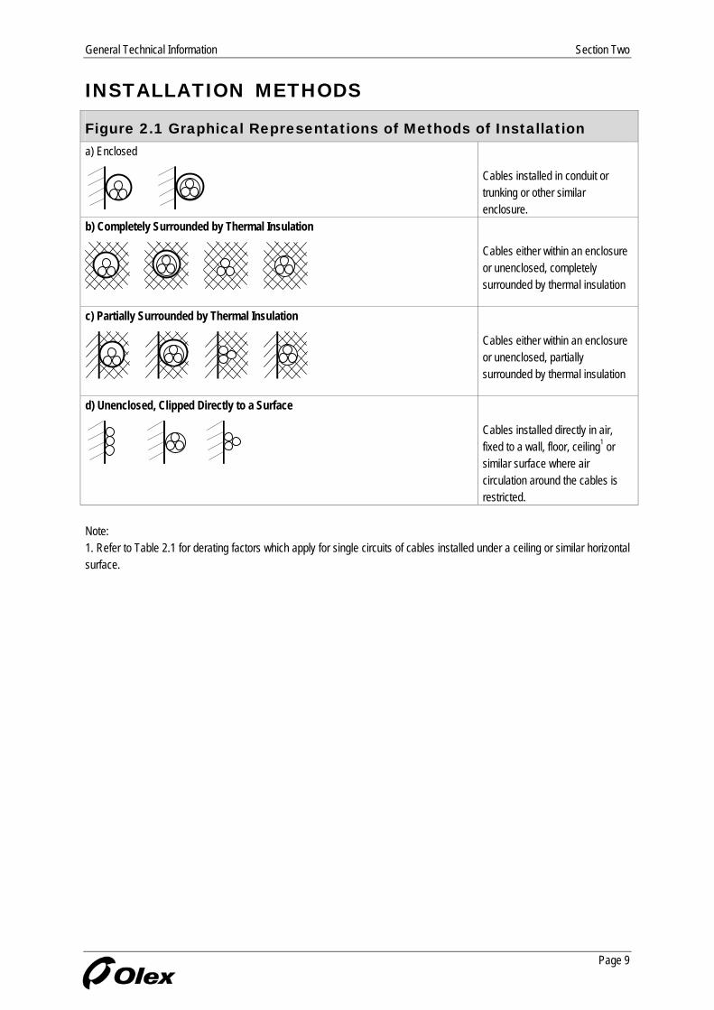
Figure 2.1 Graphical Representations of Methods of Installation a) Enclosed
Cables installed in conduit or trunking or other similar enclosure.
b) Completely Surrounded by Thermal Insulation
Cables either within an enclosure or unenclosed, completely surrounded by thermal insulation
c) Partially Surrounded by Thermal Insulation
Cables either within an enclosure or unenclosed, partially surrounded by thermal insulation
d) Unenclosed, Clipped Directly to a Surface
Cables installed directly in air, fixed to a wall, floor, ceiling1 or similar surface where air circulation around the cables is restricted.
Note: 1. Refer to Table 2.1 for derating factors which apply for single circuits of cables installed under a ceiling or similar horizontal surface.
Page 9

Section Two General Technical Information
INSTALLATION METHODS (CONT.)
Figure 2.1 (cont.) Graphical Representations of Methods of Installation e) Unenclosed, Spaced Away from a Surface1
0.3D 0.3D
D
0.3D 0.3D 0.3D
0.5D
Cables installed with minimum spacings as shown directly in air, and supported on ladders2, racks, perforated3 or unperforated trays4 etc, or suspended from a catenary wire.
f) Buried Direct in the Ground
Cables buried directly in the ground. The depth of burial is measured from the surface to the centre of the cable or group of cables.
g) Laid in Underground Ducts, Pipes or Conduits
Cables installed in underground enclosures. The depth of burial is measured from the surface to the centre of the duct or group of ducts.
Notes: 1. D = Cable OD (or Width, in the case of a flat cable). 2. Ladder support is one where the supporting metalwork which provides impedance to air flow occupies less than 10% of the plan area under the cables. 3. Perforated trays are those in which not less than 30% of the surface area is removed by perforation. 4. Refer to Table 2.2 for derating factors which apply even for single circuits of cables installed on perforated or unperforated trays.
Page 10

General Technical Information Section Two
INSTALLATION METHODS (CONT.)
Figure 2.2 Minimum Spacings in Air to Avoid Derating Method of Installation Horizontal Spacings Vertical Spacings a) Single Core Cables Cables spaced away from surfaces and supported on ladders, racks, etc. or suspended from a catenary wire, such that impedance to air flow around the cables is not greater than 10%.
D
D
D
4D 4D
Cables spaced away from surfaces and supported on perforated or unperforated trays such that air flow around the cables is partially restricted.
2D
2D
4D
Cables fixed directly to a wall, floor, ceiling or similar surface such that air circulation is restricted.
2D
2D
6D 6D
b) Multicore Cables Cables spaced away from surfaces and supported on ladders, racks, etc. or suspended from a catenary wire, such that impedance to air
t flow around the cables is nogreater than 10%.
0.5D
D
2D
4D
4D
Cables spaced away from surfaces and supported on perforated or unperforated trays such that air flow around the cables is partially restricted.
2D
4D
Cables fixed directly to a wfloor, ceiling
all, or similar surface
such that air circulation is restricted.
2D
6D
Page 11
Section Two General Technical Information
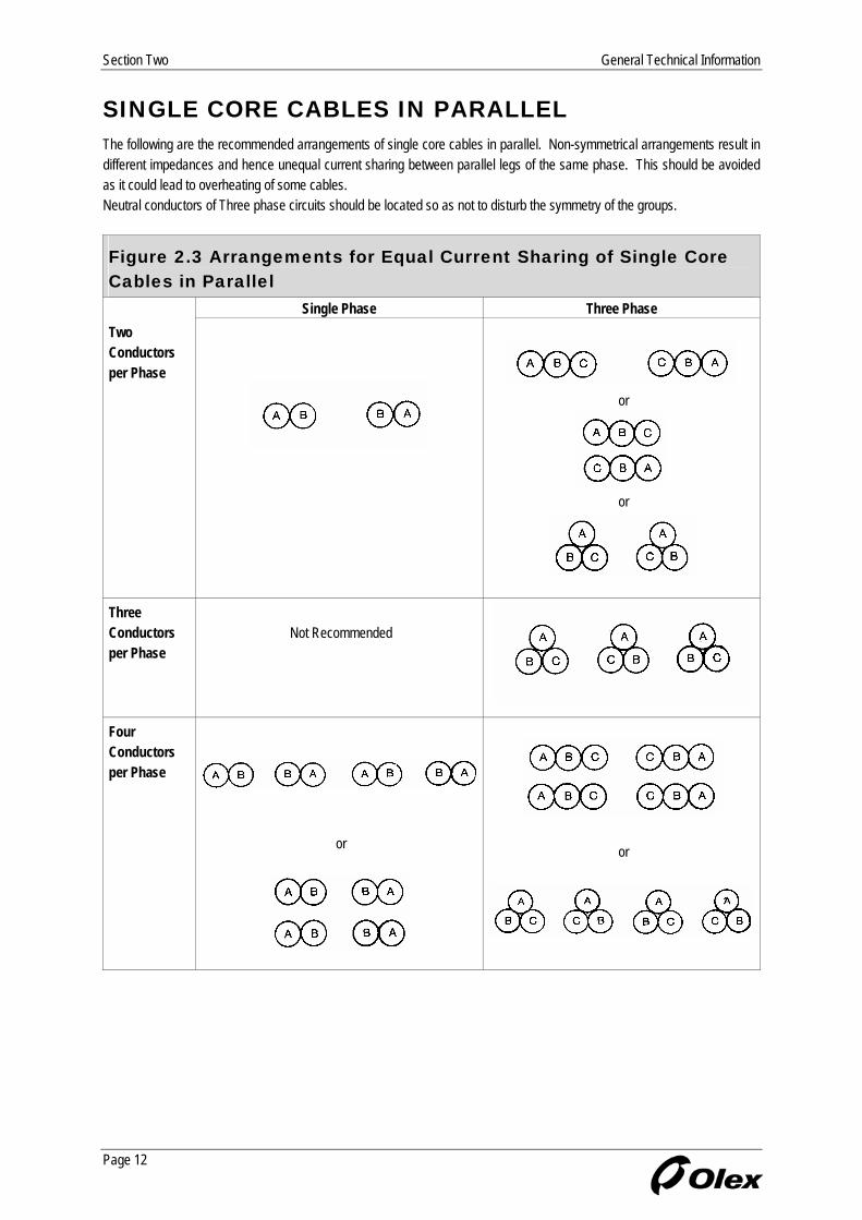
SINGLE CORE CABLES IN PARALLEL The following are the recommended arrangements of single core cables in parallel. Non-symmetrical arrangements result in different impedances and hence unequal current sharing between parallel legs of the same phase. This should be avoided as it could lead to overheating of some cables. Neutral conductors of Three phase circuits should be located so as not to disturb the symmetry of the groups.
Figure 2.3 Arrangements for Equal Current Sharing of Single Core Cables in Parallel
Single Phase Three Phase Two Conductors per Phase
or
or
Three Conductors
er Phase
Not Recommended
p
Four Conductors per Phase
or
or
Page 12

General Technical Information Section Two
RATING FACTORS
Table 2.1 Bunched Circuits of Single Core or Multicore Cables in Air or in Wiring Enclosures
Arrangement of Cables Single Layer
on Wall or Floor Single Layer
under a Ceiling
No of Circuits1 Bunched
in Air Bunched
on a Surface or Enclosed Touching Spaced2,3 Touching Spaced2,3
1 1.00 1.00 1.00 1.00 0.95 0.95
2 0.87 0.80 0.85 0.94 0.81 0.85
3 0.75 0.70 0.79 0.90 0.72 0.85
4 0.72 0.65 0.75 0.90 0.68 0.85
5 0.70 0.60 0.73 0.90 0.66 0.85
6 0.67 0.57 0.72 0.90 0.64 0.85
7 - 0.54 0.72 0.90 0.63 0.85
8 - 0.52 0.71 0.90 0.62 0.85
9 - 0.50 0.70 0.90 0.61 0.85
10 - 0.48 0.70 0.90 0.61 0.85
12 - 0.45 0.70 0.90 0.61 0.85
14 - 0.43 0.70 0.90 0.61 0.85
16 - 0.41 0.70 0.90 0.61 0.85
18 - 0.39 0.70 0.90 0.61 0.85
20 or more
- 0.38 0.70 0.90 0.61 0.85
Notes: 1. Where a bunch of cables consist of n loaded conductors, it may be considered as n/2 circuits of two loaded conductors or n/3 circuits of three loaded conductors. 2. Spaced refers to a clearance of one cable diameter between adjacent cables. 3. Refer to Figure 2.2 for spacings which avoid derating.
Page 13

Section Two General Technical Information
RATING FACTORS (CONT.)
Table 2.2 Cables on Trays, Racks or Other Supports Single Core Cables Multicore Cables
No. of Circuits1 per Tray or Rack
No of Cables1 per Tray or Rack Type of Support Arrangement No. of
Trays or
Racks 1 2 3
Arrangement No. of Trays
or Racks
1 2 3 4 6 9
1 2 3
0.95 0.92 0.91
0.85 0.83 0.82
0.84 0.79 0.76
1 2 3
0.97 0.97 0.97
0.85 0.84 0.83
0.78 0.76 0.75
0.75 0.73 0.72
0.71 0.68 0.66
0.68 0.63 0.61
Unperfor-ated Trays2
D
1 2 3
0.98 0.95 0.94
0.96 0.91 0.90
0.94 0.87 0.85
D 1 2 3
0.97 0.97 0.97
0.96 0.95 0.94
0.94 0.92 0.91
0.93 0.90 0.89
0.90 0.86 0.84
- - -
1 2 3
0.97 0.94 0.93
0.89 0.85 0.84
0.87 0.81 0.79
1 2 3
1.0 1.0 1.0
0.88 0.87 0.86
0.82 0.80 0.79
0.78 0.76 0.75
0.76 0.73 0.71
0.73 0.68 0.66
Perforated Trays2
D
1 2 3
1.0 0.97 0.96
0.98 0.93 0.92
0.96 0.89 0.86
D 1 2 3
1.0 1.0 1.0
1.0 0.99 0.98
0.98 0.96 0.95
0.95 0.92 0.91
0.91 0.87 0.85
- - -
1 2
0.94 0.92
0.85 0.83
- -
1 2
1.0 1.0
0.88 0.88
0.82 0.81
0.77 0.76
0.73 0.72
0.72 0.70
Vertical Perforated Trays3
D
1 2
1.0 0.90 0.86 1.0 0.91 0.89
D
1 2 1.0 0.91 0.88 0.87 0.86 -
1.0 0.91 0.89 0.88 0.87 -
1 2 3
1.0 0.95 0.95
0.95 0.90 0.89
0.94 0.88 0.85
1 2 3
1.0 1.0 1.0
0.87 0.86 0.85
0.82 0.80 0.79
0.80 0.78 0.76
0.79 0.76 0.73
0.78 0.73 0.70
Ladder Racks, Cleats etc2
D
1 2 3 0.97 0.94 0.90
1.0 0.97
1.0 0.95
1.0 0.93
D
3 1.0 0.98 0.97 0.96 0.93 -
1 2
1.0 1.0
1.0 0.99
1.0 0.98
1.0 0.97
1.0 0.96
- -
The factors are to be applied to “spaced from surface in air” current ratings.
its consisting of groups of two or three loaded single core cables or multicore cables having
3. Back to back vertical trays shall have a horizontal spacing of not less than 230 mm.
Notes: 1. The factors given apply to circutwo or three loaded conductors. 2. Trays or ladder type supports shall have a vertical spacing of not less than 300 mm.
Page 14

General Technical Information Section Two
BENDING RADII AND DUCT SIZES
Recommended Bending Radius Factors The safe bending radius for an electric cable is limited by the flexibility of its insulation and Jacketing material. When a cable is being installed it may be pulled around several curves in different directions and subjected to dynamic stresses which could cause damage. Consequently the bending radius around which a cable may be pulled is greater than that into which it can be set in its final position. The following recommended minimum bending radii are expressed as a function of the cable diameter and refer to the inside of the curve. In all cases, bending radii should be as large as practicable.
Recommended Minimum Bending Radii Cable Type (choose the highest value of all relevant construction features) During Installation (F) Set (F)
Nylon Covered 30 20 HDPE Jacket 25 15 Helical Copper or Brass taped 18 12 Steel Wire Armoured 18 12 Solid Aluminium Conductors 12 8
All Cable Types
Compacted or Shaped Stranded Conductors 12 8 MV XLPE Cables Single Core and Multicore Cables 18 12 LV (0.6/1 kV) Cables PVC/XLPE Insulation 9 6
Minimum Bending Radius R = F * D where, R = Bending Radius (mm), D = Cable Diameter (mm), and F = Factor from above table.
Duct Sizes Ducts are another important consideration affecting the pulling operation. Selection of the appropriate duct should be based on internal duct diameter to suit a cable size and wall thickness to prevent deformation during duct installation. The internal finish of the installed ducting should be smooth to prevent cable Jacket damage during installation. During cable installation the use of graphite or other commercially available pulling lubricants can also prevent Jacket damage and reduce pulling tensions. The following duct sizes are recommended:
Duct Selection Heavy Duty Rigid PVC Conduit Cable Diameter
Nominal Size (mm) Single Cable (mm) Three Cables (mm) Four Cables (mm) 50 Up to 30 - -
63 30 to 38 - -
65 38 to 47 Up to 24 Up to 21
80 47 to 52 24 to 27 21 to 23
100 52 to 69 27 to 35 23 to 31
150 69 to 99 35 to 51 31 to 44
200 99 to 142 51 to 73 44 to 63
250 Above 142 Above 73 Above 63
Page 15
Section Two General Technical Information
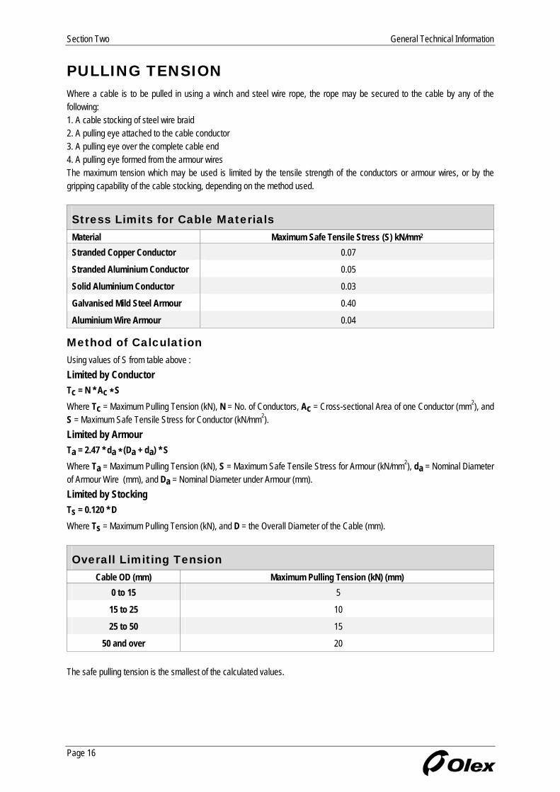
PULLING TENSION Where a cable is to be pulled in using a winch and steel wire rope, the rope may be secured to the cable by any of the following: 1. A cable stocking of steel wire braid 2. A pulling eye attached to the cable conductor 3. A pulling eye over the complete cable end 4. A pulling eye formed from the armour wires The maximum tension which may be used is limited by the tensile strength of the conductors or armour wires, or by the gripping capability of the cable stocking, depending on the method used.
Stress Limits for Cable Materials Material Maximum Safe Tensile Stress (S) kN/mm2
Stranded Copper Conductor 0.07
Stranded Aluminium Conductor 0.05
Solid Aluminium Conductor 0.03
Galvanised Mild Steel Armour 0.40
Aluminium Wire Armour 0.04
Method of Calculation Using values of S from table above : Limited by Conductor Tc = N * Ac * S Where Tc = Maximum Pulling Tension (kN), N = No. of Conductors, Ac = Cross-sectional Area of one Conductor (mm2), and S = Maximum Safe Tensile Stress for Conductor (kN/mm2). Limited by Armour Ta = 2.47 * da * (Da + da) * S Where Ta = Maximum Pulling Tension (kN), S = Maximum Safe Tensile Stress for Armour (kN/mm2), da = Nominal Diameter of Armour Wire (mm), and Da = Nominal Diameter under Armour (mm). Limited by Stocking Ts = 0.120 * D Where Ts = Maximum Pulling Tension (kN), and D = the Overall Diameter of the Cable (mm).
Overall Limiting Tension Cable OD (mm) Maximum Pulling Tension (kN) (mm)
0 to 15 5
15 to 25 10
25 to 50 15
50 and over 20 The safe pulling tension is the smallest of the calculated values.
Page 16

General Technical Information Section Two
NOTES
Page 17

Section Two General Technical Information
NOTES
Page 18
Medium Voltage TR-XLPE Cables Section Three
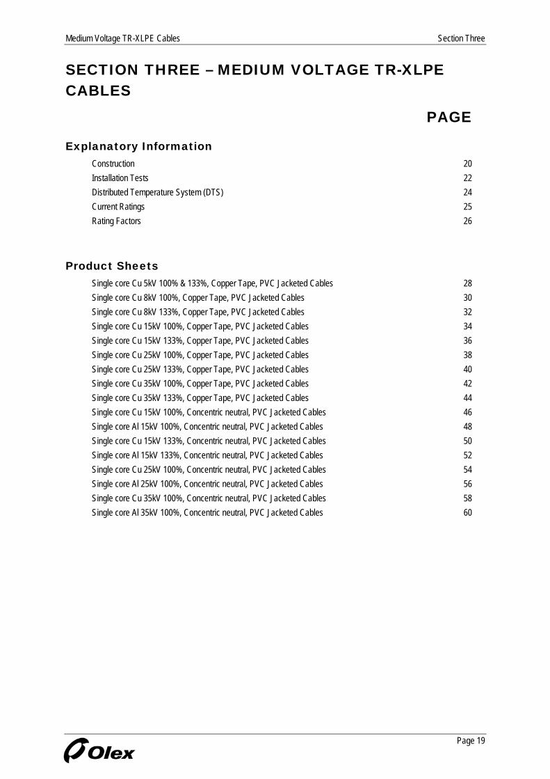
SECTION THREE – MEDIUM VOLTAGE TR-XLPE CABLES
PAGE
Explanatory Information Construction 20 Installation Tests 22 Distributed Temperature System (DTS) 24 Current Ratings 25 Rating Factors 26
Product Sheets Single core Cu 5kV 100% & 133%, Copper Tape, PVC Jacketed Cables 28 Single core Cu 8kV 100%, Copper Tape, PVC Jacketed Cables 30 Single core Cu 8kV 133%, Copper Tape, PVC Jacketed Cables 32 Single core Cu 15kV 100%, Copper Tape, PVC Jacketed Cables 34 Single core Cu 15kV 133%, Copper Tape, PVC Jacketed Cables 36 Single core Cu 25kV 100%, Copper Tape, PVC Jacketed Cables 38 Single core Cu 25kV 133%, Copper Tape, PVC Jacketed Cables 40 Single core Cu 35kV 100%, Copper Tape, PVC Jacketed Cables 42 Single core Cu 35kV 133%, Copper Tape, PVC Jacketed Cables 44 Single core Cu 15kV 100%, Concentric neutral, PVC Jacketed Cables 46 Single core Al 15kV 100%, Concentric neutral, PVC Jacketed Cables 48 Single core Cu 15kV 133%, Concentric neutral, PVC Jacketed Cables 50 Single core Al 15kV 133%, Concentric neutral, PVC Jacketed Cables 52 Single core Cu 25kV 100%, Concentric neutral, PVC Jacketed Cables 54 Single core Al 25kV 100%, Concentric neutral, PVC Jacketed Cables 56 Single core Cu 35kV 100%, Concentric neutral, PVC Jacketed Cables 58 Single core Al 35kV 100%, Concentric neutral, PVC Jacketed Cables 60
Page 19

Section Three Medium Voltage TR-XLPE Cables
CONSTRUCTION Olex Medium Voltage TR-XLPE cables are designed in accordance with ICEA S-93-639/NEMA WC74 and specific customer requirements where applicable to provide optimum performance for the end application. Olex also manufactures to other international standard such as IEC 60502.2, AS/NZS 1429.1, BS 6622 and AEIC CS8.
Component Detail Conductor Conductors are made of either copper to ASTM B8 or aluminium to ASTM B231. To assist in producing a smooth circular profile at the interface between the conductor screen and the insulation, compressed stranded conductors are used. Insulation and Semiconductive Screens All Olex Medium Voltage TR-XLPE insulated cables are produced under clean room conditions, using the triple extrusion process in which the conductor screen, insulation and insulation screen are extruded simultaneously through a single extrusion head. The surface of the insulation is never exposed to the atmosphere or to any material other than the adjacent semiconductive screens, ensuring that the interfaces between the materials are completely free of voids and contamination.
A sophisticated dimension control device uses X-Rays which are fired through the three layers of polymer to accurately measure the individual layer thicknesses; this ensures that the dimensions of all layers are constant and concentric through the entire length of the cable.
Cross sectional view of a Triple Extrusion Head
EX-RAY-800 Dimensional Controller
The cross-linking process is carried out in a totally water-free environment, using inert gas rather than steam as the curing medium. This dry-cure process ensures a high integrity insulation and leads to excellent electrical performance.
Page 20

Medium Voltage TR-XLPE Cables Section Three
CONSTRUCTION (CONT.) Insulation and Semiconductive Screens (cont.) The functional components of this triple layer are: 1. Conductor screen, a semiconductive cross-linked polymeric material applied over the conductor and bonded to the insulation. This provides a smooth, circular interface between the conductor and insulation and eliminates stress concentrations. 2. Insulation , a clean, low density, high molecular weight cross-linked polyethylene. A tree-retardant grade, which has shown improved performance in accelerated ageing tests, is used. This leads to superior long term reliability.
TR-XLPE
XLPE
Projected useful TR-XLPE cables – more than 40
life of
years
3. Insulation screen, a layer of semiconductive cross-linked polymeric material which adheres firmly to the insulation, yet remains readily strippable by hand for jointing and terminating. Metal Screen A screen of plain annealed copper tape or wire is helically applied over the semiconductive insulation screen, ie, over the core of a single core cable or each core of a three core cable. This screen acts as a return path for capacitive charging current and induced circulating currents under normal operating conditions. The screen will also carry short circuit current in the event of an electrical fault in the circuit. Core Assembly (Three Core Cable) The cores are laid up and the interstices filled with a non-hygroscopic material to achieve a circular cable cross section. The laid up core assembly is bound with helically applied non-hygroscopic tapes. Bedding and Armour (Three Core Cable) In three core armoured cables, a bedding layer of PVC is extruded over the core assembly followed by a layer of helically applied galvanised mild steel wires. Outer Jacket A Jacket of PVC, or LLDPE, is extruded over the metal screen of a single core cable, or over the core assembly or steel wire armour of three core cables. Alternative protective coverings may be applied depending on the environment in which the cable is installed, eg, MDPE, HDPE, Megolon or a dual Jacket of PVC/HDPE.
Page 21

Section Three Medium Voltage TR-XLPE Cables
INSTALLATION TESTS
General After the cable has been installed and prior to commencing terminating or jointing, it is desirable to carry out checks to establish that the cable has not been damaged during the installation process, namely a Jacket Integrity Test and an Insulation Resistance Test of Primary Insulation After completion of the tests, if the terminating or jointing is not being commenced straight away, the cable ends should be resealed with heat shrinkable end caps or similar to prevent the ingress of moisture.
Olex New Zealand Limited Recommendations for Tests After Complete Installation of TR-XLPE Medium Voltage Cables Advice Concerning Tests After Installation If a test is carried out after installation, please note that the test is to detect defects caused during installation. After installation, the test is applied to the cable and accessories. High Voltage D.C. Test After Installation The D.C. testing of the primary insulation is not recommended. There are two important reasons for not using a High Voltage DC Test. 1. The DC field in the cable and accessories applies different electric stresses (both in magnitude and in physical location) to an AC field, so much so, that it is considered to be a poor process to find faults. 2. The application of High Voltage DC leads to premature failure of aged and “wet” primary insulation. This has been proven in the Laboratory and has been proven repeatedly in the field. Safety Requirements As the voltages used in these tests are potentially lethal, appropriate safety measures must be employed to ensure that the safety of all people involved in the testing process is not compromised. Cable ends to be isolated shall be disconnected from the supply and protected from contact to supply, or ground, or accidental contact. Safety measures shall include, and shall not necessarily be limited to, earthing of cable under test prior to and after test voltages are applied, erection of safety barriers with warning signs, and an open communication channel between testing personnel. The testing guidelines outlined in this document are Olex New Zealand Limited’s recommendations only, and Olex New Zealand Limited cannot be held responsible for ensuring the safe implementation of these recommendations. Jacket Integrity Test A Jacket integrity test (eg, 1000 V minimum insulation resistance tester) applied between the outer-most metallic layer and earth can identify after-installation damage to the non-metallic outer Jacket. The measured value should be read after application of the voltage for 1 minute. Ideally the measured value should be corrected for temperature to a standard value at 20°C if correction factors are available. A rough guide is that the insulation resistance decreases to one half of the value for a 10°C rise in temperature. The cable temperature should be recorded along with the measured values. Measured values of Insulation Resistance for the Jacket should be greater than calculated values. Calculated values for new cable range from 1.5 MΩ/km to 4.0 MΩ/km @ 20°C for PVC Jackets and from 120 MΩ/km to 300 MΩ/km @ 20°C for PE Jackets. Values are highest for small cables and thick Jackets and lowest for large cables and thin Jackets (factory tests show that measured values are up to an order of magnitude greater than the calculated values). Earth the screens after an Insulation Resistance Test on a Jacket for at least 5 minutes before handling or performing other tests.
Page 22
Medium Voltage TR-XLPE Cables Section Three
INSTALLATION TESTS (CONT.) Insulation Resistance Test of Primary Installation DC voltages up to 5 kV, used when performing Insulation Resistance Tests on Primary Insulation, are not considered to be a “High voltage DC test”. An Insulation Resistance Test of the Primary Insulation should be carried out with an insulation resistance tester, with a minimum DC voltage of 2.5 kV for 1.9/3.3 kV cables or 5 kV for cables above 1.9/3.3 kV and up to 19/33 kV. The insulation test should be carried out in the “Guarded Mode” and the instrument should have a minimum full-scale range of 500 Gohms. Guarding should be applied at both ends and a spare core used for the connection lead to the guard at the far end. Any conductor or cable core used as a guard lead must have a resistance to ground of greater than 10 kohms. The measured value should be read after application of the voltage for 1 minute. Ideally the measured value should be corrected for temperature to a standard value at 20°C if correction factors are available. A rough guide is that the insulation resistance decreases to one half of the value for a 10°C rise in temperature. The cable temperature should be recorded along with the measured values. Measured values of insulation resistance for the primary insulation should be greater than calculated values. Calculated values for new cable range from 2,400 MΩ/km to 18,000 MΩ/km at 20°C. Values are highest for small conductors and higher voltages and lowest for large conductors and lower voltages (factory tests show that measured values are up to an order of magnitude greater than the calculated values). This test should be performed prior to any high voltage tests. Short the conductors to the screens after an Insulation Resistance Test on Primary Insulation for at least 10 minutes before handling or performing other tests. If the instrument used for the above insulation resistance testing is a “Megger,” Type BM 25, or equivalent, then the two following tests should be considered. 1. A 10 minute Polarisation Index Test - this test is commonly used as a replacement for the standard insulation resistance test. 2. A 5 Minute Step Voltage Test - the test should use five equal steps up to the maximum test voltage of 2.5 kV for 1.9/3.3 kV cables or 5 kV for cables greater than 1.9/3.3 kV up to 19/33 kV. This test is becoming increasingly used on cables of 6.35/11 kV and greater. Both the above tests can be carried out automatically with the Megger, BM 25 unit and guarding should be applied at both ends as above. High Voltage A.C. Test after Installation An A.C. voltage test at power frequency should be applied for 24 hours with the normal operating voltage of the system to the primary insulation. Some customers have objected to a 24 hour test at only the operating voltage of the cable and would prefer a test using a higher voltage for a shorter time. This can be achieved by a Very Low Frequency (VLF) HV AC Test, and the equipment now exists for hire in New Zealand to perform this. The VLF HV AC Test is becoming recognised throughout the world as a replacement test for the old HV DC Test or the 24 hour AC test at normal operating voltage, although not many standards have details in them at this point in time. VLF Tests are carried out at a frequency in the band of 0.1 to 0.02 Hz. The VLF Test Set must be of adequate power to test the measured cable capacitance at the frequency chosen. The suggested maximum VLF test voltage for new cable is between 2.7 and 3.0 times the cable operating voltage (Uo), for a minimum of 15 minutes. Where possible, a 30 minute testing time is now recommended as international research has shown this to give a higher confidence. Refer to the test procedure of IEEE-400-2, May 2004 draft. For existing or aged cables being recommissioned after repair or alterations, the VLF Test Voltage should be a maximum of 2.3 times the cable operating voltage (Uo), for 15 minutes. Documentation The values obtained in the above tests should be recorded in a cable log so that they are available for comparison purposes in the future.
Page 23
Section Three Medium Voltage TR-XLPE Cables
DISTRIBUTED TEMPERATURE MONITORING SYSTEM (DTS)
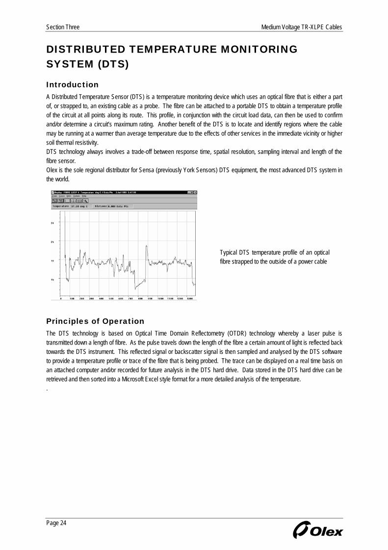
Introduction A Distributed Temperature Sensor (DTS) is a temperature monitoring device which uses an optical fibre that is either a part of, or strapped to, an existing cable as a probe. The fibre can be attached to a portable DTS to obtain a temperature profile of the circuit at all points along its route. This profile, in conjunction with the circuit load data, can then be used to confirm and/or determine a circuit’s maximum rating. Another benefit of the DTS is to locate and identify regions where the cable may be running at a warmer than average temperature due to the effects of other services in the immediate vicinity or higher soil thermal resistivity. DTS technology always involves a trade-off between response time, spatial resolution, sampling interval and length of the fibre sensor. Olex is the sole regional distributor for Sensa (previously York Sensors) DTS equipment, the most advanced DTS system in the world.
Typical DTS temperature profile of an optical fibre strapped to the outside of a power cable
Principles of Operation The DTS technology is based on Optical Time Domain Reflectometry (OTDR) technology whereby a laser pulse is transmitted down a length of fibre. As the pulse travels down the length of the fibre a certain amount of light is reflected back towards the DTS instrument. This reflected signal or backscatter signal is then sampled and analysed by the DTS software to provide a temperature profile or trace of the fibre that is being probed. The trace can be displayed on a real time basis on an attached computer and/or recorded for future analysis in the DTS hard drive. Data stored in the DTS hard drive can be retrieved and then sorted into a Microsoft Excel style format for a more detailed analysis of the temperature. .
Page 24

Medium Voltage TR-XLPE Cables Section Three
CURRENT RATINGS The continuous current ratings given in this publication have been calculated in accordance with the International Electrotechnical Commission Publication No. IEC 60287 - "Calculation of the Continuous Current Rating of Cables (100% Load factor)", based on the following environmental conditions: Ambient Air Temperature, 40°C; Ambient Soil Temperature, 25°C; Soil Thermal Resistivity, 1.2 K.m/W; Depth of burial, 0.8 m; and, Screens bonded both ends. In all cases, the ratings given are the single circuit ratings corresponding to continuous loading at the maximum conductor temperature of 90°C. Where the conditions vary from those on which the ratings are based, rating factors from Tables 3.1 to 3.4 (Section 3 Medium Voltage TR-XLPE Cables) need to be applied.
Methods of Installation The methods of installation for which the ratings are applicable are shown graphically in Figure 2.1 (Section 2 General Technical Information).
Groups of Circuits For groups of circuits unenclosed in air, the spacings and arrangements which need to be maintained to prevent derating are given in Figure 2.2 (Section 2 General Technical Information). Where a number of circuits are installed in close proximity in such a way that they are not thermally independent, the appropriate rating factors from Tables 3.5, 3.6, (Section 3 Medium Voltage TR-XLPE Cables) and 2.1, 2.2 (Section 2 General Technical Information) need to be applied.
Cables in Parallel For cables operated in parallel, each parallel leg is regarded as a separate circuit for current rating purposes and the appropriate rating factors for grouping are applicable. Refer also to Figure 2.3 (Section 2 General Technical Information) for the arrangements of single core cables so as to ensure equal current sharing between parallel legs of the same phase.
Bonding of Screens The current ratings given for single core cables assume that the copper wire screens are solidly bonded to earth at both ends. Solid bonding can result in a reduction in current ratings on larger cables due to the heating effect of circulating currents induced in the screen. This loss can be minimised, either in short runs of cable, by earthing at one end only (single point bonding) which results in a standing voltage proportional to the conductor current and the length of run being induced on the screen and in long runs of cable, by dividing the route into tri-sections and transposing or "crossbonding" the screens at every joint position in a tri-section so that the e.m.f.'s induced by the three phases cancel one another. When these methods of bonding are employed, higher current ratings may be used, however attention must be paid to the safety aspects with respect to the induced standing voltages. This places a limitation on the length of circuit for which single point bonding can be used. Generally it is only considered practical to use special cross-bonding arrangements on transmission class cables (66 kV and above) as the benefits of the higher current ratings are outweighed by the costs of the extra equipment required.
Emergency Ratings Operations at the emergency overload temperature of 130°C for TR-XLPE insulation rated at 90°C continuous shall not exceed 1500 hours cumulative during the lifetime of the cable. Lower temperatures for emergency overload conditions may be required because of the type of material used in the cable, joints, and terminations or because of cable environmental conditions.
Page 25

Section Three Medium Voltage TR-XLPE Cables
MEDIUM VOLTAGE RATING FACTORS
Table 3.1 Air Temperature Variation Air Temperature (°C)
20 25 35 40 45 50 55 Rating Factor 1.18 1.14 1.05 1.00 0.95 0.89 0.84
Table 3.2 Soil Temperature Variation Soil Temperature (°C)
10 15 20 25 30 35 40 Rating Factor 1.11 1.07 1.04 1.00 0.96 0.92 0.88
Table 3.3 Depth of Burial Variation Depth of Burial (m)
0.8 1.00 1.00 1.00
1.0 0.98 0.98 0.99
1.25 0.96 0.95 0.97
1.5 0.95 0.94 0.96
1.75 0.94 0.92 0.96
2.0 0.92 0.91 0.95
2.5 0.91 0.89 0.94
3.0 (or more) 0.90 0.88 0.93
Table 3.4 Soil Thermal Resistivity Variation Soil Thermal Resistivity
(K.m/W)
0.8 1.12 1.16 1.04 1.06
0.9 1.08 1.11 1.03 1.04
1.0 1.05 1.07 1.02 1.03
1.2 1.00 1.00 1.00 1.00
1.5 0.92 0.91 0.95 0.94
2.0 0.81 0.80 0.88 0.87
2.5 0.74 0.73 0.83 0.81
3.0 0.69 0.67 0.78 0.76
Page 26

Medium Voltage TR-XLPE Cables Section Three
MEDIUM VOLTAGE RATING FACTORS (CONT.)
Table 3.5 Groups of Circuits Laid Direct Single Core Cables
spacing spacing
Multicore Cables
spacing Touching Spacing (m) Spacing (m)
No. of Circuits
Trefoil Flat 0.15 0.30 0.45 0.60 Touching
0.15 0.30 0.45 0.60
2 0.78 0.80 0.82 0.86 0.89 0.91 0.80 0.85 0.89 0.91 0.93
3 0.66 0.68 0.71 0.77 0.80 0.83 0.68 0.76 0.81 0.84 0.87
4 0.59 0.62 0.65 0.72 0.77 0.80 0.62 0.71 0.77 0.81 0.84
5 0.55 0.58 0.61 0.68 0.74 0.78 0.57 0.66 0.73 0.78 0.82
6 0.52 0.55 0.58 0.66 0.72 0.76 0.54 0.64 0.71 0.77 0.81
7 0.49 0.52 0.56 0.64 0.70 0.75 0.51 0.61 0.69 0.75 0.79
8 0.47 0.50 0.54 0.63 0.69 0.74 0.49 0.59 0.68 0.74 0.79
9 0.45 0.48 0.52 0.61 0.68 0.74 0.47 0.58 0.67 0.73 0.78
10 0.44 0.47 0.51 0.61 0.68 0.73 0.45 0.57 0.66 0.73 0.78
11 0.43 0.46 0.50 0.60 0.67 0.73 0.44 0.55 0.65 0.72 0.77
12 0.41 0.45 0.49 0.59 0.67 0.72 0.43 0.54 0.64 0.72 0.77
Table 3.6 Groups of Circuits In Underground Ducts Multicore Cables in Single-way Ducts
or Single Core Cables in Multiway Ducts
spacingspacing
Single Core Cables in Single-way Ducts
spacing
Spacing (m) Spacing (m)
No. of Circuits
Touching 0.30 0.45 0.60
Touching 0.45 0.60
2 0.88 0.91 0.93 0.94 0.85 0.88 0.90
3 0.80 0.85 0.88 0.90 0.75 0.80 0.83
4 0.76 0.81 0.85 0.88 0.70 0.77 0.80
5 0.72 0.78 0.83 0.86 0.67 0.74 0.78
6 0.69 0.76 0.81 0.85 0.64 0.72 0.76
7 0.67 0.75 0.80 0.84 0.62 0.70 0.75
8 0.65 0.74 0.79 0.83 0.61 0.69 0.74
9 0.63 0.72 0.78 0.83 0.59 0.68 0.73
10 0.62 0.72 0.78 0.82 0.58 0.67 0.73
11 0.61 0.71 0.77 0.82 0.57 0.67 0.72
12 0.60 0.70 0.77 0.81 0.57 0.66 0.72
Page 27

Section Three Medium Voltage TR-XLPE Cables
SINGLE CORE CU 5 KV 100% & 133% CABLES Copper conductor Class B compressed stranded SCXLPE conductor screen TR-XLPE insulation Triple extruded, Dry-cure SCXLPE insulation screen Copper Tape screen PVC Jacketed
Product Sheet No. 42-101 M A Nominal Diameters Copper Tape Screen Conductor
Size Insulation Insulation Screen Area Size Thickness of PVC Jacket
Min pt
Nominal Overall Diameter
Linear Mass
Nominal (mm) (mm) mm² (mm x mm) (mm) (mm) (kg/m)
6 AWG 10.1 11.7 3.0 20 x 0.075 1.40 15.0 0.33
4 AWG 11.3 12.9 3.0 20 x 0.075 1.40 16.1 0.42
2 AWG 12.7 14.3 3.0 20 x 0.075 1.40 17.5 0.57
1 AWG 13.8 15.4 3.0 20 x 0.075 1.40 18.6 0.67
1/0 AWG 14.6 16.2 3.0 20 x 0.075 1.40 19.4 0.79
2/0 AWG 15.7 17.3 3.0 20 x 0.075 1.40 20.6 0.94
3/0 AWG 17.0 18.6 3.0 20 x 0.075 1.78 22.6 1.16
4/0 AWG 18.4 20.0 3.0 20 x 0.075 1.78 24.0 1.39
250 kcmil 19.8 21.4 3.0 20 x 0.075 1.78 25.4 1.60
300 kcmil 21.3 22.9 3.0 20 x 0.075 1.78 26.9 1.86
350 kcmil 22.6 24.2 6.3 25 x 0.125 1.78 28.4 2.17
400 kcmil 23.7 25.3 6.3 25 x 0.125 1.78 29.5 2.43
500 kcmil 25.4 27.0 6.3 25 x 0.125 1.78 31.3 2.92
600 kcmil 28.0 30.0 6.3 25 x 0.125 1.78 34.2 3.48
700 kcmil 29.7 31.7 6.3 25 x 0.125 1.78 36.0 3.99
750 kcmil 30.1 32.1 6.3 25 x 0.125 1.78 36.3 4.22
800 kcmil 31.4 33.4 6.3 25 x 0.125 1.78 37.6 4.49
1000 kcmil 33.9 35.9 6.3 25 x 0.125 1.78 40.1 5.45
Issue: November 2004
Made to ICEA S-93-639/NEMA WC74 Note: 1. Subject to confirmation, similar cables can be manufactured to other specifications.
Page 28

Medium Voltage TR-XLPE Cables Section Three
SINGLE CORE CU 5 KV 100% & 133% CABLES Copper conductor Class B compressed stranded SCXLPE conductor screen TR-XLPE insulation Triple extruded, Dry-cure SCXLPE insulation screen Copper Tape screen PVC Jacketed
Product Sheet No. 42-101 M B Current Ratings (A) Conductor
Size Conductor AC
Resistance at 50 Hz and 90°C
Conductor to Screen
Capacitance
Nominal PVC Duct Size
(Ohm/km) (µF/km) (mm)
6 AWG 1.71 0.23 50 96 104 91
4 AWG 1.08 0.27 50 126 133 117
2 AWG 0.677 0.31 50 167 172 150
1 AWG 0.540 0.34 50 193 195 170
1/0 AWG 0.426 0.37 50 221 222 194
2/0 AWG 0.338 0.40 50 256 252 220
3/0 AWG 0.268 0.44 50 297 285 249
4/0 AWG 0.214 0.49 50 342 323 282
250 kcmil 0.181 0.53 50 382 355 310
300 kcmil 0.152 0.57 50 428 391 342
350 kcmil 0.130 0.61 50 473 426 371
400 kcmil 0.114 0.65 50 515 457 398
500 kcmil 0.0927 0.70 63 586 513 453
600 kcmil 0.0782 0.78 63 661 565 500
700 kcmil 0.0680 0.83 63 726 611 540
750 kcmil 0.0640 0.84 63 751 630 557
800 kcmil 0.0605 0.88 63 784 652 577
1000 kcmil 0.0503 0.96 65 884 721 648
Issue: November 2004
Made to ICEA S-93-639/NEMA WC74
Note: 1. The values in this table are for installation conditions of: Ambient Air Temperature 40 °C Soil Temperature 25 °C Soil Thermal Resistivity 1.2 K.m/W Depth of Burial 0.8 m Screens bonded both ends
Page 29

Section Three Medium Voltage TR-XLPE Cables
SINGLE CORE CU 8 KV 100% CABLES Copper conductor Class B compressed stranded SCXLPE conductor screen TR-XLPE insulation Triple extruded, Dry-cure SCXLPE insulation screen Copper Tape screen PVC Jacketed
Product Sheet No. 42-102 M A Nominal Diameters Copper Tape Screen Conductor
Size Insulation Insulation Screen Area Size Thickness of PVC Jacket
Min pt
Nominal Overall Diameter
Linear Mass
Nominal (mm) (mm) mm² (mm x mm) (mm) (mm) (kg/m)
6 AWG 11.4 13.0 3.0 20 x 0.075 1.40 16.2 0.36
4 AWG 12.5 14.1 3.0 20 x 0.075 1.40 17.4 0.46
2 AWG 13.9 15.5 3.0 20 x 0.075 1.40 18.8 0.61
1 AWG 15.0 16.6 3.0 20 x 0.075 1.40 19.9 0.71
1/0 AWG 15.9 17.5 3.0 20 x 0.075 1.40 20.7 0.83
2/0 AWG 17.0 18.6 3.0 20 x 0.075 1.78 22.6 1.02
3/0 AWG 18.2 19.8 3.0 20 x 0.075 1.78 23.9 1.21
4/0 AWG 19.6 21.2 3.0 20 x 0.075 1.78 25.3 1.44
250 kcmil 21.0 22.6 3.0 20 x 0.075 1.78 26.7 1.65
300 kcmil 22.5 24.1 6.3 25 x 0.125 1.78 28.4 1.96
350 kcmil 23.8 25.4 6.3 25 x 0.125 1.78 29.7 2.23
400 kcmil 25.0 27.0 6.3 25 x 0.125 1.78 31.2 2.51
500 kcmil 26.7 28.7 6.3 25 x 0.125 1.78 32.9 3.02
600 kcmil 29.2 31.2 6.3 25 x 0.125 1.78 35.5 3.56
700 kcmil 31.0 33.0 6.3 25 x 0.125 1.78 37.2 4.06
750 kcmil 31.3 33.3 6.3 25 x 0.125 1.78 37.6 4.30
800 kcmil 32.6 34.6 6.3 25 x 0.125 1.78 38.9 4.57
1000 kcmil 35.1 37.1 6.3 25 x 0.125 1.78 41.4 5.55
Issue: November 2004
Made to ICEA S-93-639/NEMA WC74 Note: 1. Subject to confirmation, similar cables can be manufactured to other specifications.
Page 30

Medium Voltage TR-XLPE Cables Section Three
SINGLE CORE CU 8 KV 100% CABLES Copper conductor Class B compressed stranded SCXLPE conductor screen TR-XLPE insulation Triple extruded, Dry-cure SCXLPE insulation screen Copper Tape screen PVC Jacketed
Product Sheet No. 42-102 M B Current Ratings (A) Conductor
Size Conductor AC
Resistance at 50 Hz and 90°C
Conductor to Screen
Capacitance
Nominal PVC Duct Size
(Ohm/km) (µF/km) (mm)
6 AWG 1.71 0.19 50 98 104 91
4 AWG 1.08 0.22 50 128 134 117
2 AWG 0.677 0.26 50 169 172 151
1 AWG 0.540 0.28 50 195 196 171
1/0 AWG 0.426 0.30 50 224 222 194
2/0 AWG 0.338 0.33 50 260 251 220
3/0 AWG 0.268 0.36 50 300 285 250
4/0 AWG 0.214 0.39 50 346 323 283
250 kcmil 0.181 0.43 50 385 355 311
300 kcmil 0.152 0.46 50 432 392 342
350 kcmil 0.130 0.49 50 476 426 371
400 kcmil 0.114 0.52 63 519 458 406
500 kcmil 0.0926 0.56 63 591 514 454
600 kcmil 0.0781 0.62 63 665 566 500
700 kcmil 0.0678 0.67 63 729 612 541
750 kcmil 0.0638 0.67 63 754 631 558
800 kcmil 0.0603 0.70 65 788 653 586
1000 kcmil 0.0501 0.76 65 888 723 649
Issue: November 2004
Made to ICEA S-93-639/NEMA WC74
Note: 1. The values in this table are for installation conditions of: Ambient Air Temperature 40 °C Soil Temperature 25 °C Soil Thermal Resistivity 1.2 K.m/W Depth of Burial 0.8 m Screens bonded both ends
Page 31

Section Three Medium Voltage TR-XLPE Cables
SINGLE CORE CU 8 KV 133% CABLES Copper conductor Class B compressed stranded SCXLPE conductor screen TR-XLPE insulation Triple extruded, Dry-cure SCXLPE insulation screen Copper Tape screen PVC Jacketed
Product Sheet No. 42-103 M A Nominal Diameters Copper Tape Screen Conductor
Size Insulation Insulation Screen Area Size Thickness of PVC Jacket
Min pt
Nominal Overall Diameter
Linear Mass
Nominal (mm) (mm) mm² (mm x mm) (mm) (mm) (kg/m)
6 AWG 12.7 14.3 3.0 20 x 0.075 1.40 17.5 0.40
4 AWG 13.8 15.4 3.0 20 x 0.075 1.40 18.7 0.50
2 AWG 15.2 16.8 3.0 20 x 0.075 1.40 20.1 0.65
1 AWG 16.3 17.9 3.0 20 x 0.075 1.40 21.2 0.75
1/0 AWG 17.1 18.7 3.0 20 x 0.075 1.78 22.8 0.91
2/0 AWG 18.3 19.9 3.0 20 x 0.075 1.78 23.9 1.06
3/0 AWG 19.5 21.1 3.0 20 x 0.075 1.78 25.2 1.26
4/0 AWG 20.9 22.5 3.0 20 x 0.075 1.78 26.6 1.49
250 kcmil 22.3 23.9 3.0 20 x 0.075 1.78 28.0 1.71
300 kcmil 23.8 25.4 6.3 25 x 0.125 1.78 29.7 2.02
350 kcmil 25.1 27.1 6.3 25 x 0.125 1.78 31.4 2.32
400 kcmil 26.2 28.2 6.3 25 x 0.125 1.78 32.5 2.58
500 kcmil 28.0 30.0 6.3 25 x 0.125 1.78 34.2 3.09
600 kcmil 30.5 32.5 6.3 25 x 0.125 1.78 36.8 3.63
700 kcmil 32.3 34.3 6.3 25 x 0.125 1.78 38.5 4.14
750 kcmil 32.6 34.6 6.3 25 x 0.125 1.78 38.9 4.38
800 kcmil 33.9 35.9 6.3 25 x 0.125 1.78 40.2 4.65
1000 kcmil 36.4 38.4 6.3 25 x 0.125 1.78 42.7 5.65
Issue: November 2004
Made to ICEA S-93-639/NEMA WC74 Note: 1. Subject to confirmation, similar cables can be manufactured to other specifications.
Page 32
Medium Voltage TR-XLPE Cables Section Three
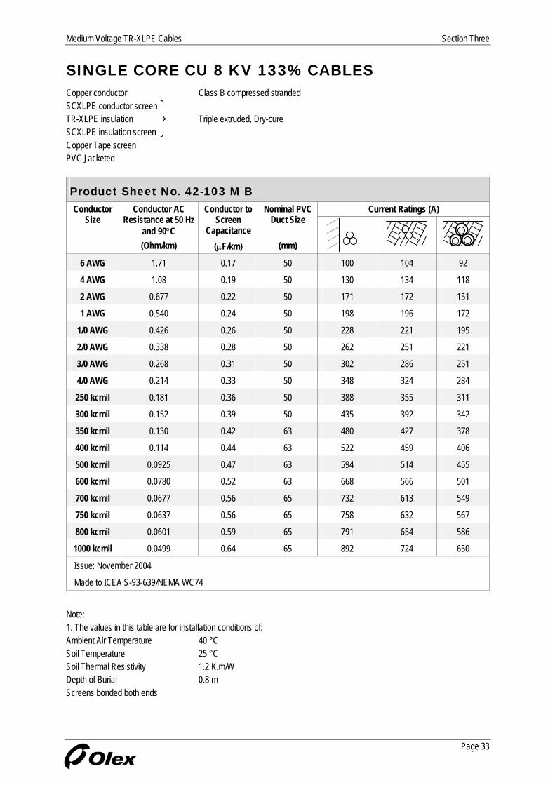
SINGLE CORE CU 8 KV 133% CABLES Copper conductor Class B compressed stranded SCXLPE conductor screen TR-XLPE insulation Triple extruded, Dry-cure SCXLPE insulation screen Copper Tape screen PVC Jacketed
Product Sheet No. 42-103 M B Current Ratings (A) Conductor
Size Conductor AC
Resistance at 50 Hz and 90°C
Conductor to Screen
Capacitance
Nominal PVC Duct Size
(Ohm/km) (µF/km) (mm)
6 AWG 1.71 0.17 100 104 50 92
4 AWG 1.08 0.19 50 130 134 118
2 AWG 0.677 0.22 50 171 172 151
1 AWG 0.540 0.24 50 198 196 172
0.426 0.26 50 228 1/0 AWG 221 195
2/0 AWG 0.338 0.28 50 262 251 221
3/0 AWG 0.268 0.31 50 302 286 251
4/0 AWG 0.214 0.33 50 348 324 284
250 kcmil 0.181 0.36 50 388 355 311
300 kcmil 0.152 0.39 50 435 392 342
350 kcmil 0.130 0.42 63 480 427 378
400 kcmil 0.114 0.44 63 522 459 406
500 kcmil 0.0925 0.47 63 594 514 455
600 kcmil 0.0780 0.52 63 668 566 501
700 kcmil 0.0677 0.56 65 732 613 549
750 kcmil 0.0637 0.56 65 758 632 567
800 kcmil 0.0601 0.59 65 791 654 586
1000 kcmil 0.0499 0.64 65 892 724 650
Issue: November 2004
Made to ICEA S-93-639/NEMA WC74
Note: 1. The values in this table are for installation conditions of: Ambient Air Temperature 40 °C Soil Temperature 25 °C Soil Thermal Resistivity 1.2 K.m/W Depth of Burial 0.8 m Screens bonded both ends
Page 33

Section Three Medium Voltage TR-XLPE Cables
SINGLE CORE CU 15 KV 100% CABLES Copper conductor Class B compressed stranded SCXLPE conductor screen TR-XLPE insulation Triple extruded, Dry-cure SCXLPE insulation screen Copper Tape screen PVC Jacketed
Product Sheet No. 42-104 M A Nominal Diameters Copper Tape Screen Conductor
Size Insulation Insulation Screen Area Size Thickness of PVC Jacket
Min pt
Nominal Overall Diameter
Linear Mass
Nominal (mm) (mm) mm² (mm x mm) (mm) (mm) (kg/m)
2 AWG 17.0 18.6 3.0 20 x 0.075 1.78 22.6 0.75
1 AWG 18.1 19.7 3.0 20 x 0.075 1.78 23.7 0.86
1/0 AWG 18.9 20.5 3.0 20 x 0.075 1.78 24.5 0.98
2/0 AWG 20.0 21.6 3.0 20 x 0.075 1.78 25.7 1.14
3/0 AWG 21.3 22.9 3.0 20 x 0.075 1.78 26.9 1.33
4/0 AWG 22.7 24.3 6.3 25 x 0.125 1.78 28.5 1.62
250 kcmil 24.1 25.7 6.3 25 x 0.125 1.78 29.9 1.84
300 kcmil 25.6 27.6 6.3 25 x 0.125 1.78 31.8 2.14
350 kcmil 26.9 28.9 6.3 25 x 0.125 1.78 33.1 2.41
400 kcmil 28.0 30.0 6.3 25 x 0.125 1.78 34.3 2.68
500 kcmil 29.7 31.7 6.3 25 x 0.125 1.78 36.0 3.19
600 kcmil 32.3 34.3 6.3 25 x 0.125 1.78 38.5 3.74
700 kcmil 34.0 36.0 6.3 25 x 0.125 1.78 40.3 4.25
750 kcmil 34.4 36.4 6.3 25 x 0.125 1.78 40.6 4.49
800 kcmil 35.7 37.7 6.3 25 x 0.125 1.78 41.9 4.77
1000 kcmil 38.2 40.6 6.3 25 x 0.125 2.54 46.4 5.95
Issue: November 2004
Made to ICEA S-93-639/NEMA WC74 Note: 1. Subject to confirmation, similar cables can be manufactured to other specifications.
Page 34

Medium Voltage TR-XLPE Cables Section Three
SINGLE CORE CU 15 KV 100% CABLES Copper conductor Class B compressed stranded SCXLPE conductor screen TR-XLPE insulation Triple extruded, Dry-cure SCXLPE insulation screen Copper Tape screen PVC Jacketed
Product Sheet No. 42-104 M B Current Ratings (A) Conductor
Size Conductor AC
Resistance at 50 Hz and 90°C
Conductor to Screen
Capacitance
Nominal PVC Duct Size
(Ohm/km) (µF/km) (mm)
2 AWG 0.677 0.19 50 175 172 152
1 AWG 0.540 0.21 50 201 195 172
1/0 AWG 0.426 0.22 50 231 222 195
2/0 AWG 0.338 0.24 50 265 252 222
3/0 AWG 0.268 0.26 50 306 286 251
4/0 AWG 0.214 0.28 50 352 324 284
250 kcmil 0.181 0.30 50 392 356 311
300 kcmil 0.152 0.33 63 439 393 349
350 kcmil 0.130 0.35 63 484 427 379
400 kcmil 0.114 0.36 63 525 459 407
500 kcmil 0.0923 0.39 63 598 515 456
600 kcmil 0.0778 0.43 65 671 567 509
700 kcmil 0.0675 0.46 65 736 614 550
750 kcmil 0.0635 0.46 65 762 633 568
800 kcmil 0.0599 0.48 65 795 655 587
1000 kcmil 0.0494 0.52 65 896 723 648
Issue: November 2004
Made to ICEA S-93-639/NEMA WC74
Note: 1. The values in this table are for installation conditions of: Ambient Air Temperature 40 °C Soil Temperature 25 °C Soil Thermal Resistivity 1.2 K.m/W Depth of Burial 0.8 m Screens bonded both ends
Page 35

Section Three Medium Voltage TR-XLPE Cables
SINGLE CORE CU 15 KV 133% CABLES Copper conductor Class B compressed stranded SCXLPE conductor screen TR-XLPE insulation Triple extruded, Dry-cure SCXLPE insulation screen Copper Tape screen PVC Jacketed
Product Sheet No. 42-105 M A Nominal Diameters Copper Tape Screen Conductor
Size Insulation Insulation Screen Area Size Thickness of PVC Jacket
Min pt
Nominal Overall Diameter
Linear Mass
Nominal (mm) (mm) mm² (mm x mm) (mm) (mm) (kg/m)
2 AWG 19.3 20.9 3.0 20 x 0.075 1.78 24.9 0.84
1 AWG 20.4 22.0 3.0 20 x 0.075 1.78 26.0 0.95
1/0 AWG 21.2 22.8 3.0 20 x 0.075 1.78 26.8 1.08
2/0 AWG 22.3 23.9 3.0 20 x 0.075 1.78 28.0 1.24
3/0 AWG 23.6 25.2 6.3 25 x 0.125 1.78 29.4 1.48
4/0 AWG 25.0 27.0 6.3 25 x 0.125 1.78 31.2 1.75
250 kcmil 26.4 28.4 6.3 25 x 0.125 1.78 32.6 1.98
300 kcmil 27.9 29.9 6.3 25 x 0.125 1.78 34.1 2.26
350 kcmil 29.2 31.2 6.3 25 x 0.125 1.78 35.4 2.54
400 kcmil 30.3 32.3 6.3 25 x 0.125 1.78 36.6 2.81
500 kcmil 32.0 34.0 6.3 25 x 0.125 1.78 38.3 3.33
600 kcmil 34.6 36.6 6.3 25 x 0.125 1.78 40.8 3.89
700 kcmil 36.3 38.3 6.3 25 x 0.125 1.78 42.6 4.41
750 kcmil 36.7 39.1 6.3 25 x 0.125 1.78 43.3 4.68
800 kcmil 38.0 40.4 6.3 25 x 0.125 2.54 46.2 5.10
1000 kcmil 40.5 42.9 6.3 25 x 0.125 2.54 48.7 6.10
Issue: November 2004
Made to ICEA S-93-639/NEMA WC74 Note: 1. Subject to confirmation, similar cables can be manufactured to other specifications.
Page 36
Medium Voltage TR-XLPE Cables Section Three
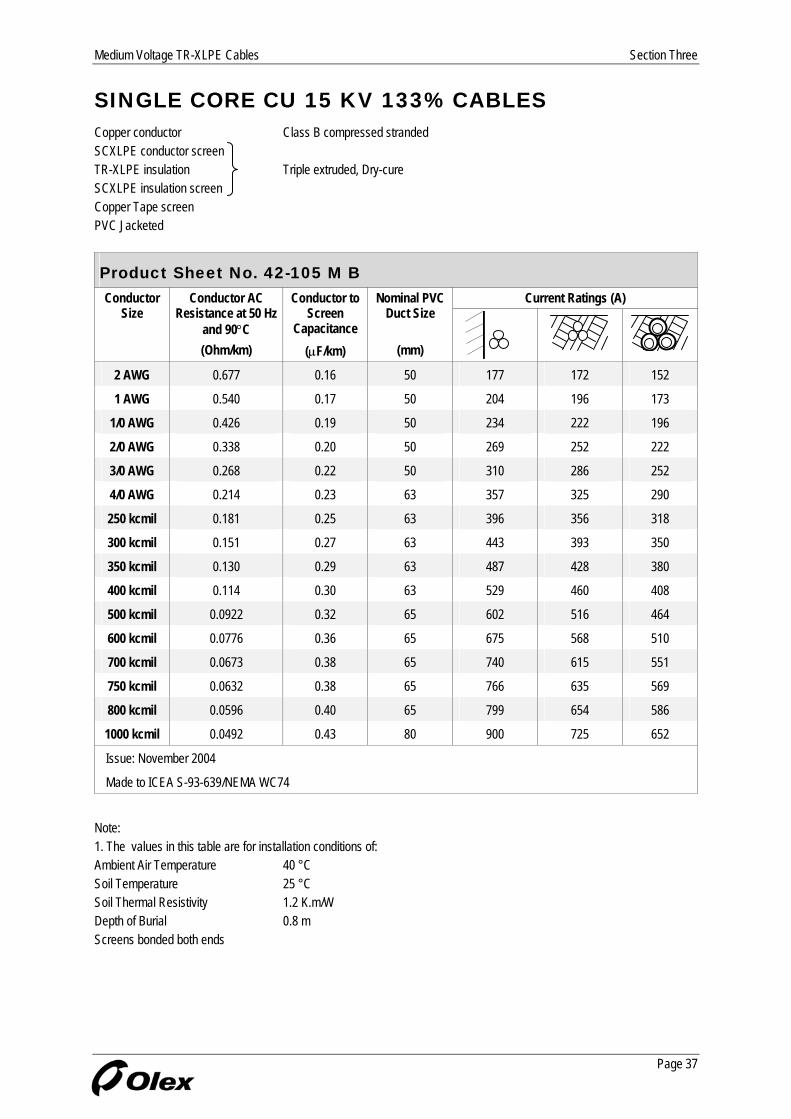
SINGLE CORE CU 15 KV 133% CABLES Copper conductor Class B compressed stranded SCXLPE conductor screen TR-XLPE insulation Triple extruded, Dry-cure SCXLPE insulation screen Copper Tape screen PVC Jacketed
Product Sheet No. 42-105 M B Current Ratings (A) Conductor
Size Conductor AC
Resistance at 50 Hz and 90°C
Conductor to Screen
Capacitance
Nominal PVC Duct Size
(Ohm/km) (µF/km) (mm)
2 AWG 0.677 0.16 50 177 172 152
1 AWG 0.540 0.17 50 204 196 173
1/0 AWG 0.426 0.19 50 234 222 196
2/0 AWG 0.338 0.20 50 269 252 222
3/0 AWG 0.268 0.22 50 310 286 252
4/0 AWG 0.214 0.23 63 357 325 290
250 kcmil 0.181 0.25 63 396 356 318
300 kcmil 0.151 0.27 63 443 393 350
350 kcmil 0.130 0.29 63 487 428 380
400 kcmil 0.114 0.30 63 529 460 408
500 kcmil 0.0922 0.32 65 602 516 464
600 kcmil 0.0776 0.36 65 675 568 510
700 kcmil 0.0673 0.38 65 740 615 551
750 kcmil 0.0632 0.38 65 766 635 569
800 kcmil 0.0596 0.40 65 799 654 586
1000 kcmil 0.0492 0.43 80 900 725 652
Issue: November 2004
Made to ICEA S-93-639/NEMA WC74
Note: 1. The values in this table are for installation conditions of: Ambient Air Temperature 40 °C Soil Temperature 25 °C Soil Thermal Resistivity 1.2 K.m/W Depth of Burial 0.8 m Screens bonded both ends
Page 37
Section Three Medium Voltage TR-XLPE Cables
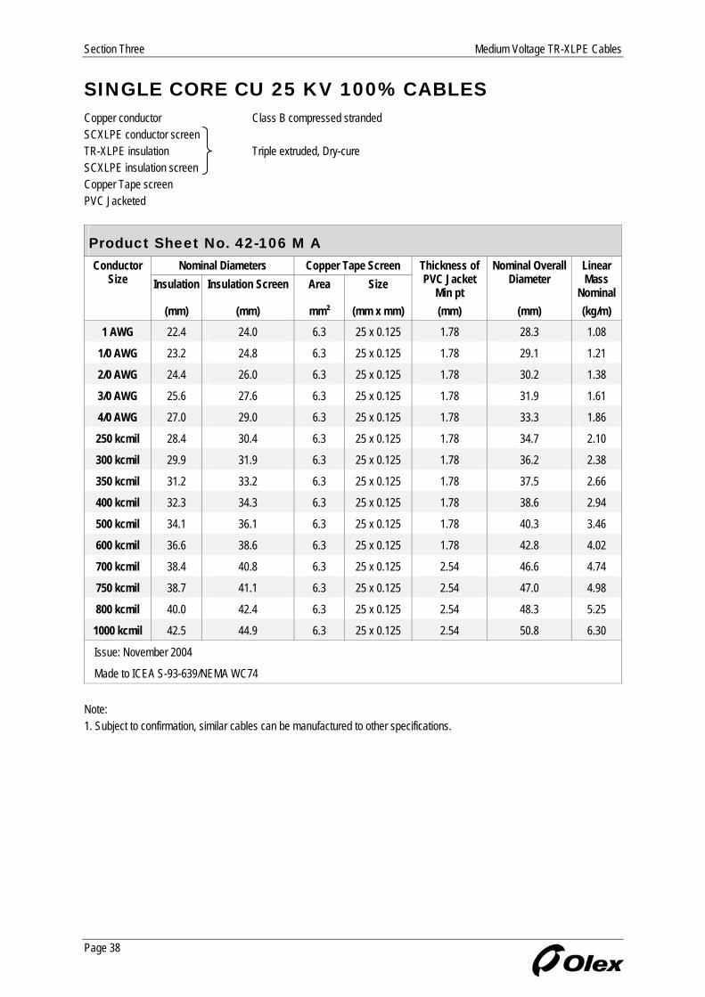
SINGLE CORE CU 25 KV 100% CABLES Copper conductor Class B compressed stranded SCXLPE conductor screen TR-XLPE insulation Triple extruded, Dry-cure SCXLPE insulation screen Copper Tape screen PVC Jacketed
Product Sheet No. 42-106 M A Nominal Diameters Copper Tape Screen Conductor
Size Insulation Insulation Screen Area Size Thickness of PVC Jacket
Min pt
Nominal Overall Diameter
Linear Mass
Nominal (mm) (mm) mm² (mm x mm) (mm) (mm) (kg/m)
1 AWG 22.4 24.0 6.3 25 x 0.125 1.78 28.3 1.08
1/0 AWG 23.2 24.8 6.3 25 x 0.125 1.78 29.1 1.21
2/0 AWG 24.4 26.0 6.3 25 x 0.125 1.78 30.2 1.38
3/0 AWG 25.6 27.6 6.3 25 x 0.125 1.78 31.9 1.61
4/0 AWG 27.0 29.0 6.3 25 x 0.125 1.78 33.3 1.86
250 kcmil 28.4 30.4 6.3 25 x 0.125 1.78 34.7 2.10
300 kcmil 29.9 31.9 6.3 25 x 0.125 1.78 36.2 2.38
350 kcmil 31.2 33.2 6.3 25 x 0.125 1.78 37.5 2.66
400 kcmil 32.3 34.3 6.3 25 x 0.125 1.78 38.6 2.94
500 kcmil 34.1 36.1 6.3 25 x 0.125 1.78 40.3 3.46
600 kcmil 36.6 38.6 6.3 25 x 0.125 1.78 42.8 4.02
700 kcmil 38.4 40.8 6.3 25 x 0.125 2.54 46.6 4.74
750 kcmil 38.7 41.1 6.3 25 x 0.125 2.54 47.0 4.98
800 kcmil 40.0 42.4 6.3 25 x 0.125 2.54 48.3 5.25
1000 kcmil 42.5 44.9 6.3 25 x 0.125 2.54 50.8 6.30
Issue: November 2004
Made to ICEA S-93-639/NEMA WC74 Note: 1. Subject to confirmation, similar cables can be manufactured to other specifications.
Page 38
Medium Voltage TR-XLPE Cables Section Three
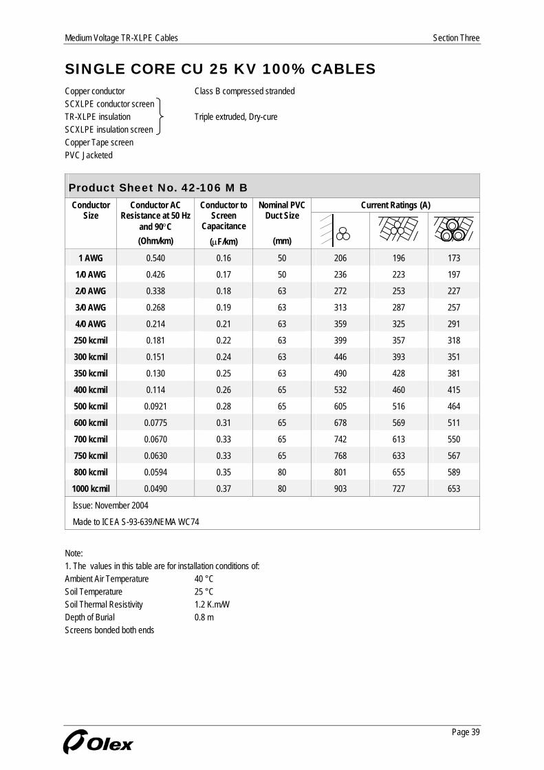
SINGLE CORE CU 25 KV 100% CABLES Copper conductor Class B compressed stranded SCXLPE conductor screen TR-XLPE insulation Triple extruded, Dry-cure SCXLPE insulation screen Copper Tape screen PVC Jacketed
Product Sheet No. 42-106 M B Current Ratings (A) Conductor
Size Conductor AC
Resistance at 50 Hz and 90°C
Conductor to Screen
Capacitance
Nominal PVC Duct Size
(Ohm/km) (µF/km) (mm)
1 AWG 0.540 0.16 50 206 196 173
1/0 AWG 0.426 0.17 50 236 223 197
2/0 AWG 0.338 0.18 63 272 253 227
3/0 AWG 0.268 0.19 63 313 287 257
4/0 AWG 0.214 0.21 63 359 325 291
250 kcmil 0.181 0.22 63 399 357 318
300 kcmil 0.151 0.24 63 446 393 351
350 kcmil 0.130 0.25 63 490 428 381
400 kcmil 0.114 0.26 65 532 460 415
500 kcmil 0.0921 0.28 65 605 516 464
600 kcmil 0.0775 0.31 65 678 569 511
700 kcmil 0.0670 0.33 65 742 613 550
750 kcmil 0.0630 0.33 65 768 633 567
800 kcmil 0.0594 0.35 80 801 655 589
1000 kcmil 0.0490 0.37 80 903 727 653
Issue: November 2004
Made to ICEA S-93-639/NEMA WC74
Note: 1. The values in this table are for installation conditions of: Ambient Air Temperature 40 °C Soil Temperature 25 °C Soil Thermal Resistivity 1.2 K.m/W Depth of Burial 0.8 m Screens bonded both ends
Page 39

Section Three Medium Voltage TR-XLPE Cables
SINGLE CORE CU 25 KV 133% CABLES Copper conductor Class B compressed stranded SCXLPE conductor screen TR-XLPE insulation Triple extruded, Dry-cure SCXLPE insulation screen Copper Tape screen PVC Jacketed
Product Sheet No. 42-107 M A Nominal Diameters Copper Tape Screen Conductor
Size Insulation Insulation Screen Area Size Thickness of PVC Jacket
Min pt
Nominal Overall Diameter
Linear Mass
Nominal (mm) (mm) mm² (mm x mm) (mm) (mm) (kg/m)
1 AWG 25.5 27.5 6.3 25 x 0.125 1.78 31.7 1.26
1/0 AWG 26.3 28.3 6.3 25 x 0.125 1.78 32.5 1.39
2/0 AWG 27.4 29.4 6.3 25 x 0.125 1.78 33.7 1.57
3/0 AWG 28.7 30.7 6.3 25 x 0.125 1.78 34.9 1.78
4/0 AWG 30.1 32.1 6.3 25 x 0.125 1.78 36.3 2.04
250 kcmil 31.5 33.5 6.3 25 x 0.125 1.78 37.7 2.28
300 kcmil 33.0 35.0 6.3 25 x 0.125 1.78 39.2 2.57
350 kcmil 34.3 36.3 6.3 25 x 0.125 1.78 40.5 2.85
400 kcmil 35.4 37.4 6.3 25 x 0.125 1.78 41.6 3.13
500 kcmil 37.1 39.1 6.3 25 x 0.125 1.78 43.4 3.66
600 kcmil 39.7 42.1 6.3 25 x 0.125 2.54 47.9 4.43
700 kcmil 41.4 43.8 6.3 25 x 0.125 2.54 49.7 4.97
750 kcmil 41.8 44.2 6.3 25 x 0.125 2.54 50.0 5.20
800 kcmil 43.1 45.5 6.3 25 x 0.125 2.54 51.3 5.50
1000 kcmil 45.6 48.0 6.3 25 x 0.125 2.54 53.8 6.55
Issue: November 2004
Made to ICEA S-93-639/NEMA WC74 Note: 1. Subject to confirmation, similar cables can be manufactured to other specifications.
Page 40

Medium Voltage TR-XLPE Cables Section Three
SINGLE CORE CU 25 KV 133% CABLES Copper conductor Class B compressed stranded SCXLPE conductor screen TR-XLPE insulation Triple extruded, Dry-cure SCXLPE insulation screen Copper Tape screen PVC Jacketed
Product Sheet No. 42-107 M B Current Ratings (A) Conductor
Size Conductor AC
Resistance at 50 Hz and 90°C
Conductor to Screen
Capacitance
Nominal PVC Duct Size
(Ohm/km) (µF/km) (mm)
1 AWG 0.540 0.14 63 209 196 177
1/0 AWG 0.426 0.14 63 240 223 201
2/0 AWG 0.338 0.15 63 275 253 227
3/0 AWG 0.268 0.17 63 316 287 258
4/0 AWG 0.214 0.18 63 363 326 291
250 kcmil 0.181 0.19 63 402 357 319
300 kcmil 0.151 0.20 65 449 394 357
350 kcmil 0.130 0.22 65 494 429 387
400 kcmil 0.114 0.23 65 535 461 416
500 kcmil 0.0920 0.24 65 608 517 465
600 kcmil 0.0773 0.26 80 680 567 512
700 kcmil 0.0668 0.28 80 745 614 553
750 kcmil 0.0628 0.28 80 771 634 571
800 kcmil 0.0592 0.29 80 804 656 591
1000 kcmil 0.0488 0.31 80 906 729 655
Issue: November 2004
Made to ICEA S-93-639/NEMA WC74
Note: 1. The values in this table are for installation conditions of: Ambient Air Temperature 40 °C Soil Temperature 25 °C Soil Thermal Resistivity 1.2 K.m/W Depth of Burial 0.8 m Screens bonded both ends
Page 41
Section Three Medium Voltage TR-XLPE Cables
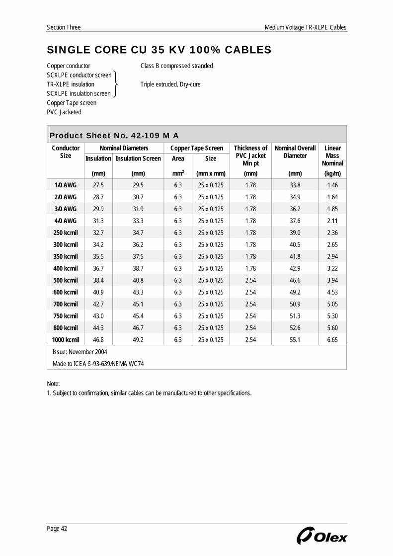
SINGLE CORE CU 35 KV 100% CABLES Copper conductor Class B compressed stranded SCXLPE conductor screen TR-XLPE insulation Triple extruded, Dry-cure SCXLPE insulation screen Copper Tape screen PVC Jacketed
Product Sheet No. 42-109 M A Nominal Diameters Copper Tape Screen Conductor
Size Insulation Insulation Screen Area Size Thickness of PVC Jacket
Min pt
Nominal Overall Diameter
Linear Mass
Nominal (mm) (mm) mm² (mm x mm) (mm) (mm) (kg/m)
1/0 AWG 27.5 29.5 6.3 25 x 0.125 1.78 33.8 1.46
2/0 AWG 28.7 30.7 6.3 25 x 0.125 1.78 34.9 1.64
3/0 AWG 29.9 31.9 6.3 25 x 0.125 1.78 36.2 1.85
4/0 AWG 31.3 33.3 6.3 25 x 0.125 1.78 37.6 2.11
250 kcmil 32.7 34.7 6.3 25 x 0.125 1.78 39.0 2.36
300 kcmil 34.2 36.2 6.3 25 x 0.125 1.78 40.5 2.65
350 kcmil 35.5 37.5 6.3 25 x 0.125 1.78 41.8 2.94
400 kcmil 36.7 38.7 6.3 25 x 0.125 1.78 42.9 3.22
500 kcmil 38.4 40.8 6.3 25 x 0.125 2.54 46.6 3.94
600 kcmil 40.9 43.3 6.3 25 x 0.125 2.54 49.2 4.53
700 kcmil 42.7 45.1 6.3 25 x 0.125 2.54 50.9 5.05
750 kcmil 43.0 45.4 6.3 25 x 0.125 2.54 51.3 5.30
800 kcmil 44.3 46.7 6.3 25 x 0.125 2.54 52.6 5.60
1000 kcmil 46.8 49.2 6.3 25 x 0.125 2.54 55.1 6.65
Issue: November 2004
Made to ICEA S-93-639/NEMA WC74 Note: 1. Subject to confirmation, similar cables can be manufactured to other specifications.
Page 42

Medium Voltage TR-XLPE Cables Section Three
SINGLE CORE CU 35 KV 100% CABLES Copper conductor Class B compressed stranded SCXLPE conductor screen TR-XLPE insulation Triple extruded, Dry-cure SCXLPE insulation screen Copper Tape screen PVC Jacketed
Product Sheet No. 42-109 M B Current Ratings (A) Conductor
Size Conductor AC
Resistance at 50 Hz and 90°C
Conductor to Screen
Capacitance
Nominal PVC Duct Size
(Ohm/km) (µF/km) (mm)
1/0 AWG 0.426 0.14 63 241 223 201
2/0 AWG 0.338 0.15 63 276 253 228
3/0 AWG 0.268 0.16 63 317 287 258
4/0 AWG 0.214 0.17 63 364 326 292
250 kcmil 0.181 0.18 65 403 357 325
300 kcmil 0.151 0.19 65 450 394 357
350 kcmil 0.130 0.20 65 495 429 388
400 kcmil 0.114 0.21 65 537 461 416
500 kcmil 0.0919 0.23 65 609 515 464
600 kcmil 0.0772 0.25 80 681 567 513
700 kcmil 0.0668 0.26 80 746 614 554
750 kcmil 0.0627 0.27 80 772 634 571
800 kcmil 0.0591 0.28 80 805 657 591
1000 kcmil 0.0487 0.30 100 908 729 662
Issue: November 2004
Made to ICEA S-93-639/NEMA WC74
Note: 1. The values in this table are for installation conditions of: Ambient Air Temperature 40 °C Soil Temperature 25 °C Soil Thermal Resistivity 1.2 K.m/W Depth of Burial 0.8 m Screens bonded both ends
Page 43

Section Three Medium Voltage TR-XLPE Cables
SINGLE CORE CU 35 KV 133% CABLES Copper conductor Class B compressed stranded SCXLPE conductor screen TR-XLPE insulation Triple extruded, Dry-cure SCXLPE insulation screen Copper Tape screen PVC Jacketed
Product Sheet No. 42-312 M A Nominal Diameters Copper Tape Screen Conductor
Size Insulation Insulation Screen Area Size Thickness of PVC Jacket
Min pt
Nominal Overall Diameter
Linear Mass
Nominal (mm) (mm) mm² (mm x mm) (mm) (mm) (kg/m)
1/0 AWG 31.4 33.4 6.3 25 x 0.125 1.78 37.6 1.69
2/0 AWG 32.5 34.5 6.3 25 x 0.125 1.78 38.7 1.87
3/0 AWG 33.7 35.7 6.3 25 x 0.125 1.78 40.0 2.09
4/0 AWG 35.1 37.1 6.3 25 x 0.125 1.78 41.4 2.36
250 kcmil 36.5 38.5 6.3 25 x 0.125 1.78 42.8 2.61
300 kcmil 38.0 40.4 6.3 25 x 0.125 2.54 46.3 3.10
350 kcmil 39.3 41.7 6.3 25 x 0.125 2.54 47.6 3.40
400 kcmil 40.5 42.9 6.3 25 x 0.125 2.54 48.7 3.69
500 kcmil 42.2 44.6 6.3 25 x 0.125 2.54 50.4 4.24
600 kcmil 44.7 47.1 6.3 25 x 0.125 2.54 53.0 4.84
700 kcmil 46.5 48.9 6.3 25 x 0.125 2.54 54.7 5.40
750 kcmil 46.8 49.2 6.3 25 x 0.125 2.54 55.1 5.65
800 kcmil 48.1 50.5 6.3 25 x 0.125 2.54 56.4 5.95
1000 kcmil 50.6 53.0 6.3 25 x 0.125 2.54 58.9 7.00
Issue: November 2004
Made to ICEA S-93-639/NEMA WC74 Note: 1. Subject to confirmation, similar cables can be manufactured to other specifications.
Page 44

Medium Voltage TR-XLPE Cables Section Three
SINGLE CORE CU 35 KV 133% CABLES Copper conductor Class B compressed stranded SCXLPE conductor screen TR-XLPE insulation Triple extruded, Dry-cure SCXLPE insulation screen Copper Tape screen PVC Jacketed
Product Sheet No. 42-312 M B Current Ratings (A) Conductor
Size Conductor AC
Resistance at 50 Hz and 90°C
Conductor to Screen
Capacitance
Nominal PVC Duct Size
(Ohm/km) (µF/km) (mm)
1/0 AWG 0.426 0.12 63 243 223 202
2/0 AWG 0.338 0.13 65 279 254 232
3/0 AWG 0.268 0.14 65 320 288 263
4/0 AWG 0.213 0.15 65 367 326 297
250 kcmil 0.180 0.16 65 406 358 325
300 kcmil 0.151 0.17 65 453 393 356
350 kcmil 0.130 0.18 80 497 427 389
400 kcmil 0.114 0.19 80 538 459 418
500 kcmil 0.0918 0.20 80 611 515 467
600 kcmil 0.0771 0.21 80 684 568 513
700 kcmil 0.0666 0.23 80 748 616 555
750 kcmil 0.0626 0.23 100 774 636 580
800 kcmil 0.0590 0.24 100 808 658 599
1000 kcmil 0.0484 0.25 100 910 731 663
Issue: November 2004
Made to ICEA S-93-639/NEMA WC74
Note: 1. The values in this table are for installation conditions of: Ambient Air Temperature 40 °C Soil Temperature 25 °C Soil Thermal Resistivity 1.2 K.m/W Depth of Burial 0.8 m Screens bonded both ends
Page 45

Section Three Medium Voltage TR-XLPE Cables
SINGLE CORE CU 15 KV 100% CABLES Copper conductor Class C compressed stranded SCXLPE conductor screen TR-XLPE insulation Triple extruded, Dry-cure SCXLPE insulation screen Copper wire screen PVC Jacketed
Product Sheet No. 331-11 M A Nominal Diameters Copper Wire Screen Conductor
Size Insulation Insulation Screen No Size Thickness of PVC Jacket
Min pt
Nominal Overall Diameter
Linear Mass
Nominal (mm) (mm) (mm) (mm) (mm) (kg/m)
Full Neutral 2 AWG 17.0 18.6 16 1.63 1.78 25.9 1.04
1 AWG 18.1 19.7 13 2.05 1.78 27.8 1.25
1/0 AWG 18.9 20.5 16 2.05 1.78 28.6 1.47
2/0 AWG 20.0 21.6 13 2.59 1.78 30.9 1.78
3/0 AWG 21.3 22.9 16 2.59 1.78 32.1 2.12
4/0 AWG 22.7 24.3 16 2.91 1.78 34.2 2.57
One Third Neutral
250 kcmil 24.1 25.7 21 1.63 1.78 33.0 2.17
350 kcmil 26.9 28.9 18 2.05 1.78 37.0 2.89
500 kcmil 29.7 31.7 17 2.59 1.78 41.3 3.95
600 kcmil 32.3 34.3 20 2.59 1.78 43.8 4.64
650 kcmil 33.2 35.2 21 2.59 1.78 44.7 4.94
750 kcmil 34.4 36.4 20 2.91 1.78 46.6 5.65
1000 kcmil 38.2 40.6 21 3.26 2.54 53.1 7.50
Issue: November 2004
Made to ICEA S-93-639/NEMA WC74 Note: 1. Subject to confirmation, similar cables can be manufactured to other specifications.
Page 46

Medium Voltage TR-XLPE Cables Section Three
SINGLE CORE CU 15 KV 100% CABLES Copper conductor Class B compressed stranded SCXLPE conductor screen TR-XLPE insulation Triple extruded, Dry-cure SCXLPE insulation screen Copper wire screen PVC Jacketed
Product Sheet No. 331-11 M B Current Ratings (A) Conductor
Size Conductor AC
Resistance at 50 Hz and 90°C
Conductor to Screen
Capacitance
Nominal PVC Duct Size
(Ohm/km) (µF/km) (mm)
Full Neutral 2 AWG 0.677 0.19 50 181 174 155
1 AWG 0.540 0.21 50 210 197 175
1/0 AWG 0.426 0.22 50 240 223 197
2/0 AWG 0.338 0.24 63 278 253 225
3/0 AWG 0.268 0.26 63 318 285 251
4/0 AWG 0.214 0.28 63 364 320 279
One Third Neutral
250 kcmil 0.181 0.30 63 400 353 313
350 kcmil 0.130 0.35 63 492 420 368
500 kcmil 0.092 0.39 65 598 493 424
600 kcmil 0.077 0.43 65 661 535 455
650 kcmil 0.072 0.45 65 689 553 469
750 kcmil 0.063 0.46 65 732 580 488
1000 kcmil 0.049 0.52 80 823 630 528
Issue: November 2004
Made to ICEA S-93-639/NEMA WC74
Note: 1. The values in this table are for installation conditions of: Ambient Air Temperature 40 °C Soil Temperature 25 °C Soil Thermal Resistivity 1.2 K.m/W Depth of Burial 0.8 m Screens bonded both ends
Page 47

Section Three Medium Voltage TR-XLPE Cables
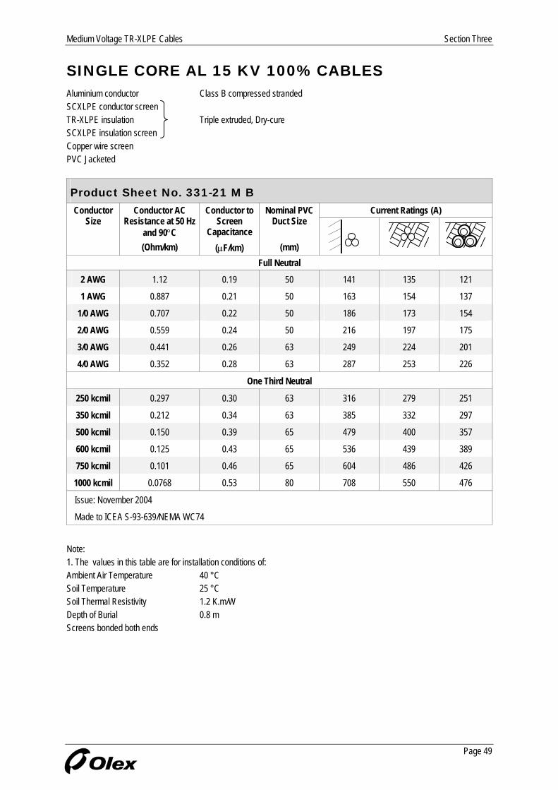
SINGLE CORE AL 15 KV 100% CABLES Aluminium conductor Class B compressed stranded SCXLPE conductor screen TR-XLPE insulation Triple extruded, Dry-cure SCXLPE insulation screen Copper wire screen PVC Jacketed
Product Sheet No. 331-21 M A Nominal Diameters Copper Wire Screen Conductor
Size Insulation Insulation Screen No Size Thickness of PVC Jacket
Min pt
Nominal Overall Diameter
Linear Mass
Nominal (mm) (mm) (mm) (mm) (mm) (kg/m)
Full Neutral 2 AWG 17.0 18.6 10 1.63 1.78 25.9 0.71
1 AWG 18.1 19.7 13 1.63 1.78 27.0 0.83
1/0 AWG 18.9 20.5 16 1.63 1.78 27.8 0.94
2/0 AWG 20.0 21.6 13 2.05 1.78 29.8 1.10
3/0 AWG 21.5 23.1 16 2.05 1.78 31.2 1.28
4/0 AWG 22.7 24.3 13 2.59 1.78 33.5 1.53
One Third Neutral
250 kcmil 24.3 25.9 13 1.63 1.78 33.2 1.22
350 kcmil 26.5 28.5 18 1.63 1.78 35.8 1.54
500 kcmil 29.7 31.7 16 2.05 1.78 39.9 1.99
600 kcmil 32.3 34.3 19 2.05 1.78 42.4 2.30
750 kcmil 34.4 36.4 24 2.05 1.78 44.8 2.73
1000 kcmil 38.7 41.1 20 2.59 2.54 52.2 3.66
Issue: November 2004
Made to ICEA S-93-639/NEMA WC74 Note: 1. Subject to confirmation, similar cables can be manufactured to other specifications.
Page 48
Medium Voltage TR-XLPE Cables Section Three
SINGLE CORE AL 15 KV 100% CABLES Aluminium conductor Class B compressed stranded SCXLPE conductor screen TR-XLPE insulation Triple extruded, Dry-cure SCXLPE insulation screen Copper wire screen PVC Jacketed
Product Sheet No. 331-21 M B Current Ratings (A) Conductor
Size Conductor AC
Resistance at 50 Hz and 90°C
Conductor to Screen
Capacitance
Nominal PVC Duct Size
(Ohm/km) (µF/km) (mm)
Full Neutral 2 AWG 1.12 0.19 50 141 135 121
1 AWG 0.887 0.21 50 163 154 137
1/0 AWG 0.707 0.22 50 186 173 154
2/0 AWG 0.559 0.24 50 216 197 175
3/0 AWG 0.441 0.26 63 249 224 201
4/0 AWG 0.352 0.28 63 287 253 226
One Third Neutral
250 kcmil 0.297 0.30 63 316 279 251
350 kcmil 0.212 0.34 63 385 332 297
500 kcmil 0.150 0.39 65 479 400 357
600 kcmil 0.125 0.43 65 536 439 389
750 kcmil 0.101 0.46 65 604 486 426
1000 kcmil 0.0768 0.53 80 708 550 476
Issue: November 2004
Made to ICEA S-93-639/NEMA WC74
Note: 1. The values in this table are for installation conditions of: Ambient Air Temperature 40 °C Soil Temperature 25 °C Soil Thermal Resistivity 1.2 K.m/W Depth of Burial 0.8 m Screens bonded both ends
Page 49

Section Three Medium Voltage TR-XLPE Cables
SINGLE CORE CU 15 KV 133% CABLES Copper conductor Class B compressed stranded SCXLPE conductor screen TR-XLPE insulation Triple extruded, Dry-cure SCXLPE insulation screen Copper wire screen PVC Jacketed
Product Sheet No. 341-11 M A Nominal Diameters Copper Wire Screen Conductor
Size Insulation Insulation Screen No Size Thickness of PVC Jacket
Min pt
Nominal Overall Diameter
Linear Mass
Nominal (mm) (mm) (mm) (mm) (mm) (kg/m)
Full Neutral 2 AWG 19.3 20.9 16 1.63 1.78 28.2 1.13
1 AWG 20.4 22.0 13 2.05 1.78 30.1 1.34
1/0 AWG 21.2 22.8 16 2.05 1.78 30.9 1.56
2/0 AWG 22.3 23.9 13 2.59 1.78 33.2 1.87
3/0 AWG 23.6 25.2 16 2.59 1.78 34.4 2.22
4/0 AWG 25.0 27.0 16 2.91 1.78 36.8 2.70
One Third Neutral
250 kcmil 26.4 28.4 21 1.63 1.78 35.7 2.31
350 kcmil 29.2 31.2 18 2.05 1.78 39.3 3.01
500 kcmil 32.0 34.0 17 2.59 1.78 43.6 4.08
600 kcmil 34.6 36.6 20 2.59 1.78 46.1 4.78
650 kcmil 35.5 37.5 21 2.59 1.78 47.0 5.10
750 kcmil 36.7 39.1 20 2.91 1.78 49.2 5.85
1000 kcmil 40.5 42.9 21 3.26 2.54 55.3 7.70
Issue: November 2004
Made to ICEA S-93-639/NEMA WC74 Note: 1. Subject to confirmation, similar cables can be manufactured to other specifications.
Page 50

Medium Voltage TR-XLPE Cables Section Three
SINGLE CORE CU 15 KV 133% CABLES Copper conductor Class B compressed stranded SCXLPE conductor screen TR-XLPE insulation Triple extruded, Dry-cure SCXLPE insulation screen Copper wire screen PVC Jacketed
Product Sheet No. 341-11 M B Current Ratings (A) Conductor
Size Conductor AC
Resistance at 50 Hz and 90°C
Conductor to Screen
Capacitance
Nominal PVC Duct Size
(Ohm/km) (µF/km) (mm)
Full Neutral 2 AWG 0.677 0.16 50 183 173 155
1 AWG 0.540 0.17 63 212 197 178
1/0 AWG 0.426 0.19 63 242 223 201
2/0 AWG 0.338 0.20 63 280 252 226
3/0 AWG 0.268 0.22 63 320 285 253
4/0 AWG 0.214 0.23 63 367 320 282
One Third Neutral
250 kcmil 0.181 0.25 63 403 353 315
350 kcmil 0.130 0.29 65 494 420 373
500 kcmil 0.0920 0.32 65 601 494 428
600 kcmil 0.0774 0.36 65 664 536 460
650 kcmil 0.0717 0.37 65 693 555 474
750 kcmil 0.0628 0.38 80 738 582 491
1000 kcmil 0.0487 0.43 100 829 633 521
Issue: November 2004
Made to ICEA S-93-639/NEMA WC74
Note: 1. The values in this table are for installation conditions of: Ambient Air Temperature 40 °C Soil Temperature 25 °C Soil Thermal Resistivity 1.2 K.m/W Depth of Burial 0.8 m Screens bonded both ends
Page 51

Section Three Medium Voltage TR-XLPE Cables
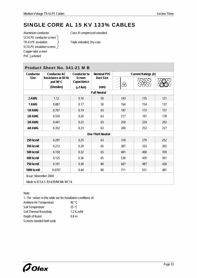
SINGLE CORE AL 15 KV 133% CABLES Aluminium conductor Class B compressed stranded SCXLPE conductor screen TR-XLPE insulation Triple extruded, Dry-cure SCXLPE insulation screen Copper wire screen PVC Jacketed
Product Sheet No. 341-21 M A Nominal Diameters Copper Wire Screen Conductor
Size Insulation Insulation Screen No Size Thickness of PVC Jacket
Min pt
Nominal Overall Diameter
Linear Mass
Nominal (mm) (mm) (mm) (mm) (mm) (kg/m)
Full Neutral 2 AWG 19.3 20.9 10 1.63 1.78 28.2 0.80
1 AWG 20.4 22.0 13 1.63 1.78 29.3 0.92
1/0 AWG 21.2 22.8 16 1.63 1.78 30.1 1.03
2/0 AWG 22.3 23.9 13 2.05 1.78 32.1 1.20
3/0 AWG 23.8 25.4 16 2.05 1.78 33.5 1.38
4/0 AWG 25.0 27.0 13 2.59 1.78 36.2 1.66
One Third Neutral
250 kcmil 26.6 28.6 13 1.63 1.78 35.9 1.36
350 kcmil 28.8 30.8 18 1.63 1.78 38.1 1.66
500 kcmil 32.0 34.0 16 2.05 1.78 42.2 2.12
600 kcmil 34.6 36.6 19 2.05 1.78 44.7 2.44
750 kcmil 36.7 38.7 24 2.05 1.78 47.1 2.87
1000 kcmil 41.0 43.4 20 2.59 2.54 54.5 3.83
Issue: November 2004
Made to ICEA S-93-639/NEMA WC74 Note: 1. Subject to confirmation, similar cables can be manufactured to other specifications.
Page 52
Medium Voltage TR-XLPE Cables Section Three
Page 53
SINGLE CORE AL 15 KV 133% CABLES Aluminium conductor Class B compressed stranded SCXLPE conductor screen TR-XLPE insulation Triple extruded, Dry-cure SCXLPE insulation screen Copper wire screen PVC Jacketed
Product Sheet No. 341-21 M B Current Ratings (A) Conductor
Size Conductor AC
Resistance at 50 Hz and 90°C
Conductor to Screen
Capacitance
Nominal PVC Duct Size
(Ohm/km) (µF/km) (mm)
Full Neutral 2 AWG 1.12 0.16 50 143 135 121
1 AWG 0.887 0.17 50 164 154 137
1/0 AWG 0.707 0.19 63 187 173 157
2/0 AWG 0.559 0.20 63 217 197 178
3/0 AWG 0.441 0.22 63 250 224 202
4/0 AWG 0.352 0.23 63 289 253 227
One Third Neutral
250 kcmil 0.297 0.25 63 318 279 252
350 kcmil 0.212 0.28 65 387 333 302
500 kcmil 0.150 0.32 65 481 400 359
600 kcmil 0.125 0.36 65 538 439 391
750 kcmil 0.101 0.38 80 607 487 428
1000 kcmil 0.0767 0.44 80 711 551 481
Issue: November 2004
Made to ICEA S-93-639/NEMA WC74
Note: 1. The values in this table are for installation conditions of: Ambient Air Temperature 40 °C Soil Temperature 25 °C Soil Thermal Resistivity 1.2 K.m/W Depth of Burial 0.8 m Screens bonded both ends

Section Three Medium Voltage TR-XLPE Cables
Page 54
SINGLE CORE CU 25 KV 100% CABLES Copper conductor Class B compressed stranded SCXLPE conductor screen TR-XLPE insulation Triple extruded, Dry-cure SCXLPE insulation screen Copper wire screen PVC Jacketed
Product Sheet No. 351-11 M A Nominal Diameters Copper Wire Screen Conductor
Size Insulation Insulation Screen No Size Thickness of PVC Jacket
Min pt
Nominal Overall Diameter
Linear Mass
Nominal (mm) (mm) (mm) (mm) (mm) (kg/m)
Full Neutral 1 AWG 22.4 24.0 13 2.05 1.78 32.2 1.42
1/0 AWG 23.2 24.8 16 2.05 1.78 33.0 1.64
2/0 AWG 24.4 26.0 13 2.59 1.78 35.2 1.96
3/0 AWG 25.6 27.6 16 2.59 1.78 36.8 2.34
4/0 AWG 27.0 29.0 16 2.91 1.78 38.9 2.80
One Third Neutral
250 kcmil 28.4 30.4 21 1.63 1.78 37.7 2.41
350 kcmil 31.2 33.2 18 2.05 1.78 41.4 3.12
500 kcmil 34.1 36.1 17 2.59 1.78 45.6 4.20
600 kcmil 36.6 38.6 20 2.59 1.78 48.1 4.91
650 kcmil 37.5 39.5 21 2.59 1.78 49.0 5.20
750 kcmil 38.7 41.1 20 2.91 2.54 52.9 6.15
1000 kcmil 42.5 44.9 21 3.26 2.54 57.4 7.85
Issue: November 2004
Made to ICEA S-93-639/NEMA WC74 Note: 1. Subject to confirmation, similar cables can be manufactured to other specifications.
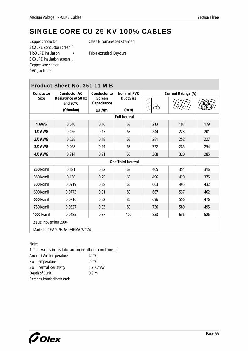
Medium Voltage TR-XLPE Cables Section Three
Page 55
SINGLE CORE CU 25 KV 100% CABLES Copper conductor Class B compressed stranded SCXLPE conductor screen TR-XLPE insulation Triple extruded, Dry-cure SCXLPE insulation screen Copper wire screen PVC Jacketed
Product Sheet No. 351-11 M B Current Ratings (A) Conductor
Size Conductor AC
Resistance at 50 Hz and 90°C
Conductor to Screen
Capacitance
Nominal PVC Duct Size
(Ohm/km) (µF/km) (mm)
Full Neutral 1 AWG 0.540 0.16 63 213 197 179
1/0 AWG 0.426 0.17 63 244 223 201
2/0 AWG 0.338 0.18 63 281 252 227
3/0 AWG 0.268 0.19 63 322 285 254
4/0 AWG 0.214 0.21 65 368 320 285
One Third Neutral
250 kcmil 0.181 0.22 63 405 354 316
350 kcmil 0.130 0.25 65 496 420 375
500 kcmil 0.0919 0.28 65 603 495 432
600 kcmil 0.0773 0.31 80 667 537 462
650 kcmil 0.0716 0.32 80 696 556 476
750 kcmil 0.0627 0.33 80 736 580 495
1000 kcmil 0.0485 0.37 100 833 636 526
Issue: November 2004
Made to ICEA S-93-639/NEMA WC74
Note: 1. The values in this table are for installation conditions of: Ambient Air Temperature 40 °C Soil Temperature 25 °C Soil Thermal Resistivity 1.2 K.m/W Depth of Burial 0.8 m Screens bonded both ends

Section Three Medium Voltage TR-XLPE Cables
Page 56
SINGLE CORE AL 25 KV 100% CABLES Aluminium conductor Class B compressed stranded SCXLPE conductor screen TR-XLPE insulation Triple extruded, Dry-cure SCXLPE insulation screen Copper wire screen PVC Jacketed
Product Sheet No. 351-1 M A Nominal Diameters Copper Wire Screen Conductor
Size Insulation Insulation Screen No Size Thickness of PVC Jacket
Min pt
Nominal Overall Diameter
Linear Mass
Nominal (mm) (mm) (mm) (mm) (mm) (kg/m)
Full Neutral 1 AWG 22.4 24.0 13 1.63 1.78 31.3 1.00
1/0 AWG 23.2 24.8 16 1.63 1.78 32.1 1.11
2/0 AWG 24.4 26.0 13 2.05 1.78 34.1 1.29
3/0 AWG 25.8 27.8 16 2.05 1.78 35.9 1.50
4/0 AWG 27.0 29.0 13 2.59 1.78 38.2 1.76
One Third Neutral
250 kcmil 28.6 30.6 13 1.63 1.78 37.9 1.46
350 kcmil 30.9 32.9 18 1.63 1.78 40.2 1.77
500 kcmil 34.1 36.1 16 2.05 1.78 44.2 2.24
600 kcmil 36.6 38.6 19 2.05 1.78 46.7 2.57
750 kcmil 38.7 41.1 24 2.05 2.54 51.2 3.21
1000 kcmil 43.0 45.4 20 2.59 2.54 56.5 3.98
Issue: November 2004
Made to ICEA S-93-639/NEMA WC74 Note: 1. Subject to confirmation, similar cables can be manufactured to other specifications.

Medium Voltage TR-XLPE Cables Section Three
Page 57
SINGLE CORE AL 25 KV 100% CABLES Aluminium conductor Class B compressed stranded SCXLPE conductor screen TR-XLPE insulation Triple extruded, Dry-cure SCXLPE insulation screen Copper wire screen PVC Jacketed
Product Sheet No. 351-21 M B Current Ratings (A) Conductor
Size Conductor AC
Resistance at 50 Hz and 90°C
Conductor to Screen
Capacitance
Nominal PVC Duct Size
(Ohm/km) (µF/km) (mm)
Full Neutral 1 AWG 0.887 0.16 63 165 154 140
1/0 AWG 0.707 0.17 63 189 173 158
2/0 AWG 0.559 0.18 63 218 197 179
3/0 AWG 0.441 0.19 63 252 224 202
4/0 AWG 0.352 0.21 65 290 253 230
One Third Neutral
250 kcmil 0.297 0.22 63 319 279 252
350 kcmil 0.212 0.25 65 389 333 303
500 kcmil 0.150 0.28 65 483 400 360
600 kcmil 0.125 0.31 65 540 440 393
750 kcmil 0.101 0.33 80 606 486 431
1000 kcmil 0.0766 0.38 100 713 553 477
Issue: November 2004
Made to ICEA S-93-639/NEMA WC74
Note: 1. The values in this table are for installation conditions of: Ambient Air Temperature 40 °C Soil Temperature 25 °C Soil Thermal Resistivity 1.2 K.m/W Depth of Burial 0.8 m Screens bonded both ends

Section Three Medium Voltage TR-XLPE Cables
Page 58
SINGLE CORE CU 35 KV 100% CABLES Copper conductor Class B compressed stranded SCXLPE conductor screen TR-XLPE insulation Triple extruded, Dry-cure SCXLPE insulation screen Copper wire screen PVC Jacketed
Product Sheet No. 371-11 M A Nominal Diameters Copper Wire Screen Conductor
Size Insulation Insulation Screen No Size Thickness of PVC Jacket
Min pt
Nominal Overall Diameter
Linear Mass
Nominal (mm) (mm) (mm) (mm) (mm) (kg/m)
Full Neutral 1/0 AWG 27.5 29.5 16 2.05 1.78 37.7 1.87
2/0 AWG 28.7 30.7 13 2.59 1.78 39.9 2.20
3/0 AWG 29.9 31.9 16 2.59 1.78 41.2 2.56
4/0 AWG 31.3 33.3 16 2.91 1.78 43.2 3.03
One Third Neutral
250 kcmil 32.7 34.7 21 1.63 1.78 42.0 2.65
350 kcmil 35.5 37.5 18 2.05 1.78 45.7 3.38
500 kcmil 38.4 40.8 17 2.59 2.54 51.9 4.68
600 kcmil 40.9 43.3 20 2.59 2.54 54.4 5.40
650 kcmil 41.8 44.2 21 2.59 2.54 55.3 5.75
750 kcmil 43.0 45.4 20 2.91 2.54 57.2 6.45
1000 kcmil 46.8 49.2 21 3.26 2.54 61.7 8.20
Issue: November 2004
Made to ICEA S-93-639/NEMA WC74 Note: 1. Subject to confirmation, similar cables can be manufactured to other specifications.
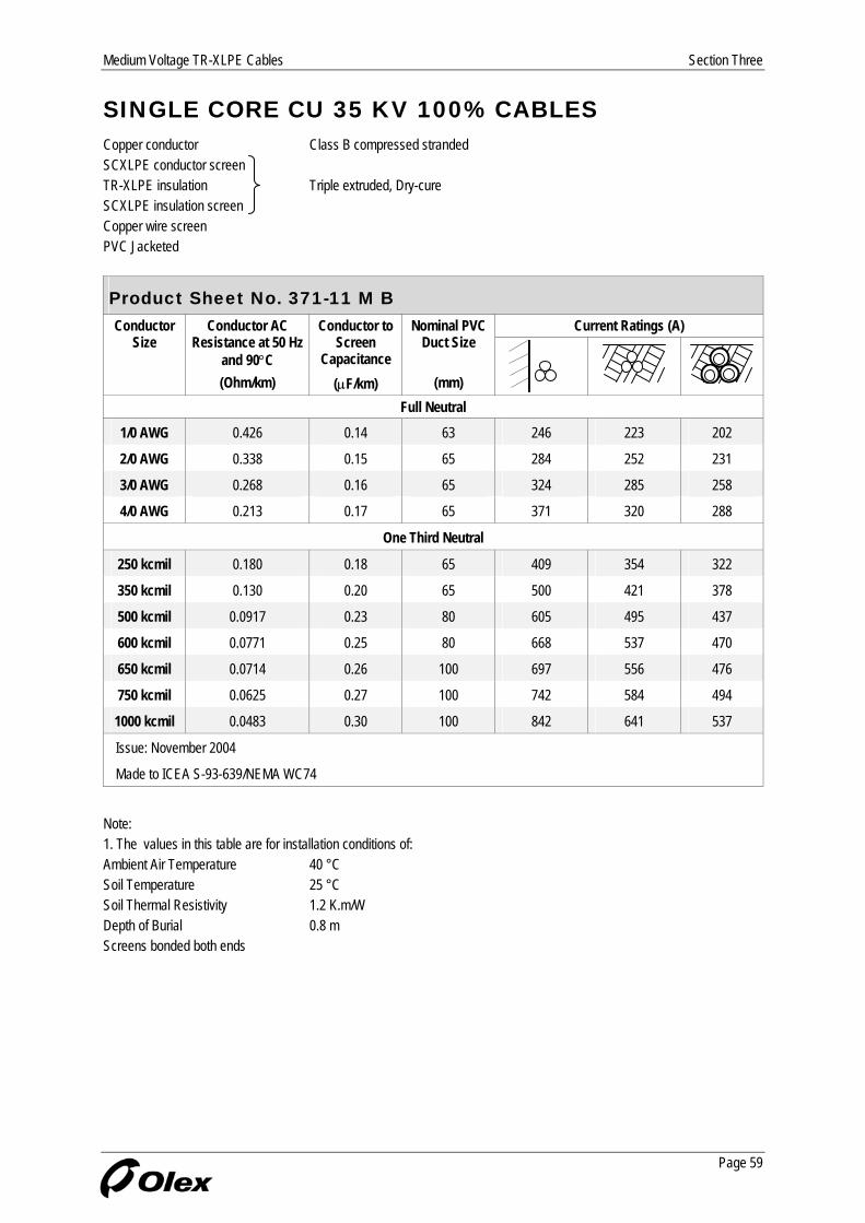
Medium Voltage TR-XLPE Cables Section Three
Page 59
SINGLE CORE CU 35 KV 100% CABLES Copper conductor Class B compressed stranded SCXLPE conductor screen TR-XLPE insulation Triple extruded, Dry-cure SCXLPE insulation screen Copper wire screen PVC Jacketed
Product Sheet No. 371-11 M B Current Ratings (A) Conductor
Size Conductor AC
Resistance at 50 Hz and 90°C
Conductor to Screen
Capacitance
Nominal PVC Duct Size
(Ohm/km) (µF/km) (mm)
Full Neutral 1/0 AWG 0.426 0.14 63 246 223 202
2/0 AWG 0.338 0.15 65 284 252 231
3/0 AWG 0.268 0.16 65 324 285 258
4/0 AWG 0.213 0.17 65 371 320 288
One Third Neutral
250 kcmil 0.180 0.18 65 409 354 322
350 kcmil 0.130 0.20 65 500 421 378
500 kcmil 0.0917 0.23 80 605 495 437
600 kcmil 0.0771 0.25 80 668 537 470
650 kcmil 0.0714 0.26 100 697 556 476
750 kcmil 0.0625 0.27 100 742 584 494
1000 kcmil 0.0483 0.30 100 842 641 537
Issue: November 2004
Made to ICEA S-93-639/NEMA WC74
Note: 1. The values in this table are for installation conditions of: Ambient Air Temperature 40 °C Soil Temperature 25 °C Soil Thermal Resistivity 1.2 K.m/W Depth of Burial 0.8 m Screens bonded both ends

Section Three Medium Voltage TR-XLPE Cables
Page 60
SINGLE CORE AL 35 KV 100% CABLES Aluminium conductor Class B compressed stranded SCXLPE conductor screen TR-XLPE insulation Triple extruded, Dry-cure SCXLPE insulation screen Copper wire screen PVC Jacketed
Product Sheet No. 371-21 M A Nominal Diameters Copper Wire Screen Conductor
Size Insulation Insulation Screen No Size Thickness of PVC Jacket
Min pt
Nominal Overall Diameter
Linear Mass
Nominal (mm) (mm) (mm) (mm) (mm) (kg/m)
Full Neutral 1/0 AWG 27.5 29.5 16 1.63 1.78 36.8 1.35
2/0 AWG 28.7 30.7 13 2.05 1.78 38.8 1.53
3/0 AWG 30.1 32.1 16 2.05 1.78 40.3 1.72
4/0 AWG 31.3 33.3 13 2.59 1.78 42.6 1.99
One Third Neutral
250 kcmil 32.9 34.9 13 1.63 1.78 42.2 1.70
350 kcmil 35.2 37.2 18 1.63 1.78 44.5 2.03
500 kcmil 38.4 40.8 16 2.05 2.54 50.5 2.72
600 kcmil 40.9 43.3 19 2.05 2.54 53.1 3.07
750 kcmil 43.0 45.4 24 2.05 2.54 55.5 3.53
1000 kcmil 47.3 49.7 20 2.59 2.54 60.8 4.33
Issue: November 2004
Made to ICEA S-93-639/NEMA WC74 Note: 1. Subject to confirmation, similar cables can be manufactured to other specifications.

Medium Voltage TR-XLPE Cables Section Three
Page 61
SINGLE CORE AL 35 KV 100% CABLES Aluminium conductor Class B compressed stranded SCXLPE conductor screen TR-XLPE insulation Triple extruded, Dry-cure SCXLPE insulation screen Copper wire screen PVC Jacketed
Product Sheet No. 371-21 M B Current Ratings (A) Conductor
Size Conductor AC
Resistance at 50 Hz and 90°C
Conductor to Screen
Capacitance
Nominal PVC Duct Size
(Ohm/km) (µF/km) (mm)
Full Neutral 1/0 AWG 0.707 0.14 63 191 173 158
2/0 AWG 0.559 0.15 65 220 197 182
3/0 AWG 0.441 0.16 65 254 224 206
4/0 AWG 0.352 0.17 65 291 253 231
One Third Neutral
250 kcmil 0.297 0.18 65 321 279 257
350 kcmil 0.212 0.20 65 391 333 304
500 kcmil 0.150 0.23 80 483 400 364
600 kcmil 0.125 0.25 80 540 439 397
750 kcmil 0.101 0.27 100 608 487 434
1000 kcmil 0.0765 0.30 100 716 555 484
Issue: November 2004
Made to ICEA S-93-639/NEMA WC74
Note: 1. The values in this table are for installation conditions of: Ambient Air Temperature 40 °C Soil Temperature 25 °C Soil Thermal Resistivity 1.2 K.m/W Depth of Burial 0.8 m Screens bonded both ends
Section Three Medium Voltage TR-XLPE Cables
NOTES
Page 62


Related Documents