FLOAT-OVER HARDWARE TECHNICAL PRESENTATION

OKI Technical Presentation
Dec 23, 2015
FLOAT OVER FUNDAMENTALS
Welcome message from author
This document is posted to help you gain knowledge. Please leave a comment to let me know what you think about it! Share it to your friends and learn new things together.
Transcript
FLOAT-OVER HARDWARE TECHNICAL PRESENTATION

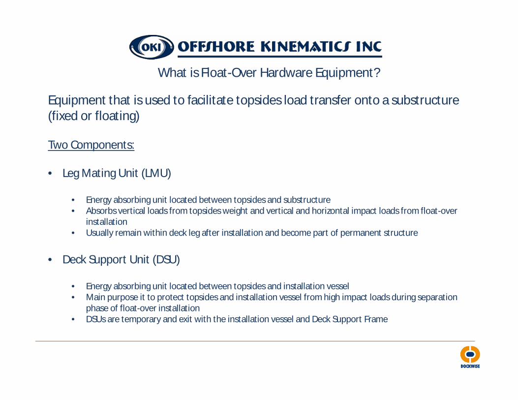
What is Float-Over Hardware Equipment?
Equipment that is used to facilitate topsides load transfer onto a substructure (fixed or floating)
Two Components:
• Leg Mating Unit (LMU)
• Energy absorbing unit located between topsides and substructure• Absorbs vertical loads from topsides weight and vertical and horizontal impact loads from float-over
installation• Usually remain within deck leg after installation and become part of permanent structure
• Deck Support Unit (DSU)
• Energy absorbing unit located between topsides and installation vessel• Main purpose it to protect topsides and installation vessel from high impact loads during separation
phase of float-over installation• DSUs are temporary and exit with the installation vessel and Deck Support Frame

4
Installation Vessel alignedover Jacket and LMUs
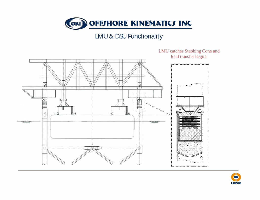
LMU & DSU Functionality
5
Float-over Equipment – LMU Operation
LMU catches Stabbing Cone andload transfer begins
LMU & DSU Functionality
6
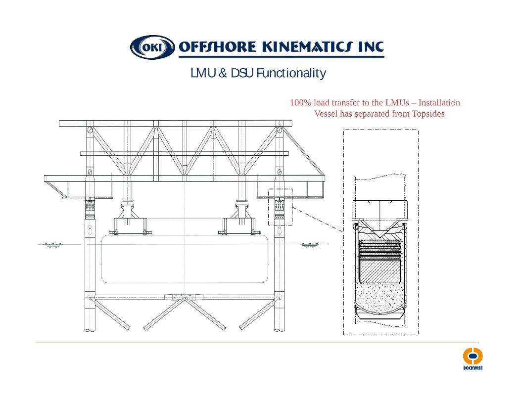
Float-over Equipment – LMU Operation
100% load transfer to the LMUs – Installation Vessel has separated from Topsides
LMU & DSU Functionality

7
Float-over Equipment – LMU Operation
Vessel leaves slot and sand is released to fully mate Topsides with Jacket
LMU & DSU Functionality

Simulated Pontoon Float-Over
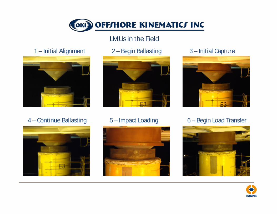
LMUs in the Field
1 – Initial Alignment 2 – Begin Ballasting 3 – Initial Capture
4 – Continue Ballasting 5 – Impact Loading 6 – Begin Load Transfer

LMUs in the Field
7 – Full Load Transfer 8 – Sand Release for Final Closure
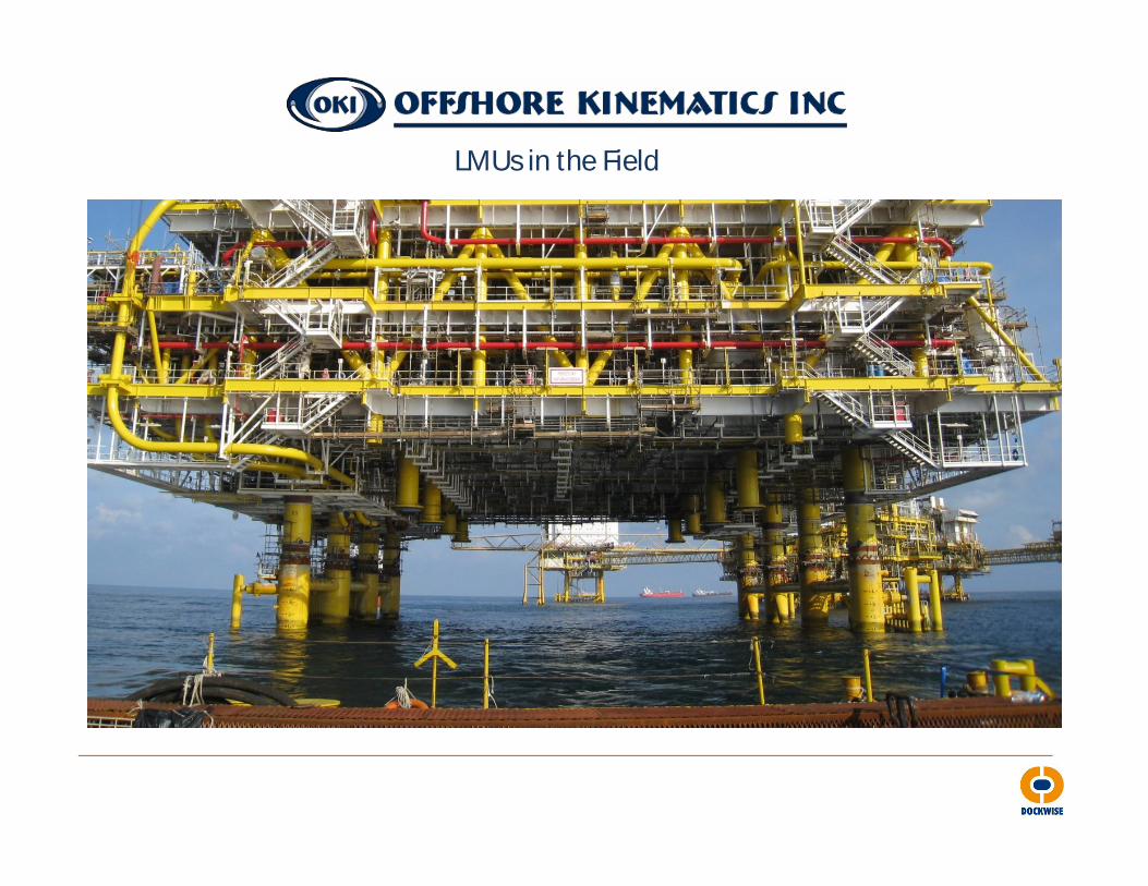
LMUs in the Field
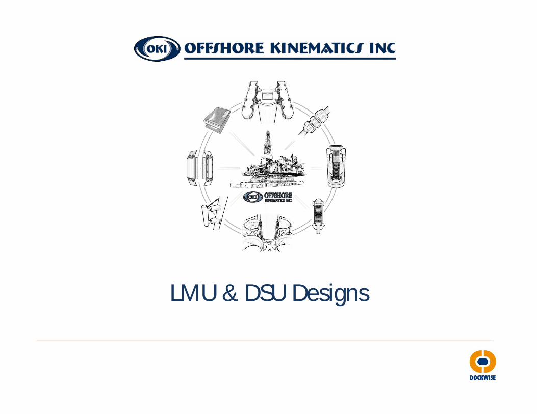
LMU & DSU Designs
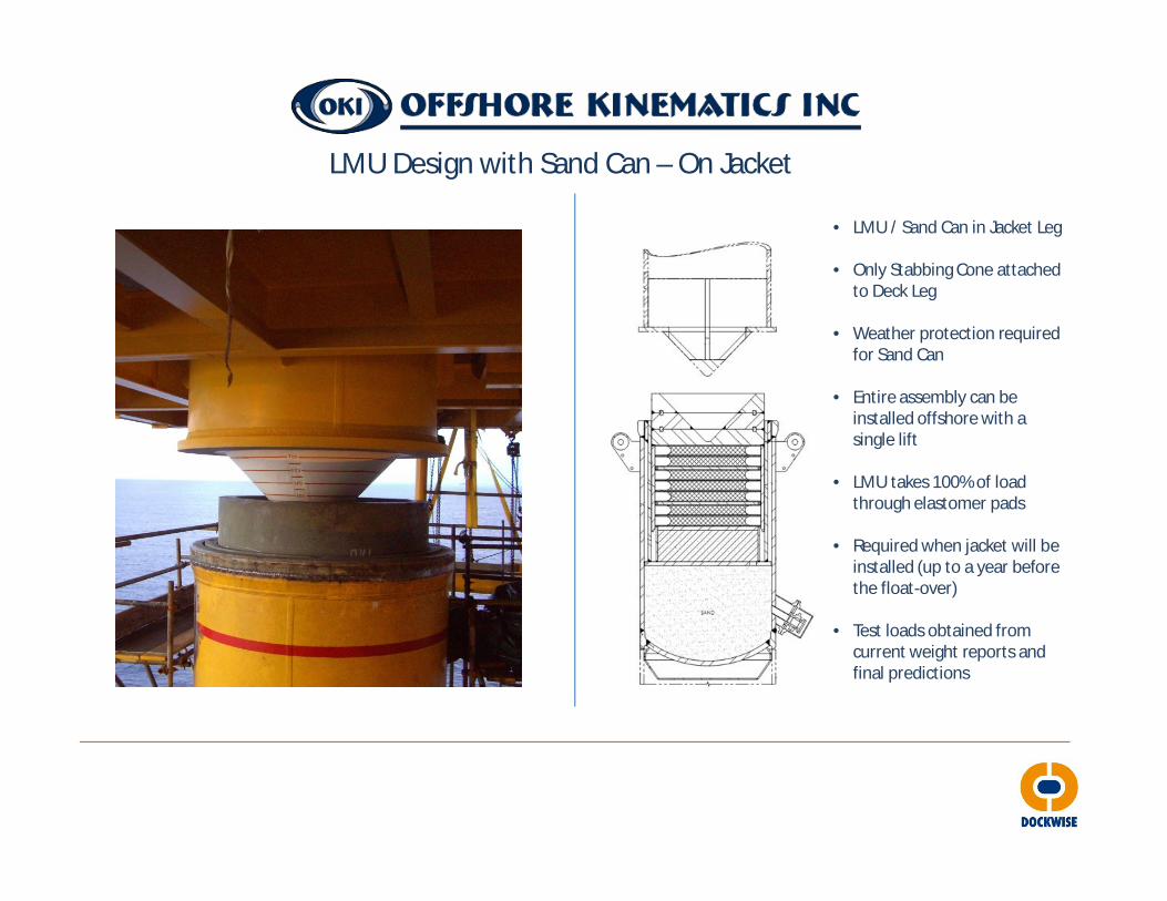
LMU Design with Sand Can – On Jacket
• LMU / Sand Can in Jacket Leg
• Only Stabbing Cone attached to Deck Leg
• Weather protection required for Sand Can
• Entire assembly can be installed offshore with a single lift
• LMU takes 100% of load through elastomer pads
• Required when jacket will be installed (up to a year before the float-over)
• Test loads obtained from current weight reports and final predictions

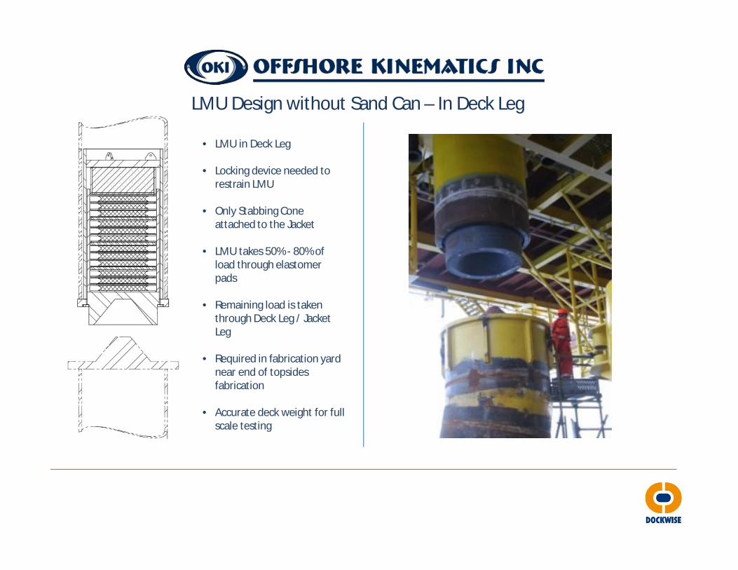
LMU Design with Sand Can – In Deck Leg
• LMU in Deck Leg
• Sand Can in Jacket Leg
• Locking device needed to restrain LMU
• Weather protection required for Sand Can
• LMU takes 100% of load through elastomer pads
• Required in fabrication yard near end of topsides fabrication
• Accurate deck weight for full scale testing

LMU Design without Sand Can – On Jacket• LMU installed in Jacket Leg
• Only Stabbing Cone attached to Deck Leg
• Weather protection required for LMU to prevent water ingress over extended period of time.
• Entire assembly can be installed offshore with a single lift
• LMU takes 50% - 80% of load through elastomer pads
• Required when jacket will be installed (up to a year before the float-over)
• Test loads obtained from current weight reports and final predictions
LMU Design without Sand Can – In Deck Leg
• LMU in Deck Leg
• Locking device needed to restrain LMU
• Only Stabbing Cone attached to the Jacket
• LMU takes 50% - 80% of load through elastomer pads
• Remaining load is taken through Deck Leg / Jacket Leg
• Required in fabrication yard near end of topsides fabrication
• Accurate deck weight for full scale testing
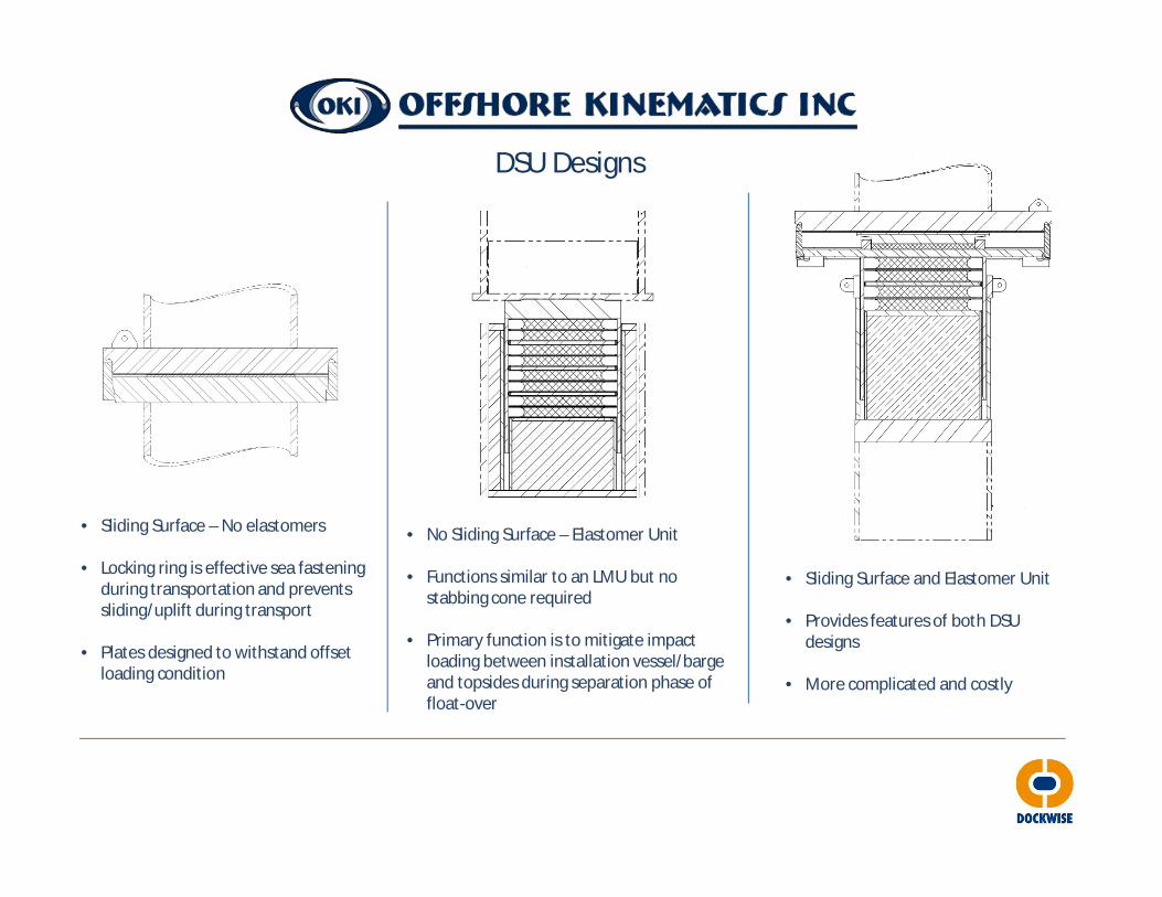
DSU Designs
• Sliding Surface – No elastomers
• Locking ring is effective sea fastening during transportation and prevents sliding/uplift during transport
• Plates designed to withstand offset loading condition
• No Sliding Surface – Elastomer Unit
• Functions similar to an LMU but no stabbing cone required
• Primary function is to mitigate impact loading between installation vessel/barge and topsides during separation phase of float-over
• Sliding Surface and Elastomer Unit
• Provides features of both DSU designs
• More complicated and costly

DSU Designs
• Sliding Surface – No elastomers
• Locking ring is effective sea fastentingduring transportation and prevents sliding/uplift during transport
• Plates designed to withstand offset loading condition
• No Sliding Surface – Elastomer Unit
• Functions similar to an LMU but no stabbing cone required
• Primary function is to mitigate impact loading between installation vessel/barge and topsides during separation phase of float-over
• Sliding Surface and Elastomer Unit
• Provides features of both DSU designs
• More complicated and costly
Contract Execution
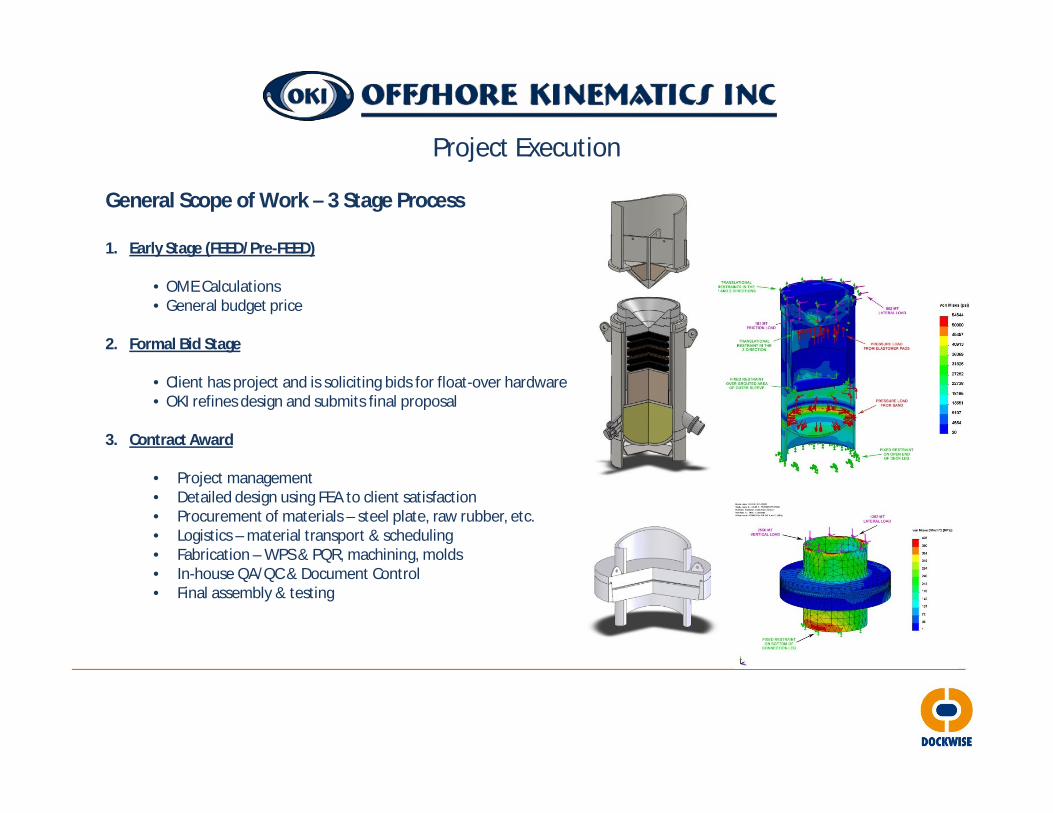
Project Execution
General Scope of Work – 3 Stage Process
1. Early Stage (FEED/Pre-FEED)
• OME Calculations• General budget price
2. Formal Bid Stage
• Client has project and is soliciting bids for float-over hardware• OKI refines design and submits final proposal
3. Contract Award
• Project management• Detailed design using FEA to client satisfaction• Procurement of materials – steel plate, raw rubber, etc.• Logistics – material transport & scheduling• Fabrication – WPS & PQR, machining, molds• In-house QA/QC & Document Control• Final assembly & testing
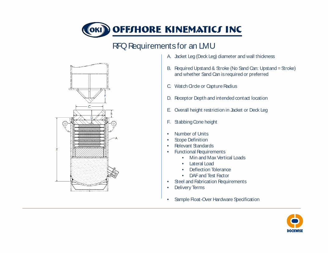
RFQ Requirements for an LMUA. Jacket Leg (Deck Leg) diameter and wall thickness
B. Required Upstand & Stroke (No Sand Can: Upstand = Stroke) and whether Sand Can is required or preferred
C. Watch Circle or Capture Radius
D. Receptor Depth and intended contact location
E. Overall height restriction in Jacket or Deck Leg
F. Stabbing Cone height
• Number of Units• Scope Definition• Relevant Standards• Functional Requirements
• Min and Max Vertical Loads• Lateral Load• Deflection Tolerance• DAF and Test Factor
• Steel and Fabrication Requirements• Delivery Terms
• Sample Float-Over Hardware Specification

RFQ Requirements for a DSU
A. DSF Leg and Deck Leg diameter and wall thickness
B. Required Stroke
C. Overall height restriction in Jacket or Deck Leg
D. Lateral Offset of Sliding Surface
• Number of Units• Scope Definition• Relevant Standards• Functional Requirements
• Min and Max Vertical Loads• Lateral Load• Deflection Tolerance• DAF and Test Factor
• Steel and Fabrication Requirements• Delivery Terms
• Loose vs. Tight Slot

Project Execution
• DESIGN
• Complete in-house design and analysis of LMUs, DSUs, Sand Cans, and Stabbing Cones• Creation of all drawings (GA, fabrication details, machine details, lifting arrangements, etc.• Review cycles with client to achieve final approval
• FABRICATION
• Performed by contracted fabrication facility• Ensure qualification and use of proper weld procedure, NDE procedures, dimensional controls, etc.• Complete trial fit of components
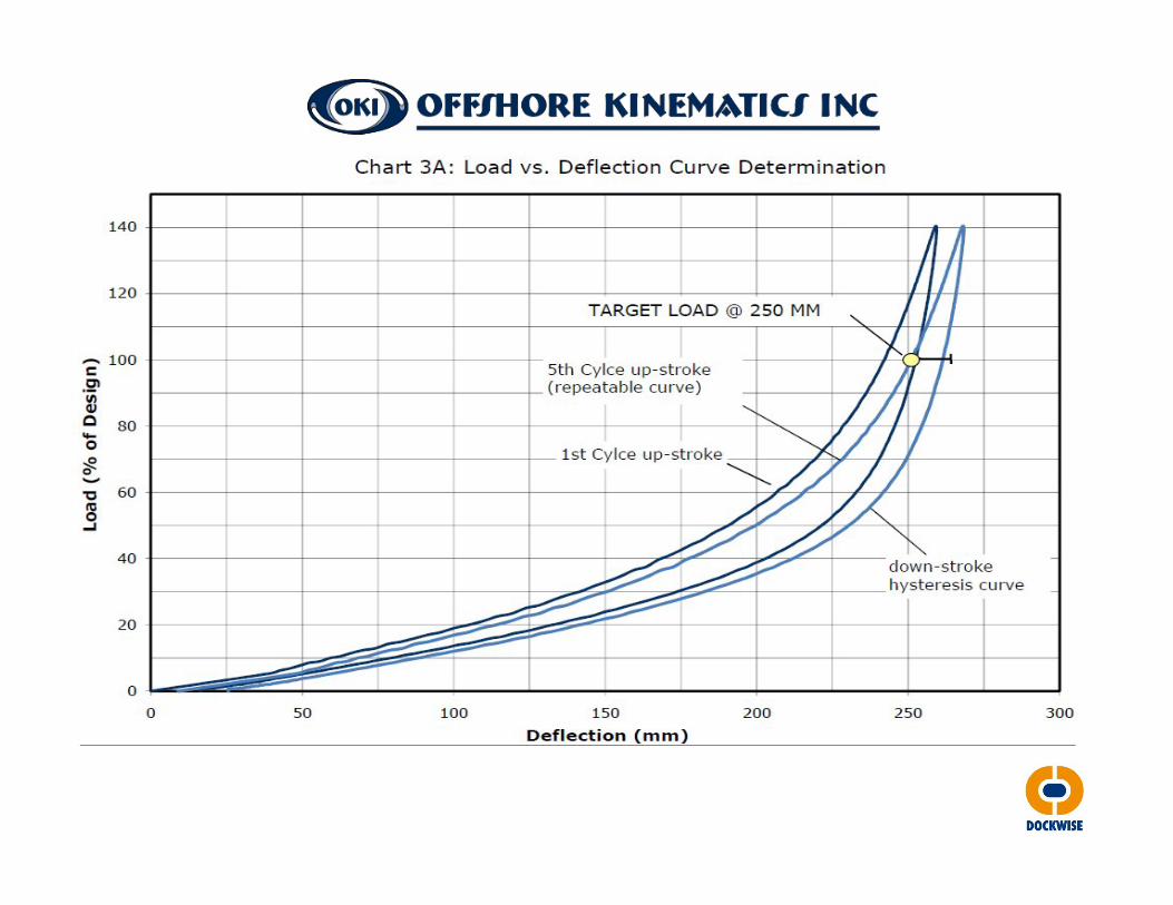
• TESTING
• All units provided are subjected to full scale testing in excess of design loads• Testing data is recorded and reported to client showing desired stiffness was achieved
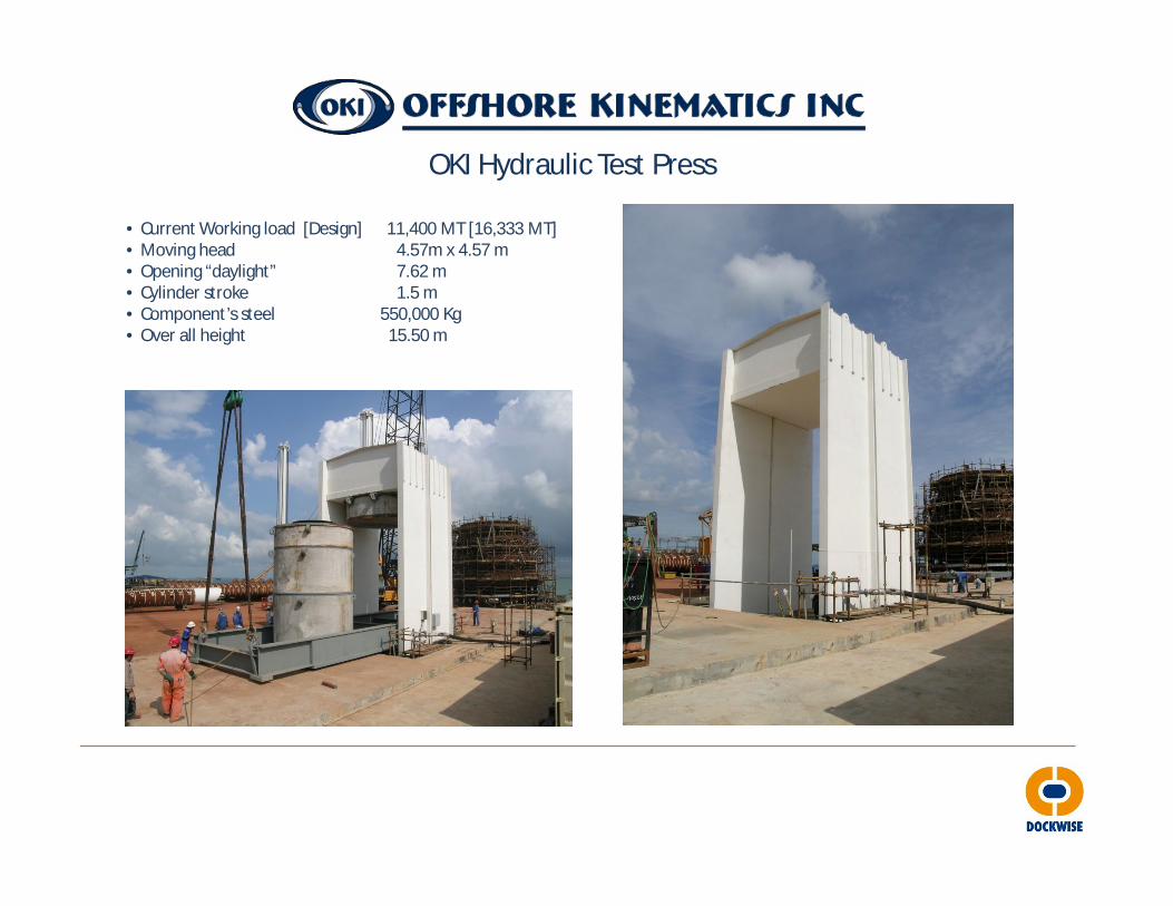
OKI Hydraulic Test Press
• Current Working load [Design] 11,400 MT [16,333 MT]• Moving head 4.57m x 4.57 m• Opening “daylight” 7.62 m• Cylinder stroke 1.5 m• Component’s steel 550,000 Kg• Over all height 15.50 m
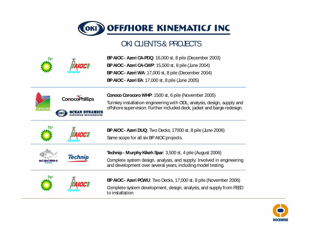
OKI CLIENTS & PROJECTS
BP AIOC - Azeri CA-PDQ: 16,000 st, 8 pile (December 2003)
BP AIOC - Azeri CA-CWP: 15,500 st, 8 pile (June 2004)
BP AIOC - Azeri WA: 17,000 st, 8 pile (December 2004)
BP AIOC - Azeri EA: 17,000 st, 8 pile (June 2005)
Conoco Corocoro WHP: 1500 st, 6 pile (November 2005)
Turnkey installation engineering with ODL, analysis, design, supply andoffshore supervision. Further included deck, jacket and barge redesign.
BP AIOC - Azeri DUQ: Two Decks, 17000 st, 8 pile (June 2006)
Same scope for all six BP AIOC projects.
Technip - Murphy Kikeh Spar: 3,500 st, 4 pile (August 2006)
Complete system design, analysis, and supply. Involved in engineeringand development over several years, including model testing.
BP AIOC - Azeri PCWU: Two Decks, 17,000 st, 8 pile (November 2006)
Complete system development, design, analysis, and supply from FEEDto installation.
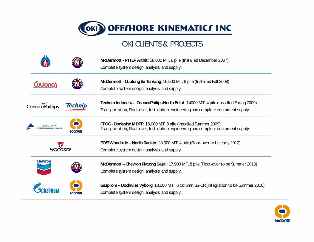
OKI CLIENTS & PROJECTS
McDermott - PTTEP Arthit: 18,000 MT, 8 pile (Installed December 2007)
Complete system design, analysis, and supply.
McDermott - Cuulong Su Tu Vang: 16,500 MT, 8 pile (Installed Fall 2008)
Complete system design, analysis, and supply.
Technip Indonesia - ConocoPhilips North Belut: 14000 MT, 4 pile (Installed Spring 2009)
Transportation, Float-over, Installation engineering and complete equipment supply.
CPOC - Dockwise MDPP: 18,000 MT, 8 pile (Installed Summer 2009)Transportation, Float-over, Installation engineering and complete equipment supply.
EOS/Woodside – North Rankin: 23,000 MT, 4 pile (Float-over to be early 2012)
Complete system design, analysis, and supply.
McDermott – Chevron Platong Gas II: 17,900 MT, 8 pile (Float-over to be Summer 2010)
Complete system design, analysis, and supply.
Gazprom – Dockwise Vyborg: 18,000 MT, 6 Column SSFDR (Integration to be Summer 2010)
Complete system design, analysis, and supply.

Related Documents


![Holly oki rcc presentation 2013 [compatibility mode]](https://static.cupdf.com/doc/110x72/568bd6c41a28ab20349d46d6/holly-oki-rcc-presentation-2013-compatibility-mode.jpg)