
Welcome message from author
This document is posted to help you gain knowledge. Please leave a comment to let me know what you think about it! Share it to your friends and learn new things together.
Transcript
oilrite.qxp 11/28/2006 10:20 AM Page 2
INTRODUCTIONTO PurgeX®
The patented PurgeX® pump is one of the
most unique and successful products in
industry today. Since 1988, thousands of
satisfied customers have made PurgeX®
their choice for reliable and precise
lubrication. It is called PurgeX® because
entrapped air and other impurities are
automatically “purged” from the system.
In lab tests, over 360,000,000 cycles
have been achieved without appreciable
wear. By dispensing very small amounts
of liquid or grease, environmental
contamination is greatly minimized.
Precision output and excellent
repeatability provide higher productivity
rates. In addition, precise metering can
be achieved over a wide range of
adjustability. Some of the more popular
applications for PurgeX® include:
• Lubricating liquids
• Food additives
• Greases
• Dyes
• Chemicals
• Solvents
• Inks
LUBRICATION TRENDSWhy Less Lubrication is BetterTraditionally, lubrication users have been under a mis-conception that if a small amount ofliquid is good, then a larger amount of liquid is better. This tendency to over-lubricate hasled to other problems in industry such as material contamination, clean up expenses andenvironmental contamination. In some cases, users have removed lubrication systemsentirely in order to prevent these problems. With the PurgeX® system, extremely small amounts of lubricant can be applied either directly or by spray.
Advantages of Automatic Lubrication Systems — Many manufacturing companies continue to use manual lubrication methods as well as gravity feed lubrication systems.Both of these types of lubrication have inherent problems that PurgeX® can solve.
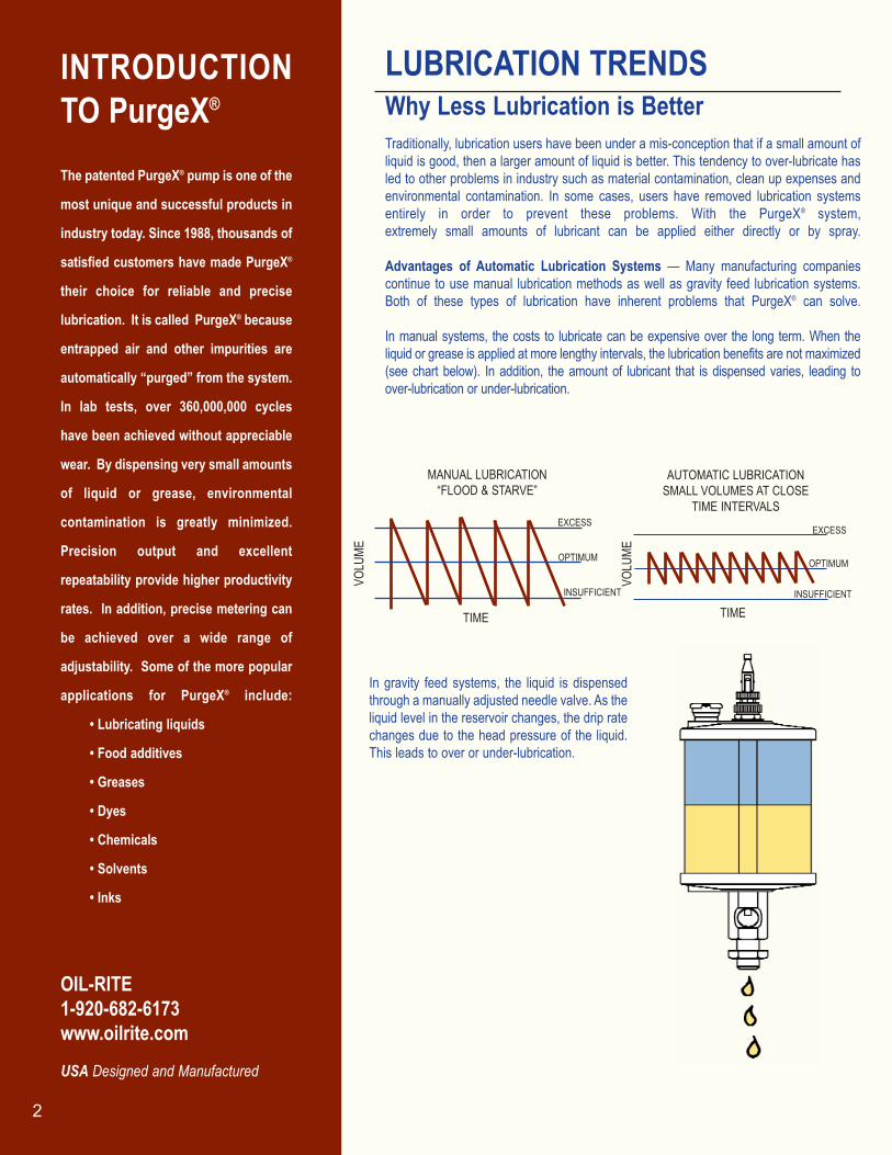
In manual systems, the costs to lubricate can be expensive over the long term. When the liquid or grease is applied at more lengthy intervals, the lubrication benefits are not maximized(see chart below). In addition, the amount of lubricant that is dispensed varies, leading to over-lubrication or under-lubrication.
In gravity feed systems, the liquid is dispensedthrough a manually adjusted needle valve. As theliquid level in the reservoir changes, the drip ratechanges due to the head pressure of the liquid.This leads to over or under-lubrication.
TIME
MANUAL LUBRICATION “FLOOD & STARVE”
AUTOMATIC LUBRICATIONSMALL VOLUMES AT CLOSE
TIME INTERVALSEXCESS
INSUFFICIENT
OPTIMUM
EXCESS
INSUFFICIENT
OPTIMUM
TIMEVO
LUME
VOLU
ME
2
OIL-RITE1-920-682-6173 www.oilrite.com
USA Designed and Manufactured
oilrite.qxp 11/28/2006 10:20 AM Page 3
THE PurgeX® THEORYHow It WorksPurgeX® is a pump that dispenses a precise amount of lubricant witheach cycle. It is available air operated or electric motor operated, andcan deliver liquid or grease directly through a 1/8” NPT port orthrough a spray nozzle.
Delivering the Smallest Amounts ofLubricationThe ability to deliver very small amounts of lubricant with each cycle is what distinguishes PurgeX® from all other lubrication products. In fact the namePurgeX®, comes from its designed ability to purge air from the lubricationsystem. This eliminates the need to pre-fill lubrication lines during initialinstallation. If the liquid reservoir runs low, or air is introduced in some othermanner into the system, the self-priming PurgeX® will fill lines with lubricantautomatically. The net result is the ability to reliably deliver the smallestamount of lubricant with each cycle.
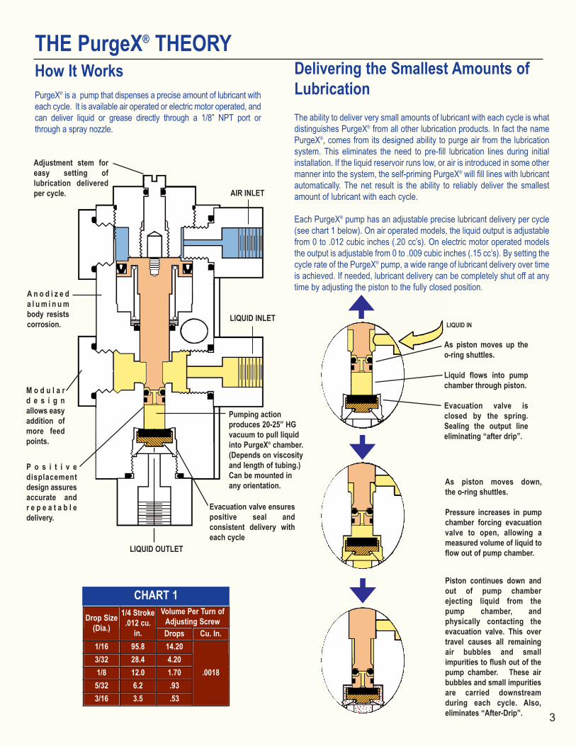
Each PurgeX® pump has an adjustable precise lubricant delivery per cycle(see chart 1 below). On air operated models, the liquid output is adjustablefrom 0 to .012 cubic inches (.20 cc’s). On electric motor operated modelsthe output is adjustable from 0 to .009 cubic inches (.15 cc’s). By setting thecycle rate of the PurgeX® pump, a wide range of lubricant delivery over timeis achieved. If needed, lubricant delivery can be completely shut off at anytime by adjusting the piston to the fully closed position.
LIQUID OUTLET
As piston moves up the o-ring shuttles.
Liquid flows into pump chamber through piston.
Evacuation valve is closed by the spring.Sealing the output lineeliminating “after drip”.
As piston moves down, the o-ring shuttles.
Pressure increases in pumpchamber forcing evacuationvalve to open, allowing ameasured volume of liquid toflow out of pump chamber.
Piston continues down andout of pump chamber ejecting liquid from thepump chamber, and physically contacting theevacuation valve. This overtravel causes all remainingair bubbles and small impurities to flush out of thepump chamber. These airbubbles and small impuritiesare carried downstream during each cycle. Also,eliminates “After-Drip”.
3
LIQUID IN
CHART 1
AIR INLET
LIQUID INLET
Pumping action produces 20-25” HGvacuum to pull liquidinto PurgeX® chamber.(Depends on viscosityand length of tubing.)Can be mounted inany orientation.
Evacuation valve ensurespositive seal and consistent delivery witheach cycle
P o s i t i v e displacement design assures accurate and r e p e a t a b l edelivery.
M o d u l a rd e s i g nallows easyaddition ofmore feedpoints.
A n o d i z e d a l u m i n u mbody resistscorrosion.
Drops Cu. In.1/16 95.8 14.203/32 28.4 4.201/8 12.0 1.70
5/32 6.2 .933/16 3.5 .53
Adjustment stem foreasy setting of lubrication deliveredper cycle.
Volume Per Turn of Adjusting Screw
1/4 Stroke.012 cu.
in.
Drop Size(Dia.)
.0018
oilrite.qxp 11/28/2006 10:20 AM Page 4
THE PurgeX® THEORY CONTINUED
Typical PurgeX® SystemRequirements
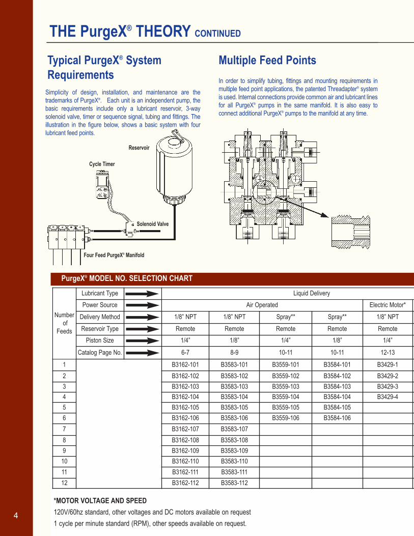
Multiple Feed PointsIn order to simplify tubing, fittings and mounting requirements inmultiple feed point applications, the patented Threadapter® systemis used. Internal connections provide common air and lubricant linesfor all PurgeX® pumps in the same manifold. It is also easy to connect additional PurgeX® pumps to the manifold at any time.
Simplicity of design, installation, and maintenance are the trademarks of PurgeX®. Each unit is an independent pump, thebasic requirements include only a lubricant reservoir, 3-way solenoid valve, timer or sequence signal, tubing and fittings. The illustration in the figure below, shows a basic system with fourlubricant feed points.
PurgeX® MODEL NO. SELECTION CHART
*MOTOR VOLTAGE AND SPEED120V/60hz standard, other voltages and DC motors available on request1 cycle per minute standard (RPM), other speeds available on request.
4
Cycle Timer
Reservoir
Solenoid Valve
Four Feed PurgeX® Manifold
Lubricant TypePower Source Electric Motor*
Delivery Method 1/8” NPT 1/8” NPT Spray** Spray** 1/8” NPT 1/8” N
Reservoir Type Remote Remote Remote Remote Remote RemPiston Size 1/4” 1/8” 1/4” 1/8” 1/4” 1/4
Catalog Page No. 6-7 8-9 10-11 10-11 12-13 6-7
1 B3162-101 B3583-101 B3559-101 B3584-101 B3429-1 B31622 B3162-102 B3583-102 B3559-102 B3584-102 B3429-2 B31623 B3162-103 B3583-103 B3559-103 B3584-103 B3429-3 B31624 B3162-104 B3583-104 B3559-104 B3584-104 B3429-4 B31625 B3162-105 B3583-105 B3559-105 B3584-105 B31626 B3162-106 B3583-106 B3559-106 B3584-106 B31627 B3162-107 B3583-107 B31628 B3162-108 B3583-108 B31629 B3162-109 B3583-109 B3162
10 B3162-110 B3583-110 B316211 B3162-111 B3583-111 B316212 B3162-112 B3583-112 B3162
Liquid DeliveryAir Operated
Numberof
Feeds
oilrite.qxp 11/28/2006 10:20 AM Page 5
SEALSBuna-N standard, other seals available on request 5
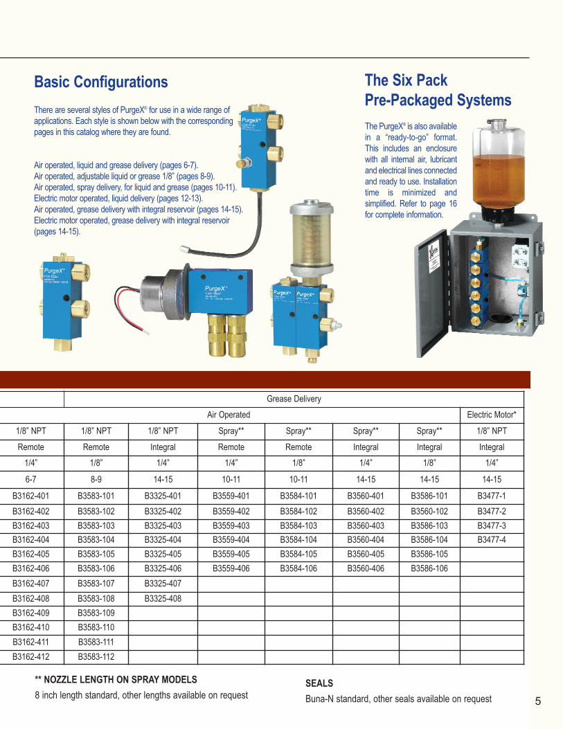
The Six PackPre-Packaged SystemsThe PurgeX® is also availablein a “ready-to-go” format.This includes an enclosurewith all internal air, lubricantand electrical lines connectedand ready to use. Installationtime is minimized and simplified. Refer to page 16for complete information.
Basic Configurations There are several styles of PurgeX® for use in a wide range of applications. Each style is shown below with the corresponding pages in this catalog where they are found.
Air operated, liquid and grease delivery (pages 6-7).Air operated, adjustable liquid or grease 1/8” (pages 8-9).Air operated, spray delivery, for liquid and grease (pages 10-11).Electric motor operated, liquid delivery (pages 12-13).Air operated, grease delivery with integral reservoir (pages 14-15).Electric motor operated, grease delivery with integral reservoir (pages 14-15).
Electric Motor*
1/8” NPT 1/8” NPT 1/8” NPT Spray** Spray** Spray** Spray** 1/8” NPT
Remote Remote Integral Remote Remote Integral Integral Integral1/4” 1/8” 1/4” 1/4” 1/8” 1/4” 1/8” 1/4”
6-7 8-9 14-15 10-11 10-11 14-15 14-15 14-15
B3162-401 B3583-101 B3325-401 B3559-401 B3584-101 B3560-401 B3586-101 B3477-1B3162-402 B3583-102 B3325-402 B3559-402 B3584-102 B3560-402 B3560-102 B3477-2B3162-403 B3583-103 B3325-403 B3559-403 B3584-103 B3560-403 B3586-103 B3477-3B3162-404 B3583-104 B3325-404 B3559-404 B3584-104 B3560-404 B3586-104 B3477-4B3162-405 B3583-105 B3325-405 B3559-405 B3584-105 B3560-405 B3586-105B3162-406 B3583-106 B3325-406 B3559-406 B3584-106 B3560-406 B3586-106B3162-407 B3583-107 B3325-407B3162-408 B3583-108 B3325-408B3162-409 B3583-109B3162-410 B3583-110B3162-411 B3583-111B3162-412 B3583-112
** NOZZLE LENGTH ON SPRAY MODELS8 inch length standard, other lengths available on request
Grease DeliveryAir Operated
oilrite.qxp 11/28/2006 10:21 AM Page 6
SPECIFICATIONS
TYPICAL INSTALLATION
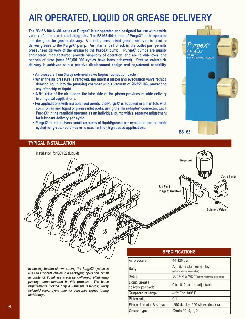
The B3162-100 & 300 series of PurgeX® is air operated and designed for use with a wide variety of liquids and lubricating oils. The B3162-400 series of PurgeX® is air operatedand designed for grease delivery. A remote, pressurized grease reservoir is used todeliver grease to the PurgeX® pump. An internal ball check in the outlet port permitspressurized delivery of the grease to the PurgeX® pump. PurgeX® pumps are qualityengineered, manufactured, provide simplicity of operation, and are reliable over long periods of time (over 360,000,000 cycles have been achieved). Precise volumetric delivery is achieved with a positive displacement design and adjustment capability.
• Air pressure from 3-way solenoid valve begins lubrication cycle.• When the air pressure is removed, the internal piston and evacuation valve retract,
drawing liquid into the pumping chamber with a vacuum of 20-25” HG, preventingany after-drip of liquid.
• A 9:1 ratio of the air side to the lube side of the piston provides reliable delivery in all typical applications.
• For applications with multiple feed points, the PurgeX® is supplied in a manifold withcommon air and liquid or grease inlet ports, using the Threadapter® connector. EachPurgeX® in the manifold operates as an individual pump with a separate adjustmentfor lubricant delivery per cycle.
• PurgeX® pump delivers small amounts of liquid/grease per cycle and can be rapidcycled for greater volumes or is excellent for high speed applications.
AIR OPERATED, LIQUID OR GREASE DELIVERY
In the application shown above, the PurgeX® system is used to lubricate chains in a packaging operation. Smallamounts of liquid are precisely delivered, eliminatingpackage contamination in this process. The basicrequirements include only a lubricant reservoir, 3-waysolenoid valve, cycle timer or sequence signal, tubingand fittings.
6
B3162
Reservoir
Six Feed PurgeX® Manifold
Cycle Timer
Solenoid Valve
Installation for B3162 (Liquid)
Air pressure 40-120 psi
Body Anodized aluminum alloy(other materials available)
Seals Buna-N & Viton® (other materials available)
Liquid/Grease delivery per cycle 0 to .012 cu. in., adjustable
Temperature range -15º F to 180º FPiston ratio 9:1Piston diameter & stroke .250 dia. by .250 stroke (inches)Grease type Grade 00, 0, 1, 2
oilrite.qxp 11/28/2006 10:21 AM Page 7
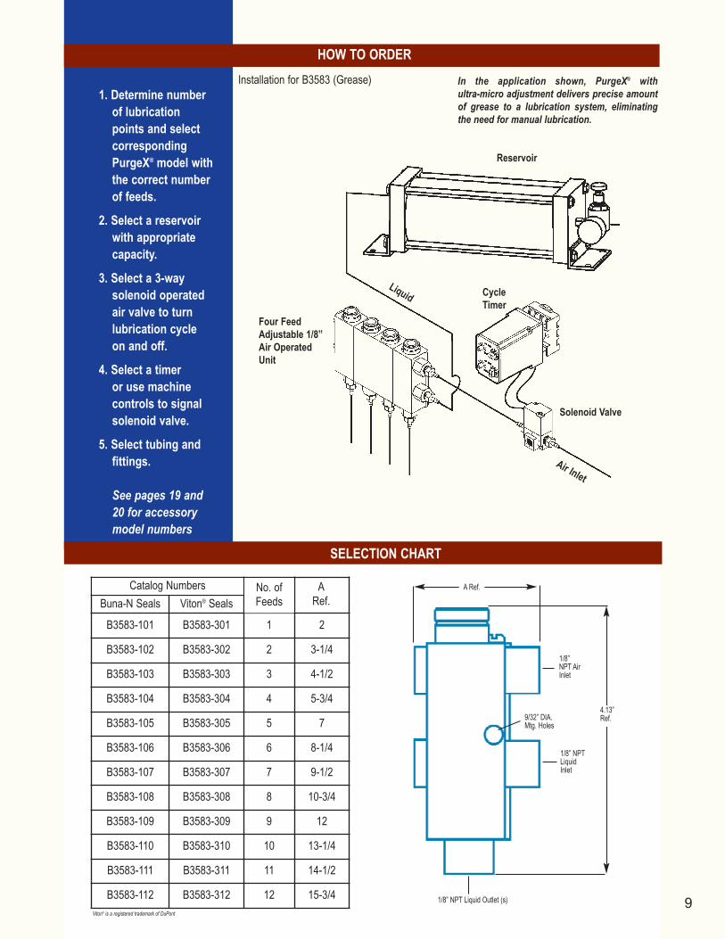
1. Determine numberof lubricationpoints and selectcorrespondingPurgeX® modelwith the correctnumber of feeds.
2. Select liquid orgrease reservoirwith appropriatecapacity.
3. Select a 3-waysolenoid operatedair valve to turnlubrication cycleon and off.
4. Select a timer or use machine controls to signalsolenoid valve.
5. Select tubing andfittings.
See pages 19 and 20for accessory modelnumbers
SELECTION CHART
HOW TO ORDER
7
1.25” HoleCenters
1/8” NPT Liquid or GreaseOutlet(s) Viton® is a registered trademark of DuPont
1/8” NPTLiquid orGreaseInlet
1/8”NPT AirInlet
Liquid or Grease Output Adjustment Stem
9/32” DIA.Mtg. Holes
4.06” (forGrease Unit)
A Ref.
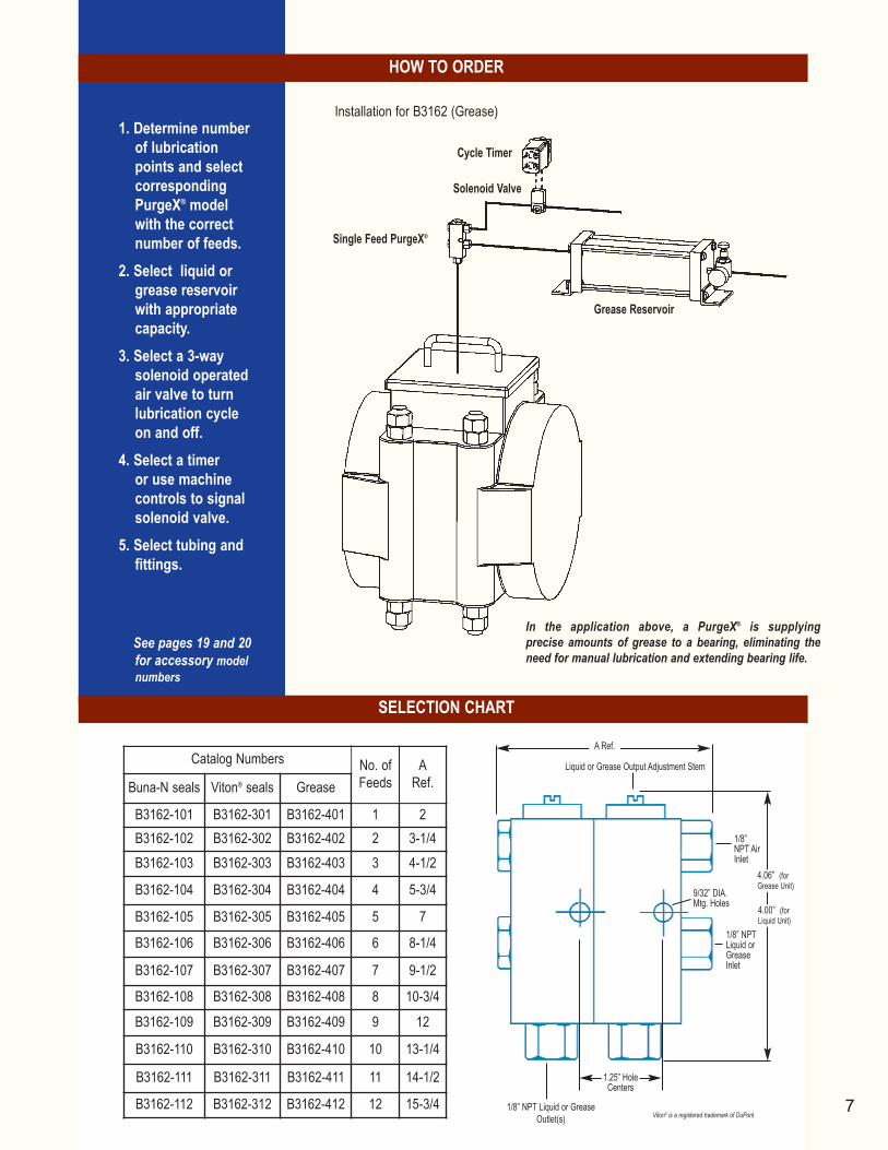
In the application above, a PurgeX® is supplying precise amounts of grease to a bearing, eliminating theneed for manual lubrication and extending bearing life.
Cycle Timer
Single Feed PurgeX®
Solenoid Valve
Grease Reservoir
Installation for B3162 (Grease)
Buna-N seals Viton® seals Grease
B3162-101 B3162-301 B3162-401 1 2B3162-102 B3162-302 B3162-402 2 3-1/4B3162-103 B3162-303 B3162-403 3 4-1/2
B3162-104 B3162-304 B3162-404 4 5-3/4
B3162-105 B3162-305 B3162-405 5 7
B3162-106 B3162-306 B3162-406 6 8-1/4
B3162-107 B3162-307 B3162-407 7 9-1/2
B3162-108 B3162-308 B3162-408 8 10-3/4
B3162-109 B3162-309 B3162-409 9 12
B3162-110 B3162-310 B3162-410 10 13-1/4
B3162-111 B3162-311 B3162-411 11 14-1/2
B3162-112 B3162-312 B3162-412 12 15-3/4
Catalog Numbers No. ofFeeds
ARef.
4.00” (forLiquid Unit)
oilrite.qxp 11/28/2006 10:21 AM Page 8
SPECIFICATIONS
TYPICAL INSTALLATION
8
B3583
ULTRA-MICRO OUTPUT PurgeX® ADJUSTABLEAIR OPERATED, with 1/8” PISTON
Reservoir
Solenoid Valve
PurgeX®
Adjustable 1/8”Air Operated Unit
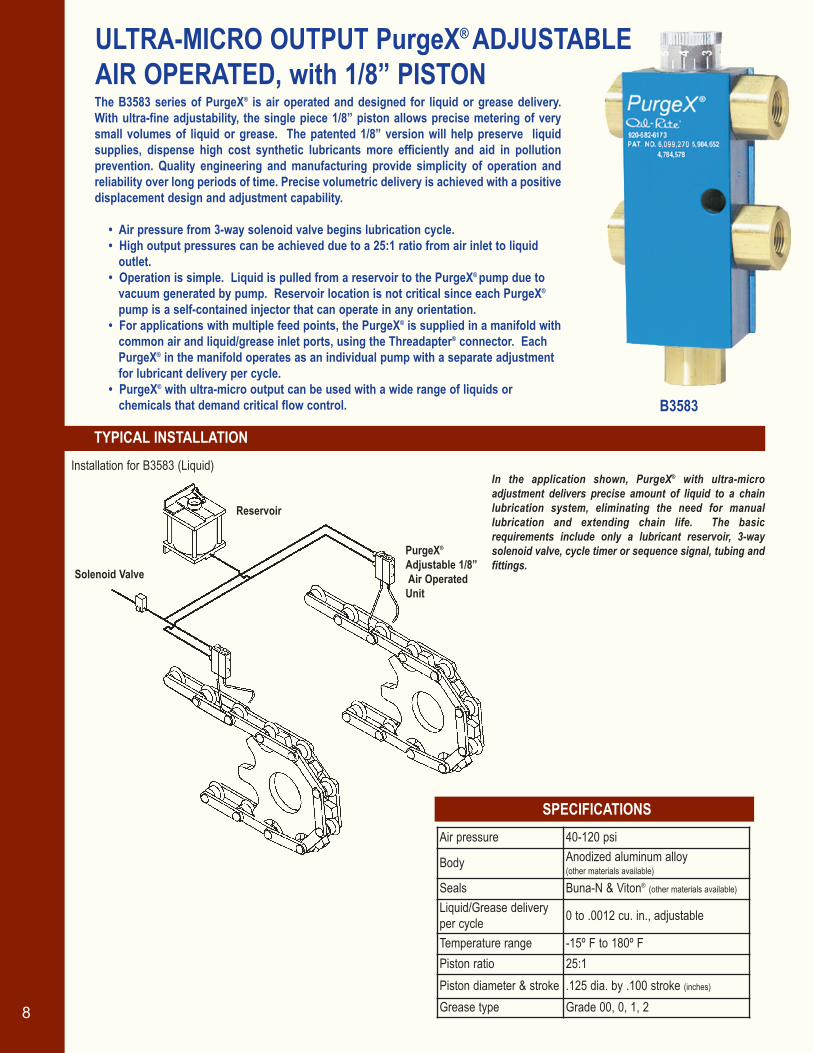
In the application shown, PurgeX® with ultra-micro adjustment delivers precise amount of liquid to a chain lubrication system, eliminating the need for manuallubrication and extending chain life. The basic requirements include only a lubricant reservoir, 3-waysolenoid valve, cycle timer or sequence signal, tubing andfittings.
The B3583 series of PurgeX® is air operated and designed for liquid or grease delivery.With ultra-fine adjustability, the single piece 1/8” piston allows precise metering of verysmall volumes of liquid or grease. The patented 1/8” version will help preserve liquid supplies, dispense high cost synthetic lubricants more efficiently and aid in pollution prevention. Quality engineering and manufacturing provide simplicity of operation andreliability over long periods of time. Precise volumetric delivery is achieved with a positivedisplacement design and adjustment capability.
• Air pressure from 3-way solenoid valve begins lubrication cycle.• High output pressures can be achieved due to a 25:1 ratio from air inlet to liquid
outlet.• Operation is simple. Liquid is pulled from a reservoir to the PurgeX® pump due to
vacuum generated by pump. Reservoir location is not critical since each PurgeX®
pump is a self-contained injector that can operate in any orientation.• For applications with multiple feed points, the PurgeX® is supplied in a manifold with
common air and liquid/grease inlet ports, using the Threadapter® connector. EachPurgeX® in the manifold operates as an individual pump with a separate adjustmentfor lubricant delivery per cycle.
• PurgeX® with ultra-micro output can be used with a wide range of liquids or chemicals that demand critical flow control.
Installation for B3583 (Liquid)
Air pressure 40-120 psi
Body Anodized aluminum alloy(other materials available)
Seals Buna-N & Viton® (other materials available)
Liquid/Grease delivery per cycle 0 to .0012 cu. in., adjustable
Temperature range -15º F to 180º FPiston ratio 25:1Piston diameter & stroke .125 dia. by .100 stroke (inches)
Grease type Grade 00, 0, 1, 2
oilrite.qxp 11/28/2006 10:21 AM Page 9
1. Determine numberof lubrication points and selectcorrespondingPurgeX® model withthe correct numberof feeds.
2. Select a reservoirwith appropriatecapacity.
3. Select a 3-waysolenoid operatedair valve to turnlubrication cycle on and off.
4. Select a timer or use machine controls to signalsolenoid valve.
5. Select tubing andfittings.
See pages 19 and20 for accessorymodel numbers
SELECTION CHART
HOW TO ORDER
91/8” NPT Liquid Outlet (s)
1/8” NPTLiquidInlet
1/8”NPT AirInlet
9/32” DIA.Mtg. Holes
4.13”Ref.
A Ref.
Buna-N Seals Viton® Seals
B3583-101 B3583-301 1 2
B3583-102 B3583-302 2 3-1/4
B3583-103 B3583-303 3 4-1/2
B3583-104 B3583-304 4 5-3/4
B3583-105 B3583-305 5 7
B3583-106 B3583-306 6 8-1/4
B3583-107 B3583-307 7 9-1/2
B3583-108 B3583-308 8 10-3/4
B3583-109 B3583-309 9 12
B3583-110 B3583-310 10 13-1/4
B3583-111 B3583-311 11 14-1/2
B3583-112 B3583-312 12 15-3/4
ARef.
No. ofFeeds
Catalog Numbers
Reservoir
CycleTimer
Solenoid Valve
Four FeedAdjustable 1/8”Air OperatedUnit
Air Inlet
Liquid
In the application shown, PurgeX® with ultra-micro adjustment delivers precise amountof grease to a lubrication system, eliminatingthe need for manual lubrication.
Installation for B3583 (Grease)
Viton® is a registered trademark of DuPont
oilrite.qxp 11/28/2006 10:21 AM Page 10
SPECIFICATIONS
TYPICAL INSTALLATION
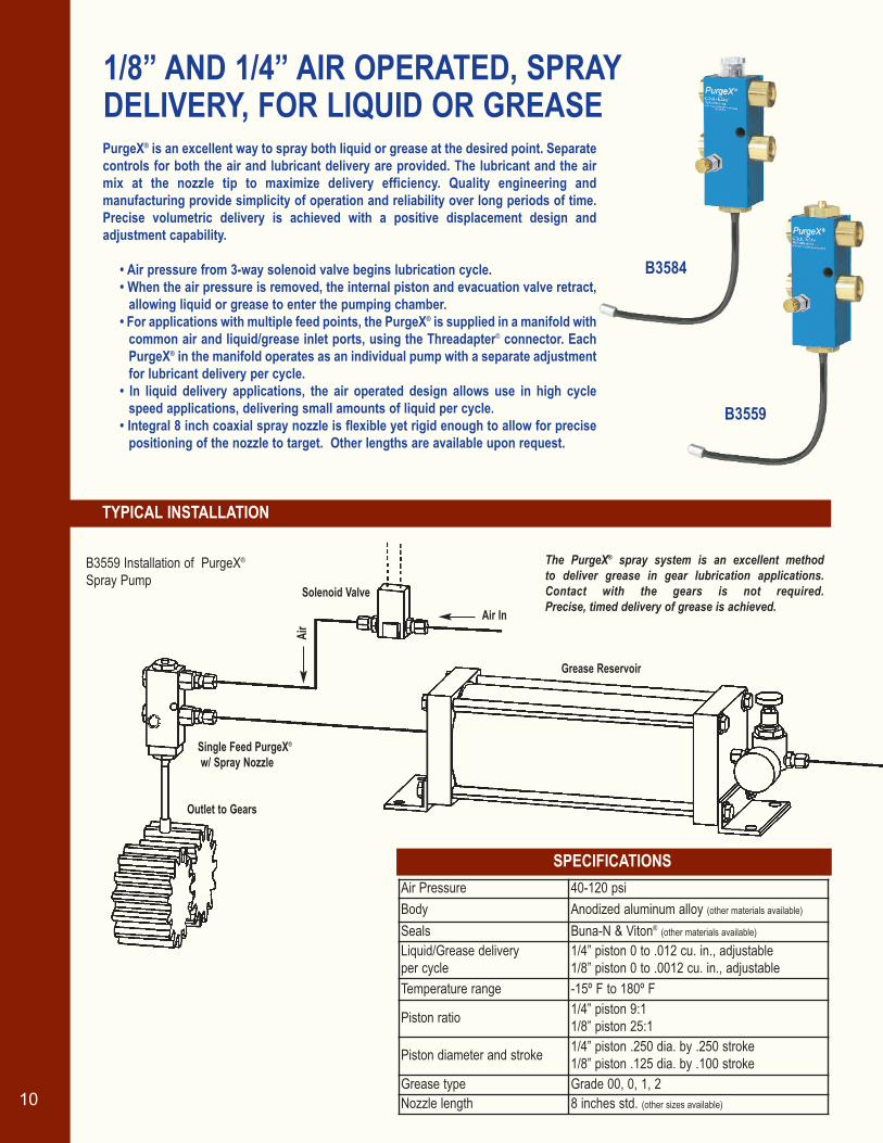
The PurgeX® spray system is an excellent method to deliver grease in gear lubrication applications. Contact with the gears is not required. Precise, timed delivery of grease is achieved.
10
Air
Single Feed PurgeX®
w/ Spray Nozzle
Air InSolenoid Valve
Outlet to Gears
Grease Reservoir
PurgeX® is an excellent way to spray both liquid or grease at the desired point. Separatecontrols for both the air and lubricant delivery are provided. The lubricant and the airmix at the nozzle tip to maximize delivery efficiency. Quality engineering and manufacturing provide simplicity of operation and reliability over long periods of time.Precise volumetric delivery is achieved with a positive displacement design and adjustment capability.
• Air pressure from 3-way solenoid valve begins lubrication cycle.• When the air pressure is removed, the internal piston and evacuation valve retract,
allowing liquid or grease to enter the pumping chamber.• For applications with multiple feed points, the PurgeX® is supplied in a manifold with
common air and liquid/grease inlet ports, using the Threadapter® connector. EachPurgeX® in the manifold operates as an individual pump with a separate adjustmentfor lubricant delivery per cycle.
• In liquid delivery applications, the air operated design allows use in high cyclespeed applications, delivering small amounts of liquid per cycle.
• Integral 8 inch coaxial spray nozzle is flexible yet rigid enough to allow for precisepositioning of the nozzle to target. Other lengths are available upon request.
1/8” AND 1/4” AIR OPERATED, SPRAYDELIVERY, FOR LIQUID OR GREASE
B3559
B3584
Air Pressure 40-120 psiBody Anodized aluminum alloy (other materials available)
Seals Buna-N & Viton® (other materials available)
Liquid/Grease delivery per cycle
1/4” piston 0 to .012 cu. in., adjustable1/8” piston 0 to .0012 cu. in., adjustable
Temperature range -15º F to 180º F
Piston ratio 1/4” piston 9:1 1/8” piston 25:1
Piston diameter and stroke 1/4” piston .250 dia. by .250 stroke 1/8” piston .125 dia. by .100 stroke
Grease type Grade 00, 0, 1, 2Nozzle length 8 inches std. (other sizes available)
B3559 Installation of PurgeX®
Spray Pump
oilrite.qxp 11/28/2006 10:21 AM Page 11

1. Determine numberof lubricationpoints and selectcorrespondingPurgeX® modelwith the correctnumber of feeds.
2. Select liquid orgrease reservoirwith appropriatecapacity.
3. Select a 3-waysolenoid operatedair valve to turnlubrication cycleon and off.
4. Select a timer or use machine controls to signalsolenoid valve.
5. Select tubing andfittings.
See pages 19 and20 for accessorymodel numbers
SELECTION CHART
HOW TO ORDER
11
4”Ref.
Air SprayAdjustment Stem
Spray Outlet
A Ref.
1/8” N.P.T.Liquid/GreaseInlet
9/32” Dia.Mtg. Holes
1/8” N.P.T.Air Inlet
Liquid/GreaseOutput Adj.Stem
Cycle Timer
Air
Liquid
Solenoid Valve
1/8” Single Feed PurgeX®
w/ Spray Nozzle
Flexible Nozzle
Liquid & Air Spray Pattern
Reservoir
Viton® is a registered trademark of DuPont
B3584 Installation of PurgeX® Spray Injector Pump
A Ref.
4.16”Ref.
Spray Outlet
Air SprayAdjustment Stem
1/8” N.P.T.Liquid/GreaseInlet
9/32” Dia.Mtg. Holes
1/8” N.P.T.Air Inlet
Liquid/GreaseOutput Adj.Stem
B3584 B3559
Simplicity of design, installation, and maintenanceare the trademarks of PurgeX®. The basic requirements include only a lubricant reservoir, 3-way solenoid valve, cycle timer or sequence signal, tubing and fittings. The illustration shows abasic system with a single lubricant feed point.
Liquid/Grease Spray1/8”
Buna-N Viton® Buna-N Viton®
B3584-101 B3584-301 B3559-101 B3559-301 B3559-401 1 1-31/32
B3584-102 B3584-302 B3559-102 B3559-302 B3559-402 2 3-7/32
B3584-103 B3584-303 B3559-103 B3559-303 B3559-403 3 4-15/32
B3584-104 B3584-304 B3559-104 B3559-304 B3559-404 4 5-23/32
B3584-105 B3584-305 B3559-105 B3559-305 B3559-405 5 6-31/32
B3584-106 B3584-306 B3559-106 B3559-306 B3559-406 6 8-7/32
No. ofFeeds
GreaseSpray 1/4”
Buna-N
Liquid Spray1/4” A
Ref.
oilrite.qxp 11/28/2006 10:22 AM Page 12
SPECIFICATIONS
TYPICAL INSTALLATION
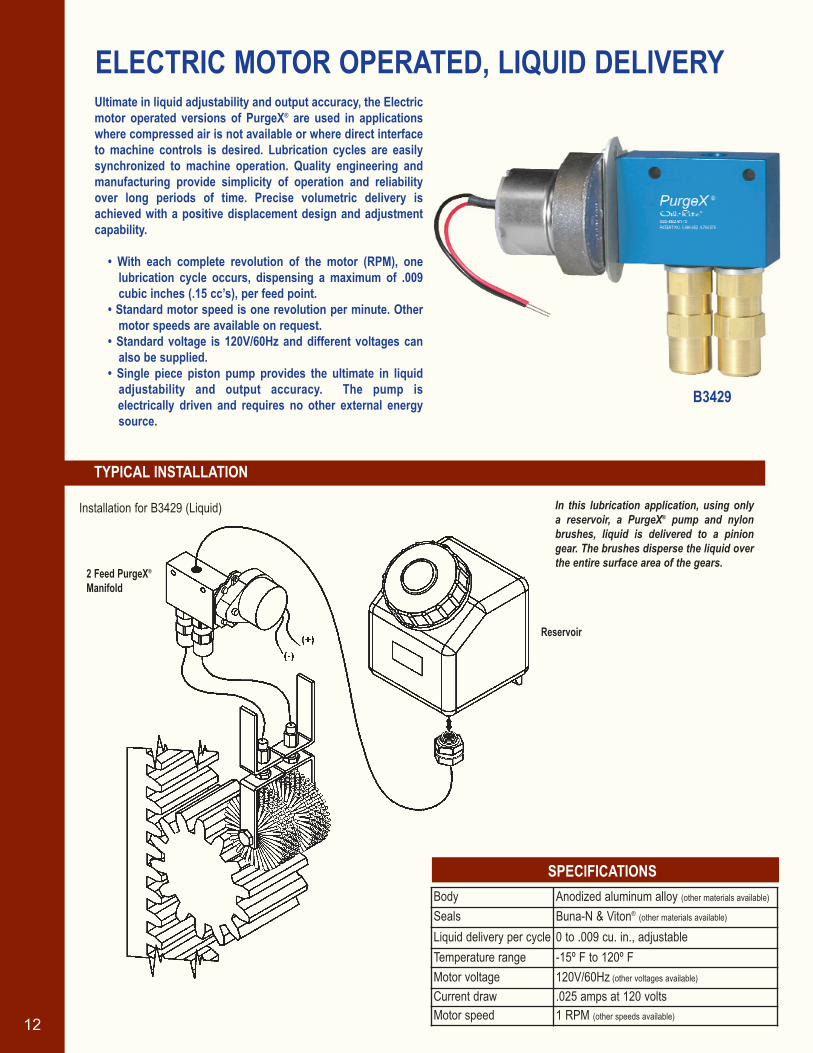
ELECTRIC MOTOR OPERATED, LIQUID DELIVERY
B3429
In this lubrication application, using only a reservoir, a PurgeX® pump and nylon brushes, liquid is delivered to a piniongear. The brushes disperse the liquid overthe entire surface area of the gears.
12
2 Feed PurgeX®
Manifold
Reservoir
Ultimate in liquid adjustability and output accuracy, the Electricmotor operated versions of PurgeX® are used in applicationswhere compressed air is not available or where direct interfaceto machine controls is desired. Lubrication cycles are easilysynchronized to machine operation. Quality engineering andmanufacturing provide simplicity of operation and reliabilityover long periods of time. Precise volumetric delivery isachieved with a positive displacement design and adjustmentcapability.
• With each complete revolution of the motor (RPM), onelubrication cycle occurs, dispensing a maximum of .009cubic inches (.15 cc’s), per feed point.
• Standard motor speed is one revolution per minute. Othermotor speeds are available on request.
• Standard voltage is 120V/60Hz and different voltages canalso be supplied.
• Single piece piston pump provides the ultimate in liquidadjustability and output accuracy. The pump is electrically driven and requires no other external energysource.
Installation for B3429 (Liquid)
Body Anodized aluminum alloy (other materials available)
Seals Buna-N & Viton® (other materials available)
Liquid delivery per cycle 0 to .009 cu. in., adjustableTemperature range -15º F to 120º FMotor voltage 120V/60Hz (other voltages available)
Current draw .025 amps at 120 voltsMotor speed 1 RPM (other speeds available)
oilrite.qxp 11/28/2006 10:22 AM Page 13
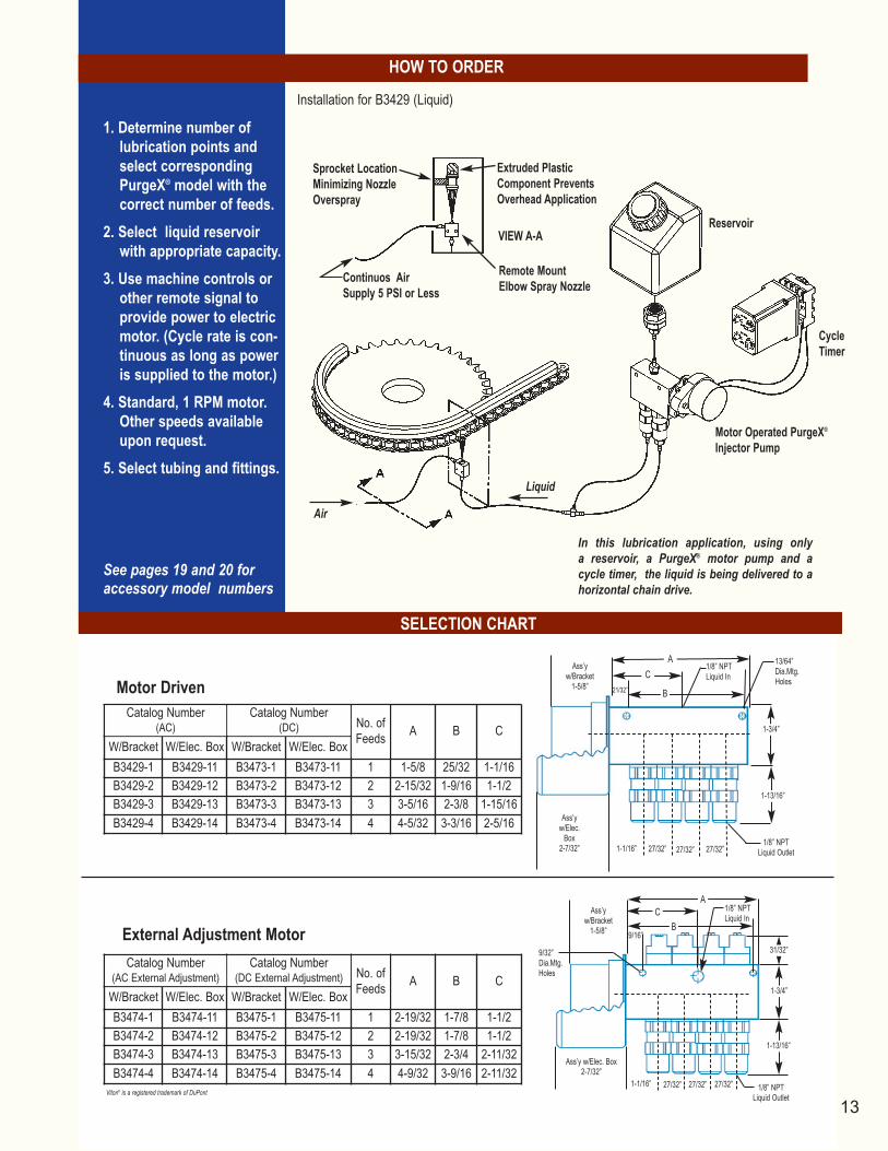
1. Determine number oflubrication points andselect correspondingPurgeX® model with thecorrect number of feeds.
2. Select liquid reservoirwith appropriate capacity.
3. Use machine controls orother remote signal toprovide power to electricmotor. (Cycle rate is con-tinuous as long as poweris supplied to the motor.)
4. Standard, 1 RPM motor.Other speeds availableupon request.
5. Select tubing and fittings.
See pages 19 and 20 foraccessory model numbers
SELECTION CHART
HOW TO ORDER
13
Ass’y w/Bracket
1-5/8”
AC
B21/32”
1/8” NPTLiquid In
13/64”Dia.Mtg.Holes
1-3/4”
1-13/16”
Ass’yw/Elec.
Box2-7/32” 1-1/16” 27/32”
1/8” NPTLiquid Outlet
ReservoirVIEW A-A
Air
CycleTimer
Motor Operated PurgeX®
Injector Pump
Liquid
Remote MountElbow Spray NozzleContinuos Air
Supply 5 PSI or Less
Sprocket LocationMinimizing NozzleOverspray
Extruded PlasticComponent PreventsOverhead Application
Viton® is a registered trademark of DuPont
Installation for B3429 (Liquid)
A B CW/Bracket W/Elec. Box W/Bracket W/Elec. BoxB3429-1 B3429-11 B3473-1 B3473-11 1 1-5/8 25/32 1-1/16B3429-2 B3429-12 B3473-2 B3473-12 2 2-15/32 1-9/16 1-1/2B3429-3 B3429-13 B3473-3 B3473-13 3 3-5/16 2-3/8 1-15/16B3429-4 B3429-14 B3473-4 B3473-14 4 4-5/32 3-3/16 2-5/16
A B CW/Bracket W/Elec. Box W/Bracket W/Elec. BoxB3474-1 B3474-11 B3475-1 B3475-11 1 2-19/32 1-7/8 1-1/2B3474-2 B3474-12 B3475-2 B3475-12 2 2-19/32 1-7/8 1-1/2B3474-3 B3474-13 B3475-3 B3475-13 3 3-15/32 2-3/4 2-11/32B3474-4 B3474-14 B3475-4 B3475-14 4 4-9/32 3-9/16 2-11/32
In this lubrication application, using only a reservoir, a PurgeX® motor pump and acycle timer, the liquid is being delivered to ahorizontal chain drive.
27/32”27/32”
Ass’y w/Elec. Box2-7/32”
Ass’y w/Bracket
1-5/8”
27/32” 27/32” 27/32”1-1/16”
9/16”
1/8” NPTLiquid In
1/8” NPTLiquid Outlet
9/32”Dia.Mtg.Holes
CB
A
1-3/4”
1-13/16”
31/32”External Adjustment Motor
Motor Driven
No. ofFeeds
Catalog Number (DC)
Catalog Number (AC)
Catalog Number (DC External Adjustment) No. of
Feeds
Catalog Number (AC External Adjustment)
oilrite.qxp 11/28/2006 10:22 AM Page 14
SELECTION CHART
SPECIFICATIONS
AIR OPERATED, 1/4” PISTON
14
8.06”1.25”
BA
Vent
GreaseOutputAdjustmentStem
1/8” NPTAir Inlet9/32” Dia.MTGHoles
GreaseFillFitting
Relief Valve1/8” NPT Grease Outlet(s)
B3477
B3325
Catalog No. No. ofFeeds A B
B3325-401 1 3-1/4 2-3/8B3325-402 2 4-1/2 2-3/8B3325-403 3 5-3/4 3-5/8B3325-404 4 7 3-5/8B3325-405 5 8-1/4 4-7/8B3325-406 6 9-1/2 4-7/8B3325-407 7 10-3/4 6-1/8B3325-408 8 12 6-1/8
Air Pressure 40-120 psiBody Anodized aluminum alloy (other materials available)
Seals Buna-N & Viton® (other materials available)
Grease delivery per cycle(air operated models)
1/4” piston 0 to .012 cu. in., adjustable1/8” piston 0 to .0012 cu. in., adjustable
Grease delivery per cycle(electric motor operated models)
1/4” piston 0 to .009 cu. in., adjustable
Temperature range -15º F to 180º F (air operated models)-15º F to 120º F (elec. mtr. operated)
Piston ratio (air operated models)
1/4” piston 9:11/8” piston 25:1
Motor voltage 120V/60Hz (other voltages available)
Current draw .025 amps at 120 voltsMotor speed 1 RPM (other RPM’s available)
Nozzle length 8 inches (other sizes available)
Grease type Grade 00, 0, 1, 2
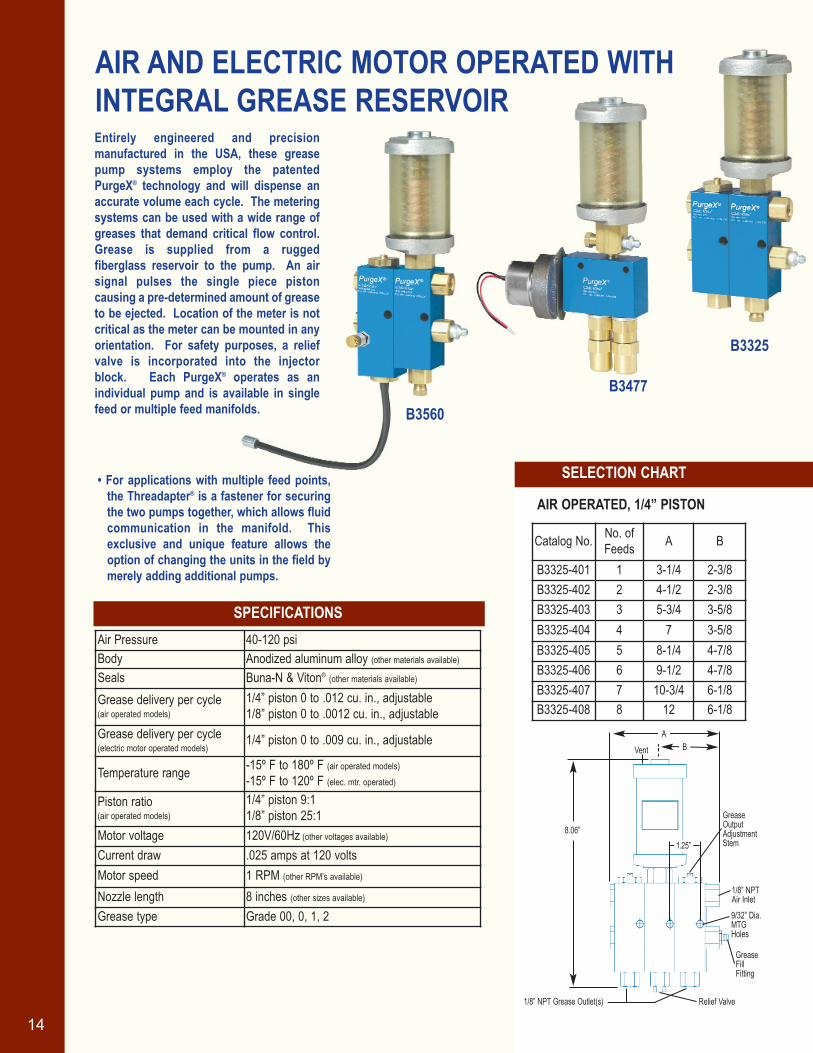
Entirely engineered and precisionmanufactured in the USA, these greasepump systems employ the patentedPurgeX® technology and will dispense anaccurate volume each cycle. The meteringsystems can be used with a wide range ofgreases that demand critical flow control.Grease is supplied from a rugged fiberglass reservoir to the pump. An air signal pulses the single piece piston causing a pre-determined amount of greaseto be ejected. Location of the meter is notcritical as the meter can be mounted in anyorientation. For safety purposes, a reliefvalve is incorporated into the injectorblock. Each PurgeX® operates as an individual pump and is available in singlefeed or multiple feed manifolds.
• For applications with multiple feed points,the Threadapter® is a fastener for securingthe two pumps together, which allows fluidcommunication in the manifold. Thisexclusive and unique feature allows theoption of changing the units in the field bymerely adding additional pumps.
B3560
AIR AND ELECTRIC MOTOR OPERATED WITH INTEGRAL GREASE RESERVOIR
oilrite.qxp 11/28/2006 10:22 AM Page 15
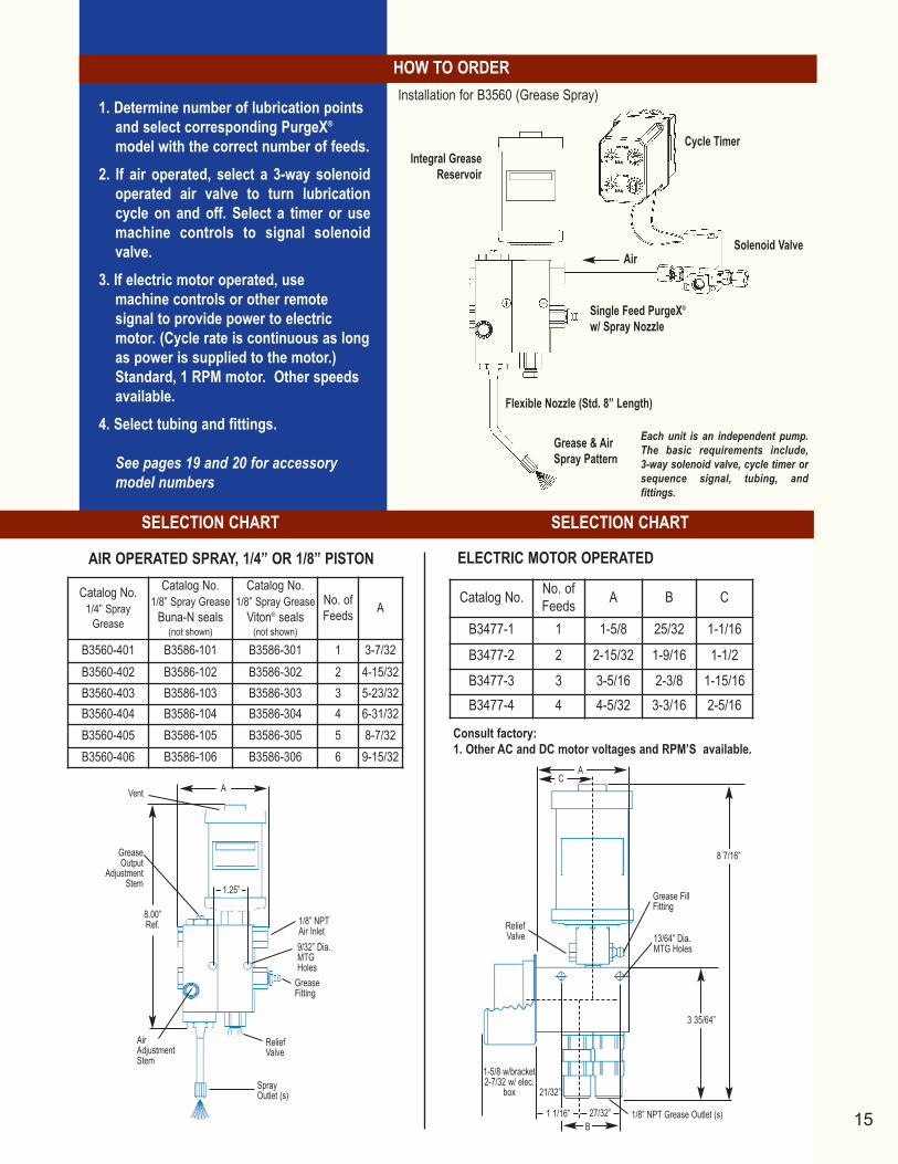
1. Determine number of lubrication pointsand select corresponding PurgeX®
model with the correct number of feeds.2. If air operated, select a 3-way solenoid
operated air valve to turn lubricationcycle on and off. Select a timer or usemachine controls to signal solenoidvalve.
3. If electric motor operated, use machine controls or other remote signal to provide power to electricmotor. (Cycle rate is continuous as longas power is supplied to the motor.)Standard, 1 RPM motor. Other speedsavailable.
4. Select tubing and fittings.
See pages 19 and 20 for accessorymodel numbers
SELECTION CHART SELECTION CHART
HOW TO ORDER
Consult factory:1. Other AC and DC motor voltages and RPM’S available.
AIR OPERATED SPRAY, 1/4” OR 1/8” PISTON ELECTRIC MOTOR OPERATED
15
Grease FillFitting
ReliefValve
AC
13/64” Dia.MTG Holes
8 7/16”
3 35/64”
1-5/8 w/bracket2-7/32 w/ elec.
box 21/32”
B1/8” NPT Grease Outlet (s)
Cycle Timer
Solenoid ValveAir
Single Feed PurgeX®
w/ Spray Nozzle
Integral GreaseReservoir
Flexible Nozzle (Std. 8” Length)
Grease & Air Spray Pattern
A
8.00”Ref.
1.25”
SprayOutlet (s)
ReliefValve
GreaseFitting
9/32” Dia.MTGHoles
1/8” NPTAir Inlet
AirAdjustmentStem
GreaseOutput
AdjustmentStem
Vent
Catalog No. No. ofFeeds A B C
B3477-1 1 1-5/8 25/32 1-1/16
B3477-2 2 2-15/32 1-9/16 1-1/2B3477-3 3 3-5/16 2-3/8 1-15/16B3477-4 4 4-5/32 3-3/16 2-5/16
Catalog No.1/4” Spray
Grease
Catalog No.1/8” Spray Grease
Buna-N seals(not shown)
Catalog No.1/8” Spray Grease
Viton® seals(not shown)
No. ofFeeds A
B3560-401 B3586-101 B3586-301 1 3-7/32B3560-402 B3586-102 B3586-302 2 4-15/32B3560-403 B3586-103 B3586-303 3 5-23/32B3560-404 B3586-104 B3586-304 4 6-31/32B3560-405 B3586-105 B3586-305 5 8-7/32B3560-406 B3586-106 B3586-306 6 9-15/32
27/32”1 1/16”
Installation for B3560 (Grease Spray)
Each unit is an independent pump.The basic requirements include, 3-way solenoid valve, cycle timer orsequence signal, tubing, and fittings.
oilrite.qxp 11/28/2006 10:22 AM Page 16
SPECIFICATIONS
16
21-1/2”Ref.
1/2 GallonPolycarbonateReservoir
NEMA 12(Gasketed)Enclosure
5/16” Dia. Mtg.Holes (4 Places)
13” W/Door Open
8”6”
10 3/4”
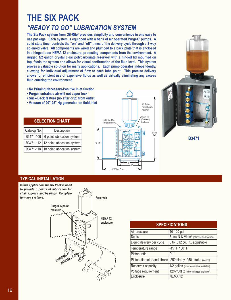
The Six Pack system from Oil-Rite® provides simplicity and convenience in one easy touse package. Each system is equipped with a bank of air operated PurgeX® pumps. Asolid state timer controls the “on” and “off” times of the delivery cycle through a 3-waysolenoid valve. All components are wired and plumbed to a back plate that is enclosedin a hinged door NEMA 12 enclosure, protecting components from the environment. Arugged 1/2 gallon crystal clear polycarbonate reservoir with a hinged lid mounted ontop, feeds the system and allows for visual confirmation of the fluid level. This systemproves a valuable solution for many applications. Each pump operates independently,allowing for individual adjustment of flow to each lube point. This precise deliveryallows for efficient use of expensive fluids as well as virtually eliminating any excessfluid entering the environment.
• No Priming Necessary-Positive Inlet Suction• Purges entrained air-will not vapor lock• Suck-Back feature (no after drip) from outlet• Vacuum of 20”-25” Hg generated on fluid inlet
THE SIX PACK “READY TO GO” LUBRICATION SYSTEM
SELECTION CHART
Catalog No. DescriptionB3471-106 6 point lubrication systemB3471-112 12 point lubrication systemB3471-118 18 point lubrication system
Air pressure 40-120 psiSeals Buna-N & Viton® (other seals available)
Liquid delivery per cycle 0 to .012 cu. in., adjustableTemperature range -15º F 180º FPiston ratio 9:1Piston diameter and stroke .250 dia by .250 stroke (inches)
Reservoir capacity 1/2 gallon (other capacities available)
Voltage requirement 120V/60Hz (other voltages available)
Enclosure NEMA 12
TYPICAL INSTALLATIONIn this application, the Six Pack is usedto provide 6 points of lubrication forchains, gears, and bearings. Completeturn-key systems. Reservoir
NEMA 12enclosure
PurgeX 6 pointmanifold
B3471
oilrite.qxp 11/28/2006 10:22 AM Page 17

17
QUICK PACK®
CENTRALIZED LUBRICATION SYSTEMSThe Quick Packs® are economically priced and easy to install. Supplied with an easy to fillreservoir, fully adjustable cycle timer and rugged mounting plate, these units are suitable wherever accuracy, simplicity and economy are required. The Quick Pack® unitsare available in both air and motor operated systems for liquid or grease in banks of 2 to36 connected pumps. Controlled by a repeat cycle timer, PurgeX® pumps immediatelydeliver the liquid or grease from a central reservoir to the point of application.Complete turn-key systems.
B3544 Air Operated - Liquid
B3545 Motor Operated - Liquid
B3546 Spring Operated Reservoir - Grease
SPECIFICATIONS:
13” Ref.
17”Ref.
Lubricant Type Grease DeliveryPower Source Air Operated
Delivery Method 1/8” NPTReservoir Cap. 1/2 GAL.
Number of Feeds6 B3538-106
12 B3538-11218 B3538-11824 B3538-12430 B3538-13036 B3538-136
10 7/8” Ref.
10 3/4”Ref.
1/8” Female NPTOutlets
B3547 Motor Operated - Grease
SELECTION CHARTS:
ADJUSTABLE AIR OPERATED RESERVOIR - GREASE
Air pressure (air operated) 40-120 psi Body Aluminum Alloy (other materials available)
Seals Buna-N & Viton® (other materials available)
Temperature range -15º F to 180º F (air operated)-15º F to 120º F (motor operated)
Piston ratio 9:1Motor voltage 120V/60Hz (other voltages available)
Motor speed 1 RPM (other speeds available)
Grease type Grade 00, 0, 1, 2Reservoir capacity 1 quart, 1 pint, Integral 1.5 oz., 1/2 gallon
Components Brass, Stainless Steel, Aluminum, Delrin, Plated Steel
17” Ref.
21” Ref.
Dotted Lines - Showing Reference Measurements
for 30 thru 36 Feed Mounting Plate
LubricantType
PowerSource
AirOperated
MotorOperated
Air Operated
MotorOperated
ReservoirCap.
Quart orPint
Quart or Pint
1.5 oz.Integral
1.5 oz.Integral
2 B3544-102 B3545-102 B3546-102 B3547-102
4 B3544-104 B3545-104 B3546-104 B3547-104
B3538 Adj. Air Operated Reservoir - Grease
Liquid Delivery Grease Delivery
Number of Feeds
oilrite.qxp 11/28/2006 10:23 AM Page 18
18
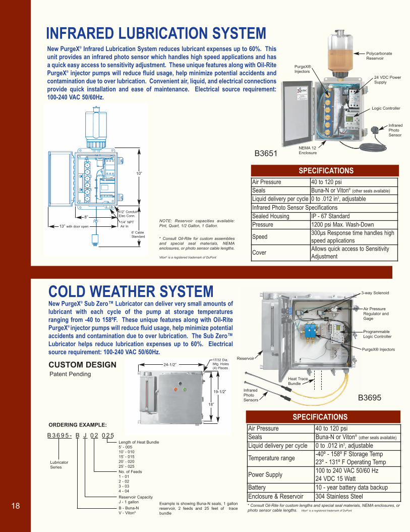
INFRARED LUBRICATION SYSTEM
COLD WEATHER SYSTEM
SPECIFICATIONS
SPECIFICATIONS Air Pressure 40 to 120 psiSeals Buna-N or Viton® (other seals available)
Liquid delivery per cycle 0 to .012 in3, adjustable
Temperature range -40º - 158º F Storage Temp23º - 131º F Operating Temp
Power Supply 100 to 240 VAC 50/60 Hz 24 VDC 15 Watt
Battery 10 - year battery data backupEnclosure & Reservoir 304 Stainless Steel
New PurgeX® Infrared Lubrication System reduces lubricant expenses up to 60%. Thisunit provides an infrared photo sensor which handles high speed applications and hasa quick easy access to sensitivity adjustment. These unique features along with Oil-RitePurgeX® injector pumps will reduce fluid usage, help minimize potential accidents andcontamination due to over lubrication. Convenient air, liquid, and electrical connectionsprovide quick installation and ease of maintenance. Electrical source requirement: 100-240 VAC 50/60Hz.
New PurgeX® Sub Zero™ Lubricator can deliver very small amounts oflubricant with each cycle of the pump at storage temperatures ranging from -40 to 158ºF. These unique features along with Oil-RitePurgeX® injector pumps will reduce fluid usage, help minimize potentialaccidents and contamination due to over lubrication. The Sub Zero™Lubricator helps reduce lubrication expenses up to 60%. Electricalsource requirement: 100-240 VAC 50/60Hz.
Air Pressure 40 to 120 psiSeals Buna-N or Viton® (other seals available)
Liquid delivery per cycle 0 to .012 in3, adjustableInfrared Photo Sensor SpecificationsSealed Housing IP - 67 StandardPressure 1200 psi Max. Wash-Down
Speed 300μs Response time handles highspeed applications
Cover Allows quick access to SensitivityAdjustment
10”
6’ Cable
Standard
13” with door open
8”
1/4” NPT
Air In
1/2” Conduit
Elec Conn.
B3651
19-1/2”
18”
24-1/2”
17/32 Dia.
Mtg. Holes
(4) Places
NOTE: Reservoir capacities available:Pint, Quart, 1/2 Gallon, 1 Gallon.
* Consult Oil-Rite for custom assembliesand special seal materials, NEMAenclosures, or photo sensor cable lengths.
Viton® is a registered trademark of DuPont
Programmable
Logic Controller
Air Pressure
Regulator and
Gage
PurgeX® Injectors
Reservoir
Infrared
Photo
Sensors
3-way Solenoid
Heat Trace
Bundle
ORDERING EXAMPLE:
B 3 6 9 5 - B J 0 2 0 2 5
No. of Feeds
1 - 01
2 - 02
3 - 03
4 - 04
B - Buna-N
V - Viton®
Lubricator
Series
Example is showing Buna-N seals, 1 gallon
reservoir, 2 feeds and 25 feet of trace
bundle
* Consult Oil-Rite for custom lengths and special seal materials, NEMA enclosures, orphoto sensor cable lengths. Viton® is a registered trademark of DuPont
Length of Heat Bundle
5’ - 005
10’ - 010
15’ - 015
20’ - 020
25’ - 025
Polycarbonate
Reservoir
Logic Controller
PurgeX®
Injectors
Infrared
Photo
Sensor
24 VDC Power
Supply
NEMA 12
Enclosure
CUSTOM DESIGN
Reservoir Capacity
J - 1 gallon
B3695
Patent Pending
oilrite.qxp 11/28/2006 10:23 AM Page 19
ACCESSORIES
SELECTION CHART
SELECTION CHART
SELECTION CHART
SELECTION CHART
BC
A
A
5-3/4
B
A
C
B
4-7/16
Catalog No. Cap. A B
B2886-1 1 Qt. 6-27/32 5-27/32B2886-2 1/2 Gal. 10-11/32 9-11/32B2886-3 1 Gal. 15-11/32 14-11/32B2886-4 2 Gal. 28-11/32 27-11/32
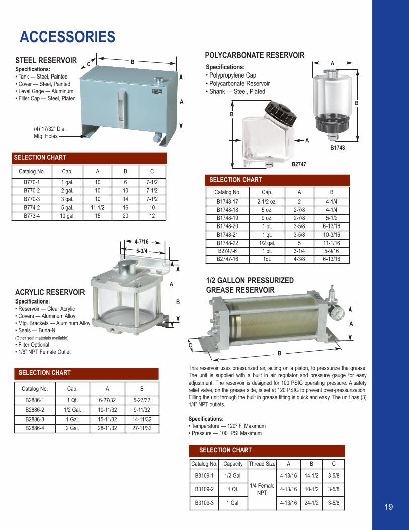
ACRYLIC RESERVOIRSpecifications:• Reservoir — Clear Acrylic• Covers — Aluminum Alloy• Mtg. Brackets — Aluminum Alloy• Seals — Buna-N (Other seal materials available)• Filter Optional• 1/8” NPT Female Outlet
STEEL RESERVOIRSpecifications:• Tank — Steel, Painted• Cover — Steel, Painted• Level Gage — Aluminum• Filler Cap — Steel, Plated
Catalog No. Cap. A B C
B770-1 1 gal. 10 6 7-1/2B770-2 2 gal. 10 10 7-1/2B770-3 3 gal. 10 14 7-1/2B774-2 5 gal. 11-1/2 16 10B773-4 10 gal. 15 20 12
POLYCARBONATE RESERVOIR
This reservoir uses pressurized air, acting on a piston, to pressurize the grease.The unit is supplied with a built in air regulator and pressure gauge for easy adjustment. The reservoir is designed for 100 PSIG operating pressure. A safetyrelief valve, on the grease side, is set at 120 PSIG to prevent over-pressurization.Filling the unit through the built in grease fitting is quick and easy. The unit has (3)1/4” NPT outlets.
Specifications:• Temperature — 120º F. Maximum• Pressure — 100 PSI Maximum
1/2 GALLON PRESSURIZED GREASE RESERVOIR
(4) 17/32” Dia.Mtg. Holes
Specifications:• Polypropylene Cap• Polycarbonate Reservoir• Shank — Steel, Plated
Catalog No. Cap. A B B1748-17 2-1/2 oz. 2 4-1/4B1748-18 5 oz. 2-7/8 4-1/4B1748-19 9 oz. 2-7/8 5-1/2B1748-20 1 pt. 3-5/8 6-13/16B1748-21 1 qt. 3-5/8 10-3/16B1748-22 1/2 gal. 5 11-1/16B2747-6 1 pt. 3-1/4 5-9/16
B2747-16 1qt. 4-3/8 6-13/16
A
B
B
AB1748
B2747
19
Catalog No. Capacity Thread Size A B C
B3109-1 1/2 Gal.1/4 Female
NPT
4-13/16 14-1/2 3-5/8
B3109-2 1 Qt. 4-13/16 10-1/2 3-5/8
B3109-3 1 Gal. 4-13/16 24-1/2 3-5/8
oilrite.qxp 11/28/2006 10:23 AM Page 20
A2256-5
TUBING AND FITTINGS
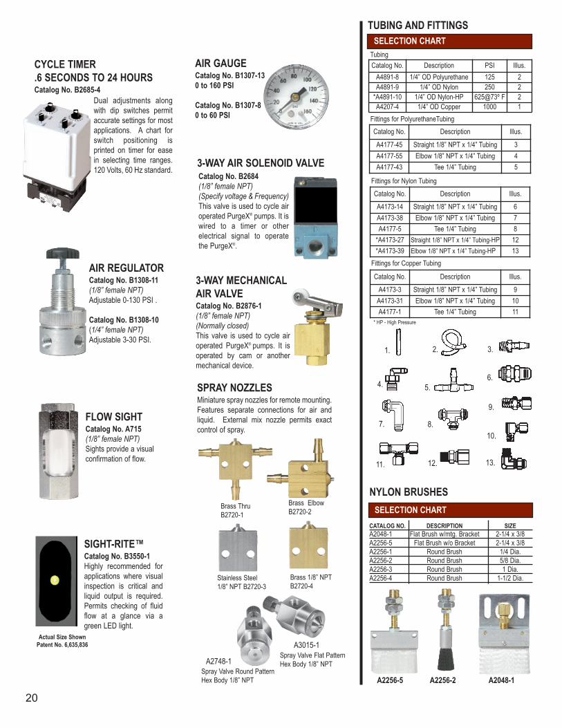
CATALOG NO. DESCRIPTION SIZEA2048-1 Flat Brush w/mtg. Bracket 2-1/4 x 3/8A2256-5 Flat Brush w/o Bracket 2-1/4 x 3/8A2256-1 Round Brush 1/4 Dia.A2256-2 Round Brush 5/8 Dia.A2256-3 Round Brush 1 Dia.A2256-4 Round Brush 1-1/2 Dia.
NYLON BRUSHESSELECTION CHART
1. 2. 3.
4. 5.6.
7. 8.10.
A2256-2
Brass ElbowB2720-2
Brass ThruB2720-1
A2048-1
11.
9.
Actual Size ShownPatent No. 6,635,836
CYCLE TIMER .6 SECONDS TO 24 HOURSCatalog No. B2685-4
AIR REGULATORCatalog No. B1308-11(1/8” female NPT)Adjustable 0-130 PSI .
Catalog No. B1308-10(1/4” female NPT)Adjustable 3-30 PSI.
FLOW SIGHTCatalog No. A715(1/8” female NPT)Sights provide a visual confirmation of flow.
SIGHT-RITE™Catalog No. B3550-1Highly recommended for applications where visualinspection is critical andliquid output is required.Permits checking of fluidflow at a glance via agreen LED light.
SPRAY NOZZLESMiniature spray nozzles for remote mounting.Features separate connections for air andliquid. External mix nozzle permits exactcontrol of spray.
3-WAY MECHANICALAIR VALVECatalog No. B2876-1(1/8” female NPT)(Normally closed)This valve is used to cycle airoperated PurgeX® pumps. It is operated by cam or anothermechanical device.
Catalog No. B2684(1/8” female NPT)(Specify voltage & Frequency)This valve is used to cycle air operated PurgeX® pumps. It iswired to a timer or other electrical signal to operate the PurgeX®.
AIR GAUGE Catalog No. B1307-130 to 160 PSI
Catalog No. B1307-80 to 60 PSI
Dual adjustments alongwith dip switches permitaccurate settings for mostapplications. A chart forswitch positioning is printed on timer for easein selecting time ranges.120 Volts, 60 Hz standard.
3-WAY AIR SOLENOID VALVE
Stainless Steel1/8” NPT B2720-3
Brass 1/8” NPTB2720-4
A3015-1Spray Valve Flat PatternHex Body 1/8” NPT
Catalog No. Description PSI Illus.A4891-8 1/4” OD Polyurethane 125 2A4891-9 1/4” OD Nylon 250 2
*A4891-10 1/4” OD Nylon-HP 625@73º F 2A4207-4 1/4” OD Copper 1000 1
Catalog No. Description Illus.
A4177-45 Straight 1/8” NPT x 1/4” Tubing 3A4177-55 Elbow 1/8” NPT x 1/4” Tubing 4A4177-43 Tee 1/4” Tubing 5
Catalog No. Description Illus.
A4173-3 Straight 1/8” NPT x 1/4” Tubing 9A4173-31 Elbow 1/8” NPT x 1/4” Tubing 10A4177-1 Tee 1/4” Tubing 11
Straight 1/8” NPT x 1/4” Tubing-HP
Catalog No. Description Illus.
A4173-14 Straight 1/8” NPT x 1/4” Tubing 6A4173-38 Elbow 1/8” NPT x 1/4” Tubing 7A4177-5 Tee 1/4” Tubing 8
*A4173-27 12*A4173-39 Elbow 1/8” NPT x 1/4” Tubing-HP 13
SELECTION CHART
12. 13.
* HP - High Pressure
Fittings for Copper Tubing
Fittings for Nylon Tubing
Fittings for PolyurethaneTubing
Tubing
Spray Valve Round PatternHex Body 1/8” NPT
A2748-1
20
oilrite.qxp 11/28/2006 10:20 AM Page 1

21P. O. BOX 1207, MANITOWOC, WI 54221-1207 (920) 682-6173 FAX (920) 682-7699
www.oilrite.com [email protected]
Sectio
n 1
000 In
dex
Dispense liquid, by gravity, from a reservoir, through an electro or manualshutoff valve. Acrylic, pyrex or polycarbonate reservoirs available.Additional sight feed valves are neededfor the regulation of liquid flow.
Dispense liquid, by gravity, from a reservoir, which are furnished withoutshutoffs or control valves.
Horizontal dispensers dispense liquid bygravity, from a reservoir, with flow controlled by means of a shutoff valve.Steel tanks dispense oil by gravity froma reservoir without flow valves or shutoff.
Dispense liquid, by air pressure, from areservoir to elevated, distant and inaccessible points.
Will maintain a fixed liquid level in abearing housing or gear box vital in preventing possible machine breakdowndue to insufficient lubrication.
Deliver a pre-adjusted rate of liquid, bygravity from a reservoir, through a normally closed solenoid or toggle shutoff valve to an adjustable needlevalve, which has a friction lock to retainits setting.
Liquid is released, by gravity, from areservoir, through a normally closedsolenoid or toggle shutoff valve to thenew modular stacked multiple sight feedvalves.
Section 1000 Index
CONSTANT LEVEL LUBRICATORS......22-23
SINGLE FEED LUBRICATORS...............24-25
MULTIPLE FEED LUBRICATORS..........26-27
FULL FLOW DISPENSER.......................28-29
RESERVOIRS.......................................30-31
HORIZONTAL DISPENSERS & STEEL
TANKS.......................................................32
CONSTANT LEVEL LUBRICATORS
INSTALLATION INSTRUCTIONS.............36
SPARE PARTS....................................34-35
AIR OPERATED DISPENSERS................33
Co
nsta
nt
Level
Lu
bric
ato
rs
22
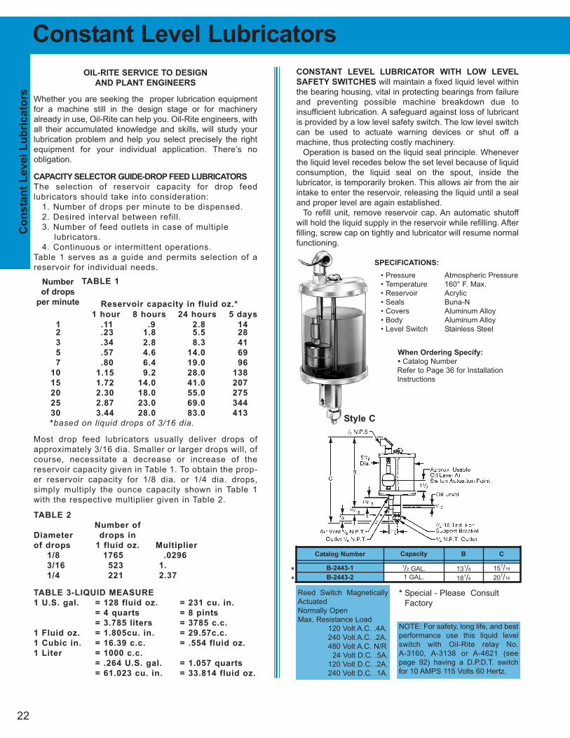
CONSTANT LEVEL LUBRICATOR WITH LOW LEVEL
SAFETY SWITCHES will maintain a fixed liquid level within
the bearing housing, vital in protecting bearings from failure
and preventing possible machine breakdown due to
insufficient lubrication. A safeguard against loss of lubricant
is provided by a low level safety switch. The low level switch
can be used to actuate warning devices or shut off a
machine, thus protecting costly machinery.
Operation is based on the liquid seal principle. Whenever
the liquid level recedes below the set level because of liquid
consumption, the liquid seal on the spout, inside the
lubricator, is temporarily broken. This allows air from the air
intake to enter the reservoir, releasing the liquid until a seal
and proper level are again established.
To refill unit, remove reservoir cap. An automatic shutoff
will hold the liquid supply in the reservoir while refilling. After
filling, screw cap on tightly and lubricator will resume normal
functioning.
SPECIFICATIONS:
• Pressure Atmospheric Pressure
• Temperature 160° F. Max.
• Reservoir Acrylic
• Seals Buna-N
• Covers Aluminum Alloy
• Body Aluminum Alloy
• Level Switch Stainless Steel
Constant Level Lubricators
OIL-RITE SERVICE TO DESIGN
AND PLANT ENGINEERS
Whether you are seeking the proper lubrication equipment
for a machine still in the design stage or for machinery
already in use, Oil-Rite can help you. Oil-Rite engineers, with
all their accumulated knowledge and skills, will study your
lubrication problem and help you select precisely the right
equipment for your individual application. There’s no
obligation.
CAPACITY SELECTOR GUIDE-DROP FEED LUBRICATORS
The selection of reservoir capacity for drop feed
lubricators should take into consideration:
1. Number of drops per minute to be dispensed.
2. Desired interval between refill.
3. Number of feed outlets in case of multiple
lubricators.
4. Continuous or intermittent operations.
Table 1 serves as a guide and permits selection of a
reservoir for individual needs.
TABLE 1
Reservoir capacity in fluid oz.*
1 hour 8 hours 24 hours 5 days
1 .11 .9 2.8 14
2 .23 1.8 5.5 28
3 .34 2.8 8.3 41
5 .57 4.6 14.0 69
7 .80 6.4 19.0 96
10 1.15 9.2 28.0 138
15 1.72 14.0 41.0 207
20 2.30 18.0 55.0 275
25 2.87 23.0 69.0 344
30 3.44 28.0 83.0 413
*based on liquid drops of 3/16 dia.
Most drop feed lubricators usually deliver drops of
approximately 3/16 dia. Smaller or larger drops will, of
course, necessitate a decrease or increase of the
reservoir capacity given in Table 1. To obtain the prop-
er reservoir capacity for 1/8 dia. or 1/4 dia. drops,
simply multiply the ounce capacity shown in Table 1
with the respective multiplier given in Table 2.
TABLE 2
Number of
Diameter drops in
of drops 1 fluid oz. Multiplier
1/8 1765 .0296
3/16 523 1.
1/4 221 2.37
TABLE 3-LIQUID MEASURE
1 U.S. gal. = 128 fluid oz. = 231 cu. in.
= 4 quarts = 8 pints
= 3.785 liters = 3785 c.c.
1 Fluid oz. = 1.805cu. in. = 29.57c.c.
1 Cubic in. = 16.39 c.c. = .554 fluid oz.
1 Liter = 1000 c.c.
= .264 U.S. gal. = 1.057 quarts
= 61.023 cu. in. = 33.814 fluid oz.
Number
of drops
per minute
Reed Switch Magnetically
Actuated
Normally Open
Max. Resistance Load
120 Volt A.C. .4A.
240 Volt A.C. .2A.
480 Volt A.C. N/R
24 Volt D.C. .5A.
120 Volt D.C. .2A.
240 Volt D.C. .1A.
NOTE: For safety, long life, and best
performance use this liquid level
switch with Oil-Rite relay No.
A-3160, A-3138 or A-4621 (see
page 92) having a D.P.D.T. switch
for 10 AMPS 115 Volts 60 Hertz.
When Ordering Specify:
• Catalog Number
Refer to Page 36 for Installation
Instructions
Catalog Number
B-2443-1
B-2443-2
Capacity
1/2 GAL.
1 GAL.
B
131/8
181/8
C
157/16
207/16
Style C
*
*
* Special - Please Consult
Factory

23
Co
nsta
nt L
evel L
ub
ric
ato
rs
Catalog Number
Acrylic Pyrex
B-576-1 B-576-11
B-576-2 B-576-12
B-576-3 B-576-13
B-576-4 B-576-14
B-576-5 B-576-15
B-576-6 B-576-16
B-576-7 —
B-737-1 B-737-11
B-737-2 B-737-12
B-737-3 B-737-13
B-737-4 B-737-14
B-737-5 B-737-15
B-737-6 B-737-16
B-737-7 —
Capacity A B C
21/2 OZ. 2 51/4 71/16
5 OZ. 21/2 53/4 79/16
9 OZ. 3 69/16 83/8
1 PT. 31/2 79/16 93/8
1 QT. 41/4 813/16 105/8
1/2 GAL. 51/2 1013/16 125/8
1 GAL. 51/2 1513/16 175/8
21/2 OZ. 2 51/4 83/8
5 OZ. 21/2 53/4 87/8
9 OZ. 3 69/16 911/16
1 PT. 31/2 79/16 1011/16
1 QT. 41/4 813/16 1115/16
1/2 GAL. 51/2 1013/16 1315/16
1 GAL. 51/2 1513/16 1815/16
Fig.
1
2
Catalog Number
Acrylic Pyrex
B-518-1 B-518-11
B-518-2 B-518-12
B-518-3 B-518-13
B-518-4 B-518-14
B-518-5 B-518-15
B-518-6 B-518-16
B-518-7 —
B-543-1 B-543-11
B-543-2 B-543-12
B-543-3 B-543-13
B-543-4 B-543-14
B-543-5 B-543-15
B-543-6 B-543-16
B-543-7 —
Capacity A B C
21/2 OZ. 2 53/16 63/8
5 OZ. 21/2 511/16 67/8
9 OZ. 3 61/2 711/16
1 PT. 31/2 71/2 811/16
1 QT. 41/4 83/4 111/16
1/2 GAL. 51/2 103/4 131/16
1 GAL. 51/2 153/4 181/16
21/2 OZ. 2 53/16 75/8
5 OZ. 21/2 511/16 81/8
9 OZ. 3 61/2 815/16
1 PT. 31/2 71/2 915/16
1 QT. 41/4 83/4 113/16
1/2 GAL. 51/2 103/4 133/16
1 GAL. 51/2 153/4 183/16
Fig.
1
2
3
Constant Level Lubricators
CONSTANT LEVEL LUBRICATORS are built to give long, trouble free service. The finest materials and workmanship areincorporated throughout. They will maintain a fixed liquid levelin a bearing housing or gear box.
When the liquid in the bearing recedes because of liquidconsumption, the liquid seal on the inside of the lubricator istemporarily broken. This allows air from the air intake to enterthe lubricator reservoir, releasing the liquid until a seal andproper level are again established.
The Style CS Constant Level Lubricator is identical indesign to Style C with two exceptions. A large sight for viewing the liquid level and condition of the liquid is provided,plus there are larger liquid outlets for rugged, heavy duty installations.
For reference, a liquid level line is scribed on the base.Units are easily refilled through a top filler cap.The reservoirneed not be removed for refilling. A shutoff valve holds the
liquid in the reservoir when the filler cap is removed. After thecap is screwed down again, the lubricator resumes normalfunctioning.
An air vent is supplied which can be piped back to the bearing or gear box thereby equalizing any existing pressureor vacuum. The reservoir is crystal clear glass or shatterproofacrylic permitting the liquid supply to be visible at all times.
SPECIFICATIONS:
• Pressure Atmospheric Pressure• Temperature 160° F. Maximum Acrylic
225° F. Maximum Pyrex• Reservoir Acrylic or Pyrex• Seals Buna-N• Sight Glass• Covers Aluminum Alloy
• Body Aluminum Alloy
Style CStyle CS
* Special - Please Consult Factory
*
*
*
*
**
**
When Ordering Specify:
• Catalog Number
Refer to Page 36 for Installation Instructions
24
Sin
gle
Feed
Ele
ctr
o L
ub
ric
ato
rs
Model Number
Acrylic Pyrex
B-1875-1 B-1875-21
B-1875-2 B-1875-22
B-1875-3 B-1875-23
B-1875-4 B-1875-24
B-1875-5 B-1875-25
B-1875-6 B-1875-26
B-1875-7 B-1875-27
B-1875-8 B-1875-28
B-1875-9 B-1875-29
B-1875-10 B-1875-30
B-1875-11 B-1875-31
B-1875-12 B-1875-32
B-1875-13 B-1875-33
B-1765-1 B-1765-5
B-1765-2 —
B-1875-16 B-1875-36
B-1875-17 B-1875-37
B-1875-18 B-1875-38
B-1875-19 B-1875-39
B-1875-20 B-1875-40
B-1765-3 B-1765-7
B-1765-4 —
Model Number
Polycarbonate
B-1763-1
B-1763-2
B-1763-3
B-1763-4
B-1763-5
B-1763-6
B-1763-7
B-1763-8
B-1763-9
B-1763-10
B-1763-11
B-1764-1
B-1764-2
B-1764-3
B-1764-4
B-1764-7
B-1763-12
B-1763-13
B-1763-14
B-1763-15
B-1764-5
B-1764-6
B-1764-8
5/8-18 NF THD.FOR REMOTE
MOUNTINGWITH 1/8
FEMALE NPTOUTLET
1 OZ
21/2 OZ.
5 OZ.
9 OZ.
1 PT.
1 QT.1/2 GAL.
1 OZ
21/2 OZ.
5 OZ.
9 OZ.
1 PT.
1 QT.1/2 GAL.
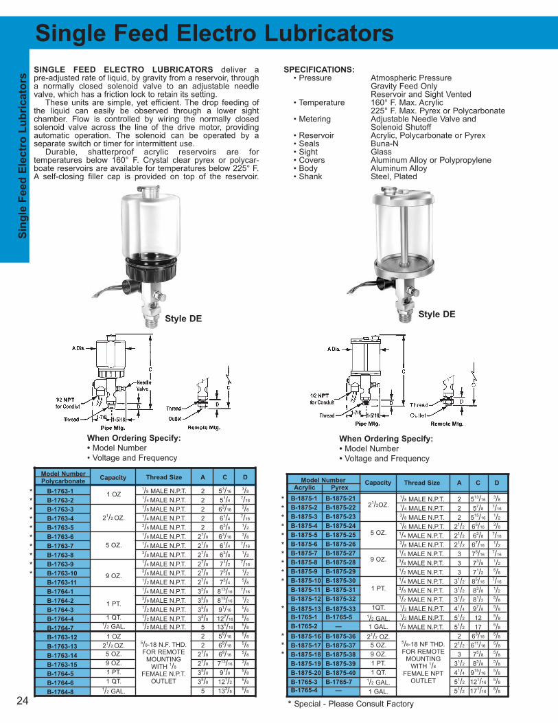
Thread Size A C D
1/8 MALE N.P.T. 2 53/163/8
1/4 MALE N.P.T. 2 51/47/16
1/8 MALE N.P.T. 2 63/163/8
1/4 MALE N.P.T. 2 61/47/16
3/8 MALE N.P.T. 2 63/81/2
1/8 MALE N.P.T. 27/8 63/163/8
1/4 MALE N.P.T. 27/8 61/47/16
3/8 MALE N.P.T. 27/8 63/81/2
1/4 MALE N.P.T. 27/8 71/27/16
3/8 MALE N.P.T. 27/8 75/81/2
1/2 MALE N.P.T. 27/8 73/45/8
1/4 MALE N.P.T. 35/8 813/167/16
3/8 MALE N.P.T. 35/8 815/161/2
1/2 MALE N.P.T. 35/8 91/165/8
1/2 MALE N.P.T. 35/8 127/165/8
1/2 MALE N.P.T. 5 135/165/8
2 59/165/8
2 69/165/8
27/8 69/165/8
27/8 713/163/8
35/8 91/85/8
35/8 121/25/8
5 133/85/8
Single Feed Electro Lubricators
When Ordering Specify:
• Model Number
• Voltage and Frequency
When Ordering Specify:
• Model Number
• Voltage and Frequency
5/8-18 N.F. THD.FOR REMOTE
MOUNTINGWITH 1/8
FEMALE N.P.T.OUTLET
SINGLE FEED ELECTRO LUBRICATORS deliver a pre-adjusted rate of liquid, by gravity from a reservoir, througha normally closed solenoid valve to an adjustable needlevalve, which has a friction lock to retain its setting.
These units are simple, yet efficient. The drop feeding ofthe liquid can easily be observed through a lower sight chamber. Flow is controlled by wiring the normally closed solenoid valve across the line of the drive motor, providingautomatic operation. The solenoid can be operated by a separate switch or timer for intermittent use.
Durable, shatterproof acrylic reservoirs are for temperatures below 160° F. Crystal clear pyrex or polycar-boate reservoirs are available for temperatures below 225° F.A self-closing filler cap is provided on top of the reservoir.
SPECIFICATIONS:
• Pressure Atmospheric PressureGravity Feed OnlyReservoir and Sight Vented
• Temperature 160° F. Max. Acrylic225° F. Max. Pyrex or Polycarbonate
• Metering Adjustable Needle Valve andSolenoid Shutoff
• Reservoir Acrylic, Polycarbonate or Pyrex• Seals Buna-N• Sight Glass• Covers Aluminum Alloy or Polypropylene• Body Aluminum Alloy• Shank Steel, Plated
Style DEStyle DE
**********
**********
*
***
* Special - Please Consult Factory
Thread Size A C D
1/8 MALE N.P.T. 2 513/163/8
1/4 MALE N.P.T. 2 57/87/16
3/8 MALE N.P.T. 2 515/161/2
1/8 MALE N.P.T. 21/2 65/163/8
1/4 MALE N.P.T. 21/2 63/87/16
3/8 MALE N.P.T. 21/2 67/161/2
1/4 MALE N.P.T. 3 75/167/16
3/8 MALE N.P.T. 3 73/81/2
1/2 MALE N.P.T. 3 71/25/8
1/4 MALE N.P.T. 31/2 85/167/16
3/8 MALE N.P.T. 31/2 83/81/2
1/2 MALE N.P.T. 31/2 81/25/8
1/2 MALE N.P.T. 41/4 97/85/8
1/2 MALE N.P.T. 51/2 12 5/8
1/2 MALE N.P.T. 51/2 17 5/8
2 63/165/8
21/2 611/165/8
3 75/85/8
31/2 85/85/8
41/4 915/165/8
51/2 121/165/8
51/2 171/165/8
21/2OZ.
5 OZ.
9 OZ.
1 PT.
1QT.
1/2 GAL.
1 GAL.
21/2 OZ.
5 OZ.
9 OZ.
1 PT.
1 QT.1/2 GAL.
1 GAL.
CapacityCapacity
25
2 51/165/8
2 61/165/8
27/8 6 5/8
27/8 71/45/8
35/8 85/85/8
35/8 12 5/8
5 127/85/8
5/8-18 N.F. THD.FOR REMOTE
MOUNTINGWITH 1/8
FEMALE N.P.T.OUTLET
Thread Size A C D
1/8 MALE N.P.T. 2 51/43/8
1/4 MALE N.P.T. 2 55/167/16
3/8 MALE N.P.T. 2 53/81/2
1/8 MALE N.P.T. 21/2 53/43/8
1/4 MALE N.P.T. 21/2 513/167/16
3/8 MALE N.P.T. 21/2 57/81/2
1/4 MALE N.P.T. 3 63/47/16
3/8 MALE N.P.T. 3 613/161/2
1/2 MALE N.P.T. 3 615/165/8
1/4 MALE N.P.T. 31/2 73/47/16
3/8 MALE N.P.T. 31/2 713/161/2
1/2 MALE N.P.T. 31/2 715/165/8
1/2 MALE N.P.T. 41/4 95/165/8
1/2 MALE N.P.T. 51/2 117/165/8
1/2 MALE N.P.T. 51/2 167/165/8
2 55/85/8
21/2 61/85/8
3 71/165/8
31/2 81/165/8
41/4 93/85/8
51/2 111/25/8
51/2 161/25/8
Catalog No.
Polycarbonate
B-1681-1
B-1681-2
B-1681-3
B-1681-4
B-1681-5
B-1681-6
B-1681-7
B-1681-8
B-1681-9
B-1681-10
B-1681-11
B-1682-1
B-1682-2
B-1682-3
B-1682-4
B-1682-7
B-1681-12
B-1681-13
B-1681-14
B-1681-15
B-1682-5
B-1682-6
B-1682-8
Capacity
1 OZ.
21/2 OZ.
5 OZ.
9 OZ.
1 PT.
1 QT.1/2 GAL.
1 OZ.
21/2 OZ.
5 OZ.
9 OZ.
1 PT.
1 QT.1/2 GAL.
Sin
gle
Feed
Man
ual L
ub
ric
ato
rs
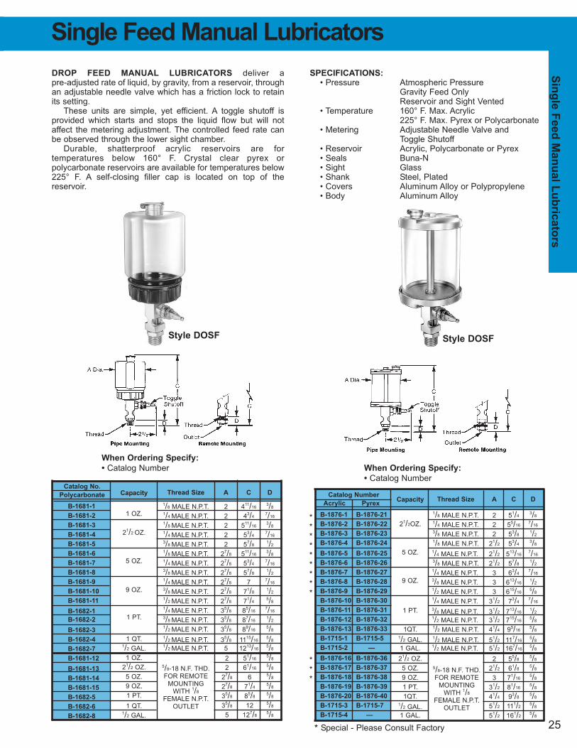
DROP FEED MANUAL LUBRICATORS deliver a pre-adjusted rate of liquid, by gravity, from a reservoir, throughan adjustable needle valve which has a friction lock to retainits setting.
These units are simple, yet efficient. A toggle shutoff is provided which starts and stops the liquid flow but will notaffect the metering adjustment. The controlled feed rate canbe observed through the lower sight chamber.
Durable, shatterproof acrylic reservoirs are for temperatures below 160° F. Crystal clear pyrex or polycarbonate reservoirs are available for temperatures below225° F. A self-closing filler cap is located on top of the reservoir.
SPECIFICATIONS:
• Pressure Atmospheric PressureGravity Feed OnlyReservoir and Sight Vented
• Temperature 160° F. Max. Acrylic225° F. Max. Pyrex or Polycarbonate
• Metering Adjustable Needle Valve andToggle Shutoff
• Reservoir Acrylic, Polycarbonate or Pyrex• Seals Buna-N• Sight Glass• Shank Steel, Plated• Covers Aluminum Alloy or Polypropylene• Body Aluminum Alloy
When Ordering Specify:
• Catalog Number
Catalog Number
Acrylic Pyrex
B-1876-1 B-1876-21
B-1876-2 B-1876-22
B-1876-3 B-1876-23
B-1876-4 B-1876-24
B-1876-5 B-1876-25
B-1876-6 B-1876-26
B-1876-7 B-1876-27
B-1876-8 B-1876-28
B-1876-9 B-1876-29
B-1876-10 B-1876-30
B-1876-11 B-1876-31
B-1876-12 B-1876-32
B-1876-13 B-1876-33
B-1715-1 B-1715-5
B-1715-2 —
B-1876-16 B-1876-36
B-1876-17 B-1876-37
B-1876-18 B-1876-38
B-1876-19 B-1876-39
B-1876-20 B-1876-40
B-1715-3 B-1715-7
B-1715-4 —
Capacity
21/2OZ.
5 OZ.
9 OZ.
1 PT.
1QT.1/2 GAL.
1 GAL.
21/2 OZ.
5 OZ.
9 OZ.
1 PT.
1QT.1/2 GAL.
1 GAL.
When Ordering Specify:
• Catalog Number
5/8-18 N.F. THD.FOR REMOTE
MOUNTINGWITH 1/8
FEMALE N.P.T.OUTLET
Thread Size A C D
1/8 MALE N.P.T. 2 411/163/8
1/4 MALE N.P.T. 2 43/47/16
1/8 MALE N.P.T. 2 511/163/8
1/4 MALE N.P.T. 2 53/47/16
3/8 MALE N.P.T. 2 57/81/2
1/8 MALE N.P.T. 27/8 511/163/8
1/4 MALE N.P.T. 27/8 53/47/16
3/8 MALE N.P.T. 27/8 57/81/2
1/4 MALE N.P.T. 27/8 7 7/16
3/8 MALE N.P.T. 27/8 71/81/2
1/2 MALE N.P.T. 27/8 71/45/8
1/4 MALE N.P.T. 35/8 85/167/16
3/8 MALE N.P.T. 35/8 87/161/2
1/2 MALE N.P.T. 35/8 89/165/8
1/2 MALE N.P.T. 35/8 1115/165/8
1/2 MALE N.P.T. 5 1213/165/8
Single Feed Manual Lubricators
Style DOSF Style DOSF
*********
***
* Special - Please Consult Factory
26
Model Number
Acrylic Pyrex
B-3152-1 B-3152-11
B-3152-2 B-3152-12
B-3152-3 B-3152-13
B-3152-4 B-3152-14
B-3152-5 B-3152-15
B-3152-6 —
Mu
ltip
le F
eed
Ele
ctr
o L
ub
ric
ato
rs
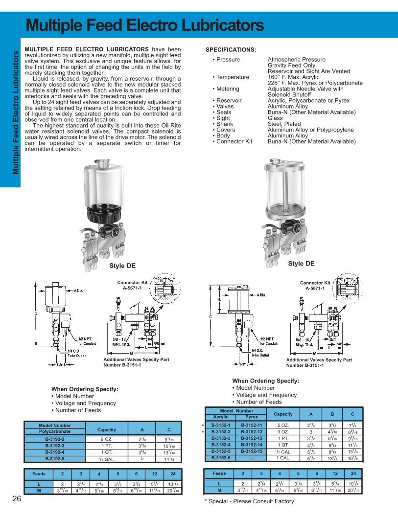
Multiple Feed Electro Lubricators
SPECIFICATIONS:
• Pressure Atmospheric PressureGravity Feed OnlyReservoir and Sight Are Vented
• Temperature 160° F. Max. Acrylic225° F. Max. Pyrex or Polycarbonate
• Metering Adjustable Needle Valve withSolenoid Shutoff
• Reservoir Acrylic, Polycarbonate or Pyrex• Valves Aluminum Alloy• Seals Buna-N (Other Material Available)• Sight Glass• Shank Steel, Plated• Covers Aluminum Alloy or Polypropylene• Body Aluminum Alloy• Connector Kit Buna-N (Other Material Available)
MULTIPLE FEED ELECTRO LUBRICATORS have beenrevolutionized by utilizing a new manifold, multiple sight feedvalve system. This exclusive and unique feature allows, forthe first time, the option of changing the units in the field bymerely stacking them together.
Liquid is released, by gravity, from a reservoir, through anormally closed solenoid valve to the new modular stackedmultiple sight feed valves. Each valve is a complete unit thatinterlocks and seals with the preceding valve.
Up to 24 sight feed valves can be separately adjusted andthe setting retained by means of a friction lock. Drop feedingof liquid to widely separated points can be controlled andobserved from one central location.
The highest standard of quality is built into these Oil-Ritewater resistant solenoid valves. The compact solenoid isusually wired across the line of the drive motor. The solenoidcan be operated by a separate switch or timer for intermittent operation.
When Ordering Specify:
• Model Number
• Voltage and Frequency
• Number of Feeds
Model Number
Polycarbonate
B-3192-2
B-3192-3
B-3192-4
B-3192-5
Capacity
9 OZ.
1 PT.
1 QT.1/2 GAL.
A
27/8
35/8
35/8
5
C
91/16
101/16
137/16
141/8
Capacity
5 OZ.
9 OZ.
1 PT.
1 QT.1/2 GAL.
1 GAL.
C
73/4
89/16
99/16
111/8
131/8
181/8
B
33/8
43/16
53/16
63/4
83/4
133/4
A
21/2
3
31/2
41/4
51/2
51/2
Style DE Style DE
Feeds
L
M
3
23/4
411/16
4
23/4
57/16
5
31/2
63/16
6
31/2
615/16
12
53/4
117/16
24
101/4
207/16
2
2
315/16
Feeds
L
M
3
23/4
411/16
4
23/4
57/16
5
31/2
63/16
6
31/2
615/16
12
53/4
117/16
24
101/4
207/16
2
2
315/16
Connector Kit
A-5671-1
Additional Valves Specify Part
Number B-3151-1
When Ordering Specify:
• Model Number
• Voltage and Frequency
• Number of Feeds
**
* Special - Please Consult Factory
Connector Kit
A-5671-1
Additional Valves Specify Part
Number B-3151-1
27
Mu
ltiple
Feed
Man
ual L
ub
ric
ato
rs
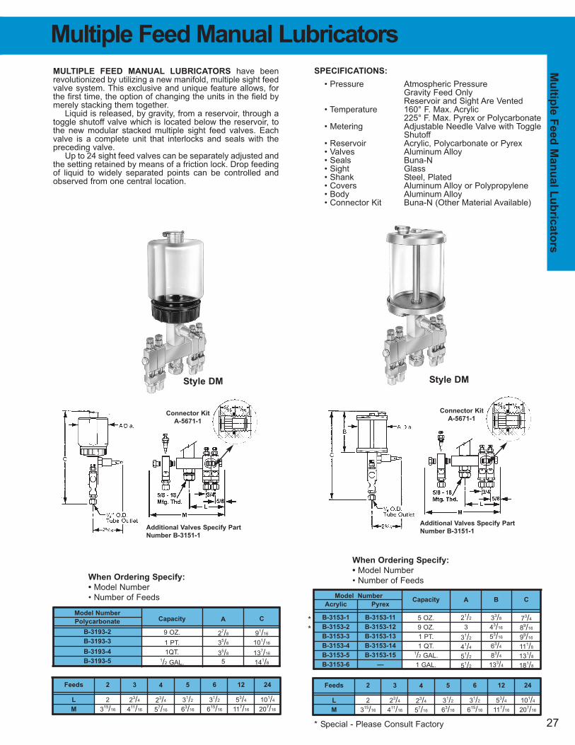
SPECIFICATIONS:
• Pressure Atmospheric PressureGravity Feed OnlyReservoir and Sight Are Vented
• Temperature 160° F. Max. Acrylic225° F. Max. Pyrex or Polycarbonate
• Metering Adjustable Needle Valve with ToggleShutoff
• Reservoir Acrylic, Polycarbonate or Pyrex• Valves Aluminum Alloy• Seals Buna-N• Sight Glass• Shank Steel, Plated• Covers Aluminum Alloy or Polypropylene• Body Aluminum Alloy• Connector Kit Buna-N (Other Material Available)
MULTIPLE FEED MANUAL LUBRICATORS have been revolutionized by utilizing a new manifold, multiple sight feedvalve system. This exclusive and unique feature allows, forthe first time, the option of changing the units in the field bymerely stacking them together.
Liquid is released, by gravity, from a reservoir, through atoggle shutoff valve which is located below the reservoir, tothe new modular stacked multiple sight feed valves. Eachvalve is a complete unit that interlocks and seals with thepreceding valve.
Up to 24 sight feed valves can be separately adjusted andthe setting retained by means of a friction lock. Drop feedingof liquid to widely separated points can be controlled andobserved from one central location.
Model Number
Acrylic Pyrex
B-3153-1 B-3153-11
B-3153-2 B-3153-12
B-3153-3 B-3153-13
B-3153-4 B-3153-14
B-3153-5 B-3153-15
B-3153-6 —
Feeds
L
M
3
23/4
411/16
4
23/4
57/16
5
31/2
63/16
6
31/2
615/16
12
53/4
117/16
24
101/4
207/16
2
2
315/16
When Ordering Specify:
• Model Number
• Number of Feeds
When Ordering Specify:
• Model Number
• Number of Feeds
Model Number
Polycarbonate
B-3193-2
B-3193-3
B-3193-4
B-3193-5
Capacity
9 OZ.
1 PT.
1QT.1/2 GAL.
A
27/8
35/8
35/8
5
C
91/16
101/16
137/16
141/8
Capacity
5 OZ.
9 OZ.
1 PT.
1 QT.1/2 GAL.
1 GAL.
C
73/4
89/16
99/16
111/8
131/8
181/8
B
33/8
43/16
53/16
63/4
83/4
133/4
A
21/2
3
31/2
41/4
51/2
51/2
Multiple Feed Manual Lubricators
Style DM Style DM
Feeds
L
M
3
23/4
411/16
4
23/4
57/16
5
31/2
63/16
6
31/2
615/16
12
53/4
117/16
24
101/4
207/16
2
2
315/16
* Special - Please Consult Factory
**
Connector Kit
A-5671-1
Additional Valves Specify Part
Number B-3151-1
Connector Kit
A-5671-1
Additional Valves Specify Part
Number B-3151-1
28
Model Number
Acrylic Pyrex
B-2084-2 B-2084-12
B-2084-3 B-2084-13
B-2084-4 B-2084-14
B-2084-5 B-2084-15
B-2084-6 B-2084-16
B-2084-7 B-2084-17
B-2084-8 —
Fu
ll F
low
Ele
ctr
o D
isp
en
sers
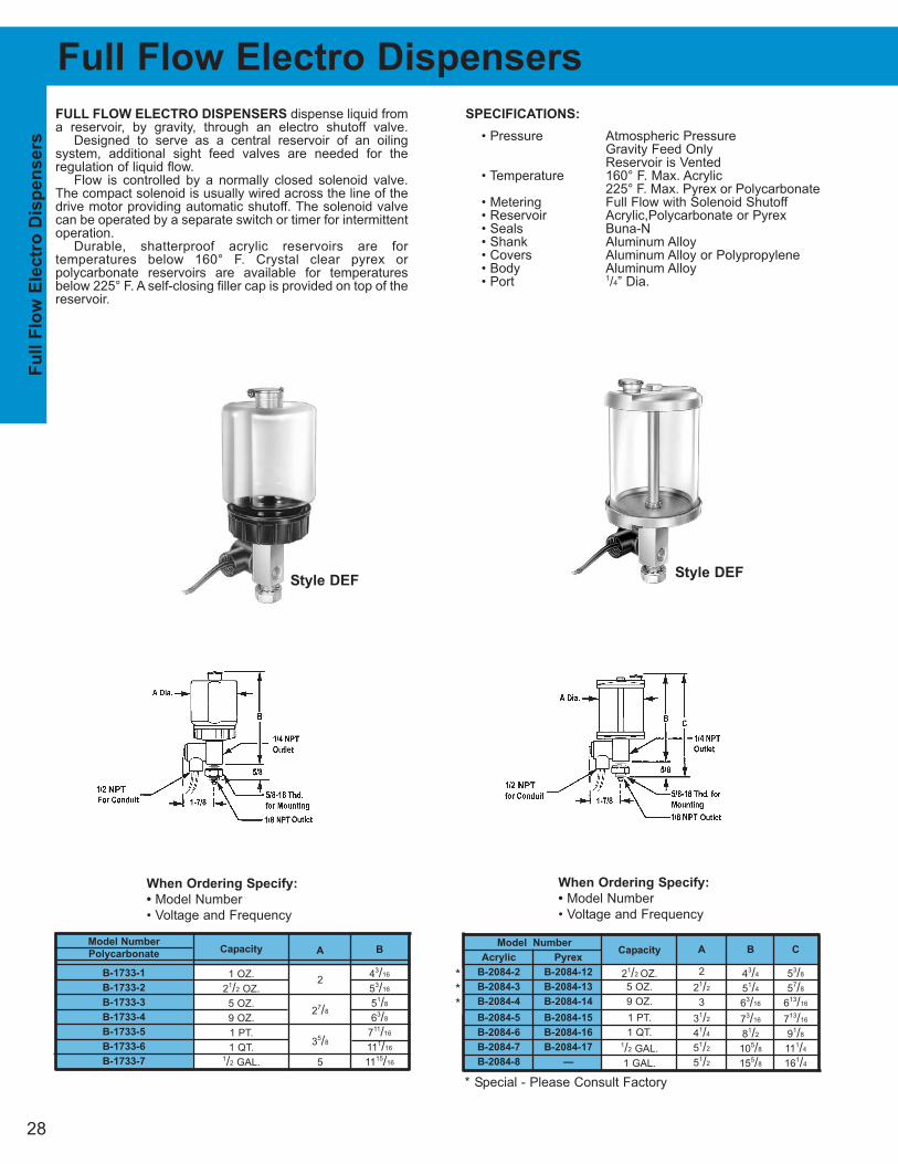
Full Flow Electro Dispensers
SPECIFICATIONS:
• Pressure Atmospheric PressureGravity Feed OnlyReservoir is Vented
• Temperature 160° F. Max. Acrylic225° F. Max. Pyrex or Polycarbonate
• Metering Full Flow with Solenoid Shutoff• Reservoir Acrylic,Polycarbonate or Pyrex• Seals Buna-N• Shank Aluminum Alloy• Covers Aluminum Alloy or Polypropylene• Body Aluminum Alloy• Port 1/4” Dia.
FULL FLOW ELECTRO DISPENSERS dispense liquid froma reservoir, by gravity, through an electro shutoff valve.
Designed to serve as a central reservoir of an oiling system, additional sight feed valves are needed for the regulation of liquid flow.
Flow is controlled by a normally closed solenoid valve.The compact solenoid is usually wired across the line of thedrive motor providing automatic shutoff. The solenoid valvecan be operated by a separate switch or timer for intermittentoperation.
Durable, shatterproof acrylic reservoirs are for temperatures below 160° F. Crystal clear pyrex or polycarbonate reservoirs are available for temperaturesbelow 225° F. A self-closing filler cap is provided on top of thereservoir.
When Ordering Specify:
• Model Number
• Voltage and Frequency
When Ordering Specify:
• Model Number
• Voltage and Frequency
Model Number
Polycarbonate
B-1733-1
B-1733-2
B-1733-3
B-1733-4
B-1733-5
B-1733-6
B-1733-7
Capacity
1 OZ.
21/2 OZ.
5 OZ.
9 OZ.
1 PT.
1 QT.1/2 GAL.
A
2
27/8
35/8
5
B
43/16
53/16
51/8
63/8
711/16
111/16
1115/16
Capacity
21/2 OZ.
5 OZ.
9 OZ.
1 PT.
1 QT.1/2 GAL.
1 GAL.
A
2
21/2
3
31/2
41/4
51/2
51/2
B
43/4
51/4
63/16
73/16
81/2
105/8
155/8
C
53/8
57/8
613/16
713/16
91/8
111/4
161/4
Style DEFStyle DEF
***
* Special - Please Consult Factory
29
Fu
ll Flo
w M
an
ual D
isp
en
sers
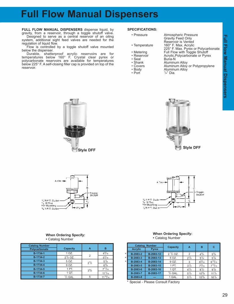
SPECIFICATIONS:
• Pressure Atmospheric PressureGravity Feed OnlyReservoir is Vented
• Temperature 160° F. Max. Acrylic225° F. Max. Pyrex or Polycarbonate
• Metering Full Flow with Toggle Shutoff • Reservoir Acrylic,Polycarbonate or Pyrex• Seal Buna-N• Shank Aluminum Alloy• Covers Aluminum Alloy or Polypropylene• Body Aluminum Alloy• Port 1/4” Dia.
FULL FLOW MANUAL DISPENSERS dispense liquid, bygravity, from a reservoir, through a toggle shutoff valve.
Designed to serve as a central reservoir of an oiling system, additional sight feed valves are needed for the regulation of liquid flow.
Flow is controlled by a toggle shutoff valve mountedbelow the dispenser.
Durable, shatterproof acrylic reservoirs are for temperatures below 160° F. Crystal clear pyrex or polycarbonate reservoirs are available for temperaturesbelow 225° F. A self-closing filler cap is provided on top of thereservoir.
Catalog Number
Acrylic Pyrex
B-2083-2 B-2083-12
B-2083-3 B-2083-13
B-2083-4 B-2083-14
B-2083-5 B-2083-15
B-2083-6 B-2083-16
B-2083-7 B-2083-17
B-2083-8 —
When Ordering Specify:
• Catalog Number
When Ordering Specify:
• Catalog Number
Catalog Number
Polycarbonate
B-1734-1
B-1734-2
B-1734-3
B-1734-4
B-1734-5
B-1734-6
B-1734-7
Capacity
1 OZ.
21/2 OZ.
5 OZ.
9 OZ.
1 PT.
1 QT.1/2 GAL.
A
2
27/8
35/8
5
B
43/16
53/16
51/8
63/8
711/16
111/16
1115/16
Capacity
2 1/2 OZ.
5 OZ.
9 OZ.
1 PT.
1 QT.1/2 GAL.
1 GAL.
A
2
21/2
3
31/2
41/4
51/2
51/2
B
43/4
51/4
63/16
73/16
81/2
105/8
155/8
C
53/8
57/8
613/16
713/16
91/8
111/4
161/4
Full Flow Manual Dispensers
Style DFFStyle DFF
***
* Special - Please Consult Factory
30
Capacity
1 OZ.
21/2 OZ.
5 OZ.
9 OZ.
1 PT.
1 QT.
1/2 GAL.
1 OZ.
21/2 OZ.
5 OZ.
9 OZ.
1 PT.
1 QT.1/2 GAL.
2 31/45/8
2 41/45/8
27/8 41/45/8
27/8 51/25/8
35/8 613/165/8
35/8 103/165/8
5 111/165/8
Thread Size A C D
1/8 MALE N.P.T. 2 3 3/8
1/4 MALE N.P.T. 2 31/167/16
1/8 MALE N.P.T. 2 4 3/8
1/4 MALE N.P.T. 2 41/167/16
3/8 MALE N.P.T. 2 41/81/2
1/8 MALE N.P.T. 27/8 4 3/8
1/4 MALE N.P.T. 27/8 41/167/16
3/8 MALE N.P.T. 27/8 41/81/2
1/4 MALE N.P.T. 27/8 53/167/16
3/8 MALE N.P.T. 27/8 53/81/2
1/2 MALE N.P.T. 27/8 51/25/8
1/4 MALE N.P.T. 35/8 613/167/16
3/8 MALE N.P.T. 35/8 67/81/2
1/2 MALE N.P.T. 35/8 613/165/8
1/4 MALE N.P.T. 35/8 103/167/16
1/2 MALE N.P.T. 35/8 103/165/8
1/4 MALE N.P.T. 5 107/87/16
1/2 MALE N.P.T. 5 111/165/8
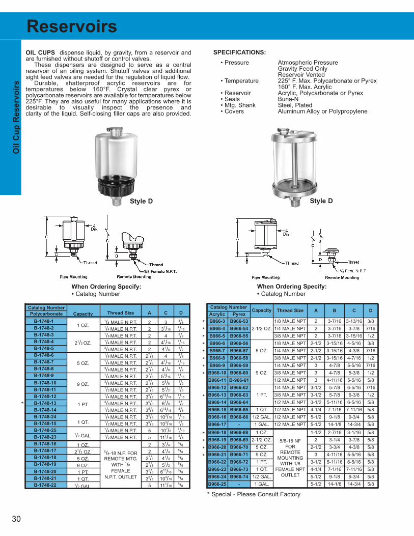
SPECIFICATIONS:
• Pressure Atmospheric PressureGravity Feed OnlyReservoir Vented
• Temperature 225° F. Max. Polycarbonate or Pyrex160° F. Max. Acrylic
• Reservoir Acrylic, Polycarbonate or Pyrex• Seals Buna-N• Mtg. Shank Steel, Plated• Covers Aluminum Alloy or Polypropylene
OIL CUPS dispense liquid, by gravity, from a reservoir andare furnished without shutoff or control valves.
These dispensers are designed to serve as a central reservoir of an oiling system. Shutoff valves and additionalsight feed valves are needed for the regulation of liquid flow.
Durable, shatterproof acrylic reservoirs are for temperatures below 160°F. Crystal clear pyrex or polycarbonate reservoirs are available for temperatures below225°F. They are also useful for many applications where it isdesirable to visually inspect the presence and clarity of the liquid. Self-closing filler caps are also provided.
Catalog Number
Polycarbonate
B-1748-1
B-1748-2
B-1748-3
B-1748-4
B-1748-5
B-1748-6
B-1748-7
B-1748-8
B-1748-9
B-1748-10
B-1748-11
B-1748-12
B-1748-13
B-1748-14
B-1748-24
B-1748-15
B-1748-25
B-1748-23
B-1748-16
B-1748-17
B-1748-18
B-1748-19
B-1748-20
B-1748-21
B-1748-22
When Ordering Specify:
• Catalog Number
When Ordering Specify:
• Catalog Number
5/8-18 N.F. FORREMOTE MTG.
WITH 1/8
FEMALE
N.P.T. OUTLET
Oil C
up
Reservo
irs
Reservoirs
Style D Style D
*
* Special - Please Consult Factory
*
*
*
*
*
*
*
*
*
*
*
*
*
Catalog Number
Acrylic Pyrex
B966-3 B966-53 1/8 MALE NPT 2 3-7/16 3-13/16 3/8
B966-4 B966-54 1/4 MALE NPT 2 3-7/16 3-7/8 7/16
B966-5 B966-55 3/8 MALE NPT 2 3-7/16 3-15/16 1/2
B966-6 B966-56 1/8 MALE NPT 2-1/2 3-15/16 4-5/16 3/8
B966-7 B966-57 1/4 MALE NPT 2-1/2 3-15/16 4-3/8 7/16
B966-8 B966-58 3/8 MALE NPT 2-1/2 3-15/16 4-7/16 1/2
B966-9 B966-59 1/4 MALE NPT 3 4-7/8 5-5/16 7/16
B966-10 B966-60 3/8 MALE NPT 3 4-7/8 5-3/8 1/2
B966-11 B-966-61 1/2 MALE NPT 3 4-11/16 5-5/16 5/8
B966-12 B966-62 1/4 MALE NPT 3-1/2 5-7/8 6-5/16 7/16
B966-13 B966-63 3/8 MALE NPT 3-1/2 5-7/8 6-3/8 1/2
B966-14 B966-64 1/2 MALE NPT 3-1/2 5-11/16 6-5/16 5/8
B966-15 B966-65 1 QT. 1/2 MALE NPT 4-1/4 7-1/16 7-11/16 5/8
B966-16 B966-66 1/2 GAL. 1/2 MALE NPT 5-1/2 9-1/8 9-3/4 5/8
B966-17 - 1 GAL. 1/2 MALE NPT 5-1/2 14-1/8 14-3/4 5/8
B966-18 B966-68 1 OZ. 1-1/2 2-7/16 3-1/16 5/8
B966-19 B966-69 2-1/2 OZ. 2 3-1/4 3-7/8 5/8
B966-20 B966-70 5 OZ. 2-1/2 3-3/4 4-3/8 5/8
B966-21 B966-71 9 OZ. 3 4-11/16 5-5/16 5/8
B966-22 B966-72 1 PT. 3-1/2 5-11/16 6-5/16 5/8
B966-23 B966-73 1 QT. 4-1/4 7-1/16 7-11/16 5/8
B966-24 B966-74 1/2 GAL. 5-1/2 9-1/8 9-3/4 5/8
B966-25 - 1 GAL. 5-1/2 14-1/8 14-3/4 5/8
2-1/2 OZ.
5 OZ.
9 OZ.
1 PT.
5/8-18 NF
FOR
REMOTE
MOUNTING
WITH 1/8
FEMALE NPT
OUTLET
Thread Size A B C DCapacity
31
Reservoirs cont.F
ilter a
nd
Lo
w L
evel S
en
so
r R
eservo
ir
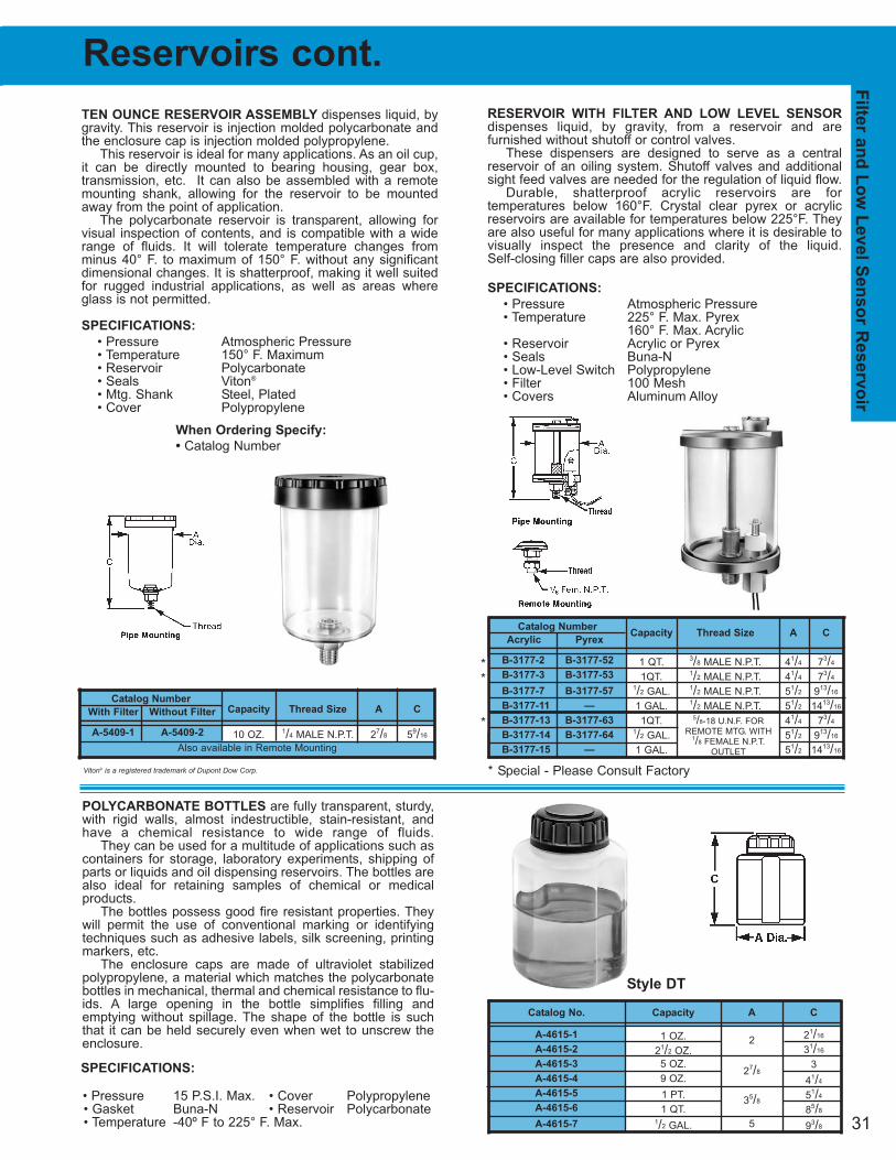
TEN OUNCE RESERVOIR ASSEMBLY dispenses liquid, bygravity. This reservoir is injection molded polycarbonate andthe enclosure cap is injection molded polypropylene.
This reservoir is ideal for many applications. As an oil cup,it can be directly mounted to bearing housing, gear box, transmission, etc. It can also be assembled with a remote mounting shank, allowing for the reservoir to be mountedaway from the point of application.
The polycarbonate reservoir is transparent, allowing forvisual inspection of contents, and is compatible with a widerange of fluids. It will tolerate temperature changes fromminus 40° F. to maximum of 150° F. without any significantdimensional changes. It is shatterproof, making it well suitedfor rugged industrial applications, as well as areas whereglass is not permitted.
SPECIFICATIONS:
• Pressure Atmospheric Pressure• Temperature 150° F. Maximum• Reservoir Polycarbonate• Seals Viton®
• Mtg. Shank Steel, Plated• Cover Polypropylene
5/8-18 U.N.F. FORREMOTE MTG. WITH
1/8 FEMALE N.P.T. OUTLET
Catalog Number
Acrylic Pyrex
B-3177-2 B-3177-52
B-3177-3 B-3177-53
B-3177-7 B-3177-57
B-3177-11 —
B-3177-13 B-3177-63
B-3177-14 B-3177-64
B-3177-15 —
Capacity Thread Size A C
10 OZ. 1/4 MALE N.P.T. 27/8 59/16
Catalog Number
With Filter Without Filter
A-5409-1 A-5409-2
Capacity Thread Size A C
1 QT. 3/8 MALE N.P.T. 41/4 73/4
1QT. 1/2 MALE N.P.T. 41/4 73/4
1/2 GAL. 1/2 MALE N.P.T. 51/2 913/16
1 GAL. 1/2 MALE N.P.T. 51/2 1413/16
1QT. 41/4 73/4
1/2 GAL. 51/2 913/16
1 GAL. 51/2 1413/16
RESERVOIR WITH FILTER AND LOW LEVEL SENSOR
dispenses liquid, by gravity, from a reservoir and are furnished without shutoff or control valves.
These dispensers are designed to serve as a centralreservoir of an oiling system. Shutoff valves and additionalsight feed valves are needed for the regulation of liquid flow.
Durable, shatterproof acrylic reservoirs are for temperatures below 160°F. Crystal clear pyrex or acrylicreservoirs are available for temperatures below 225°F. Theyare also useful for many applications where it is desirable tovisually inspect the presence and clarity of the liquid. Self-closing filler caps are also provided.
SPECIFICATIONS:
• Pressure Atmospheric Pressure• Temperature 225° F. Max. Pyrex
160° F. Max. Acrylic• Reservoir Acrylic or Pyrex• Seals Buna-N• Low-Level Switch Polypropylene• Filter 100 Mesh• Covers Aluminum Alloy
**
*
* Special - Please Consult Factory
SPECIFICATIONS:
• Pressure 15 P.S.I. Max. • Cover Polypropylene• Gasket Buna-N • Reservoir Polycarbonate• Temperature -40º F to 225° F. Max.
POLYCARBONATE BOTTLES are fully transparent, sturdy,with rigid walls, almost indestructible, stain-resistant, andhave a chemical resistance to wide range of fluids.
They can be used for a multitude of applications such ascontainers for storage, laboratory experiments, shipping ofparts or liquids and oil dispensing reservoirs. The bottles arealso ideal for retaining samples of chemical or medical products.
The bottles possess good fire resistant properties. Theywill permit the use of conventional marking or identifyingtechniques such as adhesive labels, silk screening, printingmarkers, etc.
The enclosure caps are made of ultraviolet stabilizedpolypropylene, a material which matches the polycarbonatebottles in mechanical, thermal and chemical resistance to flu-ids. A large opening in the bottle simplifies filling and emptying without spillage. The shape of the bottle is suchthat it can be held securely even when wet to unscrew theenclosure.
When Ordering Specify:
• Catalog Number
Catalog No.
A-4615-1
A-4615-2
A-4615-3
A-4615-4
A-4615-5
A-4615-6
A-4615-7
Capacity
1 OZ.
21/2 OZ.
5 OZ.
9 OZ.
1 PT.
1 QT.1/2 GAL.
A
2
27/8
35/8
5
C
21/16
31/16
3
41/4
51/4
85/8
93/8
Style DT
Also available in Remote Mounting
Viton® is a registered trademark of Dupont Dow Corp.
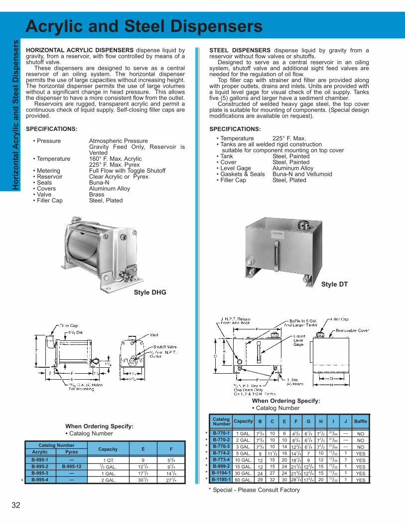
STEEL DISPENSERS dispense liquid by gravity from a reservoir without flow valves or shutoffs.
Designed to serve as a central reservoir in an oiling system, shutoff valve and additional sight feed valves areneeded for the regulation of oil flow.
Top filler cap with strainer and filter are provided alongwith proper outlets, drains and inlets. Units are provided witha liquid level gage for visual check of the oil supply. Tanksfive (5) gallons and larger have a sediment chamber.
Constructed of welded heavy gage steel, the top coverplate is suitable for mounting of components. (Special designmodifications are available on request).
SPECIFICATIONS:
• Temperature 225° F. Max.• Tanks are all welded rigid construction
suitable for component mounting on top cover• Tank Steel, Painted• Cover Steel, Painted• Level Gage Aluminum Alloy• Gaskets & Seals Buna-N and Vellumoid• Filler Cap Steel, Plated
HORIZONTAL ACRYLIC DISPENSERS dispense liquid bygravity, from a reservoir, with flow controlled by means of ashutoff valve.
These dispensers are designed to serve as a centralreservoir of an oiling system. The horizontal dispenser permits the use of large capacities without increasing height.The horizontal dispenser permits the use of large volumeswithout a significant change in head pressure. This allowsthe dispenser to have a more consistent flow from the outlet.
Reservoirs are rugged, transparent acrylic and permit acontinuous check of liquid supply. Self-closing filler caps areprovided.
SPECIFICATIONS:
• Pressure Atmospheric PressureGravity Feed Only, Reservoir isVented
• Temperature 160° F. Max. Acrylic225° F. Max. Pyrex
• Metering Full Flow with Toggle Shutoff • Reservoir Clear Acrylic or Pyrex• Seals Buna-N• Covers Aluminum Alloy• Valve Brass• Filler Cap Steel, Plated
Catalog
Number
B-770-1
B-770-2
B-770-3
B-774-2
B-773-4
B-999-2
B-1194-1
B-1195-1
When Ordering Specify:
• Catalog Number
When Ordering Specify:
• Catalog Number
Catalog Number
Acrylic Pyrex
B-995-1 —
B-995-2 B-995-12
B-995-3 —
B-995-4 —
Capacity
1 QT. 1/2 GAL.
1 GAL.
2 GAL.
F
53/4
91/4
141/4
271/4
E
9
121/2
171/2
301/2
Capacity
1 GAL.
2 GAL.
3 GAL.
5 GAL.
10 GAL.
15 GAL.
30 GAL.
60 GAL.
C
10
10
10
111/2
15
15
27
32
B
73/4
73/4
73/4
9
12
12
24
29
E
6
10
14
16
20
24
24
30
H
71/2
71/2
71/2
10
12
15
15
20
F
43/4
83/4
123/4
141/4
181/4
213/4
213/4
281/4
G
61/4
61/4
61/4
7
9
123/4
123/4
173/4
I
21/64
21/64
21/64
17/32
17/32
17/32
17/32
17/32
J
—
—
—
1
1
1
1
1
Baffle
NO
NO
NO
YES
YES
YES
YES
YES
Ho
riz
on
tal A
crylic a
nd
Ste
el
Dis
pen
sers
Acrylic and Steel Dispensers
Style DHG
Style DT
* Special - Please Consult Factory
********
32
*
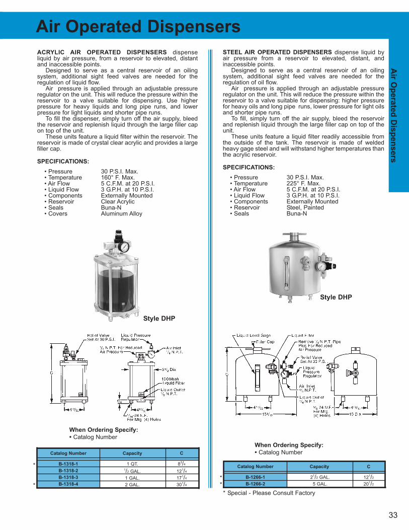
33
Air
Op
erate
d D
isp
en
sers
Air Operated Dispensers
STEEL AIR OPERATED DISPENSERS dispense liquid byair pressure from a reservoir to elevated, distant, and inaccessible points.
Designed to serve as a central reservoir of an oiling system, additional sight feed valves are needed for the regulation of oil flow.
Air pressure is applied through an adjustable pressureregulator on the unit. This will reduce the pressure within thereservoir to a valve suitable for dispensing: higher pressurefor heavy oils and long pipe runs, lower pressure for light oilsand shorter pipe runs.
To fill, simply turn off the air supply, bleed the reservoirand replenish liquid through the large filler cap on top of theunit.
These units feature a liquid filter readily accessible fromthe outside of the tank. The reservoir is made of weldedheavy gage steel and will withstand higher temperatures thanthe acrylic reservoir.
SPECIFICATIONS:
• Pressure 30 P.S.I. Max.• Temperature 225° F. Max.• Air Flow 5 C.F.M. at 20 P.S.I.• Liquid Flow 3 G.P.H. at 10 P.S.I.• Components Externally Mounted• Reservoir Steel, Painted• Seals Buna-N
ACRYLIC AIR OPERATED DISPENSERS dispense liquid by air pressure, from a reservoir to elevated, distantand inaccessible points.
Designed to serve as a central reservoir of an oiling system, additional sight feed valves are needed for the regulation of liquid flow.
Air pressure is applied through an adjustable pressureregulator on the unit. This will reduce the pressure within thereservoir to a valve suitable for dispensing. Use higher pressure for heavy liquids and long pipe runs, and lowerpressure for light liquids and shorter pipe runs.
To fill the dispenser, simply turn off the air supply, bleedthe reservoir and replenish liquid through the large filler capon top of the unit.
These units feature a liquid filter within the reservoir. Thereservoir is made of crystal clear acrylic and provides a largefiller cap.
SPECIFICATIONS:
• Pressure 30 P.S.I. Max.• Temperature 160° F. Max. • Air Flow 5 C.F.M. at 20 P.S.I.• Liquid Flow 3 G.P.H. at 10 P.S.I.• Components Externally Mounted• Reservoir Clear Acrylic• Seals Buna-N • Covers Aluminum Alloy
When Ordering Specify:
• Catalog Number
Catalog Number
B-1318-1
B-1318-2
B-1318-3
B-1318-4
Capacity
1 QT.1/2 GAL.
1 GAL.
2 GAL.
C
83/4
121/4
171/4
301/4
When Ordering Specify:
• Catalog Number
Catalog Number
B-1266-1
B-1266-2
Capacity
21/2 GAL.
5 GAL.
C
121/2
201/2
Style DHP
Style DHP
*
*
**
* Special - Please Consult Factory
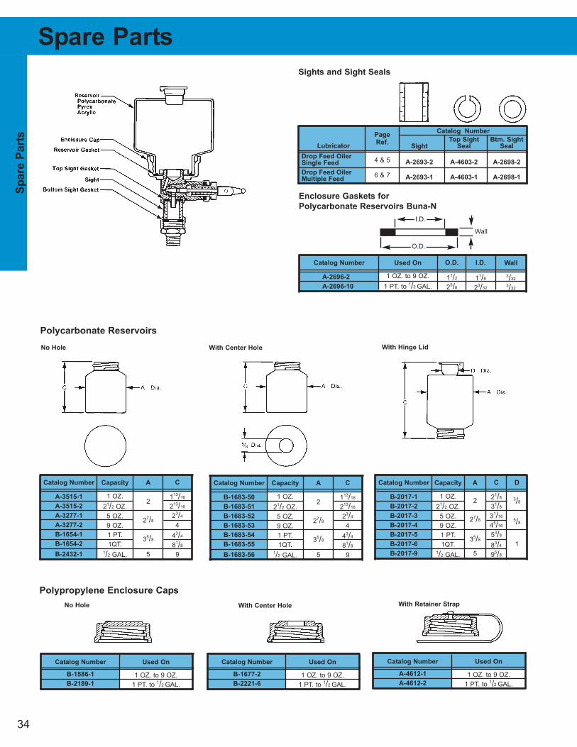
34
Sp
are P
arts
Lubricator
Drop Feed Oiler
Single Feed
Drop Feed Oiler
Multiple Feed
Catalog Number
Top Sight Btm. Sight
Sight Seal Seal
A-2693-2 A-4603-2 A-2698-2
A-2693-1 A-4603-1 A-2698-1
Catalog Number
A-2696-2
A-2696-10
Used On
1 OZ. to 9 OZ.
1 PT. to 1/2 GAL.
O.D.
11/2
25/8
I.D.
11/8
23/32
Page
Ref.
4 & 5
6 & 7
Wall
3/32
3/32
Catalog Number
B-2017-1
B-2017-2
B-2017-3
B-2017-4
B-2017-5
B-2017-6
B-2017-9
Capacity
1 OZ.
21/2 OZ.
5 OZ.
9 OZ.
1 PT.
1QT.1/2 GAL.
A
2
27/8
35/8
5
C
21/8
31/8
31/16
45/16
53/8
83/4
95/8
D
3/8
5/8
1
Catalog Number
A-3515-1
A-3515-2
A-3277-1
A-3277-2
B-1654-1
B-1654-2
B-2432-1
Capacity
1 OZ.
21/2 OZ.
5 OZ.
9 OZ.
1 PT.
1QT.1/2 GAL.
A
2
27/8
35/8
5
C
113/16
213/16
23/4
4
43/4
81/8
9
Catalog Number
A-4612-1
A-4612-2
Used On
1 OZ. to 9 OZ.
1 PT. to 1/2 GAL.
Catalog Number
B-1677-2
B-2221-6
Used On
1 OZ. to 9 OZ.
1 PT. to 1/2 GAL.
Catalog Number
B-1683-50
B-1683-51
B-1683-52
B-1683-53
B-1683-54
B-1683-55
B-1683-56
Capacity
1 OZ.
21/2 OZ.
5 OZ.
9 OZ.
1 PT.
1QT.1/2 GAL.
A
2
27/8
35/8
5
C
113/16
213/16
23/4
4
43/4
81/8
9
Spare Parts
Wall
Enclosure Gaskets for
Polycarbonate Reservoirs Buna-N
O.D.
I.D.
Polycarbonate Reservoirs
No Hole With Center Hole With Hinge Lid
Sights and Sight Seals
No Hole With Center Hole With Retainer Strap
Polypropylene Enclosure Caps
Catalog Number
B-1586-1
B-2189-1
Used On
1 OZ. to 9 OZ.
1 PT. to 1/2 GAL.
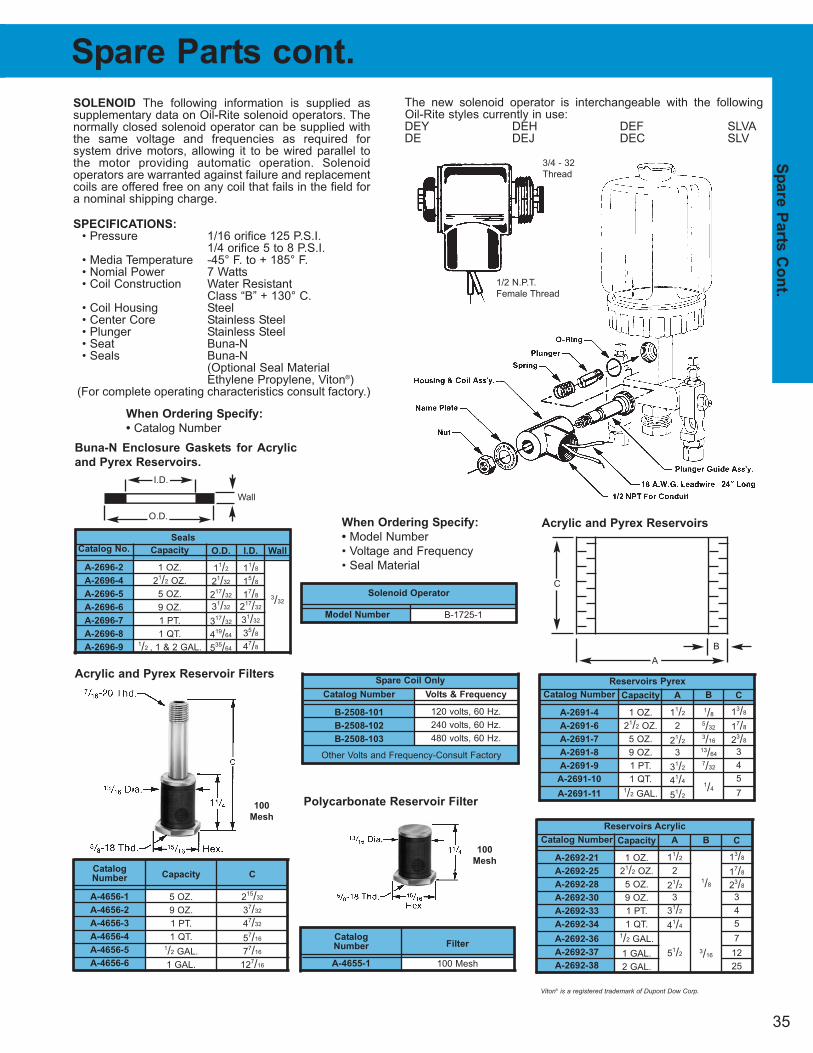
35
Sp
are P
arts
Co
nt.
Seals
Reservoirs Acrylic
Catalog Number
B-2508-101
B-2508-102
B-2508-103
B
1/8
3/16
A
11/2
2
21/2
3
31/2
41/4
51/2
Catalog Number
A-2692-21
A-2692-25
A-2692-28
A-2692-30
A-2692-33
A-2692-34
A-2692-36
A-2692-37
A-2692-38
Capacity
1 OZ.
21/2 OZ.
5 OZ.
9 OZ.
1 PT.
1 QT.1/2 GAL.
1 GAL.
2 GAL.
C
13/8
17/8
23/8
3
4
5
7
12
25
Spare Parts cont.
B
1/8
5/32
3/16
13/64
7/32
1/4
A
11/2
2
21/2
3
31/2
41/4
51/2
Catalog Number
A-2691-4
A-2691-6
A-2691-7
A-2691-8
A-2691-9
A-2691-10
A-2691-11
Capacity
1 OZ.
21/2 OZ.
5 OZ.
9 OZ.
1 PT.
1 QT.1/2 GAL.
C
13/8
17/8
23/8
3
4
5
7
Reservoirs Pyrex
I.D.
11/8
15/8
17/8
217/32
31/32
35/8
47/8
O.D.
11/2
21/32
217/32
31/32
317/32
419/64
535/64
Catalog No.
A-2696-2
A-2696-4
A-2696-5
A-2696-6
A-2696-7
A-2696-8
A-2696-9
Capacity
1 OZ.
21/2 OZ.
5 OZ.
9 OZ.
1 PT.
1 QT.1/2 , 1 & 2 GAL.
Wall
3/32
Volts & Frequency
120 volts, 60 Hz.
240 volts, 60 Hz.
480 volts, 60 Hz.
Spare Coil Only
Buna-N Enclosure Gaskets for Acrylic
and Pyrex Reservoirs.
SOLENOID The following information is supplied assupplementary data on Oil-Rite solenoid operators. Thenormally closed solenoid operator can be supplied withthe same voltage and frequencies as required for system drive motors, allowing it to be wired parallel tothe motor providing automatic operation. Solenoid operators are warranted against failure and replacementcoils are offered free on any coil that fails in the field fora nominal shipping charge.
SPECIFICATIONS:
• Pressure 1/16 orifice 125 P.S.I.1/4 orifice 5 to 8 P.S.I.
• Media Temperature -45° F. to + 185° F.• Nomial Power 7 Watts• Coil Construction Water Resistant
Class “B” + 130° C.• Coil Housing Steel• Center Core Stainless Steel• Plunger Stainless Steel• Seat Buna-N• Seals Buna-N
(Optional Seal MaterialEthylene Propylene, Viton®)
(For complete operating characteristics consult factory.)
Acrylic and Pyrex Reservoirs
A
B
C
The new solenoid operator is interchangeable with the following Oil-Rite styles currently in use:DEY DEH DEF SLVADE DEJ DEC SLV
Model Number
Solenoid Operator
B-1725-1
When Ordering Specify:
• Model Number
• Voltage and Frequency
• Seal Material
Filter
100 Mesh
Catalog
Number
A-4655-1
Capacity
5 OZ.
9 OZ.
1 PT.
1 QT.1/2 GAL.
1 GAL.
Catalog
Number
A-4656-1
A-4656-2
A-4656-3
A-4656-4
A-4656-5
A-4656-6
C
215/32
37/32
47/32
57/16
77/16
127/16
When Ordering Specify:
• Catalog Number
Wall
O.D.
I.D.
Acrylic and Pyrex Reservoir Filters
Polycarbonate Reservoir Filter100
Mesh
100
Mesh
1/2 N.P.T.
Female Thread
3/4 - 32
Thread
Other Volts and Frequency-Consult Factory
Viton® is a registered trademark of Dupont Dow Corp.

36
Insta
llati
on
In
str
ucti
on
Constant Level Lubricator Installation Instructions
INSTALLATION
1. Liquid level is usually marked on the
base of lubricator. Mount liquid by
using side or bottom outlet at the exact
and most desirable level.
2. Correct liquid level is lowest level at
which bearing operates perfectly.
3. Lubricator should be level in all
directions to function at its best.
4. Keep connections short, rigid, and
close to bearing to avoid vibration.
5. Fill bearing well by filling lubricator.
Repeated filling may be necessary.
6. The anti-friction bearings should be
fitted with breather tubes piped to the
outside or to air intake of lubricator.
7. On lubricators with top filler cap, besure cap is always screwed downtight. Removing filler cap shuts offoil supply. Loose filler cap causesleakage of liquid from reservoirthrough vent hole, rendering lubricator ineffective.
PRINCIPLE
Constant level lubricators automatically
maintain the liquid in a bearing reservoir
at a constant level. Operation is based on
the liquid seal principle. (Figure 1) When
the liquid in the bearing recedes because
of liquid consumption, the liquid seal on
the inside of the lubricator is temporarily
broken. This allows air from the air intake
to enter the lubricator reservoir, releasing
oil until a seal and proper level are again
established.
APPLICATIONS
Constant level lubricators are used on
sleeve bearing, anti-friction bearings,
gear boxes, pump housing, etc. Other
uses include moistening pads and any
other application demanding the
maintenance of a constant liquid level.
LIQUID LEVEL
Oil-Rite has available constant level
lubricators with fixed or with adjustable oil
level. Original equipment manufacturers
usually prefer lubricator with fixed liquid
level to make an installation tamperproof.
LIQUID RESERVOIR
Oil-Rite offers constant level lubricators
with acrylic, glass, or high temperature
plastic reservoirs to suit specific
applications. The reservoirs are
transparent to permit a visual check of the
oil supply at all times. Since the liquid in
the reservoir assumes the same color as
that in the bearing housing, a visual check
of the condition of the liquid is also
afforded.
AIR INLET
The air inlet on Oil-Rite’s constant level
lubricators is provided with a pipe
thread to accommodate an air filter for
the prevention of dust and dirt getting into
the liquid.
For dusty and dirty surroundings, such
as those found in cement mills, textile
plants, paper mills, coal handling
facilities, etc. it is recommended that the
air inlet of the lubricator be piped into the
top of the bearing housing. Such a closed
circuit offers full protection.
Pressure differential between theair intake of the lubricator and the bearing housing, such as is experienced on ventilating fans and blowers, anti-friction bearings, etc., necessitates that the air inlet on the lubricator be piped into the top of the bearing housing to equalize pressure.
SURGE LEVEL
In certain cases, such as in gear boxes, a
considerable quantity of liquid is carried
by the gears to the upper portion of the
gear housing during operation. After
shutdown, the liquid surges back to the
lubricator and raises the liquid level.
Constant level lubricator should therefore
be equipped with a sufficient surge level
to prevent liquid from overflowing through
the air intake.
Typical installation (Figure 3) for ring-oiledbearings. Liquid level should be slightly aboveinside diameter of ring. With the correct liquidlevel the ring carries liquid to shaft smoothlywithout splashing and chattering.
This installation (Figure 2) is especially suitable for bearings having excessive backpressure or vacuum. A constant level is maintained in spite of air pressure or vacuumin bearing, as equalizing tube assures staticbalance of pressure between bearing andlubricator.
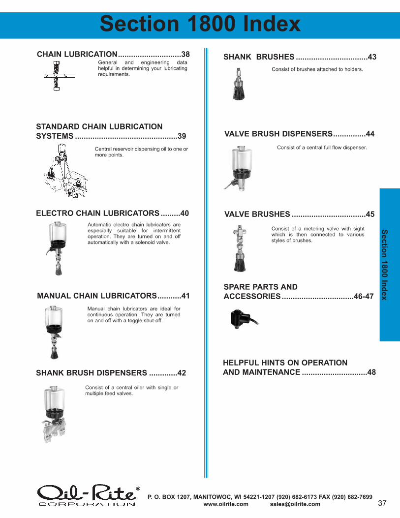
37P. O. BOX 1207, MANITOWOC, WI 54221-1207 (920) 682-6173 FAX (920) 682-7699
www.oilrite.com [email protected]
Sectio
n 1
800 In
dex
Section 1800 Index
Manual chain lubricators are ideal forcontinuous operation. They are turnedon and off with a toggle shut-off.
Consist of a central oiler with single ormultiple feed valves.
Consist of brushes attached to holders.
Consist of a central full flow dispenser.
Consist of a metering valve with sightwhich is then connected to variousstyles of brushes.
General and engineering data helpful in determining your lubricating requirements.
Central reservoir dispensing oil to one ormore points.
Automatic electro chain lubricators areespecially suitable for intermittent operation. They are turned on and offautomatically with a solenoid valve.
CHAIN LUBRICATION.............................38
STANDARD CHAIN LUBRICATION
SYSTEMS ...............................................39
ELECTRO CHAIN LUBRICATORS .........40
MANUAL CHAIN LUBRICATORS...........41
SHANK BRUSH DISPENSERS .............42
SHANK BRUSHES .................................43
VALVE BRUSHES ..................................45
VALVE BRUSH DISPENSERS...............44
SPARE PARTS AND
ACCESSORIES.................................46-47
HELPFUL HINTS ON OPERATION
AND MAINTENANCE ..............................48
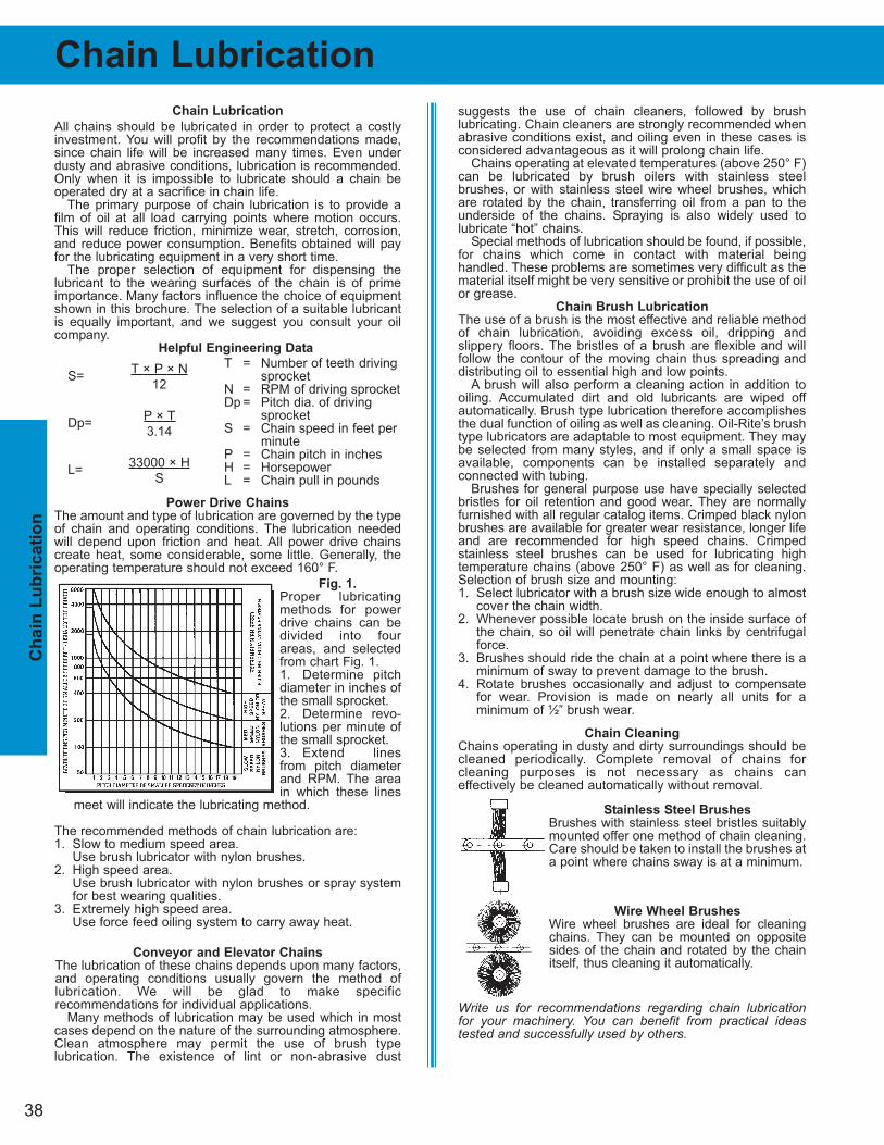
38
Ch
ain
Lu
bric
ati
on
suggests the use of chain cleaners, followed by brush lubricating. Chain cleaners are strongly recommended whenabrasive conditions exist, and oiling even in these cases isconsidered advantageous as it will prolong chain life.
Chains operating at elevated temperatures (above 250° F)can be lubricated by brush oilers with stainless steel brushes, or with stainless steel wire wheel brushes, whichare rotated by the chain, transferring oil from a pan to the underside of the chains. Spraying is also widely used to lubricate “hot” chains.
Special methods of lubrication should be found, if possible,for chains which come in contact with material being handled. These problems are sometimes very difficult as thematerial itself might be very sensitive or prohibit the use of oilor grease.
Chain Brush Lubrication
The use of a brush is the most effective and reliable methodof chain lubrication, avoiding excess oil, dripping and slippery floors. The bristles of a brush are flexible and will follow the contour of the moving chain thus spreading anddistributing oil to essential high and low points.
A brush will also perform a cleaning action in addition tooiling. Accumulated dirt and old lubricants are wiped off automatically. Brush type lubrication therefore accomplishesthe dual function of oiling as well as cleaning. Oil-Rite’s brushtype lubricators are adaptable to most equipment. They maybe selected from many styles, and if only a small space isavailable, components can be installed separately and connected with tubing.
Brushes for general purpose use have specially selectedbristles for oil retention and good wear. They are normallyfurnished with all regular catalog items. Crimped black nylonbrushes are available for greater wear resistance, longer lifeand are recommended for high speed chains. Crimped stainless steel brushes can be used for lubricating high temperature chains (above 250° F) as well as for cleaning.Selection of brush size and mounting:1. Select lubricator with a brush size wide enough to almost
cover the chain width.2. Whenever possible locate brush on the inside surface of
the chain, so oil will penetrate chain links by centrifugalforce.
3. Brushes should ride the chain at a point where there is aminimum of sway to prevent damage to the brush.
4. Rotate brushes occasionally and adjust to compensatefor wear. Provision is made on nearly all units for a minimum of ½” brush wear.
Chain Cleaning
Chains operating in dusty and dirty surroundings should becleaned periodically. Complete removal of chains for cleaning purposes is not necessary as chains can effectively be cleaned automatically without removal.
Stainless Steel Brushes
Brushes with stainless steel bristles suitablymounted offer one method of chain cleaning.Care should be taken to install the brushes ata point where chains sway is at a minimum.
Wire Wheel Brushes
Wire wheel brushes are ideal for cleaningchains. They can be mounted on oppositesides of the chain and rotated by the chainitself, thus cleaning it automatically.
Write us for recommendations regarding chain lubrication for your machinery. You can benefit from practical ideas tested and successfully used by others.
Chain Lubrication
Chain Lubrication
All chains should be lubricated in order to protect a costlyinvestment. You will profit by the recommendations made,since chain life will be increased many times. Even underdusty and abrasive conditions, lubrication is recommended.Only when it is impossible to lubricate should a chain beoperated dry at a sacrifice in chain life.
The primary purpose of chain lubrication is to provide afilm of oil at all load carrying points where motion occurs.This will reduce friction, minimize wear, stretch, corrosion,and reduce power consumption. Benefits obtained will payfor the lubricating equipment in a very short time.
The proper selection of equipment for dispensing the lubricant to the wearing surfaces of the chain is of primeimportance. Many factors influence the choice of equipmentshown in this brochure. The selection of a suitable lubricantis equally important, and we suggest you consult your oilcompany.
Helpful Engineering Data
Power Drive Chains
The amount and type of lubrication are governed by the typeof chain and operating conditions. The lubrication neededwill depend upon friction and heat. All power drive chainscreate heat, some considerable, some little. Generally, theoperating temperature should not exceed 160° F.
Fig. 1.
Proper lubricatingmethods for powerdrive chains can bedivided into fourareas, and selectedfrom chart Fig. 1.1. Determine pitchdiameter in inches ofthe small sprocket.2. Determine revo-lutions per minute ofthe small sprocket.3. Extend linesfrom pitch diameterand RPM. The areain which these lines
meet will indicate the lubricating method.
The recommended methods of chain lubrication are:1. Slow to medium speed area.
Use brush lubricator with nylon brushes.2. High speed area.
Use brush lubricator with nylon brushes or spray systemfor best wearing qualities.
3. Extremely high speed area.Use force feed oiling system to carry away heat.
Conveyor and Elevator Chains
The lubrication of these chains depends upon many factors,and operating conditions usually govern the method of lubrication. We will be glad to make specific recommendations for individual applications.
Many methods of lubrication may be used which in mostcases depend on the nature of the surrounding atmosphere.Clean atmosphere may permit the use of brush type lubrication. The existence of lint or non-abrasive dust
T × P × N
12
P × T
3.14
33000 × H
S
S=
Dp=
L=
T = Number of teeth drivingsprocket
N = RPM of driving sprocketDp = Pitch dia. of driving
sprocketS = Chain speed in feet per
minuteP = Chain pitch in inchesH = HorsepowerL = Chain pull in pounds
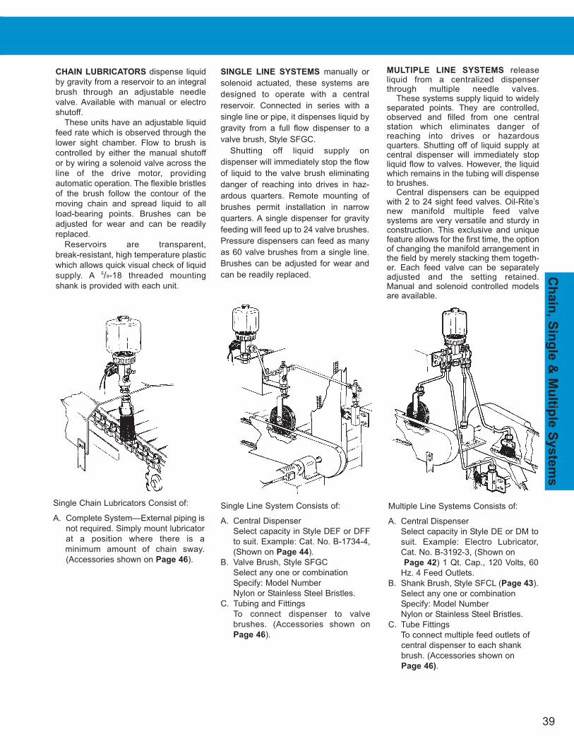
39
Ch
ain
, Sin
gle
& M
ultip
le S
yste
ms
CHAIN LUBRICATORS dispense liquid
by gravity from a reservoir to an integral
brush through an adjustable needle
valve. Available with manual or electro
shutoff.
These units have an adjustable liquid
feed rate which is observed through the
lower sight chamber. Flow to brush is
controlled by either the manual shutoff
or by wiring a solenoid valve across the
line of the drive motor, providing
automatic operation. The flexible bristles
of the brush follow the contour of the
moving chain and spread liquid to all
load-bearing points. Brushes can be
adjusted for wear and can be readily
replaced.
Reservoirs are transparent,
break-resistant, high temperature plastic
which allows quick visual check of liquid
supply. A 5/8-18 threaded mounting
shank is provided with each unit.
SINGLE LINE SYSTEMS manually or
solenoid actuated, these systems are
designed to operate with a central
reservoir. Connected in series with a
single line or pipe, it dispenses liquid by
gravity from a full flow dispenser to a
valve brush, Style SFGC.
Shutting off liquid supply on
dispenser will immediately stop the flow
of liquid to the valve brush eliminating
danger of reaching into drives in haz-
ardous quarters. Remote mounting of
brushes permit installation in narrow
quarters. A single dispenser for gravity
feeding will feed up to 24 valve brushes.
Pressure dispensers can feed as many
as 60 valve brushes from a single line.
Brushes can be adjusted for wear and
can be readily replaced.
MULTIPLE LINE SYSTEMS release liquid from a centralized dispenserthrough multiple needle valves.
These systems supply liquid to widelyseparated points. They are controlled,observed and filled from one central station which eliminates danger of reaching into drives or hazardous quarters. Shutting off of liquid supply at central dispenser will immediately stopliquid flow to valves. However, the liquidwhich remains in the tubing will dispenseto brushes.
Central dispensers can be equippedwith 2 to 24 sight feed valves. Oil-Rite’snew manifold multiple feed valve systems are very versatile and sturdy inconstruction. This exclusive and uniquefeature allows for the first time, the optionof changing the manifold arrangement inthe field by merely stacking them togeth-er. Each feed valve can be separatelyadjusted and the setting retained.Manual and solenoid controlled modelsare available.
Single Chain Lubricators Consist of:
A. Complete System—External piping is
not required. Simply mount lubricator
at a position where there is a
minimum amount of chain sway.
(Accessories shown on Page 46).
Single Line System Consists of:
A. Central Dispenser
Select capacity in Style DEF or DFF
to suit. Example: Cat. No. B-1734-4,
(Shown on Page 44).
B. Valve Brush, Style SFGC
Select any one or combination
Specify: Model Number
Nylon or Stainless Steel Bristles.
C. Tubing and Fittings
To connect dispenser to valve
brushes. (Accessories shown on
Page 46).
Multiple Line Systems Consists of:
A. Central Dispenser
Select capacity in Style DE or DM to
suit. Example: Electro Lubricator,
Cat. No. B-3192-3, (Shown on
Page 42) 1 Qt. Cap., 120 Volts, 60
Hz. 4 Feed Outlets.
B. Shank Brush, Style SFCL (Page 43).
Select any one or combination
Specify: Model Number
Nylon or Stainless Steel Bristles.
C. Tube Fittings
To connect multiple feed outlets of
central dispenser to each shank
brush. (Accessories shown on
Page 46).
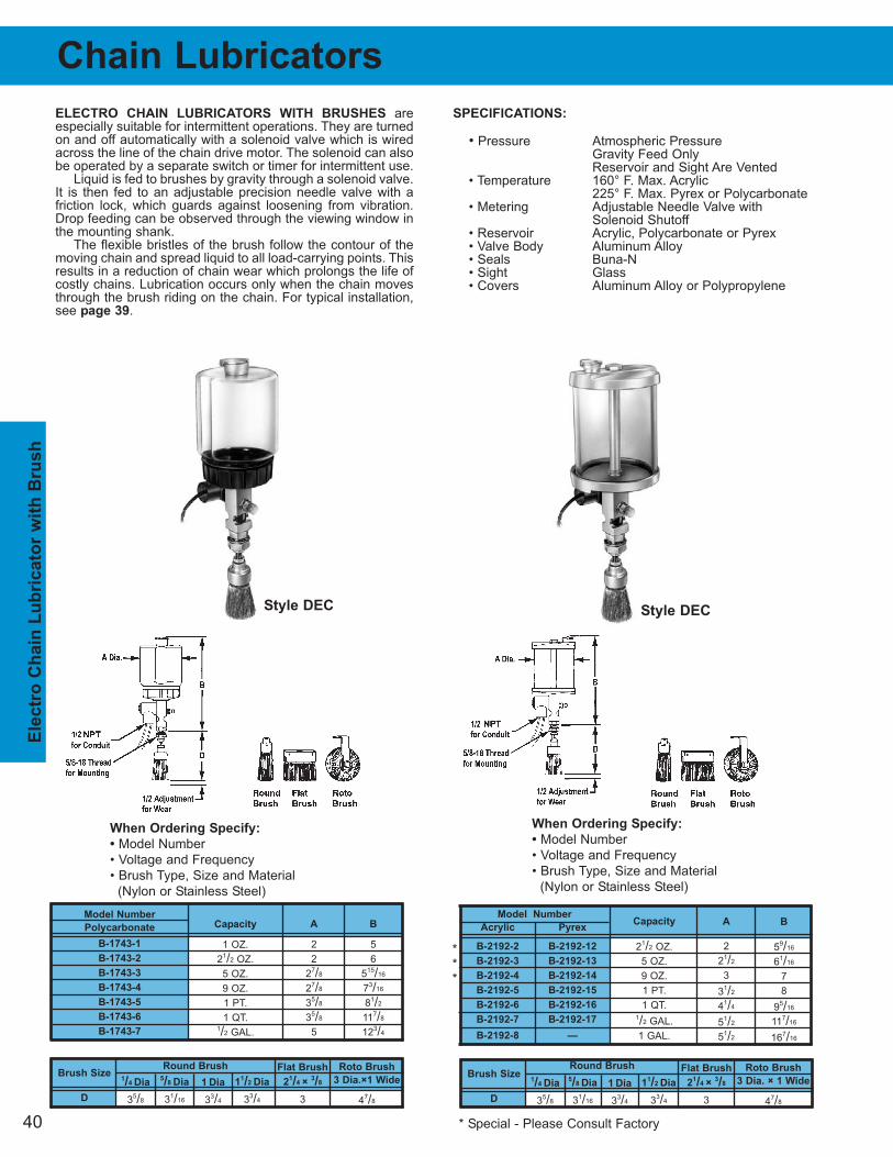
40
Ele
ctr
o C
hain
Lu
bric
ato
r w
ith
Bru
sh
Round Brush
Model Number
Acrylic Pyrex
B-2192-2 B-2192-12
B-2192-3 B-2192-13
B-2192-4 B-2192-14
B-2192-5 B-2192-15
B-2192-6 B-2192-16
B-2192-7 B-2192-17
B-2192-8 —
Brush Size
D
5/8 Dia
31/16
1 Dia
33/4
11/2 Dia
33/4
Flat Brush
21/4 ×
3/8
3
Roto Brush
3 Dia.×1 Wide
47/8
1/4 Dia
35/8
Chain Lubricators
ELECTRO CHAIN LUBRICATORS WITH BRUSHES areespecially suitable for intermittent operations. They are turnedon and off automatically with a solenoid valve which is wiredacross the line of the chain drive motor. The solenoid can alsobe operated by a separate switch or timer for intermittent use.
Liquid is fed to brushes by gravity through a solenoid valve.It is then fed to an adjustable precision needle valve with a friction lock, which guards against loosening from vibration.Drop feeding can be observed through the viewing window inthe mounting shank.
The flexible bristles of the brush follow the contour of themoving chain and spread liquid to all load-carrying points. Thisresults in a reduction of chain wear which prolongs the life ofcostly chains. Lubrication occurs only when the chain movesthrough the brush riding on the chain. For typical installation,see page 39.
SPECIFICATIONS:
• Pressure Atmospheric PressureGravity Feed OnlyReservoir and Sight Are Vented
• Temperature 160° F. Max. Acrylic225° F. Max. Pyrex or Polycarbonate
• Metering Adjustable Needle Valve withSolenoid Shutoff
• Reservoir Acrylic, Polycarbonate or Pyrex• Valve Body Aluminum Alloy• Seals Buna-N• Sight Glass• Covers Aluminum Alloy or Polypropylene
When Ordering Specify:
• Model Number
• Voltage and Frequency
• Brush Type, Size and Material
(Nylon or Stainless Steel)
When Ordering Specify:
• Model Number
• Voltage and Frequency
• Brush Type, Size and Material
(Nylon or Stainless Steel)
Model Number
Polycarbonate
B-1743-1
B-1743-2
B-1743-3
B-1743-4
B-1743-5
B-1743-6
B-1743-7
Capacity
1 OZ.
21/2 OZ.
5 OZ.
9 OZ.
1 PT.
1 QT.1/2 GAL.
A
2
2
27/8
27/8
35/8
35/8
5
B
5
6
515/16
73/16
81/2
117/8
123/4
Capacity
21/2 OZ.
5 OZ.
9 OZ.
1 PT.
1 QT.1/2 GAL.
1 GAL.
A
2
21/2
3
31/2
41/4
51/2
51/2
B
59/16
61/16
7
8
95/16
117/16
167/16
Round BrushBrush Size
D
5/8 Dia
31/16
1 Dia
33/4
11/2 Dia
33/4
Flat Brush
21/4 ×
3/8
3
Roto Brush
3 Dia. × 1 Wide
47/8
1/4 Dia
35/8
Style DEC Style DEC
***
* Special - Please Consult Factory
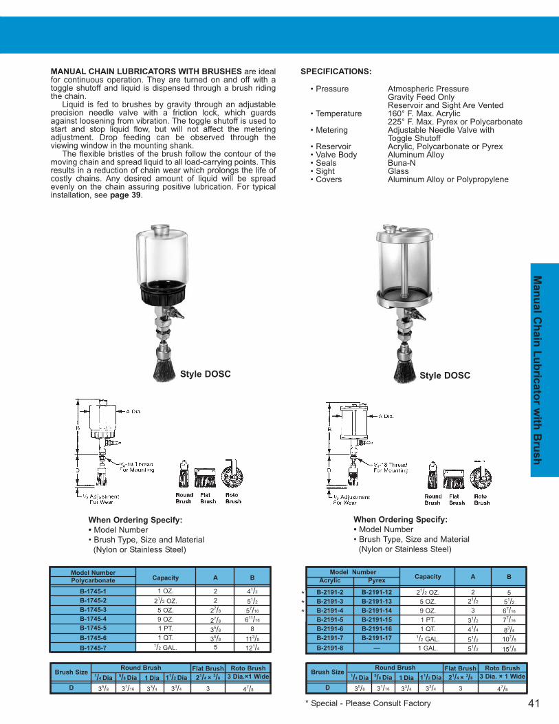
41
Man
ual C
hain
Lu
bric
ato
r w
ith B
ru
sh
MANUAL CHAIN LUBRICATORS WITH BRUSHES are idealfor continuous operation. They are turned on and off with atoggle shutoff and liquid is dispensed through a brush ridingthe chain.
Liquid is fed to brushes by gravity through an adjustable precision needle valve with a friction lock, which guardsagainst loosening from vibration. The toggle shutoff is used tostart and stop liquid flow, but will not affect the metering adjustment. Drop feeding can be observed through the viewing window in the mounting shank.
The flexible bristles of the brush follow the contour of themoving chain and spread liquid to all load-carrying points. Thisresults in a reduction of chain wear which prolongs the life ofcostly chains. Any desired amount of liquid will be spreadevenly on the chain assuring positive lubrication. For typical installation, see page 39.
SPECIFICATIONS:
• Pressure Atmospheric PressureGravity Feed OnlyReservoir and Sight Are Vented
• Temperature 160° F. Max. Acrylic225° F. Max. Pyrex or Polycarbonate
• Metering Adjustable Needle Valve withToggle Shutoff
• Reservoir Acrylic, Polycarbonate or Pyrex• Valve Body Aluminum Alloy• Seals Buna-N• Sight Glass• Covers Aluminum Alloy or Polypropylene
Round BrushBrush Size
D
5/8 Dia
31/16
1 Dia
33/4
11/2 Dia
33/4
Flat Brush
21/4 ×
3/8
3
Roto Brush
3 Dia.×1 Wide
47/8
1/4 Dia
35/8
When Ordering Specify:
• Model Number
• Brush Type, Size and Material
(Nylon or Stainless Steel)
Model Number
Polycarbonate
B-1745-1
B-1745-2
B-1745-3
B-1745-4
B-1745-5
B-1745-6
B-1745-7
Capacity
1 OZ.
21/2 OZ.
5 OZ.
9 OZ.
1 PT.
1 QT.1/2 GAL.
A
2
2
27/8
27/8
35/8
35/8
5
B
41/2
51/2
57/16
611/16
8
113/8
121/4
Model Number
Acrylic Pyrex
B-2191-2 B-2191-12
B-2191-3 B-2191-13
B-2191-4 B-2191-14
B-2191-5 B-2191-15
B-2191-6 B-2191-16
B-2191-7 B-2191-17
B-2191-8 —
When Ordering Specify:
• Model Number
• Brush Type, Size and Material
(Nylon or Stainless Steel)
Capacity
21/2 OZ.
5 OZ.
9 OZ.
1 PT.
1 QT.1/2 GAL.
1 GAL.
A
2
21/2
3
31/2
41/4
51/2
51/2
B
5
51/2
67/16
77/16
83/4
107/8
157/8
Round BrushBrush Size
D
5/8 Dia
31/16
1 Dia
33/4
11/2 Dia
33/4
Flat Brush
21/4 ×
3/8
3
Roto Brush
3 Dia. × 1 Wide
47/8
1/4 Dia
35/8
Style DOSC Style DOSC
***
* Special - Please Consult Factory

42
Sh
an
k B
ru
sh
Dis
pen
sers
C
59/16
69/16
69/16
713/16
91/8
121/2
133/8
D
5/8
5/8
5/8
5/8
5/8
5/8
5/8
A
2
2
27/8
27/8
35/8
35/8
5
Outlet
Thread Size
5/8-18 N.F. FORREMOTE
MOUNTINGWITH 1/8
FEMALEN.P.T. OUTLET
Feeds
L
M
3
21/8
5
4
27/8
53/4
5
27/8
61/2
6
35/8
71/4
12
57/8
113/4
24
103/8
203/4
2
21/8
41/4
Shank Brush Dispensers
SPECIFICATIONS:
• Pressure Atmospheric PressureGravity Feed OnlyReservoir and Sight Are Vented
• Temperature 225° F. Max.• Metering Adjustable Needle Valve with
Solenoid or Toggle Shutoff• Reservoir Polycarbonate• Valves Steel, Plated or Aluminum Alloy• Seals Buna-N• Sight Glass• Covers Polypropylene• Body Aluminum Alloy• Connector Kit Buna-N (Other Material Available)
SHANK BRUSH DISPENSERS consist of a central lubricator with single or multiple feed valves and copper orplastic tubing which connects to shank brushes.
This system allows single or multiple chain lubricationfrom one reservoir. Remote mounting of brushes permit installation in extremely narrow quarters. Drop feeding iscontrolled by feed valves directly beneath central lubricator,thus eliminating danger of reaching into drives in hazardousquarters. Shutting off liquid supply on central lubricator will immediately stop drop feeding of valves. The liquid whichremains in the tubing, however, will dispense to brushes.Central lubricators can be equipped with 1 to 24 feed outlets.Manual or automatic solenoid valve controlled models are available.
Model Number
B-3193-2
B-3193-3
B-3193-4
B-3193-5
Capacity
9 OZ.
1 PT.
1 QT.1/2 GAL.
A
27/8
35/8
35/8
5
C
91/16
101/16
137/16
141/8
Feeds
L
M
3
21/8
5
4
27/8
53/4
5
27/8
61/2
6
35/8
71/4
12
57/8
113/4
24
103/8
203/4
2
21/8
41/4
When Ordering Specify:
• Model or Catalog Number• Voltage and Frequency (If Applicable)• Number of Feeds (2 - 24, If Applicable)
Model Number
B-3192-2
B-3192-3
B-3192-4
B-3192-5
Capacity
9 OZ.
1 PT.
1 QT.1/2 GAL.
A
27/8
35/8
35/8
5
C
91/16
101/16
137/16
141/8
Model Number
B-1763-12
B-1763-13
B-1763-14
B-1763-15
B-1764-5
B-1764-6
B-1764-8
Capacity
1 OZ.
21/2 OZ.
5 OZ.
9 OZ.
1 PT.
1 QT.1/2 GAL.
C
51/16
61/16
6
71/4
85/8
12
127/8
D
5/8
5/8
5/8
5/8
5/8
5/8
5/8
A
2
2
27/8
27/8
35/8
35/8
5
Outlet
Thread Size
5/8-18 N.F. FORREMOTE
MOUNTINGWITH 1/8
FEMALEN.P.T. OUTLET
Model Number
B-1681-12
B-1681-13
B-1681-14
B-1681-15
B-1682-5
B-1682-6
B-1682-8
For Additional information See Section 1000
For Additional information See Section 1000
For Additional information See Section 1000
For Additional information See Section 1000
Capacity
1 OZ.
21/2 OZ.
5 OZ.
9 OZ.
1 PT.
1 QT.
1/2 GAL.
**
* Special - Please Consult Factory
Connector Kit
A-5671-1
Additional Valves Specify Part
Number B-3151-1
Connector Kit
A-5671-1
Additional Valves Specify Part
Number B-3151-1Style DM
Style DE
Style DOSF
Style DE
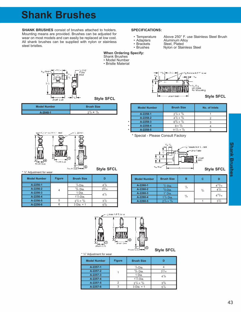
43
Sh
an
k B
ru
sh
es
When Ordering Specify:
Shank Brushes• Model Number• Bristle Material
SHANK BRUSHES consist of brushes attached to holders.Mounting means are provided. Brushes can be adjusted forwear on most models and can easily be replaced at low cost.All shank brushes can be supplied with nylon or stainlesssteel bristles.
Model Number
A-2048-1
Brush Size
21/4 × 3/8
D
41/8
39/16
41/4
31/2
53/8
Brush Size
1/4 Dia.5/8 Dia.
1 Dia.
11/2 Dia.
21/4 × 3/8
3 Dia. × 1
Model Number
A-2256-1
A-2256-2
A-2256-3
A-2256-4
A-2256-5
A-2256-6
Figure
4
5
6
* ½” Adjustment for wear
D
4
37/16
41/8
33/8
51/4
Brush Size
1/4 Dia.5/8 Dia.
1 Dia.
11/2 Dia.
21/4 × 3/8
3 Dia. × 1
Model Number
A-2257-1
A-2257-2
A-2257-3
A-2257-4
A-2257-5
A-2257-6
Figure
1
2
3
* ½” Adjustment for wear
No. of Inlets
1
2
3
4
5
Brush Size
21/4 × 3/8
41/2 × 3/8
63/4 × 3/8
9 × 3/8
111/4 × 3/8
Model Number
A-2258-1
A-2258-2
A-2258-3
A-2258-4
A-2258-5
C
3/4
1
B
1/4
3/4
D
413/16
41/4
415/16
31/2
Model Number
A-2260-1
A-2260-2
A-2260-3
A-2260-4
A-2260-5
Brush Size
1/4 Dia.5/8 Dia.
1” Dia.
11/2 Dia.
21/4 × 3/8
Shank Brushes
***
* Special - Please Consult Factory
SPECIFICATIONS:
• Temperature Above 250° F. use Stainless Steel Brush• Adapters Aluminum Alloy• Brackets Steel, Plated• Brushes Nylon or Stainless Steel
Style SFCL
Style SFCL
Style SFCL
Style SFCLStyle SFCL
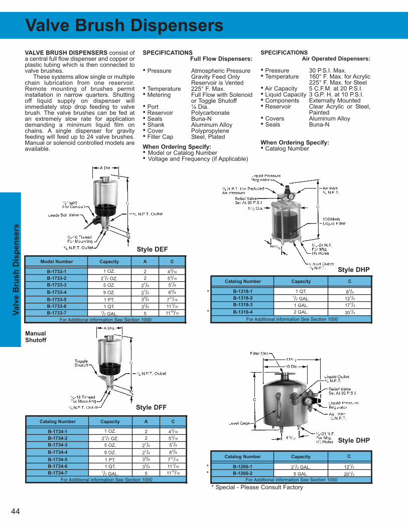
44
Valv
e B
ru
sh
Dis
pen
sers
Valve Brush Dispensers
VALVE BRUSH DISPENSERS consist ofa central full flow dispenser and copper orplastic tubing which is then connected tovalve brushes.
These systems allow single or multiplechain lubrication from one reservoir.Remote mounting of brushes permitinstallation in narrow quarters. Shuttingoff liquid supply on dispenser will immediately stop drop feeding to valvebrush. The valve brushes can be fed atan extremely slow rate for applicationdemanding a minimum liquid film onchains. A single dispenser for gravityfeeding will feed up to 24 valve brushes.Manual or solenoid controlled models areavailable.
SPECIFICATIONS
Full Flow Dispensers:
• Pressure Atmospheric PressureGravity Feed OnlyReservoir is Vented
• Temperature 225° F. Max.• Metering Full Flow with Solenoid
or Toggle Shutoff• Port ¼ Dia.• Reservoir Polycarbonate• Seals Buna-N• Shank Aluminum Alloy• Cover Polypropylene• Filler Cap Steel, Plated
When Ordering Specify:
• Model or Catalog Number• Voltage and Frequency (if Applicable)
SPECIFICATIONS
Air Operated Dispensers:
• Pressure 30 P.S.I. Max.• Temperature 160° F. Max. for Acrylic
225° F. Max. for Steel• Air Capacity 5 C.F.M. at 20 P.S.I.• Liquid Capacity 3 G.P. H. at 10 P.S.I.• Components Externally Mounted• Reservoir Clear Acrylic or Steel,
Painted• Covers Aluminum Alloy• Seals Buna-N
When Ordering Specify:
• Catalog Number
Catalog Number
B-1734-1
B-1734-2
B-1734-3
B-1734-4
B-1734-5
B-1734-6
B-1734-7
Capacity
1 OZ.
21/2 OZ.
5 OZ.
9 OZ.
1 PT.
1 QT.1/2 GAL.
A
2
2
27/8
27/8
35/8
35/8
5
C
43/16
53/16
51/8
63/8
711/16
111/16
1115/16
For Additional information See Section 1000
Model Number
B-1733-1
B-1733-2
B-1733-3
B-1733-4
B-1733-5
B-1733-6
B-1733-7
Capacity
1 OZ.
21/2 OZ.
5 OZ.
9 OZ.
1 PT.
1 QT.1/2 GAL.
A
2
2
27/8
27/8
35/8
35/8
5
C
43/16
53/16
51/8
63/8
711/16
111/16
1115/16
For Additional information See Section 1000
Catalog Number
B-1266-1
B-1266-2
Capacity
21/2 GAL.
5 GAL.
C
121/2
201/2
For Additional information See Section 1000
Catalog Number
B-1318-1
B-1318-2
B-1318-3
B-1318-4
Capacity
1 QT.1/2 GAL.
1 GAL.
2 GAL.
C
83/4
121/4
171/4
301/4
For Additional information See Section 1000
Manual
Shutoff
**
* Special - Please Consult Factory
*
*
Style DEF
Style DFF
Style DHP
Style DHP
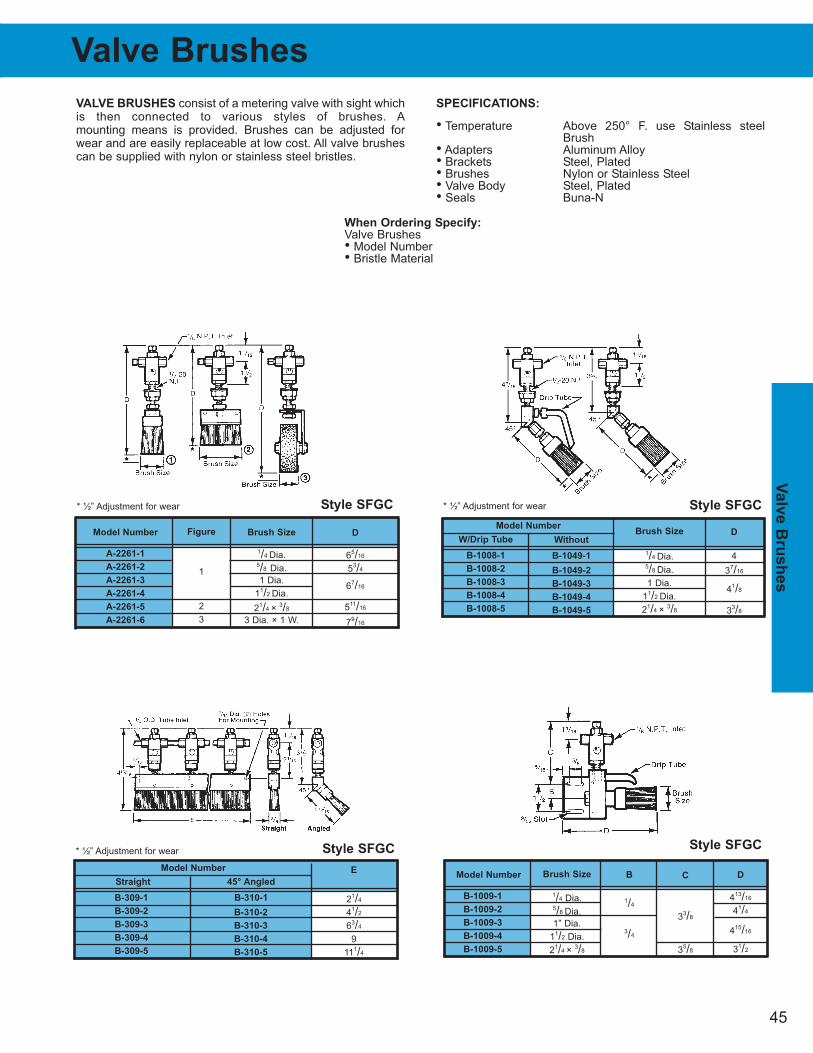
45
Valv
e B
ru
sh
es
When Ordering Specify:
Valve Brushes• Model Number• Bristle Material
VALVE BRUSHES consist of a metering valve with sight whichis then connected to various styles of brushes. Amounting means is provided. Brushes can be adjusted forwear and are easily replaceable at low cost. All valve brushescan be supplied with nylon or stainless steel bristles.
SPECIFICATIONS:
• Temperature Above 250° F. use Stainless steelBrush
• Adapters Aluminum Alloy• Brackets Steel, Plated• Brushes Nylon or Stainless Steel• Valve Body Steel, Plated• Seals Buna-N
D
65/16
53/4
67/16
511/16
79/16
Brush Size
1/4 Dia.5/8 Dia.
1 Dia.
11/2 Dia.
21/4 × 3/8
3 Dia. × 1 W.
Model Number
A-2261-1
A-2261-2
A-2261-3
A-2261-4
A-2261-5
A-2261-6
Figure
1
2
3
* ½” Adjustment for wear
E
21/4
41/2
63/4
9
111/4
45° Angled
B-310-1
B-310-2
B-310-3
B-310-4
B-310-5
Straight
B-309-1
B-309-2
B-309-3
B-309-4
B-309-5
* ½” Adjustment for wear
C
33/8
35/8
B
1/4
3/4
D
413/16
41/4
415/16
31/2
Model Number
B-1009-1
B-1009-2
B-1009-3
B-1009-4
B-1009-5
Brush Size
1/4 Dia.5/8 Dia.
1” Dia.
11/2 Dia.
21/4 × 3/8
Model Number
Brush Size
1/4 Dia.5/8 Dia.
1 Dia.
11/2 Dia.
21/4 × 3/8
Without
B-1049-1
B-1049-2
B-1049-3
B-1049-4
B-1049-5
W/Drip Tube
B-1008-1
B-1008-2
B-1008-3
B-1008-4
B-1008-5
* ½” Adjustment for wear
Model NumberD
4
37/16
41/8
33/8
Valve Brushes
Style SFGC Style SFGC
Style SFGC Style SFGC
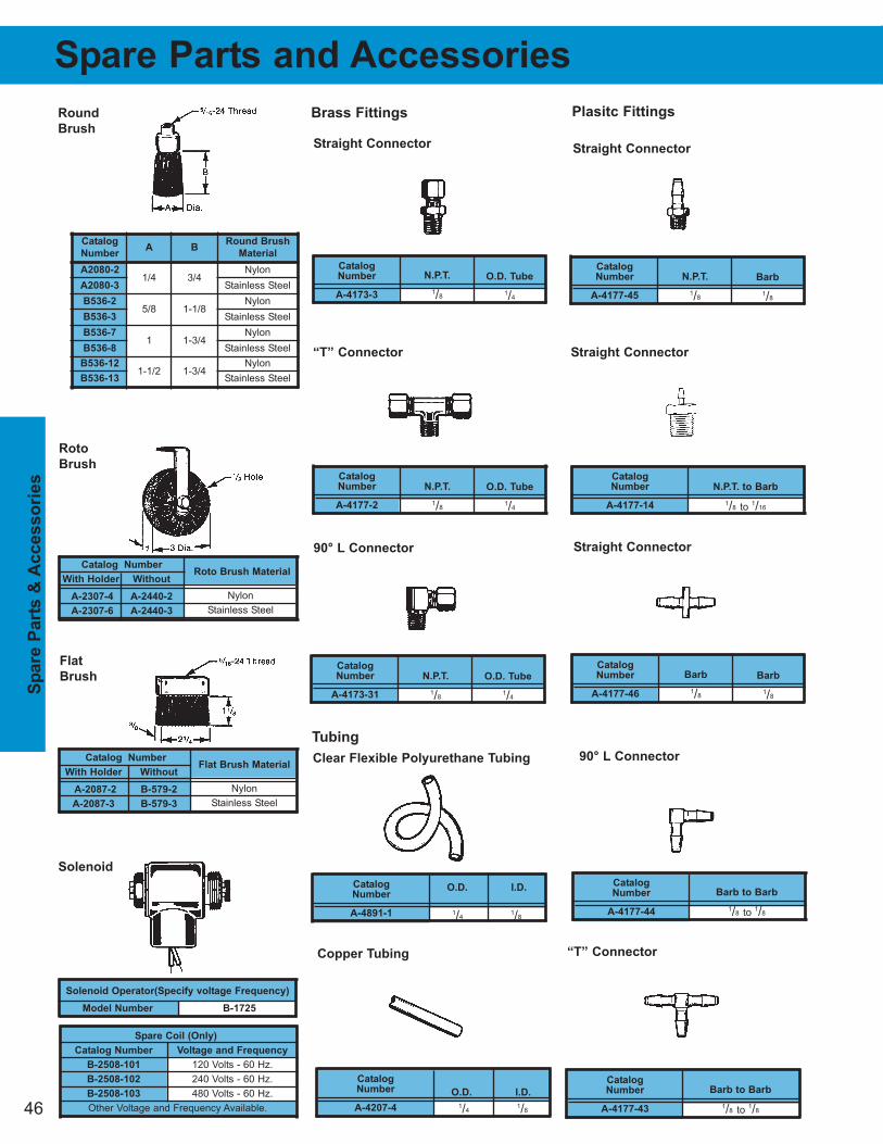
46
Sp
are P
arts
& A
ccesso
rie
s
Spare Parts and Accessories
Catalog Number
With Holder Without
A-2307-4 A-2440-2
A-2307-6 A-2440-3
Roto Brush Material
Nylon
Stainless Steel
Catalog Number
With Holder Without
A-2087-2 B-579-2
A-2087-3 B-579-3
Flat Brush Material
Nylon
Stainless Steel
Flat
Brush
Roto
Brush
Solenoid Operator(Specify voltage Frequency)
Model Number B-1725
Spare Coil (Only)
Catalog Number Voltage and Frequency
B-2508-101 120 Volts - 60 Hz.
B-2508-102 240 Volts - 60 Hz.
B-2508-103 480 Volts - 60 Hz.
Other Voltage and Frequency Available.
Solenoid
Brass Fittings
Straight Connector
N.P.T.
1/8
Catalog
Number
A-4173-3
O.D. Tube
1/4
“T” Connector
N.P.T.
1/8
Catalog
Number
A-4177-2
O.D. Tube
1/4
90° L Connector
N.P.T.
1/8
Catalog
Number
A-4173-31
O.D. Tube
1/4
Clear Flexible Polyurethane Tubing
O.D. I.D.
1/4 1/8
Catalog
Number
A-4891-1
Tubing
Copper Tubing
Straight Connector
N.P.T. to Barb
1/8 to 1/16
Catalog
Number
A-4177-14
Straight Connector
“T” Connector
O.D. I.D.
1/4 1/8
Catalog
Number
A-4207-4
90° L Connector
Barb to Barb
1/8 to 1/8
Catalog
Number
A-4177-44
Barb to Barb
1/8 to 1/8
Catalog
Number
A-4177-43
Barb
1/8
Catalog
Number
A-4177-46
Barb
1/8
Straight Connector
N.P.T.
1/8
Catalog
Number
A-4177-45
Barb
1/8
Plasitc FittingsRound
Brush
Catalog
NumberA B
Round Brush
Material
A2080-2 Nylon
A2080-3 Stainless Steel
B536-2 Nylon
B536-3 Stainless Steel
B536-7 Nylon
B536-8 Stainless Steel
B536-12 Nylon
B536-13 Stainless Steel1-1/2 1-3/4
1 1-3/4
1-1/85/8
3/41/4
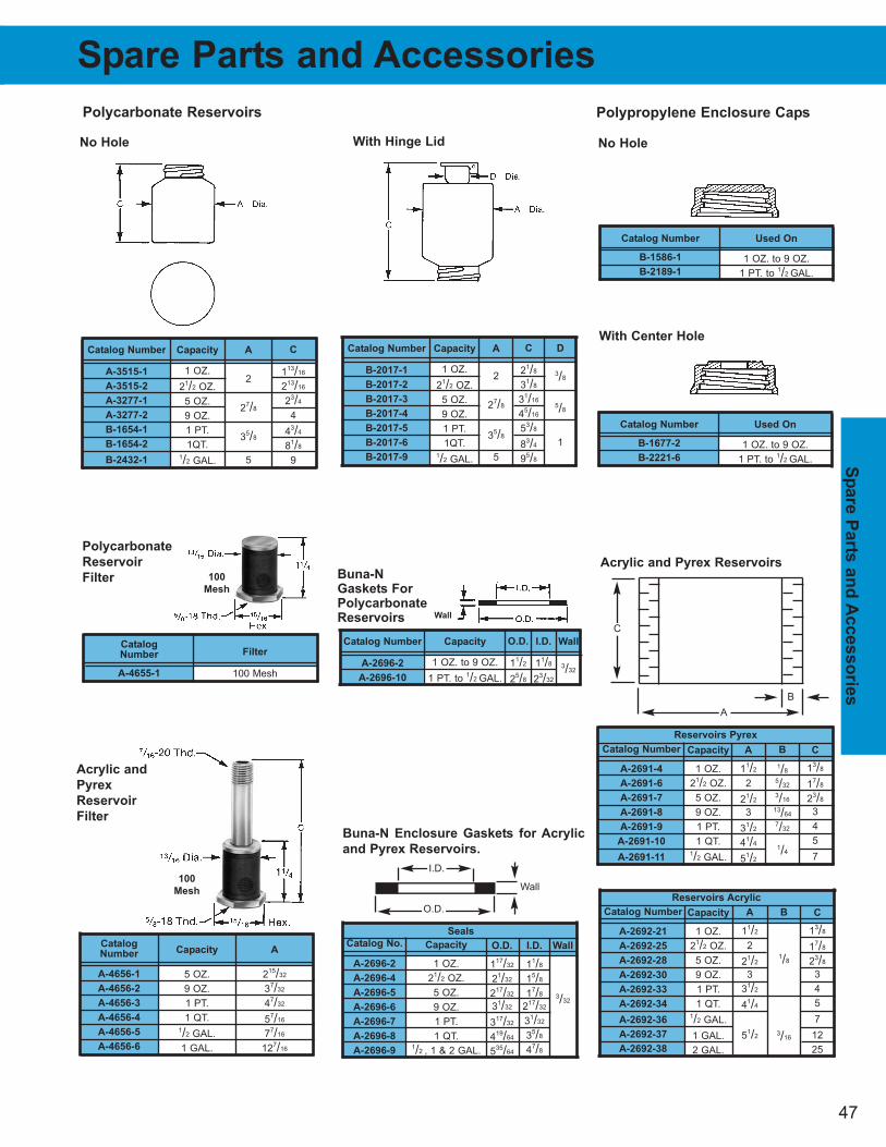
47
Sp
are P
arts
an
d A
ccesso
rie
s
Wall
3/32
Catalog Number
A-2696-2
A-2696-10
Capacity
1 OZ. to 9 OZ.
1 PT. to 1/2 GAL.
O.D.
11/2
25/8
I.D.
11/8
23/32
Spare Parts and Accessories
Buna-N
Gaskets For
Polycarbonate
Reservoirs Wall
Filter
100 Mesh
Catalog
Number
A-4655-1
Capacity
5 OZ.
9 OZ.
1 PT.
1 QT.1/2 GAL.
1 GAL.
Catalog
Number
A-4656-1
A-4656-2
A-4656-3
A-4656-4
A-4656-5
A-4656-6
A
215/32
37/32
47/32
57/16
77/16
127/16
100
Mesh
100
Mesh
Acrylic and
Pyrex
Reservoir
Filter
Polycarbonate
Reservoir
Filter
Catalog Number
A-3515-1
A-3515-2
A-3277-1
A-3277-2
B-1654-1
B-1654-2
B-2432-1
Capacity
1 OZ.
21/2 OZ.
5 OZ.
9 OZ.
1 PT.
1QT.1/2 GAL.
A
2
27/8
35/8
5
C
113/16
213/16
23/4
4
43/4
81/8
9
Polycarbonate Reservoirs
No Hole
Catalog Number
B-2017-1
B-2017-2
B-2017-3
B-2017-4
B-2017-5
B-2017-6
B-2017-9
Capacity
1 OZ.
21/2 OZ.
5 OZ.
9 OZ.
1 PT.
1QT.1/2 GAL.
A
2
27/8
35/8
5
C
21/8
31/8
31/16
45/16
53/8
83/4
95/8
D
3/8
5/8
1
With Hinge Lid
Catalog Number
B-1677-2
B-2221-6
Used On
1 OZ. to 9 OZ.
1 PT. to 1/2 GAL.
No Hole
With Center Hole
Polypropylene Enclosure Caps
Catalog Number
B-1586-1
B-2189-1
Used On
1 OZ. to 9 OZ.
1 PT. to 1/2 GAL.
Reservoirs Acrylic
B
1/8
3/16
A
11/2
2
21/2
3
31/2
41/4
51/2
Catalog Number
A-2692-21
A-2692-25
A-2692-28
A-2692-30
A-2692-33
A-2692-34
A-2692-36
A-2692-37
A-2692-38
Capacity
1 OZ.
21/2 OZ.
5 OZ.
9 OZ.
1 PT.
1 QT.1/2 GAL.
1 GAL.
2 GAL.
C
13/8
17/8
23/8
3
4
5
7
12
25
B
1/8
5/32
3/16
13/64
7/32
1/4
A
11/2
2
21/2
3
31/2
41/4
51/2
Catalog Number
A-2691-4
A-2691-6
A-2691-7
A-2691-8
A-2691-9
A-2691-10
A-2691-11
Capacity
1 OZ.
21/2 OZ.
5 OZ.
9 OZ.
1 PT.
1 QT.1/2 GAL.
C
13/8
17/8
23/8
3
4
5
7
Reservoirs Pyrex
Acrylic and Pyrex Reservoirs
A
B
C
Seals
I.D.
11/8
15/8
17/8
217/32
31/32
35/8
47/8
O.D.
117/32
21/32
217/32
31/32
317/32
419/64
535/64
Catalog No.
A-2696-2
A-2696-4
A-2696-5
A-2696-6
A-2696-7
A-2696-8
A-2696-9
Capacity
1 OZ.
21/2 OZ.
5 OZ.
9 OZ.
1 PT.
1 QT.1/2 , 1 & 2 GAL.
Wall
3/32
Buna-N Enclosure Gaskets for Acrylic
and Pyrex Reservoirs.
Wall
O.D.
I.D.
Help
ful
Info
rm
ati
on
48
Helpful information
HELPFUL HINTS FOR
OPERATION AND MAINTENANCE OF
CHAIN CONVEYORS AND ELEVATORS
EXCESSIVE NOISE
Possible Causes
1. Misalignment2. Too little or too much slack3. Improper lubrication4. Loose casing or sprockets5. Worn chain or sprockets
What to Do
1. Check alignment and correct2. Adjust take-up3. Lubricate properly (follow instructions in lubrication
section)4. Draw up all bolts...brace housings if necessary5. Replace chain and sprocket
WEAR ON CHAIN SIDE BARS AND SIDES OF SPROCKET
TEETH
Possible Causes
1. Misalignment2. Obstruction in guides, ways or troughs
What to Do
1. Correct alignment of sprockets and shafts2. Remove obstruction...repair or replace damaged
guides, ways or troughs
CHAIN CLIMBS SPROCKETS
Possible Causes
1. Poorly fitting sprockets2. Chain worn long in pitch...or worn out3. Insufficient chain wrap or excessive slack4. Material build-up in sprocket tooth pockets5. Loose or broken buckets
What to Do
1. Replace sprockets... and chain if necessary2. Replace chain3. Increase chain wrap with idler or adjust center for
proper slack4. Remove material build-up5. Tighten, repair or replace buckets
BROKEN PINS AND ROLLERS
Possible Causes
1. Conveyor speed too high for chain2. Shock or suddenly applied loads3. Inadequate lubrication4. Material build-up in sprocket tooth pockets5. Buckets striking casing
What to Do
1. Use chain of shorter pitch or sprocket with more teeth2. Reduce shock loads...easy starts give long life3. Lubricate properly (follow instructions in lubrication
section)4. Remove material build-up5. Check bucket clearance with casing and tighten loose
buckets
PULSATION
Possible Causes
1. Chain tension too low2. Chain speed too slow3. Obstruction4. Heavy or tacky lubricants5. Sprockets with too few number of teeth, resulting in
large amount of chordal actionWhat to Do
1. Adjust take-ups to restore proper tension2. Increase size of sprocket or increase conveyor speed3. Remove obstruction and be sure lower strand is not
striking foreign obstruction, ways or trough4. Lubricate correctly (follow instructions in lubrication
section)5. Replace with sprockets having correct number of teeth
CHAIN GETS STIFF JOINTS
Possible Causes
1. Misalignment2. Material in chain joint3. Improper lubrication4. Corrosion5. Peening of side bars6. Excessive overloads
What to Do
1. Check sprocket and shaft alignment, and correctreplace damaged chain if necessary
2. Remove foreign material 3. Lubricate properly (follow instructions in lubrication
section)4. Protect chain from corrosion with case...clean and
lubricate more often5. Check for interference between chain and another
member, and correct
BROKEN SPROCKET TEETH
Possible Causes
1. Excessive shock loads2. Objects wedged between chain and sprocket3. Chain climbing sprocket teeth
What to Do
1. Avoid shocks...easy starts give long life2. Remove and protect from foreign objects...alter trough
at discharge point to prevent dropping of objects ontosprocket teeth
3. (Refer to Chain Climbs Sprocket)
RAPID WEAR ON TROUGHS, WAYS OR CASINGS
Possible Causes
1. Abrasive material or obstructions in troughs, ways or casings
2. Bent or damaged flights, attachments or links3. Insufficient trough lubrication
What to Do
1. Remove obstructions and try to avoid accumulation ofabrasive material
2. Replace or repair damaged flights, attachments andlinks
3. Lubricate properly where lubrication is permitted
DAMAGE TO CONVEYED ARTICLES
Possible Causes
1. Bent or damaged flights, attachments or links2. Obstruction in troughs, ways or casings3. Improper timing
What to Do
1. Repair or replace damaged parts2. Remove obstruction3. Check timing sequence, chain elongation, chain
selection
CHAIN CLINGS TO SPROCKETS
Possible Causes
1. Incorrect or badly worn sprockets
2. Heavy or tacky lubricants
3. Material build-up in driver sprocket tooth pockets
What to Do
1. Replace chain and sprockets
2. Clean and lubricate properly3. Remove material build-up...protect from contact with
foreign material, or use sprockets with mud relief, pitchline clearance.
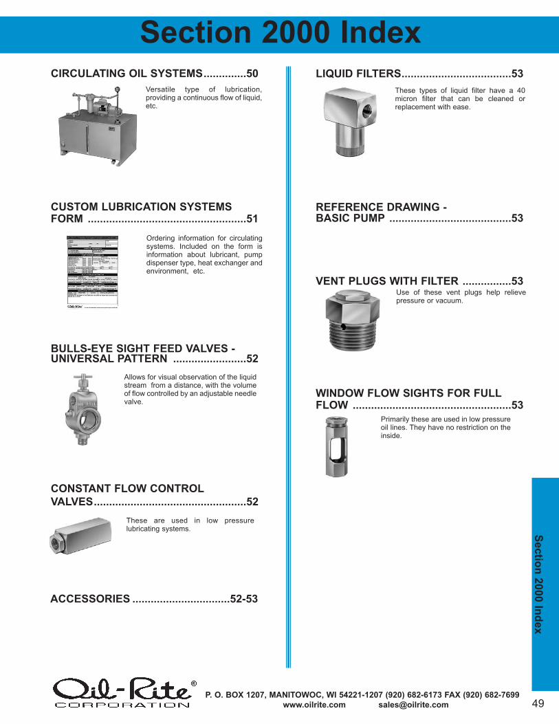
P. O. BOX 1207, MANITOWOC, WI 54221-1207 (920) 682-6173 FAX (920) 682-7699
www.oilrite.com [email protected] 49
Sectio
n 2
000 In
dex
CIRCULATING OIL SYSTEMS..............50
CUSTOM LUBRICATION SYSTEMS
FORM ....................................................51
BULLS-EYE SIGHT FEED VALVES -UNIVERSAL PATTERN ........................52
CONSTANT FLOW CONTROL
VALVES..................................................52
LIQUID FILTERS....................................53
REFERENCE DRAWING -
BASIC PUMP ........................................53
VENT PLUGS WITH FILTER ................53
WINDOW FLOW SIGHTS FOR FULL
FLOW ....................................................53
Section 2000 Index
These are used in low pressure lubricating systems.
Primarily these are used in low pressureoil lines. They have no restriction on theinside.
Use of these vent plugs help relievepressure or vacuum.
Versatile type of lubrication, providing a continuous flow of liquid,etc.
These types of liquid filter have a 40micron filter that can be cleaned orreplacement with ease.
Allows for visual observation of the liquidstream from a distance, with the volumeof flow controlled by an adjustable needlevalve.
Ordering information for circulatingsystems. Included on the form isinformation about lubricant, pumpdispenser type, heat exchanger andenvironment, etc.
ACCESSORIES ................................52-53
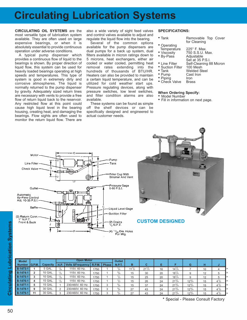
50
Cir
cu
lati
ng
Lu
bric
ati
on
Syste
ms
F
141/4
181/4
181/4
213/4
213/4
213/4
213/4
E
16
20
20
24
24
24
24
H
10
12
12
15
15
15
15
B
111/2
15
15
15
15
27
27
C
211/2
30
25
26
37
43
43
G
7
9
9
123/4
123/4
123/4
123/4
J
4
5
5
41/2
41/2
41/2
41/2
CIRCULATING OIL SYSTEMS are themost versatile type of lubrication systemavailable. They are often used on largeexpensive bearings, or when it isabsolutely essential to provide continuousoperation under adverse conditions.
A typical pump dispenser which provides a continuous flow of liquid to the bearings is shown. By proper direction ofliquid flow, this system can be used for heavily loaded bearings operating at highspeeds and temperatures. This type ofsystem is good in extremely dirty and corrosive atmospheres. The liquid is normally returned to the pump dispenserby gravity. Adequately sized return linesare necessary with vents to provide a freeflow of return liquid back to the reservoir.Any restricted flow at this point couldcause high liquid level in the bearinghousing, creating heat, and damaging the bearings. Flow sights are often used tomonitor the return liquid flow. There are
also a wide variety of sight feed valvesand control valves available to adjust and regulate the liquid flow into the bearing.
Several of the common options available for the pump dispensers aredual pumps for a back up system, dual filters available in micron ratings down to5 microns, heat exchangers, either aircooled or water cooled, permitting heatremoval rates extending into the hundreds of thousands of BTU/HR.Heaters can also be provided to maintaina certain liquid temperature, and can be utilized for cold weather start ups.Pressure regulating devices, along withpressure switches, low level switches,and filter condition alarms are also available.
These systems can be found as simpleoff the shelf devices or can be specifically designed and engineered toactual customer needs.
SPECIFICATIONS:
• Tank Removable Top Coverfor Cleaning
• OperatingTemperature 225° F. Max.
• Viscosity 750 S.S.U. Max.• By-Pass Adjustable
Set at 35 P.S.I.• Line Filter Self-Cleaning 88 Micron• Suction Filter 100 Mesh• Tank Welded Steel• Pump Cast Iron• Piping Iron• Check Valve Brass
When Ordering Specify:
• Model Number• Fill in information on next page.
Phase
1
1
1
1
3
3
3
Model
Number
B-1473-1
B-1474-1
B-1475-1
B-1476-1
B-1477-1
B-1478-1
B-1479-1
Capacity
5 GAL.
10 GAL.
10 GAL.
15 GAL.
15 GAL.
30 GAL.
30 GAL.
H.P.
1/4
1/3
1/3
1/2
1
2
3
Volts &Frequency
115V. 60 Hz.
115V. 60 Hz.
115V. 60 Hz.
115V. 60 Hz.
230/460V. 60 Hz.
230/460V. 60 Hz.
230/460V. 60 Hz.
R.P.M.
1750
1750
1750
1750
1750
1750
1750
G.P.M.
1
2
3
4
5
9
11
Open Motor Outlet
N.P.T.
1/4
3/8
1/2
1/2
3/4
3/4
3/4
Circulating Lubrication Systems
******
*
* Special - Please Consult Factory
CUSTOM DESIGNED
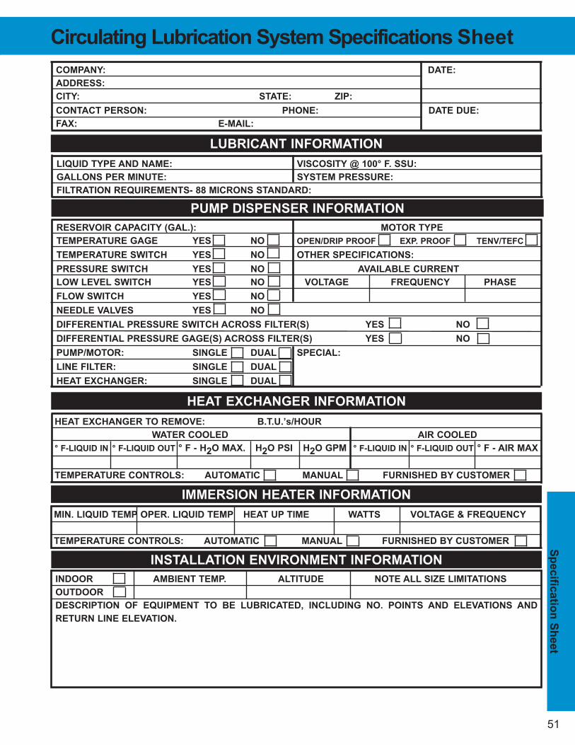
51
Sp
ecific
atio
n S
heet
HEAT EXCHANGER TO REMOVE: B.T.U.’s/HOUR
WATER COOLED AIR COOLED
° F-LIQUID IN ° F-LIQUID OUT ° F - H2O MAX. H2O PSI H2O GPM ° F-LIQUID IN ° F-LIQUID OUT ° F - AIR MAX
TEMPERATURE CONTROLS: AUTOMATIC MANUAL FURNISHED BY CUSTOMER
COMPANY: DATE:
ADDRESS:
CITY: STATE: ZIP:
CONTACT PERSON: PHONE: DATE DUE:
FAX: E-MAIL:
LUBRICANT INFORMATION
LIQUID TYPE AND NAME: VISCOSITY @ 100° F. SSU:
GALLONS PER MINUTE: SYSTEM PRESSURE:
FILTRATION REQUIREMENTS- 88 MICRONS STANDARD:
PUMP DISPENSER INFORMATION
RESERVOIR CAPACITY (GAL.): MOTOR TYPE
TEMPERATURE GAGE YES NO OPEN/DRIP PROOF EXP. PROOF TENV/TEFC
TEMPERATURE SWITCH YES NO OTHER SPECIFICATIONS:
PRESSURE SWITCH YES NO AVAILABLE CURRENT
LOW LEVEL SWITCH YES NO VOLTAGE FREQUENCY PHASE
FLOW SWITCH YES NO
NEEDLE VALVES YES NO
DIFFERENTIAL PRESSURE SWITCH ACROSS FILTER(S) YES NO
DIFFERENTIAL PRESSURE GAGE(S) ACROSS FILTER(S) YES NO
PUMP/MOTOR: SINGLE DUAL SPECIAL:
LINE FILTER: SINGLE DUAL
HEAT EXCHANGER: SINGLE DUAL
HEAT EXCHANGER INFORMATION
IMMERSION HEATER INFORMATION
MIN. LIQUID TEMP OPER. LIQUID TEMP HEAT UP TIME WATTS VOLTAGE & FREQUENCY
TEMPERATURE CONTROLS: AUTOMATIC MANUAL FURNISHED BY CUSTOMER
INSTALLATION ENVIRONMENT INFORMATION
INDOOR AMBIENT TEMP. ALTITUDE NOTE ALL SIZE LIMITATIONS
OUTDOOR
DESCRIPTION OF EQUIPMENT TO BE LUBRICATED, INCLUDING NO. POINTS AND ELEVATIONS AND
RETURN LINE ELEVATION.
Circulating Lubrication System Specifications Sheet
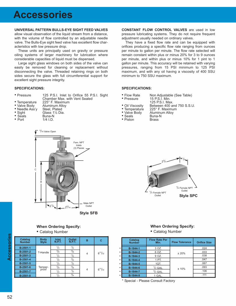
52
Ac
cesso
rie
s
OutletN.P.T.
1/4
3/8
1/2
3/4
1/4
3/8
1/2
3/4
InletN.P.T.
1/4
3/8
1/2
1/2
1/4
3/8
1/2
1/2
UNIVERSAL PATTERN BULLS-EYE SIGHT FEED VALVES
allow visual observation of the liquid stream from a distance,
with the volume of flow controlled by an adjustable needle
valve. The Bulls-Eye sight feed valve has excellent flow char-
acteristics with low pressure drop.
These units are principally used on gravity or pressure
oiling systems of larger machinery for lubrication where
considerable capacities of liquid must be dispensed.
Large sight glass windows on both sides of the valve can
easily be removed for cleaning or replacement without
disconnecting the valve. Threaded retaining rings on both
sides secure the glass with full circumferential support for
excellent sight pressure integrity.
SPECIFICATIONS:
• Pressure 125 P.S.I. Inlet to Orifice 55 P.S.I. SightChamber Max. with Vent Sealed
• Temperature 225° F. Maximum• Valve Body Aluminum Alloy• Needle Ass’y Steel, Plated• Sight Glass 1½ Dia.• Seals Buna-N• Port 1/4 I.D.
CONSTANT FLOW CONTROL VALVES are used in low
pressure lubricating systems. They do not require frequent
adjustment usually needed on ordinary valves.
They have a fixed flow rate and can be equipped with
orifices producing a specific flow rate ranging from ounces
per minute to gallon per minute. The flow rate selected will
remain constant within plus or minus 20% for 3 to 9 ounces
per minute, and within plus or minus 10% for 1 pint to 1
gallon per minute. This accuracy will be retained with varying
pressures, ranging from 15 PSI minimum to 125 PSI
maximum, and with any oil having a viscosity of 400 SSU
minimum to 750 SSU maximum.
SPECIFICATIONS:
• Flow Rate Non Adjustable (See Table) • Pressure 15 P.S.I. Min.
125 P.S.I. Max.• Oil Viscosity Between 400 and 750 S.S.U.• Temperature 225° F. Maximum• Valve Body Aluminum Alloy• Seals Buna-N• Piston Brass
Accessories
Catalog
Number
B-1844-1
B-1844-2
B-1844-3
B-1844-4
B-1844-5
B-1844-6
B-1844-7
B-1844-9
Flow Rate Per
Min.
3 OZ.
6 OZ.
9 OZ.
1 PT.
1QT.1/2 GAL.3/4 GAL.
1 GAL.
Flow Tolerance
± 20%
± 10%
Orifice Size
.024
.033
.038
.047
.067
.093
.106
.111
Catalog
Number
B-2501-1
B-2501-2
B-2501-3
B-2501-4
B-2501-5
B-2501-6
B-2501-7
B-2501-8
Body
Style
T-Handle
Tamper-proof
B
4
4
C
611/32
611/32
When Ordering Specify:
• Catalog Number
When Ordering Specify:
• Catalog Number
Male NPT
Outlet25/16
21/8
B
C
Fem. NPT
Inlets
(3) Places
5/16 Valve Open
1/4 Female NPTOutlet1/4 Female NPT
Outlet
23/4
7/8
Style SPC
Style SFB
* Special - Please Consult Factory
********
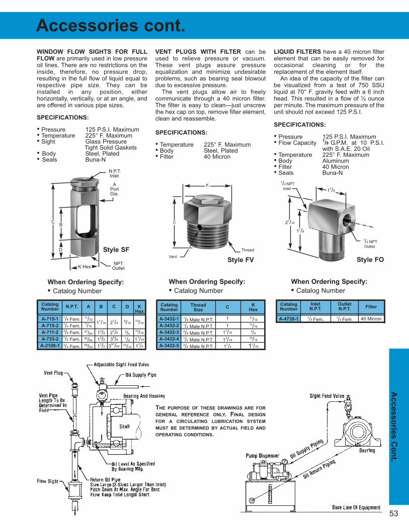
53
Accesso
rie
s C
on
t.
Thread
Size
1/8 Male N.P.T.1/4 Male N.P.T.3/8 Male N.P.T.1/2 Male N.P.T.3/4 Male N.P.T.
WINDOW FLOW SIGHTS FOR FULL
FLOW are primarily used in low pressureoil lines. There are no restrictions on theinside, therefore, no pressure drop,resulting in the full flow of liquid equal torespective pipe size. They can beinstalled in any position, either horizontally, vertically, or at an angle, andare offered in various pipe sizes.
SPECIFICATIONS:
• Pressure 125 P.S.I. Maximum • Temperature 225° F. Maximum• Sight Glass Pressure
Tight Solid Gaskets• Body Steel, Plated• Seals Buna-N
VENT PLUGS WITH FILTER can beused to relieve pressure or vacuum.These vent plugs assure pressure equalization and minimize undesirableproblems, such as bearing seal blowoutdue to excessive pressure.
The vent plugs allow air to freely communicate through a 40 micron filter.The filter is easy to clean—just unscrewthe hex cap on top, remove filter element,clean and reassemble.
SPECIFICATIONS:
• Temperature 225° F. Maximum• Body Steel, Plated• Filter 40 Micron
LIQUID FILTERS have a 40 micron filterelement that can be easily removed foroccasional cleaning or for the replacement of the element itself.
An idea of the capacity of the filter canbe visualized from a test of 750 SSU liquid at 70° F. gravity feed with a 6 inchhead. This resulted in a flow of ½ ounceper minute. The maximum pressure of theunit should not exceed 125 P.S.I.
SPECIFICATIONS:
• Pressure 125 P.S.I. Maximum• Flow Capacity
1/8 G.P.M. at 10 P.S.I.
with S.A.E. 20 Oil• Temperature 225° F. Maximum• Body Aluminum• Filter 40 Micron• Seals Buna-N
When Ordering Specify:
• Catalog Number
When Ordering Specify:
• Catalog Number
When Ordering Specify:
• Catalog Number
Catalog
Number
A-3432-1
A-3432-2
A-3432-3
A-3432-4
A-3432-5
K
Hex
11/16
11/16
3/4
15/16
11/16
C
1
1
11/16
13/16
11/4
Catalog
Number
A-715-1
A-715-2
A-711-2
A-733-2
A-2109-1
N.P.T.
1/8 Fem.1/4 Fem.3/8 Fem.1/2 Fem.3/4 Fem.
A
11/32
7/16
37/64
45/64
59/64
K
Hex
13/16
15/16
11/16
11/4
Catalog
Number
A-4739-1
Inlet
N.P.T.
1/4 Fem.
Outlet
N.P.T.
1/4 Fem.
Filter
40 Micron
D
9/16
3/4
7/8
15/16
B
11/16
13/8
13/8
11/2
C
21/4
27/8
35/8
351/64
Accessories cont.
N.P.T.Inlet
APortDia.
27/16
NPTOutlet
BC
D
K Hex
K
C
Thread
Vent
1/4 NPTInlet
1/4 NPTOutlet
17/8
17/8
Style SF
Style FV Style FO
THE PURPOSE OF THESE DRAWINGS ARE FOR
GENERAL REFERENCE ONLY. FINAL DESIGN
FOR A CIRCULATING LUBRICATION SYSTEM
MUST BE DETERMINED BY ACTUAL FIELD AND
OPERATING CONDITIONS.

55P. O. BOX 1207, MANITOWOC, WI 54221-1207 (920) 682-6173 FAX (920) 682-7699
www.oilrite.com [email protected]
Sectio
n 3
000 In
dex
Section 3000
AIR OPERATED SPRAY DISPENSERS -
CENTRAL ACRYLIC RESERVOIR........56
AIR OPERATED SPRAY DISPENSERS -
CENTRAL STEEL RESERVOIR ............57
AIR OPERATED DISPENSERS - DELUXEAIR PRESSURIZED RESERVOIR ........58
CHAIN LUBRICATION SCHEMATIC ....59
CONVEYOR CHAIN LUBRICATION
SCHEMATIC ..........................................59
CYLINDER LUBRICATION
SCHEMATIC ..........................................59
HELPFUL SUGGESTIONS FOR
REDUCING FOGGING AND
ATMOSPHERIC CONTAMINATION ......59
PATTERN AND CAPACITY CHART......59
PREVENTION OF AFTER - DRIP
INSTRUCTIONS ....................................59
SPRAY VALVES - OPERATING
INSTRUCTIONS ....................................59
Shows guide for general use only.
Versatile type of lubrication able to feedliquid to elevated, distant or inaccessiblepoints.
Simple operation in compact design withair pressurized reservoir, feeding liquidto elevated, distant, or inaccessiblepoints.
Centralized steel reservoir which dispenses liquid through one or morenozzles permitting a fine or coarsespray from any angle.
Allows for visual observation of the liquid stream from a controlledadjustable needle valve.
Shows guide for general use only.
Spray valves have excellent,dependable performance in a compact design and are offered inflat or round spray patterns.
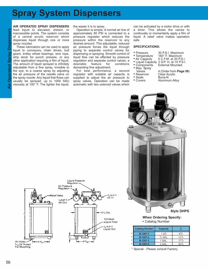
56
Air
Op
erate
d S
pray D
isp
en
sers
Spray System Dispensers
AIR OPERATED SPRAY DISPENSERS
feed liquid to elevated, distant, or inaccessible points. The system consistsof a central acrylic reservoir which dispenses liquid through one or morespray nozzles.
These lubricators can be used to applyliquid to conveyors, chain drives, bullgears, trolley wheel bearings, wire rope,strip stock for punch presses, or anyother application requiring a film of liquid.The amount of liquid sprayed is infinitelyadjustable from a fine spray, invisible tothe eye, to a coarse spray by adjustingthe air pressure of the needle valve onthe spray nozzle. Any liquid that flows canusually be sprayed, up to 1000 SSUviscosity at 100° F. The lighter the liquid,
the easier it is to spray.Operation is simple. A normal air line of
approximately 80 PSI is connected to apressure regulator which reduces thepressure within the reservoir to anydesired amount. This adjustable, reducedair pressure forces the liquid through piping to separate control valves for dispensing or spraying. Smooth control ofliquid flow can be effected by pressureregulation and separate control valves, adesirable feature for conditions demanding fine adjustment.
For best performance, a second regulator with suitable air capacity is supplied to adjust the air pressure tospray valves. Operation can be madeautomatic with two solenoid valves which
can be activated by a motor drive or witha timer. This allows the valves to continually or momentarily apply a film ofliquid. A relief valve makes operationsafe.
SPECIFICATIONS:
• Pressure 30 P.S.I. Maximum• Temperature 160° F. Maximum• Air Capacity 5 C.F.M. at 20 P.S.I.• Liquid Capacity 3 G.P. H. at 10 P.S.I.• Components External Mounted• Max. Spray
Valves 4 (Order from Page 59)• Reservoir Clear Acrylic• Seals Buna-N• Covers Aluminum Alloy
Catalog Number
B-1267-1
B-1267-2
B-1267-3
B-1267-4
Capacity
1 QT.1/2 GAL.
1 GAL.
2 GAL.
C
83/4
121/4
171/4
301/4
When Ordering Specify:
• Catalog Number
Style DHPS
****
* Special - Please consult Factory
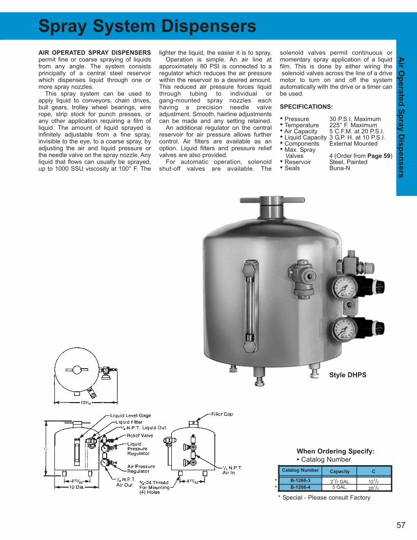
57
AIR OPERATED SPRAY DISPENSERS
permit fine or coarse spraying of liquidsfrom any angle. The system consists principally of a central steel reservoirwhich dispenses liquid through one ormore spray nozzles.
This spray system can be used toapply liquid to conveyors, chain drives,bull gears, trolley wheel bearings, wirerope, strip stock for punch presses, orany other application requiring a film ofliquid. The amount of liquid sprayed isinfinitely adjustable from a fine spray,invisible to the eye, to a coarse spray, byadjusting the air and liquid pressure orthe needle valve on the spray nozzle. Anyliquid that flows can usually be sprayed,up to 1000 SSU viscosity at 100° F. The
lighter the liquid, the easier it is to spray.Operation is simple. An air line at
approximately 80 PSI is connected to aregulator which reduces the air pressurewithin the reservoir to a desired amount.This reduced air pressure forces liquidthrough tubing to individual or gang-mounted spray nozzles each having a precision needle valve adjustment. Smooth, hairline adjustmentscan be made and any setting retained.
An additional regulator on the centralreservoir for air pressure allows furthercontrol. Air filters are available as anoption. Liquid filters and pressure reliefvalves are also provided.
For automatic operation, solenoid shut-off valves are available. The
solenoid valves permit continuous ormomentary spray application of a liquidfilm. This is done by either wiring thesolenoid valves across the line of a drive
motor to turn on and off the system automatically with the drive or a timer canbe used.
SPECIFICATIONS:
• Pressure 30 P.S.I. Maximum• Temperature 225° F. Maximum• Air Capacity 5 C.F.M. at 20 P.S.I.• Liquid Capacity 3 G.P. H. at 10 P.S.I.• Components External Mounted• Max. Spray
Valves 4 (Order from Page 59)• Reservoir Steel, Painted• Seals Buna-N
Spray System Dispensers
Catalog Number
B-1266-3
B-1266-4
Capacity
21/2 GAL.5 GAL.
C
121/2
201/2
When Ordering Specify:
• Catalog Number
Air
Op
erate
d S
pray D
isp
en
sers
Style DHPS
**
* Special - Please consult Factory
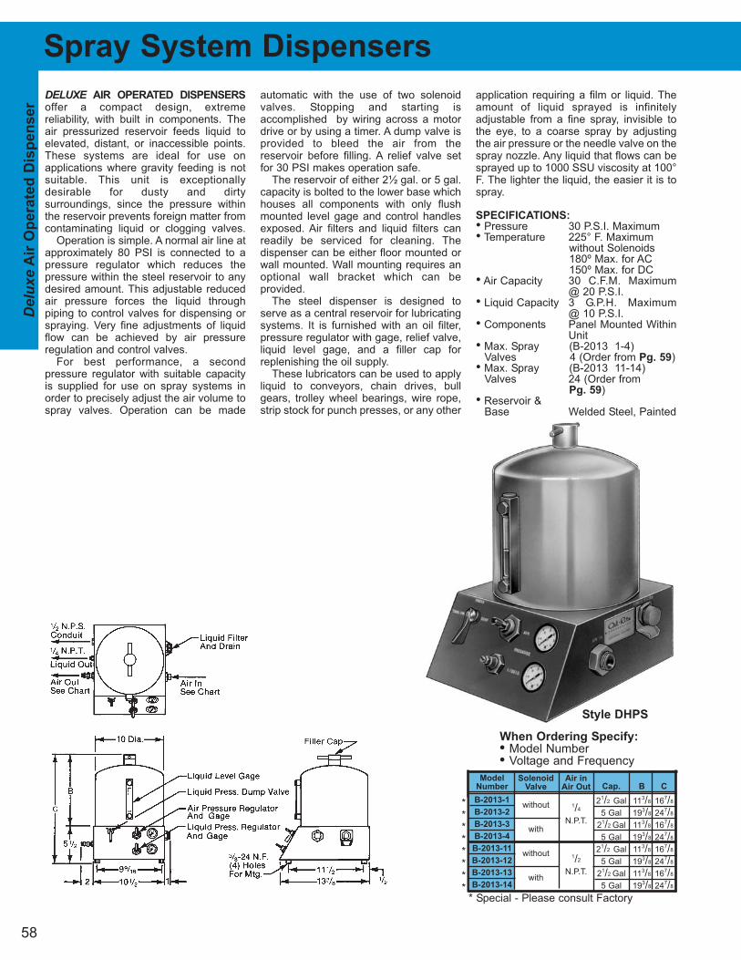
58
Del
uxe
Air
Op
erate
d D
isp
en
ser
DELUXE AIR OPERATED DISPENSERS
offer a compact design, extreme reliability, with built in components. Theair pressurized reservoir feeds liquid toelevated, distant, or inaccessible points.These systems are ideal for use on applications where gravity feeding is notsuitable. This unit is exceptionally desirable for dusty and dirty surroundings, since the pressure withinthe reservoir prevents foreign matter fromcontaminating liquid or clogging valves.
Operation is simple. A normal air line atapproximately 80 PSI is connected to apressure regulator which reduces thepressure within the steel reservoir to anydesired amount. This adjustable reducedair pressure forces the liquid through piping to control valves for dispensing orspraying. Very fine adjustments of liquidflow can be achieved by air pressure regulation and control valves.
For best performance, a second pressure regulator with suitable capacityis supplied for use on spray systems inorder to precisely adjust the air volume tospray valves. Operation can be made
automatic with the use of two solenoidvalves. Stopping and starting is accomplished by wiring across a motordrive or by using a timer. A dump valve isprovided to bleed the air from the reservoir before filling. A relief valve setfor 30 PSI makes operation safe.
The reservoir of either 2½ gal. or 5 gal.capacity is bolted to the lower base whichhouses all components with only flushmounted level gage and control handlesexposed. Air filters and liquid filters canreadily be serviced for cleaning. The dispenser can be either floor mounted orwall mounted. Wall mounting requires anoptional wall bracket which can be provided.
The steel dispenser is designed toserve as a central reservoir for lubricatingsystems. It is furnished with an oil filter,pressure regulator with gage, relief valve,liquid level gage, and a filler cap forreplenishing the oil supply.
These lubricators can be used to applyliquid to conveyors, chain drives, bullgears, trolley wheel bearings, wire rope,strip stock for punch presses, or any other
application requiring a film or liquid. Theamount of liquid sprayed is infinitelyadjustable from a fine spray, invisible tothe eye, to a coarse spray by adjustingthe air pressure or the needle valve on thespray nozzle. Any liquid that flows can besprayed up to 1000 SSU viscosity at 100°F. The lighter the liquid, the easier it is tospray.
SPECIFICATIONS:
• Pressure 30 P.S.I. Maximum• Temperature 225° F. Maximum
without Solenoids180º Max. for AC150º Max. for DC
• Air Capacity 30 C.F.M. Maximum@ 20 P.S.I.
• Liquid Capacity 3 G.P.H. Maximum @ 10 P.S.I.
• Components Panel Mounted WithinUnit
• Max. Spray (B-2013 1-4)Valves 4 (Order from Pg. 59)
• Max. Spray (B-2013 11-14)Valves 24 (Order from
Pg. 59)• Reservoir &
Base Welded Steel, Painted
When Ordering Specify:
• Model Number• Voltage and Frequency
Model
Number
B-2013-1
B-2013-2
B-2013-3
B-2013-4
B-2013-11
B-2013-12
B-2013-13
B-2013-14
Solenoid
Valve
without
with
without
with
Air in
Air Out
1/4
N.P.T.
1/2
N.P.T.
Cap.
21/2 Gal
5 Gal
21/2 Gal
5 Gal
21/2 Gal
5 Gal
21/2 Gal
5 Gal
C
167/8
247/8
167/8
247/8
167/8
247/8
167/8
247/8
B
113/8
193/8
113/8
193/8
113/8
193/8
113/8
193/8
Spray System Dispensers
Style DHPS
********
* Special - Please consult Factory
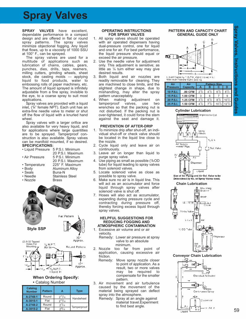
Conveyor Chain Lubrication
Chain Lubrication
Cylinder Lubrication
PATTERN AND CAPACITY CHART
GENERAL GUIDE ONLY
59
Air Air Pattern Size
Pressure Capacity A B C D
10 P.S.I. .80 CFM 21/2 41/2 61/2 81/2
15 P.S.I. 1.00 CFM 3 6 7 9
20 P.S.I. 1.25 CFM 31/2 61/2 81/2 101/2
25 P.S.I. 1.50 CFM 41/2 71/2 101/2 121/2
Sp
ray V
alv
es, In
str
uctio
ns a
nd
Gu
ides
Spray Valves
Type
Handwheel
Tamperproof
Catalog
Number
A-2748-1
A-3015-1
A-2748-2
A-3015-2
Pattern
Round
Flat
Round
Flat
A
211/16
213/16
27/16
29/16
When Ordering Specify:
• Catalog Number
Style SSP
(2) 8-32 TappedHoles ForMounting
SPRAY VALVES have excellent,dependable performance in a compactdesign and are offered in flat or roundspray patterns. The spray valves minimize objectional fogging. Any liquidthat flows, up to a viscosity of 1000 SSUat 100° F., can be sprayed.
The spray valves are used for a multitude of applications such as lubrication of chains, cables, gears,punches, dies, drills, taps, reamers,milling cutters, grinding wheels, sheetstock, die casting molds --- applying liquid to food products, water to embossing rolls of paper machinery, etc.The amount of liquid sprayed is infinitelyadjustable from a fine spray, invisible tothe eye, to a coarse spray to suit mostapplications.
Spray valves are provided with a liquidinlet, (1/8” female NPT). Each unit has anextra-fine needle valve to meter or shutoff the flow of liquid with a knurled handwheel.
Spray valves with a larger orifice arealso available for very heavy liquid, andfor applications where large quantitiesare to be sprayed. Tamperproof con-struction is also available. Spray valvescan be manifold mounted, if so desired.SPECIFICATIONS:
• Liquid Pressure 5 P.S.I. Minimum20 P.S.I. Maximum
• Air Pressure 5 P.S.I. Minimum20 P.S.I. Maximum
• Temperature 225° F. Maximum• Body Aluminum Alloy• Seals Buna-N• Needle Stainless Steel• Nozzle Brass
OPERATING INSTRUCTIONS
FOR SPRAY VALVES
1. All spray valves should be operatedwith air operated dispensers havingdual-pressure control, one for liquidand one for air. For best performance,the liquid pressure should equal orexceed the air pressure.
2. Use the needle valve for adjustmentonly. This adjustment is sensitive; aslittle as ¼ turn either way may givedesired results.
3. Both liquid and air nozzles are readily removable for cleaning. Theyare machined to close limits, and theslightest change in shape, due to mishandling, may alter the spray pattern unacceptably.
4. When making adjustment on tamperproof valves, use two wrenches so that the packing nut is not disturbed. If the packing nut is over-tightened, it could force the stemagainst the seat and damage it.
PREVENTION OF AFTER-DRIP
1. To minimize drip after shut-off, an indi-vidual shut-off or check valve shouldbe located in the liquid line close tothe nozzle.
2. Cycle liquid only and leave air on continuously.
3. Leave air on longer than liquid topurge spray valve.
4. Use piping as small as possible (1/8 ODtube) for liquid leading to spray valvesfrom solenoid valves.
5. Locate solenoid valve as close aspossible to spray valve.
6. Make sure no air is in liquid line. Thiswill act as an accumulator and forceliquid through spray valves after solenoid valve is shut off.
7. Hoses will also act as accumulator,expanding during pressure cycle andcontracting during pressure off, thereby forcing excess liquid throughspray valves.
HELPFUL SUGGESTIONS FOR
REDUCING FOGGING AND
ATMOSPHERIC CONTAMINATION
1. Excessive air volume and or air velocity.Remedy: Lower air pressure at spray
valve to an absolute minimum.
2. Nozzle too far from point of application, causing excessive air friction.Remedy: Move spray nozzle closer
to point of application. As aresult, two or more valvesmay be required to compensate for the smallerpattern.
3. Air movement and air turbulencecaused by the movement of the material being sprayed can deflectspray into the atmosphere.Remedy: Spray at an angle against
material travel.Experimentto find best angle.
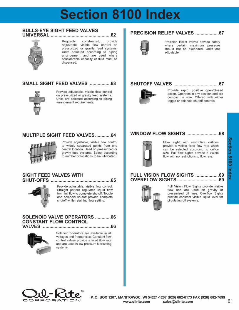
61P. O. BOX 1207, MANITOWOC, WI 54221-1207 (920) 682-6173 FAX (920) 682-7699
www.oilrite.com [email protected]
Sectio
n 8
100 In
dex
BULLS-EYE SIGHT FEED VALVES
UNIVERSAL ..............................................62
SMALL SIGHT FEED VALVES ................63
MULTIPLE SIGHT FEED VALVES............64
SIGHT FEED VALVES WITH
SHUT-OFFS ..............................................65
SOLENOID VALVE OPERATORS ............66
CONSTANT FLOW CONTROL
VALVES ....................................................66
PRECISION RELIEF VALVES ..................67
SHUTOFF VALVES ..................................67
WINDOW FLOW SIGHTS ........................68
FULL VISION FLOW SIGHTS ..................69
OVERFLOW SIGHTS ................................69
Section 8100 Index
Provide adjustable, visible flow controlon pressurized or gravity feed systems.Units are selected according to pipingarrangement requirements.
Provide adjustable, visible flow controlto widely separated points from one central location. Used on pressurized orgravity feed systems. Select accordingto number of locations to be lubricated.
Solenoid operators are available in allvoltages and frequencies. Constant flowcontrol valves provide a fixed flow rateand are used in low pressure lubricatingsystems.
Provide rapid, positive open/closedaction. Operates in any position and arecompact in size. Offered with either toggle or solenoid shutoff controls.
Precision Relief Valves provide safetywhere certain maximum pressureshould not be exceeded. Units areadjustable.
Flow sight with restrictive orifices provide a visible fixed flow rate whichcan be selected according to orificesize. Full flow sights provide a visibleflow with no restrictions to flow rate.
Ruggedly constructed, provide adjustable, visible flow control on pressurized or gravity feed systems.Units selected according to pipingarrangement and are used where considerable capacity of fluid must bedispensed.
Provide adjustable, visible flow control.Straight pattern regulates liquid flowfrom full flow to complete shutoff. Toggleand solenoid shutoff provide completeshutoff while retaining flow setting.
Full Vision Flow Sights provide visibleflow and are used on gravity or pressurized oil lines. Overflow Sights provide constant visible liquid level for circulating oil systems.
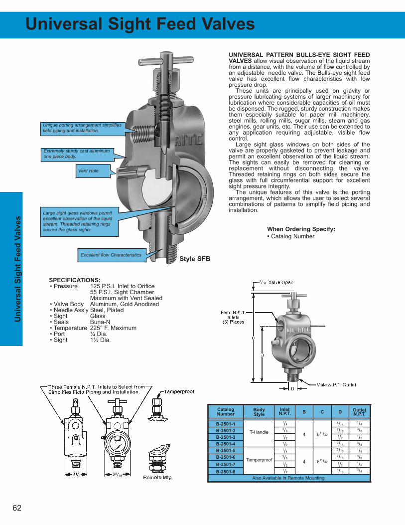
Un
iversal
Sig
ht
Feed
Valv
es
Universal Sight Feed Valves
UNIVERSAL PATTERN BULLS-EYE SIGHT FEED
VALVES allow visual observation of the liquid streamfrom a distance, with the volume of flow controlled byan adjustable needle valve. The Bulls-eye sight feedvalve has excellent flow characteristics with low pressure drop.
These units are principally used on gravity or pressure lubricating systems of larger machinery for lubrication where considerable capacities of oil mustbe dispensed. The rugged, sturdy construction makesthem especially suitable for paper mill machinery,steel mills, rolling mills, sugar mills, steam and gasengines, gear units, etc. Their use can be extended toany application requiring adjustable, visible flow control.
Large sight glass windows on both sides of thevalve are properly gasketed to prevent leakage andpermit an excellent observation of the liquid stream.The sights can easily be removed for cleaning orreplacement without disconnecting the valve.Threaded retaining rings on both sides secure theglass with full circumferential support for excellentsight pressure integrity.
The unique features of this valve is the portingarrangement, which allows the user to select severalcombinations of patterns to simplify field piping andinstallation.
62
OutletN.P.T.
1/4
3/8
1/2
3/4
1/4
3/8
1/2
3/4
B
4
4
InletN.P.T.
1/4
3/8
1/2
1/2
1/4
3/8
1/2
1/2
Catalog
Number
B-2501-1
B-2501-2
B-2501-3
B-2501-4
B-2501-5
B-2501-6
B-2501-7
B-2501-8
Body
Style
T-Handle
Tamperproof
C
611/32
611/32
D
5/16
7/16
1/2
9/16
5/16
7/16
1/2
9/16
Also Available in Remote Mounting
Unique porting arrangement simplifiesfield piping and installation.
Extremely sturdy cast aluminumone piece body.
Large sight glass windows permitexcellent observation of the liquidstream. Threaded retaining ringssecure the glass sights.
Excellent flow Characteristics
SPECIFICATIONS:
• Pressure 125 P.S.I. Inlet to Orifice55 P.S.I. Sight Chamber Maximum with Vent Sealed
• Valve Body Aluminum, Gold Anodized• Needle Ass’y Steel, Plated• Sight Glass• Seals Buna-N• Temperature 225° F. Maximum• Port ¼ Dia.• Sight 1½ Dia.
When Ordering Specify:
• Catalog Number
Style SFB
Vent Hole
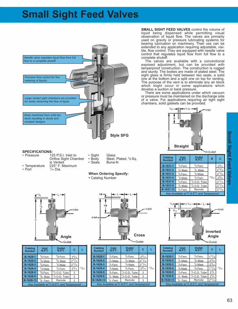
63
Sm
all S
igh
t Feed
Valv
es
Small Sight Feed Valves
SMALL SIGHT FEED VALVES control the volume ofliquid being dispensed while permitting visual observation of liquid flow. The valves are primarilyused on gravity or pressure lubricating systems forbearing lubrication on machinery. Their use can beextended to any application requiring adjustable, visi-ble, flow control. They are equipped with needle valvecontrol that regulates liquid flow from full flow to acomplete shutoff.
The valves are available with a conventionalexposed adjustment, but can be provided with tamperproof construction. The construction is ruggedand sturdy. The bodies are made of plated steel. Thesight glass is firmly held between two seals, a solidone at the bottom and a split one on top for venting.The purpose of the vent is to eliminate any air blockwhich might occur in some applications which develop a suction or back pressure.
There are some applications under which vacuumor pressure must be maintained on the discharge sideof a valve. For applications requiring air tight sightchambers, solid gaskets can be provided.
B
19/32
C
29/32
213/32
213/32
29/32
211/16
211/16
231/32
OutletN.P.T.
1/8 Fem.1/8 Male1/8 Male1/8 Fem.
1/4 O.D. Tube1/4 O.D. Tube
Remote
Catalog
Number
B-1631-1
B-1631-2
B-1631-3
B-1631-4
B-1631-5
B-1631-6
B-1631-13
InletN.P.T.
1/8 Fem.1/8 Male1/8 Fem.1/8 Male1/8 Fem. 1/8 Male1/8 Fem.
Also Available w/1/4 N.P.T. and Tamperproof
L
13/16
C
29/16
211/16
211/16
29/16
3
3
3
OutletN.P.T.
1/8 Fem.1/8 Male1/8 Male1/8 Fem.
1/4 O.D. Tube1/4 O.D. Tube
Remote
Catalog
Number
B-1628-1
B-1628-2
B-1628-3
B-1628-4
B-1628-5
B-1628-6
B-1628-13
InletN.P.T.
1/8 Fem.1/8 Male1/8 Fem.1/8 Male1/8 Fem. 1/8 Male1/8 Fem.
Also Available w/1/4 N.P.T. and Tamperproof
L
13/16
C
29/16
211/16
211/16
29/16
3
3
3
OutletN.P.T.
1/8 Fem.1/8 Male1/8 Male1/8 Fem.
1/4 O.D. Tube1/4 O.D. Tube
Remote
Catalog
Number
B-1629-1
B-1629-2
B-1629-3
B-1629-4
B-1629-5
B-1629-6
B-1629-13
InletN.P.T.
1/8 Fem.1/8 Male1/8 Fem.1/8 Male1/8 Fem. 1/8 Male1/8 Fem.
Also Available w/1/4 N.P.T. and Tamperproof
L
13/16
C
131/32
23/32
23/32
131/32
23/8
23/8
221/32
OutletN.P.T.
1/8 Fem.1/8 Male1/8 Male1/8 Fem.
1/4 O.D. Tube1/4 O.D. Tube
Remote
Catalog
Number
B-1630-1
B-1630-2
B-1630-3
B-1630-4
B-1630-5
B-1630-6
B-1630-13
InletN.P.T.
1/8 Fem.1/8 Male1/8 Fem.1/8 Male1/8 Fem. 1/8 Male1/8 Fem.
Also Available w/1/4 N.P.T. and Tamperproof
SPECIFICATIONS:
• Pressure 125 P.S.I. Inlet to • Sight GlassOrifice Sight Chamber • Body Steel, Plated, 5/8 Sq.is Vented • Seals Buna-N
• Temperature 225° F. Maximum• Port 1/16 Dia.
When Ordering Specify:
• Catalog Number
Needle valve regulates liquid flow from fullflow to a complete shutoff.
Precision flow control for finemetering of liquids.
Large vented sight chambers are providedfor easily observing the flow of liquid.
Body machined from solid barstock resulting in sturdy andcompact designs.
Style SFG
AngleCross
Inverted
Angle
Straight
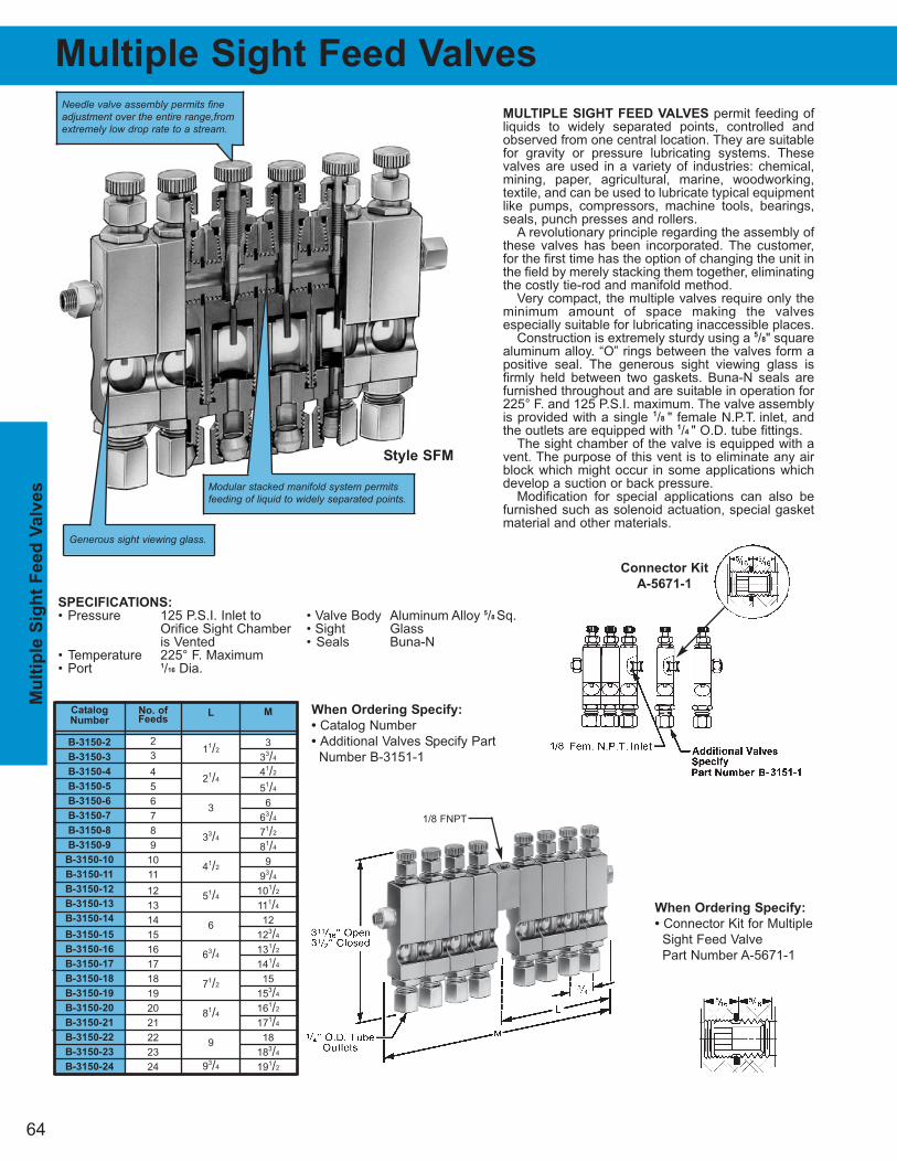
64
Mu
ltip
le S
igh
t F
eed
Valv
es
Multiple Sight Feed Valves
MULTIPLE SIGHT FEED VALVES permit feeding ofliquids to widely separated points, controlled andobserved from one central location. They are suitablefor gravity or pressure lubricating systems. Thesevalves are used in a variety of industries: chemical,mining, paper, agricultural, marine, woodworking, textile, and can be used to lubricate typical equipmentlike pumps, compressors, machine tools, bearings,seals, punch presses and rollers.
A revolutionary principle regarding the assembly ofthese valves has been incorporated. The customer,for the first time has the option of changing the unit inthe field by merely stacking them together, eliminatingthe costly tie-rod and manifold method.
Very compact, the multiple valves require only theminimum amount of space making the valves especially suitable for lubricating inaccessible places.
Construction is extremely sturdy using a 5/8" squarealuminum alloy. “O” rings between the valves form apositive seal. The generous sight viewing glass isfirmly held between two gaskets. Buna-N seals arefurnished throughout and are suitable in operation for225° F. and 125 P.S.I. maximum. The valve assemblyis provided with a single 1/8 " female N.P.T. inlet, andthe outlets are equipped with 1/4 " O.D. tube fittings.
The sight chamber of the valve is equipped with avent. The purpose of this vent is to eliminate any airblock which might occur in some applications whichdevelop a suction or back pressure.
Modification for special applications can also befurnished such as solenoid actuation, special gasketmaterial and other materials.
When Ordering Specify:
• Catalog Number
• Additional Valves Specify Part
Number B-3151-1
M
3
33/4
41/2
51/4
6
63/4
71/2
81/4
9
93/4
101/2
111/4
12
123/4
131/2
141/4
15
153/4
161/2
171/4
18
183/4
191/2
L
11/2
21/4
3
33/4
41/2
51/4
6
63/4
71/2
81/4
9
93/4
Catalog
Number
B-3150-2
B-3150-3
B-3150-4
B-3150-5
B-3150-6
B-3150-7
B-3150-8
B-3150-9
B-3150-10
B-3150-11
B-3150-12
B-3150-13
B-3150-14
B-3150-15
B-3150-16
B-3150-17
B-3150-18
B-3150-19
B-3150-20
B-3150-21
B-3150-22
B-3150-23
B-3150-24
No. ofFeeds
2
3
4
5
6
7
8
9
10
11
12
13
14
15
16
17
18
19
20
21
22
23
24
SPECIFICATIONS:
• Pressure 125 P.S.I. Inlet to • Valve Body Aluminum Alloy 5/8 Sq.Orifice Sight Chamber • Sight Glassis Vented • Seals Buna-N
• Temperature 225° F. Maximum• Port 1/16 Dia.
Needle valve assembly permits fineadjustment over the entire range,fromextremely low drop rate to a stream.
Generous sight viewing glass.
Modular stacked manifold system permitsfeeding of liquid to widely separated points.
Style SFM
When Ordering Specify:
• Connector Kit for Multiple
Sight Feed Valve
Part Number A-5671-1
Connector Kit
A-5671-1
1/8 FNPT
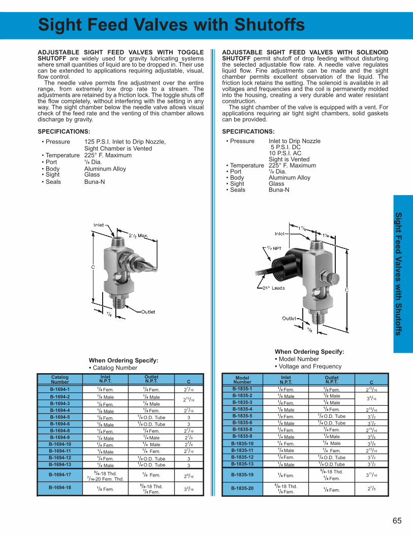
Model Number
B-1835-1
B-1835-2
B-1835-3
B-1835-4
B-1835-5
B-1835-6
B-1835-8
B-1835-9
B-1835-10
B-1835-11
B-1835-12
B-1835-13
B-1835-19
B-1835-20
65
Sig
ht F
eed
Valv
es w
ith S
hu
toffs
Sight Feed Valves with Shutoffs
When Ordering Specify:
• Catalog Number
When Ordering Specify:
• Model Number
• Voltage and Frequency
ADJUSTABLE SIGHT FEED VALVES WITH TOGGLE
SHUTOFF are widely used for gravity lubricating systemswhere small quantities of liquid are to be dropped in. Their usecan be extended to applications requiring adjustable, visual,flow control.
The needle valve permits fine adjustment over the entirerange, from extremely low drop rate to a stream. The adjustments are retained by a friction lock. The toggle shuts offthe flow completely, without interfering with the setting in anyway. The sight chamber below the needle valve allows visualcheck of the feed rate and the venting of this chamber allowsdischarge by gravity.
SPECIFICATIONS:
• Pressure 125 P.S.I. Inlet to Drip Nozzle, Sight Chamber is Vented
• Temperature 225° F. Maximum• Port 1/8 Dia.• Body Aluminum Alloy• Sight Glass
• Seals Buna-N
ADJUSTABLE SIGHT FEED VALVES WITH SOLENOID
SHUTOFF permit shutoff of drop feeding without disturbingthe selected adjustable flow rate. A needle valve regulates liquid flow. Fine adjustments can be made and the sight chamber permits excellent observation of the liquid. The friction lock retains the setting. The solenoid is available in allvoltages and frequencies and the coil is permanently moldedinto the housing, creating a very durable and water resistantconstruction.
The sight chamber of the valve is equipped with a vent. Forapplications requiring air tight sight chambers, solid gasketscan be provided.
SPECIFICATIONS:
• Pressure Inlet to Drip Nozzle5 P.S.I. DC
10 P.S.I. ACSight is Vented
• Temperature 225° F. Maximum• Port 1/8 Dia.• Body Aluminum Alloy• Sight Glass• Seals Buna-N
OutletN.P.T.
1/8 Fem.1/8 Male1/8 Male1/8 Fem.
1/4 O.D. Tube1/4 O.D. Tube
1/4 Fem.1/4 Male 1/4 Male1/4 Fem.
1/4 O.D. Tube1/4 O.D. Tube
1/8 Fem.
5/8-18 Thd.1/8 Fem.
InletN.P.T.
1/8 Fem.1/8 Male1/8 Fem.1/8 Male1/8 Fem.1/8 Male1/4 Fem. 1/4 Male1/4 Fem.1/4 Male1/4 Fem. 1/4 Male
5/8-18 Thd.7/16-20 Fem. Thd.
1/8 Fem.
C
27/16
213/16
27/16
3
3
27/16
27/8
27/8
27/16
3
3
29/16
33/16
Catalog
Number
B-1694-1
B-1694-2
B-1694-3
B-1694-4
B-1694-5
B-1694-6
B-1694-8
B-1694-9
B-1694-10
B-1694-11
B-1694-12
B-1694-13
B-1694-17
B-1694-18
Inlet
N.P.T.
1/8 Fem.1/8 Male1/8 Fem.1/8 Male1/8 Fem.1/8 Male1/4 Fem. 1/4 Male1/4 Fem.1/4 Male1/4 Fem. 1/4 Male
1/8 Fem.
5/8-18 Thd.1/8 Fem.
OutletN.P.T.
1/8 Fem.1/8 Male1/8 Male1/8 Fem.
1/4 O.D. Tube1/4 O.D. Tube
1/4 Fem.1/4 Male 1/4 Male1/4 Fem.
1/4 O.D. Tube1/4 O.D.Tube
5/8-18 Thd.1/8 Fem.
1/8 Fem.
C
215/16
35/16
215/16
31/2
31/2
215/16
33/8
33/8
215/16
31/2
31/2
311/16
27/8
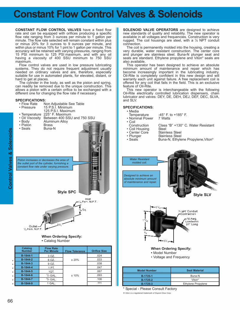
66
Co
ntr
ol
Valv
es &
So
len
oid
s
Model Number
B-1725-1
B-1725-2
B-1725-3
Seal Material
Buna-N
Viton®
Ethylene Propylene
Constant Flow Control Valves & Solenoids
SOLENOID VALVE OPERATORS are designed to achievenew standards of quality and reliability. The new operator isavailable in all voltages and frequencies. Construction is veryrugged. The coil housings are steel, with a ½ NPT conduitconnection.
The coil is permanently molded into the housing, creating avery durable, water resistant construction. The center coreand plunger are stainless steel. Buna-N plunger seat andseals are standard. Ethylene propylene and Viton® seals arealso available.
This operator has been designed to achieve an absoluteminimum amount of maintenance and repair which hasbecome increasingly important in the lubricating industry. Oil-Rite is completely confident in this new design and willwarranty each unit against failure. A free replacement coil isoffered for any coil that fails in the field. This is an exclusivefeature of Oil-Rite.
This new operator is interchangeable with the following Oil-Rite electrically controlled lubrication dispensers, chainlubricator and valves: DEY, DE, DEH, DEJ, DEF, DEC, SLVA,and SLV.
SPECIFICATIONS:
• MediaTemperature -45° F. to +185° F.
• Nominal Power 7 Watts• Coil
Construction Class “B” +130° C. Water Resistant• Coil Housing Steel• Center Core Stainless Steel• Plunger Stainless Steel• Seals Buna-N, Ethylene Propylene,Viton®
CONSTANT FLOW CONTROL VALVES have a fixed flowrate and can be equipped with orifices producing a specificflow rate ranging from 3 ounces per minute to 1 gallon perminute. The flow rate selected will remain constant within plusor minus 20% for 3 ounces to 9 ounces per minute, and within plus or minus 10% for 1 pint to 1 gallon per minute. Thisaccuracy will be retained with varying pressures, ranging from15 PSI minimum to 125 PSI maximum, and with any oil having a viscosity of 400 SSU minimum to 750 SSU maximum.
Flow control valves are used in low pressure lubricatingsystems. They do not require frequent adjustment usuallyneeded on ordinary valves and are, therefore, especially suitable for use in automated plants, for elevated, distant, orhard to get at places.
The cylinder in the body, as well as the piston and spring,can readily be removed due to the unique construction. Thisallows a piston with a certain orifice to be exchanged with adifferent one for changing the flow rate if necessary.
SPECIFICATIONS:
• Flow Rate Non Adjustable See Table• Pressure 15 P.S.I. Minimum
125 P.S.I. Maximum• Temperature 225° F. Maximum• Oil Viscosity Between 400 SSU and 750 SSU• Body Aluminum Alloy• Piston Brass• Seals Buna-N
Orifice Size
.024
.033
.038
.047
.067
.093
.106
.111
Flow Tolerance
± 20%
± 10%
Catalog
Number
B-1844-1
B-1844-2
B-1844-3
B-1844-4
B-1844-5
B-1844-6
B-1844-7
B-1844-9
Flow Rate
Per Minute
3 OZ.
6 OZ.
9 OZ.
1 PT.
1QT.1/2 GAL.3/4 GAL.
1 GAL.
When Ordering Specify:
• Model Number
• Voltage and Frequency
When Ordering Specify:
• Catalog Number
Piston increases or decreases the area ofthe outlet port of the cylinder, furnishing aconstant flow rate under varying pressure.
Water Resistantmolded coil.
Designed to achieve anabsolute minimum amountof maintenance and repair.
Style SPCStyle SLV
*******
* Special - Please Consult Factory® Viton is a registered trademark of Dupont Dow Corp.
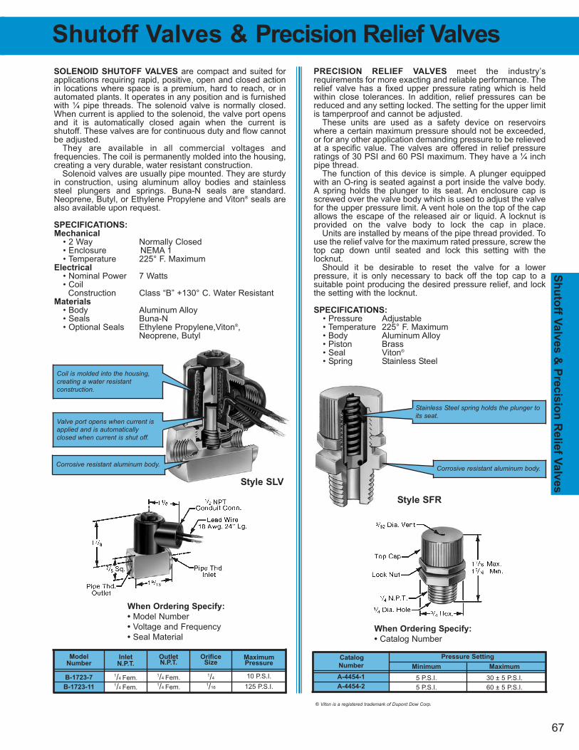
67
Sh
uto
ff Valv
es &
Precis
ion
Relie
f Valv
es
Shutoff Valves & Precision Relief Valves
PRECISION RELIEF VALVES meet the industry’s requirements for more exacting and reliable performance. Therelief valve has a fixed upper pressure rating which is heldwithin close tolerances. In addition, relief pressures can bereduced and any setting locked. The setting for the upper limitis tamperproof and cannot be adjusted.
These units are used as a safety device on reservoirswhere a certain maximum pressure should not be exceeded,or for any other application demanding pressure to be relievedat a specific value. The valves are offered in relief pressureratings of 30 PSI and 60 PSI maximum. They have a ¼ inchpipe thread.
The function of this device is simple. A plunger equippedwith an O-ring is seated against a port inside the valve body.A spring holds the plunger to its seat. An enclosure cap isscrewed over the valve body which is used to adjust the valvefor the upper pressure limit. A vent hole on the top of the capallows the escape of the released air or liquid. A locknut is provided on the valve body to lock the cap in place.
Units are installed by means of the pipe thread provided. Touse the relief valve for the maximum rated pressure, screw thetop cap down until seated and lock this setting with the locknut.
Should it be desirable to reset the valve for a lower pressure, it is only necessary to back off the top cap to a suitable point producing the desired pressure relief, and lockthe setting with the locknut.
SPECIFICATIONS:
• Pressure Adjustable• Temperature 225° F. Maximum• Body Aluminum Alloy• Piston Brass• Seal Viton®
• Spring Stainless Steel
SOLENOID SHUTOFF VALVES are compact and suited forapplications requiring rapid, positive, open and closed actionin locations where space is a premium, hard to reach, or inautomated plants. It operates in any position and is furnishedwith ¼ pipe threads. The solenoid valve is normally closed.When current is applied to the solenoid, the valve port opensand it is automatically closed again when the current is shutoff. These valves are for continuous duty and flow cannotbe adjusted.
They are available in all commercial voltages and frequencies. The coil is permanently molded into the housing,creating a very durable, water resistant construction.
Solenoid valves are usually pipe mounted. They are sturdyin construction, using aluminum alloy bodies and stainlesssteel plungers and springs. Buna-N seals are standard.Neoprene, Butyl, or Ethylene Propylene and Viton® seals arealso available upon request.
SPECIFICATIONS:
Mechanical
• 2 Way Normally Closed• Enclosure NEMA 1 • Temperature 225° F. Maximum
Electrical
• Nominal Power 7 Watts• Coil
Construction Class “B” +130° C. Water ResistantMaterials
• Body Aluminum Alloy• Seals Buna-N• Optional Seals Ethylene Propylene,Viton®,
Neoprene, Butyl
OrificeSize
1/4
1/16
OutletN.P.T.
1/4 Fem.1/4 Fem.
Model
Number
B-1723-7
B-1723-11
Inlet
N.P.T.
1/4 Fem.1/4 Fem.
MaximumPressure
10 P.S.I.
125 P.S.I.
When Ordering Specify:
• Model Number
• Voltage and Frequency
• Seal Material
Valve port opens when current isapplied and is automaticallyclosed when current is shut off.
Corrosive resistant aluminum body.
Style SLV
Pressure Setting
Maximum
30 ± 5 P.S.I.
60 ± 5 P.S.I.
Catalog
Number
A-4454-1
A-4454-2
Minimum
5 P.S.I.
5 P.S.I.
When Ordering Specify:
• Catalog Number
Stainless Steel spring holds the plunger toits seat.
Corrosive resistant aluminum body.
Style SFR
Coil is molded into the housing, creating a water resistant construction.
® Viton is a registered trademark of Dupont Dow Corp.
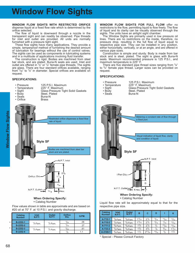
68
C
21/4
21/4
27/8
35/8
351/64
OrificeDia.
1/32
1/16
3/32
1/8
OutletN.P.T.
1/8 Fem.
1/4 Fem.
Catalog
Number
B-2252-1
B-2252-2
B-2252-3
B-2252-4
Inlet
N.P.T.
1/8 Fem.
1/4 Fem.
G.PM.
.06
.27
.61
1.1
Window Flow Sights
WINDOW FLOW SIGHTS FOR FULL FLOW offer no restrictions to the flow, permitting liquid to flow freely. The flowof liquid and its clarity can be visually observed through thesights. The units have an airtight sight chamber.
The Window Sights are primarily used in low pressure oillines. There are no restrictions on the inside, therefore, nopressure drop, resulting in the full flow of liquid equal torespective pipe size. They can be installed in any position,either horizontally, vertically, or at an angle, and are offered invarious pipe sizes.
Construction is simple and sturdy. Body is made from barstock and is steel, plated. The sight is glass with Buna-Nseals. Maximum recommended pressure is 125 P.S.I., andmaximum temperature is 225° F.
There are five standard pipe thread sizes ranging from 1/8”to 3/4” female pipe thread. Larger sizes can be provided onrequest.
SPECIFICATIONS:
• Pressure 125 P.S.I. Maximum• Temperature 225° F. Maximum• Sight Glass-Pressure Tight Solid Gaskets• Body Steel, Plated• Seals Buna-N
WINDOW FLOW SIGHTS WITH RESTRICTED ORIFICE
dispense liquid at a fixed flow rate which is determined by theorifice selected.
The flow of liquid is downward through a nozzle in the transparent sight and can readily be observed. Pipe threadsfor inlet and outlet are provided. All units are normally furnished with a pressure tight sight.
These flow sights have many applications. They provide asimple, tamperproof method of furnishing the desired amountof lubrication for bearings without the use of control valves.The sights can be used as components in lubricating systemsand in a multitude of applications involving fluid transfer.
The construction is rigid. Bodies are machined from steelbar stock, and are plated. Buna-N seals are used. Inlet andoutlet are offered in 1/8” or 1/4” female pipe threads. The sightsare glass. There are four standard orifices available, rangingfrom 1/32” to 1/8” in diameter. Special orifices are available onrequest.
SPECIFICATIONS:
• Pressure 125 P.S.I. Maximum• Temperature 225° F. Maximum• Sight Glass-Pressure Tight Solid Gaskets• Body Steel, Plated• Seals Buna-N• Orifice Brass
When Ordering Specify:
• Catalog Number
B
11/16
11/16
13/8
13/8
11/2
I
11/32
7/16
37/64
9/16
3/4
OutletN.P.T.
1/8 Fem. 1/4 Fem. 3/8 Fem. 1/2 Fem. 3/4 Fem.
Catalog
Number
A-715-1
A-715-2
A-711-2
A-733-2
A-2109-1
Inlet
N.P.T.
1/8 Fem. 1/4 Fem. 3/8 Fem. 1/2 Fem. 3/4 Fem.
K
13/16
13/16
15/16
11/16
11/4
D
9/16
9/16
3/4
7/8
15/16
When Ordering Specify:
• Catalog Number Liquid flow rate will be approximately equal to that for the
respective pipe size.Flow values shown in table are approximate and are based on
#20 oil at 70° F. at 10 P.S.I. and gravity discharge.
Metering a constant rate of flow througha fixed port.Restricted orifice dispenses a fixed flow
rate of liquid.
Visual indication of liquid flow, clarityand condition of liquid.
Bodies are machined from steel barstock and are plated.
Style SF
Style SF
*
*
Win
do
w F
low
Sig
hts
* Special - Please Consult Factory
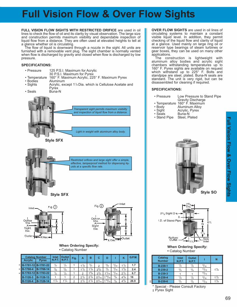
69
Fu
ll Vis
ion
Flo
w &
Over F
low
Sig
hts
Full Vision Flow & Over Flow Sights
G.P.M.
1.7
2.4
6.7
16
26.9
K
11/2
17/8
21/2
43/8
43/8
C
2
25/8
33/4
55/16
55/16
B
3/4
11/8
15/8
21/8
21/8
D
5/8
3/4
11/16
119/32
119/32
I
5/32
3/16
5/16
5/8
5/8
A
11/8
11/2
2
21/2
21/2
N
17/8
11/2
17/8
I
9/16
13/16
15/16
9/16
13/16
Outlet
N.P.T.
1/2
3/4
11/2
3/4
Catalog
Number
B-239-1
B-239-2
B-239-3
B-239-4
B-239-6
Inlet
N.P.T.
1/2
3/4
11/2
3/4
OVER FLOW SIGHTS are used in oil lines ofcirculating systems to maintain a constant visible liquid level. In addition, they permit checking of the liquid flow and clarity of liquidat a glance. Used mainly on large ring oil orreservoir type bearings of steam turbines orgear boxes, they can be used on many otherapplications.
The construction is lightweight with aluminum alloy bodies and acrylic sight chambers withstanding temperatures up to160° F. Pyrex sights are available on requestwhich withstand up to 225° F. Bolts and standpipe are steel, plated. Buna-N seals arestandard. The unit is very rigid, but can be disassembled for cleaning if required.
SPECIFICATIONS:
• Pressure Low Pressure to Stand Pipe Gravity Discharge
• Temperature 160° F. Maximum• Body Aluminum Alloy• Sight Acrylic, Pyrex• Seals Buna-N• Stand Pipe Steel, Plated
FULL VISION FLOW SIGHTS WITH RESTRICTED ORIFICE are used in oillines to check the flow of oil and its clarity by visual observation. The large sizeand construction permits maximum visibility and dependable inspection of liquid flow from a distance. They are often used at elevated heights to tell ata glance whether oil is circulating.
The flow of liquid is downward through a nozzle in the sight. All units are furnished with a removable vent plug. The sight chamber is normally ventedwhen flow is discharged by gravity and closed when flow is discharged by lowpressure.
SPECIFICATIONS:
• Pressure 125 P.S.I. Maximum for Acrylic30 P.S.I. Maximum for Pyrex
• Temperature 160° F. Maximum Acrylic, 225° F. Maximum Pyrex• Bodies Aluminum• Sights Acrylic, except 11/8 Dia. which is Cellulose Acetate and
Pyrex• Seals Buna-N
Fig.
1
1
1
2
2
Outlet
N.P.T.
1/4
3/8
1/2
1
11/4
Catalog Number
Acrylic Pyrex
B-1781-12 B-1781-22
B-1766-4 B-1766-14
B-1783-12 B-1783-22
B-1126-3 B-1126-13
B-1126-4 B-1126-14
Inlet
N.P.T.
1/4
3/8
1/2
1
11/4
When Ordering Specify:
• Catalog Number
When Ordering Specify:
• Catalog Number
Transparent sight permits maximum visibilityand inspection of liquid flow from a distance.
Light in weight with aluminum alloy body.
Restricted orifices and large sight offer a simple,effective, tamperproof method for dispensing liq-uids at a specific flow rate.
Style SFX
Style SFXStyle SO
*
*
*
* Special - Please Consult Factory‡ Pyrex Sight
‡
P. O. BOX 1207, MANITOWOC, WI 54221-1207 (920) 682-6173 FAX (920) 682-7699
www.oilrite.com [email protected] 71
Sectio
n 8
200 In
dex
STEEL LIQUID LEVEL GAGES..........72-74
BRASS LEVEL GAGES ......................75-76
BRASS LEVEL GAGES cont. ............77-78
RIGID PLASTIC LEVEL GAGES ........79-80
MILLED ALUMINUM GAGE ....................81
CHANNEL LEVEL GAGES - STEEL....... 82
FLEXIBLE LEVEL GAGES ......................83
RIGID PLASTIC LEVEL GAGES-FLUSH.84
BROAD FACE LEVEL GAGES................85
WINDOW SIGHTS - GASKETED..............86
WINDOW SIGHTS ....................................87
SPECIALIZED LEVEL GAGES ................88
Section 8200 Index
• Drum Gage with Faucet• Window Sight with Aluminum Ball
• Exploded View• Short Elbow• Long Elbow• Union Coupling Elbow
• Female Elbow• Straight Mounting• Dial Thermometer Elbow
(Flush Mounting)• Front Mounting• Back Mounting• Thermometer Front Mounting• Thermometer Back Mounting
• Fused - N.P.T. Mounting• Gasketed - N.P.T. Mounting
• Exploded View• Short Elbow• Long Elbow• Union Coupling Elbow • Straight Mounting
(Flush Mounting)• Front Mounting• Back Mounting• Thermometer Front Mounting• Thermometer Back Mounting
(Flush Mounting)• Front Mounting• Back Mounting• Thermometer Front Mounting• Thermometer Back Mounting
• Standard• Dial Thermometer• Card Thermometer• Shut-Off
• Exploded View
(Flush Mounting)• Front Mounting• Back Mounting• Dual Scale Thermometer • Shut-off
• Short Elbow• Long Elbow• Union Coupling Elbow • Straight Mounting
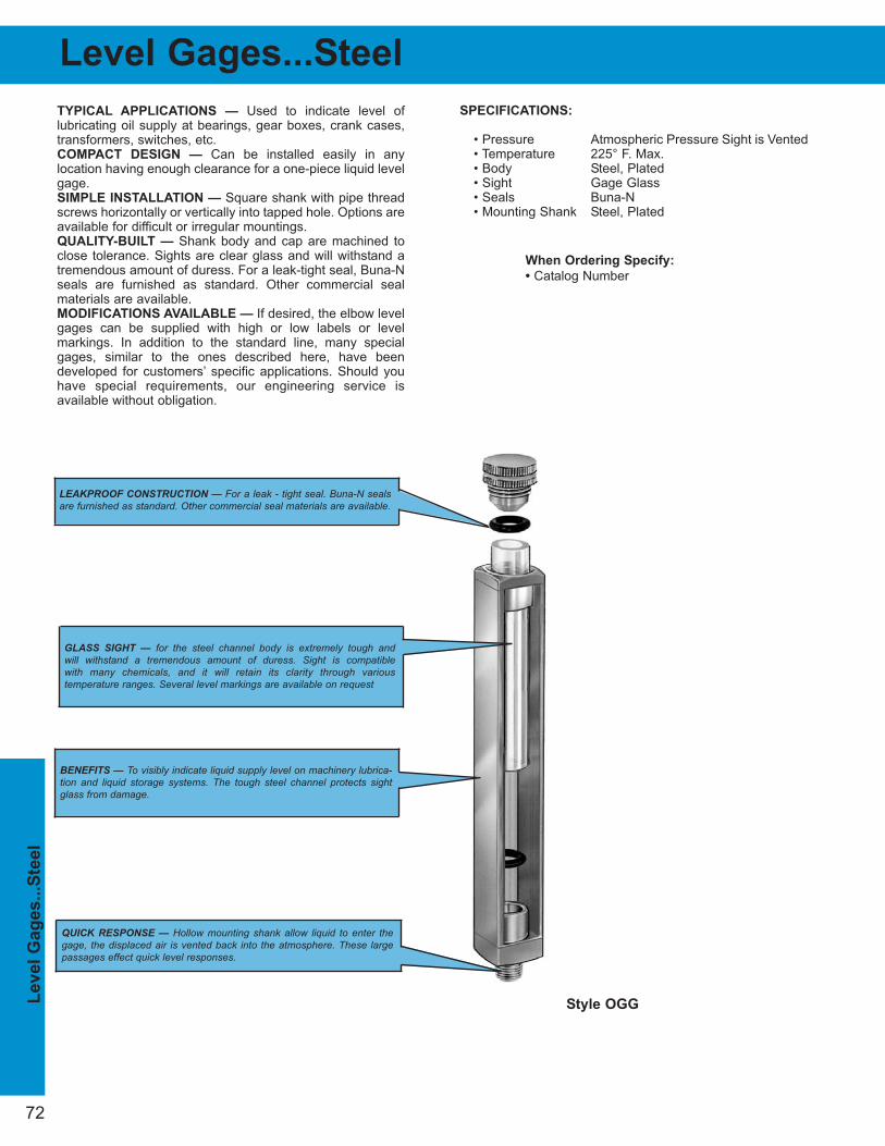
72
Level
Gag
es...S
teel
Level Gages...Steel
SPECIFICATIONS:
• Pressure Atmospheric Pressure Sight is Vented• Temperature 225° F. Max.• Body Steel, Plated• Sight Gage Glass• Seals Buna-N• Mounting Shank Steel, Plated
TYPICAL APPLICATIONS — Used to indicate level of lubricating oil supply at bearings, gear boxes, crank cases,transformers, switches, etc.COMPACT DESIGN — Can be installed easily in any location having enough clearance for a one-piece liquid levelgage.SIMPLE INSTALLATION — Square shank with pipe threadscrews horizontally or vertically into tapped hole. Options areavailable for difficult or irregular mountings.QUALITY-BUILT — Shank body and cap are machined toclose tolerance. Sights are clear glass and will withstand atremendous amount of duress. For a leak-tight seal, Buna-Nseals are furnished as standard. Other commercial sealmaterials are available.MODIFICATIONS AVAILABLE — If desired, the elbow levelgages can be supplied with high or low labels or level markings. In addition to the standard line, many specialgages, similar to the ones described here, have been developed for customers’ specific applications. Should youhave special requirements, our engineering service is available without obligation.
When Ordering Specify:
• Catalog Number
LEAKPROOF CONSTRUCTION — For a leak - tight seal. Buna-N sealsare furnished as standard. Other commercial seal materials are available.
GLASS SIGHT — for the steel channel body is extremely tough and will withstand a tremendous amount of duress. Sight is compatible with many chemicals, and it will retain its clarity through various temperature ranges. Several level markings are available on request
BENEFITS — To visibly indicate liquid supply level on machinery lubrica-tion and liquid storage systems. The tough steel channel protects sightglass from damage.
Style OGG
QUICK RESPONSE — Hollow mounting shank allow liquid to enter thegage, the displaced air is vented back into the atmosphere. These largepassages effect quick level responses.
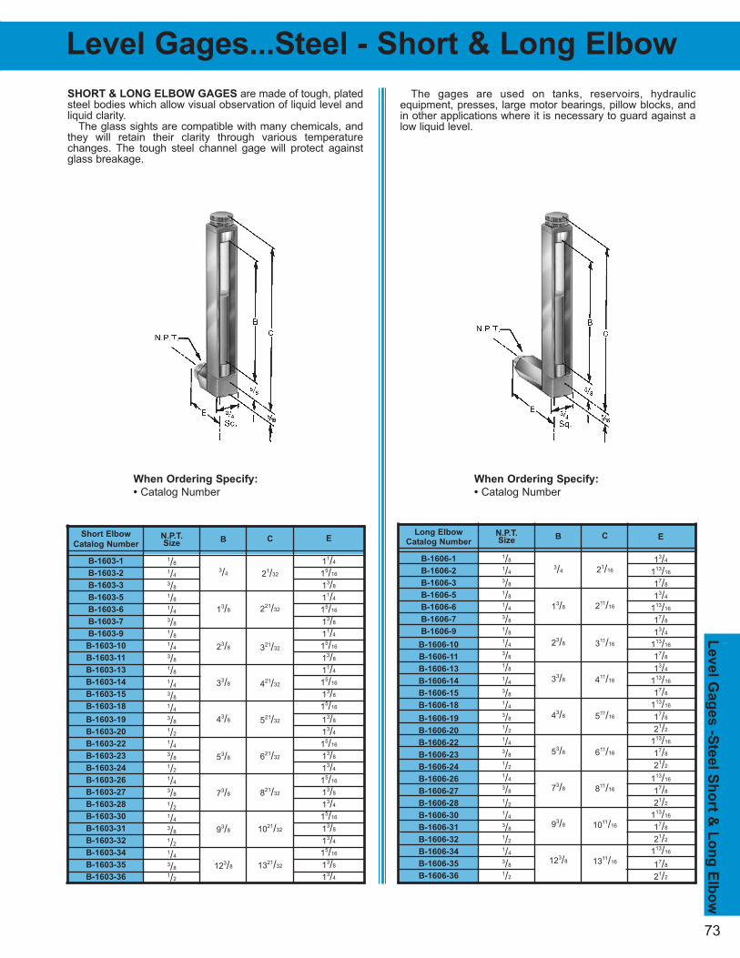
73
The gages are used on tanks, reservoirs, hydraulic equipment, presses, large motor bearings, pillow blocks, andin other applications where it is necessary to guard against alow liquid level.
Level G
ag
es -S
teel S
ho
rt &
Lo
ng
Elb
ow
Level Gages...Steel - Short & Long Elbow
SHORT & LONG ELBOW GAGES are made of tough, platedsteel bodies which allow visual observation of liquid level andliquid clarity.
The glass sights are compatible with many chemicals, andthey will retain their clarity through various temperaturechanges. The tough steel channel gage will protect againstglass breakage.
N.P.T.Size
1/8
1/4
3/8
1/8
1/4
3/8
1/8
1/4
3/8
1/8
1/4
3/8
1/4
3/8
1/2
1/4
3/8
1/2
1/4
3/8
1/2
1/4
3/8
1/2
1/4
3/8
1/2
Short Elbow
Catalog Number
B-1603-1
B-1603-2
B-1603-3
B-1603-5
B-1603-6
B-1603-7
B-1603-9
B-1603-10
B-1603-11
B-1603-13
B-1603-14
B-1603-15
B-1603-18
B-1603-19
B-1603-20
B-1603-22
B-1603-23
B-1603-24
B-1603-26
B-1603-27
B-1603-28
B-1603-30
B-1603-31
B-1603-32
B-1603-34
B-1603-35
B-1603-36
C
21/32
221/32
321/32
421/32
521/32
621/32
821/32
1021/32
1321/32
B
3/4
13/8
23/8
33/8
43/8
53/8
73/8
93/8
123/8
E
11/4
15/16
13/8
11/4
15/16
13/8
11/4
15/16
13/8
11/4
15/16
13/8
15/16
13/8
13/4
15/16
13/8
13/4
15/16
13/8
13/4
15/16
13/8
13/4
15/16
13/8
13/4
N.P.T.Size
1/8
1/4
3/8
1/8
1/4
3/8
1/8
1/4
3/8
1/8
1/4
3/8
1/4
3/8
1/2
1/4
3/8
1/2
1/4
3/8
1/2
1/4
3/8
1/2
1/4
3/8
1/2
Long Elbow
Catalog Number
B-1606-1
B-1606-2
B-1606-3
B-1606-5
B-1606-6
B-1606-7
B-1606-9
B-1606-10
B-1606-11
B-1606-13
B-1606-14
B-1606-15
B-1606-18
B-1606-19
B-1606-20
B-1606-22
B-1606-23
B-1606-24
B-1606-26
B-1606-27
B-1606-28
B-1606-30
B-1606-31
B-1606-32
B-1606-34
B-1606-35
B-1606-36
C
21/16
211/16
311/16
411/16
511/16
611/16
811/16
1011/16
1311/16
B
3/4
13/8
23/8
33/8
43/8
53/8
73/8
93/8
123/8
E
13/4
113/16
17/8
13/4
113/16
17/8
13/4
113/16
17/8
13/4
113/16
17/8
113/16
17/8
21/2
113/16
17/8
21/2
113/16
17/8
21/2
113/16
17/8
21/2
113/16
17/8
21/2
When Ordering Specify:
• Catalog Number
When Ordering Specify:
• Catalog Number
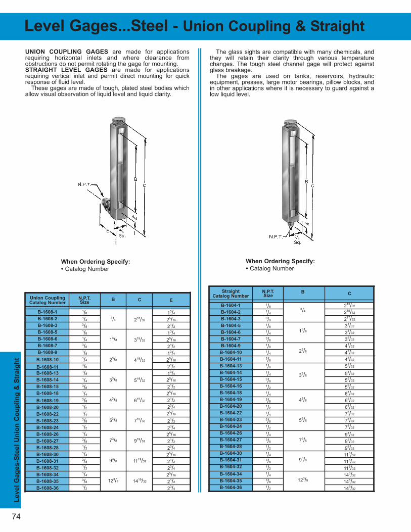
The glass sights are compatible with many chemicals, andthey will retain their clarity through various temperaturechanges. The tough steel channel gage will protect againstglass breakage.
The gages are used on tanks, reservoirs, hydraulic equipment, presses, large motor bearings, pillow blocks, andin other applications where it is necessary to guard against alow liquid level.
Le
vel
Gag
es-S
teel
Un
ion
Co
up
lin
g &
Str
aig
ht
74
Level Gages...Steel - Union Coupling & Straight
UNION COUPLING GAGES are made for applications requiring horizontal inlets and where clearance from obstructions do not permit rotating the gage for mounting.STRAIGHT LEVEL GAGES are made for applications requiring vertical inlet and permit direct mounting for quickresponse of fluid level.
These gages are made of tough, plated steel bodies whichallow visual observation of liquid level and liquid clarity.
N.P.T.Size
1/8
1/4
3/8
1/8
1/4
3/8
1/8
1/4
3/8
1/8
1/4
3/8
1/4
3/8
1/2
1/4
3/8
1/2
1/4
3/8
1/2
1/4
3/8
1/2
1/4
3/8
1/2
Union Coupling
Catalog Number
B-1608-1
B-1608-2
B-1608-3
B-1608-5
B-1608-6
B-1608-7
B-1608-9
B-1608-10
B-1608-11
B-1608-13
B-1608-14
B-1608-15
B-1608-18
B-1608-19
B-1608-20
B-1608-22
B-1608-23
B-1608-24
B-1608-26
B-1608-27
B-1608-28
B-1608-30
B-1608-31
B-1608-32
B-1608-34
B-1608-35
B-1608-36
C
231/32
319/32
419/32
519/32
619/32
719/32
919/32
1119/32
1419/32
B
3/4
13/8
23/8
33/8
43/8
53/8
73/8
93/8
123/8
E
13/4
25/16
21/2
13/4
25/16
21/2
13/4
25/16
21/2
13/4
25/16
21/2
25/16
21/2
23/4
25/16
21/2
23/4
25/16
21/2
23/4
25/16
21/2
23/4
25/16
21/2
23/4
N.P.T.Size
1/8
1/4
3/8
1/8
1/4
3/8
1/8
1/4
3/8
1/8
1/4
3/8
1/2
1/4
3/8
1/2
1/4
3/8
1/2
1/4
3/8
1/2
1/4
3/8
1/2
1/4
3/8
1/2
Straight
Catalog Number
B-1604-1
B-1604-2
B-1604-3
B-1604-5
B-1604-6
B-1604-7
B-1604-9
B-1604-10
B-1604-11
B-1604-13
B-1604-14
B-1604-15
B-1604-16
B-1604-18
B-1604-19
B-1604-20
B-1604-22
B-1604-23
B-1604-24
B-1604-26
B-1604-27
B-1604-28
B-1604-30
B-1604-31
B-1604-32
B-1604-34
B-1604-35
B-1604-36
B
3/4
13/8
23/8
33/8
43/8
53/8
73/8
93/8
123/8
C
213/32
215/32
217/32
31/32
33/32
35/32
41/32
43/32
45/32
51/32
53/32
55/32
59/32
63/32
65/32
69/32
73/32
75/32
79/32
93/32
95/32
99/32
113/32
115/32
119/32
143/32
145/32
149/32
When Ordering Specify:
• Catalog Number
When Ordering Specify:
• Catalog Number
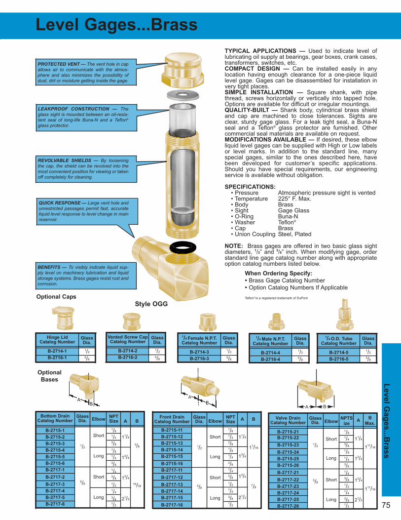
75
Level G
ag
es...B
rass
Level Gages...Brass
TYPICAL APPLICATIONS — Used to indicate level oflubricating oil supply at bearings, gear boxes, crank cases,transformers, switches, etc.COMPACT DESIGN — Can be installed easily in any location having enough clearance for a one-piece liquidlevel gage. Gages can be disassembled for installation invery tight places.SIMPLE INSTALLATION — Square shank, with pipethread, screws horizontally or vertically into tapped hole.Options are available for difficult or irregular mountings.QUALITY-BUILT — Shank body, cylindrical brass shieldand cap are machined to close tolerances. Sights areclear, sturdy gage glass. For a leak tight seal, a Buna-Nseal and a Teflon® glass protector are furnished. Othercommercial seal materials are available on request.MODIFICATIONS AVAILABLE — If desired, these elbowliquid level gages can be supplied with High or Low labelsor level marks. In addition to the standard line, many special gages, similar to the ones described here, havebeen developed for customer’s specific applications.Should you have special requirements, our engineeringservice is available without obligation.
SPECIFICATIONS:
• Pressure Atmospheric pressure sight is vented• Temperature 225° F. Max.• Body Brass• Sight Gage Glass• O-Ring Buna-N• Washer Teflon®
• Cap Brass• Union Coupling Steel, Plated
NOTE: Brass gages are offered in two basic glass sightdiameters, 1/2” and 5/8” inch. When modifying gage, orderstandard line gage catalog number along with appropriateoption catalog numbers listed below.
When Ordering Specify:
• Brass Gage Catalog Number
• Option Catalog Numbers If Applicable
NPT
Size
1/8
1/4
3/8
1/8
1/4
3/8
1/4
3/8
1/2
1/4
3/8
1/2
Elbow
Short
Long
Short
Long
Bottom Drain
Catalog Number
B-2715-1
B-2715-2
B-2715-3
B-2715-4
B-2715-5
B-2715-6
B-2717-1
B-2717-2
B-2717-3
B-2717-4
B-2717-5
B-2717-6
Glass
Dia.
1/2
5/8
A
11/4
13/4
13/4
21/2
B
3/8
15/32
Vented Screw Cap
Catalog Number
B-2714-2
B-2716-2
Glass
Dia.
1/2
5/8
NPT
Size
1/8
1/4
3/8
1/8
1/4
3/8
1/4
3/8
1/2
1/4
3/8
1/2
Elbow
Short
Long
Short
Long
Front Drain
Catalog Number
B-2715-11
B-2715-12
B-2715-13
B-2715-14
B-2715-15
B-2715-16
B-2717-11
B-2717-12
B-2717-13
B-2717-14
B-2717-15
B-2717-16
Glass
Dia.
1/2
5/8
A
11/4
13/4
13/4
21/2
B
11/16
7/8
NPTS
ize
1/8
1/4
3/8
1/8
1/4
3/8
1/4
3/8
1/2
1/4
3/8
1/2
Elbow
Short
Long
Short
Long
Valve Drain
Catalog Number
B-2715-21
B-2715-22
B-2715-23
B-2715-24
B-2715-25
B-2715-26
B-2717-21
B-2717-22
B-2717-23
B-2717-24
B-2717-25
B-2717-26
Glass
Dia.
1/2
5/8
A
11/4
13/4
13/4
21/2
B
Max.
111/16
111/16
Hinge Lid
Catalog Number
B-2714-1
B-2716-1
Glass
Dia.
1/2
5/8
1/4 Male N.P.T.
Catalog Number
B-2714-4
B-2716-4
Glass
Dia.
1/2
5/8
1/4 O.D. Tube
Catalog Number
B-2714-5
B-2716-5
Glass
Dia.
1/2
5/8
1/4 Female N.P.T.
Catalog Number
B-2714-3
B-2716-3
Glass
Dia.
1/2
5/8
PROTECTED VENT — The vent hole in capallows air to communicate with the atmos-phere and also minimizes the possibility ofdust, dirt or moisture getting inside the gage.
LEAKPROOF CONSTRUCTION — Theglass sight is mounted between an oil-resis-tant seal of long-life Buna-N and a Teflon®
glass protector.
REVOLVABLE SHIELDS — By looseningthe cap, the shield can be revolved into themost convenient position for viewing or takenoff completely for cleaning.
QUICK RESPONSE — Large vent hole andunrestricted passages permit fast, accurate liquid level response to level change in mainreservoir.
BENEFITS — To visibly indicate liquid sup-ply level on machinery lubrication and liquid storage systems. Brass gages resist rust andcorrosion.
Style OGG
Optional Caps
Optional
Bases
A B
Teflon® is a registered trademark of DuPont

E
11/2
2
21/8
11/2
2
21/8
11/2
2
21/8
11/2
2
21/8
11/2
2
21/8
11/2
2
21/8
11/2
2
21/8
11/2
2
21/8
11/2
2
21/8
11/2
2
21/8
11/2
2
21/8
21/2
B
11/32
117/32
21/32
217/32
31/32
317/32
41/32
417/32
517/32
617/32
717/32
413/32
521/32
721/32
921/32
1221/32
C
115/16
27/16
215/16
37/16
315/16
47/16
415/16
57/16
67/16
77/16
87/16
57/16
611/16
811/16
1011/16
1311/16
76
Level G
ag
es -
Bra
ss E
lbo
w a
nd
Un
ion
Co
up
lin
g
UNION COUPLING BRASS GAGES are for applications requiring horizontal inlets. They are used inareas where clearance from obstructions do not permitrotating the gage for assembly.
The brass level gages for visibly indicating liquid levels are rugged, machined from brass stock and haveglass sights which are protected by revolvable shields.A protected vent hole in the cap reduces the possibilityof dust, dirt or moisture getting inside the gage.
SHORT ELBOW BRASS GAGES are for applications requiring horizontal inlets with minimal clearance for mounting.
LONG ELBOW BRASS GAGES are for applications requiring horizontal inlets which need additional clearance.
NPT
Size
1/8
1/4
3/8
1/8
1/4
3/8
1/8
1/4
3/8
1/8
1/4
3/8
1/8
1/4
3/8
1/8
1/4
3/8
1/8
1/4
3/8
1/8
1/4
3/8
1/8
1/4
3/8
1/8
1/4
3/8
1/8
1/4
3/8
1/4
3/8
1/2
1/4
3/8
1/2
1/4
3/8
1/2
1/4
3/8
1/2
1/4
3/8
1/2
Union Cplng
Cat. No.
B-1357-1
B-1357-2
B-1357-3
B-1357-4
B-1357-5
B-1357-6
B-1357-7
B-1357-8
B-1357-9
B-1357-10
B-1357-11
B-1357-12
B-1357-13
B-1357-14
B-1357-15
B-1357-16
B-1357-17
B-1357-18
B-1357-19
B-1357-20
B-1357-21
B-1357-22
B-1357-23
B-1357-24
B-1357-25
B-1357-26
B-1357-27
B-1357-28
B-1357-29
B-1357-30
B-1357-31
B-1357-32
B-1357-33
B-2574-1
B-2574-2
B-2574-3
B-2574-4
B-2574-5
B-2574-6
B-2574-7
B-2574-8
B-2574-9
B-2574-10
B-2574-11
B-2574-12
B-2574-13
B-2574-14
B-2574-15
Glass
Dia.
1/2
5/8
Level Gages...Brass - Elbow & Union Coupling
NPTSize
1/8
1/4
3/8
1/8
1/4
3/8
1/8
1/4
3/8
1/8
1/4
3/8
1/8
1/4
3/8
1/8
1/4
3/8
1/8
1/4
3/8
1/8
1/4
3/8
1/8
1/4
3/8
1/8
1/4
3/8
1/8
1/4
3/8
1/4
3/8
1/2
1/4
3/8
1/2
1/4
3/8
1/2
1/4
3/8
1/2
1/4
3/8
1/2
Short Elbow
Catalog No.
B-1138-1
B-1138-2
B-1138-3
B-1138-4
B-1138-5
B-1138-6
B-1138-7
B-1138-8
B-1138-9
B-1138-10
B-1138-11
B-1138-12
B-1138-13
B-1138-14
B-1138-15
B-1138-16
B-1138-17
B-1138-18
B-1138-19
B-1138-20
B-1138-21
B-1138-22
B-1138-23
B-1138-24
B-1138-25
B-1138-26
B-1138-27
B-1138-28
B-1138-29
B-1138-30
B-1138-31
B-1138-32
B-1138-33
B-1139-1
B-1139-2
B-1139-3
B-1139-4
B-1139-5
B-1139-6
B-1139-7
B-1139-8
B-1139-9
B-1139-10
B-1139-11
B-1139-12
B-1139-13
B-1139-14
B-1139-15
Long Elbow
Catalog No.
B-1149-1
B-1149-2
B-1149-3
B-1149-4
B-1149-5
B-1149-6
B-1149-7
B-1149-8
B-1149-9
B-1149-10
B-1149-11
B-1149-12
B-1149-13
B-1149-14
B-1149-15
B-1149-16
B-1149-17
B-1149-18
B-1149-19
B-1149-20
B-1149-21
B-1149-22
B-1149-23
B-1149-24
B-1149-25
B-1149-26
B-1149-27
B-1149-28
B-1149-29
B-1149-30
B-1149-31
B-1149-32
B-1149-33
B-1150-1
B-1150-2
B-1150-3
B-1150-4
B-1150-5
B-1150-6
B-1150-7
B-1150-8
B-1150-9
B-1150-10
B-1150-11
B-1150-12
B-1150-13
B-1150-14
B-1150-15
Glass
Dia.
1/2
5/8
B
11/32
117/32
21/32
217/32
31/32
317/32
41/32
417/32
517/32
617/32
717/32
413/32
521/32
721/32
921/32
1221/32
C
115/16
27/16
215/16
37/16
315/16
47/16
415/16
57/16
67/16
77/16
87/16
51/2
63/4
83/4
103/4
133/4
Short
E
11/4
13/4
Long
E
13/4
21/2
K
11/16
7/8
K
11/16
7/8
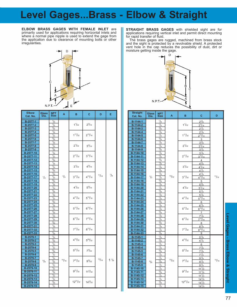
77
Level G
ag
es - B
ras
s E
lbo
w &
Str
aig
ht
Level Gages...Brass - Elbow & Straight
NPTSize
1/8
1/4
3/8
1/8
1/4
3/8
1/8
1/4
3/8
1/8
1/4
3/8
1/8
1/4
3/8
1/8
1/4
3/8
1/8
1/4
3/8
1/8
1/4
3/8
1/8
1/4
3/8
1/8
1/4
3/8
1/8
1/4
3/8
1/4
3/8
1/2
1/4
3/8
1/2
1/4
3/8
1/2
1/4
3/8
1/2
1/4
3/8
1/2
Elbow
Cat. No.
B-2577-1
B-2577-2
B-2577-3
B-2577-4
B-2577-5
B-2577-6
B-2577-7
B-2577-8
B-2577-9
B-2577-10
B-2577-11
B-2577-12
B-2577-13
B-2577-14
B-2577-15
B-2577-16
B-2577-17
B-2577-18
B-2577-19
B-2577-20
B-2577-21
B-2577-22
B-2577-23
B-2577-24
B-2577-25
B-2577-26
B-2577-27
B-2577-28
B-2577-29
B-2577-30
B-2577-31
B-2577-32
B-2577-33
B-2579-1
B-2579-2
B-2579-3
B-2579-4
B-2579-5
B-2579-6
B-2579-7
B-2579-8
B-2579-9
B-2579-10
B-2579-11
B-2579-12
B-2579-13
B-2579-14
B-2579-15
STRAIGHT BRASS GAGES with shielded sight are forapplications requiring vertical inlet and permit direct mountingfor rapid transfer of fluid.
The brass gages are rugged, machined from brass stockand the sight is protected by a revolvable shield. A protectedvent hole in the cap reduces the possibility of dust, dirt or moisture getting inside the gage.
ELBOW BRASS GAGES WITH FEMALE INLET are primarily used for applications requiring horizontal inlets andwhere a normal pipe nipple is used to extend the gage fromthe application due to clearance of mounting bolts or other irregularities.
C
25/16
213/16
35/16
313/16
45/16
413/16
55/16
513/16
613/16
713/16
813/16
529/32
75/32
95/32
115/32
145/32
B
11/32
117/32
21/32
217/32
31/32
317/32
41/32
417/32
517/32
617/32
717/32
413/32
521/32
721/32
921/32
1221/32
A
3/4
15/16
Glass
Dia.
1/2
5/8
NPTSize
1/8
1/4
3/8
1/8
1/4
3/8
1/8
1/4
3/8
1/8
1/4
3/8
1/8
1/4
3/8
1/8
1/4
3/8
1/8
1/4
3/8
1/8
1/4
3/8
1/8
1/4
3/8
1/8
1/4
3/8
1/8
1/4
3/8
1/4
3/8
1/2
1/4
3/8
1/2
1/4
3/8
1/2
1/4
3/8
1/2
1/4
3/8
1/2
Straight
Cat. No.
B-1144-1
B-1144-2
B-1144-3
B-1144-4
B-1144-5
B-1144-6
B-1144-7
B-1144-8
B-1144-9
B-1144-10
B-1144-11
B-1144-12
B-1144-13
B-1144-14
B-1144-15
B-1144-16
B-1144-17
B-1144-18
B-1144-19
B-1144-20
B-1144-21
B-1144-22
B-1144-23
B-1144-24
B-1144-25
B-1144-26
B-1144-27
B-1144-28
B-1144-29
B-1144-30
B-1144-31
B-1144-32
B-1144-33
B-1145-1
B-1145-2
B-1145-3
B-1145-4
B-1145-5
B-1145-6
B-1145-7
B-1145-8
B-1145-9
B-1145-10
B-1145-11
B-1145-12
B-1145-13
B-1145-14
B-1145-15
C
23/8
27/16
21/2
27/8
215/16
3
33/8
37/16
31/2
37/8
315/16
4
43/8
47/16
41/2
47/8
415/16
5
53/8
57/16
51/2
57/8
515/16
6
67/8
615/16
7
77/8
715/16
8
87/8
815/16
9
57/8
57/8
6
71/8
71/8
71/4
91/8
91/8
91/4
111/8
111/8
111/4
141/8
141/8
141/4
B
11/32
117/32
21/32
217/32
31/32
317/32
41/32
417/32
517/32
617/32
717/32
413/32
521/32
721/32
921/32
1221/32
A
13/32
13/32
Glass
Dia.
1/2
5/8
D E
11/167/8
13/16 1 1/8
D
11/16
13/16
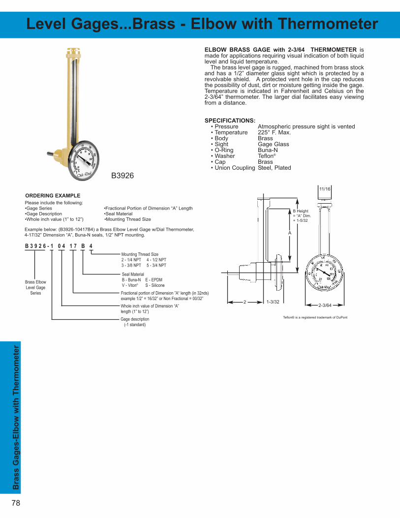
78
Bra
ss G
ag
es-E
lbo
w w
ith
Th
erm
om
ete
r
ELBOW BRASS GAGE with 2-3/64 THERMOMETER ismade for applications requiring visual indication of both liquidlevel and liquid temperature.
The brass level gage is rugged, machined from brass stockand has a 1/2” diameter glass sight which is protected by arevolvable shield. A protected vent hole in the cap reducesthe possibility of dust, dirt or moisture getting inside the gage.Temperature is indicated in Fahrenheit and Celsius on the 2-3/64” thermometer. The larger dial facilitates easy viewingfrom a distance.
Level Gages...Brass - Elbow with Thermometer
Please include the following:
•Gage Series •Fractional Portion of Dimension “A” Length
•Gage Description •Seal Material
•Whole inch value (1” to 12”) •Mounting Thread Size
B 3 9 2 6 - 1 0 4 1 7 B 4
Brass Elbow Level Gage
Series
Gage description(-1 standard)
Fractional portion of Dimension ”A“ length (in 32nds) example 1/2” = 16/32” or Non Fractional = 00/32”
Seal Material B - Buna-N E - EPDMV - Viton® S - Silicone
Whole inch value of Dimension “A”length (1” to 12”)
Mounting Thread Size2 - 1/4 NPT 4 - 1/2 NPT3 - 3/8 NPT 5 - 3/4 NPT
ORDERING EXAMPLE
Example below: (B3926-10417B4) a Brass Elbow Level Gage w/Dial Thermometer,
4-17/32” Dimension “A”, Buna-N seals, 1/2” NPT mounting.
B3926
11/16
2-3/64
A
B Height
= “A” Dim.
+ 1-5/32
SPECIFICATIONS:
• Pressure Atmospheric pressure sight is vented• Temperature 225° F. Max.• Body Brass• Sight Gage Glass• O-Ring Buna-N• Washer Teflon®
• Cap Brass• Union Coupling Steel, Plated
2 1-3/32
Teflon® is a registered trademark of DuPont

79
Level G
ag
es...R
igid
Pla
stic
Level Gages...Round Nylon
SPECIFICATIONS:
• Pressure 125 PSI Max.• Temperature 205° F. Max.• Mtg. Studs Aluminum Alloy• Sights Round Nylon (Trogamid®)• Seals Buna-N (standard)• End Blocks Aluminum Alloy
TYPICAL APPLICATIONS — Used to indicate level of lubricating oil supply at bearings, gear boxes, crank cases,transformers, switches, etc.COMPACT DESIGN — Can be installed easily in any location having enough clearance for a one-piece oil gage.SIMPLE INSTALLATION — Square shank with pipe threadscrews horizontally or vertically into tapped hole. Options areavailable for difficult or irregular mountings.QUALITY-BUILT — Shank body and cap are machined toclose tolerance. Sights are clear extrusion with wide-angleviewing and will withstand a tremendous amount of duress.For a leak-tight seal, Buna-N seals are furnished as stan-dard. Other commercial seal materials are available.MODIFICATIONS AVAILABLE — If desired, the elbow levelgages can be supplied with lower or higher viewing sights orlevel markings. In addition to the standard line, many specialgages, similar to the ones described here, have been developed for customer's specific applications. Should youhave special requirements, our engineering service is available without obligation.
When Ordering Specify:
• Catalog Number
LEAKPROOF CONSTRUCTION — For a leak - tight seal. Buna-N sealsare furnished as standard. Other commercial seal materials are available.
RIGID SIGHT — Transparent sight body is extremely tough and will with-stand a tremendous amount of duress, thus eliminating the hazards ofglass breakage experienced on conventional designs. Sight is compatiblewith many chemicals, and it will retain its clarity through various temperature ranges. Several level markings are available on request.
QUICK RESPONSE — Hollow mounting bolts allow liquid to enter thegage, the displaced air is vented back into the atmosphere. These largepassages effect quick level responses.
BENEFITS — To visibly indicate liquid supply level on machinery lubrica-tion and liquid storage systems. Tough, transparent, Trogamid® nylon sightallows viewing from all sides for maximum viewing of liquid.
Trogamid® is a registered trademark of Degussa AG
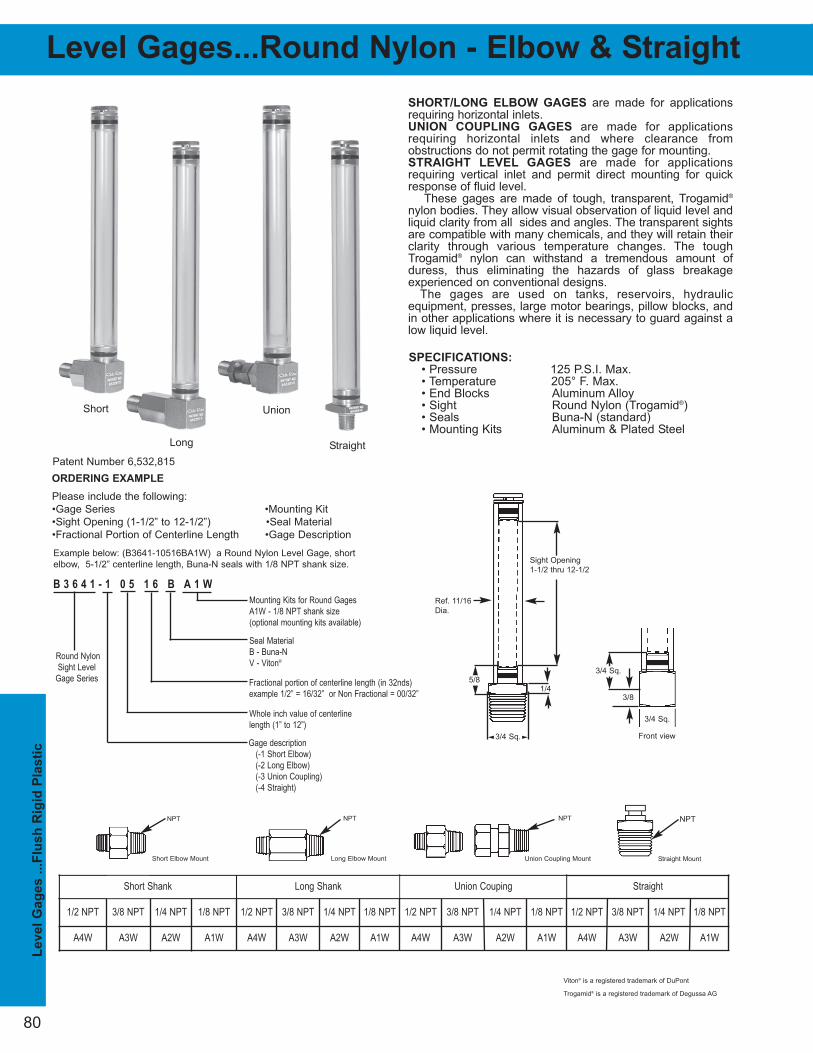
80
Level
Gag
es .
..F
lush
Rig
id P
lasti
c
SHORT/LONG ELBOW GAGES are made for applicationsrequiring horizontal inlets.UNION COUPLING GAGES are made for applications requiring horizontal inlets and where clearance from obstructions do not permit rotating the gage for mounting.STRAIGHT LEVEL GAGES are made for applications requiring vertical inlet and permit direct mounting for quickresponse of fluid level.
These gages are made of tough, transparent, Trogamid®
nylon bodies. They allow visual observation of liquid level andliquid clarity from all sides and angles. The transparent sightsare compatible with many chemicals, and they will retain theirclarity through various temperature changes. The toughTrogamid® nylon can withstand a tremendous amount ofduress, thus eliminating the hazards of glass breakage experienced on conventional designs.
The gages are used on tanks, reservoirs, hydraulic equipment, presses, large motor bearings, pillow blocks, andin other applications where it is necessary to guard against alow liquid level.
Level Gages...Round Nylon - Elbow & Straight
Please include the following:
•Gage Series •Mounting Kit
•Sight Opening (1-1/2” to 12-1/2”) •Seal Material
•Fractional Portion of Centerline Length •Gage Description
B 3 6 4 1 - 1 0 5 1 6 B A 1 W
Round NylonSight Level
Gage Series
Gage description(-1 Short Elbow)(-2 Long Elbow)(-3 Union Coupling)(-4 Straight)
Fractional portion of centerline length (in 32nds) example 1/2” = 16/32” or Non Fractional = 00/32”
Seal Material B - Buna-NV - Viton®
Whole inch value of centerlinelength (1” to 12”)
Mounting Kits for Round Gages A1W - 1/8 NPT shank size(optional mounting kits available)
ORDERING EXAMPLE
Example below: (B3641-10516BA1W) a Round Nylon Level Gage, short
elbow, 5-1/2” centerline length, Buna-N seals with 1/8 NPT shank size.
Patent Number 6,532,815
SPECIFICATIONS:
• Pressure 125 P.S.I. Max. • Temperature 205° F. Max. • End Blocks Aluminum Alloy• Sight Round Nylon (Trogamid®)• Seals Buna-N (standard)• Mounting Kits Aluminum & Plated Steel
Ref. 11/16
Dia.
Sight Opening
1-1/2 thru 12-1/2
1/2 NPT 3/8 NPT 1/4 NPT 1/8 NPT 1/2 NPT 3/8 NPT 1/4 NPT 1/8 NPT 1/2 NPT 3/8 NPT 1/4 NPT 1/8 NPT 1/2 NPT 3/8 NPT 1/4 NPT 1/8 NPT
A4W A3W A2W A1W A4W A3W A2W A1W A4W A3W A2W A1W A4W A3W A2W A1W
Union
Short Shank Long Shank Union Couping Straight
NPTNPTNPT NPT
Short Elbow Mount Long Elbow Mount Union Coupling Mount Straight Mount
3/4 Sq.
3/4 Sq.
3/8
Front view
1/4 5/8
3/4 Sq.
Viton® is a registered trademark of DuPont
Short
Long Straight
Trogamid® is a registered trademark of Degussa AG

Level Gage...Flush Aluminum
81
Level G
ag
e...F
lush
Alu
min
um
Milled Aluminum Liquid Level Gage These flush mount gages offer a
rugged milled aluminum construction with a unique staked end body design
to handle any industrial liquid level application.
These gages can be used to view liquid levels in hydraulic reservoirs,
gearboxes, bearing housings, crankcases, transformers and machinery oil
reservoirs.
Fluid enters through a cross hole in the hollow lower bolt and is
communicated back into the tank, through the cross hole in the
hollow top bolt. The gage is offered in centerline lengths ranging from 3” to
36”.
The unique design of this gage minimizes parts and optimizes production
capabilities thus offering a very competitive liquid level gage. The milled
aluminum body provides adequate fluid visibility yet a rigid gage design. All
aluminum components resist rust and corrosion.
SPECIFICATIONS:
• Pressure 175 PSI Max.
• Temperature 225° F. Max. Buna N Seals
• Body Aluminum
• Seals Buna-N, (standard)
• Mounting Kits Aluminum, Plated Steel
(Shut-off Mounting Kits - Stem, Brass)
•Torque Mounting Studs Torque to 90 IN*LB When
Installing Level Gage.
Please include the following:
•Gage Series •Fractional Portion of Centerline Length
•Gage Description •Seal Material
•Whole inch value (3” to 36”) •Mounting Kit
Patent Number 6,928,716 6,758,092 6,532,815
Standard
Dial
Thermometer
7/8 Sq.
B 3 5 4 0 - 2 0 5 1 6 B A 1 W
MilledAluminum
Level GageSeries
Gage description(-1 standard)(-2 dial thermometer)(-3 card thermometer)(only available in 3”, 5” or 10” centerline)(-4 shut-off)
Fractional portion of centerline length (in 32nds) example 1/2” = 16/32” or Non Fractional = 00/32”
Seal Material B - Buna-N E - EPDMV - Viton® S - Silicone
Whole inch value of centerlinelength (3” to 36”)
Mounting Kit A1W - 1/2-20 Front Mount(optional mounting kits below)
ORDERING EXAMPLE
Example below: (B3540-20516BA1W) a Staked Aluminum Level Gage w/Dial
Thermometer, 5-1/2” centerline length, Buna-N seals with front mounting, 1/2-20
thread size.
BackMount
M12 x 1.75stud
1/2-13stud
1/2-20stud
1/2-20stud
3/4NPT 1/2 NPT 3/8 NPT 1/4 NPT 3/4
NPTF1/2
NPTF3/8
NPTF1/4
NPTF3/4
NPSM1/2
NPSM3/8
NPSM1/4
NPSM3/4
BSPT1/2
BSPT3/8
BSPT1/4
BSPTM1W A2W A1W B1W N4W N3W N2W N1W F4W F3W F2W F1W P4W P3W P2W P1W R4W R3W R2W R1W
A1W B1W N4W N3W N2W N1W F4W F3W F2W F1W P4W P3W P2W P1W R4W R3W R2W R1WM1W A2W A1W B1W N4W N3W N2W N1W F4W F3W F2W F1W P4W P3W P2W P1W R4W R3W R2W R1W
A1L B1L N4L N3L N2L N1L F4L F3L F2L F1L P4L P3L P2L P1L R4L R3L R2L R1L
Mounting Bolts with Adapters Back Mount with Mounting Nut
Shut-Off - Front Mount
Front Mounting Bolts
Shut-Off with AdaptersShut-Off - Back Mount withMounting Nut
Front Mount with NPT Adapters with NPTF Adapters with NPSM Adapters with BSPT Adapters
Viton® is a registered trademark of DuPont
CenterlineLength 3”Thru 36”BetweenCenters ofStuds.
± 1/32 of PlayBetweenCenters ofStuds
Typical Installation
Shut-off
-1
-2
-3
-4
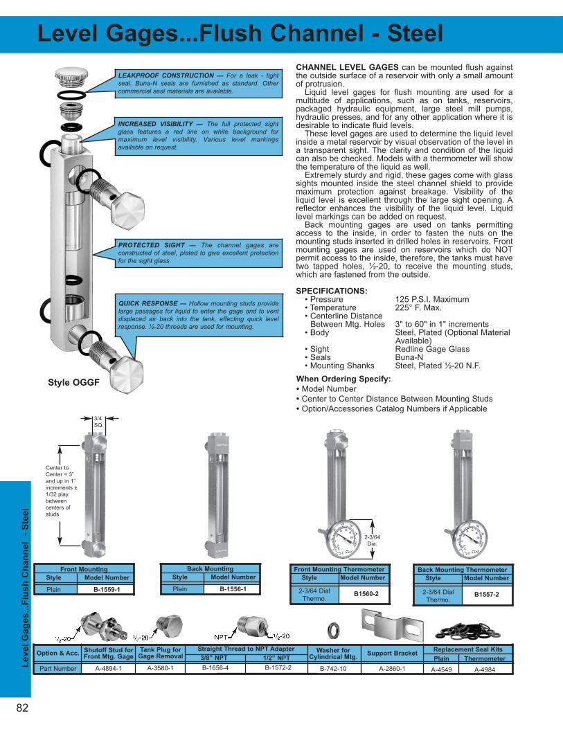
82
Replacement Seal Kits
Plain Thermometer
A-4549 A-4984
Tank Plug for
Gage Removal
A-3580-1
Washer for
Cylindrical Mtg.
B-742-10
Shutoff Stud for
Front Mtg. Gage
A-4894-1
Support Bracket
A-2860-1
Option & Acc.
Part Number
Front Mounting
Style Model Number
Plain B-1559-1
CHANNEL LEVEL GAGES can be mounted flush againstthe outside surface of a reservoir with only a small amountof protrusion.
Liquid level gages for flush mounting are used for a multitude of applications, such as on tanks, reservoirs,packaged hydraulic equipment, large steel mill pumps,hydraulic presses, and for any other application where it isdesirable to indicate fluid levels.
These level gages are used to determine the liquid levelinside a metal reservoir by visual observation of the level ina transparent sight. The clarity and condition of the liquidcan also be checked. Models with a thermometer will showthe temperature of the liquid as well.
Extremely sturdy and rigid, these gages come with glasssights mounted inside the steel channel shield to providemaximum protection against breakage. Visibility of the liquid level is excellent through the large sight opening. Areflector enhances the visibility of the liquid level. Liquidlevel markings can be added on request.
Back mounting gages are used on tanks permittingaccess to the inside, in order to fasten the nuts on themounting studs inserted in drilled holes in reservoirs. Frontmounting gages are used on reservoirs which do NOTpermit access to the inside, therefore, the tanks must havetwo tapped holes, ½-20, to receive the mounting studs,which are fastened from the outside.
SPECIFICATIONS:
• Pressure 125 P.S.I. Maximum• Temperature 225° F. Max.• Centerline Distance
Between Mtg. Holes 3" to 60" in 1" increments• Body Steel, Plated (Optional Material
Available)• Sight Redline Gage Glass• Seals Buna-N• Mounting Shanks Steel, Plated ½-20 N.F.
When Ordering Specify:
• Model Number
• Center to Center Distance Between Mounting Studs
• Option/Accessories Catalog Numbers if Applicable
Back Mounting
Style Model Number
Plain B-1556-1
Front Mounting Thermometer
Style Model Number
Back Mounting Thermometer
Style Model Number
LEAKPROOF CONSTRUCTION — For a leak - tightseal. Buna-N seals are furnished as standard. Othercommercial seal materials are available.
PROTECTED SIGHT — The channel gages are constructed of steel, plated to give excellent protectionfor the sight glass.
INCREASED VISIBILITY — The full protected sightglass features a red line on white background for maximum level visibility. Various level markings available on request.
QUICK RESPONSE — Hollow mounting studs providelarge passages for liquid to enter the gage and to ventdisplaced air back into the tank, effecting quick levelresponse. ½-20 threads are used for mounting.
Style OGGF
B-1656-4 B-1572-2
3/8” NPT 1/2” NPT
Straight Thread to NPT Adapter
Level
Gag
es..
.Flu
sh
Ch
an
nel
- S
teel
Level Gages...Flush Channel - Steel
2-3/64 Dial
Thermo.B1560-2 B1557-2
2-3/64 Dial
Thermo.
3/4
SQ.
Center to
Center = 3”
and up in 1”
increments ±
1/32 play
between
centers of
studs
2-3/64
Dia.
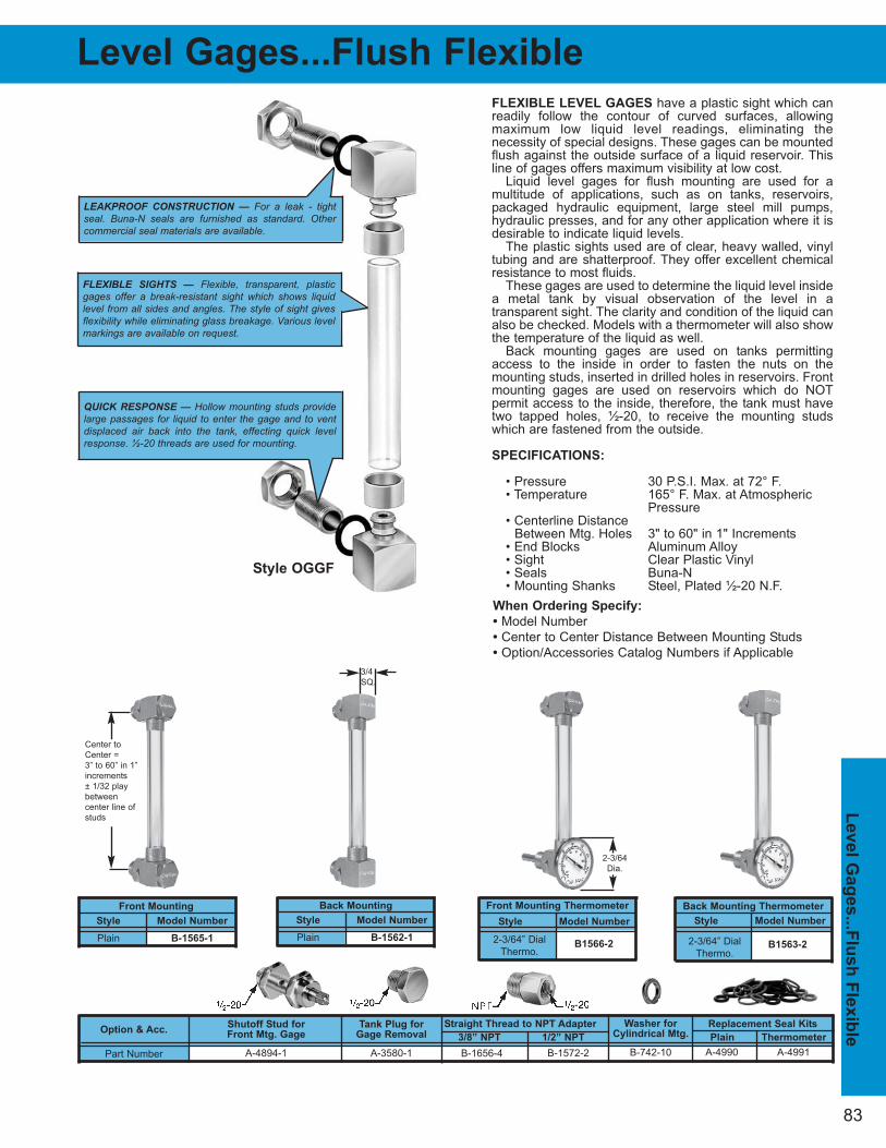
83
QUICK RESPONSE — Hollow mounting studs providelarge passages for liquid to enter the gage and to ventdisplaced air back into the tank, effecting quick levelresponse. ½-20 threads are used for mounting.
When Ordering Specify:
• Model Number
• Center to Center Distance Between Mounting Studs
• Option/Accessories Catalog Numbers if Applicable
Level G
ag
es...F
lush
Fle
xib
le
FLEXIBLE LEVEL GAGES have a plastic sight which canreadily follow the contour of curved surfaces, allowing maximum low liquid level readings, eliminating the necessity of special designs. These gages can be mountedflush against the outside surface of a liquid reservoir. Thisline of gages offers maximum visibility at low cost.
Liquid level gages for flush mounting are used for a multitude of applications, such as on tanks, reservoirs,packaged hydraulic equipment, large steel mill pumps,hydraulic presses, and for any other application where it isdesirable to indicate liquid levels.
The plastic sights used are of clear, heavy walled, vinyltubing and are shatterproof. They offer excellent chemicalresistance to most fluids.
These gages are used to determine the liquid level insidea metal tank by visual observation of the level in a transparent sight. The clarity and condition of the liquid canalso be checked. Models with a thermometer will also showthe temperature of the liquid as well.
Back mounting gages are used on tanks permittingaccess to the inside in order to fasten the nuts on themounting studs, inserted in drilled holes in reservoirs. Frontmounting gages are used on reservoirs which do NOTpermit access to the inside, therefore, the tank must havetwo tapped holes, ½-20, to receive the mounting studswhich are fastened from the outside.
SPECIFICATIONS:
• Pressure 30 P.S.I. Max. at 72° F.• Temperature 165° F. Max. at Atmospheric
Pressure• Centerline Distance
Between Mtg. Holes 3" to 60" in 1" Increments• End Blocks Aluminum Alloy• Sight Clear Plastic Vinyl• Seals Buna-N• Mounting Shanks Steel, Plated ½-20 N.F.
Tank Plug for
Gage Removal
A-3580-1
Washer for
Cylindrical Mtg.
B-742-10
Shutoff Stud for
Front Mtg. Gage
A-4894-1
Option & Acc.
Part Number
Front Mounting
Style Model Number
Plain B-1565-1
Back Mounting
Style Model Number
Plain B-1562-1
Front Mounting Thermometer
Style Model Number
Back Mounting Thermometer
Style Model Number
LEAKPROOF CONSTRUCTION — For a leak - tightseal. Buna-N seals are furnished as standard. Othercommercial seal materials are available.
FLEXIBLE SIGHTS — Flexible, transparent, plasticgages offer a break-resistant sight which shows liquidlevel from all sides and angles. The style of sight givesflexibility while eliminating glass breakage. Various levelmarkings are available on request.
Style OGGF
Replacement Seal Kits
Plain Thermometer
A-4990 A-4991
Straight Thread to NPT Adapter
B-1656-4 B-1572-2
3/8” NPT 1/2” NPT
Level Gages...Flush Flexible
2-3/64” Dial
Thermo.B1566-2 B1563-22-3/64” Dial
Thermo.
Center to
Center =
3” to 60” in 1”
increments
± 1/32 play
between
center line of
studs
3/4
SQ.
2-3/64
Dia.
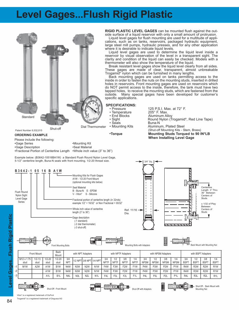
84
RIGID PLASTIC LEVEL GAGES can be mounted flush against the out-side surface of a liquid reservoir with only a small amount of protrusion.
Liquid level gages for flush mounting are used for a multitude of appli-cations, such as on tanks, reservoirs, packaged hydraulic equipment,large steel mill pumps, hydraulic presses, and for any other applicationwhere it is desirable to indicate liquid levels.
Liquid level gages are used to determine the liquid level inside areservoir by visual observation of the level in a transparent sight. Theclarity and condition of the liquid can easily be checked. Models with athermometer will also show the temperature of the liquid.
Break resistant level gages show the liquid level clearly from all sides.These gages are made of clear, transparent, almost unbreakableTrogamid® nylon which can be furnished in many lengths.
Back mounting gages are used on tanks permitting access to theinside in order to fasten the nuts on the mounting studs, inserted in drilledholes in reservoirs. Front mounting gages are used on reservoirs whichdo NOT permit access to the inside, therefore, the tank must have twotapped holes, to receive the mounting studs, which are fastened from theoutside. Many special gages have been developed for customer’s specific applications.
Please include the following:
•Gage Series •Mounting Kit
•Gage Description •Seal Material
•Fractional Portion of Centerline Length •Whole inch value (3” to 36”)
B 3 6 4 2 - 1 0 5 1 6 B A 1 W
Flush RoundNylon SightLevel Gage
Series
Gage description(-1 standard)(-2 dial thermometer)(-3 shut-off)
Fractional portion of centerline length (in 32nds) example 1/2” = 16/32” or Non Fractional = 00/32”
Seal Material B - Buna-N E - EPDMV - Viton® S - Silicone
Whole inch value of centerlinelength (3” to 36”)
Mounting Kits for Flush Gages A1W - 1/2-20 Front Mount(optional mounting kits below)
ORDERING EXAMPLE
Example below: (B3642-10516BA1W) a Standard Flush Round Nylon Level Gage,
5-1/2” centerline length, Buna-N seals with front mounting, 1/2-20 thread size.
BackMount
M12 x 1.75stud
1/2-13stud
1/2-20stud
1/2-20stud
3/4NPT 1/2 NPT 3/8 NPT 1/4 NPT 3/4
NPTF1/2
NPTF3/8
NPTF1/4
NPTF3/4
NPSM1/2
NPSM3/8
NPSM1/4
NPSM3/4
BSPT1/2
BSPT3/8
BSPT1/4
BSPTM1W A2W A1W B1W N4W N3W N2W N1W F4W F3W F2W F1W P4W P3W P2W P1W R4W R3W R2W R1W
A1W B1W N4W N3W N2W N1W F4W F3W F2W F1W P4W P3W P2W P1W R4W R3W R2W R1WA1L B1L N4L N3L N2L N1L F4L F3L F2L F1L P4L P3L P2L P1L R4L R3L R2L R1L
Mounting Bolts with Adapters Back Mount with Mounting Nut
Shut-Off - Front Mount
Front Mounting Bolts
Shut-Off with AdaptersShut-Off - Back Mount withMounting Nut
Front Mount with NPT Adapters with NPTF Adapters with NPSM Adapters with BSPT Adapters
SPECIFICATIONS:
• Pressure 125 P.S.I. Max. at 72° F.• Temperature 205° F. Max. • End Blocks Aluminum Alloy• Sight Round Nylon (Trogamid®, Red Line Tape)• Seals Buna-N• Mounting Kits Aluminum, Plated Steel
(Shut-off Mounting Kits - Stem, Brass)
•Torque Mounting Studs Torqued to 90 IN*LB
When Installing Level Gage
Patent Number 6,532,815
Standard
Level Gages...Flush Rigid Plastic L
evel
Gag
es..
.Flu
sh
Rig
id P
lasti
c
Ref. 11/16
Dia.
Viton® is a registered trademark of DuPont
3/4” Sq.
CenterlineLength 3” Thru36” BetweenCenters ofStuds.
± 1/32 of PlayBetweenCenters ofStuds
Dial ThermometerShut-off
Trogamid® is a registered trademark of Degussa AG
-1
-2
-3
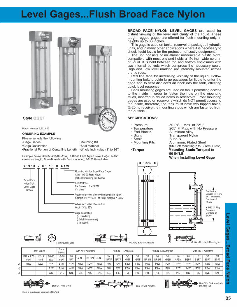
85
Level G
ag
es...B
ro
ad
Face N
ylo
n
BROAD FACE NYLON LEVEL GAGES are used for distant viewing of the level and clarity of the liquid. Thesetough, rugged gages are offered for flush mounting only, inheights up to 36 inches.
This gage is used on tanks, reservoirs, packaged hydraulicunits, and in many other applications where it is necessary tocheck liquid levels for the protection of costly equipment.
The unit consists of an almost unbreakable plastic sight,compatible with most oils and holds a 1½ inch wide columnof liquid. It is held between top and bottom enclosures withtwo internal tie rods which compress the necessary seals.High and Low level marking are internally mounted acrossthe tie rods.
Red line tape for increasing visibility of the liquid. Hollowmounting bolts provide large passages for liquid to enter thegage and to vent displaced air back into the tank, effectingquick level response.
Back mounting gages are used on tanks permitting accessto the inside in order to fasten the nuts on the mountingstuds, inserted in drilled holes in reservoirs. Front mountinggages are used on reservoirs which do NOT permit access tothe inside, therefore, the tank must have two tapped holes,½-20, to receive the mounting studs which are fastened fromthe outside.
SPECIFICATIONS:
• Pressure 50 P.S.I. Max. at 72° F.• Temperature 205° F. Max. with No Pressure• End Blocks Aluminum Alloy• Sight Transparent Nylon• Seals Buna-N• Mounting Kits Aluminum, Plated Steel
(Shut-off Mounting Kits - Stem, Brass)
•Torque Mounting Studs Torqued to
90 IN*LB
When Installing Level Gage
Style OGGF
Level Gages...Flush Broad Face Nylon
Please include the following:
•Gage Series •Mounting Kit
•Gage Description •Seal Material
•Fractional Portion of Centerline Length •Whole inch value (3” to 36”)
B 3 9 5 0 2 0 5 1 6 B A 1 W
Broad FaceNylon SightLevel Gage
Series
Gage description(-1 standard)(-2 dial thermometer)(-4 shut-off )
Fractional portion of centerline length (in 32nds) example 1/2” = 16/32” or Non Fractional = 00/32”
Seal Material B - Buna-N E - EPDMV - Viton®
Whole inch value of centerlinelength (3” to 36”)
Mounting Kits for Broad Face Gages A1W - 1/2-20 Front Mount(optional mounting kits below)
ORDERING EXAMPLE
Example below: (B3950-20516BA1W) a Broad Face Nylon Level Gage, 5-1/2”
centerline length, Buna-N seals with front mounting, 1/2-20 thread size.
Patent Number 6,532,815
BackMount
M12 x 1.75stud
1/2-13stud
1/2-20stud
1/2-20stud
3/4NPT 1/2 NPT 3/8 NPT 1/4 NPT 3/4
NPTF1/2
NPTF3/8
NPTF1/4
NPTF3/4
NPSM1/2
NPSM3/8
NPSM1/4
NPSM3/4
BSPT1/2
BSPT3/8
BSPT1/4
BSPTM1W A2W A1W B1W N4W N3W N2W N1W F4W F3W F2W F1W P4W P3W P2W P1W R4W R3W R2W R1W
A1W B1W N4W N3W N2W N1W F4W F3W F2W F1W P4W P3W P2W P1W R4W R3W R2W R1WA1L B1L N4L N3L N2L N1L F4L F3L F2L F1L P4L P3L P2L P1L R4L R3L R2L R1L
Mounting Bolts with Adapters Back Mount with Mounting Nut
Shut-Off - Front Mount
Front Mounting Bolts
Shut-Off with AdaptersShut-Off - Back Mount withMounting Nut
Front Mount with NPT Adapters with NPTF Adapters with NPSM Adapters with BSPT Adapters
Viton® is a registered trademark of DuPont
CenterlineLength 3” Thru36” BetweenCenters ofStuds.
± 1/32 of PlayBetweenCenters ofStuds
1-29/32
-1
-2
-4
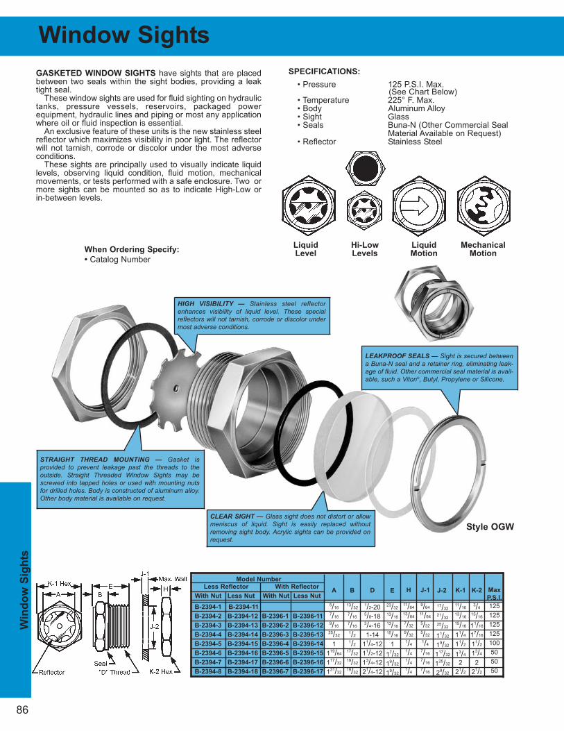
17/32
21/32
25/32
11/32
19/32
117/32
125/32
29/32
Max
P.S.I.
125
125
125
125
100
50
50
50
86
Window Sights
J-1
9/64
11/64
5/32
5/32
1/4
7/16
7/16
7/16
H
11/64
13/64
7/32
9/32
1/4
1/4
1/4
1/4
K-2
3/4
15/16
11/16
17/16
11/2
13/4
2
21/2
E
23/32
13/16
13/16
15/16
1
17/32
19/32
19/32
B
13/32
7/16
7/16
1/2
1/2
17/32
19/32
19/32
K-1
11/16
13/16
15/16
11/4
11/2
13/4
2
21/2
A
5/16
7/16
9/16
25/32
1
119/64
117/32
131/32
D
1/2-205/8-183/4-16
1-14
11/4-12
11/2-12
13/4-12
21/4-12
SPECIFICATIONS:
• Pressure 125 P.S.I. Max.(See Chart Below)
• Temperature 225° F. Max.• Body Aluminum Alloy• Sight Glass• Seals Buna-N (Other Commercial Seal
Material Available on Request)• Reflector Stainless Steel
GASKETED WINDOW SIGHTS have sights that are placedbetween two seals within the sight bodies, providing a leaktight seal.
These window sights are used for fluid sighting on hydraulictanks, pressure vessels, reservoirs, packaged power equipment, hydraulic lines and piping or most any applicationwhere oil or fluid inspection is essential.
An exclusive feature of these units is the new stainless steelreflector which maximizes visibility in poor light. The reflectorwill not tarnish, corrode or discolor under the most adverseconditions.
These sights are principally used to visually indicate liquidlevels, observing liquid condition, fluid motion, mechanicalmovements, or tests performed with a safe enclosure. Two ormore sights can be mounted so as to indicate High-Low or in-between levels.
Liquid
Level
Hi-Low
Levels
Liquid
Motion
Mechanical
Motion
Model Number
Less Reflector With Reflector
With Nut Less Nut With Nut Less Nut
B-2394-1 B-2394-11
B-2394-2 B-2394-12 B-2396-1 B-2396-11
B-2394-3 B-2394-13 B-2396-2 B-2396-12
B-2394-4 B-2394-14 B-2396-3 B-2396-13
B-2394-5 B-2394-15 B-2396-4 B-2396-14
B-2394-6 B-2394-16 B-2396-5 B-2396-15
B-2394-7 B-2394-17 B-2396-6 B-2396-16
B-2394-8 B-2394-18 B-2396-7 B-2396-17
When Ordering Specify:
• Catalog Number
CLEAR SIGHT — Glass sight does not distort or allowmeniscus of liquid. Sight is easily replaced withoutremoving sight body. Acrylic sights can be provided onrequest.
HIGH VISIBILITY — Stainless steel reflectorenhances visibility of liquid level. These specialreflectors will not tarnish, corrode or discolor undermost adverse conditions.
STRAIGHT THREAD MOUNTING — Gasket is provided to prevent leakage past the threads to the outside. Straight Threaded Window Sights may bescrewed into tapped holes or used with mounting nutsfor drilled holes. Body is constructed of aluminum alloy.Other body material is available on request.
LEAKPROOF SEALS — Sight is secured betweena Buna-N seal and a retainer ring, eliminating leak-age of fluid. Other commercial seal material is avail-able, such a Viton®, Butyl, Propylene or Silicone.
Style OGW
J-2
Win
do
w S
igh
ts
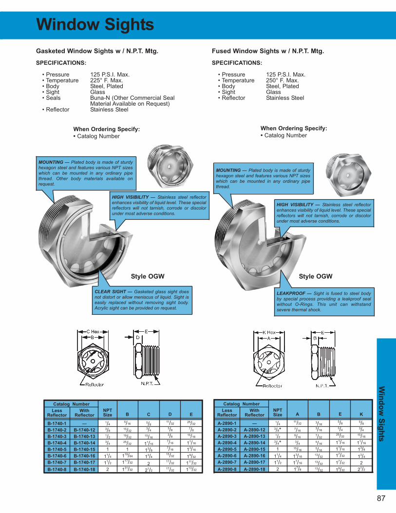
Win
do
w S
igh
ts
87
Window Sights
Gasketed Window Sights w / N.P.T. Mtg.
SPECIFICATIONS:
• Pressure 125 P.S.I. Max. • Temperature 225° F. Max. • Body Steel, Plated• Sight Glass• Seals Buna-N (Other Commercial Seal
Material Available on Request)• Reflector Stainless Steel
Fused Window Sights w / N.P.T. Mtg.
SPECIFICATIONS:
• Pressure 125 P.S.I. Max. • Temperature 250° F. Max. • Body Steel, Plated• Sight Glass• Reflector Stainless Steel
Catalog Number
Less With
Reflector Reflector
A-2890-1 —
A-2890-2 A-2890-12
A-2890-3 A-2890-13
A-2890-4 A-2890-14
A-2890-5 A-2890-15
A-2890-6 A-2890-16
A-2890-7 A-2890-17
A-2890-8 A-2890-18
NPT
Size
1/4
3/8*1/2
3/4*1
11/4
11/2
2
A
11/32
7/16
9/16
3/4
15/16
13/16
17/16
17/8
K
5/8
3/4
15/16
11/16
13/8
13/4
2
21/2
B
3/16
3/16
7/32
5/16
5/16
13/32
13/32
13/32
E
5/8
3/4
25/32
11/16
11/16
17/32
17/32
19/32
When Ordering Specify:
• Catalog Number
MOUNTING — Plated body is made of sturdyhexagon steel and features various NPT sizeswhich can be mounted in any ordinary pipethread. Other body materials available onrequest.
HIGH VISIBILITY — Stainless steel reflectorenhances visibility of liquid level. These specialreflectors will not tarnish, corrode or discolorunder most adverse conditions.
CLEAR SIGHT — Gasketed glass sight doesnot distort or allow meniscus of liquid. Sight iseasily replaced without removing sight body.Acrylic sight can be provided on request.
HIGH VISIBILITY — Stainless steel reflectorenhances visibility of liquid level. These specialreflectors will not tarnish, corrode or discolorunder most adverse conditions.
LEAKPROOF — Sight is fused to steel bodyby special process providing a leakproof sealwithout O-Rings. This unit can withstandsevere thermal shock.
MOUNTING — Plated body is made of sturdyhexagon steel and features various NPT sizeswhich can be mounted in any ordinary pipethread.
When Ordering Specify:
• Catalog Number
Style OGW Style OGW
Catalog Number
Less With
Reflector Reflector
B-1740-1 —
B-1740-2 B-1740-12
B-1740-3 B-1740-13
B-1740-4 B-1740-14
B-1740-5 B-1740-15
B-1740-6 B-1740-16
B-1740-7 B-1740-17
B-1740-8 B-1740-18
NPT
Size
1/4
3/8
1/2
3/4
1
11/4
11/2
2
B
5/16
15/32
19/32
25/32
1
119/64
117/32
131/32
E
25/32
7/8
15/16
11/16
13/16
19/32
111/32
113/32
C
5/8
3/4
15/16
11/16
13/8
13/4
2
21/2
D
11/32
3/8
3/8
7/16
7/16
15/32
17/32
17/32
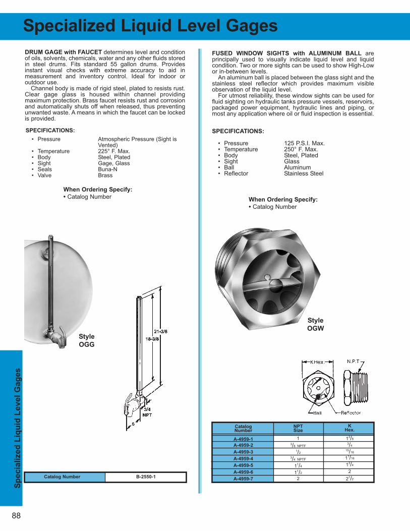
88
DRUM GAGE with FAUCET determines level and conditionof oils, solvents, chemicals, water and any other fluids storedin steel drums. Fits standard 55 gallon drums. Providesinstant visual checks with extreme accuracy to aid in measurement and inventory control. Ideal for indoor or outdoor use.
Channel body is made of rigid steel, plated to resists rust.Clear gage glass is housed within channel providing maximum protection. Brass faucet resists rust and corrosionand automatically shuts off when released, thus preventingunwanted waste. A means in which the faucet can be lockedis provided.
SPECIFICATIONS:
• Pressure Atmospheric Pressure (Sight is Vented)
• Temperature 225° F. Max. • Body Steel, Plated• Sight Gage, Glass• Seals Buna-N• Valve Brass
When Ordering Specify:
• Catalog Number
FUSED WINDOW SIGHTS with ALUMINUM BALL are principally used to visually indicate liquid level and liquid condition. Two or more sights can be used to show High-Lowor in-between levels.
An aluminum ball is placed between the glass sight and thestainless steel reflector which provides maximum visibleobservation of the liquid level.
For utmost reliability, these window sights can be used forfluid sighting on hydraulic tanks pressure vessels, reservoirs,packaged power equipment, hydraulic lines and piping, ormost any application where oil or fluid inspection is essential.
SPECIFICATIONS:
• Pressure 125 P.S.I. Max. • Temperature 250° F. Max. • Body Steel, Plated• Sight Glass• Ball Aluminum• Reflector Stainless Steel
When Ordering Specify:
• Catalog Number
Style
OGG
Catalog Number
A-4959-1
A-4959-2
A-4959-3
A-4959-4
A-4959-5
A-4959-6
A-4959-7
NPTSize
13/8 NPTF
1/2
3/4 NPTF
11/4
11/2
2
KHex.
13/8
3/4
15/16
11/16
13/4
2
21/2Catalog Number B-2550-1
Style
OGW
Sp
ecia
lized
Liq
uid
Level
Gag
es
Specialized Liquid Level Gages
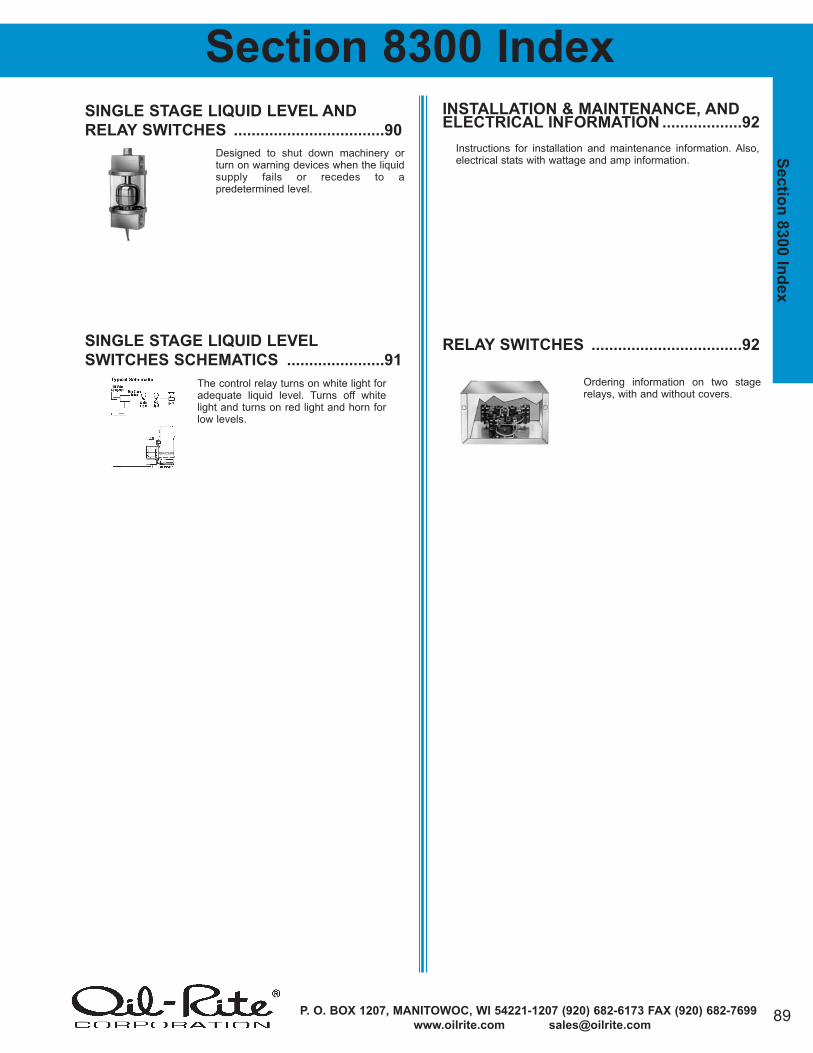
P. O. BOX 1207, MANITOWOC, WI 54221-1207 (920) 682-6173 FAX (920) 682-7699
www.oilrite.com [email protected]
Sectio
n 8
300 In
dex
INSTALLATION & MAINTENANCE, ANDELECTRICAL INFORMATION ..................92
RELAY SWITCHES ..................................92
SINGLE STAGE LIQUID LEVEL AND
RELAY SWITCHES ..................................90
SINGLE STAGE LIQUID LEVEL
SWITCHES SCHEMATICS ......................91
Section 8300 Index
Designed to shut down machinery orturn on warning devices when the liquidsupply fails or recedes to a predetermined level.
The control relay turns on white light foradequate liquid level. Turns off whitelight and turns on red light and horn forlow levels.
Instructions for installation and maintenance information. Also,electrical stats with wattage and amp information.
Ordering information on two stagerelays, with and without covers.
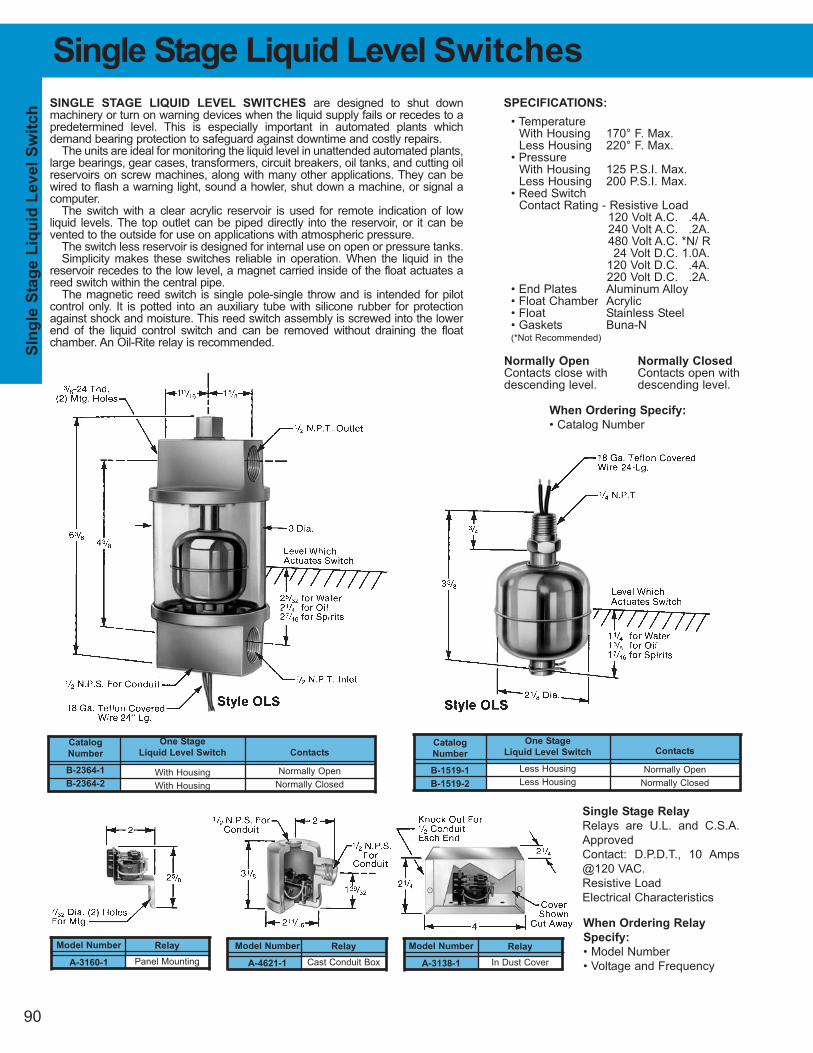
SIn
gle
Sta
ge L
iqu
id L
evel
Sw
itch
One Stage
Liquid Level Switch
With Housing
With Housing
Catalog
Number
B-2364-1
B-2364-2
Contacts
Normally Open
Normally Closed
90
Single Stage Liquid Level Switches
SPECIFICATIONS:
• TemperatureWith Housing 170° F. Max.Less Housing 220° F. Max.
• PressureWith Housing 125 P.S.I. Max.Less Housing 200 P.S.I. Max.
• Reed SwitchContact Rating - Resistive Load
120 Volt A.C. .4A.240 Volt A.C. .2A.480 Volt A.C. *N/ R24 Volt D.C. 1.0A.
120 Volt D.C. .4A.220 Volt D.C. .2A.
• End Plates Aluminum Alloy• Float Chamber Acrylic• Float Stainless Steel• Gaskets Buna-N(*Not Recommended)
Normally Open Normally Closed
Contacts close with Contacts open withdescending level. descending level.
SINGLE STAGE LIQUID LEVEL SWITCHES are designed to shut downmachinery or turn on warning devices when the liquid supply fails or recedes to apredetermined level. This is especially important in automated plants whichdemand bearing protection to safeguard against downtime and costly repairs.
The units are ideal for monitoring the liquid level in unattended automated plants,large bearings, gear cases, transformers, circuit breakers, oil tanks, and cutting oilreservoirs on screw machines, along with many other applications. They can bewired to flash a warning light, sound a howler, shut down a machine, or signal acomputer.
The switch with a clear acrylic reservoir is used for remote indication of low liquid levels. The top outlet can be piped directly into the reservoir, or it can be vented to the outside for use on applications with atmospheric pressure.
The switch less reservoir is designed for internal use on open or pressure tanks.Simplicity makes these switches reliable in operation. When the liquid in the
reservoir recedes to the low level, a magnet carried inside of the float actuates areed switch within the central pipe.
The magnetic reed switch is single pole-single throw and is intended for pilot control only. It is potted into an auxiliary tube with silicone rubber for protectionagainst shock and moisture. This reed switch assembly is screwed into the lowerend of the liquid control switch and can be removed without draining the float chamber. An Oil-Rite relay is recommended.
When Ordering Specify:
• Catalog Number
One Stage
Liquid Level Switch
Less Housing
Less Housing
Catalog
Number
B-1519-1
B-1519-2
Contacts
Normally Open
Normally Closed
Single Stage Relay
Relays are U.L. and C.S.A.
Approved
Contact: D.P.D.T., 10 Amps
@120 VAC.
Resistive Load
Electrical Characteristics
When Ordering Relay
Specify:
• Model Number
• Voltage and Frequency
Relay
Panel Mounting
Model Number
A-3160-1
Relay
Cast Conduit Box
Model Number
A-4621-1
Relay
In Dust Cover
Model Number
A-3138-1
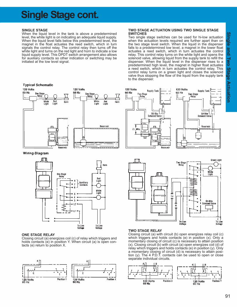
SIn
gle
an
d T
wo
Sta
ge A
ctu
atio
n
91
Single Stage cont.
TWO STAGE ACTUATION USING TWO SINGLE STAGE
SWITCHES
Two single stage switches can be used for hi-low actuationwhen the actuation levels required are further apart than onthe two stage level switch. When the liquid in the dispenserfalls to a predetermined low level, a magnet in the lower floatactuates a reed switch, which in turn actuates the controlrelay. This control relay turns on the white light and opens thesolenoid valve, allowing liquid from the supply tank to refill thedispenser. When the liquid level in the dispenser rises to apredetermined high level, the magnet in higher float actuatesa reed switch, which in turn actuates the control relay. Thiscontrol relay turns on a green light and closes the solenoidvalve thus stopping the flow of the liquid from the supply tankto the dispenser.
SINGLE STAGE
When the liquid level in the tank is above a predeterminedlevel, the white light is on indicating an adequate liquid supply.When the liquid level falls below this predetermined level, themagnet in the float actuates the reed switch, which in turn signals the control relay. The control relay then turns off thewhite light and turns on the red light and horn to indicate a lowliquid supply level. This DPDT switch arrangement also allowsfor auxiliary contacts so other indication or switching may beinitiated at the low level signal.
ONE STAGE RELAY
Closing circuit (a) energizes coil (c) of relay which triggers andholds contacts (e) in position Y. When circuit (a) is open con-tacts (e) return to position X.
TWO STAGE RELAY
Closing circuit (a) with circuit (b) open energizes relay coil (c)which triggers and holds contacts (e) in position (x). Only amomentary closing of circuit (c) is necessary to attain position(x). Closing circuit (b) with circuit (a) open energizes coil (d) ofrelay which triggers and holds contacts (e) in position (y). Onlya momentary closing of circuit (d) is necessary to attain posi-tion (y). The 4 P.D.T. contacts can be used to open or closeseparate individual circuits.
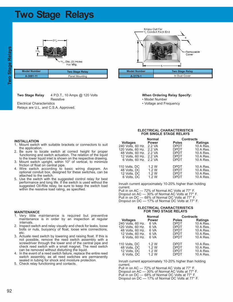
92
Two Stage Relays
Two Stage Relay
Panel Mounting
Model Number
A-3081-11
Two Stage Relay 4 P.D.T., 10 Amps @ 120 Volts
Resistive
Electrical Characteristics
Relays are U.L. and C.S.A. Approved.
When Ordering Relay Specify:
• Model Number
• Voltage and Frequency
ELECTRICAL CHARACTERISTICS
FOR SINGLE STAGE RELAYS
Normal Contracts
Voltages Power Poles Ratings
240 Volts, 60 Hz. 2.2 VA DPDT 10 A Res.120 Volts, 60 Hz. 2.2 VA DPDT 10 A Res.
48 Volts, 60 Hz. 2.2 VA DPDT 10 A Res.12 Volts, 60 Hz. 2.2 VA DPDT 10 A Res.
6 Volts, 60 Hz. 2.2 VA DPDT 10 A Res.
110 Volts, DC 1.2 W DPDT 10 A Res.48 Volts, DC 1.2 W DPDT 10 A Res.12 Volts, DC 1.2 W DPDT 10 A Res.
6 Volts, DC 1.2 W DPDT 10 A Res.
Inrush current approximately 10-20% higher than holdingcurrent.Pull in on AC — 72% of Normal AC Volts at 77° F.Dropout on AC — 30% of Normal AC Volts at 77° F.Pull in on DC — 68% of Normal DC Volts at 77° F.Dropout on DC — 17% of Normal DC Volts at 77° F.
ELECTRICAL CHARACTERISTICS
FOR TWO STAGE RELAYS
Normal Contracts
Voltages Power Poles Ratings
240 Volts, 60 Hz. 6 VA DPDT 10 A Res.120 Volts, 60 Hz. 6 VA DPDT 10 A Res.
48 Volts, 60 Hz. 6 VA DPDT 10 A Res.12 Volts, 60 Hz. 6 VA DPDT 10 A Res.
6 Volts, 60 Hz. 6 VA DPDT 10 A Res.
110 Volts, DC 1.2 W DPDT 10 A Res.48 Volts, DC 1.2 W DPDT 10 A Res.12 Volts, DC 1.2 W DPDT 10 A Res.
6 Volts, DC 1.2 W DPDT 10 A Res.
Inrush current approximately 10-20% higher than holdingcurrent.Pull in on AC — 72% of Normal AC Volts at 77° F.Dropout on AC — 30% of Normal AC Volts at 77° F.Pull in on DC — 68% of Normal DC Volts at 77° F.Dropout on DC — 17% of Normal DC Volts at 77° F.
INSTALLATION
1. Mount switch with suitable brackets or connectors to suitthe application.
2. Be sure to locate switch at correct height for proper functioning and switch actuation. The relation of the liquidto the lower liquid inlet is shown on the respective drawing.
3. Mount switch upright, within 10° of vertical, to minimizefriction of float on central pipe.
4. Wire switch according to basic wiring diagram. An optional conduit box, designed for these switches, can beattached to the switch.
5. Use the switch with the suggested control relay for bestperformance and long life. If the switch is used without thesuggested Oil-Rite relay, be sure to keep the switch loadwithin the resistive load rating, as specified.
MAINTENANCE
1. Very little maintenance is required but preventive maintenance is in order by an inspection at regular intervals.
2. Inspect switch and relay visually and check for leaks, loosebolts or nuts, buoyancy of float, loose wire connections,etc.
3. Actuate reed switch by lowering and raising float. If this isnot possible, remove the reed switch assembly with ascrewdriver through the lower end of the central pipe andcheck reed switch with a small magnet. The reed switchcan be removed without disturbing the liquid.
4. In the event of a reed switch failure, replace the entire reedswitch assembly, as all reed switches are permanentlysealed in tubing for shock and moisture protection.
5. Check relay functioning and contacts.
Tw
o S
tag
e R
ela
ys
Two Stage Relay
In Dust Cover
Model Number
A-3179-1
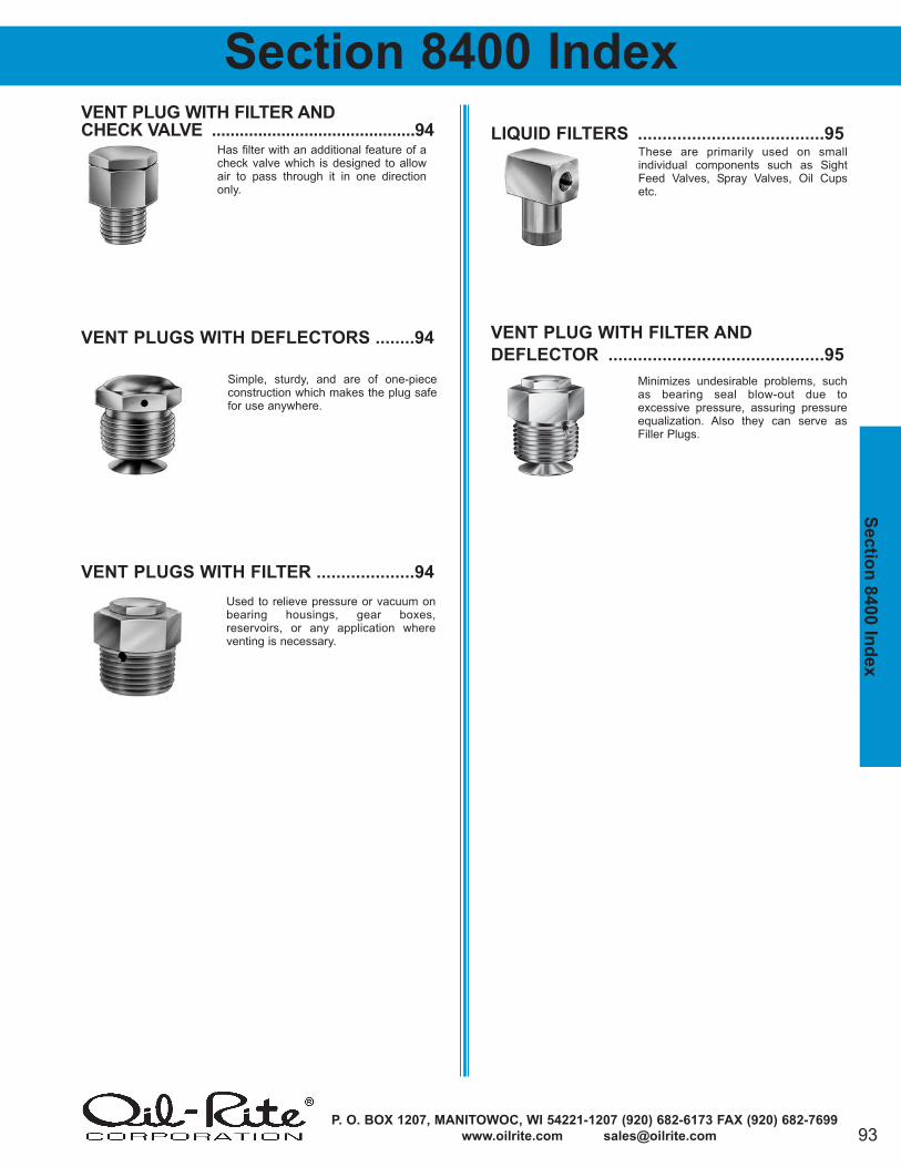
93P. O. BOX 1207, MANITOWOC, WI 54221-1207 (920) 682-6173 FAX (920) 682-7699
www.oilrite.com [email protected]
VENT PLUG WITH FILTER AND
CHECK VALVE ............................................94
VENT PLUGS WITH DEFLECTORS ........94
VENT PLUGS WITH FILTER ....................94
LIQUID FILTERS ......................................95
VENT PLUG WITH FILTER AND
DEFLECTOR ............................................95
Sectio
n 8
400 In
dex
Section 8400 Index
Simple, sturdy, and are of one-piececonstruction which makes the plug safefor use anywhere.
These are primarily used on small individual components such as SightFeed Valves, Spray Valves, Oil Cupsetc.
Has filter with an additional feature of acheck valve which is designed to allowair to pass through it in one directiononly.
Minimizes undesirable problems, suchas bearing seal blow-out due to excessive pressure, assuring pressureequalization. Also they can serve asFiller Plugs.
Used to relieve pressure or vacuum onbearing housings, gear boxes, reservoirs, or any application whereventing is necessary.
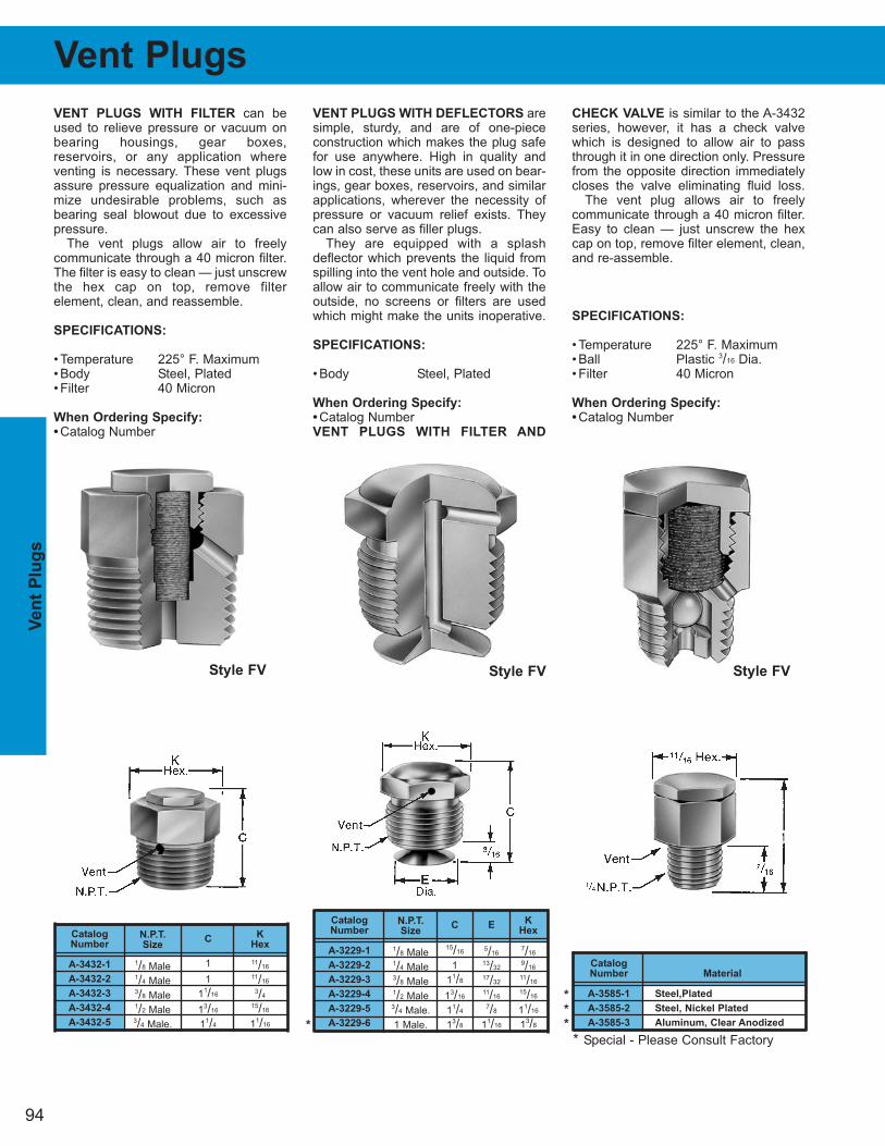
Catalog
Number
A-3229-1
A-3229-2
A-3229-3
A-3229-4
A-3229-5
A-3229-6
94
VENT PLUGS WITH FILTER can beused to relieve pressure or vacuum onbearing housings, gear boxes, reservoirs, or any application whereventing is necessary. These vent plugsassure pressure equalization and mini-mize undesirable problems, such asbearing seal blowout due to excessivepressure.
The vent plugs allow air to freely communicate through a 40 micron filter.The filter is easy to clean — just unscrewthe hex cap on top, remove filter element, clean, and reassemble.
SPECIFICATIONS:
• Temperature 225° F. Maximum• Body Steel, Plated• Filter 40 Micron
When Ordering Specify:
• Catalog Number
VENT PLUGS WITH DEFLECTORS aresimple, sturdy, and are of one-piececonstruction which makes the plug safefor use anywhere. High in quality andlow in cost, these units are used on bear-ings, gear boxes, reservoirs, and similarapplications, wherever the necessity ofpressure or vacuum relief exists. Theycan also serve as filler plugs.
They are equipped with a splashdeflector which prevents the liquid fromspilling into the vent hole and outside. Toallow air to communicate freely with theoutside, no screens or filters are usedwhich might make the units inoperative.
SPECIFICATIONS:
• Body Steel, Plated
When Ordering Specify:
• Catalog NumberVENT PLUGS WITH FILTER AND
CHECK VALVE is similar to the A-3432series, however, it has a check valvewhich is designed to allow air to passthrough it in one direction only. Pressurefrom the opposite direction immediatelycloses the valve eliminating fluid loss.
The vent plug allows air to freely communicate through a 40 micron filter.Easy to clean — just unscrew the hexcap on top, remove filter element, clean,and re-assemble.
SPECIFICATIONS:
• Temperature 225° F. Maximum• Ball Plastic 3/16 Dia.• Filter 40 Micron
When Ordering Specify:
• Catalog Number
Ven
t P
lug
s
Vent Plugs
N.P.T.
Size
1/8 Male1/4 Male3/8 Male1/2 Male3/4 Male.
Catalog
Number
A-3432-1
A-3432-2
A-3432-3
A-3432-4
A-3432-5
K
Hex
11/16
11/16
3/4
15/16
11/16
C
1
1
11/16
13/16
11/4
N.P.T.
Size
1/8 Male1/4 Male3/8 Male1/2 Male3/4 Male.
1 Male.
K
Hex
7/16
9/16
11/16
15/16
11/16
13/8
C
15/16
1
11/8
13/16
11/4
13/8
Catalog
Number Material
A-3585-1 Steel,Plated
A-3585-2 Steel, Nickel Plated
A-3585-3 Aluminum, Clear Anodized
E
5/16
13/32
17/32
11/16
7/8
11/16
Style FV Style FV Style FV
*
*
*
*
* Special - Please Consult Factory
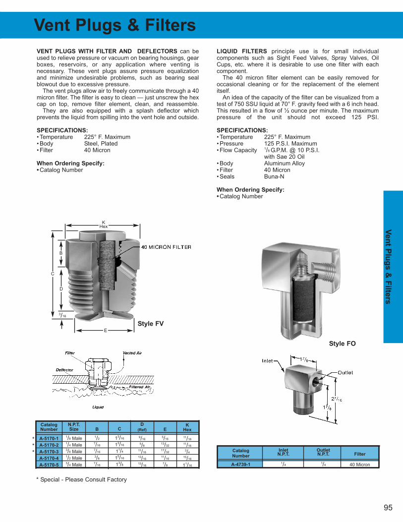
Inlet OutletN.P.T. N.P.T. Filter
1/41/4 40 Micron
95
Ven
t Plu
gs &
Filte
rs
Vent Plugs & Filters
VENT PLUGS WITH FILTER AND DEFLECTORS can beused to relieve pressure or vacuum on bearing housings, gearboxes, reservoirs, or any application where venting is necessary. These vent plugs assure pressure equalizationand minimize undesirable problems, such as bearing sealblowout due to excessive pressure.
The vent plugs allow air to freely communicate through a 40micron filter. The filter is easy to clean — just unscrew the hexcap on top, remove filter element, clean, and reassemble.
They are also equipped with a splash deflector which prevents the liquid from spilling into the vent hole and outside.
SPECIFICATIONS:
• Temperature 225° F. Maximum• Body Steel, Plated• Filter 40 Micron
When Ordering Specify:
• Catalog Number
LIQUID FILTERS principle use is for small individual components such as Sight Feed Valves, Spray Valves, OilCups, etc. where it is desirable to use one filter with each component.
The 40 micron filter element can be easily removed foroccasional cleaning or for the replacement of the elementitself.
An idea of the capacity of the filter can be visualized from atest of 750 SSU liquid at 70° F. gravity feed with a 6 inch head.This resulted in a flow of ½ ounce per minute. The maximumpressure of the unit should not exceed 125 PSI.
SPECIFICATIONS:
• Temperature 225° F. Maximum• Pressure 125 P.S.I. Maximum• Flow Capacity 1/8 G.P.M. @ 10 P.S.I.
with Sae 20 Oil• Body Aluminum Alloy• Filter 40 Micron• Seals Buna-N
When Ordering Specify:
• Catalog Number
Catalog
Number
A-4739-1
Style FO
Style FV
E
5/16
13/32
17/32
11/16
7/8
N.P.T.
Size
1/8 Male1/4 Male3/8 Male1/2 Male3/4 Male
Catalog
Number
A-5170-1
A-5170-2
A-5170-3
A-5170-4
A-5170-5
K
Hex
11/16
11/16
3/4
15/16
11/16
D
(Ref)
9/16
5/8
11/16
13/16
13/16
B
1/2
7/16
7/16
3/8
7/16
C
13/16
13/16
11/4
15/16
13/8
***
* Special - Please Consult Factory
KHex
C
3/16
D
B
E
Related Documents


![TANKS AND EQUIPMENT - lapesa · cv-hl pag. 76 cv-m1s pag. 72 cv-m1 / m1b pag. 74 cv-rb pag. 68 cv-r pag. 68 [7] heat pump solar collectors gas/fuel oil boiler solid fuels boiler electric](https://static.cupdf.com/doc/110x72/5f5c6190129c53111d0d6cbb/tanks-and-equipment-cv-hl-pag-76-cv-m1s-pag-72-cv-m1-m1b-pag-74-cv-rb-pag.jpg)
