C.L. OF Br.No. 23 (5x9.15m PLATE GIRDER (NALA) AT Km.8.150.0 C.L. OF Br.No.24 (1x9.15m PLATE GIRDER (ROB) AT Km.8.088, CH. KM:7.957.3 POINT 1 IN 12 CH. KM:7.859.7 POINT 1 IN 12 CH. KM:7.846.7 POINT 1 IN 12 CH. KM:7.768.2 F.M CH. KM:7.610.5 POINT 1 IN 12 CH. KM:7.597.5 POINT 1 IN 12 KM:7.690.4 F.M CH. KM:7.505.9 POINT 1 IN 12 CH. KM:7.427.1 POINT 1 IN 12 CH. KM:7.334.3 POINT 1 IN 12 KM:7.321.3 POINT 1 IN 12 KM:7.240.3 F.M KM:7.163.8 F.M KM:7.085.1 POINT 1 IN 12 CH KM:7.072.1 POINT 1 IN 12 CH KM:6.974.5 POINT 1 IN 12 C.L. OF Br.No.25 (1x9.15m PLATE GIRDER FLOOD OPENING) AT Km.6.907 N.R. BOUNDARY N.R. BOUNDARY N.R. BOUNDARY N.R. BOUNDARY N.R. BOUNDARY N.R. BOUNDARY N.R. BOUNDARY CUT LINE C C HIGH LEVEL PLATFORM 350.00X5.10m LONG HIGH LEVEL PLATFORM 350.0X5.10m LONG KM:9.460.52 CL OF F.O.B 3100 WIDE KM:9.505.91 CL 1x0.61 H. PIPE FLOOD OPENING BR. NO. 18 C.L. OF ANAND VIHAR TERMINAL STATION BUILDING AT Km.9.721.531 HIGH LEVEL PASS. PLATFORM 625.00X13.51M LONG Δ KM:8.944.48 CL 1X9.15 PLATE GIRDER BR. NO. 21 KM:8.554.48 CL 1X3.05 RCC SLAB FLOOD OPENING BR. NO. 22 CH. KM. 9.513.57 DMRC FLY-OVER CH. KM:8.645.32 POINT 1 IN 12 CH. KM:8.564.84 F.M CH. KM:8.488.95 F.M CH. KM:8.408.72 POINT 1 IN 12 CH. KM:8.395.72 POINT 1 IN 12 CH. KM:8.305.02 POINT 1 IN 12 KM:10.176.45 F.M C.L. OF ANAND VIHAR (HALT) AT CH. Km.9.850.00 KM:10.112.02 MEETING POINT CH. KM:8.842.50 FM CH. KM:9.903.79 CL OF F.O.B 1830M WIDE N.R. BOUNDARY N.R. BOUNDARY N.R. BOUNDARY N.R. BOUNDARY N.R. BOUNDARY N.R. BOUNDARY N.R. BOUNDARY N.R. BOUNDARY N.R. BOUNDARY N.R. BOUNDARY CH. KM:8.733.97 POINT 1 IN 12 CH. KM:8.831.57 POINT 1 IN 12 CH. KM:8.844.56 FM CH. KM:8.911.00 FM CH. KM:9.013.59 FM CH. KM:9.366.07 FM CH. KM:9.371.17 FM CH. KM:9.438.34 FM CH. KM:9.071.95 POINT 1 IN 8.5 CH. KM:9.097.98 POINT 1 IN 8.5 CH. KM:9.167.03 POINT 1 IN 8.5 CH. KM:9.226.72 POINT 1 IN 12 CH. KM:9.429.28 POINT 1 IN 12 D D CUT LINE CH. KM:8.241.531 DE CH. KM:8.402.19 DE CH. KM:8.373.346 DE KM:9.162.48 CL 1X0.61 H.P PIPE FLOOD OPENING BR. NO. 20 KM:9.342.48 CL 1X0.61 H.P PIPE FLOOD OPENING BR. NO. 19 KM:9.572.48 CL 1x0.61 H. PIPE FLOOD OPENING BR. NO. 18 KM:9.838.63 CL OF F.O.B 3000 WIDE APPROACH ROAD 6.0M WIDE AND 800.00M LONG CH. KM:9.139.06 RCC BOX- NEAR BRIDGE NO.-20 HIGH LEVEL PASS. PLATFORM 625.00X10.0 M LONG FROM NDLS/ TKJ/MWC O/H, H T LINE 66 KV CUT LINE B B TP-1 TP-2 TP-2 TP-1 CURVE No. 1 CURVE No. 2 TP-1 TP-2 CURVE No. 3 TP-2 TP-1 CURVE No. 4 TP-2 TP-1 CURVE No. 5 TP-2 TP-1 CURVE No. 6 CURVE No. 7 TP-2 TP-1 HIGH LEVEL PASS. PLATFORM 520.00X10.0 M LONG 2nd ENTRY RAILWAY OFFICE CH:8915.70 C&W COMPRESSOR ROOM WALL CH:8860.70 CH:8950.70 CH:8987.20 OHT & UG TANK CH:8957.20 Rev Status Scale at A3 Drawing Number Checked Reviewed Drawn Title App’d Ch’k’d Description Drawn Date Rev Consultant Approved Client Consultant Consultant T F W A20, Sector 2 Noida Uttar Pradesh India- 201301 +91(0) 120 254 3582 www.mottmac.com +91(0) 120 254 3583 © Mott MacDonald This document should not be relied on or used in circumstances other than those for which it was originally prepared and for which Mott MacDonald was commissioned. Mott MacDonald accepts no reuronsibility for this document to any other party other than the person by whom it was commissioned. Redevelopment of Anand Vihar Railway Station Yard Plan --------------------------------------------- MMD-321807-EX - DR-00 -YP -1200 Northern Railway 0 APR

Welcome message from author
This document is posted to help you gain knowledge. Please leave a comment to let me know what you think about it! Share it to your friends and learn new things together.
Transcript

C.L
. OF
Br.
No.
23
(5x9
.15m
PL
AT
EG
IRD
ER
(NA
LA
) AT
Km
.8.1
50.0
C.L
. OF
Br.
No.
24 (1
x9.1
5m P
LA
TE
GIR
DE
R (R
OB
) AT
Km
.8.0
88,
CH
. KM
:7.9
57.3
POIN
T 1
IN 1
2
CH
. KM
:7.8
59.7
POIN
T 1
IN 1
2
CH
. KM
:7.8
46.7
POIN
T 1
IN 1
2
CH
. KM
:7.7
68.2
F.M
CH
. KM
:7.6
10.5
POIN
T 1
IN 1
2
CH
. KM
:7.5
97.5
POIN
T 1
IN 1
2
KM
:7.6
90.4
F.M
CH
. KM
:7.5
05.9
POIN
T 1
IN 1
2
CH
. KM
:7.4
27.1
POIN
T 1
IN 1
2
CH
. KM
:7.3
34.3
POIN
T 1
IN 1
2
KM
:7.321.3
PO
IN
T 1 IN
12
KM
:7.2
40.3
F.M
KM
:7.1
63.8
F.M
KM
:7.0
85.1
POIN
T 1
IN 1
2
CH
KM
:7.0
72.1
POIN
T 1
IN 1
2
CH
KM
:6.9
74.5
POIN
T 1
IN 1
2
C.L
. OF
Br.
No.
25 (1
x9.1
5m P
LA
TE
GIR
DE
R F
LO
OD
OPE
NIN
G) A
T K
m.6
.907
N.R. BOUNDARY
N.R. BOUNDARY
N.R. BOUNDARY
N.R. BOUNDARY
N.R. BOUNDARY
N.R. BOUNDARY
N.R. BOUNDARY
CU
T LIN
E
C
C
HIGH LEVEL PLATFORM 350.00X5.10m LONG
HIGH LEVEL PLATFORM 350.0X5.10m LONG
KM
:9.4
60.5
2 C
L O
F F.
O.B
310
0 W
IDE
KM
:9.5
05.9
1 C
L 1
x0.6
1 H
. PIP
EFL
OO
D O
PEN
ING
BR
. NO
. 18
C.L
. OF
AN
AN
D V
IHA
R T
ER
MIN
AL
STA
TIO
N B
UIL
DIN
G A
T K
m.9
.721
.531
HIGH LEVEL PASS. PLATFORM 625.00X13.51M LONG
Δ
KM
:8.9
44.4
8 C
L 1
X9.
15 P
LA
TE
GIR
DE
R B
R. N
O. 2
1
KM
:8.5
54.4
8 C
L 1
X3.
05 R
CC
SL
AB
FLO
OD
OPE
NIN
G B
R. N
O. 2
2
CH
. KM
. 9.5
13.5
7 D
MR
C F
LY
-OV
ER
CH
. KM
:8.6
45.3
2 PO
INT
1 IN
12
CH
. KM
:8.5
64.8
4 F.
M
CH
. KM
:8.4
88.9
5 F.
M
CH
. KM
:8.4
08.7
2PO
INT
1 IN
12
CH
. KM
:8.3
95.7
2PO
INT
1 IN
12
CH
. KM
:8.3
05.0
2PO
INT
1 IN
12
KM
:10.
176.
45 F
.M
C.L
. OF
AN
AN
D V
IHA
R (H
AL
T)
AT
CH
. K
m.9
.850
.00
KM
:10.
112.
02M
EE
TIN
G P
OIN
T
CH
. KM
:8.8
42.5
0 FM
CH
. KM
:9.9
03.7
9C
L O
F F.
O.B
183
0M W
IDE
N.R. BOUNDARY
N.R. BOUNDARY
N.R. BOUNDARYN.R. BOUNDARY
N.R. BOUNDARY
N.R. BOUNDARY
N.R. BOUNDARY N.R. BOUNDARYN.R. BOUNDARY
N.R. BOUNDARY
CH
. KM
:8.7
33.9
7 PO
INT
1 IN
12
CH
. KM
:8.8
31.5
7 PO
INT
1 IN
12
CH
. KM
:8.8
44.5
6 FM
CH
. KM
:8.9
11.0
0 FM
CH
. KM
:9.0
13.5
9 FM
CH
. KM
:9.3
66.0
7 FM
CH
. KM
:9.3
71.1
7 FM
CH
. KM
:9.4
38.3
4 FM
CH
. KM
:9.0
71.9
5 PO
INT
1 IN
8.5
CH
. KM
:9.0
97.9
8 PO
INT
1 IN
8.5
CH
. KM
:9.1
67.0
3 PO
INT
1 IN
8.5
CH
. KM
:9.2
26.7
2 PO
INT
1 IN
12
CH
. KM
:9.4
29.2
8 PO
INT
1 IN
12
D
D
CU
T L
IN
E
CH
. KM
:8.2
41.5
31 D
E
CH
. KM
:8.4
02.1
9 D
E
CH
. KM
:8.3
73.3
46 D
E
KM
:9.1
62.4
8 C
L 1
X0.
61 H
.P P
IPE
FLO
OD
OPE
NIN
G B
R. N
O. 2
0
KM
:9.3
42.4
8 C
L 1
X0.
61 H
.P P
IPE
FLO
OD
OPE
NIN
G B
R. N
O. 1
9
KM
:9.5
72.4
8 C
L 1
x0.6
1 H
. PIP
EFL
OO
D O
PEN
ING
BR
. NO
. 18
KM
:9.8
38.6
3 C
L O
F F.
O.B
300
0 W
IDE
APPROACH ROAD 6.0M WIDE AND 800.00M LONG
CH
. KM
:9.1
39.0
6R
CC
BO
X- N
EA
R B
RID
GE
NO
.-20
HIGH LEVEL PASS. PLATFORM 625.00X10.0 M LONG
FROM NDLS/
TKJ/MWC
O/H
, H
T
L
IN
E 6
6 K
V
CU
T L
IN
E
B
B
4.7
3M
5.3
0M
TP-1
TP-2
TP-2
TP-1
CURVE No. 1
CURVE No. 2
TP-1
TP-2
CURVE No. 3
T
P
-
2
TP-1
CURVE No. 4
T
P
-
2
T
P
-
1
C
U
R
V
E
N
o
.
5
TP-2
T
P
-
1
C
U
R
V
E
N
o. 6
CURVE No. 7
TP-2
T
P
-
1
HIGH LEVEL PASS. PLATFORM 520.00X10.0 M LONG
2nd ENTRY
R
A
I
L
W
A
Y
O
F
F
I
C
E
C
H
:
8
9
1
5
.
7
0
C
&
W
C
O
M
P
R
E
S
S
O
R
R
O
O
M
W
A
L
L
7
.
4
0
M
7
.
4
6
M
5
.
8
0
M
C
H
:
8
8
6
0
.
7
0
C
H
:
8
9
5
0
.
7
0
CH
:8
98
7.2
0
1
0
.4
4
M
O
HT &
UG
TA
NK
C
H
:8
9
5
7
.2
0
Rev Status
Scale at A3
Drawing Number
Checked
Reviewed
Drawn TitleApp’d
Ch’k’dDescriptionDrawnDateRevConsultant
Approved
Client Consultant Consultant
TFW
A20, Sector 2
Noida
Uttar Pradesh
India- 201301
+91(0) 120 254 3582
www.mottmac.com
+91(0) 120 254 3583
© Mott MacDonald
This document should not be relied on or used in circumstances other than those for which it was originally prepared and for which Mott MacDonald
was commissioned. Mott MacDonald accepts no reuronsibility for this document to any other party other than the person by whom it was commissioned.
Redevelopment of Anand Vihar Railway Station
Yard Plan
---------------------------------------------
MMD-321807-EX - DR-00 -YP -1200
Northern Railway
0 APR
AutoCAD SHX Text
1IN12
AutoCAD SHX Text
1IN12
AutoCAD SHX Text
F.M
AutoCAD SHX Text
F.M
AutoCAD SHX Text
1IN12
AutoCAD SHX Text
1IN12
AutoCAD SHX Text
1IN12
AutoCAD SHX Text
1IN12
AutoCAD SHX Text
1IN12
AutoCAD SHX Text
1IN12
AutoCAD SHX Text
1IN12
AutoCAD SHX Text
1IN12
AutoCAD SHX Text
1IN12
AutoCAD SHX Text
1IN12
AutoCAD SHX Text
F.M
AutoCAD SHX Text
F.M
AutoCAD SHX Text
1ST LINE
AutoCAD SHX Text
2ND LINE
AutoCAD SHX Text
3RD LINE
AutoCAD SHX Text
4TH LINE
AutoCAD SHX Text
DN GAL
AutoCAD SHX Text
UP GAL
AutoCAD SHX Text
1ST LINE
AutoCAD SHX Text
2ND LINE
AutoCAD SHX Text
3RD LINE
AutoCAD SHX Text
4TH LINE
AutoCAD SHX Text
DN GAL
AutoCAD SHX Text
UP GAL
AutoCAD SHX Text
RRI CABIN
AutoCAD SHX Text
PF NO. 6 & 7 500.0 M X10.48M
AutoCAD SHX Text
DE
AutoCAD SHX Text
DE
AutoCAD SHX Text
PF NO. 4&5, 585.0 M X14.0M (PH-II)
AutoCAD SHX Text
PF NO.2 & 3 -585.0M X 14.00M (PH-I)
AutoCAD SHX Text
ROOM
AutoCAD SHX Text
SWITCH
AutoCAD SHX Text
R=150
AutoCAD SHX Text
T=300
AutoCAD SHX Text
WD=2000
AutoCAD SHX Text
UP
AutoCAD SHX Text
COOKING/STORAGE
AutoCAD SHX Text
SPACE FOR VENDORS
AutoCAD SHX Text
275SQ. MTR.
AutoCAD SHX Text
UP
AutoCAD SHX Text
ENT.
AutoCAD SHX Text
TOI
AutoCAD SHX Text
(L)
AutoCAD SHX Text
RS
AutoCAD SHX Text
(G)
AutoCAD SHX Text
TOI
AutoCAD SHX Text
UTS PASSENGERS
AutoCAD SHX Text
WAITING HALL FOR
AutoCAD SHX Text
RETAINING WALL
AutoCAD SHX Text
TO PARCEL PATHWAY
AutoCAD SHX Text
RAMP UP TO PF1 IN SLOPE 1:12
AutoCAD SHX Text
PF COPING ABOVE
AutoCAD SHX Text
TO PARCEL PATHWAY
AutoCAD SHX Text
LANDSCAPED COURT
AutoCAD SHX Text
SHOPPING MALL/ FUTURE USE
AutoCAD SHX Text
PORTICO ABOVE
AutoCAD SHX Text
PAVED AREA
AutoCAD SHX Text
RETANING WALL
AutoCAD SHX Text
WD=2000
AutoCAD SHX Text
LIFT
AutoCAD SHX Text
T=300
AutoCAD SHX Text
R=150
AutoCAD SHX Text
LIFT
AutoCAD SHX Text
UP
AutoCAD SHX Text
ENTRY
AutoCAD SHX Text
ENT.
AutoCAD SHX Text
LVL.+300MM
AutoCAD SHX Text
RAMP UP
AutoCAD SHX Text
STAIRS
AutoCAD SHX Text
UP
AutoCAD SHX Text
ESC.
AutoCAD SHX Text
UP
AutoCAD SHX Text
PLATFORM
AutoCAD SHX Text
TICKET
AutoCAD SHX Text
LVL.+300MM
AutoCAD SHX Text
STEPS UP TO PF1
AutoCAD SHX Text
CUTOUT ABOVE
AutoCAD SHX Text
PASSANGER'S
AutoCAD SHX Text
TO ALL
AutoCAD SHX Text
SUBWAY
AutoCAD SHX Text
10M WIDE
AutoCAD SHX Text
PLATFORMS
AutoCAD SHX Text
GATE
AutoCAD SHX Text
DN
AutoCAD SHX Text
UP
AutoCAD SHX Text
FENCING
AutoCAD SHX Text
FENCING
AutoCAD SHX Text
UP
AutoCAD SHX Text
TREAD=300
AutoCAD SHX Text
WIDTH=3350
AutoCAD SHX Text
RISER=150
AutoCAD SHX Text
SERVICE LANE 5 MTR. WD.
AutoCAD SHX Text
DN
AutoCAD SHX Text
ESC.
AutoCAD SHX Text
STAIRS
AutoCAD SHX Text
DN
AutoCAD SHX Text
T=300
AutoCAD SHX Text
WD=6000
AutoCAD SHX Text
R=150
AutoCAD SHX Text
ENQUIRY
AutoCAD SHX Text
RAILING
AutoCAD SHX Text
WD=2000
AutoCAD SHX Text
R=150
AutoCAD SHX Text
T=300
AutoCAD SHX Text
LIFT
AutoCAD SHX Text
LIFT
AutoCAD SHX Text
RAMP UP
AutoCAD SHX Text
LVL.+300MM
AutoCAD SHX Text
CBS
AutoCAD SHX Text
UP
AutoCAD SHX Text
STEPS UP TO PF1
AutoCAD SHX Text
PF COPING ABOVE
AutoCAD SHX Text
FENCING
AutoCAD SHX Text
CUTOUT ABOVE
AutoCAD SHX Text
TREAD=300
AutoCAD SHX Text
RISER=150
AutoCAD SHX Text
WIDTH=3350
AutoCAD SHX Text
DN
AutoCAD SHX Text
TO ALL
AutoCAD SHX Text
SUBWAY
AutoCAD SHX Text
10M WIDE
AutoCAD SHX Text
PASSANGER'S
AutoCAD SHX Text
PLATFORMS
AutoCAD SHX Text
UP
AutoCAD SHX Text
Y'
AutoCAD SHX Text
FENCING
AutoCAD SHX Text
GATE
AutoCAD SHX Text
UP
AutoCAD SHX Text
WD=2000
AutoCAD SHX Text
25 SQ.MTR.
AutoCAD SHX Text
UP
AutoCAD SHX Text
UP
AutoCAD SHX Text
ROOM
AutoCAD SHX Text
SWITCH
AutoCAD SHX Text
T=300
AutoCAD SHX Text
31 SQ.MTR.
AutoCAD SHX Text
R=150
AutoCAD SHX Text
LVL.+300MM
AutoCAD SHX Text
RETANING WALL
AutoCAD SHX Text
RAMP UP TO PF1 IN SLOPE 1:12
AutoCAD SHX Text
PF WALL
AutoCAD SHX Text
24.90mtr X 15.39mtr
AutoCAD SHX Text
CURRENT BOOKING HALL
AutoCAD SHX Text
39.50 mtr X 12.39 mtr
AutoCAD SHX Text
(G)
AutoCAD SHX Text
TOI
AutoCAD SHX Text
(L)
AutoCAD SHX Text
TOI
AutoCAD SHX Text
(L)
AutoCAD SHX Text
TOI
AutoCAD SHX Text
(G)
AutoCAD SHX Text
24 NOS. TICKET COUNTERS
AutoCAD SHX Text
TOI
AutoCAD SHX Text
ROOM
AutoCAD SHX Text
REC.
AutoCAD SHX Text
ROOM
AutoCAD SHX Text
COMP.
AutoCAD SHX Text
LANDSCAPING
AutoCAD SHX Text
RL 0.00
AutoCAD SHX Text
PROPOSED PLATFORM
AutoCAD SHX Text
CSR 717m FM TO FM
AutoCAD SHX Text
CSR 670m FM TO FM
AutoCAD SHX Text
CSR 735m FM TO FM
AutoCAD SHX Text
CSR 872m FM TO FM
AutoCAD SHX Text
CSR 751m FM TO FM
AutoCAD SHX Text
CSR 717m FM TO FM
AutoCAD SHX Text
CSR 658m FM TO FM
AutoCAD SHX Text
CSR 665m FM TO FM
AutoCAD SHX Text
CSR 603m FM TO FM
AutoCAD SHX Text
1IN12
AutoCAD SHX Text
1IN12
AutoCAD SHX Text
1IN12
AutoCAD SHX Text
1IN12
AutoCAD SHX Text
1IN12
AutoCAD SHX Text
1IN12
AutoCAD SHX Text
1IN12
AutoCAD SHX Text
1IN12
AutoCAD SHX Text
PF NO. 1-585.0M X 14.00M (PH-I)
AutoCAD SHX Text
DE
AutoCAD SHX Text
OVER RUNTO BE KEPT CLEAR CSR =120M FM TO DE
AutoCAD SHX Text
1IN12
AutoCAD SHX Text
1IN12
AutoCAD SHX Text
1IN12
AutoCAD SHX Text
RRI CABIN
AutoCAD SHX Text
W4
AutoCAD SHX Text
W3
AutoCAD SHX Text
W2
AutoCAD SHX Text
W1
AutoCAD SHX Text
S1
AutoCAD SHX Text
S2
AutoCAD SHX Text
S3
AutoCAD SHX Text
S4
AutoCAD SHX Text
S5
AutoCAD SHX Text
S6
AutoCAD SHX Text
DE
AutoCAD SHX Text
DE
AutoCAD SHX Text
DE
AutoCAD SHX Text
DE
AutoCAD SHX Text
DE
AutoCAD SHX Text
DE
AutoCAD SHX Text
DE
AutoCAD SHX Text
DE
AutoCAD SHX Text
DE
AutoCAD SHX Text
DE
AutoCAD SHX Text
DE
AutoCAD SHX Text
3 NOS WASHING LINES
AutoCAD SHX Text
2 NOS WASHING LINES (PHASE-I)
AutoCAD SHX Text
3 NOS STABLING LINES (PHASE-I)
AutoCAD SHX Text
3 NOS STABLING LINES (PHASE-II)
AutoCAD SHX Text
18
AutoCAD SHX Text
17
AutoCAD SHX Text
16
AutoCAD SHX Text
19
AutoCAD SHX Text
trap
AutoCAD SHX Text
RCC BOX-8.80 X3.0
AutoCAD SHX Text
NEAR BRIDGE NO.-20
AutoCAD SHX Text
OVER RUNTO BE KEPT CLEAR CSR =200+400=630mtr FM TO DE
AutoCAD SHX Text
1IN8.5
AutoCAD SHX Text
1IN8.5
AutoCAD SHX Text
1IN8.5
AutoCAD SHX Text
1IN8.5
AutoCAD SHX Text
1IN8.5
AutoCAD SHX Text
1IN8.5
AutoCAD SHX Text
1IN8.5
AutoCAD SHX Text
1IN8.5
AutoCAD SHX Text
1IN12
AutoCAD SHX Text
1IN8.5
AutoCAD SHX Text
1IN8.5
AutoCAD SHX Text
N. R. BOUNDARY
AutoCAD SHX Text
N. R. BOUNDARY
AutoCAD SHX Text
DE
AutoCAD SHX Text
CURVE No.
AutoCAD SHX Text
DEGREE(D)
AutoCAD SHX Text
DEFLECTION ANGLE (Δ))
AutoCAD SHX Text
RADIUS (Mtr.)
AutoCAD SHX Text
TANGENT LENGTH(M)
AutoCAD SHX Text
CURVE LENGTH(M)
AutoCAD SHX Text
4.00°
AutoCAD SHX Text
6.62°
AutoCAD SHX Text
437.50
AutoCAD SHX Text
25.50
AutoCAD SHX Text
50.54
AutoCAD SHX Text
DETAIL OF CURVES:-
AutoCAD SHX Text
F.M
AutoCAD SHX Text
TRAP
AutoCAD SHX Text
1IN12
AutoCAD SHX Text
1IN12
AutoCAD SHX Text
1IN12
AutoCAD SHX Text
1IN12
AutoCAD SHX Text
1IN12
AutoCAD SHX Text
F.M
AutoCAD SHX Text
F.M
AutoCAD SHX Text
CSR 625.70 FM TO DE
AutoCAD SHX Text
CSR 625.70 FM TO DE
AutoCAD SHX Text
CSR 650.95 FM TO DE
AutoCAD SHX Text
CSR 638.20 FM TO DE
AutoCAD SHX Text
CSR 638.20 FM TO DE
AutoCAD SHX Text
CSR 630.02 FM TO DE
AutoCAD SHX Text
CSR 630.02 FM TO DE
AutoCAD SHX Text
CSR 650.00 FM TO DE
AutoCAD SHX Text
CSR 650.00 FM TO DE
AutoCAD SHX Text
CSR 620.00 FM TO DE
AutoCAD SHX Text
CSR 685.00
AutoCAD SHX Text
CSR 278.00
AutoCAD SHX Text
1
AutoCAD SHX Text
1A
AutoCAD SHX Text
2
AutoCAD SHX Text
3
AutoCAD SHX Text
3A
AutoCAD SHX Text
4
AutoCAD SHX Text
5
AutoCAD SHX Text
5A
AutoCAD SHX Text
6
AutoCAD SHX Text
7
AutoCAD SHX Text
SALOON SIDING 50.0M
AutoCAD SHX Text
CSR 190.0 M TRAP TO DE
AutoCAD SHX Text
DE
AutoCAD SHX Text
N. R. BOUNDARY
AutoCAD SHX Text
N. R. BOUNDARY
AutoCAD SHX Text
N. R. BOUNDARY
AutoCAD SHX Text
N. R. BOUNDARY
AutoCAD SHX Text
N. R. BOUNDARY
AutoCAD SHX Text
LEVEL
AutoCAD SHX Text
CH:KM 9.77
AutoCAD SHX Text
4.00°
AutoCAD SHX Text
2.10°
AutoCAD SHX Text
437.50
AutoCAD SHX Text
8.02
AutoCAD SHX Text
16.04
AutoCAD SHX Text
4.00°
AutoCAD SHX Text
2.10°
AutoCAD SHX Text
437.50
AutoCAD SHX Text
8.02
AutoCAD SHX Text
16.04
AutoCAD SHX Text
7.00°
AutoCAD SHX Text
26.53°
AutoCAD SHX Text
250.00
AutoCAD SHX Text
58.93
AutoCAD SHX Text
115.76
AutoCAD SHX Text
3.89°
AutoCAD SHX Text
6.69°
AutoCAD SHX Text
450.00
AutoCAD SHX Text
26.30
AutoCAD SHX Text
52.54
AutoCAD SHX Text
8.75°
AutoCAD SHX Text
15.07°
AutoCAD SHX Text
200.00
AutoCAD SHX Text
26.50
AutoCAD SHX Text
52.60
AutoCAD SHX Text
1IN12
AutoCAD SHX Text
TP-2
AutoCAD SHX Text
1ST LINE
AutoCAD SHX Text
2ND LINE
AutoCAD SHX Text
3RD LINE
AutoCAD SHX Text
DN GAL
AutoCAD SHX Text
UP GAL
AutoCAD SHX Text
STORES BLOCK FOR CATERING & BED ROLL
AutoCAD SHX Text
STORE BLOCK FOR ELECT. AND C&W DEPTT
AutoCAD SHX Text
PORCH
AutoCAD SHX Text
1IN8.5
AutoCAD SHX Text
EXTENSION OF SICK LINE SHED
AutoCAD SHX Text
1IN8.5
AutoCAD SHX Text
STORE BLOCK 15.0X8.0 M (G+2)FOR C&W AND OFFICE FOR DIESAL ELECTRIC PIT
AutoCAD SHX Text
BATTERY CHARGING
AutoCAD SHX Text
CRS=230m
AutoCAD SHX Text
CRS=260m
AutoCAD SHX Text
D/S OFFICE FOR ELECT. AND C&W DEPTT. (SICK LINE OFFICE)
AutoCAD SHX Text
DE
AutoCAD SHX Text
SICK LINE SHED
AutoCAD SHX Text
STORES BLOCK FOR CATERING & BED ROLL
AutoCAD SHX Text
STORE BLOCK FOR ELECT. AND C&W DEPTT
AutoCAD SHX Text
PARCEL SHED & OFFICE
AutoCAD SHX Text
PARCEL PLATFORM 200.0 mtr. LONG 12.0 mtr. WD
AutoCAD SHX Text
3040 WD VERANDAH
AutoCAD SHX Text
2500 WD VERANDAH
AutoCAD SHX Text
PORCH
AutoCAD SHX Text
1IN8.5
AutoCAD SHX Text
P.WAY TRACK MACHINE SIDING
AutoCAD SHX Text
EXTENSION OF SICK LINE SHED
AutoCAD SHX Text
1IN8.5
AutoCAD SHX Text
1IN8.5
AutoCAD SHX Text
1IN8.5
AutoCAD SHX Text
1IN8.5
AutoCAD SHX Text
1IN8.5
AutoCAD SHX Text
1IN8.5
AutoCAD SHX Text
COMPRESSOR ROOM 15.0MX3.0M
AutoCAD SHX Text
pathway 3.0 m wide
AutoCAD SHX Text
pathway 3.0 m wide
AutoCAD SHX Text
pathway 3.0 m wide
AutoCAD SHX Text
STORE BLOCK 15.0X8.0 M (G+2)FOR C&W AND OFFICE FOR DIESAL ELECTRIC PIT
AutoCAD SHX Text
DE
AutoCAD SHX Text
WHEEL LATHE PIT SHED
AutoCAD SHX Text
BATTERY CHARGING
AutoCAD SHX Text
AUGMENTATION OF LINEN STORES (15X8.0 M) AT FIRST FLOOR
AutoCAD SHX Text
TP1
AutoCAD SHX Text
CRS=260m
AutoCAD SHX Text
CRS=340m
AutoCAD SHX Text
DIESEL LOCO PIT SHED
AutoCAD SHX Text
DIESEL LOCO PIT SHED
AutoCAD SHX Text
ELECTRIC LOCO PIT SHED
AutoCAD SHX Text
DE
AutoCAD SHX Text
INSPECTION PIT 50000 LONG WITH 900 MM RAISED AND 5.0 M WIDE POWER CAR ON BOTH SIDE
AutoCAD SHX Text
POWER CAR SHED 40.0MX6.0M WITH 5.0M GANTRY
AutoCAD SHX Text
D/S OFFICE FOR POWER CAR SHED (5.0X4.0M)
AutoCAD SHX Text
CRS=185.0m
AutoCAD SHX Text
1
AutoCAD SHX Text
2
AutoCAD SHX Text
2
AutoCAD SHX Text
3
AutoCAD SHX Text
4
AutoCAD SHX Text
DE
AutoCAD SHX Text
DE
AutoCAD SHX Text
PATHWAY 3.0M WIDE
AutoCAD SHX Text
CH. KM:8.308.34
AutoCAD SHX Text
CH. KM:8.383.34
AutoCAD SHX Text
CH. KM:8.368.79
AutoCAD SHX Text
KM:8.472.42 F.M
AutoCAD SHX Text
1IN8.5
AutoCAD SHX Text
KM:8.504.15
AutoCAD SHX Text
CH. KM:8.553.34
AutoCAD SHX Text
CH. KM:8.579.24
AutoCAD SHX Text
CH. KM:8.644.24
AutoCAD SHX Text
TP1
AutoCAD SHX Text
CH. KM:8.700.389 DE
AutoCAD SHX Text
CH. KM:8.786.389
AutoCAD SHX Text
1IN8.5
AutoCAD SHX Text
CH. KM:8.810.669
AutoCAD SHX Text
1IN8.5
AutoCAD SHX Text
CH. KM:8.865.449
AutoCAD SHX Text
1IN8.5
AutoCAD SHX Text
CH. KM:8.894.139
AutoCAD SHX Text
CH. KM:8.846.599
AutoCAD SHX Text
CH. KM:8.919.759
AutoCAD SHX Text
CH. KM:8.949.039
AutoCAD SHX Text
CH. KM:8.984.202
AutoCAD SHX Text
CH. KM:8.952.172
AutoCAD SHX Text
CH. KM:8.938.9122
AutoCAD SHX Text
CH. KM:8.927.8269
AutoCAD SHX Text
CH. KM:8.956.6469
AutoCAD SHX Text
CH. KM:8.985.9469
AutoCAD SHX Text
CH. KM:8.981.752
AutoCAD SHX Text
F.M
AutoCAD SHX Text
CH. KM:9.053.731
AutoCAD SHX Text
CH. KM:8.420.98
AutoCAD SHX Text
1IN8.5
AutoCAD SHX Text
1IN8.5
AutoCAD SHX Text
1IN8.5
AutoCAD SHX Text
CH. KM:9.013.512
AutoCAD SHX Text
CH. KM:9.071.500
AutoCAD SHX Text
CH. KM:9.235.81
AutoCAD SHX Text
CH. KM:9.247.81
AutoCAD SHX Text
CH. KM:9.302.03
AutoCAD SHX Text
CH. KM:9.366.28
AutoCAD SHX Text
CH. KM:9.481.10
AutoCAD SHX Text
CH. KM:9.126.681
AutoCAD SHX Text
CH. KM:9.143.521
AutoCAD SHX Text
CH. KM:9.179.761
AutoCAD SHX Text
CH. KM:9.316.761
AutoCAD SHX Text
CH. KM:9.364.481
AutoCAD SHX Text
CH. KM:9.345.350
AutoCAD SHX Text
CH. KM:9.409.48
AutoCAD SHX Text
CH. KM:10.193.45
AutoCAD SHX Text
CH. KM:10.171.561
AutoCAD SHX Text
CH. KM:10.173.691
AutoCAD SHX Text
CH. KM:8.867.23
AutoCAD SHX Text
FM
AutoCAD SHX Text
CH. KM:8.892.248
AutoCAD SHX Text
FM
AutoCAD SHX Text
CH. KM:8.879.73
AutoCAD SHX Text
FM
AutoCAD SHX Text
CH. KM:8.871.55
AutoCAD SHX Text
FM
AutoCAD SHX Text
CH. KM:8.891.53
AutoCAD SHX Text
1IN12
AutoCAD SHX Text
SWITCH ROOM 5X4M (HARD DRAWN WIRE ENCLOSURE)
AutoCAD SHX Text
SWITCH ROOM 5X4M (HARD DRAWN WIRE ENCLOSURE)
AutoCAD SHX Text
1
AutoCAD SHX Text
2
AutoCAD SHX Text
3
AutoCAD SHX Text
4
AutoCAD SHX Text
5
AutoCAD SHX Text
6
AutoCAD SHX Text
DE
AutoCAD SHX Text
OVER RUNTO BE KEPT CLEAR CSR =120M FM TO DE
AutoCAD SHX Text
1IN8.5
AutoCAD SHX Text
1IN8.5
AutoCAD SHX Text
1IN8.5
AutoCAD SHX Text
1IN8.5
AutoCAD SHX Text
PF NO.2 & 3 -585.0M X 14.00M (PH-I)
AutoCAD SHX Text
1IN8.5
AutoCAD SHX Text
1IN12
AutoCAD SHX Text
1IN8.5
AutoCAD SHX Text
1IN8.5
AutoCAD SHX Text
9.00°
AutoCAD SHX Text
8.43°
AutoCAD SHX Text
194.44
AutoCAD SHX Text
14.33
AutoCAD SHX Text
28.61
AutoCAD SHX Text
7
AutoCAD SHX Text
ANAND VIHAR TERMINAL
AutoCAD SHX Text
RESERVED FOR EXPANSION OF YARD
AutoCAD SHX Text
SUBWAY
AutoCAD SHX Text
N
saurabhtrivedi
Typewritten Text
Annexure-I

saurabhtrivedi
Typewritten Text
Annexure-II


saurabhtrivedi
Typewritten Text
saurabhtrivedi
Typewritten Text
saurabhtrivedi
Typewritten Text
Annexure-III

saurabhtrivedi
Typewritten Text
Annexure-IV

saurabhtrivedi
Typewritten Text
Annexure-V
saurabhtrivedi
Typewritten Text
Annexure-VI

saurabhtrivedi
Typewritten Text
Annexure-VII

saurabhtrivedi
Typewritten Text
Annexure-VIII

Indian Railways Station Development
Corporation Limited
July 2013
Delhi Integrated Multi-Modal Transit System Limited
Technical and Financial Feasibility Study, Master
Plan, Business Plan and providing Transaction and
Bid Advisory Services for Development/
Redevelopment of Anand Vihar (New Delhi) Railway
station on the Indian Railway Network
GEOTECHNICAL INVESTIGATIONS REPORT
saurabhtrivedi
Typewritten Text
Annexure-IX
Indian Railways Station Development Corporation
Limited
Redevelopment of AnandVihar Railway Station
Geotechnical Investigations Report
Delhi Integrated Multi Modal Transit System Limited
1
GEOTECHNICAL INVESTIGATIONS REPORT
Introduction: 1.
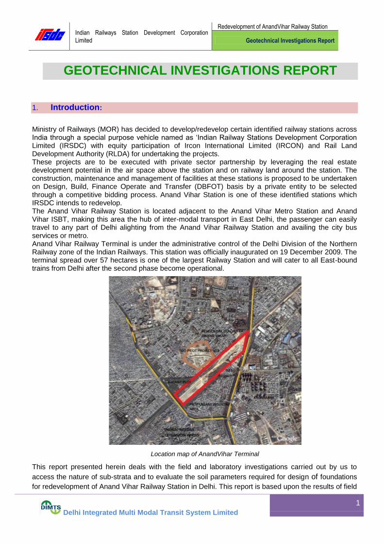
Ministry of Railways (MOR) has decided to develop/redevelop certain identified railway stations across India through a special purpose vehicle named as ‘Indian Railway Stations Development Corporation Limited (IRSDC) with equity participation of Ircon International Limited (IRCON) and Rail Land Development Authority (RLDA) for undertaking the projects. These projects are to be executed with private sector partnership by leveraging the real estate development potential in the air space above the station and on railway land around the station. The construction, maintenance and management of facilities at these stations is proposed to be undertaken on Design, Build, Finance Operate and Transfer (DBFOT) basis by a private entity to be selected through a competitive bidding process. Anand Vihar Station is one of these identified stations which IRSDC intends to redevelop. The Anand Vihar Railway Station is located adjacent to the Anand Vihar Metro Station and Anand Vihar ISBT, making this area the hub of inter-modal transport in East Delhi, the passenger can easily travel to any part of Delhi alighting from the Anand Vihar Railway Station and availing the city bus services or metro. Anand Vihar Railway Terminal is under the administrative control of the Delhi Division of the Northern Railway zone of the Indian Railways. This station was officially inaugurated on 19 December 2009. The terminal spread over 57 hectares is one of the largest Railway Station and will cater to all East-bound trains from Delhi after the second phase become operational.
Location map of AnandVihar Terminal
This report presented herein deals with the field and laboratory investigations carried out by us to
access the nature of sub-strata and to evaluate the soil parameters required for design of foundations
for redevelopment of Anand Vihar Railway Station in Delhi. This report is based upon the results of field

Indian Railways Station Development Corporation
Limited
Redevelopment of AnandVihar Railway Station
Geotechnical Investigations Report
Delhi Integrated Multi Modal Transit System Limited
2
and laboratory tests conducted on selected soil samples collected from eight bore holes (BH-1 to BH-
8).
General Geology & Related Characteristics 2.
a) Physiography and Climate: The various sites surveyed are generally plain land and forms part
of Indo-Gangetic Plains. The elevation varies from about 200-m to 275-m above mean sea level and
falls in a semi-arid zone, with extremes of climate in summer and winter. Dust storms are common
during the summer months in the area and it experiences severe heat during May and June, with
highest temperature hovering around 45C and minimum temperatures touching at 3C. The
Southwest monsoon period between July and September is the main rainy season of the area when
about 80% of the annual precipitation occurs. The mean annual rainfall is about 640-mm.
b) General Geology: The area under study is part of the Yamuna Basin comprising the newer
alluvium made-up of fine to medium sands, silts, gravel, clay and kankar (calcareous nodules). The
surface beds are admixed with wind-blown sediments of recent age. These alluvial sediments are
known to be underlined by hard formations of the Delhi system of rocks. Following is the general
sequence of formations met within the area:
Recent to Sub-Recent : Alluvium
Post-Delhi Intrusive : Pegmatic and basic intrusive
Algonkian (Delhi System) : Alwar quartzites
c) Seismicity: Region in and around Delhi may be considered as seismically active and the
tectonic elements of the area are considered capable of generating an earthquake of severe intensity,
Delhi lies in seismic Zone-IV. Suitable seismic coefficient may be adopted in the design of structure
commensurate to the Indian Standard seismic zoning of the country IS.1893-1984. It is recommended
that it will be safe to consider seismic risk value equivalent to design magnitude of 7.0 Richter, which
gives an acceleration equivalent of 0.15-g. Indian Meteorological Department has considered seismic
factor of 7% of gravity (0.07-g) to be adequate for design of structure under such situation.
Scope Of Work 3.
The scope of work provided to us for this project was limited to the following:-
3.1 Mobilizing necessary plant, equipments and personnel to the project site, setting up the
equipment, shifting of the equipment from one test location to another location, carrying
out the field investigations on land and demobilization on completion of work.

Indian Railways Station Development Corporation
Limited
Redevelopment of AnandVihar Railway Station
Geotechnical Investigations Report
Delhi Integrated Multi Modal Transit System Limited
3
3.2 Making 150 mm nominal diameter bore holes in all types of soil using suitable approved method of boring at the specified locations up to 30.0 m depth or refusal whichever occurs earlier. Refusal shall mean when SPT field ‘N’ value reaches 100 for 30 cm or less penetration of SPT sampler.
3.2.1 Conducting standard penetration tests in the bore holes at 1.50 m interval in depth & at
every change of strata, whichever is earlier as per specifications.
3.2.2 Collecting undisturbed soil samples from bore holes at 3.0 m interval in depth or at every change of strata, whichever is earlier as per specifications.
3.2.3 Collecting disturbed soil samples from bore holes at regular interval and at every
identifiable change of strata to supplement the boring records.
3.2.4 Recording the depth of ground water table in all the bore holes if observed up to the
depth of exploration during boring work as per specifications & withdrawing the casing
pipe.
3.3 Conducting the following laboratory tests on selected disturbed / undisturbed soil
samples/ Rock samples collected from various bore holes / test locations:-
(a) Bulk density and Moisture content
(b) Sieve analysis (c) Hydrometer analysis (d) Liquid limit & Plastic limits (e) Specific gravity (f) Unconfined compressive strength (g) Direct shear test (h) Tri-axial Shear test (i) Unconsolidated undrained test
3.4 A list of Indian Standard (IS) codes, which are reffered throughout the study, is also
attached at the end of this report.
Field Investigations: 4.
4.1 Necessary plant, equipment and personnel for conducting the requisite field work were
mobilized to the site. These were shifted from one test location to another location
during execution of the field work and demobilized on satisfactory completion of the
entire field work.
4.2 Eight bore holes (BH-1 to BH-8) carried out were first marked on the ground surface as per the site requirement.

Indian Railways Station Development Corporation
Limited
Redevelopment of AnandVihar Railway Station
Geotechnical Investigations Report
Delhi Integrated Multi Modal Transit System Limited
4
4.3 The bore holes were bored at this site using shell and auger method as per IS: 1892-1979. Casing as required was used to retain the bore holes.
Sl. No Test Type / Number Test conducted at / up to a depth
(m) from existing ground level
Remarks
(if any)
(1) Bore Hole
(BH-1 to BH-8 )
30.45 m By shell &
Auger method
(2) Standard penetration
tests in bore holes
1.50 m interval & at every
change of strata whichever is
earlier
---
(3) Undisturbed soil
sampling in bore
holes
3.00m interval & at every change
of strata whichever is earlier
---
4.3.1 Standard penetration tests were conducted in the above bore holes at every 1.50 m interval & at change of strata as per specifications. The bores were cleaned up to the desired depths. Standard split spoon sampler attached to lower end of ‘A’ drill rods was driven in the bore holes by means of standard hammer of 63.5 Kg. falling freely from a height of 75 cm. The sampler was driven 45 cm as per specifications & the numbers of blows required for each 15 cm penetration were recorded. The numbers of blows for the first 15 cm penetration were not taken into account. This was considered as seating drive. The numbers of blows for next 30 cm penetration were designated as SPT ‘N’ value. Wherever the total penetration was less than 45 cm, the number of blows & the depth penetrated is incorporated in respective bore logs. Disturbed soil samples obtained from standard split spoon sampler for all the above standard penetration tests were collected in polythene bags of suitable size. These samples were properly sealed, labelled, recorded and carefully transported to the laboratory for testing.
4.3.2 Undisturbed soil samples were collected from the bore holes at every 3.0 m interval in
depth & at change of strata as per sampling specifications, in thin walled sampling
tubes of 100 mm dia and 450 mm length fitted to an adopter with ball and socket
arrangement. These sampling tubes after retrieval from the bore holes were properly
waxed and sealed at both ends. These were carefully labeled and transported to the
laboratory for testing. Undisturbed soil samples wherever slipped during lifting, were
duly marked in the field bore logs as well as in the soil profile.
4.3.3 Disturbed soil samples were also collected from the bore holes at suitable
depths/intervals to supplement the boring records. These samples were collected in
polythene bags of suitable size. These samples were properly sealed, labeled, recorded
& carefully transported to the laboratory for testing.

Indian Railways Station Development Corporation
Limited
Redevelopment of AnandVihar Railway Station
Geotechnical Investigations Report
Delhi Integrated Multi Modal Transit System Limited
5
4.3.4 The depth of ground water table was checked / measured in all bore holes. The ground
water table levels derived have been tabulated below.
4.3.5 Summary of boreholes
Bore
hole No
Location Depth in over
Burden Soil (m)
Water table (m)
(1) (2) (3) (4)
BH-1 Between Halt Line & Boundary
wall near Bridge No. 22 30.45 9.00
BH-2 Between Halt Line & Boundary
wall near Bridge No. 21
30.45 8.80
BH-3 Near Parcel Office 30.45 15.70
BH-4 Near Pump House/RO Plant 30.45 10.90
BH-5 Below Metro viaduct along 30m
wide road
30.45 15.00
BH-6 In front of Store Room 30.45 9.90
BH-7 Near STP Plant 30.45 18.80
BH-8 Between STP & Bridge No. 16A 30.45 18.40
Note: Seasonal water table level shall be submitted after receiving data from Met. Department.
5.0 LABORATORY INVESTIGATIONS:
5.1 The following laboratory tests were conducted on selected soil samples recovered from
various bore hole / test locations: -
a) Bulk density and Moisture content
b) Sieve analysis
c) Hydrometer analysis
d) Liquid limit & Plastic limits
e) Specific gravity
f) Unconfined compressive strength
g) Direct shear test

Indian Railways Station Development Corporation
Limited
Redevelopment of AnandVihar Railway Station
Geotechnical Investigations Report
Delhi Integrated Multi Modal Transit System Limited
6
h) Tri-axial Shear test
i) Unconsolidated un drained test
All the above laboratory tests were carried out as per relevant Indian Standards. All the soil samples were identified and classified as per IS: 1498-1970.
6.0 FINDING OF GEOTECHNICAL INVESTIGATION:
The study of bore logs/results of laboratory and other field tests as above from ground
level reveal that:-
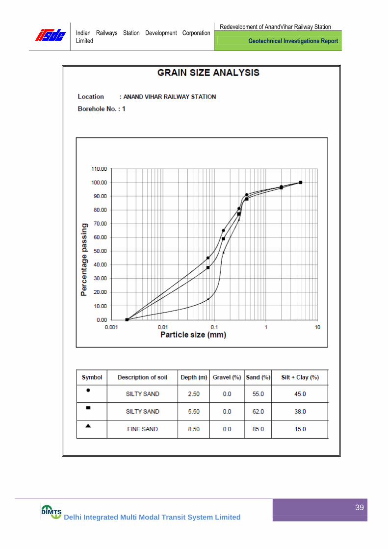
6.1.1 At the locations of bore holes BH-1
The sub-soil strata: -
(a) From existing ground surface to 7.50 m consists of grayish silty sand (SM), having SPT field ‘N’ values ranging from 5 to 12 showing loose to medium dense compactness of the strata. (b) From depths 7.50 – 15.00 m consists of grayish fine sand (SP-SM), having SPT field ‘N’ values ranging from 14 to 26 showing medium dense compactness of the strata. (c) From depths 15.00 – 21.00 m consists of yellowish clayey silt of low plasticity (CL), having SPT field ‘N’ values ranging from 16 to 23 showing very stiff consistency of the strata. (d) From depths 21.00 – 30.45m consists of yellowish fine sand (SP-SM), having SPT field ‘N’ values ranging from 38 to 50 showing dense compactness of the strata.
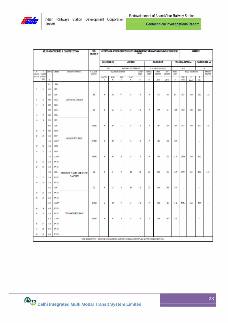
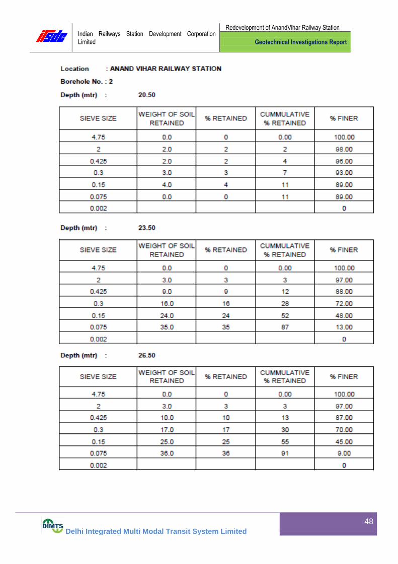
6.1.2 At the locations of bore holes BH-2
The sub-soil strata: -
(a) From existing ground surface to 7.50 m consists of grayish silty sand (SM),
having SPT field ‘N’ values ranging from 7 to 15 showing loose to medium dense
compactness of the strata.
(b) From depths 7.50 – 15.00 m consists of grayish fine sand (SP-SM), having SPT
field ‘N’ values ranging from 18 to 29 showing medium dense compactness of the
strata.
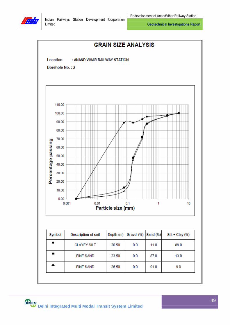
(c) From depths 15.00 – 21.00 m consists of yellowish clayey silt of low plasticity
(CL), having SPT field ‘N’ values ranging from 21 to 30 showing very stiff consistency of
the strata.
Indian Railways Station Development Corporation
Limited
Redevelopment of AnandVihar Railway Station
Geotechnical Investigations Report
Delhi Integrated Multi Modal Transit System Limited
7
(d) From depths 21.50 – 30.45m consists of yellowish fine sand (SP-SM), having
SPT field ‘N’ values ranging from 38 to 68 showing dense to very dense compactness of
the strata.
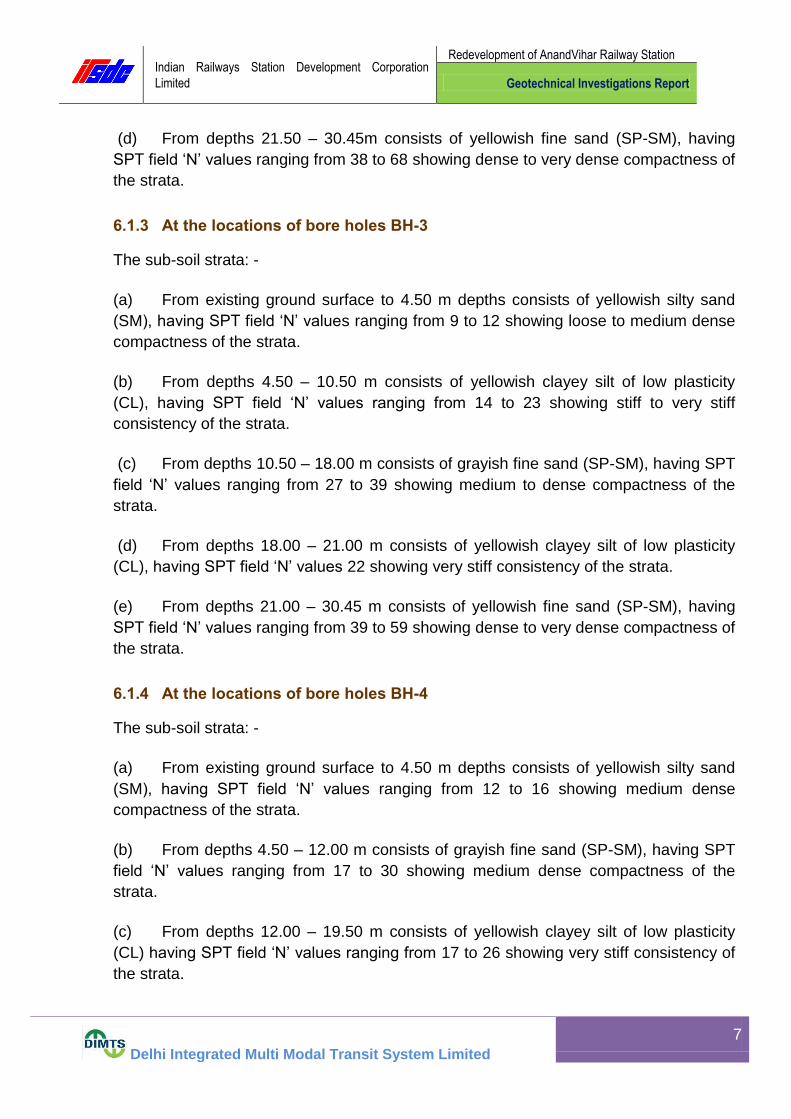
6.1.3 At the locations of bore holes BH-3
The sub-soil strata: -
(a) From existing ground surface to 4.50 m depths consists of yellowish silty sand
(SM), having SPT field ‘N’ values ranging from 9 to 12 showing loose to medium dense
compactness of the strata.
(b) From depths 4.50 – 10.50 m consists of yellowish clayey silt of low plasticity
(CL), having SPT field ‘N’ values ranging from 14 to 23 showing stiff to very stiff
consistency of the strata.
(c) From depths 10.50 – 18.00 m consists of grayish fine sand (SP-SM), having SPT
field ‘N’ values ranging from 27 to 39 showing medium to dense compactness of the
strata.
(d) From depths 18.00 – 21.00 m consists of yellowish clayey silt of low plasticity
(CL), having SPT field ‘N’ values 22 showing very stiff consistency of the strata.
(e) From depths 21.00 – 30.45 m consists of yellowish fine sand (SP-SM), having
SPT field ‘N’ values ranging from 39 to 59 showing dense to very dense compactness of
the strata.
6.1.4 At the locations of bore holes BH-4
The sub-soil strata: -
(a) From existing ground surface to 4.50 m depths consists of yellowish silty sand
(SM), having SPT field ‘N’ values ranging from 12 to 16 showing medium dense
compactness of the strata.
(b) From depths 4.50 – 12.00 m consists of grayish fine sand (SP-SM), having SPT
field ‘N’ values ranging from 17 to 30 showing medium dense compactness of the
strata.
(c) From depths 12.00 – 19.50 m consists of yellowish clayey silt of low plasticity
(CL) having SPT field ‘N’ values ranging from 17 to 26 showing very stiff consistency of
the strata.

Indian Railways Station Development Corporation
Limited
Redevelopment of AnandVihar Railway Station
Geotechnical Investigations Report
Delhi Integrated Multi Modal Transit System Limited
8
(d) From depths 19.50 – 30.45 m consists of yellowish fine sand (SP-SM), having
SPT field ‘N’ values ranging from 45 to 69 showing dense to dense compactness of the
strata.
Indian Railways Station Development Corporation
Limited
Redevelopment of AnandVihar Railway Station
Geotechnical Investigations Report
Delhi Integrated Multi Modal Transit System Limited
9
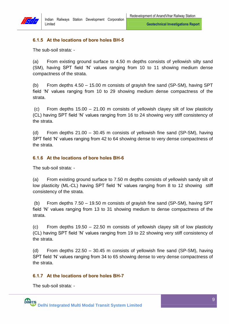
6.1.5 At the locations of bore holes BH-5
The sub-soil strata: -
(a) From existing ground surface to 4.50 m depths consists of yellowish silty sand
(SM), having SPT field ‘N’ values ranging from 10 to 11 showing medium dense
compactness of the strata.
(b) From depths 4.50 – 15.00 m consists of grayish fine sand (SP-SM), having SPT
field ‘N’ values ranging from 10 to 29 showing medium dense compactness of the
strata.
(c) From depths 15.00 – 21.00 m consists of yellowish clayey silt of low plasticity
(CL) having SPT field ‘N’ values ranging from 16 to 24 showing very stiff consistency of
the strata.
(d) From depths 21.00 – 30.45 m consists of yellowish fine sand (SP-SM), having
SPT field ‘N’ values ranging from 42 to 64 showing dense to very dense compactness of
the strata.
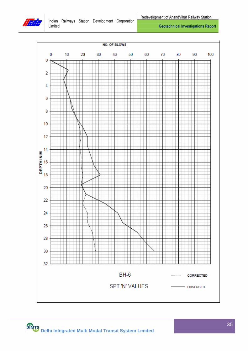
6.1.6 At the locations of bore holes BH-6
The sub-soil strata: -
(a) From existing ground surface to 7.50 m depths consists of yellowish sandy silt of
low plasticity (ML-CL) having SPT field ‘N’ values ranging from 8 to 12 showing stiff
consistency of the strata.
(b) From depths 7.50 – 19.50 m consists of grayish fine sand (SP-SM), having SPT
field ‘N’ values ranging from 13 to 31 showing medium to dense compactness of the
strata.
(c) From depths 19.50 – 22.50 m consists of yellowish clayey silt of low plasticity
(CL) having SPT field ‘N’ values ranging from 19 to 22 showing very stiff consistency of
the strata.
(d) From depths 22.50 – 30.45 m consists of yellowish fine sand (SP-SM), having
SPT field ‘N’ values ranging from 34 to 65 showing dense to very dense compactness of
the strata.
6.1.7 At the locations of bore holes BH-7
The sub-soil strata: -

Indian Railways Station Development Corporation
Limited
Redevelopment of AnandVihar Railway Station
Geotechnical Investigations Report
Delhi Integrated Multi Modal Transit System Limited
10
(a) From existing ground surface to 1.00 m depths consists of filled up.
(b) From depths 1.00 – 4.50 m consists of yellowish fine sand (SP-SM), having SPT
field ‘N’ values ranging from 8 to 11 showing loose to medium dense compactness of
the strata.
(c) From depths 4.50 – 13.50 m consists of grayish fine sand (SP-SM), having SPT
field ‘N’ values ranging from 10 to 27 showing medium dense compactness of the
strata.
(d) From depths 13.50 – 20.50 m consists of yellowish clayey silt of low plasticity
(CL) having SPT field ‘N’ values ranging from 24 to 30 showing very stiff consistency of
the strata.
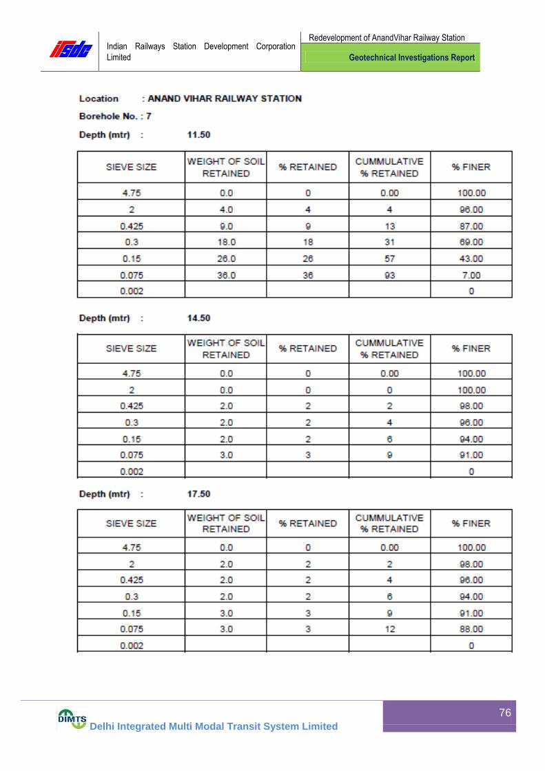
(e) From depths 20.50 – 30.45 m consists of yellowish fine sand (SP-SM), having
SPT field ‘N’ values ranging from 32 to 61 showing dense to very dense compactness of
the strata.
6.1.8 At the locations of bore holes BH-8
The sub-soil strata: -
(a) From existing ground surface to 1.00 m depths consists of filled up.
(b) From depths 1.00 – 16.50 m consists of yellowish fine sand (SP-SM), having
SPT field ‘N’ values ranging from 15 to 34 showing medium to dense compactness of
the strata.
(c) From depths 16.50 – 19.50 m consists of brownish clayey silt of low plasticity
(CL) having SPT field ‘N’ values ranging from 14 to 18 showing stiff to very stiff
consistency of the strata.
(d) From depths 19.50 – 22.50 m consists of yellowish clayey silt of low plasticity
(CL) having SPT field ‘N’ values ranging from 22 to 28 showing very stiff consistency of
the strata.
(e) From depths 22.50 – 25.50 m consists of grayish fine sand (SP-SM), having SPT
field ‘N’ values ranging from 36 to 42 showing dense compactness of the strata.
(f) From depths 25.50 – 30.45 m consists of yellowish fine sand (SP-SM), having
SPT field ‘N’ values ranging from 49 to 65 showing dense to very dense compactness of
the strata.

Indian Railways Station Development Corporation
Limited
Redevelopment of AnandVihar Railway Station
Geotechnical Investigations Report
Delhi Integrated Multi Modal Transit System Limited
11
7.0 TYPE AND DEPTH OF FOUNDATIONS:
Based upon the results of field investigations, laboratory test results, & further
discussions held with the client, the following type of foundations have been analyzed
herein below : -
Type of
foundation (s)
Depth of foundation below
existing ground surface (m)
Width / size of
foundation (s) (m)
Isolated Square
Footing 1.5,2.0 & 2.5
2.0 x 2.0
2.5 x 2.5
3.0 x 3.0
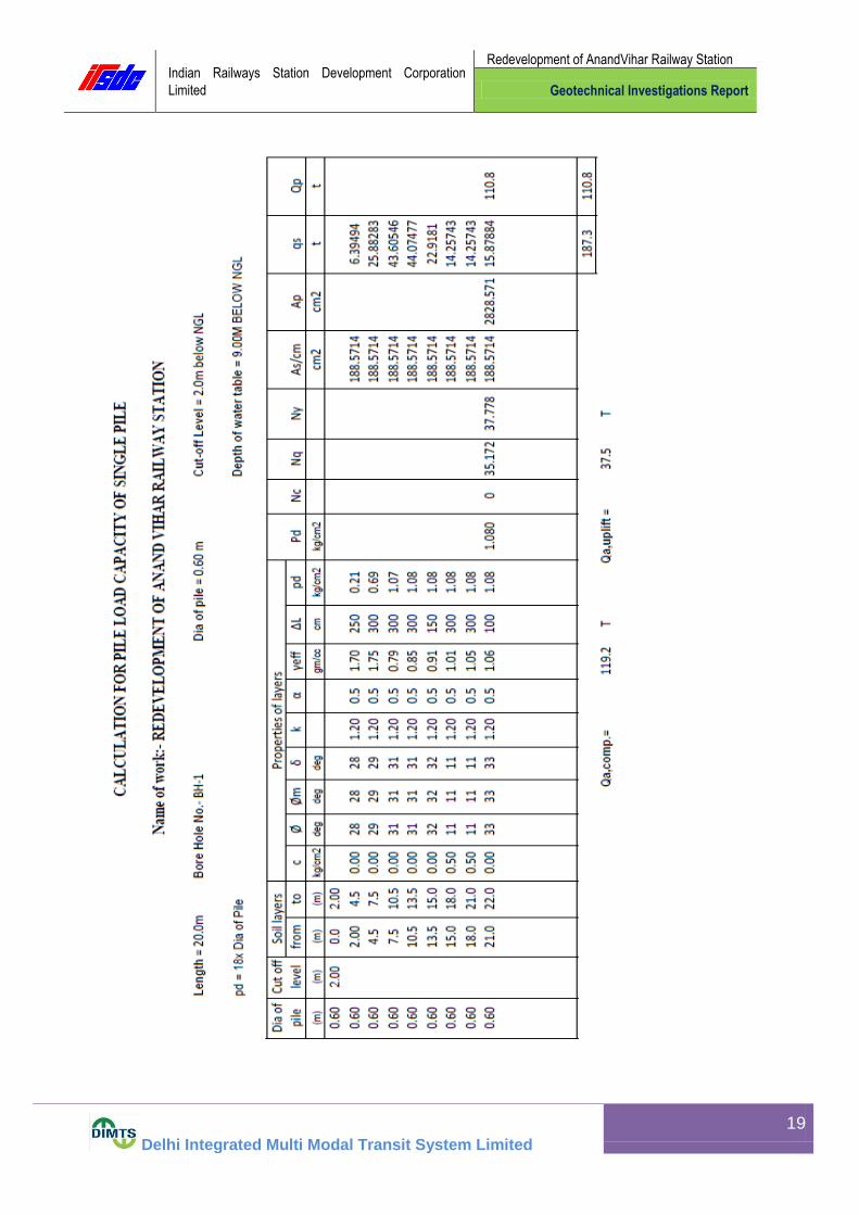
Type of foundation Diameter
of Pile (m)
Cut off
level (m)
Length of Pile below
cut off level (m)
Bored Cast in situ RCC
Pile
0.60 & 0.75 2.0 20.0, 22.0,24.0 & 26.0
8.0 ANALYSIS OF FOUNDATIONS:
The allowable bearing capacity of sub-soil strata for open spread isolated (square)
footings have been computed from shear and settlement failure considerations as per
IS: 6403-1981 & IS: 8009 (Part-I)-1976. The details of foundation analysis are presented
in the following paragraphs.
8.1 OPEN SPREAD ISOLATED (SQUARE) FOOTINGS
8.1.1 SHEAR FAILURE CONSIDERATION: -
The value of net safe bearing capacity of sub-soil strata has been estimated by
considering shear failure using the following equation for calculating the net ultimate
bearing capacity by interpolating between general and local shear failure:
qd = 2/3 x C.Nc/ Sc x dc x ic + q x (Nq/ -1).sq x dq x iq+1/2 x r x B x Nr/ sr x dr x ir x
W/

Indian Railways Station Development Corporation
Limited
Redevelopment of AnandVihar Railway Station
Geotechnical Investigations Report
Delhi Integrated Multi Modal Transit System Limited
12
Inclination factors: ic, iq and ir have been taken as 1.0. The factor of safety has been
considered as 2.5. The following soil parameters were selected for calculations: -
Shape factors have been taken as follows: -
Sc = 1.3, Sq = 1.2, Sr = 0.8
(For Square Footing)
Depth Factors have been considered as under: -
Df
dc = 1 + 0.2 N Φ,
B
Depth of
foundation
below existing
ground level
(m)
Density
γ
(kg/cc)
Cohesion
‘C’
(Kg/m2)
Angle of
internal friction
(Deg.)
ø ø/
Bearing Capacity factors
Nc/ Nq
/ Nr /
1.50 1.70 0.00 28 19.61 20.451 10.756 11.484
2.00 1.70 0.00 28 19.61 20.451 10.756 11.484
2.50 1.70 0.00 28 19.61 20.451 10.756 11.484

Indian Railways Station Development Corporation
Limited
Redevelopment of AnandVihar Railway Station
Geotechnical Investigations Report
Delhi Integrated Multi Modal Transit System Limited
13
Df
dq = dr = 1 + 0.1 NΦ, for Φ > 10 deg.
B
dq = dr = 1.0, for Φ < 10 deg.
Water table correction (W/) has been taken as 1.00
8.1.2 SETTLEMENT FAILURE CONSIDERATION:
Settlement of coarse grained strata layers comprising of fine/silty sand (SM/SP-SM)
layers below the foundation surface and up to the zone of influence were computed by
using the chart of settlement Vs SPT ‘N’ given on page 17 of IS:8009 Part-I.
9.0 SAMPLE CALCULATIONS (BASED ON BH-1)
9.1.1 SAMPLE CALCULATIONS FOR COMPUTATION OF ALLOWABLE BEARING CAPACITY OF SUB-STRATA FOR OPEN SPREAD ISOLATED SQUARE FOOTING.
The following equation for calculating net ultimate bearing capacity (By
Considering local shear failure) has been used:-
qd = 2/3 C.Nc / sc dc ic + q (Nq
/– 1) sq dq iq + ½ B N / s d i W /
Where:
Nc /, Nq
/, Nr / = Bearing capacity factors
Sc , Sq , Sr = Shape factors
dc , dq , dr = Depth factors
ic , iq , ir = Inclination factors
c = Cohesion of soil
q = Overburden pressure
= Density of soil
B = Width of footing
W / = Water table correction factor

Indian Railways Station Development Corporation
Limited
Redevelopment of AnandVihar Railway Station
Geotechnical Investigations Report
Delhi Integrated Multi Modal Transit System Limited
14
The parameters considered are:-
Size of foundation = 2.0 m x 2.0 m
Depth of foundation = 1.50 m
Water table correction factor has taken as W / =1.00
Factor of safety = 2.5
The soil parameters considered for soil just below foundation are:
c = 0.00 Kg / cm2
ø = 28
= 0.00170 Kg / cm2
Ø’ = tan –1 (2/3 tan ø) = 19.61
For ø’ = 19.61,
Nc = 26.372, Nq = 15.304, Nr = 17.792,
Nc / = 14.530, Nq
/ = 6.208, Nr / = 5.176,
Taking average
Nc = 20.451, Nq = 10.756, Nr = 11.484,
For square footing shape factors: -
Sc = 1.3, Sq = 1.2, Sr = 0.8
Depth factor = dc = 1 + 0.2 (D / B) NØ = 1.250
[Where NØ = tan (45 + Ø / 2) = 1.664]
dq = d = 1.125
Inclination factors = ic = iq = i = 1.0
Now, using the above equation, the net ultimate bearing capacity: -
qd = 5.115 Kg/cm2.
= 51.15 T / m2
Thus, net safe bearing capacity = 51.15/ 2.5
Indian Railways Station Development Corporation
Limited
Redevelopment of AnandVihar Railway Station
Geotechnical Investigations Report
Delhi Integrated Multi Modal Transit System Limited
15
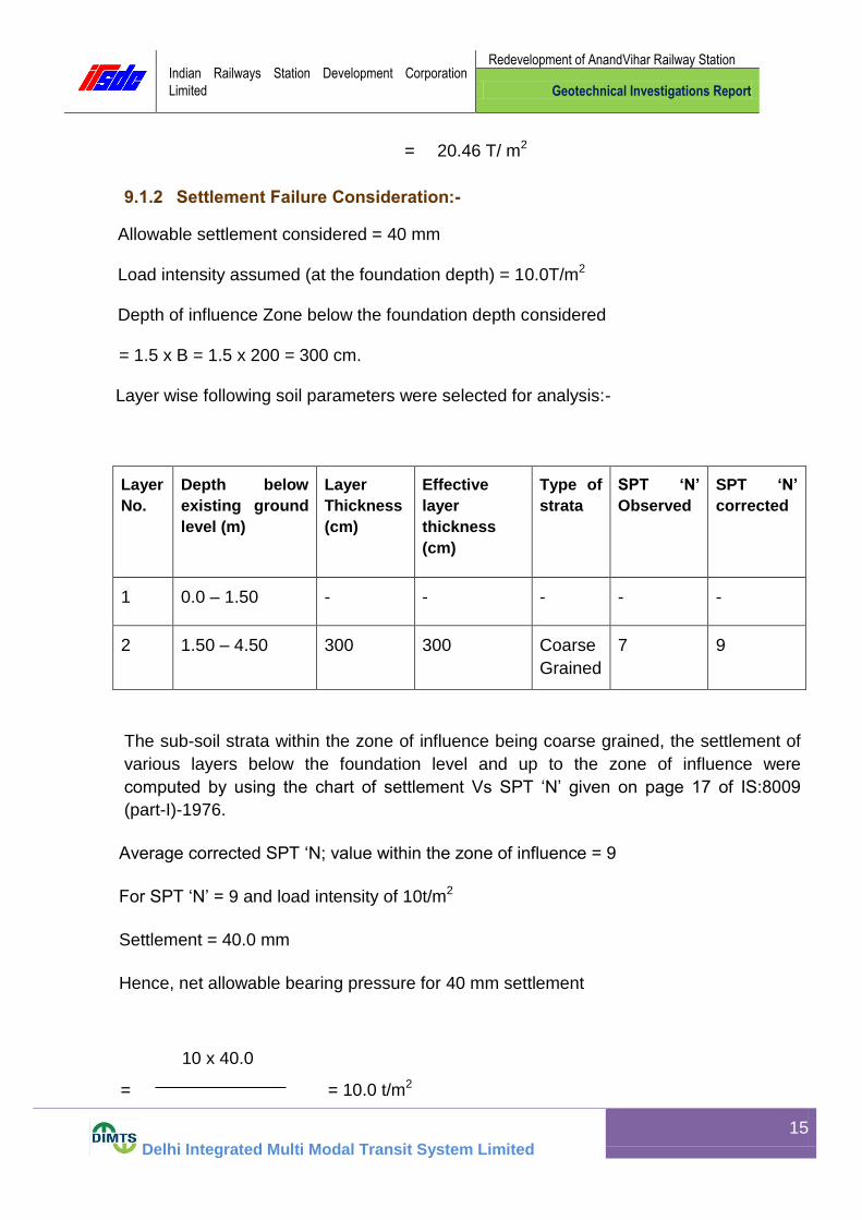
= 20.46 T/ m2
9.1.2 Settlement Failure Consideration:-
Allowable settlement considered = 40 mm
Load intensity assumed (at the foundation depth) = 10.0T/m2
Depth of influence Zone below the foundation depth considered
= 1.5 x B = 1.5 x 200 = 300 cm.
Layer wise following soil parameters were selected for analysis:-
Layer
No.
Depth below
existing ground
level (m)
Layer
Thickness
(cm)
Effective
layer
thickness
(cm)
Type of
strata
SPT ‘N’
Observed
SPT ‘N’
corrected
1 0.0 – 1.50 - - - - -
2 1.50 – 4.50 300 300 Coarse
Grained
7 9
The sub-soil strata within the zone of influence being coarse grained, the settlement of
various layers below the foundation level and up to the zone of influence were
computed by using the chart of settlement Vs SPT ‘N’ given on page 17 of IS:8009
(part-I)-1976.
Average corrected SPT ‘N; value within the zone of influence = 9
For SPT ‘N’ = 9 and load intensity of 10t/m2
Settlement = 40.0 mm
Hence, net allowable bearing pressure for 40 mm settlement
10 x 40.0
= = 10.0 t/m2

Indian Railways Station Development Corporation
Limited
Redevelopment of AnandVihar Railway Station
Geotechnical Investigations Report
Delhi Integrated Multi Modal Transit System Limited
16
40
Lower of two values of bearing capacities obtained from shear and settlement failure
considerations will govern the design of foundation.
Hence, net allowable bearing capacity = 10.0 t/m2
11. Assessment of Liquefaction
Liquefaction is the sudden loss of shear strength of the loose fine- grained sands due to earthquake induced vibration under saturated conditions. Liquefaction generally takes place in loose fine- grained sands with N values less than 15. In case of soil strata having N>15, liquefaction of soil will not take place normally.
The present site falls in seismic zone – IV. Considering the history of past earthquakes and available seismic data, an earthquake of magnitude 7.5 having peak ground acceleration amax /g= 0.16 is considered in the present analysis:
Location of BoreHole : BH-1 Dia of BoreHole : 150mm
Type of Sampler {with liner (1)/ without liner (0)} : 0 ; Magnitude of Earthquake : 7.0
Max. Ground acceleration, amax/g: 0.16
Depth of water table during investigation : 9.00 m
Depth of water table considered for analysis: 6.00 m
Induced Shear Stress due to Earthquake, Teq = 0.65P (amax/g)rd
12 9 6 3 0 From Layer depth from existing ground surface (M)
15 12 9 6 3 To
1 1 1 1 1 Layer code (Clayey = 0 / Sandy = 1)
13.5 10.5 7.5 4.5 1.5 Depth of SPT (M)
26 23 14 9 5 Observed SPT N Value, Nobs
1.91 1.85 1.79 1.75 1.70 Bulk Unit Wt of Soil during investigation (T/M
2)
0.91 0.85 1.79 1.75 1.70 Effective
1.91 1.85 1.79 1.75 1.70 Bulk Unit Wt of Soil considered for Analysis (T/M
2)
0.91 0.85 0.79 1.75 1.70 Effective
13.5 10.5 7.5 - - MID. Depth of Layer (M)
09 12 15 38 45 Silt Content (%)
0 0 0 0 0 Clay Content (%)
24.14 18.50 13.04 - - Total over burden at middle of the layer during Liquefaction, P (T/M2
)
16.64 14.00 11.54 - - Effective overburden at the middle of the layer during Liquefaction, P (T/M2
)

Indian Railways Station Development Corporation
Limited
Redevelopment of AnandVihar Railway Station
Geotechnical Investigations Report
Delhi Integrated Multi Modal Transit System Limited
17
19.6 17.0 13.0 - - Effective overburden at SPT depth (T/M2)
0.8 0.9 0.9 - - Stress Reduction, rd
2.0 1.7 1.3 - - Cyclic Stress Ratio due to Earthquake, Teq (T/M2)
19.5 17.3 10.5 - - Normalized SPT ‘N’ Value, N60
1.00 1.00 0.95 - - Rod Length Correction, Cl
1.20 1.20 1.20 Sampler Correction, Cs
1.05 1.05 1.05 - - Bore Hole Dia Correction, Cd
0.70 0.76 0.88 - - Over Burden Correction, CN
17.2 16.6 11.1 - - Corrected SPT ‘N’ –Value, (N1)60
9 12 15 - - Fines Content (Fc) (%)
0.56 1.55 2.5 - - Alpha
1.02 1.03 1.05 - - Beta
18 18 14 - - Corrected SPT ‘N’ –Value (Applying Fines Content Correction) (N1)60cs
0.191 0.191 0.150 - - Reqd. Cyclic Resistance Ratio to Liquefy the Strata at M = 7.5, (CRR)7.5
1.19 1.19 1.19 - - Magnitude Scaling Factor (MSF)
0.23 0.23 0.18 - -- Reqd. Cyclic Resistance Ratio to Liquefy the Strata at Earthquake Magnitude of ‘M’ (CRR)M
3.8 3.2 2.1 - - Reqd. Cyclic Resistance Ratio to Liquefy the Strata Tliq (T/M2)
1.86 1.86 1.63 - - F.O.S = (Tliq / Teq )
No Liquefaction Remark
12 Permeability Test Results
S. No Bore Hole No. Sample No. Depth below existing ground level (m)
Permeability (cm/sec)
1 BH - 1 UDS - 2 5.50 – 5.90 3.82 x 10⁻³
2 BH - 2 UDS - 3 8.50 – 8.90 4.32 x 10⁻³
3 BH - 3 UDS - 2 5.50 – 5.90 2.78 x 10⁻⁶
4 BH - 4 UDS - 2 5.50 – 5.90 5.16 x 10⁻³
5 BH - 5 UDS - 3 8.50 – 8.90 5.66 x 10⁻³
6 BH - 6 UDS - 2 5.50 – 5.90 7.72 x 10⁻⁵
7 BH - 7 UDS - 3 8.50 – 8.90 4.38 x 10⁻³
8 BH - 8 UDS - 2 5.50 – 5.90 2.83 x 10⁻³

Indian Railways Station Development Corporation
Limited
Redevelopment of AnandVihar Railway Station
Geotechnical Investigations Report
Delhi Integrated Multi Modal Transit System Limited
18
10. LIST OF REFFERED IS CODES
Field Investigation
1. IS : 1498- 1970 Classification and identification of soils for general
engineering purpose
2. IS : 1892-1979 Code of practice for sub surface investigations for
foundations
3. IS : 2131-1981 Method of standard penetration tests for soils
4. IS : 2132-1986 Code of practice for thin walled tube sampling of soils
Laboratory Tests
1. IS : 2720- 1983 (Part 1) Methods of tests for soils : Preparation of dry soil
samples for various tests
2. IS : 2720- 1980 (Part 2) Methods of tests for soils : Determination of
water content
3. IS : 2720- 1980 (Part 3/Sec 1) Methods of tests for soils : Determination
of specific gravity : Fine grained soils
4. IS : 2720- 1980 (Part 3/Sec 2) Methods of tests for soils : Determination
of specific gravity : Fine, medium and coarse grained soils
5. IS : 2720- 1985 (Part 4) Methods of tests for soils : Grain size analysis of
soils for general engineering purpose
6. IS : 2720- 1985 (Part 6) Methods of tests for soils : Determination of
liquid and plastic limit
Indian Railways Station Development Corporation
Limited
Redevelopment of AnandVihar Railway Station
Geotechnical Investigations Report
Delhi Integrated Multi Modal Transit System Limited
19

Indian Railways Station Development Corporation
Limited
Redevelopment of AnandVihar Railway Station
Geotechnical Investigations Report
Delhi Integrated Multi Modal Transit System Limited
20

Indian Railways Station Development Corporation
Limited
Redevelopment of AnandVihar Railway Station
Geotechnical Investigations Report
Delhi Integrated Multi Modal Transit System Limited
21

Indian Railways Station Development Corporation
Limited
Redevelopment of AnandVihar Railway Station
Geotechnical Investigations Report
Delhi Integrated Multi Modal Transit System Limited
22
Indian Railways Station Development Corporation
Limited
Redevelopment of AnandVihar Railway Station
Geotechnical Investigations Report
Delhi Integrated Multi Modal Transit System Limited
23

Indian Railways Station Development Corporation
Limited
Redevelopment of AnandVihar Railway Station
Geotechnical Investigations Report
Delhi Integrated Multi Modal Transit System Limited
24

Indian Railways Station Development Corporation
Limited
Redevelopment of AnandVihar Railway Station
Geotechnical Investigations Report
Delhi Integrated Multi Modal Transit System Limited
25

Indian Railways Station Development Corporation
Limited
Redevelopment of AnandVihar Railway Station
Geotechnical Investigations Report
Delhi Integrated Multi Modal Transit System Limited
26

Indian Railways Station Development Corporation
Limited
Redevelopment of AnandVihar Railway Station
Geotechnical Investigations Report
Delhi Integrated Multi Modal Transit System Limited
27

Indian Railways Station Development Corporation
Limited
Redevelopment of AnandVihar Railway Station
Geotechnical Investigations Report
Delhi Integrated Multi Modal Transit System Limited
28

Indian Railways Station Development Corporation
Limited
Redevelopment of AnandVihar Railway Station
Geotechnical Investigations Report
Delhi Integrated Multi Modal Transit System Limited
29

Indian Railways Station Development Corporation
Limited
Redevelopment of AnandVihar Railway Station
Geotechnical Investigations Report
Delhi Integrated Multi Modal Transit System Limited
30

Indian Railways Station Development Corporation
Limited
Redevelopment of AnandVihar Railway Station
Geotechnical Investigations Report
Delhi Integrated Multi Modal Transit System Limited
31

Indian Railways Station Development Corporation
Limited
Redevelopment of AnandVihar Railway Station
Geotechnical Investigations Report
Delhi Integrated Multi Modal Transit System Limited
32

Indian Railways Station Development Corporation
Limited
Redevelopment of AnandVihar Railway Station
Geotechnical Investigations Report
Delhi Integrated Multi Modal Transit System Limited
33

Indian Railways Station Development Corporation
Limited
Redevelopment of AnandVihar Railway Station
Geotechnical Investigations Report
Delhi Integrated Multi Modal Transit System Limited
34
Indian Railways Station Development Corporation
Limited
Redevelopment of AnandVihar Railway Station
Geotechnical Investigations Report
Delhi Integrated Multi Modal Transit System Limited
35

Indian Railways Station Development Corporation
Limited
Redevelopment of AnandVihar Railway Station
Geotechnical Investigations Report
Delhi Integrated Multi Modal Transit System Limited
36

Indian Railways Station Development Corporation
Limited
Redevelopment of AnandVihar Railway Station
Geotechnical Investigations Report
Delhi Integrated Multi Modal Transit System Limited
37

Indian Railways Station Development Corporation
Limited
Redevelopment of AnandVihar Railway Station
Geotechnical Investigations Report
Delhi Integrated Multi Modal Transit System Limited
38
Indian Railways Station Development Corporation
Limited
Redevelopment of AnandVihar Railway Station
Geotechnical Investigations Report
Delhi Integrated Multi Modal Transit System Limited
39

Indian Railways Station Development Corporation
Limited
Redevelopment of AnandVihar Railway Station
Geotechnical Investigations Report
Delhi Integrated Multi Modal Transit System Limited
40

Indian Railways Station Development Corporation
Limited
Redevelopment of AnandVihar Railway Station
Geotechnical Investigations Report
Delhi Integrated Multi Modal Transit System Limited
41

Indian Railways Station Development Corporation
Limited
Redevelopment of AnandVihar Railway Station
Geotechnical Investigations Report
Delhi Integrated Multi Modal Transit System Limited
42

Indian Railways Station Development Corporation
Limited
Redevelopment of AnandVihar Railway Station
Geotechnical Investigations Report
Delhi Integrated Multi Modal Transit System Limited
43

Indian Railways Station Development Corporation
Limited
Redevelopment of AnandVihar Railway Station
Geotechnical Investigations Report
Delhi Integrated Multi Modal Transit System Limited
44

Indian Railways Station Development Corporation
Limited
Redevelopment of AnandVihar Railway Station
Geotechnical Investigations Report
Delhi Integrated Multi Modal Transit System Limited
45

Indian Railways Station Development Corporation
Limited
Redevelopment of AnandVihar Railway Station
Geotechnical Investigations Report
Delhi Integrated Multi Modal Transit System Limited
46

Indian Railways Station Development Corporation
Limited
Redevelopment of AnandVihar Railway Station
Geotechnical Investigations Report
Delhi Integrated Multi Modal Transit System Limited
47
Indian Railways Station Development Corporation
Limited
Redevelopment of AnandVihar Railway Station
Geotechnical Investigations Report
Delhi Integrated Multi Modal Transit System Limited
48
Indian Railways Station Development Corporation
Limited
Redevelopment of AnandVihar Railway Station
Geotechnical Investigations Report
Delhi Integrated Multi Modal Transit System Limited
49

Indian Railways Station Development Corporation
Limited
Redevelopment of AnandVihar Railway Station
Geotechnical Investigations Report
Delhi Integrated Multi Modal Transit System Limited
50

Indian Railways Station Development Corporation
Limited
Redevelopment of AnandVihar Railway Station
Geotechnical Investigations Report
Delhi Integrated Multi Modal Transit System Limited
51

Indian Railways Station Development Corporation
Limited
Redevelopment of AnandVihar Railway Station
Geotechnical Investigations Report
Delhi Integrated Multi Modal Transit System Limited
52

Indian Railways Station Development Corporation
Limited
Redevelopment of AnandVihar Railway Station
Geotechnical Investigations Report
Delhi Integrated Multi Modal Transit System Limited
53

Indian Railways Station Development Corporation
Limited
Redevelopment of AnandVihar Railway Station
Geotechnical Investigations Report
Delhi Integrated Multi Modal Transit System Limited
54

Indian Railways Station Development Corporation
Limited
Redevelopment of AnandVihar Railway Station
Geotechnical Investigations Report
Delhi Integrated Multi Modal Transit System Limited
55

Indian Railways Station Development Corporation
Limited
Redevelopment of AnandVihar Railway Station
Geotechnical Investigations Report
Delhi Integrated Multi Modal Transit System Limited
56

Indian Railways Station Development Corporation
Limited
Redevelopment of AnandVihar Railway Station
Geotechnical Investigations Report
Delhi Integrated Multi Modal Transit System Limited
57

Indian Railways Station Development Corporation
Limited
Redevelopment of AnandVihar Railway Station
Geotechnical Investigations Report
Delhi Integrated Multi Modal Transit System Limited
58

Indian Railways Station Development Corporation
Limited
Redevelopment of AnandVihar Railway Station
Geotechnical Investigations Report
Delhi Integrated Multi Modal Transit System Limited
59

Indian Railways Station Development Corporation
Limited
Redevelopment of AnandVihar Railway Station
Geotechnical Investigations Report
Delhi Integrated Multi Modal Transit System Limited
60

Indian Railways Station Development Corporation
Limited
Redevelopment of AnandVihar Railway Station
Geotechnical Investigations Report
Delhi Integrated Multi Modal Transit System Limited
61

Indian Railways Station Development Corporation
Limited
Redevelopment of AnandVihar Railway Station
Geotechnical Investigations Report
Delhi Integrated Multi Modal Transit System Limited
62

Indian Railways Station Development Corporation
Limited
Redevelopment of AnandVihar Railway Station
Geotechnical Investigations Report
Delhi Integrated Multi Modal Transit System Limited
63

Indian Railways Station Development Corporation
Limited
Redevelopment of AnandVihar Railway Station
Geotechnical Investigations Report
Delhi Integrated Multi Modal Transit System Limited
64

Indian Railways Station Development Corporation
Limited
Redevelopment of AnandVihar Railway Station
Geotechnical Investigations Report
Delhi Integrated Multi Modal Transit System Limited
65

Indian Railways Station Development Corporation
Limited
Redevelopment of AnandVihar Railway Station
Geotechnical Investigations Report
Delhi Integrated Multi Modal Transit System Limited
66

Indian Railways Station Development Corporation
Limited
Redevelopment of AnandVihar Railway Station
Geotechnical Investigations Report
Delhi Integrated Multi Modal Transit System Limited
67

Indian Railways Station Development Corporation
Limited
Redevelopment of AnandVihar Railway Station
Geotechnical Investigations Report
Delhi Integrated Multi Modal Transit System Limited
68

Indian Railways Station Development Corporation
Limited
Redevelopment of AnandVihar Railway Station
Geotechnical Investigations Report
Delhi Integrated Multi Modal Transit System Limited
69

Indian Railways Station Development Corporation
Limited
Redevelopment of AnandVihar Railway Station
Geotechnical Investigations Report
Delhi Integrated Multi Modal Transit System Limited
70

Indian Railways Station Development Corporation
Limited
Redevelopment of AnandVihar Railway Station
Geotechnical Investigations Report
Delhi Integrated Multi Modal Transit System Limited
71

Indian Railways Station Development Corporation
Limited
Redevelopment of AnandVihar Railway Station
Geotechnical Investigations Report
Delhi Integrated Multi Modal Transit System Limited
72

Indian Railways Station Development Corporation
Limited
Redevelopment of AnandVihar Railway Station
Geotechnical Investigations Report
Delhi Integrated Multi Modal Transit System Limited
73

Indian Railways Station Development Corporation
Limited
Redevelopment of AnandVihar Railway Station
Geotechnical Investigations Report
Delhi Integrated Multi Modal Transit System Limited
74

Indian Railways Station Development Corporation
Limited
Redevelopment of AnandVihar Railway Station
Geotechnical Investigations Report
Delhi Integrated Multi Modal Transit System Limited
75
Indian Railways Station Development Corporation
Limited
Redevelopment of AnandVihar Railway Station
Geotechnical Investigations Report
Delhi Integrated Multi Modal Transit System Limited
76

Indian Railways Station Development Corporation
Limited
Redevelopment of AnandVihar Railway Station
Geotechnical Investigations Report
Delhi Integrated Multi Modal Transit System Limited
77

Indian Railways Station Development Corporation
Limited
Redevelopment of AnandVihar Railway Station
Geotechnical Investigations Report
Delhi Integrated Multi Modal Transit System Limited
78
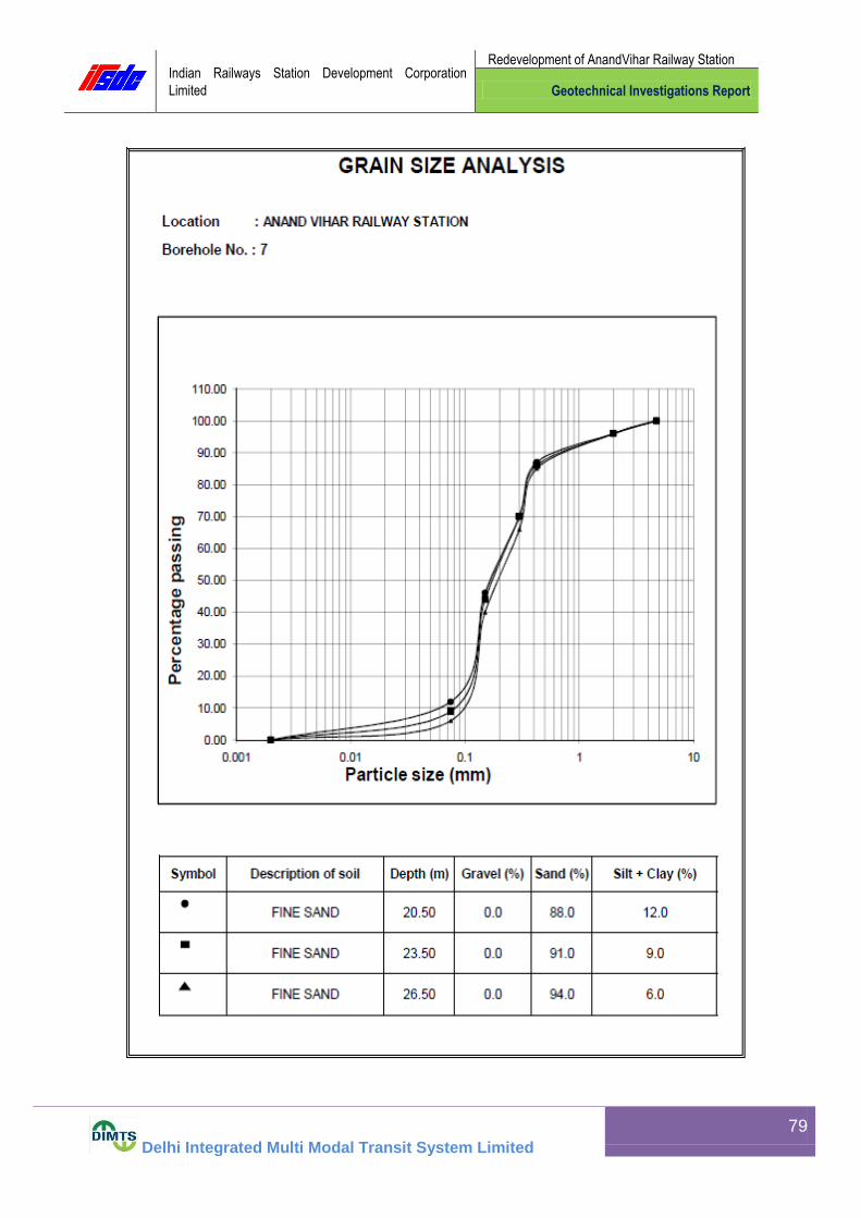
Indian Railways Station Development Corporation
Limited
Redevelopment of AnandVihar Railway Station
Geotechnical Investigations Report
Delhi Integrated Multi Modal Transit System Limited
79

Indian Railways Station Development Corporation
Limited
Redevelopment of AnandVihar Railway Station
Geotechnical Investigations Report
Delhi Integrated Multi Modal Transit System Limited
80

Indian Railways Station Development Corporation
Limited
Redevelopment of AnandVihar Railway Station
Geotechnical Investigations Report
Delhi Integrated Multi Modal Transit System Limited
81

Indian Railways Station Development Corporation
Limited
Redevelopment of AnandVihar Railway Station
Geotechnical Investigations Report
Delhi Integrated Multi Modal Transit System Limited
82

Indian Railways Station Development Corporation
Limited
Redevelopment of AnandVihar Railway Station
Geotechnical Investigations Report
Delhi Integrated Multi Modal Transit System Limited
83

Indian Railways Station Development Corporation
Limited
Redevelopment of AnandVihar Railway Station
Geotechnical Investigations Report
Delhi Integrated Multi Modal Transit System Limited
84

Indian Railways Station Development Corporation
Limited
Redevelopment of AnandVihar Railway Station
Geotechnical Investigations Report
Delhi Integrated Multi Modal Transit System Limited
85

Indian Railways Station Development Corporation
Limited
Redevelopment of AnandVihar Railway Station
Geotechnical Investigations Report
Delhi Integrated Multi Modal Transit System Limited
86

Indian Railways Station Development Corporation
Limited
Redevelopment of AnandVihar Railway Station
Geotechnical Investigations Report
Delhi Integrated Multi Modal Transit System Limited
87
13. Shear Parameters
13.1 Shear Parameter for Bore Hole 1 at 2.5 m depth
BH-1
DST DEPTH: 2.50 M
6.0
2.5 PROVING RING FACTOR= 0.258 Kg/Div.
SAMPLE No.
I II III
Weight of Wet Soil (gm) 169.86 171.23 170.86
Weight of Dry Soil (gm) 147.96 148.77 148.32
Moisture Content (%) 14.80 15.10 15.20
Bulk Density (rb) (gm/cm3) 1.89 1.90 1.90
Dry Density (rd) (gm/cm3) 1.64 1.65 1.65
1.0 Kg/ Sq.cm 2.0 Kg/ Sq.cm 3.0 Kg/ Sq.cm
De
form
atio
n
Dia
l
Re
adin
g(D
iv
) De
form
atio
n
(cm
)
Co
rre
cte
d
Are
a (
sq
cm
)
Pro
vin
g r
ing
Re
adin
g
(Div
)
Sh
ea
r F
orc
e
(Kg
)
Sh
ea
r
Str
ess
(Kg
/Cm
2)
Pro
vin
g r
ing
Re
adin
g
(Div
)
Sh
ea
r F
orc
e
(Kg
)
Sh
ea
r
Str
ess
(Kg
/Cm
2)
Pro
vin
g r
ing
Re
adin
g
(Div
)
Sh
ea
r F
orc
e
(Kg
)
Sh
ea
r
Str
ess
(Kg
/Cm
2)
Str
ain
(%
)
0..00001 0..00001 0..00001 0.0001
60 0.06 35.28 24 6.19 0.18 60 15.48 0.44 98 25.28 0.72 1.000
120 0.12 34.56 35 9.03 0.26 97 25.03 0.72 147 37.93 1.10 2.000
180 0.18 33.84 47 12.13 0.36 125 32.25 0.95 169 43.60 1.29 3.000
240 0.24 33.12 58 14.96 0.45 133 34.31 1.04 188 48.50 1.46 4.000
300 0.3 32.4 64 16.51 0.51 126 32.51 1.00 197 50.83 1.57 5.000
360 0.36 31.68 58 14.96 0.47 112 28.90 0.91 198 51.08 1.61 6.000
420 0.42 30.96 46 11.87 0.38 188 48.50 1.57 7.000
480 0.48 30.24 173 44.63 1.48 8.000
540 0.54 29.52 9.000
600 0.6 28.8 10.000
660 0.66 28.08 11.000
720 0.72 27.36 12.000
780 0.78 26.64 13.000
840 0.84 25.92 14.000
900 0.9 25.2 15.000
960 0.96 24.48 16.000
1020 1.02 23.76 17.000
1080 1.08 23.04 18.000
1140 1.14 22.32 19.000
1200 1.2 21.6 20.000
Nromal Stress
SAMPLE NO.:NAME OF THE PROJECT:
LAB. PROJECT NO:
Thickness of Sample (cm) =
ORIGNAL LENGTH OF
THE SAMPLE ( cm) =
TYPE OF THE TEST:
BORE HOLE NO.:

Indian Railways Station Development Corporation
Limited
Redevelopment of AnandVihar Railway Station
Geotechnical Investigations Report
Delhi Integrated Multi Modal Transit System Limited
88
0.0
0.5
1.0
1.5
2.0
2.5
3.0
0.0 0.5 1.0 1.5 2.0 2.5 3.0 3.5 4.0
SH
EA
R
ST
RE
SS
( k
g/s
q.c
m )
NORMAL STRESS ( kg/sq.cm )
BORE HOLE NO.:BH-1 SAMPLE NO:UDS-1 DEPTH:2.50 m COHESION(C)= 0.00 kg/sq.cm ANGLE OF FRICTION(Phi): 28 deg TYPE OF TEST:DST
0.0
0.2
0.4
0.6
0.8
1.0
1.2
1.4
1.6
1.8
0 2 4 6 8 10 12 14 16 18 20
SH
EA
R S
TR
ES
S (
kg/s
q.c
m )
STRAIN (%)
1.0 Kg/ sq. cm
2.0 Kg/sq. cm
3.0 Kg/sq. cm

Indian Railways Station Development Corporation
Limited
Redevelopment of AnandVihar Railway Station
Geotechnical Investigations Report
Delhi Integrated Multi Modal Transit System Limited
89
13.2 Shear Parameter for Bore Hole 1 at 5.5 m depth
BH-1
DST DEPTH: 5.50 M
6.0
2.5 PROVING RING FACTOR= 0.259 Kg/Div.
SAMPLE No.
I II III
Weight of Wet Soil (gm) 169.86 171.23 170.86
Weight of Dry Soil (gm) 147.96 148.77 148.32
Moisture Content (%) 14.80 15.10 15.20
Bulk Density (rb) (gm/cm3) 1.89 1.90 1.90
Dry Density (rd) (gm/cm3) 1.64 1.65 1.65
1.0 Kg/ Sq.cm 2.0 Kg/ Sq.cm 3.0 Kg/ Sq.cm
Defo
rmation
Dia
l
Readin
g(D
iv
) Defo
rmation
(cm
)
Corr
ecte
d
Are
a (
sq
cm
)
Pro
vin
g r
ing
Readin
g
(Div
)
Shear
Forc
e
(Kg)
Shear
Str
ess
(Kg/C
m2)
Pro
vin
g r
ing
Readin
g
(Div
)
Shear
Forc
e
(Kg)
Shear
Str
ess
(Kg/C
m2)
Pro
vin
g r
ing
Readin
g
(Div
)
Shear
Forc
e
(Kg)
Shear
Str
ess
(Kg/C
m2)
Str
ain
(%
)
0..00001 0..00001 0..00001 0.0001
60 0.06 35.28 33 8.55 0.24 83 21.50 0.61 142 36.78 1.04 1.000
120 0.12 34.56 48 12.43 0.36 113 29.27 0.85 182 47.14 1.36 2.000
180 0.18 33.84 58 15.02 0.44 129 33.41 0.99 200 51.80 1.53 3.000
240 0.24 33.12 65 16.84 0.51 136 35.22 1.06 213 55.17 1.67 4.000
300 0.3 32.4 70 18.13 0.56 128 33.15 1.02 219 56.72 1.75 5.000
360 0.36 31.68 64 16.58 0.52 115 29.79 0.94 205 53.10 1.68 6.000
420 0.42 30.96 54 13.99 0.45 187 48.43 1.56 7.000
480 0.48 30.24 8.000
540 0.54 29.52 9.000
600 0.6 28.8 10.000
660 0.66 28.08 11.000
720 0.72 27.36 12.000
780 0.78 26.64 13.000
840 0.84 25.92 14.000
900 0.9 25.2 15.000
960 0.96 24.48 16.000
1020 1.02 23.76 17.000
1080 1.08 23.04 18.000
1140 1.14 22.32 19.000
1200 1.2 21.6 20.000
Nromal Stress
SAMPLE NO.:NAME OF THE PROJECT:
LAB. PROJECT NO:
Thickness of Sample (cm) =
ORIGNAL LENGTH OF
THE SAMPLE ( cm) =
TYPE OF THE TEST:
BORE HOLE NO.:
SHEAR STRESS ( kg/sq.cm )

Indian Railways Station Development Corporation
Limited
Redevelopment of AnandVihar Railway Station
Geotechnical Investigations Report
Delhi Integrated Multi Modal Transit System Limited
90
0.0
0.5
1.0
1.5
2.0
2.5
3.0
0.0 0.5 1.0 1.5 2.0 2.5 3.0 3.5 4.0
SH
EA
R
ST
RE
SS
( k
g/s
q.c
m )
NORMAL STRESS ( kg/sq.cm )
BORE HOLE NO.:BH-1 SAMPLE NO:UDS-2 DEPTH:5.50 m COHESION(C)= 0.00 kg/sq.cm ANGLE OF FRICTION(Phi): 29 deg TYPE OF TEST:DST
0.0
0.2
0.4
0.6
0.8
1.0
1.2
1.4
1.6
1.8
2.0
0 2 4 6 8 10 12 14 16 18 20
SH
EA
R S
TR
ES
S (
kg/s
q.c
m )
STRAIN (%)
1.0 Kg/ sq. cm2.0 Kg/sq. cm3.0 Kg/sq. cmSeries4

Indian Railways Station Development Corporation
Limited
Redevelopment of AnandVihar Railway Station
Geotechnical Investigations Report
Delhi Integrated Multi Modal Transit System Limited
91
13.3 Shear Parameter for Bore Hole 1 at 8.5 m depth
BH-1
DST DEPTH: 8.50 M
6.0
2.5 PROVING RING FACTOR= 0.259 Kg/Div.
SAMPLE No.
I II III
Weight of Wet Soil (gm) 173.50 174.88 174.52
Weight of Dry Soil (gm) 152.46 153.27 152.82
Moisture Content (%) 13.80 14.10 14.20
Bulk Density (rb) (gm/cm3) 1.93 1.94 1.94
Dry Density (rd) (gm/cm3) 1.69 1.70 1.70
1.0 Kg/ Sq.cm 2.0 Kg/ Sq.cm 3.0 Kg/ Sq.cm
Defo
rmation
Dia
l
Readin
g(D
iv
) Defo
rmation
(cm
)
Corr
ecte
d
Are
a (
sq
cm
)
Pro
vin
g r
ing
Readin
g
(Div
)
Shear
Forc
e
(Kg)
Shear
Str
ess
(Kg/C
m2)
Pro
vin
g r
ing
Readin
g
(Div
)
Shear
Forc
e
(Kg)
Shear
Str
ess
(Kg/C
m2)
Pro
vin
g r
ing
Readin
g
(Div
)
Shear
Forc
e
(Kg)
Shear
Str
ess
(Kg/C
m2)
Str
ain
(%
)
0..00001 0..00001 0..00001 0.0001
60 0.06 35.28 30 7.77 0.22 55 14.25 0.40 112 29.01 0.82 1.000
120 0.12 34.56 51 13.21 0.38 96 24.86 0.72 166 42.99 1.24 2.000
180 0.18 33.84 66 17.09 0.51 129 33.41 0.99 205 53.10 1.57 3.000
240 0.24 33.12 72 18.65 0.56 148 38.33 1.16 226 58.53 1.77 4.000
300 0.3 32.4 65 16.84 0.52 151 39.11 1.21 236 61.12 1.89 5.000
360 0.36 31.68 54 13.99 0.44 141 36.52 1.15 221 57.24 1.81 6.000
420 0.42 30.96 125 32.38 1.05 202 52.32 1.69 7.000
480 0.48 30.24 8.000
540 0.54 29.52 9.000
600 0.6 28.8 10.000
660 0.66 28.08 11.000
720 0.72 27.36 12.000
780 0.78 26.64 13.000
840 0.84 25.92 14.000
900 0.9 25.2 15.000
960 0.96 24.48 16.000
1020 1.02 23.76 17.000
1080 1.08 23.04 18.000
1140 1.14 22.32 19.000
1200 1.2 21.6 20.000
Nromal Stress
SAMPLE NO.:NAME OF THE PROJECT:
LAB. PROJECT NO:
Thickness of Sample (cm) =
ORIGNAL LENGTH OF
THE SAMPLE ( cm) =
TYPE OF THE TEST:
BORE HOLE NO.:

Indian Railways Station Development Corporation
Limited
Redevelopment of AnandVihar Railway Station
Geotechnical Investigations Report
Delhi Integrated Multi Modal Transit System Limited
92
0.0
0.5
1.0
1.5
2.0
2.5
3.0
0.0 0.5 1.0 1.5 2.0 2.5 3.0 3.5 4.0
SH
EA
R
ST
RE
SS
( k
g/s
q.c
m )
NORMAL STRESS ( kg/sq.cm )
BORE HOLE NO.:BH-1 SAMPLE NO:UDS-3 DEPTH:8.50 m COHESION(C)= 0.00 kg/sq.cm ANGLE OF FRICTION(Phi): 31 deg TYPE OF TEST:DST
0.0
0.2
0.4
0.6
0.8
1.0
1.2
1.4
1.6
1.8
2.0
0 2 4 6 8 10 12 14 16 18 20
SH
EA
R S
TR
ES
S (
kg/s
q.c
m )
STRAIN (%)
1.0 Kg/ sq. cm2.0 Kg/sq. cm3.0 Kg/sq. cmSeries4

Indian Railways Station Development Corporation
Limited
Redevelopment of AnandVihar Railway Station
Geotechnical Investigations Report
Delhi Integrated Multi Modal Transit System Limited
93
13.4 Shear Parameter for Bore Hole 1 at 14.5 m depth
BH-1
DEPTH: 14.50 M
6.0
2.5 PROVING RING FACTOR= 0.259 Kg/Div.
SAMPLE No.
I II III
Weight of Wet Soil (gm) 169.86 171.23 170.86
Weight of Dry Soil (gm) 147.96 148.77 148.32
Moisture Content (%) 14.80 15.10 15.20
Bulk Density (rb) (gm/cm3) 1.89 1.90 1.90
Dry Density (rd) (gm/cm3) 1.64 1.65 1.65
1.0 Kg/ Sq.cm 2.0 Kg/ Sq.cm 3.0 Kg/ Sq.cm
Defo
rmation
Dia
l
Readin
g(D
iv
) Defo
rmation
(cm
)
Corr
ecte
d
Are
a (
sq
cm
)
Pro
vin
g r
ing
Readin
g
(Div
)
Shear
Forc
e
(Kg)
Shear
Str
ess
(Kg/C
m2)
Pro
vin
g r
ing
Readin
g
(Div
)
Shear
Forc
e
(Kg)
Shear
Str
ess
(Kg/C
m2)
Pro
vin
g r
ing
Readin
g
(Div
)
Shear
Forc
e
(Kg)
Shear
Str
ess
(Kg/C
m2)
Str
ain
(%
)
0..00001 0..00001 0..00001 0.0001
60 0.06 35.28 32 8.29 0.23 75 19.43 0.55 118 30.56 0.87 1.000
120 0.12 34.56 48 12.43 0.36 110 28.49 0.82 164 42.48 1.23 2.000
180 0.18 33.84 60 15.54 0.46 136 35.22 1.04 199 51.54 1.52 3.000
240 0.24 33.12 69 17.87 0.54 154 39.89 1.20 224 58.02 1.75 4.000
300 0.3 32.4 62 16.06 0.50 158 40.92 1.26 236 61.12 1.89 5.000
360 0.36 31.68 52 13.47 0.43 147 38.07 1.20 238 61.64 1.95 6.000
420 0.42 30.96 134 34.71 1.12 227 58.79 1.90 7.000
480 0.48 30.24 209 54.13 1.79 8.000
540 0.54 29.52 9.000
600 0.6 28.8 10.000
660 0.66 28.08 11.000
720 0.72 27.36 12.000
780 0.78 26.64 13.000
840 0.84 25.92 14.000
900 0.9 25.2 15.000
960 0.96 24.48 16.000
1020 1.02 23.76 17.000
1080 1.08 23.04 18.000
1140 1.14 22.32 19.000
1200 1.2 21.6 20.000
Nromal Stress
SAMPLE NO.:NAME OF THE PROJECT:
LAB. PROJECT NO:
Thickness of Sample (cm) =
ORIGNAL LENGTH OF
THE SAMPLE ( cm) =
TYPE OF THE TEST:
BORE HOLE NO.:

Indian Railways Station Development Corporation
Limited
Redevelopment of AnandVihar Railway Station
Geotechnical Investigations Report
Delhi Integrated Multi Modal Transit System Limited
94
0.0
0.5
1.0
1.5
2.0
2.5
3.0
0.0 0.5 1.0 1.5 2.0 2.5 3.0 3.5 4.0
SH
EA
R
ST
RE
SS
( k
g/s
q.c
m )
NORMAL STRESS ( kg/sq.cm )
BORE HOLE NO.:BH-1 SAMPLE NO:UDS-5 DEPTH:14.50 m COHESION(C)= 0.00 kg/sq.cm ANGLE OF FRICTION(Phi): 32 deg TYPE OF TEST:DST
0.0
0.2
0.4
0.6
0.8
1.0
1.2
1.4
1.6
1.8
2.0
2.2
0 2 4 6 8 10 12 14 16 18 20
SH
EA
R S
TR
ES
S (
kg/s
q.c
m )
STRAIN (%)
1.0 Kg/ sq. cm2.0 Kg/sq. cm3.0 Kg/sq. cmSeries5Series6

Indian Railways Station Development Corporation
Limited
Redevelopment of AnandVihar Railway Station
Geotechnical Investigations Report
Delhi Integrated Multi Modal Transit System Limited
95
13.5 Shear Parameter for Bore Hole 1 at 17.5 m depth
LAB. PROJECT NO: BORE HOLE NO: BH-1
NAME OF THE PROJECT: SAMPLE NO.:
TYPE OF THE TEST: U U T DEPTH: 17.50 M
REMARKS:
ORIGNAL LENGTH OF TH SAMPLE= 7.5 cm PROVING RING FACTOR= 0.25 Kg/Div.
SAMPLE No.
I II III
Weight of Wet Soil (gm) 150.87 152.19 151.85
Weight of Dry Soil (gm) 127.37 128.05 127.71
Moisture Content (%) 18.45 18.85 18.90
Bulk Density (rb) (gm/cm3) 1.76 1.78 1.78
Dry Density (rd) (gm/cm3) 1.49 1.50 1.49
CELL PRESSURE 1.0 Kg/ Sq.cm 2.0 Kg/ Sq.cm 3.0 Kg/ Sq.cm
Sta
in D
ial
Readin
g(D
iv
) Sta
in(%
)
Are
a(C
m2)
Pro
vin
g r
ing
Readin
g(D
iv
) Axia
l Load
(Kg)
Str
ess
(kg/C
m2)
Pro
vin
g r
ing
Readin
g(D
iv
) Axia
l Load
(Kg)
Str
ess
(kg/C
m2)
Pro
vin
g r
ing
Readin
g(D
iv
) Axia
l Load
(Kg)
Str
ess
(kg/C
m2)
0.0001 0..00001 0..00001 0..00001
75 1 11.52 27 6.75 0.59 33 8.25 0.72 43 10.75 0.93
150 2 11.64 40 10.00 0.86 56 14.00 1.20 73 18.25 1.57
225 3 11.76 48 12.00 1.02 69 17.25 1.47 89 22.25 1.89
300 4 11.88 58 14.50 1.22 80 20.00 1.68 105 26.25 2.21
375 5 12.01 67 16.75 1.39 90 22.50 1.87 116 29.00 2.41
450 6 12.13 75 18.75 1.55 99 24.75 2.04 126 31.50 2.60
525 7 12.27 81 20.25 1.65 108 27.00 2.20 135 33.75 2.75
600 8 12.40 87 21.75 1.75 115 28.75 2.32 140 35.00 2.82
675 9 12.53 93 23.25 1.86 120 30.00 2.39 135 33.75 2.69
750 10 12.65 90 22.50 1.78 117 29.25 2.31 128 32.00 2.53
825 11 12.82 83 20.75 1.62 112 28.00 2.18
900 12 12.96
975 13 13.11
1050 14 13.26
1125 15 13.42
1200 16 13.58
1275 17 13.74
1350 18 13.91
1425 19 14.08
1500 20 14.26

Indian Railways Station Development Corporation
Limited
Redevelopment of AnandVihar Railway Station
Geotechnical Investigations Report
Delhi Integrated Multi Modal Transit System Limited
96
0.0
0.2
0.4
0.6
0.8
1.0
1.2
1.4
1.6
1.8
0.0 1.0 2.0 3.0 4.0 5.0 6.0 7.0
SH
EA
R S
TR
ES
S (
Kg/s
q.c
m )
PRINCIPAL STRESS ( Kg/sq.cm )
BORE HOLE NO.:BH-1
SAMPLE NO:UDS-6
DEPTH: 17.50 M COHESION(C)= 0.50 kg/sq.cm
ANGLE OF FRICTION(Phi):11deg TYPE OF TEST:U U T
0.0
0.5
1.0
1.5
2.0
2.5
3.0
0 2 4 6 8 10 12 14 16 18 20
DE
VIA
TO
R S
TR
ES
S (
Kg/s
q.c
m )
STRAIN (%)
1.0 Kg/sq.cm2.0 Kg/sq.cm3.0 Kg/sq.cmSeries4
.

Indian Railways Station Development Corporation
Limited
Redevelopment of AnandVihar Railway Station
Geotechnical Investigations Report
Delhi Integrated Multi Modal Transit System Limited
97
13.6 Shear Parameter for Bore Hole 1 at 23.5 m depth
BH-1
DST DEPTH: 23.50 M
6.0
2.5 PROVING RING FACTOR= 0.259 Kg/Div.
SAMPLE No.
I II III
Weight of Wet Soil (gm) 169.86 171.23 170.86
Weight of Dry Soil (gm) 147.96 148.77 148.32
Moisture Content (%) 14.80 15.10 15.20
Bulk Density (rb) (gm/cm3) 1.89 1.90 1.90
Dry Density (rd) (gm/cm3) 1.64 1.65 1.65
1.0 Kg/ Sq.cm 2.0 Kg/ Sq.cm 3.0 Kg/ Sq.cm
Defo
rmation
Dia
l
Readin
g(D
iv
) Defo
rmation
(cm
)
Corr
ecte
d
Are
a (
sq
cm
)
Pro
vin
g r
ing
Readin
g
(Div
)
Shear
Forc
e
(Kg)
Shear
Str
ess
(Kg/C
m2)
Pro
vin
g r
ing
Readin
g
(Div
)
Shear
Forc
e
(Kg)
Shear
Str
ess
(Kg/C
m2)
Pro
vin
g r
ing
Readin
g
(Div
)
Shear
Forc
e
(Kg)
Shear
Str
ess
(Kg/C
m2)
Str
ain
(%
)
0..00001 0..00001 0..00001 0.0001
60 0.06 35.28 25 6.48 0.18 57 14.76 0.42 98 25.38 0.72 1.000
120 0.12 34.56 43 11.14 0.32 94 24.35 0.70 161 41.70 1.21 2.000
180 0.18 33.84 63 16.32 0.48 129 33.41 0.99 210 54.39 1.61 3.000
240 0.24 33.12 74 19.17 0.58 149 38.59 1.17 231 59.83 1.81 4.000
300 0.3 32.4 78 20.20 0.62 156 40.40 1.25 236 61.12 1.89 5.000
360 0.36 31.68 71 18.39 0.58 147 38.07 1.20 223 57.76 1.82 6.000
420 0.42 30.96 60 15.54 0.50 130 33.67 1.09 204 52.84 1.71 7.000
480 0.48 30.24 8.000
540 0.54 29.52 9.000
600 0.6 28.8 10.000
660 0.66 28.08 11.000
720 0.72 27.36 12.000
780 0.78 26.64 13.000
840 0.84 25.92 14.000
900 0.9 25.2 15.000
960 0.96 24.48 16.000
1020 1.02 23.76 17.000
1080 1.08 23.04 18.000
1140 1.14 22.32 19.000
1200 1.2 21.6 20.000
Nromal Stress
SAMPLE NO.:NAME OF THE PROJECT:
LAB. PROJECT NO:
Thickness of Sample (cm) =
ORIGNAL LENGTH OF
THE SAMPLE ( cm) =
TYPE OF THE TEST:
BORE HOLE NO.:

Indian Railways Station Development Corporation
Limited
Redevelopment of AnandVihar Railway Station
Geotechnical Investigations Report
Delhi Integrated Multi Modal Transit System Limited
98
0.0
0.5
1.0
1.5
2.0
2.5
3.0
0.0 0.5 1.0 1.5 2.0 2.5 3.0 3.5 4.0
SH
EA
R
ST
RE
SS
( k
g/s
q.c
m )
NORMAL STRESS ( kg/sq.cm )
BORE HOLE NO.:BH-1 SAMPLE NO:UDS-8 DEPTH:23.50 m COHESION(C)= 0.00 kg/sq.cm ANGLE OF FRICTION(Phi): 33 deg TYPE OF TEST:DST
0.0
0.2
0.4
0.6
0.8
1.0
1.2
1.4
1.6
1.8
2.0
0 2 4 6 8 10 12 14 16 18 20
SH
EA
R S
TR
ES
S (
kg/s
q.c
m )
STRAIN (%)
1.0 Kg/ sq. cm2.0 Kg/sq. cm3.0 Kg/sq. cmSeries4

Indian Railways Station Development Corporation
Limited
Redevelopment of AnandVihar Railway Station
Geotechnical Investigations Report
Delhi Integrated Multi Modal Transit System Limited
99
13.7 Shear Parameter for Bore Hole 2 at 2.5 m depth
BH-2
UDS-1DST DEPTH: 2.50 M
6.0
2.5 PROVING RING FACTOR= 0.259 Kg/Div.
SAMPLE No.
I II III
Weight of Wet Soil (gm) 169.86 171.23 170.86
Weight of Dry Soil (gm) 147.96 148.77 148.32
Moisture Content (%) 14.80 15.10 15.20
Bulk Density (rb) (gm/cm3) 1.89 1.90 1.90
Dry Density (rd) (gm/cm3) 1.64 1.65 1.65
1.0 Kg/ Sq.cm 2.0 Kg/ Sq.cm 3.0 Kg/ Sq.cm
De
form
atio
n
Dia
l
Re
adin
g(D
iv
) De
form
atio
n
(cm
)
Co
rre
cte
d
Are
a (
sq
cm
)
Pro
vin
g r
ing
Re
adin
g
(Div
)
Sh
ea
r F
orc
e
(Kg
)
Sh
ea
r
Str
ess
(Kg
/Cm
2)
Pro
vin
g r
ing
Re
adin
g
(Div
)
Sh
ea
r F
orc
e
(Kg
)
Sh
ea
r
Str
ess
(Kg
/Cm
2)
Pro
vin
g r
ing
Re
adin
g
(Div
)
Sh
ea
r F
orc
e
(Kg
)
Sh
ea
r
Str
ess
(Kg
/Cm
2)
Str
ain
(%
)
0..00001 0..00001 0..00001 0.0001
60 0.06 35.28 29 7.51 0.21 66 17.09 0.48 104 26.94 0.76 1.000
120 0.12 34.56 59 15.28 0.44 102 26.42 0.76 161 41.70 1.21 2.000
180 0.18 33.84 71 18.39 0.54 131 33.93 1.00 200 51.80 1.53 3.000
240 0.24 33.12 64 16.58 0.50 144 37.30 1.13 211 54.65 1.65 4.000
300 0.3 32.4 52 13.47 0.42 146 37.81 1.17 200 51.80 1.60 5.000
360 0.36 31.68 138 35.74 1.13 181 46.88 1.48 6.000
420 0.42 30.96 125 32.38 1.05 7.000
480 0.48 30.24 8.000
540 0.54 29.52 9.000
600 0.6 28.8 10.000
660 0.66 28.08 11.000
720 0.72 27.36 12.000
780 0.78 26.64 13.000
840 0.84 25.92 14.000
900 0.9 25.2 15.000
960 0.96 24.48 16.000
1020 1.02 23.76 17.000
1080 1.08 23.04 18.000
1140 1.14 22.32 19.000
1200 1.2 21.6 20.000
Nromal Stress
SAMPLE NO.:NAME OF THE PROJECT:
LAB. PROJECT NO:
Thickness of Sample (cm) =
ORIGNAL LENGTH OF
THE SAMPLE ( cm) =
TYPE OF THE TEST:
BORE HOLE NO.:

Indian Railways Station Development Corporation
Limited
Redevelopment of AnandVihar Railway Station
Geotechnical Investigations Report
Delhi Integrated Multi Modal Transit System Limited
100
0.0
0.5
1.0
1.5
2.0
2.5
3.0
0.0 0.5 1.0 1.5 2.0 2.5 3.0 3.5 4.0
SH
EA
R
ST
RE
SS
( k
g/s
q.c
m )
NORMAL STRESS ( kg/sq.cm )
BORE HOLE NO.:BH-2 SAMPLE NO:UDS-1 DEPTH:2.50 m COHESION(C)= 0.00 kg/sq.cm ANGLE OF FRICTION(Phi): 28 deg TYPE OF TEST:DST
0.0
0.2
0.4
0.6
0.8
1.0
1.2
1.4
1.6
1.8
0 2 4 6 8 10 12 14 16 18 20
SH
EA
R S
TR
ES
S (
kg/s
q.c
m )
STRAIN (%)
1.0 Kg/ sq. cm
2.0 Kg/sq. cm
3.0 Kg/sq. cm
Series4

Indian Railways Station Development Corporation
Limited
Redevelopment of AnandVihar Railway Station
Geotechnical Investigations Report
Delhi Integrated Multi Modal Transit System Limited
101
13.8 Shear Parameter for Bore Hole 2 at 5.5 m depth
BH-2
UDS-2DST DEPTH: 5.50 M
6.0
2.5 PROVING RING FACTOR= 0.259 Kg/Div.
SAMPLE No.
I II III
Weight of Wet Soil (gm) 169.86 171.23 170.86
Weight of Dry Soil (gm) 147.96 148.77 148.32
Moisture Content (%) 14.80 15.10 15.20
Bulk Density (rb) (gm/cm3) 1.89 1.90 1.90
Dry Density (rd) (gm/cm3) 1.64 1.65 1.65
1.0 Kg/ Sq.cm 2.0 Kg/ Sq.cm 3.0 Kg/ Sq.cm
Defo
rmation
Dia
l
Readin
g(D
iv
) Defo
rmation
(cm
)
Corr
ecte
d
Are
a (
sq
cm
)
Pro
vin
g r
ing
Readin
g
(Div
)
Shear
Forc
e
(Kg)
Shear
Str
ess
(Kg/C
m2)
Pro
vin
g r
ing
Readin
g
(Div
)
Shear
Forc
e
(Kg)
Shear
Str
ess
(Kg/C
m2)
Pro
vin
g r
ing
Readin
g
(Div
)
Shear
Forc
e
(Kg)
Shear
Str
ess
(Kg/C
m2)
Str
ain
(%
)
0..00001 0..00001 0..00001 0.0001
60 0.06 35.28 33 8.55 0.24 83 21.50 0.61 142 36.78 1.04 1.000
120 0.12 34.56 48 12.43 0.36 113 29.27 0.85 182 47.14 1.36 2.000
180 0.18 33.84 58 15.02 0.44 129 33.41 0.99 200 51.80 1.53 3.000
240 0.24 33.12 65 16.84 0.51 136 35.22 1.06 213 55.17 1.67 4.000
300 0.3 32.4 70 18.13 0.56 128 33.15 1.02 219 56.72 1.75 5.000
360 0.36 31.68 64 16.58 0.52 115 29.79 0.94 205 53.10 1.68 6.000
420 0.42 30.96 54 13.99 0.45 187 48.43 1.56 7.000
480 0.48 30.24 8.000
540 0.54 29.52 9.000
600 0.6 28.8 10.000
660 0.66 28.08 11.000
720 0.72 27.36 12.000
780 0.78 26.64 13.000
840 0.84 25.92 14.000
900 0.9 25.2 15.000
960 0.96 24.48 16.000
1020 1.02 23.76 17.000
1080 1.08 23.04 18.000
1140 1.14 22.32 19.000
1200 1.2 21.6 20.000
Nromal Stress
SAMPLE NO.:NAME OF THE PROJECT:
LAB. PROJECT NO:
Thickness of Sample (cm) =
ORIGNAL LENGTH OF
THE SAMPLE ( cm) =
TYPE OF THE TEST:
BORE HOLE NO.:

Indian Railways Station Development Corporation
Limited
Redevelopment of AnandVihar Railway Station
Geotechnical Investigations Report
Delhi Integrated Multi Modal Transit System Limited
102
0.0
0.5
1.0
1.5
2.0
2.5
3.0
0.0 0.5 1.0 1.5 2.0 2.5 3.0 3.5 4.0
SH
EA
R
ST
RE
SS
( k
g/s
q.c
m )
NORMAL STRESS ( kg/sq.cm )
BORE HOLE NO.:BH-2 SAMPLE NO:UDS-2 DEPTH:5.50m COHESION(C)= 0.00 kg/sq.cm ANGLE OF FRICTION(Phi): 29 deg TYPE OF TEST:DST
0.0
0.2
0.4
0.6
0.8
1.0
1.2
1.4
1.6
1.8
2.0
0 2 4 6 8 10 12 14 16 18 20
SH
EA
R S
TR
ES
S (
kg/s
q.c
m )
STRAIN (%)
1.0 Kg/ sq. cm
2.0 Kg/sq. cm
3.0 Kg/sq. cm

Indian Railways Station Development Corporation
Limited
Redevelopment of AnandVihar Railway Station
Geotechnical Investigations Report
Delhi Integrated Multi Modal Transit System Limited
103
13.9 Shear Parameter for Bore Hole 2 at 8.5 m depth
BH-2
UDS-3DST DEPTH: 8.50 M
6.0
2.5 PROVING RING FACTOR= 0.259 Kg/Div.
SAMPLE No.
I II III
Weight of Wet Soil (gm) 169.86 171.23 170.86
Weight of Dry Soil (gm) 147.96 148.77 148.32
Moisture Content (%) 14.80 15.10 15.20
Bulk Density (rb) (gm/cm3) 1.89 1.90 1.90
Dry Density (rd) (gm/cm3) 1.64 1.65 1.65
1.0 Kg/ Sq.cm 2.0 Kg/ Sq.cm 3.0 Kg/ Sq.cm
Defo
rmation
Dia
l
Readin
g(D
iv
) Defo
rmation
(cm
)
Corr
ecte
d
Are
a (
sq
cm
)
Pro
vin
g r
ing
Readin
g
(Div
)
Shear
Forc
e
(Kg)
Shear
Str
ess
(Kg/C
m2)
Pro
vin
g r
ing
Readin
g
(Div
)
Shear
Forc
e
(Kg)
Shear
Str
ess
(Kg/C
m2)
Pro
vin
g r
ing
Readin
g
(Div
)
Shear
Forc
e
(Kg)
Shear
Str
ess
(Kg/C
m2)
Str
ain
(%
)
0..00001 0..00001 0..00001 0.0001
60 0.06 35.28 27 6.99 0.20 52 13.47 0.38 90 23.31 0.66 1.000
120 0.12 34.56 42 10.88 0.31 84 21.76 0.63 139 36.00 1.04 2.000
180 0.18 33.84 55 14.25 0.42 113 29.27 0.86 187 48.43 1.43 3.000
240 0.24 33.12 67 17.35 0.52 133 34.45 1.04 224 58.02 1.75 4.000
300 0.3 32.4 70 18.13 0.56 144 37.30 1.15 234 60.61 1.87 5.000
360 0.36 31.68 63 16.32 0.52 147 38.07 1.20 223 57.76 1.82 6.000
420 0.42 30.96 51 13.21 0.43 140 36.26 1.17 204 52.84 1.71 7.000
480 0.48 30.24 124 32.12 1.06 8.000
540 0.54 29.52 9.000
600 0.6 28.8 10.000
660 0.66 28.08 11.000
720 0.72 27.36 12.000
780 0.78 26.64 13.000
840 0.84 25.92 14.000
900 0.9 25.2 15.000
960 0.96 24.48 16.000
1020 1.02 23.76 17.000
1080 1.08 23.04 18.000
1140 1.14 22.32 19.000
1200 1.2 21.6 20.000
Nromal Stress
SAMPLE NO.:NAME OF THE PROJECT:
LAB. PROJECT NO:
Thickness of Sample (cm) =
ORIGNAL LENGTH OF
THE SAMPLE ( cm) =
TYPE OF THE TEST:
BORE HOLE NO.:

Indian Railways Station Development Corporation
Limited
Redevelopment of AnandVihar Railway Station
Geotechnical Investigations Report
Delhi Integrated Multi Modal Transit System Limited
104
0.0
0.5
1.0
1.5
2.0
2.5
3.0
0.0 0.5 1.0 1.5 2.0 2.5 3.0 3.5 4.0
SH
EA
R
ST
RE
SS
( k
g/s
q.c
m )
NORMAL STRESS ( kg/sq.cm )
BORE HOLE NO.:BH-2 SAMPLE NO:UDS-3 DEPTH:8.50 m COHESION(C)= 0.00 kg/sq.cm ANGLE OF FRICTION(Phi): 31 deg TYPE OF TEST:DST
0.0
0.2
0.4
0.6
0.8
1.0
1.2
1.4
1.6
1.8
2.0
0 2 4 6 8 10 12 14 16 18 20
SH
EA
R S
TR
ES
S (
kg/s
q.c
m )
STRAIN (%)
1.0 Kg/ sq. cm
2.0 Kg/sq. cm
3.0 Kg/sq. cm

Indian Railways Station Development Corporation
Limited
Redevelopment of AnandVihar Railway Station
Geotechnical Investigations Report
Delhi Integrated Multi Modal Transit System Limited
105
13.10 Shear Parameter for Bore Hole 2 at 14.5 m depth
BH-2
UDS-5DST DEPTH: 14.50 M
6.0
2.5 PROVING RING FACTOR= 0.259 Kg/Div.
SAMPLE No.
I II III
Weight of Wet Soil (gm) 169.86 171.23 170.86
Weight of Dry Soil (gm) 147.96 148.77 148.32
Moisture Content (%) 14.80 15.10 15.20
Bulk Density (rb) (gm/cm3) 1.89 1.90 1.90
Dry Density (rd) (gm/cm3) 1.64 1.65 1.65
1.0 Kg/ Sq.cm 2.0 Kg/ Sq.cm 3.0 Kg/ Sq.cm
Defo
rmation
Dia
l
Readin
g(D
iv
) Defo
rmation
(cm
)
Corr
ecte
d
Are
a (
sq
cm
)
Pro
vin
g r
ing
Readin
g
(Div
)
Shear
Forc
e
(Kg)
Shear
Str
ess
(Kg/C
m2)
Pro
vin
g r
ing
Readin
g
(Div
)
Shear
Forc
e
(Kg)
Shear
Str
ess
(Kg/C
m2)
Pro
vin
g r
ing
Readin
g
(Div
)
Shear
Forc
e
(Kg)
Shear
Str
ess
(Kg/C
m2)
Str
ain
(%
)
0..00001 0..00001 0..00001 0.0001
60 0.06 35.28 30 7.77 0.22 60 15.54 0.44 96 24.86 0.70 1.000
120 0.12 34.56 50 12.95 0.37 88 22.79 0.66 145 37.56 1.09 2.000
180 0.18 33.84 66 17.09 0.51 118 30.56 0.90 186 48.17 1.42 3.000
240 0.24 33.12 74 19.17 0.58 141 36.52 1.10 208 53.87 1.63 4.000
300 0.3 32.4 78 20.20 0.62 157 40.66 1.26 222 57.50 1.77 5.000
360 0.36 31.68 71 18.39 0.58 160 41.44 1.31 226 58.53 1.85 6.000
420 0.42 30.96 60 15.54 0.50 151 39.11 1.26 216 55.94 1.81 7.000
480 0.48 30.24 134 34.71 1.15 197 51.02 1.69 8.000
540 0.54 29.52 9.000
600 0.6 28.8 10.000
660 0.66 28.08 11.000
720 0.72 27.36 12.000
780 0.78 26.64 13.000
840 0.84 25.92 14.000
900 0.9 25.2 15.000
960 0.96 24.48 16.000
1020 1.02 23.76 17.000
1080 1.08 23.04 18.000
1140 1.14 22.32 19.000
1200 1.2 21.6 20.000
Nromal Stress
SAMPLE NO.:NAME OF THE PROJECT:
LAB. PROJECT NO:
Thickness of Sample (cm) =
ORIGNAL LENGTH OF
THE SAMPLE ( cm) =
TYPE OF THE TEST:
BORE HOLE NO.:

Indian Railways Station Development Corporation
Limited
Redevelopment of AnandVihar Railway Station
Geotechnical Investigations Report
Delhi Integrated Multi Modal Transit System Limited
106
0.0
0.5
1.0
1.5
2.0
2.5
3.0
0.0 0.5 1.0 1.5 2.0 2.5 3.0 3.5 4.0
SH
EA
R
ST
RE
SS
( k
g/s
q.c
m )
NORMAL STRESS ( kg/sq.cm )
BORE HOLE NO.:BH-2 SAMPLE NO:UDS-5 DEPTH:14.50 m COHESION(C)= 0.00 kg/sq.cm ANGLE OF FRICTION(Phi): 32 deg TYPE OF TEST:DST
0.0
0.2
0.4
0.6
0.8
1.0
1.2
1.4
1.6
1.8
2.0
0 2 4 6 8 10 12 14 16 18 20
SH
EA
R S
TR
ES
S (
kg/s
q.c
m )
STRAIN (%)
1.0 Kg/ sq. cm2.0 Kg/sq. cm3.0 Kg/sq. cmSeries4

Indian Railways Station Development Corporation
Limited
Redevelopment of AnandVihar Railway Station
Geotechnical Investigations Report
Delhi Integrated Multi Modal Transit System Limited
107
13.11 Shear Parameter for Bore Hole 2 at 17.5 m depth
LAB. PROJECT NO: BORE HOLE NO: BH-2
NAME OF THE PROJECT: SAMPLE NO.: UDS-6
TYPE OF THE TEST: U U T DEPTH: 17.50 M
REMARKS:
ORIGNAL LENGTH OF TH SAMPLE= 7.5 cm PROVING RING FACTOR= 0.25 Kg/Div.
SAMPLE No.
I II III
Weight of Wet Soil (gm) 150.87 152.19 151.85
Weight of Dry Soil (gm) 127.37 128.05 127.71
Moisture Content (%) 18.45 18.85 18.90
Bulk Density (rb) (gm/cm3) 1.76 1.78 1.78
Dry Density (rd) (gm/cm3) 1.49 1.50 1.49
CELL PRESSURE 1.0 Kg/ Sq.cm 2.0 Kg/ Sq.cm 3.0 Kg/ Sq.cm
Sta
in D
ial
Readin
g(D
iv
) Sta
in(%
)
Are
a(C
m2)
Pro
vin
g r
ing
Readin
g(D
iv
) Axia
l Load
(Kg)
Str
ess
(kg/C
m2)
Pro
vin
g r
ing
Readin
g(D
iv
) Axia
l Load
(Kg)
Str
ess
(kg/C
m2)
Pro
vin
g r
ing
Readin
g(D
iv
) Axia
l Load
(Kg)
Str
ess
(kg/C
m2)
0.0001 0..00001 0..00001 0..00001
75 1 11.52 22 5.50 0.48 31 7.75 0.67 41 10.25 0.89
150 2 11.64 34 8.50 0.73 46 11.50 0.99 53 13.25 1.14
225 3 11.76 42 10.50 0.89 56 14.00 1.19 64 16.00 1.36
300 4 11.88 51 12.75 1.07 66 16.50 1.39 74 18.50 1.56
375 5 12.01 60 15.00 1.25 78 19.50 1.62 88 22.00 1.83
450 6 12.13 71 17.75 1.46 91 22.75 1.88 103 25.75 2.12
525 7 12.27 82 20.50 1.67 103 25.75 2.10 115 28.75 2.34
600 8 12.40 90 22.50 1.81 111 27.75 2.24 126 31.50 2.54
675 9 12.53 96 24.00 1.92 108 27.00 2.15 135 33.75 2.69
750 10 12.65 91 22.75 1.80 98 24.50 1.94 141 35.25 2.79
825 11 12.82 82 20.50 1.60 136 34.00 2.65
900 12 12.96 126 31.50 2.43
975 13 13.11
1050 14 13.26
1125 15 13.42
1200 16 13.58
1275 17 13.74
1350 18 13.91
1425 19 14.08
1500 20 14.26

Indian Railways Station Development Corporation
Limited
Redevelopment of AnandVihar Railway Station
Geotechnical Investigations Report
Delhi Integrated Multi Modal Transit System Limited
108
0.0
0.2
0.4
0.6
0.8
1.0
1.2
1.4
1.6
0.0 1.0 2.0 3.0 4.0 5.0 6.0 7.0
SH
EA
R S
TR
ES
S (
Kg/s
q.c
m )
PRINCIPAL STRESS ( Kg/sq.cm )
BORE HOLE NO.:BH-2
SAMPLE NO:UDS-6
DEPTH: 17.50 M
COHESION(C)= 0.65 kg/sq.cm
ANGLE OF FRICTION(Phi):10deg
TYPE OF TEST:U U T
0.0
0.5
1.0
1.5
2.0
2.5
3.0
0 2 4 6 8 10 12 14 16 18 20
DE
VIA
TO
R S
TR
ES
S (
Kg/s
q.c
m )
STRAIN (%)
1.0 Kg/sq.cm2.0 Kg/sq.cm3.0 Kg/sq.cmSeries4

Indian Railways Station Development Corporation
Limited
Redevelopment of AnandVihar Railway Station
Geotechnical Investigations Report
Delhi Integrated Multi Modal Transit System Limited
109
13.12 Shear Parameter for Bore Hole 2 at 23.5 m depth
BH-2
UDS-8DST DEPTH: 23.50 M
6.0
2.5 PROVING RING FACTOR= 0.259 Kg/Div.
SAMPLE No.
I II III
Weight of Wet Soil (gm) 169.86 171.23 170.86
Weight of Dry Soil (gm) 147.96 148.77 148.32
Moisture Content (%) 14.80 15.10 15.20
Bulk Density (rb) (gm/cm3) 1.89 1.90 1.90
Dry Density (rd) (gm/cm3) 1.64 1.65 1.65
1.0 Kg/ Sq.cm 2.0 Kg/ Sq.cm 3.0 Kg/ Sq.cm
Defo
rmation
Dia
l
Readin
g(D
iv
) Defo
rmation
(cm
)
Corr
ecte
d
Are
a (
sq
cm
)
Pro
vin
g r
ing
Readin
g
(Div
)
Shear
Forc
e
(Kg)
Shear
Str
ess
(Kg/C
m2)
Pro
vin
g r
ing
Readin
g
(Div
)
Shear
Forc
e
(Kg)
Shear
Str
ess
(Kg/C
m2)
Pro
vin
g r
ing
Readin
g
(Div
)
Shear
Forc
e
(Kg)
Shear
Str
ess
(Kg/C
m2)
Str
ain
(%
)
0..00001 0..00001 0..00001 0.0001
60 0.06 35.28 25 6.48 0.18 57 14.76 0.42 98 25.38 0.72 1.000
120 0.12 34.56 43 11.14 0.32 94 24.35 0.70 161 41.70 1.21 2.000
180 0.18 33.84 63 16.32 0.48 129 33.41 0.99 210 54.39 1.61 3.000
240 0.24 33.12 74 19.17 0.58 149 38.59 1.17 231 59.83 1.81 4.000
300 0.3 32.4 78 20.20 0.62 156 40.40 1.25 236 61.12 1.89 5.000
360 0.36 31.68 71 18.39 0.58 147 38.07 1.20 223 57.76 1.82 6.000
420 0.42 30.96 60 15.54 0.50 130 33.67 1.09 204 52.84 1.71 7.000
480 0.48 30.24 8.000
540 0.54 29.52 9.000
600 0.6 28.8 10.000
660 0.66 28.08 11.000
720 0.72 27.36 12.000
780 0.78 26.64 13.000
840 0.84 25.92 14.000
900 0.9 25.2 15.000
960 0.96 24.48 16.000
1020 1.02 23.76 17.000
1080 1.08 23.04 18.000
1140 1.14 22.32 19.000
1200 1.2 21.6 20.000
Nromal Stress
SAMPLE NO.:NAME OF THE PROJECT:
LAB. PROJECT NO:
Thickness of Sample (cm) =
ORIGNAL LENGTH OF
THE SAMPLE ( cm) =
TYPE OF THE TEST:
BORE HOLE NO.:

Indian Railways Station Development Corporation
Limited
Redevelopment of AnandVihar Railway Station
Geotechnical Investigations Report
Delhi Integrated Multi Modal Transit System Limited
110
0.0
0.5
1.0
1.5
2.0
2.5
3.0
0.0 0.5 1.0 1.5 2.0 2.5 3.0 3.5 4.0
SH
EA
R
ST
RE
SS
( k
g/s
q.c
m )
NORMAL STRESS ( kg/sq.cm )
BORE HOLE NO.:BH-2 SAMPLE NO:UDS-8 DEPTH:23.50 m COHESION(C)= 0.00 kg/sq.cm
ANGLE OF FRICTION(Phi): 33 deg TYPE OF TEST:DST
0.0
0.2
0.4
0.6
0.8
1.0
1.2
1.4
1.6
1.8
2.0
0 2 4 6 8 10 12 14 16 18 20
SH
EA
R S
TR
ES
S (
kg/s
q.c
m )
STRAIN (%)
1.0 Kg/ sq. cm2.0 Kg/sq. cm3.0 Kg/sq. cmSeries4

Indian Railways Station Development Corporation
Limited
Redevelopment of AnandVihar Railway Station
Geotechnical Investigations Report
Delhi Integrated Multi Modal Transit System Limited
111
13.13 Shear Parameter for Bore Hole 3 at 2.5 m depth
BH-3
UDS-1DST DEPTH: 2.50 M
6.0
2.5 PROVING RING FACTOR= 0.259 Kg/Div.
SAMPLE No.
I II III
Weight of Wet Soil (gm) 169.86 171.23 170.86
Weight of Dry Soil (gm) 147.96 148.77 148.32
Moisture Content (%) 14.80 15.10 15.20
Bulk Density (rb) (gm/cm3) 1.89 1.90 1.90
Dry Density (rd) (gm/cm3) 1.64 1.65 1.65
1.0 Kg/ Sq.cm 2.0 Kg/ Sq.cm 3.0 Kg/ Sq.cm
De
form
atio
n
Dia
l
Re
adin
g(D
iv
) De
form
atio
n
(cm
)
Co
rre
cte
d
Are
a (
sq
cm
)
Pro
vin
g r
ing
Re
adin
g
(Div
)
Sh
ea
r F
orc
e
(Kg
)
Sh
ea
r
Str
ess
(Kg
/Cm
2)
Pro
vin
g r
ing
Re
adin
g
(Div
)
Sh
ea
r F
orc
e
(Kg
)
Sh
ea
r
Str
ess
(Kg
/Cm
2)
Pro
vin
g r
ing
Re
adin
g
(Div
)
Sh
ea
r F
orc
e
(Kg
)
Sh
ea
r
Str
ess
(Kg
/Cm
2)
Str
ain
(%
)
0..00001 0..00001 0..00001 0.0001
60 0.06 35.28 29 7.51 0.21 66 17.09 0.48 104 26.94 0.76 1.000
120 0.12 34.56 59 15.28 0.44 102 26.42 0.76 161 41.70 1.21 2.000
180 0.18 33.84 71 18.39 0.54 131 33.93 1.00 200 51.80 1.53 3.000
240 0.24 33.12 64 16.58 0.50 144 37.30 1.13 211 54.65 1.65 4.000
300 0.3 32.4 52 13.47 0.42 146 37.81 1.17 200 51.80 1.60 5.000
360 0.36 31.68 138 35.74 1.13 181 46.88 1.48 6.000
420 0.42 30.96 125 32.38 1.05 7.000
480 0.48 30.24 8.000
540 0.54 29.52 9.000
600 0.6 28.8 10.000
660 0.66 28.08 11.000
720 0.72 27.36 12.000
780 0.78 26.64 13.000
840 0.84 25.92 14.000
900 0.9 25.2 15.000
960 0.96 24.48 16.000
1020 1.02 23.76 17.000
1080 1.08 23.04 18.000
1140 1.14 22.32 19.000
1200 1.2 21.6 20.000
Nromal Stress
SAMPLE NO.:NAME OF THE PROJECT:
LAB. PROJECT NO:
Thickness of Sample (cm) =
ORIGNAL LENGTH OF
THE SAMPLE ( cm) =
TYPE OF THE TEST:
BORE HOLE NO.:

Indian Railways Station Development Corporation
Limited
Redevelopment of AnandVihar Railway Station
Geotechnical Investigations Report
Delhi Integrated Multi Modal Transit System Limited
112
0.0
0.5
1.0
1.5
2.0
2.5
3.0
0.0 0.5 1.0 1.5 2.0 2.5 3.0 3.5 4.0
SH
EA
R
ST
RE
SS
( k
g/s
q.c
m )
NORMAL STRESS ( kg/sq.cm )
BORE HOLE NO.:BH-3 SAMPLE NO:UDS-1 DEPTH:2.50 m COHESION(C)= 0.00 kg/sq.cm ANGLE OF FRICTION(Phi): 29 deg TYPE OF TEST:DST
0.0
0.2
0.4
0.6
0.8
1.0
1.2
1.4
1.6
1.8
0 2 4 6 8 10 12 14 16 18 20
SH
EA
R S
TR
ES
S (
kg/s
q.c
m )
STRAIN (%)
1.0 Kg/ sq. cm
2.0 Kg/sq. cm
3.0 Kg/sq. cm
Series4

Indian Railways Station Development Corporation
Limited
Redevelopment of AnandVihar Railway Station
Geotechnical Investigations Report
Delhi Integrated Multi Modal Transit System Limited
113
13.14 Shear Parameter for Bore Hole 3 at 8.5 m depth
LAB. PROJECT NO: BORE HOLE NO: BH-3
NAME OF THE PROJECT: SAMPLE NO.: UDS-3
TYPE OF THE TEST: U U T DEPTH: 8.50 M
REMARKS:
ORIGNAL LENGTH OF THE SAMPLE= 7.5 cm PROVING RING FACTOR= 0.25 Kg/Div.
SAMPLE No.
I II III
Weight of Wet Soil (gm) 164.62 165.95 165.58
Weight of Dry Soil (gm) 138.92 139.69 139.26
Moisture Content (%) 18.50 18.80 18.90
Bulk Density (rb) (gm/cm3) 1.93 1.94 1.94
Dry Density (rd) (gm/cm3) 1.62 1.63 1.63
CELL PRESSURE 1.0 Kg/ Sq.cm 2.0 Kg/ Sq.cm 3.0 Kg/ Sq.cm
Sta
in D
ial
Readin
g(D
iv
) Sta
in(%
)
Are
a(C
m2)
Pro
vin
g r
ing
Readin
g(D
iv
) Axia
l Load
(Kg)
Str
ess
(kg/C
m2)
Pro
vin
g r
ing
Readin
g(D
iv
) Axia
l Load
(Kg)
Str
ess
(kg/C
m2)
Pro
vin
g r
ing
Readin
g(D
iv
) Axia
l Load
(Kg)
Str
ess
(kg/C
m2)
0.0001 0..00001 0..00001 0..00001
75 1 11.52 22 5.50 0.48 38 9.50 0.82 51 12.75 1.11
150 2 11.64 34 8.50 0.73 54 13.50 1.16 68 17.00 1.46
225 3 11.76 44 11.00 0.94 68 17.00 1.45 82 20.50 1.74
300 4 11.88 54 13.50 1.14 82 20.50 1.73 97 24.25 2.04
375 5 12.01 65 16.25 1.35 98 24.50 2.04 113 28.25 2.35
450 6 12.13 77 19.25 1.59 114 28.50 2.35 126 31.50 2.60
525 7 12.27 90 22.50 1.83 125 31.25 2.55 138 34.50 2.81
600 8 12.40 101 25.25 2.04 130 32.50 2.62 147 36.75 2.96
675 9 12.53 109 27.25 2.17 128 32.00 2.55 154 38.50 3.07
750 10 12.65 104 26.00 2.06 120 30.00 2.37 158 39.50 3.12
825 11 12.82 95 23.75 1.85 154 38.50 3.00
900 12 12.96 144 36.00 2.78
975 13 13.11
1050 14 13.26
1125 15 13.42
1200 16 13.58
1275 17 13.74
1350 18 13.91
1425 19 14.08
1500 20 14.26

Indian Railways Station Development Corporation
Limited
Redevelopment of AnandVihar Railway Station
Geotechnical Investigations Report
Delhi Integrated Multi Modal Transit System Limited
114
0.0
0.2
0.4
0.6
0.8
1.0
1.2
1.4
1.6
1.8
0.0 1.0 2.0 3.0 4.0 5.0 6.0 7.0
SH
EA
R S
TR
ES
S (
Kg/s
q.c
m )
PRINCIPAL STRESS ( Kg/sq.cm )
BORE HOLE NO.:BH-3
SAMPLE NO:UDS-3
DEPTH: 8.50 M COHESION(C)= 0.70 kg/sq.cm
ANGLE OF FRICTION(Phi):10deg TYPE OF TEST:U U T
0.0
0.5
1.0
1.5
2.0
2.5
3.0
3.5
0 2 4 6 8 10 12 14 16 18 20
DE
VIA
TO
R S
TR
ES
S (
Kg
/sq
.cm
)
STRAIN (%)
1.0 Kg/sq.cm2.0 Kg/sq.cm3.0 Kg/sq.cmSeries4
94

Indian Railways Station Development Corporation
Limited
Redevelopment of AnandVihar Railway Station
Geotechnical Investigations Report
Delhi Integrated Multi Modal Transit System Limited
115
13.15 Shear Parameter for Bore Hole 3 at 14.5 m depth
BH-3
UDS-5DST DEPTH: 14.50 M
6.0
2.5 PROVING RING FACTOR= 0.259 Kg/Div.
SAMPLE No.
I II III
Weight of Wet Soil (gm) 169.86 171.23 170.86
Weight of Dry Soil (gm) 147.96 148.77 148.32
Moisture Content (%) 14.80 15.10 15.20
Bulk Density (rb) (gm/cm3) 1.89 1.90 1.90
Dry Density (rd) (gm/cm3) 1.64 1.65 1.65
1.0 Kg/ Sq.cm 2.0 Kg/ Sq.cm 3.0 Kg/ Sq.cm
Defo
rmation
Dia
l
Readin
g(D
iv
) Defo
rmation
(cm
)
Corr
ecte
d
Are
a (
sq
cm
)
Pro
vin
g r
ing
Readin
g
(Div
)
Shear
Forc
e
(Kg)
Shear
Str
ess
(Kg/C
m2)
Pro
vin
g r
ing
Readin
g
(Div
)
Shear
Forc
e
(Kg)
Shear
Str
ess
(Kg/C
m2)
Pro
vin
g r
ing
Readin
g
(Div
)
Shear
Forc
e
(Kg)
Shear
Str
ess
(Kg/C
m2)
Str
ain
(%
)
0..00001 0..00001 0..00001 0.0001
60 0.06 35.28 30 7.77 0.22 63 16.32 0.46 104 26.94 0.76 1.000
120 0.12 34.56 49 12.69 0.37 100 25.90 0.75 177 45.84 1.33 2.000
180 0.18 33.84 66 17.09 0.51 133 34.45 1.02 216 55.94 1.65 3.000
240 0.24 33.12 74 19.17 0.58 152 39.37 1.19 228 59.05 1.78 4.000
300 0.3 32.4 69 17.87 0.55 158 40.92 1.26 216 55.94 1.73 5.000
360 0.36 31.68 59 15.28 0.48 147 38.07 1.20 198 51.28 1.62 6.000
420 0.42 30.96 134 34.71 1.12 7.000
480 0.48 30.24 8.000
540 0.54 29.52 9.000
600 0.6 28.8 10.000
660 0.66 28.08 11.000
720 0.72 27.36 12.000
780 0.78 26.64 13.000
840 0.84 25.92 14.000
900 0.9 25.2 15.000
960 0.96 24.48 16.000
1020 1.02 23.76 17.000
1080 1.08 23.04 18.000
1140 1.14 22.32 19.000
1200 1.2 21.6 20.000
Nromal Stress
SAMPLE NO.:NAME OF THE PROJECT:
LAB. PROJECT NO:
Thickness of Sample (cm) =
ORIGNAL LENGTH OF
THE SAMPLE ( cm) =
TYPE OF THE TEST:
BORE HOLE NO.:

Indian Railways Station Development Corporation
Limited
Redevelopment of AnandVihar Railway Station
Geotechnical Investigations Report
Delhi Integrated Multi Modal Transit System Limited
116
0.0
0.5
1.0
1.5
2.0
2.5
3.0
0.0 0.5 1.0 1.5 2.0 2.5 3.0 3.5 4.0
SH
EA
R
ST
RE
SS
( k
g/s
q.c
m )
NORMAL STRESS ( kg/sq.cm )
BORE HOLE NO.:BH-3 SAMPLE NO:UDS-5 DEPTH:14.50 m COHESION(C)= 0.00 kg/sq.cm ANGLE OF FRICTION(Phi): 31 deg TYPE OF TEST:DST
0.0
0.2
0.4
0.6
0.8
1.0
1.2
1.4
1.6
1.8
2.0
0 2 4 6 8 10 12 14 16 18 20
SH
EA
R S
TR
ES
S (
kg/s
q.c
m )
STRAIN (%)
1.0 Kg/ sq. cm2.0 Kg/sq. cm3.0 Kg/sq. cmSeries4

Indian Railways Station Development Corporation
Limited
Redevelopment of AnandVihar Railway Station
Geotechnical Investigations Report
Delhi Integrated Multi Modal Transit System Limited
117
13.16 Shear Parameter for Bore Hole 3 at 20.5 m depth
LAB. PROJECT NO: BORE HOLE NO: BH-3
NAME OF THE PROJECT: SAMPLE NO.: UDS-7
TYPE OF THE TEST: U U T DEPTH: 20.50 M
REMARKS:
ORIGNAL LENGTH OF TH SAMPLE= 7.5 cm PROVING RING FACTOR= 0.25 Kg/Div.
SAMPLE No.
I II III
Weight of Wet Soil (gm) 150.87 152.19 151.85
Weight of Dry Soil (gm) 127.37 128.05 127.71
Moisture Content (%) 18.45 18.85 18.90
Bulk Density (rb) (gm/cm3) 1.76 1.78 1.78
Dry Density (rd) (gm/cm3) 1.49 1.50 1.49
CELL PRESSURE 1.0 Kg/ Sq.cm 2.0 Kg/ Sq.cm 3.0 Kg/ Sq.cm
Sta
in D
ial
Readin
g(D
iv
) Sta
in(%
)
Are
a(C
m2)
Pro
vin
g r
ing
Readin
g(D
iv
) Axia
l Load
(Kg)
Str
ess
(kg/C
m2)
Pro
vin
g r
ing
Readin
g(D
iv
) Axia
l Load
(Kg)
Str
ess
(kg/C
m2)
Pro
vin
g r
ing
Readin
g(D
iv
) Axia
l Load
(Kg)
Str
ess
(kg/C
m2)
0.0001 0..00001 0..00001 0..00001
75 1 11.52 24 6.00 0.52 41 10.25 0.89 58 14.50 1.26
150 2 11.64 36 9.00 0.77 56 14.00 1.20 75 18.75 1.61
225 3 11.76 45 11.25 0.96 68 17.00 1.45 87 21.75 1.85
300 4 11.88 55 13.75 1.16 80 20.00 1.68 97 24.25 2.04
375 5 12.01 68 17.00 1.42 95 23.75 1.98 110 27.50 2.29
450 6 12.13 81 20.25 1.67 109 27.25 2.25 124 31.00 2.56
525 7 12.27 95 23.75 1.94 120 30.00 2.44 135 33.75 2.75
600 8 12.40 107 26.75 2.16 129 32.25 2.60 144 36.00 2.90
675 9 12.53 116 29.00 2.31 136 34.00 2.71 151 37.75 3.01
750 10 12.65 122 30.50 2.41 142 35.50 2.81 158 39.50 3.12
825 11 12.82 118 29.50 2.30 147 36.75 2.87 165 41.25 3.22
900 12 12.96 111 27.75 2.14 143 35.75 2.76 171 42.75 3.30
975 13 13.11 137 34.25 2.61 167 41.75 3.18
1050 14 13.26 160 40.00 3.02
1125 15 13.42
1200 16 13.58
1275 17 13.74
1350 18 13.91
1425 19 14.08
1500 20 14.26

Indian Railways Station Development Corporation
Limited
Redevelopment of AnandVihar Railway Station
Geotechnical Investigations Report
Delhi Integrated Multi Modal Transit System Limited
118
0.0
0.2
0.4
0.6
0.8
1.0
1.2
1.4
1.6
1.8
2.0
0.0 1.0 2.0 3.0 4.0 5.0 6.0 7.0
SH
EA
R S
TR
ES
S (
Kg/s
q.c
m )
PRINCIPAL STRESS ( Kg/sq.cm )
BORE HOLE NO.:BH-3
SAMPLE NO:UDS-7
DEPTH: 20.50 M
COHESION(C)= 0.80 kg/sq.cm
ANGLE OF FRICTION(Phi):11deg TYPE OF TEST:U U T
0 2 4 6 8 10 12 14 16 18 20
DE
VIA
TO
R S
TR
ES
S (
Kg/s
q.c
m )
STRAIN (%)
1.0 Kg/sq.cm2.0 Kg/sq.cm3.0 Kg/sq.cmSeries4
96

Indian Railways Station Development Corporation
Limited
Redevelopment of AnandVihar Railway Station
Geotechnical Investigations Report
Delhi Integrated Multi Modal Transit System Limited
119
13.17 Shear Parameter for Bore Hole 3 at 26.5 m depth
BH-3
UDS-9DST DEPTH: 26.50 M
6.0
2.5 PROVING RING FACTOR= 0.259 Kg/Div.
SAMPLE No.
I II III
Weight of Wet Soil (gm) 169.86 171.23 170.86
Weight of Dry Soil (gm) 147.96 148.77 148.32
Moisture Content (%) 14.80 15.10 15.20
Bulk Density (rb) (gm/cm3) 1.89 1.90 1.90
Dry Density (rd) (gm/cm3) 1.64 1.65 1.65
1.0 Kg/ Sq.cm 2.0 Kg/ Sq.cm 3.0 Kg/ Sq.cm
Defo
rmation
Dia
l
Readin
g(D
iv
) Defo
rmation
(cm
)
Corr
ecte
d
Are
a (
sq
cm
)
Pro
vin
g r
ing
Readin
g
(Div
)
Shear
Forc
e
(Kg)
Shear
Str
ess
(Kg/C
m2)
Pro
vin
g r
ing
Readin
g
(Div
)
Shear
Forc
e
(Kg)
Shear
Str
ess
(Kg/C
m2)
Pro
vin
g r
ing
Readin
g
(Div
)
Shear
Forc
e
(Kg)
Shear
Str
ess
(Kg/C
m2)
Str
ain
(%
)
0..00001 0..00001 0..00001 0.0001
60 0.06 35.28 26 6.73 0.19 57 14.76 0.42 107 27.71 0.79 1.000
120 0.12 34.56 43 11.14 0.32 91 23.57 0.68 177 45.84 1.33 2.000
180 0.18 33.84 59 15.28 0.45 126 32.63 0.96 218 56.46 1.67 3.000
240 0.24 33.12 73 18.91 0.57 150 38.85 1.17 234 60.61 1.83 4.000
300 0.3 32.4 78 20.20 0.62 156 40.40 1.25 236 61.12 1.89 5.000
360 0.36 31.68 71 18.39 0.58 147 38.07 1.20 225 58.28 1.84 6.000
420 0.42 30.96 60 15.54 0.50 134 34.71 1.12 204 52.84 1.71 7.000
480 0.48 30.24 8.000
540 0.54 29.52 9.000
600 0.6 28.8 10.000
660 0.66 28.08 11.000
720 0.72 27.36 12.000
780 0.78 26.64 13.000
840 0.84 25.92 14.000
900 0.9 25.2 15.000
960 0.96 24.48 16.000
1020 1.02 23.76 17.000
1080 1.08 23.04 18.000
1140 1.14 22.32 19.000
1200 1.2 21.6 20.000
Nromal Stress
SAMPLE NO.:NAME OF THE PROJECT:
LAB. PROJECT NO:
Thickness of Sample (cm) =
ORIGNAL LENGTH OF
THE SAMPLE ( cm) =
TYPE OF THE TEST:
BORE HOLE NO.:

Indian Railways Station Development Corporation
Limited
Redevelopment of AnandVihar Railway Station
Geotechnical Investigations Report
Delhi Integrated Multi Modal Transit System Limited
120
0.0
0.5
1.0
1.5
2.0
2.5
3.0
0.0 0.5 1.0 1.5 2.0 2.5 3.0 3.5 4.0
SH
EA
R
ST
RE
SS
( k
g/s
q.c
m )
NORMAL STRESS ( kg/sq.cm )
BORE HOLE NO.:BH-3 SAMPLE NO:UDS-9 DEPTH:26.50 m COHESION(C)= 0.00 kg/sq.cm ANGLE OF FRICTION(Phi): 32 deg TYPE OF TEST:DST
0.0
0.2
0.4
0.6
0.8
1.0
1.2
1.4
1.6
1.8
2.0
0 2 4 6 8 10 12 14 16 18 20
SH
EA
R S
TR
ES
S (
kg/s
q.c
m )
STRAIN (%)
1.0 Kg/ sq. cm2.0 Kg/sq. cm3.0 Kg/sq. cmSeries4

Indian Railways Station Development Corporation
Limited
Redevelopment of AnandVihar Railway Station
Geotechnical Investigations Report
Delhi Integrated Multi Modal Transit System Limited
121
13.18 Shear Parameter for Bore Hole 4 at 2.5 m depth
BH-4
UDS-1DST DEPTH: 2.50 M
6.0
2.5 PROVING RING FACTOR= 0.259 Kg/Div.
SAMPLE No.
I II III
Weight of Wet Soil (gm) 169.86 171.23 170.86
Weight of Dry Soil (gm) 147.96 148.77 148.32
Moisture Content (%) 14.80 15.10 15.20
Bulk Density (rb) (gm/cm3) 1.89 1.90 1.90
Dry Density (rd) (gm/cm3) 1.64 1.65 1.65
1.0 Kg/ Sq.cm 2.0 Kg/ Sq.cm 3.0 Kg/ Sq.cm
Defo
rmation
Dia
l
Readin
g(D
iv
) Defo
rmation
(cm
)
Corr
ecte
d
Are
a (
sq
cm
)
Pro
vin
g r
ing
Readin
g
(Div
)
Shear
Forc
e
(Kg)
Shear
Str
ess
(Kg/C
m2)
Pro
vin
g r
ing
Readin
g
(Div
)
Shear
Forc
e
(Kg)
Shear
Str
ess
(Kg/C
m2)
Pro
vin
g r
ing
Readin
g
(Div
)
Shear
Forc
e
(Kg)
Shear
Str
ess
(Kg/C
m2)
Str
ain
(%
)
0..00001 0..00001 0..00001 0.0001
60 0.06 35.28 33 8.55 0.24 83 21.50 0.61 142 36.78 1.04 1.000
120 0.12 34.56 48 12.43 0.36 113 29.27 0.85 182 47.14 1.36 2.000
180 0.18 33.84 58 15.02 0.44 129 33.41 0.99 200 51.80 1.53 3.000
240 0.24 33.12 65 16.84 0.51 136 35.22 1.06 213 55.17 1.67 4.000
300 0.3 32.4 70 18.13 0.56 128 33.15 1.02 219 56.72 1.75 5.000
360 0.36 31.68 64 16.58 0.52 115 29.79 0.94 205 53.10 1.68 6.000
420 0.42 30.96 54 13.99 0.45 187 48.43 1.56 7.000
480 0.48 30.24 8.000
540 0.54 29.52 9.000
600 0.6 28.8 10.000
660 0.66 28.08 11.000
720 0.72 27.36 12.000
780 0.78 26.64 13.000
840 0.84 25.92 14.000
900 0.9 25.2 15.000
960 0.96 24.48 16.000
1020 1.02 23.76 17.000
1080 1.08 23.04 18.000
1140 1.14 22.32 19.000
1200 1.2 21.6 20.000
Nromal Stress
SAMPLE NO.:NAME OF THE PROJECT:
LAB. PROJECT NO:
Thickness of Sample (cm) =
ORIGNAL LENGTH OF
THE SAMPLE ( cm) =
TYPE OF THE TEST:
BORE HOLE NO.:

Indian Railways Station Development Corporation
Limited
Redevelopment of AnandVihar Railway Station
Geotechnical Investigations Report
Delhi Integrated Multi Modal Transit System Limited
122
0.0
0.5
1.0
1.5
2.0
2.5
3.0
0.0 0.5 1.0 1.5 2.0 2.5 3.0 3.5 4.0
SH
EA
R
ST
RE
SS
( k
g/s
q.c
m )
NORMAL STRESS ( kg/sq.cm )
BORE HOLE NO.:BH-4 SAMPLE NO:UDS-1 DEPTH:2.50m COHESION(C)= 0.00 kg/sq.cm ANGLE OF FRICTION(Phi): 29 deg TYPE OF TEST:DST
0.0
0.2
0.4
0.6
0.8
1.0
1.2
1.4
1.6
1.8
2.0
0 2 4 6 8 10 12 14 16 18 20
SH
EA
R S
TR
ES
S (
kg/s
q.c
m )
STRAIN (%)
1.0 Kg/ sq. cm
2.0 Kg/sq. cm
3.0 Kg/sq. cm

Indian Railways Station Development Corporation
Limited
Redevelopment of AnandVihar Railway Station
Geotechnical Investigations Report
Delhi Integrated Multi Modal Transit System Limited
123
13.19 Shear Parameter for Bore Hole 4 at 8.5 m depth
BH-4
UDS-3DST DEPTH: 8.50 M
6.0
2.5 PROVING RING FACTOR= 0.259 Kg/Div.
SAMPLE No.
I II III
Weight of Wet Soil (gm) 169.86 171.23 170.86
Weight of Dry Soil (gm) 147.96 148.77 148.32
Moisture Content (%) 14.80 15.10 15.20
Bulk Density (rb) (gm/cm3) 1.89 1.90 1.90
Dry Density (rd) (gm/cm3) 1.64 1.65 1.65
1.0 Kg/ Sq.cm 2.0 Kg/ Sq.cm 3.0 Kg/ Sq.cm
Defo
rmation
Dia
l
Readin
g(D
iv
) Defo
rmation
(cm
)
Corr
ecte
d
Are
a (
sq
cm
)
Pro
vin
g r
ing
Readin
g
(Div
)
Shear
Forc
e
(Kg)
Shear
Str
ess
(Kg/C
m2)
Pro
vin
g r
ing
Readin
g
(Div
)
Shear
Forc
e
(Kg)
Shear
Str
ess
(Kg/C
m2)
Pro
vin
g r
ing
Readin
g
(Div
)
Shear
Forc
e
(Kg)
Shear
Str
ess
(Kg/C
m2)
Str
ain
(%
)
0..00001 0..00001 0..00001 0.0001
60 0.06 35.28 32 8.29 0.23 75 19.43 0.55 118 30.56 0.87 1.000
120 0.12 34.56 48 12.43 0.36 110 28.49 0.82 164 42.48 1.23 2.000
180 0.18 33.84 60 15.54 0.46 136 35.22 1.04 199 51.54 1.52 3.000
240 0.24 33.12 69 17.87 0.54 154 39.89 1.20 224 58.02 1.75 4.000
300 0.3 32.4 62 16.06 0.50 158 40.92 1.26 236 61.12 1.89 5.000
360 0.36 31.68 52 13.47 0.43 147 38.07 1.20 238 61.64 1.95 6.000
420 0.42 30.96 134 34.71 1.12 227 58.79 1.90 7.000
480 0.48 30.24 209 54.13 1.79 8.000
540 0.54 29.52 9.000
600 0.6 28.8 10.000
660 0.66 28.08 11.000
720 0.72 27.36 12.000
780 0.78 26.64 13.000
840 0.84 25.92 14.000
900 0.9 25.2 15.000
960 0.96 24.48 16.000
1020 1.02 23.76 17.000
1080 1.08 23.04 18.000
1140 1.14 22.32 19.000
1200 1.2 21.6 20.000
Nromal Stress
SAMPLE NO.:NAME OF THE PROJECT:
LAB. PROJECT NO:
Thickness of Sample (cm) =
ORIGNAL LENGTH OF
THE SAMPLE ( cm) =
TYPE OF THE TEST:
BORE HOLE NO.:

Indian Railways Station Development Corporation
Limited
Redevelopment of AnandVihar Railway Station
Geotechnical Investigations Report
Delhi Integrated Multi Modal Transit System Limited
124
0.0
0.5
1.0
1.5
2.0
2.5
3.0
0.0 0.5 1.0 1.5 2.0 2.5 3.0 3.5 4.0
SH
EA
R
ST
RE
SS
( k
g/s
q.c
m )
NORMAL STRESS ( kg/sq.cm )
BORE HOLE NO.:BH-4 SAMPLE NO:UDS3 DEPTH:8.50 m COHESION(C)= 0.00 kg/sq.cm ANGLE OF FRICTION(Phi): 32 deg TYPE OF TEST:DST
0.0
0.2
0.4
0.6
0.8
1.0
1.2
1.4
1.6
1.8
2.0
2.2
0 2 4 6 8 10 12 14 16 18 20
SH
EA
R S
TR
ES
S (
kg/s
q.c
m )
STRAIN (%)
1.0 Kg/ sq. cm2.0 Kg/sq. cm3.0 Kg/sq. cmSeries5Series6

Indian Railways Station Development Corporation
Limited
Redevelopment of AnandVihar Railway Station
Geotechnical Investigations Report
Delhi Integrated Multi Modal Transit System Limited
125
13.20 Shear Parameter for Bore Hole 4 at 14.5 m depth
LAB. PROJECT NO: BORE HOLE NO: BH-4
NAME OF THE PROJECT: SAMPLE NO.: UDS-5
TYPE OF THE TEST: U U T DEPTH: 14.50 M
REMARKS:
ORIGNAL LENGTH OF TH SAMPLE= 7.5 cm PROVING RING FACTOR= 0.25 Kg/Div.
SAMPLE No.
I II III
Weight of Wet Soil (gm) 150.87 152.19 151.85
Weight of Dry Soil (gm) 127.37 128.05 127.71
Moisture Content (%) 18.45 18.85 18.90
Bulk Density (rb) (gm/cm3) 1.76 1.78 1.78
Dry Density (rd) (gm/cm3) 1.49 1.50 1.49
CELL PRESSURE 1.0 Kg/ Sq.cm 2.0 Kg/ Sq.cm 3.0 Kg/ Sq.cm
Sta
in D
ial
Readin
g(D
iv
) Sta
in(%
)
Are
a(C
m2)
Pro
vin
g r
ing
Readin
g(D
iv
) Axia
l Load
(Kg)
Str
ess
(kg/C
m2)
Pro
vin
g r
ing
Readin
g(D
iv
) Axia
l Load
(Kg)
Str
ess
(kg/C
m2)
Pro
vin
g r
ing
Readin
g(D
iv
) Axia
l Load
(Kg)
Str
ess
(kg/C
m2)
0.0001 0..00001 0..00001 0..00001
75 1 11.52 22 5.50 0.48 31 7.75 0.67 41 10.25 0.89
150 2 11.64 34 8.50 0.73 46 11.50 0.99 53 13.25 1.14
225 3 11.76 42 10.50 0.89 56 14.00 1.19 64 16.00 1.36
300 4 11.88 51 12.75 1.07 66 16.50 1.39 74 18.50 1.56
375 5 12.01 60 15.00 1.25 78 19.50 1.62 88 22.00 1.83
450 6 12.13 71 17.75 1.46 91 22.75 1.88 103 25.75 2.12
525 7 12.27 82 20.50 1.67 103 25.75 2.10 115 28.75 2.34
600 8 12.40 90 22.50 1.81 111 27.75 2.24 126 31.50 2.54
675 9 12.53 96 24.00 1.92 108 27.00 2.15 135 33.75 2.69
750 10 12.65 91 22.75 1.80 98 24.50 1.94 141 35.25 2.79
825 11 12.82 82 20.50 1.60 136 34.00 2.65
900 12 12.96 126 31.50 2.43
975 13 13.11
1050 14 13.26
1125 15 13.42
1200 16 13.58
1275 17 13.74
1350 18 13.91
1425 19 14.08
1500 20 14.26
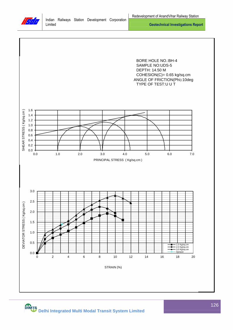
Indian Railways Station Development Corporation
Limited
Redevelopment of AnandVihar Railway Station
Geotechnical Investigations Report
Delhi Integrated Multi Modal Transit System Limited
126
0.0
0.2
0.4
0.6
0.8
1.0
1.2
1.4
1.6
0.0 1.0 2.0 3.0 4.0 5.0 6.0 7.0
SH
EA
R S
TR
ES
S (
Kg/s
q.c
m )
PRINCIPAL STRESS ( Kg/sq.cm )
BORE HOLE NO.:BH-4
SAMPLE NO:UDS-5
DEPTH: 14.50 M
COHESION(C)= 0.65 kg/sq.cm
ANGLE OF FRICTION(Phi):10deg TYPE OF TEST:U U T
0.0
0.5
1.0
1.5
2.0
2.5
3.0
0 2 4 6 8 10 12 14 16 18 20
DE
VIA
TO
R S
TR
ES
S (
Kg/s
q.c
m )
STRAIN (%)
1.0 Kg/sq.cm2.0 Kg/sq.cm3.0 Kg/sq.cmSeries4

Indian Railways Station Development Corporation
Limited
Redevelopment of AnandVihar Railway Station
Geotechnical Investigations Report
Delhi Integrated Multi Modal Transit System Limited
127
13.21 Shear Parameter for Bore Hole 4 at 23.5 m depth
BH-4
UDS-8DST DEPTH: 23.50 M
6.0
2.5 PROVING RING FACTOR= 0.259 Kg/Div.
SAMPLE No.
I II III
Weight of Wet Soil (gm) 169.86 171.23 170.86
Weight of Dry Soil (gm) 147.96 148.77 148.32
Moisture Content (%) 14.80 15.10 15.20
Bulk Density (rb) (gm/cm3) 1.89 1.90 1.90
Dry Density (rd) (gm/cm3) 1.64 1.65 1.65
1.0 Kg/ Sq.cm 2.0 Kg/ Sq.cm 3.0 Kg/ Sq.cm
Defo
rmation
Dia
l
Readin
g(D
iv
) Defo
rmation
(cm
)
Corr
ecte
d
Are
a (
sq
cm
)
Pro
vin
g r
ing
Readin
g
(Div
)
Shear
Forc
e
(Kg)
Shear
Str
ess
(Kg/C
m2)
Pro
vin
g r
ing
Readin
g
(Div
)
Shear
Forc
e
(Kg)
Shear
Str
ess
(Kg/C
m2)
Pro
vin
g r
ing
Readin
g
(Div
)
Shear
Forc
e
(Kg)
Shear
Str
ess
(Kg/C
m2)
Str
ain
(%
)
0..00001 0..00001 0..00001 0.0001
60 0.06 35.28 30 7.77 0.22 60 15.54 0.44 96 24.86 0.70 1.000
120 0.12 34.56 50 12.95 0.37 88 22.79 0.66 145 37.56 1.09 2.000
180 0.18 33.84 66 17.09 0.51 118 30.56 0.90 186 48.17 1.42 3.000
240 0.24 33.12 74 19.17 0.58 141 36.52 1.10 208 53.87 1.63 4.000
300 0.3 32.4 78 20.20 0.62 157 40.66 1.26 222 57.50 1.77 5.000
360 0.36 31.68 71 18.39 0.58 160 41.44 1.31 226 58.53 1.85 6.000
420 0.42 30.96 60 15.54 0.50 151 39.11 1.26 216 55.94 1.81 7.000
480 0.48 30.24 134 34.71 1.15 197 51.02 1.69 8.000
540 0.54 29.52 9.000
600 0.6 28.8 10.000
660 0.66 28.08 11.000
720 0.72 27.36 12.000
780 0.78 26.64 13.000
840 0.84 25.92 14.000
900 0.9 25.2 15.000
960 0.96 24.48 16.000
1020 1.02 23.76 17.000
1080 1.08 23.04 18.000
1140 1.14 22.32 19.000
1200 1.2 21.6 20.000
Nromal Stress
SAMPLE NO.:NAME OF THE PROJECT:
LAB. PROJECT NO:
Thickness of Sample (cm) =
ORIGNAL LENGTH OF
THE SAMPLE ( cm) =
TYPE OF THE TEST:
BORE HOLE NO.:

Indian Railways Station Development Corporation
Limited
Redevelopment of AnandVihar Railway Station
Geotechnical Investigations Report
Delhi Integrated Multi Modal Transit System Limited
128
0.0
0.5
1.0
1.5
2.0
2.5
3.0
0.0 0.5 1.0 1.5 2.0 2.5 3.0 3.5 4.0
SH
EA
R
ST
RE
SS
( k
g/s
q.c
m )
NORMAL STRESS ( kg/sq.cm )
BORE HOLE NO.:BH-4 SAMPLE NO:UDS-8 DEPTH:23.50 m COHESION(C)= 0.00 kg/sq.cm ANGLE OF FRICTION(Phi): 33 deg TYPE OF TEST:DST
0.0
0.2
0.4
0.6
0.8
1.0
1.2
1.4
1.6
1.8
2.0
0 2 4 6 8 10 12 14 16 18 20
SH
EA
R S
TR
ES
S (
kg/s
q.c
m )
STRAIN (%)
1.0 Kg/ sq. cm2.0 Kg/sq. cm3.0 Kg/sq. cmSeries4

Indian Railways Station Development Corporation
Limited
Redevelopment of AnandVihar Railway Station
Geotechnical Investigations Report
Delhi Integrated Multi Modal Transit System Limited
129
13.22 Shear Parameter for Bore Hole 5 at 2.5 m depth
BH-5
UDS-1DST DEPTH: 2.50 M
6.0
2.5 PROVING RING FACTOR= 0.258 Kg/Div.
SAMPLE No.
I II III
Weight of Wet Soil (gm) 169.86 171.23 170.86
Weight of Dry Soil (gm) 147.96 148.77 148.32
Moisture Content (%) 14.80 15.10 15.20
Bulk Density (rb) (gm/cm3) 1.89 1.90 1.90
Dry Density (rd) (gm/cm3) 1.64 1.65 1.65
1.0 Kg/ Sq.cm 2.0 Kg/ Sq.cm 3.0 Kg/ Sq.cm
Defo
rmation
Dia
l
Readin
g(D
iv
) Defo
rmation
(cm
)
Corr
ecte
d
Are
a (
sq
cm
)
Pro
vin
g r
ing
Readin
g
(Div
)
Shear
Forc
e
(Kg)
Shear
Str
ess
(Kg/C
m2)
Pro
vin
g r
ing
Readin
g
(Div
)
Shear
Forc
e
(Kg)
Shear
Str
ess
(Kg/C
m2)
Pro
vin
g r
ing
Readin
g
(Div
)
Shear
Forc
e
(Kg)
Shear
Str
ess
(Kg/C
m2)
Str
ain
(%
)
0..00001 0..00001 0..00001 0.0001
60 0.06 35.28 24 6.19 0.18 60 15.48 0.44 98 25.28 0.72 1.000
120 0.12 34.56 35 9.03 0.26 97 25.03 0.72 147 37.93 1.10 2.000
180 0.18 33.84 47 12.13 0.36 125 32.25 0.95 169 43.60 1.29 3.000
240 0.24 33.12 58 14.96 0.45 133 34.31 1.04 188 48.50 1.46 4.000
300 0.3 32.4 64 16.51 0.51 126 32.51 1.00 197 50.83 1.57 5.000
360 0.36 31.68 58 14.96 0.47 112 28.90 0.91 198 51.08 1.61 6.000
420 0.42 30.96 46 11.87 0.38 188 48.50 1.57 7.000
480 0.48 30.24 173 44.63 1.48 8.000
540 0.54 29.52 9.000
600 0.6 28.8 10.000
660 0.66 28.08 11.000
720 0.72 27.36 12.000
780 0.78 26.64 13.000
840 0.84 25.92 14.000
900 0.9 25.2 15.000
960 0.96 24.48 16.000
1020 1.02 23.76 17.000
1080 1.08 23.04 18.000
1140 1.14 22.32 19.000
1200 1.2 21.6 20.000
Nromal Stress
SAMPLE NO.:NAME OF THE PROJECT:
LAB. PROJECT NO:
Thickness of Sample (cm) =
ORIGNAL LENGTH OF
THE SAMPLE ( cm) =
TYPE OF THE TEST:
BORE HOLE NO.:

Indian Railways Station Development Corporation
Limited
Redevelopment of AnandVihar Railway Station
Geotechnical Investigations Report
Delhi Integrated Multi Modal Transit System Limited
130
0.0
0.5
1.0
1.5
2.0
2.5
3.0
0.0 0.5 1.0 1.5 2.0 2.5 3.0 3.5 4.0
SH
EA
R
ST
RE
SS
( k
g/s
q.c
m )
NORMAL STRESS ( kg/sq.cm )
BORE HOLE NO.:BH-5 SAMPLE NO:UDS-1 DEPTH:2.50 M COHESION(C)= 0.00 kg/sq.cm ANGLE OF FRICTION(Phi): 28 deg TYPE OF TEST:DST
0.0
0.2
0.4
0.6
0.8
1.0
1.2
1.4
1.6
1.8
0 2 4 6 8 10 12 14 16 18 20
SH
EA
R S
TR
ES
S (
kg/s
q.c
m )
STRAIN (%)
1.0 Kg/ sq. cm
2.0 Kg/sq. cm
3.0 Kg/sq. cm

Indian Railways Station Development Corporation
Limited
Redevelopment of AnandVihar Railway Station
Geotechnical Investigations Report
Delhi Integrated Multi Modal Transit System Limited
131
13.23 Shear Parameter for Bore Hole 5 at 5.5 m depth
BH-5
UDS-2DST DEPTH: 5.50 M
6.0
2.5 PROVING RING FACTOR= 0.259 Kg/Div.
SAMPLE No.
I II III
Weight of Wet Soil (gm) 169.86 171.23 170.86
Weight of Dry Soil (gm) 147.96 148.77 148.32
Moisture Content (%) 14.80 15.10 15.20
Bulk Density (rb) (gm/cm3) 1.89 1.90 1.90
Dry Density (rd) (gm/cm3) 1.64 1.65 1.65
1.0 Kg/ Sq.cm 2.0 Kg/ Sq.cm 3.0 Kg/ Sq.cm
Defo
rmation
Dia
l
Readin
g(D
iv
) Defo
rmation
(cm
)
Corr
ecte
d
Are
a (
sq
cm
)
Pro
vin
g r
ing
Readin
g
(Div
)
Shear
Forc
e
(Kg)
Shear
Str
ess
(Kg/C
m2)
Pro
vin
g r
ing
Readin
g
(Div
)
Shear
Forc
e
(Kg)
Shear
Str
ess
(Kg/C
m2)
Pro
vin
g r
ing
Readin
g
(Div
)
Shear
Forc
e
(Kg)
Shear
Str
ess
(Kg/C
m2)
Str
ain
(%
)
0..00001 0..00001 0..00001 0.0001
60 0.06 35.28 29 7.51 0.21 60 15.54 0.44 104 26.94 0.76 1.000
120 0.12 34.56 47 12.17 0.35 94 24.35 0.70 137 35.48 1.03 2.000
180 0.18 33.84 62 16.06 0.47 121 31.34 0.93 160 41.44 1.22 3.000
240 0.24 33.12 72 18.65 0.56 139 36.00 1.09 177 45.84 1.38 4.000
300 0.3 32.4 75 19.43 0.60 153 39.63 1.22 196 50.76 1.57 5.000
360 0.36 31.68 70 18.13 0.57 155 40.15 1.27 208 53.87 1.70 6.000
420 0.42 30.96 61 15.80 0.51 146 37.81 1.22 209 54.13 1.75 7.000
480 0.48 30.24 134 34.71 1.15 199 51.54 1.70 8.000
540 0.54 29.52 185 47.92 1.62 9.000
600 0.6 28.8 10.000
660 0.66 28.08 11.000
720 0.72 27.36 12.000
780 0.78 26.64 13.000
840 0.84 25.92 14.000
900 0.9 25.2 15.000
960 0.96 24.48 16.000
1020 1.02 23.76 17.000
1080 1.08 23.04 18.000
1140 1.14 22.32 19.000
1200 1.2 21.6 20.000
Nromal Stress
SAMPLE NO. NAME OF THE PROJECT:
LAB. PROJECT NO:
Thickness of Sample (cm) =
ORIGNAL LENGTH OF
THE SAMPLE ( cm) =
TYPE OF THE TEST:
BORE HOLE NO.:
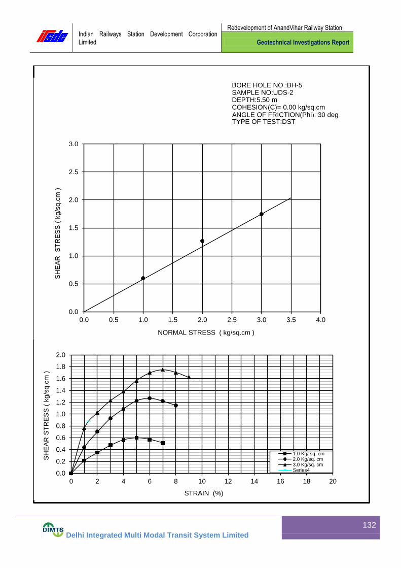
Indian Railways Station Development Corporation
Limited
Redevelopment of AnandVihar Railway Station
Geotechnical Investigations Report
Delhi Integrated Multi Modal Transit System Limited
132
0.0
0.5
1.0
1.5
2.0
2.5
3.0
0.0 0.5 1.0 1.5 2.0 2.5 3.0 3.5 4.0
SH
EA
R
ST
RE
SS
( k
g/s
q.c
m )
NORMAL STRESS ( kg/sq.cm )
BORE HOLE NO.:BH-5 SAMPLE NO:UDS-2 DEPTH:5.50 m COHESION(C)= 0.00 kg/sq.cm ANGLE OF FRICTION(Phi): 30 deg TYPE OF TEST:DST
0.0
0.2
0.4
0.6
0.8
1.0
1.2
1.4
1.6
1.8
2.0
0 2 4 6 8 10 12 14 16 18 20
SH
EA
R S
TR
ES
S (
kg/s
q.c
m )
STRAIN (%)
1.0 Kg/ sq. cm2.0 Kg/sq. cm3.0 Kg/sq. cmSeries4

Indian Railways Station Development Corporation
Limited
Redevelopment of AnandVihar Railway Station
Geotechnical Investigations Report
Delhi Integrated Multi Modal Transit System Limited
133
13.24 Shear Parameter for Bore Hole 5 at 11.5 m depth
BH-5
UDS-4DST DEPTH: 11.50 M
6.0
2.5 PROVING RING FACTOR= 0.259 Kg/Div.
SAMPLE No.
I II III
Weight of Wet Soil (gm) 169.86 171.23 170.86
Weight of Dry Soil (gm) 147.96 148.77 148.32
Moisture Content (%) 14.80 15.10 15.20
Bulk Density (rb) (gm/cm3) 1.89 1.90 1.90
Dry Density (rd) (gm/cm3) 1.64 1.65 1.65
1.0 Kg/ Sq.cm 2.0 Kg/ Sq.cm 3.0 Kg/ Sq.cm
Defo
rmation
Dia
l
Readin
g(D
iv
) Defo
rmation
(cm
)
Corr
ecte
d
Are
a (
sq
cm
)
Pro
vin
g r
ing
Readin
g
(Div
)
Shear
Forc
e
(Kg)
Shear
Str
ess
(Kg/C
m2)
Pro
vin
g r
ing
Readin
g
(Div
)
Shear
Forc
e
(Kg)
Shear
Str
ess
(Kg/C
m2)
Pro
vin
g r
ing
Readin
g
(Div
)
Shear
Forc
e
(Kg)
Shear
Str
ess
(Kg/C
m2)
Str
ain
(%
)
0..00001 0..00001 0..00001 0.0001
60 0.06 35.28 26 6.73 0.19 57 14.76 0.42 107 27.71 0.79 1.000
120 0.12 34.56 43 11.14 0.32 91 23.57 0.68 177 45.84 1.33 2.000
180 0.18 33.84 59 15.28 0.45 126 32.63 0.96 218 56.46 1.67 3.000
240 0.24 33.12 73 18.91 0.57 150 38.85 1.17 234 60.61 1.83 4.000
300 0.3 32.4 78 20.20 0.62 156 40.40 1.25 236 61.12 1.89 5.000
360 0.36 31.68 71 18.39 0.58 147 38.07 1.20 225 58.28 1.84 6.000
420 0.42 30.96 60 15.54 0.50 134 34.71 1.12 204 52.84 1.71 7.000
480 0.48 30.24 8.000
540 0.54 29.52 9.000
600 0.6 28.8 10.000
660 0.66 28.08 11.000
720 0.72 27.36 12.000
780 0.78 26.64 13.000
840 0.84 25.92 14.000
900 0.9 25.2 15.000
960 0.96 24.48 16.000
1020 1.02 23.76 17.000
1080 1.08 23.04 18.000
1140 1.14 22.32 19.000
1200 1.2 21.6 20.000
Nromal Stress
SAMPLE NO.:NAME OF THE PROJECT:
LAB. PROJECT NO:
Thickness of Sample (cm) =
ORIGNAL LENGTH OF
THE SAMPLE ( cm) =
TYPE OF THE TEST:
BORE HOLE NO.:

Indian Railways Station Development Corporation
Limited
Redevelopment of AnandVihar Railway Station
Geotechnical Investigations Report
Delhi Integrated Multi Modal Transit System Limited
134
0.0
0.5
1.0
1.5
2.0
2.5
3.0
0.0 0.5 1.0 1.5 2.0 2.5 3.0 3.5 4.0
SH
EA
R
ST
RE
SS
( k
g/s
q.c
m )
NORMAL STRESS ( kg/sq.cm )
BORE HOLE NO.:BH-5 SAMPLE NO:UDS-4 DEPTH:11.50 m COHESION(C)= 0.00 kg/sq.cm ANGLE OF FRICTION(Phi): 32 deg TYPE OF TEST:DST
0.0
0.2
0.4
0.6
0.8
1.0
1.2
1.4
1.6
1.8
2.0
0 2 4 6 8 10 12 14 16 18 20
SH
EA
R S
TR
ES
S (
kg/s
q.c
m )
STRAIN (%)
1.0 Kg/ sq. cm2.0 Kg/sq. cm3.0 Kg/sq. cmSeries4

Indian Railways Station Development Corporation
Limited
Redevelopment of AnandVihar Railway Station
Geotechnical Investigations Report
Delhi Integrated Multi Modal Transit System Limited
135
13.25 Shear Parameter for Bore Hole 5 at 17.5 m depth
LAB. PROJECT NO: BORE HOLE NO: BH-5
NAME OF THE PROJECT: SAMPLE NO.: UDS-6
TYPE OF THE TEST: U U T DEPTH: 17.50 M
REMARKS:
ORIGNAL LENGTH OF TH SAMPLE= 7.5 cm PROVING RING FACTOR= 0.25 Kg/Div.
SAMPLE No.
I II III
Weight of Wet Soil (gm) 150.87 152.19 151.85
Weight of Dry Soil (gm) 127.37 128.05 127.71
Moisture Content (%) 18.45 18.85 18.90
Bulk Density (rb) (gm/cm3) 1.76 1.78 1.78
Dry Density (rd) (gm/cm3) 1.49 1.50 1.49
CELL PRESSURE 1.0 Kg/ Sq.cm 2.0 Kg/ Sq.cm 3.0 Kg/ Sq.cm
Sta
in D
ial
Readin
g(D
iv
) Sta
in(%
)
Are
a(C
m2)
Pro
vin
g r
ing
Readin
g(D
iv
) Axia
l Load
(Kg)
Str
ess
(kg/C
m2)
Pro
vin
g r
ing
Readin
g(D
iv
) Axia
l Load
(Kg)
Str
ess
(kg/C
m2)
Pro
vin
g r
ing
Readin
g(D
iv
) Axia
l Load
(Kg)
Str
ess
(kg/C
m2)
0.0001 0..00001 0..00001 0..00001
75 1 11.52 39 9.75 0.85 51 12.75 1.11 67 16.75 1.45
150 2 11.64 57 14.25 1.22 70 17.50 1.50 84 21.00 1.80
225 3 11.76 71 17.75 1.51 83 20.75 1.76 97 24.25 2.06
300 4 11.88 84 21.00 1.77 97 24.25 2.04 109 27.25 2.29
375 5 12.01 95 23.75 1.98 108 27.00 2.25 120 30.00 2.50
450 6 12.13 106 26.50 2.18 118 29.50 2.43 129 32.25 2.66
525 7 12.27 113 28.25 2.30 128 32.00 2.61 139 34.75 2.83
600 8 12.40 111 27.75 2.24 134 33.50 2.70 150 37.50 3.02
675 9 12.53 102 25.50 2.04 131 32.75 2.61 159 39.75 3.17
750 10 12.65 124 31.00 2.45 164 41.00 3.24
825 11 12.82 160 40.00 3.12
900 12 12.96 150 37.50 2.89
975 13 13.11
1050 14 13.26
1125 15 13.42
1200 16 13.58
1275 17 13.74
1350 18 13.91
1425 19 14.08
1500 20 14.26

Indian Railways Station Development Corporation
Limited
Redevelopment of AnandVihar Railway Station
Geotechnical Investigations Report
Delhi Integrated Multi Modal Transit System Limited
136
0.0
0.2
0.4
0.6
0.8
1.0
1.2
1.4
1.6
1.8
2.0
0.0 1.0 2.0 3.0 4.0 5.0 6.0 7.0
SH
EA
R S
TR
ES
S (
Kg
/sq
.cm
)
PRINCIPAL STRESS ( Kg/sq.cm )
BORE HOLE NO.:BH-5
SAMPLE NO:UDS-6 DEPTH: 17.50 M
COHESION(C)= 0.75 kg/sq.cm
ANGLE OF FRICTION(Phi):11deg TYPE OF TEST:U U T
0.0
0.5
1.0
1.5
2.0
2.5
3.0
3.5
0 2 4 6 8 10 12 14 16 18 20
DE
VIA
TO
R S
TR
ES
S (
Kg/s
q.c
m )
STRAIN (%)
1.0 Kg/sq.cm
2.0 Kg/sq.cm
3.0 Kg/sq.cm
7

Indian Railways Station Development Corporation
Limited
Redevelopment of AnandVihar Railway Station
Geotechnical Investigations Report
Delhi Integrated Multi Modal Transit System Limited
137
13.26 Shear Parameter for Bore Hole 5 at 23.5 m depth
BH-5
UDS-8DST DEPTH: 23.50 M
6.0
2.5 PROVING RING FACTOR= 0.259 Kg/Div.
SAMPLE No.
I II III
Weight of Wet Soil (gm) 169.86 171.23 170.86
Weight of Dry Soil (gm) 147.96 148.77 148.32
Moisture Content (%) 14.80 15.10 15.20
Bulk Density (rb) (gm/cm3) 1.89 1.90 1.90
Dry Density (rd) (gm/cm3) 1.64 1.65 1.65
1.0 Kg/ Sq.cm 2.0 Kg/ Sq.cm 3.0 Kg/ Sq.cm
Defo
rmation
Dia
l
Readin
g(D
iv
) Defo
rmation
(cm
)
Corr
ecte
d
Are
a (
sq
cm
)
Pro
vin
g r
ing
Readin
g
(Div
)
Shear
Forc
e
(Kg)
Shear
Str
ess
(Kg/C
m2)
Pro
vin
g r
ing
Readin
g
(Div
)
Shear
Forc
e
(Kg)
Shear
Str
ess
(Kg/C
m2)
Pro
vin
g r
ing
Readin
g
(Div
)
Shear
Forc
e
(Kg)
Shear
Str
ess
(Kg/C
m2)
Str
ain
(%
)
0..00001 0..00001 0..00001 0.0001
60 0.06 35.28 26 6.73 0.19 57 14.76 0.42 107 27.71 0.79 1.000
120 0.12 34.56 43 11.14 0.32 91 23.57 0.68 177 45.84 1.33 2.000
180 0.18 33.84 59 15.28 0.45 126 32.63 0.96 218 56.46 1.67 3.000
240 0.24 33.12 73 18.91 0.57 150 38.85 1.17 234 60.61 1.83 4.000
300 0.3 32.4 78 20.20 0.62 156 40.40 1.25 236 61.12 1.89 5.000
360 0.36 31.68 71 18.39 0.58 147 38.07 1.20 225 58.28 1.84 6.000
420 0.42 30.96 60 15.54 0.50 134 34.71 1.12 204 52.84 1.71 7.000
480 0.48 30.24 8.000
540 0.54 29.52 9.000
600 0.6 28.8 10.000
660 0.66 28.08 11.000
720 0.72 27.36 12.000
780 0.78 26.64 13.000
840 0.84 25.92 14.000
900 0.9 25.2 15.000
960 0.96 24.48 16.000
1020 1.02 23.76 17.000
1080 1.08 23.04 18.000
1140 1.14 22.32 19.000
1200 1.2 21.6 20.000
Nromal Stress
SAMPLE NO.:NAME OF THE PROJECT:
LAB. PROJECT NO:
Thickness of Sample (cm) =
ORIGNAL LENGTH OF
THE SAMPLE ( cm) =
TYPE OF THE TEST:
BORE HOLE NO.:

Indian Railways Station Development Corporation
Limited
Redevelopment of AnandVihar Railway Station
Geotechnical Investigations Report
Delhi Integrated Multi Modal Transit System Limited
138
0.0
0.5
1.0
1.5
2.0
2.5
3.0
0.0 0.5 1.0 1.5 2.0 2.5 3.0 3.5 4.0
SH
EA
R
ST
RE
SS
( k
g/s
q.c
m )
NORMAL STRESS ( kg/sq.cm )
BORE HOLE NO.:BH-5 SAMPLE NO:UDS-8 DEPTH:23.50 m COHESION(C)= 0.00 kg/sq.cm
ANGLE OF FRICTION(Phi): 33 deg TYPE OF TEST:DST
0.0
0.2
0.4
0.6
0.8
1.0
1.2
1.4
1.6
1.8
2.0
0 2 4 6 8 10 12 14 16 18 20
SH
EA
R S
TR
ES
S (
kg/s
q.c
m )
STRAIN (%)
1.0 Kg/ sq. cm
2.0 Kg/sq. cm
3.0 Kg/sq. cm

Indian Railways Station Development Corporation
Limited
Redevelopment of AnandVihar Railway Station
Geotechnical Investigations Report
Delhi Integrated Multi Modal Transit System Limited
139
13.27 Shear Parameter for Bore Hole 6 at 2.5 m depth
LAB. PROJECT NO: BORE HOLE NO: BH-6
NAME OF THE PROJECT: SAMPLE NO.: UDS-1
TYPE OF THE TEST: U U T DEPTH: 2.50 M
REMARKS:
ORIGNAL LENGTH OF TH SAMPLE= 7.5 cm PROVING RING FACTOR= 0.25 Kg/Div.
SAMPLE No.
I II III
Weight of Wet Soil (gm) 150.87 152.19 151.85
Weight of Dry Soil (gm) 127.37 128.05 127.71
Moisture Content (%) 18.45 18.85 18.90
Bulk Density (rb) (gm/cm3) 1.76 1.78 1.78
Dry Density (rd) (gm/cm3) 1.49 1.50 1.49
CELL PRESSURE 1.0 Kg/ Sq.cm 2.0 Kg/ Sq.cm 3.0 Kg/ Sq.cm
Sta
in D
ial
Readin
g(D
iv
) Sta
in(%
)
Are
a(C
m2)
Pro
vin
g r
ing
Readin
g(D
iv
) Axia
l Load
(Kg)
Str
ess
(kg/C
m2)
Pro
vin
g r
ing
Readin
g(D
iv
) Axia
l Load
(Kg)
Str
ess
(kg/C
m2)
Pro
vin
g r
ing
Readin
g(D
iv
) Axia
l Load
(Kg)
Str
ess
(kg/C
m2)
0.0001 0..00001 0..00001 0..00001
75 1 11.52 26 6.50 0.56 43 10.75 0.93 58 14.50 1.26
150 2 11.64 41 10.25 0.88 58 14.50 1.25 73 18.25 1.57
225 3 11.76 51 12.75 1.08 71 17.75 1.51 83 20.75 1.76
300 4 11.88 61 15.25 1.28 82 20.50 1.73 94 23.50 1.98
375 5 12.01 70 17.50 1.46 93 23.25 1.94 105 26.25 2.19
450 6 12.13 79 19.75 1.63 103 25.75 2.12 116 29.00 2.39
525 7 12.27 87 21.75 1.77 112 28.00 2.28 128 32.00 2.61
600 8 12.40 93 23.25 1.88 120 30.00 2.42 137 34.25 2.76
675 9 12.53 88 22.00 1.76 125 31.25 2.49 147 36.75 2.93
750 10 12.65 80 20.00 1.58 121 30.25 2.39 154 38.50 3.04
825 11 12.82 115 28.75 2.24 150 37.50 2.93
900 12 12.96 140 35.00 2.70
975 13 13.11
1050 14 13.26
1125 15 13.42
1200 16 13.58
1275 17 13.74
1350 18 13.91
1425 19 14.08
1500 20 14.26

Indian Railways Station Development Corporation
Limited
Redevelopment of AnandVihar Railway Station
Geotechnical Investigations Report
Delhi Integrated Multi Modal Transit System Limited
140
0.0
0.2
0.4
0.6
0.8
1.0
1.2
1.4
1.6
1.8
0.0 1.0 2.0 3.0 4.0 5.0 6.0 7.0
SH
EA
R S
TR
ES
S (
Kg/s
q.c
m )
PRINCIPAL STRESS ( Kg/sq.cm )
BORE HOLE NO.:BH-6 SAMPLE NO:UDS-1
DEPTH: 2.50 M
COHESION(C)= 0.50 kg/sq.cm
ANGLE OF FRICTION(Phi):13deg TYPE OF TEST:U U T
0.0
0.5
1.0
1.5
2.0
2.5
3.0
3.5
0 2 4 6 8 10 12 14 16 18 20
DE
VIA
TO
R S
TR
ES
S (
Kg/s
q.c
m )
STRAIN (%)
1.0 Kg/sq.cm2.0 Kg/sq.cm3.0 Kg/sq.cmSeries4

Indian Railways Station Development Corporation
Limited
Redevelopment of AnandVihar Railway Station
Geotechnical Investigations Report
Delhi Integrated Multi Modal Transit System Limited
141
13.28 Shear Parameter for Bore Hole 6 at 8.5 m depth BH-6
UDS-3DST DEPTH: 8.50 M
6.0
2.5 PROVING RING FACTOR= 0.259 Kg/Div.
SAMPLE No.
I II III
Weight of Wet Soil (gm) 169.86 171.23 170.86
Weight of Dry Soil (gm) 147.96 148.77 148.32
Moisture Content (%) 14.80 15.10 15.20
Bulk Density (rb) (gm/cm3) 1.89 1.90 1.90
Dry Density (rd) (gm/cm3) 1.64 1.65 1.65
1.0 Kg/ Sq.cm 2.0 Kg/ Sq.cm 3.0 Kg/ Sq.cm
Defo
rmation
Dia
l
Readin
g(D
iv
) Defo
rmation
(cm
)
Corr
ecte
d
Are
a (
sq
cm
)
Pro
vin
g r
ing
Readin
g
(Div
)
Shear
Forc
e
(Kg)
Shear
Str
ess
(Kg/C
m2)
Pro
vin
g r
ing
Readin
g
(Div
)
Shear
Forc
e
(Kg)
Shear
Str
ess
(Kg/C
m2)
Pro
vin
g r
ing
Readin
g
(Div
)
Shear
Forc
e
(Kg)
Shear
Str
ess
(Kg/C
m2)
Str
ain
(%
)
0..00001 0..00001 0..00001 0.0001
60 0.06 35.28 25 6.48 0.18 60 15.54 0.44 101 26.16 0.74 1.000
120 0.12 34.56 43 11.14 0.32 83 21.50 0.62 142 36.78 1.06 2.000
180 0.18 33.84 55 14.25 0.42 100 25.90 0.77 173 44.81 1.32 3.000
240 0.24 33.12 67 17.35 0.52 110 28.49 0.86 198 51.28 1.55 4.000
300 0.3 32.4 72 18.65 0.58 123 31.86 0.98 209 54.13 1.67 5.000
360 0.36 31.68 64 16.58 0.52 130 33.67 1.06 212 54.91 1.73 6.000
420 0.42 30.96 53 13.73 0.44 121 31.34 1.01 200 51.80 1.67 7.000
480 0.48 30.24 109 28.23 0.93 184 47.66 1.58 8.000
540 0.54 29.52 9.000
600 0.6 28.8 10.000
660 0.66 28.08 11.000
720 0.72 27.36 12.000
780 0.78 26.64 13.000
840 0.84 25.92 14.000
900 0.9 25.2 15.000
960 0.96 24.48 16.000
1020 1.02 23.76 17.000
1080 1.08 23.04 18.000
1140 1.14 22.32 19.000
1200 1.2 21.6 20.000
Nromal Stress
SAMPLE NO.:NAME OF THE PROJECT:
LAB. PROJECT NO:
Thickness of Sample (cm) =
ORIGNAL LENGTH OF
THE SAMPLE ( cm) =
TYPE OF THE TEST:
BORE HOLE NO.:

Indian Railways Station Development Corporation
Limited
Redevelopment of AnandVihar Railway Station
Geotechnical Investigations Report
Delhi Integrated Multi Modal Transit System Limited
142
0.0
0.5
1.0
1.5
2.0
2.5
3.0
0.0 0.5 1.0 1.5 2.0 2.5 3.0 3.5 4.0
SH
EA
R
ST
RE
SS
( k
g/s
q.c
m )
NORMAL STRESS ( kg/sq.cm )
BORE HOLE NO.:BH-6 SAMPLE NO:UDS-3 DEPTH:8.50 m COHESION(C)= 0.00 kg/sq.cm ANGLE OF FRICTION(Phi): 30 deg TYPE OF TEST:DST
0.0
0.2
0.4
0.6
0.8
1.0
1.2
1.4
1.6
1.8
2.0
0 2 4 6 8 10 12 14 16 18 20
SH
EA
R S
TR
ES
S (
kg/s
q.c
m )
STRAIN (%)
1.0 Kg/ sq. cm2.0 Kg/sq. cm3.0 Kg/sq. cmSeries4

Indian Railways Station Development Corporation
Limited
Redevelopment of AnandVihar Railway Station
Geotechnical Investigations Report
Delhi Integrated Multi Modal Transit System Limited
143
13.29 Shear Parameter for Bore Hole 6 at 14.5 m depth
BH-6
UDS-5DST DEPTH: 14.50 M
6.0
2.5 PROVING RING FACTOR= 0.259 Kg/Div.
SAMPLE No.
I II III
Weight of Wet Soil (gm) 169.86 171.23 170.86
Weight of Dry Soil (gm) 147.96 148.77 148.32
Moisture Content (%) 14.80 15.10 15.20
Bulk Density (rb) (gm/cm3) 1.89 1.90 1.90
Dry Density (rd) (gm/cm3) 1.64 1.65 1.65
1.0 Kg/ Sq.cm 2.0 Kg/ Sq.cm 3.0 Kg/ Sq.cm
Defo
rmation
Dia
l
Readin
g(D
iv
) Defo
rmation
(cm
)
Corr
ecte
d
Are
a (
sq
cm
)
Pro
vin
g r
ing
Readin
g
(Div
)
Shear
Forc
e
(Kg)
Shear
Str
ess
(Kg/C
m2)
Pro
vin
g r
ing
Readin
g
(Div
)
Shear
Forc
e
(Kg)
Shear
Str
ess
(Kg/C
m2)
Pro
vin
g r
ing
Readin
g
(Div
)
Shear
Forc
e
(Kg)
Shear
Str
ess
(Kg/C
m2)
Str
ain
(%
)
0..00001 0..00001 0..00001 0.0001
60 0.06 35.28 31 8.03 0.23 68 17.61 0.50 109 28.23 0.80 1.000
120 0.12 34.56 49 12.69 0.37 105 27.20 0.79 163 42.22 1.22 2.000
180 0.18 33.84 63 16.32 0.48 136 35.22 1.04 199 51.54 1.52 3.000
240 0.24 33.12 74 19.17 0.58 152 39.37 1.19 220 56.98 1.72 4.000
300 0.3 32.4 78 20.20 0.62 156 40.40 1.25 224 58.02 1.79 5.000
360 0.36 31.68 73 18.91 0.60 147 38.07 1.20 214 55.43 1.75 6.000
420 0.42 30.96 62 16.06 0.52 134 34.71 1.12 196 50.76 1.64 7.000
480 0.48 30.24 8.000
540 0.54 29.52 9.000
600 0.6 28.8 10.000
660 0.66 28.08 11.000
720 0.72 27.36 12.000
780 0.78 26.64 13.000
840 0.84 25.92 14.000
900 0.9 25.2 15.000
960 0.96 24.48 16.000
1020 1.02 23.76 17.000
1080 1.08 23.04 18.000
1140 1.14 22.32 19.000
1200 1.2 21.6 20.000
Nromal Stress
SAMPLE NO.:NAME OF THE PROJECT:
LAB. PROJECT NO:
Thickness of Sample (cm) =
ORIGNAL LENGTH OF
THE SAMPLE ( cm) =
TYPE OF THE TEST:
BORE HOLE NO.:

Indian Railways Station Development Corporation
Limited
Redevelopment of AnandVihar Railway Station
Geotechnical Investigations Report
Delhi Integrated Multi Modal Transit System Limited
144
0.0
0.5
1.0
1.5
2.0
2.5
3.0
0.0 0.5 1.0 1.5 2.0 2.5 3.0 3.5 4.0
SH
EA
R
ST
RE
SS
( k
g/s
q.c
m )
NORMAL STRESS ( kg/sq.cm )
BORE HOLE NO.:BH-6 SAMPLE NO:UDS-5 DEPTH:14.50 m COHESION(C)= 0.00 kg/sq.cm ANGLE OF FRICTION(Phi): 31 deg TYPE OF TEST:DST
0.0
0.2
0.4
0.6
0.8
1.0
1.2
1.4
1.6
1.8
2.0
0 2 4 6 8 10 12 14 16 18 20
SH
EA
R S
TR
ES
S (
kg/s
q.c
m )
STRAIN (%)
1.0 Kg/ sq. cm
2.0 Kg/sq. cm
3.0 Kg/sq. cm

Indian Railways Station Development Corporation
Limited
Redevelopment of AnandVihar Railway Station
Geotechnical Investigations Report
Delhi Integrated Multi Modal Transit System Limited
145
13.30 Shear Parameter for Bore Hole 6 at 20.5 m depth
LAB. PROJECT NO: BORE HOLE NO: BH-6
NAME OF THE PROJECT: SAMPLE NO.: UDS-7
TYPE OF THE TEST: U U T DEPTH: 20.50 M
REMARKS:
ORIGNAL LENGTH OF THE SAMPLE= 7.5 cm PROVING RING FACTOR= 0.25 Kg/Div.
SAMPLE No.
I II III
Weight of Wet Soil (gm) 164.62 165.95 165.58
Weight of Dry Soil (gm) 138.92 139.69 139.26
Moisture Content (%) 18.50 18.80 18.90
Bulk Density (rb) (gm/cm3) 1.93 1.94 1.94
Dry Density (rd) (gm/cm3) 1.62 1.63 1.63
CELL PRESSURE 1.0 Kg/ Sq.cm 2.0 Kg/ Sq.cm 3.0 Kg/ Sq.cm
Sta
in D
ial
Readin
g(D
iv
) Sta
in(%
)
Are
a(C
m2)
Pro
vin
g r
ing
Readin
g(D
iv
) Axia
l Load
(Kg)
Str
ess
(kg/C
m2)
Pro
vin
g r
ing
Readin
g(D
iv
) Axia
l Load
(Kg)
Str
ess
(kg/C
m2)
Pro
vin
g r
ing
Readin
g(D
iv
) Axia
l Load
(Kg)
Str
ess
(kg/C
m2)
0.0001 0..00001 0..00001 0..00001
75 1 11.52 22 5.50 0.48 38 9.50 0.82 51 12.75 1.11
150 2 11.64 34 8.50 0.73 54 13.50 1.16 68 17.00 1.46
225 3 11.76 44 11.00 0.94 68 17.00 1.45 82 20.50 1.74
300 4 11.88 54 13.50 1.14 82 20.50 1.73 97 24.25 2.04
375 5 12.01 65 16.25 1.35 98 24.50 2.04 113 28.25 2.35
450 6 12.13 77 19.25 1.59 114 28.50 2.35 126 31.50 2.60
525 7 12.27 90 22.50 1.83 125 31.25 2.55 138 34.50 2.81
600 8 12.40 101 25.25 2.04 130 32.50 2.62 147 36.75 2.96
675 9 12.53 109 27.25 2.17 128 32.00 2.55 154 38.50 3.07
750 10 12.65 104 26.00 2.06 120 30.00 2.37 158 39.50 3.12
825 11 12.82 95 23.75 1.85 154 38.50 3.00
900 12 12.96 144 36.00 2.78
975 13 13.11
1050 14 13.26
1125 15 13.42
1200 16 13.58
1275 17 13.74
1350 18 13.91
1425 19 14.08
1500 20 14.26

Indian Railways Station Development Corporation
Limited
Redevelopment of AnandVihar Railway Station
Geotechnical Investigations Report
Delhi Integrated Multi Modal Transit System Limited
146
0.0
0.2
0.4
0.6
0.8
1.0
1.2
1.4
1.6
1.8
0.0 1.0 2.0 3.0 4.0 5.0 6.0 7.0
SH
EA
R S
TR
ES
S (
Kg
/sq
.cm
)
PRINCIPAL STRESS ( Kg/sq.cm )
BORE HOLE NO.:BH-6 SAMPLE NO:UDS-7 DEPTH: 20.50 M COHESION(C)= 0.70 kg/sq.cm
ANGLE OF FRICTION(Phi):10deg TYPE OF TEST:U U T
0.0
0.5
1.0
1.5
2.0
2.5
3.0
3.5
0 2 4 6 8 10 12 14 16 18 20
DE
VIA
TO
R S
TR
ES
S (
Kg/s
q.c
m )
STRAIN (%)
1.0 Kg/sq.cm
2.0 Kg/sq.cm
3.0 Kg/sq.cm

Indian Railways Station Development Corporation
Limited
Redevelopment of AnandVihar Railway Station
Geotechnical Investigations Report
Delhi Integrated Multi Modal Transit System Limited
147
13.31 Shear Parameter for Bore Hole 6 at 26.5 m depth
BH-6
UDS-9DST DEPTH: 26.50 M
6.0
2.5 PROVING RING FACTOR= 0.259 Kg/Div.
SAMPLE No.
I II III
Weight of Wet Soil (gm) 169.86 171.23 170.86
Weight of Dry Soil (gm) 147.96 148.77 148.32
Moisture Content (%) 14.80 15.10 15.20
Bulk Density (rb) (gm/cm3) 1.89 1.90 1.90
Dry Density (rd) (gm/cm3) 1.64 1.65 1.65
1.0 Kg/ Sq.cm 2.0 Kg/ Sq.cm 3.0 Kg/ Sq.cm
Defo
rmation
Dia
l
Readin
g(D
iv
) Defo
rmation
(cm
)
Corr
ecte
d
Are
a (
sq
cm
)
Pro
vin
g r
ing
Readin
g
(Div
)
Shear
Forc
e
(Kg)
Shear
Str
ess
(Kg/C
m2)
Pro
vin
g r
ing
Readin
g
(Div
)
Shear
Forc
e
(Kg)
Shear
Str
ess
(Kg/C
m2)
Pro
vin
g r
ing
Readin
g
(Div
)
Shear
Forc
e
(Kg)
Shear
Str
ess
(Kg/C
m2)
Str
ain
(%
)
0..00001 0..00001 0..00001 0.0001
60 0.06 35.28 26 6.73 0.19 57 14.76 0.42 107 27.71 0.79 1.000
120 0.12 34.56 43 11.14 0.32 91 23.57 0.68 177 45.84 1.33 2.000
180 0.18 33.84 59 15.28 0.45 126 32.63 0.96 218 56.46 1.67 3.000
240 0.24 33.12 73 18.91 0.57 150 38.85 1.17 234 60.61 1.83 4.000
300 0.3 32.4 78 20.20 0.62 156 40.40 1.25 236 61.12 1.89 5.000
360 0.36 31.68 71 18.39 0.58 147 38.07 1.20 225 58.28 1.84 6.000
420 0.42 30.96 60 15.54 0.50 134 34.71 1.12 204 52.84 1.71 7.000
480 0.48 30.24 8.000
540 0.54 29.52 9.000
600 0.6 28.8 10.000
660 0.66 28.08 11.000
720 0.72 27.36 12.000
780 0.78 26.64 13.000
840 0.84 25.92 14.000
900 0.9 25.2 15.000
960 0.96 24.48 16.000
1020 1.02 23.76 17.000
1080 1.08 23.04 18.000
1140 1.14 22.32 19.000
1200 1.2 21.6 20.000
Nromal Stress
SAMPLE NO.:NAME OF THE PROJECT:
LAB. PROJECT NO:
Thickness of Sample (cm) =
ORIGNAL LENGTH OF
THE SAMPLE ( cm) =
TYPE OF THE TEST:
BORE HOLE NO.:

Indian Railways Station Development Corporation
Limited
Redevelopment of AnandVihar Railway Station
Geotechnical Investigations Report
Delhi Integrated Multi Modal Transit System Limited
148
0.0
0.5
1.0
1.5
2.0
2.5
3.0
0.0 0.5 1.0 1.5 2.0 2.5 3.0 3.5 4.0
SH
EA
R
ST
RE
SS
( k
g/s
q.c
m )
NORMAL STRESS ( kg/sq.cm )
BORE HOLE NO.:BH-6 SAMPLE NO:UDS-9 DEPTH:26.50 m COHESION(C)= 0.00 kg/sq.cm
ANGLE OF FRICTION(Phi): 32 deg TYPE OF TEST:DST
0.0
0.2
0.4
0.6
0.8
1.0
1.2
1.4
1.6
1.8
2.0
0 2 4 6 8 10 12 14 16 18 20
SH
EA
R S
TR
ES
S (
kg/s
q.c
m )
STRAIN (%)
1.0 Kg/ sq. cm
2.0 Kg/sq. cm
3.0 Kg/sq. cm

Indian Railways Station Development Corporation
Limited
Redevelopment of AnandVihar Railway Station
Geotechnical Investigations Report
Delhi Integrated Multi Modal Transit System Limited
149
13.32 Shear Parameter for Bore Hole 7 at 2.5 m depth
BH-7
UDS-1DST DEPTH: 2.50 M
6.0
2.5 PROVING RING FACTOR= 0.259 Kg/Div.
SAMPLE No.
I II III
Weight of Wet Soil (gm) 169.86 171.23 170.86
Weight of Dry Soil (gm) 147.96 148.77 148.32
Moisture Content (%) 14.80 15.10 15.20
Bulk Density (rb) (gm/cm3) 1.89 1.90 1.90
Dry Density (rd) (gm/cm3) 1.64 1.65 1.65
1.0 Kg/ Sq.cm 2.0 Kg/ Sq.cm 3.0 Kg/ Sq.cm
Defo
rmation
Dia
l
Readin
g(D
iv
) Defo
rmation
(cm
)
Corr
ecte
d
Are
a (
sq
cm
)
Pro
vin
g r
ing
Readin
g
(Div
)
Shear
Forc
e
(Kg)
Shear
Str
ess
(Kg/C
m2)
Pro
vin
g r
ing
Readin
g
(Div
)
Shear
Forc
e
(Kg)
Shear
Str
ess
(Kg/C
m2)
Pro
vin
g r
ing
Readin
g
(Div
)
Shear
Forc
e
(Kg)
Shear
Str
ess
(Kg/C
m2)
Str
ain
(%
)
0..00001 0..00001 0..00001 0.0001
60 0.06 35.28 25 6.48 0.18 60 15.54 0.44 101 26.16 0.74 1.000
120 0.12 34.56 43 11.14 0.32 83 21.50 0.62 142 36.78 1.06 2.000
180 0.18 33.84 55 14.25 0.42 100 25.90 0.77 173 44.81 1.32 3.000
240 0.24 33.12 67 17.35 0.52 110 28.49 0.86 198 51.28 1.55 4.000
300 0.3 32.4 72 18.65 0.58 123 31.86 0.98 209 54.13 1.67 5.000
360 0.36 31.68 64 16.58 0.52 130 33.67 1.06 212 54.91 1.73 6.000
420 0.42 30.96 53 13.73 0.44 121 31.34 1.01 200 51.80 1.67 7.000
480 0.48 30.24 109 28.23 0.93 184 47.66 1.58 8.000
540 0.54 29.52 9.000
600 0.6 28.8 10.000
660 0.66 28.08 11.000
720 0.72 27.36 12.000
780 0.78 26.64 13.000
840 0.84 25.92 14.000
900 0.9 25.2 15.000
960 0.96 24.48 16.000
1020 1.02 23.76 17.000
1080 1.08 23.04 18.000
1140 1.14 22.32 19.000
1200 1.2 21.6 20.000
Nromal Stress
SAMPLE NO.:NAME OF THE PROJECT:
LAB. PROJECT NO:
Thickness of Sample (cm) =
ORIGNAL LENGTH OF
THE SAMPLE ( cm) =
TYPE OF THE TEST:
BORE HOLE NO.:

Indian Railways Station Development Corporation
Limited
Redevelopment of AnandVihar Railway Station
Geotechnical Investigations Report
Delhi Integrated Multi Modal Transit System Limited
150
0.0
0.5
1.0
1.5
2.0
2.5
3.0
0.0 0.5 1.0 1.5 2.0 2.5 3.0 3.5 4.0
SH
EA
R
ST
RE
SS
( k
g/s
q.c
m )
NORMAL STRESS ( kg/sq.cm )
BORE HOLE NO.:BH-7 SAMPLE NO:UDS-1 DEPTH:2.50 m COHESION(C)= 0.00 kg/sq.cm ANGLE OF FRICTION(Phi): 30 deg TYPE OF TEST:DST
0.0
0.2
0.4
0.6
0.8
1.0
1.2
1.4
1.6
1.8
2.0
0 2 4 6 8 10 12 14 16 18 20
SH
EA
R S
TR
ES
S (
kg/s
q.c
m )
STRAIN (%)
1.0 Kg/ sq. cm2.0 Kg/sq. cm3.0 Kg/sq. cmSeries4

Indian Railways Station Development Corporation
Limited
Redevelopment of AnandVihar Railway Station
Geotechnical Investigations Report
Delhi Integrated Multi Modal Transit System Limited
151
13.33 Shear Parameter for Bore Hole 7 at 8.5 m depth
BH-7
UDS-3DST DEPTH: 8.50 M
6.0
2.5 PROVING RING FACTOR= 0.259 Kg/Div.
SAMPLE No.
I II III
Weight of Wet Soil (gm) 169.86 171.23 170.86
Weight of Dry Soil (gm) 147.96 148.77 148.32
Moisture Content (%) 14.80 15.10 15.20
Bulk Density (rb) (gm/cm3) 1.89 1.90 1.90
Dry Density (rd) (gm/cm3) 1.64 1.65 1.65
1.0 Kg/ Sq.cm 2.0 Kg/ Sq.cm 3.0 Kg/ Sq.cm
Defo
rmation
Dia
l
Readin
g(D
iv
) Defo
rmation
(cm
)
Corr
ecte
d
Are
a (
sq
cm
)
Pro
vin
g r
ing
Readin
g
(Div
)
Shear
Forc
e
(Kg)
Shear
Str
ess
(Kg/C
m2)
Pro
vin
g r
ing
Readin
g
(Div
)
Shear
Forc
e
(Kg)
Shear
Str
ess
(Kg/C
m2)
Pro
vin
g r
ing
Readin
g
(Div
)
Shear
Forc
e
(Kg)
Shear
Str
ess
(Kg/C
m2)
Str
ain
(%
)
0..00001 0..00001 0..00001 0.0001
60 0.06 35.28 27 6.99 0.20 52 13.47 0.38 90 23.31 0.66 1.000
120 0.12 34.56 42 10.88 0.31 84 21.76 0.63 139 36.00 1.04 2.000
180 0.18 33.84 55 14.25 0.42 113 29.27 0.86 187 48.43 1.43 3.000
240 0.24 33.12 67 17.35 0.52 133 34.45 1.04 224 58.02 1.75 4.000
300 0.3 32.4 70 18.13 0.56 144 37.30 1.15 234 60.61 1.87 5.000
360 0.36 31.68 63 16.32 0.52 147 38.07 1.20 223 57.76 1.82 6.000
420 0.42 30.96 51 13.21 0.43 140 36.26 1.17 204 52.84 1.71 7.000
480 0.48 30.24 124 32.12 1.06 8.000
540 0.54 29.52 9.000
600 0.6 28.8 10.000
660 0.66 28.08 11.000
720 0.72 27.36 12.000
780 0.78 26.64 13.000
840 0.84 25.92 14.000
900 0.9 25.2 15.000
960 0.96 24.48 16.000
1020 1.02 23.76 17.000
1080 1.08 23.04 18.000
1140 1.14 22.32 19.000
1200 1.2 21.6 20.000
Nromal Stress
SAMPLE NO.:NAME OF THE PROJECT:
LAB. PROJECT NO:
Thickness of Sample (cm) =
ORIGNAL LENGTH OF
THE SAMPLE ( cm) =
TYPE OF THE TEST:
BORE HOLE NO.:

Indian Railways Station Development Corporation
Limited
Redevelopment of AnandVihar Railway Station
Geotechnical Investigations Report
Delhi Integrated Multi Modal Transit System Limited
152
0.0
0.5
1.0
1.5
2.0
2.5
3.0
0.0 0.5 1.0 1.5 2.0 2.5 3.0 3.5 4.0
SH
EA
R
ST
RE
SS
( k
g/s
q.c
m )
NORMAL STRESS ( kg/sq.cm )
BORE HOLE NO.:BH-7 SAMPLE NO:UDS-3 DEPTH:8.50 m COHESION(C)= 0.00 kg/sq.cm ANGLE OF FRICTION(Phi): 31 deg TYPE OF TEST:DST
0.0
0.2
0.4
0.6
0.8
1.0
1.2
1.4
1.6
1.8
2.0
0 2 4 6 8 10 12 14 16 18 20
SH
EA
R S
TR
ES
S (
kg/s
q.c
m )
STRAIN (%)
1.0 Kg/ sq. cm
2.0 Kg/sq. cm
3.0 Kg/sq. cm

Indian Railways Station Development Corporation
Limited
Redevelopment of AnandVihar Railway Station
Geotechnical Investigations Report
Delhi Integrated Multi Modal Transit System Limited
153
13.34 Shear Parameter for Bore Hole 7 at 14.5 m depth
LAB. PROJECT NO: BORE HOLE NO: BH-7
NAME OF THE PROJECT: SAMPLE NO.: UDS-5
TYPE OF THE TEST: U U T DEPTH: 14.50 M
REMARKS:
ORIGNAL LENGTH OF TH SAMPLE= 7.5 cm PROVING RING FACTOR= 0.25 Kg/Div.
SAMPLE No.
I II III
Weight of Wet Soil (gm) 150.87 152.19 151.85
Weight of Dry Soil (gm) 127.37 128.05 127.71
Moisture Content (%) 18.45 18.85 18.90
Bulk Density (rb) (gm/cm3) 1.76 1.78 1.78
Dry Density (rd) (gm/cm3) 1.49 1.50 1.49
CELL PRESSURE 1.0 Kg/ Sq.cm 2.0 Kg/ Sq.cm 3.0 Kg/ Sq.cm
Sta
in D
ial
Readin
g(D
iv
) Sta
in(%
)
Are
a(C
m2)
Pro
vin
g r
ing
Readin
g(D
iv
) Axia
l Load
(Kg)
Str
ess
(kg/C
m2)
Pro
vin
g r
ing
Readin
g(D
iv
) Axia
l Load
(Kg)
Str
ess
(kg/C
m2)
Pro
vin
g r
ing
Readin
g(D
iv
) Axia
l Load
(Kg)
Str
ess
(kg/C
m2)
0.0001 0..00001 0..00001 0..00001
75 1 11.52 22 5.50 0.48 31 7.75 0.67 41 10.25 0.89
150 2 11.64 34 8.50 0.73 46 11.50 0.99 53 13.25 1.14
225 3 11.76 42 10.50 0.89 56 14.00 1.19 64 16.00 1.36
300 4 11.88 51 12.75 1.07 66 16.50 1.39 74 18.50 1.56
375 5 12.01 60 15.00 1.25 78 19.50 1.62 88 22.00 1.83
450 6 12.13 71 17.75 1.46 91 22.75 1.88 103 25.75 2.12
525 7 12.27 82 20.50 1.67 103 25.75 2.10 115 28.75 2.34
600 8 12.40 90 22.50 1.81 111 27.75 2.24 126 31.50 2.54
675 9 12.53 96 24.00 1.92 108 27.00 2.15 135 33.75 2.69
750 10 12.65 91 22.75 1.80 98 24.50 1.94 141 35.25 2.79
825 11 12.82 82 20.50 1.60 136 34.00 2.65
900 12 12.96 126 31.50 2.43
975 13 13.11
1050 14 13.26
1125 15 13.42
1200 16 13.58
1275 17 13.74
1350 18 13.91
1425 19 14.08
1500 20 14.26

Indian Railways Station Development Corporation
Limited
Redevelopment of AnandVihar Railway Station
Geotechnical Investigations Report
Delhi Integrated Multi Modal Transit System Limited
154
0.0
0.2
0.4
0.6
0.8
1.0
1.2
1.4
1.6
0.0 1.0 2.0 3.0 4.0 5.0 6.0 7.0
SH
EA
R S
TR
ES
S (
Kg/s
q.c
m )
PRINCIPAL STRESS ( Kg/sq.cm )
BORE HOLE NO.:BH-7
SAMPLE NO:UDS-5 DEPTH: 14.50 M
COHESION(C)= 0.60 kg/sq.cm
ANGLE OF FRICTION(Phi):10deg TYPE OF TEST:U U T
0.0
0.5
1.0
1.5
2.0
2.5
3.0
0 2 4 6 8 10 12 14 16 18 20
DE
VIA
TO
R S
TR
ES
S (
Kg
/sq
.cm
)
STRAIN (%)
1.0 Kg/sq.cm
2.0 Kg/sq.cm
3.0 Kg/sq.cm
Series4

Indian Railways Station Development Corporation
Limited
Redevelopment of AnandVihar Railway Station
Geotechnical Investigations Report
Delhi Integrated Multi Modal Transit System Limited
155
13.35 Shear Parameter for Bore Hole 7 at 23.5 m depth
BH-7
UDS-8DST DEPTH: 23.50 M
6.0
2.5 PROVING RING FACTOR= 0.259 Kg/Div.
SAMPLE No.
I II III
Weight of Wet Soil (gm) 169.86 171.23 170.86
Weight of Dry Soil (gm) 147.96 148.77 148.32
Moisture Content (%) 14.80 15.10 15.20
Bulk Density (rb) (gm/cm3) 1.89 1.90 1.90
Dry Density (rd) (gm/cm3) 1.64 1.65 1.65
1.0 Kg/ Sq.cm 2.0 Kg/ Sq.cm 3.0 Kg/ Sq.cm
Defo
rmation
Dia
l
Readin
g(D
iv
) Defo
rmation
(cm
)
Corr
ecte
d
Are
a (
sq
cm
)
Pro
vin
g r
ing
Readin
g
(Div
)
Shear
Forc
e
(Kg)
Shear
Str
ess
(Kg/C
m2)
Pro
vin
g r
ing
Readin
g
(Div
)
Shear
Forc
e
(Kg)
Shear
Str
ess
(Kg/C
m2)
Pro
vin
g r
ing
Readin
g
(Div
)
Shear
Forc
e
(Kg)
Shear
Str
ess
(Kg/C
m2)
Str
ain
(%
)
0..00001 0..00001 0..00001 0.0001
60 0.06 35.28 26 6.73 0.19 57 14.76 0.42 107 27.71 0.79 1.000
120 0.12 34.56 43 11.14 0.32 91 23.57 0.68 177 45.84 1.33 2.000
180 0.18 33.84 59 15.28 0.45 126 32.63 0.96 218 56.46 1.67 3.000
240 0.24 33.12 73 18.91 0.57 150 38.85 1.17 234 60.61 1.83 4.000
300 0.3 32.4 78 20.20 0.62 156 40.40 1.25 236 61.12 1.89 5.000
360 0.36 31.68 71 18.39 0.58 147 38.07 1.20 225 58.28 1.84 6.000
420 0.42 30.96 60 15.54 0.50 134 34.71 1.12 204 52.84 1.71 7.000
480 0.48 30.24 8.000
540 0.54 29.52 9.000
600 0.6 28.8 10.000
660 0.66 28.08 11.000
720 0.72 27.36 12.000
780 0.78 26.64 13.000
840 0.84 25.92 14.000
900 0.9 25.2 15.000
960 0.96 24.48 16.000
1020 1.02 23.76 17.000
1080 1.08 23.04 18.000
1140 1.14 22.32 19.000
1200 1.2 21.6 20.000
Nromal Stress
SAMPLE NO.:NAME OF THE PROJECT:
LAB. PROJECT NO:
Thickness of Sample (cm) =
ORIGNAL LENGTH OF
THE SAMPLE ( cm) =
TYPE OF THE TEST:
BORE HOLE NO.:

Indian Railways Station Development Corporation
Limited
Redevelopment of AnandVihar Railway Station
Geotechnical Investigations Report
Delhi Integrated Multi Modal Transit System Limited
156
0.0
0.5
1.0
1.5
2.0
2.5
3.0
0.0 0.5 1.0 1.5 2.0 2.5 3.0 3.5 4.0
SH
EA
R
ST
RE
SS
( k
g/s
q.c
m )
NORMAL STRESS ( kg/sq.cm )
BORE HOLE NO.:BH-7 SAMPLE NO:UDS-8 DEPTH:23.50 m COHESION(C)= 0.00 kg/sq.cm
ANGLE OF FRICTION(Phi): 33 deg TYPE OF TEST:DST
0.0
0.2
0.4
0.6
0.8
1.0
1.2
1.4
1.6
1.8
2.0
0 2 4 6 8 10 12 14 16 18 20
SH
EA
R S
TR
ES
S (
kg/s
q.c
m )
STRAIN (%)
1.0 Kg/ sq. cm
2.0 Kg/sq. cm
3.0 Kg/sq. cm

Indian Railways Station Development Corporation
Limited
Redevelopment of AnandVihar Railway Station
Geotechnical Investigations Report
Delhi Integrated Multi Modal Transit System Limited
157
13.36 Shear Parameter for Bore Hole 8 at 2.5 m depth
BH-8
UDS-1DST DEPTH: 2.50 M
6.0
2.5 PROVING RING FACTOR= 0.259 Kg/Div.
SAMPLE No.
I II III
Weight of Wet Soil (gm) 169.86 171.23 170.86
Weight of Dry Soil (gm) 147.96 148.77 148.32
Moisture Content (%) 14.80 15.10 15.20
Bulk Density (rb) (gm/cm3) 1.89 1.90 1.90
Dry Density (rd) (gm/cm3) 1.64 1.65 1.65
1.0 Kg/ Sq.cm 2.0 Kg/ Sq.cm 3.0 Kg/ Sq.cm
Defo
rmation
Dia
l
Readin
g(D
iv
) Defo
rmation
(cm
)
Corr
ecte
d
Are
a (
sq
cm
)
Pro
vin
g r
ing
Readin
g
(Div
)
Shear
Forc
e
(Kg)
Shear
Str
ess
(Kg/C
m2)
Pro
vin
g r
ing
Readin
g
(Div
)
Shear
Forc
e
(Kg)
Shear
Str
ess
(Kg/C
m2)
Pro
vin
g r
ing
Readin
g
(Div
)
Shear
Forc
e
(Kg)
Shear
Str
ess
(Kg/C
m2)
Str
ain
(%
)
0..00001 0..00001 0..00001 0.0001
60 0.06 35.28 23 5.96 0.17 52 13.47 0.38 109 28.23 0.80 1.000
120 0.12 34.56 38 9.84 0.28 82 21.24 0.61 174 45.07 1.30 2.000
180 0.18 33.84 55 14.25 0.42 110 28.49 0.84 214 55.43 1.64 3.000
240 0.24 33.12 70 18.13 0.55 134 34.71 1.05 223 57.76 1.74 4.000
300 0.3 32.4 75 19.43 0.60 141 36.52 1.13 213 55.17 1.70 5.000
360 0.36 31.68 68 17.61 0.56 130 33.67 1.06 194 50.25 1.59 6.000
420 0.42 30.96 57 14.76 0.48 115 29.79 0.96 7.000
480 0.48 30.24 8.000
540 0.54 29.52 9.000
600 0.6 28.8 10.000
660 0.66 28.08 11.000
720 0.72 27.36 12.000
780 0.78 26.64 13.000
840 0.84 25.92 14.000
900 0.9 25.2 15.000
960 0.96 24.48 16.000
1020 1.02 23.76 17.000
1080 1.08 23.04 18.000
1140 1.14 22.32 19.000
1200 1.2 21.6 20.000
Nromal Stress
SAMPLE NO.:NAME OF THE PROJECT:
LAB. PROJECT NO:
Thickness of Sample (cm) =
ORIGNAL LENGTH OF
THE SAMPLE ( cm) =
TYPE OF THE TEST:
BORE HOLE NO.:

Indian Railways Station Development Corporation
Limited
Redevelopment of AnandVihar Railway Station
Geotechnical Investigations Report
Delhi Integrated Multi Modal Transit System Limited
158
0.0
0.5
1.0
1.5
2.0
2.5
3.0
0.0 0.5 1.0 1.5 2.0 2.5 3.0 3.5 4.0
SH
EA
R
ST
RE
SS
( k
g/s
q.c
m )
NORMAL STRESS ( kg/sq.cm )
BORE HOLE NO.:BH-8 SAMPLE NO:UDS-1 DEPTH:2.50 m COHESION(C)= 0.00 kg/sq.cm ANGLE OF FRICTION(Phi): 30 deg TYPE OF TEST:DST
0.0
0.2
0.4
0.6
0.8
1.0
1.2
1.4
1.6
1.8
2.0
0 2 4 6 8 10 12 14 16 18 20
SH
EA
R S
TR
ES
S (
kg/s
q.c
m )
STRAIN (%)
1.0 Kg/ sq. cm2.0 Kg/sq. cm3.0 Kg/sq. cmSeries4
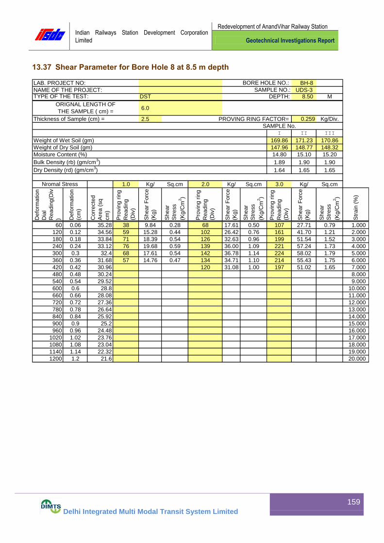
Indian Railways Station Development Corporation
Limited
Redevelopment of AnandVihar Railway Station
Geotechnical Investigations Report
Delhi Integrated Multi Modal Transit System Limited
159
13.37 Shear Parameter for Bore Hole 8 at 8.5 m depth
BH-8
UDS-3DST DEPTH: 8.50 M
6.0
2.5 PROVING RING FACTOR= 0.259 Kg/Div.
SAMPLE No.
I II III
Weight of Wet Soil (gm) 169.86 171.23 170.86
Weight of Dry Soil (gm) 147.96 148.77 148.32
Moisture Content (%) 14.80 15.10 15.20
Bulk Density (rb) (gm/cm3) 1.89 1.90 1.90
Dry Density (rd) (gm/cm3) 1.64 1.65 1.65
1.0 Kg/ Sq.cm 2.0 Kg/ Sq.cm 3.0 Kg/ Sq.cm
Defo
rmation
Dia
l
Readin
g(D
iv
) Defo
rmation
(cm
)
Corr
ecte
d
Are
a (
sq
cm
)
Pro
vin
g r
ing
Readin
g
(Div
)
Shear
Forc
e
(Kg)
Shear
Str
ess
(Kg/C
m2)
Pro
vin
g r
ing
Readin
g
(Div
)
Shear
Forc
e
(Kg)
Shear
Str
ess
(Kg/C
m2)
Pro
vin
g r
ing
Readin
g
(Div
)
Shear
Forc
e
(Kg)
Shear
Str
ess
(Kg/C
m2)
Str
ain
(%
)
0..00001 0..00001 0..00001 0.0001
60 0.06 35.28 38 9.84 0.28 68 17.61 0.50 107 27.71 0.79 1.000
120 0.12 34.56 59 15.28 0.44 102 26.42 0.76 161 41.70 1.21 2.000
180 0.18 33.84 71 18.39 0.54 126 32.63 0.96 199 51.54 1.52 3.000
240 0.24 33.12 76 19.68 0.59 139 36.00 1.09 221 57.24 1.73 4.000
300 0.3 32.4 68 17.61 0.54 142 36.78 1.14 224 58.02 1.79 5.000
360 0.36 31.68 57 14.76 0.47 134 34.71 1.10 214 55.43 1.75 6.000
420 0.42 30.96 120 31.08 1.00 197 51.02 1.65 7.000
480 0.48 30.24 8.000
540 0.54 29.52 9.000
600 0.6 28.8 10.000
660 0.66 28.08 11.000
720 0.72 27.36 12.000
780 0.78 26.64 13.000
840 0.84 25.92 14.000
900 0.9 25.2 15.000
960 0.96 24.48 16.000
1020 1.02 23.76 17.000
1080 1.08 23.04 18.000
1140 1.14 22.32 19.000
1200 1.2 21.6 20.000
Nromal Stress
SAMPLE NO.:NAME OF THE PROJECT:
LAB. PROJECT NO:
Thickness of Sample (cm) =
ORIGNAL LENGTH OF
THE SAMPLE ( cm) =
TYPE OF THE TEST:
BORE HOLE NO.:

Indian Railways Station Development Corporation
Limited
Redevelopment of AnandVihar Railway Station
Geotechnical Investigations Report
Delhi Integrated Multi Modal Transit System Limited
160
0.0
0.5
1.0
1.5
2.0
2.5
3.0
0.0 0.5 1.0 1.5 2.0 2.5 3.0 3.5 4.0
SH
EA
R
ST
RE
SS
( k
g/s
q.c
m )
NORMAL STRESS ( kg/sq.cm )
BORE HOLE NO.:BH-8 SAMPLE NO:UDS-3 DEPTH:8.50 m COHESION(C)= 0.00 kg/sq.cm ANGLE OF FRICTION(Phi): 31 deg TYPE OF TEST:DST
0.0
0.2
0.4
0.6
0.8
1.0
1.2
1.4
1.6
1.8
2.0
0 2 4 6 8 10 12 14 16 18 20
SH
EA
R S
TR
ES
S (
kg/s
q.c
m )
STRAIN (%)
1.0 Kg/ sq. cm2.0 Kg/sq. cm3.0 Kg/sq. cmSeries4
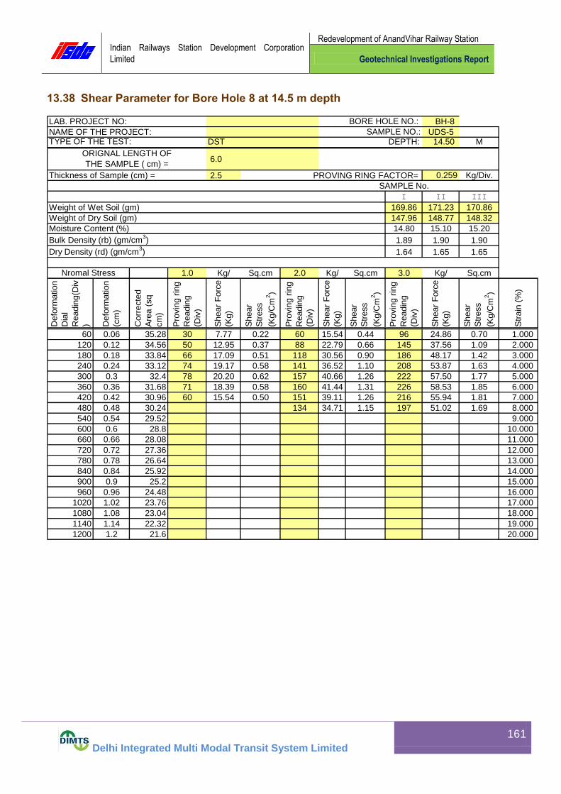
Indian Railways Station Development Corporation
Limited
Redevelopment of AnandVihar Railway Station
Geotechnical Investigations Report
Delhi Integrated Multi Modal Transit System Limited
161
13.38 Shear Parameter for Bore Hole 8 at 14.5 m depth
BH-8
UDS-5DST DEPTH: 14.50 M
6.0
2.5 PROVING RING FACTOR= 0.259 Kg/Div.
SAMPLE No.
I II III
Weight of Wet Soil (gm) 169.86 171.23 170.86
Weight of Dry Soil (gm) 147.96 148.77 148.32
Moisture Content (%) 14.80 15.10 15.20
Bulk Density (rb) (gm/cm3) 1.89 1.90 1.90
Dry Density (rd) (gm/cm3) 1.64 1.65 1.65
1.0 Kg/ Sq.cm 2.0 Kg/ Sq.cm 3.0 Kg/ Sq.cm
Defo
rmation
Dia
l
Readin
g(D
iv
) Defo
rmation
(cm
)
Corr
ecte
d
Are
a (
sq
cm
)
Pro
vin
g r
ing
Readin
g
(Div
)
Shear
Forc
e
(Kg)
Shear
Str
ess
(Kg/C
m2)
Pro
vin
g r
ing
Readin
g
(Div
)
Shear
Forc
e
(Kg)
Shear
Str
ess
(Kg/C
m2)
Pro
vin
g r
ing
Readin
g
(Div
)
Shear
Forc
e
(Kg)
Shear
Str
ess
(Kg/C
m2)
Str
ain
(%
)
0..00001 0..00001 0..00001 0.0001
60 0.06 35.28 30 7.77 0.22 60 15.54 0.44 96 24.86 0.70 1.000
120 0.12 34.56 50 12.95 0.37 88 22.79 0.66 145 37.56 1.09 2.000
180 0.18 33.84 66 17.09 0.51 118 30.56 0.90 186 48.17 1.42 3.000
240 0.24 33.12 74 19.17 0.58 141 36.52 1.10 208 53.87 1.63 4.000
300 0.3 32.4 78 20.20 0.62 157 40.66 1.26 222 57.50 1.77 5.000
360 0.36 31.68 71 18.39 0.58 160 41.44 1.31 226 58.53 1.85 6.000
420 0.42 30.96 60 15.54 0.50 151 39.11 1.26 216 55.94 1.81 7.000
480 0.48 30.24 134 34.71 1.15 197 51.02 1.69 8.000
540 0.54 29.52 9.000
600 0.6 28.8 10.000
660 0.66 28.08 11.000
720 0.72 27.36 12.000
780 0.78 26.64 13.000
840 0.84 25.92 14.000
900 0.9 25.2 15.000
960 0.96 24.48 16.000
1020 1.02 23.76 17.000
1080 1.08 23.04 18.000
1140 1.14 22.32 19.000
1200 1.2 21.6 20.000
Nromal Stress
SAMPLE NO.:NAME OF THE PROJECT:
LAB. PROJECT NO:
Thickness of Sample (cm) =
ORIGNAL LENGTH OF
THE SAMPLE ( cm) =
TYPE OF THE TEST:
BORE HOLE NO.:

Indian Railways Station Development Corporation
Limited
Redevelopment of AnandVihar Railway Station
Geotechnical Investigations Report
Delhi Integrated Multi Modal Transit System Limited
162
0.0
0.5
1.0
1.5
2.0
2.5
3.0
0.0 0.5 1.0 1.5 2.0 2.5 3.0 3.5 4.0
SH
EA
R
ST
RE
SS
( k
g/s
q.c
m )
NORMAL STRESS ( kg/sq.cm )
BORE HOLE NO.:BH-8 SAMPLE NO:UDS-5 DEPTH:14.50 m COHESION(C)= 0.00 kg/sq.cm ANGLE OF FRICTION(Phi): 32 deg TYPE OF TEST:DST
0.0
0.2
0.4
0.6
0.8
1.0
1.2
1.4
1.6
1.8
2.0
0 2 4 6 8 10 12 14 16 18 20
SH
EA
R S
TR
ES
S (
kg/s
q.c
m )
STRAIN (%)
1.0 Kg/ sq. cm2.0 Kg/sq. cm3.0 Kg/sq. cmSeries4

Indian Railways Station Development Corporation
Limited
Redevelopment of AnandVihar Railway Station
Geotechnical Investigations Report
Delhi Integrated Multi Modal Transit System Limited
163
13.39 Shear Parameter for Bore Hole 8 at 20.5 m depth
LAB. PROJECT NO: BORE HOLE NO: BH-8
NAME OF THE PROJECT: SAMPLE NO.: UDS-7
TYPE OF THE TEST: U U T DEPTH: 20.50 M
REMARKS:
ORIGNAL LENGTH OF TH SAMPLE= 7.5 cm PROVING RING FACTOR= 0.25 Kg/Div.
SAMPLE No.
I II III
Weight of Wet Soil (gm) 150.87 152.19 151.85
Weight of Dry Soil (gm) 127.37 128.05 127.71
Moisture Content (%) 18.45 18.85 18.90
Bulk Density (rb) (gm/cm3) 1.76 1.78 1.78
Dry Density (rd) (gm/cm3) 1.49 1.50 1.49
CELL PRESSURE 1.0 Kg/ Sq.cm 2.0 Kg/ Sq.cm 3.0 Kg/ Sq.cm
Sta
in D
ial
Readin
g(D
iv
) Sta
in(%
)
Are
a(C
m2)
Pro
vin
g r
ing
Readin
g(D
iv
) Axia
l Load
(Kg)
Str
ess
(kg/C
m2)
Pro
vin
g r
ing
Readin
g(D
iv
) Axia
l Load
(Kg)
Str
ess
(kg/C
m2)
Pro
vin
g r
ing
Readin
g(D
iv
) Axia
l Load
(Kg)
Str
ess
(kg/C
m2)
0.0001 0..00001 0..00001 0..00001
75 1 11.52 36 9.00 0.78 58 14.50 1.26 72 18.00 1.56
150 2 11.64 56 14.00 1.20 87 21.75 1.87 97 24.25 2.08
225 3 11.76 75 18.75 1.59 110 27.50 2.34 118 29.50 2.51
300 4 11.88 89 22.25 1.87 126 31.50 2.65 134 33.50 2.82
375 5 12.01 100 25.00 2.08 140 35.00 2.91 146 36.50 3.04
450 6 12.13 110 27.50 2.27 147 36.75 3.03 156 39.00 3.22
525 7 12.27 118 29.50 2.40 144 36.00 2.93 164 41.00 3.34
600 8 12.40 124 31.00 2.50 135 33.75 2.72 159 39.75 3.21
675 9 12.53 120 30.00 2.39 149 37.25 2.97
750 10 12.65 108 27.00 2.13
825 11 12.82
900 12 12.96
975 13 13.11
1050 14 13.26
1125 15 13.42
1200 16 13.58
1275 17 13.74
1350 18 13.91
1425 19 14.08
1500 20 14.26

Indian Railways Station Development Corporation
Limited
Redevelopment of AnandVihar Railway Station
Geotechnical Investigations Report
Delhi Integrated Multi Modal Transit System Limited
164
0.0
0.2
0.4
0.6
0.8
1.0
1.2
1.4
1.6
1.8
2.0
0.0 1.0 2.0 3.0 4.0 5.0 6.0 7.0
SH
EA
R S
TR
ES
S (
Kg/s
q.c
m )
PRINCIPAL STRESS ( Kg/sq.cm )
BORE HOLE NO.:BH-8
SAMPLE NO:UDS-7 DEPTH: 20.50 M
COHESION(C)= 0.85 kg/sq.cm
ANGLE OF FRICTION(Phi):10deg TYPE OF TEST:U U T
0.0
0.5
1.0
1.5
2.0
2.5
3.0
3.5
4.0
0 2 4 6 8 10 12 14 16 18 20
DE
VIA
TO
R S
TR
ES
S (
Kg/s
q.c
m )
STRAIN (%)
1.0 Kg/sq.cm
2.0 Kg/sq.cm
3.0 Kg/sq.cm

Indian Railways Station Development Corporation
Limited
Redevelopment of AnandVihar Railway Station
Geotechnical Investigations Report
Delhi Integrated Multi Modal Transit System Limited
165
13.40 Shear Parameter for Bore Hole 8 at 26.5 m depth
BH-8
UDS-9DST DEPTH: 26.50 M
6.0
2.5 PROVING RING FACTOR= 0.259 Kg/Div.
SAMPLE No.
I II III
Weight of Wet Soil (gm) 169.86 171.23 170.86
Weight of Dry Soil (gm) 147.96 148.77 148.32
Moisture Content (%) 14.80 15.10 15.20
Bulk Density (rb) (gm/cm3) 1.89 1.90 1.90
Dry Density (rd) (gm/cm3) 1.64 1.65 1.65
1.0 Kg/ Sq.cm 2.0 Kg/ Sq.cm 3.0 Kg/ Sq.cm
Defo
rmation
Dia
l
Readin
g(D
iv
) Defo
rmation
(cm
)
Corr
ecte
d
Are
a (
sq
cm
)
Pro
vin
g r
ing
Readin
g
(Div
)
Shear
Forc
e
(Kg)
Shear
Str
ess
(Kg/C
m2)
Pro
vin
g r
ing
Readin
g
(Div
)
Shear
Forc
e
(Kg)
Shear
Str
ess
(Kg/C
m2)
Pro
vin
g r
ing
Readin
g
(Div
)
Shear
Forc
e
(Kg)
Shear
Str
ess
(Kg/C
m2)
Str
ain
(%
)
0..00001 0..00001 0..00001 0.0001
60 0.06 35.28 25 6.48 0.18 57 14.76 0.42 98 25.38 0.72 1.000
120 0.12 34.56 43 11.14 0.32 94 24.35 0.70 161 41.70 1.21 2.000
180 0.18 33.84 63 16.32 0.48 129 33.41 0.99 210 54.39 1.61 3.000
240 0.24 33.12 74 19.17 0.58 149 38.59 1.17 231 59.83 1.81 4.000
300 0.3 32.4 78 20.20 0.62 156 40.40 1.25 236 61.12 1.89 5.000
360 0.36 31.68 71 18.39 0.58 147 38.07 1.20 223 57.76 1.82 6.000
420 0.42 30.96 60 15.54 0.50 130 33.67 1.09 204 52.84 1.71 7.000
480 0.48 30.24 8.000
540 0.54 29.52 9.000
600 0.6 28.8 10.000
660 0.66 28.08 11.000
720 0.72 27.36 12.000
780 0.78 26.64 13.000
840 0.84 25.92 14.000
900 0.9 25.2 15.000
960 0.96 24.48 16.000
1020 1.02 23.76 17.000
1080 1.08 23.04 18.000
1140 1.14 22.32 19.000
1200 1.2 21.6 20.000
Nromal Stress
SAMPLE NO.:NAME OF THE PROJECT:
LAB. PROJECT NO:
Thickness of Sample (cm) =
ORIGNAL LENGTH OF
THE SAMPLE ( cm) =
TYPE OF THE TEST:
BORE HOLE NO.:

Indian Railways Station Development Corporation
Limited
Redevelopment of AnandVihar Railway Station
Geotechnical Investigations Report
Delhi Integrated Multi Modal Transit System Limited
166
0.0
0.5
1.0
1.5
2.0
2.5
3.0
0.0 0.5 1.0 1.5 2.0 2.5 3.0 3.5 4.0
SH
EA
R
ST
RE
SS
( k
g/s
q.c
m )
NORMAL STRESS ( kg/sq.cm )
BORE HOLE NO.:BH-8 SAMPLE NO:UDS-9 DEPTH:26.50 m COHESION(C)= 0.00 kg/sq.cm ANGLE OF FRICTION(Phi): 33 deg TYPE OF TEST:DST
0.0
0.2
0.4
0.6
0.8
1.0
1.2
1.4
1.6
1.8
2.0
0 2 4 6 8 10 12 14 16 18 20
SH
EA
R S
TR
ES
S (
kg/s
q.c
m )
STRAIN (%)
1.0 Kg/ sq. cm2.0 Kg/sq. cm3.0 Kg/sq. cmSeries4

Indian Railways Station Development Corporation
Limited
Redevelopment of AnandVihar Railway Station
Geotechnical Investigations Report
Delhi Integrated Multi Modal Transit System Limited
167
14.0 Bore hole location plan
Annexure

Indian Railways Station Development Corporation
Limited
Redevelopment of AnandVihar Railway Station
Geotechnical Investigations Report
Delhi Integrated Multi Modal Transit System Limited
168
15.0 Bore Hole Images
Bore Hole Location BH - 1
Bore Hole Location BH - 2

Indian Railways Station Development Corporation
Limited
Redevelopment of AnandVihar Railway Station
Geotechnical Investigations Report
Delhi Integrated Multi Modal Transit System Limited
169
Bore Hole Location BH - 3
Bore Hole Location BH - 4
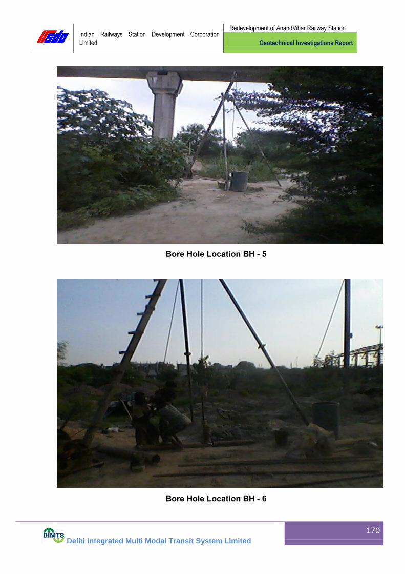
Indian Railways Station Development Corporation
Limited
Redevelopment of AnandVihar Railway Station
Geotechnical Investigations Report
Delhi Integrated Multi Modal Transit System Limited
170
Bore Hole Location BH - 5
Bore Hole Location BH - 6

Indian Railways Station Development Corporation
Limited
Redevelopment of AnandVihar Railway Station
Geotechnical Investigations Report
Delhi Integrated Multi Modal Transit System Limited
171
Bore Hole Location BH - 7
Bore Hole Location BH - 8

Indian Railways Station Development Corporation
Limited
Redevelopment of AnandVihar Railway Station
Geotechnical Investigations Report
Delhi Integrated Multi Modal Transit System Limited
172
Soil Samples

Indian Railways Station Development Corporation
Limited
Redevelopment of AnandVihar Railway Station
Geotechnical Investigations Report
Delhi Integrated Multi Modal Transit System Limited
173
16.0 RECOMMENDATIONS:
Depending on the field and laboratory observations of subsoil strata, test results and the type of structures proposed at site, the types of foundations, depths and net safe bearing capacities recommended for design purposes are given in the following table. The net SBC/API in the following table are the lower of the values obtained from shear failure criterion as per IS: 6403 and settlement failure criterion as per IS 8009, Part-I.
.
Type of
Foundation
Depth of
foundation
below
existing
ground
surface
(m)
Size of
Foundation
(m)
Net Safe Bearing Capacity/ Allowable
Pressure Intensity (T/m2)
In Shear In
Settlement
Recommended
Open spread
Isolated
(Square)
Footing
1.5
2.0 x 2.0
2.5 x 2.5
3.0 x 3.0
20.46
22.22
23.98
10.00
11.45
12.63
10.00
11.45
12.63
2.0
2.0 x 2.0
2.5 x 2.5
3.0 x 3.0
25.85
27.67
29.49
12.58
14.21
15.42
12.58
14.21
15.42
2.5
2.0 x 2.0
2.5 x 2.5
3.0 x 3.0
30.49
32.31
34.13
16.12
17.89
19.71
16.12
17.89
19.71
5.0 4.0 x 4.0 65.89 21.05 21.05
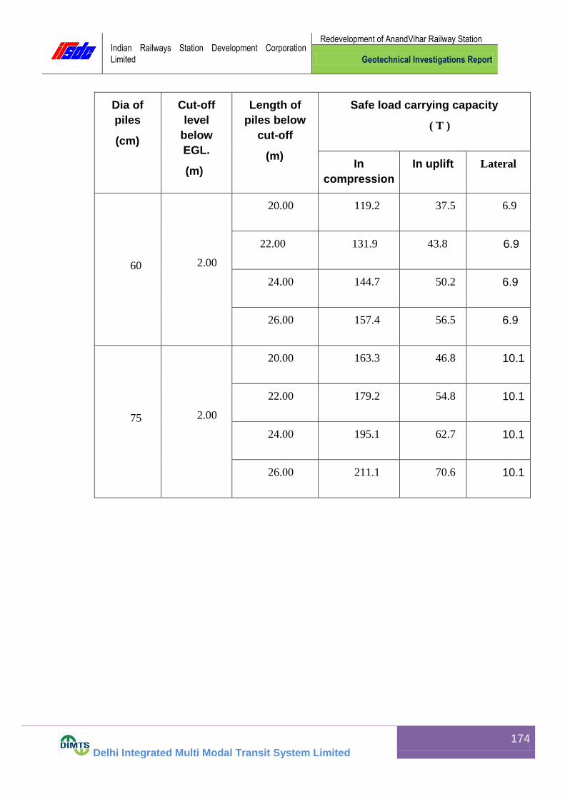
Indian Railways Station Development Corporation
Limited
Redevelopment of AnandVihar Railway Station
Geotechnical Investigations Report
Delhi Integrated Multi Modal Transit System Limited
174
Dia of
piles
(cm)
Cut-off
level
below
EGL.
(m)
Length of
piles below
cut-off
(m)
Safe load carrying capacity
( T )
In
compression
In uplift Lateral
60 2.00
20.00 119.2 37.5 6.9
22.00 131.9 43.8 6.9
24.00 144.7 50.2 6.9
26.00 157.4 56.5 6.9
75 2.00
20.00 163.3 46.8 10.1
22.00 179.2 54.8 10.1
24.00 195.1 62.7 10.1
26.00 211.1 70.6 10.1
Related Documents
![Grupo motor MTR-DCI...Manual MTR-DCI-...IO Manual 539 617 es 1201c [761 421] Grupo motor MTR-DCI](https://static.cupdf.com/doc/110x72/5f50b60cf149462795018d10/grupo-motor-mtr-manual-mtr-dci-io-manual-539-617-es-1201c-761-421-grupo.jpg)


![Motor unit MTR-DCI€¦ · Description MTR-DCI-...IO Description 539616 en 1209d [763197] Motor unit MTR-DCI](https://static.cupdf.com/doc/110x72/5f50cafd0ff31e4afa1c4f9b/motor-unit-mtr-dci-description-mtr-dci-io-description-539616-en-1209d-763197.jpg)


