Cobalt Digital Inc. OG3-FR Series openGear ® 2RU Frame and Power Supply User Manual OG3FR-OM (V1.1)

Welcome message from author
This document is posted to help you gain knowledge. Please leave a comment to let me know what you think about it! Share it to your friends and learn new things together.
Transcript

Cobalt Digital Inc.
OG3-FR SeriesopenGear® 2RU Frame and Power Supply
User Manual
OG3FR-OM (V1.1)

OG3-FR Series User Manual
• Part Number: OG3FR-OM• Release Date: September 5, 2014 .
The information contained in this manual is subject to change without notice or obligation.
Copyright
© 2014 Cobalt Digital Inc. All rights reserved.
Contents of this publication may not be reproduced in any form without the written permission ofCobalt Digital Inc. Reproduction or reverse engineering of copyrighted software is prohibited. Contentincluded here by permission.
Patents
This product is protected by the following US Patents: 4,205,346; 5,115,314; 5,280,346; 5,561,404;7,034,886; 7,508,455; 7,602,446; 7,834,886. This product is protected by the following CanadianPatents: 2039277; 1237518; 1127289. Other patents pending.
NoticeThe material in this manual is furnished for informational use only. It is subject to change withoutnotice and should not be construed as a commitment by Cobalt Digital Inc. Cobalt Digital Inc. assumesno responsibility or liability for errors or inaccuracies that may appear in this manual.
Trademarks
• is a registered trademark of Ross Video Limited.
• is a registered trademark of Cobalt Digital Inc.• DashBoard Control System™ is a trademark of Ross Video Limited.• All other product names and any registered and unregistered trademarks mentioned in this
manual are used for identification purposes only and remain the exclusive property oftheir respective owners.

Important Regulatory and Safety NoticesBefore using this product and any associated equipment, refer to the “Important Safety Instructions”listed below so as to avoid personnel injury and to prevent product damage.
Products may require specific equipment, and /or installation procedures be carried out to satisfycertain regulatory compliance requirements. Notices have been included in this publication to callattention to these Specific requirements.
Symbol Meanings
This symbol on the equipment refers you to important operating andmaintenance (servicing) instructions within the Product ManualDocumentation. Failure to heed this information may present a major risk ofdamage or injury to persons or equipment.
Warning — The symbol with the word “Warning” within the equipmentmanual indicates a potentially hazardous situation, which if not avoided, couldresult in death or serious injury.
Caution — The symbol with the word “Caution” within the equipment manualindicates a potentially hazardous situation, which if not avoided, may result inminor or moderate injury. It may also be used to alert against unsafepractices.
Notice — The symbol with the word “Notice” within the equipment manualindicates a situation, which if not avoided, may result in major or minorequipment damage or a situation which could place the equipment in a non-compliant operating state.
Warning Hazardous Voltages — This symbol is intended to alert the user tothe presence of uninsulated "dangerous voltage" within the product enclosurethat may be of sufficient magnitude to constitute a risk of shock to persons.
ESD Susceptibility — This symbol is used to alert the user that an electricalor electronic device or assembly is susceptible to damage from an ESDevent.
This symbol on the equipment indicates for use at altitudes of 2000m or less.
Important Safety InstructionsRead these instructions.
Keep these instructions.
Heed all warnings.
Follow all instructions.
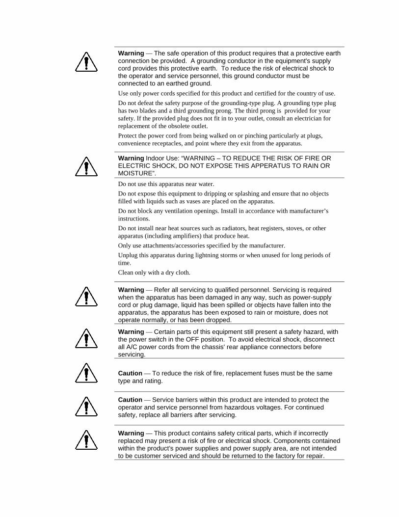
Warning — The safe operation of this product requires that a protective earthconnection be provided. A grounding conductor in the equipment's supplycord provides this protective earth. To reduce the risk of electrical shock tothe operator and service personnel, this ground conductor must beconnected to an earthed ground.
Use only power cords specified for this product and certified for the country of use.
Do not defeat the safety purpose of the grounding-type plug. A grounding type plughas two blades and a third grounding prong. The third prong is provided for yoursafety. If the provided plug does not fit in to your outlet, consult an electrician forreplacement of the obsolete outlet.
Protect the power cord from being walked on or pinching particularly at plugs,convenience receptacles, and point where they exit from the apparatus.
Warning Indoor Use: “WARNING – TO REDUCE THE RISK OF FIRE ORELECTRIC SHOCK, DO NOT EXPOSE THIS APPERATUS TO RAIN ORMOISTURE”.
Do not use this apparatus near water.
Do not expose this equipment to dripping or splashing and ensure that no objectsfilled with liquids such as vases are placed on the apparatus.
Do not block any ventilation openings. Install in accordance with manufacturer’sinstructions.
Do not install near heat sources such as radiators, heat registers, stoves, or otherapparatus (including amplifiers) that produce heat.
Only use attachments/accessories specified by the manufacturer.
Unplug this apparatus during lightning storms or when unused for long periods oftime.
Clean only with a dry cloth.
Warning — Refer all servicing to qualified personnel. Servicing is requiredwhen the apparatus has been damaged in any way, such as power-supplycord or plug damage, liquid has been spilled or objects have fallen into theapparatus, the apparatus has been exposed to rain or moisture, does notoperate normally, or has been dropped.
Warning — Certain parts of this equipment still present a safety hazard, withthe power switch in the OFF position. To avoid electrical shock, disconnectall A/C power cords from the chassis' rear appliance connectors beforeservicing.
Caution — To reduce the risk of fire, replacement fuses must be the sametype and rating.
Caution — Service barriers within this product are intended to protect theoperator and service personnel from hazardous voltages. For continuedsafety, replace all barriers after servicing.
Warning — This product contains safety critical parts, which if incorrectlyreplaced may present a risk of fire or electrical shock. Components containedwithin the product’s power supplies and power supply area, are not intendedto be customer serviced and should be returned to the factory for repair.

Warning — This product contains an “Ethernet Port” which allows thisproduct to be connected to a local network (LAN). Only connect to networksthat remain inside the building. Do not connect to networks that go outsidethe building.
EMC Notices
US FCC Part 15
This equipment has been tested and found to comply with the limits for a class A Digital device,pursuant to part 15 of the FCC Rules. These limits are designed to provide reasonable protectionagainst harmful interference when the equipment is operated in a commercial environment. Thisequipment generates, uses, and can radiate radio frequency energy and, if not installed and used inaccordance with the instruction manual, may cause harmful interference to radio communications.Operation of this equipment in a residential area is likely to cause harmful interference in which caseusers will be required to correct the interference at their own expense.
Notice — Changes or modifications to this equipment not expresslyapproved by Cobalt Digital Inc. Ltd. could void the user’s authority to operatethis equipment.
CANADAThis Class “A” digital apparatus complies with Canadian ICES-003.
Cet appareil numerique de classe “A” est conforme à la norme NMB-003 du Canada.
EUROPEThis equipment is in compliance with the essential requirements and other relevant provisions of CEDirective 93/68/EEC.
INTERNATIONALThis equipment has been tested to CISPR 22:1997 along with amendments A1:2000 and A2:2002 andfound to comply with the limits for a Class A Digital device.
Notice — This is a Class A product. In domestic environments this productmay cause radio interference in which case the user may have to takeadequate measures.
Maintenance/User Serviceable Parts
Routine maintenance to this product is not required. This product contains no user serviceable parts. Ifthe frame does not appear to be working properly, please contact Technical Support using the numberslisted under the “Contact Us” section on the last page of this manual.

Environmental Information
The equipment that you purchased required the extraction and use of natural resources for itsproduction. It may contain hazardous substances that could impact health and the environment.
To avoid the potential release of those substances into the environment and to diminish the need for theextraction of natural resources, Cobalt Digital Inc. encourages you to use the appropriate take-backsystems. These systems will reuse or recycle most of the materials from your end-of-life equipment inan environmentally friendly and health conscious manner.The crossed-out wheeled bin symbol invites you to use these systems.
If you need more information on the collection, reuse, and recycling systems, please contact your localor regional waste administration.

OG3-FR Series User Manual (V1.1) Contents •••• i
ContentsIntroduction 1-1
In This Chapter .......................................................................................................................1-1A Word of Thanks ....................................................................................................1-1
Overview.................................................................................................................................1-2Modular Frame Architecture ....................................................................................1-2Robust Power Supply with Redundancy Option.......................................................1-2Cooling .....................................................................................................................1-2Additional Frame Accessories ..................................................................................1-2
Features...................................................................................................................................1-3Documentation Terms and Conventions .................................................................................1-4
Installation 2-1In This Chapter .......................................................................................................................2-1Before You Begin ...................................................................................................................2-2
Static Discharge........................................................................................................2-2Unpacking.................................................................................................................2-2
Installing a Frame ...................................................................................................................2-3Overview ..................................................................................................................2-3OG3-FR Series Frame Mounting Requirements.......................................................2-3
Installing the Rear Support Bars and Brackets........................................................................2-4Installing the FSB-OG3 ............................................................................................2-4
Front Panel Overview .............................................................................................................2-6Rear Panel Overview ..............................................................................................................2-7Power Supplies and Power Cable ...........................................................................................2-9
Required Power Supplies..........................................................................................2-9Power Supply Connectors (PSU1, PSU2) ................................................................2-9Installing the Frame Power Supply...........................................................................2-9Power Cable Connection ........................................................................................2-10
Ethernet Connections ............................................................................................................2-11OG3-FR Series Frames...........................................................................................2-11
Monitoring ............................................................................................................................2-12OG3-FR Monitoring Features.................................................................................2-12
Ventilation and Cooling........................................................................................................2-13Overview ................................................................................................................2-13
Installing a Rear Module.......................................................................................................2-14OG3-FR Series Setup............................................................................................................3-18In This Chapter .....................................................................................................................3-18GFC-8322 and Reference Overview.....................................................................................3-19Installing the Controller Card ...............................................................................................3-20
Ethernet Setup ........................................................................................................3-20Functions of the Network Controller Card .............................................................3-20Controls and LEDs for the Network Controller Card .............................................3-20Setting Network Controller Card to Mute Audible Alarms ....................................3-23DashBoard and DashBoard Lite Control System Software ....................................3-23SNMP Monitoring and Control ..............................................................................3-23
Using the LCD Diagnostic Panel ..........................................................................................3-25

ii •••• Contents OG3-FR Series User Manual (V11.1
Using the Toggle Button.........................................................................................3-25Fan Filter Maintenance .........................................................................................................3-26
Cleaning the Frame Air Filter .................................................................................3-26Replacing the Frame Air Filter ...............................................................................3-27
Replacing the Cooling Fan Module ......................................................................................3-28Replacing the CFM-OG3 Cooling Fan Module......................................................3-28
Specifications for the OG3-FR Series Frames ......................................................................3-29Service Information...............................................................................................................6-30In This Chapter .....................................................................................................................6-30Troubleshooting Checklist ....................................................................................................6-31Warranty and Repair Policy..................................................................................................6-32Ordering Information ............................................................................................................7-33Contact Cobalt Digital Inc. ...................................................................................................7-34Visit us at the Cobalt Digital Inc. website. ............................................................................7-34

OG3-FR Series User Manual (V1.1) Introduction •••• 1-1
Introduction
In This ChapterThis chapter contains the following sections:
• Overview
• Features
• Documentation Terms and Conventions
A Word of ThanksCongratulations on choosing the OG3-FR 2RU Frame and Power Supply. The Cobalt Digital Inc.openGear® line includes video decoders and encoders, audio embedders and de-embedders,distribution amplifiers, format converters, and much more. Cobalt Digital Inc. openGear® modularconversion gear will meet your signal conversion needs now, and well into the future.
Should you have questions or concerns pertaining to the installation or operation of your frame, pleasecontact Cobalt Digital Inc. (Contact information is supplied on the back cover of this manual.) Ourtechnical staff is always available for consultation, training, or service.

1-2 •••• Introduction OG3-FR Series User Manual (V1.1)
OverviewYour openGear frame is a 2RU modular frame, designed to accommodate openGear cards. A completelist of available openGear cards is available on our website.
Modular Frame ArchitectureThe openGear frame supports module-dependent rear modules. Rear modules can be ordered withcards, and are easy and quick to install.
OG3-FR Series Frames
The OG3-FR series frames offers the flexibility of independent rear modules for connectivity to awide array of interfaces such as BNC, twisted-pair audio, and fiber. Using the split rear module allowsfor up to 20 cards to be installed (noting maximum user net power of 300W limit).
Note that cards and rear modules designed for the 8321 series frames are also supported by theOG3-FR series frames. However, some cards and rear modules may be designed specifically for theOG3-FR series frames only. Refer to the documentation for your openGear card for details on theframes you can use.
Robust Power Supply with Redundancy OptionThe openGear frame can accommodate two front-loaded power supplies. However, each frame comesstandard with one power supply. Although a single power supply can fully power a loaded frame, theaddition of a second (optional) power supply gives the frame full power redundancy. Each powersupply is fed by a separate power cord, which is held in position to guard against accidental power loss.
CoolingThe openGear frame has been designed with an advanced cooling architecture to increase ventilation.An intelligent fan controller adjusts fan speed with changes in frame power loading. Particular attentionhas been paid to frame acoustics in order to keep fan noise to a minimum.
The OG3-FR series frame is designed with front-door mounted fans to provide forced air cooling for allcards, and additional cooling for the power supplies.
Additional Frame AccessoriesTo help reduce mechanical stress due to cable weight, a rear frame support bracket is available for theframes.
Available Rear Support Brackets
Frame Model Rear Support Bracket
OG3-FR FSB-OG3

OG3-FR Series User Manual (V1.1) Introduction •••• 1-3
FeaturesThe following standard features make our openGear frames the best solution for standard and highdefinition terminal equipment:
• Two independent looping reference inputs feed all card slots
• Can house any mix of analog, digital, video and audio cards in the same frame
• Available with individual card specific modules for connector flexibility
• Optional redundant power supply is hot-swappable for 24/7 operation
• Power switch is accessible from front of the rack frame
• Power supplies are replaceable from the front of the frame without requiring rear-frame access
• Separate power cords to each supply for power feed redundancy
• PowerLock cord retainer mechanism guards against accidental power loss
• Durable powder-coat paint finish
• Removable hinged front door for easy card insertion and removal, and flexibility inservicing the cooling fans
• Optional Ethernet based Frame Controller for remote setup, monitoring, and control
In addition to the standard features, the following additional features are available on the OG3-FRseries frames:
• Aluminum and steel construction to reduce weight and increase strength
• 2RU Frame houses up to 20 cards, dissipating up to 15W per slot
• Robust power supply (300W user net) with two integral cooling fans per powersupply
• Comes standard with the Cooling Fan Module for increased ventilation and enhancedreliability
• Supports Gigabit Ethernet connectivity to each openGear card in the frame (requiresthe optional MFC-8322-N Network Controller Card)
• Supports all existing rear modules designed for the 8321 series frames
• Provides a system alarm LED on the frame front door
• Provides an LCD Diagnostic Panel on frame front that reports the frame name, andIP address; provides the ability to scroll through these reported error/statusconditions
• Removable door with durable powder-coat paint finish

1-4 •••• Introduction OG3-FR Series User Manual (V1.1)
Documentation Terms and ConventionsThe following terms and conventions are used throughout this manual.
Terms
The following terms are used:
• “20-slot frames” refers to OG3-FR and 8321 series frames and any available optionsunless otherwise noted.
• “Board”, and “Card” refer to openGear terminal devices within openGear frames,including all components and switches.
• “Frame” refers to any openGear frame within your video system.
• “MFC-8322-N” refers to the MFC-8322-N and MFC-8322-NS unless otherwiseindicated.
• “Network Controller Card” refers to the MFC-8322-S, MFC-8322-N, and MFC-8322-NS unless otherwise indicated.
• “openGear frame” refers to an openGear® High Density Multi-Definition Frame.
• “Operator” and “User” refer to the person who uses the OG3-FR series frame.
• “PSU1” refers to Power Supply Unit 1 (primary) of the frame.
• “PSU2” refers to Power Supply Unit 2 (secondary) of the frame.
• “System” and “Video system” refer to the mix of interconnected production andterminal equipment in your environment.
Conventions
The following conventions are used:
• The “Operating Tips” and “Note” boxes are used to provide additional userinformation.

OG3-FR User Manual (V1.1) 2-1
Installation
In This ChapterThis chapter provides basic instructions for installing the openGear frames.
The following topics are discussed:
• Before You Begin
• Installing an OG3-FR Series Frame
• Installing the Rear Support Bars and Brackets
• Front Panel Overview
• Rear Panel Overview
• Power Supply and Power Cables
• Ethernet Connections
• Monitoring
• Ventilation and Cooling
• Installing a Rear Module
• Installing an openGear Card
2-2 •••• Installation OG3-FR User Manual •••• (V1.1)
Before You BeginBefore proceeding with the instructions in this chapter, ensure that you read the following sections.
Static DischargeThroughout this chapter, please heed the following cautionary note:
ESD Susceptibility — Static discharge can cause serious damage to sensitivesemiconductor devices. Avoid handling circuit boards in high static environmentssuch as carpeted areas, and when wearing synthetic fiber clothing. Alwaysexercise proper grounding precautions when working on circuit boards and relatedequipment.
UnpackingUnpack each openGear frame you received from the shipping container and ensure that all items areincluded. If any items are missing or damaged, contact your sales representative or Cobalt Digital Inc.directly.

OG3-FR User Manual (V1.1) 2-3
Installing a FrameThis section outlines how to install an openGear frame. The same procedure is used to install a frameregardless of the model of frame unless otherwise noted.
OverviewThe openGear frame mounts in the rack frame by means of four rack screws fastened through the frontmounting ears. This should normally be sufficient to carry the load, including the weight ofaccompanying cables. However, in certain applications such as mobile truck installations, it may bedesirable to also support the rear of the frame. The optional Rear Support Bars and Brackets arespecifically engineered to compensate for extra load stress. Refer to the section “Installing RearSupport Bars and Brackets” for bracket installation instructions.
Installation Requirements
Keep the following in mind when installing your frame:
• Install the frame for maximum stability during operating and in such a way as toallow adequate ventilation.
• The frame cannot be sealed in a closed container and must be installed in free airspace where the ambient temperature is monitored and controlled to not exceed 40°C(104°F) at the frame front door airflow intake.
• Ensure that adequate space exists in front and behind the frame and on both sides ofthe frame for airflow exhaust.
• The location of the frame should be accessible, dry, and dust-free.
Frame Dimensions
Note that each openGear frame installs in a standard 19” rack.
Frame Dimensions
Frame Rack Units Height Depth Width
OG3-FR 2 RU 3.5” (8.89cm) 17.7” (45cm) 19” (48.26cm)
OG3-FR Series Frame Mounting RequirementsUnder some conditions, the ambient air temperature inside rack-mount cabinets can be greater that theambient temperature within a room. For safe long term reliability, ensure the ambient air temperaturesat the OG3-FR series frame front intake area are within the product’s specified operating temperaturerange. Adequate ventilation within a rack frame must also be maintained. Ensure to adhere to thefollowing clearance recommendations:
• Minimum 2” (5.08cm) clearance both right and left-hand side of the chassis sides withunrestricted vertical airflow.
• Minimum 5” (12.7cm) clearance at the chassis rear with unrestricted vertical airflow..

2-4 •••• Installation OG3-FR User Manual •••• (V1.1)
Installing the Rear Support Bars and BracketsUnder normal conditions, mounting the frame to the front of the rack with four rack screws should besufficient to carry the load, including the weight of accompanying cables. The optional Rear SupportBars and Brackets are specifically engineered to compensate for extra load stress associated withcertain applications, such as mobile truck installations, to also support the rear of the frame.
Installing the FSB-OG3This section describes how to attach the FSB-OG3 rear support bars to a OG3-FR series frame.
To install the FSB-OG3
1. Attach the Rack Mount Arms of the FSB-OG3 to the OG3-FR series frame.
Installing a Rack Mount Arm
2. Install the Rail Guides for each Rack Mount Arm.
Installing a Rail Guide
OG3-FR User Manual (V1.1) 2-5
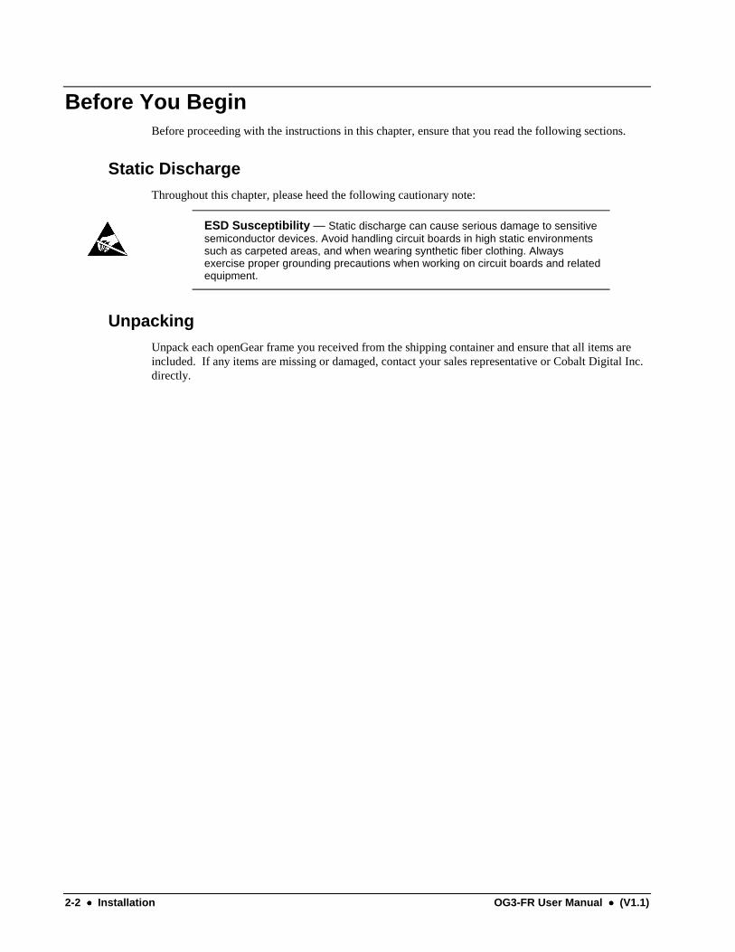
3. Secure the Rail Guides and Rack Mount Arms to the rack.
Installing the Hex Nuts
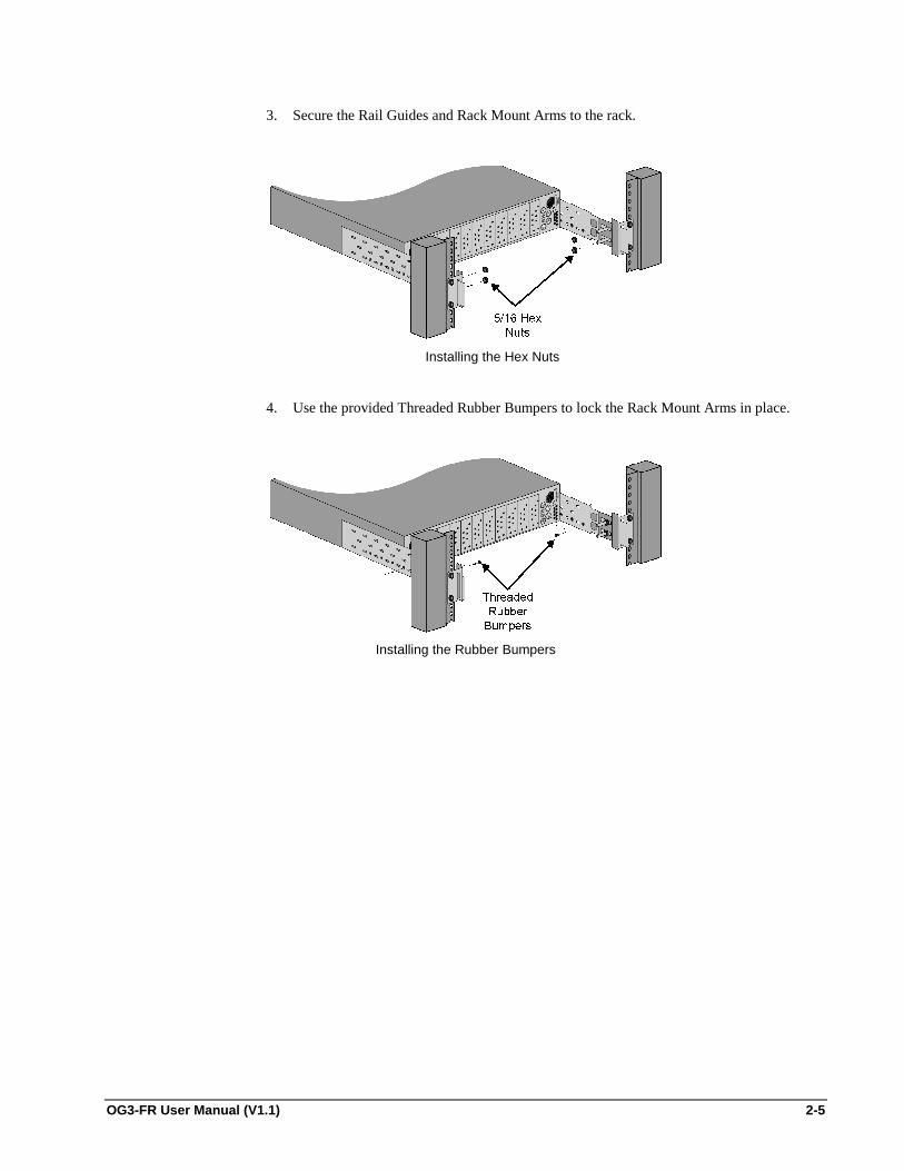
4. Use the provided Threaded Rubber Bumpers to lock the Rack Mount Arms in place.
Installing the Rubber Bumpers

2-6 •••• Installation OG3-FR User Manual •••• (V1.1)
Front Panel OverviewThe openGear frames provide monitoring features on the front door. This section briefly summarizesthe controls available on each frame model.
OG3-FR Series Frames — Front Panel
1. Diagnostic Panel 3. Door Tabs
2. STATUS/ALARM LED
1. Diagnostic Panel
This area includes a two-line LCD Diagnostic Panel, and a toggle button. The diagnostic paneldisplays the following information in a scrolling format:
• The top line in the display cycles through the name assigned to the frame in DashBoardand the current IP address of the frame (or 0.0.0.0 if none available). The IP address isconfigured on the MFC-8322-N Network Controller Card.
• The second line reports errors or alarm conditions from any source. This includes fanfailure alarms, power supply warnings, or errors reported by the cards installed in theframe. Messages are listed starting with the most recent.
Use the toggle button is used to cycle through the messages on the diagnostic panel when multipleerrors are occurring. It also mutes the audio alarm..
2. STATUS/ALARM LED
Refer to the section “OG3-FR Monitoring Features” for details on this LED.
3. Door Tabs
These tabs enable you to open the frame door and gain access to the interior of the frame. Analarm is raised when the frame door is opened longer than 5 minutes.
For More Information on…
• LCD Diagnostic Panel, refer to the section “Using the LCD Diagnostic Panel”.

OG3-FR User Manual (V1.1) 2-7
Rear Panel OverviewThe rear panel provides the communication connectors for the openGear frame control and frame-widereferences. The section summarizes the components available on the rear panels.
OG3-FR Series Frames — Rear Panel
1. PSU1 Power Supply Connector 3. Ethernet Communication Port
2. PSU2 Power Supply Connector 4. Reference Connectors
1. PSU1 Power Supply Connector
This connector is the AC Connector for the main power supply.
2. Power Supply Connector
This connector is the AC Connector for the redundant power supply.
3. Ethernet Communication Port
This Ethernet port is an RJ45 connector is used to connect the optional MFC-8322-N NetworkController card to an external Ethernet network. This Network Controller Card is required tobridge the external Ethernet network to the local communication bus for monitoring and control ofcards installed in the OG3-FR series frames. Only cards having the Communication bus interfacewill be able to be monitored and controlled this way.

2-8 •••• Installation OG3-FR User Manual •••• (V1.1)
4. Reference Connectors
Two sets of looping BNC inputs are provided to accept two independent reference signalssupporting the following reference signal types:
• Analog black
• Tri-level sync
• AES/DARS reference
This feature distributes one or two reference signals to all cards in the frame. Cards which need anexternal reference use this master reference signal in place of taking the signal from one of the cardBNCs. This provides for ease of installation and reduction in reference cabling requirements. Ifthis signal is required, it will be mentioned in the user documentation for your openGear card.
If only one reference type is required for the frame, connect it to the REF 1 BNC. If the referenceis not being looped to another frame or device, ensure that the Loop Ref BNC is terminated witha 75ohm terminator.

OG3-FR User Manual (V1.1) 2-9
Power Supplies and Power CableThe openGear frame comes standard with one power supply, with a second optional power supplyavailable for redundancy. For redundancy, and in applications where the equipment is used in a criticalsignal path, we recommend that two power supplies be used in the openGear frame. One A/C powercable has been provided with each power supply ordered.
For further redundancy, each power cord should be connected to a separate power source for protectionagainst failure of the A/C power circuit. In the event of one power supply failure, the frame load isseamlessly transferred to the other redundant power supply. Although the power supply is “hot-swappable” turning the power supply off before inserting or removing it from the frame will increasethe life span of the connectors.
Required Power SuppliesThe OG3-FR uses the PS-OG3 power supply.
Power Supply Connectors (PSU1, PSU2)There are two power supply connectors located on the back of the openGear frame:
• PSU1 — This connector is designated as the AC Connector for the main power supply.
• PSU2 — This connector is designated as the AC Connector for the redundant powersupply.
Installing the Frame Power SupplyThe PS-OG3 is an auto-sensing supply, capable of working with all world AC standards (100-240V).Each supply has an indicator LED on the front, and an error detection circuit that will indicate theconditions.The PS-OG3 power supplies install on the right and left sides of the OG3-FR series chassis.
To install the power supply
1. Carefully unpack the power supply from its box, and retain all packing material forfuture use, if required.
2. Align the power supply into an unused power slot on the right side of the frame.
3. Push the power supply in firmly to ensure a tight connection at the rear of the frame.

2-10 •••• Installation OG3-FR User Manual •••• (V1.1)
Power Cable ConnectionThis section includes information for connecting the power cables for the openGear frames.
Warning Hazardous Voltages — The safe operation of this productrequires that a protective earth connection be provided. This protective earth isprovided by the grounding conductor in the equipment's supply cord. To reduce therisk of electrical shock to operator and service personnel, this ground conductormust be connected to an earthed ground.
Warning — In some countries, it may be necessary to supply the correct mainssupply cord. Use only an approved IEC 320 C-13 type A/C line cord rated for aminimum 10A at 250V and certified for the country of use.
To connect the power cables for an openGear frame
1. Connect the cable's female IEC connector to the frame socket marked PSU 1.
2. If the Redundant Power Supply option is installed, plug the second IEC connector intoPSU 2.
3. Each AC connector includes a PowerLock, which is designed to retain the power cableconnector. Clip the PowerLock over the shoulder of the inserted AC cable end.
4. Connect the supplied power cable’s three-prong male connector to an AC outlet.
OG3-FR User Manual (V1.1) 2-11
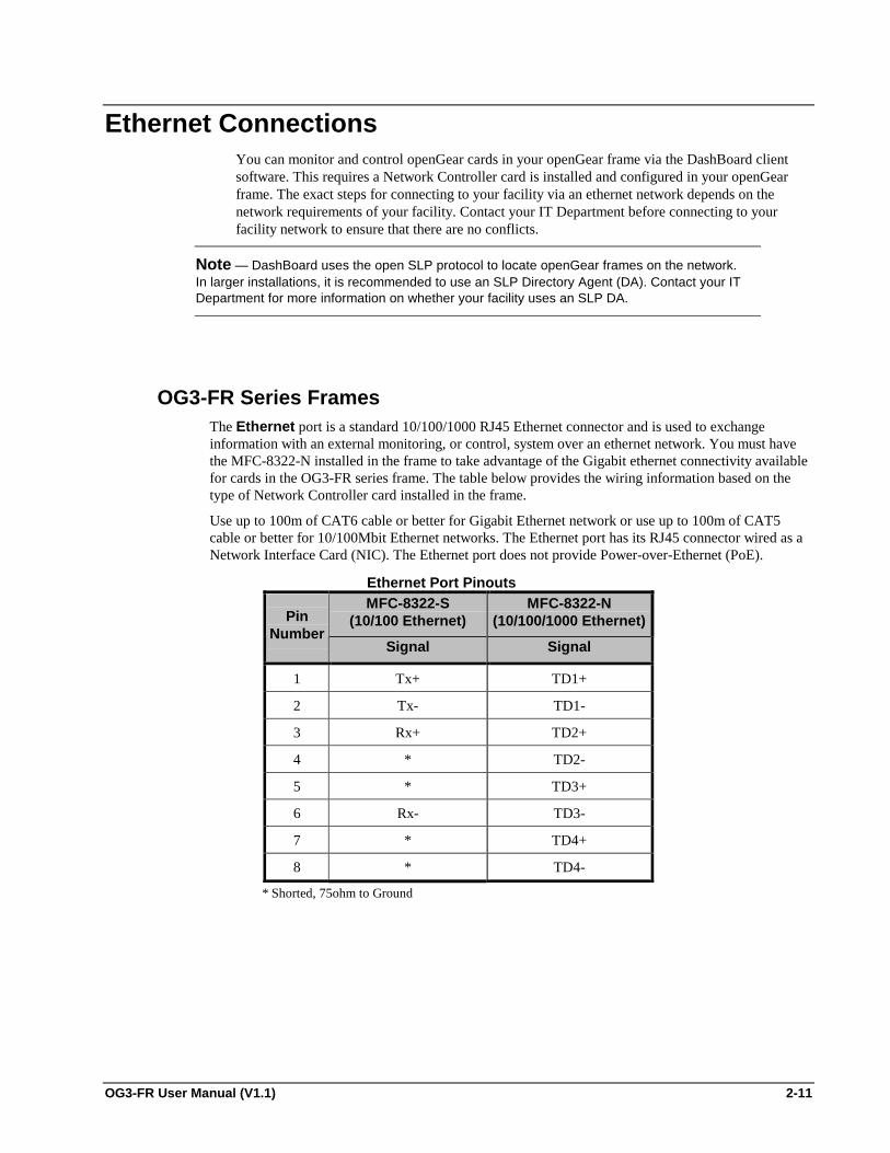
Ethernet ConnectionsYou can monitor and control openGear cards in your openGear frame via the DashBoard clientsoftware. This requires a Network Controller card is installed and configured in your openGearframe. The exact steps for connecting to your facility via an ethernet network depends on thenetwork requirements of your facility. Contact your IT Department before connecting to yourfacility network to ensure that there are no conflicts.
Note — DashBoard uses the open SLP protocol to locate openGear frames on the network.In larger installations, it is recommended to use an SLP Directory Agent (DA). Contact your ITDepartment for more information on whether your facility uses an SLP DA.
OG3-FR Series FramesThe Ethernet port is a standard 10/100/1000 RJ45 Ethernet connector and is used to exchangeinformation with an external monitoring, or control, system over an ethernet network. You must havethe MFC-8322-N installed in the frame to take advantage of the Gigabit ethernet connectivity availablefor cards in the OG3-FR series frame. The table below provides the wiring information based on thetype of Network Controller card installed in the frame.
Use up to 100m of CAT6 cable or better for Gigabit Ethernet network or use up to 100m of CAT5cable or better for 10/100Mbit Ethernet networks. The Ethernet port has its RJ45 connector wired as aNetwork Interface Card (NIC). The Ethernet port does not provide Power-over-Ethernet (PoE).
Ethernet Port PinoutsMFC-8322-S
(10/100 Ethernet)MFC-8322-N
(10/100/1000 Ethernet)PinNumber
Signal Signal
1 Tx+ TD1+
2 Tx- TD1-
3 Rx+ TD2+
4 * TD2-
5 * TD3+
6 Rx- TD3-
7 * TD4+
8 * TD4-
* Shorted, 75ohm to Ground

2-12 •••• Installation OG3-FR User Manual •••• (V1.1)
MonitoringThis section briefly summarizes the LEDs located on the frame doors that provide monitoring features.
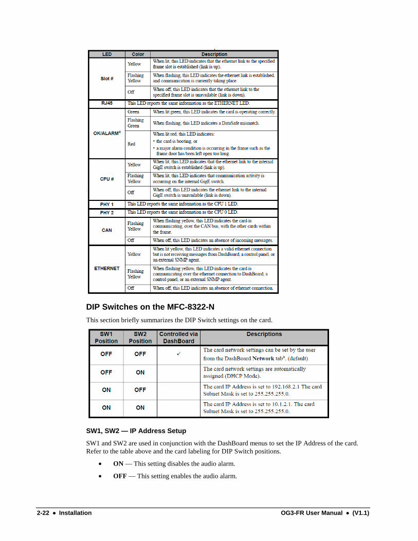
OG3-FR Monitoring FeaturesThe table below outlines the LED located on the frame door below the LCD Diagnostic Panel.
Status LED Descriptions
LED Location Color Description
GreenWhen lit green, this LED indicates correct operation, and noerrors or alarms are occurring.
Red
When lit red, this LED indicates than alarm condition ispresent. This can be caused by a fan failure, power supplyproblem, or a missing GFC-8322 card. In some cases, certaincards can trigger the door alarm under specific conditions.
Frame Door
OffWhen off, this LED indicates that no power is going to thedoor.
OG3-FR User Manual (V1.1) 2-13
Ventilation and CoolingYour frame was specially engineered to minimize internal heat buildup and thus improve cardreliability. For information on the power dissipation of openGear cards, refer to the user manual foryour card.
OverviewFor applications using less than 40W in a non-ventilated openGear frame, but where the individual cardpower consumption is greater than 8W, the cards should be evenly distributed in the frame. This willprevent the creation of concentrated heat, or unbalanced heat-rise areas, in the frame.
Notice — For reliable performance, it is recommended that the frame door not beopened for longer than 5 minutes on frames loaded with more than 40W.
OG3-FR Series Frames
The OG3-FR series frames come standard with a Cooling Fan Module installed in the frame door. Theframe and PS-OG3 can supply up to a maximum of 300W of card power, with 15W per card. Underthese ventilated conditions, there is no requirement for extra vertical spacing between the frames. TheOG3-FR series frames can be stacked one on top of the other, a feature that is highly desirable indensely crowded rack frame environments.
Notice — The two sides of the OG3-FR series frame have perforations that areneeded to ventilate the power supplies and must not be blocked.

2-14 •••• Installation OG3-FR User Manual •••• (V1.1)
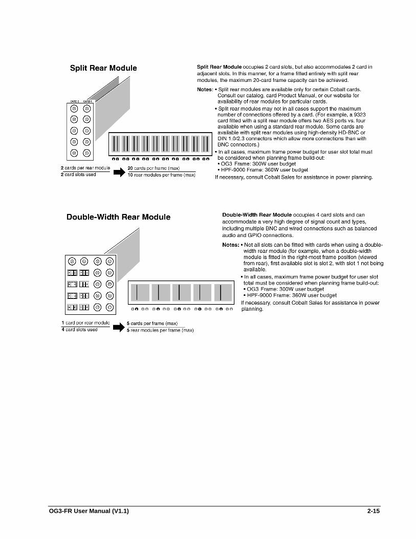
Installing a Rear ModuleDepending on the frame model you purchased, there may be variations in the BNC rear I/O modulesconnected to it. If the frame was ordered with cards requiring custom rear I/O modules, the appropriatemodules will be installed at the factory or included with the card modules.
Note: Refer to card product manuals or catalog/web pages for rear modules available for the cardsbeing installed.
BNC/Twisted-Pair Rear I/O Module 10 BNC Rear I/O Module Blank Rear I/O Module
OG3-FR User Manual (V1.1) 2-15

2-16 •••• Installation OG3-FR User Manual •••• (V1.1)

OG3-FR User Manual (V1.1) 2-17
To install a Rear Module in an openGear frame
1. Ensure that the frame is properly installed.
2. Locate the card frame slot on the rear of the frame you wish to install the openGear card in.
• Refer to the manual that accompanied your openGear card to determine if the cardrequires installation in a specific slot and which rear modules are supported by your card.
• Determine the type of rear module you have. When installing a split rear module,remember that this module still requires two slots even though it accommodates twocards.
3. Seat the bottom of the Rear Module in the seating slot at the base of the frame back plane asshown below.
• If you are installing a rear module in the OG3-FR series frames, there are two seatingslots. Refer to the section “Rear Modules for the OG3-FR Series Frames” for details.
Rear Module Installation
4. Align the top screw of the Rear Module with the screw hole on the top edge of the frame backplane.
5. Ensure the module aligns with the desired card slot before tightening the screws.
6. Using a Phillips screwdriver and the supplied screw, fasten the rear module panel to the frameback plane. Do not over tighten.
7. Ensure proper frame cooling and ventilation by having all rear frame slots covered with rearmodules or blank metal plates.
8. Blank Rear Modules (metal cover plates with mounting screw supplied with frame) are usedwhen the slot does not have a card installed. This helps to ensure proper frame cooling andventilation.

2-18 •••• Installation OG3-FR User Manual •••• (V1.1)
OG3-FR Series Setup
In This ChapterThis chapter provides information on setting up and using the OG3-FR series frame. The OG3-FRseries frame is a 2RU modular frame, designed to accommodate up to 20 openGear cards.
The following topics are discussed:
• GFC-8322 and Reference Overview
• Using the LCD Diagnostic Panel
• Rear Modules for the OG3-FR Series Frames
• Fan Filter Maintenance
• Replacing the Cooling Fan Module
• Specifications for the OG3-FR Series Frames

OG3-FR User Manual (V1.1) 2-19
GFC-8322 and Reference OverviewThe GFC-8322 comes standard with every OG3-FR series frame. Its primary function is to distributethe reference signals to openGear cards installed in the frame. This section provides a general overviewof the GFC-8322.
GFC-8322 Card
Location in Frame
When facing the frame door, the GFC-8322 is located on the left side of the OG3-FR series frame. Thiscard comes pre-installed in the designated slot immediately to the right of PS1, and is secured with ametal retaining latch.
Reference Distribution
The GFC-8322 receives the analog reference signals driven to the REF 1 and REF 2 BNCs located onthe rear panel of OG3-FR series frame. The GFC-8322 then distributes both reference signals to eachof the 20 slots in the frame.
Parameter Storage
Frame settings such as the frame IP address, frame name, and the frame serial number are stored on theGFC-8322 via its Serial EEPROM.
Troubleshooting
During normal operation, the GFC-8322 must never be removed from the OG3-FR series frame. Toensure this, the metal retaining latch located on the front of the GFC-8322 must be engaged (pusheddown) to prevent accidental removal of the GFC-8322 from its slot.
Verify that the GFC-8322 is properly seated in its slot and the retaining latch is engaged whentroubleshooting any of the following conditions:
• reference signals are unavailable to the cards installed in the frame
• loss of network connection or the network settings for the frame were reset to the defaultvalues
2-20 •••• Installation OG3-FR User Manual •••• (V1.1)
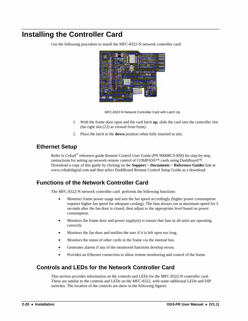
Installing the Controller CardUse the following procedure to install the MFC-8322-N network controller card:
MFC-8322-N Network Controller Card with Latch Up
1. With the frame door open and the card latch up, slide the card into the controller slot(far right slot (22) as viewed from front).
2. Place the latch in the down position when fully inserted in slot.
Ethernet SetupRefer to Cobalt® reference guide Remote Control User Guide (PN 9000RCS-RM) for step-by-stepinstructions for setting up network remote control of COMPASS™ cards using DashBoard™.Download a copy of this guide by clicking on the Support > Documents > Reference Guides link atwww.cobaltdigital.com and then select DashBoard Remote Control Setup Guide as a download.
Functions of the Network Controller CardThe MFC-8322-N network controller card performs the following functions:
• Monitors frame power usage and sets the fan speed accordingly (higher power consumptionrequires higher fan speed for adequate cooling). The fans always run at maximum speed for 5seconds after the fan door is closed, then adjust to the appropriate level based on powerconsumption.
• Monitors the frame door and power supply(s) to ensure that fans in all units are operatingcorrectly.
• Monitors the fan door and notifies the user if it is left open too long.
• Monitors the status of other cards in the frame via the internal bus.
• Generates alarms if any of the monitored functions develop errors.
• Provides an Ethernet connection to allow remote monitoring and control of the frame.
Controls and LEDs for the Network Controller CardThis section provides information on the controls and LEDs for the MFC-8322-N controller card.These are similar to the controls and LEDs on the MFC-8322, with some additional LEDs and DIPswitches. The location of the controls are show in the following figures.

OG3-FR User Manual (V1.1) 2-21
The LED indicators and controls for fan, alarm, and communication activity are shown in the followingfigure.
MFC-8322-N Card Edge Controls
2-22 •••• Installation OG3-FR User Manual •••• (V1.1)
DIP Switches on the MFC-8322-N
This section briefly summarizes the DIP Switch settings on the card.
SW1, SW2 — IP Address Setup
SW1 and SW2 are used in conjunction with the DashBoard menus to set the IP Address of the card.Refer to the table above and the card labeling for DIP Switch positions.
• ON — This setting disables the audio alarm.
• OFF — This setting enables the audio alarm.

OG3-FR User Manual (V1.1) 2-23
SW3 — Master Password Override
SW3 is used to override the Master Password. The Master Password feature limits the card to supportonly authenticated connections. Normal default position is off.
SW4
This switch is presently not used and should be left in the default off position.
SNMP Monitoring on the MFC-8322-NS
The MFC-8322-NS provides optional support for remote monitoring and control of your frame andopenGear cards using SNMP (Simple Network Management Protocol), which is compatible with manythird-party monitoring and control tools. You must obtain a license key from your openGear salesrepresentative to enable SNMP support.
Setting Network Controller Card to Mute Audible AlarmsThe frame has a pushbutton to temporarily mute the “beeper” on the card. However, to persistentlymute audible alarms, set the Network Controller Card ALARM CONFIG jumper to the Disabledposition as shown below.
DashBoard and DashBoard Lite Control System SoftwareYou can use the DashBoard or DashBoard Lite Control Systems to monitor and control your framesand controller cards from a computer. The DashBoard software and manual can be downloaded fromthe Cobalt Digital Inc. website.
SNMP Monitoring and ControlThe MFC-8322-N Network Controller card provides optional support for remote monitoring andcontrol of your frame and its cards using SNMP (Simple Network Management Protocol), which iscompatible with many third-party monitoring and control tools. This section describes how to enablethis feature and how to configure the SNMP software on the card.
Enabling SNMP
You must obtain a license key from Cobalt Digital Inc. to enable SNMP support.
Use the following procedure to obtain your license key:
1. Request a license key from your distributor or at [email protected], quotingthe 8-character hardware-ID provided on the page.
2-24 •••• Installation OG3-FR User Manual •••• (V1.1)
2. Open the Frame Configuration Page for the frame using DashBoard. OR
Point your web browser to the IP address of the frame.
3. Select the tab titled SNMP Configuration.
If SNMP has not been enabled, this page will ask you to enter a license key.
4. Enter the license key in the field provided.
5. Click Submit.
After a valid license key has been entered, the frame displays the SNMPconfiguration page.
This completes the procedure to enable the SNMP agent on the frame.
Configuring SNMP
The SNMP agent on the frame will accept SNMP GET and SET requests on the default SNMP port(161), using SNMP version 1 or SNMP version 2c. The SNMP commands will send SNMP traps toone or more notification targets, with user-configurable address, port, and protocol version number.
Use the following procedure to configure your SNMP Agent:
1. Open the configuration page for the frame using DashBoard. OR
Point your web browser to the IP address of the frame.
2. Select the tab titled SNMP Configuration.
3. Set the required parameters as follows:
• Read Community String Enter the SNMP password for GET requests.
• Write Community String Enter the SNMP password for SET requests.
4. To add a trap/notification target, specify the following:
• Target IP address Enter the IP address to which traps should be sent.
• Port number Enter the UDP port number to which traps should be sent.
• SNMP version Enter the protocol version to be used for traps to this target.
• Target community string Enter the community string.
5. Click Add to add the target to the list.
OperatingTip
To remove a trap/notification target, select the target in the list,and click Delete.
6. Click the Submit button to configure the frame.
This completes the procedure to configure your SNMP Agent.

OG3-FR User Manual (V1.1) 2-25
Using the LCD Diagnostic PanelThe LCD Diagnostic panel is located on the frame front panel and enables you to quickly monitor theframe. Information is presented in two separate lines of text. The top line alternates displaying the IPaddress the frame is currently using and the frame name. The bottom line displays any alarm messages,such as fan failure, power supply issues, and error conditions that an installed card is currentlyreporting. The bottom line reflects the error conditions reported in DashBoard for the frame, andindividual openGear cards installed in that frame.
LCD Display — IP Address of Frame LCD Display — Frame Name
For More Information on…
• the types of error conditions that your openGear card reports, refer to the user manual thatcame with your card.
• setting the IP address and frame name in DashBoard, refer to the MFC-8300 Series UserManual.
Using the Toggle ButtonThe toggle button is located directly to the left of the LCD Diagnostic Panel and enables you to:
• mute the audio alarm
• quickly scroll through the error messages reported on the second line of the diagnostic panel
To clear the audio alarm
1. Press the toggle button once to mute the audio alarm.
To scroll through the messages on the LCD Diagnostic Panel
1. Press the toggle button multiple times to scroll through the messages. The LCDDiagnostic Panel organizes the messages starting with the most recent at the top of thelist.
2. If you are scrolling through the list and a new error condition is reported, the list isautomatically updated and returns you to the beginning of the list.
2-26 •••• Installation OG3-FR User Manual •••• (V1.1)
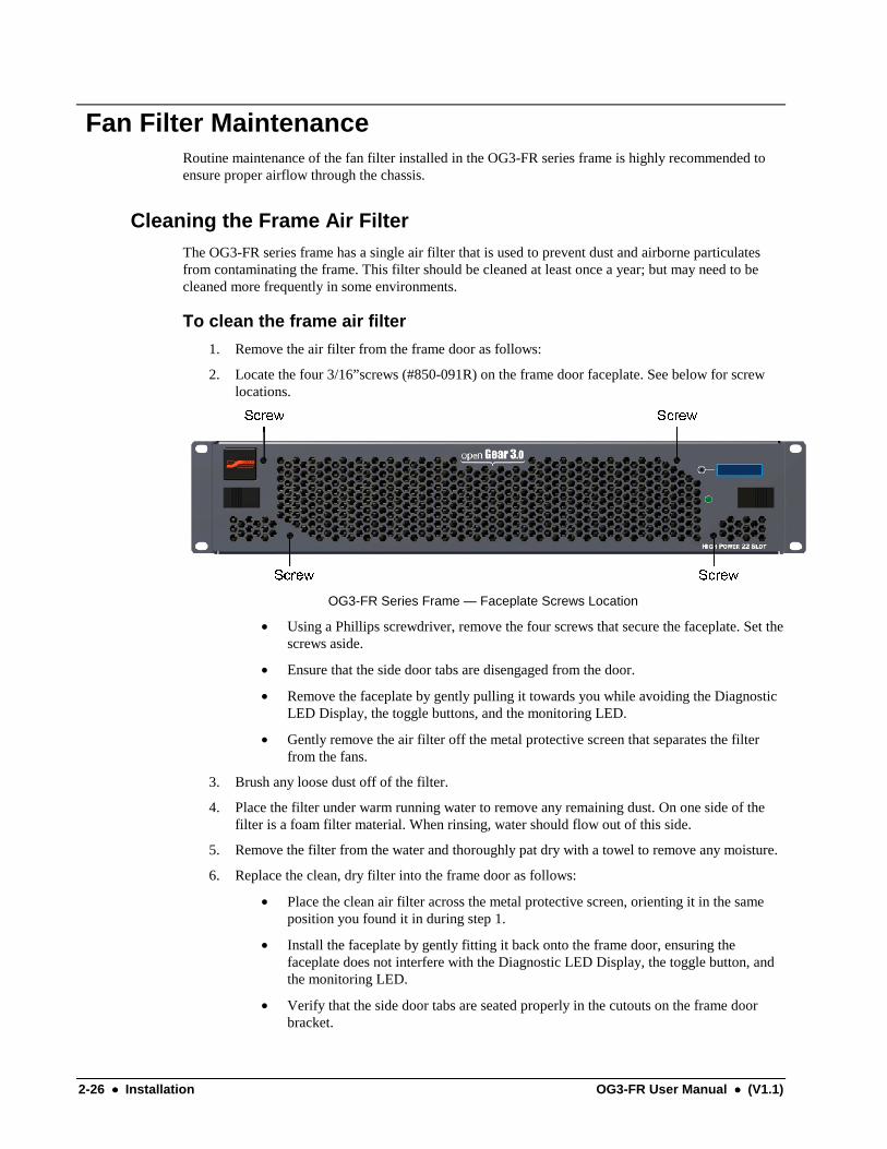
Fan Filter MaintenanceRoutine maintenance of the fan filter installed in the OG3-FR series frame is highly recommended toensure proper airflow through the chassis.
Cleaning the Frame Air FilterThe OG3-FR series frame has a single air filter that is used to prevent dust and airborne particulatesfrom contaminating the frame. This filter should be cleaned at least once a year; but may need to becleaned more frequently in some environments.
To clean the frame air filter
1. Remove the air filter from the frame door as follows:
2. Locate the four 3/16”screws (#850-091R) on the frame door faceplate. See below for screwlocations.
OG3-FR Series Frame — Faceplate Screws Location
• Using a Phillips screwdriver, remove the four screws that secure the faceplate. Set thescrews aside.
• Ensure that the side door tabs are disengaged from the door.
• Remove the faceplate by gently pulling it towards you while avoiding the DiagnosticLED Display, the toggle buttons, and the monitoring LED.
• Gently remove the air filter off the metal protective screen that separates the filterfrom the fans.
3. Brush any loose dust off of the filter.
4. Place the filter under warm running water to remove any remaining dust. On one side of thefilter is a foam filter material. When rinsing, water should flow out of this side.
5. Remove the filter from the water and thoroughly pat dry with a towel to remove any moisture.
6. Replace the clean, dry filter into the frame door as follows:
• Place the clean air filter across the metal protective screen, orienting it in the sameposition you found it in during step 1.
• Install the faceplate by gently fitting it back onto the frame door, ensuring thefaceplate does not interfere with the Diagnostic LED Display, the toggle button, andthe monitoring LED.
• Verify that the side door tabs are seated properly in the cutouts on the frame doorbracket.
OG3-FR User Manual (V1.1) 2-27
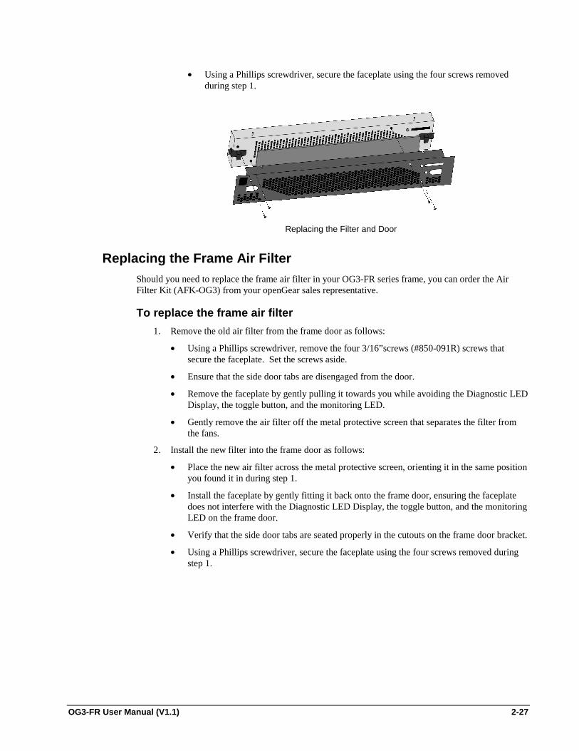
• Using a Phillips screwdriver, secure the faceplate using the four screws removedduring step 1.
Replacing the Filter and Door
Replacing the Frame Air FilterShould you need to replace the frame air filter in your OG3-FR series frame, you can order the AirFilter Kit (AFK-OG3) from your openGear sales representative.
To replace the frame air filter
1. Remove the old air filter from the frame door as follows:
• Using a Phillips screwdriver, remove the four 3/16”screws (#850-091R) screws thatsecure the faceplate. Set the screws aside.
• Ensure that the side door tabs are disengaged from the door.
• Remove the faceplate by gently pulling it towards you while avoiding the Diagnostic LEDDisplay, the toggle button, and the monitoring LED.
• Gently remove the air filter off the metal protective screen that separates the filter fromthe fans.
2. Install the new filter into the frame door as follows:
• Place the new air filter across the metal protective screen, orienting it in the same positionyou found it in during step 1.
• Install the faceplate by gently fitting it back onto the frame door, ensuring the faceplatedoes not interfere with the Diagnostic LED Display, the toggle button, and the monitoringLED on the frame door.
• Verify that the side door tabs are seated properly in the cutouts on the frame door bracket.
• Using a Phillips screwdriver, secure the faceplate using the four screws removed duringstep 1.

2-28 •••• Installation OG3-FR User Manual •••• (V1.1)
Replacing the Cooling Fan ModuleThe OG3-FR series frames come standard with the Cooling Fan Module (CFM-OG3) pre-installedin the frame door as original equipment from the factory. However, if you need to replace thecooling fan module, the CFM-OG3 Replacement Kit is for field installation.
Replacing the CFM-OG3 Cooling Fan ModuleThe CFM-OG3 Replacement Kit includes the fan board and filter pre-installed in a new OG3-FRseries frame door. You will need to remove the old door from your OG3-FR series frame andreplace it with the new door.
To replace the CFM-OG3 Cooling Fan Module
1. Carefully remove the old door from the frame as follows:
2. Gently pull the side door tabs towards the center of the door, releasing the door from theframe. The door extender arms prevent the door from falling.
OG3-FR Series Frame Door — Open
• Using both hands, pull the door towards you.
• Tilt the door upward until the arms match the cutout.
• Gently push the door extender arms in and over the retaining bolts and unhook from theframe.
• Remove the door and place it on a clean, flat, static-free surface.
3. Install the new door in the frame as follows:
• Using both hands, with the door tilted up, slide the new door into the frame while pushingthe extender arms in and over the retaining bolts.
• Pull and release the door tabs to ensure the frame door is securely locked to the OG3-FRseries frame and that the tabs latch into the frame.

OG3-FR User Manual (V1.1) 2-29
Specifications for the OG3-FR Series FramesThis section includes the technical specifications table for the OG3-FR series frame. Note thatspecifications are subject to change without notice.
OG3-FR Series Frame Technical Specifications
Category Parameter Specification
Input 100-240VAC, 47-63Hz, 500W
Output 1 12V, 28A, 336W nominal
Output 2 -7.5V, 5A, 37.5W nominal
PS-OG3Power Supply
Total Sum of both outputs not to exceed 375W maximum
Height 2RU 3.5" (8.89cm)
Width 19" (48.26cm)
Depth 17.7” (45cm)Dimensions
Weight with two PS-OG3 installed 20lb (9.07kg)
Number of Slots (User) 20
Per card occupying 4 slots: 5A, 60W
Per card occupying 2 slots: 2.5A, 30WMax. Power: +12V Rail
Per card occupying 1 slot: 1.25A, 15W
Per card occupying 4 slots: 0.8A, 6W
Per card occupying 2 slots: 0.4A, 3WMax. Power: -7.5V Rail
Per card occupying 1 slot: 0.2A, 1.5W
Frame CardSlots
Total300W, total power consumption not to exceed 15Wmaximum per card slot
Number of Inputs 2 looping
Level 1Vpp nominal
SignalAnalog video sync (black burst or tri-level), orAES/EBU DARS
Impedance 75ohm terminatingReturn Loss >30dB to 30MHz
ReferenceInputs
Max DC on Ref Input ±1V
Ambient temperature range 0ºC to 40ºC (32°F to 104°F)Environmental
Humidity, non-condensing <95%

2-30 •••• Installation OG3-FR User Manual •••• (V1.1)
Service Information
In This ChapterThis chapter contains the following sections:
• Troubleshooting Checklist
• Warranty and Repair Policy

OG3-FR User Manual (V1.1) 2-31
Troubleshooting ChecklistRoutine maintenance to this openGear product is not required. In the event of problems with yourOG3-FR series frame, the following basic troubleshooting checklist may help identify the source of theproblem. If the frame still does not appear to be working properly after checking all possible causes,please contact your openGear products distributor, or the Technical Support department at the numberslisted under the “Contact Us” section at the end of this manual.
1. Visual Review – Performing a quick visual check may reveal many problems, suchas connectors not properly seated or loose cables. Check the card, the frame, and anyassociated peripheral equipment for signs of trouble.
2. Power Check – Check the power indicator LED on the distribution frame front panelfor the presence of power. If the power LED is not illuminated, verify that the powercable is connected to a power source and that power is available at the power main.Confirm that the power supplies are fully seated in their slots. If the power LED isstill not illuminated, replace the power supply with one that is verified to work.
3. Input Signal Status – Verify that source equipment is operating correctly and that avalid signal is being supplied.
4. Output Signal Path – Verify that destination equipment is operating correctly andreceiving a valid signal.
5. Unit Exchange – Exchanging a suspect unit with a unit that is known to be workingcorrectly is an efficient method for localizing problems to individual units.

2-32 •••• OG3-FR User Manual •••• (V1.1)
Warranty and Repair PolicyCobalt Digital Inc. Limited WarrantyThis product is warranted to be free from defects in material and workmanship for a period of five (5)years from the date of shipment to the original purchaser, except that 4000, 5000, 6000, 8000 seriespower supplies, and Dolby® modules (where applicable) are warranted to be free from defects inmaterial and workmanship for a period of one (1) year.
Cobalt Digital Inc.'s (“Cobalt”) sole obligation under this warranty shall be limited to, at its option, (i)the repair or (ii) replacement of the product, and the determination of whether a defect is covered underthis limited warranty shall be made at the sole discretion of Cobalt.
This limited warranty applies only to the original end-purchaser of the product, and is not assignable ortransferrable therefrom. This warranty is limited to defects in material and workmanship, and shall notapply to acts of God, accidents, or negligence on behalf of the purchaser, and shall be voided upon themisuse, abuse, alteration, or modification of the product. Only Cobalt authorized factoryrepresentatives are authorized to make repairs to the product, and any unauthorized attempt to repairthis product shall immediately void the warranty. Please contact Cobalt Technical Support for moreinformation.
To facilitate the resolution of warranty related issues, Cobalt recommends registering the product bycompleting and returning a product registration form. In the event of a warrantable defect, thepurchaser shall notify Cobalt with a description of the problem, and Cobalt shall provide the purchaserwith a Return Material Authorization (“RMA”). For return, defective products should be double boxed,and sufficiently protected, in the original packaging, or equivalent, and shipped to the Cobalt FactoryService Center, postage prepaid and insured for the purchase price. The purchaser should include theRMA number, description of the problem encountered, date purchased, name of dealer purchased from,and serial number with the shipment.
Cobalt Digital Inc. Factory Service Center
2406 E. University Avenue Office: (217) 344-1243
Urbana, IL 61802 USA Fax: (217) 344-1245
www.cobaltdigital.com Email: [email protected]
THIS LIMITED WARRANTY IS EXPRESSLY IN LIEU OF ALL OTHER WARRANTIESEXPRESSED OR IMPLIED, INCLUDING THE WARRANTIES OF MERCHANTABILITY ANDFITNESS FOR A PARTICULAR PURPOSE AND OF ALL OTHER OBLIGATIONS ORLIABILITIES ON COBALT'S PART. ANY SOFTWARE PROVIDED WITH, OR FOR USE WITH,THE PRODUCT IS PROVIDED “AS IS.” THE BUYER OF THE PRODUCT ACKNOWLEDGESTHAT NO OTHER REPRESENTATIONS WERE MADE OR RELIED UPON WITH RESPECT TOTHE QUALITY AND FUNCTION OF THE GOODS HEREIN SOLD. COBALT PRODUCTS ARENOT AUTHORIZED FOR USE IN LIFE SUPPORT APPLICATIONS.
COBALT'S LIABILITY, WHETHER IN CONTRACT, TORT, WARRANTY, OR OTHERWISE, ISLIMITED TO THE REPAIR OR REPLACEMENT, AT ITS OPTION, OF ANY DEFECTIVEPRODUCT, AND SHALL IN NO EVENT INCLUDE SPECIAL, INDIRECT, INCIDENTAL, ORCONSEQUENTIAL DAMAGES (INCLUDING LOST PROFITS), EVEN IF IT HAS BEENADVISED OF THE POSSIBILITY OF SUCH DAMAGES.

OG3-FR User Manual (V1.1) 2-33
Ordering InformationYour openGear® 2RU Frame and Power Supply is a part of the openGear® family of products.
Standard Equipment• OG3-FR Digital Products Frame and Power Supply with Cooling Fans
(2RU, holds 20 cards maximum)
Optional Equipment• PS-OG3 Power Supply, 300W user net (redundancy option power supply for Cobalt
Digital Inc. OG3-FR series 2RU digital product frames)
• MFC-8322-N openGear® 2RU Frame Controller with Network Interface(upgrade controller card with Ethernet communication capability for use with OG3-FRframes)

2-34 •••• OG3-FR User Manual •••• (V1.1)
Contact Us
Contact Cobalt Digital Inc.
General Business Officeand Technical Support
217.344.1243
PHONEFax 217.344.1245
General Information [email protected]
Sales Information [email protected]
Cobalt Digital Inc.2406 East University AvenueUrbana, IL 61802 USAPOSTAL
SERVICE
Visit us at the Cobalt Digital Inc. website.http://www.cobaltdigital.com/
• Online catalog
• Related products and full product lines
• Trade show information
• Dealer information
• Cobalt Digital Inc. news
Related Documents