1 A)INTRODUCTION TO OFFSHORE STRUCTURES ENGINEERING AND DESIGN B) QGII JACKETS AND TOPSIDES DESIGN STRATEGY (QATARGAS OPCO Engineering Forum Oct. 2006) By: S. M. Salem

Welcome message from author
This document is posted to help you gain knowledge. Please leave a comment to let me know what you think about it! Share it to your friends and learn new things together.
Transcript

1
A)INTRODUCTION TO OFFSHORE STRUCTURES
ENGINEERING AND DESIGN
B) QGII JACKETS AND TOPSIDES DESIGN STRATEGY
(QATARGAS OPCO Engineering Forum Oct. 2006)
By: S. M. Salem

2
INTRODUCTION TO OFFSHORE STRUCTURES ENGINEERING AND DESIGN
Elements Influencing the Structural Design of an Offshore Platform
• Water depth
• Environmental forces
• Topsides size and weight
• Seabed Soil formation / geotechnical properties
• Method of Construction
• Hydrostatic pressure
• Field subsidence
• Geographical location and Earthquake effect
3
INTRODUCTION TO OFFSHORE STRUCTURES ENGINEERING AND DESIGN
Types of Offshore Platforms
Fixed
Platform
Compliant
TowerTLP Mini -TLP SPAR FPS FPSO

4
INTRODUCTION TO OFFSHORE STRUCTURES ENGINEERING AND DESIGN
Sequence Of Construction
• Steel jacket installed on seabed
• Piles driven through jacket’s legs
• Piles welded to the top of the jacket
• Transition pieces welded to the piles top
• Deck installed over transition pieces (by
lifting or float over method)
• Deck legs welded to the transition pieces
Fixed Offshore Platforms

5
INTRODUCTION TO OFFSHORE STRUCTURES ENGINEERING AND DESIGN
6
INTRODUCTION TO OFFSHORE STRUCTURES ENGINEERING AND DESIGN
Type of Analyses & Loads Considered in the Design
In-place Conditions
• Static Analysis
- Operating Environmental Loading
- Extreme Environmental Loading
- Dead weight and buoyancy
- Operational Loads
• Dynamic Analysis (for slender structures)
• Spectral Fatigue Analysis
• Earthquake Analysis

7
INTRODUCTION TO OFFSHORE STRUCTURES ENGINEERING AND DESIGN
Construction / Installation Conditions
• Loadout
- Lifted, Skidded
or Wheeled
• Transportation
- Tow stability
- Structural Transportation
• Installation (Jackets)
- Lifting / Launching,
Floatation & Upending
• Installation (Decks)
- Lifting or Float Over
Jacket Upending
Deck Floatover

8
Wave and Current Forces Calculation on Exposed Members
Some Wave Theories frequently used:
Airy wave Theory (Linear)
Stockes’ Fifth order wave Theory (Non-linear)
Stream Function Theory (Non-linear)
INTRODUCTION TO OFFSHORE STRUCTURES ENGINEERING AND DESIGN
||2
1
4
2
uDug
wCF
dt
duD
g
wCF
FFF
DD
mI
DI

9
INTRODUCTION TO OFFSHORE STRUCTURES ENGINEERING AND DESIGN
Environmental Headings Considered in the Design

10
QGII Jackets and Topsides Design Strategy
LNG TRAIN 5EXPANSIONOPTION 1
QATARGAS NFBCOMPLEX
LNG TRAIN 4EXPANSIONBASE CASE
LQPU
WH-2
PRWH-
1
FLARE
WH4 – 63.4 m(12 Slots)
QatargasRas Laffan Industrial City
QGII-AQGII-B
PL434”
(91 km)
Power/Comm5-6 Power/Comm
5-4
QATARGAS NFB COMPLEX
WH6 – 56.1 m(15 Slots)
WH5 - 46 m(15 Slots)
PL5-616”
(800 m)
PL5-416”
(300 m)
Power/CommMain
AppraisalWell
FOCto
Shore
PL638”
(81 km)
FIELD GENERAL LAYOUT

11
QGII Jackets and Topsides Design Strategy
FEED STAGE EXECUTION STRATEGY
• Advance WH4 and WH5 Jackets Engineering to the (RFC) stage for early Construction of
Jackets and Temporary Work Decks
• Perform basic Engineering and Design for full field development
• Use of RG Offshore Expansion Project Specifications and design criteria as a goby to
accelerate the Engineering Works
• Preparation of the EPC bid package and cost / Schedule estimate for the IFD and the FFD
(except for WH4, WH5 and WH6 Jackets)

12
QGII Jackets and Topsides Design Strategy
SIMILARITIES BETWEEN RG
and QGII PLATFORMS
1. Similar Design Specifications
2. Same environmental Criteria
3. Similar Process
4. Similar Topsides facilities and
arrangement
5. Similarity of water depth between
RG WH5 and QGII WH4 (64.7 m
versus 63.4 m)
DIFFERENCES BETWEEN RG
and QGII PLATFORMS
1. Different Location. i.e. different soil
formation
2. Nine wells in case of RG WH5
versus Twelve wells in case of QGII
WH4
3. Difference in Topsides Equipment
Weight and Pipeline / Riser size
4. Pipeline, Riser and valves size 38”
in case of RG WH7 versus 34” in
case of QGII WH4
13
QGII Jackets and Topsides Design Strategy
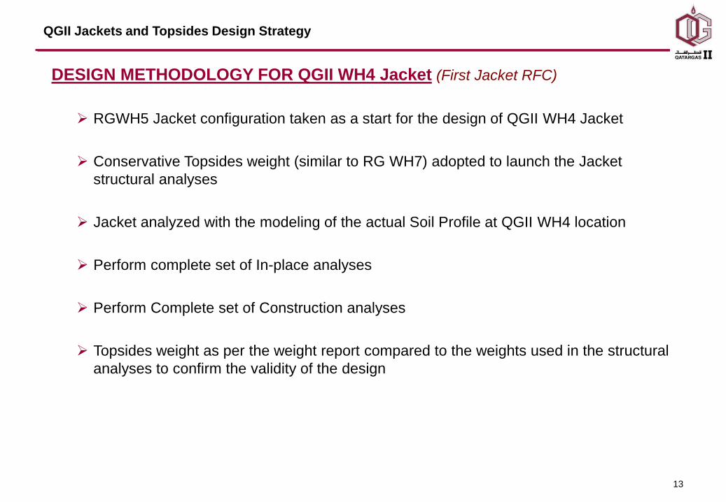
DESIGN METHODOLOGY FOR QGII WH4 Jacket (First Jacket RFC)
RGWH5 Jacket configuration taken as a start for the design of QGII WH4 Jacket
Conservative Topsides weight (similar to RG WH7) adopted to launch the Jacket
structural analyses
Jacket analyzed with the modeling of the actual Soil Profile at QGII WH4 location
Perform complete set of In-place analyses
Perform Complete set of Construction analyses
Topsides weight as per the weight report compared to the weights used in the structural
analyses to confirm the validity of the design

14
QGII Jackets and Topsides Design Strategy
FEED TOPSIDES WEIGHTS (Values in MT)
QGII - WH4 QGII - WH5
Topsides Weight Used for
QGII Final Jacket / Piles
Analyses
4065.0 3795.0
RG – WH5 topsides Weight 3785.0
(Value increased by 160 MT to
account for a future bridge
proposed for QGII – WH4)
3625.0
QGII topsides weight as per
Rev. 00 FEED Weight
Report
3761.0 3658.0

15
QGII Jackets and Topsides Design Strategy
• FEED EXECUTION MILESTONES
Date Milestones
Oct. 03 Start of FEED with J. R. McDermott
Mar. 04 WH4 Jacket and TWD Approved for Construction
Apr. 04 WH5 Jacket and TWD Approved for Construction
Apr. 04 Award Construction and Installation for WH4 and WH5 Jackets and TWD,
with an option for W6 Jacket and TWD to J. R. McDermott
Jan. 05 Exercise option of WH6 Jacket and TWD Construction and Installation
Jul. 04 Completion of FEED Stage
Oct. 04 Completion of WH4 Jacket and TWD fabrication and Installation
May. 05 Completion of WH5 Jacket and TWD fabrication and Installation
Nov. 05 Completion of WH6 Jacket and TWD fabrication and Installation

16
QGII Jackets and Topsides Design Strategy
WH4 TOPSIDES PERSPECTIVE

17
QGII Jackets and Topsides Design Strategy
WH4 JACKET ELEVATIONS & PLAN

18
QGII Jackets and Topsides Design Strategy
WH4 Jacket and TWD
19
QGII Jackets and Topsides Design Strategy
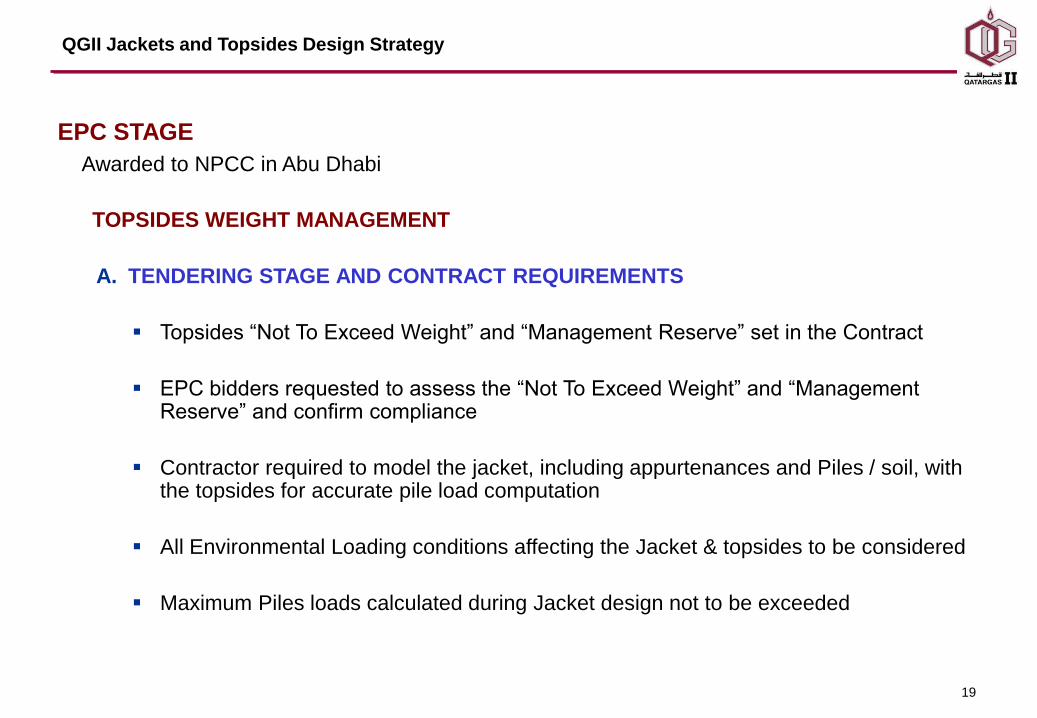
EPC STAGE
Awarded to NPCC in Abu Dhabi
TOPSIDES WEIGHT MANAGEMENT
A. TENDERING STAGE AND CONTRACT REQUIREMENTS
Topsides “Not To Exceed Weight” and “Management Reserve” set in the Contract
EPC bidders requested to assess the “Not To Exceed Weight” and “Management Reserve” and confirm compliance
Contractor required to model the jacket, including appurtenances and Piles / soil, with the topsides for accurate pile load computation
All Environmental Loading conditions affecting the Jacket & topsides to be considered
Maximum Piles loads calculated during Jacket design not to be exceeded
20
QGII Jackets and Topsides Design Strategy
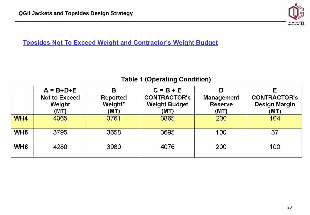
Topsides Not To Exceed Weight and Contractor’s Weight Budget

21
QGII Jackets and Topsides Design Strategy
B. EPC ENGINEERING EXECUTION AND WEIGHT MANAGEMENT
Tight weight management program set by EPC Contractor to monitor and alert Engineering disciplines of Topsides weight and COG trends
Structural weight reductions measures
Change of topsides steel material grade from Low and Medium strength to Medium and High strength
Change from pancake secondary steel construction to intercoastal secondary steel construction
Extra refinement of Live loads Calculations
Optimization of analysis and plate girders design
Piles loads calculated during the jackets detailed Engineering not to be exceed
22
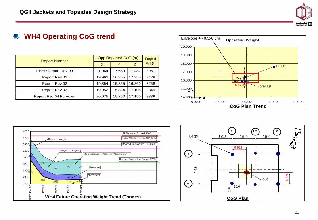
WH4 Operating CoG trendOperating Weight
ForecastRev 01
Rev A
FEED
Rev 0
14.000
15.000
16.000
17.000
18.000
19.000
20.000
18.000 19.000 20.000 21.000 22.000
CoG Plan Trend
Envelope +/- 0.5x0.5m
Y
X
5.8
24
CoG Plan
9.952
15.0
14
.0
1.51
B
A
2
15.012.0
CoG
Legs
10.0
10.0
## 385
## 396
## 384
## 472
## 472
0
0
0
0
0
0
3321
255
385
104
2818
215
396
636
2701
173
384
807
2725
152
472
716
2728
139
472
726
4065 4065 4065 4065 4065 4065
2600
2800
3000
3200
3400
3600
3800
4000
4200
FE
ED
Rev
00
Rev
01
Rev
02
Rev
03
Fore
cast
WH4 Future Operating Weight Trend (Tonnes)
Revised Contractors Budget 3255t
FEED Contractors Budget 3865t
Revised Contractors NTE 3650t
MOC increase to Company Contingency
Net Weight
Reported Weight
FEED Not to Exceed 4065t
Weight Contingency
Allowance
X Y Z
FEED Report Rev 00 21.064 17.639 17.432 3961
Report Rev 01 19.962 16.355 17.350 3429
Report Rev 02 19.854 15.865 16.860 3258
Report Rev 03 19.952 15.824 17.106 3349
Report Rev 04 Forecast 20.075 15.750 17.150 3339
Report NumberOpp Reported CoG (m) Rept'd
Wt (t)
QGII Jackets and Topsides Design Strategy
Related Documents