Official Journal of the European Union L 392 English edition Volume 64 Legislation 5 November 2021 Contents II Non-legislative acts ACTS ADOPTED BY BODIES CREATED BY INTERNATIONAL AGREEMENTS ★ UN Regulation No 94 – Uniform provisions concerning the approval of vehicles with regard to the protection of the occupants in the event of a frontal collision [2021/1860] ........................... 1 ★ UN Regulation No 95 – Uniform provisions concerning the approval of vehicles with regard to the protection of the occupants in the event of a lateral collision [2021/1861] ............................ 62 ★ UN Regulation No 137 – Uniform provisions concerning the approval of vehicles in the event of a frontal collision with focus on the restraint system [2021/1862] .............................................. 130 EN Acts whose titles are printed in light type are those relating to day-to-day management of agricultural matters, and are generally valid for a limited period. The titles of all other acts are printed in bold type and preceded by an asterisk.

Welcome message from author
This document is posted to help you gain knowledge. Please leave a comment to let me know what you think about it! Share it to your friends and learn new things together.
Transcript
Official Journalof the European Union
L 392
English edition
Volume 64
Legislation 5 November 2021
Contents
II Non-legislative acts
ACTS ADOPTED BY BODIES CREATED BY INTERNATIONAL AGREEMENTS
★ UN Regulation No 94 – Uniform provisions concerning the approval of vehicles with regard to the protection of the occupants in the event of a frontal collision [2021/1860] . . . . . . . . . . . . . . . . . . . . . . . . . . . 1
★ UN Regulation No 95 – Uniform provisions concerning the approval of vehicles with regard to the protection of the occupants in the event of a lateral collision [2021/1861] . . . . . . . . . . . . . . . . . . . . . . . . . . . . 62
★ UN Regulation No 137 – Uniform provisions concerning the approval of vehicles in the event of a frontal collision with focus on the restraint system [2021/1862] . . . . . . . . . . . . . . . . . . . . . . . . . . . . . . . . . . . . . . . . . . . . . . 130
EN Acts whose titles are printed in light type are those relating to day-to-day management of agricultural matters, and are generally valid for a limited period.
The titles of all other acts are printed in bold type and preceded by an asterisk.


II
(Non-legislative acts)
ACTS ADOPTED BY BODIES CREATED BY INTERNATIONAL AGREEMENTS
Only the original UN/ECE texts have legal effect under international public law. The status and date of entry into force of this Regulation should be checked in the latest version of the UN/ECE status document TRANS/WP.29/343, available at: https://unece.org/status-1958-agreement-and-annexed-regulations
UN Regulation No 94 – Uniform provisions concerning the approval of vehicles with regard to the protection of the occupants in the event of a frontal collision [2021/1860]
Incorporating all valid text up to:
04 series of amendments – Date of entry into force: 9 June 2021
CONTENTS
REGULATION
1. Scope
2. Definitions
3. Application for approval
4. Approval
5. Specifications
6. Instructions for users of vehicles equipped with airbags
7. Modification and extension of approval of the vehicle type
8. Conformity of production
9. Penalties for non-conformity of production
10. Production definitively discontinued
11. Names and addresses of Technical Services responsible for conducting approval tests, and of Type Approval Authorities
12. Transitional provisions
ANNEXES
1 Communication
2 Arrangements of approval marks
3 Test procedure
4 Head Performance Criterion (HPC) and 3 ms head acceleration performance criteria
5 Arrangement and installation of dummies and adjustment of restraint systems
EN Official Journal of the European Union 5.11.2021 L 392/1

6 Procedure for determining the "H" point and the actual torso angle for seating positions in motor vehicles
Appendix 1 Description of the three dimensional "H" point machine (3-D H machine)
Appendix 2 Three dimensional reference system
Appendix 3 Reference data concerning seating positions
7 Test procedure with trolley
Appendix Equivalence curve – tolerance band for curve ΔV = f(t)
8 Technique of measurement in measurement tests: Instrumentation
9 Definition of deformable barrier
10 Certification procedure for the dummy lower leg and foot
11 Test procedures for vehicles equipped with electric power train
EN Official Journal of the European Union L 392/2 5.11.2021
1. SCOPE
This Regulation applies to vehicles of category M1 (1) of a total permissible mass not exceeding 3 500 kg and to vehicles of category N1 of a total permissible mass not exceeding 2 500 kg; other vehicles may be approved at the request of the manufacturer.
2. DEFINITIONS
For the purpose of this Regulation:
2.1. "Protective system" means interior fittings and devices intended to restrain the occupants and contribute towards ensuring compliance with the requirements set out in paragraph 5. below.
2.2. "Type of protective system" means a category of protective devices which do not differ in such essential respects as:
Their technology;
Their geometry;
Their constituent materials.
2.3. "Vehicle width" means the distance between two planes parallel to the longitudinal median plane (of the vehicle) and touching the vehicle on either side of the said plane but excluding the external devices for indirect vision, side marker lamps, tyre pressure indicators, direction indicator lamps, position lamps, flexible mud-guards and the deflected part of the tyre side-walls immediately above the point of contact with the ground..
2.4. "Overlap" means the percentage of the vehicle width directly in line with the barrier face.
2.5. "Deformable barrier face" means a crushable section mounted on the front of a rigid block.
2.6. "Vehicle type" means a category of power-driven vehicles which do not differ in such essential respects as:
2.6.1. The length and width of the vehicle, in so far as they have a negative effect on the results of the impact test prescribed in this Regulation;
2.6.2. The structure, dimensions, lines and materials of the part of the vehicle forward of the transverse plane through the "R" point of the driver’s seat, in so far as they have a negative effect on the results of the impact test prescribed in this Regulation;
2.6.3. The lines and inside dimensions of the passenger compartment and the type of protective system, in so far as they have a negative effect on the results of the impact test prescribed in this Regulation;
2.6.4. The siting (front, rear or centre) and the orientation (transversal or longitudinal) of the engine, in so far as they have a negative effect on the result of the impact test procedure as prescribed in this Regulation;
2.6.5. The unladen mass, in so far as there is a negative effect on the result of the impact test prescribed in this Regulation;
2.6.6. The optional arrangements or fittings provided by the manufacturer, in so far as they have a negative effect on the result of the impact test prescribed in this Regulation;
(1) As defined in the Consolidated Resolution on the Construction of Vehicles (R.E.3.), document ECE/TRANS/WP.29/78/Rev.6, para. 2. – https://unece.org/transport/standards/transport/vehicle-regulations-wp29/resolutions
EN Official Journal of the European Union 5.11.2021 L 392/3
2.6.7. The locations of the REESS, in so far as they have a negative effect on the result of the impact test prescribed in this Regulation.
2.7. Passenger compartment
2.7.1. "Passenger compartment with regard to occupant protection" means the space for occupant accommodation, bounded by the roof, floor, side walls, doors, outside glazing and front bulkhead and the plane of the rear compartment bulkhead or the plane of the rear-seat back support;
2.7.2. "Passenger compartment for electric safety assessment" means the space for occupant accommodation, bounded by the roof, floor, side walls, doors, outside glazing, front bulkhead and rear bulkhead, or rear gate, as well as by the electrical protection barriers and enclosures provided for protecting the occupants from direct contact with high voltage live parts.
2.8. "R point" means a reference point defined for each seat by the manufacturer in relation to the vehicle’s structure, as indicated in Annex 6.
2.9. "H point" means a reference point determined for each seat by the testing service responsible for approval, in accordance with the procedure described in Annex 6.
2.10. "Unladen kerb mass" means the mass of the vehicle in running order, unoccupied and unladen but complete with fuel, coolant, lubricant, tools and a spare wheel (if these are provided as standard equipment by the vehicle manufacturer).
2.11. "Airbag" means a device installed to supplement safety belts and restraint systems in power-driven vehicles, i.e. systems which, in the event of a severe impact affecting the vehicle, automatically deploy a flexible structure intended to limit, by compression of the gas contained within it, the gravity of the contacts of one or more parts of the body of an occupant of the vehicle with the interior of the passenger compartment.
2.12. "Passenger airbag" means an airbag assembly intended to protect occupant(s) in seats other than the driver’s in the event of a frontal collision.
2.13. "High voltage" means the classification of an electric component or circuit, if its working voltage is > 60 V and ≤ 1 500 V direct current (DC) or > 30 V and ≤ 1 000 V alternating current (AC) root – mean – square (rms).
2.14. "Rechargeable Electrical Energy Storage System (REESS)" means the rechargeable energy storage system that provides electric energy for electrical propulsion.
A battery whose primary use is to supply power for starting the engine and/or lighting and/or other vehicle auxiliaries’ systems is not considered as a REESS.
The REESS may include the necessary systems for physical support, thermal management, electronic controls and casing.
2.15. "Electrical protection barrier" means the part providing protection against direct contact to the high voltage live parts.
2.16. "Electric power train" means the electrical circuit which includes the traction motor(s), and may also include the REESS, the electrical energy conversion system, the electronic converters, the associated wiring harness and connectors, and the coupling system for charging the REESS.
2.17. "Live parts" means conductive part(s) intended to be electrically energized under normal operating conditions.
EN Official Journal of the European Union L 392/4 5.11.2021
2.18. "Exposed conductive part" means the conductive part which can be touched under the provisions of the protection degree IPXXB and which is not normally energized, but which can become electrically energized under isolation failure conditions. This includes parts under a cover that can be removed without using tools.
2.19. "Direct contact" means the contact of persons with high voltage live parts.
2.20. "Indirect contact" means the contact of persons with exposed conductive parts.
2.21. "Protection degree IPXXB" means protection from contact with high voltage live parts provided by either an electrical protection barrier or an enclosure and tested using a Jointed Test Finger (degree IPXXB) as described in paragraph 4. of Annex 11,
2.22. "Working voltage" means the highest value of an electrical circuit voltage root-mean-square (rms), specified by the manufacturer, which may occur between any conductive parts in open circuit conditions or under normal operating conditions. If the electrical circuit is divided by galvanic isolation, the working voltage is defined for each divided circuit, respectively.
2.23. "Coupling system for charging the rechargeable Electrical Energy Storage System (REESS)" means the electrical circuit used for charging the REESS from an external electrical power supply including the vehicle inlet.
2.24. "Electrical chassis" means a set made of conductive parts electrically linked together, whose electrical potential is taken as reference.
2.25. "Electrical circuit" means an assembly of connected live parts which is designed to be electrically energized in normal operation.
2.26. "Electrical energy conversion system" means a system (e.g. fuel cell) that generates and provides electrical energy for electrical propulsion.
2.27. "Electronic converter" means a device capable of controlling and/or converting electrical power for electrical propulsion.
2.28. "Enclosure" means the part enclosing the internal units and providing protection against any direct contact.
2.29. "High voltage bus" means the electrical circuit, including the coupling system for charging the REESS, that operates on a high voltage.
Where electric circuits are galvanically connected to each other and fulfil the specific voltage condition, only the components or parts of the electric circuit that operate on high voltage are classified as high voltage bus.
2.30. "Solid insulator" means the insulating coating of wiring harnesses, provided in order to cover and prevent the high voltage live parts from any direct contact.
2.31. "Automatic disconnect" means a device that when triggered, galvanically separates the electrical energy sources from the rest of the high voltage circuit of the electric power train.
2.32. "Open type traction battery" means a type of battery requiring filling with liquid and generating hydrogen gas that is released to the atmosphere.
2.33. "Automatically activated door locking system" means a system that locks the doors automatically at a pre-set speed or under any other condition as defined by the manufacturer.
EN Official Journal of the European Union 5.11.2021 L 392/5
2.34. "Displacement system" means a device by which the seat or one of its parts can be displaced and/or rotated, without a fixed intermediate position, to permit easy access of occupants to and from the space behind the seat concerned.
2.35. "Ladder frame" means a chassis composed of two longitudinal rails transversally connected by crossbeams and where the cabin, made of panels, is connected to such rails.
2.36. "Aqueous electrolyte" means an electrolyte based on water solvent for the compounds (e.g. acids, bases) providing conducting ions after its dissociation.
2.37. "Electrolyte leakage" means the escape of electrolyte from the REESS in the form of liquid.
2.38. "Non-aqueous electrolyte" means an electrolyte not based on water as the solvent.
2.39. "Normal operating conditions" includes operating modes and conditions that can reasonably be encountered during typical operation of the vehicle including driving at legally posted speeds, parking and standing in traffic, as well as, charging using chargers that are compatible with the specific charging ports installed on the vehicle. It does not include, conditions where the vehicle is damaged, either by a crash, road debris or vandalization, subjected to fire or water submersion, or in a state where service and or maintenance is needed or being performed.
2.40. "Specific voltage condition" means the condition that the maximum voltage of a galvanically connected electric circuit between a DC live part and any other live part (DC or AC) is ≤ 30 V AC (rms) and ≤ 60 V DC.
Note: When a DC live part of such an electric circuit is connected to electrical chassis and the specific voltage condition applies, the maximum voltage between any live part and the electrical chassis is ≤ 30 V AC (rms) and ≤ 60 V DC.
2.41. "State of Charge (SOC)" means the available electrical charge in a REESS expressed as a percentage of its rated capacity.
2.42. "Fire" means the emission of flames from the vehicle. Sparks and arcing shall not be considered as flames.
2.43. "Explosion" means the sudden release of energy sufficient to cause pressure waves and/or projectiles that may cause structural and/or physical damage to the surrounding of the vehicle.
3. APPLICATION FOR APPROVAL
3.1. The application for approval of a vehicle type with regard to the protection of the occupants of the front seats in the event of a frontal collision (offset deformable barrier test) shall be submitted by the vehicle manufacturer or by his duly accredited representative.
3.2. It shall be accompanied by the undermentioned documents in triplicate and following particulars:
3.2.1. A detailed description of the vehicle type with respect to its structure, dimensions, lines and constituent materials;
EN Official Journal of the European Union L 392/6 5.11.2021
3.2.2. Photographs, and/or diagrams and drawings of the vehicle showing the vehicle type in front, side and rear elevation and design details of the forward part of the structure;
3.2.3. Particulars of the vehicle’s unladen kerb mass;
3.2.4. The lines and inside dimensions of the passenger compartment;
3.2.5. A description of the interior fittings and protective systems installed in the vehicle;
3.2.6. A general description of the electrical power source type, location and the electric power train (e.g. hybrid, electric).
3.3. The applicant for approval shall be entitled to present any data and results of tests carried out which make it possible to establish that compliance with the requirements can be achieved with a sufficient degree of confidence.
3.4. A vehicle which is representative of the type to be approved shall be submitted to the Technical Service responsible for conducting the approval tests.
3.4.1. A vehicle not comprising all the components proper to the type may be accepted for test provided that it can be shown that the absence of the components omitted has no detrimental effect on the results of the test in so far as the requirements of this Regulation are concerned.
3.4.2. It shall be the responsibility of the applicant for approval to show that the application of paragraph 3.4.1. above is compatible with compliance with the requirements of this Regulation.
4. APPROVAL
4.1. If the vehicle type submitted for approval pursuant to this Regulation meets the requirements of this Regulation, approval of that vehicle type shall be granted.
4.1.1. The Technical Service appointed in accordance with paragraph 12. below shall check whether the required conditions have been satisfied.
4.1.2. In case of doubt, account shall be taken, when verifying the conformity of the vehicle to the requirements of this Regulation, of any data or test results provided by the manufacturer which can be taken into consideration in validating the approval test carried out by the Technical Service.
4.2. An approval number shall be assigned to each type approved in accordance with Schedule 4 of the Agreement (E/ECE/TRANS/505/Rev.3).
4.3. Notice of approval or of refusal of approval of a vehicle type pursuant to this Regulation shall be communicated by the Parties to the Agreement which apply this Regulation by means of a form conforming to the model in Annex 1 to this Regulation.
4.4. There shall be affixed, conspicuously and in a readily accessible place specified on the approval form, to every vehicle conforming to a vehicle type approved under this Regulation, an international approval mark consisting of:
EN Official Journal of the European Union 5.11.2021 L 392/7
4.4.1. A circle surrounding the letter "E" followed by the distinguishing number of the country which has granted approval; (2)
4.4.2. The number of this Regulation, followed by the letter "R", a dash and the approval number, to the right of the circle prescribed in paragraph 4.4.1. above.
4.5. If the vehicle conforms to a vehicle type approved, under one or more other Regulations annexed to the Agreement, in the country which has granted approval under this Regulation, the symbol prescribed in paragraph 4.4.1. above need not be repeated; in such a case the Regulation and approval numbers and the additional symbols of all the Regulations under which approval has been granted in the country which has granted approval under this Regulation shall be placed in vertical columns to the right of the symbol prescribed in paragraph 4.4.1.
4.6. The approval mark shall be clearly legible and be indelible.
4.7. The approval mark shall be placed close to or on the vehicle data plate affixed by the manufacturer.
4.8. Annex 2 to this Regulation gives examples of the arrangements of approval marks.
5. SPECIFICATIONS
5.1. General specifications applicable to all tests
5.1.1. The "H" point for each seat shall be determined in accordance with the procedure described in Annex 6.
5.1.2. When the protective system for the front seating positions includes belts, the belt components shall meet the requirements of Regulation No 16.
5.1.3. Seating positions where a dummy is installed and the protective system includes belts, shall be provided with anchorage points conforming to Regulation No 14.
5.2. Specifications
The test of the vehicle carried out in accordance with the method described in Annex 3 shall be considered satisfactory if all the conditions set out in paragraphs 5.2.1. to 5.2.6. below are all satisfied at the same time.
Additionally, vehicles equipped with electric power train shall meet the requirements of paragraph 5.2.8. below. This can be met by a separate impact test at the request of the manufacturer and after validation by the Technical Service, provided that the electrical components do not influence the occupant protection performance of the vehicle type as defined in paragraphs 5.2.1. to 5.2.5. of this Regulation. In case of this condition the requirements of paragraph 5.2.8. shall be checked in accordance with the methods set out in Annex 3 to this Regulation, except paragraphs, 2, 5 and 6 of Annex 3. But a dummy corresponding to the specifications for Hybrid III (see footnote 1 of Annex 3) fitted with a 45° ankle and meeting the specifications for its adjustment shall be installed in each of the front outboard seats.
5.2.1. The performance criteria recorded, in accordance with Annex 8, on the dummies in the front outboard seats shall meet the following conditions:
5.2.1.1. The head performance criterion (HPC) shall not exceed 1 000 and the resultant head acceleration shall not exceed 80 g for more than 3 ms. The latter shall be calculated cumulatively, excluding rebound movement of the head;
(2) The distinguishing numbers of the Contracting Parties to the 1958 Agreement are reproduced in Annex 3 to the Consolidated Resolution on the Construction of Vehicles (R.E.3), document ECE/TRANS/WP.29/78/Rev. 6.
EN Official Journal of the European Union L 392/8 5.11.2021
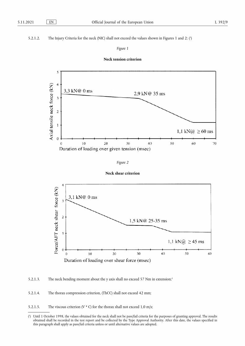
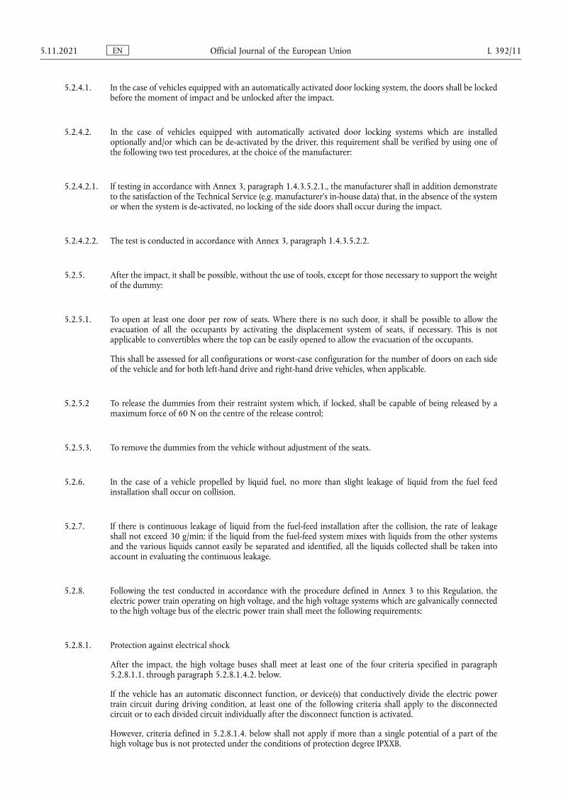
5.2.1.2. The Injury Criteria for the neck (NIC) shall not exceed the values shown in Figures 1 and 2; (3)
Figure 1
Neck tension criterion
Figure 2
Neck shear criterion
5.2.1.3. The neck bending moment about the y axis shall no exceed 57 Nm in extension;3
5.2.1.4. The thorax compression criterion, (ThCC) shall not exceed 42 mm;
5.2.1.5. The viscous criterion (V * C) for the thorax shall not exceed 1,0 m/s;
(3) Until 1 October 1998, the values obtained for the neck shall not be pass/fail criteria for the purposes of granting approval. The results obtained shall be recorded in the test report and be collected by the Type Approval Authority. After this date, the values specified in this paragraph shall apply as pass/fail criteria unless or until alternative values are adopted.
EN Official Journal of the European Union 5.11.2021 L 392/9
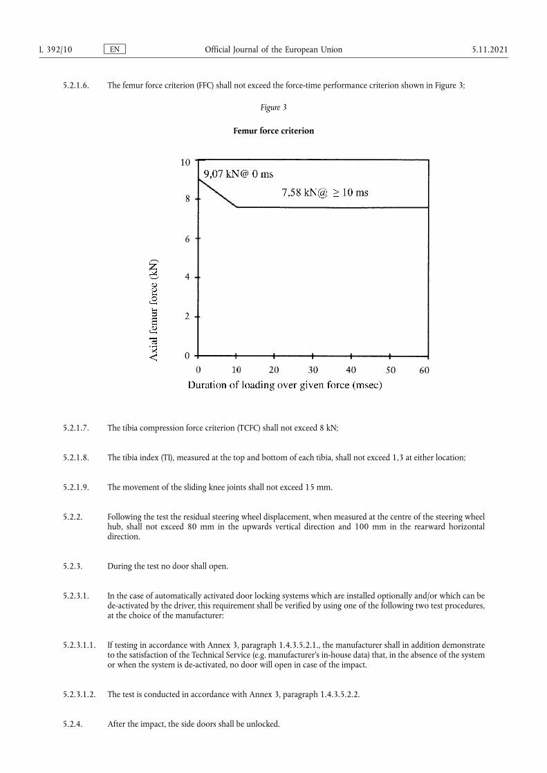
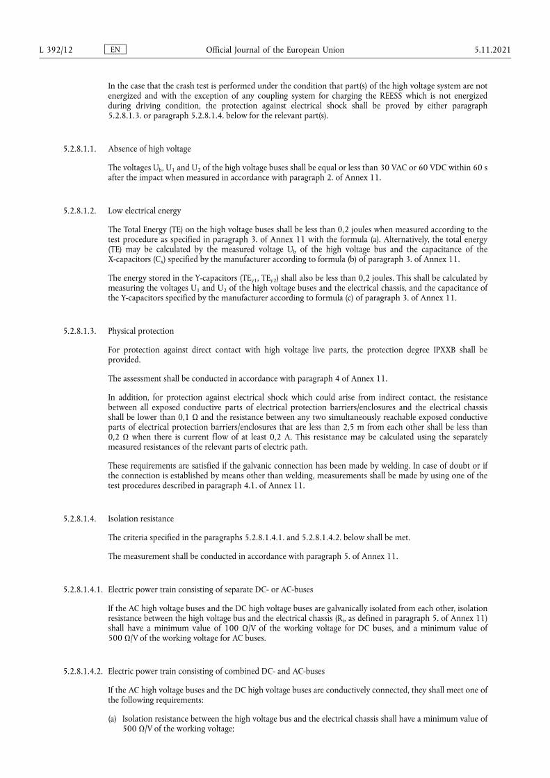
5.2.1.6. The femur force criterion (FFC) shall not exceed the force-time performance criterion shown in Figure 3;
Figure 3
Femur force criterion
5.2.1.7. The tibia compression force criterion (TCFC) shall not exceed 8 kN;
5.2.1.8. The tibia index (TI), measured at the top and bottom of each tibia, shall not exceed 1,3 at either location;
5.2.1.9. The movement of the sliding knee joints shall not exceed 15 mm.
5.2.2. Following the test the residual steering wheel displacement, when measured at the centre of the steering wheel hub, shall not exceed 80 mm in the upwards vertical direction and 100 mm in the rearward horizontal direction.
5.2.3. During the test no door shall open.
5.2.3.1. In the case of automatically activated door locking systems which are installed optionally and/or which can be de-activated by the driver, this requirement shall be verified by using one of the following two test procedures, at the choice of the manufacturer:
5.2.3.1.1. If testing in accordance with Annex 3, paragraph 1.4.3.5.2.1., the manufacturer shall in addition demonstrate to the satisfaction of the Technical Service (e.g. manufacturer’s in-house data) that, in the absence of the system or when the system is de-activated, no door will open in case of the impact.
5.2.3.1.2. The test is conducted in accordance with Annex 3, paragraph 1.4.3.5.2.2.
5.2.4. After the impact, the side doors shall be unlocked.
EN Official Journal of the European Union L 392/10 5.11.2021
5.2.4.1. In the case of vehicles equipped with an automatically activated door locking system, the doors shall be locked before the moment of impact and be unlocked after the impact.
5.2.4.2. In the case of vehicles equipped with automatically activated door locking systems which are installed optionally and/or which can be de-activated by the driver, this requirement shall be verified by using one of the following two test procedures, at the choice of the manufacturer:
5.2.4.2.1. If testing in accordance with Annex 3, paragraph 1.4.3.5.2.1., the manufacturer shall in addition demonstrate to the satisfaction of the Technical Service (e.g. manufacturer’s in-house data) that, in the absence of the system or when the system is de-activated, no locking of the side doors shall occur during the impact.
5.2.4.2.2. The test is conducted in accordance with Annex 3, paragraph 1.4.3.5.2.2.
5.2.5. After the impact, it shall be possible, without the use of tools, except for those necessary to support the weight of the dummy:
5.2.5.1. To open at least one door per row of seats. Where there is no such door, it shall be possible to allow the evacuation of all the occupants by activating the displacement system of seats, if necessary. This is not applicable to convertibles where the top can be easily opened to allow the evacuation of the occupants.
This shall be assessed for all configurations or worst-case configuration for the number of doors on each side of the vehicle and for both left-hand drive and right-hand drive vehicles, when applicable.
5.2.5.2 To release the dummies from their restraint system which, if locked, shall be capable of being released by a maximum force of 60 N on the centre of the release control;
5.2.5.3. To remove the dummies from the vehicle without adjustment of the seats.
5.2.6. In the case of a vehicle propelled by liquid fuel, no more than slight leakage of liquid from the fuel feed installation shall occur on collision.
5.2.7. If there is continuous leakage of liquid from the fuel-feed installation after the collision, the rate of leakage shall not exceed 30 g/min; if the liquid from the fuel-feed system mixes with liquids from the other systems and the various liquids cannot easily be separated and identified, all the liquids collected shall be taken into account in evaluating the continuous leakage.
5.2.8. Following the test conducted in accordance with the procedure defined in Annex 3 to this Regulation, the electric power train operating on high voltage, and the high voltage systems which are galvanically connected to the high voltage bus of the electric power train shall meet the following requirements:
5.2.8.1. Protection against electrical shock
After the impact, the high voltage buses shall meet at least one of the four criteria specified in paragraph 5.2.8.1.1. through paragraph 5.2.8.1.4.2. below.
If the vehicle has an automatic disconnect function, or device(s) that conductively divide the electric power train circuit during driving condition, at least one of the following criteria shall apply to the disconnected circuit or to each divided circuit individually after the disconnect function is activated.
However, criteria defined in 5.2.8.1.4. below shall not apply if more than a single potential of a part of the high voltage bus is not protected under the conditions of protection degree IPXXB.
EN Official Journal of the European Union 5.11.2021 L 392/11
In the case that the crash test is performed under the condition that part(s) of the high voltage system are not energized and with the exception of any coupling system for charging the REESS which is not energized during driving condition, the protection against electrical shock shall be proved by either paragraph 5.2.8.1.3. or paragraph 5.2.8.1.4. below for the relevant part(s).
5.2.8.1.1. Absence of high voltage
The voltages Ub, U1 and U2 of the high voltage buses shall be equal or less than 30 VAC or 60 VDC within 60 s after the impact when measured in accordance with paragraph 2. of Annex 11.
5.2.8.1.2. Low electrical energy
The Total Energy (TE) on the high voltage buses shall be less than 0,2 joules when measured according to the test procedure as specified in paragraph 3. of Annex 11 with the formula (a). Alternatively, the total energy (TE) may be calculated by the measured voltage Ub of the high voltage bus and the capacitance of the X-capacitors (Cx) specified by the manufacturer according to formula (b) of paragraph 3. of Annex 11.
The energy stored in the Y-capacitors (TEy1, TEy2) shall also be less than 0,2 joules. This shall be calculated by measuring the voltages U1 and U2 of the high voltage buses and the electrical chassis, and the capacitance of the Y-capacitors specified by the manufacturer according to formula (c) of paragraph 3. of Annex 11.
5.2.8.1.3. Physical protection
For protection against direct contact with high voltage live parts, the protection degree IPXXB shall be provided.
The assessment shall be conducted in accordance with paragraph 4 of Annex 11.
In addition, for protection against electrical shock which could arise from indirect contact, the resistance between all exposed conductive parts of electrical protection barriers/enclosures and the electrical chassis shall be lower than 0,1 Ω and the resistance between any two simultaneously reachable exposed conductive parts of electrical protection barriers/enclosures that are less than 2,5 m from each other shall be less than 0,2 Ω when there is current flow of at least 0,2 A. This resistance may be calculated using the separately measured resistances of the relevant parts of electric path.
These requirements are satisfied if the galvanic connection has been made by welding. In case of doubt or if the connection is established by means other than welding, measurements shall be made by using one of the test procedures described in paragraph 4.1. of Annex 11.
5.2.8.1.4. Isolation resistance
The criteria specified in the paragraphs 5.2.8.1.4.1. and 5.2.8.1.4.2. below shall be met.
The measurement shall be conducted in accordance with paragraph 5. of Annex 11.
5.2.8.1.4.1. Electric power train consisting of separate DC- or AC-buses
If the AC high voltage buses and the DC high voltage buses are galvanically isolated from each other, isolation resistance between the high voltage bus and the electrical chassis (Ri, as defined in paragraph 5. of Annex 11) shall have a minimum value of 100 Ω/V of the working voltage for DC buses, and a minimum value of 500 Ω/V of the working voltage for AC buses.
5.2.8.1.4.2. Electric power train consisting of combined DC- and AC-buses
If the AC high voltage buses and the DC high voltage buses are conductively connected, they shall meet one of the following requirements:
(a) Isolation resistance between the high voltage bus and the electrical chassis shall have a minimum value of 500 Ω/V of the working voltage;
EN Official Journal of the European Union L 392/12 5.11.2021
(b) Isolation resistance between the high voltage bus and the electrical chassis shall have a minimum value of 100 Ω/V of the working voltage and the AC bus meets the physical protection as described in paragraph 5.2.8.1.3.;
(c) Isolation resistance between the high voltage bus and the electrical chassis shall have a minimum value of 100 Ω/V of the working voltage and the AC bus meets the absence of high voltage as described in paragraph 5.2.8.1.1.
5.2.8.2. Electrolyte leakage
5.2.8.2.1. In case of aqueous electrolyte REESS.
For a period from the impact until 60 minutes after the impact, there shall be no electrolyte leakage from the REESS into the passenger compartment and no more than 7 per cent by volume of the REESS electrolyte with a maximum of 5,0 l leaked from the REESS to the outside of the passenger compartment. The leaked amount of electrolyte can be measured by usual techniques of determination of liquid volumes after its collection. For containers containing Stoddard, coloured coolant and electrolyte, the fluids shall be allowed to separate by specific gravity then measured.
5.2.8.2.2. In case of non-aqueous electrolyte REESS.
For a period from the impact until 60 minutes after the impact, there shall be no liquid electrolyte leakage from the REESS into the passenger compartment, luggage compartment and no liquid electrolyte leakage to outside the vehicle. This requirement shall be verified by visual inspection without disassembling any part of the vehicle.
5.2.8.3. REESS retention
REESS shall remain attached to the vehicle by at least one component anchorage, bracket, or any structure that transfers loads from REESS to the vehicle structure, and REESS located outside the passenger compartment shall not enter the passenger compartment.
5.2.8.4. REESS fire hazards
For a period from the impact until 60 minutes after the impact, there shall be no evidence of fire or explosion of the REESS.
5.3. Specific provisions
5.3.1. Vehicles of category M1 of a total permissible mass exceeding 2 500 kg that are based on vehicle types of category N1 of a total permissible mass exceeding 2 500 kg are deemed to meet the requirements of paragraph 5. where the requirements of UN Regulation No 137 are fully complied with and at least one of the following conditions is met:
(a) The acute angle alpha (α), measured between a horizontal plane passing through the centre of the front axle and an angular transverse plane passing through the centre of the front axle and the R-point of the driver’s seat (see Figure 4 below), is more than 22°;
(b) Or the ratio between the distance from the driver’s R-point to the centre of the rear axle (L101-L114) and the centre of the front axle and the driver’s R-point (L114) is more than 1,30 (see Figure 4 below).
This shall be verified by the Technical Service and subject to the decision of the Type Approval Authority, as well as stated under point 8.2. on the approval communication of Annex 1.
5.3.2. Vehicles of category N1 of a total permissible mass exceeding 2 250 kg but not exceeding 2 500 kg are deemed to meet the requirements of paragraph 5, where their structural basis is a ladder frame and the requirements of UN Regulation No 137 are fully complied with and at least one of the following conditions is met:
EN Official Journal of the European Union 5.11.2021 L 392/13
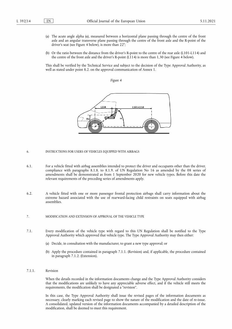
(a) The acute angle alpha (α), measured between a horizontal plane passing through the centre of the front axle and an angular transverse plane passing through the centre of the front axle and the R-point of the driver’s seat (see Figure 4 below), is more than 22°;
(b) Or the ratio between the distance from the driver’s R-point to the centre of the rear axle (L101-L114) and the centre of the front axle and the driver’s R-point (L114) is more than 1,30 (see Figure 4 below).
This shall be verified by the Technical Service and subject to the decision of the Type Approval Authority, as well as stated under point 8.2. on the approval communication of Annex 1.
Figure 4
6. INSTRUCTIONS FOR USERS OF VEHICLES EQUIPPED WITH AIRBAGS
6.1. For a vehicle fitted with airbag assemblies intended to protect the driver and occupants other than the driver, compliance with paragraphs 8.1.8. to 8.1.9. of UN Regulation No 16 as amended by the 08 series of amendments shall be demonstrated as from 1 September 2020 for new vehicle types. Before this date the relevant requirements of the preceding series of amendments apply.
6.2. A vehicle fitted with one or more passenger frontal protection airbags shall carry information about the extreme hazard associated with the use of rearward-facing child restraints on seats equipped with airbag assemblies.
7. MODIFICATION AND EXTENSION OF APPROVAL OF THE VEHICLE TYPE
7.1. Every modification of the vehicle type with regard to this UN Regulation shall be notified to the Type Approval Authority which approved that vehicle type. The Type Approval Authority may then either:
(a) Decide, in consultation with the manufacturer, to grant a new type approval; or
(b) Apply the procedure contained in paragraph 7.1.1. (Revision) and, if applicable, the procedure contained in paragraph 7.1.2. (Extension).
7.1.1. Revision
When the details recorded in the information documents change and the Type Approval Authority considers that the modifications are unlikely to have any appreciable adverse effect, and if the vehicle still meets the requirements, the modification shall be designated a "revision".
In this case, the Type Approval Authority shall issue the revised pages of the information documents as necessary, clearly marking each revised page to show the nature of the modification and the date of re-issue. A consolidated, updated version of the information documents accompanied by a detailed description of the modification, shall be deemed to meet this requirement.
EN Official Journal of the European Union L 392/14 5.11.2021
7.1.2. Extension
The modification shall be designated an "extension" if, in addition to the change of the particulars recorded in the information folder:
(a) Further inspections or tests are required; or
(b) Any information on the communication document (with the exception of its attachments) has changed; or
(c) Approval to a later series of amendments is requested after its entry into force.
7.2. Notice of confirmation, extension, or refusal of approval shall be communicated by the procedure specified in paragraph 4.3. above, to the Contracting Parties to the Agreement applying this Regulation. In addition, the index to the information documents and to the test reports, attached to the communication document of Annex 1, shall be amended accordingly to show the date of the most recent revision or extension.
8. CONFORMITY OF PRODUCTION
The conformity of production procedures shall comply with those set out in the Agreement, Schedule 1 (E/ ECE/TRANS/505/Rev.3), with the following requirements:
8.1. Every vehicle approved under this Regulation shall be manufactured so as to conform to the vehicle type approved and satisfy the requirements set forth in paragraphs 5. and 6.
8.2. The Type Approval Authority which has granted type approval may at any time verify the conformity control methods applied in each production facility. The normal frequency of these verifications shall be once every two years.
9. PENALTIES FOR NON-CONFORMITY OF PRODUCTION
9.1. The approval granted in respect of a vehicle type pursuant to this Regulation may be withdrawn if the requirement laid down in paragraph 7.1. above is not complied with.
9.2. If a Contracting Party to the Agreement applying this Regulation withdraws an approval it has previously granted, it shall forthwith so notify the other Contracting Parties applying this Regulation, by means of a copy of the approval form bearing at the end, in large letters, the signed and dated annotation "APPROVAL WITHDRAWN".
10. PRODUCTION DEFINITIVELY DISCONTINUED
If the holder of the approval completely ceases to manufacture the type of vehicle approved in accordance with the Regulation, he shall so inform the Type Approval Authority which granted the approval. Upon receiving the relevant communication that Authority shall inform thereof the other Parties to the 1958 Agreement applying this Regulation by means of a copy of the approval form bearing at the end, in large letters, the signed and dated annotation "PRODUCTION DISCONTINUED".
11. NAMES AND ADDRESSES OF TECHNICAL SERVICES RESPONSIBLE FOR CONDUCTING APPROVAL TESTS, AND OF TYPE APPROVAL AUTHORITIES
The Contracting Parties to the Agreement applying this Regulation shall communicate to the United Nations secretariat the names and addresses of the Technical Services responsible for conducting approval tests, of manufacturers authorized to carry out tests and of the Type Approval Authorities which grant approval and to which forms certifying approval or refusal or withdrawal of approval, issued in other countries, are to be sent.
EN Official Journal of the European Union 5.11.2021 L 392/15

12. TRANSITIONAL PROVISIONS
12.1. As from the official date of entry into force of the 04 series of amendments, no Contracting Party applying this Regulation shall refuse to grant or refuse to accept type-approvals under this Regulation as amended by the 04 series of amendments.
12.2. As from 1 September 2023, Contracting Parties applying this Regulation shall not be obliged to accept type- approvals of vehicles according to the preceding series of amendments, first issued after 1 September 2023.
12.3. Contracting Parties applying this Regulation shall continue to accept type-approvals of vehicles according to the preceding series of amendments, first issued before 1 September 2023, provided the transitional provisions in these respective previous series of amendments foresee this possibility
12.4. Contracting Parties applying this Regulation shall not refuse to grant type-approvals according to any preceding series of amendments to this Regulation or extensions thereof.
12.5. Notwithstanding the transitional provisions above, Contracting Parties who start to apply this Regulation after the date of entry into force of the most recent series of amendments are not obliged to accept type-approvals which were granted in accordance with any of the preceding series of amendments to this Regulation.
EN Official Journal of the European Union L 392/16 5.11.2021

ANNEX 1
Communication
(Maximum format: A4 (210 × 297 mm))
()
issued by: Name of administration. . . . . . . . . . . . . . . . . . . . . . . . . . . . . . . . . . . . . . . . .. . . . . . . . . . . . . . . . . . . . . . . . . . . . . . . . . . . . . . . . .. . . . . . . . . . . . . . . . . . . . . . . . . . . . . . . . . . . . . . . . .
Concerning (2): Approval grantedApproval extendedApproval refusedApproval withdrawnProduction definitively discontinued
of a vehicle type with regard to the protection of the occupants in the event of a frontal collision, pursuant to Regulation No 94
Approval No: . . . . . . . . . . . . . . . . . . . . . . . . . . . . . . . . . . . . . . . . . . . . . . . . Extension No: . . . . . . . . . . . . . . . . . . . . . . . . . . . . . . . . . . . . . . . . . . . . . . .
1. Trade name or mark of the power-driven vehicle . . . . . . . . . . . . . . . . . . . . . . . . . . . . . . . . . . . . . . . . . . . . . . . . . . . . . . . . . . . . . . . . . . . . . . .
2. Vehicle type . . . . . . . . . . . . . . . . . . . . . . . . . . . . . . . . . . . . . . . . . . . . . . . . . . . . . . . . . . . . . . . . . . . . . . . . . . . . . . . . . . . . . . . . . . . . . . . . . . . . . . . . . . . . .
3. Manufacturer’s name and address . . . . . . . . . . . . . . . . . . . . . . . . . . . . . . . . . . . . . . . . . . . . . . . . . . . . . . . . . . . . . . . . . . . . . . . . . . . . . . . . . . . . . . .
. . . . . . . . . . . . . . . . . . . . . . . . . . . . . . . . . . . . . . . . . . . . . . . . . . . . . . . . . . . . . . . . . . . . . . . . . . . . . . . . . . . . . . . . . . . . . . . . . . . . . . . . . . . . . . . . . . . . . . . . . . . . . . . .
4. If applicable, name and address of manufacturer’s representative
. . . . . . . . . . . . . . . . . . . . . . . . . . . . . . . . . . . . . . . . . . . . . . . . . . . . . . . . . . . . . . . . . . . . . . . . . . . . . . . . . . . . . . . . . . . . . . . . . . . . . . . . . . . . . . . . . . . . . . . . . . . . . . . .
. . . . . . . . . . . . . . . . . . . . . . . . . . . . . . . . . . . . . . . . . . . . . . . . . . . . . . . . . . . . . . . . . . . . . . . . . . . . . . . . . . . . . . . . . . . . . . . . . . . . . . . . . . . . . . . . . . . . . . . . . . . . . . . .
5. Brief description of the vehicle type as regards its structure, dimensions, lines and constituent materials . . . . . . . . . . . . . . .
. . . . . . . . . . . . . . . . . . . . . . . . . . . . . . . . . . . . . . . . . . . . . . . . . . . . . . . . . . . . . . . . . . . . . . . . . . . . . . . . . . . . . . . . . . . . . . . . . . . . . . . . . . . . . . . . . . . . . . . . . . . . . . . .
5.1. Description of the protective system installed in the vehicle . . . . . . . . . . . . . . . . . . . . . . . . . . . . . . . . . . . . . . . . . . . . . . . . . . . . . . . . . . . .
. . . . . . . . . . . . . . . . . . . . . . . . . . . . . . . . . . . . . . . . . . . . . . . . . . . . . . . . . . . . . . . . . . . . . . . . . . . . . . . . . . . . . . . . . . . . . . . . . . . . . . . . . . . . . . . . . . . . . . . . . . . . . . . .
5.2. Description of interior arrangements or fittings that might affect the tests . . . . . . . . . . . . . . . . . . . . . . . . . . . . . . . . . . . . . . . . . . . . . .
. . . . . . . . . . . . . . . . . . . . . . . . . . . . . . . . . . . . . . . . . . . . . . . . . . . . . . . . . . . . . . . . . . . . . . . . . . . . . . . . . . . . . . . . . . . . . . . . . . . . . . . . . . . . . . . . . . . . . . . . . . . . . . . .
5.3 Location of the electrical power source . . . . . . . . . . . . . . . . . . . . . . . . . . . . . . . . . . . . . . . . . . . . . . . . . . . . . . . . . . . . . . . . . . . . . . . . . . . . . . . . .
6. Site of engine: forward/rear/central2
7. Drive: front-wheel/rear-wheel2
8. Mass of the Vehicle
EN Official Journal of the European Union 5.11.2021 L 392/17

8.1. Mass of vehicle submitted for testing:
Front axle: . . . . . . . . . . . . . . . . . . . . . . . . . . . . . . . . . . . . . . . . . . . . . . . . . . . . . . . . . . . . . . . . . . . . . . . . . . . . . . . . . . . . . . . . . . . . . . . . . . . . . . . . . . . . . . .
Rear axle: . . . . . . . . . . . . . . . . . . . . . . . . . . . . . . . . . . . . . . . . . . . . . . . . . . . . . . . . . . . . . . . . . . . . . . . . . . . . . . . . . . . . . . . . . . . . . . . . . . . . . . . . . . . . . . . .
Total: . . . . . . . . . . . . . . . . . . . . . . . . . . . . . . . . . . . . . . . . . . . . . . . . . . . . . . . . . . . . . . . . . . . . . . . . . . . . . . . . . . . . . . . . . . . . . . . . . . . . . . . . . . . . . . . . . . . .
8.2. Where paragraph 5.3.1. or 5.3.2. applies:
Total permissible mass . . . . . . . . . . . . . . . . . . . . . . . . . . . . . . . . . . . . . . . . . . . . . . . . . . . . . . . . . . . . . . . . . . . . . . . . . . . . . . . . . . . . . . . . . . . . . . . . . . .
Proof of compliance with UN Regulation 137 (i.e. type approval number or test report):
9. Vehicle submitted for approval on . . . . . . . . . . . . . . . . . . . . . . . . . . . . . . . . . . . . . . . . . . . . . . . . . . . . . . . . . . . . . . . . . . . . . . . . . . . . . . . . . . . . . . .
10. Technical Service responsible for conducting approval tests . . . . . . . . . . . . . . . . . . . . . . . . . . . . . . . . . . . . . . . . . . . . . . . . . . . . . . . . . . . .
11. Date of report issued by that Service . . . . . . . . . . . . . . . . . . . . . . . . . . . . . . . . . . . . . . . . . . . . . . . . . . . . . . . . . . . . . . . . . . . . . . . . . . . . . . . . . . . .
12. Number of report issued by that Service . . . . . . . . . . . . . . . . . . . . . . . . . . . . . . . . . . . . . . . . . . . . . . . . . . . . . . . . . . . . . . . . . . . . . . . . . . . . . . . .
13. Approval granted/refused/extended/withdrawn (2)
14. Position of approval mark on vehicle . . . . . . . . . . . . . . . . . . . . . . . . . . . . . . . . . . . . . . . . . . . . . . . . . . . . . . . . . . . . . . . . . . . . . . . . . . . . . . . . . . . .
15. Place . . . . . . . . . . . . . . . . . . . . . . . . . . . . . . . . . . . . . . . . . . . . . . . . . . . . . . . . . . . . . . . . . . . . . . . . . . . . . . . . . . . . . . . . . . . . . . . . . . . . . . . . . . . . . . . . . . . . .
16. Date . . . . . . . . . . . . . . . . . . . . . . . . . . . . . . . . . . . . . . . . . . . . . . . . . . . . . . . . . . . . . . . . . . . . . . . . . . . . . . . . . . . . . . . . . . . . . . . . . . . . . . . . . . . . . . . . . . . . .
17. Signature . . . . . . . . . . . . . . . . . . . . . . . . . . . . . . . . . . . . . . . . . . . . . . . . . . . . . . . . . . . . . . . . . . . . . . . . . . . . . . . . . . . . . . . . . . . . . . . . . . . . . . . . . . . . . . . .
18. The following documents, bearing the approval number shown above, are annexed to this communication: . . . . . . . . . .
(Photographs and/or diagrams and drawings permitting the basic identification of the type(s) of vehicle and its possible variants which are covered by the approval)
_____________(1) Distinguishing number of the country which has granted/extended/refused/withdrawn approval (see approval provisions in the
Regulation).(2) Strike out what does not apply.
EN Official Journal of the European Union L 392/18 5.11.2021
ANNEX 2
Arrangements of approval marks
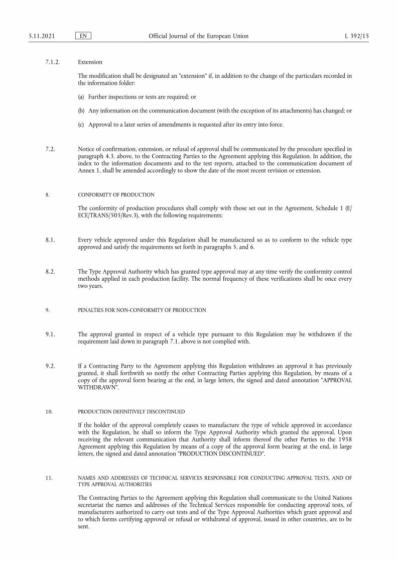
MODEL A
(See paragraph 4.4. of this Regulation)
a = 8 mm min.
The above approval mark affixed to a vehicle shows that the vehicle type concerned has, with regard to the protection of the occupants in the event of a frontal collision, been approved in the Netherlands (E 4) pursuant to UN Regulation No 94 under approval number 041424. The approval number indicates that the approval was granted in accordance with the requirements of UN Regulation No 94 as amended by the 04 series of amendments.
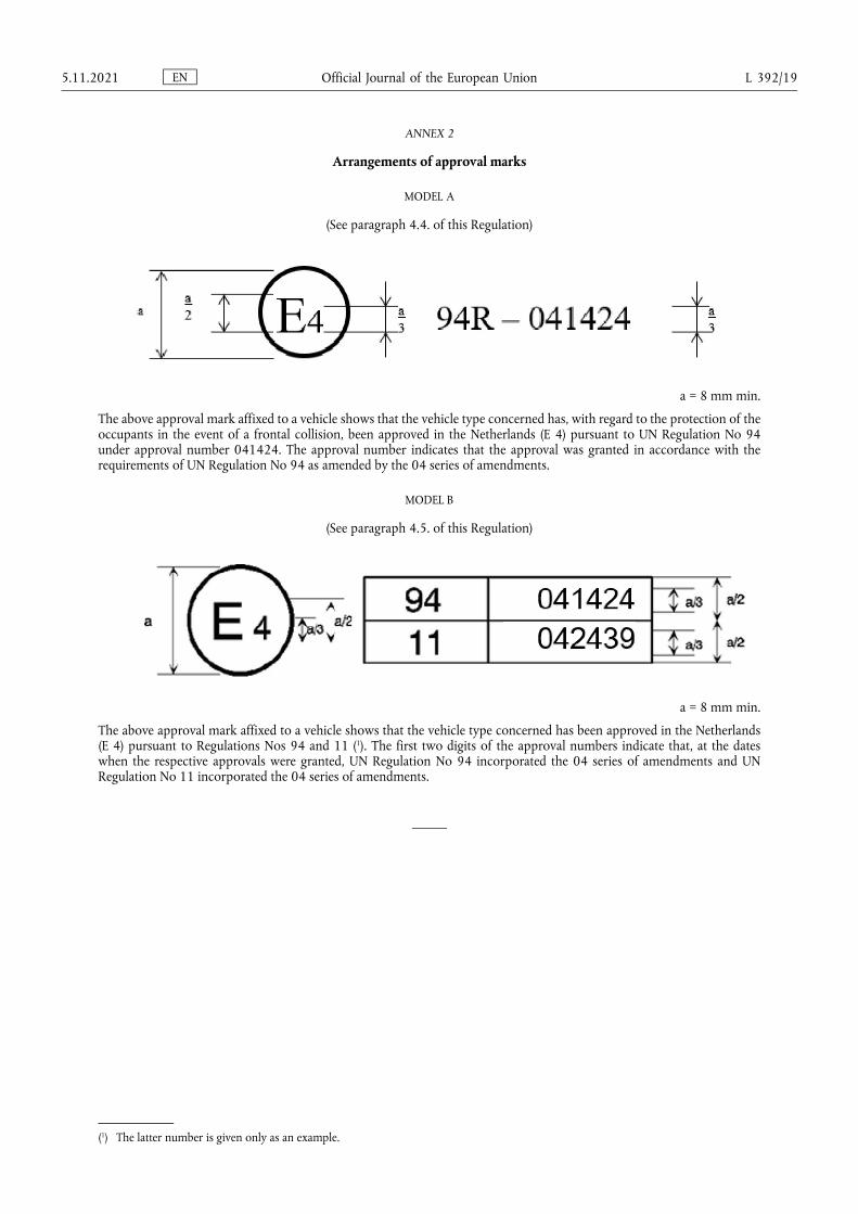
MODEL B
(See paragraph 4.5. of this Regulation)
a = 8 mm min.
The above approval mark affixed to a vehicle shows that the vehicle type concerned has been approved in the Netherlands (E 4) pursuant to Regulations Nos 94 and 11 (1). The first two digits of the approval numbers indicate that, at the dates when the respective approvals were granted, UN Regulation No 94 incorporated the 04 series of amendments and UN Regulation No 11 incorporated the 04 series of amendments.
(1) The latter number is given only as an example.
EN Official Journal of the European Union 5.11.2021 L 392/19
ANNEX 3
Test procedure
1. Installation and preparation of the vehicle
1.1. Testing ground
The test area shall be large enough to accommodate the run-up track, barrier and technical installations necessary for the test. The last part of the track, for at least 5 m before the barrier, shall be horizontal, flat and smooth.
1.2. Barrier
The front face of the barrier consists of a deformable structure as defined in Annex 9 of this Regulation. The front face of the deformable structure is perpendicular within ±1° to the direction of travel of the test vehicle. The barrier is secured to a mass of not less than 7 × 10⁴ kg, the front face of which is vertical within ±1°. The mass is anchored in the ground or placed on the ground with, if necessary, additional arresting devices to restrict its movement.
1.3. Orientation of the barrier
The orientation of the barrier is such that the first contact of the vehicle with the barrier is on the steering- column side. Where there is a choice between carrying out the test with a right-hand or left-hand drive vehicle, the test shall be carried out with the less favourable hand of drive as determined by the Technical Service responsible for the tests.
1.3.1. Alignment of the vehicle to the barrier
The vehicle shall overlap the barrier face by 40 per cent ± 20 mm.
1.4. State of vehicle
1.4.1. General specification
The test vehicle shall be representative of the series production, shall include all the equipment normally fitted and shall be in normal running order. Some components may be replaced by equivalent masses where this substitution clearly has no noticeable effect on the results measured under paragraph 6.
It shall be allowed by agreement between manufacturer and Technical Service to modify the fuel system so that an appropriate amount of fuel can be used to run the engine or the electrical energy conversion system.
1.4.2. Mass of vehicle
1.4.2.1. For the test, the mass of the vehicle submitted shall be the unladen kerb mass.
1.4.2.2. The fuel tank shall be filled with water to mass equal to 90 per cent of the mass of a full load of fuel as specified by the manufacturer with a tolerance of ±1 per cent.
This requirement does not apply to hydrogen fuel tanks.
1.4.2.3. All the other systems (brake, cooling, ...) may be empty in this case, the mass of the liquids shall be carefully compensated.
1.4.2.4. If the mass of the measuring apparatus on board the vehicle exceeds the 25 kg allowed, it may be compensated by reductions which have no noticeable effect on the results measured under paragraph 6. below.
EN Official Journal of the European Union L 392/20 5.11.2021
1.4.2.5. The mass of the measuring apparatus shall not change each axle reference load by more than 5 per cent, each variation not exceeding 20 kg.
1.4.2.6. The mass of the vehicle resulting from the provisions of paragraph 1.4.2.1. above shall be indicated in the report.
1.4.3. Passenger compartment adjustments
1.4.3.1. Position of steering wheel
The steering wheel, if adjustable, shall be placed in the normal position indicated by the manufacturer or, in the absence of any particular recommendation by the manufacturer, midway between the limits of its range(s) of adjustment. At the end of propelled travel, the steering wheel shall be left free, with its spokes in the position which according to the manufacturer corresponds to straight-ahead travel of the vehicle.
1.4.3.2. Glazing
The movable glazing of the vehicle shall be in the closed position. For test measurement purposes and in agreement with the manufacturer, it may be lowered, provided that the position of the operating handle corresponds to the closed position.
1.4.3.3. Gear-change lever
The gear-change lever shall be in the neutral position. If the vehicle is propelled by its own engine, then the gear-change level shall be defined by the manufacturer.
1.4.3.4. Pedals
The pedals shall be in their normal position of rest. If adjustable, they shall be set in their mid-position unless another position is specified by the manufacturer.
1.4.3.5. Doors
The doors shall be closed but not locked.
1.4.3.5.1. In the case of vehicles equipped with an automatically activated door locking system, the system shall be activated at the start of propulsion of the vehicle in order to lock the doors automatically before the moment of impact. At the choice of the manufacturer, the doors shall be locked manually before the start of propulsion of the vehicle.
1.4.3.5.2. In the case of vehicles equipped with an automatically activated door locking system that is installed optionally and/or which can be de-activated by the driver, one of the following two procedures shall be used at the choice of the manufacturer:
1.4.3.5.2.1. The system shall be activated at the start of propulsion of the vehicle in order to lock the doors automatically before the moment of impact. At the choice of the manufacturer, the doors shall be locked manually before the start of propulsion of the vehicle.
1.4.3.5.2.2. The side doors on the impacted side shall be unlocked and the system overridden for these doors; for the side doors on the non-impacted side, the system may be activated in order to lock these doors automatically before the moment of impact. At the choice of the manufacturer, these doors shall be locked manually before the start of propulsion of the vehicle.
EN Official Journal of the European Union 5.11.2021 L 392/21
1.4.3.6. Opening roof
If an opening or removable roof is fitted, it shall be in place and in the closed position. For test measurement purposes and in agreement with the manufacturer, it may be open.
1.4.3.7. Sun-visor
The sun-visors shall be in the stowed position.
1.4.3.8. Rear-view mirror
The interior rear-view mirror shall be in the normal position of use.
1.4.3.9. Arm-rests
Arm-rests at the front and rear, if movable, shall be in the lowered position, unless this is prevented by the position of the dummies in the vehicles.
1.4.3.10. Head restraints
Head restraints adjustable for height shall be in their appropriate position as defined by the manufacturer. In the absence of any particular recommendation from the manufacturer, then the head restraints shall be in their uppermost position.
1.4.3.11. Seats
1.4.3.11.1. Position of front seats
Seats adjustable longitudinally shall be placed so that their "H" point, determined in accordance with the procedure set out in Annex 6 is in the middle position of travel or in the nearest locking position thereto, and at the height position defined by the manufacturer (if independently adjustable for height). In the case of a bench seat, the reference shall be to the "H" point of the driver’s place.
1.4.3.11.2. Position of the front seat-backs
If adjustable, the seat-backs shall be adjusted so that the resulting inclination of the torso of the dummy is as close as possible to that recommended by the manufacturer for normal use or, in the absence of any particular recommendation by the manufacturer, to 25° towards the rear from the vertical.
1.4.3.11.3. Rear seats
If adjustable, the rear seats or rear bench seats shall be placed in the rearmost position.
1.4.4. Electric power train adjustment
1.4.4.1. Procedures for SOC adjustment.
1.4.4.1.1. The adjustment of SOC shall be conducted at an ambient temperature of 20 ± 10 °C.
1.4.4.1.2. The SOC shall be adjusted according to one of the following procedures as applicable. Where different charging procedures are possible, REESS shall be charged using the procedure which yields the highest SOC:
(a) For a vehicle with a REESS designed to be externally charged, the REESS shall be charged to the highest SOC in accordance with the procedure specified by the manufacturer for normal operation until the charging process is normally terminated.
EN Official Journal of the European Union L 392/22 5.11.2021
(b) For a vehicle with a REESS designed to be charged only by an energy source on the vehicle, the REESS shall be charged to the highest SOC which is achievable with normal operation of the vehicle. The manufacturer shall advise on the vehicle operation mode to attain this SOC.
1.4.4.1.3. When the vehicle is tested, SOC shall be no less than 95 per cent of SOC according to paragraphs 1.4.4.1.1. and 1.4.4.1.2. for REESS designed to be externally charged and shall be no less than 90 per cent of SOC according to paragraphs 1.4.4.1.1. and 1.4.4.1.2. for REESS designed to be charged only by an energy source on the vehicle. SOC will be confirmed by a method provided by the manufacturer.
1.4.4.2. The electric power train shall be energized with or without the operation of the original electrical energy sources (e.g. engine-generator, REESS or electric energy conversion system), however:
1.4.4.2.1. By the agreement between Technical Service and manufacturer it shall be permissible to perform the test with all or parts of the electric power train not being energized insofar as there is no negative influence on the test result. For parts of the electric power train not energized, the protection against electrical shock shall be proved by either physical protection or isolation resistance and appropriate additional evidence.
1.4.4.2.2. In the case where an automatic disconnect is provided, at the request of the manufacturer it shall be permissible to perform the test with the automatic disconnect being triggered. In this case it shall be demonstrated that the automatic disconnect would have operated during the impact test. This includes the automatic activation signal as well as the galvanic separation considering the conditions as seen during the impact.
2. Dummies
2.1. Front seats
2.1.1. A dummy corresponding to the specifications for Hybrid III fiftieth percentile male dummy (1)fitted with a 45° ankle and meeting the specifications for its adjustment shall be installed in each of the front outboard seats in accordance with the conditions set out in Annex 5. The ankle of the dummy shall be certified in accordance with the procedures in Annex 10.
2.1.2. The car will be tested with restraint systems, as provided by the manufacturer.
3. Propulsion and course of vehicle
3.1. The vehicle shall be propelled either by its own engine or by any other propelling device.
3.2. At the moment of impact the vehicle shall no longer be subject to the action of any additional steering or propelling device.
3.3. The course of the vehicle shall be such that it satisfies the requirements of paragraphs 1.2. and 1.3.1. above.
(1) The technical specifications and detailed drawings of Hybrid III corresponding to the principal dimensions of a fiftieth percentile male of the United States of America, and the specifications for its adjustment for this test are deposited with the Secretary-General of the United Nations and may be consulted on request at the secretariat of the Economic Commission for Europe, Palais des Nations, Geneva, Switzerland.
EN Official Journal of the European Union 5.11.2021 L 392/23
4. Test speed
Vehicle speed at the moment of impact shall be 56 -0/+1 km/h. However, if the test was performed at a higher impact speed and the vehicle met the requirements, the test shall be considered satisfactory.
5. Measurements to be made on the dummy in front seats
5.1. All the measurements necessary for the verification of the performance criteria shall be made with measurement systems corresponding to the specifications of Annex 8.
5.2. The different parameters shall be recorded through independent data channels of the following CFC (Channel Frequency Class):
5.2.1. Measurements in the head of the dummy
The acceleration (a) referring to the centre of gravity is calculated from the triaxial components of the acceleration measured with a CFC of 1 000.
5.2.2. Measurements in the neck of the dummy
5.2.2.1. The axial tensile force and the fore/aft shear force at the neck/head interface are measured with a CFC of 1 000.
5.2.2.2. The bending moment about a lateral axis at the neck/head interface are measured with a CFC of 600.
5.2.3. Measurements in the thorax of the dummy
The chest deflection between the sternum and the spine is measured with a CFC of 180.
5.2.4. Measurements in the femur and tibia of the dummy
5.2.4.1. The axial compressive force and the bending moments are measured with a CFC of 600.
5.2.4.2. The displacement of the tibia with respect to the femur is measured at the knee sliding joint with a CFC of 180.
6. Measurements to be made on the vehicle
6.1. To enable the simplified test described in Annex 7 to be carried out, the deceleration time history of the structure shall be determined on the basis of the value of the longitudinal accelerometers at the base of the "B" pillar on the struck side of the vehicle with a CFC of 180 by means of data channels corresponding to the requirements set out in Annex 8;
6.2. The speed time history which will be used in the test procedure described in Annex 7 shall be obtained from the longitudinal accelerometer at the "B" pillar on the struck side.
EN Official Journal of the European Union L 392/24 5.11.2021
ANNEX 4
Head Performance Criterion (HPC) and 3 ms head acceleration performance criteria
1. Head Performance Criterion (HPC36)
1.1. The Head Performance Criterion (HPC36) is considered to be satisfied when, during the test, there is no contact between the head and any vehicle component.
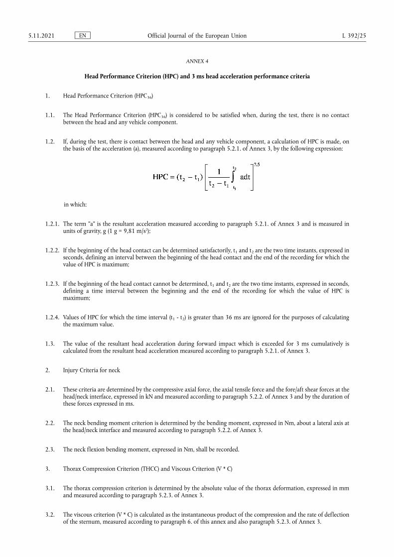
1.2. If, during the test, there is contact between the head and any vehicle component, a calculation of HPC is made, on the basis of the acceleration (a), measured according to paragraph 5.2.1. of Annex 3, by the following expression:
in which:
1.2.1. The term "a" is the resultant acceleration measured according to paragraph 5.2.1. of Annex 3 and is measured in units of gravity, g (1 g = 9,81 m/s2);
1.2.2. If the beginning of the head contact can be determined satisfactorily, t1 and t2 are the two time instants, expressed in seconds, defining an interval between the beginning of the head contact and the end of the recording for which the value of HPC is maximum;
1.2.3. If the beginning of the head contact cannot be determined, t1 and t2 are the two time instants, expressed in seconds, defining a time interval between the beginning and the end of the recording for which the value of HPC is maximum;
1.2.4. Values of HPC for which the time interval (t1 - t2) is greater than 36 ms are ignored for the purposes of calculating the maximum value.
1.3. The value of the resultant head acceleration during forward impact which is exceeded for 3 ms cumulatively is calculated from the resultant head acceleration measured according to paragraph 5.2.1. of Annex 3.
2. Injury Criteria for neck
2.1. These criteria are determined by the compressive axial force, the axial tensile force and the fore/aft shear forces at the head/neck interface, expressed in kN and measured according to paragraph 5.2.2. of Annex 3 and by the duration of these forces expressed in ms.
2.2. The neck bending moment criterion is determined by the bending moment, expressed in Nm, about a lateral axis at the head/neck interface and measured according to paragraph 5.2.2. of Annex 3.
2.3. The neck flexion bending moment, expressed in Nm, shall be recorded.
3. Thorax Compression Criterion (THCC) and Viscous Criterion (V * C)
3.1. The thorax compression criterion is determined by the absolute value of the thorax deformation, expressed in mm and measured according to paragraph 5.2.3. of Annex 3.
3.2. The viscous criterion (V * C) is calculated as the instantaneous product of the compression and the rate of deflection of the sternum, measured according to paragraph 6. of this annex and also paragraph 5.2.3. of Annex 3.
EN Official Journal of the European Union 5.11.2021 L 392/25
4. Femur Force Criterion (FFC)
4.1. This criterion is determined by the compression load expressed in kN, transmitted axially on each femur of the dummy and measured according to paragraph 5.2.4. of Annex 3 and by the duration of the compressive load expressed in ms.
5. Tibia Compressive Force Criterion (TCFC) and Tibia Index (TI)
5.1. The tibia compressive force criterion is determined by the compressive load (Fz) expressed in kN, transmitted axially on each tibia of the dummy and measured according to paragraph 5.2.4. of Annex 3.
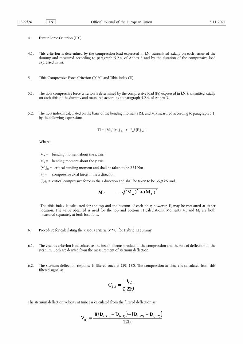
5.2. The tibia index is calculated on the basis of the bending moments (Mx and My) measured according to paragraph 5.1. by the following expression:
TI = | MR/ (MC) R | + | FZ/ (FC) Z |
Where:
MX = bending moment about the x axis
MY = bending moment about the y axis
(MC)R = critical bending moment and shall be taken to be 225 Nm
FZ = compressive axial force in the z direction
(FC)Z = critical compressive force in the z direction and shall be taken to be 35,9 kN and
The tibia index is calculated for the top and the bottom of each tibia; however, Fz may be measured at either location. The value obtained is used for the top and bottom TI calculations. Moments Mx and My are both measured separately at both locations.
6. Procedure for calculating the viscous criteria (V * C) for Hybrid III dummy
6.1. The viscous criterion is calculated as the instantaneous product of the compression and the rate of deflection of the sternum. Both are derived from the measurement of sternum deflection.
6.2. The sternum deflection response is filtered once at CFC 180. The compression at time t is calculated from this filtered signal as:
The sternum deflection velocity at time t is calculated from the filtered deflection as:
EN Official Journal of the European Union L 392/26 5.11.2021
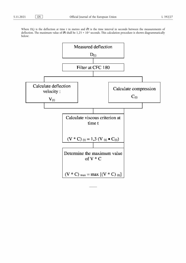
Where D(t) is the deflection at time t in metres and is the time interval in seconds between the measurements of deflection. The maximum value of shall be 1,25 × 10⁻⁴ seconds. This calculation procedure is shown diagrammatically below:
EN Official Journal of the European Union 5.11.2021 L 392/27
ANNEX 5
Arrangement and installation of dummies and adjustment of restraint systems
1. Arrangement of dummies
1.1. Separate seats
The plane of symmetry of the dummy shall coincide with the vertical median plane of the seat.
1.2. Front bench seat
1.2.1. Driver
The plane of symmetry of the dummy shall lie in the vertical plane passing through the steering wheel centre and parallel to the longitudinal median plane of the vehicle. If the seating position is determined by the shape of the bench, such seat shall be regarded as a separate seat.
1.2.2. Outer passenger
The plane of symmetry of the dummy shall be symmetrical with that of the driver dummy relative to the longitudinal median plane of the vehicle. If the seating position is determined by the shape of the bench, such seat shall be regarded as a separate seat.
1.3. Bench seat for front passengers (not including driver)
The planes of symmetry of the dummy shall coincide with the median planes of the seating positions defined by the manufacturer.
2. Installation of dummies
2.1. Head
The transverse instrumentation platform of the head shall be horizontal within 2,5°. To level the head of the test dummy in vehicles with upright seats with non-adjustable backs, the following sequences must be followed. First adjust the position of the "H" point within the limits set forth in paragraph 2.4.3.1. below to level the transverse instrumentation platform of the head of the test dummy. If the transverse instrumentation platform of the head is still not level, then adjust the pelvic angle of the test dummy within the limits provided in paragraph 2.4.3.2. below. If the transverse instrumentation platform of the head is still not level, then adjust the neck bracket of the test dummy the minimum amount necessary to ensure that the transverse instrumentation platform of the head is horizontal within 2,5°.
2.2. Arms
2.2.1. The driver’s upper arms shall be adjacent to the torso with the centrelines as close to a vertical plane as possible.
2.2.2. The passenger’s upper arms shall be in contact with the seat back and the sides of the torso.
2.3. Hands
2.3.1. The palms of the driver test dummy shall be in contact with the outer part of the steering wheel rim at the rim’s horizontal centreline. The thumbs shall be over the steering wheel rim and shall be lightly taped to the steering wheel rim so that if the hand of the test dummy is pushed upward by a force of not less than 9 N and not more than 22 N, the tape shall release the hand from the steering wheel rim.
EN Official Journal of the European Union L 392/28 5.11.2021
2.3.2. The palms of the passenger test dummy shall be in contact with outside of thigh. The little finger shall be in contact with the seat cushion.
2.4. Torso
2.4.1. In vehicles equipped with bench seats, the upper torso of the driver and passenger test dummies shall rest against the seat back. The midsagittal plane of the driver dummy shall be vertical and parallel to the vehicle’s longitudinal centreline, and pass through the centre of the steering wheel rim. The midsagittal plane of the passenger dummy shall be vertical and parallel to the vehicle’s longitudinal centreline and the same distance from the vehicle’s longitudinal centreline as the midsagittal plane of the driver dummy.
2.4.2. In vehicles equipped with individual seats, the upper torso of the driver and passenger test dummies shall rest against the seat back. The midsagittal plane of the driver and the passenger dummy shall be vertical and shall coincide with the longitudinal centreline of the individual seat.
2.4.3. Lower torso
2.4.3.1. "H" point
The "H" point of the driver and passenger test dummies shall coincide within 13 mm in the vertical dimension and 13 mm in the horizontal dimension, with a point 6 mm below the position of the "H" point determined using the procedure described in Annex 6 except that the length of the lower leg and thigh segments of the "H" point machine shall be adjusted to 414 and 401 mm, instead of 417 and 432 mm respectively.
2.4.3.2. Pelvic angle
As determined using the pelvic angle gauge (GM) drawing 78051-532 incorporated by reference in Part 572, which is inserted into the "H" point gauging hole of the dummy, the angle measured from the horizontal on the 76,2 mm (3 inch) flat surface of the gauge shall be 22,5 degrees plus or minus 2,5 degrees.
2.5. Legs
The upper legs of the driver and passenger test dummies shall rest against the seat cushion to the extent permitted by placement of the feet. The initial distance between the outboard knee clevis flange surfaces shall be 270 mm ± 10 mm. To the extent practicable, the left leg of the driver dummy and both legs of the passenger dummy shall be in vertical longitudinal planes. To the extent practicable, the right leg of the driver dummy shall be in a vertical plane. Final adjustment to accommodate placement of feet in accordance with paragraph 2.6. for various passenger compartment configurations is permitted.
2.6. Feet
2.6.1. The right foot of the driver test dummy shall rest on the undepressed accelerator with the rearmost point of the heel on the floor surface in the plane of the pedal. If the foot cannot be placed on the accelerator pedal, it shall be positioned perpendicular to the tibia and placed as far forward as possible in the direction of the centreline of the pedal with the rearmost point of the heel resting on the floor surface. The heel of the left foot shall be placed as far forward as possible and shall rest on the floor pan. The left foot shall be positioned as flat as possible on the toe board. The longitudinal centreline of the left foot shall be placed as parallel as possible to the longitudinal centreline of the vehicle. For vehicles equipped with a footrest, it shall be possible at the request of the manufacturer to place the left foot on the footrest. In this case the position of the left foot is defined by the footrest.
2.6.2. The heels of both feet of the passenger test dummy shall be placed as far forward as possible and shall rest on the floor pan. Both feet shall be positioned as flat as possible on the toe board. The longitudinal centreline of the feet shall be placed as parallel as possible to the longitudinal centreline of the vehicle.
EN Official Journal of the European Union 5.11.2021 L 392/29
2.7. The measuring instruments installed shall not in any way affect the movement of the dummy during impact.
2.8. The temperature of the dummy and the system of measuring instruments shall be stabilized before the test and maintained so far as possible within a range between 19 °C and 22,2 °C.
2.9. Dummy clothing
2.9.1. The instrumented dummies will be clothed in formfitting cotton stretch garments with short sleeves and mid-calf length trousers specified in FMVSS 208, drawings 78051-292 and 293 or their equivalent.
2.9.2. A size 11XW shoe, which meets the configuration size, sole and heel thickness specifications of the US military standard MIL S 13192, revision P and whose weight is 0,57 ± 0,1 kg, shall be placed and fastened on each foot of the test dummies.
3. Adjustment of restraint system
The dummy jacket shall be installed at the appropriate position where the bolt hole of the neck lower bracket and the work hole of the dummy jacket are at the same position. With the test dummy at its designated seating position, as specified by the appropriate requirements of paragraphs 2.1. to 2.6. and 3.1 to 3.6. above, place the belt around the test dummy and fasten the latch. Remove all slack from the lap belt. Pull the upper torso webbing out of the retractor horizontally at a position via the centre of the dummy and allow it to retract. Repeat this operation four times. The shoulder belt should be at the position in the area which shall not be taken off from shoulder and shall not contact with the neck. For Hybrid III fiftieth percentile male dummy the seat belt path shall be positioned so that the hole of the outer side dummy jacket is not fully hidden by the seat belt. Apply a 9 to 18 N tension load to the lap belt. If the belt system is equipped with a tension-relieving device, introduce the maximum amount of slack into the upper torso belt that is recommended by the manufacturer for normal use in the owner’s manual for the vehicle. If the belt system is not equipped with a tension-relieving device, allow the excess webbing in the shoulder belt to be retracted by the rewind force of the retractor.
Where the safety belt and safety belt anchorages are located such that the belt does not lie as required above then the safety belt may be manually adjusted and retained by tape.
EN Official Journal of the European Union L 392/30 5.11.2021

ANNEX 6
Procedure for determining the "H" point and the actual torso angle for seating positions in motor vehicles (1)
Appendix 1 – Description of the three dimensional "H" point machine (3-D H machine) (1)
Appendix 2 – Three-dimensional reference system (1)
Appendix 3 – Reference data concerning seating positions (1)
(1) The procedure is described in Annex 1 to the Consolidated Resolution on the Construction of Vehicles (RE.3) (document ECE/TRANS/ WP.29/78/Rev.6).
EN Official Journal of the European Union 5.11.2021 L 392/31
ANNEX 7
Test procedure with trolley
1. Test installation and procedure
1.1. Trolley
The trolley shall be so constructed that no permanent deformation appears after the test. It shall be so guided that, during the impact phase, the deviation in the vertical plane does not exceed 5° and 2° in the horizontal plane.
1.2. State of the structure
1.2.1. General
The structure tested shall be representative of the series production of the vehicles concerned. Some components may be replaced or removed where such replacement or removal clearly has no effect on the test results.
1.2.2. Adjustments
Adjustments shall conform to those set out in paragraph 1.4.3. of Annex 3 to this Regulation, taking into account what is stated in paragraph 1.2.1. above.
1.3. Attachment of the structure
1.3.1. The structure shall be firmly attached to the trolley in such a way that no relative displacement occurs during the test.
1.3.2. The method used to fasten the structure to the trolley shall not have the effect of strengthening the seat anchorages or restraint devices, or of producing any abnormal deformation of the structure.
1.3.3. The attachment device recommended is that whereby the structure rests on supports placed approximately in the axis of the wheels or, if possible, whereby the structure is secured to the trolley by the fastenings of the suspension system.
1.3.4. The angle between the longitudinal axis of the vehicle and the direction of motion of the trolley shall be 0° ± 2°.
1.4 Dummies
The dummies and their positioning shall conform to the specifications in Annex 3, paragraph 2.
1.5. Measuring apparatus
1.5.1. Deceleration of the structure
The position of the transducers measuring the deceleration of the structure during the impact shall be parallel to the longitudinal axis of the trolley according to the specifications of Annex 8 (CFC 180).
1.5.2. Measurements to be made on the dummies
All the measurements necessary for checking the listed criteria are set out in Annex 3, paragraph 5.
1.6. Deceleration curve of the structure
The deceleration curve of the structure during the impact phase shall be such that the "variation of speed in relation to time" curve obtained by integration at no point differs by more than ±1 m/s from the "variation of speed in relation to time" reference curve of the vehicle concerned as defined in appendix to this annex. A displacement with regard to the time axis of the reference curve may be used to obtain the structure velocity inside the corridor.
EN Official Journal of the European Union L 392/32 5.11.2021

1.7. Reference curve ΔV = f(t) of the vehicle concerned
This reference curve is obtained by integration of the deceleration curve of the vehicle concerned measured in the frontal collision test against a barrier as provided for in paragraph 6. of Annex 3 to this Regulation.
1.8. Equivalent method
The test may be performed by some other method than that of deceleration of a trolley, provided that such method complies with the requirement concerning the range of variation of speed described in paragraph 1.6. above.
EN Official Journal of the European Union 5.11.2021 L 392/33
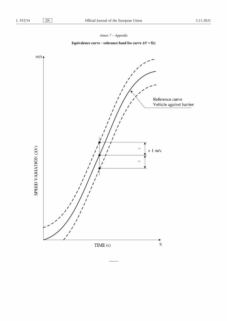
Annex 7 – Appendix
Equivalence curve – tolerance band for curve ΔV = f(t)
EN Official Journal of the European Union L 392/34 5.11.2021
ANNEX 8
Technique of measurement in measurement tests: Instrumentation
1. Definitions
1.1. Data channel
A data channel comprises all the instrumentation from a transducer (or multiple transducers whose outputs are combined in some specified way) up to and including any analysis procedures that may alter the frequency content or the amplitude content of data.
1.2. Transducer
The first device in a data channel used to convert a physical quantity to be measured into a second quantity (such as an electrical voltage) which can be processed by the remainder of the channel.
1.3. Channel Amplitude Class: CAC
The designation for a data channel that meets certain amplitude characteristics as specified in this annex. The CAC number is numerically equal to the upper limit of the measurement range.
1.4. Characteristic frequencies FH, FL, FN
These frequencies are defined in Figure 1 of this annex.
1.5. Channels Frequency Class: CFC
The channel frequency class is designated by a number indicating that the channel frequency response lies within the limits specified in Figure 1 of this annex. This number and the value of the frequency FH in Hz are numerically equal.
1.6. Sensitivity coefficient
The slope of the straight line representing the best fit to the calibration values determined by the method of least square within the channel amplitude class.
1.7. Calibration factor of a data channel
The mean value of the sensitivity coefficients evaluated over frequencies which are evenly spaced on a logarithmic scale
between FL and
1.8. Linearity error
The ratio, in per cent, of the maximum difference between the calibration value and the corresponding value read on the straight line defined in paragraph 1.6. above at the upper limit of the channel amplitude class.
1.9. Cross sensitivity
The ratio of the output signal to the input signal, when an excitation is applied to the transducer perpendicular to the measurement axis. It is expressed as a percentage of the sensitivity along the measurement axis.
EN Official Journal of the European Union 5.11.2021 L 392/35
1.10. Phase delay time
The phase delay time of a data channel is equal to the phase delay (in radians) of a sinusoidal signal, divided by the angular frequency of that signal (in radians/second).
1.11. Environment
The aggregate, at a given moment, of all external conditions and influences to which the data channel is subjected.
2. Performance requirements
2.1. Linearity error
The absolute value of the linearity error of a data channel at any frequency in the CFC, shall be equal to or less than 2,5 per cent of the value of the CAC, over the whole measurement range.
2.2. Amplitude against frequency
The frequency response of a data channel shall lie within the limiting curves given in Figure 1 of this annex. The zero dB line is determined by the calibration factor.
2.3. Phase delay time
The phase delay time between the input and the output signals of a data channel shall be determined and shall not vary by more than 0,1 FH seconds between 0,03 FH and FH.
2.4. Time
2.4.1. Time base
A time base shall be recorded and shall at least give 1/100 s with an accuracy of 1 per cent.
2.4.2. Relative time delay
The relative time delay between the signal of two or more data channels, regardless of their frequency class, must not exceed 1 ms excluding delay caused by phase shift.
Two or more data channels of which the signals are combined shall have the same frequency class and shall not have relative time delay greater than 1/10 FH seconds.
This requirement applies to analogue signals as well as to synchronization pulses and digital signals.
2.5. Transducer cross sensitivity
The transducer cross sensitivity shall be less than 5 per cent in any direction.
2.6. Calibration
2.6.1. General
A data channel shall be calibrated at least once a year against reference equipment traceable to known standards. The methods used to carry out a comparison with reference equipment shall not introduce an error greater than 1 per cent of the CAC. The use of the reference equipment is limited to the frequency range for which they have been calibrated. Subsystems of a data channel may be evaluated individually and the results factored into the accuracy of the total data channel. This can be done for example by an electrical signal of known amplitude simulating the output signal of the transducer which allows a check to be made on the gain factor of the data channel, excluding the transducer.
EN Official Journal of the European Union L 392/36 5.11.2021
2.6.2. Accuracy of reference equipment for calibration
The accuracy of the reference equipment shall be certified or endorsed by an official metrology service.
2.6.2.1. Static calibration
2.6.2.1.1. Accelerations
The errors shall be less than ±1,5 per cent of the channel amplitude class.
2.6.2.1.2. Forces
The error shall be less than ±1 per cent of the channel amplitude class.
2.6.2.1.3. Displacements
The error shall be less than ±1 per cent of the channel amplitude class.
2.6.2.2. Dynamic calibration
2.6.2.2.1. Accelerations
The error in the reference accelerations expressed as a percentage of the channel amplitude class shall be less than ±1,5 per cent below 400 Hz, less than ±2 per cent between 400 Hz and 900 Hz, and less than ±2,5 per cent above 900 Hz.
2.6.2.3. Time
The relative error in the reference time shall be less than 10-5.
2.6.3. Sensitivity coefficient and linearity error
The sensitivity coefficient and the linearity error shall be determined by measuring the output signal of the data channel against a known input signal for various values of this signal. The calibration of the data channel shall cover the whole range of the amplitude class.
For bi-directional channels, both the positive and negative values shall be used.
If the calibration equipment cannot produce the required input owing to the excessively high values of the quantity to be measured, calibrations shall be carried out within the limits of the calibration standards and these limits shall be recorded in the test report.
A total data channel shall be calibrated at a frequency or at a spectrum of frequencies having a significant value
between FL and
2.6.4. Calibration of the frequency response
The response curves of phase and amplitude against frequency shall be determined by measuring the output signals of the data channel in terms of phase and amplitude against a known input signal, for various values of this signal varying between FL and 10 times the CFC or 3 000 Hz, whichever is lower.
EN Official Journal of the European Union 5.11.2021 L 392/37

2.7. Environmental effects
A regular check shall be made to identify any environmental influence (such as electric or magnetic flux, cable velocity, etc.). This can be done for instance by recording the output of spare channels equipped with dummy transducers. If significant output signals are obtained corrective action shall be taken, for instance by replacement of cables.
2.8. Choice and designation of the data channel
The CAC and CFC define a data channel.
The CAC shall be 1, 2 or 5 to a power of ten.
3. Mounting of transducers
Transducers should be rigidly secured so that their recordings are affected by vibration as little as possible. Any mounting having a lowest resonance frequency equal to at least 5 times the frequency FH of the data channel considered shall be considered valid. Acceleration transducers in particular should be mounted in such a way that the initial angle of the real measurement axis to the corresponding axis of the reference axis system is not greater than 5° unless an analytical or experimental assessment of the effect of the mounting on the collected data is made. When multi-axial accelerations at a point are to be measured, each acceleration transducer axis should pass within 10 mm of that point, and the centre of seismic mass of each accelerometer should be within 30 mm of that point.
4. Data processing
4.1. Filtering
Filtering corresponding to the frequencies of the data channel class may be carried out during either recording or processing of data. However, before recording, analogical filtering at a higher level than CFC should be effected in order to use at least 50 per cent of the dynamic range of the recorder and to reduce the risk of high frequencies saturating the recorder or causing aliasing errors in the digitalizing process.
4.2. Digitalizing
4.2.1. Sampling frequency
The sampling frequency should be equal to at least 8 FH. In the case of analogical recording, when the recording and reading speeds are different, the sampling frequency can be divided by the speed ratio.
4.2.2. Amplitude resolution
The size of digital words should be at least 7 bits and a parity bit.
5. Presentation of results
The results should be presented on A4 size paper (ISO/R 216). Results presented as diagrams should have axes scaled with a measurement unit corresponding to a suitable multiple of the chosen unit (for example, 1, 2, 5, 10, 20 millimetres). SI units shall be used, except for vehicle velocity, where km/h may be used, and for accelerations due to impact where g, with g = 9,8 m/s2, may be used.
EN Official Journal of the European Union L 392/38 5.11.2021
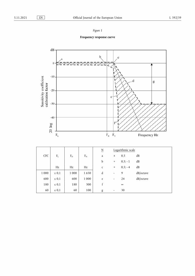
Figure 1
Frequency response curve
N Logarithmic scale
CFC FL FH FN a ± 0,5 dB
b + 0,5; - 1 dB
Hz Hz Hz c + 0,5; - 4 dB
1 000 ≤ 0,1 1 000 1 650 d - 9 dB/octave
600 ≤ 0,1 600 1 000 e - 24 dB/octave
180 ≤ 0,1 180 300 f ∞
60 ≤ 0,1 60 100 g - 30
EN Official Journal of the European Union 5.11.2021 L 392/39
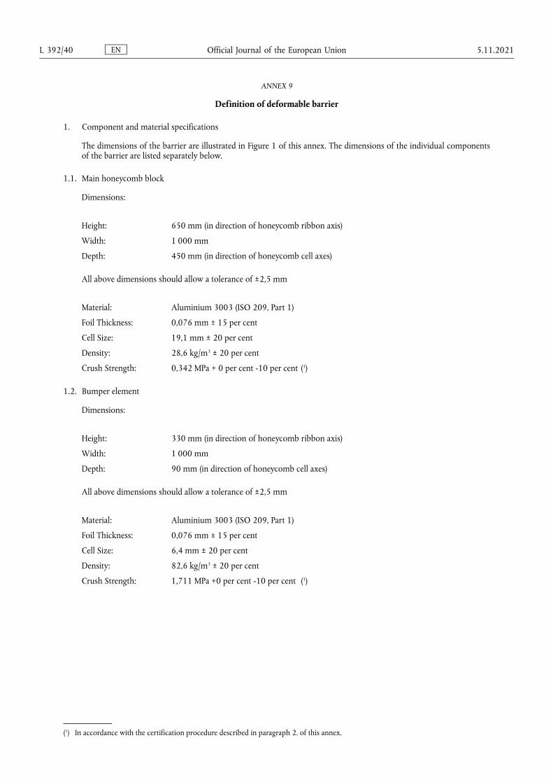
ANNEX 9
Definition of deformable barrier
1. Component and material specifications
The dimensions of the barrier are illustrated in Figure 1 of this annex. The dimensions of the individual components of the barrier are listed separately below.
1.1. Main honeycomb block
Dimensions:
Height: 650 mm (in direction of honeycomb ribbon axis)
Width: 1 000 mm
Depth: 450 mm (in direction of honeycomb cell axes)
All above dimensions should allow a tolerance of ±2,5 mm
Material: Aluminium 3003 (ISO 209, Part 1)
Foil Thickness: 0,076 mm ± 15 per cent
Cell Size: 19,1 mm ± 20 per cent
Density: 28,6 kg/m3 ± 20 per cent
Crush Strength: 0,342 MPa + 0 per cent -10 per cent (1)
1.2. Bumper element
Dimensions:
Height: 330 mm (in direction of honeycomb ribbon axis)
Width: 1 000 mm
Depth: 90 mm (in direction of honeycomb cell axes)
All above dimensions should allow a tolerance of ±2,5 mm
Material: Aluminium 3003 (ISO 209, Part 1)
Foil Thickness: 0,076 mm ± 15 per cent
Cell Size: 6,4 mm ± 20 per cent
Density: 82,6 kg/m3 ± 20 per cent
Crush Strength: 1,711 MPa +0 per cent -10 per cent (1)
(1) In accordance with the certification procedure described in paragraph 2. of this annex.
EN Official Journal of the European Union L 392/40 5.11.2021
1.3. Backing sheet
Dimensions
Height: 800 mm ± 2,5 mm
Width: 1 000 mm ± 2,5 mm
Thickness: 2,0 mm ± 0,1 mm
1.4. Cladding sheet
Dimensions
Length: 1 700 mm ± 2,5 mm
Width: 1 000 mm ± 2,5 mm
Thickness: 0,81 ± 0,07 mm
Material: Aluminium 5251/5052 (ISO 209, part 1)
1.5. Bumper facing sheet
Dimensions
Height: 330 mm ± 2,5 mm
Width: 1 000 mm ± 2,5 mm
Thickness: 0,81 mm ± 0,07 mm
Material: Aluminium 5251/5052 (ISO 209, part 1)
1.6. Adhesive
The adhesive to be used throughout should be a two-part polyurethane (such as Ciba-Geigy XB5090/1 resin with XB5304 hardener, or equivalent).
2. Aluminum honeycomb certification
A complete testing procedure for certification of aluminium honeycomb is given in NHTSA TP-214D. The following is a summary of the procedure that should be applied to materials for the frontal impact barrier, these materials having a crush strength of 0,342 MPa and 1,711 MPa respectively.
2.1. Sample locations
To ensure uniformity of crush strength across the whole of the barrier face, eight samples shall be taken from four locations evenly spaced across the honeycomb block. For a block to pass certification, seven of these eight samples shall meet the crush strength requirements of the following sections.
The location of the samples depends on the size of the honeycomb block. First, four samples, each measuring 300 mm × 300 mm × 50 mm thick shall be cut from the block of barrier face material. Please refer to Figure 2 of this annex for an illustration of how to locate these sections within the honeycomb block. Each of these larger samples shall be cut into samples for certification testing (150 mm × 150 mm × 50 mm). Certification shall be based on the testing of two samples from each of these four locations. The other two should be made available to the applicant, upon request.
EN Official Journal of the European Union 5.11.2021 L 392/41
2.2. Sample size
Samples of the following size shall be used for testing:
Length: 150 mm ± 6 mm
Width: 150 mm ± 6 mm
Thickness: 50 mm ± 2 mm
The walls of incomplete cells around the edge of the sample shall be trimmed as follows:
In the "W" direction, the fringes shall be no greater than 1,8 mm (see Figure 3 of this annex).
In the "L" direction, half the length of one bonded cell wall (in the ribbon direction) shall be left at either end of the specimen (see Figure 3 of this annex).
2.3. Area measurement
The length of the sample shall be measured in three locations, 12,7 mm from each end and in the middle, and recorded as L1, L2 and L3 (Figure 3 of this annex). In the same manner, the width shall be measured and recorded as W1, W2 and W3 (Figure 3 of this annex). These measurements shall be taken on the centreline of the thickness. The crush area shall then be calculated as:
2.4. Crush rate and distance
The sample shall be crushed at a rate of not less than 5,1 mm/min and not more than 7,6 mm/min. The minimum crush distance shall be 16,5 mm.
2.5. Data collection
Force versus deflection data are to be collected in either analog or digital form for each sample tested. If analog data are collected then a means of converting this to digital shall be available. All digital data shall be collected at a rate of not less than 5 Hz (5 points per second).
2.6. Crush strength determination
Ignore all data prior to 6,4 mm of crush and after 16,5 mm of crush. Divide the remaining data into three sections or displacement intervals (n = 1, 2, 3) (see Figure 4 of this annex) as follows:
(1) 06,4 mm – 09,7 mm inclusive;
(2) 09,7 mm – 13,2 mm exclusive;
(3) 13,2 mm – 16,5 mm inclusive.
Find the average for each section as follows:
Where m represents the number of data points measured in each of the three intervals. Calculate the crush strength of each section as follows:
EN Official Journal of the European Union L 392/42 5.11.2021
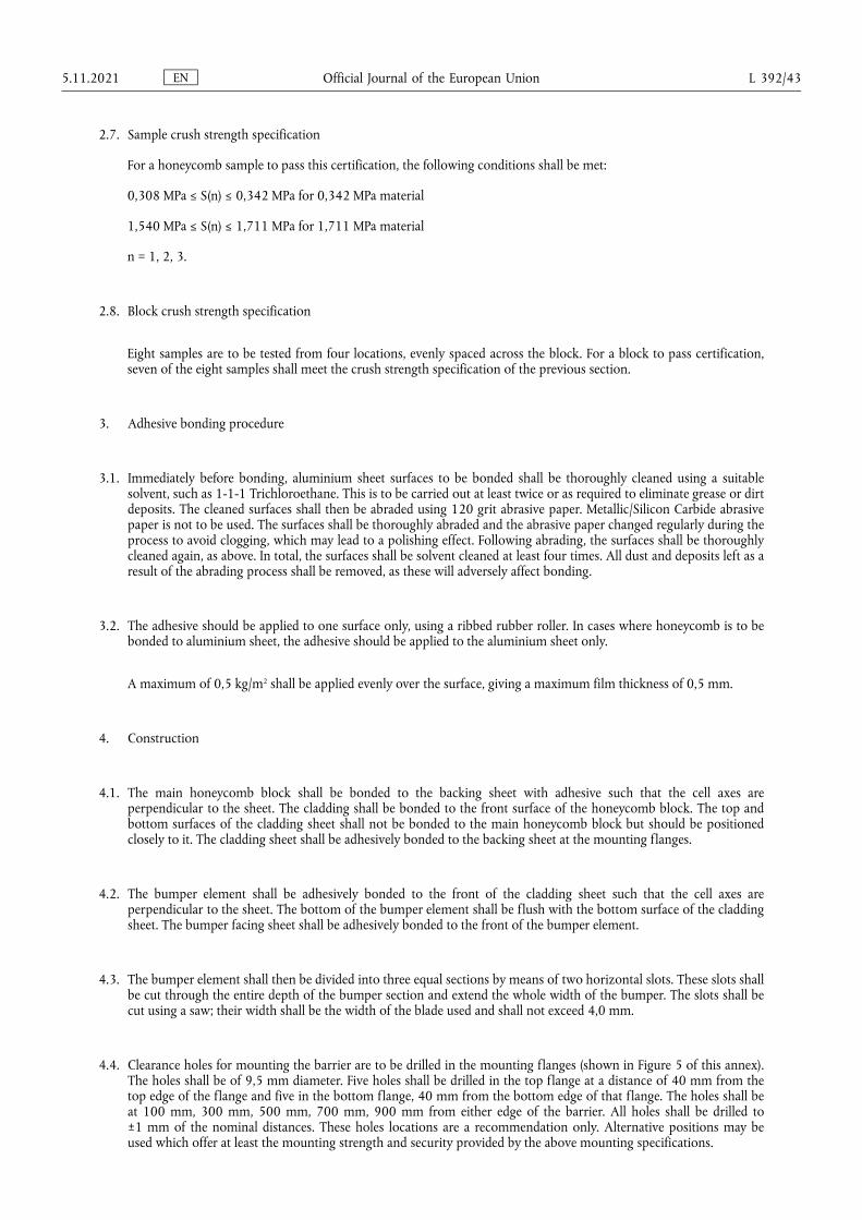
2.7. Sample crush strength specification
For a honeycomb sample to pass this certification, the following conditions shall be met:
0,308 MPa ≤ S(n) ≤ 0,342 MPa for 0,342 MPa material
1,540 MPa ≤ S(n) ≤ 1,711 MPa for 1,711 MPa material
n = 1, 2, 3.
2.8. Block crush strength specification
Eight samples are to be tested from four locations, evenly spaced across the block. For a block to pass certification, seven of the eight samples shall meet the crush strength specification of the previous section.
3. Adhesive bonding procedure
3.1. Immediately before bonding, aluminium sheet surfaces to be bonded shall be thoroughly cleaned using a suitable solvent, such as 1-1-1 Trichloroethane. This is to be carried out at least twice or as required to eliminate grease or dirt deposits. The cleaned surfaces shall then be abraded using 120 grit abrasive paper. Metallic/Silicon Carbide abrasive paper is not to be used. The surfaces shall be thoroughly abraded and the abrasive paper changed regularly during the process to avoid clogging, which may lead to a polishing effect. Following abrading, the surfaces shall be thoroughly cleaned again, as above. In total, the surfaces shall be solvent cleaned at least four times. All dust and deposits left as a result of the abrading process shall be removed, as these will adversely affect bonding.
3.2. The adhesive should be applied to one surface only, using a ribbed rubber roller. In cases where honeycomb is to be bonded to aluminium sheet, the adhesive should be applied to the aluminium sheet only.
A maximum of 0,5 kg/m2 shall be applied evenly over the surface, giving a maximum film thickness of 0,5 mm.
4. Construction
4.1. The main honeycomb block shall be bonded to the backing sheet with adhesive such that the cell axes are perpendicular to the sheet. The cladding shall be bonded to the front surface of the honeycomb block. The top and bottom surfaces of the cladding sheet shall not be bonded to the main honeycomb block but should be positioned closely to it. The cladding sheet shall be adhesively bonded to the backing sheet at the mounting flanges.
4.2. The bumper element shall be adhesively bonded to the front of the cladding sheet such that the cell axes are perpendicular to the sheet. The bottom of the bumper element shall be flush with the bottom surface of the cladding sheet. The bumper facing sheet shall be adhesively bonded to the front of the bumper element.
4.3. The bumper element shall then be divided into three equal sections by means of two horizontal slots. These slots shall be cut through the entire depth of the bumper section and extend the whole width of the bumper. The slots shall be cut using a saw; their width shall be the width of the blade used and shall not exceed 4,0 mm.
4.4. Clearance holes for mounting the barrier are to be drilled in the mounting flanges (shown in Figure 5 of this annex). The holes shall be of 9,5 mm diameter. Five holes shall be drilled in the top flange at a distance of 40 mm from the top edge of the flange and five in the bottom flange, 40 mm from the bottom edge of that flange. The holes shall be at 100 mm, 300 mm, 500 mm, 700 mm, 900 mm from either edge of the barrier. All holes shall be drilled to ±1 mm of the nominal distances. These holes locations are a recommendation only. Alternative positions may be used which offer at least the mounting strength and security provided by the above mounting specifications.
EN Official Journal of the European Union 5.11.2021 L 392/43
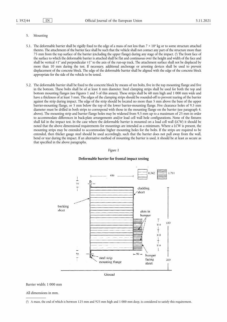
5. Mounting
5.1. The deformable barrier shall be rigidly fixed to the edge of a mass of not less than 7 × 10⁴ kg or to some structure attached thereto. The attachment of the barrier face shall be such that the vehicle shall not contact any part of the structure more than 75 mm from the top surface of the barrier (excluding the upper flange) during any stage of the impact. (2) The front face of the surface to which the deformable barrier is attached shall be flat and continuous over the height and width of the face and shall be vertical ±1° and perpendicular ±1° to the axis of the run-up track. The attachment surface shall not be displaced by more than 10 mm during the test. If necessary, additional anchorage or arresting devices shall be used to prevent displacement of the concrete block. The edge of the deformable barrier shall be aligned with the edge of the concrete block appropriate for the side of the vehicle to be tested.
5.2. The deformable barrier shall be fixed to the concrete block by means of ten bolts, five in the top mounting flange and five in the bottom. These bolts shall be of at least 8 mm diameter. Steel clamping strips shall be used for both the top and bottom mounting flanges (see Figures 1 and 5 of this annex). These strips shall be 60 mm high and 1 000 mm wide and have a thickness of at least 3 mm. The edges of the clamping strips should be rounded-off to prevent tearing of the barrier against the strip during impact. The edge of the strip should be located no more than 5 mm above the base of the upper barrier-mounting flange, or 5 mm below the top of the lower barrier-mounting flange. Five clearance holes of 9,5 mm diameter must be drilled in both strips to correspond with those in the mounting flange on the barrier (see paragraph 4. above). The mounting strip and barrier flange holes may be widened from 9,5 mm up to a maximum of 25 mm in order to accommodate differences in back-plate arrangements and/or load cell wall hole configurations. None of the fixtures shall fail in the impact test. In the case where the deformable barrier is mounted on a load cell wall (LCW) it should be noted that the above dimensional requirements for mountings are intended as a minimum. Where a LCW is present, the mounting strips may be extended to accommodate higher mounting holes for the bolts. If the strips are required to be extended, then thicker gauge steel should be used accordingly, such that the barrier does not pull away from the wall, bend or tear during the impact. If an alternative method of mounting the barrier is used, it should be at least as secure as that specified in the above paragraphs.
Figure 1
Deformable barrier for frontal impact testing
Barrier width: 1 000 mm
All dimensions in mm.
(2) A mass, the end of which is between 125 mm and 925 mm high and 1 000 mm deep, is considered to satisfy this requirement.
EN Official Journal of the European Union L 392/44 5.11.2021
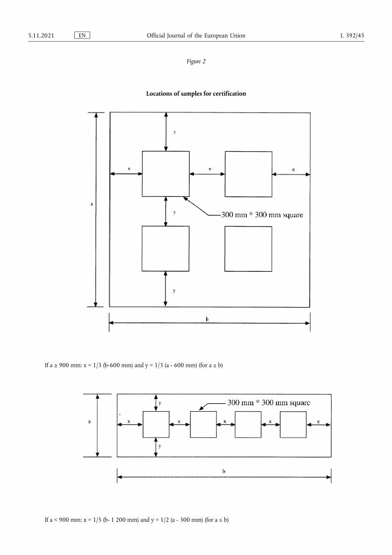
Figure 2
Locations of samples for certification
If a ≥ 900 mm: x = 1/3 (b-600 mm) and y = 1/3 (a - 600 mm) (for a ≤ b)
If a < 900 mm: x = 1/5 (b- 1 200 mm) and y = 1/2 (a - 300 mm) (for a ≤ b)
EN Official Journal of the European Union 5.11.2021 L 392/45
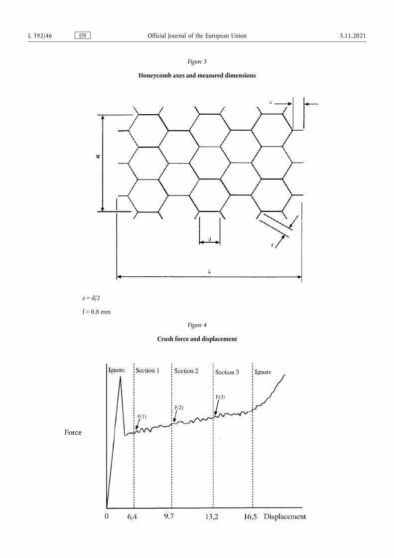
Figure 3
Honeycomb axes and measured dimensions
e = d/2
f = 0,8 mm
Figure 4
Crush force and displacement
EN Official Journal of the European Union L 392/46 5.11.2021
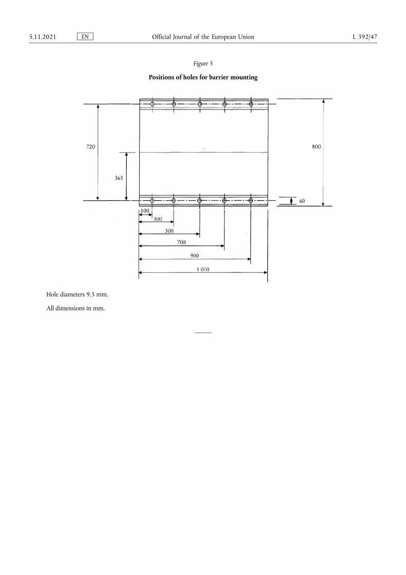
Figure 5
Positions of holes for barrier mounting
Hole diameters 9,5 mm.
All dimensions in mm.
EN Official Journal of the European Union 5.11.2021 L 392/47
ANNEX 10
Certification procedure for the dummy lower leg and foot
1. Upper foot impact test
1.1. The objective of this test is to measure the response of the Hybrid III foot and ankle to well-defined, hard faced pendulum impacts.
1.2. The complete Hybrid III lower leg assembly, left (86-5001-001) and right (86-5001-002), equipped with the foot and ankle assembly, left (78051-614) and right (78051-615), shall be used, including the knee assembly.
The load cell simulator (78051-319 Rev A) shall be used to secure the knee assembly (79051-16 Rev B) to the test fixture.
1.3. Test procedure
1.3.1. Each leg assembly shall be maintained (soaked) for four hours prior to the test at a temperature of 22 °C ± 3 °C and a relative humidity of 40 ± 30 per cent. The soak period shall not include the time required to reach steady state conditions.
1.3.2. Clean the impact surface of the skin and also the impactor face with isopropyl alcohol or equivalent prior to the test. Dust with talc.
1.3.3. Align the impactor accelerometer with its sensitive axis parallel to the direction of impact at contact with the foot.
1.3.4. Mount the leg assembly to the fixture shown in Figure 1 of this annex. The test fixture shall be rigidly secured to prevent movement during impact. The centre line of the femur load cell simulator (78051-319) shall be vertical with a tolerance of ±0,5°. Adjust the mount such that the line joining the knee clevis joint and the ankle attachment bolt is horizontal with a tolerance of ±3°, with the heel resting on two sheets of a flat low friction (PTFE sheet) surface. Ensure that the tibia flesh is located fully towards the knee end of the tibia. Adjust the ankle such that the plane of the underside of the foot is vertical and perpendicular to the direction of impact with a tolerance of ±3° and such that the mid sagittal plane of the foot is aligned with the pendulum arm. Adjust the knee joint to 1,5 ± 0,5 g range before each test. Adjust the ankle joint so that it is free and then tighten just sufficiently to keep the foot stable on the PTFE sheet.
1.3.5. The rigid impactor comprises a horizontal cylinder diameter 50 ± 2 mm and a pendulum support arm diameter 19 ± 1 mm (Figure 4 of this annex). The cylinder has a mass of 1,25 ± 0,02 kg including instrumentation and any part of the support arm within the cylinder. The pendulum arm has a mass of 285 ± 5 g. The mass of any rotating part of the axle to which the support arm is attached should not be greater than 100 g. The length between the central horizontal axis of the impactor cylinder and the axis of rotation of the whole pendulum shall be 1 250 ± 1 mm. The impact cylinder is mounted with its longitudinal axis horizontal and perpendicular to the direction of impact. The pendulum shall impact the underside of the foot, at a distance of 185 ± 2 mm from the base of the heel resting on the rigid horizontal platform, so that the longitudinal centre line of the pendulum arm falls within 1° of a vertical line at impact. The impactor shall be guided to exclude significant lateral, vertical or rotational movement.
1.3.6. Allow a period of at least 30 minutes between successive tests on the same leg.
1.3.7. The data acquisition system, including transducers, shall conform to the specifications for CFC 600, as described in Annex 8.
1.4. Performance specification
EN Official Journal of the European Union L 392/48 5.11.2021
1.4.1. When each ball of the foot is impacted at 6,7 (±0,1) m/s in accordance with paragraph 1,3. above, the maximum lower tibia bending momentum about the y-axis (My) shall be 120 ± 25 Nm.
2. Lower foot impact test without shoe
2.1. The objective of this test is to measure the response of the Hybrid III foot skin and insert to well-defined, hard faced pendulum impacts.
2.2. The complete Hybrid III lower leg assembly, left (86-5001-001) and right (86-5001-002), equipped with the foot and ankle assembly, left (78051-614) and right (78051-615), shall be used, including the knee assembly.
The load cell simulator (78051-319 Rev A) shall be used to secure the knee assembly (79051-16 Rev B) to the test fixture.
2.3. Test procedure
2.3.1. Each leg assembly shall be maintained (soaked) for four hours prior to the test at a temperature of 22 ± 3 °C and a relative humidity of 40 ± 30 per cent. The soak period shall not include the time required to reach steady state conditions.
2.3.2. Clean the impact surface of the skin and also the impactor face with isopropyl alcohol or equivalent prior to the test. Dust with talc. Check that there is no visible damage to the energy absorbing insert to the heel.
2.3.3. Align the impactor accelerometer with its sensitive axis parallel to the impactor longitudinal centre line.
2.3.4. Mount the leg assembly to the fixture shown in Figure 2 of this annex. The test fixture shall be rigidly secured to prevent movement during impact. The centre line of the femur load cell simulator (78051-319) shall be vertical with a tolerance of ±0,5°. Adjust the mount such that the line joining the knee clevis joint and the ankle attachment bolt is horizontal with a tolerance of ±3° with the heel resting on two sheets of a flat low friction (PTFE sheet) surface. Ensure that the tibia flesh is located fully towards the knee end of the tibia. Adjust the ankle such that the plane of the underside of the foot is vertical and perpendicular to the direction of the impact with a tolerance of ±3° and such that the mid sagittal plane of the foot is aligned with the pendulum arm. Adjust the knee joint to 1,5 ± 0,5 g range before each test. Adjust the ankle joint so that it is free and then tighten just sufficiently to keep the foot stable on the PTFE sheet.
2.3.5. The rigid impactor comprises a horizontal cylinder diameter 50 ± 2 mm and a pendulum support arm diameter 19 ± 1 mm (Figure 4 of this annex). The cylinder has a mass of 1,25 ± 0,02 kg including instrumentation and any part of the support arm within the cylinder. The pendulum arm has a mass of 285 ± 5 g. The mass of any rotating part of the axle to which the support arm is attached should not be greater than 100 g. The length between the central horizontal axis of the impactor cylinder and the axis of rotation of the whole pendulum shall be 1 250 ± 1 mm. The impact cylinder is mounted with its longitudinal axis horizontal and perpendicular to the direction of impact. The pendulum shall impact the underside of the foot, at a distance of 62 ± 2 mm from the base of the heel resting on the rigid horizontal platform, so that the longitudinal centreline of the pendulum arm falls within 1° of a vertical line at impact. The impactor shall be guided to exclude significant lateral, vertical or rotational movement.
2.3.6. Allow a period of at least 30 minutes between successive tests on the same leg.
2.3.7. The data acquisition system, including transducers, shall conform to the specifications for CFC 600, as described in Annex 8.
2.4. Performance specification
2.4.1. When the heel of each foot is impacted at 4,4 ± 0,1 m/s in accordance with paragraph 2.3., the maximum impactor acceleration shall be 295 ± 50 g.
EN Official Journal of the European Union 5.11.2021 L 392/49
3. Lower foot impact test (with shoe)
3.1. The objective of this test is to control the response of the Shoe and Hybrid III heel flesh and ankle joint to well- defined hard faced pendulum impacts.
3.2. The complete Hybrid III lower leg assembly, left (86-5001-001) and right (86-5001-002), equipped with the foot and ankle assembly, left (78051-614) and right (78051-615), shall be used, including the knee assembly. The load cell simulator (78051-319 Rev A) shall be used to secure the knee assembly (79051-16 Rev B) to the test fixture. The foot shall be fitted with the shoe specified in Annex 5, paragraph 2.9.2.
3.3. Test procedure
3.3.1. Each leg assembly shall be maintained (soaked) for four hours prior to the test at a temperature of 22 ± 3 °C and a relative humidity of 40 ± 30 per cent. The soak period shall not include the time required to reach steady state conditions.
3.3.2. Clean the impact surface of the underside of the shoe with a clean cloth and the impactor face with isopropyl alcohol or equivalent prior to the test. Check that there is no visible damage to the energy absorbing insert to the heel.
3.3.3. Align the impactor accelerometer with its sensitive axis parallel to the impactor longitudinal centre line.
3.3.4. Mount the leg assembly to the fixture shown in Figure 3 of this annex. The test fixture shall be rigidly secured to prevent movement during impact. The centre line of the femur load cell simulator (78051-319) shall be vertical with a tolerance of ±0,5°. Adjust the mount such that the line joining the knee clevis joint and the ankle attachment bolt is horizontal with a tolerance of ±3°, with the heel of the shoe resting on two sheets of a flat low friction (PTFE sheet) surface. Ensure that the tibia flesh is located fully towards the knee end of the tibia. Adjust the ankle such that a plane in contact with the heel and sole of the underside of the shoe is vertical and perpendicular to the direction of impact with a tolerance of ±3° and such that the mid sagittal plane of the foot and shoe is aligned with the pendulum arm. Adjust the knee joint to 1,5 ± 0,5 g range before each test. Adjust the ankle joint so that it is free and then tighten just sufficiently to keep the foot stable on the PTFE sheet.
3.3.5. The rigid impactor comprises a horizontal cylinder diameter 50 ± 2 mm and a pendulum support arm diameter 19 ± 1 mm (Figure 4 of this annex). The cylinder has a mass of 1,25 ± 0,02 kg including instrumentation and any part of the support arm within the cylinder. The pendulum arm has a mass of 285 ± 5 g. The mass of any rotating part of the axle to which the support arm is attached should not be greater than 100 g. The length between the central horizontal axis of the impactor cylinder and the axis of rotation of the whole pendulum shall be 1 250 ± 1 mm. The impact cylinder is mounted with its longitudinal axis horizontal and perpendicular to the direction of impact. The pendulum shall impact the heel of the shoe in a horizontal plane which is a distance of 62 ± 2 mm above the base of the dummy heel when the shoe is resting on the rigid horizontal platform, so that the longitudinal centreline of the pendulum arm falls within one degree of a vertical line at impact. The impactor shall be guided to exclude significant lateral, vertical or rotational movement.
3.3.6. Allow a period of at least 30 minutes between successive tests on the same leg.
3.3.7. The data acquisition system, including transducers, shall conform to the specifications for CFC 600, as described in Annex 8.
3.4. Performance specification
3.4.1. When the heel of the shoe is impacted at 6,7 ± 0,1 m/s in accordance with paragraph 3.3. above, the maximum Tibia compressive force (Fz) shall be 3,3 ± 0,5 kN.
EN Official Journal of the European Union L 392/50 5.11.2021
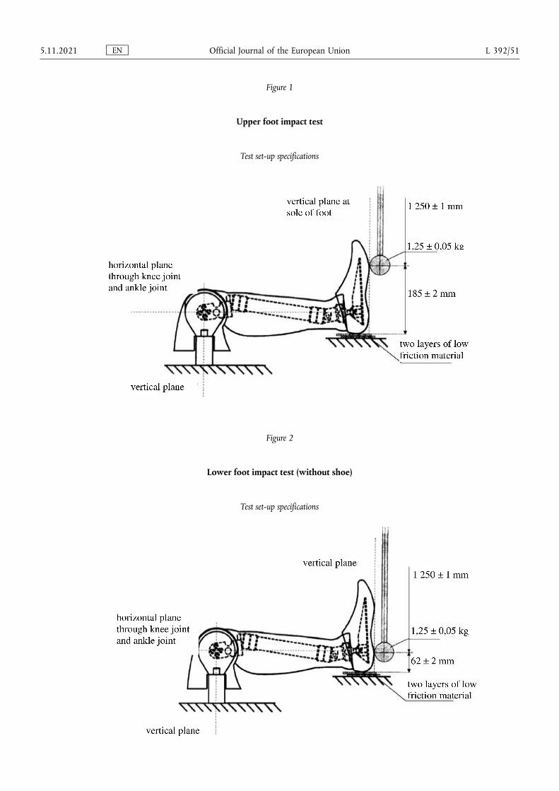
Figure 1
Upper foot impact test
Test set-up specifications
Figure 2
Lower foot impact test (without shoe)
Test set-up specifications
EN Official Journal of the European Union 5.11.2021 L 392/51
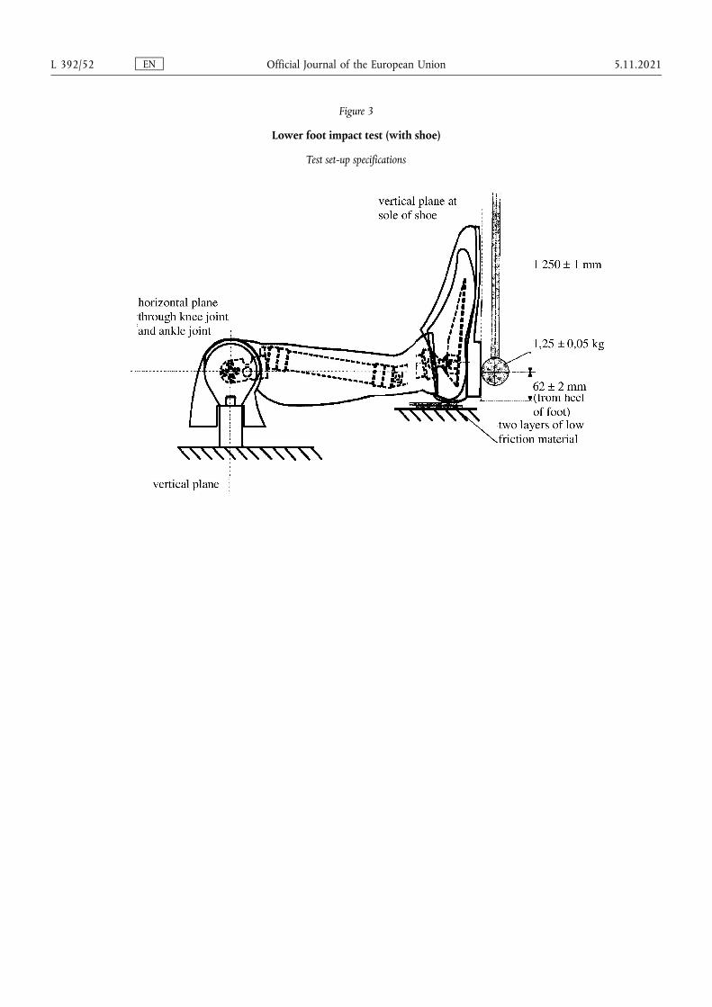
Figure 3
Lower foot impact test (with shoe)
Test set-up specifications
EN Official Journal of the European Union L 392/52 5.11.2021
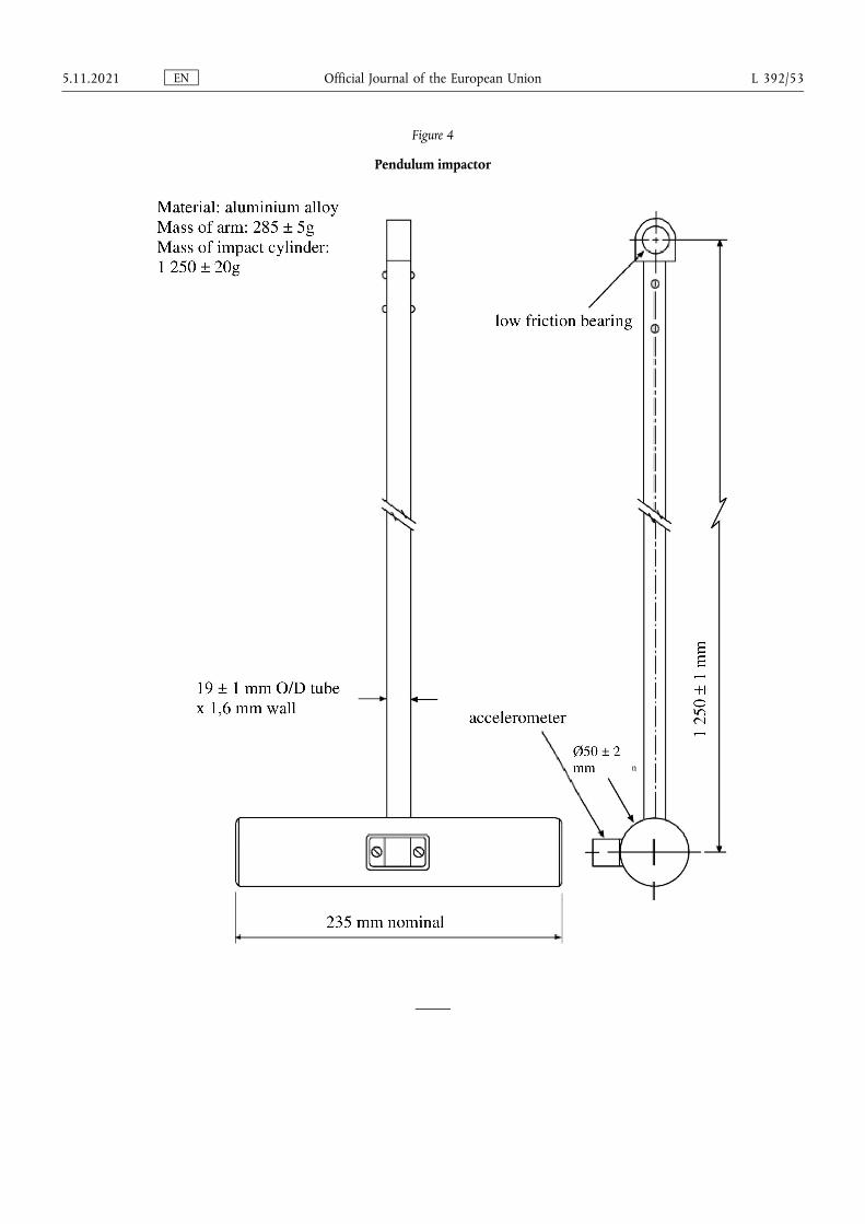
Figure 4
Pendulum impactor
EN Official Journal of the European Union 5.11.2021 L 392/53
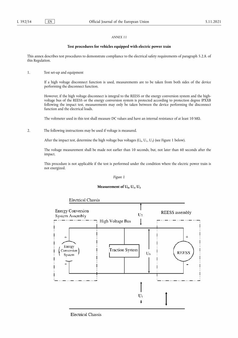
ANNEX 11
Test procedures for vehicles equipped with electric power train
This annex describes test procedures to demonstrate compliance to the electrical safety requirements of paragraph 5.2.8. of this Regulation.
1. Test set-up and equipment
If a high voltage disconnect function is used, measurements are to be taken from both sides of the device performing the disconnect function.
However, if the high voltage disconnect is integral to the REESS or the energy conversion system and the high- voltage bus of the REESS or the energy conversion system is protected according to protection degree IPXXB following the impact test, measurements may only be taken between the device performing the disconnect function and the electrical loads.
The voltmeter used in this test shall measure DC values and have an internal resistance of at least 10 MΩ.
2. The following instructions may be used if voltage is measured.
After the impact test, determine the high voltage bus voltages (Ub, U1, U2) (see Figure 1 below).
The voltage measurement shall be made not earlier than 10 seconds, but, not later than 60 seconds after the impact.
This procedure is not applicable if the test is performed under the condition where the electric power train is not energized.
Figure 1
Measurement of Ub, U1, U2
EN Official Journal of the European Union L 392/54 5.11.2021
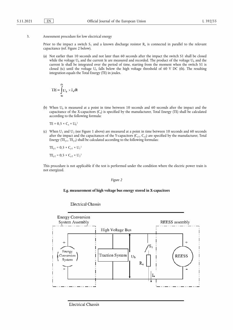
3. Assessment procedure for low electrical energy
Prior to the impact a switch S1 and a known discharge resistor Re is connected in parallel to the relevant capacitance (ref. Figure 2 below).
(a) Not earlier than 10 seconds and not later than 60 seconds after the impact the switch S1 shall be closed while the voltage Ub and the current Ie are measured and recorded. The product of the voltage Ub and the current Ie shall be integrated over the period of time, starting from the moment when the switch S1 is closed (tc) until the voltage Ub falls below the high voltage threshold of 60 V DC (th). The resulting integration equals the Total Energy (TE) in joules.
(b) When Ub is measured at a point in time between 10 seconds and 60 seconds after the impact and the capacitance of the X-capacitors (Cx) is specified by the manufacturer, Total Energy (TE) shall be calculated according to the following formula:
TE = 0,5 × Cx × Ub2
(c) When U1 and U2 (see Figure 1 above) are measured at a point in time between 10 seconds and 60 seconds after the impact and the capacitances of the Y-capacitors (Cy1, Cy2) are specified by the manufacturer, Total Energy (TEy1, TEy2) shall be calculated according to the following formulas:
TEy1 = 0,5 × Cy1 × U12
TEy2 = 0,5 × Cy2 × U22
This procedure is not applicable if the test is performed under the condition where the electric power train is not energized.
Figure 2
E.g. measurement of high voltage bus energy stored in X-capacitors
EN Official Journal of the European Union 5.11.2021 L 392/55
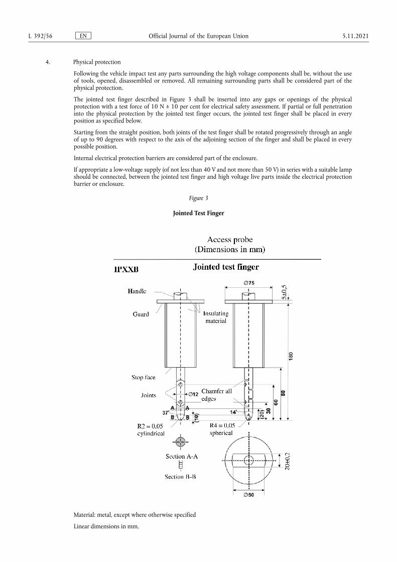
4. Physical protection
Following the vehicle impact test any parts surrounding the high voltage components shall be, without the use of tools, opened, disassembled or removed. All remaining surrounding parts shall be considered part of the physical protection.
The jointed test finger described in Figure 3 shall be inserted into any gaps or openings of the physical protection with a test force of 10 N ± 10 per cent for electrical safety assessment. If partial or full penetration into the physical protection by the jointed test finger occurs, the jointed test finger shall be placed in every position as specified below.
Starting from the straight position, both joints of the test finger shall be rotated progressively through an angle of up to 90 degrees with respect to the axis of the adjoining section of the finger and shall be placed in every possible position.
Internal electrical protection barriers are considered part of the enclosure.
If appropriate a low-voltage supply (of not less than 40 V and not more than 50 V) in series with a suitable lamp should be connected, between the jointed test finger and high voltage live parts inside the electrical protection barrier or enclosure.
Figure 3
Jointed Test Finger
Material: metal, except where otherwise specified
Linear dimensions in mm.
EN Official Journal of the European Union L 392/56 5.11.2021
Tolerances on dimensions without specific tolerance:
(a) on angles: +0/-10 seconds;
(b) on linear dimensions:
(i) up to 25 mm: +0/-0,05;
(ii) over 25 mm: ±0,2.
Both joints shall permit movement in the same plane and the same direction through an angle of 90° with a 0 to +10° tolerance.
The requirements of paragraph 5.2.8.1.3. of this Regulation are met if the jointed test finger described in Figure 3, is unable to contact high voltage live parts.
If necessary a mirror or a fiberscope may be used in order to inspect whether the jointed test finger touches the high voltage buses.
If this requirement is verified by a signal circuit between the jointed test finger and high voltage live parts, the lamp shall not light.
4.1. Test method for measuring electric resistance:
(a) Test method using a resistance tester.
The resistance tester is connected to the measuring points (typically, electrical chassis and electro conductive enclosure/electrical protection barrier) and the resistance is measured using a resistance tester that meets the specification that follows:
(i) Resistance tester: Measurement current at least 0,2 A;
(ii) Resolution: 0,01 Ω or less;
(iii) The resistance R shall be less than 0,1 Ω.
(b) Test method using DC power supply, voltmeter and ammeter.
The DC power supply, voltmeter and ammeter are connected to the measuring points (Typically, electrical chassis and electro conductive enclosure/electrical protection barrier).
The voltage of the DC power supply is adjusted so that the current flow becomes at least 0,2 A.
The current "I" and the voltage "U" are measured.
The resistance "R" is calculated according to the following formula:
R = U / I
The resistance R shall be less than 0,1 Ω.
Note: If lead wires are used for voltage and current measurement, each lead wire shall be independently connected to the electrical protection barrier/enclosure/electrical chassis. Terminal can be common for voltage measurement and current measurement.
Example of the test method using DC power supply, voltmeter and ammeter is shown below.
EN Official Journal of the European Union 5.11.2021 L 392/57
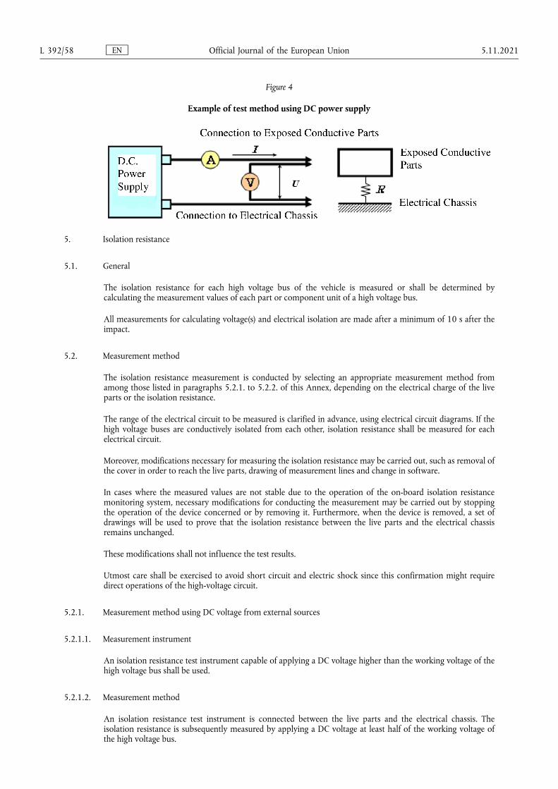
Figure 4
Example of test method using DC power supply
5. Isolation resistance
5.1. General
The isolation resistance for each high voltage bus of the vehicle is measured or shall be determined by calculating the measurement values of each part or component unit of a high voltage bus.
All measurements for calculating voltage(s) and electrical isolation are made after a minimum of 10 s after the impact.
5.2. Measurement method
The isolation resistance measurement is conducted by selecting an appropriate measurement method from among those listed in paragraphs 5.2.1. to 5.2.2. of this Annex, depending on the electrical charge of the live parts or the isolation resistance.
The range of the electrical circuit to be measured is clarified in advance, using electrical circuit diagrams. If the high voltage buses are conductively isolated from each other, isolation resistance shall be measured for each electrical circuit.
Moreover, modifications necessary for measuring the isolation resistance may be carried out, such as removal of the cover in order to reach the live parts, drawing of measurement lines and change in software.
In cases where the measured values are not stable due to the operation of the on-board isolation resistance monitoring system, necessary modifications for conducting the measurement may be carried out by stopping the operation of the device concerned or by removing it. Furthermore, when the device is removed, a set of drawings will be used to prove that the isolation resistance between the live parts and the electrical chassis remains unchanged.
These modifications shall not influence the test results.
Utmost care shall be exercised to avoid short circuit and electric shock since this confirmation might require direct operations of the high-voltage circuit.
5.2.1. Measurement method using DC voltage from external sources
5.2.1.1. Measurement instrument
An isolation resistance test instrument capable of applying a DC voltage higher than the working voltage of the high voltage bus shall be used.
5.2.1.2. Measurement method
An isolation resistance test instrument is connected between the live parts and the electrical chassis. The isolation resistance is subsequently measured by applying a DC voltage at least half of the working voltage of the high voltage bus.
EN Official Journal of the European Union L 392/58 5.11.2021
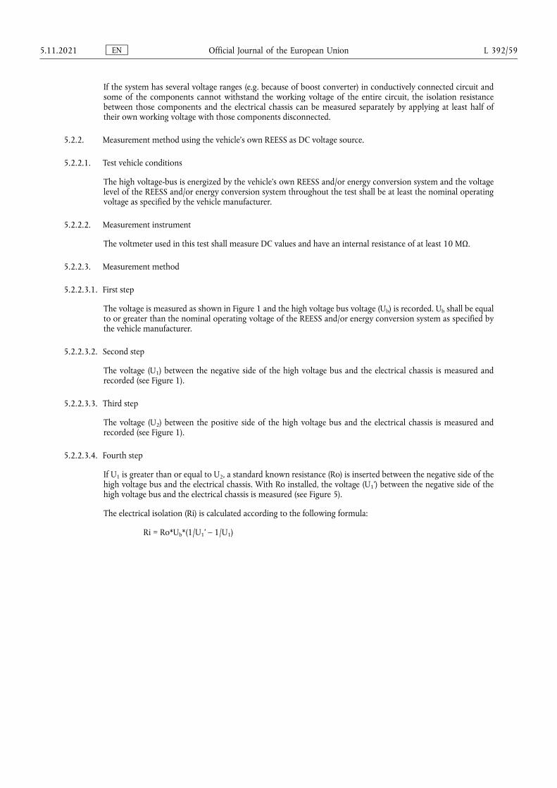
If the system has several voltage ranges (e.g. because of boost converter) in conductively connected circuit and some of the components cannot withstand the working voltage of the entire circuit, the isolation resistance between those components and the electrical chassis can be measured separately by applying at least half of their own working voltage with those components disconnected.
5.2.2. Measurement method using the vehicle’s own REESS as DC voltage source.
5.2.2.1. Test vehicle conditions
The high voltage-bus is energized by the vehicle’s own REESS and/or energy conversion system and the voltage level of the REESS and/or energy conversion system throughout the test shall be at least the nominal operating voltage as specified by the vehicle manufacturer.
5.2.2.2. Measurement instrument
The voltmeter used in this test shall measure DC values and have an internal resistance of at least 10 MΩ.
5.2.2.3. Measurement method
5.2.2.3.1. First step
The voltage is measured as shown in Figure 1 and the high voltage bus voltage (Ub) is recorded. Ub shall be equal to or greater than the nominal operating voltage of the REESS and/or energy conversion system as specified by the vehicle manufacturer.
5.2.2.3.2. Second step
The voltage (U1) between the negative side of the high voltage bus and the electrical chassis is measured and recorded (see Figure 1).
5.2.2.3.3. Third step
The voltage (U2) between the positive side of the high voltage bus and the electrical chassis is measured and recorded (see Figure 1).
5.2.2.3.4. Fourth step
If U1 is greater than or equal to U2, a standard known resistance (Ro) is inserted between the negative side of the high voltage bus and the electrical chassis. With Ro installed, the voltage (U1') between the negative side of the high voltage bus and the electrical chassis is measured (see Figure 5).
The electrical isolation (Ri) is calculated according to the following formula:
Ri = Ro*Ub*(1/U1' – 1/U1)
EN Official Journal of the European Union 5.11.2021 L 392/59
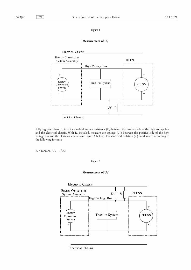
Figure 5
Measurement of U1’
If U2 is greater than U1, insert a standard known resistance (Ro) between the positive side of the high voltage bus and the electrical chassis. With Ro installed, measure the voltage (U2’) between the positive side of the high voltage bus and the electrical chassis (see Figure 6 below). The electrical isolation (Ri) is calculated according to the following formula:
Ri = Ro*Ub*(1/U2’ – 1/U2)
Figure 6
Measurement of U2’
EN Official Journal of the European Union L 392/60 5.11.2021
5.2.2.3.5. Fifth step
The electrical isolation value Ri (in Ω) divided by the working voltage of the high voltage bus (in V) results in the isolation resistance (in Ω/V).
Note: The standard known resistance Ro (in Ω) should be the value of the minimum required isolation resistance (Ω/V) multiplied by the working voltage (V) of the vehicle plus/minus 20 per cent. Ro is not required to be precisely this value since the equations are valid for any Ro; however, a Ro value in this range should provide a good resolution for the voltage measurements.
6. Electrolyte leakage
An appropriate coating, if necessary, may be applied to the physical protection (casing) in order to confirm if there is any electrolyte leakage from the REESS resulting from the test. Unless the manufacturer provides means to differentiate between the leakage of different liquids, all liquid leakage shall be considered as the electrolyte.
7. REESS retention
Compliance shall be determined by visual inspection.
EN Official Journal of the European Union 5.11.2021 L 392/61

Only the original UN/ECE texts have legal effect under international public law. The status and date of entry into force of this Regulation should be checked in the latest version of the UN/ECE status document TRANS/WP.29/343, available at:
https://unece.org/status-1958-agreement-and-annexed-regulations
UN Regulation No 95 – Uniform provisions concerning the approval of vehicles with regard to the protection of the occupants in the event of a lateral collision [2021/1861]
Incorporating all valid text up to:
05 series of amendments – Date of entry into force: 9 June 2021
CONTENTS
REGULATION
1. Scope
2. Definitions
3. Application for approval
4. Approval
5. Specifications and tests
6. Modification of the vehicle type
7. Conformity of production
8. Penalties for non-conformity of production
9. Production definitively discontinued
10. Names and addresses of Technical Services responsible for conducting approval tests, and of Type Approval Authorities
11. Transitional provisions
ANNEXES
1 Communication
2 Arrangements of the approval mark
3 Procedure for determining the ‘H’ point and the actual torso angle for seating positions in motor vehicles
4 Collision test procedure
5 Mobile deformable barrier characteristics
6 Technical description of the side impact dummy
7 Installation of the side impact dummy
8 Partial test
9 Test procedures for vehicles equipped with electric power train
EN Official Journal of the European Union L 392/62 5.11.2021

1. SCOPE
This Regulation applies to vehicles of category M1 with a maximum permissible mass not exceeding 3 500 kg and to vehicles of category N1. (1)
2. DEFINITIONS
For the purposes of this Regulation:
2.1. ‘Approval of a vehicle’ means the approval of a vehicle type with regard to the behaviour of the structure of the passenger compartment in a lateral collision.
2.2. ‘Vehicle type’ means a category of power-driven vehicles which do not differ in such essential respects as:
2.2.1. The length, width and ground clearance of the vehicle, in so far as they have a negative effect on the performance prescribed in this Regulation;
2.2.2. The structure, dimensions, lines and materials of the side walls of the passenger compartment in so far as they have a negative effect on the performance prescribed in this Regulation;
2.2.3. The lines and inside dimensions of the passenger compartment and the type of protective systems, in so far as they have a negative effect on the performance prescribed in this Regulation;
2.2.4. The sitting of the engine (front, rear or centre) and the orientation (transversal or longitudinal) of the engine, in so far as they have a negative effect on the result of the impact test of this Regulation;
2.2.5. The unladen mass, in so far as there is a negative effect on the performance prescribed in this Regulation;
2.2.6. The optional arrangements or interior fittings in so far as they have a negative effect on the performance prescribed in this Regulation;
2.2.7. The type of front seat(s) and position of the ‘R’ point in so far as they have a negative effect on the performance prescribed in this Regulation;
2.2.8. The locations of the REESS, in so far as they have a negative effect on the result of the impact test prescribed in this Regulation.
2.3. ‘Passenger compartment’ means the space for occupant accommodation, bounded by the roof, floor, side walls, doors, outside glazing and front bulkhead and the plane of the rear compartment bulkhead or the plane of the rear-seat back support.
2.3.1. ‘Passenger compartment with regard to occupant protection’ means the space for occupant accommodation, bounded by the roof, floor, side walls, doors, outside glazing and front bulkhead and the plane of the rear compartment bulkhead or the plane of the rear-seat back support.
2.3.2. ‘Passenger compartment for electric safety assessment’ means the space for occupant accommodation, bounded by the roof, floor, side walls, doors, outside glazing, front bulkhead and rear bulkhead, or rear gate, as well as by the electrical protection barriers and enclosures provided for protecting the occupants from direct contact with high voltage live parts..
(1) As defined in the Consolidated Resolution on the Construction of Vehicles (R.E.3.), document ECE/TRANS/WP.29/78/Rev.6, para. 2 - https://unece.org/transport/standards/transport/vehicle-regulations-wp29/resolutions
EN Official Journal of the European Union 5.11.2021 L 392/63
2.4. ‘R point’ or ‘seating reference point’ means the reference point specified by the vehicle manufacturer which:
2.4.1. Has co-ordinates determined in relation to the vehicle structure;
2.4.2. Corresponds to the theoretical position of the point of torso/thighs rotation (H point) for the lowest and most rearward normal driving position or position of use given by the vehicle manufacturer for each seating position specified by him.
2.5. ‘H point’ is as established by Annex 3 to this Regulation.
2.6. ‘Capacity of the fuel tank’ means the fuel-tank capacity as specified by the manufacturer of the vehicle.
2.7. ‘Transverse plane’ means a vertical plane perpendicular to the median longitudinal vertical plane of the vehicle.
2.8. ‘Protective system’ means devices intended to restrain and/or protect the occupants.
2.9. ‘Type of protective system’ means a category of protective devices which do not differ in such essential respects as their:
Technology;
Geometry;
Constituent materials.
2.10. ‘Reference mass’ means the unladen mass of the vehicle increased by a mass of 100 kg (that is the mass of the side impact dummy and its instrumentation).
2.11. ‘Unladen mass’ means the mass of the vehicle in running order without driver, passengers or load, but with the fuel tank filled to 90 per cent of its capacity and the usual set of tools and spare wheel on board, where applicable.
2.12. ‘Mobile deformable barrier’ means the apparatus with which the test vehicle is impacted. It consists of a trolley and an impactor.
2.13. ‘Impactor’ means a crushable section mounted on the front of mobile deformable barrier.
2.14. ‘Trolley’ means a wheeled frame free to travel along its longitudinal axis at the point of impact. Its front supports the impactor.
2.15. ‘High voltage’ means the classification of an electric component or circuit, if its working voltage is > 60 V and ≤ 1 500 V direct current (DC) or > 30 V and ≤ 1 000 V alternating current (AC) root - mean - square (rms).
2.16. ‘Rechargeable Electrical Energy Storage System (REESS)’ means the rechargeable energy storage system that provides electric energy for electrical propulsion.
A battery whose primary use is to supply power for starting the engine and/or lighting and/or other vehicle auxiliaries’ systems is not considered as a REESS.
The REESS may include the necessary systems for physical support, thermal management, electronic controls and casing.
2.17. ‘Electrical protection barrier’ means the part providing protection against direct contact to the high voltage live parts.
EN Official Journal of the European Union L 392/64 5.11.2021
2.18. ‘Electric power train’ means the electrical circuit which includes the traction motor(s), and may also include the REESS, the electrical energy conversion system, the electronic converters, the associated wiring harness and connectors, and the coupling system for charging the REESS.
2.19. ‘Live parts’ means conductive part(s) intended to be electrically energized under normal operating conditions.
2.20. ‘Exposed conductive part’ means the conductive part which can be touched under the provisions of the protection degree IPXXB and which is not normally energized, but which can become electrically energized under isolation failure conditions. This includes parts under a cover that can be removed without using tools.
2.21. ‘Direct contact’ means the contact of persons with high voltage live parts.
2.22. ‘Indirect contact’ means the contact of persons with exposed conductive parts.
2.23. ‘Protection degree IPXXB’ means protection from contact with high voltage live parts provided by either an electrical protection barrier or an enclosure and tested using a Jointed Test Finger (degree IPXXB) as described in paragraph 4 of Annex 9.
2.24. ‘Working voltage’ means the highest value of an electrical circuit voltage root-mean-square (rms), specified by the manufacturer, which may occur between any conductive parts in open circuit conditions or under normal operating conditions. If the electrical circuit is divided by galvanic isolation, the working voltage is defined for each divided circuit, respectively.
2.25. ‘Coupling system for charging the Rechargeable Electrical Energy Storage System (REESS)’ means the electrical circuit used for charging the REESS from an external electrical power supply including the vehicle inlet.
2.26. ‘Electrical chassis’ means a set made of conductive parts electrically linked together, whose electrical potential is taken as reference.
2.27. ‘Electrical circuit’ means an assembly of connected live parts which is designed to be electrically energized in normal operation.
2.28. ‘Electrical energy conversion system’ means a system (e.g. fuel cell) that generates and provides electrical energy for electrical propulsion.
2.29. ‘Electronic converter’ means a device capable of controlling and/or converting electrical power for electrical propulsion.
2.30. ‘Enclosure’ means the part enclosing the internal units and providing protection against any direct contact.
2.31. ‘High voltage bus’ means the electrical circuit, including the coupling system for charging the REESS, that operates on a high voltage.
Where electric circuits are galvanically connected to each other and fulfil the specific voltage condition, only the components or parts of the electric circuit that operate on high voltage are classified as a high voltage bus.
2.32. ‘Solid insulator’ means the insulating coating of wiring harnesses, provided in order to cover and prevent the high voltage live parts from any direct contact.
2.33. ‘Automatic disconnect’ means a device that when triggered, galvanically separates the electrical energy sources from the rest of the high voltage circuit of the electric power train.
EN Official Journal of the European Union 5.11.2021 L 392/65
2.34. ‘Open type traction battery’ means a type of battery requiring filling with liquid and generating hydrogen gas that is released to the atmosphere.
2.35. ‘Automatically activated door locking system’ means a system that locks the doors automatically at a pre-set speed or under any other condition as defined by the manufacturer.
2.36. ‘Latched’ means any coupling condition of the door latch system, where the latch is in a fully latched position, a secondary latched position, or in between a fully latched position and a secondary latched position.
2.37. ‘Latch’ is a device employed to maintain the door in a closed position relative to the vehicle body with provisions for deliberate release (or operation).
2.38. ‘Fully latched position’ is the coupling condition of the latch that retains the door in a completely closed position.
2.39. ‘Secondary latched position’ refers to the coupling condition of the latch that retains the door in a partially closed position.
2.40. ‘Displacement system’ means a device by which the seat or one of its parts can be displaced and/or rotated, without a fixed intermediate position, to permit easy access of occupants to and from the space behind the seat concerned.
2.41. ‘Aqueous electrolyte’ means an electrolyte based on water solvent for the compounds (e.g. acids, bases) providing conducting ions after its dissociation.
2.42. ‘Electrolyte leakage’ means the escape of electrolyte from the REESS in the form of liquid.
2.43. ‘Non-aqueous electrolyte’ means an electrolyte not based on water as the solvent.
2.44. ‘Normal operating conditions’ includes operating modes and conditions that can reasonably be encountered during typical operation of the vehicle including driving at legally posted speeds, parking and standing in traffic, as well as, charging using chargers that are compatible with the specific charging ports installed on the vehicle. It does not include, conditions where the vehicle is damaged, either by a crash, road debris or vandalization, subjected to fire or water submersion, or in a state where service and or maintenance is needed or being performed.
2.45. ‘Specific voltage condition’ means the condition that the maximum voltage of a galvanically connected electric circuit between a DC live part and any other live part (DC or AC) is ≤ 30 V AC (rms) and ≤ 60 V DC.
Note: When a DC live part of such an electric circuit is connected to electrical chassis and the specific voltage condition applies, the maximum voltage between any live part and the electrical chassis is ≤ 30 V AC (rms) and ≤ 60 V DC.
2.46. ‘State of Charge (SOC)’ means the available electrical charge in a REESS expressed as a percentage of its rated capacity.
2.47. ‘Fire’ means the emission of flames from the vehicle. Sparks and arcing shall not be considered as flames.
2.48. ‘Explosion’ means the sudden release of energy sufficient to cause pressure waves and/or projectiles that may cause structural and/or physical damage to the surrounding of the vehicle.
EN Official Journal of the European Union L 392/66 5.11.2021
3. APPLICATION FOR APPROVAL
3.1. The application for approval of a vehicle type with regard to the protection of the occupants in the event of a lateral collision shall be submitted by the vehicle manufacturer or by his duly accredited representative.
3.2. It shall be accompanied by the under mentioned documents in triplicate and the following particulars:
3.2.1. A detailed description of the vehicle type with respect to its structure, dimensions, lines and constituent materials;
3.2.2. Photographs and/or diagrams and drawings of the vehicle showing the vehicle type in front, side and rear elevation and design details of the lateral part of the structure;
3.2.3. Particulars of the vehicle’s mass as defined by paragraph 2.11 of this Regulation;
3.2.4. The lines and inside dimensions of the passenger compartment;
3.2.5. A description of the relevant side interior fittings and protective systems installed in the vehicle;
3.2.6. A general description of the electrical power source type, location and the electric power train (e.g. hybrid, electric).
3.3. The applicant for approval shall be entitled to present any data and results of tests carried out which make it possible to establish that compliance with the requirements can be achieved on prototype vehicles with a sufficient degree of accuracy.
3.4. A vehicle which is representative of the type to be approved shall be submitted to the Technical Service responsible for conducting the approval tests.
3.4.1. A vehicle not comprising all the components proper to the type may be accepted for tests provided that it can be shown that the absence of the components omitted has no detrimental effect on the performance prescribed in the requirements of this Regulation.
3.4.2. It shall be the responsibility of the applicant for approval to show that the application of paragraph 3.4.1 above is in compliance with the requirements of this Regulation.
4. APPROVAL
4.1. If the vehicle type submitted for approval pursuant to this Regulation meets the requirements of paragraph 5 below, approval of that vehicle type shall be granted.
4.2. An approval number shall be assigned to each type approved in accordance with Schedule 4 of the Agreement (E/ECE/TRANS/505/Rev.3).
4.3. Notice of approval or of refusal of approval of a vehicle type pursuant to this Regulation shall be communicated by the Parties to the Agreement which apply this Regulation by means of a form conforming to the model in Annex 1 to this Regulation.
4.4. Notice of approval or of extension or of refusal of approval of a vehicle type pursuant to this Regulation shall be communicated by the Parties to the Agreement applying this Regulation by means of a form conforming to the model in Annex 1 to this Regulation and photographs and/or diagrams and drawings supplied by the applicant for approval, in a format not exceeding A4 (210 × 297 mm) or folded to that format and on an appropriate scale.
EN Official Journal of the European Union 5.11.2021 L 392/67
4.5. There shall be affixed to every vehicle conforming to a vehicle type approved under this Regulation, conspicuously and in a readily accessible place specified on the approval form, an international approval mark consisting of:
4.5.1. A circle surrounding the letter ‘E’ followed by the distinguishing number of the country which has granted approval; (2)
4.5.2. The number of this Regulation, followed by the letter ‘R’, a dash and the approval number, to the right of the circle prescribed in paragraph 4.5.1 above.
4.6. If the vehicle conforms to a vehicle type approved, under one or more other Regulations annexed to the Agreement, in the country which has granted approval under this Regulation, the symbol prescribed in paragraph 4.5.1 above need not be repeated; in this case the Regulation and approval numbers and the additional symbols of all the Regulations under which approval has been granted in the country which has granted approval under this Regulation shall be placed in vertical columns to the right of the symbol prescribed in paragraph 4.5.1 above.
4.7. The approval mark shall be clearly legible and shall be indelible.
4.8. Annex 2 to this Regulation gives examples of the arrangements of approval marks.
5. SPECIFICATIONS AND TESTS
5.1. The vehicle shall undergo a test in accordance with Annex 4 to this Regulation.
5.1.1. The test will be carried out on the driver’s side unless asymmetric side structures, if any, are so different as to affect the performance in a side impact. In that case either of the alternatives in paragraph 5.1.1.1 or 5.1.1.2 below may be used by agreement between the manufacturer and Type Approval Authority.
5.1.1.1. The manufacturer will provide the authority responsible for approval with information regarding the compatibility of performances in comparison with the driver’s side when the test is being carried out on that side.
5.1.1.2. The Type Approval Authority, if concerned as to the construction of the vehicle, will decide to have the test performed on the side opposite the driver, this being considered the least favourable.
5.1.2. The Technical Service, after consultation with the manufacturer, may require the test to be carried out with the seat in a position other than the one indicated in paragraph 5.5.1 of Annex 4. This position shall be indicated in the test report. (3)
5.1.3. The result of this test shall be considered satisfactory if the conditions set out in paragraphs 5.2 and 5.3 below are satisfied.
5.2. Performance criteria
Additionally, vehicles equipped with electric power train shall meet the requirements of paragraph 5.3.7 below. This can be met by a separate impact test at the request of the manufacturer and after validation by the Technical Service, provided that the electrical components do not influence the occupant protection performance of the vehicle type as defined in paragraphs 5.2.1 to 5.3.5 of this Regulation. In case of this condition the requirements of paragraph 5.3.7 shall be checked in accordance with the methods set out in Annex 4 to this Regulation, except paragraphs 6, 7 and Appendices 1 and 2. But the side-impact dummy shall be installed in the front seat on the impact side.
(2) The distinguishing numbers of the Contracting Parties to the 1958 Agreement are reproduced in Annex 3 to the Consolidated Resolution on the Construction of Vehicles (R.E.3), document ECE/TRANS/WP.29/78/Rev. 6, Annex 3
(3) Until 30 September 2000, for the purposes of the test requirements, the range of normal longitudinal adjustments shall be limited such that the H-point lies within the length of the door aperture.
EN Official Journal of the European Union L 392/68 5.11.2021
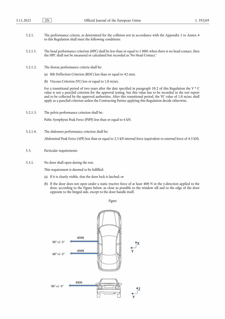
5.2.1. The performance criteria, as determined for the collision test in accordance with the Appendix 1 to Annex 4 to this Regulation shall meet the following conditions:
5.2.1.1. The head performance criterion (HPC) shall be less than or equal to 1 000; when there is no head contact, then the HPC shall not be measured or calculated but recorded as ‘No Head Contact.’
5.2.1.2. The thorax performance criteria shall be:
(a) Rib Deflection Criterion (RDC) less than or equal to 42 mm;
(b) Viscous Criterion (VC) less or equal to 1,0 m/sec.
For a transitional period of two years after the date specified in paragraph 10.2 of this Regulation the V * C value is not a pass/fail criterion for the approval testing, but this value has to be recorded in the test report and to be collected by the approval authorities. After this transitional period, the VC value of 1,0 m/sec shall apply as a pass/fail criterion unless the Contracting Parties applying this Regulation decide otherwise.
5.2.1.3. The pelvis performance criterion shall be:
Pubic Symphysis Peak Force (PSPF) less than or equal to 6 kN.
5.2.1.4. The abdomen performance criterion shall be:
Abdominal Peak Force (APF) less than or equal to 2,5 kN internal force (equivalent to external force of 4,5 kN).
5.3. Particular requirements
5.3.1. No door shall open during the test.
This requirement is deemed to be fulfilled:
(a) If it is clearly visible, that the door lock is latched; or
(b) If the door does not open under a static tractive force of at least 400 N in the y-direction applied to the door, according to the Figure below, as close as possible to the window sill and to the edge of the door opposite to the hinged side, except to the door handle itself.
Figure
EN Official Journal of the European Union 5.11.2021 L 392/69
5.3.1.1. In the case of automatically activated door locking systems which are installed optionally and/or which can be de-activated by the driver, this requirement shall be verified by using one of the following two test procedures, at the choice of the manufacturer:
5.3.1.1.1. If testing in accordance with Annex 4, paragraph 5.2.2.1, the manufacturer shall in addition demonstrate to the satisfaction of the Technical Service (e.g. manufacturer’s in-house data) that, in the absence of the system or when the system is de-activated, no door will open in case of the impact.
5.3.1.1.2. If testing in accordance with Annex 4, paragraph 5.2.2.2, the manufacturer shall in addition demonstrate that the inertial load requirements of paragraph 6.1.4 of the 03 series of amendments to Regulation No 11 are met for the unlocked side doors on the non-struck side.
5.3.2. After the impact, the side doors on the non-struck side shall be unlocked.
5.3.2.1. In the case of vehicles equipped with an automatically activated door locking system, the doors shall be locked before the moment of impact and be unlocked after the impact at least on the non-struck side.
5.3.2.2. In the case of automatically activated door locking systems which are installed optionally and/or which can be de-activated by the driver, this requirement shall be verified by using one of the following two test procedures, at the choice of the manufacturer:
5.3.2.2.1. If testing in accordance with Annex 4, paragraph 5.2.2.1, the manufacturer shall in addition demonstrate to the satisfaction of the Technical Service (e.g. manufacturer’s in-house data) that, in the absence of the system or when the system is de-activated, the side doors on the non-struck side are unlocked after the impact.
5.3.2.2.2. If testing in accordance with paragraph Annex 4, paragraph 5.2.2.2 the manufacturer shall in addition demonstrate that when applying the inertial load of paragraph 6.1.4 of the 03 series of amendments to Regulation No 11, the unlocked side doors on the non-struck side remain unlocked.
5.3.3. After the impact, it shall be possible without the use of tools to:
5.3.3.1. Open at least one door per row of seats. Where there is no such door, it shall be possible to allow the evacuation of all the occupants by activating the displacement system of seats, if necessary. In case no displacement system is available for the evacuation of a rear seated occupant, it shall be shown that a 50th
percentile manikin can be evacuated without the use of any devices to support its weight and any other tools.
For vehicles of category N1 this evacuation may be done via an emergency window if this window can be easily opened, but if tools are necessary, (e.g. for breaking the window) these tools shall then be provided by the manufacturer and shall be visible and located in close proximity to that emergency window.
This shall be assessed for all configurations or worst-case configuration for number of doors on each side of the vehicle and for both left-hand drive and right-hand drive vehicles, when applicable.
5.3.3.2. Release the dummy from the protective system;
5.3.3.3. Remove the dummy from the vehicle;
5.3.4. No interior device or component shall become detached in such a way as noticeably to increase the risk of injury from sharp projections or jagged edges;
5.3.5. Ruptures, resulting from permanent deformation are acceptable, provided these do not increase the risk of injury;
EN Official Journal of the European Union L 392/70 5.11.2021
5.3.6. If there is continuous leakage of liquid from the fuel-feed installation after the collision, the rate of leakage shall not exceed 30 g/min; if the liquid from the fuel-feed system mixes with liquids from the other systems and the various liquids cannot easily be separated and identified, all the liquids collected shall be taken into account in evaluating the continuous leakage.
5.3.7. Following the test conducted in accordance with the procedure defined in Annex 4 to this Regulation, the electric power train operating on high voltage, and the high voltage systems which are galvanically connected to the high voltage bus of the electric power train, shall meet the following requirements:
5.3.7.1. Protection against electrical shock
After the impact, the high voltage buses shall meet at least one of the four criteria specified in paragraph 5.3.7.1.1 through paragraph 5.3.7.1.4.2.
If the vehicle has an automatic disconnect function, or device(s) that conductively divide the electric power train circuit during driving condition, at least one of the following criteria shall apply to the disconnected circuit or to each divided circuit individually after the disconnect function is activated.
However, criteria defined in 5.3.7.1.4 shall not apply if more than a single potential of a part of the high voltage bus is not protected under the conditions of protection degree IPXXB.
In the case that the crash test is performed under the condition that part(s) of the high voltage system are not energized and with the exception of any coupling system for charging the REESS which is not energized during driving condition, the protection against electrical shock shall be proved by either paragraphs 5.3.7.1.3 or 5.3.7.1.4 below for the relevant part(s).
5.3.7.1.1. Absence of high voltage
The voltages Ub, U1 and U2 of the high voltage buses shall be equal or less than 30 VAC or 60 VDC within 60 s after the impact when measured in accordance with paragraph 2 of Annex 9.
5.3.7.1.2. Low electrical energy
The total energy (TE) on the high voltage buses shall be less than 0,2 joules when measured according to the test procedure as specified in paragraph 3 of Annex 9 with the formula (a). Alternatively, the total energy (TE) may be calculated by the measured voltage Ub of the high voltage bus and the capacitance of the X-capacitors (Cx) specified by the manufacturer according to formula (b) of paragraph 3 of Annex 9.
The energy stored in the Y-capacitors (TEy1, TEy2) shall also be less than 0,2 joules. This shall be calculated by measuring the voltages U1 and U2 of the high voltage buses and the electrical chassis, and the capacitance of the Y-capacitors specified by the manufacturer according to formula (c) of paragraph 3 of Annex 9.
5.3.7.1.3. Physical protection
For protection against direct contact with high voltage live parts, the protection degree IPXXB shall be provided.
The assessment shall be conducted in accordance with paragraph 4 of Annex 9.
In addition, for protection against electrical shock which could arise from indirect contact, the resistance between all exposed conductive parts of electrical protection barriers/enclosures and the electrical chassis shall be lower than 0,1 Ω and the resistance between any two simultaneously reachable exposed conductive parts of electrical protection barriers/enclosures that are less than 2,5 m from each other shall be less than 0,2 Ω when there is current flow of at least 0,2 A. This resistance may be calculated using the separately measured resistances of the relevant parts of electric path.
EN Official Journal of the European Union 5.11.2021 L 392/71
These requirements are satisfied if the galvanic connection has been made by welding. In case of doubt or the connection is established by mean other than welding, measurements shall be made by using one of the test procedures described in paragraph 4 of Annex 9.
5.3.7.1.4. Isolation resistance
The criteria specified in the paragraphs 5.3.7.1.4.1 and 5.3.7.1.4.2 below shall be met.
The measurement shall be conducted in accordance with paragraph 5 of Annex 9.
5.3.7.1.4.1. Electric power train consisting of separate DC- or AC-buses.
If the AC high voltage buses and the DC high voltage buses are galvanically isolated from each other, isolation resistance between the high voltage bus and the electrical chassis (Ri, as defined in paragraph 5 of Annex 9) shall have a minimum value of 100 Ω/V of the working voltage for DC buses, and a minimum value of 500 Ω/V of the working voltage for AC buses.
5.3.7.1.4.2. Electric power train consisting of combined DC- and AC-buses
If the AC high voltage buses and the DC high voltage buses are conductively connected, they shall meet one of the following requirements:
(a) Isolation resistance between the high voltage bus and the electrical chassis shall have a minimum value of 500 Ω/V of the working voltage;
(b) Isolation resistance between the high voltage bus and the electrical chassis shall have a minimum value of 100 Ω/V of the working voltage and the AC bus meets the physical protection as described in paragraph 5.3.7.1.3;
(c) Isolation resistance between the high voltage bus and the electrical chassis shall have a minimum value of 100 Ω/V of the working voltage and the AC bus meets the absence of high voltage as described in paragraph 5.3.7.1.1.
5.3.7.2. Electrolyte leakage
5.3.7.2.1. In case of aqueous electrolyte REESS.
For a period from the impact until 60 minutes after the impact, there shall be no electrolyte leakage from the REESS into the passenger compartment and no more than 7 per cent by volume of the REESS electrolyte with a maximum of 5,0 l leaked from the REESS to the outside of the passenger compartment. The leaked amount of electrolyte can be measured by usual techniques of determination of liquid volumes after its collection. For containers containing Stoddard, coloured coolant and electrolyte, the fluids shall be allowed to separate by specific gravity then measured.
5.3.7.2.2. In case of non-aqueous electrolyte REESS.
For a period from the impact until 60 minutes after the impact, there shall be no liquid electrolyte leakage from the REESS into the passenger compartment, luggage compartment and no liquid electrolyte leakage to outside the vehicle. This requirement shall be verified by visual inspection without disassembling any part of the vehicle.
5.3.7.3. REESS retention
REESS shall remain attached to the vehicle by at least one component anchorage, bracket, or any structure that transfers loads from REESS to the vehicle structure, and REESS located outside the passenger compartment shall not enter the passenger compartment.
5.3.7.4. REESS fire hazards
For a period from the impact until 60 minutes after the impact, there shall be no evidence of fire or explosion from the REESS.
EN Official Journal of the European Union L 392/72 5.11.2021
5.3.8. The fuel system and high voltage system shall be assessed for all configurations or worst-case configuration for left-hand drive and right-hand drive vehicles, when applicable.
6. MODIFICATION OF THE VEHICLE TYPE
6.1. Every modification of the vehicle type with regard to this UN Regulation shall be notified to the Type Approval Authority which approved that vehicle type. The Type Approval Authority may then either:
(a) Decide, in consultation with the manufacturer, that a new type approval is to be granted; or
(b) Apply the procedure contained in paragraph 6.1.1 (Revision) and, if applicable, the procedure contained in paragraph 6.1.2 (Extension).
6.1.1. Revision
When particulars recorded in the information documents have changed and the Type Approval Authority considers that the modifications made are unlikely to have appreciable adverse effect, and that in any case the vehicle still meets the requirements, the modification shall be designated a ‘revision’.
In such a case, the Type Approval Authority shall issue the revised pages of the information documents of as necessary, marking each revised page to show clearly the nature of the modification and the date of re-issue. A consolidate, updated version of the information documents accompanied by a detailed description of the modification, shall be deemed to meet this requirement.
6.1.2. Extension
The modification shall be designated an ‘extension’ if, in addition to the change of the particulars recorded in the information folder:
(a) Further inspections or tests are required; or
(b) Any information on the communication document (with the exception of its attachments) has changed; or
(c) Approval to a later series of amendments is requested after its entry into force.
6.2. Notice of confirmation, extension, or refusal of approval shall be communicated by the procedure specified in paragraph 4.3 above, to the Contracting Parties to the Agreement applying this UN Regulation. In addition, the index to the information documents and to the test reports, attached to the communication document of Annex 1, shall be amended accordingly to show the date of the most recent revision or extension.
7. CONFORMITY OF PRODUCTION
The conformity of production procedure shall comply with the requirements set out in Schedule 1 of the Agreement (E/ECE/TRANS/505/Rev.3).
7.1. Vehicles approved under this Regulation shall be so manufactured as to conform to the type approved by meeting the requirements of the relevant part(s) of this Regulation.
7.2. In order to verify that the requirements of paragraph 7.1 are met, appropriate production checks shall be carried out.
7.3. The Type Approval Authority which has granted type approval may at any time verify the conformity control methods applied in each production facility. The normal frequency of these verifications shall be once every two years.
EN Official Journal of the European Union 5.11.2021 L 392/73

8. PENALTIES FOR NON-CONFORMITY OF PRODUCTION
8.1. The approval granted in respect of a vehicle type pursuant to this Regulation may be withdrawn if the requirement laid down in paragraph 7.1 above is not complied with.
8.2. If a Contracting Party to the Agreement applying this Regulation withdraws an approval it has previously granted, it shall forthwith so notify the other Contracting Parties applying this Regulation, by means of a copy of the approval form bearing at the end, in large letters, the signed and dated annotation ‘APPROVAL WITHDRAWN’.
9. PRODUCTION DEFINITIVELY DISCONTINUED
If the holder of the approval completely ceases to manufacture the type of vehicle approved in accordance with the Regulation, he shall so inform the Type Approval Authority which granted the approval. Upon receiving the relevant communication that Type Approval Authority shall inform thereof the other Parties to the Agreement applying this Regulation by means of a copy of the approval form bearing at the end, in large letters, the signed and dated annotation ‘PRODUCTION DISCONTINUED’.
10. NAMES AND ADDRESSES OF TECHNICAL SERVICES RESPONSIBLE FOR CONDUCTING APPROVAL TESTS, AND OF TYPE APPROVAL AUTHORITIES
The Contracting Parties to the Agreement applying this Regulation shall communicate to the United Nations secretariat the names and addresses of the Technical Services responsible for conducting approval tests, and of the Type Approval Authority which grant approval and to which forms certifying approval or extension, or refusal or withdrawal of approval, issued in other countries, are to be sent.
11. TRANSITIONAL PROVISIONS
11.1. As from the official date of entry into force of the 05 series of amendments, no Contracting Party applying this Regulation shall refuse to grant or refuse to accept type-approvals under this Regulation as amended by the 05 series of amendments.
11.2. As from 1 September 2023, Contracting Parties applying this Regulation shall not be obliged to accept type- approvals of vehicles having an electric power train operating on high voltage according to the preceding series of amendments, first issued after 1 September 2023.
11.3. Contracting Parties applying this Regulation shall continue to accept type-approvals of vehicles not having an electric power train operating on high voltage according to the 04 series of amendments to this Regulation or type-approvals issued according to the preceding series of amendments to this Regulation, for the vehicles which are not affected by the changes introduced by the 04 series of amendments.
11.4. Contracting Parties applying this Regulation shall not refuse to grant type-approvals according to any preceding series of amendments to this Regulation or extensions thereof.
11.5. Notwithstanding the transitional provisions above, Contracting Parties who start to apply this Regulation after the date of entry into force of the most recent series of amendments are not obliged to accept type-approvals which were granted in accordance with any of the preceding series of amendments to this Regulation.
EN Official Journal of the European Union L 392/74 5.11.2021

ANNEX 1
Communication
(maximum format: A4 (210 × 297 mm))
()
issued by: Name of administration. . . . . . . . . . . . . . . . . . . . . . . . . . . . . . . . . . . . . . . . .. . . . . . . . . . . . . . . . . . . . . . . . . . . . . . . . . . . . . . . . .. . . . . . . . . . . . . . . . . . . . . . . . . . . . . . . . . . . . . . . . .
Concerning: (2) Approval granted
Approval extended
Approval refused
Approval withdrawn
Production definitively discontinued
of a vehicle type with regard to protection of occupants in the event of a lateral collision pursuant to Regulation No 95
Approval No . . . . . . . . . . . . . . . . . . . . . . . . . . . . . . . . . . . . . . . . . . . . . . . . Extension No . . . . . . . . . . . . . . . . . . . . . . . . . . . . . . . . . . . . . . . . . . . . . . . .
1. Trade name or mark of the power-driven vehicle: . . . . . . . . . . . . . . . . . . . . . . . . . . . . . . . . . . . . . . . . . . . . . . . . . . . . . . . . . . . . . . . . . . . . . . .
2. Vehicle type: . . . . . . . . . . . . . . . . . . . . . . . . . . . . . . . . . . . . . . . . . . . . . . . . . . . . . . . . . . . . . . . . . . . . . . . . . . . . . . . . . . . . . . . . . . . . . . . . . . . . . . . . . . . . .
3. Manufacturer’s name and address: . . . . . . . . . . . . . . . . . . . . . . . . . . . . . . . . . . . . . . . . . . . . . . . . . . . . . . . . . . . . . . . . . . . . . . . . . . . . . . . . . . . . . . .
4. If applicable, name and address of manufacturer’s representative: . . . . . . . . . . . . . . . . . . . . . . . . . . . . . . . . . . . . . . . . . . . . . . . . . . . . . . . .
5. Vehicle submitted for approval on: . . . . . . . . . . . . . . . . . . . . . . . . . . . . . . . . . . . . . . . . . . . . . . . . . . . . . . . . . . . . . . . . . . . . . . . . . . . . . . . . . . . . . . .
6. Side impact dummy utilized ES-1/ES-2:2. . . . . . . . . . . . . . . . . . . . . . . . . . . . . . . . . . . . . . . . . . . . . . . . . . . . . . . . . . . . . . . . . . . . . . . . . . . . . . . . . .
7. Location of the electric power source: . . . . . . . . . . . . . . . . . . . . . . . . . . . . . . . . . . . . . . . . . . . . . . . . . . . . . . . . . . . . . . . . . . . . . . . . . . . . . . . . . . .
8. Technical Service responsible for conducting approval tests: . . . . . . . . . . . . . . . . . . . . . . . . . . . . . . . . . . . . . . . . . . . . . . . . . . . . . . . . . . . . .
9. Date of test report:. . . . . . . . . . . . . . . . . . . . . . . . . . . . . . . . . . . . . . . . . . . . . . . . . . . . . . . . . . . . . . . . . . . . . . . . . . . . . . . . . . . . . . . . . . . . . . . . . . . . . . . .
10. Number of test report: . . . . . . . . . . . . . . . . . . . . . . . . . . . . . . . . . . . . . . . . . . . . . . . . . . . . . . . . . . . . . . . . . . . . . . . . . . . . . . . . . . . . . . . . . . . . . . . . . . . .
11. Approval granted/refused/extended/withdrawn:2. . . . . . . . . . . . . . . . . . . . . . . . . . . . . . . . . . . . . . . . . . . . . . . . . . . . . . . . . . . . . . . . . . . . . . . . .
12. Position of approval mark on the vehicle: . . . . . . . . . . . . . . . . . . . . . . . . . . . . . . . . . . . . . . . . . . . . . . . . . . . . . . . . . . . . . . . . . . . . . . . . . . . . . . . .
EN Official Journal of the European Union 5.11.2021 L 392/75

13. Place: . . . . . . . . . . . . . . . . . . . . . . . . . . . . . . . . . . . . . . . . . . . . . . . . . . . . . . . . . . . . . . . . . . . . . . . . . . . . . . . . . . . . . . . . . . . . . . . . . . . . . . . . . . . . . . . . . . . . .
14. Date: . . . . . . . . . . . . . . . . . . . . . . . . . . . . . . . . . . . . . . . . . . . . . . . . . . . . . . . . . . . . . . . . . . . . . . . . . . . . . . . . . . . . . . . . . . . . . . . . . . . . . . . . . . . . . . . . . . . . . .
15. Signature: . . . . . . . . . . . . . . . . . . . . . . . . . . . . . . . . . . . . . . . . . . . . . . . . . . . . . . . . . . . . . . . . . . . . . . . . . . . . . . . . . . . . . . . . . . . . . . . . . . . . . . . . . . . . . . . . .
16. The list of documents deposited with the Type Approval Authority which has granted approval is annexed to this communication and may be obtained on request.
_____________(1) Distinguishing number of the country which has granted/extended/refused/withdrawn approval (see approval provisions in the
Regulation).(2) Strike out what does not apply.
EN Official Journal of the European Union L 392/76 5.11.2021
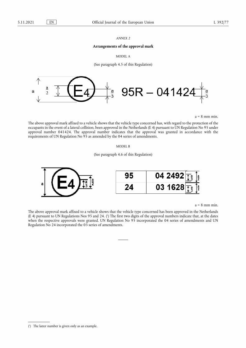
ANNEX 2
Arrangements of the approval mark
MODEL A
(See paragraph 4.5 of this Regulation)
a = 8 mm min.
The above approval mark affixed to a vehicle shows that the vehicle type concerned has, with regard to the protection of the occupants in the event of a lateral collision, been approved in the Netherlands (E 4) pursuant to UN Regulation No 95 under approval number 041424. The approval number indicates that the approval was granted in accordance with the requirements of UN Regulation No 95 as amended by the 04 series of amendments.
MODEL B
(See paragraph 4.6 of this Regulation)
a = 8 mm min.
The above approval mark affixed to a vehicle shows that the vehicle type concerned has been approved in the Netherlands (E 4) pursuant to UN Regulations Nos 95 and 24. (1) The first two digits of the approval numbers indicate that, at the dates when the respective approvals were granted. UN Regulation No 95 incorporated the 04 series of amendments and UN Regulation No 24 incorporated the 03 series of amendments.
(1) The latter number is given only as an example.
EN Official Journal of the European Union 5.11.2021 L 392/77

ANNEX 3
Procedure for determining the ‘H’ point and the actual torso angle for seating positions in motor vehicles (1)
Appendix 1 – Description of the three dimensional ‘H’ point machine (3-D H machine) (1)
Appendix 2 – Three-dimensional reference system (1)
Appendix 3 – Reference data concerning seating positions (1)
(1) The procedure is described in Annex 1 to the Consolidated Resolution on the Construction of Vehicles (RE.3) (document ECE/TRANS/ WP.29/78/Rev.6).
EN Official Journal of the European Union L 392/78 5.11.2021
ANNEX 4
Collision test procedure
1. Installations
1.1. Testing ground
The test area shall be large enough to accommodate the mobile deformable barrier propulsion system and to permit after-impact displacement of the vehicle impacted and installation of the test equipment. The part in which vehicle impact and displacement occur shall be horizontal, flat and uncontaminated, and representative of a normal, dry, uncontaminated road surface.
2. Test conditions
2.1. The vehicle to be tested shall be stationary.
2.2. The mobile deformable barrier shall have the characteristics set out in Annex 5 to this Regulation. Requirements for the examination are given in the appendices to Annex 5. The mobile deformable barrier shall be equipped with a suitable device to prevent a second impact on the struck vehicle.
2.3. The trajectory of the mobile deformable barrier longitudinal median vertical plane shall be perpendicular to the longitudinal median vertical plane of the impacted vehicle.
2.4. The longitudinal vertical median plane of the mobile deformable barrier shall be coincident within ±25 mm with a transverse vertical plane passing through the R point of the front seat adjacent to the struck side of the tested vehicle. The horizontal median plane limited by the external lateral vertical planes of the front face shall be at the moment of impact within two planes determined before the test and situated 25 mm above and below the previously defined plane.
2.5. Instrumentation shall comply with ISO 6487:1987 unless otherwise specified in this Regulation.
2.6. The stabilized temperature of the test dummy at the time of the side impact test shall be 22 ± 4 °C.
3. Test speed
The mobile deformable barrier speed at the moment of impact shall be 50 ± 1 km/h. This speed shall be stabilized at least 0,5 m before impact. Accuracy of measurement: 1 per cent. However, if the test was performed at a higher impact speed and the vehicle met the requirements, the test shall be considered satisfactory.
4. State of the vehicle
4.1. General specification
The test vehicle shall be representative of the series production, shall include all the equipment normally fitted and shall be in normal running order. Some components may be omitted or replaced by equivalent masses where this omission or substitution clearly has no effect on the results of the test.
It shall be allowed by agreement between manufacturer and Technical Service to modify the fuel system so that an appropriate amount of fuel can be used to run the engine or the electrical energy conversion system.
4.2. Vehicle equipment specification
The test vehicle shall have all the optional arrangements or fittings likely to influence the results of the test.
EN Official Journal of the European Union 5.11.2021 L 392/79
4.3. Mass of the vehicle
4.3.1. The vehicle to be tested shall have the reference mass as defined in paragraph 2.10 of this Regulation. The mass of the vehicle shall be adjusted to ±1 per cent of the reference mass.
4.3.2. The fuel tank shall be filled with water to a mass equal to 90 per cent of the mass of a full load of fuel as specified by the manufacturer with a tolerance of ±1 per cent.
This requirement does not apply to hydrogen fuel tanks.
4.3.3. All the other systems (brake, cooling, etc.) may be empty; in this case, the mass of the liquids shall be offset.
4.3.4. If the mass of the measuring apparatus on board of the vehicle exceeds the 25 kg allowed, it may be offset by reductions which have no noticeable effect on the results of the test.
4.3.5. The mass of the measuring apparatus shall not change each axle reference load by more than 5 per cent, each variation not exceeding 20 kg.
5. Preparation of the vehicle
5.1. The side windows at least on the struck side shall be closed.
5.2. The doors shall be closed, but not locked.
5.2.1. However, in the case of vehicles equipped with an automatically activated door locking system, it shall be ensured that all the side doors are locked before the test.
5.2.2. In the case of vehicles equipped with an automatically activated door locking system, which is installed optionally and/or which can be de-activated by the driver, one of the following two procedures shall be used at the choice of the manufacturer:
5.2.2.1. All the side doors shall be locked manually before the start of the test.
5.2.2.2. It shall be ensured that the side doors on the struck side are unlocked and the side doors on the non-struck side locked before the impact; the automatically activated door-locking system may be overridden for this test.
5.3. The transmission shall be placed in neutral and the parking brake disengaged.
5.4. The comfort adjustments of the seats, if any, shall be adjusted to the position specified by the vehicle manufacturer.
5.5. The seat containing the dummy, and its elements, if adjustable, shall be adjusted as follows:
5.5.1. The longitudinal adjustment device shall be placed with the locking device engaged in the position that is nearest to midway between the foremost and rearmost positions; if this position is between two notches, the rearmost notch shall be used.
5.5.2. The head restraint shall be adjusted such that its top surface is level with the centre of gravity of the dummy’s head; if this is not possible, the head restraint shall be in the uppermost position.
5.5.3. Unless otherwise specified by the manufacturer, the seat-back shall be set such that the torso reference line of the three-dimensional H point machine is set at an angle of 25° ± 1° towards the rear.
EN Official Journal of the European Union L 392/80 5.11.2021
5.5.4. All other seat adjustments shall be at the mid-point of available travel; however, height adjustment shall be at the position corresponding to the fixed seat, if the vehicle type is available with adjustable and fixed seats. If locking positions are not available at the respective mid-points of travel, the positions immediately rearward, down, or outboard of the mid-points shall be used. For rotational adjustments (tilt), rearward will be the adjustment direction which moves the head of the dummy rearwards. If the dummy protrudes outside the normal passenger volume, e.g. head into roof lining, then 1 cm clearance will be provided using: secondary adjustments, seat-back angle, or fore-aft adjustment in that order.
5.6. Unless otherwise specified by the manufacturer, the other front seats shall, if possible, be adjusted to the same position as the seat containing the dummy.
5.7. If the steering wheel is adjustable, all adjustments are positioned to their mid-travel locations.
5.8. Tyres shall be inflated to the pressure specified by the vehicle manufacturer.
5.9. The test vehicle shall be set horizontal about its roll axis and maintained by supports in that position until the side impact dummy is in place and after all preparatory work is complete.
5.10. The vehicle shall be at its normal attitude corresponding to the conditions set out in paragraph 4.3 above. Vehicles with suspension enabling their ground clearance to be adjusted shall be tested under the normal conditions of use at 50 km/h as defined by the vehicle manufacturer. This shall be assured by means of additional supports, if necessary, but such supports shall have no influence on the crash behaviour of the test vehicle during the impact.
5.11. Electric power train adjustment
5.11.1. Procedures for SOC adjustment.
5.11.1.1. The adjustment of SOC shall be conducted at an ambient temperature of 20 ± 10 °C.
5.11.1.2. The SOC shall be adjusted according to one of the following procedures as applicable. Where different charging procedures are possible, the REESS shall be charged using the procedure which yields the highest SOC:
(a) For a vehicle with a REESS designed to be externally charged, the REESS shall be charged to the highest SOC in accordance with the procedure specified by the manufacturer for normal operation until the charging process is normally terminated.
(b) For a vehicle with a REESS designed to be charged only by an energy source on the vehicle, the REESS shall be charged to the highest SOC which is achievable with normal operation of the vehicle. The manufacturer shall advise on the vehicle operation mode to achieve this SOC.
5.11.1.3. When the vehicle is tested, the SOC shall be no less than 95 per cent of the SOC according to paragraphs 5.11.1.1 and 5.11.1.2 for REESS designed to be externally charged and shall be no less than 90 per cent of SOC according to paragraphs 5.11.1.1 and 5.11.1.2 for REESS designed to be charged only by an energy source on the vehicle. The SOC will be confirmed by a method provided by the manufacturer.
5.11.2. The electric power train shall be energized with or without the operation of the original electrical energy sources (e.g. engine-generator, REESS or electric energy conversion system), however:
EN Official Journal of the European Union 5.11.2021 L 392/81

5.11.2.1. By the agreement between Technical Service and manufacturer it shall be permissible to perform the test with all or parts of the electric power train not being energized insofar as there is no negative influence on the test result. For parts of the electric power train not energized, the protection against electrical shock shall be proved by either physical protection or isolation resistance and appropriate additional evidence.
5.11.2.2. In the case where an automatic disconnect is provided, at the request of the manufacturer it shall be permissible to perform the test with the automatic disconnection being triggered. In this case it shall be demonstrated that the automatic disconnect would have operated during the impact test. This includes the automatic activation signal as well as the galvanic separation considering the conditions as seen during the impact.
6. Side impact dummy and its installation
6.1. The side impact dummy shall comply with the specifications given in Annex 6 and be installed in the front seat on the impact side according to the procedure given in Annex 7 to this Regulation.
6.2. The safety-belts or other restraint systems, which are specified for the vehicle, shall be used. Belts should be of an approved type, conforming to Regulation No 16 or to other equivalent requirements and mounted on anchorages conforming to Regulation No 14 or to other equivalent requirements.
6.3. The safety-belt or restraint system shall be adjusted to fit the dummy in accordance with the manufacturer’s instructions; if there are no manufacturer’s instructions, the height adjustment shall be set at middle position; if this position is not available, the position immediately below shall be used.
7. Measurements to be made on the side impact dummy
7.1. The readings of the following measuring devices are to be recorded.
7.1.1. Measurements in the head of the dummy
The resultant triaxial acceleration referring to the head centre of gravity. The head channel instrumentation shall comply with ISO 6487:1987 with:
CFC: 1 000 Hz, and
CAC: 150 g
7.1.2. Measurements in the thorax of the dummy
The three thorax rib deflection channels shall comply with ISO 6487:1987
CFC: 1 000 Hz
CAC: 60 mm
7.1.3. Measurements in the pelvis of the dummy
The pelvis force channel shall comply with ISO 6487:1987
CFC: 1 000 Hz
CAC: 15 kN
7.1.4. Measurements in the abdomen of the dummy
The abdomen force channels shall comply with ISO 6487:1987
CFC: 1 000 Hz
CAC: 5 kN
EN Official Journal of the European Union L 392/82 5.11.2021
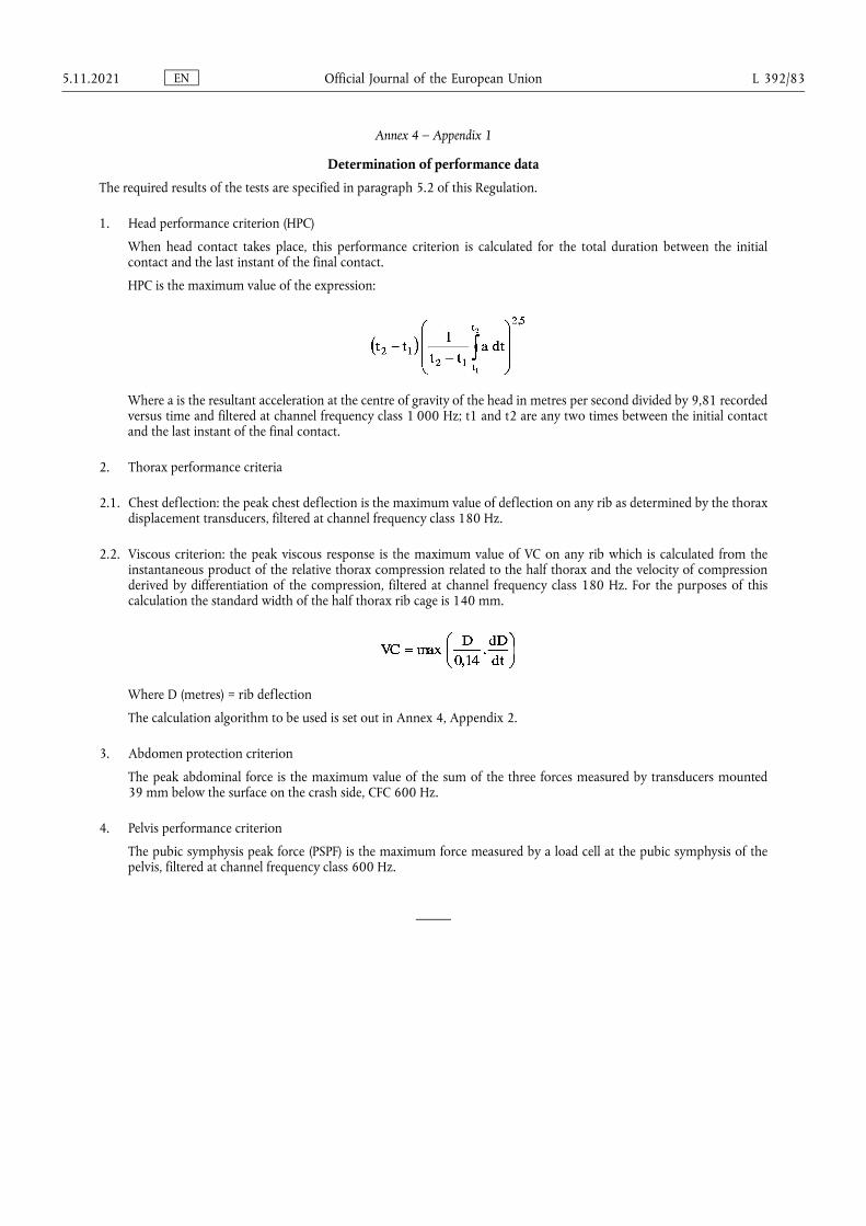
Annex 4 – Appendix 1
Determination of performance data
The required results of the tests are specified in paragraph 5.2 of this Regulation.
1. Head performance criterion (HPC)
When head contact takes place, this performance criterion is calculated for the total duration between the initial contact and the last instant of the final contact.
HPC is the maximum value of the expression:
Where a is the resultant acceleration at the centre of gravity of the head in metres per second divided by 9,81 recorded versus time and filtered at channel frequency class 1 000 Hz; t1 and t2 are any two times between the initial contact and the last instant of the final contact.
2. Thorax performance criteria
2.1. Chest deflection: the peak chest deflection is the maximum value of deflection on any rib as determined by the thorax displacement transducers, filtered at channel frequency class 180 Hz.
2.2. Viscous criterion: the peak viscous response is the maximum value of VC on any rib which is calculated from the instantaneous product of the relative thorax compression related to the half thorax and the velocity of compression derived by differentiation of the compression, filtered at channel frequency class 180 Hz. For the purposes of this calculation the standard width of the half thorax rib cage is 140 mm.
Where D (metres) = rib deflection
The calculation algorithm to be used is set out in Annex 4, Appendix 2.
3. Abdomen protection criterion
The peak abdominal force is the maximum value of the sum of the three forces measured by transducers mounted 39 mm below the surface on the crash side, CFC 600 Hz.
4. Pelvis performance criterion
The pubic symphysis peak force (PSPF) is the maximum force measured by a load cell at the pubic symphysis of the pelvis, filtered at channel frequency class 600 Hz.
EN Official Journal of the European Union 5.11.2021 L 392/83
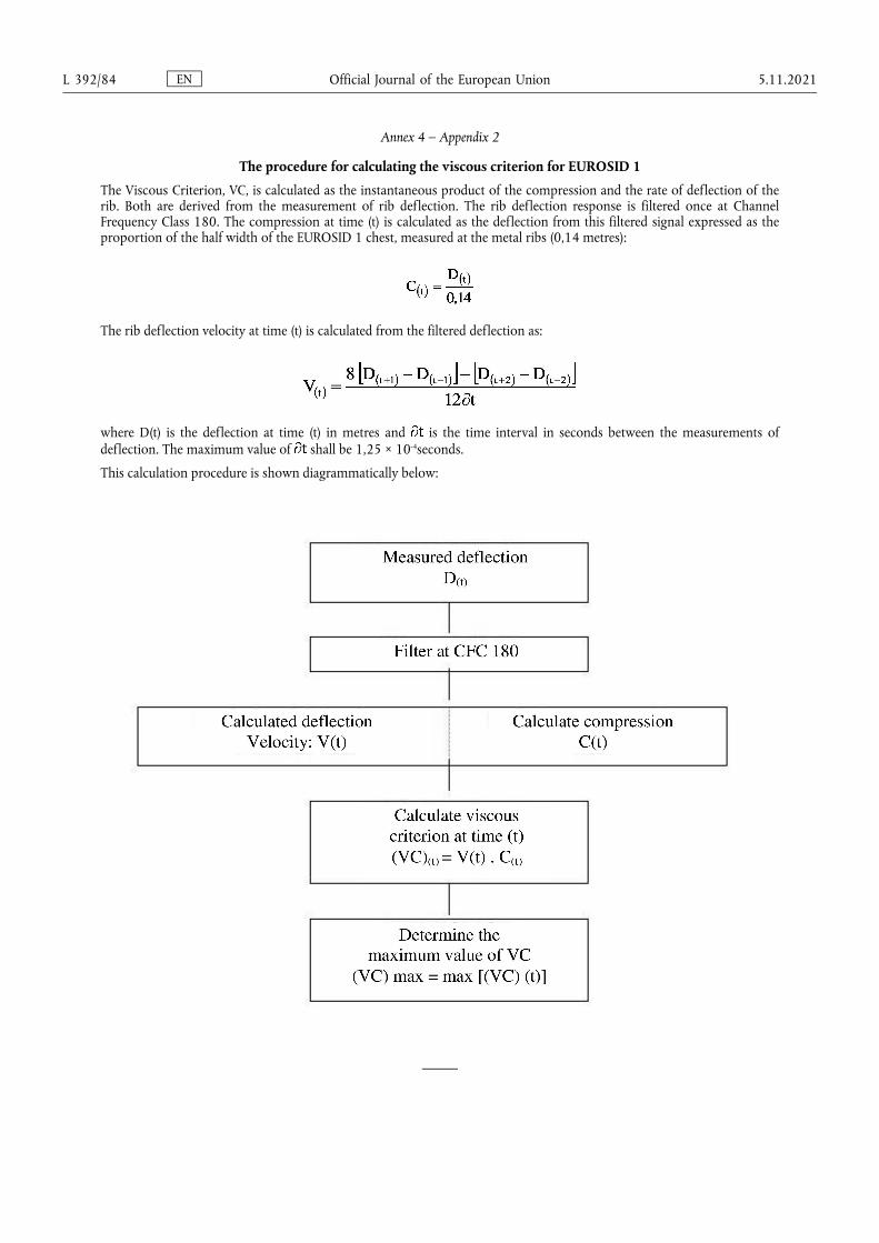
Annex 4 – Appendix 2
The procedure for calculating the viscous criterion for EUROSID 1
The Viscous Criterion, VC, is calculated as the instantaneous product of the compression and the rate of deflection of the rib. Both are derived from the measurement of rib deflection. The rib deflection response is filtered once at Channel Frequency Class 180. The compression at time (t) is calculated as the deflection from this filtered signal expressed as the proportion of the half width of the EUROSID 1 chest, measured at the metal ribs (0,14 metres):
The rib deflection velocity at time (t) is calculated from the filtered deflection as:
where D(t) is the deflection at time (t) in metres and is the time interval in seconds between the measurements of deflection. The maximum value of shall be 1,25 × 10⁻⁴seconds.
This calculation procedure is shown diagrammatically below:
EN Official Journal of the European Union L 392/84 5.11.2021
ANNEX 5
Mobile deformable barrier characteristics
1. Characteristics of the mobile deformable barrier
1.1. The mobile deformable barrier (MDB) includes both an impactor and a trolley.
1.2. The total mass shall be 950 ± 20 kg.
1.3. The centre of gravity shall be situated in the longitudinal median vertical plane within 10 mm, 1 000 ± 30 mm behind the front axle and 500 ± 30 mm above the ground.
1.4. The distance between the front face of the impactor and the centre of gravity of the barrier shall be 2 000 ± 30 mm.
1.5. The ground clearance of the impactor shall be 300 ± 5 mm measured in static conditions from the lower edge of the lower front plate, before the impact.
1.6. The front and rear track width of the trolley shall be 1 500 ± 10 mm.
1.7. The wheelbase of the trolley shall be 3 000 ± 10 mm.
2. Characteristics of the impactor
The impactor consists of six single blocks of aluminium honeycomb, which have been processed in order to give a progressively increasing level of force with increasing deflection (see paragraph 2.1 below). Front and rear aluminium plates are attached to the aluminium honeycomb blocks.
2.1. Honeycomb blocks
2.1.1. Geometrical characteristics
2.1.1.1. The impactor consists of six joined zones whose forms and positioning are shown in Figures 1 and 2. The zones are defined as 500 ± 5 mm × 250 ± 3 mm in Figures 1 and 2. The 500 mm should be in the W direction and the 250 mm in the L direction of the aluminium honeycomb construction (see Figure 3).
2.1.1.2. The impactor is divided into 2 rows. The lower row shall be 250 ± 3 mm high, and 500 ± 2mm deep after pre- crush (see paragraph 2.1.2 below), and deeper than the upper row by 60 ± 2 mm.
2.1.1.3. The blocks must be centred on the six zones defined in Figure 1 and each block (including incomplete cells) should cover completely the area defined for each zone).
2.1.2. Pre-crush
2.1.2.1. The pre-crush shall be performed on the surface of the honeycomb to which the front sheets are attached.
2.1.2.2. Blocks 1, 2 and 3 should be crushed by 10 ± 2 mm on the top surface prior to testing to give a depth of 500 ± 2 mm (Figure 2).
2.1.2.3. Blocks 4, 5 and 6 should be crushed by 10 ± 2 mm on the top surface prior to testing to give a depth of 440 ± 2 mm.
2.1.3. Material characteristics
2.1.3.1. The cell dimensions shall be 19 mm ± 10 per cent for each block (see Figure 4).
EN Official Journal of the European Union 5.11.2021 L 392/85

2.1.3.2. The cells must be made of 3003 aluminium for the upper row.
2.1.3.3. The cells must be made of 5052 aluminium for the lower row.
2.1.3.4. The aluminium honeycomb blocks should be processed such that the force deflection-curve when statically crushed (according to the procedure defined in paragraph 2.1.4 below) is within the corridors defined for each of the six blocks in Appendix 1 to this annex. Moreover, the processed honeycomb material used in the honeycomb blocks to be used for constructing the barrier, should be cleaned in order to remove any residue that may have been produced during the processing of the raw honeycomb material.
2.1.3.5. The mass of the blocks in each batch shall not differ by more than 5 per cent of the mean block mass for that batch.
2.1.4. Static tests
2.1.4.1. A sample taken from each batch of processed honeycomb core shall be tested according to the static test procedure described in paragraph 5 of this annex.
2.1.4.2. The force-compression for each block tested shall lie within the force deflection corridors defined in Appendix 1. Static force-deflection corridors are defined for each block of the barrier.
2.1.5. Dynamic test
2.1.5.1. The dynamic deformation characteristics, when impacted according to the protocol described in paragraph 6 of this annex.
2.1.5.2. Deviation from the limits of the force-deflection corridors characterising the rigidity of the impactor - as defined in Appendix 2 of this annex - may be allowed provided that:
2.1.5.2.1. The deviation occurs after the beginning of the impact and before the deformation of the impactor is equal to 150 mm;
2.1.5.2.2. The deviation does not exceed 50 per cent of the nearest instantaneous prescribed limit of the corridor;
2.1.5.2.3. Each deflection corresponding to each deviation does not exceed 35 mm of deflection, and the sum of these deflections does not exceed 70 mm (see Appendix 2 to this annex);
2.1.5.2.4. The sum of energy derived from deviating outside the corridor does not exceed 5 per cent of the gross energy for that block.
2.1.5.3. Blocks 1 and 3 are identical. Their rigidity is such that their force deflection curves fall between corridors of Figure 2a.
2.1.5.4. Blocks 5 and 6 are identical. Their rigidity is such that their force deflection curves fall between corridors of Figure 2d.
2.1.5.5 The rigidity of block 2 is such that its force deflection curves fall between corridors of Figure 2b.
2.1.5.6. The rigidity of block 4 is such that its force deflection curves fall between corridors of Figure 2c.
2.1.5.7. The force-deflection of the impactor as a whole shall fall between corridors of Figure 2e.
EN Official Journal of the European Union L 392/86 5.11.2021
2.1.5.8. The force-deflection curves shall be verified by a test detailed in Annex 5, paragraph 6, consisting of an impact of the barrier against a dynamometric wall at 35 ± 0,5 km/h.
2.1.5.9. The dissipated energy (1) against blocks 1 and 3 during the test shall be equal to 9,5 ± 2 kJ for these blocks.
2.1.5.10. The dissipated energy against blocks 5 and 6 during the test shall be equal to 3,5 ± 1 kJ for these blocks.
2.1.5.11. The dissipated energy against block 4 shall be equal to 4 ± 1 kJ.
2.1.5.12. The dissipated energy against block 2 shall be equal to 15 ± 2 kJ.
2.1.5.13. The dissipated total energy during the impact shall be equal to 45 ± 3 kJ.
2.1.5.14. The maximum impactor deformation from the point of first contact, calculated from integration of the accelerometers according to paragraph 6.6.3 of this annex, shall be equal to 330 ± 20 mm.
2.1.5.15. The final residual static impactor deformation measured after the dynamic test at level B (Figure 2) shall be equal to 310 ± 20 mm.
2.2. Front plates
2.2.1. Geometrical characteristics
2.2.1.1. The front plates are 1 500 ± 1 mm wide and 250 ± 1 mm high. The thickness is 0,5 ± 0,06 mm.
2.2.1.2. When assembled the overall dimensions of the impactor (defined in Figure 2) shall be: 1 500 ± 2,5 mm wide and 500 ± 2,5 mm high.
2.2.1.3. The upper edge of the lower front plate and the lower edge of the upper front plate should be aligned within 4 mm.
2.2.2. Material characteristics
2.2.2.1. The front plates are manufactured from aluminium of series AlMg2 to AlMg3 with elongation ≥ 12 per cent, and a UTS ≥ 175 N/mm2.
2.3. Back plate
2.3.1. Geometric characteristics
2.3.1.1. The geometric characteristics shall be according to Figures 5 and 6.
2.3.2. Material characteristics
2.3.2.1. The back plate shall consist of a 3 mm aluminium sheet. The back plate shall be manufactured from aluminium of series AlMg2 to AlMg3 with hardness between 50 and 65 HBS. This plate shall be perforated with holes for ventilation: the location, the diameter and pitch are shown in Figures 5 and 7.
(1) The amounts of energy indicated are the amounts of energy dissipated by the system when the extent to which the impactor is crushed is greatest.
EN Official Journal of the European Union 5.11.2021 L 392/87
2.4. Location of the honeycomb blocks
2.4.1. The honeycomb blocks shall be centred on the perforated zone of the back plate (Figure 5).
2.5. Bonding
2.5.1. For both the front and the back plates, a maximum of 0,5 kg/m2 shall be applied evenly directly over the surface of the front plate, giving a maximum film thickness of 0,5 mm. The adhesive to be used throughout should be a two-part polyurethane {such as Ciba Geigy XB5090/1 resin with XB5304 hardener} or equivalent.
2.5.2. For the back plate the minimum bonding strength shall be 0,6 MPa, (87 psi), tested according to paragraph 2.5.3.
2.5.3. Bonding strength tests:
2.5.3.1. Flatwise tensile testing is used to measure bond strength of adhesives according to ASTM C297-61.
2.5.3.2. The test piece should be 100 mm × 100 mm, and 15 mm deep, bonded to a sample of the ventilated back plate material. The honeycomb used should be representative of that in the impactor, i.e. chemically etched to an equivalent degree as that near to the back plate in the barrier but without pre-crushing.
2.6. Traceability
2.6.1. Impactors shall carry consecutive serial numbers which are stamped, etched or otherwise permanently attached, from which the batches for the individual blocks and the date of manufacture can be established
2.7. Impactor attachment
2.7.1. The fitting on the trolley must be according to Figure 8. The fitting will use six M8 bolts, and nothing shall be larger than the dimensions of the barrier in front of the wheels of the trolley. Appropriate spacers must be used between the lower back plate flange and the trolley face to avoid bowing of the back plate when the attachment bolts are tightened.
3. Ventilation system
3.1. The interface between the trolley and the ventilation system should be solid, rigid and flat. The ventilation device is part of the trolley and not of the impactor as supplied by the manufacturer. Geometrical characteristics of the ventilation device shall be according to Figure 9.
3.2. Ventilation device mounting procedure.
3.2.1. Mount the ventilation device to the front plate of the trolley;
3.2.2. Ensure that a 0,5 mm thick gauge cannot be inserted between the ventilation device and the trolley face at any point. If there is a gap greater than 0,5 mm, the ventilation frame will need to be replaced or adjusted to fit without a gap of > 0,5 mm.
3.2.3. Dismount the ventilation device from the front of the trolley;
3.2.4. Fix a 1,0 mm thick layer of cork to the front face of the trolley;
3.2.5. Re-mount the ventilation device to the front of the trolley and tighten to exclude air gaps.
EN Official Journal of the European Union L 392/88 5.11.2021
4. Conformity of production
The conformity of production procedures shall comply with those set out in the Agreement, Appendix 2 (E/ECE/ 324-E/ECE/TRANS/505/Rev.2), with the following requirements:
4.1. The manufacturer shall be responsible for the conformity of production procedures and for that purpose must in particular:
4.1.1. Ensure the existence of effective procedures so that the quality of the products can be inspected;
4.1.2. Have access to the testing equipment needed to inspect the conformity of each product;
4.1.3. Ensure that the test results are recorded and that the documents remain available for a time period of 10 years after the tests;
4.1.4. Demonstrate that the samples tested are a reliable measure of the performance of the batch (examples of sampling methods according to batch production are given below).
4.1.5. Analyse results of tests in order to verify and ensure the stability of the barrier characteristics, making allowance for variations of an industrial production, such as temperature, raw materials quality, time of immersion in chemical, chemical concentration, neutralisation etc., and the control of the processed material in order to remove any residue from the processing.
4.1.6. Ensure that any set of samples or test pieces giving evidence of non-conformity gives rise to a further sampling and test. All the necessary steps must be taken to restore conformity of the corresponding production.
4.2. The manufacturer's level of certification must be at least ISO 9002 standard.
4.3. Minimum conditions for the control of production: the holder of an agreement will ensure the control of conformity following the methods hereunder described.
4.4. Examples of sampling according to batch
4.4.1. If several examples of one block type are constructed from one original block of aluminium honeycomb and are all treated in the same treatment bath (parallel production), one of these examples could be chosen as the sample, provided care is taken to ensure that the treatment is evenly applied to all blocks. If not, it may be necessary to select more than one sample.
4.4.2. If a limited number of similar blocks (say three to twenty) are treated in the same bath (serial production), then the first and last block treated in a batch, all of which are constructed from the same original block of aluminium honeycomb, should be taken as representative samples. If the first sample complies with the requirements but the last does not, it may be necessary to take further samples from earlier in the production until a sample that does comply is found. Only the blocks between these samples should be considered to be approved.
4.4.3. Once experience is gained with the consistency of production control, it may be possible to combine both sampling approaches, so that more than one groups of parallel production can be considered to be a batch provided samples from the first and last production groups comply.
EN Official Journal of the European Union 5.11.2021 L 392/89

5. Static tests
5.1. One or more samples (according to the batch method) taken from each batch of processed honeycomb core shall be tested, according to the following test procedure:
5.2. The sample size of the aluminium honeycomb for static tests shall be the size of a normal block of the impactor, that is to say 250 mm × 500 mm × 440 mm for top row and 250 mm × 500 mm × 500 mm for the bottom row.
5.3. The samples should be compressed between two parallel loading plates which are at least 20 mm larger than the block cross section.
5.4. The compression speed shall be 100 millimetres per minute, with a tolerance of 5 per cent.
5.5. The data acquisition for static compression shall be sampled at a minimum of 5 Hz.
5.6. The static test shall be continued until the block compression is at least 300 mm for blocks 4 to 6 and 350 mm for blocks 1 to 3.
6. Dynamic tests
For every 100 barrier faces produced, the manufacturer shall make one dynamic test against a dynamometric wall supported by a fixed rigid barrier, according to the method described below.
6.1. Installation
6.1.1. Testing ground
6.1.1.1. The test area shall be large enough to accommodate the run-up-track of the mobile deformable barrier, the rigid barrier and the technical equipment necessary for the test. The last part of the track, for at least 5 metres before the rigid barrier, shall be horizontal, flat and smooth.
6.1.2. Fixed rigid barrier and dynamometric wall
6.1.2.1. The rigid wall shall consist of a block of reinforced concrete not less than 3 metres wide and not less than 1,5 metres high. The thickness of the rigid wall shall be such that it weighs at least 70 tonnes.
6.1.2.2. The front face shall be vertical, perpendicular to the axis of the run-up-tack and equipped with six load cell plates, each capable of measuring the total load on the appropriate block of the mobile deformable barrier impactor at the moment of impact. The load cell impact plate area centres shall align with those of the six impact zones of the mobile deformable barrier face. Their edges shall clear adjacent areas by 20 mm such that, within the tolerance of impact alignment of the MDB, the impact zones will not contact the adjacent impact plate areas. Cell mounting and plate surfaces shall be in accordance with the requirements set out in the annex to standard ISO 6487:1987.
6.1.2.3. Surface protection, comprising a plywood face (thickness: 12 ± 1 mm), is added to each load cell plate such that it shall not degrade the transducer responses.
6.1.2.4. The rigid wall shall be either anchored in the ground or placed on the ground with, if necessary, additional arresting devices to limit its deflection. A rigid wall (to which the load cells are attached) having different characteristics but giving results that are at least equally conclusive may be used.
6.2. Propulsion of the mobile deformable barrier
EN Official Journal of the European Union L 392/90 5.11.2021
At the moment of impact the mobile deformable barrier shall no longer be subject to the action of any additional steering or propelling device. It shall reach the obstacle on a course perpendicular to the front surface of the dynamometric wall. Impact alignment shall be accurate to within 10 mm.
6.3. Measuring instruments
6.3.1. Speed
The impact speed shall be 35 ± 0,5 km/h the instrument used to record the speed on impact shall be accurate to within 0,1 per cent.
6.3.2. Loads
Measuring instruments shall meet the specifications set forth in ISO 6487:1987
CFC for all blocks: 60 Hz
CAC for blocks 1 and 3: 200 kN
CAC for blocks 4, 5 and 6: 100 kN
CAC for block 2: 200 kN
6.3.3. Acceleration
6.3.3.1. The acceleration in the longitudinal direction shall be measured at three separate positions on the trolley, one centrally and one at each side, at places not subject to bending.
6.3.3.2. The central accelerometer shall be located within 500 mm of the location of the centre of gravity of the MDB and shall lie in a vertical longitudinal plane which is within ±10 mm of the centre of gravity of the MDB.
6.3.3.3. The side accelerometers shall be at the same height as each other ±10 mm and at the same distance from the front surface of the MDB ±20 mm
6.3.3.4. The instrumentation shall comply with ISO 6487:1987 with the following specifications:
CFC 1 000 Hz (before integration)
CAC 50 g
6.4. General specifications of barrier
6.4.1. The individual characteristics of each barrier shall comply with paragraph 1 of this annex and shall be recorded.
6.5. General specifications of the impactor
6.5.1. The suitability of an impactor as regards the dynamic test requirements shall be confirmed when the outputs from the six load cell plates each produce signals complying with the requirements indicated in this annex.
6.5.2. Impactors shall carry consecutive serial numbers which are stamped, etched or otherwise permanently attached, from which the batches for the individual blocks and the date of manufacture can be established.
EN Official Journal of the European Union 5.11.2021 L 392/91
6.6. Data processing procedure
6.6.1. Raw data: At time T = T0, all offsets should be removed from the data. The method by which offsets are removed shall be recorded in the test report.
6.6.2. Filtering
6.6.2.1. The raw data will be filtered prior to processing/calculations.
6.6.2.2. Accelerometer data for integration will be filtered to CFC 180, ISO 6487:1987.
6.6.2.3. Accelerometer data for impulse calculations will be filtered to CFC 60, ISO 6487:1987.
6.6.2.4. Load cell data will be filtered to CFC 60, ISO 6487:1987.
6.6.3. Calculation of MDB face deflection
6.6.3.1. Accelerometer data from all three accelerometers individually (after filtering at CFC 180), will be integrated twice to obtain deflection of the barrier deformable element.
6.6.3.2. The initial conditions for deflection are:
6.6.3.2.1. Velocity = impact velocity (from speed measuring device).
6.6.3.2.2. Deflection = 0
6.6.3.3. The deflection at the left hand side, mid-line and right hand side of the mobile deformable barrier will be plotted with respect to time.
6.6.3.4. The maximum deflection calculated from each of the three accelerometers should be within 10 mm. If it is not the case, then the outlier should be removed and difference between the deflections calculated from the remaining two accelerometers checked to ensure that it is within 10 mm.
6.6.3.5. If the deflections as measured by the left hand side, right hand side and mid-line accelerometers are within 10 mm, then the mean acceleration of the three accelerometers should be used to calculate the deflection of the barrier face.
6.6.3.6. If the deflection from only two accelerometers meets the 10 mm requirement, then the mean acceleration from these two accelerometers should be used to calculate the deflection for the barrier face.
6.6.3.7. If the deflections calculated from all three accelerometers (left hand side, right hand side and mid-line) are NOT within the 10 mm requirement, then the raw data should be reviewed to determine the causes of such large variation. In this case the individual test house will determine which accelerometer data should be used to determine mobile deformable barrier deflection or whether none of the accelerometer readings can be used, in which case, the certification test must be repeated. A full explanation should be given in the test report.
6.6.3.8. The mean deflection-time data will be combined with the load cell wall force-time data to generate the force- deflection result for each block.
EN Official Journal of the European Union L 392/92 5.11.2021
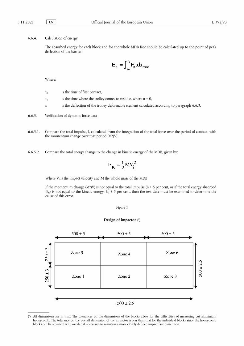
6.6.4. Calculation of energy
The absorbed energy for each block and for the whole MDB face should be calculated up to the point of peak deflection of the barrier.
Where:
t0 is the time of first contact,
t1 is the time where the trolley comes to rest, i.e. where u = 0,
s is the deflection of the trolley deformable element calculated according to paragraph 6.6.3.
6.6.5. Verification of dynamic force data
6.6.5.1. Compare the total impulse, I, calculated from the integration of the total force over the period of contact, with the momentum change over that period (M*)V).
6.6.5.2. Compare the total energy change to the change in kinetic energy of the MDB, given by:
Where Vi is the impact velocity and M the whole mass of the MDB
If the momentum change (M*)V) is not equal to the total impulse (I) ± 5 per cent, or if the total energy absorbed (En) is not equal to the kinetic energy, EK ± 5 per cent, then the test data must be examined to determine the cause of this error.
Figure 1
Design of impactor (2)
(2) All dimensions are in mm. The tolerances on the dimensions of the blocks allow for the difficulties of measuring cut aluminium honeycomb. The tolerance on the overall dimension of the impactor is less than that for the individual blocks since the honeycomb blocks can be adjusted, with overlap if necessary, to maintain a more closely defined impact face dimension.
EN Official Journal of the European Union 5.11.2021 L 392/93
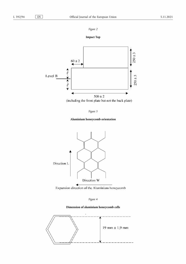
Figure 2
Impact Top
Figure 3
Aluminium honeycomb orientation
Figure 4
Dimension of aluminium honeycomb cells
EN Official Journal of the European Union L 392/94 5.11.2021
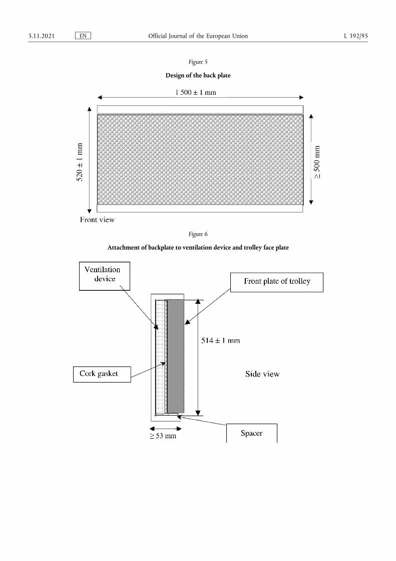
Figure 5
Design of the back plate
Figure 6
Attachment of backplate to ventilation device and trolley face plate
EN Official Journal of the European Union 5.11.2021 L 392/95
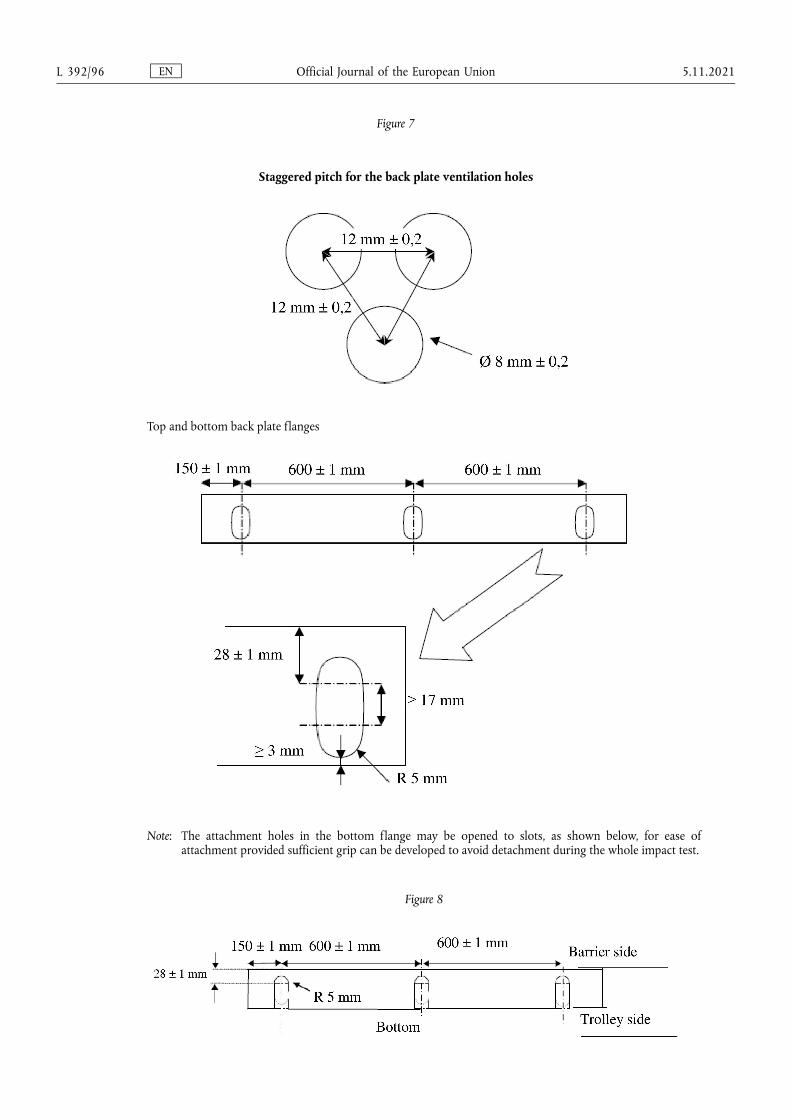
Figure 7
Staggered pitch for the back plate ventilation holes
Top and bottom back plate flanges
Note: The attachment holes in the bottom flange may be opened to slots, as shown below, for ease of attachment provided sufficient grip can be developed to avoid detachment during the whole impact test.
Figure 8
EN Official Journal of the European Union L 392/96 5.11.2021
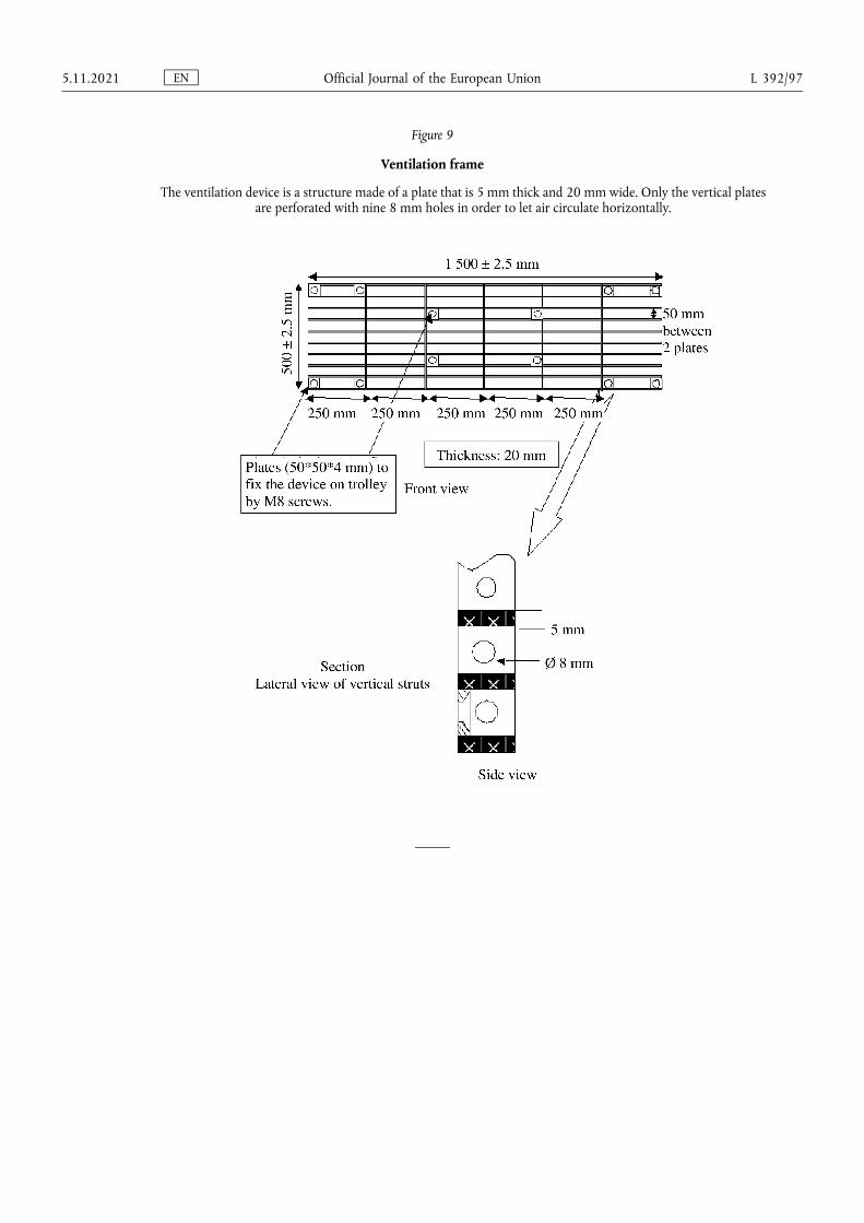
Figure 9
Ventilation frame
The ventilation device is a structure made of a plate that is 5 mm thick and 20 mm wide. Only the vertical plates are perforated with nine 8 mm holes in order to let air circulate horizontally.
EN Official Journal of the European Union 5.11.2021 L 392/97
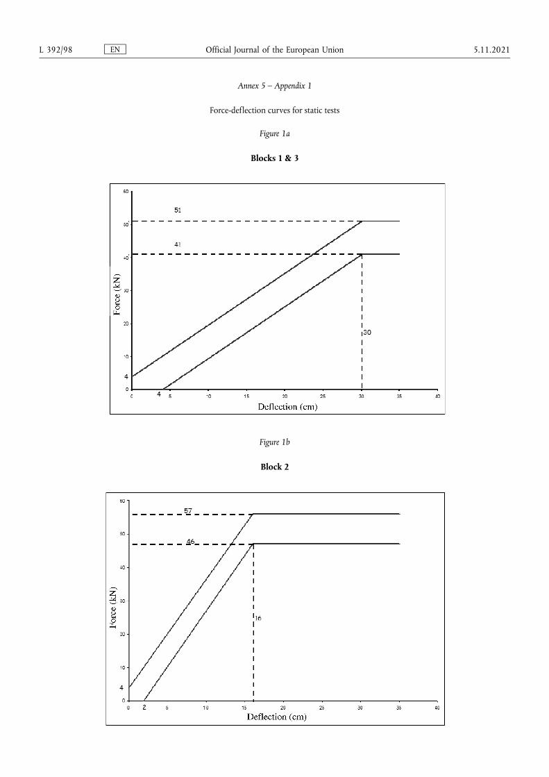
Annex 5 – Appendix 1
Force-deflection curves for static tests
Figure 1a
Blocks 1 & 3
Figure 1b
Block 2
EN Official Journal of the European Union L 392/98 5.11.2021
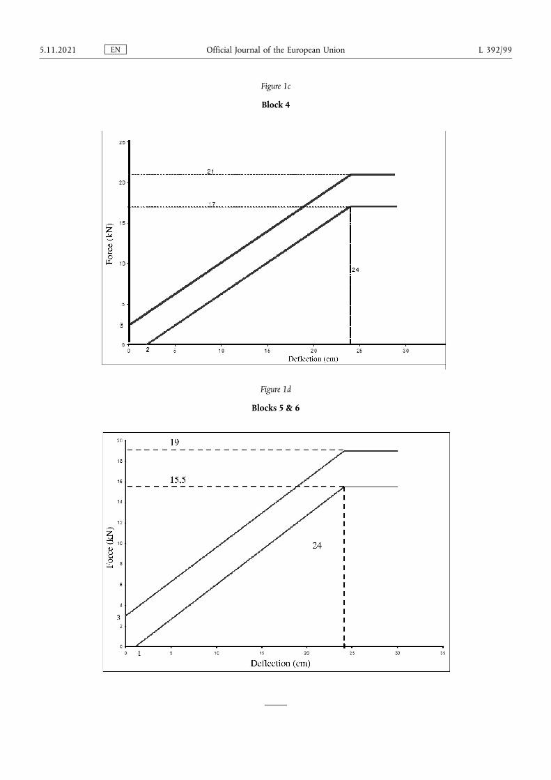
Figure 1c
Block 4
Figure 1d
Blocks 5 & 6
EN Official Journal of the European Union 5.11.2021 L 392/99
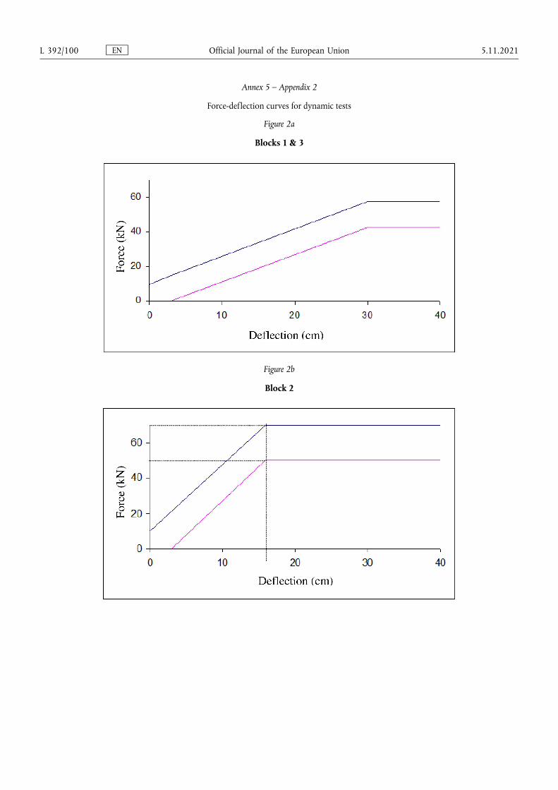
Annex 5 – Appendix 2
Force-deflection curves for dynamic tests
Figure 2a
Blocks 1 & 3
Figure 2b
Block 2
EN Official Journal of the European Union L 392/100 5.11.2021
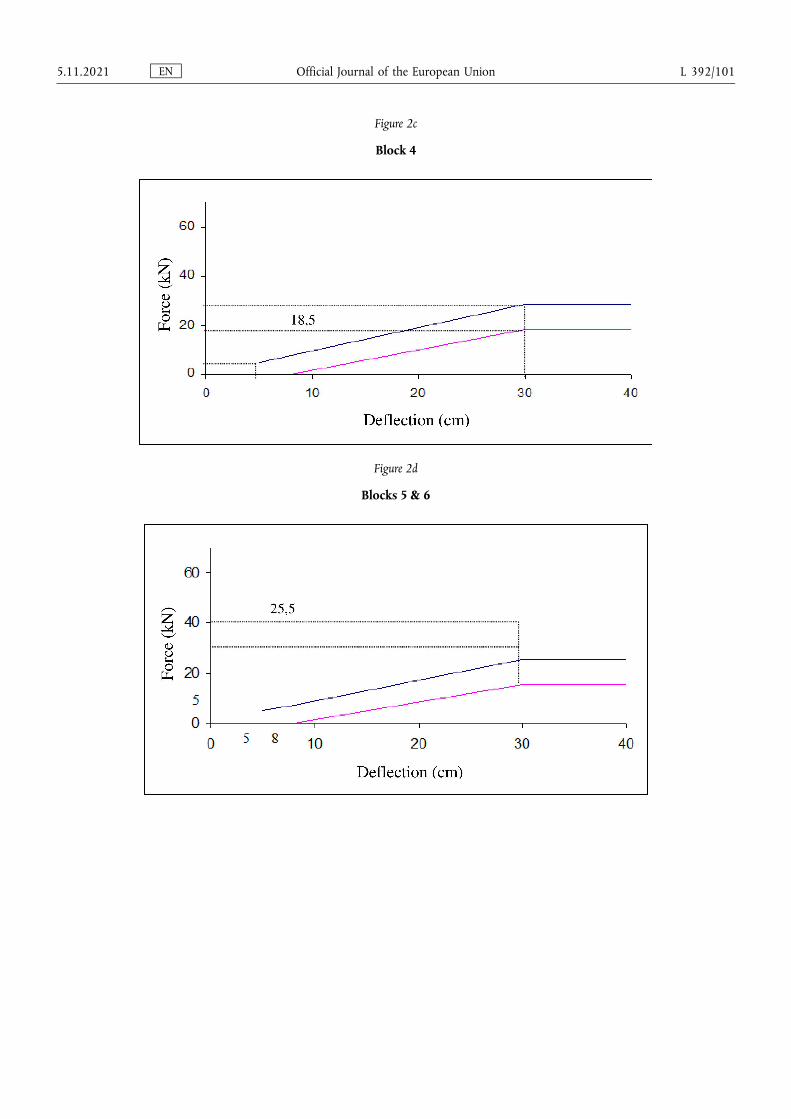
Figure 2c
Block 4
Figure 2d
Blocks 5 & 6
EN Official Journal of the European Union 5.11.2021 L 392/101
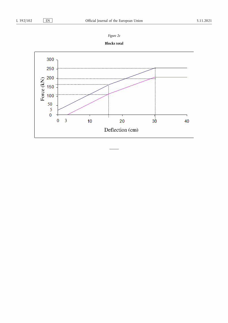
Figure 2e
Blocks total
EN Official Journal of the European Union L 392/102 5.11.2021
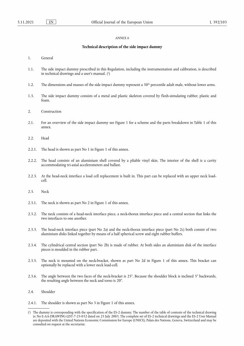
ANNEX 6
Technical description of the side impact dummy
1. General
1.1. The side impact dummy prescribed in this Regulation, including the instrumentation and calibration, is described in technical drawings and a user's manual. (1)
1.2. The dimensions and masses of the side impact dummy represent a 50th percentile adult male, without lower arms.
1.3. The side impact dummy consists of a metal and plastic skeleton covered by flesh-simulating rubber, plastic and foam.
2. Construction
2.1. For an overview of the side impact dummy see Figure 1 for a scheme and the parts breakdown in Table 1 of this annex.
2.2. Head
2.2.1. The head is shown as part No 1 in Figure 1 of this annex.
2.2.2. The head consists of an aluminium shell covered by a pliable vinyl skin. The interior of the shell is a cavity accommodating tri-axial accelerometers and ballast.
2.2.3. At the head-neck interface a load cell replacement is built in. This part can be replaced with an upper neck load- cell.
2.3. Neck
2.3.1. The neck is shown as part No 2 in Figure 1 of this annex.
2.3.2. The neck consists of a head-neck interface piece, a neck-thorax interface piece and a central section that links the two interfaces to one another.
2.3.3. The head-neck interface piece (part No 2a) and the neck-thorax interface piece (part No 2c) both consist of two aluminium disks linked together by means of a half spherical screw and eight rubber buffers.
2.3.4. The cylindrical central section (part No 2b) is made of rubber. At both sides an aluminium disk of the interface pieces is moulded in the rubber part.
2.3.5. The neck is mounted on the neck-bracket, shown as part No 2d in Figure 1 of this annex. This bracket can optionally be replaced with a lower neck load-cell.
2.3.6. The angle between the two faces of the neck-bracket is 25°. Because the shoulder block is inclined 5° backwards, the resulting angle between the neck and torso is 20°.
2.4. Shoulder
2.4.1. The shoulder is shown as part No 3 in Figure 1 of this annex.
(1) The dummy is corresponding with the specification of the ES-2 dummy. The number of the table of contents of the technical drawing is: No E-AA-DRAWING-LIST-7-25-032 dated on 25 July 2003. The complete set of ES-2 technical drawings and the ES-2 User Manual are deposited with the United Nations Economic Commission for Europe (UNECE), Palais des Nations, Geneva, Switzerland and may be consulted on request at the secretariat.
EN Official Journal of the European Union 5.11.2021 L 392/103
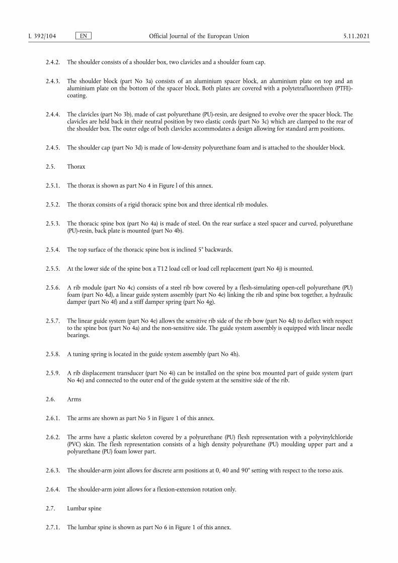
2.4.2. The shoulder consists of a shoulder box, two clavicles and a shoulder foam cap.
2.4.3. The shoulder block (part No 3a) consists of an aluminium spacer block, an aluminium plate on top and an aluminium plate on the bottom of the spacer block. Both plates are covered with a polytetrafluoretheen (PTFE)- coating.
2.4.4. The clavicles (part No 3b), made of cast polyurethane (PU)-resin, are designed to evolve over the spacer block. The clavicles are held back in their neutral position by two elastic cords (part No 3c) which are clamped to the rear of the shoulder box. The outer edge of both clavicles accommodates a design allowing for standard arm positions.
2.4.5. The shoulder cap (part No 3d) is made of low-density polyurethane foam and is attached to the shoulder block.
2.5. Thorax
2.5.1. The thorax is shown as part No 4 in Figure l of this annex.
2.5.2. The thorax consists of a rigid thoracic spine box and three identical rib modules.
2.5.3. The thoracic spine box (part No 4a) is made of steel. On the rear surface a steel spacer and curved, polyurethane (PU)-resin, back plate is mounted (part No 4b).
2.5.4. The top surface of the thoracic spine box is inclined 5° backwards.
2.5.5. At the lower side of the spine box a T12 load cell or load cell replacement (part No 4j) is mounted.
2.5.6. A rib module (part No 4c) consists of a steel rib bow covered by a flesh-simulating open-cell polyurethane (PU) foam (part No 4d), a linear guide system assembly (part No 4e) linking the rib and spine box together, a hydraulic damper (part No 4f) and a stiff damper spring (part No 4g).
2.5.7. The linear guide system (part No 4e) allows the sensitive rib side of the rib bow (part No 4d) to deflect with respect to the spine box (part No 4a) and the non-sensitive side. The guide system assembly is equipped with linear needle bearings.
2.5.8. A tuning spring is located in the guide system assembly (part No 4h).
2.5.9. A rib displacement transducer (part No 4i) can be installed on the spine box mounted part of guide system (part No 4e) and connected to the outer end of the guide system at the sensitive side of the rib.
2.6. Arms
2.6.1. The arms are shown as part No 5 in Figure 1 of this annex.
2.6.2. The arms have a plastic skeleton covered by a polyurethane (PU) flesh representation with a polyvinylchloride (PVC) skin. The flesh representation consists of a high density polyurethane (PU) moulding upper part and a polyurethane (PU) foam lower part.
2.6.3. The shoulder-arm joint allows for discrete arm positions at 0, 40 and 90° setting with respect to the torso axis.
2.6.4. The shoulder-arm joint allows for a flexion-extension rotation only.
2.7. Lumbar spine
2.7.1. The lumbar spine is shown as part No 6 in Figure 1 of this annex.
EN Official Journal of the European Union L 392/104 5.11.2021
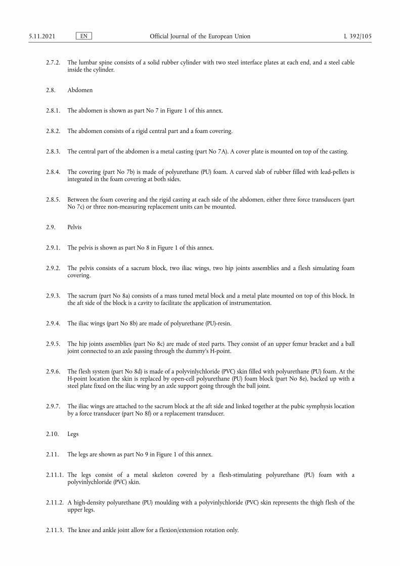
2.7.2. The lumbar spine consists of a solid rubber cylinder with two steel interface plates at each end, and a steel cable inside the cylinder.
2.8. Abdomen
2.8.1. The abdomen is shown as part No 7 in Figure 1 of this annex.
2.8.2. The abdomen consists of a rigid central part and a foam covering.
2.8.3. The central part of the abdomen is a metal casting (part No 7A). A cover plate is mounted on top of the casting.
2.8.4. The covering (part No 7b) is made of polyurethane (PU) foam. A curved slab of rubber filled with lead-pellets is integrated in the foam covering at both sides.
2.8.5. Between the foam covering and the rigid casting at each side of the abdomen, either three force transducers (part No 7c) or three non-measuring replacement units can be mounted.
2.9. Pelvis
2.9.1. The pelvis is shown as part No 8 in Figure 1 of this annex.
2.9.2. The pelvis consists of a sacrum block, two iliac wings, two hip joints assemblies and a flesh simulating foam covering.
2.9.3. The sacrum (part No 8a) consists of a mass tuned metal block and a metal plate mounted on top of this block. In the aft side of the block is a cavity to facilitate the application of instrumentation.
2.9.4. The iliac wings (part No 8b) are made of polyurethane (PU)-resin.
2.9.5. The hip joints assemblies (part No 8c) are made of steel parts. They consist of an upper femur bracket and a ball joint connected to an axle passing through the dummy’s H-point.
2.9.6. The flesh system (part No 8d) is made of a polyvinlychloride (PVC) skin filled with polyurethane (PU) foam. At the H-point location the skin is replaced by open-cell polyurethane (PU) foam block (part No 8e), backed up with a steel plate fixed on the iliac wing by an axle support going through the ball joint.
2.9.7. The iliac wings are attached to the sacrum block at the aft side and linked together at the pubic symphysis location by a force transducer (part No 8f) or a replacement transducer.
2.10. Legs
2.11. The legs are shown as part No 9 in Figure 1 of this annex.
2.11.1. The legs consist of a metal skeleton covered by a flesh-stimulating polyurethane (PU) foam with a polyvinlychloride (PVC) skin.
2.11.2. A high-density polyurethane (PU) moulding with a polyvinlychloride (PVC) skin represents the thigh flesh of the upper legs.
2.11.3. The knee and ankle joint allow for a flexion/extension rotation only.
EN Official Journal of the European Union 5.11.2021 L 392/105
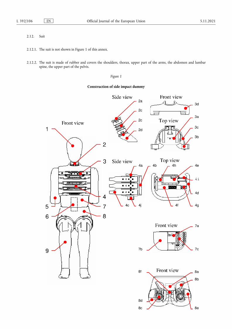
2.12. Suit
2.12.1. The suit is not shown in Figure 1 of this annex.
2.12.2. The suit is made of rubber and covers the shoulders, thorax, upper part of the arms, the abdomen and lumbar spine, the upper part of the pelvis.
Figure 1
Construction of side impact dummy
EN Official Journal of the European Union L 392/106 5.11.2021

Table 1
Side Impact Dummy Components (See Figure 1)
Part No Description Number
1 Head 1
2 Neck 1
2a Head-neck interface 1
2b Central section 1
2c Neck-thorax interface 1
2d Neck-bracket 1
3 Shoulder 1
3a Shoulder box 1
3b Clavicles 2
3c Elastic cord 2
3d Shoulder foam cap 1
4 Thorax 1
4a Thoracic spine 1
4b Back plate (curved) 1
4c Rib module 3
4d Rib bow covered with flesh 3
4e Piston-cylinder assembly 3
4f Damper 3
4g Stiff damper spring 3
4h Tuning spring 3
4i Displacement transducer 3
4j T12 load cell or load cell replacement 1
5 Arm 2
6 Lumbar spine 1
7 Abdomen 1
7a Central casting 1
7b Flesh covering 1
7c Force transducer 3
8 Pelvis 1
8a Sacrum block 1
8b Iliac wings 2
8c Hip joint assembly 2
8d Flesh covering 1
8e H-point foam block 2
8f Force transducer or replacement 1
9 Leg 2
10 Suit 1
EN Official Journal of the European Union 5.11.2021 L 392/107

3. Assembly of the dummy
3.1. Head-neck
3.1.1. The required torque on the half-spherical screws for assembly of the neck is 10 Nm.
3.1.2. The head-upper neck load cell assembly is mounted to the head-neck interface plate of the neck by four screws.
3.1.3. The neck-thorax interface plate of the neck is mounted to the neck-bracket by four screws.
3.2. Neck-shoulder-thorax
3.2.1. The neck-bracket is mounted to the shoulder block by four screws.
3.2.2. The shoulder-block is mounted to the top-surface of the thoracic spine box by three screws.
3.3. Shoulder-arm
3.3.1. The arms are mounted to the shoulder clavicles by means of a screw and an axial bearing. The screw shall be tightened to obtain a 1 - 2 g holding force of the arm on its pivot.
3.4. Thorax-lumbar spine-abdomen
3.4.1. The mounting direction of rib modules in the thorax shall be adapted to the required impact side.
3.4.2. A lumbar spine adapter is mounted to the T12 load cell or load cell replacement at the lower part of the thoracic spine by two screws.
3.4.3. The lumbar spine adapter is mounted to the top of the lumbar spine with four screws.
3.4.4. The mounting flange of the central abdominal casting is clamped between the lumbar spine adapter and the lumbar spine top plate.
3.4.5. The location of the abdominal force transducers shall be adapted to the required impact side.
3.5. Lumbar spine-pelvis-legs
3.5.1. The lumbar spine is mounted to the sacrum block cover plate by three screws. In case of using the lower lumbar spine load cell four screws are used.
3.5.2. The lumbar spine bottom plate is mounted to the sacrum block of the pelvis by three screws.
3.5.3. The legs are mounted to the upper femur bracket of the pelvis hip joint assembly by a screw.
3.5.4. The knee and ankle links in the legs can be adjusted to obtain a 1 - 2 g holding force.
4. Main characteristics
4.1. Mass
4.1.1. The masses of the main dummy components are presented in Table 2 of this annex.
EN Official Journal of the European Union L 392/108 5.11.2021
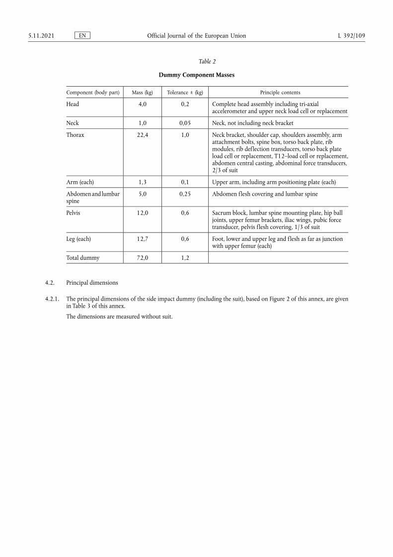
Table 2
Dummy Component Masses
Component (body part) Mass (kg) Tolerance ± (kg) Principle contents
Head 4,0 0,2 Complete head assembly including tri-axial accelerometer and upper neck load cell or replacement
Neck 1,0 0,05 Neck, not including neck bracket
Thorax 22,4 1,0 Neck bracket, shoulder cap, shoulders assembly, arm attachment bolts, spine box, torso back plate, rib modules, rib deflection transducers, torso back plate load cell or replacement, T12–load cell or replacement, abdomen central casting, abdominal force transducers, 2/3 of suit
Arm (each) 1,3 0,1 Upper arm, including arm positioning plate (each)
Abdomen and lumbar spine
5,0 0,25 Abdomen flesh covering and lumbar spine
Pelvis 12,0 0,6 Sacrum block, lumbar spine mounting plate, hip ball joints, upper femur brackets, iliac wings, pubic force transducer, pelvis flesh covering, 1/3 of suit
Leg (each) 12,7 0,6 Foot, lower and upper leg and flesh as far as junction with upper femur (each)
Total dummy 72,0 1,2
4.2. Principal dimensions
4.2.1. The principal dimensions of the side impact dummy (including the suit), based on Figure 2 of this annex, are given in Table 3 of this annex.
The dimensions are measured without suit.
EN Official Journal of the European Union 5.11.2021 L 392/109
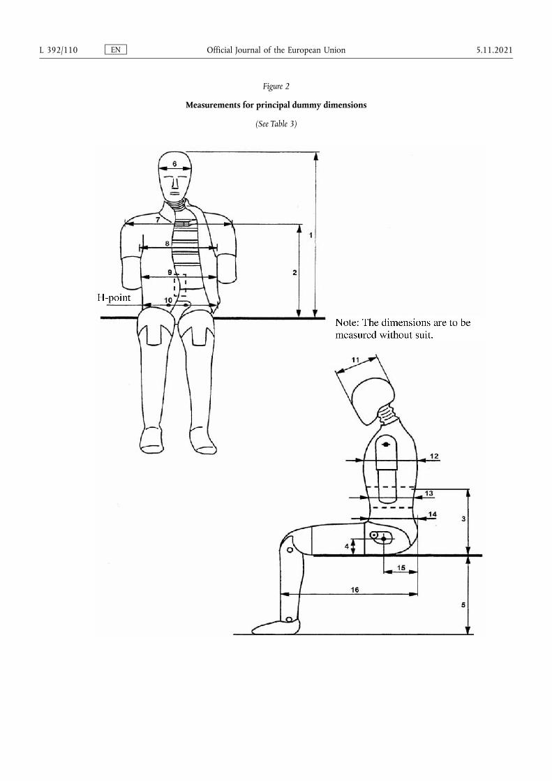
Figure 2
Measurements for principal dummy dimensions
(See Table 3)
EN Official Journal of the European Union L 392/110 5.11.2021
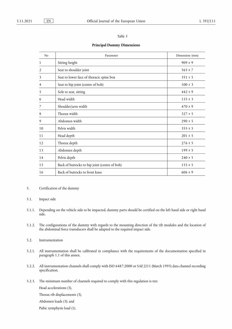
Table 3
Principal Dummy Dimensions
No Parameter Dimension (mm)
1 Sitting height 909 ± 9
2 Seat to shoulder joint 565 ± 7
3 Seat to lower face of thoracic spine box 351 ± 5
4 Seat to hip joint (centre of bolt) 100 ± 3
5 Sole to seat, sitting 442 ± 9
6 Head width 155 ± 3
7 Shoulder/arm width 470 ± 9
8 Thorax width 327 ± 5
9 Abdomen width 290 ± 5
10 Pelvis width 355 ± 5
11 Head depth 201 ± 5
12 Thorax depth 276 ± 5
13 Abdomen depth 199 ± 5
14 Pelvis depth 240 ± 5
15 Back of buttocks to hip joint (centre of bolt) 155 ± 5
16 Back of buttocks to front knee 606 ± 9
5. Certification of the dummy
5.1. Impact side
5.1.1. Depending on the vehicle side to be impacted, dummy parts should be certified on the left hand side or right hand side.
5.1.2. The configurations of the dummy with regards to the mounting direction of the rib modules and the location of the abdominal force transducers shall be adapted to the required impact side.
5.2. Instrumentation
5.2.1. All instrumentation shall be calibrated in compliance with the requirements of the documentation specified in paragraph 1.1 of this annex.
5.2.2. All instrumentation channels shall comply with ISO 6487:2000 or SAE J211 (March 1995) data channel recording specification.
5.2.3. The minimum number of channels required to comply with this regulation is ten:
Head accelerations (3),
Thorax rib displacements (3),
Abdomen loads (3); and
Pubic symphysis load (1).
EN Official Journal of the European Union 5.11.2021 L 392/111

5.2.4. Additionally a number of optional instrumentation channels (38) are available:
Upper neck loads (6),
Lower neck loads (6),
Clavicle loads (3),
Torso back plate loads (4),
T1 accelerations (3),
T12 accelerations (3),
Rib accelerations (6, two on each rib),
T12 spine loads (4),
Lower lumbar loads (3),
Pelvis accelerations (3); and
Femur loads (6).
Additional four position indicator channels are optionally available:
Thorax rotations (2); and
Pelvis rotations (2)
5.3. Visual check
5.3.1. All dummy parts should be visually checked for damage and if necessary replaced before the certification test.
5.4. General test set-up
5.4.1. Figure 3 of this annex shows the test set-up for all certification tests on the side impact dummy.
5.4.2. The certification test set-up arrangements and testing procedures shall be in accordance with the specification and requirements of the documentation specified in paragraph 1.1.
5.4.3. The tests on the head, neck, thorax and lumbar spine are carried out on sub-assemblies of the dummy.
5.4.4. The tests on the shoulder, abdomen and pelvis are performed with the complete dummy (without suit, shoes and underwear). In these tests the dummy is seated on a flat surface with two sheets of less than or equal to 2 mm thick polytetrafluoretheen (PTFE), placed between the dummy and the flat surface.
5.4.5. All parts to be certified should be kept in the test room for a period of at least four hours at a temperature between and including 18 and 22 °C and a relative humidity between and including 10 and 70 per cent prior to a test.
5.4.6. The time between two certification tests on the same part should be at least 30 minutes.
5.5. Head
5.5.1. The head sub assembly, including the upper neck load cell replacement, is certified in a drop test from 200 ± 1 mm onto a flat, rigid impact surface.
5.5.2. The angle between the impact surface and the mid-sagittal plane of the head is 35 ± 1° allowing an impact to the upper part of the head side (this can be realised with a sling harness or a head drop support bracket with a mass of 0,075 ± 0,005 kg.).
5.5.3. The peak resultant head acceleration, filtered using ISO 6487:2000 CFC 1 000, should be between and including 100 g and 150 g.
EN Official Journal of the European Union L 392/112 5.11.2021
5.5.4. The head performance can be adjusted to meet the requirement by altering the friction characteristics of the skin- skull interface (e.g. by lubrication with talcum powder or polytetrafluoretheen (PTFE) spray).
5.6. Neck
5.6.1. The head-neck interface of the neck is mounted to a special certification head-form with a mass of 3,9 ± 0,05 kg (see Figure 6), with the help of a 12 mm thick interface plate with a mass of 0,205 ± 0,05 kg.
5.6.2. The head-form and neck are mounted upside-down to the bottom of a neck- pendulum (2) allowing a lateral motion of the system.
5.6.3. The neck-pendulum is equipped with a uni-axial accelerometer according to the neck pendulum specification (see Figure 5).
5.6.4. The neck-pendulum should be allowed to fall freely from a height chosen to achieve an impact velocity of 3,4 ± 0,1 m/s measured at the pendulum accelerometer location.
5.6.5. The neck-pendulum is decelerated from impact velocity to zero by an appropriate device, (3) as described in the neck pendulum specification (see Figure 5), resulting in a velocity change - time history inside the corridor specified in Figure 7 and Table 4 of this annex. All channels have to be recorded according to the ISO 6487:2000 or SAE J211 (March 1995) data channel recording specification and filtered digitally using ISO 6487:2000 CFC 180 or SAE J211:1995 CFC 180. The pendulum deceleration has to be filtered using ISO 6487:2000 CFC 60 OR SAE J211:1995 CFC 60.
Table 4
Pendulum velocity change – time corridor for neck certification test
Upper boundary time (s) Velocity (m/s) Lower boundary time (s) Velocity (m/s)
0,001 0,0 0 - 0,05
0,003 - 0,25 0,0025 - 0,375
0,014 - 3,2 0,0135 - 3,7
0,017 - 3,7
5.6.6. The maximum head-form flexion angle relative to the pendulum (Angle dθA + dθC in Figure 6) should be between and including 49,0 and 59,0 degrees and should occur between and including 54,0 and 66,0 ms.
5.6.7. The maximum head-form centre of gravity displacements measured in angle dθA and dθB (see Figure 6) should be: Fore pendulum base angle dθA between and including 32,0 and 37,0° occurring between and including 53,0 and 63,0 ms and aft pendulum base angle dθB between and including 0,81*(angle dθA) +1,75 and 0,81*(angle dθA) +4,25° occurring between and including 54,0 and 64,0 ms.
5.6.8. The neck performance can be adjusted by replacing the eight circular section buffers with buffers of another shore hardness.
(2) Neck pendulum corresponding with American Code of Federal Regulation 49 CFR. Chapter V Part 572.33 (10-1-00 Edition) (See also Figure 5).
(3) The use of 3-inch honeycomb is recommended (see Figure 5).
EN Official Journal of the European Union 5.11.2021 L 392/113
5.7. Shoulder
5.7.1. The length of the elastic cord should be adjusted so that a force between and including 27,5 and 32,5 N applied in a forward direction 4 ± 1 mm from the outer edge of the clavicle in the same plane as the clavicle movement, is required to move the clavicle forward.
5.7.2. The dummy is seated on a flat, horizontal, rigid surface with no back support. The thorax is positioned vertically and the arms should be set at an angle of 40 ± 2° forward to the vertical. The legs are positioned horizontally.
5.7.3. The impactor is a pendulum with a mass of 23,4 ± 0,2 kg and diameter of 152,4 ± 0,25 mm with an edge radius of 12,7 mm. (4) The impactor is suspended from rigid hinges by four wires with the centre line of the impactor at least 3,5 m below the rigid hinges (see Figure 4).
5.7.4. The impactor is equipped with an accelerometer sensitive in the direction of impact and located on the impactor axis.
5.7.5. The impactor should freely swing onto the shoulder of the dummy with an impact velocity of 4,3 ± 0,1 m/s.
5.7.6. The impact direction is perpendicular to the anterior-posterior axis of the dummy and the axis of the impactor coincides with the axis of the upper arm pivot.
5.7.7. The peak acceleration of the impactor, filtered using ISO 6487:2000 CFC 180, should be between and including 7,5 and 10,5 g.
5.8. Arms
5.8.1. No dynamic certification procedure is defined for the arms.
5.9. Thorax
5.9.1. Each rib module is certified separately.
5.9.2. The rib module is positioned vertically in a drop test rig and the rib cylinder is clamped rigidly onto the rig.
5.9.3. The impactor is a free fall mass of 7,78 ± 0,01 kg with a flat face and a diameter of 150 ± 2 mm.
5.9.4. The centre line of the impactor should be aligned with the centre line of the rib’s guide system.
5.9.5. The impact severity is specified by the drop heights of 815, 204 and 459 mm. These drop heights result in velocities of approximately 4, 2 and 3 m/s respectively. Impact drop heights should be applied with an accuracy of 1 per cent.
5.9.6. The rib displacement should be measured, for instance using the rib’s own displacement transducer.
5.9.7. The rib certification requirements are given in Table 5 of this annex.
5.9.8. The performance of the rib module can be adjusted by replacing the tuning spring inside the cylinder with one of a different stiffness.
(4) Pendulum corresponding with American Code of Federal Regulation 49 CFR Chapter V Part 572.36(a) (10-1-00 Edition) (See also Figure 4).
EN Official Journal of the European Union L 392/114 5.11.2021
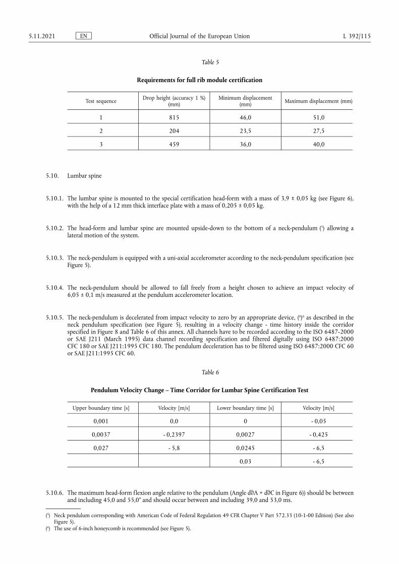
Table 5
Requirements for full rib module certification
Test sequence Drop height (accuracy 1 %) (mm)
Minimum displacement (mm) Maximum displacement (mm)
1 815 46,0 51,0
2 204 23,5 27,5
3 459 36,0 40,0
5.10. Lumbar spine
5.10.1. The lumbar spine is mounted to the special certification head-form with a mass of 3,9 ± 0,05 kg (see Figure 6), with the help of a 12 mm thick interface plate with a mass of 0,205 ± 0,05 kg.
5.10.2. The head-form and lumbar spine are mounted upside-down to the bottom of a neck-pendulum (5) allowing a lateral motion of the system.
5.10.3. The neck-pendulum is equipped with a uni-axial accelerometer according to the neck-pendulum specification (see Figure 5).
5.10.4. The neck-pendulum should be allowed to fall freely from a height chosen to achieve an impact velocity of 6,05 ± 0,1 m/s measured at the pendulum accelerometer location.
5.10.5. The neck-pendulum is decelerated from impact velocity to zero by an appropriate device, (6)6 as described in the neck pendulum specification (see Figure 5), resulting in a velocity change - time history inside the corridor specified in Figure 8 and Table 6 of this annex. All channels have to be recorded according to the ISO 6487-2000 or SAE J211 (March 1995) data channel recording specification and filtered digitally using ISO 6487:2000 CFC 180 or SAE J211:1995 CFC 180. The pendulum deceleration has to be filtered using ISO 6487:2000 CFC 60 or SAE J211:1995 CFC 60.
Table 6
Pendulum Velocity Change – Time Corridor for Lumbar Spine Certification Test
Upper boundary time [s] Velocity [m/s] Lower boundary time [s] Velocity [m/s]
0,001 0,0 0 - 0,05
0,0037 - 0,2397 0,0027 - 0,425
0,027 - 5,8 0,0245 - 6,5
0,03 - 6,5
5.10.6. The maximum head-form flexion angle relative to the pendulum (Angle dθA + dθC in Figure 6)) should be between and including 45,0 and 55,0° and should occur between and including 39,0 and 53,0 ms.
(5) Neck pendulum corresponding with American Code of Federal Regulation 49 CFR Chapter V Part 572.33 (10-1-00 Edition) (See also Figure 5).
(6) The use of 6-inch honeycomb is recommended (see Figure 5).
EN Official Journal of the European Union 5.11.2021 L 392/115
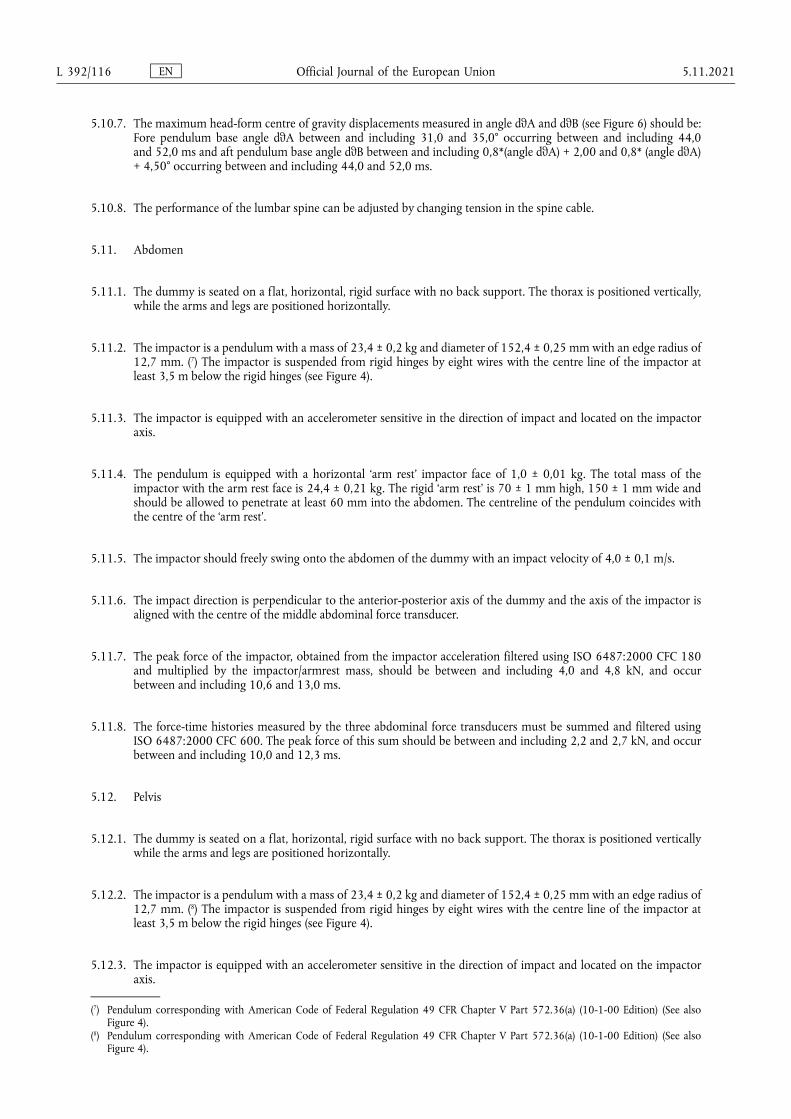
5.10.7. The maximum head-form centre of gravity displacements measured in angle dθA and dθB (see Figure 6) should be: Fore pendulum base angle dθA between and including 31,0 and 35,0° occurring between and including 44,0 and 52,0 ms and aft pendulum base angle dθB between and including 0,8*(angle dθA) + 2,00 and 0,8* (angle dθA) + 4,50° occurring between and including 44,0 and 52,0 ms.
5.10.8. The performance of the lumbar spine can be adjusted by changing tension in the spine cable.
5.11. Abdomen
5.11.1. The dummy is seated on a flat, horizontal, rigid surface with no back support. The thorax is positioned vertically, while the arms and legs are positioned horizontally.
5.11.2. The impactor is a pendulum with a mass of 23,4 ± 0,2 kg and diameter of 152,4 ± 0,25 mm with an edge radius of 12,7 mm. (7) The impactor is suspended from rigid hinges by eight wires with the centre line of the impactor at least 3,5 m below the rigid hinges (see Figure 4).
5.11.3. The impactor is equipped with an accelerometer sensitive in the direction of impact and located on the impactor axis.
5.11.4. The pendulum is equipped with a horizontal ‘arm rest’ impactor face of 1,0 ± 0,01 kg. The total mass of the impactor with the arm rest face is 24,4 ± 0,21 kg. The rigid ‘arm rest’ is 70 ± 1 mm high, 150 ± 1 mm wide and should be allowed to penetrate at least 60 mm into the abdomen. The centreline of the pendulum coincides with the centre of the ‘arm rest’.
5.11.5. The impactor should freely swing onto the abdomen of the dummy with an impact velocity of 4,0 ± 0,1 m/s.
5.11.6. The impact direction is perpendicular to the anterior-posterior axis of the dummy and the axis of the impactor is aligned with the centre of the middle abdominal force transducer.
5.11.7. The peak force of the impactor, obtained from the impactor acceleration filtered using ISO 6487:2000 CFC 180 and multiplied by the impactor/armrest mass, should be between and including 4,0 and 4,8 kN, and occur between and including 10,6 and 13,0 ms.
5.11.8. The force-time histories measured by the three abdominal force transducers must be summed and filtered using ISO 6487:2000 CFC 600. The peak force of this sum should be between and including 2,2 and 2,7 kN, and occur between and including 10,0 and 12,3 ms.
5.12. Pelvis
5.12.1. The dummy is seated on a flat, horizontal, rigid surface with no back support. The thorax is positioned vertically while the arms and legs are positioned horizontally.
5.12.2. The impactor is a pendulum with a mass of 23,4 ± 0,2 kg and diameter of 152,4 ± 0,25 mm with an edge radius of 12,7 mm. (8) The impactor is suspended from rigid hinges by eight wires with the centre line of the impactor at least 3,5 m below the rigid hinges (see Figure 4).
5.12.3. The impactor is equipped with an accelerometer sensitive in the direction of impact and located on the impactor axis.
(7) Pendulum corresponding with American Code of Federal Regulation 49 CFR Chapter V Part 572.36(a) (10-1-00 Edition) (See also Figure 4).
(8) Pendulum corresponding with American Code of Federal Regulation 49 CFR Chapter V Part 572.36(a) (10-1-00 Edition) (See also Figure 4).
EN Official Journal of the European Union L 392/116 5.11.2021
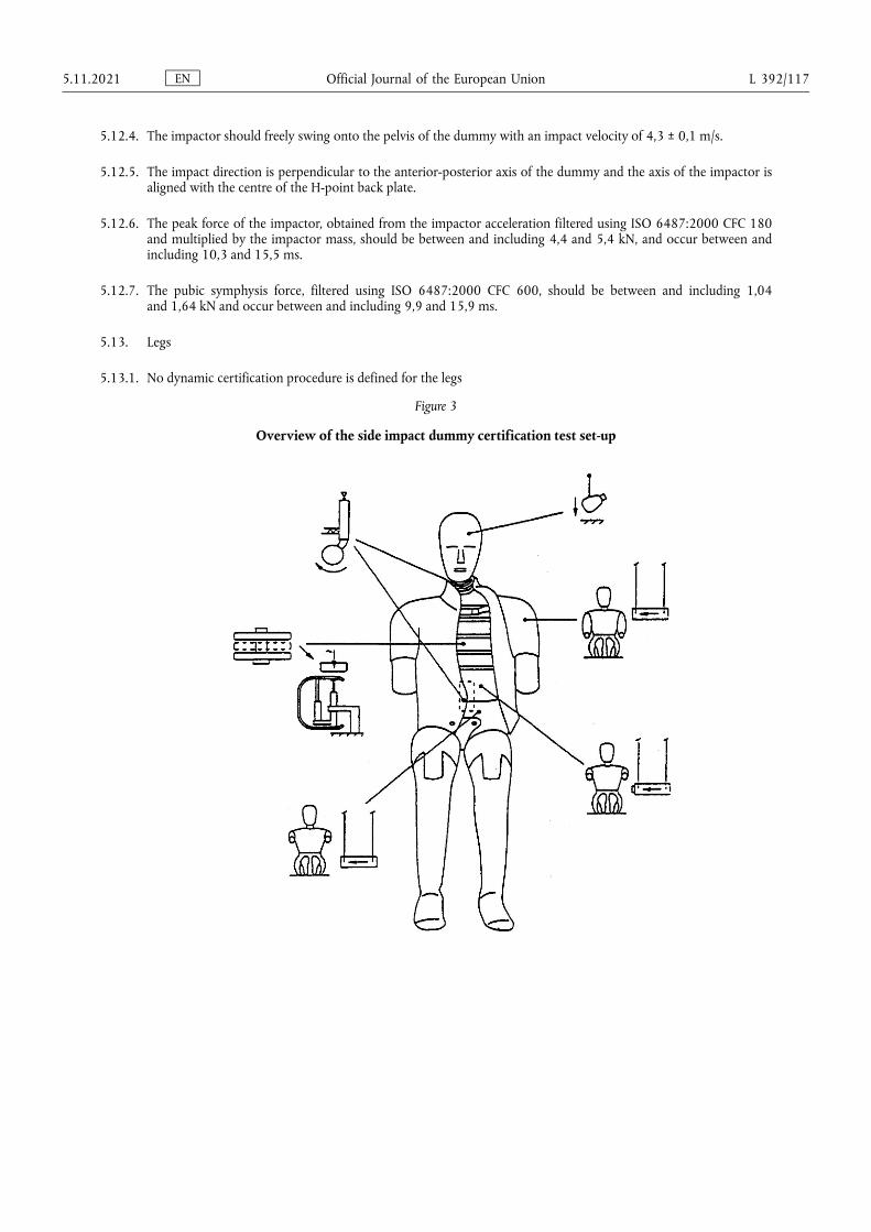
5.12.4. The impactor should freely swing onto the pelvis of the dummy with an impact velocity of 4,3 ± 0,1 m/s.
5.12.5. The impact direction is perpendicular to the anterior-posterior axis of the dummy and the axis of the impactor is aligned with the centre of the H-point back plate.
5.12.6. The peak force of the impactor, obtained from the impactor acceleration filtered using ISO 6487:2000 CFC 180 and multiplied by the impactor mass, should be between and including 4,4 and 5,4 kN, and occur between and including 10,3 and 15,5 ms.
5.12.7. The pubic symphysis force, filtered using ISO 6487:2000 CFC 600, should be between and including 1,04 and 1,64 kN and occur between and including 9,9 and 15,9 ms.
5.13. Legs
5.13.1. No dynamic certification procedure is defined for the legs
Figure 3
Overview of the side impact dummy certification test set-up
EN Official Journal of the European Union 5.11.2021 L 392/117
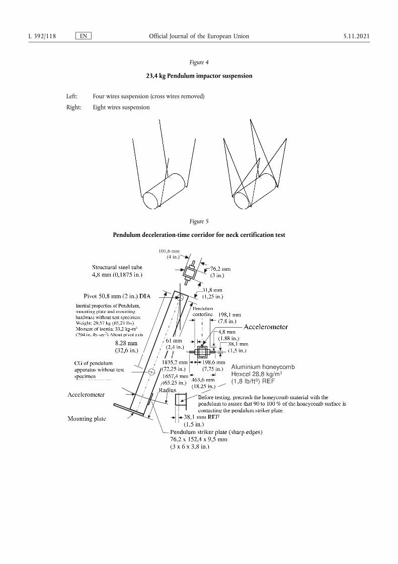
Figure 4
23,4 kg Pendulum impactor suspension
Left: Four wires suspension (cross wires removed)
Right: Eight wires suspension
Figure 5
Pendulum deceleration-time corridor for neck certification test
EN Official Journal of the European Union L 392/118 5.11.2021
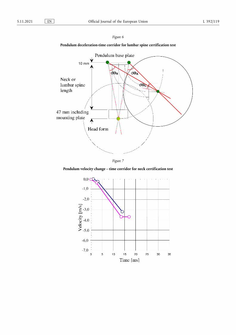
Figure 6
Pendulum deceleration-time corridor for lumbar spine certification test
Figure 7
Pendulum velocity change – time corridor for neck certification test
EN Official Journal of the European Union 5.11.2021 L 392/119
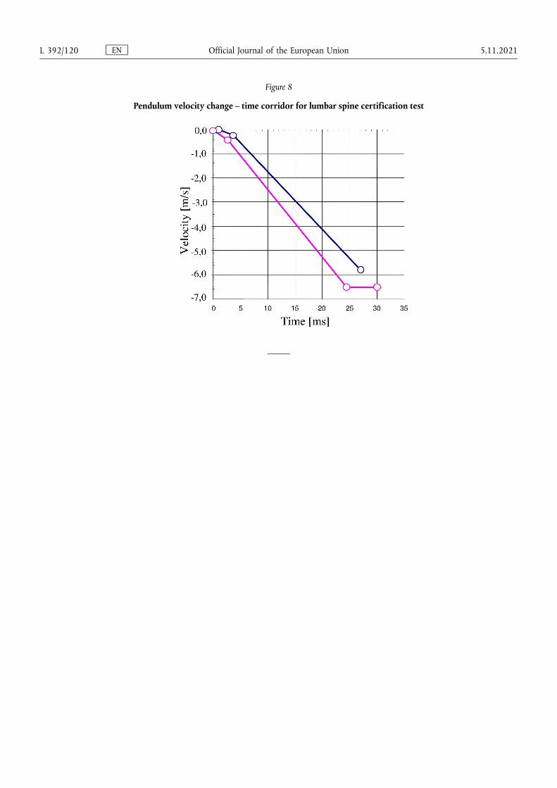
Figure 8
Pendulum velocity change – time corridor for lumbar spine certification test
EN Official Journal of the European Union L 392/120 5.11.2021
ANNEX 7
Installation of the side impact dummy
1. General
1.1. The side impact dummy as described in Annex 6 to this Regulation is to be used according the following installation procedure.
2. Installation
2.1. Adjust the knee and ankle joints so that they just support the lower leg and the foot when extended horizontally (1 to 2 g - adjustment).
2.2. Check if the dummy is adapted to the desired impact direction.
2.3. The dummy shall be clothed in a form-fitting cotton stretch mid-calf length pant and may be clothed in a form- fitting cotton stretch shirt with short sleeves.
2.4. Each foot shall be equipped with a shoe.
2.5. Place the dummy in the outboard front seat of the impacted side as described in the side impact test procedure specification.
2.6. The plane of symmetry of the dummy shall coincide with the vertical median plane of the specified seating position.
2.7. The pelvis of the dummy shall be positioned such that a lateral line passing through the dummy H-points is perpendicular to the longitudinal centre plane of the seat. The line through the dummy H-points shall be horizontal with a maximum inclination of ±2°. (1)
The correct position of the dummy pelvis can be checked relative to the H-point of the H-point Manikin by using the M3 holes in the H-point back plates at each side of the ES-2 pelvis. The M3 holes are indicated with ‘Hm’. The ‘Hm’ position should be in a circle with a radius of 10 mm round the H-point of the H-point Manikin.
The correct position of the dummy pelvis
2.8. The upper torso shall be bent forward and then laid back firmly against the seat back (see note 1). The shoulders of the dummy shall be set fully rearward.
2.9. Irrespective of the seating position of the dummy, the angle between the upper arm and the torso arm reference line on each side shall be 40° ± 5°. The torso arm reference line is defined as the intersection of the plane tangential to the front surface of the ribs and the longitudinal vertical plane of the dummy containing the arm.
2.10. For the driver’s seating position, without inducing pelvis or torso movement, place the right foot of the dummy on the non-depressed accelerator pedal with the heel resting as far forward as possible on the floor-pan. Set the left foot perpendicular to the lower leg with the heel resting on the floor-pan in the same lateral line as the right heel. Set the knees of the dummy such that their outside surfaces are 150 ± 10 mm from the plane of symmetry of the dummy. If possible within these constraints place the thighs of the dummy in contact with the seat cushion.
2.11. For other seating positions, without inducing pelvis or torso movement, place the heels of the dummy as far forward as possible on the floor-pan without compressing the seat cushion more than the compression due to the weight of the leg. Set the knees of the dummy such that their outside surfaces are 150 ± 10 mm from the plane of symmetry of the dummy.
(1) The dummy can be equipped with tilt sensors in the thorax and the pelvis. These instruments can help to obtain the desired position.
EN Official Journal of the European Union 5.11.2021 L 392/121
ANNEX 8
Partial test
1. Purpose
The purpose of these tests is to verify whether the modified vehicle presents at least the same (or better) energy absorption characteristics than the vehicle type approved under this Regulation.
2. Procedures and installations
2.1. Reference tests
2.1.1. Using the initial padding materials tested during the approval of the vehicle, mounted in a new lateral structure of the vehicle to be approved, two dynamic tests, utilizing two different impactors shall be carried out (Figure 1).
2.1.1.1. The head form impactor, defined in paragraph 3.1.1 below, shall hit at 24,1 km/h, in the area impacted for the EUROSID head during the approval of the vehicle. Test result shall be recorded, and the HPC calculated. However, this test shall not be carried out when, during the tests described in Annex 4 of this Regulation: where there has been no head contact, or when the head contacted the window glazing only, provided that the window glazing is not laminated glass.
2.1.1.2. The body block impactor, defined in paragraph 3.2.1 below, shall hit at 24,1 km/h in the lateral area impacted by the EUROSID shoulder, arm and thorax, during the approval of the vehicle. Test result shall be recorded, and the HPC calculated.
2.2. Approval test
2.2.1. Using the new padding materials, seat, etc. presented for the approval extension, and mounted in a new lateral structure of the vehicle, tests specified in paragraphs 2.1.1.1 and 2.1.1.2 above, shall be repeated, the new results recorded, and their HPC calculated.
2.2.1.1. If the HPC calculated from the results of both approval tests are lower than the HPC obtained during the reference tests (carried out using the original type approved padding materials or seats), the extension shall be granted.
2.2.1.2. If the new HPC are greater than the HPC obtained during the reference tests, a new full scale test (using the proposed padding/seats/etc.) shall be carried out.
3. Test equipment
3.1. Head form impactor (Figure 2)
3.1.1. This apparatus consists of a fully guided linear impactor, rigid, with a mass of 6,8 kg. Its impact surface is hemispherical with a diameter of 165 mm.
3.1.2. The head form shall be fitted with two accelerometers and a speed-measuring device, all capable of measuring values in the impact direction.
3.2. Body block impactor (Figure 3)
3.2.1. This apparatus consists of a fully guided linear impactor, rigid, with a mass of 30 kg. Its dimensions and transversal section is presented in Figure 3.
3.2.2. The body block shall be fitted with two accelerometers and a speed-measuring device, all capable of measuring values in the impact direction.
EN Official Journal of the European Union L 392/122 5.11.2021
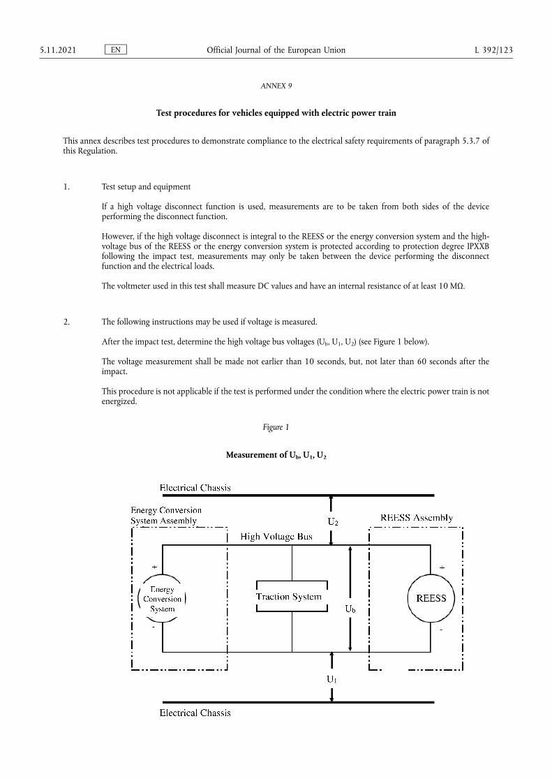
ANNEX 9
Test procedures for vehicles equipped with electric power train
This annex describes test procedures to demonstrate compliance to the electrical safety requirements of paragraph 5.3.7 of this Regulation.
1. Test setup and equipment
If a high voltage disconnect function is used, measurements are to be taken from both sides of the device performing the disconnect function.
However, if the high voltage disconnect is integral to the REESS or the energy conversion system and the high- voltage bus of the REESS or the energy conversion system is protected according to protection degree IPXXB following the impact test, measurements may only be taken between the device performing the disconnect function and the electrical loads.
The voltmeter used in this test shall measure DC values and have an internal resistance of at least 10 MΩ.
2. The following instructions may be used if voltage is measured.
After the impact test, determine the high voltage bus voltages (Ub, U1, U2) (see Figure 1 below).
The voltage measurement shall be made not earlier than 10 seconds, but, not later than 60 seconds after the impact.
This procedure is not applicable if the test is performed under the condition where the electric power train is not energized.
Figure 1
Measurement of Ub, U1, U2
EN Official Journal of the European Union 5.11.2021 L 392/123
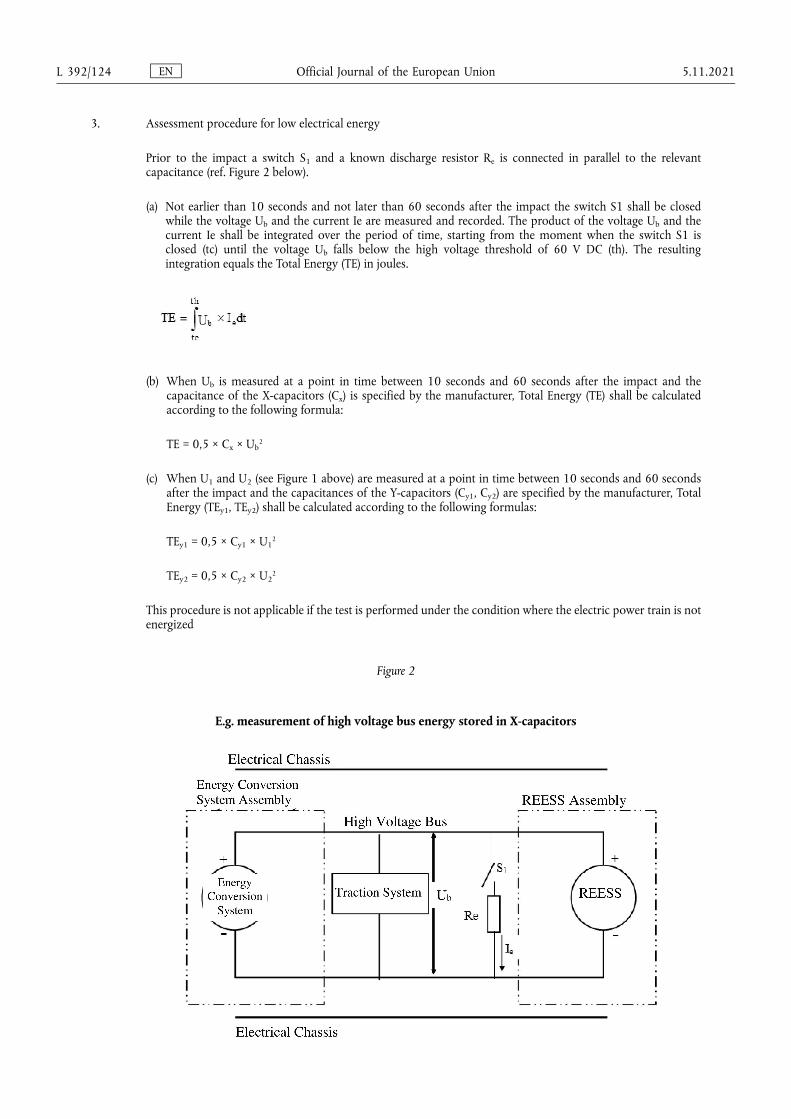
3. Assessment procedure for low electrical energy
Prior to the impact a switch S1 and a known discharge resistor Re is connected in parallel to the relevant capacitance (ref. Figure 2 below).
(a) Not earlier than 10 seconds and not later than 60 seconds after the impact the switch S1 shall be closed while the voltage Ub and the current Ie are measured and recorded. The product of the voltage Ub and the current Ie shall be integrated over the period of time, starting from the moment when the switch S1 is closed (tc) until the voltage Ub falls below the high voltage threshold of 60 V DC (th). The resulting integration equals the Total Energy (TE) in joules.
(b) When Ub is measured at a point in time between 10 seconds and 60 seconds after the impact and the capacitance of the X-capacitors (Cx) is specified by the manufacturer, Total Energy (TE) shall be calculated according to the following formula:
TE = 0,5 × Cx × Ub2
(c) When U1 and U2 (see Figure 1 above) are measured at a point in time between 10 seconds and 60 seconds after the impact and the capacitances of the Y-capacitors (Cy1, Cy2) are specified by the manufacturer, Total Energy (TEy1, TEy2) shall be calculated according to the following formulas:
TEy1 = 0,5 × Cy1 × U12
TEy2 = 0,5 × Cy2 × U22
This procedure is not applicable if the test is performed under the condition where the electric power train is not energized
Figure 2
E.g. measurement of high voltage bus energy stored in X-capacitors
EN Official Journal of the European Union L 392/124 5.11.2021
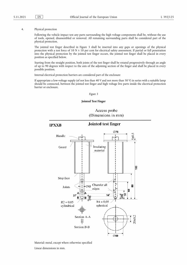
4. Physical protection
Following the vehicle impact test any parts surrounding the high voltage components shall be, without the use of tools, opened, disassembled or removed. All remaining surrounding parts shall be considered part of the physical protection.
The jointed test finger described in Figure 3 shall be inserted into any gaps or openings of the physical protection with a test force of 10 N ± 10 per cent for electrical safety assessment. If partial or full penetration into the physical protection by the jointed test finger occurs, the jointed test finger shall be placed in every position as specified below.
Starting from the straight position, both joints of the test finger shall be rotated progressively through an angle of up to 90 degrees with respect to the axis of the adjoining section of the finger and shall be placed in every possible position.
Internal electrical protection barriers are considered part of the enclosure
If appropriate a low-voltage supply (of not less than 40 V and not more than 50 V) in series with a suitable lamp should be connected, between the jointed test finger and high voltage live parts inside the electrical protection barrier or enclosure.
Figure 3
Jointed Test Finger
Material: metal, except where otherwise specified
Linear dimensions in mm.
EN Official Journal of the European Union 5.11.2021 L 392/125
Tolerances on dimensions without specific tolerance:
(a) on angles: +0/-10 seconds;
(b) on linear dimensions:
(i) up to 25 mm: +0/-0,05;
(ii) over 25 mm: ±0,2.
Both joints shall permit movement in the same plane and the same direction through an angle of 90° with a 0 to +10° tolerance.
The requirements of paragraph 5.3.7.1.3 of this Regulation are met if the jointed test finger described in Figure 3, is unable to contact high voltage live parts.
If necessary a mirror or a fiberscope may be used in order to inspect whether the jointed test finger touches the high voltage buses.
If this requirement is verified by a signal circuit between the jointed test finger and high voltage live parts, the lamp shall not light.
4.1. Test method for measuring electric resistance:
(a) Test method using a resistance tester.
The resistance tester is connected to the measuring points (typically, electrical chassis and electro conductive enclosure/electrical protection barrier) and the resistance is measured using a resistance tester that meets the specification that follows:
(i) Resistance tester: Measurement current at least 0,2 A;
(ii) Resolution: 0,01 Ω or less;
(iii) The resistance R shall be less than 0,1 Ω.
(b) Test method using DC power supply, voltmeter and ammeter.
The DC power supply, voltmeter and ammeter are connected to the measuring points (Typically, electrical chassis and electro conductive enclosure/electrical protection barrier).
The voltage of the DC power supply is adjusted so that the current flow becomes at least 0,2 A.
The current ‘I’ and the voltage ‘U’ are measured.
The resistance ‘R’ is calculated according to the following formula:
R = U / I
The resistance R shall be less than 0,1 Ω.
Note: If lead wires are used for voltage and current measurement, each lead wire shall be independently connected to the electrical protection barrier/enclosure/electrical chassis. Terminal can be common for voltage measurement and current measurement.
Example of the test method using DC power supply, voltmeter and ammeter is shown below.
EN Official Journal of the European Union L 392/126 5.11.2021
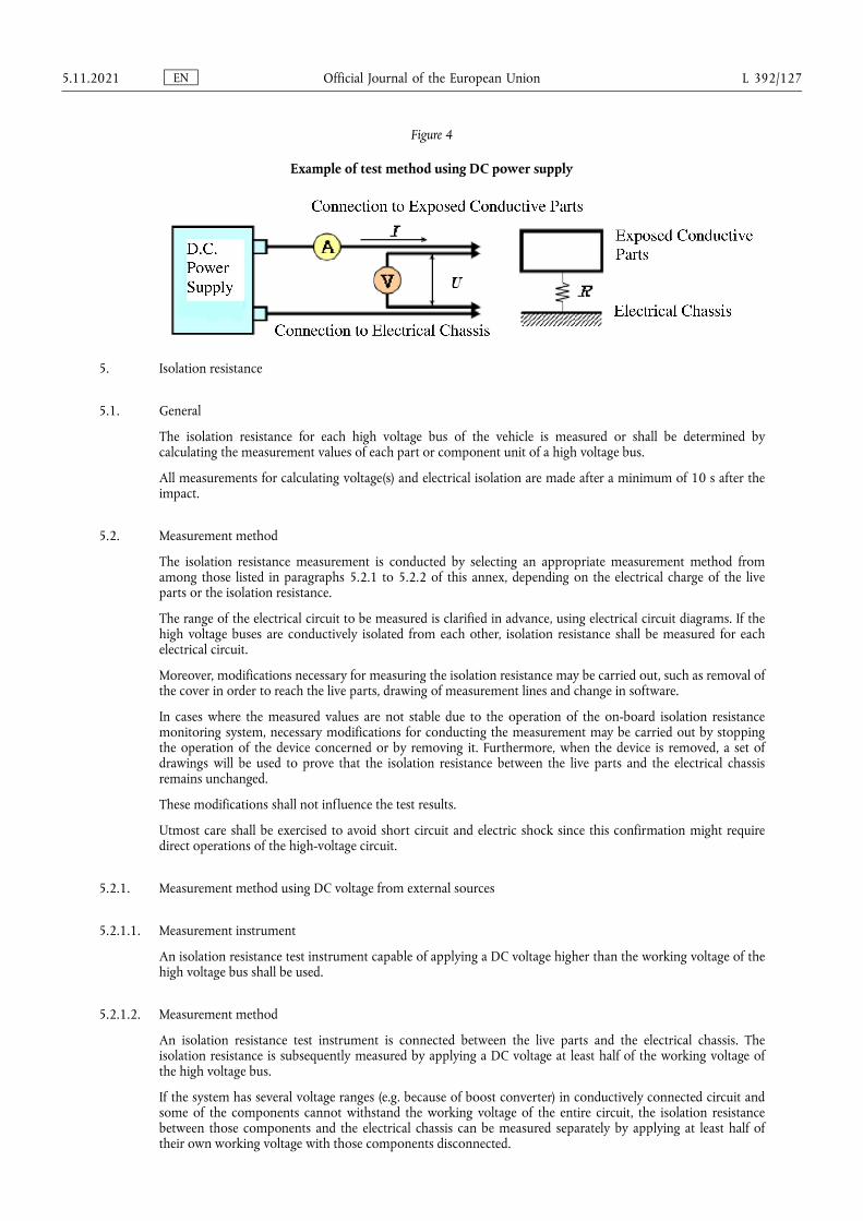
Figure 4
Example of test method using DC power supply
5. Isolation resistance
5.1. General
The isolation resistance for each high voltage bus of the vehicle is measured or shall be determined by calculating the measurement values of each part or component unit of a high voltage bus.
All measurements for calculating voltage(s) and electrical isolation are made after a minimum of 10 s after the impact.
5.2. Measurement method
The isolation resistance measurement is conducted by selecting an appropriate measurement method from among those listed in paragraphs 5.2.1 to 5.2.2 of this annex, depending on the electrical charge of the live parts or the isolation resistance.
The range of the electrical circuit to be measured is clarified in advance, using electrical circuit diagrams. If the high voltage buses are conductively isolated from each other, isolation resistance shall be measured for each electrical circuit.
Moreover, modifications necessary for measuring the isolation resistance may be carried out, such as removal of the cover in order to reach the live parts, drawing of measurement lines and change in software.
In cases where the measured values are not stable due to the operation of the on-board isolation resistance monitoring system, necessary modifications for conducting the measurement may be carried out by stopping the operation of the device concerned or by removing it. Furthermore, when the device is removed, a set of drawings will be used to prove that the isolation resistance between the live parts and the electrical chassis remains unchanged.
These modifications shall not influence the test results.
Utmost care shall be exercised to avoid short circuit and electric shock since this confirmation might require direct operations of the high-voltage circuit.
5.2.1. Measurement method using DC voltage from external sources
5.2.1.1. Measurement instrument
An isolation resistance test instrument capable of applying a DC voltage higher than the working voltage of the high voltage bus shall be used.
5.2.1.2. Measurement method
An isolation resistance test instrument is connected between the live parts and the electrical chassis. The isolation resistance is subsequently measured by applying a DC voltage at least half of the working voltage of the high voltage bus.
If the system has several voltage ranges (e.g. because of boost converter) in conductively connected circuit and some of the components cannot withstand the working voltage of the entire circuit, the isolation resistance between those components and the electrical chassis can be measured separately by applying at least half of their own working voltage with those components disconnected.
EN Official Journal of the European Union 5.11.2021 L 392/127
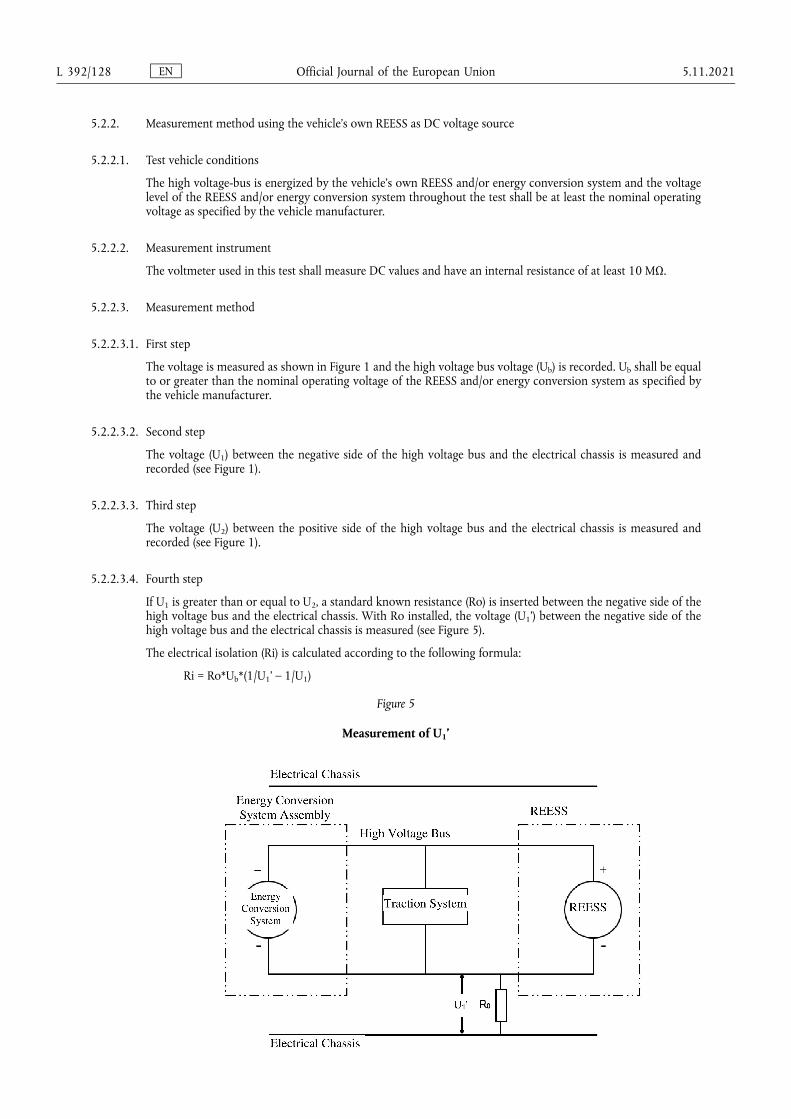
5.2.2. Measurement method using the vehicle's own REESS as DC voltage source
5.2.2.1. Test vehicle conditions
The high voltage-bus is energized by the vehicle's own REESS and/or energy conversion system and the voltage level of the REESS and/or energy conversion system throughout the test shall be at least the nominal operating voltage as specified by the vehicle manufacturer.
5.2.2.2. Measurement instrument
The voltmeter used in this test shall measure DC values and have an internal resistance of at least 10 MΩ.
5.2.2.3. Measurement method
5.2.2.3.1. First step
The voltage is measured as shown in Figure 1 and the high voltage bus voltage (Ub) is recorded. Ub shall be equal to or greater than the nominal operating voltage of the REESS and/or energy conversion system as specified by the vehicle manufacturer.
5.2.2.3.2. Second step
The voltage (U1) between the negative side of the high voltage bus and the electrical chassis is measured and recorded (see Figure 1).
5.2.2.3.3. Third step
The voltage (U2) between the positive side of the high voltage bus and the electrical chassis is measured and recorded (see Figure 1).
5.2.2.3.4. Fourth step
If U1 is greater than or equal to U2, a standard known resistance (Ro) is inserted between the negative side of the high voltage bus and the electrical chassis. With Ro installed, the voltage (U1') between the negative side of the high voltage bus and the electrical chassis is measured (see Figure 5).
The electrical isolation (Ri) is calculated according to the following formula:
Ri = Ro*Ub*(1/U1' – 1/U1)
Figure 5
Measurement of U1’
EN Official Journal of the European Union L 392/128 5.11.2021
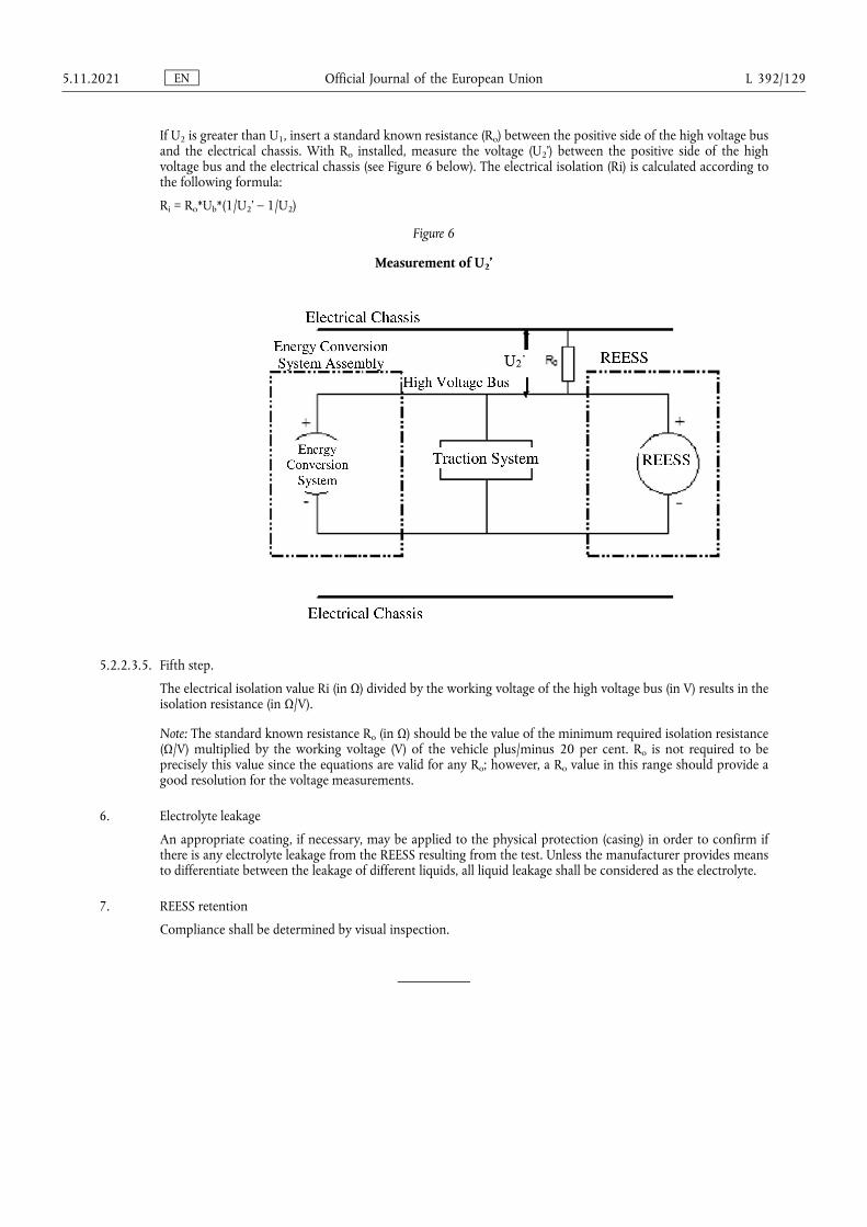
If U2 is greater than U1, insert a standard known resistance (Ro) between the positive side of the high voltage bus and the electrical chassis. With Ro installed, measure the voltage (U2’) between the positive side of the high voltage bus and the electrical chassis (see Figure 6 below). The electrical isolation (Ri) is calculated according to the following formula:
Ri = Ro*Ub*(1/U2’ – 1/U2)
Figure 6
Measurement of U2’
5.2.2.3.5. Fifth step.
The electrical isolation value Ri (in Ω) divided by the working voltage of the high voltage bus (in V) results in the isolation resistance (in Ω/V).
Note: The standard known resistance Ro (in Ω) should be the value of the minimum required isolation resistance (Ω/V) multiplied by the working voltage (V) of the vehicle plus/minus 20 per cent. Ro is not required to be precisely this value since the equations are valid for any Ro; however, a Ro value in this range should provide a good resolution for the voltage measurements.
6. Electrolyte leakage
An appropriate coating, if necessary, may be applied to the physical protection (casing) in order to confirm if there is any electrolyte leakage from the REESS resulting from the test. Unless the manufacturer provides means to differentiate between the leakage of different liquids, all liquid leakage shall be considered as the electrolyte.
7. REESS retention
Compliance shall be determined by visual inspection.
EN Official Journal of the European Union 5.11.2021 L 392/129

Only the original UN/ECE texts have legal effect under international public law. The status and date of entry into force of this Regulation should be checked in the latest version of the UN/ECE status document TRANS/WP.29/343, available at: https://unece.org/status-1958-agreement-and-annexed-regulations
UN Regulation No 137 – Uniform provisions concerning the approval of vehicles in the event of a frontal collision with focus on the restraint system [2021/1862]
Incorporating all valid text up to:
02 series of amendments – Date of entry into force: 9 June 2021
This document is meant purely as documentation tool. The authentic and legally binding texts are:
— ECE/TRANS/WP.29/2015/106
— ECE/TRANS/WP.29/2018/77
— ECE/TRANS/WP.29/2018/140
— ECE/TRANS/WP.29/2020/59 and
— ECE/TRANS/WP.29/2020/110
CONTENTS
REGULATION
1. Scope
2. Definitions
3. Application for approval
4. Approval
5. Specifications
6. Instructions for users of vehicles equipped with airbags
7. Modification and extension of approval of the vehicle type
8. Conformity of production
9. Penalties for non-conformity of production
10. Production definitively discontinued
11. Names and addresses of Technical Services responsible for conducting approval tests, and of Type Approval Authorities
12. Transitional provisions
ANNEXES
1 Communication
2 Arrangements of approval marks
3 Test procedure
4 Performance criteria
5 Arrangement and installation of dummies and adjustment of restraint systems
6 Procedure for determining the ‘H’ point and the actual torso angle for seating positions in motor vehicles
Appendix 1 - Description of the three dimensional ‘H’ point machine (3-D H machine)
EN Official Journal of the European Union L 392/130 5.11.2021

Appendix 2 - Three dimensional reference system
Appendix 3 - Reference data concerning seating positions
7 Test procedure with trolley
Appendix- Equivalence curve - tolerance band for curve ΔV = f(t)
8 Technique of measurement in measurement tests: Instrumentation
9 Test procedures for vehicles equipped with electric power train
EN Official Journal of the European Union 5.11.2021 L 392/131
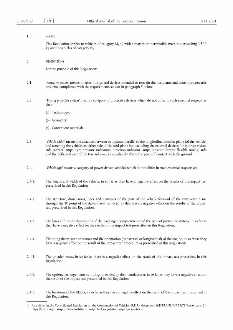
1. SCOPE
This Regulation applies to vehicles of category M1 (1) with a maximum permissible mass not exceeding 3 500kg and to vehicles of category N1.
2. DEFINITIONS
For the purpose of this Regulation:
2.1. ‘Protective system’ means interior fittings and devices intended to restrain the occupants and contribute towards ensuring compliance with the requirements set out in paragraph 5 below.
2.2. ‘Type of protective system’ means a category of protective devices which do not differ in such essential respects as their:
(a) Technology;
(b) Geometry;
(c) Constituent materials.
2.3. ‘Vehicle width’ means the distance between two planes parallel to the longitudinal median plane (of the vehicle) and touching the vehicle on either side of the said plane but excluding the external devices for indirect vision, side marker lamps, tyre pressure indicators, direction indicator lamps, position lamps, flexible mud-guards and the deflected part of the tyre side-walls immediately above the point of contact with the ground.
2.4. ‘Vehicle type’ means a category of power-driven vehicles which do not differ in such essential respects as:
2.4.1. The length and width of the vehicle, in so far as they have a negative effect on the results of the impact test prescribed in this Regulation;
2.4.2. The structure, dimensions, lines and materials of the part of the vehicle forward of the transverse plane through the ‘R’ point of the driver's seat, in so far as they have a negative effect on the results of the impact test prescribed in this Regulation;
2.4.3. The lines and inside dimensions of the passenger compartment and the type of protective system, in so far as they have a negative effect on the results of the impact test prescribed in this Regulation;
2.4.4. The siting (front, rear or centre) and the orientation (transversal or longitudinal) of the engine, in so far as they have a negative effect on the result of the impact test procedure as prescribed in this Regulation;
2.4.5. The unladen mass, in so far as there is a negative effect on the result of the impact test prescribed in this Regulation;
2.4.6. The optional arrangements or fittings provided by the manufacturer, in so far as they have a negative effect on the result of the impact test prescribed in this Regulation;
2.4.7. The locations of the REESS, in so far as they have a negative effect on the result of the impact test prescribed in this Regulation.
(1) As defined in the Consolidated Resolution on the Construction of Vehicles (R.E.3.), document ECE/TRANS/WP.29/78/Rev.6, para. 2 - https://unece.org/transport/standards/transport/vehicle-regulations-wp29/resolutions
EN Official Journal of the European Union L 392/132 5.11.2021
2.5. Passenger compartment
2.5.1. ‘Passenger compartment with regard to occupant protection’ means the space for occupant accommodation, bounded by the roof, floor, side walls, doors, outside glazing and front bulkhead and the plane of the rear compartment bulkhead or the plane of the rear seat-back support;
2.5.2. ‘Passenger compartment for electric safety assessment’ means the space for occupant accommodation, bounded by the roof, floor, side walls, doors, outside glazing, front bulkhead and rear bulkhead, or rear gate, as well as by the electrical protection barriers and enclosures provided for protecting the occupants from direct contact with high voltage live parts.
2.6. ‘R point’ means a reference point defined for each seat by the manufacturer in relation to the vehicle's structure, as indicated in Annex 6.
2.7. ‘H point’ means a reference point determined for each seat by the Technical Service responsible for conducting the tests, in accordance with the procedure described in Annex 6.
2.8. ‘Unladen kerb mass’ means the mass of the vehicle in running order, unoccupied and unladen but complete with fuel, coolant, lubricant, tools and a spare wheel (if these are provided as standard equipment by the vehicle manufacturer).
2.9. ‘Airbag’ means a device installed to supplement safety belts and restraint systems in power-driven vehicles, i.e. systems which, in the event of a severe impact affecting the vehicle, automatically deploy a flexible structure intended to limit, by compression of the gas contained within it, the gravity of the contacts of one or more parts of the body of an occupant of the vehicle with the interior of the passenger compartment.
2.10. ‘Passenger airbag’ means an airbag assembly intended to protect occupant(s) in seats other than the driver's in the event of a frontal collision.
2.11. ‘High voltage’ means the classification of an electric component or circuit, if its working voltage is > 60 V and ≤ 1 500 V direct current (DC) or > 30 V and ≤ 1 000 V alternating current (AC) root – mean – square (rms).
2.12. ‘Rechargeable Electrical Energy Storage System (REESS)’ means the rechargeable energy storage system that provides electric energy for electrical propulsion.
A battery whose primary use is to supply power for starting the engine and/or lighting and/or other vehicle auxiliaries’ systems is not considered as a REESS.
The REESS may include the necessary systems for physical support, thermal management, electronic controls and casing.
2.13. ‘Electrical protection barrier’ means the part providing protection against any direct contact to the high voltage live parts.
2.14. ‘Electric power train’ means the electrical circuit which includes the traction motor(s), and may also include the REESS, the electrical energy conversion system, the electronic converters, the associated wiring harness and connectors, and the coupling system for charging the REESS.
2.15. ‘Live parts’ means conductive part(s) intended to be electrically energized under normal operating conditions.
2.16. ‘Exposed conductive part’ means the conductive part which can be touched under the provisions of the protection degree IPXXB and which is not normally energized, but which can become electrically energized under isolation failure conditions. This includes parts under a cover that can be removed without using tools.
EN Official Journal of the European Union 5.11.2021 L 392/133
2.17. ‘Direct contact’ means the contact of persons with high voltage live parts.
2.18. ‘Indirect contact’ means the contact of persons with exposed conductive parts.
2.19. ‘Protection degree IPXXB’ means protection from contact with high voltage live parts provided by either an electrical protection barrier or an enclosure and tested using a Jointed Test Finger (IPXXB) as described in paragraph 4 of Annex 9.
2.20. ‘Working voltage’ means the highest value of an electrical circuit voltage root-mean-square (rms), specified by the manufacturer, which may occur between any conductive parts in open circuit conditions or under normal operating conditions. If the electrical circuit is divided by galvanic isolation, the working voltage is defined for each divided circuit, respectively.
2.21. ‘Coupling system for charging the Rechargeable Electrical Energy Storage System (REESS)’ means the electrical circuit used for charging the REESS from an external electrical power supply including the vehicle inlet.
2.22. ‘Electrical chassis’ means a set made of conductive parts electrically linked together, whose electrical potential is taken as reference.
2.23. ‘Electrical circuit’ means an assembly of connected live parts which is designed to be electrically energized in normal operation.
2.24. ‘Electrical energy conversion system’ means a system (e.g. fuel cell) that generates and provides electrical energy for electrical propulsion.
2.25. ‘Electronic converter’ means a device capable of controlling and/or converting electrical power for electrical propulsion.
2.26. ‘Enclosure’ means the part enclosing the internal units and providing protection against any direct contact.
2.27. ‘High voltage bus’ means the electrical circuit, including the coupling system for charging the REESS, that operates on a high voltage. Where electric circuits, that are galvanically connected to each other and fulfil the specific voltage condition, only the components or parts of the electric circuit that operate on high voltage are classified as a high voltage bus.
2.28. ‘Solid insulator’ means the insulating coating of wiring harnesses, provided in order to cover and prevent the high voltage live parts from any direct contact.
2.29. ‘Automatic disconnect’ means a device that when triggered, galvanically separates the electrical energy sources from the rest of the high voltage circuit of the electric power train.
2.30. ‘Open type traction battery’ means a type of battery requiring filling with liquid and generating hydrogen gas that is released to the atmosphere.
2.31. ‘Automatically activated door locking system’ means a system that locks the doors automatically at a pre-set speed or under any other condition as defined by the manufacturer.
2.32. ‘Displacement system’ means a device by which the seat or one of its parts can be displaced and/or rotated, without a fixed intermediate position, to permit easy access of occupants to and from the space behind the seat concerned.
2.33. ‘Aqueous electrolyte’ means an electrolyte based on water solvent for the compounds (e.g. acids, bases) providing conducting ions after its dissociation.
EN Official Journal of the European Union L 392/134 5.11.2021
2.34. ‘Electrolyte leakage’ means the escape of electrolyte from the REESS in the form of liquid.
2.35. ‘Non-aqueous electrolyte’ means an electrolyte not based on water as the solvent.
2.36. ‘Normal operating conditions’ include operating modes and conditions that can reasonably be encountered during typical operation of the vehicle including driving at legally posted speeds, parking and standing in traffic, as well as, charging using chargers that are compatible with the specific charging ports installed on the vehicle. It does not include, conditions where the vehicle is damaged, either by a crash, road debris or vandalization, subjected to fire or water submersion, or in a state where service and or maintenance is needed or being performed.
2.37. ‘Specific voltage condition’ means the condition that the maximum voltage of a galvanically connected electric circuit between a DC live part and any other live part (DC or AC) is ≤ 30 V AC (rms) and ≤ 60 V DC.
Note: When a DC live part of such an electric circuit is connected to electrical chassis and the specific voltage condition applies, the maximum voltage between any live part and the electrical chassis is ≤ 30 V AC (rms) and ≤ 60 V DC.
2.38. ‘State of Charge (SOC)’ means the available electrical charge in a REESS expressed as a percentage of its rated capacity.
2.39. ‘Fire’ means the emission of flames from the vehicle. Sparks and arcing shall not be considered as flames.
2.40. ‘Explosion’ means the sudden release of energy sufficient to cause pressure waves and/or projectiles that may cause structural and/or physical damage to the surrounding of the vehicle.
3. APPLICATION FOR APPROVAL
3.1. The application for approval of a vehicle type with regard to the protection of the occupants of the front seats in the event of a frontal collision shall be submitted by the vehicle manufacturer or by their duly accredited representative.
3.2. It shall be accompanied by the undermentioned documents in triplicate and following particulars:
3.2.1. A detailed description of the vehicle type with respect to its structure, dimensions, lines and constituent materials;
3.2.2. Photographs, and/or diagrams and drawings of the vehicle showing the vehicle type in front, side and rear elevation and design details of the forward part of the structure;
3.2.3. Particulars of the vehicle's unladen kerb mass;
3.2.4. The lines and inside dimensions of the passenger compartment;
3.2.5. A description of the interior fittings and protective systems installed in the vehicle;
3.2.6. A general description of the electrical power source type, location and the electric power train (e.g. hybrid, electric).
EN Official Journal of the European Union 5.11.2021 L 392/135

3.3. The applicant for approval shall be entitled to present any data and results of tests carried out which make it possible to establish that compliance with the requirements can be achieved with a sufficient degree of confidence.
3.4. A vehicle which is representative of the type to be approved shall be submitted to the Technical Service responsible for conducting the approval tests.
3.4.1. A vehicle not comprising all the components proper to the type may be accepted for test provided that it can be shown that the absence of the components has no detrimental effect on the results of the test in so far as the requirements of this Regulation are concerned.
3.4.2. It shall be the responsibility of the applicant for approval to show that the application of paragraph 3.4.1 above is compatible with compliance with the requirements of this Regulation.
4. APPROVAL
4.1. If the vehicle type submitted for approval pursuant to this Regulation meets the requirements of this Regulation, approval of that vehicle type shall be granted.
4.1.1. The Technical Service appointed in accordance with paragraph 12 below shall check whether the required conditions have been satisfied.
4.1.2. In case of doubt, account shall be taken, when verifying the conformity of the vehicle to the requirements of this Regulation, of any data or test results provided by the manufacturer which can be taken into consideration in validating the approval test carried out by the Technical Service.
4.2. An approval number shall be assigned to each type approved in accordance with Schedule 4 of the Agreement (E/ECE/TRANS/505/Rev.3).
4.3. Notice of approval or of refusal of approval of a vehicle type pursuant to this Regulation shall be communicated by the Parties to the Agreement which apply this Regulation by means of a form conforming to the model in Annex 1 to this Regulation.
4.4. There shall be affixed, conspicuously and in a readily accessible place specified on the approval form, to every vehicle conforming to a vehicle type approved under this Regulation, an international approval mark consisting of:
4.4.1. A circle surrounding the letter ‘E’ followed by the distinguishing number of the country which has granted approval; (2)
4.4.2. The number of this Regulation, followed by the letter ‘R’, a dash and the approval number, to the right of the circle prescribed in paragraph 4.4.1 above.
4.5. If the vehicle conforms to a vehicle type approved, under one or more other Regulations annexed to the Agreement, in the country which has granted approval under this Regulation, the symbol prescribed in paragraph 4.4.1 above need not be repeated; in such a case the Regulation and approval numbers and the additional symbols of all the Regulations under which approval has been granted in the country which has granted approval under this Regulation shall be placed in vertical columns to the right of the symbol prescribed in paragraph 4.4.1.
(2) The distinguishing numbers of the Contracting Parties to the 1958 Agreement are reproduced in Annex 3 to the Consolidated Resolution on the Construction of Vehicles (R.E.3), document ECE/TRANS/WP.29/78/Rev. 6
EN Official Journal of the European Union L 392/136 5.11.2021
4.6. The approval mark shall be clearly legible and be indelible.
4.7. The approval mark shall be placed close to or on the vehicle data plate affixed by the manufacturer.
4.8. Annex 2 to this Regulation gives examples of the arrangements of approval marks.
5. SPECIFICATIONS
5.1. General specifications
5.1.1. The ‘H’ point for each seat shall be determined in accordance with the procedure described in Annex 6.
5.1.2. When the protective system for the front seating positions includes belts, the belt components shall meet the requirements of Regulation No 16.
5.1.3. Seating positions where a dummy is installed and the protective system includes belts, shall be provided with anchorage points conforming to Regulation No 14.
5.2. Specifications for the restraint system test (Full Width Rigid Barrier test)
The vehicle shall be tested and approved in accordance with the method described in Annex 3.
The vehicle which, in agreement with the Technical Service, is considered as having the worst case effect on the result of the injury criteria specified in paragraph 5.2.1 shall be selected for this test.
The test of the vehicle carried out in accordance with the method described in Annex 3. shall be considered satisfactory if all the conditions set out in paragraphs 5.2.1 to 5.2.6 below are all satisfied at the same time.
Additionally, vehicles equipped with electric power train shall meet the requirements of paragraph 5.2.8. This can be met by a separate impact test at the request of the manufacturer and after validation by the Technical Service, provided that the electrical components do not influence the occupant protection performance of the vehicle type as defined in paragraphs 5.2.1 to 5.2.5 of this Regulation. In case of this condition the requirements of paragraph 5.2.8 shall be checked in accordance with the methods set out in Annex 3 to this Regulation, except paragraphs 2, 5 and 6 of Annex 3.
A dummy corresponding to the specifications for Hybrid III fiftieth percentile (see footnote 1 of Annex 3) fitted with a 45° ankle angle and meeting the specifications for its adjustment shall be installed in driver’s seat.
A dummy corresponding to the specifications for Hybrid III fifth percentile (see footnote 1 of Annex 3) fitted with a 45° ankle angle and meeting the specifications for its adjustment shall be installed in the outboard passenger’s seat.
5.2.1. The performance criteria described in Annex 4 and recorded in accordance with Annex 8, on the dummies in the front outboard seats shall meet the following conditions:
5.2.1.1. Hybrid III fiftieth percentile adult male dummy performance requirements:
5.2.1.1.1. The Head Performance Criterion (HPC) shall not exceed 1 000 and the resultant head acceleration shall not exceed 80 g for more than 3 ms. The latter shall be calculated cumulatively, excluding rebound movement of the head;
5.2.1.1.2. The injury criteria for neck shall not exceed the following values:
(a) The axial tensile neck force shall not exceed 3,3 kN;
(b) The fore/aft shear forces at the head/neck interface shall not exceed 3,1 kN;
(c) The neck bending moment about the y axis shall not exceed 57 Nm in extension;
EN Official Journal of the European Union 5.11.2021 L 392/137
5.2.1.1.3. The Thorax Compression Criterion (ThCC) shall not exceed 42 mm.
5.2.1.1.4. The Viscous Criterion (V * C) for the thorax shall not exceed 1,0 m/s;
5.2.1.1.5. The Femur Force Criterion (FFC) shall not exceed 9,07 kN.
5.2.1.2. Hybrid III fifth percentile adult female dummy performance requirements:
5.2.1.2.1. The Head Performance Criterion (HPC) shall not exceed 1 000 and the resultant head acceleration shall not exceed 80 g for more than 3 ms. The latter shall be calculated cumulatively, excluding rebound movement of the head;
5.2.1.2.2. The injury criteria for neck shall not exceed the following values:
(a) The axial tensile neck force shall not exceed 2,9 kN;
(b) The fore/aft shear forces at the head/neck interface shall not exceed 2,7 kN;
(c) The neck bending moment about the y axis shall not exceed 57 Nm in extension.
5.2.1.2.3. The thorax compression criterion (ThCC) shall not exceed 34 mm (3) in the case of vehicles of category M1
and 42 mm in the case of vehicles of category N1.
5.2.1.2.4. The Viscous Criterion (V * C) for the thorax shall not exceed 1,0 m/s;
5.2.1.2.5. The Femur Force Criterion (FFC) shall not exceed 7 kN.
5.2.2. Steering wheel displacement
5.2.2.1. After the test the residual steering wheel displacement, when measured at the centre of the steering wheel hub, shall not exceed 80 mm in the upwards vertical direction and 100 mm in the rearward horizontal direction.
5.2.2.2. Vehicles meeting the steering wheel displacement requirements of either Regulations Nos. 12 or 94 are deemed to comply with paragraph 5.2.2.1 above.
5.2.3. During the test no door shall open.
5.2.3.1. In the case of automatically activated door locking systems which are installed optionally and/or which can be de-activated by the driver, this requirement shall be verified by using one of the following 2 test procedures, at the choice of the manufacturer:
5.2.3.1.1. If testing in accordance with Annex 3, paragraph 1.4.3.5.2.1, the manufacturer shall in addition demonstrate to the satisfaction of the Technical Service (e.g. manufacturer’s in-house data) that, in the absence of the system or when the system is de-activated, no door will open in case of the impact.
5.2.3.1.2. The test is conducted in accordance with Annex 3, paragraph 1.4.3.5.2.2.
5.2.4. After the impact, the side doors shall be unlocked.
5.2.4.1. In the case of vehicles equipped with an automatically activated door locking system, the doors shall be locked before the moment of impact and be unlocked after the impact.
(3) This threshold limit is derived from the injury criteria of a 65-year old fifth percentile female. This criterion should be limited to the front outboard passenger position under the load case and the test condition of this Regulation. Its usage should only be extended following further consideration and review.
EN Official Journal of the European Union L 392/138 5.11.2021
5.2.4.2. In the case of vehicles equipped with automatically activated door locking systems which are installed optionally and/or which can be de-activated by the driver, this requirement shall be verified by using one of the following 2 test procedures, at the choice of the manufacturer:
5.2.4.2.1. If testing in accordance with Annex 3, paragraph 1.4.3.5.2.1, the manufacturer shall in addition demonstrate to the satisfaction of the Technical Service (e.g. manufacturer’s in-house data) that, in the absence of the system or when the system is de-activated, no locking of the side doors shall occur during the impact.
5.2.4.2.2. The test is conducted in accordance with Annex 3, paragraph 1.4.3.5.2.2.
5.2.5. After the impact, it shall be possible, without the use of tools except for those necessary to support the weight of the dummy:
5.2.5.1. To open at least one door per row of seats. Where there is no such door, it shall be possible to allow the evacuation of all the occupants by activating the displacement system of seats, if necessary. This is not applicable to convertibles where the top can be easily opened to allow the evacuation of the occupants.
This shall be assessed for all configurations or worst-case configuration for the number of doors on each side of the vehicle and for both left-hand drive and right-hand drive vehicles, when applicable.
5.2.5.2. To release the dummies from their restraint system which, locked, shall be capable of being released by a maximum force of 60 N on the centre of the release control;
5.2.5.3. To remove the dummies from the vehicle without adjustment of the seats.
5.2.6. In the case of a vehicle propelled by liquid fuel, no more than slight leakage of liquid from the fuel feed installation shall occur on collision.
5.2.7. If there is continuous leakage of liquid from the fuel-feed installation after the collision, the rate of leakage shall not exceed 30 g/min; if the liquid from the fuel-feed system mixes with liquids from the other systems and the various liquids cannot easily be separated and identified, all the liquids collected shall be taken into account in evaluating the continuous leakage.
5.2.8. Following the test conducted in accordance with the procedure defined in Annex 3 to this Regulation, the electric power train operating on high voltage and the high voltage systems which are galvanically connected to the high voltage bus of the electric power train shall meet the following requirements:
5.2.8.1. Protection against electrical shock
After the impact, the high voltage buses shall meet at least one of the four criteria specified in paragraph 5.2.8.1.1 through paragraph 5.2.8.1.4.2 below.
If the vehicle has an automatic disconnect function, or device(s) that conductively divide the electric power train circuit during driving condition, at least one of the following criteria shall apply to the disconnected circuit or to each divided circuit individually after the disconnect function is activated.
However, criteria defined in 5.2.8.1.4. below shall not apply if more than a single potential of a part of the high voltage bus is not protected under the conditions of protection degree IPXXB.
In the case that the crash test is performed under the condition that part(s) of the high voltage system are not energized and with the exception of any coupling system for charging the REESS which is not energized during driving condition, the protection against electrical shock shall be proved by either paragraph 5.2.8.1.3 or paragraph 5.2.8.1.4 below for the relevant part(s).
EN Official Journal of the European Union 5.11.2021 L 392/139
5.2.8.1.1. Absence of high voltage
The voltages Ub, U1 and U2 of the high voltage buses shall be equal or less than 30 VAC or 60 VDC within 60 seconds after the impact when measured in accordance with paragraph 2 of Annex 9.
5.2.8.1.2. Low electrical energy
The Total Energy (TE) on the high voltage buses shall be less than 0,2 joules when measured according to the test procedure as specified in paragraph 3 of Annex 9 with the formula (a). Alternatively the total energy (TE) may be calculated by the measured voltage Ub of the high voltage bus and the capacitance of the X-capacitors (Cx) specified by the manufacturer according to formula (b) of paragraph 3 of Annex 9.
The energy stored in the Y-capacitors (TEy1, TEy2) shall also be less than 0,2 joules. This shall be calculated by measuring the voltages U1 and U2 of the high voltage buses and the electrical chassis, and the capacitance of the Y-capacitors specified by the manufacturer according to formula (c) of paragraph 3 of Annex 9.
5.2.8.1.3. Physical protection
For protection against direct contact with high voltage live parts, the protection degree IPXXB shall be provided.
The assessment shall be conducted in accordance with paragraph 4 of Annex 9.
In addition, for protection against electrical shock which could arise from indirect contact, the resistance between all exposed conductive parts of electrical protection barriers/enclosures and the electrical chassis shall be lower than 0,1 Ω and the resistance between any two simultaneously reachable exposed conductive parts of electrical protection barriers/enclosures that are less than 2,5 m from each other shall be less than 0,2 Ω when there is current flow of at least 0,2 A. This resistance may be calculated using the separately measured resistances of the relevant parts of electric path.
These requirements are satisfied if the galvanic connection has been made by welding. In case of doubt or the connection is established by mean other than welding, measurements shall be made by using one of the test procedures described in paragraph 4.1 of Annex 9.
5.2.8.1.4. Isolation resistance
The criteria specified in paragraphs 5.2.8.1.4.1 and 5.2.8.1.4.2 below shall be met.
The measurement shall be conducted in accordance with paragraph 5 of Annex 9.
5.2.8.1.4.1. Electric power train consisting of separate DC- or AC-buses
If the AC high voltage buses and the DC high voltage buses are galvanically isolated from each other, isolation resistance between the high voltage bus and the electrical chassis (Ri, as defined in paragraph 5 of Annex 9) shall have a minimum value of 100 Ω/V of the working voltage for DC buses, and a minimum value of 500 Ω/V of the working voltage for AC buses.
5.2.8.1.4.2. Electric power train consisting of combined DC- and AC-buses
If the AC high voltage buses and the DC high voltage buses are conductively connected, they shall meet one of the following requirements:
(a) Isolation resistance between the high voltage bus and the electrical chassis shall have a minimum value of 500 Ω/V of the working voltage;
(b) Isolation resistance between the high voltage bus and the electrical chassis shall have a minimum value of 100 Ω/V of the working voltage and the AC bus meets the physical protection as described in paragraph 5.2.8.1.3;
(c) Isolation resistance between the high voltage bus and the electrical chassis shall have a minimum value of 100 Ω/V of the working voltage and the AC bus meets the absence of high voltage as described in paragraph 5.2.8.1.1.
EN Official Journal of the European Union L 392/140 5.11.2021
5.2.8.2. Electrolyte leakage
5.2.8.2.1. In case of aqueous electrolyte REESS.
For a period from the impact until 60 minutes after the impact, there shall be no electrolyte leakage from the REESS into the passenger compartment and no more than 7 per cent by volume of the REESS electrolyte with a maximum of 5,0 l leaked from the REESS to the outside of the passenger compartment. The leaked amount of electrolyte can be measured by usual techniques of determination of liquid volumes after its collection. For containers containing Stoddard, coloured coolant and electrolyte, the fluids shall be allowed to separate by specific gravity then measured.
5.2.8.2.2. In case of non-aqueous electrolyte REESS.
For a period from the impact until 60 minutes after the impact, there shall be no liquid electrolyte leakage from the REESS into the passenger compartment, luggage compartment and no liquid electrolyte leakage to outside the vehicle. This requirement shall be verified by visual inspection without disassembling any part of the vehicle.
5.2.8.3. REESS retention
REESS shall remain attached to the vehicle by at least one component anchorage, bracket, or any structure that transfers loads from REESS to the vehicle structure, and REESS located outside the passenger compartment shall not enter the passenger compartment.
5.2.8.4. REESS fire hazards
For a period from the impact until 60 minutes after the impact, there shall be no evidence of fire or explosion from the REESS.
6. INSTRUCTIONS FOR USERS OF VEHICLES EQUIPPED WITH AIRBAGS
6.1. For a vehicle fitted with airbag assemblies intended to protect the driver and occupants other than the driver, compliance with paragraphs 8.1.8 to 8.1.9 of UN Regulation No 16 as amended by the 08 Series of amendments shall be demonstrated as from 1 September 2020 for new vehicle types. Before this date the relevant requirements of the preceding Series of amendments apply.
7. MODIFICATION AND EXTENSION OF APPROVAL OF THE VEHICLE TYPE
7.1. Every modification of the vehicle type with regard to this Regulation shall be notified to the Type Approval Authority which approved that vehicle type. The Type Approval Authority may then either:
(a) Decide, in consultation with the manufacturer, that a new type approval is to be granted; or
(b) Apply the procedure contained in paragraph 7.1.1 (Revision) and, if applicable, the procedure contained in paragraph 7.1.2 (Extension).
7.1.1. Revision
When the details recorded in the information documents have changed and the Type Approval Authority considers that the modifications made are unlikely to have appreciable adverse effect, and that in any case the vehicle still meets the requirements, the modification shall be designated a ‘revision’.
In such a case, the Type Approval Authority shall issue the revised pages of the information documents as necessary, marking each revised page to show clearly the nature of the modification and the date of re-issue. A consolidated, updated version of the information documents accompanied by a detailed description of the modification, shall be deemed to meet this requirement.
EN Official Journal of the European Union 5.11.2021 L 392/141
7.1.2. Extension
The modification shall be designated an ‘extension’ if, in addition to the change of the particulars recorded in the information folder:
(a) Further inspections or tests are required; or
(b) Any information on the communication document (with the exception of its attachments) has changed; or
(c) Approval to a later series of amendments is requested after its entry into force.
7.2. Notice of confirmation, extension, or refusal of approval shall be communicated by the procedure specified in paragraph 4.3 above, to the Contracting Parties to the Agreement applying this Regulation. In addition, the index to the information documents and to the test reports, attached to the communication document of Annex 1, shall be amended accordingly to show the date of the most recent revision or extension.
8. CONFORMITY OF PRODUCTION
The conformity of production procedures shall comply with those set out in the Agreement, Schedule 1 (E/ ECE/TRANS/505/Rev.3), with the following requirements:
8.1. Every vehicle approved under this Regulation shall be manufactured so as to conform to the vehicle type approved and satisfy the requirements set forth in paragraphs 5 and 6;
8.2. The Type Approval Authority which has granted type approval may at any time verify the conformity control methods applied in each production facility. The normal frequency of these verifications shall be once every two years.
9. PENALTIES FOR NON-CONFORMITY OF PRODUCTION
9.1. The approval granted in respect of a vehicle type pursuant to this Regulation may be withdrawn if the requirement laid down in paragraph 7.1 above is not complied with.
9.2. If a Contracting Party to the Agreement applying this Regulation withdraws an approval it has previously granted, it shall forthwith so notify the other Contracting Parties applying this Regulation, by means of a copy of the approval form bearing at the end, in large letters, the signed and dated annotation ‘APPROVAL WITHDRAWN’.
10. PRODUCTION DEFINITIVELY DISCONTINUED
If the holder of the approval completely ceases to manufacture the type of vehicle approved in accordance with the Regulation, he shall so inform the Type Approval Authority which granted the approval. Upon receiving the relevant communication that Type Approval Authority shall inform thereof the other Parties to the Agreement applying this Regulation by means of a copy of the approval form bearing at the end, in large letters, the signed and dated annotation ‘PRODUCTION DISCONTINUED’.
11. NAMES AND ADDRESSES OF TECHNICAL SERVICES RESPONSIBLE FOR CONDUCTING APPROVAL TESTS, AND OF TYPE APPROVAL AUTHORITIES
The Contracting Parties to the Agreement applying this Regulation shall communicate to the United Nations secretariat the names and addresses of the Technical Services responsible for conducting approval tests, of manufacturers authorized to carry out tests and of the Type Approval Authorities which grant approval and to which forms certifying approval or refusal or withdrawal of approval, issued in other countries, are to be sent.
EN Official Journal of the European Union L 392/142 5.11.2021

12. TRANSITIONAL PROVISIONS
12.1. As from the official date of entry into force of the 02 series of amendments, no Contracting Party applying this Regulation shall refuse to grant or refuse to accept type-approvals under this Regulation as amended by the 02 series of amendments.
12.2. As from 1 September 2023, Contracting Parties applying this Regulation shall not be obliged to accept type- approvals of vehicles having an electric power train operating on high voltage according to the 01 series of amendments, first issued after 1 September 2023.
12.3. Contracting Parties applying this Regulation shall continue to accept type-approvals of vehicles not having an electric power train operating on high voltage according to the 01 series of amendments to the Regulation.
12.4. Contracting Parties applying this Regulation shall not refuse to grant type-approvals according to any preceding series of amendments to this Regulation or extensions thereof.
12.5. Notwithstanding the transitional provisions above, Contracting Parties who start to apply this Regulation after the date of entry into force of the most recent series of amendments are not obliged to accept type-approvals which were granted in accordance with any of the preceding series of amendments to this Regulation.
EN Official Journal of the European Union 5.11.2021 L 392/143

ANNEX 1
Communication
(maximum format: A4 (210 × 297 mm))
()
Issued by: (Name of administration). . . . . . . . . . . . . . . . . . . . . . . . . . .. . . . . . . . . . . . . . . . . . . . . . . . . . .
concerning (2): Approval granted
Approval extendedApproval refusedApproval withdrawnProduction definitively discontinued
of a vehicle type with regard to the protection of the occupants in the event of a frontal collision, pursuant to Regulation No 137
Approval No: . . . . . . . . . . . . . . . . . . . . . . . . . . . . . . . . . . . . . . . . . . . . . . . . Extension No: . . . . . . . . . . . . . . . . . . . . . . . . . . . . . . . . . . . . . . . . . . . . . . . . .
1. Trade name or mark of the power-driven vehicle . . . . . . . . . . . . . . . . . . . . . . . . . . . . . . . . . . . . . . . . . . . . . . . . . . . . . . . . . . . . . . . . . . . . . . .
2. Vehicle type . . . . . . . . . . . . . . . . . . . . . . . . . . . . . . . . . . . . . . . . . . . . . . . . . . . . . . . . . . . . . . . . . . . . . . . . . . . . . . . . . . . . . . . . . . . . . . . . . . . . . . . . . . . . .
3. Manufacturer's name and address . . . . . . . . . . . . . . . . . . . . . . . . . . . . . . . . . . . . . . . . . . . . . . . . . . . . . . . . . . . . . . . . . . . . . . . . . . . . . . . . . . . . . . .
. . . . . . . . . . . . . . . . . . . . . . . . . . . . . . . . . . . . . . . . . . . . . . . . . . . . . . . . . . . . . . . . . . . . . . . . . . . . . . . . . . . . . . . . . . . . . . . . . . . . . . . . . . . . . . . . . . . . . . . . . . .
4. If applicable, name and address of manufacturer's representative
. . . . . . . . . . . . . . . . . . . . . . . . . . . . . . . . . . . . . . . . . . . . . . . . . . . . . . . . . . . . . . . . . . . . . . . . . . . . . . . . . . . . . . . . . . . . . . . . . . . . . . . . . . . . . . . . . . . . . . . . . . .
5. Brief description of the vehicle type as regards its structure, dimensions, lines and constituent materials . . . . . . . . . . . . . . .
. . . . . . . . . . . . . . . . . . . . . . . . . . . . . . . . . . . . . . . . . . . . . . . . . . . . . . . . . . . . . . . . . . . . . . . . . . . . . . . . . . . . . . . . . . . . . . . . . . . . . . . . . . . . . . . . . . . . . . . . . . .
5.1. Description of the protective system installed in the vehicle . . . . . . . . . . . . . . . . . . . . . . . . . . . . . . . . . . . . . . . . . . . . . . . . . . . . . . . . . . . .
. . . . . . . . . . . . . . . . . . . . . . . . . . . . . . . . . . . . . . . . . . . . . . . . . . . . . . . . . . . . . . . . . . . . . . . . . . . . . . . . . . . . . . . . . . . . . . . . . . . . . . . . . . . . . . . . . . . . . . . . . . .
5.2. Description of interior arrangements or fittings that might affect the tests . . . . . . . . . . . . . . . . . . . . . . . . . . . . . . . . . . . . . . . . . . . . . .
5.3. Location of the electrical power source . . . . . . . . . . . . . . . . . . . . . . . . . . . . . . . . . . . . . . . . . . . . . . . . . . . . . . . . . . . . . . . . . . . . . . . . . . . . . . . . .
6. Site of engine: forward/rear/central2
7. Drive: front-wheel/rear-wheel2
(1) Distinguishing number of the country which has granted, extended, refused or withdrawn approval (see approval provisions in the Regulation).
(2) Strike out which does not apply.
EN Official Journal of the European Union L 392/144 5.11.2021

8. Mass of vehicle submitted for testing:
Front axle: . . . . . . . . . . . . . . . . . . . . . . . . . . . . . . . . . . . . . . . . . . . . . . . . . . . . . . . . . . . . . . . . . . . . . . . . . . . . . . . . . . . . . . . . . . . . . . . . . . . . . . . . . . . . . . .
Rear axle: . . . . . . . . . . . . . . . . . . . . . . . . . . . . . . . . . . . . . . . . . . . . . . . . . . . . . . . . . . . . . . . . . . . . . . . . . . . . . . . . . . . . . . . . . . . . . . . . . . . . . . . . . . . . . . . .
Total: . . . . . . . . . . . . . . . . . . . . . . . . . . . . . . . . . . . . . . . . . . . . . . . . . . . . . . . . . . . . . . . . . . . . . . . . . . . . . . . . . . . . . . . . . . . . . . . . . . . . . . . . . . . . . . . . . . . .
9. Vehicle submitted for approval on . . . . . . . . . . . . . . . . . . . . . . . . . . . . . . . . . . . . . . . . . . . . . . . . . . . . . . . . . . . . . . . . . . . . . . . . . . . . . . . . . . . . . . .
10. Technical Service responsible for conducting approval tests . . . . . . . . . . . . . . . . . . . . . . . . . . . . . . . . . . . . . . . . . . . . . . . . . . . . . . . . . . . .
11. Date of report issued by that Service . . . . . . . . . . . . . . . . . . . . . . . . . . . . . . . . . . . . . . . . . . . . . . . . . . . . . . . . . . . . . . . . . . . . . . . . . . . . . . . . . . . .
12. Number of report issued by that Service . . . . . . . . . . . . . . . . . . . . . . . . . . . . . . . . . . . . . . . . . . . . . . . . . . . . . . . . . . . . . . . . . . . . . . . . . . . . . . . .
13. Approval granted/refused/extended/withdrawn2
14. Position of approval mark on vehicle . . . . . . . . . . . . . . . . . . . . . . . . . . . . . . . . . . . . . . . . . . . . . . . . . . . . . . . . . . . . . . . . . . . . . . . . . . . . . . . . . . . .
15. Place . . . . . . . . . . . . . . . . . . . . . . . . . . . . . . . . . . . . . . . . . . . . . . . . . . . . . . . . . . . . . . . . . . . . . . . . . . . . . . . . . . . . . . . . . . . . . . . . . . . . . . . . . . . . . . . . . . . . .
16. Date . . . . . . . . . . . . . . . . . . . . . . . . . . . . . . . . . . . . . . . . . . . . . . . . . . . . . . . . . . . . . . . . . . . . . . . . . . . . . . . . . . . . . . . . . . . . . . . . . . . . . . . . . . . . . . . . . . . . .
17. Signature . . . . . . . . . . . . . . . . . . . . . . . . . . . . . . . . . . . . . . . . . . . . . . . . . . . . . . . . . . . . . . . . . . . . . . . . . . . . . . . . . . . . . . . . . . . . . . . . . . . . . . . . . . . . . . . .
18. The following documents, bearing the approval number shown above, are annexed to this communication . . . . . . . . . . .
(Photographs and/or diagrams and drawings permitting the basic identification of the type(s) of vehicle and its possible variants which are covered by the approval)
EN Official Journal of the European Union 5.11.2021 L 392/145
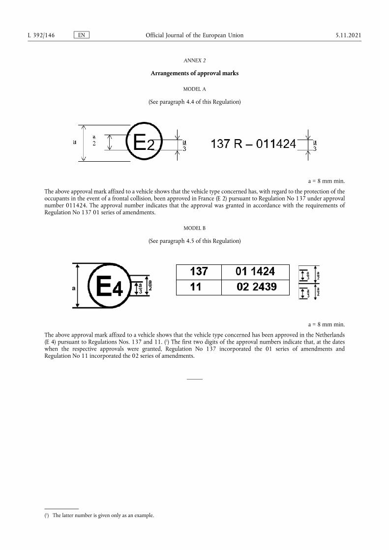
ANNEX 2
Arrangements of approval marks
MODEL A
(See paragraph 4.4 of this Regulation)
a = 8 mm min.
The above approval mark affixed to a vehicle shows that the vehicle type concerned has, with regard to the protection of the occupants in the event of a frontal collision, been approved in France (E 2) pursuant to Regulation No 137 under approval number 011424. The approval number indicates that the approval was granted in accordance with the requirements of Regulation No 137 01 series of amendments.
MODEL B
(See paragraph 4.5 of this Regulation)
a = 8 mm min.
The above approval mark affixed to a vehicle shows that the vehicle type concerned has been approved in the Netherlands (E 4) pursuant to Regulations Nos. 137 and 11. (1) The first two digits of the approval numbers indicate that, at the dates when the respective approvals were granted, Regulation No 137 incorporated the 01 series of amendments and Regulation No 11 incorporated the 02 series of amendments.
(1) The latter number is given only as an example.
EN Official Journal of the European Union L 392/146 5.11.2021
ANNEX 3
Test procedure
The purpose of this test is to verify whether the vehicle satisfies the requirements set forth in paragraph 5.2 of the Regulation.
1. Installation and preparation of the vehicle
1.1. Testing ground
The test area shall be large enough to accommodate the run-up track, barrier and technical installations necessary for the test. The last part of the track, for at least 5 m before the barrier, shall be horizontal, flat and smooth.
1.2. Barrier
The barrier shall consist of a block of reinforced concrete not less than 3 m wide in front and not less than 1,5 m high. The barrier shall be of such thickness that it weighs at least 70 metric tons. The front face shall be flat, vertical and perpendicular to the axis of the run-up track. It shall be covered with plywood boards 20 ± 2 mm thick, in good condition. A structure on a steel plate at least 25 mm thick may be placed between the plywood board and the barrier. A barrier with different characteristics may likewise be used, provided that the area of the impact surface is greater than the frontal crash area of the vehicle being tested and provided that it gives equivalent results.
1.3. Orientation of the barrier
1.3.1. Alignment of the vehicle to the barrier.
It shall reach the obstacle on a course perpendicular to the collision wall; the maximum lateral misalignment tolerated between the vertical median line of the front of the vehicle and the vertical median line of the collision wall is ± 30 cm.
1.4. State of vehicle
1.4.1. General specification
The test vehicle shall be representative of the series production, shall include all the equipment normally fitted and shall be in normal running order. Some components may be replaced by equivalent masses where this substitution clearly has no noticeable effect on the results measured under paragraph 6 below.
It shall be allowed by agreement between manufacturer and Technical Service to modify the fuel system so that an appropriate amount of fuel can be used to run the engine or the electrical energy conversion system.
1.4.2. Mass of vehicle
1.4.2.1. For the test, the mass of the vehicle submitted shall be the unladen kerb mass;
1.4.2.2. The fuel tank shall be filled with water to mass equal to 90 per cent of the mass of a full load of fuel as specified by the manufacturer with a tolerance of ±1 per cent;
This requirement does not apply to hydrogen fuel tanks.
1.4.2.3. All the other systems (brake, cooling ...) may be empty in this case, the mass of the liquids shall be compensated;
1.4.2.4. If the mass of the measuring apparatus on board the vehicle exceeds the 25 kg allowed; it may be compensated by reductions which have no noticeable effect on the results measured under paragraph 6 below.
EN Official Journal of the European Union 5.11.2021 L 392/147
1.4.2.5. The mass of the measuring apparatus shall not change each axle reference load by more than 5 per cent, each variation not exceeding 20 kg.
1.4.2.6. The mass of the vehicle resulting from the provisions of paragraph 1.4.2.1 above shall be indicated in the report.
1.4.3. Passenger compartment adjustments
1.4.3.1. Position of steering wheel
The steering wheel, if adjustable, shall be placed in the normal position indicated by the manufacturer or, in the absence of any particular recommendation by the manufacturer, midway between the limits of its range(s) of adjustment. At the end of the propelled travel, the steering wheel shall be left free, with its spokes in the position which according to the manufacturer corresponds to straight-ahead travel of the vehicle.
1.4.3.2. Glazing
The movable glazing of the vehicle shall be in the closed position. For test measurement purposes and in agreement with the manufacturer, it may be lowered, provided that the position of the operating handle corresponds to the closed position.
1.4.3.3. Gear-change lever position
The gear-change lever shall be in the neutral position. If the vehicle is propelled by its own engine, then the gear-change lever position shall be defined by the manufacturer.
1.4.3.4. Pedals
The pedals shall be in their normal position of rest. If adjustable, they shall be set in their mid-position unless another position is specified by the manufacturer.
1.4.3.5. Doors
The doors shall be closed but not locked.
1.4.3.5.1. In the case of vehicles equipped with an automatically activated door locking system, the system shall be activated at the start of propulsion of the vehicle in order to lock the doors automatically before the moment of impact. At the choice of the manufacturer, the doors shall be locked manually before the start of propulsion of the vehicle.
1.4.3.5.2. In the case of vehicles equipped with an automatically activated door locking system that is installed optionally and/or which can be de-activated by the driver, one of the following two procedures shall be used at the choice of the manufacturer:
1.4.3.5.2.1. The system shall be activated at the start of propulsion of the vehicle in order to lock the doors automatically before the moment of impact. At the choice of the manufacturer, the doors shall be locked manually before the start of propulsion of the vehicle.
1.4.3.5.2.2. The side doors on the driver side shall be unlocked and the system overridden for these doors; for the side doors on the passenger side, the system may be activated in order to lock these doors automatically before the moment of impact. At the choice of the manufacturer, these doors shall be locked manually before the start of propulsion of the vehicle. This test is deemed to be fulfilled, if the unlocked and locked doors are reversed.
1.4.3.6. Opening roof
If an opening or removable roof is fitted, it shall be in place and in the closed position. For test measurement purposes and in agreement with the manufacturer, it may be open.
EN Official Journal of the European Union L 392/148 5.11.2021
1.4.3.7. Sun-visor
The sun-visors shall be in the stowed position.
1.4.3.8. Rear-view mirror
The interior rear-view mirror shall be in the normal position of use.
1.4.3.9. Arm-rests
Arm-rests at the front and rear, if movable, shall be in the lowered position, unless this is prevented by the position of the dummies in the vehicles.
1.4.3.10. Head restraints
Head restraints adjustable for height shall be in their appropriate position as defined by the manufacturer. In the absence of any particular recommendation from the manufacturer, then the head restraints shall be in their uppermost position for the fiftieth percentile male dummy and in the lowermost position for the fifth percentile female dummy.
1.4.3.11. Seats
1.4.3.11.1. Position of front driver seat
Seats adjustable longitudinally shall be placed so that their ‘H’ point, determined in accordance with the procedure set out in Annex 6 is in the middle position of travel or in the nearest locking position thereto, and at the height position defined by the manufacturer (if independently adjustable for height). In the case of a bench seat, the reference shall be to the ‘H’ point of the driver's place.
1.4.3.11.2. Position of front passenger seat
Seats adjustable longitudinally shall be placed so that their ‘H’ point, determined in accordance with the procedure set out in Annex 6, is:
(a) In the position given by the manufacturer, which shall be forward of the middle position of travel; or
(b) In the absence of any particular recommendation from the manufacturer, as near as possible to a position which is midway between the forward most position of the seat and the centre position of its travel.
Any support system shall be adjusted as defined by the manufacturer. In the absence of any particular recommendation from the manufacturer, then any support system (e.g. seat cushion length and tilt adjustment) shall be in its retracted/ lowermost position.
1.4.3.11.3. Position of the front seat-backs
If adjustable, the seat-backs shall be adjusted so that the resulting inclination of the torso of the dummy is as close as possible to that recommended by the manufacturer for normal use or, in the absence of any particular recommendation by the manufacturer, to 25° towards the rear from the vertical. For the fifth percentile female dummy, the seat back may be adjusted to a different angle, if this is needed to respect the requirements of Annex 5, paragraph 3.1.
1.4.3.11.4. Rear seats
If adjustable, the rear seats or rear bench seats shall be placed in the rearmost position.
1.4.4. Electric power train adjustment
1.4.4.1. Procedures for SOC adjustment.
EN Official Journal of the European Union 5.11.2021 L 392/149
1.4.4.1.1. The adjustment of SOC shall be conducted at an ambient temperature of 20 ± 10 °C.
1.4.4.1.2. The SOC shall be adjusted according to one of the following procedures as applicable. Where different charging procedures are possible, the REESS shall be charged using the procedure which yields the highest SOC:
(a) For a vehicle with a REESS designed to be externally charged, the REESS shall be charged to the highest SOC in accordance with the procedure specified by the manufacturer for normal operation until the charging process is normally terminated.
(b) For a vehicle with a REESS designed to be charged only by an energy source on the vehicle, the REESS shall be charged to the highest SOC which is achievable with normal operation of the vehicle. The manufacturer shall advise on the vehicle operation mode to achieve this SOC.
1.4.4.1.3. When the vehicle is tested, the SOC shall be no less than 95 per cent of the SOC according to paragraphs 1.4.4.1.1 and 1.4.4.1.2 for REESS designed to be externally charged and shall be no less than 90 per cent of SOC according to paragraphs 1.4.4.1.1 and 1.4.4.1.2 for REESS designed to be charged only by an energy source on the vehicle. The SOC will be confirmed by a method provided by the manufacturer.
1.4.4.2. The electric power train shall be energized with or without the operation of the original electrical energy sources (e.g. engine-generator, REESS or electric energy conversion system), however:
1.4.4.2.1. By the agreement between Technical Service and manufacturer it shall be permissible to perform the test with all or parts of the electric power train not being energized insofar as there is no negative influence on the test result. For parts of the electric power train not energized, the protection against electrical shock shall be proved by either physical protection or isolation resistance and appropriate additional evidence.
1.4.4.2.2. In the case where an automatic disconnect is provided, at the request of the manufacturer it shall be permissible to perform the test with the automatic disconnect being triggered. In this case it shall be demonstrated that the automatic disconnect would have operated during the impact test. This includes the automatic activation signal as well as the galvanic separation considering the conditions as seen during the impact.
2. Dummies
2.1. Front seats
2.1.1. A dummy corresponding to the specifications for Hybrid III fiftieth percentile male dummy (1) meeting the specifications for its adjustment shall be installed in the driver seat in accordance with the conditions set out in Annex 5.
A dummy corresponding to the specifications for Hybrid III fifth percentile female dummy1 meeting the specifications for its adjustment shall be installed in the passenger seat in accordance with the conditions set out in Annex 5.
2.1.2. The car will be tested with restraint systems, as provided by the manufacturer.
(1) The Working Party on Passive Safety (GRSP) of UNECE intends to prepare an addendum for the Mutual Resolution M.R.1 on frontal impact dummies. Until the addendum is available the technical specifications and detailed drawings of Hybrid III with the principal dimensions of a fiftieth percentile male dummy and of a fifth percentile female dummy and the specifications for their adjustment for this test are deposited with the Secretary-General of the United Nations and may be consulted on request at the secretariat to the Economic Commission for Europe, Palais des Nations, Geneva, Switzerland.
EN Official Journal of the European Union L 392/150 5.11.2021
3. Propulsion and course of vehicle
3.1. The vehicle shall be propelled by its own engine or by any other propelling device;
3.2. At the moment of impact the vehicle shall no longer be subject to the action of any additional steering or propelling device.
3.3. The course of the vehicle shall be such that it satisfies the requirements of paragraphs 1.2 and 1.3.1.
4. Test speed
Vehicle speed at the moment of impact shall be 50 -0/ +1 km/h. However, if the test was performed at a higher impact speed and the vehicle met the requirements, the test shall be considered satisfactory.
5. Measurements to be made on dummies in front seats
5.1. All the measurements necessary for the verification of the performance criteria shall be made with measurement systems corresponding to the specifications of Annex 8.
5.2. The different parameters shall be recorded through independent data channels of the following CFC (Channel Frequency Class):
5.2.1. Measurements in the head of the dummy
The acceleration (a) referring to the centre of gravity is calculated from the triaxial components of the acceleration measured with a CFC of 1 000.
5.2.2. Measurements in the neck of the dummy
5.2.2.1. The axial tensile force and the fore/aft shear force at the neck/head interface are measured with a CFC of 1 000.
5.2.2.2. The bending moment about a lateral axis at the neck/head interface are measured with a CFC of 600.
5.2.3. Measurements in the thorax of the dummy
The chest deflection between the sternum and the spine is measured with a CFC of 180.
5.2.4. Measurements in the femur of the dummy
5.2.4.1. The axial compressive force is measured with a CFC of 600.
6. Measurements to be made on the vehicle
6.1. To enable the simplified test described in Annex 7 to be carried out, the deceleration time history of the structure shall be determined on the basis of the value of the longitudinal accelerometers at the base of one of the ‘B’ pillars of the vehicle with a CFC of 180 by means of data channels corresponding to the requirements set out in Annex 8;
6.2. The speed time history which will be used in the test procedure described in Annex 7 shall be obtained from the longitudinal accelerometer at the ‘B’ pillar.
EN Official Journal of the European Union 5.11.2021 L 392/151

7. Equivalent procedures
7.1. Alternative procedures may be permitted at the discretion of the Type Approval Authority provided equivalence can be demonstrated. A report shall be attached to the approval documentation describing the method used and the results obtained or the reason for not carrying out the test.
7.2. Responsibility for demonstrating the equivalence of the alternative method shall rest with the manufacturer or his agent wishing to use such a method.
EN Official Journal of the European Union L 392/152 5.11.2021
ANNEX 4
Performance criteria
1. Head Performance Criterion (HPC36)
1.1. The Head Performance Criterion (HPC36) is considered to be satisfied when, during the test, there is no contact between the head and any vehicle component.
1.2. If, during the test, there is contact between the head and any vehicle component, a calculation of HPC is made, on the basis of the acceleration (a), measured according to paragraph 5.2.1 of Annex 3, by the following expression:
in which:
1.2.1. The term ‘a’ is the resultant acceleration measured according to paragraph 5.2.1 of Annex 3 and is measured in units of gravity, g (1 g = 9,81 m/s2);
1.2.2. If the beginning of the head contact can be determined satisfactorily, t1 and t2 are the two time instants, expressed in seconds, defining an interval between the beginning of the head contact and the end of the recording for which the value of HPC is maximum;
1.2.3. If the beginning of the head contact cannot be determined, t1 and t2 are the two time instants, expressed in seconds, defining a time interval between the beginning and the end of the recording for which the value of HPC is maximum;
1.2.4. Values of HPC for which the time interval (t1 - t2) is greater than 36 ms are ignored for the purposes of calculating the maximum value.
1.3. The value of the resultant head acceleration during forward impact which is exceeded for 3 ms cumulatively is calculated from the resultant head acceleration measured according to paragraph 5.2.1 of Annex 3.
2. Injury criteria for neck
2.1. These criteria are determined by, the axial tensile force and the fore/aft shear forces at the head/neck interface, expressed in kN and measured according to paragraph 5.2.2 of Annex 3.
2.2. The neck bending moment criterion is determined by the bending moment, expressed in Nm, about a lateral axis at the head/neck interface and measured according to paragraph 5.2.2 of Annex 3.
3. Thorax Compression Criterion (THCC) and Viscous Criterion (V * C)
3.1. The thorax compression criterion is determined by the absolute value of the thorax deformation, expressed in mm and measured according to paragraph 5.2.3 of Annex 3.
3.2. The Viscous Criterion (V * C) is calculated as the instantaneous product of the compression and the rate of deflection of the sternum, measured according to paragraph 5 of this annex and also paragraph 5.2.3 of Annex 3.
EN Official Journal of the European Union 5.11.2021 L 392/153
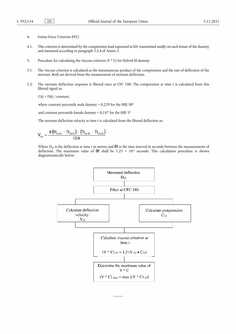
4. Femur Force Criterion (FFC)
4.1. This criterion is determined by the compression load expressed in kN, transmitted axially on each femur of the dummy and measured according to paragraph 5.2.4 of Annex 3.
5. Procedure for calculating the viscous criterion (V * C) for Hybrid III dummy
5.1. The viscous criterion is calculated as the instantaneous product of the compression and the rate of deflection of the sternum. Both are derived from the measurement of sternum deflection.
5.2. The sternum deflection response is filtered once at CFC 180. The compression at time t is calculated from this filtered signal as:
C(t) = D(t) / constant,
where constant percentile male dummy = 0,229 for the HIII 50th
and constant percentile female dummy = 0,187 for the HIII 5th
The sternum deflection velocity at time t is calculated from the filtered deflection as:
Where D(t) is the deflection at time t in metres and is the time interval in seconds between the measurements of deflection. The maximum value of shall be 1,25 × 10⁻⁴ seconds. This calculation procedure is shown diagrammatically below:
EN Official Journal of the European Union L 392/154 5.11.2021
ANNEX 5
Arrangement and installation of dummies and adjustment of restraint systems
1. Arrangement of dummies
1.1. Separate seats
The plane of symmetry of the dummy shall coincide with the vertical median plane of the seat.
1.2. Front bench seat
1.2.1. Driver
The plane of symmetry of the dummy shall lie in the vertical plane passing through the steering wheel centre and parallel to the longitudinal median plane of the vehicle. If the seating position is determined by the shape of the bench, such seat shall be regarded as a separate seat.
1.2.2. Outer passenger
The plane of symmetry of the dummy shall be symmetrical with that of the driver dummy relative to the longitudinal median plane of the vehicle. If the seating position is determined by the shape of the bench, such seat shall be regarded as a separate seat.
1.3. Bench seat for front passengers (not including driver)
The planes of symmetry of the dummy shall coincide with the median planes of the seating positions defined by the manufacturer.
2. Installation of the HIII fiftieth percentile male dummy on the driver seat
2.1. Head
The transverse instrumentation platform of the head shall be horizontal within 2,5°. To level the head of the test dummy in vehicles with upright seats with non-adjustable backs, the following sequences shall be followed. First adjust the position of the ‘H’ point within the limits set forth in paragraph 2.4.3.1 below to level the transverse instrumentation platform of the head of the test dummy. If the transverse instrumentation platform of the head is still not level, then adjust the pelvic angle of the test dummy within the limits provided in paragraph 2.4.3.2 below. If the transverse instrumentation platform of the head is still not level, then adjust the neck bracket of the test dummy the minimum amount necessary to ensure that the transverse instrumentation platform of the head is horizontal within 2,5°.
2.2. Arms
2.2.1. The driver's upper arms shall be adjacent to the torso with the centrelines as close to a vertical plane as possible.
2.3. Hands
2.3.1. The palms of the driver test dummy shall be in contact with the outer part of the steering wheel rim at the rim's horizontal centreline. The thumbs shall be over the steering wheel rim and shall be lightly taped to the steering wheel rim so that if the hand of the test dummy is pushed upward by a force of not less than 9 N and not more than 22 N, the tape shall release the hand from the steering wheel rim.
2.4. Torso
2.4.1. In vehicles equipped with bench seats, the upper torso of the driver test dummy shall rest against the seat back. The midsagittal plane of the driver dummy shall be vertical and parallel to the vehicle's longitudinal centreline, and pass through the centre of the steering wheel rim.
EN Official Journal of the European Union 5.11.2021 L 392/155
2.4.2. In vehicles equipped with individual seats, the upper torso of the driver test dummy shall rest against the seat back. The midsagittal plane of the driver dummy shall be vertical and shall coincide with the longitudinal centreline of the individual seat.
2.4.3. Lower torso
2.4.3.1. ‘H’ point
The ‘H’ point of the driver test dummy shall coincide within 13 mm in the vertical dimension and 13 mm in the horizontal dimension, with a point 6 mm below the position of the ‘H’ point determined using the procedure described in Annex 6 except that the length of the lower leg and thigh segments of the ‘H’ point machine shall be adjusted to 414 and 401 mm, instead of 417 and 432 mm respectively.
2.4.3.2. Pelvic angle
As determined using the pelvic angle gauge (GM) drawing 78051-532 incorporated by reference in Part 572 which is inserted into the ‘H’ point gauging hole of the dummy, the angle measured from the horizontal on the 76,2 mm (3 inch) flat surface of the gauge shall be 22,5 degrees plus or minus 2,5 degrees.
2.5. Legs
The upper legs of the driver test dummy shall rest against the seat cushion to the extent permitted by placement of the feet. The initial distance between the outboard knee clevis flange surfaces shall be 270 mm ± 10 mm. To the extent practicable, the left leg of the driver dummy shall be in vertical longitudinal plane. To the extent practicable, the right leg of the driver dummy shall be in a vertical plane. Final adjustment to accommodate placement of feet in accordance with paragraph 2.6 for various passenger compartment configurations is permitted.
2.6. Feet
2.6.1. The right foot of the driver test dummy shall rest on the undepressed accelerator with the rearmost point of the heel on the floor surface in the plane of the pedal. If the foot cannot be placed on the accelerator pedal, it shall be positioned perpendicular to the tibia and placed as far forward as possible in the direction of the centreline of the pedal with the rearmost point of the heel resting on the floor surface. The heel of the left foot shall be placed as far forward as possible and shall rest on the floor pan. The left foot shall be positioned as flat as possible on the toe board. The longitudinal centreline of the left foot shall be placed as parallel as possible to the longitudinal centreline of the vehicle. For vehicles equipped with a footrest, it shall be possible at the request of the manufacturer to place the left foot on the footrest. In this case the position of the left foot is defined by the footrest.
2.7. The measuring instruments installed shall not in any way affect the movement of the dummy during impact.
2.8. The temperature of the dummy and the system of measuring instruments shall be stabilized before the test and maintained so far as possible within a range between 19 °C and 22,2 °C.
2.9. Dummy HIII fiftieth percentile clothing
2.9.1. The instrumented dummy will be clothed in formfitting cotton stretch garments with short sleeves and mid-calf length trousers specified in FMVSS 208, drawings 78051-292 and 293 or their equivalent.
2.9.2. A size 11XW shoe, which meets the configuration size, sole and heel thickness specifications of the United States of America military standard MIL S 13192, revision P and whose weight is 0,57 ± 0,1 kg, shall be placed and fastened on each foot of the test dummy.
EN Official Journal of the European Union L 392/156 5.11.2021
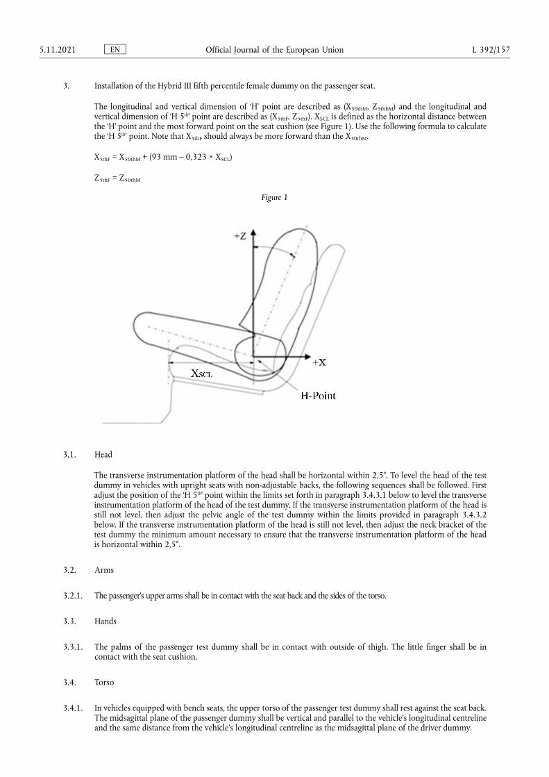
3. Installation of the Hybrid III fifth percentile female dummy on the passenger seat.
The longitudinal and vertical dimension of ‘H’ point are described as (X50thM, Z50thM) and the longitudinal and vertical dimension of ‘H 5th’ point are described as (X5thF, Z5thF). XSCL is defined as the horizontal distance between the ‘H’ point and the most forward point on the seat cushion (see Figure 1). Use the following formula to calculate the ‘H 5th’ point. Note that X5thF should always be more forward than the X50thM.
X5thF = X50thM + (93 mm – 0,323 × XSCL)
Z5thF = Z50thM
Figure 1
3.1. Head
The transverse instrumentation platform of the head shall be horizontal within 2,5°. To level the head of the test dummy in vehicles with upright seats with non-adjustable backs, the following sequences shall be followed. First adjust the position of the ‘H 5th’ point within the limits set forth in paragraph 3.4.3.1 below to level the transverse instrumentation platform of the head of the test dummy. If the transverse instrumentation platform of the head is still not level, then adjust the pelvic angle of the test dummy within the limits provided in paragraph 3.4.3.2 below. If the transverse instrumentation platform of the head is still not level, then adjust the neck bracket of the test dummy the minimum amount necessary to ensure that the transverse instrumentation platform of the head is horizontal within 2,5°.
3.2. Arms
3.2.1. The passenger's upper arms shall be in contact with the seat back and the sides of the torso.
3.3. Hands
3.3.1. The palms of the passenger test dummy shall be in contact with outside of thigh. The little finger shall be in contact with the seat cushion.
3.4. Torso
3.4.1. In vehicles equipped with bench seats, the upper torso of the passenger test dummy shall rest against the seat back. The midsagittal plane of the passenger dummy shall be vertical and parallel to the vehicle's longitudinal centreline and the same distance from the vehicle's longitudinal centreline as the midsagittal plane of the driver dummy.
EN Official Journal of the European Union 5.11.2021 L 392/157
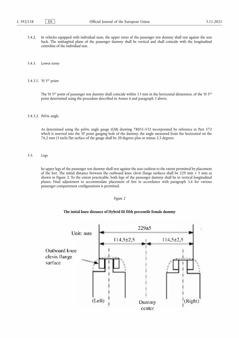
3.4.2. In vehicles equipped with individual seats, the upper torso of the passenger test dummy shall rest against the seat back. The midsagittal plane of the passenger dummy shall be vertical and shall coincide with the longitudinal centreline of the individual seat.
3.4.3. Lower torso
3.4.3.1. ‘H 5th’ point
The ‘H 5th’ point of passenger test dummy shall coincide within 13 mm in the horizontal dimension, of the ‘H 5th’ point determined using the procedure described in Annex 6 and paragraph 3 above.
3.4.3.2. Pelvic angle
As determined using the pelvic angle gauge (GM) drawing 78051-532 incorporated by reference in Part 572 which is inserted into the ‘H’ point gauging hole of the dummy, the angle measured from the horizontal on the 76,2 mm (3 inch) flat surface of the gauge shall be 20 degrees plus or minus 2,5 degrees.
3.5. Legs
he upper legs of the passenger test dummy shall rest against the seat cushion to the extent permitted by placement of the feet. The initial distance between the outboard knee clevis flange surfaces shall be 229 mm ± 5 mm as shown in Figure 2. To the extent practicable, both legs of the passenger dummy shall be in vertical longitudinal planes. Final adjustment to accommodate placement of feet in accordance with paragraph 3.6 for various passenger compartment configurations is permitted.
Figure 2
The initial knee distance of Hybrid III fifth percentile female dummy
EN Official Journal of the European Union L 392/158 5.11.2021
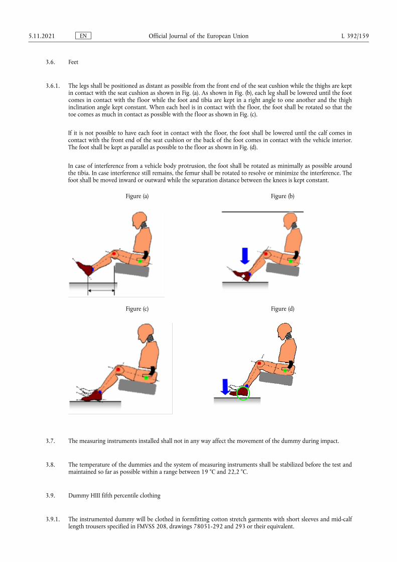
3.6. Feet
3.6.1. The legs shall be positioned as distant as possible from the front end of the seat cushion while the thighs are kept in contact with the seat cushion as shown in Fig. (a). As shown in Fig. (b), each leg shall be lowered until the foot comes in contact with the floor while the foot and tibia are kept in a right angle to one another and the thigh inclination angle kept constant. When each heel is in contact with the floor, the foot shall be rotated so that the toe comes as much in contact as possible with the floor as shown in Fig. (c).
If it is not possible to have each foot in contact with the floor, the foot shall be lowered until the calf comes in contact with the front end of the seat cushion or the back of the foot comes in contact with the vehicle interior. The foot shall be kept as parallel as possible to the floor as shown in Fig. (d).
In case of interference from a vehicle body protrusion, the foot shall be rotated as minimally as possible around the tibia. In case interference still remains, the femur shall be rotated to resolve or minimize the interference. The foot shall be moved inward or outward while the separation distance between the knees is kept constant.
Figure (a) Figure (b)
Figure (c) Figure (d)
3.7. The measuring instruments installed shall not in any way affect the movement of the dummy during impact.
3.8. The temperature of the dummies and the system of measuring instruments shall be stabilized before the test and maintained so far as possible within a range between 19 °C and 22,2 °C.
3.9. Dummy HIII fifth percentile clothing
3.9.1. The instrumented dummy will be clothed in formfitting cotton stretch garments with short sleeves and mid-calf length trousers specified in FMVSS 208, drawings 78051-292 and 293 or their equivalent.
EN Official Journal of the European Union 5.11.2021 L 392/159
3.9.2. A size 7,5 W small female size shoe, which meets the configuration size, sole and heel thickness specifications of the United States of America military standard MIL-S-21711E, revision P and whose weight is 0,41 ± 0,09 kg, shall be placed and fastened on each foot of the test dummies.
4. Adjustment of restraint system
The dummy jacket shall be installed at the appropriate position where the bolt hole of the neck lower bracket and the work hole of the dummy jacket should be at the same position. With the test dummy at its designated seating position as specified by the appropriate requirements of paragraphs 2.1 through 2.6 and paragraphs 3.1 to 3.6 above, place the belt around the test dummy and fasten the latch. Remove all slack from the lap belt. Pull the upper torso webbing out of the retractor and allow it to retract. Repeat this operation four times. The shoulder belt should be at the position between the area which shall not be taken off of shoulder and shall not come in contact with the neck. The seat belt path shall be positioned: for Hybrid III fiftieth percentile male dummy, the hole of the outer side dummy jacket shall not be fully hidden by the seat belt. For Hybrid III fifth percentile female dummy, the seat belt shall lie between the breasts. Apply a 9 to 18 N tension load to the lap belt. If the belt system is equipped with a tension-relieving device, introduce the maximum amount of slack into the upper torso belt that is recommended by the manufacturer for normal use in the owner's manual for the vehicle. If the belt system is not equipped with a tension-relieving device, allow the excess webbing in the shoulder belt to be retracted by the rewind force of the retractor. Where the safety belt and safety belt anchorages are located such that the belt does not lie as required above then the safety belt may be manually adjusted and retained by tape.
EN Official Journal of the European Union L 392/160 5.11.2021

ANNEX 6
Procedure for determining the ‘H’ point and the actual torso angle for seating positions in motor vehicles (1)
Appendix 1 – Description of the three dimensional ‘H’ point machine (3-D H machine) (1)
Appendix 2 – Three-dimensional reference system (1)
Appendix 3 – Reference data concerning seating positions (1)
(1) The procedure is described in Annex 1 to the Consolidated Resolution on the Construction of Vehicles (RE.3) (document ECE/TRANS/ WP.29/78/Rev.6).
EN Official Journal of the European Union 5.11.2021 L 392/161
ANNEX 7
Test procedure with trolley
1. Test installation and procedure
1.1. Trolley
The trolley shall be so constructed that no permanent deformation appears after the test. It shall be so guided that, during the impact phase, the deviation in the vertical plane does not exceed 5° and 2° in the horizontal plane.
1.2. State of the structure
1.2.1. General
The structure tested shall be representative of the series production of the vehicles concerned. Some components may be replaced or removed where such replacement or removal clearly has no effect on the test results.
1.2.2. Adjustments
Adjustments shall conform to those set out in paragraph 1.4.3 of Annex 3 to this Regulation, taking into account what is stated in paragraph 1.2.1 above.
1.3. Attachment of the structure
1.3.1. The structure shall be firmly attached to the trolley in such a way that no relative displacement occurs during the test.
1.3.2. The method used to fasten the structure to the trolley shall not have the effect of strengthening the seat anchorages or restraint devices, or of producing any abnormal deformation of the structure.
1.3.3. The attachment device recommended is that whereby the structure rests on supports placed approximately in the axis of the wheels or, if possible, whereby the structure is secured to the trolley by the fastenings of the suspension system.
1.3.4. The angle between the longitudinal axis of the vehicle and the direction of motion of the trolley shall be 0° ± 2°.
1.4. Dummies
The dummies and their positioning shall conform to the specifications in Annex 3, paragraph 2.
1.5. Measuring apparatus
1.5.1. Deceleration of the structure
The position of the transducers measuring the deceleration of the structure during the impact shall be parallel to the longitudinal axis of the trolley according to the specifications of Annex 8 (CFC 180).
1.5.2. Measurements to be made on the dummies
All the measurements necessary for checking the listed criteria are set out in Annex 3, paragraph 5.
EN Official Journal of the European Union L 392/162 5.11.2021

1.6. Deceleration curve of the structure
The deceleration curve of the structure during the impact phase shall be such that the ‘variation of speed in relation to time’ curve obtained by integration at no point differs by more than ±1 m/s from the ‘variation of speed in relation to time’ reference curve of the vehicle concerned as defined in appendix to this annex. A displacement with regard to the time axis of the reference curve may be used to obtain the structure velocity inside the corridor.
1.7. Reference curve ΔV = f(t) of the vehicle concerned
This reference curve is obtained by integration of the deceleration curve of the vehicle concerned measured in the frontal collision test against a barrier as provided for in paragraph 6 of Annex 3 to this Regulation.
1.8. Equivalent method
The test may be performed by some other method than that of deceleration of a trolley, provided that such method complies with the requirement concerning the range of variation of speed described in paragraph 1.6 above.
EN Official Journal of the European Union 5.11.2021 L 392/163
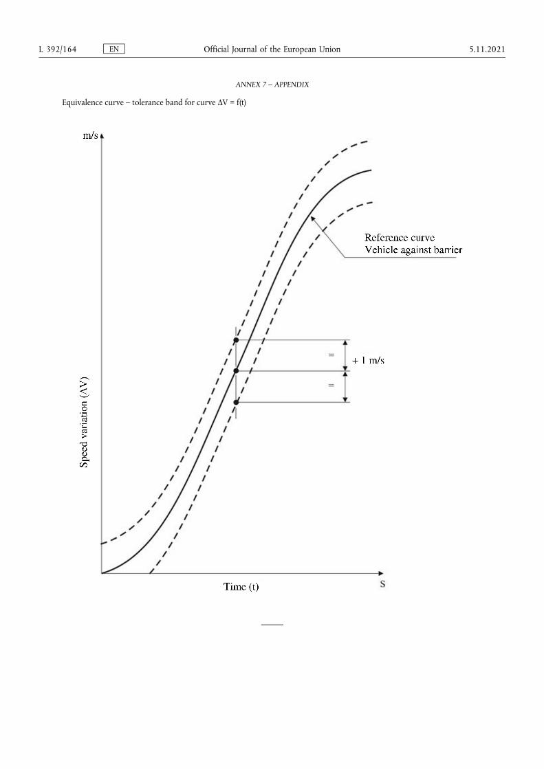
ANNEX 7 – APPENDIX
Equivalence curve – tolerance band for curve ΔV = f(t)
EN Official Journal of the European Union L 392/164 5.11.2021
ANNEX 8
Technique of measurement in measurement tests: Instrumentation
1. Definitions
1.1. Data channel
A data channel comprises all the instrumentation from a transducer (or multiple transducers whose outputs are combined in some specified way) up to and including any analysis procedures that may alter the frequency content or the amplitude content of data.
1.2. Transducer
The first device in a data channel used to convert a physical quantity to be measured into a second quantity (such as an electrical voltage) which can be processed by the remainder of the channel.
1.3. Channel Amplitude Class: CAC
The designation for a data channel that meets certain amplitude characteristics as specified in this annex. The CAC number is numerically equal to the upper limit of the measurement range.
1.4. Characteristic frequencies FH, FL, FN
These frequencies are defined in Figure 1 of this annex.
1.5. Channels Frequency Class: CFC
The channel frequency class is designated by a number indicating that the channel frequency response lies within the limits specified in Figure 1 of this annex. This number and the value of the frequency FH in Hz are numerically equal.
1.6. Sensitivity coefficient
The slope of the straight line representing the best fit to the calibration values determined by the method of least square within the channel amplitude class.
1.7. Calibration factor of a data channel
The mean value of the sensitivity coefficients evaluated over frequencies which are evenly spaced on a logarithmic scale between
FL and
1.8. Linearity error
The ratio, in per cent, of the maximum difference between the calibration value and the corresponding value read on the straight line defined in paragraph 1.6 above at the upper limit of the channel amplitude class.
1.9. Cross sensitivity
The ratio of the output signal to the input signal, when an excitation is applied to the transducer perpendicular to the measurement axis. It is expressed as a percentage of the sensitivity along the measurement axis.
1.10. Phase delay time
EN Official Journal of the European Union 5.11.2021 L 392/165
The phase delay time of a data channel is equal to the phase delay (in radians) of a sinusoidal signal, divided by the angular frequency of that signal (in radians/second).
1.11. Environment
The aggregate, at a given moment, of all external conditions and influences to which the data channel is subjected.
2. Performance requirements
2.1. Linearity error
The absolute value of the linearity error of a data channel at any frequency in the CFC, shall be equal to or less than 2,5 per cent of the value of the CAC, over the whole measurement range.
2.2. Amplitude against frequency
The frequency response of a data channel shall lie within the limiting curves given in Figure 1 of this annex. The zero dB line is determined by the calibration factor.
2.3. Phase delay time
The phase delay time between the input and the output signals of a data channel shall be determined and shall not vary by more than 1/10 FH seconds between 0,03 FH and FH.
2.4. Time
2.4.1. Time base
A time base shall be recorded and shall at least give 1/100 s with an accuracy of 1 per cent.
2.4.2. Relative time delay
The relative time delay between the signal of two or more data channels, regardless of their frequency class, shall not exceed 1 ms excluding delay caused by phase shift.
Two or more data channels of which the signals are combined shall have the same frequency class and shall not have relative time delay greater than 1/10 FH seconds.
This requirement applies to analogue signals as well as to synchronization pulses and digital signals.
2.5. Transducer cross sensitivity
The transducer cross sensitivity shall be less than 5 per cent in any direction.
2.6. Calibration
2.6.1. General
A data channel shall be calibrated at least once a year against reference equipment traceable to known standards. The methods used to carry out a comparison with reference equipment shall not introduce an error greater than 1 per cent of the CAC. The use of the reference equipment is limited to the frequency range for which they have been calibrated. Subsystems of a data channel may be evaluated individually and the results factored into the accuracy of the total data channel. This can be done for example by an electrical signal of known amplitude simulating the output signal of the transducer which allows a check to be made on the gain factor of the data channel, excluding the transducer.
EN Official Journal of the European Union L 392/166 5.11.2021
2.6.2. Accuracy of reference equipment for calibration
The accuracy of the reference equipment shall be certified or endorsed by an official metrology service.
2.6.2.1. Static calibration
2.6.2.1.1. Accelerations
The errors shall be less than ±1,5 per cent of the channel amplitude class.
2.6.2.1.2. Forces
The error shall be less than ±1 per cent of the channel amplitude class.
2.6.2.1.3. Displacements
The error shall be less than ±1 per cent of the channel amplitude class.
2.6.2.2. Dynamic calibration
2.6.2.2.1. Accelerations
The error in the reference accelerations expressed as a percentage of the channel amplitude class shall be less than ±1,5 per cent below 400 Hz, less than ±2 per cent between 400 Hz and 900 Hz, and less than ±2,5 per cent above 900 Hz.
2.6.2.3. Time
The relative error in the reference time shall be less than 10-5.
2.6.3. Sensitivity coefficient and linearity error
The sensitivity coefficient and the linearity error shall be determined by measuring the output signal of the data channel against a known input signal for various values of this signal. The calibration of the data channel shall cover the whole range of the amplitude class.
For bi-directional channels, both the positive and negative values shall be used.
If the calibration equipment cannot produce the required input owing to the excessively high values of the quantity to be measured, calibrations shall be carried out within the limits of the calibration standards and these limits shall be recorded in the test report.
A total data channel shall be calibrated at a frequency or at a spectrum of frequencies having a significant value between
FL and
2.6.4. Calibration of the frequency response
The response curves of phase and amplitude against frequency shall be determined by measuring the output signals of the data channel in terms of phase and amplitude against a known input signal, for various values of this signal varying between FL and 10 times the CFC or 3 000 Hz, whichever is lower.
2.7. Environmental effects
A regular check shall be made to identify any environmental influence (such as electric or magnetic flux, cable velocity, etc.). This can be done for instance by recording the output of spare channels equipped with dummy transducers. If significant output signals are obtained corrective action shall be taken, for instance by replacement of cables.
EN Official Journal of the European Union 5.11.2021 L 392/167
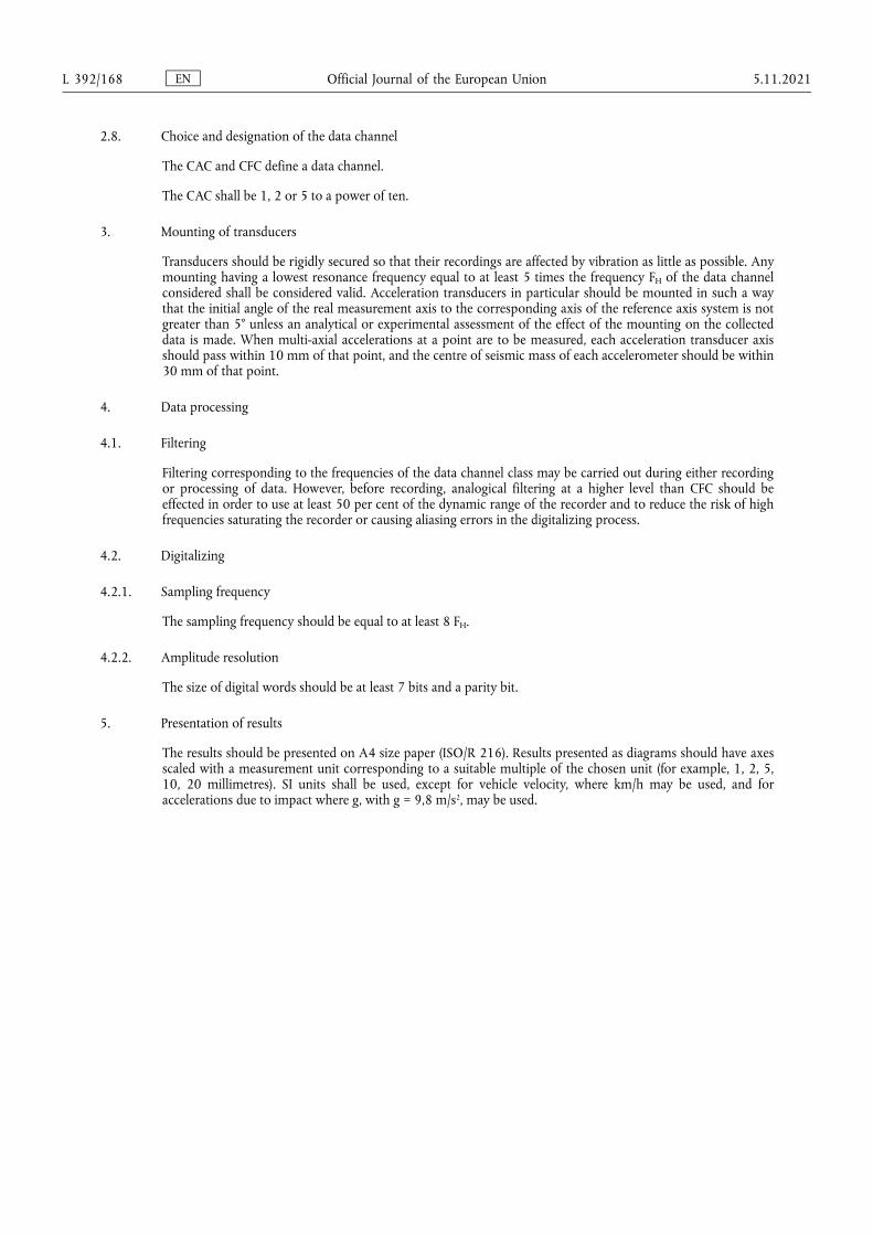
2.8. Choice and designation of the data channel
The CAC and CFC define a data channel.
The CAC shall be 1, 2 or 5 to a power of ten.
3. Mounting of transducers
Transducers should be rigidly secured so that their recordings are affected by vibration as little as possible. Any mounting having a lowest resonance frequency equal to at least 5 times the frequency FH of the data channel considered shall be considered valid. Acceleration transducers in particular should be mounted in such a way that the initial angle of the real measurement axis to the corresponding axis of the reference axis system is not greater than 5° unless an analytical or experimental assessment of the effect of the mounting on the collected data is made. When multi-axial accelerations at a point are to be measured, each acceleration transducer axis should pass within 10 mm of that point, and the centre of seismic mass of each accelerometer should be within 30 mm of that point.
4. Data processing
4.1. Filtering
Filtering corresponding to the frequencies of the data channel class may be carried out during either recording or processing of data. However, before recording, analogical filtering at a higher level than CFC should be effected in order to use at least 50 per cent of the dynamic range of the recorder and to reduce the risk of high frequencies saturating the recorder or causing aliasing errors in the digitalizing process.
4.2. Digitalizing
4.2.1. Sampling frequency
The sampling frequency should be equal to at least 8 FH.
4.2.2. Amplitude resolution
The size of digital words should be at least 7 bits and a parity bit.
5. Presentation of results
The results should be presented on A4 size paper (ISO/R 216). Results presented as diagrams should have axes scaled with a measurement unit corresponding to a suitable multiple of the chosen unit (for example, 1, 2, 5, 10, 20 millimetres). SI units shall be used, except for vehicle velocity, where km/h may be used, and for accelerations due to impact where g, with g = 9,8 m/s2, may be used.
EN Official Journal of the European Union L 392/168 5.11.2021
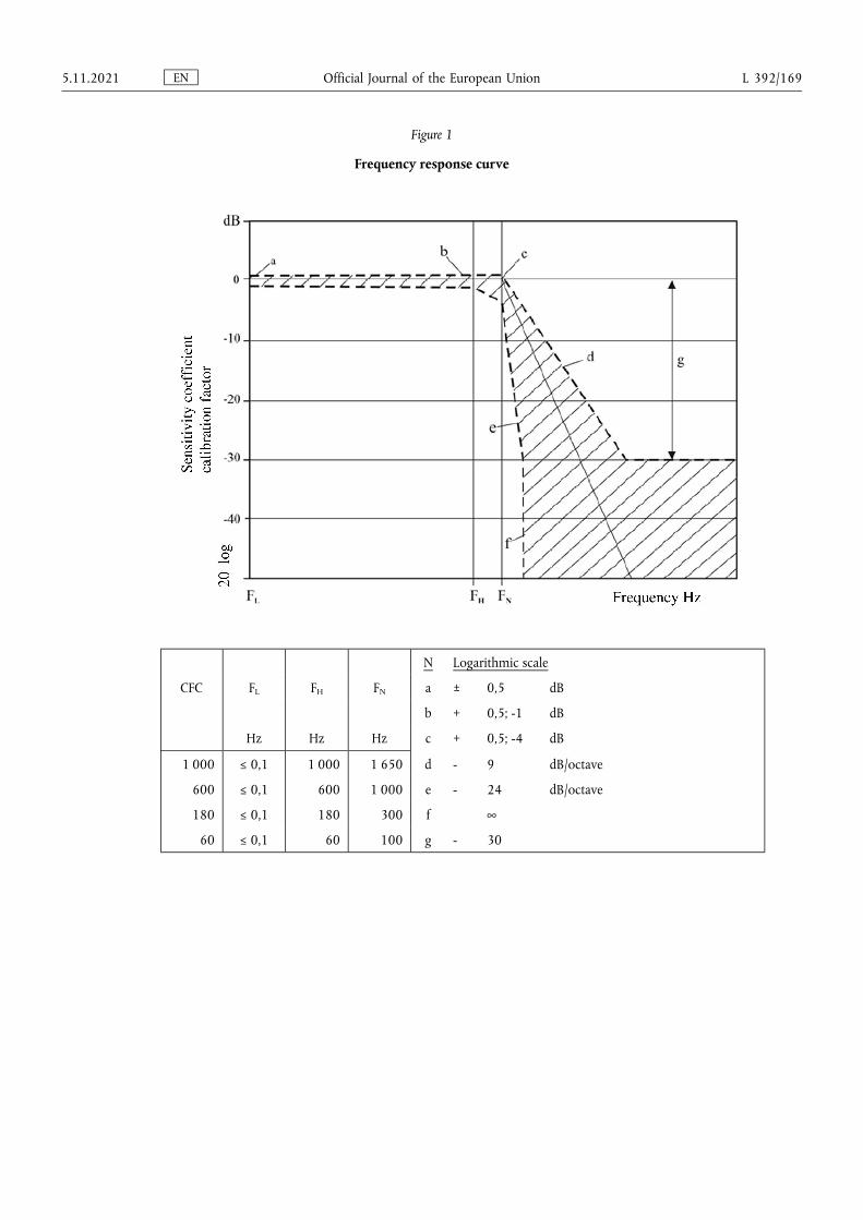
Figure 1
Frequency response curve
N Logarithmic scale
CFC FL FH FN a ± 0,5 dB
b + 0,5; -1 dB
Hz Hz Hz c + 0,5; -4 dB
1 000 ≤ 0,1 1 000 1 650 d - 9 dB/octave
600 ≤ 0,1 600 1 000 e - 24 dB/octave
180 ≤ 0,1 180 300 f ∞
60 ≤ 0,1 60 100 g - 30
EN Official Journal of the European Union 5.11.2021 L 392/169
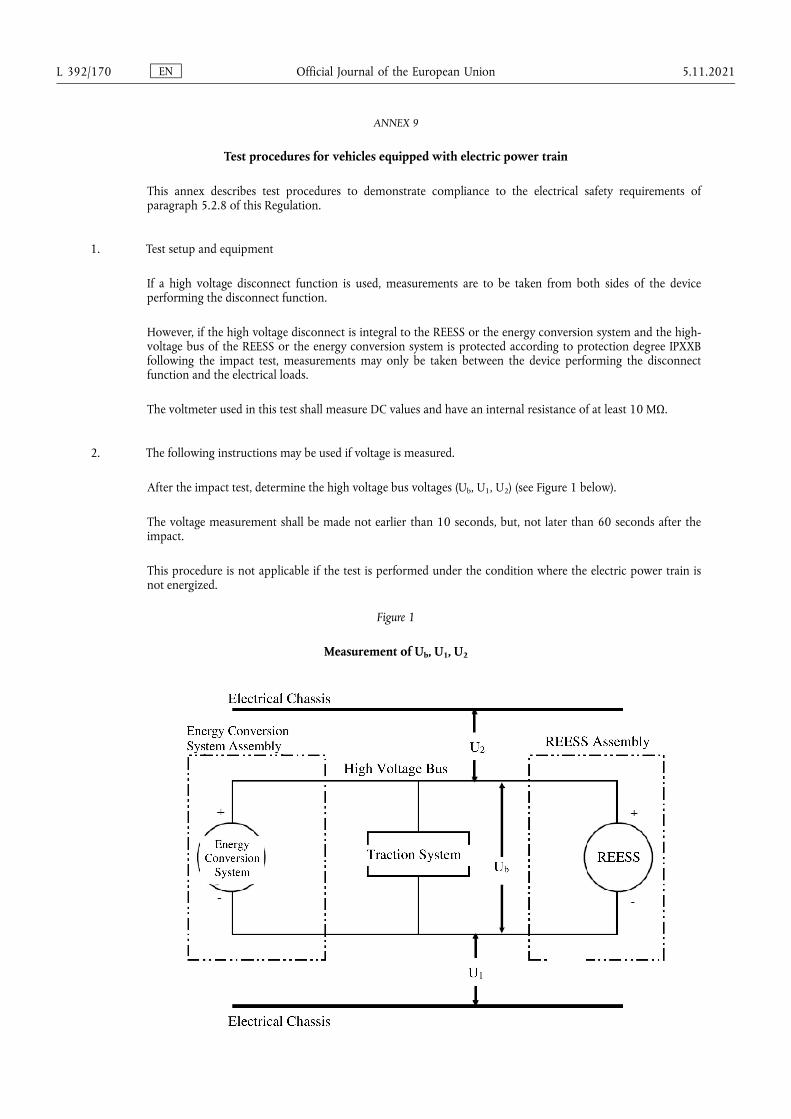
ANNEX 9
Test procedures for vehicles equipped with electric power train
This annex describes test procedures to demonstrate compliance to the electrical safety requirements of paragraph 5.2.8 of this Regulation.
1. Test setup and equipment
If a high voltage disconnect function is used, measurements are to be taken from both sides of the device performing the disconnect function.
However, if the high voltage disconnect is integral to the REESS or the energy conversion system and the high- voltage bus of the REESS or the energy conversion system is protected according to protection degree IPXXB following the impact test, measurements may only be taken between the device performing the disconnect function and the electrical loads.
The voltmeter used in this test shall measure DC values and have an internal resistance of at least 10 MΩ.
2. The following instructions may be used if voltage is measured.
After the impact test, determine the high voltage bus voltages (Ub, U1, U2) (see Figure 1 below).
The voltage measurement shall be made not earlier than 10 seconds, but, not later than 60 seconds after the impact.
This procedure is not applicable if the test is performed under the condition where the electric power train is not energized.
Figure 1
Measurement of Ub, U1, U2
EN Official Journal of the European Union L 392/170 5.11.2021
3. Assessment procedure for low electrical energy
Prior to the impact a switch S1 and a known discharge resistor Re is connected in parallel to the relevant capacitance (ref. Figure 2 below).
(a) Not earlier than 10 seconds and not later than 60 seconds after the impact the switch S1 shall be closed while the voltage Ub and the current Ie are measured and recorded. The product of the voltage Ub and the current Ie shall be integrated over the period of time, starting from the moment when the switch S1 is closed (tc) until the voltage Ub falls below the high voltage threshold of 60 V DC (th). The resulting integration equals the Total Energy (TE) in joules.
(b) When Ub is measured at a point in time between 10 seconds and 60 seconds after the impact and the capacitance of the X-capacitors (Cx) is specified by the manufacturer, Total Energy (TE) shall be calculated according to the following formula:
TE = 0,5 × Cx × Ub2
(c) When U1 and U2 (see Figure 1 above) are measured at a point in time between 10 seconds and 60 seconds after the impact and the capacitances of the Y-capacitors (Cy1, Cy2) are specified by the manufacturer, Total Energy (TEy1, TEy2) shall be calculated according to the following formulas:
TEy1 = 0,5 × Cy1 × U12
TEy2 = 0,5 × Cy2 × U22
This procedure is not applicable if the test is performed under the condition where the electric power train is not energized.
Figure 2
E.g. measurement of high voltage bus energy stored in X-capacitors
4. Physical protection
Following the vehicle impact test any parts surrounding the high voltage components shall be, without the use of tools, opened, disassembled or removed. All remaining surrounding parts shall be considered part of the physical protection.
EN Official Journal of the European Union 5.11.2021 L 392/171
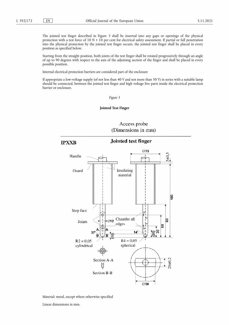
The jointed test finger described in Figure 3 shall be inserted into any gaps or openings of the physical protection with a test force of 10 N ± 10 per cent for electrical safety assessment. If partial or full penetration into the physical protection by the jointed test finger occurs, the jointed test finger shall be placed in every position as specified below.
Starting from the straight position, both joints of the test finger shall be rotated progressively through an angle of up to 90 degrees with respect to the axis of the adjoining section of the finger and shall be placed in every possible position.
Internal electrical protection barriers are considered part of the enclosure
If appropriate a low-voltage supply (of not less than 40 V and not more than 50 V) in series with a suitable lamp should be connected, between the jointed test finger and high voltage live parts inside the electrical protection barrier or enclosure.
Figure 3
Jointed Test Finger
Material: metal, except where otherwise specified
Linear dimensions in mm.
EN Official Journal of the European Union L 392/172 5.11.2021
Tolerances on dimensions without specific tolerance:
(a) on angles: +0/-10 seconds;
(b) on linear dimensions:
(i) up to 25 mm: +0/-0,05;
(ii) over 25 mm: ±0,2.
Both joints shall permit movement in the same plane and the same direction through an angle of 90° with a 0 to +10° tolerance.
The requirements of paragraph 5.2.8.1.3 of this Regulation are met if the jointed test finger described in Figure 3, is unable to contact high voltage live parts.
If necessary a mirror or a fiberscope may be used in order to inspect whether the jointed test finger touches the high voltage buses.
If this requirement is verified by a signal circuit between the jointed test finger and high voltage live parts, the lamp shall not light.
4.1. Test method for measuring electric resistance:
(a) Test method using a resistance tester.
The resistance tester is connected to the measuring points (typically, electrical chassis and electro conductive enclosure/electrical protection barrier) and the resistance is measured using a resistance tester that meets the specification that follows:
(i) Resistance tester: Measurement current at least 0,2 A;
(ii) Resolution: 0,01 Ω or less;
(iii) The resistance R shall be less than 0,1 Ω.
(b) Test method using DC power supply, voltmeter and ammeter.
The DC power supply, voltmeter and ammeter are connected to the measuring points (Typically, electrical chassis and electro conductive enclosure/electrical protection barrier).
The voltage of the DC power supply is adjusted so that the current flow becomes at least 0,2 A.
The current ‘I’ and the voltage ‘U’ are measured.
The resistance ‘R’ is calculated according to the following formula:
R = U / I
The resistance R shall be less than 0,1 Ω.
Note: If lead wires are used for voltage and current measurement, each lead wire shall be independently connected to the electrical protection barrier/enclosure/electrical chassis. Terminal can be common for voltage measurement and current measurement.
EN Official Journal of the European Union 5.11.2021 L 392/173
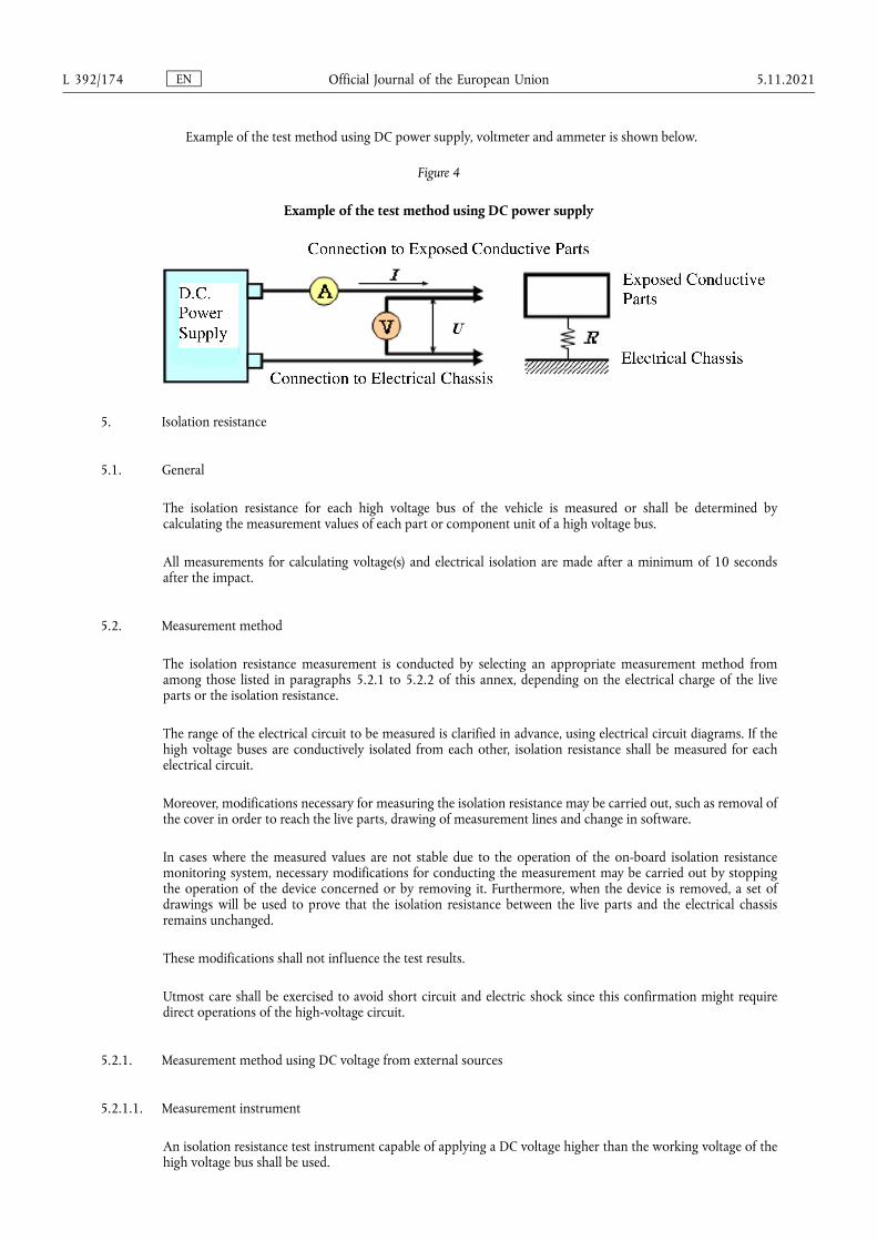
Example of the test method using DC power supply, voltmeter and ammeter is shown below.
Figure 4
Example of the test method using DC power supply
5. Isolation resistance
5.1. General
The isolation resistance for each high voltage bus of the vehicle is measured or shall be determined by calculating the measurement values of each part or component unit of a high voltage bus.
All measurements for calculating voltage(s) and electrical isolation are made after a minimum of 10 seconds after the impact.
5.2. Measurement method
The isolation resistance measurement is conducted by selecting an appropriate measurement method from among those listed in paragraphs 5.2.1 to 5.2.2 of this annex, depending on the electrical charge of the live parts or the isolation resistance.
The range of the electrical circuit to be measured is clarified in advance, using electrical circuit diagrams. If the high voltage buses are conductively isolated from each other, isolation resistance shall be measured for each electrical circuit.
Moreover, modifications necessary for measuring the isolation resistance may be carried out, such as removal of the cover in order to reach the live parts, drawing of measurement lines and change in software.
In cases where the measured values are not stable due to the operation of the on-board isolation resistance monitoring system, necessary modifications for conducting the measurement may be carried out by stopping the operation of the device concerned or by removing it. Furthermore, when the device is removed, a set of drawings will be used to prove that the isolation resistance between the live parts and the electrical chassis remains unchanged.
These modifications shall not influence the test results.
Utmost care shall be exercised to avoid short circuit and electric shock since this confirmation might require direct operations of the high-voltage circuit.
5.2.1. Measurement method using DC voltage from external sources
5.2.1.1. Measurement instrument
An isolation resistance test instrument capable of applying a DC voltage higher than the working voltage of the high voltage bus shall be used.
EN Official Journal of the European Union L 392/174 5.11.2021
5.2.1.2. Measurement method
An isolation resistance test instrument is connected between the live parts and the electrical chassis. The isolation resistance is subsequently measured by applying a DC voltage at least half of the working voltage of the high voltage bus.
If the system has several voltage ranges (e.g. because of boost converter) in conductively connected circuit and some of the components cannot withstand the working voltage of the entire circuit, the isolation resistance between those components and the electrical chassis can be measured separately by applying at least half of their own working voltage with those components disconnected.
5.2.2. Measurement method using the vehicle's own REESS as DC voltage source.
5.2.2.1. Test vehicle conditions
The high voltage-bus is energized by the vehicle's own REESS and/or energy conversion system and the voltage level of the REESS and/or energy conversion system throughout the test shall be at least the nominal operating voltage as specified by the vehicle manufacturer.
5.2.2.2. Measurement instrument
The voltmeter used in this test shall measure DC values and have an internal resistance of at least 10 MΩ.
5.2.2.3. Measurement method
5.2.2.3.1. First step
The voltage is measured as shown in Figure 1 and the high voltage bus voltage (Ub) is recorded. Ub shall be equal to or greater than the nominal operating voltage of the REESS and/or energy conversion system as specified by the vehicle manufacturer.
5.2.2.3.2. Second step
The voltage (U1) between the negative side of the high voltage bus and the electrical chassis is measured and recorded (see Figure 1).
5.2.2.3.3. Third step
The voltage (U2) between the positive side of the high voltage bus and the electrical chassis is measured and recorded (see Figure 1).
5.2.2.3.4. Fourth step
If U1 is greater than or equal to U2, a standard known resistance (Ro) is inserted between the negative side of the high voltage bus and the electrical chassis. With Ro installed, the voltage (U1') between the negative side of the high voltage bus and the electrical chassis is measured (see Figure 5).
The electrical isolation (Ri) is calculated according to the following formula:
Ri = Ro*Ub*(1/U1' – 1/U1)
EN Official Journal of the European Union 5.11.2021 L 392/175
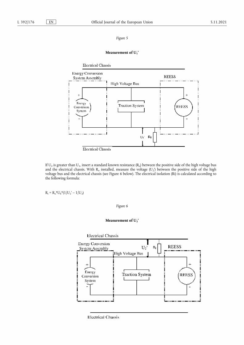
Figure 5
Measurement of U1’
If U2 is greater than U1, insert a standard known resistance (Ro) between the positive side of the high voltage bus and the electrical chassis. With Ro installed, measure the voltage (U2’) between the positive side of the high voltage bus and the electrical chassis (see Figure 6 below). The electrical isolation (Ri) is calculated according to the following formula:
Ri = Ro*Ub*(1/U2’ – 1/U2)
Figure 6
Measurement of U2’
EN Official Journal of the European Union L 392/176 5.11.2021

5.2.2.3.5. Fifth step.
The electrical isolation value Ri (in Ω) divided by the working voltage of the high voltage bus (in V) results in the isolation resistance (in Ω/V).
Note: The standard known resistance Ro (in Ω) should be the value of the minimum required isolation resistance (Ω/V) multiplied by the working voltage (V) of the vehicle plus/minus 20 per cent. Ro is not required to be precisely this value since the equations are valid for any Ro; however, a Ro value in this range should provide a good resolution for the voltage measurements.
6. Electrolyte leakage
An appropriate coating, if necessary, may be applied to the physical protection (casing) in order to confirm if there is any electrolyte leakage from the REESS resulting from the test. Unless the manufacturer provides means to differentiate between the leakage of different liquids, all liquid leakage shall be considered as the electrolyte.
7. REESS retention
Compliance shall be determined by visual inspection.
EN Official Journal of the European Union 5.11.2021 L 392/177


EN
ISSN 1977-0677 (electronic edition) ISSN 1725-2555 (paper edition)
Related Documents