2012 SIMULIA Community Conference 1 Off-highway Diesel Engines - Reducing Cost, Improving Quality and Shortening Development Cycles at Caterpillar using Advanced Virtual Validation Rob Lacey Caterpillar, Peterborough, UK Abstract: This presentation will demonstrate how Abaqus can be used to drive design decisions at an early stage in the engine development process. Caterpillar is committed to using virtual validation methods within its engine design and development process. This has several benefits, namely, reducing the cost of numerous design iterations, ensuring that designs are durable and fit for purpose and also compressing the time between concept and production. Caterpillar has employed virtual methods for over 35 years, using a mix of commercial FE software supported by internal codes. Abaqus has been used within Caterpillar from 1995 and since then has become the core FE code for engine analysis. Most components on the Tier 4 interim engines have been assessed using Abaqus, including, importantly, the interaction of systems of components, such as multiple bolted joints, cylinder head/block/cylinder head gasket assemblies and valve trains. As engines have become ever more complex to meet new emissions standards, the breadth of analysis has shifted from core engine components to encompass the assessment of ancillaries such as after-treatment and NRS coolers. In order to support this expansion of analysis scope, a whole range of new and advanced methodologies have had to be developed and implemented, whilst maintaining a focus on the core engine assessment. The use of XFEM and fracture mechanics, manufacturing simulation using Abaqus/Explicit, multi-body dynamics and optimization using Abaqus/ATOM will be presented, plus examples of the integration of Abaqus with internal software and the capture of standard workflow. Keywords: Abaqus/CAE, Abaqus/Explicit, Abaqus/Standard, Bolt Loading, Cold Rolling, Coupled Analysis, Crack Propagation, Creep, Damage, Design Optimization, Dynamics, Elasticity, Experimental Verification, Failure, Fatigue, Fatigue Life, Fillet Rolling, Fracture, Heat Transfer, Hyperelasticity, Impact, Interface Friction, Low-Cycle Fatigue, Multi-Body Dynamics, Optimization, Plasticity, Power-train, Residual Stress, Thermal Stress, Vibration.

Welcome message from author
This document is posted to help you gain knowledge. Please leave a comment to let me know what you think about it! Share it to your friends and learn new things together.
Transcript
2012 SIMULIA Community Conference 1
Off-highway Diesel Engines - Reducing Cost, Improving Quality and Shortening Development
Cycles at Caterpillar using Advanced Virtual Validation
Rob Lacey
Caterpillar, Peterborough, UK
Abstract: This presentation will demonstrate how Abaqus can be used to drive design decisions at
an early stage in the engine development process.
Caterpillar is committed to using virtual validation methods within its engine design and
development process. This has several benefits, namely, reducing the cost of numerous design
iterations, ensuring that designs are durable and fit for purpose and also compressing the time
between concept and production. Caterpillar has employed virtual methods for over 35 years,
using a mix of commercial FE software supported by internal codes. Abaqus has been used within
Caterpillar from 1995 and since then has become the core FE code for engine analysis. Most
components on the Tier 4 interim engines have been assessed using Abaqus, including,
importantly, the interaction of systems of components, such as multiple bolted joints, cylinder
head/block/cylinder head gasket assemblies and valve trains. As engines have become ever more
complex to meet new emissions standards, the breadth of analysis has shifted from core engine
components to encompass the assessment of ancillaries such as after-treatment and NRS coolers.
In order to support this expansion of analysis scope, a whole range of new and advanced
methodologies have had to be developed and implemented, whilst maintaining a focus on the core
engine assessment. The use of XFEM and fracture mechanics, manufacturing simulation using
Abaqus/Explicit, multi-body dynamics and optimization using Abaqus/ATOM will be presented,
plus examples of the integration of Abaqus with internal software and the capture of standard
workflow.
Keywords: Abaqus/CAE, Abaqus/Explicit, Abaqus/Standard, Bolt Loading, Cold Rolling, Coupled
Analysis, Crack Propagation, Creep, Damage, Design Optimization, Dynamics, Elasticity,
Experimental Verification, Failure, Fatigue, Fatigue Life, Fillet Rolling, Fracture, Heat Transfer,
Hyperelasticity, Impact, Interface Friction, Low-Cycle Fatigue, Multi-Body Dynamics,
Optimization, Plasticity, Power-train, Residual Stress, Thermal Stress, Vibration.
u48
Typewritten Text
Visit the Resource Center for more SIMULIA customer papers
2 2012 SIMULIA Community Conference
1. Introduction
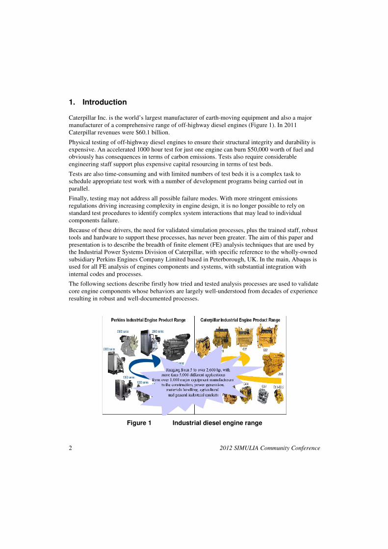
Caterpillar Inc. is the world’s largest manufacturer of earth-moving equipment and also a major manufacturer of a comprehensive range of off-highway diesel engines (Figure 1). In 2011 Caterpillar revenues were $60.1 billion.
Physical testing of off-highway diesel engines to ensure their structural integrity and durability is expensive. An accelerated 1000 hour test for just one engine can burn $50,000 worth of fuel and obviously has consequences in terms of carbon emissions. Tests also require considerable engineering staff support plus expensive capital resourcing in terms of test beds.
Tests are also time-consuming and with limited numbers of test beds it is a complex task to schedule appropriate test work with a number of development programs being carried out in parallel.
Finally, testing may not address all possible failure modes. With more stringent emissions regulations driving increasing complexity in engine design, it is no longer possible to rely on standard test procedures to identify complex system interactions that may lead to individual components failure.
Because of these drivers, the need for validated simulation processes, plus the trained staff, robust tools and hardware to support these processes, has never been greater. The aim of this paper and presentation is to describe the breadth of finite element (FE) analysis techniques that are used by the Industrial Power Systems Division of Caterpillar, with specific reference to the wholly-owned subsidiary Perkins Engines Company Limited based in Peterborough, UK. In the main, Abaqus is used for all FE analysis of engines components and systems, with substantial integration with internal codes and processes.
The following sections describe firstly how tried and tested analysis processes are used to validate core engine components whose behaviors are largely well-understood from decades of experience resulting in robust and well-documented processes.
Figure 1 Industrial diesel engine range
2012 SIMULIA Community Conference 3
2. Core engine component analysis
2.1 General
Core components are defined loosely as those parts of the engine which are key to its fundamental operation; in most cases the assessment of their structural response to applied loads has been performed since the early decades of the 1900s where hand calculations were employed in association with extensive component testing. The use of FE analysis from the 1970s has revolutionized how engine design and virtual validation has been carried. Certainly, within Caterpillar, there are certain components such as crankshafts where FE analysis is the primary sign off tool.
A non-exhaustive list of the components and assemblies comprising the core engine might be:
• cylinder block and bearing caps
• cylinder head
• crankshaft
• piston assembly
• connecting rod
• exhaust manifold
• valve train
• gear train
• flywheel
In addition to these major items there are various gaskets, seals, bearings and bolted joints which are modeled to various degrees of complexity depending on which assessment is required. Some of the standard processes for the assessment of these core components are outlined below.
2.2 Cylinder block
This is the main structural component in any engine. It provides a base for the major reciprocating parts of the power-train, that is, the crankshaft and piston assemblies. All Cat® cylinder blocks are manufactured from cast iron since it is durable, relatively cheap and its casting processes have been understood for many years. The use of aluminum in passenger cars is driven mainly by mass considerations where, in contrast to earth-moving machinery, the engine forms a large proportion of the overall mass of the vehicle. Figure 2 shows a typical 3 cylinder block.
Firing loads are transmitted via the pistons and connecting rods to the crankshaft pins, and are reacted onto the cylinder block bearing panels via the crankshaft main bearings. These reciprocating loads are both time-dependent and spatially-varying; within Caterpillar they are determined using an in-house elasto-hydrodynamic (EHD) bearing solver which is able to map the bearing oil film pressures onto an Abaqus model of the cylinder block. The Abaqus cylinder block

4 2012 SIMULIA Community Conference
model contains the bearing caps attached to the block with sliding contact, threaded connections using the *CLEARANCE method and machining corrections on the bearing shells.
Figure 2 Cylinder block
At present the process considers the assessment of a complete 720° cycle to be a series of static load-cases which are selected automatically based upon load reversals and magnitude. This is appropriate for small, stiff cylinder blocks where the modal response is insignificant but may be an approximation for larger, more flexible blocks. Following completion of the Abaqus analysis, the odb results file is processed by an in-house fatigue code which creates a new odb file containing safety factors and failures rates. This code will account for the relative notch-insensitivity of grey cast iron.
2.3 Cylinder head
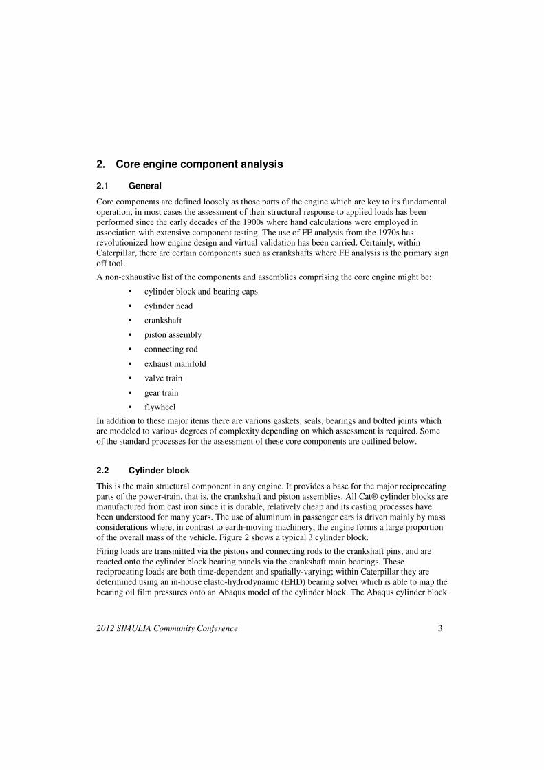
All Cat® cylinder heads are cast iron. The cylinder head is bolted to the block with the cylinder head gasket in between providing the seal for the combustion gases as well as coolant and oil. The camshaft and associated valve train operate valves within the cylinder head to allow air into the combustion chamber and the products of combustion to escape. Fuel injectors, whose nozzles protrude from the cylinder head flame face at the centre of each cylinder bore, provide measured quantities of vaporized diesel fuel at specific times during the engine cycle. Cast coolant passages within the cylinder head allow for cooling close to the combustion chamber. Figure 3 shows an FE model of a cylinder head (valves removed).
2012 SIMULIA Community Conference 5
The FE analysis of cylinder heads is one of the more challenging tasks due a variety of reasons, such as:
• in-cylinder thermal boundary condition generation
• water side boundary condition generation
• cylinder head gasket behavior
• component interaction such as valve seat inserts
• cast iron behavior when cycled between hot and cold conditions
Figure 3 Cylinder head FE model
At Caterpillar, the core of the thermal and structural analysis process uses Abaqus. However, there are a host of other commercial and in-house codes which provide inputs and outputs to the overall cylinder head assessment. This workflow is largely controlled by specifically-written GUIs and plug-ins to the corporate pre- and post-processor, NX. For example, in-cylinder thermal boundary conditions are generated from a coupled CFD analysis that uses a proprietary Caterpillar combustion code to model the closed cycle diesel combustion process and GT-Power for the open cycle event. Resultant thermal boundary conditions in the form of heat transfer coefficients (HTC) and sink temperatures are automatically cycle-averaged over the 720° engine cycle and mapped onto the FE mesh for the Abaqus heat transfer analysis. A similar process is performed on the coolant side. Potential nucleate boiling of coolant close to the cylinder head flame face is accounted for by local modification of the CFD-calculated HTC via an Abaqus *FILM user subroutine. Note that the entire assembly of cylinder head, block and piston plus ring pack is considered in this process in order to properly model the distribution of heat flow from the cylinder, be it heat to exhaust, heat to coolant or heat to oil.

6 2012 SIMULIA Community Conference
Heat transfer between the piston/ring pack and liner bore is modeled by an internally-developed process that accounts for the cycle-dependent relative position of the piston and liner surfaces and the degree of their overlap.
Subsequently, a series of steady-state Abaqus structural analyses are performed to model assembly, low cycle and high cycle events. For the low cycle events, thermal boundary conditions derived previously are used. Extensive use is made of the following Abaqus capabilities:
• *CLEARANCE threaded connector for cylinder head bolts
• *GASKET SECTION definition to model non-linear cylinder head gasket behavior.
• *CONTACT INTERFERENCE to model initial interferences between cylinder head and valve seat inserts/stem guides
It is worth noting that the Abaqus gasket elements have been critical to assessing head gasket effectiveness, in terms of combustion gas sealing, oil and coolant sealing and gasket bead durability. In many cases, Abaqus analyses have driven decisions on investment in expensive tooling.
Durability calculations are performed using an in-house code, which also accounts for the particular characteristics of flake cast iron such as asymmetric tensile/compressive response, Young’s modulus reduction with strain, bulk stress relaxation and notch insensitivity.
Extensive testing has been used to establish fatigue properties of the specific grades of cast iron used in Cat® cylinder heads, both in terms of nominal fatigue strengths and also their distribution. This enables not only the estimation of mean life but also the failure rate based on a target life.
2.4 Crankshaft
Most Cat® crankshafts are manufactured from steel, although at the Perkins facility production of spheroidal graphite (SG) iron 3 and 4 cylinder crankshafts has been in place for some time.
Structural analysis and sign off of crankshafts is a well-documented standard process at Caterpillar. An in-house code, RUMBLE, is used to generate loads on a fully-detailed FE model of the crankshaft, taking into account, amongst other effects:
• cylinder pressures over the engine cycle
• inertial effects of piston, rings, connecting rod, crankshaft, flywheel and damper(s)
• dynamic response due to modal behavior of the crankshaft assembly
• EHD oil film bearing pressures
• cylinder block foundation stiffness
The RUMBLE solution is computationally efficient because, although it solves in the time domain, the FE model of the crankshaft is reduced down to master degrees of freedom that represent the modal behavior of the structure adequately.
Spatially-varying and time-varying bearing loads are applied to an Abaqus FE model which is solved as series of linear static steps; this is possible because dynamic effects are already accounted for in the prior RUMBLE analysis.
2012 SIMULIA Community Conference 7
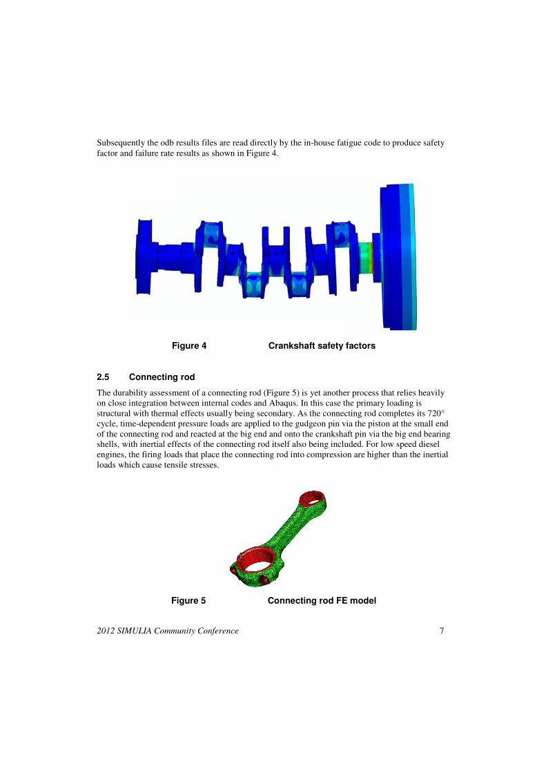
Subsequently the odb results files are read directly by the in-house fatigue code to produce safety factor and failure rate results as shown in Figure 4.
Figure 4 Crankshaft safety factors
2.5 Connecting rod
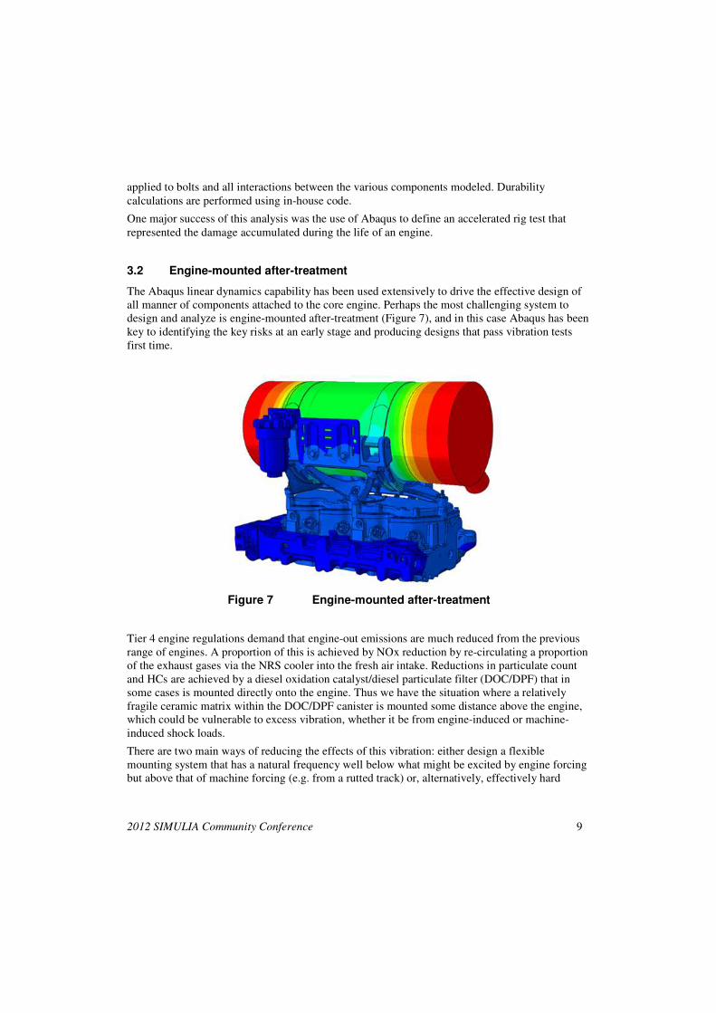
The durability assessment of a connecting rod (Figure 5) is yet another process that relies heavily on close integration between internal codes and Abaqus. In this case the primary loading is structural with thermal effects usually being secondary. As the connecting rod completes its 720° cycle, time-dependent pressure loads are applied to the gudgeon pin via the piston at the small end of the connecting rod and reacted at the big end and onto the crankshaft pin via the big end bearing shells, with inertial effects of the connecting rod itself also being included. For low speed diesel engines, the firing loads that place the connecting rod into compression are higher than the inertial loads which cause tensile stresses.
Figure 5 Connecting rod FE model

8 2012 SIMULIA Community Conference
These dynamic loads are determined by in-house software which uses cylinder pressure traces as the load input and knowledge of the connecting rod geometry and its reduced stiffness matrix to calculate the surface pressures applied to the big end bearing shells as function of time and connecting rod attitude in Abaqus format.
The Abaqus FE analysis is performed at automatically selected time points based on peak compressive, tensile and bending in the connecting rod. Also taken into account are bearing cap bolt up (using the threaded connector *CLEARANCE method), big and small end bearing shell interference and sliding contact between all components.
The in-house fatigue code is used to determine durability.
3. Ancillary component analysis
3.1 NRS cooler
An NRS (NOx reduction strategy) cooler is used to reduce engine emissions and is basically an air to water/glycol heat exchanger. It works by cooling a portion of the exhaust gas flow which is mixed with clean air and fed back into the combustion chamber. There are significant design challenges to achieving adequate durability for this component since the exhaust gas inlet to the NRS cooler is typically at 600°C with coolant at 85°C. Therefore high thermal gradients exist within the cooler during normal engine operation causing thermal stresses that might be exacerbated by different materials having differing thermal expansions coefficients. Furthermore, low cycle fatigue comes into play when the engine alternates between hot and cold conditions.
Figure 6 NRS cooler assembly
Thermal boundary conditions for the Abaqus heat transfer analysis are generated from steady-state gas side and coolant CFD analyses, which are mapped onto the FE model. Assembly loads are
2012 SIMULIA Community Conference 9
applied to bolts and all interactions between the various components modeled. Durability calculations are performed using in-house code.
One major success of this analysis was the use of Abaqus to define an accelerated rig test that represented the damage accumulated during the life of an engine.
3.2 Engine-mounted after-treatment
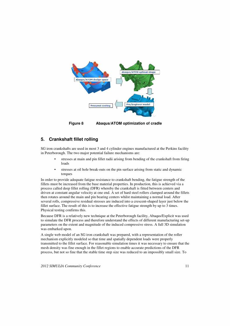
The Abaqus linear dynamics capability has been used extensively to drive the effective design of all manner of components attached to the core engine. Perhaps the most challenging system to design and analyze is engine-mounted after-treatment (Figure 7), and in this case Abaqus has been key to identifying the key risks at an early stage and producing designs that pass vibration tests first time.
Figure 7 Engine-mounted after-treatment
Tier 4 engine regulations demand that engine-out emissions are much reduced from the previous range of engines. A proportion of this is achieved by NOx reduction by re-circulating a proportion of the exhaust gases via the NRS cooler into the fresh air intake. Reductions in particulate count and HCs are achieved by a diesel oxidation catalyst/diesel particulate filter (DOC/DPF) that in some cases is mounted directly onto the engine. Thus we have the situation where a relatively fragile ceramic matrix within the DOC/DPF canister is mounted some distance above the engine, which could be vulnerable to excess vibration, whether it be from engine-induced or machine-induced shock loads.
There are two main ways of reducing the effects of this vibration: either design a flexible mounting system that has a natural frequency well below what might be excited by engine forcing but above that of machine forcing (e.g. from a rutted track) or, alternatively, effectively hard

10 2012 SIMULIA Community Conference
mount the after-treatment package and design a system that is stiff enough to not be excited by engine forcing.
For the flexible system, the challenge is to position its natural frequency at the point between engine and machine forcing so that the response of the system meets component design targets. This can be difficult to achieve if damping levels are not well understood, since significant responses could be obtained even when well away from the input forcing. Flexible systems also suffer from potential excess displacement levels that can compromise attached pipe work.
Hard mounted systems are less problematic in that engine forcing is the major concern, nevertheless, a sufficiently stiff system can be difficult to engineer, where for a 4 cylinder engine operating at a maximum speed of 2200 rpm a natural frequency of about 220 Hz is needed to avoid potential resonances.
Abaqus models of engine-mounted after-treatment systems are complex and comprise many interacting components. The initial assembly step uses the threaded connector *CLEARANCE method plus finite sliding between the DOC/DPF canister and the straps holding it to the cradle. Modal extraction is performed on the assembled model. If the above frequency criterion is not met then a forced response analysis would be necessary and a frequency domain fatigue assessment performed.
4. Component optimization
As mentioned above, designing structures containing overhung masses in situations where there is significant forcing can be challenging.
A situation arose where an initial prototype cradle supporting the after-treatment DOC/DPF canister had been designed and procured before analysis involvement had been requested. NVH testing showed that acceleration levels on the DPF canister had been far exceeded. Subsequent Abaqus analysis showed that the design was indeed inadequate. Excellent agreement between analysis and test was achieved both with predicted frequencies and acceleration levels.
At this point Abaqus/ATOM was used to produce an optimal cradle design based on maximizing lateral stiffness (minimizing strain energy) subject to constraints of design space and mass target.
Abaqus/ATOM was critical to achieving a successful design. The initial optimization study took around 2-3 days and produced a shape in the form of an STL file. Following a tidying up exercise the STL surfaces were converted back to a solid mesh using tools available within Abaqus/CAE and the natural frequency checked to ensure that the target had been met. Next the model was passed to a designer who read it into Pro/Engineer and used it as the basis for a design that addressed manufacturing constraints such as fillet radii and casting ability. The Abaqus analysis was repeated to ensure that the frequency target was still met.
A casting of the redesigned cradle was procured, assembled to the after-treatment and engine tested by the NVH team. The vibration limits were found to be well within target and showed remarkable correlation with the Abaqus predictions.
Figure 8 shows the workflow used for the cradle optimization.
2012 SIMULIA Community Conference 11
Figure 8 Abaqus/ATOM optimization of cradle
5. Crankshaft fillet rolling
SG iron crankshafts are used in most 3 and 4 cylinder engines manufactured at the Perkins facility in Peterborough. The two major potential failure mechanisms are:
• stresses at main and pin fillet radii arising from bending of the crankshaft from firing loads
• stresses at oil hole break-outs on the pin surface arising from static and dynamic torques
In order to provide adequate fatigue resistance to crankshaft bending, the fatigue strength of the fillets must be increased from the base material properties. In production, this is achieved via a process called deep fillet rolling (DFR) whereby the crankshaft is fitted between centers and driven at constant angular velocity at one end. A set of hard steel rollers clamped around the fillets then rotates around the main and pin bearing centers whilst maintaining a normal load. After several rolls, compressive residual stresses are induced into a crescent-shaped layer just below the fillet surface. The result of this is to increase the effective fatigue strength by up to 3 times. Physical testing confirms this.
Because DFR is a relatively new technique at the Peterborough facility, Abaqus/Explicit was used to simulate the DFR process and therefore understand the effects of different manufacturing set-up parameters on the extent and magnitude of the induced compressive stress. A full 3D simulation was embarked upon.
A single web model of an SG iron crankshaft was prepared, with a representation of the roller mechanism explicitly modeled so that time and spatially dependent loads were properly transmitted to the fillet surface. For reasonable simulation times it was necessary to ensure that the mesh density was fine enough in the fillet regions to enable accurate predictions of the DFR process, but not so fine that the stable time step size was reduced to an impossibly small size. To
12 2012 SIMULIA Community Conference
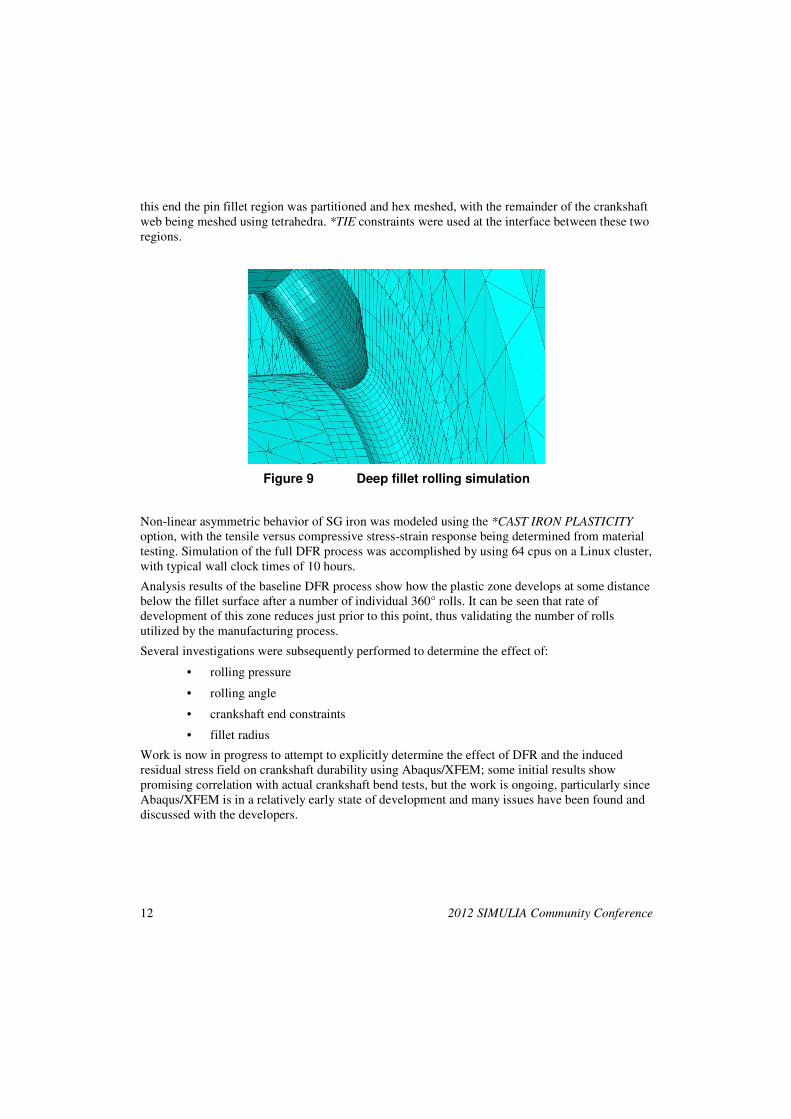
this end the pin fillet region was partitioned and hex meshed, with the remainder of the crankshaft web being meshed using tetrahedra. *TIE constraints were used at the interface between these two regions.
Figure 9 Deep fillet rolling simulation
Non-linear asymmetric behavior of SG iron was modeled using the *CAST IRON PLASTICITY option, with the tensile versus compressive stress-strain response being determined from material testing. Simulation of the full DFR process was accomplished by using 64 cpus on a Linux cluster, with typical wall clock times of 10 hours.
Analysis results of the baseline DFR process show how the plastic zone develops at some distance below the fillet surface after a number of individual 360° rolls. It can be seen that rate of development of this zone reduces just prior to this point, thus validating the number of rolls utilized by the manufacturing process.
Several investigations were subsequently performed to determine the effect of:
• rolling pressure
• rolling angle
• crankshaft end constraints
• fillet radius
Work is now in progress to attempt to explicitly determine the effect of DFR and the induced residual stress field on crankshaft durability using Abaqus/XFEM; some initial results show promising correlation with actual crankshaft bend tests, but the work is ongoing, particularly since Abaqus/XFEM is in a relatively early state of development and many issues have been found and discussed with the developers.
2012 SIMULIA Community Conference 13
6. Future simulation
6.1 Valve train
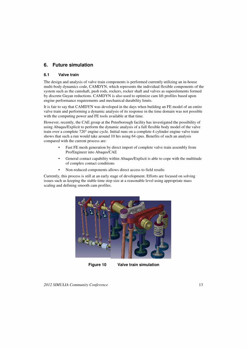
The design and analysis of valve train components is performed currently utilizing an in-house multi-body dynamics code, CAMDYN, which represents the individual flexible components of the system such as the camshaft, push rods, rockers, rocker shaft and valves as superelements formed by discrete Guyan reductions. CAMDYN is also used to optimize cam lift profiles based upon engine performance requirements and mechanical durability limits.
It is fair to say that CAMDYN was developed in the days when building an FE model of an entire valve train and performing a dynamic analysis of its response in the time domain was not possible with the computing power and FE tools available at that time.
However, recently, the CAE group at the Peterborough facility has investigated the possibility of using Abaqus/Explicit to perform the dynamic analysis of a full flexible body model of the valve train over a complete 720° engine cycle. Initial runs on a complete 4 cylinder engine valve train shows that such a run would take around 10 hrs using 64 cpus. Benefits of such an analysis compared with the current process are:
• Fast FE mesh generation by direct import of complete valve train assembly from Pro/Engineer into Abaqus/CAE
• General contact capability within Abaqus/Explicit is able to cope with the multitude of complex contact conditions
• Non-reduced components allows direct access to field results
Currently, this process is still at an early stage of development. Efforts are focused on solving issues such as keeping the stable time step size at a reasonable level using appropriate mass scaling and defining smooth cam profiles.
Figure 10 Valve train simulation
14 2012 SIMULIA Community Conference
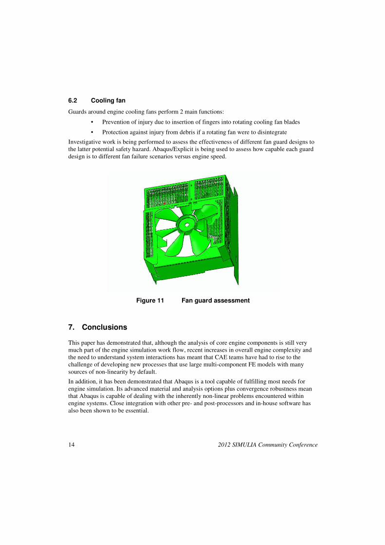
6.2 Cooling fan
Guards around engine cooling fans perform 2 main functions:
• Prevention of injury due to insertion of fingers into rotating cooling fan blades
• Protection against injury from debris if a rotating fan were to disintegrate
Investigative work is being performed to assess the effectiveness of different fan guard designs to the latter potential safety hazard. Abaqus/Explicit is being used to assess how capable each guard design is to different fan failure scenarios versus engine speed.
Figure 11 Fan guard assessment
7. Conclusions
This paper has demonstrated that, although the analysis of core engine components is still very much part of the engine simulation work flow, recent increases in overall engine complexity and the need to understand system interactions has meant that CAE teams have had to rise to the challenge of developing new processes that use large multi-component FE models with many sources of non-linearity by default.
In addition, it has been demonstrated that Abaqus is a tool capable of fulfilling most needs for engine simulation. Its advanced material and analysis options plus convergence robustness mean that Abaqus is capable of dealing with the inherently non-linear problems encountered within engine systems. Close integration with other pre- and post-processors and in-house software has also been shown to be essential.

2012 SIMULIA Community Conference 15
8. Acknowledgments
I would like to take opportunity of thanking the CAE structural team and design and development teams at Industrial Power Systems Division at Peterborough for performing much of the work presented here.
u48
Typewritten Text
Visit the Resource Center for more SIMULIA customer papers
Related Documents