This electronic version (PDF) was scanned by the International Telecommunication Union (ITU) Library & Archives Service from an original paper document in the ITU Library & Archives collections. La présente version électronique (PDF) a été numérisée par le Service de la bibliothèque et des archives de l'Union internationale des télécommunications (UIT) à partir d'un document papier original des collections de ce service. Esta versión electrónica (PDF) ha sido escaneada por el Servicio de Biblioteca y Archivos de la Unión Internacional de Telecomunicaciones (UIT) a partir de un documento impreso original de las colecciones del Servicio de Biblioteca y Archivos de la UIT. ﻫﺬﻩ ﺍﻹﻟﻜﺘﺮﻭﻧﻴﺔ ﺍﻟﻨﺴﺨﺔ(PDF) ﻧﺘﺎﺝ ﺗﺼﻮﻳﺮ ﺑﺎﻟﻤﺴﺢ ﻗﺴﻢ ﺃﺟﺮﺍﻩ ﺍﻟﻀﻮﺋﻲ ﻭﺍﻟﻤﺤﻔﻮﻇﺎﺕ ﺍﻟﻤﻜﺘﺒﺔ ﻓﻲ ﺍﻟﺪﻭﻟﻲ ﺍﻻﺗﺤﺎﺩ ﻟﻼﺗﺼﺎﻻﺕ(ITU) ً ﻧﻘﻼ◌ ﻭﺛﻴﻘﺔ ﻣﻦ ﻭﺭﻗﻴﺔ ﺿﻤﻦ ﺃﺻﻠﻴﺔ ﻓﻲ ﺍﻟﻤﺘﻮﻓﺮﺓ ﺍﻟﻮﺛﺎﺋﻖ ﻗﺴﻢﻭﺍﻟﻤﺤﻔﻮﻇﺎﺕ ﺍﻟﻤﻜﺘﺒﺔ. 此电子版(PDF版本)由国际电信联盟(ITU)图书馆和档案室利用存于该处的纸质文件扫描提供。 Настоящий электронный вариант (PDF) был подготовлен в библиотечно-архивной службе Международного союза электросвязи путем сканирования исходного документа в бумажной форме из библиотечно-архивной службы МСЭ. © International Telecommunication Union

Welcome message from author
This document is posted to help you gain knowledge. Please leave a comment to let me know what you think about it! Share it to your friends and learn new things together.
Transcript

This electronic version (PDF) was scanned by the International Telecommunication Union (ITU) Library & Archives Service from an original paper document in the ITU Library & Archives collections.
La présente version électronique (PDF) a été numérisée par le Service de la bibliothèque et des archives de l'Union internationale des télécommunications (UIT) à partir d'un document papier original des collections de ce service.
Esta versión electrónica (PDF) ha sido escaneada por el Servicio de Biblioteca y Archivos de la Unión Internacional de Telecomunicaciones (UIT) a partir de un documento impreso original de las colecciones del Servicio de Biblioteca y Archivos de la UIT.
(ITU) لالتصاالت الدولي االتحاد في والمحفوظات المكتبة قسم أجراه الضوئي بالمسح تصوير نتاج (PDF) اإللكترونية النسخة هذه .والمحفوظات المكتبة قسم في المتوفرة الوثائق ضمن أصلية ورقية وثيقة من نقال◌ً
此电子版(PDF版本)由国际电信联盟(ITU)图书馆和档案室利用存于该处的纸质文件扫描提供。
Настоящий электронный вариант (PDF) был подготовлен в библиотечно-архивной службе Международного союза электросвязи путем сканирования исходного документа в бумажной форме из библиотечно-архивной службы МСЭ.
© International Telecommunication Union
INTERNATIONAL TELECOMMUNICATION UNION
THE INTERNATIONAL TELEGRAPH AND TELEPHONE CONSULTATIVE COMMITTEE
YELLOW BOOK
VOLUME X - FASCICLE X.2
MBEK OF THE YELLOW BOOK
VII™ PLENARY ASSEM BLYGENEVA, 10-21 NOVEMBER 1980
Geneva 1981
INTERNATIONAL TELECOMMUNICATION UNION
CCITTTHE INTERNATIONAL TELEGRAPH AND TELEPHONE CONSULTATIVE COMMITTEE
YELLOW BOOK
VOLUME X - FASCICLE X.2
INDEX OF THE YELLOW BOOK
VIIth PLENARY ASSEMBLYGENEVA, 10-21 NOVEMBER 1980
Geneva 1981 r U.l.T.
ISBN 92-61-01201-9

OI.T.U.
TABLE OF CONTENTS
Page
PART I — Contents o f the CCITT Book applicable after the Seventh Plenary Assembly (1980).............. 1
PART II - List o f Recommendations published in the Yellow B o o k .............................................................. 3
PART III — Index to the Yellow B o o k ....................................................................................................................... 49
Fascicle X.2 — Index III
PRELIMINARY NOTE
The Index o f the Yellow Book consists of three parts.
Part I gives the contents of the Yellow Book, in the form of a list of the volumes and fascicles together with their title and corresponding Recommendation Series and Study Groups.
Part II is a list, in alphanumerical order, of all the Recommendations found in the Yellow Book with titles.
Part III is the actual index. Taking advantage of the fact that the texts o f the Yellow Book are stored magnatically, two subsidiary data banks were formed by computer processing based on the main data bank of Recommendation texts: the first to produce the Terms and Definitions and the second for the Index (which is the above-mentioned Part III).
Because of the great amount of information processed, it was necessary to limit the number of references for each of the approximately 5700 index entries in each of the three language versions (Spanish, French, English) of the index. Thus one reference only per Recommendation was retained, and three per fascicle or Recommendation Series for any given index entry.
The references are presented in the following way:
— The Recommendation number or Glossary number (Glos. No. ...) or Supplement number (Sup. No. ...) together with the paragraph number form a reference unit; these units are separated by a semicolon. In the case of a glossary or supplement, the number of the volume or fascicle in which it appears is indicated in parentheses.
— If the index entry is defined, the Recommendation, glossary or supplement number is printed in italics.
— If the index entry comes from an annex to a Recommendation or a supplement, the number of the Recommendation (or supplement) is given, together with the number of the corresponding paragraph of the annex. If the annex does not have numbered paragraphs, then only the letter designating the annex is given after the Recommendation or supplement number.
— In the case of index entries defined in terminology Recommendations followed by a glossary in alphabetical order, only the Recommendation number is given. However, for Recommendation R.140, the reference comprises both the Recommendation number and the number assigned to the term.
— For certain index entries appearing regularly in a section or group of Recommendations, the reference indicates the number of the first and of the last Recommendation of this section or group, separated by a hyphen.
— If the Recommendation where the index entry appears contains divisions and subdivisions, all these indications are given in the reference, in decreasing order of importance, the last indication being that of the paragraph number (e.g. F.1, § A III 1.1).
IV Fascicle X.2 — Preliminary note
PARTI
CONTENTS OF THE CCITT BOOK
APPLICABLE AFTER THE SEVENTH PLENARY ASSEMBLY (1980)
YELLOW BOOK
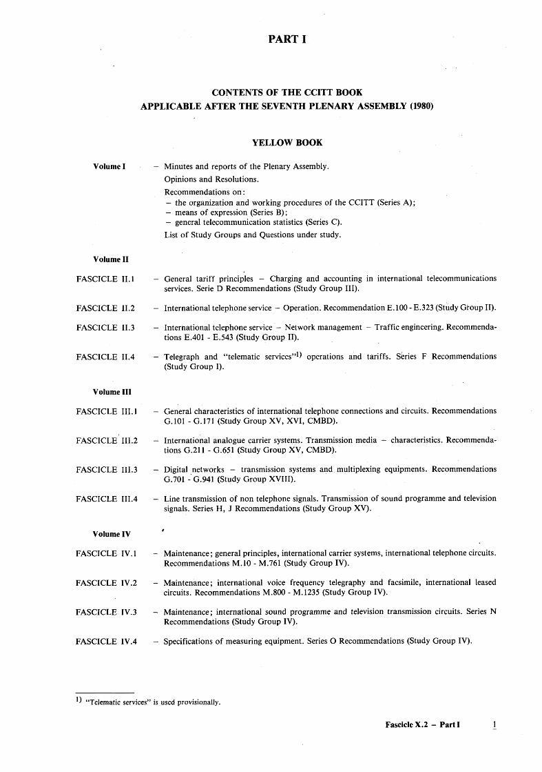
Volume I Minutes and reports of the Plenary Assembly.Opinions and Resolutions.Recommendations o n :- the organization and working procedures of the CCITT (Series A);- means of expression (Series B);- general telecommunication statistics (Series C).List of Study Groups and Questions under study.
Volume II
FASCICLE II. 1
FASCICLE II.2
FASCICLE II.3
FASCICLE II.4
- General tariff principles - Charging and accounting in international telecommunications services. Serie D Recommendations (Study Group III).
- International telephone service - Operation. Recommendation E. 100 - E.323 (Study Group II).
- International telephone service - Network management - Traffic engineering. Recommendations E.401 - E.543 (Study Group II).
- Telegraph and “ telematic services”1) operations and tariffs. Series F Recommendations (Study Group I).
Volume III
FASCICLE III.l
FASCICLE III.2
FASCICLE III.3
General characteristics of international telephone connections and circuits. Recommendations G.101 - G.171 (Study Group XV, XVI, CMBD).
International analogue carrier systems. Transmission media - characteristics. Recommendations G.211 - G.651 (Study Group XV, CMBD).
Digital networks - transmission systems and multiplexing equipments. Recommendations G.701 - G.941 (Study Group XVIII).
FASCICLE III.4 - Line transmission of non telephone signals. Transmission of sound programme and televisionsignals. Series H, J Recommendations (Study Group XV).
Volume IV
FASCICLE IV. 1
FASCICLE IV.2
FASCICLE IV.3
Maintenance; general principles, international carrier systems, international telephone circuits. Recommendations M.10 - M.761 (Study Group IV).
Maintenance; international voice frequency telegraphy and facsimile, international leased circuits. Recommendations M.800 - M. 1235 (Study Group IV).
Maintenance; international sound programme and television transmission circuits. Series N Recommendations (Study Group IV).
FASCICLE IV.4 - Specifications of measuring equipment. Series O Recommendations (Study Group IV).
^ “Telematic services” is used provisionally.
Fascicle X.2 - Part I
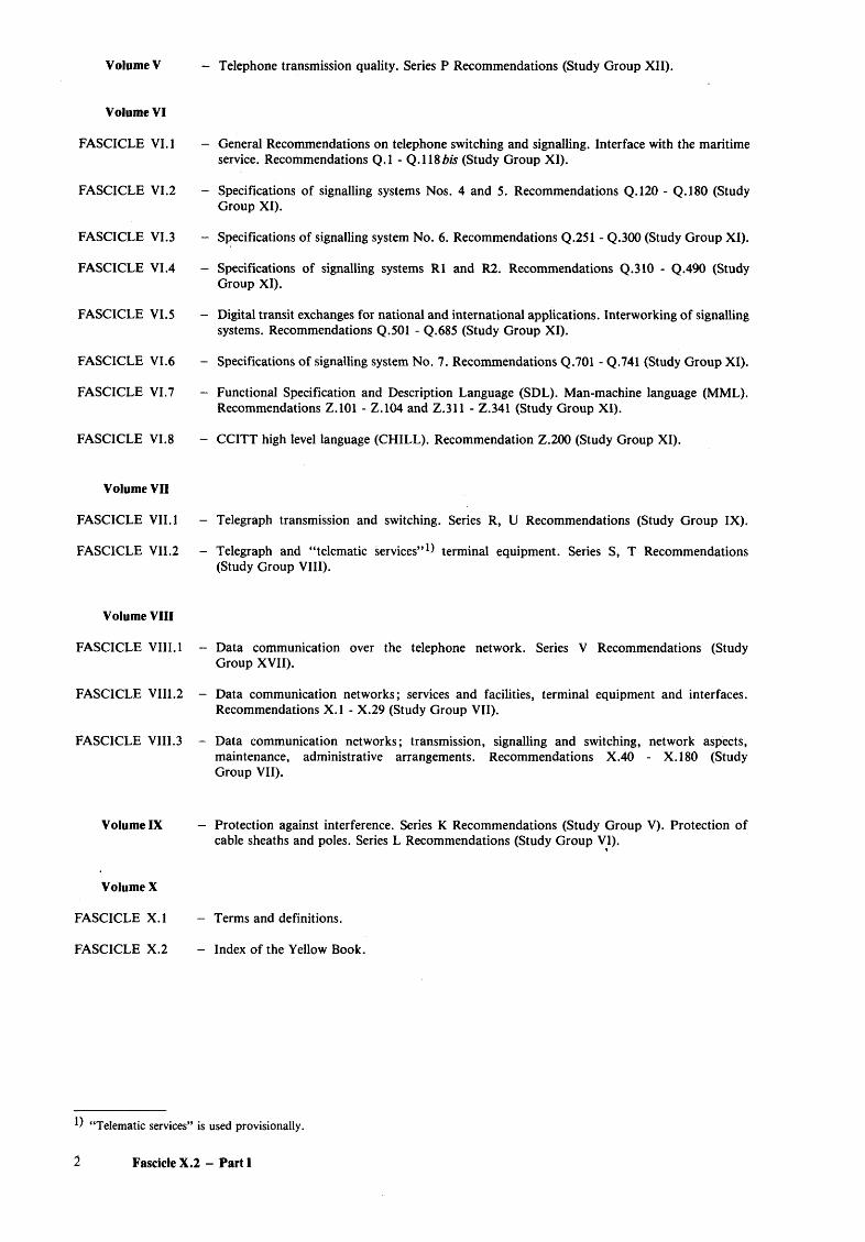
Volume V - Telephone transmission quality. Series P Recommendations (Study Group XII).
Volume VI
FASCICLE VI. 1
FASCICLE VI.2
FASCICLE VI.3
FASCICLE VI .4
FASCICLE VI.5
FASCICLE VI.6
FASCICLE VI.7
FASCICLE VI.8
Volume VII
FASCICLE VII. 1
FASCICLE VII.2
Volume VIII
FASCICLE VIII. 1
FASCICLE VIII.2
FASCICLE VIII.3
Volume IX
Volume X
FASCICLE X.l
FASCICLE X.2
General Recommendations on telephone switching and signalling. Interface with the maritime service. Recommendations Q .l - Q.118Z>/s (Study Group XI).
Specifications of signalling systems Nos. 4 and 5. Recommendations Q.120 - Q.180 (Study Group XI).
Specifications of signalling system No. 6. Recommendations Q.251 - Q.300 (Study Group XI).
Specifications of signalling systems R1 and R2. Recommendations Q.3I0 - Q.490 (Study Group XI).
Digital transit exchanges for national and international applications. Interworking of signalling systems. Recommendations Q.501 - Q.685 (Study Group XI).
Specifications of signalling system No. 7. Recommendations Q.701 - Q.741 (Study Group XI).
Functional Specification and Description Language (SDL). Man-machine language (MML). Recommendations Z.101 - Z.104 and Z.311 - Z.341 (Study Group XI).
CCITT high level language (CHILL). Recommendation Z.200 (Study Group XI).
Telegraph transmission and switching. Series R, U Recommendations (Study Group IX).
Telegraph and “telematic services” 1) terminal equipment. Series S, T Recommendations (Study Group VIII).
Data communication over the telephone network. Series V Recommendations (Study Group XVII).
Data communication networks; services and facilities, terminal equipment and interfaces. Recommendations X .l - X.29 (Study Group VII).
Data communication networks; transmission, signalling and switching, network aspects, maintenance, administrative arrangements. Recommendations X.40 - X .l80 (Study Group VII).
Protection against interference. Series K Recommendations (Study Group V). Protection of cable sheaths and poles. Series L Recommendations (Study Group VI).
Terms and definitions.
Index of the Yellow Book.
!) “Telematic services” is used provisionally.
2 Fascicle X.2 - Parti
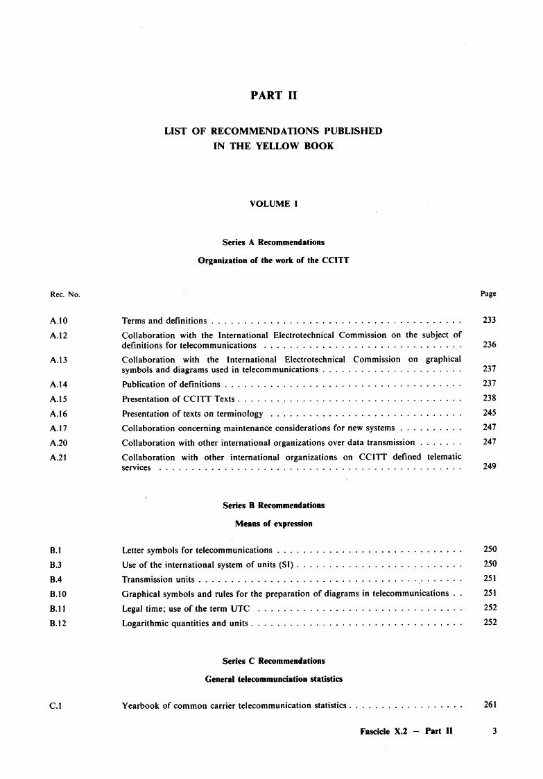
PART II
LIST OF RECOM M ENDATIONS PUBLISHED
IN THE YELLOW BOOK
VOLUME I
Series A Recommendations
Organization of the work of the CCITT
Rec. No. Page
A.10 Terms and d efin itions................................................................................................................ 233
A. 12 Collaboration with the International Electrotechnical Commission on the subject ofdefinitions for telecom m unications........................................................... 236
A. 13 Collaboration with the International Electrotechnical Commission on graphicalsymbols and diagrams used in telecommunications......................................................... 237
A. 14 Publication of defin itions.......................................................................................................... 237
A. 15 Presentation of CCITT T exts.................................................................................................... 238
A. 16 Presentation o f texts on term in o lo g y .................................................................................... 245
A. 17 Collaboration concerning maintenance considerations for new sy stem s..................... 247
A.20 Collaboration with other international organizations over data transm ission........... 247
A.21 Collaboration with other international organizations on CCITT defined telematicservices ................................................................................................................................................. 249
Series B Recommendations
Means of expression
B.l Letter symbols for telecom m unications.................................................................. ....................... 250
B.3 Use o f the international system of units (S I ) ....................................................................... 250
B.4 Transmission u n its ............................................................................................................................... 251
B.10 Graphical symbols and rules for the preparation of diagrams in telecommunications . . 251
B .ll Legal time; use o f the term UTC ................................................................................................... 252
B .l2 Logarithmic quantities and u n its ............................................................................................. 252
Series C Recommendations
General telecommunciation statistics
C.l Yearbook of common carrier telecommunication statistics.............................................. 261
Fascicle X.2 — Part II 3
FASCICLE II. 1
GENERAL TARIFF PRINCIPLES CHARGING AND ACCOUNTING IN
INTERNATIONAL TELECOMMUNICATIONS SERVICES
Series D Recommendations
Rec. No. Page
Recommendations fo r general application
D.l General principles for the lease of international (continental and intercontinental)private leased telecommunication circuits . .................................................................................. 3
D.2 Special conditions for the lease of continental telecommunication circuits for privates e rv ic e .................................................................................................................................................... 10
D.3 Special conditions for the lease of intercontinental telecommunication circuits forprivate service ..................................................................................................................................... 13
D.4 Special conditions for the lease of international programme (sound or television)circuits for private service.................................................................................................................. 15
D.5 Costs and value of services rendered as factors in the fixing of rates .................................. 15
D.6 General principles for the provision of international telecommunications facilities toorganizations formed to meet the specialized international communication needs of their m em bers........................................................................................................................................ 16
D.9 Private leasing of transmitters or re c e iv e rs .................................................................................... 18
D.10 General tariff principles for international public data transmission on public datanetworks dedicated to this type of tran sm iss io n ......................................................................... 19
D.l l Special tariff principles for international packet-switched public data transmissionservices by means of the virtual call f a c i l i ty ............................................................................... 21
D .l2 Measurement unit for charging by volume in the International packet-switched datatransmission s e rv ic e ................................................................................................. 24
D.20 Special tariff principles for the international circuit-switched public data transmissionservice by means of public data n e tw o r k s .................................................................................. 25
DAO General tariff principles applicable to telegrams exchanged in the international publictelegram service ......................... 27
D.41 Introduction of accounting rates by zones in the international public telegram service . 31
D.42 Charging, accounting and refunds in the international public telegram se rv ice ................. 45
D.51 Accounting procedure to be applied when a circuit carrying VH telegraphy is replacedby another having a different ro u tin g ............................................................................................ 45
D.60 Guiding principles to govern the apportionm ent of accounting rates in intercontinentaltelex re la tio n s ........................................................................................................................................ 47
D.61 The chargeable duration of a telex c a l l .......................................................................... 48
D.67 Charging and accounting in the international telex service .................................................... 48
D.70 General tariff principles for the international public facsimile service between publicbureaux (bureaufax service). . . . . . . . .................................................................................. 49
D.71 General tariff principles for the public facsimile service between subscriber stations(telefax serv ice)..................................................................................................................................... 51
D.80 Provisions about phototelegrams .................................................................... 53
4 Fascicle X.2 — Part II
Rec. No. Page
D.81 Provisions relating to private phototelegraph c a l l s .......................................... 53
D.83 Rates for phototelegrams and private phototelegraph calls ................................................... 53
D.85 Rules for international phototelegraph communications to multiple destinations 53
D.90 Charging, accounting and refunds in the maritime mobile s e r v ic e ................ . .................. 55
D.98 The transferred account telegraph service...................................................................................... 75
D .l00 Charging for international calls in manual or semiautomatic o p e ra t in g ............................. 77
D.101 Charging in automatic international telephone s e rv ic e ............................................................ 78
D.103 Charging in automatic service for calls terminating on special services for suspended,cancelled or transferred su b sc rib e rs .............................................................................................. 80
D .l04 Charging for calls to subscriber’s station connected either to the absent subscriber’sservice or to a device substituting a subscriber in his ab sen ce ................................................. 80
D .l05 Charging for calls from or to a public call office ...................................................... 80
D .l06 Introduction of reduced rates during periods of light traffic in the internationaltelephone se rv ic e ................................................................................................................................. 80
D .l 10 Conference c a l l s .................................................................................................................................. 81
D .l50 New system for accounting in international te le p h o n y ............................................................. 82
D.151 Old system for accounting in international telephony ................................................ 94
D .l52 Mode of application of the flat-rate price procedure set forth in Recommendation D .l50 for remuneration of facilities made available to the administrations of other coun tries................................................................................................................................................. 95
D .l70 Monthly telephone a c c o u n ts ...................................................................................................... . 99
D .l71 Adjustments and r e f u n d s ................................................ 105
D .l72 Accounting for calls circulated over international routes for which accounting rateshave not been estab lished ................................................................................................................. 105
D .l73 Defaulting subscribers......................................................................................................................... 106
D .l74 Conventional transmission of information necessary for billing and accountingregarding collect and credit card c a lls ........................................................................................... 106
D .l76 Transmission in encoded form of telephone reversed charge billing and accountingin fo rm a tio n ........................................................................................................................................... 107
D .l80 International so und-and television-programme transmissions ............................................. I l l
D .l90 Transmission in encoded form of monthly international accounting information . . . . 125
D .l95 Settlement of international telecommunication balances of ac c o u n ts .................................... 131
Recommendations fo r regional application
D.200 R Determination of accounting rate shares and collection charges in telephone relationsbetween countries in A frica .................................................. 135
D.201 R Determination of accounting rate shares and collection charges in telex relationsbetween countries in A frica ............................... 146
D.300 R Determination of accounting rate shares and collection charges in telephone relationsbetween countries in Europe and the M editerranean B a s i n ................................................... 157
D.301 R Determination of accounting rate shares and collection charges in telex relationsbetween countries in Europe and the M editerranean B a s i n ................................................... 166
Fascicle X.2 — Part II 5
Page
174
179
188
189
191
191
193
194
3
9
9
10
10
11
15
17
18
19
25
29
30
Determination of the accounting rate shares and collection charges for the international public telegram service applicable to telegrams exchanged between countries in Europe and the Mediterranean B a s in ...........................................................................................
Determination of accounting rate shares and collection charges applicable to occasional sound- and television-programme transmissions between countries in Europe and the Mediterranean B asin ...........................................................................................................
Determination of rentals for the lease of international programme (sound- and television-) circuits for private service in relations between countries in Europe and the Mediterranean B asin ...........................................................................................................................
Accounting system in the international automatic telephone se r v ic e ...................................
Charges for calls carried by emergency rou tes............................................................................
Utilization by public utilities of continental telephone connections which are their property.................................................................................................................................................
Accounting rates applicable in telephone relations between countries in Latin America .
Accounting rates applicable to telex relations between countries in Latin America . . .
FASCICLE II.2
INTERNATIONAL TELEPHONE SERVICE - OPERATION
Series E Recommendations (E.100 to E.182)
International operation
Definitions of terms used in international telephone op eration ............................................
Organization of the international telephone n etw ork ...............................................................
Extension o f international telephone s e r v ic e s ............................................................................
Arrangements to be made for controlling the telephone services between two countries .
Supply o f lists o f subscribers (directories and other m ea n s) ...................................................
Information service for telephone subscriber numbers in foreign countries (directory assistance)..............................................................................................................................................
Credit card s...........................................................................................................................................
Provisions concerning the device substituting a subscriber in his ab sen ce .........................
Instruction of staff operating international p o sitio n s ...............................................................
Instructions for users of the international telephone serv ice...................................................
Pictograihs and symbols to assist users o f the telephone service .........................................
Measures to reduce customer difficulties in the international telephone service................
The use and printing of symbols and separators in national and international telephone num bers.....................................................................................................................................
Fascicle X.2 - Part II
Rec. No. Page
E.125 Inquiries among users of the international telephone s e r v ic e ................................................. 35
E.130 Choice of the most useful and desirable supplementary telephone s e rv ic e s ....................... 47
E.131 Subscriber control procedures for supplementary telephone se rv ices .................................... 48
E.132 Standardization of elements o f control procedures for supplementary telephoneservices ................................................................................................................................................. 55
E.140 Principles for the operation of international telephone serv ices.............................................. 57
E.141 Instructions for the international telephone se rv ic e ................................................................... 59
E.142 Time-to-answer by o p e ra to rs ............................................................................................................ 60
E.143 Demand operating of international circuits ................................................................................ 60
E.144 Advantages of semiautomatic international s e rv ic e ................................................................... 60
E.145 Advantages of international automatic serv ice ............................................................................. 61
E.146 Division of circuits into outgoing and incoming c irc u its ...................... 61
E.147 Manually operated international transit traffic .......................................... . ........................... 61
E.148 Routing of traffic by automatic transit exchanges...................................................................... 62
E.149 Presentation of routing d a t a ............................................................................................................ 63
E.150 Publication of a “list of international telephone routes” .......................................................... 66
E.151 Conference c a l l s .................................................................................................................................. 69
E.160 Definitions relating to national and international numbering p l a n s .................................... 73
E.161 Arrangement of figures, letters and symbols on rotary dials and pushbutton telephones e t s .......................................................................................................................................................... 76
E.163 Numbering plan for the international telephone s e rv ic e .......................................................... 82
E.170 Overflow — alternative routing — rerouting - automatic repeat a ttem p t.......................... 91
E.171 International routing plan ............................................................................................................... 92
E.180 Characteristics of the dial tone, ringing tone, busy tone, congestion tone, specialinformation tone and warning t o n e .............................................................................................. 93
E.181 Customer recognition of foreign t o n e s ......................................................................................... 97
E.182 Application of tones and recorded announcements in telephone s e rv ic e s .......................... 98
E.200 Operational provisions for the maritime mobile s e r v ic e .......................................................... 107
E.210 Ship station identification for V H F /U H F and maritime mobile-satellite services 128
E.211 Numbering and dialling procedures for V H F/U H F and maritime mobile-satellitetelephone s e r v ic e s .............................................................................................................................. 136
Operational provisions relating to charging and accounting in the international telephone service
E.230 Chargeable duration of c a l l s ............................................................................................................ 147
E.231 Charging in automatic service for calls terminating on special services for suspended,cancelled or transferred su b sc r ib e rs ........................................................ 148
E.232 Charging for calls to subscriber’s station connected either to the absent subscriber’sservice or to a device substituting a subscriber in his absence ...................................... 148
E.250 New system for accounting in international te le p h o n y ............................................................. 149
E.251 Old system for accounting in international telephony ............................................................. 149
Fascicle X.2 — Part II 7
Rec. No. Page
E.252 Mode of application of the flat-rate price procedure set forth in RecommendationD .l50 for remuneration of facilities made available to the Administrations of other coun tries . . 149
E.260 Basic technical problems concerning the measurement and recording of call durations . 151
E.261 Devices for measuring and recording call durations ................................................................. 154
E.270 Monthly telephone a c c o u n ts ............................................................................................................. 157
E.275 Transmission in encoded form of monthly international accounting information . . . . 157
E.276 Transmission in encoded form of telephone reversed charge billing and accountingin fo rm a tio n ........................................................................................................................................... 157
E.277 Conventional transmission of inform ation necessary for the collection of charges andthe accounting regarding collect and credit card calls ............................................................ 157
Utilization o f the international telephone network fo r non-telephony applications
E.300 Special uses of circuits normally employed for automatic telephone t r a f f ic ........................ 161
E.320 Speeding up the establishment and clearing of phototelegraph c a l l s .................................... 163
E.323 Rules for phototelegraph communications set up over circuits normally used fortelephone t r a f f i c ................................................................................................................................. 164
FASCICLE II.3
INTERNATIONAL TELEPHONE SERVICE - NETWORK MANAGEMENT,
TRAFFIC ENGINEERING
Series E Recommendations (E.401 to E.427)
International telephone network management and checking o f service quality
E.401 Statistics for the international telephone service (number of circuits in operation andvolume of traffic) ............... 3
E.410 International network management — planning and operating p ro c e d u re s ............ 5
E.420 Checking the quality of the international telephone service — general considerations . . 15
E.421 Service quality observations ............................................................................................................. 16
E.422 Observations on international outgoing telephone calls for quality of serv ice ......... 21
E.423 Observations on traffic set up by o p e r a to r s ..................................................................... 25
E.424 Test calls ............................................................................................................................................... 28
E.426 General guide to the percentage of effective attempts which should be observed forinternational telephone c a l l s ................................................................................................ 30
E.427 Collection and statistical analysis o f special quality of service observation data formeasurements of customer difficulties in the international automatic s e rv ic e ........ 31
8 Fascicle X.2 — Part II
Traffic engineering
E.500 Measurement and recording of tra ff ic ............................................................................................. 37
E.502 Forecasting international telephone t r a f f ic ................................................................................... 41
E.510 Determination of the number of circuits in manual opera tio n ................................................. 53
E.520 Number of circuits to be provided in automatic an d /o r semiautomatic operation,without overflow facilities .............................................................................................................. 55
E.521 Calculation of the number of circuits in a group carrying overflow t r a f f i c ....................... 57
E.522 Number of circuits in a high-usage g r o u p .................................................................................. 67
E.523 Standard traffic profiles for international traffic stream s.......................................................... 71
E.540 Overall grade of service of the international part of an international connection . . . . 77
E.541 Overall grade of service for international connections (subscriber-to-subscriber) 78
E.543 Grades of service in analogue/digital international telephone e x c h a n g e s .......................... 81
Rec. No. Page
FASCICLE II.4
TELEGRAPH AND TELEMATIC SERVICES OPERATIONS AND TARIFFS
Series F Recommendations
Telegraph and “telematic services” operations and tariffs
Operating methods fo r the international public telegram service
F.l Operational provisions for the international public telegram se rv ic e .................................... 5
F.2 Instructions for the international public telegram service ....................................................... 78
F.10 Character error rate objective for telegraph communication using 5-unit start-stopeq u ip m en t.............................................................................................................................................. 79
The gentex network
F.20 The international gentex s e rv ic e ...................................................................................................... 81
F.21 Composition of answer-back codes for the international gentex s e rv ic e .............................. 85
F.23 Grade of service for long-distance international gentex c irc u its .............................................. 88
F.24 Average grade of service from country to country in the gentex se rv ic e .............................. 88
Fascicle X.2 - Part II 9
Page
91
93
103
109
119
119
119
121
136
138
139
140
145
146
146
158
164
168
170
172
173
178
180
183
186
192
The telegram retransmission system
Use of various sequences of combinations for special p u rp o ses . . .
Telegram retransmission s y s te m .....................................................................................................
Tariffs and accounting methods fo r the international public telegram service
The transferred account telegraph service.....................................................................................
Charging, accounting and refunds in the international public telegram se rv ice ................
Transfer in encoded form of monthly international accounting in fo rm a tio n ...................
Regional tariff recommendations for the international public telegram se rv ic e ................
Accounting procedure to be applied when a circuit carrying VF telegraphy is replaced by another having a different ro u tin g ...........................................................................................
Telex
Operational provisions for the international telex s e r v ic e ......................................................
The chargeable duration of a telex c a l l ........................................................................................
Duplex operation in the telex s e rv ic e ............................................................................................
Additional facilities in the international telex se rv ice ...............................................................
Determination of the number of international telex circuits required to carry a given volume of t r a f f ic .................................................................................................................................
Time-to-answer by operators at international telex positions ...............................................
Regional tariff recommendations for the international telex s e r v ic e ...................................
Charging and accounting in the international telex service ...................................................
Establishment of the automatic intercontinental telex n e tw o r k ............................................
Plan for telex destination codes ............................................................................................
Observations on the quality of service in the international telex se rv ic e .............................
Interconnection of private teleprinter networks with the telex network ............................
Instructions for the international telex se rv ic e ............................................................................
Phototelegraph services
Provisions about phototelegram s.....................................................................................................
Provisions relating to private phototelegraph c a l l s ..................................................................
Rules for phototelegraph calls established over circuits normally used for telephone t r a f f i c ....................................................................................................................................................
Rates for phototelegrams and private phototelegraph calls ...................................................
Rules for phototelegraph communications established over radio circuits or combined radio and metallic circuits ...............................................................................................................
Rules for international phototelegraph communications to multiple destinations.............
Fascicle X.2 — Part II
Rec. No. Page
Statistics and publications on international telegraph services
F.91 General statistics for the telegraph services.................................................................................... 199
F.92 Service c o d e s ......................................................................................................................................... 200
F.93 Routing table for offices connected to the gentex service ....................................................... 202
F.95 Table of international telex relations and traffic.......................................................................... 203
F.96 List o f destination indicators............................................................................................................. 205
Scheduled and leased communication services
F.100 Scheduled radiocommunication serv ice .......................................................................................... 207
Maritime mobile service
F.110 Operational provisions for the maritime mobile s e r v ic e .......................................................... 209
F .l l l Charging, accounting and refunds in the maritime mobile s e r v ic e ....................................... 226
F.112 Quality objectives for 50-baud start-stop telegraph transmission in the maritimemobile-satellite service........................................................................................................................ 241
F.120 Ship station identification for VH F/UH F and maritime mobile-satellite services 242
F.121 Numbering and selection procedures for maritime mobile radiotelex services..................... 247
F.130 Maritime answer-back c o d e s ......................................................................... 257
F.131 Radiotelex service codes ................................................................................................................... 259
F.132 Procedures for use of store-and-forward facilities in the maritime mobile services forship-originated c a l l s ........................................................................................................................... 260
Public facsimile service
F.160 General operational provisions for the international public facsimile s e r v ic e s ................. 265
F.170 Operational provisions for the international public facsimile service between publicbureaux (bureaufax)........................................................................................................................... 270
F.180 Operational provisions for the international public facsimile service betweensubscribers’ s ta t io n s . . . . 277
Teletex service
F.200 Teletex s e r v ic e ...................................................................................................................................... 281
Videotex service
F.300 Videotex s e r v ic e ................................................................................................................................... 301
Fascicle X.2 — Part II 11
FASCICLE III.1
GENERAL CHARACTERISTICS OF INTERNATIONAL
TELEPHONE CONNECTIONS AND CIRCUITS
Series G Recommendations (G.101 to G.171)
Rec. No. Page
General characteristics fo r international telephone connections and international telephone circuits
G.101 The transmission p l a n ......................................................................................................................... 3
G.102 Transmission performance objectives and recommendations ................................................ 17
G.103 Hypothetical reference c o n n e c tio n s ...................................................................................... 20
G.104 Hypothetical reference connections (digital n e tw o rk )................................................................ 28
G.105 Hypothetical reference connection for crosstalk studies.............................................................. 30
G.106 Concepts, terms and definitions related to availability and reliability s tu d ie s .................... 35
G .l l l Corrected reference equivalents (CREs) in an international c o n n e c tio n ............................. 55
G.113 Transmission im p a irm e n ts ............................................................................................................... 64
G.114 Mean one-way propagation tim e ...................................................................................................... 70
G.117 Transmission aspects of unbalance about e a r t h .......................................................................... 73
G.120 Transmission characteristics of national ne tw orks...................................................................... 88
G.121 Corrected reference equivalents (CREs) of national system s...................... 90
G.122 Influence of national networks on stability and echo losses in national sy s te m s ................ 102
G.123 Circuit noise in national ne tw orks............................................................................... 112
G.125 Characteristics of national circuits on carrier systems ............................................................. 116
G.131 Stability and e c h o ................................ 116
G.132 Attenuation d is to r tio n ......................................................................................................................... 125
G.133 Group-delay distortion ...................................................................................................................... 126
G.134 Linear crosstalk ................................................ 127
G.135 Error on the reconstituted f r e q u e n c y ............................................................................................. 128
G.141 Transmission losses, relative levels and attenuation d isto rtio n ................................................ 129
G.142 Transmission characteristics of e x c h a n g e s ................................................................................... 130
G.143 Circuit noise and the use of co m p an d o rs ...................................................................................... 134
G.151 General performance objectives applicable to all modern international circuits andnational extension circuits ............................................................................................................... 137
G.152 Characteristics appropriate to long-distance circuits of a length not exceeding 2500 km 142
G.153 Characteristics appropriate to international circuits more than 2500 km in length . . . . 143
G.161 Echo-suppressors suitable for circuits having either short or long propagation times . . 145
G.162 Characteristics of compandors for telephony ............................................................................. 146
G.163 Call concentrating s y s te m s ............................................................................................................... 152
G.164 Echo suppressors.................................................................................................................................. 154
G.165 Echo cance llers ...................................................................................................................................... 182
G.171 Transmission characteristics of leased circuits forming part of a private telephonen e tw o r k ................................................................................................................................................. 193
12 Fascicle X.2 — Part II
FASCICLE III.2
INTERNATIONAL ANALOGUE CARRIER SYSTEMS
CHARACTERISTICS OF TRANSMISSION MEDIA
Series G Recommendations (G.211 to G.651)
Rec. No. Page
General characteristics common to all analogue carrier-transmission systems
G.211 Make-up of a carrier l i n k ....................................................................................................... 3
G.212 Hypothetical reference c irc u its .............................................................................................. 10
G.213 Interconnection of systems in a main repeater s t a t i o n .................................................. 12
G.214 Line stability of cable s y s te m s .............................................................................................. 16
G.215 Hypothetical reference circuit of 5000 k m ........................................................................ 17
G.221 Overall recommendations relating to carrier-transmission sy stem ............................... 18
G.222 Noise objectives for design of carrier-transmission systems of 2500 k m ................... 19
G.223 Assumptions for the calculation of noise on hypothetical reference circuits for telephony 23
G.224 Maximum permissible value for the absolute power level (power referred to onemilliwatt) of a signalling p u ls e ............................................................................................ 31
G.225 Recommendations relating to the accuracy of carrier frequencies . .................................... 32
G.226 Noise on a real l i n k ................................................................................................................. 33
G.227 Conventional telephone s ig n a l .............................................................................................. 34
G.228 Measurement of circuit noise in cable systems using a uniform-spectrum random noiseload in g ........................................................................................................................................ 37
G.229 Unwanted modulation and phase j i t t e r .............................................................................. 48
G.230 Measuring methods for noise produced by modulating equipment and through-connec-tion f i l te r s .................................................................................................................................. 49
G.231 Arrangement of carrier equ ipm en t................................................................... 53
G.232 12-channel terminal e q u ip m e n ts ................................................................................................... .. 54
G.233 Recommendations concerning translating e q u ip m e n ts .................................................. 65
G.234 8-channel terminal equ ipm ents................................ 74
G.235 16-channel terminal e q u ip m e n ts ........................................ 74
G.241 Pilots on groups, supergroups, etc......................................................................................... 76
G.242 Through-connection of groups, supergroups, etc............................................................... 82
G.243 Protection of pilots and additional measuring frequencies at points where there is athrough-connection ........................................................................................................................... 88
Individual characteristics o f international carrier telephone systems on metallic lines
G.311 General characteristics of systems providing 12 carrier telephone circuits on anopen-wire p a i r ......................................................................................................................... 93
G.312 Intermediate repeaters for open-wire carrier systems conforming to recommendationG.311 98
Fascicle X.2 — Part II 13
Rec. No. Page
G.313 Open-wire lines for use with 12-channel carrier sy ste m s ............................................... 99
G.314 General characteristics of systems providing eight carrier telephone circuits on anopen-wire p a i r ............................................... 101
G.322 General characteristics recommended for systems on symmetric pair cables ................. 102
G.323 Typical transistorized systems on symmetric cable p a ir s ............................................... 109
G.324 General characteristics for valve-type systems on symmetric cable p a irs................... I l l
G.325 General characteristics recommended for systems providing 12 telephone carriercircuits on a symmetric cable pair [(12 + 12) system s]............................................................ I l l
G.326 Typical systems on symmetric cable pairs [(12 + 12) systems] ............................................. 115
G.327 Valve-type systems offering 12 carrier telephone circuits on a symmetric cable pair[(12 + 12) systems] ........................................................................................................................... 117
G.332 12-MHz systems on standardized 2.6/9.5-mm coaxial cable pairs ....................................... 117
G.333 60-MHz systems on standardized 2.6/9.5-mm coaxial cable pairs.......................................... 125
G.334 18-MHz systems on standardized 2.6/9.5-mm coaxial p a ir s ......................................... 134
G.337 General characteristics of systems on 2.6/9.5-mm coaxial cable p a i r s ................................. 142
G.338 4-MHz valve-type systems on standardized 2.6/9.5-mm coaxial cable p a ir s ........................ 142
G.339 12-MHz valve-type systems on standardized 2.6/9.5-mm coaxial cable p a ir s ......... 143
G.341 1.3-MHz systems on standardized 1.2/4.4-mm coaxial cable p a ir s ............................ 143
G.343 4-MHz systems on standardized 1.2/4.4-mm coaxial cable p a i r s .......................................... 147
G.344 6-MHz systems on standardized 1.2/4.4-mm coaxial cable p a i r s .......................................... 150
G.345 12-MHz systems on standardized 1.2/4.4-mm coaxial cable pairs.......................................... 152
G.346 18-MHz systems on standardized 1.2/4.4-mm coaxial cable pairs.......................................... 152
G.352 Interconnection o f coaxial carrier systems of different types ................................................. 153
G.356 (120 + 120)-channel systems on a single coaxial p a i r ............................................................. 156
G.361 Systems providing three carrier telephone circuits on a pair o f open-wire lines .............. 158
G.371 FDM carrier systems for submarine c a b le .................... 162
General characteristics o f international carrier telephone systems on radio-relay or satellite links and interconnection with metallic lines. Coordination o f radiotelephony and line telephony
G.411 Use of radio-relay systems for international telephone c ir c u its ............................................. 165
G.412 Terminal equipments of radio-relay systems forming part of a general telecommunication n e tw o r k ........................................................................................................................................ 166
G.421 Methods of interconnection................................................................................................................ 166
G.422 Interconnection at audio-frequencies............................................................................................. 167
G.423 Interconnection at the baseband frequencies o f frequency-division multiplex radio-relaysystems ................................................................................................................................................. 168
G.431 Hypothetical reference circuits for frequency-division multiplex radio-relay systems . . . 175
14 Fascicle X.2 — Part II
Rec. No.
G.433
G.434
G.441
G.442
G.444
G.445
G.451
G.453
G.464
G.471
G.473
G.541
G.542
G.543
G.544
G.601
G.611
G.612
G.621
G.622
G.623
G.631
G.641
G.651
Page
Hypothetical reference circuit for tropospheric-scatter radio-relay systems using frequency-division m u ltip le x ........................................................................................................... 176
Hypothetical reference circuit for communication-satellite sy s tem s...................................... 176
Permissible circuit noise on frequency-division multiplex radio-relay system s................... 177
Radio-relay system design objectives for noise at the far end of a hypothetical reference circuit with reference to telegraphy transm ission ..................................................... 178
Allowable noise power in the hypothetical reference circuit for tropospheric scatter radio-relay systems using frequency-division m u ltip lex ............................... 179
Noise objectives for communication-satellite system d e s ig n .................................................. 179
Use of radio links in international telephone c irc u its ............................................................... 179
Improved transmission system for H F radio-telephone c irc u its ............................................ 181
Principles of the devices used to achieve privacy in radiotelephone conversations . . . . 181
Conditions necessary for interconnection of mobile radiotelephone stations and international telephone l in e s .................................................................................................................... 182
Interconnection o f a maritime mobile satellite system with the international automatic switched telephone service; transmission aspects ..................................................................... 182
Audio-frequency circuits
Specification of factory lengths o f loaded telecommunication c a b l e ................................... 194
Specification o f loading coils for loaded telecommunication c a b l e s ................................... 194
Specification for repeater sections of loaded telecommunication c a b le ................................ 194
Specifications for terminal equipment and intermediate repeater s ta t io n s ......................... 194
Characteristics o f transmission media
Terminology for c a b l e s ..................................................................................................................... 195
Characteristics of symmetric cable pairs for analogue transmission ................................... 200
Characteristics of symmetric cable pairs designed for the transmission of systems withbit rates of the order of 6 to 34 M b i t / s ........................................................................................ 204
Characteristics of 0.7/2.9-mm coaxial cable p a i r s ...................................................... 209
Characteristics o f 1.2/4.4-mm coaxial cable p a i r s ..................................................................... 212
Characteristics o f 2.6/9.5-mm coaxial cable p a i r s ..................................................................... 218
Types of submarine cable to be used for systems with line frequencies o f less than about 45 M H z .................................................................................................................................... 224
Waveguide d ia m e te r s ........................................................................................................................ 225
Characteristics of 50/125 pm graded index optical fibre c a b le s ............................................ 226
Fascicle X.2 — Part II 15
FASCICLE III.3
DIGITAL NETWORKS - TRANSMISSION SYSTEMS AND MULTIPLEXING EQUIPMENTS
Series G Recommendations (G.701 to G.941)
Rec. No. Page
General aspects o f digital transmission systems; terminal equipments
G.701 Framework of the Series G.700, G.800 and G.900 Recommendations . ........................... 3
G.702 Vocabulary of pulse code modulation (PCM) and digital transmission te rm s .... 6
G.703 General aspects of in te rfa c es ............................................................................................. 34
G.704 Maintenance of digital n e tw orks....................................................................................... 63
G.705 Integrated services digital network (IS D N ).................................................................... 65
G.711 Pulse code modulation (PCM) of voice frequencies............................................................. . 67
G.712 Performance characteristics of PCM channels at audio frequencies................................ . 74
G.721 Hypothetical reference digital p a th s ................................................................................................. 82
G.722 Interconnection of digital paths using different techniques ..................................................... 84
G.731 Primary PCM multiplex equipment for voice fre q u e n c ie s ................................... 85
G.732 Characteristics of primary PCM multiplex equipment operating at 2048 kbit/s ............. 86
G.733 Characteristics of primary PCM multiplex equipment operating at 1544 kb it/s ............. 93
G.734 Characteristics o f 2048-kbit/s frame structure for use with digital ex ch an g es.... 97
G.735 Characteristics required to terminate 1544-kbit/s digital paths on a digital exchange . . 100
G.736 Characteristics of synchronous digital multiplex equipment operating at 1544 kbit/s . . 101
G.737 Characteristics of primary PCM multiplex equipment operating at 2048 kbit/s andoffering synchronous 64-kbit/s digital access options . . ...................................................... 105
G.738 Characteristics of a synchronous digital multiplex equipment operating at 2048 kbit/s . 109
G.739 Characteristics of an external access equipment operating at 2048 kbit/s and offeringsynchronous digital access at 64 k b i t / s ............................ 114
G.741 General considerations on second order multiplex e q u ip m e n ts .............................. 119
G.742 Second order digital multiplex equipment operating at 8448 kb it/s and using positiveju s tif ic a tio n ..................................................... 124
G.743 Second order digital multiplex equipment operating at 6312 kb it/s and using positiveju s tif ic a tio n ........................................................................................................................... 128
G.744 Second order PCM multiplex equipment operating at 8448 k b i t / s ........................ 132
G.745 Second order digital multiplex equipment operating at 8448 kb it/s and using positive/zero/negative justification ............................................................................................................... 138
G.746 Characteristics of 8448 kbit/s frame structure for use with digital ex ch an g es.... 142
16 Fascicle X.2 — Part II
Rec. No. Page
G.751 Digital multiplex equipments operating at the third order bit rate of 34 368 kbit/s andthe fourth order bit rate of 139 264 kbit/s and using positive justification ...................... 144
G.752 Characteristics of digital multiplex equipments based on a second order bit rate of6312 kb it/s and using positive justification .................................................................................. 156
G.753 Third order digital multiplex equipment operating at 34 368 kbit/s and using positive/zero/negative justification .............................................................................................................. 163
G.754 Fourth order digital multiplex equipment operating at 139 264 kbit/s and using positive/zero/negative ju stifica tio n ................................................................................................. 167
G.791 General considerations on transmultiplexing equipments ...................................................... 170
G.792 Characteristics common to all transmultiplexing e q u ip m e n ts ................................................ 171
G.793 Characteristics of 60-channel transmultiplexing eq u ip m en ts ................................................... 180
Digital networks
G.811 Performance of clocks suitable for plesiochronous operation of international digitall i n k s ....................................................................................................................................................... 189
G.821 Error performance on an international digital connection forming part of an integratedservices digital n e tw o rk .................................................................................................................... 193
G.822 Controlled slip rate objectives on an international digital c o n n e c tio n ................................ 196
Digital line transmission systems
G.901 General considerations on digital line sections and digital line sy s te m s ............................. 199
G.911 Digital line sections and digital line systems on cable at 1544 k b i t / s ................................... 201
G.912 Digital line sections and digital line systems on cable at 2048 k b i t / s ................................... 203
G.913 Digital line sections and digital line systems on cable at 6312 k b i t / s ................................... 206
G.914 Digital line sections and digital line systems on cable at 8448 k b i t / s ................................... 207
G.915 Digital line sections and digital line systems on cable at 32 064 k b i t / s ................................ 209
G.916 Digital line sections and digital line systems on cable at 34 368 k b i t / s ................................ 210
G.917 Digital line sections and digital line systems on cable at 44 736 k b i t / s ................................ 213
G.918 Digital line sections and digital line systems on cable at 139 264 k b i t / s ............................. 214
G.921 Digital line sections and digital line systems on cable at 3152 k b i t / s ................................... 216
G.922 Digital line system at 564 992 kb it/s on coaxial pairs ............................................................ 218
G.941 Digital line systems provided by FDM transmission bearers ................................................ 225
Fascicle X.2 — Part II 17
FASCICLE III.4
LINE TRANSMISSION OF NON-TELEPHONE SIGNALS
TRANSMISSION OF SOUND-PROGRAMME AND TELEVISION SIGNALS
Series H Recommendations
Lines used for the transmission of signals other than telephone signals, such as telegraph, facsimile, data, etc., signals
Rec. No. Page
Characteristics o f transmission channels used fo r other than telephone purposes
H .ll Characteristics o f circuits in the switched telephone n e tw o r k ...................................... 5
H.12 Characteristics of telephone-type leased c irc u its ................................................................ 6
H.13 Characteristics of an impulsive noise measuring instrument for telephone-type circuits . 13
H.14 Characteristics of group links for the transmission of wide-spectrum s ig n a ls .......... 13
H.15 Characteristics of supergroup links for the transmission of wide-spectrum signals . . . . 18
H.16 Characteristics of an impulsive-noise measuring instrument for wideband data transmission ................................................................................................................................................. 20
Use o f telephone-type circuits fo r voice-frequency telegraphy
H.21 Composition and terminology o f international voice-frequency telegraph systems . . . . 25
H.22 Transmission requirements of international voice-frequency telegraph links (at 50, 100and 200 b a u d s ) ..................................................................................................................................... 26
H.23 Basic characteristics of telegraph equipments used in international voice-frequencytelegraph system s................................................................................................................................. 32
Telephone circuits or cables used fo r various types o f telegraph transmission or fo r simultaneous transmissions
H.32 Simultaneous communication by telephony and telegraphy on a telephone-type circuit . 35
H.34 Subdivision of the frequency band of a telephone-type circuit between telegraphy andother se rv ic e s ........................................................................................................................................ 36
Telephone-type circuits used fo r facsimile telegraphy
H.41 Phototelegraph transmissions on telephone-type c ir c u its .......................................................... 39
H.42 Range of phototelegraph transmissions on a telephone-type circuit .................................... 42
H.43 Document facsimile transmissions on leased telephone-type c ir c u i ts .......................... 45
Characteristics o f data signals
H.51 Power levels for data transmission over telephone l i n e s .......................................................... 47
H.52 Transmission of wide-spectrum signals (data, facsimile, etc.) on wideband group links . 49
H.53 Transmission of wide-spectrum signals (data, etc.) over wideband supergroup links . . . 50
18 Fascicle X.2 - Part II
Characteristics o f visual telephone systems
H.61 Visual telephone s y s te m s .................................................................................................................. 51
Series J Recommendations
Sound-programme and television transmissions
General recommendations concerning sound-programme transmissions
J . l l Hypothetical reference circuits for sound-programme tra n sm iss io n s .................................... 57
J.12 Types of sound-programme circuits established over the international telephonen e tw o r k ................................................................................................................................................. 59
J.13 Definitions for international sound-programme c i r c u i t s .......................................................... 60
J.14 Relative levels and impedances on an international sound-programme connection . . . 63
J.15 Lining-up and monitoring an international sound-programme c o n n e c t io n ....................... 66
J.16 Measurement of weighted noise in sound-programme c ircu its ................................................ 68
J.17 Pre-emphasis used on sound-programme circuits in group links .......................................... 75
J.18 Crosstalk in sound-programme circuits set up on carrier system s.......................................... 76
J.19 A conventional test signal simulating sound-programme signals for measuring interference in other ch an n e ls ........................................................................................................................ 79
Performance characteristics o f sound-programme circuits
J.21 Performance characteristics of 15-kHz type sound-programme circu its ................................. 81
J.22 Performance characteristics of 10-kHz type sound-programme circu its ................................. 87
J.23 Performance characteristics of narrow-bandwidth sound-programme c irc u its .................... 92
Characteristics o f equipment and lines used fo r setting up sound-programme circuits
J.31 Characteristics of equipment and lines used for setting up 15-kHz type sound-programme circuits ....................................................................................................... 97
J.32 Characteristics of equipment and lines used for setting up 10-kHz type sound-programme circuits ........................................................................................................................... 113
J.33 Characteristics of equipment and lines used for setting up 6.4-kHz type sound-programme circuits ........................................................................................................................... 114
J.34 Characteristics of equipment used for setting up 7-kHz type sound-programme circuits . 115
Characteristics o f circuits fo r television transmissions
J.61 Transmission performance of television circuits designed for use in internationalc o n n e c tio n s ........................................................................................................................................... 119
J.62 Single value of the signal-to-noise ratio for all television system s......................................... 119
J.63 Insertion of test signals in the field-blanking interval of monochrome and colourtelevision s ig n a ls ........................................................................ 119
Rec. No. Page
Fascicle X.2 — Part II 19
Rec. No. Page
J.64 Definitions of parameters for automatic measurement of television insertion test signals 120
J.65 Standard test signal for conventional loading of a television c h a n n e l ................................. 120
J.66 Transmission of one sound programme associated with analogue television signal bymeans of time division multiplex in the line synchronizing p u ls e ......................................... 120
General characteristics o f systems fo r television transmission over metallic lines and interconnection with radio-relay links
J.73 Use of a 12-MHz system for the simultaneous transmission of telephony and television 121
J.74 Methods for measuring the transmission characteristics of translating equipments . . . . 126
J.75 Interconnection of systems for television transmission on coaxial pairs and on radiorelay l in k s .............................................................................................................................................. 127
J.77 Characteristics of the television signals transmitted over 18-MHz and 60-MHz systems . 128
VOLUME IX
PROTECTION
Series K Recommendations
Protection against interference
K.l Connection to earth of an audio-frequency telephone line in c ab le ........................ 3
K.2 Protection of repeater power-feeding systems against interference from neighbouringelectricity l i n e s ........................................................... 4
K.3 Interference caused by audio-frequency signals injected into a power distributionn e tw o r k .................................................................................................................................. 4
K.4 Disturbance to s ig n a llin g ...................................................................... 4
K.5 Joint use of poles for electricity distribution and for telecom m unications............ 5
K.6 Precautions at c rossings....................................................................................................... 5
K.7 Devices for protection against acoustic s h o c k .............................................................. 7
K.8 Separation in the soil between telecommunication and power in s ta lla tio n s ......... 8
K.9 Protection of telecommunication staff and plant against a large earth potential due toa neighbouring electric traction l i n e ................................................................................ 10
K.10 Unbalance of telecommunication in s ta lla tio n s .............................................................. 11
K .ll Protection against overvoltages....................... 11
K .l2 Specification clauses for the requirements to be met by gas discharge protectors for theprotection of telecommunciation in s ta lla tio n s ............................................................. 15
20 Fascicle X.2 — Part II
Rec. No. Page
K .l3 Induced voltages in cables with plastic-insulated conductors ................................................ 28
K .l4 Provision of a metallic screen in plastic-sheathed c a b le s ............................................. 29
K .l5 Protection of remote-feeding systems and line repeaters against lightning and interference from neighbouring electricity lines 30
K .l6 Simplified calculation method for estimating the effect o f magnetic induction frompower lines on remote-fed repeaters in coaxial pair telecommunication sy s te m s ......... 33
K .l7 Tests on power-fed repeaters using solid-state devices in order to check the arrangements for protection from external in te rfe ren ce 55
K .l8 Calculation of voltage induced into telecommunication lines from radio stationbroadcasts and methods of reducing in te rfe re n ce ......................................................... 62
K .l9 Joint use of trenches and tunnels for telecommunication and power c ab le s .......... 77
Series L Recommendations
Protection of cable sheaths and poles
L.l Protection against c o r r o s io n ............................................................................................... 81
L.2 Impregnation of wooden p o le s ............................................................................................ 81
L.3 Armouring of c a b le s ............................................................................................................... 81
L.4 Aluminium cable s h e a th s ..................................................................................................... 84
L.5 Cable sheaths made of metals other than lead or a lu m in iu m ................................... 86
L.6 Methods of keeping cables under gas p ressu re ................................................................ 87
L.7 Application of joint cathodic p ro te c t io n ......................................................................... 87
L.8 Corrosion caused by alternating c u r r e n t ...................... 89
FASCICLE IV. 1
MAINTENANCE - GENERAL PRINCIPLES - INTERNATIONAL CARRIER SYSTEMS -
INTERNATIONAL TELEPHONE CIRCUITS
Series M Recommendations (M.10 to M.761)
Introduction
M.10 General recommendation concerning m a in te n a n c e ................................................................... 3
M.15 M aintenance considerations for new systems ............................................................................. 3
M.25 Line-up and m aintenance l im i t s ...................................................................................................... 3
M.50 V o c a b u la ry ............................................................................................................... 4
Fascicle X.2 — Part II 21
5
6
8
9
11
12
13
15
17
20
22
30
37
46
49
52
55
60
62
62
63
63
69
72
72
80
96
97
99
99
General
Guiding principles on the general maintenance organization for telephone-type international c irc u its .......................................................................................................................................
Control stations .................................................................................................................................
Circuit control station (leased and special c irc u its ) ..................................................................
Sub-control s ta t io n s ...........................................................................................................................
Sub-control station (leased and special c irc u its ) .........................................................................
Transmission maintenance point (international line) (T M P -IL )............................................
Exchange of contact point information for international leased and special circuit maintenance .......................................................................................................................................
Exchange of contact point information for group, supergroup, etc., and transmission system m a in te n a n c e ...........................................................................................................................
Service c i r c u i ts ....................................................................................................................................
Circuit te s tin g ............................................ ...........................................................................................
Operational procedures in locating and clearing transmission f a u l t s ...................................
Designation of international circuits, groups, etc.........................................................................
Routine maintenance schedule for international public telephony c ircu its .........................
Stability of transmission ..................................................................................................................
Transmission path restoration for service p ro te c t io n ...............................................................
Exchange of information for planned outages of transmission s y s te m s .............................
International carrier systems
Definitions concerning international carrier s y s te m s ...............................................................
Numbering of the channels in a g r o u p .........................................................................................
Numbering of groups within a su perg roup ..................................................................................
Numbering o f supergroups within a m aste rg ro u p ......................................................................
Numbering of mastergroups within a superm aste rg roup .........................................................
Numbering in coaxial sy s te m s ........................................................................................................
Numbering in systems on symmetric pair c a b l e .........................................................................
Numbering in radio-relay links or open-wire line sy s tem s......................................................
Bringing a new international carrier system into s e rv ic e .........................................................
Bringing international group, supergroup, etc., links into se rv ice .........................................
Setting up and lining up the channels of an international g r o u p .........................................
Routine m aintenance measurements to be made on regulated line s e c tio n s ......................
Readjustment to the nominal value of a regulated line section (on a symmetric pair line, a coaxial line or a radio-relay link) ................ ..................................................................
Routine maintenance on international group, supergroup, etc., links ................................
Readjustment to the nominal value of an international group, supergroup, etc., link . .
Spe&ial m aintenance procedures for multiple destination, unidirectional (MU) group and supergroup l i n k s ........................................................................................................................
Routine maintenance of carrier and pilot generating e q u ip m e n t.........................................
Fascicle X.2 — Part II
Page
105
106
108
117
117
118
120
122
123
126
127
129
130
134
136
140
141
143
144
144
146
147
148
149
150
151
152
157
161
162
162
163
167
171
23
Overall loss of a c i r c u i t .................................................................. ..................................................
Constitution o f the circuit; preliminary exchange of in fo rm ation .........................................
Setting up and lining up an international circuit for public te lep h o n y ...............................
Setting up a circuit fitted with a c o m p an d o r...............................................................................
Organization o f routine maintenance measurements on c ircu its ............................................
Periodicity of maintenance measurements on c ircu its ...............................................................
Methods for carrying out routine measurements on c irc u its ..................................................
M aintenance of circuits using control chart m e th o d s ...............................................................
Four-wire switched connections and four-wire measurements on circuits . . ................
Routine line measurements to be made on the line repeaters of audio-frequency sections or c ir c u i ts ..............................................................................................................................
Periodical in-station tests of echo suppressors complying with Recommendation G.161 of Volume III o f the CCITT Orange B o o k ..................................................................................
M aintenance of a circuit fitted with a com pandor ..................................................................
Lining up and maintaining international demand assignment circuits (S P A D E ).............
Definitions for the maintenance o rg a n iz a tio n ...........................................................................
General m aintenance organization for the international automatic and semiautomatic service ....................................................................................................................................................
Fault report point ( c i r c u i t ) ..............................................................................................................
Fault report point (n e tw o rk ) ...........................................................................................................
Testing point ( tra n sm iss io n ) ...........................................................................................................
Testing point (line signalling) ........................................................................................................
Testing point (switching and interregister s ig n a llin g ) ...............................................................
Network analysis p o i n t ....................................................................................................................
System availability information p o in t ...........................................................................................
Network management p o i n t ...........................................................................................................
Circuit control s ta t io n .......................................................................................................................
Circuit sub-control station . ........................................................................................................
Restoration control p o in t .................................................................................................................
Guidelines for the cooperation between maintenance e le m e n ts ............................................
M aintenance m e th o d s .......................................................................................................................
Subjective te s tin g .................................................................................................................................
Signalling and switching routine maintenance tests and measurements ............................
Transmission routine maintenance measurements on automatic and semiautomatic c irc u its ....................................................................................................................................................
Exchange of inform ation on incoming test facilities at international switching centres .
Common channel signalling systems
Transfer link for common channel signalling system No. 6 ..................................................
Setting up and lining up a transfer link for common channel signalling system No. 6 (analogue v e r s io n ) ..............................................................................................................................
International telephone circuits
Fascicle X.2 - Part II
FASCICLE IV.2
MAINTENANCE OF INTERNATIONAL VOICE-FREQUENCY TELEGRAPHY AND
FACSIMILE CIRCUITS AND INTERNATIONAL LEASED CIRCUITS
Series M Recommendations (M.800 to M.1235)
Rec. No. Page
International circuits fo r voice-frequency telegraph and facsimile transmission
M.800 Use of circuits for voice-frequency te leg rap h y ............................................................................. 3
M.810 Setting up and lining up an international voice-frequency telegraph link for publictelegraph circuits (for 50, 100 and 200 baud m odulation r a t e s ) ............................................ 6
M.820 Periodicity of routine tests on international voice-frequency telegraph l i n k s .................... 15
M.830 Routine measurements to be made on international voice-frequency telegraph links . . . 15
M.880 International phototelegraph tra n sm iss io n ................................................................................... 16
International leased group and supergroup links
M.900 Use of leased group and supergroup links for wide-spectrum signal transmission (data,facsimile, etc.) ..................................................................................................................................... 19
M.910 Setting up and lining up an international leased group link for wide-spectrum signaltransm ission.................................................. 22
International leased circuits
M.1010 Constitution and nomenclature of international leased c i r c u i ts ............................................. 27
M.1015 Types of transmission on leased c i r c u i t s ...................................................................................... 30
M.1020 Characteristics of special quality international leased circuits with special bandwidthconditioning ........................................................................................................................................ 32
M.1025 Characteristics of special quality international leased circuits with basic bandwidthconditioning ........................................................................................................................................ 36
M.1040 Characteristics of ordinary quality international leased c irc u its .............................................. 39
M.1045 Preliminary exchange of information for the provision of international leased circuits . 41
M.1050 Lining up an international point-to-point leased c i r c u i t .......................................................... 43
M.1055 Lining up an international multiterminal leased c ircu it............................................................. 48
M.1060 M aintenance of international leased c irc u its ................................................................................ 51
Maritime systems
M.1100 General m aintenance aspects o f maritime satellite system s....................................................... 55
International public network maintenance
M.1220 Exchange of network maintenance in fo rm a tio n .......................................................................... 63
M.1230 Assessment of the performance of the international telephone n e tw o r k ............................. 65
M.1235 Use of automatically generated test calls for assessment of network performance . . . . 66
24 Fascicle X.2 — Part II
FASCICLE IV.3
MAINTENANCE OF INTERNATIONAL SOUND-PROGRAMME
AND TELEVISION TRANSMISSION CIRCUITS
Series N Recommendations
Rec. No. Page
International sound-programme transmission
N .l Definitions for application to international sound-programme transm issions..................... 3
N.2 Different types of sound-programme c i r c u i t ................................................................................ 8
N.3 Control c ircu its ...................................................................................................................................... 9
N.4 Definition and duration of the line-up period and the preparatory p e r i o d ........................ 10
N.5 Sound-programme control, sub-control and send reference s t a t i o n s .................................... 10
N.10 Limits for international sound-programme links and connections ....................................... 12
N .ll Essential transmission performance objectives for international sound-programmecentres (ISPC) .................................................................................................................................... 15
N .l2 Measurements to be made during the line-up period that precedes a sound-programmetransm ission ........................................................................................................................................... 16
N .l3 Measurements to be made by the broadcasting organizations during the preparatoryp e r i o d .................................................................................................................................................... 16
N .l5 Maximum permissible power during an international sound-programme transmission . 17
N .l6 Identification s ig n a l ............................................................................................................................ 18
N .l7 M onitoring the tra n sm iss io n ............................................................................................................. 18
N .l8 M onitoring for charging purposes, re leasin g ................................................................................ 19
N.21 Limits and procedures for the lining-up of a sound-programme c i r c u i t .............................. 19
N.23 Routine maintenance measurements to be made on international sound-programmec ircu its .................................................................................................................................................... 23
International television transmissions
N.51 Definitions for application to international television tran sm iss io n s .................................... 27
N.52 Multiple television transmissions and coordinating centres .................................................... 32
N.54 Definition and duration of the line-up period and the preparatory p e r i o d ........................ 33
N.55 Organization, responsibilities and functions of control and sub-control ITCs andcontrol and sub-control stations for international television connections, links, circuits and circuit sections ............................................................... 34
N.60 Nominal amplitude of video signals at video interconnection p o in ts .................................... 40
N.61 Measurements to be made before the line-up period that precedes a televisiontransm ission ........................................................................................................................................... 41
N.62 Tests to be made during the line-up period that precedes a television transmission . . . 41
N.63 Test signals to be used by the broadcasting organizations during the preparatoryp e r i o d .................................................................................................................................................... 57
N.64 Quality and impairment assessm en t...................................................................... 57
N.67 M onitoring television transmissions use of the field blanking in te rv a l................................. 58
N.73 Routine maintenance m easurem ents................................................................................................ 62
Fascicle X.2 - Part II 25
FASCICLE IV.4
SPECIFICATIONS OF MEASURING EQUIPMENT
Series O Recommendations
Rec. No. Page
Specifications fo r analogue-type measurement equipment
0.11 Specifications for manual maintenance access l in e s .................................................................... 30.21 CCITT automatic transmission measuring equipment ATME No. 1 (for telephone-type
c i r c u i ts ) ................................................................................................................................................. 70.22 Specification for the CCITT automatic transmission measuring and signalling testing
equipment ATME No. 2 .................................................................................................................. 70.31 Specification for an automatic measuring equipment for sound-programme circuits . . . 220.32 Specification for an automatic measuring equipment for stereophonic pairs of sound-
programme circuits ........................................................................................................................... 300.41 Psophometers (apparatuses for the objective measurements of circuit n o i s e ) .................... 400.51 Volume m e te r s ...................................................................................................................................... 400.61 Essential clauses for a simple instrument to measure interruptions on telephone circuits 400.62 Essential clauses for a sophisticated instrument to measure interruptions on telephone
c irc u its .................................................................................................................................................... 420.71 Specification for an impulsive noise measuring instrument for telephone-type circuits . 450.72 Characteristics o f an impulsive-noise measuring instrument for wideband data trans
missions ................................................................................................................................................. 470.81 Specification for a group-delay measuring set for audio c i r c u i t s .......................... 470.82 Description and basic specification for a group-delay measuring set for the range 5 to
600 k H z ................................................................................................................................................. 53
0.91 Essential clauses for an instrument to measure phase jitter on telephone c ircu its............... 580.95 Specification for an instrument to count phase and amplitude h i t s ....................... 610.111 Specification of essential clauses for an instrument to measure frequency shift on a
carrier c h a n n e l ..................................................................................................................................... 640.121 Definitions and measuring techniques concerning the degree of balance with respect to
earth of transmission test a p p a ra tu s ............................................................................................... 680.131 Specification for a quantizing distortion measuring apparatus using a pseudo-random
noise stim ulus........................................................................................................................................ 730.132 Specification for a quantizing distortion measuring equipment using a sinusoidal test
signal ..................................................................................................................................................... 780.141 Description and basic specification for a semiautomatic in-circuit echo suppressor
testing system (ESTS) ........................................................................................................ 81
Specifications fo r digital-type measurement equipment
0.151 Specification for instrumentation to measure bit-error-ratio on digital sy s tem s................. 870.161 Specification for an in-service code violation m onitor for digital transmission systems . 910.162 Specification for an instrument to monitor the frame alignment signal of frame
structures that are in accordance with Recommendation G.732 (frame alignment signal m o n ito r) .................................................. 93
0.171 Specification for instrumentation to measure timing jitter on digital e q u ip m e n t 98
26 Fascicle X.2 — Part II
VOLUME V
TELEPHONE TRANSM ISSION QUALITY
Series P Recommendations
Rec. No. Page
Vocabulary — Effects o f transmission parameters on customer opinion o f transmission quality and their assessment
P. 10 Vocabulary of terms on telephone transmission quality and telephone s e t s ........................ 3
P. 11 Effect o f transmission im p a irm e n ts ................................................................................................ 4
P. 12 Articulation reference equivalent ( A E N ) ...................................................................................... 23
P. 16 Subjective effects of direct crosstalk: thresholds of audibility and intelligibility .............. 25
Subscribers’ lines and sets
P.33 Subscriber telephone sets containing either loudspeaking receivers or microphonesassociated with am plifiers ................................................................................................................. 37
P.34 Sensitivities of loudspeaker te le p h o n e s ......................................................................................... 38
Transmission standards
P.41 Description of the A R A E N ................................................................................................................ 41
P.42 Systems for the determination of reference equivalen ts............................................................. 49
P.43 Instructions for forwarding standard systems and commercial telephone apparatus tothe CCITT laboratory to have the reference equivalents of these systems determined . . 69
P.44 Description and adjustment of the reference system for the determination of AEN(S R A E N ) .............................................................................................................................................. 70
P.45 Measurement of the AEN value of a commercial telephone system (sending andreceiving) by comparison with the SRAEN ............................................................................... 73
P.47 Charges for the determination of reference equivalents and AENS (sending andreceiving) of working standard systems and commercial telephone circuits in the CCITT la b o ra to ry .............................................................................................................................. 77
P.48 Specification for an intermediate reference s y s te m ................................................................... 77
Objective measuring apparatus
P.51 Artificial voices, artificial mouths, artificial ears ...................................................................... 83
P.52 Volume m e te r s ..................................................................................................................................... 90
P.53 Psophometers (apparatus for the objective measurement of circuit n o is e ) ........................... 92
P.54 Sound level meters (apparatus for the objective measurement of room n o i s e .................... 96
P.55 Apparatus for the measurement of impulsive n o is e ................................................................... 96
Objective electro-acoustical measurements
P.61 Methods of absolute calibration of measuring m icrophones.................................................... 97
P.62 Measurements on subscribers’ telephone equipment ................................................................ 97
P.63 Methods for the evaluation of transmission quality on the basis of objective measurements .................................................................................................................................................... 99
P.64 Determination of sensitivity/frequency characteristics o f local telephone systems topermit calculation of their loudness r a t i n g s ............................................................................... 99
Fascicle X.2 - Part II 27
Subjective voice-ear measurements
P.71 Measurement of speech v o lu m e ...................................................................................................... 107
P.72 Measurement of reference equivalents and relative e q u iv a le n ts ............................................. 107
P.73 Measurement of the sidetone reference equivalent ................................................................ 118
P.74 Methods for subjective determination of transmission q u a lity ................................................. 120
P.75 Standard conditioning method for handsets with carbon m icrophones................................. 121
P.76 Determination of loudness ratings; fundamental p r in c ip le s .................................................... 122
P.77 Method for evaluation of service from the standpoint of speech transmission quality . . 131
P.78 Subjective testing method for determination of loudness ratings in accordance withRecommendation P .7 6 .............................................................................................. 133
P.79 Calculation of loudness ratings ...................................................................................................... 148
Rec. No. Page
FASCICLE VI.l
GENERAL RECOMMENDATIONS ON TELEPHONE SWITCHING AND SIGNALLING
INTERFACE WITH THE MARITIME SERVICE
Series Q Recommendations (Q .l to Q.118 bis)
Signalling in the international manual service
Q.l Signal receivers for manual working .............................................................................................. 3
Q.2 Signal receivers for automatic and semi-automatic working, used for manual working . 4
General recommendations relating to signalling and switching in the automatic and semi-automatic services
Q.5 Advantages of semi-automatic service in the international telephone s e r v ic e ..................... 9
Q.6 Advantages of international automatic working ................................................................. 9
Q.7 Signalling systems to be used for international automatic and semi-automatic telephonew o rk in g .................................................................................................................................................. 10
Q.9 Vocabulary of switching and signalling t e r m s .............................................................................. 15
Q.10 Definitions relating to national and international numbering p l a n s ..................................... 67
Q .ll Arrangement of figures, letters and symbols on rotary dials and pushbutton telephones e t s ........................................................................................................................................................... 69
Q .ll bis Numbering plan for the international telephone s e r v ic e ........................................................... 75
Q .ll ter Ship station identification for V H F /U H F and maritime mobile-satellite services 83
Q .ll quater Numbering and dialling procedures for V H F /U H F and maritime mobile-satellitetelephone s e r v ic e s ............................................................................................................................... 91
28 Fascicle X.2 — Part II
Rec. No. Page
Q .l2 Overflow-alternative routing-rerouting- automatic repeat a tte m p t.......................................... 99
Q .l3 International routing plan ............................................................................................................... 100
Q .l4 Means to control the number of satellite links in an international telephone connection 100
Q .l5 Nominal mean power during the busy h o u r ................................................................................ 101
Q .l6 Maximum permissible value for the absolute power level of a signalling p u ls e ................. 103t
Q.20 Comparative advantages of “in-band” and “out-band” system s............................................. 104
Q.21 Systems recommended for out-band signalling .......................................................................... 105
Q.22 Frequencies to be used for in-band s ig n a llin g ............................................................................. 106
Q.23 Technical features of push-button telephone s e t s ...................................................................... 106
Q.25 Splitting arrangements and signal recognition times in “in-band” signalling systems . . 108
Q.26 Direct access to the international network from the national n e tw o rk ................................. I l l
Q.27 Transmission of the answer s ig n a l.................................................................................................. I l l
Q.28 Determination of the moment of the called subscriber’s answer in the automatic service 111
Q.29 Causes of noise and ways of reducing noise in telephone exchanges.................................... 112
Q.30 Improving the reliability of contacts in speech c irc u its ............................................................. 114
Q.31 Noise in a national 4-wire automatic e x c h a n g e ......................................................................... 115
Q.32 Reduction of the risk of instability by switching m e a n s .......................................................... 115
Q.33 Protection against the effects o f faulty transmission on groups of c ircu its .......................... 117
Q.35 Characteristics of the dial tone, ringing tone, busy tone, congestion tone, specialinformation tone and warning t o n e .............................................................................................. 119
Q.36 Customer recognition of foreign t o n e s ......................................................................................... 123
Q.40 The transmission p l a n ........................................................................................................................ 125
Q.41 Mean one-way propagation tim e ...................................................................................................... 128
Q.42 Stability and echo (echo su p p resso rs)............................................................................................ 130
Q.43 Transmission losses, relative levels ............................................................................................... 131
Q.44 Attenuation d is to r tio n ........................................................................................................................ 134
Q.45 Transmission characteristics of an international ex ch an g e ...................................................... 135
Q.46 and Q.47 Characteristics of primary PCM multiplex equipment operating at 2048 kb it/s and1544 k b i t / s ........................................................................................................................................... 143
Q.48 Demand assignment signalling sy s te m s ......................................................................................... 145
Q.49 Specification for the CCITT autom atic transmission measuring and signalling testingequipment ATME No. 2 ................................................................................................................. 149
Interworking with the Maritime Mobile-Satellite Service
Q.60 General requirements for the interworking of the terrestrial telephone network and theMaritime Mobile-Satellite S e rv ic e .................................................................................................. 153
Q.61 Interworking with Signalling System R 2 ...................................................................................... 157
Q.62 Interworking with Signalling System No. 5 ................................................................................ 160
Clauses applicable to C C ITT standard systems
Q.101 Facilities provided in international semi-automatic w o rk ing ..................................................... 169
Q .l02 Facilities provided in international automatic w o rk in g ............................................................. 171
Q .l03 Numbering u s e d ......................................... 171
Fascicle X.2 — Part II 29
Page
172
173
173
174
182
185
186
187
188
189
190
193
197
197
198
199
3
9
15
15
19
20202022
22
23
23
25
25
Language digit or discriminating digit ........................................................................................
National (significant) n u m b e r ........................................................................................................
The sending-finished s ign a l..............................................................................................................
Standard sending sequence of forward address inform ation...................................................
Analysis of forward address information for rou tin g ...............................................................
One-way or both-way operation of international circuits.........................................................
Transmission of the answer signal in international exchanges...............................................
General aspects of the utilization of standardized CCITT signalling systems on PCM l in k s .......................................................................................................................................................
Signal levels and signal receiver sensitivity..................................................................................
Connection of signal receivers in the c ircu it ...............................................................................
Typical transmission requirements for signal senders and receivers......................................
Control o f echo su ppressors...........................................................................................................
Indication given to the outgoing operator or calling subscriber in case of an abnormal c o n d it io n ..............................................................................................................................................
Alarms for technical staff and arrangements in case of fa u lts ................................................
Special release arrangements.................................................................................................. ...
Indication of congestion conditions at transit exchanges.........................................................
FASCICLE VI.2
SPECIFICATIONS OF SIGNALLING SYSTEMS Nos. 4 AND 5
Series Q Recommendations (Q.120 to Q.180)✓
Specifications o f Signalling System No. 4
Definition and function of sign a ls..................................................................................................
Signal c o d e ...........................................................................................................................................
Signal sender and signal r e c e iv e r ..................................................................................................
Signal r e ce iv er .....................................................................................................................................
Splitting arrangements........................................................................................................................
Speed of switching in international exchanges............................................................................
Analysis and transfer of digital in form ation...............................................................................
Release of registers...............................................................................................................................
Switching to the speech p osition .....................................................................................................
Maximum duration o f a blocking s ig n a l ......................................................................................
Special arrangements in case o f failures in the sequence of sign a ls......................................
Abnormal release conditions of the outgoing register causing release of the international c ir c u it ........................................................................................................................................
Numbering for access to automatic measuring and testing d e v ic e s ......................................
Routine testing of equipment (local maintenance)......................................................................
Fascicle X.2 — Part II
Page
26
26
27
28
29
51
55
59
60
60
62
63
65
6667
67
68
68
69
71
71
72
74
95
5
8
9
31
Principles o f rapid transmission testing e q u ip m e n t..................................................................
Loop transmission m ea su re m e n ts .................................................................................................
Automatic testing eq u ip m e n t...........................................................................................................
Instruments for checking equipment and measuring s ig n a ls ..................................................
M anual t e s t in g ....................................................................................................................................
Specifications o f Signalling System No. 5
Definition and function of s ig n a ls .................................................................................................
Signal code for line s ig n a llin g ........................................................................................................
Double seizing with both-way o p e ra t io n .....................................................................................
Line signal s e n d e r ..............................................................................................................................
Line signal r e c e iv e r ..........................................................................................................................
Splitting arrangem ents.......................................................................................................................
Speed of switch in international exchanges..................................................................................
Signal code for register s ig n a llin g .................................................................................................
End-of-pulsing conditions — Register arrangements concerning ST (end-of-pulsing) signal ....................................................................................................................................................
Multifrequency signal se n d e r ...........................................................................................................
Multifrequency signal re c e iv e r ........................................................................................................
Analysis o f digital information for ro u tin g ..................................................................................
Release of international registers....................................................................................................
Switching to the speech p o s itio n ....................................................................................................
General arrangements for manual tes tin g .....................................................................................
Routing testing of equipment (local maintenance) ..................................................................
M anual t e s t in g ....................................................................................................................................
Test equipment for checking equipment and s i g n a l s ...............................................................
Interworking o f Signalling Systems No. 4 and No. 5
Interworking of signalling systems No. 4 and No. 5 ...............................................................
FASCICLE VI.3
SPECIFICATIONS OF SIGNALLING SYSTEM No. 6
Series Q Recommendations (Q.251 to Q.300)
Functional description o f the signalling system
G e n e r a l...........................................................................................................
Signal transfer time definitions..................................................................
Association between signalling and speech netw orks.........................
Fascicle X.2 — Part II
Rec. No. Page
Definition and function o f signals
Q.254 Telephone signals ............................................................................................................................... 13
Q.255 Signalling-system-control s ig n a ls ...................................................................................................... 17
Q.256 Management s ig n a ls ............................................................................................................................ IB
Signal unit form ats and codes
Q.257 G e n e r a l .................................................................................................................................................. 19
Q.258 Telephone signals ............................................................................................................................... 23
Q.259 Signalling-system-control s igna ls ...................................................................................................... 30
Q.260 Management s ig n a ls ............................................................................................................................ 34
Signalling procedures
Q.261 Normal call s e t-u p ............................................................................................................................... 39
Q.262 Analysis of digital information for ro u tin g .................... 45
Q.263 Double seizing with both-way o p e ra t io n ...................................................................................... 46
Q.264 Potential for automatic repeat a t t e m p t .......................................................................................... 47
Q.265 Speed of switching and signal transfer in international e x c h a n g e s .................................. . 47
Q.266 Blocking and unblocking sequences and control of quasi-associated signalling ................. 48
Q.267 Unreasonable and superfluous m e ssa g e s ...................................................................................... 50
Q.268 Release of international connections and associated equ ipm en t............................................. 53
Continuity check o f the speech path
Q.271 G e n e r a l .................................................................................................................................................. 57
Signalling link
Q.272 Requirements for the signalling data l in k ...................................................................................... 61
Q.273 Data transmission rate ...................................................................................................................... 66
Q.274 Transmission m e th o d s ......................................................................................................................... 67
Q.275 Data channel failure d e te c tio n ......................................................................................................... 75
Q.276 Service d e p e n d a b ili ty ........................................................................................................ 75
Q.277 Error c o n t r o l ......................................................................................................................................... 76
Q.278 Synchronization .................................................................................................................................. 79
Q.279 Drift compensation ............................................................................................................................ 82
Signal traffic characteristics
Q.285 Signal priority c a te g o rie s ................................................................................................................... 83
Q.286 Signalling channel loading and queueing d e lay s .......................................................................... 84
Q.287 Signal transfer time re q u ire m e n ts ................................................................................................... 88
Security arrangements
Q.291 G e n e r a l .................................................................................................................................................. 91
32 Fascicle X.2 — Part II
Rec. No. Page
Q.292 Reserve facilities p r o v id e d ...................................................... 94
Q.293 Intervals at which security measures are to be in v o k ed .............................................................. 96
Testing and maintenance
Q.295 Overall tests of Signalling System No. 6 ...................................................................................... 103
Interworking between C C ITT Signalling' System No. 6 and national common channel signalling systems
Q.300 Interworking between CCITT Signalling System No. 6 and national common channelsignalling systems .............................................................................................................................. 137
FASCICLE VI.4
SPECIFICATIONS OF SIGNALLING SYSTEMS R1 AND R2
Series Q Recommendations (Q.310 to Q.490)
Specifications of Signalling System R1
Definition and function o f signals
Q.310 Definition and function of s ig n a ls ................................................................................................... 5
Line signalling
Q.311 2600 Hz line signalling . . ............................................................................................................ 7
Q.312 2600 Hz line signal sender (transmitter) ...................................................................................... 8
Q.313 2600 Hz line signal receiving e q u ip m e n t...................................................................................... 9
Q.314 PCM line s ig n a llin g ............................................................................................................................ 11
Q.315 PCM line signal sender ( tra n s m itte r ) ............................................................................................. 11
Q.316 PCM line signal r e c e iv e r ................................................................................................................... 13
Q.317 Further specification clauses relative to line s ig n a llin g ............................................................. 13
Q.318 Double seizing with both-way o p e r a t io n ...................................................................................... 14
Q.319 Speed of switching in international exchanges............................................................................. 14
Register signalling
Q.320 Signal code for register s ig n a llin g ................................................................................................... 15
Q.321 End-of-pulsing conditions — Register arrangements concerning ST s i g n a l ....................... 16
Q.322 Multifrequency signal se n d e r ............................................................................................................ 17
Q.323 Multifrequency signal receiving equ ipm en t................................................................................... 17
Q.324 Analysis of address information for ro u t in g ................................................................................ 18
Q.325 Release o f registers............................................................................................................................... 19
Q.326 Switching to the speech position ................................................................................................... 19
Fascicle X.2 — Part II 33
21
21
22
22
23
29
37
41
42
48
50
51
57
58
61
63
66
75
76
77
79
80
81
84
87
93
93
Testing arrangements
General a rran g em en ts ........................................................................................................................
Routine testing of equipment (local m aintenance).....................................................................
Manual te s t in g ....................................................................................................................................
Automatic transmission and signalling te s t in g ............................................................................
Test equipment for checking equipment and s i g n a l s ...............................................................
Interworking o f Signalling System R1 with other standardized systems
In te rw o rk in g .......................................................................................................................................
Specifications of Signalling System R2
Definitions and functions o f signals
Definitions and functions of s ig n a ls ...............................................................................................
Line signalling, analogue version
Line signalling c o d e ...........................................................................................................................
Clauses for exchange line signalling e q u ip m e n t.........................................................................
Signal s e n d e r ........................................................................................................................................
Signal r e c e iv e r ....................................................................................................................................
Interruption c o n t r o l ...........................................................................................................................
Line signalling, digital version
Digital line signalling c o d e ...............................................................................................................
Clauses for exchange line signalling e q u ip m e n t.........................................................................
Protection against the effects of faulty transmission ...............................................................
Interregister signalling
G e n e r a l ........................................................................................ ........................................................
Signalling c o d e ....................................................................................................................................
Pulse transmission of backward signals A-3, A-4, A-6 or A -1 5 ............................................
G e n e r a l .................................................................................................................................................
D e f in i t io n s ...........................................................................................................................................
Requirements relating to transmission c o n d itio n s ......................................................................
The sending part of the multifrequency signalling e q u ip m e n t................................................
The receiving part of the multifrequency e q u ip m e n t ...................... ........................................
Range of interregister s ig n a llin g .....................................................................................................
Reliability of interregister signalling ...............................................................................................
Signalling procedures
Normal call set-up procedures for international working ......................................................
Signalling between the outgoing international R2 register and an incoming R2 register in an international ex c h a n g e ............................................................................................................
Fascicle X.2 — Part II
Rec. No. Page
Q.463 Signalling between the outgoing international R2 register and an incoming R2 registerin a national exchange in the destination c o u n try ................................................................. . 96
Q.464 Signalling between the outgoing international R2 register and the last incoming R2reg is te r............................................................................................................................... 96
Q.465 Particular c a s e s ................................................................................................................. 97
Q.466 Supervision and release of the call ............................................................................................... 98
Q.468 Routing and numbering for international w o r k in g ............................................... 98
Q.470 Termination of interregister signalling at an incoming R2 register situated in a transitexchange............................................................................................................................ 99
Q.471 Termination of interregister signalling at the last incoming R2 register situated in theexchange to which the called subscriber is connected .......................................... 100
Q.472 Termination of interregister signalling at the last incoming R2 register situated in atransit e x c h a n g e ............................................................................................................. 101
Q.473 Use of end-of-pulsing signal 1-15 in international w o r k in g ............................... 102
Q.474 Use o f group B s i g n a l s ................................................................................................. 103
Q.475 Normal release of outgoing and incoming R2 registers........................................ 104
Q.476 Abnormal release of outgoing and incoming R2 re g is te rs .................................. 106
Q.478 Relay and regeneration of R2 interregister signals by an outgoing R2 register in atransit e x c h a n g e ............................................................................................................. 107
Q.479 Echo-suppressor control — Signalling re q u ire m e n ts ........................................... 108
Q.480 Miscellaneous p ro ced u res ................................................................................ I l l
Testing and maintenance
Q.490 Testing and m a in te n a n c e ............................................................................................. 115
FASCICLE VI.5
DIGITAL TRANSIT EXCHANGES FOR NATIONAL AND INTERNATIONAL APPLICATIONS
INTERWORKING OF SIGNALLING SYSTEMS
Series Q Recommendations (Q.501 to Q.685)
Digital transit exchanges fo r national and international applications
Q.501 Introduction ......................................................................................................................................... 3
Q.502 Basic fu n ction s...................................................................................................................................... 4
Q.503 Technical p aram eters......................................................................................................................... 6
Q.504 Performance requirements ................................................................................................................ 16
Q.505 Traffic m easurem ents......................................................................................................................... 27
Q.506 Network management fu n ctio n s...................................................................................................... 27
Q.507 Transmission characteristics for telephony of digital transit exchanges................................. 28
Fascicle X.2 - Part II 35
Rec. No. Page
Interworking o f signalling systems
Q.601 G e n e r a l ................................................................................................................................................... 37
Q.602 Introduction ......................................................................................................................................... 39
Q.603 E v e n ts ..................................................................................................................................................... 42
Q.604 Information analysis ta b le s ............................................................................................... 42
Q.605 Drawing c o n v e n tio n s .......................................................................................................................... 43
Q.606 Logic p ro ced u res .................................................................................................................................... 49
Q.607 Interworking requirements for new signalling s y s te m s .............................................................. 50
Q.608 Miscellaneous interworking a s p e c ts ................................................................................................. 51
Q.611 Logic procedures for incoming signalling system No. 4 .......................................................... 70
Q.612 Logic procedures for incoming signalling system No. 5 .......................................................... 74
Q.613 Logic procedures for incoming signalling system No. 6 .......................................................... 79
Q.615 Logic procedures for incoming signalling system R 1 ............................................................... 89
Q.616 Logic procedures for incoming signalling system R 2 ............................................................ . 92
Q.621 Logic procedures for outgoing signalling system No. 4 ............................................................. 97
Q.622 Logic procedures for outgoing signalling system No. 5 ............................................................. 102
Q.623 Logic procedures for outgoing signalling system No. 6 ............................................................. 106
Q.625 Logic procedures for outgoing signalling system R1.................................................................... 112
Q.626 Logic procedures for outgoing signalling system R 2 ................................................................ 115
Q.634 Logic procedures for interworking of signalling system No. 4 to R 2 ................................... 120
Q.642 Logic procedures for interworking of signalling system No. 5 to No. 6 .............................. 123
Q.644 Logic procedures for interworking of signalling system No. 5 to R 1 ................................... 127
Q.645 Logic procedures for interworking of signalling system No. 5 to R 2 ................................... 129
Q.652 Logic procedures for interworking of signalling system No. 6 to No. 5 .............................. 132
Q.654 Logic procedures for interworking of signalling system No. 6 to R 1 ..................................... 135
Q.655 Logic procedures for interworking of signalling system No. 6 to R 2 ..................................... 137
Q.671 Logic procedures for interworking of signalling system R1 to No. 5 ..................................... 140
Q.672 Logic procedures for interworking of signalling system R1 to No. 6 ..................................... 143
Q.674 Logic procedures for interworking of signalling system R1 to R2 ........................................ 146
Q.681 Logic procedures for interworking of signalling system R2 to No. 4 ..................................... 149
Q.682 Logic procedures for interworking of signalling system R2 to No. 5 ..................................... 151
Q.683 Logic procedures for interworking of signalling system R2 to No. 6 ..................................... 154
Q.685 Logic procedures for interworking of signalling system R2 to R1 ........................................ 157
36 Fascicle X.2 — Part II
FASCICLE VI.6
SPECIFICATIONS OF SIGNALLING SYSTEMS No. 7
Series Q Recommendations (Q.701 to Q.741)
Rec. No. Page
Message transfer part (MTP)
Q.701 Functional description of the signalling system (message transfer p a r t ) .............................. 5
Q.702 Signalling data l i n k ...................................................................... 17
Q.703 Signalling l i n k ...................................................................................................... 23
Q.704 Signalling network functions and messages ............................. 68
Q.705 Signalling network s t r u c tu r e ............................................................................................................. 161
Q.706 Message transfer part signalling p e rfo rm a n c e ............................................................................. 178
Q.707 Testing and m a in te n a n c e ................................................................................................................... 194
Q.721 Functional description of the signalling system telephone user part ( T U P ) ........................ 198
Q.722 General function of telephone messages and s ig n a l s ................................................................ 199
Q.723 Fbrmats and c o d e s .......................................................................... 205
Q.724 Signalling p ro c e d u re s ......................................................................................................................... 219
Q.725 Signalling performance in the telephone a p p lic a tio n ................................................................ 251
Q.741 Signalling System No. 7 — Data User Part ....................................................................... 258
FASCICLE VII. 1
TELEGRAPH TRANSMISSION AND SWITCHING
Series R Recommendations
Telegraph transmission
Telegraph distortion
R.2 Element error r a t e ................................................................................................................................ 3
R.4 Methods for the separate measurements of the degrees of various types o f telegraphd i s to r t io n .............................................................................................................................................. 4
R.5 Observation conditions recommended for routine distortion measurements on international telegraph c irc u i ts ..................................................................................................................... 4
R.9 How the laws governing distribution of distortion should be arrived a t ............................ 5
R .ll Calculation of the degree of distortion of a telegraph circuit in terms of the degrees ofdistortion of the component l i n k s .............................................................. ................................... 6
Fascicle X.2 — Part II 37
Voice-frequency telegraphy
R.20 Telegraph modem for subscriber lines ........................................................................................... 9
R.30 Transmission characteristic for international VFT l i n k s .......................................................... 10
R.31 Standardization of AMVFT systems for a modulation rate of 50 b a u d s .............................. 11
R.35 Standardization of FMVFT systems for a modulation rate of 50 b a u d s .............................. 14
R.35 bis 50-baud wideband VFT sy s te m s ....................................... 19
R.36 — R.38 B Report on voice-frequency telegraph channels for use above 50 bauds ............................. 20
R.36 Coexistence of 50-baud/120-Hz channels, 100-baud/240-Hz channels, 200-baud/360-Hz or 480-Hz channels on the same voice-frequency telegraph s y s te m ...................... 22
R.37 Standardization of FMVFT systems for a modulation rate of 100 b a u d s .......................... 23
R.38 A Standardization of FMVFT system for a modulation rate of 200 bauds with channelsspaced at 480 H z ................................................................................................................................. 27
R.38 B Standardization o f FMVFT systems for a modulation rate of 200 bauds with channelsspaced at 360 Hz usable on long intercontinental bearer circuits generally used with a 3-kHz spacing ..................................................................................................................................... 30
R.39 Voice-frequency telegraphy on radio c ircu its ................................................................................. 32
Special cases o f alternating current telegraphy
R.40 Coexistence in the same cable o f telephony and supra-acoustic te le g ra p h y ........................ 35
R.41 Utilization of the interchannel frequency band of telephone carrier circuits for telegraph transm ission .............................................................................................................................. 35
R.43 Simultaneous communication by telephone and telegraph on a telephone-type circuit 36
R.44 6-unit synchronous time-division 2-3-channel multiplex telegraph system for use overFMVFT channels spaced at 120 Hz for connection to standardized teleprinter networks 37
R.49 Interband telegraphy over open-wire 3-channel carrier sy s tem s.............................................. 43
Transmission quality
R.50 Tolerable limits for the degree of isochronous distortion of code-independent 50-baudtelegraph c irc u its .................................................................................................................................. 45
R.51 Standardized text for distortion testing of the code-independent elements of a completec i r c u i t ..................................................................................................................................................... 46
R.51 bis Standardized text for testing the elements of a complete c irc u it.............................................. 47
R.52 Standardization o f international texts for the measurement o f the margin of start-stopeq u ip m en t.............................................................................................................................................. 48
R.53 Permissible limits for the degree of distortion on an international 50-baud/ 120-Hz VFTchannel (frequency and amplitude m o d u la tio n ) ............................................................... 48
R.54 Conventional degree of distortion tolerable for standardized start-stop 50-baud systems 49
R.55 Conventional degree of d is to r t io n .................................................................................................... 50
Rec. No. Page
38 Fascicle X.2 — Part II
Rec. No. Page
R.57 Standard limits of transmission quality for planning code-independent internationalpoint-to-point telegraph communications and switched networks using 50-baud start- stop e q u ip m en t.................................................................................................................................... 50
R.58 Standard limits of transmission quality for the gentex and telex networks ........................ 52
R.59 Interface requirements for 50-baud start-stop telegraph transmission in the MaritimeMobile Satellite S e rv ic e .................................................................................................................... 54
Correction o f signals
R.60 Conditions to be fulfilled by regenerative repeaters for start-stop signals of International Telegraph Alphabet No. 2 ..................................................................................................... 55
R.62 Siting of regenerative repeaters in international telex c irc u its ................................................. 56
Telegraph maintenance
R.70 Designation of international telegraph circu its............................................................................. 57
R.70 bis Numbering of international VFT c h a n n e ls .................................................................................. 58
R.71 Organization of the maintenance of international telegraph c i r c u i ts .................................... 60
R.72 Periodicity of maintenance measurements to be carried out on the channels ofinternational VFT systems .................................................................................... 61
R.73 M aintenance measurements to be carried out on VFT s y s te m s ............................................. 61
R.74 Choice of type of telegraph distortion-measuring e q u ip m e n t ................................................ 63
R.75 M aintenance measurements on code-independent international sections of internationaltelegraph c irc u its ................................................................................................................................. 64
R.76 Reserve channels for maintenance measurements on channels of international VFTsystems ................................................................................................................................................. 65
R.77 Use of bearer circuits for voice-frequency te leg rap h y ................................................................ 65
R.78 Pilot channel for AMVFT system s................................................................................................... 69
R.79 Automatic tests o f transmission quality on telegraph circuits between switching centreswhere no regeneration is in v o lv e d .................................................................................................. 69
R.79 bis Automatic tests o f transmission quality of telegraph circuits between switching centreswhere regeneration is in v o lv ed ........................................................................................................ 76
R.80 Causes of disturbances to signals in VFT channels and their effect on telegraphd is to r t io n .......................................................................................................................... 78
R.81 Maximum acceptable limit for the duration of interruption of telegraph channelsarising from failure of the normal power supplies ............... 80
R.82 Appearance of false calling and clearing signals in circuits operated by switchedteleprinter se rv ic e s .............................................................................................................................. 80
R.83 Changes of level and interruptions in VFT c h a n n e ls ............................................................... 81
R.90 Organization for locating and clearing faults in international telegraph switchedne tw orks................................................................................................................................................. 82
Time division multiplexing
R.100 Transmission characteristics o f international TDM l in k s .................................................. 89
R.101 Code and speed dependent TDM system for anisochronous telegraph and datatransmission using bit in terleaving.................................................................................................. 91
R. I l l Code and speed independent TDM system for anisochronous telegraph and datatransm ission ........................................................................................................................................... 105
Fascicle X.2 — Part II 39
Transmission quality above 50 bauds
R.120 Tolerable limits for the degree of isochronous distortion of code-independent telegraphcircuits operating at modulation rates of 75, 100 and 200 b a u d s ......................................... 115
R.121 Standard limits o f transmission quality for start-stop user classes of service 1 and 2 onanisochronous data ne tw orks........................................................................................................... 116
Definitions
R.140 Definitions of essential technical terms in the field of telegraph transmission ................. 117
Series U Recommendations
Telegraph switching
General
U.l Signalling conditions to be applied in the international telex serv ice .................................... 145
U.2 Standardization of dials and dial pulse generators for the international telex service . . 155
U.3 Arrangements in switching equipment to minimize the effects o f false calling signals . . 156
U.4 Exchange of information regarding signals destined to be used over internationalcircuits concerned with switched teleprinter networks ............................................................ 156
U.5 Requirements to be met by regenerative repeaters in international connections................. 157
U.6 Prevention of fraudulent transit traffic in the fully automatic international telex service 158
U.7 Numbering schemes for automatic switching n e tw o rk s .............................................................. 159
U.10 Equipment of an international telex position ............................................................................. 160
Specific signalling schemes
U .ll Telex and gentex signalling on intercontinental circuits used for intercontinentalautomatic transit traffic (type C signalling) ......................... 161
U .l2 Terminal and transit control signalling system for telex and similar services oninternational circuits (type D s ig n a llin g ) ...................................................................................... 174
Signalling over radio and multiplexed channels
U.20 Telex and gentex signalling on radio channels (synchronous 7-unit systems affordingerror correction by automatic re p e titio n ) ...................................................................................... 199
U.21 Operator recall on a telex call set up on a radiotelegraph c ir c u i t .......................................... 205
U.22 Signals indicating delay in transmission on calls set up by means of synchronoussystems with automatic error correction by repetition ............................................................ 206
U.23 Use of radiotelegraph circuits with ARQ equipment for fully automatic telex callscharged on the basis of elapsed t i m e ............................................................................................ 207
U.24 Requirements for telex and gentex operation to be met by synchronous multiplexequipment described in Recommendation R .4 4 ......................................................................... 211
U.25 Requirements for telex and gentex operation to be met by code- and speed-dependentTDM systems conforming to Recommendation R .1 0 1 ............................................................ 216
Rec. No. Page
40 Fascicle X.2 — Part II
Rec. No. Page
Gentex signalling
U.30 Signalling conditions for use in the international gentex network ........................................ 221
U.31 Prevention of connection to faulty stations a n d /o r station lines in the gentex service . . 222
Particular signalling facilities
U.40 Reactions by automatic terminals connected to the telex network in the event ofineffective call attempts or signalling in c id e n ts ........................................................ 223
U.41 Changed address interception and call redirection in the telex se rv ic e ................. 226
Radiotelex interworking
U.60 General requirements to be met in interfacing the international telex network withmaritime satellite sy s tem s................................................................................................. 229
U.61 Detailed requirements to be met in interfacing the international telex network withmaritime satellite sy s tem s................................................................................................. 230
FASCICLE VII.2
TELEGRAPH AND TELEMATIC SERVICES TERMINAL EQUIPMENT
Series S Recommendations
Alphabetical telegraph and telematic (except facsimile)
services terminal equipment
Start-stop terminals
5.3 Transmission characteristics o f the local end with its termination (ITA No. 2 ) ....... 5
5.4 Use of international telegraph alphabet No. 2 ................................................................... 7
5.5 Standardization of page-printing Start-Stop equipment and cooperation between page-printing and tape-printing start-stop equipment (ITA No. 2 ) ..................................... 11
5.6 Characteristics of answer-back units (ITA No. 2 ) ............................................................ 12
5.7 Control o f teleprinter m o to rs ............................. 13
5.8 Intercontinental Standardization of the modulation rate of start-stop apparatus and ofthe use of combination No. 4 in figure c a s e ..................................................................... 14
5.9 Switching equipment of start-stop a p p a ra tu s ...................................................................... 15
S. 10 Transmission at reduced character transfer rate over a standardized 50-baud telegraphchannel ................................................................................................................................................. 16
S .ll Use of start-stop reperforating equipment for perforated tape retransm ission.......... 16
Fascicle X.2 — Part II 41
Rec. No. Page
S. 12 Conditions that must be satisfied by synchronous systems operating in connection withstandard 50-baud teleprinter circuits ........................................................................................... 17
S. 13 Use on radio circuits of 7-unit synchronous systems giving error correction byautomatic re p e ti t io n ........................................................................................................................... 18
S. 14 Suppression of unwanted reception in radiotelegraph multi-destination teleprintersystems ................................................................................................................................................. 26
S. 15 Use of the telex network for data transmission at 50 b a u d s .................................................... 26
S. 16 Connection to the telex network of an automatic terminal using a V.24 [1] D C E /D T Ein te rfa c e ................................................................................................................................................. 30
S. 17 Answer-back unit s im u la to rs ............................................................................................................ 41
S. 18 Conversion between international telegraph alphabet No. 2 and International AlphabetNo. 5 .................................................................................................................... 42
S. 19 Calling and answering in the telex network with automatic terminal e q u ip m e n t 47
5.20 Automatic clearing procedure for a telex terminal ................................................................... 50
5.21 Use of display screens in telex m a c h in e s ...................................................................................... 51
5.22 Use of “conversation impossible” response to J/B ell signals from a telex terminal . . . 53
5.30 Standardization of basic model page-printing machine using International AlphabetNo. 5 ....................................................................................................................................................... 54
5.31 Transmission characteristics for start-stop data terminal equipment using InternationalAlphabet No. 5 ..................................................................................................................................... 55
5.32 Answer-back units for 200- and 300-baud start-stop machines in accordance withRecommendation S .3 0 ........................................................................................................................ 56
5.33 Standardization of an international text for the measurement of the margin ofstart-stop machines using International Alphabet No. 5 ......................................................... 57
Teletex terminals
5.60 Terminal equipment for use in the teletex se rv ic e ......................................... 59
5.61 Character repertoire and coded character sets for the international teletex service . . . . 70
5.62 Control procedures for the teletex s e r v i c e ................................................................................... 101
S.70 Network-independent basic transport service for t e le te x .......................................................... 147
Videotex terminals
S. 100 International information exchange for interactive v id eo tex .................................................... 165
Series T Recommendations
Terminal equipment and transmission for facsimile services
T.O Classification of facsimile apparatus for document transmission over the publicnetw orks.................................................................................................................................................. 209
T.l Standardization of phototelegraph apparatus ............................................................................. 210
T.2 Standardization of Group 1 facsimile apparatus for document tra n s m is s io n .................... 213
T.3 Standardization of Group 2 facsimile apparatus for document tra n s m is s io n .................... 216
T.4 Standardization of Group 3 facsimile apparatus for document tra n s m is s io n .................... 222
T.10 Document facsimile transmissions on leased telephone-type c ir c u i ts ................................... 235
T.10 bis Document facsimile transmissions in the general switched telephone n e tw o r k ................ 236
T .ll Phototelegraph transmissions on telephone-type c ir c u i ts .......................................................... 237
42 Fascicle X.2 — Part II
Rec. No. Page
T .l2 Range of phototelegraph transmissions on a telephone-type circuit...... ................................. 240
T .l5 Phototelegraph transmission over combined radio and metallic c irc u its ............................. 243
T.20 Standardized test chart for facsimile tran sm iss io n s ................................................................... 245
T.21 Standardized test charts for document facsimile tra n sm is s io n s ............................. 249
T.30 Procedures for document facsimile transmission in the general switched telephonen e tw o r k ................................................................................................................................................. 255
FASCICLE VIII.l
DATA COMMUNICATION OVER THE TELEPHONE NETWORK
Series V Recommendations
Data communication over the telephone network
General
V.l Equivalence between binary notation symbols and the significant conditions of atwo-condition c o d e .............................................................................................................................. 5
V.2 Power levels for data transmission over telephone l i n e s .......................................................... 7
V.3 International alphabet No. 5 ............................................................................................................. 9
V.4 General structure of signals o f international alphabet No. 5 code for data transmissionover public telephone n e tw o r k s ..................................................................................................... 20
V.5 Standardization of data signalling rates for synchronous data transmission in thegeneral switched telephone n e tw o rk .............................................................................................. 22
V.6 Standardization of data signalling rates for synchronous data transmission on leasedtelephone-type c ircu its ............................................................................... . ..................................... 23
V.7 Definitions of terms concerning data communication over the telephone network . . . . 24
Interfaces and voice-band modems
V.10 Electrical characteristics for unbalanced double-current interchange circuits for generaluse with integrated circuit equipment in the field of data co m m u n ica tio n s ...................... 27
V .ll Electrical characteristics for balanced double-current interchange circuits for generaluse with integrated circuit equipment in the field of data co m m u n ica tio n s...................... 43
V .l5 Use of acoustic coupling for data tra n s m is s io n .......................................................................... 56
V .l6 Medical analogue data transmission m o d e m s ............................................................................. 57
V .l9 Modems for parallel data transmission using telephone signalling freq u en c ies ................. 63
V.20 Parallel data transmission modems standardized for universal use in the generalswitched telephone network ........................................................................................................... 66
Fascicle X.2 - Part II 43
Rec. No. Page
V.21 300 bits per second duplex modem standardized for use in the general switchedtelephone n e tw o rk .............................................................................................................................. 71
V.22 1200 bits per second duplex modem standardized for use on the general switchedtelephone network and on leased c ircu its ..................................................................................... 76
V.23 600/1200-baud modem standardized for use in the general switched telephone network 91
V.24 List of definitions for interchange circuits between data terminal equipment and datacircuit-terminating equipment ........................................................................................................ 97
V.25 Automatic calling and /o r answering equipment on the general switched telephonenetwork, including disabling of echo suppressors on manually established c a l l s ............. 112
V.26 2400 bits per second modem standardized for use on 4-wire leased telephone-typec ircu its ................................................................................................................................................ . 119
V.26 bis 2400/1200 bits per second modem standardized for use in the general switchedtelephone n e tw o rk .............................................................................................................................. 123
V.27 4800 bits per second modem with manual equalizer standardized for use on leasedtelephone-type c ircu its........................................................................................................................ 130
V.27 bis 4800/2400 bits per second modem with automatic equalizer standardized for use onleased telephone-type c ircu its ............................................................................................................ 136
V.27 ter 4800/2400 bits per second modem standardized for use in the general switchedtelephone n e tw o rk .............................................................................................................................. 148
V.28 Electrical characteristics for unbalanced double-current interchange c i r c u i t s ..................... 161
V.29 9600 bits per second modem standardized for use on point-to-point 4-wire leasedtelephone-type c ircu its ........................................................................................................................ 165
V.31 Electrical characteristics for single-current interchange circuits controlled by contactc lo su re .................................................................................................................................................... 177
Wideband modems
V.35 Data transmission at 48 kilobits per second using 60-108 kHz group band circuits . . . 181
V.36 Modems for synchronous data transmission using 60-108 kHz group band circuits . . . 187
V.37 Synchronous data transmission at a data signalling rate higher than 72 kbits using60-108 kHz group band c i r c u i t s ..................................................................................................... 195
Error control
V.40 Error indication with electromechanical eq u ip m en t.................................................................... 205
V.41 C ode—Independent error-control sy s tem ....................................................................................... 205
Transmission quality and maintenance
V.50 Standard limits for transmission quality of data transm ission ................................................. 215
V.51 Organization of the maintenance of international telephone-type circuits used for datatransm ission........................................................................................................................................... 216
V.52 Characteristics of distortion and error-rate measuring apparatus for data transmission . 221
V.53 Limits for the maintenance of telephone-type circuits used for data transmission . . . . 223
V.54 Loop test devices for m o d e m s .................................................... 226
V.55 Specification for an impulsive noise measuring instrument for telephone-type circuits . 233
V.56 Comparative tests of modems for use over telephone-type c ir c u i ts ........................................ 233
V.57 Comprehensive data test set for high data signalling r a te s ........................................................ 240
44 Fascicle X.2 — Part II
FASCICLE VIII.2
DATA COMMUNICATION NETWORKS
SERVICES AND FACILITIES, TERMINAL EQUIPMENT AND INTERFACES
Series X Recommendations (X .l to X.29)
Rec. No. Page
Services and facilities
X .l International user classes of service in public data networks ................................................. 5
X.2 International user services and facilities in public data n e tw o rk s ........................................... 7
X.3 Packet assembly/disassembly facility (PAD) in a public data n e tw o rk ................................. 10
X.4 General structure of signals of International Alphabet No. 5 code for data transmission over public data netw orks........................................ 21
X .l5 Definitions of terms concerning public data n e tw o rk s ............................................. 23
Interfaces
X.20 Interface between data terminal equipment (DTE) and data circuit-terminating equipment (DCE) for start-stop transmission services on public data n e tw o rk s ......................... 33
X.20 bis Use on public data networks of data terminal equipment (DTE) which is designed forinterfacing to asynchronous duplex V-Series modems ............................................................ 51
X.21 Interface between data terminal equipment (DTE) and data circuit-terminating equipment (DCE) for synchronous operation on public data ne tw orks......................................... 56
X.21 bis Use on public data networks of data terminal equipment (DTE) which is designed forinterfacing to synchronous V-Series m odem s............................................................................... 82
X.22 Multiplex D T E /D C E interface for user classes 3 - 6 ................................................................... 91
X.24 List o f definitions for interchange circuits between data terminal equipment (DTE) anddata circuit-terminating equipment (DCE) on public data n e tw o rk s ................................... 96
X.25 Interface between data terminal equipment (DTE) and data circuit-terminating equipment (DCE) for terminals operating in the packet mode on public data networks . . . . 100
X.26 Electrical characteristics for unbalanced double-current interchange circuits for generaluse with integrated circuit equipment in the field of data co m m u n ica tio n s ...................... 190
X.27 Electrical characteristics for balanced double-current interchange circuits for generaluse with integrated circuit equipment in the field of data co m m u n ica tio n s...................... 190
X.28 D T E /D C E interface for a start-stop mode data terminal equipment accessing thepacket assembly/disassembly facility (PAD) in a public data network situated in the same c o u n tr y ........................................................................................................................................ 191
X.29 Procedures for the exchange of control information and user data between a packetassembly/disassembly facility (PAD) and a packet mode DTE or another P A D ............. 220
Fascicle X.2 — Part II 45
FASCICLE VIII.3
DATA COMMUNICATION NETWORKS
TRANSMISSION, SIGNALLING AND SWITCHING, NETWORK ASPECTS, MAINTENANCE,
ADMINISTRATIVE ARRANGEMENTS
Series X Recommendations (X.40 to X.180)
Rec. No. Page
Transmission, signalling and switching
X.40 Standardization o f frequency-shift modulated transmission systems for the provision oftelegraph and data channels by frequency division of a g r o u p ............................................ 3
X.50 Fundamental parameters of a multiplexing scheme for the international interfacebetween synchronous data netw orks............................................................................................... 5
X.50 bis Fundamental parameters of a 48-kbit/s user data signalling rate transmission schemefor the international interface between synchronous data netw orks...................................... 12
X.51 Fundamental parameters of a multiplexing scheme for the international interfacebetween synchronous data networks using 10-bit envelope s tru c tu re ................................... 13
X.51 bis Fundamental parameters of a 48-kbit/s user data signalling rate transmission schemefor the international interface between synchronous data networks using 10-bit envelope s tru c tu re ........................................................................................................................................ 17
X.52 Method of encoding anisochronous signals into a synchronous user b e a re r ........................ 19
X.53 Numbering of channels on international multiplex links at 64 k b i t / s .................................. 21
X.54 Allocation of channels on international multiplex links at 64 k b i t / s ..................................... 22
X.60 Common channel signalling for circuit switched data ap p lica tio n s ........................................ 24
X.61 Signalling System No. 7 — Data user p a r t .................................................................................... 25
X.70 Terminal and transit control signalling system for start-stop services on internationalcircuits between anisochronous data n e tw o rk s ............................................................................ 75
X.71 Decentralized terminal and transit control signalling system on international circuitsbetween synchronous data netw orks.............................................................................. 108
X.75 Terminal and transit call control procedures and data transfer system on internationalcircuits between packet-switched data n e tw o rk s ......................................................................... 142
X.80 Interworking of interexchange signalling systems for circuit switched data services . . . 208
X.87 Principles and procedures for realization o f international user facilities and networkutilities in public data n e tw o rk s ..................................................................................................... 219
Network aspects
X.92 Hypothetical reference connections for public synchronous data n e tw o rk s ........................ 237
X.96 Call progress signals in public data n e tw o rk s ............................................................................. 240
X.l 10 Routing principles for international public data services through switched public datanetworks of the same t y p e ............................................................................................................... 244
46 Fascicle X.2 - Part II
Rec. No. Page
X .l21 International numbering plan for public data n e tw o rk s .............................................. 245
X .l30 Provisional objectives for call set-up and clear-down times in public synchronous datanetworks (circuit sw itching)..................................................... 256
X .l32 Provisional objectives for grade of service in international data communications overcircuit switched public data n e tw o rk s ............................................................................... 259
Maintenance
X .l50 DTE and DCE test loops for public data n e tw o rk s ....................................................... 263
Administrative arrangements
X.180 Administrative arrangements for international closed user groups ( C U G s ) .... 271
FASCICLE VI.7
FUNCTIONAL SPECIFICATION AND DESCRIPTION LANGUAGE (SDL)
MAN-MACHINE LANGUAGE (MML)
Series Z Recommendations (Z.101 to Z.341)
Functional specification and description language (SDL)
Z.101 General explanation of the specification and description language (S D L ).......................... 3
Z.102 Symbols and r u l e s ............................................................................................................................... 6
Z.103 Use of pictorial elements within state sym bols............................................................................. 8
Z.104 S e m a n tic s ............................................................................................................................................... 17
Man-machine language (M M L)
Z.311 Introduction ......................................................................................................................................... 75
Z.312 Basic form l a y o u t ............................................................................................................................... 77
Z.313 The meta-language for describing the syntax and p ro c e d u re s ................................................ 78
Z.314 The character set and basic e le m e n ts ............................................................................................ 79
Z.315 Input (command) language syntax specification .......................................................................... 86
Z.316 Output language syntax sp ec ifica tio n ............................................................................................ 92
Z.317 M an-machine d ia lo g u e ...................................................................................................................... 100
Z.318 List of fu n c t io n s .................................................................................................................................. 114
Z.341 Glossary of terms ............................................................................................................................... 121
Fascicle X.2 — Part II 47
FASCICLE VI.8
CCITT HIGH LEVEL LANGUAGE (CHILL)
Series Z Recommendations (Z.200)
Rec. No. Page
Z.200 C C ITT High Level Language (C H IL L ) ......................................................................................... 1
48 Fascicle X.2 — Part II
PART III
INDEX TO THE YELLOW BOOK
AA-law
G.101, § 5.3.2.3; G.113, §3 .1 ; P .l l , §2.12; Q.43, § 5.3.2.3; Sup. N.° 2, § 2 (VI.l); Sup. N.° 21, § 1 (III .l)
Abandoned call attemptSup. N .° 7(11.3)
Abbreviated addressF.110, § B 6.8; X.25, § 4.1.2; X.28, § 3.5.15.2; X.87, § 2.1
Abbreviated address signalX.20, § 4.6.1.2; X.21, § 4.6.1.2
Abbreviated dialling prefixE.131, § A. 19
Abbreviated dialling servicesSup. N. ° 1, § 2.1 (11.2)
Abbreviated numberE.131, § A. 18
Abnormal terminationS.62, § 3.2.6.2
Absence of frame realignment R . l l l , § 1.7.1
Absent subscriber serviceE.232; Sup. N .° 1, § 1.1 (11.2)
Absent subscriber/office closedF.131
Absolute addressQ.9
Absolute phaseV.29, § 2.2.1
Absolute phase diagramV.29, § 2.2.2
Absolute power levelG.101, § 5.3.2.1
Absolute power level deviation0.22, § 3.4
Absolute power level measurements0.22, § 3.1
A.C. spark-over voltage of a protectorK .l2, § 3.4
A.C. testsK.17, § 2.2
Accented letterV.61, § 4.1.2.2
Acceptance and delivery of a telegramDAO, § 2.7; D.302 R, § 1.6
Acceptance inputZ.317, § 7.5.4; Z.341, § 2
Acceptance outputZ.317, § 7.2.7.1; Z.341, § 2
Acceptance procedureQ.703, § 4
Acceptance testG.134, § A.3; K.12, § 9; K.17, § 1.4; Q.45, § 1.3
Accepting officerF.l, § A III 4.7
Access barredX .l5,^ 1.1; X.87, § 1.2.1.2; Sup. N.° 3, §5.2.5 (VII.l)
Access barred signalQ.741, § 2.3.5.5; X.61, § 2.3.5.5; X.87, § 2.2.2
Access chargesD.20, § 1.2.1
Access codeF.60, §3.2.2; F.121, §2.1.3; 0.11, §1.3.1, Q.490, § 6.3.1; R.79, § 5.2; R.79 bis, § 7; X.121, § 2.3.2
Access information pathX.28, § 1.1.1
Access name Z.200, § 4.2.2
Access pointE.421, § 4; M.580, § 4.1; M.640, § 2.1; M.717, § 3.3; M.1010, § 2
Access prefixF.60, § 3.7.1.6; F.68, § 1.4.3
Access to operator servicesQ.503, § 9
Access to supplementary servicesE.131, § A.8
Accessory chargesF.42, § B II 5; F.85, § 6.2.1
Accounting authorityD.90, § J 1.1; F.l 11, § J 1.1.
Accounting authority identification code (AAIC)D.90 ,§ J 1.2; E.200, § A 1.2; F.l 10, § A 1.2; F.l 1, § J 1.2
Accounting procedureF.51
Fascicle X.2 — Part III 49
Accounting rateD.40, § 2.8; D.150, § A.9; D.200 R, § 1.8; F.l, § A IX 2.11; F.42, § A I; F.67, § A 9
Accounting rate (in gold francs)D.302 R, § 1.7
Accounting rate share (in gold francs)D.200 R, § 1.8; D.J02 R, § 1.8
Accounting revenue division procedureD.150, § A.14; D.170, §2.1; D.200 R, §D.2.1.1;D.201 R, § D.2.1.1
AccuracyG.117, § 6.3; G.122, § B.4; G.135; V.52, § 1.2; V.57, § 1.2
Accuracy and stabilityV.24, § 4.6.3
Accuracy of carrier frequenciesG.225; G.233, § 10
Acknowledgement5.62, § A.3.4; S. 100, § 7.2.6
Acknowledgement indicatorQ.255, §2.2.1; Q.259, § 3.3.2.2; Glos. S.S. N.° 6 (VI.3)
Acknowledgement of receiptF.l, § B V 2
Acknowledgement PAD service signalX.28, § 3.2.1.5
Acknowledgement signal0.22, §6.1.4; 0.141, §5.2.3; Q .l, §3.1; Q.440, § 4.1.4; Q.478; Q.602, § 2.1; V.54, § 4.2.2
Acknowledgement signal unitQ.251, §1.1.2; Q.257, § 3.1.3.1; Glos. S.S. N .° 6 (VI.3)
Acknowledgement signal unit generatorQ.251, § 1.1.1
Acknowledgement window5.62, § 4.3; S.62, § A.3.4
Acknowledging frameX.25, § 2.4.11.1
Acoustic couplingV .l6, § 4.1
Acoustic fieldP.42, § 1.2; P.51
Acoustic impedanceP.51, § 1.2.2; P.64, § 5
Acoustic pressureP.10, § 2.3; P.41, § 4; P.62, § 2
Acoustic shockK .l
Acoustic shock (only in telephony)P.10, § 2.3
ActionZ.101, §1.3.3; Z.104, § B.l; Z.200, §6.1; Z.317, § 7.2.2
Action statementZ.200, § 6.1
Action statement listZ.200, § 7.2
Activation attemptQ.704, § 10.3.1.2
Active channel stateX.25, § 2.2.12.1
Active corrective maintenance timeG.106, § A.2.4.9
Active link stateX.28, § 2.2.2
Active maintenanceG.106, § 2.11
Active maintenance timeG.106, § A.2.4.4
Active positionR.79, § 1.3; S.61, § 2.1.1; S.100, § 3.3.2.2
Active position addressing S. 100, § 5.4.1.2
Active preventive maintenance timeG.106, § A.2.4.7
Active redundancyG.106, § A.4.1.2
Active repair timesee: Active corrective maintenance time
Active signalling linkQ.704, § 10.2.3; Glos. S.S. N .° 7(VI.6)
Activity factorG.223, § 2.3; Sup. N.° 22, § 2.1 (III.2)
Actual parameterZ.200, § 6.7
Actual parameter listZ.200, § 6.7
Actual relative levelG.101, § 5.3.2.2; Q.43, § 5.3.2.2
Actual route distanceD.200 R, § 2.3.1.2.2; D.201 R, § 2.2.1.2.2
Actual switching pointG.122, § A
Actual transmission lossQ.507, § 4.1.2.2
Actual transmission of a telegramF .l, § C V 6
Acute accentS.61, § B.l
Adaptive attenuationG.164, § A.l
Adaptive break-in echo suppressorG.164, § 2.6
Adaptive equalizerT.3, § 7.5
Additional header informationZ.316, § 6.2.2; Z.341, § 2
50 Fascicle X.2 — P art III
Additional informationZ.104, § 4.2.3; Z.316, § 6.2.4; Z.341, § 2
Additional measuring frequenciesG.243; G.332, § 2; G.333, § 2; G.334, § 2; M.500, § 2
AddressF.l, § A III 7; F.31, § 2.4; 0 .9
Address blockX.20, § 4.6.1; X.21, § 4.6.1; X.28, § 3.5.15
Address-complete message 0.722, § 1.4.1; Q.723, § 3.6.1
Address complete signalQ.261, §4.1.5; Q.400, §1.4.5; Q.422, § 3.2.4.1; Q.441, § 4.2.4.2; Q.608, § A.2.7; Q.722, §3.4.2; Q.723, § 3.6.1; Q.724, § 1.3
Address-complete signal, chargeQ.254, § 2.1.16; Q.722, § 3.4.3; Q.723, § 3.6.1
Address-complete signal, coin-boxQ.254, § 2.1.18; Q.722, § 3.4.5; Q.723, § 3.6.1
Address-complete signal, no chargeQ.254, § 2.1.17; Q.722, § 3.4.4; Q.723, § 3.6.1
Address-complete, subscriber-free signal, chargeQ.254, § 2.1.19
Address-complete, subscriber-free signal, coin-boxQ.254, § 2.1.21
Address-complete, subscriber-free signal, no chargeQ.254, § 2.1.20
Address digitQ.60, § 5.1; Q.440, § 4.1.2; Q.441, § 4.2.3.1; Q.462, § 5.1.2.1
Address fieldT.30, § 5.3.4; X.25, § 2.2.3; X.75, § 2.2.3;
Address-incomplete signalQ.9; Q.254, § 2.1.15; Q.261, § 4.1.6; Q.268,§ 4.8.1.1; Q.722, § 3.4.10; Q.723, § 3.7; Q.724, § 1.7
Address information0.11, §2.4; 0.22, §4.4; 0.141, §3.3; Q .l, §3.3; Q.254, § 2.1.2; Q.261, § 4.1.4; Q.262, § 4.2.1; Q.722, § 1.1.1; X.25, § 5.1.4.1
Address length fieldX.25, § 6.8.2.3.1; X.75, § 4.2.1.2
Address length indicatorX.25, § 6.2.1.2
Address messageQ.257, § 3.1.2.2; Q.258, § 3.2.4; Q.722, § 1.2; 0 .74 /, § 2 .1 .1 .1 ; X .6 / , § 2.1.1.1
Address partF .l, § A III 7; F.31, § 2.4
Address separatorQ.9
Address signal0.9; Q.61, §2.1.1; Q.107, §2.1; Q.254, §2.1.1; Q.258, §3.2.1; Q.261, §4.1.1; Q.310, § 1.5; Q.400, §1.3.1; Q.462; Q.608; §A.1.1; Q.722, §3.3.1; Q.723, §3.3.1; Q.741, §2.3.3.1; X.20, § 4.6.1.3; X.21, § 4.6.1.3; X.61, § 2.3.3.1; X.70, §2.7; X.71, § 2.7; U .l2, § 3.5
Address signal completeQ-9
Adjacent channelG.222, § 4; G.227, § 1; G.230, § 1.2
Adjacent channel interferenceV.35, § 8; V.36, § 8; V.37, § 9
Adjacent signalling points0.9; Q.701, § 3.1.1; Q.704, § 11.2.1; Glos. S.S. N. 7 (VI.6)
Adjustable attenuatorP.78, § 2
Administration controlling the intercontinental circuitD.170, § 3.1.2
Administration of destinationsee: Country (or Administration) o f destination
Administration of originsee: Country (or Administration) o f origin
Administrative processor0.9; Z.341, § 2
Administrative time for corrective maintenanceG.106, § A.2.4.2
Advance preparation operatingE.100, § 7
Adverse stateV.35, § 1.1.4; V.36, § 1.1.4; V.37, § 1.1.4
Adverse state detectorV.35, § 1.2; V.36, § 1.2; V.37, § 1.2
Advice of nondeliveryE.200, § B 5, F.l 10, § B 5
AENsee: Articulation reference equivalent
Aggregate bearer channelR .l l l , § 1.2
Aggregate bit rate R.101
Aggregate modulation rateR.44, § 1.2
Aggregate signalR.101, § 4.5.2
AircraftF.l 10, § B 1.2.3
IAlarm
Z.101, § 1.1.3; Z.104, § C.4; Z.341, § 2
Alarm call servicesSup. N .° 1, § 2.2 (II.2)
Alarm conditionZ.341, § 2
Alarm detectionQ.504, § 4.1.2
Alarm indicationR .l l l , § 1.3.2
Alarm indication signalG.702; G.703, § 1.1.2; G.704, § 5.1; Q.504, § 4.1.2
Fascicle X.2 — Part III
Alarm signalR.78
Alarm statementZ.316, § 6.2.3; Z.341, § 2
AlgorithmQ.9; Q.703, § 1.3; T.4, § 4.2.1.3.3; T.30, § 5.2.1
Alignment error rate monitoringGlos. S.S. N .° 7 (VI.6)
All-analogue connectionG.101, § 5.1; G.121, § 6.3
All-digital connectionG.101, § 4.3; G . l l l ; G.121
All-digital networkG.101, § 4.5; Sup. N.° 21 (III.l)
Allowable noise powerG.153, § 3
Alpha signalU.20, § 8.2.1
AlphabetF.300, § 2.7.1
Alphabetic characterS.18; S.61, § 3.2.1.1; S.100, § 2.4.1
Alphabetic line codeG.912, § 1.4.1.6; G.914, § 1.4.1.6; G.916, § 1.4.1.6
Alphabetic signalR.140, § 31.04
Alphabetic telegraphyR.140
Alphageometric option5.100, § 6
Alphamosaic option5.100, § 5
Alphanumeric charactersF.300, § 1.2.4.3.3
Alphaphotographic option5.100, § 8
Alternate mark inversion signalG.702
Alternate mark inversion violationG.702
Alternate routesee: Alternative route
Alternating codesee: Paired-disparity code
Alternating current telegraphyR.40-R.49
Alternating discharge current of a protectorK .l2, § 3.7
Alternative fieldsZ.200, § 3.10.4
Alternative routeE.522, § 1; F .l, § C V 10.2; U.l 1, § 12; U.12, § 2.5; Sup. A. 7 (11.3)
Alternative routingE.170, § 2 ; E.522, §2 .1; E.541, § 5 ; Q.12, § 2 ; Q.741, § 2.3.4.3; X.61, § 2.3.4.3; X.70, § 1.5; X.71, § 1.6
Alternative routing indicatorQ.741, § 2.3.4.3; X.61, § 2.3.4.3
Alternative routing (of signalling)Q.704, § 4.3.3; Glos. S .S . N.° 7 (VI.6)
Aluminium cable sheaths L.4
Aluminium screenK.18, § 3.2.1
Aluminium sheathL.4, § 2; L.5, § 1
Amplitude- and phase-corrected echoG.601
Amplitude-corrected echoG.601
Amplitude limitingG.232, § 8
Amplitude-modulated phototelegraph transmissionH.41, § 2.5
Amplitude-modulated voice-frequency telegraphR.31, § 1
Amplitude-modulated voice-frequency telegraph systemH.23, § 1.1
Amplitude modulationM.880, § 4.2; M.1050, § 6; M.1060, § 8; R.35 bis; R.49, § 5; R.140, § 32.29; V.36, § 5.2
Amplitude quantized controlG.702; Q.9
Amplitude surge0 .81, § 1; 0 .82, § 1
Analog repeatersee: Analogue repeater
Analogue carrier systemsG.211-G.651
Analogue circuitG .l l l , § 1.1
Analogue controlG.702; Q.9
Analogue interfaceG.791, § 1.1; G.793, § 3
Analogue networkG.103
Analogue repeaterG.601
Analogue signalling data linkQ.272, § 6.1.1.1; Q.702, § 6
Analogue systemsG.623, § 2.2
Analogue telephone-type circuitR.101
52 Fascicle X.2 — P art III
Analogue television signalJ.21, § 4
Answer seizure ratiosee: Completion ratio
Analogue transmissionG.101, § 4.2
Analogue-type measurement equipment 0.11-0.141
Analogue/digital coderG.121, § 6.2
Analysis of address information for routingQ.324
Analysis of digital information for routingQ.262
Analysis of forward address informationQ .l07 bis
Analysis of loudness efficacy balancesP.42, § 5.3
Ancillary deviceV.3, § 7.1; X.28, § 4.6
Ancillary device controlX.3, § 3.5; X.28, § 4.6
AnisochronousG.702; Q.9
Anisochronous data networkR.121; X.70
Anisochronous telegraph and data transmissionR.101
AnnotationZ.102, § 2.6; Z.104, § B.2; Z.313, § 3.3.7
Annotation symbolZ.341, § 2
AnnouncementQ.261, § 4.1.5
Annual charge ratioE.522, § 2.4
Annual chargesSup. N.° 1, § 3.2.1.2 (II.l)
Annual maintenance costs Sup. N.° 1, § 3.3.1.1.3 (II.l)
Answer-back codeF.l, § C V 3; F.20, § 2 ; F.21; F.130; R.79, §5.5; R.90, § A; S.6; S.17, § 1; U .l, § 7.7; U.12, § 3.13; U.31
Answer-back signalU .l, § 7.3; U.12, § 3.14; U.20, § 6.2
Answer-back unitF.60, § 3.3.6.2.1; S.8; S.32
Answer-back unit simulatorS.15, § 1.8; S.17
Answer modeV.22, § 6.1
Answer mode modemV.22, § 6.3.1.2
Answer seizure ratio (ASR)E.410, § 3.4.3; Sup. N.° 5, § 4.3 (II.3)
Answer sequenceS.15, § 1.3.1.4
Answer signalD.150, § 1.4.1.1; E.230, § 3 ; E.231; E.410, § A.6;E.422, § 3; 0.11, § 4.2; 0.22, § 6.1.2; 0.141, § 5.1.2; Q.27; Q.28, § 2 ; Q.48, § 9 ; Q.120, §1 .7 ; Q.140, § 1.7; Q.310, § 1.7; Q.313, § 2.3.3; Q.400, § 1.2.2; Q.504, §5.2; Q.506; Q.608, §8 .1 ; Sup. N.° 7, § 11.44 (II.3)
Answer signal, chargeQ.254, § 2.1.32; Q.722, § 3.5.2; Q.723, § 3.8; Q.724, § 10.3
Answer signal, no chargeQ.254, § 2.1.33; Q.722, § 3.5.3; Q.723, § 3.8; Q.724, § 10.3
Answering delaySup. N .° 7(11.3)
Answering timeE.142
Answering time of operatorsE.100, § 17
Answering toneF .l80, § 5.3.2.2; V.16, §4.4; V.22, § 6.3.1.1; V.25, § 3.18
Anti-shock deviceP. 10, § 2.4
ApostropheZ.200, § 5.2.4.7
Application of joint cathodic protectionL.7, § 2
Applied data bitV.35, § 1.1.1; V.36, § 1.1.1; V.37, § 1.1.1
ARAEN volume meterP.43, § 1; P.52
Arc current of a protectorK.12, § 3.14
Arc dischargeK.12, § 1.2
ArchivesF.l, § A XIII
Area codeQ.608, § A.3.12; T.30, § 5.3.6.2.4
Arithmetic additive operatorZ.200, § 5.3.5
Arithmetic delimitersZ.341, § 2
Arithmetic expression (in MML)Q.9; Z.341, § 2
Arithmetic multiplicative operatorZ.200, § 5.3.6
Arithmetic signS.61, § 3.2.1.1; S.100, § B.3.1
Fascicle X.2 — Part III 53
Armouring of cablesL.3; L.5, § 2.3
Arrangement of line frequenciesG.334, § 1; G.361, § 1
Arrangement of line frequencies for telephonyG.332, § 1.3; G.334, § 1
Arrangements for protection from external interferenceK.17
Array elementZ.200, § 4.2.7
Array lengthZ.200, § 4.2.8
Array modeZ.200, § 3.10.3
Array sliceZ.200, § 4.2.14
Array specificationZ.200, § 3.10.5
Array tupleZ.200, § 5.2.5
Arrow headZ.102, § 2.5.5
ArticulationP. 12; P.62, § 1; Sup. N.° 2, § 2(V)
Articulation reference equivalent (AEN)P.12; P.43, § 2.2.1
Articulation testP.12, § 1; P.43, § 2.2.1; P.45, § 3
Artificial earP-41, § 3, P.51, § 1; P.64, § 5
Artificial lineR.35, § 13; R.37,.§ 13; R.38A, § 13
Artificial mouthP.42, § 2.1; P.64, § 4; P.76, § A.2
Artificial voice P.51; P.76, § A.4
To assembleQ.9
AssemblerQ 9
Assembly languageQ.9
Assembly programsee: Assembler
Assert actionZ.200, § 6.10
Assessing telephony transmission performance Sup. N.° 2 (V)
Assigning operatorZ.200, § 6.2
Assignment actionZ.200, § 6.2
Assignment messageSup. N.° 1, § 2.2(VII.l)
Assignment of ship station identificationF .l20, § 3
Assignment of ship station identitiesE.210, § 10; F .l20, § 10; Q .ll ter, § 10
Assignment signalSup. N.° 2, § 4.1.2(VII.l)
Assignment symbolZ.200, § 6.2
Assistance operatorQ. 101, § 1.1.6; Q.102; Q.107 bis, § 4.2; Q.254, § 2.1.31; Q.261, § 4.1.12; Q.400, § 1.1.3
Associated connectorsZ.104, § B.3
Associated mode (of signalling)Q.9; Q.705, § 1; Glos. S.S. N .° 7 (VI.6)
Associated mode of operation Q.253, § 1.3.1.1
Associated signallingQ.701, § 3.5.1; Glos. S.S . N.° 6 (VI.3)
Asymmetrical distortionR.140, § 33.17
AsymmetryG.121, § 2.2
Asymptotic availabilityG.106, § A.3.2.4
Asymptotic unavailabilityG.106, § A.3.2.4
Asynchronous balanced modeX.25, § 2.3.4.6; X.75, § 2.3.4.5
Asynchronous modeV.22, § 1.2
Asynchronous response modeX.25, § 2.1.4
ATME No. 2see: Automatic transmission measuring equipment
Atmospheric dischargeK.12, § 1.1; K.15, § 2.2; L.3, § 3
Attack timeG.162, § 7
Attended repeater stationG.323, § 1.11; G.341, § 6.2.2; G.352, § B
AttenuationG.228, § B.2.3.1; G.232, § 12.2; G.651, § B
Attenuation and crosstalk measurementsG.622, § 2.3; G.624, § 2.4
Attenuation coefficientG.612, § 2.2; G.621, § 1.1.2; G.622, § 1.3
Attenuation distorsionG.101, §4 .2 ; G.102, § 1 ; G.103, §2 .1 ; G.132; G.232, § 1; G.235, § 2 ; G.423, §5 .2; P .l l , §2 .6 ; P.62, § 1; Q.44; Q.45, § 1.2; Q.l 13, §2.2.4; T .l l , §2 .5 ; V.51, § 3.1; Sup. N.° 3, § 1 (V)
54 Fascicle X.2 - P art III
AttenuatorG.162, § 2.6; G.164, § 5.3.1.1
AudibilityP.16
Audible alarmG.732, § 3.2.2
Audible indicationE.182, § A.1.1
Audible toneE.121, § A.3; E.181, § 2; Q.261, § 4.1.5; Q.00, § 4.4
Audio circuitG.361, § 1; G.541-G544; H .l l ; H.42; J.22; R.30, § 2
Audio frequency circuitsee: Audio circuit
Automatic adaptive equalizerV.27 bis, § 1; V.29, § 1; V.36, § 9
Automatic alternate routingSup. N.° 5, § 3.3 (II.3)
Automatic alternative routingF.68, § 1.5.1
Automatic booked callSup. N .° 7, § 2.3 (II.2)
Automatic calling equipmentS. 16, § 2.3; V.24, § 2; V.25, § 11;
Automatic changeoverS.15, § 1.3.2
Automatic chargingU.23, § 1
Automatic circuitE.300
Automatic credit card serviceSup. N .° 7, § 2.10 (II.2)
Automatic equalizerT.3, § 7.5; V.27, § 13; V.27 bis; V.37, § 3
Automatic error correctionR.39, § 1.3
Automatic error correction by repetitionU.22
Automatic error correction deviceF .l, § C I 1.4.7
Automatic gain regulatorG.311, §5 ,
Automatic intercontinental telex networkF.68
Automatic international exchangeD.200 R, § 2.4.1; D.201 R, § 2.3.1
Automatic international operationE.163, § 4.1; Q .ll bis, § 4.1
Automatic international serviceE.161, §1 .1; E.163, §2 .1 ; Q .l l , §1.1; Q .ll bis, § 2.1
Automatic international telephone serviceE.426, § 1.1
Automatic international Teletex serviceF.200
Automatic maintenance testsR.79, § 4.2
Automatic measurementR.79, § 4.4
Automatic measuring equipmentN.12; N.21, § 2.1
Automatic measuring equipment for stereophonic pairs0.32
Automatic measuring equipment for sound-programme circuits
0.31
Automatic observation of the service qualityE.420; E.421, § 1.3
Automatic operationF.60, § 3.2; F.67, § 3.2.2; F.68, § 2.8.1
Automatic personal callSup. N .° 1, § 1.4 (II.2)
Automatic put-backF.l, § C VI 4.3.3
Automatic re-runF .l, § C VI 4.3.2; F.31, § 11.4.2
Automatic re-runs and put-backsF .l, § C VI 4.3.5; F.31, § 11.4
Automatic regulationG.131, § 1; G.151, § 3; J.32, § 3
Automatic regulatorM.160, § 5.8
Automatic repeat attemptE.170, § 5; Q .l2, § 5; Q.264; Q.266, § 4.6.1; Q.267, § 4.7.4; Q.318, § 2.8.3
Automatic repetitionR.140, § 33.31; S.13
Automatic retest signalU .l, § 10.5.6; U .ll , § 10.1; U.12, § 3.4; X.70, § 2.4; X.71, § 2.4
Automatic retransmissionE.200, § B 8.2; F.l 10, § B 8.2
Automatic retransmission centreD.40, § 3.3.3
Automatic selectionF.60, § 3.2.1; F.64; F.200, § 5.1.1; Q.108, § 1.8.2.3
Automatic selection of a free lineSup. N.° 1, § 2.6 (II.2)
Automatic serviceE.100, § 9; E.145; E.161; Q .ll
Automatic service adviceF.31, § 11.3; F.96, § 3.4
Automatic speedU .ll , § 1; U.12, § 2.3
Automatic switchingM.201, § 1.2
Fascicle X.2 — Part III 55
Automatic switching equipmentQ.9; M.700- Q.45, § A .l;
Automatic systemQ-9
Automatic telex networkF.l 10 § C 2.2.1
Automatic testingsee: Automatic tests
Automatic testing equipment0.22; Q.49
Automatic testsM.150, § 3.6; R.79, § 1.3; U .l l ; U.60, § A.2
Automatic tests of transmission qualityR.79; R.79 bis
Automatic trafficE.260, § 2; F.l 11, § L 2.2.5
Automatic transferred charge callSup. N .° 1, § 1.15 (II.2)
Automatic transferred debiting of chargesSup. N .° 1, § 1.7 (11.2)
Automatic transitE.110, § 3; E.300, § 5
Automatic transmission measuring and signalling testing equipment
M.620, § 2
Automatic transmission measuring equipmentM.150, § 3; Q.330
Automatic verbal announcement of charges applied service
Sup. N.° /, § 2.8 (II.2)
Automatically generated noteF.31, § 11.5
Automation of maritime mobiles servicesF .l20, § 1.3
Auxiliary conditions of a modulationR.140, § 31.31
Auxiliary line-regulating pilotG.243, § 3.1; G.332, § 2.1; G.333, § 2.1
AvailabilityD .l52, § 3.1; D .l80, § 4.2.1; F.64; G.106, § A.3.2.1; G.821, § 2 ; G.911, §1.2.3; Q.45, §3.2; Q.741, § 6.1.3; X.61, § 6.1.3; Sup. N.° 7(11.3)
Availability of a connection to be establishedG.106, § A.3.3.1
Availability of a leased circuitG.106, A.3.3.2
Availability performanceG.106, § 2.9
Average call durationE.510, § 2
Average cladding diameterG.651, § B.8
Average core diameterG.651, § B.4
Average delaysee: Mean waiting time
Average grade of serviceF.24
Average human ear P.51, § 1.1
Average human mouthP.51, § 2.2.2
Average operating timeE.510, § 2
Average reference surface diameterG.651, § B .l2
BBabble
J.21, § 3.1.10.2; J.22, § 6; J.23, § 3.10
BabyphoneSup. N.° 1, § 2.16 (II.2)
Background colourS.100, § 9.3.3
Background noiseH.14, § 2.5; H.15, § 2.5; P .ll , § 2.5
Backward channelV .l9, § 3.2; V.23, § 4; V.26, § 5
Backward echoG.601
Backward indicator bitQ.703, § 5.1; Glos. S.S . N.° 7(V 1.6)
Backward interregister signalsQ J , § 3.4
Backward interworking telephone eventsQ.602, § 2.2; Q.603; Q.608, § A.2
Backward sequence numberQ.703, § 2.3.5; Glos. S.S. N.° 7 (VI.6)
Backward set-up request messageQ.723, § 3.5
Backward set-up request message groupQ.722, § 1.3
Backward signallingQ.l 15, § 3.2; Sup. N.° 2, § 3.3.2 (VI.1)
Balance return lossG .l l l , § 6.1; G.121, § A.4; G.122
Balance to earth K.4
Balanced attenuatorG.164, § 5.2
Balanced circuitH.16, § 2; V.10, § A .l; V.l 1, § A.l
Balanced codeG.702
Balanced interchange circuitV .l l ,§ 1
56 Fascicle X.2 - P art III
Balanced interfaceV.21, § 9.2; V.23, § 9.2; V.27 bis, § 6.2
Band-limited pseudo-random noise0.32
Band numberQ.9; Q.260, § 3.4.1.1; Q.266, § 4.6.2.1; Q.295, § 9.5.1
Bandpass filterP.42, § B; P.44, § 1.2
Bandwidth compressionT.O, § 2.1
Bandwidth factorSup. N.° 3, § 2.4(V)
Base addressQ.9
Baseband responseG.651, § B.26
Baseband signalV .l6, § 3.1.1; V.35, § 5; V.37, § 5
Based declaration Z.200, § 4.1.4
Basic alphabetR.52
Basic (error correction) methodQ.703, § 5; Glos. S.S. N.° 7 (VI.6)
Basic form layoutZ.312
Basic groupG.211, § 1; G.215; G.232
Basic mastergroupG.211, § 1; G.332, § 3; G.334, § 3.2.1
Basic model page-printing machineS.30
Basic session referenceS.62, § A.2.3
Basic set of SDL symbolsZ.102, § 2.9; Z.103, § 3.2.4
Basic signal unit formatQ.703, § 2; Q.704, § 12.1
Basic signalling rate rangeV.22, § 4.2.2
Basic supergroupG.211, § 1; G.215; G.332, § 3
Basic supermastergroupG.211, § 1; G.242, § 1.1; G.243, § 4
Basic teletex character repertoireF.200, § 1.1.4
Basic teletex serviceS.61, § 1.4; S.62
Basic transport service for teletexS.70, § 5.1.3
BaudR.140, § 31.28
Bearer channelR .l l l , § 2.5.2; R.140, § 02.66
Bearer circuitR.36-R.38B, § 5; R.101, § 3.7
Bearer circuit for voice-frequency telegraphyR.77
Bearer identification codeQ.704, § 13.10.3; Q.741, § 2.3.1.3; X.61, § 2.3.1.3
Bearer rateQ.741, § 3.2.2.4; X.50, § 5; X.61, § 3.2.2.4
Begin-end blockZ.200, § 7.3
Begin-end bodyZ.200, § 7.2
Beta signalU.20, § 4.22
Bias distortionR.4; R.35, § 13; R.38A, § 13
BidE.410, § A.4; Sup. N .° 7(11.3)
BidirectionalQ.9; Sup. N.° 7(11.3)
Bids per circuit per hour (BCH)E.410, § 3.4.2; Sup. N.° 5, § 4.2 (II.3)
Bilateral closed user groupQ.741, §2.3.8; X.15, §1.2; X.25, §7.1.14; X.61, § 2.3.8; X.87, § 2
Bilateral closed user group call indicatorQ.741, § 2.3.8.1; X.61, § 2.3.8.1
Bilateral closed user group facilityX.62, § 5.3; X.87, § 2.1
Bilateral controlG.702; Q.9
Binary bit string literalZ.200, § 5.2.4.8
Binary coded handshaking procedureT.30, § IV
Binary digitG.702
Binary figureG.702
Binary integer literal 'Z.200, § 5.2.4.2
Binary modulationR.140
Binary numeralQ.9; Z.314, § 4.4.4.3; Z.341, § 2
Binary restitutionsee: Binary modulation
Binary tariff systemDAO, § 2.7; D.302 R, § 1.6
Bipolar signalsee: Alternate mark inversion signal
Fascicle X.2 — Part III 57
Bipolar violationsee: Alternate mark inversion violation
Bit allocationG.732, § 4.2.2; G.742, § 3; G.744, § 4.2.2
Bit assignmentsee: Bit allocation
Bit combinationS.61, § 2.15; S.100, § 3.3.3.7
Bit error rateG.106, § A .l.3.1; K.17, § 1.2; V.52, § 5; V.53, § 2.1; V.56, § 4.1
Bit error ratioQ.501, § 3; Q.503, § 4.6; Q.504, § 2.6
Bit integrityG.142, § 2.6; Q.503, § 4.9
Bit rateQ.274, § 6.4.1.1; S.60, § 6.2
Bit sequence independenceG.702; G.722; Q.503, § 4.4
Bit string literalZ.200, § 5.2.4.8
Bits inserted for transparencyX.75, § 2.4.7.3
Bituminous compoundL.3, § 7; L.4, § 3
Black background5.100, § 5.3.2.13; T.20, § A.5
Black levelT.2, § 7.3; T.3, § 8
Black signalT .l, § 8; T.2, § 7.4
BlockF.300, § 1.2.4.2.1; Q.9; V.41, § 1; Glos. S.S. N .° 6 (VI.3)
Block-acknowledged counterQ.278, § 6.8.1; Glos. S .S . N.° 6 (VI.3)
Block-acknowledgement sequence numberQ.278, § 6.8.1
Block-completed counterQ.278, § 6.8.1; Glos. S .S . N.° 6 (VI.3)
Block-completed sequence numberQ.278, § 6.8.1
Block counterQ.278, § 6.8.4
Block formatS.70, § 5.5.4
Block length5.100, § 10.4.2.6; V.41, § 1; V.57, § 5
Block of parametersZ.315, § 5.2.3; Z.317, § 7.2.6.1.1; Z.341, § 2
Block resynchronizationQ.278, § 6.8.4
Block separation, E.131, § A. 11
Block separatorE.131, § A. 16
Block timingV.41, § 5.2
BlockingSup. N .° 7(11.3)
Blocking acknowledgementQ.741, § 2.3.6.6; X.61, § 2.3.6.6
Blocking acknowledgement signalQ.254, §2.1.43; Q.261, §4.1.4; Q.266, §4.6.1;Q.722, § 3.6.5; Q.723, § 3.9; Q.741, § 2.3.6.6; X.61, § 2.3.6.6
Blocking probabilityQ.503, § 4.2.3; Q.504, § 2.2
Blocking signalH.41, §3.2; Q.120, §1.11; Q.254, §2.1.41; Q.261, § 4.1.4; Q.400, § 1.2.5; Q.412, § 2.2.4; Q.424,§3.3.2; Q.722, §3.6.3; Q.723, §3 .9 ; Q.741,§ 2.3.6.4; X.61, § 2.3.6.4; T .l l , § 3.2
Blue-print methodsZ.103, § B.4
BookingE.200
Boolean literalZ.200, § 5.2.4.3
Boolean modeZ.200, § 3.4.3
Both wayQ.9; Sup. N .° 7(11.3)
Both-way circuitE.401; E.410, § 6.2; R.79, § 5.1; U .l, § 10.4.2
Both-way operationE.170, § 3; Q.7, § 3.2; Q.12, § 3; Q.108, § 1.8.2; U.12, § 2.6; U.24; X.70, § 1.6; X.71, § 1.7
Bouncing busy hoursee: Peak busy hour
Bound reference modeZ.200, § 3.6.2
Bracketed actionZ.200, § 6.1
BrancheZ.104, § C.6.7.2
Break-inG.164, § 1.7.1; 0.141, § 5.3.11; Q.285, § 7.1.2
Break-in functionG.164, § A
Break-in hangover timeG.164, § 2.16
Break-in modeG.164, § 3.1.1.7
Breakdown voltageK .l; K.13, § 1
Bridging equipment for conference callsE.151, § 4.1.4
58 Fascicle X.2 — P art III
Broadcast repeaterR.140, § 32.09
BroadcastingJ.16, § A
Broadcasting organizationD.180, §2.4; D.303 R, § 1.3.1; M.140, § 1.5; N .l, § 2; N.3, § 1; N.51, § 2
Broadcasting organization (send)J.13, § 2; N. 1, § 3; N.51, § 3; N.55, § 2.1
Broadcasting organization (receive)J.13,§ 3; J.21, § 3.1.2.2; N .l, § 4; N.51, § 4; N.55, § 2.1
BufferG.164, §5.4.2; Q.251, § 1.1.3; V.22, §4.3.2; V.29, § 12.2; V.37, § 12.1
Buffer element modeZ.200, § 3.9.3
Buffer lengthZ.200, § 3.9.3
Buffer modeZ.200, § 3.9.3
Buffer receive alternativeZ.200, § 6.19.3
Building costsSup. N.° 1, § 3.3.1.1.6 (II.l)
Built-in routine callZ.200, § 11.1
Built-in routine parameter Z.200, § 11.1
Built-in routine parameter listZ.200, § 11.1
Bunched frame alignment signalG.702; G.742, § 3; G.745, § 3; Q.9
Bundle of telegraph-type circuitsD.2, § 6
BureaufaxF.l 70
Bureaufax serviceF .l70, § 10
Bus (USA)see: (Time division) highway
Bussee: Highway
BusyQ.9\ Sup. N .° 7(11.3)
Busy conditionQ.254, § 2.1.14
Busy flash signalE.170, § 4 ; 0.22, § 1 ; Q.12, § 4 ; Q.62, §2 .2 ; Q.l 18 bis, § 4.4.1; Q.120, § 1.6; Q.140, § 1.6; Q.261, § 4.1.5
Busy hourE.401; E.424, § 1; F.10; F.24; F.60, § 3.2.5; G . l l l , § 1.1; G.123, § 3.2; G.163, § 2; G.223, § 1; G.228; Q .l; Q.15; Q.442; R.73; U .l, §5.1.4; U .ll , § 12; U.12, §2.9 ; Sup.N .° 5, §1.1.2 (III.2); Sup.N .° 7 (11.3)
Busy-hour trafficE.401; E.502, § 4.1; E.521
Busy-hour/day ratioE.502, § 4.3
Busy periodSup. N .° 7(11.3)
Busy signalU.5, § 3.1.4; U.31
Busy testQ.9
Busy testsee: Engaged test
Busy toneE.180, § 5; E.182, § A.2.6; Q.35, § 5; Q.60, § 6; Q.62, § A .l ; Q.464, § 5.1.4.3; Q.474, § 5.3.5.1; Q.490, § E.3.2.3; Sup.N.° 7, § 11.42 (II.3)
Byte timingQ.274, § 6.3.2.2; X.22, § 2.4.3; X.24, § 3.7
Byte timing interchange circuitX.21, § 3.1.1
cC-Message weighting
P.53, § 3
Cable carrier systems R.41
Cable codeR.140, § 31.46
Cable coreL.4, § 2.1
Cable jointK .l4, § 5; K.18, § 3.2.2
Cable sectionM.100, § 2
Cable sheathG.601, § 1; G.611, § 1.3.2; G.622, § 2.3; K.16, § 2; K.18, § A.2; L.1-L.8
Cable specificationG.611, § 1; G.621, § 2; G.622, § 2; G.623, § 2
Cable stationD.200 R, § 2.3.1.2.2; D.201 R, § 2.2.1.2.2
Cable systemG.123, § 2.1.2; G.213, § 1; G.222, § 1.1.1; G.225, § 1
Cable terminationV.10, § B; V .ll, § 1.3
CablesG.601-G.651
Calculation of distancesD.200 R, § 2.3; D.201 R, § 2.2
Calculation of loudness ratingP.64, § 7; P.79
Calibration of earphoneP.51, § 1.2.2
Fascicle X.2 — Part III 59
Calibration signalV .l6, § 3.4
CallQ.9
Call (in software)Q.9
Call accepted conditionQ.741, § 2.4.3; X.61, § 2.4.3
Call accepted messageQ.741, § 2.1.1.3; X.61, § 2.1.1.3
Call accepted signalQ.741, § 2.3.5.1; X.61, § 2.3.5.1
Call actionZ.200, § 6.7
Call and circuit related messagesQ.741, § 2.1.1; X.61, § 2.1.1
Call atempt chargeD.l 1, § 2.2; D.20, § 1.3.1
Call attemptSup. N.° 7(11.3)
Call attempt abandonedsee: Abandoned call attempt
Call attempt completedsee: Completed call attempt
Call attempt effectivesee: Completed call attempt
Call attempt lostsee: Lost call attempt
Call attempt successfulsee: Successful call attempt
Call collision at the DTE/DCE interfaceX .l5, § 1.3
Call concentrating system G.163
Call-confirmation signalR.90, § A: U .l, § 4; U.20, § 3; U.24
Call congestionSup. N.° 7(11.3)
Call connected packetX.25, § 7.2.2; X.29, § A.3.6
Call-connected signalF.61, § 1; R.79, § 31; U .l, § 7; U.5; U.12, § 3.14
Call establishmentX .l5, § 1.4
Call-failure signalQ.9; Q.254, § 2.1.28; Q.261, § 4.1.5; Q.268, § 4.8.3; Q.722, § 3.4.11; Q.723, § 3.7; Q.724, § 1.6
Call identification lineF.200, § 5.3.1.2
Call identifierX .l5, § 1.5
Call informationE.182, § A. 1.4 '
Call information service signalQ.741, § 2.3.5.13; X.61, § 2.3.5.13
Call intensitySup. N .° 7(11.3)
Call intentSup. N .° 7(11.3)
Call phasesF.200, § B.l
Call processingZ.101, § 1.1.3; Z.104, § C.4
Call processing controlQ.724, § 10.1
Call progress signalX .l5, § 1.6
Call redirectionU.41
Call redirection facilityU.41
Call rejected messageQ.741, § 2.1.1.4; X.61, § 2.1.1.4
Call requestE.100, § 2
Call request packetS.70, § 3.2.3.1
Call request signalX.15, § 1.7; Sup. N.° 1, § 3.2.1 (VII.l)
Call requests satisfied immediatelyE.510, § 1
Call set-up chargeD.20, § 1.3.1
Call set-up procedureQ.62, § A.2; Q.741, § 1.2; X.61, § 1.2
Call set-up timeQ.741, § 4.3.2.3; X.61, § 4.3.2.3; X.130, § 9 ; X.132, §3.5
Call set-up timesee: Setting-up time
Call stringSup. N .° 7(11.3)
Call supervision messageQ.723, § 3.8
Call supervision message groupQ.722, § 1.6
Call supervision signalsQ.722, § 3.5
Call user data fieldX.25, § 6.2.1.6; X.28, § 3.5.15.3; X.29, § 1.3; X.75, § 4.2.1.8
Call waiting servicesSup. N .° 1, § 2.23 (11.2)
Call waiting toneE.182, § A.2.11
Called line identificationQ.741, § 5.5; U.12, § 3.13; X.61, § 5.5; X.70, § 2.14; X.87, § 4
60 Fascicle X.2 — Part III
Called line identification blockX.20, § 4.6.3.1; X.21, § 4.6.3.1;
Called line identification facilityQ.741, § 2.3.10; X.61, § 2.3.10; X.87, § 4
Called line identification request indicatorQ.741, § 2.3.10.1; X.61, § 2.3.10.1
Called line identification signalX.20, § D, X.21, § D
Called line identityQ.741, § 2.3.10.3; X.61, § 2.3.10.3
Called line identity indicatorQ.741, § 2.3.10.2; X.61, § 2.3.10.2
Called-party’s-line-condition signalQ.254, § 2.1.16; Q.261, § 4.1.8; Q.268, § 4.8.1.1
Called terminalF.200, § B.3; S.62, § A .l.4; S.70, § 3.2.2.2
Calling line identificationU.12, § 3.13; U.61; X.20, § 4.1.10.1; X.21, § 4.1.9.1; X.61, § 5.4; X.70, § 2.14; X.87, § 3
Calling line identification blockX.20, § 4.6.3.1; X.21, § 4.6.3.1
Calling line identification facilityQ.741, § 2.3.9; X.20, § 4.1.10.1; X.61, § 2.3.9; X.87, § 3
Calling line identification request indicatorQ.741, § 2.3.9.1; X.61, § 2.3.9.1
Calling line identification signalX.20, § D; X.21, § D
Calling line identityQ.702, § 3.3.8; Q.741, § 2.3.9.3; X.61, § 2.3.9.3
Calling line identity indicatorQ.723, § 3.3.2; Q.741, § 2.3.9.2; X.61, § 2.3.9.2
Calling line identity messageQ.722, § 1.2.1; Q.723, § 3.4.1; Q.741, § 2.1.1.2; X.61, § 2 . 1. 1.2
Calling-line-identity-request messageQ.722, § 1.3.1
Calling-line-identity-request signalQ.722, § 3.4.1; Q.723, § 3.5
Calling-line-identity-unavailable messageQ.722, § 1.2.2; Q.723, § 3.4.2
Calling-line-identity-unavailable-signalQ.722, § 3.3.9; Q.723, § 3.4.2
Calling number indicationSup. N .° 1, § 1.20 (II.2)
Calling-party’s category Q.261, § 4.1.1
Calling party’s category indicatorQ.9; Q.107, §2 .1 ; QA07 bis, § 2 ; Q.254, §2.1.5; Q.258, § 3.2.1.2; Q.261, § 4.1.1; Q.722, § 3.3.6
Calling party’s category signalsQ.400, § 1.3.7
Calling signalE.100, § 17.1; E.182, § A.2.5; E.320, § 2; R.90, § A; U .l, §4.2; U.5, §3.2.1; U .ll , §7.1.4; V.24, §3 .1 ; X.70, § 2.2; X.71, § 2.3
Calling terminalF.200,§ B.2; S.62, § A. 1.3; S.70, § 3.2.2.2
Calling toneT.30, § 4.3.3.3; V.25, § 1.1
CancellationG.122, §2.2; G.165, §2.3; Q.741, §2.1.22; X.61, § 2.1.22; X.87, § 2.1
Cancellation chargeF.80, § 10.1.2
Cancellation completed signalQ.741, § 2.3.8.6; X.61, § 2.3.8.6
Cancellation feeD.180, § 4.1.5; D.303 R, § 1.3.3
Cancellation procedureX.87, § 2.1
Cancellation requestQ.741, § 3.4.2.10; X.61, § 3.4.2.10
Cancellation request signalQ.741, 2.3.8.3; X.61, § 2.3.8.3
Capacity unbalanceG.611, § 1.3.2
Capital lettersS.61, § 3.2.1.1; S.100, § B.1.2
Carbon microphoneG.121, § 4.2; P.42, § 5.4; P.62, § 2; P.64, § A; App. I, § 1.3 (III.l)
Carriage-returnF.l, § C IV 3.8.3; F.60, § 3.4.2.4; F.130, § 4; R.140; U .l, § 10.1.2; U.20, § 10.1; U.21; S.61, § 2.1.3; V.3, § 7.2; X.3, § 3.13; Z.316, § 6.2.8.1
Carrier circuitG.211-G.651; H.22, §1.6; H.41; H.42; Q.411, § 2.1.1; Q.416, § 2.4.2
Carrier current telegraphyR.140, §32.28
Carrier frequency toleranceV.26, § 4; V.26 bis, § 3.3; V.29, § 4
Carrier generatorG.311, § 6
Carrier lossR.101, § 3.5
Carrier systemG.211, § 2; G.212, § 2; G.223, § 2.3; J.14, § 2; J.18; J.21, § 3.1.10.2; M.160, § 5.8; N.13; N.15, § 2; Q.9, § 0; Q.20; Q.21; Q.416, § 2.4.2; V.19, § 4.1
Carrier system on coaxial cableG.332, § 3; G.341, § 3.1
Carrier systems R.140
Carrier systems on coaxial cable pairsG.332-G.356
Carrier systems on metallic linesG.311-G.371; G.421-G.423
Carrier telephone systemG.311-G.473; J.31, § 1.2; J.32, § 1; J.34
Fascicle X.2 — Part III 61
Carrier-transmission systemG.221; G.222; G.225, § 2; G.231-G.235
Carrier waveR.140, § 02.30
Case actionZ.200, § 6.4
Case alternativeZ.200, § 6.4
Case labelZ.200, § 9.1.3
Case label listZ.200, § 9.1.3
Case label specificationZ.200, § 9.1.3
Case selector listZ.200, § 6.4
Cathodic protectionL.4, § 5
Cathodic protection equipmentL.7, § 2
Cause actionZ.200, § 6.12
CCITT automatic transmission measuring and signalling testing equipment ATME No. 2
0.22
CCITT automatic transmission measuring equipment ATME No. 1
0.21
CCITT high level languageQ.9; Z.200
CCITT laboratory P.41; P.42; P.43
CCITT MMLQ.9; Z.311 -Z.341; Z.341, § 2
CCITT psophometerH.22, § 1.5.1; 0.22, § 8.2; P.53, § 3
CELTIC (Concentrator exploiting the idle time of circuits)
Sup. N.° 2, § 1.1 (VI. 1)
Centralized clockG.703, § 1.1.4.2; G.736, § 3.1
Centralized multipoint facilityX .l5, § 1.8
Centre clippingG.165, § 2.8
Centre conductorG.623, § A
Centrex serviceSup. N .° 1, § 2.15 (II.2)
Chain of circuitsG.131, § 2.1; G.134, § A .l; G.162, § 2.6
Chain of international circuitsG.113, § 2; Q.l 12, § 2.1.2
Chaining searchQ.9
ChangebackQ.9; Q.293, § 8.6.2; Q.701, § 3.3.1; Q.704, § 1.3.3; Glos. S .S . N .° 6 (VI.3); Glos. S .S . N .° 7 (VI.6)
Changeback acknowledgementQ.704, § 6.3.2
Changeback bufferQ.704, § 6.3.1
Changeback codeQ.704, § 6.3.3; Glos. S .S . N .° 7 (VI.6)
Changeback controlQ.704, § 14.4
Changeback declarationQ.704, § 6.3.1
Changeback messageQ.704, § 13.5 '
Changed number signalQ.741, § 2.3.5.6; X.61, § 2.3.5.6
ChangeoverQ.6; Q.9; Q.255, § 2.2.3.2; Q.276, § 6.6.2; Q.701, §3.3.1; Q.704, § 1.3.3; R.77, §3.5.1; R.80; R.101, § 6.4.2; S. 15, § 1.3; Glos. S.S. N .° 6 (VI.3);Glos. S .S . N .° 7 (VI.6)
Changeover acknowledgement signalQ.704, § 13.4.3
Changeover control Q.704, § 14.4
Changeover message Q.704, § 13.4
Changeover order signalQ.704, § 13.4
Changeover signalQ.255, § 2.2.3.1; Q.293, § 8.6.1
ChannelQ.9; R.140, § 02.02; Sup. N.° 7(11.3)
Channel allocationR.101, § 5.6.1; V.22, § 6.1
Channel associated signallingG.702; G.122, § 3.1.3; G.733, § 4.2; Q.9; Q.502, § 7; Q.504, § 2.3.1
Channel associated signalling systemQ .l07, § 2.2; Q .l07 bis, § 2
Channel equipmentG.105, § 3; G.132; R.36, § 1.2
Channel gateG.702; Q.9
Channel indicatorF .l, § C VI 2.1.2.1; F.31, § 2.1.2
Channel modulatorG.232, § 11.1; Sup. N.° 22, § 4.5 (III.2)
Channel position numberR.37, § 2; R.38B, § 3
62 Fascicle X.2 — P art III
Channel sequence numberF .l, § C VI 2.1.2; F.31, § 2.1.2
Channel switchingQ.9
Channel terminal equipmentG.232; G.234; G.325
Channel-time-slotG.702; G.732, §2.4; G.733, §3.2.4; Q.9; Q.274,§ 6.4.2.4; Q.503, § 2.4.1
Channel time slot assignmentG.733, § 2.3; G.736, § 2.3; G.737, § 2.3
Channel-translating equipmentG.151, §4.2.3; M.300, § 2 ; M.470, § 1 ; M.640,§ 2.1; M.1050, § 8; X.40, § 14
Channel translating equipmentsee: Channel terminal equipment
Channels of international VFT systemsR.72
CharacterE.131, § A.4; F .l, § A III 4; F.31, §6 .1 ; F.60,§ A.3.5; Q.9; R.44, § 8.4; R.101, § 4.3; R.140,§31.09; S.61, §2.10; S.100, §2.1.2; U .ll ,§ 13;U.12, § 3 ; U.61, § 3 ; V.3, §5 .3 ; V.19, §2 .1 ; V.20, § 2.1; X.3, § 1.4.11; X.15, § 1.9; X.21, § 3.2; X.52, § 2; X.70, § 2; X.71, § 2; Z.200, § 5.2.4.7; Z.314, § 4.3.3; Z.315, § 5.3.3; Z.341, § 2
Character alignmentX.15, § 1.9; X.21, § 3.1; X.22, § 3.1
Character error rateF.10
Character modeZ.200, § 3.4.4
Character periodR.44, § 1.1; U.61, § 6
Character pitchF.200, § 8.6.3.1
Character positionS.61, § 2.1.1; S.100, § 3.3.2.2
Character rate V.22, § 4.2.1.1
Character repertoireF.200, § 4; F.300, § 2.3.2.2; S.61, § 3.1.9
8-character-repetition cycleU.23, § 5
Character setS.100, § 5.4.2.2.14
Character set (in MML)Q.9; Z.313, § 3.2.1; Z.314, § 4.2; Z.341, § 2
Character set for the CCITT man-machine languageZ.314, § 4.2
Character signalG.702; G.711, § 3.2; G.712, § 16.3; Q.9; V.40
Character spacingS.60, § 3.2.2; S.62, § 5.7.12
Character stringZ.200, § 2.4
Character string literalZ.200, § 5.2.4.7
Character transparencyX.28, § 4.9.1
Character widthS.100, § 3.3.2.8
Characteristic distortionR.4, § 4; R.80; R.140, § 33.15
Characteristic frequencyR.35, § 13; R.37, § 2; R.38A, § 2; V.21, § 3; V.27, § 5; V.27 ter, § 4
Characteristic impedanceV.35, § II.2
Characteristics of echo suppressorsG.131, § 2.2; G.164, § 3
Characterization testT.21
Charge per wordD.40, § 2.7; D.302 R, § 1.6
Charge periodD .l00, § 4; D .l06, § 3.3; F.67, § E 4
Chargeable daysD .l, § 2.5.1; D .l52, § 4.2.3
Chargeable durationD.l 1, §5 .2; D.90, § L 2.1.2; D.101, §2.2; E.100, §15; E.140, § 4 ; F.61; F.67, § D 9.2; F.l 10, § C 1.3.1; N.18; N.55, § 8.7; U .l, § 7.1; U.10
Chargeable duration of a telex callF.61
Chargeable timeD.150, § 1.4.2.1
Chargeable timesee: Chargeable duration
Chargeable wordF.l, § A IV 2; F.31, § 2.2.4; F.42, § A I 1.7
Charged durationE.100, § 15
Charged timeD.150, § 1.4.2.1; D.200 R, § 2.4; D.300 R, § 2.4
Charge/no charge indicatorQ.741, § 2.3.5.17; X.61, § 2.3.5.17
Charges for radiocommunicationsF . l l l , § K 1.1.1
Charges for special servicesF.42, § C II 5.1
ChargingQ.741, § 4.2.1.6; X.61, § 4.2.1.6
Charging and accountingF.l 10, § C 3.1.2.2
Charging and accounting in the international facsimile service
D.70; D.71
Fascicle X.2 — Part III 63
Charging and accounting in the international phototelegraph service
D.80-D.85
Charging and accounting in the international public telegram service
D.40-D.51; F.41-F.51
Charging and accounting in the international telephone service
D.100-D.176; E.230-E.277
Charging and accounting in the international telex service
D.60-D.67
Charging and accounting in the maritime mobile serviceD.90
Charging by periodic pulsesD.90, § K 3.1.5; D.101, § 1.2; F.61, § 1.1.2; F . l l l , § K 3.1.5
Charging in progress PEZ.104, § B.4
Charging informationX.15, § 1.10; X.20, § D; X.21, § 4.1.9.2
Charging information blockX.20, § 4.6.3.2; X.21, § 4.1.9.2
Charging information signalX.20, § 4.1.10.2; X.21, § 4.1.9.2
Charging messageQ.722, § 1.4.2; Q.723, § 3.6
Charging of paid service advicesF.l, § D II 3.4
Charging principlesD.6, § 3; D.70, § 2; D.71, § 2; F.170, § 8.1
Charging scaleF.84, § 4.4
Charging zoneD.200 R, § 2.2; D.300 R, § 2.2; D.390, § 4; E.260, § 4.2; E.261, § A.l
ChassisK.17, § 3.2.1.1.1
Check bitQ.7, §3 .5 ; Q.251, §1.1.2; Q.252, §1.2.1; Q.277, §6.7.1; Q.701, §2.3.3; Q.703, §2.3.3; S.16, § 1.6; V.41, § 1; X.51, § 5.2; Glos. S .S . N.° 7 (VI.6)
Check loopQ.261, §4.1.4; Q.263, §4.3.5; Glos. S.S. N .° 6 (VI.3); Glos. S .S . N.° 7 (VI.6)
Check-out timeG.106, § A.2.4.13
Check pointS.62, § A.3.3; S.62, § 3.5.3
Checking the dielectric strengthK.13, § 1
Checking the number of words transmittedF.l, § B V 1
CHILLsee: C C ITT high level language
CHILL directiveZ.200, § 2.6
CHILL value built-in routine callZ.200, § 5.2.16
CircuitE.100, § 4.2; E.112; E.410, § A .l; Q.9
Telecommunication circuitQ.9
(Electric) circuitQ.9
. . . CircuitQ.9
Circuit access pointE.421, §4.1 ; M.110, §1.3; M.130, §2.1 ; M.640, § 2.1; M.1050, § 2.1.2; M.1100, § 6.2.4.2; N .l l , § 3
Circuit congestion lossSup. N.° 5, § 4 (II.3)
Circuit control stationM.82, § 1; M.130, § 2.1; M.150, § 1; M.723, § 1; M.810, § 1.3; M.1050, § 4; M.1060, § 10
Circuit echoG.165, § 1.1
Circuit groupE.500, § 1.3; Q.9; Q.35, § 5.1; Sup. N.° 7(11.3)
Circuit-group-congestion signalQ.254, § 2.1.13; Q.300, § 4.2; Q.722, § 3.4.8; Q.723, § 3.7; Q.724, § 7.4.2
Circuit identification codeQ.704, § 13.10.3; Q.722, § 3.1.3; Q.724, § 2.5
Circuit loss G.131, § 2.4
Circuit noiseG .l l l , § 4; G.122, § A.; G.123; G.143; G.334, § 4; G.441-G.445; H.16, § 2; J.21, § 3.1.5; J.22, § 5; M.761, §2.10; M.1020, § A; M.1025, § A; P .l l , § 2.3; P. 16, § 1.2; Q.29; Sup. N.° 3, § 2.1 (V)
Circuit noise equivalentSup. N.° 3, § 2.2(V)
Circuit occupancyE.541, § 4.3
Circuit performance objectiveG.143, § 1.1; G.151, § 4.1; G.152, § 1
Circuit performance objective for noiseG.143, § 1.3
Circuit released acknowledgement signalQ.741, § 2.3.6.2; X.61, § 2.3.6.2
Circuit released signalQ.741, § 2.3.6.1; X.61, § 2.3.6.1
Circuit sectionH.22, § 1.2; H.41, § 2.6.1.2; M.160, § 1.1.2
Circuit seizureQ.325, § 3.6.2
Circuit state messageQ.741, § 2.1.1.6; X.61, § 2.1.1.6
64 Fascicle X.2 — P art III
Circuit status indicatorQ.260, § 3.4.2.4; Q.295, § 9.5.1
Circuit sub-control stationM.92, § 1; M.150, § 2.3; M.724, § 1
Circuit subgroupQ.9; Sup. N .° 7(11.3)
Circuit supervision messageQ.723, § 3.9
Circuit supervision message groupQ.722, § 1.7
Circuit supervision signalsQ.722, § 3.6
Circuit-switched data networkS.60, § 6.1
Circuit-switched data transmission serviceD.20; X.60; X.61, § 1.2
Circuit-switched networkX.132, § 1
Circuit-switched serviceR.101, § 3.6.2; X.20, § 5.1; X.20 bis, § 5.3.1; X.21, § 7.2
Circuit switchingQ.9
Circuit terminalsG.101, § 2.1; M.640, § 1.2.2
Circuit-terminating equipmentV.25, § 6
Circuit test access pointG.101, § 5.3.4; Q.43, § 5.3.4; Q.45, § 1.1
Circuit testingM.110
Circuits for phototelegraph transmissionsF.82, § 2.1
Circuits in underground cablesK.18, § 1
Circuits terminated by transformersK.13
CladdingG.651, § B.5
Cladding centreG.651, § B.6
Cladding diameterG.651, § B.7
Cladding surfaceG.651, § 1.1.2
Cladding surface diameter deviationG.651, § B.22
Clarifying textZ.316, § 6.2.5.1; Z.341, § 2
Class-of-traffic characterU.12, § 3.5.1; X.70, § 2.5.1; X.71, § 2.5.1
Class-of-traffic-check signalU .l l ; U.61, § 6.1
Class-of-traffic signalU .ll ; U.12, § 3.3; U.61, § 6.1
Clear-back signal0.22, § 6.1.7
Clear-back signal0.22, § 6.1.7; Q.9; Q.60, § 2; Q.61, § 3.7; Q.120, § 1.8;Q.140, § 1.8; Q.254, § 2.1.34; Q.261, §4.1.10; Q.267, §4.7.3; Q.400, §1.2.3; Q.412, § 2.2.2.6; Q.422, § 3.2.4.1; Q.722, § 3.5.4; Q.723, § 3.8; Q.724, § 1 . 1 1
Clear-back signalsee: Hang-up signal
Clear collisionX.20, § 6.4; X.25, § 4.1.9
Clear confirmationX.20, § 6.2; X.20 bis, § 3.4.4; X.21 bis, § 2.2.1.1.3
Clear confirmation packetX.25, § 4.1.8; X.75, § 3.1.6
Clear confirmation PAD service signalX.28, § 3.2.2.1
Clear confirmation signalU .l, § 9.2; U.20, § 8.2; U.24; X.20 bis, § 3.4.4; X.21 bis, § 2.2.1.1.3; X.80, § 2.3
Clear forward conditionD.150, § 1.4.1.1
Clear forward signalD.150, § 1.4.1.1; E.260, §1 .1; 0.22, §6.1.7; Q.9; Q.60, § 5.4; Q.62, § A.4; Q.120, § 1.9; Q.140, § 1.9; Q.254, §2.1.36; Q.261, §4.1.4; Q.266, §4.6.1; Q.400, §1.1.2; Q.412, § 2.2.2.6; Q.416, § 2.4.2.1; Q.602; Q.608, § A.3.7; Q.722, § 3.5.6; Q.723, § 3.8; Q.724, §1.11;
Clear-forward signalsee: Disconnect signal
Clear indicationX.20, § 4.1.9; X.20 bis, § 3.4.4; X.21, § 4.1.9.2
Clear indication packetX.25, § 6.2.3.2; X.29, § 3.2.1
Clear indication PAD service signalX.28, § 3.2.1.5
Clear messageQ.741, § 2.1.1.5; X.61, § 2.1.1.5; X.80, § 2.3
Clear requestX.20, § 4.1.8; X.21, § 5.1; X.25, § 7.4.1; X.75, § 4.2.3.2; X.87, § 6.2.5
Clear request conditionQ.741, § 2.4.4; X.61, § 2.4.4
Clear request packetX.25, § 4.1.7; X.29, § A.4.3; X.75, § 3.1.5
Clear request PAD command signalX.28, § 3.2.2.1
Clear request signalX.21, § 6.1; X.80, § 2.3
Clear request stateX.25, § 4.1.7
Fascicle X.2 - Part III 65
Clear signalU.40, § 1.1.1
Clear user data fieldX.25, § 6.8.2.3.5; X.75, § 4.2.3.3.7
Clearing procedureX.20, § 6.4
Clearing signalE.100, §14 ; E. 151, §4.1.2; F .l, § C V 5.4.2;F.20,§ 3.2; F.60, §3.3.6.1.1; R.79, §6.2; R.82; S.7; S .l l ; S.15, § 1.7; U .l, § 7.1; U.5; U.10
Click generatorQ.414, § 2.3.1.5; Q.415, § 2.3.2.3
ClockG.702; G.753, § 8; G.754, § 8; Q.9; V.19, § 9; V.23, § 11; V.26, § 7; Sup. N.° 2, § 1.2 (VI. 1)
Clock generator0.171, § 2.2
Closed-circuit workingR.140, § 32.15
Closed couplerP.41, § 3
Closed dyadic operatorZ.200, § 6.2
Closed user groupU.12, §3.5.4; X.25, §7.1.9; X.61, § 2.3.7.1; X.75, § 5.3.7; X.87, § 1;
Closed user group call indicatorQ.741, § 2.3.7.1; X.61, § 2.3.7.1
Closed user group characterU.12, § 3.5.4; X.70, § 2.5.4; X.71, § 2.5.4
Closed user group facilityQ.741, §2.3.8; U.12, §3.5.4; X.25, § 7.4.2.1; X.61, § 2.3.8; X.87, § 1.1; X.180, § 8
Closed user group with outgoing access facility Q.741, § 2.3.8; X.61, § 2.3.8; X.87, § 1.1
Closing flagQ.703, § 2.3.2
Closing of serviceF.l, § A 1
Closing timeF .l, § A I 1.5
Co-located exchange concentratorQ.9
Coast earth stationF.121, § 2.1.5; R.59; U.60; U.61, § 3; Sup. N.° 1 (V II.l)
Coast-earth-stationsee: Maritime centre
Coast earth station identificationSup. N.° 2, § 4.1.3(VII 1)
Coast stationE.210, §1 .2 ; E.211, § 3.2.2.3; F.120, §1 .2 ; F.121, § 3.2.3.3; Q .ll ter, § 1.2; Q .ll quater, § 3.2.2.3
Coast station identityE.210, § 1.2; F.120, § 1.2; Q .ll ter, § 1.2
Coast/shore stationE.210, § 5; F.120, § 6; Q .ll ter, § 5
CoatingG.651, § 1.1.3
Coaxial cableG.901, § 1; G.914, § 3; G.916, § 2; J.32, § 1; J.75, § 1
Coaxial cable applicationV.10, § B, § 5.3.2. bis
Coaxial cable systemG.332; G.333, § 7.2; G.421, § 2
Coaxial cablesG.311; G.325, § 6; G.332-G.356; G.621-G.623
Coaxial pairG.131, § 2; H.21; § 2.2; J.32, § 1; J.73; J.75; K.15, § 1; K.16, § 1; K.17, § 3.1; L.3, § 8; M.300, § 1; M.380, § 2; M.800, § 1.2.2; R.77, § 2.2.2
Coaxial pair cableG.918, § 2; G.922, § 4
Coaxial-pair repeatersK.17, § 2.1
Coaxial systemM.340; M.380
CodeA.20; E.115, §5.4.2; E.131, § A.6; S.61, §2.16; X.25, § 7.4.2.1.1; X.28, § 1.1.3.3; Z.311, § 1.3; Z.318, § 8.2.2.5
Code characterR.l 11 ,§ A .l; R.140, § 31.01
Code conversionG.702; R.140, § 31.12
Code conversion rulesG.703, § 1.2.1.1.5
Code converterR.140, § 32.08
Code-dependent multiplexingR.101
Code-dependent systems R.51; R.75
Code divisionQ.9
Code expressionF.60, § 4.1; U .l, § 10.1.2
Code extension5.61, § 2.19
Code extension control function5.61, § 3.3.4; S.100, § 3.3.3
Code extension techniqueV.3, § 7.2
Code-independent elementsR.51
Code tableS.32; S.61, § 2.17; S.100, § 3.3.3.4
66 Fascicle X.2 — Part III
Code violation0.161, § 2; 0 .M 2, § 3.4.1
Code violation monitor0.161; 0.162, § 6.4
Code violation rate0.161, § 4.2; 0.162, § 3.3.2
Code wordT.4, § 4.1.1
CodecG.101, § 5.3.2.3; G.142, §2 .1 ; G.164, § 3.1.3.2; G.702
Coded character setsee: Code
Coded inband signallingV.7, § 7
Coded mark inversionG.703, § 9.1
CoderQ.251, § 1.1.3; Q.277, § 6.7.1
Codersee: Encoder
Codes and abbreviationsF.92, § 1
Coding5.62, § 5; S.70, § 2.1.2; S.100, § 4.2
Coding (in PCM)see: Encoding
Coding lawG.792, § 1; G.793, § 2.1
Coding lineT.4, § 4.2.1.3
Coding modeT.4, § 4.2.1.3.2
Coding of command and response identifiers5.62, § 5.4
Codirectional interface G.703, § 1.1.4.1
Collection chargeDAO, §2 .9; D.150, § A.10; D.200 R, §1.10;D.302 R, § 1.11; F.42, § A II; F.67, § A 10; F.l 11, § K 1.1.3
Colour transmissionsN.67, § 3
Combination characterizing the class of trafficU .l, § 6.4; U.20, § 5.2
Combined local/transit exchangeQ.9
Combined lossG.165, § 2.7
Combined loss and delay systemSup. N .° 7(11.3)
Combined radio and metallic circuitsF.82, § 1.3; F.84
Combined signalling sender and receiver PEZ.104, § B.5
Comfort toneE.182, § A.2.14
CommandE.131, § A.3; S.62, § A .l.6; T.30, § 2.3.2.2; X.25, § 2.3.2.1; X.75, § 2.3.4
Command (in MML)Q.9; Z.315, § 5.2.1; Z.317, § 7.2.3; Z.341, § 2
Command codeZ.315, § 5.2.2; Z.317, § 7.2.5.2; Z.341, § 2
Command frameX.25, § 2.3.3
Command identifier5.62, § 5.1.1
Command languageQ.9
Command referenceZ.316, § 6.2.5; Z.341, § 2
Command sequence numberZ.316, § 6.2.5; Z.341, § 2
Command signal0.22, § 6.4.4; 0.31, § 3.1.6; 0.32, § 3.1.7
CommentQ.9; Z.104, § B.6; Z.200, § 2.4; Z.341, § 2
Commissioning objectivesG.102, § 4; G.142, § 1
Commitment unit5.62, § 3.4.1.1
Common channel exchangeQ.261, § 4.1.2; Glos. S.S. N.° 6 (VI.3); Q.300, § 4.2
Common channel exchange, firstGlos. S .S , N.° 6 (VI.3)
Common channel exchange, intermediateGlos. S.S. N.° 6 (VI.3)
Common channel exchange, lastGlos. S .S . N.° 6 (VI.3)
Common channel signallingG.164, § 3.1.2.3; G.702; G.732, §4.1; 0.162,§ 3.3.5.3; Q.9; Q.251, § 1.1.1; Q.252, § 1.2.1; Q.502, § 7 ; Q.503, §2.4.1; Q.504, §4.3.3; Q.701, §1.2; Q.741, §5 .1 ; X.60; X.61, §5 .1 ; X.87, §2.1; Glos.S.S. N .° 6 (VI.3); Glos. S.S. N.° 7(V 1.6)
Common channel signalling systemM.760; M.761; Q.9, § 2 ; Q.107, §2 .1 ; Q .l07 bis, § 2; Q.267, § 4.7.1; Q.286, § 7.2.2; Q.300, § 1
Common collection charges for geographical zonesD.40, § 4; D.200 R, § 3.1; D.300 R, § 3.1
Common-mode noise V.10, § II
Common-mode rejection ratio0 .121, § 2
Common mode voltageV.l 1, § 7
Fascicle X.2 — Part III 67
Common protective deviceL.7, § 1
Common returnV.19, § 10; V.20, § 7.1; V.24
CommonalityQ.300,*§ 2.2
CommunicationSup. N.° 7(11.3)
Communication between processes Z.104, § 4.3.1
Communication chargeD.20, § 1.3.4
CompandorG.143; G.153; G.162; J.13, § 7; J.14, § 4; J.18, § 4; M.590; M.640, §2 .1; M.670; M.1100, §7.1.5;T.10 bis, § 1
Compandor functioning test0.31, § 2; 0.32, § 3.1.5
Compandored carrier systemsQ.313, § 2.3.1; Q.323, § 3.4.1
Comparative tests of modemsV.56
CompatibilityQ.300, § 2.4; Q.607, § 7.1
Compelled signallingQ.9; Q.440, § 4.1.4; Q.473, § 5.3.4.1
Compelled signalling cycleQ.473, § 5.3.4.1
To compileQ.9
CompilerQ.9
Compiling programsee: Compiler
Completed call attemptSup. N.° 7(11.3)
Completion of calls to busy subscribers serviceSup. N.° 1, § 1.14 (II.2)
Completion ratioSup. N.° 7(11.3)
Composite attenuationP.12, § 2
Composite cableK.15, § 3.1.1
Composite forecasting strategyE.502, § 2.2
Composite gainG.117, § 4.2.2
Composite graphic characterS.61, § 2.13
Composite lossG.117, § 4.2.2
Composite modeZ.200, § 3.10.1
Composition of answer-back codesF.21; F.60, § 3.4.2.1; F.130
Compound parameter argumentZ.315, § 5.2.1.2; Z.341, § 2
CompressionJ.31, § A.2
CompressorG.143, § 2; G.162
Compromise equalizerV.22, § 3.3
Computer languageQ.9
ConcatenationS.70, § 5.5.3
Concentration (in a switching stage)Q-9
ConcentratorQ-9, § 1
Concentricity error, core/claddingG.651, § B.14
Concentricity error, core/reference surfaceG.651, § B .l3
Condition AR.140, § 31.381
Condition ZR.140, § 31.381
Conductor insulationK.l 1, § 5.2
Conference (telegraph) repeaterR.140, § 32.10
Conference call servicesSup. N .° 1, § 1.17 (11.2)
ConferencingQ.502, § 9
Confidence intervalSup. N.° 2, § 3.3.1(V)
Confidence limitP.42, § A; P.78, § 8.3
Confirmation of deliveryF.l, § A XI 4
Confusion signalQ.9; Q.254, § 2.1.27; Q.264; Q.261, § 4.7.6.4
Congested routeE.410, § 6.2
Congested switching centreE.410, § 6.2; Sup. N.° 5, § 2.2 (II.3)
CongestionD.20, § 1.3.2.3; E.140, § 3.3; E.170, § 4; Q.12, § 4; Q.61, § 2.1.3; E.410, § 3.2; E.423, § 2; F.68, § 1.5.4;F.131; Q.254, §2.1.12; Q.261, §4.1.5; Q.267,§4.7.5; Q.325, §3.6.2; Q.400, §1.4.4; Q.441,§ 4.2.4.1; Q.741, § 4.2.1.2; X.61, § 4.2.1.2; X.70, § 1.9; X.132, § 1
68 Fascicle X.2 — P art III
Congestionsee: Blocking
Congestion signalE.170, § 4 ; Q.12, § 4 ; Q.15, § 3.9; Q.261, §4.1.7; Q.268, §4.8.1; Q.400, §1.4.4; Q.462, § 5.1.2.2; Q.464, § 5.1.4.1
Congestion toneE.180, § 5; E.182, § A.2.7; Q.35, § 5; Q.60, § 6; Q.62, § 6; Q.254, § 2.1.28
Connect signalQ.310, § 1.1; Q.313, § 2.3.3
Connect-when-free facilityX.15, §1.11; X.61, §2.3.12.1; X.71, §111; X.87, § 6.1
Connect when free signalQ.741, § 2.3.12.1; X.61, § 2.3.12.1; X.87, § 6.2.1
Connected PAD service signalX.28, § 3.2.1.5
Connected switching path PEZ.104, § B.7
ConnectionG.101, § 2; G.103, § 2.1; G.104, § 2
Connection (communication path)Sup. N .° 7(11.3)
Connection (in telecommunication)Q.7, §1 .1 ; 0 .9
Connection in progress X.21, §4.1.10
Connection-not-possible signalQ.704, § 10.6.3
Connection-not-successful signalQ.704, § 10.6.3
Connection-successful signalQ.704, § 10.6.3
Connection through an exchangeG.123, § 3.1; Q.45, § 2.1
Connections using common channel signallingX.50, § 1.6; X.50 bis, § 1.5; X.51 bis, § 1.8
Connections using decentralized signallingX.50, § 1.6; X.50 bis, § 1.5; X.51 bis, § 1.8
Connector (in SDL)Q.9; Z.104, § B.8
Connector pin assignment planV.21, § 9.1; V.26, § 8; V.27, § 6.6.1
Connector symbolZ.104, § C.6.8
Constant failure intensity periodG.106, § A.3.7.9
Consumption of a signalZ.104, § B.9
Contact noiseQ.29, § 2.1
Contact pointM.97; M.98
Contact point informationM.97; M.98; M.1045
Continental circuitD .l, §4 .1; D.150, § A.6.2; D.151, § 4 ; F.67,§ A 6.1; F.68, § 1.1.3
Continental connectionF.68, § 1.3.2
Continental exchangeF.68, § 1.2.3
Continuation characterZ.341, § 2
Continuation modeZ.341, § 2
Continuation mode operating sequenceZ.317, § 7.2.5.1.1; Z.341, § 2
Continue actionZ.200, § 6.15
Continuity checkQ.9\ Q.20, § 1.4; Q.61, § 2.4; Q.261, § 4.1.4; Q.271; Q.608, § A.3.24; Q.724, §1.4; Glos. S.S. N.° 6 (VI.3); Glos. S.S. N.° 7 (VI.6)
Continuity-check incomingQ.724, § 10.1
Continuity-check indicatorQ.722, § 3.3.7; Q.723, § 3.3.1; Q.724, § 7.3
Continuity-check outgoingQ.724, § 10.1
Continuity check-request signalQ.722, § 3.6.7; Q.723, § 3.9; Q.724, § 7.3
Continuity check transceiverQ.263, § 4.3.5; Q.271, § 5.4; Glos. S.S. N.° 6 (VI.3)
Continuity check transponderGlos. S.S. N.° 7 (VI.6)
Continuity-failure signalQ.722, § 3.3.11; Q.723, § 3.4.3; Q.724, § 7.3
Continuity messageQ.722, § 1.2.3
Continuity of serviceM.760, § 2; Sup. N.° 6, § 7 (II.3)
Continuity-recheck incomingQ.724, § 10.1
Continuity-recheck outgoingQ.724, § 10.1
Continuity signalQ.254, §2.1.10; Q.261, §4.1.4; Q.263, §4.3.5; Q.722, § 3.3.10; Q.723, § 3.4.3; Q.724, § 1.4
Continuity toneQ.61, § 2.4
Contradirectional interfaceG.732, § 3.1.3
Control actionZ.311, § 1.2
Control and timing circuitV.10, § 4.1; V .ll, § 4.1
Fascicle X.2 — Part III 69
Control characterA.20, § 4; F.200, § 8.2.3; Q.9; S.100, § 3.3.3.2; V.3, § 7.1; V.24; X.20, § 4.1.8; X.21, § 3.1; Z.314, § 4.2; Z.341, § 2
Control character (in MML)Q.9\ Z.314, § 4.2; Z.341, § 2
Control cicuitD.180, § 2.6.3; D.310 R, § 1.2; E.148; G.162, § 4.2; M.100, § 7; N.3, § 1; N.4, § 1.1; N.16; V.20, § 8.2
Control currentG.162, § 4.1
Control element PEZ.104, § B.10
Control fieldT.30, § 5.3.5; X.25, § 2.2.4; X.75, § 2.2.4
Control field formatsX.25, § 2.3.2.1; X.75, § 2.3.2.1
Control field parametersX.25, § 2.3.2.2
Control functionF.300, § 3.3.2; Q.502, § 8; S.60, § 3.1.8; S.61, § 2.11;5.100, § 3.5; V.3, § 7.2; V.41, § 3.1
Control identifier fieldX.29, § 1.5.1
Control informationV.41, § 3.1; X.15, § 1.46; X.25, § 2.3.5.2
Control logicE.161, § 4.1; Q .ll, § 4.1
Control methodsQ.l 15, § 3.1
Control of echoG .l l l , § 6.1; G.121, § 6.2; G.122
Control of echo suppressors Q.l 15
Control opcode5.100, § 6.5
Control partZ.200, § 6.5.1
Control procedureE.131, § A.2; E.182, § A.2.18; S.62; S.70, § 3.3.3.1; T.4, § 3.1
Control sequence introducerS.62, § 5.7.12; S.100, § 3.3.3.3
Control signalQ.l 15, § 3.8; R.101, § 7.2; S.19, § 2.3; T.30, § 1.4.1; V .l6, § 2; V.24, § 3.1; X .l; X.15, § 1.6; X.24, § 3.5
Control stationF.84, §3.7; F.85, §3.3; M.80, § 1; M.130, §2.1; M.150, § 2.2; M.1060, § 3.2; M.UOO, § 6.2.2.2; N.5, § 1; N.52; N.55, § 1.3; 0.22, § 1; R.71, § 3.1; T.15, § 4
Controlled carrier operationV.22, § 6.3.2.; V.29, § 1
Controlled maintenanceG.106, § A.2.2.3; M.700
Controlled not ready signalQ.741, § 2.3.5.9; X.61, § 2.3.5.9
Controlled reroutingGlos. S .S . N. ° 7 (VI.6)
Controlled rerouting bufferQ.704, § 8.2.1
Controlled rerouting controlQ.704, § 14.4
Controlled slipG.702
Controlling exchangeE.100, § 11; E.147, § 3.1; Q.490, § E.3.2.3; Q.741, § 5.6; X.61, § 5.6
Controlling international operatorF.60, § 3.3.6.2.1
Controlling international positionF.60, § 3.3.6.2.1
Controlling operatorE.100, §12 ; E.147, §3.2.1; E.200, § A 1.1; F.60;F.110, § A 1.1
Controlling telex operatorU.21
Controlling testing station (on a circuit)R.140, § 33.26
Convenience functionE.523
Conventional degree of distortionR.54; R.55; R.140, § 33.14
Conventional telephone signalG.223, § 2.3; G.227
ConvergenceG.165, § 2.9; Z.102, § 2.5.3; Z.104, § B .ll
Convergence timeG.165, § 2.10
Conversation testP.74, § 2; Sup. N.° 2, § 3.4.1.3 (V)
Conversation timeD.150, § 4A.13; D.200, § 2.4; E.423, § 2; Sup. N.° 2, § 3 (VII.l)
Conversation timesee: Duration o f a call
Conversational modeF.200, § B.4; Q.9
Conversational mode of operationS.22; S.62, § F.3.1
Conversion transfer ratioG.117, § 4.2.2
Coordinated Universal TimeB .ll; F.l 10, § B 1.4.2; F . l l l , § K 1.1.8
Copies of telegramsF .l, § A X III 2.1
CoreG.651, § B.l
70 Fascicle X.2 — Part III
Core centreG.651, § B.2
Core diameterG.651, § B.3; K .l4, § 2; L.4, § 2.3
Core diameter deviationG.651, § B.20
Correct reception-confirmationU.12, § 3.4
Corrected equivalent resistance errorG.601
Corrected reference equivalentG .l l l , § A.2; G.120, § 2; G.121; G.473, § 4.1; P .l l , § 2.2; P.62, § 3
Correction characterZ.314, § 4.4.5; Z.341, § 2
Corrective maintenanceG.106, § A.2.2.2; M.700; M.730, § 3; Sup. N.° 4.10, § 2 (IV.3)
Corrective maintenance timeG.106, § A.2.4.6
Corrective maintenance timesee: Repair time
Correspondence in the international public telegram service
F .l, § A II
Correspondence with this suscriber is not admitted (NA)F.131
CorrosionL .l ; L.3, § 9; L.4, § 3; L.7, § 1; L.8
Corrosion protectionL.3, § 11; L.7, § 1
Corrugated metal sheathL.5, § 3
Cost studiesSup. N.° 1, § 1.3 (II.l)
Counting of wordsF .l, § A IV; F.l 10, § B 2
Counting the number of chargeable wordsF .l, § A IV 2
Country codeE.115, § 3 ; E.160, § 2 ; E.163, §4 .2 ; E.502, § 6 ;F.21; F.120, § 9 ; F.121, § 2.3.3.2; Q.10, § 2 ;Q .ll bis, § 4.2; Q.103, § 1.3.2; Q.254, § 2.1.2; Q.258, § 3.2.1.2; Q.261, §4.1.1; Q.441, §4.2.3.1; Q.462, § 5.1.2.1; Q.480, § 5.8.1; Q.608, § A.3.12
Country-code and echo-suppressor indicatorsQ.400, § 1.3.2
Country-code indicatorQ.9; Q.61, § 3.2; Q.107, § 2.1; Q.254, § 2.1.2; Q.258, § 3.2.1.2; Q.261, §4.1.1; Q.441, § 4.2.2.2; Q.462, § 5.1.2.1; Q.470, § 5.3.1.1; Q.608, § A. 1.2
Country of arrivalU.30, § 1.2
Country (or Administration) of destinationD.40, § 2.3; D.150, § A.3; D.200 R, § 1.3; D.302 R, §1 .3 ; E.100, § 8 ; E.115, § 2 ; E.140, §1.4; E.421, § 6.2; E.422, § 2.1; F .l, § A III 6.4.4.2; F.67, § A 3;
Q .ll bis § 1.2.3; Q.101, § 1.1.7; Q.l 18, § 4.3.3; U.7; X.87, § 5.1
Country (or Administration) of originD.40, § 2.2; D.150, § A.2; D.200 R, § 1.2; D.302 R, §1 .2 ; F .l, § A III 4.1; F.42, § B I 2.2; F.60,§ 3.7.2.4; F.41, §1 .3 ; F.67, § A 2; F.100, §2.3; Q .l04, § 1.4.2.5; U.6
CouplerP.51, § 1.1; P.64, § 5
CouplingP .ll , § 2.14; P.79, § 2.2
Coverage areaE.200, § D 1.6.2; E.211, § 3.3.4; F.131; Sup. N.° 3, § 5.2.5 (VII.l)
Credit cardD.150, § 1.4.2.1; D.174; E.116; E.140, § 1.2
Credit cardE.116; E.140, § 1.2
Credit card serviceSup. N.° 1, § 1.7 (11.2)
Criterion for loss of frame alignmentR .l l l , § 1.7.2
Cross-exchange check (cross-office)Q.9
Cross-office checkQ.261, §4.1.5; Q.271, §5.2; Q.724, §1 .5 ; Glos.S.S. N .° 6(VI.3); Glos. S.S. N .° 7 (VI.6)
Cross-office transfer timeQ.252, §1.2.2; Q.287, §7.3; Q.725, §5 .2 ; Q.741, § 6.2.2.1; X.61, § 6.2.2.1
Crossbar switchQ-9
Crossbar system Q.9
CrosstalkG.102, § 1; G .l l l , § 1.1; G.134; G.232, § 9; G.235, § 7; G.313, § 2; H.22, § 1.6; J.18; J.21, § 3.1.10.2; J.22, §6 .2 ; M.810, § 6 ; M.1220, § 3 ; P .l l , §2.14; P.16; P.48, § 10; R.80
Crosstalk attenuationG.105, § 2.2.1; G.164, § 3.1.1.10; J.18, § 2
Crosstalk attenuationJ.18, § 2
Crosstalk between pairsG.622, § 2.4; G.623, § 2.4
Crosstalk componentsG.242, § 1.2
Crosstalk couplingP.16, § 1.6
Crosstalk limits between two sound-programme circuitsJ.21, § 3.1.10; J.22, § 6.2; J.23, § 3.10.2
Crosstalk noiseG.311, § 8
Crosstalk pathP.16, § 1
Fascicle X.2 — P art III 71
Crosstalk ratioG.151, §4.2.2; G.171, § 1 ; G.232, §9.1; G.235, § 7.1; G.312, § 6; H.22, § 1.6; J.21, § 3.2.3; M.620, § 4; M.810, § 6
Crosstalk studiesG.105
Crowflight distanceD .l80, §5.5.1; D.200 R, § 2.3.1.1.1; D.300 R, § 2.3.1.1.1
Crystal controlR.35; R.37, § 13; R.38A
Curbed modulationR.140, § 31.32
Cursor off5.100, § 5.2.2.1
Cursor on5.100, § 5.2.2.1
Customer recognition of foreign tonesQ.36
Customer recorded information serviceSup. N.° 1, § 2.12 (II.2)
Cut-back methodG.651, § C.4.1.1.2
Cut-off frequencyG.121, § C.3.4.3; G.162, § 7
Cyclic distortionR.140, § 33.18
DD-bit modification facility
X.15, § 1.12
D bit procedureX.25, § 4.3.3
DA circuitsee: Demand assignment circuit
DA signalling systemsee: Demand assignment signalling system
Daily trafficE.521, § 1
Data baseF.300, § 1.2.2; S.100, § 9.3.4
Data carrier failure detectorQ.275, § 6.5.2.1; Q.277, §6.7.2; Glos. S.S. N .° 6 (VI.3)
Data channelQ.9; X.22, § 4.1.1
Data channel, analogueGlos. S .S . N .° 6 (VI.3)
Data channel conditionsQ.741, §2.4; X.61, § 2.4
Data channel, digitalGlos. S .S . N .° 6 (VI.3)
Data channel failure detectionQ.275
Data channel failure detectorQ.251, §1.1.5; Q.275, §6.5.2.1; Glos. S.S. N .° 6 (VI.3)
Data channel propagation timeQ.706, § 4.3.2.4
Data circuitD.3, § 4.2; X.21, § 1.4; X.21 bis; X.24, § 3.2
Data circuit terminating equipmentA.20; R.140, § 02.09; S.16, § 1.1; S.19, § 1.3; S.22; X.20; X.20 bis; X .l50
Data communicationA.20; V.25, § 5
Data communicationsee: Data transmission
Data communication over the telephone networkV.7
Data concentratorV.7, § 3
Data country codeX.61, § 2.3.3.1; X.70, § 1.4; X.121, § 2.2.2
Data fieldX.75, § 3.3.3
Data field lengthX.75, § 3.3.3
Data line signal levelV.2; V.36. § 11.1; V.37, § 15.1
Data linkQ.9; Q.277, § 6.7.3; Q.295, § 9.2; Q.702, § 4.6; X.15, § 1.31; X.75, § 1; X.92, § 4
Data modemG.117, §2 ; M.760, §4.1; M.1010, §3.1; R.100, § 1.3; V.21, § 10; V.23, § 7; V.26, § 9;Sup. N.° 4.10, § 5 (IV.3)
Data networkF.300, § 1.1.3
Data network identification code (DNIC)X.20, § G .l; X.21, § 4.6.3.1; X.25, § 7.4.2.4.2; X.61, § 2.3.3.1; X.70, § 1.4; X.121, § 2.2.2
Data packetX.25, § 4.3.2; X.75, § 4.3.1
Data phaseQ.741, § 3.5; X.24, § 3.4; X.50, § 4.3; X.61, § 3.5; X.80, § 2.3
Data processing servicesF.300, § 1.1.6
Data servicesG.821, § 1.5
Data setV .l9, § 10; V.20, § 7.1; V.24, § 3.1
Data signal quality detectorV .l9, § 10; V.20, § 7.1; V.24, §3.1
Data signalling and modulation rateV.27 bis, § 2.4.1
Data signalling rateD .l, §5.4; G.143, § 4 ; R .l l l , §1.5.1; V.6; V.10, § 6.4; V .ll, § 6.4; V.21, § 2; X.21, § 2.1.1; X.21 bis, §1.2; X.28, §4.3; X.50, § 5 ; X.51, §2.1; X.150, § 3.2.1
72 Fascicle X.2 — P art III
Data signalling traffic modelQ.741, § 6.3; X.61, § 6.3
Data statementZ.200, § 7.2
Data statement listZ.200, § 7.2
Data switching exchangeQ.741, § 3.2.2.2; X.61, § 3.2.2.2; X.92, § 4; X.121, § 2.4.1
Data terminal equipmentA.20; S.15, § 1.8; S.16, § 4.2; S.19, § 1.2; V.10, § 2; V .ll, § 2; X.24; X.25; X.132; X.150
Data transferX.15, § 1.13
Data transfer phaseX.15, § 1.30; X.21, § 5; X.21 bis, § 2.2.2
Data transfer procedureS.70, § 5.3
Data transfer stateX.3, § 1.4.12; X.25, § 4.1.4; X.28, § 3.2.1.3; X.75
Data transmissionA.20; F.62; G.121, § B; G.131, § 2.3; G.143, § 4;H.12, §2.1; H.14, §2.3; H.51; M.90, § 2 ; M.140, §2.1.3; M.300, § 4 ; M.1020, § 1 ; M.1050, § 6 ; M.1060, § 6; P .l l , § 2.7; P.55; Q.7, § 3.6; Q.23, § 2; R.55; R.140, § 32.02; V .l; V.19, § 2.2; Z.314,§ 4.2
Data transmission applicationV.10, § 3; V .ll, § 3; V.28, § 2
Data transmission over public data networks V.4
Data transmission serviceX.15, § 1.43; X.61, § 3.2.5; X.87, § 9.1
Data transmission system V.54, § 1
Data User PartQ.701, § 2.1; Q.741, § 1.2; X.60; X.61, § 1.2; Glos.S.S. N .° 7 (VI.6)
Data User Part handling timeQ.741, § 6.2.2.2; X.61, § 6.2.2.2
DatagramX.15, § 1.14; X.25, § 5.1.2; X.87, § 1.1; X.96; X.l 10, § 3.6
Datagram call progress signal logical channelX.15, § 1.19
Datagram delivery confirmationX.15, § 1.15; X.25, § 5.1.4.1
Datagram identification fieldX.25, § 6.4.2.5
Datagram logical channelX.25, § 5.1.1
Datagram nondelivery indicationX.15, § 1.16; X.25, § 5.1.4.1
Datagram packetX.25, § 6.4.1.6
Datagram queue length selectionX.15, § 1.17
Datagram serviceX.15, § 1.6; X.25; X.87, § 1.1; X.96; X.l 10, § 3.6
Datagram service signalsX.25, § 5.1.4
Date and time of handing-inF.82, § 3.3.1; F.84, § 4.1.1; F.l 10, § B 1.4.1
DATEL serviceF .l80, § 5.2.1
Day to busy-hour ratioSup. N.° 7(11.3)
Day-to-day traffic variationsE.521, § 1
dBmP
dBmOJ.14,§ 3.1
dBmOpP
dBmOpsJ.16
dBmOsJ.14, § 3.3; J.16
dBqOpsJ.16
dBqOsJ.16
dBrJ.14, § 3.2
dBrsJ.14, § 3.4
D.C. offset voltageV .ll, § 7
D.C. sensitivity measurementV.10, § 12.1; V .ll, § 6.3
D.C. spark-over voltageK.12, § 3.2
DCC/DNIC indicatorQ.741, § 2.3.4.2; X.61, § 2.3.4.2
DCE busy conditionX.25, § 2.4.6.7
DCE clear confirmationX.20, § 6.1; X.21, § 6.1
DCE clear indicationX.20, § 6.2; X.20 bis, § 3.4.4; X.21 bis, § 2.2.1
DCE power off signalQ.741, § 2.3.5.11; X.61, § 2.3.5.11
DCE reset confirmation packetX.25, § 4.4.3.4
DCE restart confirmation packetX.25, § 3.3.1
Fascicle X.2 — Part III
DCE/DTE interfaceV.24
De luxe formF .l, § A XI 6
Dead sectorT .l, § 3.1; T.2, § 3.2
Dead time0.61, § 1.2; 0.62, § 1.2; 0.71, § 2.1
To debug (in programming)Q.9
Decentralized signallingQ.741, § 2.3.5.2; X.61, § 2.3.5.2; X.70, § 1.2; X.87, § 2.1; U.12
Decimal integer literalZ.200, § 5.2.4.2
Decimal numeralQ.9; Z.314, § 4.4.3; Z.341, § 2
Decision (in SDL)Q.9; Z.101, § 1.3.7; Z.102, § 2.1; Z.104, § B.12
Decision circuitG.702
Decision instant of a digital signalG.702
Decision levelR.79, § 3.1
Decision signalR.79, § 4.7
Decision symbolZ.102, § 2.3.5; Z.104, § B.13
Decision valueG.702; G.733, § 4.2.4
DeclarationZ.200, § 4.1.1
Declaration statementZ.200, § 4.1.1
DecoderG.702; Q.251, § 1.1.4; Q.277, § 6.7.1; Sup. N.° 21, § 1 (H U )
DecodingG.702
Dedicated circuitF .l60, § 1.2.4
Default throughput classesX.25, § 7.1.3; X.29, §A.2.2
Default valueZ.315, § 5.2.4.1; Z.317, § 7.2.6.1.1; Z.341, § 2
Default window sizesX.25, § 7.1.2
Defaulting subscribersD.l 73
Defining modeZ.200, § 3.2.1
Definition statementZ.200, § 7.2
Definitions for telecommunicationsA.12
Degraded service signalQ.741, § 2.3.5.16; X.61, § 2.3.5.16
Degree of balanceV .ll, § 1
Degree of distortionR.4, § 3; R.l 1; R.35, § 13; V.50; V.53, § 1
Degree of distortion in serviceR.51; R.140, § 33.11
Degree of gross start-stop distortionR.57, § 1; R.58, § 1; R.140, § 33.09; S.3, § 2.1; S.31, § 2.1
Degree of inherent distortionR.140, § 33.13
Degree of inherent isochronous distortionR.35, § 13; R.37, § 13; R.38A, § 13
Degree of inherent start-stop distortionR.53; R.58, § 1; R.121, § 1.2
Degree of isochronous distortionR.9; R.44, § 9.2; R.140, § 33.07; V.51, § 2.1.1
Degree of matchG.122, § B.2
Degree of standardized test distortionR.140, § 33.12
Degree of start-stop distortionR.l 1, § 2; R.57, § 1; R.140, § 33.08
Degree of synchronous start-stop distortionR.l 1, § 2; R.60; R.140, § 33.10
Degrees of different types of distortionR.4, § 4
Delay actionZ.200, § 6.16
Delay alternativeZ.200, § 6.17
Delay case actionZ.200, § 6.17
Delay-dialling signalQ.310, § 1.2; Q.318, § 2.8.3; Q.325, § 3.6.2
Delay distortionG.164, § 3.1.1.3; G.165, § 3.3.1.1; T.2
Delay grade of serviceE.543, § 3.2
Delay lineSup. N.° 2 § 1.2 (VI.l).
Delay operatorQ .l01, § 1.1.5; Q.254, § 2.1.31; Q.400, § 1.1.3
Delay probabilityQ.504, § 2.3
Delay signalU.21; U.22
Delay systemSup. N .° 7(11.3)
74 Fascicle X.2 — Part III
Delay timesee: Answering time o f operators
Delayed deliveryF .l, § A VIII 3; F.200, § 5.4.1
Deletion characterZ.341, § 2
DelimiterZ.341, § 2
DeliveryF.80, § 9.1.3; F.l 10, § B 4.4.11; F.170, § 6
Delivery at destinationF .l, § A VIII
Delivery confirmationX.15, § 1.12; X.25, § 6.3.1.2; X.29, § A.3.6; X.75, § 3.3.4
Delivery confirmation bitX.25, § 4.3.3
Delivery of letter telegramsF .l, § A VIII 2.5
Delivery officeF .l, § A III 7.3.3
Delivery unitS.62, § 3.4.1.1
Delta modulationG.702
Demand assignment circuitM.675
Demand assignment signalling system Q.48
Demand operatingE.100, § 8
Democratic (mutually synchronized) networkG.702; Q.9
Demodulating equipmentG.233, § 9.1.2
DemodulationJ.22, § 3; J.34, § 6; R.140, § 02.38
DemodulatorJ.31, §1 .4 ; J.34, § 3 ; J.74, § 5 ; Q.252, §1.2.1; Q.278, § 6.8.2
DemultiplexerG.736, § 5 ; G.741, § A.3; F.742, §10.1.5; R . l l l , § 1.7.1
Demultiplexer input jitterG.743, § 6.3; G.752, § 1.2.5.3
Demultiplexer output jitterG.743, § 6.3; G.752, § 1.2.5.3
Dependent (repeater) stationG.601
Dereferenced bound referenceZ.200, § 4.2.3
Dereferenced free referenceZ.200, § 4.2.4
Dereferenced rowZ.200, § 4.2.15
Descrambled test patternV.36, § 1.2; V.37, § 1.2
DescramblerG.702; V.22, §1 .1 ; V.27, §2 .3 ; V.21 bis, § 1 ; V.27 ter, § I;
Descrambling processV.29, § II; V.35, § 1.2; V.36, § 1.2
Description (in SDL)Q.9; Z.101, § 1.2.2; Z.104, § B.14
Deserializersee: Serial to parallel converter
Design objectiveG.102, § 3 ; G.103, §2.2.4; G.105, §2.2.1; Q.287, § 7.3
Designation of international telegraph circuits R.70
Despotic (synchronized) networkG.702; Q.9
DestinationE.410, § A.3
Destination addressQ.741, § 2.3.3.2; X.61, § 2.3.3.2
Destination Administrationsee: Country (or Administration) o f destination
Destination codeU .l, § 13.6; U .ll , § 3; U.12, § 3.5
Destination countrysee: Country (or Administration) o f destination
Destination identifierZ.317, § 7.2.3; Z.341, § 2
Destination indicatorF.l, § C VI 2.2.1; F.31, § 2.2.1; F.96
Destination network identificationX.87, § 10.3
(Signalling) destination pointQ.9; Glos. S.S. N.° 7 (VI.6)
Destination point codeQ.722, §3.1.1; Q.741, § 2.3.1.1; X.61, § 2.3.1.1; Glos. S.S. N.° 7 (VI.6)
Destination prologueZ.317, § 7.2.3; Z.341, § 2
Destruction characteristic of a protectorK.12, § 3.11
Detection of double seizingQ.263, § 4.3.3; Q.318, § 2.8.3
Determination of accounting rate sharesD.200 R; D.201 R; D.300 R
Determination of collection chargesD.200 R; D.201 R; D.300 R; E.230-232
Determination of loudness ratingP.34, § 2; P.62, § 3; P.76
Fascicle X.2 - Part III 75
Determination of reference equivalentP.42; P.43, § 1; P.72, § 1
Deviation ratioR.140, § 02.46
Device control functionV.3, § 7.1
Device start5.100, § 5.2.2.1
Device stop5.100, § 5.2.2.1
Device wait5.100, § 5.2.2.1
Devices for protection against acoustic shockK .l
Diacritical markS.61, § 4.1.3.1; S.100, § 4.2.5
Diacritical signF.300, § 1.2.4.2.1
Diacritical signsee: Diacritical mark
Diagnostic code (in Recommendation X.25)X.15, § 1.20
Diagnostic code fieldX.25, § 6.2.3.2; X.75, § 4.2.3.2
Diagnostic packetX.25, § 6.7
Diagrams used in telecommunicationsA .13; B.10
Dial pulse generatorU.2
Dial toneE.180, § 3 ; E.182, §A .2.1; Q.35, § 3 ; Q.60, § 6 ; Sup. N.° 7, § 12.02 (11.3)
Dial-tone delayE.543, § 3.2; Sup. N.° 7(11.3)
Diallable symbolsE.123, § 2.2; E.161, § A
Dialling code bookletsE.120, § 2.3
Dialling instructionsE.122, § 3; Sup. N.° 6 (II.2)
Dialling-timeSup. N.° 7(11.3)
Dialling toneQ.60, § 4.3
Dialogue procedureZ.316, § 6.2.2; Z.317, § 7.2
Diaphragm of the microphoneP.41, § 4; P.45, § 3; P.72, § 3.4
Diary serviceSup. N.° 1, § 2.4 (II.2)
DibitQ.274, § 6.3.1; V.22, § 2.5.2.1; V.26, § 2.3; V.26 bis, § 2.4.1
Dichotomizing searchQ-9
Dielectric strengthG.611, § 4 ; G.621, §2.5; G.622, §2 .5; K.13, § 1 ; K.15, § 2.1; K.17
Dielectric strength between the conductorsK .l; K.15, § 4.2
Dielectric strength testG.621, § 2.5
Difference between the two characteristic frequenciesR.35, § 5; R.37, § 4; R.38A, § 4
Difference in transmission lossG .l l l , § 3.3; G.121, § 2.2
Differential echo suppressorG.164, § 2.4
Differential gainG.121, § B; G.122, § 1.4
Differentia] pulse code modulationG.702
Differential receiverV.10, § 1; V .ll, § 6.1
Differential sensitivityG.164, § 2.17
Digging toolL.5, § 3
DigitG.702; Q.9\ Q.261, §4.1.1; Q.262, §4.2.1; Q.265, § 4.5.2; Z.200, § 5.2.4.2; Z.314, § 4.3.2; Z.318, § 8.2.2.2; Z.341, § 2
Digit analysisQ .ll bis, §1.2.3; Q .l07 bis, § 2 ; Q.261, §4.1.3; Q.608, § A. 1.2
Digit capacity of international registersQ .ll bis, § 3
Digit positionG. 702
Digit rateG.702
Digit sequence integrityG.702
Digit time slotG.702-, G.732, § 4.2.1; G.744, § 4.2.1; Q.9
Digital blockG.702-, Q.9
Digital channelQ.252, § 1.2.1; Q.273, § 6.2.2; Q.274, § 6.3.2
Digital circuitG.101, § 5.2; G.103; G . l l l , § 1.1; H.61, § 1; Q.9
Digital connectionQ.9
Digital demultiplexerG.702
Digital distribution frameG.702-, G.703, § 2.1; G.704, § 2.1
76 Fascicle X.2 - Part III
Digital errorG.702
Digital exchangeG.101, §4.1; G.142, § 2 ; Q.9; Q.501, § 1 ; Q.503, § 2 .2.2
Digital fillingG.702
Digital filteringG.793, § 5
Digital hierarchyG.704, § 5.1; G.751, § 1.1
Digital interfaceG.732, § 5; G.736, § 6; G.737, § 5
Digital interface adaptorQ.274, § 6.3.2.2; Q.295, § 9.2
Digital line pathG.702
Digital line sectionG.702; G.703, § 1.1.3; G.901, § 1; Q.9
Digital line systemG.702; G.122; G.901, § 1; G.941
Digital line systems on cable G.911-G.921
Digital line transmission system G.901 - G.941
Digital muldexG.738, § 3.1
Digital multiplex equipmentG.702; G.736, § 3.1; G.742
Digital multiplex equipment using positive justificationG.742; G.743
Digital multiplex hierarchyG.702
Digital multiplexerG.702
Digital multiplexingG.751, § 1.3
Digital networkG.103; G.104
Digital padG.101, § 4.1; G.103, § 4; Sup. N.° 21, § 2 (III.l)
Digital pathG.104, § 2 ; G.702; G.703, § B; G.711, §3.4; Q.9; R .l00, § 2
Digital processG.101, § 4.3; G.113, § 3; G.142, § 2.1
Digital radio pathG.702
Digital radio sectionG.702
Digital radio systemG.702
Digital reference sequenceG.101, § 5.3.3.2; G.142, § 2.2; Q.43, § 5.3.3.2
Digital sectionG.702; Q.9
Digital signalG.702; G.703, § 1.1.3; G.722
Digital signalling data linkQ.272, § 6.1.1.2; Q.702, § 5
Digital speech interpolationQ.7, § 3.3; Sup. N.° 2, § 2 (VI.l)
Digital sumG.702
Digital sum variationG.702
Digital switchingG.101, § 4.2; G.702; Q.9
Digital systemG.103; G.104, § 1 ; G . l l l , §3 .2 ; G.721; G.741, § B .l; G.753, § 1; P .l l , § 2.12
Digital transit exchangesQ.501-Q.507
Digital transmisionG.101, § 4.2; G.622; G.651; G.941; J.23, § 3
Digital transmission systemQ.490, § C .l ; 0.151, § 1; 0.161
Digital-type measurement equipment0.151-171
Digital/analogue decoderG.121, §6.2
Digits required for routing the callQ.261, § 4.1.1; Q.262, §4.2.1
Digroupsee: Primary block
Diplex . . .R.140, § 32.24
Direct accessQ.9; U .ll , § 15
Direct addressQ.9
Direct callX.15, § 2.1
Direct circuitD.150, §3.2.1; D.170, §4.7; D.200, § 1.5.1; E.147, § 1; E.300, § 6; E.410, § 1.3; E.522, § 3; E.540, § 1;F.67, § A 5.1; F.68, § 2.1.5;
Direct-current transmissionR.140, § 32.12
Direct dialling-inSup. N .° 1, § 1.11 (II.2)
Direct erlang forecasting strategyE.502, § 2.2
Direct galvanic couplingV .l6, § 2
Direct manual demand operatingE.100, § 8
Fascicle X.2 — Part III 77
Direct routeD.150, § C.2.1; D.170, § 2.1.1; E.170, § 4
Direct service circuitM.100
Direct telegraph circuitF.42, § C II 1.2.3
Direct through-connectionG.242, § 7; G.243, § 5
Direct through-connection filterG.213, § 1; G.242, § 1.2; G.243, § 5.1.2
Direct transit countryD.150, § A.5.2; D.200 R, § 1.5.1; F.67, § A 5.1
Directing equipmentM.150, § 3.2
Directing equipment0.22, § 1; 0.141, § 1
Direction of generator power-offV.10, § 11; V .ll, § 9; V.28, § 7
Direction of speechP.72, § 3.4
DirectiveZ.200, § 2.6
Directive clauseZ.200, § 2.6
Directly powered (repeater) stationG.601
DirectoryE.120, § 3.6.1; E.121, § 2.2; E.160, § 5; Q.10, § 5
Directory inquiry serviceSup. N .° 1, § 1.2 (11.2)
DIS signalT.30, § 5.3.6.1
Disabled modeG.164, § 4.4; V.21, § 5; V.26 bis, § 9; V.27 ter, § 10
DisablerG.164, § 4.2; M.660, § 2.1.5
Disabling of echo suppressorsH.43, § 1; T.10 bis, § 1; T.30, § 2.3.2.2; V.25
Disabling signalG.164, § 4.6
Disabling toneG.164, § 4.2; 0.22, § 6.4.1; V.21, § 5; V.26 bis, § 9; V.27 ter, § 10
Discharge currentK.12, § 1.3
Disconnect (DISC) commandX.25, § 2.3.4.7; X.75, § 2.3.4.6
Disconnect signalQ.310, § 1.10
Disconnected phaseX.25, § 2.3.4.9; X.75, § 2.3.4.6
DisconnectionX.75, § 2.4.3
Discrete modeZ.200, § 3.4.1
Discriminating digitE.211, § 2.2.2; E.260, § 2; Q.60, § 4.3; Q.61, § 3.3; Q .l02, § 1.2; Q.104; Q.261, §4.1.1; Q.400, § 1.3.3; Q.441, § 4.2.2.2; Q.462, § 5.1.2.2;
Discriminating informationQ .l02, §1.2; Q.104, § 1.4.2; Q.261, § 4.1.1
Discrimination digitsee: Discriminating digit
DisparityG.702; G.703, § B
Display area5.100, § 3.2.1
Display area attributes5.100, § 5.4.2.1
Display control function5.100, § 5.3.2
Display formatF.300, § 2.6
Display screenS.21, § 8; S.100, § 6.1.5.1
Displayed informationF.300, § 1.2.4
DisseminationF.85
Distant network loss Sup. N.° 5, § 4 (11.3)
DistortionR.4; R.9; R.l 1, § 1; V.10, § II; V .ll, § 1.2; V.35, §5.2
Distortion analyzerR.9, § 2.1
Distortion correctorR.58, § 3
Distortion in timeV.50
Distortion measurementR.36-R.38B, § 2; R.51; R.75; V.57
Distortion measurement on international telegraph circuits
R.5
Distortion-measuring equipmentR.4, § 4; R.74
Distortion meterR.4, § 4
Distortion monitorR.79, § 3.1
Distress messageF . l l l , § K 2.2.1.1
Distributed frame alignment signalG.702; Q.9
Distribution frameM.760, § 2.4; M.1050, § 8; Q.9
78 Fascicle X.2 - P art III
Distribution networkM.1055, § 1.1
Disturbance to signalling K.4
Disturbances to signals in VFT channelsR.80
Disturbed circuitJ.18, § 4; J.21, § 3.1.10.1; J.22, § 6
Disturbing circuitJ.21, § 3.1.10.1; J.22, § 6.1; J.23, § 3.1.10
DIV signalG.941, § 2.1.2.1
DivergenceZ.104, § B .l5
Diversion if number busy serviceSup. TV. ° 7, § 1.3 (II.2)
Diversion of telegramsF .l, § A VII 1
Do actionZ.200, § 6.5.1
Do not disturb serviceSup. TV. ° 7, § 1.2 (II.2)
Document5.62, § A.3.1; T.2; T.3
Document command5.62, § 3.4 .
Document element5.62, § 5.5
Document facsimile transmissionT.0, § 1; T.10; T.10 bis
Document reference number5.62, § 3.4.1.2
Document type identifier5.62, § 3.4.1.2
Double-current transmissionR.140, § 32.14
Double-ended synchronizationG.702-, Q.9
Double phantom balanced telegraph circuitR.140, § 32.52
Double seizingQ.318, § 2.8.1; Q.422, § 3.2.6.1
Double seizingsee: Double seizure
Double seizureQ.12, § 5; Q .l08, § 1.8.2.3; Q.263, § 4.3.3
Double talkG.164. § 1.7.1; G.165, § 3.2
Double talk detectorG.165, § 3.2
Doubtful receptionF.l 10, § B 4.1
DOV signalG.941, § 3.1.2
Down-loading process5.100, § 7.2.1
Down stateG.106, § A. 1.1.6
Down timeG.106, § A.3.4.5
Drawing command5.100, § 6.1.1.1
Drawing operation5.100, § 6.1.3.1
Drawing primitive5.100, § 6.1.3.2
Drift compensationQ.261, § 4.7.3; Q.279; Glos. S.S. N.° 6 (VI.3)
Drum apparatusT .l, § 3.2
Drum factorT .l, § 3.2
DTE busyX.15, § 1.21
DTE controlled not readyX.15, § 1.22
DTE inactive registration facilityX.15, § 1.23
DTE uncontrolled not readyX.15, § 1.24
DTE/DCE interfaceS.16, § 2; S.19, § 2; S.60, § 6.2
DTE/DCE interfaceQ.741, § 2.4; X.3; X.15, § 1.3; X.22, § 2.4.2.2; X.61, § 2.4; X.87, § 3.2; X.150, § 2
DTE/DCE interface characteristicsX.25
Dual seizureQ.724, § 2; Glos. S.S. N.° 7 (VI.6)
Dual telephone numbersSup. N .° 1, § 2.24 (11.2)
DuctK.8; L.3, § 2
Dummy answerbackSup. N.° 2, § 4.3.2(VII.l)
Dummy line identificationX.20, § 4.1.10.1; X.21, § 4.1.9.1
To dumpQ-9
Duplex (circuit, connection)R.140, § 32.18
Duplex modemV.25, § 3.20
Duplex operationF.62; R.140; V.15; V.22, § 1.1; X.21, § 1.3
Fascicle X.2 — Part III 79
Duplex, two way simplex (connection)R.140, § 32.27
Duration of a callE.100, § 14
Duration of communicationD .ll , § 5.2.2
Duration of interruption of telegraph channelsR.81
Duration of serviceF.l, § A I
Dynamic mode locationZ.200, § 4.2.1
Dynamically redefinable character setS.100, § 7
EEar-cap
P.45, § 3; P.48, § 3; P.72, § 3.4; P.76, § A.2
Ear reference pointP.64, § A; P.76, § 2.1; P.79, § 2.2
Earlier transmitted bitV.35, § 1.1.3; V.36, § 1.1.3, V.37, § 1.1.3
Early failure periodG.106, § A.3.7.8
EarphoneP.51, § 1.2.1; P.76, § 2.3.1; P.78, § 6
Earpiecesee: Ear-cap
Earth conductivityK.18, § 3.2.1
Earth electrode system K .l4, § 5
Earth faults in power systems K.l 1, § 1.5
Earth potentialK.12, § 1.5
Earth resistivityK.8; K.18, § 2
Earth returnR.140
Earth return circuitK.18, § 2.2
Earth-return double phantom circuitR.140, § 32.51
Earth-return phantom circuitR.140, § 32.50
Earth stationD.90, § J 1.5; D .l80, § 7; D.200 R, § D.2.2.1; F.l 11 § J 1.5; G.811, §6.1; H.12, § A; M.460, §5.5 M.675; M.761, § 2.6; M.1020, § 2.11; M.1025, § A N.21, § 1.2; N.55, § 2.3; Q.48, § 3
ECG recorderV .l6, § 2
Echelon telegraphyR.140, § 32.45
EchoG .l l l , §6 .1 ; G.121, § A.4; G.122, § B.3; G.601; X.3, § 3.2; X.28, § 3.6.2.2
Echo balance return lossG.122, § B.5; G.131, § A; Sup. N.° 2 (III.l)
Echo cancellerG.114, § 1; G.131, § 2.2; G.165, § 2.1
Echo controlG.171, § 9; G.473, § 6.7; Q.502, § 9
Echo control deviceG.114, § 1; G.131, § 2; G.142, § 2.7; G.473, § 6.7
Echo curveG.601; G.621, § 2.2; G.622, § 2.2
Echo lossG.122, § 2.2; G./65, § 2.2; G.473, § 6.7
Echo pathG.114, § 1; G.122, § B.5; G.131, § 2.1; P .ll , § 2.9; Sup. N.° 3, § 2.5(V)
Echo-path delaySup. N.° 3, § 2.5(V)
Echo path lossG.164, § 1.7.3; Sup. N.° 3, § 2.5(V)
Echo reference equivalentG.122, § B.5
Echo signalG.165, § 2.3
Echo suppressorG.114, § 1; G.122, § A; G.161; G.164, § 2.1; G.451, § 2.3; G.473, § 4.2; H.21, § 2.3; H.51; M.580, § 9.3; M.660; M.760, § 1.2; M.800, § 2.4.1; M.880, § 1.2; M.1050, § 3.1; 0.11, § 2.4.2; 0.22, § 5.2; 0.141, § 1; P.77, § 3; Q.42; Q.45, § 3.2; Q.l 15; Q.258, § 3.2.4.1; Q.261, §4.1.1; Q.441, § 4.2.2.2; Q.462, § 5.1.2.2; Q.479, § 5.7.1; Q.503, § 7.1; R.77, § 2.2.3; V.2; V.22, § 6.3.2; V.25, § 5; X.28, § 1.1.3.1
Echo suppressor controlQ.60, § 7; Q.l 15; Q.479
Echo suppressor disabling tome0.22, § 5.2
Echo suppressor indicatorQ.60, § 7.1.2; Q.254, § 2.1.4; Q.261, § 4.1.1; Q.262, § 4.2.1; Q.608, § A.1.3; Q.722, § 3.3.5; Q.723, § 3.3.1
Echo suppressor test line 0 .11, § 1.4
Echo suppressor testing system 0.11, § 1.1; 0.141
Echo suppressor tests 0.141
Echo suppressor tone disablerV.21, § 5; V.26 bis, § 9; V.27 ter, § 10
Echometric measurementG.601
80 Fascicle X.2 - Part III
Echoplex modeX.15, § 1.25
EditingX.15, § 1.26
Editing bufferX.3, § 3.15; X.28, § 3.6.1
Editing functionX.28, § 3.5.15.3
Effective call attemptE.426, § 2
Effective call attemptsee: Completed call attempt
Effective capacityG.611, §1.2.1
Effective data transfer rateV.7, § 1
Effective trafficSup. N.° 7(11.3)
Effectively transmitted signals in sound-programme transmission
y .;i,§ 10
Effectively transmitted signals in sound-programme transmission
N .l, § 16
Effects of false calling signalsU.3
Efficiency factorE.502, § 4.2; U.23, § 3
Efficiency factor in time (of a telegraph communication with automatic repetition for the correction of errors)
R.140, § 33.23; U.23
Efficiency ratesee: Answer seizure ratio
Efficiency ratiosee: Completion ratio
Electric railwaysK .l4, § 4.2
Electric traction lineK.4; K.9, § 2
Electrical background noiseP.12, § 4; P.44, § 1.3; P.45, § 5
Electrical characteristics for balanced double-current interchange circuit
V .ll; V.35, § II; X.21
Electrical characteristics for unbalanced double-current interchange circuit
V.10; V.28; X.26
Electrical characteristics of interchange circuitsV.20, § 7.2; V.21, § 9; V.22, § 3.5
Electrical safetyK .l9, § 2
Electricity lineK.5; K.6; K.15, § 1; K.17, § 2.3
Electrified railwaysK.9, § 1
Electro-acoustic efficiencySup. N.° 6 (V)
Electro-acoustical measurementP.64
Electro-cardiogram (ECG)V.16
Electro-mechanical relayR.35, § 4; R.37, § 6; R.38A, § 6
ElectrodesK.12, § 3.13
Electrolytic corrosionL.3, § 3
Electromagnetic inductionK .l9, § 3
Electromotive forceK.18, § 2.1
Electronic recordF.l 11, § L 5.1
Electronic relayR.140, § 07.14
Element error rateR.2
Element layoutZ.200, § 3.10.6
Element modeZ.200, § 3.10.3
Elementary cable sectionG.341; G.343, § 6.3;G.601;G.62\, § 3; G.622, § 3; G.623, § 3; G.702
Elementary echoG.601
Elementary graphic characterS.61, §2.13
Elementary regenerated sectionG.601
Elementary regenerator sectionG.702
Elementary repeater sectionG.702
Elementary repeatered sectionG.601
Else clauseZ.200, § 6.3
Emergency call serviceSup. N.° 1, § 2.14 (II.2)
Emergency changeover messageQ.704, § 13.6
Emergency changeoverQ.704, § 5.6; Glos. S .S . N.° 7 (VI.6)
Emergency-load-transf er-signalQ.255, § 2.23.1, Q.293, § 8.7
Fascicle X.2 — Part III 81
Emergency proving periodQ.255, § 2.2.3J', Q.291, § 8.3.3; Q.293, § 8.7
Emergency restartGlos. S.S. N.° 6 (VI.3)
Emergency routeD.170, §4.1 ; D.391 R; E.100, § 10; F.60, § 1.2.1;F.67, § D 12; F.68, § 1.5.2; G.131, § 2.3.2.4
Emptiness literalZ.200, § 5.2.4.5
EmptyZ.200, § 6.11
Empty actionZ.200, § 6.11
Empty parameter substringS.61, § 4.4.1
En bloc operationQ.258, § 3.2.4.1; Q.265, § 4.5.2
EncoderG.702; T.4, § 4.2.1.3.3; V.37, § 6.2; X.52, § 2
Encoding (in PCM)G.702
Encoding lawG.702; G.711, § 3; G.732, § 1.1
Encoding methodV.37, § 4
EndZ.200, § 4.2.13
End bitZ.200, § 3.10.6
End-delayG.164, § 1.7.3
End markS.70, § 5.3.3.1
End of dialogueZ.317, § 7.4.4.1; Z.341, § 2
End-of-failure monitorQ.291, § 8.3.3
End of lineF.l, § C VI 2.1.4
End-of-line-identification signalU.12, § 3.13; X.70, § 2.13; X.71, § 2.12
End-of-message signalF.l, § C VI 2.4; F.30, § 3; F.31, § 2.7; S .l l ; T.30, § 3.2.2
End of outputZ.316, § 6.2.9; Z.341, § 2
End-of-pulsing (ST) signalE.211, § 2.3.1.1; Q.9; Q .ll quater, §2.3.1.1; Q.61, § 2.3; Q.120, § 1.4; Q.140, § 1.5; Q.254, § 2.1.6; Q.261, § 4.1.5; Q.268, § 4.8.1.3; Q.310, § 1.6; Q.321, § 3.2.1; Q.400, § 1.3.6; Q.722, § 3.3.2; Q.724, § 1.3
End-of-selection signalQ.62, § A.2; U .l, § 6.4; U.20, § 5.2; X.20, § 4.1.9; X.21, §4.1.2; X.70, § 2 ; X.71, § 2 ; Sup. N.° 2, § 4.1.8 (V II.l)
End of transmissionF.82, § 3.7.3; F.84, § 6.4; V.3, § 7.2; V.41, § 3.3
End statementZ.317, § 7.2.5.2; Z.341, § 2
End-to-end acknowledgement of deliveryX.25, § 4.3.3
End-to-end controlA.21; S.62, § 1.1.4
End-to-end protocolS.100, § 10
End-to-end servicingF.l, § D II 3.2.1
End-to-end signallingQ.l 12, § 2.1.2
End valueZ.200, § 6.5.2
Energy densityV.27 bis, § 2.1.1; V.27 ter, § 2.1.1; V.29, § 11
Energy spectrumV.27, § 9; V.27 bis, § 2.1.1; V.27 ter, § 2.1.1
Engaged testQ.9
Entry definitionZ.200, § 7.4
Entry statementZ.200, § 7.4
EnvelopeQ.741, § 3.5; X.50, § 2.2; X.61, § 3.5
Envelope alignment bitX.51, § 2.1; X.51 bis, § 1.2
Envelope delayG.712, § 2
Envelope delay distorsionG.712, § 2.2
EOM signalsee: End-of-message signal
Equal-Iength codeR.140, § 31.10
EqualizationH.14, §2.1 ; M.761, §1.2; M.910, §1 .6 ; M.1050, § 3.2; V.22, § 2.3; V.24, § 4.4; V.27 bis, § 9
EqualizerG.151, § 1; H.12, § 2.1; J.31, § 1.10; M.580, § 5.2; M.1020, § 1 ; M.1025, § 1 ; M.1050, §2.1.2; P.42, § 1.1; P.48, § 1; V.22, § 2.3; V.26 bis, § 10; V.27 bis, § 1; X.150, § 3.2.3
Equalizer conditioning patternV.27 bis, § 2.5.1.2; V.27 ter, § 2.5.1.2; V.29, § I
Equalizer convergenceV.27 ter, § 2.5.1
Equilibrium mode distributionG.651, § C.2
Equipment design objectiveG.123, § 2.1.1; G.143, § 1.2
82 Fascicle X.2 - Part III
Equipment for simultaneous telegraphy and telephonyR.140, § 32.57
Equipment without crystal controlR.35, § 3; R.37, § 13; R.38A, § 3
Equivalent baseband signalV.37, § 11.3
Equivalent binary contentG.702; G.703, § 6.2; G.732, § 3.2.6
Equivalent bit rateG.702
Equivalent circuitK .l6, § 2
Equivalent lip positionP.64, § 4; P.76, § A.4
Equivalent random circuit groupSup. N .° 7(11.3)
Equivalent random traffic intensitySup. N .° 7(11.3)
Equivalent resistance errorG.601, § 2.1; G.622, § 2.2
Equivalent r.m.s. sine wave power of the peak of a multiplex telephone signal
G.223, § 6.2
Erect characterS.13, § A.3.5.5
ErlangE.401; E.502, § 2.3; Sup. N.° 7(11.3)
Erlang formulaSup. N.° 1 (11.3)
Erlang loss formula Sup. N.° 1 (II.3)
Error burstGlos. S.S. N.° 7 (VI.6)
Error checkingV.3, § 2.2; X.21, § 3.2; X.22, § 3.2
Error controlQ.251, § 1.1.5; Q.227; S.15, § 1.6; V.7, § 2; V.23, § 1; V.24, § 1.2
Error control equipmentQ.275, § 6.5.1; V.24, § 3.1; V.31, § 7.2
Error control loopQ.255, § 2.2.4.1; Q.277, §6.7.3; Glos. S .S . N .° 6 (VI.3)
Error control system A.20, V.41
Error-correcting telegraph codeR.140, § 33.35
Error-correcting telegraph systemR.140, § 33.34
Error correctionQ.7, §3 .6 ; Q.272, §6.7.3; Q.701, §2.2.3; Q.703, § 1.4; S.100, § 10.3.2.1
Error correction by automatic repetitionU.20
Error correction by retransmissionQ.251, § 1.1.5; Q.300, § 3.2
Error correction deviceF.l, § C V 16
Error-detecting codeR.140, § 33.34
Error-detecting telegraph codeR.140, § 33.33
Error detectionE.170, § 5; Q.12, § 5; Q.701, § 2.2.3; Q.703, § 1.3; Q.725, § 2
Error in reconstituted frequencyG.135; G.225, § 1 ; G.325, § 5 ; G.371, § 3 ; J.21, § 3.1.9; J.22, § 10; J.23, § 3.9
Error multiplicationG.702; G.922, § A.l
Error multiplication factorG.702
Error PAD messageX.29, § 3.5.2
Error PAD service signalX.28, § 3.2.3.1.1
Error performanceG.821; G.822, § 3; G.911, § 1.2.1
Error protectionF.200, § 7.3
Error rateA.20; F.10; F.200, §7.3.1; R.2; R.54; R.83; V.4, § III; V.51, § 2.2
Error rate measurementV.57
Error rate monitorQ.293, § 8.7; Glos. S.S. N.° 6 (VI.3)
Error rate of a telegraph communicationR.140, § 33.19
Error rate of a translationR.140, § 33.21
Error rate of keyingR.140, § 33.20
Error ratioG.702; G.732, § 3.1.6; G.131, § 3.1.6
Error recovery5.62, § 4; S.70, § 1.1.2; X.25, § 2.3.5
Error signalF .l, § B IV 2
Error spreadG.702
Escape character5.62, § 5.7.9; U.12, § 3.5.2
Escape indicationZ.341, § 2
Escape sequenceS.61, § 2.20; S.100, § 2.2.2
Fascicle X.2 — Part III 83
Escape signal X.28, § 4.9.1
Establishment of accountsD.90, § L 2; D.150, § 2.4.1; D.174, § 3
Establishment of international accountsE.260, § 1.2; F.42, § A I 1.4; F.61, § 1.6; F.67, § A 9
Establishment of international telegraph circuitsR.50; R .l20
European master reference system for telephone transmission (SFERT)
P.42
EventZ.316, § 6.2.1
Event lengthZ.200, § 3.9.2
Event listZ.200, § 6.17
Event modeZ.200, § 3.9.2
Exception listZ.200, § 3.7
Exception nameZ.200, § 3.7
ExchangeQ-9
Exchange and verification of accountsF.42, § B III; F.l 11, § L 3.1
Exchange and verification of maritime accountsF.l 11, § L 3
Exchange call-release delayQ.9; Q.504, § 2.3.4
Exchange call set-up delayQ.9; Q.504, § 2.3.2; Sup. N.° 7(11.3)
Exchange clockQ.503, § 2.4.4
Exchange concentratorQ.9
Exchange control systemQ.9; Z.341, § 2
Exchange of contact point informationM.97; M.98; M.760, § 4.3; M.1100, § 6.3
Exchange of control informationX.28, § 3
Exchange of international accountsD.400 R, § 2
Exchange of originE.140, § 2.3.1
Exchange of packets containing control informationX.25; X.29, § A .l.3
Exchange of radiotelegrams by radiotelephonyF.l 10, § D 1.7
Exchange of radiotelegrams by radiotelexF.l 10, § C 1.5
Exchange of user dataX.28, § 4
Exchange signal-transfer delayQ.504, § 2.3.5
Execution characterZ.315, § 5.2.1; Z.317, § 7.2.6.1; Z.341, § 2
Executive programQ.9
Exit actionZ.200, § 6.6
Expanded session referenceS.62, § A.2.4
ExpanderG.143, § 2; G.162; J.22, § A.3; J.31, § 1.3; J.34, § 2
ExpansionQ-9
ExpressionZ.200, § 5.3.2
Expression conversionZ.200, § 5.2.14
Expression listZ.200, § 4.2.7
Extended answer message indicationQ.723, § 3.8
Extension circuitR.57, § 1; R.140, § 32.04
External blockingSup. N.° 7(11.3)
External down timeG.106, § A.3.4.6
External input and output symbols Z.104, § A.3.1.1
External signalZ.101, § 1.3.1; Z.104, B .l6
Extremity in terminal operationD.201 R, § 2.3.1; D.300 R, § 2.4.1; D.301 R, § 2.3.1
Extruded sheathL.4, § 2.3
FFacilities and utilities
Q.741, § 6.3; X.61, § 6.3; X.87
Facilities for disabling echo suppressorsV.21, § 5; V.26 bis, § 9; V.27 ter, § 10
Facilities in public data networkX.3
Facilities provided in international automatic workingQ.l 02
Facilities provided in international semi-automatic working
Q.101
FacilityX.3; X.15, § 1.40; X.20 bis, § 3.4.1; X.61, §2.3.9; X.87, § 1; X.121, § 1.10
84 Fascicle X.2 — Part III
Facility codeX.25, § 6.4.2.8
Facility code fieldX.25, § 7.4.1
Facility fieldX.25, § 6.2.1.6
Facility length fieldX.25, § 6.2.1.4
Facility length indicatorX.25, § 6.2.1.4
Facility parameterX.20, § 4.6.1.1; X.21, § 4.6.1.1; X.25, § 7.4.1
Facility parameter fieldX.25, § 7.4.1
Facility registration and cancellationQ.741, § 2.1.2; X.61, § 2.1.2
Facility registration and cancellation message Q.741, § 2.3.1; X.61, § 2.3.1
Facility registration and cancellation related messagesQ.741, § 2.1.2; X.61, § 2.1.2
Facility registration/cancellation blockX.20, § 4.6.1; X.21, § 4.6.1.3
Facility registration/cancellation request accepted message
Q.741, § 2.1.2.2; X.61, § 2.1.2.2
Facility registration/cancellation request message Q.741, § 2.1.2.1; X.61, § 2.1.2.1
Facility registration/cancellation request rejected message
Q.741, § 2.1.2.3; X.61, § 2.1.2.3
Facility registration/cancellation signalX.20, § 4.5; X.21, § 4.6.1.3
Facility request blockX.20, § 4.6.1; X.21, § 4.6.1.1; X.28, § 3.2.1.2
Facility request signalX.20, § 4.6.1.1; X.21, § 4.6.1.1
FacsimileF.160, § 1.2.1; G.125; G.241, § 7; G.941; H.34, § 3;H.52; M.82, § 1 ; M.140, §1 .4 ; M.460, §10;M.1015, § 1 ; M.1050, § 6 ; M.1060, § 8 ; X.75, § 5.3.10; Sup. No. 16, § 2 (III.4)
Facsimile apparatusT.2; T.3; T.4
Facsimile control fieldT.30, § 5.3.6.1
Facsimile document formF .l70, § 4.2
Facsimile information fieldT.30, § 5.3.6
Facsimile machinesee: Facsimile terminal
Facsimile on private networksF.160, § 1.2.6
Facsimile serviceF.160, § 1.2.5
Facsimile telegraphyH.41
Facsimile terminalF.160, § 1.2.2
Facsimile transmissionF .l70, § 3.1; G.151, § 7; H.34, § 1; H.43, § 4; T.3, § 7.2; T.10; T.30
Factor of cooperationT .l, § 2; T.3, § 2
FadingQ.29, § 2.3
Fail safeG.106, § A.4.1.4
FailureG.106, § A .l.1.1
Failure correction timeG.106, § A.2.4.11
Failure diagnosis timeG.106, § A.2.4.10
Failure modeG.106, § A .l.1.4
Failure occurrenceG.106, § A .l.1.2
Failure of codecG.732, § 3.1.2; G.737, § 3.12; G.744, § 3.1.2
Failure of internal power supplyG.912, § 1.4.1.1; G.914, § 1.4.1.1; G.916, § 1.4.1.1
Failure of power feeding of regeneratorsG.912, § 1.4.1.2; G.914, § 1.4.1.2; G.916, § 1.4.1.2
Failure rateG.106, § A.3.5.2
Failure recognitionG.106, § A.2.1.4
Failure stateG.106, § A .l.1.3
False break-inG.164, § 5.4.1
False calling signalsU.3
Far-end crosstalkG.322, § 1.5; G.622, § 3.4; G.623, § 3.4
Far-end crosstalk ratioG.611, § 1.3.1; G.622, § 3.4; G.623, § 3.4; J.21-J.23
Far-to-near loss0.141, § 5.3.6
Far-to-near noise 0.141, § 5.3.8
Fast selectX.15, § 1.27
Fast select acceptance facilityX.25, § 6.8.2.1
Fascicle X.2 — Part III 85
Fast select acceptanceX.15, § 1.28
Fast select facilityS.70, § 3.1.3; X.25, § 6.8.2.1
Fast select indicationX.75, § 5.3.6
Fast select optional user facilityX.75, § 4.2.1.8
Fault conditions of interchange circuitsX.20, § 2.4; X.20 bis, § 5.1; X.21, § 2.6.1
Fault detectionQ.504, § 4.1.1; V.10, § 11; V .ll, § 9; V.21, § 8.4
Fault localizationZ.318, § 8.2.3.3
Fault locationE.424, § 1; M.95, § 3.2; M.580, § 2.3; M.723, § 3.6; M.1060, § 3
Fault location and clearanceV.51, § 5
Fault reportM.715, § 1; M.720, § 2.1; M.728, § 1.2
Fault report point (circuit)M.715, § 1
Fault report point (network)M.716, § 1
Faulty link informationQ.278, §6.8.2; Q.293, §8.6.1; Glos. S.S. N.° 6 (VI.3)
FCS errorT.30, § 5.2.1
FDM carrier systemG.123, § 4
FDM carrier system for submarine cableG.371
Feeding bridgeP.42, § A; P.43, § 2.2.1; P.64, § 1
Feeding circuitK.17, § 2.1
Feeding currentP.42, § A; P.64, § 2
FieldQ.9; S.62, § 5.1.6; S.70, § 5.5.2.2; S.100, § 10.4.2.7; T.30, § 5.3; Z.200, § 3.10.4
Field indicatorQ.722, § 3.2.3; Q.741, § 2.3.2.3; X.61, § 2.3.2.3
Field layoutZ.200, § 3.10.6
Field length indicatorQ.722, § 3.2.2; Q.741, § 2.3.2.2, X.61, § 2.3.2.2
Field name listZ.200, § 5.2.5
Fifteen-supergroup assemblyG.211, § 1 ; G.233, §11.1; G.241, §4.4; M.300, § 16; M.380, § 1.1; M.450, § 3.1.2.5
Fifteen-supergroup assembly distribution frameG.211, § 3.6; G.233, § 6
Fifteen-supergroup assembly linkG.211, § 3.6; M.300, § 14; M.460, § 3
Fifteen-supergroup assembly sectionG.211, § 3.11; M.300, § 15
Figure-shiftF .l, § C VI 2.1.2.3; F.21; F.31, §2.1.2; S.6; S. § 4; U .l, § 6.3; U.20, § 5.2; U.30, § 1.2
FileQ.9
Fill-in signal unitQ.703, §5.2.2; Q.724, §7.4.1; Glos. S .S . N. (VI.6)
FillerV.41, § 5.1
Filler codeQ.258, § 3.2.1; Q.741, § 3.3.2.8; X.61, § 3.3.2.8
Filter networkP.53, § 2
Final bitX.25, § 2.3.2.1
Final circuit groupE.541, § 4.1; Sup. N.° 7(11.3)
Final routeE.522, § 1; Sup. N.° 5, § 4.2 (II.3)
Financial chargesSup. N.° 1, § 2.2.1 (II.l)
FirstZ.200, § 4.2.14
First choice circuit groupSup. N .° 7(11.3)
First class-of-traffic characterU.12, § 3.3
First class-of-traffic signalU.12, § 3.6
First earlier transmitted bitV.35, § 1.1.3; V.36, § 1.1.3; V.37, § 1.1.3
First user-class characterU.12, § 3.5.2
Five-unit code5.15, § 2.1
Five-unit start-stop code5.15, § 2.1
Fixed chargeD.40, § 2.7; D. 180, § 5; D.302 R, § 2
Fixed componentD.6, § 3.1; D.l 1, § 3.1; D.20, § 1.1.1
Fixed compromise equalizerT.3, § 7.5; V.22, § 2.3; V.26 bis, § 10
Fixed costsD.40, § 3.2.2.3
Fixed destination call services Sup. N .° 7, § 2.21 (11.2)
86 Fascicle X.2 — P art III
Fixed fieldsZ.200, § 3.10.4
Fixed-satellite service J.ll
Fixed surchargeD.303 R, § 1.3.1
FlagQ.703, § 1.2; T.30, § 5.2.1; X.75, § 2.2.9; Glos. S.S. N.° 7 (VI.6)
Flag sequenceX.25, § 2.2.2; X.75, § 2.2.2
Flat-rate priceD.150, § 2.1.1; D.200 R, § 2.3.3.2; D.201 R, § 2.2.4
Flat-rate price per circuitF.67, § C 1.2
Flat-rate price procedureD.40, § 3.3.4; D.150, § 1.3.1.1; D.170, § 2.3; E.151, § 6.5; F.67, § C 1.2
Flat-rate price (per circuit) procedureD.150, § A .ll ; F.67, § A 11
Floating potentialK.15, § 3.1.2; K .l6, § 3; K.17, § 3.1
Flow controlS.70, § 5.1.1.2; X.3, §1.4.11; X.25, §4.4.1; X.28, § 4.4; X.75, § 2.5.4.5
Flow control parameterX.25, § 7.2.2; X.75, § 5.3.3.2
Flow control parameter negotiationX.25, § 7.2.2
Flow control parameter selection/negotiation and indication for virtual call service
X.15, § 1.29
Flow controlled packetX.25, § 7.1.4
Flow lineQ.9; Z.102, § 2.5; Z.104, § B .l7; Z.341, § 2
Flow of trafficF.60, § 3.3 4.6
FMVFT channel R.44
FMVFT equipmentR.35, § 13; R.37, § 13; R.38B, § 13
FMVFT systemH.23, § 1.2
Follow-on service advicesF.l, § D II 3.2.2
For controlZ.200, § 6.5.2
Forbid clauseZ.200, § 9.2.6.2
Forbid name listZ.200, § 9.2.6.2
Forced reroutingGlos. S.S. N .° 7 (VI.6)
Forced rerouting bufferQ.704, § 7.2.1
Forced rerouting controlQ.704, § 14.4
Forecasting international telephone trafficE.502
Foreground colourS.100, § 5.3.2.14
Foreign visitorsE.120, § 3.6.1; E.125, § 2
Forked workingR.140, § 32.46
Formal parameterZ.200, § 7.4
Formal parameter listZ.200, § 7.4
FormatA.20; Q.9; X.20, § 4.1.9; X.21, § 4.6.2; Z.341, § 2
Format converterF.l, § C V 16
Format effectorS.30, § 3 ; S.61, §2 .1 ; V.3, §7.2; X.28, §3.5.2; Z.314, § 4.3.4; Z.316, § 6.2.2.1.2; Z.341, § 2
Format of charging informationX.20, § 4.1.10.2; X.21, § 4.1.9.2
Format of control sequencesS.61, § D
Format outputZ.316, § 6.2.2.1.2; Z.317, § 1.2.6.2; Z.341, § 2
Format parameter entry sequenceZ.317, § 7.2.6.2; Z.341, § 2
Format parameter inputZ.311, § 1.2; Z.317, § 1.2.6.2; Z.341, § 2
Formats for optional user facilitiesX.25, § 7.4; X.75, § 5.2
Formats of PAD command signalsX.28, § 3.1.1
Fortuitous distortionR.4, § 3; R.35, § 13; R.140, § 33.16
Forward address informationQ .l07, § 2.1; Q .l07 bis
Forward address messageQ.723, § 3.3
Forward address message groupQ.722, § 1.1
Forward echoG.601
Forward indicator bitQ.703, § 5.1; Glos. S .S . N.° 7 (VI.6)
Forward interworking telephone eventsQ.602,' § 2.2; Q.603; Q.608, § A.l
Forward sequence numberQ.703, §2.3.5; Q.704, §5.4.2; Glos. S.S. N .° 7 (VI.6)
Fascicle X.2 — Part III 87
Forward set-up messageQ.723, § 3.4
Forward set-up message groupQ.722, § 1.2
Forward set-up telephone signalsQ.722, § 3.3
Forward-transfer facilityQ.490, § A.l
Forward transfer signal0.22, § 6.1.5; Q.101, § 1.1.2; Q.102; Q.120, § 1.12; Q.140, §1.11; Q.254, §2.1.31; Q.261, §4.1.12; Q.267, §4.7.3; Q.400, § 1.1.3; Q.490, § A .l; Q.722, § 3.5.1; Q.723, § 3.8; Q.724, § 1.13
Forward-transfer signalsee: Ring-forward signal
Four-wire chainG.101, § 2.2
Four-wire circuitG.171, § 3.1
Four-wire circuit test access point M.1100, § 2.1
Four-wire leased telephone-type circuitV.26; V.29
Four-wire switchingQ.9
Four-wire telephone-type circuitsR.77, § 2.2.1
Fourth order digital multiplex equipmentG.751; G.754
FrameX.22, § 4.1.1; X.25, § 2.2.9; X.51, § 3.1; X.54; X.75, § 2.2.9
Frame (multiplex structure)G.702; Q.9
Frame alignmentG.702; G.122, §1 .3 ; G.733, §3.2.2; Q.9; Q.424, § 3.3.1; Q.503, § 2.4.1; Q.504, § 4.1.2; R . l l l , § 1.7; R.101, § 5.4; X.51, § 3.2.1
Frame alignment deviceG.741, § A.3; G.742, § 4; G.744, § 2.6
Frame alignment loss R . l l l , §1.3.4
Frame alignment patternQ.504, § 4.1.4; X.51, § 3.2.1
Frame alignment recovery timeG.702; G.743, § 4; G.752, § 1.2.3; Q.9
Frame alignment signalG.702; G.732, § 2.4; G.733, § 2.4; Q.9
Frame alignment signal monitor0.162
Frame alignment systemG.753, § 4; G.754, § 4
Frame alignment time slotG.702; Q.9
Frame checking sequenceT.30, § 5.3.7; X.75, § 2.2.7
Frame realignmentR .l l l , § 1.7.1
Frame reject (FRMR) responseX.75, § 2.3.4.7
Frame rejection conditionX.25, § 2.4.6.1; X.75, § 2.4.5
Frame repetition rateG.732, § 2.2; G.736-G.739, § 2.2
Frame start identificationX.24, § 3.8
Frame structureR.101, § 5; R . l l l , § 1.3; X.75, § 2.2
Framing informationR .l l l , § 2.3.2
Franking privilegeF.200, § 1.5.1
Franking privilege callsE.151
Franking privilege telegramF .l, § A X 3
Free directiveZ.200, § 2.6
Free fieldP.42, § 2.1; P.51, § 2.3; P.64, § B.4
Free line conditionR.44, § 8.3; R.101, § 6.5; U .l, § 2; U.20, § 1
Free reference modeZ.200, § 3.6.3
Free timeG.106, A.3.4.2
Free transmissionF .l, § D II 1.7
Freephone serviceSup. N .° 1, § 1.5 (11.2)
Frequency allocationM.380, § 2; M.390, § 3.1; M.450, § 3.1.2
Frequency and amplitude modulationR.53
Frequency bandM.300, § 2 ; M.320, .§ 1 .3 ; M.500, § 2 ; M.910, § 1.1.3
Frequency channelR.140, § 32.021
Frequency deviationJ.32, § 2; R.140, § 02.44; V.21, § 3;
Frequency divisionQ.9
Frequency-division multiplexR.43; R . l l l ; R.140, § 32.36
Frequency-division multiplex radio-relay systemsG.431
M.900;
88 Fascicle X.2 — P art III
Frequency division switching Q.9
Full break-in operate timeG.164, § 2.15
Frequency driftH.22, § 1.9; R.35, § 13; R.37, § 13; R.38A,§ 13;V.23, § 5; V.26 bis, § 4.2
Frequency drift controlR.35, § 14; R.37, § 14; R.38A, § 14
Frequency drifts on modern telephone-type circuitsR.35, § 14; R.37, § 14; R.38A, § 14
Frequency errorH.12, § 2.2.10; H.14, § 2.7; H.15, § 2.7; M.761, § 2.11; M.810, § 8; M.910, § 1.10; M.1020, § 2.10; M.1025, § 2.10; M.1050, § 3.10;
Frequency-exchange signallingR.140, § 32.32
Frequency-f roggingG.325, § 5; G.326
Frequency-modulated' voice-frequency telegraphR.30, § 7; R.35; R.38A; R.38B;
Frequency modulationM.880, §11.2; R.35 bis; R.36-R.38B, § 8 ; R.140, § 32.20; V .l, § 5; V.16, § 3.1.2; V.23, § 1
Frequency of modulationR.35, § 11; R.37, § 11; R.38A, § 11
Frequency responseV.16, § 3.1.1
Frequency shift keying (FSK)R.140, § 32.31
Frequency-shift systems R.39, § 1.2
Frequency translationR.140, § 02.26
Frequency uncertaintyG.811, § 4.1
Frequency weightingSup. N.° 4, § 6(V)
FRMR responseX.25, § 2.4.9.4
Frontier relationsD.200 R, § 5; D.300 R, § 4; D.390 R, § 3
Frontier repeaterH.22, § 2.1
Frontier stationG.325, § 6 ; G.333, §7 .1 ; G.341, §7 .1 ; J.73, § 4 ; M.300, § 23; M.460, § 6.1.1; M.570; N .l, § 8; N.23, § 1.1; N.51, § 8
Frontier trafficE.260, § 4.4
Full addressF .l, § A III 7.3
Full address signalX.20, § 4.6.1.2; X.21, § D
Full break-inG.164, § 2.14
Full echo suppressorG.131, § 2.3.1.2; G.164, § 2.2
Full-rate channelsR.44, § 4.4
Full-row attribute5.100, § 5.4.2.3.1
Full-screen attribute5.100, § 5.4.2.3
Fully automatic international telex serviceU.6
Fully automatic operationF.200, § B.5
Fully-automatic telex callU.23
Fully automatic telex serviceU .l, § 12.1; U.23, § 1
Fully converged stateG.165, § 3.3.2.3.2
Fully dissociated mode of operationQ.253, § 1.3.1.2
Fully dissociated signallingGlos. S.S. N.° 6 (VI.3)
Fully provided circuit groupSup. N.° 7(11.3)
Function (in MML)Q.9; Z.104, § C.5.3.2.1; Z.341, § 2
Function affecting maintenanceG.106, § A.2.2.6
Function codeE.131, § A.15
Function degrading failureG.106, § A. 1.2.6
Function degrading maintenanceG.106, § A.2.2.8
Function identificationE.131, § A.10
Function permitting failureG.106, § A. 1.2.7
Function permitting maintenanceG.106, § A.2.2.9
Function preventing failureG.106, § A. 1.2.5
Function preventing maintenanceG.106, § A.2.2.7
Functional block (in SDL)Q.9; Z.101, § 1.2.4; Z.104, § B.18
Functional block boundary PEZ.104, § B.19
Functional block boundary symbolZ.104, § C.6.13.7
Fascicle X.2 - Part III
Functional block descriptionZ.101, § 1.2.4; Z.104, § B.20
Functional block specificationZ.101, § 1.2.4; Z.104, § B.21
Functional characteristics of interchange circuitsV.20, § 7
Functional description (FD) (in SDL)Q.9-, Z.101, § 1.2.2; Z.104, § B.22
Functional modeG.106, § A.4.1.5
Functional signalF.31, § 2.8
Functional specification (FS) (in SDL)Q.9; Z.101, § 1; Z.103, § 3.3.2; Z.104, § B.23
Functional specification and description language (SDL)Z.101-Z.104
Functional testM.580, § 9; M.700\ M.730, § 2.1
Functional unitQ-9
Fundamental reference systemP.78, § 2
FuseK.l 1, § 4.5
GGalvanic coupling
V.16, § 2
Gas discharge protectorsee: Gas-filled protector
Gas-filled protectorK.l 1, § 4.3; K.12, § 1
Gateway exchangeX.87, § 1.1; Sup. N.° 3, § 1.4 (V II.1)
General format identifierX.25, § 3.2; X.75, § 4.1.1
General format identifier fieldX.25, § 6.1.1
General maintenance organizationM.70; M.710
General negative recorded announcementE.182, § A.3.3
General parameters (in SDL)Q.9\ Z.101, § 1.2.2; Z.104, § B.42
General performance objectivesG.151
General positive recorded announcementE.182, § A.3.2
General recorded announcementE.182, § A.3.1
General switched networkA.20; V.27 bis, § 10
General switched telephone networkG.105; T.2; T.3; T.4; V.19, § 1; V.20; V.21
General tariff principlesD.1-D.195
General telecommunications information serviceSup. N .° 1, § 1.3 (II.2)
GeneralityZ.200, § 7.4
Generations of alarmsQ.504, § 4.1.3.1
Generator and receiverV.10, § A.2; V .ll, § A.2
Generator polynomialV.41, § 2; X.25, § 2.2.7; X.75, § 2.2.7
Generator power-off conditionV.10, § 11; V .ll, § 9; V.28, § 7
GentexR.70
Gentex networkF.20-F.24
Gentex operationF.l, § C V; R.44, § 10
Gentex serviceF.20; F.21; F.23; F.24; S.6; U.31
Geographically distributed exchangeQ-9
Geometric primitivesS.100, § 6.1.3
Getstack argumentZ.200, § 5.2.16
Glow current of a protectorK.12, § 3.13
Glow dischargeK.12, § 5.3.1
GMTF.110, § B 1.4.2; F.l 11, § K 1.1.8
Go-to-return crosstalkG.151, §4.2.3; G.232, §9.4; G.233, §12 ; G.712, § 12; G.792, § 17; J.18, § 5
Go-to-return crosstalk ratioG.473, § 5.2
Goto actionZ.200, § 6.9
Government letter telegramF.l, § A VI 1.1.10
Government telegramsF.l, § A IX 2; F.42, § C II 1.3; F.60, § 1.2.1
JGovernment telex calls
F.60, § 1.2.1
Grade of serviceE.540-E.543; F.23; F.24; F.64; Q.504, §2 .1 ; U.3; U.12, §2 .8 ; U.23, § 9 ; S.60, §7.1; X.25, §4.4.2; X.70, § 1.8; X.71, § 1.9; X.132; Z.101, § 1.2.2; Z.104, § B.24; Z.318, § 8.2.2.3; Sup. N .° 7(11.3)
90 Fascicle X.2 — Part III
Grade of service standardsE.500, § 1.2; E.543, § 1.2
Grant statementZ.200, § 9.2.6.2
Grant windowZ.200, § 9.2.6.2
Granted elementZ.200, § 9.2.6.2
Graphic character5.61, § 2.13; S.100, § 3.3.2.8; V.4, § IV
Graphic character repertoireF.200, § 1.2.2.1; S.100, § 11.2.1
Graphic character set5.61, § E.4.1; S.62, § 5.7.9; S.100, § 3.3.3.4
Graphic charactersF.200, § 5.3.2.10; Q.9\ Z.314, § 4.3.3; Z.316,§ 6.3.2.2.1; Z.341, § 2
Graphic code extension5.61, § 2.3
Graphic elementF.300, § 1.2.4.2
Graphic rendition5.61, § 3.3,3.1; S.62, § 5.7.12
Graphic symbolS.4, § 2
Graphical representation with state picturesZ.104, § A.3.1.3
Graphical representation without state picturesZ.104, § A.3.1.2
Graphical symbols used in telecommunicationsA.13; B.10
Grey scaleS.100, § 6.5.4.15
Gross bit rateX.50 bis, § 2.1; X.51, § 1; X.51 bis, § 1.1
Gross revenueD.150, § C.2.3.2.2; D.170, § 2.1.2
Gross start-stop distortionR.57, § 1; S.12
Gross start-stop distortion in serviceR.l 1, § 2
Ground potentialK.6, § 1
GroupG.211, §1 ; G.214; G.223, §5.1; G.241-G.327; M.130, § 2.1; M.140, § 3; M.300, § 4; M.810, § 3.5; M.900, § 2.5; M.1050, § 9
Group 1 facsimile apparatus. T.O, § 2.1
Group 2 facsimile apparatusT.O, § 2.1
Group 3 facsimile apparatusT.O, § 2.1
Group 4 facsimile apparatusT.O, § 2.2
Group bandG.232, § 5.1
Group band circuitV.35; V.36; V.37
Group callsF.121, § 2.6
Group carrying overflow trafficE.521
Group control stationM.130, § 2.1
Group delayH.14, § 2.1; H.22, § 1.7; P .ll, § 2.7;T.12; V.22, § 2.4
Group-delay distortionG.103, § 2.1; G.106, § A.l.3.1; G.120, § 1.1; G.133; M.580, § 7; M.761, § 2.5; M.900, § 2.5; M.910, § 1.3.4; M.1020, § 2.3; P .ll, § 2.7; Q.45, § 6.2; V.37, § 6.3
Group-delay distortion limitsM.761, § 1.1
Group-delay measurements0.81, § 2.2.1; 0.82, § 2.2.1
Group-delay measuring set0.81; 0.82
Group-delay measuring set for audio circuits0.81
Group distribution frameG.232, § 5.1; G.233, § 3; G.325, § 7
Group linkG.211, § 3.2; H.14, § 1; J.14, § 2; J.17; J.18; M.140, §4.1; M.160, §2.3.1; M.300, §2; M.910, §1.1.3; Q.416, § 2.4.3.6; Q.490, § 6.7.1; V.36, § 9
Group modulatorG.792, § 8; G.793, § 8.1
Group of circuitsE.170, § 1; Q.12, § 1; Q.33; Q.108, § 1.8.2.2; Q.253, § 1.3.1.2; Q.257, § 3.1.3.3
Group of speech circuits Q.253, § 1.3.1
Group pilotG.232, § 12; G.235, §9.1; G.241, § 1; H.14, §2 ; J.31, § A.l; J.34, § 1; M.160, § 5.8; Q.416, § 2.4.1; Q.490, § 6.7.1
Group reference pilotM.460, § 7.6.2; M.910, § 1.2.3; V.35, § 7; V.36, § 6; V.37, § 7
Group sectionG.211, §3.7; M.300, §3; M.460, §7.1.1; M.900, § 2.3.1; M.910, § 1.2.1
Guarantor AdministrationF.41, § 1.3
Guard against head-on collisionsU.12, § 3.3
Fascicle X.2 — Part III 91
Guard circuitT .l1, § 3.2
Guard periodPeriodo de guarda
Guard-ringP.43, § 2.2.1; P.45, § 3; P.72, § 3.4
Guard toneV.22, § 2.1
Guidance outputZ.341, § 2
HHalf duplex circuit (or connection)
R.140, § 32.23
Half-duplex facilityX.21 bis, § 1.2.1.1
Half-duplex modeV.23, § 8.5; V.25, § 5; V.26 bis, § 5.4
Half-duplex operationV.7, § 8; X.21, § 5.1; X.21 bis, § A
Half-echo suppressorG.131, § 2.2; G.151, § 4.2.3; G.164, § 2.3; Q.60, § 7; Sup. N.° 23, § 1.3.2 (III.2)
Handing in of telegramsF.l, § A III
HandlerZ.200, § 10.2
Handling timeQ.253, § 1.3.2; Q.271, § 5.7.2
HandsetP.45, § 3; P.72, § 3.4; P.76, § 2.3.5
Handshake sequenceV.22, § 3.3
Handshaking procedureS.60, § 3.3.1
Handshaking sequencesee: Handshake sequence
Hang-up signalQ.310, § 1.8; Q.311, § 2.3.3; Q.329, § 4.3.2
Hangover timeG.131, § 2.3.1.4; G.164, § 2.15; M.660, § 1.2.2; R.35, § 4; R.37, § 6; R.38A, § 6
HardwareZ.101, § 1.3.1; Z.104, § C.4; Z.318, § 8.2.3.4
Harmful out-of-band components (direct through- connection)
G.242, § 1.2
Harmful voltage surgesG.232, § 6
Harmless out-of-band components (direct through- connection)
G.242, § 1.2
Harmonic distortionG.162, §5.1; G.164, § 3.1.1.6; H.12, §2.2.11; J.23, §3 .8 ; M.761, §2.12; M.1020, §2.11; M.1050, § 3.11; V.56, § 3.3
Harmonic distortion coefficientJ.22, § 8; J.23, § 3.8
HDB3 codeG.703, § A
HDLC frameT.30, § 5.3
Head-on collisionQ.741, § 4.4.6; U .l, § 12.2; U .ll , § 2; U.12, § 3.3; X.61, § 4.4.6; X.70, § 2.3; X.71, § 2.3
HeaderQ.9; Z.316, § 6.2.2; Z.317, § 7.2.23; Z.341, § 2
HeadingF.l, § A III 6; Q.257, § 3.1.3.1; Q.258, § 3.2.2.2; Q.259, § 3.3.2.2; Q.722, § 3.2.1; Q.723, § 3.1; Q.741, § 2.3.2.1; X.61, § 2.3.2.1; V.3, § 7.2
Heading codeQ.257, § 3.1.3.1; Q.258, §3.2.1; Q.259, § 3.3.2.2; Q.704, § 13.3; Q.707, § 5.3; Q.723, § 3.1
Hearing lossP.78, § 4.1; P.79, § 2.2
Hearing thresholdP.79, § 2.2
Heat coilK.l 1, § 4.6
HeterochronousG.702; Q.9
Hexadecimal bit string literalZ.200, § 5.2.4.8
Hexadecimal digitZ.200, § 5.2.4.2
Hexadecimal integer literalZ.200, § 5.2.4.2
Hexadecimal numeralQ.9; Z.314, § 4.4.4.1; Z.341, § 2
HF radio circuitsR.39, § 1.3
Hidden-loss methodP.42, § 5; P.72, § 2.1.1
Hierarchic (mutually synchronized) networkG.702; Q.9
Hierarchical bit rates• G.703; G.901, § 1
Hierarchical transmultiplexerG.791, § 1.3
High earth resistivityK.l 1, § 3.1
High-gain systemG.323, § 1; G.325, § 6; G.326
High impedance state V .ll, §11.1
High level data link controlT.30; S.60, § 1.4
High level language (HLL)Q.9
92 Fascicle X.2 - Part III
High priority outputZ.317, § 7.5.4
High-usage circuitE.521, § 2
High usage circuit groupE.522, § 2.4; Sup. N .° 7(11.3)
High-usage direct linksU.12, § 2.8
High-usage groupE.521, §2; E.522
High-usage routeE.522, § 1
HighwayG.702
(Time division) highway (in switching)Q-9
Holding timeD.150, § 1.4.1.4; E.100, § 16; E.260, § 1.2; E.410, § A.7; F.83
Holding time of an international circuitE.100, § 16
Holdover clockQ.274, § 6.4.2.1
Holdover functionQ.274, § 6.4.2.2
Home positionS.61, § 2.1.3
HomochronousG.702; Q.9
Homogeneous sectionG.212, § 3; G.222, § 2.4; G.311, § 7;G.325, § 3
Horizontal modeT.4, § 4.2.1.3.2
Host computerF.300, § 1.2.2.1
Hoth spectrumP.44, § 1.3; Sup. N.° 2, § 3.4.1.4(V); Sup. N.° 4, § 4(V)
Hours of service of officesF.l, § A I
Housekeeping bitsV.36, § 2.2; V.37, § 14; X.51, § 5.1
Housekeeping digitssee: Service digits
Human factorsE.131, § 1.3
Hypothetical reference circuitG.135; G.152, § 1; G.153, § 3; G.212, § 1; G.215;G.322, § 1.1; G.431-G.434; H.14, § 3.1; H.22, § 1.9; J . l l ; J.21, § 3; J.22, § A.3; Q.9; R.140, § 02.08;
Hypothetical reference circuit for radio-relay systemsG.431, § 1
Hypothetical reference circuit for telephonyG.212; G.222, § 2.1
Hypothetical reference circuit on open-wire linesG.311, § 7
Hypothetical reference connectionG.101, §3.3; G.103; G.104; G.105; G.822, §2.2; P .l l , § 1; P.16, § A .l; R.140, § 02.081; X.20; X.21; X.92; X .l30, § 1; X.132
Hypothetical reference digital pathG. 721; G.901, § 1; G.911, § 1.2
Hypothetical reference digital path at 64 kbit/sG.721
Hypthetical reference circuits for sound-programme transmissions
J .l l
IIdeal instants
R.140, § 33.02
Identification codeF.68, § 2.2.2; R.79, § 5.5; U .ll, § 4
Identification invitationZ.317, § 7.2.2; Z.341, § 2
Identification lettersF.60, § 3.4.2.4
Identification procedureZ.317, § 1.2.2.2
IdentifierQ-9
Identifier (in MML)Q.9; Z.314, § 4.4.1; Z.315, § 5.2.5; Z.341, § 2
Idle channel noiseG.712, § 4; G.792, § 11.1
Idle channel stateX.25, § 2.2.12.2
If actionZ.200, § 6.3
Image attenuationP.12, § A
Imitative frame alignment signalG.131, § 2.5; G.738
Impairment assessment N.64
ImpedanceG.232, § 11; G.312, § 2; G.332, § 5
Impedance balance ratio0.121, § 1; 0.141, § 6.1.3
Impedance mismatchP .ll , § 2.4; P.64, § 1; P.79, § 6
Impedance unbalanceK.18, § 2.1
Implementation directiveZ.200, § 2.6
Impregnation of wooden polesL.2
Fascicle X.2 — Part III 93
Impulse discharge current of a protectorK.12, § 3.9
Impulse spark-over voltage of a protectorK.12, § 3.5
Impulse spark-over voltage/time-curve of a protectorK.12, § 3.5
Impulse testK.17, § 3.1.1.2.1
Impulsive noiseM.761, § 2.7; M.810, § 5.2; M.910, § 1.9; M.1020, § 2.6; M.1050, § 3.6
Impulsive noise counterR.35, § A.3
Impulsive noise measuring instrument0.71; 0.72; P.55
Impulsive-noise measuring instrument for wideband data transmission
H.16
In-band line signallingQ.490, § D.1.1
In-band signallingG.792, §24 ; G.793, §7.1; Q.9; Q.20, § 1.5; Q.22; Q.490, § A.2; R.49, § 3
In-band signalling systems Q.l 10, § 2.0.1
In-callQ-9
In-call rearrangementQ.9; Q.503, § 4.8
In-connectorZ.104, § B.25
In-message procedureT.30, § 2.3.3
In-service code violation monitor0.161
In-slot signallingG.702; Q.9
In-station testsM.670, § 1; M.731
Inactive characterX.15, § 1.30
Inactive signalling linkQ.704, § 10.2.1.1; Glos. S.S. N .° 7 (VI.6)
Inactivity timerS.62, § 3.3.2.6
Inband signallingG.361, § 2.2.2; V.7, § 5; V.36, § 7.1
Incoming call barringSup. N .° 1, § 1.12 (II.2)
Incoming calls barredX.15, § 2.2.
Incoming countryF.24; U .l, § 1.1; U.6; U.20, § 5.2
Incoming echo suppressorQ-115, § 3.3
Incoming exchangeE.140, § 4; E.144; E.401
Incoming half-echo suppressorQ.60, §7.1.1; Q.61, §3.2; Q .l 15, §3 .3 ; Q.400, § 1.3.2; Q.441, § 4.2.3.1; Q.462, § 5.1.2.2
Incoming international exchangeE.423, § 2
Incoming operatorE.142, § 4; E.423, § 2; Q.101, § 1.1.3; Q.261, § 4.1.12; Q.310
Incoming positionF.21
Incoming registerQ.325, § 3.6.1; Q.440, § 4.1.1
Incoming response delayE.543, § 3.2; Q.9; Q.504, § 2.3.1; Sup. N .° 7(11.3)
Incoming switching equipmentQ.421, § 3.1.1; Q.422, § 3.2.4.2; Q.424, § 3.3.2
Incoming test equipementQ.490, § 6.3.1
Incoming trafficD.300 R, § 2.4.1; D.301 R, § 2.3.1; E.149, § 2.1.1.4;F.200, § 7.2.4; Sup. N .° 7(11.3)
Incompatible user class of service signalQ.741, § 2.3.5.14; X.61, § 2.3.5.14
Incorporation of PCM digital processesG .l l l , § 6; G.121, § 6
Incorporation of unintegrated digital processesG.101, § 4; G.103, § 4; G.113, § 3
Incorrect modulation (restitution, signal)R.140, § 33.03
Incorrect restitutionsee: Incorrect modulation
Incorrect signalsee: Incorrect modulation
Index modeZ.200, § 3.10.3
Index of cooperationT .l, § 2; T.2, § 2; T.3, § 2
Indication of loss of frame alignmentG.732, § 3.1.4; G.734, § 3.1.2; G.737-G.739
Indication of network congestionX.75, § 5.3.3.3
IndicatorZ.314, § 4.4.9; Z.34J, § 2
Indirect addressQ.9
Indirect manual demand operatingE.100, § 8
Individual distortionR.9, § 1.3; R.55; R.140, § 33.06; V.51, § 2.1.1
94 Fascicle X.2 - P art III
Induced longitudinal voltageK .l6, § 2; K.18, § 2.2; K.19, § 3
Induced voltageG.229, § 1.3
Induced voltage in cablesK.13
Influence of national networks on stabilityP .ll , § 2.10
Information bitsR .l l l , § 2.3.3; X.50, § 5; X.51, § 2.1
Information blockX.20, § 4.1.10; X.21, § 4.6.3
Information fieldT.30, § 5.3.6; X.25, § 2.2.5; X.75, § 2.2.5
Information groupingZ.315, § 5.2.9
Information required for chargingD.10, § 3.3
Information required for charging and accountingX.70, § 1.7; X.71, § 1.8; X.75, § 3
Information serviceE.115; E.422, § 3; E.423, § 2; F.60, § 4.1.1; Q.741, § 2.3.5.13; X.61, § 2.3.5.13
Information symbolsE.123, § 2.2
Information transfer phaseX.25, § 2.3.4.5; X.75, § 2.3.4.5
Information unitZ.314, § 4.4.3; Z.315, § 5.2.8; Z.347, § 2
Inherent distortionR.140, § 33.13
Inherent start-stop distortion on standardized textR.57, § 1
Initial address messageQ.48, § 11 ; Q .l07, §2 .1 ; Q .l07 bis, § 3 ; Q.257, §3.1.1.2; Q.258, §3.2.1; Q.608, § A.3.1; Q.722, § 1.1.1; Q.723, § 3.3; Q.724, § 1.1; Glos. S.S. N .° 6 (VI.3)
Initial alignmentQ.703, § 7; Q.704, § 10.3.1.4; Glos. S.S. N .° 7 (VI.6)
Initial alignment controlQ.703, § 11.1
Initial signal unitQ.257, §3.1.1.3; Q.258, § 3.2.1.1; Glos. S.S . N.° 6 (VI.3)
Initial signal unit alignmentGlos. S.S . N .° 7 (VI.6)
InitialisationZ.200, § 4.1.2; X.3, § 2.4.1; X.28, § 2.2
Initiation signalV.22, § 7.1.1
Initiator of MML inputZ.341, § 2
InletQ.9; Q.504, § 2.2
INMARSAT SystemQ.62, § A.l
Input (in MML)Q.9; Z.341, § 2
Input (in SDL)Q.9; Z.101, § 1.3.2; Z.104, § B.26
Input balance testV.10, § 6.4; V.l l , § 6.4
Input bufferQ.251, § 1.1.4; Q.252, § 1.2.1
Input characterZ.315, § 5.3.2
Input elementZ.314, § 4.5; Z.315, § 5.1; Z.316, § 6.1
Input languageZ.315, § 5.1
Input language syntax specificationZ.315
Input signalZ.104, § C.6.2.4
Input symbolZ.102, § 2.2; Z.104, § B.27
Input/output managementZ.317, § 7.5
Inquiry serviceE.115, § 1
Insertion gainJ.21, § 3.1.12; J.23, § 3.2
Insertion lossG.121, § C.3; G.164, §3.1.1.1; H.22, §1.1; J.31, § A.2; K .l; P.12, § 2; P.44, § 1.2; P.79, § 1; Q.l, § A.2; Q.l 13, § 2.2.4; Q.l 14, § 2.3.3
Insertion of echo suppressorsQ.479, § 5.7.1
Insertion test signalsN.62, § 2
Instance modeZ.200, § 3.8
Instantaneous availabilityG.106, § A.3.2.2
Instantaneous failure intensityG.106, § A.3.5.6
Instantaneous failure rateG.106, § A.3.5.3
Instantaneous repair rateG.106, § A.2.3.3
Instantaneous unavailabilityG.106, § A.3.2.2
Instrument to measure frequency shift O. l l l
Instrument to measure phase jitter0.91
Fascicle X.2 — Part III 95
Insulated resistanceK.12, § 4.3
InsulationK.l 1, § 1.4; K.15, § 3.1.1
Insulation between the conductorsK.13
Insulation resistanceG.611, § 1.5; G.621, § 2.6; G.622, § 2.6
Integer literalZ.200, § 5.2.4.2
Integer modeZ.200, § 3.4.2
Integrated circuit equipmentV.10; V .ll
Integrated digital networkG.702; G.741, § B .l; Q .l, § 3.6; Q.502, § 1; Q.503, § 1; Q.504, § 1; Glos. S.S. N.° 7 (VI.6)
Integrated numbering planE.160, § 1; Q.10, § 4; Q .ll bis, § A
Integrated services digital networkG.702; G.705; G.821; Q .l, § 3.6; Q.502, § 1; Q.503, § 1 ; Q.504, § 1 ; Q.724, §1.6; Glos. (VI.6); Glos.S.S. N .° 7 (VI.6)
Integrated services exchange Q.9
IntelligibilityP.16; Sup. N.° 2, § 3.5(V)
Intelligible crosstalkG.105, §2.1.1; G.151, §4.1; G.221, §2 .2 ; G.232, §9 .1 ; G.235, §7 .1 ; G.792, § 16.1; J.18, § 1; J.22; P .ll , § 2.14; P.16, § A .l; R.80
Intelligible crosstalk components (direct through-connection)
G.242, § 1.2
Intelligible crosstalk ratioJ.21, § 3.1.10; J.22, § 6; J.23
Interactive mode operating sequenceZ.316, § 6.2.1; Z.317, § 7.2.5.1; Z.341, § 2
Interband telegraph channel R.49
Interband telegraphyR.49; R.140, § 32.55
Interception of callsSup. N .° /, § 1.4 (II.2)
Interchange circuitR.20, § 2; S. 16, § 2.1; S.19, § 2.1; V.10, § 1; V .ll; V.20, §8 .3 ; X.20, §2.1 ; X.20 bis; X.21, §2.1.1; X .l50, § 3.2.1; Sup. N.° 2, § 3.1 (VI. 1)
Interchange pointV.10, § 3; V .ll , § 3; V.24, § 2
Interchannel interferenceR.35, § 13; R.37, § 13; R.38A, § 13
Interconnecting cableV.10, § 1; V .ll, § 8; V.24, § 3.3
Interconnection of international circuitsG.101, § 5.4
Intercontinental circuitD .l, § 4.1; D.150, § A.6.3; D.151, § 4; F.31, § 8.1;F.67, § A 6.2; F.68, § 1.1.4
Intercontinental connectionF.68, § 1.3.3
Intercontinental relationsD.2; D.3; D.106, § 4.1
Intercontinental routesE.150, § A.l
Intercontinental signalling system U .ll
Intercontinental telephone serviceE.141
Intercontinental transit circuitF.68, § 1.1.5
Intercontinental transit exchangeF.68, § 1.2.4
InterfaceA.20; G.703; G.732, § 4; G.734, § 1.4; Q.9; Q.741, §3.5; R.59; R . l l l , §1.9.1; V.10, § 11 ; V .ll, § 3 ; X.61, § 3.5; X.75, § 3.4.1.2; X.150, § 2
Interface adaptorQ.251, §1.1.3; Q.252, §1.2.1; Glos. S.S. N.° 6 (VI.3)
Interface cableV.31, § 3.1; V.35, § II.2
Interface specificationsG.742, § 10.2.5; G.751, § 2.5.2.5
InterferenceG.233, § 9; G.235, § 7.2; G.241, § 5
Interference between additional measuring frequenciesG.243, § 3.2
Interference from neighbouring electricity lines K.2
Interfering frequencyJ.31, § 2
Interfering signalG.164, § 3.2.4.2; J.21, § 3.1.10; J.22, § 6; J.23, § 3.10
Interframe time fillX.25, § 2.2.11
Interlock codeQ.741, § 2.3.1.2; X.61, § 2.3.7.2; X.87, § 1.2.1.1
Intermediate distribution frameQ-9
Intermediate reference systemP.48; P.76, § 2.3.2; P.78, § 2
Intermittent failureG.106, § A. 1.2.9
IntermodulationG.162, § 5.2; G.164, § 3.1.1.7; H.34, § 6; J.18, § 1; Q.23, § 7.2
96 Fascicle X.2 — P art III
Intermodulation distortionP .l l , § 2.11; P.62, § 2
Intermodulation noiseG.214; G.311, § 8; G.322, § 1.2
Intermodulation productG.222, § 2.4; Q.45, § 6.1
Internal blockingSup. N.° 7(11.3)
Internal clockR.101, § 9
Internal down timeG.106, § A.3.4.6
Internal inputZ.104, § C.6.3.5
Internal logic processZ.104, § B.48
Internal signalZ.101, § 1.3.1; Z.104, § B.28
Internal trafficSup. N .° 7(11.3)
International accountsD .l, § 3.1.2; D.9, § 2; E.151, § 4.1.4; F.42, § B I 1;F.60, § 3.3.4.8; F.67, § D
International alphabet No. 5A.20; S.18; S.30; S.31; V.3; V.4; X.3, § 1.4.5; X.4; X.70, § 2; X.71, § 2
International automatic circuitM.700; M.710, § 2.3
International automatic networkE.163, § 4.1
International automatic serviceE.145; E.231; Q.6
International automatic telephone serviceE.427
International automatic workingQ.5-Q.9; Q .l02
International centreE.200, § D 1.5.1; E.424, § 1
International chainG.101, § 2.1; M.640, § 1.2.1
International circuitD.150, § A.6; D.200 R, §1 .6 ; F.60, §1.3.3; F.67, § A 6; F.68, § 1.1.2
International closed user groupX.180
International communicationE.502, § 4.5
International connectionE.541; F.68, §1.3.1; F.85, §2 .3 ; F.200, §2.3; M.700; M.1100, § 3.1
International CUG numberX.87, § 1; X.180, § 2
International data numberX.20, § G . l ; X.21, § H .l; X.75, § 4.2.1.3; X.87, § 10.2; X.121, § 1.5
International exchangeD.150, § 1.3.1.1; D.171, § 1; D.200 R, § 1.7; E.100, § 5 ; E.110, § 1; F.67, § A 6; F.68, § 1.2.2; F.l 10, § C 2.3.1
International frequency comparisonG.332, § 2.2; G.334, § 2.2; G.341, § 2.2
International gentex serviceF.20; F.21
International housekeeping bitsX.51, § 5.1
International information serviceE.211, § 2.3.2.2
International interlock codeX.75, § 5.4.3.7.2; X.87, § 1.3
International junction circuitR.58, § 1; R.121, § 1.2
International leased circuitD .l, § 1.2; D.6; M.1010, § 3.1; M.1015-M.1060
International leased group link or supergroup linkM.900, § 1.1; M.910
International lineM.110, § 1.3; M.130, § 2.1; M.700; M.810, § 10.1.2; M.880, § 1,2; M.1010, § 3.3
International linkM.1010, § 3.2; M.1050, § 2.3; M.1235, § 1.3
International main sectionM.900, § 1.4; M.910, § 1.3.1
International maintenance organizationM.70, § 1.3
International multiple destination sound-programme circuit
N .l, § 10
International multiple destination sound-programme circuit section
N .l, § 8
International multiple destination sound-programme connection
N .l, § 14
International multiple destination sound-programme linkN .l, § 12
International multiple destination television circuitN.51, § 10
International multiple destination television circuit section
N.51 § 8
International multiple destination television connectionN.51, § 14
International multiple destination television linkN.51, § 12
International network managementE.410, § 1.2
International numberE.115, § 3 ; E.160, § 7 ; E.163, §2 .1 ; F.120, §1 .2; Q.10, § 7; Q .ll bis, § 2.1
Fascicle X.2 — Part III 97
International numbering planE.160; E.210, § 9 ; F.120, § 9 ; § 9 ; Q.10; Q .ll ter, § 9; Q.261, § 4.1.1; X.121
International operatorE.230, § 1
International phototelegraph positionE.320, § 1; F.80, § 11.2.1; F.82, § 2.4
International phototelegraph serviceF.82, § 1.1; F.84, § 1.1
International point-to-point leased circuitM.1050
International positionE.200, § C 1.3.1
International prefixE.120, § 3.6.1; E.160, § 1; E.163, § 4.1; Q.10, § 1; Q .ll bis, § 4.1; Q.103, § 1.3.1
International private leased circuitD.l
International public facsimile serviceD.70; F.160, § 1.2.7; F.160-F.180
International public facsimile service between public bureaux
F.l 70
International public facsimile service between subscribers’ stations
F.l 80
International public telegram serviceD.40, § 2.1; D.41; F .l; F.2; F.42
International relationE.510, § 2; E.523; E.541, § 3.1
International routing planE.110, § 3; E.170, § 4; E.171; E.540, § 1; Q.12, § 4; Q.l 3
Internationa] sectionM.300, §24; M.460, §7.2.1; M.800, §1.3.1;M.1050, § 2.3; M.1055, § 1.1
International semi-automatique workingQ.5-Q.9; Q.101
International serviceG.101, § 1; R.31, § 2; R.35, § 2; R.37, § 2; U.31
International service statisticsE.401
International signalling pointQ.705, § 3
International sound-programme centreD.180, § 2.2; J.13, § 4; N .l, § 5; N.5, § 1.1; N .ll
International sound-programme circuitJ . l l , § A; J.13, § 7; N .l, § 9; N.13; N.21, § 1; N.23
International sound-programme connectionJ . l l , § A; J.13, § 5 ; J.14; N .l, §13 ; N.10, § 2 ; N.13; N.10-N.18
International sound-programme linkJ.13, § 6 ; J.14, § 1; N .l, § 11; N.10; N.12; N.10- N.18
International sound-programme transmissionJ.13, § 1; N .l, § 1; N.15; N.1-N.23
International switching centreE.122, §2.1; E.211, §2.4.2; E.410, §3 .5 ; E.426, § 1.4
International system of unitsB.3
International telefax serviceD.71, § 2.1; F .l80, § 5.4.1.2
International telegram accountsD.90, § L 2.2.1
International Telegraph Alphabet No. 2F.l, § C 1.1; F.60, §1 .1 ; F.130, § 4 ; R.2; R.60; R.79, § 4.7; U .l, § 2.1; U.20, § 5.2; U.61, § 3
International telegraph servicesF.91-F.96
International telephone connectionG.101, §2 .1 ; G . l l l , §6.1; G.113, §3 .1 ; M.640, § 1.2
International telephone networkE.410, § 1.1; E.502, § 1; E.523
International telephone operationE.100
International telephone serviceD.100; D.101; D.106; E.119; E.122; E.163; E.401;E.410, § 1.1; F.60, § 2.2.2; G.121, § 6.3; G.311, § 5; Q.5; Q .ll bis
International teletex serviceS.60, § 1.1; S.61; S.62, § 1.1.1
International television centreN.51, § 5; N.55; N.62, § 2
International television circuitN.51, § 9; N.54, § 2; N.55
International television connectionD.180, § 2.3; N.51, § 13; N.52; N.55, § 1.3; N.60- N.67
International television linkN.51, § 11; N.54, § 1; N.55, § 1.1.
International television programme centreD.180, § 2.3
International television transmissionN.51, § 1; N.55, § 3.1; N.51-N.73
International telex positionF.60, § 1.2.1; F.61, § 2.2; F.65
International telex serviceD.201 R, § 4; F.60; F.63; F.67; S.9; S.18; U .l; U.2; U.4
International trafficE.161, § 1.3; E.163, § 3; Q .ll , §1.3; Q .ll bis, § 3
International transferred account telegraph serviceF.41, § 1.1
International transit exchangeD.60, § 2.1; D.150, § 3.4.3; E.100, § 6; E.147, § 3.1
International transmission planQ.457, § 4.5.1.2
98 Fascicle X.2 — Part III
International user classes of serviceX .l; X.2
Internationa] user facilitiesX.87
International user services and facilitiesX.2
Interregister signallingM.710, § A.2; M.719, § A; Q.7, § 3.1; Q.l 15, § 3.2; Q.440-Q.458
InterruptQ-9
Interrupt request packetS.70, § 3.1.3
InterruptionN.18; N.55, § 8.7; 0.61, § 1.1; 0.62, § 1.1.
Interruptionsee: Interrupt
Interruption controlQ.412, § 2.2.1; Q.416; Q.724, § 9; Glos. S .S . N .° 7 (VI.6)
Interruption of a call in progressSup. N .° 1, § 2.20 (II.2)
Interruption of telegram communicationsF .l, § A VII
Interruption of transmission (service)G.106, § A. 1.3.1
Interruption to serviceM.80, § 4.2; M.82, § 3.4; M.160, § 5.3; M.723, § 3.3
InterworkingQ.601, § 1.2; Q.602; Q.605, § 5.3
Interworking between Teletex and other servicesF.200, § B.7
Interworking eventQ.602, § 2.1; Q.607, § 7.1
Interworking in the Teletex service between different networks
F.200, § B.6
Interworking logic proceduresQ.602, § 2.1; Q.606
Interworking of signalling systems Q.601-Q.685
Interworking pointQ.300, § 3.3
Interworking situationsQ.741, § 4.5.1; X.61, § 4.5.1
Intraband telegraphyR.140, § 32.56
Intracharacter signalling rateV.22, § 4.2.1.1
Introduction of noise into electronic circuitryV.24, § 3.1
Intrusion toneE.182, § A.2.10
Invalid facility requestX.28, § 3.2.3.1.4
Invalid frameX.25, § 2.2.9
Invalid general format identifierX.25, § 4.3.3
Invitation to clear PAD message X.29, § 4.4.8
I/O devicesQ.9; Z.317, § 7.5.1; Z.341, § 2
Irregularity reflection coefficientG.601
IrrelevantZ.200, § 9.1.3
IsochronousG.702; Q.9
Isochronous distortionR.9; R.57
Isochronous distortion in serviceR.57, § 4
Isochronous modulation (restitution, signal)R.140, § 31.29
Isochronous restitutionsee: Isochronous modulation
Isochronous signalsee: Isochronous modulation
Isochronous system R.140, § 31.37
Item of informationF.300, § 1.2.3
IterationZ.200, § 6.5.2
JJitter
G.702; G.703, § 10.3; G.732, § 6; Q.503, § 2.4.3
Jitter bandwidthG.911, § A.l
Jitter measurementsG.911, § A.l
Jitter measuring circuit 0.171, § 1.1.1
Jitter modulationG.703, § 6.3; G.743, § 6.1; G.912, § 1.3.2.1
Jitter on digital equipment0.171
Jitter specficationsG.703
Jitter transfer functionG.131, § 6.3.1; G.739, § 5.2; G.911, § 1.2.2.4
Joint cathodic protectionL.7
Fascicle X.2 — P art III
Jointing of aluminium sheathsL.4, § 4
Junction loudness ratingP.76, § 2.1; P.78, § 2
Junctor (in the crossbar system)Q.9
Justifiable digit time slotG.702
JustificationG.702; G.742, § 5; G.743, § 5; R . l l l , § 1.3.6; X.51, § 4; X.51 bis, § 1.4
Justification bitX.51, § 4
Justification control digitsG.742, § 10.2.5
Justification control signalG.742-G.743, § 5; G.752-G.754
Justification ratioG. 702
Justification service digitsG.702
Justification service signalX.51, § 6
Justifying digitG.702
JuteL.3, § 1.2
KKeraunic level
K.l 1, § 3.1
KeyboardZ.317, § 7.2.2.1
Keyboard selectionS. 16, § 2.4
Keyed numeralZ.314, § 4.4.4.4.; Z.341, § 2
Keyingsee: Modulation
KP signalQ .l40, § 1.3; Q.310, § 1.4
LLabel
Q.9; Q.257, § 3.1.3.3; Q.258, § 3.2.2.2; Q.701, § 2.3; Q.704, §2.2.1; Q.741, §3.2; X.61, §3.2; Glos.S.S. N .° 6 (VI.3); Glos. S.S. N.° 7 (VI.6)
Label componentsQ.722, § 3.1; Q.741, § 2.3.1; X.61, § 2.3.1
Label fieldQ.741, § 3.1.3; X.61, § 3.1.3
Label structureQ.741, § 3.2; X.61, § 3.2
Labelled array tupleZ.200, § 5.2.5
Labelled structure tupleZ.200, § 5.2.5
Land coaxial pair cablesG.621-G.623
Land stationD.90, § K 1.1.2; E.200, § B .l.2.2; F .l,§ A III 7.2.10; F.42, § C.II.6.2; F.l 10, § B.l.2.2
Land station chargeD.90, § J 1.5; E.200, § B.4.4.12; F.110, § BAA 12;F .l l l , § J 1.5
Land station operatorE.200, § B 1.3.1
Landline chargeD.90, § J 1.4; E.200, § C 3.2.2.2; F.l 10, § C 3.2.2.2;F .l l l , § J 1.4
Language difficultiesF.l 10, § D 1.1.1; Q.101, § 1.1.6
Language digitE.149, § 2.1.1.3; Q.61, § 2.1.1; Q.101, § 1.1.5; Q.104; Q.261, §4.1.1; Q.400, §1.3.3; Q.441, § 4.2.2.2; Q.462, § 5.1.2.2; Q.608, § A.1.1
Language informationsee: Language digit
LAPBX.25, § 2.1.4
LAPBsee: Link access procedure B
LastZ.200, § 4.2.14
Last choice circuit groupSup. N.° 7(11.3)
Laws governing distribution of distortionR.9
LayerS.62, § 1.3.1; S.70, § 1.1
Layout functionsF.300, § 2.4.1
Layout optionZ.316, § 6.2.2; Z.341, § 2
Lead sheathK .l4, § 2; L.4, § 1
Lead sleeveL.4, § 4
Leading edgeT.2, § 6
Leak timeG.165, § 2.11
Leakproof layerL.4, § 3
Lease of telegraph circuitsD.3, § 3.2
100 Fascicle X.2 - Part III
Leased channelR.70; R.101, § 3.7
Leased circuitE.300; F.51, § 13.3; F.82, § 1.1; F.85, § 6.2.3; G.171, §4 .2 ; M.110, § 1.3; M.140, § 2 ; M.1010-M.1060; T.2, §7 .2; T.4, §5.2; T.10, § 1; V.2, §2 .3; V.51, § 4.1; V.53, § 4.2; X.150, § 5.3.2
Leased circuitsee: Leased channel
Leased circuit serviceF.10; X.20, § 5.2; X.20 bis, § 1; X.21, § 5.3
Leased telephone circuitV.20, § 1; V.21, § 1; V.51, § 4.2
Leased telephone-type circuitH.43; H.51, § 1.3; T.10; V.2, § 1.3; V.27; V.27 bis Sup. N.° 16 (III.4)
Lecture callSup. N .° 1, § 2.27 (II.2)
Left elementZ.200, § 4.2.6
Legal timeB .ll ; F .l, § A I 1; F.60, § 1.4.5
LengthZ.200, § 3.10.6
Length indicatorQ.703, § 2.2; Q.707, § 5.4; S.62, § 5.1.2; S.70, § 5.5.2.2; G/os. S.S. N .° 7 (VI.6)
Letter0.9; Z.200, § 5.2.4.7; Z.314, § 4.3.1; Z.341, § 2
Letter-shiftF .l, § C IV 3.8.3; F.21; F.31, §2.1.3; R.51; R.79, § 6.1; R.79 bis, § 2; U .l, § 10.1.2; U.20, § 6.3; U.41, § 2.1
Letter symbolsB.l
Letter telegramD.40, § 5 ; D.90, § K 2.2.6.1; E.200, § B 6.7; F .l, § A X.2; F.42, § A I 1.7; F.l 10, § B 6.7
Level measurementG.164, § 5.1.2; M.450, § 2.3
Level of day-to-day traffic variationsE.521, § 1
Level of maintenanceG.106, § A.2.1.2
Level of single tone interferenceH.12, § 2.2.9
Level structure modeZ.200, § 3.10.5
Lifetime-bound initialisationZ.200, § 4.1.2
LightningG.323, § 1.11; G.333, § 7.2
Lightning dischargesL.4, § 3
Lightning protectorK.12, § 1.4; K.13, § 1; K.15, § 3.1; K.17, § 1.3
Lightning strikes K.l 1, § 1.1
Limit testM.700; M.730, § 2.3
LimiterG.232, § 8
Limiting values of distortionR.58
LineR.31, § 5 ; R.49, § 6 ; R.140, § 02.09; U .l, §4.1; U.10; U.12, § 3.13
Line access pointsM.95, § 3.1; M.110, § 1.3; M.640, § 2.1
Line codeG.702; G.911, § A.2
Line concentratorQ.9; Sup. N.° 2, § 1 (VII.l)
Line conditioningT.4, § 5.1; T.30, § 4.3.2.2
Line equipmentG.213, § 1; G.229, § 1.3
Line-feedF.l, § C IV 3.8.3; F.21; F.31, §2.1.4; R.140; U .l, § 10.1.2; U.20, § 10.1; U.21
Line-feed signalS.4, § 3; S.5
Line-frequency allocationG.333, § 8.4; G.334, § 9.4; M.390, § 3.1
Line identification blockX.20, § 4.6.3.1; X.21, § 4.6.1.2
Line identification facilityX.20, § 4.1.10.1; X.21, § 4.1.9.1
Line identification signalX.20, § D; X.21, § D; X.21 bis, § 2.2.1.1.4
Line link (using symmetric pairs, coaxial pairs, etc.)G.211, § 3.1 ;G.213, § 1; G.242, § 1; G.753, § 4 ;G.754, § 4
Line link (using symmetric pairs, coaxial pairs, radiorelay link, etc.)
M.80, § 2; M.90, § 2.1.3; M.300, § 1
Line noiseG.311, § 8; G.325, § 4
Line of maintenanceG.106, § A.2.1.3
Line-of-sight radio-relay systemG.222, § 2.1; G.423; G.431
Line-out-of-service signalQ.254, § 2.1.25; Q.261, § 4.18; Q.300, § 4.2; Q.722, § 3.4.14; Q.723, § 3.7; Q.724, § 1.9
Line pilotG.333, § 2.3; G.361, § 1.3; G.423, § 2; M.160, § 5.8; M.450, § 3.1.3
Fascicle X.2 — Part III 101
Line pilot levelM.500, § 1.1
Line protocolS.100, § 10.3
Line-regulating pilotG.213, § 1; G.243, § 5.1.1; G.322, § 1.4; G.325, § 2;G.333, § 2.1
Line regulating systemG.214
Line sectionG.243, § 5
Line signal detectorV.36, § 11.2; V.37, § 15.2
Line signal receiver Q.l 13, § 2.2.1
Line signallingM.710, § 2.2; M.715, § 2.1; M.718; Q.7, § 3.3; Q.9; Q.311-Q.319; Q.411-Q.424; Sup. N.° 2, § 1.4.4 (VI.l)
Line signalling systemQ.328, § 4.2.3; Q.416, § 2.4.2; Q.490, § 6.7
Line signalling testsM.620, § 2.2
Line spacingS.61, § 2.2
Line synchronizing pulseJ.21, § 4
Line systemG.211-G.651
Line terminalG.312, § 1; G.322, § 1.5
Line test access point M.640, § 2.1
Line transformersR.80
Line-up periodN.4; N.12; N.54, § 1
Line-up testsN.55, § 4.2
Linear analogue controlG.702
Linear crosstalkG.134; G.151, § 4; G.221, § 2
Linear microphoneP.64, § B.5
Linear operationV.16, § 3.1.2
Linefeed characterX.3, § 1.4.13
Linefeed insertion after carriage returnX.3, § 1.4.12
Lining-up and maintenanceM.25; M.110, § 2.3; M.675, § 1
Lining-up of an international television connectionN.60-N.67
Lining-up of international circuitsM.717, § 2.1; M.718, § 2.1; M.719, § 2.1
Lining-up of international sound-programme circuitsN.21; N.23
Lining-up the international sound-programme connections
N.10-N.18
Lining-up the international sound-programme linksN.10-N.18
LinkQ.9
Link (in the crossbar system)Q.9
Link (in programming)Q.9
To link (in programming)Q.9
Link access procedure B5.70, § 3.1.2; X.25, § 2.1.1
Link availability controlQ.704, § 14.4
Link-by-link register signallingQ.320, § 3.1.1
Link-by-link signallingQ.25, § .1.2.1; Q.l 12, § 2.1.2
Link-by-link signalling control of callsU.12, § 2.2
Link control functionX.25, § 2.3.5.2
Link layer procedure5.70, § 3.1.2
Link levelS.60, § 1.4; X.75, § 2
Link set controlQ.704, § 14.5
Link set-up and disconnectionX.25, § 2.4.4
Link state controlQ.703, § 1.1.2
Link status signal unitQ.703, § 5.2.2; Q.704, § A.5; Glos. S.S. N .° 7 (VI.6)
Linked entry officeF .l, § C VI 1.1; F.31
Linked exit officeF.l, § C VI 1.1; F.31
Linked officesF.l, § C VI 1.1; F.31
Lip positionP.76, § A.4
Lip-ringP.76, § A.3
102 Fascicle X.2 — P art III
List of answer-back codesF.60, § 3.7.1.3.2
List of country codes Q .ll bis, § 4.2.3
List of definitions for interchange circuitsV.24; X.24
List of destination indicatorsF.96; F . l l l , § A.1.1
List of essential interchange circuitsV.20, § 7.1; V.26 bis, § 5.1; V.27, § 6.1
List of interchange circuitsV .l9, § 10; V.21, § 8.1; V.23, § 8.2
List of telex destination codesF.69, § A
Listener echoP .l l , § 2.10; Sup. N.° 3, § 2.5 (V)
Listener echo pathP .l l , § 2.10
Listener echo path lossP .l l , § 2.10; Sup. N.° 3. § 2.5 (V)
Listening effortSup. N.° 2, § 3.3.1 (V)
Lists of subscribersE.114; E.120, § 3.1
LiteralZ.200, § 5.2.4.1
Literal expression listZ.200, § 3.10.4
Literal rangeZ.200, § 3.4.6
Live picturesN.54, § 2
Loadsee: Traffic intensity
Load capacityG.702
Load-sharing (general)Q.9\ Glos. S.S . N .° 7 (VI.6)
Load transferQ.255, § 2.2.3.8; Q.293, §8.6.2; Glos. S.S. N.° 6 (VI.3)
Load-transfer-acknowledgement signalQ.255, § 2.2.3.8; Q.293, § 8.6.2
Load transfer signalQ.255, § 2.2.3.6; Q.293, § 8.6.2
Loaded cableG.114, §2 .2 ; G.121, § C.3.4.3; G.313, § A; K .l; Q.41, § 2.2;
Loaded-cable circuitG.120, § 1.2; G.131, § 2
LoadingG.171, § 6.1
Loading coilG.326, § 1.1
Loc-identity declarationZ.200, § 4.1.3
Local end (with its termination)S.3
Local exchangeQ.9-, Q.40, § 3.1
Local indexQ.741, § 2.3.8.7; X.61, § 2.3.8.7
Local lineR.140, § 32.05
Local loopQ.741, § 2.3.5.12; X.52, § A; X.61, § 2.3.5.12
Local modeF.200, § B.8
Local networkSup. N.° 4, § A.9 (V)
Local numberF.68, § 1.4.2
Local procedure errorX.25, § 7.1.4; X.28, § 3.2.3.1.3
Local telephone circuitsee: Local telephone system
Local telephone systemP.64, § 6; P.76, § 2.2.1; P.79, § 1
Local test loopX.150, § 3
Local window size X.25, § 4.5
Localization of faultsM.700
LocationZ.200, § 4.2.1
Location built-in routine callZ.200, § 4.2.11
Location contentsZ.200, § 5.2.2
Location conversionZ.200, § 4.2.12
Location declarationZ.200, § 4.1.2
Location enumerationZ.200, § 6.5.2
Location procedure callZ.200, § 4.2.10
Locking tone0.22, § 6.4.14
Logarithmic quantitiesB.12
Logarithmic unitsB.12
Logical channelX.15, § 1.31; X.25, § 6.1.2; X.75, § 3.1; X.96
Fascicle X.2 — Part III
Logical channel group numberX.25, § 6.1.2
Logical channel numberX.25, § 3.1; X.75, § 4.1.3
Logistic delay timeG.106, § A.2.4.8
Lone signal unitQ.257, §3.1.1; Q.258, § 3.2.2.1; Glos. S.S. N .° 6 (VI.3)
Long circuitQ.115, § 3.3
Long-distance relationsG.325
Long telegramsF .l, § B III 2
Long-term bit error rateQ.706, § 3.1; Glos. S.S. N .° 7 (VI.6)
Longitudinal conversion lossG.117, § 6.1
Longitudinal conversion ratioG.117, § 2
Longitudinal current K.4
Longitudinal impedance ratioG.117, § 3.1
Longitudinal interferenceQ.29, § 3.4
Longitudinal noiseV.35, § II.6
Longitudinal voltageK.15, § 2.1; K .l6, § 2; K.18, § 2.3
Loop activationX.150, § 5.2
Loop activation commandX.20, § 7.2; X.20 bis, § 5.3.2; X.21, § 7.2
Loop-around test line 0.11, § 1.5
Loop checking methodQ.271, § 5.4
Loop counterZ.200, § 6.5.2
Loop propagation timeQ.277, § 6.7.3
Loop testV.51, §4.1
Loop within the DCEX.20, § 7.1; X.20 bis, § 5.3.1; X.21, § 7.1
LoopbackR.101, § 3.6.2
LoopbackV.24, § 3.1
Looped power-feedingG.333, § 7.1; G.341, § 7.1
LossF.41, § C.6; F.42, § A II 2.2; F.80, § 3.5
Losssee: Call congestion
Loss and recovery of frame alignmentG.732-G.733, § 2.5; G.737, § 2.5; G.71, § A.3;G.745, § 4
Loss between subscribers’ telephonesH.51, § 2.3
Loss grade of serviceE.543, § 3.1
Loss of alignmentX.21, § 2.6.2; X.21 bis, § 2.2.2.1.3
Loss of block synchronismQ.278, § 6.8.4
Loss of frame alignmentG.732, § 3.1.5; G.733-G.751; Q.33; Q.274, § 6.4.2.4; Q.275, §6.5.3; R . l l l , §1.3.3; X.50, §2 .3 ; X.51, § 3.2.2.1
Loss of frame alignment detectorQ.275, § 6.5.2.2; Q.277, §6.7.2; Glos. S .S .. N .° 6 (VI.3)
Loss of frame alignment indicationQ.274, § 6.4.2.1
Loss of incoming line signalG.912, § 1.4.1.5; G.914, § 1.4.2.4
Loss of multi-block synchronismQ.293, § 8.5
Loss of multiframe alignmentG.732, § 4.2.4.1.3; G.733, § 4.2.2; Q.33
Loss of synchronismR.101, § 6.3.2
Loss probabilityE.148; E.520, § 1.1; E.541, § 1.3; F.23; F.24; F.64, § 1.3
Loss systemSup. N .° 7(11.3)
Loss variationG.101, § 4.2
Loss/frequency distortionM.450, § 3.2; M.500, § 1.2.1; M.580, § 3.3; M.810, § 4.2.4; M.880, § 4
Lost call attemptSup. N .° 7(11.3)
Lost trafficSup. N .° 7(11.3)
LoudnessG.151, § 1
Loudness loss P .l l , § 2.4
Loudness of speechP.79, § 4.2; Sup. N.° 4, § 5 (V)
Loudness ratingP.64; P.76; P.79
104 Fascicle X.2 — P art III
Loudspeaker telephoneP.33; P.34
Low-gain systemG.322, § 2.2; G.325, § 6; G.326
Low level languageQ.9
Low-speed anisochronous data signals R . l l l
Lower boundZ.200, § 3.4.6
Lower elementZ.200, § 4.2.8
M(i-law
P .l l , § 2.12
Machine languagesee: Computer language
Macro (instruction)see: Macroinstruction
MacroinstructionQ-9
Magnetic inductionK.5; K.15, § 2.1; K.16
Magnetic screeningL.3, § 4
Magnetic tapeZ.311, § 1.3
Main distribution frameK.l 1, § 5.4; Q.9
Main-line regulating pilotG.332, § 2.1; G.333, § 2.1; G.341, § 2.1
Main repeater stationG.211, § 3.18; G.213, § 1; G.423, § 1
Main sectionM.300, § 25; M.460, § 6.3
Main stationG.213, § 1; G.325, § 7; G.333, § 6
MaintainabilityG.106, § A.2.3.1
Maintainability performanceG.106, § 2.11
MaintenanceF.60, § 3.3.1.4; G.106, §A.2.1.1; G.241, § 1 ; K .ll §6 .7 ; M.10-M.1235; M.700\ R.35 bis; R.80; R.140 T.l 1, § 2.6.2; V.51, § 4.2; X.75, § 2.4.1; X.150, § 1 Z.311, § 1.2; Z.316, § 6.2.4; Z.318, § 8.2.3
Maintenance activityQ.295, § 9.5
Maintenance alarmG.704, § 5.1; G.743, § 10.2.1
Maintenance and fault treatmentZ.101, § 1.1.3; Z.104, § C.4
Maintenance costsR.35; R.37; R.38A
Maintenance functionsQ.295, § 9.2; X.52, § A; Z.318, § 8.2.3
Maintenance informationQ.260, § 3.4.2.3
Maintenance limitG.102, § 5; M.25; M.510
Maintenance measurementH.22, § 2.1; M.730, § 2.4; M.820, § 4; M.1060, § 6; R.71, § 2; R.73; R.75; V.51, § 4.1
Maintenance methodM.730
Maintenance of international sound-programme transmission circuits
N.l-N-23
Maintenance of international telegraph circuitsR.71
Maintenance of international television transmission circuits
N.51-N.73
Maintenance operationG.106, § A.2.4.3; M.160, § 5.4; M.201, § 1.1
Maintenance organizationG.106, § 2.12; M.70, § 3; M.700; M.710, § 2; M.1100, § 3.1; M.1230, § 1
Maintenance organizationsee: Maintenance unit
Maintenance services R.5
Maintenance staffR.79, § 1.2; R.83; U .ll , § 6
Maintenance support performanceG.106, § 2.12
Maintenance test position 0 . 11 , § 1.1
Maintenance timeG.106, § A.2.4.3
Maintenance unitM.50; M.92, § 3.2; M.724, § 3.2; M.1100, § 3.1
Make-up codeT.4, § 4.1.1
Malicious call identification servicesSup. N.° 1, § 1.19 (II.2)
Man-machine dialogueZ.313, § 3.1; Z.314, § 4.1; Z.317
Man-machine languageQ.9; Z.311-Z.341; Z.341, § 2
Man-machine terminalZ.317, § 7.2.2.1; Z.341, § 2
ManagementQ.256, § 2.3; Q.260, § 3.4.1
Management informationF.300, § 1.2.7.2; Q.260, § 3.4.1.1
Fascicle X.2 — P art III 105
Management information fieldQ.260, § 3.4.1.1
Management signal unitQ.260, § 3.4.1.1
Management signalsQ.256; Q.260; Glos S.S. N .° 6 (VI.3)
Management systemQ.704, § 2.1.5; Q.705, § 2.2
Manual answering service Sup. N.° 1, § 1.1 (II.2)
Manual changeoverQ.255, § 2.2.3.3; Q.293, § 8.6.3.1
Manual-changeover-acknowledgement signalQ.255, § 2.2.3.3, Q.293, § 8.6.3.1
Manual-changeover signalQ.255, § 2.2.3.2; Q.293, § 8.6.3.1
Manual demand operatingE.100, § 8
Manual international exchangeD.200 R, § 2.4.1; D.201 R, § 2.3.1; D.300 R, § 2.4.1
Manual maintenance access lines 0.11
Manual measurements0.31, § 3.4.2; 0.32, § 3.4.2; Sup. N.° 4.1, § 3.1.2.5 (IV.3)
Manual observation of the service qualityE.421, § 1.2
Manual operationE.147, § 1; F.60, § 3.3
Manual operatorE.502, § A.2.7
Manual serviceE.200, § C 2.1; E.211, § 3.2.2.2; F.60, § 3.3.4.4;F.61, § 2 ; F.l 10, § C 2 .1 ; Q .l; Q.2; Q .ll quater, § 3.2.2.2; Sup. N.° 1, § 1.8 (II.2)
Manual testingM.1100, § 7.1.3
Manually-operated circuitQ .l, § A
To map (over)Q.9
MarginR.52; R.54; R.90, § A; S.3, § 3.2; S.13; S.31, § 3.2; V.4, § III; V.41, § 1; V.50
Margin against saturationJ.31, § 1.11.1.2
Margin of stabilityG.162, § 2.6
Margin of start-stop equipmentR.52
MARISAT SystemSup. N.° 1, § 2(VII.l); Sup. N.° 2(VII.l)
MARISAT Telex Service Sup. N.° l(V II.l)
Maritime accountD.90, § J 1.3; F .ll l , § J 1.3
Maritime answer-back codesF.l 30
Maritime centreE.211, § 3.3.1.1; G.473, §2 .5 ; M.1100, §2.5;Q .ll quater, § 3.3.1.1
Maritime international codeE.211, § 2.2.1; Q .ll quater, § 2.2.1
Maritime local systemG.473, § 2.4; M.1100, § 2.4;
Maritime mobile radiotelex servicesF.121, § 1.1
Maritime mobile-satellite serviceD.90, § 6; E.200, § B 8; E.210, § 1.2; E.211, § 2;F.l 10, § 5; F . l l l , § 6; F.120, § 1.2; Q .ll ter, § 1.2; Q .ll quater, § 2; Q.60-Q.62; R.59
Maritime mobile-satellite systemE.210, § 1.3; E.211, § 2.1.1; F . l l l , § L 2.2.6; F.121, §2.1.1; G.473, §2 .1 ; Q .ll ter, §1 .3 ; Q .ll quater, § 2.1.1; Sup. N.° 23 (III.2)
Maritime mobile serviceD.90, § 6 ; E.163, § B.3; E.200, § 5 ; E.210, § 1.1;F.l 10-F.132; Q .ll bis, § B.3; Q .ll ter, § 1.1
Maritime Mobile (Terrestrial) ServiceE.210, § 1.2; F.120, § 1.2; Q .ll ter, § 1.2
Maritime mobile stationG.473, § 1
Maritime mobile unitM.1100, § 3.1
Maritime satellite circuitG.473, § 2.3; M.1100, § 2.3
Maritime Satellite ServiceSup. N.° 2, § l(V II.l); Sup. N.° 3, § 5.2.1(VII.l)
Maritime Satellite Switching CentreM.1100, § 2.7; Q.60, § 2; Q.61
Maritime satellite systemE.210, § 2.1; G.473, § 1; M.1100, § 2.1; U.60; U.61; Sup. N.° 23, § 1.2.4 (III.2)
Maritime Satellite Telex Service Sup. N.° 2(VI1.1)
Maritime servicesE.210, § A 1.4; F.120, § A.1.4; F.121, §3.2.1;Q .ll ter, § A.1.4
Maritime systemsee: Maritime mobile-satellite system
Maritime terminalG.473, § 2.6; M.1100, § 2.6
Maritime terrestrial circuitG.473, § 2.2; M.1100, § 2.2
MarkV .l; V.10, § 4.1; V .ll, § 4.1
Mark; space; marking; spacingR.140, § 31.37; Sup. N.° 1, § 2.4(VII.l)
106 Fascicle X.2 — Part III
Markingsee: M ark; space; marking; spacing
Maximum throughput classX.25, § 7.1.3
Marking percentageR.140, § 31.34
Master clockG.702; Q.504, § 4.4.2
MastergroupG.211, § 1; G.233, § 8 ; G.241, §4.2; M.80, §4.3 ; M.140, § 3.3; M.300, § 10
Mastergroup distribution frameG.233, § 4; G.941, § .2.2.1
Mastergroup linkG.211, § 3.4; G.941, § 2.2; M.300, § 8; M.460, § 3
Mastergroup sectionG.211, § 3.9; M.300, § 9
Material dispersion coefficientG.651, § B.27
Maximum admissible levelV.21, § 8.2.1.1; V.23, § 8.3.1.1; V.26 bis, § 5.2.1
Maximum data field lengthX.25, § 4.4.2; X.75, § 3.3.3
Maximum data signal levelV.2
Maximum degree of isochronous distortionR.101, § 8.2
Maximum driftV.27 bis, § 3; V.27 ter, § 3
Maximum energy densityV.27 bis, § 2.1.1; V.27 ter, § 2.1.2; V.29, § 11
Maximum frequency driftR.35, § 14; R.37, § 14; R.38A, § 14; V.23, § 3; V.26, § 4; V.26 bis, § 3
Maximum glow discharge currentK.12, § 5.3.3
Maximum induced longitudinal voltageK.18, § 2.3
Maximum information field lengthX.25, § 2.2.5
Maximum justification rateG.702; G.754, § 5
Maximum justification rate per tributaryG.742, § 5; G.743, § 5; G.745, § 5
Maximum modulation rateR .l l l , § A.2
Maximum number of digitsF.69; Q .ll ter, § I; Q .l07 bis, § 2
Maximum output jitterG.912-G.921
Maximum stuffing ratesee: M aximum justification rate
Maximum theoretical numerical apertureG.651, § A.6
Maximum theoretical numerical aperture (for bound modes)
G.651, § B .l9
Maximum user data field lengthX.25, § 4.3.2; X.75, § 5.4.3.5
Mean active speech powerSup. N.° 23, § 2.3.2 (III.2)
Mean availabilityG.106, § A.3.2.3
Mean busy hourE.426, § 2.1; E.510, § 1; E.540, § 2
Mean busy hoursee: Time consistent busy hour
Mean busy-hour trafficE.520, § 1.2
Mean failure intensityG.106, § A.3.5.7
Mean failure rateG.106, § A.3.5.4
Mean holding time per seizureE.410, § 3.4.6
Mean noise powerG.123, § 3.2; G.153, § 2.2.1
Mean one-way propagation timeG.114; G.131, § 2.1; Sup. N.° 2 (III.l)
Mean power per channelR.37, § 7; R.38A, § 7; R.38B, § 8
Mean psophometric noise powerG.152, § 1; G.222, § 1.1.1; G.311, § 8; G.334, § 4; R.35, § A.2
Mean repair rateG.106, § A.2.3.4
Mean static frequencyR.35, § 4; R.37, § 6; R.38A, § 6
Mean time between failuresG.106, § A.3.7.6
Mean time between interruptionsG.106, § A.3.6.2
Mean time to failureG.106, § A.3.7.5
Mean time to first failureG.106, § A.3.7.4
Mean unavailabilityG.106, § A.3.2.3
Mean waiting timeE.423, § 2, Sup. N.° 7(11.3)
MeasurementM.110, §1 .2; M.130, §2.1; M.700; M.910, §1 .8 ; M.1055, § 9; M.1060, § 10
Measurement and recording of trafficE.500
Measurement of bit-error-ratio on digital systems 0.151
Measurement of carbon telephone microphonesP.64, § B
Fascicle X.2 — Part III 107
Measurement of circuit noiseM.580, § 6; N.21, § 2.3; N.23, § 1.2
Measurement of distortionR.9; V.52, § 4; V.57, § 4;
Measurement of frequency shift0 . 111, § 2
Measurement of impulsive noiseH.16, § 1; P.53, § 4; P.55
Measurement of interruptions0.61; 0.62
Measurement of levelM.830, § 1
Measurement of levelN.23, § 1.3; 0.32, § 3.1.3
Measurement of level/frequency response0.31, § 3.1.3; 0.32, § 3.1.3
Measurement of noiseG.230; M.580, § 6; V.51, § 3.1
Measurement of nonlinear distortionsee: Measurement o f nonlinearity distortion
Measurement of nonlinearity distortionN.21, § 2.4; N.23, § 1.3; 0.31, § 3.1.4; 0.32, § 3.1.4
Measurement of phase jitterH.12, § 2.2.7; M.1020, § 2.7; M.1025, § 2.7
Measurement of reference equivalentsP.47, § 1; P.72
Measurement of weighted noise J.16
Measurement tone0.22, § 5.1
Measurements of impulsive noiseQ.45, § 5.2; Sup. N.° 7 (VI.1)
Measuring apparatusE.260, § 2; S.3, § 3.2; S.31, § 3.2; V.52, § 1.1; V.57, § 1 - 1
Measuring crosstalkG.134, § A
Measuring equipmentK.12, §7 .1 ; M.110, §2 .3 ; M.460, §2.2.1; M.640, § 2.1; M.1050, § 3.8; R.53; R.90, § 7
Measuring equipment Measuring instrumentsee: Measuring apparatus
Measuring filter0.131, § 3.2.3; 0.132, § 3.3.4
Measuring frequenciesG.228, § B.5.1.3; G.230, § 2.2; G.332, § 2.3
Measuring instrument Measuring apparatussee: Measuring equipment
Measuring signalM.460, § 7.3
Measuring techniquesSup. N.° 2.1-Sup. N.° 2.15 (IV.3)
Mechanical damageL.3, § 3
Medium-term bit error rateQ.706, § 3.1; Glos. S .S . N .° 7 (VI.6)
Member modeZ.200, § 3.5
Membership operatorZ.200, § 5.3.4
MemoryS.21, § 7 ; S.62, § 2.2.3.1; S.100, § 5.3.1.1; Z.318, § 8.2.4.4
Memory dumpZ.318, § 8.2.5
Memory overflowS.62, § 3.4.15.2
Menu modeZ.317, § 7.2.5.2; Z.341, § 2
Menu mode operating sequenceZ.317, § 7.2.5.2; Z.341, § 2
Menu outputZ.317, § 7.2.5.2.3; Z.341, § 2
Menu selection procedureZ.317, § 7.2.5.2.1; Z.341, § 2
MesochronousG.702; Q.9
MessageE.115, §5.4.1; E.131, § A.5; Q.9, § 2 ; Q.48, § 9 ; Q .l07 bis, § 3 ; F.60, § A.2; F.67, § E 1 ; F.121, § 2.6.1; S .l l ; S.14; S.15, § 1.3.4.2
Message code fieldX.29, § 1.5.1
Message discriminationQ.701, § 3.2.3; Q.704, § 2.4
Message distributionQ.701, § 3.2.2; Q.704, § 2.4
Message format identifiersQ.722, § 3.2; Q.741, § 2.3.2; X.61, § 2.3.2
Message polynomialV.27, § 10; V.27 bis, § 8; V.27 ter, § 9
Message-refusal signalQ.254, § 2.1.29; Q.261, § 4.1.5; Q.266, § 4.6.2.3
Message relaySup. N.° 1, § 2.19 (II.2)
(Signalling) message routeQ.9; Glos. S.S. N.° 7 (VI.6)
Message routingQ.701, §3.2.1; Q.704, §2.3; Q.741, §2.3.1; X.61, § 2.3.1
Message routing functionQ.701, § 3.2.1; Q.704, § 2.3
Message signal unitQ.701, § 2.3; Q.703, § 2.2; Glos. S.S. N.° 7(V 1.6)
Message suffixE.131, § 3.2.5; E.131, § A.17
Message switching Q.9
108 Fascicle X.2 — P art III
Message Transfer PartQ.9; Q.701-Q.707; Q.741, § 1.3; X.60; X.61, § 1.3; Glos. S.S. N. ° 7 (VI.6)
Message Transfer Part receiving time Q.706, § 4.3.2.3
Message Transfer Part sending timeQ.706, § 4.3.2.1
Message transfer time at signalling transfer pointsQ.706, § 4.3.2.2
Message transfer time componentsQ.706, § 4.3
Message waiting indicationZ.317, § 7.5.4.2; Z.341, § 2
MessengerF.80, § 5.1
Meta-language (in MML)Q.9; Z.311, § 1.5; Z.313; Z.341, § 2
.Metal screen K.14
Metal sheathK.9, § 4; K.14, § 4.1; L.3, § 9
Metal structuresK.9, § 1
Metallic circuitG.451
Metallic lineG.311-G.371; G.421-G.423
Metallic screen in plastic-sheathed cables K.14
Meteorological radiotelegramF . l l l , § K 2.2.3
Meteorological telegramF.l, § A IX 3; F.42, § C II 1.3
Metering pulseSup. N.° 1, § 3 (VIA)
Metering signalQ.490, § E.l
Method of reducing interferenceK.18
Methods of keeping cables under gas pressureL.6
MicroinstructionQ.9
MicrophoneP.41, § 3; P.42, § 2.1; P.51, § 1.3.4
Microphone resistanceP.42, § 5.4
MicroprogramQ-9
Minimum accounting rateF.42, § A I 1.7
Minimum attenuationV.54, § 2.4
Minimum chargeD.6, §3 .1 ; D.20, §1.3.1; F.42, § A I 1.6; F . l l l , § K 3.1.4
Minimum chargeable durationD.180, § 5.1.8
Minimum group delayG.792, § 10.2
Minimum number of chargeable wordsF.l, § A IX 1.7
Minimum number of digitsF.69; F.120, § 8.1
Minimum stop element durationR.101, § 3.3
Misrouted telegramsF.l, § C V 12
Mixed analogue/digital connectionG.101, § 5.2; G.103, § 4; G . l l l , § 6.2
Mixed analogue/digital networkG.103, § 4; G . l l l , § 6.1; Sup. N.° 21, § 3.1 (III.l)
MMLsee: Man-machine language
Mnemonic (abbreviation)Q.9; Z.341, § 2
Mobile radiotelephone servicesSup. N .° 1, § 1.8 (11.2)
Mobile radiotelephone stationG.471
Mobile serviceF.l 10, § B 4.1.1
Mobile stationD.90, § J 1.3; E.200, § B 4.1.4; F .l, § A IV 4.1;F.l 10, § B 1.3; F . l l l , § K 1.3; G.471; G.473, § 1
Mobile station chargeD.90, § J 1.6; E.200, § B 4.4.12; F.l 10, § B 4.4.12;F. l l l , § J 1.6
Mobile subscriberSup. N.° 1, § 1.8 (II.2)
Mobile terminalQ.60, § 4.1; Q.61, § 2.2; Q.62, § 2.1.1
ModeZ.200, § 3.3
Mode definitionZ.200, § 3.2.1
Mode distributionG.651, § C.2
Mode of communication identificationE.131, § A .l
Mode scramblerG.651, § C.2
ModemA.20; G.211, § 3.2; G.215; H.12, § 2.1; H.14, § 1;H.52, § 2; M.300, § 8; M.760, § 2.2; M.1020, § 1; M.1060, § 6; Q.43, § 5.3.2.3; Q.l 10, § 2.0.2; Q.274, §6.4; Q.275, § 6.5.2.1; Q.291, §8.3.1; R.20, § 2 ; R .l00, § 1.3; R.101, § 3.5; V.16, § 3.1.2; V.19, § 10; X .l; X.28, § 1.1.1
Fascicle X.2 — P art III 109
Modes of sessionS.62, § A.2.1
Modified alternate mark inversionG.702
Modulated noise reference unitP .l l , § 2.12; Sup. N.° 2, § 5 (V); Sup. N.° 3, § 2.3 (V)
Modulating equipmentG.222, § 4; G.223, § 5; G.230; J.74, § 4
Modulating frequencyR.140, § 02.32
ModulationR.37, § 15; R.38A, § 15; R.140, § 02.28
Modulation (sense appropriate to the purpose of telegraphy)
R.140, § 31.13
Modulation depth0.81, § 4.1.4.1; 0.82, § 4.1.4.1; T.21, § 3.6
Modulation distortion factor0.81, § 2.1; 0.82, § 2.1
Modulation (restitution, signal) elementR.140, § 31.19
Modulation equipmentM.460, §9 .1 ; M.470, § 1 ; M.761, §2.8; M.1020, § 2.7; M.1025, § 2.7
Modulation methodsG.333, § A; G.334, § 9.4.2
Modulation productsR.140, § 02.29
Modulation rateG.143, § 4.1; Q.274, § 6.4.1.1; R.4, § 2; R.5; R.31; R.140, § 31.27; V.20, § 2.1; X.4; X.40, § 2
Modulation ratioJ.73
ModulatorG.792, § 8
ModuleZ.200, § 7.6
Module bodyZ.200, § 7.2
Modulion nameZ.200, § 9.2.6.3
MoistureL.4, § 3
MOM signalU .l, § 10.2.5; Sup. N.° 3, § 5.3.4(VII.l)
Monadic operatorZ.200, § 5.3.7
Monetary unitF.42, § B I 1
Money order telegramF .l, § A X 1
MonitorQ.9
Monitor tone0.141, § 5.2.2
Monitoring of an international television connectionN.60-N.67
Monitoring the international sound-programme connec tions
N.10-N.18
Monitoring the international sound-programme linksN.10-N.18
Monochrome transmissionsN.67, § 3
Monophonic transmissionJ.12, § 2; J.23
Monthly accountD.170, § 2.1.1; F.42, § B III 1; F.67, § D 4.1
Monthly international accounting informationD .l90; F.43
Monthly paid-minutesE.502, § 2.2
Monthly telephone accountsD.170
Monthly telex accountsF.67, § D 6.2
Morse codeF .l, § B I; R.140, § 31.42
Morse code signalsF .l, § B I 1
Morse dashR.140, § 31.44
Morse dotR.140, § 31.43
Morse spaceR.140, § 31.45
MosaicF.300, § 1.2.4.2.1
Mosaic repertoireS.100, § 5.1.1
Mouth reference pointP.64, § A; P.76, § 2.3.1; P.79, § 2.1
MouthpieceP.64, § 2; P.76, § 2.3.5
MuldexG.702; Q.503, § 2.2.2
Muldex jitter transfer characteristicG.742, § 6.1; G.751, § 2.3.1
Multi-blockQ.251, § 1.1.2; Glos. S .S . N .° 6 (VI.3)
Multi-block acknowledgementQ.277, § 6.7.3
Multi-block acknowledgement signalQ.255, § 2.2.4.2; Q.259, § 3.3.5.2; Q.278, § 6.8.2
Multi-block monitoringQ.277, § 6.7.3
110 Fascicle X.2 — P art III
Multi-block monitoring signalQ.255, § 2.2.4.1; Q.259, § 3.3.5.2; Q.278, § 6.8.2
Multi-block synchronisation signal unitGlos. S .S . N .° 6 (VI.3)
Multi-block synchronismQ.255, § 2.2.4.1; Q.278, § 6.8.2
Multi-frequency command acknowledgement signal0.22, § 6.4.9
Multi-frequency command signal0.22, § 6.4.2; 0.141, § 5.2.1
Multi-frequency measurementM.470, § 2.1; M.580, § 4.2; M.620, § 1.1
Multi-frequency measurementsN.21, § 1
Multi-station teletex terminal installationF.200, § B.9
Multi-unit management message Q.260, § 3.4.1.2
Multi-unit messageQ.251, § 1.1.3; Q.252, § 1.2.2; Glos S.S. N .° 6 (VI.3)
Multichannel peak factorSup. N.° 22, § 3.3 (III.2)
MultiframeG.702; Q.9
Multiframe alignmentG.732, §4.2.3; G.733, §2.3.2; G.743, § 4 ; Q.424, § 3.3.1
Multiframe alignment signalG.732, § 4.2.1; G.733, § 2.2; G.744, § 4.2.2; Q.9, § 1
Multiframe structureG.732, § 4.2.1; G.733, § 4.2.1; G.744, § 4.2.1
Multifrequency codeQ.7, § 3.2; Q.23, § 5
Multifrequency signalQ.322, § 3.3.3
Multifrequency signal receiving equipmentQ.323
Multifrequency signal senderQ.322
Multifrequency signallingR.43
Multifrequency test combinationQ.455, § 4.4.5.2
Multilines to the same DTEsee: Multiple circuits to the same DTE
Multilink control fieldX.75, § 2.4.7.3
Multilink control field formatX.75, § 2.5.3.1
Multilink control field parameterX.75, § 2.5.3.2
Multilink frameX.75, § 2.5.2
Multilink operationX.75, § 2.4.1
MultipleQ-9
Multiple assignment actionZ.200, § 6.2
Multiple circuits to the same DTEX.15, § 1.32
Multiple destination circuitN.55, § 9.1
Multiple destination sound-programme circuitN.5, § 2
Multiple destination television circuitN.55, § 9.2
Multiple destination transmissionsN.55, § 9
Multiple television transmissionN.5 2
Multiple terminals with the same data numberX.15, § 1.33
Multiple transmissionsD.180, § 2.5.4
MultiplexR.90, § A; R.101, § 9.3; R.140, § 32.34
Multiplex equipmentG.423, § 5.1; G.441, § 1; G.701, § 7.5; G.702, § 2.3; G.703; J.22, § A.4
Multiplex interfaceX.15, § 1.34
Multiplex linkX.15, § 1.35
Multiplex SystemR.44, § 4.1; U .ll, § 1
MultiplexerG.702, § 2.3; G.741, § A.5; G.742, § 10.1.2; R.100, § 2; R . l l l , § 2.3.1; V.37, § 12
Multiplexer timing signalG.741, § A.7; G.742, § 8; G.743, § 8
MultiplexingG.751, § 1.3; R.44, § 1.2; R.101, § 1.2.2.2
Multiplexing methodG.736, § 4; G.742, § 5; G.743, § 5
Multiplexing schemeX.50; X.51; X.52, § 1
Multipoint operationV .ll, § II
Multislot connectionQ.9; Q.503, § 4.2.3
Multiterminal circuitH.12, § 2.2.5
Multiterminal conference networkH.12, § 1; M.1020; M.1025; M.1040
Multiterminal service circuitM.100
Fascicle X.2 — P art III 111
Multitone systemR.140, § 32.40
MutilationF.l, § C V 11.2; F.31, § 11.2; F.130; R .l l l , § A.3; R./40, § 33.24; U .l, § 10.2.5; U.20, § 6.3; U.23, § 8
Mutually synchronized networkG.702\ Q.9
N(n) level alternative
Z.200, § 3.10.5
(n) level alternative fieldsZ.200, § 3.10.5
(n) level fieldsZ.200, § 3.10.5
(n) level fixed fieldsZ.200, § 3.10.5
(n) level variant fieldsZ.200, § 3.10.5
N-unit codeR.140, § 31.11
NameZ.200, § 2.2
Name listZ.200, § 2.6
Name of addresseeF.l, § A VIII 3.4; F.41, § 9
Narrow-bandwidth sound-programme circuitsJ.23
n-ary digital signalsG.702
National access information pathX.28, § 1
National automatic serviceF.61, § 1.1.2; F . l l l , § K 3.1.5
National circuitD.200 R, § 2.4.1; D.300 R, § 2.4.1; D.301 R, § 2.3.1;F.68, §1.1.1; F.84, §6 .1 ; J.13, § 9 ; Q.25, §3.4.1; Q.40, § 3.1; Q.l 18, § 4.3.3
National common channel signalling system Q.300
National data numberX.121, § 1.5; X.180, § A
National exchangeD.300 R, §2.4.1; D.301 R, §2.3.1; E.100, §11.3;F.68, § 1.2.1
National extensionD.150, § A.7; D.200, §1 .7 ; F.67, § A 7; G.121, §6 .2 ; G.122, § A; G.142, §2 .1 ; P .ll, § D; Sup. N.° 23, § 1.1.3 (III.2)
National extension circuitG.101, § 2.2; G.114, § 2; G.121, § 2.2; Q.40, § 2.2; Q 41, § 2
National indicatorQ.722, § 2.2; Q.741, § 2.2.2; X.61, § 2.2.2; Glos. S .S . N.° 7 (VI.6)
National lineM.82, § 3.6; M.1010, § 3.4
National main sectionM.900, § 1.3
National networkG.101, § 1; G.103, § 1; G.104, § 2
National-network-congestion signalQ.254, § 2.1.14; Q.261, § 4.1.7; Q.300, § 4.2; Q.722, § 3.4.9; Q.723, § 3.7
National numberE.123, §1 .1 ; E.160, § 6 ; E.163, §4.5.1; F.68, § 2.3.4.1; F.121, § 3.5.2; Q.10, § 6; Q .ll bis, § 4.5.1; Q .ll quater, §3.5.2; Q.261, §4.1.2; X.20, § G .l ; X.21, § H
National numbering planE.161, §1 .1; E.163, § 1 ; E.211, § 3.2.2.3; F.121, § 3.2.3.3; Q .ll, § 1.1; Q .ll bis, § 1; Q .ll quater, § 3.2.2.3; Q.261, § 4.1.5; U .l, § 13.6; U.7
National prefixE.211, § 3.2.2.3; Sup. N.° 5, § 7 (II.2); Q .ll quater, § 3.2.2.3
National sectionM.92, §3 .1 ; M.300, §23 ; M.724, §3 .1 ; M.1050, § 2.1
National signalling pointQ.705, § 3
National signalling systemG.122, § A; Q.25, § 3.1.2.1; Q.601, § 1.3
National (significant) numberE.115, § 5.2; E.160, § 6; Q.10, § 6; Q .ll bis, § 2.2; Q.105; Q.120, § 1.5.5.2; Q.261, §4.1.1; Q.320, § 3.1.2; Q.441, § 4.2.3.1
National sound-programme centreN .l, § 6
National sound-programme circuitJ.13, § 4
National subscriber numberF.71, § 7; F.200, § 8.5.3
National switched networksR.58; R.121
National switching centreE.410, § 1.1
National systemsG.101, §2.1; M.560, § 2 ; M.640, §1.2.1; M.1050, § 3.1; M.1060, § 3.3
National telephone numberE.211, § 3.3.3.2; Q .ll quater, § 3.3.3.2
National television-centreN.51, § 6
National transmission planG.101, §5.2; G . l l l , §6 .2; G.120, § 2 ; Q.457, § 4.5.1.2; Q.507, § 4.2.1
National videotex serviceF.300, § 1.1.1; S.100, § 9.1.2
National/international call indicatorQ.741, § 2.3.4.1; X.61, § 2.3.4.1
112 Fascicle X.2 — P art III
Nationality identification digitsE.210, § 3.3; F.120, § 3.3; Q .ll ter, § 3.3
Nature-of-address indicatorQ.107, § 2.1; Q .l07 bis, § 3; Q.722, § 3.3.3; Q.723, § 3.3.1
Nature-of-circuit indicatorQ.254, § 2.1.3; Q.261, § 4.1.1; Q.262, § 4.2.1; Q.400, § 1.3.5; Q.608, § A .l.5; Q.722, § 3.3.4; Q.723, § 3.3.1
Near-end crosstalkG.151, § 4.2.2; J.18, § 3; J.21, § 3.1.10.2; R.80; V.10, § 5.3.2; Sup. N.° 19 (III.2)
Near-end crosstalk attenuationG.313, § 2; G.611, § 1.3.1; G.621, § 2.4
Near-end crosstalk ratioG.151, §4.2.1; G.221, §2.1; G.232, §9.3; G.322, § 1.5; G.792, § 17
Near-to-far loss0.141, § 5.3.5
Near-to-far noise0.141, § 5.3.7
Negative acknowledgementQ.703, § 1.4.2
Negative indication toneE.182, § A.2.19
Negative justificationG.702-, G.745, § 5; G.753, § 5
Negative pulse stuffingsee: Negative justification
Nested structure modeZ.200, § 3.10.4
Net switching lossQ.45, § 2.3; Q.507, § 4.1.2.3
Network access componentD.10, § 2.1; D.l 1, § 3.1; D.20, § 1.1.1
Network administrative signallingX.15, § 1.39
Network analysis pointE.421, § 6.1; M.710, § 2.4.6; M.715, § 2.1; M.720
Network clusterSup. N .° 7(11.3)
Network congestionX.75, § 3.1.2; X.87, § 2.4; X.132, § 2.3
Network congestion signalQ.741, § 2.3.5.15; X.61, § 2.3.5.15
Network control informationX.25
Network coordination stationQ.61, § 2.4; Q.62, § A.2
Network failureX.15, § 1.36
Network failure signalQ.741, § 2.3.5.3; X.61, § 2.3.5.3
Network fault in local loop signalQ.741, § 2.3.5.12; X.61, § 2.3.5.12
Network identification signalU.12, § 3.4; U.60, § A.3; X.70, § 1.4; X.71, § 1.4
Network identification utilityQ.741, § 2.3.16; X.61, § 2.3.16
Network identityQ.741, § 2.3.16.1; X.61, § 2.3.16.1; X.70, § 2.9; X.71, § 2.9
Network-independent basic transport service5.70, § 1.1
Network information fieldX.25, § 6.4.2.8
Network layer5.70, § 3.2.2.1
Network layer procedure5.70, § 3.1.3
Network maintenance signalsQ.256, § 2.3.2; Q.260, § 3.4.1; Q.295, § 9.5
Network managementE.410; M.710, §2.2; M.1230, § 1; Z.318, § 8.2.3.4; Sup. N.° 5 (II.3); Sup. N.° 6, § 4 (II.3)
Network management functionsQ.506
Network management informationE.410, § 7.1
Network management pointM.719, § 2.6; M.722; M.728, § 1.3
Network management signalsE.410, § 7.3; Q.256, § 2.3.1; Q.260, § 3.4.10
Network nodeG.811, § 1
Network performance objectiveG.113, § 2; G.114, § 1; G.123, § 1
(Network) resource(s)Q.9
Network selection signalsU.12, § 3.5; X.70, § 2.5; X.71, § 2.5
Network synchronization systemG.734, § 1.3.2; G.735, § 1.3.2; G.746, § 1.3.2
Network terminal numberX.70, § 2.5; X.121, § 2.3.1
Network test loopX.20, § 7.2; X.20 bis-, X.21, § 7.2
Network transfer delayX.15, § 1.37
Network user identification signalX.28, § 3.2.1.2
Network utilityQ.741, § 4.2.1.4; X.15, § 1.38; X.61, § 4.2.1.4; X.75, § 53; X.87
Network utility fieldX.15, § 1.39; X.75, § 3.4.1.1
Network utility length fieldX.75, § 4.2.1.4
Fascicle X.2 — Part III 113
Network utilization componentD.10, § 2.1; D.l 1, § 3.2; D.20, § 1.1.1
Newmode definition statementZ.200, § 3.2.3
Next transmitted bitV.35, § 1.1.2; V.36, § 1.1.2; V.37, § 1.1.2
No. 7 exchangeGlos. S.S. N .° 7 (VI.6)
No. 7 exchange — firstGlos. S.S. N .° 7 (VI.6)
No. 7 exchange — lastGlos. S.S. N .° 7 (VI.6)
No circuitsF.131
NoiseG.212, § 1 ; G.222; G.228; P .ll , §2.3; P.45, § 5 ; P.62, § 2; Q.29; Q.45, § 5; Q.l 13; Q.455, § 4.4.5.2; Q.458, § 4.5.3.1; V.2; V.41, § 6.2
Noise factorG.322, § 2.2.4; G.326, § 2.2
Noise levelR.82
Noise limitsG.222, § 4; G.230, § 2.4; G.333, § 8.2
Noise measurementH.16, § 2 ; M.500, §1.2.1; M.580, §6.2; M.620, §1 .2 ; M.1100, §7.1.5; N.21, §2.3; 0.22, §3.2 ; 0.31, § 3.23; 0.32, § 3.23; Q.45, § 5; Sup. N.° 4.1, § 3.2.2 (IV.3)
Noise measurement on leased circuitsM.1020, § A; M.1025, § A; M.1040, § A
Noise measuring device0.22, § 3.2.2
Noise objectiveG.222; P .ll , § 2.3.2
Noise powerG.226, § 1; G.228, § 5; G.325, § 4
Noise power levelG.228, § A.3; J.22, § A.4; Sup. N.° 23,§ 1.2.4 (III.2)
Noise signalG.230, § 1
Noise sourceP.16, § A.2; V.56, § 3.3
Noise valueJ.22, § A.l
Nominal alternating discharge current of a protectorK.12, § 3.8
Nominal bit rateG.703, § 1.2.1.1.1; G.732, § 1.2; G.733, § 1.2
Nominal corrected reference equivalents of the national systems
G .l l l , § 1.1
Nominal D.C. spark-over voltage of a protectorK.12, § 3.3
Nominal frequencyQ.23, § 7.1; Q.43, § 5.3.5
Nominal impulse discharge current of a protectorK.12, § 3.10
Nominal justification rateG.702
Nominal levelR.31, § 12; R.35, § 12; R.37, § 12
Nominal maximum circuitsee: Hypothetical reference circuit
Nominal modulation rateV.16, § 3.2
Nominal relative levelG.101, § 5.3.2.1; G.311, § 3; M.570; M.640, § 1.3;M.910, § 1.4; M.1010, §2 .1; Q.43, § 5.3.2.1; Q.45,§ 2.2
Nominal repeater spacingG.922, § 4.4
Nominal stuffing ratesee: Nominal justification rate
Nominal transmission lossG.101, §2.2; G . l l l , § 2 ; G.122, §1 .5 ; M.640,§ 1.2.3; M.810, § 3.4; Q.507, § 4.1.2.1
Nominal transmission loss of the 4-wire circuit between virtual switching points
G.101, § 2.1; M.640, § 1.2.3
Non-associated mode (of signalling)Q.9; Glos. S.S. N .° 7 (VI.6)
Non-associated mode of operationQ.253, § 1.3.1.2
Non-associated signallingGlos. S .S . N.° 6 (VI.3)
Non-basic terminal capabilitiesS.62, § 3.2.1.2
Non-composite modeZ.200, § 3.3
Non-data modeV.24, § 3.1
Non-decimal numeralZ.314, § 4.4.4; Z.341, § 2
Non-deliveryF.l, § A VIII 3; F.42, § C II 1.1; F.132, § 4.3
Non-speech terminalT.30, § 1.3.1
Non-switched leased telephone circuitV.21, § 8.1; V.23, § 8.2
Non-terminal symbolZ.313, § 3.2.2; Z.341, § 2
Nonalphabetic charactersS.61, § 3.2.1.1
Noncircularity of claddingG.651, § B .l7
Noncircularity of coreG.651, § B .l5
114 Fascicle X.2 — Part III
Noncircularity of reference surfaceG.651, § B .l6
Nondelivery indication facilityX.25, § 5.1.4.1
Nonhierarchical bit ratesG.901, § 1
Nonlinear distorsionG.151, § 5 ; G.162, § 5 ; G.326, §2 .1 ; J.21, §3.18; J.22, § 8; Q.45, § 3.3; Q. 114, § 2.3.5; V.16, § 3.1.2
Nonlinear distortion measurementssee: Measurement o f nonlinearity distortion
Nonlinear processing lossG.165, § 2.5
NonlinearityK.7
Nonlinearity productsG.228, § B.2.3.1
Nonoperating timeG.106, § A.3.4.4
Nonsynchronized networkG.702; Q.9
Nonuniform encodingG.702
Nonuniform quantizingG.702
Normal DCE data signalling rateV.54, § 4.1
Normal routeF.42, § A I 2.3; F.51, § 8; F.67, § D 5.3
Normal route protection channelM.201, § 1.2
Normal routingF.95, § 2
Normal routing (of signalling)Q.701, § 3.3.1; Glos. S .S . N .° 7 (VI.6)
NOSFERG . l l l , § A.2
NOSFER receiving systemP.42, § 2.2
NOSFER sending system P.42, § 2.1; P.76, § 2.3.3
Not obtainable signalQ.741, § 2.3.5.7; X.61, § 2.3.5.7
NUI facility requestX.28, § B
Null transitionZ.104, § C.6.3.1
Number busy signalQ.741, § 2.3.5.4; X.61, § 2.3.5.4; X.87, § 6.2.1
Number of significant conditionsR.140, § 31.35
Number-received signalQ.120, § 1.5; Q.261, § 4.1.5
Number repetition serviceSup. N .° 1, § 2.26 (11.2)
Numbered set elementZ.200, § 3.4.5
Numbered set listZ.200, § 3.4.5
Numbering lineF .l, § A VI 3.1; F.31, § 2.1
Numbering planF .l30, § 3; F.200, § 3; X.70, § 2.9; X.72, § 2.9; X.121
Numbering plan in the international service Q.10-Q.11 quater
Numbering plan of the international telephone serviceE.160-E.163
Numbering schemes for automatic switching networksU.7
Numbering sequenceF.121, § 2.6.4
Numbering systemE.116, § 5; Z.341, § 2
NumeralZ.314, § 4.4.4.; Z.315, § 5.2.8; Z.341, § 2
Numerical signalQ.120, § 1.3; Q.140, § 1.4
oObject language
Q.9
Object programsee: Target program
Objective measurement of circuit noiseP.53
Objective measurement of reference equivalentsP.62, § 3
Objective measurement of room noise P.54
Obligatory telegramsF .l, § A II 1.1
ObliquenessT.21, § 3.6
Observation access pointE.421, § 4
Observation on traffic set up by operatorsE.420; E.423
OGC service signalU.40, § 1.4.1.1; Sup. N.° 1, § 4.3(VII.l)
Occasional transmissionsD.180, § 2.5.2
OccupancyE.410, § 3.4.5; Sup. N.° 5, § 4.2 (II.3)
Octal bit string literalZ.200, § 5.2.4.8
Fascicle X.2 — Part III 115
Octal integer literalZ.200, § 52.4.2
Octal numeralQ.9; Z.314, § 4.4.4.2; Z.547, § 2
OctaveP.54
OctetG.702\ G.703, § 1.1.3; G.722; S.62, § 5.3.4; S.70, § 5.5.1.2; V.36, § 2.2; V.37, § 14; V.57, § 4.2.1; X.25, §2.2.3; X.28, §4.3; X.29, §4.1; X.75, §2.2.3; X.150, § 3.2.3
Odd parityV.35, § 1.2; V.36, § 1.2; V.37, § 1.2; X.4; X.21, § 3.2; X.22, § 3.2
Off conditionV.21, § 8.2.1.2; V.22, § 3.4; V.23, § 8.3.1.2
Off hookV.25, § 3.5; Z.104, § C.4
Offered trafficE.521, § 3.1; E.522, § 3; Sup. N.° 7(11.3)
Office of destinationE.200, § B 1.5.5; F .l, § A III 7.2.12; F.31, § 2.4.2;F.41, § 9.1
Office of originE.200, § B 1.2.2; F .l, § A III 1.3; F.31, § 2.1.3;F.42, § B II 4
Official franking privilege telegramsF.l, § A X 3.2
Official meteorological serviceF.l 10, § A 2.1
Old transmission planG .l l l , § 5; Ap. I, § 1.3 (III.l)
Oligarchic (synchronized) networkG.702\ Q.9
Omnibus service circuitM.100
Omnibus systemR.140, § 32.44
On-alternativeZ.200, § 10.2
On conditionV.21, § 8.2.1.2; V.22, § 3.4; V.23, § 8.3.1.2
On-line facility registration facilityX.15, § 1.40
One-dimensional codingT.4, § 4.2.1.2
One-minute mean powerG.222, §2.5; G.441, §1.1; Sup. N.° 5, § 1.2.3.1(III.2)
One-minute proving periodQ.255, § 2.2.3.4; Q.278, § 6.8.2; Q.291, § 8.3.3
One-unit messageQ.251, §1.1.3; Q.257, §3.1.1; Glos. S.S. N .° 6 (VI.3)
One waySup. N .° 7(11.3)
One-way circuitR.79, § 2.3; U .l, § 10.4.2
One-way logical channelX.25, § 7.1.7
One-way operationQ .l, § 3.1; Q.108, § 1.8.1
One-way propagation timeG.114, § 2
One-wayQ.9\ Sup. N.° 7(11.3)
Only route circuit groupSup. N.° 7(11.3)
Opcodesee: Operational code
Open-circuit workingR.140, § 32.16
Open-circuited interconnecting cableV.10, § 11; V .ll, § 9; V.28, § 7
Open-wire carrier system R.49
Open-wire lineG.121, § C.3.2; G.311-G.314; G.361; K.6, § 1; K.15; K.18, § 1
Open-wire pairG.311-G.314; G.361
Opening flagQ.703, § 2.3.2; T.30, § 5.3.7; X.25, § 2.2.2; X.75, § 2.2.7
Operand-1Z.200, § 5.3.3
Operand-2Z.200, § 5.3.4
Operand-3Z.200, § 5.3.5
Operand-4Z.200, § 5.3.6
Operand-5Z.200, § 5.3.7
Operand-6Z.200, § 5.3.8
Operating costsD.200 R, § 2.4.1; D.201 R, § 2.3.1; D.300 R, § 2.4.1;E.149, § 2.2
Operating system Q.9
Operating timeE.510, § 1; G.106, § A.3.4.4
Operation and maintenance centreZ.316, § 6.2.2
Operation and maintenance centre processorQ.9, Z.341
116 Fascicle X.2 — Part III
Operation of international telephone servicesE.140-E.151
Operation timeQ.451, § 4.4.2.2
Operational codeS.100, § 6.2.1
OperatorE.100, § 7 ; E.200, § C 2.2.1; E.410, §1.1; E.421, §2 .1 ; M.722, §2.2.1; 0.31, §3.2.1; 0.32, §3.2.1; 0.111, § 2; Q.310, § 1.9; Q.400, § 1.1.3; Q.462
Operator-3Z.200, § 5.3.4
Operator-4Z.200, § 5.3.5
Operator access codeF.121, § 2.3.3.2
Optical fibreG.651; G.702, § 2.9
Optical fibre cableG.651; G.911, § 3; G.912, § 3; G.913, § 3
Optical parametersG.651, § C.3
Optional addressing facilitiesX.25, § 6.2.1.3
Optional interchange circuitV.22, § 3.1
Optional maximum data field lengthS.70, § 5.3.2.2
Optional telegramsF.l, § A II 1.2.3
Optional user facilityX.15, § 1.12; X.25, § 7.3; X.29, § A.2.1; X.75, § 5.3; X.87, § 1.1
Order of transmission of telegramsF .l, § A VI 1
Ordinary private telegamDAO, § 2.8; D.302 R, § 1.7; F .l, § A IX 5; F.42, § C II 1.3
Ordinary private telex callsF.60, § 1.2.1; F.67, § B 1.6
Ordinary public service circuitD.200 R, § 2.4.2.1.2; D.201 R, § 2.3.2.1.2
Organization for locating and clearing faultsR.90
Origin Administrationsee: Country (or Administration) o f origin
Origin array mode nameZ.200, § 3.10.3
Origin countrysee: Country (or Administration) o f origin
Origin indicatorF.l, § C VI 2.2.3; F.31, § 2.2.3; F.96, § 4.5
Origin string mode nameZ.200, § 3.10.2
Origin variant structure mode nameZ.200, § 3.10.4
Originated point codeQ.741, § 2.3.1.2; X.61, § 2.3.1.2
Originating countryE.115, § 2; E.122, § 2.3; E.422, § 3; E.424, § 1
Originating international exchangeE.426, § 2.1
Originating network identification request indicatorQ.741, § 2.3.16.2; X.61, § 2.3.16.2
Originating network identification utilityX.87, § 10.2
(Signalling) originating pointQ.9; Glos. S.S. N .° 7 (VI.6)
Originating point codeQ.704, § 2.2.3; Q.722, § 3.1.2; Q.741, § 2.3.1.2; X.61, § 2.3.1.2; Glos. S.S. N.° 7 (VI.6)
Originating trafficSup. N .° 7(11.3)
Other Teletex character repertoiresS.61, § 2.9
Out-band signallingQ.9; Q.20, § 2.3; Q.490, § 6.7.1
Out-band signalling channelQ.490, § 6.7.2.1
Out-band signalling system Q.21
Out-connectorZ.102, § 2.5.2; Z.104, § B.29
Out-of-band signallingG.792, § 11.2; G.793, §7.3; V.7, § 6 ; V.19, § 11; V.20, § 8
Out-of-frame alignment timeG.702; G.752, § 1.2.3; Q.9
Out of order (DER)F.131
Out of order signalQ.741, § 2.3.5.8; X.61, § 2.3.5.8
Out-slot signallingG.702; Q.9
Outer conductorG.621, § 1.2; G.622, § 1.2; G.623, § 1.2
Outgoing access X.25, § 7.1.11
Outgoing AdministrationU .l, § 10.5.4; U .ll, § 10.2; U.12, § 3.16
Outgoing countryU . l , § 1.1
Outgoing half-echo suppressorQ.254, § 2.1.4; Q.258, § 3.2.1.2; Q.400, § 1.3.2; Q.441, § 4.2.3.1; Q.479, § 5.7.1
Outgoing international circuitE.420; E.426, § 1.4
Fascicle X.2 — Part III 117
Outgoing international exchangeE.100, § 7; E.147, § 3.1; E.421, § 4.1; E.422, § 3
Outgoing international registerQ.321, § 3.2.1
Outgoing international signalling equipmentQ .l07, § 2
Outgoing operatorE.423, § 2; Q.101, § 1.1.2; Q.103, § 1.3.2; Q.l 16
Outgoing positionF.21
Outgoing preparation operatingE.100, § 7
Outgoing registerQ.319, § 2.9.3; Q.325, § 3.6.1; Q.440, § 4.1.1
Outgoing switching equipmentQ.421, § 3.1.1; Q.422, § 3.2.3.2; Q.424, § 3.3.2
Outgoing test equipmentQ.490, § 6.2
Outgoing trafficD.150, § C.3.1.3; D.300 R, § 2.4.1; D.301 R, § 2.3.1;E.410; F.70, § 3; F.95, § 2; F.200, § 2.5; Q.293, § 8.6.1; U .ll , § 10.1; U.12, § 3.16; Sup. N .° 7(11.3)
Outlet0.9; Q.504, § 2.2
Output (in MML)Q.9; Z.341, § 2
Output (in SDL)0.9; Z.101, § 1.3.6; Z.104, § B.30
Output languageZ.316
Output language syntax specification Z.316
Output outside dialogueZ.316, § 6.2.1; Z.317, § 7.1; Z.341, § 2
Output signal balance ratioG.117, §3.3
Output symbolZ.102, § 2.2; Z.104, B.31
OutstationV.19, § 11; V.20, § 8
Outstation modemV.19, § 11; V.20. § 8
Overall maintenance control stationM.760, § 4.2
Overall message transfer timeQ.706, § 4.3.3
OverflowE.170, § 1 ; E.260, §4 .4 ; E.410, §3.4.1; E.521;E.540, § 1; F.21; F.132; Q.12, § 1; U .ll, § 5; U.12, § 2.5; X.70, § 1.5; X.71, § 1.6
Overflow positionF .l, § C V 5.4.1; F.21; F.24
Overflow routeU .l l , § 2; U.12, § 3.3
Overflow trafficE.170, § 2; E.520, § 2; E.521, § 2; F .l, § C V 3.3; Sup. N .° 7(11.3)
Overflow/blocked bidsE.500, § 3.1.2
Overhead cableK.18, § C
Overhead lineR.80
Overhead linesee: Open-wire line
Overland systemG.371, § 1.1
Overlap mode of operationQ .l, § 3.1; Q.48, § 5
Overlap operationQ.261, § 4.1.2; Q.265, § 4.5.2
OverloadG.162, § 1; G.164, § 3.1.1.5; J.22, § A.2; N.15, § 2; 0.31, § 3.1.4; 0.32, § 3.1.4
Overload capacityJ.16, § 2.3
Overload controlZ.101, § 1.1.3; Z.104, § C.4
Overload levelsee: Overload point
Overload pointG.223, § 6.1; G.312, § 4; G.322, § 2.2.5
Overload point (of an amplifier)J.31, § 1.11.1.3
Overload pointsee: Load capacity
OvervoltageK.l 1, § 2; K.12, § 1; K.15, § 2
Overvoltage protectorsee: Lightning protector
PPABX
E.182, § 4
PABX internal dial toneE.182, § A.2.2
To packQ.9
PacketX.3, § 1.4.4; X.15, § 1.37; X.25, § 6.1.2, X.75, § 3
Packet assembly/disassembly (PAD)X.15, § 1.41
Packet assembly/disassembly facilityX.28; X.29, § 4.2.1
Packet formatX.75, § 4
Packet levelX.25; X.75, § 3
118 Fascicle X.2 — P art III
Packet level DTE/DCE interfaceX.25
Packet level resetS.70, § 4.5
Packet modeX .l; X.3; X.15, § 1.18
Packet mode DTEX.3; X.29
Packet signalling procedures between signalling terminals
X.75, § 3
Packet sizeX.25, § 7.4.2.5.1.2; X.75, § 5.3.5
Packet size indication utilityX.75, § 5.3.5.1
Packet switched data transmission servicesX.2; X.3; X.25, § 1.1; X.75
Packet switchingX.15, § 2.2
Packet transfer procedures between signalling terminalsX.75, § 2
Packet typeX.25, § 3.2; X.29
Packet type identifierX.25, § 3.2
PadG.101, § 4.2; G.103, § 2.2.6; G . l l l , § 6.1
PAD command signalX.3, § 1.3; X.28, § 3.1.3; X.29, § 3.3.4
PAD command signal delimiterX.28, § 3.5
PAD parametersX.3; X.28, § 3.1.1; X.29, § 3.4
PAD service signalX.3, § 1.4.6; X.28, § 3.2.1.3; X.29, § 1.3
PaddingX.3, § 3.9
Padding bitX.51, § 3.1; X.51 bis, § 1.3
Padding charactersX.3, § 3.9; X.28, § 3.5.2
PageS.60, § D.2
Page-printing start-stop equipmentS.5
Page-printing teleprinterF .l, § C V 16
Paid minuteE.502, § A.l
Paid service advicesF.l, § D I 3; F.42, § C II 1.7
Paid timeE.502, § A.2.7
Pair cableJ.21, § 3.1.10; J.22, § 6; J.23, § 3.10.2; J.32, § 4
Pair of complementary channelsSup. N.° 7(11.3)
Paired-disparity codeG.702
Paper format5.60, § 2.5
Paper size Z.312, § 2.1
Paper tapeV.4, § IV; V.21, § 10; Z.311, § 1.3
Parallel to serial converterG.702; Q.9
Parameter (in MML)Q.9; Z.341, § 2
Parameter argumentZ.315, § 5.2.7; Z.341, § 2
Parameter attributeZ.200, § 3.7
Parameter blockZ.315, § 5.2.4.1; Z.341, § 2
Parameter block introduction sequenceZ.317, § 7.2.6.1.1; Z.341, § 2
Parameter block request indicationZ.317, § 7.2.6.1; Z.341, § 2
Parameter field5.62, § 3.4.3.2; S.70, § 5.5.1.5; X.25, §7.4.1; X.29; § 1-5.1
Parameter group identifier5.62, § 5.1.4
Parameter identifier5.62, § 5.1.3
Parameter listZ.200, § 3.7
Parameter nameZ.315, § 5.2.5; Z.317, § 7.2.6.1.1; Z.341, § 2
Parameter name defined parameterZ.315, § 5.2.4.2; Z.316, § 6.2.7; Z.341, § 2
Parameter referenceX.28, § 3.3.2; X.29, § 4.4.5.3
Parameter specZ.200, § 3.7
Parameter value5.60, § 3.2.2; S.61, § 3.3.3.4; S.62, § 5.1.4; X.28, § 3.5.6; Z.315, § 5.2.6; Z.317, § 7.2.6.1.1; Z.341, § 2
Parameter value fieldS.70, § 5.5.1.6
Parameter value PAD service signalX.28, § 3.3.2
Parameterised array modeZ.200, § 3.10.3
Parameterised string modeZ.200, § 3.10.2
Fascicle X.2 — Part III 119
Parameterised structure modeZ.200; § 3.10.4
Parameters of error performanceG.911, § 1.2; G.912, § 1.3; G.913, § 1.2
Parcel of trafficsee: Traffic relation
Parenthesised expressionZ.200, § 5.3.8
Parity bitX.70, § 2
Parity errorU.12, § 3.6
Parity functionX.15, § 1.42
Parity unitX.4
Partial break-inG.164, § 2.12
Partial break-in echo suppressorG.164, § 2.5
Partial break-in operate timeG.164, § 2.13
Partial exposure to inductionK.16, § 3
Pass modeT.4, § 4.2.1.3.2
PassbandR.140, § 02.20
PasswordZ.317, § 7.2.2.2; Z.341, § 2
To patchQ.9
PatchesZ.318, § 8.2.5
PathQ.9; Q.271, § 5.4
Path lossG.164, § 5.4.2
Pattern sizeZ.200, § 3.10.6
Pay toneE.182, § A.2.12
Payment of chargesF.41, § 4.5.5; F.42, § A II 3.1; F.l 10, § C 3.2.1.4
PayphoneE.121; E.182, § A.2.13
Payphone recognition toneE.182, § A.2.13
Payphone serviceSup. N .° 1, § 1.1 (II.2)
PBXE.120, § 7.1; E.123, § 4.6
PBX line hunting services Sup. N .° /, § 2.6 (11.2)
PCM binary codeG.702
PCM channelG.712, § 5.2; R.100, § 1.5
PCM digital reference sequence (DRS)G.101, § 5.3.3; Q.43, § 5.3.3
PCM equipmentR .l l l , § 1.9.1
PCM line signallingQ.314
PCM muldexG.704, § 4.3; G.739
PCM multiplexSup. N.° 16, § 1
PCM multiplex equipmentG.702; G.731-G.754
PCM sampling rate0.132, § 3.2.4; Sup. N.° 3.5, § 1 (IV.4)
PCM systemG.123, §2.2 ; Q.316, §2.6.1; Q.421, § 3 . N.° 4, § 10.1 (V); Sup. N.° 16. § 1
PCM time slot R . l l l , § 1.1.1
PCM transmission system Q.l 10, § 2.0.1
Peak amplitude of an elementary echoG.601
Peak busy hourSup. N .° 7(11.3)
Peak detector0.91, § 2.7
Peak factorG.228, § 2.3; G.326, § 2.3; J.15
Peak hourQ.272, § 6.1.3
Peak limitingG.702
Peak-to-peak jitterG.703, § B; G.732, § 6.1; G.737, § 6.1.1
Peaked trafficSup. N .° 7(11.3)
Peakedness factorE.521, § 2; Sup. N .° 7(11.3)
Per channel in-slot signallingQ.315, § 2.5.1
Per word tariff systemD.40, § 2.6; D.302 R, § 1.5
Percentage overflowE.410, § 3.4.1
Perfect modulation (restitution, signal)R.140, § 33.01
.1; Sup.
120 Fascicle X.2 — Part III
Perfect restitutionsee: Perfect modulation
Perfect signalsee: Perfect modulation
Perforated tapeF.60, § A.3.5; R.90, § A; S.4, § 3; S.9; S .l l ; V.l
PerforationS .l l ; V .l, § 3
Performance objectives for circuit noiseG.153, § 1.2
Performance of joint cathodic protection devicesL.7, § 4
Period of retentionF .l, § A XI 4.11
Period of retention of radiotelegramsF .l, § A II 1.2.4; F.42, § C II 1.6.5; F.l 10, § B 4.4
Periodicity of maintenance measurementsR.72; R.73
Periodicity of measurementsM.610; M.880, § 10
Permanent failureG.106, § A. 1.2.8
Permanent subscriber numberSup. N .° 1, § 1.18 (11.2)
Permanent virtual circuitX.15, § 1.6; X.25, § 4.2; X.75, § 3.2
Permanent virtual circuit serviceX.15, § 1.6; X.25, § 4.2
Personal callE.149, § 2.1.1.6; E.160, § 1
Persons protected in time of wardD.40, § 3.1.2; D.90, § K 2.2.4
P/F bitsee: Poll/Final Bit
Phantom circuitJ.32, § 3
Phantom telegraph circuitR.140, § 32.49
Phase-difference equalizerJ.31, § 1.10
Phase distorsionG.162, § 5.2
Phase hit0.95, § 4.3; Sup. N.° 4.10, § 3.2 (IV.3)
Phase jitterG.229; G.941, § 2.2.5; M.761, § 2.8; M.1020, § 2.7; M.1025, §2 .7 ; M.1050, §3.7; 0 .91; 0.95, §2.4 ; P .l l , § 2.13
Phase meter0.81, § 1; 0 .82, § 1
Phase modulationG.151, § 7; V .l, § 6
Phase reversalV.27 bis, § I; V.27 ter, § I
Phase surge0 .81, § 1 ; 0 .82, § 1
Phasing signalR.44, § 7.2; T.15, § 1.1; T.30, § 4.3.1.2.1
Phototelegraph circuitM.70, § 2; M.880, § 10
Phototelegraph positionE.320, § 3
Phototelegraph servicesF.80-F.85
Phototelegraph stationE.320, § 1; M.880, § 1.2; T .l, § 7; T .l l , § 2.1
Phototelegraph transmissionD.150, § 1.4.2.1; D.170, §4.4; E.320, § 1 ; H.41, § 2.4; M.140, § 1.4; M.880, § 7
PhototelegraphyE.320-E.323; F.80, §5.2; F.82, §2 .1 ; F.84, §3.1;G.223, § 1 ; H.34, § 1 ; H.41; H.42, § 1 ; M.140, § 2.1.4; T .l l ; T.12, § 1; T.15, § 4
Physical layerS.70, § 3.2.1
Physical levelX.25; X.75, § 1
Pick-up facilitySup. N.° 1, § 2.22 (II.2)
PictogramE.120, § 5.10; E.121
Pictorial elementQ.9\ Z.103, § 3.1.2; Z.104, § B.32
Pictorial modesF.300, § 2.3.3
Picture elementS.100, § 6.1.6; T.4, § 4.2.1.3.4
PilotM.300, § 22; M.380, § 2.2; M.450, § 3.1.3; M.900, § 3.1; Glos. S.S. N .° 7 (VI.6)
Pilot channelR.31, § 2; R.37, § 7; R.38A, § 7
Pilot frequencyR.35, § 14; R.37, § 14; R.38A, § 14
Pilot generatorG.241, § 3; G.332, § 2.1; G.334, § 2.1.2
Pilot interruptionQ.490, § C.2
Pilot interruption controlQ.7, § 3.4
Pilot levelM.500, § 3; M.520, § 2
Pilot level variations with timeG.241, § 3; G.332, § 2.1; G.334, § 2.1.3
Pilot lineF .l, § A III 6.3; F.31, § 2.2
Pilot pick-off filterG.241, § 5.1
Fascicle X.2 — Part III 121
Pilot receiverQ.416, § 2.4.2; Q.490, § C. 1.1.1
Pilots and additional measuring frequenciesG.243; G.332, § 2; G.333, § 2; G.334, § 2
Plain languageE.200, § B 1.1; F.l, § A III 2.1; F.100, § 2.3; F.l 10, § B 1.1.1
Plan for telex destination codesF.69
Planned outageM.201, § 3.3; M.721, § 2.9; M.722, § 1
Planned outages of transmission systemsE.410, § 1.1
Planning of international connectionsSup. N.° 21 (III.l)
Plastic coveringL.3, § 7; L.4, § 3
Plastic-insulated conductorsK.13
Plastic-sheathed cableK.14, § 3; L.3, § 6
PlesiochronousG.702; Q.9
Point of regenerationR.79 bis, § 1
Point of zero relative sound-programme levelJ.14, § 3.3; J.22, § A.4 .
Point-to-point circuitD.2, § 2.1.1; H.12, § 2.2.11; M.1020, § 2.11; M.1025, § 2.11; R.36-R.38 B, § 3; R.70; S.13; V.22, § 1.1; V.54, § 5
Point-to-point leased circuitV.22, § 6.1; X.21, § 7.2
Point-to-point trafficsee: Traffic relation
Points of international connection at baseband frequencies of a radio-relay system
G.213, § 2
Points of telephony input and output for the line linkG.213, § 1
Poisson trafficSup. N.° 7(11.3)
Polarized relayR.140, § 07.16
PoleK.5
Poll/Final BitX.25, § 2.3.2.1.1; X.75, § 2.3.3
PolyethyleneL.3, § 6; L.4, § 3
Pool of resourcesSup. N.° 7, § 11.24 (II.3)
PosZ.200, § 3.10.6
PositionS.61, § 2.18; Z.200, § 4.2.6
Position AR.140, § 31.38
Position defined parameterZ.341, § 2
Position ZR.140, § 31.38
Positive indication toneE.182, § A.2.18
Positive justificationG.702; G.742; G.743
Positive pulse stuffingsee: Positive justification
Positive/zero/negative justificationG.702; G.741; G.745
Possible crosstalk components (direct through-connection)
G.242, § 1.2
Post-dialling delayE.543, § 3.2; Q .l, § 3.3; Q.9; Sup. N .° 7(11.3)
Post-message procedureT.30, § 2.3.5
Post office boxF.l, § A VIII 2.1
Post office box addressF.l, § A III 7.8
Post selected busy hoursee: Peak busy hour
Post selection timeX.130, § 9; X.132, § 3.2
Postal cheque telegramF.l, § A X 1
Postal serviceF.80, § 7.3; F . l l l , § M 1.2.1; F.170, § 6.4
Poste restante addressF.l, § A III 7.7
Power dissipationV.10, § 8; V .ll, § 8
Power distribution networkK.3
Power feedingG.332, § 7; G.333, § 7; G.341, § 7
Power feeding accross a frontierG.322, § 2.2.7; G.333, § 7.1; G.341, § 7.1
Power-feeding circuitK.17, § 3.1.1.2
Power feeding of repeatersK.2; K.15
Power feeding (repeater) stationG.601
Power-feeding sectionK.16, § 3
122 Fascicle X.2 — Part III
Power feeding stationG.333, § 7.1; G.341, § 7.1
Power feeding systemG.332, § 7; G.333, § 7; G.341, § 7
Power levels for data transmissionH.51; V.2
Power lineG.123, § 1; G.333, § 7.2
Power-off conditionV.10, §5.2.4; V .ll, §5.2.4; V.24, § 3.3
Power-off measurementV.10, § 5.2.4; V .ll, § 5.2.4
Power per telegraph channelH.23, § 1.1
Power supplyR.80; R.101, § 10.2
Power supply systemL.7, § 2
Power supply voltageR.73
Powerset difference operatorZ.200, § 5.3.5
Powerset enumerationZ.200, § 6.5.2
Powerset inclusion operatorZ.200, § 5.3.4
Powerset modeZ.200, § 3.5
Powerset tupleZ.200, § 5.2.5
Pre-emphasis characteristicsG.423, § 1; Sup. N.° 19 (III.2)
Pre-emphasis curveJ.17; J.31, § B.2
Pre-emphasis networkJ.31, § B.4
Pre-message procedureT.30
Preamble informationF .l70, § 4.2
Preamble lineE.200, § B 1.3.1; F .l, § A III 6.4; F.31, §2.2.4;F.41, § 6
PrecorrectionR.140, § 33.32
Preferential CUGX.87, § 1.2.1.1
PrefixF.20, § 2.1; V.41, § 6.3
Prefix giving access to the intercontinental automatic transit telex network
F.68, § 1.4.5
Prefix giving access to the international automatic telex network
F.68, § 1.4.4
Prefix giving access to the long-distance automatic telex network
F.68, § 1.4.3
Prepaid replyD.40, § 5; D.302 R, § 4; F .l, § A XI 3; F.42, § B II 5.1
Prepaid reply voucherF.42, § C II 4
Preparation and handing-in of radiotelegramsF.l 10, §B 1
Preparation of telegramsF.l, § A III
Preparation operatingE.100, § 7
Preparatory periodD.180, § 5.3.1; N.4; N.12; N.54, § 1
Preparatory signalV.54, § 4.1
Prepare-for-digits signalU .l, § 6.3; U.20, § 5.2; U.30, § 1.2
Prescribed maintenanceG.106, § A.2.4.3
Presentation5.61, § 2.14
Presentation control function5.61, § 2.2; S.62, § F.3.1; S.100, § 3.3.3.3
Presentation of CCITT textsA.15
Presentation of texts on terminologyA. 16
Press radiotelegramD.90, § K 2.2.5; F . l l l , § K 2.2.5
Press telegramsD.40, § 5; F.l, § A X 4; F.42, § A I 1.6
Prevailing background colourS.100, § 5.3.1.1
Prevention of fraudulent transit trafficU.6
Preventive cyclic retransmission (error control) methodQ.703, §1.4.1; Q.706, §4.2.1; Glos. S.S. N .° 7 (VI.6)
Preventive maintenanceE.424, § 1; G.106, § A.2.2.1; M.700; M.730, § 4
Preventive maintenance measurementsV.51, § 4.5
Preventive maintenance timeG.106, § A.2.4.5
Price per circuitD.150, § 2.1.1
Primary blockG.702; G.704, § 4.3; Q.9
Primary centreG.123, § 2.1.2
Fascicle X.2 — Part III 123
Primary coatingG.651, § B.23
Primary multiplex equipmentG.731-G.739; G.741; G.742, § 1; G.743, § 1; Q.272, § 6.1.1.2; Q.274, § 6.4.2.3
Primary PCM equipmentQ.444, § 3.3.1
Primary PCM multiplexG.704, § 4.4; G.743, § 10.2.3
Primary PCM multiplex equipmentQ.46-Q.47
Primary routeD.172; D.391 R, § 1; E.100, § 10; E.140, § 3; F.60, § 1.2.1; F.67, § D 13.1; F.68, § 1.5.3; U.12, § 3.3
Primary set of graphic characterS.61, § 2.3
Primitive valueZ.200, § 5.2.1
Principal test sectionR.140, § 33.30
Printable areaF.200, § 9.1.3; S.60, § D.l
Printed record of duration and charge of calls serviceSup. iV .° / ,§ 2.9 (11.2)
Printing characterF.l, § C VI 2.1.3.1; F.31, § 2.1.3; F.42, § A I 1.1
Printing mechanismS.60, § A.2
PriorityZ.200, § 6.16; Sup. N.° 1, § 1.5 (II.2)
Priority and tariff indicatorF.l, § C VI 2.2.2; F.31, § 2.2.2
Priority of transmissionF.l, § A X 2.1; F.31, § 2.2.2
PrivacyE.182, § 4
Private continental telephone connectionsD.392 R, § 1
Private exchangeG.171, § 5.2
Private franking privilege telegramsF.l, § A X 3.1
Private leased circuitD .l, § 1.3
Private networkG.171, § 6.1
Private number ringing signalSup. N .° 1, § 1.22 (11.2)
Private telegramF .l, § A XII 1.1
Private Telegraph Operating Agencies R.71
Private teleprinter networksF.71
Privated leased circuit networkD .l, § 3.3 .
Probability of failureG.106, § A.2.2.1
Probability of losssee: Call congestion
Probability of successful service completionG.106, § A.3.1.1
Probe-tube microphoneP.41, § 3
Proc bodyZ.200, § 7.2
Procedural errorS.62, § 3.4.2.1; S.70, § 5.5.7.2
Procedural symbolsE.123, § 2.2
Procedure attributesZ.200, § 7.4
Procedure callZ.200, § 6.7
Procedure callsee: Call
Procedure definitionZ.200, § 7.4
Procedure definition statementZ.200, § 7.4
Procedure epilogueZ.317, § 7.2.4; Z.341, § 2
Procedure errorX.25, § 7.1.4; X.75, § 3.4.1.2
Procedure literalZ.200, § 5.2.4.6
Procedure modeZ.200, § 3.7
Procedure prologueZ.317, § 7.2.2; Z.341, § 2
Proceed-to-select signalR.44, §8 .9 ; R.90, § A; U .l, §5.1.3; U.20, §4.1; U.24; X.20, §4.1.3; X.21, §4.1.2; X.71, §2.3 ; X.132, § 3.2
Proceed-to-send signalQ.9, § 1; Q.62, § A.3; Q.120, § 1.2; Q .l40, § 1.2; Sup. N.° 7, § 12.06 (11.3)
Proceed-to-send signalsee: Start-dialling signal
Proceed-to-transmit signalU .l, § 5.2; U.20, § 4.2; U.30, § 1.1
Process (in a data processing system)Q.9
Process (in SDL)Q.9; Z.101, § 1.2.5; Z.102, § 2.1; Z.104, § B.33
Process bodyZ.200, § 7.2
124 Fascicle X.2 — Part III
Process definitionZ.200, § 7.5
Process definition statementZ.200, § 7.5
Process descriptionZ.101, § 1.2.5; Z.104, § B.34
Process specificationZ.101, § 1.2.5; Z.104, § B.35
Processing (handling) timesee: Switching delay
Processing (handling) timeQ.252, § 1.2.2
ProcessorQ.9, Z.341, § 2
Processor outageQ.703, § 8; Q.704, § 3.3.5.2; Glos. S .S . N.° 7 (V 1.6)
Processor outage controlQ.703, §11.1
Profile selection PAD command signalX.28, § 4.9.2.5
ProgramZ.200, § 7.8
Programme booking centre (PBC)D.180, § 2.1
Programme meterM.110, § 2.1
Programme signalJ.34, § 3
Programme transmissionJ.15; J.22, § 7; J.31, § 2
Programming languageQ.9, § 6.4
Programming systemQ.9
Prompt maintenance alarmG.704, § 4.3; G.743, § 10.2.1; Q.504, § 4.4.2
Prompt maintenance alarm indicationQ.504, § 4.1.3.1.1
Prompt PAD service signalX.3, § 3.6; X.28, § 3.1.3
PromptingZ.341, § 2
Prompting outputZ.341, § 2
Propagation performanceG.106, § 2.8
Propagation timeG.114, § 1; R.101, § 3.7
Properties of diallable symbolsE.123
Protection against corrosionL .l ; L.3, § 1.2
Protection against disturbancesQ.451, § 4.4.2.1
Protection against lightning surgesK.l 1, § 4.3
Protection against overvoltagesK.l 1; K.15, § 3.1
Protection devicesK.l 1; L.7, § 1
Protection of pilotsG.232, § 12; G.233, § 9.1.1; G.243
Protection of repeater power-feeding systemsK.2
Protection of repeatersK.15, § 3.1.2
Protection of telecommunication staff and plantK.9
Protection switchingG.811, § 4.2; G.822, § 2.4; M.201, § 1.1
Protective coveringL.4, § 3
Protective deviceSup. N.° 6(V)
ProtocolS.62, § 2.2.1.1; T.30, § 2.1.2; X.25, § 6.2.1.6
Protocol functionsS.100, § 10.3.2.1
Protocol identifierS.70, § 3.1.3
Protocol identifier fieldX.29, § 1.3
Prototype testsK.17, § 1.3
Pseudo-random noise stimulusG.712, § 8; 0.131
Pseudo-random patternV.27 bis, § 2.5.1.2.2
Pseudo-random sequenceG.703, §6.2; G.912, § 1.3.2.1; G.914, § 1.3.2.1; V.27 bis, § 2.5.1.2; V.27 ter, § 2.5.1.2; V.29, § 8.2
Pseudo-ternary signalG.702
PsophometerG.134, § A.3.1; G.227, § 3 ; G.232, §9.2; J.31, § A.3.1; M.580, § 6.1; P.53; R.35, § A.2; V.51, § 3.1
Psophometric noiseG.792, §11.1
Psophometric noise powerG.123, § 4; M.620, § 1.2; M.761, § 2.6; M.1020, § 2.5; M.1025, § 2.5; M.1040, § 2.3
Psophometric powerG.212, § 4; G.311, § 8
Psophometric weightingJ.16; 0.22, § 3.2.2; 0.141, § 6.2.1
Fascicle X.2 — Part III 125
Psophometrically weighted noiseG.123, § 3.2; Q.45, § 5.1
Public bureauxD.70
Public data networkA.20; D.10, § 1; D.12; D.20; F.170, § 11; T.O, § 2.2; V.24, §1 .4 ; V.36, § 1 ; X .l; X.15, §2.3; X.87; X.121; X.130
Public data transmission serviceD.10, § 3; X.15, § 1.43
Public facsimile bureauF.160, § 1.2.8; F.170, § 5.5
Public facsimile service between subscriber stationsD.71
Public facsimile servicesF.160; F.170; F.180
Public facsimile stationF.160, § 1.2.4; F.170, § 10.2
Public recorded information serviceSup. N .° 1, § 2.13 (II.2)
Public switched data networkX.3; X.28, § 1.2; X.29
Public switched networkE.210, § 2.1; F.120, § 2.2; Q .ll ter, § 2.1
Public switched telephone networkF.160, § 2.1.1; F.170, § 10.1; F.180, § 5; S.60, § 6.3; S.70; T.O, § 4; X.3; X.28, § 1.1.1; X.29
Public synchronous data networkX.20; X.92; X.130
Public telegram serviceF.10; F.51, § 5 ; F.91; R.54; U.4; Sup. N.° 1, § 3.2.1 (II.l)
Public telephone boothE.120, § 4
Public telephone networkD .l, §6.3.1; D.20, §1.2.2; G.171, § 1 ; M.100; M.710, § 2.2; T.O, § 2.1; V.4; V.16, § 1; X.3; X.28
Public telex networkD .l, § 6.2
Publication of definitions A.14
Pulse codeG.702
Pulse code modulationG.702; G.711; G.731; R.30, § 7 ; R.100, §1 .5 ; R . l l l ; Sup. N.° 3, § 2.3 (V)
Pulse code modulation systemM.761, § 2.9; M.1025, § 2.8
Pulse durationG.601, § 2.2; G.612, § 2.1; G.623, § 3.2
Pulse echo attenuationsee: Pulse echo return loss
Pulse echo meterG.601, § 2.2; G.621, § 2.2; G.622, § 2.2
Pulse echo return lossG.601, § 2.2
Pulse stuffingsee: Justification
Punctuation marksS.61, § 3.2.3.3; S.100, § B.3.2; T.20, § A.12
Pure chance trafficE.521; Sup. N.° 7(11.3)
Push-button telephone setE.131, § 1.4; E.161; H.32; Q .l l ; Q.23; R.43
Put-backF.l, § C VI 4.1.2; F.31, § 11.1
QQKS text
R.4, § 1; R.79; R.79 bis, § 2
Qualifier bitX.25, § 4.3.6
Quality assessment N.64
Quality controlV.16, § 3.5
Quality index of a channelR.140, § 33.22
Quality of an international manual demand serviceE.510, § 1
Quality of serviceE.144; E.180, § 5.2; E.420; E.422; F.10; F.70; F.160, § 2.2; G.106, § 2.1; M.720, § 1; M.730, § 1; M.1230; Q.5; Q.35, § 5.2; S.70, § 5.1.1.2; Sup. N .° 7(11.3)
Quality of the international telephone serviceE.420-E.427
Quality of transmissionG.106, § 2.4; R.35; R.37; R.38 A; Ap. I, § 1.1 (III.l)
QuantizingG.702
Quantizing distortionG.103, § 4; G.113, § 3.1; G.702; G.712, § 8; G.733, § 4.2.4; M.1020, § 2.8; M.1025, § 2.8; M.1050, § 3.8; P .l l , § 2.12
Quantizing distortion measuring apparatus0.131
Quantizing distortion powerG.702
Quantizing distortion unitSup. N.° 21 (III.l)
Quantizing intervalG.702
Quantizing noiseM.761, § 2.9; M.1020, § 2.8; M.1025, § 2.8; M.1050, § 3.8; 0.91; P .ll , § 2.12; Sup. N.° 3, § 2.3 (V); Sup. N.° 4, § 2 (V)
Quasi-associated mode (of signalling)Q.7, § 3.5; Q.9; Glos. S .S . N .° 7 (VI.6)
126 Fascicle X.2 — P art III
Quasi-associated mode of operation Q.253, § 1.3.1.2; Q.258
Quasi-peak measuring instrumentJ.22, § 5; J.23, § 3.5
Quasi-associated signallingQ.266; Q.701, § 4.4; Glos. S.S. N .° 6 (VI.3)
Queueing delayQ.252, § 1.2.2; Q.286, § 7.2.2; Q.741, § 6.2.3; X.61, § 6.2.3; Glos. S.S. N .° 6 (VI.3)
Quiescent signalsX.21, § 2.5.1
Quiescent statesX.21, § 2.5.3; X.22, § 2.4.1
Quiet termination test line0.11, § 1.2; Q.258, § 3.2.1.2; Q.295, § 9.1.1
RRadial network
H.12, § 1; M.1020; M.1025; M.1040
Radio circuitF.83, § 2.3; F.84; F.85, § 1.7; R.39; R.140, § 32.33; U.20; U.21; U.23, § 9; S.8; S.13; T .l, § 10.2; T.15, § 1
Radio linkD.200 R, § 2.1.2; D.201 R, § 2.1.2; D.300 R, § 2.1.2;G.213, § 1; G.223, § 1; G.226, § 2; G.442
Radio paging serviceSup. N .° 1, § 1.9 (11.2)
Radio-relay linkD.180; D.303 R, § 1.2.2
Radio-relay systemE.150, § A.5; G.114, §2.3; G.123, §2.1.2; G.131, § 2 ; G.213, § 2 ; G.411-G.473; H.21, §2.2 ; J.21, §3.1.5; J.75, § 1 ; M.100; M.460, §5.5; M.800, § 1.2.2
Radio transmitterG.451
Radioactive matterK.12, § 4.1
Radiocommunications between mobile stationsF . l l l , § K 1.3
Radiocommunications originating in mobile stationsF . l l l , § L 2.1.2
Radiomaritime letterD.90, § M 1.2; E.200, § B 6; F . l l l , § M 1.2
RadiotelegramD.90, § K 1.1.7; E.200, § A 2.1; F .l, § A III 7.2.10;F.l 10, § B; F . l l l , § K 2
Radiotelegrams destined for mobile stationsF.l 10, §2.1
Radiotelegrams of immediate general interestF . l l l , § K 2.2.1
Radiotelegrams originating in mobile stationsF.l 10, § B 2.1; F . l l l , § K 2.2.1.1
Radiotelegraph circuitS.4, § 3; S.13; U.21; U.23
Radiotelegraph systemU.20; U.23, § 5
Radiotelephone callD.90, § K 1.1.9
Radiotelephone circuitG.451; G.453; G.464
Radiotelephone linkG.451
RadiotelephonyE.200, § D 1.7.1
RadiotelexE.200, § C
Radiotelex callD.90, § K 1.1.9
Radiotelex serviceF.131
Radiotelex service codesF.131
Random circuit noiseM.1020, § 2.5; M.1025, § 1; M.1040, § 2.3
Random errorsGlos. S.S. N.° 7 (VI.6)
Random noiseG.143, § 41; G.171, § 8
Random trafficE.521, § 2
RangeZ.200, § 5.2.5
Range enumerationZ.200, § 6.5.2
Range listZ.200, § 6.4
Range modeZ.200, § 3.4.6
Rate per telegramD.40, § 1
Rate per traffic unitD.2, § 1.2; D.150, § A.9; F.67, § A 9
Rate per wordDAO, § 1; D.302 R, § 2.1.2.2
Rates for phototelegramsF.83; F.85, § 6.3.3
Rates for private phototelegraph callsF.83
Ratio of compression /G.162, § 2.1
Ratio of expansionG.162, § 2.2
Re-answer signalsee: Reanswer signal
Fascicle X.2 — Part III
Re-runF.l, § C VI 4; F.31, § 11.1
Reach-bound initialisationZ.200, § 4.1.2
Read PAD command signalX.28, § 3.4
Read PAD message X.29, § 4.4.3
ReadabilityT.21, § 2; Z.314, § 4.3.3
Readability of outputZ.316, § 6.2.2.1.1
Ready indicationZ.315, § 5.3.2; Z.317, § 7.2.2.2.1; Z.341, § 2
Ready indicatorZ.341§ 2
Ready stateX.21, § 2.5.1.3; X.25, § 4.1.3; X.75, § 3.1.2
Real attenuationG.164, § A
Real circuitG.226, § 1; G.325, § 4
Real linkG.226
Real timeQ.9
Reanswer signalQ.254, § 2.1.35; Q.722, § 3.5.5; Q.723, § 3.8
Reasonableness check tablesQ.267, § 4.7.2; Glos. S .S . N .° 6 (VI.3)
Reattemptsee: Repeated call attempt
Receive buffer case actionZ.200, § 6.19.3
Receive case action Z.200, § 6.19.1
Receive expressionZ.200, § 5.2.18
Receive-in portG.164, § 2.10; G.165, § 2.11
Receive lossG.164, § 2.8
Receive signal case actionZ.200, § 6.19.2
Received line signal detectorV.21, § 8.2.1.1; V.23, § 8.3.1.1; V.24, § 3.1
Receiver margin R.54
Receiver signal element timingV.22, § 4.2.1; V.24, § 3.1; V.26, § 7
Receiver timing recoveryQ.274, § 6.3.1
Receiver transfer timeQ.252, § 1.2.2
Receiving AdministrationD.176, § 1.2; D .l90, § 3.2.2
Receiving CREG .l l l , § 1.1; G.121; G.171, § 6.3
Receiving earth stationD.180, § 5.2.5
Receiving equipment congestion signalU .ll , § 12
Receiving line splitQ.313, § 2.3.4; Q.316, § 2.6.2
Receiving measuring setV.52, § 3; V.57, § 4.5
Receiving officeF .l, § A VI 7.4 '
Receiving operatorF .l, § B I 4.2.2
Receiving positionF.20, § 3.1
Receiving reference equivalentG.131, § 2.3.1.1; G.171, § 6.3; P.16, § 1.1; P.42, § B; P.72, § A; Sup. N.° 2 (III.l)
Receiving sensitivity of a local telephone systemP.64, § 7
Receiving stationF .l, § C V 4; F.82; F.84, § 5.2.1
Receiving terminalD.180, § 5.1.1
Reception-confirmation signalU.12, § 3.3; U.24; X.70, § 2.3
Reception-congestion signalU.12, § 3.4; X.70, § 2.3
Reception controlQ.703, § 11.2; Q.704, § A.6.5
Reception of telegramsF .l, § C V 9
Reception of two consecutive alpha signals U.20, § 8.1.1
Reception of two consecutive beta signalsU.20, § 2.1
Reciprocity technique P.61
Recognition of a signalZ.104, § B.36
Recognition timeQ.315, § 2.3.3; Q.412, § 2.2.1; Q.416, § 2.4.2
Recommended formatF.l, § C VI 5; F.31, § 10.2
Recommended frequency for single-frequency maintenance measurement
M.470, § 2.1; M.580, § 4.2; M.620, § 1.1; N.21, § 1; Q.43, § 5.3.5
128 Fascicle X.2 — P art III
Reconstructed sampleG.702
Reenterable program (routine) (subroutine)see: Reentrant program
RecordQ-9
Record toneE.182, § A.2.16
Recorded announcementE.122, § 2; E.182, § A.1.3; E.422, § 3; Q.35, § 6.1; Q.36, § 2; Sup. N.° 5, § 5 (II.3); Sup. N.° 7, § 12.12 (II.3)
Recorded messageSup. N.° 1, § 2.4 (II.2)
RecorderV.16, § 3.6.1
Recording deviceE.261, § 5; 0.31, § 3.2.7; 0.32, § 3.2.9; 0.62, § 2.4
Recording machineE.182, § 4
Recording system R.2
Recovery pointS.62, § G.2.1
Recovery timeG.162, § 7
RectifierK.7
Redirected call indicatorQ.741, § 2.3.11.4; X.61, § 2.3.11.4
Redirected call signalQ.741, § 2.3.11.5; X.61, § 2.3.11.5
RedirectionQ.741, §2.3.11; X.15, § 1.40; X.61, §2.3.11; X.87, § 5
Redirection addressQ.741, § 2.3.11.3; X.61, § 2.3.11.3; X.87, § 5.2.1.1
Redirection address indicatorQ.741, § 2.3.11.2; X.61, § 2.3.11.2
Redirection at the addressee’s requestF .l, § A XI 5
Redirection of callsX.15, § 2.4
Redirection request signalQ.741, §2.3.11.1; X.61, §2.3.11.1; X.87, § 5.2.1.2.2
Reduced character transfer rateS.10
Reduced chargeE.140
Reduction of interferenceK.18, § 3
RedundancyG.106, § A.4.1.1
Redundant n-ary signal G.702
Reentrant program (routine) (subroutine)Q.9
Reentrant trunkingQ.9
Reference apparatus for the determination of transmission performance ratings (ARAEN)
P.41; P.42, § 1; P.44, § 1
Reference clockG.702\ G.811, § 1
Reference equivalentG .l l l , § 5 ; G.120, §1.1; G.121, §C.1.1; G.473, §4.1; P.42; P.43; P.47; P.72; Sup. N.° 23, § 1.1.2(III.2)
Reference equivalent measurementP.51, § 1.1; P.72
Reference equivalent methodP .ll, § 2.2; P.76, § 1
Reference frequencyG.101, § 2.1; G . l l l , § 1.1; G.171, § 3.1
Reference ideal instantR.140
Reference lineT.4, § 4.2.1.3
Reference measurementM.80, § 4.2; M.82, § 3.2; M.450, § 3; M.810, § 12; M.1050, § 3
Reference modeZ.200, § 3.6.1
Reference numberF.l, § C V 5.1; F.132, § 3.2; F.200, § 5.3.2.8
Reference phaseV.l, § 6
Reference pilotM.460, § 7.6; M.530, § 1
Reference pointT.3, § 4
Reference potentialV.24, § 3.1
Reference surfaceG.651, § B.9
Reference surface centreG.651, § B.10
Reference surface diameter G.651, § B .ll
Reference surface diameter deviationG.651, § B.21
Reference systemP.41, § 3; P.44; P.72, § 2
Reference system for the determination of AENP.12, § 1; P.44; P.45
Reference test frequenciesM.580, § 5.2.2; M.910, § 1.3.1.1; Sup. N.° 3.5, § 1 (IV.4)
Fascicle X.2 — Part III 129
Reference test methodG.651, § C.l
Reference timing signalQ.503, § 2.4.4
Reference vocal levelP.79, § 2.1; Sup. N.° 4, § 6(V)
Referenced locationZ.200, § 5.2.13
Referenced modeZ.200, § 3.6.2
Reflection coefficientG.323, § 1.8; G.343, § 5; G.601, § 2.3
Refractive indexG.651, § B.l
Refractive index profileG.651, § B .l8
Refund of chargesD.70, §4.1; D.71, §4.1; D.90, § L 5.2; E.200, § B 4.4.3; F .l, § A X III 1.2; F.42, § C; F.80, § 10
RegenerationG.702; R.4; R.79 bis
Regenerative repeaterG.601, § 1 ; G.702; R.36-R.38B, § 2 ; R.50; R.60; R.140, § 32.11; S.3; S.15, § 2.2; U.2; U.5
RegeneratorG.702
RegionZ.200, § 7.7
Region bodyZ.200, § 7.2
Regional Tariff GroupsF.45; F.66
RegisterQ.9; Q .ll , § 4.2,1; Q.l 13, § 2.2.1
Register functionQ.9; Q.605, § 5.6; Q.608, § A. 1.7
Register signallingQ.9; Q.320-Q.326
Registered addressF.l, § A III 7.4; F.l 10, § B 6.8
Registration accepted signalQ.741, § 2.3.8.5; X.61, § 2.3.8.5
Registration and cancellation procedureX.87, § 2.1
Registration completion signalQ.741, § 2.3.8.4; X.61, § 2.3.8.4
Registration of incoming callsSup. N .° 7, § 1.13 (II.2)
Registration request signalQ.741, § 2.3.8.2; X.61, § 2.3.8.2
Registration/cancellation requestX.87, § 2.4
Regular signalling linkQ.9
Regular transmissionsD.180, § 2.5.1
Regularity lossG.601
Regulated line sectionG.211, §3.17; G.213, § 1 ; G.322, §1.4.1; G.423, § 3; M.80, § 2; M.450, § 3.2; M.500
Regulated line section (symmetric pairs, coaxial pairs or radio-relay links, etc.)
G.211, § 3.17; M.300, § 22
Regulated line section control stationM.80, § 2.3
Regulated line section terminal station1VI.500, § 1.1
Regulated potentialK .l6, § C.3
RegulationM.160, § 5.8
RegulatorG.121, § C.3.1; M.160, §5.8 ; M.460, § 1 ; M.500, § 2; M.900, § 3.2
REJ exception conditionX.25, § 2.3.4.3
REJ frameX.25, § 2.3.5.3
REJ responseX.25, § 2.4.6.3
Reject packetX.25, § 7.1.4
RejectionQ.741, §2.3.13.2; X.20, §4.5; X.21, §4.5; X.61, § 2.3.13.2; X.87, § 1.2.3
Rejection outputZ.317, § 1.2.1.2; Z.341, §2
Relation between two terminal countriesD.40, § 2.1; D.150, § A .l; D.200 R, § 1.1
Relation (international public telegram service)DAO, § 2.1; D.302 R, § 1.1
Relational operatorZ.200, § 5.3.4
Relative amplitude of an elementary echoG.601
Relative humidity0.61, § 4.1; 0.62, § 4.1; 0.71, § 4
Relative levels applicable to telephonyJ.21, § 3.1.10.2; J.22, § 6.2; J.23, § 3.10.2
Relative power levelG.165, § 2; G.233, § 3; G.361, § 1.2; G.423, § 2; M.450, § 2.2; M.620, § 1.3.1
RelayR.140, § 07.11
ReleaseQ.9; Sup. N.° 7(11.3)
130 Fascicle X.2 — P art III
Release-guard sequenceQ.412, § 2.2.2.6; Q.416, § 2.4.2.1; Q.466
Release-guard signalQ.9; Q.120, § 1.10; Q.140, § 1.10; Q.254, § 2.1.37; Q.261, § 4.1.4; Q.267, § 4.7.6.2; Q.400, § 1.2.4;Q.411, §2.1.2; Q.416, § 2.4.2.1; Q.722, §3.6.1;Q.723, § 3.9; Q.724, § 1.14
Release time Q.451, § 4.4.2.2
ReliabilityG.106, § A.3.5.1; G.911, §2.3.2; K.12; M.500,§ 1.2.1; M.730, § 1; Q.271, § 5.2; X.4; X.15, § 1.32; X.61, §6.1.3; Sup. N.° 6, §4(11.3); Sup. N .° 7 (II.3)
Reliability of an established (telephone) connectionG.106, § A.3.6.1
Reliability of interregister signallingQ.458
Reliability performanceG.106, § 2.10
Relocatable addressQ-9
To relocateQ.9
Remote alarm indicationQ.504, § 4.1.3.1.2
Remote exchange concentratorQ.9
Remote-feeding circuitK.15, § 1.3
Remote-feeding sectionK.16, § 5
Remote switching stageQ.9
Remotely controlled exchangeQ.9
Removal of faultsR.71, § 2; R.140
RemunerationD.150, § 3.1.2; Sup. N.° 1, § 2.1.1 (II.l)
Remuneration for exclusive use of circuitsD.150, § A.8.2
Remuneration for exclusive use of circuitsF.67, § A 8.2
Remuneration for shared use of circuits and equipmentD.150, § A.8.1; F.67, § A.8.1
Repairsee: Corrective maintenance
Repair rateG.106, § A.2.3.2
Repair timeG.106, § A.2.4.6
Repair timesee: Corrective maintenance time
RepeatS.100, § 5.4.1.2
Repeated attemptsF.68
Repeated call attemptSup. N.° 7(11.3)
RepeaterG.311, § 3; G.312, § 4; G.601, § 1; H.22, § 2.3; J.18, § 1; J.73, § 5; K.15; K.17; Q .l; R.140, § 32.09
Repeater power-feeding circuitK.17, § 3.1.1.2
Repeater power-feeding system K.15
Repeater sectionG.611, § 2; G.623, § 1.1.2; J.73, § A
Repeater spacingG.334
Repeater stationG.231, § 4; G.243, § 5; G.313, § 4; G.544; H.14, § 3.1; J.15; J.32, § 3; J.73, § 4; M.50; M.130, § 1; M.460, § 7.1.1; M.810, § 14; M.900, § 1.6; M.1010, § 3.6; N.5, § 1.6; V.36, § 7.2; V.37, § 8; Sup. N.° 4.1, § 3.1.2.5 (IV.3)
Repeaters using solid-state devices K.15, § 4; K.17
ReperforatorS.4; S .ll
Repertoire of control functions5.61, § 3.3
Repertoire of graphic characters5.61, § 3.2.1.2; S.100, § B
Repetition of a telegramF .l, § D II 3.6
Repetitive patternsV.35, § 1.1.4; V.36, § 1.1.4; V.37, § 1.1.4
Reply service adviceF.l, § C VI 4.2.2
RequestZ.317, § 7.2.2.1; Z.341, §2
Request for calling line identityX.80, § 2.2
Request for confirmation of deliveryF.42, § C II 5.2; F.80, § 9.1.3
Request for informationF .l, § A III 7.2.1; F.l 10, § B 6.8; F.170, § 3.3
Request outputZ.317, § 1.2.1.3; Z.341, § 2
Request service adviceF .l, § D II 3.2.3.1
Request signalsSup. N.° 2, § 4.1 .l(V II.l)
Request transmission timesee: Answering time o f operators
Fascicle X.2 — Part III 131
Requests for informationE.140, § 1.2; E.149, § 2.1.1.6
Required timeG.106, § A.3.4.1
Requirements for telex and gentex operationU.24; U.25
ReroutingE.170, § 4; F.68, § 1.5.4; M.201, § 1.2; 0.72, § 4;
Re-runF.7, § C VI 4.1.1
Reserve channels for maintenance measurementsR.76
Reserve circuitR.140, § 32.61
Reserve circuits for voice-frequency telegraphyR.77, § 3.5.4
Reserve signalling linkQ-9
Reserved switching path PEZ.104, § B.37
Reset-band-acknowledgement messageQ.295, § 9.5.1
Reset-band-acknowledgement signalQ.256, § 2.3.2.2
Reset-band signalQ.256, § 2.3.2.1; Q.295, § 9.5.1
Reset-circuit signalQ.254, §2.1.38; Q.268, §4.8.4; Q.295, §9.5.1; Q.722, §3.6.2; Q.723, §3.9; Q.741, § 2.3.6.3; X.61, § 2.3.6.3
Reset collisionX.25, § 4.4.3.3
Reset confirmation packetX.25, § 4.4.3.3; X.75, § 3.4.2.3
Reset indication packetX.25, § 6.5.3.1; X.29, § A.3.5
Reset PAD command signalX.28, § 3.5.12
Reset PAD service signalX.28, § 3.5.7
Reset procedureX.25, § 7.1.4; X.29, § A.3.3; X.75, § 3.4.2
Reset request packetX.75, § 3.4.2.1
Resetting proceduresee: Reset procedure
Residual echo levelG.165,§ 2.4
Residual voltage of a protectorK.12, § 3.12
Responding equipmentM.150, § 3.1; 0.22, § 1; 0.141, § 1
Responsabilities of control and sub-control stationsN.5, § 1; N.55, § 9
Response5.62, § A. 1.7
Response curveR.140, § 07.58
Response frameX.25, § 2.4.3
Response identifier5.62, § 5.1.1
Response outputZ.317, § 7.2.7; Z.341, § 2
Response timeV.21, § 8.2.2; V.36, § 11.2; V.37, § 15.2; Sup. N.° 2, § 3.3.4 (VI.l)
RestitutionR.4; R.140, § 31.15
Restitution delayR.140, § 31.25
Restitution elementsee: Modulation
Restoration activitiesM.710, § 2.4.11; M.725, § 2.3
Restoration controlM.710, § 2.2
Restoration control-pointM.98; M.710, § A.2; M.721, § 2.3; M.725
Restoration planM.725, § 1
Restriction in the outgoing direction serviceSup. N.° 1, § 2.5 (II.2)
ResultZ.200, § 6.8
Result actionZ.200, § 6.8
Result specZ.200, § 3.7X
Retained signalZ.104, § B.38
Retest signalU .l, § 10.5; U .ll, § 10; U.12, § 3.16
Retest signalX.70, § 2.4; X.71, § 2.4
RetimingG.702; Q.9
RetransmissionF.l, § A V 1.5; F.31, § 6.3; F.84, § 2; X.25, § 2.3.5.3
Retransmission bufferQ.703, §6.3.1; Q.704, §5.1.1; Glos. S.S. N .° 7 (VI.6)
Retransmission centreF.l, § C VI 1.1; F.31
Retransmission countX.25, § 2.4.6.8; X.75, § 2.4.4.9
Retransmission of packetsX.25, § 4.4.1.6
132 Fascicle X.2 - Part III
RetrievalQ.704, § 5.1.1; Glos. S.S. N .° 7(V 1.6)
Return actionZ.200, § 6.8
Return circuitV.20, § 8.2
Return lossG.117, §4.1.1; G.122, § B .l; G.131, § A; G.233, § 7; G.423, § 5.1; G.703, § 10.3; G.712, § 3.2
Return service advices (including paid return service advices)
F.l, § D II 3.2.3; F.96, § 3.3
Returned echo levelG.165, § 2.6
Reusable programQ.9
Reusable routinesee: Reusable program
ReversalsR.4, § 2; R.53; R.75; V.22, § 7.1.1; V.24, § 4.2
Reverse charge acceptance facilityQ.741, § 2.3.13.2; X.61, § 2.3.13.2
Reverse charge acceptance not subscribed signalQ.741, § 2.3.13.2; X.61, § 2.3.13.2
Reverse chargingQ.741, §2.3.23.1; X.25, §7.1.16; X.61, §2.3.23.1; X.75, § 5.3.9; X.87, § 7
Reverse charging acceptanceX.15, § 1.44; X.25, § 7.1.17; X.87, § 7.1
Reverse charging facilityX.28, § 3.2.1.2
Reverse charging indication utilityX.75, § 5.3.9
Reverse charging request indicationQ.741, § 5.8; X.61, § 5.8; X.87, § 7.2.1
Reverse charging request indicatorQ.741, § 2.3.13.1; X.61, § 2.3.13.1
Reversed chargeD.l 76
Reversible sound-programme circuitM.140, § 1.5
RFT signalR.79, § 6.2; R.79 bis
Right elementZ.200, § 4.2.6
Ring-fonvard signalQ.310. § 1.9; Q.329, § 4.3.2
Ring tonesee: Ringing tone
Ringback tonesee: Ringing tone
Ringing currentE.117, § A.1.1; Q.35, § 4.2
Ringing signalSup. N.° 7, § 12.08 (11.3)
Ringing toneE.180, § 4; E.182, § A.2.5; E.422, § 3; Q.9; Q.35, § 4; Q.60, §5.2; Q.464, § 5.1.4.2; Q.471, § 5.3.2.1; Q.474, § 5.3.5.1
RippleH.14, § 2.2
Rise timeV.10, § 5.3.2; V.35, § II.3
Risk of instabilityG.162, § 2.6
Risk of noise interferenceK.14, § 4.2
R.M.S. measuring instrumentJ.21, § 3.1.5; J.22, § 5; J.23, § 3.5
RNR packetX.25, § 7.1.4; X.75, § 3.4.1.4
RNR responseX.25, § 2.4.6.5; X.75, § 2.4.4.8
Rodents and insectsL.3, § 10
Room noiseG.121, § 5; P .ll , § 2.5; P.16, § 1.3; P.45, § 5
Rotary dialQ .ll, § 2
Rotary dial telephone setE.161; Q .ll
Rounding-off distancesD.200 R, § 2.3.3; D.201 R, § 2.2.3; D.300 R, § 2.3.3
RouteE.100, §10 ; E.140, § 3 ; E.410, § A.2; F.42,§ A II 1.5; F.51, § 4; F.60, § 1.3; V.16, § 1; Sup. N.° 7(11.3)
Routes traversing different transit countriesD.200 R, § 2.3.4; D.201 R, § 2.2.4; D.301 R, § 2.2.4
RoutineQ-9
Routine maintenanceM.92, §3.2; M.150, § 1 ; M.160, §5.5.1; Q.295, § 9.2.7.2
Routine maintenance measurementsM.80, § 4.2; M.150, § 2.1; M.610; M.830, § 1; N.23; N.73; Sup. N.° 4.1, § 1 (IV.3)
Routine maintenance scheduleM.150
Routine measurementsM.650; M.830; M.880, § 10
Routine repetitionF.l, § A III 9; F.31, § 2.6
Routine retransmission by mobile stationsF.l 10, § B 4.3
Routine testingQ.271, §5.1
Fascicle X.2 — Part III 133
Routine testsM.715, § 2; M.719, § 2.3; M.880, § 10
RoutingF.68, § 1.5; F.95; F.l 10, § B 3; Q.45, § 1.2; Q.61, §2.1.1; Q.107 bis; Q.262; Q.265, §4.5.1; Q.741, § 4.2.1.2; R .l00, § 2 ; U .ll , §15 ; X.61, § 4.2.1.2; X.l 10; Sup. N.° 2, § 2 (VII.l)
Routing dataE.149
Routing errorF .l, § A V 2
Routing formM.460, § 1; M.570
Routing informationE.149, § 2.1.1.9; F.170, § 3; Q.107, § 2.1; Q.107 bis, § 3 ; Q.258, §3.2.1; Q.262, §4.2.1; Q.490, §6.3.1; Q.741, § 4.2.1.2; X.61, § 4.2.1.2; X.l 10, § 2.2
Routing labelQ.701, §3.1.4; Q.704, §1.2.2; Glos. S.S. N .° 7 (VI.6)
Routing of radiotelegramsE.200, § B 3
Routing of telegramsF .l, § A V
Routing planE.171; E.410, §4 .3 ; G.101, §3.2; Q.13; Q.324; U .l l , § 5
Routing plan for international service Q.12-Q.14
Routing restrictionG.114, § 2.3; M.761, § 1.2; M.1050, § 3.3.2
Row modeZ.200, § 3.6.4
RPOA out of order signalQ.741, § 2.3.15.3; X.61, § 2.3.15.3
RPOA selectionX.25, § 7.1.18; X.61, §2.3.15.1; X.87, § 9 ; X.121, § 1.10
RPOA selection indicatorQ.741, § 2.3.15.1; X.61, § 2.3.15.1
RPOA transit network identityQ.741, § 2.3.15.2; X.61, § 2.3.15.2
Rubber earpadP.51, § 1.6
sS-digit
Q.60, § 4.2
SABM commandX.25, § 2.3.4.6; X.75, § 2.3.4.5
SABM/SABME commandX.75, § 2.4.6.2
Safeguard measuresU.23, § 2
Safety of life telex callsF.60, § 1.2.1
SampleG.702
SamplingG.702
Sampling frequencyG.101, §5.3.5; G.164, §3.1; G.712, §4.2; G.792, §19
Sampling pulsesR .l l l , § A.l
Sampling rateG.702; G.711, § 2; G.732, § 1.1; Sup. N.° 3.5, § 1 (IV.4)
Sampling techniqueG.106, § A.3.2.3
SARM commandX.25, § 2.3.4.5
SatelliteE.150, § A.6; F.120
Satellite circuitD.180, §2.7.1; E.523; F.83, §2 .1; 0.22, §6.4.1; Q.254, § 2.1.3; Q.258, § 3.2.1.2; Q.741, § 1.2; X.61, § 1.2; Sup. N.° 23, § 1.1.2 (111.2)
Satellite circuit sectionN.55, § 4.2
Satellite coverage areaF.121, § 2.2.2; Q .ll quater, § 2.2.3; Q.61, § 2.4
Satellite exchangeQ-9
Satellite linkD.200 R, § 2.1.2; D.201 R, § 2.1.2; D.300 R, § 2.1.2;E.150, § A.5; N.21, § 1.2; 0.141, § 1
Satellite repeaterN.55, § 9.1
Satellite systemE.211, §2.2.1; F.121, §2.1.4; G.114, §2 .3 ; G.151, §4 .1 ; G.811, § 6 ; M.460, §6.4; N.55, §9.1; Q.7, § 1.1; Q .ll quater, § 2.1.2; Q.41, § 2.3
Save (in SDL)Q.9; Z.101, § 1.3.4; Z.104, § B.39
Save symbol Z.104, B.40
Scanning densityT.2, § 4; T.3, § 2
Scanning intervalE.261, § 4
Scanning lineT .l, § 3.1
Scanning trackT .l, § 1; T.2, § 1; T.3, § 1
Scheduled maintenanceG.106, § A.2.2.4
Scheduled radiocommunication serviceF.l 00
134 Fascicle X.2 — P art III
Scrambled dataV.29, § II.l
Scrambled data streamV.29, § 2.2.1
ScramblerG.702; G.911, § A.2; G.922, § A .l; T.4, § 5; V.22, § 1.1; V.27, § 2.3; V.27 to , § 2.3.2
Scrambler generating polynomialV.27, § 10; V.27 bis, § 8; V.29, § 9
Scrambling processV.27, § 1.3; V.29, § II.3; V.35, § I
ScreenK.l 1, § 5.2; K.14, § 5; K.18, § 2
Screen factor of the cableK .l6, § C.3; K.19, § 3; L.4, § 1
SDLsee: Specification and description language
SDL diagramQ.741, § 4.3.3; X.61, § 4.3.3; Z.103, § B.2; Z.104, § 4.2.1
SDL processZ.101, § 1.3; Z.104, § 4.2.1
SDL representationZ.104, § 4.1
SDL semantics Z.104
SDL symbolZ.103, § 3.2.4; Z.104, § C.6.10
SDL/GR Z.104, B.41
SDL/PRZ.101, § 1.1.1; Z.104, § B.42
Second class-of-traffic characterU.12, § 3.5.1
Second dial toneE.182, § A.2.4
Second order digital systemsG.741, § B.2
Second order multiplex equipmentG.741-G.746; G.752
Second user-class characterU.12, § 3.5.2
Secondary routesE.100, § 10; E.140, § 3; F.60, § 1.2.1; F.68, § 1.5.5
Secret language (telegrams)F.l, § A III 3; F. 100, § 2.3
Section terminationG.601; G.702
Sectionalization tests M.130, § A. 1.2
Security arrangementsGlos. S .S . N .° 6 (VI.3)
SegmentD.6, § 3.2; D .l 1, § 5.1.1; D.12
Segmented encoding lawG.702
Seize statementZ.200, § 9.2.6.3
Seize windowZ.200, § 9.2.6.3
Seized elementZ.200, § 9.2.6.3
Seizing-acknowledgertient signalQ.400, § 1.2.1; Q.422, § 3.2.3.2; Q.424, § 3.3.2
Seizing signalE.543, § 3.3; Q.61, § 2.1; Q.62, § 2.1; Q.120, § 1.1; Q .l40, § 1.1; Q.400, § 1.1.1; Q.504, § 2.3.2; Q.608, § A.3.1; Sup. N.° 7, §12.08(11.3); Sup. N.° 2, § 3.3.5 (VI.1)
Seizing signalsee: Connect signal
SeizureE.410, § A.5; Q.9; Q.60, § 5.3; Q.267, § 4.7.4; Q.506; R.79, § 6.4; U.60, § A.2; Sup. N.° 7(11.3)
Seizures per circuit per hourE.410, § 3.4.4; Sup. N.° 5, § 4.2 (II.3)
Select horizontal spacing5.62, § 5.7.12
Select vertical spacing5.62, § 5.7.12
Selection acknowledgement outputZ.341, § 2
Selection by complete blockU .ll
Selection digitsU .l, § 13.7; U.40, § 1.2.1; Sup. N.° 1, § 2.6(VII.l)
Selection identityZ.317, § 7.2.5.2.4; Z.341, § 2
Selection inputZ.317, § 7.2.5.2.5; Z.341, § 2
Selection informationU .l, § 5.1.1; U .ll ; U.20, § 4.1.1.1
Selection PAD command signalX.28, § 3.2.1.2
Selection signalU .l, § 6; U .ll , § 13; U.12, § 2.3; U.20, § 5; X.70, § 1.3; X.71, § 1.4; X.132, § 3.2
Selection stage Q.9
Selective accountingSup. N .° 1, § 2.11 (II.2)
Self-test switchV.22, § 7.2.2
SemanticsZ.104; Z.341, § 2
SemationR.140, § 31.18
Fascicle X.2 — Part III 135
SematorR.140, § 31.16
Semi-automatic demand operatingE.100, § 8
Semi-automatic in-circuit echo suppressor testing system 0.141
Semi-automatic international exchangeD.200 R, § 2.4.1; D.201 R, § 2.3.1; D.300 R, § 2.4.1
Semi-automatic observationE.421, § 1.4
Semi-automatic operationE.100, § 15.3; E.163, § 4.2.1; F.60, § 3.3; F.61, § 2.3;F.68, § 2.8.6; Q.108, § 1.8.2.3; U.23, § 1
Semi-automatic serviceD.170, § 7; E.100, § 15.2; E.200, § C 2.3; F.60, § 3.3.1.2; F.61, § 2; M.710; M.715, § 1; M.728, § 1.3
Semi-automatic systemQ 9
Semi-automatic telephone serviceM.97; M.723, § 4; M.731
Semi-octetQ.741, § 33.2.8; X.25, § 6.2.1.3; X.61, § 3.3.2.8; X.75, § 4.2.1.3
Semi-permanent connectionQ.9; Q.503, § 4.2.3; Q.504, § 2.4.2
Semiconductor componentsK.15, § 3.1.2
Send actionZ.200, § 6.18.1
Send buffer actionZ.200, § 6.18.3
Send reference stationAf./,.§ 15; N.5, § 2; N.51, § 15
Send signal actionZ.200, § 6.18.2
Send-special-information tone signalQ.254, § 2.1.26; Q.261, § 4.1.8; Q.400, § 1.4.6; Q.722, § 3.4.15; Q.723, § 3.7; Q.724, § 1.9
Sender transfer timeQ.252, § 1.2.2
Sending CREG.121, § 1; G.171, § 6.1
Sending distortionV.50, § 4
Sending-finished signal Q .l 06
Sending loudness ratingP.34, § 2; P.76, § 2.2.2; P.79, § 5
Sending officeF .l, § A V 2.1
Sending operatorF .l, § B IV 3.3
Sending reference equivalentG.171, § 6.1; P.16, § 1.6; P.34, § 2; P.42, § B; Sup. N.° 23, § 2.2 (III.2)
Sending sensitivity of a local telephone-circuitP.64
Sending systemP.42, § 5.2; P.72, § 2.1.2.1
Sensitivities of loudspeaker telephonesP.34
SensitivityG.117, § 4.4; G.121, § 4.2; G.164, § 4.4
Sensitivity measurementP.76, § A.4; V.10, § 6.3
Sensitivity of the artificial earP.64, § 5
Sensitivity/frequency characteristicP.42, § 2.2; P.48, § 7.1; P.76, § 1
Separating amplifierV.16, § 2
Separator (in MML)Q.9; Z.314, § 4.4.8; Z.315, § 5.2.4.2; Z.341, § 2
Sequence numberX.25, § 2.2.8; X.75, § 2.2.8
Sequential . . . ; coincident (signal elements)R.140, § 31.41
Serial to parallel converterG.702; Q.9
Serializersee: Parallel to serial converter
Service adviceE.200, § B 4.4.10; F.l, § D I 1.2; F.31, §11.4.7;F.42, § C II 3.2
Service advice of non-deliveryF .l, § A VIII 3.8; F.42, § C II 1.7
Service alarmG.733, § 3.2.2; Q.504, § 4.4.3
Service alarm indicationQ.504, § 4.1.3.1.1
Service areaF.110, § B 4.1.9; F.l 12; F.121, § 3.3.4.2'
Service availability performanceG.106, § 2.6
Service bitR .l l l , § 1.3.3; V.41, § 3
Service channelG.744, § 2.4.1; H.14, § 2.2; M.100
Service circuitE.410, § 7.3; M.100; M.715, § 3; M.716, § 3; N.55, § 3.3
Service codeE.131, § A.13; F.92; F.131; U.23, § 8; U.31; U.40, § 1.4.2.2
Service code prefixE.131, § A. 14
Service codes and abbreviationsF.l, § C V 20; F.92, § 4.9
136 Fascicle X.2 — P art III
Service-connected signalU .l, § 10.2.4
Service correspondenceF .l, § C VI 2.2.3.1; F.20, § 4.1; F.31, § 2.2.3
Service digitsG.702; G.736, § 2.4; G.742, § 9
Service hoursF.20, § 4.2; F.170, § 10.2
Service identificationE.131, § A.9
Service identification signalX.70, § 1.4; X.71, § 1.4
Service indicationE.200, § B 4.4.2; F .l, § A III 7.1; F.84, §4.1.1;F.l 10, § B 4.4.2
Service indication lineF .l, § C IV 2.2; F.31, § 2.4.1
Service indication RPxF .l, § A XI 3.2; F.31, § 3.4
Service indicatorQ.9; Q.704, §12.2.1; Q.722, §2 .1 ; Q.741, 2.2.1; X.61, § 2.2.1; Glos. S.S . N.° 7 (VI.6)
Service informationQ.701, § 2.3; Q.722, § 2; Q.741, § 2.2; X.15, § 1.39; X.61, § 2.2
Service information octetQ.703, § 2.3.4; Q.704, § 12.1; Q.741, § 3.1.2; X.61, § 3.1.2; Glos. S.S . N.° 7 (VI.6)
Service instructionF.l, § A III 6.4.4; F.31, § 2.3; F.170, § 2.7
Service instruction AMPLIATIONF .l, § A VII 1.9; F.l 10, § B 4.1.6
Service instruction CTFF.l, § A VI 7.2
Service instruction DEVIEF .l, § A III 6.4.4.3
Service instruction RISQUES EXPEDITEURF.80, § 3.2; F.170, § 2.7
Service interworkingS.62, § A. 1.5
Service languageQ.101, §1.1.5; Q.104, § 1.4.1.1; Q.254, §2.1.5; Q.400, § 1.3.3; Q.702, § 3.3.6
Service messageS.100, § 10.4.2.3
Service noteF .l, § B IV
Service observationE.421, § 1.1; F.200, § A; F.300, § 5.6
Service operability performanceG.106, § 2.3
Service qualityF.180, § 5.4.2.2; F.200, § 7; F.300, § 5
Service quality observationE.421
Service reliability performanceG.106, § 2.5
Service restorationM.201, § 2.1
Service signalS.16, § 3.7; S.19, § 3.5; S.22, § 3; U .l, § 10.1.2; U.12, § 3.3; U.20, § 10; U.21, § 7; V.25, § 11; X.3, § 3.6; X.25, § 6.4.2.7; X.28, § 3.5.11
Service support performanceG.106, § 2.2
Service telegramsF.l, § D I 1.1
Service telex callsF.60, § 1.2
Service textF.132, § 3.3.3
Service tonesZ.104, § A.3.1.2
Services and facilitiesX.20; X.21; X.22
Session5.62, § A.2.1
Session suspension5.62, § D
Session suspension facility5.62, § D
Set and read PAD command signalX.28, ,§ 3.3.2
Set and read PAD messageX.29, § 2.1
Set asynchronous balanced modeX.75, § 2.3.4.5
Set asynchronous balanced mode extendedX.75, § 2.3.4.5
Set elementZ.200, § 3.4.5
Set listZ.200, § 3.4.5
Set literalZ.200, § 5.2.4.4
Set modeZ.200, § 3.4.5
Set of charactersS.61, § 2.21; S.100, § 2.4.1
Set of functionsS.100, § 10.5.1
Set-up phaseX.25, § 3.1
SETABsee: Working standards with subscriber’s equipement
SETACsee: Working standard system using a Solid Back car
bon microphone and Bell receiver
Fascicle X.2 - Part III 137
SETEDsee: Working standard having an electro-dynamic mic
rophone and receiver
Setting-up for shore originated callsQ.60, § 5.1
Setting-up phaseU.61, § 8
Setting-up the international sound-programme connections
N.10-N.18
Setting up the international sound-programme linksN.10-N.18
Setting-up timeU.l, § 11; U.12, § 2.3
Setting-up time of a station callE.100, § 17.4
Setting-up times on an international callsee: Answering time o f operators
Settlement of accountsD.70, § 3.2; D.150, § A .l; D.200 R, § 1.1
Seven-unit alphabetV.3; V.4, § III
SFERTsee: European master reference system fo r telephone
transmission
Shaping processV.36, § 4
SharesD.150, § C.2.3.2.2; D.150, § 5.1.7
SheathK .l; K.9, § 4; L.3, § 8; L.4; L.6
Shift functionS.61, § 2.3
Shift-in (SI)5.100, § 3.3.3.5
Shift-in character5.100, § 3.3.3.4
Shift-out5.100, § 3.3.3.4
Shift-outV.3, § 7.1
Shift register0.131, § 3.1.3; Q.295, § A; V.29, § II .l; V.41, § 1.1; V.52, § 2.1
Ship earth stationsee: Maritime terminal see: Mobile terminal
Ship stationE.210, §2.2; F.120; F.121; F.131; Q .ll ter, §2 .2 ; R.59; Sup. N.° 2, § 3 (VII.l)
Ship station identificationE.210; F.120; Q .ll ter
Ship station identification systemE.210, § 1.3; F.120, § 1.3; Q .ll ter, § 1.3
Ship station identityE.210, § 1.2; E.211, § 1.3; F.120, § 1.2; F.121, § 1.3; Q .ll ter, § 1.2; Q .ll quater, § 1.3
Ship station numberE.210, §1.2; E.211, §2.2.1; F.120, §1 .2 ; F.121, § 1.3; Q .ll ter, § 1.2; Q .ll quater, § 2.2.1
Ship terminalG.473, § 1
Shipboard installationG.473, § 5.1.2; Sup. N.° 23, § 1.4.2 (III.2)
Shipboard local systemSup. N.° 23, § 1.1.4 (III.2)
Shipboard subscriberE.211, § 2.3.1.1; Q .ll quater, 2.3.1.1
Ship’s answerbackSup. N.° 1, § 2.6(VII.l); Sup. N.° 2, § 4.1.3(VII.l); Sup. N.° 3, § 5.2.3(VII.l)
Shore stationE.210, § 1.2; E.211, §2.1.3; F.120, § 1.2; M.1100, § 2.5; Q .ll ter, § 1.2; Q .ll quater, § 2.1.3; Q.60, § 2
Shore stationsee: Maritime centre
Shore station identitysee: Coast station identity
Short circuitQ .l 15, § 3.3
Short-circuit measurementV.10, § 5.2.3; V .ll, § 5.2.3
Short-circuited interconnecting cableV.10, § 11; V .ll, § 9; V.28, § 7
SIBYL methodP.74, § 2; Sup. N.° 5(V)
SidebandJ.31, § B .l; R.140, § 02.31
SidetoneG.121, § 5; P .l l , § 2.4; P.16, § 1.3; P.73
Sidetone lossP .ll , § 1
Sidetone loudness lossP .ll , § 2.4; P.76, § 3
Sidetone reference equivalentG.121, § 5; G.473, § 5.1.2; P .l l , § 2.4.1; P.73; P.76, § 1
Sidetone suppressionSup. N.° 2, § 6(V); Sup. N.° 4, § A.2(V)
SignalG.702; Q.9\ R.140, § 02.27
Signal (in SDL)Q.9\ Z.101, § 1.3.1; Z.102, § 2.7.1; Z.104, § B.43
Signal balance ratio0.61, § 2.4.1; 0.62, § 2.3.3.1; 0.81, § 4.2.3.2
Signal balance ratio for sinusoidal signal generators0.121, § 3.1
138 Fascicle X.2 — P art III
Signal balance ratio for sinusoidal signal receivers0.121, § 3.2
Signal code for register signallingQ.320
Signal common returnV.10, § 10
Signal conversionU .l, § 13.5;U.12, § 1
Signal definitionZ.200, § 8.5
Signal definition statementZ.200, § 8.5
Signal detectorV.21, § 8.3; V.22, § 3.3; V.26, § 6.4
Signal elementsee: Modulation
Signal element timingX.21, § 7.4; X.21 bis, § 3.4; X.22, § 4.1.1; X.150, § 3.2.1.1
Signal element timing informationV.24, § 3.1
Signal element timing signalX.21, § 2.6.3; X.21 bis, § 3.4
Signal generatorR.35, § 4; R.37, § 6; R.38A, § 6
Signal groundV.19, § 10; V.20, § 7.1; V.24, § 3.1
Signal identificationZ.104, § 4.3.2
Signal imitationQ.20, § 1.5; Q.25, § 3.1.1
Signal informationQ.257, § 3.1.3.2; Q.258, § 3.2.2.2; Q.259, § 3.3.4.2
Signal information codeQ.257, § 3.1.3.2; Q.258, § 3.2.1.2; Q.259, § 3.3.4.2
Signal information fieldQ.257, § 3.1.2.2; Q.258, § 3.2.1.2
Signal lineZ.104, B.44
(Signal) messageGlos. S.S. N .° 6 (VI.3)
Signal processing deviceSup. N.° 21, § 3.2
Signal receive alternativeZ.200, § 6.19.2
Signal receiverQ .l; Q.2; Q.l 12-Q.l 14
Signal recognition timeQ.2; Q.25, § 3.1.1
Signal regenerationR.121, § 2
Signal-to-crosstalk ratioG. 134, § 1; Q.45, § 4.3
Signal-to-noise ratioG.106, § A .l.3.1; J.19; J.73, § 6 ; J.75, § 1 ; K.18, § 1; V.16, § 3.1.1; V.56, § 4.1
Signal-trainR.140, § 31.17
Signal transfer pointQ.9; Q.253, § 1.3.3; Q.256, § 2.3.3.1; Q.701, § 3.1.3; Q.704, § 1.2.3; Glos. S.S . N.° 6 (VI.3); Glos. S.S. N.° 7 (VI.6)
Signal transfer timeQ.252; Q.287
Signal transfer time componentsQ.252, § 1.2.2
Signal unitQ.7, §3 .6 ; Q.9; Q.48, § 9 ; Q.251, §1.1.2; Q.257, § 3.1.1; Q.701, § 2.2.3; Q.703, § 1.1.1; Q.741, § 3.1.1; X.61, §3.1.1; Glos. S.S . N . ° 6 { \ 1.3); Glos. S.S. N.° 7 (VI.6)
Signal unit alignmentQ.703, § 1.2; Glos. S.S. N.° 7 (VI.6)
Signal unit delimitationQ.703, § 1.2
Signal unit error rateQ.278, § 6.8.2; Q.291, § 8.3.2
Signal unit error rate monitorQ.278, § 6.8.3; Q.291, § 8.3.2; Q.293
Signal unit error rate monitoringQ.701, § 2.2.3; Glos. S.S. N.° 7 (VI.6)
SignallingG.702; G.703, § 1.1.2; G.712, § 13; Q.9; R.44, § 8.4; S.14; S. 16, § 2.6; T .l l , § 3.2; U .l; U .ll , § 15; U.12; X.71, § 1.1; X.92, § 2
Signalling and switchingQ.5-Q.49
Signalling bitQ.315, § 2.5.1; Q.490, § C.2.1
Signalling channelG.702, § 2.6; G.732, § 4.2.2; G.744, § 4.2.2; Q.9; Q.48, § 12.3; Q.103, § 1.3.2; Q.251, § 1.1.2; Q.255, § 2.2.2; Q.315, § 2.5.1; Q.411, § 2.1.1; Q.416, § 2.4.1; Q.503, § 5.1; Q.706, § 2.2; Glos. S.S. N .° 6 (VI.3)
Signalling codeQ.421, § 3.1.1; Q.422, § 3.2.4.2; Q.441
Signalling conversionU .l, § 7.4
Signalling currentQ .l; Q.2i Q.25, § 1.2
Signalling data linkM.761, § 2.1; Q.9; Q.107, § 2.1; Q.272; Q.295, § 9.2; Q.701, § 2.2.2; Q.702; Q.703, § 1.1.1; Q.741, § 3.1.1; X.61, § 3.1.1; Glos. S.S . N .° 6 (VI.3)
Signalling data link allocationQ.704, § 14.5
Signalling data link connection order messageQ.704, § 13,10
Fascicle X.2 - Part HI 139
Signalling equipmentM.82, §3.1; M.460, §7.2.1; M.760, §1.2; M.800, § 1.2.3; Q.312, § 2.2.6; Q.416, § 2.4.2; Q.422,§ 3.2.6.1
Signalling frequenciesE.117, § A.2.1; Q.20, § 1.5; Q.25, § 3.3; Sup. N.° 2, § 1.2.2 (VI. 1)
Signalling informationQ.257, §3.1.3.3; Q.701, §2.3; Q.722, § 3 ; Q.741, § 2.3; X.61, § 2.3
Signalling information fieldQ.703, § 2.3.8; Q.704, § 2.2.2; Q.741, § 3.1.1; X.61, § 3.1.1; Glos S.S. N.° 7 (VI.6)
Signalling interworkingQ.300, § 2.1
Signalling linkQ.9; Q.272-Q.279; Q.701, § 1.2; Q.703; Q.741, § 4.2.11; X.61, § 4.2.11; Glos. S.S. N.° 7 (VI.6)
Signalling link activationQ.704, § 3.2.5
Signalling link activity controlQ.704, § 14.5
Signalling link blockingGlos. S.S. N .° 7 (VI.6)
Signalling link codeQ.704, § 2.2.4; Glos. S.S. N.° 7 (VI.6)
Signalling link deactivationQ.704, § 3.2.4
Signalling link error monitoringQ.703, § 9; Glos. S.S. N.° 7 (VI.6)
Signalling link failureQ.704, § 3.2.2; Glos. S .S . N.° 7 (VI.6)
Signalling link groupGlos. S.S. N .° 7 (VI.6)
Signalling link managementQ.701, § 3.3.2; Q.704, § 10
Signalling link management functionsQ.701, §3.3.2; Q.704, §3.1.3; Glos. S.S. N.° 7 (VI.6)
Signalling link restorationQ.704, § 3.2.3; Glos. S .S . N.° 7 (VI.6)
Signalling link selection fieldQ.704, §2.3.1; Q.705, §A.5.1; Glos. S.S. N.° 7 (VI.6)
Signalling link setQ.9; Q.701, § 3.1.1; Q.704, § 10.1.2; Glos. S.S. N.°7 (VI.6)
Signalling link testQ.707, § 2.2
Signalling link test messageQ.707, § 2.2
Signalling link unblockingGlos. S.S. N .° 7 (VI.6)
Signalling messageQ.9; Q.701, § 2.2.3; Q.704, § 1.1.1; Glos. S.S. N.° 7 (VI.6)
(Signalling) message discriminationGlos. S .S . N .° 7 (VI.6)
(Signalling) message distributionGlos. S .S . N.° 7 (VI.6)
Signalling message handling functionsQ.701, § 2.2.4; Q.704, § 1.2; Glos. S .S . N .° 7 (VI.6)
(Signalling) message routingGlos. S .S . N.° 7 (VI.6)
Signalling networkQ.9; Q.704; Q.705; Q.741, § 3.2.2.2; X.61, § 3.2.2.2; Glos. S .S . N .° 7(VI.6); Q.741, § 3.2.2.2; X.61, § 3.2.2.2
Signalling network functionsQ.701, § 2.2.4; Q.704; Glos. S.S. N .° 7 (VI.6)
Signalling network management functionsQ.9; Q.701, § 2.2.4; Q.704, § 1.3.1; Glos. S .S . N .° 7 (VI.6)
Signalling-network-management signalsQ.256, § 2.3.3; Q.260, § 3.4.3
Signalling pathQ 9, § 2
Signalling pointQ.9; Q.701, §3.1.1; Q.704, § 1.2; Q.741, § 3.2.2.2; X.61, § 3.2.2.2; Glos. S.S. N.° 7 (VI.6)
Signalling point codeQ.705, § 3; Q.724, § 2.5; Glos. S.S. N .° 7 (VI.6)
Signalling procedure controlQ.724, § 10.1
Signalling rateQ.457, §4.5.2; R . l l l , §1.6.2; V.10, §11; V.22, § 4.2.1.1
Signalling receiver PEZ.104, § B.45
Signalling relationQ.9; Q.701, §3.1.1; Q.725, § 3 ; Glos. S.S. N .° 7 (VI.6)
Signalling requirements U .l, § 1.1
Signalling routeQ.9; Q.701, § 3.2.1; Q.704, § 2.3.3; Glos. S .S . N .° 7 (VI.6)
Signalling route management functionsQ.701, §3.3.2; Q.704, §3.1.3; Glos. S.S. N .° 7 (VI.6)
Signalling route setQ-9
Signalling-route-set-testQ.704, §11.4
Signalling route-set-test procedureQ.704, § 11.4.1; Glos. S.S. N.° 7 (VI.6)
Signalling routingQ-9
Signalling routing controlQ.704, § 14.4
140 Fascicle X.2 — P art III
Signalling sender PEZ.104, § B.46
Signalling standardsU.4
Signalling systemG.117, § 3.4; G.131, § 2.3; G.162, § 5.2; G.732, § 4;G.744, § 4 ; K.4; M.130, §A .1.1; M.150, §3.1; M.732; Q.7; Q.9; Q.21, § A.3; Q.741, § 1 ; V.16, § 3.2; X.61, § 1; X.70; X.80; Glos. S .S . N .° 6 (VI.3) 6 (VI.3)
Signalling-system-control signalsQ.255; Q.259; Q.285, § 7.1.1
Signalling system for telex serviceU.12, § 3.1
Signalling system functional test0 .22, § 1
Signalling System No. 6 Q.251-Q.295
Signalling system R1Q.310-Q.331
Signalling System R2 Q.400-Q.480
Signalling terminalX.75
Signalling terminal allocationQ.704, § 14.5
Signalling terminal equipmentQ.274, § 6.4.2.3; Q.292, § 8.3.1
Signalling terminal/physical circuit interfaceX.75, § 1
Signalling testsM.150, § 3.1
Signalling time slotG.702; Q.9
Signalling toneG.164, § 4.2
Signalling trafficQ-9, § 2
(Signalling) traffic flow controlQ.704, § 9; Glos. S.S. N .° 7 (VI.6)
Signalling traffic managementQ.701, § 3.3.1; Q.704, § 4
Signalling traffic management functionsQ.701, §3.2.1; Q.704, §3.1.3; Glos. S.S. N .° 7 (VI.6)
Signalling transfer pointsee: Signal transfer point
Signalling typesU.l, § 1
SignatureF .l, § A III 8.2
Significant conditions of a modulationR.140, § 31.20
Significant conditions of a restitutionR.140, § 31.21
Significant conditions of a signalR.140, § 31.211
Significant instantR.5; R.60; R.140, § 31.24; V.50; V.51, § 2
Significant instants of a digital signalG.702
Significant intervalR.140, § 31.22
Silent periodE.180, § 4.1; Q.35, § 4.1; V.19, § 7; V.25, § 3.18
Simple instrument to measure interruptions0.61
Simple multipoint circuitV.7, § 4
Simple parameter argumentZ.315, § 5.2.7.1; Z.341, § 2
Simple transmissionsD.180, § 2.5.3
Simplex (circuit)R.140, § 32.17
Simulated circuitV.29, § 12.4
Simultaneous seizureU .l, § 10.5.8
Simultaneous transmissionV.26, § 2.2; V.27 bis, § 2.2; X.15, § 1.3
Simultaneous transmission of telephony and televisionJ.73
Sine-squaredG.601
Singing pointM.650
Single assignment actionZ.200, § 6.2
Single-current transmissionR.140, § 32.13
Single-ended synchronizationG.702; Q.9
Single fibre jacketG.651
Single-frequency measurementG.101, §5.3.5; M.470, §2.1; M.580, §4.2 ; M.620, § 1.1; Q.43, § 5.3.5
Single link operationX.75, § 2.4.1
Single-operator procedureE.200, § C 3.2; F.l 10, § C 3.2
Single-operator serviceD.90, § L 2.3; E.200, § D 2.2; F.l 10, § C 2.2; F . l l l , § L2.3
Single sidebandJ.31, § C; 5.17, § 3
Fascicle X.2 - Part III 141
Single tone interferenceG.102, § 1; G.221, § 4; H.12, § 2.2.9; J.21, § 3.1.6; J.22, § 11; J.23, § 3.6; M.761, § 2.10; M.1020, § 2.9; M.1025, § 2.9; M.1050, § 3.9; V.56, § 3.3
SinkS.62, § 2.2.3.1
Sinusoidal jitterG.703, § 6.3; G.742, § 6.1; G.743, § 6.1
Sinusoidal test signalG.101, § 5.3.2.2; G.142, § 2.2; G.312, § 3
Sixty-channel transmultiplexerG.793
Sliding period methodU.23, § 5
Small lettersS.18
Smooth trafficSup. N .° 7(11.3)
SoftwareQ.9; Z.104, § C.4; Z.318, § 8.2.3.4
Soil resistivitysee: Earth resistivity
Sophisticated instrument to measure interruptions0.62
Sound- and television-programme connectionsD.180, § 2.7
Sound circuitD.180, § 5.1.2
Sound-control stationN.5, § 1; N.52; N.55; 0.22, § 1
Sound-in-syncD.180, § 5.1.2; D.303 R, § 1.5.3
Sound level meter P.54
Sound pressureK.7; P.64, § 2; P.76, § 2.3.1; P.79, § 2.1
Sound-programme circuitD.180, §2.6.1; D.310 R, §1.2; D.303 R, §1.3.1;G.221, § 4 ; G.223, § 1; J.14, § 1; J.15; J.18, § 1; N .l, § 17; N.2; N.21; 0.31, § 1; 0.32, § 1
Sound-programme circuit sectionJ.13, § 8; N .l, § 7; N .l l , § 3; N.21, § 1.1
Sound-programme connectionN.10, § 2; N.16; 0.31, § 1
Sound-programme equipmentJ.21, § 3.1.10; J.22, § 6.2; J.23
Sound-programme linkN.10, § 1; N.12; N.18
Sound-programme transmissionD.180; D.303 R; G.102, § 1 ; G.229, § 2 ; G.232, §5 .2 ; G.233, §11.3; J . l l ; J.13, § 10; J.18, § 2 ; M.140, § 1.5; N .l, § 16; N.2; N.4; N.12; P.52
Sound sourceP.51, § 2
Sound — programme circuitM.70, § 2; M.80, § 2.1; M.90, § 2
Source address X.25, § 5.1.4.1
Source identifierZ.316, § 6.2.2.2; Z.341, § 2
Source languageQ.9
Source/sink relationshipS.62, § A. 1.8
SpaceZ.200, § 5.2.4.7
Spacesee: M ark; space; marking; spacing
Space division 'Q.9
Space division switchingQ.9
Space segmentD.200 R, § D.2.1.2; D.201 R, § D.2.1.2; Sup. N.° § 3 (V II.l)
Spacingsee: M ark; space; marking; spacing
Spacing signalSup. N.° 1, § 2.3(VII.l)
Spacing symbolsE.123, § 2.2
SPADE systemE.150, § A.5
Spare codeX.121, § B
Spare country codeE.163, § 4.3.2; Q .ll bis, § 4.3.2
Spark gapK.9, § 3; K.17, § 3.1.1.1.1
Spark-over of a protectorK.12, § 3.1
Spark-over voltageK.12, § 3.2
SPC switching systemZ.101, § 1.1.1; Z.104, § A.l
Speaker circuitR.140, § 32.62
Speaking positionP.76, § A .l; P.79, § 2.1
Speaking testM.580, § 9.1; M.590
Special character combinationZ.314, § 4.4.3; Z.341, § 2
Special charges for personal radiotelephoneF . l l l , § K 3.2.1
Special dial toneE.182, § A.2.3; E.543, § 3.2
142 Fascicle X.2 — P art III
Special first class-of-traffic character for retestU.12, § 3.16
Special information toneE.180; E.182, § A.2.8; Q.35, § 6 ; Q.60, § 6 ; Q.62, § 2.6; Q.254, § 2.1.26; Q.261, § 4.1.8; Q.400, § 1.4.6; Q.441, § 4.2.4.2; Q.464, § 5.1.4.3
Special quality circuitM.1050, § 2.1.2; V.6, § 1
Special quality international leased circuitM.1020; M.1025
Special quality leased circuitH.12, § 2; M.1015, § 3; M.1050, § 9; M.1060, § 10; V.27 bis, § 5.3; V.29, § 1-
Special ringing toneE.182, § A.2.17
Special serviceE.149, § 2.1.1.6; E.200, § B 7; E.300; F .l,§ A I 1.2.4; F.42, § C II 5; F.80, § 9; Q.102; R.70
Special tariff principlesD.l 1; D.20
Special user facilitiesX.21, § 4.1.1; X.24, § 3.5
Specialized networksD .l, § 5.2; D.6, § 1.1
Specialized positionF.20, § 3.4; F.21
Specific negative recorded announcement without supplementary information
E.182, § A.3.6
Specific positive recorded announcement with supplementary information
E.182, § A.3.7
Specific positive recorded announcement without supplementary information
E.182, § A.3.5
Specific recorded announcementE.182, § A.3.4
Specific signalling schemesU .l l ; U.12
Specification (in SDL)Q.9; Z.101, § 1.2.2; Z.103, § 3.1.3; Z.104, § B.47
Specification and description languageQ.9; Q.741, § 4.3.2.1; X.61, § 4.3.2.1; Z.101; Z.104, § B.48
Specifications of measuring equipment0.11-0.171
SpectrumR.140, § 02.21
Spectrum densityP.79, § 2.1
Speech channelQ.422, § 3.2.4.2; Q.490, § 6.7.2.1
Speech circuitF.85, § 4; Q.20; Q.29, § 1.2; Q.48, § 4; Q.254, § 2.1.10; Q.256, § 2.3.3; Q.261, § 4.1.4; Q.421, § 3.1.1; Sup. N.° 1, § 2.1 (VI.4)
Speech circuit networkQ.256; Q.260, § 3.4.1
Speech concentratorG.143, § 1.4; G.151, § 4.2.2
Speech detectorQ.292, § 8.4.3; Sup. N.° 2, § 1.2.2 (VI.l)
Speech digit signallingG.702; Q.9
Speech interpolation systemQ.7, § 1.3
Speech pathQ.261, § 4.1.4; Q.266, § 4.6.1, § Q.271
Speech path across the exchangeQ.254, § 2.1.10; Q.261, § 4.1.4; Q.271, § 5.2
Speech plus duplex (equipment)R.140, § 32.58
Speech plus simplex (equipment)R.140, § 32.57
Speech power density curveG.232, § 9.2
Speech transmission qualityP .ll
Speech voltmetersee: Volume meter
Speed-independent channels R .l l l
Speed of switchingQ.265
Split-screen techniquesH.61, § 2
Splitting arrangementsQ.312, § 2.2.6; Q.490, § A.2.2
Splitting deviceQ.25, § 3.1.1; Q.60, § 5.5
Splitting timeQ.25, § 3.1.1.; Q.60, § 5.5
Spontaneous outputZ.316, § 6.2.1; Z.341, § 2
SpreadR.140, § 33.05
Spurious out-of-band signalsG.712, § 6
SRAENsee: Reference system fo r the determination o f A E N
SSSS sequence S. 16, § 3.4
ST signalsee: End-of-pulsing
StabilityG .l l l , §3 .2 ; G.121, §6.2; G.122; G.131; R.44, § 9.1
Stability and echoG.131; Q.42
Fascicle X.2 — Part III 143
Stability balance return lossG.131, § 1
Stability lossG.122, § 1.1; G.171, § 5.2
Stability of a circuitM.610; M.650; M.1050, § 3.1
Stability of international connectionsG.122, § 1.5; G.131, § 1; G.151, § 3
Stability of transmissionM.160
Stability requirementsU.23, § 3
Stage of modulationG.235, § 9.1; G.241, § 4.1
Stand alone concentratorsee: Line concentrator
Standard deviation of transmission lossG.103, § 2.2.9; G.131, § 1; G.162, § 2.7
Standard limits of transmission qualityR.57; R.58; R.121
Standard profileX.28, § 3.1.1
Standard profile selectionX.15, § 1.45
Standard profile selection PAD command signalX.28, § 3.3.1
Standard routing labelQ.741, § 3.2.1; X.61, § 3.2.1
Standard telephone label structureQ.741, § 3.2.1; X.61, § 3.2.1
Standardization of AMVFT systems R.31
Standardization of FMVFT systems R.35; R.37; R.38A
Standardization of international texts R.52
Standardized graphical entityZ.104, § B.32
Standardized optionF.200, § B.10
Standardized test chartT.20, § A
Standardized textR.l 1, § 2; R.53; R.57, § 1
Standardized text for distortion testing R.51
Standards converterD.303 R, § 1.3.3
Standards of transmission qualityR.58, § 1
Standby data linkQ.704, § A.4.1
Standby data link selectionQ.704, § A.4.3
Standby facilitiesV.24, § 3.1
Standby modeV.24, § 3.1
Standby-ready-acknowledgement signalQ.255, § 2.2.3.5; Q.293, § 8.8
Standby-ready signalQ.255, § 2.2.3.4; Q.293, § 8.8
Standby redundancyG.106, § A.4.1.3
Standby timeG.106, § A.3.4.3
Standing-wave tubeP.41, § 3
StartZ.200, § 4.2.13
Start actionZ.200, § 6.13
Start bitZ.200, § 3.10.6
Start-dialling signalQ.310, § 1.3; Q.311; Q.318, § 2.8.3; Q.504, § 2.3.1
Start elementR.101, § 4.3; R.140, § 33.02; S.3, § 3.2; S.31, § 3.2; V.4, § III
Start expressionZ.200, § 5.2.17
Start-of-message signalF.l, § C VI 2.1.1; F.30, § 4; F.31, § 2.1.1
Start-of-pulsing signalQ .l40, § 1.3
Start of pulsing signalsee: KP signal
Start polarityR.35, § 9; R.37, § 9; R.38A, § 8; S.13; U .l, § 9.3.2; U .ll , § 11; U.12, § 3.2; X.40, § 3; X.70, § 2
Start polarity frequencyR.38A, § 9; R.38B, § 10
Start signal0.31, §3.1.1; 0.32, §3.1.1; R.60; R.140, §31.05; X.52, § 2
Start signal (in a start-stop system)R.140, § 31.05
Start-stop apparatusS.3-, S.8; S.9; S.31
Start-stop data terminal equipmentS.31
Start-stop distortionR.9, § 3; R.74; R.140, § 33.10
Start-stop distortion measuring setR.57, § 1
144 Fascicle X.2 — P art III
Start-stop equipmentF.60, § 3.4.1
Start-stop individual distortionR.9, § 1
Start-stop mode X.l
Start-stop mode data terminal equipmentX.15, § 1.26; X.28; X.29, § 1.3
Start-stop modulationR.140, § 31.30
Start-stop restitutionR.140, § 31.30
Start-stop signalR.90, § 7; R.101, § 2.1; R.140, § 31.30; V.4, § III
Start-stop systemR.140; S.3; S.31; V.4, § III; X.4
Start-stop telegraphyR.39, § 1.4
Start-stop transmission services on public data networksX.20; X.28, § 1.2.2
Start-stop user classes of service R.121
Start valueZ.200, § 6.5.2
Starting procedureV.41, § 5
Starting signalF.l, § B I 1.1.3; V.25, § 2
State (in SDL)Q.9; Z.101, § 1.3.3; Z.103, § 3.1.2; Z.104, § B.49
State diagramX.75, § A.2
State nameZ.103, § 3.1.2
State numberZ.103, § 3.1.2; Z.104, § A.3.1.3
State pictureZ.103, § 3.3.1; Z.104, § A.3.1.2
State symbolZ.102, § 2.3.1; Z.104, § B.50
State transition diagramZ.101, § 1.1.1; Z.104, § C.4
State variableX.25, § 2.4.5.1; X.75, § 2.3.4.1
Static mode locationZ.200, § 4.2.1
Static modulatorQ.414, § 2.3.1.3
Station callE.100, § 17.4
Status bitX.50, § 1.6; X.51, § 2.1; X.71, § 2
Status fieldQ.703, § 2.1; Glos. S.S. N.° 7 (VI.6)
Status sub-commandS.100, § 6.5.4
Steel sheathL.7, § 3
Steel-wire armouringL.3, § 2
StepZ.200, § 3.10.6
Step enumerationZ.200, § 6.5.2
Step sizeZ.200, § 3.10.6
Step valueZ.200, § 6.5.2
Stereophonic pairD.180, § 3.1; D.303 R, § 1.3.1; D.310 R, § 1.2; J.21, § 2.2; J.31, § A .l; 0.32, § 1
Stereophonic pair of circuitsM.140, § 1.5
Stereophonic pairs of sound-programme circuits0.32
Stereophonic transmissionD.180, § 3.1; D.303 R, § 1.3.1; D.310 R, § 1.2; J.12, § 1; J.21
Stop actionZ.200, § 6.14
Stop elementR.2; R.79 bis, § 2; R.101, § 1.1; S.3, § 1.3; S.22, § 4; S.31, § 1.3; V.4, § III; V.22, § 4.2.1; V.24, § 4.5; X.4
Stop polarityR.31, § 15; R.35, § 9; R.37, § 9; X.40, § 3; X.70, § 2
Stop signal0.31, § 3.1.1; 0.32, § 3.1.1; X.52, § 2
Stop signal (in a start-stop system)R.140, § 31.06
Stoppage of telegramsF.l, § A X II; F.42, § C III 2
StorageS.20, § 4; S.60, § 5.2; V.41, § 1
Storage capacityQ.291, § 8.1
Storage deviceU.20, § 2.3
Storage equipementS.8; S.21, § 4
Storage stages V.41, § 1.1
Storage within the networkF.200, § B .ll
Store-and-forward equipmentF.60, § A. 1.3; F .l32
Fascicle X.2 — Part III 145
Store-and-forward facilityF.l 32
Stored-programme control (SPC) switching systemZ.101, § 1; Z.104, § B.48
Striking voltage of the protectorK.12, § 4.2; K.15, § 4.2; K.17, § 1.3
String concatenation operatorZ.200, § 5.3.5
String elementZ.200, § 4.2.5
String lengthZ.200, § 3.10.2
String modeZ.200, § 3.10.2
String repetition operatorZ.200, § 5.3.7
String sliceZ.200, § 4.2.13
String typeZ.200, § 3.10.2
Structure fieldZ.200, § 4.2.9
Structure modeZ.200, § 3.10.4
Structure tupleZ.200, § 5.2.5
Stuff able digit time slotsee: Justifiable digit time slot
Stuffing digitsee: Justifying digit
Stuffing ratiosee: Justification ratio
Stuffing service digitssee: Justification service digits
Sub-arrayZ.200, § 4.2.8
Sub-commandS.100, § 6.5.4.2
Sub-control stationF.85, § 3.4; R.71, § 3.8; R.140, § 33.27
Sub-expressionZ.200, § 5.3.2
Sub-operand-1Z.200, § 5.3.3
Sub-operand-2Z.200, § 5.3.4
Sub-operand-3Z.200, § 5.3.5
Sub-operand-4Z.200, § 5.3.6
Sub-service fieldQ.703, § 2.3.4; Q.704, § 12.2.2; Q.723, § 1.2
Subcarrier frequency modulationR.140, § 32.33
Sub-control stationM.90, § 1; M.130, § 2.1; M.460, § 1; M.810, § 12; M.1100, § 6.2.3
SubfieldQ.741, § 3.1.3; X.61, § 3.1.3
SubframeG.702; Q.9
Subframe identifierX.51, § 3.2.1
Subjective testG .l l l , § 3.2; G.121, § C .l; G.163, § 2; P .l l , § 2.6; P.76, § 1
Subjective testing methodP.78
Submarine cableE.150, § A.5; F.42, § A I 1.2.3; F.60, § 3.3.4.1; F.83, § 2.1; G.135; G.153, § 2.2; G.371; G.631; H.34, § 3; R.44; R.140, §31.46; X.110, §3 .3 ; Sup.N.° 18 (III.2)
Submarine cable circuitsD.302 R, § 2.2.2
Submarine cable stationD.200 R, § 2.3.1.2.2; D.201 R, § 2.2.1.2.2; D.300 R, § 2.3.1.2.2
Submarine cable systemG.101, §5.3.1; G.143, §1 .3 ; G.152, § 1 ; G.371, § 1.1; G.631
Submarine system/overland system interconnection pointG.371, § 1.1
SubmultiplexerR .l l l
SubrepertoireS.61, § 3.3.5
SubroutineQ.9; T.30, § 5.2.1
SubroutineT.30, § 5.2.1
Subscriber-busy signal (electrical)Q.254, § 2.1.24; Q.261, § 4.1.8; Q.300, § 4.2; Q.722, § 3.4.13; Q.723, § 3.7; Q.724, § 1.9
Subscriber call charge meterSup. N.° 1, § 2.7 (11.2)
Subscriber calling rateSup. N .° 7(11.3)
Subscriber channelX.15, § 1.46; X.22, § 2.4
Subscriber channel in a multiplexed D TE/D CE interface
X.15, § 1.46
Subscriber engaged (OCC)F.131
Subscriber-free indicatorQ.722, § 3.4.6
146 Fascicle X.2 — P art III
Subscriber lineF.91, § A.3.1; F.200, § 6.2.2.3; G.106, § A.5.5;G.121, § C; G.122, § 1; S.16, §3.2 ; S.60, §3.1.3; X.150, § 3.2.1.1
Subscriber line busy (Signalling System R2)Q.400, § 1.4.6; Q.441, § 4.2.4.2
Subscriber line free, chargeQ.400, § 1.4.6; Q.441, § 4.2.4.2
Subscriber line free, no chargeQ.400, § 1.4.6; Q.441, § 4.2.4.2
Subscriber line out of orderQ.400, § 1.4.6; Q.441, § 4.2.4.2
Subscriber line PEZ.104, § B.51
Subscriber-line test loopX.150, § 3
Subscriber numberE.123, §4.3 ; E.160, § 5 ; E.161, §1 .1 ; Q.10, § 5 ; Q .l l , § 1.1; Q.61, § 2.1.9
Subscriber or terminal category PEZ.104, § B.52
Subscriber stationF.160, § 1.1
Subscriber terminalF.200, § 8
Subscriber-to-subscriber test callM.1230, § 2; M.1235, § 1.1
Subscriber traffic rateSup. N.° 7(11.3)
Subscriber’s alpha-numerical displaySup. N.° 1, § 1.21 (11.2)
Subscriber’s answer-backF.60, § 3.3.6.1.1; S.20, § 4
Subscriber’s facsimile stationF.160, § 1.2.3
Subscriber’s lineE.117, § A .l.2; E.180, § 4.1; P .l l , § 2.9; P.42, § A; P.73; Q.9; Q.35, § 4.1; Q.l 18, § 4.3.3
Subscriber’s national telex numberF.68, § 1.4.1
Subsequent address messageQ.258, § 3.2.2; Q.261, § 4.1.2; Q.722, § 1.1.2; Q.723, § 3.3; Q.724, § 1.2; Glos. S.S . N .° 6 (VI.3)
Subsequent class-of-traffic charactersU.12, § 3:5.3
Subsequent signal unitQ.257, §3.1.1.4; Q.258, § 3.2.1.2; Glos. S.S . N .° 6 (VI.3)
Subservice fieldQ.741, § 3.1.2.3; X.61, § 3.1.2.3
Subtelephone telegraphyR.140, § 32.53
Successful backward set-up information message groupQ.722, § 1.4
Successful callSup. N.° 7(11.3)
Successful call attemptSup. N° 7(11.3)
Successive phases of a callE.100, § 13
Super-telephone frequencyR.140, § 02.25
Super-telephone telegraphyR.140, § 32.54
Superfluous messageQ.267
SupergroupG.211, § 1 ; G.214; G.223, §5.1; G.241-G.243;G.322-G.327; G.792, § 6 ; M.130, § 1; M.140, § 3 ; M.300, § 7; M.900, § 2.4; M.1050, § 9; M.1060, § 10
Supergroup distribution frameG.233, § 3; G.793, § 3.1
Supergroup linkG.211, §3.3; G.232, § A.2; G.233, §9.1.1; H.15, § 2; J.31, § C; M.140, § 3.6; M.160, § 5.8; M.300, § 5; M.900, § 2.2; Q.416, § 2.4.3.1
Supergroup pilotG.232, §12; G.233, §9.1.1; G.241, §5.1; H.14, § 2.1; M.160, § 5.8; Q.416, § 2.4.3.1; Q.490, § 6.7.1
Supergroup reference pilotH.15, § 2.2
Supergroup sectionG.211, § 3.8; M.300, § 6; M.460, § 5.4; M.900, § 1.3
SupermastergroupG.241, § 4.3; G.242, § 1.1; G.243, § 4; M.140, § 3.4; M.300, § 13; M.460, § 7.1.1
Supermastergroup distribution frameG.233, § 5
Supermastergroup linkG.211, § 3.5; G.243, § 4; M.300, § 11; M.460, § 3
Supermastergroup pilotG.241, § 5.2; G.242, § 5; G.243, § 4
Supermastergroup sectionG.211, § 3.10; M.300, § 12
Superposed circuitR.140, § 32.47
Supervisorsee: Executive program
Supervisory formatX.25, § 2.3.2.1.2
SubstringZ.200, § 4.2.6
Subtelephone frequencyR.140, § 02.24
Supervisory frameX.25, § 2.4.3; X.75, § 2.3.4.2
Supervisory programsee: Executive program
Fascicle X.2 - Part III 147
Supervisory signalsQ.300, § 4.1
Supplementary chargeF.l, § A XI 6.3
Supplementary informationE.131, § A.12; E.182, § A.3.5
Supplementary set of control functions5.61, § 4.2.1.1; S.100. § 5.4.2.1
Supplementary set of graphic characters5.61, § 2.3
Supplementary telephone serviceE.130; E.131, § A .l; E.132; Sup. N.° 1 (II.2)
Suppression hangover timeG.164, § 2.11
Suppression lossG.164, § 2.7; M.660, § 1.1.2
Suppression of pilotsG.232, § 12
Suppression operate timeG.164, § 2.10
Suppression thresholdG.164, § 3.2.4.1
Supra-acoustic telegraphyR.40
Suspended processZ.104, § B.53
SVH telegramF .l, § A IX 1; F.42, § B II 5
Sweep measurements0 .81, § 1; 0 .82, § 1
Switchboard PEZ.104, § B.54
Switched public data networkX.l 10; X.132
Switched telegraph networkR.81
Switched telephone circuitV.20, § 1
Switched telephone networkV.19; Sup. N,° 23, § 2.3.1 (III.2)
Switched teleprinter networks U.4
Switched teleprinter servicesR.82
Switched transit countryD.150, § A.5.3; D.200, § 1.5.2; F.67, § A 5.2
Switched virtual circuitsee: Virtual call
SwitchingQ.9; Q.61, § 2.6; Q.62, § 2.8; Q.272, § 6.1.1; S.13
Switching centreF .l, § C V 1.1; F.20, §1.1; F.60, §1.4.4; Q.l 15, § 3.1; Q.252, § 1.2.1; Q.253, § 1.3.3.1
Switching centresee: Exchange
Switching congestionSup. N.° 5, § 3.4 (II.3)
Switching costD.200 R, § 2.4.1; D.201 R, § 2.3.1; D.300 R, § 2.4.1
Switching delayQ.9
Switching equipmentG.732, §3.2.1; G.737, §3.2.1; G.744, §3.2.1; Q.6; Q.7, §1 .2 ; Q.25, §2.1 ; Q.266, §4.6.1; Q.414, § 2.3.1.5; Q.415, § 2.3.2.3; Q.416, § 2.4.2; S.3; S.31
Switching-equipment-congestion signalQ.254, § 2.1.12; Q.722, § 3.4.7; Q.723, § 3.7; Q.724, § 10.3
Switching exchangesee: Exchange
Switching lossSup. N.° 5, § 4 (11.3)
Switching matrixQ.9; Z.318, § 8.2.2.1
Switching module PEZ.104, § B.55
Switching networkQ-9
Switching nodeQ.9
Switching path PEZ.104, § B.56
Switching processing interface telephone eventsQ.602, § 2.2; Q.603; Q.608, § A.3
Switching stageQ.9; Q.29, § 2.7; Q.45, § 4.2
Switching systemG.106, §1.1; G.142, §2.4; Q.15-Q.33; Q.464,§ 5.1.4.1
Switching timeQ.319, § 2.9.1
Switching unitSup. N.° 6, § 3 (II.3)
SymbolE.161; Q.9; Q .l l ; S.4, § 2 ; S.60, § D.3; S.100, § 9.3.3; Z.102, § 2.2; Z.104, § B.57; Z.200, § 5.2.4.7; Z.341, § 2
Symbol rateG. 702
Symbolic nameZ.314, § 4.4.2; Z.315, § 5.2.8; Z.341, § 2
Symbols and rules of SDLZ.102; Z.104, § C.4
Symmetric cable pairsG.611; G.612
Symmetric pair cableM.390; M.900, § 2.4
148 Fascicle X.2 — P art III
Symmetric-pair lineM.450, § 2.3
Symmetrical binary codeG.702
Symmetrical pairG.703, § 1.2.1.3
Symmetrical pair cableG.911, § 2; G.913, § 2; G.916, § 3
SYNC frame R.101, § 6.4.1
Synchronisation modeZ.200, § 3.9.1
SynchronismQ.278, § 6.8.2; Q.291, § 8.3.2; Q.293, § 8.6.2
SynchronizationG.225, § 2; G.702; G.793, § 6; Q.9
SynchronizationQ.272, § 6.1.5; Q.277, § 6.7.3; Q.278
Synchronization blockV.41, § 6.2
Synchronization controlQ-9, § 1
Synchronization patternR.101, § 5.6.4; V.41, § 6.1
Synchronization procedureQ.278, § 6.8.2; Q.293, § 8.6.1
Synchronization signalG.793, § 6; Q.255, § 2.2.2
Synchronization signal unitQ.251, §1.1.2; Q.259, §3.3.3; Glos. S.S. N.° 6 (VI.3)
Synchronization systemG.793, § 6; G.811, § 3
Synchronized networkG.702; G.734, § 1.3.2; G.735, § 1.3.2; Q.9
Synchronizing bitsR.101, § 6.3.1
Synchronizing signalJ.73, § 2 ; V.27, § 8 ; V .l l bis, §2.5.1; V..27 ter, § 2.5.1
SynchronousG.702; Q.9
Synchronous dataV.22, § 4.1; V.35, § 3
Synchronous data networkX.52, § 1; X.71
Synchronous data transmissionV.5; V.6; V.37
Synchronous digital multiplex equipmentG.736; G.738
Synchronous modeT.30, § 5
Synchronous multiplex system R.44
Synchronous networkG.746, § 1.3.2
Synchronous operationV.21, § 4
Synchronous operation on public data networksX.21; X.21 bis, X.22
Synchronous systemS.12; S.13; S.15
Synchronous telegraphyR.39, § 1.3
Synmode definition statementZ.200, § 3.2.2
Synonym definitionZ.200, § 5.1
Synonym definition statementZ.200, § 5.1
SyntaxQ.9; Z.311-Z.317; Z.341, § 2
Syntax diagramQ.9; Z.314-Z.317; Z.341, § 2
System (in MML)Q.9; Z.341, § 2
System availability information pointE.410, § 2.4; M.710, § 2.4.7; M.715, § 2.7; M.721
System controlZ.101, § 1.1.3; Z.104, § C.4
System control signal unitGlos. S.S. N.° 6 (VI.3)
System-control signalsQ.255, § 2.2.3; Q.259, § 3.3.3.2
System control stationR.71, § 2; R.140, § 33.28
System No. 6 exchangeGlos. S.S. N.° 6 (VI.3)
System No. 6. exchange, firstGlos. S .S . N.° 6 (VI.3)
System No. 6 exchange, intermediateGlos. S .S . N.° 6 (VI.3)
System No. 6, lastGlos. S.S. N.° 6 (VI.3)
System R2 compelled signallingQ.440, § 4.1.4
TTA card
F.41, § 4
TA ServiceF.41, § 1.2
TA TableF.41, § 5
TableZ.314, § 4.2; Z.316, § 6.2.8; Z.341, § 2
Fascicle X.2 — Part III
Tag bitT.4, § 3
TagsZ.200, § 3.10.4
Tailsee: Extension circuit
Take-up factorG.601; G.622, § 2.3; G.623, § 2.3
Talk-off protectionG.164, § 4.5
Talker echoG.131, § 2.3.11; P .ll, § 2.9; P.74, § 1
Talker echo pathP .ll, § 2.9; Sup. N.° 3, § 1(V)
Talker sidetoneP.73; P.76, § 3
TapeS.9; V.4, § IV; V.40
Tape armouringL.3, § 4
Tape-printing systemF.l, § C IV 1.7
Tape-printing teleprinterF.l, § C V 18.1
Tapping loss0.61, § 2.4.2.2; 0.62, § 2.3.3.1; 0.71, § 3.1.2
Target languagesee: Object language
Target programQ.9
Tariff componentsD.10, § 2; D.l 1, § 3; D.20, § 1.1
Tariff indicatorF.l, § C VI 3.3.2; F.31, § 2.2.2
Tariff principlesD.10; D.71; F.200, § 10; F.300, § 9
Tariff principles applying to data communication services over dedicated networks
D.10-D.20
Tariff zonesU.7
Tariffs and accounting methodsF.41-F.51
TASI equipment M.130, § A.1.1
TASI locking tone0.22, § 5.3
TASI systemG.163, § 1 ; M.130, § A .l; 0.22, §5.3; Q.292, § 8.4.3; Sup. N.° 2, § 3.3 (VI.l)
Task (in SDL)Q.9; Z.101, § 1.3.8; Z.102, § 2.1; Z.104, § B.58
Task symbolZ.104, § B.59
Technical delay timeG.106, § A.2.4.12
Technical features of push-button telephone sets Q.23
TelecommunicationQ 9
Telecommunication servicesA.20; V.4, § I
Telecommunications trafficSup. N.° 7(11.3)
Telefax serviceD.71; F.180, § 5
TelegramU.21; U.31
Telegram formatF .l, § C VI 2
Telegram retransmission centreF.l, § C V 6.3; F.31, § 5.1
Telegram retransmission systemF.l, § C VI 6; F.30, § 1; F.31
Telegram serviceD.90, § K 2.2.6.1; Sup. N.° 3, § 4 (V II.l)
Telegrams concerning persons protected in time of warF .l, § A IX 4
Telegrams of more than 300 wordsF .l, § C VI 3
Telegrams relating to the safety of life (SVH)F.l, § A IX 1
Telegrams relative to the application of the United Nations Charter
F .l, § A IX 2
Telegrams with identical textF .l, § B III
Telegraph alphabetF.l, § C I 2; R.140, § 31.08
Telegraph and data channelsR .l l l , § 1.6
Telegraph apparatusR.54; R.140
Telegraph carrier frequenciesR.80
Telegraph channelD.201 R, § 2.3.2.1.1; D.301 R, § 2.3.2.2; G.361, §2 .3 ; H.22, § 1.8; H.23, § 1.1; H.34, § 3 ; M.810, § 7; R.31, § 4; R.35, § 7; R.37, § 13; R.140, § 32.01;S.10
Telegraph character error rateR.35, § A.4
(Telegraph) circuitR.140, § 32.02
Telegraph circuitR.l 1; R.75; R.79; R.140, § 02.07
Telegraph codeR.140, § 31.07
150 Fascicle X.2 — P art III
Telegraph converterR.140, § 32.07
Telegraph distortionR.2-R.11; R.140, § 33.04; V.50; V.51, § 2.1
Telegraph distortion between national networksR.58; R.121
Telegraph installationK.l
Telegraph maintenanceR .70-R .90
Telegraph maintenance measurementsV.51, § 2
Telegraph modemR.20
Telegraph modem for subscriber linesR.20
Telegraph modulationR.44, § 1; R.140, § 31.14
Telegraph multiplexerR .l l l
Telegraph officeF.l, § A III 6.4.1.4; F.20, § 1.1; F.41, § C.2
Telegraph office of destinationF.l, § A III 7.2.6; F.l 10, § B 1.5.4
Telegraph repeaterR.140, § 32.06
Telegraph serviceG.442; H.22, § 1.8; H.23, § 1.1; R.83
Telegraph service correspondenceF.l, § A IX 6
Telegraph signalR.31, § 14; R.140, § 31.011
(Telegraph) signal element (general sense)R.140, § 31.02
Telegraph signal element (in alphabetic systems)R.140, § 31.03
Telegraph signalling methodR.140
Telegraph system M.140, § 1.2
Telegraph transmissionG.222, § 1.2; G.442; H.22, § 1.3
Telegraph transmission measurementsR.71, § 3.2
Telegraph-type circuitD.2, § 3.1; F.60, § 1.3.1
Telegraphe restant addressF .l, § A III 7.7
TelegraphyM.140, § 2.1.2; R.140; V.l
Telematic servicesA.21
Telephone accountsF.80 bis, § 7.1
Telephone boothE.121, § 2.2
Telephone callE.100, § 1
Telephone channelG.213, § 2 ; G.222, § 1 ; G.223, § 1 ; H.22, §1 .8;H.23, § 1.1; H.34, § 3; J.14, § 2; J.21, § 3.1.10; J.22, § 6.2; M.400; M.810, § 7; Q.15; Q.43, § 5.3.1
Telephone circuitG.223, § 2.3; G.225, § 2.2; G.311; G.314; M.70, § 2; M.800, § 2.1.4; M.880, § 4 ; Q.9; Q.20, § 1.2; Q.23, § 2; T .l l , § 3; T.12, § 3
Telephone circuit (international or trunk circuits)E.100, § 4; E.300
Telephone frequencyR.140, § 02.23
Telephone handsetP.45, § 3; P.64, § 2; P.76, § 2.3.5
Telephone instrumentsee: Telephone set
Telephone messageE.100, § 3
Telephone microphoneP.10, § 2.1; P .ll , § 2.2; P.64, § B
Telephone networkQ.295, § 9.5; V.15
Telephone numberE.121, § 2.1; E.123, § 1; E.161, § 1; Q .ll , § 1
Telephone rateD.180, § 5.2.3; D.303 R, § 1.3.1
(Telephone) relationD.150, § A .l; D.200 R, § 1.1
Telephone serviceE . l l l ; E.112; E.141; F.60, § 2.2.2; F.82, § 2.1; F.83;G.113, §3.5; J.31, §1.11.1.1; R.83; Sup. N.° 1, § 3.2.1.1 (II.l)
Telephone setE.161; K.7; K.18, § 1; P.10, § 2.1; P.62, § 1; Q .l l ; R.140; V.16, § 4.2; V.19, § 7; Sup. N.° 6 (V)
Telephone signalQ.254; Q.258; Glos. S.S. N.° 6 (VI.3)
Telephone signal informationQ.253, § 1.3.3.2; Q.258, § 3.2.4; Q.276, § 6.6.1
Telephone signalling messagesQ.722, § 1
Telephone stationP.10, § 2.2
Telephone systemE.120, § 6.4; E.182, § 4; V.15; V.25, § 3.7
Telephone transmissionG.344, § 1.1; G.623, § 3.4
Telephone transmission qualityP.10; P .ll , § 2.4
Fascicle X.2 — Part III 151
Telephone-type circuitD.2, §2.2; D.180, §2.6.3; D.310 R, §1.1; F.180, §5.2.1; G.229, §2; H.32; H.34, §3 ; H.41; M.70; M.600; M.810, § A.1.2; N.3, § 1; 0.21; 0.71; 0.95, § 1; R.31, § 4; R.35, § 7; R.43; T.O, § 2.1; T.2; T.3; V.53, § 4.1; V.56
Telephone-type circuit for telephony and telegraphy R.43
Telephone User PartQ.721-Q.725; Glos. S.S. N.° 7 (VI.6)
Telephones on transport systems Sup. N .° 7, § 1.10 (II.2)
Telephonic addressF.l, § A III 7.5
Telephonometric measurementP.51, § 1.1; P.72, § 1
Telephonometric testP.42, § 5; P.72, § A
TeleprinterF.60, § 3.4.4; F.71; F.131; M.100; R.52; R.90, § 8.1; S.7; S .16, § 4.1; S.17, § 4; U .l, § 10.3.1; U.22; U.31; V.41, § 8
Teleprinter motorsS.7
Teleprinter signalsU.5; U .ll, § 1; U.20, § 4.2.3
Teleprinter switching networksU.24; U.25
TeletexA.21; S.61, § 1.3; S.62, § 3.2.1.2
Teletex basic control function repertoire5.60, § 2.8
Teletex basic graphic character repertoire5.60, § 3.1.9; S.61, § 2.6; S.100, § B.2.1
Teletex callF.200, § B.12; S.62, § A.1.2
Teletex character repertoire5.61, § 2.4
Teletex control function repertoire5.61, § 2.7
Teletex documentF.200, § B .l4
Teletex graphic character repertoire5.61, § 2.5
Teletex pageF.200, § B .l3; S.62, § A.3.2
Teletex serviceF.200; S.60; S.61, § 1.2; S.62
Teletex terminalF.200, § B.15; S.60, § 1; S.62, § A.1.1; S.70, § 2.1.1
TeletrafficSup. N.° 7 (II.3)
Teletrafficsee: Telecommunications traffic
Teletypewritersee: Teleprinter
Television broadcastingsee: Television transmission
Television channelG.333, § 8.4; G.334, § 9.4; J.75, § 2.2
Television circuitD.180, § 2.6.2
Television circuitN.51
Television circuit sectionN.51, § 7
Television connectionN.51; N.67, § 6.1
Television linkN.55, § 8.7
Television-programme circuitD.4, § 1.3; D.303 R, § 1.3.3
Television programme connectionssee: Sound- and television-programme connections
Television programme transmissionG.104, § 3
Television signalG.214; G.333, § 8.1; G.344, § 1.2; J.73, § 1; J.75, § 1; J.77
Television system J.77
Television transmissionD.180; G.333, § 8 ; G.334, § 9 ; G.344, §2.1; J.73, § 2 ; J.75; J.77; M.140, § 1.5; N .l, § 2 ; N.3, § 1; N.51, § 2
TelexA.20; D.60; D.61; D.67; E.120, § 3.7.2; E.210, § 9;E.211, § 1.3; F .l, § A III 6.4.1.5; F.60-F.79; M.570; M.1045; Q. 11 ter, § 9 ; Q .ll quater, §1 .3 ; R.44, §8.4 ; S.60, §3.1.17; S.62, § 1.1.6; S.100, § 11.1.1; U .ll , § 7.1.2; U.12; U.21; X.71, § 1.1; X.121, § 2.1.2
Telex accountsD.90, § L 2.2.1
Telex addressF.l, § A III 7.6
Telex and gentexS.6
Telex and gentex operation R.62
Telex and gentex services R.70
Telex and gentex signallingR.44, § 8; U .l l ; U.60
Telex circuitD.201 R, § 2.3.1; D.301 R, § 2.3.1; F.95
Telex destination codeF.60, § 3.2.2; F.68, § 1.4.8; F.69; U .l, § 10.5.9; U .l l ; U.12, § 3.5.5
152 Fascicle X.2 - P art III
Telex networkN.55, §3 .3 ; S.15; S.16; S.19; V.24, §3.2; X.121, § 1-7
Telex network identification codeF.60, § 3.4.2.1; F.68, § 1.4.7; F.130, § 1; U .ll , § 4
(Telex) relationD.60; D.201 R; D.301 R; F.60, § 1.2.1; F.67, § A 1
Telex serviceD.301 R; F.60-F.79; R.l 1, § 2 ; S.6; S.7; S.9; U.4; U.41; Sup. N.° 1, § 3.2.1.1 (II.l)
Telex service codesF.131
Telex service signalU.61, § 3
Telex signallingR.101, § 7
Telex terminalS.20; S.21, § 2; S.22
TemplateZ.103, § 3.2.4; Z.104, § C.6.1.1
Temporary direct circuitE.147, § 2
Temporary leaseD .l, § 2.5
TerminalZ.317, § 7.2.2; Z.341, § 2
Terminal Administrationsee: Terminal country (or Administration) see: Terminal country
Terminal and transit control signalling systemU.12; U.60; X.70
Terminal-call indicatorQ.107, § 2.2.1
Terminal calledQ.741, § 2.3.14.1; X.61, § 2.3.14.1
Terminal circuit sub-control stationM.90, § 2.1.1; M.732
Terminal country (or Administration)DAO, § 2.4; D.150, § A.4; D.200, § 1.4; D.302, § 1.4
Terminal countryE.502, §2 .1 ; F.42, § A I 1.6; F.67, § A 4; G.131, § 2.4; M.130, § 2.4; M.160, § 5.3; M.201, § 2.3; N .l, § 11; N.51, § 11; R.58, § 1; U .ll , § 15
Terminal echo suppressorG.164, § 2.9
Terminal equipmentG.211, §3 .2 ; G.232; G.235; R.101, §6 .8 ; R.140, § 32.35; U.40, § 1.5.1
Terminal equipment PEZ.104, § B.60
Terminal international centreM.82, § 4; M.130, § 2.1; M.640, § 2.1; M.900, § 1.6; M.1010, § 3.5; M.1050, § 2.2.1
Terminal international exchangeF.68, § 1.2.5
Terminal national centreM.900, § 1.5; M.910, § 1.1.4; M.1010, § 3.6
Terminal national sectionM.800, § 1.2.2; M.900, § 1.2; M.1010, § 3.7
Terminal proceed-to-send signalQ.120, § 1.2
Terminal rateF.42, § A I 1.2.1
Terminal seizing signalQ.107, § 2.2.1; Q.120, § 1.1; Q.490, § D.l.2.1
Terminal shareDAO, § 2.8.1; D.302 R, § 1.9
Terminal sub-control stationM.90, § 2.1; M.460, § 6.1.2; M.580, § 4.2
Terminal sub-control stationN.5, § 1.1
Terminal symbolZ.313, § 3.2.1; Z.341, § 2
Terminal trafficD.150, § C.3.2.1; E.170, § 4 ; E.260, §4 .2 ; E.261, § A.2;'F.68, § 2.1.4
Terminating setG.101, § 5.2; G.103, § 2.2.10; G . l l l , § A.3.3
Terminating trafficSup. N.° 7(11.3)
Terminating unitG.142, § 2.4; M.160, § 5.5.4
TerminationV .ll, § 1.3; V.36, § 10.1.2; V.37, § 13.2
Termination signalV.54, § 4.4
Terminology working groupsA. 10, § A
Terms and definitionsA.10
Terrestrial circuitE.523; Q.14; Q.60, § 5.3; Q.61, § 3.1; Sup. N.° 23, § 1.1.2; (III.2)
Terrestrial networkQ.60, § 5.4; Q.61, § 2.6; Q.62, § 2.8
Terrestrial signalling systemQ.60, § 5.5
Terrestrial telephone networkF.l 10, § D 2.5
TestM.700
Test access pointM.110, § 1; M.900, § 1.4; M.1100, § 4
Test bridge0.121, § 4
Test callE.424
Test call indicatorQ.400, § 1.3.4; Q.441, § 4.2.3.1
Fascicle X.2 — Part III 153
Test call of the subscriber-to-subscriber typeE.424, § 1
Test call of type 1E.424, § 1
Test call of type 2E.424, § 1
Test call of type 3E.424, § 1
Test sectionR.140, § 33.29
Test-termination measurementV.10, § 12.1; V .ll, § 5.2.2
Testing and maintenanceQ.295
Testing and measuring deviceQ.107, § 3
Testing equipmentK.17, § 2.1; R.71, § 3.2; R.79, § 3
Testing methodsK.17, § 2
Testing pointM.70, § 3; M.710, § 2.4.3; M.717; M.718
Testing point (switching and interregistration signalling)M.710, § 2.4.5; M.715, § 2.1; M.719
Testing point (transmission)M.717
Testing point (line signalling)M.718
Testing point (switching and interregister signalling)M. 719
Testing point (transmission)0.11, § 1.3
Testing stationR.71, § 5; R.79, § 6.4
TestsG.105, § 2.1.1; G . l l l , § A.1.3; G.121 § 5
Tests on power-fed repeatersK.17
Text5.60, § D.3; S.61, §2 .2 ; S.62, § 3.4.8.4; Z.104, § C.6.7.2; Z.313, § 3.3.7; Z.316, § 6.2.5
Text area5.61, § 2.1.2
Text blockZ.316, § 6.2.7; Z.341, § 2
Text modeF.300, § 2.7.1
Text of a telegramF .l, § A III 8.1; F.21; F.31, § 2.5.1
Text part of a telegramF .l, § A III 8
Text stringZ.314, § 4.4.5; Z.315, § 5.2.8; Z.341, § 2
Text transmitterR.79, § 3.1
The called party is not or is no longer a subscriber (NP)F.131
Then clauseZ.200, § 6.3
Theoretical duration of a significant intervalR.140, § 31.23
Theoretical intervalR.140, § 33.07
Theoretical unit intervalR.140, § 33.02
Thermal noiseG.223, § 5.3; G.333, § 8.2; G.334, § 9.2
Third order digital multiplex equipmentG.751; G.752, § 1.2; G.753
Three-condition cable codeR.140, § 31.48
Three party servicesSup. N .° 1, § 1.16 (II.2)
Threshold of data channel detectorV.23, § 8.4; V.26 bis, § 5.3; V.27 bis, § 5.3
Thresholds of audibility and intelligibilityP.16
Through-connection delayE.423, § 3.3; Q.9; Sup. N.° 3, § 5.2.3 (V II.l); Sup. N.° 7(11.3)
Through-connection equipmentJ.18, § 1; M.500, § 2
Through-connection filterG.211, § 2; G.230, § 3; G.242, § 1; H.16, § 3.3
Through-connection pointG.211, § 3.11; G.233, § 9.1.1; M.160, § 5.8
Through-connection procedureX.70, Ap. I ll; X.71, Ap. Ill
Through-connection stationM.90, § 4; M.460, § 6.1.1
Through-group connectionG.242, § 2; G.243, § 2
Through-group connection pointG.211, § 3.12; M.300, § 17
Through-group filterH.14, § 2.1; M.300, § 17; M.460, § 7.1.2
Through-mastergroup connectionG.242, § 4
Through-mastergroup connection pointG.211, § 3.14; M.300, § 19
Through-mastergroup filterM.300, § 19; M.460, § 7.1.2
Through-15-supergroup assembly connection pointG.211, § 3.1
Through-supergroup connectionG.242, § 3; G.243, § 3
154 Fascicle X.2 - P art III
Through-supergroup connection pointG.211, § 3.13; M.300, § 18
Through-supergroup filterM.300, § 18; M.460, § 7.1.2
Through-supermastergroup connectionG.242, § 5
Through-supermastergroup connection pointG.211, § 3.15; M.300, § 20
Through-supermastergroup filterM.300, § 20; M.460, § 7.1.2
Throughput characteristicsX,25, § 4.5
Throughput class indication utilityX.75, § 5.3.3.1
Throughput class negotiation facilityX.25, § 7.1.3
Throughput class valueX.75, § 5.3.3.1
Time between failuresG.106, § A.3.7.3
Time congestionSup. N.° 7(11.3)
Time consistent busy hourE.500, § 3.3; Sup. N.° 7(11.3)
Time constantV.16, § 3.1.1
Time differenceE.523
Time divisionQ.9
Time division digital exchangeQ.l 10, § 2.0.1
Time-division multiplexJ.21, § 4
Time-division multiplex equipmentR.62
Time-division multiplexingG.702; Q.9, § 1 ; R.79 bis; R.100-R.111; R.140, § 32.35
Time division switchingQ.9
Time intervalV.23, § 8.5; V.26 bis, § 5.4; V.27, § 6.4
Time interval errorG.811, § 4.1
Time interval error at the exchange outputQ.503, § 2.4.4
Time-limitX.20, § C; X.21; X.25, § D
Time of handing-inE.200, § B 1.4
Time-outQ.254, § 2.1.15; V.19, § 8; X.15, § 2.5; X.20, § C.2; X.21; X.61, § 4.5.3; X.75, D
Time-out deviceQ.416, § 2.4.2.1
Time-out recoveryX.25, § 2.3.5.4
Time quantized controlG.702; Q .l, § 3.4; Q.9
Time sharingQ.9
Time slicingQ.9
Time slotG.702; G.703, § 2.7; G.732, § 3.1.3; Q.9; Q.741, § 3.2.2.4; R . l l l , § 1; R.140, § 02.02; X.22, §4.1.1; X.61, § 3.2.2.4
Time slot assignmentG.741, § A.2
Time slot codeQ.741, § 2.3.1.4; X.61, § 2.3.1.4
Time slot interchangeQ.9
Time slot sequence integrityQ-9
Time slots per frameG.736, § 2.2; G.741, § A.2
Time supervision of a process PEZ.104, § B.61
Time-to-answer by operatorsE.142; F.65
Time to failureG.106, § A.3.7.2
Time to first failureG.106, § A.3.7.1
TimerX.25, §2.4.11.1; X.28, § 1.2.2.6; X.75, § 2.4.3.3; Z.104, § C.6.13.4
Timer recovery conditionX.25, § 2.4.3; X.75, § 2.3.4.7
Timer symbolZ.104, § C.6.13.9
TimingQ.261, §4.1.4; Q.293, §8.8; Q.318, §2.8.3; Q.411, § 2.1.2; U.20, § 11.2; V.29, § 7; V.57, § 1.2
Timing arrangementsV.26, § 7; V.26 bis, § 6; V.27, § 7
Timing deviceU.20, § 11.2
Timing extractionsee: Timing recovery
Timing informationQ.9, § 1; X.21 bis, § 1.2.1.4; X.150, § 3.1.1.1
Timing process Z.104, § C.6.13.9
Timing recoveryG.702; Q.9
Fascicle X.2 - Part III 155
Timing signalG.702; G.703, § 1.1.2; G.732, § 1.3; Q.9, § 1; Q.502, § 4; Q.503, § 2.4.4; V.27 bis, § I; V.27 ter, § I; V.36, § 10.2; X.21 bis, § 2.2.1; X.50, § 5
Timing toleranceU.4, § 3.2.2; U.5, § 3.2.2
To designate5.61, § 2.21
To invoke5.61, § 2.22
ToneE.182, § A.1.2
Tone-burst generatorG.164, § 5.3
Tone detectorSup. N.° 2, § 1.2.2 (VI.l)
Tone disablerG.131, § 2.3; G.164, § 4.1; G.165, § 4
Tone generationQ.502, § 9
Tone on holdE.182, § A.2.15
Tone periodE.180, § 4.1; Q.35, § 4.1
Tones and recorded announcementsE.182, § 4
Tones for national signalling systemsQ.35; Q.60, § 3
Tones for use on national signalling systemsE.180-E.182
Total accounting rateD .l51, § 3; D.202 R, § 3.3.1
Total distortionR.35, § 13; R.37, § 13; R.38A, § 13
Total holding timeE.410, § 3.4.6; E.510, § 2
Total noiseG.121, § 5; G.143, § 1.1
Total scanning line lengthT .l, § 8; T2, § 3.2; T.3, § 2
Traction linesK.15, § 3.2
Traction systems R.80
TrafficD.60, § 1.1; D.101, § 2.2; E.401; E.410, § 1.1; F .l, § C I 1.3; F.23; V.25, § 1.4
Traffic carriedSup. N .° 7(11.3)
Traffic-carrying deviceQ-9
Traffic characteristicsQ.286, § 7.2.1
Traffic distributionG.121, § 1
Traffic distribution imbalanceSup. N .° 7(11.3)
Traffic engineeringE.500-E.543
Traffic flowE.500, § 1.3; E.502, § 5
Traffic intensityF.200, § 7.2.4; Sup. N.° 7(11.3)
Traffic itemsee: Traffic relation
Traffic load imbalanceSup. N .° 7(11.3)
Traffic matrixSup. N.° 7(11.3)
Traffic measurementE.500, § 1.1; E.502, § 5
Traffic measurement equipmentE.502, § 2.5
Traffic modelsee: Data signalling traffic model
Traffic offeredSup. N.° 7(11.3)
Traffic performancesee: Trafficability performance
Traffic profileE.523
Traffic relationE.502, § 2.1; Sup. N.° 7(11.3)
Traffic routingSup. N.° 7(11.3)
Traffic statisticsE.500, § 3; E.522, § 2.2; U .ll , § 4; U.12,
Traffic streamsee: Traffic relation
Traffic surgeSup. N.° 5, § 2.1 (II.3)
Traffic unitD.150, § 1.4; D.170, § 2.2.1; F.67, § A 13
Traffic unit price procedureD.150, § A .l2; D.200 R, § D.2.1.2;§ D.2.1.2; E.151, § 6.5; F.67, § A 12
Traffic volumeSup. N .° 7(11.3)
Trafficability performanceG.106, § 2.7
Training signalT.4, § 5.1; T.30, § 4.3.2.2
Trans-horizon radio-relay systemsR.39, § 2
TransducerP.10, § 2.1; P.48, § 3; P.64, § 1; V.15
§ 3.9
D.201
156 Fascicle X.2 - Part III
Transfer-allowed-acknowledgement signalQ.256, § 2.3.3.3; Q.266, § 4.6.2.2; Q.704, § 13.8.3
Transfer allowed controlQ.704, § 14.6
Transfer-allowed (procedure)Q.704, § 11.3.1; Glos. S .S . N.° 7 (VI.6)
Transfer-allowed signalQ.256, § 2.3.3.2; Q.266, § 4.6.2.2; Q.704, § 13.8.3
Transfer channelGlos. S.S. N .° 6 (VI.3)
Transfer delayR.101, § 4.3
Transfer linkM.140, § 1.6; M.728, § 1.3; M.760; M.761; Glos.S.S. N.° 6 (VI.3)
Transfer-prohibited-acknowledgement signalQ.704, § 13.7.3
Transfer prohibited controlQ.704, § 14.6
Transfer-prohibited (procedure)Q.704, § 11.2.1; Glos. S.S . N.° 7 (VI.6)
Transfer-prohibited signalQ.256, § 2.3.3.1; Q.266, § 4.6.2.1; Q.293, §8.6.1; Q.704, § 13.7.3
Transferred account serviceD.98
TransformerK.l
Transient analogue circuit impairmentsSup. N.° 4.10 (IV.3)
Transient phenomenaK.12, § 7.1
Transistorized systemG.323; M.450, § 2.2
TransitU .ll ; U.12
Transit AdministrationE.421, §6 .1 ; E.426, §2 .2 ; F.42, § B I 2.2; F.67, § A 5; U .l, § 13.6; U .ll , § 4
Transit administrationsee: Transit country
Transit centreE.150, § A.4; E.300, § 7
Transit centres through-connected signalX.70, § 2.15; X.71, § 2.14; X.80, § 2.1
Transit countryDAO, §2 .5 ; D.150, § A.5; D.200 R, §1.5; E .U 2;E.122, § 2.3; E.147, § 1; F.60, § 3.3.4.1; F.67, § A 5;F.68, § 2.3.4.2; M.90, § 2.2.1; M.460, § 6.1.3; M.570; N.5, § 1.2; R.58, § 3; R.121, § 2; U .ll , § 15; U.21
Transit delaysU.60
Transit exchangeD.150, § 3.2.2; D.390 R, § 6; E.170, § 4; Q.9; Q.107 bis, § 3 ; Q.l 15, §3 .7 ; Q.l 18 bis; Q.440, § 4.1.1; Q.441, § 4.2.2.2; Q.466
Transit failure signalU .ll , § 2
Transit network identificationX.15, § 1.47; X.75, § 5.3.1; X.87, § 10.4
Transit network identityQ.741, § 3.3.3.15; X.61, § 3.3.3.15
Transit officeF .l, § A IV 4.3
Transit operationE.540, § 1; U.20, § 6.4
Transit proceed-to-send signalQ.120, § 1.2
Transit rateF.42, § A I 1.2.2
Transit routingD.60, §1.4; D.150, §3.2.1; Q.462, § 5.1.2.1; Sup. N.° 3, § 5.2.1 (VII.1)
Transit seizing signalQ.120, § 1.1
Transit shareDAO, § 2.8.2; D.60, § 2.2; D.302 R, § 1.10
Transit through-connect signalQ.741, § 2.3.5.2; X.61, § 2.3.5.2; X.70, § 2.15; X.80, § 2
Transit trafficD.150, §3.2.1; E.147; E.260, § 3 ; E.421, §5.2.3;E.502, § 2.1; Sup. N.° 7(11.3)
Transition (in SDL)Q.9; Z.101, § 1.3.5; Z.102, § 2.1; Z.104, § B.62
Transition from glow to arc dischargeK.12, § 8.3.3
Translating equipmentD.201 R, §2.3.1; D.301 R, §2.3.1; G.211, § 1 ;G.213, § 1 ; G.223, §5.2; G.231-G.235; J.18, § 1 ; J.73, § 4; J.74
Translating equipmentsee: Modulation equipment
TranslationG.215; G.332, § 3; G.334, § 1.3; G.341, § 3.1; Q.9
TranslatorQ.9
Transmission access test line0.11, § 1.3.1; Q.258, § 3.2.1.2; Q.295, § 9.1.1
Transmission bufferQ.703, § 12.2; Q.704, § 5.1.1; Glos. S.S. N.° 7 (VI.6)
Transmission channelA.20; R.79, § 3.1; R.140; V .l; V.3, § 7
Transmission characteristicsG.422; G.473, § 1; G.651; M.460, § 10; M.761, § 2; M.1100, § 6.1
Transmission characteristics of exchangesG.142
Transmission-confirmation signal U .ll
Fascicle X.2 - Part III 157
Transmission controlQ.703, § 11.2; Q.704, § A.6.5
Transmission control characterV.3, § 7.2
Transmission control functionsS.100, § 3.3.3.2
Transmission delayG.103, § 4; G.142, § 2.7; R.101, § 6.8; U .ll , § 14; Sup. N.° 3, § 5.2.3 (VII.l)
Transmission delay (through a digital exchange)Q.9
Transmission distortionR.79
Transmission equipmentG.142, § 2.4; M.160, § 5.5.4
Transmission impairmentG.101, §4.3; G.102, § 1 ; G.103, § 4 ; G.113; P .l l ; P.12, § 2; Sup. N.° 3, § 1 (V)
Transmission in serial working V.4
Transmission levelG.122, § A
Transmission lineG.228, § A.3
(Transmission) linkR.79 bis, § 1; R.140, § 32.03
Transmission lossG .l l l , § 1.1; G.121, § 6.2; G.122
Transmission maintenance pointM.110, § 1.3
Transmission maintenance points — international lineM.82, § 3.3; M.95; M.97; M.1010, § 3.5
Transmission measurementG.101, §5.3.4; M.620, §2.1; M.640, §2.1; M.900, § 1.5; M.1010, § 3.6; 0.22, § 2
Transmission measuring procedure0 .22, § 6
Transmission of a verbal messageSup. N .° 1, § 2.17 (II.2)
Transmission of data in encoded formD.176, § 1.3; D .l90, § 1.4
Transmission of radiotelegramsE.200, § B 4
Transmission of telegramsF .l, § A VI; F.42, § A I 1.2.2
Transmission of telegrams to page-printing systemsF .l, § C IV 2
Transmission of telegrams to tape-printing systemsF .l, § C IV 1
Transmission of wide-spectrum signalsG.241, § 7; M.900
Transmission performanceG.734, § 1.5; G.735, § 1.5; G.746, § 1.5
Transmission performance (of a service)G.106, § 2.4
Transmission performance of the international networkSup. N.° 4.1-N.° 4.10 (IV.3)
Transmission planG.101, § 1 ; G . l l l , § 5 ; G.122, §1.5; P .l l , § 1 ; Q.40; Q.45, § 2.2; U.41, § 2.3; Sup. N.° 4, § A.3 (V)
Transmission qualityE.125, § 1 ; M.1230, § 2 ; Q.271, §5.2; R.50-R.59; R.120; R.121
Transmission rateV.35, § 2
Transmission ratingSup. N.° 3(V)
Transmission rating modelSup. N.° 3(V)
Transmission reference pointG.101, § 5.3.1; Q.4, § 5.3.1
Transmission requirementsG.142, § 1
Transmission servicesX.15, § 2.3; X.28; X.29; X.87
Transmission signalsF.l, § C I
Transmission systemG.101, §4.1; G.103, §2.2.6; G.121, § 1 ; G.215;G.223, § 1; G.228, § A.2; M.70, § 3; M.98; M.720, § 2.9; R.101; R . l l l ; U.3; U .ll
Transmission system maintenanceM.97; M.98
Transmission testsR.79, § 6.1
Transmission unitsB.4
Transmitted frequency bandG.345, § 5; G.346, § 5; G.361, § 1.1
TransmitterV.22, § 4.2.1; V.23, § 3; V.26, § 4
Transmitter distortionR.90, § A; V.52, § 2.3; V.57, § 2.2
Transmitter energy spectrumV.27 bis, §11 ; V.27 ter, §11 ; V.29, § 11
Transmitting line splitQ.312, § 2.2.6; Q.315, § 2.5.3
TransmultiplexerG.702; G.791; G.792, § 6; Q.490, § C.l
Transmultiplexer channelG.791
Transmultiplexing equipmentG.791-G.793
TransparencyQ.300, § 2.3; S.70, § 2.1.2; X.25, § 2.2.6; X.75, § 2 .2.6
158 Fascicle X.2 — P art III
Transparent backgroundS.100, § 5.4.2.2.11
Transparent data transfer phaseX.15, § 1.48
Transport control block5.70, § 3.1.3
Transport data block5.70, § 3.1.3
Transport data block size negotiation5.70, § 5.5.4.3
Transport layer5.70, § 1.1
Transport layer functions5.70, § 5.1.1.2
Transport protocol5.70, § 3.1.3
Transport serviceS.62, § 1.2.1; S.70, § 1.1
TranspositionR.140, § 33.25
Transposition schemeG.313, § A
Transverse conversion ratioG.117, §3.1
Transverse voltage of a protectorK .ll , § 6.2; K.12, § 3.16; K.18, § 2.8
Treatment of machine readable textsA.15, § I
TrenchK.8, § A; K .ll , § 2.3; L.3, § 2
TribitV.27, § 2.3; V.27 bis, § 2.3.2; V.27 ter, § 2.3.2
TributaryG.736, § 2.3.1; G.738, § 1.2; G.741, § A.2
Tributary channelX.53; X.54
Trombone (loop) connectionQ.9
Trunk circuitG.232, § 11.2; P.12, § 2; P.76, § 2.2.1; P.79, § 2.3; Sup. N .° 7(11.3)
Trunk codeE.115, § 3; E.160, § 4; Q.10, § 4; Q.480, § 5.8.1
Trunk exchangeG.232, § 11.2
Trunk free conditionQ.741, § 2.4.1; X.61, § 2.4.1
Trunk groupE.543, § 3.1
Trunk junctionG .l l l , § A.3.3; G.121, § C; G.141, § 1.2; P.12, § 2
Trunk PEZ.104, § B.63
Trunk prefixE.122, § 1 ; E.160, § 3 ; E.163, §4.5 Q .ll bis, § 4.5
Trunk seized conditionQ.741, § 2.4.2; X.61, § 2.4.2
TunnelK.19, § 4
TupleZ.200, § 5.2.5
Turn-off sequenceV.27 bis, § 2.5.2; V.27 ter, § 2.5.2
Turn-on sequenceV.27 bis; § 2.5.2; V.27 ter, § 2.5.2
Two-condition cable codeR.140, § 31.47
Two-dimensional codingT.4, § 4.2.1.3
Two-stage selectionE.210, § A.1.4; E.211, § 3.3.1; Q .ll Q .ll quater, § 3.3.1
Two way simplex . . .R.140, § 32.25
Two-wire switchingQ.9
Type A signallingU .l, § 5.1.2; U.5, § 3.1.3; U.24
Type B signallingU .l, § 5.1.3; U.5, § 3.2.2; U.24
Type C echo suppressorG.164, § 1.6
Type C signallingU .l; U .l l ; U.24; U.60
Type D signallingU.12; U.60; U.61, § 3
Type of communication identificationsee: Mode o f communication identification
Type of signallingX.70, § 2.13; X.71, § 2.12; X.87, § 4.2
Type of sound circuitD.180, § 3
Type P transmultiplexer (TMUX —P)G.791
Type S transmultiplexer (TMUX — S)G.791
Types of failureQ.291, § 8.3
Types of sound-programme circuitN .l, § 17; N.2
Types of telegraph distortionR.4
; Q.10, § 3 ;
ter, § A.1.4;
Fascicle X.2 — Part III 159
u Unidirectional sound-programme circuitM.140, § 1.5
U format commandX.25, § 2.3.4.8
UmlautS.61, § 4.1.2.2
Unaffected levelG.162, § 1; G.473, § 6.2; J.31, § 1.5.2; M.590, § 4; M.670, § 2; Sup. N.° 4, § 10.2 (V); Sup. N.° 23, § 1.2.4 (III.2)
Unallocated-number signalQ.254, § 2.1.23; Q.261, § 4.1.8; Q.300, § 4.2; 0.400, §1.4.6; Q.441, § 4.2.4.2; Q.465, § 5.1.5.1; Q.608, § A.3.12; 0.722, § 3.4.12; Q.723, § 3.7; Q.724, § 1.9
UnavailabilityG.106, § A.3.2.1
Unbalance of telecommunication installationsK.10
Unbalance to earthQ.45, § 6.4.3
Unbalanced double-current interchange circuitX.24, § 3.1
Unblocking acknowledgementQ.741, § 2.3.6.7; X.61, § 2.3.6.7
Unblocking-acknowledgement signalQ.254, §2.1.44; Q.266, §4.6.1; 0.722, §3.6.6;Q.724, § 5; Q.741, § 2.3.6.7; X67, § 2.3.6.7
Unblocking sequenceQ.266, § 4.6.1
Unblocking signalQ.254, §2.1.42; Q.266, §4.6.1; Q.268, § 4.8.5.4; 0.722, §3.6.4; Q.724, § 5 ; Q.741, § 2.3.6.5; X.61, § 2.3.6.5
Uncertainty symbol PEZ.104, § B.64
Uncontrolled not ready signalQ.741, § 2.3.5.10; X.61, § 2.3.5.10
Uncontrolled slipG.702
Undefined valueZ.200, § 5.3.1
Underground cableK.4; K.6, § 1; K.18, § 3.2.3
Underground metallic structuresL.7, § 1
Undetected errorQ.267, § 4.7.2; Q.276, § 6.6.1; Q.277, § 6.7.3
Undetected failure timeG.106, § A.2.4.1
UnidirectionalG/os. S.S. N .° 6 (VI.3); Sup. N .° 7(11.3)
Unidirectional circuitD.9, § 4; D.180, § 2.6.1; U.l l , § 15
Unidirectional connectionR.140, § 32.26
Uniform encodingG.702
Uniform quantizingG.702
Uniform spectrum random noiseG.134, § A.2; G.223, § 2.3; G.228, § B.l
Unilateral controlG.702; Q.9
Unintegrated digital processG.103, § 4; G.113, § 3.6
Unintegrated PCM digital processG.101, § 4.3; G.141, § 1.2; G.142, § 2.1
Unintelligible crosstalkG.712, § 6.2; G.792, § 16.2
Unintelligible crosstalk components (direct through-connection)
G.242, § 1.2
UnitR.140, § 31.40
Unit elementR.140, § 31.39; V.50, § 2
Unit element error rate for isochronous modulationR.2
Unit intervalG.743, § 6.3; G.811, § 1; R.51; R.60; R.140, § 31.26, V.10, § 5.3.2; V.24, § 3.1
Unit of quantizing distortionG.113, § 3.1
Unit of transmission impairmentG.113, § 3.5; G.142, § 2.1
Universal access numberSup. N .° 1, § 2.18 (11.2)
Unlabelled array tupleZ.200, § 5.2.5
Unlabelled structure tupleZ.200, § 5.2.5
Unloaded cableG.121, § C.5
Unloaded symmetric cable pairsG.322-G.327
Unnamed valueZ.200, § 3.4.5
Unnumbered commandX.25, § 2.4.6.5; X.75, § 2.3.2.1.3
Unnumbered responseX.25, § 2.3.4.8; X.75, § 2.3.2.1.3
Unnumbered set listZ.200, § 3.4.5
Unreasonable messageQ.267; Glos. S .S . N .° 6 (VI.3)
Unrequired timeG.106, § A.3.4.1
160 Fascicle X.2 — P art III
Unscheduled maintenanceG.106, § A.2.2.5
Unsuccessful backward set-up information message group
Q.722, § 1.5
Unsuccessful-call-attempt messageQ.722, § 1.5.1
Unwanted modulationG.229
Unweighted noiseG.123, § 3.2; N.21, § 2.3; 0.31, § 2; 0.32, § 3.4.1
Unweighted noise measurementJ.21, § 3.1.5; J.22, § 5; J.23, § 3.5; 0.31, § 3.2.3; 0.32, § 3.2.3
Unweighted noise powerG.222, § 1.1.4; G.442
Up stateG.106, § A .l.1.5
Up timeG.106, § A.3.4.5
Upper boundZ.200, § 3.4.6
Upper elementZ.200, § 4.2.8
Upper envelope methodP.64, § B.l
Upper indexZ.200, § 3.10.3
Upstream failure indicationG.702; G.704, § 4.4
Urgent transmission and deliveryF.l, § A II 1.2.4; F.42, § C II 1.3
Use of the decibelB.12, § A
Useful lifeG.106, § A.3.7.7
User-class characterU.12, § 3.5.2; X.70, § 2.5.2; X.71, § 2.5.2
User class indicatorQ.741, § 2.3.4.4; X.61, § 2.3.4.4
User class of serviceD.10, §2.5; D.20, § 1.3.2.1; S.31; S.70, § 3.3.2.1; Q.741, § 2.3.4.4; X .l; X.15, §1.49; X.20; X.61, § 2.3.4.4; X.70, § 2.5
User dataV.27 bis, § 2.5.1.3; V.27 ter, § 2.5.1.3; V.29, § 8.3
User data fieldX.28, § 4.11
User data field lengthX.25, § 5.1.2
User data signalling ratesX.l
User facilitiesQ.741, § 1.2; U.12, § 3.5.3; X.61, § 1.2; X.75, § 5; X.87
User facilities and network utilitiesQ.741, § 1.2; X.61, § 1.2; X.87
User facilities in public data networksX.2
User facility fieldX.75, § 4.2.1.7
User groupsU.60, § A3
User handling timeQ.725, § 5.2
User (of the signalling system)Q.701, § 2.1; Glos. S.S. N.° 7 (VI.6)
User PartQ.9; Q.701, § 2.1; Q.703, § 2.3.8; Q.741, § 1.2; X.61, § 1.2; Glos. S.S. N .° 7 (VI.6)
User selectable functionsX.3, § 1.4
Utility parameter fieldX.75, § 5.4.3
Utility parameter lengthX.75, § 5.4.1
Utilization componentD.6; § 3.3
VValidation check
X.87, § 1.1
Validity of requestsE.200,§ C 1.4; F.l 10, § C 1.4
ValueZ.200, § 5.3.1
Value array elementZ.200, § 5.2.9
Value array sliceZ.200, § 5.2.11
Value built-in routine callZ.200, § 5.2.16
Value enumerationZ.200, § 6.5.2
Value nameZ.200, § 5.2.3
Value of phase jitterM.761, § 2.8; M.1020, § 2.7; M.1025, § 2.7
Value procedure callZ.200, § 5.2.15
Value string elementZ.200, § 5.2.6
Value string sliceZ.200, § 5.2.8
Value structure fieldZ.200, § 5.2.12
Value sub-arrayZ.200, § 5.2.10
Fascicle X.2 — Part III 161
Value substringZ.200, § 5.2.7
Values of PAD parametersX.3, § 2.4
Valve-type systemG.322, § 2.1
Variable textZ.316, § 6.2.3.1; Z.341, § 2
VarianceE.521; Sup. N.° 7, § 13.08 (II.3)
Variant alternativeZ.200, § 3.10.4
Variant fieldsZ.200, § 3.10.4
Variation of transmission lossG.121, § B; G.131, § 1
Vertical modeT.4, § 4.2.1.3.2
Vertical resolutionS.100, § 1.2.5; T.4, § 4.2.1.1
Vertical spacingS.61, § 3.3.3.1; S.100, § 6.5.4.34
Vestigial sidebandJ.73, § 3; J.75, § 1; J.77, § 1; T.O, § 2.1
VFTsee: Voice-frequency telegraphy
VFT bearer circuitD.201 R, § 2.3.2.2; R.73; R.77, § 2.2.2
VFT channelR.36-R.38B, § 4; R.44, § 1.2; R.53
VFT Systemsee: Voice-frequency telegraph system
VHF/UHF Maritime Mobile ServiceF.121, § 3
VHF/UHF serviceE.210, § A .l ; E.211, §1.3; Q .ll ter, § A .l;Q .ll quater, § 1.3
VibrationL.7, § 3
Vibration testsM.160, § 5.7
Video bandwidthG.333, § 8.4; G.334, § 9.4.1; J.73
Video interconnection pointsN.60; N.61
Video signalJ.75, § 1; J.77, § 6; N.60; N.61
Videotex serviceA.21; F.300; S.100, § 2.1.1
Virtual analogue switching pointsG.101, §2 .1 ; G . l l l , §1.1; G.121; G.473, §4 .1; Q.40, § 2.1; Q.43, § 5.4; Q.507, § 4.3.1
Virtual callD .ll , § 1; X.75, § 3.3.1
Virtual carrierV.36, § 7.1: V.37, § 8
Virtual carrier frequencyG.225, § 1; G.332, § 1.3; G.791, § 1.4; J.31, § 1.1; J.32, § 2; J.33; Q.21, § A.3; Q.490, § 6.7.1
Virtual circuitX.75, § 3.3.4
Virtual circuit and datagram servicesX.25, § 7.1
Virtual circuit serviceX.25, § 3
Virtual decision valueG.702
Virtual switching pointG.101, §5.3.1; G.103, §2.2.1; G . l l l , § 2 ; M.580, § 5.2.2.4; M.640, §1.2.2; 0.22, §3.1.2; P.12, § 4 ; Q.43, §5.3.1; Q.45, §2.2; Q.450; Q.452, § 4.4.3.3; Q.454, § 4.4.4.2; V.54, § 2.4; Sup. N.° 23,§ 1.3 (III.2)
Visibility statementZ.200, § 9.2.6.1
Visual telephone serviceH.61, § 1
Voice diallingSup. N.° 1, § 2.25 (11.2)
Voice-ear measurementsee: Telephonometric measurement
Voice-frequency signallingG.162, § 5.1
Voice-frequency telegraph bearerG.223, § 1
Voice-frequency telegraph circuitE.148; M.70, § 2; M.820, § 5;
Voice-frequency telegraph linkM.140, § 1.2.1; M.800-M.830; M.1060, § 7;
Voice-frequency telegraph systemM.810, § A; M.820, § 5 ; R.35 bis; R.44, §4.1; R.140, § 32.38; X.40, § 14
Voice-frequency telegraph terminalM.130, § 2.1
Voice-frequency telegraph terminal equipmentM.800, § 1.2.1; M.810, § 13
Voice-frequency telegraphyG.135; G.223, § 1; G.225, § 1; G.442; R.20-R.39; R.140, § 32.37
Voice servicesG.821
Voltage/discharge current curve of a protectorK.12, § 3.15
Volume meterP.41, § 4; P.42, § 5; P.52
Volume of trafficD.150, §2.4.2; D.170, § 7 ; F .l, § B V I 1 ; F.64;F.67, § C 3.4.2; Sup. N.° 7, § 13.24 (II.3)
VoucherF .l, § A XI 3.3; F.42, § C II 4.2
162 Fascicle X.2 — Part 111
wWaiting allowed facility
Q.741, §2.3.12.1; X.15, § 1.11; X.61, §2.3.12.1; X.87, § 6.1
Waiting periodQ.261, § 4.1.5; Q.267, § 4.7.6.2
Waiting signalQ.285, § 7.1.1; Q.293, § 8.6.1; U .l, § 10.2.1; U.22
WanderQ.503, § 2.4.3
Warning toneE.180; E.182, § A.2.9; Q.35
WaveguideG.641
WaveshapingV.10, § 1; V .ll, § 1
Wear-out failure periodG.106, § A.3.7.10
Weighted noiseG.712, § 4.1; N.21, § 2.3; 0.31, § 3.4.1; 0.32, § 3.4.1
Weighted noise measurements0.31, § 3.2.3; 0.32, §3.2.3
Weighted noise power levelG.228, § A.2.1
WeightingJ.16; J.31, § A.3.1
Weighting networkJ.21, § 3.1.5; J.22, § 5; J.23, § 3.5
Welded sheathL.4, § 2.2
Wheatstone instrumentF.l, § B I 2.5
While controlZ.200, § 6.5.3
White backgroundT.20, § A.5
White levelF.82, § 4.2; N.60; T.2, § 7.3; T.3, § 8
White noiseG.164, §4.3; G.228; G.442; G.792, §11.4; P .ll , § 2.12; V.56, § 3.3
White noise measuring methodG.228, § A
White signalT.3, § 7.1
Wide area telephone serviceSup. N .° 1, § 1.6 (11.2)
Wide-spectrum signalG.241, § 7; H.52, § 1.3
Wideband circuitG.241, § 7.1; H.52, § 1.3; J.12, § 2
Wideband data transmissionH.16, § 2
Wideband signalG.223, § 2.3
WindowS.21, § 6; X.25, § 4.4.1.3; X.75, § 2.5.3.2.7
Window mechanism5.62, § 4.3.3
Window size5.62, § 4.3.2; X.25, § 4.4.1.2; X.75, § 5.3.4
Window size indication utilityX.75, § 5.3.4.3
Wire armouringL.3, § 5
With controlZ.200, § 6.5.4
With partZ.200, § 6.5.4
Wooden polesL.2
WordZ.200, § 3.10.6
Working rangeG.702
Working standard having an electro-dynamic microphone and receiver (SETED)
P.42, § B; P.72, § 2
Working standard system using a Solid Back carbon microphone and Bell receiver (SETAC)
P.43, § 2.2.2; P.47, § 1; P.72, § 2.2
Working standards with subscriber’s equipement (SETAB)
P.42, § A; P.43, § 2.2.1; P.72, § 2
World numbering zoneE.163, § 4.2.2; Q .ll bis, § 4.2.2; Q.310, § 1.8; Q.330
YYearbook of common carrier telecommunication statistics
C.l
Yes or no testM.700
zZero-adic operator
Z.200, § 5.2.19
Zones for accounting rate sharesD.200 R, § 3.2; D.300 R, § 3.2
Fascicle X.2 — Part III 163

Printed in Switzerland — ISBN 92-61-01201-9
Related Documents