HEAT f'ROE J\ FilJNED PIN TO THE Alii3IENT AIR HY Th<.:sis su.bmi ttecl to the Graduato faculty of the Virginia Polytechnic Institute in candidacy for the de1;):'eG of MASTER OF SCIENCE f!IECH/\NI CAL llay 1963 Blacksburg, Virginia

Welcome message from author
This document is posted to help you gain knowledge. Please leave a comment to let me know what you think about it! Share it to your friends and learn new things together.
Transcript
HEAT TRANSFBI~ f'ROE J\ FilJNED PIN TO THE Alii3IENT AIR
HY
Th<.:sis su.bmi ttecl to the Graduato faculty
of the
Virginia Polytechnic Institute
in candidacy for the de1;):'eG of
MASTER OF SCIENCE
f!IECH/\NI CAL ENGINEElU:rK~
llay 1963
Blacksburg, Virginia
- 2 -
TABLE OF CONTENTS
CHAPTER PAGE
I. INTRODUCTION ••••••••••••••••••••••••••••••••••• 7
II. REVIEv1 or LITERATURE ••••••••••••••••••••••••••• 9
Basic Heat Transfer Equations for Pins........ 10
P.ins of Finite Length with End Effect Neglected ••••••••••••••••••••••••••••••• 10
Pins of Finite Length with End Effact By Convection••••••••••••••••••••••••••••••• 11
Efficiency and Effectiveness • • • • • • • • • • • • • • • •.• ll
Efficiency cf Pins and Straight Rectangular Fins••••••••••••••••••••••••••,•••••••••• 11
Effectiveness of Pins ••••••••••••••••••• 14
Simplified Equations •••••••••••••••••••••••• 14
Pins with Corrected Length •••••••••••••
Pins with End Effect Neglected........... t~
Effect of Surface Area on Heat Transfe1'.. 15
Effect of Pin Efficiency on Heat 'rr-ansfer.. 16
Effect of Convective Heat Transfer Coefficient on He~t 'i'ransfer.............. 18
Empirical Equations for the Convective Heat Transfer Coefficients for Pins and Vertical Plates 18
Optimum Conditions............................. 20
Straight Rectangular Fins •••••••••••••••• 20
Pins•••••••••••••••••••••••••••••••••••••• 22
-3-
Optimum Dimensions of Rectangular Fins........ 22
Annular Fins of Constant Thickness............ 24
Basic Equation •••••••••••••••••••••••••• 24
Efficiency •••••••••••••••••••••••••••••• 25
Effectiveness of an Annular Fin ••••••••• 27
Comparison of Pins with Rectangular Fins...... 30
III~ THEORETICAL INVESTIGATION .••••• • ••• •........... 33
Derivation of Basic Heat Transfer Equations of a Two~Disc Finned Pin •••••••••••••••••••••••• 33
Optimum .:Dimensions • • • • • • • • • • • • • • • • • • • • • • • • • • • 49
Pins••••••••••••••••••••••••••••••••••••• 49.
Ann ula1" Fins •••••••••••••••••••••••••••• 53
Finned Pins ••••••••••••••••••••••••••••• 57
Efficiency and Effectiveness of the Two-Disc Finned Pins •••••••••••••••••••••••••••••••••• 57
Sample Calculation of Optimum Dimensions...... 58
Sample Calculation of Heat Transfer •••••••••• 64
Sample Calculation of Temperature Distribution. 70
IV. EXPERH1ENTAI. INVESTIGATION • • • • • • • • • • • • • • • • • • • • • 73
Objective of Investigation •.•. • •• ••••••••••••••• 73
Expel'.'imental Procedure ••••••••••••••••• •·•.... 73
Set-up of Heat-Supply Circuit • • • • • • • • • • • 73
Construction of Hea·t Bo}<'.. 1 Pins and Finned Pins ••••••••••••••••••••••••••••••••••• 75
Set-up of Measuring Cir•cui t.......... . . . . Tl
Attachment of Thermocouples • • • • • • • • • • • • • • • 79
-4-
Experimental Operation •••••••••••••••••••
List of Material ••••••••••••••••••o•••••
List of Apparatus •••••••••••••••••••••••
Data and Result .............................. t:.leasured Data •••••••••••••••••••••.••••••
Calculation of Heat Transfe1• •••••••••••••
V. DISCUSSION•••••••••••••••••••••••••••••••••••••
Experimental Accuracy ••••••••••••••••••••••••
Comparison of the Two-Disc Finned Pin with the Plain Pin Having Optimum Dimensions •••••••••
Temperature Distribution •••••••••••••••••
Heat-Flow Rate ••••••••••••••••••••••••••
Effecti veriess •••.••••••••••••••••••••••••
Limiting Condition ••••••••••••••••••••••
Summary ••••••••••••••••••••••••••••••••••••••
VI. CONCLUSIONS •••••••••••••••••••••••••••••••••••
VII. RECOMMENDATIONS •••••••••••••~•••••••••••••••o
VIII. BIBLIOGRAPHY ••••••••••••••••••••••••••••••••
IX. ACKNOWLEDGEMENT ••••••••••••••••••••••••••••••
x. VITA •••••••••••••••• e. • ••••••••••••••••••••••
XI. APPEl~DIX ••••••••••••••••••• ~ •••••••••••••••••
79
81
82
8!:1-
85
88
91
91
92
92
94
95
97
98
99
lOO
101
103
104
105
-5-
LIST OF FIGURES
Figure l. Schematic Sketch of Temperature Distribution of Pins of Finite Length ••••••••••••••••.•••••••••••••
Figure 2. (a) Increase in Effective Area by Cutting a Rectangular Fin into Fins
PAGE
12
of Square Profile................... 17
(b) Relation Between Fin Efficiency and Heat Transfer Co~ffi.clent....... 17
Figure 3. Air Flow Passing Among Staggered Pins 32
Figure 4. Sketch of the Two-Disc Finned Pin.... 35
Figure 5. Efficiency Curves of Annular Fins of Constant Thickness................... 55
Figure 6. Schematic Sketch of Measuring Apparatus•••••••••••••••••••••••••••• 74
Figure 7. Sketch of Heat Box •••••••••••••••••• 76
Figure 8. Measuring Thermocouples.............. 78
Figure 9. Calculated and Measured Temperature Distribution Curves •••••••••••••••• 93a
-6-
LIST OF TABLES
Table 1. Comparison of One-Dimensional and Two-Dimensional Radial Cases of Annular Fins ••••••••••••••••••
Table 2. Calculated Temperature Distribution of the Plain Pin ••••••••••••••••••
Table 3. Calculated Temperature Distribution of the Two-Disc Finned Pin •••••••••
Table 4. Measured Data of Heat-Flow from the Plain Pins to Still Air at Room Temperature••••••••••••••••••••••••
Table 5. MeasUl"ed Data of Heat-Flow Rate from the Two-Disc Finned Pius to Still Air at Room Temperature ••••••••••••
Table 6. Measured Data of Temperature Distri-bution. o • • • • • • • • • • • • • • • • • • • • • • • • • • • •
Table 7. Calculated Data for Plotting Efficiency Curves of Annular Fins of Constant Thickness ••••••••••••••••••••••••••
PAGE
17
71
72
85
86
87
105
-7-
1. INTimDUCTION
In view of the wide industrial applications of extended
surfaces, the study and development of geometrical configurations
of extended surfaces were emphasized.
A variety of extended surfaces has been developed to
increase the heat transfer rate from u primacy surface. Among
these are, in general, fins of vrir5.ous shapeo and small rods
or pins.
Many types of electrical apparatus, heat exchangers,
radiators, air conditioners and air-cooled internal combustion
engines are equipped with fins to increase the area of heat
exchange surface for the dissipation of excess heat. Thus,
extensive investigations employing fins have been conducted.
In l'ecent years pins have been employed in some cases to replace
fins in order to increase the rate of heat transfer. However,
no information is available on the heat transfer c~aracteristics
of a pin and annular fin combination.
The increased surface area of a finned pin for a given
volume of mater·ial would promote more efficient heat transfer.
Therefore, the objective of this thesis was to carry out an
investigation of heat transfer characteristics of a finned pin
and to conduct an experimental investigation to verify the theory.
-a-
The general procedure followed was:
(1) Derivation of heat flux and temperature distribution equations of a finned pin.
(2) Estimation of optimum dimensions.
(3) Calculation of heat transfer.
(4) Experimental measurements of the temperature distribution and the heat-flow rate of both a finned pin and a plain pin having optimum dimensions.
(5) Comparison of heat transfer characteristics of the finned pin with those of the plain pin.
-9-
II. REVIEW OF LITERATURE
The geometrical configurations of extended surfaces play
an important role in the basic heat transfer characteristics.
To date many investigations on the surface configurations have
been conducted. Most of them have been conducted employing
various shapes of fins. A few of them have been conducted
employing pins. For example, Kays (1), (2), (3), who sponsored
a research program for the investigation of compact surfaces,
had suggested 94 surface configurations in his papers before
1960.
In the study of heat transfer of extended surfaces many
factors that influence heat flow have been explored. This thesis
is concerned wlth the possibility of a new heat exchange surface
and only basic heat transfer characteristics will be presented.
Owing to the fact that the configuration of a finned pin is
the combination of a pin and annular fins, the basic heat traI1sfer
characteristics of a finned pin will be closely related to that of
pins and fins.
Therefore, the review of literature will be limited to basic
heat transfer characteristics of pins and fins that will be avail-
able in the study of a finned pin.
-10-
BASIC HEAT TRANSFER EQUATIONS FOR PINS
PINS OF FINITE LENGTH ~UTH END EFFECT NEGLECTED
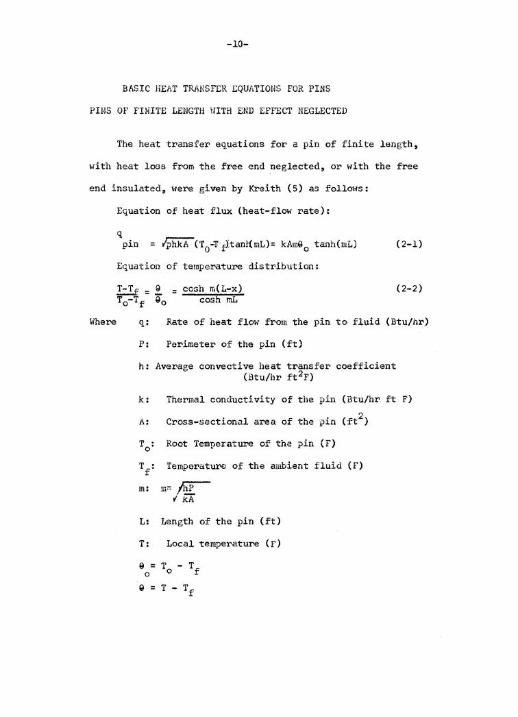
The heat transfer equations for a pin of finite length~
with heat loss from the free end neglected, or with the free
end insulated 11 were given by Kreith (5) as follows:
Where
Equation of heat flux (heat-flow rate)z
q pin = lphkA c·r0-T:;t1tanl(mL)= kAm9 0 tanh(mL) (2-1)
Equation of temperature distribution:
(2-2)
q: Rate of heat flow from the pin to fluid (Btu/hr)
P: Perimeter of the pin (ft)
h: Average convective heat transfer coefficient (Btu/hr £t2F)
k:
A:
m:
L:
T:
Thermal conductivity of the pin (Btu/hr ft F) 2 Cross-sectional area of the pin (ft )
Root Temperature of the pin {F)
Temperature of the ambient fluid (F)
m= /hp l rr
Length of the pin (ft)
Local temperature (F)
9 = T - T 0 0 f
9 = T - Tf
-11-
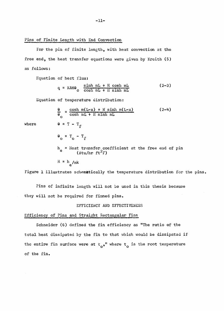
Pins of Finite Length with End Convection
For the pin of finite length, with heat convection at the
free end, the heat transfer equations were given by l<l.~aith (5)
as follows:
where
F.quation of heat flux:
= KAMS sinh mL + H cosh mL q o cosh mL + H sinh mL
Equation of temperature distribution:
-9 0
= cosh m(L-x) + H sinh m(L-x) cosh mL + H sinh mL
9 = T - T.c .1.
9 = T - T_ o o r
(2-3)
(2-4)
h = Heat transfer coefficient at the free end of pin e (Btu/hr ~2F)
H = h /mk e
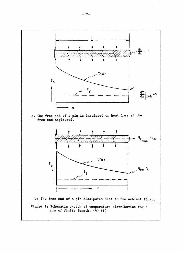
Figure l illustrates schematically the temperature distribution for the pins.
Pins of infinite length will not be used in this thesis because
they will not be required for finned pins.
EFFICIEi"ICY AND EFFECTIVENESS
Efficiency of Pins and Straight Rectangular Fin~
Schneider (6) defined the fin efficiency as "The ratio of the
total heat dissipated by the fin to that which would be dissipated if
the entire fin surface were at t 11 where t is the root temperature o 9 o
of the fin.
-12-
L-- --0
T(x)
/ T /y_' i_ - =O dT 1 ·
dx x=L
x
a. The free end of a pin is insulated or heat loss at the free end neglected.
T 0
I I 1- ---·--·- .. -------- x
b: The free end of a pin dissipates heat to the ambient fluid.
Figure 1: Schematic sketch of temperature distribution for a pin of finite length. (4) (5)
Schneider ~lso gave
e = .'.L = T \s /8 qo o o
constant
-13-
the definition inequation form:
hT dS = ~ S /- TdS, if h is 0 0
(2-5a)
where e = Fin efficiency
T:o+-t = Q 0 ~ f 0
= Temperature difference if the entire surface were at temperature
2 3 = Surface area (~ ) = PL
ds = pdx, where p = perimeter
T = t - t.c = Q J..
= Local temperature difference at the fin surface (F)
The eq_uations for determining the fin efficiency are given in the
following fo:t>ms by integrating Equation 2-Sa, changing ds = pdx,
T = T0 cosh m (L-x) cosh mL
For pins and straight rectangular fins with end effects neglected(6) tanh nL (2-5b) e = nL
For pins and straight rectangula:;:• fins with cor1"ected fin lengths
(12)
e = tanh nL0 nL c
(2-6)
-14-
where e = Fin efficiency
L = Fin length (ft)
L = Corrected length of the straight rectangular fin or c
pin of which the end effect is to be compensated by the corrected
length (ft).
n = m = Effectiveness of Pins
Effectiveness of pins is defined as the ratio of heat dissi-
pation from a pin to that from the root area without pins, i.e.,
sinh mL + a cosh mL cosh mL + H sinh mL
SIMPLIFIED EQUATIONS
Pins with Corrected Length
The simplified heat transfer equations for straight rectangular
fins with heat convection at the free end, given by Harper and Brown
(12), were:
q = kAmQ 0
Q cosh = Q 0
tanh mL c
m (19 -cosh mL
x)
c L = corrected length) c
These equations are analogous to Equations 2-l and 2-2.
The heat flux equation for pins was furthermore simplified by
introducing the pin efficiency ( 4)
q_. = 9 hSe -pin o
(2-7)
(2-8)
(2-9)
where Q = T - T 0 0 f
-15-
= Temperature difference across the film at the root of the
pin (F)
S = Surface area of the pin in contact with the ambient fluid(ft).
Pins with End Effect Neglected
q~· = fhpkA (T - Tf) tanh mL -pin o
= G f hpkA mL 0
tan11 mL mL
= G0 fhpkA /r& Le
= Q hpLe = Q hSe 0 0
where m =/hp/kA
e ::: tanh mL mL
e =tanh mLc fo't' Equation 2-7, r11L '
S = pL ; S = pL , c
c
for Equation 2-7
(2-1)
(2-5)
From Equation 2-9 it is evident that the heat dissipation fr>om
a pin is directly proportional to the temperature difference G0 , the
convective heat transfer coefficient h, the surface area S and the
pin efficiency e. Usually Q is given for general practice, the 0
terms h, S and e will be the factors that influence heat flow.
Effect of Surf ace Area on Heat Transfer
By Equation 2-9, it is seen that a larger surface area will
dissipate more heat from a pin to the ambient fluid. However, the
surface area is limited by the space available within the heat
exchange equipment. Attention has, therefore, been concentrated
-16-
on the selection of the geometry of surface configurationso
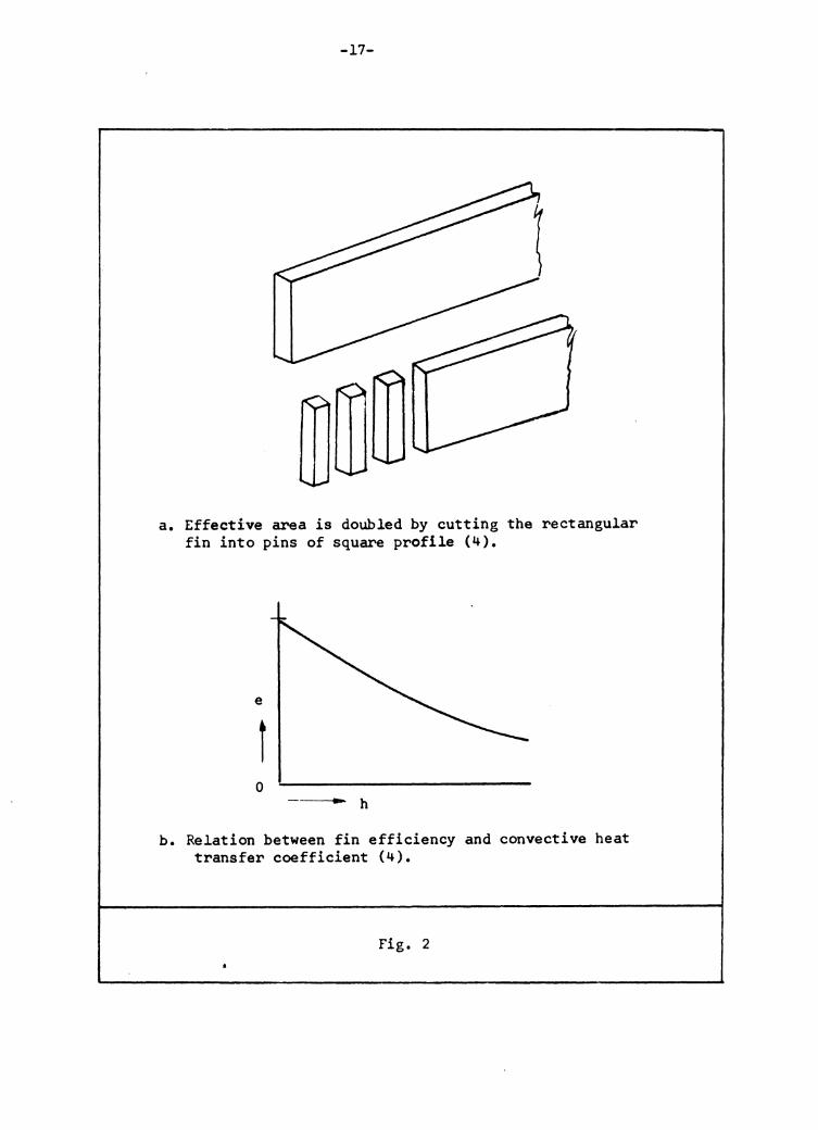
"It is interesting to note that pins will furnish more
heat transfer area for equal total cross-section. This is
easily visualized by cutting a horizontal rectangular fin
into square fins, which doubles the surface area with no
increase in cross-section·;." (Fig. 2-A) ( 4).
Effect of Pin Efficiency on Heat Transfer:
The pin efficiency must be involved in the simplified
heat flux equation because the temperature is not uniform along
the entire pin. Heat from the primary surface enters the pin
and is dissipated continuously along the length of the pin by
transfer to the ambient fluid. The inter-relations between
efficiency and heat transfer coefficient are shown on Figure 2-b.
It is seen that as the heat transfer coefficient increases the
pin efficiency decreases.
"In essence the efficiency factor is a measure of the ability
of the pin to transport heat to the dissipating surface." ( 4)
-17-
a. Effective area is doubled by cutting the rectangular fin into pins of square profile (4).
e
t 0
• h
b. Relation between fin efficiency and convective heat transfer coefficient (4).
Fig. 2
-18-
Effect of Convective Heat Transfer Coefficient on Heat Transfer
According to the simplified heat flux equation, q =AThSe, it
seems that the larger the heat transfer coefficient the greater the
heat flux. Actually this is not tr1le because the heat transfer
coefficient h is also involved in the efficiency equation.
For a pin, tanh mL e = --~-mL
= tanh( / ph/k~ L) /ph/kA L
= tanh(/!Jh/kD L)
J '+h/kD L
"The effic:i.enny function is useful for predicting the influence
of changes in the varoious para.meters involved 9 namely, the unit
surface conductance h, the concl:t.lcti vi ty k and the fin dimensions•" ( 6).
For a pin, a small h and L and a large k and D will increase
the pin efficiency, .but the usual pi>actice is to use many pins of a
small diameter. This will be explained further in the discussion of
optimum dimensions.
EMPIRICAL EQUATIONS FOR THE CONVECTIVE HEAT TRANSFER COEFFICIENTS
The convective heat transfezi coefficient that will be used in this thesis is for natural convection. For theestimation of the
I convective heat transfer coefficient of natural convection McAdai~s(S)
recommended the following equations:
-19-
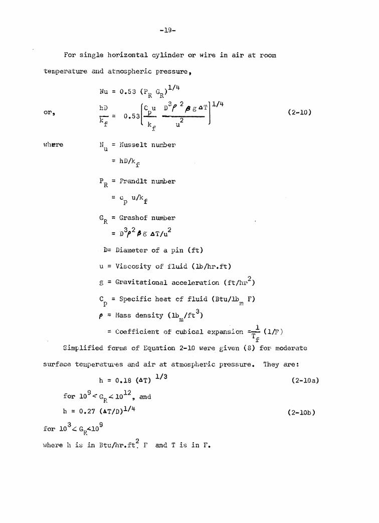
For single horizontal cylinder or wire in air at room
temperature and atmospheric pressure,
or,
where
~·'u = 0 "-3· (P '"')l/4 ·• • ;:, i'\ liR
hD [
Cpu D3f2(JgA'r]l/4 0.53 - 2
k u f
H = Nusselt nuriber u
PR = Prandlt number
= c u/k p f
GR = Grashof nUJT1.ber
= D3f2 ~ r; ~T/u2
D= Diameter of a pin (ft)
u = Viscosity of f'luid (lb/hr.ft) ')
g = Gravitational acceleration (ft/hr-)
C = Specific heat of fluid {Btu/lb F) p In
tJ = Mass density (lb /ft 3) r m l = Coefficient of C\lbical expansion =- { l/F)
T.r.: r
(2-10)
Simplified forms of Equation 2-10 were given (8) for· mode:r.>ate
surface temperatux•(-:s and air at atmosphe1~ic pl>essure. They are:
h = 0.18 (~T) l/3
for 109 <GR~ io12 , and
h = 0.27 (AT/D)l/4
for 10 3 4' G 4109 R
whe:i:'e h is in Btu/hr.ft~ F and T is in F.
(2-lOa)
(2-lOb)
-20-
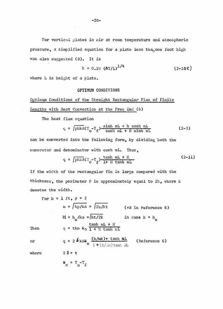
For vertical plates in air at room temperature and atmvspheric
pressure, a simplified equation for a plate less thCliJ.One foot high
was also suggested ( 8). It is
h = 0.29 (AT/L)l/4 (2-lOC)
where L is height of a plate.
OPTIMUM CONDITIONS
Optimwn Conditions of the Straight Rectangular Fins of Finite
Lengths with Heat Convection at the .Free End (6)
The heat flux equation
= J hkA(T -T ) sin~ mL + h cosh mL q P o f cosh mL + H sinh mL (2-3)
can be converted into the following form, by dividing both the
nutrierator and denominator with cosh mL. Thus,
_ J h,'"A('-· T ) tanh mL + H q - P ~ 10- f l+ H tanh mL
If the width of the rectangular fin is large compared with the
thickness, the perimeter P is approximately equal to 2b 11 where :b
denotes the width.
Then
or
where
For b = l ft, p = 2
m = f hp/kA = f 2h/kt
H = h /km = /ht/2k e tanh mL + H
q = tkm Go l + H tanh mL
(=N in reference 6)
in case h = h e
q = 2 S kNQ (h/Nk)+ tanh l\IL o l+(h/_i%)ta~1 i·~L
(Reference 6)
2 ~ = t
Q = T -T 0 0 f
(2-11)
-21-
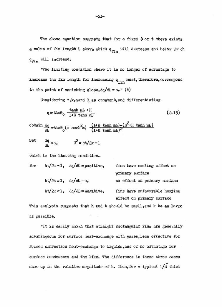
The above equation augg-ests that for a fb:ed b or t ther-e exists
a value of fin leng·lih L above which q"'.. vill decrease and below '1:hi.ch .l.lll
qfin 1i'ill increase.
111.t'he limiting cox1di·f;ion 1,here :i.t is no longer of advantage to
i..'lcrElase the fin length for increasing qfin mui:rt, therefore, correspond
to the :poi..YJ.t of' vanishing slope, dq/ d1 = o. '1 ( 6)
Set dq_o dL - •
tanh mL +H 1-+ H ta.n.'li w.J~
(l+H u!Jll1 m.L)-(H2-+H tanh mL) (l·Hl tanh. mL)~
(2-13)
which is the lilliUng condition •. ·
.Fbr ht/2k <l, dt:d/aL :poeitive,
ht/2k =1, drjdL =o, ht/'& >l, uq/<lL=nega.tiva,
fins have cooling ef i'ec;t on
primary surface no effect on p:t'imar<J su.rface
fins have unfavorable he01jrir.g
effect on primary &'UI'l:'aco
'l.1his analysis sus·i-ests that h and 't should be srnall,a.nd k be as laxge
ci.s possible,.
11It is easily ahow.n. that at:i:·air;ht rectaugula-r fins are geneTally
advantageous for surface 1eat-exchange with gases,leas effective for
fo1·ced c~nvec·tion heat-exchange to liquids,and of no advarrtage :for
surface (,'Ondensers a:11d tb.e like. 'J!ha difference in these tt:ree cases
show ·1J.:p in thfJ ralati ve llk'-gni tude of h. T!ms, fo:r a tyJ>icru. !./a' ·!;hick
-22-
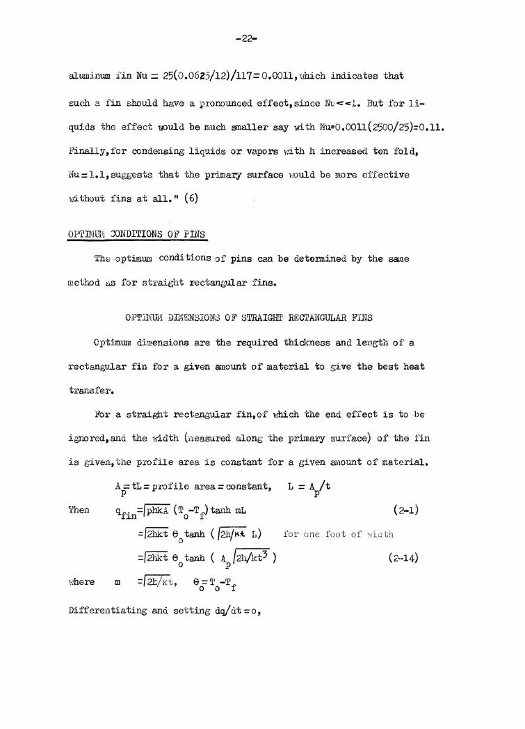
aluminum. fin Nu.= 25(0.06Z5/12)/117= 0.0011, which indicates that
such a. fin should have a p:rur.ounced effect, since Nv<=<l. But fo:r li-
quids the effect 1-i\Juld be much smaller say with Nu=0.00ll(2500/25)=0.ll.
J!'inally,for condensing liquids or va.pors r:ith h increased ten fold,
Nu=l.l,suggests that ·the primal'".f surface \·JOuld be more effective
,.p_ thout fins at all. 11 ( 6)
OPTINlJiii C:ONDITIONS Ob, Prns
Th~ .9ptimum conditions of pins can be dete:rmined by the same
method as for strai.ght r-ectangular fins.
OPTlliiUf'I DTI'f;f..filSIONS OF STRAIGHl' RECTANGULAR FINS
Cptimum dimensions are the required thickness and length of a
rectangvlar fin for a given amount of material to give the best heat
transfer.
ltor a straight rectangular fin,of which the end effect is to be
ignored,and the width (measured along the primary surface) of the fin
is given, the profile area is constant for a given amount of material.
'l'hen
1·:here
A= tL =profile area= cons·tant, p
qfin =/ pbk.A ( T 0 -T f) tanh mL
m
=/2hk:t 6 0 tanh ( /2h/K:t. L)
=/2hkt e tanh ( A /2h/kt3 ) 0 p
=f 2b/kt, e ='11 -'r 0 0 f
Differentiating anci setting dq/O.t=o,
L =A /t p
for one foot of ' ... iGth
(2-1)
(2-14)
-23-
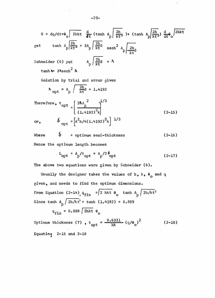
~ d f2h A~) Q_,... f2hkt o = dq/dt=Q 0 I 2hkt ft ( tanh AP f f.t3 )+ ( tanh p/ ict3 dt" 0
get tanh Ap/*3 = 3Ap I ~k2ht... 2 ~ sech A 2h~ p ""'ict"'
Schneider (6) put
tanh 1\= 3Asech 2 ?\
A 1~ = ~ p kt
Solution by trial and error gives
~ = AP J2h:. = 1. 4192 opt I ~
Therefore, t t op
or, b opt
[ 2ftA 2 1/3
= (l.l~l92) 2k
= [A2h/4(1.4192)2k) l/3
Where = optimum semi-thickness
Hence the optimum length becomes
L = A /t = A /2 6 opt p opt p opt
The above two equations were given by Schneider (6).
( 2-15)
( 2-16)
( 2-17)
Usually the designer takes the values of h, k, 90 and q
given, and needs to find the optimum dimensions.
From Equation (2-14) qr. =/2 hkt 90 tanh AP/ 2h/kt~ I _l.Il
Since tanh A J 2h/ktl = tanh (1.4192) = 0.889 p
qfin = 0.889 J 2hkt G0
Optimum thickness (7) , t = opt
Equatin~ 2-15 and 2-18
0.6321 hk (2-18)
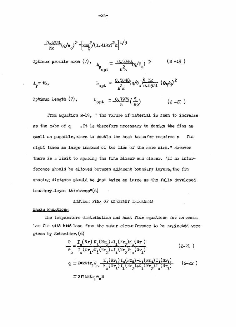
Optimum profile area (7), A = 0.5J4.8(q/e ) 3 (2 -19 ) p t hi 0 op .kt
T
J"opt - o. 501§r - l9 )3 .. bk ( 0o·"'i) 2
... 2. \YI' ';) ().6321 '/'
.u .!C
<Jptimum length (7), J, opt - o. 7070.·. ( 'l - ---:...l~- -;::- ) h co (2 -2() )
Pror.1 Equation 2-19, " the volume 1:>f rl!aterial is scan to inc1-ease
ao 'the cube of q • It .l.o therefoz·e necessa:£y to design the fins r.a
small as possible, since to aouble the heat tr<:.nsfer r-equirns a fin
oiL<l'lt times as large instead of two fins of ·the sar.ie size." However
there is a limit to sp:>.cing: foe fins :Cbs::?r end clo~o1•. "If no int.:il'-
apacin.e; distance shoulcl be jU3t twice as large as th.a iUlly developed
bowldv.:cy-layer thickaeas"( 6)
Baeic Eggations
'l'Le temperature distribution and heat flux equations fo:r a.vi annu-
lar fin with neat loss from the ou·~er circu:;;li'erence ·f.o be neglectdki wero
given by Sc.imeidcr. (6)
...: = I 0 ( Nr) K1 (Nr2)+I1 (i~r2:~)Nr ) e I (1:r1J:::. (Nr2) .,.r_ C"~r.JL (li:!.·1 )
0 0 l .l. .i.O
q =2"kf~tr 8 :~1(~~r1)I 1 (1·::ra)-~~1(~i·2.)~ 1 {~ir1 ) 1 c L \~'~r.,)I1 (.:.r . .)+K_(Nr2)I \flr1)
0 - ... 1 0
(2-21 )
(2-22 )
Where
-25-
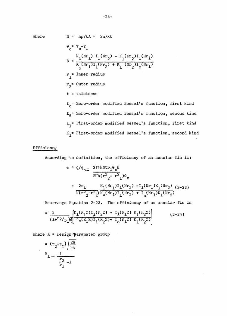
N = hp/kA = 2h/kt
Q = T -Tf 0 0
K1 (Nr1 ) I 1 (:Nri2 ) - K (Nr,,)I1 (l{r1 ) B = . 1 ~
K 0 (Nr1)I1 (Nr2) + K1 (Nr 2)10 (N1"1 )
r = Inne~ radius l
r = Outer radius 2
t = thickness
I = Zero-order modified Bessel's 0
K :: 0 Zero-order modified Bessel's
I = l First-order modified Bessel's
K = l First-order modified Bessel's
function,
function,
function,
function,
first kind
second kind
first kind
second kind
Efficiency
According to definition; the efficiency of an annular fin is:
e = q/q0 = 2TTkNtr190 B
2Tlb(r22_ r2l)Qo
= 2r1 K1 (Nr1 )I1 (i~r2 ) -11 (Nr1 )K1 CNr2 ) c2_23 )
N(r2 2-r2-) K0 (Nr1)I1 (Ur2) + I 0 (Nr1 )K1 (Nr2)
Rearrange Equation 2-23. The efficiency of an annular fin is
e= 2 .fK1(R1Z)I1(R2Z) - I1CR1Z) K1CR2Z)l (l+r2/r~~[ K0 (R1Z)I1(R2Z)+ I 0 (R1z) K1(R2z)
where A = Design4tarameter group
: (r -I'.) /2h 2 l kt
R1 =_1 __ r _;2 -l i~l
(2-24)
-26-
1\Z = 1 (rz-r){2h/kt :rt'ri-1
r1 / 2b/kt = Nr1
1 (r2.-r1)/2b/kt =Nr2 l-r1/r2
2 ~ 2~
(l+r/r1)z-(r2-1-r1)(r2 -r1)/2h/kt - (r~-ri) /2il/kt
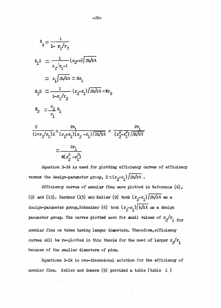
Equation 2-24 is used for plotting efficiency curves of efficiency
versus the design-parameter group, Z =(r2-r1) /2b/kt •
Efficiency curves of annular fins were plotted in Reference ( 6),
(9) and (13). Gardner (13) and Keller (9) took (r2-r1)/2b/kt as a
design-parameter group,Schneider (6) took (r2-r1)/ b/kt as a design
parameter group. The curves plotted were for small values of r/r1 for
annular fins on tubes having larger diameters. Therefore, efficiency
curves will be re-plotted in this thesis for the need of larger r/r1
because of the smaller diameters of pins.
Equations 2-24 is one-dimensional solution for the efficiency of
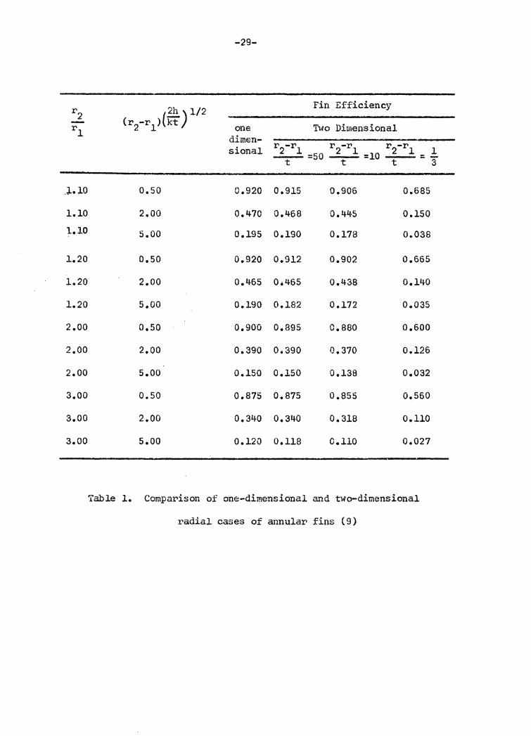
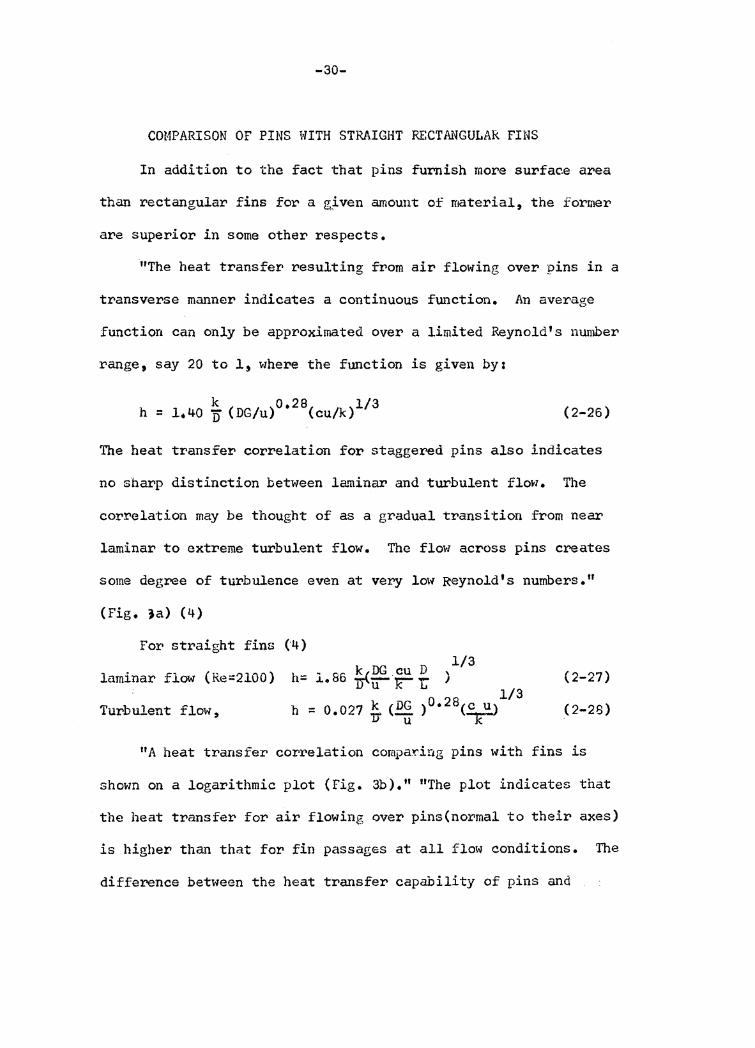
annular fins. Keller and Somers (9) provided a table (table 1 )
-27-
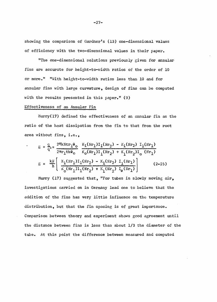
showing the comparison of Gai.,<lner' s ( 13) one-dimensional values
of efficiency with the two-dimensional values in their papei"'.
"The one-dimensional solutions previously given for annular
fins are accurate for height-to-width ratios of the order of 10
or more." "With height-to-width ratios less than 10 and for
annular fins with large curvature, design of fins can be computed
with the results presented in this paper." (9)
Effectiveness of an Annular Fin
Hurcy{l7) defined the effectiveness of an annular fin as the
ratio of the heat dissipation from the fin to that from the root
area with out fins, i.e. ,
E = ,9. _ 2TTkNtr190 K1{Nr1 )I1{Nr2 ) - K1 (Nr2) I 1 (Nr1 ) q•- -----2Tir1thGo K0 (Nr1)I1(Nr2) + K1(Nr2)I0 (Nr1)
E = ~[ K1(Nr1 ~I1(Nr2 ) - K1(~r2) I 1.(Nr1) l (2_25 ) i<0 (Nr1 ,11 (Nr2 ) + 1\ (Nr2 ) I 0 (Nr1)
Murry (17) suggested that, "For tubes in slowly moving air,
investigations carried on in Germany lead one to believe that the
addition of the fins has very little influence on the temperatur•e
distribution, but that the fin spacing is of great importance.
Comparison between theory and experiment shows good agreement until
the distance between fins is less than about 1/3 the diameter of the
tube. At this point the difference between measured and computed

-28-
heat transfer appears to be about 12 per cent, with the difference
becoming greater as the distance between fins is decreased. As one
would expect, the calculated value of the heat transfer is always
higher than the measured value. However, with greater distance
between the fins, the two values closely approach one anothers."
-29-
r2 2h) 1/2 Fin Efficiency
- Cr2-r1 >(IT Two Dimensional rl one di men-sional r2-rl
=50 r2-rl r2-rl l =10 = -t t t 3
.J..;LO a.so 0.920 0.915 o.906 0 .. 685
1.10 2.00 0.470 0.468 0.445 0.150 1.10 5.00 0.195 0.190 0.178 o.osa
1.20 o.so 0.920 0.912 0.902 0.665
l.20 2.00 0.465 Oe465 0.438 0.14-0
1.20 5.00 0.190 0.182 0.172 0.035
2.00 o.so 0.900 0.895 0.860 o.soo
2.00 2.00 0.390 0.390 0.370 0.126
2.00 5.00 0.150 0.150 0.138 0.032
3.00 0.50 0.875 0.875 0.855 o.560
3.00 2.00 0.340 0.340 0.310 0.110
3.00 5.00 0.120 0.118 0.110 0.021
Table 1. Comparison of one-dimensional and two-dimensional
radial cases of annular fins (9)
-30-
COMPARISON OF PINS WITH STRAIGHT RECTAt~GULAR FINS
In addition to the fact that pins furnish more surf ac.e area
than rectangular fins for a Kiven amount of material, the former
are superior in some other respects.
"The heat transfer resulting from air flowing over pins in a
transverse manner indicates a continuous function. An average
function can only be approximated over a limited Reynold's number
range, say 20 to l, where the function is given by:
(2-26)
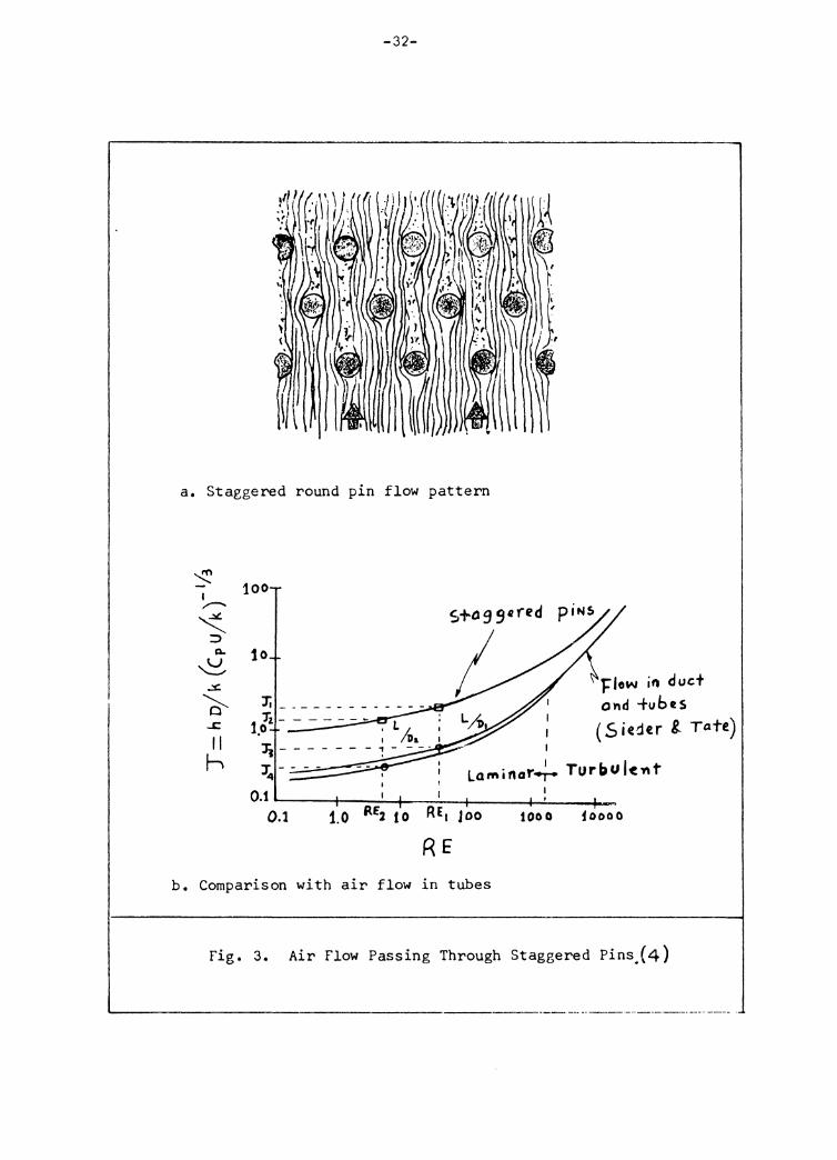
The heat transfer correlation for staggered pins also indicates
no sharp distinction between laminar and turbulent flow. The
correlation may be thought of as a gradual transition from near
laminar to extreme turbulent flow. The flow across pins creates
some degree of turbulence even at very low Reynold's numbers. 11
(Fig. ja) (4)
For straight fins (4) 1/3
laminar flow ( Re=2100) h= l. 86 ~~ r ~ ) m b 1 fl h -- 0.027 ~ (_DGu ) 0 • 28(~) iur UJ..ent ow, jJ x:
(2-27) 1/3
(2-28)
11 A heat transfer correlation compadng pins with fins is
shown on a logarithmic plot (Fig. 3b)." "The plot indicates that
the heat transfer for air flowing over pins(norimal to their axes)
is higher than that for fin passages at all flow conditions. The
difference between the heat transfer capability of pins and
a factor of 10 to 1."{'~)
:t'<i!Sult of 'thta 1'ao"t01' k/D in i~1iuatioos 2•.26 ~nd 2•27. CQW1i: . .c~l/3
ing 'this he.:H; t:rM$f ~t" incr~ase fa the f\1'~ctor (~ ~ ~ ) for duct in Equation 2-27 i amd the faotor· (E§. )o.2e foz• pina in
u r:..:ruaticn 2-26., It is obvious that i'l cr1ange in f) in tb<it factor
(~ S E.. )t/3 1.1ount,.,r'a.ct$ heact: tMnaf'er• incrom;ie mor·.a tba.11 21 u k L
~dmilau:• chanzo ef D in the .taoto1• (OO/u)0• ~IO•"
to J 2 for pins and from J 3 to J 4 for fin passages." ( 4)
-32-
a, Staggered round pin flow pattern
~ I ,,,,._ ~ ::>
Q.
~ ~
~ ....c
11 h
100
10
J'j ____________ _
'Ji-------1,o · LL 1 /Da
Ji-------~----J;. ___ _ I
f!ow ifl duct ond -tubes ( S iedtr 8. Tate)
Laminar~ Turbul~-nt O.t ----1-~~f--~-+---.µ.--~
0.1 1.0 RE2 to RE, Joo 1000 foooo
RE b, Comparison with air flow in tubes
Fig. 3. Air Flow Passing Through Staggered Pins.(4)
-------------------------·---------------·--·--·----.
-33-
III. THEORETICAL INVESTIGATIONS
DERIVATION OF BASIC HEAT TRANSFER EQUATIONS OF A TWO-DISC F!l~NED PIN
The derivation of mathematical equations will be based
on the following assumptions:
l. The temperature over any cross-section of the pin is
uniform so that the heat conduction is one dimensional in
the solid.
2. The temperature of the ambient fluid is given, constant
and uniform.
3. The annular fin is considered very thin. The temperature
over t>.n~f circumferential cross-section is uniform so that
the heat conduction is one dimensional. Heat loss from
the outer edge to the ambient fluid is neglected.
4. The root temperature of the finned pin is given.
s. The material of the finned pin is isotropic and k¢ f(t)
so that the thermal conductivity is constant. Isotropic
means k is constant in all directions.
6. The finned pin is of finite length and with heat con-
vection to the ambient fluid over the circumferential
surface and at the free end.
7. For simplicity, the heat transfer coefficient over the
surface of the finned pin is considered constant,
although the coefficient over the pin surface may be
different from that over the fin surface.
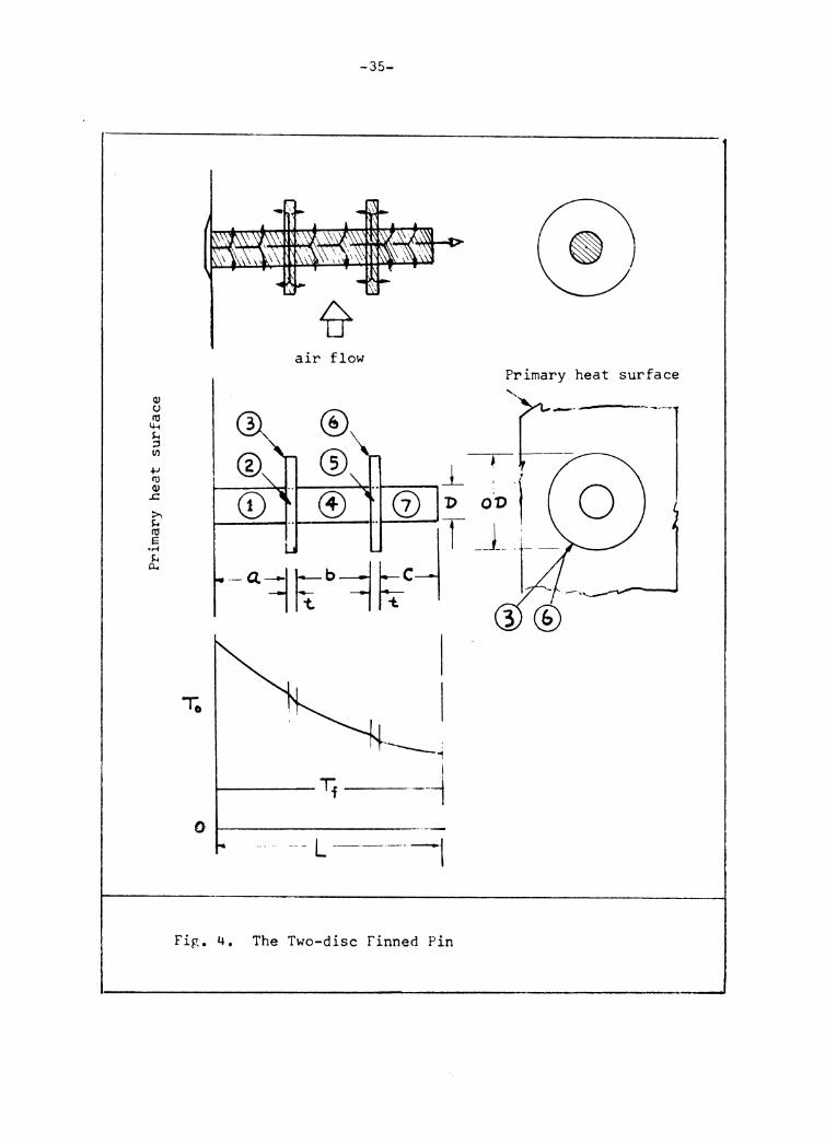
-34-
8. A finned pin may have a number of annular fins on it. In order to facilitate the work of deriving heat
tr>ansfer equations 9 a two-disc finned pin was chosen.
Consider pin 7 in Figure 4. The heat flux equation is
given by Equation 2-3.
= kAmQ 7 -o sinh me + H1 eosh me
cash me +H1 sinh me
Where q7 = Heat flux fr•om pin 7 -o C = Length of pin 7
Q = T - T 7-o 7-o f
T7 = Root temperature of pin 7 -o m = /ph/kA =f4h/kP1
(assume h = he)
B = sinh me + H1 cosh me 1 cosh me + H1 sinh me
By Equation 2-22, the heat flux from fin 6 is
(3-1)
q6 = 21TkNtr1o c -o o-o K1(Nr1)I1(Nr2) - I 1(Nr1)K1(Nr2) K0 (Nr1 ) r1(Nr2) +I0(Nr1)K1(Nr2)
= B296-o Where q6 = h·~at flux from fin 6 -o
Q . 6-o T 6-o = Average root temperature of fin 6
N = /Ph/kA = / 2h/kf k K1(Nr1)I1(Nr2)-I1(Nr1 )K1(Nr,,) B2 = 211' Ntr1 1..
where r 1 = D/2
r = OD/2 2
K_,(Nr1)I1(Nr25 +I0 (Nr-15 K1(Nr2)
(3-2)
-35-
air flow Primary heat surface
----- ' ' 1
I i-----Tf --1
0 t------------- L --------1
Fig. 4. The Two-disc Finned Pin
-36-
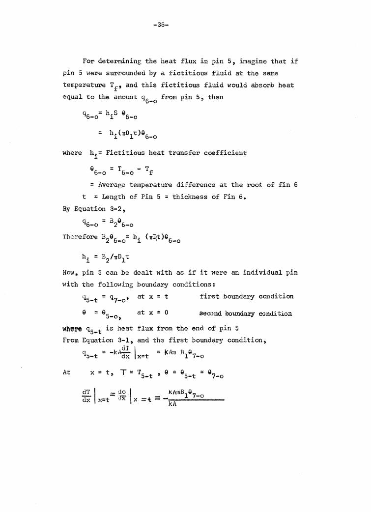
For determining the heat flux in pin 5, imagine that if pin 5 were surrounded by a fictitious fluid at the same temperature Tf' and this fictitious fluid would absorb heat equal to the amount q from pin 5, then 6-o
=
where h.= Fictitious heat transfer coefficient l.
Q6 = Tc: - Tf -o v-0 -
= Averaee temperature difference at the root of fin 6 t = Length of Pin 5 = thickness of Fin 6.
By Equation 3-2~
q6-o = :a296-o
Therefore B296_ 0 = hi (1TD1t)G6_ 0
Now, pin 5 can be dealt with as if it were an individual pin with the following boundary conditions:
Q = Q 5-o,
at x = t
at x = 0
first boundary condition
second boundary condition
wh~f!@ q5_t is heat flux from the end of pin 5 From Equation 3-1, and the first boundary condition,
At
dT I q = -kA--. 5-t dx x=t
x=t T=T g-Q -Q ' 5-t ' - 5-t - 7-o
dT I ·-do \ _ kAmB1G7_ 0 dX" x=t - rJx x =t - --------kA
-37-
That is dQr:. t B " o- = -m 11'5-t dx
( 3-3)
Since the heat bcllance for a differential element of pin 5 is
or ( ~.P m. = l. 1 -
kA
The solution of the above differential equation is
ill.x C -m.x Q = c1 e 1 + 2 e 1
For Pin s, at x = t~ Q = QS-t
mt -rn.t GS-t = c1 e i + c2e 1
~-t dx ··
in Equation 3-3.
ag5-t = -mBl(cl emit + c2e-mit) dx
··m. t Th~n J'll.c1e 1 ]. .
-m.t - c e i z m.t - c,e 1
.1.
=
=
= B ( rn.t + -m.t ) -m 1 c1e 1 . c~e 1
mB1 { C m. t -m. t i"" l. + c 2e 1
m. l.
mB1 { m.t + c 2e -m.t c1e l. J. m .
l.
)
) (3~+)
-38-
The second boundary condition is
at x = o, e = e for Pin 5 5-o From 9 m·x -m.x = c1e 1 + c2e l.
e = cl+ c2 , cl = e - c2 (3-5) 5-o 5-o
Solving Equation 3-4 and 3-5 simultaneously
-rn·t c e i -2 (8 -c )emit = mBl [ ( 95-o -
5-o 2 - mi
+ emit t~l (emit - e-mit)l = mi [ -m·t c e J.
2
= e [1 5-o
= 6s-o [
Substl.. tute C · d C • "' m · x -mi· x 1 an 2 in o = c1e 1 + c 2e
e = [( -rnit mB3 e - -· e ... ,
5-o m•t -m1·t e J. + e
e-mit) t::mix + mBl(e:nit
IDi
( m1·t mB1 + e +-m· -m·t) 1 - e l
Therefore, the temperature distribution of Pin 5 is
cosh mi (t-x) + H2 sinh mi(t-x) cosh mit +H2 sinh mit
= .!!1_ B m. l 1
m.t) m·xl e 1 e 1 J
( 3-6)
-39-
For Pin 5 at x = t, 6 = e5_t = 07_0
By Equation
~ 9 5-0
3-6
e = :::I:o •s-o
e 7-o
=
=
cosh mi(t-t) + H2 sinh mi(t-t) cosh m1t + H2 sinh mit
l cosh mit + H2 sinh m1t
95-o = ----_..------~~-:-~---cos h mit + 112 sinh m1t
l Where B3 = --h~-· ---.;,;.--.-. -.h...----cos m1t + h2 sin mi t
By differentiating Equation 3-6
d9 - rn.e5 sinh m1(t-x) + H2 cosh mi = dx l. -o
cosh m.t + H2 sinh m.t l. l.
2!1 :: -m. a sinh mit + H2 cosh mit dx x=O l. 5 ... 0 cosh m.t + H2 sinh m.t
l. l.
qs-o = -kA ~1 dx x=O
kAm.95 sinh IDit + H2 cosh mit = ]. -o cosh m.t + H2 sinh m.t
l. J.
qs-o = kAmi es-o 81t
= sinh mit + H2 cosh mit cosh m1t + H2 sinh mit
( t.,..'X)
( 3-'/)
(3-8)
( 3-9)
-40-
For Pin 4
Let q - heat flux from the end of Pin 4 at x = b 4-b -
0 = Temperature difference at the end of Pin 4 at x = b 4-b
By equation 3-9, the heat balance at x = b is
-kA -2!.I k 11 B 9 dx x=b = nmi 4 5-0
At x = b,
T = T4-b' a = 94-b * l x=b = *'x=b = ::,4-b
dQ Hence - kA __!:.b = kA- B 9 dX ~Hi 4 5-Q
( 3-10)
Recall that the heat balance equation for a differential element
of a pin is
d29 2 e Jll ;; 0 dx2
-
and the solution is mx -mx
9 = c1 e + c2 e
At x = b
G = Then
Substitu.te
Hence,
dQ4-b dx
G 5-0
dG~-b dx
=
mb mc1 e
= mb -mb mc1e •me e 2
"it-b mb + -mb = c1 e c2 e in Equation 3-10
.(3-11)
At x = 0 9 Q = 94_0 for Pin 4 9 Second boundar-y condition
At x = 0 9 G4_0 = c1 + c2
cl = 04-o - c2
Solve Equation 3-ll and 3-12 simultaneously -mb mb 14i [ mb c e -(Q - c )e = - B4 (G4 -c2)e 2 4-o 2 m -o + c2e -wj
m. mb -mb l mb
c2 [ e-mb .. mb m. J. + -2:. B4(e - e ) = Q4 Ce + ;=s4 + e -o m
(3-12)
mb ) e
·;.,
-42-
C2= 94-0 (emb + :1 ll4 emb) I [emb + e -mb + :!:i D4 (e mb - e -ml'> l cl = 94-0 -c2
So, mx -mx e = c e + c e l 2
[ •mb mi ·mb mx mb m. mb -mx] = e e -lii"Bta.e . ) e + (e +i;l. n4e )e
4-o mb • mb mb e + e-mo + :iB~ (e - e - )
r m(b-x) + -m(b~x>J + t• [· m(h-x) -m(b-x)J 9 = e4_0 le e · d 3 e -e (3-lS)
mb •Il'slJ H ( w.b -mh ) e + e + 3 e • e
Thus the tempe~ature dist~ibution of Pin 4 is ' .
e cosh m (b-x) + H3 sinh m(b-x) e ~-o = cosh mb + H3 sinh mb
(3-14)
at x = b, a,_ .. _ 9 5,..0 :: l = a5 e4 - 8 . cosh mb + 113 sinh mb -o 4~o
(3-15)
Since dT l de I dx x=o = di'. x=O at x = o
By differentiating Equation 3-14,
9 [ m(b-x) •m(b-x) u (· m(b-x) -m(b-x
4_0 -me + me + u -me -me mb -mb m:b -mb .1 e + e +H3 (e - e J
dt -dx d& = ---= dx
-43-
mb -mb mb -mb ] dT I e - e + H3 ( e + e )
-m9 dX ~=O 4-o mb -mb H (emb - e -mb) e + e + 3
Therefore, the heat flux is
q4 = -kA ;g_l <lx x = 0
kA.rne 4 sinh mb + H3 co sh mb = -o co sh mb H3 sinh mb +
q4-o = kAm94-o B6 (3-16)
Where B6 sinh mb + H3 cash mb = cosh mb + H3 sinh mb
Next, Pin 2 comes into consideration.Because the conditions of Pin 2 are similar to that of Pin-S.,Pin 2 can, therefore, be dealt 1,>fi th in the same pattern as heat transfer equations of Pin 5.
The heat <lissipation from Pin 3 is obviously
Since the term B2 does not change by making Fin 3 with exactly the same dimensions as Fin 6 foi' the same heat transfer coefficient h.
Put q2_t = Heat flux from the end of Pin 2
By equation 3-16,
q2-t = - kA -dT 1 · dx x=t (3-17)
-44-
= dQ I di'x=t
Hence. -kA-dQ l dx x=t
Following the same pattern used in deriving Equations 3-3 to 3-9, a.n equation analogous to Equation 3-b is of the following form:
= cosh mi (t-x) + H4 sinh (t-x) cosh m.t
l. m.t
J.
By Equation 3-18, at x = t
94-o =
Q 4-o
Where, B7 =
= Q!J.-0 r-- =
2-o
Q 2-o
l
l cosh m.t + H4sinh m.t
l. . J.
cosh mi t + 1\ sinh mi t
(3-18)
(3-19)
(3-20}
The heat flux of Pin 2 is analogous to Equation 3-9.
q2 = kArn. B8 Q 2 -o J. -o (3-21)
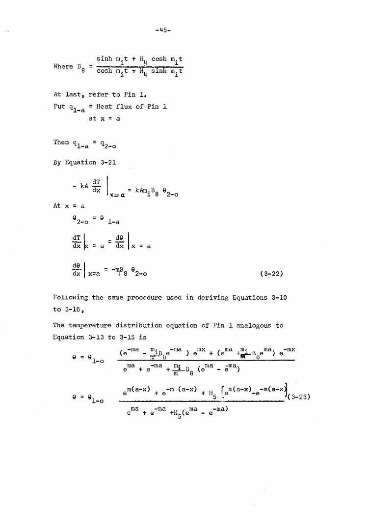
-45-
sinh m.t + H cosh m.t J. !+ l. Where B8 = __________ .....,. ____ ..,...~--
cosh mit ~ H4 sinh mit
At last, refer to Pin l. Put q1 = Heat flux of Pin l -a
at x =a
Then q = q 1-a 2-o
By Equation 3-21
- kA !.!'!:. I dx = kAm.B8 e2_0 'I<= a. l.
At x = a Q
2-o = 9 l-a
d9 I = mB Q ax x=a - i 8 2-o ( 3-22)
Following the same procedure used in deriving Equations 3-10 to 3-16,
The temperature distribution equation of Pin 1 analogous to Equation 3-13 to 3-15 is
9 = 9 1-o ( -ma mii'B -ma ) mx + ( ma +mi B ma) -mx e - nr-- 8e e e m 8e e
m(a-x) -m (a-x) + H r.em(a-x)_9-m(a-x~ e + e 5· -. . 1(3-23)
ma -ma ma -ma) e + e +H5(e - e
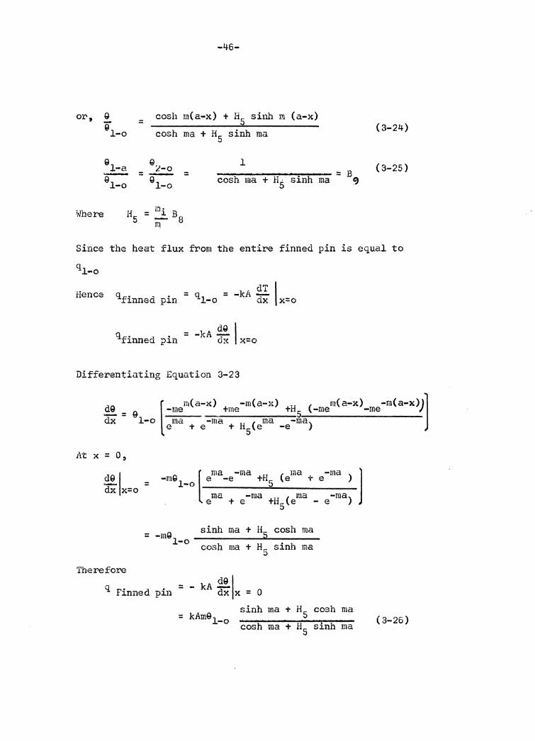
or,
Where
g i 1-o
Q 1-a g-1-o
=
=
-46-
cosh m(a•x) + H5 sfoh m (a-x) cosh ma + H5 sinh ma
Gi..'-o = g-1-o
l ~~--~~----...-..... --- = B cosh ma + HS sinh ma 9
(3-24)
{3-25)
Since the heat flux from the entire finned pin is equal to
ql-o
Hence qfinned pin = dT I = -kA -ql-o dx x=o
dQ I qfinned = -kA-pin dx x=o
Differentiuting Equation 3-23
d9 dX - ( m( a-x_) -m( a-x) H ( rn( a..:x) -m( a-x))] Q -me +me + 5 -me -me
1-o ma -ma H ( ma -ma) e + e + 5 e -e
At x = o,
dQ I = ~ x=o
" [ ma -ma LI ( ma -ma ) l -m~ e -e +• e + e 1-o 5 ma -ma II ( ma -ma) _ e + e +- 5 e - e
-mQ sinh ma + H~ cosh ma = 1-o cosh + Hr.: sinh ma ma 0
Therefo!'e
q Finned pin = - kA ~1 dx x = o sinh ma + HS cosh ma = kAm91_0 cosh ma + H sinh ma 5
( 3-26)
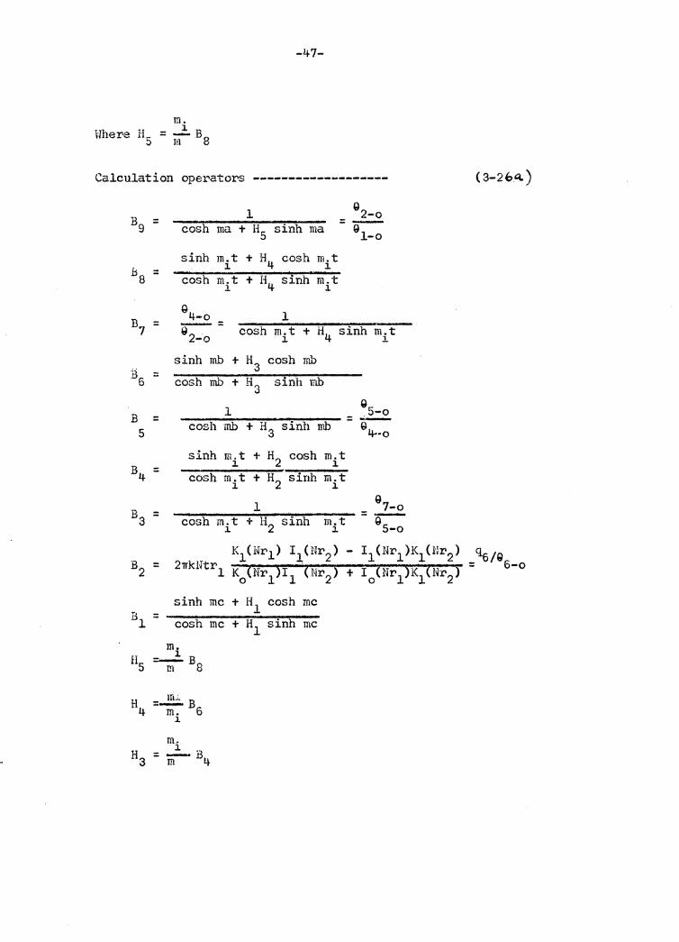
m. Hhere H5 :: ..2:.. B
l!1 8
-47-
Calculation operators -------------------
1 Q
2-o B9 = =-cosh ma + H5 sinh ma g
1-o sinh m.t + l\ cosh m.t
.b8 l. l. = cosh m.t + I\ sinh m.t ]. l.
~ 4-o 1 = -= B7 ~ 2-o cosh m.t + H4 sinh m.t l.
sinh mb + H3 cosh mb B = sinh mb 6 cosh mb + H3
1 B = cosh mb + H3 sinh rnb 5 sinh m.t + H2 cosh m.t
B4 J. J. = cosh m.t + H2 sirih m.t J. J.
l B3 = cosh m.t + H2 sinh m.t
l. J.
K1CNr1 ) IJ,(Nr2) B = 2'lTkHtr1 K0 (Nr1)I1 (Nr2) 2
sinh me + Hl cosh me B = l cosh me + Hl sinh me
m. l. H5 =-B m 8
H4 =.....!!!.;.. B6 m. l.
J.
Q
= .5-o G 4-·o
g 7-o -~
5-o
- I1(Nr1 )K1(Nr2)
+ I 0 (Nr1)K1(Nr2)
( 3-2 b"-)
q6/Q = 6-o
- 48 -
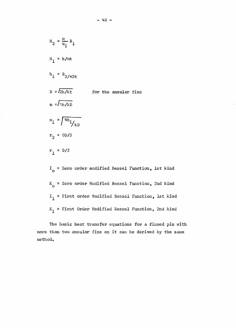
H2 = !!!_ B m. l l.
Hl = h/mk
h. = B2/irDt l.
N = fah/kt for the annular fins
m =l1fa/kD
= / 4h/ m. l. 1 kD
r2 = OD/2
rl = D/2
I = Zero order modified Bessel Function, lst kind 0
K = Zero order Modified Bessel Function, 2nd kind 0
I 1 = First order Modified Bessel Function, lst kind
K = First Order Modified Bessel Function, 2nd kind l
The ha.sic heat transfer equations for a finned pin with more than two annular fins on it can be derived by the same method.
-49-
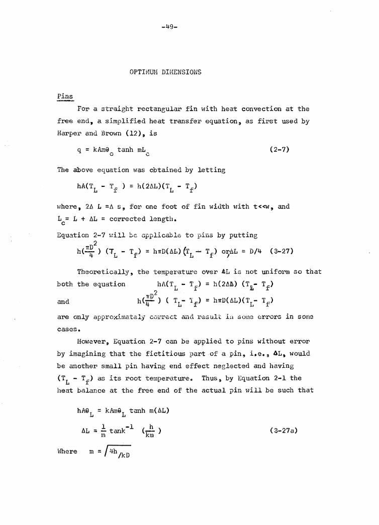
OPTIMUM DIMENSIONS
Pins
For a straight rectangular fin with heat convection at the
free end, a simplified heat transfer equation, as first used by
Harper and Brown (12), is
q = kA~9 tanh mL c c (2-7)
The above equation was obtained by letting
where, 2/J. L =ti. s, for one foot of fin width with t <<w, and
L = L + t.L = corrected length. c Equation 2-7 will be applicable to pi11s by putting
2 h(~ ) (TL - Tf) = hlfD(t.L) (rL -- Tf) o:r;/.\L = D/4 (3-27)
Theoretically, the temperature over .tL is not unifol"'T!l so that
both the equation
and
hi\(TL -
1rD2 h(-) ( T -4 L
T,) l:
'1 ) f
= h(2ti.b) (T1- Tf)
= htrD( t.L)( T1- T f)
are only approximatzly c0:i.0 r.cct aa<l r 1esult lH some errors in some
cases.
However, Equation 2-7 cai1 be applied to pins without error
by imagining that the fictitious part of a pin, i.e. 9 AL, would
be another• small pin having end effect neglected and having
(TL - Tf) as its root tempera.turee Thus~ by Equation 2-1 the
heat balance at the free end of the actual pin will be such that
Where
bL = .!_ tank -l m
(~) km ( 3-27a)
-so-
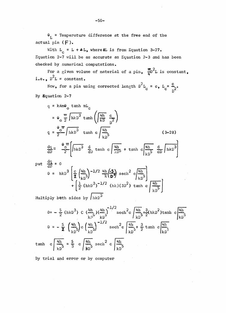
GL = Temperature difference at the free end of the actual pin ( F ) •
With L = L +AL, where AL is from Equation 3-27. c Equation 2-7 will be as accurate as Equation 2-3 and has been checked by numerical computations.
For a eiven volume of material of a pin, . 2 i.e., D L =constant.
Now, for a pin using corrected length D2L = c
By tiq,uation 2-7
q = kAmQ tanh mL 0 c
= Q0 'i /hkn3 tanh (/~ ;, ) QoTT/-S ~h q = - hkD tanh c -2 kDS
dq put dD = 0
Q OTT [ra d f4h 2 /hkD- dD tanh c / :<i)5 +
c c., L = - • c 02
( 3-28)
d r3l do I hkD J
o = hkD3 [ i {;;5)-112 2*f~~ sech2 c/;;s]
+ [ ~ (hkD3>-112 (hkH3D2 ) tanh c J ::s J Multiply bt>th sides by f hkD3
5 3 4h 4h )-112 2 ~h 3 2 O= - 2 (hkD ) c (-6 )(-!:> sech c - 5-tf hkD )tanh . kD kD kD
14h c-kD5
- 5 ( 4h ) ( 4h )-112 0--- __... c -
1 kD5 kD5 sech2c 1~ + ~ tanh c~
kD5 2 /kn5
tanh
By trial and error or by computer
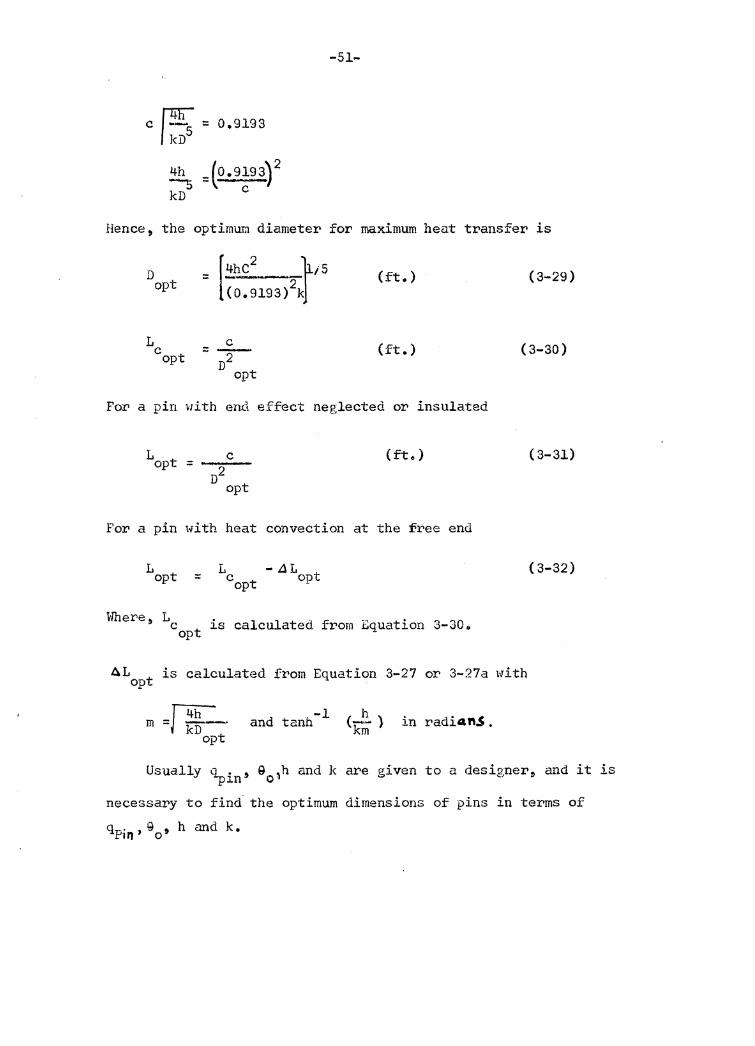
c I ~5 = 0.9193 kD
~ =(0.9193~ 2 kD c
-51-
Hence, the optimUJ~ diameter for maximum heat transfer is
D opt
L c opt c = T opt
(ft.)
(ft.)
For a pin with end effect neglected or insulated
L . c opt= ---
D2 opt
(ft.)
For a pin with heat convection at the free end
L L -ilL opt = c opt opt
Where, 1c is calculated from Equation 3-30. opt
( 3-29)
(3-30)
( 3-31)
( 3-32)
AL is calculated from Equation 3-27 or 3-27a with opt
m =J1¥=t op -1 and tanh h <--) km in radiaft.S.
Usually ~in' 90 ,h and k are given to a designer, and it is
necessary to find. the optimum dimensions of pins in terms of qp. , g , h and k. 1n o
-52-
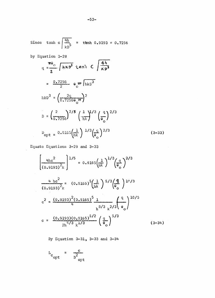
Since tanh c ~ = tanh 0.9193 = o. 7256
by Equation 3-28
"TJ'Q ~ r4h q =-0 .. , bKD3 tenh ( J KI>5
2,
= 0.'7256_ 9 Tr /hkD3 2 0
hkD3 ( 2q \2 : 0 • 72569 TT-,
0
= (-=-- \ 2/3 (-1 y.13 (~) 2/3 D 0.7256} ~ 9
0
D 0 01r.r:(~) l/3(_s.)2/3 opt = ,e~~uJ hk Q 0
Equate Equations 3-29 and 3-33
[ 4hc2 l 1/5 ( 1 )1/3( q )2/3 = 0.9165 - -::. (0.9193) 2k hk 9 0
2 4 he -----· (0.9193) 2k
c2 = (0.9193) 2(0.9165) 5 l R:q ) l0/3
4 8/3 2/3 ~ h k 0
c = (0.9193)(0.9165)512 ( ~o) 513 2hlt/3 kl/3 ~
By Equation 3-31, 3-33 and 3-34
L = c opt
c
T opt
(3-33)
( 3-34)
-53-
5/3 = (0.9193)(009165) 512 !...51) (hk) 213 (Q0 )4/3
2h4:/S k113 \go (009165) 2 q
Therefore, L = c 0.4213 ( ~) i13 ( r )1/3
Where
with
opt
L opt
h 0
= L _ AL t copt op
L is from Equation 3-35 c opt
AL is from Equation 3-27 or 3-27a opt
m =~ ~ opt
tanh-1(-kh) in radians. m
Annular Fins
By definition of fin efficiency, e = q/q 0
( 3-35)
( 3-36)
where Q = Heat flux: from a fin if the entire fin were -o at temperature T
0
2 2 = 211(r2 rl )hQO
q= ~., f 2 rr- ( 2 .9.. = n r 2 - r ' 9 ··O
In the Ahove equation, usually 2 al'.e.. given, and the terms ( r 2 -
2 1 ) e ( 3-37)
the terws q, G0 , h and r 1 2 r 1 ) and e will determine the
r optimum dimensions of annular fins, i.e., the values of 2/r1
and t that make er; - r 2) e maximum for a given volume of
material will be the optimum dimensions. Therefore, efficiency
curves of annular fins are basic data for designers.
By Equ.c:ttion 2-24
2 e ==-----
( l+r21r)z
-54-
K1(R1Z) r1(R2Z) - I1(R1Z)K1(R2Z) K0~R1z) I1~R2z) + I 0 (R1Z)K1(R2Z)
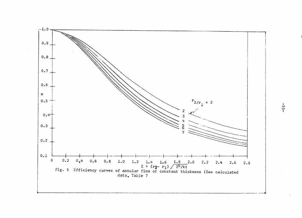
curves are plotted by putting r 2/r1 = 2 to 7 (any adequate
number can })e chosen i:f necessary) with the design-parameter group, z = (r2 - r 1 ) /2h/kt, as abscissa and efficiency e as ordinate. (Fig. 5).
0.9
0.8
0.7
0.6
e I
o. 5 1-. !
0.4-i-
0.3
0.2
0.1 0 0.2
Fig. 5
0,4 0.6 0.8
Efficiency curves
r 2/r1 = 2
1.0 1.2 1.4 li6 1.8 2.0 2.2 Z = (r2- r1) / 2h/kt
of annular fins of constant thickness (See data, Table 7
2.4 2.6
calculated
2.8
I ui ui I
-56-
By Equation 3-37 and with the aid of Figure S !'I optimum dimensions of an annulCl!" fin can be estimated for two cases that follow:
(l) For given values of q, Q and h 0
Assign values of r 2/r1 , calculate corresponding values of e by
Equation 3-37, check the corresponding values of Z from efficiency curves and then corresponding values of t are determined by
Z = (r2 - r 1 ) f 2h/kt. The value oft and the value of r 2/r1 that result in least volume of material will be the optimum dimensions, (r1 being given).
(2). For given values of h and a given volume of material with r 1 given, choose the value of t according to commercial gauge of sheet metal. The values of r 2/r and t, that result in maximum
heat transfer, will be optimum dtmensions for a given volume of material.
The optimum conditions of an annular fin are somewhat lik~ that of a straight rectangular fin. Equation 3-37 can be put into a simplified form,
q/ Q = hS e, which is the simplified form for a pin or a straight0 rectangular fin with end effect neglected. For a given
2 2 value of h, the surface S = 2 TT(r -r1 ) and efficiency e are factors that influence heat flow.
For given values of r 2/r1 , if t is doubled, the volume of material will be doubled without increasing the surface (except the slight increase in outer-edge area), and the design parameter group Z decreases (1/ {2"times its original value), resulting in a slight increase in efficiency~ as seen from Figure 5. It is meant that the heat transfer increase slightly with the volume doubled. BU:t with two thinner fins of thickness t,
-57-
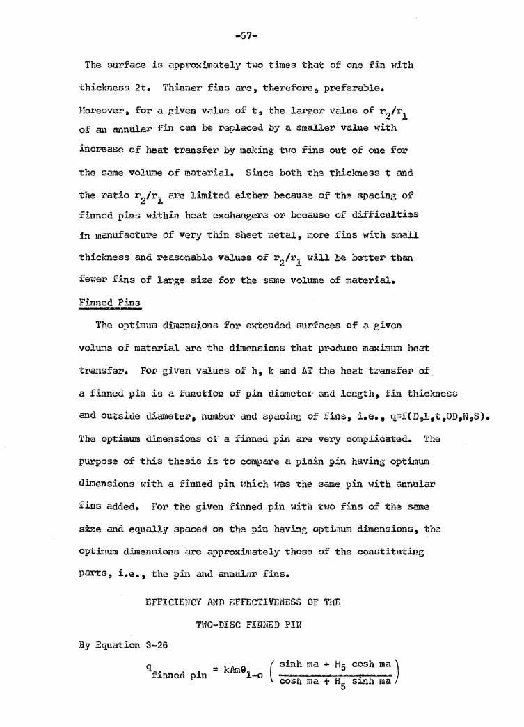
The surface is approximately two times that of one fin with
thickness 2t. 'l'hi."lnel' fins arc, therefore 0 preferable.
Horeover, for a given value of t~ the larger VcW.ue of r .. 2/r1 of an annulaJ:> fin can be replaced by a smallet> value with
increase of heat' triansf er by making two fins out of one fo:<>
the same volume of material. Since both the thickness t and
the ratio r 2/r1 are l:ltnited either because of the spacing of
finned pins within heat exchangers or because of difficulties
in manu£aoture of very thin sheet metal~ mor~ fins with small
thickness and reasonable values of r 2/r1 will be hette~ than
fewer fins of large size for the same volume of material.
Pinned Pins
'l'he optimum dimensions :for extended surfaces of a given
voluma of material are the dimensions that produce maximum heat
·transfer. For given values of h, k and h.T the heat transfer of.
a finned pin is a function of pin diametex· ari<l length• fin thickness
and outside diameter, number and spacing of fins, i.e., q=f(D,L,tirOD,N,S).
The optimum dimensions of a fi.~ned pin are ve~y complicated. Tho
purpose of this thesis is to compare a plain pin having optimum
dimensions with a finned pin which was the same pi.r. with annular
fins added. for the given finned pin with two fins of the same
size and equally spaced on the pin having optimum dimensions, the
optimum dimensions are approximately those of the constituting
parts, i.e., the pin and annular fins.
EFf'! CIEHCY ih'?D :t:FFECTIVENESS OF THE
TWO-DISC FINNED PIN
By Equation 3 ... 26
q • • f:i.nned pin
-58-
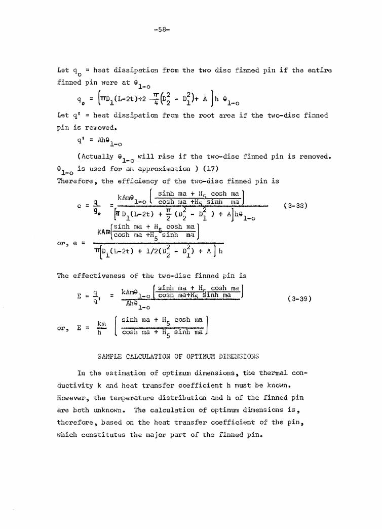
Let q :: heat dissipation from the two disc finned pin if the entire 0
finned pin we:rie at 91 -o
q 0 = (1TD1(L-2t)-n :(n; - D~)+ A ]h Ql-o
Let q• :: heat dissipation from the root area if the two-disc finned
pin is removed.
q' = AhQ 1-o
(Actually Ql will rise if the two-disc finned pin is remoyedo -o G1_0 is used for an approximation ) (17)
Therefore, the efficiency of the t1·10-disc finned
e =
or, e =
kAm91_0 ( sinh ma + Hr: cosh ma J .:l. cosh ma +H5 sinh ma = -qi> (:rr D l ( L-2t) 'TT 2 D2 + AlhQl-o + 2 (D2 - )
1
(sinh ma KA iil cosh ma
+ H5 cosh ma J
l/2(D; - D~) + A 1 h
The effectiveness of thB two-disc finned pin is
[ sinh ma + Hr cosh ma J E :;: .'.1 = kAmfl i-o . • fOSh ma+l15 ~hnh ma
CJ.' AMl 1 -o
km [ sinh ma + HS cosh m~ 1 or, E = -h cosh ma + HS sinh ma
pin
SAMPLE CALCULATION OF OPTIMUM DINENSIONS
is
( 3-38)
( 3-39)
In the estimation of optimum dimensions, the thei"!nal con-
ductivity k and heat trans for coefficient h must be known.
However, the temperature distribution and h of the finned pin
a1"e both unknown. The calculation of optimum dimensions is,
therefore, based on the heat transfer coefficient of the pin,
which constitutes the major pai.,t of the finned pine
-59-
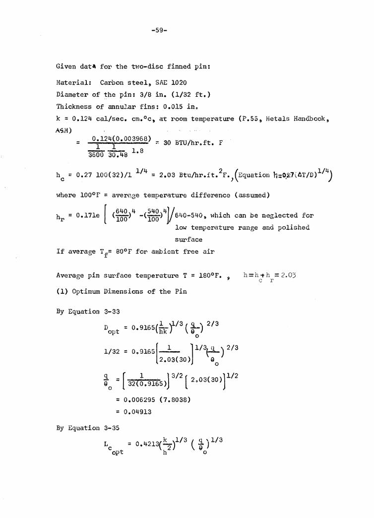
Given dat4 for the two-disc finned pin:
Material: Carbon steel, SAE 1020 Di&~eter of the pin: 3/8 in. (l/32 ft.) Thickness of annular fins: 0.015 in. k = 0.124 cal/sec. cm. 0 c, at room temperatUI'e (P.55,, Metals Handbook, AS.M)
= 0.144(0.003968) 1 l
'3'5'0'0" '36":'4 8 1. 8 ·· 30 BTU/hroft. F
he= 0.27 100(32)/l 114 = 2.03 Btu/hr.it. 2F.,(Equation h:~~7(AT/D)114J
where l00°F = aver."'1.r;e temper;iture difference (assumed)
[ 640 4 540 4]/ . hr= 0.171e C100 ) -< 100 ) 640-540, which can be neglected for low temperature range and polished
SUI' face If average Tf= 80°F for ambient free air
Average pin surface temperature T = 1S0°F. j
(1) Optimum Dimensions of the Pin
By Equation 3-33
D opt
l/32 = o. 9165[ l l l/3P-) 2/3 2.03(30) G
0
q [ 1 J 3/2 ( ) 1/2 G0 = 32(009165) 2 •03( 30)
= 0.006295 (7.8038)
= 0.04913
By Equation 3-35
Le = O.l~213(-hk2 )l/3 ( %oJ 1/3 opt
h=h-th =2.03 c r
-60-
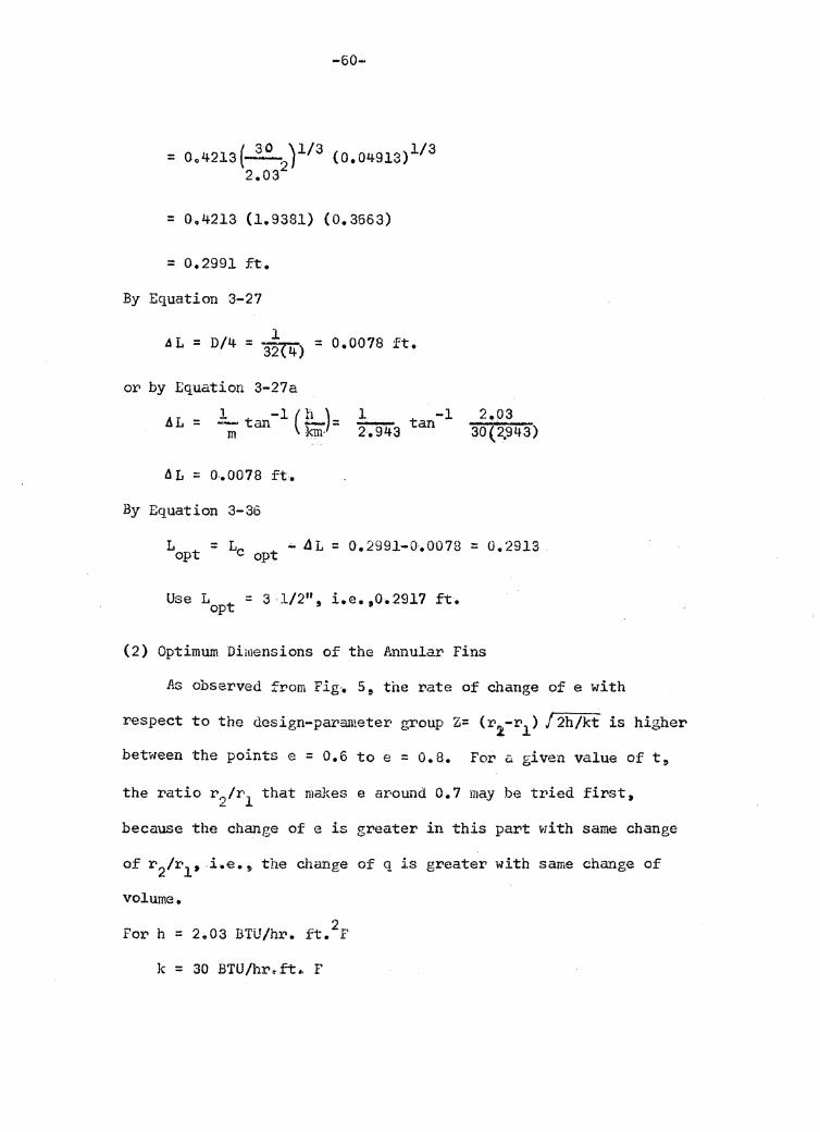
= 004213(~2)113 (0.04913)113 2.03
= 004213 (l.9381) (0.3663)
= 0.2991 ft.
By Equation 3-27
l ~L = D/4 = 3'2("4} = 0.0078 ft.
or by Equation 3-27a
AL = L tan-l ( !!....)= 1 tan-l m km· 2:'§'43
i1L = o .• Q078 ft.
By Equation 3-36
2.03 30( 2,943)
L = L - ~L = 0.2991-0.0078 = 0.2913 opt c opt
Use L = 3 1/211 9 i.e.,0.2917 ft. opt
(2) Optimum Dimensions of the Annular Fins
As observed from Fig·. 5, the rate of change of e with
respect to the design-parameter· group Z= (r1-r1 ) J 2h/kt is higher
between the points e = 0.6 toe = o.a. For a given value oft,
the ratio r 2/r1 that maJrns e ar·ound 0.1 may be tried first,
because the change of e is greater in this part with same change
of r 2/r1 , i.e., the change of q is greater with same change of
volume.
For h = 2.03 BTU/hr. ft. 2F
k = 30 BTU/hr.~~ F
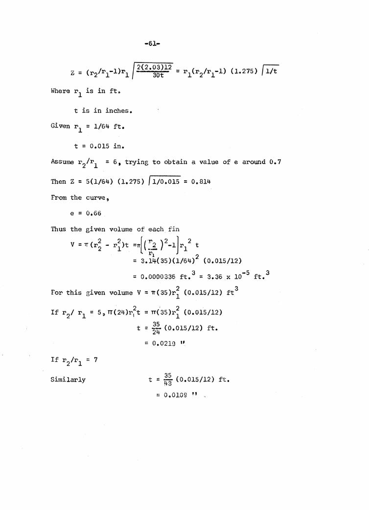
-61-
Where r 1 is in ft.
t is in inches.
Given r 1 = l/64 ft.
t = o.015 in.
Assume r 2/r 1 = 6 • trying to obtain a value of e around o. 7
Then Z = 5(1/64) (l.275) f l/0.015 = 0.814
From the curve ,
e = o.66
Thus the given volume of each fin
v = iT er; .. r~)t =1T[ c:j_ )2-1]r12 t
= 3.14(35)(1/64)2 (0.015/12)
= 0.0000335 ~. 3 = 3.36 .x io-5 ft. 3
2 3 For this given volume V = ~(35)r1 (0.015/12) ft
. 2 . 2 . s, TT(24)r1 t = rr(35)r1 (0.015/12)
t = * (0.015/12) ft.
= 0.0219 "
Similarly 35 t = '1+3 < o. o 15I12) ft.
:: 0.0109 " "
-62-
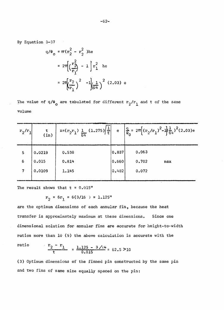
By Equation 3-37
The value of q/90 are tabulated for different r 2/r1 and t of the same
volume
r2/rl z=(r2r 1 ) .!,_ (1.275)~ .9.. = [ 2 41 2 t e 2rr (r2/r1 ) - :g-4 ) (2.03)e (in) 64 eo
5 0.0219 0.538 0.837 0.063
6 0.015 0.814 0.660 0.702 max
7 0.0109 1.145 0.482 0.072
The result shows that t = 0.015 11
r 2 = 6r1 = 6(3/16 ) = 1.125"
are the optimum dimensions of each annular fin, because the heat
transfer is approximately maximum at these dimensions. Since one
dimensional solution for annular fins are accurate for height-to-width
ratios more than 10 (9) the above calculation is accurate with the
ratio : l. 12 5 - 3 /I o = 6 2 r:: > lO
0.015 .~
(3) Optimum dimensions of the finned pin constructed by the same pin
and two fins of same size equally spaced on the pin:
-63-
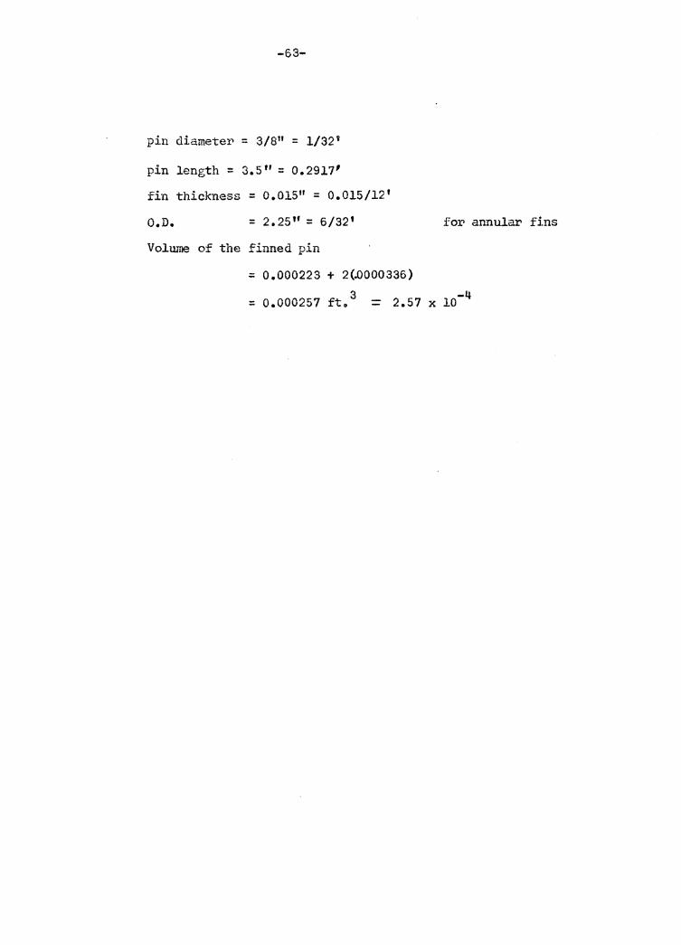
pin diamete1., = 3/811 = 1/32 9
pin length = 3.5" = 0.2917'
fin thickness = 0.015 11 = 0.015/12'
O.D. = 2.25'' = 6/32' for annular fins
Volume of the finned pin
= 0.000223 + 2{~000336)
= 0.000257 fto 3 = 2.57 X 10⁻⁴
-64-
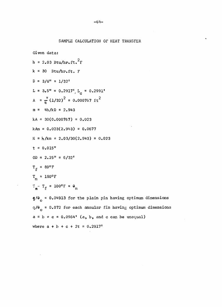
SAMPLE CALCULATION OF HEAT TRANSFER
Given data:
h = 2.03 Btu/hr.ft. 2F
k = 30 Btu/hr.ft. F
D = 3/8" = 1/32 1
L = 3.5" = 0.2917' L = 0.2991 1 ) c
A = 4n (l/32) 2 = 0.000767 ft 2
m = 4h/kD = 2~943 kA = 30(0.000767) = 0.023
kAm = 0.023(2.943) = 0.0677
H = h/km = 2.03/30(2.943) = 0.023
t = o.01s 11
OD = 2.25 11 = 6/32'
Tf = 80°F
T = iao°F m T - T = ioo0 r = Q m f m
g/90 = 0.04913 for the plain pin having optimum dimensions
q/9 = 0.072 for each annular fin having optimum dimensions 0
a = b = c = 0.0964' (a, b 9 and c can be unequal)
where a + b + c + 2t = 0.2917 1
-65-
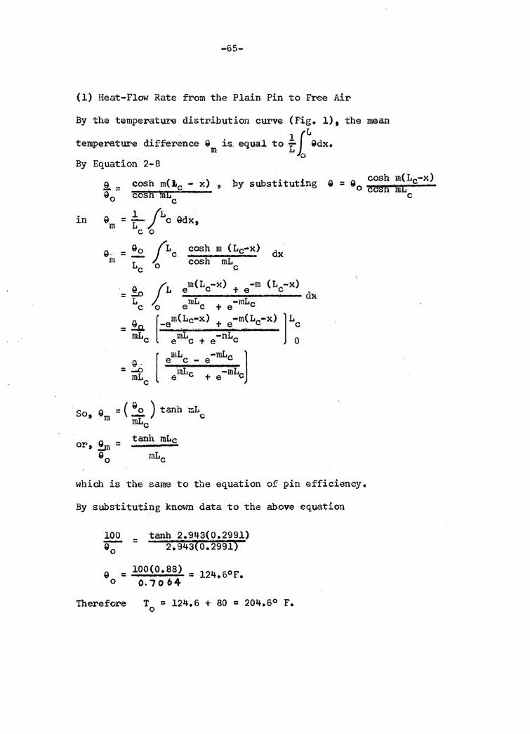
(l) Heat-Flow Rate from the Plain Pin to Free Air
By the temperature distribution curve (Fig. 1) 9 the mean . lfL temperature difference Qm is., equal to L Qdx. 0
By Equation 2-8
§.. = cosh m(J.c - x) 90 cosn mt:c
, by substituting G = 9 cosh m(Lc-x> 0 cosn mt
in n l /L d . 'I'm = 1 cg x, c 0
g .. = ~ /Le _c_o~sh""' ..... m._C_L_c_""_x) m Le 0 · cosh mLc
=~ L c
e c ~ e [ m_L_ · .. _ "'mLc l
tanh mLc
mLc
dx
which is the same to the equation of pin efficiency.
By substituting known data to the above equation
100 tanh 2.943(0.2991) 90 = 2.943to.2§91)
Q = 100(0.88) = 124• 60 F. 0 0.-7064
Therefore T = 124.6 + 80 = 204.6° F. 0
c
-66-
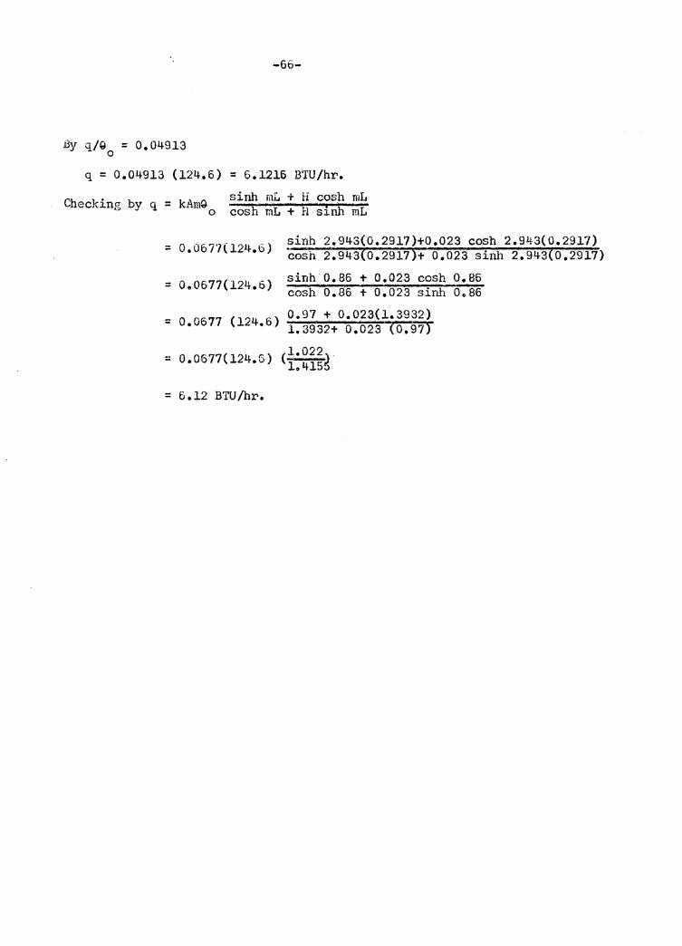
By q/Q = 0.04913 0
q = 0.04913 (124.6) = 6.1216 BTU/hr.
Checking by q = kAmQ sinh mL + H cosh mL o cosh mL + H sinh mL
= o.o67'7(l24•6 ) sinh 2.943(0.291.7)+0.023 cosh 2.943(0.2917) cosh 2.943(0.29175+ 0.023 sinh 2.943(0.2917)
= o. 0677c124•6) sinh 0.86 + 0.023 cosh 0.86 cosh 0.86 + 0.023 sinh 0086
= 0.0677 (124.6)
= 0.0677(124.6)
= 6.12 BTU/hr.
0.97 + 0.023(1.3932) 1.3932+ 0.023 ~0.9?)
(l.022~ l.415:>
-67-
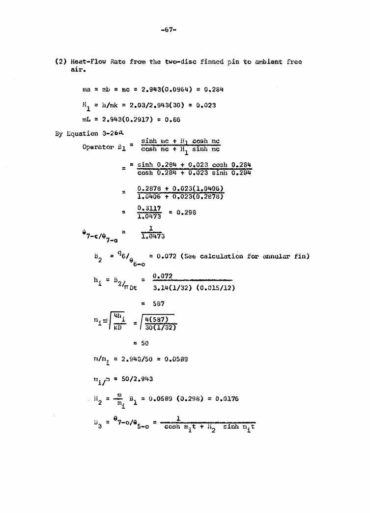
(2) Heat-Flow Rate from the two-diso finned pin to aw.bient fx'ee air.
ma = mh = me = 2.943(0.0964) = o.2s4
Hl = h/mk ::: 2.03/2.9L~3(30) : 0.023
mL = 20943(0.2917) = O.BS
By :Cquation 3-26tl
Operator Bl = sinh &~c +;. H3 aosh me cosfi me + H1 .sinh me
= = zinh 0.284 + 0.023 cosh 0.294
& ill 7-c/&7 -o
cooh 0.284 + o."023 sinh 0.204'
0.2070 + 0.023(1.0~06) 1.0406 ·+ 0.023(0.2878)
o.u11 = o.29s l.0473
l
B2 = q6/ = 0.012 (See calculation for annular fin) 9"
h .. = l.
u-o
= 0.012 3.14(1/32) (0.015/12)
= SB?
/ 4(597) = SOCl/32)
:: 50
m/m. = 2.943/SO = 0.0509 :i.
.B 4
B 6 =
-68-
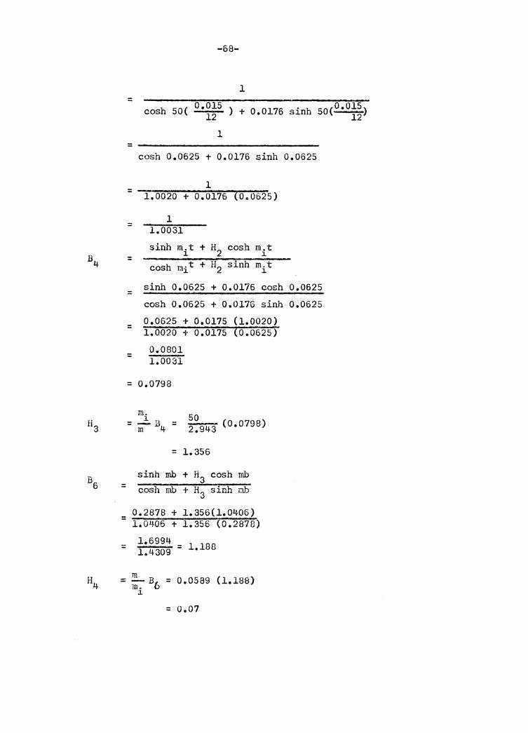
1 =
cosh 50( O.OlS ) + 0.0176 sinh soc 0 •015 ) 12 12
l
cosh 0.0625 + 0.0176 sinh 0.0625
1 = ...,,.__,..,,__ _____ ....,,..__,,,,,_..,...,.~ 1.0020 + 0.0176 (Oe0625)
=
=
=
=
=
l 1.0031
sinh mit + H2 cosh mit
sinh 0.0625 + 0.0176 cosh 0.0625
cosh 0.0625 + 0.0176 sinh 0.0625
0.0625 + 0.0175 (l.0020) 1.0020 + 0.0175 (0.0625)
0.0801 1.0031
= o.0798
m. 50 = ~ B4 = 2 •943 (0.0798)
= 1.356
sinh mb + H3 cosh mb cosh mb + H3 sinh mb
0.2878 + 1.356(1.0406) = ~1-. o"""· 4_,0""'6-+-1""".-3~5..,.5-r( o~.-:2~8-=7~8)
l 0 699L~ = 1.4309 = 1.188
= !.!:._ B6 = 0.0589 (l.188) m. J.
= 0.07
B9
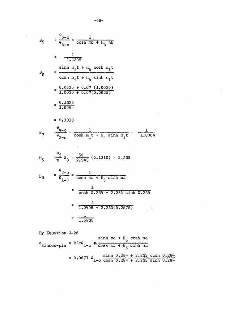
-69-
g 5-o 1
= e--- = cosh mb + H3 rob 4-o
1 = 1.4309
sinh m.t + H4 cosh m. t J. 1 =
cash m.t + H sinh m.t l. 4 l.
0.0625 + 0.01 (l.0020) = 0.07(0.0625) 1.0020 +
0.1325 = 1.0064
= 0.1318
Q4-o 1 =~ = cosh m.t + H4 sinh m.t = 2-o i i
m. l. =-B = m 8
Q 2-o =-=
Ql-0
=
=
=
50 (0.1318) 20235 = 2.943
l cosh ma + HS s:i.nh ma
l cosh o.284 + 2.235 sinh
l 1.0406 + 2.23G(0.2878)
1 1.6838
l 1.0064
o.284
By Equation 3-26 . sinh ma + H5 cash ma
q = kAmQl ~ finned-pin -o c=o.sh ma + H5 sinh ma
sinh o.284 + 2.235 cosh 0.284 = 0 •0677 91-0 cosh 0.284 + 2.235 sinh 0.284
::: 0.0677 Q 1-o
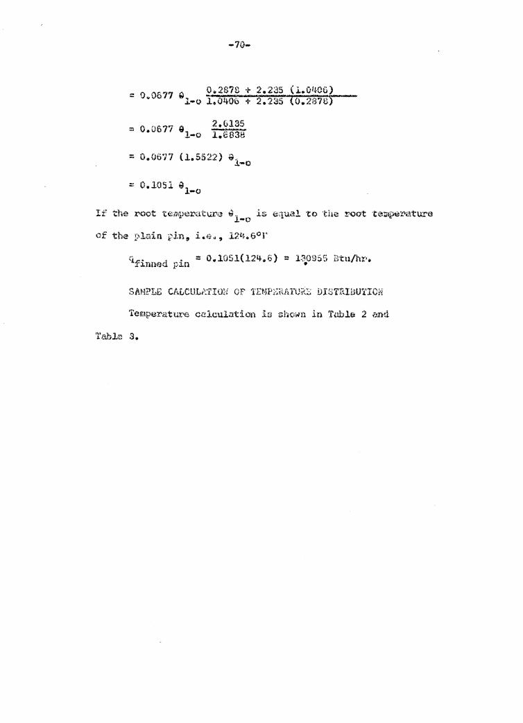
-70-
2.6135 I:6838
~ 0.06?7 (l.5522) ~l-o
= 0.1051 ~l -o
Temperatrn:'e celcul;:ition i::i shi;;iwn in 'f~lble 2 ;.m~i
'l'abJ.r.:; s.
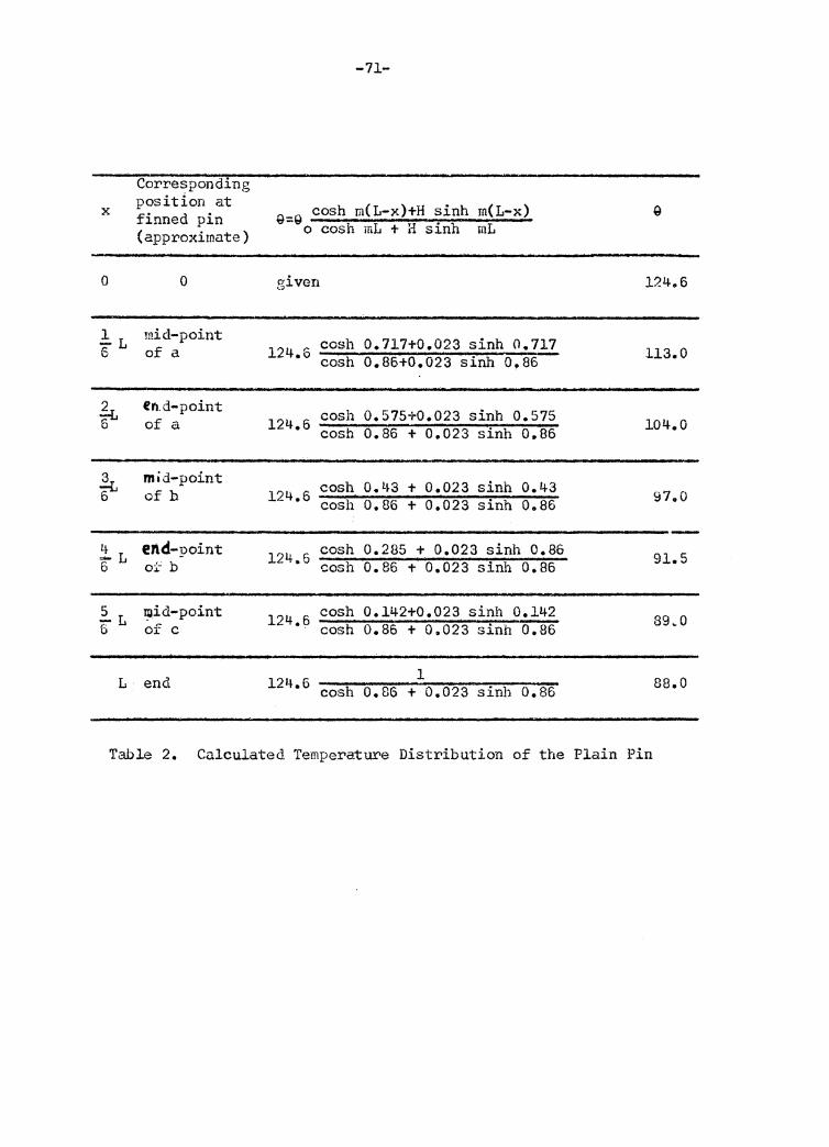
-71-
Corresponding x position at
Q=Q cosh m(L-x)+H sinh m(L-x) finned pin (approximate) o cosh mL + a sinh mL
0 0 given l?.4.6
!1 mid-point co sh o.717+0.023 sinh o.717 6 of a 124.6 cosh 0.86+0.023 sinh 0.86 113.0
.k en.d-point cosh 0.575+0.023 sinh 0.575 6 of a 124.6 cosh 0.86 + 0.023 sinh 0.86 104.0
.k mid-point cosh 0. L~3 + 0.023 sinh 0.43 6 of h 124.6 co sh o.86 + 0.023 sinh 0.86 9'7o0
i1 end-point 124.6 cosh 0.285 + 0.023 sinh 0.86 91. 5 6 ot b cosh 0.86 + 0.023 sinh 0.86
5 ?J.!id-point 124.6 cosh 0.142+0.023 sinh 0.142 89~0 5L of c cash o. 86 + Oo023 sinh 0.86
L end 124.6 l 88.0 cosh o.86 + 0.023 sinh 0.86
Table 2. Calculated Temperature Distribution of the Plain Pin
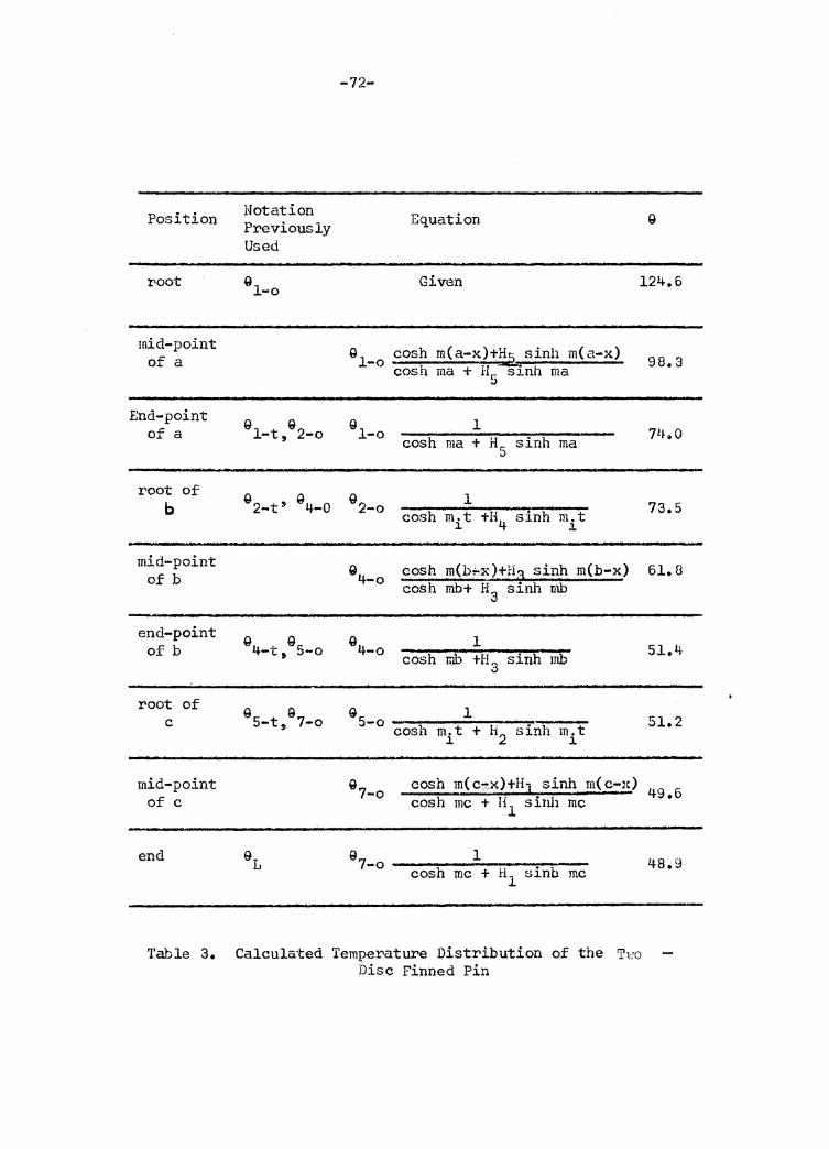
-72-
Position Notation Equation Previously Used
root 9 l-o Given 124.6
mid-point Q cosh m(a-x)+~ sinh m(a-x) of a l-o cosh ma + H5 sinh ma
End-point g Q Q l of a 1-t, 2-o 1-o cosh ma +Hr.: sinh ma 0
root of 92-t' 94-0
Q l b 2-o cosh mit +l\ s:i.nh mi t
mid-point 9 cosh m(b,i,,x2+H3 sinh m(b-x) of b 4-o cosh mb+ H3 sinh mb
end-point g Q 9 l 0£ b 4-t, 5-o 4-o cosh mb +I-I sinh mb 3
root of G Q 9 l c 5-t, 7-o 5-o cosh m.t + H2 sinh mit l.
mid~point 9 cosh m(C'.'.!'.X)+HJ sinh m(c-x) 7-o of c cosh me + H1 sinh me
end 9L Q 1 7-o cosh me + H1 sinb me
Table 3. Calculated Temperature Distribution of the T1·;0 Disc Finned Pin
98. 3
1i~.o
73.5
61.8
51.4
51.2
49.6
48.9
-73-
IV. EXPERIMENTAL INVESTIGATION
OBJECTIVE OF INVESTIGATION
It has been the intention of this investigation to verify
the basic heat transfer equations derived in this thesis by
comparing experimental and theoretical results. The ultimate
objective is to determine the heat transfer characteristics of
finned pins.
EXPERIMENTAL PROCEDlfRE
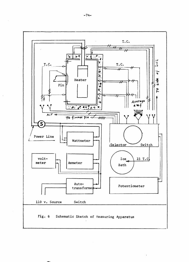
Set-up of Heat Supply Circuit
Since the ammeter and VOf tmeter were placed between the
wattmeter and the auto-transformer, (wiring system shown Fig. 7)
there was no effect on wattmeter reading. The potential circuit
of the wattmeter was connected directly across the heater. By
disconnecting the load , i.e. & by tur·ning off switch S the
potential and current circuits of the wattmeter continued to
carry a current and, therefore, the wattmeter itself consumed
electric energy. The net power taken by the load was the reading
when switch S was on, minus the reading when switch S was off.
T. C.
Power Line L .. ------
volt-meter
110 v. Source
'. -0
-74-
:-o·~
Heater
L
Wattrneter
Auto-transforrne
Switch
T. C •
. 4· .. ., \."
T. C.
~ .. :O (I.
o: to. ·~
15 T.C
Potentiometer
Fig. 6 Schematic Sketch of Measuring Apparatus
;•'("
·~ -'}
·-~-Q
~ "' ~
y
-75-
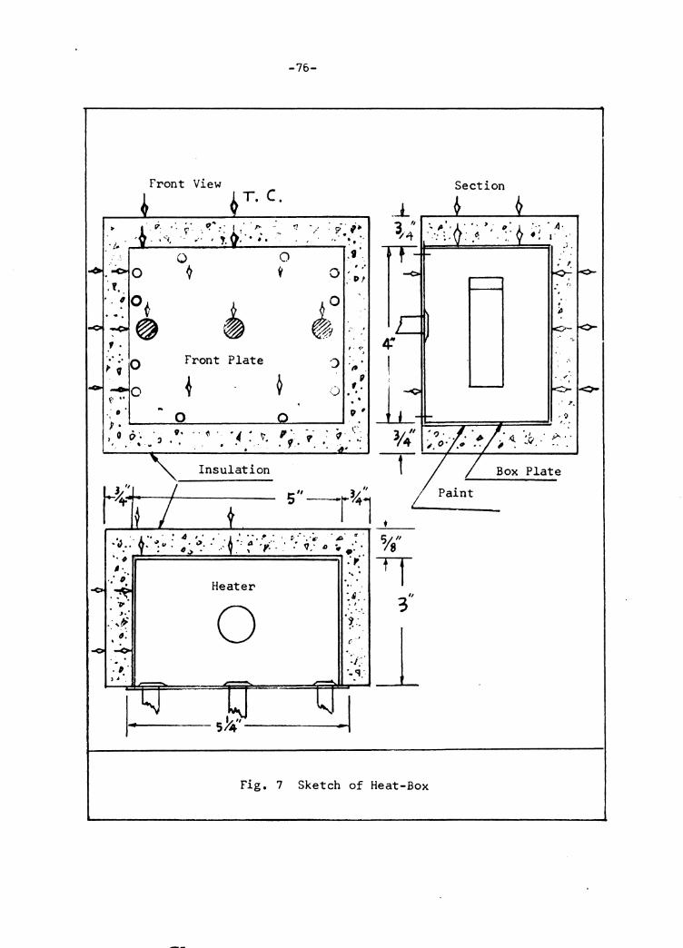
Construction of Heat Box, Pins and Finned Pins
Heat Box - Three front plates were cut to size and holes
were drilled in the plates and box so that each plate could
be §Grewed to the box front, (Fig. 7). Insulation around
the box (except front plate) was accomplished by putting
plaster of asbestos in the space between the heat box and a
large:t:• wooden box.
Pins - Three pin holes were drilled in one front plateo The
pins were slipped in and fastened on the back of plate by
silver solderingo
Finned Pins - Starting with one annular fin slipped on the pin•
the end of the pin was heated by gas flame and soft solder
was applied around the circumferential contact line. The
pins had to be fastened to another front plate by silver
soldering before the fastening of annular fins, otherwise,
soft solder would be melted because of the higher temperature
required for silver solder.
-76-
Front View T. C.
_j_ •'
-? . ,. .. - . ~.
> '. i: · ·. ;.,· "~~:: I .· . "' .: ~ ' . . " • ' ... -.;, .,:• I '· I • f. ·t..
.9 0
, . . I>'
0
~ , . ('
>
') p Front Plate
II . :) , . ..
• (•" 0 .: • 0 ?· ,.._ -. 1 0 O ', l . V• · · {I • ·' ~ 'I. r
• . • .•. w • • • • ,_. '"
• C. ~·. ·.;
' ,
14' s" -r%1 ' __.._ __
I .... • • r, ,•, ,' '~· 11' .,"'·;,;_ ... ··:v~a · . ' ~· . . ;, .· .. :( •. #
Heater '. .. · o: . ..
:~:.
-1 Fig. 7 Sketch of Heat-Box
Section
·"· . A· • ~ I .
·' .
; '·
.· 7.
·.~ . y.. .. JI.. . ..
-77-
Set-up of Measuring Circuit
(1) Construction and Calibration of The~nocouples:
Thermocouples were made of copper-constantan with junctions
formed with soft solder which can be worked to temperatures up to
300° F.
The thermocouples were calibrated at the steam point only
and it was found that the thermocouple emf at the steam point
was consistent with the standard emf-temperature table. Because
the temperatures to be measured were 32° F to 280° F. and
because the aesired measurement was temperature difference
r•ather• thai.1 absol1..ri:e -Cernpe1~atur·e, uetailed calibration was not
necessary.
(2) Therimocouple Circuit:
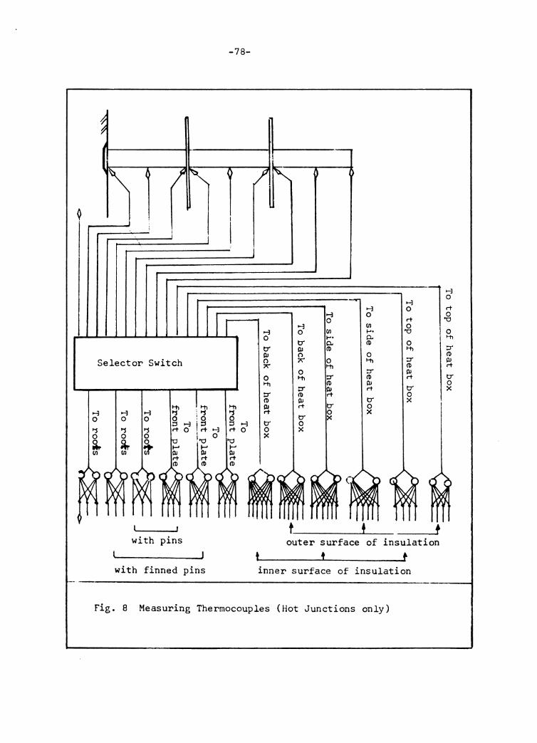
Each thermocouple drcui t was completed by inserting a
selector switch and a potentiometer on the copper wirie between
the hot and cold j unctiom;. Parallel multi-circuits were used
where an average temperature was required (See Fig. U) o
Selector Switch
>-3 0 >j 0 ~ Cll
>-3 >-3 0 0 >j >j 0 0
~ ~
with pins
:;i g rt >-3
0
with finned pins
-78-
t
>-3 0 tr PJ 0 ;.;-
0 I-ti ::r ro ~ tr 0 x
>-3 0 tr PJ R-o t-ti
::r ro PJ rt
tr 0 x
>-3 0 Cll I-'• 0.. ro 0 I-ti
::r ro rt
tr 0 x
>-3 0 Cll ..... 0.. ro 0 I-ti
::r ro PJ rt
tr 0 x
>-3 0 rt 0
"O
0 ~
::r ro PJ rt
tr 0 x
outer surface of insulation t t
inner surface of insulation
Fig. 8 Measuring Thermocouples (Hot Junctions only)
>-3 0 rt .g 0 ~
::r ro OJ rt
tr 0 x
-79-
Attachment of the Thermocouples
The thermocouple hot junctions were attached to metallic
surfaces by soldering 9 but for the inner and outer surfaces
of the insulation, the hot junctions were put in contact with
the surfaces (next to the inner insulation surface , the
ready-made box had a layer of existing paint; thermocouples
could not be soldered.) (See Fig. 7).
Experimental Operation
(1) By putting the. f-ront plate on the heat box and switching
on the power supply circuit, the box was heated up gradually
until the three thermocouples with their hot junctions at the
roofs of the pins had a reading of average emf corresponding
to the given root temperature T0 • T0 was determined by Q0 +Tf'
wherie T f was measu1"ed. by t!10 thermoco-uple with the hot junction
in ambient air and 90 was a predetermined constant temperature
difference.
Several hours were required before the root temperature
reached steady state. When T reached the predetermined value 0
an<l did not change with time, the heat box and plain pins we1"e
then at static conditions. The power supply and temperaturie
measurements from each thermocouple circuit were made.
(2) The front plate with plain pins was then replaced by the
f-ront plate with no pins. following the same method as described
in ( 1) , the temperatwe rise of the box because of the removal
-80-
of pins was measured with heat supply unchanged.
( 3) The front plate with th1"'ee finned pins was then substituted for
the plain plate. The power supply and temperatures were measured
in the same way as described in ( 1).
(4) The front plate with the finned pins was then replaced by
the plain plate again. The heat box was heated with the same heat
supply as for the finned pins. The temperature rise of the box,
because of the !'emoval of the finned pins, was measured, following
the same procedure.
( 5) I'o1~ measuring the temperature along the plain pin or the finned
pin, single-circuit the:r:raocouples were employed. Measurements of
temperature were made when the root temperatul"e of one pin or one
finned pin was maintained at predetermined value at static condition.
If the heat supply by keeping one pin at 9 was slightly different 0
from the case by keeping three pins at average Q , it was immaterial. 0
The determination of the temperature distr•ibution was dependent on
G , h and k. 0
-81-
List of Mater.ial
The following material was used in this expel"iment:
Thermocouple Hire.
Hatched copper-constantan wires, obtained from the
Mechanical Engineering Department, Virginia Polytechnic
Institute were used for constructing thermocouples.
Steel Bar
SAE 1020, square bars, obtained from and cut into round
rods by the machine shop t Mechanical Engineering Department,
Virginia Polytechnic Institute were used as pins.
Steel Plate.
SAE 1020, 0.015 inch thickness, obtained from and
cut into discs by the machine shop, Mechanical Engineering
Department, Virginia Polytechnic Institute, was used as
annular fins.
Steel Plate
About 1/16" thickness, obtained from the Mechanical
Engineering Department, V.P.I. was used as f-ront plate of
the heat box. The front plate was used as the primary surface.
-82-
List of Apparatus
The following apparatus was used in this investigation:
Wattmeter
Weston type, rated current, 1 amp. voltage, low range 0-74,
hir;h range 75-150, power range 0-150 watts. Total resistance
5764 and 11528 ohm, manufactured by Daystrom, Inc., Weston
Instrument Division, Newark, New Jersey~ Used for measuring
heat supply.
Ammeter
Range 0-3 amp., Heston type, manufactured by DaystrOl!l, Inc.
used in conjunction with wattmeter for checking current.
Voltmeter
Used in conjunction with wattmeter for checking voltage.
Auto transformer
Type W5M.T, manufactured by General Radio Company, Cambridge,
Mass. Input voltage 115 v. output voltage 0-135 v. Used for
regulating electric power to heater.
Heater
Cartridge type, 135 watt, 115 volt, used as the heat generating
source.
Selector Switch
Manufactured by Minneapolis-Honeywell Regulator Company,
Philadelphia, Pa. Used to connect desired thermocouple circuit.
-83-
Potentiometer
Nur.iber 8662 » Portable precision type 1 manufactured by
Leeds nnd Northrup Company, Philadelphia, Pa., used for
measuring emf between the hot junction and cold junction of
a ther>mocouple.
Vacuum Bottle
Obtained from the Mechanical Engineering Department,
V.P.I. 1 used as ice bottle for the reference junctions of
thermocouple circuits.
Heat Box
A ready-made painted steel box of 3" x 5" x 4" size,
obtained from the Mechanical Engineering Department, v. P.I.,
used as primary heat surface for the pins or finned pins.
-84-
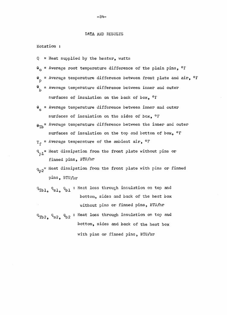
DATA AND RESULTS
Notation :
Q = Heat supplied by the heater, watts
Qo = Average root temperature difference of the plain pins,
Q = Average temperature difference between front plate and p Q = Average temperatUI'e difference between inner and outer b
surfaces of insulation on the back of box, 0 r
Q = Average temperature difference between inner and outer s surfaces of insulation on the sides of box, 0 r
Of
air,
9Tb= Average temperature difference between the inner and outer
surfaces of insulation on the top and bottom of box, °F
Tf = Average temperature of the ambient air, °F
qpl= Heat dissipation from the front plate without pins or
finned pins 9 BTU/hr
qp2= Heat dissipation from the front plate with pins or finned
pins, BTU/hr
ClTble qsl, qbl : Heat loss through insulation on top a'f'ld
bottom, sides and back of the heat box
without pins or finned pins, BTU/hr
qTb2 • qs2 , qb2 : Heat loss through insulation on top and
bottom. sides and back of the heat box
with pins or finned pins, BTU/hr
Of
-85-
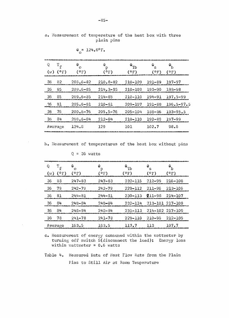
a. t'leastu•ement of temperature of the heat box with three plain pins
Q T~ g G QTb Q gb r 0 p s (w) (Of) (Of) (OF) (Of) (OF) (OF)
36 B2 205.6-82 210. 8-82 210-109 191-89 197-97
35 85 20905-85 214.3-85 210-109 193-90 198-98
36 85 20906-35 214-85 210-110 191+-91 197.5-99
.% 81 205.6-81 210-81 209-107 191-88 196.5-97.5
36 76 200.6-76 205.5-76 205-104 188-86 193-95.5
36 84 208.6-8L~ 212-8l~ 210-110 192-89 197-99
Average 124.6 129 101 102.7 98.5
h. r:Jeasurement of temperatures of the heat box with out pins
Q = 36 watts
Q Tf G ~ GTb G {,}b 0 p s (w) (Of) (OF) (OF) (Of) (Of) (Of)
36 83 247-83 247-83 232-115 212-99 216-108
36 79 242-79 242-79 229-112 211-96 213-106
36 81 244-81 244-81 230-113 211-98 214·-107
36 84 248-84 248-84 232-114 213-101 217-109
36 84 248-84 248-f34 231-113 2lt~-102 217-109
36 78 241-78 241-78 229-110 210-96 212-105
Average 163.5 163.5 117.7 113 107.7
c. Heas,wement of ene1'gy consumed Hithin the wattmeter by turning o:ff sid·tch S( discorrnect the load): Energy loss within wattmeter = o.6 watts
Table 4. Measured Data of Heat Flow .Rate from the Plain
Pins to Still Air at Room Temperature
-86-
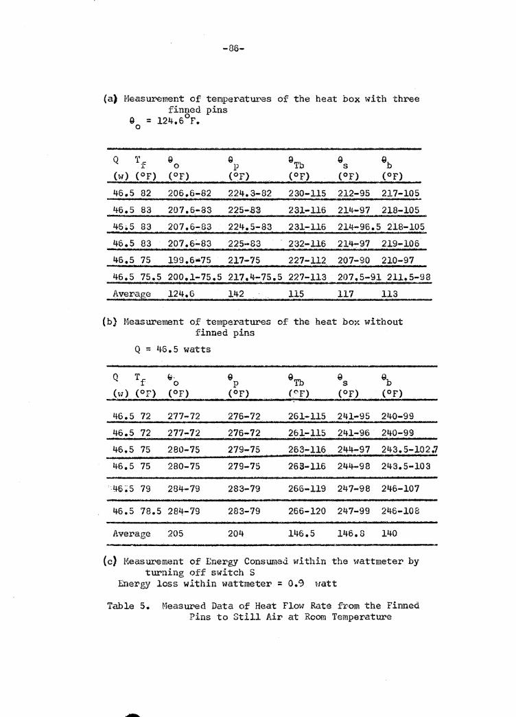
(a) Measurement of temperatui.,es of the heat box with three finned pins
0 9 = 124.6 F.
Q
0
T f (W) (OF)
46.5 82
46.5 83
Q 0
(OF)
206.6-82
207 .6.-83
Q Q p s
(OF) (OF)
224.3-82 230-115 212-95 217-105
225-ll3 231-116 214-97 218-105 45•5 83 207.6~83 224.5-83 231-116 214-96.5 218-105
46.5 83 207.6~83 225-83 232-116 214-97 219-106 46.5 75 199.6~75 217-75 227-112 207-90 210-97
46.5 75.5 200.1-75.5 217.4-75.5 227-113 207.5-91 211.5-98 Averag_e 124.6 .. 113 142 115 117
(b) Measurement of temperatures of the heat box without finned pins
Q = 46.5 watts
~- G Q 0 p s
(Of) (OF) (OF)
46.5 72 277-72 276-72 261-115 241-95 240-99
46.5 72 2.77-72 276-72 261-115 241-96 240-99
46.5 75 280-75 279-75 263-116 244-97 2!~3.5-102.7
46.5 75 280-75 279-75 265-116 244-98 243.5-103
' 46 ~ 5 79 284-79 283-79 266-119 247-98 246-107
46.5 78.5 281.t-79 283-79 266-120 247-99 246-108
Average 205 204 146.5 146.8 140
{c) Measurement of Ene:t>gy Consurnad within the wattmeter by turning off switch S
Ene:t>gy loss within wattmeter ::: 0.9 watt
Table 5. Measured Data of Heat Flow Rate fr-om the Finned Pins to Still Air at Room Temperature
-87-
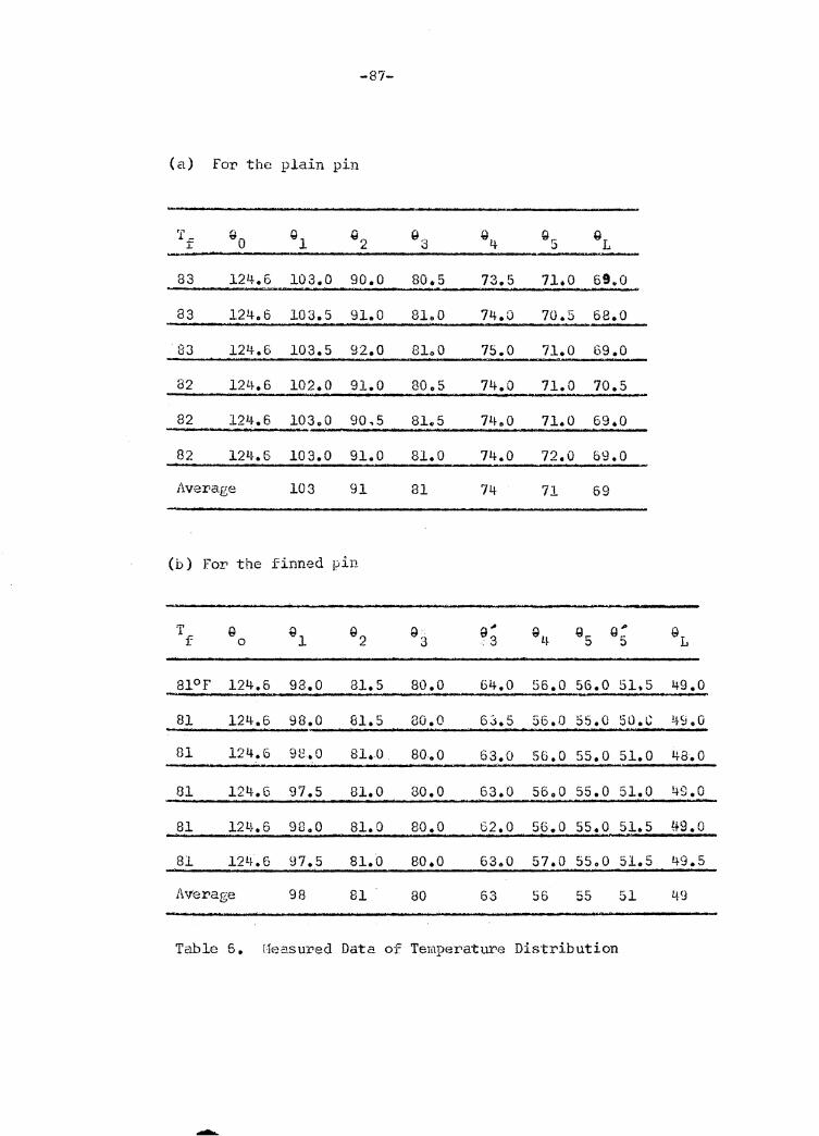
(a) For the plain pin
T -- " Ql Q2 fl 3 Q4 Q,.. GL r "o ;.)
83 12'+. 6 103.0 90.0 80.5 73.5 71.0 69.0
83 124.6 103.5 91.0 81.0 74.0 70.5 68.0
83 124.6 103.5 92.0 8lo0 75.0 71.0 69.0
82 l2L~• 6 102.0 91.0 80.5 74.0 71.0 70.5
82 12'·~.6 103.0 90,5 81.5 7!~. 0 71.0 69.0
82 124.6 103.0 91.0 81.0 74.0 72.0 69.0
i\vera.ge 103 91 81 74 71 69
(b) For the finned pin
T G Ql Q2 Q3 g" Ql~ Q5 Q; l\ f 0 .3
81°F 124.5 98.0 81.5 so.o 64.0 56.0 56.0 51.5 49.0
81 124.6 98.0 81.5 80.0 63.5 56.0 55.0 50.G 49.0
81 124.6 98.0 81.0 80.0 63.0 56.0 55.0 51.0 48.0
81 124.6 97.5 81.0 so.a 63.0 56.0 55.0 51.0 49.0
81 12L~. 6 98.0 81.0 80.0 62.0 56.0 55.0 51.5 !+9.0
81 121~.6 97.5 81.0 80.0 63.0 57.0 55.0 51.5 49.5
Average 98 81 80 ,.. " Ov 56 55 51 4.9
Table "' Vo flea.sured Data of Temperature Distribution
-88-
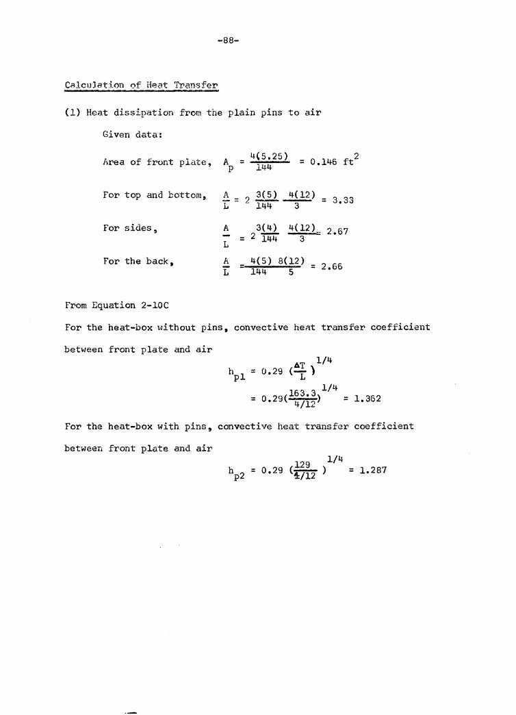
Calculat5.on of Heat Transfer
(1) Heat dissipation from the plain pins to air
Given data:
At•ea of front plate, A = 4(5.25) = 0.146 ft 2 p 144
For top and bottom, A 2~ 4(12) 3.33 1- = 144 3
For sides, A 3(4) 4(12)~ 2.67 = 2 'i.44 3 L
For the back, A 4(5) 8(12) 2.66 - = L 144 5
From Equation 2-lOC
For the heat-box without pins, convective hent transfer coefficient
between front plate and air AT 1/4
hpl = 0.29 c1 ) 1/4
= 0 29( 163. 3) • 4/12 = 1.362
For the heat-box with pins, convective heat transfer coefficient
between front plate and air 129 114 = o.29 <47i2 > = i.201
-89-
Heat loss through insulation of the box without pins
q'l'bJ.:= 3.33 (117.7)k = 392k
qSl = 2.67 (113)k = 302k
qbl = 2.66(107.7)k = 286k
Heat loss through. insulation = ( 392 + 302 + 286 )k = 9801< Btu/hr.
Heat loss fro"'.' front plate~ qPl = A h)1 9,i'lo.146(1.362)(163.5) p I =32~ 5· Btu/hr.
Net heat supply = heat loss from front plate + ·11~at. loss tnr>ough insulation in static condition
Therefore, (36 - 0,6)3.412 =- 32,.5 + 980k (lWaH = 3.412 Btu/hr)
k ~ (36 - 0.6) 3.412 ~ 32.5 0 09 990 = •
Heat loss through insulation of the box with pins
qTb2 = 3.33 (lOl)k = 3.33(101)0.09 = 30.27 Btu/hr
QS2 = 2.67 (102.3) 0.09 = 24.58 Btu/hr.
qb2 = 2.66 (98.6) o.o9 = 23.6 Btu/hr.
Heat dissipation from the plain pins to air
= net heat supply - heat loss through insulation - heat loss from front plate
Thus, heat dissipation from the three plain pins to air
q = (36-006)3.412 - (30.27'+24.~i+23.6) - 24.4
= 120.78-120.69
= 19.09 Btu/hr•
-
-90-
(2) Beat dissipation from the Finned Pin to Air
For the box without finned pins,
(~l = 001%(1.44)(204)
= 42.9 Btu/hr.
qTbl = 3.33(147)k = 489k
qSl = 2.67 ( 146 )k = 390k
qbl = 2.66 (139.2)k = 370k
(46.5 - 0.9)3.412 = 42.9+(489+390+370)k
112.69 . k = 1249 - 0. 09 (approximate)
For• the boi~ with finned pins
hP2 = 0.29 ( 14~(12}) 1/4 = 1.317
qp2 = 0.146 (l.317) 142 = 27.3 Btu/hr.
q'I'b 2 = 3.33 (115) o.09 = 34047 Btu/hr.
q = 2.67 (117)0.09 = 28.12 Btu/hr. s2
qb 2 = 2.66(113)0.09 = 27.05 Btu/in'.
Heat dissipation fr-OJ;) the finr.e<l vi11s to air
= net heat supply - heat loss through insulation
- heat loss fr1om front plate
q = (46.5 -0.9) 3.412 - (34.47+28.12+27.05) -27.3
= 155.59 - 116.94
= 38.65 Btu/hr.
-91-
V. DISCUSSION
EXPERIMENTAL ACCURACY
The data obtain~d from the pouer supply apparatus employrad
in this investigation wer-e peproducible, and the temperature
measuring instrument as well as the copper-constantan thermocouples
. wer-e accurate for• the range of temperature measured. 1,;
'!'he heat box, having the heater at its center 11 created slightly
higher• temperature at the root position where the central pin was to
be attached. Steel plates were placed inside th•3 :bo:>!'. to make the
root temperature uniform. This was done fm:• both cases, (front plate
i·Iithout pins, with pins or with finned pins). The temperatu:.,e at tbe
root of the central pin still was consistently high. The average root
tempe!'ature was measured by a multi-thermocouple circuit for measuring
average emfo Since the root temperatures diffe~ad f~om each other
slightly (l to 5°F), measurement of average emf was considered
acceptable.
As to the attachment of thermocouples, the tighter or loose:"
contact with the ov.tel" SUl'face of insulation made the measured emf
waver slightly. This error was expected to be :i:teduced by the avel'age
of repeated measurements. Ther'ttlocouple attachments elsewhere were
stable.
-92··
Measurements wel.'e carried out at a room temperature
around 80°F. In case of room temperatm'e change during
measurement, the pre-determined root temperature had to be
adjusted to ke~p G0 unchanged.
Heat dissipation from pins or finned pins is dependent
upon h, k and 90 • For a given 9 , although slight changes of 0
room temperature result in changes in the pin temperature, the
changes in h and k are so small that they can be neglected.
The aver-age temperature measurement of insulation was an
approximation. It was insufficient to measure the true average
temperature, but since the desired measui"ement was temperature
difference, there was no appreciable effect on accuracy. same
errors caused by an insufficient number or improper position of
thermocouples in hot and cold temperature measurements had little
effect on temperature difference.
COMPARISON OF THE TWO-DISC FINNED PIN WITH 'l'HE PLAIN FIN
Tµ;nperature Distribution
The temperature distribution curves plotted from calculated
and measured data are shown in Figure 9. Curve 1, the calculated
temperature distribution 9 is higher than Curve 2, the measured
temperature distribution. The measured temperatures are considered
comparatively accurate because all temperatures were measured
on the pin itself. Since the temperature distribution is
dependent only upon h and k, and since the value of k is accurate,
-93-
it is concluded that a small h made the calculated Q greater than
measured 9. The value of h was calculated by neglecting h , heat r
transfer coefficient by radiation, which might be noticeable
because of the larger emmissivity of the pin surface which was
not highly polished. A smaller average h results in less heat
dissipation along the pin, and the1'efore, the rate of temperatUI'e
drop with respect to distance along the pin was sma.l'.ler than
the actual pin, i.e., the calculated curve is higher than the
measured curve.
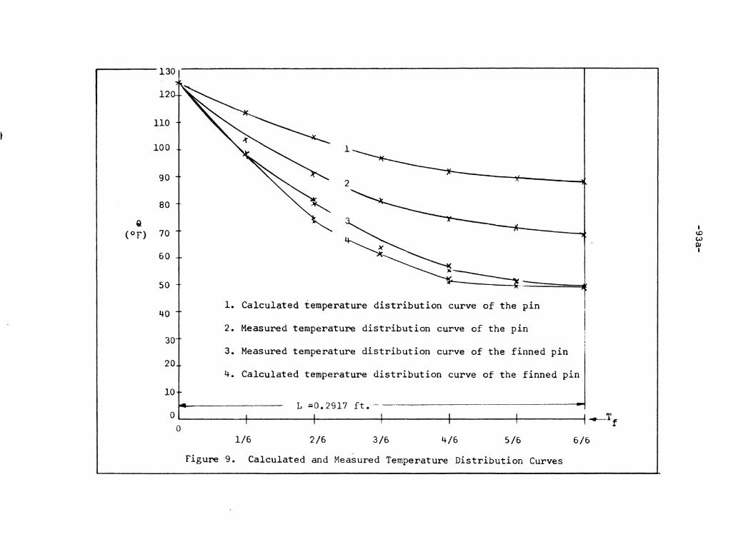
Q (OF)
130 I
12
110
100 1
90 2
80
70
60
50
40 1. Calculated temperature distribution curve of the pin
2. Measured temperature distribution curve of the pin 30
3. Measured temperature distribution curve of the finned pin 20
4. Calculated temperature distribution curve of the finned pin
10 L ;Q.2917 ft. - ---------
0 0 L-~~~~~1--~~~~~1--~~~~--+~~~~~~~~~~~--+~~~~~--1_.._Tf
1/6 2/6 3/6 4/6 5/6 6/6
Figure 9. Calculated and Measured Temperature Distribution Curves
I ID w Ill I
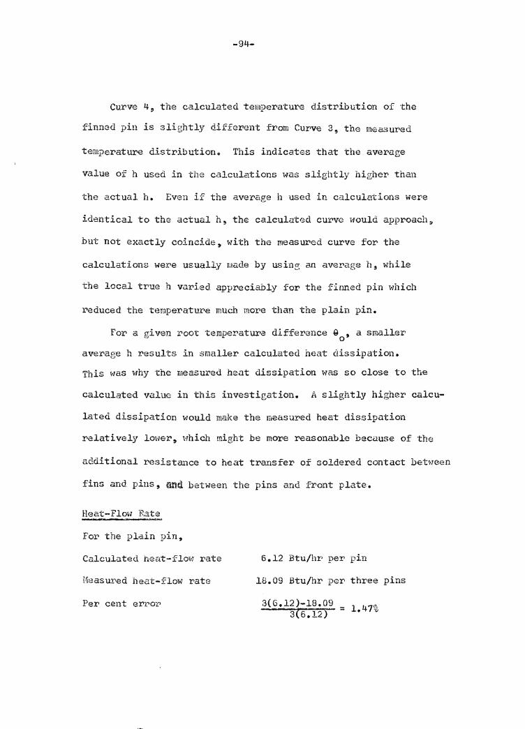
-94-
Curve 4, the calculated temperature distribution of the
finned pin is slightly different from Curve 3, the measured
temperature distributiono This indicates that the average
value of h used in the calculations was slightly higher than
the actual h. Even if the average h used in calculations wer·e
identical to the actual h ~ the calculated curve would approach~
but not exactly coincide,. with the measured curve for the
calculations we:ce usually made by us in~ an average h, while
the local true h varied appreciably for the finned pin which
i~educed the ternperatur.•e much more than the plain pin.
For a given root temperatwa difference G , a smaller 0
average h results in smaller calculated heat dissipation.
This was why the measured heat dissipation was so close to the
calculated value in this investigation. A slightly higher calcu-
lated dissipation would make the measured heat dissipation
relatively lower, t·rhich might be more reasonable because of the
additional resistance to heat tra.nsfer of soldered contact bet~rnen
fins and pins, ~nil between the pins and front plate.
Heat-Flow :Rate
For the plain pin,
Calculated heat-flow rate 6.12 Btu/hr per pin
Measured heat-flow rate 18.09 Btu/hr per three pins
3(6.12)-18.09 = i.4n, 3(6.12)-Per cent er1..,or
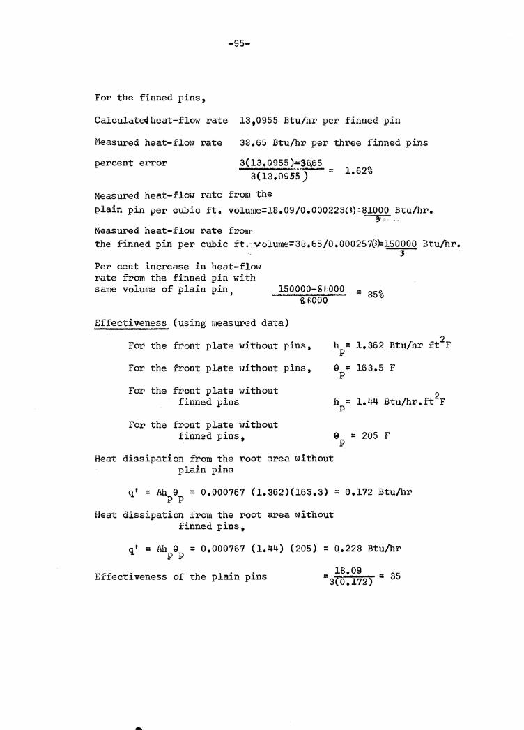
-95-
For the finned pins,
Calculate<Jheat-flow rate 13,0955 Btu/hr per finned pin
Measured heat-flow rate 38.65 Btu/hr per three finned pins
percent error 3( 13.0955 )•38.65 sc13.09ss·) =
Measured heat-flow rate from the plain pin per cubic ft. volume=l8.09/0.0002230):81000 Btu/hr.
~
Measured heat-flow rate from· the finned pin per cubic ft. volume=38.65/0.000257(3):::150000 Btu/hr.
3 Per cent increase in heat-flow rate from the finned pin with same volume of plain pin, 150000-SIOOO
ll f.000 = 85%
Effectiveness (using measured data)
For the front plate without
For the front plate without
For the front plate without finned pins
For the front plate without finned pins 9
pins~
pins,
Heat dissipation from the root area without plain pins
h = 1.362 Btu/hr ft2r p
9 = 163.5 F p
9 = 205 F p
q' = Ah g = 0.000767 (1.362)(163.3) = 0.172 Btu/hr p p
Heat dissipation from the root area without finned pins,
q t = Ah 9 = 0.000767 (1.4~) (205) = 0.228 Btu/hr p p
Effectiveness of the plain pins - 18.09 - 3r: -sro.112> - 0
-

-96-
Effectiveness of the finned pins
Per cent increase in effectiveness of the two-disc finned pins
38.65 = 3(0.228) = 56 •5
56. 5 -35 = ~---= 35 51%
-9'7-
Limitin~ Condition
Suppose the volume of a finned pin is equal to m+l pins,
the increase of surface of the finned pin ceases when the surface
of the :finned pin is equal to the surface of the pins. . sl +ns2 surface of the finned pin =
surface of the m+l pins sl + msl Then,
Where n = number of annular fins
s = surface of each annular fin with outer edge 2 area neglected
s 1 = surface of each pin with end are.::1 neglected
Since volume of annular fins =volume of.m pins
-~ ir ( D 2 - D 2 ) t = •ii I!. ,. ? L D 2 · ') 2 = 1. 4 2 1 " 4. '1 ' 2 - 'l
nS 2
D 2L m 1 . ) E.! ( . 2 nt = 2t
mDi2 L nt
ms 1 -
When nS2 ~ 1~ the surface of the finned pin is equal
to the t>urface of m+l pins having the same volume. Since the heat
dissipation from a finned pin depends mainly on increased surface~
D 2t = 1 is e.pproximately the limiting con di ti on that a finned [Jin
has no more increase in heat dissipation. The value of D should 2t
be as large as possible in determining the inter-relation between
the dimensions of the pins and annular fins.
-98-
SUMMARY
It has been shown that the expex>irnental accuracy was within
acceptable limit. Even with a higher h used for• calculation for
the given root temparature the experimental results were acceptable.
For example, from the measured temperatures the value of h was
approximately 2.66 for the plain pin (corresponding to an emissivity
of 0. 45) by a trial·...; and-error calculation. Hi th this value of h,,
the calculated heat-flow rate equals 6.5 Btu/hr.~ and the experimental
accuracy equals 3(6.5) - 18.09 3(6.5) = 7.295, which is acceptable.
The basic heat transfer equations der>i ved in this thesis have
been Pl"OVen to be logical and the pattern of process for deriving
these mathematical equations ca.i-1 be used by others with confidence~
arid ca11 be applied to any finned pin regardless of the mur.be:ci and
spacing of annular· fins, natural or forced convection.
-99-
VI. CONCLUSIONS
The object of this investigation was accomplished since;
(1) the heat exchange capability and effectiveness of a finned
pin were found to be much better than those of a plain pin, and
(2) the basic heat transfer equations derived for a finned pin
were verified by the experiment.
The increase in heat transfer by employing a finned pin
depends on the dimensions, spacing and number of annular fins.
In general, the thickness of annular fins should be much smaller
compared to diameter of the pin. If a finned pin were constructed
of a pin and a bank of annular :fins, the increase in heat transfer·
and pin effectiveness could be much higher.
It is expected that the finned pins can be applied to
practical use. No doubt where pins can be used, finned pins can
be employed to improve heat transfer capabilityc It is also
possible for the designer to use finned pins as substitute for
ordinary fins of various type with or without re-desiL,>ning the
primm.~y heat surface.
-100-
VII. RECOI'1MENDATIONS
It is recommended for the coming investigators of finned
pins that:
1. A cylindrical heat-box be used because
(1) The heat loss throug insulation can be accurately
meastu~ed because no corner effect exists ai.•<l ( 2)
the temperature will be uniform cil'cumferentia.lly on the
cylindrical surface, with a heater at center.
2. A finned pin be constructed of a pin and a bank of annular fins.
3. Perform e}{periments on a group of staggered finned pins.
4. Forced convection be employed.
5. Average heat transfer coefficient of annular fins be
pre-determined experimentally, if possible.
6. ]athematical solution of optimum dimensions for finned pins
be derived i·F possible. 1 -
7. Experiment be made in an air con<li tioned room.
-101-
VIII. BIBLIOGRAPHY
1. KAYS, W. M. - The Basic Heat Transfer and Flow F1.,iction
Characteristics of Six Compact High Performance Heat
Transfer> Surfaces, Journal of Engineering for ?ewer,
Transactions, ASHE, Sc1"ies ti, No. 1 (1960)
2. KAYS, W. f-1., LONDON, A. L. and JOHNSON, D. W. -Gas Turbine
Heat Exchangers, Copyright by ASME ( 19 51)
3. KAYS, A.21., and LONDON, A. L. ~ Heat Transfer and Flow
Friction Characteristics of some Compact Heat Exchanger
Su~faces 9 Transactions ASME, Vol. 72 (1950)
L~. DREXEL, W. H. Convection Cooling, Sperry Engine0ring Reviel-i-,
Vol. 14, No. J.!+ ( 1961)
5. KREITH, F. - Pr'inciple of Heat Trausfer, Third P1 ... inting,
Inter~al Textbook Company (1960)
6. SCHNEIDER, P. s. - Conduction Heat Transfer, Second Printing,
Addison-Wesley Publishing Company, Inc. (1957)
7. CASSELL, D. s. - Notes on Heat Transfer, Department of
Mechanical Engineering, V. P. I. (1962 ), unpublished.
8. MC ADAMS, D. s. - Heat Transmission, Third Edition, McGraw-Hill
Book Company, Inc.
9. KELLER, H. H. and SOM~1ERS, E. V. - Heat Transfer from an Annular
Fin of Constant Thickness, Journal of Heat Transfer, Vol. 81,
Series C~ No. 2 (1959)
"
-102-
10. NATIONAL DUR:::AU OF STAlWARDS - Applied Mathematics, Series 25 •
United States Government Printing Office, Washington, D.c. (1952)
11. ANDREW• G. and HATHE~'lS, G. B. - A Treatise on Bessel Functions,
Reprinted, Macmilla11 and Company (1931)
12. HARPER, H. H. and .BROHH, D. R. - Mathematical Equations for
Heat Conduction in the Fins of Air Cooled Engines, NACA Report 158
(1922)
13. GARDNER, K. 1 .... - l:fficiency of Extended Sui.,face, Ti•ans. ASME,
Vol. 67, No. 8 (1945)
*14. GARDNER, K. A. and CARlrn.VOS, T. C. - Thermal Contact Resistance
in finned Tubing, Jownal of Heat Transfo:r:·, Vol. 82, Series C,
No. 4 (1960)
15. SAE Handbook (1961)
16. WOOD, W. P. i:Uld CORK, J. M. - Pyr·ometry, Copywright by the
McGraw-Hill Book Company, Inc. (1941)
17. HURRAY 9 W. M. - Heat Dissipation thr>ough an Aimular Disc or
Fin of Uniform Thickness, Journal of Applied Mechanics, Vol.
5, Trans. ASHE, Vol. 60 (1958)
13. HSU, s. T. -Engineering Heat Trailsi'e:c, D.Va.r.. Nostrand Co.Inc.,Prineeton,New Jersey(1963)
-103-
IX. ACKNOWLEDGEr1ENT
It is with a sincere sense of appreciation that the author
acknowledges the assistance of Dr. H. L. Wood, Chairman of his
Comrni ttee, who was personally responsible for> making the ex-
perimental equipment available for this investigation and handled
daily problems.
The author wishes to express his thanks to Dr. s. 'I'. Hsu,
who suggested the concept of this thesis and helped the autho:r>
in s~lv5~E ttd p~otlems encountered.
A special thanks is extended to Prcfessor J. B~ Jones,
Head of the department, who gave the autho!' oppo!'tunity for his
study in the Mechanical Engineel"ing Department, Virginia Polytechnic
Institute.
Sincere thanks are extended to the following gentlemen:
Professor D. s. Cassell, the author's Committee men~er and in-
structor in heat transmission.
Professor c. H. Long, Mechanical Engineering Department
Professor R. s. Lecky, Mathematics Department

The vita has been removed from the scanned document
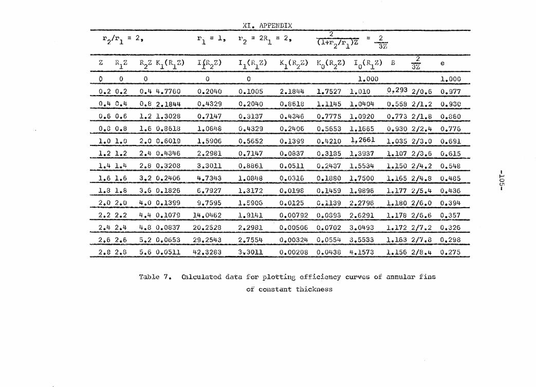
XI. APPENDIX
r2/rl = 2, 1, 2R 2, 2 2 r = 1' = :: (l+r2Jr1 )z = l 2 1 37 <? H.Z R2z K1(R1Z) rr r:>) I 1(R1Z) K1(R2z) K0(R2Z) I 0(R1Z) B 2 l..J . "2LJ 3Z e
J.
0 0 0 0 0 1.000 1.000
0.2 0.2 0.4 4.7760 0. 2Q!j.(J 0.1005 2.1844 l. 7527 ·1.010 _O ~2~3 2/0.6 0.977
0.4 0.4 0.8 2.1844 o.4329 0.2040 0.8618 1.1145 1.0404 o.sss 2/1.2 0.930
0.6 0.6 1.2 1.3028 0.7147 o.3137 0.4346 o. 7775 1.0920 o.773 2/1.B o.860 0 .o 0.8 1.6 0.8618 1. Q8L~8 0.4329 0.2406 o.5653 1.1665 0.930 2/2.4 0.'176
1.0 l.O 2.0 0.6019 1.5906 o.5652 0.1399 o.4210 l, 26,61 1.035 2/3.0 0.691
1.2 1.2 2.4 0.431+6 2.2981 0.7147 0.,0837 0.3185 1.3937 1.107 2/3.6 0.615
1.4 1.4- 2.8 0.3208 303011 0.8861 0.0511 o.2437 1.5534 1.150 2/4.2 0.548 I
1.6 l.6 3.2 0.2405 4. 731~3 l.08L~B 0.0316 0.1880 1.7500 1.165 2/4.8 o.485 I-' 0 (J1
1.8 1.8 3.6 0.1826 6.7927 1.3172 o.019s 0.11+59 l.9896 L,177 2/5.4 o.436 I
2.0 2.0 4.0 0.1399 9.7595 l.590G 0.0125 0.1139 2.2796 l.180 2/6.0 0.394
2.2 2.2 I~ .4 o.107g 14-.0!~b2 l.911U 0.00792 o .. os93 2.6291 1.178 2/6.6 0.357 2.4 2.4 4.8 0.0837 20.2528 2.2981 0.00506 0.0702 3.0'+93 1.172 .2/7 .2 o.326 2.6 2.6 5.2 0.0653 29.2543 2. 7554. 0.-00324 o.05sit- 3.5533 1.163 2/7.8 0.292
2.8 2.8 5.6 o.os11 42.3283 3-.3011 0.00208 000438 4.1573 1.156 2/8.4 0.275
Table 7. Calculated data. for plotting efficiency curves of annular fins
of constant thickness
r2 . l 3 2 R = - R = 3R = - , l _;:: 3 1 2 = 2 1 2 (1 + r27r1 )z 2Z r1
z R Z R2Z K1(R1Z) I 1 (R2Z) I 1(R1Z) K1 (R2Z) K0 (R1Z) I 0 (R1z) B 1 1 iZ e
o.o o.oo o.oo 00 0 0 00 00 1.00 00 1.000
0.2 0.10 0.30 9.8538 0.1517 0.0500 3.0560 2.427 1.0025 0.3910 l/0.4 0.97]_
0 .i~ 0.20 0.50 !.J.. 7760 0.3137 0.1005 1.3028 1.7527 1.0100 0.7329 i10.s o.s1L 0.6 0.30 0.90 3.0560 0.4971 (1.1517 o. 7165 1.3725 1.0226 o.9967 1/1~2 o.s31
o.s o.4o l.20 2 .18l~4 o.7147 0.2040 0.4346 1.J.145 1.0404 1.1792 l!l.6 0.737 1
1.0 0.50 1.50 1.6564 0.9817 0.2579 0.2774 0.9241; 1.0635 1.2928 1/2.0 0.646 I I-' 0 en
1.2 0.60 1~80 1.3028 1.3172 0.3137 0.1826 o. 7775 1.0920 1. 3557 1/2.4 0.565 I
1.4 0.10 2.10 1.0503 1.7455 0.3719 0.1227 0.6605 1.1263 1.3846 1/2.8 o.1+<fi5
1.6 0.80 2.40 0.861G 2.2981 0.4329 0.0837 0.5653 1.1565 1.3921 l/3.2 O.U35.
1.8 o.9o 2.70 0.7J.65 3.0161 o.4971 0.0577 0.48G7 1.2130 1.3872 1/3.6 0.335
2.0 l.OO 3.00 0.6019 3.9531+ 0.5652 0.9402 0.4210 1..2661 1.37!.J.l 1/4.o 0.3Lf-4
2.2 1.10 3.30 0.5098 5.1810 0.6375 o.02a1 0.3656 1.3262 1.3582 1/4.4 0.309
2.4 1.20 3.60 0.4344 6. '7927 0.711.J.7 0.0198 0.3l85 1. 3937 1.3409 l/4 •. 8 ') .279
2.6 1.30 3.90 o. 3725 8.9128 o.7973 0.0140 0.2782 1. '+693 1. 3235 1/5.2 0.255
2.8 1.40 4.20 0.3208 11.7056 0.8861 0.0099 0. 21~37 l.5534 1.3062 1/5 .. 6 0.233
r2 4, p - 1 R2
- 4 z 2 -= '1 - 3· = 4H. = 3 t ~l+r2 )z =-
rl 5Z --n
z R Z 1 -{ '7. 1 2.c> K1(R1Z) I 1(R2Z) I (R Z) 1 1 Kl (1~2Z) K0(R1Z) r 0 (R1Z) B 2
5Z e
0.10 0.06 0.24 16.5637 0.1209 0.0300 3.9191 2.9329 1.0009 0.4407 210.90 o.979
o. 36 0.12 0.48 8.1688 0.2470 0.0601 1. 741~7 2. 21~79 1.0035 0 .829L!· 2/1.80 0.922
0.54 0.18 Oo72 5.3447 o.3838 0 .090!~ 1.0083 1.8537 1.0081 1.1343 2/2.70 0.840
0.72 0.24 o.96 3.9191 o.5375 0.1209 0.6447 1.5798 l.01L~5 1.3496 2/3.60 0.750
0.90 2/4.50 I,
0.30 1.20 3.0560 o.7147 0.1517 0.4346 1.3725 1.0226 l.1~861 0.560 ...... 0 -...J I
1.08 o. 36 1.4'~ 2.4760 0.9235 0.1829 o.3034 1.2075 1.0327 1.5620 2/5 .40 0.579
1.26 0.42 1.68 2.0590 l.1733 0.2147 0.2156 1.0721 1.0446 1.5977 2/6. 30 o.so1 1.44 0.40 1.92 l.7447 1.4758 0.2470 0.1557 0.9584 1.0584 1.6059 2/7.20 0.446
1.62 0,54 .2.16 i. i~994 1 0 8L~49 0.2800 0.1138 0. 8!314 .l.0742 1.597'1 2/8.10 o.s94
,-1.ao 0,60 2.40 l. 3028 2.2981 0.3137 o.0837 o. 7775 l.0920 1.5801 2/9.00 o.351
1.98 0.66 2.64 1.1420 2. 8569 0.3483 0.0623 o. 7043 . 1.1119 l.5570 2/9.90 0.315
2.16 o. 72 2.88 l,,0083 3.5480 o.3838 <). 0465 0.6399 l.1339 1~5323 2/1.08 0.284
2 .• 314-' o. 78 ·3,12 0.8955 4.4QL~9 0.4204 0 .03lH3 0.5829 1.1580 1.5070 2/1.17 0.258
2.52 o.84 3.36 0.7993 5.%91 0 .. 4581 0.0262 o.5321 1.1843 1.4823 2/1.26 0.235
2.70 0.90 3.60 o.7165 6.7927 0.4971 0.0198 0.4867 1.2130 lol.t·586 2/1.35 0.216
z R1z R2Z K1(R1Z) I~R2Z) I 1 (R1Z) K1 CR2Z)
0.2 0.05 0.25 l9.9Q~'7 0.1260 0.0250 3.7470
0.4 0.10 0.25 9.9538 0.2579 0.0501 1.6564
0.6 0.15 0.75 6.4775 0.4020 0.0752 0.9496
O.B 0.20 1.00 4.7760 0.5652 0.1005 0.6019
1.0 0.25 l.25 3.7470 o.7553 0.1260 O.t~035
1.2 0.30 1.50 3.0560 0.9817 o.1s11 0.2774
1.4 0.35 1.75 2.5591 1.2555 0.1777 0.1960
1.6 0.40 2.00 2.1844 1.5906 0.2040 0.1399
1.8 o.45 2.25 1.8915 2.0040 0.2307 0.1010 2·.o 0.50 2.50 1.6564 2.5167 o.2579 0.0739 2.2 0.55 2.75 1.4637 3.1554 0.2855 0.0544
2.4 0.60 3.00 1.3028 3.9534 0.3137 0.0402
2.6 0.55 3.25 1.1668 4.9525 0.3425 0.0299
2.B 0.70 3.50 1.0503 6.2058 0.3719 0.0222
K0(R1Z) Io 0~2z B
3.1142 1.0006 0-58~1 2.4271 1.0025 1.0752 2.0300 1.0056 1.4291
1.7527 1.0100 1.5509
J..5415 1.0157 I.7656
1.3725 1.0226 l.Sl35
1.2327 1.0309 1.8163
1.1145 l.OLW4 1.7950
1.0129 1.0513 1.7636
0.9244 l. 0635 l. 7251+
0.8466 1.0771 1.6867
o. 7775 1.0920 1.6480
0.7159 1.1081~ 1.6119
0.6605 1.1263 1.5740
1 ,'JZ
l/0.6 1/1.2 1/1.8
1/2.4
1/3.0
1/3.6
1/4.2
1/4.8
1/5.4 1/6.0
1/6.6
1/7.2
1/7.8 1/8.4
e
0.972 0.896 0.794
; 0.688
0.588
0.504 0.432
0.374 0.327 0.288
0.256
0.229 0.207 0.187
I I-' 0 co I
r2/rl = 6, R = 1/5 0.2, R2 BP = 1.2, 2 2. = = { l+r2Jr1 )z -Tl l "l
z R1z \'~ '" K1(R1Z) I 1(R2Z) I 1(R1Z) Kl (R2Z) K0(R1Z) I 0(R1Z) B 2 -·2'-' n e
0.1 0.02 ooi2 49.954'7 0.0601 000100 8.1688 4.0285 1.0001 0.3472 2/0.7 o.992
0.3 0.06 0.36 16.5637 0.1829 o. o::rno 2.l~760. 2.9329 lo0009 0.9803 2/2.1 0.934 o.s 0.10 Oo60 908538 0.3137 0.0501 1.3023 2.l+271 1.0025 l.46:35 2/3.5 o.836
0.1 0.14 0.84 6. 9615 0.1~581 0.0102 007993 2.0972 1. OOt~g 1. 7762 2/L~. 9 0.125 0.9 C.18 1.08 5.3447 0~622'7 0.0904 005256 1.8537 1.0081 l.91.J.67 2/6.3 0.618 1.1 0.22 1.32 4.3092 0.8146 0.1107 o.3602 1.6620 1.0121 200194 2/7.7 o.525 1.3 0.26 1.56 3.5800 1.0426 001311 0.2553 1.5048 1.0l.70 2.0275 2/9.l 0.,446
I 1.s 0.30 1.80 :3.0560 1.3172 0.1517 Ool.826 1.3725 1.0226 2.0043 2/10.5 0.382 .... 0 tO
1.7 0.34 2.04 2.6470 1.6510 0.1725 0.1310 1.2587 1.0291 1.9647 2/11.9 0.330 I
1.9 0 .. 38 2.28 2.3227 2.0593 0.1935 0.0976 1.1596 1.036!~ l.9l!W 2/13.3 0.288
2.1 0.42 2.52 2.0590 2.5628 0.2147 0.0722 1.0721 1.04!+6 1.8637 2/14.7 o. 251~ 2.3 o.46 2.76 1.8405 3.18l}Q 0.2361 0.0537 o. 991.i.3 1.0536 l.BJ.46 2/lG.l 0.225
2o5 o.so 3.00 1.6564 3.9534 0.2579 0.0402 o.9244 1.0635 l.7683 2/17.5 0 .. 202
2.7 0.54 3.24 1.4994 4.9081 0.2800 0.0302 0.8614 1.0742 1.7254- 2/18.9 0.185
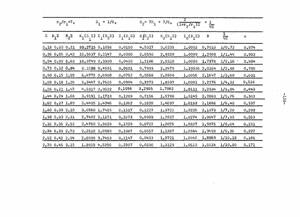
2 ::: 1 (l+r2 tr-1 )z ~ L~Z
K1(K Z) I 1 (R,,Z) 1 :!
B 1 4Z e
o.1s o.o3 0.21 as.211s 0.1055 0.0150 i+.5317 :J.6235 i.0002 0.1010 110.12 o.974
_o_.3_B __ o_._o_6_o_._4_2 __ 1_6_·._5_6_3~7_0_0_2_1~4-7.._.._o_._o_3~o-o ___ 2_._o_s_9u_'...__2_. __ 93_? __ 9 __ .._..1_._0_0_09 l.29~~--1_1_.1_._4_4~~--o_.9_0_2~-
0.54 0.09 o.sa io.9749 o.3309 0.0450 i.21es 2.sa10 i.0020 1.7376 i12.1s o.ao4 0.72 0.12 0.84 S.1688 Ool.!·581 O • .O&Ol 007993 2.2479 l.10036 2.0164 1/2.88 0.700 o.9o o.1s 1~os G.4775 o.sooe o.01s2 o.ss5a 2.0300 i.ooss 2.1647 i;a.60 o.so1 i.na o.1e i.26 s.3447 o.7636 0.0904 o.3973 1.es31 i.0001 2.221s l/4.a2 o,s1s 1.26 0.21 1.47 u.5317 o. 9522 0 . .,_1Q56 0~2905. 1.7062 ;t.Olll 2 0 2334 1/5.04 0 0 443
1.44 0.24 1.ss 3.9191 1.1733 0.1209 o.21ss lo579B 1.0145 2.2053 1/5.76 o.aaa
J..62 0.21 1.s9 3.4405 1.4346 o.1362 o.1s20 1.4697 1.01ss 2.1806 l/6.4G o.337 1.ao Oe30 2.10 3.0560 l. 71~55 · C.1517 0.1227 1.3725 1.0226 2.1079 1/7.20 0.293 1.98 o.33 2.31 2.11to2 2.1111 o.1G73 0.0939 i.2857 100274 2.0847 1/7.92 0.263
2.16 o.as 2.s2 2.~1so 2.ss2e o.ia29 0.0122 l.201s i.oa21 1.9975 ·11s.64 0.231
2.34 0.39 2.73 2.2518 3.0989 0.1987 0.0557 1•1367 . 1.0384 1.91!·59 1/9.36 0.201 2.52 0.42 2.94 2.0590 3.7453 0.2147 o.nq33 i.0121 1.0446 1~8969 1/10.18 0.186
2.70 0.45 3.15 1.8915 4.5256 002307 0.0336 l.0129 1.0513 1.8514 1/10.80 0.171
I . !-' !-' 0 I

ABSTRACT
Extensive investigations employing fins as extended surfaces
have been conducted, but relatively little experimental work has
been conducted with pins, no information is available on the heat
transfer characteristics of a pin and annular fin combination,
i.e., a finned pin.
The increased surface area of a finned pin would promote
more heat transfer. In this thesis a theoretical investigation
of the basic heat transfer characteristics of a finned pin, and an
experimental investigation to verify the theoretical result were
conducted.
1. Theoretical investigation consists of:
(1) Optimum dimensions (2) Sample calculation of optimum dimensions (3) Derivation of heat transfer equations (4) Sample calculations of heat flow-rate and temperature
distribution
2. Experimental investigation consists of:
(1) Set-up of experimental equipment (2) Measurements of heat flow-rate and temperature distribu-
tion (3) Comparison of theoretical results with measured results
3. Conclusions: The conclusions were based on the comparison of the two-disc finned pin with the plain pin.
(1) For the two-disc finned pin employed in this thesis:
Increase in heat-flow-rate: Increase of effectiveness:
85% 61%
(2) In general, the increase in heat flow-rate depends on the material, dimensions, temperature difference and spacing of annular fins.
Related Documents