“I hereby acknowledge that the scope and quality of this thesis is qualified for the award of the Bachelor Degree of Electrical Engineering (Power Systems)” Signature : ______________________________________________ Name : MOHD SHAWAL BIN JADIN Date : 12 TH MAY 2009

Welcome message from author
This document is posted to help you gain knowledge. Please leave a comment to let me know what you think about it! Share it to your friends and learn new things together.
Transcript

“I hereby acknowledge that the scope and quality of this thesis is qualified for the award
of the Bachelor Degree of Electrical Engineering (Power Systems)”
Signature : ______________________________________________
Name : MOHD SHAWAL BIN JADIN
Date : 12TH MAY 2009

AUTOMATED SOLAR TRACKING SYSTEM USING PLC
MOHAMAD JOHAN BIN BAKTI
A thesis submitted
in fulfillment of the requirements for the award of the degree of
Bachelor of Electrical and Electronic Engineering (Power System)
Faculty of Electrical & Electronics Engineering
Universiti Malaysia Pahang
MAY, 2009

“All the trademark and copyrights use herein are property of their respective owner.
References of information from other sources are quoted accordingly; otherwise the
information presented in this report is solely work of the author.”
Signature : ____________________________
Author : MOHAMAD JOHAN BIN BAKTI
Date : 12 MAY 2009

To my beloved mother, father and Diana

ACKNOWLEDGEMENT
First and foremost, I am very grateful to the almighty ALLAH S.W.T for giving
me the key and opportunity to accomplish my Final Year Project.
In particular, I wish to express my sincere appreciation to my supervisor, En.
Mohd Shawal Bin Jadin for encouragement, guidance, suggestions, critics and friendship
throughout finishing this project.
Secondly, I wish to thank lecturers, staff and technicians, for their cooperation,
indirect or directly contribution in finishing my project..
Most importantly, I wish my gratitude to my parents and Diana for their support,
encouragement, understanding, sacrifice and love.
Lastly I want to thanks all my friends, who directly and indirectly helped me in
this project especially to my friends who dedicated her knowledge and time for the
success of this project.

ABSTRACT
In our daily life, the need of energy increases each and every day. The source of
electricity is commonly from motor generators that is generate from the source of coal or
other element of fuel. Another new way in this era is by using solar energy. The solar
energy convert solar irradiation to power that can be used in common electric appliances.
Since solar is a new type of source, the usage of the solar is still small compare to the old
conventional ways. The solar energy is converted when the solar cells on the solar panel
detects light irradiation. However, the angle of the sun is proportional to the energy
converted. If the sun is 90° vertical to the solar panel, the energy received is maximum
compare to other angles. In this case, a project is developed to track the solar during the
movement of the sun from morning till night. The ASTS (Automated Solar Tracking
System) is developed by moving the solar panel during anytime of the day that the sun is
available and the motor will move the panel to a 90° vertical angle directly to the sun. The
system is controlled by OMRON Programmable Logic Controller which will process data
from the sensor and convert it to output for the motor movement. As the result, a
prototype of Automated Solar Tracking System is operated and able to achieve the
objective of this project.

ABSTRAK
Dalam kehidupan harian, penggunaan tenaga bertambah dari hari ke hari. Punca
tenaga elektrik sebahagian besar adalah daripada generator motor yang mendapat bahan
bakat daripada pembakaran arang atau bahan bakar yang lain. Satu cara baru di zaman ini
adalah dengan penggunaan tenaga solar. Tenaga solar adalah ditukar daripada radiasi
cahaya matahari kepada tenaga elektrik yang boleh digunakan oleh perkakas elektrik yang
biasa digunakan seharian. Disebabkan tenaga solar adalah satu sumber tenaga yang baru,
oleh itu penggunaan tenaga solar masih sedikit berbanding dengan penggunaan tenaga
daripada bahan bakar.Tenaga solar diproses apabila tenaga radiasi matahri dikesan.
Walaubagaimanapun, sudut matahari berkadar terus dengan tenaga elektrik yang
dihasilkan. Jika sudut matahari adalah 90° kepada solar panel, tenaga yang diproses adalah
maksimum berbanding dengan sudut yang lain.Dalam kes ini, sebuah projek dibina untuk
mengesan matahari apabila ia bergerak daripada pagi hingga ke malam. Projek
’Automated Solar Tracking System ’ dibina untuk mengesan matahari pada waktu pagi
dan ia akan menggereakkan motor untuk memposisikan solar panel 90° kepada cahaya
matahari. Sistem ini dikendali oleh OMRON ’Programmable Logic Controller’yang akan
memproses data daripada sensor dan mendapatkan output untuk menggerakkan motor.
Diakhir projek, sebuah prototaip Automated Solar Tracking System Berjaya dihasilkan
yang mengikut objektif projek.
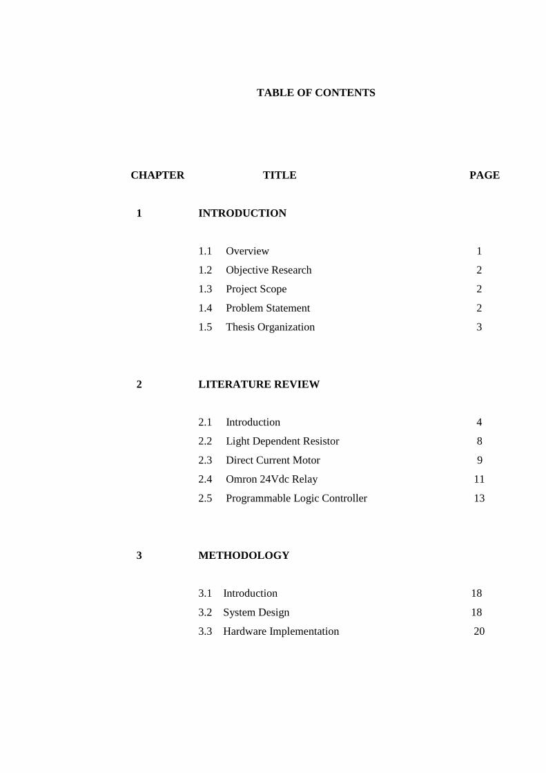
TABLE OF CONTENTS
CHAPTER TITLE PAGE
1 INTRODUCTION
1.1 Overview 1
1.2 Objective Research 2
1.3 Project Scope 2
1.4 Problem Statement 2
1.5 Thesis Organization 3
2 LITERATURE REVIEW
2.1 Introduction 4
2.2 Light Dependent Resistor 8
2.3 Direct Current Motor 9
2.4 Omron 24Vdc Relay 11
2.5 Programmable Logic Controller 13
3 METHODOLOGY
3.1 Introduction 18
3.2 System Design 18
3.3 Hardware Implementation 20
3.3.1 Circuit of Light Dependent Resistor 21
3.3.2 Circuit of DC motor with relay 22
3.3.3 Connection for PLC 24
3.4 ASTS Implementation to real condition 26
3.4.1 Measuring Irradiation, Voltage, Current , and
Temperature Using MACSOLAR 27
3.4.1.1 MACSOLAR(e)economy 27
3.4.1.2 Introduction 27
3.4.1.3 Principle of operation 29
3.4.1.4 Operation 30
3.4.2 Measuring the angle of solar panel for
efficiency 31
3.4.2.1 Clinometer (SUUNTO) 31
3.4.2.2 Introduction 31
3.4.2.3 Principle of operation 33
4 RESULT AND DISCUSSION
4.1 Introduction 35
4.2 Hardware implementation 35
4.3 Sun irradiation analysis 37
4.3.1 Analysis for solar power 37
4.3.2 Analysis for solar voltage 39
4.3.3 Analysis for temperature 41
4.3.4 Analysis for light intensity 42
4.4 Discussion 43

5 CONCLUSION AND RECOMMENDATIONS
5.1 Conclusion 45
5.2 Recommendation 46
REFERENCE 47
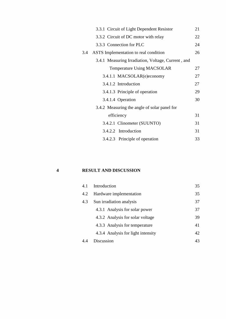
LIST OF TABLES
TABLE NO. TITLE PAGE
2.1 Advantages and disadvantages of DC motor 11
3.1 Measuring Range / Resolution 28
4.1 Data of module power % (Pn) 38
4.2 Data of voltage % (Un) 40
4.3 Data of light intensity (w/m) 42

LIST OF FIGURES
FIGURE NO. TITLE PAGE .
2.1 Basic Automatic Sun Tracking System 5
2.2 LDR assembly a) Top view b) Front 6
2.3 A photograph of ASTS 7
2.4 Structure of a Light Dependent Resistor. 9
2.5 Simple relay circuit 12
2.6 PLC Program 17
3.1 Automated Solar Tracking System 19
3.2 Flow chart of overall system 20
3.3 Light Dependant Resistor circuit picture 21
3.4 Light Dependant Resistor circuit 22
3.5 Relay circuit picture 22
3.6 Connection to motor from relay 23
3.7 Overall connection of PLC 24
3.8 Connection of PLC port input and output 25
3.9 DB 9 RS232 programming cable 25
3.10 Theoretical reading for solar panel on still condition 26
3.11 MACSOLAR solar measuring device 30
3.12 The Clinometer 32
3.13 Leveling 34
4.1 Relay circuit for motor 36
4.2 ASTS device for irradiation reading 36
4.3 Graph of module power (Pn) 37
4.4 Graph of average module power (Pn) 38
4.5 Graph of solar voltage % (Un) 39
4.6 Graph of average solar voltage % (Un) 40

4.7 Graph of temperature (°C) 41
4.8 Graph of average light intensity (°C) 43
CHAPTER 1
INTRODUCTION
1.1 OVERVIEW
The sun is a low cost source of electricity for instead of using generators, solar panel
can convert direct sun rays to electricity. Conventional solar panel, fixed with a certain
angle, limits their area of exposure from the sun due to rotation of the earth. Output of the
solar cells depends on the intensity of the sun and the angle of incidence.
In pursuing to get the maximum energy converted from the sun, an automated
system is required which should be capable to constantly rotate the solar panel. The
Automatic Sun Tracking System (ASTS) is a project meant to solve this problem. It is
completely automatic and keeps the panel parallel to the sun.
In this project, it the ASTS takes the sun as a guiding source. Sensors are used to
constantly monitor the sunlight and rotate the solar panel to the maximum intensity of
sunlight. PLC (Programmable Logic Controller) is used as a device for controlling the
output for the motor. If the sun is not visible during a short period due to cloudy weather,
the PLC is set with a program which will engage the motor rotation to halt which only will
be reactivated due to a sensor which will detect availability of the sun to continue its next
cycle.

1.2 RESEARCH OBJECTIVES
This study attempts to achieve the following objective:
i. To develop a solar tracker with optimum tracking from the sun.
ii. Positioning of solar panel through stepper motor control using PLC.
iii. Result for the efficiency of the device.
1.3 SCOPE OF PROJECT
This project is focused to develop and build an Automated Solar Tracking System
(ASTS) by using plc to move the DC motor that will direct the solar panel from east to
west and back to its initial. Therefore, the project scope is as follow.
i. An automated tracking system which detects the sun during daylight.
ii. Use PLC to move the motor clockwise or counterclockwise.
iii. Show result by differentiate with other angle reading.(45 , 90 , 135)
.
1.4 PROBLEM STATEMENT
This study aims to seek the following research:
i. The sun is moving 180º from east to west so the light irradiation is varied due to
the rotation cycle of the earth.
ii. A solar panel which is static for instant 45º (east/west) will only take the light
irradiation w/m² at the first 90º or the end 180º therefore the maximum power for
the solar panel does not occur.
1.5 THESIS ORGANIZATION
This thesis consists of five chapters. This chapter discuss about overview of project,
objective research, project scope, problem statement and thesis organization.
Chapter 2 contains a detailed description and idea of Automated Solar Tracking
System using PLC or other device. It will explain about the concept of sun tracking using
LDR for maximum light power, the advantage of this system and the involved component
in this project.
Chapter 3 includes the project methodology. It will explain how the project is
organized and the flow of process in completing this project. Also in this topic discusses
the methodology of the system, step to develop the system, and device used to measure the
light irradiation and angle of solar panel during each data taken.
Chapter 4 will be discussing about the result obtained in this project and a discussion
about the result.
Finally, the conclusions for this project are presented in chapter 5. This chapter also
discusses about the recommendation for the project and for the future development.
CHAPTER 2
LITERATURE REVIEW
2.1 INTRODUCTION
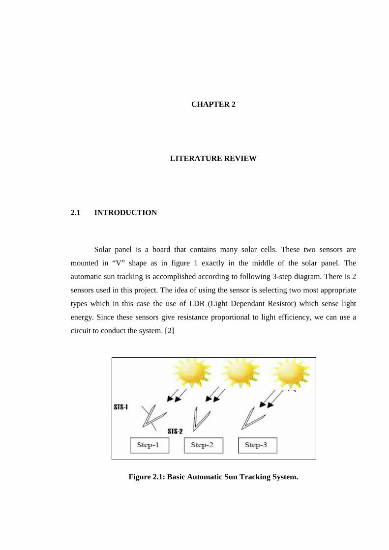
Solar panel is a board that contains many solar cells. These two sensors are
mounted in “V” shape as in figure 1 exactly in the middle of the solar panel. The
automatic sun tracking is accomplished according to following 3-step diagram. There is 2
sensors used in this project. The idea of using the sensor is selecting two most appropriate
types which in this case the use of LDR (Light Dependant Resistor) which sense light
energy. Since these sensors give resistance proportional to light efficiency, we can use a
circuit to conduct the system. [2]
Figure 2.1: Basic Automatic Sun Tracking System.
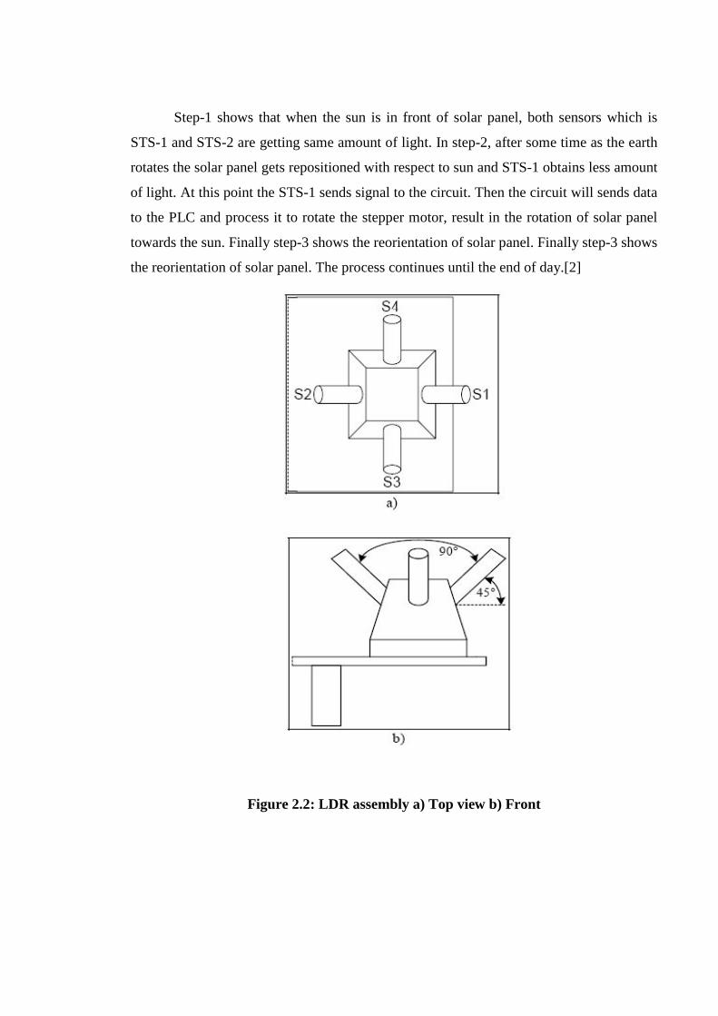
Step-1 shows that when the sun is in front of solar panel, both sensors which is
STS-1 and STS-2 are getting same amount of light. In step-2, after some time as the earth
rotates the solar panel gets repositioned with respect to sun and STS-1 obtains less amount
of light. At this point the STS-1 sends signal to the circuit. Then the circuit will sends data
to the PLC and process it to rotate the stepper motor, result in the rotation of solar panel
towards the sun. Finally step-3 shows the reorientation of solar panel. Finally step-3 shows
the reorientation of solar panel. The process continues until the end of day.[2]
Figure 2.2: LDR assembly a) Top view b) Front
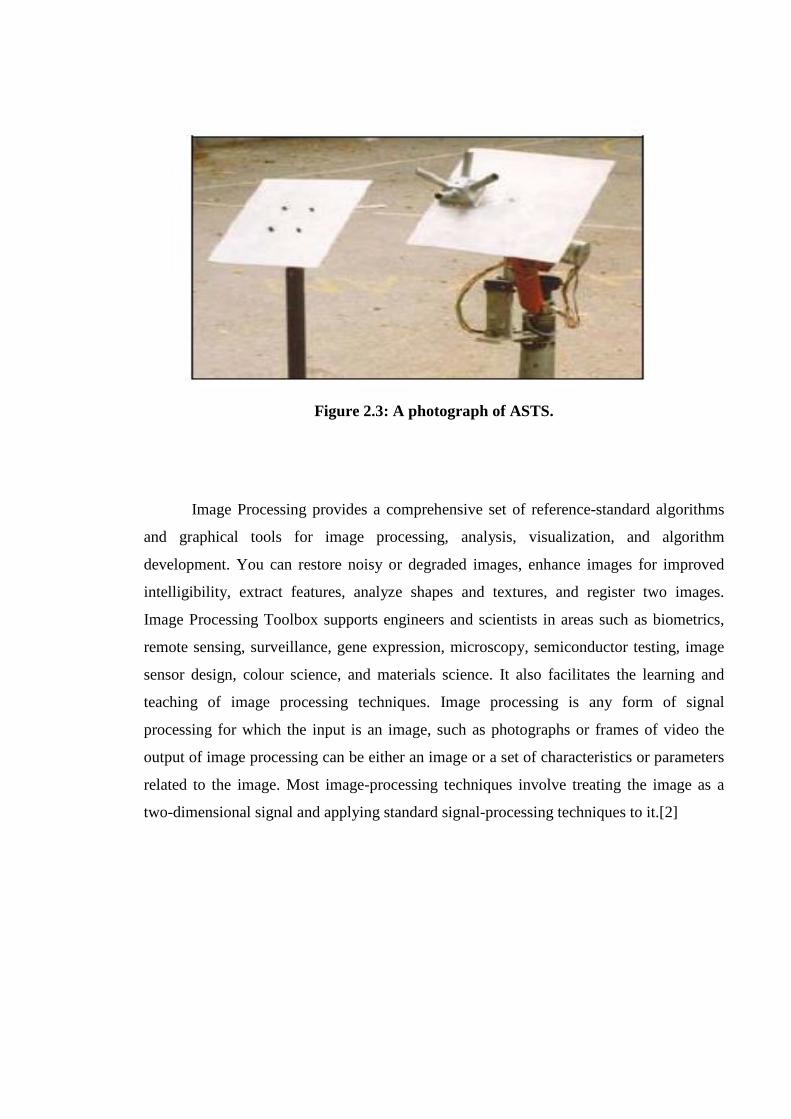
Figure 2.3: A photograph of ASTS.
Image Processing provides a comprehensive set of reference-standard algorithms
and graphical tools for image processing, analysis, visualization, and algorithm
development. You can restore noisy or degraded images, enhance images for improved
intelligibility, extract features, analyze shapes and textures, and register two images.
Image Processing Toolbox supports engineers and scientists in areas such as biometrics,
remote sensing, surveillance, gene expression, microscopy, semiconductor testing, image
sensor design, colour science, and materials science. It also facilitates the learning and
teaching of image processing techniques. Image processing is any form of signal
processing for which the input is an image, such as photographs or frames of video the
output of image processing can be either an image or a set of characteristics or parameters
related to the image. Most image-processing techniques involve treating the image as a
two-dimensional signal and applying standard signal-processing techniques to it.[2]

2.2 Light Dependent Resistor
A photoresistor or light dependent resistor or cadmium sulfide (CdS) cell is a
resistor whose resistance decreases with increasing incident light intensity. It can also be
referenced as a photoconductor. [7]
A photoresistor is made of a high resistance semiconductor. If light falling on the device is
of high enough frequency, photons absorbed by the semiconductor give bound electrons
enough energy to jump into the conduction band. The resulting free electron (and its hole
partner) conduct electricity, thereby lowering resistance. [7]
A photoelectric device can be either intrinsic or extrinsic. An intrinsic semiconductor has
its own charge carriers and is not an efficient semiconductor, e.g. silicon. In intrinsic
devices the only available electrons are in the valence band, and hence the photon must
have enough energy to excite the electron across the entire bandgap. Extrinsic devices
have impurities, also called dopants, and added whose ground state energy is closer to the
conduction band; since the electrons do not have as far to jump, lower energy photons
(i.e., longer wavelengths and lower frequencies) are sufficient to trigger the device. If a
sample of silicon has some of its atoms replaced by phosphorus atoms (impurities), there
will be extra electrons available for conduction. This is an example of an extrinsic
semiconductor. [7]
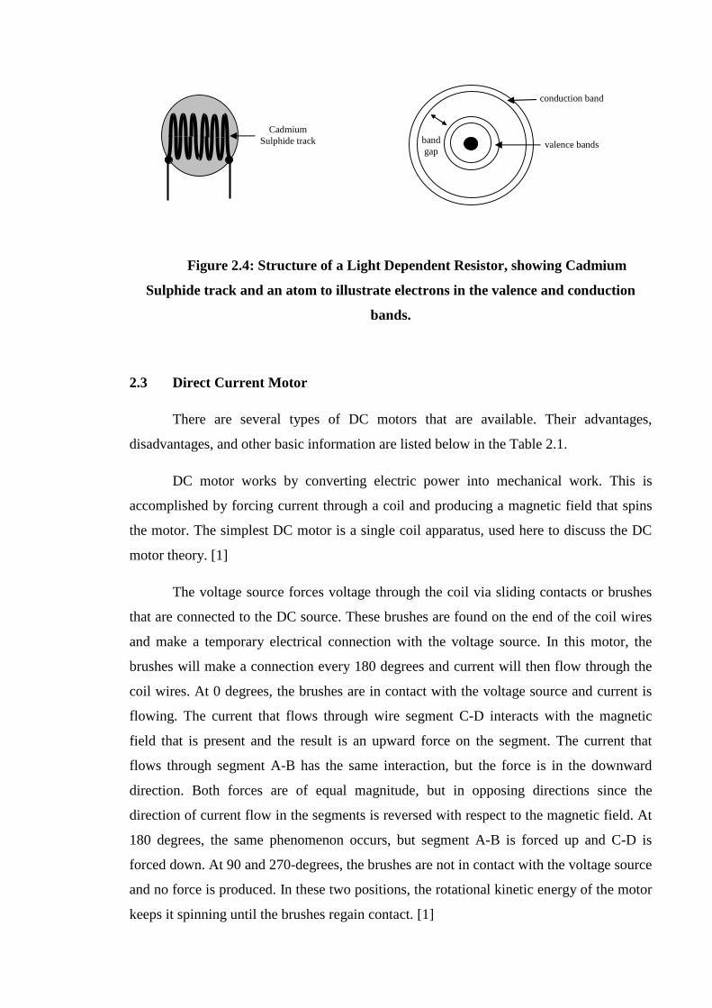
Figure 2.4: Structure of a Light Dependent Resistor, showing Cadmium
Sulphide track and an atom to illustrate electrons in the valence and conduction
bands.
2.3 Direct Current Motor
There are several types of DC motors that are available. Their advantages,
disadvantages, and other basic information are listed below in the Table 2.1.
DC motor works by converting electric power into mechanical work. This is
accomplished by forcing current through a coil and producing a magnetic field that spins
the motor. The simplest DC motor is a single coil apparatus, used here to discuss the DC
motor theory. [1]
The voltage source forces voltage through the coil via sliding contacts or brushes
that are connected to the DC source. These brushes are found on the end of the coil wires
and make a temporary electrical connection with the voltage source. In this motor, the
brushes will make a connection every 180 degrees and current will then flow through the
coil wires. At 0 degrees, the brushes are in contact with the voltage source and current is
flowing. The current that flows through wire segment C-D interacts with the magnetic
field that is present and the result is an upward force on the segment. The current that
flows through segment A-B has the same interaction, but the force is in the downward
direction. Both forces are of equal magnitude, but in opposing directions since the
direction of current flow in the segments is reversed with respect to the magnetic field. At
180 degrees, the same phenomenon occurs, but segment A-B is forced up and C-D is
forced down. At 90 and 270-degrees, the brushes are not in contact with the voltage source
and no force is produced. In these two positions, the rotational kinetic energy of the motor
keeps it spinning until the brushes regain contact. [1]
Cadmium Sulphide track valence bands
conduction band
band gap
One drawback to the motor is the large amount of torque ripple that it has. The
reason for this excessive ripple is because of the fact that the coil has a force pushing on it
only at the 90 and 270 degree positions. The rest of the time the coil spins on its own and
the torque drops to zero. The torque curve produced by this single coil, as more coils are
added to the motor, the torque curve is smoothed out. [1]
The resulting torque curve never reaches the zero point and the average torque for the
motor is greatly increased. As more and more coils are added, the torque curve approaches
a straight line and has very little torque ripple and the motor runs much more smoothly.
Another method of increasing the torque and rotational speed of the motor is to increase
the current supplied to the coils. This is accomplished by increasing the voltage that is sent
to the motor, thus increasing the current at the same time. [1]
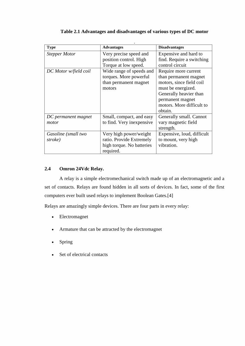
Table 2.1 Advantages and disadvantages of various types of DC motor
. Type Advantages Disadvantages
Stepper Motor Very precise speed and position control. High Torque at low speed.
Expensive and hard to find. Require a switching control circuit
DC Motor w/field coil Wide range of speeds and torques. More powerful than permanent magnet motors
Require more current than permanent magnet motors, since field coil must be energized. Generally heavier than permanent magnet motors. More difficult to obtain.
DC permanent magnet motor
Small, compact, and easy to find. Very inexpensive
Generally small. Cannot vary magnetic field strength.
Gasoline (small two stroke)
Very high power/weight ratio. Provide Extremely high torque. No batteries required.
Expensive, loud, difficult to mount, very high vibration.
2.4 Omron 24Vdc Relay.
A relay is a simple electromechanical switch made up of an electromagnetic and a
set of contacts. Relays are found hidden in all sorts of devices. In fact, some of the first
computers ever built used relays to implement Boolean Gates.[4]
Relays are amazingly simple devices. There are four parts in every relay:
· Electromagnet
· Armature that can be attracted by the electromagnet
· Spring
· Set of electrical contacts

The following figure shows these four parts in action:
Figure 2.5: Simple relay circuit.
In this figure, you can see that a relay consists of two separate and completely
independent circuits. The first is at the bottom and drives the electromagnetic. In this
circuit, a switch is controlling power to the electromagnet. When the switch is on, the
electromagnet is on, and it attracts the armature (blue). The armature is acting as a switch
in the second circuit. When the electromagnet is energized, the armature completes the
second circuit and the light is on. When the electromagnet is not energized, the spring
pulls the armature away and the circuit is not complete. In that case, the light is dark.[4]
When purchase relays, you generally have control over several variables:
· The voltage and current that is needed to activate the armature
· The maximum voltage and current that can run through the armature and the
armature contacts
· The number of armatures (generally one or two)
· The number of contacts for the armature (generally one or two -- the relay shown
here has two, one of which is unused)
· Whether the contact (if only one contact is provided) is normally open (NO) or
normally closed (NC)
Related Documents